Electrical System Design of Solar-Powered Electrical Water ...
Upload
khangminh22Category
view
0download
0
e September, 1 976 New I nformation Ma iled to: E, D, C/1 901 , 1 928/D B
Westing house Electric Corporation Low Voltage Breaker Division Beaver, Pennsylvania 1 5009
Federal Speci fication W-C-375b
29-1 60 A WE A Application Data
Page 20.1
AB DE-ION® Circuit Breakers
Federal Specification W-C-375b recently superseded specification W-C-375a listed on page 4 of this publication. The following tabulation of circuit breaker specification class designations replaces the listing on page 4. Type Continuous No. of Ac Specification Breaker Amp. Rating Poles Volts Class
OC, HOP, BAB 1 0-70 1 1 20/240 1 2a, 1 1 a, 1 Oa 1 5·1 25 2 1 20/240 1 2a, 1 0a
HOC, HONP, BA 1 5-50 2 240 1 2b, 1 1 b, 1 Ob 1 5- 1 00 3 240 1 2b, 1 1 b, 1 Ob
BA 1 5-30 277 1 2c OHP, OHC, H BA 1 5-30 1 -2 1 20/240 1 5a
1 5-20 3 240 1 5b
OPGF, OBGF 1 5-30 1 1 20 1 1 a OPGF, OBGF 1 5-30 2 1 20/240 1 0a, 1 2a
OPHGF, OBHGF 1 5-30 1 1 20 1 1 a OPHGF, OBHGF 1 5-30 2 1 20/240 1 4a, 1 2a, 1 0a
OPH, OCH, OBH 1 5-70 1 1 20/240 1 4a 1 5- 1 00 2 1 20/240 1 4a 1 5- 1 00 3 240 1 4b
CA 1 25-225 2-3 240 1 2b
CAH 1 25-225 2-3 240 1 4b
DA 250-400 2-3 240 1 4b EB Standard 1 5- 1 00 1 1 20 1 1 a
1 5- 1 00 2-3 240 1 2b, 1 1 b, 1 0b
E H B Standard 1 5- 1 00 1 277 1 3a 1 5-1 00 2-3 480 1 3b
FB Standard 1 5- 1 50 2-3 600 1 8a
JA, KA 70-225 2-3 600 20a, 1 9a
J B, KB Standard 70-250 2-3 600 20a, 1 9a
LB, LB B Standard 70-400 2-3 600 21 a
LA Standard 70-600 2-3 600 21 a
LC 75-600 2-3 600 21 a
MA 1 25-800 2-3 600 21 a
MC Seltronic 400-800 2-3 600 21 a
NB 700-1 200 2-3 600 21 a
NC Seltronic 800-1 200 2-3 600 21 a PB 600-3000 2-3 600 25a
PC Seltronic 1 000-3000 2-3 600 25a PCC Seltronic 1 000-3000 2-3 600 25a
H F B Mark 75 1 5-30 1 277 1 3a 40- 1 00 1 277 1 3a 1 5- 1 50 2-3 600 22a
HKA 70-225 2-3 600 23a
HKB Mark 75 70-250 2-3 600
HLB Mark 75 1 25-400 2-3 600 23a
HLA Mark 75 70-600 2-3 600 23a
HLC 75-600 2-3 600 23a
H M A 1 25-BOO 2-3 600 23a
H M C Mark 75 400-800 2-3 600 23a
HNB 700-1 200 2-3 600 23a
HNC Mark 75 B00-1 200 2-3 600 23a
FB Tri-Pac 1 5- 1 00 2-3 600 26a, 1 7a, 1 6b, 1 6a
LA Tri-Pac 70-400 2-3 600 26a, 1 7a, 1 6b, 1 6a
NB Tri-Pac 300-BOO 2-3 600 26a, 1 7a, 1 6b
PB Tri-Pac 600-1 600 2-3 600 1 7a, 26a
www . El
ectric
alPar
tMan
uals
. com

29-1 60 A WE A Application Data
Page 20.2
Westingho use Ele ctri c Corpor ation Low Voltage Breaker Division Beaver, Pennsylvania 1 5009
www . El
ectric
alPar
tMan
uals
. com

e September, 1 976 Supersedes Application Data 29-1 60 all previous issues. M ailed to: E, D, C/1 901 , 1 928/D B
1 Pole Type OC
Westi ng house Electric Corporation Low Voltage Breaker D ivision Beaver, Pennsylvania 1 5009
29- 1 60 A WE A Application Data
Page 21
Standard Types H OP, H O N P, OC, H OC, OPH, OCH and MARK 75® Types OHC, OHP 1 0- 1 25 Amperes, 1 , 2 and 3 Poles, 1 20/240 and 240 Volts Ac
AB DE-IQN® Quicklag® Circuit Breakers
1 Pole Type O H P Type OPH
1 Pole Type OCH. Type O H C
2 Pole Type H O N P, Type O H P Type OPH
2 Pole Type HOC, Type OCH Type OHC
3 Pole Type HONP, Type O H P Type O P H
3 Pole Type HOC, Type OCH Type O H C
Note: MARK 75 Breaker Cases Are of Gray Molded Material
Contin uous Am pere Ratings and Interrupting Capacity Underwriters' Laboratories, Inc. Listed
Types H OP. H O N P . OC, H OC 1 0,000 Amperes Asym, a nd Sym. I .C .<D 1 - Pole, 1 20/240 Volts Ac: 1 0 to 70 Amps. 2-Poles, 1 20/240 Volts Ac: 1 0 to 1 25 Amps. 2- Poles, 240 Volts Ac: 1 5 to 50 Amps. 3 - Poles, 240 Volts Ac: 1 5 to 1 00 Amps.
Types O P H . OC H 22,000 Amperes Sym., 25,000 Amps Asym. I. C. 1 - Pole, 1 20/240 Volts Ac: 1 5 to 70 Amps. 2-Poles. 1 20/240 Volts Ac: 1 5 to 1 00 Amps. 2- Poles, 240 Volts Ac: 1 5 to 50 Amps. 3-Poles, 240 Volts Ac: 1 5 to 1 00 Amps.
M A R K 75 Types O H C, O H P 65,000 Amperes Sym., 75,000 Amperes Asym. I .C. 1 - Pole, 1 20/240 Volts Ac: 1 5-30 Amps. 2-Poles, 1 20/240 Volts Ac: 1 5-30 Amps. 3 - Poles, 240 Volts Ac: 1 5 -20 Amps.
Appl ication These breakers are designed to protect small branch circuits in residential, commercial, or industrial applications. Typical uses are in
<D Panelboards us ing these 1 0.000 I . C. breakers as Branch Breakers i n series with Type CAH or OP 22.000 Amp I. C. M a i n Breakers can be l isted for app l i cat ion at 22.000 amperes.
loadcenters, l ighting panelboards, and for individual mounting. They are listed with Underwriters' Laboratories Inc.
On all three-phase Delta, grounded B phase applications, refer to Westinghouse.
Construction Features of these breakers i nclude arc quenchers, quick-make, quick-break trip-free mechanisms, silver alloy contacts, electrically welded connections, and Molded case. The MARK 75 breakers have these same standard features, plus a higher grade molded case (identified by light gray color) for higher interrupting capacity.
Two and three-pole breakers are common trip to insure simultaneous manual or automatic opening of all poles. Ferrous parts are chemically plated to insure corrosion resistance.
Federal S peci fication W-C-375b See tabulation on page 20.1 .
Terminals Types H OP, HON P, OPH and OH P plug-in Breakers have a female clamp-type l ine terminal which clips on to a bus stab projection of a panel board or loadcenter.
Bolt on Breaker line terminals are screw and
clamp up to 20 amp (Type OC) and binding head screw up to 30 amp (Types H OC, OCH OHC) with pressure type removable terminals on higher ratings.
Load terminals use binding head screws for 30 amperes and less (20 amp and less for type OC) . Higher rated breakers have pressure type connectors for load leads.
O peration The breaker is shown i n the "off' position. I n tripping, the contacts part a n d the handle moves to a mid-way position. Moving handle to extreme "off" position resets the breaker and it can be restored to service by moving handle to "on" position. Ouicklag Breakers are U/L listed for inverted mounting and reverse feed.
Thermal Magnetic Tr ip These breakers are equipped with a thermal magnetic trip. On temporary overloads, the breaker will not trip. On sustained overloads beyond safe limits for wire, the bi-metal will deflect, causing the breaker to trip. I nstantaneous tripping is provided by a magnetic element under short circuit conditions. Trip elements are non-adjustable and noninterchangeable. Ouicklag breakers are calibrated at 40"C as standard. Breakers applied in ambients higher than 40"C should be derated. www .
Elec
tricalP
artM
anua
ls . c
om

29-1 60 A WE A Application Data
Page 22
Typical Exploded View (Type P Plug-in Breaker Shown) 1 Pole
Moving Contact
Cover Operating Han d l e
3 Pole
Base Cover M ovi n g Contact
Cover Rivets Arc E x t i n g u i sher B i-Metal Armatu re
Switching N e utral B reakers TypesHQNPandHQC 10,000Amps,I.C. Only
Switching neutral breaker is available in 2-pole, 1 5 and 20 ampere ratings. Its application is gasoline station dispensing pump circuits. Meets the requirements of N E C (Article 51 4-5); "Each circuit leading to or through a dispensing pump or island shall be provided with a switch or other acceptable means to disconnect simultaneously from the source of supply all conductors of the circuit including the grounded neutral, if any".
D elta B reakers Types HQNP and HOC 10,000 Amps. I. C. Only
r------ Line ! ..-.. : Load
�-"-'IL=-in__;, e�: Load} �g'0 !Line..-... : Load Volt �-+--T�---�----�
Grounded Load Delta Neutral Center Bus Breaker Engineered for 3-phase 4-wire 1 20/240 volt Ac delta applications which utilize 3-phase
Armature Gas Vent
motor circuits, such as air conditioning and heat pump applications.
B reaker Mounting Types H QP, H QN P, Q H P, Q P H (Pl u g - i n ) : The load e n d o f the breaker i s inserted under the mounting clamp of a panelboard and the line end is merely snapped into position over the bus stab.
Types QC, H OC, Q H C , Q C H (Bolt-on): The breaker is mounted in a panel board by inserting the load end under the mounting clamp and bolting the line end to bus connections. For independent mounting, face mounting plates are used for flush mounting the breakers. Base mounting plates can be used where the plates are mounted in a panel, in this method the breaker base snaps into line and load clips to hold it firm.
C i rcuit B reaker R emoval Before inspecting, installing or removing from a circuit, the circuit breaker should be in the "off" position, and if practicable, the circuit should be de-energized.
Inspection and M a i ntenance Good maintenance procedure calls for periodic inspection of all electrical apparatus including molded case circuit breakers. Terminal lugs must be tight to prevent overheating. Due to the inherent wiping action built into the moving contacts of all Westinghouse circuit breakers, operating the breaker several times under load will remove any high resistance film that may have formed.
Accessories and M od i fications Accessories and modifications available include: lockdog, handle locks for use with padlock, moisture and fungus treatment, and handle ties for using two single-pole breakers for 1 20/240 volt 2 wire operation. Handle ties assure simultaneous switching, but allow either breaker to register independent trip positions.
Further I n formation Prices: Price List 29-020 P WE A Ordering Data: Tech Data 29- 1 20 T W E A Dimensions: Dimension Sheet 29- 1 70 Trip Curves: 29- 1 61 A W E A
D i mensions, I nches® Not to be used for construction purpq�es. See Dimension Sheet 29- 1 70 for detailed dimensions.
Type HOP
21.? 16
c@ -,"�---.j 32�
® 2-pole breaker is 2" wide. 3-po/e is 3" wide.
�-------2� � 32 � Type oc Types HOC, OHC
www . El
ectric
alPar
tMan
uals
. com

September, 1 976 Supersedes Application Data 29- 1 60 all previous issues. Mailed to: E, D, C/1 901 , 1 928/DB
Interrupting C apacity: 1 0,000 Amps Sym. or Asym., and 22,000 Amps. Sym., 25,000 Amps Asym.
Sensitivity : 5 Milliamps or Greater
Westinghouse Quicklag Ground Fault circuit breakers are U L listed as Class A, ground fault circuit interrupters.
Application Quicklag Ground Fault circuit breakers are normally used in loadcenters or panelboards to protect small branch circuits in residential, commercial or industrial applications. They function to protect humans from ground faults of 5 milliamperes or greater, as well as normal circuit protection providing inverse time overload and instantaneous short circuit protection.
Typical applications include protection against ground fault hazards in circuits near swimming pools and outdoor receptacles for which the National Electric Code requires protection of human life against ground faults. (Ref. N .E.C. articles 680-31 , 680-20, 680-6, and 2 1 0-8)
Construction Quicklag Ground Fault circuit breakers are 1 or 2 pole thermal magnetic circuit breakers which incorporate a solid state ground fault sensing circuit to detect ground current. Available as plug-in (Type P) or bolt-on (Type B) design, they are interchangeable in load centers or panelboards with standard Westinghouse Type P plug-in and Type B bolt-on quicklag breaker. The breaker features a quick-make, quick-break trip free operating mechanism, silver alloy contacts and welded connections.
The ground fault sensing circuit consists of a monitor, a solid state amplifier, and a shunt trip mechanism.
Federal Speci fi c ation W-C-375b See tabulation on page 20.1.
Terminals Type P plug-in design has a female.clamptype line terminal which plugs onto the bus stab of a panelboard or loadcenter.
Type B bolt-on design has an extended tang line terminal that bolts directly to the panelboard bus connecting strap.
Load terminals are pressure-type connectors suitable for use with either copper or aluminum wire. 1 5 to 25 ampere breakers accept
Westinghouse Electric Corporation Low Voltage Breaker Division Beaver, Pennsylvania 1 5009
Standard Types P and B 1 5-30 Amperes, 1 20 Volts Ac 1 Pole, 1 20/240 Volts Ac 2 Poles
ill 1 4- ill 1 0 Cu or ill 1 2- ill 8 AI, and 30 ampere breakers accept ill 1 4- ill 4 Cu or ill 8- ill 4 AI.
I nst al l ation The load end of the breaker is inserted under the mounting clamp of a panel board, and the line end is plugged onto the bus stab (or, in the case of bolt-on design, bolted to the bus connector strap).
The load end on single pole breakers has two terminals and a white "pigtail" wire. Two wires from the 1 20 volt load to be protected are brought into the panel board and con nected to the terminals. The black wire is
Shunt Trip
� >- Solid State
r Amplifier
I I I I I I
Breaker I ,....._ Hot- -
120 Volt Line Source - Neutral -
r Ground
Figure 1
29-1 60 A WE A Application Data
Page 23
AB DE-ION® Quicklag® Ground Fault Circuit Breakers
,._� connected to the terminal marked Load, and the white wire connected to the terminal marked Load Neutral. (These wires are shown passing through the monitor in Figure 1 .) The "pigtail" is connected to the neutral bar in the panelboard.
Two pole breakers have three load terminals and a white pigtail. The colored hot load wires are connected to the outside load terminals. The white neutral wire (if used) is connected to the center terminal, identified by a white mark. The pigtail is connected to the panel neutral.
il r; r; Monitor IV V 1...
�""''"' Load
- l "'=
Unintentional Ground Path Hazardous to Humans
www . El
ectric
alPar
tMan
uals
. com

29-1 60 A W E A Application Data
Page 24
O peration The Quicklag Ground Fault circuit breaker operates as any standard thermal magnetic breaker, providing protection against overloads and short circuits. The ground fault sensing circuit, Figure 1 , monitors current flow in the load supply and return wires (which pass through the monitor) and opens the circuit when it senses a ground fault current of five milliamperes or greater.
Current flowing through a wire generates a magnetic field around the wire. Normally, at any one instant, the current flowing through the load supply and return wires are equal, and their magnetic fields cancel each other. Since there is no current imbalance, no current flows in the secondary winding of the monitor.
However, should an unintentional grounding of the load supply conductor occur, then an alternate path to the system ground would be established. The amount of fault current flowing depends upon the impedance (resistance) of the ground path. The resulting magnetic field, caused by the load supply current exceeding the load return current through the monitor, generates a voltage i n the monitor causing current t o flow in the secondary winding. This current imbalance is amplified and fed to the shunt trip, which trips the circuit breaker, opening the circuit to the load. After the ground fault condition has been corrected, the breaker is reset in the normal manner.
G round Fault C h aracteristics The 5 milliamp sensitivity rating offers adequate protection for human life, and minimizes unnecessary operation on small electrical impulses or leakage currents not dangerous to human life. The key to safety appears to be the amount of current an individual can withstand and yet be able to "let go". The 5 milliamp rating is below the known average "let go" current for both women and men.
The Westinghouse Quicklag Ground Fault circuit breaker is UL listed under Standard 943 as a class A, ground fault circuit interrupter, which is defined as a device that will trip when the fault current to ground is within the range of 5 through 264 milliamps. An inverse trip time which varies between 7.26 seconds at 5 MA and .024 seconds at 264 MA is specified.
I nspection and M a i ntenance Good maintenance procedure calls for periodic inspection of electrical apparatus. Underwriters' Laboratories, I nc. suggests that the device be checked monthly, and a test record card is provided for this purpose.
Use caution when inspecting or removing the breaker from the circuit, the breaker should be in the Off position and if practical, the circuit should be deenergized.
A test button provides for a check of the electrical system of the ground fault sensing
Dimensions, I nches.
circuit, and the mechanical operations of the breaker.
Terminal lugs must be tight to prevent overheating. Due to the inherent wiping action built into the moving contacts of all Westinghouse circuit breakers, operating the breaker several times under load will remove any high resistance film that may have formed.
Further I nformation Prices: Price List 29-020 P WE A Ordering Data: Tech Data 29-1 20 T WE A Dimensions: Dimension Sheet 29-1 70
Not to be used for construction purposes. See Dimension Sheet 29- 1 70 for detailed dimensions.
Plug-In Breakers
Front View ( 1 Pole) r-1--1 Front View ( 2 Pole) r----2 ----1
Panel--�-=:::..._,..� Neutral W�re
Bolt-on Breakers
Front View ( l Pole)
rF�ll Front View ( 2 Pole) r-Fcsl 2r&l
9 :32
9 :32
Side View �----------2�--------·�1
Side View
0
www . El
ectric
alPar
tMan
uals
. com

S eptember, 1 976 Supersedes Application Data 29-1 60 all previous issues. Mailed to: E, D, C/1 901 , 1 928/ D B
2 Pole
Westinghouse Electric Corpo ration Low Voltage Breaker Division Beaver, Pen nsylvania 1 5009
Standard Types BA, BAB and Quicklag® Type Q B H , and MARK 75®Type H BA 1 0- 1 25 Amperes, 1 20/240, 240, 277 Volts Ac 1 , 2, 3 Poles
2 Pole
29-160 A WE A Application Data
Page 25
AB DE-ION®
Circuit Breakers
1 Pole Type BA (277 Volt)
1 Pole Type BAB Type BAB
1 20/240 Volt
1 Pole Type H BA, Type Q B H
Type BA, (240 Volt) Type H BA,
3 Pole Type BA, Type H BA, Type QBH Type OBH
Note: MARK 75 Cases Are of Gray Molded Material.
Continuous Ampere Ratings and Interrupting Capacities Underwriters' Laboratories, Inc. Listed
Types BAB, BA 1 0,000 Amperes Sym. or Asym. I .C .<D 1 Pole, 1 20/240 Volts Ac: 1 0 to 70 Amperes 2 Poles, 1 20/240 Volts Ac: 1 0 to 1 25 Amperes 2 Poles, 240 Volts Ac: 1 5 to 50 Amperes 3 Poles, 240 Volts Ac: 1 5 to 1 00 Amperes 1 Pole, 277 Volts Ac: 1 5 to 30 Amperes
Quicklag Type Q B H 22,000 Amperes Sym., 25,000 Amperes Asym. I . C. 1 Pole, 1 20/240 Volts Ac: 1 5 to 70 Amperes 2 Poles, 1 20/240 Volts Ac: 1 5 to 1 00 Amperes 2 Poles, 240 Volts Ac: 1 5 to 50 Amperes 3 Poles, 240 Volts Ac: 1 5 to 1 00 Amperes
Mark 75 Type H BA 65,000 Amperes Sym., 75,000 Amperes Asym. I .C . 1 Pole, 1 20/240 Volts Ac: 1 5-30 2 Pole, 1 20/240 Volts Ac: 1 5-30 3 Pole, 240 Volts Ac: 1 5-20
Application These circuit breakers are used primarily in panel boards where a bolted l ine terminal connection is required. Listed by Underwriters' Laboratories, I nc. On all three phase Delta, grounded B phase applications, refer to Westinghouse.
<D Panelboards using these 10.000 I. C. breakers as branch breakers in series with CAH or OBH 22.000 amp I. C. ma in breakers can be listed for application at 22.000 amps.
C onstruction Features of the Type BA, BAB & Quicklag Q B H Breakers include arc quencher, qu ickmake, quick-break trip free mechanism, silver a l loy contacts, electrically welded connections, and a molded case. The MARK 75 Type H BA has all the standard features, plus a higher grade molded case (identified by light gray color) for higher interrupting capacity. Two and three-pole breakers are common trip to insure simultaneous manual or automatic opening of a l l poles. Ferrous parts are chemically plated to insure corrosion resistance.
Federal S pecification W-C -375b See tabulation on page 20. 1 .
Terminals Line terminals are provided in the form of an extended tang which bolts directly to the panelboard bus connecting strap. Load terminals are as follows:
Type BA 277 volt: Pressure Type. Type BA, H BA, Quicklag Q B H:
Binding head screw up to 30 amp and pressure type on higher ratings.
Type BAB: Pressure Type
Thermal M ag netic Tr ip These breakers are equ ipped with a thermal magnetic trip. On temporary overloads, the breaker will not trip. On sustained overloads beyond safe l imits for wire, the bimetal will deflect causing the breaker to trip. Instantaneous tripping is provided by a magnetic
element under short circuit conditions. Trip elements are non-adjustable and noninterchangeable. These breakers are calibrated at 4o·c as standard. Breakers applied in ambients higher than 4o•c should be derated.
Switching Neutral B reakers Type BA 1 0,000 Amps. I. C. Only Switching neutral breaker is available in 2-pole, 1 5 and 20 ampere ratings. Its application is gasol ine station dispensing pump circuits. Meets the requirements of N EC (Article 51 4-5); "Each circuit leading to or through a dispensing pump or island shall be provided with a switch or other acceptable means to disconnect simultaneously from the source of supply all conductors of the circuit including the grounded neutral, if any".
Delta B reakers Type BA 1 0,000 Amps. I . C. Only
r------ Line
l'B-ii--+iL_in--'e:: ����} i:o iline_...... : Load Volt
�--+-+=.� � Load
Center Bus
L------J
Delta Brecker
Engineered for 3-phase 4 -wire 1 20/240 volt Ac delta applications which utilize 3-phase motor circuits, such as air conditioning and heat pump applications. www .
Elec
tricalP
artM
anua
ls . c
om

29-1 60 A WE A Application Data
Page 26
Typical Exploded View 1 20/240, 240 Volt Ac Breakers
Pole Type B A B 3 Pole Type BA M oving Contact Line Terminal
Cover Operat ing Handle I Moving Contact Cover
Arc Extinguisher Base Magnet Armature Arc Ext inguisher Armature Gas Vent
O peration The breaker is shown in the "OFF" position. I n tripping, the contacts part and the handle moves to a mid-way position. Moving handle to extreme "OFF" position resets the breaker and it can be restored to service by moving handle to "ON" position. These breakers are U L I nc. Listed for inverted mounting and reverse feed.
M ou nting The load end of the breaker is inserted under the mounting clamp of a panel board and the line end is bolted to the bus connector strap.
Dimensions, Inches®
Circuit Breaker Removal Before inspecting, installing, or removing from a circuit, the circuit breaker should be in the "OFF" position, and if practicable, the circuit should be de-energized.
Inspection and M ai ntenance Good maintenance procedure calls for periodic inspection of all electrical apparatus including molded case circuit breakers. Terminal lugs must be tight to prevent overheating. Due to the inherent wiping action built into the moving contacts of all Westinghouse circuit breakers, operating the breaker several times under load will remove any high resistance film that may have formed.
Not to be used for construction purposes. See Dimension Sheet 29- 1 70 for detailed dimensions.
0
Type BA 277 Volt
® 2-pole breaker is 2" wide, 3-pole is 3" wide.
We stinghou se Electric Corporatio n Low Voltage Breaker Division Beaver, Pennsylvania 1 5009
Type BAB
Accessories and M od i fications Accessories and modifications available include: lockdog, handle locks for use with padlock, moisture and fungus treatment, and handle ties for using two single pole breakers for 1 20/240 volt 2 wire operation . Handle ties assure simultaneous switching, but allow either breaker to register independent trip positions.
Further In formation Prices: Price List 29-020 P WE A Ordering Data: Tech Data 29-1 20 T WE A Dimensions: Dimension Sheet 29 -1 70 Trip Curves: Application Data 29- 1 61 A WE A
www . El
ectric
alPar
tMan
uals
. com

e September, 1 976 Supersedes Application Data 29- 1 60 all previous issues. Mailed to: E, D, C/1 901 , 1 928/ D B
Continuous Ampere Ratings Underwriters' Laboratories, Inc. Listed 1 25, 1 50, 1 75, 200 and 225 Amperes
Interrupting Ratings, Amperes Underwriters' Laboratories, Inc. Listed Type CA: 1 0,000 Asym. and Sym. Type CAH: 25,000 Asym., 22,000 Sym.
Applicatio n C A and CAH AB De-ion® circuit breakers are designed for protection of branch and feeder circuits in either commercial or industrial applications. Because of their high continuous ampere capacity and compact size, they are particularly well-suited for use as main protection in load centers, metering panels and lighting panel boards. They are also suited for installation in distribution panelboards, motor control centers, control panels and separate enclosures where a 240 volt, 225 ampere frame breaker is required.
Listed with Underwriters' Laboratories, I nc. (Two pole breakers are listed for grounded B phase applications.)
Federal Specification W-C-375b See tab ulation on page 20.1
Construction Type CA and CAH breakers have al l the standard AB circuit breaker features such as De-ion® arc extinguishers, and quick- make, quick-break, trip-free toggle mechanisms.
Type CAH breakers are the same size and have the same mounting dimensions as Type CA. However, the CAH breaker is constructed of stronger molded material, enabling them to have a higher I.C. Type CAH breakers are U L Listed for use ahead of 1 0,000 ampere I .C. Ouicklag and BA breakers in panelboards to permit their application at 22,000 ampere fault levels.
Two-pole breakers are supplied in a two-pole frame, 2% in. wide, three-pole breakers are supplied in a three-pole frame, 4Ys in. wide.
Terminals Terminals are Underwriters' Laboratories, I nc. listed for the wire type and size l isted below. When used with aluminum conductors, use joint compound. Max. Catalog Wire Range B reaker Number and Type Amps.
175 TA175CA1 !I 1 -4/0 AIICu 225 TA225CA1 2/0-300 MCM AI/Cu
Westing house Electric C o rporation Low Voltage Breaker Division Beaver, Pen nsylvania 1 5009
Types CA and CAH 125-225 Amperes, 240 Volts Ac, 2 and 3 Poles
O peratio n When the breaker contacts are open, the handle is in either the mid or OFF position. If, in the mid-position, the breaker has been tripped automatically, the latch must be reset by moving the operating handle to the extreme OFF position before attempting to restore service. Contacts may be closed after resetting the latch, by moving the handle to the O N position. CA a n d CAH breakers may be mounted in an inverted position and are approved for reverse feed.<D The toggle handle operates with the following forces in pounds from the end of the handle: O N ; 10 lbs.; OFF: 1 1 lbs.: RESET: 21 lbs.
Thermal Magnetic B reaker Thermal magnetic breakers are equipped with thermal and magnetic trip elements to provide complete circuit protection against overloads and short circuits.
The thermal trip elements (bimetals) provide inverse trip characteristics and are indirectly heated for longer overload time delay which is desirable in feeder circuits. On temporary overloads, the breaker will not trip; but on sustained overloads beyond the safe l imits of the wire, the bimetal will deflect. causing the breaker to trip.
The magnetic trip element (electro-magnet) is set to trip the breaker instantaneously at currents of approxi mately 10 ti mes the con tinuous rating o f the breaker.
29-1 60 A WE A Application Data
Page 27
AB DE-ION® Circuit Breakers
Trip elements are non-adjustable and noninterchangeable.
M olded Case Switches (Type CA only) ( Non -Automatic I nterrupters) These are breakers without overload or short circuit tripping elements. They can be installed where a compact high capacity disconnect switch is required without overcurrent protection.
C i rcuit B reaker Removal Before inspecting, installing or removing from a circuit, the circuit breaker should be in the "off' position, and if practical, the circuit should be de-energized. If the circuit cannot be de-energized, insulated tools, rubber gloves and a rubber floor mat should be used.
To remove a front-connected circuit breaker from its mounting, loosen terminal screws and remove cables from terminals. Remove circuit breaker mounting screws and pull circuit breaker forward.
Inspection and M a i ntenance Good maintenance procedure calls for periodic inspection of all electrical apparatus including molded case circuit breakers. Terminal lugs must be tight to prevent over-
<D Breakers with i nternal attachments are not su itable for reverse feed. www .
Elec
tricalP
artM
anua
ls . c
om

29-1 60 A WE A Application Data
Page 28
Exploded View, Thermal Magnetic B reaker
Breaker Mount ing Sc rew
B reaker
heating. Due to the inherent wiping action built into the moving contacts of all Westinghouse circuit breakers, operating the breaker several times under load will remove any high resistance film that may have formed.
It should be noted that removing the sealed cover of the type CA breaker voids the Underwriters' Laboratories, Inc., label.
Accessories Accessories include shunt trips, auxiliary switches, panelboard connectors for C D P panel boards and a padlockable handle lock for use with loadcenters or other applications where a face trim is used.
F u r ther I n fo rm a tion Prices: Price List 29-020 P WE A Ordering Data: Tech Data 29-1 20 T WE A Dimensions: Dimension Sheet 29-1 70 Trip Curves: Application Data 29- 1 61 A WE A
We stinghou se Electric Corporation Low Voltage Breaker Division Beaver, Pennsylvania 1 5009
8 Terminal Mounting Screw Contact Mount ing Screw
I . �""); -{.;w Term inal _l Arc Exti nguisher Base
l nterpole Barr ier
D i men si o n s, I nche s Not to be used for construction purpose. See Dimension Sheet 29- 1 70 for detailed dimensions.
�------4§ --------·
2 Poles 3 Poles
www . El
ectric
alPar
tMan
uals
. com

8 September, 1 976 Supersedes Application Data 29- 1 60 all previous issues. Mailed to: E, D, C/1 901 , 1 928/D B
Continuous Ampere Ratings Underwriters' Laboratories, Inc. Listed 250, 300, 350 and 400 Amperes
Interruptin g Ratings, Amperes Underwriters' Laboratories, Inc. Listed 240 Volts Ac: 25,000 Asym., 22,000 Sym. 250 Volts De: 1 0,000
Application Type DA breakers are designed to provide overload and short circuit protection for branch and feeder circuits in either commercial or industrial installations. Because of their high continuous ampere capacity and compact size, they are particularly well-suited for use as main protection in load centers, metering panels and lighting panels. They are also ideally suited for installation in switchboards, panel boards, motor control centers, control panels and separate enclosures where a 240 volt, 400 amp frame size breaker is required.
Listed with Underwriters' Laboratories, I nc.
On all three phase Delta, grounded B phase applications. refer to Westinghouse.
Federal Specification W- C-375b See tabulation on page 20. 1 .
Construction Type DA breakers have all the standard AB breaker features.
In addition to the standard features, the molded case is made of glass polyester, giving the breaker greater strength and resistance to tracking.
Two and three pole breakers are supplied in one frame size; the current carrying parts being omitted from the center pole for two pole breakers.
Termi nals Terminals are Underwriters' Laboratories, Inc. listed for the wire type and size listed below. When used with aluminum conductors, use joint compound. Max. Catalog Breaker Number Amps.
Wire Range, Type No. of Cables
Standard Terminals (for Copper cable) 350 T350DA 1 250-500 MCM Cu 400 T400DA2 2 3/0-250 MCM Cu Alternate Aluminum Body Terminals 350 TA350DA 1 250-500 MCM AI/Cu 400 TA400DA1 2 3/0-250 MCM AI,Cu
Terminal mounting arrangement permits
(j) I ncludes use With standard internal attachments ex· cept auxiliary switches with 2A-2B contacts.
Westing house Electric Corporation Low Voltage Breaker Division Beaver, Pennsylvania 1 5009
Type DA 250-400 Amperes, 240 Volts Ac, 250 Volts De, 2 and 3 Poles
ready use of other circuit connecting means such as rear connecting studs, panel board connectors and plug-in adaptor kits.
O peration When the breaker contacts are open the handle is in either the mid or OFF position. If in the mid-position the breaker has been tripped automatically. The latch must be reset by moving the operat ing handle to the extreme OFF position before attempting to restore service. Contacts may be closed, after resetting the latch, by moving the handle to the ON position. DA breakers may be mounted in an inverted position and are approved for reverse feed.CD The toggle handle operates with the following forces in pounds from the end of the handle: ON- 24 lbs; OFF -1 0 lbs; RES ET -1 5 lbs.
Thermal Magnetic B reakers Thermal magnetic breakers are equipped with thermal and magnetic trip elements to provide overload and short circuit protection. The thermal element (bimetal) is indirectly heated to offer a longer overload time delay desirable for feeder circuits. The magnetic element (e lectro-magnet) is fixed (non -adjustable) and is set to trip the breaker instantaneously at currents of approximately 1 0 times the continuous rating of the breaker.
Trip elements are non - i nterchangeable.
29-1 60 A WE A Application Data
Page 29
AB DE-ION® Circuit Breakers
M olded Case Switches ( Non-Automatic I nterrupters) DA breakers with non-automatic details (latch bracket and bridging strap) can be installed where a heavy-duty, high capacity disconnect switch is required without overcurrent protection. Accessories, such as shunt trip, undervoltage, etc., cannot be field
mounted in non-automatic breakers as a dummy trip is required for mounting. Accessories can be mounted if specified when breaker is ordered. C i rcuit B reaker Removal Before inspecting, installing, or removing from a circuit, the circuit breaker should be in the OFF position, and if practical the circuit should be de-energized. If the circuit cannot be de-energized insulated tools, rubber gloves and a rubber floor mat should be used. To remove a front-connected circuit breaker from its mounting, loosen screws in terminal l ugs and remove cables from terminals. Remove circuit breaker mounting screws and pul l circuit breaker forward. To remove a rear-connected circuit breaker from its mounting, remove terminal stud locknuts and pull circuit breaker forward. To remove a circuit breaker equipped with plug-in mounting blocks from its mounting, remove breaker mounting screws and pull circuit breaker forward. www .
Elec
tricalP
artM
anua
ls . c
om

29-160 A WE A Application Data
Page 30
Exploded View, Thermal Magnetic B reaker
Cover
Termina l Lug Assembly Contact Mounting Screw
�l I
I Arc Extingu isher
I t)
Base
Stationary Contact Assembly
Operating Handle Cover Mounting Screws
I nspection and Maintenance Good maintenance procedure calls for periodic inspection of all electrical apparatus including molded case circuit breakers.
Terminal and trip element connections must be tight to prevent overheating. Due to the inherent wiping action built into the moving contacts of all Westinghouse circuit breakers, operating the breaker several times under load
will remove any high resistance film that may have formed. Under normal conditions, additional cleaning of contacts is not required. However, should operating and/or atmospheric conditions make it desirable to clean the contacts further, the following procedure is recommended:
1 . Remove cover, arc extinguishers and stationary contact assemblies.
2. Wipe contact surfaces with a clean cloth dipped in a chlorinated solvent. If surfaces are excessively oxidized or corroded, scrape lightly with a fine file before wiping.
It should be noted that removing the :;ealed cover of the type DA breaker voids the Underwriters' Laboratories, I nc., label.
Termina l Lug Assembly
Accessories and Modifications Accessories and modifications available for use with DA breakers include:
Alarm switch Auxiliary switch Shunt trip Undervoltage release Line terminal shields
Plug-in adaptor kits Rear connecting studs Center studs Mechanical interlocks Panelboard connectors Paralleling straps Motor operators Handle locking devices Moisture and fungus treatment
D i mensions. Inches® Not to be used for construction purposes. See Dimension Sheet 29- 1 70 for detailed dimensions.
® 2-pole breakers are supplied in 3-pole frames with center pole parts removed.
Further I nformation Prices: Price List 29-020 P WE A Ordering Data: Tech Data 29-1 20 T WE A Dimensions: Dimension Sheet 29-170 Trip Curves: Application Data 29-161 A WE A
www . El
ectric
alPar
tMan
uals
. com

September, 1 976 Supersedes Application Data 29- 1 60 all previous issues. Mailed to: E, D, C/1 901 , 1 928/ D B
Continuous Ampere Ratings Underwriters' Laboratories, Inc. Listed
Type E B 1 Pole, 1 20 Volts Ac, 1 25 Volts De: 1 5- 1 00 2, 3 Poles, 240 Volts Ac, 1 25/250 Volts De:
1 5-1 00
Type EH B 1 Pole, 277 Volts Ac, 1 25 Volts De: 1 5-1 00 2 Poles, 480 Volts Ac, 250 Volts De: 1 5-1 00 3 Poles, 480 Volts Ac: 1 5- 1 00
Type F B 2 Poles, 600 Volts Ac, 250 Volts De: 1 5- 1 50 3, 4 Poles, 600 Volts Ac: 1 5- 1 50
MAR K 75 Type H F B 1 Pole, 277 Volts Ac, 1 25 Volts D e : 1 5- 1 00 2 Poles, 600 Volts Ac, 250 Volts De: 1 5-1 50 3 Poles, 600 Volts Ac: 1 5-1 50
I nterrupting Ratings, Amperes Underwriters' Laboratories, Inc. Listed
Type EB: 1 20, 240 Volts Ac: 1 0,000 (Asym. and Sym.) 1 20/250 Volts De: 5,000
Type EH B : 240 Volts Ac: 20,000 Asym., 1 8,000 Sym. 277 Volts Ac: 1 5,000 Asym., 1 4,000 Sym. 480 Volts Ac: 1 5,000 Asym., 1 4,000 Sym. 250 Volts De: 1 0,000
Type FB: 240 Volts Ac: 20,000 Asym., 1 8,000 Sym. 480 Volts Ac: 1 5,000 Asym., 1 4,000 Sym. 600 Volts Ac: 1 5,000 Asym., 1 4,000 Sym. 250 Volts De: 1 0,000
M A R K 75 Type H F B 240 Volts Ac: 75,000 Asym., 65,000 Sym.® 480 Volts Ac: 30,000 Asym., 25,000 Sym. 600 Volts Ac: 20,000 Asym., 1 8,000 Sym. 250 Volts De: 20,000@
Application These breakers are designed for use in control panels, convertible power panel boards, switchboards, motor control centers, lighting panels, bus duct plug- ins, individual enclosures and machine tool control panels. This breaker is used most frequently on motor branch circuits because its ratings cover most protective requirements. These breakers are l isted with the Underwriters' Laboratories, I nc.
On al l three phase Delta, grounded B phase appl ications, refer to Westinghouse.
Westing house Electric Corporation Low Voltage B reaker Division Beaver, Pennsylvania 1 5009
Standard Types EB, EH B, FB, and MARK 75® Type H FB 1 5-1 00 Amperes, 1 , 2, 3 Poles; 1 5- 1 50 Amperes 2, 3, 4 Poles
EB HFB EHB 1 Pole 1 Pole 2 Poles
Construction These breakers have all the standard A B breaker features. The H FB breaker molded material is a high im pact, high tensile, flame resistant glass polyester, six times stronger and 21 times more resistant to tracking than the standard black moldarta.
Federal S pecification W-C-375b See tabulation on page 20. 1 .
Terminals Thermal magnetic breakers include load terminals only, Underwriters' Laboratories, I nc. listed for wire sizes and ranges listed below. Line terminals are available if required. When used with aluminum conductors, use joint compound.
Max. Breaker Amps.
Wire Type
Standard Pressure Terminals 20 (EB, EHB) AI/Cu
1 00 AI/Cu 150 AI/Cu
Optional AI/Cu Pressure Terminals. 50 AI/Cu
100 AI/Cu
Wire Range
1111 4-1111 0 11114-1/0 iii4-4/0
11114-1114 iii4-4/0
Removable terminal collar permits ready use of rear con nected studs; plug-in adapter kits, or panel board connector straps.
O peration When the breaker contacts are open, the handle is in either the mid or O FF position.
If in mid-position, the breaker has been tripped automatically and the latch must be reset by moving the operating handle to the extreme OFF position before attempting to restore to service. Contacts may be closed, after resetting the latch, by moving the handle to the ON position.
29-1 60 A WE A Application Data
Page 31
AB DE-ION®
Circuit Breakers
FB HFB 3 Poles 3 Poles
Pounds of force required to operate toggle handle:
Breaker Amps.
Up to 1 00 1 25, 150
O n
15.5 25.5
Off
3.75 6.5
Thermal M agnetic Breakers
Relatch
6.5 9.5
EB, EH B, F B and H F B frame breakers are equipped with cooperative thermal magnetic trip elements. On low overloads, the bimetal in itiates tripping action. On short ci rcuits, the magnetic element instantly opens the circuit. On high overloads, the bimetal, gradually bending, assists magnetic tripping by shortening the air gap. After calibration, breaker cases are sealed to prevent tampering; thus
trip elements are not adjustable and are not interchangeable.
Magnetic Only Breakers (FB, H FB)® Front adjustable magnetic only circuit breakers are instantaneous trip devices providing short circuit protection only. They are normally used in conjunction with additional overcurrent protection.
Trip units are calibrated and set at the factory on the high value of the trip range, but may be field-adjusted to the low value. The trip setting may be changed by turning the
® 1 pole breakers are rated at 277 volts Ac with a n interrupting ratrng of 75.000 amps. Asym .. 65.000 amps. Sym. for 15-30 amps; and 30,000 amps. Asym . . 25.000 amps. Sym. for 40-100 amps.
® Not UL Inc. Listed. @ Ratings above 10,000 amps not UL Listed.
www . El
ectric
alPar
tMan
uals
. com

29-1 60 A WE A Application Data
Page 32
Exploded View. Thermal Magnetic B reaker
Breaker Moun tmg Screw
I Cover Screw Cover
adjusting knob in the front cover of the breaker. The adjustment is designed to follow a linear scale, so that each of the settings provided has a definite ampere significance within calibration tolerances.
Magnetic Trip Range and Settings Setting Continuous Ampere Rating
3 5 10 25 Low 7 15 35 32 High 22 45 1 10 80
Setting Continuous Ampere Rating
25 66
190
30 50
1 50
30 90
270
50 50 70 100 1 00 150 Low 66 160 100 1 50 450 575 High 190 480 270 480 1550 1800
Saf-T-Vue Breakers (Except HFB)® Saf-T-Vue breakers are similar to standard breakers except that the cover is fitted with a transparent window located over the breaker contacts. They are commonly used in steel mill applications where sight of contacts is required. Can be supplied in all standard ratings.
Molded Case S witches ( Except HFB) (Non -Auto Interrupters) These are breakers without overload or short circuit tripping elements and can be installed where a compact high capacity disconnect switch is required without overcurrent protection .
M in i ng Service B reakers® A special version of F B and H F B breakers is available to meet Bureau of M ines requirements for trailing cable applications. Refer to Technical Data 29-1 28 T WE A.
B reaker M ou nting Breakers are approved for either upside down mounting or reverse feed.®
Westinghouse Electric Corporation Low Voltage B reaker Division Beaver, Pen nsylvania 1 5009
Op eratmg Term i nal Mounting Screw Arc E xtinguis her M ou n ting Screw Han d l e Arc E xtmgu1sher
Lme Barner
I Base I �"'"
Term1nal
C i rcuit Breaker Removal Before inspecting, install ing, or removing from a circuit, the circuit breaker should be in the OFF position, and if practical, the circuit should be de-energized. If the circuit cannot be de-energized, insulated tools, rubber gloves, and a rubber floor mat should be used.
To remove a rear-con nected circuit breaker from its mounting, remove terminal stud locknuts and pull circuit breaker forward.
To remove a front-connected circuit breaker from its mounting, loosen terminal screws and remove cables from terminals. Remove circuit breaker mounting screws and pull circuit breaker forward.
To remove a circuit breaker equipped with support blocks from its mounting. remove support block breaker mounting screws and pul l circuit breaker forward. When the optional bolt-on support block feature is used, the screws mounting the stabs to the breaker conductor must also be removed.
I nspection and M a intenance Good maintenance procedure calls for periodic inspection of all electrical apparatus including molded case circuit breakers. Terminal lugs must be tight to prevent overheating. Due to the inherent wiping action built into the moving contacts of a l l Westinghouse circuit breakers. operating the breaker several times under load will remove any high resistance film that may have formed.
® Not Underwri ters· Laboratories. I nc. listed. @ 1 pole breakers are 1 %'' wide, 2 pole breakers are 2%"
wide. except 2 pole FB magnetic on ly, and all 2 pole H FB which are the same as 3 pole. 4 pole FB breakers are 5 Y," wide: other dimensions are same as 3 pole.
@ Breakers with internal attachments are not suitable for reverse feed.
Accessories, M od ifications Accessories and modifications are available as follows: See PL 29-120 or D B 29-1 50 for description. Line terminal shields, rear connecting studs, plug-in adapter kits, panelboard connectors. center studs. handle locking devices. parallel connectors. moisture and fungus treatment. shunt trip, undervoltage release, auxiliary switch, alarm switch, mechanical interlocks. and motor operator.
D i mensions. I nches® Not to be used for construction purposes. See Dimension Sheet 29-170 for detailed dimensions.
Further I n formation Prices: Price List 29-020 P WE A Ordering D ata: Tech D ata 29-1 20 T WE A Dimensions: Dimension Sheet 29-1 70 Trip Curves: Application Data 29-1 6 1 A WE A
www . El
ectric
alPar
tMan
uals
. com
·8 September, 1 976 Supersedes Application Data 29-1 60 al l previous issues. Mailed to: E, D, C/1 901 , 1928/ D B
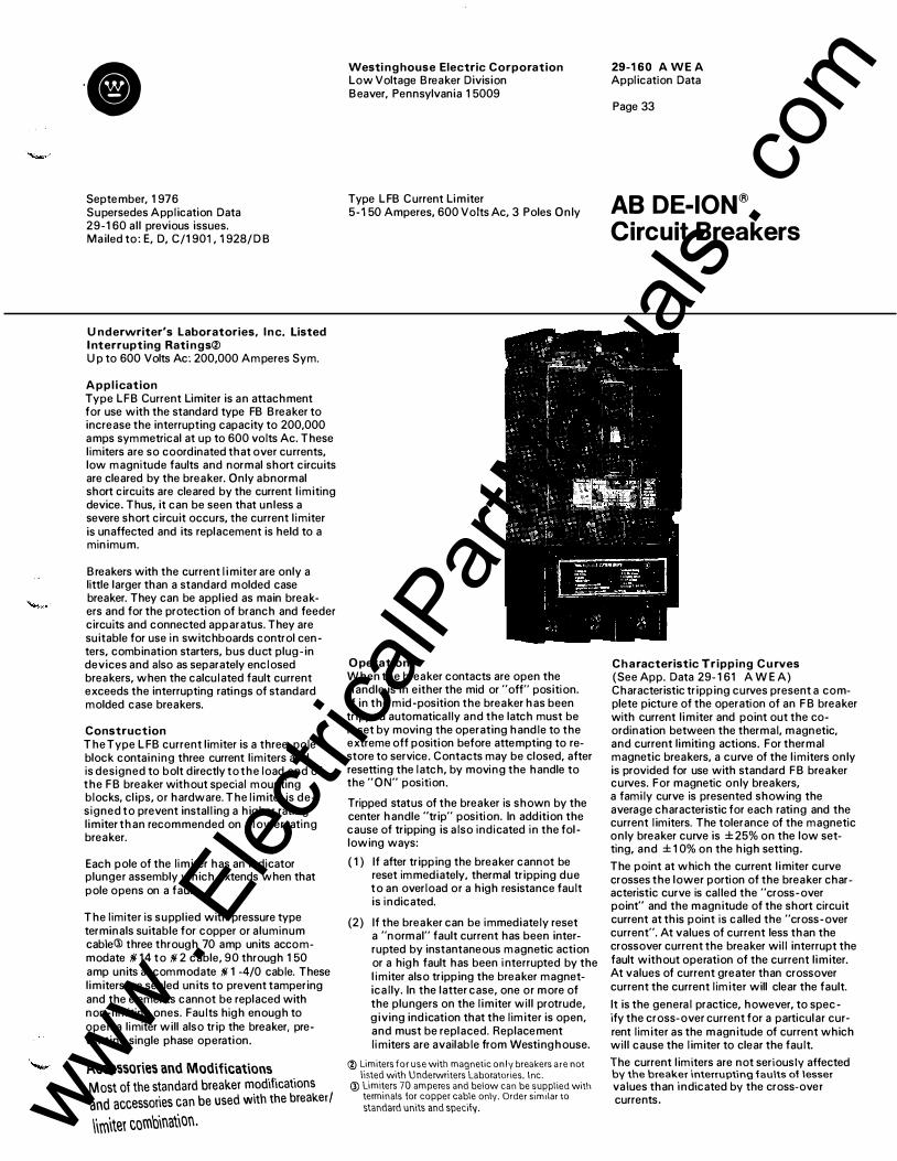
U nderwriter's Laboratories, Inc. Listed I nterrupting Rati ngs® U p to 600 Volts Ac: 200,000 Amperes Sym.
Appl ication Type LF B Current Limiter is an attachment for use with the standard type FB B reaker to increase the interrupting capacity to 200,000 amps symmetrical at up to 600 volts Ac. These l imiters are so coordinated that over currents, low magnitude faults and normal short circuits are cleared by the breaker. Only abnormal short circuits are cleared by the current l imiting device. Thus, it can be seen that unless a severe short circuit occurs, the current l imiter is unaffected and its replacement is held to a minimum.
B reakers with the current limiter are only a little larger than a standard molded case breaker. They can be applied as main breakers and for the protection of branch and feeder circuits and connected apparatus. They are suitable for use in switchboards control centers, combination starters, bus duct plug -in devices and also as separately enclosed breakers, when the calculated fault current exceeds the interrupting ratings of standard molded case breakers.
Construction The Type LFB current limiter is a three- pole block containing three current l imiters and is designed to bolt directly to the load end of the F B breaker without special mounting blocks, clips, or hardware. The limiter is designed to prevent installing a higher rating limiter than recommended on a lower rating breaker.
Each pole of the limiter has an indicator plunger assembly which extends when that pole opens on a fault.
The limiter is supplied with pressure type terminals suitable for copper or aluminum cable@ three through 70 amp units accommodate ill 14 to ill 2 cable, 90 through 1 50 amp units accommodate ill 1 -4/0 cable. These limiters are sealed units to prevent tampering and the elements cannot be replaced with non-limiting ones. Faults high enough to open a limiter will also trip the breaker, preventing single phase operation.
Accessories and Modifications Most of the standard breaker modificaf1ons and accessories can be used with the breaker I \iroitet combination.
Westi ng house Electric Corporation Low Voltage B reaker Division Beaver, Pennsylvania 1 5009
Type LFB Current Limiter 5-150 Amperes, 600 Volts Ac, 3 Poles Only
O peration When the breaker contacts are open the handle is in either the mid or "off' position. If in the mid-position the breaker has been tripped automatically and the latch must be reset by moving the operating handle to the extreme off position before attempting to restore to service. Contacts may be closed, after resetting the latch, by moving the handle to the "ON" position.
Tripped status of the breaker is shown by the center handle "trip" position. In addition the cause of tripping is also indicated in the following ways:
( 1 ) If after tripping the breaker cannot be reset immediately, thermal tripping due to an overload or a high resistance fault is indicated.
(2) If the breaker can be immediately reset a "normal" fault current has been interrupted by instantaneous magnetic action or a high fault has been i nterrupted by the l imiter also tripping the breaker magnetically. In the latter case, one or more of the plungers on the limiter wil l protrude, giving indication that the limiter is open, and must be replaced. Replacement li miters are available from Westinghouse.
® Limiters for use with magnetic only breakers are not listed with Underwriters laboratories. Inc.
@ limiters 70 amperes and below can be supplied with terminals for copper cable only. Order sJmllar to standard units and specify.
29-1 60 A WE A Application Data
Page 33
AB DE-ION® Circuit Breakers
Characteristic Tripping C u rves (See App. Data 29- 1 61 A WE A) Characteristic tripping curves present a complete picture of the operation of an F B breaker with current limiter and point out the coordination between the thermal, magnetic, and current limiting actions. For thermal magnetic breakers, a curve of the l imiters only is provided for use with standard F B breaker curves. For magnetic only breakers, a family curve is presented showing the average characteristic for each rating and the current limiters. The tolerance of the magnetic only breaker curve is ±25% on the low setting, and ± 1 0% on the high setting. The point at which the current limiter curve crosses the lower portion of the breaker characteristic curve is called the "cross-over point" and the magnitude of the short circuit current at this point is called the "cross-over current". At values of current less than the crossover current the breaker will interrupt the fault without operation of the current limiter. At values of current greater than crossover current the current limiter will clear the fault. It is the general practice, however, to spec-ify the cross-over current for a particular current limiter as the magnitude of current which wil l cause the limiter to clear the fault. The current limiters are not seriously affected by the breaker interrupting faults of lesser values than indicated by the cross-over currents. www .
Elec
tricalP
artM
anua
ls . c
om

29-1 60 A WE A Application Data
Page 36
Westinghouse Electric Corporation Low Voltage Breaker Division Beaver, Pennsylvania 15009
www . El
ectric
alPar
tMan
uals
. com

September, 1 976 Supersedes Application Data 29- 1 60 a l l previous issues. Mai led to: E, D, C/1 901 , 1 928/ D B
Contin uous Ampere Rati ngs Underwriters' Laboratories, I nc. Listed 70, 90, 1 00, 1 25, 1 50, 1 75, 200, 225, 250
I nterrupting Ratings, Amperes Underwriters' Laboratories, I nc. Listed
Types J B and K B 240 Volts Ac: 30,000 Asym., 25,000 Sym. 480 Volts Ac : 25,000 Asym., 22,000 Sym. 600 Volts Ac: 25,000 Asym., 22,000 Sym. 250 Volts De: 1 0,000
M A R K 75 Type H K B 240 Volts Ac: 75,000 Asym., 65,000 Sym. 480 Volts Ac: 30,000 Asym., 25,000 Sym. 600 Volts Ac: 25,000 Asym., 22,000 Sym. 250 Volts De: 20,000@
Application These breakers are designed for the protection of branch and feeder circuits. Being of compact size, they are ideally suited for use in control panels, panelboards, switchboards or separate enclosures where a 250 ampere frame size breaker is required.
MARK 75 Type H KB B reakers, because of their higher interrupting capacity, are ideally suited for use in network systems where un usually high fault currents are avai lable.
Listed with Underwriters' Laboratories, Inc.
Westing house Electric Corporation Low Voltage Breaker D ivision Beaver, Pennsylvania 1 5009
Standard Types J B, KB, and MARK 75® Type H KB 70-250 Amperes, 600 Volts Ac, 250 Volts De, 2 and 3 Poles
On all three phase Delta, grounded B phase applications, refer to Westinghouse.
Construction These breakers have al l the standard AB breaker features. Two and three pole breakers are suppl ied in one frame size; the current carrying parts being omitted from the center pole for two pole breakers. In addition, the MARK 75 Type H KB molded case is a higher strength g lass polyester material with greater resistance to tracking. Type JB B reakers have non-interchangeable trip units, while Types KB and H KB have interchangeable trips.
Federal Specification W-C-375b See tabulation on page 20.1
Termi nals Two terminals required per pole. Terminals are Underwriters' Laboratories, Inc. listed for wire type and range l isted below. When used with a luminum conductors, use joint compound.
Terminal arrangement permits ready use of other circuit connecting means, such as rearconnecting studs, panelboard connectors and plug-in adaptor kits.
Max. Breaker Amps.
Catalog Number
Wire Range, Type No. of Ca bles
Standard Pressure Terminals (Copper Only) 250 T250KB 1 lll 4-350 MCM Cu. or
1 !1 2-350 MCM AI
Optional AI/Cu Pressure Terminals 250 TA250KB 1 !1 4-350 MCM AI/Cu
O peration When the breaker contacts are open the handle is in either the mid or OFF position. If in the mid-position the breaker has been tripped automatically. The latch must be reset by moving the operating handle to the extreme OFF position before attempting to restore service. Contacts may be closed, after resetting the latch, by moving the handle to the ON position . J B breakers may be mounted in an inverted position and are approved for reverse feed.® Types KB and H KB may be mounted in an inverted position, but are not approved for reverse feed. The toggle handle operates with the fol lowing force in pounds from the end of the handle: O N - 27 lbs; OFF -29 lbs; RESET - 43 lbs.
Thermal Magnetic B reakers These breakers are equipped with thermal,
29-1 60 A WE A Application Data
Page 37
AB DE-ION® Circuit Breakers
front-adjustable magnetic trip elements. Thermal trip elements are of an indirectly heated bimetallic type having a long time delay well suited for starting motors having high inrush currents of long duration. I n stantaneous magnetic trip setting may be adjusted between established l imits to take care of circuit surge conditions. Trip un its are non- interchangeable on J B breakers, and interchangeable on Type KB and H KB.
Magnetic Trip and Setting Range<D
Ampere Rating 70 90 1 00 1 25 1 50 1 75 200 225 250
High 700 900 1 000 1 250 1 500 1 750 2000 2250 2500 Low 350 450 500 625 750 875 1 000 1 1 25 1 250
Magnetic Only C i rcuit I nterrupters® These are breakers with adjustable magnetic tri p elements only, for appl ications where short circuit protection only is required. M agnetic trip ranges are the same as those l isted for therma l -magnetic breakers, but the cont inuous current ratings in al l cases are 225 amperes.
Saf-T-Vue B reakers (JB. KB O n ly)® Saf-T-Vue breakers are similar to standard breakers except that they have a transparent window located over the breaker contacts. Saf-T- Vue breakers are commonly used in steel mi l l appl ications where sight of contacts is required. Can be supplied in a l l standard ratings.
M olded Case Switches (JB, KB Only) ( N on -Automatic I nterrupters) B reakers with non-automatic details can be installed where a heavycduty, high capacity disconnect switch without overcurrent protection is required.
C i rcuit B reaker Removal Before inspecting, instal l ing, or removing from a circuit, the circuit breaker should be in the OFF position, and if practicable the circuit should be de-energized. If the circuit cannot be de-energized insulated tools, rubber g loves and a rubber floor mat should be used.
<D Al l adjustable magnetic trips are set i n high position at factory; may be adjusted down to required l imit in the f ield.
® Not U nderwriters' Laboratories. I nc. l i sted. @ Breakers with internal attachments are not suitable for
reverse feed. @) Ratings above 10,000 amps are not U L Listed.
www . El
ectric
alPar
tMan
uals
. com

29-1 60 A WE A Application Data
Page 38
Typical Exploded View
Cover Operating Handle Arc Extinguishers
Terminal Lugs Base
Cover
Cover --c-To remove a rear-con nected circuit breaker from its mounting, remove terminal stud lockn uts and pul l circuit breaker forward.
To remove a front-connected circuit breaker from its mounting, loosen screws in terminal l ugs and remove cables from terminals. Remove circuit breaker mounting screws and pul l circuit breaker forward.
To remove a circuit breaker equipped with p lug- in mounting blocks from its mounting, remove breaker mounting screws and pul l circuit breaker forward.
I nspection and M ai ntenance Good maintenance procedure calls for periodic i nspection of al l electrical apparatus inc luding molded case circuit breakers. Terminal lugs and trip units must be tight to prevent overheating . Due to the i nherent wiping action bui lt into the moving contacts of all Westinghouse circuit breakers, operating the breaker several times u nder load wi l l remove any high resistance f i lm that may have formed. Under normal conditions, additional cleaning of contacts is not required. However, should operati ng and/or atmospheric conditions make it desirable to clean the contacts further, the following procedure is recommended.
1 . Remove cover, arc extinguishers and stationary contact assemblies.
2 . Wipe contact surfaces with a clean cloth d ipped in a chlorinated solvent. If surfaces are excessively oxidized or corroded, scrape l ightly with a fine file before wiping.
It should be noted that removing the sealed cover of the type J B breaker voids the Underwriters' Laboratories, Inc., label.
Replacing I nterchangeable Trip U n it, Types KB and H K B
1 . Remove circuit breaker from its mounting per instructions under "circuit breaker removal".
2 . Remove cover by removing four screws.
3. Remove screws from the outer poles of the l ine side of the trip unit and loosen the screw in the center pole of the same side of the trip unit.
4. Lift trip unit from frame after removing the operating handle from its mounting.
5. I nsta l l new trip unit by reversing above procedure.
6 . Before replacing frame cover and mounting circuit breaker, check for proper latching and closing. Perform latching and closing operations per instructions under "operation". Open and close breaker several times to make certai n proper latching has been achieved.
7 . Replace frame cover and mount circuit breaker.
Accessories and Modifications Accessories and modifications avai lable include: alarm switch, auxi l iary switch, shunt trip, undervoltage release, l ine terminal shields, p lug- in adaptor kits, rear-connecting studs, center studs, mechanical interlocks, panelboard connectors, para l lel ing straps, motor operators, handle locking devices, moisture and fungus treatment.
D i mensions, lnches<D Not to be used for construction purposes. See Dimension Sheet 29- 1 70 for detailed dimensions.
10
<D 2 -pole breakers suppl i ed 1n 3 - pole frames w1th center pole parts omitted.
Further I nformation Prices: Price List 29-020 P WE A Ordering Data: Tech. Data 29 - 1 20 T WE A D imensions: D imension Sheet 29- 1 70 Trip Curves: App. Data 29-1 61 A WE A
www . El
ectric
alPar
tMan
uals
. com

September, 1 976 Supersedes Application Data 29 - 1 60 all previous issues. M ai led to: E, D, C/1 901 , 1 928/D B
Continuous Ampere Ratings Underwriters' Laboratories, Inc. Listed 70, 90, 1 00, 1 25, 1 50, 1 75, 200, 225
I nterrupting Ratings, Amperes Underwriters' Laboratories, Inc. Listed
Types JA and KA 240 Volts Ac: 30,000 Asym., 25,000 Sym. 480 Volts Ac: 25,000 Asym., 22,000 Sym. 600 Volts Ac: 25,000 Asym., 22,000 Sym. 250 Volts De: 1 0,000
M ark 75 Type H KA 240 Volts Ac: 75,000 Asym., 65,000 Sym. 480 Volts Ac: 40,000 Asym., 35,000 Sym. 600 Volts Ac: 30,000 Asym., 25,000 Sym. 250 Volts De: 20,000®
Appl ication These breakers are designed for the protection of branch and feeder circuits. Being of compact size, they are ideally suited for use in control panels, panel boards, switchboards or separate enclosures where a 225 ampere frame size breaker is required.
MARK 75 Type H KA Breakers, because of their higher i nterrupting capacity, are ideal ly suited for use in network systems where unusual ly h igh fault currents are ava i lable.
Listed with U nderwriters' Laboratories, I nc.
On all three phase Delta, grounded B phase appl ications, refer to Westinghouse.
Westing house Electric C orporation Low Voltage Breaker Division Beaver, Pennsylvan ia 1 5009
Standard Types JA, KA, and MARK 75® Type H KA 70-225 Amperes, 600 Volts Ac, 250 Volts De, 2 and 3 Poles
Construction These breakers have al l the standard AB breaker features. Two and three pole breakers are supplied in one frame size; the current carrying parts being omitted from the center pole for two pole breakers. In addition, the MARK 75 Type H KA molded case is a higher strength g lass polyester material with greater resistance to tracki ng. Type JA breakers have non- interchangeable trip u nits. Types KA and H KA have interchangeable trips.
Federal Specification W-C -375b See ta bulation on page 20. 1 .
Terminals Two terminals required per pole. Terminals are U nderwriters' Laboratories, I nc . l isted for wire type and range l isted below. When used with a luminum conductors, use joint compound.
Terminal arrangement permits ready use of other circuit connecting means, such as rearconnecting studs, panel board connectors and p lug- in adaptor kits.
Max. Breaker Amps
Catalog N u mber
Wire Range, Type N o. of Cables
Standard Pressure Terminals (Copper Only) 225 T225LA 1 i!i 6-350 MCM
Optional AI/Cu Pressure Terminals 225 TA225LA1 1 ;;1 6 -350 MCM Cu, or
1 ;;1 4-350 MCM AI
O pe ration When the breaker contacts are open the handle is in either the mid or OFF position. I f i n the mid-position the breaker has been tripped automatical ly. The latch must be reset by moving the operating handle to the extreme O F F position before attempting to restore service. Contacts may be closed, after resetting the latch, by moving the handle to the ON posit ion . JA breakers may be mounted in an inverted position and are approved for reverse feed.@ Types KA and H KA may be mounted i n an inverted position, but are not approved for reverse feed. The toggle handle operates with the following forces i n pounds from the end of the handle: ON - 24 lbs; OFF -1 0 lbs; reset - 1 5 l bs .
Thermal Mag netic B reakers These breakers are equipped with thermal, front-adjustable magnetic trip elements. Thermal trip elements are of an ind irectly heated bimetal l ic type having a long time delay well su ited for starting motors havi ng high inrush currents of long duration . I n stantaneous
29-1 60 A WE A Application Data
Page 39
AB DE-ION® Circuit Breakers
magnetic tri p settings may be adjusted between established l imits to take care of circu it surge conditions. Trip units are noni nterchangeable on JA breakers, and interchangeable on Type KA and H KA.
Mag netic Trip Setti ng and Range®
Ampere Rating 70 90 100 125 150 175 200 225
High 700 900 1 000 1250 1500 1750 2000 2250 Low 350 450 500 625 750 875 1000 1 125
Mag netic O n ly Circuit l nterruptersQ:l These are breakers with adjustable magnetic trip e lements on ly, for appl ications where short circuit protection only is required. Magnetic trip ranges are the same as those l isted for thermal - magnetic breakers, but the continuous current ratings i n a l l cases are 225 amperes.
Ambient Compensati n g B reakersQ:l H ave thermal and magnetic trip elements. They are thermal compensating to carry ful l load at 50°C whi le a lso meeting U/L trip requirements at 25°C. Can be applied where a wide range of ambients is experienced.
Saf-T-Vue B reakers (JA, KA O n ly)Q:l Saf-T-Vue breakers are s imi lar to standard breakers except that they have a transparent window located over the breaker contacts. Saf-T-Vue breakers are commonly used i n steel m i l l appl ications where sight o f contacts is required. Can be supplied i n a l l standard ratings.
M olded Case Switches (JA, KA Only) (Non-Auto I nterrupters) Breakers with non-automatic details ( latch bracket and bridging strap) can be i nstalled where a heavy-duty, h igh-capacity d isconnect switch without overcurrent protection is required. Accessories, such as shunt trip, u ndervoltage release, etc., cannot be field mounted in molded case switches as a dummy trip is required for mounting. Accessories can be mounted if specified when breaker is ordered.
Mining Service B reakersQ:l A special version of KA and H KA breakers is avai lable to meet Bureau of M ines requirements for tra i l ing cable appl ications. Refer to Techn ical Data 29 - 1 28 T WE A.
® Al l adJustable magnetic trips ace set in high position at factory; may be adjusted down to req uired l imit in the field.
@ Not U nderwriters" Laboratories. Inc. listed. @) Except when used with an auxi liary switch having
2A-2B contacts. @ Ratings above 1 0.000 amps are not U L Listed. www .
Elec
tricalP
artM
anua
ls . c
om

29-1 60 A WE A Application Data
Page 40
Typical Exploded View
�· Cover Mount ing Sc rews
C i rcuit B reaker Removal
C over
Before i nspecting, insta l l ing, or removing from a circuit. the circuit breaker should be in the O F F position, and if practicable the circuit should be de-energized. If the circuit cannot be de-energized insu lated tools, rubber g loves and a rubber floor mat should be used.
To remove a rear-connected circuit breaker from its mounti ng, remove termina l stud l ocknuts and pull circuit breaker forward.
To remove a front-connected circuit breaker from its mounting, loosen screws in termina l l ugs and remove cables from termina ls. Remove circuit breaker mounting screws and pu l l circuit breaker forward.
To remove a circuit breaker equipped with p lug- in mounting blocks from its mounting, remove breaker mounting screws and pu l l circuit breaker forward.
I n spection and Mai ntenance Good maintenance procedure cal ls for periodic inspection of al l electrical apparatus inc luding molded case circuit breakers. Terminal l ugs and trip un its must be tight to prevent overheating . Due to the inherent wiping action bui lt into the moving contacts of a l l Westi nghouse circuit breakers, operating the breaker several t imes under load wi l l remove any h igh resistance fi l m that may have formed. Under normal conditions, additional cleaning of contacts is not required. However, should operating and/or atmospheric conditions make it desirable to clean the contacts further, the following procedure is recommended.
1 . Remove cover, arc extinguishers and stationary contact assemblies.
e Operating H a ndle Terminal Lugs
Stationa ry Contact Assembly With Terminal I nsert Base
C onductor Mounting Screw
A rc E xtinguishers tt'
Term inal Lugs I 2 . Wipe contact surfaces with a clean cloth
dipped in a chlorinated solvent. If surfaces are excessively oxidized or corroded, scrape l ightly with a fine file before wiping.
I t should be noted that removing the sealed cover of the type JA breaker voids the Underwriters' Laboratories, I nc., label .
Replacing I ntercha ngeable Trip U nit, Types KA and H KA 1 . Remove circuit breaker from its mounting
per instructions under "circuit breaker removal " · .
2 . Remove cover by removing four screws.
3. Remove screws from the outer poles of the l ine side of the trip unit and loosen the screw in the center pole of the same side of the trip u nit.
4. Lift tri p unit from frame after removing the operating handle from its mounting.
5 . Insta l l new trip unit by reversing above procedure.
6. Before replacing frame cover and mounting circuit breaker, check for proper latching and closing . Perform latching and closing operations per instructions under "opera tion". Open and close breaker several times to make certain proper latching has been achieved .
7 . Replace frame cover and mount circuit breaker.
Accessories and Modifications Accessories and modifications avai lab le inc lude: a larm switch, auxi l i a ry switch, shunt trip, undervoltage release, l ine termina l shie lds, p lug- in adaptor kits, rear-connecting studs, center studs, mechanical interlocks, panelboard connectors, para l le l ing straps, motor operators, handle locking devices, moisture and fungus treatment.
D i mensions, I nches@ Not to be used for construction purposes. See Dimension Sheet 29- 1 70 for detailed dimensions.
410o O o00 0 0
� 1 . J �@9 000®
lin 101 8 ....
�
� �5�-- �4�� 1--416 @ 2 - pole breakers suppl 1ed 1n 3 -pole frames w1th center
pole parts om 1tted.
Further I nformatio n Prices: Price List 29-020 P WE A Ordering Data: Tech. Data 29 - 1 20 T WE A D imensions: D imension Sheet 29 - 1 70 Trip Curves: App. Data 29 - 1 61 A WE A
www . El
ectric
alPar
tMan
uals
. com

September, 1 976 Supersedes Application D ata 29-1 60 all previous issues. M ailed to: E, D, C/1 901 , 1 928/D B
Continuous Ampere R atings Underwriters' Laboratories, Inc. Listed 70, 90. 1 00, 1 25. 1 50. 1 75. 200. 225. 250, 300. 350, 400 Amperes
I nterrupti ng Ratings, Am peres Underwriters' Laboratories. Inc. Listed
Types LB and L B B 240 Volts Ac; 50,000 Asym.; 42.000 Sym. 480 Volts Ac; 35,000 Asym.; 30,000 Sym. 600 Volts Ac; 25,000 Asym.; 22.000 Sym. 250 Volts De; 20.000<D
M A R K 75 Type H L B 240 Volts Ac; 75.000 Asym.; 65.000 Sym. 480 Volts Ac; 40,000 Asym.; 35.000 Sym. 600 Volts Ac; 30.000 Asym.; 25.000 Sym. 250 Volts De; 20,000<D
Application These breakers are designed for the protection of branch and feeder circuits. Being of compact size. they are ideally suited for use in control panels, panelboards, switchboards, or separate enclosures where a 400 ampere frame size breaker is required.
MARK 75 Type H LB breakers, because of their higher i nterrupting capacity, are well suited for use in network distribution systems where u nusually high fault currents are available.
On al l three phase Delta, grounded B phase appl ications, refer to Westinghouse.
Construction These breakers have all the standard AB breaker features. I n addition. MARK 75 Type H LB molded case is a higher strength glass polyester material with greater resistance to tracking. Two and three-pole breakers are supplied in one frame size; the current-carrying parts being omitted from the center pole for 2-pole breakers.
Type L B B breakers have non- interchangeable trip un its, Type LB and Type H LB breakers have i nterchangeable trip units.
Federal S pecification W-C-375b See tabulation on page 20.1
Terminals Two terminals are required per pole. Terminals are U nderwriters' Laboratories. I nc. l isted for wire type and range l isted below.
When used with aluminum cable, use joint compound.
Terminal arrangement permits ready use of other circuit connecting means, such as rear connecting studs, panelboard connectms and plug-in adaptor kits.
<D Ratings above 1 0.000 amps not U.L. listed.
Westin g house Electric Corporation Low Voltage Breaker Division Beaver, Pennsylvan ia 1 5009
Standard Types LBB, LB, and MARK 75® Type H LB 70-400 Amperes, 600 Volts Ac, 250 Volts De, 2 and 3 Poles
Max. Amps.
Catalog N umber
No. of Cables, Size of Wire
For Copper Cable ( Supplied as Standard) 225 T225LA (1) 11 6-350 M C M Cu 350 T350DA (1) 250-500 MCM Cu 400 T400DA2 (2) 3/0-250 MCM Cu For AI/Cu Cable ( Must be Specified) 225 TA225LA1 (1) 11 6-350 MCM Cu. or
( 1 ) 11 4-350 M C M AI 350 TA350DA (1) 250-500 MCM AI/Cu 400 TA400DA1 (2) 3/0-250 M C M AI/Cu
Terminal I nstal lation To install T225LA terminals for 'fl, 6 to 350 M C M wire sizes. screw bushings into stationary contact assembly, and load end terminal inserts. The bushings must be i nstalled from the back of the breaker before the breaker is mounted, and must be tight so that they will not become u nscrewed when the terminals are i nstalled. The terminals then can be i n stalled by running screws i nto the bushings from the front of the breaker.
All other terminals are i nstalled by screws running from the front of the terminal, after removing the set screws, directly into the stationary conductor.
O peration When the breaker contacts are open the handle is i n either the mid or OFF position. If in the mid-position the breaker has been tripped automatically and the latch must be reset by moving the operating handle to the extreme OFF position before attempting to restore to
® Except when used with an auxiliary switch having
2A-2 B contacts.
29-1 60 A WE A Application Data
Page 41
AB DE-ION®
Circuit Breakers
service. Contacts may be closed, after resetting the latch by moving the handle to the O N position. L B B may b e mounted i n an i nverted position and is l isted for reverse feed®. Types LB and H LB Breakers may be mounted in an i nverted position, but are not listed for reverse feed. The toggle handle operates with the following forces in pounds from the end of the handle: ON - 24 lbs.; O F F - 1 0 lbs.; reset -1 5 1bs.
Thermal Magnetic Breakers These breakers are equipped with thermal, front-adjustable magnetic trip elements. Thermal trip elements are of i ndirectly heated bimetal l ic type having a long time delay well suited for starting motors having high inrush currents of long duration . I nstantaneous magnetic trip settings may be varied between established l imits to take care of circuit surge conditions.
Thermal Magnetic Breaker Trip Range and Settings
Ampere Rating High Low
70 700 350 90 900 450
100 1000 500 125 1250 625 150 1500 750 175 1750 875 200 2000 1000 225 2250 1125 250 2500 1250 300 3000 1 500 350 3500 1 750 400 4000 2000 www .
Elec
tricalP
artM
anua
ls . c
om

29-1 60 A WE A Application D ata
Page 44
Westi nghouse Electric Corporation Low Voltage B reaker Division Beaver, Pennsylvan ia 1 5009
www . El
ectric
alPar
tMan
uals
. com

September, 1 976 Supersedes Application Data 29- 1 60 all previous issues. M ailed to: E, D, C/1 901 , 1 928/D B
Continuous Ampere Ratings Underwriters' Laboratories, Inc. Listed Type LAB: 1 25, 1 50, 1 75, 200, 225, 250,
300, 350, 400 Amperes
Type LA 400 Amp: 1 25, 1 50, 1 75, 200, 225, 250, 300, 350, 400 Amperes
Type LA 600 Amp: 250, 300, 350, 400, 500, 600 Amperes
I nterrupting Ratings, Amperes Underwriters' Laboratories, Inc. Listed
Types LA and LAB 240 Volts Ac; 50,000 Asym.; 42,000 Sym. 480 Volts Ac; 35,000 Asym.; 30,000 Sym. 600 Volts Ac; 25,000 Asym.; 22,000 Sym. 250 Volts De; 20,000®
M A R K 75 Type H LA 240 Volts Ac; 75,000 Asym.; 65,000 Sym. 480 Volts Ac; 40,000 Asym.; 35,000 Sym. 600 Volts Ac; 30,000 Asym.; 25,000 Sym. 250 Volts De; 20,000®
Application These breakers are designed for the protection of branch and feeder circuits. Being of compact size they are ideally suited for use in control panels, panelboards, switchboards, or separate enclosures where a 400 or 600 ampere frame size breaker i s required.
M A R K 75 Type H LA breakers, because of their higher interrupting capacity, are well suited for use in network distribution systems where unusually high fault currents are avai lable.
Listed by U nderwriters' Laboratories I nc .
On a l l three phase Delta, grounded B phase appl ications, refer to Westinghouse.
Construction These breakers have all the standard AB breaker features. In addition, MARK 75 Type H LA molded case is a higher strength glass polyester material with greater resistance to tracking. Two and three-pole breakers are supplied in one frame size; the current-carrying parts being omitted from the center pole for for 2-pole breakers.
Note: Trip u nits, terminals, and accessories are not i nterchangeable between 400 amp. and 600 amp. frame LA and H LA breakers.
Type LAB breakers have non-interchangeable \1ip units, Type LA and MARK 75 Type H LA breakers have i nterchangeable trip units.
Westin ghouse Electric Corporation Low Voltage Breaker D ivision Beaver, Pennsylvan ia 1 5009
Standard Types LAB , LA, and MARK 75® Type H LA 1 25-600 Amperes, 600 Volts Ac, 250 Volts De, 2 and 3 Poles
LA400, LAB
Federal Specification W-C-375b See tabulation on page 20. 1 .
Terminals Two terminals are required per pole . Terminals are U nderwriters' Laboratories, Inc. l isted for wire type and range l isted below. When used with a luminum cable, use joint compound .
Terminal arrangement permits ready use of other circuit connecting means, such as rear connecting studs, panelboard connectors and plug-in adaptor kits.
Max. Breaker Amps
Terminal Catalog N umber
Wire Range, Type, No. of Cables
Standard Copper Pressure Terminals 225@ T225LA 1 ;!1 6-350 MCM Cu 400@ T401 LA 1 i!1 4-250 MCM Cu, plus
1 310-600 MCM Cu 600@ T600LA 2 250-500 M C M Cu
Optional AI/Cu Pressure Terminals 225@ TA225LA1 1 i!l 6-350 MCM Cu, or
1 i!1 4-350 MCM AI 400@ TA400LA1 1 ;!1 4-250 MCM AIICu, plus
1 3/0-600 M C M Al/Cu 400@ T A401 LA 1 600-750 MCM AI 600@ TA600LA 2 250-500 MCM AI/Cu
Terminal Installation To install low rating terminals on 400 amp. frames for '# 6 to 350 M C M wire sizes, screw bushings into stationary contact assembly,
@ 400 ampere lrames only. @ 600 amperelrames only. @) Ratings above 10,000 amps ore not UL Listed.
29-160 A WE A Application Data
Page 45
AB DE-ION® Circuit Breakers
and load end terminal i nserts. The bushings must be installed from the back of the breaker before the breaker is mounted, and must be tight so that they wil l not become unscrewed when the terminals are installed. The terminals then can be i nstalled by running screws into the bushings from the front of the breaker.
The high rating terminals are installed by runn ing screws thru the stationary contact assembly from the back of the breaker into the terminal .
Terminals are installed to the 600 amp. frames by two screws running from the front of the terminal. after removing the set screws, directly into the stationary conductor.
O peration When the breaker contacts are open the handle is in either the mid or OFF position. If in the mid-position the breaker has been tripped automatically and the latch must be reset by moving the operating handle to the extreme O F F position before attempting to restore to service. Contacts may be closed, after resetting the latch by moving the handle to the ON position. LAB may be mounted i n an inverted position and is approved for reverse feed. Types LA and H LA Breakers may be mounted i n an inverted position, but are not approved for reverse feed. The toggle handle operates with the following forces in pounds from the end of the handle: ON - 36 \bs.; O F F - 1 6.5 lbs.; R ES ET - 33 lbs. www .
Elec
tricalP
artM
anua
ls . c
om

29-1 60 A W E A Application Data
Page 48
Westi ng house Electric Corporation Low Voltage Breaker D ivision Beaver, Pennsylvania 1 5009
www . El
ectric
alPar
tMan
uals
. com

Cl September, 1 976 Supersedes Application Data 29- 1 60 all previous issues Mailed to: E, D, C/1 901 , 1 928/D B
LC-1 50
Continuous Ampere Ratings Underwriters' Laboratories, I nc. Listed
LC-1 50, H LC-1 50 Frames: 75,90,1 00,1 25,1 50 LC-300, H LC-300 Frames: 1 50,1 75,200,225,
250,275,300 LC-600 H LC-600 Frames: 300,350,400,450,
500,600
I nterrupti ng Rati ng, Amperes Underwriters' Laboratories, Inc. Listed Type LC 240 Volts Ac; 50,000 Asym.; 42,000 Sym. 480 Volts Ac; 35,000 Asym.; 30,000 Sym. 600 Volts Ac; 25,000 Asym.; 22,000 Sym.
Type H LC 240 Volts Ac; 75,000 Asym.; 65,000 Sym. 480 Volts Ac; 40,000 Asym.; 35,000 Sym. 600 Volts Ac; 30,000 Asym.; 25,000 Sym.
Application Type LC breakers are designed for the protection of branch and feeder circuits. They are used most frequently on distribution feeders in commercial bui ld ings and industrial plants and in heavy equipment circuits. Being of compact size, they are ideally suited for in sta l l ation in control panels, panel boards, switchboards or separate enclosures. MARK 75 Type H LC Breakers, with higher interrupting capacity, are well su ited for use in network distribution systems where unusual ly h igh fau lt currents are avai lable.
LC and H LC breakers are listed with Underwriters' Laboratories Inc.
On a l l 3 phase Delta, grounded B phase appl ications, refer to Westinghouse.
@ I nternal attachments for reverse feed breakers must be of type l isted for f ield mounting.
Westinghouse Electric Corporation Low Voltage Breaker Division Beaver, Pennsylvania 1 5009
Standard Types LC-1 50, LC-300, LC-600 and MARK 75® Types H LC-1 50, H LC-300 and H LC-600 75-600 Amperes, 600 Volts Ac, 50/60 Hz 2 and 3 Poles
Construction Type LC Seltronic breaker consists of three parts: frame, rating p lug, and terminals.
Frame LC and H LC SELTRON IC breaker frames in clude a l l of the standard AB breaker features, and, in addition, includes a re l iable solid state tripping element with associated current monitors and flux transfer shunt trip com pletely factory assembled a n d tested. Each frame also includes a push-to-trip button to mechanically check the tripping mechanism or for use under emergency trip conditions. These frames use glass polyester cases with openings in the cover for easy access to the terminals. 600 amp frames have a removable cover over line terminal access holes. Two pole breakers are bui lt on three pole frames with current carrying parts omitted from the center pole.
Rating Plugs Smal l , interchangeable rating plugs are used to establish the continuous current rating of each SELTRON IC circuit breaker. Fixed and adjustable rating plugs are avai lable.
Fixed rating plugs are avai lable as standard in all continuous ampere ratings as l isted at left. In addition, a series of optional adjustable rating p lugs is avai lable to adjust the selected continuous ampere rating from a 70% to a high of 1 00% of the plug nameplate rating (except 1 00 and 400 amp plugs are 75% to 1 00%) . This feature provides the closest level of overload protection possible for equipment protection.
An interlock is provided in the rating plug to insure that the breaker wi l l tr ip should an attempt be made to remove the plug with the breaker in the ON position. With the plug removed, the breaker will remain in the tripped position and cannot be accidentally closed.
Rating plugs are not interchangeable between the three LC frames or other SELTRON I C breakers.
Federal Specification W-C-375b See tabulation on page 20.1 .
Terminals Two terminals are required per pole . Terminals are Underwriters' Laboratories, Inc. l isted for wire type and range l isted below. When used with a luminum conductors, use
29-1 60 A WE A Application Data
Page 49
AB DE-ION®
Circuit Breakers
joint compound. These terminals are designed to permit tightening of individual cables without disturbing adjacent cables. Terminal arrangement permits ready use of other circuit connecting means, such as rear-connecting studs, panel board connectors, and p lug- in adaptor kits.
Max. Amps
Terminal Cat. No.
Wire Range, Type, No. of Cables
LC1 50, H LC150, LCJOO & H LCJOO Only Standard Copper Pressure Terminals 225 T225LA ( 1 ) Jli 6-350 M C M Cu 225 T225LBF ( 1 ) 11 6- 250 MCM Cu 300 T401 LA ( 1 ) Jli 4-250 M C M Cu, plus
(1) 3/0·600 M C M Cu Optional AI/Cu Pressure Terminals 225 TA225LA1 ( 1 ) 11 6-350 MCM Cu, or
( 1 ) 11 4-350 M C M AI 300 TA400LA1 ( 1 ) Jii 4-250 M C M AI/Cu, plus
( 1 ) 3/0-600 M C M AI/Cu 300 TA401 LA ( 1 ) 600-750 MCM AI LC600, H LC600 Only Standard Copper Pressure Terminals 600 T600LA ( 2) 250-500 MCM Cu Optional AI/Cu Pressure Terminals 600 TA600LA (2) 250/500 M C M AI/Cu
O peration The sol id state tr ip un it of the standard Sel tronic breaker provides long delay and magnetic tripping s imi lar to thermal magnetic breakers. I n addition, the magnetic trip also incl udes a short time delay, making possible coordination and selective tripping with downstream devices. The magnetic trip has a single adjustment for all three poles from five to ten times the continuous current rating and s imultaneously adjusts the short delay from instantaneous at 5X to maximum of 10 cycles at 1 OX . (See characteristics trip curves) .
Trip t imes and ratings are not affected by temperature changes.
When the breaker contacts are open the hand le is in either the mid or OFF position. If in mid position, the breaker has been tripped automatica l ly and the l atch must be reset by moving the operating handle to the extreme OFF position and then to the ON position to restore service. Moving the handle to the OFF position relatches the breaker. The LC and H LC breakers can be mounted in an inverted position and a re listed for reverse feed@. The toggle handle operates with the following forces in pounds from the end of the handle: ON - 36 lbs.; OFF - 1 6.5 l bs.; RESET - 33 1 bs. www .
Elec
tricalP
artM
anua
ls . c
om

29-1 60 A WE A Application Data
Page 50
Typical Open View
Rating Plug - L ine Ter mina l
inghouse circuit breakers, operating the breaker several times under load will remove any high resistance film that may have formed. Under normal conditions, additional cleaning of contacts is not required.
B reaker H a ndle
S ol id State --iiiii--Tr ip Unit
Mag netic Adjustment
Push-to-Trip B utton
Mag netic Only Circuit lnterru pters<D Magnetic-only Seltronic breakers are spe-cial frames similar to the standard breakers except they provide adjustable magnetic tripping only for applications where short circuit protection only is required. Their trip range is established by using the standard interchangeable rating plugs and the ranges are the same as the magnetic portion of standard breakers.
The continuous ratings of these breakers are: LC-1 50, H LC-1 50 frame: 1 50 amps; LC-300, H LC-300 frame: 300 amps; and LC-600, H LC-600 frame, 600 amps.
Saf-T -Vue® B reakers<D (LC Only) Saf-T-Vue breakers are similar to standard breakers except that they have a transparent window located over the breaker contacts. Saf-T-Vue are common ly used in steel mi l l applications where sight of contacts is required. Can be supplied in all standard ratings.
M olded Case Switches ( Non-automatic Interrupters) A molded case switch version of the LC-600 breaker is avai lable for applications where no overcurrent protection is requ ired. A rating plug is not requ ired, and i nternal attachments must be factory mounted since they are not the same as used on standard SELTRONIC breakers.
Westinghouse Electric Corporation Low Voltage B reaker D ivision Beaver, Pennsylvania 1 5009
Cover ( 600 Am p Frame On ly)
Portable Test Kit A portable test kit is available to provide verification of performance of Seltronic breakers whi le the devices are still i n service under varying load a nd/or phase unbalance. The tester operates on 1 20 volt 60
Main Cover Hz and i ncludes complete i nstructions and test times for functional ly testing both the long time and instantaneous operation of the breaker. (Refer to Tech. Data 29-1 20 T WE A for tester).
M i ning Service B reakers<D A special version of LC breakers is available to meet Bureau of M ines requirements for trai l ing cable applications. Refer to Technical Data 29- 1 28 T WE A.
C i rcuit B reaker Removal Before inspecting, i nstalling or removing from a circuit, the circuit breaker should be in the OFF position, and if practicable, the circuit should be de-energized. If the circuit can n ot be de-energized, insulated tools, rubber gloves and a rubber floor mat should be used. To remove a rear-connected breaker from its mounting, remove terminal stud lock n uts and pull circuit breaker forward . To remove a front-connected circuit breaker from its mounting, loosen terminal lug screws and remove cables from termi nals. Remove circuit breaker mounting screws and pull circuit breaker forward. To remove a circuit breaker equipped with plug- in mounting blocks from its mounting, remove breaker mounting screws and pull circuit breaker forward.
Inspection and M a i ntenance Good maintenance procedure calls for periodic i nspection of all electrical apparatus including m olded case circuit breakers. Terminal lugs must be tight to prevent overheati ng. D ue to the inherent wiping action built into the moving contacts of all West-
<D Not U n derwriters" Laboratories. I nc. listed. ® 2 - pole breakers suppl ied in 3-pole frames with center
pole parts omitted.
Accessories and M od ifications Accessories and modifications available i n clude: rear-connecting studs, han dle locking devices, moisture and fungus treatment, provisions to tri p the flux transfer shunt trip from an external source, a larm switch, auxi liary switches, walki ng beam and slide bar type mechanical i nterlocks and motor operator.
D i mensions, I nches® Not to be used for construction purposes. See Dimension Sheet 29- 1 70 for detailed dimensions.
Further I nformation Prices: Price List 29-020 P WE A Ordering Data: Tech. Data 29- 1 20 T WE A Dimensions: D imension Sheet 29- 1 70 Trip Curves: App. Data 29- 1 61 A WE A
www . El
ectric
alPar
tMan
uals
. com

September, 1 976 Supersedes Application Data 29 - 1 60 a l l previous issues. M ai led to: E, D, C/ 1 901 , 1 928/ D B
Continuous Ampere Ratings Underwriters' Laboratories, Inc. Listed 1 25, 1 50, 1 75, 200, 225, 250, 300, 350, 400, 500, 600, 700, 800
Interrupting Ratings. Amperes Underwriters' Laboratories, Inc. Listed
Type M A 240 Volts Ac; 50,000 Asym.; 42,000 Sym. 480 Volts Ac; 35,000 Asym.; 30,000 Sym. 600 Volts Ac; 25,000 Asym.; 22,000 Sym. 250 Volts De; 20,000Ql
Mark 75 Type H M A 240 Volts Ac; 75,000 Asym.; 65,000 Sym . 480 Volts Ac; 40,000 Asym.; 35,000 Sym. 600 Volts Ac; 30,000 Asym. ; 25,000 Sym. 250 Volts De; 20,000Ql
Appl ication Type MA breakers are designed for the protection of branch and feeder c i rcuits. They are used most frequently on distribution feeders in commercial bui ldings and industr ia l p lants and in heavy equipment c i rcuits. Being of compact size, they are ideally su ited for instal lation in control panels, panelboards, switch boards or separate enclosures. MARK 75 Type H MA Breakers, because of their h igher interrupting capacity, are wel l suited for use in network distribution systems where unusually h igh fault currents are avai l able. MA and H MA breakers a re listed with U nderwriters' Laboratories, I nc.
On al l 3 phase Delta, grounded B phase applications, refer to Westinghouse.
Westinghouse Electric Corporation Low Voltage B reaker Division Beaver, Pennsylvania 1 5009
Standard Type MA, and MARK 75® Type H MA 1 25-800 AmperesQl, 600 Volts Ac, 250 Volts De, 2 and 3 Poles
Constructio n These breakers have a l l t he standard AB breaker features. Two pole and 3 pole breakers are supplied on one frame size; the current carrying parts being omitted from the center pole for 2 - pole breakers. In addition MARK 75 Type H MA Breakers have higher strength gl ass polyester molded cases with greater resistance to tracking.
Federal Specification W-C-375b See tabulation on page 20.1 .
Termi nals Two termina ls are required per po le . Termi nals are Underwriters· Laboratories, I nc . l isted for wire type and range l isted below. When used with a luminum conductors, use joint compound.
Termina l arrangement permits ready use of other c i rcuit connecting means, such as rearconnecting studs, panel board connectors and p lug- in adaptor kits.
Max. Breaker Amps.
Terminal Cat. No.
Wire Range, Type No. of Cables
Standard Copper Pressure Terminals 350 T350MA 1 * 1 - 600 MCM Cu 600 T600MA1 2 2/0- 500 M C M Cu 800 T800MA1 3 3/0-300 M C M Cu
Optional AI/Cu Pressure Terminals 600 TA700MA1 2 * 1 - 500 MCM AI/Cu 800 TA800 MA2 3 3/0-400 M C M AI/Cu
O peration When the breaker contacts are open the handle is in either the mid or OFF posit ion. If i n mid position, the breaker has been tr ipped automatical ly and the l atch must be reset by moving the operating handle to the extreme OFF position and then to the ON position to restore service. The MA or H MA breaker can be mounted in an i nverted posit ion but is not approved for reverse feed. The toggle handle operates with the following forces from the end of the handle: ON -50 lbs,; O F F - 24 1bs.; R ESET - 60 lbs.
Thermal Magnetic B reakers These breakers are equipped with a thermal, front- adjustable magnetic trip unit. Thermal trip e lements are of an indirectly heated bimeta l l ic type having a long t ime delay wel l su ited for motor circuits. I nstantaneous magnetic tr ip settings may be adjusted between establ ished l imits to take care of circuit surge conditions. Sealed tr ip un its are interchangeable. The rat ing of the tr ip un it being used shows in the cover window Trip units rated 1 25 through 600 amp. are suitable for both
29-160 A WE A Application Data
Page 51
AB DE-ION(R' Circuit Breakers
Ac and De c i rcuits. The 700 and 800 amp. un its can be used only on Ac however, since they wil l not respond to De.
The conti nuous ampere rat ings and corresponding mag netic tri p ranges of the various trip units are as follows:
M ag netic Trip Range a n d Setti ngs Ampere Ratings
1 25 1 50 200 225 250
H i g h 1 250 1 500 2000 2250 2500 Low 625 750 1 000 1 1 25 1 250
Ampere Ratings 350 400 500 600 700
H ig h 3500 4000 5000 6000 6000 Low 1 7 50 2000 2500 3000 3000
300
3000 1 500
800
6000 3000
Magnetic O n ly C i rcuit I nterrupters@ These breakers are equipped with adjustable magnetic only tr ip un its for appl ications where short circuit protection only is requ ired. The continuous rat ing of these interrupters is 800 amperes and they may be insta l led in either Ac or De circuits. Magnetic tr ip settings are set in the high position at the factory, but may be adjusted down to the low l im it in the field. The magnetic tr ip ranges are as follows:
Mag netic Trip Range H igh 1 250 2000 3000 4000 6000 8000
Low 625 1 000 1 500 2000 3000 4000
Ambient Compensating Breakers@ H ave thermal and magnetic tr ip elements. They are thermal compensating to carry fu l l load at 50°C whi le a lso meeting U/L tr ip requi rements at 25°C. Can be applied where a wide range of ambients is experienced.
Saf-T-Vue® B reakers@ (Type MA On ly) Saf-T-Vue breakers are simi lar to standard breakers except that they have a transparent window located over the breaker contacts. Saf-T-Vue breakers are commonly used in steel m i l l appl ications where sight of contacts is required. Can be supplied i n a l l standard rat ings.
Molded Case Switches (Type MA On ly) (Non -Automatic I nterrupters) MA breakers with non-automatic deta ils ( l atch bracket and bridging straps) can be insta l led where a heavy-duty, h igh-capacity disconnect switch is required without overcurrent protect ion. Accessories, such as shunt trip, undervoltage, etc., cannot be field mounted in non-automatic breaker as a dummy trip is required for mounting. Accessories can be mounted if specified when breaker is ordered. (?) Not Underw"ters' Laboratories. Inc . . l isted. Q) De ratings apply to magnetic only breakers or 600 a m p
ancl below thermal magnetiC breakers. a n d ratings over 1 0.000 amps are not UL l 1sted. www .
Elec
tricalP
artM
anua
ls . c
om

29-1 60 A WE A Application Data
Page 52
Typical Exploded View
Cover Mounting Screws l --3 Piece Cover Terminal Lug Screws -1 �J r • • Teem"'' M o:�:":
.
:,
::�,
�:u-
Operating Handle Stationary Contact Assembly --tiL
Trip Unit Mounting Screws
b.-Terminal Lug
I ' w;}- i r=_l
l,
Terminal Mounting Screw
Cover Mounting Screws
M i n i n g Service B reakersCD A special version of MA and H MA breakers is available to meet B ureau of Mines requirements for trai l ing cable applications. Refer to Technical Data 29- 1 28 T WE A.
C i rcuit B reaker Removal Before inspecting, installing or removing from a circuit, the circuit breaker should be in the OFF position, and if practicable, the circuit should be de-energ ized . If the c i rcu it cannot be de-energized, insulated tools, rubber gloves and a rubber floor mat should be used. To remove a rear-connected breaker from its mounting, remove terminal stud lock n uts and pull circuit breaker forward. To remove a front-connected circuit breaker from its mounting, loosen terminal lug screws and remove cables from terminals. Remove circuit breaker mounting screws and pul l c i rcuit breaker forward.
To remove a ci rcuit breaker equipped with pl ug- in mounting blocks from its mounting, remove breaker mounting screws and pull circuit breaker forward.
Inspection and M a i ntenance G ood maintenance procedure calls for periodic inspection of all electrical a pparatus i ncluding molded case circuit breakers. Terminal l ugs and trip un its must be tight to prevent overh eating. Due to the inherent wiping action bu i l t into the moving contacts of al l Westinghouse circuit breakers, operating the breaker several times under load wil l remove
I nterpole Ba rr ier
Tr ip Unit
any h igh resistance fi lm that may have formed. Under normal conditions, additional cleaning of contacts is not requ i red . However, should operating and/or atmospheric conditions make it desirable to clean the contacts further, the following procedure is recommended:
1 . Remove cover, arc extinguishers and l ine terminal assemblies.
2 . Wipe contact surfaces with a clean cloth dipped in a chlorinated solvent. If surfaces are excessively oxidized or corroded, scrape l ightly with a fine file before wiping.
Replacing I nterchangeable Trip U n its Remove circuit breaker from its mounting per instructions under "circuit breaker removal". Remove cover by removing six screws. Remove molded barrier between poles at line end of trip un it. Remove all load end terminals. Remove screws from the outer poles of the l ine side of the trip un it and loosen the screw (not shown ) in the center pole of the same side of the trip un it. Lift trip un it from frame. To replace the trip unit reverse the a bove procedure. Be sure to replace the two i nterpole barriers before replacing the breaker cover. Before replacing f rame cover and mounting circuit breaker, check for proper latch ing and closing . Perform latching and closing operations per instructions under "operation". Open and close breaker several times to make certa in proper latching has been achieved.
Insert Mounting Screws
Accessories and Modifications Accessories and modifications ava i lable include: rear-connecting studs, center studs, handle locking devices, moisutre and fungus treatment, shunt trip, undervoltage release, a larm switch, auxi l iary switches, walk ing beam and s l ide bar type mechanical interlocks and motor operator.
D i mensions, I nches@ Not to be used for construction purposes. See Dimension Sheet 29- 1 70 for detailed dimensions.
• •
[06! 0 .$ ()
s!
1 16
CD Not Underwriters· Laboratories, I n c l 1 sted. @ 2 -pole breakers su ppl ied i n 3 - pole frames with center
pole parts o mitted.
Further I n fo rmation Prices: Price List 29-020 P WE A Ordering Data: Tech. Data 29-1 20 T WE A Dimensions: D imension Sheet 29- 1 70 Trip Curves: App. Data 29- 1 61 A WE A www .
Elec
tricalP
artM
anua
ls . c
om

September, 1 976 Supersedes Application Data 29- 1 60 all previous issues. M ailed to: E, D, C/1 901 , 1 928/ D B
Conti nuous Ampere Ratings Underwriters' Laboratories. Inc. Listed 400, 500, 600, 700, 800
I nterrupting Ratings, Amperes Underwriters' Laboratories, Inc. Listed
Type M C 240 Volts Ac; 50,000 Asym.; 42,000 Sym. 480 Volts Ac; 35,000 Asym.; 30,000 Sym. 600 Volts Ac; 25,000 Asym.; 22,000 Sym.
M a rk 75 Type H M C 240 Volts Ac; 75,000 Asym.; 65,000 Sym. 480 Volts Ac; 58,000 Asym.; 50,000 Sym. 600 Volts Ac; 30,000 Asym.; 25,000 Sym.
Application Type M C breakers are designed for the protection of branch and feeder circuits. They are used most frequently on distribution feeders in commercial bui ldings and industrial plants and in heavy equipment circuits. Being of compact size, they are ideally suited for installation in control panels, panelboards, switchboards or separate enclosures. MARK 75 Type H MC Breakers, because of their higher interrupting capacity, are well suited for use in network distribution systems where unusual ly h igh fault currents are available. M C and H M C breakers are l isted with Underwriters' Laboratories, Inc.
On al l 3 phase Delta, grounded B phase applications, refer to Westinghouse.
Westin g house Electric Corporation Low Voltage Breaker D ivision Beaver, Pennsylvania 1 5009
Standard Type M C and MARK 75® Type H M C 400-800 Amperes, 600 Volts Ac, 50/60 Hz 2 and 3 Poles
Construction The type M C Seltronic breaker consists of three parts: frame, rating p lug, and terminals.
Frame The Seltronic frame includes a l l of the standard AB breaker features, and, in addition, includes a reliable solid state tripping element with associated current monitors and flux transfer shunt t r ip completely factory assembled and tested. Each frame also includes a push -to-trip button to mechanical ly check the tripping mechanism or for use under emergency trip conditions. These frames use glass polyester cases with three piece covers having individually removable ends for easy access to the terminals. Two pole breakers are built on three pole frames with current carrying parts omitted from the center pole.
Rati ng Plugs Smal l interchangeable rating p lugs are used to establish the continuous current rating of each Seltronic circuit breaker. Rating p lugs are avai lable in two types: fixed and adjustable.
Fixed rating plugs are avai lable as standard in ratings of 400, 500, 600, 700 and 800 amps. I n addition, a series of optional ad j ustable rating plugs are ava i lable to adjust the selected continuous rating from a low of 70% to a h igh of 1 00% of the plug nameplate rating (except 500 amp rating is 80 to 1 00%) . This feature provides the closest level of overload protection possible for equipment protection.
An interlock is provided in the rating plug to insure that the breaker wil l trip should an attempt be made to remove the plug with the breaker in the ON position. With the plug removed, the breaker wil l remain in the tripped position and cannot be accidentally closed.
Rating plugs are not interchangeable between breaker frame types.
Federal Specification W-C-375b See tabulation on page 20. 1 .
Terminals Two terminals are required per pole. Terminals are Underwriters' Laboratories, Inc. listed for wire type and range l isted below. When used with a luminum conductors, use joint compound. These terminals are designed to permit tightening of individual cables without disturbing adjacent cables.
Terminal arrangement permits ready use of other circuit connecting means, such as
29-1 60 A W E A Application Data
Page 53
AB DE-ION® SELTRON IC™ Circuit Breakers
rear-connecting studs, panelboard connectors and plug- in adaptor kits.
Max. Breaker Amps.
Terminal Cat. No.
Wire Range, Type No. of Cables
Standard Copper Pressure Terminals 600 T600MA1 2 2/0-500 MCM Cu BOO TBOOMA1 3 3/0-300 M C M Cu Optional AI/Cu Pressure Terminals 600 TA700MA1 2 i11 1 -500 M C M AI/Cu 800 TA800MA2 3 3/0-400 M C M AI/Cu
O peration The solid state trip un it of the standard Seltronic breaker provides long delay and magnetic tr ipping simi lar to thermal magnetic breakers. I n addition, the magnetic trip also includes a short time delay, making possible coordination and se lective tripping with downstream devices. The magnetic trip has a single adjustment for a l l th ree poles from five to ten times the continuous current rating and simultaneously adjusts the short delay from instantaneous at 5X to maximum of 1 0 cycles at 1 OX. ( See characteristics trip curves) .
Trip times and ratings are not affected by temperature changes.
When the breaker contacts are open the handle is in either the mid or OFF position. If in mid position, the breaker has been tripped automatically and the latch must be reset by moving the operating handle to the extreme OFF position and then to the ON position to restore service. The MC or H M C breaker can be mounted in an inverted position and are l isted for reverse feed.® The toggle handle operates with the following forces i n pounds from the end of the handle: ON - 50 lbs.; OFF - 24 l bs.; R ESET - 60 lbs.
The continuous ampere ratings and corresponding magnetic trip ranges of the various un its are as fol lows:
Magnetic Trip Range and Settings
Ampere Ratings 400
High Low
4000 2000
500
5000 2500
600
6000 3000
700
7000 3500
800
8000 4000
Magnetic Only C i rcuit I nterrupters@ Magnetic-only Seltronic breakers are special frames similar to the standard breakers except
@ Not U nderwriters" Laboratories. I n c . . l isted. ® I nternal attachments for reverse feed breakers must be
of the type listed for f ie ld mounting. www . El
ectric
alPar
tMan
uals
. com

29-1 60 A WE A Application Data
Page 54
Typical O pen View
Arc C h utes
B reaker H a n dle
Sol id State Trip U n it
M a g n etic Adjustment
Push-to-Trip B utton
L ine Terminal
Ma in C over
Load Terminal C over
Rating Plug
they provide adj ustable magnetic tr ipping only for a pplications where short circuit protection on ly is requ i red . Their tri p range is esta bl ished by using the standard interchangeable rat ing plugs and the ranges are the same as the magnetic port ion of standard breakers. C onti nuous rati ng is 800 amps.
Saf-T-Vue® B reakers® ( Type MC Only) Saf-T- Vue breakers are s imi lar to standard brea kers except that they have a tra nsparent window over the breaker co ntacts. They are commonly used i n steel mil l a ppl ications where sight of co ntacts is required. Can be su pplied i n a l l standard rati ngs.
B u i lt- in G round Fault P rotection Types MC and H M C Seltron ic Breakers are ava i lab le with bu i lt - i n circuitry to detect ground faults and cause the breaker to tr ip when the fault reaches a predetermined current sett ing and t ime sett i n g . These b reakers have two addit ional adj ustment k n o bs to set the current p ickup point ( .2 to 1 t imes the breaker cont inuous ratin g ) and to set the time delay on ground fault tri pping ( 0 (no inten t iona l t ime delay) to 30 cycles) .®
The Seltron ic breaker with ground fault is s u pplied with a neutral current transformer to mount external to the brea ker ( 1 5 foot maxi m u m ) when it is used on a 3 - phase 4-wi re system. They may also be used on a 3 - phase, 3-wire system by o m itting the C.T., or a special breaker can be suppl ied without the C . T. N o extern a l power is requ i red to tr ip these ground fault breakers. They a lso inc lude a memory c i rcuit that will cause the breaker to o pen i f an i ntermittent ground fault of a level equal to or greater than the ground fa ult tr ip setting but of a t ime durat ion less than the tr ip t ime sett ing persists. The more rapid the frequency and the higher the value of such a fa ult the qu icker the b reaker wil l trip. A n adj ustable rating plug is not
avai la ble for Seltron ics with Ground Fault and the f ixed rat ing plugs are not i nterchangeable with sta ndard Seltronic rat ing plugs. Seltro n ic breakers with b u i lt - i n ground fault wi l l accept the same field mou ntable o r factory mou nted accessories and attach ments used on sta ndard Seltron i c b reakers ( except UV release) .
An optional, remotely-mou nted u n it wi l l be ava i lab le (for breakers prod uced after late th ird qu arter of 1 976) to i nd icate breaker has tripped on a ground fault . I t requires separate 1 20/60 co ntrol power and must be manual ly reset after each tr ip i ndicati o n . See page 65.
M i n ing Service B reakersQJ A special version of the M C breaker is avai la ble to meet B urea u of M i nes req uirements for tra i l i ng cable a ppl ications. Refer to Tech nical Data 2 9 - 1 28 T W E A .
Molded Case Switches ( No n - automatic I nterrupters) A molded case switch version of the M C brea ker i s available when n o overcurrent protection is requ i red . I t d oes not requi re a rat ing plug and does not use standard Seltron ic breaker attachments.
C i rcuit B reaker Remova l Before inspect ing, i nsta l l ing or removi ng from a c i rcuit, the circuit breaker should be i n the OFF position, and if pract ica ble, the circuit should be d e - e n ergized . I f the c ircuit cannot be de-energized, insulated tools, rubber gloves and a rubber f loor mat should be used . T o remove a rear-connected breaker from its mou nting, remove termina l stud Jock n uts and pul l circuit breaker forward. To remove a front-con nected circuit breaker from its mou nting, loosen terminal lug screws and remove ca bles from termi n a ls. Remove circuit breaker mounting screws and pull circuit brea ker forward.
To remove a circuit breaker equi pped with p lug- in mount ing b locks from its mount ing remove breaker mounting screws a n d pul l c ircuit breaker forward.
I nspection and Mai ntena nce G ood maintenance procedure cal ls for periodic i nspection of all e lectrical a pparatus inc lud ing molded case circuit breakers. Term i n al l ugs m ust be tight to prevent overheat ing . Due to the i n herent wip ing action bui l t i nto the m oving contacts of al l Westing house circuit breakers, operatin g the brea ker several t imes under load wi l l remove any h igh resistance film that may have formed. Under n ormal condit ions, addit ional clea n i n g of contacts is not requ i red.
Porta ble Test Kit A portable test kit i s ava i lab le to provide verification of performance of Seltron ic breakers whi le the devices are sti l l i n service under varyi ng load and/or phase unbalance. The tester o perates on 1 20 volt 60 H z and inc l udes complete instructions a n d test t imes for functio nal ly test i n g the long t ime i nsta n taneous and Ground Fault o perat ion o f the breaker. ( Refer to Tec h . Data 2 9 - 1 20 T W E A for tester) .
Accessories and Modifications Accessories and modif icat ions avai lable i n elude: rear- connecti n g studs, handle locking devices, moisture a n d fungus treatment, provision to tr ip the flux transfer s h u n t trip from an external source, alarm switch, aux i l iary switches, undervoltage release, wa lk ing beam and s l ide bar type mech an ica l i nterlocks and m otor operator.
Di mensions, Inches@ Not to be used for construction purposes. See Dimension Sheet 29- 1 70 for detailed dimensions.
@ 2 - pole breakers s u pplied in 3 - pole frames with center pole parts omitted .
® Not UL Listed @) Normal G . F. sensing , s a res i d u al scheme. S o m e
syste ms (such as d o u b l e - e n ded switchboard) m ay require alternate s e n s 1 n g methods. Consult WestI ng h ouse for deta i ls .
F u rther I n formation Prices: Price List 29-020 P W E A O rder ing Data: Tech . Data 29- 1 20 T WE A Dimensions: D i mension S heet 29-1 70 Trip Curves: App. Data 29- 1 6 1 A W E A
c (/) )>
www . El
ectric
alPar
tMan
uals
. com

8 September, 1 976 Supersedes App l ication Data 29- 1 60 a l l previous issues. M ai led to: E, D, C/1 901 , 1 928/D B
Continuous Ampere Rati ngs Underwriters' Laboratories, Inc. Listed 700, 800, 900, 1 000, 1 200
Interrupti ng Rati ng, Amperes Underwriters' Laboratories, Inc. Listed
Type N B 240 Volts Ac; 50,000 Asym.; 42,000 Sym. 480 Volts Ac; 35,000 Asym.; 30,000 Sym. 600 Volts Ac; 25,000 Asym.; 22,000 Sym. 250 Volts De; 20,000@ Type H N B 240 Volts Ac; 75,000 Asym.; 65,000 Sym. 480 Volts Ac; 40,000 Asym . ; 35,000 Sym. 600 Volts Ac; 30,000 Asym.; 25,000 Sym. 250 Volts De; 20,000@
Appl ication These breakers are designed for the protection of branch and feeder circu its. They are used most frequently on distribution feeders in commercia l bui ldings and industrial plants and in heavy equipment circuits. Being of compact size, they are ideal ly suited for insta l lation in control panels, panelboards, switchboards or separate enclosures. MARK 75 Type H N B Breakers, with its higher interrupting capacity, is wel l suited for use in network distri bution systems where unusual ly h igh fault currents are avai lable.
NB and H N B breakers are listed with U nderwriters' Laboratories, Inc .
On a l l 3 phase Delta, grounded B phase appl ications, refer to Westinghouse.
Westing house E lectric Corporation Low Voltage Breaker Division Beaver, Pennsylvan ia 1 5009
Standard Type N B, and MARK 75® Type H N B 700- 1 200 Amperes, 600 Volts Ac, 250 Volts De,@ 2 and 3 Poles
Construction These breakers have a l l the standard AB breaker features. Two pole and 3 pole breakers are suppl ied on one frame size; the current carrying parts being omitted from the center pole for 2 -pole breakers. In addition Type H N B have h igher strength g lass polyester molded cases with greater resistance to tracking .
Federal S pecification W- C-375b See tabul ation on page 20.1 .
Terminals Two terminals are required per pole. Terminals are Underwriters' Laboratories, I nc. l isted for wire type and range l isted below. When used with a luminum conductors, use joint compound.
Termina l arrangement permits ready use of other circuit connecting means, such as rearconnecting studs, panel board connectors, and mounting blocks.
Max. Breaker Amps
Terminal Catalog Number
Wire Range, Type, No. of Cables
Standard Copper Pressure Terminals 1 000 T1 000NB1 3 3/0-500 MCM Cu 1 200 T1 200N B 1 4 3/0-400 MCM C u Alternate AI/Cu Pressure Terminals 1 000 TA1000NB1 3 3/0-400 MCM AI/Cu 1 200 TA1 200N B1 4 4/0-500 MCM AI/Cu 1 200 TA1 201 N B 1 3 500-750 M C M AI/Cu
O peration When the breaker contacts are open the handle is i n either the mid or OFF position. If i n mid position, the breaker has been tripped automatical ly and the latch must be reset by moving the operating handle to the extreme O F F position and then to the ON position to restore service. Moving the handle to the OFF position relatches the breaker. The N B and H N B breakers can be mounted i n an inverted position but are not approved for reverse feed. The toggle handle operates with the fol lowing forces in pounds from the end of the handle: ON - 58 lbs.; OFF - 38 lbs.; R ESET - 95 lbs.
Thermal Mag netic B reakers These breakers are equipped with a thermal, front-adjustable magnetic trip unit. Thermal trip elements are of an indirectly heated bimeta l l ic type having a long time delay well suited for motor circuits. I nstantaneous magnetic trip settings may be adjusted between establ ished l imits to take care of circuit surge conditions. Sealed trip un its are interchangeable. The rat ing of the tri p unit being
29-160 A WE A Application Data
Page 55
AB DE- ION®
Circuit Breakers
used shows in the cover window. Trip units can be used only on Ac si nce they wi l l not respond to De.
The cont inuous ampere ratings and corresponding magnetic trip ranges of the various trip un its are as fol lows:
Magnetic Tr ip Range and Settings Ampere Ratings
700 800 900 1 000 1 200 H igh 6000 6000 8000 8000 8000 Low 3000 3000 4000 4000 4000
Magnetic Only C i rcuit Interru pters@ These breakers are equipped with adjustable magnetic only trip un its for appl ications w here short c i rcuit protection on ly is required. The cont inuous rating of these interrupters is 1 200 amperes and they may be insta l led in either Ac or De circuits. Magnetic trip settings are set in the h igh position at the factory; but may be adjusted down to the low l imit in the field. The magnetic t r ip ranges are as fol lows:
Mag netic Tr ip Range High 6000 8000 Low 3000 4000
1 0000 5000
Saf-T-Vue® B reakers@ ( N B Only)
1 2000 6000
Saf-T-Vue breakers are simi lar to standard breakers except that they have a transparent window located over the breaker contacts. Saf-T-Vue breakers are commonly used i n steel m i l l appl ications where sight of contacts is required. Can be supplied in a l l standard ratings.
Molded Case Switches ( N B Only) ( Non-Automatic I nterrupters) N B breakers with non-automatic detai ls can be insta l led where a heavy-duty, h ighcapacity disconnect switch without overcurrent protection is required. Accessories, such as shunt trip, undervoltage release, etc., can be field mounted in non-automatic N B breakers.
M i ning Service B reakers@ A special version of N B and H N B breakers is avai lable to meet Bureau of M i nes requirements for tra i l ing cable appl ications. Refer to Technical Data 29-1 28 T WE A.
@ Not U nderwnters· Laboratones. l nc. l 1 sted. @ 250 volt De rat ing applied on ly to m agnetiC only
breakers and IS based on N E MA test procedures.
www . El
ectric
alPar
tMan
uals
. com

29-1 60 A WE A Appl ication Data
Page 56
Typical Exploded View
Cover Mounting Screws
3 Piece Cover
Termina l Mount ing Screw Trip Un it
r� �� ----------�· . � _______.,-, u;- ' •
Termina l Lug --:
C i rcuit Breaker Remova l Before inspect ing, insta l l i ng or removing from a circuit, the circuit breaker should be in the OFF position, and if practicable, the circuit should be de-energized. I f the circuit cannot be de-energized, insulated tools, rubber g loves and a rubber floor mat should be used. To remove a rear-connected breaker from its mounting, remove termina l stud lock n uts and pull circuit breaker forward. To remove a front-connected circuit breaker from its mounting, loosen termina l l ug screws and remove cables from terminals . Remove circuit breaker mounting screws and pul l c ircuit breaker forward.
Inspection and M ai ntenance Good maintenance procedure cal ls for periodic inspection of all e lectrical apparatus inc luding molded case circuit breakers. Termina l lugs and tri p un its must be t ight to prevent overheati ng. Due to the inherent wiping action bui lt into the moving contacts of all Westi nghouse circuit breakers, operating the breaker several times under load wi l l remove any h igh resistance f i lm that may have formed. Under normal conditions, additiona l c leaning of contacts is not required. However, should operating and/or atmospheric condit ions make it desirable to clean the contacts further, the following procedure is recommended:
1 . Remove cover arc extinguisher hold down screws, arc ext inguishers and l ine termina l assemblies.
2 . Wipe contact surfaces with a clean cloth dipped in a ch lorinated solvent. If surfaces
are excessively oxidized or corroded, scrape l ightly with a fine file before wiping.
Replacing Interchangeable Trip U n its Remove circuit breaker from its mounting per instructions under "circuit breaker removal". Remove cover.
Remove a l l load end termina ls . Remove screws from the outer poles of the l ine side of the trip un it and loosen the screw in the center pole of the same side of the trip un it. Lift tr ip unit from frame. To replace the trip unit reverse the above procedu re.
Before replacing frame cover and mounting circuit breaker, check for proper latching and closi ng . Perform latching and closing operations per instructions under "operation". Open and close breaker several t imes to make certain proper latching has been achieved.
Accessories and Modifi cations Accessories and modifications available i n clude: rea r-connecti ng studs, center studs, handle locking devices, moisture and fungus treatment, shunt tr ip, undervoltage release, a larm switch, auxi l iary switches, walking beam and sl ide bar type mechanica l i nterlocks and motor operator.
Trip Un it Mounting Screws
D i mensions, I nches@
8
Base
Not to be used for construction purposes. See Dimension Sheet 29- 1 70 for detailed dimensions.
I o o o 1 0::•0 • �' ···' & •:'1 0
sl 4
1 16
@ 2 - po le breakers suppl ied 1n 3 - pole frames w1th center pole parts omi tted.
Fu rther Information Prices: Price List 29-020 P WE A Orderi ng Data: Tech Data 29- 1 20 T WE A D imensions: Dimension Sheet 29-1 70 Trip Curves: App. Data 29- 1 6 1 A WE A
www . El
ectric
alPar
tMan
uals
. com

September, 1 976 Supersedes Application Data 29-1 60 a l l previous issues. M ailed to: E, D, C/1 901 , 1 928/D B
Contin uous Ampere Ratings Underwriters ' Laboritories, Inc. L isted 800, 900, 1 000, 1 200
Interrupting R ating, Amperes Underwriters' Laboratories, Inc. Listed
Type N C 240 Volts Ac; 50,000 Asym.; 42,000 Sym. 480 Volts Ac; 35,000 Asym.; 30,000 Sym. 600 Volts Ac; 25,000 Asym.; 22,000 Sym.
Type H N C 240 Volts Ac; 75,000 Asym.; 65,000 Sym. 480 Volts Ac; 58,000 Asym.; 50,000 Sym. 600 Volts Ac; 30,000 Asym.; 25,000 Sym.
Application These breakers are designed for the protection of branch and feeder circuits. They are used most frequently on distribution feeders in commercial bui ldings and industrial plants and in heavy equipment circuits. Being of compact size, they are ideally suited for insta l l ation in control panels, panelboards, switchboards or separate enclosures. MARK 75 Type HNC breakers, with its higher interrupting capacity, is well suited for use in network distribution systems where unusual ly h igh fault currents are available.
NC and H N C breakers are listed with Underwriters· Laboratories, Inc.
On al l 3 phase Delta, grounded B phase appl ications, refer to Westinghouse.
Westi n g ho use E lectric Corporation Low Voltage Breaker Division Beaver, Pennsylvania 1 5009
Standard Type NC and MARK 75® Type H N C 800-1 200 Amperes, 600 Volts Ac, 50/60 H z 2 a n d 3 Poles
Constructi o n NC Seftronic breakers consist of three parts: frame, rating plug, and terminals.
Frame The Seltronic frame includes all of the standard AB breaker features, and, in addition, includes a reliable solid state tripping element with associated current monitors and flux transfer shunt trip completely factory assembled and tested. Each frame a lso includes a push -to-trip button to mechanical ly check the tripping mechanism or for use under emergency trip conditions. These frames use g lass polyester cases with three piece covers having i ndividua l ly removable ends for easy access to the terminals. Two pole breakers are bui lt on three pole frames with current carrying parts omitted from the center pole.
Rating P l ugs Small interchangeable rating plugs are used to establish the continuous current rating of each seltronic circuit breaker. R ating plugs are available as fixed and adjustable.
Fixed rating plugs are avai lable as standard in ratings of 800, 900, 1 000 and 1 200 amps. I n addition, a series o f optional adjustable rating plugs are available to adjust the selected continuous rating from a low of 70% to a high of 1 00% of the plug nameplate rating (except 800 amp rating is 75 to 1 00%) . This feature provides the closest level of overload protection possible for equipment protection.
An interlock is provided in the rating plug to insure that the breaker wil l trip should an attempt be made to remove the plug with the breaker in the ON position. With the plug removed, the breaker wi l l remain in the tripped position and cannot be accidentally closed. Rating plugs are not interchangeable between breaker frame types.
Federal Specification W-C-375b See tabulation on page 20.1 .
Terminals Two terminals are required per pole. Term inals are U nderwriters' Laboratories, I nc. listed for wire type and range fisted below. When used with a luminum conductors, use joint compound. These terminals are designed to permit tightening of individua l cables without disturbing adjacent cables.
Terminal arrangement permits ready use of other circuit connecting means, such as rearconnecting studs, panelboard connectors, and mounting blocks.
29-1 60 A WE A Application Data
Page 57
AB DE-ION® Circuit Breakers
Max. Breaker Amps
Terminal Catalog N umber
Wire Range, Type, No. of Cables
Standard Copper Pressure Terminals 1 000 T1000NB1 3 3/0-500 M C M Cu 1 200 T1 200NB1 4 3/0-400 M C M Cu
Alternate AI/Cu Pressure Terminals 1 000 TA1 000NB1 3 3/0-400 M C M AI/Cu 1 200 TA1 200N B 1 4 4/0-500 M C M AI/Cu 1 200 TA1 201 N B 1 3 500/750 M C M AI/Cu
O peration The solid state trip unit of the standard Seltronic breaker provides long delay and magnetic tripping s imi la r to therma l magnetic breakers. I n addition, the magnetic trip a lso includes a short time delay, making possible coordination and selective tripping with downstream devices. The magnetic trip has a single adjustment for a l l three poles from four to eight times the continuous current rating and simultaneously adjusts the short delay from instantaneous at 4X to maximum of 10 cycles at 8X. (See characteristic trip curves ) . Trip t imes and ratings a re not affected by temperature changes.
When the breaker contacts are open the handle is in either the mid or O F F position. If in mid position, the breaker has been tripped automatically and the latch must be reset by moving the operating hand le to the extreme O F F position and then to the ON position to restore service. Moving the handle to the OFF position relatches the breaker. The NC and H N C breakers can be mounted in an inverted position and are listed for reverse feed.@ The toggle handle operates with the following forces in pounds from the end of the handle: ON - 58 lbs.; OFF - 38 lbs.; RESET - 95 lbs.
The continuous ampere ratings and corresponding magnetic trip ranges of the various un its are as follows:
Ampere Ratings
800 High 6400 Low 3200
900 7200 3600
1 000 8000 4000
1 200 9600 4800
M a gnetic O n l y Circuit Interru pters@ Magnetic-only Seltronic breakers are special frames simi lar to the standard breakers except they provide adjustable magnetic tripping only for appl ications where short circuit protection only is required. Their trip range is established by using the standard @ N ot U n derwnters· Laboratories. Inc. l isted.
(J) I nternal attachments for reverse feed breakers m ust be of the type l1sted for f ield mountmg. www .
Elec
tricalP
artM
anua
ls . c
om

29-1 60 A WE A Application Data
Page 58
Typical Open View
Solid State Trip Unit
Magnetic Adjustment r
Line Terminal
Main Cover
Inspection a n d Maintenance Good maintenance procedure cal ls for periodic inspection of all electrical apparatus including molded case circuit breakers. Termina l lugs m ust be t ight to prevent overheating. Due to the i nherent wiping action bu i lt into the movin g contacts of all Westinghouse circu it breakers, operating the breaker several times u nder load will remove any h igh resistance fi lm that may have formed. U nder normal conditions, additional clean ing of contacts is not required.
Portable Test K it A portable test kit is avai lable to provide verification of performance of Seltronic breakers whi le the devices are still in service u nder varying load and/or phase u n balance. The tester operates on 1 20 volt 60 Hz and includes complete i nstructions and test times for functional ly test ing the long t ime instantaneous and G round Fault operation of
Load Terminal the breaker. ( Refer to Tech . Data 29- 1 20
Rating Plug Cover T WE A for tester) .
i nterchangeable rat ing plugs and the ranges are the same as the magnetic portion of standard breakers. The continuous rating of these breakers is 1 200 a mps.
B uilt-in G round Fault Protection Types NC and H N C Seltronic Breakers are avai lable with bui lt- in circu itry to detect ground fau lts and cause the breaker to trip when the fault reaches a predetermined current setting and time setting. These breakers have two additional adjustment knobs to set the current pickup point ( .2 to 1 times the breaker continuous rating) and to set the time delay on ground fault tripping (0 (no i ntentiona l t ime delay) to 30 cycles) .@
The Seltronic breaker w ith g round fault is suppl ied with a neutra l current transformer to mount externa l to the breaker ( 1 5 foot maximum) when it is used on a 3-phase 4 -wire system. They may a lso be used on a 3 -phase, 3-wire system by omitting the C.T., or a special breaker can be supplied without the C.T. No externa l power is required to trip these g round fau lt breakers. They a lso i nclude a memory circuit that will cause the breaker to open if an intermittent ground fault of a level equal to or greater than the g round fault trip setting but of a time duration less than the trip time sett ing persists. The more rapid the frequency and the h igher the value of such a fault the quicker the breaker will trip. An adjustable rating plug is not avai lable for Seltronics with Ground Fault and the fixed rating plugs are not i nterchangeable with standard Seltronic rating p lugs. Seltronic breakers with bui lt- in ground fault wi l l accept the same field mountable or factory mounted accessories and attachments used on standard Seltronic breakers ( except u ndervoltage release) .
An optional , remotely-mounted unit wi l l be ava ilable (for breakers produced after late
third Quarter of 1 976) to indicate the breaker has tripped on a ground fault. It requires separate 1 20/60 control power and must be manually reset after each trip indication. See page 65.
M i ning Service B reakers® A special version of the NC breaker is avai lable to meet B ureau of M ines requ irements for tra i l ing cable a ppl ications. Refer to Tech nical Data 29- 1 28 T WE A.
M olded Case Switches (type N C only) (Non-automatic I nterrupters) A molded case switch version of the N C breaker is available when n o overcurrent protection is req u ired. It does not require a rating p lug and does not use standard SELTRON IC breaker attachments.
Saf-T-Vue® B reakers@ ( N C Only) Sat-T-Vue breakers are similar to standard breakers except that they have a transparent window located over the breaker contacts. Saf-T-Vue breakers are commonly used i n steel m i l l applications where sight o f contacts is required. Can be supplied i n a l l standard ratings.
Circuit B reaker Removal Before inspecting, i nsta l l ing or removing from a circuit, the circuit breaker should be i n the O F F position, and if practicable, the circuit should be de-energized. If the circu it cannot be de-energized, insulated tools, rubber g loves and a rubber floor mat should be used. To remove a rear -connected breaker from its mounting, remove termina l stud lock nuts and pull circuit breaker forward. To remove a front-connected circuit breaker from its mounting, loosen termina l lug screws a nd remove cables from terminals. Remove circu it breaker mounting screws and pu l l circu it breaker forward.
Accessories and M odifications Accessories and modifications avai lable i n clude : rea r-connecting studs, handle locking devices, moisture and fungus treatment, provisions to trip the f lux transfer shunt trip from an external source, a larm switch, a uxi l - �
iary switches. u ndervoltage release, walk ing beam and sl ide bar type mecha nical i nterlocks and motor operator.
D i men sions, I nches@ Not to be used for construction purposes. See Dimension Sheet 29- 1 70 for detailed dimensions.
@ 2-pole breakers supplied in 3-po/e frames with center pole parts om itted.
® Not U nderwriters· Laboratories. Inc. l isted. @) Normal G . F. sensing is a residuai scheme. Some
systems (such as double-ended switchboard) may require alternate sensing methods. Consult Westinghouse lor details.
F u rther I nformation Prices: Price List 29-020 P W E A Ordering Data: Tech. Data 29-1 20 T WE A Dimensions: D imension Sheet 29- 1 7 0 Trip Curves: Application Data 29- 1 61 A W E A www .
Elec
tricalP
artM
anua
ls . c
om

April, 1 976 Supersedes Application Data 29-1 60, pages 41 -56 dated January, 1 97 1 Mai led to: E, D , C/1 901 , 1 903, 1 928/DB
Application The increase in demand for electrical power in modern commercial and industrial buildings has resulted in electrical services becoming substantially larger. In some low voltage distribution systems, available short circuit currents can exceed 1 00,000 symmetrical rms amperes. Fault currents of this intensity may exceed the interrupting ratings of molded case breakers. As a result, larger expensive circuit interrupting devices which could withstand the thermal and magnetic stresses associated with currents of this value have had to be used.
Now, h igh interrupting capacity current l imiting devices have been developed which wil l restrict short circuit current. I f applied correctly, they may be used in conjunction with the molded case circuit breakers to provide adequate and economical protection. Because of this fact, Westinghouse developed the TRI-PAC breaker, so named because it affords TRiple-PACkage protection with ( 1 ) time delay thermal trip, (2) instantaneous magnetic trip and (3) current l imiting protection, combined and coordinated in a compact and economical device. These protective actions are so coordinated that overcurrents and low magnitude faults are cleared by the thermal action; normal short circuits are cleared by the magnetic action; and abnormal short circu its, above an establ ished value, are cleared by the current l imiting device and the breaker. Thus, it can be seen that unless a severe short circuit occurs, the current l imiter is not seriously affected and its replacement is held to a minimum.
TRI-PAC breakers are compact, only a little larger than a standard molded case breaker. They can be applied as main breakers and for the protection of branch and feeder circuits and connected apparatus. They are suitable for use in switchboards, control centers, combination starters, bus duct plug-in devices and also as separately enclosed TRIPAC breakers, when the calculated fault current exceeds the interrupting ratings of standard molded case breakers.
TRI-PAC breakers have thermal and magnetic trip elements similar to standard molded case breakers, therefore continuous current ratings are chosen in the same manner as for standard molded case breakers.
On a l l 3-phase Delta, grounded B phase applications, refer to Westinghouse.
Westinghouse Electric Corporation Low Voltage B reaker Division Beaver, Pennsylvania 1 5009
Interrupting Ratings, Amperes Underwriters' Laboratories, Inc. Listed 600 Volts Ac: 200,000 Sym.
Based on NEMA Test Procedures 250 Volts De: 1 00,000 Sym.
LA 70-400 Amperes
FB 15-100 Amperes 600 Volts Ae. 250 Volts De 2 and 3 poles
NB 300-800 Amperes
29-160 A WE A Application Data
Page 67
AB DE-ION® TRI-PAC Circuit Breakers Types FB, LA, N B , PB,
600·1600 Amperes &OOVolts, 60 HzAc<D, 250Volts Dc® 2 and 3 poles
600 Volts Ae, 250 Volts De 2 and 3 poles
600 Volts. 60 Hz Ac<D. 250 Volts De® 2 and 3 poles
Continous Ampere Ratings (Ul Inc. Listed) FB: 1 5, 20, 30, 40, 50, 70, 90, 1 00 LA: 70, 90, 1 00, 1 25, 1 50, 1 75, 200, 225, 250, 300, 350, 400, N B : 300, 350, 400, 500, 600, 700, 800, PB: 600, 700, 800, 900, 1 000, 1 200, 1 400, 1 600
Construction TRI-PAC circuit breakers have a l l the standard AB breaker features. Two and three pole breakers are built into the 3-pole frame size; current carrying parts being omitted from the center pole for 2-pole devices.
Basically, the circuit breaker portion of the TRI-PAC breaker is of the same design as a standard molded case breaker of comparative ampere rating, with a special housing added for the current l imiting device®. Specially designed cu rrent l imiters are located within this housing. An interlock is provided which insures the opening of the breaker contacts
<D On ratings above 350 amps, higher frequency calibration not available. Minimum of 50 Hz calibration available on spectal order.
@ 250 volts De rating applies only to magnetic only breakers, and 300 and 350 amp NB TRI-PAC breakers.
before the l imiter housing or breaker cover can be removed. Each current l imiting device is constructed with a spring loaded plu nger which is ejected when the l imiter operates, initiating simultaneous opening of all poles of the breaker. Therefore, the possibility of single phasing is el iminated.
These breakers meet requirements for circuit breakers, as defined in Federal Specification W-C-375a, as follows:
FB : Class 2e LA: Class 3c and 4a N B : Class 6 PB: Not defined in W-C-375a.
® PB TRI-PAC breakers house the limiters within standard molded frame.
www . El
ectric
alPar
tMan
uals
. com

Page 68
Type FB TRI-PAC, Open View
Stab Type Plug-in Connectors
Type LA TRI-PAC, Open View
Load Terminal Cover
Current Limiter Housing Assembly
Current limiter ousing Interlock
Cover
Current limiter Housing Interlock ---!!""
Current Limiter Housing Assembly
Current Limiter Trip Bar
Current Limiter Retaining Bar � ..
urrent limiter
Missing Current Limiter Trip Bar Limiter Interlock
www . El
ectric
alPar
tMan
uals
. com

Type NB TRI-PAC, Open View
Load Terminal Cover
Type PB TRI-PAC, Open View
Breaker Handle
Trip Unit -----
Current -----� limiting Fuse
Current Limiter Housing Assembly
Cover
Cover nterlock
29-160 A WE A Appl ication Data
Page 69
Current limiter Trip Bar
www . El
ectric
alPar
tMan
uals
. com

Page 70
Operation When the breaker contacts are open the handle is in either the "mid" or "off" position. If in the "mid" position, the breaker has been tripped automatically and the latch must be reset by moving the operating h andle to the extreme "off" position and then to the "on" position to restore service. Moving the handle to the "off" position relatches the breaker.
Tripped status of the breaker is shown by the center handle "trip" position. In addition the cause of tripping is also indicated in the following ways:
( 1 ) If after tripping the breaker cannot be reset immediately, thermal tripping due to an overload or a high resistance fault is indicated.
(2) If the breaker can be immediately reset a "normal" fault current has been interrupted by instantaneous magnetic action .
(3) I f the TAI-PAC cannot be reset, then fau lt current interruption by the current l imiter has taken place.
In the latter case, one or more new l imiters must be insta lled. Since these devices are especial ly designed for use with TAI-PAC breakers, they can be purchased only from Westinghouse.
TAI-PAC breakers are suitable for inverted mounting but are not suitable for reverse feed.
The toggle handle operates with the following forces in pounds from end of handle ( in case of PB, from end of handle extension) :
Breaker Ty:ee On (Lbs.) Oft(lbs.)
FB 1 5. 5 3.75 LA 36 16.5 NB 58 38 PB 80 53
Description Thermal Magnetic Breakers FB TRI-PAC
Reset (Lbs.)
6.5 33 95 80
These breakers are equ i ped with thermalmagnetic trip elements. Trip elements for ratings 50 amperes and over have indirectly heated bi-metallic thermal trips cal ibrated at 40°C, plus the magnetic trips. The magnetic trip is not adjustable.
LA, NB and PB TRI-PAC ( Interchangeable Trip) These breakers are equipped with a front adjustable thermal-magnetic trip un it calibrated at 40°C. Thermal trip elements are of an indirectly heated bi-metal l ic type having a long time delay well suited for starting motors having h igh inrush currents of long duration. I nstantaneous magnetic trip settings may be varied between established l imits to take care of circuit surge conditions. Sealed trip units
a re interchangeable and the rating of the trip u nit being used shows in the cover window. The magnetic trip ranges corresponding to the ampere rating of the trip unit are as follows:
Type LA TAI-PAC 5 to 10 times continuous ampere rating.
N B TRI-PAC Thermal Magnetic Trip Trip Range Amperes Amperes
300 1 500-3000 350 1750-3500 400 2000-4000 500 2500-5000
600 3000-6000 700 3000-6000 BOO 3000-6000
PB TRI-PAC Thermal Magnetic Trip Trip Range Amperes Amperes
600 1 500-5000 700 1 500-5000 800 1 500-5000 900 1 500-5000
1000 1 500-5000 1 200 2000-6000 1 400 2500-7000 1 600 3000-8000
Magnetic Only Circuit Interrupters® ( Interchangeable Tri p - LA, N B, PB only) These breakers are equipped with adjustable magnetic only trip u nits for appl ications where short circuit protection only is required. The continuous current rating of these interrupters is equal to the maximum frame rating. Magnetic trip settings are set in the high position at the factory, but may be adjusted down to the low l imit in the field.
Magnetic Trip Ranges, Amperes LA TAI-PAC High 700 1 250 1 500 1 7 50 2250 3000 4000 Low 350 625 750 875 1 1 25 1 500 2000
N B TRI-PAC High 3000 3500 4000 5000 6000 8000 Low 1 500 1750 2000 2500 3000 4000
PB TAI-PAC High 5000 6000 7000 8000 1 0000 1 2000 Low 1 500 2000 2500 3000 3500 4000
Circuit Breaker Removal Before inspecting, instal l ing, or removing from a circuit, the circuit breaker should be in the off position, and if practicable, the circuit should be de-energized. If the circuit cannot be de-energized, insulated tools, rubber g loves and a rubber floor mat should be used.
To remove a rear connected circuit breaker from its mounting (except Type PB), remove terminal stud locknuts and pul l circuit breaker forward.
® Not UL, Inc. listed.
For Type PB with back connectors, first loosen and remove bolts holding back connectors to bus. Next, loosen breaker mounting screw and pu l l breaker forward.
To remove a front con nected circuit breaker from its mounting (except Type PB), loosen terminal l ug screws and remove cables from terminals. Remove circuit breaker mou nting screws and pu l l circuit breaker forward.
To remove a circuit breaker equipped with plug-in type terminals (FB, LA only) from its mounting, remove breaker mounting screws and pu l l circuit breaker forward.
Inspection and Maintenance Good maintenance procedure cal ls for periodic inspection of all electrical a pparatus including molded case circuit breakers. Term inal l ugs and bus connections must be tight to prevent overheating. Due to the inherent wiping action bui lt into the moving contacts of a l l Westinghouse circuit breakers, operating the breaker several t imes under load wil l remove any high resistance fi lm that may have formed. Under normal conditions, additional cleaning of contacts is not required. However, should operating and/or atmospheric conditions make it desirable to clean the contacts further, the following procedure is recommended.
( 1 ) Remove cover, arc extingu isher mounting screws, arc extinguishers.
(2) Wipe contact surfaces with a clean cloth dipped in a chlorinated solvent. If surfaces are excessively oxidized or corroded, scrape l ightly with a fine file before wiping.
Replacing Interchangeable Trip Unit (except type FB) Remove circuit breaker from its mounting per instructions under "Circuit Breaker Removal". Remove l imiter housing or cover. Remove current l imiters from trip u nit conductors. Remove screws from the outer poles of the l ine side of the trip un it and loosen the captive screws in the center pole of the same side of the trip un it. Lift trip un it from frame. To replace trip u n it reverse above procedure. Before replacing frame cover and mounting circuit breaker, check for proper latching and closing operations per instructions u nder "operation". Open and close breaker several times to make certain proper latching h as been achieved.
Accessories, Modifications Accessories and modifications available i ncl ude: auxil iary switch, shunt trip, u ndervoltage release, l ine terminal shields, support b locks, rear connecting studs, mechanical interlock, handle lock, moisture-fungus treatment and motor operator. Refer to 29-1 20 T WE A for specific avai labil ity. www .
Elec
tricalP
artM
anua
ls . c
om

Terminals Two terminals are required per pole. Terminals are UL Inc. listed for wire size and type l isted below. When used with a luminum conductors, use joint compound.
FB TRI-PAC (Included with breaker) Max. Breaker Wire Wire �� �� �� Standard Pressure Terminals 1 00 AI/Cu # 14-1/0
Optional AI/Cu Pressure Terminals 50 AI/Cu # 1 4·#4
1 00 AI/Cu #4-410
Removable terminal col lar permits ready use of rear connected studs, plug-in adapter kits, or panelboard connector straps.
LA TRI-PAC (Shipped Separately) Max. Terminal Wire Range, Type, Breaker Catalog No. of Cables Amps. Number
Standard Copper Pressure Terminals 225 T225LA ( 1 ) #6-350 MCM Cu 400 T401LA ( 1 ) #4-250 MCM Cu, plus
(1) 310-600 MCM Cu
Optional AI/Cu Pressure Terminals 225 TA225LA1 ( 1 ) #6-350 MCM Cu, or
( 1 ) #4-350 MCM AI 400 TA400lA1 ( 1 ) #4-250 MCM AIICu, plus
( 1 ) 310-600 MCM AI/Cu 400 TA401 LA ( 1 ) 600-750 MCM AI
NB TRI-PAC (Shipped Separately) Max. Terminal Wire Range, Type Breaker Catalog No. of Cables Amps. Number
Standard Copper Pressure Terminals 350 T350NB ( 1 ) # 1-600 MCM Cu 700 T700NB 1 (2) 210-500 MCM Cu 800 T1 OOONB 1 (3) 310-500 MCM Cu
Optional AI/Cu Pressure Terminals 700 TA700N81 (2) # 1 -500 MCM AI1Cu 800 TA 1000NB1 (3) 310-400 MCM AI/Cu
PB TRI-PAC (Shipped Separately) PB TRI-PAC breakers are furnished for rear connection to bus bars. A "T" connector (two required per pole) accepts up to four bus bolts and can be rotated 90° for maximum flexibility. A cable connector which fits the "T" connector and accepts four 600 MCM copper cables is available.
Characteristic Tripping Curves TRI-PAC characteristic tripping curves present a complete picture of the breaker operation and point out the coordination between the thermal. magnetic, and current l imiting actions. Percentage current curves, such as those used for standard AB breakers are impractical in this case; therefore, TRI-PAC curves are direct reading in amperes. Curves are presented showing the minimum and maximum characteristic for each rating.
The u pper segment of each curve represents the thermal (time delay) tripping of the breaker as a result of a n overload condition.
The abrupt break and vertical segment of the curves represents the magnetic (instantaneous) tripping of the breaker because of short circuit currents.
The extreme lower part of the TRI-PAC characteristic curve represents the maximu m interrupting time o f short circuit currents which exceed the magnitude of the magnetic trip setting. The point at which the cu rrent l imiter curve crosses the instantaneous portion of the breaker characteristic curve is called the "cross-over point" and the magnitude of the short circuit current at this point is called the "cross-over cu rrent". At values of cu rrent less than the cross-over current the breaker wil l interrupt the fault without operation of the current l imiter. At values of current greater than cross-over current, the cu rrent l imiter and the breakers wil l clear the fault. The current l imiters are not seriously affected by the breaker interrupting faults of lesser values than indicated by the cross-over currents.
It is the general practice, however, to specify the cross-over current for a particular current l imiter as the magnitude of the available short circuit current which wil l melt the l inks of the cu rrent l imiter in .01 second. This is done for standardization purposes and also to permit coordination with current l imiting fuses.
29-160 A WE A Application Data
Page 7 1
Protection of Connected Apparatus In applying TRI-PAC breakers correctly, it is extremely important to determine whether or not the connected a pparatus wil l withstand the "let through" current during the clearing of a fault.
Although greatly restraining the magnitude of fault currents, the current l imiters must necessarily al low some current to pass for a short period of time in order to cause it to function. Figure A i l lustrates the operating characteristic of the current l imiters used with TRI-PAC breakers. ,------,, 1 ,/ \ , \ , ' I \ �-------��- \
\ Ia \ \ \ \
i8 : available peak current
tm : melting time
im : current at the melting time
ip : peak "let-through" current
t8: arcing time
tc : total interrupting {clearing) time
' '
' \ \ \ /
When TRI-PAC circuit breakers are used for back-up protection with standard Westinghouse molded case circuit breakers, see tables I thru IV below.
Breakers Protected by TRI-PAC Breakers When Available RMS Symmetrical Amperes Are Not Exceeded
Table 1 - FB TRI-PAC Breaker Breaker Protected Max. RMS
Sym. Amperes Breaker Ampere Applied With Type Rating AC Limiter
Voltage 1 00FBP06
Ouicklag 1 5-100 1 201240, 240 200,000 BA 1 5-100 1 201240, 240 200,000 BA 1 5-30 277 200,000 EB 1 5- 1 00 240 200,000 EHB 1 5-100 2771480 200,000 FB 1 5-100 600 200,000 MCP 3-100 600 200,000
Limiter 1 00FBP06 is UL listed and used on a l l ratings ( 1 5- 1 00 Amp) of FB Tri-Pac's.
www . El
ectric
alPar
tMan
uals
. com

Page 72
Breakers Protected by TRI-PAC Breakers When Available Symmetrical Amperes Are Not Exceeded
Table 11-TRI-PAC LA Breakers Breaker Protected Max. RMS Symmetrical Amperes
Breaker Ampere Applied With With With@ Type Rating AC Limiter Limiter limiter
Voltage 200LAP08 400LAP10 500LAP1 5
Quicklag 50-100 1201240, 240 200,000 BA 50-100 1 201240, 240 200,000 EB 1 5-100 240 200,000 EHB 1 5- 1 00 2771480 200,000 EHB 50-100 240 200,000 200,000 EHB 70-100 480 200,000 65,000 CA 1 2 5-225 240 200,000 65,000 FB, MCP 15-1 50 600 200,000 FB, MCP 50-150 240 200,000 200,000 FB, MCP 70-150 600 200,000 65,000 KA 70-225 600 200,000 200,000 1 00,000<D KB 70-250 600 200,000 200,000 1 00,000<]) LA 70-400 600 200,000 200,000 1 00,000<D LB 70-400 600 200,000 200,000 1 00,000<]) LC 75-400 600 200,000 200,000 1 00,000<D
UL Inc. listing and Westinghouse Recommendation for l i miter a pplication are: Limiter 200LAP08 : 70-200 Amp LA TRI-PAC Breakers Limiter 400LAP1 0 : 70-400 Amp LA TRI-PAC B reakers
Table Ill - NB TRI-PAC Breakers Breaker Protected Max. RMS Symmetrical Amperes
Breaker Ampere Applied With With Type Rating AC Limiter Limiter
Voltage 500NBP12 800NBP20
KA 70-225 600 200,000 200,000 KB 70-250 600 200,000 200,000 DA 250-400 240 200,000 200,000 LA 70-600 600 200,000 200,000 LB 70-400 600 200,000 200,000 LC 75-600 600 200,000 200,000 MA 1 25-800 600 200,000 200,000 M C 400-800 600 200,000 200,000 NB 700-800 600 200,000 200,000
UL Inc. listing and Westinghouse recommendation for l imiter a pplication a re: Limiter 500NBP 1 2 : 300-500 Amp N B TRI-PAC B reakers Limiter 800NBP20: 300-800 Amp NB TRI-PAC Breakers
Table IV - PB TRI-PAC Breakers Breaker Protected Max. RMS Symmetrical Amperes
Breaker Ampere Applied With With Type Rating AC Limiter Limiter
Voltage 1 000PBR20 1 600PBR30
LA 200-600 600 200,000 200,000® LC 200-600 600 200,000 200,000® MA 200-800 600 200,000 200,000® MC 400-800 600 200,000 200,000® N B 700-1200 600 200,000 200,000 NC 600- 1200 600 200,000 200,000 PB 600-1600 600 200,000 200,000 PC, PCC 1 000- 1 600 600 200,000 200,000
UL Inc. listing and Westinghouse recommendation for l imiter a pplication are: 1 000PBR20: 600- 1 000 Amp PB TRI-PAC Breakers 1 600PBR30: 600-1 600 Amp PB TRI-PAC B reakers
Use Of Lower Rated Limiters Than Recommended Lower rated l imiters can be used with higher rated trip units but this a pplication compromises coordination and suggested operating temperatures, i.e., the l imiter assumes a greater portion of the overload protection and the l imiter operates at a h igher temperature causing element fatigue and possible premature melting.
CD 480 volts maximum. ® 240 volts maximum. @ Not UL, Inc. Listed.
To compensate for the coordination problem, the instantaneous pick-ups should be lowered to permit the breaker to trip instantaneously rather than cause the l imiter to melt.
The m aximum combinations to consider should be: TAI-PAC Breaker
LA NB PB
Operating Data
Cu rrent Limiter
200LAP08 500NBP12 1 000PBR20
Max. Trip U n it
250 600
1200
Tables V thru VIII have been prepared from actual test data of bolted faults on the load side of TRI-PAC breakers. Installations made on basis of these tables a l low a margin of safety because any other additional apparatus inserted into the distribution system further l imits the short circuit cu rrent.
It can be seen from the table that with a TRI-PAC breaker in the system, fault currents are l imited before reaching possible peak currents. This action reduces the let-through currents and thus reduces substantially the thermal and magnetic stresses.
Under short circuit conditions any fai lure of apparatus wil l be due to excessive magnetic or thermal stresses. Magnetic stress is proportional to the product of the peak currents in two adjacent conductors. Thermal stress is proportional to the square of the rms let-through cu rrent multiplied by time (12t.) When the thermal and magnetic capabilities of the connected a pparatus a re known, then the data in the a bove mentioned tables can be used in designing complete systems.
Table V- FB TAI-PAC Characteristics When Applied at 600 Volts Circuit Characteristics
Average 30 R.M.S. Power Maximum Symmetrical Factor Peak Amperes Amperes
1 0,000 25 20,400 20,000 25 40,800 30,000 1 5 68,700 40,000 1 5 91 ,600 50,000 1 5 1 1 4,500 60,000 8.5 1 50,000 70,000 8.5 1 75,000 80,000 8.5 200,000 90,000 8.5 225,000
1 00,000 8.5 250,000 1 25,000 8.5 3 1 2,000 1 50,000 8.5 375,000 1 75,000 8.5 438,000 200,000 8.5 500,000
1 . For let-through data at 480 volts Ac: - mu ltiply 12t for 600 volts Ac by 0.80
TRI-PAC Characteristics
FB TRI-PAC 100 Amp Rating With 1 00FBP06 Limiter
l't of Maximum Maximum Peak Phase x 1 06 Let-Through
Amperes
.23 1 2,000
.30 1 4,000
.30 1 5,000
.30 17,000 .28 18,000 .28 20,000 .30 21 ,000 .32 22,000 .35 23,000 .40 24,000 .40 26,000 .40 27,000 .40 28,000 .40 28,000
- multiply maximum peak let-through for 600 volts Ac by 0.95
2. For let-through data @ 240 volts Ac: - multiply 12t for 600 volts Ac by 0.50 - multiply maximum peak let-through for 600 volts Ac by 0.80
3. Al l data pertains to 1 00 Amp rating.
12t Values For 1 5 and 20 amp, ratings ( regardless of a pplied voltage) are approximately equal to the 240 volt values, i.e., tabulated values mu ltipl ied by 0.50.
Peak Let-through Currents For 1 5 and 20 Amp vary as follows:
For 600 Volt data, multiply tabulated values by 0.75 For 480 Volt data, m ultiply tabulated values by 0.70 For 240 Volt data, m ultiply tabulated values by 0.60 www .
Elec
tricalP
artM
anua
ls . c
om

Table VI - LA TRI-PAC Characteristics When Applied at 600 Volts Ac Circuit Characteristics TRI-PAC Characteristics
LA TRI-PAC w/200 Amp LA TRI-PAC w/400 Amp LA TRI-PAC w/400 Amp Trip Unit and @ 200LAP08 Trip Unit and @ 400LAP10 Trip Unit and @ 500LAP1 5 Limiter @ 600 V AC Limiter @ 600 V AC Limiter@ 480 V AC
Average 30 R.M.S. Power Maximum 12tof Maximum l't of Maximum 12t of Maximum Symmetrical Factor Peak Maximum Peak Maximum Peak Maximum Peak Amperes Amperes Phase x 1 06 Let-Through Phase x 106 Let-Through Phase x 1 06 Let-Through
Amperes CD ® Amperes® ® Amperes®
1 0,000 25 20,400 1 . 0 16,000 1 . 2 1 7,000 1 . 5 18,000 20,000 25 40,800 1.0 20,000 2.0 24,000 2.5 30,000 30,000 1 5 68.700 1 . 0 22,000 2.3 30,000 3.0 40,000 40,000 1 5 91 ,600 1 . 0 24,000 2.5 34,000 3.5 45,000 50,000 1 5 1 1 4,500 1.0 25,000 3.0 37,000 4.0 50,000 60,000 8.5 1 50,000 1 . 1 0 26,000 3.3 40,000 4.0 53,000 70,000 8.5 1 75,000 1 . 1 0 27,000 3.5 42,000 4.0 55,000 80,000 8.5 200,000 1 . 1 0 28,000 3.7 44,000 4.5 57,000 90,000 8.5 225,000 1 .20 30,000 3.9 46,000 4.5 58,000
1 00,000 8.5 250,000 1 .30 3 1 ,000 4.0 47,000 5.0 60,000 1 25,000 8.5 312,000 1 .30 33,000 4.3 50,000 1 50,000 8.5 375,000 1 .30 35,000 4.5 53,000 1 75,000 8.5 438,000 1 .40 37,000 4.7 56,000 200,000 8.5 500,000 1 .40 38,000 5.0 58,000
Table VII - NB TAI-PAC Characteristics When Applied at 600 Volts Ac Circuit Characteristics TRI-PAC Characteristics
NB TRI-PAC wi500NBP12 Limiter NB TRI-PAC w/800 Amp Trip Unit @ 600V AC (500 Amp. Trip) and 800 NBP20 Limiter
@ 600V AC
Average30 R.M.S. Power Maximum Ft of Maximum Maximum l't of Maximum Maximum Symmetrical Factor Peak Phase x 1 06 Let-Through Phase x 1 06 Let-Through Amperes Amperes Amperes@{j) Amperes ® ®
1 0,000 25 20,400 3.0 20,000 3.0 20,000 20,000 25 40,800 7.0 35,000 8.0 38,000 30,000 1 5 68,700 7.0 40,000 10.0 50,000 40,000 1 5 91 ,600 7.0 44,000 10.0 55,000 50,000 1 5 1 14,500 7.0 48,000 10.0 60,000 60,000 8.5 1 50,000 7.0 50,000 1 1 .0 65,000 70,000 8.5 1 75,000 7.0 52,000 1 1 .0 68,000 80,000 8.5 200,000 8.0 64,000 12.0 70,000 90,000 8.5 225,000 8.0 55,000 12.0 75,000
1 00,000 8.5 250,000 8.0 57,000 13.0 77,000 1 25,000 8.5 312,000 8.0 62,000 1 5.0 80,000 1 50,000 8.5 375,000 8.0 66,000 17.0 83,000 1 75,000 8.5 438,000 8.0 68,000 18.0 87,000 200,000 8.5 500,000 8,0 70,000 19.0 90,000
Table VIII - PB TRI-PAC Characteristics When Applied at 600 Volts Ac Circuit Characteristics TRI-PAC Characteristics
PB TRI-PAC w/1000PBPR20 PB TRI-PAC w/1600PBPR30 Limiter @ 600V AC ( 1 000 Amp. Trip) Limiters @ 600V AC ( 1 600 Amp. Trip)
Average 30 R.M.S. Power Maximum i2t of Maximum Maximum 12t of Maximum Maximum Peak Symmetrical Factor Peak Phas e x 1 06 Let-Through Phasex 1 06 Let-Through Amperes Amperes Amperes®l ® Amperes®@
1 0,000 25 20,400 3.0 20,000 3.0 20,000 20,000 25 40,800 12.0 38,000 1 2.0 38,000 30,000 1 5 68,700 1 5.0 55,000 20.0 65,000 40,000 1 5 91 ,600 1 6.0 60,000 28.0 78,000 50,000 1 5 1 14,500 17.0 65,000 28.0 80,000 60,000 8.5 1 50,000 18.0 70,000 28.0 85,000 70,000 8.5 1 75,000 19.0 75,000 28.0 90,000 80,000 8.5 200,000 20.0 80,000 29.0 95,000 90,000 8.5 225,000 20.0 85,000 29.0 1 00,000
1 00,000 8.5 250,000 20.0 90,000 29.0 1 03,000 1 2 5,000 8.5 31 2,000 20.0 95,000 35.0 1 1 5,000 1 50,000 8.5 375,000 2 1 .0 1 00,000 40.0 1 30,000 1 75,000 8.5 438,000 2 1 .0 105,000 45.0 1 40,000 200,000 8.5 500,000 22.0 1 1 0,000 48.0 1 50,000
29-160 A WE A Appl ication Data
Page 73
(j) For let-through data (ii 480 Volts Ac:
- multiply l't lor 600 Volts Ac by 0. 80 - multiply maximum peak let-through for 600 Volts Ac by 0.95
0 For let -through data @ 240 Volts Ac
- multiply l't for 600 Volts Ac by 0.50 - multiply maximum peak let-through lor 600 Volts Ac by 0.90
® For let-through data (ii 480 Volts Ac:
- multiply l't lor 600 Volts Ac by 80 - multiply max1mum peak let-through lor 600 Volts Ac by .95
@ For let-through data (<i 240 Volts Ac: - Multiply l't lor 600 Volts Ac by .70 - multiply maximum peak let-through lor 600 Volts Ac by .90
® For let-through data @ 240 Volts Ac
- multiply 12t lor 480 Volts Ac by 0 75 - multiply peak let-through lor 480 Volts Ac by 0.85
® For 480 Volt Ac let-through values. - multiply 600 Volt Ac l't by 0 90
- multiply 600 Volt Ac max1mum peak let-through by 0 95 r1J For 240 Volt Ac let-through values.
- multiply 600 Volt Ac 12t by 0.80
- multiply 600 Volt Ac maximum peak let-through by 0 90 ® For let-through data (<1 480 Volt Ac.
- multiply l't lor 600 Volt Ac by 0.80
- multiply maximum peak let-through lor 600 Volt Ac by 0.95 ® For let-through data @ 240 Volt Ac:
- multiply 12t lor 600Volt Ac by 0.75 - multiply maximum peak let-through lor 600 Volt Ac by 0.90
®! For let-through values @ 480 Volt Ac: - multiply f2t lor 600 Volt Ac by 0 95 - multiply maximum peak let-through lor 600 Volt Ac by 1 .00
G� For let-through values (ii: 240 Volt Ac:
- multiply 12t lor 600 Volt Ac by 0.90 - multiply maximum peak let-through lor 600 Volt Ac by 1 .00
G� For 480 Volt let-through values - multiply l't lor 600 Volt Ac by 0.95 - multiply max1mum peak let-through lor 600 Volt Ac by 1 .00
@ For 240 Volt let-through values - multiply 12t lor 600 Volt Ac by 0.90 - multiply maximum peak let-through for 600 Volt Ac by 1 .00
www . El
ectric
alPar
tMan
uals
. com

29-160 A WE A Application Data
Page 74
Outline Dimensions, Inches Not to be used for construction purposes unless approved.
Type FB TRI-PAC
0
g 0 0 0 0 ,�@]8@]
�4� Type NB TRI-PAC
I
0 0 0 0
[§ 0 0
"' 0 0
!U
0 0
0 0
0 I 22
Further Information
� -
r-t HI�
� 6 f------7,�
Prices: Price List 29-020 P WE A Characteristic Trip Curves: App. Data 29- 161 A WE A Dimensions: Dimension Sheet 29- 1 70
Westinghouse Electric Corporation Low Voltage Breaker Division Beaver, Pennsylvania 1 5009
Type LA TRI·PAC
Type PB TRI-PAC
0 0 0 @ c·,,�
16
www . El
ectric
alPar
tMan
uals
. com

September, 1 976 Supersedes Application Data 29-1 60 all previous issues. M ailed to: E, D, C/1 901 , 1 928/ D B
Continuous Ampere Ratings Underwriters' Laboratories, Inc. Listed 1 000, 1 200, 1 400, 1 600, 1 800, 2000, 2500, 3000
Type PCC Seltronic B reakers have been tested for 1 00 percent contin uous d uty appl i cation in l ine with the "exception" clause in the N EC u nder Article 220. These ratings are U L l isted for continuous operation at 1 00 percent of rating when mounted in an appropriate size enclosure having a recommended min i m u m area of ventilation. Should the breakers be cable-connected, only copper cables are to be used.
Type PC breakers are l isted for standard appl ications per N .E.C . requirements at 80% of rating using appropriate size a luminum or copper bus bar or cable.
I nterrupting R atings, Amperes Underwriters' Laboratories, Inc. Listed 240 Volts Ac; 1 50,000 asym; 1 25,000 sym. 480 Volts Ac; 1 1 5,000 asym; 1 00,000 sym. 600 Volts Ac; 1 1 5,000 asym; 1 00,000 sym.
Application The type PC or PCC breaker is designed for the protection of h igh capacity feeder and branch circuits. Although it is used most frequently as protection for heavy equipment feeder circu its and as service entrance for large commercial bui ldings and industrial p lants, the PC or PCC breaker is also utilized for appl ication in branch circuits subjected to
Westing house E lectric Corporation Low Voltage Breaker D ivision Beaver, Pennsylvan ia 1 5009
Standard Types PC-2000, PC-2500, PC-3000 PCC-2000, PCC-2500 and PCC-3000 1 000-3000 Amperes, 600 Volts Ac, 50/60 Hz 2 and 3 Poles
high fault currents such as would be the case with resistance welders.
Being the most compact device of its capacity, the PC or PCC breaker is ideally su ited for i n sta l lation in switchboards, control panels and separate enclosures. I n addition to these, PC or PCC breakers can be conveniently i n sta l led i n bus d uct applications.
On al l three-phase De lta, g rounded B phase appl ications, refer to Westinghouse.
Construction The type PC or PCC Seltronic breaker consists of three parts: frame, rating plug, and rear bus connectors.
Frame The Seltronic frame inc ludes all of the standard AB breaker features, and, in addition, inc l udes a rel iable solid state tripping element with associated current monitors and flux transfer shunt trip completely factory assem bled and tested. Each frame also inc ludes a push to trip button to mechanically check the tripping mechan ism or for use under emergency trip conditions. These frames use g lass polyester cases. Two pole breakers are bui lt on three pole frames with current carrying parts omitted from the center pole. The type PC or PCC is avai lable in three frame ratings: 2000, 2500, and 3000 amps.
Rating Plugs Smal l i nterchangeable rating plugs are used to establish the contin uous current rati ng of each Seltronic circuit breaker. Rating plugs are avai lable in two types: fixed and adjustable.
Fixed rating p l ugs are avai lable as stan dard in ratings as fol lows: PC 2000 and PCC 2000: 1 000, 1 200, 1 400, 1 600, 1 800 and 2000 amps. PC 2500 and PCC 2500: 1 400, 1 600, 1 800, 2000 and 2500 amps. PC 3000 and PCC 3000: 1 600, 1 800, 2000, 2500 and 3000 amps. In addition, a series of optional adjustable rating p lugs are avai lable to adjust the selected contin uous rating from a low of 70% to a high of 1 00% of the plug nameplate rating . This feature provides the c losest level of overload protection possible for equipment protection.
An interlock is provided i n the rating plug to insure that the breaker wil l trip should an attempt be made to remove the plug with the breaker in the "On" position. With the plug removed, the breaker wil l remain in the tripped position and cannot be accidentally closed.
29-1 60 A WE A Application Data
Page 63
AB DE-ION® SEL TRONIC Circuit Breakers
Rating plugs are not interchangeable between breaker frame types, or other PC- PCC frame ratings.
Bus Bar Connectors Standard breakers are provided with back connectors to faci l itate bus connections. For ratings through 2500 amperes, a "T" connector (two required per pole) accepts up to four bus bolts and can be rotated 90° for maximum flexibi l ity. 3000 ampere breakers have rear bus connectors bui lt i nto the breaker frame.
A front connected version (2500 amperes max.) of this breaker, with bus connectors extending from the ends of the breaker, is also avai lable. Suitable for use in shal low depth switchboards, this design permits easy assembly or removal from the front.
Federal Specification W - C-375b See tabulation on page 20. 1 .
O peration The sol id state tr ip u n it of the standard Seltronic breaker provides long delay and magnetic tri pping simi lar to thermal magnetic breakers. In addition, the magnetic trip also i ncludes a short time delay, making possible coordination and selective tripping with downstream devices. The magnetic trip has a single adjustment for all three poles and simultaneously adjusts the short delay from instantaneous at low setting to maximum of 1 0 cycles at h igh setting. Trip times and ratings are not affected by temperature changes.
When the breaker contacts are open, the handle is either in the "mid" or "O FF" posi tion. I f i n the "mid" position, the breaker has been tripped automatically and the latch must be reset by moving the operat ing handle to the extreme "OFF" position and then to the "ON" position to restore service.
The PC and PCC breakers can be mounted i n an inverted position and are l isted for reverse feed.<D The toggle handle operates with the fol lowing forces i n pounds from the end of the handle extension: ON: 80 lbs., OFF: 53 lbs., RESET: 80 l bs.
The continuous ampere ratings and corresponding magnetic trip ranges of the various un its are as follows:
(j) Internal attachments for reverse feed breakers must be of the type l isted for field mounting. www .
Elec
tricalP
artM
anua
ls . c
om

Page 64
PC 2000, PCC 2000 Amp Frame 1000 3000 1200 3600 1400 4200 1600 4800 1800 5400 2000 6000
PC 2500, PCC 2500 Amp Frame 1400 3500 1600 4000 1800 4500 2000 5000 2500 6250
PC 3000, PCC 3000 Amp Frame 1 600 3200 1 800 3600 2000 4000 2500 5000 3000 6000
B u i lt- in G round Fault P rotection
6000 7200 8400 9600
1 0800 12000
7000 8000 9000
10000 12500
6400 7200 8000
10000 12000
Types PC and PCC Seltronic B reakers are available with bui lt-·in circuitry to detect ground faults and cause the breaker to trip when the fault reaches a predetermined current sett ing and time setting. These breakers have two additional adjustment knobs to set the current pickup point (200- 1 200 Amps for 2000 Amp Frame) (240-1 200 Amps for 2500 Amp Frame) (300-1 200 Amps for 3000 Amp Frame) and to set the time delay on ground fau lt tripping (0 (no i ntentional time delay) to 30 cycles) .®
The Seltronic with ground fault is supplied with a neutral current transformer to mount externa l to the breaker ( 1 5 foot maximum) when i t is used on a 3 phase 4 wire system. They may also be used on a 3 - phase, 3 -wire system by omitting the C.T., or a special breaker can be supplied without the C.T. No external power is requ i red to tri p these ground fault breakers. They also include a memory circuit that will cause the breaker to open if an i ntermittent ground fault of a level equal to or greater than the ground fault trip setting but of a time duration less than the trip time setti ng persists. The more rapid the frequency and the h igher the value of such a fault the qu icker the breaker will tr ip. An adjustable rating plug is not available for Seltronics with ground fault and the fixed rating plugs are not interchangeable with standard Seltronic rating plugs. Seltronic breakers with bui lt- in ground fault wil l accept the same field mountable or factory mounted accessories and attachments used on standard Seltronic breakers (except undervoltage release ) .
An optional remotely mounted unit will be available (for breakers produced after late 3rd Quarter of 1 976) to indicate the breaker has tripped on a ground fault. It requires separate 1 20/60 control power and must be manually reset after each trip ind ication.
M olded Case Switches ( Non-auto Circuit I nterrupters) M olded case switch versions of the PC breakers are avai lable for use when no overcurrent protection is required. A rating plug
Arc C hutes
B reaker Handle
Button
Solid State Trip Unit
Magnetic Adjustment I Cover
Rating Plug
is not required and they do not use standard S E LTR O N I C breaker attachments.
Mag netic O n ly C i rcuit Interrupters@ Magnetic-only Seltronic breakers are special frames similar to the standard breakers except they provide adjustable magnetic tripping only for applications where short circuit protection only is required. Their trip range is established by using the standard i nterchangeable rat ing pl ugs, and the ranges are the same as the magnetic portion of standard breakers. The conti nuous rating of these breakers is 2000, 2500 or 3000 amps.
C i rcuit B reaker Removal Before inspecting, instal l ing or removing from a circuit, the circuit breaker should be in the OFF position, and if practical, the circuit should be de-energized. If the circuit cannot be de-energized, insulated tools, rubber gloves and rubber floor mat should be used. To remove a rear-connected breaker, loosen and remove bolts, afix ing back connectors to bus. Next, loosen breaker mounting screws and pull breaker forward.
Inspection and M ai ntenance Good maintenance procedure calls for periodic inspection of all electrical apparatus including molded case circuit breakers. Bus connections must be tight to prevent overheating. Due to the inherent wiping action built into the moving contacts of all Westinghouse circuit breakers, operat ing the breaker several times under load will remove any h igh resistance fi lm that may have formed. U nder normal conditions, additional cleaning of contacts is not required.
Portable Test K it A portable test kit is avai lable to provide verifi cation of performance of al l frame sizes of
Seltronic breakers whi le the devices are still i n service under varying load and/or phase unbalance. The tester operates on 1 20 volt 60 Hz and includes complete instructions and test times for functional ly testing both the long time i nstantaneous and Ground Fault operation of the breaker. ( Refer to Tech. Data 29- 1 20 T WE A for tester) .
Accesso ries, Mod ifications Accessories and modifications for the PC breaker include: Provisions to trip the flux transfer shunt trip from an external source, auxi l iary switch, alarm switch, undervoltage release, Kirk key i nterlock, motor operator, d rawout frame and moisture-fungus-corrosion treatment.
@Not Underwriters' Laboratories, Inc. listed. Q) Normal G .F . sens ing 1 s a res1d ua l scheme. Some
systems (such as double-ended swrtchboard) may requ1re alternate sensmg methods. Consult Westmghouse for detai ls .
www . El
ectric
alPar
tMan
uals
. com

Di mensions, Inches® Not to be used for construction purposes. See Dimension Sheet 29- 1 70 for detailed dimensions.
Type PC or PCC 2000, 2500 Amperes, Rear Connected
c 0 • •
J�. O o Q ... • •
Type PC or PCC 3000 Amperes, Rear Connected
Type PCF or PCCF 2000 and 2500 Amperes@
@ 2 - pole breakers sup p l ied in 3 - pole frames with center pole parts o m itted.
@ B u s c onnectors for 2 500 a m pere breakers are larger thiln those for 2000 amp breakers.
Typ ical Service Entrance
Grounding Electrode
Neutral Current Transformer
Omit Neutral on 3 Wire System
N
A 8 C
Seltronic Breaker
D
29-160 A WE A Application Data
Page 65
0 Additional grounding points must not be down stream from neutral current transformer.
® Breakers for use on Three Phase. Three Wire ungrounded systems, employ a suffix "X" designation For these breakers only, the N/G terminals are omitted. The above scheme can also be used on 3 Phase. 3 Wire ung rounded systems. In this application NO CONNECTIONS are to be made to N/G
0 Connections L 1 and L2 are for use with optional remote Ground Fault Trip Indicator and are suppl ied on all Seltronic Breakers with built in Ground Fault protection .
Optional Remote G round Fault Tr ip Ind icator U n it for Seltron ic B reakers With Bui lt- in G round Fault P rotection.
Seltronic Breaker With Built- in Ground Fault Protection ( Simular to Figure Above)
0 Trip Indicator Light and Test- Reset Button
To a Seperate { 120 Volt Ac Power Supply
3 Amp Continuous ( 120Volt Ac) Contacts for Customer Connected Light and/or Alarm Unit } 0 Connections for Optiona l
-- Remote Test- Reset -- Pushbutton ( Norma l l y
Open Contact)
0 unit must be reset after a Ground Fault indication occurs When either the local or remote test button is depressed it simulates a Ground Fault and checks all circuits and the light of the indicator un it ( Including remote connection light or alarm) and s imultaneously resets the un it
Further Information Prices: Price List 29-020 P WE A Ordering Data: Tech. Data 29-1 20 T WE A Dimensions: D imension Sheet 29- 1 70 Trip Curves: App. Data 29- 1 61 A WE A
www . El
ectric
alPar
tMan
uals
. com

29-1 60 A WE A Application Data
Page 66
Westinghouse Electric Corpo ration Low Voltage Breaker Division Beaver, Pennsylvania 1 5009
www . El
ectric
alPar
tMan
uals
. com

September, 1 976 S upersedes Application Data 29- 1 60 all previous issues. Ma i led to: E, D. C/1 901 , 1 928/D B
Continuous A mpere Ratings Underwriters' Laboratories, Inc. L isted 600, 700, 800, 900, 1 000, 1 200, 1 400, 1 600. 1 800, 2000, 2500, 3000
I nterrupting Ratings, A mperes Underwriters' Laboratories Inc. Listed 240 Volts Ac; 1 50,000 asym; 1 25,000 sym. 480 Volts Ac; 1 1 5,000 asym; 1 00.000 sym . 600 Volts Ac; 1 1 5,000 asym; 1 00,000 sym. 250 Volts De; 75,0000
Applicat ion The type P B breaker is designed for the protection of high capacity feeder and branch circu its. Although it is used most frequently as protection for heavy equip ment feeder circu its and as service entrance for large commerc ia l bu i ld ings and i ndustrial p lants, the PB breaker is a lso uti l ized for app l ication i n branch circuits subjected to h igh fault currents such as would be the case with resistance welders.
Being the most compact device of its capacity, the P B breaker is ideal ly su ited for i n sta l lation i n switchboards, control panels and separate enclosures. I n addition to these, PB breakers can be conveniently i nstalled in bus d uct app l ications.
On a l l three-phase Delta, grounded B phase applications, refer to Westinghouse.
Construction The PB breakers have al l the standard AB breaker features including g lass polyester cases, De- ion arc ext inguishers, q u ickmakequ ickbreak toggle mechan isms and accurate, tamper-proof, i nterchangeable trip u n its.
Two and three pole breakers are sup plied i n one frame size; the current carrying parts being o mitted from the center po le for two pole breakers.
The 2500 ampere frame wi l l accept trip ratings 600 through 2500 a mperes only; the 3000 a mpere frame wi l l accept trip ratings 600 through 3000 amperes.
Federal S pecification W-C-375b See tabulation on page 20.1 .
@ De rating applies to magnetic only interrupters and is based on N EMA test procedures.
West i n ghouse Electric Corporation Low Voltage Breaker D ivision Beaver, Pennsylvan ia 1 5009
Standard Types PB-2500 and PB-3000 600-3000 Amperes, 600 Volts Ac, 2 and 3 Poles
B u s B a r Connectors Standard breakers are provided with back connectors to faci l itate bus connections. For ratings through 2000 a mperes, a "T" connector (two required per pole) accepts up to four bus bolts and can be rotated 90° for maximum flexib i l ity. A cable connector which fits the "T" connector and accepts four 600 M C M copper cables is avai lab le. 2500 and 3000 a mpere breakers use a "C" connector (two requ i red per pole ) .
A front connected version (2000 amperes max. ) of th is breaker, with bus connectors extending from the ends of the breaker, is a lso avai la ble. Su itable for use in sha llow depth switchboards, this design permits easy assembly or removal from the front. The cable connector mentioned for use with the "T" connector can a lso be used on these breakers.
O perat ion When the breaker contacts are open, the handle is either in the "mid" or "OFF" posit ion. I f i n the "mid" position, the breaker has been tripped a utomatica l ly and the latch must be reset by moving the operating handle to the extreme "OFF" posit ion and then to the "ON" position to restore service.
29-1 6 0 A WE A Appl ication Data
Page 5 9
AB DE-ION® Circuit Breakers
The PB breaker can be mounted i n an inverted position but is not a pproved for rever feed. The togg le handle operates with the fol lowing forces i n pounds from the end of the handle extension :
O N 8 0 lbs. OFF : 53 l bs. R E S ET : 80 lbs.
Thermal M a gnetic B reakers These breakers are equip ped with a ther front adjustable magnetic trip u nit whic be i nterchanged with other thermal ma trip u nits of a d ifferent rating or with r netic on ly trip u n its. I n the trip u nit, tr trip elements indirectly heated by a tr: former, provide i nverse time delay ch . istics for overload conditions. Being former heated, the thermal elements respond to direct current and theref be used on a lternating current circL Adjustable magnetic elements, acti pendently of the thermal elements i nstantaneous short c i rcu it protec• adjustment knobs to adjust the m range protrude through the break maxim u m accessib i l ity. The ratin unit being used shows through . the breaker cover. www .
Elec
tricalP
artM
anua
ls . c
om

Page 60
Typical Exploded View
Cover Main Cover Mounting Screws Arc Extin guisher Stationary Cond uctor Screws Cover Screws ��·----� .. -----�---�
I Arc
Trip U nit Mounting Bolts Trip U nit
Thermal-front adjustable magnetic trip M olded Case Switches u nits listed with U n derwriters' Laboratories, (Non-Automatic I nterrupters) I nc., are as foll ows: P B breakers with non-automatic trip u nits
Continuous Ampere Rating
Magnetic Trip Setting Range
-�-------�Hi9�--��-��ow 600 700 BOO 900 )00 '00 00 )0 10 0 )@ \@
5000 5000 5000 5000 5000 6000 7000 8000 8000 8000 8000
1 :2000
1 500 1 500 1 500 1 500 1 500 2000 2500 3000 3000 3000 3000 4000
1netic O n ly C i rcuit I nterrupters® e breakers are equipped with adjustable etic o n ly trip u nits for app lications ' short circuit protection only is re-. The continuous current rating of these oters is 2000, 2500 or 3000 a mperes. tic trip settings are set in the high 1 at the factory but may be adjusted , the low l imit i n the field. M ay be Ac or De circuits. Magnetic trip ·e as fol lows :
0 6000 7000 8000 1 0,000 1 2.000 ) 2000 2500 3000 3500 4000
with Underwriters· Laboratories. Inc. ;cted only.
can be i nstalled where a heavy-duty, highcapacity disconnect is required when no over-current protection is required. Acces-sories such as shunt trip, u ndervoltage release. etc., can be supplied with these breakers.
S hort Time Delay B reakers® ( Delayed I nstantaneous) Short time delay breakers are equi pped with delayed i nstantaneous trip u nits which can delay tripp ing action u p to 6% cycles after a fault to a llow sma l ler downstream breakers to clear the fault without disturbing ma in service.
Delayed i nstantaneous trip u nits are supp lied with thermal and magnetic trip elements. The thermal elements are i ndependent of the delayed magnetic action and maintain their standard inverse t ime delay characteristics for norma l overload protection. The magnetic elements are non-adjustable and are factory set as fol l ows :
600 700 800 900
1 000 1 200 1 400 1 600 1 800 2000 2500 3000
T-Connector and B olts o r C-Connector a:��-�--
• ' ;� :�
5000 5000 5000 5000 5000 6000 7000 8000 8000 8000 8000
1 2000
I nterrupting C a pa city i n A m peres for S hort Time Delay B reakers 240 Volts Ac: 75,000 Asym .• 65,000 Sym. 480 Volts Ac: 75,000 Asym., 65,000 Sym. 600 Volts Ac: 75,000 Asym .• 65,000 Sym.
www . El
ectric
alPar
tMan
uals
. com

Time delay elements are inertia type gear mechanisms and are connected to the armatures of the magnetic elements. The i nstan taneous action o f the magnetic e lements are thus delayed when fault current is impressed across the pole.
Delayed instantaneous trip units are avai l able with either of two t ime delay mechanisms to p rovide maximum or min imum time delay. The following table l ists the length of time delay effected by these mechanisms, based upon the amount of fau l t current:
Fault Current ( R M S Amperes) Sym. Asym.
26,000 34,000 47,000 56,000 62,000
30,500 40,000 54,000 67,000 75,000
Time Delay (60 Cycle Circuit) Maximum Delay Mechanism (TX2)
6% Cycles 6 Cycles 5% Cycles 4% Cycles 4% Cycles
Min imum Delay Mechanism (TX1 )
31> Cycles 31' Cycles 2¥. Cycles 21' Cycles 2 Cycles
For system coordination and selective trip, apply time delay breakers in accordance with the following guidelines:
1 . When maximum and min imum time delay breakers are connected in series, the min imum delay breaker will trip on fault current, but the maximum delay wi l l not trip.
2 . When maximum or min imum time delay breakers are connected in series with any standard molded case breaker, the standard breaker will trip on fault current, but the time delay breaker wil l not trip.
Circuit B reaker Removal Before inspecting, insta l ling or removing from a circuit, the circuit breaker should be in the OFF position, and if practical, the circuit should be de-energized. If the circuit cannot be de-energ ized, insulated too ls, rubber gloves and rubber floor mat should be used. To remove a rear-connected breaker equipped with back connectors, first loosen and remove bolts afixing back connectors to bus. Next, loosen breaker mounting screws and pul l breaker forward.
To remove a breaker from a plug - in mounting frame, reference shou ld be made to the instruction leaflet supplied with the mounti ng frame.
I nspection and M a i ntenance Good maintenance procedure cal ls for periodic inspection of al l electrical apparatus including molded case circuit breakers. Bus and tr ip un it connections must be t ight to prevent overheating. Due to the inherent wiping action bui lt into the moving contacts of a l l Westinghouse circuit breakers, operating the breaker several times u nder load will remove any high resistance film that may have formed. U nder normal conditions, ad ditional clean ing of contacts is not requ ired. However, should operating and/or atmospheric conditions make it desirable to clean contacts further, the fol lowing procedure is recommended . Remove cover arc extinguishers and stationary contact assembly. Wipe contact surfaces with a clean cloth dipped in a chlorinated solvent. I f surfaces are excessively oxidized or corroded, scrape l ightly with a fine file before wiping.
Replacing I nterchangeable Trip U n i t Remove circuit breaker from its mounting per instructions under "Circu it Breaker Removal". Remove cover. Remove back connectors from trip unit conductors. Remove screws from the outer poles of the l ine side of the trip un it and loosen the captive screws ( not shown) in the center pole of the same side of the trip un it. Remove screws hold-ing tr ip un it conductors to frame. Lift tr ip unit from frame. To replace tr ip u n it reverse above procedure. Before replacing frame cover and mounting circuit breaker, check for proper latching and closing operations per instructions u nder "operation". Open and close breaker severa l times to make certain proper latching has been achieved.
Accessories, M odifications Accessories and modifications for the PB breaker include: shunt tr ip, undervoltage release, auxi l iary switch, alarm switch, Kirk key i nterlock, motor operator, fuse mounting base and moisture-fungus-corrosion treatment.
Further I nformation Prices: Price List 29-020 P WE A Ordering Data: Tech. Data 29- 1 20 T WE A D imensions : D imension Sheet 29-1 70 Tr ip Curves: App. Data 29- 1 61 A WE A
29-1 60 A WE A Application Data
Page 6 1
D i mensions, I nches® Not to be used for construction purposes. See Dimension Sheet 29- 1 70 for detailed dimensions.
• • .. ..
0 0 0 0
@ @ 0 ---'-----+ j , --, �� l 12@� �6�� Type P B 2000 Amperes, Rear Connected
@ @ .. ..
.. ..
121� Type P B 2500 Amperes Type PB 3000 Amperes
c:;::t·
0
12,� Type P B F 2000 Amperes
A = 4Ys" A = 1 1 %"
_j_ 3�
11 1 22§
® 2-pole breakers supplied in 3-pole frames with center pole parts omitted.
www . El
ectric
alPar
tMan
uals
. com

29-1 60 A WE A Application Data
Page 62
Westing house Elect ric Corporation Low Voltage B reaker Division B eaver, Pennsylvania 1 5009
www . El
ectric
alPar
tMan
uals
. com

M ay, 1 976 Supersedes AD 29-1 60, pages 1 - 1 6 dated January, 1 97 1 ; pages 1 6. 1 - 1 6.2 dated October, 1 97 1 ; and pages 1 6.3 - 1 6.4 dated February, 1 973. Mai led to: E. D, C/ 1 90 1 , 1 903, 1 928/D B
I ndex
Descriptio_('l____ __ _ _ _ _ I Page
Standard, SEL T R O N I C and ---�--· M A R K 75 Circuit B reakers I General information . . . . . . . . . . . . . . 1 Circu it breaker components and thei r function . . . . . . . . . . . . . . . . . . .
Westinghouse family of molded case circuit breakers . . . . . . . . . . . . . . 1 -2 Characteristic trip curves . . . . . . . . . . . 2 C ircuit breaker ratings . . . . . . . . . . . . . 3 Underwriters' Laboratories test re-qui rements . . . . . . . . . . . . . . . . . . . . . 3 Ratings chart . . . . . . . . . . . . . . . . . . . 4 Appl ication i nformation . . . . . . . . . . . 5
Circuit voltage . . . . . . . . . . . . . . . . 5 C i rcuit frequency . . . . . . . . . . . . . . 5 Continuous current rating . . . . . . . 5-6 Unusual operating conditions . . . . . 6 Avai lable short circuit current . . . . . 6 Field test ing of molded case breakers . . . . . . . . . . . . . . . . . . . . . 1 6 Molded case breakers tor resistanc:e welding circuits . . . . . . . 1 7, 1 8 %Duty cycle vs. dur ing weld amperes . . . . . . . . . . . . . . . . . . . . . 1 9
T R I - PAC breakers General i nformation . . . . . . . . . . . . . . 6 Selection g uide . . . . . . . . . . . . . . . . . . 7 Characteristic tr ipping curves . . . . . . . 7 Basic appl ication in distribution systems . . . . . . . . . . . . . . . . . . . . . . . . 7 Protection of connected apparatus . . . 8 Operating data . . . . . . . . . . . . . . . . . . 8
Tables Table A: AB breaker ratings tor motor branch circuits . . . . . . . . . . . . . 9 Table B: Motor terminal amperes at fu l l load . . . . . . . . . . . . . . . . . . . . . . 9 Table C, C - 1 : Motor appl ication tor front-adjustable magnetic-only circuit breakers . . . . . . . . . . . . . . . . . . 1 0,1 1 Table D : Derating chart for noncompensated thermal magnetic breakers cal i brated for 40°C . . . . . . . . 1 2 Table E: Current l imiting fuse ratings . . 1 3 Table F: Al lowable current-carrying capacities of copper conductors in amperes . . . . . . . . . . . . . . . . . . . . . 1 5 Table F- 1 : Correction factors, room temperatures over 30°C, 86°F2 . . . . . . 1 5 Table G : Al lowable cu rrent-carry-ing capacities of a luminum con-ductors i n amperes . . . . . . , . . . . . . 1 5
Westi nghouse Electric Corporation Low Voltage B reaker D ivision Beaver, Pennsylvania 1 5009
Standard, SELTRON I C®, MARK 75®, and T R I - PAC® Designs
Sta ndard, S E L T R O N I C a n d M A R K 7 5 Ci rcu it B reakers
General Circuit B reaker Information AB D E - I O N molded case circuit breakers are designed to provide circuit protection for low voltage distribution systems. They are described by N E MA as, " . . . . . a device tor closing and interrupting a circuit between separable contacts under both normal and abnormal conditions.'' and further as," . . . . . . a breaker assembled as an integral un it in a supporting and enclosing housing of insulati ng material". The N . E.C. describes them as, "A device designed to open and close a circu i t by non-automatic means, and to open the circuit a utomatically on a predetermined overload of current, without injury to itself when properly appl ied within its rating."
So designed, AB D E - I O N circuit breakers protect conductors against overloads and conductors and connected apparatus, such as motors and motor starters, against short ci rcuits.
All Westinghouse molded case circuit breakers are bui lt to meet the requirements of N E MA Standard A B - 1 - 1 975.
Circuit Breaker Components and Their Functions Being essentially a h igh i nterrupting capacity switch with repetitive elements, AB D E - I O N circuit breakers are comprised o f three main functional components. These are: tr ip elements, operating mechanism and arc ext inguishers.
Trip Elements The function of the tr ip element is to trip the operating mechanism in the event of a prolonged overload or short c i rcu it current. To accomplish t his, a thermal-magnetic tr ip action is provided.
Standard B reakers Thermal tr ip action is achieved through the use of a bimetal heated by the load current. On a susta ined overload, the bimetal wi l l deflect, causing the operating mechanism to trip. Because bimetals are responsive to the heat emitted by the current flow. they a l low a long time delay on l ight overloads, yet they have a fast response on heavier overloads.
Magnetic trip action is achieved throug h the use of an electro magnet i n series with the load current. Th is provides an i nstantaneous
29- 1 60 A WE A Application Data
Page 1
AB De-IQN® Circuit Breakers
tr ipping action w hen the current reaches a predetermined value. Front adjustable magnet ic tr ip elements are suppl ied as standard on 225 amp frame breaker and above (except CA & DA) and on the 1 00 and 1 50 amp magnetic only breakers, a l l other thermal magnetic breakers have non-adj ustable magnetic tr ip elements.
SEL T R O N I C B reakers Both the thermal type trip action and the magnetic trip of SELT R O N I C breakers are achieved by the use of current transformers and solid state ci rcuitry that mon itors the current and in itiates tr ipping through a flux transfer shunt tr ip when an overload or short circuit is present.
All mult iple pole circuit breakers have trip elements in each pole and a common trip bar. An abnormal circuit condition in a ny one pole wi l l cause a l l poles to open s imultaneously.
Operating M echanism The function of the operat ing mechanism is to provide a means of opening and closing the breaker contacts. Al l mechanisms are of the quick-make, quick-break type and are "trip free." "Trip free" mechanisms are designed so that the contacts cannot be he ld closed against an abnormal circuit condit ion and are sometimes referred to as an "over center toggle mechanism". In addition to i ndicating whether the breaker is "on" or "off", the operat ing mechanism handle ind i cates when the breaker is "tripped" by moving to a position midway between the extremes. This distinct trip point is part icularly advantageous where breakers a re grouped, as i n panel board appl ications, because i t clear ly i ndicates the fau lty circuit.
Arc Extingu ishers The function of the D E - I O N arc ext ingu isher is to confine, divide and extinguish the arc drawn between opening breaker contacts. I t consists of specially shaped steel g rids isolated from each other and supported by an insulating housing. When the contacts are opened, the arc drawn induces a magnetic field i n the grids, which in turn draws the arc from the contacts and i nto the grids. The arc is thus spl it into a series of smal ler arcs and the heat generated is quickly dissipated through the metal . These two actions result i n a rapid removal of ions from the arc, wh ich hastens dielectric bui ld -up between the contacts and results in rapid extinction of the arc. www .
Elec
tricalP
artM
anua
ls . c
om

Page 2
Westi n g ho use F a m i l y of M o lded C ase C i rc u it B rea kers In secondary d istribution systems, there ae many varied appl ications of molded case circuit breakers. To better cover this wide range of appl ications, Westinghouse offers a family of D E- I O N circuit breakers within a given frame size.
This family of breakers inc ludes: Therma l Magnetic (Std. and S E LTRO N I C) Magnetic On ly (Std. and SELTRONIC) Ambient Compensati ng Saf-T-Vue® MARK 75 (Std. and S E LTRON IC) TR I - PAC
Thermal M ag netic Circuit B reakers Therma l magnetic breakers are general purpose devices suitable for the majority of breaker appl ications and are considered the i ndustry standard. Combining thermal and magnetic trip actions, they provide accurate overload and short circuit protection for conductors and connected a pparatus.
Mag netic-Only Circuit B reakers M agnetic-only breakers are s imi lar to standard thermal magnetic breakers except that they do not have thermal trip elements. They are equ ipped with front-adjustable magnetic tri p elements and are used where on ly short circuit protection is required. Because the adj ustment feature a l lows closer short circuit protection, these breakers are commonly preferred for motors and resistance welder circuits.
Ambient Compensati ng C i rcuit B reakers (Standard B reakers O n ly) Ambient compensating breakers are s imi lar to standard thermal magnetic breakers in that they are thermal magnetic and provide overl oad and short circuit protect ion. The difference is that a mbient compensating breakers automatica l ly compensate for variations in ambient temperature. Th is provides a nearconstant current rat ing over a wide range of temperatures. In effect, this breaker min imizes the need for derating in h igher ambients, and uprating in lower ambients.
Because these breakers wi l l carry their rated current in higher ambients, circuit conductors must be sized according ly. General ly, standard thermal magnetic breakers, which derate in about the same ratio as the average con d uctor ratings, are best suited for conductor protection .
Typical applications of ambient compensating breakers i nc l ude:
1 . Conductors not subjected to same temperature changes as the breaker.
a . Wiring located i nside of a bui ld ing having temperature control, but the protect ing breaker mounted outside for convenience.
b. Wiri ng buried underground, but breaker exposed such as in some outdoor pump control ler a ppl ications.
2 . Where overload protection of wiring is not of prime importance.
3. I n portable engine generator sets, where varied c l imates and temperatures are en countered and the generator is designed to the anticipated temperature extremes.
Because the above applications are in the minority, ambient compensating is not supplied as standard S E LTR O N I C breakers are insensitive to temperature changes. However, they include circuitry to protect the components from abnormal ly h igh temperatures.
Saf-T -Vue® Circuit B reakers Saf-T-Vue breakers are s imi lar to standard molded case breakers except that they are equipped with a window of transparent thermoplastic over the breaker contacts. This a l lows you to see whether the contacts are open or closed. These breakers fu lfi l l the needs of industri a l plants where safety codes require visible contacts as an addit iona l safety precaution for maintenance personnel . They can be suppl ied with thermal magnetic, magnetic-on ly or ambient compensating trip elements to cover a wide scope of app l i cations. They are not ava i lable in MARK 75 or TR I - PAC breakers.
M A R K 75 Circuit B reakers M A R K 75 breakers are s imi lar to standard molded case breakers. They are, however, designed with increased interrupting capacities - up to 75,000 amperes asymmetrical at 240 volts Ac. The improved performance makes these breakers ideal ly suited for use in network systems and other appl ications where unusual ly high fault currents exist. Standard MARK 75 breakers are equipped with thermal magnetic trip actions. Magnet ic-only and ambient compensating<D tri p elements are also avai lab le . MARK 75 molded cases are of a gray polyester material which easi ly dist inguishes them from standard breakers, which are black.
TRI- PAC Ci rcuit B reakers T R I - PAC circu it breakers offer an even h ig her interrupting capacity than MARK 75 breakers. They are s imi lar to standard ther-mal magnetic breakers except that they incorporate a current l imiting device. This enables them to be used in secondary d istirbution systems where fault currents up to 200,000 symmetrical rms, amperes are avai lable. Thus, as their name impl ies, they are a tr iple package of protection - ( 1 ) t ime delay thermal trip for overload protection, (2 ) i nstantaneous magnetic t r ip for normal fau l t current protection, and (3) current l imiting action for higher fault current protection - combined and coordinated in a s ingle compact and econom-
ical device. Because they l imit current, T R I PAC breakers c a n b e used t o protect smal ler AB breakers and other connected apparatus in addition to protecting feeder and branch circuits. More specific information on TR I PAC breakers is contai ned elsewhere in th is publ ication .
Characteristic Trip C u rves ( Except TRI- PAC) Characteristic trip curves are found in Appl i cation Data 29- 1 61 A WE A wh ich is avai l able o n request.
The band curves shown for each breaker type represent current trippin g l im its for the breaker and are within l imits establ ished by the Underwriters' Laboratories. For a g iven current, at rated ambient a breaker will clear the circuit automatica l ly at some total t ime within the two extreme values defined by "maximum" and "min imum" curves. For example, a 1 pole, 1 5 ampere Ouicklag would tri p i n not less than 1 0 seconds and in not more than 1 50 seconds on a 30 ampere current. Because of this a l lowed spread, users should not specify exact tripping times.
The upper left portions of these curves show the inverse time delay tripping of the breakers due to thermal action . The lower right seg ments of these curves portray the magnetic tr ipping action of the breakers. I n the case of the front adjustable therma l - magnetic breakers, the magnetic tripp ing elements may be adjusted to trip at va l ues within a specific current range. This adjustment is shown on their respective characteristic tripping curves. When these breakers leave the factory their magnetic tr ip elements are set at the h igh side of their tripping range. Adjustment downward may be made to fit the requirements of the i nsta l l at ion. Currents equal to or greater than these magnetic settings wi l l cause i nstant tripping. Curves shown are fami ly curves and are su itable for most a ppl ications; for more accurate appl ication, a deta i led curve of the part icular type and ampere rat ing of the breaker should be requested.
The total time taken by a breaker to clear a fault consists of the mechanica l operating t ime plus the time of actual current i nterruption . Characteristic fami ly curves show total clearing times. Magnetic only breakers have no time delay in tripping. The tripping characteristics of these breakers are simi lar to the right hand port ion of the standard breakers, except with the vertical l ines extended to the top of the curve.
C i rcuit B reaker Ratings A circuit breaker is rated i n rms amperes, (at a specific ambient) voltage, frequency (usua l ly 60 hertz), and interrupting capacity ( i n rms symmetrical and assymmetrical amperes ) . AB De-ion circuit breakers l isted in the 29-000 section of the Westi nghouse catalog are rated
<D Except for S E LTR O N I C breakers. www . El
ectric
alPar
tMan
uals
. com

a maximum of 3000 amperes continuous and 600 volts Ac, 250 volts De. For a summary l ist of ratings, voltages and interrupting capacities, see selection chart on page 4.
Circuit breakers are not horsepower rated. Un l ike switches, circuit breakers are not horsepower rated because they a re able to safely i n terrupt currents far in excess of the locked rotor value for any motor with which they may be applied. This abi l ity is recognized in the N .E.C . as stated in paragraph 430- 1 09, and is proven by the Underwriters' tests described in U/L Bu l let in n umber 489, "Standard for Branch Ci rcuit and Service C i rcuit Breakers".
For example, a breaker must pass the U / L overload test consisting of breaking a current 600% of its ampere ratings. As motor branch circuit breaker ratings are usual ly 1 25% to 250% of motor fu l l - load currents, this test establishes the abi l ity of the breaker to more than interrupt locked rotor currents. Fol lowing the overload test and others, the breaker is ca l led upon to successful ly clear its rated short c i rcuit current which is a min imum of 5000 amperes. This a lso is many times h igher than motor locked rotor current. Because by defi n i t i on a c i rcuit breaker is requ i red to "open u nder abnormal conditions . . . without injury to itself", the breaker must sti l l be in operat ing condition after the test.
U nderwriters' Laborato ries Test R eq u i rements
Standard Tests 1 . The tr ipping mechan ism sha l l be enclosed to prevent tampering .
2 . The mechanism sha l l t r ip free of the hand le on overload.
3. A l l breakers shal l be cal ibrated to carry their continuous rating in an ambient temperature of 40'C.<D
4. 200% cal ibration check.
5. 1 35% ca l ibration check.
6 . Overload tests at 600% normal current at rated voltage.
Up to 1 600 Amperes: 50 operations 2000, 2500 Amperes: 25 operations 3000, 4000 Amperes: Three operations at 600% fol lowed by 25 operations at 200%.
7 . Temperature rise check at 1 00% rated load continuously without exceeding specified temperature l imits.
8 . Endurance test: Ampere Rating
---- -
0 - 1 00 1 01 - 225 226 - 600 601 - 800 801 - 2500
2501 - 4000
Operations -Fu_II ___ N
_o __ __ Per
�
Load Load Minute � - - -�
6000 4000 6 4000 4000 5 1 000 5000 4
500 3000 1 500 2000 1 400 1 1 00 1
9. After endurance test, the breaker must again pass a cal ibration test at the 200% and 1 35% ratings.
29- 1 60 A WE A Appl ication Data
Page 3
1 0. It m ust next pass short circuit tests at its rated voltage at the value shown in the fol lowing chart.
Breaker Rating Test Circuit For Three Pole Breakers lndi- Common Total vidual Poles No. of Poles Amps Tests
Volts ___ Amr>_S_ __ �mps _
___
� -
250 & Below Above 250 Any Any Any Any Any Any Any
1 00 & Below 1 00 & Below 1 01 - 800 801 - 1 200
1 201 - 1 600 1 601 - 2000 2001 - 2500 2501 - 3000 3001 - 4000
4,330 8,660 8,660
1 2,1 20 1 4,000 1 4,000 20,000 25,000 30,000
5.000 1 0,000 1 0,000 1 4,000 20,000 25,000 30,000 35,000 45,000
7 7 7 7 8 8 8 8 8
1 1 . After the short circuit test, the breaker must again pass a cal ibration test at 200% of its rat ing.
1 2 . Successful breakers passing a l l of the above tests must then pass a die lectric withstand for one m inute without breakdown. The test consists of a 60 hertz potential of 1 000 volts plus twice the rated voltage between l ine and load terminals with the breaker open and in the "tripped" position, between terminals of opposite polarity with the breaker closed and between l ive parts and the enclosure with the breaker open and closed.
1 3 . A sample lot of breakers, as defi ned by U . L., I N C., must pass the above sequence of tests without fai l u re to achieve the i n it ia l standard U .L. l isting . Once standard l isting is achieved then h igher interrupting ratings may be obtained by submitting sample lots of breakers to additiona l i nterrupting tests cond ucted for the part icular rating desired. These additional tests wi l l be conducted in accordance with the fol lowing sequence:
H ig h I nterrupting Capacity Tests 1 . 200% Cal i bration Check.
2 . Short circuit interruption. Two three-phase tests, one "open" fol lowed by a "close-open" at the desired rat ing.
3 . 250% Ca l ibration check.
4. F inal ly, a die lectric withstand simi l iar to the one described above m ust be passed. The voltage for th is test is twice rated but not less than 900 volts.
(j) Additional tests as an e nclosed device requ ired for l istmg as 1 00% application device. www .
Elec
tricalP
artM
anua
ls . c
om

Page 4
A B D E - I O N ® C i rcuit B reaker I nterru pti n g Ratings Circuit Breaker Ratings U.L. Listed Interrupting Capacities- R M S Symmetrical Amps Type ·-- ---C�o�n-t -- ---N-0-. ---- - Volt-s ----
Fed Spec. W-C-375a Class
Ac Rating vOi!S - - -- -- - - DcRatifl9vOI!s� Amp. Poles Ac Rating
1 20/240---2-40 - 277 -- 480- - 600 1 25 250
Lighting Circuit Breakers QC, HOP, BAB 1 0-70
1 5- 1 25 1 2
-H Q-C,-HQNp;-BA _
___ 1 5---50-- -- -;;-2---
-------- --- _1 5
�-�1
-'c-00
___ 3
BA 1 5-30 Q H P, QHC, HBA
QPGF, QBGF QPH G F, QBHG F QPH, QCH, QBH
CA CAH DA
1 5-30 1 5-20 1 5-30 1 5-30 1 5-70 1 5- 1 00 1 5- 1 00
1 25-225 1 25-225 250-400
Industrial Circuit Breakers
EB Standard
1 -2 3
1 -2 1 1 2 3
2-3 2-3 2-3
1
1 20/240 1 20/240
1 a 1 a
1 0,000 1 0,000
240 1 b 1 0,000 240 1 b 1 0,000
-277 - -za------ ---------- 1 0,000 - -
1 20/240 - r:])- ---- ---- 65,000 - - - - - �- - -- -240 65,000
1 20/240 <1J 1 20/240 <1J
---,20/240 -
- -1 20/240 <1J
240 240 240 240
1 0,000 22,000
--22,000 22,000
1 0,000(1 )
22,000 1 0,000 22,000 22,000 1 0,000(4)
5,000 1 5- 1 00 1 5- 1 00 1 5- 1 00 1 5- 1 00 1 5- 1 00
2-3 1 20 240
2b 2c 2a 2d 2d
1 0,000 -- - -- -----
---·
-_
__ 5,000(2) E H B Standard
FB(3) Standard
J B - K B Standard
LB-LBB Standard
--,-s:-150 -1 5-1 50 70-250 70-250 70-400 70-400
1 2 3
2 3 2 3
2 3
277 480 480 600 600 600 600 600 600
2d 2d 3b 3b 4b 4b
1 8,000 1 8,000 1 8,000 1 8,000 25,000 25,000 42,000 42,000
1 4,000 1 4,000 1 4,000 1 4,000 1 4,000 22,000 22,000 30,000 30,000
1 4,000 1 4,000 22,000 22.000 22,000 22,000
1 0,000 1 0,000
1 0,000
1 0,000
1 0,000
LA Standard 250-600 2 600 4b 42,000 30,000 22,000 1 0,000 250-600 3 600 4b 42,000 30,000 22,000
LC Seltronic 75-600 · -2-3 - -- � -- 4b- -- -- - - -�b- -
- --- 30,ooo 2�2�.0�0�0�--- - - -Me:� 400-800 2T-- -- 60o- -58 - ------- -42.ooo-- --- 3o.ooo ----n:-ooo ___ _ -- --- ---NC Seltronic - 600-1200- N-- -- �----5-a ___ --- -- - - 42,000- - - - - 3o.ooo 22,000 ---- - ---
-----
----- - --- - - -PC Seltronic 1 000-3000 2-3 600 <1J 1 25,000 1 00,000 1 00,000
PCC(6j Seltro-;:;;c -1 000-3000 �------600- - <1J 1 25,000 1 00,000 1 00,000 High Interrupting Capacity Circuit Breakers H FB Mark 75 1 5-30 1 277 <1J
40-1 00 1 277 (j) 1 5- 1 50 2 600 21 1 5-1 50 3 600 21
_H_K_B_M_a-rk 75 ----::7oc0-"'2"'5.0 2 - GOO -� - -70-250 3 600 <1J
HLB Mark 75-- 1 25-400 _ ___ 2 ___ --eDO __
4_c_
--
1 25-400 3 600 4c
65,000 65,000 65,000 65,000 65,000 65,000
65,000 25,000
25,000 25,000
25,000 25,000 35,000 35,000
1 8,000 1 8,000 22,000 22,000 25,000 25,000
1 0,000 1 0,000
1 0,000
1 0,000
1 0,000
H LA Mark 75 250-600 _
_ 2 ______ 6_0_0 --- -4c-- --- - ---
---6-5,0_0_0 -- ---- ----
-- -- -- ----35,000 25,000 1 0,000
250-600 3 600 4c 65,000 ------ --- --- - ---- -- --- ---- -- - - -- --- ---��----'-HLC Mark 75 75-600 2-3 600 4c 65,000 H M C Mark 75 -- --4-0-0--8-00- - 2- - --6oo
___ 5b-
- --- -- - 65,000
H N C Mark 75 400-800 3 600 5b 65,000 600-1 200 2::3- - - - -60_0 ___ 5_b
_ ___ ---- ------ -65.ooo-- - -
-- --- -- ---c=�-c--FB Tri-Pac 1 5- 1 00 2-3 600 2e -- - 26o-;oDo- --
-- - ---------LA Tri-Pac 70-400 2-3 600 3c/4a ______ 200,000 NB Tri-Pac 300-800 --;:>T -------eoo----6
-- - 200,000
PB Tri-Pac '60-0--1-60_0__ 2-3 600 <1J ---- 200,000
(j) 1 20 volt only. @ 1 2 5/250 Volts D e o n ly. @ Ava 1 lable 1 11 4 pole version. @ 2 pole on ly. @ H 1gher N EMA ratings avai lable. @ U . L. l isted at 1 00% rat ing. <lJ N ot def ined '" W - C -375a. @ 1 00.000 based on N EMA test procedure.
35,000 25,000 35,000 25,000
--5-o.ooo -"'2-;o-5,-;;-oo"'oo--50,ooo 25,ooo
- .. 50,000 �-0------------ - 200.ooo 2oo.ooo ®
200,000 200,000 ® 2oO:OOo- Too.oOo _______ ----
200,000 200,000
www . El
ectric
alPar
tMan
uals
. com

Appl ication I n formation Selection of an AB breaker, with proper c i rcuit protective characteristics, i nvolves consideration of the fol lowing factors:
1 . Circuit Voltage
2. C i rcuit Frequency
3. Continuous Cu rrent Rati ng
4. Unusual Operating Conditions
5. Avai lable Short C i rcuit Current
The fol lowing discussion of these appl ication considerations is based on National Electric Code and NEMA requirements.
1. C i rcuit Voltage Molded case circuit breakers are rated by voltage class and should be appl ied on ly to system voltages with in their rating .
Note: On a l l three phase Delta, g rounded B phase appl ications, refer to Westi nghouse.
2. C i rcuit Frequency Most standard molded case circuit breakers up to 600 amps can be appl ied to frequencies from De up to 1 20 hertz without derating . On h igher frequency appl ications, however, t he i ncreased effect o f eddy currents and i ron losses causes greater heating with in the thermal trip elements necessitating that the breakers either be especial ly cal ibrated for the specific frequency or be derated accordingly. The amount of derating depends upon the frame size and ampere rat ing as wel l as the current frequency. In general, the higher the ampere rati ng in a given frame size, the greater the derating required.
Some 600 amp breakers and all higher ratings have a transformer- heated bimetal, and are su itable for 60 hertz Ac maximum, with special cal ibration avai lable for 50 hertz Ac min imum.
I n the smal ler frames -Quicklags, BA, CA, EB, EH B and FB - higher frequencies require more current to tr ip the breakers magnetical ly. In the larger frames - JA and larger - magnetic tr ip elements constructed with laminated magnets have simi lar trip characteristics at frequencies of either 60 hertz or 400 hertz.
For specific derating i nformation or information regard ing appl ication to frequencies h igher than 400 cycles, consult factory. SELTRO N I C breakers are su itable for 50/60 Hertz Ac circu its on ly.
3. Continuous Ampere Rating Molded case c i rcuit breakers are rated in r .m.s. amperes at a specific ambient. This ampere rat ing is the continuous current they will carry in the ambient temperature for which they are cal ibrated. Westinghouse thermal magnetic breakers are cal ibrated for an ambient temper-
ature 40°C which is the average temperature within an enclosure; thus, they min imize the need for derat ing. If the enclosure ambient is known to exceed 40°C, the breaker used should either be especial ly cal ibrated for that ambient or be derated accordingly. ( Refer to Item 4, U n usual Operat ing Conditions, for specific i nformation) .
The selection of a specific ampere rating for a given appl ication is dependent upon the type of l oad and duty cycle, and is governed by the National Electric Code. In general, the N .E .C. requires overcurrent protection at the supply and at points where wire sizes are reduced. It further states that the conductors be protected in accordance with their cu rrent carrying capacity, but l ists exceptions for appl ications such as motor ci rcuits where a larger rat ing is often requ ired to override motor inrush currents.
The fol l owing paragraphs outl ine pert inent information from the N.E .C. according to the type of load and duty cycle.
A. Service A service inc ludes the conductors and equipment for del ivering electrical energy from the supply system to the wir ing system of the premises served.
N.E.C. Article 230- 1 through 230-98 contains the many requ i rements for services of 600 volts or l ess inc luding the sizing, location and over-current protection of conductors, disconnect means, permissable number of disconnects, rat ing of disconnects, grounding of conductors and g round fault protection requirements of service equipment.
B. Feeder C i rcuits A feeder is composed of the conductors of a wir ing system between the service equipment or the generator switchboard of an isolated plant and the branch circuit over-current device.
N.E.C. Article 220- 1 0 (b) : Where a feeder suppl ies loads or any combinat ion of cont inuous and noncontin uous l oad, neither the ampere rat ing of the overcurrent device nor the ampacity of the feeder conductors sha l l be less than the noncontinuous load plus 1 25 percent of the continuous load.
Exception: Where the assembly inc luding the overcurrent devices protect ing the feeder(s) are l isted for operation at 1 00 percent of their rating, ne ither the ampere rating of the overcurrent device nor the ampacity of the feeder conductors sha l l be less than the sum of the continuous l oad plus the nonconti nuous l oad.
Only breakers l isted for 1 00% appl ication, and so labeled, can be appl ied under the exception (for example, type PCC) . Breakers without 1 00% appl ication listing and label are appl ied under (b) above, or at 80% of rat ing.
29-160 A WE A Appl ication Data
Page 5
N. E. C. Article 430-63: Breakers for feeders havi ng mixed loads, i.e. heating ( l ighting and heat appl iances) and motors, should have ratings suitable for carrying the heating loads plus the capacity requ ired by the motor loads.
N.E.C. Article 430-62: Breakers for motor feeders shal l have a rating not g reater than the sum of the h ighest breaker rat ing of any of its branches and the fu l l load currents of a l l other motors served by the feeder.
C. Branch Circuits A branch circuit is the portion of a wir ing system extending beyond the f inal overcurrent device protect ing the circu it.
1. Lighting Circuits (N.E.C. Tables 310- 1 6 through 19). These are protected i n accordance with the conductor ratings as given. H ig h wattage incandescent lamp loads may result in abnormally high in rush currents that must be taken into account to avoid nuisance tr ipping. The lamp manufacturer should be consulted for data relative to the i nrush currents.
2. Motor Circuits (N.E.C. Article 430-51 ) : Breakers are primari ly intended for the protection of conductors, motor control apparatus a nd motors against short circu its and ground fault conditions.
On motor overloads, the motor overcurrent device wi l l open the circuit before the correctly app l ied breaker. Currents h igher than the locked rotor value wi l l be interrupted by the breakers, protecting the circuit from these heavy fault currents. The breaker must not trip on normal motor start ing.
While breakers may be applied for motor run n ing overcurrent protection when the requ irements of Article 430 of the N . E.C . are met, these appl ications are not recomme nded for Type AB breakers and, therefore, this discussion is confined to the use of a breaker as a circuit protector.
For many appl ications, particu larly those where the starting behavior if the motor is unknown, the N . E.C. maximum ru les are fol lowed. Usual ly, lower rated breakers can be used successful ly. This is further d iscussed under motor c i rcu it appl ication and motor appl ication tables.
Motor Circuit Application (N.E.C. Article 430- 1 10) : The breaker must have a contin uous rat ing of not less than 1 1 5% of the motor fu l l load current. Before applying a breaker, one should check to determine the effect of any of the fo l lowing conditions: High ambient temperature, heati ng with in breaker enclosure due to grouping of current consuming devices, frequent motor starting, lengthy motor acceleration period. www .
Elec
tricalP
artM
anua
ls . c
om

Page 6
Breaker Rating or Setting (N.E.C.) Article 430-52): The motor branch circuit over-current device shall be capable of carrying the starti ng current of the motor. The required protection shall be considered as being obtained when the overcurrent device has a rating or setting not exceeding the values g iven in Table A, page 9 ( reference N .E .C. tables 430-1 52) .
An instantaneous trip circuit breaker (without time delay) shall be used only if adjustable and if part of a combination controller having overcurrent protection i n each conductor and the combination is especially approved for the purpose. I n the event a breaker chosen on this basis still does not a l low motor starting a higher rating is permitted by the code. See exceptions listed with Table A, page 9 .
Due to the infin ite number o f motor-and- load combinations and because comparable breakers of d ifferent manufacture have different tr ipping characteristics, N .E.C . motor-circuit breaker rules are of a general nature and are set up as maximum boundaries. Protection is considered satisfactory if the breaker rating does not exceed the f igure allowed by the N .E.C. requ i rements. Although Westinghouse breakers rated less than the N . E.C. maximum values may be appl ied in most cases. Many operating engineers select breakers on the basis of the N .E.C. maximum rules simply because consideration of other factors is not usually necessary, or to insure motor starting when the starting behavior of the motor is not known. Tables A and B, page 9, are adapted from Article 430- 1 47 through 1 52 of N .E .C.
When a certai n motor is standard for a given job, as on a volume produced machine tool, it is practical (and often more economical) to select a breaker for closer protection than one chosen on the basis of N .E.C . maximum rules.
D. Capacitor Protection (460-8 N .E .C . ) I n normal applications, breakers rated about 1 50% of capacitor rated currents are recommended. This factor al lows for switching surges, and possible overcurrent due to overvoltage and harmonic currents. Such selection fully meets the N.E.C. requ i rement in 460-8 for a conductor and d isconnect to be rated not less than 1 35% capacitor rating. Where the o perating currents exceed 1 35% of rated current due to harmonic components, service conditions may require the selection of a breaker with a h igher current rating.
For application in ambients h igher than the rated ambient of the breaker, the breaker derating table on page 1 1 should be checked to determine the rating of the breaker required to meet the min imum of 1 35% capacitor rating. In locations where temperatures vary greatly, ambient compensating breakers may be desireable.
For automatic switch ing, motor-operated AB breakers are economical devices.
E. Transformer Protection (450-Jb N . E. C . ) ( 1 ) Primary. Each transformer 600 volts o r less shall be protected b y a n individual overcurrent device on the primary side. Rated or set at not more than 1 25 percent of the rated primary current of the transformer.
Exception No. 1 : Where the rated primary current of a transformer is 9 amperes or more and 1 25 percent of this current does not correspond to a standard rating of a fuse or nonadjustable circuit breaker, the next higher standard rating described in Section 240-6 shal l be permitted. Where the rated primary current is less than 9 amperes, an overcurrent device rated or set at not more than 1 67 percent of the primary current shall be permitted.
Where the rated primary current is less than 2 amperes, an over-current device rated or set at not more than 300% shall be permitted.
Exception No. 2 : An ind ividual over-current device shall not be requ i red where the primary circuit overcurrent device provides the protection specified in this Section.
Exception No. 3: As provided in (b) (2) below.
(2) Primary and Secondary. A transformer 600 volts or less having an over-current device on the secondary side rated or set at not more than 1 25 percent of the rated secondary current of the transformer shall not be requ i red to have an ind ividual overcurrent device on the primary side if the primary feeder overcurrent device is rated or set at a current value not more than 250 percent of the rated primary current of the transformer.
A transformer 600 volts or less, equ ipped with coordinated thermal overload protection by the manufacturer and arranged to interrupt the primary current, shall not be required to have an individual overcurrent device on the primary side if the primary feeder overcurrent device is rated or set at a current value not more than 6 times the rated current of the transformer for transformers having more than 6 percent impedance and not more than 4 times the rated current of the transformer for transformers having more than 6 but not more than 1 0 percent impedance.
Exception : Where the rated secondary current of a transformer is 9 amperes or more and 1 25 percent of this current does not correspond to a standard rating of a fuse or nonadjustable circuit breaker, the next h igher standard rating described in Section 240-6 shal l be permitted
Where the rated secondary current is less than 9 amperes, an overcurrent device rated or set at not more than 1 67 percent of the rated secondary current shall be permitted.
Closer protection can be provided by breakers having shunt trips actuated by a temperature sensing device imbedded in transformer windings.
4. U nusual O perating Conditions A. H i g h Ambient Temperatures Because standard thermal magnetic breakers are temperature sensitive and are cal ibrated for a specific ambient of 40'C (average enclosure temperature), the presence of an ambient h igher than 40'C wi l l cause the breaker to carry less current than its nameplate rating, or in other words, wil l cause the breaker to "derate" (see Table D). S imi larly, the safe current carrying capacity of a circuit conductor is based upon an ambient temperature of 30'C (average a i r temperature) and the presence of a higher ambient wil l reduce its safe current carrying capacity causing it to "derate" (see Table F). Thus, it can be seen from Tables D and F that in the presence of a fluctuating temperature, a thermal magnetic breaker will derate nearly parallel with its connected circuit conductors and mainta in close circu it protection.
If the appl ication temperature exceeds 40'C and is known, either a breaker especially cal ibrated for the higher ambients or one oversized according to Table D can be selected. It should be noted that in a case such as this, the circuit conductors should be oversized also according to the correction factors in Table F - 1 .
SELTRO N I C breakers are insensitive to temperature changes. H owever, they do include circu itry to protect the components from abnormally h igh temperatures.
B. M oist u re - Corrosio n For atmospheres having h igh moisture content and/or where fungus growth is prevalent, a special treatment of breakers to resist moisture and fungi is recommended.
Where the air is heavily laden with corrosive elements, breakers made with special corrosion- resistant f inishes are recommended .
C. Altitude At altitudes above 6,000 feet, breakers must be progressively derated for interru pting in su lating (voltage), current-carrying abi lity and interrupting abi l ity. (Refer to Westinghouse) .
D . Shock Where h igh shock is an anticipated condition, h i -shock Navy type breakers are recommended.
www . El
ectric
alPar
tMan
uals
. com

E. Maritime ABS, USCG, C G-259, and I EEE-45 requ ire ments for maritime breakers are met by using AB breakers simi l iar to standard except cal ibrated for 50'C ambients.
5. Avai lable Short Circuit Cu rrent A standard, MARK 75 or T R I - PAC circuit breaker should be appl ied only where their publ ished interrupting capacity exceeds the ava i lable short circuit current ( including motor contributions)at the point of a ppl icat ion. S ince there are many considerations involved in determin ing short circuit currents, a special brochure ( 1!1 B-8674, " H ow to Calcu late Fau lt Currents") has been prepared to simpl ify this procedure (copies are ava i l able on request). It includes an explanation of the factors and circuit characteristics used to determine short-circuit values.
Current l imiters in series with AB breakers: If the avai lable short circuit current at the point of appl ication exceeds the publ ished interrupting capacity of the breaker, current l imit ing devices can be installed in the circuit in series with the breaker; however, before this solution is chosen, ful l consideration should be g iven to the use of TR I -PAC circuit breakers, or breakers with current l imiter attachment.
Table E on page 1 2 l ists the recommended current l imiting fuse ratings to be used with thermal magnetic breakers in such appl ications.
T R I - PAC B reakers
General I n formation The i ncrease i n demand for electrical power in modern commercial and industrial bui ldings has resulted i n electricC'I services becoming substantia l ly larger. I n some low voltage distribution systems, avai lable short circuit currents can exceed 1 00,000 symmetrical rms amperes. Fault currents of this intensity may exceed the interrupting ratings of molded case breakers. As a result, larger expensive circuit interrupting devices which could withstand the thermal and magnetic stresses associ<�ted with currents of this value have had to be used. H igh interrupting capacity current l im it ing devices have been deve loped which will restrict short circuit current. If appl ied correctly, they may be used i n conjunction with the molded case circuit breakers to provide adequate and economical protection.
Because of this fact, Westinghouse developed the T R I - PAC breaker, so named because it affords TR iple-PACkage protection with ( 1 ) time delay thermal trip, (2) instan taneous magnetic trip a n d ( 3 ) current l im it ing protection, combined and coordinated in a compact and economical device. These protective actions are so coordinated that overcurrents and low magnitude fau lts are cleared by the therma l action; normal short circuits are
cleared by the magnetic action; and abnormal short circu its, above an esbablished value, are cleared by the current l imiting device. Thus, u n less a severe short circuit occurs, the current l imiter is u naffected and its replacement is held to a min imum.
Tripped status of the breaker is shown by the center handle "trip" position. In addition the cause of tripping is also ind icated in the following ways:
1 . If after tripping the breaker cannot be reset immediately, thermal tripping due to an overload or a h igh resistance fault is i ndicated.
2. If the breaker can be immediately re-set a "normal" fault current has been i n terrupted by i nstantaneous magnetic action.
3 . If the TRI - PAC cannot be reset, then fault current interruption by the current l imiter has taken place.
In the latter case, one or more new l im iters must be instal led. Since these devices are especial ly designed for use with TR 1- PAC breakers, they can be purchased only from Westinghouse.
TR I - PAC breakers are bui lt to the same exacting design standards and methods as used with standard molded case breakers. They are ava i lable in ratings from 1 5 through 1 600 amperes. T R I - PAC breakers have a U/L l isted interrupting capacity of 200,000 amperes at up to 600 volts Ac, and based on N EMA test procedures, have an interrupting capacity of 1 00,000 amps. at up to 250 volts De. Basical ly, the circuit breaker portion of the TRI- PAC breaker is of the same design as a standard molded case breaker of comparative a mpere rating, except to have special ly designed current l imiters l ocated withi n an added housing separated from the sealed trip u nit of the breaker for easy access.
An interlock is provided which insures the opening of the breaker contacts before the l imiter housing can be removed. Each current l im it ing device is constructed with a spring loaded p lunger which is ejected during the operation, i n itiating s imultaneous opening of a l l poles of the breaker. Therefore, the possibi l ity of single phasing is e l iminated.
The TR I - PAC breaker has many advantages over other means of h igh current fault protection. To mention a few, the T R I - PAC breaker . . .
1 . Provides complete protection in one compact device.
2 . Prevents the use of improper fuses.
3. Averts single phasing.
4. Saves space.
29-1 60 A WE A Application Data
Page 7
5. I nstalled cost is general ly lower.
6 . G ives an indication of the magnitude of the overcurrent.
7 . Is thoroughly tested.
Thus, in the TR I -PAC breaker a l l the adva n tages of t h e economical molded case breaker and the current l imiter are retai ned, whi le the disadvantages of separately mounted devices are e l iminated.
Selection G u ide T R I - PAC breakers are compact, on ly a l ittle larger than a standard molded case breaker. They can be appl ied as main breakers for the protection of branch and feeder circuits and connected apparatus. They are suitable for use in switchboards, control centers, panel boards, combination starters, bus duct p lug- in devices and also as separately enclosed T R I - PAC breakers, when the calcul ated fault current exceeds the i nterrupting ratings of standard molded case breakers.
S ince TR I - PAC breakers have thermal and magnetic tr ips s imi lar to standard molded case breakers, they can be appl ied in much the same manner. T R I - PAC cont inuous current ratings are chosen i n the same manner as standard molded case breakers.
In general, it is recommended that standard thermal magnetic breakers be considered fu l ly before selecting TR I - PAC breakers. Attention should be given to the possibility of using l arger frame size standard molded case breakers to obtai n the required interrupting capacity. When standard molded case breakers or MARK 75 breakers do not have adequate ratings to handle the calculated fault currents, TR I - PAC breakers have many sal ient features which should receive next consideration.
The selection of TR I - PAC breakers should be made careful ly. They should be a pp l ied in strict accordance with the general rules as described i n the paragraphs u nder "basic appl ication i n distribution systems" and in accordance with the characteristic tripping curves.
Characteristic Trip Cu rves T R I - PAC characteristic tripping curves in Appl ication Data 29-1 62 A WE A present a complete picture of the breaker operation and point out the coord ination between the thermal, magnetic, and current l im it ing actions. Percentage current curves such as those used for standard AB breakers are impractical in this case and therefore TR I - PAC curves are direct reading in amperes. Curves are presented showing maximum and min imum trip characteristic for each rat ing.
The upper segment of each curve represents the thermal (time delay) tripping of the breaker as a result of an overload condition. www .
Elec
tricalP
artM
anua
ls . c
om

Page 8
The abrupt break and vertical segment of the curves represents the magnetic ( instantaneous tri pping of the breaker because of short circuit currents. The l ower part of the TR 1- PAC characteristic curve represents the maximum i n terrupting time o f short circuit currents which exceed the magnitude of the magnetic trip setti ng. The point at which the current l im iter curve crosses the lower portion of the breaker characteristic curve is cal l ed the "cross-over point"' and the magnitude of the short circuit current at this point is ca l led the "cross-over current". At val ues of current less than the cross-over current, the breaker wi l l i nterrupt the fault without operation of the current l im iter. At va l ues of current greater than cross-over current, the current l im iter and the breaker wi l l clear the fault . The current l im iters are not seriously affected by the breaker in terru ptin g faults of lesser values than indicated by the cross-over currents.
Basic Appl i cation in Distri bution Systems There are three basic appl ications for TR I PAC circuit breakers. Certa in procedures outl ined in the fol lowing paragraphs must be fol lowed i n these appl ications to insure safe, wel l coord inated, and soundly engi neered systems.
( 1) Individual TRI-PA C Breakers in Distribution Systems When a single TR I - PAC circuit breaker, in its own enclosure, is used to protect electrica l equipment it is applied in the same manner as a standard molded case breaker. TR I - PA C can be connected d irectly to any l ow voltage d istribution system where ava i l able fault currents may reach values as h igh as 200,000 symmetrical rms amperes. It has been proven by test that TR I - PAC wi l l have adequate interrupting capacity. Figure 1 �) I
TRI-PAC (II) Combination of TRI-PAC Circuit Breakers in Distribution Systems If a l l the circuit breakers i n the system are T R I - PAC breakers, no appl ications problem exists because al l of the breakers are self - pro tecting. Current ratings are selected in the same manner as standard molded case breakers. Figure 2
I
T L) I I L) L)
Type NB TRI-PAC Main Circuit Breaker
Type LA TRI-PAC Feeder Circuit Breaker
� � Type FB TRI-PAC L) L) L) L) Branch Circuit Breaker r r r I
(/II) TRI-PA C Main Breaker Feeding Standard Molded Case Breakers in Distribution Systems When a TRI - PAC circuit breaker is used for back up protection for standard molded case c ircu it breakers, see Figs. 3 and 4. They should be appl ied using the ru les for protection and coord ination of connected apparatus found with the Appl ication Data for the specific TR I - PAC breaker involved.
Figure 3 '-AAAJ
T L) I I I I ) ) ? I I Figure 4
I) I) I) I I I l l l l L) L) L) L) r r r I
Pane/boards
I I ) ) I I
Tti i · PAC Ma1n Crrr.ur t Breaker
I) Standard Branch
Crrcurt Breakers I
Type LAorNB TRI-"AC Main Circuit Breaker
Type JB, KB, LBB,LB HLA and HMA Standard Feeder Circuit Breaker
Type FB TRI-PAC Branch Circuit Breaker
Quick lags Type EB,EHB, FB and HFB Standard Circuit Breakers
T R I - PAC breakers may be used in panelboards as branch and feeder circuit protection devices or as main breakers. Ru les as outl ined in paragraphs II and I l l apply. F igure 5 represents a panelboard made up of TR I - PAC breakers which presents no appl i cation problem. However, i f the panel board is made up of standard molded case breakers with a TR I - PAC main, as shown in Figure 6, the appl i cation should be made careful ly as outl ined in the rules of paragraph I l l .
Consideration should also be given to the matter of circuit continu ity. For example i n f igure 6 , a high fault could trip the main breaker interrupting power to a l l the circuits. When continu ity of service is a prime requirement, it is recommended that each circuit be protected by TRI - PAC breakers as i l l ustrated in F igure 5.
Figure 5
TRI-PAC Branch Circu1t Breakers Panel board
Figure 6
� _r--.=l=L)
r--._
___ r--. r--. __ _
___ r--. r--. __ _
TRI-PAC N B Frame Main Circuit Breaker
Standard JB Frome Branch Circuit Breakers Panel board
Switchboards or Substations TRI - PAC breakers may be used in l ow voltage switchboards or substations where avai lab le currents do not exceed 200,000 symmetrical rms amperes. They may be connected directly to the secondary bus or grouped behind main low voltage circuit breakers. ( Figures 7 and 8.)
Figure 7
Figure 8 I)
Type PC or Low t Voltage Power Circuit Breaker
r r r L) L) L ) L) TRI-PAC Feeder
i i i i Circuit Breaker
Control Centers T R I - PAC breakers may be used i n control centers as protection for ma in bus, as a ma in d isconnect, and as branch protective devices. H owever, due to the special problems encountered in control centers, it i s recommended that the appl ication be referred to the control center manufacturer.
Bus Duct Distribution Systems
TRJ - PAC breakers may be used in bus duct systems as a main protective device for low impedance and p lug- in duct. They may also be used in the p lug- in un its feeding specrftc l oads. Aga in , the previous rules as outl i ned i n paragraphs I I a n d I l l apply.
Protection of C o n n ected Apparatus
. Although greatly restra in ing the magnrtude of fault currents, the current l imiters must necessarily a l low some current to pass for a short period of t ime i n order to cause it to function. Figure 9 i l l ustrates the operatrng . characteristic of the current l im iter used wtth TRI - PAC breaker.
www . El
ectric
alPar
tMan
uals
. com

- -- - •. ------�--Figure 9
,' '"",, ,/'' \ ,/ \
.------�'- \ ' \ ' ' ' \
\
Ia: Available Peak Current Tm: Melting Time lm: Current at Melting Time lp: Peak Let-thru Current Ta: Arcing Time Tc: Total Interrupting (clearing) Time
Operatin g D ata
' \ \
...... ,' ... ____ ,
/
Tables have been prepared from actual test data of bolted faults on the load side of TRI PAC breakers. These tables are found with the specific T R I - PAC involved. I nstallations made on basis of these tables a l low a margin of safety because any other additional apparatus inserted into the distribution system further l imits the short circuit current.
It can be seen from the tables that with a TR I - PAC breaker in the system, fault currents are l imited before reaching possible peak currents. This action reduces the let-through currents and thus reduces substantially the thermal and magnetic stresses.
U nder short circuit conditions any failure of apparatus wil l be due to excessive magnetic or thermal stresses. M agnetic stress is proportional to the product of the peak currents in two adjacent conductors. Thermal stress is proportional to the square of the rms letthrough current multiplied by time ( J 2t.) When the thermal and magnetic capabilities of the connected apparatus are known, then the data in the above mentioned tables can be used in designing complete systems.
29-1 60 A WE A Application Data
Page 9
Ta b le A : A B B reaker R atings for M otor B ranch Circu its Motor Type and Method of Starting Maximum Rating@ in
% of Full Load Current
For M otors Marked With a Code Letter
All Ac single-phase and polyphase squirrel-cage and synchronous motors with full voltage, resistor, or reactor starting:
Code letter A . . . . . . . . . . . . . . . . . . . . . . . . . . . . . . . . . . . . . . . . . . . . . . . . . . . . . . Code letters B to E . . . . . . . . . . . . . . . . . . . . . . . . . . . . . . . . . . . . . . . . . . . . . . . . . . Code letters F to V . . . . . . . . . . . . . . . . . . . . . . . . . . . . . . . . . . . . . . . . . . . . . . . . . .
All Ac squirrel-cage and synchronous motors with autotransformer starting: Code letter A . . . . . . . . . . . . . . . . . . . . . . . . . . . . . . . . . . . . . . . . . . . . . . . . . . . . . . Code letters B to E . . . . . . . . . . . . . . . . . . . . . . . . . . . . . . . . . . . . . . . . . . . . . . . . . . Code letters F to V . . . . . . . . . . . . . . . . . . . . . . . . . . . . . . . . . . . . . . . . . . . . . . . . . .
for Motors Not Marked With a Code Letter
Single-phase, all types . . . . . . . . . . . . . . . . . . . . . . . . . . . . . . . . . . . . . . . . . . . . . . . . . Squirrel-cage and synchronous motors (full voltage, resistor and reactor starting) . . . Squirrel-cage and synchronous motors (autotransformer starting) . . . . . . . . . . . . . . . High reactance squirrel-cage:
not more than 30 amperes . . . . . . . . . . . . . . . . . . . . . . . . . . . . . . . . . . . . . . . . . . . . more than 30 amperes . . . . . . . . . . . . . . . . . . . . . . . . . . . . . . . . . . . . . . . . . . . . . . .
Wound-rotor . . . . . . . . . . . . . . . . . . . . . . . . . . . . . . . . . . . . . . . . . . . . . . . . . . . . . . . . . Direct-current
not more than 50 H P . . . . . . . . . . . . . . . . . . . . . . . . . . . . . . . . . . . . . . . . . . . . . . . . more than 50 H P . . . . . . . . . . . . . . . . . . . . . . . . . . . . . . . . . . . . . . . . . . . . . . . . . . .
Thermal Magnetic Breakers (Time Limit Type)
1 50 200 250
1 50 200 200
250 250 200
250 200 1 50
1 50 1 50
Magnetic Only Breakers (Instantaneous Type)
700 700 700
700 700 700
700 700 700
700 700 700
250 1 75
® Exception: Where the overcurrent protection specified in tables is not suff1cient for starting current of motor: a . The rating or setting of a time limit circuit breaker may be increased but shall in no case exceed (1) 400% of the fu l l load currents of 100 amps or less. and ( 2 ) 300% for ful l load currents greater than 1 00 amps. b. The setting of an instantaneous trrp circuit breaker (without time delay) may be increased over 700 per cent but shall in no case exceed 1300 per cent of the motor fu l l load current.
Table B : M otor Termi na l Amperes At F u l l Load® Average Values For All Speeds and Frequencies HP
% Y. � )(, o/.
1 11(, 2 3 5
71(, 1 0 1 5 20 25
30 40 50 60 7 5
Single Phase Ac
1 1 5 Volts
4.4 5.8 7.2 9.8
1 3.8
1 6 20 24 34 56
80 1 00 . . . . . . . . .
. . .
. . .
. . .
. . .
. . .
230@ Volts
2.2 2.9 3.6 4.9 6.9
8 1 0 1 2 1 7 28
40 50 . . . . . . . . .
. . .
. . .
. . .
. . .
. . .
Polyphase Ac ( Induction Type) Squirrel-Cage and Wound-Rotor
1 1 5 Volts 3- Ph
. . .
. . .
. . . 4 5.6
7.2 1 0.4 1 3.6 . . . . . .
. . .
. . .
. . .
. . .
. . .
. . .
. . .
. . .
. . .
. . .
2-Ph@ 4-Wire
. . .
. . .
. . . 4 4.8
6.4 9.0
1 1 .8 . . . . . .
. . .
. . .
. . .
. . .
. . .
. . .
. . .
. . .
. . .
. . .
230 Volts@ 3-Ph 2-Ph@
4-Wire
. . . . . .
. . . . . .
. . . . . . 2 2 2.8 2.4
3.6 3.2 5.2 4.5 6.8 5.9 9.6 8.3
1 5.2 1 3.2
22 1 9 28 24 42 36 54 47 68 59
80 69 1 04 90 1 30 1 1 3 1 54 1 33 1 92 1 66
460 Volts 3-Ph
. . .
. . .
. . . 1 1 .4
1 . 8 2.6 3.4 4.8 7.6
1 1 1 4 21 27 34
40 52 65 77 96
2-Ph@ 4-Wire
. . .
. . .
. . . 1 1 .2
1 . 6 2.3 3 4.2 6.6
9 1 2 1 8 23 29
35 45 56 67 83
575 Volts 3-Ph
. . . . . . . . .
.8 1 .1
1 .4 2.1 2.7 3.9 6.1
9 1 1 1 7 22 27
32 41 52 62 77
2-Ph@ 4-Wire
. . .
. . .
. . . .8
1
1 .3 1 .8 2.4 3.3 5.3
8 1 0 1 4 1 9 24
28 36 45 53 66
Direct-Current
1 20 240 Volts Volts
. . . . . . 3.1 1 .6 4.1 2.0 5.4 2.7 7.6 3.8
9.5 4.7 1 3.2 6.6 1 7 8.5 25 1 2.2 40 20
58 29 76 38 . . . 55 . . . 72 . . . 89
. . . 1 06
. . . 1 40
. . . 1 73
. . . 206
. . . 255
@ These values of full load current are for motors running at speeds usual for belted motors and motors with normal torque characteristics. Motors built for especially low speeds or high-torques may require more running current in which case the nameplate current rating should be used.
@) Current in common conductor of 2-phase, 3-wire systems will be 1 .41 times value given. @ For full load currents of 208 and 200-volt motors, increase the corresponding 230-volt motor full load current by 1 0
and 1 5% respectively.
www . El
ectric
alPar
tMan
uals
. com

Page 1 0
M otor Appl ication for Front-Adjustable Magnetic-Only C i rcuit B reaker Table C: Standard B reakers
Hp Rating
230 Volt 3 Phase
460 Volt 3 Phase I Motor I Breaker I Contin- I Magnetic Trip Range/Adjustment Positions Low to High
Full Load Type uous Low 1 2 3 4 5 6 7 8 9 Amps Rating
Amps
. . . . . . . . . . %, %, 1 .54-1 .8 FB 3 7 8 8.5 9 1 0 1 1 1 2 1 3 1 5 1 6 %, ')< ')<, 1 , 1 %, 2 1 .2-3.7 FB 5 1 5 1 7 1 8 20 22 24 26 28 30 33 ')<, 1 , 1 %, 2 2, 3, 5 2.7-8.6(j) FB 1 0 35 40 45 50 55 60 65 70 80 85 %, 1. 1 1> 1 %. 2, 3 2.5-6.6 FB 25 32 35 39 43 47 50 54 58 62 65 1 %, 2, 3, 5 5, 7%, 1 0 5.1 - 1 5.7 FB 25 66 75 80 85 90 1 00 1 1 0 1 20 1 30 1 40 1 %, 2, 3 3, 5, 7% 3.9-1 2.4 FB 30 50 56 65 72 80 90 96 1 05 1 1 0 1 20 3, 5, 7% 5, 7%, 1 0, 1 5 7.0-22.2 FB 30 90 1 00 1 1 0 1 1 5 1 25 1 40 1 55 1 70 1 85 200 1 %, 2, 3, 5 5, 7%, 1 0 5.1 -1 5.7 FB 50 66 75 80 85 90 1 00 1 1 0 1 20 1 30 1 40 5, 7%, 1 0 1 o. 1 5, 20, 25 1 2.3-39.6 FB 50 1 60 1 80 1 95 2 1 0 230 250 285 320 350 380 2. 3. 5, 7% 5, 7%, 1 0. 1 5 7.7-22.3 FB 70 1 00 1 1 0 1 25 1 40 1 50 1 65 1 75 1 90 205 21 5 5, 7%, 1 0 1 o. 1 5, 20, 25 1 1 .6-39.6 FB 1 00 1 50 1 70 1 90 205 225 250 285 320 350 380 1 5, 20, 25, 30 30, 40, 50, 60 34.7-87(!) FB 1 00 450 500 540 580 625 670 750 825 900 1 000 20. 25, 30, 40, 50 40, 50, 60, 75, 1 00 44.3-1 30(!) FB 1 50 575 650 700 750 825 900 1 050 1 200 1 300 1 400
1 0, 1 5, 20 20, 25, 30, 40 27-61 JB-KB 250 350 400 440 480 525 560 61 0 660 20, 25, 30, 40 40, 50, 60, 75 49-1 08 J B - KB 250 625 700 780 860 940 1 020 1 050 1 1 70 25, 30, 40 50, 60, 75, 1 00 58-1 30 JB-KB 250 750 850 930 1 030 1 1 25 1 21 0 1 300 1 400 25, 30, 40, 50 60, 75, 1 00 68-1 51 JB-KB 250 875 980 1 1 00 1 200 1 300 1 400 1 500 1 640 40, 50, 60, 75 75, 1 00, 1 25, 1 50 87-1 95 JB-KB 250 1 1 25 1 290 1 425 1 560 1 700 1 840 1 980 21 1 5 40, 50, 60, 75 1 00, 1 25, 1 50 97-21 6(j) JB-KB 250 1 250 1 400 1 560 1 720 1 880 2040 21 00 2340
1 0, 1 5, 20 20, 25, 30, 40 27-61 LBB-LB 400 350 400 440 480 525 560 61 0 660 20, 25, 30. 40 40, 50, 60, 75 49- 1 08 LBB-LB 400 625 700 780 860 940 1 020 1 050 1 1 70 25, 30, 40 50, 60, 75, 1 00 58-1 30 LBB-LB 400 750 850 930 1 030 1 1 25 1 2 1 0 1 300 1 400 25, 30, 40. 50 60, 75, 1 00 68-1 51 LBB-LB 400 875 980 1 1 00 1 200 1 300 1 400 1 500 1 640 40, 50, 60, 75 75. 1 00, 1 25, 1 50 87-1 95 LBB-LB 400 1 125 1 290 1 425 1 560 1 700 1 840 1 980 21 1 5 50, 60, 75, 1 00 1 00, 1 25, 1 50, 200 1 1 5-260 LBB-LB 400 1 500 1 690 1 875 2065 2250 2440 2630 281 5 60, 75, 1 00, 1 25 1 25, 1 50, 200, 250 1 54-346(!) LBB-LB 400 2000 2250 2500 2750 3000 3250 3500 3750
40, 50, 60, 75 75, 1 00, 1 25, 1 50 87-1 95 LA 600 1 1 25 1 265 1 405 1 555 1 690 1 830 1 970 21 1 0 50, 60, 75, 1 00 1 00, 1 25, 1 50, 200 1 1 5-260 LA 600 1 500 1 685 1 875 2060 2250 2435 2625 281 0 60, 75, 1 00, 1 25 1 25, 1 50, 200, 250 1 54-346 LA 600 2000 2250 2500 2750 3000 3250 3500 3750 75, 1 00, 1 25, 1 50 200, 250, 300, 350 1 93-433 LA 600 2500 281 5 3 1 25 3440 3750 4065 4375 4690 1 00, 1 25, 1 50, 200 200, 250, 300, 350, 400 231 -520(!) LA 600 3000 3375 3750 4 1 25 4500 4875 5250 5625
O n combination starters or special control panels where the circuit breaker is mounted in close proximity to the starter unit, it may be advisable to use a magnetic-only circuit breaker. This is true for two reasons: 1 ) the overload relays on the starter or control panel will supply the circuit overload protection needed and 2) since it is adjustable, the magnetic-only circuit breaker can provide closer short circuit protection, thus preventing some heater burnouts.
Tables C a n d C - 1 assume the fol lowing conditions:
1 . The first % cycle asymmetrical i n rush current is not more than 1 1 times motor full l oad current. This is true for most motors.
2. A continuous rating of the breaker should not be less than 1 1 5% of the motor FLC.
(j) Maximum motor full load current based on use of 75•c rated conductors and ambients inside enclosures not exceeding 6o·c. @ Maximum trip position setting permissable without exceeding 1 3 times maximum motor full load current.
When magnetic only circuit breakers are used in motor circuits, they should be set to trip just above the current inrush. The first halfcycle inrush wil l vary with the motor characteristics. M otors with locked rotor currents of six times motor full load amperes will usually require an instantaneous magnetic setting of 1 0 to 1 1 times motor full load amperes to prevent tripping when starting. To obtain the best protection, the magnetic trip should be adjusted downward until the breaker trips in starting and then adjusted upward one setting position . This will insure that the circuit wil l o pen instantly on any current above the motor inrush.
Many factors can influence the trip point of magnetic-only breakers. See Field Testing, page 1 6.
. . . .
. . . .
. . . .
. . . .
. . . .
. . . .
. . . .
. . . .
. . . .
. . . .
. . . .
. . . .
. . . .
. . . .
. . . .
. . . .
. . . .
. . . .
. . . .
. . . .
. . . .
. . . .
. . . .
. . . .
. . . .
. . . .
. . . .
. . . .
. . . .
. . . .
. . . .
. . . .
. . . .
. . . .
. . . .
. . . .
1 0 1 1
1 8 1 9 36 39 90 1 00 69 73
1 50 1 65 1 25 1 35 21 5 230 1 50 1 65 405 430 230 245 405 430
1 1 25@ 1 250 1 500
. . . .
. . . .
. . . .
. . . .
. . . .
. . . .
. . . .
. . . .
. . . .
. . . .
. . . .
. . . .
. . . .
. . . .
. . . .
. . . .
. . . .
. . . .
1 600
. . . .
. . . .
. . . .
. . . .
. . . .
. . . .
. . . .
. . . .
. . . .
. . . .
. . . .
. . . .
. . . .
. . . .
. . . .
. . . .
. . . .
. . . .
1 2 High
20 22 42 45
1 05 1 1 0 76 80
1 75 1 90 1 40 1 50 250 270 1 75 1 90 455 480 255 270 455 480
1 400 1 550 1 700@ 1 800
. . . .
. . . .
. . . .
. . . .
. . . .
. . . .
. . . .
. . . .
. . . .
. . . .
. . . .
. . . .
. . . .
. . . .
. . . .
. . . .
. . . .
. . . .
700 1 250 1 500 1 750 2250 2500
700 1 250 1 500 1 750 2250 3000 4000
2250 3000 4000 5000 6000
www . El
ectric
alPar
tMan
uals
. com

8 Moto r Appl ication for Front-Adjustable Magnetic O n ly B reakers, Continued Table C-1 : S E LT R O N I C Breakers ( M ag netic-only)
Hp Rating 230 Volt 3 Phase
1 5, 20 1 5, 20, 25 1 5, 20, 25, 30 20, 25, 30, 40 25, 30, 40, 50 25, 30, 40, 50 30, 40, 50, 60 40, 50, 60, 75 50, 60, 75 50, 60, 75, 1 00 60, 75, 1 00 60, 75, 1 00, 1 25 75, 1 00, 1 25, 1 50 1 00, 1 25, 1 50 1 00, 1 25, 1 50, 200
60, 75, 1 00, 1 25 1 00, 1 25, 1 50 1 00, 1 25, 1 50, 200 1 25, 1 50, 200
75, 1 00, 1 25, 1 50 1 00, 1 25, 1 50, 200 1 00, 1 25, 1 50, 200 1 25, 1 50, 200, 250
460 Volt 3 Phase
25, 30, 40, 50 30, 40, 50, 60 30, 40, 50, 60 40, 50, 60, 7 5 50, 60, 75, 1 00 60, 75, 1 00 60, 75, 1 00, 1 25 1 00, 1 25, 1 50 1 00, 1 25, 1 50 1 00, 1 25, 1 50, 200 1 25, 1 50, 200 1 25, 1 50, 200, 250 1 50, 200, 250, 300 200, 250, 300, 350 200, 250, 300, 350, 400
1 25, 1 50, 200, 250 200, 250, 300, 350 200, 250, 300, 350, 400 200, 250, 300, 350, 400
200, 250, 300 200, 250, 300, 350, 400 250, 300, 350, 400, 450 250, 300, 350, 400, 450, 500
I Motor I Breaker Full Load Type Amps
29-65 LC 35-78 LC 39-87 LC 49-1 08 LC 58-1 30 LC 68- 1 51 LC 77-1 73 LC 97-21 6 LC
1 06-238 LC 1 1 6-260 LC 1 35-303 LC 1 54-346 LC 1 74-390 LC 1 93-433 LC 231 -520(!) LC
1 54-346 MC 1 93-433 MC 231 -520 MC 270-606 M C 308-693(!) MC
1 85-41 6 N C 21 6-485 NC 247-554 NC
277-623 NC 308-693 NC 370-831 NC
231 -520 PC 277-623 PC 324-779 PC 370-831 PC 41 6-935 PC 462-1 040 PC
270-606 PC 308-693 PC 347-779 PC 385-866 PC 481 - 1 082 PC
247-554 PC 277-623 PC 308-693 PC 385-866 PC 462-1 040 PC
<D Maximum motor fu l l load current based on use of 75'C rated conductors and ambients inside enclosures not exceedmg 60'C.
Continuous Rating Amps
600 600 600 600 600 600 600 600 600 600 600 600 600 600 600
800 800 800 800 800
1 200 1 200 1 200
1 200 1 200 1 200
2000 2000 2000 2000 2000 2000
2500 2500 2500 2500 2500
3000 3000 3000 3000 3000
Magnetic Trip Range Continuously Adjustable Low High
375 750 450 900 500 1 000 625 1 250 750 1 500 875 1 750
1 000 2000 1 250 2500 1 375 2750 1 500 3000 1 750 3500 2000 4000 2250 4500 2500 5000 3000 6000
2000 4000 2500 5000 3000 6000 3500 7000 4000 8000
2400 4800 2800 5600 3200 6400
3600 7200 4000 8000 4800 9600
3000 6000 3600 7200 4200 8400 4800 9600 5400 1 0800 6000 1 2000
3500 7000 4000 8000 4500 9000 5000 1 0000 6250 1 2500
3200 6400 3600 7200 4000 8000 5000 1 0000 6000 1 2000
29-1 60 A WE A Application Data
Page 1 1
www . El
ectric
alPar
tMan
uals
. com

Page 1 2
Table D : Derating Chart for Non-Compensated Thermal Magnetic B reakers Cal ibrated for 40°C Breaker Ampere Rating At Breaker Ampere Rating At Ampere 25" c 50" c 60" c Ampere 25" c 50" c 60" c Rating (77" F) (1 22" F) (1 40" F) Rating (77" F) (1 22" F) ( 140" F) at 40" C at 40" C
Type EB Type LA 6 00 Amp Frame
1 5 1 7 1 3 1 1 250 275 235 220 20 22 1 8 1 6 300 330 276 252 25 28 23 21 350 385 325 301 30 33 28 26 400 440 372 340 35 39 30 25 500 550 468 435 40 44 37 34 600 660 564 525 50 55 46 42
Type MA 60 66 56 52 70 77 65 60 1 25 1 38 1 1 5 1 03 90 99 84 78 1 50 1 65 1 39 1 28
1 00 1 1 0 94 87 1 75 1 92 1 63 1 51 200 220 1 86 1 70
Type E H B 225 247 21 0 1 95 1 5 1 7 1 3 1 1 250 275 232 21 3 20 22 1 8 1 6 300 332 277 252 25 28 23 21 350 388 322 292 30 33 28 26 400 444 368 334 35 39 30 25 450 495 41 8 383 40 44 37 34 500 550 468 435 50 55 46 42 600 660 564 525 60 66 56 52 700 770 658 61 3 70 77 65 60 800 880 754 704 90 99 84 78
Type N B 1 00 1 1 0 94 87
Type FB 700 770 658 61 3 800 880 754 704
1 5 1 7 1 3 1 1 900 990 828 749 20 22 1 8 1 6 1 000 1 1 00 900 825 25 28 23 21 1 200 1 320 1 090 1 000 30 33 28 26
Type P B 3 5 39 30 25 40 44 37 34 600 660 540 474 50 55 46 42 700 770 630 554 60 66 56 52 800 880 728 632 70 77 65 60 900 990 820 720 90 99 84 78 1 000 1 1 00 920 800
1 00 1 1 0 94 87 1 1 00 1 21 0 1 01 0 891 1 25 1 37 1 1 6 1 05 1 200 1 320 1 1 1 5 972 1 50 1 65 1 38 1 25 1 400 1 540 1 304 1 1 48
Type CA 1 600 1 760 1 500 1 320 1 800 1 980 1 690 1 485
1 25 1 37 1 1 4 1 00 2000 2200 1 880 1 650 1 50 1 65 1 36 1 20 2500 2750 2350 2060 1 75 1 92 1 59 1 40 3000 3300 2820 2470 200 220 1 82 1 60 225 247 205 1 80 S E L T R O N I C B reakers
Type J B, KB SELTRONIC breakers are insensitive to 70 79 63 55 changes in ambient temperature. However 90 1 02 81 71 they include circuitry to protect the compo-1 00 1 1 5 89 76
1 25 1 40 1 1 4 1 02 nents from abnormally high temperatures. 1 50 1 71 1 34 1 1 6 1 75 200 1 56 1 34 200 230 1 78 1 53 225 252 205 1 83 250 281 227 201
Type DA
250 275 235 220 300 330 276 252 350 385 325 301 400 440 372 340
Type LBB, LB 70 85 63 55 90 1 07 82 73
1 00 1 21 90 79 1 25 1 45 1 1 6 1 06 1 50 1 88 1 32 1 1 1 1 75 21 0 1 59 1 41 200 243 1 80 1 57 225 255 21 2 1 98 250 294 230 208 300 364 270 236 350 41 2 322 291 400 471 368 333
www . El
ectric
alPar
tMan
uals
. com

Table E : C u rrent Limiting Fuse Ratings (See page 1 4 for "How to Use Table E") In series with standard and MARK 7 5 ® therma l magnetic circuit breakers.
Circuit Breaker Ampere Rating
Current Limiting Fuse Rating, Amperes Min . Fuse
�- - --� - ---
--Max. Fuse Load Side
Max. Fuse Line Side
Ouicklag P. B. C and Type BA Breakers<!) 1 5 50 200 20 50 200
30 1 00 200 40 1 00 200 50 1 00 200
70 1 50
90 1 50
1 00 1 50
EB Breakers 1 5 70 20 1 00
30 1 00
40 1 00 50 1 00
70 200 90 200
1 00 200
EH B Breakers 1 5 70 20 70 30 1 00
40 1 00
50 1 00
70 200
90 200
1 00 200
FB, H FB Breakers 1 5 70 20 70 30 1 00
40 1 00
50 1 00
70 200
90 200 1 00 200 1 25 200 1 50 200
CA. CAH Breakers 1 25 400 1 50 400
1 75 400 200 600 225 600
DA Breakers 250 600
300 600
350 400
600 600
200 200 200 200 200
200 200 200
200 200 200 200 200
200 200 200
200 200 200 200 200
200 200 200 200 200
600 600
600 600 600
800 800
800 800
250 250 250
250 250 250 250 250
300 300 300
300 300 300 300 300
600 600 600
300 300 300 300 300
600 600 600 600 600
600 600
600 600 600
1 000 1 000
1 000 1 000
<!) Also appl ies to MARK 75 Types H P. HC and H BA. @ J B. KB. H KB only.
Circuit Breaker Ampere Rating
Current Limiting Fuse Rating. Amperes - - ---- - -- -·- ---Min . Fuse l nst. Trip Lo
Min . Fuse l nst. Trip H i
Max. Fuse Load Side
JA, KA, H KA. J B, KB. H KB, Breakers
Max. Fuse Line Side
70 200 400 600 600 90 200 400 600 600
1 00 300 400 600 600 1 25 300 400 600 800 1 50 300 400 600 800
1 7 5 200 225 250@
300 400 400 400
400 600 600 600
800 800 800 800
LAB. LA. H LA. LB. LBB, HLB Breakers 70 200 400 600 90 200 400 600
1 00 300 400 600 1 25 300 400 600 1 50 300 400 600
1 75 200 225 250 300
350 400 500 600
300 400 400 400 400
400 400 800 BOO
MA, H MA Breakers 1 25 300
1 50 300
1 75 200 225 250 300
350 400 500 600 700
800
300 400 400 400 400
600 600 800 BOO
1 000
1 000
N B, H N B Breakers 700 1 000
800 1 000 900 1 200
1 000 1 200 1 200 1 400
PB Breakers 600 1 000
700 1 000
800 900
1 000 1 200 1 400
1 600 1 800 2000 2500 3000
1 000 1 200 1 200 1 400 1 600
1 BOO 2000 2500 3000 3000
400 600 600 600 600
600 600 800 800
400 400
400 600 600 600 600
600 800 800 800
1 000
1 000
1 200
1 200 1 400 1 400 1 600
1 200 1 200
1 200 1 400 1 400 1 600 1 800
2000 2500 3000 3000 3000
800 800 800 800 800
800 800
1 000 1 000
600 600
BOO 800 800 BOO 800
800 1 000 1 000 1 000 1 000
1 000
1 600
1 600 1 600 1 600 1 600
3000 3000
3000 3000 3000 3000 3000
3000 3000 3000 3000 3000
800 800 BOO BOO
600 600 600 800 800
800 1 000 1 000 1 000 1 000
1 000 1 000 1 000 1 000
800 800
800 1 000 1 000 1 000 1 000
1 000 1 200 1 200 1 200 1 200
1 200
1 600
1 600 1 600 1 600 1 600
3000 3000
3000 3000 3000 3000 3000
3000 3000 3000 3000 3000
29-1 60 A WE A Application Data
Page 1 3
Circuit Breaker Ampere Rating
Current Limiting Fuse Rating, Amperes Min . -- M in . --- Max-. - - M1ix. Fuse Fuse Fuse Fuse l nst. l nst. Load Line Trip Trip Side Side Lo Hi
LC, H LC SELTR ONIC Breakers 75 1 50 300
90 250 600
1 00 250 600
1 25 300 600
1 50 300 600
1 75 200 225 250 300
350 400 500 600
600 600 600 600 600
800 BOO 800 800
800 800 800 BOO BOO
1 000 1 000 1 200 1 200
M C, H M C SELTRONIC Breakers 400 800 1 200 500 800 1 200 600 1 000 1 200 700 1 200 1 600
800 1 200 1 600
NC, H N C S ELTRONIC Breakers
600 1 200 1 600
700 1 200 1 600
800 900
1 000 1 200
1 200 1 200 1 400 1 600
1 600 1 600 1 600 1 600
PC, PCC S ELTRO N I C Breakers 1 000 1 400 1 800 1 200 1 600 2000 1 400 1 800 2500
1 600 1 800 2000 2500 3000
1 800 2000 2000 2500 3000
3000 3000 3000 3000 3000
1 200 1 200 1 200 1 200 1 200
1 200 1 200 1 200 1 200 1 200
1 200 1 200 1 200 1 200
1 600 1 600 1 600 1 600
1 600
1 600 1 600
1 600 1 600 1 600 1 600
3000 3000 3000
3000 3000 3000 3000 3000
1 200 1 200 1 200 1 200 1 200
1 200 1 200 1 200 1 200 1 200
1 200 1 200 1 200 1 200
1 600 1 600 1 600 1 600
1 600
1 600 1 600
1 600 1 600 1 600 1 600
3000 3000 3000
3000 3000 3000 3000 3000
www . El
ectric
alPar
tMan
uals
. com

Page 1 4
How to Use Table E ( Page 1 3) Table E is based on the fol lowing type fuses:
240 volts: Class K1
600 Volts: Class J, K1 or L
The ratings l isted are for appl ications u p to 200,000 amps sym. avai lable fau lts.
When applying 480 or 600 volt breakers on 240 volt (or less) circuits, the maximum l ine s ide fuse rating may be increased as fol l ows:
Breaker Rated 480 or 600 Volts Ac
E H B , FB JA, KA, J B, KB LA, LAB, LB, LBB, LC MA, M C NB, NC PB , PC, PCC
Increase Using 600 Volt 250 Volt Fuses
20% 20% 20% 20% 20% 20%
Fuses
25% 50% 50% 50% 50% 25%
M i n i m u m Cu rrent Limiting Fuse Rating The columns headed "M in . Fuse" show the minimum fuse rat ing whose characteristic curve wi l l not cross the thermal port ion of the breaker characteristic curve. Thus, the fuse wi l l not blow un less the short circuit current exceeds the instantaneous tr ip sett ing of the circuit breaker.
The magnetic tri p sett ing of the Quicklags, Types CA, DA, EB, E H B , and FB thermal magnetic circuit breakers is non-adjustable. The instantaneous tr ip settings of the types JA, KA, H KA, JB , KB, H KB, LA, LAB, H LA, LB, LBB, H LB, MA, H MA, M C, H M C, NB , H N B, NC, H NC, PB , PC, and PCC, are adjustable so that two col umns, headed "M in . Fuse l nst. Trip LO" and "M in . Fuse l nst. Trip H I " are provided to show the min imum fuse ratings at the l ow and h igh position of the magnetic trip sett ing. Other fuse ratings may be used between those shown for the LO and HI positions of the adjustable instantaneous trip, provided the magnetic tr ip adjustment is correctly set.
Maxi mum C u rrent Limiting Fuse Rating on Load Side of B reakers The columns headed " M ax . Fuse Load Side" show the maximum fuse rat ing which may be used on the load side of the breaker. I t should be noted that the ratings given are less than the ratings which may be used on the l ine side . The lower ratings are used because of the arc voltage created by the fuses during i nterrupt ion. These voltages wi l l be i mpressed across the poles of a 2 or 3 pole breaker when the fuses are appl ied on the l oad side. At the same time, ion ized gases are generated. If fuses of h igher rat ing than those shown in the table are used on the l oad side, the arc voltage and the ionized gases may cause flash-over between the poles of the breaker. This condition is not present if the fuses are used on the l ine side.
Maximum Cu rrent Limiting Fuse Rating on Line Side of B reaker The co lumns headed " Max. Fuse Line Side" show the maximum fuse rat ing for each circuit breaker ampere rat ing which may be used i n series with, a n d on t h e l i n e side o f t h e breaker These are the maximum fuse ratings which wil l l imit the short circuit current to with i n the capacity of the breaker and a lso protect the thermal elements. When these ratings are used, the fuses wi l l not blow un less the short circuit approaches the maximum interrupting rat ing of the breaker. Appl ied i n this manner, nu isance fuse blowing is min imized.
General Appl ication R ules 1 . In an appl ication i nvolving several different frame sizes or ampere ratings of circuit breakers, the maximum fuse rating is that one which wi l l protect the smal lest breaker in the system. The minimum fuse rat ing should be no less than the min imum rati ng shown for the l argest breaker i n the system.
2 . If the appl ication i n question wi l l not con form to the above requirement, the appl ication is not i n accordance with sound engineering practice.
Current Limiter Selectivity Within an electrical distribution system, it is economical ly advantageous to provide selectivity whenever possible. Selectivity defines the interrelated performance of pro tective devices. The following is a tabu lation of i nformation necessary to app ly Tri - Pac breakers and M CP's or FB breakers, with current l imiter attachments in various arrangements, to provide coord ination of l imiters such that serious damage wi l l not occur to the upstream l imiter should the downstream l im iter melt, regardless of the fau lt current within the maxi mum rating of the devices.
This does not imply that there wi l l be any selectivity between tripping of the breakers involved but applies on ly to the current l im iters as fol l ows :
Tri - Pac's used with Tri-Pac's Tri- Pac's used with breaker and current l im iter attachment Breaker and l imiter attachment used with breaker and l imiter attachment.
This is based on the 1 2t values of the l imiters. To insure selectivity, 1 2t value of the upstream l imiter must be at least three times that of the downstream l imiter. Example: EL3030R wi l l coordinate with 200LAP08.
Limiter
FB Current Limiters
LFB3070R LFB31 50R LFB3003M R LFB3005M R LFB301 0MR LFB3025M R LFB3030MR LFB3050 M R LFB3070MR LFB3 1 00 M R LFB31 50M R
MCP Current Limiters
EL3003R EL3007R EL301 5R EL3030R EL3050R EL31 OOR EL31 50R
Tri-Pac Current Limiters
1 OOFBP06 200LAP08 400LAP1 0 500LAP1 5 500N BP1 2 800NBP20 1 000PBPR20 1 600PBPR30
.35
.7
.002
.004
.006
.03
.03
. 1 5
.35
.41 5
. 7
.002 .004 .02 .03 . 1 5 .41 5 .7
.40 1 .30 4.0 5.0 8.0
1 3.0 20.0 29.0
www . El
ectric
alPar
tMan
uals
. com

Table F : Al lowable Ampacities of I nsulated Copper Cond uctors®ClJ
Not more than three conductors i n raceway or cable or d i rect burial ( B ased on ambient temperature of 30"C. 86T)<D Wire Size AWG MCM
1 8 1 6 1 4 1 2 1 0
8 --
6 4 3 2 1
--
1 /0 2/0 3/0 4/0
-
250 300 350 400 500
--
600 700 750 800 900
--
1 000 1 250 1 500 1 750 2000
Temperature Rating of Conductor (See Table F-1 ) 60"C
1 40'F Types R UW ( 1 4-2) , T, TW, U F
. . .
. . . 1 5 20 30 40
---
55 70 80 95
1 1 0 ---
1 25 1 45 1 65 1 95
---
21 5 240 260 280 320
---
355 385 400 4 1 0 435
---
455 495 520 545 560
I 75'C 1 67"F Types RH, RHW R U H ( 1 4-2) THW THWN XHHW U S E
. . .
. . . 1 5 20 30 45
---
65 85
1 00 1 1 5 1 30
---
1 50 1 75 200 230
---
255 285 31 0 335 380
---
420 460 475 490 520
---
545 590 625 650 665
I 85' c l so·c 1 85'F 1 94"F I Types Types V, TA, TBS, M l SA, A VB,
S IS, FEP, FEPB, R H H, T H H N, XHHW@
. . . 21 22 22 25 25@ 30 30@ 40 40@ 50 50
--- ---
70 70 90 90
1 05 1 05 1 20 1 20 1 40 1 40
--- ---
1 55 1 55 1 85 1 85 2 1 0 21 0 235 235
--- ---
270 270 300 300 325 325 360 360 405 405
--- ---
455 455 490 490 500 500 51 5 51 5 555 555
--- ---
585 585 645 645 700 700 735 735 775 775
1 1 0'C 230'F Types AVA, AVL
. . .
. . . 30 35 45 60
---
80 1 05 1 20 1 35 1 60
---
1 90 21 5 245 275
---
3 1 5 345 390 420 470
---
525 560 580 600
. . . ---
680 . . . 785 . . . 840
I 1 25'C 257"F Types AI ( 1 4-8) , AlA
. . .
. . . 30 40 50 65
---
85 1 1 5 1 30 1 45 1 70
---
200 230 265 3 1 0
335 380 420 450 500
---
545 600 620 640 . . .
---
730 . . . . . . . . . . . .
I 200'C 392'F Types A ( 1 4-8), AA, FEP@ FEPB@
. . .
. . . 30 40 55 70
---
95 1 20 1 45 1 65 1 90
---
225 250 285 340
. . .
. . .
. . .
. . .
. . .
---
. . .
. . .
. . .
. . .
. . . ---
. . .
. . .
. . .
. . .
. . .
I 250'C 482'F Type TFE N ickel or nickel coated copper only
. . .
. . . 40 55 75 95
--
1 20 1 45 1 70 1 95 220
---
250 280 3 1 5 370
. . .
. . .
. . .
. . .
. . . ---
. . .
. . .
. . .
. . .
. . .
---
. . .
. . .
. . .
. . .
. . .
Table F-1 : Correction Factors - Ambient Temps. Over 30oC. 86oF. I 60'C I 75'C I 85"C I 90'C I 1 1 0'C 1 1 25'C I 200"C I 250'C C ' F ' 1 40"F 1 67"F 1 85'F 1 94'F 230"F 257"F 392"F 482'F
40 1 04 .82 45 1 1 3 .71 50 1 22 .58 55 1 31 .41 60 1 40 . . 70 1 58 . . 75 1 67 . . 80 1 76 . . 90 1 94 . .
1 00 21 2 . .
1 20 248 . . 1 40 284 . . 1 60 320 . .
1 80 356 . .
200 392 . . 225 437 . .
.88
.82
.75
.67
.58
.35 . . . . . . . . . . . . . . . .
. .
. .
.90
.85 .80 .74 .67 . 52 .43 .30
. .
. .
. .
. .
. .
. .
. .
. .
.91
.87
.82
.76
.71 .58 .50 .41 . .
. .
. .
. .
. .
. .
. .
. .
.94
. 90
. 87
. 83
. 79
.71
.66
.61
.50 . . . . . .
. .
. .
. .
. .
.95
.92
.89
.86
.83
.76
.72
.69
.61
.51 . . . .
. .
. .
. .
. .
. .
. .
. .
. . .91 .87 .86 .84 .80 .77 .69 .59
. .
. .
. .
. .
(j) For ambient temperatures over 30'C, see Table F - 1 , Correction Factors. @ For dry locations only. See Table 31 0-1 3 of N .E.C. @ These ampacities relate only to conductors described in Table 31 0-1 3.
. .
. .
. .
. . .95 .91 .89 .87 .83 .80 .72 .59 .54 .50 .43 .30
@ Ampacities for Types FEP, FEPB, R H H, T H H N and XHHW conductors for sizes 1 4, 1 2 and 1 0 shall be the same as designated for 75"C conductors in this table.
® Ampacities for Types R H H, TH H N and XH HW conductors for sizes 1 2 and 1 0 shall b e the same a s designated for 75'C conductors in this table.
@ Special use only. See Table 31 0-1 3.
29-1 60 A WE A Appl ication Data
Page 1 5
Table G : Al lowa ble Ampacities of I nsu lated A l u m i n u m and Copper- Clad A l u m i n u m Conductors®®
Not more than three conductors in raceway or cable or d i rect burial (Based on ambient temperature of 30"C. 86"F . )<D Wire Temperature Rating of Conductor (See Table F-1 ) Size 60'C I 75"C AWG 1 40' F 1 67"F M C M Types Types
RUW RH, ( 1 2-2). R HW, T, TW, R U H U F ( 1 2- 2).
THW, THWN. XH HW, USE
1 2 1 5 1 5 1 0 25 25
8 30 40 6 40 50
--- --- ---
4 55 65 3 65 75 2 75 90 1 85 1 00
--- --- ---
1 /0 1 00 1 20 2/0 1 1 5 1 35 3/0 1 30 1 55 4/0 1 55 1 80
---
250 1 70 205 300 1 90 230 350 21 0 250 400 225 270 500 260 31 0
---
600 285 340 700 3 1 0 375 750 320 385 800 330 395 900 355 425
1 000 375 445 ---
1 250 405 485 1 500 435 520 1 750 455 545 2000 470 560
Caution
I 85'C I 1 85'F Types V, M l
25 30 40 55
---
70 80 95
1 1 0
1 25 1 45 1 65 1 85
21 5 240 260 290 330
370 395 405 41 5 455 480
530 580 61 5 650
90'C 1 94'F Types TA, TBS, SA, AVB, S IS, R H H , T H H N, X H HW@
25@ 30@ 40 55
----
70 80 95
1 1 0
1 25 1 45 1 65 1 85
21 5 240 260 290 330
370 395 405 41 5 455 480
530 580 61 5 650
I 1 1 0'C 230'F Types AVA, AVL
25 35 45 60
80 95
1 05 1 25
1 50 1 70 1 95 21 5
---
250 275 3 1 0 335 380
425 455 470 485 . . . 560
. . . 650 . . . 705
I 1 25'C 257"F Types AI, (1 2-8) , A lA
30 40 50 65
90 1 00 1 1 5 1 35
----
1 60 1 80 2 1 0 245
---
270 305 335 360 405
440 485 500 520 . . . 600
. . .
. .
. . .
. . .
I 200'C 302'F Types A ( 1 2-8) . AA
30 45 55 75
95 1 1 5 1 30 1 50
---
1 80 200 225 270
----
. . .
. . .
. . .
. . .
. . .
. . .
. . . . . . . . . . . . . . .
. . .
. . .
. . .
. . .
Molded case circuit breakers are l isted with U L, I nc. using 60"C rated conductor for ratings up to 1 00 amperes and 75"C rated conductor for a l l higher rati ngs. The use of smal ler conductor with a higher tempera ture insu lation rating wi l l cause the breaker to operate hot and result in premature tripping and/or damage to the breaker.
(l) Taken from N.E.C. Table 31 0- 1 6. For information on aluminum conductors. refer to Table G .
@ Taken from N .E.C. Table 3 1 0- 1 8. For i nformation o n copper conductors, see Table F.
www . El
ectric
alPar
tMan
uals
. com

Page 1 6
Field Test i n g o f M o l ded Case C i rcuit B reakers
Data obtained from field tests of molded case breakers often d iffers from published information, resulting in confusion on the part of the user as to which is correct.
Factory cal ibration and testing, on which published information is based, nearly dupl i cates actual operating conditions, i.e., 40°C a mbient temperature, with poles in series i n case of two and three pole breakers. Field testing, on the other hand, is usually done at room temperature (25oC) on i ndividual poles.
Field testing should be performed by qual ified individuals using the proper equipment and procedure. Such a service is available through the Westinghouse Electric Service D ivision. However, as a guide to those users who desire to do their own testing, the following procedure is offered:
Test Procedure Any deviation from this procedure will result in time values different from those in Table 2, requir ing interpretation of those values to adjust for the difference. 1 . Connect breakers as instructed in Table 1 , one pole at a time, using four feet of wire or cable as specified. 2. Conduct test at 300% of breaker rating i n an ambient temperature o f 25oC (77°F) . 3. Resulting trip time should agree with trip times i n Table 2. 4. Allow at least five (5) minutes cooling time between tests of adjacent poles.
(j) If copper bus rs useJ in l ieu of cable. on these ratings, base size on 1 000 amps . per sq. i nch .
® TR I -PA C breakers must be tested us rng dummy fuses or shorting the fuse term mal w1th a copper strap, or results wil l not be accurate and unnecessary b lowing of fuses may result.
Ta ble 1 Four feet of copper wire or cable, sized as ind icated below, should be used for each pole. Breaker Wire No. of Breaker Wire No. of Amp. Size Cables Amp. Size Cables Rating Per Po le Rating Per Pole
1 5 ;(1 1 4 400 ii! OOO 2 20 ;!1 1 2 500 250 M C M 2 30 ;(1 1 0 600 350 M C M 2 40 ill S 700 500 M C M 2 50 ;(1 6 SOO(j) 300 M C M 3
70 ;(1 4 900(j) 350 M C M 3 90 1!! 2 1 000(j) 400 M C M 3
1 00, 1 25 11! 1 1 1 00(j) 300 M C M 4 1 50 ii! O 1 200(j) 350 M C M 4 1 75 1!! 00 1 300(j) 400 M C M 4
200 1!! 000 1 400(j) 500 M C M 4 225 1!! 0000 1 500(j) 350 M C M 5 250 250 M C M 1 600(j) 400 M C M 5 300 350 M C M 1 700-2000(!) 500 M C M 5 350 500 M C M 2500(j) 500 M C M 6
3000(j) 600 M C M 7
Table II Test values are based on 300% of breaker rat ing on i ndividual poles at 25°C. Type Breaker No. of Amp. Trip Time in Seconds
Poles Rating M inimum M aximum
Standard Breakers
Ouicklag B, C, P, HC, H P; Types BA, BAS, H BA 1 1 5-40 5 35 Ouicklag B, C, P, H C, H P; Types BA, BAS, H BA 1 50-70 6 40 Ouicklag B, C, P, HC, H P; Types BA, BAS, HBA 2,3 1 5-40 4 4 5 Ouicklag B, C, P , H C, H P; Types BA BAS, H BA 2,3 50-1 00 6 70 BA 277 Volt 1 1 5-30 1 2 35
CA, CAH 2,3 1 25-225 1 5 1 40 DA 2,3 250-400 65 250 EB, E H B, H FB 1 1 5-40 8 35 EB, E H B, HFB 1 50- 1 00 22 75 EB, E H B, FB. H F B 2,3 1 5-40 9 45
EB, E H B, FB, H F B 2,3 50- 1 50 23 1 1 0 JA. KA. H KA 2,3 70-1 00 65 1 50 JA, KA, H KA 2,3 1 25-225 65 200 J B, KB, HKB 2,3 70-1 00 5 1 50 J B, KB, H K B 2,3 1 25-225 1 0 200 JB, KB, HKB 2,3 2 50 25 250 LB, LBB, HLB 2,3 70- 1 00 65 1 50 LB, LBB, HLB 2,3 1 25-400 50 250 LA, H LA (400 amp. frame) 2,3 1 25-400 50 250 LA H LA (600 amp. frame) 2,3 250-600 50 250 MA. H MA 2,3 1 25-600 35 225
MA. H MA 2,3 700-800 1 00 450 NB, H N B 2,3 700- 1 200 1 20 450 PB 2,3 600- 1 600 1 50 575
PB 2,3 1 800-3000 1 35 600
TRI-PAC Breakers@
FB T R I - PAC 2,3 1 5-40 9 4 5
FB T R I - PAC 2,3 50-1 00 23 1 1 0 LA TR I -PAC 2,3 70-300 70 1 70 LA TR I -PAC 2,3 350, 400 1 1 5 230 NB TR I -PAC 2,3 300-400 1 80 480 N B TR I -PAC 2,3 500-800 21 0 540 PB TRI-PAC 2,3 600- 1 600 1 50 575
S ELTR O N I C Breakers
LC, H LC 2,3 75-600 25 1 50 MC, H M C 2,3 400-800 25 1 50
N C, H N C 2,3 600-1 200 25 300
PC, PCC 2,3 1 000-3000 25 450
Magnetic Only Breakers
Due to the many possible outside influencing factors, it may be very difficult to duplicate the factory calibration of magnetic only breakers or the instantaneous portion of standard thermal magnetic breakers. Such factors as the presence of steel, its thickness and proximity to the breaker, if the breaker is front or rear connected, the type of enclosure in which the breaker is mounted, current waveshape, current rate of rise, and power supply capacity al l exert varying degrees of influence on the magnetic trip response of a breaker.
www . El
ectric
alPar
tMan
uals
. com

M o lded Case B rea kers fo r A p p l i cation on Resista nce Wel d i n g C i rcu its Short circuit protection for resistance welding devices can be obtained by properly applying instantaneous trip molded case circuit breakers. These breakers permit normal ly high welding currents, but trip instantaneously if a short circuit develops.
These breakers include standard molded case circuit breaker features such as trip-free operation, dead front and single phase protection. Because the breakers are resettable after tripping, replacement costs and downtime are minimized.
The proper breaker can be selected by using the curve on page 1 9, and the i nstantaneous Trip Range tables at right using the "duringweld" amperes and % duty cycle.
Duty cycle is based on the one minute averaging time of the breaker, and can be determined as follows:
0 _ Weld Time x 1 00 Yo Duty Cycle -
Weld Time + Off Time
" During-weld" amperes can be obtained from the welder manufacturer, or as fol lows:
During-weld Amperes =
During-weld KVA x 1 000 Voltage
Interrupting capacity of the breaker should be within the maximum ava i lable at the point of appl ication.
For additional i n formation on complete breakers l isted in the tables, refer as follows:
Prices: Price List 29-020 P WE A Ordering Information, etc:
Tech. Data 29-1 20 T WE A D imensions: D imension Sheet 29 - 1 70 Application : Application Data 29-1 60
CD B reaker not ava r lab le i n AB molded case desrgn .
% Duty Cycle
1 2 3 4 5 6 7 8 9
1 0 1 5 20 25 30 35 40 45 50 55 60 65 70 75 80 85 90 95
1 00
% Duty Cycle
1 2 3 4 5 6 7 8 9
1 0 1 5 20 25 30 35 40 45 50 55 60 65 70 75 80 85 90 95
1 00
1 00 A Frame Weld Current Amps
1 000 707 577 500 447 408 378 353 333 31 6 258 224 200 1 83 1 68 1 58 1 49 1 41 1 35 1 29 1 24 1 20 1 1 6 1 1 2 1 09 1 05 1 03 1 00
400 A Frame
lnst. Cali b. Amps
t t I ' "' i u.. "' 0 u.. 0 00 0 � "' J, � 1'- 0 I � � � +
Weld l lnst. Current Calib. Amps Amps
4000 2828 231 0 2000 1 790 1 635 1 51 2 1 4 1 2 1 332 1 264
+ I + 0 0 ' 0 "' «;' u -' 0 -' •
8 <i. � "' -' 0 t g "" 0 0 0 N
I "' u.. 0 00 'T 0 <0
1 032 + I 896 BOO 731 672 632 596 00 -' 564 540 <!.. -' 51 6 0 496 0 "' 480 464 0 "' 448 1'-436 l 420 41 1 400
29-1 60 A WE A Application Data
Page 1 7
1 50 A Frame Weld l lnst. Current Calib. Amps Amps
1 500 1 060
866 750 671 61 2 568 530 500 474 387 336 300 275 252 237 224 21 2 203 1 94 1 86 1 80 1 74 1 68 1 64 1 58 1 55 1 50
� r I . � I
600 A Frame Weld l lnst. Current Calib. Amps Amps
+ 6000 I 4250 <i. t :;;; <( 3450
o -' u 3000 0 . -' 2785 0 g .. 2450 OJ c. <( o (J) ...J 2270 0 . 0 o u 0 21 20 +:;;; � 2000
<( "' "'. "' 0 0 r--0 "' "'
+
225 A Frame
Current Calib. Weld l l nst.
Amps Amps
2250 1 592 1 300 1 1 25 1 007
9 1 9 851 795 750 7 1 1 604 505 450 41 2 378 356 336 31 8 304 290 279 270 261 252 246 236 232 225
800 A Frame Weld l l nst. Current Calib. Amps Amps
t 8000 0 . 5656 o " o "' 4620 N Q.
� (/) + 4000 0 <( u 3580 g :;;; :;;; 3270 <0 • 3024 ..... � <i. :;;; 2824 2664 0 0 0
0 0 "' I I +
1 896 8 + 2528 1 550 0 I 2064 � � "' 1 345 + 1 792 1 200 I 1 600 1 1 00 1 462 1 01 0 1 344
950 1 264 u u 895 -' 1 1 92 :;;; 846 <i. 1 1 28 <i. 81 1 -' 1 080 :;;; 775 0 1 032 0 0 745 "' 992 0 N 0 720 0 960 '? 696 "' 928 0 N 0 672 1 896 "' 655 872 1 631 840 61 8 822 600 + 800
250 A Frame Weld l lnst. Current Calib. Amps Amps
2500 1 767 1 443 1 250 1 1 1 8 1 020
1 0 ;j' "' + 6 _J � g <!.� c6 "t ...J � + g "' N
0 "'
945 883 833 790 645 560 500 458 420 395 373 353 338 323 31 0 300 290 280 272 263 257 250
� r
1 200 A Frame
<( "' "'. "' 0 0 0 0 0 "'
l Current Calib. Weld l l nst.
Amps Amps
i + 1 2000 8500 8 u 6900 O CL 6000 0 O a:i 5570 � z 4900 ' o 4540
8 g r 4240 ; � 4000 3792 0 0 3 1 00 0 <0 2690 + � 2400 0 2200 0 2020 ...
<0 1 900 0 1 790 0 N 1 692 "' 1 622 "' 1 550 z 1 490 0 0 1 440 0 1 392
<0 0
1 344 0 1 31 0 0 "' 1 262 I 1 236 1 200 +
www . El
ectric
alPar
tMan
uals
. com

Page 1 8
M o lded Case B reakers for Appl icati o n o n Resistance Weld i ng C i rcu its, Continued
% 2000 A Frame Duty Weld l lnst. Cycle Current Calib.
Amps. Amps.
1 20000 1--2 1 41 40 I l 3 1 1 550 e 4 1 0000 0
8950 0
5 0 6 81 75 0 M 7 7560 6 8 7060 0 0 9 6660 0
1 0 6320 � 1 5 51 60 0 0 20 4480 0 r 25 4000 � aJ 30 3655 u 35 3360 Vl 40 31 60 0 0 aJ 45 2980 0 0.. aJ 0 0.. 50 2820 N 0 55 2700 6 0 0
0 0 0 60 N 0 2580 0 <Xl N 65 2480 r o 70 2400 0 0
1 1 75 2320 80 2240 85 21 80 90 21 00 95 2050
1 00 2000
1 2500 A Frame Weld lnst. Current I Calib. Amps. Amps.
25000 1--1 7680 I 1 4420 e 1 2500 0 1 1 280
0 0 1 0200 0 M
9450 6 8830 0 l 0 8330 N 7900 J 6450 5600 5000 4580 4200 3950 aJ 3725 0.. 3525 0 3395 0 0 3225 N 31 00 6 3000 0 0 2900 ... 2800 l 2725 2625 2580 2500
CD Breaker not avai lable in AS molded case design.
r aJ 0.. 0 0 0 <Xl 6 0 0 M
l
1 3000 A Frame Weld lnst. Current I Calib. Amps. Amps.
30000 1 21 250 1 7250 0 1 5000 0 1 3925
0 <Xl 1 2250 ...
6 1 1 350 0 1 0600 0 "' 1 0000 � 9480
7750 I r 6725 6000 5500 5050 4750 4475 0.. aJ 0.. 4230 0 4055 0 0 0 0 3875 N 0 <Xl 3725 6 6 3600 0 0 0 0 3480 ... M 3360 l l 3275 31 55 3090 3000
www . El
ectric
alPar
tMan
uals
. com

% D uty Cycle Vs. D u r i n g - Weld Am peres
..., E
0:: "' � � E
<l "0 Q) 3: c> £ ... :I 0
50,000
40,000
30,000
25,000
20,000
15,000
10,000 9,000
8,000
7,000
6,000
5,000
4,000
3,000
2,500
2,000
1 ,500
1,000
900
800
100
600
500
400
300
250
200
150
1001 1.5 2 2.5 3
Percent Duty Cycle
4 5 6 7 8 9 1 0 1 5
29-1 60 A WE A Application Data
Page 1 9
20 25 30 40 50 60 70 8090 100
www . El
ectric
alPar
tMan
uals
. com

29-1 60 A WE A Application Data
Page 20
Westing house Electric Co rporation Low Voltage B reaker Division Beaver, Pennsylvania 1 5009
www . El
ectric
alPar
tMan
uals
. com

October, 1 988 Supersedes Appl ication Data 29- 1 60 A WE A, pages 33-36, dated September, 1 976 Mai led to : E, D, C/29-1 00A, 31 -400A,
31 -500A
Underwriters' laboratories, Inc. Listed Interrupting RatingsCD Up to 600 Volts Ac: 200,000 Amperes Sym.
Application Type LFB Current Limiter is an attachment for use with the standard type FB Breaker to increase the interrupting capacity to 200,000 amps symmetrical at up to 600 volts Ac. These l im iters are so coordinated that over currents, low magnitude faults and normal short circuits are cleared by the breaker. Only abnormal short circuits are cleared by the current l imiting device. Thus, it can be seen that u nless a severe short circuit occurs, the current l imiter is unaffected and its replacement is held to a min imum.
Breakers with the current l imiter are only a little larger than a standard molded case breaker. They can be applied as main breakers and for the protection of branch and feeder circuits and connected apparatus. They are suitable for use in switchboards control centers, combination starters, bus duct p lug- in devices and a lso as separately enclosed breakers, when the calculated fault current exceeds the interrupting ratings of standard molded case breakers.
Construction The Type LFB current l imiter is a three-pole block containing three current l imiters and is designed to bolt directly to the load end of the FB breaker without special mounting blocks, cl ips, or hardware. The l im iter is designed to prevent insta l l ing a higher rating l imiter than recommended on a lower rating breaker.
Each pole of the l imiter has an indicator p lunger assembly which extends when that pole opens on a fault.
The l imiter is suppl ied with p ressure type termina ls suitab le for copper o r a l um inum cable@ th ree th rough 70 a m p u nits accommodate ill 1 4 to ill 2 cable, 90 through 1 50 amp un its accommodate ill 1 -4/0 cable. These l im iters are sealed un its to prevent tampering and the elements cannot be replaced with non- l imiting ones. Faults high enough to open a l imiter wi l l also trip the breaker, preventing single phase operation.
Accessories and Modifications Most of the standard breaker modifications and accessories can be used with the breaker/ l imiter comoination.
Westinghouse Electric Corporation Distr ibution and Control Business U nit E lectrical Components D ivision Pittsburgh, Pennsy lvania, U .S.A. 1 5220
Type LFB Current Limiter 5 - 1 50 Amperes, 600 Volts Ac, 3 Poles On ly
O peration When the breaker contacts are open the handle is in either the mid or "off" posit ion. If in the mid-position the breaker has been tripped automatically and the latch m ust be reset by moving the operating handle to the extreme off position before attempting to restore to service. Contacts may be closed, after resetting the latch, by moving the handle to the "ON" position.
Tripped status of the breaker is shown by the center handle "trip" position. In addition the cause of tripping is also indicated in the fol lowing ways:
( 1 ) If after tripping the breaker cannot be reset immediately, thermal tripping due to an overload or a high resistance fault is indicated.
{2) If the breaker can be i mmediately reset a "normal" fault current has been interrupted by instantaneous magnetic action or a high fau lt has been interrupted by the l imiter also tripping the breaker magnetical ly. I n the latter case, one or more of the p lungers on the l imiter wi l l protrude, giving indication that the l imiter is open, and m ust be replaced. Replacement l imiters are available from Westinghouse.
CD Limiters for use with magnetic only breakers are not listed with U nderwriters' Laboratories, Inc.
® Limiters 70 amperes and below can be supplied with terminals for copper cable only. Order similar to standard units and specify.
Applicatio n Data 29-1 60
AB DE-ION® Circuit Breakers
Characteristic Tripping Curves (See App. Data 29-1 61 )
Page 33
Characteristic tripping curves present a complete picture of the operation of an F B breaker with current l imiter and point out the coordination between the thermal, magnetic, and current l imiting actions. For thermal magnetic breakers, a curve of the l imiters only is provided for use with standard FB breaker curves. For magnetic on ly breakers, a family curve is presented showing the average characteristic for each rating and the current l imiters. The tolerance of the magnetic on ly breaker curve is ± 25% on the low setting, and ± 1 0% on the h igh setting.
The point at which the current l imiter curve crosses the lower portion of the breaker characteristic curve is cal led the "cross-over point" and the magnitude of the short circuit current at this point is cal led the "cross- over current". At values of current less than the crossover current the breaker will interrupt the fault without operation of the current l imiter. At values of current greater than crossover current the current l im iter wi l l clear the fau lt.
It is the general practice, however, to spec-ify the cross-over current for a particular current l imiter as the magnitude of current which wil l cause the l im iter to clear the fau lt.
The current l imiters are not seriously affected by the breaker interrupting fau lts of lesser values than indicated by the cross-over currents. www .
Elec
tricalP
artM
anua
ls . c
om

Appl ication Data 29-1 60
Page 34
P rotection of Connected Apparatus Although greatly restra in ing the magnitude of fault currents, the current l imiters must necessari ly a l low some current to pass for a short period of t ime in order to cause it to function. Figure A i l l ustrates the operating characteristic of the current l imiter.
Figure A , ...
....... --...... ,, / \ / \ / \ / \ .--------�, \ \ \ \ \ \ \ \ \ \ \ \ \
Ia: Available Peak Current Tm: Melting Time lm: Current at Melting Time lp: Peak Let-thru Current Ta: Arcing Time Tc: Total I nterrupting (clearing) Time
' ' ' .... _ _ ...
For proper coord ination and protection, the l imiters must be matched to the breaker rat ing as fol lows:
Thermal M ag netic B reakers Amperes Limiter Used
1 5-70 80-150
LFB3070R LFB31 50R
Thermal magnetic breakers with l im iters p rovide p rotect ion for other 100 a m p frame therma l magneticCD b reake rs i n the circuit as fo l lows :
Limiter Cat. No.
LFB3070R LFB31 50R
Wil l Protect These Ratings of Quicklag® EB, EH B, FB, H FB
1 5 to 70 Amp 50 to 1 50 Amp
Magnetic O n ly B reakers Cont. Amperes Limiter Used
3 5
1 0 25 30 50 70
1 00 1 50
LFB3003 M R LFB3005 M R LFB301 0 M R LFB3025M R LFB3030 M R LFB3050M R LFB3070 M R LFB31 00M R LF B31 50M R
Magnetic only breakers with l imiters wil l protect other breakers (thermal magnetic or magnetic only) with a conti nuous rat ing equal to or greater than magnetic only breaker when appl ied per the table above.
Proper coordination provides: 1 . M aximum protection 2. Min imum let-through energy dur ing short
circuits 3 . El iminates nu isance function ing of the
l imiter 4. Util izes the breaker for the majority of
fau lts
Operati ng Data Tables I through V I I have been prepared from actual test data of bolted faults on the load side of FB breakers with current l imiter in stallations made on basis of these tables a l low a marg in of safety because any addi t ional apparatus i nserted into the distri but ion system further l imits the short circuit current.
I t can be seen from the tables that with a current l imiter system, fault currents are l imited before reaching possible peak currents. This action reduces the let-through currents and thus reduces substantial ly the thermal and magnetic stresses. As a result, bracing of conductors for maximum avai lable currents is not necessary.
Under short circuit conditions, any fai lure of apparatus will be due to excessive magnetic or thermal stresses. Magnetic stress is proport ional to the product of the peak cu rrents in two adjacent conductors. Thermal stress is proport ional to the square of the rms letthrough current mult iplied by time ( 1 2 t ) . When the therma l and magnetic capabil ities of the connected apparatus are known, then the data in the tables can be used in designing complete systems.
CD See listing below for protection of mag netic only breakers.
Table 1: 3 or 5 Amp FB Magnetic Only B reaker With Limiters, lF B3003 M R or LF B3005 M R
Available System Currents
Average 3 Phase Symmetrical R M S Amps
1 0,000 20,000 30,000 40,000 50,000 60,000 70,000 80,000 90,000
1 00,000 200,000
Power Factor %
25 25 1 5 1 5 1 5
8 .5 8 .5 8 .5 8 .5 8 .5 8.5
Max. Peak Amps
20,400 40,800 68,700 91 ,600
1 1 4.500 1 50,000 1 75,000 200,000 225,000 250,000 500.000
Breaker with Limiter Operational Data
l't-- --Max:--ot Peak Max. Let-Phase thru x 1 06 Amps
.01 2500
.01 5 3000
.01 5 3000
.01 3 3000
.01 2 3000
.01 3 3000
.01 4 3000
.01 5 3000
.01 7 3000
.020 3000
.020 3000
Ta ble II : 1 0 Amp FB Magnetic Only B reaker With Lim iter LFB301 0 M R
Available System Currents
Average 3 Phase Symmetrical R M S Amps
1 0,000 20,000 30,000 40,000 50,000 60,000 70,000 80,000 90,000
1 00,000 200,000
Power Factor, %
25 25 1 5 1 5 1 5
8 .5 8 .5 8 .5 8 .5 8 .5 8 .5
Breaker with Limiter Operational Data
Max. Peak Amps
- l'tot.------rviax-:-
20,400 40,800 68,700 91 ,600
1 1 4,000 1 50.000 1 75,000 200,000 225,000 250,000 500,000
Max. Peak Phase Let-x 1 06 thru
Amps
.024 4000
.036 4800
.030 5600
.024 5600
.01 8 6400
.01 8 6400 .01 8 6400 .01 8 7200 .01 8 7200 .01 8 7200 .042 8000
Table I l l 25 or 30 A m p FB Magnetic O n ly B reaker With Limiter LFB3025 M R o r LFB3030 M R
Available System Currents
Average 3 Phase Symmetrical R M S Amps
1 0,000 20,000 30,000 40,000 50,000 60,000 70,000 80,000 90,000
1 00,000 200,000
Power Factor, %
25 25 1 5 1 5 1 5
8.5 8.5 8.5 8.5 8.5 8.5
Breaker with Limiter Operational Data
Max:- - 12!01- M ax. Peak Max. Peak Amps Phase Let·
20,400 40,800 68,700 91 ,600
1 1 4,500 1 50,000 1 75,000 200,000 225,000 250,000 500,000
x 1 06 thru Amps
.06 7000 .06 8000 .05 8000 .05 9000 .05 1 0000 .06 1 0000 .06 1 0000 .07 1 1 000 .09 1 1 000 . 1 0 1 1 000 . 1 0 1 1 000
October, 1988 www . El
ectric
alPar
tMan
uals
. com

Table IV: 50 Amp F B M ag netic Only B reaker With Limiter LFB3050M R Avai lable System Breaker with Currents Limiter Opera-
tiona! Data Average Power Max. 12t of Max. 3 Phase Factor, Peak Max. Peak Sym- % Amps Phase Let-metrical x 1 o• thru R M S Amps Amps
1 0,000 25 20.400 .1 6 1 0,000 20.000 25 40.800 .25 1 3,000 30,000 1 5 68,700 .22 1 3,000 40,000 1 5 91 .600 .20 1 4,000 50,000 1 5 1 1 4.500 . 1 7 1 4,000 60,000 8.5 1 50,000 .1 9 1 4,000 70,000 8.5 1 75,000 .20 1 4,000 80,000 8.5 200,000 .22 1 4,000 90,000 8.5 225,000 .24 1 5,000
1 00,000 8.5 250,000 .25 1 5,000 200,000 8.5 500.000 .25 1 7,000
Table V: 70 Amp FB Magnetic Only With Li m iter LF B3070M R. or 1 5 to 70 Amp FB Thermal Magnetic B reaker With Limiter LF B3070R Available System Breaker with Currents Limiter Opera-
tiona! Data Average Power Max. 12t of Max. 3 Phase Factor, Peak Max. Peak Sym- % Amps Phase Let-metrical x 1 o• thru RMS Amps Amps
1 0,000 25 20.400 .50 1 3,000 20,000 25 40,800 .35 1 5,000 30,000 1 5 68,700 .35 1 6,000 40,000 1 5 91 ,600 .40 1 6,000 50.000 1 5 1 1 4,500 .40 1 7,000 60,000 8.5 1 50,000 .40 1 8,000 70,000 8.5 1 75.000 .40 1 8,000 80,000 8.5 200,000 .35 1 9,000 90,000 8.5 226,000 .35 1 9,000
1 00,000 8.5 250,000 .35 20,000 200,000 8.5 500.000 .35 22.000
Table VI: 1 00 Amp FB Magnetic Only B reaker With Limiter LF B31 OOM R Available System Currents
Average 3 Phase Symmetrical R M S Amps
1 0,000 20.000 30,000 40,000 50,000 60,000 70,000 80,000 90,000
1 00,000 200,000
Power Factor, %
25 25 1 5 1 5 1 5 8.5 8.5 8.5 8.5 8.5 8.5
October, 1988
Breaker with limiter Operational Data
Max. Peak Amps
121 of Max. Max. Peak Phase Let-x 1 06 thru
20.400 .50 40.800 .70 68,700 .60 91 ,600 .60
1 1 4,500 . 50 1 50,000 .55 1 75,000 .60 200,000 .60 225,000 .60 250,000 .70 500,000 .70
Amps
1 5,000 20,000 21 ,000 21 ,000 22,000 22,000 23,000 23.000 24,000 25,000 25,000
Table VII: 1 50 Amp FB Magnetic Only Breaker With Limiter LFB3150MR or 80-150 Amp FB Thermal Magnetic Breaker With Limiter LFB3150R Available System Breaker with Currents Limiter Opera-
tiona! Data Average Power Max. 12t of Max. 3 Phase Factor. Peak Max. Peak Sym- % Amps Phase Let-metrical X 1 06 thru R M S Amps Amps
1 0,000 25 20.400 .50 1 5,000 20,000 25 40,800 .70 20,000 30,000 1 5 68,700 .60 2 1 ,000 40,000 1 5 91 ,600 .60 22,000 50,000 1 5 1 1 4,500 .50 23,000 60,000 8.5 1 50,000 . 55 25,000 70,000 8.5 1 75,000 .60 25,000 80,000 8.5 200,000 .60 26,000 90,000 8.5 225.000 .60 27,000
1 00,000 8.5 250,000 .70 28,000 200,000 8.5 500,000 .70 30,000
Outl ine Di mensions, Inches
(Not to be used for construction purposes unless approved.)
T � � i s2 4 I I
Further Information
Appl ication Data 29-1 60 Page 35
Prices : Price List 29-020, 29-021 Ordering Data : Techn ical Data 29- 12 1 D imensions : D imens ion Sheet 29- 1 70 Trip Cu rves : Appl ication Data 29- 16 1
www . El
ectric
alPar
tMan
uals
. com

Application Data 29-1 60 Page 36
Westinghouse Electric Corporation Distr ibution and Control Bus i ness Un it Electrical Components Division Pittsburgh, Pennsylvania , U .S .A. 1 5220
October, 1988 www . El
ectric
alPar
tMan
uals
. com

December, 1 988 Supersedes Appl ication Data 29- 1 60, pages 37-38, dated November, 1 981 Mai led to : E , D, C/29-1 00A, 31 -400A,
31 -500A
Continuous Ampere Ratings@ Underwriters' Laboratories, I nc. Listed 90, 1 00, 1 25, 1 50, 1 75, 200, 225, 250
Interrupti ng Ratings, Amperes Underwriters' Laboratories, I nc. Listed
Types JB and KB 240 Volts Ac: 30,000 Asym., 25,000 Sym. 480 Volts Ac : 25,000 Asym., 22,000 Sym. 600 Volts Ac: 1 5,000 Asym . , 1 4,000 Sym. 250 Volts De: 10,000
MARK 75 Type HKB 240 Volts Ac: 75,000 Asym. , 65,000 Sym. 480 Volts Ac: 30,000 Asym. , 25,000 Sym. 600 Volts Ac: 20,000 Asym. , 1 8,000 Sym. 250 Volts De: 20,000@)
Application These breakers are designed for the protection of branch and feeder circuits. Being of compact size, they are ideally suited for use in control panels, panelboards, switchboards or separate enclosures where a 250 ampere frame size breaker is required.
MARK 75 Type H KB Breakers, because of their higher interrupting capacity, are ideally suited for use in network systems where unusually high fault currents are available.
Listed with Underwriters' Laboratories, Inc.
Westinghouse Electric Corporation Distri bution and Control Business Un it E lectrical Components Divis ion Pittsburg h, Pennsylvan ia , U .S.A. 1 5220
Standard Types JB, KB, and MARK 75® Type HKB 90-250 Amperes, 600 Volts Ac, 250 Volts De, 2 and 3 Poles
On all three phase Delta, grounded B phase applications, refer to Westinghouse.
Construction These breakers have all the standard AB breaker features. Two and three pole breakers are supplied in one frame size; the current carrying parts being omitted from the center pole for two pole breakers. In addition, the MARK 75 Type HKB molded case is a higher strength glass polyester material with greater resistance to tracking. Type JB Breakers have non-interchangeable trip units, while Types KB and H KB have interchangeable trips.
Federal S pecification W-C-375b See tabulation on page 20.1
Terminals@ Two terminals required per pole. Terminals are Underwriters' Laboratories, I nc. listed for wire type and range listed below. When used with aluminum conductors, use joint compound.
Terminal arrangement permits ready use of other circuit connecting means, such as rearconnecting studs, panel board connectors and plug-in adaptor kits.
Max. Breaker Amps.
Catalog Number
Wire Range, Type No. of Cables
Standard AI/Cu Pressure Terminals 250 TA250KB 1 #4·350 MCM AI.Cu
Optional Pressure Terminals (Copper Only)
250 T250KB 1 #4-350 MCM Cu
Operation When the breaker contacts are open the handle is in either the mid or OFF position. If in the mid-position the breaker has been tripped automatically. The latch must be reset by moving the operating handle to the extreme OFF position before attempting to restore service. Contacts may be closed, after resetting the latch, by moving the handle to the O N position. J B breakers may be mounted in an inverted position and are approved for reverse feed.® Types KB and HKB may be mounted in an inverted position, but are not approved for reverse feed. The toggle handle operates with the following force in pounds from the end of the handle: O N - 27 lbs; OFF -29 lbs; RESET - 43 lbs.
Thermal M agnetic Breakers These breakers are equipped with thermal,
Application Data 29- 1 60
Page 37
AB DE-ION® Circuit Breakers
front-adjustable magnetic trip elements. Thermal trip elements are of an indirectly heated bimetal lic type having a long time delay well suited for starting motors having high inrush currents of long duration. Instantaneous magnetic trip setting may be adjusted between established limits to take care of circuit surge conditions. Trip units are non-interchangeable on JB breakers, and interchangeable on Type KB and H KB.
Magnetic Trip and Setting Range CD @ Ampere Rating
90 1 00 125 1 50 1 75 200 225 250 - ----High 900 1 000 1 250 1 500 1 750 2000 2250 2500 Low 450 500 625 750 875 1 000 1 1 25 1 250
Magnetic Only Circuit Interrupters@ These a re breakers with adj ustable magnetic tr ip e lements on ly, fo r a ppl ications where short c i rcuit protect ion on ly is requ i red. Magnetic tr ip ranges a re the same as those l i sted for thermal-magnetic breakers, but the cont inuous current rati ngs in a l l cases a re 250 amperes.
Saf-T-Vue Breakers (J B, KB Only)(2) Saf-T-Vue breakers are similar to standard breakers except that they have a transparent window located over the breaker contacts. Saf-T-Vue breakers are commonly used in steel mill applications where sight of contacts is required. Can be supplied in al l standard ratings.
Molded Case Switches (JB, KB Only)@ Molded Case Switches are Underwriters' Laboratories, Inc. l i sted devices and a re avai lable only as h igh magnetic tr ip type with fixed tri p sett ing .
For appl ication i nformation and U L Inc . l isted withstand ratings, refer to Appl ication Data 29- 1 60, page 75.
Circuit Breaker Removal Before inspecting, installing, or removing from a circuit, the circuit breaker should be in the OFF position, and if practicable the circuit should be de-energized. If the circuit cannot be de-energized insulated tools, rubber gloves and a rubber floor mat should be used.
CD All adjusta ble magnetic trips are set i n high position at factory; may be adjusted down to required l imit in the field.
@ Not Underwriters' Laboratories, Inc. listed. ® Breakers with i nternal attachm ents are not suitable for re
verse feed. ® Ratings above 1 0,000 amps are not UL Listed. 8 Changed since previous issue. www .
Elec
tricalP
artM
anua
ls . c
om

Appl ication Data 29- 1 60
Page 38
Typical Exploded View
C over Operat ing Handle Arc Extingu ishers
Terminal Lugs Base
Cover
To remove a rear-connected circuit breaker from its mounting, remove terminal stud l ockn uts and pull circuit breaker forward.
To remove a front-connected circuit breaker from its mounting, l oosen screws in termina l lugs and remove cables from termina ls. Remove circuit breaker mounting screws and pul l circuit breaker forward.
To remove a circuit breaker equipped with p lug- in mounting blocks from its mounting, remove breaker mounting screws and pul l circuit breaker forward.
Inspection and Mai ntenance Good maintenance procedure cal ls for periodic inspection of all electrical apparatus including molded case circuit breakers. Termina l lugs and trip un its must be tight to prevent overheating. Due to the inherent wiping action built i nto the moving contacts of a l l Westinghouse circuit breakers, operati ng the breaker several times u nder load wi l l remove any high resistance f i lm that may have formed. Under normal conditions, additional c leaning of contacts is not required. However, should operating and/or atmospheric conditions make it desirable to clean the contacts further, the fo l lowing procedure is recommended.
1 . Remove cover, arc extinguishers and stationary contact assemblies.
2. Wipe contact surfaces with a clean cloth dipped in a chlorinated solvent. If surfaces are excessively oxidized or corroded, scrape l ightly with a fine fi le before wiping.
It should be noted that removing the sealed cover of the type JB breaker voids the Underwriters' Laboratories, I nc., label .
Replacing I nterchangeable Trip U n it, Types K B and H K B
1 . Remove circuit breaker from its mounting per instructions under "circuit breaker removal" .
2 . Remove cover by removing four screws.
3. Remove screws from the outer poles of the l i ne side of the trip unit and loosen the screw in the center pole of the same side of the trip un it.
4. Lift trip unit from frame after removing the operating hand le from its mounting.
5. I nsta l l new tri p unit by reversing above procedure.
6 . Before replacing frame cover and mounting circuit breaker, check for proper latching and closing . Perform l atch ing and closing operations per instructions under "operation" . Open and close breaker several times to make certain proper latch ing has been achieved.
7. Replace frame cover and mount circuit breaker.
Accessories and Modifications Accessories and mod ifications ava i l ab le include: alarm switch, aux i l i a ry switch, shunt trip, undervoltage release, l i ne term i na l sh ie lds , pl ug- in adaptor kits, rea r-connect ing studs, mecha n ical interlocks, panelboa rd connectors, motor operators, hand le l ocking devices, moistu re and fungus treatment.
Di mensions, lnches<D Not to be used for construction purposes. See Dimension Sheet 29- 1 70 for detailed dimensions.
10
(!) Changed or added since previous issue. :1' 2-pole breakers supplied in 3-pole frames with center
pole parts omitted.
Further Information @ Prices: Price List 29-02 1 Ordering Data : Techn ical Data 29- 1 2 1 Dimensions: Dimension Sheet 29-1 70 Trip Curves : Appl ication Data 29-1 61
December, 1988 www . El
ectric
alPar
tMan
uals
. com

October, 1 988 Supersedes Appl ication Data 29- 1 60 A WE A. pages 39-40, dated September, 1 976 Ma i led to : E, D, C/29-1 00A. 3 1 -400A,
31 -500A
Conti n u o u s Ampere R a t i n g s Underwriters' Laboratories, Inc. Listed 70, 90, 1 00, 1 25, 1 50, 1 75, 200, 225
I nterrupting Ratings, Amperes Underwriters ' Laboratories, Inc. Listed
Types JA a n d KA 240 Volts Ac: 30,000 Asym., 25,000 Sym. 480 Volts Ac: 25,000 Asym., 22,000 Sym . 600 Volts Ac: 25,000 Asym., 22,000 Sym. 250 Volts De: 1 0,000
M ark 75 Type H KA 240 Volts Ac: 75,000 Asym., 65,000 Sym. 480 Volts Ac: 40,000 Asym., 35,000 Sym. 600 Volts Ac: 30,000 Asym., 25,000 Sym . 250 Volts De: 20,000®
Appl ication These breakers are designed for the protection of branch and feeder circuits. Being of compact size, they are idea l ly su ited for use in control panels, panel boards, switchboards or separate enclosures where a 225 ampere frame size breaker is required.
MAR K.75 Type H KA Breakers, because of
their higher interrupt ing capacity, are idea l ly suited for use in network systems where u n usual ly h i g h fault currents are avai lable.
Listed with Underwriters' Laboratories, I nc .
On a l l three phase Delta, grounded B phase applications, refer to West inghouse.
Westinghouse Electric Corporation Distri but ion a n d Control Bus iness U n it E l ectr ical Components Divis ion Pittsburgh , Pennsylvan ia , U .S.A. 1 5220
Standard Types JA. KA. and MAR K 75® Type H KA 70-225 Amperes, 600 Volts Ac, 250 Volts De, 2 and 3 Poles
C onstruct i o n These breakers have a l l the standard AB breaker features. Two and three pole breakers are suppl ied in one frame size; the current carrying parts being omitted from the center pole for two pole breakers. I n add iti on, the MAR K 75 Type H KA molded case is a h igher strength glass polyester material with greater resistance to tracking. Type JA breakers have non - interchangeable trip un its. Types KA and H KA have interchangeable trips.
Fed e r a l Specif ication W - C -375b See tabulation on page 20. 1 .
Ter m i n a ls Two terminals required per pol e. Termina ls are Underwriters' Laboratories, I nc. l i sted for wire type and range l isted below. When used with a luminum conductors, use JO int compound.
Termina l arrangement permits ready use of other circuit con nect ing means, such as rearcon necting studs, panelboard connectors and p lug- in adaptor kits.
Breaker Rati n g , Amps.
Catalog N u m be r
W i r e R a n g e, Type No. of C a b l es
Standard AI/Cu Pressure Terminals 70-225 TA225LA1 1 #6-350 MCM Cu, or
1 #4-350 MCM AI
Optional Pressure Terminals (Copper Only) 70-225 T225LA 1 #6-350 MCM 70-225 T225LBF 1 #6-250 M C M
O perati o n When the breaker contacts are open the handle is in either the mid or 0 FF posit ion . If i n the mid -posit ion the breaker has been tripped automatical ly. The latch must be reset by moving the operating handle to the extreme OFF position before attempting to restore service. Contacts may be closed, after resett ing the latch, by moving the handle to the ON posit ion . JA breakers may be mounted in an inverted position and are approved for reverse feed.@ Types KA and H KA may be mounted in an inverted posit ion, but are not approved for reverse feed. The toggle handle operates with the following forces in pounds from the end of the handle : ON - 24 lbs; OFF -1 0 l bs; reset - 1 5 lbs.
Thermal Magnetic Breakers These breakers are equipped with thermal, front-adjustable magnetic trip elements. Thermal tri p elements are of an ind i rectly heated bimeta l l ic type having a long t ime delay
Appl ication Data 29-1 60
AB DE-ION® Circuit Breakers
Page 39
wel l su i ted for starti ng motors havi ng h igh i n rush currents of long du rat ion . I nstantaneous magnetic tr i p settings may be adjusted between established l imits to take care of cir-cuit surge condit ions.
M a g netic Trip Sett i n g a n d R a nge@ Ampere Rat ing
70 90 1 00 1 25 1 50 1 75 200 225
High 700 900 1 000 1 250 1 500 1 750 2000 2250 Low 350 450 500 625 750 875 1 000 1 1 25
M a g netic O n l y C i rc u it l nterru ptersQJ These are breakers with adjustable magnetic tr ip elements on ly, for appl ications where short c ircuit protect ion on ly is requ ired . Mag netic tr ip ranges are the same as those l isted for therma l - magnetic breakers, but the con t inuous current ratings in a l l cases are 225 amperes.
A m b i e n t C o m pensating B reakers<ll Have thermal and magnetic trip elements. They are therma l compensat ing to carry fu l l load at 50"C whi le a lso meeting U/L tr ip re quirements at 25T. Can be appl ied where a wide range of ambients is experienced.
Saf-T-Vue B reakers ( J A , KA O n l y)Ql Saf-T-Vue breakers are s imi lar to standard breakers except that they have a transparent window located over the breaker contacts. Saf-T-Vue breakers are commonly used in steel mi l l appl ications where sight of contacts is required. Can be suppl ied in a l l standard ra t i n gs .
Molded Case Switches (JA, KA Only) Molded Case Switches a re Underwriters' Laboratories, Inc. l i sted devices a n d a re ava i lab le on ly as h igh magnetic tr ip type with fixed tr ip sett ing .
For app l ication i nformation and UL Inc . l i sted withstand rat ings, refer to Appl icat ion Data 29-1 60, page 75.
Mining Service Breakers@ A Specia l version of KA a n d H KA breakers i s ava i lab le to meet Bureau of M i nes req u i rements for tra i l i ng cable app l ications . Refer to Techn ica l Data 29-128.
@ Al l adjustable magnetic tnps ace set i n h igh posit ion at factory; may be adjusted down to required l i m it i n the f ie ld.
Q) N ot Underwriters' Laboratories. I nc. l isted. @ Except when used w1th an a ux i l iary switch having
2A- 2 B contacts. ® Rat ings above 1 0,000 amps are not U L Listed. www .
Elec
tricalP
artM
anua
ls . c
om

Application Data 29-1 60 Page 40
Typical Exploded View
Cover Mount ing Screws
C i r c u i t Breaker R emoval
Cover
Before i nspect ing, i nsta l l i ng, or removing from a circu it, the circuit breaker should be i n the OFF posit ion, and if practicable the circu i t should be de-energized. I f the c i rcu i t cannot be de-energized insu lated tools, rubber g loves and a rubber floor mat shou ld be used.
To remove a rear-connected circuit breaker from its mounting, remove termina l stud lockn uts and pul l circuit breaker forward.
To remove a front-connected circuit breaker from its mounting, loosen screws in termina l lugs and remove cables from termina ls. Remove circuit breaker mounting screws and pu l l circuit breaker forward.
To remove a circuit breaker equ ipped with p lug- in mounting blocks from its mount ing, remove breaker mount ing screws and pul l c i rcuit breaker forward.
I nspectio n and M ai ntenance Good maintenance procedure calls for periodic inspection of al l e lectrica l apparatus inc lud ing molded case c i rcu i t breakers. Termina l l ugs and tr ip un its must be t ight to prevent overheating Due to the i n herent wiping action bui l t i nto the moving contacts of al l West inghouse circuit breakers, operating the breaker several t imes under load wi l l remove any h igh resistance f i lm that may have formed. U nder normal conditions, addit ional c lean ing of contacts is not requ i red. H owever, should operating and/or atmospheric conditions make it desirable to clean the contacts further, the fol lowing procedure is recommended.
1 . Remove cover, arc exti ngu ishers and stat ionary contact assembl ies.
Operating Handle Termina l Lugs Stat ionary Contact Assembly Wi th Ter m inal I nsert Base
Conductor Mount ing Screw I -�
Termina l Lugs -�1 2 . Wipe contact surfaces with a clean cloth
d ipped i n a ch lor inated solvent. If surfaces are excessively oxidized or corroded, scrape l ightly with a f ine f i le before wiping.
I t should be noted that removing the sealed cover of the type JA breaker voids the U nderwriters' Laboratories, I nc., label .
Replacing I nterchangeable Trip U nit, Types KA a n d H KA 1 . Remove circuit breaker from its mounting
per instructions under "circuit breaker removal" .
2. Remove cover by removing four screws.
3. Remove screws from the outer poles of the l i ne s ide of the tr ip un it and loosen the screw i n the center pole of the same side of the trip un i t .
4 . Lift tr ip un i t f rom frame after removing the operating hand le from its mount ing.
5. I nsta l l new trip unit by reversing above procedure.
6 . Before replacing frame cover and mounting circuit breaker, check for proper l atching and closing. Perform latching and closing operations per instructions under "operat ion" . Open and close breaker several times to make certain proper l atching has been achieved .
7 . Replace frame cover and mount circuit breaker.
Accessories and Modifications Accessories and modifications avai lab le i nclude : a l a rm switch, aux i l i a ry switch, shunt trip, u ndervoltage release, l i ne terminal sh ields, plug-in ada ptor kits, rearconnecting stu ds, mech anica l i nterlocks, pane lboard connectors, motor operators, h andle locking devices, moisture and fungus treatment.
D i mensions, Inc hes@ Not to be used for construction purposes. See Dimension Sheet 29- 1 70 for detailed dimensions.
@ 2 - pole breakers suppl 1ed 1 n 3 - pole frames w1th center pole parts om 1 tted.
Further Information Prices : Price List 29-021 Ordering Data : Tech . Data 29- 12 1 Dimensions : Dimension Sheet 29-1 70 Trip Cu rves : App. Data 29-1 63
October, 1988 www . El
ectric
alPar
tMan
uals
. com

October, 1 988 Supersedes Appl icat ion Data, pages 41 -42, dated September, 1 976 Mai led to : E, D, C/29- 1 00A, 31 -400A,
3 1 -500A
Continuous Ampere Ratings Underwriters' Laboratories, Inc. Listed 70, 90, 1 00, 1 25, 1 50, 1 75, 200, 225. 250, 300, 350, 400 Amperes
Interrupting R atings, Amperes Underwriters' Laboratories, Inc. Listed
Types L B a n d L B B 240 Volts Ac; 50,000 Asym.; 42,000 Sym. 480 Volts Ac; 35,000 Asym.; 30,000 Sym. 600 Volts Ac; 25,000 Asym.; 2 2,000 Sym. 250 Volts De; 20,000<D
M A R K 75 Type H LB 240 Volts Ac; 75,000 Asym.; 65,000 Sym. 480 Volts Ac; 40,000 Asym.; 35,000 Sym. 600 Volts Ac; 30,000 Asym.; 25,000 Sym. 250 Volts De; 20,000<D
Application These breakers are designed for the protection of branch and feeder circuits. Being of compact size, they are ideally suited for use in control panels, panelboards, switchboards, or separate enclosures where a 400 ampere frame size breaker is required.
MARK 75 Type H LB breakers, because of their higher i nterrupting capacity, are well suited for use in network distribution systems where unusually h igh fault currents are available.
On al l three phase Delta, grounded B phase appl ications, refer to Westinghouse.
C o n struction These breakers have al l the standard AB breaker features. In addition, MARK 75 Type H LB molded case is a h igher strength glass polyester material with greater resi.stance to tracking. Two and three-pole breakers are supplied in one frame size; the current-carrying parts being omitted from the center pole for 2 - pole breakers.
Type L B B breakers have non- interchangeable trip units, Type LB and Type H LB breakers have interchangeable trip units.
Federal Specification W - C-375b See tabulation on page 20.1
Termi n al s Two terminals are required per pole. Terminals are Underwriters' Laboratories, Inc. listed for wire type and range l isted below.
When used with a luminum cable, use joint compound.
Terminal arrangement permits ready use of other circuit connecting means, such as rear connecting studs, panel board connectors and plug- in adaptor kits.
<D Ratings above 1 0,000 amps not U . L. Iisted. <6) Except when used with a n auxiliary switch having
2A-2 B contacts.
Westinghouse Electric Corporation Distribution and Control Business U nit E l ectrical Components Div is ion Pittsburgh, Pennsylvania , U .S.A. 1 5220
Standard Types LBB , LB, and MARK 75® Type H LB 70-400 Amperes, 600 Volts Ac, 250 Volts De, 2 and 3 Poles
Max. Amps.
Terminal Cat . No.
Wire Range, Type No. of Cables
Standard Pressure Terminals 225 TA225LA1 1 #6-350 MCM Cu, or
1 #4-350 MCM AI 350 T A350DA 1 250-500 MCM AI;Cu 400 T400DA2 2 3/0-250 MCM Cu Only
Optional Copper Pressure Terminals 225 T225LA 1 #6-350 MCM Cu 225 T225LBF 1 #6-250 MCM Cu 350 T35DDA 1 250-500 MCM Cu
Terminal Installation All termi na ls except T225LA a re instal led by screws runn ing from the front of the terminal , after removing the set screws, d i rectly into the stat ionary conductor.
To install T225LA terminals for 'If, 6 to 350 M C M wire sizes, screw bushings into stationary contact assembly, and load end terminal inserts. The bushings must be installed from the back of the breaker before the breaker is mounted, and must be tight so that they will not become unscrewed when the terminals are instal led. The terminals then can be in stal led by running screws i nto the bushings from the front of the breaker.
O peration When the breaker contacts are open the handle is in either the mid or OFF position. If i n the mid-position the breaker has been tripped automatically and the latch must be reset by moving the operating handle to the extreme OFF position before attempting to restore to service. Contacts may be closed, after reset-
Appl ication Data 29-1 60
AB DE-ION®
Circuit Breakers
Page 41
ting the latch by moving the handle to the ON position. LBB may be mounted in an inverted position and is listed for reverse feed<b>. Types LB and H LB Breakers may be mounted in an inverted position, but are not listed for reverse feed. The toggle handle operates with the fol l owing forces in pounds from the end of the handle: ON - 24 lbs.; OFF - 1 0 l bs.; reset -1 5 1 bs.
Thermal M a g netic B reakers These breakers are equipped with thermal. front-adjustable magnetic trip elements. Thermal trip e lements are of indirectly heated bimetal l ic type having a l ong time delay well suited for starting motors having high inrush currents of l ong duration. I nstantaneous magnetic tr ip settings may be varied between established l imits to take care of circuit surge conditions.
Thermal M a gnetic B reaker T r i p R a n g e a n d Settin g s
Ampere Rating High Low
70 700 350 90 900 450
1 00 1 000 500 1 25 1 250 625 1 50 1 500 750 1 75 1 750 875 200 2000 1 000 225 2250 1 1 25 250 2500 1 250 300 3000 1 500 350 3500 1 750 400 4000 2000 www .
Elec
tricalP
artM
anua
ls . c
om

Application Data 29-1 60 Page 42
Typical Exploded View
C over Mounting Screws
Co
M a g netic O n l y C i rcuit I nterrupters® These breakers are equipped with adjustable magnetic only tri p elements for appl ications where short circuit protection only is requ i red. The cont in uous current rating of these interrupters is 400 amperes. Magnetic tri p sett ings are set in the h igh position at the factory but may be adjusted down to the low limit in the field. The magnetic trip ranges are shown below.
M a g netic O n ly C i rcuit I nterru pter Trip R a n g e
High 700 1 250 1 500 1 750 2250 3000 4000 Low 350 625 750 875 1 1 25 1 500 2000
A m bi e nt C o m pe nsati n g B reakers® Have thermal and magnetic trip elements. They are thermal compensatin g to carry full load at 50oC whi le also meeting U/L trip requirements at 25°C. Can be applied where a wide range of ambients is experienced .
Sat-T -Vue® B reakers® ( L B B , LB Only) Saf-T-Vue breakers are similar to standard breakers except that they have a window located over the breaker contacts. Saf-T-Vue breakers are commonly used in steel mi l l applications where sight of contacts is required. Available in all standard ratings.
Molded Case Switches (LBB, LB On ly) Molded Case Switches a re U nderwriters' Laboratories, Inc. l isted devices and a re
Operating Handle
Arc Extinguishers
Terminal L ug
Terminal L ug ( 400 Amp Max imum )
. ...... !. ......... .
(225 Amp Maximum )
I avai lable only as h igh magnetic tr ip type with fixed trip setti ng .
Fo r appl ication i nformation a nd UL Inc . l isted withstand rati ngs, refer to Appl ication Data 29-1 60, page 75.
C i rcuit B reaker R emova l B efore inspecting, i nstal l i ng, or removing from a circuit, the breaker should be in the O F F position, a n d i f practical, the circuit should be de-energized. If the circuit can not be deenergized, insulated tools, rubber gloves and a rubber floor mat should be used.
To remove a rear-connected circuit breaker from its mounting, remove terminal stud locknuts and pul l circu it breaker forward.
To remove a front-connected circuit breaker from its mounting, loosen screws in terminal l ugs and remove cables from terminals. Remove circuit breaker mounting screws and pul l circuit breaker forward.
To remove a circuit breaker equipped with p lug- in mounting blocks from its mounting, remove breaker mounting screws and pull circuit breaker forward.
I nspection and M a i nten a n ce Good maintenance procedure calls for peri odic inspection of all electrical apparatus including molded case circuit breakers. Terminal lugs and trip units must be tight to pre-
Stationary Contact Assembly
Conductor Base Mountin Screw
vent overheating . Due to the inherent wiping actton bui lt into the moving contacts of al l Westi nghouse circuit breakers, operati ng the breaker several times under load will remove any high resistance fil m that may have formed. U nder normal conditions, additiona l clean ing of contacts i s not required. However, should operating and/or atmospheric conditions make it desirable to clean the contacts further, the following procedure is recommended.
1 . Remove cover, arc extinguishers and l i ne terminal assemblies.
2. Wipe contact surfaces with a clean cloth dipped in a chlorinated solvent. If surfaces are excessively oxidized or corroded, scrape l ightly with a fine file before wiping .
It should be noted that removing the sealed cover of the type L B B breaker voids the Underwriters' Laboratories, Inc . label .
R ep l a c i n g I nterc h a n g e a b l e Trip U n it, ( Types LB a n d H LB ) 1 . Remove circuit breaker from its mounting
per i nstructions under "circuit breaker removal".
2 . Remove cover by removing four screws.
<D Not U nderwnters' Laboratones. l n c . l r s ted.
October, 1 988 www . El
ectric
alPar
tMan
uals
. com

3. Remove a l l load end terminals. Remove screws from the outer poles of the l ine side of the trip unit and l oosen the screw in the center pole of the same side of the trip unit .
4 . Lift trip unit from frame.
5. To replace the tri p un it reverse the above procedure.
6 . Before replacing frame cover and mounting circuit breaker, check for proper l atching and closing. Perform l atch ing and closing operations per instructions under "operat ion". Open and close breaker several times to make certain proper l atching has been achieved.
Accessories and Modifications Accessories and modificat ions ava i lable include : a la rm switch, aux i l i a ry switch, shunt tr ip, undervoltage release, l ine terminal sh ie lds, p l ug- in adaptor kits, rearcon necting studs, mechanica l i nterlocks, panelboard connectors, Kirk key i nter lock, motor operator, hand le l ocki ng devices and moisture and fungus treatment.
D i mensions, I nc h es<£> Not to be used for construction purposes. See Dimension Sheet 29- 1 70 for detailed dimensions.
��>0o 0o01b 0 0 � �
I 1 ��>o ooooe
lin 101 8
u
� �5�-- �4�1 -4i6 (£) 2 · pole breakers suppl ied in 3 · pole frames with center
pole parts om 1tted.
Further Information Prices : Price List 29-021 Ordering Data : Tech. Data 29- 1 2 1 Dimensions: Dimension Sheet 29- 1 70 Tr ip Curves : App. Data 29- 1 61
October, 1988
Appl icatio n Data 29-1 60 Page 43
www . El
ectric
alPar
tMan
uals
. com

Appl ication Data 29-1 60 Page 44
Westinghouse E lectric Corporation Distribution and Control Business Un it E lectrical Components Divis ion Pittsburgh , Pennsylvania , U .S.A. 1 5220
October, 1 988 www . El
ectric
alPar
tMan
uals
. com

December, 1 988 Supersedes 29- 1 60 A WE A Appl ication Data, pages 45-48, dated September, 1 976 Mai led to : E, D, C/29-1 00A, 3 1 -400A,
3 1 -500A
Continuous Ampere Ratings Underwriters ' Laboratories, Inc. Listed
Type LAB: 1 25, 1 50, 1 75, 200, 225, 250, 300, 350, 400 Amperes
Type LA 400 Amp: 1 25, 1 50, 1 75, 200, 225, 250, 300, 350, 400 Amperes
Type LA 600 Amp: 250, 300, 350, 400, 500, 600 Amperes
Type LAY CD : 250, 300, 350, 400, 500, 600 Amperes
Interrupting Ratings, Amperes Underwriters ' Laboratories, Inc. Listed
Types LA and LAB 240 Volts Ac; 50,000 Asym. ; 42,000 Sym. 480 Volts Ac; 35,000 Asym. ; 30,000 Sym. 600 Volts Ac; 25,000 Asym. ; 22,000 Sym. 250 Volts De; 20,000@
MARK 75 Type HLA 240 Volts Ac; 75,000 Asym. ; 65,000 Sym. 480 Volts Ac; 40,000 Asym. ; 35,000 Sym. 600 Volts Ac; 30,000 Asym. ; 25,000 Sym. 250 Volts De; 20,000@
Type LAY 240 Volts Ac; 1 1 5,000 Asym. ; 1 00,000 Sym.
Application These breakers a re designed for the p rotection of branch a n d feeder ci rcuits. Being of compact size they a re idea l ly su ited for use i n control panels, pane lboards, switchboards, or sepa rate enclosu res where a 400 or 600 a mpere frame size breaker is requ i red.
MARK 75 Type H LA breake rs, because of their h igher i nterrupting capacity, a re wel l su ited for use in network d istribution systems where unusua l ly h igh fault cu rrents a re avai l ab le.
Type LAYCD breake rs a re rated 240 volts Ac, 1 00,000 amps interrupting capacity, a n d a re used for app l ications such as meter centers.
Listed by Underwriters' Laboratories I nc.
On a l l th ree phase Delta, g rounded B phase appl ications, refer to Westinghouse.
Construction These breakers have a l l the standard AB breaker features. In a ddit ion, MARK 75 Type
Westinghouse Electric Corporation Distr ibution and Control Busi ness Unit E lectrica l Components Divis ion Pittsburgh , Pennsylvan ia , U .S.A. 1 5220
Standard Types LAB, LA. a n d MARK 75® Type HLA 1 25-600 Amperes, 600 Volts Ac, 250 Volts De, 2 and 3 Poles Type LAY 240 Volts Ac, 250-600 Amperes
HLA molded case is a h igher strength glass polyester mater ia l with g reater resistance to tracking . Two and th ree-pole breakers a re suppl ied in one frame size; the cu rrent-carrying parts being om itted from the center pole for 2-pole breakers.
Note: Trip un its, termina ls, and accessories a re not interchangeable between 400 amp . and 600 amp. frame LA a n d HLA breakers.
Type LAB breake rs have non-i nterchangeab le tr ip u n its, Types LA. MARK 75 Type HLA, and LAY breake rs have i nterchangeab le tri p un its.
Federal S pecification W - C -375b See tabulation on page 20. 1 .
Ter m i n a l s Two terminals are required per pole. Terminals are U nderwriters' Laboratories, I nc. l isted for wire type and range l isted below. When used with a luminum cable, use joint compound.
Terminal arrangement permits ready use of other circuit connecting means, such as rear connecting studs, panelboard connectors and p lug - i n adaptor kits.
Max. Terminal Breaker Catalog
Wire Range, Type, No. of Cables
Amps __ Nu_m_b_er __ _ __ ___ _ _
Standard AI/Cu Pressure Terminals 225GJ TA225LA 1 ® 1 #6-350 MCM Cu, or
1 #4-350 MCM AI 400GJ TA400LA 1 ® 1 #4-250 MCM AI;Cu, plus
1 310-600 MCM AI•Cu 500® GJ TA602LDQl 2 250-350 MCM AI/Cu 600® ® TA603LAQl 2 400-500 MCM AI/Cu 600® TA600LAQl 2 250-500 MCM AliCu Optional Copper Pressure Terminals 225GJ T225LA 1 #6-350 MCM Cu 400@ T401 LA 1 #4-250 MCM Cu, plus
1 3/0-600 MCM Cu 600® T600LA 2 250-500 MCM Cu
Terminal Installation To i nsta l l low rati ng termina ls on 400 amp . frames for #6 to 350 MCM wi re sizes, screw bushi ngs i nto stationary contact assembly, and load end termina l i nserts. The bushings must be i nsta l led from the back of the breaker before the breaker is mounted, and must be tight so that they wi l l not become unscrewed when the terminals are insta l led . The termina ls then can be instal led by runn ing screws into the bushings from the front of the breaker.
CD Type LAY uses the same terminals and accessories as Type LA-600.
® Ratings above 10 ,000 amps are not UL Listed. G) 400 ampere frames only.
Appl ication Data 29-160 Page 45
AB DE-ION® C i rcuit Breakers
lA400, lAB
The h igh rat ing terminals ar� installed by run n ing screws thru the stationary contact assembly from the back of the breaker into the termina l .
Terminals are installed to the 600 amp. frames by two screws running from the front of the termina l , after removing the set screws, directly into the stationary conductor.
O peration When the breaker contacts are open the handle is in either the mid or OFF position. If i n the mid- position the breaker has been tripped automatical ly and the latch must be reset by moving the operati ng handle to the extreme O F F position before attempting to restore to service. Contacts may be closed, after resetting the latch by moving the handle to the ON position . LAB may be mounted in an inverted position and is approved for reverse feed. Types LA and H LA Breakers may be mounted in an inverted position, but are not approved for reverse feed. The togg le handle operates with the fol lowing forces in pounds from the end of the handle: ON - 36 l bs.; O F F - 1 6.5 lbs.; R ESET - 33 lbs.
@ 600 ampere frames only. ® Avai lable 1 st quarter 1 989. ® Type AL7CU a lum1num termina l . ® Type AL9CU aluminum terminal. www .
Elec
tricalP
artM
anua
ls . c
om

Applicat ion Data 29- 1 60
Page 46
Typical Exploded View lA400, lAB Breaker
, r Cover Mounting Screws
Cover Terminal Lug Assembly ( H igh Rating ) Terminal Mounting Screw
I Stationary Contact Assembly (L ine)
M oving Contact Assembly �� I
Terminal Lug
�-�-Cover M ounting Screws
Thermal M a g netic B reakers These breakers are equipped with thermal, front-adjustable magnetic trip elements. Thermal trip elements are of indirectly heated bi . metallic type having a long t ime delay well suited for starting motors havi ng high inrush currents of long duration . I nstantaneous magnetic trip settings may be varied between established l imits to take care of circu1t surge conditions.
M a g netic O n ly C i rcuit I nterru pters()) These breakers are equipped with adjustable magnetic only trip elements for appl ications where short cirucit protection only is required. The continuous current rating of these interrupters is 400 or 600 am peres. Magnetic trip settings are set in the high position at the factory but may be adjusted down to the low limit in the field. The magnetic trip ranges are shown at right.
CD Not UL, Inc. listed.
Assembly ( Low Rating ) I
Stationary Contact Assembly (L ine)
""-- Terminal Lug Assembly ( H igh Rating )
B reaker Mounting
Therma l Magnetic Breaker Trip Range and Settings
Ampere Ratings LAB and 400 Amp LA and H LA
1 25 1 50 1 75 200 225
H igh 1 250 1 500 1 750 2000 2250 Low 625 750 875 1 000 1 1 25
Ampere Ratings 600 Amp LA and H LA 250 300 350
·-----
H igh 2500 3000 3500 Low 1 250 1 500 1 750
Magnetic Only Circuit I nterrupter Trip Range
250 300
2500 3000 1 250 1 500
400 500
4000 5000 2000 2500
I I I Load Terminal
I nsert
350 400
3500 4000 1 750 2000
600
6000 3000
400 Ampere Frame 600 A m pere Frame
High 700 1 2 50 1 500 1 7 50 2250 3000 4000 H igh 2250 3000 4000 5000 6000 Low 350 625 750 875 1 1 2 5 1 500 2000 Low 1 1 25 1 500 2000 2500 3000
December, 1988 www . El
ectric
alPar
tMan
uals
. com

Ambient Co mpensati ng B reakersCD Have thermal and magnetic tri p elements. They are thermal compensati ng to carry fu l l load at 50°C while also meeting U / L trip requ i rements at 2 5°C. Can be appl ied where a wide range of ambients is experienced .
Saf-T-Vue@ B reakersCD ( LAB, LA On ly) Sal -T -Vue breakers are s imi lar to standard breakers except that they have a window located over the breaker contacts. Sal-T- Vue breakers are commonly used in steel m i l l ap pl ications where s ight of contacts i s requ ired. Can be suppl ied in al l standard rati ngs.
Molded Case Switches ( LA, LAB On ly) These Molded Case Switches a re Unde rwriters' Laboratories, I nc. l isted devices and a re ava i lab le on ly as a h igh magnetic t r ip type device with fixed tr ip sett ing .
For app l ication i nformation and UL Inc . l i sted withstand rat ings, refer to Appl ication Data 29-1 60, page 75.
Mining Service BreakersCD A specia l version of LA and HLA 400 amp frame b reake rs is ava i lab le to meet Bu reau of Mines requ i rements for tra i l i ng cable appl ications. Refer to Technica l Data 29- 1 28.
C i rc u i t B reaker Removal Before inspecti ng, insta l l i ng, or removing from a circuit, the circuit breaker should be in the OFF posit ion, and if practical, the circuit should be de-energized. If the circuit cannot be de-energized, insu lated tools, rubber gloves and a rubber floor mat should be used.
To remove a rear-connected circu it breaker from its mounti ng, remove terminal stud locknuts and pu l l circuit breaker forward.
To remove a front- connected circuit breaker from its mounting, loosen screws in termina l l ugs and remove cables from terminals. Remove circuit breaker mount ing screws and pu l l c ircuit breaker forward.
To remove a circuit breaker equipped with p lug- in mounting blocks from its mounting remove breaker mounting screws and pul l circuit breaker forward.
I nspect i o n and M a i ntena nce Good maintenance procedure cal ls for periodic inspection of a l l electrical apparatus inc luding molded case c i rcu it breakers. Terminal l ugs and trip u n its must be tight to prevent over-
December, 1 988
heating . Due to the in herent wip ing action bu i lt i nto the moving contacts of all West inghouse c i rcu it breakers, operating the breaker several times under load will remove any high resistance fi lm that may have formed. U nder normal conditions, additional c leaning of contacts is not requ ired. However, should operating and/or atmospheric conditions make it desirable to clean the contacts further, the following procedure is recommended.
1 . Remove cover, arc exti nguishers and l i ne termina l assemblies. To remove the arc exti ngu ishers, the line end barriers must fi rst be removed.
2. Wipe contact surfaces with a clean cloth d ipped in a ch lor inated solvent. If surfaces are excessively oxidized or corroded, scrape l ightly with a fine file before wiping.
I t should be noted that removing the sealed cover of the type LAB breaker voids the Underwriters' Laboratories, I nc. labe l .
R e p l a c i n g I nterc h a n g e a b l e Tri p U n it, (Types LA a n d H LA) 1 . Remove circuit breaker from its mou nting
per instructions under "circuit breaker removal" .
2 . Remove cover.
3 . Remove molded barriers between poles at l i ne end of trip un it.
4 . Remove all load end termina ls. Remove screws from the outer poles of the l i ne side of the trip un it and loosen the screw in the center pole of the same side of the tr ip unit .
5 . Lift tr ip un it from frame.
6 . To replace the trip unit reverse the above procedure. Be sure to replace the two i nterpole barriers before replacing the breaker cover.
7 . Before repl acing frame cover and mounting c i rcu it breaker, check for proper latch ing and closi ng. Perform latch ing and closing operations per instructions u nder "operation". Open and close breaker several times to make certa in proper latch ing has been ach ieved.
Appl ication Data 29-160 Page 47
Accessories a n d M od i ficati o n s Accessories and modificati ons ava i lable in c lude : a la rm switch, auxi l iary switch, shunt tr ip, undervoltage release, l ine termina l shields, pl ug - i n adaptor kits, rear-connecti ng studs, mechan ical interlocks, panelboard connectors, Kirk key interlock, center studs (for dua l voltage connection) . motor operator, har1dle locking devices and moistu re and fungus treatment.
D i mensions, I n c h es@ Not to be used for construction purposes. See Dimension Sheet 29- 1 70 for detailed dimensions.
CD Not Underwriters' Laboratories, Inc. listed. ® 2-pole breakers supplied ·In 3-pole frames with
center pole parts om itted.
Further Information Prices : Pr ice List 29-020 Order ing Data : Technica l Data 29- 1 20 Dimensions: Dimension Sheet 29- 1 70 Trip Cu rves : Appl ication Data 29- 1 63
www . El
ectric
alPar
tMan
uals
. com

Appl ication Data 29-1 60 Page 48
Westi nghouse E lectric Corporation Distri bution and Control Busi ness Un it E lectrica l Components Divis ion Pittsburgh, Pennsylvan ia , U .S.A. 1 5220
December, 1988 www . El
ectric
alPar
tMan
uals
. com

December, 1 988 Supersedes Appl icat ion Data 29- 1 60, pages 49-50, dated June, 1 988 Mai led to : E, D, C/29- 1 00A, 31 -400A,
31 -500A
LC-600 The standard i nterrupting capacity breaker Type LC, the high i nterrupti ng capacity breaker Type HLC and Type LCYCD 240 volt AC breaker a re referenced throughout this publ ication . Un less otherwise specified this information a lso appl ies to the several variations of these basic types as fo l l ows : Types LCAIHLCAILCYA - Adjustab le Short Delay Time Types LCG/HLCG/LCYG - Bui lt-i n Ground Fault Types LCGA/HLCGA/LCYGA - Bui lt- in Ground Fault and Adjustab le Short Delay Time Types LCC/HLCC - 1 00% Rated Breaker Types LCCA/HLCCA - 1 00% Rated Breaker and Adjustable Short De lay Time Types LCCG/HLCCG - 1 00% Rated Breaker and Bui lt- in Ground Fault Types LCCGA/HLCCGA - 1 00% Rated Breaker and Bui lt-in Ground Fault and Adjustable Short De lay Time
Continuous Ampere Ratings Underwriters' Laboratories, I nc . Listed
LC- 1 50, HLC-1 50 Frames : 75, 90, 1 00, 1 25, 1 50
LC-300, HLC-300 Frames : 1 50, 1 75, 200, 225, 250, 275, 300
LC-400, HLC-400 Frames: 200, 225, 250, 300, 350, 400
LC-600, HLC-600 Frames: 300, 350, 400, 450, 500, 600
LCY Frame CD : 300, 350, 400, 450, 500, 600
Types LCC, LCCA, LCCG, LCCGA, HLCC, HLCCA, HLCCG and HLCCGA Seltron ic Breakers have been tested for 1 00 percent conti nuous duty appl ication in l i ne with the "exception" clause in the NEC u nder Article 220. These rat ings are UL l isted fo r cont inuous operation at 1 00 percent of rati ng when mounted i n a n appropriate s ize enclosure having a recommended min imum area of venti lation . These cable con nected breakers CD The Type LCY uses the same accessories and
rating plugs as the LC-600 and HLC-600. ® Avai lable 1 st Quarter 1 989. @ Type AI7Cu Aluminum Termina l . ""' o . ..... ..... A lar . . A l . . ....... i n L L rn T,:..rmin;::� l
Westinghouse Electric Corporation Distr ibution and Control Busi ness Un it E lectrical Components Divis ion Pittsburgh, Pennsylvan ia , U .S.A. 1 5220
Standard Types LC-1 50, LC-300, LC-400, LC-600 and MARK 75" Types HLC-1 50, HLC-300, HLC-400 and HLC-600 75-600 Amperes, 600 Volts Ac, 50/60 Hz 2 and 3 Poles Type LCY, 300-600 Amp, 240 Volts Ac 50/60 Hz, 3 Pole
must use 90°C insu lated wire with ampacity based on 75°C rated conductor. Wire connectors used sha l l be i dentified AL9, CU9AL, or AL9CU if used with a l um inum or copperclad a lum inum conductors.
All other type breakers are l isted for standard app l ications per N .E .C. requ i rements at 80% of rati ng using appropriate size a l uminum or copper bus bar or cable.
Interrupting Rating, Amperes Underwriters ' Laboratories, Inc. Listed Type LC 240 Volts Ac; 50,000 Asym. ; 42,000 Sym. 480 Volts Ac; 35,000 Asym. ; 30,000 Sym. 600 Volts Ac; 25,000 Asym. ; 22,000 Sym.
Type HLC 240 Volts Ac; 75,000 Asym. ; 65,000 Sym. 480 Volts Ac; 40,000 Asym. ; 35,000 Sym. 600 Volts Ac; 30,000 Asym. ; 25,000 Sym.
Type LCY 240 volt AC; 1 1 5,000 Asym. ; 1 00,000 Sym.
Application Type LC breakers a re designed for the protect ion of branch and feeder ci rcu its. They are used most frequently on distri bution feeders i n commercia l bu i ld ings and industrial p lants and in heavy equ ipment ci rcu its. Being of compact size, they a re idea l ly suited fo r insta l lat ion i n control panel s, pane lboards, switchboards or separate enclosures. MARK 75 Type HLC Breakers, with higher i nterrupti ng capacity, are wel l su ited for use i n network distr ibution systems where unusua l ly h igh fault cu rrents are ava i l ab le . The Type LCY is a 600 amp frame 240 vo l t AC breaker used for app l ications such as meter centers.
LC, HLC and LCY breakers are l isted with Underwriters' Laboratories Inc .
On a l l 3 phase Delta , grounded B phase appl ications, refer to Westi nghouse.
Construction The Seltron ic breaker consists of three pa rts : frame, rati ng p lug , and termina ls .
Frame SEL TRON IC breaker frames i nc lude a l l of the stan dard AB breaker featu res, and , i n addit ion, i ncludes a rel i ab le sol id state tripping element with associated cu rrent moni tors and f lux transfer shunt tr ip completely factory assembled and tested. Each frame a lso inc ludes a push-to-trip button to mechan ica l ly check the tr ipping mechanism or for use under emergency trip cond it ions. These frames use g l ass po lyester cases with openings i n the cover for easy access to the termina ls . 600 amp frames have a removable cover over l i ne termina l access holes . Two pole breakers are bu i l t on th ree pole
Appl icat ion Data 29-160
AB DE-ION® Circuit Breakers
Page 49
frames with cu rrent carrying pa rts omitted from the center pole.
Rating Plugs Smal l , i nterchangeable rati ng p lugs are used to establ ish the conti nuous cu rrent rating of each SELTRONIC c i rcuit breaker. Fixed and adjustab le rati ng p lugs a re ava i lab le .
Fixed rating p lugs are avai l ab le as standard i n a l l conti nuous ampere rat ings as l i sted at left. In addit ion, a series of optiona l adjustab le rati ng plugs is ava i l ab le to adjust the selected conti nuous ampere rating from 70% to 1 00% of the p l ug nameplate rati ng (except A1 LC1 00, A6LC400 are 75-1 00% and A1 LC1 50, A3LC300, A4LC400, A6LC600 are 50-1 00%). This feature provides the closest level of overload protect ion possib le for equipment protect ion .
An interlock is provided in the rating p lug to i nsure that the breaker wi l l t r ip shou ld an attempt be made to remove the p lug with the breaker in the ON position . With the p lug removed, the breaker wi l l rema in in the tripped position and cannot be accidental ly closed.
Rating plugs are not i nterchangeable between the four LC/HLC frames or other SEL TRON IC breakers.
Federal Specification W-C-375b See tabu lat ion on page 20. 1 .
Terminals Two termina ls a re requ i red per pole. Termina ls are Underwriters' Laboratories, Inc. l i sted for wire type and range l isted below. When used with a lum inum conductors, use joint compound . These term ina l s a re designed to permit t ighten ing of i nd iv idua l cab les without d istu rbing adjacent cables. Termina l arrangement permits ready use of other circuit connecti ng means, such as rear-connecting studs, pane lboard connectors, and p lug- in adaptor kits.
Max. Termina l Wire Range, Type, Amps Cat. No. No. of Cab les -- · . LC/HLC 1 50, 300, and 400 Amp Frames Standard AI/Cu Pressure Terminals 225 TA225LA 1 @ ( 1 ) #6-350 MCM Cu, or
( 1 ) #4-350 MCM AI 400 TA400LA1 @ ( 1 ) #4-250 MCM AI/Cu, plus
( 1 ) 3/0-600 MCM AI/Cu Optional Copper Pressure Terminals 225 T225LA ( 1 ) #6-350 MCM Cu 225 T225LBF ( 1 ) #6-250 MCM Cu 400 T401 LA ( 1 ) #4-250 MCM Cu, p lus
( 1 ) 3/0-600 MCM Cu LC600, H LC600 Frames Standard AI/Cu Pressure Terminals 500® TA602LD@l (2) 250-350 MCM AI/Cu 600® TA603LA@l (2)400-500 MCM AI/Cu 600 TA600LA@l (2) 250-500 MCM AI/Cu Optional Copper Pressure Terminals 600 T600LA (2) 250-500 MCM Cu www .
Elec
tricalP
artM
anua
ls . c
om

Appl icat ion Data 29- 1 60
Page 50
Typical O pen View
Rating Plug -- Line Termina l
B reaker Handle
Solid State ---liir-Trip Unit
Magnetic Adjustment
Push� to� Trip Button
Operation The sol id state tr ip un it of the standard Sel � tronic breaker provides long de lay and short delay tr ipping s imi la r to thermal mag netic breakers.
With the standard version , the short delay pickup adjustment s imu ltaneously va ries the short delay tr ip t ime values. The short delay tr ip t imes fo l l ow inversely the sett ings on the short delay pickup values . As the pickup setti ng i s increased, the short delay tri p t ime is decreased making possib le coord ina� t ion and selective tri pp ing with downstream devices.
The optiona l vers ion (LCA. HLCA. LCYA, etc . ) a l lows the short delay pickup and the short delay t ime sett ings to be adjusted independently of each other. With this added option , the Seltron ic a l l ows the user a wider range of sett ings when close coordination is a must. (See cha racteristics tr ip cu rves. )
Short delay pickup adjustment is 3 to 1 0 times t h e p l u g rating a m ps. Short delay t ime adjustment is .06 to .22 seconds.
Tr ip t imes and rati ngs are not affected by temperature changes.
When the breaker contacts a re open the hand le is in e ither the mid o r OFF position . If i n mid posit ion, the breaker has been tri pped automatica l l y and the latch must be reset by moving the operat ing hand le to the extreme OFF position and then to the ON posit ion to restore service. Mov ing the hand le to the OFF position relatches the breaker. The LC and HLC breakers can be mounted in an i nverted position and are l isted for reverse fee d CD . The togg le hand le operates with the fo l lowing forces i n pounds from t h e end o f t h e h a n d l e : ON -36 lbs . ; OFF - 1 6.5 lbs . ; RESET - 33 l bs .
CD Internal attachments for reverse feed breakers must be of type l isted for field mount ing.
® Not Underwriters' Laboratories, I nc. listed.
Cover (600 Amp F rame Only)
Main Cover
Magnetic Only Circuit Interrupters (LC and HLC Only) Magnetic-on ly Seltronic breakers are specia l frames s imi lar t o t h e standard breakers except they provide adjustable magnetic tr ipping only fo r appl icat ions where short ci rcuit protection on ly is requ i red. Their tri p range is estab l ished by us ing the standard i nterchangeable rating p lugs and the ranges are the same as the magnetic portion of standard breakers.
The cont inuous rat ings of these breakers are : LC-1 50, HLC- 1 50 frame : 1 50 amps; LC-300, HLC-300 frame : 300 amps; LC-400, HLC-400 frame : 400 a m ps . LC-600, HLC-600 frame : 600 amps.
Molded Case Switches (LC-600 Only) Type LC-600 Molded Case Switches a re Underwriters' Laboratories, I nc. l i sted devices and are ava i lab le on ly as a h igh magnetic tri p t ype device with f ixed tr ip sett ing . A rati ng p lug is not requ i red, and interna l attachments must be factory mounted since they are not the same as used on standard SEL TRONIC breakers.
For appl icat ion i nformation and UL Inc . l i sted withstand rati ngs, refer to Appl ication Data 29-1 60, page 75.
Built-in Ground Fault Protection Types LC, HLC and LCY Seltronic Breakers are ava i lab le with bu i lt- in circu itry to detect ground fau lts (LCG, HLCG, LCYG, etc . ) and cause the breaker to trip when the fault reaches a predetermined cu rrent setting and t ime setti ng . These b reakers have two addit iona l adjustment knobs to set the cu rrent picku p point ( 1 50A frame = 50- 1 50, 300A frame = 60-300, 400A frame = 80-400, 600A frame = 1 20-600) and to set the t ime delay on ground fau lt tr ipping (3.5 to 30 cycles) . @
Gl Normal G . F. sensing i s a residual scheme. Some systems (such as double-ended switchboard) may requ i re alternate sensing methods. Consult West inghouse for deta i ls .
The Seltron ic breaker with g round fault i s suppl ied with a neutra l cu rrent tra n sformer to mount externa l to the breaker ( 1 5 foot maximum) when it i s used on a 3-phase 4-wire system . They may a lso be used on a 3-phase, 3-wire system by omitt ing the C.T., or a specia l breaker can be suppl ied without the C .T. No externa l power is requ i red to tr ip these ground fau lt breakers. They a lso inc lude a memory ci rcuit that wi l l cause the breaker to open if a n i nterm ittent ground fau l t of a level equa l to or g reater than the g round fault tr ip setti ng but of a t ime durat ion less than the tr ip t ime sett ing persists. The more rapid the frequency and the h igher the va lue of such a fau lt the qu icker the breaker wi l l tr ip .
Seltronic breakers with bu i lt- in ground fault wi l l accept the same f ie ld mou ntable or factory mounted accessories and attachments used on standard Seltronic breakers (except UV release) .
An optiona l , remotely-mounted u n it is ava i l ab le to ind icate breaker has tri pped on a ground fau lt. It requ i res sepa rate 1 20/60 control power and must be manua l ly reset after each trip i n dication . See page 50. 1 .
Mining Service Breakers@ A specia l vers ion of LC breakers is ava i l ab le to meet Bureau of Mines requ i rements fo r tra i l i ng cable appl icat ions. Refer to Techn i ca I Data 29-1 28.
Circuit Breaker Removal Before i nspecti ng, i nsta l l i ng or removing from a ci rcu it, the c i rcuit breaker shou ld be i n the OFF posit ion , and i f practicable, the circuit should be de-energized. If the circuit cannot be de-energ ized, insu lated tools, rubber g loves and a rubber f loor mat shou ld be used. To remove a rear-con nected breaker from i ts mounti ng, remove term ina l stud lock nuts and pul l c ircuit breaker forward. To remove a front-connected ci rcuit b reaker from its mount ing, loosen term ina l lug screws and remove cables from termina ls . Remove circuit breaker mou nting screws and pu l l ci rcuit breaker forward. To remove a ci rcuit breaker equ ipped with p lug- in mount ing blocks from its mount ing, remove breaker mount ing screws and pull ci rcuit breaker forward.
Inspection and Maintenance Good maintenance procedure ca l l s for periodic i nspect ion of a l l e lectrical apparatus inc lud ing molded case ci rcuit breakers. Termina l lugs must be t ight to prevent overheati ng . Due to the i nherent wip ing act ion bui l t i nto the moving contacts of a l l Westinghouse c i rcuit breakers, o perati ng the breaker several t imes under load wi l l remove any h igh resistance fi lm that may have formed. U nder normal condit ions, addit iona l c leaning of contacts is not requi red.
December, 1988 www . El
ectric
alPar
tMan
uals
. com

Portable Test Kit A portable test kit is ava i l ab le to provide verification of performance of Seltronic breakers while the devices a re sti l l in service under varying load and/or phase unba l ance. The tester operates on 1 20 vo lt 60 Hz and includes complete instruct ions and test t imes for functiona l ly testing both the long t ime and instantaneous operation of the breaker. (Refer to Technical Data 29- 1 20 for tester) .
Accessories and Modifications Accessories and mod ifications ava i lab le incl ude : rear-connecting studs, handle locking devices, moisture and fungus treatment, provisions to trip the fl ux transfer shunt tr ip from an external source, a l a rm switch, auxi l iary switches, walking beam and sl ide bar type mechanical i nterlocks and motor operator.
Dimensions, Inches® Not to be used for construction purposes. See Dimension Sheet 29- 1 70 for detailed dimensions.
Further Information Prices : Price List 29-020 Ordering Data : Technical Data 29-1 20 Dimensions : Dimension Sheet 29- 170 Trip Curves: Appl ication Data 29-1 62
Cs) 2-pole breakers s u p p l i ed in 3-pole frames w ith center pole pa rts om i tted .
December, 1988
Appl ication Data 29-1 60
Page 50. 1
Typical Service Entrance
Grounding Electrode
0 • 111--L---1------'L--e--------+---1---------.::w
Neutra I Disconnect
Neutral Current Transformer
Omit Neutral on 3 Wire System
N
A B c
0 Additional grounding points must not be down stream from neutral current transformer.
@ Breakers for use on Three Phase. Three Wire ungrounded systems. employ a suffix ''X" designation. For these breakers only. the N/G terminals are omitted The above scheme can also be used on 3 Phase. 3 Wire ungrounded systems. In this application NO CONNECTIONS are to be made to N/G
0 Connections L 1 and L2 are for use with optional remote Ground Fault Trip Indicator and are supplied on all Seltronic Breakers with built in Ground Fault protection .
O ptional Remote G ro u nd Fault Tr ip I ndicator U n it for Seltronic B reakers With B u i lt- i n G round Fault Protectio n .
To a Seperate { l20 Volt Ac Power Supply
Seltronic Breaker With Built- in Ground Fault Protection ( Simular to Figure Above)
0Trip Indicator Light and Test- Reset Button
- - - 1 --
3 Amp Continuous ( l 20 Volt Ac) Contacts for Customer Connected Light and/or Alarm Unit } 0 Connections for Optional
-- Remote Test - Reset -- Pushbutton ( Norma l l y
Open Contact l
0 Unit must be reset after a Ground Fau l t indicatoon occurs. When either the local or remote test button is depressed it simulates a G round Fault and checks all circu its and the light of the indicator unit ( Including remote connectoon loght or alarm I and simultaneously resets the u n it
www . El
ectric
alPar
tMan
uals
. com

Application Data 29-1 60 Page 50.2
Westinghouse E lectric Corporation Distri bution and Control Business Unit E lectrical Components Division Pittsburgh, Pennsylvan ia , U .S .A. 1 5220
December, 1988 www . El
ectric
alPar
tMan
uals
. com

Cl September, 1 976 Supersedes Application Data 29- 1 60 all previous issues. Mailed to: E, D, C/1 901 , 1 928/D B
Continuous A m pere Ratings Underwriters' Laboratories, Inc. Listed 1 25, 1 50, 1 75, 200, 225, 250, 300, 350, 400, 500, 600, 700, 800
Interrupting Ratings, Amperes Underwriters' Laboratories, Inc. Listed
Type M A 240 Volts Ac; 50,000 Asym.; 42,000 Sym. 480 Volts Ac; 35,000 Asym.; 30,000 Sym. 600 Volts Ac; 25,000 Asym.; 22,000 Sym. 250 Volts De; 20,000@
M ark 75 Type H M A 240 Volts Ac; 75,000 Asym.; 65,000 Sym. 480 Volts Ac; 40,000 Asym.; 35,000 Sym. 600 Volts Ac; 30,000 Asym.; 25,000 Sym. 250 Volts De; 20,000@
A ppl ication Type MA breakers are designed for the protection of branch and feeder circuits. They are used most frequently on distribution feeders in commercial buildings and industrial plants and in heavy equipment circuits. Being of compact size, they are ideally suited for i nstallation in control panels, panel boards, switchboards or separate enclosures. MARK 75 Type H MA Breakers, because of their h igher interrupting capacity, are well su ited for use in network distribution systems where unusually high fault currents are available. MA and H MA breakers are listed with U nderwriters' Laboratories, Inc .
On all 3 phase Delta, grounded B phase applications, refer to Westinghouse.
Westinghouse Electric Corporation Distribution and Protection Business Unit Commercial Division - Components Beaver, PA 1 5009
Standard Type MA, and MARK 75® Type H MA 1 25-800 Amperes@, 600 Volts Ac, 250 Volts De, 2 and 3 Poles
Const ruction These breakers have all the standard AB breaker features. Two pole and 3 pole breakers are supplied on one frame size; the current carryin g parts being omitted from the center pole for 2 -pole breakers. In addition MARK 75 Type H MA Breakers have h igher strength glass polyester molded cases with greater resistance to tracking.
Federal Specification W-C-375b See tabulation on page 20.1 .
Term inals Two termi nals are required per pole. Term i nals are Underwriters' Laboratories, I n c. listed for wire type and range l isted below. When used with a luminum conductors, use joint compound.
Terminal arrangement permits ready use of other circuit connecting means, such as rearconnecting studs, panel board connectors and plug-in adaptor kits.
Max. Breaker Amps.
Terminal Cat. No.
Wire Range, Type No. of Cables
Standard Copper Pressure Terminals 350 T350MA 1 11 1 -600 MCM Cu 600 T600MA1 2 2/0-500 M C M Cu 800 T800MA1 3 3/0-300 MCM Cu Optional AI/Cu Pressure Terminals 600 TA700MA1 2 11 1 -500 M C M AI/Cu 800 TA800MA2 3 3/0-400 M C M AI/Cu
O peration When the breaker contacts are open the handle is in either the mid or OFF position. If i n mid position, the breaker has been tripped automatically and the latch must be reset by moving the operating handle to the extreme OFF position and then to the ON position to restore service. The MA or H MA breaker can be mounted in an inverted position but is not approved for reverse feed. The toggle handle operates with the following forces from the end of the handle: ON -50 lbs,; OFF - 24 lbs.; R ES ET - 60 lbs.
Thermal M ag netic B reakers These breakers are equipped with a thermal, front-adjustable magnetic tri p unit. Thermal trip elements are of an indirectly heated bimetallic type having a long t ime delay well su ited for motor circuits. I nstantaneous magnetic trip settings may be adjusted between established l imits to take care of circuit surge conditions. Sealed trip units are interchangeable. The rating of the trip unit being used shows in the cover window Trip un its rated 1 25 through 600 amp. are suitable for both
29-1 60 A WE A Application Data
Page 51
AB DE- ION®
Circuit Breakers
Ac and De circuits. The 700 and 800 amp. un its can be used only on Ac however, since they will not respond to De.
The contin uous ampere ratings and corresponding magnetic trip ranges of the various tri p un its are as follows:
Magnetic Trip Range and Settings Ampere Ratings
1 25 1 50 200 225 250 300 High 1 250 1 500 2000 2250 2500 3000 Low 625 750 1 000 1 1 25 1 250 1 500 Ampere Ratings
350 400 500 600 700 800 High 3500 4000 5000 6000 6000 6000 low 1 750 2000 2500 3000 3000 3000
Magnetic Only C i rcuit I nterru pters@ These breakers are equipped with adjustable magnetic only trip un its for applications where short circuit protection only is requ i red. The continuous rating of these i nterrupters is 800 amperes and they may be installed in either Ac or De circuits. Magnetic trip settings are set in the h igh position at the factory, but may be adjusted down to the low l imit in the field. The magnetic trip ranges are as follows:
M ag n etic Trip Range High 1 250 2000 3000 4000 6000 8000 Low 625 1 000 1 500 2000 3000 4000
Ambient Compensati ng B reakers@ Have thermal and magnetic trip elements. They are thermal compensating to carry full load at 50°C while also meeting U/L trip req uirements at 25°C. Can be applied where a wide range of ambients is experienced.
Saf-T-Vue® B reakers@ (Type MA Only) Sat-T-Vue breakers are s imilar to standard breakers except that they have a transparent window located over the breaker contacts. Saf-T-Vue breakers are commonly used i n steel mill applications where sight o f contacts is required. Can be supplied in al l standard ratings.
M olded Case S witches (Type MA Only) (Non-Automatic I nterrupters) MA breakers with non-automatic details (latch bracket and bridging straps) can be installed where a heavy-duty, high-capacity disconnect switch is requ i red without overcurrent protection. Accessories, such as shunt trip, undervoltage, etc., cannot be field mounted in non-automatic breaker as a dummy trip is required for mounting. Accessories can be mounted if specified when breaker is ordered. @ Not Underwriters" laboratories. Inc .. l isted. @ De ratings apply to magnetic only breakers or 600 amp
and below thermal magnetic breakers. and ratings over 1 0.000 amps are not U l listed. www .
Elec
tricalP
artM
anua
ls . c
om

29-1 60 A WE A Application Data
Page 5 2
Typical Exploded View
Cover M ounting Screws
3 Piece Cover Terminal Lug Screws ---j Terminal Mounting Screw -� ---�
Arc Extinguisher
Operating Handle
Cl
Stationary Contact Assembly --�
Trip Unit Mounting Screws
l,..� Terminal Lug
�L, -�ct.J l �� t ��
Terminal ' 1 Mounting Screw
Cover Mounting Screws
M ining Service B reakers<D A specia l vers ion of MA and H MA breakers is avai lable to meet Bureau of M ines requirements for tra i l ing cable appl ications. Refer to Techn ical Data 29-1 28 T WE A.
Circuit B reaker R emoval Before inspect ing, insta l l ing or removing from a circuit, the circuit breaker should be in the O F F position, and if practicable, the circuit should be de-energized. If the circuit cannot be de-energized, insu lated tools, rubber g loves and a rubber floor mat should be used. To remove a rear-connected breaker from its mounting, remove termina l stud lock nuts and pu l l c ircuit breaker forward. To remove a front-connected circuit breaker from its mounting, l oosen terminal lug screws and remove cables from terminals. Remove circuit breaker mounting screws and pul l circuit breaker forward.
To remove a circuit breaker eq uipped with p lug- in mounting b locks from its mounting, remove breaker mounting screws and pu l l circuit breaker forward.
I nspection and M a i ntenance Good maintenance procedure cal ls for periodic inspection of all electrical apparatus inc luding molded case circuit breakers. Termina l lugs and tr ip units must be t ight to prevent overheating. Due to the inherent wiping action built into the moving contacts of all Westinghouse circuit breakers, operating the breaker several times under l oad wil l remove
�--l nterpole Barrier
Trip Unit Terminal I nsert -T any h igh resistance fi l m that may have formed. Under normal conditions, additional c leaning of contacts is not required. However, should operating and/or atmospheric conditions make it desirable to clean the contacts further, the fol lowing procedure is recommended:
1 . Remove cover, arc extinguishers and l ine termina l assembl ies.
2 . Wipe contact surfaces with a clean cloth d ipped in a chlorinated solvent. If surfaces are excessively oxid ized or corroded, scrape l ightly with a f ine f i le before wiping.
Replacing I nterchangeable Trip U n its Remove circuit breaker from its mounting per i nstructions under "circuit breaker removal". Remove cover by removing six screws. Remove molded barrier between poles at l ine end of trip un it. Remove a l l load end terminals. Remove screws from the outer poles of the l ine side of the trip unit and loosen the screw (not shown) i n the center pole of the same side of the trip unit. Lift trip unit from frame. To replace the trip unit reverse the above procedure. Be sure to replace the two interpole barriers before replacing the breaker cover. Before replacing f rame cover and mounting circuit breaker, check for proper latching and closing. Perform latching and closing operations per instructions under "operation". Open and close breaker several t imes to make certain proper latching has been achieved.
I nsert Mounting Screws
Accessories and M odifications Accessories and modifications avai lable i n clude: rear-connecting studs, center studs, handle locking devices, moisutre and fungus treatment. shunt trip, undervoltage release, a larm switch, auxi l iary switches, walk ing beam and s l ide bar type mechanical interlocks and motor operator.
D i mensions, Inches® Not to be used for construction purposes. See Dimension Sheet 29- 1 70 for detailed dimensions.
(j) Not Underwriters' Laboratones. Inc . l isted. ® 2 - pole breakers supplied i n 3 - pole frames with center
pole parts omitted.
F u rther I nformation Prices: Price List 29-020 P WE A Ordering Data: Tech. Data 29-1 20 T WE A D imensions: D imension Sheet 29- 1 70 Trip Curves: App. Data 29 - 1 61 A WE A www .
Elec
tricalP
artM
anua
ls . c
om

December, 1 988 Supersedes Appl ication Data 29- 1 60, pages 53-54, dated June, 1 988 Ma i led to : E, D, C/29- 1 00A, 31 -400A,
31 -500A
The standard i nterrupti ng capacity b reaker Type MC, the high i nterrupti ng capacity breaker Type HMC and Type MCY 240 volt AC breaker a re referenced throughout this publ icat ion . Un less otherwise specified th is information a lso appl ies to the several var i at ions of these basic types as fo l lows : Types MCA/HMCA/MCYA - Adjustab le Short De lay Time Types MCG/HMCG/MCYG - Bu i lt-i n Ground Fault Types MCGA/HMCGA/MCYGA - Bui lt- i n Ground Fau l t and Adjustable Shor t Delay Time Types MCC/HMCC - 1 00% Rated Breaker Types MCCA/HMCCA - 1 00% Rated Breaker and Adjustable Short Delay Time Types MCCG/HMCCG - 1 00% Rated Breaker and Bu i lt- in Ground Fault Types MCCGA/HMCCGA - 1 00% Rated Breaker and Bu i lt-i n G round Fault and Adjustable Short De lay Time
Continuous Ampere Ratings Underwriters ' Laboratories, Inc. Listed 400, 500, 600, 700, 800
Types MCC, MCCA, MCCG, MCCGA, HMCC, HMCCA, H MCCG and HMCCGA Seltron ic Breakers have been tested for 1 00 percent conti nuous duty appl icat ion in l i ne with the "except ion" clause in the NEC under Article 220. These rat ings a re UL l i sted for cont inuous operation at 1 00 percent of rati ng when mounted i n a n appropriate size enclosure havi ng a recommended m in imum a rea of venti lat ion. These cable connected breakers must use 90°C insu lated wire with ampacity
CD Type AI9Cu Aluminum Termina l .
Westinghouse Electric Corporation Distri bution and Control Bus i ness Un it E l ectrical Components Divis ion Pittsbu rgh, Pennsylvan ia , U .S .A. 1 5220
Standard Type MC and MARK 75" Type HMC 400-800 Amperes, 600 Volts Ac, 50/60 Hz 2 and 3 Poles Type MCY, 400-800 Amp 240 Volt AC, 50/60 Hz, 3 Pole
based on 75°C rated conductor. Wire connectors used shal l be identified AL9, CU9AL, or AL9CU if used with a l um inum or copperclad a l um inum conductors.
All other type breakers a re l i sted for standard appl icat ions per N .E .C . requ i rements at 80% of rat ing us ing appropr iate size a l uminum or copper bus bar or cable .
Interrupting Ratings, Amperes Underwriters ' Laboratories, Inc. Listed
Type MC 240 Volts Ac; 50,000 Asym . ; 42,000 Sym. 480 Volts Ac; 35,000 Asym. ; 30,000 Sym. 600 Volts Ac; 25,000 Asym. ; 22,000 Sym.
Mark 75 Type HMC 240 Volts Ac; 75,000 Asym. ; 65,000 Sym. 480 Volts Ac; 58,000 Asym. ; 50,000 Sym. 600 Volts Ac; 30,000 Asym. ; 25,000 Sym.
Type MCY 240 Volt AC; 1 1 5,000 Asym. ; 1 00,000 Sym.
Application Type MC b reakers a re designed for t he protect ion of branch and feeder ci rcuits. They a re used most frequently on d istri bution feeders i n commercia l bu i ld ings and i ndustr ia l p la nts and i n heavy equipment ci rcuits. Being of compact size, they a re idea l ly su ited for i nsta l lation i n control panels , panelboards, switchboards or separate enclosures. MARK 75 Type HMC Breakers, because of their higher interru pting capacity, a re wel l su ited for use i n network d istribution systems where u n usua l ly high fault cu rrents a re avai l ab le . The Type MCY is a 800 amp frame 240 volt AC b reaker used for appl ications such as meter centers. MC, HMC and MCY breake rs a re l i sted with Underwriters' Laboratories, Inc .
On a l l 3 phase Delta , grounded B phase appl ications, refer to Westi nghouse.
Construction The Seltronic breaker consists of three parts: frame, rat ing p lug , and termi na ls .
Frame The Seltronic frame inc ludes a l l of the standard AB breaker features, and , i n addit ion, inc l udes a rel iab le so l id state tri pp ing e lement with associated current mon itors and f l ux transfer shunt t r i p completely factory assembled and tested. Each frame a lso inc ludes a push-to-trip button to mechani cal ly check the tr ipping mechan ism or fo r use under emergency tr ip condit ions. These frames use g lass po lyester cases with th ree piece covers having i nd ividua l ly removable ends for easy access to the termina ls . Two
Appl ication Data 29-1 60
AB DE-ION® SELTRONIC ™ C i rcuit Breakers
Page 53
pole breake rs a re bui l t on th ree po le frames with current ca rryi ng pa rts om itted from the center pole.
Rating Plugs Smal l i nterchangeable rat ing p lugs a re used to establ ish the conti nuous cu rrent rati ng of each Seltron ic c i rcu it breaker. Rating p lugs a re ava i l ab le i n two types : f ixed and adjustable.
Fixed rat ing p lugs are ava i l able as standard in rat ings of 400, 500, 600, 700 and 800 amps. I n addit ion, a series of o pt iona l adjustable rating p lugs a re ava i lab le to adjust the selected conti nuous rat ing from a low of 70% to a h igh of 1 00% of the p l ug nameplate rati ng (except 500 amp rati ng is 80 to 1 00% and 800 amp is 50- 1 00%). Th is feature provides the closest level of overload protection possible for equ ipment p rotect ion.
An i nterlock is p rovided i n the rati ng p l ug to insure that the breaker wi l l tr i p shou ld an attempt be made to remove the p l ug with the b reake r in the ON position . With the plug removed, the b reaker wil l rema in in the tr ipped position and cannot be accidenta l ly closed.
Rating plugs a re not i nterchangeable between b reaker frame types.
Federal Specification W-C-375b See tabu lation on page 20. 1 .
Terminals Two term ina l s a re requ i red per pole. Terminals a re Underwriters' Laboratories, Inc . l i sted for wire type and range l i sted below. When used with a l um inum conductors, use joint compound . These termina ls a re designed to permit tighten ing of i nd iv idua l cables without d istu rbing adjacent cables.
Term ina l a rrangement permits ready use of other c i rcuit connecti ng means, such as rea r-con nect ing studs, pane lboard connectors and p lug- in adaptor kits.
Max. Breaker Amps.
Terminal Cat. No.
Wire Range, Type No. of Cables
Standard AI/Cu Pressure Terminals 600 TA700MA1 CD 2 # 1 -500 MCM AI/Cu 800 TA800MA2CD 3 3/0-400 MCM AI/Cu
Optional Copper Pressure Terminals 600 T600MA1 2 2/0-500 MCM Cu 800 T800MA1 3 3/0-300 MCM Cu www .
Elec
tricalP
artM
anua
ls . c
om

Appl ication Data 29-1 60
Page 54
Typica l Open View
B reaker Handle
Sol id State Trip Unit
Magnetic Adjustment
Push-to-Trip Button
Main Cover
f ie ld mountab le or factory mounted accessories and attachments used on standard Seltronic breakers (except UV re lease) .
An optiona l , remotely-mounted un it i s ava i l ab le to ind icate breaker has tr ipped on a ground fault . It requi res separate 1 20/60 control power and must be manua l ly reset after each tri p i ndicat ion. See page 54. 1 .
Mining Service Breakers(?) A specia l version of the MC breaker is ava i l ab le to meet Bureau of M ines requi rements for tra i l ing cable app l ications. Refer to Technical Data 29- 1 28.
Molded Case Switches (MC Only) Type MC Molded Case Switches a re Underwriters' Laboratories, Inc. l i sted devices a nd a re avai l ab le on ly as a h igh magnetic tr ip type device with f ixed tr ip sett ing . A rati ng
Load Termina l p lug is not requ i red, and i nternal attachments must be factor y mounted si nce they a re not the same as used on standard SEL-
Rating Plug TRONIC breakers.
Operation The sol id state tr ip un it of the standard Sel tronic breaker provides long de lay and short delay tr ipping s im i l a r to therma l magnetic breakers.
With the standard version, the short de lay p ickup adjustment s imu ltaneously var ies the short de lay t ri p t ime va lues . The short de lay tr ip t imes fol low inversely the sett ings on the short delay pickup va l ues. As the pickup setting is increased, the short delay tr ip t ime is decreased making possib le coord inat ion and selective t r ipp ing with downstream devices. The optiona l version (MCA, H MCA, MCYA, etc . ) a l lows the short de lay pickup and the short de lay time sett ings to be a djusted independently of each other. With th is added option, the Seltron ic a l lows the user a wider range of sett ings when close coordination is a must. (See cha racteristics tri p curves.)
Short de lay pickup adjustment is 3 to 10 t imes the p lug rati ng a m ps. Short de lay t ime adjustment is .08 to .28 seconds.
Trip t imes and rati ngs a re not affected by temperature changes.
When the breaker contacts a re open the hand le i s i n either the mid or OFF position. If in mid posit ion, the breaker has been tripped automatica l l y and the l atch must be reset by moving the operating hand le to the extreme OFF posit ion and then to the ON position to restore service. The MC or HMC breaker can be mounted in an inverted position and a re l isted for reverse feed. G) The togg le handle operates with the fo l lowing forces in pounds from the end of the handle : ON - 50 lbs . ; OFF - 24 lbs . ; RESET - 60 lbs.
Magnetic Only Circuit Interrupters (MC and HMC Only) Magnetic-on ly Seltronic breakers a re specia l frames s im i l a r to the standard breakers except they provide adjustable magnetic tri pping only for app l ications where short ci rcu it protection only is requ i red. Their tr ip range is establ ished by using the standard i nterchangeable rati ng p lugs and the ranges a re the same as the magnetic portion of standard breakers. Cont inuous rating is 800 amps.
Built-in Ground Fault Protection Types MC, HMC, and MCY Seltronic Breakers a re ava i lab le with bu i l t- in circuitry to detect g round fau lts (MCG, HMCG, MCYG, etc.) and cause the breaker to trip when the fault reaches a predetermined cu rrent sett ing and t ime sett ing. These breakers have two addit ional adjustment knobs to set the cu rrent pickup point ( .1 to 1 t imes the breaker frame rati ng ) and to set the time delay on g round fau lt tr ipping (3 .5 to 30 cycles) . Gl
The Seltronic breaker with g round fault is suppl ied with a neutral cu rrent transformer to mount externa l to the breaker ( 1 5 foot max imum) when it is used on a 3-phase 4-wire system. They may also be used on a 3-phase, 3-wire system by omitting the C.T., or a specia l breaker can be suppl ied without the C.T. No external power is requ i red to trip these g round fault breakers. They a lso inc lude a memory circuit that wi l l cause the breaker to open if an intermittent ground fau lt of a leve l equa l to or g reater than the ground fault tr ip setting but of a t ime duration Jess than the trip time sett ing persists. The more rapid the frequency and the h igher the va lue of such a fau lt the quicker the breaker wi l l trip. Seltronic breakers with bu i lt-in ground fault wi l l accept the same
For app l ication information and UL I nc. l i sted withstand ratings, refer to Appl ication Data 29- 1 60, page 75.
Circuit Breaker Removal Before i nspect ing, i nsta l l ing or removing from a circu it, the c i rcuit breaker shou ld be in the OFF position, and if practicable, the circuit should be de-energized. If the c i rcuit cannot be de-energ ized, insu lated tools, rubber g loves and a rubber f loor mat should be used. To remove a rea r-connected breaker from its mount ing, remove term ina l stud lock nuts and pu l l c i rcuit breaker forward. To remove a front-connected c i rcuit breaker from its mounting, loosen termina l lug screws and remove cab les from termina ls . Remove c i rcu it breaker mou nting screws and pu l l c ircuit breaker forward.
To remove a c i rcuit breaker equ ipped with p lug- in mounting b locks from its mounting remove breaker mount ing screws and pu l l c ircuit breaker forward.
Inspection and Maintenance Good maintenance procedure ca l l s for periodic inspection of al l e lectr ical apparatus inc luding molded case c i rcuit breakers. Termina l lugs must be t ight to prevent overheating. Due to the inherent wip ing action bui lt into the moving contacts of a l l Westinghouse c i rcuit breakers, operat ing the breaker severa l t imes under load wi l l remove a n y h igh resistance f i lm that may have formed. Under norma l conditions, additional cl ean ing of contacts is not requ i red.
CD I nternal attachments for reverse feed breakers must be of the type l isted for field mounting.
0 Not Underwriters' Laboratories, Inc., listed. 0 Normal G.F. sensi ng is a residual scheme.
Some systems (such as double-ended switchboard) may require a lternate sensing methods. Consult Westinghouse for details.
December, 1988 www . El
ectric
alPar
tMan
uals
. com

Appl ication Data 29-1 60
Page 54. 1
Portable Test Kit Typical Service Entrance
A portable test kit i s ava i lab le to provide verification of performance of Seltron ic breakers whi le the devices a re sti l l in ser- Grounding Electrode
vice under varying load and/or phase unbal a nce. The tester operates on 1 20 volt 60 Hz 0 and i ncludes com plete i nstruct ions and test tii---L--+---'---.------1---1-------__:w t imes for functiona l ly testing the long t ime i n stantaneous and G round Fault o peration of the breaker. ( Refer to Tech nica l Data 29- 1 20 for tester) .
Accessories and Modifications Accessories and modifications ava i lab le i nc lude : rear-connecting studs, moisture and fu ngus treatment, provis ion to tri p the f lux transfer shunt tr ip from an externa l sou rce, a larm switch, aux i l iary switches, undervoltage release, walk ing beam and s l ide bar type mechanical interlocks and motor operator.
Dimensions, Inches® Not to be used for construction purposes. See Dimension Sheet 29- 1 70 for detailed dimensions.
Further Information Prices: Price List 29-020 Ordering Data : Technica l Data 29- 1 20 Dimensions: Dimension Sheet 29- 170 Trip Cu rves: Appl ication Data 29- 1 62
® 2-pole breakers supplied in 3-pole frames with center pole parts omitted.
December, 1988
0 Additional grounding points must not be down stream from neutral current transformer .
® Breakers for use o n Three Phase. Three Wire ungrounded systems, employ a suffix "X" designation. For these breakers only, the N/G terminals are omitted. The above scheme can also be used on 3 Phase, 3 Wire ungrounded systems . In this application NO CONNECTIONS are to be made to N/G.
0 Connections L 1 and L2 are for use with optional remote G round Fault Trip Indicator and are supplied on all Seltronic Breakers with built in G round Fault protection.
O ptional R emote G round Fault Tr ip Ind icator U n it for Seltro nic B reakers With Bu i lt- in G round Fault Protect ion.
To a Seperote { 120 VoltAc Power Supply
Seltronic Breaker With Built-in Ground
Fault Protection (Simulorto Figure Above)
0Trip Indicator Light and Test-Reset Button
l {
3 Amp Continuous ( l20 Volt Ac) Contacts for Customer Connected Light and/or Alarm Unit } 0 Connections for Optional Remote Test -Reset Pushbutton ( Norma l l y Open Contact)
0 Unit must be reset after a Ground Fault indication occurs. When either the local or remote test button is depressed it simulates a Ground Fault and checks all circuits and the light of the indicator unit ( Including remote connectton ltght or alarm) and simultaneously resets the unit .
www . El
ectric
alPar
tMan
uals
. com

Appl ication Data 29-1 60
Page 54.2
West inghouse E l ectric Corporation Distribution and Control Business Unit E lectrica l Components Div is ion Pittsburgh, Pennsylvan ia , U .S.A. 1 5220
December, 1988 www . El
ectric
alPar
tMan
uals
. com

December, 1 988 Supersedes 29-1 60 A WE A Appl icat ion Data, pages 55-56, dated Septem ber, 1 976 Ma i led to : E, D, C/29-1 00A, 31 -400A,
31 -500A
Continuous Ampere Ratings Underwriters' Laboratories, Inc. Listed 700, 800, 900, 1000, 1200
Interrupting Rating, Amperes Underwriters' Laboratories, Inc. Listed
Type NB 240 Volts Ac; 50,000 Asym.; 42,000 Sym. 480 Volts Ac; 35,000 Asym.; 30,000 Sym. 600 Volts Ac; 25,000 Asym. ; 22,000 Sym . 250 Volts D e ; 20,000CD
Type HNB 240 Volts Ac; 75,000 Asym. ; 65,000 Sym. 480 Volts Ac; 40,000 Asym. ; 35,000 Sym. 600 Volts Ac; 30,000 Asym. ; 25,000 Sym. 250 Volts De; 20,000CD
Type NBY 240 Volts Ac; 1 1 5,000 Asym. ; 1 00,000 Sym.
Application These breakers a re designed for the protect ion of branch and feeder c ircuits. They a re used most frequently on d istribution feeders i n commercia l bu i ld ings and i n dustria l p lants and i n heavy equ ipment ci rcuits. Being of compact size, they are ideal ly suited for i nsta l l at ion i n control pane ls , panelboards, switchboards or separate e nclosures. MARK 75 Type H N B Breakers, with its higher i nterrupti ng capacity, is wel l suited for use i n network d istribution systems where u n usual ly h igh fault currents are ava i lab le .
Westinghouse Electric Corporation Distr ibution and Control Bus iness Un it E lectrical Components Division Pittsburgh, Pen nsylvania, U .S.A. 1 5220
Standard Type N B, and MARK 75® Type H N B 700- 1 200 Amperes, 600 Volts Ac, 250 Volts Dc,CD 2 and 3 Poles Type N BY 240 Volts Ac, 700-1 200 Amperes
Type N BY breakers are rated 240 volts Ac, 1 00,000 amperes i nterrupting capacity and are used for app l ications such as meter centers.
NB, HNB, and N BY breakers are l i sted with Underwriters' Laboratories, Inc .
On a l l 3 phase De lta, grounded B phase appl ications refer to Westinghouse.
Construction These breakers have a l l the standard AB breaker features. Two pole and 3 pole breakers are suppl ied on one frame size; the current carrying parts being omitted from the center pole for 2 - pole breakers. I n addition Type H N B have higher strength g lass polyester molded cases with greater resistance to tracking.
Federal Specif ication W- C- 375b See tabulation on page 20. 1 .
Terminals Two terminals a re required per pole. Terminals are Underwriters· Laboratories, I nc . listed for wire type and range l isted below. When used with a luminum conductors, use jo int compound.
Terminal arrangement permits ready use of other circuit connecting means, such as rearconnecti ng studs, panelboard connectors, and mounting blocks.
Max. Terminal Wire Range, Type, Breaker Catalog No. of Cables Amps Numb:_:e::_r __________ _ Standard AI/Cu Pressure Terminals lOOO ___ TA1000NB1 @ 3 3/0-400 MCM AI/Cu 1 200 TA1 200NB 1 @ 4 4/0-500 MCM AI/Cu 1 200 TA1 201 NB 1 @ 3 500/750 MCM AI/Cu Optional Copper Pressure Terminals 1 000 T1000NB1 3 3/0-500 MCM Cu 1 200 T1 200NB1 4 3/0-400 MCM Cu
Operation When the breaker contacts are open the hand le is i n either the mid or OFF position . I f i n mid position, the breaker has been tripped automatical ly and the latch must be reset by moving the operating handle to the extreme OFF position and then to the ON position to restore service. Moving the handle to the OFF position relatches the breaker. The N B and H N B breakers can be mounted in an inverted position but are not approved for reverse feed. The togg le handle operates with the fol lowing forces in poun ds from the end of the handle: ON - 58 l bs.; OFF - 38 l bs.; R ESET - 95 lbs.
CD 250 volt De rating applied only to magnetic only breakers and is based on NEMA test procedures. .
@ Not Underwriters' Laboratories, Inc. l1sted. @ Type AL9CU aluminum termina l .
App l ication Data 29-160
AB DE-ION® Circuit Breakers
Thermal M ag netic B reakers
Page 55
These breakers are equipped with a thermal, front-adjustable magnetic trip un it. Thermal tri p elements are of an indi rectly heated bimeta l l ic type having a long time delay wel l suited for motor circuits. I nstantaneous magnetic trip settings may be adjusted between established l imits to take care of circuit surge conditions. Sealed trip units are interchangeable. The rating of the trip unit being
used shows in the cover window. Trip un its can be used only on Ac since they wi l l not respond to De.
The continuous ampere rati ngs and corresponding magnetic trip ranges of the various trip un its are as fol lows:
Magnetic Trip Range and Sett ings Ampere Ratings
700 800 900 1 000 1 200 High 6000 6000 8000 8000 8000 Low 3000 3000 4000 4000 4000
M ag netic Only Ci rcu it Interrupters@ These breakers are equipped with adjustable magnetic only trip units for applications where short circuit protection only is required. The continuous rating of these interrupters is 1 200 amperes and they may be installed in either Ac or De circu its. Magnetic trip settings are set in the high position at the factory; but may be adjusted down to the low l imit in the f ie ld . The magnetic t r ip ranges are as fol lows:
Magnetic Tr ip Range High 6000 8000 Low 3000 4000
1 0000 5000
Saf-T-Vue® B reakers@ (NB On ly)
1 2000 6000
Saf-T -Vue breakers are simi lar to standard breakers except that they have a transparent window located over the breaker contacts. Saf-T -Vue breakers are commonly used in steel m i l l appl ications where sight of contacts is required. Can be supplied in all standard ratings.
Molded Case Switches ( N B O n ly) Type NB Mol ded Case Switches are U n derwriters' Laboratories, I nc. l i sted devices and are ava i lab le o n ly as a h igh mag netic trip type device with fixed tr ip setting .
For app l ication i nformation and UL I nc. l i sted withstan d ratings, refer to Appl icat ion Data 29-1 60, page 75.
Mining Service Breakers@ A specia l vers ion of NB and H N B breakers is ava i lab le to meet Bu reau of M in es requ irements for tra i l i ng cable app l icatio ns. Refer to Techn ical Data 29-1 28. www .
Elec
tricalP
artM
anua
ls . c
om

Appl icat ion Data
29- 1 60 Page 56
Typical Exploded View
C over Mount ing Screws
3 Piece C over
Termina l Mounting Screw Trip U nit
� · . ��� Term ina l Lug ��
M o unting S crews
C i rc u it B reaker Re mova l Before i nspecti ng, i nsta l l i n g or removi ng from a c i rcuit, the c i rcu i t brea ker s h ould be in the O F F position , and if pract icable, t h e c i r c u i t shou ld be d e - energized. I f the circuit cannot be d e - en ergized, insulated tools, rubber gl oves and a ru bber floor mat s h o u ld be used. To remove a rear-con nected breaker from its mount ing, remove termi n a l stud lock n u ts and pul l c i rcuit breaker forward. To remove a front-con nected circuit breaker from its mounting, loosen termi n a l l u g screws and remove ca bles from termina ls . Remove circuit brea ker mount ing screws a n d pu l l c i rcu i t brea ker forward .
I nspect i o n a n d M ai ntenance G ood maintenance procedure cal ls for periodic inspection of a l l electrical apparatus inc luding m olded case circuit breakers. Term inal lugs a n d tri p u n its m ust be t ight to prevent overheating . Due to the i n h erent wip ing action bu i l t i nto the moving contacts of a l l West i n g h ouse circuit breakers, operati n g the b reaker several t imes under load wi l l remove a n y h i g h resistance f i lm that may have formed. U nder normal condit i ons, addit ional clean ing of conta cts is n ot req u i red. However, shou ld o perat ing an d/or atmospheric condit ions make it desirable to clean the contacts further , the following procedure is recom mended :
1 . Remove cover arc ext ingu isher h old down screws, arc exti n gu ish ers and l ine termi n a l assembl ies .
Westi n g h o u se E lectric Corporation D istri but ion a n d Control B u s i ness U nit E lectrica l Components D iv is ion Pitts b u rg h , Pen nsylvan i a, U.S.A. 1 5220
2. Wipe contact surfaces with a c lean cloth d ipped i n a c h lorin ated solvent. If surfaces are excessively oxidized or corroded, scrape l ig htly with a fine fi le before wiping.
Replacing I nterch a ngeable T r i p U n its Remove c i rcu i t breaker from its mount ing per instructions under "c i rcu i t breaker removal" . Remove cover.
Remove al l l oad end terminals . Remove screws from the outer poles of the l i n e s ide of the tr ip u n it and loosen the screw i n the center pole of the same side of the tr ip u n it. Lift tr ip unit from fra me. To replace the trip u nit reverse the above proced u re.
B efore replac ing fra me cover and m o u nt ing c i rcu i t breaker, check for proper l atch ing a n d clos ing . Perform latc h i n g and closing operations per i nstruct ions under "operat ion". O pen and cl ose breaker several t imes to make certa i n proper latc h i n g has been ach ieved.
Accesso ries a n d M od if icat i o ns Accessories and modifications ava i lab le i n c lude: rear-con necti ng studs, center studs, handle lock ing devices, moistu re and fungus treatment, s h u nt tri p, undervoltage release, a larm switc h , a u xi l i a ry switc hes, walking beam and sl ide bar type mechanical i nterlocks and motor operator.
Trip Unit M o unting Screws
Dimensions, lnchesCD
Base
Not to be used for construction purposes. See Dimension Sheet 29- 1 70 for detailed dimensions.
1 16
CD 2-po/e breakers supplied in 3-pole frames with center pole parts omitted.
Further Information Prices: Price List 29-020 Order ing Data : Tec h n i ca l D ata 29-1 20 Dimensi o n s : D i mens ion Sheet 29- 1 70 Tri p C u rves: Appl icat i o n Data 29-1 63
www . El
ectric
alPar
tMan
uals
. com
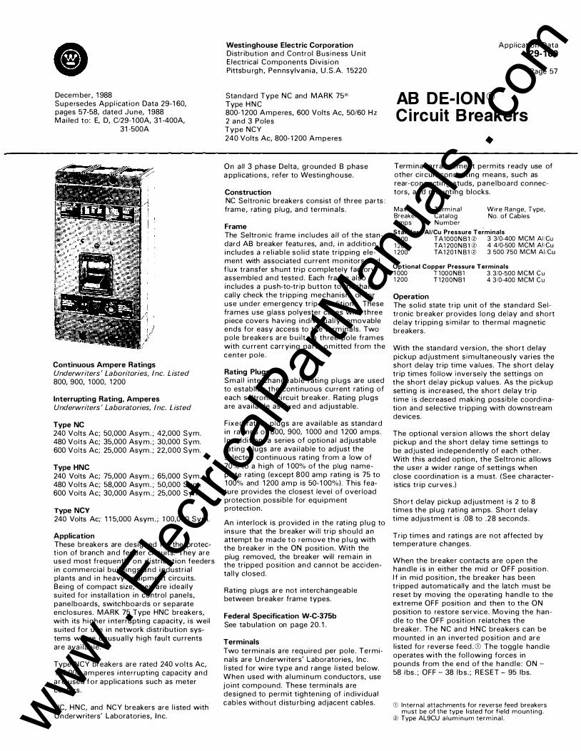
Cl December, 1 988 Supersedes Appl icat ion Data 29-1 60, pages 57-58, dated June, 1 988 Ma i led to: E, D, C/29-1 00A, 31 -400A,
31 -500A
Continuous Ampere Ratings Underwriters ' Laboritories, Inc. Listed 800, 900, 1 000, 1 200
Interrupting Rating, Amperes Underwriters ' Laboratories, Inc. Listed
Type NC 240 Volts Ac; 50,000 Asym. ; 42,000 Sym. 480 Volts Ac; 35,000 Asym. ; 30,000 Sym. 600 Volts Ac; 25,000 Asym. ; 22,000 Sym.
Type HNC 240 Volts Ac; 75,000 Asym. ; 65,000 Sym. 480 Volts Ac; 58,000 Asym. ; 50,000 Sym. 600 Volts Ac; 30,000 Asym. ; 25,000 Sym.
Type NCY 240 Volts Ac; 1 1 5,000 Asym. ; 1 00,000 Sym.
Application These breakers are designed for the protect ion of branch and feeder ci rcuits. They are used most frequently on d istri bution feeders in commercia l bu i ld i ngs and i ndustr ia l plants and i n heavy equ ipment circu its. Be ing of compact size, they a re ideal ly su ited for insta l lat ion in control panels, pane/boards, switchboards o r separate enclosures. MARK 75 Type HNC breakers, with its h igher i nterrupti ng capacity, i s well su ited for use in network distr ibution systems where unusua l ly h igh fau l t cu rrents are avai lable .
Type NCY breakers are rated 240 volts Ac, 1 00,000 amperes i nterrupting capacity and a re used fo r appl ications such as meter centers.
NC, HNC, and NCY breakers are l i sted with Underwriters' Laboratories, Inc.
Westinghouse Electric Corporation Distr ibution and Control Bus i ness U n it E lectrical Components Div is ion Pittsbu rgh , Pennsylvan ia , U .S .A. 1 5220
Standard Type NC and MARK 75'') Type HNC 800- 1 200 Amperes, 600 Volts Ac, 50/60 Hz 2 and 3 Poles Type NCY 240 Volts Ac, 800- 1 200 Amperes
On al l 3 phase Delta, grounded B phase a ppl ications, refer to Westi nghouse.
Construction NC Seltron ic breakers consist of th ree parts : frame, rati n g plug, and termina ls .
Frame The Seltron ic frame i nc ludes a l l of the standard AB breaker featu res, and , i n addition , includes a re l i ab le so l id state tr ipping element with associated cu rrent mon itors and f lux transfer shunt tri p completely factory assembled and tested . Each frame also includes a push-to-tr ip button to mechan ical ly check the tr ipping mechanism or for use under emergency tr ip condit ions. These frames use glass polyester cases with three piece covers having ind iv idua l ly removable ends for easy access to the term ina ls. Two pole breakers are bu i lt on th ree pole frames with cu rrent carrying pa rts om itted from the center pole .
Rating Plugs Sma l l i nterchangeable rati ng p lugs are used to establ ish the conti nuous current rati ng of each seltron ic ci rcuit breaker. Rating p lugs a re ava i lab le as fixed and adjustable.
F ixed rati ng p lugs a re ava i l ab le as standard in rat ings of 800, 900, 1 000 and 1 200 a m ps. I n addit ion, a series of optiona l adjustable rat ing plugs are ava i l able to adjust the selected continuous rat ing from a low of 70% to a h igh of 1 00% of the plug namep late rating (except 800 amp rati ng is 75 to 1 00% and 1 200 a m p is 50- 1 00%). This feature provides the closest level of overload protect ion possib le for equipment p rotect ion.
An i nterlock is provided i n the rat i ng p lug to insure that the breaker wi l l tr ip shou ld a n attempt b e made t o remove t h e p l u g with the b reaker in the ON posit ion . With the plug removed, the breaker will rema in in the tr ipped posit ion and cannot be accidenta l ly closed.
Rating plugs are not interchangeable between breaker frame types.
Federal Specification W-C-375b See tabulat ion on page 20. 1 .
Terminals Two termina ls a re requ i red per pole. Terminals are Underwriters' Laboratories, Inc . l i sted for wi re type and range l i sted below. When used with a l um inum conductors, use jo int compound . These term inals a re designed to permit t ighten ing of ind iv idua l cab les without d istu rbing adjacent cables.
Appl ication Data 29-1 60
AB DE-ION® C i rcuit B reakers
Page 57
Term ina l a rrangement perm its ready use of other circuit connect ing means, such as rear-con n ecti ng studs, pane /board connectors, and mount ing blocks.
Max. Breaker Amps
Term ina l Catalog Number
Wire Range, Type, No. of Cables
Standard AI/Cu Pressure Terminals 1 000 TA1000NB1 ® 3 3/0-400 MCM AL'Cu 1 200 TA1 200NB1 ® 4 4/0-500 MCM AliCu 1 200 TA1 201 NB1 ® 3 500750 MCM AliCu
Optional Copper Pressure Terminals 1 000 T1000NB1 3 310-500 MCM Cu 1 200 T 1200NB1 4 310-400 MCM Cu
Operation The sol id state tr ip un it of the standard Seltronic breaker provides long delay and short de lay tr ippin g s im i l a r to thermal magnetic breakers.
With the standard vers ion, the short delay pickup adjustment s imu ltaneously vari es the short delay tr ip t ime va lues . The short delay tr ip t imes fol low i nversely the sett ings on the short de lay pickup val ues. As the pickup sett ing is increased, the short delay tr ip t ime is decreased making possib le coord i nation and selective tr ipping with downstream devices.
The optiona l versio n a l lows the short de lay pickup and the short delay t ime sett ings to be adjusted independently of each other. With this added option , the Se/tro n ic a l lows the user a wider range of sett ings when close coord inat ion is a must. (See cha racteristics tr ip curves.)
Short delay pickup adjustment i s 2 to 8 t imes the pl ug rati ng a m ps. Short delay t ime adjustment is .08 to .28 seconds.
Tr ip t imes and rati ngs a re not affected by temperature changes.
When the breaker contacts a re open the hand le i s in either the mid or OFF position . I f i n mid position , the breaker has been t ripped automatical ly and the latch must be reset by moving the operat ing hand le to the ext reme OFF position and then to the ON position to restore service . Moving the hand le to the OFF position relatches the breaker. The NC and HNC breakers can be mounted i n a n i nverted posit ion and are l isted fo r reverse feed . G) The togg le handle operates with the fo l l owing forces in pounds from the end of the hand le : ON -58 lbs . ; OFF - 38 /bs . ; RESET - 95 lbs.
CD Internal attachments for reverse feed breakers must be of the type l isted for field mounting.
0 Type AL9CU a luminum terminal . www . El
ectric
alPar
tMan
uals
. com

Appl ication Data 29-1 60
Page 58
Typical Open View
Arc Chutes
B reaker Handle
Sol id State Trip U nit
Magnetic Adjustment
Line Terminal
Main Cover
r Rating Plug
Load Terminal Cover
Magnetic Only Circuit Interrupters(]) (NC & HNC O n ly) Magnetic-on ly Seltron ic breakers a re specia l frames s im i l a r to t h e standard breakers except they provide adjustab le magnetic tripp ing on ly fo r appl ications where short circuit protect ion o n ly is requ i red . Their tr ip range is establ ished by us ing the standard i nterchangeable rati ng p l ugs and the ranges are the same as the mag netic port ion of standard breakers. The conti nuous rati ng of these breakers is 1 200 a m ps.
Built-in Ground Fault Protection Types NC, HNC a n d NCY Seltron ic Breakers are ava i lab le with bu i lt- in circu itry to detect ground faults and cause the breaker to tr ip when the fau l t reaches a predetermined current sett ing and t ime sett i ng . These breakers have two addit iona l adjustment knobs to set the cu rrent pickup point ( . 1 to 1 t imes the breaker frame rating ) and to set the t ime delay on ground fault tri pp ing 3.5 to 30 cycles) . ®
The Seltron ic breaker with ground fault is supp l ied with a neutra l current transformer to mount externa l to the breaker ( 1 5 foot max imum) when it i s used on a 3-phase 4-wire system . They may a lso be used on a 3-phase, 3-wire system by omitti ng the C.T., or a specia l breaker can be suppl ied without the C.T. No externa l power is requ i red to tr ip these ground fault breakers. They also inc lude a memory ci rcuit that wil l cause the breaker to open if a n i nterm ittent ground fau lt of a level eq ua l to or g reater than the ground fault tr ip sett ing but of a t ime duration less than the trip time setti ng persists. The more rapid the frequency and the h igher the va lue of such a fau lt the qu icker the breaker wi l l trip . Se ltron ic breakers with bu i lt - in ground fault wil l accept the same field mountable or factory mounted accessories and attachments used on standard Seltron ic breakers (except u ndervoltage release) .
An optiona l , remotely-mounted u n it is avai l able to ind icate the breaker has tr ipped on a ground fault . It requ i res separate 1 20/60 •
control power and must be manua l ly reset after each tr ip i nd ication . See page 65.
Mining Service Breakers (]) A specia l version of the NC breaker is avai l ab le to meet Bureau of M ines requi rements for tra i l i ng cable appl icat ions . Refer to Technical Data 29-1 28.
Molded Case Switches (NC Only ) Type NC Molded Case Switches are U nderwriters' Laboratories, Inc. l i sted devices and a re avai lable on ly as h igh magnetic tr ip type devices with a fixed tr ip setti ng . A rating p lug is not requ i red, and i nternal attachments must be factory mounted s ince they are not the same as used on standard SEL TRONIC breakers.
For appl icat ion i nformation and UL I nc. l i sted withstand ratings, refer to Appl ication Data 29-1 60, page 75.
Circuit Breaker Removal Before i nspecting, i nsta l l i ng or removing from a circu it. the circuit breaker should be i n the OFF posit ion, and if practicable, the circuit should be de-energized. If the ci rcu it cannot be de-energ ized, insu lated tools, rubber g loves and a rubber f loor mat shou ld be used. To remove a rea r-con nected breaker from its mount ing, remove termina l stud lock n uts and pul l c ircuit breaker forward. To remove a front-connected circuit breaker from its mount ing , loosen term ina l l ug screws and remove cables from term i na ls . Remove ci rcuit breaker mount ing screws and pu l l ci rcuit breaker forward .
Inspection and Maintenance Good maintenance procedure ca l l s for periodic i nspection of al l electrical apparatus inc lud ing molded case circuit breakers. Term ina l lugs must be tight to prevent over-
heati ng . Due to the i nherent wip ing act ion bui l t i nto the moving contacts of a l l Westinghouse circuit breakers, operat ing the breaker several t imes under load wi l l remove any h igh resistance fi l m that may have formed. U nder normal condit ions, additi ona l c leaning of contacts is not requ i red.
Portable Test Kit A portable test kit is ava i l ab le to provide verif ication of perfo rmance of Seltron ic breakers whi le the devices a re sti l l i n service u nder vary ing load and/or phase u n bala nce. The tester operates on 1 20 volt 60 Hz and i ncludes complete i nstruct ions and test t imes for functiona l ly test ing the long t ime i nstantaneous and Ground Fault operation of the breaker. ( Refer to Technica l Data 29-1 20
·for tester) .
Accessories and Modifications Accessories and modifications ava i la b le i nc lude: rear-con nect ing studs, moisture and fungus treatment, provis ions to tr ip the f lux transfer shunt tr ip from a n externa l source, a l a rm switch, aux i l iary switches, undervoltage release, walki ng beam and s l ide bar type mechan ical i nterlocks and motor operator.
Dimensions, Inches@ Not to be used for construction purposes. See Dimension Sheet 29- 1 70 for detailed dimensions.
lQI \QT 121 121
©> ©>
� I 0 0 00 1
121 0
.Jfu. _(o)_ Cs� Further Information Prices: Price List 29-020
) 1---
16
r::::
r---
� I--51� 2 3 7i6
Ordering Data : Technica l Data 29- 1 20 Dimensions: D imension Sheet 29-1 70 Trip Curves: Appl icat ion Data 29-1 62
CD Not Underwriters' Laboratories, Inc. listed. ® Normal G.F . sensing is a residual scheme.
Some systems (such as double-ended switchboard) may require alternate sensing methods. Consult Westinghouse for details.
Gl 2-pole breakers suppl ied in 3-pole frames with center pole parts omitted.
December, 1988 www . El
ectric
alPar
tMan
uals
. com

December, 1 988 Supersedes Appl ication Data 29-1 60, pages 59-62, dated Novem ber, 1 981 Ma i led to : E, D, C/29- 1 00A, 31 -400A,
31-500A
Conti n uous Am pere R atings Underwriters' Laboratories, Inc. L isted 600, 700, 800, 900, 1 000, 1 200, 1 400, 1 600, 1 800, 2000, 2500
Interrupting R atings, Amperes Underwriters' Laboratories Inc. L isted 240 Volts Ac; 1 50,000 asym; 1 25,000 sym . 480 Volts Ac; 1 1 5,000 asym; 1 00,000 sym . 600 Volts Ac; 1 1 5,000 asym; 1 00,000 sym . 250 Volts De ; 75,000CD
Application@ The type PB breaker is designed for the protection of h igh capacity feeder and branch circuits. Although it is used most frequently as protection for heavy equipment feeder circuits and as service entrance for l arge commercia l bui ld ings and industrial p lants, the PB breaker is a lso uti l ized for appl ication in branch circuits subjected to h igh fau lt currents such as would be the case with resistance welders.
The PB breaker is idea l ly su ited for i nsta l l at ion in switchboards, control pane ls a n d separate enclosures. I n addit ion t o these, PB b reakers can be conven iently i nsta l led i n bus duct appl ications .
On a l l three-phase Delta, grounded B phase appl ications, refer to Westinghouse.
Construction The PB breakers have al l the standard AB breaker features including glass po lyester cases, De- ion arc ext inguishers, quickmakequ ickbreak toggle mechan isms and accurate, tamper-proof, i nterchangeable tr ip un its.
Two and three pole breakers are suppl ied in one frame size; the current carrying parts being omitted from the center pole for two pole breakers.
The 2500 a m pere frame will accept t rip rati ngs 600 throug h 2500 amperes.
Federal Specification W-C-375b See tabu lat ion on page 20. 1 .
(!) Changed o r added s1nce previous issue. , De rating app\1es to mag netic only interrupters and is
based on NEMA test procedures.
Westinghouse Electric Corporation Distr ibution a n d Control Busi ness U nit E l ectr ical Components Div is ion Pittsbu rgh, Pennsy lvan ia , U .S .A. 1 5220
Standard Type PB-2500 600-2500 Amperes, 600 Volts Ac, 2 and 3 Poles
Bus Bar Connectors Sta nda rd b reakers a re p rovided with back connectors to faci l itate bus connections . For rat ings through 2000 amperes, a "T" con nector (two requ i red per pole) accepts up to four bus bolts and can be rotated goo fo r maximum f lex ib i l ity. A cable con necto r which fits the "T" connector and accepts four 600 MCM copper cables is ava i l ab le . 2500 ampere breakers use a "C" con necto r (two requ i red per pol e ) .
A front connected version (2000 a mperes max.) of this breaker, with bus connectors extending from the ends of the breaker, is a lso avai lab le . Su itable for use in sha l low depth swilchboards, this design permits easy assembly or removal from the front. The cable connector mentioned for use with the "T" connector can a lso be used on these breakers.
Operation When the breaker contacts are open, the handle is either in the "mid" or "O FF" posit ion. If i n the "mid" position, the breaker has been tripped automatica l ly and the latch must be reset by moving the operating handle to the extreme "OFF" position and then to the "ON" position to restore service.
Appl ication Data 29-1 60
AB DE-ION® Circuit Breakers
Page 59
The PB breaker can be mounted i n a n i n verted position but i s n o t approved f o r reverse feed. The toggle hand le operates with the fol lowing forces i n pounds from the end of the hand le extension :
ON 80 lbs. OFF : 53 lbs. RESET: 80 lbs.
Thermal M ag netic B reakers These breakers are equipped with a thermalfront adjustable magnetic tr ip un it which may be interchanged with other therma l magnetic trip un its of a d ifferent rating or with magnet ic only trip u n its. In the tr ip un it, thermal tr ip elements ind irectly heated by a transformer, provide inverse t ime delay characteristics for overload condit ions. Being transformer heated, the thermal e lements do not respond to di rect current and therefore must be used on a lternating cu rrent ci rcuits on ly. Adjustable magnetic elements, acting independently of the therma l elements provide i nstantaneous short circuit protection. Red adjustment knobs to adjust the magnetic trip range protrude through the breaker cover for maximum accessib i l ity. The rating of the trip un it being used shows through a window in the breaker cover. www .
Elec
tricalP
artM
anua
ls . c
om

Application Data 29-1 60
Page 60
Typical Exploded View
Cover Sc rews
Mount ing Screws A rc Ext inguisher Stationary Conductor Arc rl�--------+----�
Main Cover Screws
� -�4�,�� �::00.001"�
� Cover Screws Trip Un it Mount ing B olts Trip Un it
Thermal -front adjustable magnetic trip units listed with Underwriters' Laboratories, I nc. , are as follows:
Magnetic Trip Continuous Ampere Rating
Settir1g_ Ril_llfle_ _ _ _ _
600 700 800 900
1 000 1 200 1 400 1 600 1 800 2000 2500 i)
High
5000 5000 5000 5000 5000 6000 7000 8000 8000 8000 8000
Magnetic Only Circuit lnterrupters e?l
Low
1 500 1 500 1 500 1 500 1 500 2000 2500 3000 3000 3000 3000
These breakers a re equipped with adjustab le magnetic on ly tr ip un its for appl ications where short circuit protect ion only is requ i red. The conti n uous cu rrent rating of these i n terrupters is 2000 or 2500 a m peres. Magnetic trip sett ings are set in the h igh posit ion at the factory but may be adjusted down to the low l imit in the field . May be used on Ac o r De circu its . Magnetic tr ip ranges are as fo llows :
High 5000 6000 7000 8000 1 0,000 1 2,000 Low 1 500 2000 2500 3000 3500 4000
@ Changed or added since prev1ous issue. RAar con nected only.
2 Not l i sted wtth Underwriters' Laboratories, Inc.
Molded Case Switches@ Molded Case Switches a re U nderwriters' Laboratories. I nc. l isted devices and a re ava i lab le on ly as h igh magnetic trip type with fixed trip sett ing .
For appl ication i nformation and UL I nc. l i sted withstand rati ngs, refer to Appl ication Data 29- 1 60, page 75.
Base
I
December, 1988 www . El
ectric
alPar
tMan
uals
. com

C i rcuit B reaker Removal Before inspecting, insta l l i ng or removing
·from a circu it, the circuit breaker should be in the OFF position, and if p ractical, the circuit should be de-energ ized. If the c ircuit cannot be de-energized, insu lated tools, rubber g loves and rubber floor mat should be used. To remove a rear-connected breaker equipped with back connectors, first loosen and remove bolts afixing back con nectors t o bus. Next, loosen breaker mounting screws and pu l l breaker forward.
To remove a breaker from a plug - i n mounting frame, reference should be made to the instruction leaflet suppl ied with the mounting frame.
Inspection and Maintenance Good maintenance procedure cal ls for periodic inspection of a l l e lectrical apparatus including molded case circuit breakers. Bus and trip unit connections must be tight to prevent overheating. Due to the inherent wip ing action bu i lt into the moving contacts of a l l Westinghouse circuit breakers, operating the breaker several times under load wil l remove any h igh resistance fi lm that may have formed. U nder normal cond itions, additional c lean ing of contacts is not required . However, should operating and/or atmospheric conditions make it desirable to clean contacts further, the fol lowing procedure is recommended. Remove cover arc ext ingu ishers and stationary contact assembly. Wipe contact surfaces with a clean cloth d ipped in a chlorinated solvent. I f surfaces are excessively oxidized or corroded, scrape lightly with a fine file before wiping.
December, 1988
Replacing I nterchangeable Trip U n i t Remove circuit breaker from its mounting per instructions under "Circu it Breaker Remova l" . Remove cover. Remove back connectors from trip un it conductors. Remove screws from the outer poles of the l ine side of the trip unit and loosen the captive screws (not shown) in the center pole of the same side of the trip unit. Remove screws holding trip unit conductors to frame. Lift trip un it from frame. To replace trip un it reverse above procedure. Before replacing frame cover and mounting circuit breaker, check for proper latching and c losing operations per i nstructions under "operation". Open and close breaker several times to make certain proper latching has been achieved.
Accesso ries, M odifications Accessories and mod ifications for the PB breaker include: shunt trip, undervoltage re lease, auxi l iary switch, a larm switch, Kirk key i nterlock, motor operator, fuse mounting base and moisture-fungus-corrosion treatment.
Further Information@ Prices : Price List 29-020 Ordering Data : Technical Data 29-1 20 Dimensions: D imension Sheet 29-170 Trip Curves : App l icat ion Data 29-1 63
Dimensions, lnchesCD
Appl ication Data 29- 1 60
Page 61
Not t o b e used for construction purposes. See Dimension Sheet 29- 1 70 for detailed dimensions.
22�
1-------g l 0 @> .. � �12i6 916�48 I 15 16 I
Type PB 2000 Amperes, Rear Con nected
. T -22�
�12�� Type PB 2500 Amperes
Type P B F 2000 Amperes
@ Changed or added since previous issue. , 2-po\e breakers supplied in 3-pole frames with center
pole parts om1tted
www . El
ectric
alPar
tMan
uals
. com

A p p l i c a t i o n Data
29- 1 60
Page 62
Westi n g h o u se E l ectric Corporat ion D i stri b u t i o n a n d Control B u s i ness U n i t E lectrical C o m pon ents D i v i s i o n P i t tsburgh, Pe n n sylva n i a , U . S.A. 1 5220
December, 1 988 www . El
ectric
alPar
tMan
uals
. com

September, 1 988 Supersedes 29- 1 60 A WE A Appl icat ion Data, pages 63-66, dated September, 1 976 Mai led to : E, D, C/29-1 00A. 3 1 -400A,
3 1 -500A
Continuous Ampere Ratings Underwriters' Laboratories, Inc. Listed 1 000, 1 200, 1 400, 1 600, 1 800, 2000, 2500, 3000
Type PCC Seltronic Breakers have been tested for 1 00 percent continuous duty appl i cation in l ine with the "exception" clause in the N E C under Artic le 220. These ratings are U L l isted for continuous operation at 1 00 percent of rating when mounted in an appropriate size enclosure having a recommended min i mum area of venti lation. Shou ld the breakers be cable-connected, only copper cables are to be used.
Type PC breakers are l isted for standard appl ications per N .E .C . requirements at 80% of rating using appropriate size a luminum or copper bus bar or cable.
I nterrupting Ratings, A m peres Underwriters' Laboratories, Inc. Listed 240 Volts Ac; 1 50,000 asym; 1 25,000 sym. 480 Volts Ac; 1 1 5,000 asym; 1 00,000 sym. 600 Volts Ac; 1 1 5,000 asym; 1 00,000 sym.
Appl ication The type PC or PCC breaker is designed for the protection of h igh capacity feeder and branch circuits. Although it is used most frequently as protection for heavy equipment feeder circuits and as service entrance for large commercial bui ld i ngs and industrial plants, the PC or PCC breaker is also uti l ized for appl ication in branch circuits subjected to
Westinghouse Electric Corporation Distri bution and Control Bus iness U nit E lectrical Components Divis ion Pittsburgh, Pennsylvan i a , U .S .A . 1 5220
Standard Types PC-2000, PC-2500, PC-3000 PCC-2000, PCC-2500 and PCC-3000 1 000-3000 Amperes, 600 Volts Ac, 50/60 Hz 2 and 3 Poles
high fau lt currents such as would be the case with resistance welders.
The PC or PCC b reaker is idea l l y su ited for i nsta l lation i n switchboa rds, control pane ls and sepa rate enclosures. I n addit ion to these, PC or PCC b reakers can be conveniently insta l led in bus duct app l ications .
On a l l three- phase De lta, grounded B phase appl ications, refer to Westinghouse.
Construction The type PC or PCC Seltronic breaker consists of three parts: frame, rating plug, and rear bus connectors.
F rame The Seltronic frame includes a l l of the standard AB breaker features, and, in addition, inc ludes a re l iable solid state tripping element with associated current mon itors and flux transfer shunt tri p completely factory assem bled and tested. Each frame a lso includes a push to tri p button to mechanica l ly check the tri pping mechanism or for use under emergency trip conditions. These frames use g lass polyester cases. Two pole breakers are bui lt on three pole frames with current carrying parts omitted from the center pole. The type PC or PCC is avai lable in three frame ratings: 2000, 2500, and 3000 amps.
Rating Plugs Smal l interchangeable rat ing pl ugs are used to establish the continuous current rating of each Seltronic circuit breaker. Rating p lugs are avai lable in two types: f ixed and adjustable.
Fixed rating p lugs a re ava i l abl e as standard i n ratings as fo l lows: PC 2000 a nd PCC 2000 : 1 000, 1 200, 1 400, 1 600, 1 800 a n d 2000 a m ps. PC 2500 a n d PCC 2500: 1 400, 1 600, 1 800, 2000 a n d 2500 a m ps . PC 3000 a nd PCC 3000: 1 600, 1 800, 2000, 2500 and 3000 amps. I n add ition , a series of optiona l adjustable rati ng p lugs a re ava i l ab le to adjust the selected conti nuous rating from a low of 70% to a h igh of 1 00% of the p lug nameplate rati ng (except A20PC2000, A25PC2500 and A30PC3000 are 50 to 1 00%). This feature p rovides the closest level of overload protection poss ib le for equipment p rotect ion.
An interlock is provided i n the rating p lug to i nsure that the breaker wi l l trip should an attempt be made to remove the p l ug with the breaker in the "On" position. With the plug removed, the breaker wi l l remain i n the tripped position and cannot be accidenta l ly c losed.
Appl icatio n Data 29-1 60 Page 63
AB DE-ION® SEL TRONIC Circuit Breakers
Rating plugs are not i nterchangeable between breaker frame types, or other PC- PCC frame ratings.
Bus Bar Connectors Standard breakers are provided with back connectors to fac i l itate bus connections. For ratings through 2 500 amperes, a "T" con nector (two required per pole) accepts up to four bus bolts and can be rotated so· for maximum flexibi lity. 3000 ampere breakers have rear bus connectors bui lt into the breaker frame.
A front connected version (2500 amperes max.) of this breaker, with bus connectors extending from the ends of the breaker, is also avai lable . Su itable for use in shal low depth switchboards, this design permits easy assembly or removal from the front.
Federal S pecification W - C-375b See tabulation on page 2 0. 1 .
Operation The so l id state tr ip u n it of the standard Seltronic b reaker p rovides long delay and short delay tr ipping s imi l a r to thermal m agnetic breakers.
With the standard vers ion, the short delay pickup adjustment s imu ltaneously varies the short delay trip t ime values. The short delay trip t imes fol low i nversely the setti ngs on the short de lay pickup val u es. As the pickup sett ing is i ncreased, the short delay trip t ime i s decreased making poss ib le coord ination and selective tr ipp ing with downstream devices.
The optiona l version (PCA. PCCA) a l lows the short de lay pickup a n d the short delay t ime setti ngs to be adjusted independent ly of each other. With th is added o ption, the Se l t ron ic a l l ows the user a wider range of sett ings when close coordinat ion is a must. (See cha racteristics t r ip cu rves.)
Short delay pickup a dj ustment is 2 to 8 times the p lug rating a m ps. Short delay t ime adjustment is .08 to .28 seconds.
Tr ip t imes and rat ings a re not affected by temperatu re changes.
When the breaker contacts are open, the handle is either in the "mid" or "OFF" posit ion. If in the "mid" position, the breaker has been tripped automatica l ly and the l atch must be reset by moving the operating handle www .
Elec
tricalP
artM
anua
ls . c
om

Appl ication Data 29-1 60 Page 64
to the extreme "OFF" position and then to the "ON" position to restore service.
The PC and PCC breakers can be mounted i n an inverted position a n d are l isted for reverse feed. CD The toggle handle operates with the fol lowing forces in pounds from the end of the handle extension: ON: 80 l bs., O FF: 53 l bs., R ESET: 80 lbs.
Built-in Ground Fault Protection Types PC and PCC Seltron ic Breake rs a re ava i l ab le with bu i lt- in ci rcu itry to detect ground fau lts (PCG, PCCG) and cause the breaker to tr ip when the fau l t reaches a p redetermined cu rrent sett ing and time sett ing. These breakers have two additiona l adjustment knobs to set the cu rrent pickup point (200- 1 200 Amps for 2000 Amp Frame) (240-1 200 Amps for 2500 Amp Frame) (300- 1 200 Amps for 3000 Amp Frame) and to set the t ime de lay on g round fau lt tr ipping (3 .5 to 30 cycles) . Q)
T h e Seltronic with g round fau lt i s suppl ied with a neutral cu rrent transformer to mount externa l to the breaker ( 1 5 foot max imum) when it is used on a 3 phase 4 wire system. They may a lso be u sed on a 3-phase, 3-wire system by omitti n g the C.T. , or a specia l breaker can be suppl ied without the C.T. No externa l power is requ i red to t r i p these g round fault breakers. They a lso i nc lude a memory ci rcuit that wi l l cause the breaker to open if an i ntermittent g round fault of a level equal to or g reater than the g round fau l t t r ip sett ing but of a t ime du ration less than the tr ip time sett ing pers ists. The more rapid the frequency and the h igher the value of such a fault the qu icker the breake r wi l l tr ip. Seltron ic breakers with bui lt- in ground fault wi l l accept the same f ie ld mountable o r factory mounted accessories and attachments used on standard Seltronic breake rs (except u ndervoltage release) .
An optional remotely mounted u n it is avai l able to i ndicate the breake r has tripped on a g round fau lt. It requ i res separate 1 20/60 control power a nd m ust be manua l ly reset after each trip i ndicat ion .
Molded Case Switches Type PC and PCC Molded Case Switches a re U nderwriters' Laboratories, Inc . l i sted and are avai lable only as h igh magnetic tr ip type devices with f ixed tr ip setti ng . A rat ing p lug is not req u i red, and i nternal attachments must be factory mounted si nce they a re not the same as used on standard SELTRONIC breakers.
For appl ication i nformation and UL Inc . l i sted withstand rati ngs, refer to Appl ication Data 29-1 60, page 75.
Typical O pen View
Arc Chutes
B reaker Handle
Button
Solid State Trip Un it
Magnetic Adjustment 1 Cover
Rating P lug
M a g netic Only C i rc u i t I nterru pters @ Magnetic-only Seltronic breakers are special frames similar to the standard breakers except they provide adjustable magnetic trippi ng only for appl ications where short circuit protection only is required. Their tri p range is established by using the standard interchangeable rati ng pl ugs, and the ranges are the same as the magnetic portion of standard breakers. The conti nuous rating of these breakers is 2000, 2500 or 3000 amps.
C i rc u i t B reaker R e moval Before inspecting, insta l l i ng or removing from a circuit. the circuit breaker should be in the OFF position, and if practical , the circuit should be de-energized. If the circuit cannot be de-energized, insul ated tools, rubber gloves and rubber floor mat should be used. To remove a rear-connected breaker, loosen and remove bolts, afixing back connectors to bus. Next, loosen breaker mounting screws and pu l l breaker forward.
I nspection a n d M ai nten a nce Good maintenance procedure cal ls for periodic inspection of al l electrical apparatus inc luding molded case circuit breakers. Bus connections must be tight to prevent overheat ing. Due to the inherent wiping action bui lt i nto the moving contacts of a l l Westinghouse circuit breakers, operating the breaker several times under l oad wi l l remove any h igh resistance f i lm that may have formed. Under normal conditions, addit ional cleaning of contacts is not required.
Portable Test K it A portable test kit is avai lable to provide verif i cation of performance of a l l frame sizes of
Seltronic breakers wh i le the devices are sti l l i n service under va ry ing load and/or phase unba l ance. The tester operates on 1 20 volt 60 Hz and i nc ludes complete i nstruct ions and test t imes for functiona l ly testi ng both the long time instantaneous and G round Fau lt operatio n of the breaker. (Refer to Tech . Data 29- 1 20 for tester ) .
Access o ries, M o d ificati o n s Accessories and modifications for the PC breaker inc l ude: Provisions to trip the f lux transfer shunt tr ip from an external source, auxi l iary switch, a larm switch, undervoltage release, Kirk key interlock, motor operator, drawout fra me and moisture-fungus -corrosion treatment.
CD Internal attachments for reverse feed breakers must be of the type listed for field mount ing.
CiJ Normal G.F. sensing is a residua l scheme. Some systems (such as double-ended switchboard) may require alternate sensing methods. Consult West inghouse for detai ls .
@ Not Underwriters' Laboratories, Inc. listed.
September, 1988 www . El
ectric
alPar
tMan
uals
. com

D i mension s, I nches@ Not to be used for construction purposes. See Dimension Sheet 29- 1 70 for detailed
dimensions.
Type PC or PCC 2000. 2500 Amperes, Rear Connected
. �. o o do
. ,.
Type PC or PCC 3000 Amperes. Rear Connected
Type PCF or PCCF 2000 and 2500 Amperes@
@ 2 - pole breakers suppl ied i n 3 - pole frames with center pole parts om itted.
@ Bus connectors for 2 500 a mpere breakers are larger thiln those for 2000 amp breakers.
September, 1988
Typical Service Entrance
Grounding Electrode
A B C
Seltronic Breaker D
Application Data 29-1 60 Page 65
0 Additional grounding points must not be down stream from neutral current transformer.
@ Breakers for use on Three Phase, Three Wire ungrounded systems, employ a suffix "X" designation. For these breakers only, the N/G terminals are omitted. The above scheme can also be used on 3 Phase, 3 Wire ungrounded systems. In this application NO CONNECTIONS are to be made to N/G
0 Connections L 1 and L2 are for use with optional remote Ground Fault Trip Indicator and are supplied on all Seltronic Breakers with built in Ground Fault protect ion .
O ptional Remote G ro u nd Fault Tr ip Ind icato r U n it for Seltronic B reakers With B u i lt- in G round Fault Protection .
Seltronic Breaker With Built-in Ground Fault Protection (Simular to Figure Above)
0 Trip Indicator Light and Test- Reset Button
To a Seperate { l20 Volt Ac Power Supply
3 Amp Continuous ( l 20 Volt Ac) Contacts for Customer Connected Light and/or Aiarm Unit } 0 Connections for Optional
-- Remote Test - Reset -- Pushbutton ( Norma l l y
Open Contact)
0 unit must be reset after a Ground Fault mdication occurs When either the local or remote test button is depressed it simulates a Ground Fault and checks all circuits and the light of the indicator unit ( I ncluding remote connection lig ht or alarm) and simultaneously resets the un1t .
Further Information Prices : Price List 29-020 Order ing Data : Tech . Data 29- 1 20 Dimensions : D imension Sheet 29-1 70 Trip Cu rves: App. Data 29- 1 62
www . El
ectric
alPar
tMan
uals
. com

Application Data 29-1 60 Page 66
Westi nghouse E lectric Corporation Distr ibution and Control Busi ness U nit E lectrica l Components Division Pittsburgh , Pennsylvan ia , U .S.A. 1 5220
September, 1988 www . El
ectric
alPar
tMan
uals
. com

October, 1 988 Supersedes Appl ication Data 29-1 60, pages 75-76, dated June, 1 988 Mai led to: E, D, C/29-1 00A, 31 -400A,
31 -500A
Molded Case Switches Westinghouse molded case switches are high magnetic tr ip type devices with a f ixed trip setting, and they a re Underwriters' Laboratories, Inc. l isted to standard UL 1 087 .
Molded case switches must be marked with specific application and withstand rating i nformation .
Westinghouse molded case switches are l isted and marked as shown in the fol l owing tables.
Most standard c ircuit breaker accessories can be suppl ied factory mounted i n these switches.
Further Information List Prices: Price Lists 29-020 and 29-021 Dimensions: Dimension Sheet 29-1 70 (Same as equ ivalent thermal magnetic breaker) Terminals : Technical Data 29- 1 20, page 46. 1 , and Technical Data 29- 1 2 1 , page 17
Westinghouse Electric Corporation Distribution and Control Business U nit E lectrical Components Division Pittsburgh, Pennsylvania, U .S.A. 1 5220
Application Data 29- 1 60
Page 75
Molded Case Switches: Fixed, High Magnetic Trip Setting AB D E-ION®
C i rcuit B reakers
Molded Case Switches With High Magnetic Trip - Trip Setting and Tolerance Fra_m_E) _ _ _ __ _ _ _ _ _ _ _ £�il1_9_ _ __ _ _ _ _ _ �i!J �ettirl9J�m_Pl_ _ _ EB 1 00 1 000 EHB/FB 1 00 1 200 FB 1 50 1 500
CA 225 2250
JAIKA 225 2250
JB/KB 250 2500
DAILB/LBB/LA(400) 400 4000
LAILC 600 6000
MAIMC 800 8000
NB/NC 1 200 1 2000
PB/PC 2000-3000 1 2000
Tolerance (%) � 20 � 2o :" 20
+ 20 - 10 + 10 - 0 + 1 0 - 0
+ 1 0 - 0 + 1 0 - 0 + 1 0 - 0
+ 10 -0 + 10 - 0
Molded Case Switches With High Magnetic Trip (Fixed Trip Setting)
Switch Amps No. Application Rating Senes Application Catalog Number<D of When Used Alone Ratings Devices
Poles Volts/ Max. Volts' Max. Breaker Breaker Fuse Amps Max. Freq. System Freq. System or Limiter Line Load
Fault Fault Fuse Current Current Type
E B 1 1 00LK 1 00 1 1 20Ac 1 0,000 1 20Ac 1 00,000 FBP 1 00FBP06 1 25Dc 5,000 LAP 200LAP08
200,000 FCL LCL
1 00,000 J,T,RK1 400 400 RK5 1 00 1 00
200,000 J,T,RK1 200 200
EB21 00LK, EB31 00LK, 1 00 2, 3 240Ac 1 0,000 240Ac 1 00,000 FBP 1 00FBP06 EB31 00SLK 250Dc 5,000 LAP 200LAP08
200,000 FCL LCL
1 00,000 J,T,RK1 400 400 RK5 1 00 1 00
200,000 J,T,RK1 200 200
EHB1 1 00LK 1 00 1 277Ac 1 4,000 277Ac 1 00,000 FBP 1 00FBP06 1 25Dc 10,000 LAP 200LAP08
1 50,000 FCL LCL
1 00,000 J,T,RK1 400 400 RK5 1 00 1 0 0
200,000 J,T,RK1 200 200
EHB21 00LK, EHB31 00LK, 1 0 0 2, 3 240Ac 1 8,000 480Ac 1 00,000 FBP 1 00FBP06 EHB31 00SLK 480Ac 1 4,000 LAP 200LAP08
250Dc 1 0,000 1 50,000 FCL LCL
FB21 00LK, FB21 50LK, 1 00!150 2, 3 240Ac 1 8,000 240Ac 200,000 FCL FB31 00LK, FB31 50LK 480Ac 1 4,000 LCL FB3 1 50SLK 600Ac 1 4,000 480Ac 1 00,000 J,T,RK1 400 400
250Dc 10,000 RK5 1 00 1 00 200,000 J,T,RK1 200 200
CA2225WK, CA3225WK 225 2, 3 240Ac 1 0,000 240Ac 200,000 LCL 1 00,000 LAP 200LAP08
.J,T,RK1 400 400 RK5 200 200
200,000 J,T,RK1 200 200
CD Catalog numbers w1th "W" suffiX are Without terminals. www . El
ectric
alPar
tMan
uals
. com

Application Data 29-1 60 Page 76
Molded Case Switches With High Magnetic Trip (Fixed Trip Setting), Continued
Switch Amps No. Application Rating Catalog NumbereD of When Used Alone
Poles Volts/ Max. Freq. System
Fault Current
JA2225WK, JA2225WSK, 225 2, 3 240Ac 25,000 JA3225WK, JA3225WSK, 480Ac 22,000 KA2225WK, KA2225WSK, 600Ac 22,000 KA3225WK, KA3225WSK 250Dc 1 0,000
JB2250WK, JB2250WSK, 250 2, 3 240Ac 25,000 JB3250WK, JB3250WSK, 480Ac 22,000 KB2250WK, K B2250WSK, 600Ac 14,000 KB3250WK, KB3250WSK 250Dc 10,000
DA2400WK, DA3400WK 400 2, 3 240Ac 22,000 250Dc 10,000
LB2400WK, LB2400WSK, 400 2, 3 240Ac 42,000 LB3400WK, LB3400WSK, 480Ac 30,000 LBB2400WK, LBB2400WSK, 600Ac 22,000 LBB3400WK, LBB3400WSK 250Dc 10,000
LA2400WK, LA2400WSK, 400 2, 3 240Ac 42,000 LA3400WK, LA3400WSK, 480Ac 30,000 LAB2400WK, LAB2400WSK, 600Ac 22,000 LAB3400WK, LAB3400WSK 250Dc 10,000
LA2600WK, LA2600WSK, 600 2, 3 240Ac 42,000 LA3600WK, LA3600WSK, 480Ac 30,000 LC2600WK, LC3600WK 600Ac 22,000
250Dc 1 0,000
MA2800WK, MA2800WSK 800 2, 3 240Ac 42,000 MA3800WK, MA3800WSK 480Ac 30,000 MC2800WK, MC3800WK 600Ac 22,000
250Dc 1 0,000
NB21 200WK, NB21 200WSK, 1 200 2, 3 240Ac 42,000 NB31 200WK, NB31 200WSK, 480Ac 30,000 NC21 200WK, NC31 200WK 600Ac 22,000
250Dc 10,000
PB22000WK, PB32000WK, 2000 2, 3 240Ac 1 25,000 PBF22000K, PBF32000K, 480Ac 1 00,000 PC22000WK, PC32000WK, 600Ac 100,000 PCC22000WK, PCC32000WK, PCF22000K, PCF32000K
PB22500WK, PB32500WK, 2500 2, 3 240Ac 1 25,000 PC22500WK, PC32500WK, 480Ac 100,000 PCC22500WK, PCC32500WK 600Ac 100,000
PC23000K, PC33000K, 3000 2, 3 240Ac 1 25,000 PCC23000K, PCC33000K 480Ac 1 00,000
600Ac 100,000
CD Catalog numbers with "W" suffix are without terminals. ® These upstream series device ratings also apply to equivalent SEL TRONIC™ breakers.
Westinghouse E lectric Corpo ration Distribution and Control Business Unit E l ectrical Components Divis ion Pittsburgh, Pennsylvania , U .S .A. 1 5220
Series Application 0 Ratings
Volts/ Max. Freq. System
Fault Current
480Ac 1 00,000
240Ac 200,000 480Ac 100,000
200,000 100,000 1 50,000
480Ac 100,000
240Ac 200,000
480Ac 1 50,000
100,000
200,000
240Ac 100,000
200,000 1 00,000
480Ac 1 00,000
240Ac 200,000 480Ac 1 50,000
100,000
200,000
480Ac 100,000
240Ac 200,000 480Ac 1 50,000
100,000 200,000 100,000 200,000
480Ac 100,000
240Ac 200,000 480Ac 1 50,000
1 00,000
200,000
480Ac 1 00,000
200,000
480Ac 100,000
480Ac 200,000
480Ac 200,000
480Ac 200,000
Devices
Breaker Breaker or limiter Fuse Type
LAP 400LAP10 NBP 500NBP12 LCL · · · · · · · · RK5 . . . . . J,T,RK1 · · · · · · · · J,T,RK1 · · · · · · · · LCL . . . . . . . .
FBP 100FBP06 LAP 200LAP08 LAP 400LAP10 NBP 500NBP1 2 FCL LCL . . . . . . . . FCL . . . . . . . . LCL · · · · · · · · J,T,RK1 . . . . . . . . RK5 . . . . . . . J,T,RK1 . . . .
LAP 400LAP10 NBP 500NBP12 NBP 800NBP20 LCL · · · · · · · · J,T,RK1 . . . . . . . . RK5 . . . . . . . .
LAP 400LAP10 NBP 500NBP1 2 LCL . . . . . . . . LCL . . . . . . . . L · · · · · · · · RK5 . . . . . . J,T,RK1 · · · · · . . RK5 . . . . . . . .
LAP 400LAP1 0 NBP 500NBP12 NBP 800NBP20 LCL . . . . . . . . LCL . . . . . . . L . . . . . . . . J,T,RK1 · · · · · · · · RK5 . . . . . L . . . . . . RK5 . . . .
LAP 400LAP10 NBP 500NBP12 NBP 800NBP20 LCL . . . . . . . . LCL . . . . L . . . . . . . . RK5 . . . . . . J,T,RK1 . . . . . . RK5 . . . . . .
LAP 400LAP1 0 NBP 500NBP12 NBP 800NBP20 L . . . . J,T,RK1 . . . . RK5 . . . . . . . . L . . . . . . .
NBP 500NBP12 NBP 800NBP20 L . . . . . .
L . . . .
L . . . . . . .
L . .
Cl Fuse Amps Max.
Line
. . . . . . .
. . . 200 200 600
. . . .
. . . .
. . . .
. . . .
. . . .
. . . .
. . . . . . .
. . . . 600 200 200
. . . .
. . . .
. . . .
. . . . 600 400
. . . .
. . . .
. . . .
. . . . 1200 600 600 400
. . . .
. . . .
. . . .
. . . .
. . . . 1200
600 600 800 400
. . . .
. . . . . . . . . .
. . . . 1 200
600 600 400
1 200 600 600 800
. . . .
. . . . 1 200
2000
2000
2000
Load
. . . .
. . . . . . . 200 200 600
. . . .
. . . . . . . . . . . . . . . . . . . . . . . . . . . . . . . 600 200 200
. . . .
. . . .
. . . .
. . . . 600 400
. . . . . . .
. . . . . .
1200 600 600 400
. . . .
. . .
. . . .
. . . .
. . . . 1200 600 600 800 400
. . .
. . . .
. .
1200 600 600 400
. . . .
. . .
. . . 1 200 600 600 800
. . . .
. . . . 1 200
2000
2000
2000
October, 1988 www . El
ectric
alPar
tMan
uals
. com

June, 1 988 Supersedes Appl icat ion Data 29-1 60, pages 27-28, dated September, 1 976 Mai led to: E , D, Ci29- 1 00A, 3 1 -400A,
3 1 -500A
Continuous Ampere Ratings Underwriters ' Laboratories, Inc. Listed 1 25, 1 50, 1 75, 200 and 225 Amperes
Interrupting Ratings, Amperes Underwriters' Laboratories, Inc. Listed Type CA: 1 0,000 Asym. and Sym. Type CAH : 25,000 Asym . , 22,000 Sym. Type HCA: 42,000 Sym .
Application CA, CAH and HCA AB De-ion " circuit b reakers a re designed for protect ion of branch and feeder ci rcuits in either commercia l o r i ndustria l app l ications . Because o f their h igh conti nuous ampere capacity and compact size, they are particu lar ly wel l-su ited for use as main protection i n load centers, meter ing panels and l ight ing panelboards. They a re also suited fo r i nstal lation in d istr ibution panelboards, motor control centers, control panels and separate enclosu res where a 240 volt, 225 ampere frame breaker is requ i red .
Listed with U nderwriters' Laborato ries, I nc. (Two pole b reakers are l isted fo r grounded B phase appl ications 1 0,000 amp I .C . max. )
Federal Specification W-C-375b See tabulat ion on page 20. 1
Construction Type CA. CAH and HCA breakers have a l l t he standard AB ci rcuit breaker features such as De-ion ' arc exti ngu ishers, and qu ick-make, qu ick-break, tri p-free togg le mechan isms.
Type CAH and H C A breakers are the same size and have the same mount ing dimensions as Type CA. However, their design and const ruction enable them to have a h igher I .C . Type CAH breakers a re UL Listed for use ahead of 1 0,000 ampere I .C . Qu icklag and BA b reakers in panelboards to permit their app l ication at 22,000 ampere fau lt levels .
Two-pole breakers are suppl ied i n a twopole frame, 2% i n . wide, th ree-pole b reakers are suppl ied in a th ree-pole frame, 4'/s i n . wide.
Terminals Termina ls a re Underwriters' Laboratories, I nc. l isted fo r the wi re type and size l i sted below. When used with a l um inum conductors, use jo int compound.
Max. Breaker Amps. 225
Catalog Number
TA225CA2
Wire Range and Type
- - - -# 1 ·300 MCM AICu
CD Breakers with internal attachments are not suitable for reverse feed.
Westinghouse Electric Corporation Distribution and Contro l Busi ness U n it E lect rical Components Division Pittsburgh, Pen nsylvania , U .S.A. 1 5220
Types CA, CAH and HCA 1 25-225 Amperes, 240 Volts Ac, 2 and 3 Poles
Operation When the breaker contacts are open, the hand le is i n e ither the mid o r OFF posit ion . I f , i n the mid-posit ion, the b reaker has been tr ipped automatical l y, the l atch must be reset by moving the operating hand le to the extreme OFF position before attempting to restore service. Co ntacts may be c losed after resetti ng the latch, by moving the hand le to the O N position . CA. CAH and HCA breakers may be mou nted in an i nverted position and a re approved for reverse feed. CD The toggle hand le operates with the fo l lowing forces i n pounds from the end of the handle : ON: 10 lbs . ; OFF: 1 1 lbs . ; RESET: 2 1 lbs.
Thermal Magnetic Breaker Thermal magnetic b reakers a re equipped with thermal and magnetic tr ip elements to provide complete circuit protect ion against overloads and short ci rcuits.
The thermal tr ip e lements (b imetals) provide inverse tr ip cha racteristics and a re i ndirectly heated for longer over load t ime delay which is desirable in feeder ci rcuits. On temporary overloads, the breaker wi l l not t r ip ; but on sustained overloads beyon d the safe l im its of the wi re, the bimetal wi l l deflect. caus ing the b reaker to tr ip.
The mag netic tr ip element (e lectro-magnet) i s set to tri p the breaker i nstantaneously at cu rrents of approximately 10 t imes the continuous rati ng of the breaker.
Appl ication Data
AB DE-IO N ® Circuit Breakers
29- 1 60
Page 27
Trip e lements a re non-adjustable and noni nterchangeable.
Molded Case Switches (Type CA on ly) Molded Case Switches are Underwriters' Laborato ries, I nc . l i sted devices and are ava i lab le only as h igh magnetic tr ip type with fixed trip sett ing .
For appl ication information and U L Inc . l i sted withstand rat ings, refer to Application Data 29- 1 60, page 75.
Circuit Breaker Removal Before inspecti ng, insta l l i ng or removin g from a ci rcuit, t h e circuit breaker shou ld b e i n t h e "off" posit ion, and i f practica l , t h e c i rcuit shou ld be de-energ ized. If the circuit cannot be de-energized, insu lated tools, rubber g loves and a rubber f loor mat shou ld be used.
To remove a front-connected ci rcuit breaker from its mount ing , l oosen termina l screws and remove cables from term ina ls . Remove ci rcuit b reaker mount ing screws and pu l l c i rcu it breaker forward.
Inspection and Maintenance Good maintenance procedure ca l l s for periodic inspection of all e lectr ical appa ratus i ncl ud ing molded case c i rcuit b reakers. Termina l lugs must be tight to prevent overheat ing . Due to the i nherent wiping action bu i l t i nto the moving contacts of al l Westinghouse circuit b reakers, operating the www .
Elec
tricalP
artM
anua
ls . c
om

Application Data 29-1 60
Page 28
Exploded View, Thermal Magnetic Breaker
B reaker
Screw
B reaker
T Cover Mounting Screw
breaker several times under load wi l l remove any h igh resistance fi l m that may have formed.
It should be noted that removing the sealed cover of the type CA, CAH o r HCA breaker voids the U nderwriters' Laboratories, I nc., label .
Accessories Accessories i nc lude shunt trips, aux i l i a ry switches, panelboard connectors fo r COP panelboa rds and a padlockab le handle lock for use with loadcenters o r other a pp l ications where a face trim is used.
Further Information Prices: Price List 29-020 Orderi ng Data : Tech Data 29- 1 20 Dimensions : D imens ion S heet 29- 1 70 Trip Cu rves : Appl icati on Data 29- 1 6 1
Westinghouse E lectric Corporation Distr ibution and Control Busi ness U nit E lectrical Components Divis ion Pittsburgh, Pennsylvan ia , U .S .A. 1 5220
Termina l Mounting Screw Contact Mount ing Screw
Ter m inal
Arc E xtinguisher Base
l n t erpole B a rr i er
.......:" r·�·-B a r r i e r
Dimensions, Inches Not to be used for construction purpose. See Dimension Sheet 29- 1 70 for detailed dimensions.
0 . l o® g <® g (@� l o@>p(@o J
g 6l 2 g 6l 2 ,C h n
@)��f @g(@�.@ f �2�--- 4 1 �� 8 316 2 Poles 3 Poles
June, 1988 www . El
ectric
alPar
tMan
uals
. com

June, 1 988 Supersedes Appl ication Data 29- 1 60, pages 49-50, dated Septem ber, 1 976 Mai led to : E, D, C/29-1 00A, 31 -400A,
31 -500A
LC-600
Continuous Ampere Ratings Underwriters' Laboratories, Inc. Listed
LC-1 50, HLC-1 50 Frames : 75, 90, 1 00, 1 25, 1 50
LC-300, HLC-300 Frames : 1 50, 1 75, 200, 225, 250, 275, 300
LC-400, HLC-400 Frames: 200, 225, 250, 300, 350, 400
LC-600, HLC-600 Frames: 300, 350, 400, 450, 500, 600
Interrupting Rating, Amperes Underwriters ' Laboratories, Inc. Listed Type LC 240 Volts Ac; 50,000 Asym. ; 42,000 Sym. 480 Volts Ac; 35,000 Asym. ; 30,000 Sym. 600 Volts Ac; 25,000 Asym. ; 22,000 Sym.
Type HLC 240 Volts Ac; 75,000 Asym . ; 65,000 Sym. 480 Volts Ac; 40,000 Asym. ; 35,000 Sym. 600 Volts Ac; 30,000 Asym. ; 25,000 Sym.
Application Type LC breakers are designed for the protection of branch and feeder c i rcuits. They are used most frequently on distribution feeders i n commercial bu i ld ings and industr ia l p lants and in heavy equipment c i rcu its. Be ing of compact size, they a re idea l ly su ited for i nsta l lation i n control panels, panelboards, switchboards or sepa rate enclosu res. MARK 75 Type HLC Breakers with h igher i nterrupti ng capacity, are we ll su ited for use i n network d istri bution systems where u nusua l ly h igh fault cu rrents are ava i lab le .
LC and HLC b reake rs are l isted with U nderwriters' Laboratories I nc.
On al l 3 phase Delta, g rounded B phase appl ications, refer to West inghouse.
CD I nternal attachments for reverse feed breakers must be of type l'1sted for field mounti ng.
Westinghouse Electric Corporation Distri bution and Control Busi ness U n it E l ectrical Components Division Pittsburgh, Pennsylvan ia , U .S.A. 1 5220
Standard Types LC-1 50, LC-300, LC-400, LC-600 and MARK 75® Types HLC- 1 50, HLC-300, HLC-400 and HLC-600 75-600 Amperes, 600 Volts Ac, 50/60 Hz 2 and 3 Poles
Construction Type LC Seltron ic b reaker consists of th ree parts: frame, rat ing p lug, and term ina ls .
Frame LC and HLC SEL TRONIC breaker frames inc lude a l l of the standard AB breaker featu res, and, in addit ion, i ncludes a re l iab le so l id state tr ipping e lement with associated current monitors a nd fl ux transfer shunt trip completely factory assembled and tested. Each frame a lso inc l udes a push-to-trip button to mechan ica l ly check the tr ipping mechanism o r for use under emergency tr ip cond1t 1ons. These frames use g lass polyester cases with openings in the cover for easy access to the termina ls . 600 amp frames have a removable cover over l i ne term ina l access h fl les . Two po le breakers are bui l t on th ree pole frames with current carrying parts om itted from the center pole.
Rating Plugs Smal l , i nterchangeable rati ng p lugs are used to estab l ish the conti nuous current rating of each SEL TRONIC circuit breaker. Fixed and adjustab le rat ing plugs a re ava i lab le .
Fixed rati n g p lugs a re ava i lab le as standard in al l conti nuous ampere rat ings as l i sted at left. I n addition , a series of opt ional adjustable rat ing p lugs is ava i lab le to adjust the selected conti nuous ampere rati ng from 70% to 1 00% of the plug nameplate rati ng (except A1 LC1 00, A6LC400 are 75-1 00% and A 1 LC1 50, A3LC300, A4LC400, A6LC600 a re 50-1 00%). This feature provides the closest level of overload protection possib le fo r equipment protect ion .
An interlock is provided i n the rat ing p lug to msure that the b reaker wi l l t r ip shou ld an attempt be made to remove the p lug with the breaker in the ON position . With the p lug removed, the breaker wi l l remain in the tr ipped position and cannot be accidental ly closed.
Rati ng plugs are not i nterchangeable between the fou r LC frames o r other SELTRONIC breakers.
Federal Specification W-C-375b See tabulat ion on page 20. 1 .
Terminals Two termina ls a re requ i red per pole. Termina ls a re Underwriters' Laboratories, Inc. l i sted for wi re type and range l i sted be low. When used with a l um inum conductors use joint compound. These termina ls a re '
designed to permit t ighten ing of i nd iv idual cables without d istu rb ing adjacent cables. Term ina l a rrangement perm its ready use of other ci rcuit con necting means, such as
Appl ication Data 29-1 60
AB DE-IO N ® C i rcuit B reakers
Page 49
rear-con nect ing studs, panelboa rd con nectors, and p lug- in adaptor kits.
Max. Terminal Wire Range, Type, Amps Cat. No. No. of Cables LC/HLC 150, 300, and 400 Amp Frames Only Standard AI/Cu Pressure Terminals 225 TA225LA 1 ( 1 ) #6-350 MCM Cu, or
400 TA400LA1 ( 1 ) #4-350 MCM AI ( 1 ) #4-250 MCM AI/Cu, plus ( 1 ) 3/0-600 MCM AI/Cu
Optional Copper Pressure Terminals 225 T225LA ( 1 ) #6-350 MCM Cu 225 T225LBF ( 1 ) #6-250 MCM Cu 400 T401 LA ( 1 ) #4-250 MCM Cu, p lus
( 1 ) 3/0-600 MCM Cu
LC600, HLC600 Only Standard AI/Cu Pressure Terminals 600 TA600LA (2) 250/500 MCM AI/Cu
Optional Copper Pressure Terminals 600 T600LA (2) 250-500 MCM Cu
Operation The sol id state tr ip un it of the standard Sel tron ic breaker provides long delay and short delay tr ipping s imi la r to thermal magnetic breakers.
With the �tandard version, the short delay pickup adjustment s imu ltaneously varies the short delay tr ip t ime values. The short delay tnp t 1 mes fo l low i nversely the sett ings on the sho rt delay pickup va lues. As the pickup s.ettmg I S mcreased, the short delay tr ip t 1me I S decreased making poss ib le coordinat ion and selective tr ipping with downstream devices.
The optional version a l l ows the short delay pickup and the short delay t ime sett ings to be adjusted i ndependently of each other. With th is added opt ion, the Seltron ic a l lows the user a wider range of sett ings when close coordinat ion is a must. (See cha racteristics tr ip curves. )
Short delay picku p adjustment is 3 to 1 0 times the p lug rat ing amps. Short delay t 1me adjustment is .06 to .22 seconds.
Trip t imes and rati ngs a re not affected by temperature changes.
When the breaker contacts a re open the hand le is in either the mid or OFF position . I f i n mid position , the breaker has been tripped automatica l ly and the latch must be reset by moving the operati ng hand le to the extreme OFF position and then to the ON position to restore service. Moving the hand le to the OFF posit ion relatches the breaker. The LC and HLC b reakers can be mounted i n an inve rted position and a re l i sted fo r reverse feed CD . The togg le hand le operates with the fol lowing forces i n pounds from t h e e n d o f t h e hand le : ON -36 l bs . ; OFF - 1 6.5 lbs . ; RESET - 33 lbs. www .
Elec
tricalP
artM
anua
ls . c
om

Appl ication Data 29- 1 60
Page 50
Typical Open View
Rating P lug -- Line Terminal Cover ( 600
B reaker Handle
Solid State --;;r-Trip Unit
Magnetic Adjustment
Push-to-Trip Button
Magnetic Only Circuit lnterruptersCD Magnetic-only Seltron ic breakers a re special frames s imi la r to the standard breakers except they provide adjustable magnetic tr ipping on ly for appl ications where short ci rcuit protect ion o n ly is requ i red. Their trip range is establ ished by using the standard i nterchangeable rati ng p lugs and the ranges a re the same as the magnetic portion of standard breakers.
The cont inuous rati ngs of these breakers are: LC-1 50, HLC- 1 50 frame: 1 50 amps; LC-300, HLC-300 frame: 300 amps; LC-400, HLC-400 frame: 400 amps. LC-600, HLC-600 frame : 600 amps.
Molded Case Switches Type LC-600 Molded Case Switches are Underwriters' Laboratories, I nc. l i sted devices and are avai lable as standard type with no overcu rrent protection, and h igh magnetic t r ip type with fixed t r ip sett ing . A rating p lug is not requ i red, and i nternal attachments must be factory mounted si nce they a re not the same as used on standard SEL TRON IC breakers.
For appl ication i nformation and UL Inc. l i sted withstand rati ngs, refer to Appl ication Data 29-1 60, page 75.
Built-in Ground Fault Protection Types LC and HLC Seltronic Breakers a re ava i l able with bu i lt- in ci rcuitry to detect ground fau lts and cause the breaker to tr ip when the fault reaches a predetermined current setting and t ime setti ng . These breakers have two additiona l adjustment knobs to set the cu rrent pickup point ( .2 to 1 t imes the breaker conti nuous rati ng ) and to set the t ime delay on g round fault tr ipping (3 .5 to 30 cycles) . @
The Seltronic breaker with g round fault is suppl ied with a neutral cu rrent transformer to mount externa l to the breaker ( 1 5 foot maximum) when it is used on a 3-phase 4-wire system . They may a l so be used on a 3-phase, 3-wire system by omitting the C.T., or a special breake r can be suppl ied without the C.T. No externa l power is requ i red to
Amp F rame Only)
Main Cover
trip these g round fau lt breakers. They also i nclude a memory c i rcuit that wil l cause the breaker to open if an i nterm ittent ground fault of a l eve l equa l to or g reater than the g round fault tr ip sett ing but of a t ime du ration less than the trip t ime sett ing persists. The more rapid the frequency and the h igher the va lue of such a fault the qu icker the breaker wi l l tr ip.
Seltron ic breakers with bui lt- in ground fault wi l l accept the same field mountable o r factory mounted accessories and attachments used on standard Seltronic breakers (except UV release) .
An optiona l , remotely-mounted u n it is avai lable to ind icate breaker has tr ipped on a ground fau lt . It requ i res separate 1 20/60 control power and must be manua l ly reset after each trip ind ication . See page 65.
Mining Service Breakers CD A special version of LC breakers is avai lable to meet Bureau of Mi nes requ i rements for tra i l i ng cable appl ications . Refer to Technical Data 29- 1 28.
Circuit Breaker Removal Before inspecting, insta l l i ng or removing from a ci rcuit, the c i rcuit breaker should be in the OFF posit ion, and if practicable, the ci rcu it shou ld be de-energ ized. If the c ircuit cannot be de-energ ized, insu lated tools, rubber g loves and a rubber f loor mat shou ld be used. To remove a rear-connected breaker from its mount ing, remove termina l stud lock nuts and pu l l c i rcuit breake r forward. To remove a front-connected c ircuit breaker from its mount ing, l oosen termina l lug screws and remove cab les from terminals . Remove c i rcuit breaker mount ing screws and pu l l c ircuit breaker forward. To remove a circuit breake r equ ipped with p l ug- in mounting b locks from its mount ing, remove breaker mounting screws and pu l l ci rcuit breaker forward.
Inspection and Maintenance Good maintenance procedure ca l l s for periodic inspection of al l electrical apparatus inc lud ing molded case ci rcuit breakers. Ter-
mina l lugs must be tight to prevent overheat ing . Due to the i nherent wip ing act ion bu i lt i nto the moving contacts of a l l Westinghouse c i rcu it breakers, operating the breaker several t imes under load wi l l remove any h igh resistance fi l m that may have formed. Under normal condit ions, additiona l cleaning of contacts is not requ i red .
Portable Test Kit A portable test kit is ava i lab le to provide verif ication of performance of Seltronic breakers whi le the devices a re sti l l i n service under va ry ing l oad and/or phase unba l ance. The tester operates on 120 volt 60 Hz and i nc ludes complete i nstructions and test t imes for functiona l ly test ing both the long t ime and i nstantaneous operation of the breaker. (Refer to Techn ical Data 29-1 20 for tester) .
Accessories and Modifications Accessories and modifications avai lab le inc lude: rear-connecti ng studs, hand le l ocking devices, moisture and fu ngus treatment, provisions to trip the f lux transfer shunt tr ip from an externa l source, a l a rm switch, auxi l iary switches, walk ing beam and s l ide bar type mechanical interlocks and motor operator.
Dimensions, lnches0 Not to be used for construction purposes. See Dimension Sheet 29- 1 70 for detailed dimensions.
Further Information Prices: Price List 29-020 Ordering Data : Techn ica l Data 29- 1 20 Dimensions : Dimension Sheet 29- 1 70 Trip Curves : Appl ication Data 29- 1 62
CD Not Underwriters' Laboratories, Inc. listed. 0 2-pole breakers suppl ied in 3-pole frames with
center pole parts omitted. 0 Normal G . F. sensi ng is a residua l scheme.
Some systems (such as double-ended switchboard) may requ i re alternate sensing methods. Consult Westinghouse for deta i l s.
June, 1988 www . El
ectric
alPar
tMan
uals
. com

June, 1 988 Supe rsedes Appl ication Data 29-1 60, pages 53-54, dated September, 1 976 Ma i led to : E , D, C/29-1 00A, 3 1 -400A,
3 1 -500A
Continuous Ampere Ratings Underwriters ' Laboratories, Inc. Listed 400, 500, 600, 700, 800
Interrupting Ratings, Amperes Underwriters ' Laboratories, Inc. Listed
Type MC 240 Volts Ac ; 50,000 Asym . ; 42,000 Sym . 480 Volts Ac; 35,000 Asym. ; 30,000 Sym. 600 Volts Ac; 25,000 Asym . ; 22,000 Sym.
Mark 75 Type HMC 240 Volts Ac ; 75,000 Asy m . ; 65,000 Sym. 480 Volts Ac; 58,000 Asym. ; 50,000 Sym. 600 Volts Ac; 30,000 Asym. ; 25,000 Sym.
Application Type MC b reakers are designed for the protection of b ra nch and feeder ci rcu its. They are used most frequently on d istr i bution feeders i n commercial bu i ld ings and i n dustrial pla nts and in heavy equipment ci rcuits. Being of compact s ize, they are ideal ly suited for i nsta l lation i n control panels, panelboa rds, switchboards o r separate enclosu res. MARK 75 Type HMC Breakers, because of the i r h igher i nter rupting capacity, are wel l su ited for use i n network d istr i bution system s where u n usual ly h igh fault currents are avai lab le . MC and HMC breakers are l i sted with U nderwriters' Laborator i es, I nc.
On a l l 3 phase Delta, grounded B phase appl ications, refer to Westi nghouse.
Westinghouse Electric Corporation Distri bution and Control Bus i ness U n it E lectr ical Components Div is ion Pittsburgh, Pennsy lvan ia , U .S .A. 1 5220
Standard Type MC and MARK 75'') Type H M C 400-800 Amperes, 600 Volts Ac, 50/60 Hz 2 and 3 Poles
Construction The type MC Seltron ic breaker consists of th ree parts : frame, rati ng p lug , and terminals .
Frame The Seltronic frame inc ludes a l l of the standard AB breaker featu res, and, i n add it ion, inc ludes a re l iable sol id state tr ipping element with associated cu rrent mon itors and f l ux transfer shunt t r i p completely factory assembled and tested. Each frame a lso i nc ludes a push-to-trip button to mechan i ca l ly check the tr ipping mechanism o r for use under emergency tr ip condit ions. These frames use g l ass po lyester cases with three p i ece covers having i nd iv idua l ly removable ends for easy access to the term ina l s. Two pole breakers are bu i lt on th ree pole frames with cu r rent car ry ing pa rts omitted from the center pole .
Rating Plugs Smal l i nterchangeable rati ng p lugs are used to establ ish the conti nuous current rati ng of each Seltron ic ci rcuit b reaker. Rating p lugs are ava i lable i n two types : f ixed and adjustable.
F ixed rati ng plugs are avai lable as standard i n rati ngs of 400, 500, 600, 700 and 800 amps. In add it ion, a ser ies of optiona l adjustable ratin g p lugs are avai l able to adjust the selected conti nuous rating from a low of 70% to a h igh of 1 00% of the p lug nameplate rati ng ( except 500 amp rati ng is 80 to 1 00% and 800 amp is 50- 1 00%). This feature provides the closest level of overload p rotection possible for equ ipment protection.
An i nterlock is provided i n the rat ing p lug to insure that the breaker wi l l t r ip should an attem pt be made to remove the p lug with the breaker in the ON position . With the plug removed, the breaker wi l l rema in i n the tr ipped posit ion and cannot b e accidental ly closed.
Rating p lugs are not i nterchangeable between breaker frame types.
Federal Specification W-C-375b See tabulat ion on page 20. 1 .
Terminals Two termina ls are requ i red per pole . Termina ls are Underwriters' Laboratories, Inc . listed for wire type and range l isted below. When used with a l um inum conductors, use jo int com pound . These termina ls are designed to permit t ighten ing of i n div idua l cables without d istu rbing adjacent cables.
Appl ication Data 29- 1 60
AB D E-ION® SELTRON I C ™ C i rcu it B reakers
Page 53
Term ina l arrangement permits ready use of other ci rcuit con nect ing means, such as rear-connectin g studs, panelboard con n ectors and p lug- in adapto r kits.
Max. Breaker Amps.
Terminal Cat. No.
Wire Range, Type No. of Cables
Standard A I/Cu Pressure Terminals 600 TA700MA1 2 # 1 -500 MCM AI/Cu 800 T A800MA2 3 3/0-400 MCM AI/Cu
Optional Copper Pressure Terminals 600 T600MA 1 2 2/0-500 MCM Cu 800 T800MA 1 3 3/0-300 MCM Cu
Operation The sol id state tr ip u n it of the standard Seltronic breake r p rovides long delay and short delay t r ipp ing s im i l a r to therma l m ag n etic b reakers.
With the standa rd version, the short delay pickup adjustment s imu ltaneously var ies the short delay tr ip time va lues. The short de lay tr ip t imes fo l low i nversely the settings on the short de lay pickup values . As the picku p setti ng i s i ncreased, the short de lay trip t ime is decreased making poss ib le coordinat ion and selective tripp ing with downstream devices.
The optiona l version a l lows the short de lay pickup and the short delay t ime sett ings to be adjusted i ndependently of each other. With this added option , the Seltron i c a l l ows the user a wide r range of settings when close coordination is a must. (See characteristics trip curves . )
Short delay p ickup adjustment is 3 to 10 t imes the p lug rati ng amps. Short delay t ime adjustment is .08 to .28 seconds.
Tr ip t imes and rat ings are not affected by tem peratu re changes.
When the b reaker contacts are open the handle i s i n eithr the mid o r OFF posit ion . If in mid position, the breaker has been tripped automatically and the latch m ust be reset by moving the operating handle to the extreme OFF position and then to the ON position to restore service. The MC o r HMC breaker can be mounted i n a n i nverted posit ion and are l i sted for reverse feed. CD The toggle handle operates with the fol lowing forces in pounds from the end of the hand le : ON - 50 lbs. ; OFF - 24 lbs . ; RESET - 60 lbs .
0! Internal attachments for reverse feed breakers must be of the type l isted for field mounting.
[2) Not Underwriters' Laboratories, Inc . , listed.
www . El
ectric
alPar
tMan
uals
. com

Appl ication Data 29-1 60 Page 54
Typical Open View
Arc Chutes
B reaker Handle
Sol id State Trip Unit
Magnetic Adjustment
Push-to-Trip Button
Inspection and Maintenance Good maintenance procedure cal ls for periodic inspect ion of a l l e lectrical apparatus
Line Terminal inc lud ing mo lded case ci rcu it breakers. Termina l lugs must be t ight to prevent overheat ing . Due to the i nherent wiping action bui l t i nto the moving contacts of a l l Westinghouse circuit breakers, operati ng the breaker several t imes under load wi l l remove any h igh resistance fi l m that may
Main Cover have formed. Under normal condit ions, addit ional cleaning of contacts is not requ i red.
Portable Test Kit A portable test kit is avai lable to provide verificat ion of perfo rmance of Seltronic breakers while the devices a re sti l l in service u n der varying load and/or phase u n ba l ance. The tester operates o n 1 20 volt 60 Hz and i ncludes complete instruct ions and test times for functiona l ly test ing the long t ime i nstantaneous and G round Fau lt operation of the breaker. (Refer to Techn ica l Data
Rating Plug 29- 1 20 for tester) .
Magnetic Only Circuit Interrupters® Magnetic-only Seltron ic breakers a re specia l frames s im i l a r to the standard breakers except they provide adjustab le magnetic tr ipping on ly for appl ications where short circuit protection on ly is requ i red. Their tr ip range is establ ished by using the standard intercha ngeable rati ng p lugs and the ra nges a re the same as the magnetic portion of standard breakers. Continuous rati ng is 800 amps.
Built-in Ground Fault Protection Types MC and H M C Seltronic Breakers are ava i lable with bu i l t- i n c ircuitry to detect ground fau lts and cause the breaker to tr ip when the fault reaches a predeterm ined current setti ng and t ime setti ng . These breakers have two addit ional adjustment knobs to set the current pickup point ( .2 to 1 t imes the breaker conti nuous rati ng ) and to set the t ime delay o n ground fault tr ipping (3.5 to 30 cycles) . CD
The Seltron ic breaker with ground fau l t is suppl ied with a neutral cu rrent t ra nsformer to mount external to the breaker ( 1 5 foot maximum) when it i s used on a 3-phase 4-wire system. They may a lso be used on a 3-phase, 3-wire system by omitt ing the C.T., o r a special breaker can be suppl ied without the C .T. No external power is requ i red to trip these ground fault breakers. They also i nclude a memory ci rcuit that wi l l cause the breaker to open if an i ntermittent ground fault of a level equa l to or g reater than the ground fau lt t ri p setti ng but of a t ime d u ration less than the trip tim e setti ng persists . The more rapid the frequency and the higher the value of such a fau lt the q u icker the breaker wi l l trip. Seltronic breakers with bui lt-in ground fau lt will accept the same field mountable or factory mounted accessories and attachments used on standard Seltronic breakers (except UV release) .
An optiona l , remotely-mounted un it is avai l able to ind icate breaker has t ripped on a ground fault . It requ i res separate 1 20/60 control power and m ust be manua l ly reset after each trip i ndicat io n . See page 65.
Mining Service Breakers ® A specia l vers ion of the M C breaker is avai lable to meet Bureau of M ines requ i rements for tra i l i ng cable appl ications . Refer to Technical Data 29- 1 28.
Molded Case Switches Type MC Molded Case Switches a re U nderwriters' Laboratories, Inc . l isted devices and are avai lable as standard type with n o overcu rrent protect ion , and h igh magnetic trip type with fixed trip setting . A rating p lug is not requ i red, and internal attachments m ust be factory mounted s ince they are not the same as used on standard SEL TRONIC breakers .
For appl ication i nformation and U L I nc. l i sted withstand rati ngs, refer to Appl ication Data 29- 1 60, page 75.
Circuit Breaker Removal Before inspect ing, i nsta l l ing or removing from a ci rcu it, the circuit breaker should be in the OFF position, and if practicable, the ci rcuit should be de-energized. If the circu it cannot be de-energized, i nsu lated tools, rubber gloves and a rubber floor mat should be used. To rem ove a rear-connected breaker from its mount ing, rem ove termina l stud l ock nuts and pull c ircu it breaker forward. To remove a front-connected circu it breaker from its mount ing, loosen termina l lug screws and remove cab les from terminals . Remove circuit breaker mounting screws and pu l l circuit breaker forward .
To remove a circu it breaker equ ipped with plug- in mount ing blocks from its mounting remove breaker mounting screws and pul l c ircuit breaker forward .
Accessories and Modifications Accessories and modifications ava i lab le i nc lude : rear-con n ecti ng studs, moisture and fungus treatment, provis ion to tr ip the f lux transfer shunt tr ip from a n external source, a larm switch, auxi l iary switches, undervoltage re lease, walking beam and s l ide bar type m echan ical interlocks and motor operator.
Dimensions, Inches@ Not to be used for construction purposes. See Dimension Sheet 29- 170 for detailed dimensions.
Further Information Prices : Price List 29-020 Orderi ng Data : Techn ical Data 29- 1 20 Dimensions : Dimension Sheet 29- 170 Trip Cu rves: Appl ication Data 29- 1 62
G.: Normal G . F. sensing is a residua l scheme. Some systems (such as double-ended switchboard ) may require a lternate sensing methods. Consult Westinghouse for details.
0 Not UL Listed. 0 2-pole breakers suppl ied in 3-pole frames with
center pole parts omitted.
June, 1988 www . El
ectric
alPar
tMan
uals
. com

June, 1 988 Supersedes Appl ication Data 29-1 60, pages 57-58, dated September, 1 976 Mai led to : E , D, C/29-1 00A, 31 -400A,
31 -500A
Continuous Ampere Ratings Underwriters ' Laboritories, Inc. Listed 800, 900, 1 000, 1 200
Interrupting Rating, Amperes Underwriters ' Laboratories, Inc. Listed
Type NC 240 Volts Ac; 50,000 Asym . ; 42,000 Sym. 480 Volts Ac; 35,000 Asy m . ; 30,000 Sym. 600 Volts Ac; 25,000 Asym. ; 22,000 Sym.
Type HNC 240 Volts Ac ; 75,000 Asym. ; 65,000 Sym. 480 Volts Ac; 58,000 Asym. ; 50,000 Sym. 600 Volts Ac; 30,000 Asym. ; 25,000 Sym.
Application These breakers are designed for the protect ion of branch and feeder ci rcuits. They a re used most frequently on distribution feeders in commerc ia l bu i ld ings and industr ia l p lants and i n heavy equipment c i rcuits. Being of compact size, they a re idea l ly su ited for insta l l ation i n control panels, panelboa rds, switchboa rds or separate enclosu res. MARK 75 Type HNC breakers, with its h igher interrupting capacity, i s wel l su ited for use i n network distr i bution systems where u nusua l ly h igh fault currents are avai lable.
NC and HNC breakers are l isted with Underwriters' Laboratories, Inc .
On a l l 3 phase Delta, g rounded B phase appl ications, refer to Westi ng house.
G) Internal attachments for reverse feed breakers must be of the type l isted for field mounting.
® Not Underwriters' Laboratories, I nc. listed.
Westinghouse Electric Corporation Distribution and Control Business U n it Electrical Components Divis ion Pittsburgh, Pennsylvan ia , U .S .A. 1 5220
Standard Type NC and MARK 75'"; Type HNC 800- 1 200 Amperes, 600 Volts Ac, 50/60 Hz 2 and 3 Poles
Construction NC Seltron ic breakers consist of th ree parts : frame, rati ng p lug , and termina ls.
Frame The Seltronic frame i ncludes a l l of the standard AB breaker features, and, i n addit ion, i nc ludes a re l i able sol id state tr ipping element with associated current monitors and f lux transfer shunt t r ip completely factory assembled and tested. Each frame also includes a push-to-tr ip button to mechanical ly check the tr ipping mechanism or for use under emergency trip conditions. These frames use g lass polyester cases with three piece covers having indiv idua l ly removable ends for easy access to the termina ls . Two pole breakers a re bui lt on th ree pole frames with cu rrent carrying pa rts om itted from the center pole.
Rating Plugs Smal l interchangeable rati ng p lugs a re used to establ ish the cont inuous current rating of each seltronic c ircuit breaker. Rating p lugs a re avai l ab le as fixed and adjustable.
F ixed rat ing p lugs a re ava i lab le as standard in rati ngs of 800, 900, 1 000 and 1 200 a m ps. In addition, a ser ies of optiona l adjustable rati ng p l ugs a re avai l ab le to adjust the selected cont inuous rati ng from a low of 70% to a h igh of 1 00% of the p lug nameplate rat ing (except 800 amp rati ng is 75 to 1 00% and 1 200 a m p is 50- 1 00%). This feature p rovides the closest level of overload protection possible for equ i pment protect ion.
An interlock is p rovided in the rati ng p lug to i nsure that the breaker wi l l tr ip should an attempt be made to remove the p l ug with the breaker in the ON position . With the plug removed, the breaker wi l l rema in i n the tripped position a n d cannot b e accidenta l ly closed.
Rating p lugs a re not i nterchangeable between breaker frame types.
Federal Specification W-C-375b See tabulation on page 20. 1 .
Terminals Two termina ls are requ ired per pole. Terminals are Underwriters' Laboratories, Inc. l isted for wire type and range l i sted below. When used with a l um inum conductors, use joint compound. These term ina ls a re designed to permit tightening of indiv idual cables without distu rbing adjacent cables.
Appl ication Data 29- 1 60
AB D E-ION® C i rcuit B reakers
Page 57
Term inal a rrangement perm its ready use of other c ircuit connecting means, such as rear-connect ing studs, panelboa rd connectors, and mounting b locks.
Max. Termina l Wire Range, Type, Breaker Catalog No. of Cables Amps_ _ Number_ ____ _ _ __ _ _
Standard AI/Cu Pressure Terminals 1 000 TA1 000NB 1 3 310-400 MCM AI/Cu 1 200 TA1 200NB 1 4 4/0-500 MCM AI/Cu 1 200 TA1 201 NB1 3 500/750 MCM AI/Cu
Optional Copper Pressure Terminals 1 000 T1000NB 1 3 3/0-500 MCM Cu 1 200 T1 200NB 1 4 3/0-400 MCM Cu
Operation The sol id state trip un it of the standard Seltronic breaker provides long delay and short delay tr ipping s imi lar to thermal magnetic breakers.
With the standard version, the short delay pickup adjustment s imu ltaneously var ies the short delay tr ip t ime values. The short delay trip times fol low inversely the sett ings on the short de lay pickup va lues . As the pickup setting is i ncreased, the short delay tr ip t ime is decreased making possible coord ination and selective tr ipping with downstream devices.
The optiona l version a l lows the short delay pickup and the short delay t ime sett ings to be adjusted independently of each other. With this added option, the Se ltron ic a l lows the user a wider range of sett ings when close coord ination is a must. ( See cha racteristics trip cu rves . )
Short delay pickup adjustment is 2 to 8 times the p l ug rating amps. Short delay t ime adjustment i s .08 to .28 seconds.
Trip t imes and rati ngs a re not affected by temperature changes.
When the breaker contacts a re open the handle is i n either the mid or OFF posit ion . If i n mid position, the breaker has been tr ipped automatica l ly and the l atch must be reset by moving the operati ng handle to the extreme OFF position and then to the ON position to restore service. Moving the handle to the OFF posit ion re latches the breaker. The NC and HNC breakers can be mounted i n an i nverted position and a re l isted for reverse feed. CD The toggle hand le operates with the fol lowing forces in pounds from the end of the handle : ON -58 lbs . ; OFF - 38 lbs . ; RESET - 95 lbs.
www . El
ectric
alPar
tMan
uals
. com

Appl i cation Data 29- 1 60
Page 58
Typical Open View
B reaker Handle
Solid State ---ii Trip Unit
Magnetic Adjustment
Line Terminal
Main Cover
r Rating Plug
Load Terminal Cover
Magnetic Only Circuit Interrupters® Magnetic-on ly Seltron ic breakers are specia l frames s im i l a r to the standard breakers except they provide adjustable magnetic tripping on ly for appl ications where short ci rcuit protection on ly is req u i red. The i r tr ip range i s establ ished by using the standard i nterchangeable rat ing p lugs and the ranges are the same as the magnetic portion of standard breakers. The conti nuous rating of these breakers i s 1200 amps.
Built-in Ground Fault Protection Types NC and HNC Seltron ic Breakers are ava i lable with bui lt-in ci rcuitry to detect g round fau lts and cause the breaker to trip when the fau lt reaches a predetermined current setting and t ime sett ing . These breake rs have two additiona l adjustment knobs to set the cu rrent pickup po int (.2 to 1 t imes the breaker conti nuous rati ng ) and to set the time delay on g round fault tr ipping 3 .5 to 30 cyc les) .(])
The Seltron ic breaker with g round fau lt is suppl ied with a neutral cu rrent transformer to mount external to the b reaker ( 1 5 foot maximum) when it is used on a 3-phase 4-wire system. They may a lso be used on a 3-phase, 3-wire system by omitt ing the C.T., or a specia l breaker can be supp l ied with out the C.T. No external power is requ i red to trip these g round fault breakers. They also inc lude a memory circuit that wi l l cause the breaker to open if an i nterm ittent g round fault o f a level equa l to o r g reater than the g round fault t r ip sett ing but of a t ime d u ration l ess than the trip time setti ng persists. The more rapid the frequency and the h igher the va lue of such a fault the qu icker the breaker will trip. Seltronic breake rs with bui lt-in ground fault wi l l accept the same field mountable or factory mounted accessories and attachments used on standard Seltron ic breakers ( except undervoltage release) .
An optional , remotely-mounted un it is avai lable to ind icate the breaker h as tri pped on a g round fau lt. It requ i res separate 1 20/60 control power and must be manua l ly reset after each trip i nd ication . See page 65.
Mining Service Breakers® A special version of the NC b reaker is avai lab le to meet B u reau of Mines requi rements for tra i l i ng cable appl icat ions. Refer to Technical Data 29- 1 28.
Molded Case Switches Type NC Molded Case Switches are Underwriters' Laboratories, Inc . l i sted devices and a re ava i lable as standard type with no overcu rrent protect ion, and h igh magnetic trip type with fixed trip sett ing. A rating plug is not requ i red, and i nternal attachments must be factory mounted si nce they a re not the same as used on standard SEL TRONIC breakers .
For appl ication i nformation and UL Inc . l i sted withstand rat ings, refer to Appl ication Data 29- 1 60, page 75.
Circuit Breaker Removal Before inspect ing, i nsta l l ing or removing from a c i rcuit, the c i rcu it breaker should be i n the OFF position, and i f practicable, the circuit shou ld be de-energized. If the circuit cannot be de-energ ized, insu lated tools, rubber g loves and a rubber f loor mat shou ld be used. To remove a rear-connected breaker from its mount ing, remove term ina l stud lock nuts and pul l c i rcu it breaker forward. To remove a front-connected c i rcuit breaker from its mounting, l oosen termina l Jug screws and remove cables f rom termina ls . Remove c i rcu it breaker mount ing screws and pu l l c i rcu it breaker forward.
Inspection and Maintenance Good maintenance proced u re ca l l s for periodic i nspection of al l e lectrical apparatus inc lud ing molded case circuit breakers. Termina l Jugs must be tight to prevent over-
heat ing . Due to the i nhe rent wip ing action bui lt i nto the moving contacts of a l l Westinghouse circuit breakers, operati ng the breaker several times under load wi l l remove any h igh resistance f i lm that may have fo rmed. U nde r normal condit ions, addit ional c lean ing of contacts is not requ i red.
Portable Test Kit A portable test kit is avai lable to provide verificat ion of performance of Seltron ic breakers whi le the devices a re sti l l i n service under va ry ing l oad and/or phase unbalance. The tester operates on 120 volt 60 Hz and inc ludes complete i nstructions and test t imes for fu nct iona l ly test ing the long t ime i nstantaneous and G round Fau lt operation of the breaker. (Refer to Techn ical Data 29- 120 for tester ) .
Accessories and Modifications Accessories and modifi cations avai lab le inc lude : rear-connecti ng studs, moisture and fungus treatment, provis ions to tr ip the f lux transfer shunt tr ip from a n externa l sou rce, a l a rm switch, auxi l i a ry switch es, undervoltage release, wa lk ing beam and slide bar type mechan ical i nterlocks and motor operator.
Dimensions, lnchesGl Not to be used for construction purposes. See Dimension Sheet 29- 1 70 for detailed dimensions.
Further Information Prices : Price List 29-020 Ordering Data : Technical Data 29- 1 20 Dimensions : D imension S heet 29-1 70 Trip Curves: Appl ication Data 29- 1 6 1
CD Normal G . F. sensing is a residual scheme. Some systems (such as double-ended switchboard) may require alternate sensing methods. Consult Westinghouse for details.
® Not Underwriters' Laboratories, Inc. listed. 0 2-pole breakers suppl ied in 3-pole frames with
center pole parts omitted.
June, 1988 www . El
ectric
alPar
tMan
uals
. com

June, 1 988 Supersedes Application Data 29-1 60, pages 75-76, dated February, 1 984 Mai led to : 29-1 00A, 31 -400A, 3 1 -500A
Molded Case Switches Underwriters Laboratories, I nc . standard U L 1 087 covers molded case switches. Th is stan dard perm its the l isting of switches with a fixed, h igh magnetic trip sett ing, in addit ion to the traditiona l molded case switches which do not have automatic trip mechan isms. (No overcu rrent protect ion) .
Molded case switches must be marked with specific appl ication and withstand rati ng i nformation .
Westi nghouse wi l l supply both types of switches, l isted and marked as shown i n the followin g tables.
Most standard c i rcuit breaker accessories can be suppl ied factory mou nted in these switches.
Further Information List Prices: Price Lists 29-020 a n d 29-021 Dimensions: D imens ion S heet 29- 1 70 (Same as equivalent thermal magnetic breaker) Terminals : Technica l Data 29-1 20, page 46.2, and Technical Data 29-1 2 1 , page 1 8
Westinghouse Electric Corporation Distr ibution and Control Busi ness U nit E lectrical Components Divis ion Pittsbu rgh, Pennsylvania, U . S .A . 1 5220
Mo lded Case Switches: Standard (No Overcu rrent Protect ion) ; Fixed, H igh Magnetic Tr ip Sett ing
Appl ication Data 29- 1 60
AB D E-ION® C i rc u it B reakers
Page 75
Standard Molded Case Switches (No Overcurrent Protection)
Application Short Circuit Withstand Rating Molded Case Switch Max. No. of Ac UL Inc. Listed When Protected By Catalog NumbereD Amps. Poles Volts, Withstand Rating A Circuit Breaker
Max. (Amps. ) . . . .,.. or Fuse Rated-Amps or Less
EB1 1 00N 1 00 1 1 20 5,000 1 00 EB21 00N, EB3 100N 1 00 2. 3 240 5,000 1 00 EHB1 1 00N 1 00 1 277 1 0,000 1 00 EHB2 1 00N, EHB3100N 1 00 2, 3 480 1 0,000 1 00 FB2100N, FB3100N 1 00 2, 3 600 1 0,000 1 00 FB2 150N, FB31 50N 1 50 2, 3 600 1 0,000 1 50 JA2225N, JA3225N 225 2, 3 600 1 0,000 225
KA2225N, KA3225N JB2250N, JB3250N, 250 2, 3 600 10,000 250
KB2250N, KB3250N DA2400N, DA3400N 400 2, 3 240 10,000 400 LB2400N, LB3400N 400 2, 3 600 10,000 400
LBB2400N, LBB3400N , LA2400N, LA3400N
LA2600N, LA3600N, 600 2, 3 600 1 0,000 600 LC2600NVV, LC3600NW
MA2800N, MA3800N, 800 2, 3 600 1 0,000 800 MC2800NVV, MC3800NVV
NB21 200N, NB3 1 200N, 1 200 2, 3 600 1 4,000 1 200 NC21 200NW, NC31 200NW
PB22000N, PB32000N, 2000 2. 3 600 25,000 2000 PC22000NVV, PC32000NVV
PB22500N, PB32500N, 2500 2, 3 600 30,000 2500 PC22500NVV, PC32500NVV
PC23000N, PC33000N 3000 2, 3 600 35,000 3000
CD Catalog Numbers shown are complete with terminals, nals, SAF-T-VUE ' breakers and front conn ected PBF except for Seltronic breakers. Ratings shown also apply and PCF breakers. to other terminal arrangements, breakers without termi-
Molded Case Switches With High Magnetic Trip (Fixed Trip Setting)
Switch Amps No. Application Rating Series Application Catalog Nu mber@ of When Used Alone Ratings Devices
Poles Volts Max. Volts Max. Breaker Breaker Fuse Amps Max. Freq. System Freq. System or Limiter Line Load
Fault Fault Fuse Current Current Type
E B 1 1 00LK 1 00 1 1 20Ac 1 0,000 1 20Ac 1 00,000 FBP 1 00FBP06 1 25Dc 5,000 LAP 200LAP08
200,000 FC L LCL
1 00,000 J,T,RK1 400 400 RK5 . . . 1 00 1 00
200,000 J,T,RK1 200 200
EB21 00LK, EB31 00LK, 1 00 2, 3 240Ac 1 0,000 240Ac 1 00,000 FBP 1 00FBP06 EB31 00SLK 250Dc 5,000 LAP 200LAP08
200,000 FCL LCL
1 00,000 J.T.RK1 400 400 RK5 1 00 1 00
200,000 J,T,RK1 200 200
EHB1 1 00LK 1 00 1 277Ac 1 4,000 277Ac 1 00,000 FBP 1 00FBP06 1 25Dc 1 0,000 LAP 200LAP08
1 50,000 FCL LCL
1 00,000 J,T,RK1 400 400 RK5 1 00 1 00
200,000 J,T,RK1 200 200
EHB21 00LK, EHB31 00LK, 1 00 2, 3 240Ac 1 8,000 480Ac 1 00,000 FBP 1 00FBP06 EHB31 00SLK 480Ac 1 4,000 LAP 200LAP08
250Dc 1 0,000 1 50,000 FCL LCL
FB21 OOLK, FB21 50LK, 1 00. 1 50 2, 3 240Ac 18,000 240Ac 200,000 FCL FB31 OOLK, FB31 50LK 480Ac 14,000 LCL FB31 50SLK 600Ac 14,000 480Ac 1 00,000 J,T,RK1 400 400
250Dc 1 0,000 RK5 1 00 1 00 200,000 J,T,RK1 200 200
CA2225WK. CA3225WK 225 2, 3 240Ac 1 0,000 240Ac 200,000 LCL 1 00,000 LAP 200LAP08
J,T,RK1 400 400 RK5 200 200
200,000 J,T,RK1 200 200
® Catalog numbers w1th "W" suff1x are Without termmals. www . El
ectric
alPar
tMan
uals
. com

Appl ication Data 29- 1 60
Page 76
Molded Case Switches With High Magnetic Trip (Fixed Trip Setting), Continued
Switch Amps No. Application Rating Catalog N u mber® of When Used Alone
Poles Volts1 Max. Freq. System
Fault Current
JA2225WK, JA2225WSK, 225 2, 3 240Ac 25,000 JA3225WK, JA3225WSK, 480Ac 22.000 KA2225WK, KA2225WSK, 600Ac 22,000 KA3225WK, KA3225WSK 250Dc 1 0,000
JB2250WK, JB2250WSK, 250 2, 3 240Ac 25,000 JB3250WK, J B3250WSK, 480Ac 22,000 KB2250WK, KB2250WSK, 600Ac 14,000 KB3250WK, KB3250WSK 250Dc 1 0,000
DA2400WK, DA3400WK 400 2, 3 240Ac 22,000 250Dc 1 0,000
LB2400WK, L82400WSK, 400 2 , 3 240Ac 42,000 L83400WK, LB3400WSK, 480Ac 30,000 LBB2400WK, LBB2400WSK, 600Ac 22,000 LBB3400WK, LBB3400WSK 250Dc 1 0,000
LA2400WK, LA2400WSK, 400 2, 3 240Ac 42,000 LA3400WK, LA3400WSK, 480Ac 30,000 LAB2400WK, LAB2400WSK, 600Ac 22,000 LAB3400WK, LAB3400WSK 250Dc 1 0,000
LA2600WK, LA2600WSK, 600 2, 3 240Ac 42,000 LA3600WK, LA3600WSK, 480Ac 30,000 LC2600WK, LC3600WK 600Ac 22,000
250Dc 10,000
MA2800WK, MA2800WSK 800 2, 3 240Ac 42,000 MA3800WK, MA3800WSK 480Ac 30,000 MC2800WK, M C3800WK 600Ac 22,000
250Dc 10,000
NB21 200WK, N B2 1 200WSK, 1 200 2, 3 240Ac 42,000 NB31 200WK, NB31 200WSK, 480Ac 30,000 NC21 200WK, NC31 200WK 600Ac 22,000
250Dc 1 0,000
PB22000WK, PB32000WK, 2000 2, 3 240Ac 1 25,000 PBF22000K, PBF32000K, 480Ac 1 00,000 PC22000WK, PC32000WK, 600Ac 1 00,000 PCC22000WK, PCC32000WK, PCF22000K, PCF32000K
PB22500WK, PB32500WK, 2500 2, 3 240Ac 1 25,000 PC22500WK, PC32500WK, 480Ac 1 00,000 PCC22500WK, PCC32500WK 600Ac 1 00,000
PC23000K, PC33000K, 3000 2, 3 240Ac 1 25,000 PCC23000K, PCC33000K 480Ac 1 00,000
600Ac 1 00,000
G) These upstream series device ratings also apply to equivalent SELTRONIC™ breakers. ® Catalog numbers with "W" suffix are without terminals.
Westi nghouse E lectric Corporatio n Distribution a n d Control Bus i ness U nit E lectrical Components Divis ion Pittsbu rgh, Pennsylvan ia , U .S .A. 1 5220
Series Application CD Ratings
Volts/ Max. Freq. System
Fault Cu rrent
480Ac 1 00,000
240Ac 200,000 480Ac 1 00,000
200,000 1 00,000 1 50,000
480Ac 1 00,000
240Ac 200,000
480Ac 1 50,000
1 00,000
200,000
240Ac 1 00,000
200,000 1 00,000
480Ac 1 00,000
240Ac 200,000 480Ac 1 50,000
1 00,000
200,000
480Ac 1 00,000
240Ac 200,000 480Ac 1 50,000
1 00,000 200,000 1 00,000 200,000
480Ac 1 00,000
240Ac 200,000 480Ac 1 50,000
1 00,000
200,000
480Ac 1 00,000
200,000
480Ac 1 00,000
480Ac 200,000
480Ac 200,000
480Ac 200,000
Devices
Breaker Breaker Fuse Amps Max. or Limiter Fuse
Line Load
Type
LAP 400LAP1 0 . . . NBP 500NBP12 . . . . . LCL RK5 . . . . 200 200 J,T,RK1 . . . 200 200 J,T,RK1 600 600 LCL
FBP 100FBP06 LAP 200LAP08 . . . . . LAP 400LAP10 NBP 500N BP12 . . FCL . . LCL . . . . . . . . . . . . . . . FCL LCL . . . . . . . J,T,RK1 . . 600 600 RK5 . . . . . . 200 200 J,T,RK1 . . . . . 200 200
LAP 400LAP10 . . . . NBP 500N BP12 NBP 800NBP20 . . . . LCL . . . . J,T,RK1 . . . 600 600 RK5 . . . . . . . . 400 400
LAP 400LAP10 NBP 500N BP12 . . . . . . . . LCL LCL . . . . . L . . . 1 200 1 200 RK5 . . . . 600 600 J,T,RK1 . . . . . . 600 600 RK5 400 400
LAP 400LAP10 NBP 500N BP12 NBP 800NBP20 . . LCL . . . . LCL L . . 1 200 1 200 J,T,RK1 · · · · · 600 600 RK5 · · · · · · 600 600 L . . . . . . 800 800 RK5 400 400
LAP 400LAP10 . . . . NBP 500NBP12 NBP 800NBP20 . . . . . . . LCL . . . . LCL · · · · · . . . . L . . . . 1 200 1 200 RK5 . . . 600 600 J,T,RK1 600 600 RK5 400 400
LAP 400LAP1 0 NBP 500NBP12 . . . NBP 800NBP20 . . . L . . . . . . . . 1 200 1 200 J,T,RK1 . . . 600 600 RK5 · · · · · . . 600 600 L · · · · · · · 800 800
NBP 500NBP12 NBP 800NBP20 . . . . . . L . . . . . . . 1 200 1 200
L 2000 2000
L . . . 2000 2000
L · · · · · · · 2000 2000
June. 1988
www . El
ectric
alPar
tMan
uals
. com

October, 1 988 Supersedes Appl ication Data 29- 1 60 A WE A, pages 39-40, dated September, 1 976 Ma i led to : E , D, C/29-1 00A, 31 -400A,
3 1 -500A
Continuous Ampere Rat i ngs Underwriters' Laboratories, Inc. Listed 70, 90, 1 00, 1 25, 1 50, 1 75, 200, 225
I nterrupting Ratings, Amperes Underwriters' Laboratories, Inc. Listed
Types JA and KA 240 Volts Ac: 30,000 Asym., 25,000 Sym. 480 Volts Ac: 25,000 Asym., 22,000 Sym. 600 Volts Ac: 25,000 Asym., 22,000 Sym. 250 Volts De: 1 0,000
M ark 75 Type H KA 240 Volts Ac: 75,000 Asym., 65,000 Sym. 480 Volts Ac: 40,000 Asym., 35,000 Sym. 600 Volts Ac: 30,000 Asym., 25,000 Sym. 250 Volts De: 20,000®
Application These breakers a re designed for the protection of branch and feeder circuits. Being of compact size, they are ideally suited for use in control panels, panelboards, switchboards or separate enclosures where a 225 ampere frame size breaker is required.
MARK.75 Type H KA B reakers, because of
their higher i nterrupting capacity, are ideal ly suited for use in network systems where u n usual ly high fault currents are avai l able.
Listed with Underwriters' Laboratories, I nc.
On all three phase Delta, grounded B phase applications, refer to Westinghouse.
Westinghouse Electric Corporation Distr ibut ion and Control Bus iness U nit E lectr ical Components Div is ion Pittsburgh, Pennsylvan i a , U .S .A. 1 5220
Standard Types JA, KA, and MARK 75® Type H KA 70-225 Amperes, 600 Volts Ac, 250 Volts De, 2 and 3 Poles
Construction These breakers have a l l the standard AB breaker features. Two and three pole breakers are suppl ied in one frame size; the current carryi ng parts being omitted from the center pole for two pole breakers. In addit ion, the MARK 75 Type H KA molded case is a higher strength glass polyester material with greater resistance to tracking. Type JA breakers have non- i nterchangeable trip un its. Types KA and H KA have i nterchangeable trips.
Federal Specif icat ion W- C -375b See ta bu lation on page 20. 1 .
Termi nals Two term ina ls required per pole. Terminals are U nderwriters' Laboratories, Inc . l isted for wire type and range l isted below. When used with a luminum conductors, use joint compound.
Termina l arrangement permits ready use of other circuit connecting means, such as rearconnecting studs, panelboard connectors and plug - i n adaptor kits.
Breaker Rati ng , Amps.
Catalog Number
Wire Range, Type No. of Cables
- -- -- - -- -Standard AI/Cu Pressure Terminals 70-225 TA225LA 1 1 #6-350 MCM Cu, or
1 #4-350 MCM AI
Optional Pressure Terminals (Copper Only) 70-225 T225LA 1 #6-350 MCM 70-225 T225LBF 1 #6-250 MCM
O peration When the breaker contacts are open the handle is in either the mid or OFF position . I f in the mid-position the breaker has been tripped automatical ly. The latch must be reset by moving the operat ing handle to the extreme OFF position before attempting to restore service. Contacts may be c losed, after resetti ng the latch, by moving the handle to the ON position. JA breakers may be mounted i n an inverted position and a re approved for reverse feed.® Types KA and H KA may be mounted in an inverted position, but are not approved for reverse feed. The toggle handle operates with the following forces in pounds from the end of the handle: ON - 24 lbs; OFF -1 0 lbs; reset - 1 5 lbs.
Thermal M ag netic B reakers These breakers are equipped with thermal, front-adjustable magnetic trip elements. Thermal trip e lements are of an indirectly heated bimeta l l ic type having a long time delay
Appl ication Data 29- 1 60
AB DE-ION® Circuit Breakers
Page 39
wel l su ited for start ing motors having h igh i nrush currents of long du ration . I nstantaneous magnetic trip settings may be adjusted between establ ished l im its to take care of cir-cu it surge cond itions
M ag netic Tr ip Setti n g a n d Range® Ampere Rat ing
70 90 1 00 1 25 1 50 1 7 5 200 2 2 5 High 700 900 1 000 1 250 1 500 1 7 50 2 0 0 0 2250 Low 350 4 50 500 625 750 875 1 000 1 1 2 5
Mag netic Only Circuit Interrupters@ These are breakers with adjustable magnetic trip e lements on ly, for appl icati ons where short c ircuit protection only is required. Magnetic t r ip ranges are the same as those l isted for therma l - magnetic breakers, but the con t inuous current ratings in a l l cases are 225 amperes.
Ambient Compe nsat ing B reakers@ Have thermal and magnetic trip elements. They are thermal compensating to carry ful l load at 50"C whi le also meeting U / L tr ip requ i rements at 25"C. Can be appl ied where a wide range of ambients is experienced.
Saf-T-Vue Breakers (JA, KA O n ly)@ Saf-T -Vue breakers a re s imi lar to standard breakers except that they have a transparent window located over the breaker contacts. Saf-T-Vue breakers are commonly used i n steel m i l l appl ications where sight of con tacts is required. Can be suppl ied in a l l standard ratings .
Molded Case Switches (JA, KA Only) Molded Case Switches a re Underwr iters' Laboratories, Inc. l i sted devices and a re avai l ab le on ly as h igh magnetic tr ip type with fixed tr ip setti ng .
For app l ication i nformation and U L I nc. l i sted withstand rati ngs, refer to Appl ication Data 29-1 60, page 75.
Mining Service BreakersGl A Speci a l vers ion of KA and H KA breakers is ava i lab le to meet B u reau of Mines requ i rements fo r tra i l i ng cab le app l ications . Refer to Technica l Data 29-1 28.
@ Al l adjustab le m ag netic t r ips a re se t i n h igh position a t factory: may be adjusted down to required l im it i n t h e f ield.
@ Not U nderwriters' Laboratories, I nc . l isted. @) Except when used with an aux i l iary switch having
2A-2 B contacts. ® Ratings above 1 0.000 amps are not U L Listed. www .
Elec
tricalP
artM
anua
ls . c
om

Application Data 29- 1 60
Page 40
Typical Exploded V i ew
C over Mounting Screws
C i rcu i t B reaker Removal
Cover
Before inspecting, instal l ing, or removing from a circu it, the circuit breaker should be in the OFF position, and if practicable the cir� cuit should be de� energized. I f the circu it can� not be de-energ ized insu lated tools, rubber gloves and a rubber floor mat should be used.
To remove a rear-connected circuit breaker from its mou nting, remove terminal stud lock� nuts and pull circuit breaker forward.
To remove a front �connected circuit breaker from its mounting, loosen screws in termina l l ugs and remove cables from terminals . Re� move circuit breaker mount ing screws and pul l circuit breaker forward.
To remove a circuit breaker equipped with p lug- in mounting blocks from its mounting, remove breaker mounting screws and pu l l circuit breaker forward.
I nspect i o n a n d M a i ntenance Good maintenance procedure cal ls for periodic inspection of a l l electrical apparatus inc lud ing molded case circuit breakers. Termina l lugs and trip un its must be tight to prevent overheating Due to the inherent wiping action bui lt into the moving contacts of all West inghouse circuit breakers, operati ng the breaker several times under load will remove any high resistance f i lm that may have formed. Under normal conditions, additional cleaning of contacts is not requ ired. However, should operating and/or atmospheric conditions make it desirable to clean the contacts further, the following procedure is recommended.
1 . Remove cover, arc exti nguishers and stationary contact assemblies.
Operat ing Handle Term ina l Lugs Stationary Contact Assembly With Ter m ina l I nsert B ase
Conductor M o unting Screw I --�
Terminal Lugs I 2. Wipe contact surfaces with a clean cloth
d i pped in a chl orinated solvent. I f surfaces are excessively oxid ized or corroded, scrape l ightly with a fine file before wiping.
I t should be noted that removing the sealed cover of the type JA breaker voids the Underwriters' Laboratories, I nc. , l abel .
R e p l a c i n g I nterchangeable T r i p U n it, Types KA and H KA 1 . Remove circuit breaker from its mounting
per instructions under "circuit breaker remova l" .
2 . Remove cover by removing four screws.
3. Remove screws from the outer poles of the l ine side of the tr ip unit and loosen the screw in the center pole of the same side of the trip un it.
4. Lift trip un it from frame after removing the operating handle from its mounting.
5 . Instal l new trip un it by reversi ng above procedure .
6. Before replacing frame cover and mounting circuit breaker, check for proper latching and closing. Perform latching and closing operations per instruct ions under "operation". Open and close breaker several t imes to make certa i n proper latching has been achieved.
7. Replace frame cover and mount circuit breaker.
Accessories and Modifications Accessories a n d modificat ions ava i labl e i nc lude : a l a rm switch, aux i l i ary switch, shunt trip, u ndervoltage release, l i ne terminal shields, p lug- in ada ptor kits, rearcon n ecting studs, mechanical i nterlocks, panelboard conn ectors, motor operators, hand le locki ng devices, m oistu re a n d fungus treatment.
D i mensions, I nc hes@ Not to be used for construction purposes. See Dimension Sheet 29- 7 70 for detailed dimensions.
<?) 2 - pole breakers s u ppl 1cd 1 n 3 - pole frames w1th center pole parts om 1 tted
Further Information Prices : Price List 29-021 Ordering Data : Tech . D ata 29- 1 2 1 Dimensions: D imension Sheet 29- 1 70 Trip Curves : App. Data 29- 1 63
October, 1988 www . El
ectric
alPar
tMan
uals
. com

October, 1 988 Supersedes Application Data, pages 41 -42, dated September, 1 976 Mai led to : E, D, Ci29-1 00A, 31 -400A,
3 1 -500A
Continuous Ampere Ratings Underwriters' Laboratories, Inc, Listed 70, 90, 1 00, 1 25, 1 50, 1 75, 200, 225, 250, 300, 350, 400 Amperes
Interrupting R atings, Am peres Underwriters' Laboratories, Inc. Listed
Types L B and L B B 240 Volts Ac; 50,000 Asym.; 42,000 Sym. 480 Volts Ac; 35,000 Asym.; 30,000 Sym. 600 Volts Ac; 25,000 Asym.; 22,000 Sym. 250 Volts De; 20,000<D
M A R K 75 Type H LB 240 Volts Ac; 75,000 Asym.; 65,000 Sym. 480 Volts Ac; 40,000 Asym.; 35,000 Sym. 600 Volts Ac; 30,000 Asym.; 25,000 Sym. 250 Volts De; 20,000<D
Application These breakers are designed for the protection of branch and feeder circuits. Being of compact size, they are ideally suited for use i n control panels, panelboards, switchboards, o r separate enclosures where a 400 ampere frame size breaker is required.
MARK 75 Type H LB breakers, because of their h igher i nterrupting capacity, are well suited for use i n network distribution systems where unusually h igh fault currents are avai lable.
On a l l three phase Delta, grounded B phase applications, refer to Westinghouse.
Construction These breakers have a l l the standard AB breaker features. I n addition, MARK 7 5 Type H LB molded case is a higher strength glass polyester material with greater resistance to tracking. Two and three - pole breakers are suppl ied in one frame size; the current-carrying parts being omitted from the center pole for 2 - pole breakers.
Type LBB breakers have non- interchangeable trip un its, Type LB and Type H LB breakers have interchangeable trip u nits.
Federal S pecification W- C -375b See tabulation on page 20.1
Term in als Two terminals are required per pole. Terminals are U nderwriters' Laboratories, Inc. l i sted for wire type and range listed below.
When used with a luminum cable, use joint compound.
Terminal arrangement permits ready use of other circuit connecting means, such as rear connecting studs, panel board connectors and p lug- in adaptor kits.
(j) Ratings above 1 0.000 amps not U .L. Iisted. @ Except when used with a n auxi l iary switch having
2A- 2 B contacts.
Westinghouse Electric Corporation Distribution and Control Busi ness U nit E lectrical Components Division Pittsburgh, Pennsylvan ia , U .S.A. 1 5220
Standard Types LBB , LB, and MARK 75® Type H LB 70-400 Amperes, 600 Volts Ac, 250 Volts De, 2 and 3 Poles
Max. Terminal Wire Range, Type Amps. Cat. No. No. of Cables
- � - - - - - - - - - - - - - - - - - - - - - - - - - - - - - -Standard Pressure Terminals 225 TA225LA1 1 #6-350 MCM Cu, or
1 #4-350 MCM AI 350 TA350DA 1 250-500 MCM AI/Cu 400 T400DA2 2 3/0-250 MCM Cu Only
Optional Copper Pressure Terminals 225 T225LA 1 #6-350 MCM Cu 225 T225LBF 1 #6-250 MCM Cu 350 T350DA 1 250-500 MCM Cu
Terminal Installation All terminals except T225LA are insta l led by screws runn ing from the front of the terminal , after removing the set screws, d i rectly i nto the stationary conductor .
T o install T225LA terminals for ;If, 6 t o 350 MCM wire sizes, screw bushings into stationary contact assembly, and load end terminal i nserts. The bushings must be i nstalled from the back of the breaker before the breaker is mounted, and must be tight so that they wil l not become u nscrewed when the terminals are i nstal led. The terminals then can be installed by runn ing screws i nto the bushings from the front of the breaker.
O peration When the breaker contacts are open the han die is i n either the mid or O F F position. If i n the mid-position the breaker has been tripped automatically and the latch must be reset by movin g the operating handle to the extreme OFF position before attempting to restore to service. t;ontacts may be closed, after reset-
Appl ication Data 29- 1 60
AB DE-ION® Circuit Breakers
Page 41
t ing the latch by moving the handle to the ON position . LBB may be mounted i n an inverted position and is listed for reverse feed@. Types LB and H LB Breakers may be mounted in an i nverted position, but are not listed for reverse feed. The toggle handle operates with the fol lowing forces in pounds from the end of the handle: ON - 24 lbs.; O F F - 1 0 lbs.; reset -1 5 1 bs.
Thermal Mag netic B reakers These breakers are equipped with thermal, front-adjustable magnetic trip elements. Thermal trip elements are of i ndirectly heated bimetal l ic type having a long time delay well suited for starting motors having h igh inrush currents of long duration. I nstantaneous magnetic trip settings may be varied between established l imits to take care of circuit surge conditions.
Thermal M ag netic B reaker Trip Range and Settings
Ampere Rating High Low
70 700 350 90 900 450
1 00 1 000 500 1 25 1 250 625 1 50 1 500 750 1 75 1 750 875 200 2000 1 000 225 2250 1 1 25 250 2500 1 250 300 3000 1 500 350 3500 1 750 400 4000 2000 www .
Elec
tricalP
artM
anua
ls . c
om

Appl icat ion Data 29- 1 60 Page 42
Typical Exploded View
Cover Mounting S crews
c
M ag netic Only C i rcuit l nterruptersCD These breakers are equipped with adjustable magnetic on ly trip elements for appl ications where short circuit protection only is required. The contin uous current rating of these interrupters is 400 amperes. Magnetic trip sett ings a re set i n the h igh position at the factory but may be adjusted down to the low l imit in the field. The magnetic trip ranges are shown below.
Magnetic Only C i rcuit I nterrupter Trip Range
High 700 1 250 1 500 1 750 2250 3000 4000 Low 350 625 750 875 1 1 25 1 500 2000
Ambient C o m pensating B reakersCD Have thermal and magnetic trip elements. They are thermal compensating to carry full load at 50°C while also meeting U/L trip requ irements at 25°C. Can be a ppl ied where a wide range of ambients is experienced.
Sat-T-Vue@ B reakersCD ( LBB , LB On ly) Saf-T-Vue breakers are s imi lar to standard breakers except that they have a window located over the breaker contacts. Saf-T-Vue breakers are commonly used in steel mi l l a ppl ications where sight of contacts is required. Avai lable in all standard ratings.
Molded Case Switches (LBB, LB Only) Molded Case Switches a re U nderw riters' Laboratories, Inc . l isted devices and a re
Operating Handle
Arc Exting u ishers
Terminal L ug
Terminal Lug (400 Amp Maximum) ".-.L ... _ ...
( 2 2 5 Amp Maximum ) J ava i lab le on ly as h igh magnetic tr ip type with fixed trip setti ng .
For a ppl ication i nformation and U L Inc. l isted withstand rat ings, refer to Appl ication Data 29-1 60, page 75.
C i rcuit B reaker Removal Before inspecting, i nsta l l i ng, or removing from a circuit. the breaker shou ld be in the O F F position, and i f practicaL the circuit should be de-energized. If the circuit cannot be deenergized, insu lated tools, rubber gloves and a rubber floor mat should be used.
To remove a rear-con nected circuit breaker from its mounti ng, remove termina l stud locknuts and pul l c ircuit breaker forward.
To remove a front-connected circuit breaker from its mounting, loosen screws in termina l lugs and remove cables from terminals. Remove circuit breaker mou nting screws and pul l c i rcuit breaker forward.
To remove a circuit breaker equipped with plug - in mounting blocks from its mounting, remove breaker mounting screws and pul l c ircuit breaker forward.
I nspection and Maintenance Good maintenance procedure calls for peri odic i nspection of a l l electrical appa ratus i ncluding molded case circuit breakers. Termina l lugs and trip u n its must be tight to pre-
Stationary Contact Assembly
C onductor Screw
vent overheating . Due to the inherent wipi ng actron bui lt into the moving contacts o f a l l Westinghouse circuit breakers, operat ing the breaker several times under l oad will remove any h igh resistance film that may have formed. Under normal conditions, addit ional clean ing of contacts i s not required. H owever, should operating and/or atmospheric condit ions make it desirable to clean the contacts further, the following procedure is recommended.
1 . Remove cover, arc ext inguishers and l i ne termina l assemblies.
2 . Wipe contact surfaces with a clean cloth d ipped in a chlori nated solvent. If surfaces are excessively oxidized or corroded, scrape l ightly with a fine file before wip ing .
I t should be noted that removing the sealed cover of the type LB B breaker voids the Underwriters· Laboratories, I nc . label .
Repl aci ng Interchangeable Trip U n it, (Types L B and H L B ) 1 . Remove circuit breaker from its mounting
per instructions under "circuit breaker removal".
2. Remove cover by removing four screws.
(j) Not U n d e rwr�tcrs' Laboratories. I nc. l isted.
October, 1 988 www . El
ectric
alPar
tMan
uals
. com

3. Remove a l l load end termina ls. Remove screws from the outer poles of the l ine side of the trip unit and loosen the screw i n the center pole of the same side of the trip unit.
4. Lift trip unit from frame.
5 . To replace the trip unit reverse the above procedure.
6 . Before replacing frame cover and mounting circuit breaker, check for proper latching a nd closing. Perform latching and closing operations per instructions under '"operat ion' · . Open and close breaker several times to make certain proper latching has been achieved.
Accessories and Modifications Accessories a n d modifications ava i lab le i nc lude : a l a rm switch, aux i l i a ry switch, shunt tr ip, u ndervoltage release, l ine terminal sh ields, plug-in ada ptor kits, rea rconnecti ng studs, mechan ica l i nter locks, panelboard connectors, Kirk key i nter lock, motor operator, hand le locking devices a n d moisture and fungus treatment.
Dimensions, l nches<ll Not to be used for construction purposes. See Dimension Sheet 29- 1 70 for detailed dimensions.
(l) 2 - po!e breakers suppl red in 3-po!e frames wrth center pole parts om itted.
Further Information Prices: Price List 29-02 1 O rder ing Data : Tech. Data 29- 1 2 1 D imens ions : D imens ion Sheet 29-1 70 Tr ip Curves : App. Data 29- 16 1
October, 1988
Application Data 29-160 Page 43
www . El
ectric
alPar
tMan
uals
. com

Appl ication Data 29-1 60 Page 44
Westinghouse E lectric Corporation Distri bution and Control Business U nit E lectrical Components Division Pittsburgh, Pennsylvan ia, U.S.A. 1 5220
October, 1988 www . El
ectric
alPar
tMan
uals
. com

Cl October, 1 988 Supersedes Appl ication Data 29- 1 60, pages 75-76, dated J u ne, 1 988 Ma i led to : E, D, C/29-1 00A, 31 -400A,
31 -500A
Molded Case Switches Westinghouse molded case switches a re h igh magnetic tr ip type devices with a fixed trip sett ing, and they a re U nderwriters' Laboratories, Inc. l i sted to standard UL 1 087.
Molded case switches must be marked with specific appl ication and withstand rati ng i nformation .
Westinghouse molded case switches a re l i sted and marked as shown i n the fol lowing tables.
Most standard ci rcuit breaker accessories can be suppl ied factory mounted i n these switches.
Further Information List Prices : Price Lists 29-020 and 29-021 Dimensions : Dimension Sheet 29-1 70 (Same as equivalent thermal magnetic breaker) Termina ls : Technical Data 29-1 20, page 46. 1 , and Technical Data 29- 1 2 1 , page 1 7
Westinghouse Electric Corporation Distribution and Control Business U n it E lectrical Components Division Pittsburgh, Pennsylvan ia , U .S.A. 1 5220
Molded Case Switches : Fixed, H igh Magnetic Trip Sett ing
Appl icat ion Data 29- 1 60
AB DE-ION® Circuit Breakers
Page 75
Molded Case Switches With High Magnetic Trip - Trip Setting and Tolerance Frame Rati ng ___
-- -- -- --Tri�ttinjj�p.) __ Tolerance (%)
EB 1 00 1 000 .± 20 EHB/FB 1 00 1 200 ± 20 FB 1 50 1 500 + 20
CA 225 2250 + 20 - 1 0
JAIKA 225 2250 + 1 0 - 0
JB/KB 250 2500 + 1 0 - 0
DAILB/LBB/LA(400) 400 4000 + 1 0 - 0
LA!LC 600 6000 + 1 0 - 0
MAIMC 800 8000 + 1 0 - 0
NB/NC 1 200 1 2000 + 1 0 - 0
PB/PC 2000-3000 1 2000 + 1 0 - 0
Molded Case Switches With High Magnetic Trip (Fixed Trip Setting)
Switch Amps No. Application Rating Series Application Catalog Number<D of When Used Alone Ratings Devices
Poles Volts' Max. Volts1 Max. Breaker Breaker Fuse Amps Max. Freq. System Freq. System or Limiter Line Load
Fault Fault Fuse Current Current Type
EB1 1 00LK 1 00 1 1 20Ac 1 0,000 1 20Ac 1 00,000 FBP 1 00FBP06 1 25Dc 5,000 LAP 200LAP08
200,000 FCL LCL
1 00,000 J,T,RK1 400 400 RK5 100 1 00
200,000 J,T,RK1 200 200
E821 00LK, EB3100LK, 1 00 2, 3 240Ac 1 0,000 240Ac 1 00,000 FBP 1 00FBP06 EB31 00SLK 250Dc 5,000 LAP 200LAP08
200,000 FCL LCL
1 00,000 J,T,RK1 400 400 RK5 1 00 1 00
200,000 J,T,RK1 200 200
EHB1 1 00LK 1 00 1 277Ac 14,000 277Ac 1 00,000 FBP 1 00FBP06 1 25Dc 1 0,000 LAP 200LAP08
1 50,000 FCL LCL
1 00,000 J,T,RK1 400 400 RK5 1 00 1 00
200,000 J,T,RK1 200 200
EHB2100LK, EHB3100LK, 1 00 2, 3 240Ac 1 8,000 480Ac 1 00,000 FBP 1 00FBP06 EHB31 00SLK 480Ac 1 4,000 LAP 200LAP08
250Dc 1 0,000 1 50,000 FCL LCL
FB21 00LK, FB21 50LK, 1 001150 2, 3 240Ac 1 8,000 240Ac 200,000 FCL FB31 OOLK, FB31 50LK 480Ac 1 4,000 LCL FB31 50SLK 600Ac 1 4,000 480Ac 1 00,000 J,T,RK1 400 400
250Dc 1 0,000 RK5 1 00 1 00 200,000 J,T,RK1 200 200
CA2225WK, CA3225WK 225 2, 3 240Ac 1 0,000 240Ac 200,000 LCL 1 00,000 LAP 200LAP08
.J,T,RK1 400 400 RK5 200 200
200,000 J,T,RK1 200 200
(1) Cata log numbers wtth "W" sufftx are Without termmals. www . El
ectric
alPar
tMan
uals
. com

Appl ication Data 29-1 60 Page 76
Molded Case Switches With High Magnetic Trip ( Fixed Trip Setting), Continued
Switch Amps No. Application Rating Catalog NumbereD of When Used Alone
Poles Volts/ Max. Freq. System
Fault Current
JA2225WK, JA2225WSK, 225 2, 3 240Ac 25,000 JA3225WK, JA3225WSK, 480Ac 22,000 KA2225WK, KA2225WSK, 600Ac 22,000 KA3225WK, KA3225WSK 250Dc 1 0,000
JB2250WK, JB2250WSK, 250 2, 3 240Ac 25,000 J83250WK, JB3250WSK, 480Ac 22,000 KB2250WK, KB2250WSK, 600Ac 1 4,000 KB3250WK, KB3250WSK 250Dc 1 0,000
DA2400WK, DA3400WK 400 2, 3 240Ac 22,000 250Dc 1 0,000
LB2400WK, LB2400WSK, 400 2, 3 240Ac 42,000 LB3400WK, LB3400WSK, 480Ac 30,000 LBB2400WK, LBB2400WSK, 600Ac 22.000 LBB3400WK, LBB3400WSK 250Dc 1 0,000
LA2400WK, LA2400WSK, 400 2, 3 240Ac 42,000 LA3400WK, LA3400WSK, 480Ac 30,000 LAB2400WK, LA82400WSK, 600Ac 22,000 LA83400WK, LAB3400WSK 250Dc 1 0,000
LA2600WK, LA2600WSK, 600 2, 3 240Ac 42,000 LA3600WK, LA3600WSK, 480Ac 30,000 LC2600WK, LC3600WK 600Ac 22,000
250Dc 1 0,000
MA2800WK, MA2800WSK 800 2, 3 240Ac 42,000 MA3800WK, MA3800WSK 480Ac 30,000 MC2800WK, MC3800WK 600Ac 22,000
250Dc 1 0,000
NB21 200WK, NB21 200WSK, 1 200 2, 3 240Ac 42,000 NB31 200WK, N831 200WSK, 480Ac 30,000 NC21 200WK, NC31 200WK 600Ac 22,000
250Dc 1 0,000
PB22000WK, PB32000WK, 2000 2, 3 240Ac 1 25,000 PBF22000K, PBF32000K, 480Ac 1 00,000 PC22000WK, PC32000WK, 600Ac 1 00,000 PCC22000WK, PCC32000WK, PCF22000K, PCF32000K
PB22500WK, PB32500WK, 2500 2, 3 240Ac 1 25,000 PC22500WK, PC32500WK, 480Ac 1 00,000 PCC22500WK, PCC32500WK 600Ac 1 00,000
PC23000K, PC33000K, 3000 2, 3 240Ac 1 25,000 PCC23000K, PCC33000K 480Ac 1 00,000
600Ac 1 00,000
CD Catalog numbers with "W" suffix are without terminals. @ These upstream senes device rati ngs also apply to equivalent SELTRONIC™ breakers.
Westinghouse Electric Corporation Distri bution and Control Busi ness U nit E lectr ical Components Division Pittsb u rgh , Pennsylvan ia , U .S .A. 1 5220
Series Application®
Ratings
Volts/ Max. Freq. System
Fault Current
480Ac 1 00,000
240Ac 200,000 480Ac 1 00,000
200,000 1 00,000 1 50,000
480Ac 1 00,000
240Ac 200,000
480Ac 1 50,000
1 00,000
200,000
240Ac 1 00,000
200,000 1 00,000
480Ac 1 00,000
240Ac 200,000 480Ac 1 50,000
1 00,000
200,000
480Ac 1 00,000
240Ac 200,000 480Ac 1 50,000
1 00,000 200,000 1 00,000 200,000
480Ac 1 00,000
240Ac 200,000 480Ac 1 50,000
1 00,000
200,000
480Ac 1 00,000
200,000
480Ac 1 00,000
480Ac 200,000
480Ac 200,000
480Ac 200,000
Devices
Breaker Breaker or Limiter Fuse Type
LAP 400LAP1 0 NBP 500N BP1 2 LCL · · · · · · · · RK5 . . . . . J,T,RK1 . . . . . . J,T,RK1 . . . . . . . LCL . . . . .
FBP 1 00FBP06 LAP 200LAP08 LAP 400LAP10 NBP 500NBP12 FCL . . . . . . . . LCL . . . . . . . . FCL . . . . . LCL . . . . . J,T,RK1 . . . RK5 . . . J,T,RK1 . . . . . . . .
LAP 400LAP1 0 NBP 500NBP12 NBP 800NBP20 LCL . . . . . . . J,T,RK1 . . . . . . RK5 . . . . . . . .
LAP 400LAP10 NBP 500NBP12 LCL . . . . . LCL . . . L . . . . RK5 . . . . . . . . J,T,RK1 . . . . RK5 . . . .
LAP 400LAP1 0 NBP 500NBP12 NBP 800NBP20 LCL . . . . . . LCL . . . . . . . . L . . . . J,T,RK1 . . . . RK5 · · · · · · · L . . . . . . RK5 . . . . .
LAP 400LAP1 0 NBP 500NBP12 NBP 800NBP20 LCL . . . . . . LCL . . . . . . . L . . . . RK5 . . . . . J,T,RK1 . . . . . . . . RK5 . . .
LAP 400LAP1 0 NBP 500NBP12 NBP 800NBP20 L . . . . . J,T,RK1 . . . . . RK5 . . . . L . . . . . . . .
NBP 500NBP12 NBP 800NBP20 L . . . . . . .
L . . . . . . .
L . . . . .
L . . . . .
Fuse Amps Max.
Line
. . . .
. . 200 200 600 . . .
. . . . . . . . . . . . . . .
. .
. . 600 200 200
. . .
. . . .
600 400
. . . .
. . . .
. . . . 1 200
600 600 400
. . .
. . . .
. . . .
. . . 1 200
600 600 800 400
. . . .
. . . .
. . . . 1 200 600 600 400
. . . .
. . . . 1 200 600 600 800
. . . .
1 200
2000
2000
2000
Load
. . . .
. . . .
. . . . 200 200 600
. . .
. . . . . . . . . . . . . . . . .
. . . . . . . . . 600 200 200
. . . . . . . . . . . . 600 400
. . .
. . .
. . . . 1 200
600 600 400
. .
. . . . . . . . . 1200
600 600 800 400
. . . .
. . . .
. .
. . . . 1 200
600 600 400
. . . . . . . . . . 1 200
600 600 800
. . . .
. . 1 200
2000
2000
2000
October, 1988
www . El
ectric
alPar
tMan
uals
. com

Septem ber, 1 988 Supersedes 29- 1 60 A WE A Appl icat ion Data, pages 63-66, d ated September, 1 976 Ma i l ed to : E, D, C/29- 1 00A, 31 -400A,
31 -500A
Continuous Ampere Ratings Underwriters' Laboratories, Inc. Listed 1 000, 1 200, 1 400, 1 600, 1 800, 2000, 2500, 3000
Type PCC Seltronic Breakers have been tested for 1 00 percent continuous duty appl i cation in l i ne with the "exception" clause in the N EC u nder Article 2 20. These ratings are UL listed for conti nuous operation at 1 00 percent of rating when mounted in an appropriate size enclosure having a recommended min i mum area of venti lation. Shou ld the breakers be cable-connected, on ly copper cables are to be used.
Type PC breakers are l isted for standard appl ications per N . E.C . requ i rements at 80% of rati ng using appropriate size a luminum or copper bus bar or cable.
Interrupting Rati ngs, Amperes Underwriters' Laboratories, Inc, Listed 240 Volts Ac; 1 50,000 asym; 1 25,000 sym. 480 Volts Ac; 1 1 5,000 asym; 1 00,000 sym. 600 Volts Ac; 1 1 5,000 asym; 1 00,000 sym.
Appl ication The type PC or PCC breaker is designed for the protection of h igh capacity feeder and branch circu its. Although it is used most frequently as protection for heavy equipment feeder c i rcuits and as service entrance for large commercial bui ld ings and industrial plants, the PC or PCC breaker is also util ized for appl ication in branch circuits subjected to
Westinghouse Electric Corporation Distri bution and Control Busi ness U n it E lectr ica l Components Divis ion Pittsburgh , Pen n sylva n ia , U .S .A. 1 5220
Standard Types PC-2000, PC-2500, PC-3000 PCC-2000, PCC-2500 and PCC-3000 1 000-3000 Amperes, 600 Volts Ac, 50/60 Hz 2 and 3 Poles
high fault currents such as would be the case with resistance welders.
The PC or PCC breaker is idea l ly su ited for i nsta l l at ion in switchboa rds, control panels and separate enclosu res. I n addit ion to these, PC or PCC breakers can be conveniently i n sta l led in bus duct appl ications.
On a l l three-phase Delta, grounded B phase appl ications, refer to West inghouse.
Const ruction The type PC or PCC Seltronic breaker consists of three parts: frame, rat ing plug, and rear bus con nectars.
F rame The Seltronic frame inc ludes a l l of the standard AB breaker features, and, in addition, includes a re l iable solid state tri pping element with associated current monitors and f lux transfer shunt trip completely factory assembled and tested. Each frame also incl udes a push to trip button to mechanical ly check the tr ipping mechanism or for use under em ergency tri p conditions. These frames use g lass polyester cases. Two pole breakers are bui lt on three pole frames with current carryi ng parts omitted from the center pole. The type PC or PCC is available in three frame ratings: 2000, 2500, and 3000 amps.
Rating Plugs Smal l i nterchangeable rating p lugs are used to establish the conti nuous current rat ing of each Seltronic circuit breaker. Rating plugs are avai lable in two types: f ixed and adjustable.
Fixed rat ing p lugs a re avai l able as standa rd i n rati ngs as fo l l ows : PC 2000 and PCC 2000 : 1 000, 1 200, 1 400, 1 600, 1 800 and 2000 amps. PC 2500 and PCC 2500: 1 400, 1 600, 1 800, 2000 and 2500 amps. PC 3000 and PCC 3000: 1 600, 1 800, 2000, 2500 and 3000 amps. I n addition, a series of optiona l adjustable rat ing p lugs are ava i lab le to adjust the selected conti nuous rat ing f rom a low of 70% to a h igh of 1 00% of the p lug nameplate rat ing (except A20PC2000, A25PC2500 and A30PC3000 a re 50 to 1 00%). This feature provides the closest level of overload protect ion possible for equ ipment protect ion .
An interlock is provided i n the rat ing plug to insure that the breaker wil l tr ip should an attempt be made to remove the plug with the breaker in the "On" posit ion. With the plug removed, the breaker wi l l remain in the tripped position and cannot be accidenta l ly closed.
Appl icatio n Data 29-1 60 Page 63
AB DE-ION® SEL TRONIC Circuit Breakers
Rati ng plugs are not interchangeable between breaker frame types, or other PC- PCC frame ratings.
Bus Bar Con nectors Standard breakers are provided with back con nectors to faci l itate bus connections. For rat ings through 2500 amperes, a 'T' connector (two required per pole) accepts up to four bus bolts and can be rotated 90° for maximum flexibil ity. 3000 ampere breakers have rear bus connectors bui lt i nto the breaker frame.
A front connected version ( 2500 amperes max.) of th is breaker, with bus connectors extending from the ends of the breaker, is also avai lable. Suitable for use in shal low depth switchboards, this design permits easy assembly or removal from the front.
Federal Specification W-C -375b See tabulation on page 2 0. 1 .
Operation The sol id state tr ip u n it of the standard Seltronic breaker provides long delay and short delay tr ipping s imi la r to thermal magnetic breakers.
With the standard vers ion, the short delay pickup adjustment s imu ltaneously varies the short delay tr ip t ime val ues. The short delay trip t imes fo l l ow inversely the sett ings on the short delay p icku p values. As the pickup sett ing is increased, the short delay t r ip t ime is decreased making possib le coordinat ion and selective tr ipping with downstream devices.
The optiona l vers ion (PCA, PCCA) a l lows the short delay pickup and the short delay t ime sett ings to be adjusted i ndependently of each other. With this added option, the Seltronic a l lows the user a wider range of sett ings when close coordination is a must. (See cha racteristics tr ip cu rves. )
Short delay pickup adjustment is 2 to 8 t imes the plug rat ing a mps. Short delay t ime adjustment is .08 to .28 seconds.
Trip times and rati ngs a re not affected by temperatu re changes.
When the breaker contacts are open, the handle is either in the "mid" or "OFF" posi t ion. If in the "mid" position, the breaker has been tripped automatical ly and the latch must be reset by moving the operating handle www .
Elec
tricalP
artM
anua
ls . c
om

Application Data 29-1 60 Page 64
to the extreme "OFF" position and then to the "ON" position to restore service.
The PC and PCC breakers can be mounted in an inverted position and are l isted for reverse feed. Gl The toggle handle operates with the following forces in pounds from the end of the handle extension: ON: 80 lbs., O F F: 53 l bs., R ESET: 80 l bs.
Built-in Ground Fault Protection Types PC and PCC Seltro n ic B reakers a re ava i l able with bu i lt- in c i rcuitry to detect g round fau lts (PCG, PCCG) and cause the breaker to tr ip when the fau lt reaches a predetermined cu rrent sett ing and time sett ing . These breakers have two addit iona l adjustment knobs to set the cu rrent pickup point (200-1 200 Amps for 2000 Amp Frame) (240-1 200 Amps for 2500 Amp Frame) (300-1 200 Amps for 3000 Amp Frame) and to set the t ime delay on g round fault tr ipping (3.5 to 30 cycles) . CD
The Seltron ic with ground fault is suppl ied with a neutra l cu rrent transformer to mount externa l to the breaker ( 1 5 foot max imum) when it i s used on a 3 phase 4 wi re system. They may a lso be used on a 3-phase, 3-wire system by o mitt ing the C.T., or a specia l breaker can be suppl ied without the C.T. No externa l power is requ i red to tr ip these g round fault breakers. They a lso include a memory c i rcuit that wi l l cause the breaker to open if an i nterm ittent g round fault of a level equa l to o r g reater than the g round fau l t tr ip sett ing but of a t ime d u ration less than the tr ip time sett ing persists. The m ore rapid the frequency and the h igher the va lue of such a fault the quicker the breaker wil l trip. Seltron ic breakers with bu i lt- in ground fau lt w i l l accept the same field mountable or factory mounted accesso ries a nd attachments used on standard Seltron ic breakers (except u ndervoltage release) .
An optiona l remotely mounted un it i s avai lab le to indicate the breaker has tripped o n a g round fau lt. It requ i res separate 1 20/60 control power a n d m ust be manua l ly reset after each tr ip i nd icatio n .
Molded Case Switches Type PC and PCC Mo lded Case Switches a re U nderwriters' Laboratories, I nc. l i sted and a re ava i l ab le o n ly as h igh magnetic tr ip type devices with fixed tr ip sett ing . A rating plug is not requ i red, and i nternal attachments m ust be factory mounted s ince they a re n ot the same as used on standard SELTRON IC breakers.
For a pplication i nformation and UL I nc. l i sted withstand rat ings, refer to Appl ication Data 29-1 60, page 75.
Typical O pen View
Arc Chutes
B reaker Handle
B utton
Solid State Trip U nit
Magnetic Adjustment I Cover
Rating Plug
Magnetic Only C i rcuit I nterru pters @ Magnetic-only Seltronic breakers are special frames simi lar to the standard breakers except they provide adjustable magnetic tripping only for applications where short circuit protection only is required. Their trip range is establ ished by using the standard interchangeable rating plugs, and the ranges are the same as the magnetic portion of standard breakers. The continuous rating of these breakers is 2000, 2500 or 3000 amps.
Circuit B reaker Removal Before inspecting. insta l l ing or removing from a circuit. the circuit breaker should be in the O F F position, and if practical, the circuit should be de-energized. If the circuit cannot be de-energized, insu lated tools, rubber g loves and rubber floor mat should be used. To remove a rear-connected breaker, loosen and remove bolts, afixing back connectors to bus. Next, loosen breaker mounting screws and pull breaker forward.
Inspection and M a i ntenance G ood maintenance procedure cal ls for periodic inspection of all electrical apparatus inc luding molded case circuit breakers. Bus connections must be tight to prevent overheating. Due to the inherent wiping action built into the moving contacts of all Westinghouse circuit breakers, operating the breaker several times under load wil l remove any high resistance fi lm that may have formed. Under normal conditions, additional cleaning of contacts is not required.
Portable Test Kit A portable test k i t is avai lable to provide verifi cation o f performance o f a l l frame sizes of
Seltronic breakers wh i le the devices a re sti l l i n service u nder varying load a nd/or phase u n ba lance. The tester operates o n 1 20 volt 60 Hz and i ncludes complete instruct ions and test t imes for functiona l l y testing both the long time i nstantaneous a n d Ground Fault operation of the breaker. ( Refer to Tech . Data 29- 1 20 for tester ) .
Accessories, Modif ications Accessories and modifications for the PC breaker include: Provisions to trip the f lux transfer shunt tr ip from an external source, auxi l iary switch , a la rm switch. u ndervoltage release, Kirk key interlock, motor operator, drawout frame and moisture-fungus-corrosion treatment.
Gl Internal attachments for reverse feed breakers must be of the type listed for field mounting.
@ Normal G.F. sensing is a residual scheme. Some systems (such as double-ended switchboard) may require alternate sensing methods. Consult Westinghouse for details.
Gl Not Underwriters' Laboratories, Inc. listed.
September, 1988
-�.
www . El
ectric
alPar
tMan
uals
. com

D i mensions. I nches@ Not to be used for construction purposes. See Dimension Sheet 29- 1 70 for detailed dimensions.
Type PC or PCC 2000. 2500 Amperes. Rear Connected
Type PC or PCC 3000 Amperes. Rear Connected
Type PCF or PCCF 2000 and 2500 Amperes@
@ 2 -pole breakers supplied i n 3 - pole frames with center pole parts omitted.
® B u s connectors for 2 500 am pere breakers are larger than those for 2000 amp breakers.
September, 1988
Typical Service Entrance
Grounding Electrode
Appl icatio n Data 29-160 Page 65
A B C
G) Additional grounding points must not be down stream from neutral current transformer.
Neutral Current Transformer
0 Breakers for use on Three Phase. Three Wire ungrounded systems. employ a suffix ""X"
desig nation . For these breakers only. the N / G terminals a r e omitted.
The above scheme can also be used on 3 Phase. 3 Wire ungrounded systems. I n this application NO C O N N ECTI ONS are to be made to N / G
0 Connections L 1 and L2 a r e f o r use with optional remote Ground Fault Trip Indicator and are supplied on all Seltronic Breakers with built in Ground Fault protection.
O ptional Remote G round Fault Tr ip Ind icator U n it for Seltro nic B reakers With B u i lt- in G round Fault P rotection.
To a Seperate { 120 Volt Ac Power Supply
0Trip Indicator Light and Test- Reset Button
Seltronic Breaker With Built-in Ground
I {
3 Amp Continuous ( l20 Volt Ac) Contacts for Customer Connected Light and/or Alarm Unit } 0 Connections for Optional
Remote Test - Reset Pushbutton ( Normal ly Open Contact)
0 Unit must be reset after a Ground Fault indication occurs. When either the local or remote test button is depressed it simulates a Ground Fault and checks all circuits and the light of the indicator unit ( Including remote connection light or alarm ) and Simultaneously resets the unit .
Further Information Prices: Price List 29-020 Ordering Data : Tech. Data 29- 1 20 Dimensions: Dimension Sheet 29- 1 70 Trip Curves: App. Data 29- 1 62
www . El
ectric
alPar
tMan
uals
. com

Appl ication Data 29-1 60 Page 66
West inghouse E lectric Corporation Distr ibution and Control Busi ness U n it E lectrica l Components Divis ion Pittsbu rgh, Pennsylvan ia , U .S.A. 1 5220
September, 1988 www . El
ectric
alPar
tMan
uals
. com

8 May, 1 976 Supersedes AD 29-1 60, pages 1 -1 6 dated January, 1 971 ; pages 1 6. 1 - 1 6 .2 dated October, 1 971 ; and pages 1 6 .3-1 6 .4 dated February, 1 973. Ma i led to: E, D, C/1 901 , 1 903, 1 928/DB
I ndex Description
___ _ _ _ __,__P_a_-g�e-
Standard, S E L T R O N I C and M A R K 75 C i rcuit B reakers General information . . . . . . . . . . . . . . Circuit breaker components and the i r function . . . . . . . . . . . . . . . . . . . West inghouse family of molded case circuit breakers . . . . . . . . . . . . . . 1 -2 Characteristic trip curves . . . . . . . . . . . 2 Circuit breaker ratings . . . . . . . . . . . . . 3 U nderwriters' Laboratories test re-quirements . . . . . . . . . . . . . . . . . . . . . 3 Ratings chart . . . . . . . . . . . . . . . . . . . 4 Application i nformation . . . . . . . . . . . 5
Circuit voltage . . . . . . . . . . . . . . . . 5 Circuit frequency . . . . . . . . . . . . . . 5 Cont inuous current rating . . . . . . . 5-6 Unusual operating conditions . . . . . 6 Avai lable short circuit current . . . . . 6 Field testing of molded case breakers . . . . . . . . . . . . . . . . . . . . . 1 6 Molded case breakers for resistance weld ing circuits . . . . . . . 1 7, 1 8 %Duty cycle vs. during weld amperes . . . . . . . . . . . . . . . . . . . . . 1 9
TR I - PAC b reakers General i nformation . . . . . . . . . . . . . . 6 Selection guide . . . . . . . . . . . . . . . . . . 7 Characteristic tripping curves . . . . . . . 7 Basic application in distribution systems . . . . . . . . . . . . . . . . . . . . . . . . 7 Protection of connected apparatus . . . 8 Operating data . . . . . . . . . . . . . . . . . . 8
Tables Table A: AB breaker ratings for motor branch circuits . . . . . . . . . . . . . 9 Table B: Motor termina l amperes at ful l load . . . . . . . . . . . . . . . . . . . . . . 9 Table C, C-1 : Motor appl ication for front-adjustable magnetic-on ly circuit breakers . . . . . . . . . . . . . . . . . . 1 0,1 1 Table D: Derat ing chart for noncompensated thermal magnetic breakers cal ibrated for 40"C . . . . . . . . 1 2 Table E: Current l imit ing fuse rati ngs . . 1 3 Table F: Allowable current-carrying capacities of copper conductors in amperes . . . . . . . . . . . . . . . . . . . . . 1 5 Table F- 1 : Correction factors, room temperatures over 30"C, 86"F2 . . . . . . 1 5 Table G : Al lowable current-carry-ing capacities of a luminum con-ductors in amperes . . . . . . . . . . . . . . . 1 5
Westinghouse Electric Corpo ration Low Voltage B reaker D ivision Beaver, Pennsylvan ia 1 5009
Standard, SELTRO N I C®, MARK 75®, and TR I -PAC® Designs
Sta ndard, S E LTR O N I C a n d M A R K 7 5 C i rc u it B reakers
Gene ral C i rcuit B reaker I nformation AB D E- I O N molded case circuit breakers are designed to provide circuit protection for low voltage distribution systems. They are described by N EMA as, " ' . . . . . a device for closing and interrupting a circuit between separable contacts under both normal and abnormal conditions,"' and further as, " ' . . . . . . a breaker assembled as an integral un it in a supporting and enclosing housing of insulating materia l " ' . The N .E .C . describes them as, " 'A device designed to open and close a circuit by non-automatic means, and to open the circuit automatical ly on a predetermined overload of current, without injury to itself when properly a pplied within its rating ." '
So designed, AB DE- ION circuit breakers protect conductors against overloads and conductors and connected a pparatus, such as motors and motor starters, against short c i rcuits.
Al l Westinghouse molded case circuit breakers are bui lt to meet the requirements of NEMA Standard AB- 1 - 1 975.
C i rcuit Breaker Components and Their Functions Being essentia l ly a h igh i nterrupti ng capacity switch with repetitive elements, AB DE - ION circuit breakers are comprised of three main functional components. These are: trip elements, operating mechanism and arc extinguishers.
Trip El ements The function of the tr ip element is to tr ip the operating mechanism in the event of a prolonged overload or short circuit current. To accomplish this, a thermal- magnetic trip action is provided.
Standard B reakers Thermal trip action is achieved through the use of a bimetal heated by the load current. On a sustained overload, the bimetal wi l l deflect, causing the operating mechan ism to tr ip . Because bimetals are responsive to the heat emitted by the current flow, they a l low a long time delay on l ight overloads, yet they have a fast response on heavier overloads.
Magnetic trip action is achieved through the use of an electro magnet in series with the load current. This provides an instantaneous
29-1 60 A WE A Appl ication Data
Page 1
AB De-IQN® Circuit Breakers -
tripping action when the current reaches a predetermined value. Front adjustable magnetic t r ip elements are supplied as standard on 225 amp frame breaker and above (except CA & DA) and on the 1 00 a nd 1 50 amp magnetic on ly breakers, a l l other thermal magnetic breakers have non-adjustable magnetic trip elements.
S ELT R O N I C B reakers Both the thermal type trip action and the magnetic tri p of S E LTR O N I C breakers are achieved by the use of current transformers and solid state circuitry that mon itors the current and in itiates tripping through a f lux transfer shunt tr ip when an overload or short circuit is present.
All mult iple pole ci rcuit breakers have trip elements in each pole and a common trip bar. An abnormal circuit condition in any one pole wi l l cause a l l poles to open s imultaneously.
Operating M echanism The function of the operat ing mechanism is to provide a means of open ing and closing the breaker contacts. Al l mechanisms are of the quick-make, quick-break type and are "'tri p free."' "'Trip free"' mechan isms a re designed so that the contacts cannot be held closed against an abnormal circuit 'condition and are sometimes referred to as an "over center toggle mechanism" ' . In addition to indicat ing whether the breaker is "on"' or "off" ' , the operat ing mechanism handle ind i cates when the breaker is "'tripped"' by moving to a position midway between the extremes. This distinct trip point is part icularly advan tageous where breakers are grouped, a s i n panel board appl ications, because i t clearly indicates the faulty circuit.
Arc Exting uishers The function of the DE - ION arc exti nguisher is to confine, divide and extinguish the arc drawn between opening breaker contacts. I t consists of specia l ly shaped steel grids isolated from each other and supported by an insulating housing . When the contacts are opened, the arc drawn induces a magnetic field in the grids, which in turn draws the arc from the contacts and into the grids. The arc is thus split i nto a series of smaller arcs and the heat generated is qu ickly dissipated through the metal . These two actions result i n a rapid removal of ions from the arc, which hastens dielectric bui ld - u p between the contacts and results in rapid extinct ion of the arc. www .
Elec
tricalP
artM
anua
ls . c
om

Page 2
West i n g house Family of Mo lded C ase Ci rcu it B reakers I n secondary distribution systems, there ae many varied appl ications of molded case circu it breakers. To better cover this wide range of appl ications, West inghouse offers a family of D E - I O N circuit breakers within a given frame size.
This family of breakers inc ludes: Thermal Magnetic (Std. and SELTRO N I C) Magnetic Only (Std. and SELT R O N I C) Ambient Compensating Saf-T-Vue® MARK 75 (Std. and SELTRON IC) TR I - PAC
Thermal M ag netic C i rcuit B reakers Thermal magnetic breakers are general purpose devices suitable for the majority of breaker appl ications and are considered the industry standard. Combin ing thermal and magnetic tr ip actions, they provide accurate overload and short circuit protection for conductors and connected apparatus.
M ag netic-O nly C i rcuit B reakers Magnetic-only breakers are s imi lar to standard thermal magnetic breakers except that they do not have thermal tr ip elements. They are equipped with front-adjustable magnetic trip elements and are used where on ly short circuit protection is required. Because the adjustment feature a l l ows c loser short circuit protection, these breakers are commonly preferred for motors and resistance welder circuits.
Ambient Compensating C i rcuit B reakers (Standa rd B reakers Only) Ambient compensat ing breakers are simi lar to standard thermal magnetic breakers in that they are therma l magnetic and provide overload and short circuit protection . The difference is that ambient compensating breakers automatical ly compensate for variations i n ambient temperature. This provides a nearconstant current rat ing over a wide range of temperatures. I n effect, th is breaker min imizes the need for derating in higher ambients, and uprating in lower ambients.
Because these breakers will carry their rated current in higher ambients, c ircuit conductors must be sized accordingly. Generally, stand ard thermal magnetic breakers, which derate in about the same ratio as the average conductor ratings, are best su ited for conductor protection .
Typical appl ications of ambient compensating breakers i nclude:
1 . Conductors not subjected to same temperature changes as the breaker.
a. Wiring located inside of a bui ld ing having temperature control, but the protecting breaker mounted outside for conven ience.
b. Wiring buried underground, but breaker exposed such as in some outdoor pump control ler appl ications.
2 . Where overload protection of wir ing is not of prime importance.
3. In portable engine generator sets, where varied cl imates and temperatures are encountered and the generator i s designed to the anticipated temperature extremes.
Because the above applications are in the minority, ambient compensating is not supplied as standard SELTRON IC breakers are i nsensitive to temperature changes. However, they i nclude circuitry to protect the components from abnormal ly h igh temperatures.
Saf-T -Vue® C i rcuit B reakers Saf-T -Vue breakers are similar to standard molded case breakers except that they are equipped with a window of transparent thermoplastic over the breaker contacts. This al lows you to see whether the contacts are open or closed. These breakers fulfil l the needs of industrial plants where safety codes require visible contacts as an additional safety precaution for maintenance personnel . They can be suppl ied with thermal magnetic, magnetic-only or ambient compensating tri p elements to cover a wide scope of appl i cations. They are not avai lable i n M A R K 7 5 or T R I - PAC breakers.
M A R K 75 C i rcuit B reakers MARK 75 breakers are simi lar to standard molded case breakers. They are, however, designed with i ncreased interrupting capacities - up to 75,000 amperes asymmetrical at 240 volts Ac. The improved performance makes these breakers ideal ly suited for use in network systems and other appl ications where unusual ly high fault currents exist. Standard MARK 75 breakers are equipped with thermal magnetic trip actions. Magnetic-only and ambient compensati ng(!) trip elements are also avai lable. MARK 75 molded cases are of a gray polyester material which easi ly dist ingu ishes them from standard breakers, which are black.
T R I - PAC C i rcuit B reakers T R I - PAC circuit breakers offer an even h ig her i nterrupting capacity than MARK 7 5 breakers. They are simi lar t o standard ther-mal magnetic breakers except that they incorporate a current l im iting device. This enables them to be used in secondary distirbution systems where fault currents up to 200,000 symmetrical rms, amperes are available. Thus, as their name impl ies, they are a triple package of protection - ( 1 ) time delay thermal trip for overload protection, (2) instantaneous magnetic trip for normal fault current protection, and (3) current l imit ing action for higher fault cu rrent protection - combined and coord inated in a single compact and econom-
ical device. Because they l imit current, T R I PAC breakers c a n b e used t o protect smal ler AB breakers and other connected apparatus in addition to protecting feeder and branch circuits. More specific information on T R I PAC breakers i s contained elsewhere in this publication .
Characteristic Tr ip Cu rves ( Except T R I - PAC) Characteristic trip curves are found in Appl i cation Data 29- 1 61 A WE A wh ich is ava i l able on request.
The band curves shown for each breaker type represent current tr ipping l imits for the breaker and are within l im its established by the U nderwriters' Laboratories. For a given current, at rated ambient, a breaker wi l l clear the circuit automatical ly at some total time within the two extreme values defined by "maximum" and "min imum" curves. For example, a 1 pole, 1 5 ampere Ouicklag would trip in not less than 1 0 seconds and i n not more than 1 50 seconds on a 30 ampere current. Because of this a l lowed spread, users should not specify exact tr ipping times.
The upper left port ions of these curves show the i nverse t ime delay tr ipping of the breakers due to thermal act ion . The lower r ight segments of these curves portray the magnetic tripping action of the breakers. In the case of the front adjustable thermal- magnetic breakers. the magnetic tripping elements may be adjusted to trip at values within a specific current range. This adjustment is shown on their respective characteristic tri pping curves. When these breakers leave the factory their magnetic trip elements are set at the high side of their tripping range. Adjustment downward may be made to fit the requirements of the instal lation . Currents equal to or greater than these magnetic sett ings wi l l cause i nstant tripping. Curves shown are family curves and are suitable for most appl icat ions; for more accurate appl ication, a detailed curve of the particular type and ampere rat ing of the breaker should be requested.
The total time taken by a breaker to clear a fault consists of the mechan ical operat ing t ime plus the time of actual current i nterruption. Characteristic family curves show total clearing times. Magnetic only breakers have no time delay in tri pping. The tr ipping characteristics of these breakers are s imi lar to the right hand portion of the standard breakers, except with the vertical l i nes extended to the top of the curve.
C i rcuit B reaker Ratings A circuit breaker is rated i n rms amperes, (at a specific ambient) voltage, frequency (usual ly 60 hertz), and interrupting capacity ( i n rms symmetrical and assymmetrical amperes) . AB De- ion circuit breakers l isted i n the 29-000 section of the Westinghouse catalog are rated
(j) Except for S E LT R O N I C breakers. www . El
ectric
alPar
tMan
uals
. com

a maximum of 3000 amperes continuous and 600 volts Ac, 250 volts De. For a summary l ist of ratings, voltages and i nterrupting capacities, see selection chart on page 4 .
C i rcuit breakers a r e n o t horsepower rated. Un l ike switches, circuit breakers are not horsepower rated because they are able to safely i nterrupt currents far in excess of the locked rotor value for any motor with which they may be applied. This abi l ity is recognized in the N . E.C . as stated in paragraph 430-1 09, and is proven by the Underwriters' tests described in U/L Bu l letin number 489, "Standard for B ranch Circuit and Service Circuit Breakers".
For example, a breaker must pass the U/L overload test consisting of breaking a current 600% of its ampere rati ngs. As motor branch circuit breaker ratings are usual ly 1 25% to 250% of motor fu l l - load currents, this test establishes the abi l ity of the breaker to more than i nterrupt locked rotor currents. Following the overload test and others, the breaker is cal led upon to successfully clear its rated short c i rcuit current which is a min imum of 5000 amperes. This also is many times higher than motor locked rotor current. Because by def in i t ion a circuit breaker is required to "open under abnormal conditions . . . without inj ury to itself", the breaker must sti l l be in operating condition after the test.
U nd erwriters' la boratories Test R eq u i rements
Standard Tests 1 . The tripping mechan ism shal l be enclosed to prevent tamperi ng .
2 . The mechanism shal l t r ip free of the handle on overload.
3. Al l breakers shal l be cal i brated to carry their conti nuous rat ing in an ambient tempera ture of 40°C.<D
4. 200% cal ibration check.
5. 1 35% cal ibration check.
6. Overload tests at 600% normal current at rated voltage.
Up to 1 600 Amperes: 50 operations 2000, 2500 Amperes: 25 operations 3000, 4000 Amperes: Three operations at 600% followed by 25 operations at 200%.
7 . Temperature r ise check at 1 00% rated load continuously without exceeding specified temperature l im its.
8. Endurance test: Ampere Rating
Operations F� - � Load Load ---- �-----
0 - 1 00 1 01 - 225 226 - 600 601 - 800 801 - 2500
2501 - 4000
6000 4000 1 000
500 500 400
4000 4000 5000 3000 2000 1 1 00
Per Minute
6 5 4 1 1 1
9. After endurance test the breaker must again pass a cal ibration test at the 200% and 1 35% ratings.
29-1 60 A WE A Application Data
Page 3
1 0. It must next pass short circuit tests at its rated voltage at the value shown in the following chart.
Breaker Rating Test Circuit For Three Pole Breakers lndi- Common Total vidual Poles No. of Poles Amps Tests
Volts Amps Amps ------ -------
250 & Below Above 250 Any Any Any Any Any Any Any
1 00 & Below 1 00 & Below 1 01 - 800 801 - 1 200
1 201 - 1 600 1 601 - 2000 2001 - 2500 2501 - 3000 3001 - 4000
4,330 8,660 8,660
1 2,1 20 1 4,000 1 4,000 20,000 25,000 30,000
5.000 1 0,000 1 0,000 1 4,000 20,000 25,000 30,000 35,000 45,000
7 7 7 7 8 8 8 8 8
1 1 . After the short circuit test, the breaker must again pass a ca l ibration test at 200% of its rat ing.
1 2 . Successful breakers passing a l l of the above tests must then pass a dielectric withstand for one minute without breakdown. The test consists of a 60 hertz potential of 1 000 volts plus twice the rated voltage between l ine and load termina ls with the breaker open and in the "tripped" position, between terminals of opposite pol arity with the breaker closed and between l ive parts and the enclosure with the breaker open and closed.
1 3 . A sample lot of breakers, as defined by U .L. , I N C., must pass the above sequence of tests without fail ure to ach ieve the i n it ial standard U . L. listing . Once standard l isting is achieved then h igher interrupt ing rat ings may be obtained by submitt ing sample l ots of breakers to additional interrupting tests con ducted for the particu lar rating desired. These additional tests wil l be conducted in accordance with the fol lowing sequence:
H i g h Interrupting Capacity Tests 1 . 200% Cal ibration Check.
2 . Short circuit interruption. Two three- phase tests, one "open" followed by a "close-open" at the desired rating.
3 . 250% Cal ibration check.
4. F ina l ly, a dielectric withstand s imi l iar to the one described above must be passed. The voltage for this test is twice rated but not less than 900 volts.
(j) AdditiOnal tests as an e n closed device req u ired for listing as 1 00% application device. www .
Elec
tricalP
artM
anua
ls . c
om

Page 4
AB D E- I O N ® C i rcu it B reaker I nterru pti n g Rat i n g s U . L. Listed Interrupting Capacities-RMS Symmetrical Amps Circuit Breaker Ratings �-----c� -·-�- - -Volts Fed Spec.
W-C-375a Class AeRating Volts -- -- --- --- -
De RatinQVOi!S{� Amp. Poles Ac 1 20/2-.w---- 240 --277 ---480 - - 600 1 25 250 Rating
lighting Circuit Breakers QC, HOP, BAB 1 0-70 1 1 20/240 1 a
1 5-1 25 2 1 20/240 1 a 1 0,000 1 0,000
H oc:-HQ-NP. BA-�0- - --z--- -240 _ __ 11) __ _ - -----mooo _ _ __ -
1 5 - 1 00 3 240 1 b 1 0,000 __ __:_ __ -, 0,000 - -- -BA _ __ _ _ - -,�--, - -- - 277- - Za ___ ____ _
OH P�HC�H� 15-30--,�--- - - f20/240 -CD-- 65,000 1 5-20 3 240 65,000
GPGF,O.BGF-- 1 5-3_0 __ _ .,-:-z- - - 1 20/240-- � - - -, 0,0�---- -- - -- -- --· ---- -- - ------ --
OPHGF, QBHGF 1 5-30 _1_ __ _ __120/240
_ _ \j)
__ _ ___ _22,000
_ _ _ _ ___
__ _ _ ______ __ _ __ __ _ opH.QcH;-o6H--,-5-=7o- , 1 20/24o 22.ooo 1 5- 1 00 2 1 20/240 (j) 22,000 1 5- 1 00 3 240
CA --- - - - 1 25-225 2-3 -- -�0 - _------c:JJ ____ _ CAH 1 25-225 2-3 240
22,000 - - - --To:ooo __ _ _ _
22,000 -- --- -- --- -DA�---- -" ·-· 250.AQQ 2-3 240 --- - ------� 22,000 �u
.st
.�ial .�.���.�
�.!l.!�!?V
EB Standard 1 5- 1 00 1 1 20 2b 1 0,000(1 )
1 0,000(4)
5,000 1 5- 1 00 2-3 240
1 ---.277 2c 1 0,000
- ---- 5,000(2)
EHB Standard 1 5- 1 00 1 5- 1 00 1 5- 1 00
FB(3}Standard - --,-5�50 --1 5- 1 50
J B - KB Standard
LB-LBB Standard
70-250 70-250 70-400 70-400
LA Standard 250-600 250-600
-LC-S-eltronic - -----c7c;-:5c--c;o:60""0c--
2 480 3 480
--2--- -- - 600 3 600
_2 _____ 600 3 600 2 3 2 3
2-3
600 600 600 600 600
2a 1 4,000 1 0,000 2d 1 8,000 1 4,000 2d 1 8,000 1 4,000 -2d - - -- - - - -,s:-ooo - --- - 14.ooo --- 14.ooo --2d 1 8,000 1 4,000 1 4,000 3
b- - - ·- --- --25,ooo -- - --n.ooo ----zTooo -3b 25,000 22,000 22,000 4b 4b 4b 4b 4b
42,000 42,000 42,000 42,000
30,000 30,000 30,000 30,000
---,4;-;;2c-o.o:-;;oc;oo--- - ---3o.ooo
22,000 22,000 22,000 22,000
MC Seltronic 400-800 2-3 600 5a 42,000 30,000 22,000 22,000
NC SeltroriiC __ _ - 600-1 200 _ __ 2--3---PC Seltronic 1 000-3000 2-3
-- -- �----600 5a 42,000 30,000 22,000 600 (j)
-- --
- - --- -,-25-
.-oo_o _ _ _ - ---o-, �oo:o-.-o:ooc;o:o;;-----c,"'o:-;;oc-o.o;-;c;oo
1 0,000
1 0,000
1 0,000
1 0,000
1 0,000
PCC(6)S81iffir1;c;- 1ooo-3ooo 2-3 ---- 600 (j) 1 25,0.:-:0ccoOc----- -- 1 00,0_0_0--1--00-.-00_0 __ -----
High Interrupting Capacity Circuit Breakers H FB Mark 75 1 5-30 1 277 (j) 65,000
40-1 00 1 277 (j) 25,000 1 5- 1 50 2 600 2! 65,000 25,000 1 8,000 1 5-1 50 3 600 2! 65,000 25,000 1 8,000
1 0,000 1 0,000
HKB Mark 75 _ __ "'7o:o-_-;;2"'5o _ 2 ____ 600 _ rJ) - - --- -65,ooo __ _ _ -25.ooo -------naoo - -70-250 3 600 (j) 65,000 25,000 22,000
H LB Mark 7"'5c-----c1 "'25=---c4-:-00=-- ---2--- 600 4c -- - - 65,000 35,0-00 _ __ 2_5-,0-00
H LA Mark 75
HLC Mark 75
1 25-400 3 600 4c 65,000 35,000 25,000 250-600 250-600
75-600
2 600 4c -------65,00o ____ ---:35.ooo 25,000 3 600 4c 65,000 35,000 25,000
2-3 600 4c 65,000 35,000 25,000
1 0,000
1 0,000
1 0,000
1 0,000
H M C Mark 75 400-800- - 2 --- �- -51) --- - -- --65,ooo-- - - --5-0,000 . 25,000 - -- ----400-800 3 600 5b 65,000 50,000 25,000
H N C Mark 75 600-1 200 2-3 _600 ____ 5b _ _ - - -- - - 65-;-ooo-- - -- 50,000 25,000 - --- - -- --FB Tri - Pac LA Tri - Pac NB Tri - Pac PB Tri- Pac
(!) 1 20 volt only.
1 5- 1 00 70-400
300-800 600-1 600
@ 1 2 5/250 Volts De o n ly. @ AVa i lable 1n 4 pole vers1on. @) 2 pole o n ly. @ H 1gher N EMA rati ngs available. @ U .L. l 1sted at 1 00% rat ing. (j) Not defmed 1n W - C - 375a .
2-3 2-3 2-3 2-3
® 1 00,000 based o n N EMA test procedure.
600 2e 600 3cj4a 600 6 600
------ ---- -- ---- -- - - - ----200,000 200,000 200,000 ® 200,000 200,000 200,000
=-�-
--
_-
_-
_-
_-_-_
-_-_-
_-®""8--
-----�2�00,000 ---- - - - ---200,000- 200,000 200,000 200,000 200,000
www . El
ectric
alPar
tMan
uals
. com
A p p l i cation I n format i o n Selection of an AB breaker, with proper circuit protective characteristics, involves considera tion of the fol lowing factors:
1 . Circuit Voltage
2. Circuit Frequency
3 . Continuous Current Rating
4. Unusual Operating Conditions
5 . Avai lable Short Circuit Current
The fol lowing discussion of these a ppl ication considerations is based on National Electric Code and NEMA requirements.
1 . C i rcuit Voltage Molded case circuit breakers are rated by voltage class and should be applied on ly to system voltages within their rating .
Note: On a l l three phase Delta, grounded B phase appl ications, refer to Westi nghouse.
2 . C i rcuit Freq uency Most standard molded case circuit breakers up to 600 amps can be appl ied to frequencies from De up to 1 20 hertz without derating, On higher frequency appl ications, however, the i ncreased effect of eddy currents and iron losses causes greater heating with in the thermal trip elements necessitating that the breakers either be especial ly cal ibrated for the specific frequency or be derated accordingly. The a mount of derating depends upon the frame size and ampere rating as well as the current frequency. In genera l , the higher the ampere rat ing in a g iven frame size, the greater the derati ng required.
Some 600 amp breakers and all higher rat ings have a transformer- heated bimetal, and are suitable for 60 hertz Ac maximum, with specia l ca l i bration avai lable for 50 hertz Ac min imum.
I n the smal ler frames -Quicklags, SA CA, EB, EH B and FB - higher frequencies require more current to trip the breakers magnetical ly. In the l arger frames - JA and larger - magnetic tri p elements constructed with laminated magnets have simi lar trip characteristics at frequencies of either 60 hertz or 400 hertz.
For specific derating information or information regarding appl ication to frequencies h igher than 400 cycles, consult factory. SELTRONIC breakers are suitable for 50/60 Hertz Ac circuits on ly.
3. Continuous Am pere Rat ing Molded case circuit breakers are rated in r.m.s. amperes at a specific ambient. This ampere rating is the continuous current they wi l l carry in the ambient temperature for which they are cal ibrated. Westinghouse thermal magnetic breakers are cal ibrated for an ambient temper-
ature 40"C which is the average temperature within an enclosure; thus, they min imize the need for derat ing . If the enclosure ambient is k nown to exceed 40"C, the breaker used should either be especia l ly cal ibrated for that ambient or be derated accordi ngly. (Refer to Item 4, Unusual Operati ng Conditions, for specific information ) .
The selection o f a specific ampere rati ng for a g iven appl ication is dependent upon the type of load and duty cycle, and is governed by the National Electric Code. In general, the N .E .C . requires overcurrent protection at the supply and at points where wire sizes are reduced. It further states that the cond uctors be protected in accordance with their current carrying capacity, but l ists exceptions for appl ications such as motor circuits where a l arger rating is often required to override motor inrush currents.
The following paragraphs outl ine pertinent information from the N .E .C. according to the type of load and duty cycle .
A. Service A service inc l udes the conductors and equipment for del ivering electrical energy from the supply system to the wir ing system of the premises served.
N.E. C. Article 230 - 1 through 230-98 contai ns the many requirements for services of 600 volts or less including the sizing, l ocation and over-current protection of conductors, disconnect means, permissable number of disconnects, rat ing of disconnects, grounding of conductors and ground fault protection requirements of service equipment.
B . Feeder Ci rcuits A feeder is composed of the conductors of a wiring system between the service equipment or the generator switchboard of an isolated plant and the branch circuit over-current device.
N.E. C. Article 220- 1 0 (b): Where a feeder supplies l oads or any combination of cont inuous and noncontinuous l oad, neither the ampere rating of the overcurrent device nor the ampacity of the feeder conductors shal l be less than the noncontinuous load plus 1 25 percent of the continuous load.
Exception: Where the assembly including the overcurrent devices protecting the feeder(s) are l isted for operation at 1 00 percent of their rating, neither the ampere rat ing of the overcurrent device nor the ampacity of the feeder conductors shal l be less than the sum of the continuous l oad plus the noncontinuous l oad.
Only breakers l isted for 1 00% appl ication, and so labeled, can be appl ied under the exception (for example, type PCC) . Breakers without 1 00% appl ication l isting and label are appl ied under (b) above, or at 80% of rating.
29-1 60 A WE A Appl ication Data
Page 5
N.E. C. Article 430-63: Breakers for feeders having mixed loads, i .e. heating ( l ighting and heat appliances) and motors, should have ratings suitable for carrying the heating loads pl us the capacity required by the motor loads.
N.E.C. Article 430-62: Breakers for motor feeders sha l l have a rating not greater than the sum of the h ighest breaker rat ing of any of its branches a nd the fu l l load cu rrents of a l l other motors served by the feeder.
C . B ranch C i rcuits A branch circuit is the portion of a wir ing system extending beyond the fina l overcurrent device protect ing the circuit.
1. Lighting Circuits (N. E. C, Tables 3 1 0- 1 6 through 19). These are protected in accordance with the conductor ratings as g iven. H igh wattage i ncandescent lamp loads may result in abnorma l ly high inrush currents that must be taken into account to avoid nuisance tripping. The lamp manufacturer should be consulted for data relative to the i n rush currents.
2. Motor Circuits (N.E.C. Article 430-51 ): Breakers are primari ly intended for the protection of conductors, motor control apparatus and motors against short circuits and ground fault conditions.
On motor overloads, the motor overcurrent device wi l l open the circuit before the correctly applied breaker. Currents h igher than the locked rotor va lue wil l be interrupted by the breakers, protecting the circuit from these heavy fault currents. The breaker must not trip on normal motor start ing .
Whi le breakers may be a pp lied for motor run n ing overcurrent protection when the requirements of Article 430 of the N .E.C. are met, these appl ications are not recommended for Type AS breakers and, therefore, th is discussion is confined to the use of a breaker as a circuit protector.
For many appl ications, particularly those where the starting behavior if the motor is unknown, the N .E.C. maximum rules are followed. Usually, lower rated breakers can be used successful ly. This is further discussed under motor circuit application and motor appl ication tables.
Motor Circuit Application (N. E. C. Article 430- 1 10): The breaker must have a contin uous rat ing of not less than 1 1 5% of the motor ful l load current. Before applying a breaker, one should check to determine the effect of any of the fol lowing conditions: High ambient temperature, heating with in breaker enclosure due to grouping of current consuming devices, frequent motor starting, lengthy motor acceleration period. www .
Elec
tricalP
artM
anua
ls . c
om

Page 6
Breaker Rating or Setting (N.E.C.) Article 430-52) : The motor branch circuit over-current device sha l l be capable of carrying the starti ng current of the motor. The required protection shal l be considered as being obtained when the overcurrent device has a rating or setting not exceed ing the values given in Table A, page 9 (reference N.E.C. tables 430-1 52) .
An i nstantaneous trip circuit breaker (without time delay) shall be used on ly if adjustable and if part of a combination controller having overcurrent protection i n each conductor and the combination is especia l ly approved for the purpose. In the event a breaker chosen on this basis sti l l does not a l low motor starting a h igher rating is permitted by the code. See exceptions l isted with Table A, page 9 .
Due to the inf in ite number of motor-and- load combinations and because comparable breakers of different manufacture have different tripping characteristics, N .E.C. motor-circuit breaker rules are of a general nature and are set up as maximum boundaries. Protection is considered satisfactory if the breaker rating does not exceed the figure al lowed by the N.E.C. requirements. Although Westinghouse breakers rated less than the N.E.C. maximum values may be applied in most cases. Many operating engineers select breakers on the basis of the N.E.C. maximum rules simply because consideration of other factors is not usual ly necessary, or to insure motor starting when the start ing behavior of the motor is not known. Tables A and B, page 9, are adapted from Article 430- 1 �7 through 1 52 of N .E.C.
When a certain motor is standard for a g iven job, as on a volume produced machine tool, it is practical (and often more economical) to select a breaker for c loser protection than one chose n on the basis of N.E.C. maximum rules.
D. Capacitor Protect ion (460-8 N . E .C. ) I n normal appl ications, breakers rated about 1 50% of capacitor rated currents are recommended. This factor a l lows for switch ing surges, and possible overcurrent due to overvoltage and harmonic currents. Such selection fu lly meets the N.E.C. requirement in 460-8 for a conductor and disconnect to be rated not less than 1 35% capacitor rat ing . Where the operating currents exceed 1 35% of rated current due to harmonic components, service conditions may require the selection of a breaker with a h ig her current rating.
For application i n ambients higher than the rated ambient of the breaker, the breaker derating table on page 1 1 should be checked to determine the rating of the breaker required to meet the min imum of 1 35% capacitor rating. In locations where temperatures vary greatly, ambient compensating breakers may be desireable.
For automatic switching, motor-operated AB breakers are economical devices.
E. Transformer Protection (450-3b N . E. C . ) ( 1 ) Pri mary. Each transformer 600 volts or less shal l be protected by an ind ividual overcurrent device on the primary side. Rated or set at not more than 1 25 percent of the rated primary current of the transformer.
Exception No. 1 : Where the rated primary current of a transformer is 9 amperes or more and 1 25 percent of this current does not correspond to a standard rating of a fuse or nonadjustable circuit breaker, the next h igher standard rating described in Section 240-6 shal l be permitted. Where the rated primary current is less than 9 amperes, an overcurrent device rated or set at not more than 1 67 percent of the primary current shal l be permitted.
Where the rated primary current is less than 2 amperes, an over-current device rated or set at not more than 300% shal l be permitted.
Exception No. 2 : An ind ividual over-current device shal l not be required where the primary circuit overcurrent device provides the protection specified in this Section.
Exception No. 3 : As provided in (b) (2) below.
(2) Primary and Secondary. A transformer 600 volts or less having an over-current device on the secondary side rated or set at not more than 1 25 percent of the rated secondary current of the transformer shal l not be required to have an individual overcurrent device on the primary side if the primary feeder overcurrent device is rated or set at a current value not more than 250 percent of the rated primary current of the transformer.
A transformer 600 volts or less, equipped with coordinated thermal overload protection by the manufacturer and arranged to interrupt the primary current, shall not be required to have an individual overcurrent device on the primary side if the primary feeder overcurrent device is rated or set at a current value not more than 6 times the rated current of the transformer for transformers having more than 6 percent impedance and not more than 4 times the rated current of the transformer for transformers having more than 6 but not more than 1 0 percent impedance.
Exception : Where the rated secondary current of a transformer is 9 amperes or more and 1 25 percent of this current does not correspond to a standard rating of a fuse or nonadjustable circuit breaker, the next h igher standard rat ing described in Section 240 - 6 shal l b e permitted
Where the rated secondary current is less than 9 amperes, an overcurrent device rated or set at not more than 1 67 percent of the rated secondary current shal l be permitted.
Closer protection can be provided by breakers having shunt trips actuated by a temperature sensing device imbedded in transformer windings.
4. U n usual O perating Conditions A. High Ambient Temperatures Because standard thermal magnetic breakers are temperature sensitive and are ca l ibrated for a specific ambient of 40°C (average enclosure temperature), the presence of an ambient h igher than 40°C wil l cause the breaker to carry less current than its nameplate rating, or in other words, wi l l cause the breaker to "derate" (see Table D ) . Simi larly, the safe current carrying capacity of a circuit conductor is based upon an ambient temperature of 30°C (average air temperature) and the presence of a h igher ambient wi l l reduce its safe current carrying capacity causing it to "derate" (see Table F ) . Thus, it can be seen from Tables D and F that in the presence of a f luctuating temperature, a thermal magnetic breaker wi l l derate nearly para l le l with its . connected circuit conductors and maintain c lose circuit protection.
I f the appl ication temperature exceeds 40°C and is known, either a breaker especial ly cal ibrated for the higher ambients or one oversized according to Table D can be selected. I t should be noted that in a case such as this, the circuit conductors should be oversized also according to the correction factors in Table F- 1 .
SELTRO N I C breakers are insensitive to temperature changes. H owever, they do include circuitry to protect the components from abnormally h igh temperatures.
B. Moisture - Corrosion For atmospheres having high moisture content and/or where fungus growth is prevalent, a spec ia l treatment of breakers to resist moisture and fungi is recommended.
Where the air is heavi ly laden with corrosive elements, breakers made with special corrosion-resistant f in ishes are recommended.
C. Altitude At alt itudes above 6,000 feet, breakers must be progressively derated for i nterrupt ing i n sulating (voltage), current-carrying abi l ity and interrupting abi l ity. (Refer to Westinghouse).
D. Shock Where h igh shock is an anticipated condition, h i -shock Navy type breakers are recommended.
www . El
ectric
alPar
tMan
uals
. com

Cl E. Maritime ABS, USCG, CG -259, and I EEE-45 requirements for maritime breakers are met by using AB breakers simil iar to standard except cal ibrated for 50°C ambients.
5. Available Short C i rcuit Current A standard, MARK 75 or TR I - PAC circuit breaker should be appl ied only wh ere their published interrupting capacity exceeds the available short circuit current ( including motor contributions) at the point of applica tion. Since there are many considerations involved in determining short circuit currents, f-a special brochure ( fii B-8674, "How to .J, Calcu late Fault Currents") has been prepare<¥ to simplify this procedure (copies are avai l able on request) . I t includes an explanation of the factors and circuit characteristics used to determine short-circuit values.
Current l imiters in series with AB breakers: If the available short circuit current at the point of appl ication exceeds the published interrupting capacity of the breaker, current l imiting devices can be installed in the c i rcuit in series with the breaker; however, before this solution is chosen, ful l consideration should be given to the use of TR I - PAC circuit breakers, or breakers with current l imiter attachment.
Table E on page 1 2 lists the recommended current l imiting fuse ratings to be used with thermal magnetic breakers in such applications.
T R I - PAC B reakers
General Information The increase i n demand for electrical power in modern commercia l and industrial bui ldings has resulted in electric?! services becoming substantially larger. I n some low voltage distribution systems, available short circuit currents can exceed 1 00,000 symmetrical rms amperes. Fault currents of this intensity may exceed the interrupting ratings of molded case breakers. As a result, larger expensive circuit interrupting devices which could withstand the therma l and magnetic stresses associrtted with currents of this value have had to be used. H igh i nterrupting capacity current l imiting devices have been developed which will restrict short circuit current. If appl ied correctly, they may be used in conj unction with the molded case circuit breakers to provide adequate and economical protect ion.
Because of this fact, Westinghouse deve l oped the T R I - PAC breaker, so named because it affords TR iple- PACkage protection with ( 1 ) time delay thermal trip, (2) i nsta n taneous magnetic trip a n d ( 3 ) current l imiting protection, combined and coordinated i n a compact and economical device. These protective actions a re so coordinated that overcurrents and low magnitude faults a re cleared by the thermal action; normal short circuits are
cleared by the magnetic action; and abnormal short circu its, above an esbablished value, are cleared by the current l imiting device. Thus, un less a severe short circuit occurs, the current l imiter is unaffected and its replacement is held to a minimum.
Tripped status of the breaker is shown by the center handle "trip" position. In addition the cause of tripping is also indicated i n the following ways:
1 . If after tripping the breaker cannot be reset immediately, thermal tri pping due to an overload or a high resistance fault is indicated.
2 . If the breaker can be immediately re-set a "normal" fault current has been in terrupted by instantaneous magnetic action .
3 . I f the T R I - PAC cannot be reset, then fault current i nterruption by the current l imiter has taken place.
In the latter case, one or more new l imiters must be i nsta l led. Since these devices are especial ly designed for use with T R I - PAC breakers, they can be purchased only from Westinghouse.
TR 1- PAC breakers are built to the same exacting design standards and methods as used with standard molded case breakers. They are available in ratings from 1 5 through 1 600 amperes. TR I - PAC breakers have a U/L listed interrupting capacity of 200,000 amperes at up to 600 volts Ac, and based on N EMA test procedures, have an i nterrupting capacity of 1 00,000 a mps. at up to 250 volts De . Basical ly, the circuit breaker portion of the TR I - PAC breaker is of the same design as a standard molded case breaker of comparative am pere rating, except to have specially designed current l imiters located with i n an added housing separated from the sealed tri p unit of the breaker for easy access.
An interlock is provided which i nsures the opening of the breaker contacts before the l imiter housing can be removed. Each current l imiting device is constructed with a spring loaded plunger which is ejected during the operation, in itiating simultaneous opening of al l poles of the breaker. Therefore, the possibil ity of single phasing is el iminated.
The T R I - PAC breaker has many advantages over other means of high current fault protection. To mention a few, the TRI - PAC breaker . . .
1 . Provides complete protection in one compact device.
2 . Prevents the use of improper fuses.
3. Averts single phasing .
4. Saves space.
29-1 60 A WE A Application Data
Page 7
5. I nstalled cost is general ly lower.
6 . Gives an indication of the magnitude of the overcurrent.
7 . Is thoroughly tested.
Th us, in the TR I - PAC breaker a l l the advantages o f the economical molded case breaker and the current l imiter are reta ined, while the disadvantages of separately mounted devices are el iminated.
Selection G u ide TRI - PAC breakers are compact, on ly a little larger than a standard molded case breaker. They can be appl ied as main breakers for the protection of branch and feeder circuits and connected a pparatus. They are suitable for use in switchboards, control centers, panel boards, combination starters, bus duct p lug- in devices and also as separately enclosed T R I - PAC breakers, when the calculated fault current exceeds the i nterrupting ratings of standard molded case breakers.
Since T R I - PAC breakers have thermal and magnetic trips similar to standard molded case breakers, they can be a pplied in much the same manner. T R I - PAC continuous current ratings are chosen i n the same manner as standard molded case breakers.
In general, it is recommended that standard thermal magnetic breakers be considered fully before selecting TR I - PAC breakers. Attention should be given to the possibility of using l arger frame size standard molded case breakers to obtain the requ i red i nterrupting capacity. When standard molded case breakers or MARK 75 breakers do not have adequate ratings to handle the calculated fault currents, TR I - PAC breakers have many sa l ient features which should receive next consideration.
The selection of TRI- PAC breakers should be made carefully. They should be a pplied in strict accordance with the general rules as described in the paragraphs under "basic appl ication in distribution systems" and in accordance with the characteristic tr ipping curves.
Characteristic Trip Cu rves TR I - PAC characteristic tripping curves in Application Data 29- 1 62 A WE A present a complete picture of the breaker operation and point out the coordination between the thermal , magnetic, and current l imiting actions. Percentage current curves such as those used for standard AB breakers are impractical in th is case and therefore T R I - PAC curves are d i rect reading in amperes. Curves are presented showing maximum and min imum trip characteristic for each rat ing.
The upper segment of each curve represents the thermal (time delay) tri pping of the breaker as a result of an overload condition. www .
Elec
tricalP
artM
anua
ls . c
om

Page 8
The abrupt break and vertical segment of the curves represents the magnetic ( i nstantaneous tripping of the breaker because of short circuit currents. The lower part of the TR I - PAC characteristic curve represents the maximum i n terrupting time of short circuit currents which exceed the magn itude of the magnetic trip sett ing. The point at which the current l im iter curve crosses the lower portion of the breaker characteristic curve is cal led the "cross-over point" and the mag nitude of the short circuit current at this point is cal led the "cross-over current" . At values of current less than the cross-over current, the breaker will i nterrupt the fault without operation of the current l imiter. At val ues of current greater than cross-over current, the current l imiter and the breaker wi l l clear the fau lt . The current l imiters are not seriously affected by the breaker i n terrupting faults o f lesser values t h a n indicated by the cross-over currents.
Basic Application in Distribution Systems There are three basic appl ications for TR I PAC circuit breakers. Certain procedures outl ined in the fol lowing paragraphs must be fol lowed in these appl ications to i nsure safe, well coordinated, and soundly engineered systems.
(1) Individual TRI-PAC Breakers in Distribution Systems When a single TR I - PAC circuit breaker, in its own enc losure, is used to protect e lectrica l equipment it is applied i n the same manner as a standard molded case breaker. T R I - PAC can be connected di rectly to any low voltage distribution system where avai lable fault currents may reach values as high as 200,000 symmetrical rms amperes. It has been proven by test that TR I - PAC wi l l have adequate interrupting capacity. Figure 1 �) 1
TRI·PAC (II) Combination of TRI-PAC Circuit Breakers in Distribution Systems If a l l the circuit breakers in the system are T R I - PAC breakers, no app lications problem exists because all of the breakers are self-protecting . Current ratings are selected in the same manner as standard molded case breakers. Figure 2
T L) I Type NB TRI-PAC Main Circuit Breaker
l) l) Type LA TRI-PAC L L Feeder Circuit Breaker
�) n-r-) ) ) Type FBTRI-PAC L L l L Branch Circuit Breaker i i i i
(Ill) TRI-PAC Main Breaker Feeding Standard Molded Case Breakers in Distribution Systems When a T R I - PAC circuit breaker is used for back up protection for standard molded case circuit breakers, see Figs. 3 and 4. They should be appl ied using the rules for protection and coordination of connected apparatus found with the Appl ication Data for the specific TR 1- PAC breaker i nvolved.
Figure 3
'-"-'VJ
T L) I I I ) ) I I
Figure 4
I ) I
TPI · PAC Mo1n C1rCu 1 t Breaker
I ) Standard Branch C1rCu1t Breakers I
Type LAorNB TRI-"AC Main Circuit Breaker
I I I) ? ? I Type JB, KB, LBB,LB HLA and HMA Standard Feeder Circuit Breaker
1 1 1 1 Type FB TRI-PAC L) L) L) L) Branch Circuit Breaker
T T � Quick logs Type EB,EHB, ) )
FB and HFB Standard
Pane/boards
1 1 Circuit Breakers
TR I - PAC breakers may be used in panelboards as branch and feeder circuit protection devices or as main breakers. Rules as outl ined in paragraphs II and I l l apply. Fig ure 5 represents a panel board made up of TR I - PAC breakers which presents no appl i cation problem. However, i f the panelboard is made up of standard molded case breakers with a T R I - PAC main, as shown i n Figure 6, the appl ication should be made careful ly as outl ined in the ru les of paragraph I l l .
Consideration should a lso be given t o the matter of circuit continu ity. For example in figure 6, a h igh fault could trip the main breaker interrupting power to a l l the circuits. When continu ity of service is a prime requirement, it is recommended that each circu it be protected by T R I - PAC breakers as i l l ustrated i n Figure 5.
Figure 5
TRI-PAC Branch Circuit Breakers Panel board
Figure 6 J.
-�=t:L) �-
---� �---
---� �---
TRI-PAC NB Frome Main Circuit Breaker
Standard JB Frame Branch C�rcuit Breakers Panel baord
Switchboards or Substations T R I - PAC breakers may be used in low voltage switchboards or substations where avai lable currents do not exceed 200,000 symmetrical rms amperes. They may be connected d irectly to the secondary bus or grouped behind main low voltage circuit breakers. ( Figures 7 and 8 . )
Figure 7
Figure 8 I) Type PC or Low t Voltage Power
Circuit Breaker
r l l L) L) L) L) TRI- PAC Feeder
i i i i Circuit Breaker
Control Centers TR I - PAC breakers may be used in control centers as protection for main bus, as a main disconnect, and as branch protective devices. However, due to the special problems encountered i n control centers, i t is recommended that the application be referred to the control center manufacturer.
Bus Duct Distribution Systems TR I - PAC breakers may be used in bus duct systems as a main protective device for low impedance and p lug - i n duct. They may also be used in the p lug- in u nits feeding specific loads. Again, the previous rules as outl ined i n paragraphs I I a n d I l l apply.
Protection of Con nected Appa ratus
. Although greatly restra in ing the magmtude of fault currents, the current l im iters must necessarily a l low some current to pass for a
short period of time in order to cause tt to function. Figure 9 i l l ustrates the operattng . characteristic of the current l imiter used wtth TR I -PAC breaker.
www . El
ectric
alPar
tMan
uals
. com

8
Ia: Available Peak Current Tm: Melting Time lm: Current at Melting Time lp: Peak let-thru Current Ta: Arcing Time Tc: Total I nterrupting (clearing) Time
O perating Data
/ ' .. ... ___ ,'
Tables have been prepared from actual test data of bolted faults on the load side of TR I PAC breakers. These tables are found with the specific T R I - PAC involved. Installations made on basis of these tables allow a margin of safety because any other additional apparatus inserted into the distribution system further l imits the short circuit current.
It can be seen from the tables that with a TR I - PAC breaker in the system, fault currents are l imited before reaching possible peak currents. This action reduces the let-through currents and thus reduces substantially the thermal and magnetic stresses.
Under short circuit conditions any failure of apparatus will be due to excessive magnetic or thermal stresses. Magnetic stress is proportional to the product of the peak currents in two adjacent conductors. Thermal stress is proportional to the square of the rms letthrough current multiplied by time ( 1 2t.) When the thermal and magnetic capabilities of the connected apparatus are known, then the data in the above mentioned tables can be used in designing complete systems.
29-1 60 A WE A Application Data
Page 9
Table A : AB B reaker R ati ngs for M otor B ranch C i rcu its Motor Type and Method of Starting Maximum Rating@ in
% of Full load Current
For Motors Marked With a Code letter
All Ac single- phase and polyphase squirrel-cage and synchronous motors with full voltage, resistor, or reactor starting:
Code letter A . . . . . . . . . . . . . . . . . . . . . . . . . . . . . . . . . . . . . . . . . . . . . . . . . . . . . . Code letters B to E . . . . . . . . . . . . . . . . . . . . . . . . . . . . . . . . . . . . . . . . . . . . . . . . . . Code letters F to V . . . . . . . . . . . . . . . . . . . . . . . . . . . . . . . . . . . . . . . . . . . . . . . . . .
All Ac squirrel-cage and synchronous motors with autotransformer starting: Code letter A . . . . . . . . . . . . . . . . . . . . . . . . . . . . . . . . . . . . . . . . . . . . . . . . . . . . . . Code letters B to E . . . . . . . . . . . . . . . . . . . . . . . . . . . . . . . . . . . . . . . . . . . . . Code letters F to V . . . . . . . . . . . . . . . . . . . . . . . . . . . . . . . . . . . . . . . . . . . . . . . . . .
For M otors Not Marked With a Code letter
Single- phase, all types . . . . . . . . . . . . . . . . . . . . . . . . . . . . . . . . . . . . . . . . . . . . . . . . . Squirrel-cage and synchronous motors (full voltage, resistor and reactor starting) . . . Squirrel-cage and synchronous motors (autotransformer starting) . . . . . . . . . . . . . . . High reactance squirrel-cage:
not more than 30 amperes . . . . . . . . . . . . . . . . . . . . . . . . . . . . . . . . . . . . . . . . . . . . more than 30 amperes . . . . . . . . . . . . . . . . . . . . . . . . . . . . . . . . . . . . . . . . . . . . . . .
Wound-rotor . . . . . . . . . . . . . . . . . . . . . . . . . . . . . . . . . . . . . . . . . . . . . . . . . . . . . . . . . Direct-current
not more than 50 HP . . . . . . . . . . . . . . . . . . . . . . . . . . . . . . . . . . . . . . . . . . . . . . . . more than 50 H P . . . . . . . . . . . . . . . . . . . . . . . . . . . . . . . . . . . . . . . . . . . . . . . . . . .
Thermal Magnetic Breakers (Time limit Type)
1 50 200 250
1 50 200 200
250 250 200
250 200 1 50
1 50 1 50
Magnetic Only Breakers ( Instantaneous Type)
700 700 700
700 700 700
700 700 700
700 700 700
250 1 75
@ Exception: Where the overcurrent protection specif 1ed m tables is not suff 1c1ent for startmg current of m otor a . The rat 1ng or sett ing of a t ime l 1m1t circUit breaker m ay be increased but sha l l i n n o case exceed ( 1 ) 400% of the ful l load currents of 1 00 a m ps or less . and ( 2 ) 300% for fu l l load currents greater than 1 00 a m ps. b . The setting of an I nStantaneous tr :p cirCUit breaker (without t 1me delay) m ay be increased over 700 per cent but sha l l i n no case exceed 1 300 per cent of the m otor fu l l load current.
Ta ble B : M otor Term i n a l Am peres At Ful l load® Average Values For All Speeds and Frequenc ies H P
Y.
Y. }; y, %
1 1 12 2 3 5
7Y, 1 0 1 5 20 25
30 40 50 60 75
Single Phase Ac 1 1 5 Volts
4.4 5.8 7.2 9.8
1 3.8
1 6 20 24 34 56
80 1 00 . . . . . . . . .
. . .
. . .
. . .
. . .
. . .
230@ Volts
2.2 2.9 3.6 4.9 6.9
8 1 0 1 2 1 7 28
40 50 . . . . . . . . .
. . .
. . .
. . .
. . .
. . .
Polyphase Ac ( Induction Type) Squirrel-Cage and Wound - R otor 1 1 5 Volts 3 - Ph
. . .
. . .
. . . 4 5.6
7.2 1 0.4 1 3.6 . . . . . .
. . .
. . .
. . .
. . .
. . .
. . .
. . .
. . .
. . .
. . .
2-Ph@ 4-Wire
. . .
. . .
. . . 4 4.8
6.4 9.0
1 1 .8 . . . . . .
. . .
. . .
. . .
. . .
. . .
. . .
. . .
. . .
. . .
. . .
230 Volts® 3-Ph
. . .
. . .
. . . 2 2.8
3.6 5.2 6.8 9.6
1 5 .2
22 28 42 54 68
80 1 04 1 30 1 54 1 92
2-Ph@ 4-Wire
. . .
. . .
. . . 2 2.4
3.2 4.5 5.9 8.3
1 3 .2
1 9 24 36 47 59
69 90
1 1 3 1 33 1 66
460 Volts 3-Ph
. . .
. . .
. . . 1 1 .4
1 .8 2.6 3.4 4.8 7.6
1 1 1 4 21 27 34
40 52 65 77 96
2 - Ph@ 4-Wire
. . . . . . . . .
1 1 .2
1 .6 2.3 3 4.2 6.6
9 1 2 1 8 23 29
35 45 56 67 83
575 Volts 3-Ph
. . . . . . . . .
. 8 1 .1
1 .4 2.1 2 .7 3 .9 6.1
9 1 1 1 7 22 27
32 41 52 62 77
2-Ph@ 4-Wire
. . .
. . .
. . . . 8
1
1 .3 1 .8 2.4 3.3 5.3
8 1 0 1 4 1 9 24
28 36 45 53 66
Direct-Current 1 20 Volts
. . . 3.1 4.1 5 .4 7.6
9.5 1 3.2 1 7 25 40
58 76 . . . . . . . . .
. . .
. . .
. . .
. . .
. . .
240 Volts
. . . 1 .6 2.0 2.7 3.8
4.7 6.6 8.5
1 2.2 20
29 38 55 72 89
1 06 1 40 1 73 206 255
@ These values of ful l load current are for motors running at speeds usual for belted motors and motors with normal torque characteristics. Motors built for especially low speeds or high-torques may require more running current in which case the nameplate current rating should be used.
@ Current in common conductor of 2-phase, 3-wire systems will be 1 .41 times value given. ® For ful l load currents of 208 and 200-volt motors, increase the corresponding 230-volt motor full load current by 1 0
and 1 5% respectively.
www . El
ectric
alPar
tMan
uals
. com

Page 1 0
M otor Application for Front-Adjustable M ag netic- O n ly C i rcuit B reaker Table C: Standard Breakers Hp Rating
230 Volt 3 Phase
460 Volt 3 Phase
Full Load Type uous Low 1 2 3 4 5 6 7 8 9 I Motor I Breaker I Contin- I Magnetic Trip Range/Adjustment Positions Low to High
. . . . . . . . . . %, 'lt 1 Y.z, % %, 1 , 1 %, 2 *· 1, 1 %, 2 2, 3, 5 *· 1 , 1 % 1 %, 2. 3 1 %, 2, 3, 5 5, 7%, 1 0 1 %, 2. 3 3, 5, 7% 3, 5 , 7% 5, 7%, 1 0, 1 5 1 %, 2. 3, 5 5, 7%, 1 0 5, 7%. 1 0 1 0, 1 5, 20, 25 2, 3, 5, 7% 5, 7%, 1 0, 1 5 5, 7%. 1 0 1 0, 1 5, 20, 25
Amps Rating Amps
.54-1 .8 FB 3 1 .2-3.7 FB 5 2.7-8.6(j) FB 1 0 2.5-6.6 FB 25 5.1 -1 5.7 FB 25 3.9-1 2.4 FB 30 7.0-22.2 FB 30 5.1 - 1 5.7 FB 50
1 2.3-39.6 FB 50 7.7-22.3 FB 70
1 1 .6-39.6 FB 1 00
7 1 5 35 32 66 50 90 66
1 60 1 00 1 50
8 8.5 9 1 0 1 1 1 2 1 3 1 5 1 6 1 7 1 8 20 22 24 26 28 30 33 40 45 50 55 60 65 70 80 85 35 39 43 47 50 54 58 62 65 75 80 85 90 1 00 1 1 0 1 20 1 30 1 40 56 65 72 80 90 96 1 05 1 1 0 1 20
1 00 1 1 0 1 1 5 1 25 1 40 1 55 1 70 1 85 200 75 80 85 90 1 00 1 1 0 1 20 1 30 1 40
1 80 1 95 210 230 250 285 320 350 380 1 1 0 1 25 1 40 1 50 1 65 1 75 1 90 205 21 5 1 70 1 90 205 225 250 285 320 350 380
1 0
1 8 36 90 69
1 50 1 25 21 5 1 50 405 230 405
1 1 1 2
1 9 20 39 42
1 00 1 05 73 76
1 65 1 75 1 35 1 40 230 250 1 65 1 75 430 455 245 255 430 455
High
22 45
1 1 0 80
1 90 1 50 270 1 90 480 270 480
1 5, 20, 25, 30 30, 40, 50, 60 34.7-87(j) FB 1 00 450 500 540 580 625 670 750 825 900 1 000 1 1 25� 1 250 1 400 1 550 20, 25, 30, 40, 50 40, 50, 60, 75, 1 00 44.3-1 30(j) FB 1 50 57S 650 700 750 825 900 1 050 1 200 1 300 1 400 1 500
1 0, 1 5, 20 20, 25, 30, 40 27-61 J B- KB 250 3SO 400 440 480 525 560 61 0 660 20. 25. 30, 40 40, 50, 60, 75 49-1 08 J B - KB 250 62S 700 780 860 940 1 020 1 050 1 1 70 25, 30. 40 so. 60, 75, 1 00 58-1 30 JB-KB 250 7SO 850 930 1 030 1 1 25 1 21 0 1 300 1 400 25, 30, 40, 50 60, 75, 1 00 68-1 51 JB-KB 250 87S 980 1 1 00 1 200 1 300 1 400 1 500 1 640 40, 50, 60, 75 7S, 1 00, 1 25, 1 50 87-1 95 J B- KB 250 1 1 2S 1 290 1 425 1 560 1 700 1 840 1 980 21 1 5 40, 50, 60, 75 100, 1 25, 1 50 97-21 6(j) J B-KB 250 1 250 1 400 1 560 1 720 1 880 2040 2100 2340
1 0, 1 5, 20 20, 25, 30, 40 27-61 LBB-LB 400 350 400 440 480 525 560 61 0 660 20, 25, 30, 40 40, 50, 60, 75 49-1 08 LBB-LB 400 62S 700 780 860 940 1 020 1 050 1 1 70 25, 30, 40 50, 60, 7S, 1 00 58-1 30 LBB-LB 400 750 850 930 1 030 1 1 25 1 21 0 1 300 1 400 25, 30, 40, 50 60, 75, 1 00 68-1 51 LBB-LB 400 875 980 1 1 00 1 200 1 300 1 400 1 500 1 640 40, 50, 60, 75 75, 1 00, 1 25, 1 50 87-1 95 LBB-LB 400 1 1 2S 1 290 1 425 1 560 1 700 1 840 1 980 21 1 5 50, 60, 75, 1 00 1 00, 1 25, 1 50, 200 1 1 5-260 LBB-LB 400 1 500 1 690 1 875 2065 2250 2440 2630 281 5 60, 75, 1 00, 1 25 1 2S, 1 50, 200, 250 1 54-346(j) LBB-LB 400 2000 2250 2500 2750 3000 3250 3500 3750
40, 50, 60, 75 75, 1 00, 1 25, 1 50 87-1 95 LA 600 1 1 25 1 265 1 405 1 555 1 690 1 830 1 970 21 1 0 50, 60, 75, 1 00 1 00, 1 25, 1 50, 200 1 1 5-260 LA 600 1 SOO 1 685 1 875 2060 2250 2435 2625 281 0 60, 7S, 1 00, 1 25 1 25, 1 so. 200, 250 1 54-346 LA 600 2000 2250 2500 2750 3000 3250 3500 3750 75, 1 00, 1 25, 1 50 200, 250, 300, 350 1 93-433 LA 600 2SOO 281 5 3125 3440 3750 4065 4375 4690 1 00, 1 25, 1 50, 200 200, 250, 300, 350, 400 231 -520(j) LA 600 3000 3375 3750 41 25 4500 4875 5250 5625
On combination starters or special control panels where the circuit breaker is mounted in close proximity to the starter unit, it may be advisable to use a magnetic-only circuit breaker. This is true for two reasons: 1 ) the overload relays on the starter or control panel will supply the circuit overload protection needed and 2) since it is adjustable, the magnetic-only circuit breaker can provide closer short circuit protection, thus preventing some heater burnouts.
Tables C and C-1 assume the following conditions:
1 . The first % cycle asymmetrical inrush current is not more than 1 1 times motor full load current. This is true for most motors.
2. A continuous rating of the breaker should not be less than 1 1 5% of the motor FLC.
(j) Maximum motor full load current based on use of 75•c rated conductors and ambients inside enclosures not exceeding 6o·c. � Maximum trip position setting permissable without exceeding 1 3 times maximum motor full load current.
When magnetic only circuit breakers are used in motor circuits, they should be set to trip just above the current inrush. The first halfcycle inrush will vary with the motor characteristics. Motors with locked rotor currents of six times motor full load amperes will usually require an instantaneous magnetic setting of 1 0 to 1 1 times motor full load amperes to prevent tripping when starting. To obtain the best protection, the magnetic trip should be adjusted downward until the breaker trips in starting and then adjusted upward one setting position. This will insure that the circuit will open instantly on any current above the motor inrush.
Many factors can influence the trip point of magnetic-only breakers. See Field Testing, page 1 6.
. . . .
. . . .
. . . .
. . . .
. . . .
. . . .
. . . .
. . . .
. . . .
. . . .
. . . .
. . . .
. . . .
. . . .
. . . .
. . . .
. . . .
. . . .
. . . .
. . . .
. . . .
. . . .
. . . .
. . . .
. . . .
. . . .
. . . .
. . . .
. . . .
. . . .
. . . .
. . . .
. . . .
. . . .
. . . .
. . . .
. . . .
. . . . . . . . . . . . . . . . . . . .
. . . .
. . . .
. . . .
. . . .
. . . .
. . . .
. . . .
. . . .
. . . .
. . . .
. . . .
. . . .
1 600 1 700� 1 800
. . . . . . . . . . . . . . . . . . . . . . . .
. . . .
. . . .
. . . .
. . . .
. . . .
. . . .
. . . .
. . . .
. . . .
. . . .
. . . .
. . . .
. . . .
. . . .
. . . .
. . . .
. . . .
. . . .
. . . .
. . . .
. . . .
. . . .
. . . .
. . . .
. . . .
. . . .
. . . .
. . . . . . . . . . . .
700 1 2SO 1 500 1 7SO 22SO 2500
700 1 2SO 1 500 1 750 2250 3000 4000
2250 3000 4000 5000 6000
www . El
ectric
alPar
tMan
uals
. com

M otor Appl ication for Front-Adjustable Mag netic O n ly B reakers, Continued Table C -1 : SEL T R O N I C B reakers ( Magnetic-only)
Hp Rating
230 Volt 3 Phase
1 5, 20 1 5, 20, 25 1 5, 20, 25, 30 20, 25, 30, 40 25, 30, 40, 50 25, 30, 40, 50 30, 40, 50, 60 40, 50, 60, 75 50, 60, 75 50, 60, 75, 1 00 60, 75, 1 00 60, 75, 1 00, 1 25 75, 1 00, 1 25, 1 50 1 00, 1 25, 1 50 1 00, 1 25, 1 50, 200
60, 75, 1 00, 1 25 1 00, 1 25, 1 50 1 00, 1 25, 1 50, 200 1 25, 1 50, 200
75, 1 00, 1 25, 1 50 1 00, 1 25, 1 50, 200 1 00, 1 25, 1 50, 200 1 25, 1 50, 200, 250
460 Volt 3 Phase
25, 30, 40, 50 30, 40, 50, 60 30, 40, 50, 60 40, 50, 60, 75 50, 60, 75, 1 00 60, 75, 1 00 60, 75, 1 00, 1 25 1 00, 1 25, 1 50 1 00, 1 25, 1 50 1 00, 1 25, 1 50, 200 1 25, 1 50, 200 1 25, 1 50, 200, 250 1 50, 200, 250, 300 200, 250, 300, 350 200, 250, 300, 350, 400
1 25, 1 50, 200, 250 200, 250, 300, 350 200, 250, 300, 350, 400 20� 250, 300, 350, 400
200, 250, 300 200, 250, 300, 350, 400 25� 300, 350, 400, 450 250, 300, 350, 400, 450, 500
I Motor I Breaker Full Load Type Amps
29-65 LC 35-78 LC 39-87 LC 49-1 08 LC 58-130 LC 68-1 51 LC 77-1 73 LC 97-2 1 6 LC
1 06-238 LC 1 1 6 -260 LC 1 35-303 LC 1 54-346 LC 1 74-390 LC 1 93-433 LC 231 -520Q) LC
1 54-346 M C 1 93-433 M C 231 -520 MC 270-606 MC 308-693Q) MC
1 85-41 6 NC 2 1 6-485 N C 247-554 NC
277-623 NC 308-693 NC 370-831 N C
231 -520 PC 277-623 PC 324-779 PC 370-831 PC 41 6-935 PC 462-1 040 PC
270-606 PC 308-693 PC 347-779 PC 385-866 PC 481 -1 082 PC
247-554 PC 277-623 PC 308-693 PC 385-866 PC 462-1 040 PC
Q) Maximum motor full load corrent based on use of 75"C rated conductors and ambients inside enclosures not exceeding so·c.
I Co�tinuous I Ratmg Amps
600 600 600 600 600 600 600 600 600 600 600 600 600 600 600
800 800 800 800 800
1 200 1 200 1 200
1 200 1 200 1 200
2000 2000 2000 2000 2000 2000
2500 2500 2500 2500 2500
3000 3000 3000 3000 3000
Magnetic Trip Range Continuously Adjustable
Low High
375 750 450 900 500 1 000 625 1 250 750 1 500 875 1 750
1 000 2000 1 250 2500 1 375 2750 1 500 3000 1 750 3500 2000 4000 2250 4500 2500 5000 3000 6000
2000 4000 2500 5000 3000 6000 3500 7000 4000 8000
2400 4800 2800 5600 3200 6400
3600 7200 4000 8000 4800 9600
3000 6000 3600 7200 4200 8400 4800 9600 5400 1 0800 6000 1 2000
3500 7000 4000 8000 4500 9000 5000 1 0000 6250 1 2500
3200 6400 3600 7200 4000 8000 5000 1 0000 6000 1 2000
29-1 60 A WE A Application Data
Page 1 1
www . El
ectric
alPar
tMan
uals
. com

Page 1 2
Table D : Derati ng Chart for Non- Compensated Thermal Mag netic B reakers Cali brated for 40°C Breaker Ampere Rating At Breaker Ampere Rating At Ampere 25' c 50' c 60' c Ampere 25' c 50' c 60' c Rating (77" F) (1 22' F) (1 40' F) Rating (77' F) (1 22' F) ( 1 40' F) at 40' C at 40' C
Type EB Type LA 600 Amp Frame •
1 5 1 7 1 3 1 1 250 275 235 220 20 22 1 8 1 6 300 330 276 252 25 28 23 21 350 385 325 301 30 33 28 26 400 440 372 340 35 39 30 25 500 550 468 435 40 44 37 34 600 660 564 525 50 55 46 42
Type M A 60 66 56 52 70 77 65 60 1 25 1 38 1 1 5 1 03 90 99 84 78 1 50 1 65 1 39 1 28
1 00 1 1 0 94 87 1 75 1 92 1 63 1 51 200 220 1 86 1 70
Type EHB 225 247 210 1 95 1 5 1 7 1 3 1 1 250 275 232 21 3 20 22 1 8 1 6 300 332 277 252 25 28 23 21 350 388 322 292 30 33 28 26 400 444 368 334 35 39 30 25 450 495 41 8 383 40 44 37 34 500 550 468 435 50 55 46 42 600 660 564 525 60 66 56 52 700 770 658 61 3 70 77 65 60 800 880 754 704 90 99 84 78
Type N B 1 00 1 1 0 94 87 700 770 658 61 3
Type FB 800 880 754 704 1 5 1 7 1 3 1 1 900 990 828 749 20 22 1 8 1 6 1 000 1 1 00 900 825 25 28 23 21 1 200 1 320 1 090 1 000 30 33 28 26
Type PB 35 39 30 25 40 44 37 34 600 660 540 474 50 55 46 42 700 770 630 554 60 66 56 52 800 880 728 632 70 77 65 60 900 990 820 720 90 99 84 78 1 000 1 1 00 920 800
1 00 1 1 0 94 87 1 1 00 1 21 0 1 01 0 891 1 25 1 37 1 1 6 1 05 1 200 1 320 1 1 1 5 972 1 50 1 65 1 38 1 25 1 400 1 540 1 304 1 1 48
Type CA 1 600 1 760 1 500 1 320 1 800 1 980 1 690 1 485
1 25 1 37 1 1 4 1 00 2000 2200 1 880 1 650 1 50 1 65 1 36 1 20 2500 2750 2350 2060 1 75 1 92 1 59 1 40 3000 3300 2820 2470 200 220 1 82 1 60 225 247 205 1 80 S E LT R O N I C Breakers
Type J B, KB SELTRONIC breakers are insensitive to 70 79 63 55 changes in ambient temperature. However 90 1 02 81 71 they include circuitry to protect the compo-1 00 1 1 5 89 76
1 25 1 40 1 1 4 1 02 nents from abnormally high temperatures. 1 50 1 71 1 34 1 1 6 1 75 200 1 56 1 34 200 230 1 78 1 53 225 252 205 1 83 250 281 227 201
Type DA 250 275 235 220 300 330 276 252 350 385 325 301 400 440 372 340
Type LBB, LB 70 85 63 55 90 1 07 82 73
1 00 1 21 90 79 1 25 1 45 1 1 6 1 06 1 50 1 88 1 32 1 1 1 1 75 21 0 1 59 1 41 200 243 1 80 1 57 225 255 21 2 1 98 � ·�. 250 294 230 208 300 364 270 236 350 41 2 322 291 400 471 368 333
www . El
ectric
alPar
tMan
uals
. com

Ta b l e E : Cu rrent Limiting Fuse Ratings (See page 1 4 for "How to Use Table E")
I n series with standard and MARK 75® thermal magnetic circuit breakers. Circuit Current Limiting Fuse Rating, Amperes Breaker - - --- ------ ---- --
Min . Max. Max_ Ampere Fuse Fuse Fuse Rating Load Line
Side Side Quicklag P, B. C and Type BA Breakers(j)
1 5 50 200 20 50 200 30 1 00 200 40 1 00 200 50 1 00 200
70 1 50 250 90 1 50 250
1 00 1 50 250 EB Breakers
1 5 70 200 250 20 1 00 200 250 30 1 00 200 250 40 1 00 200 250 50 1 00 200 250
70 200 200 300 90 200 200 300
1 00 200 200 300 E H B Breakers
1 5 70 200 300 20 70 200 300 30 1 00 200 300 40 1 00 200 300 50 1 00 200 300
70 200 200 600 90 200 200 600
1 00 200 200 600 FB, H FB Breakers
1 5 70 200 300 20 70 200 300 30 1 00 200 300 40 1 00 200 300 50 1 00 200 300
70 200 200 600 90 200 200 600
1 00 200 200 600 1 25 200 200 600 1 50 200 200 600 CA. CAH Breakers 1 25 400 600 600 1 50 400 600 600
1 75 400 600 600 200 600 600 600 225 600 600 600 DA B reakers 250 600 800 1 000 300 600 800 1 000
350 600 800 1 000 400 600 800 1 000
(j) Also appl ies to M A R K 75 Types H P. H C and H BA. (?) J B. KB. H KB only.
Circuit Breaker Ampere Rating
Current Limiting Fuse Rating, Amperes - - - - -- - -- - - - ��-Min. Min. Max. Max. Fuse Fuse Fuse Fuse In st. l nst Load Line Trip Trip Side Side Lo Hi
JA. KA, H KA. J B, KB, H K B. Breakers 70 200 400 600 600 90 200 400 600 600
1 00 300 400 600 600 1 25 300 400 600 800 1 50 300 400 600 800
1 75 300 400 800 800 200 400 600 800 800 225 400 600 800 800 250(?) 400 600 800 800
LAB. LA. HLA. LB. L B B. H L B Breakers 70 200 400 600 600 90 200 400 600 600
1 00 300 400 600 600 1 25 300 400 600 800 1 50 300 400 600 800
1 75 300 400 800 800 200 400 600 800 1 000 225 400 600 800 1 000 250 400 600 800 1 000 300 400 600 800 1 000
350 400 600 800 1 000 400 400 600 800 1 000 500 800 800 1 000 1 000 600 800 800 1 000 1 000
MA. H MA Breakers 1 25 300 400 600 800 1 50 300 400 600 800
1 75 300 400 800 800 200 400 600 800 1 000 225 400 600 800 1 000 250 400 600 800 1 000 300 400 600 800 1 000
350 600 600 800 1 000 400 600 800 1 000 1 200 500 800 800 1 000 1 200 600 800 800 1 000 1 200 700 1 000 1 000 1 000 1 200
BOO 1 000 1 000 1 000 1 200 N B , H N B Breakers
700 1 000 1 200 1 600 1 600
800 1 000 1 200 1 600 1 600 900 1 200 1 400 1 600 1 600
1 000 1 200 1 400 1 600 1 600 1 200 1 400 1 600 1 600 1 600 PB Breakers
600 1 000 1 200 3000 3000 700 1 000 1 200 3000 3000
800 1 000 1 200 3000 3000 900 1 200 1 400 3000 3000
1 000 1 200 1 400 3000 3000 1 200 1 400 1 600 3000 3000 1 400 1 600 1 800 3000 3000
1 600 1 800 2000 3000 3000 1 800 2000 2500 3000 3000 2000 2500 3000 3000 3000 2500 3000 3000 3000 3000 3000 3000 3000 3000 3000
29-1 60 A WE A Application Data
Page 1 3
Circuit Current Limiting Fuse Rating, Amperes Breaker Min .
- ------ - --�----Min. Max. Ampere Fuse Fuse Fuse Rating l nst. I n st. Load
Trip Trip Side Lo H i
LC, HLC SELTRONIC Breakers 75 1 50 300 1 200 90 250 600 1 200
1 00 250 600 1 200 1 25 300 600 1 200 1 50 300 600 1 200
1 75 600 800 1 200 200 600 800 1 200 225 600 800 1 200 250 600 800 1 200 300 600 800 1 200
350 800 1 000 1 200 400 800 1 000 1 200 500 800 1 200 1 200 600 800 1 200 1 200
M C. H M C SELTRONIC Breakers 400 800 1 200 1 600 500 800 1 200 1 600 600 1 000 1 200 1 600 700 1 200 1 600 1 600
800 1 200 1 600 1 600 NC. H N C SELTRONIC Breakers
600 1 200 1 600 1 600 700 1 200 1 600 1 600
800 1 200 1 600 1 600 900 1 200 1 600 1 600
1 000 1 400 1 600 1 600 1 200 1 600 1 600 1 600 PC, PCC SELTRONIC Breakers 1 000 1 400 1 800 3000 1 200 1 600 2000 3000 1 400 1 800 2500 3000
1 600 1 800 3000 3000 1 800 2000 3000 3000 2000 2000 3000 3000 2500 2500 3000 3000 3000 3000 3000 3000
Max. Fuse Line Side
1 200 1 200 1 200 1 200 1 200
1 200 1 200 1 200 1 200 1 200
1 200 1 200 1 200 1 200
1 600 1 600 1 600 1 600
1 600
1 600 1 600
1 600 1 600 1 600 1 600
3000 3000 3000
3000 3000 3000 3000 3000
www . El
ectric
alPar
tMan
uals
. com

Page 1 4
H ow to U se Table E ( Page 1 3) Table E is based on the following type fuses:
240 volts: C lass K1
600 Volts: Class J, K1 or L
The ratings l isted are for appl ications up to 200,000 amps sym. avai lable faults.
When applying 480 or 600 volt breakers on 240 volt (or less) circu its, the maximum l ine side fuse rating may be i ncreased as fol lows:
Breaker Rated 480 or 600 Volts Ac
EH B, FB JA, KA, J B , KB LA, LAB, LB, L B B, LC MA, M C NB, NC PB , PC, PCC
I ncrease Using 600 Volt 250 Volt Fuses
20% 20% 20% 20% 20% 20%
Fuses
25% 50% 50% 50% 50% 25%
M i nimum Current Limiting Fuse R ating The co lumns headed "Min . Fuse" show the min imum fuse rating whose characteristic curve wi l l not cross the thermal portion of the breaker characteristic curve. Thus, the fuse wi l l not blow un less the short circuit current exceeds the i nstantaneous trip setting of the circuit breaker.
The magnetic trip setting of the Ouicklags, Types CA, DA, EB, E H B, and FB therma l magnetic circuit breakers is non-adjustable. The instantaneous trip settings of the types JA, KA, H KA, J B, KB, H KB, LA, LAB, H LA, LB, LBB , H LB, MA, H MA, M C, H M C, N B, H N B, NC, H NC, PB, PC, and PCC, are adjustable so that two columns, headed "M in . Fuse l nst. Trip LO" and "Min . Fuse In st. Trip H I" are provided to show the min imum fuse ratings at the low and h igh position of the magnetic trip sett ing. Other fuse ratings may be used between those shown for the LO and HI positions of the adjustable i nstantaneous trip, provided the magnetic trip adjustment is correctly set.
M aximum Current Limiting Fuse Rating on Load Side of B reakers The columns headed " Max. Fuse Load Side" show the maximum fuse rating which may be used on the load side of the breaker. It should be noted that the ratings given are less than the ratings which may be used on the l ine side . The lower ratings are used because of the arc voltage created by the fuses during interruption . These voltages will be impressed across the poles of a 2 or 3 pole breaker when the fuses are applied on the load side. At the same time, ion ized gases are generated. If fuses of higher rating than those shown in the table are used on the load side, the arc voltage and the ionized gases may cause f lash-over between the poles of the breaker. This condition is not present if the fuses are used on the l ine s1de.
M aximum C u rrent Limiting Fuse Rating o n Line Side of B reaker The columns headed " Max. Fuse Line Side" show the maximum fuse rating for each circuit breaker ampere rating wh ich may be used in series with, and on the l ine side of the breaker These are the maximum fuse ratings wh ich wi l l l im it the short circuit current to within the capacity of the breaker and a lso protect the thermal elements. When these ratings are used, the fuses wi l l not blow un less the short circuit approaches the maximum i nterrupting rating of the breaker. Applied in this manner, n uisance fuse blowing is min im ized.
General Appl icat ion Rules 1 . In an appl ication i nvolving several different frame sizes or ampere ratings of circuit breakers, the maximum fuse rating is that one which wi l l protect the smal lest breaker i n the system. The min imum fuse rating should be no less than the minimum rating shown for the largest breaker i n the system.
2 . If the appl ication i n question wi l l not conform to the above requirement, the appl ication is n ot in accordance with sound engineering practice.
Current Limiter Selectivity Within an electrical distribution system, it is economical ly advantageous to provide selectivity whenever possible. Selectivity defines the interrelated performance of protective devices. The following is a tabulation of information necessary to apply Tri-Pac breakers and MCP's or FB breakers, with current l im iter attachments in various arrangements, to provide coordination of limiters such that serious damage wi l l not occur to the upstream l imiter should the downstream l im iter melt, regardless of the fault current within the maximum rating of the devices.
This does not imply that there wi l l be any selectivity between tripping of the breakers involved but appl ies on ly to the current l imiters as fol lows:
Tri- Pac's used with Tri- Pac's Tri- Pac's used with breaker and current l im iter attachment Breaker and l imiter attachment used with breaker and l imiter attachment.
This is based on the l 2t values of the l imiters. To insure selectivity, 1 2t value of the upstream l imiter must be at least three times that of the downstream l imiter. Example : EL3030R wi l l coordinate with 200 LAP08.
Limiter
F B Current Limiters
LFB3070R LFB31 50R LFB 3003 M R L F B3005 M R LFB301 0 M R LFB3025M R LFB3030M R LFB3050 M R LFB3070 M R LFB31 OOMR LFB31 50 M R
M C P Current Limiters
EL3003R EL3007R EL301 5 R EL3030R EL3050R EL31 OOR EL31 50R
Tri-Pac Current Limiters
1 OOF B P06 200LAP08 400LAP1 0 500LAP1 5 500 N B P1 2 800 N 8 P20 1 OOOPBPR20 1 600PBPR30
.35
.7
.002
.004 .006 .03 .03 . 1 5 .35 .41 5 .7
.002
.004
.02
.03
.1 5
.41 5
.7
.40 1 .30 4.0 5.0 8.0
1 3.0 20.0 29.0
www . El
ectric
alPar
tMan
uals
. com

8 Table F : A l lowa ble Ampacities of I nsu lated Copper Cond uctorsa:>CD
Not more than three conductors in raceway or cable or direct burial (Based on ambient temperature of 30'C. 86' F . ) <D
Wire Size AWG MCM
1 8 1 6 1 4 1 2 1 0
8 --
6 4 3 2 1
--
1 /0 2/0 3/0 4/0
-
250 300 350 400 500
--
600 700 750 800 900
--
1 000 1 250 1 500 1 750 2000
Temperature Rating of Conductor (See Table F-1 ) 60'C I 75"C I 1 40"F 1 67'F
-- -
Types RUW ( 1 4-2) , T, TW, U F
. . .
. . . 1 5 20 30 40
---
55 70 80 95
1 1 0 ---
1 25 1 45 1 65 1 95
---
2 1 5 240 260 280 320
---
355 385 400 4 1 0 435
---
455 495 520 545 560
Types R H , R H W R U H ( 1 4-2) THW THWN X H H W U S E
. . .
. . . 1 5 20 30 45
---
65 85
1 00 1 1 5 1 30
---
1 50 1 75 200 230
---
255 285 3 1 0 335 380
---
420 460 475 490 520
---
545 590 625 650 665
85' cl
9o·c 1
1 1 o·c 1
1 25'C 1 85� _ ____1 94"F �� 257'F Types V, M l
. . . 22 25 30 40 50
---
70 90
1 05 1 20 1 40
---
1 55 1 85 21 0 235
---
270 300 325 360 405
---
455 490 500 5 1 5 555
---
585 645 700 735 775
Types TA. TBS. SA, A VB, SIS, F E P, FEPB, R H H, T H H N, XH HW@
21 22 25@ 30@ 40@ 50
---
70 90
1 05 1 20 1 40
---
1 55 1 85 21 0 235
---
270 300 325 360 405
---
455 490 500 51 5 555
---
585 645 700 735 775
Types AVA. AVL
. . .
. . .
30 35 45 60
---
80 1 05 1 20 1 35 1 60
---
1 90 2 1 5 245 275
---
3 1 5 345 390 420 470
---
525 560 580 600 . . .
---
680 . . . 785 . . .
840
Types AI ( 1 4-8) , AlA
. . .
. . . 30 40 50 65
---
85 1 1 5 1 30 1 45 1 70
---
200 230 265 3 1 0
---
335 380 420 450 500
545 600 620 640 . . .
730 . . . . . . . . . . . .
I 200"C 392'F Types A (1 4-8), AA, FEP@ FEPB@
. . .
. . . 30 40 55 70
---
95 1 20 1 45 1 65 1 90
---
225 250 285 340
---
. . .
. . .
. . .
. . .
. . .
. . .
. . .
. . .
. . .
. . .
. . .
. . .
. . .
. . .
. . .
I 250"C 482'F Type TFE Nickel or nickel coated copper only
. . .
. . .
40 55 75 95
--
1 20 1 45 1 70 1 95 220
--
250 280 3 1 5 370
. . .
. . .
. . .
. . .
. . .
. . .
. . .
. . .
. . .
. . .
. . .
. . .
. . .
. . .
. . .
Ta ble F-1 : Correction Factors - A m bient Temps. Over 30°C. 86° F.
I 60'C 1 75'C I ss·c I go·c l 1 1 o·c l 1 2s·c I 2oo·c I 2so·c c • F " 1 40'F 1 67"F 1 85"F 1 94"F 230'F 257'F 392'F 482"F
40 1 04 45 1 1 3 50 1 22 55 1 31 60 1 40 70 1 58 75 1 67 80 1 76 90 1 94
1 00 2 1 2 1 20 248 1 40 284 1 60 320 1 80 356 200 392 225 437
.82
. 71
.58
.41 . . . . . . . . . . . . . .
. .
. .
. .
. .
. .
.88
.82
.75
.67
.58
.35 . . . . . . . . . .
. .
. .
. .
. .
. .
.90
.85
.80
.74
.67
.52
.43
.30 . .
. .
. .
. .
. .
. .
. .
. .
.91
.87
.82
.76
.71
.58
.50
.41 . .
. .
. .
. .
. .
. .
. .
. .
.94 .90 . 87 . 83 . 79 .71 .66 .61 .50 . . . . . . . .
. .
. .
. .
.95
.92
.89
.86
.83
.76
.72
.69
.61
.51 . . . .
. .
. .
. .
. .
. .
. .
. .
. . .91 .87 .86 .84 .80 .77 .69 .59 . . . .
. .
. .
<D For ambient temperatures over 30"C, see Table F- 1 , Correction Factors. @ For dry locations only. See Table 3 1 0 - 1 3 of N. E.C. Q) These a mpacities relate only to conductors described in Table 3 1 0-1 3.
. .
. .
. .
. . .95 .91 .89 .87 .83 .80 .72 .59 .54 .50 .43 .30
@) Ampacities for Types FEP. FEPB, R H H , T H H N and X H H W conductors for sizes 1 4, 1 2 and 1 0 shall be the same as designated for 75'C conductors in this table.
@ Ampacities for Types R H H, TH H N and XH HW conductors for sizes 1 2 and 1 0 shall be the same a s designated for 75'C conductors i n this table.
@ Special use only. See Table 3 1 0- 1 3.
29-1 60 A WE A Application Data
Page 1 5
Ta b l e G : A l lowable Ampacities of I nsul ated A l u m i n u m a n d Copper-Clad A l u m i n u m Cond uctors®®
Not more than three conductors i n raceway or cable or d i rect burial (Based on ambient temperature of 30'C. 86' F. ) <D
Wire Temperature Rating of Conductor (See Table F-1 ) Size 60'C I 75
'C I AWG 1 40'F 1 67"F
M C M Types Types RUW RH, ( 1 2-2), R HW. T, TW, R U H U F ( 1 2-2),
THW, THWN, X H H W, USE
1 2 1 5 1 5 1 0 25 25
8 30 40 6 40 50
--- ---
4 55 65 3 65 75 2 75 90 1 85 1 00
--- ---
1 /0 1 00 1 20 2!0 1 1 5 1 35 3/0 1 30 1 55 4/0 1 55 1 80
---
250 1 70 205 300 1 90 230 350 2 1 0 250 400 225 270 500 260 3 1 0
---
600 285 340 700 3 1 0 375 750 320 385 800 330 395 900 355 425
1 000 375 445 ---
1 250 405 485 1 500 435 520 1 750 455 545 2000 470 560
Caution
85'C I 9o·c 1 85'F I 1 94' F Types Types V, TA. TBS, Ml SA, AVB,
S I S, R H H , T H H N , X H H W @
2 5 2 5 @ 3 0 30@ 40 40 55 55
70 70 80 80 95 95
1 1 0 1 1 0
1 25 1 25 1 45 1 45 1 65 1 65 1 85 1 85
21 5 2 1 5 240 240 260 260 290 290 330 330
370 370 395 395 405 405 4 1 5 41 5 455 455 480 480
530 530 580 580 6 1 5 61 5 650 650
I 1 1 0"C 230'F Types AVA, AVL
25 35 45 60
---
80 95
1 05 1 25
1 50 1 70 1 95 2 1 5
250 275 3 1 0 335 380
425 455 470 485 . . . 560
. . . 650 . . . 705
I 1 25'C 257'F Types AI, (1 2-8) , A lA
30 40 50 65
---
90 1 00 1 1 5 1 35
----
1 60 1 80 21 0 245
---
270 305 335 360 405
---
440 485 500 520 . . . 600
. . .
. . .
. . .
. . .
I 200'C 302'F Types A ( 1 2- 8) , AA
30 45 55 75
----
95 1 1 5 1 30 1 50
---
1 80 200 225 270
----
. . .
. . .
. . .
. . .
. . . ---
. . .
. . .
. . .
. . .
. . .
. . .
. . .
. . .
. . .
. . .
Molded case circuit breakers are l isted with U L, I nc. using 60'C rated conductor for ratings up to 1 00 amperes and 75'C rated conductor for all higher ratings. The use of smaller conductor with a higher temperature insulation rating will cause the breaker to operate hot and result in premature tri pping and /or damage to the breaker.
CD Taken from N.E.C. Table 3 1 0- 1 6. For information on aluminum conductors, refer to Table G.
@ Taken from N .E .C . Table 3 1 0 - 1 8. For information on copper conductors, see Table F.
www . El
ectric
alPar
tMan
uals
. com

Page 1 6
Field Test i n g of M olded Case C i rcu it B reakers
Data obtained from field tests of molded case breakers often differs from publ ished information, resulting in confusion on the part of the user as to which is correct.
Factory cal ibration and testing, on which publ ished information is based, nearly dup l i cates actual operating conditions, i.e., 40°C ambient temperature, with poles in series i n case of two and three pole breakers. Fie ld testing, on the other hand, is usually done at room temperature (25oC) on ind ividual poles.
Field test ing should be performed by qual ified individuals using the proper equipment and procedure. Such a service is ava i lable through the Westinghouse Electric Service D ivision. However, as a guide to those users who desire to do their own testing, the following procedure is offered :
Test Procedure Any deviation from this procedure wi l l result in time values d ifferent from those in Table 2, requiring interpretation of those values to adjust for the difference. 1 . Connect breakers as instructed in Table 1 , one pole at a time, using four feet of wire or cable as specified. 2. Conduct test at 300% of breaker rating in an ambient temperature of 25•c (7rF) . 3 . Resulting trip t ime should agree with trip times in Table 2.
·
4. Allow at least five (5) minutes cool ing t ime between tests of adjacent poles.
(j) If copper bus IS used i n l 1eu of cable. o n these rat ings. base s1ze on 1 000 amps. per sq. i nch.
� TRI -PAC breakers m ust be tested us 1ng dummy fuses or short ing the fuse term 1na l wJth a copper strap, or results wi l l not be accurate and u n necessary blowmg of fuses may result.
Table 1 Four feet of copper wire or cable, sized as indicated below, should be used for each pole. Breaker Wire No. of Amp. Size Cables Rating Per Pole
1 5 � 1 4 20 � 1 2 30 � 1 0 40 � 8 50 � 6
70 � 4 90 � 2
1 00, 1 25 � 1 1 50 � 0 1 75 � 00
200 � 000 225 � 0000 250 250 M C M 300 350 M C M 350 500 M C M
Table I I
Breaker Amp. Rating
400 500 600 700 800(!)
900(!) 1 000(!) 1 1 OO(j) 1 200(!) 1 300(!)
1 400(!) 1 500(!) 1 600(!) 1 700-2000(!) 2500(!) 3000(!)
Wire No. of Size Cables
Per Pole
� 000 2 250 M C M 2 350 M C M 2 500 M C M 2 300 M C M 3
350 M C M 3 400 M C M 3 300 M C M 4 350 M C M 4 400 M C M 4
500 M C M 4 350 M C M 5 400 M C M 5 500 M C M 5 500 M C M 6 600 M C M 7
Test values are based on 300% of breaker rating on i nd ividual poles at 25·c. Type Breaker No. of Amp. Trip Time in Seconds
Poles Rating Minimum Maximum Standard Breakers Ouicklag B, C, P, H C, HP; Types BA, BAB, H BA 1 1 5-40 5 35 Ouicklag B, C, P, HC, H P; Types BA, BAB, H BA 1 50-70 6 40 Ouicklag B, C, P, HC, H P; Types BA, BAB, H B A 2,3 1 5-40 4 45 Ouicklag B, C, P, HC, H P; Types BA, BAB, H BA 2,3 50- 1 00 6 7 0 BA 2 7 7 Volt 1 1 5-30 1 2 35
CA, CAH 2,3 1 25-225 1 5 1 40 DA 2,3 250-400 65 250 EB, E H B, H F B 1 1 5-40 8 35 EB, EHB, H F B 1 50- 1 00 22 75 EB, EHB, FB, H F B 2,3 1 5-40 9 45
E B, E H B, FB, H F B 2,3 50-1 50 23 1 1 0 JA, KA, H KA 2,3 70-1 00 65 1 50 JA, KA, H KA 2,3 1 25-225 65 200 JB, KB, HKB 2,3 70-1 00 5 1 50 JB, KB, H K B 2,3 1 25-225 1 0 200 J B, KB, H K B 2,3 250 25 250 LB, L B B, H L B 2,3 70-1 00 65 1 50 LB, L B B, H L B 2,3 1 25-400 50 250 LA, H LA (400 amp. frame) 2,3 1 25-400 50 250 LA, H LA (600 amp. frame) 2,3 250-600 50 250 MA, H MA 2,3 1 25-600 35 225
MA, H MA 2,3 700-800 1 00 450 N B, H N B 2,3 700-1 200 1 20 450 PB 2,3 600-1 600 1 50 575 PB 2,3 1 800-3000 1 35 600 TRI- PAC Breakers� FB T R I - PAC 2,3 1 5-40 9 45 FB T R I - PAC 2,3 50-1 00 23 1 1 0 LA T R I - PAC 2,3 70-300 70 1 70 LA TRI-PAC 2,3 350, 400 1 1 5 230 NB TRI- PAC 2,3 300-400 1 80 480 N B T R I - PAC 2,3 500-800 2 1 0 540 PB TRI- PAC 2,3 600-1 600 1 50 57 5 SELTRONIC Breakers LC, H LC 2,3 75-600 25 1 50 M C, H M C 2,3 400-800 25 1 50 N C, H N C 2,3 600-1 200 25 300 PC, PCC 2,3 1 000-3000 25 450 Magnetic Only Breakers
Due to the many possible outside influencing factors, it may be very difficult to duplicate the factory calibration of magnetic only breakers or the instantaneous portion of standard thermal magnetic breakers. Such factors as the presence of steel, its thickness and proximity to the breaker, if the breaker is front or rear connected, the type of enclosure in which the breaker is mounted, current waveshape, current rate of rise, and power supply capacity al l exert varying degrees of influence on the magnetic trip response of a breaker.
�-
www . El
ectric
alPar
tMan
uals
. com

M ol d ed Case B reakers for Appl ication on R esistance Wel d i n g C i rcu its Short circuit protection for resistance weld ing devices can be obtained by properly applying i nstantaneous trip molded case circuit breakers. These breakers permit normally h igh welding currents, but trip instantaneously if a short circuit develops.
These breakers include standard molded case circuit breaker features such as trip-free operation, dead front and s ingle phase protection. Because the breakers are resettable after tripping, replacement costs and downtime are min imized.
The proper breaker can be selected by using the curve on page 1 9, and the i nstantaneous Trip Range tables at right using the ''duringweld" amperes and % duty cycle.
Duty cycle is based on the one minute averaging time of the breaker, and can be determined as follows:
Weld Time x 1 00 % Duty Cycle
= Weld Time + Off Time
' 'During-weld'' amperes can be obtained from the welder manufacturer, or as follows:
During-weld Amperes =
During -weld KVA x 1 000 Voltage
I nterrupting capacity of the breaker should be with in the maximum avai lable at the point of application.
For additional i n fo rmation on complete b reakers l isted i n the tables, refer as fol lows:
Prices: Price List 29 -020 P WE A Ordering I nformation, etc:
Tech . Data 29- 1 20 T WE A D imensions: D imension Sheet 29- 1 70 Application : Application Data 29 - 1 60
(j) Breaker n o t available 1 n AB molded case des1gn .
% Duty Cycle
1 2 3 4 5 6 7 8 9
1 0 1 5 20 25 30 35 40 45 50 55 60 65 70 75 80 85 90 95
1 00
% Duty Cycle
1 2 3 4 5 6 7 8 9
1 0 1 5 20 25 30 35 40 45 50 55 60 65 70 75 80 85 90 95
1 00
1 00 A Frame
Weld Current Amps
In st. Cali b. Amps
t t I I m I u.. QJ 0 u.. g 0 "' .;, "' G:; 0
1 000 707 577 500 447 408 378 353 333 3 1 6 258 224 200 1 83 1 68 1 58 1 49 1 4 1 1 35 1 29 1 24 1 20 1 1 6 1 1 2 1 09 1 05 1 03 1 00
� � � I I ..Y i 't
400 A Frame
Weld l lnst. Current Calib. Amps Amps
4000 2828 23 1 0 2000 1 790 1 635 1 51 2 1 41 2 1 332 1 264
+ I + 0 0 ' 0 QJ '\' u __J 0 --' -0 . ..: o ..: __J "' --' 0 t 0 0 "
6 0 0 N
i I I QJ u.. 0 "' " 6 CD
1 032 + I 896 800 731 672 632 596 QJ __J 564 540 � __J 51 6 0 496 0 "' 480 �
6 464 "' 448 r--436 l 420 41 1 400
29 -1 60 A WE A Application Data
Page 1 7
1 50 A Frame
Weld 1 / nst. Current Calib. Amps Amps
1 500 1 060
866 750 671 6 1 2 568 530 500 474 387 336 300 275 252 237 224 2 1 2 203 1 94 1 86 1 80 1 74 1 68 1 64 1 58 1 55 1 50
r r 1 :
600 A Frame
Weld 1 /nst. Current Calib. Amps Amps + 6000 I 4250 � t ::1' ..: 3450 o --' u 3000 0 . __J 2785 g � <(� 2450 6 U) ...J 2270 0 - 0 21 20 o u 0
+::1' � 2000
..: "" m" "" 0 0 r--6 "' I
1 896 8 + 1 550 0 I "' 1 345 't 1 200 I 1 1 00 1 01 0
950 u 895 __J
846 ..:· 81 1 __J
775 0 0 745 "' N 720 6 696 "' N 672 1 655 631 61 8 600 't
225 A Frame
Weld l lnst. Current Calib. Amps Amps
2250 1 592 1 300 1 1 25 1 007
1 + 0 QJ 0 __J '? C) � 0 __J QJ 0 - "" Ln <>: 0 � __J 0 t �
6 9 1 9 851 795 750 71 1 604 505 450 41 2 378 356 336 31 8 304 290 279 270 261 252 246 236 232 225
� t 't I
800 A Frame
Weld l lnst. Current Calib. Amps Amps
t 8000 0 · 5656 o '-' o '" 4620 � � 4000 ' ..: + 3580 g ::1' � 3270 +�- � 3024 2824 ::1' 2664 0 0 2528 0
I I I ..: "" m· "" 0 0 0 6 0 "' I
2064 � � 1 792 1 600 1 462 1 344 1 264 u 1 1 92 ::1' 1 1 28 � 1 080 ::1' 1 032 0
992 0 0 960 "'
6 928 0 896 "' 872 1 840 822 800
250 A Frame
Weld l lnst. Current Calib. Amps Amps
2500 1 767 1 443 1 250 1 1 1 8 1 020
t 0 0 � QJ + c) ....I � 8 <i 00� N --' >< + 8 "' N
6 "'
945 883 833 790 645 560 500 458 420 395 373 353 338 323 3 1 0 300 290 280 272 263 257 250
� + 't I J "" m" "" 0 0 0 6 0 "'
l 1 200 A Frame
Weld Current Amps
1 2000 8500 6900 6000 5570 4900 4540 4240 4000 3792 31 00 2690 2400 2200 2020 1 900 1 790 1 692 1 622 1 550 1 490 1 440 1 392 1 344 1 31 0 1 262 1 236 1 200
1 /nst. Cali b. Amps i + 8 u 0 0.. 0 0 -CD QJ � 2 ' o 8 g r g N
't ":' 0 0 0 CD ..y u 2 0 0 " CD 6 0 N "' iri 2 0 0 0 CD 6 0 0 "' I 't
www . El
ectric
alPar
tMan
uals
. com

Page 1 8
M o lded Case B reakers for Appl ication on R esistance Wel d i ng Ci rcu its, Continued
% Duty Cycle
1 2 3 4 5 6 7 8 9
1 0 1 5 20 25 30 35 40 45 50 55 60 65 70 7 5 80 85 90 95
1 00
1 2000 A Frame Weld l l nst. Current Calib. Amps Amps.
20000 + 1 41 40 I l 1 1 550 e 1 0000 0
8950 0 0 8 1 7 5 0 "' 7560 0 7060 0 0 6660 0 6320 � 51 60 0 0 4480 0 N 4000 "' 3655 u 3360 en 31 60 0 0 2980 0 0 2820 N 2700 0 0 2580 0
I "' c.. "' 0.. 0 0 0 0 0 N 0 � ro N 2480 r o 2400 0 0
1 1 2320 2240 21 80 21 00 2050 2000
l --c2cc
5c-
Oc-Oc-A_F-cra_m
c-e ____ \ 3000 A Frame
Weld l lnst. I Weld l l nst. Current Calib. Current Calib. Amps Amps Amps Amps
25000 + 30000 t 1 7680 I 21 250 1 4420 e 1 7 250 e 0 1 2500 0 1 5000 0 1 1 280 0 0 0 1 3925 ro 1 0200 0 1 2250 ... "' 0 9450 0 1 1 3 50 0
8830 0 l 1 0600 0 0 <!) 8330 N 1 0000 � 7900 J 9480 6450 7750 r 5600 I 6725 5000 6000 4580 5500 4200 5050 3950 4750 "' "' 3725 0.. "' 4475 0.. 0.. 3525 0 4230 0 3395 0 0 4055 0 0 0 0 3225 N 0 3875 N ro 31 00 0 0 3725 0 3000 0 0 3600 0 0 0 0 2900 ... "' 3480 ... 2800 1 1 3360 I 2725 3275 2625 31 55 l 2580 3090 2500 3000
CD Breaker not available i n AB molded case design.
r "' 0.. 0 0 0 ro 0 0 0 I
www . El
ectric
alPar
tMan
uals
. com

% D uty Cycle Vs. D u r i n g - Weld A m peres
"' E
a:: <II � � E <[ "'0 � 0> c ·;:: :l
0
50,000
40,000
30,000
25,000
20,000
15,000
10,000 9,000
8,000
7,000
6,000
5,000
4,000
3,000
2,500
2,000
1 ,500
1 ,000 900
800
700
600
500
400
300
250
200
150
1001 1.5 2 2.5 3
Percent Duty Cycle
4 5 6 7 8 9 10 15
29-1 60 A WE A Application Data
Page 1 9
20 25 30 40 50 60 70 8090 100 www . El
ectric
alPar
tMan
uals
. com

29-1 60 A WE A Application Data
Page 20
Westing house Electric Corporation Low Voltage Breaker Division Beaver, Pennsylvania 1 5009
www . El
ectric
alPar
tMan
uals
. com

8 September, 1 976 New l nfmmation Mai led to: E, D, C/1 901 , 1 928/D B
Westi nghouse Electric Corporation Low Voltage Breaker Division Beaver, Pennsylvania 1 5009
I ' I
�" /
Federal Specification W-C-375b
29-1 60 A WE A Application Data
Page 20.1
AB DE-ION® Circuit Breakers
Federal Specification W-C-375b recently superseded specification W-C-375a listed on page 4 of this publication. The fol lowing tabulation of circuit breaker specification class designations replaces the listing on page 4. Type Continuous No. of Ac Specification Breaker Amp. Rating Poles Volts Class
OC, HOP, BAB 1 0-70 1 1 20/240 1 2a, 1 1 a, 1 0a 1 5- 1 25 2 1 20/240 1 2a, 1 0a
HOC, HON P, BA 1 5-50 2 240 1 2b, 1 1 b, 1 0b 1 5-1 00 3 240 1 2b, 1 1 b, 1 0b
BA 1 5·30 277 1 2c
OHP, OHC, H BA 1 5-30 1 -2 1 20/240 1 5a 1 5-20 3 240 1 5b
OPGF, OBGF 1 5·30 1 1 20 1 1 a OPGF, OBGF 1 5·30 2 1 20/240 1 0a, 1 2a
OPHGF, OBHGF 1 5-30 1 1 20 1 1 a OPHGF, OBHGF 1 5-30 2 1 20/240 1 4a, 1 2a, 1 0a
OPH, OCH, OBH 1 5-70 1 1 20/240 1 4a 1 5- 1 00 2 1 20/240 1 4a 1 5-1 00 3 240 1 4b
CA 1 25-225 2-3 240 1 2b
CAH 1 25-225 2-3 240 1 4b
DA 250-400 2-3 240 14b
EB Standard 1 5-1 00 1 1 20 1 1 a 1 5- 1 00 2-3 240 1 2b, 1 1 b, 1 0b
E H B Standard 1 5- 1 00 1 277 1 3a 1 5-1 00 2·3 480 1 3b
FB Standard 1 5-1 50 2·3 600 1 8a
JA, KA 70-225 2-3 600 20a, 1 9a
JB, KB Standard 70-250 2-3 600 20a, 1 9a
LB, LBB Standard 70-400 2-3 600 21 a
LA Standard 70-600 2-3 600 21 a
LC 75-600 2-3 600 21 a
MA 1 25-800 2-3 600 21 a
MC Seltronic 400-800 2-3 600 21 a
N B 700-1 200 2-3 600 21 a
NC Seltronic 800-1 200 2-3 600 21 a
PB 600-3000 2-3 600 25a
PC Seltronic 1 000-3000 2-3 600 25a
PCC Seltronic 1 000-3000 2-3 600 25a
H F B Mark 75 1 5-30 1 277 1 3a 40-100 1 277 1 3a 1 5- 1 50 2-3 600 22a
HKA 70-225 2-3 600 23a
HKB Mark 75 70-250 2-3 600
HLB Mark 75 1 25-400 2-3 600 23a
H LA Mark 75 70-600 2-3 600 23a
H LC 75-600 2-3 600 23a
HMA 1 25-800 2-3 600 23a
H M C Mark 75 400-800 2-3 600 23a
H N B 700-1 200 2-3 600 23a
HNC Mark 75 800-1 200 2-3 600 23a
FB Tri-Pac 1 5- 1 00 2-3 600 26a, 1 7a, 1 6b, 1 6a
LA Tri-Pac 70-400 2-3 600 26a, 1 7a, 1 6b, 1 6a
NB Tri-Pac 300-800 2-3 600 26a, 1 7a, 1 6b
PB Tri-Pac 600-1 600 2-3 600 1 7a, 26a
www . El
ectric
alPar
tMan
uals
. com

29-1 60 A WE A Application D ata
Page 20.2
Westinghouse Electric Corpora tion Low Voltage Breaker Division Beaver, Pennsylvania 1 5009
www . El
ectric
alPar
tMan
uals
. com
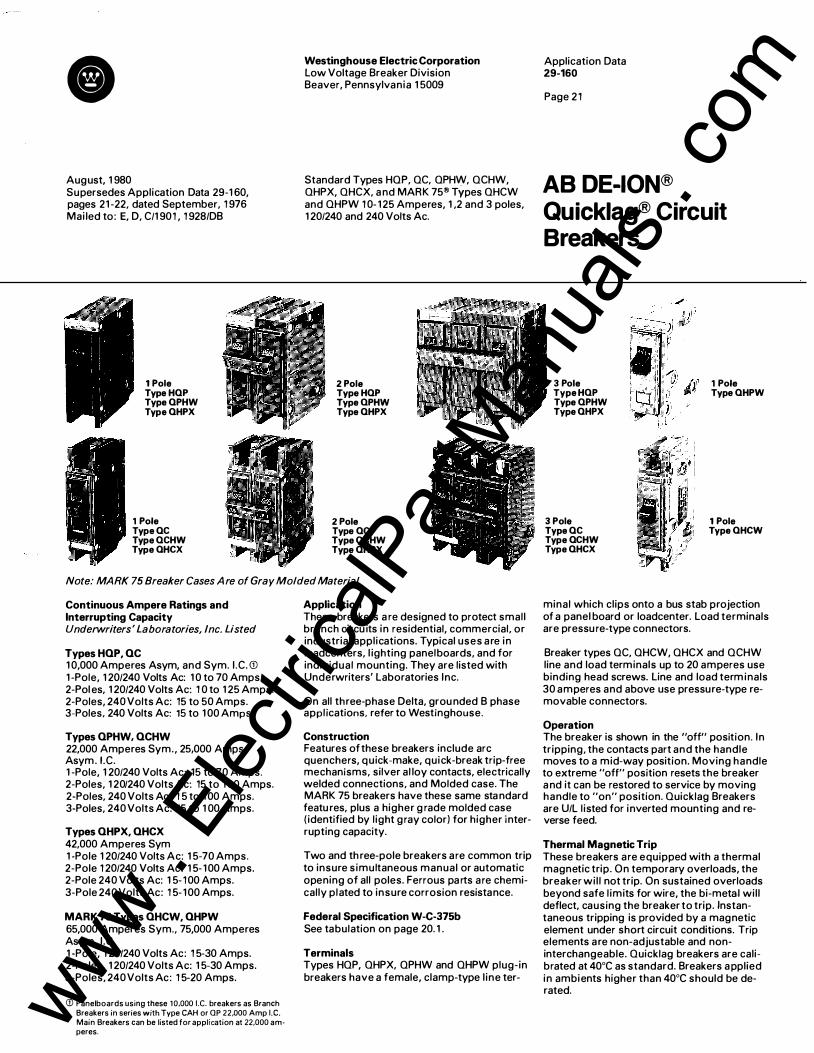
e August, 1 980 Supersedes Application Data 29-1 60, pages 21 -22, dated September, 1 976 Mai led to: E, D, C/1 901 , 1 928/DB
1 Pole Type HQP Type QPHW Type QHPX
1 Pole Type QC Type QCHW Type QHCX
Westinghouse Electric Corporation Low Voltage Breaker Division Beaver, Pennsylvania 1 5009
Standard Types HOP, OC, OPHW, OCHW, OHPX, OHCX, a nd MARK 75® Types OHCW and OHPW 1 0- 1 25 Amperes, 1 ,2 and 3 poles, 1 20/240 and 240 Volts Ac.
2 Pole Type HQP Type OPHW Type QHPX
2 Pole Type QC Type QCHW Type QHCX
Note: MARK 75 Breaker Cases A re of Gray Molded Material
Continuous Ampere Ratings and Interrupting Capacity Underwriters' Laboratories, Inc. Listed
Types HQP, QC 1 0,000 Amperes Asym, and Sym. I.C. G:l 1 -Pole, 1 20/240 Volts Ac: 1 0 to 70 Amps. 2-Pol es, 1 20/240 Volts Ac: 1 0 to 1 25 Amps. 2-Poles, 240 Volts Ac: 15 to 50 Amps. 3-Poles, 240 Volts Ac: 15 to 1 00 Amps.
Types QPHW, QCHW 22,000 Amperes Sym., 25,000 Amps Asym. I.C. 1 -Pole, 1 20/240 Volts Ac: 15 to 70 Amps. 2-Poles, 1 20/240 Volts Ac: 15 to 1 00 Amps. 2-Poles, 240 Volts Ac : 1 5 to 1 00 Amps. 3-Poles, 240 Volts Ac: 15 to 1 00 Amps.
Types QHPX, QHCX 42,000 Amperes Sym 1 -Pole 1 20/240 Volts Ac: 1 5-70 Amps. 2-Pole 1 20/240 Volts Ac: 1 5- 100 Amps. 2-Pole 240 Volts Ac: 1 5- 100 Amps. 3-Pole 240 Volts Ac: 1 5- 100 Amps.
MARK 75 Types QHCW, QHPW 65,000 Amperes Sym., 75,000 Amperes Asym. I.C. 1 -Pole, 1 20/240 Volts Ac: 1 5-30 Amps. 2-Poles, 1 20/240 Volts Ac: 1 5-30 Amps. 3-Poles, 240 Volts Ac: 1 5-20 Amps.
(j) Panel boards using these 10.000 I . C. breakers as Branch Breakers in series with Type CAH or Qp 22,000 Amp I.C. Main Breakers can be listed for application at 22.000 am· peres.
Application These breakers a re designed to protect small branch circu its in residential, commercial, or industrial applications. Typical uses are in loadcenters, l ighting panel boards, and for individual mounting. They are listed with Underwriters' Laboratories Inc.
On all three-phase Delta, grou nded B phase appl ications, refer to Westinghouse.
Construction Features of these breakers include arc quenchers, quick-make, quick-break trip-free mechanisms, silver al loy contacts, electrically welded connections, and Molded case. The MARK 75 breakers have these same sta ndard featu res, plus a higher g rade molded case ( identified by light gray color) for higher interrupting capacity.
Two and th ree-pole breakers are common trip to insure simultaneous manual or automatic opening of all poles. Ferrous pa rts are chemically plated to insure corrosion resistance.
Federal Specification W-C-375b See tabulation on page 20. 1 .
Terminals Types HOP, OHPX, OPHW and OHPW plug-in breakers have a female, clamp-type l ine ter-
Application Data 29-160
Page 2 1
AB DE-ION® Quicklag® Circuit Breakers
3 Pole Type HOP Type QPHW Type QHPX
3 Pole Type QC Type QCHW Type QHCX
1 Pole Type QHPW
1 Pole Type QHCW
minal which clips onto a bus stab projection of a panel board or loadcenter. Load terminals are pressu re-type connectors.
Breaker types OC, OHCW, OHCX and OCHW line and load terminals up to 20 amperes use binding head screws. Line and load term inals 30 amperes and above use pressure-type removable connectors.
Operation The breaker is shown in the "off" position. In tripping, the contacts part and the handle moves to a mid-way position. Moving handle to extreme "off" position resets the breaker a nd it can be restored to service by moving handle to "on" position. Ouicklag Breakers are U/L l isted for inverted mounting and reverse feed.
Thermal Magnetic Trip These breakers are equipped with a thermal magnetic trip. On temporary overloads, the breaker wil l not trip. On sustained overloads beyond safe l imits for wire, the bi-metal wil l deflect, causing the breaker to trip. Instantaneous tripping is provided by a magnetic element under short circuit conditions. Trip elements are non-adjustable and noninterchangeable. Ouicklag breakers are calibrated at 40°C as standard. Breakers a pplied in ambients higher than 40°C should be derated. www .
Elec
tricalP
artM
anua
ls . c
om

Application Data 29-160
Page 22
Typical Exploded View (Type P Plug-in Breaker Shown)
1 Pole Moving Contact
Cover
3 Pole
Base C over M o v i n g Contact
Cover Rivets Arc Ext inguisher B i-Metal Armature
Switching Neutral Breakers Types HQNPL and HOCL 10,000 A mps, I. C. Only
Switching neutral breaker is available in 2-pole, 15 and 20 a mpere ratings. Its application is gasol ine station dispensing pump circu its. Meets the requirements of NEC (Article 514-5); "Each circuit leading to or through a dispensing pump or island shall be provided with a switch or other acceptable means to disconnect simultaneously from the sou rce of supply al l conductors of the circuit including the grounded neutral, if a ny".
Switching Duty For switching duty requi rements for 1 20 Volts Ac fluorescent l ight applications, use type QPHW, HOP, QCHW, QC, QHPW, QHCW, QHPX and QHCX, 15 and 20 amperes 1 pole breakers only.
Breaker Mounting Types HQP, QHPX, QHPW, QPHW (Plug-in): The load end of the breaker is i nserted under
Armature Gas Vent
the mounting clamp of a panelboard and the l ine end is merely snapped into position over the bus stab.
Types QC, QHCW, QHCX, QCHW (Bolt-on) : The breaker is mounted in a panel board by inserting the load end u nder the mounting clamp and bolting the line end to bus connections. For independent mounting, face mounting plates are used for flush mounting the breakers. Base mounting plates can be used where the plates are mou nted i n a panel, in this method the breaker base snaps into l ine and load clips to hold it firm.
Circuit Breaker Removal Before inspecting, instal l ing or removi ng from a circuit, the circuit breaker should be in the "off" position, and if practicable, the circuit should be de-energized.
Inspection and Maintenance Good maintenance procedure cal ls for periodic i nspection of all electrical apparatus including molded case circuit breakers. Termi-
nal lugs must be tight to prevent overheating. Due to the inherent wiping action built into the moving contacts of a l l Westinghouse circu it breakers, operating the breaker several times u nder load will remove any high resistance fi l m that may have formed.
Accessories and Modifications Accessories and modifications avai lable include: lockdog, handle locks for use with padlock, moisture and fungus treatment, and handle ties for using two single-pole breakers for 1 201240 volt 2 wire operation. Handle ties assure simultaneous switching, but a l low either breaker to register i ndependent trip positions.
Further Information Prices: Price List 29-020 P WE A Ordering Data: Tech Data 29- 1 20 T WE A Dimensions: Dimension Sheet 29-170 Trip Curves: 29-161 A WE A
Dimensions, Inches® Not to be used for construction purposes. See Dimension Sheet 29- 170 for detailed dimensions.
Type HQP
c@ �+-----_,"� 32�
® 2-po\e breaker is 2" wide. 3-po\e is 3'' wide.
Type QC www . El
ectric
alPar
tMan
uals
. com

September, 1 976 Supersedes Application Data 29-1 60 al l previous issues. Mailed to: E, D, C/1 901 , 1 928/ D B
Interrupting Capacity: 1 0,000 Amps Sym. or Asym., and 22,000 Amps. Sym., 25,000 Amps Asym.
Sensitivity: 5 Mil l iamps or Greater
Westinghouse Quicklag Ground Fault circuit breakers are UL l isted as Class A, ground fault circuit interrupters.
Application Quicklag Ground Fault circuit breakers are normally used in Joadcenters or panel boards to protect small branch circuits in residential, commercial or industrial applications. They function to protect humans from ground faults of 5 mil l iamperes or greater, as well as normal circuit protection providing inverse time overload and instantaneous short circuit protection.
Typical applications include protection against ground fault hazards in circuits near swimming pools and outdoor receptacles for which the National Electric Code requires protection of human life against ground faults. ( Ref. N .E.C. articles 680-31 , 680-20, 680-6, and 2 1 0-8)
Construction Quicklag Ground Fault circuit breakers are 1 or 2 pole thermal magnetic circuit breakers which incorporate a solid state ground fault sensing circuit to detect ground current. Available as plug-in (Type P) or bolt-on (Type B) design, they are interchangeable in load centers or panelboards with standard Westinghouse Type P plug-in and Type B bolt-on quicklag breaker. The breaker features a quick- make, quick-break trip free operating mechanism, silver alloy contacts and welded connections.
The ground fault sensing circuit consists of a monitor, a solid state amplifier, and a shunt trip mechanism.
Federal Specification W-C-375b See tabulation on page 20.1 .
Terminals Type P plug-in design has a female.clamptype line terminal which plugs onto the bus stab of a panelboard or loadcenter.
Type B bolt-on design has an extended tang line terminal that bolts directly to the panelboard bus connecting strap.
Load terminals are pressure-type connectors suitable for use with either copper or aluminum wire. 1 5 to 2 5 ampere breakers accept
Westinghouse Electric Corporation Low Voltage Breaker Division Beaver, Pennsylvania 1 5009
Standard Types P and B 1 5-30 Amperes, 1 20 Volts Ac 1 Pole, 1 20/240 Volts Ac 2 Poles
ifi 1 4- !11 1 0 Cu or ifi 1 2- !fl 8 AI, and 30 ampere breakers accept ifi 1 4- ifi 4 Cu or !11 8- ifi 4 AI.
Installation The load end of the breaker is inserted under the mounting clamp of a panel board, and the line end is plugged onto the bus stab (or, in the case of bolt� on design, bolted to the bus connector strap) .
The load end on single pole breakers has two terminals and a white "pigtail" wire. Two wires from the 1 20 volt load to be protected are brought into the panel board and connected to the terminals. The black wire is
Shunt Trip
� Solid State Amplifier
I I I I I I Breaker I ,.--...
Hot- -120 Volt Line Source - Neutral -
r Ground Figure 1
29-1 60 A WE A Application Data
Page 23
AB DE-ION® Quicklag® Ground Fault Circuit Breakers
connected to the terminal marked Load, and the white wire connected to the terminal marked Load Neutral. (These wires are shown passing through the monitor in Figure 1 .) The "pigtail" is connected to the neutral bar in the panelboard.
Two pole breakers have three load terminals and a white pigtai l . The colored hot load wires are connected to the outside load terminals. The white neutral wire (if used) is connected to the center terminal, identified by a white mark. The pigtail is connected to the panel neutral.
'l � A Monitor
IV v I... �120Vo" Load
- 1 -=
Unintentiona I Ground Path Hazardous to Humans
www . El
ectric
alPar
tMan
uals
. com

29-1 60 A W E A Application Data
Page 24
O peration The Quicklag Ground Fault circuit breaker operates as any standard thermal magnetic breaker, providing protection against overloads and short circuits. The ground fault sensing circuit, Figure 1 , monitors current flow i n the load supply and return wires (which pass through the monitor) and opens the circuit when it senses a ground fault current of five mil l iamperes or greater.
Current flowing through a wire generates a magnetic field around the wire. Normally, at any one i nstant, the current flowing through the load supply and return wires are equal, and their magnetic fields cancel each other. Since there is no current imbalance, no current flows in the secondary winding of the monitor.
However, should an unintentional grounding of the load supply conductor occur, then an alternate path to the system ground would be established. The amount of fault current flowing depends upon the impedance (resistance) of the ground path. The resulting magnetic field, caused by the load supply current exceeding the load return current through the monitor, generates a voltage in the monitor causing current to flow in the secondary winding. This current imbalance is amplified and fed to the shunt trip, which trips the circuit breaker, opening the circuit to the load. After the ground fault condition has been corrected, the breaker is reset in the normal manner.
G round Fault C haracteristics The 5 mil liamp sensitivity rating offers adequate protection for human life, and minimizes unnecessary operation on small electrical i mpulses or leakage currents not dangerous to human life. The key to safety appears to be the amount of current an individual can withstand and yet be able to "let go". The 5 mil l iamp rating is below the known average "let go" current for both women and men.
The Westinghouse Ouicklag Ground Fault circuit breaker is U L l isted under Standard 943 as a class A, ground fault circuit interrupter, which is defined as a device that will trip when the fault current to ground is within the range of 5 through 264 mil l iamps. An inverse trip time which varies between 7.26 seconds at 5 MA and .024 seconds at 264 MA is specified.
I nspection and M a i ntenance Good maintenance procedure calls for periodic inspection of electrical apparatus. Underwriters· Laboratories. Inc. suggests that the device be checked monthly, and a test record card is provided for this purpose.
Use caution when inspecting or removing the breaker from the circuit, the breaker should be in the Off position and if practical, the circuit should be deenergized.
A test button provides for a check of the electrical system of the ground fault sensing
Di mensions, Inches.
circuit, and the mechanical operations of the breaker.
Terminal lugs must be tight to prevent overheating. Due to the inherent wiping action built into the moving contacts of all Westinghouse circuit breakers, operating the breaker several times under load will remove any high resistance fi lm that may have formed.
Further I n formation Prices: Price List 29-020 P W E A Ordering Data: Tech Data 29- 1 20 T WE A Dimensions: Dimension Sheet 29-1 70
Not to be used for construction purposes. See Dimension Sheet 29- 1 70 for detailed dimensions.
Plug-In Breakers
Front View ( 1 Pole)
r--, __,
W1re
Bolt-on Breakers
Front View ( 2 Pole) r--2 ·I
Front View ( 1 Pole) Front View ( 2 Pole)
9 32
9 32
Side View
Side View
rr � ll r-Fcsl2r&l �-=�-r��L-1-.�---r---,---------,----�
Panel _......---====--"""0 Neutral Wire
0
www . El
ectric
alPar
tMan
uals
. com

8 September, 1 976 Supersedes Application Data 29- 1 60 all previous issues. Mai led to: E, D, C/1 901 , 1 928/ D B
2 Pole
Westing house Electric Co rporation Low Voltage Breaker Division Beaver, Pennsylvania 1 5009
Standard Types BA, BAB and Ouicklag® Type OBH , and MARK 75® Type H BA 1 0-1 25 Amperes, 1 20/240, 240, 277 Volts Ac 1 , 2, 3 Poles
2 Pole
29-1 60 A WE A Appl ication Data
Page 25
AB DE-ION ®
Circuit Breakers
1 Pole Type BA (277 Volt)
1 Pole Type BAB Type BAB
1 20/240 Volt
1 Pole Type H BA, Type QBH
Type BA, (240 Volt) Type H BA,
3 Pole Type BA, Type H BA, Type QBH Type QBH
Note: MARK 75 Cases Are of Gray Molded Material.
Continuous Ampere Ratings and I nterrupti ng Capacities Underwriters' Laboratories, Inc. Listed
Types BAB, BA 1 0,000 Amperes Sym. or Asym. I . C.(!) 1 Pole, 1 20/240 Volts Ac: 1 0 to 70 Amperes 2 Poles, 1 20/240 Volts Ac: 1 0 to 1 25 Amperes 2 Poles, 240 Volts Ac: 1 5 to 50 Amperes 3 Poles, 240 Volts Ac: 1 5 to 1 00 Amperes 1 Pole, 277 Volts Ac: 1 5 to 30 Amperes
Quicklag Type O B H 22,000 Amperes Sym., 25,000 Amperes Asym. I .C. 1 Pole, 1 20/240 Volts Ac: 1 5 to 70 Amperes 2 Poles, 1 20/240 Volts Ac: 1 5 to 1 00 Amperes 2 Poles, 240 Volts Ac: 1 5 to 50 Amperes 3 Poles, 240 Volts Ac: 1 5 to 1 00 Amperes
Mark 75 Type H BA 65,000 Amperes Sym., 75,000 Amperes Asym. I .C. 1 Pole, 1 20/240 Volts Ac: 1 5-30 2 Pole, 1 20/240 Volts Ac: 1 5-30 3 Pole, 240 Volts Ac: 1 5-20
Applicat ion These circuit breakers are used primarily i n panel boards where a bolted l i n e terminal connection is required. Listed by Underwriters' Laboratories, Inc. On all three phase Delta, grounded B phase applications, refer to Westinghouse.
(j) Panel boards using these 1 0.000 I . C . breakers as branch breakers i n series with CAH or OBH 2 2,000 amp I . C. marn breakers can be l isted for appl ication at 2 2 .000 amps.
Construction Features of the Type BA, BAB & Ouicklag OBH Breakers include arc quencher, quickmake, quick-break trip free mechanism, silver a l loy contacts, electrically welded con nections, and a molded case. The MARK 75 Type H BA has a l l the standard features, plus a higher grade molded case (identified by l ight gray color) for h igher i nterrupting capacity. Two and three-pole breakers are common trip to i nsure s imultaneous manual or automatic opening of al l poles. Ferrous parts are chemically plated to insure corrosion resi�tance.
Federal Specification W-C-375b See tabulation on page 20. 1 .
Terminals Line terminals are provided i n the form of an extended tang which bolts d irectly to the panel board bus connecting strap. Load terr(linals are as follows:
Type BA 277 volt: Pressure Type. Type BA, H BA, Ouicklag OBH:
B inding head screw up to 30 amp and pressure type on h igher ratings.
Type BAB: Pressure Type
Thermal Magnetic Trip These breakers are equipped with a thermal magnetic trip. On temporary overloads, the breaker wil l not trip. On susta ined overloads beyond safe l imits for wire, the bimetal wi l l deflect, causing the breaker to trip. I nstan taneous tripping is provided by a magnetic
element u nder short circuit conditions. Trip elements are non-adjustable and noni nterchangeable. These breakers are cal ibrated at 40"C as standard. Breakers applied i n ambients h igher than 40"C should be derated.
Switching Neutral B reakers Type BA 1 0,000 Amps. I. C. On ly Switching neutral breaker is avai lable i n 2-pole, 15 and 20 ampere ratings. Its application is gasol ine station dispensing pump circuits. Meets the requirements of NEC (Article 51 4-5) ; "Each circuit leading to or through a dispensing pump or island sha l l be provided with a switch or other acceptable means to disconnect simultaneously from the source of supply al l conductors of the circuit i nc luding the grounded neutral, if any".
Delta B reakers Type BA 1 0,000 Amps. I. C. Only
Load Center Bus
Delta Breaker
Engineered for 3 -phase 4-wire 1 20/240 volt Ac delta applications which utilize 3 -phase motor circuits, such as air condition ing and heat pump applications. www .
Elec
tricalP
artM
anua
ls . c
om

29-1 60 A W E A Application Data
Page 26
Typical Exploded View 1 20/240, 240 Volt Ac Breakers
Po le Type BAB 3 Pole Typ e BA
M o v i n g C o n t a c t L i n e Term i n a l
Cover Operat ing H a n d l e . I M o v i n g C on ta c t C o v e r
A rc E x t i n g uisher Base M a g n e t A r m a t u re Arc E x t i n g u i s h e r A r m a t u re G a s Vent
O peratio n The breaker is shown i n the "OFF" position. In tripping, the contacts part and the handle moves to a mid-way position. Moving handle to extreme "OFF" position resets the breaker and it can be restored to service by moving handle to "ON" position. These breakers are UL I nc. Listed for inverted mounting and reverse feed.
Mounting The load end of the breaker is inserted under the mounting clamp of a panelboard and the l ine end is bolted to the bus connector strap.
Di mensions, I nches®
Circuit B reaker Removal Before inspecting, instal l ing, or removing from a circuit, the circuit breaker should be in the "OFF" position, and if practicable, the circuit should be de-energized.
Inspection and Maintenance Good maintenance procedure calls for periodic inspection of all electrical apparatus including molded case circuit breakers. Terminal lugs must be tight to prevent overheating. Due to the inherent wiping action built into the moving contacts of all Westinghouse circuit breakers, operating the breaker several times under load wil l remove any high resistance fi lm that may have formed.
Not to be used for construction purposes. See Dimension Sheet 29- 1 70 for detailed dimensions.
0
Type BA 277 Volt
® 2-pole breaker is 2" " wide, 3-pole is 3" wide.
Westing house Electric Corporation Low Voltage Breaker Division Beaver, Pennsylvania 1 5009
Type BAB
Accessories and M od ifications Accessories and modifications available in clude: l ockdog, handle locks for use with padlock, moisture and fungus treatment, and handle ties for using two single pole breakers for 1 20/240 volt 2 wire operation . H andle ties assure simultaneous switching, but al low either breaker to register independent trip positions.
Further Info rmation Prices: Price List 29-020 P WE A Ordering Data: Tech Data 29-1 20 T WE A Dimensions: D imension Sheet 29- 1 70 Trip Curves: Application Data 29- 1 61 A WE A
www . El
ectric
alPar
tMan
uals
. com

8 September, 1 976 Supersedes Application Data 29- 1 60 all previous issues. M ai led to: E, D, C/1 90 1 , 1 928/D B
Continuous Ampere Ratings Underwriters' Laboratories, Inc. Listed 1 25, 1 50, 1 75, 200 and 225 Amperes
I nterrupti ng Ratings, Amperes Underwriters' Laboratories, Inc. Listed Type CA: 1 0,000 Asym. and Sym. Type CAH: 25,000 Asym., 22,000 Sym.
Applicati o n CA and CAH AB De-ion@ circuit breakers are designed for protection of branch and feeder circuits in either commercial or industrial appl ications. Because of their high continuous ampere capacity and compact size, they are particularly well-suited for use as main protection in load centers, metering panels and l ighting panel boards. They are also suited for instal lation in distribution panelboards, motor control centers, control panels and separate enclosures where a 240 volt, 225 ampere frame breaker is required.
Listed with Underwriters' Laboratories, Inc. (Two pole breakers are l isted for grounded B phase appl ications.)
Federal S pecification W-C-375b See tabulation on page 20.1
Construction Type CA and CAH breakers have al l the standard AB circuit breaker features such as De- ion® arc extinguishers, and quick-make, quick-break, trip-free toggle mechanisms.
Type CAH breakers are the same size and have the same mounting dimensions as Type CA. However, the CAH breaker is constructed of stronger molded materia l , enabling them to have a higher I. C. Type CAH breakers are U L Listed for use ahead of 1 0,000 ampere I. C. Quicklag and BA breakers in panel boards to permit their appl ication at 22,000 ampere fault levels.
Two-pole breakers are supplied in a two- pole frame, 2% in . wide, three-pole breakers are suppl ied in a three-pole frame, 4% in. wide.
Term i nals Terminals are Underwriters' Laboratories, I nc. l isted for the wire type and size l isted below. When used with a luminum conductors, use joint compound.
M ax . Catalog Wire Range Breaker Number and Type Amps. 1 75 TA1 75CA1 !1 1 -4/0 Al/Cu 225 TA225CA1 2/0-300 M C M AI/Cu
Westinghouse Electric Corpo ratio n Low Voltage Breaker Division Beaver, Pennsylvania 1 5009
Types CA and CAH 1 25-225 Amperes, 240 Volts Ac, 2 and 3 Poles
Operation When the breaker contacts are open, the handle is i n either the mid or OFF position. If, in the mid-position, the breaker has been tripped automatically, the latch must be reset by moving the operating handle to the extreme OFF position before attempting to restore service. Contacts may be closed after resetting the latch, by moving the handle to the ON position. CA and CAH breakers may be mounted in an inverted position and are approved for reverse feed.<D The toggle handle operates with the following forces in pounds from the end of the handle: ON; 1 0 lbs.; OFF: 1 1 lbs.: R ESET: 21 lbs.
Thermal Magnetic B reaker Thermal magnetic breakers are equipped with thermal and magnetic trip elements to provide complete circuit protection against overloads and short circuits.
The thermal trip elements (bi metals) provide i nverse trip characteristics and are indirectly heated for longer overload time delay which is desirable in feeder circuits. On temporary overloads, the breaker wi l l not trip; but on sustained overloads beyond the safe l imits of the wire, the bimetal wil l deflect. causing the breaker to trip.
The magnetic trip element (electro- magnet) is set to trip the breaker instantaneously at currents of approximately 1 0 times the continuous rating of the breaker.
29-1 60 A WE A Application Data
Page 27
AB DE-ION® Circuit Breakers
Trip elements are non-adjustable and noninterchangeable.
M o lded Case Switches (Type CA only) ( Non-Automatic I nterrupters) These are breakers without overload or short circuit tripping elements. They can be instal led where a compact high capacity disconnect switch is required without overcurrent protection.
C i rcuit B reaker Removal Before inspecting, insta l l ing or removing from a circuit, the circuit breaker should be in the "off" position, and if practical, the circuit should be de-energized. If the circuit cannot be de-energized, insulated tools, rubber g loves and a rubber floor mat should be used.
To remove a front-connected circuit breaker from its mounting, loosen termina l screws and remove cables from termi nals. Remove circuit breaker mounting screws and pul l circuit breaker forward.
Inspection and Maintenance Good maintenance procedure cal ls for periodic inspection of all electrical apparatus including molded case circuit breakers. Termina l lugs must be tight to prevent over-
CD Breakers with i nternal attachments are not suitable for reverse feed. www .
Elec
tricalP
artM
anua
ls . c
om

29-1 60 A WE A Application Data
Page 28
Exploded View, Thermal Magnetic B reaker
heating. Due to the inherent wiping action built into the moving contacts of all Westinghouse circuit breakers, operating the breaker several times under load wil l remove any high resistance f i lm that may have formed.
It should be noted that removing the sealed cover of the type CA breaker voids the Underwriters' Laboratories, I nc., label.
Accessories Accessories include shunt trips, auxil iary switches, panelboard connectors for C D P panelboards and a padlockable handle lock for use with loadcenters or other applications where a face trim is used.
Further I nformation Prices: Price List 29-020 P WE A Ordering Data: Tech Data 29-1 20 T WE A D imensions: D imension Sheet 29- 1 70 Trip Curves: Application Data 29-1 61 A WE A
Westing house Electric Corporation Low Voltage Breaker D ivision Beaver, Pennsylvania 1 5009
Term i n a l M o u n t ing Sc rew C o n tact M o u n t i n g Sc rew
I Term i n a l -(
L i n e C o n t a ct -
Arc E x t i n g uisher Base
l nterpole Ba rr ier
l Barr ier
Dimensions, Inches Not to be used for construction purpose. See Dimension Sheet 29- 1 70 for detailed dimensions.
o@ g ®o o@ g @ g @o l J
rn 61 rn 61 ,..--2 2 ,'------
® � ® ® � @ � ® .
�2�--- 4 1 �� 8 316 2 Poles 3 Poles
'
www . El
ectric
alPar
tMan
uals
. com

8 September, 1 976 Supersedes Application Data 29- 1 60 all previous issues. M ailed to: E, D, C/1 901 , 1 928/ D B
Contin uous Ampere Ratings Underwriters' Laboratories, Inc. Listed 250, 300, 350 and 400 Amperes
Interrupting Ratings, Amperes Underwriters' Laboratories, Inc. Listed 240 Volts Ac: 25,000 Asym., 22,000 Sym. 250 Volts De: 1 0,000
Application Type DA breakers are designed to provide overload and short circuit protection for branch and feeder circuits in either commercial or industrial installations. Because of their high continuous ampere capacity and compact size, they are particularly well�suited for use as main protection in load centers, metering panels and l ighting panels. They are also ideally suited for installation in switchboards, panel boards, motor control centers, control panels and separate enclosures where a 240 volt, 400 amp frame size breaker is required.
Listed with Underwriters' Laboratories, Inc.
On al l three phase Delta, grounded B phase applications, refer to Westinghouse.
Federal S pecification W-C-375b See tabulation on page 20.1 .
Construction Type DA breakers have all the standard AB breaker features.
In addition to the standard features, the molded case is made of glass polyester, giving the breaker greater strength and resistance to tracking.
Two and three pole breakers are supplied in one frame size; the current carrying parts being omitted from the center pole for two pole breakers.
Termi nals Terminals are Underwriters' Laboratories, I nc. l isted for the wire type and size l isted below. When used with a luminum conductors, use joint compound.
Max. Catalog Breaker Number Amps.
Wire Range, Type No. of Cables
Standard Terminals (for Copper cable) 350 T350DA 1 250-500 MCM Cu 400 T400DA2 2 3/0-250 MCM Cu
Alternate Aluminum Body Terminals 350 TA350DA 1 250-500 MCM AI/Cu 400 TA400DA1 2 3/0-250 MCM AI1Cu
Terminal mounting arrangement permits
(J) Inc ludes use With standard i nternal attachments except auxil iary switches with 2A-2 B contacts.
Westing house Electric Corporation Low Voltage Breaker D ivision Beaver, Pennsylvania 1 5009
Type DA 250-400 Amperes, 240 Volts Ac, 250 Volts De, 2 and 3 Poles
ready use of other circuit connecting means such as rear connecting studs, panel board connectors and plug- in adaptor kits.
O peration When the breaker contacts are open the handle is in either the mid or OFF position . If i n the mid-position the breaker has been tripped automatically. The latch must be reset by moving the operating handle to the extreme OFF position before attempting to restore service. Contacts may be closed, after resetting the latch, by moving the handle to the ON position. DA breakers may be mounted in an inverted position and are approved for reverse feed.<D The toggle handle operates with the following forces in pounds from the end of the handle: ON - 24 lbs; OFF - 1 0 lbs; R ESET - 1 5 lbs.
Thermal M ag netic Breakers Thermal magnetic breakers are equipped with thermal and magnetic trip elements to provide overload and short circuit protection. The thermal element (bimetal) is indirectly heated to offer a longer overload time delay desirable for feeder circuits. The magnetic element (electro-magnet) is fixed (non-adjustable) and is set to trip the breaker instantaneously at currents of approximately 1 0 times the continuous rating of the breaker.
Trip elements are non- interchangeable.
29-1 60 A WE A Application Data
Page 29
AB DE-ION® Circuit Breakers
Motded Case Switches ( N on-Automatic Interrupters) DA breakers with non-automatic details (latch bracket and bridging strap) can be installed where a heavy-duty, high capacity disconnect switch is required without overcurrent protection. Accessories, such as shunt trip, undervoltage, etc., cannot be field mounted in non-automatic breakers as a dummy trip is required for mounting. Accessories can be mounted if specified when breaker is ordered.
Circuit Breaker Removal Before inspecting, instal l ing, or removing from a circuit, the circuit breaker should be in the OFF position, and if practical the circuit should be de-energized. If the circuit cannot be de-energized insulated tools, rubber gloves and a rubber floor mat should be used.
To remove a front-connected circuit breaker from its mounting, loosen screws in terminal lugs and remove cables from termina ls. Remove circuit breaker mounting screws and pull circuit breaker forward. To remove a rear-connected circuit breaker from its mounting, remove terminal stud locknuts and pull circuit breaker forward. To remove a circuit breaker equipped with plug- in mounting blocks from its mounting, remove breaker mounting screws and pul l circuit breaker forward. www .
Elec
tricalP
artM
anua
ls . c
om

29-1 60 A WE A Application Data
Page 30
Exploded View. Thermal M ag netic Breaker
C over
Termina l Lug Assembly C ontact M ount ing Sc rew
I Arc E xt ingu isher f) I
I Base
Stationary C ontact Assembly
Operating H a n dle C over M o u nt ing Screws
I nspection and M a i ntenance Good maintenance procedure cal ls for periodic i nspection of all electrical apparatus including molded case circuit breakers.
Terminal and trip element connections must be tight to prevent overheating. Due to the i nherent wiping action built into the moving contacts of all Westinghouse circuit breakers. operating the breaker several times under load will remove any high resistance film that may have formed. Under normal conditions, additional cleaning of contacts is not required. However, should operating and/or atmospheric conditions make it desirable to clean the contacts further, the following procedure is recommended:
1 . Remove cover, arc extinguishers and stationary contact assemblies.
2. Wipe contact surfaces with a clean cloth d ipped in a chlorinated solvent. I f surfaces are excessively oxidized or corroded, scrape l ightly with a fine file before wiping.
I t should be noted that removing the sealed cover of the type DA breaker voids the U nderwriters' Laboratories, I nc., label.
Termina l L u g Assem bly
Accessories and M od i fi cations Accessories and modifications available for use with DA breakers include:
Alarm switch
Auxiliary switch
Shunt trip
Undervoltage release
Line terminal shields
Plug- in adaptor kits
Rear connecting studs
Center studs
Mechanical interlocks
Panelboard connectors
Paralleling straps
M otor operators
Handle locking devices
Moisture and fungus treatment
D i mensions. Inches® Not to be used for construction purposes. See Dimension Sheet 29- 1 70 for detailed dimensions. eOo0o01Tn
a a � •oi
�
�
I l !Oo 0o0o• L5�� �4��=:J l+----41�
2 16
® 2-pole breakers are supplied in 3-pole frames with center pole parts removed.
Further I n formatio n Prices: Price List 29-020 P WE A Ordering Data: Tech Data 29- 1 20 T WE A Dimensions: D imension Sheet 29-1 70 Trip Curves: Application Data 29- 1 61 A WE A
www . El
ectric
alPar
tMan
uals
. com

8 September, 1 976 Supersedes Application Data 29-1 60 al l previous issues. Mailed to: E, D, C/1 901 , 1 928/ D B
Contin uous Ampere Ratings Underwriters' Laboratories, Inc. Listed
Type E B 1 Pole, 1 20 Volts Ac, 1 25 Volts De: 1 5- 1 00 2, 3 Poles, 240 Volts Ac, 1 25/250 Volts De:
1 5- 1 00
Type E H B 1 Pole, 277 Volts Ac, 1 25 Volts De: 1 5- 1 00 2 Poles, 480 Volts Ac, 250 Volts De: 1 5- 1 00 3 Poles, 480 Volts Ac: 1 5- 1 00
Type FB 2 Poles, 600 Volts Ac, 250 Volts De: 1 5- 1 50 3, 4 Poles, 600 Volts Ac: 1 5 - 1 50
M A R K 75 Type H F B 1 Pole, 277 Volts Ac, 1 25 Volts De: 1 5- 1 00 2 Poles, 600 Volts Ac, 250 Volts De: 1 5- 1 50 3 Poles, 600 Volts Ac: 1 5- 1 50
I nterruptin g Ratings, Amperes Underwriters' Laboratories, Inc. Listed
Type E B : 1 20, 240 Volts Ac: 1 0,000 (Asym. and Sym.) 1 20/250 Volts De: 5,000
Type E H B : 240 Volts Ac: 20,000 Asym., 1 8,000 Sym. 277 Volts Ac: 1 5,000 Asym., 1 4,000 Sym. 480 Volts Ac: 1 5,000 Asym., 1 4,000 Sym. 250 Volts De: 1 0,000
Type F B : 240 Volts Ac: 20,000 Asym., 1 8,000 Sym. 480 Volts Ac: 1 5,000 Asym., 1 4,000 Sym. 600 Volts Ac: 1 5,000 Asym., 1 4,000 Sym. 250 Volts De: 1 0,000
M A R K 75 Type H F B 240 Volts Ac: 75,000 Asym., 65,000 Sym.® 480 Volts Ac: 30,000 Asym., 25,000 Sym. 600 Volts Ac: 20,000 Asym., 1 8,000 Sym. 250 Volts De: 20,000®
Application These breakers are designed for use in control panels, convertible power panel boards, switchboards, motor control centers, l ighting panels, bus duct plug- ins, ind ividual enclosures and machine tool control panels. This breaker is used most frequently on motor branch circuits because its ratings cover most protective requirements. These breakers are listed with the Underwriters' Laboratories, I nc.
On all three phase Delta, grounded B phase applications, refer to Westinghouse.
Westin g house Electric Corporation Low Voltage Breaker D ivision Beaver, Pennsylvania 1 5009
Standard Types EB, EH B, FB, and MARK 75® Type H FB 1 5- 1 00 Amperes, 1 , 2, 3 Poles; 1 5- 1 50 Amperes 2, 3, 4 Poles
EB H F B EHB 1 Pole 1 Pole 2 Poles
Construction These breakers have all the standard AB breaker features. The H FB breaker molded material is a high impact, high tensile, flame resistant g lass polyester, six times stronger and 21 times more resistant to tracking than the standard black moldarta.
Federal Specification W - C-375b See tabulation on page 20.1 .
Terminals Thermal magnetic breakers include load terminals only, Underwriters' Laboratories, Inc . listed for wire sizes and ranges listed below. Line terminals are available if required. When used with aluminum conductors, use joint compound.
Max. Breaker Amps .
Wire Type
Standard Pressure Terminals 20 (EB, EHB) AI/Cu
1 00 AI/Cu 1 50 AI/Cu
Optional AI/Cu Pressure Terminals . 50 AI/Cu
1 00 AI/Cu
Wire Range
i11 1 4- iii 1 0 # 1 4- 1 /0 11 4-4/0
J!I 1 4- J!I 4 11 4-4/0
Removable terminal collar permits ready use of rear connected studs; p lug- in adapter kits, or panel board connector straps.
O peration When the breaker contacts are open, the handle is in either the mid or OFF position.
If i n mid-position, the breaker has been tripped automatically and the latch must be reset by moving the operating handle to the extreme OFF position before attempting to restore to service. Contacts may be closed, after resetting the latch, by moving the handle to the ON position.
29-1 60 A WE A Application Data
Page 31
AB DE-ION® Circuit Breakers
FB H F B 3 Poles 3 Poles
Pounds of force required to operate toggle handle:
Breaker Amps.
U p to 1 00 1 25, 1 50
On
1 5.5 25.5
Off
3.75 6.5
Thermal Magnetic Breakers
Relatch
6.5 9.5
EB, EH B, FB and H FB frame breakers are equipped with cooperative thermal magnetic trip elements. On low overloads, the bimetal in itiates tripping action. On short circuits, the magnetic element instantly opens the circuit. On high overloads, the bimetal, gradual ly bending, assists magnetic tripping by shortening the air gap. After calibration, breaker cases are sealed to prevent tampering; thus trip elements are not adjustable and are not interchangeable.
Magnetic O n ly B reakers (FB , H FB)® Front adjustable magnetic on ly circuit breakers are instantaneous trip devices providing short circuit protection on ly. They are normally used in conjunction with additional overcurrent protection.
Trip un its are cal ibrated and set at the factory on the high value of the trip range, but may be field-adjusted to the low value. The trip setting may be changed by turning the
® 1 pole breakers are rated at 277 volts Ac with an interrupting rating of 75.000 amps. Asym .. 65.000 amps. Sym. for 1 5-30 amps; and 30.000 amps. Asym . . 2 5.000 amps. Sym. for 40-1 00 amps.
@ Not UL I nc. Listed. ® Ratings above 1 0.000 amps not UL Listed.
www . El
ectric
alPar
tMan
uals
. com

29-1 60 A WE A Application Data
Page 32
Exploded View, Thermal M agnetic B reaker
B reilker Mounti ng Screw
I Cover Screw Cover
adjusting knob in the front cover of the breaker. The adjustment is designed to follow a l inear scale, so that each of the settings provided has a defin ite ampere significance within cal i bration tolerances.
Magnetic Trip Range and Settings Setting Continuous Ampere Rating
3 5 1 0 25 25 30 3 0
Low 7 1 5 3 5 32 66 5 0 9 0 High 22 4 5 1 1 0 8 0 1 90 1 50 270
Setting Continuous Ampere Rating
50 50 70 1 00 1 00 1 50
Low 66 1 60 1 00 1 50 450 575 High 1 90 480 270 480 1 550 1 800
Saf-T-Vue B reakers ( Except H FB)® Saf-T-Vue breakers are simi lar to standard breakers except that the cover is fitted with a transparent window located over the breaker contacts. They are commonly used in steel mi l l applications where sight of contacts is required. Can be supplied in al l standard ratings.
Molded Case Switches ( Except H FB) ( Non-Auto I nterrupters) These are breakers without overload or short circuit tripping elements and can be i nsta l led where a compact high capacity disconnect switch is required without overcurrent protection .
M i ning Service B reakers® A special version of FB and H FB breakers is available to meet B ureau of M ines requirements for trai l i ng cable applications. Refer to Technical Data 29- 1 28 T WE A.
B reaker Mounting Breakers are approved for either upside down mounting or reverse feed.®
Westing house Electric Corporation Low Voltage B reaker Division Beaver, Pennsylvania 1 5009
O p e r il t i ng Te r m inal Mountmg Screw Arc E x t mgu1sher Mounting Screw H n n cl l e A r c E xt i ngu1s h e r
Li n e B a r r i e r
I B ase I �
Te r m i n a l
C i rcuit Breaker Removal Before inspecting, i nstal l i ng, or removing from a circuit, the circuit breaker should be in the OFF position, and if practical, the circuit should be de-energized. If the circuit cannot be de-energized, i nsulated tools, rubber gloves, and a rubber floor mat should be used.
To remove a rear-connected circuit breaker from its mounting, remove termina l stud lockn uts and pull circuit breaker forward.
To remove a front-connected circuit breaker from its mounting, loosen terminal screws and remove cables from terminals. Remove circuit breaker mounting screws and pull circuit breaker forward.
To remove a circuit breaker equipped with support blocks from its mounting, remove support block breaker mounting screws and pul l circuit breaker forward. When the optional bolt-on support block feature is used, the screws mounting the stabs to the breaker conductor must also be removed.
Inspection and Mai ntenance Good maintenance procedure cal l s for periodic i nspection of all electrical apparatus i ncluding molded case circuit breakers. Termina l lugs must be tight to prevent overheating. Due to the i nherent wiping action bui lt i nto the moving contacts of all Westinghouse circuit breakers, operating the breaker several times under load wil l remove any high resistance fi lm that may have formed.
® Not Underwnters" Laboratories. I nc. listed. @ 1 pole breakers are 1 %"" wide. 2 pole breakers are 2%"'
wide. except 2 pole FB magnetic on ly, and all 2 pole H FB which are the same as 3 pole. 4 pole FB breakers are 5Yz" wide; other dimensions are same as 3 pole.
@ Breakers with i nternal attachments are not suitable for reverse feed.
Accessories, Mod ifications Accessories and modifications are ava i lable as follows: See PL 29-1 20 or DB 29-1 50 for description. L ine termina l shields. rear connecting studs, pl ug- in adapter kits. panelboard connectors. center studs, handle locking devices. parallel connectors. moisture and fungus treatment, shunt trip. u ndervoltage release, auxi l iary switch, alarm switch, mechanica l i nterlocks, and motor operator.
D i mensions, Inches® Not to be used for construction purposes. See Dimension Sheet 29- 1 70 for detailed dimensions.
n 6
r-,..__
l
11
II
l--3� � Further Information Prices: Price List 29-020 P WE A Ordering Data: Tech Data 29- 1 20 T WE A D imensions: D imension Sheet 29- 1 70 Trip Curves: Application Data 29- 1 61 A WE A
www . El
ectric
alPar
tMan
uals
. com

September, 1 976 Supersedes Application Data 29- 1 60 all previous issues. Mai led to: E, D, C/1 901 , 1 928/ D B
Underwriter's Laboratories, Inc. Listed Interrupting R atings® U p to 600 Volts Ac: 200,000 Amperes Sym.
Application Type LFB Current Limiter is an attachment for use with the standard type FB B reaker to increase the interrupting capacity to 200,000 amps symmetrical at up to 600 volts Ac. These l imiters are so coordinated that over currents, low magnitude faults and normal short circuits are cleared by the breaker. Only abnormal short circuits are cleared by the current l imiting device. Thus, it can be seen that unless a severe short circuit occurs, the current l imiter is unaffected and its replacement is held to a minimum.
Breakers with the current l imiter are only a little larger than a standard molded case breaker. They can be applied as main breakers and for the protection of branch and feeder circuits and connected apparatus. They are suitable for use in switchboards control centers, combination starters, bus duct plug-in devices and also as separately enclosed breakers, when the calculated fault current exceeds the interrupting ratings of standard molded case breakers.
Construction The Type LFB current l imiter is a three-pole block containing three current l imiters and is designed to bolt directly to the load end of the FB breaker without special mounting blocks, clips, or hardware. The l imiter is designed to prevent instal l ing a higher rating l imiter than recommended on a lower rating breaker.
Each pole of the l imiter has an indicator plunger assembly which extends when that pole opens on a fault.
The l imiter is supplied with pressure type terminals suitable for copper or aluminum cable® three through 70 amp units accommodate 11 1 4 to 11 2 cable, 90 through 1 50 amp units accommodate 11 1 -4/0 cable. These l imiters are sealed units to prevent tampering and the elements cannot be replaced with non- l imiting ones. Faults high enough to open a l imiter wil l also trip the breaker, preventing single phase operation.
Accessories and Modifications Most of the standard breaker modifications and accessories can be used with the breaker/ l imiter combination.
Westing house Electric Corporation Low Voltage Breaker Division Beaver, Pennsylvania 1 5009
Type LFB Current Limiter 5 - 1 50 Amperes, 600 Volts Ac, 3 Poles Only
O peration When the breaker contacts are open the handle is in either the mid or "off" position. If in the mid-position the breaker has been tripped automatically and the latch must be reset by moving the operating handle to the extreme off position before attempting to restore to service. Contacts may be closed, after resetting the latch, by moving the handle to the "ON" position.
Tripped status of the breaker is shown by the center handle "trip" position. In addition the cause of tripping is also indicated in the following ways:
( 1 ) If after tripping the breaker cannot be reset immediately, thermal tripping due to an overload or a high resistance fault is i ndicated.
(2) If the breaker can be immediately reset a "normal" fault current has been interrupted by instantaneous magnetic action or a high fault has been i nterrupted by the l imiter also tripping the breaker magnetically. In the latter case, one or more of the plungers on the l imiter will protrude, giving indication that the l imiter is open, and must be replaced. Replacement l imiters are available from Westinghouse.
® Limiters for use with magnetic only breakers are not l isted with Underwriters Laboratories. Inc.
® Limiters 70 amperes and below can be supplied with terminals for copper cable on ly. Order similar to standard un its and specify.
29-1 60 A WE A Application Data
Page 33
AB DE-ION® Circuit Breakers
Characteristic Tripping Curves ( See App. Data 29- 1 61 A WE A) Characteristic tripping curves present a complete picture of the operation of an FB breaker with current limiter and point out the coordination between the thermal, magnetic, and current l imiting actions. For thermal magnetic breakers, a curve of the l imiters only is provided for use with standard F B breaker curves. For magnetic only breakers, a family curve is presented showing the average characteristic for each rating and the
· current l imiters. The tolerance of the magnetic only breaker curve is ±25% on the low setting, and ± 1 0% on the high setting.
The point at which the current l imiter curve crosses the lower portion of the breaker characteristic curve is called the "cross-over point" and the magnitude of the short circuit current at this point is called the "cross-over current". At values of current less than the crossover current the breaker will interrupt the fault without operation of the current l imiter. At values of current greater than crossover current the current l imiter wil l clear the fault.
I t is the general practice, however, to spec-ify the cross-over current for a particular current l imiter as the magnitude of current which wil l cause the l imiter to clear the fault.
The current l imiters are not seriously affected by the breaker interrupting faults of lesser values than indicated by the cross-over currents. www .
Elec
tricalP
artM
anua
ls . c
om

Page 34
P rotection of Con nected Apparatus Although greatly restra in ing the magnitude of fault currents, the current l imiters must necessarily allow some current to pass for a short period of time in order to cause it to function. Figure A il lustrates the operating characteristic of the current l imiter.
Figure A ,,
... ,--...... ,, /' \
/ \ -,-----J,'.... \ \
\ \ \ \ \ \ \ \ \
Ia: Available Peak Current Tm: Melting Time l m: Current at Melting Time lp: Peak Let-thru Current Ta: Arcing Time Tc: Total Interrupting (clearing) Time
For proper coordination and protection, the l imiters must be matched to the breaker rating as follows:
Thermal M ag netic B reakers Amperes Limiter Used
1 5-70 90- 1 50
LFB3070R LFB31 50R
Thermal magnetic breakers with l imiters provide protection for other 1 00 amp frame thermal magnetic® breakers in the circuit as follows:
Limiter Cat. No.
LFB3070R LFB31 50R
Wil l Protect These Ratings of Quicklag® EB, E H B, FB, H FB
1 5 to 70 Amp 50 to 1 50 Amp
Magnetic O n ly B reakers Cont. Amperes Limited Used
3 5
1 0 25 30 50 70
1 00 1 50
LFB3003M R LFB3005M R LFB301 0 M R LFB3025M R LFB3030M R LFB3050 M R LFB3070 M R LFB31 00M R LFB31 50M R
Magnetic only breakers with l imiters will protect other breakers (thermal magnetic or magnetic only) with a continuous rating equal to or greater than magnetic only breaker when appl ied per the table above.
Proper coordination provides: 1 . Maximum protection 2. Min imum let-through energy during short
circuits 3. El iminates nu isance functioning of the
l im iter 4. Util izes the breaker for the majority of
faults
O perating Data Tables I through V I I have been prepared from actual test data of bolted faults on the load side of FB breakers with current l imiter i n stallations made on basis of these tables allow a margin of safety because any addi tional apparatus inserted into the distribution system further l imits the short circuit current.
It can be seen from the tables that with a current l imiter system, fault currents are l imited before reaching possible peak currents. This action reduces the Jet-through currents and thus reduces substantially the thermal and magnetic stresses. As a result, bracing of conductors for maximum available currents is not necessary.
Under short circuit conditions, any failure of apparatus will be due to excessive magnetic or thermal stresses. M agnetic stress is proportional to the product of the peak currents in two adjacent conductors. Thermal stress is proportional to the square of the rms letthrough current multiplied by time ( 12t). When the thermal and magnetic capabilities of the connected apparatus are known, then the data in the tables can be used i n designing complete systems.
® See l ist ing below for protection of magnetic only breakers.
Table 1 : 3 or 5 Amp FB Mag netic O n l y Breaker With Lim iters, LFB3003 M R or LF B3005 M R
Available System Currents
Average 3 Phase Symmetrical R M S Amps
1 0,000 20,000 30,000 40,000 50,000 60,000 70,000 80,000 90,000
1 00,000 200,000
Power Factor %
25 25 1 5 1 5 1 5
8.5 8.5 8.5 8.5 8.5 8.5
Max. Peak Amps
20,400 40,800 68,700 91 ,600
1 1 4,500 1 50,000 1 75,000 200,000 225,000 250,000 500,000
Breaker with Limiter Operational Data 12t of Max. Phase X 1 06
.01
.01 5
.01 5
.01 3
.01 2
.01 3
.01 4
.01 5
.01 7
.020
.020
Max. Peak Letthru Amps
2500 3000 3000 3000 3000 3000 3000 3000 3000 3000 3000
Ta ble I I : 1 0 Amp FB Mag netic O n ly Breaker With Limiter LFB301 0 M R
Available System Currents
Average 3 Phase Symmetrical RMS Amps
1 0,000 20,000 30,000 40,000 50,000 60,000 70,000 80,000 90,000
1 00,000 200,000
Power Factor, %
25 25 1 5 1 5 1 5
8.5 8.5 8.5 8.5 8.5 8.5
Max. Peak Amps
20.400 40,800 68,700 91 ,600
1 1 4,000 1 50,000 1 75,000 200,000 225,000 250,000 500,000
Breaker with Limiter Operational Data r>t of Max. Max. Peak Phase Let-x 1 06 thru
.024
.036
.030
.024
.01 8
.01 8
.01 8
.01 8
.01 8
.01 8
.042
Amps
4000 4800 5600 5600 6400 6400 6400 7200 7200 7200 8000
Table I l l 25 or 30 A m p FB M ag netic O n ly B reaker With Limiter LFB3025 M R o r LFB3030 M R
Available System Currents
Average 3 Phase Symmetrical R M S Amps
1 0,000 20,000 30,000 40,000 50,000 60,000 70,000 80,000 90,000
1 00,000 200,000
Power Factor, %
25 25 1 5 1 5 1 5
8.5 8.5 8.5 8.5 8.5 8.5
Max. Peak Amps
20,400 40,800 68,700 91 ,600
1 1 4,500 1 50,000 1 75,000 200,000 225,000 250,000 500,000
Breaker with Limiter Operational Data r>t of Max. Phase X 1 06
.06
.06
.05
.05
.05
.06
.06
.07
.09
. 1 0
.1 0
Max. Peak Letthru Amps
7000 8000 8000 9000
1 0000 1 0000 1 0000 1 1 000 1 1 000 1 1 000 1 1 000
www . El
ectric
alPar
tMan
uals
. com

Table IV: 50 Amp F B M ag netic Only B reaker With Limiter LFB3050 M R Available System Currents
Average 3 Phase Symmetrical RMS Amps
1 0,000 20.000 30,000 40,000 50,000 60,000 70,000 80,000 90,000
1 00,000 200,000
Power Factor, %
25 25 1 5 1 5 1 5
8.5 8.5 8.5 8.5 8.5 8.5
Breaker with Limiter Operational Data
Max. Peak Amps
12t of Max. Max. Peak Phase Let-x 1 06 thru
20,400 . 1 6 40,800 .25 68,700 .22 91 ,600 .20
1 1 4,500 .1 7 1 50,000 .1 9 1 75,000 .20 200,000 .22 225,000 .24 250,000 .25 500,000 .25
Amps
1 0,000 1 3,000 1 3,000 1 4,000 1 4,000 1 4,000 1 4,000 1 4,000 1 5,000 1 5,000 1 7,000
Table V: 70 Amp FB M ag netic O n ly With Limiter LFB3070M R, or 1 5 to 70 Amp FB Thermal M ag netic Breaker With Limiter LFB3070R Available System Currents
Average 3 Phase Symmetrical RMS Amps
1 0,000 20,000 30,000 40,000 50,000 60,000 70,000 80,000 90,000
1 00,000 200,000
Power Factor, %
25 25 1 5 1 5 1 5
8.5 8.5 8.5 8.5 8.5 8.5
Breaker with Limiter Operational Data
Max. Peak Amps
12t of Max. Max. Peak Phase Let-x 1 06 thru
20,400 .50 40,800 .35 68,700 .35 91 ,600 .40
1 1 4,500 .40 1 50,000 .40 1 75,000 .40 200,000 .35 226,000 .35 250,000 .35 500,000 .35
Amps
1 3,000 1 5.000 1 6,000 1 6,000 1 7,000 1 8,000 1 8,000 1 9,000 1 9,000 20,000 22.000
Table VI: 1 00 Amp FB M ag netic Only B reaker With Limiter LFB31 00 M R Available System Currents
Average 3 Phase Symmetrical RMS Amps
1 0,000 20,000 30,000 40,000 50,000 60,000 70,000 80,000 90,000
1 00,000 200,000
Power Factor, %
25 25 1 5 1 5 1 5
8.5 8.5 8.5 8.5 8.5 8.5
Breaker with Limiter Operational Data
Max. Peak Amps
121 of Max. Max. Peak Phase Let-x 1 06 thru
20.400 .50 40,800 .70 68,700 .60 91 ,600 .60
1 1 4,500 .50 1 50,000 .55 1 75,000 .60 200,000 .60 225,000 .60 250,000 .70 500,000 .70
Amps
1 5,000 20.000 21 ,000 21 ,000 22,000 22,000 23,000 23,000 24,000 25,000 25,000
Table VII : 1 50 Amp F B Mag netic Only B reaker With Limiter LF B31 50M R or 90-1 50 Amp F B Thermal Mag netic Breaker With Limiter LFB31 50R
Available System Currents
Average 3 Phase Symmetrical RMS Amps
1 0,000 20,000 30,000 40,000 50,000 60,000 70,000 80,000 90,000
1 00,000 200,000
Power Factor, %
25 25 1 5 1 5 1 5
8.5 8.5 8.5 8.5 8.5 8.5
Max. Peak Amps
20,400 40,800 68,700 91 ,600
1 1 4,500 1 50,000 1 75,000 200,000 225,000 250,000 500,000
Breaker with Limiter Operational Data
12t of Max. Max. Peak Phase Let· X 1 06 thrU
.50
.70
.60
.60
.50
.55
.60
.60
.60
.70
.70
Amps
1 5,000 20,000 21 ,000 22,000 23,000 25,000 25,000 26,000 27,000 28,000 30,000
Outline Dimensions, Inches
(Not to be used for construction purposes unless approved.)
29-1 60 A WE A Application Data
Page 35
Further Information Prices: Price List 29-020 P WE A Ordering Data: Tech. Data 29-1 20 T WE A Dimensions: D imension Sheet 29-1 70 Trip Curves: Application Data 29- 1 61 A WE A
www . El
ectric
alPar
tMan
uals
. com

29-1 60 A W E A Application Data
Page 36
We stinghou se Elec tric Corpora tion Low Voltage Breaker D ivision Beaver, Pennsylvania 1 5009
www . El
ectric
alPar
tMan
uals
. com

November, 1981 Supersedes Appl ication Data 29-1 60, pages 37-38, dated September, 1976 Mailed to : E, D, C/190 1 , 1928/DB
Continuous Ampere Ratings Underwriters' Laboratories, I nc. Listed 70, 90, 1 00, 1 25, 1 50, 1 75, 200, 225, 250
Interrupting Ratings. Amperes Underwriters' Laboratories, I nc. Listed
Types JB and KB 240 Volts Ac: 30,000 Asym., 25,000 Sym. 480 Volts Ac : 25,000 Asym., 22,000 Sym. 600 Volts Ac: 1 5,000 Asym.,$ 1 4,000 Sym . $ 250 Volts Dc: 10,000
MARK 75 Type H KB 240 Volts Ac: 75,000 Asym., 65,000 Sym. 480 Volts Ac: 30,000 Asym., 25,000 Sym. 600 Volts Ac: 20,000 Asym.,$ 1 8,000 Sym . $ 250 Volts De : 20,000@
Application These breakers are designed for the protection of branch and feeder circuits. Being of compact size, they are ideally suited for use in control panels, panelboards, switchboards or separate enclosures where a 250 ampere frame size breaker is required.
MARK 75 Type HKB Brea!<ers, because of their higher interrupting capacity, are ideally suited for use in network systems where unusually high fault currents are available.
Listed with Underwriters' Laboratories, I nc.
Westing house Electric Corporation Low Voltage Breaker Division Beaver, Pennsylvania 1 5009
Standard Types J B, KB, and MARK 75® Type HKB 70-250 Amperes, 600 Volts Ac, 250 Volts De, 2 and 3 Poles
On all three phase Delta, grounded B phase applications, refer to Westinghouse.
Construction These breakers have all the standard AB breaker features. Two and three pole breakers are supplied in one frame size; the current carrying parts being omitted from the center pole for two pole breakers. I n addition, the MARK 75 Type H KB molded case is a higher strength glass polyester material with greater resistance to tracking. Type J B Breakers have non-interchangeable trip units, while Types KB and H KB have interchangeable trips.
Federal Specification W-C-375b See tabulation on page 20.1
Terminals Two terminals required per pole. Terminals are Underwriters' Laboratories, I nc. listed for wire type and range listed below. When used with aluminum conductors, use joint compound.
Terminal arrangement permits ready use of other circuit connecting means, such as rearconnecting studs, panel board connectors and plug-in adaptor kits.
Max. Breaker Amps.
Catalog Number
Wire Range, Type No. of Cables
Standard Pressure Terminals (Copper Only) 250 T250KB 1 111 4-350 M C M Cu. or
1 111 2-350 M C M AI
Optional AI/Cu Pressure Terminals 250 TA250KB 1 111 4-350 MCM AI/Cu
Operation When the breaker contacts are open the handle is in either the mid or OFF position. I f in the mid-position the breaker has been tripped automatically. The latch must be reset by moving the operating handle to the extreme OFF position before attempting to restore service. Contacts may be closed, after resetting the latch, by moving the handle to the ON position. JB breakers may be mounted in an inverted position and are approved for reverse feed.® Types KB and HKB may be mounted in an inverted position, but are not approved for reverse feed. The toggle handle operates with the following force in pounds from the end of the handle: O N - 27 lbs; OFF -29 lbs; RESET - 43 lbs.
Thermal Mag netic B reakers These breakers are equipped with thermal,
Applicat ion Data 29-160
Page 37
AB DE-ION®
Circuit Breakers
front-adjustable magnetic trip elements. Thermal trip elements are of an indirectly heated bimetallic type having a long time delay well suited for starting motors having high inrush currents of long duration. Instantaneous magnetic trip setting may be adjusted between established limits to take care of circuit surge conditions. Trip units are non-interchangeable on JB breakers, and interchangeable on Type KB and HKB.
M ag netic Trip and Setting Range<D
Ampere Rating 70 90 1 00 1 25 1 50 1 75 200 225 250
High 700 900 1 000 1 250 1 500 1 750 2000 2250 2500 Low 350 450 500 625 750 875 1 000 1 1 25 1 250
Magnetic Only Circuit Interrupters® These a re breakers with adjustable magnetic trip elements o nly, for appl ications where short ci rcuit p rotect ion only is req u i red. Magnetic trip ranges a re the same as those listed for thermal-magnetic breakers, but the conti nuous current ratings in a l l cases a re 250 amperes.
Saf-T-Vue B reakers (J B. KB Only)<ll Saf-T -Vue breakers are similar to standard breakers except that they have a transparent window located over the breaker contacts. Saf-T-Vue breakers are commonly used in steel mill applications where sight of contacts is required. Can be supplied in all standard ratings.
Molded Case Switches (JB. K B Only) (Non-Automatic I nterrupters) Breakers with non-automatic details can be installed where a heavy-duty, high capacity disconnect switch without overcurrent protection is required.
C i rcuit B reaker Removal Before inspecting, installing, or removing from a circuit, the circuit breaker should be in the OFF position, and if practicable the circuit should be de-energized. If the circuit cannot be de-energized insulated tools, rubber gloves and a rubber floor mat should be used.
CD All adjustable magnetic trips are set in high position at factory; may be adjusted down to required limit in the field.
® Not Underwriters' Laboratories, Inc. listed. ® Breakers with internal attachments are not suitable for re
verse feed. ® Ratings above 1 0,000 amps are not UL Listed. (i Changed since previous issue. www .
Elec
tricalP
artM
anua
ls . c
om

Application Data 29-160
Page 38
Typical Exploded View
Cover O perating H and l e Arc Exting uishers
Termi n a l Lugs B ase
To remove a rear-connected circuit breaker from its mounting, remove terminal stud locknuts and pull circuit breaker forward.
To remove a front-connected circuit breaker from its mounting, loosen screws in terminal lugs and remove cables from terminals. Remove circuit breaker mounting screws and pull circuit breaker forward.
To remove a circuit breaker equipped with plug- in mounting blocks from its mounting, remove breaker mounting screws and pul l circuit breaker forward.
I nspection and Mai ntenance Good maintenance procedure calls for periodic inspection of all electrical apparatus including molded case circuit breakers. Terminal lugs and trip units must be tight to prevent overheating. Due to the i nherent wiping action built into the moving contacts of all Westinghouse circuit breakers, operating the breaker several times under load wi l l remove any high resistance f i lm that may have formed. Under normal conditions, additional cleaning of contacts is not required. H owever, should operating and/or atmospheric conditions make it desirable to clean the contacts further, the fol lowing procedure is recommended.
1 . Remove cover, arc extinguishers and stationary contact assemblies.
2 . Wipe contact surfaces with a clean cloth dipped in a chlori nated solvent. If surfaces are excessively oxidized or corroded, scrape l ightly with a fine file before wiping.
It should be noted that removing the sealed cover of the type J B breaker voids the Underwriters' Laboratories, Inc., labe l .
Replaci ng I nterchangeable Tr ip U nit, Types KB and H K B
1 . Remove circuit breaker from its mounting per instructions under "circuit breaker removal" .
2 . Remove cover by removing four screws.
3. Remove screws from the outer poles of the l ine side of the trip un it and loosen the screw in the center pole of the same side of the trip un it.
4. Lift trip un it from frame after removing the operating handle from its mounting.
5. I nstal l new trip unit by reversing above procedure.
6 . Before replacing frame cover and mounting circuit breaker, check for proper latching and closing. Perform latching and closing operations per instructions under "operation". Open and close breaker several times to make certain proper latching has been achieved.
7. Replace frame cover and mount circuit breaker.
Accessories and Modifications Accessories a nd mod ifications avai lab le i nclude : a larm switch, aux i l i a ry switch, shunt tr ip, undervoltage release, l ine terminal sh ields, p lug- in adaptor kits, rea r-connecting studs, mechanical interlocks, panelboard connectors, motor operators, handle locking devices, moisture and fungus treatment.
Dimensions, lnches<D Not to be used for construction purposes. See Dimension Sheet 29- 1 70 for detailed dimensions.
10
(j) 2 -pole breakers supplied i n 3-pole frames w1th center pole parts omitted.
Further Information Prices : Price List 29-020 O rde ring Data : Tech. Data 29- 1 20 Dimensions: D imension Sheet 29-170 Trip Curves: App. Data 29- 16 1
www . El
ectric
alPar
tMan
uals
. com

Cl September, 1 976 Supersedes Application Data 29 - 1 60 all previous issues. Mai led to: E, D, C/1 901 , 1 928/D B
Continuous Ampere Ratin g s Underwriters' Laboratories, Inc. Listed 70, 90, 1 00, 1 25, 1 50, 1 75, 200, 225
I nterrupti ng R atings, Amperes Underwriters' Laboratories, Inc. Listed
Types JA and KA 240 Volts Ac: 30,000 Asym., 25,000 Sym. 480 Volts Ac: 25,000 Asym., 22,000 Sym. 600 Volts Ac: 25,000 Asym., 22,000 Sym. 250 Volts De: 1 0,000
Mark 75 Type H KA 240 Volts Ac: 75,000 Asym., 65,000 Sym. 480 Volts Ac: 40,000 Asym., 35,000 Sym. 600 Volts Ac: 30,000 Asym., 25,000 Sym. 250 Volts De: 20,000®
Applicatio n These breakers are designed for the protection of branch and feeder circuits. Being of compact size, they are ideal ly suited for use in control panels, panelboards, switchboards or separate enclosures where a 225 ampere frame size breaker is required.
MARK 75 Type H KA Breakers, because of their higher i nterrupting capacity, are ideal ly suited for use in network systems where u n usual ly high fault currents are avai lable .
Listed with U nderwriters' Laboratories, I nc.
On a l l three phase Delta, grounded B phase appl ications, refer to Westinghouse.
Westin ghouse Electric Corporation Low Voltage Breaker Division Beaver, Pennsylvan ia 1 5009
Standard Types JA, KA, and MARK 75® Type H KA 70-225 Amperes, 600 Volts Ac, 250 Volts De, 2 and 3 Poles
Constructio n These breakers have a l l t he standard AB breaker features. Two and three pole breakers are suppl ied in one frame size; the current carryi ng parts being omitted from the center pole for two pole breakers. In addition, the MARK 75 Type H KA molded case is a higher strength g lass polyester material with greater resistance to tracking . Type JA breakers have non- interchangeable trip un its. Types KA and H KA have i nterchangeable trips.
Federal Specification W-C -375b See tabu lation on page 20. 1 .
Terminals Two terminals required per pole. Terminals are Underwriters' Laboratories, I nc. l isted for wire type and range l isted below. When used with a luminum conductors, use joint compound.
Terminal arrangement permits ready use of other circuit connecting means, such as rearconnecting studs, panelboard connectors and p lug- in adaptor kits.
Max. Breaker Amps
Catalog N u mber
Wire Range, Type No. of Cables
Standard Pressure Terminals (Copper Only) 225 T225LA 1 Jli 6-350 MCM Optional AI/Cu Pressure Terminals 225 TA225LA1 1 >11 6-350 MCM Cu, or
1 >11 4-350 M C M AI
O peration When the breaker contacts are open the handle is in either the mid or OFF position. If in the mid-position the breaker has been tripped automatically. The latch must be reset by moving the operating handle to the extreme OFF position before attempting to restore service. Contacts may be closed, after resetting the latch, by moving the handle to the ON position. JA breakers may be mounted i n an inverted position and are approved for reverse feed.@ Types KA and H KA may be mounted in an inverted position, but are not approved for reverse feed. The toggle handle operates with the following forces i n pounds from the end of the handle: O N - 24 lbs; OFF -1 0 lbs; reset - 1 5 l bs.
Thermal M ag netic Breakers These breakers are equipped with thermal, front-adjustable magnetic trip elements. Thermal trip elements are of an indirectly heated bimetal l ic type having a long time delay wel l suited for starting motors having high inrush currents of long duration. I nstantaneous
29-1 60 A WE A Appl ication Data
Page 39
AB DE- ION®
Circuit Breakers
magnetic trip settings may be adjusted between established l imits to take care of circuit surge conditions. Trip un its are noni nterchangeable on JA breakers, and i nterchangeable on Type KA and H KA.
M ag netic Trip Setti n g and Range® Ampere Rating
7 0 90 1 00 1 25 1 50 1 7 5 200 225 H ig h 700 900 1 000 1 250 1 500 1 7 50 2000 2250 Low 350 450 500 625 750 875 1 000 1 1 25
M ag n etic O n ly Circuit I nterrupters@ These are breakers with adjustable magnetic trip elements only, for appl ications where short circuit protection only is required. M ag netic trip ranges are the same a s those l isted for thermal -magnetic breakers, but the con tin uous current ratings i n a l l cases are 225 amperes.
Ambient Compensatin g Breakers@ H ave thermal and magnetic trip elements. They are thermal compensating to carry fu l l load at 50°C whi le a lso meeting U/L trip requirements at 25°C. Can be applied where a wide range of ambients is experienced.
Saf-T-Vue Breakers {JA, KA Only)@ Saf-T -Vue breakers are similar to standard breakers except that they have a transparent window located over the breaker contacts. Saf-T -Vue breakers are commonly used i n steel mi l l appl ications where sight of contacts is required. Can be supplied i n al l standard ratings.
M olded Case Switches {JA, KA O n ly ) ( Non-Auto I nterrupters) Breakers with non-automatic details ( l atch bracket and bridging strap) can be i nstalled where a heavy-duty, h igh-capacity disconnect switch without overcurrent protection is required. Accessories, such as shunt trip, undervoltage release, etc., cannot be field mounted in molded case switches as a dummy trip is required for mounting . Accessories can be mounted if specified when breaker is ordered.
M ining Service Breakers@ A specia l version of KA and H KA breakers is avai lable to meet Bu reau of M ines requirements for tra i l ing cable appl ications. Refer to Technica l Data 29- 1 28 T WE A.
@ Al l adjustable magnetic trips a'e set in h igh position at factory; may be adjusted down to required l imit in the field.
® Not Underwriters· Laboratories. I nc. listed. @ Except when used with an auxi l iary switch having
2A-2 B contacts. ® Ratings above 1 0.000 a m ps are not UL Listed. www .
Elec
tricalP
artM
anua
ls . c
om

29-1 60 A WE A Appl ication Data
Page 40
Typical Exploded View
Cover
Cover Mounting Sc rews
Circuit B reaker Removal Before inspecting, instal l ing, or removing from a circuit, the circuit breaker should be in th'e O F F position, and if practicable the circuit should be de-energized . If the c ircuit cannot be de-energized insulated tools, rubber g loves and a rubber floor mat should be used.
To remove a rear-connected circuit breaker from its mounting, remove terminal stud lockn uts and pull circuit breaker forward.
To remove a front-connected circuit breaker from its mounting, loosen screws in termina l lugs and remove cables from termina ls. Remove circuit breaker mounting screws and pull circuit breaker forward.
To remove a circuit breaker equipped with p lug- in mounting blocks from its mount ing, remove breaker mounting screws and pu l l circuit breaker forward.
I nspection and Mai ntenance Good maintenance procedure calls for periodic i nspection of al l electrical apparatus inc luding molded case circuit breakers. Termina l lugs and tri p un its must be tight to prevent overheating Due to the inherent wiping action bui lt i nto the moving contacts of all Westinghouse circuit breakers, operating the breaker several times under load will remove any h igh resistance f i lm that may have formed. Under normal conditions, additional clean ing of contacts is not required. However, should operating and/or atmospheric conditions make it desirable to clean the contacts further, the fol lowing procedure is recommended.
1 . Remove cover, arc exti nguishers and stationary contact assemblies.
Operating Handle Term ina l Lugs Stationa ry Contact Assembly With Terminal I nsert Base
Conductor Mount ing Screw I -��
B reaker Mount ing Sc rews
Ter m ina l Lugs I 2. Wipe contact surfaces with a clean cloth
d ipped in a chlor inated solvent. If surfaces are excessively oxidized or corroded, scrape l ightly with a fine file before wiping.
It should be noted that removing the sealed cover of the type JA breaker voids the Underwriters' Laboratories, I nc., label .
Replacing Interchangeable Trip U n it, Types KA and H KA 1 . Remove circuit breaker from its mounti ng
per instructions under "circuit breaker removal" .
2. Remove cover by removing four screws.
3. Remove screws from the outer poles of the l ine side of the trip un it and loosen the screw in the center pole of the same side of the trip unit.
4 . Lift trip unit from frame after removing the operatin g handle from its mounting .
5. I nstal l new trip un it by reversing above procedure.
6 . Before replacing frame cover and mounting circuit breaker, check for proper latching and closing. Perform latching and closing operations per instructions under "opera tion". Open and close breaker several times to make certa in proper latching has been achieved.
7. Replace frame cover and mount circuit breaker.
Accessories and Mod ifications Accessories and modifications ava i lable i n clude: alarm switch, auxil iary switch, shunt trip, u ndervoltage release, l i ne termina l sh ields, plug - i n adaptor kits, rear-connecting studs, center studs, mechanica l i nterlocks, panelboard connectors, paral le l ing straps, motor operators, handle locki ng devices, moisture and fungus treatment.
Dimensions, Inches@ Not to be used for construction purposes. See Dimension Sheet 29- 1 70 for detailed dimensions.
00 oOo00
I
0 0
� I
00 9 0 000
ll� 10.!. 8
)
l c5�-- 134�:1 1--416 <?) 2 - pole breakers suppl ied 1 n 3 - pole frames With center
pole parts om1tted.
Further Informatio n Prices: Price List 29 -020 P WE A Ordering
· Data : Tech. Data 29-1 2 0 T WE A
D imensions: D imension Sheet 29- 1 70 Trip Curves: App. Data 2 9 - 1 6 1 A WE A
www . El
ectric
alPar
tMan
uals
. com

September, 1 976 Supersedes Application Data 29- 1 60 al l previous issues. M ailed to: E, D, C/1 901 , 1 928/D B
Contin uous Ampere Ratings Underwriters' Laboratories, Inc. Listed 70, 90, 1 00, 1 25, 1 50, 1 75, 200, 225, 250, 300, 350, 400 Amperes
I nterrupting Ratings, Am peres Underwriters' Laboratories, Inc. Listed
Types LB and L B B 240 Volts Ac; 50,000 Asym.; 42,000 Sym. 480 Volts Ac; 35,000 Asym.; 30,000 Sym. 600 Volts Ac; 25,000 Asym.; 22,000 Sym. 250 Volts De; 20,000CD
M A R K 75 Type H L B 240 Volts Ac; 75,000 Asym.; 65,000 Sym. 480 Volts Ac; 40,000 Asym.; 35,000 Sym. 600 Volts Ac; 30,000 Asym.; 25,000 Sym. 250 Volts De; 20,000CD
Application These breakers are designed for the protection of branch and feeder circuits. Being of compact size, they are ideally suited for use in control panels, panelboards, switchboards, or separate enclosures where a 400 ampere frame size breaker is required.
MARK 75 Type H LB breakers, because of their higher i nterrupting capacity, are well suited for use in network distribution systems where u nusually high fault currents are available.
On al l three phase Delta, grounded B phase applications, refer to Westinghouse.
Construction These breakers have all the standard AB breaker features. In addition, MARK 75 Type H LB molded case is a higher strength glass polyester material with greater resistance to tracking. Two and three -pole breakers are supplied in one frame size; the current-carrying parts being omitted from the center pole for 2 -pole breakers.
Type LBB breakers have non- interchangeable trip un its, Type LB and Type H LB breakers have i nterchangeable trip un its.
Federal Specification W-C-375b See tabulation on page 20.1
Term inals Two terminals are required per pole. Terminals are U nderwriters' Laboratories, Inc. listed for wire type and range l isted below.
When used with a luminum cable, use joint compound.
Terminal arrangement permits ready use of other circuit connecting means, such as rear connecting studs, panelboard connectors and plug-in adaptor kits.
(j) Ratings above 1 0.000 amps not U .L . I isted.
Westinghouse Electric Corporation Low Voltage Breaker Division Beaver, Pennsylvania 1 5009
Standard Types LBB, LB, and MARK 75® Type H LB 70-400 Amperes, 600 Volts Ac, 250 Volts De, 2 and 3 Poles
Max. Catalog No. of Cables, Size of Wire Amps. Number
For Copper Cable ( Supplied as Standard) 225 T225LA (1 ) fl 6-350 MCM Cu 350 T350DA (1 ) 250-500 MCM Cu 400 T400DA2 (2) 3/0-250 MCM Cu
For AI/Cu Cable ( M ust be Specified) 225 TA225LA1 ( 1 ) fi 6-350 MCM Cu, or
(1 ) fl 4-350 M C M AI 350 TA350DA (1 ) 250-500 MCM AI/Cu 400 TA400DA1 (2) 3/0-250 MCM AI/Cu
Termi nal I nstallation To install T225LA terminals for 'If, 6 to 350 M C M wire sizes, screw bushings into stationary contact assembly, and load end terminal i nserts. The bushings must be i nstalled from the back of the breaker before the breaker is mounted, and must be tight so that they wil l not become u nscrewed when the terminals are installed. The terminals then can be in stalled by runn ing screws into the bushings from the front of the breaker.
All other terminals are installed by screws running from the front of the terminal, after removing the set screws, directly i nto the stationary conductor.
O peration When the breaker contacts are open the hand le is i n either the mid or OFF position . If i n the mid-position the breaker has been tripped automatically and the latch must be reset by moving the operating handle to the extreme OFF position before attempting to restore to
@ Except when used with an auxil iary switch having 2A-2 B contacts.
29-1 60 A WE A Application Data
Page 41
AB DE-ION®
Circuit Breakers
service. Contacts may be closed, after resett ing the latch by moving the handle to the ON position. LBB may be mounted i n an inverted position and is l isted for reverse feedal. Types LB and H LB B reakers may be mounted in an inverted position, but a re not l isted for reverse feed. The toggle handle operates with the fol lowing forces i n pounds from the end of the handle: ON - 24 lbs.; OFF - 1 0 l bs.; reset -1 5 lbs.
Thermal M ag netic B reakers These breakers are equipped with thermal. front-adjustable magnetic trip elements. Thermal trip elements are of indirectly heated bimetal l ic type having a long time delay well suited for starting motors having high i n rush currents of long duration. I nstantaneous magnetic tr ip settings may be varied between established l imits to take care of circuit surge conditions.
Thermal M ag netic B reaker Trip Range and Setti ngs
Ampere Rating High Low
70 700 350 90 900 450
1 00 1 000 500 1 25 1 250 625 1 50 1 500 750 1 75 1 750 875 200 2000 1 000 225 2250 1 1 25 250 2500 1 250 300 3000 1 500 350 3500 1 750 400 4000 2000 www .
Elec
tricalP
artM
anua
ls . c
om

Page 42
Typical Exploded View
Mount ing Screws
Cover
Cov
M ag netic Only C i rcuit l nterru pters<D These breakers are equipped with adjustable magnetic on ly trip elements for appl ications where short circuit protection on ly is required. The conti nuous current rat ing of these interrupters is 400 amperes. Magnetic trip settings are set in the high position at the factory but may be adjusted down to the low l imit in the field. The magnetic tri p ranges are shown below.
M ag netic Only Circuit Interrupter Trip Range High 700 1 250 1 500 1 750 2250 3000 4000 low 350 625 750 875 1 1 25 1 500 2000
Ambient Compensating Breakers<D Have thermal and magnetic trip elements. They are thermal compensating to carry full load at 50•c whi le also meeting U/L tri p requirements at 25·c. Can be applied where a wide range of ambients is experienced.
Saf-T-Vue® Breakers<D ( LBB , LB Only) Saf-T -Vue breakers are similar to standard breakers except that they have a window l ocated over the breaker contacts. Saf-T -Vue breakers are commonly used i n steel mil l appl i cations where s ight of contacts is required. Available in all standard ratings.
M olded Case Switches ( LB B, LB Only) (Non-Automatic I nterrupters) Breakers with non-automatic details ( latch bracket and bridging straps) can be i nsta l led
Operating Hand le
Arc Extinguishers
Terminal Lug (225 A m p Maxim u m )
where a heavy-duty, h igh-capacity disconnect switch is required without overcurrent protection. Accessories, such as shunt trip, undervoltage, etc. cannot be field mounted i n molded case switches as a dummy trip is required for mounting. Accessories can be mounted if specified when breaker is ordered.
C i rcuit Breaker Removal Before inspecting, insta l l ing, or removing from a circu it, the breaker should be in the O F F position, a n d i f practical, the circuit should be de-energized. If the circuit cannot be deenergized, insulated tools, rubber gloves and a rubber floor mat should be used.
To remove a rear-connected circuit breaker from its mounting, remove termina l stud locknuts and pul l circuit breaker forward.
To remove a front-connected circuit breaker from its mounting, loosen screws in terminal l ugs and remove cables from termina ls. Remove circuit breaker mounting screws and pul l circuit breaker forward.
To remove a circuit breaker equipped with p lug- in mounting blocks from its mounting, remove breaker mounting screws and pul l circuit breaker forward.
Inspection and Maintenance Good maintenance procedure calls for peri odic inspection of al l electrical apparatus including molded case circuit breakers. Terminal l ugs and tri p un its must be tight to pre-
Stationary C o ntact Assembly
C onductor Base M o unti Screw
vent overheat ing. Due to the inherent wiping action bui lt into the moving contacts of al l Westinghouse circuit breakers, operat ing the breaker several times under load wi l l remove any high resistance fi l m that may have formed . Under normal conditions, additional clean ing of contacts is not required. H owever, should operating and/or atmospheric conditions make it desirable to clean the contacts further, the fol lowing procedure is recommended.
1 . Remove cover, arc extinguishers and l i ne termina l assemblies.
2. Wipe contact surfaces with a clean cloth d ipped in a chlor inated solvent. If surfaces are excessively oxidized or corroded, scrape l ightly with a fine file before wip ing .
It should be noted that removing the sealed cover of the type LB B breaker voids the U nderwriters' Laboratories, I nc. label.
Replacing I nterchangeable Trip U n it, (Types LB and H L B ) 1 . Remove circuit breaker from its mounting
per i nstructions u nder "circuit breaker removal".
2. Remove cover by removing four screws.
(j) Not Underwriters' Laboratories. I nc. l isted .
www . El
ectric
alPar
tMan
uals
. com

3. Remove al l load end terminals. Remove screws from the outer poles of the l ine side of the trip u nit and loosen the screw in the center pole of the same side of the trip u nit.
4 . Lift trip unit from frame.
5 . To replace the trip u nit reverse the above procedure.
6 . Before replacing frame cover and mounting circuit breaker, check for proper latching and c losing. Perform latching and closing operations per instructions u nder "operation". Open and close breaker several times to make certain proper latching has been achieved.
Accessories and Modifications Accessories and modifications available i n clude: a larm switch, auxi l iary switch, shunt trip, undervoltage release, l ine terminal shields, pl ug- in adaptor kits, rear-connecting studs, mechanical interlocks, panelboard connectors, paral lel ing straps, Kirk key interlock, center studs (for dual voltage connection) , motor operator, handle locking devices and moisture and fungus treatment.
Dimensions, I nches@ Not to be used for construction purposes. See Dimension Sheet 29- 1 70 for detailed dimensions.
00 o O o O®
[
0 0
m] I 00 o 0 o 0 0
lin 10.!. 8
�
n Cs�- �4��1 1--4f6 <I> 2 - po le breakers suppl ied in 3 -pole frames with center
pole parts omitted.
F u rther Information Prices: Price List 29-020 P WE A Ordering Data: Tech. Data 29 - 1 20 T WE A D imensions: D imension Sheet 29- 1 70 Trip Curves: App. Data 29- 1 61 A WE A
29-1 60 A WE A Application Data
Page 43
\ '
www . El
ectric
alPar
tMan
uals
. com

29-1 60 A WE A Application Data
Page 44
Westi ngh ouse Electric Corporatio n Low Voltage Breaker D ivision Beaver, Pennsylvania 1 5009
www . El
ectric
alPar
tMan
uals
. com

September, 1 976 S upersedes Application Data 29 - 1 60 a l l previous issues. Mai led to: E, D, C/ 1 901 , 1 928/ D B
Continuous Ampere Ratings Underwriters' Laboratories, Inc. Listed Type LAB: 1 25, 1 50, 1 75, 200, 225, 250,
300, 350, 400 Amperes
Type LA 400 Amp: 1 25, 1 50, 1 75, 200, 225, 250, 300, 350, 400 Amperes
Type LA 600 Amp: 250, 300, 350, 400, 500, 600 Amperes
Interrupting R atings, Amperes Underwriters' Laboratories, Inc. Listed
Types LA and LAB 240 Volts Ac; 50,000 Asym.; 42,000 Sym. 480 Volts Ac; 35,000 Asym.; 30,000 Sym. 600 Volts Ac; 25,000 Asym.; 22,000 Sym. 250 Volts De; 20,000®
M A R K 75 Type H LA 240 Volts Ac; 75,000 Asym.; 65,000 Sym. 480 Volts Ac; 40,000 Asym.; 35,000 Sym. 600 Volts Ac; 30,000 Asym.; 25,000 Sym. 250 Volts De; 20,000®
Application These breakers are designed for the protection of branch and feeder circuits. Being of compact size they are ideal ly suited for use in control panels, panelboards, switchboards, or separate enclosures where a 400 or 600 ampere frame size breaker i s required.
MARK 75 Type H LA breakers, because of their higher i nterrupting capacity, are well su ited for use in network distribution systems where unusual ly high fault currents are ava i lable.
Listed by Underwriters' Laboratories I nc.
On a l l three phase Delta, grounded B phase appl ications, refer to Westinghouse.
Construction These breakers have a l l the standard AB breaker features. I n addition, MARK 75 Type H LA molded case is a higher strength g lass polyester material with greater resistance to tracking. Two and three-pole breakers are supplied in one frame size; the current-carrying parts being omitted from the center pole for for 2-pole breakers.
Note: Trip u nits, terminals, and accessories are not interchangeable between 400 amp. and 600 amp. frame LA and H LA breakers.
Type LAB breakers have non- interchangeable trip un its, Type LA and MARK 75 Type H LA breakers have interchangeable trip un its.
Westinghouse Electric Corporation Low Voltage Breaker Division Beaver, Pennsylvania 1 5009
Standard Types LAB, LA, and MARK 75® Type H LA 1 25-600 Amperes, 600 Volts Ac, 250 Volts De, 2 and 3 Poles
LA400, LAB
Federal Specification W-C-375b See tabulation on page 20. 1 .
Terminals Two terminals are required per pole . Terminals are Underwriters' Laboratories, I nc. l isted for wire type and range listed below. When used with a luminum cable. use joint compound.
Terminal arrangement permits ready use of other circuit connecting means. such as rear connecting studs. panelboard connectors and plug-in adaptor kits.
Max. Breaker Amps
Terminal Catalog N umber
Wire Range, Type, No. of Cables
Standard Copper Pressure Terminals 225@ T225LA 1 ll1 6-350 MCM Cu 400@ T401 LA 1 ll1 4- 250 MCM Cu, plus
1 3/0-600 MCM Cu 600@ T600LA 2 250-500 MCM Cu
Optional AI/Cu Pressure Terminals 225@ TA225LA1 1 ll1 6-350 MCM Cu, or
1 lli 4-350 MCM AI 400@ TA400LA1 1 ll1 4-250 MCM AI/Cu, plus
1 3/0-600 MCM AI/Cu 400@ TA401 LA 1 600-750 MCM AI 600@ TA600LA 2 250-500 MCM AI/Cu
Terminal I nstal lation To i nstal l low rating terminals on 400 amp. frames for '# 6 to 350 MCM wire sizes. screw bushings into stationary contact assembly,
® 400 a m pere frames only. @ 600 am pere frames only_ @) Ratings above 1 0.000 a m ps ere not UL Listed.
29-1 60 A WE A Application Data
Page 45
AB DE-ION® Circuit Breakers
and load end termina l i nserts. The bushings must be installed from the back of the breaker before the breaker is mounted, and must be tight so that they will not become unscrewed when the terminals are instal led. The terminals then can be installed by run ning screws into the bushings from the front of the breaker.
The high rat ing terminals are i nstalled by runn ing screws thru the stationary contact assembly from the back of the breaker into the termina l .
Terminals are i nstalled to the 600 amp. frames by two screws runn ing from the front of the terminal, after removing the set screws, directly into the stationary conductor.
Operation When the breaker contacts are open the hand le is in either the mid or OFF position. If in the mid-position the breaker has been tripped automatically and the latch must be reset by moving the operating handle to the extreme OFF position before attempting to restore to service. Contacts may be closed, after resetting the latch by moving the handle to the ON position. LAB may be mounted i n an inverted position and is approved for reverse feed. Types LA and H LA Breakers may be mounted in an inverted position, but are not approved for reverse feed. The toggle handle operates with the following forces in pounds from the end of the handle : ON - 36 lbs.; OFF - 1 6.5 lbs.; R ESET - 33 lbs. www .
Elec
tricalP
artM
anua
ls . c
om

Page 46
Typical Exploded View LA400, LAB Breaker
J r C over Mounting Screws
��,·· �
Cover
Operating H a n dle-
M oving Contact Assembly
Terminal Lug Assembly ( H igh Rat ing) Term inal Mount ing Screw
I � '-t
I Stationa ry Contact Assembly (L ine)
�., , Terminal L u g
Assembly ( Low Rat ing)
-1 · -1;:;;;;
I
l nterpole Ba rriers
Stationary Contact Assembly ( Line)
B reaker Mount ing Cover Mount ing Screws
""' Terminal Lug Assembly ( H igh Rat ing) I nsert
Thermal Magnetic B reakers These breakers are equipped with thermal, front-adjustable magnetic trip elements. Thermal trip elements are of ind irectly heated bi metal l ic type having a long time delay well suited for starting motors having high inrush currents of long duration. I nstantaneous magnetic trip settings may be varied between established l imits to take care of circuit surge conditions.
Mag netic Only Circuit l nterru pters<D These breakers are equipped with adjustable magnetic only trip elements for appl ications where short cirucit protection only is required. The continuous current rating of these i nterrupters is 400 or 600 amperes. Magnetic trip settings are set in the high position at the factory but may be adjusted down to the low l imit in the field. The magnetic trip ranges are shown at right.
<D Not U L. I nc . l isted.
Thermal Magnetic Breaker Trip Range and Settings
Ampere Ratings LAB and 400 Amp LA and H LA 1 25 1 50 1 75 200 225 250 300
High 1 250 1 500 1 750 2000 2250 2500 3000 Low 625 750 875 1 000 1 1 25 1 250 1 500
Ampere Ratings 600 Amp LA and H LA 250 300 350 400 500
High 2500 3000 3500 4000 5000 Low 1 250 1 500 1 750 2000 2500
M ag n etic Only Circuit Interrupter Trip Range
400 Ampere Frame 600 Ampere Frame
High 700 1 250 1 500 1 750 2250 3000 4000 High 2250 3000 4000 Low 350 625 750 875 1 1 25 1 500 2000 Low 1 1 25 1 500 2000
350 400
3500 4000 1 750 2000
600
6000 3000
5000 6000 2500 3000
www . El
ectric
alPar
tMan
uals
. com

Ambient Compensating B reakers<D H ave thermal and magnetic trip elements. They are thermal compensating to carry fu l l load at 50'C while also meeting U/L trip requirements at 25'C. Can be appl ied where a wide range of ambients is experienced.
Saf-T -Vue® B reakers<D ( LAB, LA On ly) Saf-T -Vue breakers are simi lar to standard breakers except that they have a window located over the breaker contacts. Saf-T-Vue breakers are common ly used in steel mil l app l ications where sight of contacts is required. Can be suppl ied in all standard rati ngs.
M olded Case Switches ( LAB, LA Only) ( Non Automatic I nterrupters) Breakers with non-automatic details ( l atch bracket and bridging straps) can be i nsta l led where a heavy-duty, h igh-capacity disconnect switch is required. Accessories, such as shunt trip, u ndervoltage, etc. cannot be field mounted i n non-automatic breakers as a dummy trip is required for mounting. Accessories can be mounted if specified when breaker is ordered.
M i n i n g Service B reakers<D A special version of LA and H LA 400 amp frame breakers is avai lable to meet Bureau of M i nes requirements for trai l ing cable appl ications. Refer to Technical Data 29- 1 28 T WE A.
Circuit B reaker Removal Before inspecting, i nstal l ing, or removing from a circuit, the circuit breaker s hou ld be in the OFF position, and if practical, the circuit shou ld be de-energized. If the circuit cannot be de-energized, insulated tools, rubber g loves and a rubber floor mat should be used.
To remove a rear-connected circuit breaker from its mounting, remove terminal stud locknuts and pul l circuit breaker forward.
To remove a front-connected circuit breaker from its mounting, loosen screws in terminal lugs and remove cables from terminals. Remove circuit breaker mounting screws and pu l l circuit breaker forward.
To remove a circuit breaker equipped with p lug- in mounting b locks from its mounting remove breaker mounting screws and pu l l circuit breaker forward.
I n spection and Mai ntenance Good maintenance procedure calls for periodic i nspection of all electrical apparatus i ncluding
molded case circuit breakers. Terminal l ugs and trip un its must be tight to prevent overheating. Due to the in herent wiping action bu i lt into the moving contacts of a l l Westinghouse circuit breakers, operating the breaker several times under load wi l l remove any high resistance f i lm that may have formed. Under normal conditions, additional cleaning of contacts is not required. However, should operating and/or atmospheric conditions make it desirable to clean the contacts fu rther, the fol lowing procedure is recommended.
1 . Remove cover, arc extinguishers and l i ne termina l assemblies. To remove the arc extinguishers, the l ine end barriers must first be removed.
2. Wipe contact surfaces with a clean cloth dipped in a chlori nated solvent. If surfaces are excessively oxidized or corroded, scrape l ightly with a fine f i le before wiping .
I t should be noted that removing the sealed cover of the type LAB breaker voids the Underwriters' Laboratories, Inc. label .
Replacing Interchangeable Trip U n it, (Types LA and H LA) 1 . Remove circuit breaker from its mounting
per i nstructions under "circuit breaker removal".
2. Remove cover.
3. Remove molded barriers between poles at line end of trip unit.
4. Remove a l l load end terminals. Remove screws from the outer poles of the l ine side of the trip un it and loosen the screw in the center pole of the same side of the trip un it.
5. Lift trip un it from frame.
6. To replace the trip unit reverse the above procedure. Be sure to replace the two interpole barriers before replacing the breaker cover.
7. Before replacing frame cover and mounting circuit breaker, check for proper latching and closing. Perform latching and closing operations per i nstructions u nder "operation". Open and close breaker several t imes to make certain proper latching has been achieved.
29-1 60 A WE A Application Data
Page 47
Accessories and Modifications Accessories and modifications avai lable i n cl ude: a larm switch, auxi l iary switch, shunt trip, undervoltage release, l ine terminal shields, p lug- in adaptor kits, rear-connecting studs, mechanical interlocks, panelboard connectors, Kirk key interlock, center studs (for dual voltage connection) , motor operator, handle locking devices and moisture and fungus treatment.
D i mensions, Inches@ Not to be used for construction purposes. See Dimension Sheet 29- 1 70 for detailed dimensions.
(j) Not U nderwnters' Laboratones. Inc . Listed. @ 2 - pole breakers supplied in 3 - pole frames with center
pole parts om itted.
Further I nformation Prices: Price List 29-020 P W E A Ordering Data : Tech. Data 29- 1 20 T WE A D imensions: D imension Sheet 29- 1 70 Tr ip Curves: App. Data 29- 1 61 A WE A
www . El
ectric
alPar
tMan
uals
. com

29-1 60 A WE A Appl ication Data
Page 48
Westi ng house Electric Corporation Low Voltage Breaker Division Beaver, Pennsylvan ia 1 5009
www . El
ectric
alPar
tMan
uals
. com

September, 1 976 Supersedes Application Data 29 - 1 60 all previous issues Mai led to: E, D, C/ 1 901 , 1 928/D B
LC-1 50
Conti nuous Ampere R atings Underwriters' Laboratories, Inc. Listed
LC- 1 50, H LC-1 50 Frames: 75,90,1 00, 1 25, 1 50 LC-300, H LC-300 Frames: 1 50, 1 75,200,2 25,
250,275,300 LC-600 H LC-600 Frames: 300,350,400,450,
500,600
Interrupting Rating, Amperes Underwriters' Laboratories, Inc. Listed Type LC 240 Volts Ac; 50,000 Asym.; 42,000 Sym. 480 Volts Ac; 35,000 Asym.; 3 0,000 Sym. 600 Volts Ac; 25,000 Asym.; 22,000 Sym.
Type H LC 240 Volts Ac; 75,000 Asym.; 65,000 Sym. 480 Volts Ac; 40,000 Asym.; 35,000 Sym. 600 Volts Ac; 30,000 Asym.; 25,000 Sym.
Application Type LC breakers are designed for the protect ion of branch and feeder circuits. They are used most frequently on distribution feeders in commercial bui ldings and industrial plants and in heavy equipment circuits. Being of compact size, they are idea l ly suited for i n sta l lat ion i n control panels, panelboards, switchboards or separate enclosures. MARK 75 Type H LC Breakers, with higher i nterrupting capacity, are wel l suited for use i n network distribution systems where u nusually high fau l t currents are available.
LC and H LC breakers are l isted with U nderwriters' Laboratories Inc .
On a l l 3 phase Delta, grounded B phase applications, refer to Westinghouse.
@ I nternal attachments for reverse feed breakers must be of type l isted for f ie ld mounting.
Westi nghouse Electric Corporation Low Voltage Breaker Division Beaver, Pen nsylvania 1 5009
Standard Types LC-1 50, LC-300, LC-600 and MARK 75® Types H LC- 1 50, H LC-300 and H LC-600 75-600 Amperes, 600 Volts Ac, 50/60 H z 2 a n d 3 Poles
Construction Type LC Seltronic breaker consists of three parts: frame, rating p lug, and terminals.
Frame LC and H LC SELTRO N I C breaker frames in clude al l of the standard AB breaker features, and, in addition, i ncludes a rel iable solid state tr ipping element with associated current monitors and flux transfer shunt trip completely factory assembled and tested. Each frame also includes a push -to-trip button to mechanically check the tripping mechanism or for use under emergency trip conditions. These frames use glass polyester cases with openings in the cover for easy access to the terminals. 600 amp frames have a removable cover over line termina l access holes. Two pole breakers are bui lt on three pole frames with current carrying parts omitted from the center pole.
Rating Plugs Small , interchangeable rat ing plugs are used to establ ish the continuous current rating of each SELTRONIC circuit breaker. Fixed and adjustable rating plugs are avai lable.
Fixed rating plugs are avai lable as standard in a l l cont inuous ampere ratings as listed at left. In addit ion, a series of optional adjustable rating plugs is avai lable to adjust the selected continuous ampere rating from a 70% to a h igh of 1 00% of the plug nameplate rat ing (except 1 00 and 400 amp plugs are 75% to 1 00%) . This feature provides the closest level of overload protection possible for equipment protection.
An i nterlock is provided in the rating plug to i nsure that the breaker wi l l tr ip should an attempt be made to remove the p lug with the breaker in the ON position . With the plug removed, the breaker wi l l remain i n the tripped position and cannot be accidenta l ly closed.
Rating plugs are not interchangeable between the three LC frames or other S E LTRO N I C breakers.
Federal Specification W-C-375b See tabulation on page 20. 1 .
Terminals Two terminals are required per pole. Terminals are U nderwriters' Laboratories, I nc. l isted for wire type and range listed below. When used with a luminum conductors, use
29-1 60 A W E A Application Data
Page 49
AB DE-ION®
Circuit Breakers
joint compound. These terminals are designed to permit t ighten ing of individual cables without disturbing adjacent cables. Terminal arrangement permits ready use of other circuit connecting means, such as rear-connecting studs, panelboard connectors, and p lug- in adaptor kits.
Max. Amps
Terminal Cat. No.
Wire Range, Type, No. of Cables
LC150, H LC1 50, LC300 & H LC300 Only Standard Copper Pressure Terminals 225 T225LA ( 1 ) lli 6-350 M C M Cu 225 T225LBF ( 1 ) lli 6-250 MCM Cu 300 T401 LA ( 1 ) lli 4-250 M C M Cu, plus
(1 ) 3/0-600 MCM Cu Optional AI/Cu Pressure Terminals 225 TA225LA1 ( 1 ) lli 6-350 M C M Cu, or
( 1 ) lli 4-350 M C M AI 300 TA400LA1 ( 1 ) lii 4-250 M C M AI/Cu, plus
( 1 ) 3/0-600 MCM AI/Cu 300 TA401 LA ( 1 ) 600-750 M C M AI LC600, H LC600 Only Standard Copper Pressure Terminals 600 T600LA (2) 250-500 MCM Cu Optional AI/Cu Pressure Terminals 600 TA600LA (2) 250/500 MCM AI/Cu
O peration The solid state trip un it of the standard Seltronic breaker provides long delay and magnetic tr ipping similar to thermal magnetic breakers. I n addition, the magnetic trip also includes a short t ime delay, making possible coordination and selective tr ipping with downstream devices. The magnetic trip has a s ingle adjustment for a l l three poles from five to ten times the continuous current rating and simultaneously adjusts the short delay from instantaneous at 5X to maximum of 1 0 cycles at 1 OX. (See characteristics tr ip curves) .
Trip times and ratings are not affected by temperature changes.
When the breaker contacts are open the handle is i n either the m id or OFF position . If i n mid position, the breaker has been tripped automatically and the l atch must be reset by moving the operating handle to the extreme OFF position and then to the ON position to restore service. Moving the handle to the OFF position relatches the breaker. The LC and H LC breakers can be mounted i n an i n verted position and are listed for reverse feed@. The toggle handle operates with the following forces i n pounds from the end of the handle: ON - 36 lbs.; OFF - 1 6.5 l bs.; R ESET - 33 lbs.
www . El
ectric
alPar
tMan
uals
. com

29-1 60 A WE A Application Data
Page 50
Typical O pen View
Rating P lug - Line Ter mina l
i nghouse circuit breakers, operating the breaker several times under load will remove any high resistance fi lm that may have formed. U nder normal conditions, additional clean ing of contacts is not required.
B reaker Handle
Solid State --1iii-Trip U n it
Magnetic Adjustment
B utton
M ag n etic O n ly Circuit l nterruptersCD Magnetic-only Seltron ic breakers are spe-cial frames similar to the standard breakers except they provide adjustable magnetic tripping only for applications where short circuit protection only is required. Their trip range is established by using the standard interchangeable rating plugs and the ranges are the same as the magnetic portion of standard breakers.
The conti nuous ratings of these breakers are: LC-1 50, H LC - 1 50 frame: 1 50 amps; LC-300, H LC-300 frame: 300 amps; a nd LC-600, H LC-600 frame, 600 amps.
Saf-T -Vue® B reakersCD (LC Only) Saf-T-Vue breakers are similar to standard breakers except that they have a transparent window located over the breaker contacts. Saf-T-Vue are commonly used in steel mill applications where sight of contacts is required. Can be supplied i n al l standard ratings.
M olded Case Switches ( Non-automatic I nterrupters) A molded case switch version of the LC-600 breaker is available for applications where no overcurrent protection is required. A rating p lug is not required, and internal attachments must be factory mounted since they are not the same as used on standard S E LTR O N I C breakers.
Westinghouse Electric Corporation Low Voltage Breaker D ivision Beaver, Pennsylvan ia 1 5009
Cover (600 Amp Frame Only)
Portable Test Kit A portable test kit is available to provide verification of performance of Seltronic breakers whi le the devices are sti l l i n service under varying load and/or phase un balance. The tester operates on 1 20 volt 60
Main Cover Hz and includes complete i nstructions and test times for fu nctionally testing both the long time and instantaneous operation of the breaker. (Refer to Tech. Data 29- 1 20 T WE A for tester) .
M i ning Service B reakersCD A special version of LC breakers is available to meet Bureau of M ines requirements for trai l ing cable applications. Refer to Techn ical Data 29- 1 28 T WE A.
Circuit B reaker Removal Before i nspecting, install i ng or removing from a circuit the circuit breaker should be in the O F F position, and if practicable, the circuit should be de-energized. If the circuit cannot be de-energized, insulated tools, rubber gloves and a rubber floor mat should be used. To remove a rear-connected breaker from its mounting, remove terminal stud lock n uts and pull circuit breaker forward. To remove a front-connected circuit breaker from its mounting, loosen terminal lug screws and remove cables from terminals. Remove circuit breaker mounting screws and pull circuit breaker forward. To remove a circuit breaker equipped with plug- i n mounting blocks from its mounting, remove breaker mounting screws and pull circuit breaker forward.
Accessories and Modifications Accessories and modifications avai lable i n clude: rear-connecting studs, handle locking devices, moisture and fungus treatment provisions to trip the flux transfer shunt trip from an external source, alarm switch, auxi liary switches, walking beam and sl ide bar type mechanical i nterlocks and motor operator.
Di mensions, Inches® Not to be used for construction purposes. See Dimension Sheet 29- 1 70 for detailed dimensions.
•C!l><>C!1>6<=>•11. ® ® . 0 <>
Q �l c . (
I oocr f � Inspection and Maintenance Good maintenance procedure calls for periodic i nspection of all electrical apparatus i ncluding molded case circuit breakers. Terminal lugs must be tight to prevent overheating . Due to the inherent wiping action built into the movin g contacts of all West-
c:o=· �E f--4,6 51 2
CD Not U n derwriters" Laboratories. Inc. listed. ® 2 - pole breakers supplied i n 3 - po le frames with center
pole parts omitted.
Further Info rmatio n Prices: Price List 29-020 P WE A Ordering Data: Tech. Data 29- 1 20 T WE A D imensions: D imension Sheet 29- 1 70 Trip Curves: App. Data 29- 1 61 A WE A
www . El
ectric
alPar
tMan
uals
. com

September, 1 976 Supersedes Application Data 29 - 1 60 al l previous issues. Mailed to: E, D , C / 1 901 , 1 928/ D B
Continuous Amp'ere Ratings Underwriters' Laboratories, Inc. Listed 1 25, 1 50, 1 75, 200, 225, 250, 300, 350, 400, 500, 600, 700, 800
I nterru pti ng Ratings, Amperes Underwriters' Laboratories, Inc. Listed
Type M A 240 Volts Ac; 50,000 Asym.; 42,000 Sym. 480 Volts Ac; 35,000 Asym.; 30,000 Sym. 600 Volts Ac; 25,000 Asym.; 22,000 Sym. 250 Volts De; 20,000@
M ark 75 Type H M A 240 Volts Ac; 75,000 Asym.; 65,000 Sym. 480 Volts Ac; 40,000 Asym.; 35,000 Sym. 600 Volts Ac; 30,000 Asym.; 25,000 Sym. 250 Volts De; 20,000@
Application Type MA breakers are designed for the protection of branch and feeder circuits. They are used most frequently on distribution feeders in commercial bui ldings and industria l plants and in heavy equipment circuits. Being of compact size, they are ideally suited for installation in control panels, panel boards, switchboards or separate enclosures. MAR K 75 Type H MA Breakers, because of their higher interrupting capacity, are well suited for use in network distribution systems where unusual ly h igh fault currents are available. MA and H MA breakers are listed with Under-
Westinghouse Electric Corporation Low Voltage Breaker D ivision Beaver, Pennsylvania 1 5009
Standard Type MA, and MAR K 75® Type H MA 1 25-800 Amperes@, 600 Volts Ac, 250 Volts De, 2 and 3 Poles
Constructio n These breakers have a l l t h e standard A B breaker features. Two pole a n d 3 pole breakers are suppl ied on one frame size; the current carrying parts being omitted from the center pole for 2 - pole breakers. In addition MAR K 75 Type H MA Breakers have higher strength g lass polyester mo lded cases with greater resistance to tracking.
Federal Specification W-C-375b See tabu lation on page 20.1 .
Terminals Two terminals are required per pole . Term i na ls are U nderwriters' Laboratories, I nc. listed for wire type and range listed below. When used with a luminum conductors, use joint compound.
Terminal arrangement permits ready use of other circuit connecting means, such as rearconnecting studs, panel board connectors and plug-in adaptor kits.
Max. Breaker Amps.
Terminal Cat. No.
Wire Range, Type N o. of Cables
Standard Copper Pressure Terminals 350 T350MA 1 11 1 - 600 MCM Cu 600 T600MA1 2 2/0-500 MCM Cu 800 T800MA1 3 3/0-300 M C M Cu Optional AI/Cu Pressure Terminals 600 TA700MA1 2 1i 1 - 500 M C M AI/Cu 800 TA800MA2 3 3/0-400 M C M AI/Cu
O peration When the breaker contacts are open the handle is i n either the mid or OFF position. If in mid position, the breaker has been tr ipped automatically and the latch must be reset by moving the operating handle to the extreme OFF position and then to the ON position to restore service. The MA or H MA breaker can be mounted in an inverted position but is not approved for reverse feed. The toggle handle operates with the fol lowing forces from the end of the handle: ON -50 lbs,; O F F - 24 1bs.; R ES ET - 60 lbs.
Thermal M ag netic B reakers
29-1 60 A WE A Application Data
Page 51
AB DE-lONe"! Circuit Breakers
Ac and De circuits. The 700 and 800 amp. units can be used on ly on Ac however, since they wil l not respond to De.
The contin uous ampere ratings and corresponding magnetic trip ranges of the various trip un its are as fo l lows:
M agnetic Trip Range and Settings Ampere Ratings
1 25 1 50 200 225 250 300 High 1 250 1 500 2000 2250 2500 3000 Low 625 750 1 000 1 1 25 1 250 1 500 Ampere Ratings
350 400 500 600 700 800 H ig h Low
3500 1 750
4000 2000
5000 2500
6000 3000
6000 3000
6000 3000
Mag netic Only C i rcuit I n terru pters@ These breakers are equipped with adjustable magnetic only trip units for appl ications where short circuit protection only is required. The contin uous rating of these i nterrupters is 800 amperes and they may be insta l led in either Ac or De circuits. Magnetic trip settings are set in the h igh position at the factory, but may be adjusted down to the low l imit in the field. The magnetic tr ip ranges are as follows:
Mag netic Trip Range High 1 250 2000 3000 4000 6000 8000 Low 625 1 000 1 500 2000 3000 4000
Ambient Compensating B reakers@ Have thermal and magnetic trip e lements. They are thermal compensating to carry fu l l load at 5o·c whi le a lso meeting U/L trip requirements at 25·c. Can be appl ied where a wide range of ambients is experienced.
Saf-T-Vue® B reakers@ (Type MA On ly) Saf-T-Vue breakers are simi lar to standard breakers except that they have a transparent window located over the breaker contacts. Saf-T-Vue breakers are commonly used in steel mi l l applications where sight of contacts is required. Can be supplied i n a l l standard ratings.
M o lded Case Switches (Type MA Only) (Non -Automatic I nterrupters) MA breakers with non-automatic detai ls ( latch bracket and bridging straps) can be i nstalled where a heavy-duty, h igh-capacity disconnect switch is required without overcurrent protection. Accessories, such as shunt trip, undervoltage, etc., cannot be field mounted in non-automatic breaker as a dummy trip is required for mounting. Accessories can be mounted if specified when breaker is ordered.
These breakers are equipped with a thermal, front-adjustable magnetic trip u nit. Thermal trip elements are of an indirectly heated bi metal l ic type having a long time delay wel l suited for motor circuits. I nstantaneous magnetic trip settings may be adjusted between establ ished l imits to take care of circuit surge conditions. Sealed trip un its are interchange-
writers' Laboratories, I nc. able. The rating of the trip un it being used @ Not Underwriters' Laboratories. Inc .. l isted . 0 II 3 h D I d d B h h
· h · d T · · d - @ De rat ,ngs apply to magnetic only breakers or 600 amp n a P ase e ta, groun e P ase ap- S ows m t e cover wm ow rip umts rate r"?' and below thermal m agnet ic bre a kers. a n d ratings 1
pl ications, refer to Westinghouse. 1 25 through 600 amp. are SUitable for both
.
( over 1 o.ooo �p1 ps are not U L l isted. �� r J 1 .. -/4� ', '-._... 7/�/ /j ( - . ';? . ..)' �:.;� - -� /;,_'J..f\.. _ /7fi;- .
,(") -r-c \ ·-�- '/ 1:1 ..., A <'-<. /tf <� · - - �-�__; 7 o _
c o v ()'7 �- I ) ·r,�: · _v,-.6-f - -� �-�>>''� .� " p·r -� · :f'/r'--_ . __
. "'--' _ _ L--_ /- ;,f_j__ 1 Aht.<Y > -::�L-f_l; ._: \ '"'o' ' �_ If f-�', _.,....¢-% __ ? 1 · 1 · '-" " ,-.f',...:r .4!.-J 114 (/" � ·" . . . · _;--l_j ·• 0-f:-Ju-...:/ _, / , ''"" '/ �� ·J-.Y rr
www . El
ectric
alPar
tMan
uals
. com

29-1 60 A WE A Application Data
Page 52
Typical Exploded View
Cover M ounting Sc rews
Operating Handle
Cl
Terminal Lug Stationa ry Contact Hold Down Screws
, I
j I '' j
Stationary Contact Assembly --d
Trip Un it M ounting Screws
� � l nterpole Barr ier Terminal Lug
>-'l 1 �j Terminal Mounting Screw
Cover M ounting Screws
M i n i n g Service B reakers<D A special version of MA and H MA breakers is available to meet Bureau of M ines requirements for trai l ing cable appl ications. Refer to Technical Data 29- 1 28 T WE A.
Circuit B reaker Removal Before inspecting, instal l ing or removing from a circuit, the circuit breaker should be in the O F F position, and if practicable, the circuit should be de-energized. If the circuit cannot be de-energized, insulated tools, rubber gloves and a rubber floor mat should be used . To remove a rear-connected breaker from its mounting, remove terminal stud lock nuts and pul l circuit breaker forward. To remove a front-connected circuit breaker from its mounting, loosen terminal lug screws and remove cables from terminals. Remove circuit breaker mounting screws and pull circuit breaker forward.
To remove a circuit breaker equipped with p lug- in mounting blocks from its mounting, remove breaker mounting screws and pul l circuit breaker forward.
Inspection and M a i ntenance Good maintenance procedure calls for periodic inspection of all electrical apparatus inc luding molded case circuit breakers. Terminal l ugs and trip units must be tight to prevent overheating. Due to the i nherent wiping action bui lt into the moving contacts of all Westinghouse circuit breakers, operating the breaker several times under load wil l remove
Trip Unit
any high resistance f i lm that may have formed. U nder normal conditions, additional cleaning of contacts is not required. H owever, should operating and/or atmospheric conditions make it desirable to clean the contacts further, the following procedure is recommended:
1 . Remove cover, arc extinguishers and l i ne terminal assemblies.
2. Wipe contact surfaces with a clean cloth d ipped in a chlorinated solvent. If surfaces are excessively oxidized or corroded, scrape l ightly with a fine file before wiping.
Replacing Interchangeable Trip U n its Remove circuit breaker from its mounting per instructions under "circuit breaker removal". Remove cover by removing six screws. Remove molded barrier between poles at l ine end of tri p un it. Remove all load end terminals. Remove screws from the outer poles of the l ine side of the tri p unit and loosen the screw ( not shown) in the center pole of the same side of the trip un it. Lift trip un it from frame. To replace the trip unit reverse the above procedure. Be sure to replace the two interpole barriers before replacing the breaker cover. Before replacing f rame cover and mounting circuit breaker, check for proper latching and closing. Perform latching and closing operations per instructions under "operation". Open and close breaker several times to make certa in proper latching has been achieved.
-T I nsert M ounting Screws
Accessories and Mod ifications Accessories and modifications avai lable in clude: rear-connecting studs, center studs, handle locking devices, moisutre and fungus treatment, shunt trip, undervoltage release, alarm switch, auxi l iary switches, walking beam and sl ide bar type mechanical i nterlocks and motor operator.
D i mensions, Inches@ Not to be used for construction purposes. See Dimension Sheet 29- 1 70 for detailed dimensions.
[o$ .o & o s!
1 16
(j) Not Underwnters· Laboratones. I nc . l isted. @ 2 -pole breakers suppl ied in 3 - pole frames with center
pole parts om i1ted.
F u rther I nformation Prices: Price List 29-020 P WE A Ordering Data: Tech. Data 29-1 20 T WE A Dimensions: Dimension Sheet 29-1 70 Trip Curves: App. Data 29- 1 6 1 A WE A
www . El
ectric
alPar
tMan
uals
. com

September, 1 976 Supersedes Application Data 29- 1 60 al l previous issues. Mailed to: E, D, C/1 901 , 1 928/D B
Continuous Ampere R atings Underwriters' Laboratories, Inc. Listed 400, 500, 600, 700, 800
I nterrupting R atings, Amperes Underwriters' Laboratories, Inc. Listed
Type M C 240 Volts Ac; 50,000 Asym.; 42,000 Sym. 480 Volts Ac; 35,000 Asym.; 30,000 Sym. 600 Volts Ac; 25,000 Asym.; 22,000 Sym.
M ark 75 Type H M C 240 Volts Ac; 75,000 Asym.; 65,000 Sym. 480 Volts Ac; 58,000 Asym.; 50,000 Sym. 600 Volts Ac; 30,000 Asym.; 25,000 Sym.
Application Type M C breakers are designed for the protection of branch and feeder circuits. They are used most frequently on distribution feeders in commercial bui ldings and industrial plants and in heavy equipment circuits. Being of compact size, they are ideally suited for installation in control panels, panelboards, switchboards or separate enclosures. MARK 75 Type H M C Breakers, because of their higher interrupting capacity, are well suited for use in network distribution systems where unusually high fault currents are available. M C and H M C breakers are l isted with Underwriters' Laboratories, I nc.
On all 3 phase Delta, grounded B phase applications, refer to Westinghouse.
Westin ghouse Electric Corporatio n Low Voltage Breaker Division Beaver, Pennsylvania 1 5009
Standard Type MC and MARK 75® Type H M C 400-800 Amperes, 600 Volts Ac, 50/60 Hz 2 and 3 Poles
Constructio n The type MC Seltronic breaker consists of three parts: frame, rating plug, and terminals.
Frame The Seltronic frame includes al l of the standard AB breaker features, and, i n addition, includes a re l iable solid state tripping element with associated current monitors and f lux transfer shunt tr ip completely factory assembled and tested. Each frame also includes a push -to-trip button to mechanically check the tripping mechanism or for use under emergency trip conditions. These frames use glass polyester cases with three piece covers having individually removable ends for easy access to the terminals. Two pole breakers are built on three pole frames with current carrying parts omitted from the center pole.
Rating Plugs Smal l interchangeable rating pl ugs are used to establish the continuous current rating of each Seltronic circuit breaker. Rating plugs are avai lable in two types: fixed and adjustable.
Fixed rating plugs are avai lable as standard in ratings of 400, 500, 600, 700 and 800 amps. I n addition, a series of optional adjustable rating plugs are avai lable to adjust the selected continuous rating from a low of 70% to a high of 1 00% of the plug nameplate rating (except 500 amp rating is 80 to 1 00%). This feature provides the closest level of overload protection possible for equipment protection.
An interlock is provided in the rating plug to insure that the breaker wil l trip should an attempt be made to remove the plug with the breaker in the ON position. With the plug removed, the breaker wil l remain in the tripped position and cannot be accidentally closed.
Rating plugs are not i nterchangeable between breaker frame types.
Federal Specification W-C-375b See tabulation on page 20.1 .
Terminals Two terminals are required per pole. Terminals are Underwriters' Laboratories, Inc. listed for wire type and range l isted below. When used with a luminum conductors, use joint compound. These terminals are designed to permit tightening of individual cables without disturbing adjacent cables.
Terminal arrangement permits ready use of other circuit connecting means, such as
29-1 60 A W E A Application Data
Page 53
AB DE-ION® SELTRON IC™ Circuit Breakers
rear-connecting studs, panel board connectors and plug- in adaptor kits.
Max. Breaker Amps.
Terminal Cat. No.
Wire Range, Type No. of Cables
Standard Copper Pressure Terminals 600 T600MA1 2 2/0-500 MCM Cu 800 T800MA1 3 3/0-300 MCM Cu
Optional AI/Cu Pressure Terminals 600 TA700MA1 2 IJI 1 -500 MCM Al;Cu 800 TA800MA2 3 3/0-400 MCM AI/Cu
O peration The sol id state tr ip un it of the standard Seltronic breaker provides long delay and magnetic tripping similar to thermal magnetic breakers. In addition, the magnetic trip also includes a short time delay, making possible coordination and selective tripping with downstream devices. The magnetic trip has a single adjustment for al l three poles from five to ten times the continuous current rating and simultaneously adjusts the short delay from instantaneous at 5X to maximum of 1 0 cycles at 1 OX. (See characteristics trip curves) .
Trip times and ratings are not affected by temperature changes.
When the breaker contacts are open the handle is in either the mid or OFF position . If in mid position, the breaker has been tripped automatically and the latch must be reset by moving the operating handle to the extreme OFF position and then to the ON position to restore service. The M C or H M C breaker can be mounted in an inverted position and are l isted for reverse feed.® The toggle handle operates with the fol lowing forces in pounds from the end of the handle: ON - 50 lbs.; OFF - 24 1bs.; R ES ET - 60 lbs.
The continuous ampere ratings and corresponding magnetic trip ranges of the various un its are as follows:
M ag netic Trip Range and Settings
Ampere Ratings 400
High 4000 Low 2000
500
5000 2500
600
6000 3000
700
7000 3500
800
8000 4000
M ag netic Only Circuit I nterrupters® Magnetic-only Seltronic breakers are special frames similar to the standard breakers except
® Not Underwriters" Laboratories. I n c .. l isted. ® I nternal attachments for reverse feed breakers m ust be
of the type l i sted for field mounting.
www . El
ectric
alPar
tMan
uals
. com

29-1 60 A WE A Appl ication Data
Page 54
Typical O pen View
B reaker H andle
Solid State Trip Unit
Magnetic Adjustment
Push-to-Trip Button
Main Cover
Load Termina l
Rating Plug
they provide adjustable magnetic tripping only for appl ications where short circuit protection only is requ ired. Their tri p range is establ ished by using the standard i nterchangeable rati ng plugs and the ranges are the same as the magnetic portion of standard breakers. Conti n uous rati ng is 800 amps.
Saf-T-Vue® B reakersQJ (Type M C On ly) Saf-T-Vue breakers are s imi lar to standard breakers except that they have a transparent window over the breaker contacts. They are commonly used in steel mill appl ications where sight of contacts is requ i red. Can be supplied in all standard rat ings.
B u i lt- in G round Fault Protection Types MC and H M C Seltronic Breakers are ava i lable with bu i lt- in circu itry to detect ground fau lts and cause the breaker to tri p when the fau lt reaches a predetermined current setti ng and t ime setting. These breakers have two addit ional adjustment knobs to set the current pickup point ( .2 to 1 times the breaker continuous rating) and to set the time delay on ground fault tri pping (0 (no intentional time delay) to 30 cycles) .@l The Seltronic breaker with ground fault is suppl ied with a neutral current transformer to mount external to the breaker ( 1 5 foot maximum) when it is used on a 3 -phase 4 -wire system. They may also be used on a 3 -phase, 3 -wi re system by om itting the C.T., or a special breaker can be suppl ied without the C.T. No external power is required to trip these ground fault breakers. They also i nclude a memory circuit that wi l l cause the breaker to o pen if an i ntermittent ground fau lt of a level equal to or greater than the ground fault trip setting but of a time duration less than the tri p time setting persists. The more rapid the frequency and the h igher the value of such a fau lt the qu icker the breaker wi l l trip. An adjustable rating p lug is not
available for Seltronics with Ground Fault and the fixed rating p lugs are not i nterchangeable with standard Seltronic rati ng plugs. Seltronic breakers with bu i lt - in ground fault wi l l accept the same field mountable or factory mounted accessories and attach ments used on standard Seltron ic breakers (except UV release) .
An optiona l , remotely-mounted u nit wil l be avai lable (for breakers produced after late third quarter of 1 976) to ind icate breaker has tripped on a ground fau lt. It requ i res separate 1 20/60 control power and must be manual ly reset after each trip ind ication. See page 65.
M i n ing Service Breakersal A specia l version of the MC breaker is avai lable to meet Bureau of M i nes requ i rements for tra i l ing cable appl ications. Refer to Technical Data 29- 1 28 T WE A.
M olded Case Switches (Non -automatic I nterrupters) A molded case switch version of the M C breaker i s avai lable when n o overcurrent protection is requ i red. It does not requ i re a rating plug and does not use standard Seltronic breaker attachments.
C i rcuit Breaker Removal Before inspecting, insta l l ing or removing from a c i rcu it the circuit breaker should be in the OFF position, and if practicable, the circuit should be de-energized. If the c i rcu it cannot be de-energized, insu lated tools, rubber gloves and a rubber floor mat should be used. To remove a rear-connected breaker from its mounting, remove termina l stud lock nuts and pull circuit breaker forward. To remove a front-connected circuit breaker from its mounting, l oosen termina l lug screws and remove cables from terminals. Remove c i rcuit breaker mounting screws and pul l circu it breaker forward.
To remove a circuit breaker equ ipped with p lug- in mounting blocks from its mounting remove breaker mounting screws and pu l l c i rcu it breaker forward.
I nspection and Mai ntenance Good maintenance procedure calls for peri od ic i nspection of all electrical apparatus i ncluding molded case circuit breakers. Termina l l ugs must be tight to prevent overheating. Due to the in herent wiping action bu ilt i nto the moving contacts of a l l Westi nghouse circu it breakers, operating the breaker several t imes under load wi l l remove any high resistance film that may have formed. U nder normal conditions, addit ional clean i ng of contacts is not requ i red.
Portable Test Kit A portable test kit is avai lable to provide verification of performance of Seltronic breakers whi le the devices are still i n service u nder varyi ng load and/or phase unba lance. The tester operates on 1 20 volt 60 Hz and includes complete i nstructions and test times for functional ly testing the long time i nstantaneous and Ground Fault operation of the breaker. (Refer to Tech . Data 29- 1 20 T WE A for tester) .
Accessories and Modif ications Accessories and modifications avai lable inc lude: rear-connecting studs, handle locking devices, moisture and fungus treatment, provision to trip the flux transfer shunt tri p from an external source, a larm switch, aux i l iary switches, u ndervoltage release, walking beam and sl ide bar type mechanical i nterlocks and motor operator.
D i mensi ons, Inches® Not to be used for construction purposes. See Dimension Sheet 29- 1 70 for detailed dimensions.
® 2 - pole breakers suppl ied i n 3 -pole frames with center pole parts omitted.
QJ N ot UL L i sted. @) Norma l G . F. sens ing i s a residua l scheme. Some
syste ms (such as double-ended switchboard) may requlfe alternate sensing methods. Consult Westi nghouse for detai ls
Further Information Prices: Price List 29-020 P WE A Ordering Data: Tech . Data 29 - 1 20 T WE A D imensions: D imension Sheet 29 - 1 70 Trip Curves: App. Data 29- 1 6 1 A WE A
c (1) )>
www . El
ectric
alPar
tMan
uals
. com

Seltronic Test Kit Operating Instructions I . BEFORE HOOK-UP II. HOOK-UP
1. Place mode and range selector in their 1 . Remove test leads from test kit plug into "OFF " position. Fig. 1 . Se\tronic test jacks a s indicated i n 2 for all
2. Seltronic breaker should be in the "ON " po- standard Seltronic breaker tests, or as shown in Fig. 3 for additional Ground F a u l t Trip tests for those breakers equipped with Ground Fault Trip. Note: Test plugs are size co-ordinated to prevent incorrect position insertion.
sition. 3. Note breaker so they can be returned to
their original settinq test.
Range Selector Switch
Mode Selector Fuse
F I GURE 1
�
Push to Trip Button
Magnetic Pick-up Adjustment F IG U R E 2
Continuous Rating Plug
Push to Trip Button be -
I Red lf[Qf�--"1 l -0 - �I Lead £tandard
U Black
Breaker Test
G
��--� _ _ _ __ _()/� Lead Connections
round Fault D r� ( � il
Tnp Trme L - '-) \ � - ! Co
AdJuStment - - - - - ��--+- R a�,� �uous
Ground F I "'
Plug
�rip Amp:�e 1
0
-J Lead
d)ustment ('
Black
Magnetic Pick-up Adjustment
Red Lead
Ground Fault Trip Test Connections
Westinghouse Electric Corporation low Voltage BreakE .jion ' ·
;(-,?// {:; _f_.-�-�- -�.;.:.._ __ �-�
I l l . TEST PROCEDURES FOR BOTH G ROUND FAULT TRIP BREAKERS AND STANDARD SEL TRONIC BREAKERS
1. To trip breaker in mode A. Leave range "OF F " po-
sition. B. Move mode selector switch to Position #1
or UP position. Breaker should trip instantaneously. Release mode selector switch and it wil l spring return to the "OF F " position. Do not hold the mode selector switch in the UP position.
C. Reset Seltronic breaker by moving handle to extreme "OF F" position, then to "ON".
2. T o trip breaker in long time delay mode A. Preset 1 . E xamine the Seltronic breaker nameplate
and determine: a. F rame Size ( LC , MC, NC or PC) b. Ampere R ating of Rating Plug
2. Review the test chart i n the test kit and de-termine: a. Range selector switch setting position and preset as required.
3. Maximum trip time expected B. R u n test
Caution: Breaker must have magnetic trip set in a f u l l y clockwise position.
1 Move mode selector switch to position 2 -switch wil l remain in this position (see Fig. 1 l .
2. Begin timing - Breaker should trip within time l imit determined from test chart.
C. 'After tripping 1 . Return mode selector and range selector i n
their "OF F " position. 1111 2. Reset and recluse breaker. D. Repeat operation - AI! ow five minutes be-
fore repeating long delay time tests E. Should breaker fail to trip 1 . Check t o see if power indicating lamp i s on
(see Fig. 1) if it is not on: a . Make sure the power source is energized. b. Examine the fuse in the test kit (see Fig. 1 ) and replace i f blown.
2. Repeat the instantaneous test and if the breaker again fails to trip, open the bre21ker manually and contact your local Westinghouse representative.
Beaver. PA 15009
@ I.S. 14850.C
IV. GROUND FAULT TRIP TEST PROCEDURES 1 . Repeat steps I and I I and insure proper test lead
connections to the Ground Fault Trip test jacks on the breaker, as shown in Fig. 3.
2. To trip breaker in ground instantaneous mode A. Set Ground Fault Trip �� and 1i!:.!J§. ad-
justments to minimum position. B. Move range selector to high, and mode se-
lector to position 2, breaker should trip instantaneously.
C. Return mode selector and range selector to " O F F " position.
D. Reset Seltronic breaker by movmg handle to extreme "OF F " position, then to "ON"
3. To trip breaker in Ground Time Delay mode A. Set Ground F ault Trip ampere adjustment
to IJli..o..i..o:: setting and tirli"e adjustment to .5 seconds.
B.�ange selector to high, and mode selector to position 2, breaker should trip with a slight delay.
C. Return mode selector and range selector to " O F F ' ' position.
D. Reset Seltronic breaker by moving handle to extreme " O F F " position and then to "ON".
4. Should breaker fail to trip A. Check to see if power indicating lamp is on
(see F ig. 1 ) if it is not on: 1 . Make sure the power source is enerqized. 2. Examine the fuse in the test k i t (see F ig. 1 )
and replace i f blown. B. Repeat the instantaneous test and if the
breaker again fails to trip, open the breaker manually and contact your local Westinghouse representative.
All tests performed above are functional operation tests only, and are not intended as a check of the actual calibration of the breaker. Calibration can best be done at the factory with precise calibration equipment.
8-74 Printed 1n U.S.A.
www . El
ectric
alPar
tMan
uals
. com

www . El
ectric
alPar
tMan
uals
. com

-
Instructions for Seltronic8 Breaker Types MC and HMC
GENERAL DESCRIPTION
AB De-Ion® Seltronic Circuit Breakers (Fig. 1 ) are equipped with solid state trip units with interchangeable rating plugs (Figs. 3 and 4) and "De-Ion" arc chambers. The "De-Ion" chamber interrupts a short circuit fault current without outward disturbances.
This breaker has been completely factory inspected and tested.
When the breaker is open, the handle is in either the MID or OFF position. If in MID position, the breaker has been tripped and the latch must be reset by moving the handle to the extreme OFF position before attempting to restore to service. To close the breaker after resetting the latch, move the handle to the ON position.
Each rating plug (see Figs. 2 and 3) will carry 1 00% of its assigned rating continuously, will permit small overcurrents to continue for short periods of time, and will trip out on sustained overcurrents of 1 25% of the plug rating within 2 hours and in less time at higher overloads .
A magnetic pick-up adjustment (Fig. 4) is adjustable from 5 to 1 0 times the fixed plug rating or the adjustable plug setting. Seltronic Breakers are shipped with the magnetic adjustment set to the minimum (Sx) setting.
BREAKER INSTALLATION
Seltronic Breakers are suitable for mounting in any position or for reverse feeding.
Rating Plug Installation and Removal "' . � '"liS-
The Seltronic Breaker is shipped with the rating plug opening covered with a shipping plug. Remove the shipping plug and align the rating plug with opening key way and push-in (Fig. 4). With a small screwdriver, tighten the rating plug screw securely until the plug is pulled flush with the face of the breaker. The screw serves a dual purpose : plug retention and interlock. Should an attempt be made to remove the rating plug with the breaker in the "On" position, the breaker will trip automatically. The breaker cannot be closed with the rating plug removed.
Effective August, 1973
Fig. 1 Type MC Seltronic Circuit Breaker
I.L. 1 4858 File 29-000
To remove the rating plug, place the breaker in the "Off' position, loosen the interlocking screw and remove the plug. MC rating plugs are not interchangeable with rating plugs of other frame sizes.
Short Delay
The magnetic pick-up adjustment alters the trip characteristics of the Seltronic Circuit Breaker in two ways simultaneously :
1 . Adjusts the level of magnetic pick-up current
2. Establishes the time delay of the magnetic pick-up
At a given level of pick-up current in excess of the maximum pick-up setting and below the non-adjustable protective override trip setting of the breaker, three time delay tripping bands have been established to provide for selective hipping co-ordination with down stream devices . Selective tripping co-ordination provides for maximum continuity of service by allowing the down stream device closest to the fault to clear the fault, thus causing minimum system down time.
www . El
ectric
alPar
tMan
uals
. com

2
Fig. 2 Fixed Rating Plug
These three time delay tripping bands are : minimum, intermediate and maximum. The minimum time delay occurs with the magnetic pick-up setting at Sx; the intermediate time delay occurs with the magnetic pick-up setting at approximately midpoint ; the maximum delay occurs with the magnetic pick-up at l Ox. These three
bands are illustrated in Fig. 5 .
Fig. 3 Adjustable Rating Plug
Optional Adjustable Rating Plugs
Adjustable rating plugs can be adjusted from 70 to 1 00% of the plug rating (80% for the 500 Amp plug). Conductors for Seltronic Breakers employing adjustable rating plugs must be applied on the basis of the 1 00% rating of the plug (Fig. 3).
··
Westinghouse Electric CorpOFation Low Voltage Breaker Division, Beaver, Pa. 1 5 009
TESTING
A push-to-trip pushbutton mechanically exercises the operating mechanism of the Seltronic Circuit Breaker. Test plugs electrically test the breaker in one of two methods explained below, utilizing the portable test kit. The kit includes two test jumpers, testing instructions, and requires 1 20-volt ac control power. While the breaker is in service and without removing connected line/load conductors, it may·� be tested at ( 1 ) the equivalent of a high level fault which causes the breaker to trip instantaneously or, (2) at a predetermined point in the overload tripping range which causes the breaker to trip within a given time band. Downtime is limited to reset and reclosing time.
M agnetic Pick- Up Adjustment Push -to-Test
B utton Rating Plug
Fig. 4 Solid State Trip Unit
- A0JU$TABLE LONG TIME PICK UP !OPTIONAL!
Fig. 5 Time-Delay Tripping Bands
Test P lug Open ings
Printed in U.S.A. www . El
ectric
alPar
tMan
uals
. com

Rating Plug-
I nstal lation
AB De- iorf> Sel tronic�L
Circuit Breakers
Types MC-NC - PC 2 and 3 Pole
1 INSTALLATION OF RATING PLUGS
I I 1 7 J I . . I ! .� ., / ./ · « '
-�--------�-·-·--·
• I.S. 1486 1-B
The Seltronic breaker is shipped from the factory with the rating plug opening covered for protection with a yellow shipping label. To install a plug, remove the shipping label and align the plug with the opening key way and push-in. With a small screwdriver, tighten the screw securely. The screw serves a dual function : plug retention and interlock . Should an attempt be made to remove the rating plug with the breaker in the "On" position, the breaker will trip automatically. The breaker cannot be closed with the rating plug removed, or if its mounting screw is not secure.
To remove a rating plug: Place the breaker in the "Off" position, loosen the interlocking screw and remove the rating plug from the breaker.
Rating plugs are not interchangeable with rating plugs of other frame sizes.
Westinghouse Electric Corporation Low Voltage Breaker Division , Beaver, Pa. 1 5 009 January, 1974
www . El
ectric
alPar
tMan
uals
. com

� .
., .. .
I . .. . "f' ..
www . El
ectric
alPar
tMan
uals
. com

---- ----. .'
"':i', .,.,.. _
,-4: ·- '
r-:V\ Westinghouse \!:!:) Seltronic® Complete circuit protection
in a molded-case circuit breaker.
.- · ···-·
c_-:�··"
www . El
ectric
alPar
tMan
uals
. com

Seltronic breaker is the only one in the world with these features: • System coordination at no extra cost.
• Simple, easy to change rating plug replaces conventional trip unit.
• Built-in ground fault protection.
• UL listed for application at 1 00% of rating.
• Only breaker that can be tested while in service.
• Available with UL listed field mountable attachments.
The best concept in circuit protection.
Since the i r i ntroduction, Westinghouse Seltron ic® molded-case c i rcuit breakers have represented the best concept ever in c i rcuit protection. They're safe, flexible, and surpris ingly s imple. So s imple, i n fact, that they're appl ied in exactly the same way as a thermal-magnetic breaker, and they're completely i nterchangeable with the conventional 400 and 600A LA, BOOA MA, 1 200A NB, and 3000A PB frame sizes.
2 MC 800 www .
Elec
tricalP
artM
anua
ls . c
om

PC 2000 PC 2500 PC 3000
PCC 2000 PCC 2500 PCC 3000
3 www . El
ectric
alPar
tMan
uals
. com

System coordination at no extra cost.
The standard Westinghouse Seltron ic breaker assu res a continu ity of service. It h as an adj ustable bu i lt-i n short-time delay that can be adjusted from instantaneous to 10 cycles, thus holding the breaker in whi le downstream breakers c lear the fault. This delay perm its the breaker nearest the fault to open, isolating the faulted c ircuit from the rest of the system.
When fault currents exceed the interrupting capacity of the downstream breakers, a patented feature overrides the short-t ime delay. This opens the Seltron ic main b reaker instantaneously, thus p rotecting the ent ire system .
The top set o f curves depicts the t ime current characteristics for a 250A KB feeder breaker located downstream from an 800A MA b reaker in a typ ical d istribution system . Both breakers wi l l t r ip i nstantaneously for a fault current beyond the ir magnetic p ick-up, therefore, the system is non-selective.
If an 800A MC Seltron ic breaker is used in place of the conventional MA breaker in the same d istribution system, as shown in the second set of curves, then on ly the KB breaker wi l l t r ip and the system is selective.
This next set of curves i l l ustrates the flex ib i l ity of the magnetic-trip adj ustment. With an 800A contin uous-current rating plug i n an MC 800A frame and the magnetic setting on 5 or at 4000A (5 x 800) , the breaker trips instantaneously. With the magnetic tr ip set on 1 0 o r 8000A ( 1 0 x 800), the breaker wi l l delay u p to 10 cycles before tripping.
4 www . El
ectric
alPar
tMan
uals
. com

Removable plugs for fast, easy rating changes. @Changing the continuous rat ing o n a
onic takes just a few seconds. One l plug i n the front of the breaker
e ermines this rating. To change the rating, s imply change the plug . Without removing the cover. Without touch i ng the sol id-state trip un it, which is factory mounted and tested in the frame. Without exposing l ive parts. Without mounting hardware. And these i nterchangeable plugs are only a fraction of the cost of a thermal-magnetic trip u nit.
Adjustable overcurrent protection.
Before Seltronic, overcurrent protection adjustable to the exact load requ i rements was only avai lable on very expensive systems b reakers and on power breakers. But now, Seltron ic featu res a rating plug that permits adj ustment of the continuous-current rating from 70 to 1 00% of the g iven p lug rat ing. However, this plug cannot be used on Seltronics with bu i lt- in g round-fau lt protection.
5 www . El
ectric
alPar
tMan
uals
. com

Built-in ground-fault protection.
Unti l recently, providing equi pment ground-fault protection was a very compl icated, i nvo lved and expensive process. You f irst had to insta l l a shunt trip i n the main breaker. Then you had to f ind a place to i nstal l the relay, engineer and i nstal l the cu rrent transformer, and wire a l l of the above.
Now, there's a better way. A Westinghouse Seltron ic with exclu
sive bu i lt-in ground-fault protection can be appl ied in the same way as a standard thermal-magnetic breaker and insta l led i n the same size space. But you pay less for it than you would for any other ground-fault system. And you get complete g round-fault protection bu i l t in . Noth ing more for you to do . No additional relays, current transformers or shunt trips are requ i red. And adjustable g round-fault current and time selection are provided for systems coord i nation.
This new Seltron ic is avai lable i n BOOA, 1 200A a n d 3000A frame sizes and from 400 through 3000A continuouscurrent rating. The MCG and NCG can be mounted in standard switchboards and panels, the PCG and PCCG have ... standard switchboard mounting. ; •
Now there are two ways to provide ground-fault protection.
6
The complicated, expensive way.
.. .
The uncomplicated,
inexpensive way.
www . El
ectric
alPar
tMan
uals
. com

Only breaker that can be tested while in service.
You can field test Seltronic both �chanically and e lectrical ly wh i le it � . i l l in service. You don't have to
d ismantle the breaker, and there is a min imum of downtime involved.
Since the Seltronic is sol id-state, only a low current is needed to verify the electrical performance. And this low cu rrent can be suppl ied by a s imple, hand-held test un it that connects into a standard 1 1 5V outlet.
With this u nit, and the breaker i n serv ice, under varying load conditions, the overload and magnetic tr ipping characteristics of the breaker can be checked. In addit ion, test receptacles are provided to fu nctional ly test the ground fau lt c ircu itry with the same hand-held test un it.
For mechanical verification, a s imple, push-to-trip button is provided on the face of the breaker.
7 www . El
ectric
alPar
tMan
uals
. com

UL-Iisted fieldmountable attachments.
The Westinghouse LC, MC, NC, PC and PCC Seltronic breakers are now available with provisions for the field mounting of attachments. The auxil iary switch and shunt trip attachments (Lower-right photo) are UL l isted and field mounting by you r customer wil l not void the UL label. All new style shunt trips have voltage ratings of 48-1 20V DC-60 Hertz Class 1 Ground-fault appl ication; 32-1 20V DC-60 Hertz for general appl ication.
8
m ,... ,.. n � rm
www . El
ectric
alPar
tMan
uals
. com

Built-in safety. Since trip ratings on the Seltron ic are
selected and adjusted by changing a
Q-"i:� plug on the face of the b reaker,
��r.�'s no need to expose personnel ve parts in the heart of the unit.
And the breaker automatically trips every time one of the interchangeable plugs is removed.
As a further safety measure, removable terminal covers permit safe, easy access to the terminals without exposing the heart of the breaker.
For increased safety, each of these rating plugs are interlocked. When a plug is removed, the breakef automatically trips. In addition, all plugs and frames are keyed so that plugs are not interchangeable between frame s izes.
9
www . El
ectric
alPar
tMan
uals
. com

UL-Iisted for application at 100% of rating.
The Seltron ic PCC is the f irst molded-case breaker UL l i sted for appl i cation at 1 00% of its rat ing, per 1 975 National E lectrical Code, Paragraph 220-1 O(b) .
I n order to understand the 1 00% rule, let's run through a simple example. Fi rst we must decide what the load is . . . cont inuous and non-cont inuous, present and antici pated. In practice, this is not an easy exercise, but for the sake of example, let 's take 1 804 A continuous as our load i n laying out a main switchboard.
1 0
- _l_ --
Then paragraph 220-1 O(b) tel ls us to mu l ti p ly 1 804 by 1 .25 to get the cu rrent rating for the main bus. In this case (Fig. 1 ) i t wou ld be 1 804 x 1 .25, or 2255A -not a standard rating for either c i rcuit breakers or bus. So we move to the next h ighest avai lable size. This wou l d b e a 2500A m a i n bus. T o protect the 2500A main bus, we then must choose a 2500A-frame breaker with a 2500A tr ip.
The above calculation shows that the overcurrent protective device and the feeder conductors are appl ied far below their cont inuous current ratings. Therefore, to comply with the code, si nce the overcurrent device is UL rated for app l ication at 80% , you m ust pay fu l l price for equi pment that is operated at 80% efficiency.
Now let's take a look at the exception (Fig. 2) to Paragraph 222-1 O(b).
We again start with an 1 804A load, but this time we mu lt ip ly 1 804 by 1 .0 to get the rating for the main bus. S ince there is no standard 1 804A main bus ,� we move to the next h ighest avai lable s ize, a 2000A main bus. To protect the 2000A bus, we chose a 2000A breaker UL rated for 1 00% appl ication.
So we now have seen two different ways to handle the same job. Both are completely safe, workable and approved by the National E lectrical Code. But the 1 00% way costs 30% less.
www . El
ectric
alPar
tMan
uals
. com

SELTRONIC . . . available in four mounting
prranQements "-'� ,;tl With 100% rating.
·�
' . ;
1 1 www . El
ectric
alPar
tMan
uals
. com

@ Westinghouse For more information on Seltronic, see you r local Westinghouse distributor, or write to:
Westinghouse Electric Corporation Low Voltage Breaker Division Beaver, Pa. 1 5009
Westinghouse Seltronic . . . Circuit protection as it should be
8-24A 1-75 File 29-000 Printed in U.S.A. www . El
ectric
alPar
tMan
uals
. com

8 September, 1 976 Supersedes Application Data 29- 1 60 all previous issues. M ailed to: E, D, C/1 901 , 1 928/D B
Continuous Ampere Ratings Underwriters' Laboratories, Inc. Listed 700, 800, 900, 1 000, 1 200
Interrupting Rating, Amperes Underwriters' Laboratories, Inc. Listed
Type N B 240 Volts Ac; 50,000 Asym.; 42,000 Sym. 480 Volts Ac; 35,000 Asym.; 30,000 Sym. 600 Volts Ac; 25,000 Asym.; 22,000 Sym. 250 Volts De; 20,000®
Type H N B 240 Volts Ac; 75,000 Asym .; 65,000 Sym. 480 Volts Ac; 40,000 Asym . ; 35,000 Sym. 600 Volts Ac; 30,000 Asym.; 25,000 Sym. 250 Volts De; 20,000®
Application These breakers are designed for the protection of branch and feeder circuits. They are used most frequently on distribution feeders i n commercial bui ldi ngs a n d industrial plants and in heavy equipment circuits. Being of compact size, they are ideally suited for installation in control panels, panelboards, switchboards or separate enclosures. MARK 75 Type H N B Breakers, with its higher interrupting capacity, i s well suited for use i n network distribution systems where unusual ly h igh fault currents are avai lable.
NB and H N B breakers are l isted with Underwriters' Laboratories, I nc.
On all 3 phase Delta, grounded B phase applications, refer to Westinghouse.
Westing house E lectric Corporatio n Low Voltage Breaker D ivision Beaver, Pennsylvania 1 5009
Standard Type N B , and MARK 75® Type H N B 700-1 200 Amperes, 600 Volts Ac, 250 Volts De,® 2 and 3 Poles
Construction These breakers have all the standard AB breaker features. Two pole and 3 pole breakers are supplied on one frame size; the current carrying parts being omitted from the center pole for 2-pole breakers. In addition Type H N B have higher strength g lass polyester molded cases with greater resistance to tracking.
Federal Specification W-C-375b See tabu lation on page 20.1 .
Terminals Two terminals are required per pole . Terminals are Underwriters' Laboratories, I nc. l isted for wire type and range listed below. When used with a luminum conductors, use joint compound.
Terminal arrangement permits ready use of other circuit connecting means, such as rearconnecting studs, panel board connectors, and mounting blocks.
Max. Breaker Amps
Terminal Catalog
Wire Range, Type, No. of Cables
Numb,_:e::_r ___ _ Standard Copper Pressure Terminals 1 000 T1 000 N B 1 3 3/0-500 M C M Cu 1 200 T1 200 N B 1 4 3/0-400 M C M Cu Alternate AI/Cu Pressure Terminals 1 000 TA1 OOONB1 3 3/0-400 M C M AI/Cu 1 200 TA1 200NB1 4 4(0-500 M C M AI/Cu 1 200 TA1 201 N B 1 3 500-750 M C M AI(Cu
O peration When the breaker contacts are open the handle is in either the mid or OFF position. If in mid position, the breaker has been tripped automatical ly and the latch must be reset by moving the operating handle to the extreme OFF position and then to the ON position to restore service. Moving the handle to the OFF position relatches the breaker. The N B and H N B breakers can be mounted i n an inverted position but are not approved for reverse feed. The toggle handle operates with the fol lowing forces i n pounds from the end of the handle: ON - 58 l bs.; OFF - 38 l bs. ; R ES ET - 95 1bs.
Thermal Magnetic Breakers These breakers are equipped with a thermal. front-adjustable magnetic trip un it . Thermal trip elements are of an indirectly heated bi-
29-1 60 A WE A Application Data
Page 55
AB DE-ION® Circuit Breakers
used shows in the cover window. Trip un its can be used on ly on Ac since they wi l l not respond to De.
The cont inuous ampere rat ings and corresponding magnetic trip ranges of the various trip units are as follows:
Magnetic Trip Range and Settings Ampere Ratings
700 High Low
6000 3000
800 6000 3000
900 8000 4000
1 000 8000 4000
1 200 8000 4000
M ag netic Only Circuit I nterrupters® These breakers are equipped with adjustable magnetic only trip units for appl ications where short circuit protection o n ly is required. The cont inuous rating of these interrupters is 1 200 amperes and they may be instal led in either Ac or De circuits. Magnetic trip sett ings are set in t he high position at the factory; but may be adjusted down to the low l imit i n t he field. The magnetic trip ranges are as fol lows:
Mag netic Tr ip Range High 6000 8000 Low 3000 4000
1 0000 5000
Saf-T-Vue® Breakers® ( N B On ly)
1 2000 6000
Saf-T-Vue breakers are s imi lar to standard breakers except that they have a transparent window located over the breaker contacts. Saf-T-Vue breakers are commonly used i n steel mi l l applications where sight o f contacts is required. Can be supplied in a l l standard ratings.
M olded Case Switches ( N B On ly) ( Non-Automatic Interrupters) NB breakers with non-automatic deta i ls can be i nstalled where a heavy-duty, h ig h capacity disconnect switch without overcurrent protection is required. Accessories, such as shunt trip, undervoltage release, etc., can be field mounted in non-automatic N B breakers.
M i n i n g Service Breake rs® A special version of N B and H N B breakers is avai lable to meet Bureau of M ines requirements for tra i l ing cable appl ications. Refer to Technical Data 29- 1 28 T WE A.
metal l ic type having a long time delay well @ N o t U ndcrw11ters' Laboratories. Inc. l isted.
suited for motor circui ts. Instantaneous c· @ 250 volt De ratmg appl ied o n ly to m ag n etiC only · ·
tt.
b d' t d b breakers and IS based on N E M A test procedures. � magnetiC tnp se mgs may e a J U S e e- � tween establ_ishe
.
d l im
.
its t
.
o ta
.
ke . . care of circuit �)� _.' t::I. _. �'!fc..r
.
· (JVv'rft surge cond1t1ons. Sealed tnp un1ts are mter- --- . . ·-.
·••
changeable. The rating of t::��P un it being _ _ ;:,\.. ,. .,,: ri / ) t r} �q ./'· 'f.' ' -/ • � l ) • .} -rn-·J.·M- ""-J/.J.-C, ).1' I !. I -� _;v'-4? J? . .f_ , £.'
-. ) f 1:_ L-';_j ;:.:;::::::·--. ; / ·z:· . v Y:' -.· -. ; J_ L �> .( � cf?; T� ( _r--:, �- .
. uL ' .. · • u ' .v � F ) ; 1 �· '7 · ·::.J_ ;, __ ·_:_._,._ ,; , - 2.1 1'- 1./'·r· ·
/'7 ..J-- � �. ;f . · "A... ( t:#. 1. . /i._.i . / . - � -- V ... ·:�r;- r - � ..,......,--F '- - , .. , ,- ,, ?" v
,., ·-o<'C - -� .
/ .. �if: li j f ! }::.� _/ ' >� .--- .:J �qL � "" 0
www . El
ectric
alPar
tMan
uals
. com

29-1 60 A WE A Appl ication Data
Page 56
Typical Exploded View
Cover M ounting Screws
3 Piece Cover
Termina l Mounting Screw Trip Unit
rt=L. ,, I):;::=a ---------::; Terminal Lug ----+)
M ounting Screws
Circuit B reaker Remova l Before inspecting, insta l l ing or removing from a circuit, the circuit breaker should be i n the O F F posit ion, and if pract icable, the circu it should be de-energized. If the circuit cannot be de-energized, insu lated tools, rubber gloves and a rubber floor mat should be used. To remove a rear-connected breaker from its mounting, remove terminal stud lock n uts and pul l c ircuit breaker forward. To remove a front-connected circuit breaker from its mounting, loosen termina l lug screws and remove cables from terminals . Remove circuit breaker mount ing screws and pul l circuit breaker forward.
I nspection and M a i ntenance Good maintenance procedure calls for periodic i nspection of al l electrical apparatus i ncluding molded case circuit breakers. Termina l lugs and tr ip un its must be tight to prevent overheating. Due to the inherent wiping action built i nto the moving contacts of al l West inghouse circu it breakers, operating the breaker several t imes under load will remove any high resistance f i lm that may have formed . Under normal conditions, addit ional cleaning of contacts is not required. H owever, should operat ing and/or atmospheric conditions make it des irable to clean the contacts further, the foll owing procedure is recommended:
1 . Remove cover arc extingu isher hold down screws, arc extinguishers and l ine terminal assemblies.
2. Wipe contact surfaces with a clean cloth d ipped in a chlorinated solvent. If surfaces
are excessively oxid ized or corroded, scrape l i ghtly with a fine file before wiping.
Replacing I nterchangeable Trip U n its Remove circuit breaker from its mounting per i nstructions under "circuit breaker removal". Remove cover.
Remove all load end terminals . Remove screws from the outer poles of the l i ne side of the trip unit and l oosen the screw in the center pole of the same side of the trip un it . Lift tri p u n it from frame. To replace the tr ip unit reverse the above procedure.
Before replacing frame cover and mounting circu it breaker, check for proper latching and closing. Perform latching and closing operations per i nstructions under "operation". Open and close breaker several times to make certain proper latching has been achieved .
Accesso ries and M odifications Accessories and modifications ava i lable i n clude: rear-connecti ng studs, center studs, handle locking devices, moisture and fungus treatment shunt trip, undervoltage release, a larm switch, auxi l iary switches, walking beam and sl ide bar type mechanical interlocks and motor operator.
Trip Unit Mounting Screws
Di mensions, Inches@ Not to be used for construction purposes. See Dimension Sheet 29- 1 70 for detailed dimensions.
I o o o I !.':•0 · � �) . � q
al 4
1 16
@ 2 -pole breakers suppl ied 1n 3 - pole frames with center pole parts omitted.
F u rther I nformation Prices: Price List 29-020 P WE A Ordering Data: Tech Data 29- 1 20 T WE A D imensions: D i mension Sheet 2 9 - 1 70 Tri p Curves: App. Data 29- 1 6 1 A WE A
" c "' i>
www . El
ectric
alPar
tMan
uals
. com

September, 1 976 Supersedes Application Data 29- 1 60 all previous issues. M ailed to: E, D, C/1 901 , 1 928/D B
Continuous Ampere Ratings Underwriters ' Laboritories. Inc. L isted 800, 900, 1 000, 1 200
I nterru pti ng Rating, Amperes Underwriters' Laboratories, Inc. Listed
Type N C 240 Volts Ac; 50,000 Asym.; 42,000 Sym. 480 Volts Ac; 35,000 Asym.; 30,000 Sym. 600 Volts Ac; 25,000 Asym.; 22,000 Sym.
Type H N C 240 Volts Ac; 75,000 Asym.; 65,000 Sym. 480 Volts Ac; 58,000 Asym.; 50,000 Sym. 600 Volts Ac; 30,000 Asym.; 25,000 Sym.
Appl ication These breakers are designed for the protection of branch and feeder circuits. They are used most frequently on distribution feeders in commercial bui ldings a nd industrial plants a nd in heavy equipment circuits. Being of compact size, they are ideally suited for in sta llation in control panels, panelboards, switchboards or separate enclosures. MARK 75 Type HNC breakers, with its higher interrupting capacity, is well suited for use in network distribution systems where unusually high fault currents are available.
NC and H N C breakers are listed with Underwriters' Laboratories, I nc.
On a l l 3 phase Delta, grounded B phase appl ications, refer to Westinghouse.
Westin ghouse Electric Corporation Low Voltage B reaker D ivision Beaver, Pennsylvan ia 1 5009
Standard Type NC and MARK 75® Type H N C 800 - 1 200 Amperes, 600 Volts Ac, 50/60 Hz 2 and 3 Poles
Construction NC Seltronic breakers consist of three parts: frame, rating p lug, and terminals.
Frame The Seltronic frame i ncludes a l l of the standard AB breaker features, a nd, i n addition, i ncludes a rel iable solid state tripp ing element with associated current monitors and flux transfer shunt trip completely factory assembled and tested. Each frame also i ncludes a push -to-trip button to mechanical ly check the tripping mechanism or for use u nder emergency trip conditions. These frames use glass polyester cases with three p iece covers having ind ividually removable ends for easy access to the termina ls . Two pole breakers are bui lt on three p ole frames with current carrying parts omitted from the center pole.
Rating Plugs Smal l interchangeable rating plugs are used to establish the continuous current rating of each seltronic c i rcuit breaker. Rating plugs are avai lable as fixed and adjustable.
Fixed rating p lugs are avai lable as standard i n ratings o f 800, 900, 1 000 a nd 1 200 amps. I n addition , a series o f optional adjustable rating plugs are available to adjust the selected continuous rating from a low of 70% to a high of 1 00% of the plug nameplate rating (except 800 amp rating is 75 to 1 00%) . This feature provides the closest level of overload protection possible for equ ipment protection.
An interlock is provided in the rating plug to insure that the breaker wi l l trip should an attempt be made to remove the plug with the breaker i n the ON position. With the plug removed, the breaker wi l l remain in the tripped position and cannot be accidentally closed. Rating plugs are not interchangeable between breaker frame types.
Federal S pecification W-C-375b See tabulation on page 20.1 .
Term i nals Two terminals are required per pole. Term inals are U nderwriters' Laboratories, I nc. listed for wire type and range listed below. When used with a luminum conductors, use joint compound. These terminals are designed to permit tightening of individual cables without disturbing adjacent cables.
Terminal arrangement permits ready use of other circuit connecting means, such as rearconnecting studs, panelboard connectors, and mounting blocks.
29-1 60 A WE A Application Data
Page 57
AB DE-ION® Circuit Breakers
Max. Breaker Amps
Terminal Catalog N umber
Wire Range, Type, No. of Cables
Standard Copper Pressure Terminals 1 000 T1 OOONB1 3 310-500 MCM Cu 1 200 T1 200NB1 4 3/0-400 MCM Cu
Alternate AI/Cu Pressure Terminals 1 000 TA1 OOONB1 3 3/0-400 MCM AI/Cu 1 200 TA1 200N B1 4 4/0-500 MCM AI/Cu 1 200 TA1 201 N B 1 3 500/150 MCM AI/Cu
O peration The solid state trip un it of the standard Seltronic breaker provides long delay and magnetic tripping simi lar to thermal magnetic breakers. In addition, the magnetic trip also includes a short t ime delay, making possible coordination and selective tripping with downstream devices. The magnetic trip has a single adjustment for all three poles from four to eight times the continuous current rating and simultaneously adjusts the short delay from i nstantaneous at 4X to maximum of 1 0 cycles at 8X . (See characteristic trip curves) . Trip times and ratings are not affected by temperature changes.
When the breaker contacts are open the handle is in either the mid or OFF posit ion. I f i n mid position, the breaker has been tr ipped automatically and the latch must be reset by moving the operating handle to the extreme OFF position and then to the O N position to restore service. Moving the handle to the OFF position relatches the breaker. The NC and H N C breakers can be mounted in an inverted position and are l isted for reverse feed.® The toggle handle operates with the following forces in pounds from the end of the handle: ON - 58 lbs.; O F F - 38 lbs.; R ESET - 95 lbs.
The continuous ampere ratings and corresponding magnetic trip ranges of the various un its are as fo l lows:
Ampere Ratings
High Low
800 6400 3200
900
7200 3600
1 000 8000 4000
1 200 9600 4800
Magnetic O nly Circuit I nterru pters@ Magnetic-on ly Seltronic breakers are special frames simi lar to the standard breakers except they provide adjustable magnetic tripping on ly for applications where short circuit protection only is required. Their trip range is establ ished by using the standard @ Not U nderwriters' Laboratories. I nc . l isted.
Q) I nternal attachments for reverse feed breakers m ust be of the type listed for f ie ld mount ing. www .
Elec
tricalP
artM
anua
ls . c
om

29-1 60 A WE A Application Data
Page 58
Typical Open View
B reaker Handle
Solid State ---Ti! Trip U nit
Magnetic Adjustment r
Line Terminal
Ma in Cover
Inspection a n d M a i ntenance Good maintenance procedure cal ls for periodic i nspection of a l l electrical apparatus including molded case circuit breakers. Terminal lugs must be tight to p revent overheating. Due to the inherent wiping action bui lt into the moving contacts of all Westi nghouse circuit breakers, operating the breaker several t imes under load wil l remove any high resistance fi lm that may have formed. U nder normal conditions, additional clean ing of contacts is not required.
Portable Test K it A portable test kit is avai lable to provide verification of performance of Seltronic breakers while the devices are sti l l in service under varying load and/or phase unbalance. The tester operates on 1 20 volt 60 Hz and includes complete instructions and test times for functionally testing the long time i nstantaneous and Ground Fault operation of
Load Terminal the breaker. (Refer to Tech. Data 29- 1 20
Rating Plug Cover T WE A for tester) .
interchangeable rating plugs and the ranges are the same as the magnetic portion of standard breakers. The continuous rating of these breakers is 1 200 amps.
B u i lt- in Ground Fault Protection Types N C and HNC Seltronic Breakers are ava i lab le with bu ilt- i n circu itry to detect ground faults and cause the breaker to trip when the fault reaches a predetermined current setting and time setting. These breakers have two additional adjustment knobs to set the current pickup point ( .2 to 1 times the b reaker continuous rating) and to set the time delay on ground fau lt tripping (0 (no intentional t ime delay) to 30 cycles) .®
The Seltronic b reaker with ground fault is supplied with a neutral current transformer to mount external to the breaker ( 1 5 foot maximum) when it is used on a 3-phase 4-wire system. They may a lso be used on a 3 - phase, 3-wire system by omitting the C.T., or a special breaker can be supplied with out the C.T. No external power is required to trip these ground fault breakers. They also i nclude a memory circuit that will cause the breaker to open if an i ntermittent ground fault of a level equal to or greater than the ground fault trip setting but of a time duration less than the trip time setting persists. The more rapid the frequency and the h igher the value of such a fault the quicker the breaker wi l l trip. An adjustable rating plug is not available for Seltronics with Ground Fault and the fixed rating plugs are not i nterchangeable with standard Seltronic rating plugs. Seltronic breakers with bui lt- in ground fau lt will accept the same field mountable or factory mounted accessories and attach ments used on standard Seltronic breakers ( except undervoltage release) .
An optional, remotely-mount8d un it wi l l be available (for breakers produced after late
third Quarter of 1 976) to indicate the breaker has tripped on a ground fault. It requires separate 1 20/60 control power and must be manually reset after each trip indication. See page 65.
M i n i n g Service B reakers@ A special version of the NC breaker is ava i l able to meet Bureau of M ines requirements for tra i l ing cable applications. Refer to Technical Data 29- 1 28 T WE A.
M olded Case Switches (type N C only) ( Non-automatic I nterrupters) A molded case switch version of the N C breaker i s available when no overcurrent protection is required. It does not require a rating p lug and does not use standard SELTRO N I C breaker attachments.
Saf-T-Vue® B reakers@ ( N C Only) Saf-T-Vue b reakers are similar to standard breakers except that they have a transparent window located over the breaker contacts. Saf-T-Vue breakers are commonly used in steel mi l l appl ications where sight of contacts is required. Can be supplied i n a l l standard ratings.
C i rcuit B reaker Removal Before i nspecting, i nsta l l ing or removing from a circuit, the circuit breaker should be in the O F F position, and if practicable, the circuit should be de-energized . If the circuit cannot be de-energized, insulated tools, rubber gloves and a rubber floor mat should be used. To remove a rear-connected breaker from its mounting, remove terminal stud lock n uts and pull circuit breaker forward. To remove a front-connected circuit breaker from its mounting, loosen terminal lug screws and remove cables from termina ls. Remove circuit breaker mounting screws and pul l circuit breaker forward.
Accessories a n d Modifi cations Accessories and modifications available include: rear-connecti ng studs, handle lock-ing devices, moisture and fungus treatment, provisions to trip the flux transfer shunt trip from an external source, alarm switch, auxi l iary switches, u ndervoltage release, walk ing beam and s l ide bar type mechanica l i nterlocks and motor operator.
Dimensions, I n ches® Not to be used for construction purposes. See Dimension Sheet 29- 1 70 for detailed dimensions.
lgr 91 J 0 0 r--
01 01
� 16
�
I 0 0 c;· I �
ll> ll>
h ..(01.
· . .
Cs1 -51� 2 3 7i6
® 2-pole breakers supplied in 3 - pole frames with center pole parts omitted.
@ Not Underwriters" Laboratories. I nc. l isted. @) Normal G.F. sensing is a residuai scheme. Some
systems (such as double-ended switchboard) may requ i re alternate sensing methods. Consult West· inghouse for details.
Further I nformation Prices: Price List 29 -020 P WE A Ordering Data : Tech. Data 29-1 20 T WE A D imensions: D imension Sheet 29-1 70 Trip Curves: Appl ication Data 29- 1 61 A WE A www .
Elec
tricalP
artM
anua
ls . c
om

November, 1 98 1 Supersedes Appl icat ion Data 29-1 60, pages 59-62, dated September, 1 976 Mai led to : E, D, C/1 901 , 1 928/DB
Conti nuous Ampere Ratings Underwriters' Laboratories, Inc. Listed 600, 700, 800, 900, 1 000, 1 200, 1 400, 1 600, 1 800, 2000, 2500
Interru pti n g Rati ngs, Amperes Underwriters' Laboratories Inc. Listed 240 Volts Ac; 1 50,000 asym; 1 25,000 sym. 480 Volts Ac; 1 1 5,000 asym; 1 00,000 sym. 600 Volts Ac; 1 1 5,000 asym; 1 00,000 sym. 250 Volts De; 75,000®
Application The type PB breaker is designed for the protection of high capacity feeder and branch circuits. Although it is used most frequently as protection for heavy equipment feeder circuits and as service entrance for large commercia l bui ld ings and industrial plants, the PB breaker is also util ized for appl ication in branch circuits subjected to high fault currents such as would be the case with resistance welders.
Being the most compact device of its capacity, the PB breaker is ideal ly su ited for in sta llation in switchboards, control panels and separate enclosures. In addition to these, PB breakers can be conveniently installed in bus duct applications.
On a l l three-phase Delta, grounded B phase applications, refer to Westinghou5e.
Construction The PB breakers have a l l the standard AB breaker features including g lass polyester cases, De- ion arc extinguishers, quickmakequ ickbreak toggle mechanisms and accurate, tamper-proof, interchangeable trip un its.
Two and three pole breakers are suppl ied i r1 one frame size; the current carrying parts being omitted from the center pole for two pole breakers.
The 2500 am pere frame wi l l accept trip rati ngs 600 through 2500 amperes.
Federal Specification W-C-375b See tabulation o n page 20. 1 .
® De rating applies to magnetic only interrupters and is based on N EMA test procedures.
Westi ng house Electric Corporation Low Voltage Breaker Division Beaver, Pennsylvania 1 5009
Standard Type PB-2500 600-2500 Amperes, 600 Volts Ac, 2 and 3 Poles
Bus Bar Connectors Sta ndard b reakers are provided with back connectors to faci l itate bus connections. For ratings through 2000 amperes, a "T" con nector (two req uired per pole) accepts up to four bus bolts and can be rotated 90° fo r maximum flex ib i l ity. A cable connector which fits the "T" connector and accepts four 600 MCM copper cables is ava i lable . 2500 ampere breakers use a "C" connector (two requ i red per pole) .
A front connected vers ion (2000 amperes max.) of this breaker, with bus connectors extending from the ends of the breaker, is a lso ava i lable. Suitable for use in sha l low depth switchboards, this design permits easy assembly or removal from the front. The cable connector mentioned for use with the "T" connector can also be used on these breakers.
O peration When the breaker contacts are open, the handle is either in the "m id" or "OFF" posi t ion. If in the "mid" position, the breaker has been tripped automatically and the latch must be reset by moving the operating handle to the extreme "OFF" position and then to the "ON" position to restore service.
Appl icat ion Data 29-1 60
Page 59
AB DE-ION® Circuit Breakers
The PB breaker can be mounted in an inverted position but is not approved for reverse feed. The toggle handle operates with the following forces in pounds from the end of the handle extensio n :
ON 80 lbs. OFF : 53 lbs. RESET: 80 l bs.
Thermal Mag netic Breakers These breakers are equ ipped with a thermalfront adjustable magnetic tr ip unit which may be interchanged with other thermal magnetic trip un its of a d ifferent rating or with magnetic only trip un its. In the trip un it, therma l trip elements indirectly heated by a transformer, provide inverse time delay characteristics for overload conditions. Being transformer heated, the thermal elements do not respond to direct current and therefore must be used on alternating current circuits on ly. Adjustable magnetic elements, acting independently of the thermal elements provide instantaneous short circuit protection. Red adjustment knobs to adjust the magnetic trip range protrude through the breaker cover for maximum accessibi l ity. The rating of the trip unit being used shows through a window in the breaker cover. www .
Elec
tricalP
artM
anua
ls . c
om

Page 60
Typical Exploded View
Cover Main Screws Cover Screws rL-� ---r--
Main Cover Screws
�- �----�==:';'�
�>���� �
Cover I Mounting Screws Arc
Arc Exting uisher Stationary Conductor
Cover Sc rews Trip Unit M o u nting Bolts Trip U n it
Thermal-front adjustable magnetic trip u nits listed with Underwriters' La boratories, I nc., are as follows:
M olded Case Switches ( N o n-Automatic I nterrupters) PB breakers with non-automatic trip u nits c a n be i nstalled where a heavy-duty, h igh-
Continuous Magnetic Trip capacity disconnect is required when no Ampere Setting Range over-current protection is required. Acces-�R
�at�in�g-------�H-'-i_,gcch ______ c:_Lo�w- sories such as shunt trip, u ndervoltage release,
600 700 800 900
1 000 1 200 1 400 1 600 1 800 2000 2500@
5000 5000 5000 5000 5000 6000 7000 8000 8000 8000 8000
Magnetic Only Circuit Interrupters®
1 500 1 500 1 500 1 500 1 500 2000 2500 3000 3000 3000 3000
These breakers a re eq u i p ped with a dj u stable m a g n etic only trip u nits for a p p lications where short circuit protection only is req u i red. The contin uous current rating ofthese i nterrupters i s 2000 o r 2500 am peres. Magnetic tr ip settin g s are set i n the high position at the factory but may be adj usted down to the low l i m it i n the field. May be u sed o n Ac or De circuits. Mag netic trip ranges a re as follows :
High 5000 6000 7000 8000 1 0,000 1 2,000 Low 1 500 2000 2500 3000 3500 4000
® Not listed with Underwriters" Laboratories. Inc. @ Rear connected only.
etc., can be su pplied with these breakers.
Base
I
www . El
ectric
alPar
tMan
uals
. com

Circuit Breaker Removal Before inspecting, insta l l ing or removing from a circu it, the circuit breaker should be in the O F F position, and if practical, the circ u it should be de-energized. If the circuit cannot be de-energized, insulated tools, rubber gloves and rubber floor mat should be used. To remove a rear-connected breaker equipped with back connectors, first loosen and remove bolts afixing back connectors to bus. Next, loosen breaker mounting screws and pull breaker forward.
To remove a breaker from a plug- i n mounting frame, reference should be made to the instruction leaflet supplied with the mounting frame.
Inspection and Maintenance Good m a i ntenance .procedure calls for periodic inspection of al l electrical apparatus including molded case circuit breakers. Bus and trip u n it connections must be tight to prevent overheating. Due to the inherent wiping action bui lt into the moving contacts of a l l Westing house circuit breakers, operating the breaker several times under load wi l l remove any high resistance film that may have formed. U nder normal conditions, additional cleaning of contacts is not required. H owever, should operating and/or atmospheric conditions make it desirable to clean contacts further, the following procedure is recommended. Remove cover arc extinguishers and stationary contact assembly. Wipe contact surfaces with a clean cloth dipped in a chlorinated solvent. If surfaces are excessively oxid ized or corroded, scrape lightly with a fine file before wiping.
Replacing I nterchangeable Trip U nit Remove circuit breaker from its mounting per instructions under "Circuit Breaker Removal". Remove cover. Remove back connectors from trip unit conductors. Remove screws from the outer poles of the l ine side of the trip u n it and loosen t he captive screws ( not shown) in the center pole of the same side of the trip u n it. Remove screws holding trip unit conductors to frame. Lift trip u nit from frame. To replace trip unit reverse above procedure. Before replacing frame cover and mounting circuit breaker, check for proper latching and closing operations per instructions under "operation". Open and close breaker several times to make certa i n proper latching has been achieved.
Accessories, M odifications Accessories and modifications for the P B breaker include: shunt trip, u ndervoltage release, auxi l iary switch, a larm switch, Kirk key interlock, motor operator, fuse mounting base and moisture-fungus-corrosion treatment.
Further Information Prices: Price List 29-020 O rdering Data : Tech. Data 29- 120 Dimensions: Dimension S h eet 29-170 Trip C u rves: App. Data 29- 161
Appl ication Data 29-160
Page 61
Dimensions, I nches® Not to be used for construction purposes. See Dimension Sheet 29- 1 70 for detailed dimensions.
22�
Type PB 2000 Amperes, Rear Connected
22�
Type P B 2500 Amperes
121� Type P B F 2000 Am peres
® 2-pole breakers suppl ied in 3-pole frames with center pole parts omitted.
www . El
ectric
alPar
tMan
uals
. com

Applicat ion Data 29-160
Page 62
Westi ng house Electric Corporati o n Low Voltage B reaker Division Beaver, Pennsylvania 1 5009
www . El
ectric
alPar
tMan
uals
. com

September, 1 976 Supersedes Application Data 29-1 60 all previous issues. Mailed to: E, D, C/1 901 , 1 928/ D B
Continuous Ampere Ratings Underwriters' Laboratories, Inc. Listed 1 000, 1 200, 1 400, 1 600, 1 800, 2000, 2500, 3000
Type PCC Seltronic B reakers have been tested for 1 00 percent contin uous duty appl ication in l ine with the "exception" clause in the NEG u nder Article 220. These ratings are UL listed for continuous operation at 1 00 percent of rating when mou nted in an appropriate size enclosure having a recommended minimum area of ventilation. Should the breakers be cable-connected, on ly copper cables are to be used.
Type PC breakers are listed for standard appl ications per N . E.C. requirements at 80% of rating using appropriate size a luminum or copper bus bar or cable.
I nterrupting Ratings, Amperes Underwriters' Laboratories, Inc. Listed 240 Volts Ac; 1 50,000 asym; 1 25,000 sym. 480 Volts Ac; 1 1 5,000 asym; 1 00,000 sym. 600 Volts Ac; 1 1 5,000 asym; 1 00,000 sym.
Application The type PC or PCC breaker is designed for the protection of high capacity feeder and branch circuits. Although it is used most frequently as protection for heavy equipment feeder circuits and as service entrance for large commercial buildings and industrial plants, the PC or PCC breaker is also utilized for application in branch circuits s u bjected to
Westin g house Electric Corporation Low Voltage B reaker D ivision Beaver, Pennsylvania 1 5009
Standard Types PC- 2000, PC-2500, PC-3000 PCC-2000, PCC-2500 and PCC-3000 1 000- 3000 Amperes, 600 Volts Ac, 50/60 Hz 2 and 3 Poles
high fault currents such as would be the case with resistance welders.
Being the most compact device of its capacity, the PC or PCC breaker is ideally suited for installation in switchboards, control panels and separate enclosures. In addition to these, PC or PCC breakers can be conveniently insta lled in bus duct applications.
On al l three- phase Delta, grounded B phase applications, refer to Westinghouse.
Construction The type PC or PCC Seltronic breaker consists of three parts: frame, rating plug, and rear bus connectors.
Frame The Seltronic frame includes al l of the standard AB breaker features, and, in addition, includes a re liable solid state tri pping element with associated current mon itors and flux transfer shunt trip completely factory assembled and tested. Each frame also includes a push to trip button to mechanically check the tripping mechanism or for use u nder emergency trip conditions. These frames use glass polyester cases. Two pole breakers are built on three pole frames with current carrying parts omitted from the center pole. The type PC or PCC is avai lable in three frame ratings: 2000, 2500, and 3000 amps.
Rating Plugs Small interchangeable rating plugs are used to establish the contin uous current rating of each Seltronic circuit breaker. Rating plugs are avai lable in two types: fixed and adjustable.
Fixed rating plugs are avai lable as standard
29-1 60 A WE A Application Data
Page 63
AB DE-ION® SEL TRON IC Circuit Breakers
Rating plugs are not interchangeable between breaker frame types, or other PC- PCC fra me ratings.
Bus Bar Connectors Standard breakers are provided with back connectors to facil itate bus con nections. For ratings through 2500 amperes, a 'T' con nector (two required per pole) accepts up to four bus bolts and can be rotated 90° for maximum flexibil ity. 3000 ampere breakers have rear bus connectors bui lt into the breaker frame.
A front connected version (2500 amperes max.) of this breaker, with bus connectors extending from the ends of the breaker, is also avai lable. Suitable for use in shal low depth switchboards, this design permits easy assembly or removal from the front.
Federal Specification W-C-375b See tabulation on page 20.1 .
Operation The solid state trip unit of the standard Seltronic breaker provides long delay and magnetic tripping similar to thermal magnetic breakers. In addition, the magnetic trip also includes a short time delay, making possible coordination and selective tripping with downstream devices. The magnetic trip h.as a single adjustment for a l l three poles and simultaneously adjusts the short delay from instantaneous at low setting to maximum of 1 0 cycles at high setting. Trip times and ratings are not affected by temperature changes.
When the breaker contacts are open, the handle is either in the "mid" or "OFF" position. If in the "mid" position, the breaker has been tripped automatically and the latch must be reset by moving the operating handle to the extreme "O FF" position and then to the "ON" pos�tiQ.n.1Q_!�9JJL�llrY.i.£E:). _____ _ �:.:�0..--· � --- ----- --
�-----
in ratings as follows: PC 2000 and PCC 2000: 1 000, 1 200, 1 400, 1 600, 1 800 and 2000 amps. PC 2500 and PCC 2500: 1 400, 1 600, 1 800, 2000 and 2500 amps. PC 3000 and PCC 3000: 1 600, 1 800, 2000, 2500 and 3000 amps. In addition, a series of optional adjustable rating plugs are avai lable to adjust the selected contin uous rating from a low of 70% to a high of 1 00% of the plug n ameplate rating. This feature provides the closest level of overload protection possible for eq uipment protection.
',The PC and PCC breakers can be mountedv· n / an.in_ver��.9J�_9sition and are l isted for reverse { feed.<DThe toggrehandle operates with the
following forces in pounds from the end of
An interlock is provided in the rating plug to insure that the breaker wil l trip should an attempt be made to remove the plug with the breaker in the " 'On" position. With the plug removed, the breaker will remain in the tripped position and cannot be accidentally closed.
the handle extension: O N : 80 lbs., OFF: 53. 1 �
-�::_R �s E_�: _s_o l�s��-
. _________ ___ / The contin uous ampere ratings and corresponding magnetic trip ranges of the various units are as follows:
(j) Internal attachments for reverse feed breakers m ust be of the type l isted for f ie ld mounting. www .
Elec
tricalP
artM
anua
ls . c
om

Page 64
O peration , Continued Typical O pen View Continuous Magnetic Trip Setting, Amperes Ampere Rating Low High
PC 2000, PCC 2000 Amp Frame 1 000 3000 1 200 3600 1 400 4200 1 600 4800 1 800 5400 2000 6000
PC 2500, PCC 2500 Amp Frame 1 400 3500 1 600 4000 1 800 4500 2000 5000 2500 6250
PC 3000, PCC 3000 Amp Frame 1 600 3200 1 800 3600 2000 4000 2500 5000 3000 6000
Bui lt-in G round Fau lt Protection
6000 7200 8400 9600
1 0800 1 2000
7000 8000 9000
1 0000 1 2500
6400 7200 8000
1 0000 1 2000
Arc Chutes
B reaker Handle
Button
Solid State Trip Un it
Magnetic Adjustment I Cover
Types PC and PCC Seltronic Breakers are available with built-·in circuitry to detect ground faults and cause the breaker to trip when the fault reaches a predetermined current setting and time setting. These breakers have two additional adjustment knobs to set the current pickup point (200 - 1 200 Amps for 2000 Amp Frame) (240- 1 200 Amps for 2500 Amp Frame) (300 - 1 200 Amps for 3000 Amp Frame) and to set the time delay on ground fault tripping (0 (no intentional time delay)
Rating Plug
to 30 cycles) .®
The Seltronic with ground fault is supplied with a neutral current transformer to mount external to the breaker ( 1 5 foot maximum) when i t is used on a 3 phase 4 wire system. They may also be used on a 3-phase, 3-wire system by omitting the C.T., or a special breaker can be supplied without the C.T. No external power is required to trip these ground fault breakers. They also i nclude a memory circuit that will cause the breaker to open if an intermittent ground fault of a level equal to or greater than the ground fault trip setti ng but of a time duration less than the trip time setting persists. The more rapid the frequency and the higher the value of such a fault the quicker the breaker will trip. An adjustable rating plug is not available for Seltronics with ground fault and the fixed rating plugs are not i nterchangeable with standard Seltronic rating plugs. Seltronic breakers with bui lt- in ground fault will accept the same field mountable or factory mounted accessories and attachments used on standard Seltronic breakers (except undervoltage release) .
A n optional remotely mounted unit wil l be available (for breakers produced after late 3rd Quarter of 1 976) to indicate the breaker has tripped on a ground fault. It requires separate 1 20/60 control power and must be manually reset after each trip indication.
M olded Case Switches (Non-auto Circuit Interrupters) Molded case switch versions of the PC breakers are available for use when no overcurrent protection is requ ired. A rating plug
is not requi red and they do not use standard SELTRO N I C breaker attachments.
Mag netic Only Circuit Interrupters® Magnetic-only Seltronic breakers are special frames similar to the standard breakers except they provide adjustable magnetic tripping only for applications where short circuit protection only is required. Their trip range is established by using the standard interchangeable rating plugs, and the ranges are the same as the magnetic portion of standard breakers. The continuous rating of these breakers is 2000, 2500 or 3000 amps.
Circuit Breaker Removal Before inspecting, instal l ing or removing from a circuit, the circuit breaker should be in the O F F position, and if practical, the circuit should be de-energized. If the circuit cannot be de-energized, i nsulated tools, rubber gloves and rubber floor mat should be used. To remove a rear-connected breaker, loosen and remove bolts, afixing back connectors to bus. Next, loosen breaker mounting screws and pull breaker forward.
I nspection and Maintenance Good maintenance procedure calls for periodic inspection of al l electrical apparatus i ncluding molded case circuit breakers. Bus connections must be tight to prevent overheating. Due to the inherent wiping action built into the moving contacts of al l Westinghouse circuit breakers, operating the breaker several times under load will remove any high resistance film that may have formed. Under normal conditions, additional cleaning of contacts is not required.
Portable Test Kit A portable test kit is available to provide verification of performance of all frame sizes of
Seltronic breakers while the devices are still in service under varying load and/or phase unbalance. The tester operates on 1 20 volt 60 Hz and i ncludes complete i nstructions and test times for functionally testing both the long time instantaneous and Ground Fault operation of the breaker. ( Refer to Tech. Data 29-1 20 T WE A for tester) .
Accessories, Modifications Accessories and modifications for the PC breaker include: Provisions to trip the fl ux transfer shunt trip from an external source, auxi liary switch, alarm switch, undervoltage release, Kirk key interlock, motor operator, drawout frame and moisture-fungus-corrosion treatment.
@Not Underwriters' Laboratories. Inc. listed. @ Normal G . F . sens1ng IS a res1dual scheme. Some
systems (such as doub le-ended switchboard) m ay requ 1 re alternate sensmg m ethods. Consult West� mghouse for deta i ls.
www . El
ectric
alPar
tMan
uals
. com

D i mensions, Inches® Not to be used for construction purposes. See Dimension Sheet 29- 1 70 for detailed
dimensions .
• •
Type PC or PCC 2000, 2500 Amperes, Rear Connected
Type PC or PCC 3000 Amperes. Rear Connected
J�l I · oo cJ· I 22�
•
Type PCF or PCCF 2000 and 2500 Amperes@
® 2 - pole breakers suppl ied in 3 -pole frames with center pole parts om 1tted.
® Bus connectors for 2 500 am pere breakers are larger than those for 2000 amp breakers.
Typical Service Entrance
Grounding Electrode
Neutral Disconnect
Neutral Current Transformer
Omit Neutral on 3 Wire System
A B C
Seltronic Brecker 0
29-1 60 A WE A Application Data
Page 65
0 Additional grounding points must not be down stream from neutral current transformer.
® Breakers for use on Three Phase, Three Wire ungrounded systems, employ a suffix "X" designation . For these breakers only, the N / G terminals are omitted.
The above scheme can also be used on 3 Phase. 3 Wire ungrounded systems. I n this application NO C O N N ECTIONS are to be made to N / G .
0 Con nections L 1 a n d L2 are for use with optional remote G round Fault Trip Indicator and are supplied on all Seltronic Breakers with built in Ground Fault protectio n .
Optional Remote G ro u nd Fault Tr ip Ind icato r U n it for Seltron i c B reakers With Bu i lt- in G round Fault Protection.
Seltronic Breaker With Bui lt- in Ground Fault Protection ( Simular to Figure Above)
Ghrip Indicator Light and Test- Reset Button
To a Seperate { l20 VoltAc Power Supply
3 Amp Continuous ( l20Volt Ac) Contacts for Customer Connected Light and/or Alarm Un it } 0 Connections for Optional
-- RemoteTest- Reset -- Pushbutton ( Normal l y
Open Contact)
0 U n it must be reset after a Ground Fault indication occurs. When either the local or remote test button is depressed it simulates a Grou nd Fault and checks all circuits and the l ight of the indicator u n it ( I ncluding remote connection l ight or alarm) and simu ltaneously resets the unit .
Further Informatio n Prices: Price List 29-020 P WE A Ordering Data: Tech. Data 29- 1 20 T WE A Di mensions: Dimension Sheet 29- 1 70 Trip Curves: App. Data 29-1 61 A WE A
www . El
ectric
alPar
tMan
uals
. com

29-1 60 A WE A Application Data
Page 66
Westi ng house Electric Corporation Low Voltage Breaker D ivision Beaver, Pennsylvania 1 5009
www . El
ectric
alPar
tMan
uals
. com

March, 1 983 Supersedes Appl ication Data 29-1 60, pages 66. 1 -66. 1 6 dated November, 1 981 Mai led to : E,D,C/1 901 , 1 903,1 928/DB
General By definition CD, a current l imiting ci rcuit breaker is a ci rcuit breaker that does not employ a fusible element and that when o perat ing within its cu rrent- l imiting ra nge, l im its the let-through 12t to a value less t han the 12t of a 1 /2 cycle wave of the symmetrical prospective current.
No protective device cou ld comply with the above requ i re ment un less the device had u ltra-high-speed operating characteristics that could l im it the fau lted ci rcuit before the cu r rent reached its maxim u m prospective peak value in the first half-cyc le . The new Westinghouse Current Lim it-R ci rcuit breakers do this by combin ing the convenience and qua l ity o f mo lded case c i rcuit breakers with u ltra-high-speed a rc i nterruption . Fault i nterruption is acco mplished by high-speed contact o pening; there a re no blown fuses or current l imiters to be replaced, thus prov id ing the u lt imate in safety and maxim u m system eco nomy .
Application I n today's dist ri bution systems, the ava i lable fault cu rrent under short circuit conditions can easi ly reach the 200,000 amp l evel. U nti l now, the only c i rcu it p rotective devices available requ i red the use of current- l im it ing fuses used in conjunction with a disconnect switch, or l ocated with in the frame of a special molded case c ircuit breaker. U nder either a rrangement, the cu rrent- l im iting fuse requ i red replacement fol l owing a high-level fault interruption - a long with the related inco nvenience, expense, and potential safety hazard.
Table 1 : Current Limit-R Circuit Breaker Interrupting Ratings - UL Listed Frame Interrupting Rating Type F!MS Symmetrical Ampe� __ __ _
(a 240 Volts, (a 480 Volts, (i1 600 Volts, 50/60 Volts 50/60 Hertz 50/60 Hertz
-- -------- ·---- --- -- -- -FCL- 100 200,000 1 50,000 LCL-250 200,000 200,000 1 00,000 LCL-400 200,000 200,000 1 00,000
G) UL489 (proposed).
Westinghouse Electric Corporation Low Voltage B reaker Divis ion Beaver, Pennsy lvania 1 5009
Type FCL: 1 5- 1 00 Amperes; 240/480 Vo lts, 50/60 Hertz, 2 and 3 Pol es Type LCL-250 and Type LCL-400 : 200-400 Amperes, 600 Volts, 50/60 Hertz, 2 and 3 Poles
Description
FCL-1 00 1 5-100 Amperes 480 Volts 50/60 Hertz 2 and 3 Poles
To satisfy the above need, Westinghouse developed the Cur rent Limit-R molded case c i rcuit b reaker with i nterrupting rat ings u p to 200,000 amps, as shown in Table 1 , to provide complete system protection against fau lts, incl ud ing:
1 - Over loads, by using i nverse t ime cu rrent tr ipping cha racteristics;
2 - Low-Level Short Circuits, by us ing i nstantaneous and/or short t ime delay tr ipping cha racteristics;
3- Hig h-Level Short Ci rcuits, by us ing u ltrah igh-speed, b low apart, cur rent- l imiti ng contacts.
App l icatio n Data 29- 160
Page 66.1
AB DE-ION® Cu rrent Limit-A Cu rrent L imiting Circuit Breakers
LCL-250 1 25-250 Amperes 600 Volts 50/60 Hertz 2 and 3 Poles
LCL-400 200-400 Amperes 600 Volts 50/60 Hertz 2 and 3 Poles
Cur rent Lim it-R ci rcu it breakers can be used in series with Westinghouse sta ndard molded case circu it breakers with l isted i nterrupt i ng rati ngs as low as 10,000 amps. in systems capable of del ivering fau l t currents as h igh as 200,000 a mps. The excel lent cu rrent l imit ing properties of the Cu rrent Limit-R breakers completely protect all Westi nghouse downstream series circuit breakers applied with i n thei r voltage ratings.
www . El
ectric
alPar
tMan
uals
. com

Page 66.2
Construction The Cur rent Limit-R molded case ci rcuit breakers a re avai lab le in two physical frame sizes and th ree continuous cu rrent frame rati ngs, as shown in Table 1 .
The Type FCL has a maximum continuous current frame rating of 1 00 a mps. It is equ ipped with a conventiona l , noninterchangeable, thermal magnetic-type trip u nit with i ndividual ampere rati ngs as shown i n Table 2. The Type LCL is avai lab le with frames having maximum continuous cu rrent ratings of either 250 or 400 a mps. Overload and low level short circu it protection is provided by the Westinghouse Seltron ic c i rcu it b reaker with sol id state tri p u n it, which uses the ind ividual rating plug concept for determ i n ing the conti nuous rating of an i ndividua l breaker. Rati ng p lugs a re ava i lab le with either fixed or adjustable continuous current ratings, as i l lustrated in Table 2. In each frame type, the high l evel cu rrent- l imiti ng action is ach ieved by the use of special design, b lowapart contacts. The open i ng speed of the contacts is ampl ified by the repulsion force i n the patented s lot m otor to effectively separate the contacts under h igh level fau lt condit ions in less than one m i l l isecond. The rapid r ise of arc voltage i ntroduces impedance into the system, thus l imit ing the amount of the otherwise ava ilable fault current.
The Current L im it-R cu rrent l im iti ng c i rcuit breakers inco rporate al l the adva ntages a nd features of conventional molded case c i rcuit breakers. They are ava i l ab le in two and three pole vers ions with out I ine d imensions as shown in Figures 2- 1 a nd 2-2. The i r compact size offers a disti nct and economical spacesaving advantage over conventional fusible devices employing separate current- l im it ing fuses. Because al l poles open under fau lt condit ions, motor bu rn-out due to single phasing is e l im inated. Single phasing most l ikely occurs when a s ing le fuse in a conventiona l fusible device opens on a phase-to-ground fau lt .
Table 2: Current Limit-R Circuit Breaker, Continuous Current Ratings in Amperes
Type FCL LCL-250 LCL-400 - -------- - - - - ----- ------ ------------------------
Non- Interchangeable Trip Unit , Amperes
1 5 20 25 30 35 40 45 50 60 70 80 90
1 00
Figure 2-1
Figure 2-2
Rating Plugs, Amperes ----- -----------·--------------------Fixed Adjust- Adjustable Fixed Adjust- Adjustable
1 25 1 50 175 200 225 250
able Range % able Range %
1 75 200 225 250
I(
I J
75- 1 00 70- 1 00 70- 1 00 50- 100
! I � l ...... ---[� '"'i.. _ _ J!:S II
200 225 250 275 300 300 75- 1 00 350 350 70- 1 00 400 400 50- 1 00
www . El
ectric
alPar
tMan
uals
. com

Principles of Operation Automatic Trip Indication As with any standard molded case c ircuit breaker, the status of the device is i ndicated by the posit ion of the hand le. When the breaker is open, the handle is i n either the "Tripped" (mid) or "Off" posit ion . lf the handle is i n the "Tripped" posit ion, the breaker has tr ipped automatica l ly . Before the b reaker can be reclosed fol l owing an automatic tr ipp ing operation , the breaker operating mechan ism must be reset. To reset the breaker, move the handle to the extreme "Off" posit ion and then to the "On" position to restore service as desired.
Caution : As with any circuit protective device, always determine the cause of the fault initiating the automatic tripping operation and correct the condition before reclosing the circuit breaker.
Since the Type FCL circu it breaker has a thermal magnetic type of tr ip u n it, the hand le i n the "Tripped" position can indicate the cause of the automatic t r ipp ing operation i n t h e fo l l owing manner :
1 . If, after t r ipp ing, the breaker cannot be reset immediately, thermal tripp ing due to an overload o r a h igh resistance fau l t is i n d icated. Normal t ime delay before resett ing fol l owing a thermal tr ipping operat ion cou ld be a coup le of m inutes.
2. l f the breaker can be immediately reset after a tr ipping operation , then it has operated as a result of either a l ow level fau lt i n t h e magnet ic tr ipping range o r a h igh- level fau lt in the cu rrent- l im it ing range.
Si nce the Type LCL ci rcuit breaker has a sol id state type oftr ip device wh ich is basica l ly insensitive to thermal conditions, the breaker mechanism can be reset i mmediately after any automatic tr ipping operat ion . The breaker is p rovided with a redu ndant thermal device that wi l l i n itiate an automatic tr ipping operation i n the event of abnormal ly high ambient condit ions with in the breaker.
Overload and Magnetic (Short Time Pickup) Trip Operations Type FCL Circuit Breaker Thermal tr ip action is achieved through the use of a b imetal heated by the l oad current. Directly heated b imetals are used for the lower rat ings, whi le i nd i rectly heated b imeta ls are used for ratings 50 amps and over. O n a sustained overload, the bimetal wi l l deflect, causing the operating mechanism to tr ip. Since bimetals are responsive to the heat caused by the l oad current, they p rovide i nverse tr ip t ime cha racteristics, i .e . , low cu rrents- long tri p times, h igh cur rents-short tr ip t imes.
Magnetic tr ip action is ach ieved through the u se of an e lectromagnet in series with the load cu rrent. This p rovides an instantaneous tr ipping action when the fau It current reaches a predetermined va lue . The mag netic trip range is not adjustable. Magnetic trip ranges fo r the various cont inuous current rat ings are shown in Table 3.
Table 3: Continuous Ampere Ratings and Magnetic (Short Delay Pickup) Trip Values FCL LCL (250 and
Continuous Fixed Amps-rms Magnetic
Range Amps-rms
1 5 l 20 25 30 600-1 000 35 40
45 l "�'� 50 60 70 80 90
1 00
400 Amp Frames) Continuous Adjustable Amps-rms Short Delay
Pickup Range Amps-r�
1 25 563- 1 1 25 1 50 675- 1 350 1 7 5 788-1 575 200 900- 1 800 225 1 0 1 3-2025 250 1 1 25-2250
200 800-1 600 225 900- 1 800 250 1 000-2000 275 1 1 00-2200 300 1 200-2400 350 1 400-2800 400 1 600-3200
Overload and Magnetic (or Short Delay Pickup) Trip Operations Type LCL Circuit Breaker Since these breakers a re equ ipped with the Seltronic sol id state trip device, both the inverse time and the magnetic o r short delay tr ip act ions are achieved by the use of i nternal ly mounted cu rrent transformers a nd sol id state ci rcuitry. These i nternal ly mounted devices
Appl ication Data 29-160
Page 66.3
mon itor the l oad current and i n itiate tr ipping through a fl u x transfer shunt tr ip when predetermined overload and/or fault l evel condit ions occur . No externa l control power is requi red to operate the tr ip device. Front removable rat ing p l ugs of either the fixed or adjustable type as ind icated in Table 2 determ i ne the conti n u ous ampere rating of an in d iv idua l breaker. Rating p lugs a re mechani cal ly keyed to prevent insertio n i nto a n i mp roperly rated frame. The p lugs are further interlocked with the breaker operat ing mechan ism to prevent an ind iv idua l b reaker from being o perated with the p l ug removed or imp ro per ly t ightened. The i nterchangeable rating p l ug is the equ ivalent to an i nterchangeable type tr ip in a thermal magnetic type breaker.
The short delay pickup is adjustable in cal ibrated steps as a m u lti p le of the ampere rating of the selected rat ing p lug , as shown i n Table 3. The pickup range for the LCL-250 is from 3 to 9 times the selected p lug rating , wh i le the LCL-400 is adjustable f rom 2 to 8 times. The exact pickup range, which has a tolerance of ± 1 0%, is shown i n Table 3. When an adjustable rati ng p lug is selected, the value of the short delay pickup tracks the sett ing position of the adjustable rating p lug . Therefore, the value of the short time pickup setti ng must be derated to the same percentage as the selected posit ion of the adjustable rating p lug .
Al l short de lay pickup sett ings incl ude a sl ight t ime delay to enha nce the selective coordinat ion with downstream c i rcu it protective devices in their magnetic tr ip range. The t ime delay increases as the picku p sett ing i ncreases u p to the value of the short delay override. The exact amount of the time delay is a funct ion of the short delay pickup sett ing and the actual fau lt cu rrent that occurs i n the magnetic pickup range. Approximate t ime delay va lues can be determined from the a pplicable t ime cu rrent curve. The va lue of the short delay override has been selected to be at that value of fau It cu rrent just be low where the contacts tend to blow apart. Short delay override val ues fo r the two LCL frame ratings are shown o n the app l icable t ime cur rent curve.
www . El
ectric
alPar
tMan
uals
. com

Page 66.4
Contact Operating Sequence Figure 3 Various FCL Breaker Contact Positions The main contacts in the Cu rrent Lim it-R ci r-cuit b reaker operate in two d ifferent modes, depending upon the type of operation in- Normal Direction of Current Flow valved : manua l switching, automatic tr ipping under overload, o r l ow level fault cu rrent conditions, and a utomatic tripping caused by h igh-level short c i rcu it conditions. The va rious breaker contact posit ions a re i l lustrated in F igure 3.
I n the no rmal breaker "closed" posit ion, the contact a rms rest together i n the posit ion shown i n F igure 3- 1 . When the breaker is manual ly switched to the "Off" position, or when the breaker i nterrupts a n overload or l ow-level fau lt cu rrent i n the magnetic pickup range, the contact arms assume the position shown i n F igure 3-2. Thus, u nder normal manual switch ing and low level fau l t cu rrent automatic tripping operations, the breaker performs as a conventiona l molded case circuit breaker.
Some current l im it ing ci rcu it breakers use the contact "blow-off" pri nciple in itiated by opposing cu rrent paths in para l lel conductors to obta in the rel atively h igh i nterrupting ratin gs they normal ly achieve. This is one of the pr inciples used i n the Current Lim it-R ci rcu it breakers to i n itiate the " h igh-speed" currentl im it ing o pen ing operation . As shown in Figu re 3- 1 , the cu rrent passes through the upper and lower contact arms i n para l le l paths but i n opposite d i rections. The magnetic f ields generated by these cu r rent paths establ ish an e lectromagnetic repu ls ion force between the contact arms. U nder no rmal service o r overload conditions, the repuls ion forces between the contacts and contact arms due to the cu rrent a re neg l ig ib le; however, under short c i rcuit conditions, they atta i n h igh values because they a re proport iona l to the squa re of the peak va lue of t he fault cu rrent ( lp2) . The contact part ing cu rrent value of fault cu rrent, as shown on the related Cu rrent Li mit-R t ime cu rrent cu rves, can be defined as "The level of fau l t current that causes the contract arms to be dr iven a part by the self- induced e lectromagnetic forces, ahead of the trippi ng mechanism. The maximum value of the magnetic o r short delay trip is always set below this contact part ing current value which is a function of the contact arm size and configu rations, as well as the amount of contact pressure, and is fixed for any g iven breaker type. Contact part ing cu rrent values are shown i n Table 4.
The "blow-off" effect of the repuls ion forces act ing between the para l le l contact arms u nder fault current condit ions is ampl ified sign ifica ntly by the patented "slot motor." The slot motor, as i l lustrated in Figu res 3-1 and 4- 1 , consists of a series of steel l aminations that are encased i n a g lass polyester mold ing and strateg ica l ly placed su rroundtng
Load Slot Motor Lower Contact Arm
Figure 3-1 : Contacts Closed-ON Position
Figure 3-2: Contacts Open-OFF Position
Figure 3-3: Contacts Open Position during High-Level Fault Interruption
Source (Line)
www . El
ectric
alPar
tMan
uals
. com

Table 4: Current Limit-R Breaker Contact Parting Currents Frame Continuous Contact Parting
Current (;_UI"f�f1!._A_rnps _ _ _ Rating rms Peak ____ Am�_::- l"_ms
FCL LCL LCL
100 250 400
1 600 3050 3600
2256 4300 5076
the contact arms. The magnetic fields generated by the cu rrent in the paral le l contact arms are conce ntrated across them. This action increases the repuls ion forces between the contact arms. Tremendous acceleration i s imparted to the moving contacts to achieve a l a rge contact gap of 1 .5 i nches i n o nly 0.001 seconds in the FCL-100 breaker. Under h igh fau lt cond itions, the accele ration is so great that shock absorbers a re requ i red, as shown in Figu re 3-3, to cushion the contact arms at the end of thei r open ing stroke. This rapid contact acce leration and resulting a rc resistance achieve except iona l current l im itat ion . For comparative pu rposes, Figures 4-1 and 4-2 i l lustrate computer-drawn flux plots of the magnetic fields surrounding the contact arms du ri ng fau lt cu rrent i nterruptions. Figu re 4-1 i l lustrates the fie ld flux pattern i n effect where the contact a rms have reached the midpoint of their opening stroke travel . F igure 4-2 i l lustrates the same i nterrupting condition without the benefit of the slot motor. The contact repuls ion force is 33 1bs. for Figure 4-1 a nd on ly 1 . 2 1bs. for F igure 4-2. Thus, in this example, there is a net i ncrease in repuls ion forces of 27 times when the slot motor is used.
In the Type FCL-1 00 circuit breaker, under very h igh fau l t conditions, the magnetic tr ip mechan ism is un l atched concurrently with the open ing of the high-speed contacts. No magnetic trip assist or supplementary unl atching mechan isms a re requ i red. The s lot motor forces ho ld the contact arm open unt i l the mechan ism opens, thereby catch i ng the upper contact a rms and holding them in the open positio n .
Figure 4 Magnetic Field Flux Plot of Type FCL-100 Contact Arms During Fault Interruption of 14,000 Amps Peak at Midpoint of Opening Stroke
\ \
Figure 4-1 : Magnetic Field With Slot MotorForce Between Contact Arms = 33 Lbs.
\
Figure 4-2: Magnetic Field Without S lot MotorForce Between Contact Arms = 1 .2 Lbs.
Appl ication Data 29-160
Page 66.5
In the Types LCL-250 and LCL-400 ci rcuit breakers, under very high fau lt conditions, the h igh-speed contact a rms ca n reach their maximum open gap position before the magnetic trip mechan ism can be un latched. Consequently, to avoid any contact bounce and possib le "restrike," the upper contact arm is latched in the open position unt i l it is subsequently un l atched when the breaker mechanism tr ips.
Application Considerations UL Listing The Current Lim it-R FCL and LCL frames a re l isted by Underwriters' Laboratories, Inc . , i n accordance with the "Standard fo r Molded Case Ci rcuit Breakers and C i rcuit B reaker Enclosu res," UL 489.
By UL defi n it ion, a Cu rrent Limiting Circuit Breaker is a c i rcuit breaker that does not employ a fusib le e lement and that when operati ng with i n its cu rrent- l imit ing range, l imits the let-through l't to a value less than the l't of a % cycle wave of the symmetrical prospective cu rrent. UL 489 paragraph 2.4A. The Current Limit-R breakers meet these UL requi rements and a re l isted in the technological ly advanced category of Cu rrent Limiting Breakers.
Important Definitions
Current Limiting Range The rms symmetrical prospective cu rrents between the threshold cu rrent and the maximum interrupting rating cu rrent.
lp (Peak Let-through Current) The maximum instantaneous peak current which passes through the c i rcu it breaker du ring the total clearing t ime.
Ft (Amperes Squared Seconds) An expression related to the energy ava i l ab le as a result of current flow, meani ngful on ly for adiabatic conditions. As used here, the l't between the in itiation of the fau lt cu rrent and the clearing of the c ircuit .
Prospective Current (Available Current) The current that wou ld flow during a short-circuit if the circuit breaker and the wi res used for its connection were replaced by a sol id conductor of negl ig ib le impedance.
Threshold Current The rms symmetrical prospective cu rrent at the threshold of the current- l imiting range, where ( 1 ) the peak current let-through in each phase is less than the peak of that symmetrical prospective cu rrent, and (2) the l't in each phase is less than the l't of a % cycle wave of the symmetrical prospective cu rrent.
www . El
ectric
alPar
tMan
uals
. com

Page 66.6
Individual Current Limit-R Performance Characteristics
Figure 5 Circuit Breaker Type: Current Limit-R FCL, LCL Continuous Ampere Rating: 100, 250, 400 Ac Voltage: 240
:J u
Available Short Circuit Cu rrent, KA rms
Figure 5-1 : Peak Let-thru Current Fie � · -y-®LJM f-�-� � --,-
6000
0 4000 � 3000 X (.) 2000 OJ "'
+ - tv - -
'--- T 1f - r-
--�-
t--t--· -
-
� 1000
j ® LCL250 1-� i= t LCL400
c BOO - 600
2 500 .c 400 f-;" 300 Ql
200 _J ""' "' "' "- 1 00 80 60 50
f=C:=:=f= $ t= � � LCL�O r-- - - r- 1l�-c--:=�[ FCL 1bo r-- .....
v ......-r--c--r--r-- ©/- ....
f=t= f:lf-- /_ f--t--rJ1 r-- -
Available Short Circuit Cu rrent, KA rms
Figure 5-2: Peak Let-thru r•t
Threshold Levels at 240 Volts@ A: Threshold va lue of LCL 400 - 7500
Amperes, rms B : Threshold va lue of LCL 250 - 6500
Amperes, rms C : Threshold value of FCL 1 00 - 4400
Amperes, rms
Performance These breakers can be applied at their max im u m l isted i nterrupting rati ngs when mounted in a min imum e nclosure size as foll ows :
FCL: 1 6% ln . H x 7Y, ln . W x 4'!. ln . D LCL: 27 ln . H x 1 3 ln . W x 7Y, ln . D.
The lp and 12t data given i n Figu res 5-9 for a s ing le breaker was determ i ned in accordance
Figure 6 Circuit Breaker Type: Current Limit-R FCL Continuous Ampere Rating 1 00, 50, 30, 15 Ac Voltage: 240
<( "" 2 0 s c i':' :; u 2
.r:: f-:' Q) _J -"' "' OJ "-
Ava1:able Short CICCUit Current. KA rms
Figure 6-1 : Peak Let-thru Current
600
400
(.) OJ 1/l ;;; 200
s -:J _c f-:' Q) _J -"' "' OJ a._
=1
-I
2 0 0L---�-L--
ol-�
ol_Lo��o�--�o
oo:::t c.o co 0 � Available Short ClfCUit Current. KA rms
Figure 6-2: Peak Let-thru 12t
with U L 489 test requ i re ments using fou r (4) feet of rated conductor per pole for l i ne side connect ions to the test station, and ten inches o n the l oad s ide to the shorti ng point.
The performance of i ndividual breakers for appl ication on 240 volt Ac is g iven i n Figures 5 - 6, for 480 volt Ac in Figu res 7 - 8, and for 600 volt Ac in Figure 9. In these curves the peak let-through cu rrents and l't are given as a function of the ava i l ab le rms short circuit cu rrent. The maximum va lues obtained in numerous tests a re given for each point that was used to generate these cu rves. This takes i nto account the worst closi ng ang les on the waveform.
Figure 7 Circuit Breaker Type: Current Limit-R FCL, LCL Continuous Ampere Rating : 100, 250, 400 Ac Voltage: 480
<( "" c c � :J u 2
.c f-;" B Ql _J 7 ""' 6 "'
5 OJ "- 4
3
Avai lable Short Ci rcuit Cu rrent, KA rms
Figure 7- 1 : Peak Let-thru Current
6000
0 4000 3000
(.) 2000 OJ "' � 1 000 c 800 - 600
2 500 400 .c
f-:' 300 Ql
200 _J -"' "' OJ a._ 1 00 80 60 50
=t®
LCL400 -iilii r---7 0 LC�,o �� I � ,::: � - j � I {® I_/
=+= �-= �$ r-r--�£���7� ' © /
,+ t t= �-H f- --t-- f---
f- LC� r:cLJso �i-' �Joo
P"
I
o a o o o o N M -<::t" <.C OO O
Avai lable Short Ci rcuit Current, KA rms
Figure 7-2: Peak Let-thru 12t
Threshold Level at 480 Volts@ A: Threshold value of LCL 400 - 1 0800
Amperes, rms B : Threshold va lue of LCL 250 - 6700
Amperes, rms C: Threshold value of FCL 1 00 - 5500
Amperes, rms
CD This l ine i ndicates the maximum available symmetrical peak prospective value of lp for one half cycle.
® Maximum allowable threshold level (65 times frame rating) to comply with Underwriters requirements. UL 489 paragraph 43.9.
@ This l ine ind icates the maximum available symmetrical rms prospective value of 12t for one half cycle.
@ 12t threshold value to meet UL testing requirements of current limiting. UL 489 paragraph 32C. 1 . Actual test values are 20 percent lower than those levels indicated above.
www . El
ectric
alPar
tMan
uals
. com

Individual Current Limit-R Circuit Breaker Performance Characteristics, Continued
Figure 8 Circuit Breaker Type: Current Limit-R FCL Continuous Ampere Rating: 1 00, 50, 30, 1 5 Ac Voltage: 480
� !: c � ::J u ::J _c f-:" Oi _j -"' ro QJ a_
20
1 0
o o a a q- u:" co 0 Available Short Circuit Current, KA rms
Figure 8-1 : Peak Let-Thru Current
X cS QJ "' � c
Available Short C�rcuit Current KA rms Figure 8-2: Peak Let-Thru Pt
Q) This l ine indicates the maximum available symmetrical peak prospective value of lp for one half cycle.
® Maximum allowable threshold level (65 times frame rating) to comply with Underwriters requirements. UL 489 paragraph 43.9.
® This line indicates the maximum available symmetrical rms prospective value of 12t for one half cycle.
@ 12t threshold value to meet U L testing requirements of current limiting. UL 489 paragraph 32C . 1 . Actual test values are 20 percent lower than those levels indicated above.
0 �
0 �
Figure 9 Circuit Breaker Type: Current Limit-R LCL Continuous Ampere Rating: 250,400 Ac Voltage: 600
<t ><: c c � ::J u 2 .c f-:" Oi -' -"' ro QJ a_
Avai lable Short Circu i t Current, KA rms
Figure 9-1 : Peak Let-Thru Current
6000
0 4000
3000 X u 2000 QJ "' ::r 1000 c 800
- 600
2 500
.c 400
f-:" 300
Q) 200 _j
-"' ro QJ a_ 100
80
60 50
pm LCL400 � tt"it -� l- 1----!-..= I ! -
r- lCLL400- -"-
6! · -f-· LCL250 H® -£/_ IL1"�L1215Q_ -I I �;;, / 1--I �
�"' r-r-· 1/ '--r- - ® � f--1--
'-- ·--c'--
N M � (.L) C0 0
-r-
o o o o o o N M "'!t" C.O CO O
· -!--
0 a N Avai lable Short Circuit Cu rrent, KA rms
Figure 9-2: Peak Let-Thru Ft
Threshold Levels At 600 Volts@ A - Threshold value of LCL 400 - 1 3500
Amperes, rms B - Threshold va lue of LCL 250 - 7000
Amperes, rms
Appl ication Data 29- 1 60
Page 66.7
www . El
ectric
alPar
tMan
uals
. com

Page 66.8
Protection of Downstream Circuit Devices Series Testing Underwriters' Laboratories Inc., u n der U.L . 489 permits the l isting of "Seri es Tested" molded case circuit breakers. These series tests take i nto account the total ci rcuit i mpeda nce of the devices in series inc lud ing the connection conductors. The net result is that the system can be g iven an " integrated" rating higher than the rati ng of the downstream device when it is tested and/or a ppl ied a lone. In no case can the system be rated higher than the l isted interrupting rat ing oft he downstream device. Because of the factors outl ined u nder "system concepts" below, a series test is always recommended to verify protective devices appl ied i n series.
System Concepts When applying Current L imit-R B reakers in distribution systems where it is desirable to protect a downstream device, the fol lowing factors should be considered :
1 . Both the downstream device and connecting conductors have i m pedances which wi l l further reduce the peak letthru ( lp ) and (12t) .
2. The downstream device has a m axim u m lp and 12t let-thru withstand capabil ity that m ust be considered.
3 . If the downstream d evice h as moving contacts that can be blown apart, it a lso has a maxi m u m fVarcl dt tolerance.
The mechanical stresses on the downstream conductors, molded case enclosures, welded components and detai l pa rts i n general a re determined by the maximum value of the peak let-thru cu rrent, ( lp) . These peak fo rces a re proportiona l to the sq ua re of th is peak cu rrent, ( lp2) .
12t is an indicator of the thermal heati ng that occurs du r ing a high l evel cu rrent i nterruption. The total power d issipated through the current conductor path resistive elements, (R) . is determined by the sum of the i ndiv idua l l2t R values. This factor determi nes the insulation withstand capabi l ity of the cables, the wire a nd/or conductor sizes, the reproducibi l ity of bimetal l ic overload t ri p devices a nd, in general , over temperature conditions.
Table 5: Available UL Listed Series-Tested Ratings (E7819) Upstream (Mai�) �reak�r@ __ _ ·--· ·--Downstream
(Branch) Breakers®@ FCL-100 lui-250 ' LCL-400 '"" " --;;;.; <Afiom-,.,-" Ooo <A I '"' <A---,-w "
-0�-���L-n�-
GF��-
It-AC-I Ii
��-�-t-�n:�-��-��-::�
:: "' �" ''r 'k �" 'k � 'k :� 'k = 'k
CA (1 25-225) . X . . . . X DA (250-4001 . . . . . . . . X EB ( 1 5- 100) X �X�
X
X EHB ( 1 5- 100) X X X X FB ( 1 5-1 50) X X X X X JA, KA 170-2251 x x I x�x JB, KB (70-250) . X X X LA, LAB, LB, LBB, LC, LCG (70-250) I' X X X LA, LAB, LB, LBB, LC, LCG (250-400) . � . . MCP Size 0-4 (3-150) I X X X X MCP Size 5 250 . . X X I XX MCP Size 5 400 . .
CD BA 1 pole 277V not tested. ® All Breakers must be applied within their marked voltage rating. @ Only Standard rated breakers shown above. Equivalent higher interrupting breakers also protected. @) FB 20-150 Amp only.
Series Breaker Protection
X X X X X X X X X
100 KA 600 VAc
X @J X X X X
X X
JVarcl dt is a measure of the power dissipated in arcing in a series device. If contacts a re b lown apart by the peak let-thru current, a n a rc is formed. This a rc h a s a n impedance rel ated to the voltage that is generated. The distance the contacts a re driven apart or how the a rc is d riven i nto an a rc chamber determi nes how much a rc voltage is obta i ned. The electromagnetic forces about the contact a rms and at the contact themselves, p lus the contact spring forces, determine the contact blow-off characteristics. This factor, if it is large, can greatly reduce the lp and 12t of the system compared to what is obta ined with the Cu rrent Lim it-R device a lone. The gases generated by the a rc determine t he pressure bu i ld-up in the series device. The ab i l ity of the series device to tolerate this is one of the criteria for successful protection.
A comprehensive test program has been conducted using each of the ava i l able Current Limit-R c i rcuit breakers in series with Westinghouse standard molded case c i rcu it breakers downstream. Table 5 is a summary of these UL l i sted series-tested appl ications that can be used on d istribution systems with ava i lab le fau lt cu rrent levels up to 200KA at 240 volts, o r 1 50KA at 480 volts, or 1 00KA at 600 volts. Al l standard Westinghouse molded case circuit breakers a re covered.
For the above reasons, true circuit performance for protective devices connected in series ca n best be determined by actual series tests.
www . El
ectric
alPar
tMan
uals
. com

Series Tested Current Limit-R Performance Characteristics The top curve i n each figure i l l ustrates the Cu rrent Li mit-R breaker results when tested alone. The other cu rve i l l ustrates the performance characteristics when the indicated breaker is i nc luded in a series test.
Figure 10: Upstream Circuit Breaker Type : Current Limit-R FCL Continuous Ampere Rating: 100 Ac Voltage: 240 Downstream Series Breakers: Ouicklag 100 & 1 5
40
� '= 20
c ;>' :s u 1 0 2
.r:: >-;-0) ..J ""' "' Q) n.
2
v v
./ / -!--"
0
v tl� 9L� ol1 5 -
0 0 0 <0 "" 0
Ava ilable Short C�rcu1t Current, KA rms
Figure 10-1 : Peak Let-thru Current lpCD
X <.i Q) "' � c
2 .!:: t-il ..J -" "' Q) a..
40 0
20 0
0
1 00
8
60
40
I
/ v ............
0 N
-
v
,�!,fF--v ..... I
QL1 00
0 0 0 <0 "" 0
QL1 5
Ava11able Short CirCUit Current, KA rms
Figure 10-2: Peak Let-thru FtCD
CD The lp and 12t data given in Figures 1 0· 1 9 for breakers tested in series was determined in accordance with UL 489, Paragraph 36.8. Four (4) feet of rated conductors for the Current Limit-R breaker per pole, were connected from the test station to the line side. A total of four (4) feet per pole of rated conductor for the down· stream breaker, was connected from the load side of the upstream breaker to the line side of the downstream breaker, and from the load side of the downstream breaker to the shorting point.
Figure 1 1 : Upstream Circuit Breaker Type: Current Limit-R LCL Ac Voltage : 240 Continuous Ampere Rating: 250 Downstream Series Breakers : Ouicklag 100 & 1 5
40 I I <t � 20
LC� '= c ;>' :s u 1 0 ::J .c 8 >-;-0)
..J ""' "' Q) n.
2
� v ............... v ..........-�,..--"
---
0
1---' f..-
.....
I--" � 1---'
0 0 0 <0 "" 0
QL1 5 -
Ava ilable Short C1rcu1t Current, KA rms
Figure 1 1 -1 : Peak Let-thru Current lpCD
X <.i
800
60 0
Q) 40
� 0
c
200
1 00
80
60
..-�J---l--�
-
.......
>---
I I I LCL250 --H1 - -
d�1 oo�
OL1 5 -
I 0 0 N
Available Short C�rcu1t Current, KA rms
Figure 1 1-2: Peak Let-thru FtCD
Appl ication Data 29- 160
Page 66.9
Figure 12: Upstream Circuit Breaker Type : Current Limit-R LCL Continuous Ampere Rating: 400 Ac Voltage: 240 Downstream Series Breakers: Ouicklag 1 00 & 1 5
40
<t � 20 '= c � ::J u 1 0
2 .r:: >-;-Oi -' -"'-"' Q) n.
2
v
� v vv
_j.....---.......
L 0
f..-�
LCL4� - -
)...-- � )...--
1--
0 0 0 <0 "" 0
QL1 5-=
Ava ilable Short C�rcu1t Current, KA rms
Figure 12-1 : Peak Let-thru Current lpCD
2.000
0 1 .000 X
<.i 800
Q) 600 "' �
c 400 -
2 .!:: I-;" Qi 200 ..J -'< "' Q) n.
1 00
80
60
40
--_..........
-t--�
-
0
,.......
� !--
+-
LCL400..-
0 0 "" 0
OL1 00
0�
Ava ilable Short C�rcu1t Current. KA rms
Figure 12-2: Peak Let-thru FtCD
www . El
ectric
alPar
tMan
uals
. com

Page 66. 1 0
Series Tested Current Limit-R Performance Characteristics, Continued The top cu rve in each f ig u re i l lustrates the Current L imit-R breaker results when tested a lone. The other curve i l lustrates the performance cha racteristics when the ind icated breaker i s included in a series test.
Figure 13: Upstream Circuit Breaker Type : Current Limit-R FCL Continuous Ampere Rating: 1 00 Ac Voltage: 240 Downstream Series Breakers: EB 100 & 1 5
c:: c � :J u :J .c ":" a; ....J .X "' '" Cl.
1 00 ,---------------------------,
80
60
40 -- --- t--� I - - - --- !
-i + - �
0 0 <X) 0
Ava1lable Short C1rcu1t Current. KA rms Figure 13- 1 : Peak let-thru Current lp
X u '" "' 4: c
1,000 ,---�---,--,--------;---,--,------------, 800
200�--�,-�--�--�,-��--�0 �
Ava ilable Short C�rcult Current, KA rms Figure 13-2: Peak let-thru 12t
Figure 14: Upstream Circuit Breaker Type: Current Limit-R LCL Continuous Ampere Rating: 400 Ac Voltage: 240 Downstream Series Breakers: EB 100 & 1 5
- - ---- -- ---+ t --+----+ � t :: -�=-=t<_: -: - �-= J : :
40 -- ----r----+ --r---
20
4 -
- - J -- -
--- -+ I --+
--+ t + -r--+ t : : t EB1 5 --"--- . - • f . : � I , � + -+----t T --�
- --+-- · + ------+-------+- t -+--+
- 1
t--7-t- ' t r - t 1 �1-
Ava ilable Short C�rcu1t Current, KA rms Figure 14-1 : Peak let-thru Current lp
1 ,000 --
800
Cj X u Ql � c � 2 .r::. 1-i ....J
-" "' Ql c.. .
r +
- -+ I 200 0 0 N "
t · t t · 1 +-l- j - . ' I
j
I I 1 + -: ! I I I 0 0 0 <0 <X) 0
Ava ilable Short C�rcu1t Current, KA rms Figure 14-2: Peak let-thru 12t
0 �
Figure 15 : Upstream Circuit Breaker Type : Current Limit-R FCL Continuous Ampere Rating: 1 00 Ac Voltage: 480 Downstream Series Breakers : EHB 100 & 1 5
+-- t ---t-
t-----r 0 0 0 <0 <X) 0
Available Short C�rcu1t Current. KA rms
Figure 15-1 : Peak let-thru Current lp
Cj 1,000
X 800
u Ql 600 �
c 400
----2
.r::. ":" Qi ....J -" "' '" c..
1 00 0 � 0 0 0 0 " <0 <X) S' Available Short C�rcu1t Current. KA rms
Figure 15-2: Peak let-thru l•t
<D The lp and 12t data given in Figures 1 0-19 for breakers tested in series was determined in accordance with UL 489, Paragraph 36.8. Four (4) feet of rated conductors for the Current Limit-A breaker per pole, were connected from the test station to the line side. A total of four (4) feet per pole of rated conductor for the downstream breaker, was connected from the load side of the upstream breaker to the line side of the downstream breaker, and from the load side of the downstream breaker to the shorting poi nt .
0 �
www . El
ectric
alPar
tMan
uals
. com

Cl Series Tested Current Limit-R Performance Characteristics, Continued The top curve in each fig u re i l lustrates the Cu rrent L imit-R breaker results when tested a lone. The other cu rve i l lustrates the performance characteristics when the indicated breaker is incl u ded in a series test.
Figure 1 6 : Upstream Circuit Breaker Type: Current Limit-R LCL Continuous Ampere Rating: 250 Ac Voltage: 480 Downstream Series Breakers : EHB 1 00 & 1 5
� '= c � ::l u ::l .c '";" 1 0 1ii --' 8 -"" "' "' a.
Available Short CircUit Current. KA rms
Figure 16- 1 : Peak Let-thru Current lp
I I I ' ] I l l I I I LCL25o s X c..i "' "' <x: c -2 .r:: ';;: "' --' """ "' "' a..
1 .ooo f-- --800 E-- :-_ -600 � -
f--400 �
200
1 00 L__ 0 _L_ j _ 0 N
I I
0 0 0 «> "' 0
Available Short CirCUit Current, KA rms
Figure 1 6-2: Peak Let-thru Ft
CD The lp and 12t data given i n Figures 1 0-19 for breakers tested in series was determined in accordance with UL 489, Paragraph 36.8. Four (4) feet of rated conductors for the Current Limit-A breaker per pole, were connected from the test station to the line side. A total of four (4) feet per pole of rated conductor for the downstream breaker, was connected from the load side of the upstream breaker to the l ine side of the downstream breaker, and from the load side of the downstream breaker to the shorting point.
0 0 N
Figure 1 7 : Upstream Circuit Breaker Type: Current Limit-R LCL Continuous Ampere Rating: 400 Ac Voltage 480 Downstream Series Breaker: EHB 100 & 1 5
Ava ilable Short CirCuit Cur rent, KA rms
Figure 17-1 : Peak Let-thru Current lp
s X ;j "' "' <x: ·'= � ::l .c f-t .....J .>.(_ "' "' a.
Ava ilable Short CirCUit Current. KA rms
Figure 17-2: Peak Let-thru Ft
0 �
Appl ication Data 29-160
Page 66. 1 1
Figure 18: Upstream Circuit Breaker Type Current Limit-R LCL Continuous Ampere Rating: 250 Ac Voltage: 600 Downstream Series Breaker: FB 1 50 & 1 5
0 0 0 0 0 0 C'J M o::::!'" f.D CO O
Ava i lable Short Circuit Cu rrent , KA rms
Figure 1 8-1 : Peak Let-thru Current
6000
0 4000 3000 X
u 2000 "' "' <x: 1000 c 800 - 600 2 500
.r:: 400 ';;: 300 Q) 200 .....J """ "' "' a. 1 00
80 60 50
�� too � fi- t--- -
LCL250 t---<::..§ ® I f/ l § f-t-- �+ � �
1// M= �® IL--- -!-""
I
,----�--� j--� -- t--t--
f-- -f-� L�---f--- -t--
I-' �J6_ f--
� � -t--- - t--� -t--f-
N M -=:t" tD CO O o o a o o o N M od'" C.O C:O O
Available Short Circuit Cu rrent, KA rms
Figure 18-2: Peak Let-thru Ft
www . El
ectric
alPar
tMan
uals
. com

Page 66. 1 2
Figure 19 : Upstream Circuit Breaker Type: Current Limit-R LCL Continuous Ampere Rating: 400 Ac Voltage : 600 Downstream Series Breaker: FB 150 & 20
60
<l: 40 ,c c 30
c 20 � � u 2 1 0 -<:: 1-:" B OJ -' 7 -" 6 <0 5 "' a..
4
� U:+� "--- - o; I �L y ill t .. :;�;-1 �t - j �l2�v�tt
f-- 0 t-t-'-f-- +-
- t- t-
f + +-+-- -e--lL!- IT - -t- -t-v -r f-t- t- t-
t�L4bo ·,':f 1 -FB20
il t --t-
--
- -t-0 0 0 0 0 0 N M "d'" C.O CO O 0 0
N
Ava i lable Short Ci rcuit Current. KA rms
Figure 19-1 : Peak Let-thru Current
6000
0 4000 3000
u 2000 QJ "' <x: 1 000 c BOO - 600 2 500 -<:: 400 1-:" 300 '§ 200 -" <0 "' a.. 1 00
80 60 50
B® LCL400
+ -'-� �� llf I �% ��?�7. f-t-f-+- I; f -
r--r- r-f-I
lf- t-L� -f- v l.u..H --tz�-' t-" FB1 50-Vr I I I I I
FB2Q -
+----
N M -=:T C.O C:O O 0 0 0 0 0 0 N M oo::t C.O OO O
f--t--
f--f--
Avai lable Short Ci rcuit Current, KA rms
Figure 19-2: Peak Let-thru 12t
CD The lp and i2t data given in Figures 10-19 for breakers tested in series was determined in accordance with U L 489, Paragraph 36.8. Four (4) feet of rated conductors for the Current Limit-A breaker per pole, were connected from the test station to the line side. A total of four (4) feet per pole of rated conductor for the down· stream breaker, was connected from the load side of the upstream breaker to the line side of the downstream breaker, and from the load side of the downstream breaker to the shorting point.
Other Application Considerations The UL Listed series-tested breaker rati ngs from Table No. 5, along with the l p and i't data from Fig u res 5-1 9, clearly i l l u strate the cu rrent l im iting effect of the Cu rrent Lim it-Rtype ci rcuit breakers when tested a lone, and when tested in series with specific Westinghouse molded case c i rcuit breakers. For reasons expla ined under "System Concepts" it is most desi rable to apply c i rcuit breakers and other c i rcuit devices in series downstream that have proven performance-tested characteristics. In many cases, however, it wi l l be necessary for the user to apply downstream c i rcuit devices, where combination testing before-hand cannot be justified. When this is the case, the fol lowing guidel ines may be considered :
Case 1 G iven a downstream c i rcuit device with known lp and Pt withstand capabilities. Note: This data can be from publ ished l iterature, o r from test data suppl ied by the manufacturer of the downstream device.
Step 1 Determine the lp and l't maxi mum peak let-thru data of the Cu rrent Lim it-R circuit breaker selected to protect the given downstream device using Figu res 5-9. Be sure to select the f igure with the correct system voltage, 240, 480 or 600, and use the data given at the vertical l i ne i ndicat ive of the avai lable system short ci rcu it current at the point of appl ication. As an example : Select an LCL400 c i rcu it breaker for appl ication at 240 volts with 100KA short c i rcu it cu rrent avai lable . Using Fig u re 5- 1 , read maximum lp letthru as 900A2 x 1 03•
Step 2 Compare the maximum lp and l't peak withstand capability data as received from the manufacturer of the downstream device to be protected .
Decision If the withstand capabi l ity, both in terms of lp and l't, of the downstream device is greater than the maximum peak let-thru data of the Cu rrent Limit-R breakers as determined a bove, the appl ication is good. If the reverse condition exists, then the appl ication should not be made.
Case 2 Given : A downstream c i rcu it device where lp and 12t a re not known, but where the manufactu rer has publ ish ed a specific type and rating of cu rrent l im iting fuse that wi l l protect the downstream device. Also given: Ava i lab i l ity of the fuse manufacturers cu rrent l im iting fuse t ime current cu rves.
Step 1 (Using Figu re 20 as a gu ide) Select the Cu rrent L imit-R c i rcu it breaker lp and l't cu rves from F igu res 5-9 for the selected breaker and system voltage.
Step 2 Replot the selected cu rves on a ppropriate log-log pape r. Note: Fu l l size let-th ru cu rves for the Cu rrent L imit-R breakers a re avai lable.
Step 3 For the downstream device to be protected, us ing the manufacturers recommended maximum fuse size lp and 12t data, replot the fuse cu rves on the same log- log paper as used for Step 2.
Note : With Cu rrent L im it-R c ircuit b reaker lp and Ft cu rves and equ iva lent fuse curves on the same scale l og-log paper, replotting is not necessary. One cu rve ca n be easi ly superimposed on the other and the result readi ly viewed.
Decision The a pplication decisions ca n best be i l l ustrated by comparing the f indings in Step 3 above with Figu res 20- 1 , 20-2 and 20-3.
Decision 1 : (Refer to F igu re 20-1 as a gu ide) I f both the lp and 12t cu rves of the Cu rrent Lim it-R circu it breaker a re lower than, o r equa l to, the equivalent cu rves o f the type and maximu m rated fuse or cu rrentl im iting device recommended by the manufactu rer of the downstream device to be protected, this is a good appl ication .
Decision 2: (Refer to F ig u re 20-3 as a gu ide ) If the reverse of Decision 1 a bove is t rue, then the appl ication should not be made.
Decision 3 : (Refer to F igure 20-3 as a gu ide) I f both the lp and 12t cu rves of the Current Lim it-R circuit b reaker cross the equ iva lent cu rves of the type and maximu m rated fuse or cur rent- l imit ing device recommended by the manufactu rer ofthe downstream device to be p rotected then :
(a ) The appl ication is good, even if the cu rves cross, i f the Cu rrent L imit-R Curves a re lower than the a lternate device cu rves, a nd if the curves cross at a point above the system avai lable short circuit cur rent at the point of appl ication.
(b ) The a pplication could be good if the ava i lab le short circuit cu rrent is greater than the va lue where the curves cross, only if verification ser ies tests a re conducted to prove the su itabi l ity of the appl ication.
www . El
ectric
alPar
tMan
uals
. com

Case 3 Given : A downstream ci rcuit device where lp and 12t data is not avai lable.
Decision Proper appl ication of upstream protective devices can only be made fol lowing appropriate series test ing at the system app l ications voltage and ava i lable short c i rcu it cu rrent level .
Note : The a bove gu idel ines wi l l not a utomatica l ly produce a UL l isted series app l ication. The l isti ng of a series tested combination of c ircuit breakers requ i res UL witness testing, verification and documentation that the requ i rements of UL 489 have been compl ied with.
Figure 20: Application Guidelines for Non-Series Tested Devices (Correct Device Application Voltage Required)
"0 c ro _g. :::J .c 1-� � ro Q) a..
Maximum Fuse Recommended by Senes Dev1ce Manufacturer
Ava i lable Short Circuit Current
Figure 20·1 : Good Application.
"0 c ro _g.
:::J .c 1-� � ro Q) a..
_ Current L1m1ter - - - Max1mum Fuse
Recommended by Senes Dev1ce Manufacturer
Ava ilable Short Circuit Current
Figure 20-2: Do Not Apply.
"0 c ro _g.
:::J .c '";" ;:; -' � ro Q) a..
X
Current L1m1ter
Max1mum Fuse Recommended by Senes Dev1ce Manufacturer
Ava ilable Short Circuit Current
Figure 20·3: 1. With Available Short Circuit Current Equal
to or Less Than "X" Good Application or 2. Greater Than "X", Test Required.
How Not to Apply Current Limiting Devices A popu lar method has been promoted over the years to determine the requ i red size of a cu rrent l im iting fuse to protect a downstream molded case ci rcuit breaker having a specified RMS symmetrical interrupting rating. This method suggests the use of a peak let-thru current curve as shown in F igure 21 . For simpl icity, F igure 2 1 i l l ustrates the method used to determine the requ i red RMS symmetrical interrupting rating of a downstream molded case ci rcuit breaker to be protected by a specific type of cu rrent l imiting fuse rated 2000 amps.
The suggested steps a re as fol lows : ( 1 ) At the prospective short c i rcu i t current
200KA rms, for example, go vertica l ly to the fuse "typica l peak let-thru" cu rve i ntersect ing it at poi nt A.
(2) Now go horizontal ly from A to the maximum avai lable cu rve intersecting it at point B.
(3) Drop vertica l ly from B to i ntersect horizontal to find rati ng of device that is requ i red, i .e . , 65 KA rms.
Conclus ion: A molded case ci rcuit breaker l i sted with a 65KA interrupt ing capacity wi l l be protected by a specified 2000 amp. C/L fuse. This conclusion is wrong. It is i nva l i d because not a l l of the fo l lowing factors have been considered : ( 1 ) The peak let-thru cur rent of t h is 2000 amp
fuse i s 1 50KA;
(2) The cu rrent l im it ing threshold of this 2000 amp fuse is 57KA;
(3) Typica l mo lded case circuit breakers that wou ld be used in series are, themselves, somewhat current- l im it ing at their rated short ci rcu it interrupting rat ings.
To i l lustrate th is fact, consider the fol lowi ng example : (a ) HOP 20 amp Ou ickl ag : 8. 3KA peak maxi
mum o n 65KA, 240 volt Ac ci rcu it.
(b) HFB 100 a m p : 35KA peak maxim u m on 65KA 240 volt Ac circu it.
(c) HKA 225 a m p : 58KA peak max imum on 65KA 240 volt, Ac circu it .
(4) For these example molded case circuit breakers, the manufacture r reco mmends the following maximum rati ngs for a l i ne side current l im it ing fuse:
Breaker Maximum Rated Fuse
(a ) HOP 20 amp 200 amp RKI/KTN (b) HFB 100 amp 600 amp R KI/KTN (c) HKA 800 a m p
Each recommendation is much less t h a n the 2000 amp. fuse size selected by the a bove "popu lar method". The manufacturers rati ng selections were based on test resu lts.
Application Data 29-160
Page 66. 1 3
(5) The peak let-thru cu rrent of 1 50KA associated with a current l imiting fuse as i l l ustrated in F igure 2 1 , is a sharp pulse and is not equiva lent to a normal rate of rise associated with a 65KA RMS fau lt. The rate of rise is much steeper.
Note: The key factor that must be considered as missing in this method is the dynamic impedance, or inherent currentlimiting of the downstream molded case circuit breaker, caused by its contacts blowing apart due to the peak let-thru current. The method outlined in Figure 21 assumes that the contacts do not part.
Even though this method is simple and may have been used in the past, it must be stated unequivocally that this method should not be used, as it could lead to unsafe applications.
Figure 21 : A Popular Method Suggested For Sizing a Current Limiting Fuse to Protect a Downstream Molded Case Circuit Breaker.
Cl Cl Cl d - - - - - - - - - - - - - -"�' Asymmetrical Prospective
Peak C urve at 1 5% � Power Factor
� -------E <! � Cl c o Q) o. � Cl � "' 3 -:::J .c 1-� � ro Q) a.. I
Apparent I
2000 Amp Current Limiter Fuse Curve
Prospective : Short Circuit Current ""' 1 Current RMS
L----6.,-5.:..,. 0'-0.,-0----..,2-,.00,-.J.. 0:-:0-cO- Amperes
DO NOT USE THIS METHOD.
www . El
ectric
alPar
tMan
uals
. com

Page 66. 1 4
Time Current Curves Fu l l size t ime cu rrent curves for the Current Lim it-R c ircuit breakers a re avai lable in Appl ication Data 29- 1 62A. Typical , reduced cu rves a re i l l ustrated in Figu res 22-24. Figu re 22 i l l ustrated the FCL 1 00 amp. , c i rcuit breaker t ime cu rrent tr ipping cha racteristics. Maximum and min imum tolera nce bands a re shown in the inverse t ime and magnetic pick-up ranges. No adjustments a re ava i l able. Max imum clearing t imes vary s l ightly i n the high cu rrent range as a factor of the system voltage. Typical clea ri ng times for 240 and 480 volt systems a re i l l ustrated. Contact parting currents, as g iven in Table 4, a re shown on each cu rve. For the FCL, sepa rate time cu rrent cu rves a re provided
Figure 22: Type FCL, 1 00 Ampere Current Limit-R Breaker 2 and 3 poles, 240/480 Volts, 50/60 Hertz,
�
for each ampere rat ing. In general , the magnetic trip rati ngs range from 40 to 67 t imes for the 15 amp. rati ng to 7 .5 to 13 t imes for the 1 00 amp. rati ng.
Typical time-cu rrent cu rves for the LCL 250 amp and 400 amp circuit breakers a re i l l ustrated i n Figu res 23 and 24. Si nce the LCL uti l izes the SEL TRON IC-type trip unit, adjustable short delay pick-up sett ings are standa rd. Non-adjustable rat ing plugs a re standard ; however adjustable plugs a re avai lab le for fine tuning the ampere sett ings in the inverse t ime region where desired. The ava i lab le adjustable sett ings and tolerance bands a re shown in the cu rves for each of the two frame ratings.
Figure 23: Type LCL, 250 Ampere Frame Current Limit-R Breaker 2 and 3 poles, 600 Volts, 50/60 Hertz
� � 10000 "' 5000 EBEl=S:�rJ=l l��� :i 1:i 1i= 1 t1i=J l if=fl=.���� � 10000
"' 5000 • I I . 1. '· I I I l .I 1 --++f---+--1--t--1 I -�
I I I 1 1 T TrT Standard Fixed Rating PlugT :r --
2000 1000 500
200 c 100 � 50
20 "' 10
"0 c 5 0 '-' '" (f) c '" E i=
0.1 0.05
02 001 005
002 001
H-fl"'Ht----+P Max1 mum Total ---++-t--1-+-+--1 2000 Clearing Time 1000
f-+-1-\\-t-+-++-1 +---+ I -+ ++' l lr--+1+-+�--+-t---t--1 H--Htt--r�-+'J in i� ur�/ � ot�l +-4-+--f--f-+-+--1
I
Clearing Time
' I i I
H-+-+-+-+11-+t-Contact Parting Current c--JMaximum Interrupting
�tt=t�=t��t��'.j_Ti ir:e, At, 4,80, Yqlts,A,c .= t- Maximum Interrupting H-+-+-+-+fitt:it-f-Time
)At 240 Volts Ac ., I I I . -T-
� ..... - I-
500
200 c 100 � - 50
"' "0 c 0 '-' '" (f) " '" E i=
20 10
1 .5
0.1 0 05
02 0.0 005
1 f-
J-002 00 "' ..-- N M I.D 0 0 0 0 0 0 0 0 0
.-- N M U"l 0 0 0 0 0 ..--- N I.D ;: � Cu rrent in Amperes (Mu ltiply by 10)
0 0 o o o o cn o
� '(
c-3X !- ,' I 1- �X
1- -
Avai lable Adjustable Rating P lug Shown With Cal ibration Marks At: 50%, 60%, 70%,
80%, 90%, 1 00°/o · M�ximu� T�t�l Clearing Time Minimum Total Clearin[:J Time
�
! l. I ! I
9X (Short Time Pickupj Settings With Cal ibration Marks I in Mu ltiples of P lug Ratings as Sh ow'!= ( ± .10% Tal . ) '
' · '· I ')j-,.-Short Delay Overide C��t�ct1P1ariin� C� r1re�t-
;J'
v:
Maximum Interrupting T ime At 600 Volts Ac
./,At 480 Volts Ac :::<:!! At 240 Volts Ac
v A' '-:/ f-;U
� Y::l J
0 0 o o o o cn o
Current in Amperes (Mu ltiply by 1 0)
As the short t ime (delay) pick-u p i s adjusted from min imum to max imum sett ings, a sl ight t ime delay is added unt i l the current reaches the override point shown. At this point the tr ip un it wi l l respond instantaneously without an intentiona l delay. The contact parting cu rrent shown is the level at which the contacts beg in to blow apart thus i nitiating cu rrent l im it ing. Specific values a re shown in Table 4.
Two-Level Coordination Example Figure 25 i l l ustrates the t ime-cu rrent coordination cu rves of two circuit breakers appl ied in series, i .e. an LCL 250 as a ma in a nd an EHB-50 as a downst ream device. I n this example, tripping of both the LCL 250 and
Figure 24: Type LCL, 400 Ampere Frame Current Limit-R Breaker 2 and 3 Poles, 600 Volts, 50/60 Hertz
� � 1 0000 "' 5000
:r --2000 1000 500
T I 1 1 T l r T T T�-� St��d�r,d , Fi�e,d ��t!ng, P, lu�::::: Avai lable Adjustab le R at ing Plug Shown With Cal ibration Marks At: 50%, 60%, 70%,
I aqo;�, p ��0/o, , ,1 O?o;�
Maximum Total Clearing Time 200
c 1 00 � - 50
"' "0 c 0 '-' '" (f) c '" E i=
20 10
I
I 0.05 .02
0.0 .005
I
.00 2 1
f--2X t-4X
-
Minimum Total Cleannq Time
\:
-
v
l 8X (Short Time Pickup Settings With Cal ibrati on Marks- I in Multiples of Plug Ratings as Show n ( ± 1 0% Tol . l I I l I 1 1 1 ��or� �elay Ove�idd Contact Parting Cu rren
Maximum l nterruptin g Time At 600 Volts Ac t:-.. 1/ t 480 Volts A
At 240 Volts c Ac
/ /
� v �
� 0 0 0 0 � g
Current in Amperes (Multiply by 10 )
www . El
ectric
alPar
tMan
uals
. com

the downstream b reaker wou ld be ind icative of a high level fault cu rrent above the short delay override of the LCL 250 ci rcuit breaker. However, for al l overload a nd/or fault currents up to this overr ide va lue - tolerance bands taken i nto consideration -selective coordination would exist, i .e . , on ly the downstream EHB would tr ip and service conti nu ity wou ld be maintai ned to the balance of the distr ibution system .
Multiple Level System Coordination Example Current Limit-R ci rcuit breakers can be appl ied downstream of non-cu r rent-l im iti ng circuit breakers with appl ication advantages. Figures 26 and 27 i l l ustrate one example.
Figure 25 : Typical Two Level Coordination Curve on 480 Volt Ac System
lll ;:; 1QO()O ..: 5000 I ·-� 2000
1 000 500 200
c 1 00 :2 50
20 <f> 1 0 "0 c 0 5 u "' (f) c "' E c=
0 . 1 0.05 .02
0.01 005 002 001
--
1\"
EHB 50
� I
�
c -
c -
I LCL 250 With Short Delay Pick-Up Set at 6X
I f-- 6X I
Short Delay Overlde-' l 1 d J 1J l 1 Maximum Interrupting Time At 480 Volts Ac
!> j l ;>-..
/ r7 / / �
I -1--i
I h 8 8 o o cn o
Current in Amperes (Mu ltiply by 1 01
The example i l lustrates i n F igure 26, the use of Type SPB System Pow-R circu it b reakers in a switchboa rd, with an LCL 400 ma in breaker and Type HQP b ranch b reakers i n a remote pane lboa rd. Coord i nation cu rves a re shown i n Figure 27.
As can be seen from the cu rves, the standard rated ( 1 0KA) branch breakers wi l l coord inate fu l ly with the upstrea m LCL 400 circuit breaker up to the short delay override point (See F igure 24) of the LCL 400 breaker . For fau lts above the override and/ or contact part ing current points (See Figu re 24). the LCL 400 wi l l selectively coordinate with the two u pstream Type SPB breakers. Si nce the LCL breaker wi l l l im it any down-
Figure 26: Typical 240 Volt Ac, 1 00 kA Distribution Single Line
TPB- 100 ) 3000A I Ma1n '0 '" _g .r:
I) SPB- 100 -� BOOA (f)
Appl ication Data 29-160
Page 66. 1 5
stream fault with 1 00KA R M A Sym. avai lab le to a maximum of 30KA peak let-thru ( lp, Figure 5-1 ) , the selective override of the 800 amp SPB feeder b reaker wi l l not be exceeded and the breake r wi l l not tr ip (The selective override of an 800 amp SPB-1 00 breaker equipped with a Pow-R-Tr ip 7 tr ip device is 25KA RMS Sym. or 57.5 KA peak for a system having a 1 5% P.F. or X/R ratio of 6.6). Even at 200 KA avai lab le, the LCL 400 wou ld sti l l l imit the peak let-thru to less than 40 KA and selectivity would be ma intained with a n upstream SPB-1 50, 800 amp breaker ( rated 200 KA, at 240 volts Ac).
Figure 27: Typical Multi-Level Distribution System Coordination Curve
� ;:; 10000 ..: 5000
I �-� 2000
1 000 500 200
ll.
r rr r-SPB 1 00 3000A ,-
I I I I SPB 1 0Q= BOOA -
� i� I Feeder �-;;,��--r I) LCL-400A
Mam "' 20 1 0 5
�
I I � � I � ] i '( "-N I '1. Selectiv e e
100A ) � l__l � 1 5A) I HOP Branches
c
0 1 0.05
02 0.01 005 002 001
/" LCL 400
I HOP 1 00 v
HOP 1 5 c---1-
t n
�
� �
/ /
Overrid
f\:,_
/ �
"� "':S �0
o o 0 0 � g
Current i n Amperes (Mult iply by 1 01
www . El
ectric
alPar
tMan
uals
. com

Appl ication Data 29-160
Page 66. 1 6
Accessories The FCL frame is a sealed breaker and accessories m ust be factory i nstal led. Ava i l able accessories a re as follows:
Type Description
-- - -- --- ------ -- - -
Auxi l i a ry 1 A , 1 B o r 1 A 1 B Switch CD 250 VAC 5 amp
Max imum
Be l l Alarm CD 1 A o r 1 B 1 20 VAC 5 am p
Max imum
Shunt T r ip CD Ac Volts: 24, 48, 60, 1 20, 208, 240, 480
De Volts: 1 2, 24, 48, 60, 1 25, 250
Undervoltage Ac Volts: Release CD 24, 48, 60, 1 20,
208, 240, 480 De Volts:
1 2, 24, 48, 60, 1 25, 250
Pole Location - - -- - --
Left a nd/or Right
Center
Left or Right
R ig ht Only
The min imum enclosu re size for this frame is 1 7 1n . ( H) x 7'1. ln. (W) x 4V. ln. (D ) .
Please refer to Technical Data 29- 1 20 for the fol lowing items:
Plug in blocks l Rear connected studs Panelboa rd connectors J Line term ina l sh ields
Al l s im i la r to the FB TRI/PAC
Operators for the FCL a re mod ified vers ions of exist ing items. Please refer as fol lows fo r the fo l lowing items:
Motor o pe rators: Techn ica l Data 29- 1 20
Handle mechanisms : (TD 29-520)
Gl UL Listed.
MC, SM, Va ri-depth, AMT Vari-depth
Westinghouse Electric Corporation Low Voltage B reaker D ivision Beaver, Pennsylvan ia 1 5009
LCL 250 and 400 amp Frames Table 6 shows the accessories fo r the LCL frames, i ncl ud ing the aux i l i a ry switch , bel l a l a rm , shunt t r ip a nd undervoltage release (UVR ) . These attachments a re fieldmountable, with the exception of the UVR and be l l a l a rm .
Panelboard connectors:
Enclos u re :
Style N o . 1 275C85G01 - Short Style No . 1 275C85G02 - Medium Style No. 1 275C85G03 - Long
M in imum Size : 27 1n . (H) x 1 3 1n . (W) x 7Y, ln . (D ) .
Table 6: Accessory Guide, 250 and 400 Amp LCL Breakers Basic Attachment Maximum Number Mounting Area
of 1A- 1 B Aux. Sw. Left or Right Contacts Available Pole
Auxil iary SwitchGl® ( 1A, 1 B or 1A- 1 B)
3A-3B Left or Right
Bell AlarmGl ® 2A-2B o r 1A- 1 B ( 1A or 1 B) and Shunt Trip (All ) Left
Shunt Trip 24 VDc Only
2A-2B Left
Shunt Trip 2A-2B Left 32- 1 20 VDc
Shunt Trip 2A-2B Left 48-600 VAc 50-60 Hz
UVR® None® Left 1 20 VAc 50-60 Hz
UVR® None® Left 24 VDc Only
UL Listed Factory Field Installed Mountable UL Listed
Yes Yes
No Yes
Yes Yes
Yes Yes
Yes Yes
No Yes
No Pending
CD Auxiliary Switch a n d B e l l Alarm Contact Ratings: M a x . continuous current a t 1 2 0 VAC, 2 4 0 VAC a n d 480 VAC i s 6 amps, at 1 25 VDC max. continuous current is .5 amps, at 240 VDC max. continuous current is .25 a m ps.
® 'A' contacts are open when breaker is open, ' 8' contacts are closed when breaker is open. @ Consult Factory for Ava i la b i l ity. @) A maximum of 3A-38 Auxi l iary Switches may be mounted in Right Hand Pole. Field mountable and UL Listed.
� ,,,�Rft!�,.
� · ,.J
www . El
ectric
alPar
tMan
uals
. com

April, 1 976 Supersedes Application Data 29-160, pages 41 -56 dated January, 1 97 1 M ai led to : E, D, C/1901 , 1 903, 1 928/DB
Application The increase in demand for electrical power in modern commercial and industrial bui ldings has resulted i n electrical services becoming substantia l ly l a rger. In some low voltage d istribution systems, avai la ble short circuit currents can exceed 1 00,000 symmetrical rms amperes. Fault currents of this intensity may exceed the interrupting ratings of molded case breakers. As a result, larger expensive circuit interrupting devices which could withstand the thermal and magnetic stresses associated with cu rrents of th is value have had to be used.
Now, h igh i nterrupting capacity current l imiting devices have been developed which wi l l restrict short circuit cu rrent. If a ppl ied correctly, they may be used in conjunction with the molded case circuit breakers to provide adequate and economical protection . Because of this fact, Westinghouse developed the TRI-PAC breaker, so named because it affords TRiple-PACkage p rotection with ( 1 ) t ime delay therma l trip, (2) instantaneous magnetic tr ip and (3) current l imiting protection, combined and coordinated i n a compact and economical device. These protective actions are so coord inated that overcurrents and low magnitude faults a re cleared by the thermal action; normal short circu its a re cleared by the magnetic action ; and a bnormal short circuits, above an establ ished value, a re cleared by the cu rrent l imiting device and the breaker. Thus, it can be seen that un less a severe short circuit occurs, the current l imiter is not seriously affected and its replacement is held to a min imum.
TRI-PAC breakers a re compact, on ly a little l a rger than a standard molded case breaker. They can be a ppl ied as main breakers and for the protection of branch and feeder circuits and connected a pparatus. They are suitable for use in switchboards, control centers, combination starters, bus duct plug-in devices and a lso as separately enclosed TRIPAC breakers, when the calcul ated fau lt current exceeds the i nterrupting ratings of standa rd molded case breakers.
TRI-PAC breakers have thermal and magnetic tr ip elements s imi lar to standard molded case breakers, therefore continuous current ratings are chosen in the same manner as for standard molded case breakers.
On al l 3-phase Delta, g rounded B phase appl ications, refer to Westinghouse.
Westinghouse Electric Corporation Low Voltage B reaker Division Beaver, Pennsylvania 1 5009
Interrupting Ratings, Amperes Underwriters' Laboratories, Inc. Listed 600 Volts Ac: 200,000 Sym.
Based on NEMA Test Procedures 250 Volts De: 1 00,000 Sym.
FB 15-100 Amperes 600 Volts Ac. 250 Volts De 2 and 3 poles
LA NB 70-400 Amperes 300-800 Amperes
29-160 A WE A Appl ication Data
Page 67
' I
, �
AB DE-ION® TAI-PAC Circuit Breakers Types FB, LA, NB, PB,
600-1600 Amperes 600Volts, 60 Hz AcGJ. 250 Volts Dc® 2 and 3 poles
600 Volts Ae, 250 Volts De 2 and 3 poles
600Volts, 60 Hz AcGJ, 250 Volts De@ 2 and 3 poles
Continous Ampere Ratings (UL Inc. Listed) FB : 1 5, 20, 30, 40, 50, 70, 90, 1 00 LA: 70, 90, 1 00, 1 25, 1 50, 1 75, 200, 225, 250, 300, 350, 400, NB : 300, 350, 400, 500, 600, 700, 800, PB : 600, 700, 800, 900, 1 000, 1 200, 1 400, 1 600
Construction TRI-PAC c i rcu it breakers have a l l the standard AB breaker featu res. Two and th ree pole breakers a re bui lt into the 3-pole frame size; cur rent carrying parts being omitted from the center pole for 2-pole devices.
Basica l ly, the circuit breaker portion of the TRI-PAC breaker is of the same design as a standard molded case breake r of comparative ampere rating, with a special housing added for the current l imiting device@. Specia l ly designed cu rrent l im iters are located within this housing. An interlock is p rovided which insu res the opening of the breaker contacts
CD On ratings above 350 amps, h1gher frequency calibration not available Minimum of 50 Hz calibration available on special order,
® 250 volts De rating applies only to magnetic only breakers, and 300 and 350 amp NB TRI-PAC breakers
before the l imiter housing or breaker cover can be removed. Each cu rrent l im it ing device is constructed with a spring loaded plu nger which is ejected when the l imiter operates, initiating s imultaneous open ing of a l l poles of the breaker. Therefore, the possibi l ity of s ingle phasing is e l iminated.
These breakers meet requ irements for circuit breakers, as defined i n Federal Specification W-C-375a, as follows:
FB: Class 2e LA: Class 3c a n d 4a NB: Class 6 PB: Not defined i n W-C-375a.
(j) PB TRI-PAC breakers house the limiters within standard molded frame,
www . El
ectric
alPar
tMan
uals
. com

Page 68
Type FB TRI-PAC, Open View
Stab Type Plug-in Connectors
Type LA TRI-PAC, Open View
Load Terminal Cover
Cover
Current limiter Housing Assembly
Current limiter Housing I nterlock
Cover
Current limiter Housing Interlock
Current limiter Housing Assembly
Handle
Current limiter
Trip Mechanism
Current limiter Trip Bar
Current limiter Retaining Bar
rrent Limiter
Missing Current Limiter Trip Bar Limiter Interlock
www . El
ectric
alPar
tMan
uals
. com

Type NB TRI-PAC, Open View
Load Terminal Cover
Type PB TRI-PAC, Open View
Breaker Handle
Trip U nit -----
Current ------Limiting Fuse
Current Limiter Housing Assembly
29-160 A WE A Application Data
Page 69
Current Limiter Trip Bar
www . El
ectric
alPar
tMan
uals
. com

Page 70
Operation When the breaker contacts are open the handle is in either the "mid" or "off" position. I f in the "mid" position , the breaker has been tripped automatically and the l atch must be reset by moving the operating handle to the extreme "off" position and then to the "on" position to restore service. Moving the handle to the "off" position relatches the breaker.
Tripped status of the breaker is shown by the center handle "trip" position. In addition the cause of tripping is also i ndicated in the following ways:
( 1 ) I f after tripping the breaker can not be reset immed iately, thermal trippin g due to a n overload or a high resistance fault is indicated.
(2) J f the breaker can be immediately reset a "normal" fault current has been interrupted by instantan eous magnetic action.
(3) I f the TRI-PAC cannot be reset, then fault current interruption by the current l imiter has taken place.
In the latter case, one or more n ew l imiters must be installed. Since these devices a re especially designed for use with TRI-PAC breakers, they can be purchased only from Westinghouse.
TRI-PAC breakers are suitable for inverted mounting but a re not su itable for reverse feed.
The toggle handle operates with the following forces in pounds from end of handle ( in case of PB, from end of handle extens ion ) :
Breaker Tyee O n (Lbs.) Off (Lbs.)
FB 1 5. 5 3.75 LA 36 1 6. 5 NB 58 38 PB 80 53
Description Thermal Magnetic Breakers FB TRI-PAC
Reset (Lbs.)
6.5 33 95 80
These breakers a re equiped with thermalmagnetic trip elements. Trip elements for ratings 50 amperes and over have ind irectly heated bi-meta l l ic thermal trips cal ibrated at 40°C, plus the magnetic trips. The magnetic trip is not adjustable.
LA, NB and PB TRI-PAC ( Intercha ngeable Trip) These breakers are equ ipped with a front adjustable thermal-magnetic trip u nit cal ibrated at 40°C. Thermal trip elements a re of an indirectly heated bi-metallic type having a long time delay well su ited for starting motors having high in rush currents of long duration. I nstantaneous magnetic trip settings may be varied between establ ished l imits to take care of circuit surge cond itions. Sealed trip units
a re interchangeable and the rating of the trip u n it being used shows in the cover window. The magnetic trip ranges corresponding to the ampere rating of the trip unit are as follows:
Type LA TRI-PAC 5 to 1 0 t imes continuous ampere rating .
NB TRI-PAC Thermal Magnetic Trip Trip Range Amperes Amperes
300 1 500-3000 350 1750-3500 400 2000-4000 500 2500-5000
600 3000-6000 700 3000-6000 800 3000-6000
PB TRI-PAC Thermal Magnetic Trip Trip Range Amperes Am peres
600 1 500-5000 700 1 500-5000 800 1 500-5000 900 1 500-5000
1 000 1 500-5000 1 200 2000-6000 1 400 2500-7000 1 600 3000-8000
Magnetic Only Circuit Interrupters® ( Interchangeable Trip - LA, NB, PB only) These breakers a re equipped with adjustable magnetic only tr ip u nits for a pplications where short circuit protection only is requ i red. The continuous current rating of these interrupters is equal to the maximum frame rating. Magnetic trip settings are set in the h igh position at the factory, but may be adjusted down to the low l imit in the field.
M agnetic Trip Ranges, Amperes LA TRI-PAC High 700 1 250 1 500 1 750 2250 3000 4000 Low 350 625 750 875 1 1 25 1 500 2000
N B TRI-PAC High 3000 3500 4000 5000 6000 8000 Low 1 500 1 750 2000 2500 3000 4000
PB TRI-PAC High 5000 6000 7000 8000 1 0000 1 2000 Low 1 500 2000 2500 3000 3500 4000
Circuit Breaker Removal Before inspecting, insta l l ing, or removing from a circu it, the c ircuit b reaker should be i n the off position, a n d i f practicable, the c ircuit should be de-energized. I f the circuit cannot be de-energized, insulated tools, rubber g loves and a rubber floor mat should be used.
To remove a rear connected circuit breaker from its mounting (except Type PB), remove terminal stud locknuts a n d pull circuit breaker forward.
® Not UL, Inc. listed.
For Type PB with back connectors, first loosen a n d remove bolts hold ing back connectors to bus. Next, loosen breaker mounting screw and pul l breaker forward.
To remove a front conn ected circuit breaker from its mounting (except Type PB), loosen terminal lug screws and remove cables from terminals. Remove circuit breaker mounting screws a n d pul l circuit breaker forward.
To remove a circuit breaker equ i pped with plug-in type term inals ( FB, LA only) from its mounting, remove breaker mounting screws and pull c i rcuit breaker forward.
Inspection and Maintenance Good maintenance procedure calls for periodic inspection of all e lectrical a pparatus includ ing molded case circuit b reakers. Termina l lugs and bus connections must be tight to prevent overheating. Due to the inherent wiping action bui lt into the moving contacts of a l l Westinghouse circuit b reakers, operating the breaker several t imes under load will remove any high resistance f i lm that may h ave formed. U n der normal conditions, additional clean ing of contacts is not requ i red. However, should operating a nd/or atmospheric cond itions make it d es irable to clean the contacts further, the following procedure is recommended.
( 1 ) Remove cover, arc extingu isher mounting screws, a rc extingu ishers.
(2) Wipe contact surfaces with a clean cloth d i pped in a chlorinated solvent. If surfaces are excessively oxidized or corroded, scrape l ightly with a fine f i le before wiping.
Replacing Interchangeable Trip Unit ( except type FB) Remove circuit breaker from its mounting per i nstructions under "Circuit Breaker Remova l". Remove l imiter housing or cover. Remove current l im iters from trip u n it conductors. Remove screws from the outer poles of the l ine side of the trip unit and loosen the captive screws in the center pole of the same side of the trip u n it. Lift trip u n it from frame. To replace trip u n it reverse above procedure. Before replacing frame cover and mounting circuit breaker, check for proper latching and closing operations per instructions u n der "operation". Open a n d close breaker several times to make certain proper latch ing h as been achieved.
Accessories, Modifications Accessories and modifications avai lable include: auxi l iary switch, shunt tr ip, undervoltage release, l ine terminal sh ields, support blocks, rear connectin g studs, mechan ical interlock, handle lock, moisture-fungus treatment and motor operator. Refer to 29-1 20 T WE A for specific ava i lab il ity.
�
www . El
ectric
alPar
tMan
uals
. com

Cl Terminals Two terminals are required per pole. Termin a ls are UL I nc. l isted for wire size a n d type l isted be low. When used with a luminum conductors, use joint compound.
FB TAI-PAC (Included with breaker) Max. Breaker Wire Wire Amps Type Range
Standard Pressure Terminals 1 00 AI/Cu # 1 4-1 10
Optional AI/Cu Pressure Terminals
50 AI/Cu # 1 4-#4 1 00 AI/Cu #4-4/0
Removable terminal col l a r permits ready use of rear connected studs, plug-in adapter kits, or panel board con nector straps.
LA TRI-PAC (Shipped Separately) Max. Terminal Wire Range, Type, Breaker Catalog No. of Cables Amps. N u mber
Standard Copper Pressure Terminals 225 T225LA ( 1 ) #6-350 MCM Cu 400 T401 LA ( 1 ) #4-250 MCM Cu, plus
( 1) 3/0-600 MCM Cu
Optional AI/Cu Pressure Terminals 225 TA225LA 1 ( 1 ) #6-350 MCM Cu, or
( 1 ) #4-350 MCM AI 400 TA400LA 1 ( 1 ) #4-250 MCM AI/Cu, plus
( 1) 3/0-600 MCM AI/Cu 400 TA40 1 LA ( 1 ) 600-750 MCM AI
NB TAI-PAC (Shipped Separately) Max. Terminal Wire Range, Type Breaker Catalog No. of Cables Amps. Number
Standard Copper Pressure Terminals 350 T350NB ( 1 ) # 1 -600 MCM Cu 700 TIOONB1 (2) 210-500 MCM Cu 800 T 1 000NB1 (3) 3/0-500 MCM Cu
Optional AI/Cu Pressure Terminals 700 TA700NB1 (2) # 1-500 MCM AI/Cu 800 TA1000NB1 (3) 310-400 MCM AI/Cu
PB TRI-PAC (Shipped Separately) PB TRI-PAC breakers are furnished for rear connection to bus bars. A "T" connector (two requ i red per pole) accepts up to four bus bolts and can be rotated 90° for maximum flexibi l ity. A cable connector which fits the "T" con nector and accepts four 600 MCM copper cables is avai lable.
Characteristic Tripping Curves TRI-PAC characteristic tr ipping curves present a complete p icture of the breaker operation a n d point out the coordi n ation between the thermal , magnetic, a n d current l imiting actions. Percentage current curves, such as those used for standa rd AB breakers are impractical in this case; therefore, TRI-PAC curves a re d i rect reading in amperes. Curves a re presented showing the min imum a n d maximum characteristic for each rat ing.
The u pper segment of each curve represents the thermal (time de lay) tr ipping of the breaker as a result of an overload condit ion.
The abrupt break and vertica l segment of the cu rves represents the magnetic ( instantaneous) tr ipping of the breaker because of short circuit currents.
The extreme l ower part ofthe TRI-PAC characteristic curve represents the maximum interrupt ing time of short circuit currents which exceed the magn itude of the magnetic trip setting . The point at wh ich the current l imiter cu rve crosses the instantaneous portion of the breaker characteristic cu rve is called the "cross-over point" a n d the magnitude of the short circuit current at this point is ca l led the "cross-over current". At va lues of cu rrent less than the cross-over current the breaker wil l interrupt the fault without operat ion of the current l im iter. At va lues of cu rrent g reater than cross-over cu rrent, the cu rrent l im iter a n d the breakers will clear the fau lt. The current l im iters a re not seriously a ffected by the breaker interrupt ing fau lts of lesser va lues than indicated by the cross-over cu rrents.
It i s the general practice, however, to specify the cross-over current for a particula r current l im iter as the magn itude of the ava i l ab le short circuit cu rrent which wi l l melt the l i nks of the current l im iter in .01 second . This is done for standardization purposes a n d also to permit coord ination with current l imiting fuses.
29-160 A WE A Appl ication Data
Page 71
Protection of Connected Apparatus In a pplying TRI-PAC breakers correctly, it is extremely important to determine whether or not the connected a pparatus wi l l withstand the "let through" current dur ing the clea ring of a fault.
Although g reatly restra i n ing the magnitude of fau lt currents, the current l im iters must necessari ly a l l ow some current to pass for a short period of time in order to cause it to function. F igure A i l l ustrates the operating characteristic of the cu rrent l im iters used with TRI-PAC breakers.
,,--. .... .-,-------,.--,,/ '\\ ' \ ' \ I \
�----:l___ \ \ \ \ \ \ \
I a
\
i8 : available peak current
tm : melting time
im : current at the melting time
i p : peak "l et-th rough" current
t8 : arcing time
tc : total interrupting (clearing) time
\ \ \ \ \ '
When TRI-PAC circuit breakers are used for back-up protection with stan dard Westinghouse molded case circuit breakers, see tables I th ru IV below.
Breakers Protected by TRI-PAC Breakers When Available RMS Symmetrical Amperes Are Not Exceeded
Table 1 - FB TRI-PAC Breaker Breaker Protected Max. RMS
I
Sym. Amperes
Breaker Ampere Applied With Type Rating AC Limiter
Voltage 1 00FBP06
Ouicklag 1 5- 1 00 1 20/240, 240 200,000 BA 1 5- 1 00 1 20/240, 240 200,000 BA 1 5-30 277 200,000 EB 1 5- 1 00 240 200,000 EHB 1 5- 1 00 2771480 200,000 FB 1 5- 100 600 200,000 MCP 3-1 00 600 200,000
Limiter 1 00FBP06 is UL l isted a n d used on a l l rat ings ( 1 5- 100 Amp) of FB Tri-Pac's.
www . El
ectric
alPar
tMan
uals
. com

Page 72
Breakers Protected by TRI-PAC Breakers When Available Symmetrical Amperes Are Not Exceeded
Table 11-TRI-PAC LA Breakers Breaker Protected Max. RMS Symmetrical Amperes
Breaker Ampere Applied With With Wit h ® Type Rating AC Lim iter Limiter Limiter
Voltage 200LAP08 400LAP10 500LAP15
Ouicklag 50-100 1 20/240, 240 200,000 BA 50-100 120/240, 240 200,000 EB 1 5· 100 240 200,000 EHB 1 5- 1 00 277/480 200,000 EHB 50-100 240 200,000 200,000 EHB 70·100 480 200,000 65,000 CA 1 2 5-225 240 200,000 65,000 FB, MCP 1 5- 1 50 600 200,000 FB, MCP 50-1 50 240 200,000 200,000 FB, MCP 70-150 600 200,000 65,000 KA 70·225 600 200,000 200,000 1 00,000(]) KB 70·250 600 200,000 200,000 1 00,000(]) LA 70-400 600 200,000 200,000 1 00,000(]) LB 70-400 600 200,000 200,000 1 00,000(]) LC 75-400 600 200,000 200,000 1 00,000(])
UL Inc. listing and Westinghouse Recommendation for l imiter a pplication are: Limiter 200LAP08: 70-200 Amp LA TAI-PAC B reakers Limiter 400LAP1 0 : 70-400 Amp LA TAI-PAC Breakers
Table Ill - NB TRI-PAC Breakers Breaker Protected Max. RMS Symmetrical Amperes
Breaker Ampere Applied With With Type Rating AC limiter Limiter
Voltage 500NBP12 800NBP20
KA 70-225 800 200,000 200,000 KB 70-250 600 200,000 200,000 DA 250-400 240 200,000 200,000 LA 70-600 600 200,000 200,000 L B 70-400 600 200,000 200,000 LC 75-600 600 200,000 200,000 MA 1 2 5-800 600 200,000 200,000 MC 400-800 600 200,000 200,000 NB 700-800 600 200,000 200,000
UL Inc. listing a nd Westinghouse recommendation for l imiter appl ication are: Limiter 500NBP1 2 : 300-500 Amp NB TAI-PAC Breakers Limiter 800NBP20: 300-800 Amp NB TAI-PAC Breakers
Table IV - PB TRI-PAC Breakers Breaker Protected Max. RMS Symmetrical Amperes
Breaker Ampere Applied With With Type Rating AC Limiter Limiter
Voltage 1 000PBR20 1 600PBR30
LA 200-600 600 200,000 200,000® LC 200-800 600 200,000 200,000® MA 200-800 600 200,000 200,000® MC 400.800 600 200,000 200,000® N B 700-1200 600 200,000 200,000 N C 600· 1200 600 200,000 200,000 PB 600-1 600 600 200,000 200,000 PC, PCC 1 000·1 600 600 200,000 200,000
UL Inc. listing and Westingh ouse recommendation for l imiter a ppl ication are: 1 000PBR20: 600-1 000 Am p PB TAI-PAC Breakers 1 600PBR30: 600- 1 600 Amp PB TAI-PAC B reakers
Use Of Lower Rated Limiters Than Recommended Lower rated l imiters can be used with higher rated trip units but this a pplication compromises coordination and suggested operating temperatures, i.e., th e l imiter assumes a greater portion of the overload protection and the l imiter operates at a h igher tem perature causing element fatigue and possible premature melting.
(j) 480 volts maximum. ® 240 volts maximum. @ Not UL, Inc. Listed.
To com pensate for the coordination problem, the instantaneous pick-ups should be lowered to permit the breaker to tri p instantaneously rather than cause the l imiter to melt.
The m aximum combinations to consider should be: TRI-PAC Breaker
LA N B PB
Operating Data
Current limiter
200LAP08 500N BP12 1 000PBR20
Max. Trip Unit
250 600
1200
Tables V thru VIII have been prepared from actual test data of bolted faults on the load side of TRI-PAC breakers. Instal lations made on basis of these tables al low a margin of safety because any oth er additional a pparatus inserted into the distribution system further l imits the short circuit current.
It can be seen from the table that with a TAI-PAC breaker in the system, fault currents are l im ited before reaching possible peak currents. This action reduces the let-th rough cu rrents and thus reduces substantia l ly the thermal and magnetic stresses.
Under short circuit conditions any failure of a ppa ratus wi l l be due to excessive magnetic or thermal stresses. Magnetic stress is proportional to the product of the peak cu rrents in two adjacent conductors. Thermal stress is proportional to the square of the rms let-through cu rrent multiplied by time ( 12t.) When the thermal and magnetic capabilities of the connected a pparatus are known, then the data in the above mentioned tables can be used in designing complete systems.
Table V- FB TRI-PAC Characteristics When Applied at 600 Volts Circuit Characteristics
Average 30 R.M.S. Power Maximum Symmetrical Factor Peak Amperes Amperes
1 0,000 25 20,400 20,000 25 40,800 30,000 1 5 68,700 40,000 1 5 91 ,600 50,000 1 5 1 14,500 60,000 8.5 1 50,000 70,000 8.5 1 75,000 80,000 8.5 200,000 90,000 8.5 225,000
1 00 ,000 8.5 250,000 1 25,000 8.5 3 1 2,000 1 50,000 8.5 375,000 1 75,000 8.5 438,000 200,000 8.5 500,000
1 . For let-through data at 480 volts Ac: - multiply 12t for 600 volts Ac by 0.80
TRI-PAC Characteristics
FB TRI·PAC 1 00 Amp Rating With 1 00FBP06 Limiter
l2t of Maximum Maximum Peak Phase x 1 06 Let-Th rough
A m peres
.23 1 2,000
.30 14,000
.30 1 5 ,000
.30 1 7,000
.28 1 8,000
.28 20,000
.30 2 1 ,000
.32 22,000
.35 23,000
.40 24,000
.40 26,000
.40 27,000 .40 28,000 .40 28,000
- multiply maximum peak let-through for 600 volts Ac by 0.95
2. For let-through data @ 240 volts Ac : - multiply 12t for 600 volts Ac by 0.50 - multiply maxim um peak let-th rough for 600 volts Ac by 0.80
3. All data pertains to 100 Amp rating.
l2tValues For 1 5 and 20 amp, ratings (regardless of a pplied voltage) a re approximately equal to the 240 volt values, i .e., tabulated values multipl ied by 0.50.
Peak Let-through Currents For 1 5 and 20 Amp vary as follows:
For 600 Volt data, multiply tabulated values by 0.75 For 480 Volt data, mu ltiply tabulated values by 0.70 For 240 Volt data, mu ltiply tabulated values by 0.60 www .
Elec
tricalP
artM
anua
ls . c
om

Table VI - LA TRI-PAC Characteristics When Applied at 600 Volts Ac Circuit Characteristics TRI-PAC Characteristics
LA TRI-PAC w/200 Amp LA TRI-PAC w/400 Amp LA TRI-PAC w/400 Amp Trip Unit and @ 200LAP08 Trip Unit and @ 400LAP10 Trip Unit and @ 500LAP1 5 Limiter @ 600 V AC Limiter @ 600 V AC Limiter@ 480 V AC
Average 30 R.M.S. Power Maximum 12tof Maximum 12tof Maximum 12t of Maximum Symmetrical Factor Peak Maximum Peak Maximum Peak Maximum Peak Amperes Amperes Phase x 106 Let-Through Phase x 106 Let-Through Phase x 1 06 Let-Through
Amperes CD ® Amperes®® Amperes®
10,000 25 20,400 1 .0 1 6,000 1 .2 17,000 1 .5 18,000 20,000 25 40,800 1.0 20,000 2.0 24,000 2.5 30,000 30,000 1 5 68,700 1 .0 22,000 2.3 30,000 3.0 40,000 40,000 1 5 91 ,600 1 .0 24,000 2.5 34,000 3.5 45,000 50,000 1 5 1 1 4,500 1 .0 25,000 3.0 37,000 4.0 50,000 60,000 8.5 1 50,000 1 . 1 0 26,000 3.3 40,000 4.0 53,000 70,000 8.5 175,000 1 .10 27,000 3.5 42,000 4.0 55,000 80,000 8.5 200,000 1 . 10 28,000 3.7 44,000 4.5 57,000 90,000 8.5 225,000 1 .20 30,000 3.9 46,000 4.5 58,000
100,000 8.5 250,000 1 .30 31 ,000 4.0 47,000 5.0 60,000 1 25,000 8.5 312,000 1 .30 33,000 4.3 50,000 1 50,000 8.5 375,000 1 .30 35,000 4.5 53,000 175,000 8.5 438,000 1 .40 37,000 4.7 56,000 200,000 8.5 500,000 1 .40 38,000 5.0 58,000
Table VII - NB TRI-PAC Characteristics When Applied at 600 Volts Ac Circuit Characteristics TRI-PAC Characteristics
NB TRI-PACw/500NBP12 Limiter NB TRI-PAC w/800 Amp Trip Unit @ 600V AC (500 Amp. Trip) and 800 NBP20 Limiter
@ 600V AC Average 30 R.M.S. Power Maximum l2t of Maximum Maximum 121 of Maximum Maximum Symmetrical Factor Peak Phase x 106 Let-Through Phase x 106 Let-Through Amperes Amperes Amperes®CV Amperes®®
10,000 25 20,400 3.0 20,000 3.0 20,000 20,000 25 40,800 7.0 35,000 8.0 38,000 30,000 1 5 68,700 7.0 40,000 10.0 50,000 40,000 1 5 91 ,600 7.0 44,000 1 0.0 55,000 50,000 1 5 1 14,500 7.0 48,000 10.0 60,000 60,000 8.5 1 50,000 7.0 50,000 1 1 .0 65,000 70,000 8.5 175,000 7.0 52,000 1 1 .0 68,000 80,000 8.5 200,000 8.0 54,000 1 2.0 70,000 90,000 8.5 225,000 8.0 55,000 1 2.0 75,000
100,000 8.5 250,000 8.0 57,000 13.0 77,000 1 25,000 8.5 312,000 8.0 62,000 1 5.0 80,000 1 50,000 8.5 375,000 8.0 66,000 17.0 83,000 175,000 8.5 438,000 8.0 68,000 18.0 87,000 200,000 8.5 500,000 8.0 70,000 19.0 90,000
Table VIII - PB TRI-PAC Characteristics When Applied at 600 Volts Ac Circuit Characteristics TRI-PAC Characteristics
PB TRI-PACw/1000PBPR20 PB TRI-PAC w/1600PBPR30 Limiter @ 600V AC ( 1000 Amp. Trip) Limiters @ 600V AC ( 1600 Amp. Trip)
Average 30 R.M.S. Power Maximum 12t of Maximum Maximum l2t of Maximum Maxi mum Peak Symmetrical Factor Peak Phase x 1 06 Let-Through Phase x 106 Let-Through Amperes Amperes Amperes®® Amperes@@
1 0,000 25 20,400 3.0 20,000 3.0 20,000 20,000 25 40,800 12 .0 38,000 1 2.0 38,000 30,000 1 5 68,700 1 5.0 55,000 20.0 65,000 40,000 1 5 91 ,600 1 6.0 60,000 28.0 78,000 50,000 1 5 1 14,500 17 .0 65,000 28.0 80,000 60,000 8. 5 1 50,000 18.0 70,000 28.0 85,000 70,000 8.5 175,000 19.0 75,000 28.0 90,000 80,000 8.5 200,000 20.0 80,000 29.0 95,000 90,000 8.5 225,000 20.0 85,000 29.0 1 00,000
100,000 8.5 250,000 20.0 90,000 29.0 103,000 1 25,000 8.5 31 2,000 20.0 95,000 35.0 1 15,000 1 50,000 8.5 375,000 2 1 .0 100,000 40.0 130,000 175,000 8.5 438,000 2 1 .0 105,000 45.0 1 40,000 200,000 8.5 500,000 22.0 1 1 0,000 48.0 1 50,000
29-160 A WE A Appl ication Data
Page 73
GJ For let-through data �� 480 Volts Ac - multiply l't for 600 Volts Ac by 0.80
- mu ltiply maxrmum peak let-through for 600 Volts Ac by 0.95 ® For let-through data 0 240 Volts Ac
- multiply 12t for 600 Volts Ac by 0. 50 - multiply maximum peak let-through for 600 Volts Ac by 0.90
® For let-through data (<' 480 Volts Ac. - multiply 12t for 600 Volts Ac by .80
- multiply maximum peak let-through for 600 Volts Ac by .95 @ For let-through data (a 240 Volts Ac .
- Multiply 12( for 600 Volts Ac by .70 - multiply maximum peak let-through for 600 Volts Ac by 90
® For let-through data (ii: 240 Volts Ac - multiply 12t for 480 Volts Ac by 0.75 - multiply peak let-through for 480 Volts Ac by 0 85
® For 480 Volt Ac let-through values - multiply 600 Volt Ac l't by 0.90
- multiply 600 Volt Ac maximum peak let-through by 0.95 (J) For 240 Volt Ac let-through values:
- multiply 600 Volt Ac l't by 0.80
- multiply 600 Volt Ac maximum peak let-through by 0.90 ® For let-through data (a 480 Volt Ac:
- multiply 12t for 600 Volt Ac by 0.80
- multiply maximum peak let-through for 600 Volt Ac by 0.95 ® For let-through data «r 240 Volt Ac:
- multiply 12t for 600 Volt Ac by 0. 75 - multiply maximum peak let-through for 600 Volt Ac by 0.90
@ For let-through values (a 480 Volt Ac: - mult iply l't for 600 Volt Ac by 0.95 - multiply maximum peak let-through for 600 Volt Ac by 1 .00
C!� For let-through values (a 240 Volt Ac: - multiply l't for 600Volt Ac by 0.90 - multiply maximum peak let-through for 600 Volt Ac by 1 .00
C!� For 480 Volt let-through values - multiply l't for 600 Volt Ac by 0.95 - multiply maximum peak let-through for 600 Volt Ac by 1 .00
@ For 240 Volt let-through values - multiply 12t for 600 Volt Ac by 0.90 - multiply maximum peak let-through for 600 Volt Ac by i .00
www . El
ectric
alPar
tMan
uals
. com

29-160 A WE A Application Data
Page 74
Outline Dimensions, Inches Not to be used for construction purposes unless approved.
Type FB TRI-PAC
0
g 0 0 0 0
Type NB TRI·PAC
I
Q) Q) 0 0
[§ 0 0
1/) 0 Q)
0
0 I "'
Q) 0
0-
rel� 4
22
8� 4
Further Information
c
,__
r �- ol;�j -- s -7� 16
Prices: P rice List 29-020 P WE A Characteristic Trip Curves: App. Data 29-1 61 A WE A D imensions : D imension Sheet 29- 1 70
Westinghouse Electric Corporation Low Voltage Breaker Division Beaver, Pennsylvania 1 5009
Type LA TRI.PAC
gl 4 Type PB TRI-PAC
16
www . El
ectric
alPar
tMan
uals
. com

I \
, y
-.
february, 1 984 New Information Mai led to : 29-1 00A, 31 -400A -
Molded Case Switches Underwriters Laboratories, Inc. has issued standard UL 1 087 which covers molded case s.witches. This new standard permits the l ist ing of switches with a f ixed, h igh magnetic trip sett ing, in addition to the tradit ional molded case switches which do not have automatic trip mechan isms. (No overcurrent protection) .
Molded case switches must be marked with specific a pplication and withstand rat ing i nformation.
Westinghouse wi l l supply both types of switches, l isted and marked as shown i n the fol lowing tables.
Most standard circuit breaker accessories can be suppl ied factory mounted in these switches.
Further Information List Prices: Price List 29-020 D imensions: D imension Sheet 29-1 70 (Same as equ ivalent therma l magnetic
'breaker) Term ina ls : Tech. Data 29-1 20, Page 46.2
Westinghouse Electric Corporation Low Voltage Breaker Division Beaver, Pennsylvania 1 5009
Molded Case Switches: Standard (No Overcu rrent Protect ion) ; Fixed, H igh Magnetic Tr ip Sett ing
Appl ication Data 29-1 60
Page 75
AB D E-I O N ® C i rcuit B reakers
Standard Molded Case Switches (No Overcurrent Protection)
Application Short Circuit Withstand Rating Molded Case Switch Max. No. of Ac UL Inc. Listed When Protected By Catalog NumberGJ Amps. Poles Volts,
Max, Withstand Rating A Circuit Breaker (Amps.) · · · · · � or Fuse Rated-
Amps or Less EB1 1 00N 1 00 1 1 20 5,000 1 00 EB2100N, EB3100N 1 00 2, 3 240 5,000 1 00 EHB1 1 00N 1 00 1 277 1 0,000 1 00 EHB2100N, EHB31 00N 1 00 2, 3 480 1 0,000 1 00 FB2 100N, FB3100N 1 00 2, 3 600 1 0,000 1 00 FB2 1 50N, FB31 50N 1 50 2, 3 600 1 0,000 1 50 CA2225N, CA3225N 225 2, 3 240 1 0,000 225 JA2225N, JA3225N 225 2, 3 600 1 0,000 225
KA2225N, KA3225N JB2250N, JB3250N, 250 2, 3 600 1 0,000 250
KB2250N, KB3250N DA2400N, DA3400N 400 2, 3 240 1 0,000 400 LB2400N, LB3400N 400 2, 3 600 1 0,000 400
LBB2400N, LBB3400N, LA2400N, LA3400N
LA2600N, LA3600N, 600 2, 3 600 1 0,000 600 LC2600NW, LC3600NW
MA2800N, MA3800N, 800 2, 3 600 1 0,000 800 MC2800NW, MC3800NW
NB21 200N, NB31 200N, 1 200 2, 3 600 1 4,000 1 200 NC21200NW, NC31 200NW
PB22000N, PB32000N, 2000 2, 3 600 25,000 2000 PC22000NW, PC32000NW
PB22500N, PB32500N, 2500 2, 3 600 30,000 2500 PC22500NW, PC32500NW
PC23000N, PC33000N 3000 2, 3 600 35,000 3000
CD Catalog Numbers shown are complete with terminals, nals, SAF-T-VUE® breakers and front connected PBF except for Seltronic breakers. Ratings shown also apply and PCF breakers, to other terminal arrangements, breakers without termi-
Molded Case Switches With High Magnetic Trip (Fixed Trip Setting)
Switch Amps No. Application Rating Series Application@ Catalog Number® of When Used Alone Ratings Devices
Poles Volts/ Max. Volts/ Max, Breaker Breaker Fuse Amps Max. Freq, System Freq. System or Limiter Line Load
Fault Fault Fuse Current Current Type
EB1 1 00LK 1 00 1 1 20Ac 1 0,000 1 20Ac 1 00,000 FBP 1 00FBP06 . . . . 1 25Dc 5,000 LAP 200LAP08 . . . . ' "
200,000 FCL . . . . . . . . . . LCL . . . . . . . . . . ' "
1 00,000 J,T,RK1 . . . . . . . 400 400 RK5 · · · · · · 100 1 00
200,000 J,T,RK1 ' " . . . . . 200 200
EB21 00LK, EB31 00LK, 1 00 2, 3 240Ac 1 0,000 240Ac 1 00,000 FBP 1 00FBP06 ' " EB31 00SLK 250Dc 5,000 LAP 200LAP08 " ' . . . .
200,000 FCL " ' . . . . LCL ' " ' " " "
1 00,000 J,T,RK1 ' " 400 400 RK5 ' " ' " 1 00 1 00
200,000 J,T,RK1 ' " . . . . 200 200
EH B 1 1 00LK 1 00 1 277Ac 14,000 277Ac 1 00,000 FBP 1 00FBP06 . . . . 1 25Dc 1 0,000 LAP 200LAP08 ' " . . . .
1 50,000 FCL ' " " ' . . . . LCL " . . . .
1 00,000 J,T,RK1 " ' ' " 400 400 RK5 1 00 1 00
200,000 J,T,RK1 . . . . " ' 200 200
EHB21 00LK, EHB31 00LK, 1 00 2, 3 240Ac 18,000 480Ac 1 00,000 FBP 1 00FBP06 . . . . " "
EHB31 00SLK 480Ac 1 4,000 LAP 200LAP08 ' " " 250Dc 10 ,000 1 50,000 FCL ' "
LCL . . . . . . . . FB21 00LK, FB21 50LK, 1 00/1 50 2, 3 240Ac 18,000 240Ac 200,000 FCL . . . . . . . .
FB31 00LK, FB31 50LK 480Ac 14,000 LCL ' " FB3150SLK 600Ac 14,000 480Ac 1 00,000 J,T,RK1 400 400
250Dc 10 ,000 RK5 1 00 1 00 200,000 J,T,RK1 . . . . . . . . 200 200
CA2225WK, CA3225WK 225 2, 3 240Ac 10 ,000 240Ac 200,000 LCL . . . . 1 00,000 LAP 200LAP08 ' "
J,T,RK1 400 400 RK5 . . . . 200 200
200,000 J,T,RK1 200 200
® Catalog numbers w1th "W" suff1x are Without termmals. @ These upstream series device ratings also apply to equivalent thermal mag netic or SELTRONIC™ breakers. www .
Elec
tricalP
artM
anua
ls . c
om

Appl ication Data 29-1 60
Page 76
Molded Case Switches With High Magnetic Trip (Fixed Trip Setting), Continued
Switch Amps No. Application Rating Series Application (j) Catalog Number® of When Used Alone Ratings
Poles Volts/ Max. Volts/ Max. Freq. System Freq. System
Fault Fault Current Current
JA2225WK, JA2225WSK, 225 2, 3 240Ac 25,000 4B0Ac 1 00,000 JA3225WK, JA3225WSK, 4BOAc 22,000 KA2225WK, KA2225WSK, 600Ac 22,000 240Ac 200,000 KA3225WK, KA3225WSK 250Dc 1 0,000 4BOAc 1 00,000
200,000 1 00,000 1 50,000
JB2250WK, JB2250WSK, 250 2, 3 240Ac 25,000 4B0Ac 1 00,000 JB3250WK, JB3250WSK, 4BOAc 22,000 KB2250WK, KB2250WSK, 600Ac 14,000 KB3250WK, KB3250WSK 250Dc 1 0,000
240Ac 200,000
4B0Ac 1 50,000
1 00,000
200,000
DA2400WK, DA3400WK 400 2, 3 240Ac 22,000 240Ac 1 00,000 250Dc 1 0,000
200,000 1 00,000
LB2400WK, LB2400't\'SK, 400 2, 3 240Ac 42,000 4B0Ac 1 00,000 LB3400WK, L83400WSK, 4BOAc 30,000 LB82400WK, LBB2400WSK, 600Ac 22,000 240Ac 200,000 LBB3400WK, LB83400WSK 250Dc 10,000 4BOAc 1 50,000
1 00,000
200,000
LA2400WK, LA2400WSK, 400 2, 3 240Ac 42,000 4BOAc 1 00,000 LA3400WK, LA3400WSK, 4B0Ac 30,000 LAB2400WK, LAB2400WSK, 600Ac 22,000 LA83400WK, LAB3400WSK 250Dc 1 0,000 240Ac 200,000
4BOAc 1 50,000 1 00,000 200,000 1 00,000 200,000
LA2600WK, LA2600WSK, 600 2, 3 240Ac 42,000 480Ac 1 00,000 LA3600WK, LA3600WSK, 480Ac 30,000 LC2600WK, LC3600WK 600Ac 22,000
250Dc 1 0,000 240Ac 200,000 4BOAc 1 50,000
1 00,000
200,000
'
MA2BOOWK, MA2BOOWSK BOO 2, 3 240Ac 42,000 480Ac 1 00,000 MA3800WK, MA3800WSK 4B0Ac 30,000 MC2800WK, MC3BOOWK 600Ac 22,000
250Dc 1 0,000
200,000
NB21 200WK, NB21 200WSK, 1 200 2, 3 240Ac 42,000 480Ac 1 00,000 NB31 200WK, NB31 200WSK, 4BOAc 30,000 NC21 200WK, NC31 200WK 600Ac 22,000
250Dc 1 0,000
PB22000WK, PB32000WK, 2000 2, 3 240Ac 1 25,000 4BOAc 200,000 PBF22000K, PBF32000K, 4BOAc 1 00,000 PC22000WK, PC32000WK, 600Ac 1 00,000 PCC22000WK, PCC32000WK, PCF22000K, PCF32000K
PB22500WK, PB32500WK, 2500 2, 3 240Ac 125,000 4BOAc 200,000 PC22500WK, PC32500WK, 480Ac 1 00,000 PCC22500WK, PCC32500WK 600Ac 1 00,000
PC23000K, PC33000K, 3000 2, 3 240Ac 125,000 4BOAc 200,000 PCC23000K, PCC33000K 4BOAc 1 00,000
600Ac 1 00,000
CD These upstream series device ratings also apply to equivalent thermal magnetic or SELTRONICTM breakers. ® Catalog numbers with "W" suffix are without terminals.
·
Westinghouse Electric Corporation Low Voltage Breaker Division Beaver, Pennsylvania 1 5009
Devices
Breaker or Fuse Type
LAP NBP LCL RK5 J,T,RK1 J,T,RK1 LCL
FBP LAP LAP NBP FCL LCL FCL LCL J,T,RK1 RK5 J,T,RK1
LAP NBP NBP LCL J,T,RK1 RK5
LAP NBP LCL LCL L RK5 J,T,RK1 RK5
LAP NBP NBP LCL LCL L J,T,RK1 RK5 L RK5
LAP NBP NBP LCL LCL L RK5 J,T,RK1 RK5
LAP NBP NBP L J,T,RK1 RK5 L
NBP NBP L
L
L
L
Breaker Limiter
400LAP10 500NBP12
. . . . . . . . . . , . . . .
. . . . . . .
. . . .
1 00FBP06 200LAPOB 400LAP10 500NBP12
. . . .
400LAP10 500NBP12 BOONBP20
400LAP10 500NBP12
400LAP10 500NBP12 BOONBP20
. . . . .
400LAP10 500NBP1 2 800NBP20
. . . .
400LAP10 oOONBP12 800NBP20
. . . . . . . .
. . . .
. .
500NBP12 800NBP20
. . . . .
. . . . .
Fuse Amps Max.
line
. . . .
. . . . . . . 200 200 600
. .
. . .
. . . .
600 200 200
600 400
1 200 600 600 400
1 200 600 600 BOO 400
1 200 600 600 400
. . .
1 200 600 600 BOO
1 200
2000
2000
2000
Load
. . .
. . . .
200 200 600
. . .
. . .
. . . .
. . . .
600 200 200
600 400
1 200 600 600 400
1 200 600 600 BOO 400
1 200 600 600 400
. . . 1 200
600 600 BOO
. . . 1 200
2000
2000
2000
February, 1984
::;:' 3 iii Q. 3 c Ul l>
www . El
ectric
alPar
tMan
uals
. com

AB De-ion® circuit breakers application data
for lighting, distribution, and power circuits
29-160 page 1
definition
The circuit breaker is defined in the N.E.C. as "a device de
signed to open under abnormal conditions a current-carrying
circuit without injury to itself" . The AB breaker is a molded case circuit breaker described by NEMA as "a breaker assembled as an integral unit in a supporting and enclosing housing of
insulating material" . Circuit interrupters are circuit breakers
without time delay overload tripping elements. They may be either "magnetic interrupters" with instantaneous tripping ele
ments for short circuit protection, or "non-automatic circuit
breakers" with no automatic tripping element. Therefore, nonautomatic breakers (or interrupters) are merely self enclosed
high interrupting ability switches.
construction of an AD breaker
Standard circuit breakers provide both time delay overload and
instantaneous short circuit protection and comprise three main
elements:
(1) a tripping unit, (2) a switching mechanism, and (3) a current
interrupting chamber. Therefore, it is essentially a load switch
with repetitive protective elements. The switch can be operated
both manually by using its handle and automatically by the re
lease of a trigger latch actuated by the tripping element.
The handle of an AB breaker serves both as the operating means
and as a true indicator of the condition of the circuit which it
protects. AB breaker handles have a center tripped position
to indicate automatic tripping, as well as the extreme on and
off positions. This distinct tripped point is a desirable feature,
particularly where breakers are grouped as in panelboard applica
tions, because it clearly indicates the faulty circuit. The handle is also trip-free, meaning that if the handle is held or locked in
the on position, the breaker will still trip open in the event of a circuit fault.
The current interrupting chamber of an AB circuit breaker is the De-ion arc quencher. This device consists of parallel steel plates partially surrounding the contacts and enclosed by a
fibre wrapper or ceramic supports. When the contacts open, the arc drawn induces a magnetic field in the plates, which draws the arc off the contacts into the plates, splitting it into a series of smaller arcs. These plates also conduct heat away from the arcs. These two actions result in a rapid removal of ions from the arc, thus hastening dielectric build-up between the contacts and snuffing out the arc.
ratings
A circuit breaker is rated in rms amperes, voltage, frequency
{usually 60 cycles), interrupting rating {in rms amperes), and
the ambient temperature for which it is calibrated. Type AB
breakers are made in the following maximum ratings: 600 am
peres; 600 volts a-c, 240 volts d-e; in interrupting ratings of
25,000 amperes at 600 volts a-c; 50,000 amperes at 240 volts a-c; 35,000 amperes at 480 volts a-c. These ratings are for the
standard calibration temperature of 25 C. For complete list of
ratings, see page 21.
January, 1956
why AD breakers are not horsepower rated
Unlike switches, circuit breakers are not horsepower rated be
cause breakers are able to safely interrupt currents far in excess
of the locked rotor value for any motor with which they may be
applied. This ability is proved by the Underwriters' tests de
scribed on page 20. A breaker must pass a U.L. overload test consisting of breaking fifty times a current 600 % of its ampere rating. As motor branch circuit breaker ratings are usually
125 %-250% of motor full-load currents, this test establishes
the ability of the breaker to interrupt locked rotor currents.
Following the overload test and others, the breaker is called
upon to successfully clear its rated short circuit current. Because
by definition a circuit breaker is required to "open under abnormal conditions . . . . without injury to itself", the breaker must
still be in operating condition after the test.
in tlais application data: subject 1 page
general application . . . . . . . . . . . . . . . . . . . . . . . . . . . . . . . 2
characteristic breaker curves P-1 . . . . . . . . . . . . . . . . 3 ---------- ----
PL . . . . . . . . . . . . . . . . 4
Quic:klag-P 1-pole 6 2-pole 6
Quic:klag . . . . 1-pole 7 2-pole 8
------
E 15 to 50 . . . . 1 -pole 9 2,3-pole 10
E 70 to 100 . . . 1-pole 11 2,3-pole 12
F 15 to 40 2,3-pole 13 50 to 100 2,3-pole 14
G . . . . . . . . . . . . . . . . . 15 J . . . . . . . . . . . . . . . . . . 16 K . . . . . . . . . . . . . . . . . 17 KL . . . . . . . . . . . . . . . . 18 L . . . . . . . . . . . . . . . . . 19
test requirements and ratings . . . . . . . . . . . . . . . . . . . . . . 20, 21
selection guide . . . . . . . . . . . . . . . . . . . . . . . . . . . . . . . . . . tables . . . . . . . . . . . . . . . . . . . . . . . . . . . . . . . . . .
21 26, 26
supersedes application data 29-060, pages 1 to 20 dated February 1, 1954 pages 21 and 22 dated July 1Z. 1955 mailed to: E/243/AD; D63-3C, C25-3Y www .
Elec
tricalP
artM
anua
ls . c
om

page 2
general application
primary functions Molded case breakers are primarily designed for circuit pro
tection and are usually applied for this purpose. So used, breakers
provide overload protection (except in the case of motor running
overcurrent) for conductors, and short circuit protection for all
circuit elements including conductors, motors, starters, etc.
Breakers are dual purpose in that they combine protective
devices with a switching mechanism. Because of this, they are load disconnects as well as circuit protectors.
In motor branch circuits, the AB breaker functions as the dis
connecting means and as a circuit protective device. However,
since the breaker normally serves in conjunction with a manual
or magnetic motor starter having overload relays for motorrunning overcurrent protection, it provides only fault protection
for the circuit. The starter overload relays protect the circuit,
as well as the motor, against motor overloads up to and including
locked rotor currents.
tripping characteristics Current ratings of type AB circuit breakers correspond in gen
eral to the N.E.C. ratings of conductor carrying capacities
because these breakers are primarily designed for the protection of conductors. Besides furnishing overload (except in the case
of motor running overcurrent) and short circuit protection for
the conductors, AB breakers provide short circuit protection for all other circuit elements, i.e., equipment such as motors and
motor starters.
The two band curves shown for each breaker type represent
calibration limits for this breaker. These limits are within those
set by the Underwriters' Laboratories. (See page 20.) For a
given current, at 25 C., a breaker is guaranteed to clear the circuit automatically at some total time within the two extreme
values defined by "maximum" and "minimum" curves. For
example, a 15 ampere Quicklag would trip in not less than 16 seconds and in not more than 55 seconds on a 30 ampere current.
Because of this allowed spread, users should not specify exact
tripping times.
The smooth upper portions of these calibration limit curves show
the time delay tripping of the breakers due to thermal action. The ''knees" and lower segments of these curves portray the
instant tripping of the breakers due to magnetic action. In the
case of G, J, K, KL and L breakers, the magnetic tripping elements may be adjusted by the user to act instantly at various currents
within their respective ranges. This feature is shown on their
curve sheets. (When these breakers leave the factory, their
magnetic elements are set to trip at the high points of their trip
ping ranges unless otherwise specified.) Currents equal to or
greater than these magnetic settings will cause instant tripping.
Magnetic only breakers, called magnetic interrupters, have no
time delay trips. Only those portions of curves below the "knees" apply to these devices which are generally used only for short
circuit protection.
Note that typical breaker unlatching times are shown; these are
the time periods actually required for the breaker trips to trigger
release the mechanisms. The total time taken by a breaker to clear a fault consists of the unlatching interval plus the me
chanical operating time plus the period of actual current inter
ruption. Curves on pages 3 through 19 show total clearing times.
www . El
ectric
alPar
tMan
uals
. com

AB De-ion circuit breakers
for lighting, distribution and power circuits
application data
29-160
page 3
maximum and minimum chal'actel'istics cul'ves· 25 C ambient • cold start
type P-1 10 to 50 amperes 1-pole 120 v a-c, 120/240 v a-c, 32 v d-e � " 0
.<:;
N
1 0000
5000
.� � " 0 .<:;
.. .., c 0 u ., .. .: ., e
·;:
3000
2000
1000
500
400
300
200
1 00
50
40
30
20
1 0
5
4
3
2
1.0
.5
.4
.3
.2
0.1
0.05 0.04
0.03
0.02
0.01
0005
0.004
0.003
0.002
0.00 1 0 0
0 "'
1'\ '
m i n i m u m
0 0 .,
0 0 ..
I' maximum
'
1-.
0 0 0 0 0 0 0 o o o o o o 0 Ul CQ f'o. CD <n O 0
"' percent rated current
• For explanation, see trippinQ chaJ:acteriotica, paq• 2.
0 0 g g ., ..
t;;;;: "'f...
0 0 0 0 0 0 0 0 0 0 0 0 0 0 0 0 0 0 II) CD "'" CD <n O
I
0 0 0 It)
0 0 0 0 "'
www . El
ectric
alPar
tMan
uals
. com

page 4
maximum and minimum characteristics curves• 25 C ambient • cold start
type PL 15 to 50 amperes
� ::J 0
.r:
N
1 0000
5000
: _iQQQ ::J 0
.r:
! ::J c::
e
.. "0 c:: 0 u
:; c::
.. E
3000
2000
1000
500
400
300
200
1 00
50
40
30
20
1 0
5
4 r
3
2
1.0
.5
4
3
2
0.1
0.05
004
0.03
0.02
0.01
0005
0.004
0.003
0.002
0.001 0
�
m i n i m u m
0 0 "'
1-pole
m a x i m u m ./
'\ 1'\.
1\.
0 0 0 0 0 0 0 0 "' " "' <D
• For explanation, see tripping characteristics, paqe 2.
0 0 ...
120/240 v a-c, 2-w • ambient compensating
overage u n latch i n g t i m es
brea ker tripp i n g magnet i c a l l y
c u r rent t i m e
r m s amps sec
500 .0056 1 000 0051 3000 . 0034 5000 . 0027
-
]\
m a x i m u m interrupting t i me
0 0 0 0 0 0 0 0 0 0 0 0 0 0 0 0 0 8 0 0 0 0 0 0 0 0 a> O> O 0 0 0 0 0 0 0 0 0 "' "' ... "' "' .... "' 0> 0 "'
percent rated current
I
0 0 0 0 ...
www . El
ectric
alPar
tMan
uals
. com

AB De-ion circuit breakers
for ligh ting, distribu tion, and power circuits
Quicklag-P 15 to 50 amperes • 1-pole • 120/240 v a-c, 2-w ambient compensating
1 0000
5000
' � " 0
.<:
E
"' "0 c e "' "' c "' E
3000
2000
1000
500
400
300
200
1 00
5 0
40
30
20
1 0
5
4 1--3
2
1.0
.5
.4
. 3
. 2
0.1
0.05
0.04
0.03
0.02
0.0 1
0.005
0.004
0.003
0.002
0.001 0 0
m i n i m u m
0 0 "'
0 0 "'
./ maxim u m
"\ "'\
0 0 'It 8 "'
1\..
g g g g g U) t- G) <n O
1\
0 0 0 "'
percent rated current
-
overage u n latch i n g t i m es
breaker tripp i n g mog net i c o l l y
c u rrent t i me
r m s a mps ses
500 . 0 0 5 6
1 0 00 . 00 5 1 �
3000 . 0 034
5000 . 0 0 2 7
I
m a x i m u m interrupting t i m e
0 g "'
0 g 'It 0 0 0 "'
g g g g g 0 0 0 0 0 CQ t'-- G) <7' 0
1
0 0 0 "'
application data
29-160
page 5
0 0 0 0 ..
www . El
ectric
alPar
tMan
uals
. com

page 6
maximum and minimum characteristics curves•
Quicklag-P 15 to 50 amperes • 2-pole • 120/240 v a-c, 2-w
� :::J 0 .c (\J
1 0000
5000
__iQQQ 3000
2000
Z5 C ambient • cold start
ambient compensating
I i
1000 average unlatching times
C/) , c 0 0 OJ C/)
c
OJ
E +=
500
400
300
200
1 00
5 0
4 0
30
20
1 0
� 4
3
2
1.0
.,5
.4
.3
.2
0.1
0.05
0.04
0.03
0.02
0.01
QOOS
0.004
0.003
0.002
0.001 0
1\
I
1\
m i n imum
0 0 "'
'
\.
0 0 "'
maximum
""' 1\.
0 0 ...
\.
0 0 10
...... r-....
\
'
0 0 0 0 0 0 0 0 0 0 c.o r-. m m o
0 0 0 "'
percel)t rated current ..._ For explanation, see tripping cha:racteristics, paqe 2.
breaker tripping magnetically
c u rrent
rms amps
500 1000 3000 5000
0 8 "' 0 0 0 ...
time
sec
.00220
.002 10
.00190
.00182
t
I IT
��
I '
' '
r-' '
m a x i m u m interrupting t ime , + +-�
I '
I I T1 1 1 1- -'CU. :_Li---::P�· ' r:=p= �-=t+t+ 1i+f=
g g g g g g 0 0 0 0 0 0 U'> CD ,.... m m o
0 0 0 10
0 0 0 0 "'
www . El
ectric
alPar
tMan
uals
. com

Quicklag 15 to 50 amperes
"'
:::> 0
.r:;
"' ::> 0
.r:;
"' .., c: 0 u
� c:
"' E
10000
5000
� 3000
2000
1000
500
400
300
200
1 00
5 0
40
30
20
1 0
5
4
3
2
1.0
.5
.4
.3
.2
0.1
0.05
0.04
0.03
0.02
0.01
Q005
0.004
0.003
Q002
0.001 0
�
1\
m i n i m u m '\.
8 g N ... 0 �
AB De-ion circuit breakers
for lighting, distribu tion, and po wer circuits
1-pole • 120/240 v a-c, 2-w ambient compensating
maximum
1\..
g "'
1 '"-
0 0 0 "'
perce n t rated curre nt
overage u n latch i n g times
breaker tri ppi n g magnet ica l ly
current
rms a m ps
500
1 0 00
3000
5 0 0 0
0 8 8 ... ...
time
sec
.00240
.00220
.00195
. 0 0 190
mox 1mum 1nterrupting time
0 0 0 "'
8 8 8 g g 0 0 0 0 0 CD 1'-- GJ O. O
0 0 0 on
application data
29-160
page 7
0 0 0 0 "'
www . El
ectric
alPar
tMan
uals
. com

page 8
maximum and minimum characteristics curves• 25 C ambient • cold start
Quicklag 15 to 50 amperes • 2-pole • 120/240 v a-c, 2-w ., .... ::> 0 £:: N .... ::> 0 .c:
"' ::> c .E
rn '0 c 0 " "' rn s "' E -=
1 0000
5000
..!QQQ - 3000
2 000
1000
500
400
300
200
1 00
50
40
30
20
1 0
5
4
3
2
1.0
.5
.4
. 3
. 2
0.1
0.05 0.04
0.03
0.02
0.01
0.005
0.004
0.003
0.002
0.001
I
�
f= m i n i m u m
I
I
I
I i t- I+
C++ +f �
I i
==r- · := l:=c�r- +h
0 0
l-
0 0 "'
I
J_
I
if '
I I
I
I
m aximum
'\. \. '\. \.
-1--
�:-..-
0 0 "'
- ·
0 0 .. 0 0 "'
I
I
I
'-
\ I
t--·
,_ I
I I I
I
" 1--
I 0 0 0 0 10 ,._
0 0 0 0 0 0 ., (1) 0 0 0 0 "'
percent rated c u rrent • For ez:planation, see tripping characteristics, page 2.
I I
! I
ambient compensating
I I I
average unlatching times
breaker tripping magnetically
cu rrent time
rms amps sec
500 .00220 1000 .002 10 3000 .00190 -+T 5000 .00182 I
! i
t
I
1 ! i �
;::r: c.... 1 -c...... - it -1+
I I I I
I I f.- �f! I I J. I
1-- iff.-- • t ' 1-=- �=t-f.- lj Hf--1--
fi--f.--f.- .
·f.-
I m a x i��m interrupting t i m
1e
0 0 0 "'
I l l 1 I
: _ # t . -- · -
0 g ..
- tt 0 0 0 "'
l '
0 0 0 0 0 0 0 0 0 0 0 0 0 0 0 f.D f'- <0 <7:1 0
I
0 0 0 "' 0 0 0 0 "'
www . El
ectric
alPar
tMan
uals
. com

type E 15 to 50 amperes • 1-pole
.,
::> c:
E
.. .., c: 0 u
::: = ., E
1 0000
5000
� 3000
2000
1000
500
400
300
200
1 00
50
40
30
20
1 0
5
4
3
2
1.0
5
4
3
f-.2
0.1
0.05
0.04
0.03
0.02
0.01
Q005
0.004
0.003
0.002
0.001 0 0
1\ \
; I mtntmum
g "'
8 "'
'\.
..... "
0 0 ...
8 "'
AB De-ion circuit breakers
for lighting, distribution, and po wer circuits
120 v a-c, 125 v d-e; 271 v a-c
/ maximum 1
..,..
�
,, 1\
0 0 0 0 0 0 0 0 0 0 CD .... CD (J) O
1\
0 0 0 "'
percent rated c u r re n t
overage u n la t c h i ng t i m e s
breaker tripping m{lgneti c o l l y
current f t m e
r m s amps sec
500 . 0 0 4 5
1 0 0 0 . 0 0 4 0
3 0 0 0 . 0 0 3 4
5 0 0 0 . 0 0 3 0
I'\. I\.
moxomum onterruptong time
8 0 8 "' ... 0 0 0 "'
8 0 0 0 0
0 8 g g g tQ .... c» cn o
tbis curve does .aot apply to ambie.at c:ompe.asati.ag breakers
0 0 0 "'
application data
29-160
page 9
8 0 0 "'
www . El
ectric
alPar
tMan
uals
. com

page 10
maximum and minimum characteristics curves• 25 C ambient • cold start
type E 15 to 50 amperes • 2 and 3-pole • 240 v a-c, 125/250 v d-e
� " 0 .c:
1 0000
5000
� 3000
' 2000
1000 overage u n latching times
.. :; c:
E
.. "0 c: 0 u .. .. c: .. E
5 00
400 1\ 300
200
1 00
5 0 40
30
20
l o
5
4
3
2
1.0
.5
.4
. 3
.2
0.1
0.05 0.04
003
0.02
0.01
breaker tripping magnetical l y
curre n t t i m e
rms amps sec
500 .0045 1 000 .0040 3000 .0034 5000 .0030
� mox im!Jm
m in imum " � i �
!\
1\
\o.
max imum i n terrupting ti Q005
0.004
0.003
0.002
0.001 0 0 0 0 "'
0 0 "' 0 0 .. g "'
0 0 0 0 0 0 0 0 0 0 CO f'to. Ol cn O
0 0 0 "'
p e rcent r a t e d current
• For explanation, see tripping characteristics, paqe 2. tlds curve does 110t apply to ambie11t compeJJsatiJJg breakers
8 "' 0 0 0 ..
0 0 0 "' 8 g g g g 0 0 0 0 0 co ,.. co cn o
0 0 0 "'
me
0 0 0 0 "'
www . El
ectric
alPar
tMan
uals
. com

AB De-ion circuit breakers
for lighting, distribu tion, and power circuits
type E 70 to 100 amperes • 1-pole • 120 v a-c, 125 v d-e .. " 0 .s::;
N
" 0 .s::;
.. " "
E
"' .., c 0 v :::
.. E
1 0000
5000
� 3000
2000
1000
�00
400
300
200
1 00
50
40
30
20
1 0
5
4
3
2
1.0
.5
.4
. 3
. 2
0. 1
0.05
0.04
0.03
0.02
O.DI
Q005
0.004
0.003
Q002
0 .001 0 0
1\
mi n imum
0 0 "'
v
0 0 ..,
\.
maximum
,,
\.
0 0 ...
0 0 on
'
g g g g g U) ...... CD (J) O
0 0 0 "'
perce n t r a t e d cu rrent
tlds curve c:loes Dot apply to ambjeDt compeDsatjDg breaker•
overage un latc hing t i mes
brea ker tr ipping magnetical ly
cu rrent
rms amps
500
1 000 3 0 0 0
5000
0 0 g g .., ...
t i me
sec
.0045
.0040
. 0034
. 0 0 3 0
maxi m u m interruptingtime ,
0 0 0 0 0 0 0 0 0 0 0 0 0 0 0 0 0 0 10 «.P """' q:) Q\ 0
0 0 0 on
application data
29-160
page 1 1
0 0 0 0 IN
www . El
ectric
alPar
tMan
uals
. com

page 12
maximum and minimum characteristics curves• ZS C ambient • cold start
type E 70 to 100 amperes • 2 and 3-pole • 240 v a-c, 125/250 v d-e
E
.. "t> c: 0 ...
:: c:
.. E
1 0000
5000
� 3000
2000
1000
500
400
300
200
100
5 0 4 0
3 0
2 0
1 0
5
4
3
2
1.0
.5
.4
.3
.2
0.1
0.05 0.04
0.03
0.02
O.DI
Q005
0.004
0.003
0.002
0.001 0 0
1\
mini mum
0 0 "'
0 0 "'
\
0 0 ..
m a x imum
0 0 It)
"\.
1 \
g 8 g g g 0 0 0 «D r-. co cn o "'
percen t rated curre n t
• For explanation, see tripping characteristics, page 2. Ibis curve does not apply to ambient compeZJsating breakers
0 8 "'
overage u n l a t c h i n g times
breaker t r i ppin g magnetica l l y
curre n t l i m e
r m s amps sec
500 .0045 1 000 . 0040 3000 . 0034 5000 . 0030
maximum Interrupting t ime
0 0 0 ..
0 0 0 It)
g 0 0 0 0
0 8 g 8 g (D ,..., G) (1) 0
0 0 0 ...
--
= -
-
: -
0 8 0 "'
www . El
ectric
alPar
tMan
uals
. com

type F 15 to 40 amperes • 2 and 3-pole
� " 0 .s:; "'
" 0 .s:;
.. " c E
"' , c 0 u � c .. E
1 0000
5000
� 3000
2000
1000
500
400
300
200
1 00
50 40
30
20
1 0
5
4
3
2
1.0
.5
.4
.3
.2
0. 1
0.05 0.04
0.03
0.02
0.01
1\
moxim u rn
' '
m i n i m u m "'
I'..
AB De-ion circuit breakers
for lighting, distribu tion, and power circuits
600 v a-c, 250 v d-e
overage unlatching times
breaker tripping magnetical ly
current time
rms amps sec
1 00 0 . 0055 3000 . 0036 5000 . 003 1 1 0,000 . 0025 1 5,000 . 0022
1\
maximum Interrupting time Q005
0.004
0.003
0.002
0.001 0 0 0 0 0 0 0 0 0 0 0 0 0 0 0 0 0 0 0 0
� 0 0 0 0 0 0 � a; 8 0 0 0 0 0 0 0 0 0 0 "' .., " "' <D ... 0 0 0 0 0 0 0 0 0 0
"' .., " "' <D ... CD <I> O "' percent rated current
tbls curve does uot apply to ambleuf compeusatlug bzeaken
application data
29-160
page 13
0 0 0 0 "'
www . El
ectric
alPar
tMan
uals
. com

page 14
maximum and minimum chal'actel'istics curves• 25 C ambient • cold start
type F 50 to 100 amperes
� => 0 .c
cv � => 0 .c
E
� .., <: 0 <.> .. ., <:
.. E
1 0000
5000
� 3000
2000
1000
500 400
300
200
1 00
5 0
4 0
3 0
2 0
10
5
4
3
2
1.0
.5
.4
.3
.2
0.1
0.05 0.04
0.03
0.02
0.01
0.005
0.004
0.003
0.002
0.001 0 0
1\
m i n i m u m
I
I
0 0 "'
, ,
I
I
I
0 0 "'
'I(
Z and 3-pole • 600 v a-c, 250 v d-e
/
0 0 ...
maximum
0 0 "'
'
�
0 0 0 0 0 0 0 0 0 0 (O ('o. Q) O) Q
i\
0 0 0 "'
percent rated cu rrent
average u n l atching l imes
breaker t r i ppi n g magnet ica l l y
current t i m e
r m s amps sec
1 0 00 . 0 0 5 5
3 0 0 0 . 0 0 3 6
5 00 0 . 00 3 1
1 0,000 . 00 2 5
1 5,000 . 0 0 2 2
tn a x i m u m i nterrupting ti m e
0 8 "' 0 0 0 ...
0 0 0 "' 0 0 0 0 0 0 0 0 0 0 0 0 0 0 0 <O r--. m m o
" For explanation, see tripping characteristics, page 2.
Ibis curve does not apply to ambient compensating breakers
t
'
I
'
i +
I
J j-t=U t� fj:_i !=+
:
1---f�
� n= I
c ;_ -t-
0 0 0 "'
�L h f+
0 0 0 0 "'
www . El
ectric
alPar
tMan
uals
. com

AB De-ion circuit breakers
for lighting, distribution, an d power circuits
type G 50 to 100 amperes • 2 and 3-pole • 600 v a-c, 250 v d-e .,
::> 0
.c
N
::> 0
.c
:> c
"' '0 c 0 u ::; c "' E
1 0000
5 000
� ,
3000
2000
1000
5 00
400
300
200
1 00
5 0
40
30
20
1 0
5
4
3
2
1.0
.5
.4
.3
r--. 2
1---1---0.1
0.05
0.04
0.03
0.02
0.01
I H-e-r--:-
I
:
I
-+
I
overage u n latching times
breaker t r ipping magnetical ly
m a xi m u m - 70 to 100 amperes c u r r e n t t i m e
maxi mu m - 50 amperes rms a m ps sec
1 00 0 . 0053
3000 . 0 0 4 1
5000 . 00 3 6
1 0,000 . 003 1
1 5,000 . 0 028
m i n i m u m t'-.. b..
I � I I
ge of ran h igh magne t i c m i n i m u m 5 0 a t r i p set t i n g I I ma g ne t ic t i m e s n o r m a l I t r i p sett ing rat ing :!: 10 0/o for for rat i n g 1-['1-_70a all ra t i ngs. i n d i c a t e d
I l+-9oa� i.o100
\
-
m a x i m u m interrup t i n g l i m e
0005 I 0.004
0.003 r= �
0.002
0.001 0 0 0 0 0 0 0 0 0 0 0 � 0 0 0 0 0 0 0 0 0 0 "' .., .. "' <D ... 0) (71 0 0 "'
percent rated current
this curve does not apply to ambient compensating breakers
0 0 0 0 0 0 0 0 0 0 0 0 .., .. "' <D 0 0 0 0 0 0 ... "'
0 0 0 0 0 0 <7> 0
0 0 0 "'
application data
29-160
page 15
0 g 0 "'
www . El
ectric
alPar
tMan
uals
. com

page 16
maximum and minimum characteristics curves• 25 C ambient • cold start
type J 70 to 225 amperes • 2 and 3-pole • 600 v a-c, 250 v d-e
:> 0 .c
1 0000
5000
� 3000
2000
l\
1000 maximum-(25 to 225 amperes overage u n l atching limes
.. .., c: 0 u .. .. c:
.. E
500
400
300 r-
zoo
min 1mum 1 00
5 0 40
30
20
10
5
4
3
2 r range of t= minimum 1.0 f- m a gnetic
r- trip setting
f- for ra ting
.5 f- indica t ed
4
3
2
0.1
0.05 0.04
0.03
0.02
0.01
0005
0.004
0.003
0.002
0.001 0 0
� 0 "'
maximum- 70 to 100 amperes
'\
"
high magnetic trip setting 10 times normal
\� rating ± IO'Yo 70a tor all ratings
90a I OOa
1 25a-ll I 50 a
175 0 1+200 a � 225at+l
0 0 0 0 0 0 0 0 0 0 0 0 0 0 0 0 0 0 .... 't "' ., ... 0> <71 0 0 "'
percent rated current " For explanation, see tripping characteristics. paqe 2. tbi• curve doe• 1101 a;p;ply lo ambie11t com;pe��sating breakers
breaker tri ppi ng mog n e l • c o l l y
current t i m e
r m s amps sec
1 000 .0 122 5000 .0045 1 0,000 . 0 029 1 5 ,000 . 0024 20,000 . 0020 25 ,000 . 00 1 7
maximum interrupting lime
0 0 0 0 0 0 0 0 0 0 0 0 0 0 o o 0 0 0 0 0 0 0 0 .... .. "' ., ... ., (71 0
0 0 0 0 0 0 "' 0 N
www . El
ectric
alPar
tMan
uals
. com

AB De-ion® circuit breakers
thermal magnetic and TRI-PAC®
amperes: 15 to 800 maximum volts: 600 volts a-c • 250 volts d-e
table C
AB breaker ratings for motor branch circuits motor type and method of starting
fo�r moton ma�:ked with a code Jette�:
all a-c single-phase and polyphase squirrel-cage and synchronous motors with full voltage, resistor, or reactor starting:
code letter A . . . . . . . . . . code letters B to E . . . . code letters F to V . . . . . . . . . . . . . . . . . . . . . . . . . . . . . . . . . . . . . . . . . .
all a-c squirrel-cage and synchronous motors with autotransformer starting: code letter A . . . . . . . . code letters B to E . . code letters F to V . . . . . . . . . . .
fo�r moton not ma�:ked with a code Jette�:
single-phase, all types . . . . . . . . . . . . . . . . . . . . . . . . . . . . . . . . . . . . . . . . . . . . . . . . . . . . . squirrel-cage and synchronous motors (full voltage, resistor and reactor starting) . . . squirrel-cage and synchronous motors (autotransformer starting) . high reactance squirrel-cage:
not more than 30 amperes . . . more than 30 amperes .
wound-rotor . . . . . . direct-current . . . . . .
® These allowances may be increased up to 400% of motor full-load current if not satisfactory for starting. Lower values can often be used, down to a minimum of 115% of motor full load.
June, 1961 supersedes ad 29-160, pages 17, 18, dated August, 1960 mailed to: E/243/AD; D /806, 807/PL; C /308/AD; C/312/CB
maximum ® thermal magnetic breaker rating in percent motor full-load current
150 200 250
150 200 200
250 250 200
250 200 150 150
application data
29-160
page 17
www . El
ectric
alPar
tMan
uals
. com

application data
29-160
page 18
AB breaker motor application table
for magnetic-only front adjustable instantaneous trip breakers
HP rating adjustment position 220 volt 1 440 volt 3 phase 3 phase
motor FL amps I break-� contin-
er uous type rating I magnetic
trip range low I I 1 2 1 3 1 4 1 5
. . . · · · · · · · · l--2-% .6- 1 .4 F 5 7- 15 7 8 9 !0 I I Y,-')4 %-1-I Y, 1 .4- 3.2 F 10 15- 35 15 17.5 20 22.5 25 1-I Y,-2 2-3 2.9- 7.3 F 25 32- 80 32 38 44 50 56 2-3-5 5-7Y,-!O 6.0- 17.5 F 50 66- 190 66 82 97 1 1 3 128 5-7Y,-I0-!5 15-20-25-30 14.5- 43.5 F 50 160- 560 160 210 260 310 360 5-7Y, 7Y,-10-15 9.1- 24.5 F 70 1 00- 270 100 120 140 165 185 5-7Y,-10-!5 15-20-25-30 14.5- 51 F 100 160- 560 160 210 260 3!0 360 20-25-30 40-50-60 44 - 87 F 100 490-1550 490 620 755 885 !020
15-20-25 25-30-40-50 32 - 64 KA 225 350- 700 350 395 435 480 525 25-30-40 50-60-75 57 -114 KA 225 625-1250 625 705 780 860 935 30-40-50 60-75-100 68 -137 KA 225 750-1500 750 845 935 1030 1125 40-50-60 75-100-125 79 -160 KA 225 875-1750 875 985 !095 1205 1310 40-50-60-75 100-125-150 102 -196 KA 225 1 125-2250 1 125 1265 1405 1555 1690
25-30-40 50-60-75 57 -114 LA 400 625-1250 625 705 780 860 935 30-40-50 60-75-100 68 -137 LA 400 750-1500 750 845 935 1030 1 125 40-50-60 75-100-125 79 -160 LA 400 875-1750 875 985 !095 1205 1310 40-50-60-75 100-125-150 95 -205 LA 400 1050-2250 1050 1200 1350 1500 !650 60-75-100 125-150-200 136 -275 LA 400 1500-3000 1500 1685 1875 2060 2250 75-100-125 150-200-250 180 -348 LA 400 2000-4000 2000 2250 2500 2750 3000
25-30-40 50-60-75 57 -114 MA 800 625-1250 625 705 780 860 935 30-40-50 60-75-100 68 -137 MA 800 750-1500 750 845 935 1030 1 1 25 40-50-60 75-100-125-150 91 -182 MA 800 1000-2000 1000 1 !25 1250 1375 1500 60-75-100 125-150-200 136 -275 MA 800 1500-3000 1500 1685 1875 2060 2250 75-100-125 150-200-250 !59 -320 MA 800 1 750-3500 1 750 1970 2190 2405 2625 75-100, 125-150 200-250-300 182 -365 MA 800 2000-4000 2000 2250 2500 2750 3000 100-125-150 200-250-300 225 -455 MA 800 2500-5000 2500 2815 3125 3440 3750 125-150-200 250-300-400 270 -550 MA 800 3000-6000 3000 3375 3750 4125 4500
note: This table assumes the following:
The average motor locked rotor current is six times motor FLC.
The first � cycle asymmetrical inrush current is not more than 1 1 times motor full load current. This is true for most motors.
A continuous rating of the breaker should not be less than 1 15 % of the motor FLC.
12 27.5 62
144 410 205 410
1 150
570 1015 1220 1420 1830
1015 1220 1420 1800 2435 3250
1015 1220 1625 2435 2845 3250 4065 4875
1 6 1 7 I high
13 1 4 15 30 32.5 35 68 74 80
!59 175 190 460 5!0 560 225 250 270 460 510 560
1285 1415 1550
610 655 700 1095 1 170 1250 1310 1405 1500 1530 1 640 1750 1970 2110 2250
1095 1 170 1250 1310 1405 1500 1530 1640 1750 1 950 2100 2250 2625 2810 3000 3500 3750 4000
1095 1 170 1250 1310 1405 1500 1750 1875 2000 2625 2810 3000 3065 3280 3500 3500 3750 4000 4375 4690 5000 5250 5625 6000
When magnetic trip only circuit breakers are used in motor circuits, they should he set to trip just above the current inrush. The first half-cycle inrush will vary with the motor characteristics. Motors with locked rotor currents of six times motor full load amperes will usually require an instantaneous magnetic setting of 10 to 11 times motor full load amperes to prevent tripping when starting. To obtain the best protection, the magnetic trip should be adjusted downward until the breaker trips in starting and then adjusted upward one setting position. This will insure that the circuit will open instantly on any current above the motor inrush
Westinghouse Electric Corpol'ation Standal'd Control Division: Beavel' Plant • Beavel', Pa. printed in U.S.A. www .
Elec
tricalP
artM
anua
ls . c
om

AB De-ion circuit breakers
for lighting, distribu tion, and po wer circuits
type K 70 to ZZS amperes 2 and 3-pole • 600 v a-c, 250 v d-e
" 0 .<::
.. " c E
.. .., c 0 u .. .. .!: .. E
1 0000
5000
� 1\ 3000
2000
1000
500
400
300
200
1 00 !- ,minimum
5 0
4 0
30
20
1 0
range of minimum
5 magnetic 4
trip setting
3 for roting indicated
2
1.0
.5
.4
. 3
. 2
0 . 1
0.05
0.04
003
0.02
0.01
0.005
0.004
0.003
0.002
0.001 0 0 � 0
maximum -.125 to 225 ampe_t"es
v Maximum 70 Ia tOO amperes
'\.
1"-
I" 70 a
... 9o a ' 11+\oo a:-t I'\ 125 0
150 0
175 Q 2000
225 0
-r-
0 0 0 0 0 0 0 0 0 0 0 .. 0 0 0 0 0
high magnetic trip setting 10 times normal rating ± tO% all ratings.
0 0 0 "'
for
percent r a t e d c u r r e n t
tb.is curve does not apply to ambient compensating breakers
overage u n latching times
breaker tripping magnetica l l y
current l i m e
r m s a rr ps sec
1 000 0 1 2 2 5000 0045
10,000 0029
1 5,000 .0024 20,000 . 0020
25,000 . 00 1 7
ma ximum i nterrupting ! 1 me
0 0 0 .... 0 0 0 ..
0 0 0 0 0 0 0 0 0 0 0 0 0 0 0 0 ('-.. G) 0'1 0
+ -t T
0 0 0 "'
-
application data
29-160
page 17
0 0 0 0 "'
www . El
ectric
alPar
tMan
uals
. com

page 18
maximum and minimum characteristics curves• 25 C ambient • cold stal't
type KL 125 to 400 ampel'es 2 and 3-pole • 600 v a-c, 250 v d-e
� " 0 .s::. (\) '-" 0 .c
E
U> "0 c: 0 0 ., U> c:
Cl.) E
10000
5000 � 3000
2000
1000
500 400 300
200
maximum 250 fa 400 amperes f-+-1-\4-+++-.w.N�t+++l- I _I I 1_1 1 � I I I I I � 1 l T f f ++-H+-f+ H-l--M-1-4++1!--1!'11-l\.f.H-++!M- max' m u m 125 to 225 om peres 1-+-++-+++
1\
50 �����+H��+-+-�����#H-+-+��444++++ 40 H-+�-r�HHH+�+N�-+�-4����-+-+-+4-����
overage unlatching times breaker tr ipp i ng magnetically
current · time rms amps sec 1000 .0122 5000 .0045 10,000 .0029 15,000 .0024 20,000 .0020 25,000 .0017
30·--· 20 " ' 0 range of high m
og'netic
mimimum 125 a trip setting ...._ 10 times normal 5 m a g n e t i c HH4+1-Hol++ 'lll50 �-t -1>�1-+-H..J+f+l+l+l--'!o.++H rating ± 10 o;o far*f++++I--+++H+H-H+++--1--l-H-++-+-H-H+i 4 tn p setting Hl-f+++H+H-ft---t�c+'-+-+H'++++++++-+�-\I"'c-f-+-t I l l II al l ratings.
3 �-�f�oir�ro�t
�
i n�g�������1 7�5�''�������������1!������;-�����������������������!;���������"�� =: indicated 2
200a
aoosH-+�-r��f+++H+H�-+-4-4�-H++l+I�-+-+-++�+�H-��+H+H-H+++-+-+-�H++H++���-+4-�++++� ooo4�-t�rr��H++H+H�-f���*��-+-+-+4-�+��H4+H+H+H#H+-+-+-H+�#H���-+4-�+++++1 0.003_,_ ___ _ 0.002m 0.00 1 �0��-LLLLLL0�LU��0�4-�0��0LU�0llli�J_��_L�LLLLLUULLU�llUUL-L-L-ULUllli�_L_L��_L��J-U
0 0 0 0 0 0 t\.1 f() v ll) <0
• For explanation, see tripping characteristics, page 2.
tbis curve does not apply to ambient compensating breakers www . El
ectric
alPar
tMan
uals
. com

AB De-ion circuit brea�rs
for lighting, dis tribution, and power circuits
type L IZS to 600 ampel'es 2 and 3-pole 600 v a-c, 250 v d-e
"' " 0 .s:;
N " 0 .s:;
., ., c 0 u � c "' E
1 0000
5000
4000
3000
2aOO
1000
500
400
300
200
1 00
5 0
40
30
20
1 0
5
4
3
2
1.0
.5
.4
. 3
.2
0.1
0.05
a.04
0.03
0.02
0 0 1
0.005
0.004
0.003
0.002
0.001 0 0
� '
minimum
range of minimum magnetic trip setting for rating i ndicated
f-- ---
0 0 N
maximum 450 to 600 amps.
: ���xi�u� ��61 ����8o �m p s .
I I I 1 1 1 1 1 1 1 1 1 1 1 I I I / maximum - 12 5 to 2 2 5 amps.
1'\..
1 2 5 e. 150 a
175a
200G �f2 5 a I I I I I
EJ25 0 a 2 7 5 a
300 a
3k���� 3 5 0 a
400 a
4 5 0 a f+j
500 a � 5 5 0 .a
600 a
0 0 "'
.,
0 0 ...
......
'"
0 0 0 0 0 0 0 0 0 0 0 0 10 tD f'o. Q) O'I O
0 0 0 N
percent ra ted current
IIJis cuJ"ve does DOl apply to ambjeDI compeDsafjDg bJ"eakeJ"s
I
overage u n latch i n g times
breaker tri p p i n g m o g n et i c o l ly
current t i me rms o m p s sec
1 0 00 . 0 1 3 0 5 0 0 0 . 0 0 5 6 1 0,000 . 0040 1 5,000 . 0 033 20,000 .0028 25,000 .0026
--
maximum inte r r u pting t i m e
0 0 0 "'
0 g ...
+---
c--1----
0 0 0 0 0 0 0 0 0 0 0 0 0 0 0 0 0 0 U') c,p ,.... Gl 0'1 0
"
I
application data
29-160
page 19
fit I I
f:: �
t T -
I I I I I I I t- tj=fl: =+ j__, 1--, -- �1�rt -
I I
I
.... - -
"t 1-t -r
0 0 0 "'
0 0 0 0 N
www . El
ectric
alPar
tMan
uals
. com

page 20
Undel'writel's' Labol'atol'ies test l'equil'ements
Westinghouse AB breakers hearing Underwriters' Laboratories labels conform to the following basic requirements given in the
U.L. Bulletin 711 489, "Standard for Branch Circuit and Service Circuit Breakers".
1. The tripping mechanism shall he enclosed to prevent
tampering.
2. The mechanism shall trip free of the handle on overload.
3. All breakers are calibrated in a temperature (ambient)
of 25C (77F) .
4. The breaker must trip at 200% rating within a specified
time.
5. The breaker must trip at 125% rating within a specified time.
6. It must pass an overload test consisting of operating 50
times with six times normal current at a 45-50% power
factor load and at rated voltage. In no case must the test
current he less than 150 amperes.
7. Breakers rated 50 amperes and less, 240 volts and less,
on a tungsten lamp load equal to the rating of the breaker are required to he closed four times at 2-minute intervals
without welding the contacts or tripping.
8. The breaker must carry 100% rated load continuously without exceeding specified temperature limits.
9. The breaker must pass the following endurance test:
ampere I operations rating full load I no load I per minute 0-100 I 6000 4000 6 101-225 4000 4000 5 226-600 1000 5000 4
10. After endurance test, the breaker must again pass a cali .
hration test at the 200% and 125% ratings.
1 1 . It must next pass three short circuit tests per individual
pole, consisting of l test with all poles in series and 2 tests on each pole single phase, the latter being at full voltage per pole, per the following:
breaker rating volts 240 and below 240 and below
over 240 I amperes volts I amperes I power factor I test circuit 100 and below _ �-� 5,000 -� 45-50%
over 100 rated 10,000 45-50% ---- ---- -----
all rated 10,000 45-50% d·c tests same, except on non-inductive loads.
12. After the short circuit test, the breaker must again pass a calibration test at 200% of its rating.
13. After completing all of the above tests, the breaker must
pass an insulation test consisting of 1,000 volts plus twice
the rated voltage between live parts and ground; between
poles with the breaker closed; and between line and load
terminals with the breaker open and in tripped position.
www . El
ectric
alPar
tMan
uals
. com

I
AB De-ion circuit breakers application data
29-160 for lighting, distribu tion, and power circuits page 21
AB breaker ratings
b�reake1r amperes ampere voltage ratings based on ratings based on NEMA test procedure .6. type rating Underwriters'
range standards
interrupting interrupting ratings amps a-c interrupting
I ratings 240 volts I 241 to 480 I 481 to 600
rating amps (a-c or d-e)
or less volts volts amps d-e
P-1 50 10-50
PL 50 15-50
120 v a-c 32 v d-e I · · · · · · 5,000 (120 v) . . . . . .
-----. . . . . .
. . . . . .
. . . . . .
5,000
. . . . . . ----- 120/240 v a-c 2-w 5,000 a-c only 5,000 (120/240v) ------- ------� --------Quicklag-P
Quicklag 50
E 100
10-50 ----
15-100
240 v a-c t 2 3 1 125/250 v d-e ' -po e
� �g ; d:� 1-pole 5,000
. . . . . . ------ --�----
7, 500 . . . . . .
. . . . ------
. . . . . .
. . . . . . --------
5,000
--------· 15 and 20 277 v a-c 10,000 a-c only
single pole . . . . 10,000 (277 v) . . . . . . . . . . . .
----�---- · ------ --------
F 100 15-100 600 v a-c 10,000 20,000 15,000 1 5,000 10,000 250 v d-e
------ ------ ------ -------- -G 100 1 5-100
600 v a-c 10,000 20,000 15,000 15,000 10,000 250 v d-e ------ --------J 225 125-225@ 600 v a-c 10,000 25,000 20,000 1 5,000 10,000 250 v d-e
------- -----K 225 125-225 @
600 v a-c 10,000 30,000 25,000 25,000 10,000 250 v d-e ----- ------KL 400 125-400 600 v a-c 10,000 40,000 30,000 25,000 20,000 250 v d-e ----- -----L 600 125-600 600 v a-c 10,000 50,000 35,000 25,000 20,000 250 v d-e
A, Westinghouse AB breakers, in addition to passing Underwriters' Laboratories, Inc. tests are also given an interrupting rating based on NEMA test procedure. (NEMA test procedure differs from Underwriters' in that NEMA procedure omits the single-pole, short-circuit tests for multi-pole breakers, but calls instead for test on a multi-pole basis. Also NEMA a-c lest circuits have the following power factors: 45-50% at 10,000 amperes or below, 25-30% at 10,000 amperes to 20,000 amperes, and 15-20% above 20,000 amperes.)
/1) Breakers rated 70.100 amperes can safely interrupt a-c ratings listed for 125-225 ampere ratings, though heater-conductor burn-outs may occur. To avoid the possibility of burn·outs, necessitating replacement, rate 70-100 ampere Type J breakers at 20,000 amperes-240 volts a·C and 15,000 amperes at 241.600 volts a·c; and apply 7()..100 ampere Type K breakers where currents may not exceed 25,000 amperes�240 volts a-c, 20,000 amperes at 241-480 volts a-c, and 15,000 amperes at 481-600 volts a-c.
selection guide
Selection of an AB breaker with proper protective characteristics
involves consideration of the following factors:
1 Circuit voltage and frequency
2 Circuit current load
3 Available short-circuit current
4 Operating conditions
5 Type of load and duty cycle
The discussion of these application factors is based on National
Electrical Code and NEMA requirements.
1 ci�rcuit voltage and bequency: The service voltage should
not exceed the breaker voltage rating. For operation where the
a-c frequency exceeds 120 cycles, Westinghouse recommenda
tions should be requested.
400 cycle apparatus is becoming increasingly popular. The follow
ing multipliers may be applied to listed ampere ratings to obtain
approximate 400 cycle continuous current ratings for AB breakers:
type PL, Quicklag, Quicklag P, and E: 0.93
types F and G: 0.85
types J, K, KL, and L: 0.90
These factors take into account additional heating due to eddy
currents. The values obtained are approximate as each rating within a frame size derates differently, depending on bimetals, heater-conductors, and magnetic circuits used.
Except for type L having a laminated magnet structure, standard breaker magnetic trip values will be altered due to saturation at
high frequencies. For most breakers a given magnetic adjustment
will cause 400 cycle instantaneous tripping when the 400 cycle current value is about 200-300% of the 60 cycle setting. In other
words, a 60 cycle type F 100 ampere breaker set to trip instan
taneously at 1,000 amperes coul('not be expected to yield in
stantaneous tripping on 400 cycle currents of less than 2,000
amperes. Such operation is usually satisfactory because most 400
cycle fault currents fall within the breaker's thermal element
tripping range; high frequency generators can produce only rela
tively low short circuit currents. If low instantaneous settings are
needed, or if exact 400 cycle calibration is required, special
breakers will be supplied.
Z ci�rcuit cunent load: The continuous current rating of an AB
breaker is based on the maximum load it will carry continuously
without tripping in the ambient for which it is calibrated (25 C
is standard),
www . El
ectric
alPar
tMan
uals
. com

page 22 3 maximum short circuit current: A molded case breaker
should not be applied where the available short circuit current
(including motor contributions) at the line terminals of the breaker
is greater than the published interrupting rating of the breaker.
Current limiting devices may be used to limit fault currents to a
value not in excess of the breaker interrupting rating. Suitable
current limiters will be recommended on request.
In the past it has been convenient to figure short circuits available
at transformer secondary terminals, neglecting hard-to-calculate
impedances of conductors between transformers and breakers.
Even small impedances have great current-limiting effects and
their consideration may result in substantial economies by allow
ing the use of smaller breakers.
AlEE 55-442 published June 1955 is an excellent approach to the
computation of available fault currents considering conductor
impedances and provides charts for ready determinations. See
application data 29-161 available in 1956.
4 operating conditions:
(a) ambient temperature : The primary function of an over
current protective device is to guard conductors against over•
heating. The conductor current carrying ability is limited by
the safe operating temperature of its insulation. As the operating
temperature is the sum of the ambient temperature plus tern·
perature rise due to conductor heat loss, the N.E.C. specifies conductor derating for ambients above 30 C (86F}. For ex·
ample, Table # 1, Chapter # 10 of the N.E.C. shows that Types
R, RW, and RU insulated wire should carry only 58% of their
ratings at 50 C (140F). Thus, the ideal protective device is one
which automatically rerates itself-as the ambient temperature increases or decreases-in a manner which closely parallels
the current carrying capacity of the protected conductor.
Standard AB breakers are calibrated without enclosures in a 25
C ambient, and their current rating is based on this temperature.
Because breakers are calibrated in the open, breaker ratings are usually factored for enclosures, to take into account the differences in temperatures within and outside of the enclosures.
For panelboards, this factor would vary, depending largely upon
the number of circuits; NEMA recommends that panelboard circuits be generally loaded not in excess of 70% of protective
device and conductor ratings because there may be as many as 42 lighting and appliance branch breakers grouped in a panel· board.
Inasmuch as the N.E.C. allows conductors to be continuously
loaded to 80 % conductor current ratings, the 70% NEMA·
recommended limit causes objections to additional costs of
larger conductors. Yet, past experiences have proved this 70%
factor has been proper in applying small thermal breakers to
multi-circuit panelboards. To eliminate this drawback, all
Westinghouse PL, Quicklag-P, and Quicklag breakers now
being manufactured are ambient-compensating, so the average
breaker will carry its full nameplate rating in a surrounding
temperature of approximately SOC. (In designing these breakers,
full load capacity at 50 C was decided upon because this tem
perature approximates that found in the upper section of a
many-circuit panelboard housing smaller breakers where the
outside ambient is 25-30 C.} Thus, these breakers now can be
generally applied up to the 80% N.E.C. limit.
Most often, PL, Quicklag-P, and Quicklag breakers are mounted
in panelboards, and when so employed they compensate for the
difference between the higher temperature of the panel interior
and the "outside" temperature to which the conductors will
be exposed.
Spacings in panelboards using Types E and larger breakers are
greater, so derating due to heat accumulation is not as great as
for panels having smaller breakers. For this reason, and be
cause many of these larger breakers are used in AB-I's and
other individual housings, furnishing ambient compensation as
standard in E through L sizes is undesirable. The ambient
rerating of the non-compensating models acts to limit to a safe
value the current through a conductor in a high ambient, as explained abo-ve. The use of special compensating breakers
is discussed below.
The N.E.C. states that fixed loads should be served by conductors rated 125% of these circuit loads, and this minimum factor
(motor circuit breakers are rated much higher} is usually ade
quate for taking into account the temperature difference between exterior and interior temperatures of individual breaker com
partments. Thus, for AB-I's, the rating of breakers and con
ductors at 125% of demands is satisfactory for normal ambients.
If the ambient may greatly exceed 25 C (77 F), the additional
derating of conductors per Table #1, Chapter #10, N.E.C., and
of breakers per the table on Page 23 of this publication, is
necessary. Of course, wire bearing better insulation may be
used and, likewise, breakers calibrated for specific ambients
higher than 25 C may be ordered.
ABS, USCG CG-259, and AIEE-45 requirements for mari
time breakers are met by using AB breakers similar to standard
ones except calibrated for 50 C ambients.
For some jobs, breakers having nearly constant current ratings
under varying ambient conditions are needed. When the breaker is subject to great changes in ambient while the wire
remains at a relatively constant temperature, a constant current breaker is better. Another example is a situation where the breaker and the wire are subject to different varying ambients.
Here such a breaker offers best protection when breaker and wire ratings are correlated at the highest ambient to which the
conductor will be exposed. Still a third application for the constant current breaker is the usage where overload protec
tion of conductors is not the prime consideration. Many critical control circuits fall into this category. For such cases, ambient
compensating Types E, F, G, J, K, KL and L breakers have been
designed. These breakers have additional temperature com
pensating bimetals not subjected to load currents and opposing
actions of main bimetals.
note: Because such applications are in the minority, ambient
compensation is not a standard feature in E through L sizes. For
reasons given above, it is standard in PL, Quicklag-P, and
Quicklag breakers.
(b) unusual operating conditions : For atmospheres having
high moisture content and/or where fungus growth is prevalent,
the treatment of breakers to resist moisture and fungi is
recommended.
Where the air is heavily laden with corrosive elements, breakers
made of especially corrosion-resistant parts are available.
www . El
ectric
alPar
tMan
uals
. com

AB De-ion circuit breakers application data
29-160 for lighting, distribution, and power circuits page 23
At altitudes above 6,000 feet, breakers must be progressively derated for both insulating {voltage) and current-carrying
abilities.
Where high shock is anticipated, consult your Westinghouse
representative.
5 type of load and duty cycle: The characteristics of the load
and the full-load current determine the breaker ampere rating. When special duty cycles are involved, such as scheduled tem
porary overloads and periodic motor starting and stopping, it may be necessary to integrate the combined heating effects of the
current loads to determine the proper breaker.
Due to Code requirements of overcurrent protection at the supply
and at points where wire sizes are reduced, breakers are most
often supplied at service entrances and for feeder and branch
circuit protection.
{a) service entrance : A service entrance includes the conductors and equipment for delivering electrical energy from the
supply system {transformer, street main, or distribution feeder)
to the wiring system of the premises served.
Each ungrounded conductor must be protected in accordance
with its carrying capacity except for the consideration of motor
starting currents. No more than six (') circuit breakers may
serve as the overcurrent device. (Section 2371, N.E.C.)
( ') . . . . "two . . . single pole switches or breakers capable of
individual operation may be grouped on multi-wire circuits . . . .
as one multi-pole disconnect, provided they are equipped with
"handle ties" . . . . making it practical to disconnect all con
ductors of the service with no more than six operations of the hand" . . . . Per Section 2351-A of the N.E.C.
{b) feeder circuits : A feeder is composed of the conductors
of a wiring system between the service equipment or the gen
erator switchboard of an isolated plant and the branch circuit
overcurrent device.
Lighting feeder circuits generally require a circuit breaker
rated in accordance with the conductor carrying capacity. (N.E.C., Chapter 10, Tables 1 and 2).
Breakers for feeders having mixed loads, i.e., heating (lighting
and heat appliances) and motors, should have ratings suitable
for carrying the heating loads plus the capacity required by the motor loads. {N.E.C. Section 4363).
Breakers for motor feeders shall have a rating not greater than
the sum of the highest breaker rating of any of its branches and the full-load currents of all other motors served by the feeder.
(N.E.C. Section 4362).
(c) branch circuits : A branch circuit is the portion of a wir·
ing system extending beyond the final overcurrent device
protecting the circuit.
(1 ) lighting and appliance branch circuits: These are
protected in accordance with the conductor ratings as given
in Chapter 10, Tables 1 and 2 of the N.E.C. (Article 210 of
the 1953 N.E.C.)
(2) motor circuits: Breakers are primarily intended for
circuit protection; that is, the protection of conductors. As
generally applied on motor circuits, they provide protection
against heavy circuit overload and short circuit conditions.
On motor overloads, the motor overcurrent device will open
the circuit before the correctly-applied breaker. Currents
higher than the locked-rotor value will be interrupted by the
breakers, protecting the circuit from these heavy fault cur
rents. The breaker must not trip on normal motor starting.
While Breakers may be applied for motor-running overcur
rent protection when the requirements of Article 430 of the
N.E.C. are mel, these applications are not recommended for Type AB breakers and therefore this discussion is confined
to the use of a breaker as a circuit protector.
For many applications, particularly those where the starting
behavior of the motor is unknown, the N.E.C. maximum rules
are followed. Usually, lower rated breaker can be used
successfully. This is further discussed under "Single Motor"
applications.
The circuit breaker requirements differ, depending on whether
one motor or more than one are in the circuit.
(A) single motor circuit : The breaker must have a con
tinuous rating of not less than 115% of the motor full-load
current. (N.E.C. Section 4347.) Before applying a breaker
rated at or near 1 15 % motor full-load, one should check to
determine the effect of any of the following conditions:
high ambient temperature, heating within breaker en
closure due to grouping of current-consuming devices,
frequent motor starting, lengthy motor acceleration period.
Motors having code letters other than A through J might
cause instantaneous magnetic breaker tripping on a 1 15 %
application so breaker curves should be checked.
According to Tables 26 and 27 of the N.E.C., the breaker
rating may not exceed the values given in Table B ex
pressed in percentages of motor full-load currents, except
that the next higher rating breaker may be chosen when
this value does not correspond to a standard breaker rating.
(In the event a breaker chosen on this basis still does not
allow motor starting, a higher rating is permitted by the
Code; but in no case may the breaker rating exceed 400%
of the motor full-load).
Therefore, to meet the N.E.C. requirements, the breaker
rating must be at least 1 15% of molar full-load current and not more than 150%, 200% or 250% of motor full-load current, depending upon the type of motor and starting
device used. Due to the infinite number of motor-and-load combinations and because comparable breakers of different manufacture have different protective characteristics,
N.E.C. motor-circuit breaker rules are of a general nature
and are set up as maximum boundaries. Protection is con
sidered satisfactory if the breaker rating does not exceed
the figure allowed by the N.E.C. requirements. Although
Westinghouse breakers rated less than the N.E.C.-maximum
values may be applied in most cases, many operating
engineers select breakers on the basis of the N.E.C.
maximum rules simply because consideration of other
factors is not usually necessary, or to insure motor starting
when the starting behavior of the motor is not known.
Tables A and B are adapted from Tables 21-24, 26, and
27 of the N.E.C.
www . El
ectric
alPar
tMan
uals
. com

page 24 bl'eakel' cul'l'ent l'atings •
breaker amperes rating at
type I normal 40 c I SO c I so c rating at 109 F 122 F 140 F 25 c
E 15 13 1 1 8 20 18 17 IS 25 23 22 20 30 28 26 24 35 32 30 27 40 37 34 31 so 46 46 39 70 64 59 54 90 83 79 72
100 92 88 79 ------ ------
F I S 13 1 1 8 20 1 7 14 11 25 22 19 16 30 26 23 20 35 30 26 22 40 35 31 26 so 45 41 35 70 62 57 50 90 80 73 66
100 89 81 70 -----
0 so 45 4 1 35 70 63 58 5 1 90 81 75 68
100 90 83 72 -- ------
J,K 70 64 59 54 90 82 76 70
100 91 85 78 125 1 1 4 106 97 ISO 136 127 1 1 7 175 159 149 136 200 182 170 156 225 205 191 175
-- ---- -----
KL 125 I l l 100 89 ISO 133 121 107 175 155 141 125 200 177 161 143 225 :>00 181 161 250 :!22 201 179 300 267 249 215 350 3 l l 282 250 400 35S 322 286
-------- ------ --- --
L 125 lOS lOS 70 ISO 130 108 84 17S 147 12S 98 200 168 143 l l 2 22S 189 161 126 2SO 210 179 140 275 231 196 IS4 300 252 214 168 325 273 232 182 350 294 250 196 400 346 306 258 450 398 363 320 500 442 402 345 550 476 421 355 600 519 458 387
.& Does not apply to ambient compensating breakers.
When a certain motor is standard for a given job, as on a volume-produced machine tool, it is practical {and often
more economical) to select a breaker for closer protection
than one chosen on the basis of N.E.C. maximum rules,
i.e., Tables B and C, in these cases. Motor starting char
acteristics, generally available in such applications, must
first be found since the magnitude of the peak starting
inrush current and the duration of the accelerating period
for a given motor determined by the load dictate the mini
mum breaker size. Comparing the motor starling and
motor overload relay characteristics with the breaker trip
ping curves enables the engineer to choose the breaker
that will best coordinate with the motor starter relays for
ault current protection.
When referring a problem of breaker selection for motor
circuit protection to Westinghouse, include starling be-
havior information, along with complete motor nameplate
data, and a statement of operating conditions.
(B) two or more motors: When there are two or more mo
tors on one machine tool branch circuit, the circuit breaker
rating is based on the greatest starling inrush current of
any motor in the group, plus the full-load currents of all
other motors of the group which may be in operation at
one time. (Per N.E.C. Section 670.)
The breaker is selected as follows:
First, determine from table A, page 25, the full-load cur
rents of the larger motor or motors in the group. Knowing the types of motors and the starting methods, the individual
motor requiring the highest breaker rating can be deter
mined by multiplying the full-load values by the applicable
percentages given in table B, page 26.
To the largest value obtained under the above paragraph,
add the full-load currents of all other motors. (If there are
two identical motors having the highest starting current
values, one motor is considered the largest for these calcu
lations.) If no breaker rating corresponds to the total figure,
the next higher breaker rating may be chosen. (Lower
ratings may be applied, particularly when breakers having
indirectly-heated bimetals are used.)
The N.E.C. states that the breaker rating may not exceed
200 amperes at 250 volts or less, or 100 amperes at over
250 volts up to 600 volts, and may not be less than 1 1 5 %
o f the sum of the full-load currents for motors operating
simultaneously, per Sections 6742 and 4343.b.5 of the N.E.C.
When one motor has a considerably higher horsepower
rating than the other motors in the group, an alternate
method may be used. This method simply selects the rating
on the basis of 1 1 5 % of all the full-load currents and may
often result in a rating smaller than that chosen by the maximum method above. If no breaker corresponds to this figure, the next higher rating must be chosen since the
1 15% figure is the minimum allowed by the Code per Section 4347.
The above selection method assumes that all other motors
of the group operating at one time are on the line when the largest one is started; this may or may not be realistic, but
assures starting as long as motors are not started simultaneously. If motors are to be started simultaneously,
additional consideration may be necessary.
(d) capacitor protection : Where ambient temperatures out
side enclosures do not exceed 40 C, breakers rated about 150%
of capacitor rated currents are recommended. This factor allows
for 40 C ambients, switching surges, and possible overcurrent due to overvoltage and harmonic currents. Such selection fully
meets the N.E.C. requiring, in 4607-C, a disconnected rated not
less than 135% capacitor current rating and, in 4607-B, over
current protection generally not in excess of 250 %. Closer
overload protection is not required because, unlike motors, for
example, capacitor loads are fixed.
For ambients higher than 40 C, breakers having higher current
ratings should be used. In locations where temperatures vary
greatly, ambient-compensating breakers may be desirable.
www . El
ectric
alPar
tMan
uals
. com

AB De-ion circuit breakers application data
for ligh ting, dis tribution, and power circuits
For automatic switching, motor-operated AB breakers are eco
nomical devices.
(e) transformer protection : Rules for the overcurrent pro
tection of transformers are set forth in Section 4512 of the Code.
Breakers connected across the primary are rated or set at not
more than 250% of the rated transformer primary current; pri
mary breakers are not required if the primary circuit over
current device meets this requirement. If a breaker is connected across the secondary and is rated or set at not more than 250%
of the rated secondary current, or if coordinated thermal pro
tection is furnished by the manufacturer, a breaker connected
in the transformer primary is not required-provided the pri
mary feeder overcurrent device is rated or set to open at a
current value not more than six limes the rated transformer
current for transformers having not more than 6% impedance
and not more than four times rated transformer current for
transformers having more than 6% but not more than 10%
impedance.
For built-in dry-type transformer protection, one manufacturer
furnishes a 50 C primary breaker rated approximately 200%
of the primary current. Closer protection can be provided by
breakers or interrupters having shunt trips connected in series
with thermostatic discs with normally open contacts and im
bedded in transformer windings.
table a motol' tel'minal ampel'es at full loadc
average values for all speeds and frequencies hp single-phase a-c polyphase a-c (induction type) squirrel-cage and wound-rotor 115 , �0 1 440 llO volts I ZZO volts+ 1 440 volts volts volta I volta 3-Ph 1 2-ph 3-ph 1 2-ph 3-ph \ 2-ph
4-wire' 4-wire' 4-wird
Yst 3.2 1 .6 Y41 4.6 2.3 �· 7.4 3.7 4 4 2 2 1 1 •• 10.2 5.1 5.6 4.8 2.8 2.4 1.4 1.2 11 13 6.5 7 6.4 3.5 3.2 1.8 1.6
1 Y., 18.4 9.2 10 8.8 5 4.4 2.5 2.2 2 24 12 13 11.2 6.5 5.6 3.3 2.8 3 34 17 9 8 4.5 4 5 56 28 15 13 7.5 7 7 Y., 80 40 21 22 19 11 9
10 100 so 26 27 24 14 12 15 40 34 20 17 20 52 45 26 23 25 64 55 32 28 30 78 67 39 34 40 104 88 52 44 50 125 108 63 54 60 150 129 75 65 75 185 158 93 79
1 550 volts 3-ph 1 2-ph 4-wire4
.8 .8 1 .1 1 1.4 1.3 2 1.8 2.6 2.2 4 3.2 6 6 9 8
1 1 1 0 1 6 14 21 18 26 22 31 27 41 35 50 43 60 52 74 63
29-160
page 25
direct-current 115 1 230 1 550 volta volta volta
4.6 2.3 6.6 3.3 1.4 8.6 4.3 1.8
12.6 6.3 2.6 16.4 8.2 3.4 24 1 2 5 40 20 8.3 58 29 12 76 38 16
112 56 23 148 74 31 184 92 38 220 110 46 292 146 61 360 180 75 430 215 90 536 268 1 1 1
6. These values o f full-load current are for motors running a t speeds usual for belted motors and motors with normal torque characteristics. Motors built for especially low speeds or high torques may require more running current, in which case the nameplate current rating should be used.
I For running protection of motors of 1 horsepower or less, see Section 4322 NEC. 6 Current in common conductor of 2�phase, 3-wire system will be 1.41 times value given. + For full-load currents of 208 and 200-volt motors, increase the corresponding 220-volt motor full-load current by 6 and 10 percent respectively. I For lull-load currents of 208 and 200-volt motors, increase the corresponding 230-volt motor lull-load current by 10 and 15 percent respectively.
www . El
ectric
alPar
tMan
uals
. com

page 26
table b
AB breaker ratings for motor branch circuits motor type and method of starting
for motors marked with a code letter
all a-c single-phase and polyphase squirrel-cage and synchronous motors with full voltage, resistor, or reactor starting:
code letter A . . . . . . . . . . . . . . . . . . . . . . . . . . . . . . . . . . . . . . . . . . . . . . . . . . . . . . . . . . . . . . . . . code letters B to E . . . . . . . . . . . . . . . . . . . . . . . . . . . . . . . . . . . . . . . . . . . . . . . . . . . . . . . . . . . . . code letters F to V . . . . . . . . . . . . . . . . . . . . . . . . . . . . . . . . . . . . . . . . . . . . . . . . . . . . . . . . . . . .
all a-c squirrel-cage and synchronous motors with autotransformer starting : code letter A . . . . . . . . . . . . . . . . . . . . . . . . . . . . . . . . . . . . . . . . . . . . . . . . . . . . . . . . . . . . . . . . . code letters B to E . . . . . . . . . . . . . . . . . . . . . . . . . . . . . . . . . . . . . . . . . . . . . . . . . . . . . . . . . . . . . code letters F to V . . . . . . . . . . . . . . . . . . . . . . . . . . . . . . . . . . . . . . . . . . . . . . . . . . . . . . . . . . . .
for motors not marked with a code letter
single-phase, all types . . . . . . . . . . . . . . . . . . . . . . . . . . . . . . . . . . . . . . . . . . . . . . . . . . . . . . . . . . . . . squirrel-cage and synchronous motors (full voltage, resistor and reactor starting) . . . . . . . . . . squirrel-cage and synchronous motors (autotransformer starting) . . . . . . . . . . . , . . . . . . . . . . . . . hiqh reactance squirrel-cage:
not more than 30 amperes . . . . . . . . . . . . . . . . . . . . . . . . . . . . . . . . . . . . . . . . . . . . . . . . . . . . . . more than 30 amperes . . . . . . . . . . . . . . . . . . . . . . . . . . . . . . . . . . . . . . . . . . . . . . . . . . . . . . . . .
wound-rotor . . . . . . . . . . . . . . . . . . . . . . . . . . . . . . . . . . . . . . . . . . . . . . . . . . . . . . . . . . . . . . . . . . . . . . direct-current . . . . . . . . . . . . . . . . . . . . . . . . . . . . . . . . , . . . . . . . . . . . . . . . . . , . . . . . . . . . . . . . . . . . .
IThese allowances may be increased up to 400% of motor full-load current il not satiafa.ctoey fo1 startinq. Lower values can often be used, down to a minimum of l iS % of motor full load.
table c
maximum bl'eakel' l'atings, motol' circuits
full load rating of motor in amperes
I to 6 7 8
9, IO
1 1, I2 I3
I4, I5 16
I 7 to 20
22, 24 26 28
30, 32
34 36 to 40 42 to 46
48, 50
52 to 60 62
64, 66 68, 70
72, 74 76 to 80
82 84, 86 88, 90
92 to IOO 105, 1 10
1 1 5 I20
I25 I30
I35, I40 145, I50
I55, I60 165
170, I75 I80 to 200
210 to 230 240 250 260
270 to 300 320
340 to 400
maximum motor branch circuit breaker rating, amperes
column
1 I z I 15 I5 15 I5 1 5 2 0 I5 20
20 30 20 30 30 30 30 40 30 40
40 50 40 70 50 70 50 70
70 70 70 100 70 IOO
100 100
100 125 IOO 125 100 150 125 ISO
125 ISO I25 175 125 175 ISO 175 I 50 200
I 50 200 175 225 I75 250 200 250
200 2SO 200 300 225 300 225 300
2SO 3SO 250 3SO 300 3SO 300 400
350 500 400 500 400 500 400 600
500 600 500 . . . 600 . . .
3 I5 20 20 30
30 40 40 40 50
70 70 70
100
IOO IOO I25 125
ISO I7S I75 175
200 200 225 225 225
2SO 300 300 300
350 350 350 400
400 500 500 500
600 600 . . . . . .
. . .
. . .
. . .
I maximum% circuit breaker rating in percent motor full-load current
I 50 200 250
I 50 200 200
250 250 200
250 200 I 50 ISO
select circuit breaker rating from table C refer to column :
I 2 3
I 2 2
3 3 2
3 2 I I
www . El
ectric
alPar
tMan
uals
. com

AB De-ion circuit breakers
for ligh ting, distribu tion, and po wer circuits
application data
29-160 page 27
www . El
ectric
alPar
tMan
uals
. com

.. application � data
29-160 AB De-ion circuit breakers
page 28 for lighting, distribution and power circuits
lurtb.e:r inlo:rmation: prices: price list 29-120 description: descriptive bulletin 29-150 dimensions: dimension sheets 29- 1 70
Westinghouse Electric Corporation standard control division: Beaver plant printed in U.S.A.
Beaver, Pa.
, -�
www . El
ectric
alPar
tMan
uals
. com

type JA 225 ampere
AB De-ion® circuit breakers
thermal and front adjustable magnetic trip non-interchangeable trip unit
application data
29-160
page 5 1
maximum and minimum characteristics curves 25 C ambient • cold start
type JA 70 to 225 amperes • 600 volts a-c; 250 volts d-e • 2 and 3 pole
I IICO�O:OO�!§�f!!!������������������!!������������������ N �000
��.� .H-H-� 111111111111111111 :I: 3000
2000
1000
UJ 0 z 0 (.) w UJ "!: w ::;; ;:
1 0
5 I, I 4 I 1 1 I
=
maximum interrupting t ime
o.oz�t (.- -t
0.01 ______ _
Percent rated current
this curve does not apply to ambient compensating breakers
June, 1961 new information
mailed to; E/Z43/AD; D/606/801; C/31Z/CB www . El
ectric
alPar
tMan
uals
. com

application data
29-160
page 52
Westinghouse Electric Corporation Standard Control Division: Beaver Plant • Beaver, Pa. prinled)n U.S.A. www .
Elec
tricalP
artM
anua
ls . c
om

. --- ---,·�· ·- --. .........__..
type KA 225 ampere
AB De-ion® circuit breakers
thermal and front adjustable magnetic trip interchangeable trip unit
application data
29-160
page 55 maximum and minimum characteristics curves 25 C ambient • cold start
type KA 70 to ZZ5 ampel'es • 600 volts a-c; 250 volts d-e • 2 and 3 pole
(I) "' :) 0 :z: N "' "' 0 :z:
w >-"' z ::;
(I) 0 z 0 (.) w (/) :": w ::; ;:
10000
5000 i\ 4000
1\ � 3000
2000
1000
500
400
300 I
f- t 200
I 100
50
40 30
20
10 '
5
4
31- � -1-
2
1.0
.5
.4
.3
.2
0.1
0.05
0.04
0.03 -j-1--L-0.02 f-- t-
0.01 r-t+ 0.005
0.004
0.003
0.002 r-r=
0.001
1
I
I
I I
i
I I
I
-
!
m ;n i m u m I ' ! I
qt-t-t
I
I I
li � I I
0 N
I
Percent rated current
I I : I
I
'-l;_
i I
I I I I
'-
'
I
I--
----
1--.=
· -
0 "'
maximum
...
r\,. �
� :=� -"
adjustable I-magnetic f.,
---1-- 1--
...... +--�o.
- 1- 1- 1- 1-j:-.:_ 1--f-= 1- 1-1--f-1 - f--\--1 -
I
f-- 1- � - 1-1-
1-l---t- -1-
0 0 o o o o o q- LO CD I'- CD CT1 9
�
h i g h +10%
+-
this curve does not apply to ambient compensating breakers
June, 1961 new information
mailed to; EfZ43/AD; Df806f807; C/312/CB
I
thermal
H f�f
1-f
I
I
I I
I
rna
0 0 N
I I
x i m u m interrupting l ime
0 0 "' 0 o o o o o o 0 o o o o o o q- LO CD 1'- G) en g
0 0 0 "'
www . El
ectric
alPar
tMan
uals
. com

application daia
29-160
page 56
Westinghouse Electric Corporation Standard Control Division: Beaver Plant • Beaver, Pa. printed in U.S.A. www .
Elec
tricalP
artM
anua
ls . c
om
Copyright © 2022 FDOKUMEN