Appendix A. PDS Data Object Definitions
156
Appendix A. PDS Data Object Definitions A-1 Appendix A. PDS Data Object Definitions This section provides an alphabetical reference of approved PDS data object definitions used for labeling primary and secondary data objects. The definitions include descriptions, lists of required and optional keywords, lists of required and optional subobjects (or child objects), and one or more examples of specific objects. For a more detailed discussion on primary and secondary data objects, see the Data Products chapter in this document. Data object definitions are refined and augmented from time to time, as user community needs arise, so object definitions for products designed under older versions of the Standards may differ significantly. To check the current state of any object definition, consult a PDS data engineer or either of these URLs: PDS Catalog Search: http://pdsproto.jpl.nasa.gov/onlinecatalog/top.cfm Data Dictionary Search: http://pdsproto.jpl.nasa.gov/ddcolstdval/newdd/top.cfm The examples provided in this Appendix are based on both existing and planned PDS archive products, modified to reflect the current version of the PDS Standards. Additional examples may be obtained by contacting a PDS Data Engineer. NOTE: Any keywords in the Planetary Science Data Dictionary may also be included in a specific data object definition. Primitive Objects There exist four primitive data objects: ARRAY; BIT_ELEMENT; COLLECTION; and ELEMENT. Although these objects are available, they should only be used after careful consideration of the current high-level PDS Data Objects. Please see the PDS Objects chapter in this document for guidelines on the use of primitive objects.
-
Upload
khangminh22 -
Category
Documents
-
view
1 -
download
0
Transcript of Appendix A. PDS Data Object Definitions

Appendix A. PDS Data Object Definitions A-1
Appendix A. PDS Data Object Definitions
This section provides an alphabetical reference of approved PDS data object definitions used for
labeling primary and secondary data objects. The definitions include descriptions, lists of
required and optional keywords, lists of required and optional subobjects (or child objects), and
one or more examples of specific objects. For a more detailed discussion on primary and
secondary data objects, see the Data Products chapter in this document.
Data object definitions are refined and augmented from time to time, as user community needs
arise, so object definitions for products designed under older versions of the Standards may
differ significantly. To check the current state of any object definition, consult a PDS data
engineer or either of these URLs:
PDS Catalog Search: http://pdsproto.jpl.nasa.gov/onlinecatalog/top.cfm
Data Dictionary Search: http://pdsproto.jpl.nasa.gov/ddcolstdval/newdd/top.cfm
The examples provided in this Appendix are based on both existing and planned PDS archive
products, modified to reflect the current version of the PDS Standards. Additional examples may
be obtained by contacting a PDS Data Engineer.
NOTE: Any keywords in the Planetary Science Data Dictionary may also be included in a
specific data object definition.
Primitive Objects
There exist four primitive data objects: ARRAY; BIT_ELEMENT; COLLECTION; and
ELEMENT. Although these objects are available, they should only be used after careful
consideration of the current high-level PDS Data Objects. Please see the PDS Objects chapter in
this document for guidelines on the use of primitive objects.

A-2 Appendix A. PDS Data Object Definitions
Chapter Contents
Appendix A. PDS Data Object Definitions .......................................................................... A-1
A.1 ALIAS ................................................................................................................... A-3
A.2 ARRAY (Primitive Data Object)............................................................................ A-4
A.3 BIT_COLUMN...................................................................................................... A-8
A.4 BIT ELEMENT (Primitive Data Object) ...............................................................A-11
A.5 CATALOG ...........................................................................................................A-12
A.6 COLLECTION (Primitive Data Object) ................................................................A-15
A.7 COLUMN.............................................................................................................A-16
A.8 CONTAINER .......................................................................................................A-20
A.9 DATA_PRODUCER ............................................................................................A-27
A.10 DATA_SUPPLIER ...............................................................................................A-29
A.11 DIRECTORY........................................................................................................A-31
A.12 DOCUMENT........................................................................................................A-33
A.13 ELEMENT (Primitive Data Object) ......................................................................A-36
A.14 FIELD...................................................................................................................A-38
A.15 FILE .....................................................................................................................A-41
A.16 GAZETTEER_TABLE .........................................................................................A-45
A.17 HEADER..............................................................................................................A-55
A.18 HISTOGRAM.......................................................................................................A-57
A.19 HISTORY.............................................................................................................A-60
A.20 IMAGE .................................................................................................................A-64
A.21 INDEX_TABLE ...................................................................................................A-69
A.22 PALETTE.............................................................................................................A-74
A.23 QUBE ...................................................................................................................A-77
A.24 SERIES.................................................................................................................A-85
A.25 SPECTRAL_QUBE..............................................................................................A-90
A.26 SPECTRUM .......................................................................................................A-109
A.27 SPICE KERNEL.................................................................................................A-112
A.28 SPREADSHEET.................................................................................................A-115
A.29 TABLE ...............................................................................................................A-120
A.30 TEXT..................................................................................................................A-141
A.31 VOLUME ...........................................................................................................A-143

Appendix A. PDS Data Object Definitions A-3
The ALIAS object provides a method for identifying alternate terms or names for approved data
elements or objects within a data system. The ALIAS object is an optional sub-object of the
COLUMN object.
A.1.1 Required Keywords
1. ALIAS_NAME
2. USAGE_NOTE
A.1.2 Optional Keywords
Any
A.1.3 Required Objects
None
A.1.4 Optional Objects
None
A.1.5 Example
The following label fragment shows the ALIAS object included as a sub-object of a COLUMN:
OBJECT = COLUMN
NAME = ALT_FOOTPRINT_LONGITUDE
START_BYTE = 1
DATA_TYPE = REAL
BYTES = 10
OBJECT = ALIAS
ALIAS_NAME = AR_LON
USAGE_NOTE = "MAGELLAN MIT ARCDR SIS"
END_OBJECT = ALIAS
END_OBJECT = COLUMN
A.1 ALIAS

A-4 Appendix A. PDS Data Object Definitions
The ARRAY object is provided to describe dimensioned arrays of homogeneous objects. Note
that an ARRAY may contain only a single sub-object, which can itself be another ARRAY or
COLLECTION if required. A maximum of 6 axes is allowed in an ARRAY. By default, the
rightmost axis is the fastest varying axis.
The optional “AXIS_*” elements are used to describe the variation between successive objects
in the ARRAY. Values for AXIS_ITEMS and “AXIS_*” elements for multidimensional arrays
are listed in axis order. The optional START_BYTE data element provides the starting location
relative to an enclosing object. If a START_BYTE is not specified, a value of 1 is assumed.
A.2.1 Required Keywords
1. AXES
2. AXIS_ITEMS
3. NAME
A.2.2 Optional Keywords
1. AXIS_INTERVAL
2. AXIS_NAME
3. AXIS_UNIT
4. AXIS_START
5. AXIS_STOP
6. AXIS_ORDER_TYPE
7. CHECKSUM
8. DESCRIPTION
9. INTERCHANGE_FORMAT
10. START_BYTE
A.2.3 Required Objects
None
Note that while no specific sub-object is required, the ARRAY object must contain at least one
of the optional objects, following. That is, a null ARRAY object may not be defined.
A.2 ARRAY (Primitive Data Object)

Appendix A. PDS Data Object Definitions A-5
A.2.4 Optional Objects
1. ARRAY
2. BIT_ELEMENT
3. COLLECTION
4. ELEMENT
A.2.5 Example 1
Following is an example of a two-dimensional spectrum array in a detached label.
PDS_VERSION_ID = PDS3
RECORD_TYPE = FIXED_LENGTH
RECORD_BYTES = 1600
FILE_RECORDS = 180
DATA_SET_ID = "IHW-C-SPEC-2-EDR-HALLEY-V1.0"
OBSERVATION_ID = "704283"
TARGET_NAME = "HALLEY"
INSTRUMENT_HOST_NAME = "IHW SPECTROSCOPY AND SPECTROPHOTOMETRY
NETWORK"
INSTRUMENT_NAME = "IHW SPECTROSCOPY AND SPECTROPHOTOMETRY"
PRODUCT_ID = "704283"
OBSERVATION_TIME = 1986-05-09T04:10:20.640
START_TIME = 1986-05-09T04:07:50.640
STOP_TIME = UNK
PRODUCT_CREATION_TIME = 1993-01-01T00:00:00.000
^ARRAY = "SPEC2702.DAT"
/* Description of Object in File */
OBJECT = ARRAY
NAME = "2D SPECTRUM"
INTERCHANGE_FORMAT = BINARY
AXES = 2
AXIS_ITEMS = (180,800)
AXIS_NAME = ("RHO","APPROXIMATE WAVELENGTH")
AXIS_UNIT = (ARCSEC,ANGSTROMS)
AXIS_INTERVAL = (1.5,7.2164)
AXIS_START = (1.0,5034.9)
OBJECT = ELEMENT
DATA_TYPE = MSB_INTEGER
BYTES = 2
NAME = COUNT
DERIVED_MAXIMUM = 2.424980E+04
DERIVED_MINIMUM = 0.000000E+00
OFFSET = 0.000000E+00
SCALING_FACTOR = 1.000000E+00

A-6 Appendix A. PDS Data Object Definitions
NOTE = "Conversion factor 1.45 may be applied
to data to estimate photons/sq
m/sec/angstrom at 6800 angstroms."
END_OBJECT = ELEMENT
END_OBJECT = ARRAY
END
A.2.6 Example 2
The following label shows ARRAY, COLLECTION and ELEMENT primitive objects all used
together.
PDS_VERSION_ID = PDS3
RECORD_TYPE = FIXED_LENGTH
RECORD_BYTES = 122
FILE_RECORDS = 7387
^ARRAY = "MISCHA01.DAT"
DATA_SET_ID = "VEGA1-C-MISCHA-3-RDR-HALLEY-V1.0"
TARGET_NAME = HALLEY
SPACECRAFT_NAME = "VEGA 1"
INSTRUMENT_NAME = "MAGNETOMETER"
PRODUCT_ID = "XYZ"
START_TIME = "UNK"
STOP_TIME = "UNK"
SPACECRAFT_CLOCK_START_COUNT = "UNK"
SPACECRAFT_CLOCK_STOP_COUNT = "UNK"
NOTE = "VEGA 1 MISCHA DATA"
OBJECT = ARRAY
NAME = MISCHA_DATA_FILE
INTERCHANGE_FORMAT = BINARY
AXES = 1
AXIS_ITEMS = 7387
DESCRIPTION = "This file contains an array of fixed-
length Mischa records."
OBJECT = COLLECTION
NAME = MISCHA_RECORD
BYTES = 122
DESCRIPTION = "Each record in this file consists of a
time tag followed by a 20-element array
of magnetic field vectors."
OBJECT = ELEMENT
NAME = START_TIME
BYTES = 2
DATA_TYPE = MSB_INTEGER
START_BYTE = 1
END_OBJECT = ELEMENT
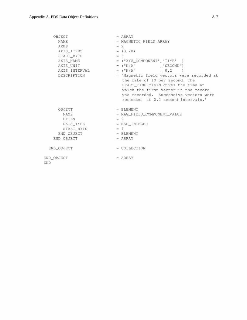
Appendix A. PDS Data Object Definitions A-7
OBJECT = ARRAY
NAME = MAGNETIC_FIELD_ARRAY
AXES = 2
AXIS_ITEMS = (3,20)
START_BYTE = 3
AXIS_NAME = ("XYZ_COMPONENT","TIME" )
AXIS_UNIT = ("N/A" ,"SECOND")
AXIS_INTERVAL = ("N/A" , 0.2 )
DESCRIPTION = "Magnetic field vectors were recorded at
the rate of 10 per second. The
START_TIME field gives the time at
which the first vector in the record
was recorded. Successive vectors were
recorded at 0.2 second intervals."
OBJECT = ELEMENT
NAME = MAG_FIELD_COMPONENT_VALUE
BYTES = 2
DATA_TYPE = MSB_INTEGER
START_BYTE = 1
END_OBJECT = ELEMENT
END_OBJECT = ARRAY
END_OBJECT = COLLECTION
END_OBJECT = ARRAY
END

A-8 Appendix A. PDS Data Object Definitions
The BIT_COLUMN object identifies a string of bits that do not fall on even byte boundaries and
therefore cannot be described as a distinct COLUMN. BIT_COLUMNs defined within columns
are analogous to columns defined within rows. Notes:
(1) The Planetary Data System recommends that all fields (within new objects) be defined on
byte boundaries. This precludes having multiple values strung together in bit strings, as
occurs in the BIT_COLUMN object.
(2) BIT_COLUMN is intended for use in describing existing binary data strings, but is not
recommended for use in defining new data objects because it will not be recognized by
most general purpose software.
(3) A BIT_COLUMN must not contain embedded objects.
BIT_COLUMNs of the same format and size may be specified as a single BIT_COLUMN by
using the ITEMS, ITEM_BITS, and ITEM_OFFSET elements. The ITEMS data element is used
to indicate the number of occurrences of a bit string.
A.3.1 Required Keywords
1. NAME
2. BIT_DATA_TYPE
3. START_BIT
4. BITS (required for BIT_COLUMNs without items)
5. DESCRIPTION
A.3.2 Optional Keywords
1. BIT_MASK
2. BITS (optional for BIT_COLUMNSs with ITEMS)
3. FORMAT
4. INVALID_CONSTANT
5. ITEMS
6. ITEM_BITS
7. ITEM_OFFSET
8. MINIMUM
9. MAXIMUM
10. MISSING_CONSTANT
11. OFFSET
A.3 BIT_COLUMN

Appendix A. PDS Data Object Definitions A-9
12. SCALING_FACTOR
13. UNIT
A.3.3 Required Objects
None
A.3.4 Optional Objects
None
A.3.5 Example
The label fragment below was extracted from a larger example which can be found under the
CONTAINER object. The BIT_COLUMN object can be a sub-object only of a COLUMN
object, but that COLUMN may itself be part of a TABLE, SPECTRUM, SERIES or
CONTAINER object. ____________________________________________________________________________
OBJECT = COLUMN
NAME = PACKET_ID
DATA_TYPE = LSB_BIT_STRING
START_BYTE = 1
BYTES = 2
VALID_MINIMUM = 0
VALID_MAXIMUM = 7
DESCRIPTION = "Packet_id constitutes one of three
parts in the primary source information
header applied by the Payload Data
System (PDS) to the MOLA telemetry
packet at the time of creation of the
packet prior to transfer frame
creation."
OBJECT = BIT_COLUMN
NAME = VERSION_NUMBER
BIT_DATA_TYPE = MSB_UNSIGNED_INTEGER
START_BIT = 1
BITS = 3
MINIMUM = 0
MAXIMUM = 7
DESCRIPTION = "These bits identify Version 1 as the
Source Packet structure. These bits
shall be set to '000'."
END_OBJECT = BIT_COLUMN
OBJECT = BIT_COLUMN

A-10 Appendix A. PDS Data Object Definitions
NAME = SPARE
BIT_DATA_TYPE = MSB_UNSIGNED_INTEGER
START_BIT = 4
BITS = 1
MINIMUM = 0
MAXIMUM = 0
DESCRIPTION = "Reserved spare. This bit shall be set
to '0'"
END_OBJECT = BIT_COLUMN
OBJECT = BIT_COLUMN
NAME = FLAG
BIT_DATA_TYPE = BOOLEAN
START_BIT = 5
BITS = 1
MINIMUM = 0
MAXIMUM = 0
DESCRIPTION = "This flag signals the presence or
absence of a Secondary Header data
structure within the Source Packet.
This bit shall be set to '0' since no
Secondary Header formatting standards
currently exist for Mars Observer."
END_OBJECT = BIT_COLUMN
OBJECT = BIT_COLUMN
NAME = ERROR_STATUS
BIT_DATA_TYPE = MSB_UNSIGNED_INTEGER
START_BIT = 6
BITS = 3
MINIMUM = 0
MAXIMUM = 7
DESCRIPTION = "This field identifies in part the
individual application process within
the spacecraft that created the Source
Packet data."
END_OBJECT = BIT_COLUMN
OBJECT = BIT_COLUMN
NAME = INSTRUMENT_ID
BIT_DATA_TYPE = MSB_UNSIGNED_INTEGER
START_BIT = 9
BITS = 8
MINIMUM = "N/A"
MAXIMUM = "N/A"
DESCRIPTION = "This field identifies in part the
individual application process within
the spacecraft that created the Source
Packet data. 00100011 is the bit
pattern for MOLA."
END_OBJECT = BIT_COLUMN
END_OBJECT = COLUMN
Appendix A. PDS Data Object Definitions A-11
Under review.
A.4 BIT ELEMENT (Primitive Data Object)

A-12 Appendix A. PDS Data Object Definitions
The CATALOG object is used within a VOLUME object to reference the completed PDS high-
level catalog object set. The catalog object set provides additional information related to the data
sets on a volume. Please refer to the File Specification and Naming chapter in this document for
more information.
A.5.1 Required Keywords
None
A.5.2 Optional Keywords
1. DATA_SET_ID
2. LOGICAL_VOLUME_PATHNAME
3. LOGICAL_VOLUMES
A.5.3 Required Objects
1. DATA_SET
2. INSTRUMENT
3. INSTRUMENT_HOST
4. MISSION
A.5.4 Optional Objects
1. DATA_SET_COLLECTION
2. PERSONNEL
3. REFERENCE
4. TARGET
A.5.5 Example
The example below is a VOLDESC.CAT file for a volume containing multiple data sets. In this
case, the catalog objects are provided in separate files referenced by pointers.
PDS_VERSION_ID = PDS3
LABEL_REVISION_NOTE ="1998-07-01, S. Joy (PPI);"
RECORD_TYPE = STREAM
OBJECT = VOLUME
A.5 CATALOG

Appendix A. PDS Data Object Definitions A-13
VOLUME_SERIES_NAME = "VOYAGERS TO THE OUTER PLANETS"
VOLUME_SET_NAME = "VOYAGER NEPTUNE PLANETARY PLASMA
INTERACTIONS DATA"
VOLUME_SET_ID = USA_NASA_PDS_VG_1001
VOLUMES = 1
VOLUME_NAME = "VOYAGER NEPTUNE PLANETARY PLASMA
INTERACTIONS DATA"
VOLUME_ID = VG_1001
VOLUME_VERSION_ID = "VERSION 1"
VOLUME_FORMAT = "ISO-9660"
MEDIUM_TYPE = "CD-ROM"
PUBLICATION_DATE = 1992-11-13
DESCRIPTION = "This volume contains a collection of
non-imaging Planetary Plasma datasets
from the Voyager 2 spacecraft encounter
with Neptune. Included are datasets
from the Cosmic Ray System (CRS),
Plasma System (PLS), Plasma Wave System
(PWS), Planetary Radio Astronomy (PRA),
Magnetometer (MAG), and Low Energy
Charged Particle (LECP) instruments, as
well as spacecraft position vectors
(POS) in several coordinate systems.
The volume also contains documentation
and index files to support access and
use of the data."
DATA_SET_ID = {"VG2-N-CRS-3-RDR-D1-6SEC-V1.0",
"VG2-N-CRS-4-SUMM-D1-96SEC-V1.0",
"VG2-N-CRS-4-SUMM-D2-96SEC-V1.0",
"VG2-N-LECP-4-SUMM-SCAN-24SEC-V1.0",
"VG2-N-LECP-4-RDR-STEP-12.8MIN-V1.0",
"VG2-N-MAG-4-RDR-HG-COORDS-1.92SEC-V1.0",
"VG2-N-MAG-4-SUMM-HG-COORDS-48SEC-V1.0",
"VG2-N-MAG-4-RDR-HG-COORDS-9.6SEC-V1.0",
"VG2-N-MAG-4-SUMM-NLSCOORDS-12SEC-V1.0",
"VG2-N-PLS-5-RDR-2PROMAGSPH-48SEC-V1.0",
"VG2-N-PLS-5-RDR-ELEMAGSPHERE-96SEC-V1.0",
"VG2-N-PLS-5-RDR-IONMAGSPHERE-48SEC-V1.0",
"VG2-N-PLS-5-RDR-IONLMODE-48SEC-V1.0",
"VG2-N-PLS-5-RDR-IONMMODE-12MIN-V1.0",
"VG2-N-PLS-5-RDR-ION-INBNDWIND-48SEC-V1.0",
"VG2-N-POS-5-RDR-HGHGCOORDS-48SEC-V1.0",
"VG2-N-POS-5-SUMM-NLSCOORDS-12-48SEC-V1.0",
"VG2-N-PRA-4-SUMM-BROWSE-SEC-V1.0",
"VG2-N-PRA-2-RDR-HIGHRATE-60MS-V1.0",
"VG2-N-PWS-2-RDR-SA-4SEC-V1.0",
"VG2-N-PWS-4-SUMM-SA-48SEC-V1.0",
"VG2-N-PWS-1-EDR-WFRM-60MS-V1.0"}
OBJECT = DATA_PRODUCER
INSTITUTION_NAME = "UNIVERSITY OF CALIFORNIA, LOS ANGELES"
FACILITY_NAME = "PDS PLANETARY PLASMA INTERACTIONS NODE"
FULL_NAME = "DR. RAYMOND WALKER"

A-14 Appendix A. PDS Data Object Definitions
DISCIPLINE_NAME = "PLASMA INTERACTIONS"
ADDRESS_TEXT = "UCLA
IGPP
LOS ANGELES, CA 90024 USA"
END_OBJECT = DATA_PRODUCER
OBJECT = DATA_SUPPLIER
INSTITUTION_NAME = "NATIONAL SPACE SCIENCE DATA CENTER"
FACILITY_NAME = "NATIONAL SPACE SCIENCE DATA CENTER"
FULL_NAME = "NATIONAL SPACE SCIENCE DATA CENTER"
DISCIPLINE_NAME = "NATIONAL SPACE SCIENCE DATA CENTER"
ADDRESS_TEXT = "Code 633 \n
Goddard Space Flight Center \n
Greenbelt, Maryland, 20771, USA"
TELEPHONE_NUMBER = "3012866695"
ELECTRONIC_MAIL_TYPE = "NSI/DECNET"
ELECTRONIC_MAIL_ID = "NSSDCA::REQUEST"
END_OBJECT = DATA_SUPPLIER
OBJECT = CATALOG
^MISSION_CATALOG = "MISSION.CAT"
^INSTRUMENT_HOST_CATALOG = "INSTHOST.CAT"
^INSTRUMENT_CATALOG = {"CRS_INST.CAT",
"LECPINST.CAT",
"MAG_INST.CAT",
"PLS_INST.CAT",
"PRA_INST.CAT",
"PWS_INST.CAT"}
^DATA_SET_CATALOG = {"CRS_DS.CAT",
"LECP_DS.CAT",
"MAG_DS.CAT",
"PLS_DS.CAT",
"POS_DS.CAT",
"PRA_DS.CAT",
"PWS_DS.CAT"}
^TARGET_CATALOG = TARGET.CAT
^PERSONNEL_CATALOG = PERSON.CAT
^REFERENCE_CATALOG = REF.CAT
END_OBJECT = CATALOG
END_OBJECT = VOLUME
END

Appendix A. PDS Data Object Definitions A-15
The COLLECTION object allows the ordered grouping of heterogeneous objects into a structure.
The COLLECTION object may contain a mixture of different object types, including other
COLLECTIONs. The optional START_BYTE data element provides the starting location
relative to an enclosing object. If a START_BYTE is not specified, a value of 1 is assumed.
A.6.1 Required Keywords
1. BYTES
2. NAME
A.6.2 Optional Keywords
1. DESCRIPTION
2. CHECKSUM
3. INTERCHANGE_FORMAT
4. START_BYTE
A.6.3 Required Objects
None
Note that although a specific sub-object is not required, the COLLECTION must contain at least
one of the optional objects listed following. That is, a null COLLECTION may not be defined.
A.6.4 Optional Objects
1. ELEMENT
2. BIT_ELEMENT
3. ARRAY
4. COLLECTION
A.6.5 Example
Please refer to Section A.2.6, Example 2 under the ARRAY object for an illustration of the
COLLECTION object used in conjunction with other primitive objects.
A.6 COLLECTION (Primitive Data Object)

A-16 Appendix A. PDS Data Object Definitions
The COLUMN object identifies a single column in a data object. Notes:
(1) Current PDS data objects that include COLUMN objects are the TABLE,
CONTAINER, SPECTRUM and SERIES objects.
(2) COLUMNs must not themselves contain embedded COLUMN objects.
(3) COLUMNs of the same format and size which constitute a vector may be specified as a
single COLUMN by using the ITEMS, ITEM_BYTES, and ITEM_OFFSET elements.
The ITEMS data element indicates the number of occurrences of the field (i.e.,
elements in the vector).
(4) BYTES and ITEM_BYTES counts do not include leading or trailing delimiters or line
terminators.
(5) For a COLUMN containing ITEMS, the value of BYTES should represent the total size
of the column including delimiters between the items. (See examples 1 and 2 below.)
A.7.1 Required Keywords
1. NAME
2. DATA_TYPE
3. START_BYTE
4. BYTES (required for COLUMNs without ITEMs)
A.7.2 Optional Keywords
1. BIT_MASK
2. BYTES (optional for COLUMNs with ITEMs)
3. COLUMN_NUMBER
4. DERIVED_MAXIMUM
5. DERIVED_MINIMUM
6. DESCRIPTION
7. FORMAT
8. INVALID_CONSTANT
9. ITEM_BYTES
10. ITEM_OFFSET
11. ITEMS
12. MAXIMUM
13. MAXIMUM_SAMPLING_PARAMETER
14. MINIMUM
15. MINIMUM_SAMPLING_PARAMETER
A.7 COLUMN

Appendix A. PDS Data Object Definitions A-17
16. MISSING_CONSTANT
17. OFFSET
18. SAMPLING_PARAMETER_INTERVAL
19. SAMPLING_PARAMETER_NAME
20. SAMPLING_PARAMETER_UNIT
21. SCALING_FACTOR
22. UNIT
23. VALID_MAXIMUM
24. VALID_MINIMUM
A.7.3 Required Objects
None
A.7.4 Optional Objects
1. BIT_COLUMN
2. ALIAS
A.7.5 Example 1
The label fragment below shows a simple COLUMN object, in this case from an ASCII TABLE.
OBJECT = COLUMN
NAME = "DETECTOR TEMPERATURE"
START_BYTE = 27
BYTES = 5
DATA_TYPE = ASCII_REAL
FORMAT = "F5.1"
UNIT = "KELVIN"
MISSING_CONSTANT = 999.9
END_OBJECT = COLUMN
A.7.6 Example 2
The fragment below shows two COLUMNs containing multiple items. The first COLUMN is a
vector containing three ASCII_INTEGER items: xx, yy, zz. The second COLUMN contains
three character items: “xx”, “yy” and “zz”. Note that the value of BYTES includes the comma
delimiters between items, but the ITEM_BYTES value does not. The ITEM_OFFSET is the
number of bytes from the beginning of one item to the beginning of the next.
OBJECT = COLUMN
NAME = COLUMN1XYZ
DATA_TYPE = ASCII_INTEGER
A-18 Appendix A. PDS Data Object Definitions
START_BYTE = 1
BYTES = 8 /*includes delimiters*/
ITEMS = 3
ITEM_BYTES = 2
ITEM_OFFSET = 3
END_OBJECT = COLUMN
OBJECT = COLUMN
NAME = COLUMN2XYZ
DATA_TYPE = CHARACTER
START_BYTE = 2 /* value does not include leading quote */
BYTES = 12 /* value does not include leading and */
/* trailing quotes */
ITEMS = 3
ITEM_BYTES = 2 /* value does not include leading and */
/* trailing quotes */
ITEM_OFFSET = 5 /* value does not include leading quote */
END_OBJECT = COLUMN
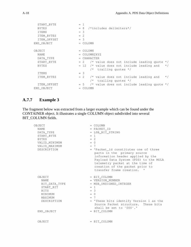
A.7.7 Example 3
The fragment below was extracted from a larger example which can be found under the
CONTAINER object. It illustrates a single COLUMN object subdivided into several
BIT_COLUMN fields.
OBJECT = COLUMN NAME = PACKET_ID DATA_TYPE = LSB_BIT_STRING START_BYTE = 1 BYTES = 2 VALID_MINIMUM = 0 VALID_MAXIMUM = 7 DESCRIPTION = "Packet_id constitutes one of three
parts in the primary source information header applied by the Payload Data System (PDS) to the MOLA telemetry packet at the time of creation of the packet prior to transfer frame creation. "
OBJECT = BIT_COLUMN NAME = VERSION_NUMBER BIT_DATA_TYPE = MSB_UNSIGNED_INTEGER START_BIT = 1 BITS = 3 MINIMUM = 0 MAXIMUM = 7 DESCRIPTION = "These bits identify Version 1 as the
Source Packet structure. These bits shall be set to '000'."
END_OBJECT = BIT_COLUMN OBJECT = BIT_COLUMN

Appendix A. PDS Data Object Definitions A-19
NAME = SPARE BIT_DATA_TYPE = MSB_UNSIGNED_INTEGER START_BIT = 4 BITS = 1 MINIMUM = 0 MAXIMUM = 0 DESCRIPTION = "Reserved spare. This bit shall be set
to '0'" END_OBJECT = BIT_COLUMN OBJECT = BIT_COLUMN NAME = FLAG BIT_DATA_TYPE = BOOLEAN START_BIT = 5 BITS = 1 MINIMUM = 0 MAXIMUM = 0 DESCRIPTION = "This flag signals the presence or
absence of a Secondary Header data structure within the Source Packet. This bit shall be set to '0' since no Secondary Header formatting standards currently exist for Mars Observer."
END_OBJECT = BIT_COLUMN OBJECT = BIT_COLUMN NAME = ERROR_STATUS BIT_DATA_TYPE = MSB_UNSIGNED_INTEGER START_BIT = 6 BITS = 3 MINIMUM = 0 MAXIMUM = 7 DESCRIPTION = "This field identifies in part the
individual application process within the spacecraft that created the Source Packet data."
END_OBJECT = BIT_COLUMN OBJECT = BIT_COLUMN NAME = INSTRUMENT_ID BIT_DATA_TYPE = MSB_UNSIGNED_INTEGER START_BIT = 9 BITS = 8 MINIMUM = "N/A" MAXIMUM = "N/A" DESCRIPTION = "This field identifies in part the
individual application process within the spacecraft that creeated the Source Packet data. 00100011 is the bit pattern for MOLA."
END_OBJECT = BIT_COLUMN END_OBJECT = COLUMN

A-20 Appendix A. PDS Data Object Definitions
The CONTAINER object is used to group a set of sub-objects (such as COLUMNs) that repeat
within a data object (such as a TABLE). Use of the CONTAINER object allows repeating groups
to be defined within a data structure.
A.8.1 Required Keywords
1. NAME
2. START_BYTE
3. BYTES
4. REPETITIONS
5. DESCRIPTION
A.8.2 Optional Keywords
Any
A.8.3 Required Objects
None
A.8.4 Optional Objects
1. COLUMN
2. CONTAINER
A.8.5 Example
The set of labels and format fragments below illustrates a data product layout in which the
CONTAINER object is used. The primary data product is a TABLE of data records. Each record
within the TABLE begins with 48 columns (143 bytes) of engineering data. The data product
acquires science data from seven different frames. Since the data from each frame are formatted
identically, one CONTAINER description suffices for all seven frames.
In this example there are two CONTAINER objects. The first CONTAINER object describes the
repeating frame information. Within this CONTAINER there is a second CONTAINER object in
which a 4-byte set of three COLUMN objects repeats 20 times. The use of the second
CONTAINER object permits the data supplier to describe the three COLUMNS (4 bytes) once,
instead of specifying sixty column definitions.
A.8 CONTAINER

Appendix A. PDS Data Object Definitions A-21
In the first CONTAINER, the keyword REPETITIONS is equal to 7. In the second
CONTAINER, REPETITIONS equals 20. Both CONTAINER objects contain a collection of
COLUMN objects. In most cases it is preferable to save space in the product label by placing
COLUMN objects in a separate file and pointing to that file from within the CONTAINER
object.
This attached label example describes the above TABLE structure using CONTAINER objects.
PDS_VERSION_ID = PDS3
RECORD_TYPE = FIXED_LENGTH
FILE_RECORDS = 467
RECORD_BYTES = 1080
LABEL_RECORDS = 4
FILE_NAME = "AEDR.A01"
^MOLA_SCIENCE_MODE_TABLE = 5
DATA_SET_ID = "MO-M-MOLA-1-AEDR-L0-V1.0"
PRODUCT_ID = "MOLA-AEDR-10010-0001"
SPACECRAFT_NAME = MARS_OBSERVER
INSTRUMENT_ID = MOLA
INSTRUMENT_NAME = MARS_OBSERVER_LASER_ALTIMETER
TARGET_NAME = MARS
SOFTWARE_NAME = "BROWSER 17.1"
UPLOAD_ID = "5.3"
PRODUCT_RELEASE_DATE = 1994-12-29T02:10:09.321
START_TIME = 1994-09-29T04:12:43.983
STOP_TIME = 1994-09-29T06:09:54.221
SPACECRAFT_CLOCK_START_COUNT = "12345"
SPACECRAFT_CLOCK_STOP_COUNT = "12447"
PRODUCT_CREATION_TIME = 1994-01-29T07:30:333
MISSION_PHASE_NAME = MAPPING

A-22 Appendix A. PDS Data Object Definitions
ORBIT_NUMBER = 0001
PRODUCER_ID = MO_MOLA_TEAM
PRODUCER_FULL_NAME = "DAVID E. SMITH"
PRODUCER_INSTITUTION_NAME = "GODDARD SPACE FLIGHT CENTER"
DESCRIPTION = "This data product contains the
aggregation of MOLA telemetry packets by Orbit. All Experiment
Data Record Packets retrieved from the PDB are collected in this
data product. The AEDR data product is put together with the
Project-provided software tool Browser."
OBJECT = MOLA_SCIENCE_MODE_TABLE
INTERCHANGE_FORMAT = BINARY
ROWS = 463
COLUMNS = 97
ROW_BYTES = 1080
^STRUCTURE = "MOLASCI.FMT"
DESCRIPTION = "This table is one of two that describe
the arrangement of information on the Mars Observer Laser
Altimeter (MOLA) Aggregated Engineering Data Record (AEDR). ..."
END_OBJECT = MOLA_SCIENCE_MODE_TABLE
...
END
Contents of the MOLASCI.FMT file:
OBJECT = COLUMN
NAME = PACKET_ID
DATA_TYPE = LSB_BIT_STRING
START_BYTE = 1
BYTES = 2
VALID_MINIMUM = 0
VALID_MAXIMUM = 7
DESCRIPTION = "Packet_id constitutes one of three
parts in the primary source information header applied by the
Payload Data System (PDS) to the MOLA telemetry packet at the time
of creation of the packet prior to transfer frame creation."
OBJECT = BIT_COLUMN
NAME = VERSION_NUMBER
BIT_DATA_TYPE = UNSIGNED_INTEGER
START_BIT = 1
BITS = 3
MINIMUM = 0
MAXIMUM = 7
DESCRIPTION = "These bits identify Version 1 as the
Source Packet structure. These bits shall be set to '000'."
END_OBJECT = BIT_COLUMN
OBJECT = BIT_COLUMN
NAME = SPARE
BIT_DATA_TYPE = UNSIGNED_INTEGER

Appendix A. PDS Data Object Definitions A-23
START_BIT = 4
BITS = 1
MINIMUM = 0
MAXIMUM = 0
DESCRIPTION = "Reserved spare. This bit shall be set
to '0'"
END_OBJECT = BIT_COLUMN
OBJECT = BIT_COLUMN
NAME = SECONDARY_HEADER_FLAG
BIT_DATA_TYPE = BOOLEAN
START_BIT = 5
BITS = 1
MINIMUM = 0
MAXIMUM = 0
DESCRIPTION = "This flag signals the presence or
absence of a Secondary Header data structure within the Source
Packet. This bit shall be set to '0' since no Secondary Header
formatting standards currently exist for Mars Observer."
END_OBJECT = BIT_COLUMN
OBJECT = BIT_COLUMN
NAME = ERROR_STATUS
BIT_DATA_TYPE = UNSIGNED_INTEGER
START_BIT = 6
BITS = 3
MINIMUM = 0
MAXIMUM = 7
DESCRIPTION = "This field identifies in part the
individual application process within the spacecraft that created
the Source Packet data."
END_OBJECT = BIT_COLUMN
OBJECT = BIT_COLUMN
NAME = INSTRUMENT_ID
BIT_DATA_TYPE = UNSIGNED_INTEGER
START_BIT = 9
BITS = 8
MINIMUM = 2#0100011#
MAXIMUM = 2#0100011#
DESCRIPTION = "This field identifies in part the
individual application process within the spacecraft that created
the Source Packet data. 00100011 is the bit pattern for MOLA."
END_OBJECT = BIT_COLUMN
END_OBJECT = COLUMN
...
OBJECT = COLUMN
NAME = COMMAND_ECHO
DATA_TYPE = INTEGER
START_BYTE = 125
BYTES = 16
ITEMS = 8

A-24 Appendix A. PDS Data Object Definitions
ITEM_BYTES = 2
MINIMUM = 0
MAXIMUM = 65535
DESCRIPTION = "First 8 command words received during
current packet, only complete commands are stored, MOLA specific
commands only. The software attempts to echo all valid commands.
If the command will fit in the room remaining in the..."
END_OBJECT = COLUMN
OBJECT = COLUMN
NAME = PACKET_VALIDITY_CHECKSUM
DATA TYPE = INTEGER
START_BYTE = 141
BYTES = 2
MINIMUM = 0
MAXIMUM = 65535
DESCRIPTION = "Simple 16 bit addition of entire packet
contents upon completion. This location is zeroed for addition.
This word is zeroed, then words 0-539 are added without carry to a
variable that is initially zero. The resulting lower 16 bits
are..."
END_OBJECT = COLUMN
OBJECT = CONTAINER
NAME = FRAME_STRUCTURE
^STRUCTURE = "MOLASCFR.FMT" /*points to the columns*/
/*that make up the frame descriptors */
START_BYTE = 143
BYTES = 134
REPETITIONS = 7
DESCRIPTION = "The frame_structure container
represents the format of seven repeating groups of attributes in
this data product. The data product reflects science data
acquisition from seven different frames. Since the data from each
frame are ..."
END_OBJECT = CONTAINER
Contents of the MOLASCFR.FMT FILE:
OBJECT = CONTAINER
NAME = COUNTS
START_BYTE = 1
BYTES = 4
REPETITIONS = 20
^STRUCTURE = "MOLASCCT.FMT"
DESCRIPTION = "This container has three sub-elements
(range to surface counts, 1st channel received pulse energy, and
2nd channel received pulse energy). The three sub-elements repeat
for each of 20 shots."
END_OBJECT = CONTAINER
OBJECT = COLUMN
NAME = SHOT_2_LASER_TRANSMITTER_POWR

Appendix A. PDS Data Object Definitions A-25
DATA_TYPE = UNSIGNED_INTEGER
START_BYTE = 81
BYTES = 1
MINIMUM = 0
MAXIMUM = 65535
DESCRIPTION = "..."
END_OBJECT = COLUMN
OBJECT = COLUMN
NAME = SHOT_1_LASER_TRANSMITTER_POWR
DATA_TYPE = UNSIGNED_INTEGER
START_BYTE = 82
BYTES = 1
MINIMUM = 0
MAXIMUM = 65535
DESCRIPTION = "..."
END_OBJECT = COLUMN
OBJECT = COLUMN
NAME = SHOT_4_LASER_TRANSMITTER_POWR
DATA_TYPE = UNSIGNED_INTEGER
START_BYTE = 83
BYTES = 1
MINIMUM = 0
MAXIMUM = 65535
DESCRIPTION = "..."
END_OBJECT = COLUMN
...
OBJECT = COLUMN
NAME = CH_3_2ND_HALF_FRAME_BKGRND_CN
DATA_TYPE = UNSIGNED_INTEGER
START_BYTE = 133
BYTES = 1
MINIMUM = 0
MAXIMUM = 255
DESCRIPTION = "The background energy or noise count
levels in channels 1, 2, 3, and 4 respectively by half-frame.
Pseudo log value of NOISE(1, 2, 3, 4) at the end of a half-frame
of current frame, 5.3 bit format. Plog base 2 of background count
sum..."
END_OBJECT = COLUMN
OBJECT = COLUMN
NAME = CH_4_2ND_HALF_FRAME_BKGRND_CN
DATA_TYPE = UNSIGNED_INTEGER
START_BYTE = 134
BYTES = 1
MINIMUM = 0
MAXIMUM = 255
DESCRIPTION = "The background energy or noise count
levels in channels 1, 2, 3, and 4 respectively by half-frame.
Pseudo log value of NOISE(1, 2, 3, 4) at the end of a half-frame

A-26 Appendix A. PDS Data Object Definitions
of current frame, 5.3 bit format. Plog base 2 of background count
sum..."
END_OBJECT = COLUMN
Contents of the MOLASCCT.FMT FILE:
OBJECT = COLUMN
NAME = RANGE_TO_SURFACE_TIU_CNTS
DATA_TYPE = MSB_INTEGER
START_BYTE = 1
BYTES = 2
DESCRIPTION = "The possible 20 valid frame laser shots
surface ranging measurements in Timing Interval Unit (TIU) counts.
The least significant 16 bits of TIU (SLTIU), stored for every
shot. B[0] = Bits 15-8 of TIU reading; B[1] = Bits 7-0 of ..."
END_OBJECT = COLUMN
OBJECT = COLUMN
NAME = FIRST_CH_RCVD_PULSE_ENRGY
DATA_TYPE = UNSIGNED_INTEGER
START_BYTE = 3
BYTES = 1
DESCRIPTION = "The level of return, reflected energy
as received by the first channel and matched filter to trigger.
This is a set of values for all possible 20 shots within the
frame. Lowest numbered non-zero energy reading for each shot."
END_OBJECT = COLUMN
OBJECT = COLUMN
NAME = SECOND_CH_RCVD_PULSE_ENRGY
DATA_TYPE = UNSIGNED_INTEGER
START_BYTE = 4
BYTES = 1
DESCRIPTION = "The level of return, reflected energy
as received by the second channel and matched filter to trigger.
This is a set of values for all possible 20 shots within the
frame. 2nd lowest numbered non-zero energy reading for each
shot..."
END_OBJECT = COLUMN

Appendix A. PDS Data Object Definitions A-27
The DATA_PRODUCER object is a required sub-object of the VOLUME object. The
DATA_PRODUCER, as opposed to the DATA_SUPPLIER, is an individual or organization
responsible for collecting, assembling, and/or engineering the raw data into one or more data
sets.
A.9.1 Required Keywords
1. INSTITUTION_NAME
2. FACILITY_NAME
3. FULL_NAME
4. ADDRESS_TEXT
A.9.2 Optional Keywords
1. DISCIPLINE_NAME
2. NODE_NAME
3. TELEPHONE_NUMBER
4. ELECTRONIC_MAIL_TYPE
5. ELECTRONIC_MAIL_ID
A.9.3 Required Objects
None
A.9.4 Optional Objects
None
A.9.5 Example
The fragment below was extracted from the example under the VOLUME object.
OBJECT = DATA_PRODUCER INSTITUTION_NAME = "U.S.G.S. FLAGSTAFF" FACILITY_NAME = "BRANCH OF ASTROGEOLOGY" FULL_NAME = "ERIC M. ELIASON" DISCIPLINE_NAME = "IMAGE PROCESSING" ADDRESS_TEXT = "Branch of Astrogeology United States Geological Survey 2255 North Gemini Drive
A.9 DATA_PRODUCER

A-28 Appendix A. PDS Data Object Definitions
Flagstaff, Arizona 86001 USA" END_OBJECT = DATA_PRODUCER

Appendix A. PDS Data Object Definitions A-29
The DATA_SUPPLIER object is an optional sub-object of the VOLUME object. The
DATA_SUPPLIER, as opposed to the DATA_PRODUCER, is an individual or organization
responsible for distributing the data sets and associated data to the science community.
A.10.1 Required Keywords 1. INSTITUTION_NAME
2. FACILITY_NAME
3. FULL_NAME
4. ADDRESS_TEXT
5. TELEPHONE_NUMBER
6. ELECTRONIC_MAIL_TYPE
7. ELECTRONIC_MAIL_ID
A.10.2 Optional Keywords 1. DISCIPLINE_NAME
2. NODE_NAME
A.10.3 Required Objects None
A.10.4 Optional Objects None
A.10.5 Example The fragment below was extracted from the larger example which can be found under the
VOLUME object.
OBJECT = DATA_SUPPLIER
INSTITUTION_NAME = "NATIONAL SPACE SCIENCE DATA CENTER"
FACILITY_NAME = "NATIONAL SPACE SCIENCE DATA CENTER"
FULL_NAME = "NATIONAL SPACE SCIENCE DATA CENTER"
DISCIPLINE_NAME = "NATIONAL SPACE SCIENCE DATA CENTER"
ADDRESS_TEXT = "Code 633
Goddard Space Flight Center
Greenbelt, Maryland, 20771, USA"
TELEPHONE_NUMBER = "3012866695"
ELECTRONIC_MAIL_TYPE = "NSI/DECNET"
A.10 DATA_SUPPLIER

A-30 Appendix A. PDS Data Object Definitions
ELECTRONIC_MAIL_ID = "NSSDCA::REQUEST"
END_OBJECT = DATA_SUPPLIER

Appendix A. PDS Data Object Definitions A-31
The DIRECTORY object is used to define a hierarchical file organization on a linear (i.e.,
sequential) medium such as tape. The DIRECTORY object identifies all directories and
subdirectories below the root level. It is a required sub-object of the VOLUME object for
volumes delivered on sequential media. Note: The root directory on a volume does not need to be explicitly defined with the
DIRECTORY object. Subdirectories are identified by defining DIRECTORY objects as sub-objects of the root
DIRECTORY. Files within the directories and subdirectories are sequentially identified by using
FILE objects with a SEQUENCE_NUMBER value corresponding to their position on the
medium. The SEQUENCE_NUMBER value must be unique for each file on the medium.
A.11.1 Required Keywords
1. NAME
A.11.2 Optional Keywords
1. RECORD_TYPE
2. SEQUENCE_NUMBER
A.11.3 Required Objects
1. FILE
A.11.4 Optional Objects
1. DIRECTORY
A.11 DIRECTORY

A-32 Appendix A. PDS Data Object Definitions
A.11.5 Example
The fragment below was extracted from the larger example which can be found under the
VOLUME object.
OBJECT = DIRECTORY
NAME = INDEX
OBJECT = FILE
FILE_NAME = "INDXINFO.TXT"
RECORD_TYPE = STREAM
SEQUENCE_NUMBER = 5
END_OBJECT = FILE
OBJECT = FILE
FILE_NAME = "INDEX.LBL"
RECORD_TYPE = STREAM
SEQUENCE_NUMBER = 6
END_OBJECT = FILE
OBJECT = FILE
FILE_NAME = "INDEX.TAB"
RECORD_TYPE = FIXED_LENGTH
RECORD_BYTES = 512
FILE_RECORDS = 6822
SEQUENCE_NUMBER = 7
END_OBJECT = FILE
END_OBJECT = DIRECTORY

Appendix A. PDS Data Object Definitions A-33
Note: This section is currently undergoing major revision. Please consult a PDS
data engineer for the latest available information on document labelling.
The DOCUMENT object is used to label a particular document that is provided on a volume to
support an archived data product. A document can be made up of one or more files in a single
format. For instance, a document may be comprised of as many TIFF files as there are pages in
the document. Multiple versions of a document can be supplied on a volume with separate formats, requiring a
DOCUMENT object for each document version (i.e., OBJECT = TEX_DOCUMENT and
OBJECT = PS_DOCUMENT when including both the TEX and Postscript versions of the same
document). PDS requires that at least one version of any document be plain ASCII text in order to allow
users the capability to read, browse, or search the text without requiring software or text
processing packages. This version can be plain, unmarked text, or ASCII text containing a
markup language. (See the Documentation chapter of this document for more details.) The DOCUMENT object contains keywords that identify and describe the document, provide the
date of publication of the document, indicate the number of files comprising the document,
provide the format of the document files, and identify the software used to compress or encode
the document, as applicable. DOCUMENT labels must be detached files unless the files are plain, unmarked text that will not
be read by text or word processing packages. A DOCUMENT object for each format type of a
document can be included in the same label file with pointers, such as ^TIFF_DOCUMENT for
a TIFF formatted document. (See example below.)
A.12.1 Required Keywords
1. DOCUMENT_NAME
2. DOCUMENT_TOPIC_TYPE
3. INTERCHANGE_FORMAT
4. DOCUMENT_FORMAT
5. PUBLICATION_DATE
A.12.2 Optional Keywords
1. ABSTRACT_TEXT
2. DESCRIPTION
3. ENCODING_TYPE
A.12 DOCUMENT

A-34 Appendix A. PDS Data Object Definitions
4. FILES
A.12.3 Required Objects
None
A.12.4 Optional Objects
None
A.12.5 Example
The following example detached label, PDSUG.LBL, is for a Document provided in three
formats: ASCII text, TIFF, and TEX.
PDS_VERSION_ID = PDS3
RECORD_TYPE = UNDEFINED
^ASCII_DOCUMENT = "PDSUG.ASC"
^TIFF_DOCUMENT = {"PDSUG001.TIF", "PDSUG002.TIF",
"PDSUG003.TIF", "PDSUG004.TIF" }
^TEX_DOCUMENT = "PDSUG.TEX"
OBJECT = ASCII_DOCUMENT
DOCUMENT_NAME = "Planetary Data System Data Set Catalog
User's Guide"
PUBLICATION_DATE = 1992-04-13
DOCUMENT_TOPIC_TYPE = "USER'S GUIDE"
INTERCHANGE_FORMAT = ASCII
DOCUMENT_FORMAT = TEXT
DESCRIPTION = "The Planetary Data System Data Set
Catalog User's Guide describes the fundamentals of accessing,
searching, browsing, and ordering data from the PDS Data Set Catalog
at the Central Node. The text for this 4-page document is provided
here in this plain, ASCII text file."
ABSTRACT_TEXT = "The PDS Data Set Catalog is similar in
function and purpose to a card catalog in a library. Use a Search
screen to find data items, a List/Order screen to order data items,
and the More menu option to see more information."
END_OBJECT = ASCII_DOCUMENT
OBJECT = TIFF_DOCUMENT
DOCUMENT_NAME = "Planetary Data System Data Set Catalog
User's Guide"
DOCUMENT_TOPIC_TYPE = "USER'S GUIDE"

Appendix A. PDS Data Object Definitions A-35
INTERCHANGE_FORMAT = BINARY
DOCUMENT_FORMAT = TIFF
PUBLICATION_DATE = 1992-04-13
FILES = 4
ENCODING_TYPE = "CCITT/3"
DESCRIPTION = "The Planetary Data System Data Set
Catalog User's Guide describes the fundamentals of accessing,
searching, browsing, and ordering data from the PDS Data Set Catalog
at the Central Node.
The 4-page document is provided here in 4 consecutive files, one
file per page, in Tagged Image File Format (TIFF) using Group 3
compression. It has been successfully imported into WordPerfect
5.0, FrameMaker, and Photoshop."
ABSTRACT_TEXT = "The PDS Data Set Catalog is similar in
function and purpose to a card catalog in a library. Use a Search
screen to find data items, a List/Order screen to order data items,
and the More menu option to see more information."
END_OBJECT = TIFF_DOCUMENT
OBJECT = TEX_DOCUMENT
DOCUMENT_NAME = "Planetary Data System Data Set Catalog
User's Guide"
DOCUMENT_TOPIC_TYPE = "USER'S GUIDE"
INTERCHANGE_FORMAT = ASCII
DOCUMENT_FORMAT = TEX
PUBLICATION_DATE = 1992-04-13
DESCRIPTION = "The Planetary Data System Data Set
Catalog User's Guide describes the fundamentals of accessing,
searching, browsing, and ordering data from the PDS Data Set Catalog
at the Central Node.
The 4-page document is provided here in TeX format with all
necessary macros included."
ABSTRACT_TEXT = "The PDS Data Set Catalog is similar in
function and purpose to a card catalog in a library. Use a Search
screen to find data items, a List/Order screen to order data items,
and the More menu option to see more information."
END_OBJECT = TEX_DOCUMENT
END

A-36 Appendix A. PDS Data Object Definitions
The ELEMENT object provides a means of defining a lowest-level component of a data object,
and which can be stored in an integral multiple of 8-bit bytes. ELEMENT objects may be
embedded in COLLECTION and ARRAY data objects. The optional START_BYTE element
identifies a location relative to the enclosing object. If not explicitly included, a START_BYTE
= 1 is assumed for the ELEMENT.
A.13.1 Required Keywords
1. BYTES
2. DATA_TYPE
3. NAME
A.13.2 Optional Keywords
1. START_BYTE
2. BIT_MASK
3. DERIVED_MAXIMUM
4. DERIVED_MINIMUM
5. DESCRIPTION
6. FORMAT
7. INVALID_CONSTANT
8. MINIMUM
9. MAXIMUM
10. MISSING_CONSTANT
11. OFFSET
12. SCALING_FACTOR
13. UNIT
14. VALID_MINIMUM
15. VALID_MAXIMUM
A.13.3 Required Objects
None
A.13.4 Optional Objects
None
A.13 ELEMENT (Primitive Data Object)

Appendix A. PDS Data Object Definitions A-37
A.13.5 Example
Please refer to the example in the ARRAY Primitive object (Section A.2) for an example of the
use of the ELEMENT object.

A-38 Appendix A. PDS Data Object Definitions
The FIELD object identifies a single variable-width field in a SPREADSHEET object.
Notes:
1. The only PDS data object that includes FIELD objects is the SPREADSHEET. FIELDs
must not themselves contain embedded FIELD objects.
2. The DATA_TYPE keyword is required to specify the data type of the values that are
stored in the field when data are present.
3. A vector with two or more identically formatted components may be specified as a single
FIELD by using the ITEM and ITEM_BYTES elements. The ITEMS data element
indicates the number of occurrences within the field (i.e., components in the vector).
4. If a FIELD contains multiple items, then the ITEM_BYTES keyword is used to specify
the maximum number of bytes any item in the set may have. ITEM_BYTES does not
include the quotation marks that enclose string items.
5. The BYTES keyword is used to specify the maximum size of the FIELD object, not
including leading or trailing delimiters or line terminators. When a field contains items,
the BYTES value is set to the product of the ITEM_BYTES and ITEMS values plus the
number of interior delimiter bytes (e.g., for three ASCII_INTEGER items of three bytes
each ITEMS = 3, ITEM_BYTES=3, and BYTES= 11, which includes the two delimiters
WITHIN the field but not the trailing delimiter).
6. The (optional) FORMAT element may be used to specify the format of FIELD data when
they are present. The FORMAT specification applies to the maximum size of the field
object, allowing shorter variations. For example, FORMAT = "F5.1" is consistent with
each of the following:
... ,127.1, ...
... ,-12.7, ...
... ,3.1, ...
... ,3.01, ... and
... ,, ...
7. Inclusion of data elements VALID_MINIMUM and VALID_MAXIMUM within FIELD
object definitions is encouraged.
8. If data element MISSING_CONSTANT is used, its meaning must be clearly stated since
absence of a field value is the default indication of 'no data'.
A.14.1 Required Keywords
A.14 FIELD

Appendix A. PDS Data Object Definitions A-39
1. BYTES
2. DATA_TYPE
3. NAME
A.14.2 Optional Keywords
1. DESCRIPTION
2. FIELD_NUMBER
3. FORMAT
4. ITEM_BYTES
5. ITEMS
6. UNIT
7. VALID_MAXIMUM
8. VALID_MINIMUM
9. PSDD
A.14.3 Required Objects
None
A.14.4 Optional Objects
1. ALIAS
A.14.5 Example 1
The label fragment below shows a simple FIELD object from a SPREADSHEET object (see the
SPREADSHEET section of this document). OBJECT = FIELD NAME = "DETECTOR TEMPERATURE" FIELD_NUMBER = 3 BYTES = 5 DATA_TYPE = "ASCII_REAL" FORMAT = "F5.1" UNIT = "KELVIN" END_OBJECT = FIELD
A.14.6 Example 2

A-40 Appendix A. PDS Data Object Definitions
The fragment below shows two FIELDs containing multiple items. The first FIELD is a vector
containing three ASCII_INTEGER items: xx, yy, zz. The second FIELD contains three
character items: "xx", "yy" and "zz". Note that the value of BYTES includes the comma
delimiters between items, but the ITEM_BYTES value does not.
OBJECT = FIELD NAME = "FIELD 1 - IX, IY, IZ" DATA_TYPE = "ASCII_INTEGER" FIELD_NUMBER = 1 BYTES = 8 /*includes item separating delimiters*/ ITEMS = 3 /* i.e. 17,15,27 or 1,2,3 */ ITEM_BYTES = 2 /* individual item maximum size in bytes */ FORMAT = "I2" MISSING_CONSTANT = -1 DESCRIPTION = "Raw values of FIELD 1. IX, IY, and IZ represent independent, non-negative measurements. A value of -1 denotes a measurement that could not be processed." END_OBJECT = FIELD OBJECT = FIELD NAME = "FIELD 2 - AX, AY,AZ" DATA_TYPE = "CHARACTER" FIELD_NUMBER = 2 /* One FIELD object precedes this object */ BYTES = 12 /* Doesn't include first/last quotes */ ITEMS = 3 /* i.e. "xx","yy","zz" */ ITEM_BYTES = 2 FORMAT = "A2" END_OBJECT = FIELD

Appendix A. PDS Data Object Definitions A-41
The FILE object is used in attached or detached labels to define the attributes or characteristics
of a data file. In attached labels, the file object is also used to indicate boundaries between label
records and data records in data files which have attached labels. The FILE object may be used
in three ways:
1. As an implicit object in attached or detached labels. All detached label files and attached
labels contain an implicit FILE object which starts at the top of the label and ends where
the label ends. In these cases, the PDS recommends against using the NAME keyword to
reference the file name. This label fragment shows the required FILE object elements as
they typically appear in labels:
RECORD_TYPE = FIXED_LENGTH
RECORD_BYTES = 80
FILE_RECORDS = 522
LABEL_RECORDS = 10
For data products labelled using the implicit file object (e.g., in minimal labels)
“DATA_OBJECT_TYPE = FILE” should be used in the DATA_SET catalog object.
2. As an explicit object which is used when a file reference is needed in a combined
detached or minimal label. In this case, the optional FILE_NAME element is used to
identify the file being referenced.
OBJECT = FILE
FILE_NAME = "IM10347.DAT"
RECORD_TYPE = STREAM
FILE_RECORDS = 1024
... END_OBJECT = FILE
For data products labelled using the explicit FILE object (e.g., in minimal labels)
DATA_OBJECT_TYPE = FILE should be used in the DATA_SET catalog object.
3. As an explicit object to identify specific files as sub-objects of the DIRECTORY in
VOLUME objects. In this case, the optional FILE_NAME element is used to identify the
file being referenced on a tape archive volume.
OBJECT = FILE
FILE_NAME = "VOLDESC.CAT"
RECORD_TYPE = STREAM
SEQUENCE_NUMBER = 1
END_OBJECT = FILE
A.15 FILE

A-42 Appendix A. PDS Data Object Definitions
The keywords in the FILE object always describe the file being referenced, and not the file in
which the keywords are contained (i.e., if the FILE object is used in a detached label file, the
FILE object keywords describe the detached data file, not the label file which contains the
keywords). For example, if a detached label for a data file is being created and the label will be
in STREAM format, but the data will be stored in a file having FIXED_LENGTH records, then
the RECORD_TYPE keyword in the label file must be given the value FIXED_LENGTH. The following table identifies data elements that are required (Req), optional (Opt), and not
applicable (-) for various types of files
Labeling Method Att Det Att Det Att Det Att Det
RECORD_TYPE FIXED_LENGTH VARIABLE_LENGTH STREAM UNDEFINED
RECORD_BYTES Req Req Rmax Rmax Omax - - -
FILE_RECORDS Req Req Req Req Opt Opt - -
LABEL_RECORDS Req - Req - Opt - - -
A.15.1 Required Keywords
1. RECORD_TYPE (See above table for the conditions of use of additional required keywords)
A.15.2 Optional Keywords
1. DESCRIPTION
2. ENCODING_TYPE
3. FILE_NAME (required only in minimal detached labels and tape archives)
4. FILE_RECORDS (required only in minimal detached labels and tape archives)
5. INTERCHANGE_FORMAT
6. LABEL_RECORDS
7. RECORD_BYTES
8. REQUIRED_STORAGE_BYTES
9. SEQUENCE_NUMBER
10. UNCOMPRESSED_FILE_NAME
A.15.3 Required Objects
None
A.15.4 Optional Objects

Appendix A. PDS Data Object Definitions A-43
None
A.15.5 Example
Following is an example of a set of explicit FILE objects in a combined detached label. An
additional example of the use of explicit FILE object can be found under the VOLUME object
(Section A.29).
PDS_VERSION_ID = PDS3
HARDWARE_MODEL_ID = "SUN SPARC STATION"
OPERATING_SYSTEM_ID = "SUN OS 4.1.1"
SPACECRAFT_NAME = "VOYAGER 2"
INSTRUMENT_NAME = "PLASMA WAVE RECEIVER"
MISSION_PHASE_NAME = "URANUS ENCOUNTER"
TARGET_NAME = URANUS
DATA_SET_ID = "VG2-U-PWS-4-RDR-SA-48.0SEC-V1.0"
PRODUCT_ID = "T860123-T860125"
OBJECT = FILE
FILE_NAME = "T860123.DAT"
FILE_RECORDS = 1800
RECORD_TYPE = FIXED_LENGTH
RECORD_BYTES = 105
START_TIME = 1986-01-23T00:00:00.000
STOP_TIME = 1986-01-24T00:00:00.000
^TIME_SERIES = "T860123.DAT"
OBJECT = TIME_SERIES
INTERCHANGE_FORMAT = BINARY
ROWS = 1800
ROW_BYTES = 105
COLUMNS = 19
^STRUCTURE = "PWS_DATA.FMT"
SAMPLING_PARAMETER_NAME = TIME
SAMPLING_PARAMETER_UNIT = SECOND
SAMPLING_PARAMETER_INTERVAL = 48.0
END_OBJECT = TIME_SERIES
END_OBJECT = FILE
OBJECT = FILE
FILE_NAME = "T860124.DAT"
FILE_RECORDS = 1800
RECORD_TYPE = FIXED_LENGTH
RECORD_BYTES = 105
START_TIME = 1986-01-24T00:00:00.000
STOP_TIME = 1986-01-25T00:00:00.000
^TIME_SERIES = "T860124.DAT"

A-44 Appendix A. PDS Data Object Definitions
OBJECT = TIME_SERIES
INTERCHANGE_FORMAT = BINARY
ROWS = 1800
ROW_BYTES = 105
COLUMNS = 19
^STRUCTURE = "PWS_DATA.FMT"
SAMPLING_PARAMETER_NAME = TIME
SAMPLING_PARAMETER_UNIT = SECOND
SAMPLING_PARAMETER_INTERVAL = 48.0
END_OBJECT = TIME_SERIES
END_OBJECT = FILE
OBJECT = FILE
FILE_NAME = "T860125.DAT"
FILE_RECORDS = 1799
RECORD_TYPE = FIXED_LENGTH
RECORD_BYTES = 105
START_TIME = 1986-01-30T00:00:00.000
STOP_TIME = 1986-01-30T23:59:12.000
^TIME_SERIES = "T860125.DAT"
OBJECT = TIME_SERIES
INTERCHANGE_FORMAT = BINARY
ROWS = 1799
ROW_BYTES = 105
COLUMNS = 19
^STRUCTURE = "PWS_DATA.FMT"
SAMPLING_PARAMETER_NAME = TIME
SAMPLING_PARAMETER_UNIT = SECOND
SAMPLING_PARAMETER_INTERVAL = 48.0
END_OBJECT = TIME_SERIES
END_OBJECT = FILE
END

Appendix A. PDS Data Object Definitions A-45
The GAZETTEER_TABLE object is a specific type of TABLE object that provides information
about the geographical features of a planet or satellite. It contains information about named
features such as location, size, origin of feature name, and so on. The GAZETTEER_TABLE
contains one row for each named feature on the target body. The table is formatted so that it may
be read directly by many data management systems on various host computers. All fields
(columns) are separated by commas, and character fields are enclosed by double quotation
marks. Each record consist of 480 bytes, with a carriage return/line feed sequence in bytes 479
and 480. This allows the table to be treated as a fixed length record file on hosts that support this
file type and as a normal text file on other hosts. Currently the PDS Imaging Node at the USGS is the data producer for all
GAZETTEER_TABLEs.
A.16.1 Required Keywords
1. NAME
2. INTERCHANGE_FORMAT
3. ROWS
4. COLUMNS
5. ROW_BYTES
6. DESCRIPTION
A.16.2 Optional Keywords
Any
A.16.3 Required Objects
1. COLUMN
A.16.3.1 Required COLUMN Objects (NAME =)
TARGET_NAME
SEARCH_FEATURE_NAME
DIACRITIC_FEATURE_NAME
MINIMUM_LATITUDE
MAXIMUM_LATITUDE
CENTER_LATITUDE
MINIMUM_LONGITUDE
A.16 GAZETTEER_TABLE
A-46 Appendix A. PDS Data Object Definitions
MAXIMUM_LONGITUDE
CENTER_LONGITUDE
LABEL_POSITION_ID
FEATURE_LENGTH
PRIMARY_PARENTAGE_ID
SECONDARY_PARENTAGE_ID
MAP_SERIAL_ID
FEATURE_STATUS_TYPE
APPROVAL_DATE
FEATURE_TYPE
REFERENCE_NUMBER
MAP_CHART_ID
FEATURE_DESCRIPTION
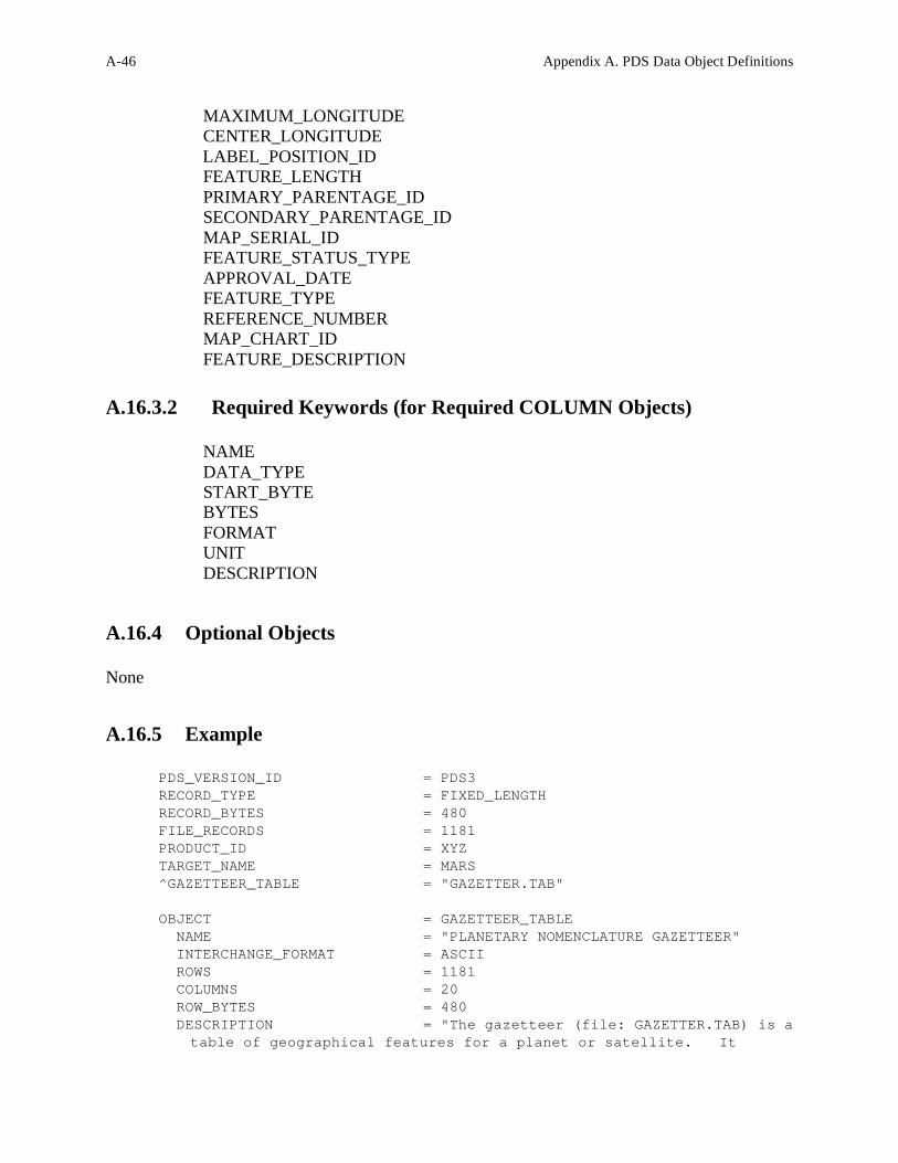
A.16.3.2 Required Keywords (for Required COLUMN Objects)
NAME
DATA_TYPE
START_BYTE
BYTES
FORMAT
UNIT
DESCRIPTION
A.16.4 Optional Objects
None
A.16.5 Example
PDS_VERSION_ID = PDS3
RECORD_TYPE = FIXED_LENGTH
RECORD_BYTES = 480
FILE_RECORDS = 1181
PRODUCT_ID = XYZ
TARGET_NAME = MARS
^GAZETTEER_TABLE = "GAZETTER.TAB"
OBJECT = GAZETTEER_TABLE
NAME = "PLANETARY NOMENCLATURE GAZETTEER"
INTERCHANGE_FORMAT = ASCII
ROWS = 1181
COLUMNS = 20
ROW_BYTES = 480
DESCRIPTION = "The gazetteer (file: GAZETTER.TAB) is a
table of geographical features for a planet or satellite. It

Appendix A. PDS Data Object Definitions A-47
contains information about a named feature such as location, size,
origin of feature name, etc. The Gazetteer Table contains one row
for each feature named on the target body. The table is formatted
so that it may be read directly into many data management systems on
various host computers. All fields (columns) are separated by
commas, and character fields are preceded by double quotation marks.
Each record consist of 480 bytes, with a carriage return/line feed
sequence in bytes 479 and 480. This allows the table to be treated
as a fixed length record file on hosts that support this file type
and as a normal text file on other hosts."
OBJECT = COLUMN
NAME = TARGET_NAME
DATA_TYPE = CHARACTER
START_BYTE = 2
BYTES = 20
FORMAT = "A20"
UNIT = "N/A"
DESCRIPTION = "The planet or satellite on which the
feature is located."
END_OBJECT = COLUMN
OBJECT = COLUMN
NAME = SEARCH_FEATURE_NAME
DATA_TYPE = CHARACTER
START_BYTE = 25
BYTES = 50
FORMAT = "A50"
UNIT = "N/A"
DESCRIPTION = "The geographical feature name with all
diacritical marks stripped off. This name is stored in upper case
only so that it can be used for sorting and search purposes. This
field should not be used to designate the name of the feature
because it does not contain the diacritical marks. Feature names not
containing diacritical marks can often take on a completely
different meaning and in some cases the meaning can be deeply
offensive."
END_OBJECT = COLUMN
OBJECT = COLUMN
NAME = DIACRITIC_FEATURE_NAME
DATA_TYPE = CHARACTER
START_BYTE = 78
BYTES = 100
FORMAT = "A100"
UNIT = "N/A"
DESCRIPTION = "The geographical feature name
containing standard diacritical information. A detailed description
of the diacritical mark formats are described in the gazetteer
documentation.
DIACRITICALS USED IN THE TABLE

A-48 Appendix A. PDS Data Object Definitions
The word diacritic comes from a Greek word meaning to separate.
It refers to the accent marks employed to separate, or distinguish,
one form of pronunciation of a vowel or consonant from another.
This note is included to familiarize the user with the codes used
to represent diacriticals found in the table, and the values usually
associated with them. In the table, the code for a diacritical is
preceded by a backslash and is followed, without a space, by the
letter it is modifying.
This note is organized as follows: the code is listed first,
followed by the name of the accent mark, if applicable, a brief
description of the appearance of the diacritical and a short
narrative on its usage.
acute accent; a straight diagonal line extending from upper right to
lower left. The acute accent is used in most languages to lengthen a
vowel; in some, such as Oscan, to denote an open vowel. The acute
is also often used to indicate the stressed syllable; in some
transcriptions it indicates a palatalized consonant.
diaeresis or umlaut; two dots surmounting the letter. In Romance
languages and English, the diaeresis is used to indicate that
consecutive vowels do not form a dipthong (see below); in modern
German and Scandinavian languages, it denotes palatalization of
vowels.
circumflex; a chevron or inverted 'v' shape, with the apex at the
top. Used most often in modern languages to indicate lengthening of
a vowel.
tilde; a curving or waving line above the letter. The tilde is a
form of circumflex. The tilde is used most often in Spanish to form
a palatalized n as in the word 'ano', pronounced 'anyo'. It is
also used occasionally to indicate nasalized vowels.
macron; a straight line above the letter. The macron is used almost
universally to lengthen a vowel.
breve; a concave semicircle or 'u' shape surmounting the letter.
Originally used in Greek, the breve indicates a short vowel.
a small circle or 'o' above the letter. Frequently used in
Scandinavian languages to indicate a broad 'o'.
e dipthong or ligature; transcribed as two letters in contact with
each other. The dipthong is a combination of vowels that are
pronounced together.
cedilla; a curved line surmounted by a vertical line, placed at the
bottom of the letter. The cedilla is used in Spanish and French to
denote a dental, or soft, 'c'. In the new Turkish transcription,
'c' cedilla has the value of English 'ch'. In Semitic languages,
the cedilla under a consonant indicates that it is emphatic.

Appendix A. PDS Data Object Definitions A-49
check or inverted circumflex; a 'v' shape above the letter. This
accent is used widely in Slavic languages to indicate a palatal
articulation, like the consonant sounds in the English words chapter
and shoe and the 'zh' sound in pleasure.
a single dot above the letter. This diacritical denotes various
things; in Lithuanian, it indicates a close long vowel. In Sanskrit,
when used with 'n', it is a velar sound, as in the English 'sink';
in Irish orthography, it indicates a fricative consonant (see
below).
accent grave; a diagonal line (above the letter) extending from
upper left to lower right. The grave accent is used in French,
Spanish and Italian to denote open vowels.
fricative; a horizontal line through a consonant. A fricative
consonant is characterized by a frictional rustling of the breath as
it is emitted."
END_OBJECT = COLUMN
OBJECT = COLUMN
NAME = MINIMUM_LATITUDE
DATA_TYPE = REAL
START_BYTE = 180
BYTES = 7
FORMAT = "F7.2"
UNIT = DEGREE
DESCRIPTION = "The minimum_latitude element specifies
the southernmost latitude of a spatial area, such as a map, mosaic,
bin, feature, or region."
END_OBJECT = COLUMN
OBJECT = COLUMN
NAME = MAXIMUM_LATITUDE
DATA_TYPE = REAL
START_BYTE = 188
BYTES = 7
FORMAT = "F7.2"
UNIT = DEGREE
DESCRIPTION = "The maximum_latitude element specifies
the northernmost latitude of a spatial area, such as a map, mosaic,
bin, feature, or region."
END_OBJECT = COLUMN
OBJECT = COLUMN
NAME = CENTER_LATITUDE
DATA_TYPE = REAL
START_BYTE = 196
BYTES = 7
FORMAT = "F7.2"
UNIT = DEGREE
DESCRIPTION = "The center latitude of the feature."

A-50 Appendix A. PDS Data Object Definitions
END_OBJECT = COLUMN
OBJECT = COLUMN
NAME = MINIMUM_LONGITUDE
DATA_TYPE = REAL
START_BYTE = 204
BYTES = 7
FORMAT = "F7.2"
UNIT = DEGREE
DESCRIPTION = "The minimum_longitude element
specifies the easternmost latitude of a spatial area, such as a
map, mosaic, bin, feature, or region. "
END_OBJECT = COLUMN
OBJECT = COLUMN
NAME = MAXIMUM_LONGITUDE
DATA_TYPE = REAL
START_BYTE = 212
BYTES = 7
FORMAT = "F7.2"
UNIT = DEGREE
DESCRIPTION = "The maximum_longitude element specifies
the westernmost longitude of a spatial area, such as a map, mosaic,
bin, feature, or region. "
END_OBJECT = COLUMN
OBJECT = COLUMN
NAME = CENTER_LONGITUDE
DATA_TYPE = REAL
START_BYTE = 220
BYTES = 7
FORMAT = "F7.2"
UNIT = DEGREE
DESCRIPTION = "The center longitude of the feature."
END_OBJECT = COLUMN
OBJECT = COLUMN
NAME = LABEL_POSITION_ID
DATA_TYPE = CHARACTER
START_BYTE = 229
BYTES = 2
FORMAT = "A2"
UNIT = "N/A"
DESCRIPTION = "The suggested plotting position of the
feature name (UL=Upper left, UC=Upper center, UR=Upper right,
CL=Center left, CR=Center right, LL=Lower left, LC=Lower center,
LR=Lower right). This field is used to instruct the plotter where to
place the typographical label with respect to the center of the
feature. This code is used to avoid crowding of names in areas
where there is a high density of named features."
END_OBJECT = COLUMN
OBJECT = COLUMN
NAME = FEATURE_LENGTH

Appendix A. PDS Data Object Definitions A-51
DATA_TYPE = REAL
START_BYTE = 233
BYTES = 8
FORMAT = "F8.2"
UNIT = KILOMETER
DESCRIPTION = "The longer or longest dimension of an
object. For the Gazetteer usage, this field refers to the length of
the named feature."
END_OBJECT = COLUMN
OBJECT = COLUMN
NAME = PRIMARY_PARENTAGE_ID
DATA_TYPE = CHARACTER
START_BYTE = 243
BYTES = 2
FORMAT = "A2"
UNIT = "N/A"
DESCRIPTION = "This field contains the primary origin
of the feature name (i.e. where the name originated). It contains
a code for the continent or country origin of the name. Please see
Appendix 5 of the gazetteer documentation (GAZETTER.TXT) for a
definition of the codes used to define the continent or country."
END_OBJECT = COLUMN
OBJECT = COLUMN
NAME = SECONDARY_PARENTAGE_ID
DATA_TYPE = CHARACTER
START_BYTE = 248
BYTES = 2
FORMAT = "A2"
UNIT = "N/A"
DESCRIPTION = "This field contains the secondary
origin of the feature name. It contains a code for a country, state,
territory, or ethnic group. Please see Appendix 5 of the gazetteer
documentation (GAZETTER.TXT) for a defintion of the codes in this
field."
END_OBJECT = COLUMN
OBJECT = COLUMN
NAME = MAP_SERIAL_ID
DATA_TYPE = CHARACTER
START_BYTE = 253
BYTES = 6
FORMAT = "A6"
UNIT = "N/A"
DESCRIPTION = "The identification of the map that
contains the named feature. This field represents the map serial
number of the map publication used for ordering maps from the U.S.
Geological Survey. The map identified in this field best portrays
the named feature."
END_OBJECT = COLUMN
OBJECT = COLUMN

A-52 Appendix A. PDS Data Object Definitions
NAME = FEATURE_STATUS_TYPE
DATA_TYPE = CHARACTER
START_BYTE = 262
BYTES = 12
FORMAT = "A12"
UNIT = "N/A"
DESCRIPTION = "The IAU approval status of the named
feature. Permitted values are 'PROPOSED', 'PROVISIONAL', 'IAU-
APPROVED', and 'DROPPED'. Dropped names have been disallowed by the
IAU. However, these features have been included in the gazetteer for
historical purposes. Some named features that are disallowed by the
IAU may commonly be used on some maps."
END_OBJECT = COLUMN
OBJECT = COLUMN
NAME = APPROVAL_DATE
DATA_TYPE = INTEGER
START_BYTE = 276
BYTES = 4
FORMAT = "I4"
UNIT = "N/A"
DESCRIPTION = "Date at which an object has been
approved by the officially sanctioned organization. This field
contains the year the IAU approved the feature name."
END_OBJECT = COLUMN
OBJECT = COLUMN
NAME = FEATURE_TYPE
DATA_TYPE = CHARACTER
START_BYTE = 282
BYTES = 20
FORMAT = "A20"
UNIT = "N/A"
DESCRIPTION = "The feature type identifies the type of
a particular feature, according to IAU standards. Examples are
'CRATER', 'TESSERA', 'TERRA', etc. See Appendix 7 of the gazetteer
documentation (GAZETTER.TXT).
DESCRIPTOR TERMS (FEATURE TYPES)
FEATURE DESCRIPTION
ALBEDO FEATURE Albedo feature
CATENA Chain of craters
CAVUS Hollows, irregular depressions
CHAOS Distinctive area of broken terrain
CHASMA Canyon
COLLES Small hill or knob
CORONA Ovoid-shaped feature
CRATER Crater
DORSUM Ridge
ERUPTIVE CENTER Eruptive center
FACULA Bright spot
FLEXUS Cuspate linear feature
FLUCTUS Flow terrain

Appendix A. PDS Data Object Definitions A-53
FOSSA Long, narrow, shallow depression
LABES Landslide
LABYRINTHUS Intersecting valley complex
LACUS Lake
LARGE RINGED FEATURE Large ringed feature
LINEA Elongate marking
MACULA Dark spot
MARE Sea
MENSA Mesa, flat-topped elevation
MONS Mountain
OCEANUS Ocean
PALUS Swamp
PATERA Shallow crater; scalloped, complex edge
PLANITIA Low plain
PLANUM Plateau or high plain
PROMONTORIUM Cape
REGIO Region
RIMA Fissure
RUPES Scarp
SCOPULUS Lobate or irregular scarp
SINUS Bay
SULCUS Subparallel furrows and ridges
TERRA Extensive land mass
TESSERA Tile; polygonal ground
THOLUS Small domical mountain or hill
UNDAE Dunes
VALLIS Sinuous valley
VASTITAS Widespread lowlands
VARIABLE FEATURE Variable feature "
END_OBJECT = COLUMN
OBJECT = COLUMN
NAME = REFERENCE_NUMBER
DATA_TYPE = INTEGER
START_BYTE = 304
BYTES = 4
FORMAT = "I4"
UNIT = "N/A"
DESCRIPTION = "Literature reference from which the
spelling and description of the feature name was derived. See
Appendix 6 of the gazetteer documentation (GAZETTER.TXT)."
END_OBJECT = COLUMN
OBJECT = COLUMN
NAME = MAP_CHART_ID
DATA_TYPE = CHARACTER
START_BYTE = 310
BYTES = 6
FORMAT = "A6"
UNIT = "N/A"
DESCRIPTION = "This field contains the abbreviation of
the map designator or chart identification (example MC-19, MC-18,
etc.)."
END_OBJECT = COLUMN

A-54 Appendix A. PDS Data Object Definitions
OBJECT = COLUMN
NAME = FEATURE_DESCRIPTION
DATA_TYPE = CHARACTER
START_BYTE = 319
BYTES = 159
FORMAT = "A159"
UNIT = "N/A"
DESCRIPTION = "Short description of the feature name."
END_OBJECT = COLUMN
END_OBJECT = GAZETTEER_TABLE
END

Appendix A. PDS Data Object Definitions A-55
The HEADER object is used to identify and define the attributes of commonly used header data
structures such as VICAR or FITS. These structures are usually system or software specific and
are described in detail in a referenced description text file. The use of BYTES within the header
object refers to the number of bytes for the entire header, not a single record.
A.17.1 Required Keywords
1. BYTES
2. HEADER_TYPE
A.17.2 Optional Keywords
1. DESCRIPTION
2. INTERCHANGE_FORMAT
3. RECORDS
A.17.3 Required Objects
None
A.17.4 Optional Objects
None
A.17.5 Example
The following example shows the detached label file “TIMTC02A.LBL”. The label describes the
data product file “TIMTC02A.IMG” which contains a HEADER object followed by an IMAGE
object.
PDS_VERSION_ID = PDS3
/* PDS label for a TIMS image */
RECORD_TYPE = FIXED_LENGTH
RECORD_BYTES = 638
FILE_RECORDS = 39277
/* Pointers to objects */
A.17 HEADER

A-56 Appendix A. PDS Data Object Definitions
^IMAGE_HEADER = ("TIMTC02A.IMG",1)
^IMAGE = ("TIMTC02A.IMG",2)
/* Image description */
DATA_SET_ID = "C130-E-TIMS-2-EDR-IMAGE-V1.0"
PRODUCT_ID = "TIMTC02A"
INSTRUMENT_HOST_NAME = "NASA C-130 AIRCRAFT"
INSTRUMENT_NAME = "THERMAL INFRARED MULTISPECTRAL SCANNER"
TARGET_NAME = EARTH
FEATURE_NAME = "TRAIL CANYON FAN"
START_TIME = 1989-09-29T21:47:35
STOP_TIME = 1989-09-29T21:47:35
CENTER_LATITUDE = 36.38
CENTER_LONGITUDE = 116.96
INCIDENCE_ANGLE = 0.0
EMISSION_ANGLE = 0.0
/* Description of objects */
OBJECT = IMAGE_HEADER
BYTES = 638
RECORDS = 1
HEADER_TYPE = VICAR2
INTERCHANGE_FORMAT = BINARY
^DESCRIPTION = "VICAR2.TXT"
END_OBJECT = IMAGE_HEADER
OBJECT = IMAGE
LINES = 6546
LINE_SAMPLES = 638
SAMPLE_TYPE = UNSIGNED_INTEGER
SAMPLE_BITS = 8
SAMPLE_BIT_MASK = 2#11111111#
BANDS = 6
BAND_STORAGE_TYPE = LINE_INTERLEAVED
END_OBJECT = IMAGE
END

Appendix A. PDS Data Object Definitions A-57
The HISTOGRAM object is a sequence of numeric values that provides the number of
occurrences of a data value or a range of data values in a data object. The number of items in a
histogram will normally be equal to the number of distinct values allowed in a field of the data
object. For example, an 8-bit integer field can have a maximum of 256 values, and would result
in a 256 item histogram. HISTOGRAMs may be used to bin data, in which case an offset and
scaling factor indicate the dynamic range of the data represented. The following equation allows the calculation of the range of each bin in the histogram:
bin_lower_boundary = bin_element * SCALING_FACTOR + OFFSET
A.18.1 Required Keywords
1. ITEMS
2. DATA_TYPE
3. ITEM_BYTES
A.18.2 Optional Keywords
1. BYTES
2. INTERCHANGE_FORMAT
3. OFFSET
4. SCALING_FACTOR
A.18.3 Required Objects
None
A.18.4 Optional Objects
None
A.18.5 Example
A.18 HISTOGRAM

A-58 Appendix A. PDS Data Object Definitions
PDS_VERSION_ID = PDS3 /* FILE FORMAT AND LENGTH */ RECORD_TYPE = FIXED_LENGTH RECORD_BYTES = 956 FILE_RECORDS = 965 LABEL_RECORDS = 3 /* POINTERS TO START RECORDS OF OBJECTS IN FILE */ ^IMAGE_HISTOGRAM = 4 ^IMAGE = 6 /* IMAGE DESCRIPTION */ DATA_SET_ID = "VO1/VO2-M-VIS-5-DIM-V1.0" PRODUCT_ID = "MG15N022-GRN-666A" SPACECRAFT_NAME = VIKING_ORBITER_1 TARGET_NAME = MARS START_TIME = 1978-01-14T02:00:00 STOP_TIME = 1978-01-14T02:00:00 SPACECRAFT_CLOCK_START_TIME = UNK SPACECRAFT_CLOCK_STOP_TIME = UNK PRODUCT_CREATION_TIME = 1995-01-01T00:00:00 ORBIT_NUMBER = 666 FILTER_NAME = GREEN IMAGE_ID = "MG15N022-GRN-666A" INSTRUMENT_NAME = {VISUAL_IMAGING_SUBSYSTEM_CAMERA_A, VISUAL_IMAGING_SUBSYSTEM_CAMERA_B} NOTE = "MARS MULTI-SPECTRAL MDIM SERIES" /* SUN RAYS EMISSION, INCIDENCE, AND PHASE ANGLES OF IMAGE CENTER*/ SOURCE_PRODUCT_ID = "666A36" EMISSION_ANGLE = 21.794 INCIDENCE_ANGLE = 66.443 PHASE_ANGLE = 46.111 /* DESCRIPTION OF OBJECTS CONTAINED IN FILE */ OBJECT = IMAGE_HISTOGRAM ITEMS = 256 DATA_TYPE = VAX_INTEGER ITEM_BYTES = 4 END_OBJECT = IMAGE_HISTOGRAM OBJECT = IMAGE LINES = 960 LINE_SAMPLES = 956 SAMPLE_TYPE = UNSIGNED_INTEGER SAMPLE_BITS = 8 SAMPLE_BIT_MASK = 2#11111111# CHECKSUM = 65718982 /* I/F = SCALING_FACTOR*DN + OFFSET, CONVERT TO INTENSITY/FLUX */

Appendix A. PDS Data Object Definitions A-59
SCALING_FACTOR = 0.001000 OFFSET = 0.0 /* OPTIMUM COLOR STRETCH FOR DISPLAY OF COLOR IMAGES */ STRETCHED_FLAG = FALSE STRETCH_MINIMUM = ( 53, 0) STRETCH_MAXIMUM = (133,255) END_OBJECT = IMAGE END
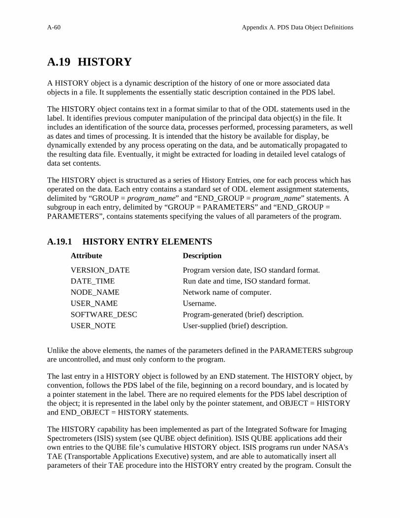
A-60 Appendix A. PDS Data Object Definitions
A HISTORY object is a dynamic description of the history of one or more associated data
objects in a file. It supplements the essentially static description contained in the PDS label. The HISTORY object contains text in a format similar to that of the ODL statements used in the
label. It identifies previous computer manipulation of the principal data object(s) in the file. It
includes an identification of the source data, processes performed, processing parameters, as well
as dates and times of processing. It is intended that the history be available for display, be
dynamically extended by any process operating on the data, and be automatically propagated to
the resulting data file. Eventually, it might be extracted for loading in detailed level catalogs of
data set contents. The HISTORY object is structured as a series of History Entries, one for each process which has
operated on the data. Each entry contains a standard set of ODL element assignment statements,
delimited by “GROUP = program_name” and “END_GROUP = program_name” statements. A
subgroup in each entry, delimited by “GROUP = PARAMETERS” and “END_GROUP =
PARAMETERS”, contains statements specifying the values of all parameters of the program.
A.19.1 HISTORY ENTRY ELEMENTS
Attribute Description
VERSION_DATE Program version date, ISO standard format.
DATE_TIME Run date and time, ISO standard format.
NODE_NAME Network name of computer.
USER_NAME Username.
SOFTWARE_DESC Program-generated (brief) description.
USER_NOTE User-supplied (brief) description. Unlike the above elements, the names of the parameters defined in the PARAMETERS subgroup
are uncontrolled, and must only conform to the program. The last entry in a HISTORY object is followed by an END statement. The HISTORY object, by
convention, follows the PDS label of the file, beginning on a record boundary, and is located by
a pointer statement in the label. There are no required elements for the PDS label description of
the object; it is represented in the label only by the pointer statement, and OBJECT = HISTORY
and END_OBJECT = HISTORY statements. The HISTORY capability has been implemented as part of the Integrated Software for Imaging
Spectrometers (ISIS) system (see QUBE object definition). ISIS QUBE applications add their
own entries to the QUBE file’s cumulative HISTORY object. ISIS programs run under NASA's
TAE (Transportable Applications Executive) system, and are able to automatically insert all
parameters of their TAE procedure into the HISTORY entry created by the program. Consult the
A.19 HISTORY

Appendix A. PDS Data Object Definitions A-61
ISIS System Design document for details and limitations imposed by that system. (See the
QUBE object description for further references.)
A.19.2 Required Keywords
None
A.19.3 Optional Keywords
None
A.19.4 Required Objects
None
A.19.5 Optional Objects
None
A.19.6 Example
The following single-entry HISTORY object is from a Vicar-generated PDS-labeled QUBE file.
(See the QUBE object example.) There is only one entry because the QUBE (or rather its label)
was generated by a single program, VISIS. A QUBE generated by multiple ISIS programs would
have multiple history entries, represented by multiple GROUPs in the HISTORY object. The diagram following illustrates the placement of the example HISTORY object within a
QUBE data product with an attached PDS label.

A-62 Appendix A. PDS Data Object Definitions
OBJECT = HISTORY
GROUP = VISIS
VERSION_DATE = 1990-11-08
DATE_TIME = 1991-07-25T10:12:52
SOFTWARE_DESC = "ISIS cube file with PDS label has
been generated as systematic product by MIPL using the following
programs:
NIMSMERGE to create EDR's;
NIMSCMM to create the merged mosaic & geometry cube;
HIST2D to create a two-dimensional histogram;
SPECPLOT to create the spectral plots;
TRAN, F2, and INSERT3D to create the SII cube;
VISIS to create the ISIS cube."
USER_NOTE = "VPDIN1/ Footprint, Limbfit,
Height=50"
GROUP = PARAMETERS
EDR_FILE_NAME = " "
/*EDR accessed through MIPL Catalog*/
IMAGE_ID = NULL
SPICE_FILE_NAME = "N/A"
SPIKE_FILE_NAME = "MIPL:[MIPL.GLL]BOOM_OBSCURATION.NIM"
DARK_VALUE_FILE_NAME = "N/A"
CALIBRATION_FILE_NAME = "NDAT:NIMSGS2.CAL"
MERGED_MOSAIC_FILE_NAME = "NDAT:VPDIN1_DN_FP_LF_H50.CUB"
DARK_INTERPOLATION_TYPE = NOUPDAT
PHOTOMETRIC_CORRECTION_TYPE = NONE
CUBE_NIMSEL_TYPE = NOCAL
BINNING_TYPE = FOOTPRNT
FILL_BOX_SIZE = 0
FILL_MIN_VALID_PIXELS = 0
SUMMARY_IMAGE_RED_ID = 0

Appendix A. PDS Data Object Definitions A-63
SUMMARY_IMAGE_GREEN_ID = 0
SUMMARY_IMAGE_BLUE_ID = 0
ADAPT_STRETCH_SAT_FRAC = 0.000000
ADAPT_STRETCH_SAMP_FRAC = 0.000000
RED_STRETCH_RANGE = ( 0, 0)
GREEN_STRETCH_RANGE = ( 0, 0)
BLUE_STRETCH_RANGE = ( 0, 0)
END_GROUP = PARAMETERS
END_GROUP = VISIS
END_OBJECT = HISTORY
END

A-64 Appendix A. PDS Data Object Definitions
An IMAGE object is a two-dimensional array of values, all of the same type, each of which is
referred to as a sample. IMAGE objects are normally processed with special display tools to
produce a visual representation of the samples by assigning brightness levels or display colors to
the values. An IMAGE consists of a series of lines, each containing the same number of samples.
The required IMAGE keywords define the parameters for simple IMAGE objects:
• LINES is the number of lines in the image.
• LINE_SAMPLES is the number of samples in each line.
• SAMPLE_BITS is the number of bits in each individual sample.
• SAMPLE_TYPE defines the sample data type.
In more complex images, each individual line may have some attached data which are not part of
the image itself (engineering data, checksums, time tags, etc.). In this case the additional, non-
image parameters are accounted for as either LINE_PREFIX_BYTES or
LINE_SUFFIX_BYTES, depending on whether they occur before or after the image samples in
the line. These keywords indicate the total number of bytes used for the additional data, so that
software processing the image can clip these bytes before attempting to display or manipulate the
image. The structure of the prefix or suffix bytes is most often defined by a TABLE object (in
the same label), which will itself have ROW_SUFFIX_BYTES or ROW_PREFIX_BYTES, to
allow table-processing software to skip over the image data. Figure A.1 illustrates the layout of
prefix and suffix bytes around an image.
Figure A.1 – Prefix and Suffix Bytes Attached to an Image
A.20 IMAGE

Appendix A. PDS Data Object Definitions A-65
Sometimes a single image is composed of several bands of data. For example, a color image for
video display may actually consist of three copies of the image: one in red, one in green and one
in blue. Each logical sample corresponds to one value for each of the bands. In this case, the
keyword BANDS is used to indicate the presence of multiple bands of data.
BAND_STORAGE_TYPE indicates how the banded values are organized:
• SAMPLE_INTERLEAVED means that in each line, all band values for each sample are
adjacent in the line. So in the above example of an RGB image, each line would look like
this (numbers are sample numbers, RGB = red, green, blue):
1R 1G 1B 2R 2G 2B 3R 3G 3B ...
• LINE_INTERLEAVED means that successive lines contain the band values for
corresponding samples. Continuing with the RGB example, the first physical lines in the
image data would represent the first display line of the image, first in red, then green,
then blue:
1R 2R 3R 4R ... 1G 2G 3G 4G ... 1B 2B 3B 4B ...
By default, IMAGE objects should be displayed so that the lines are drawn from left to right and
top to bottom. Other organizations can be indicated by using the LINE_DISPLAY_DIRECTION
and SAMPLE_DISPLAY_DIRECTION keywords. Figure A.2 illustrates band storage schemes
and the related keyword values.

A-66 Appendix A. PDS Data Object Definitions
Figure A.2 – Keywords for a Multi-Band Image
A.20.1 Required Keywords
1. LINES
2. LINE_SAMPLES
3. SAMPLE_TYPE
4. SAMPLE_BITS
A.20.2 Optional Keywords
1. BAND_SEQUENCE
2. BAND_STORAGE_TYPE
3. BANDS
4. CHECKSUM
5. DERIVED_MAXIMUM

Appendix A. PDS Data Object Definitions A-67
6. DERIVED_MINIMUM
7. DESCRIPTION
8. ENCODING_TYPE
9. FIRST_LINE
10. FIRST_LINE_SAMPLE
11. INVALID_CONSTANT
12. LINE_PREFIX_BYTES
13. LINE_SUFFIX_BYTES
14. MISSING _CONSTANT
15. OFFSET
16. SAMPLE_BIT_MASK
17. SAMPLING_FACTOR
18. SCALING_FACTOR
19. SOURCE_FILE_NAME
20. SOURCE_LINES
21. SOURCE_LINE_SAMPLES
22. SOURCE_SAMPLE_BITS
23. STRETCHED_FLAG
24. STRETCH_MINIMUM
25. STRETCH_MAXIMUM
A.20.3 Required Objects
None
A.20.4 Optional Objects
None
A.20.5 Example
This is an example of an (attached) IMAGE label for a color digital mosaic image from the Mars
Digital Image Map CD-ROMs. It includes a CHECKSUM to support automated volume
production and validation, a SCALING_FACTOR to indicate the relationship between sample
values and geophysical parameters and stretch keywords to indicate optimal values for image
display.
PDS_VERSION_ID = PDS3
RECORD_TYPE = FIXED_LENGTH
RECORD_BYTES = 956
FILE_RECORDS = 965
LABEL_RECORDS = 3

A-68 Appendix A. PDS Data Object Definitions
^IMAGE_HISTOGRAM = 4
^IMAGE = 6
DATA_SET_ID = "VO1/VO2-M-VIS-5-DIM-V1.0"
PRODUCT_ID = "MG15N022-GRN-666A"
SPACECRAFT_NAME = VIKING_ORBITER_1
TARGET_NAME = MARS
IMAGE_TIME = 1978-01-14T02:00:00
START_TIME = UNK
STOP_TIME = UNK
SPACECRAFT_CLOCK_START_COUNT = UNK
SPACECRAFT_CLOCK_STOP_COUNT = UNK
PRODUCT_CREATION_TIME = 1995-01-01T00:00:00
ORBIT_NUMBER = 666
FILTER_NAME = GREEN
IMAGE_ID = "MG15N022-GRN-666A"
INSTRUMENT_NAME = {VISUAL_IMAGING_SUBSYSTEM_CAMERA_A,
VISUAL_IMAGING_SUBSYSTEM_CAMERA_B}
NOTE = "MARS MULTI-SPECTRAL MDIM SERIES"
SOURCE_PRODUCT_ID = "666A36"
EMISSION_ANGLE = 21.794
INCIDENCE_ANGLE = 66.443
PHASE_ANGLE = 46.111
/* DESCRIPTION OF OBJECTS CONTAINED IN FILE */
OBJECT = IMAGE_HISTOGRAM
ITEMS = 256
DATA_TYPE = VAX_INTEGER
ITEM_BYTES = 4
END_OBJECT = IMAGE_HISTOGRAM
OBJECT = IMAGE
LINES = 960
LINE_SAMPLES = 956
SAMPLE_TYPE = UNSIGNED_INTEGER
SAMPLE_BITS = 8
SAMPLE_BIT_MASK = 2#11111111#
CHECKSUM = 65718982
SCALING_FACTOR = 0.001000
/* I/F = scaling factor*DN+offset, */
/* convert to intensity/flux. */
OFFSET = 0.0
STRETCHED_FLAG = FALSE
/* Optimum color stretch for display */
/* of color images. */
STRETCH_MINIMUM = ( 53, 0)
STRETCH_MAXIMUM = (133,255)
END_OBJECT = IMAGE
END

Appendix A. PDS Data Object Definitions A-69
The INDEX_TABLE object is a specific type of a TABLE object that provides information
about the data stored on an archive volume. The INDEX_TABLE contains one row for each data
file (or data product label file, in the case where detached labels are used) on the volume. The
table is formatted so that it may be read directly by many data management systems on various
host computers: all fields (columns) are separated by commas; character fields are enclosed in
double quotation marks; and each record ends in a carriage return/line feed sequence.
The columns of an INDEX_TABLE contain path information for each file, plus values extracted
from keywords in the PDS labels. Columns are selected to allow users to a) search the table for
specific files of interest; and b) identify the exact location of the file both on the volume and in
the PDS catalog. In general, the columns listed in Section A.20.5.1 as optional are used for
searching the table; the required columns listed in Section A.20.4.1 provide the identification
information for each file. Where possible the PDS keyword name should be used as the NAME
value in the corresponding COLUMN definition.
Note: See Section 17.2 for information about the use of the constants “N/A”, “UNK” and
“NULL” in an INDEX_TABLE.
A.21.1 INDEX_TABLEs Under Previous Version of the Standards
Prior to version 3.2 of the Standards, the INDEX_TYPE keyword was optional. Cumulative
indices were identified by their filenames, which were (and still are) of the form
“CUMINDEX.TAB” or “axxCMIDX.TAB” (with axx representing up to three alphanumeric
characters). So, when INDEX_TYPE is not present, it defaults to “CUMULATIVE” in
cumulative index files (that is, file with filenames as above) and “SINGLE” in all other index
files.
A.21.2 Required Keywords
1. INTERCHANGE_FORMAT
2. ROWS
3. COLUMNS
4. ROW_BYTES
5. INDEX_TYPE
A.21.3 Optional Keywords
1. NAME
2. DESCRIPTION
3. INDEXED_FILE_NAME
A.21 INDEX_TABLE

A-70 Appendix A. PDS Data Object Definitions
4. UNKNOWN_CONSTANT
5. NOT_APPLICABLE_CONSTANT
A.21.4 Required Objects
1. COLUMN
A.21.4.1 Required COLUMN Objects
The following COLUMN objects (as identified by the COLUMN_NAME keyword) are required
to be included in the INDEX_TABLE object:
COLUMN_NAME
1. FILE_SPECIFICATION_NAME, or PATH_NAME and FILE_NAME 2. PRODUCT_ID
**
3. VOLUME_ID *
4. DATA_SET_ID *
5. PRODUCT_CREATION_TIME *
6. LOGICAL_VOLUME_PATH_NAME * (must be used with PATH_NAME
and FILE_NAME for a logical volume)
* If the value is constant across the data in the index table, this keyword can appear
in the index table’s label. If the value is not constant, then a column of the given name
must be used. ** PRODUCT_ID is not required if it has the same value as FILE_NAME or
FILE_SPECIFICATION_NAME.
A.21.4.2 Required Keywords (for Required COLUMN Objects)
1. NAME
2. DATA_TYPE
3. START_BYTE
4. BYTES
5. DESCRIPTION
A.21.5 Optional Objects
None
A.21.5.1 Optional COLUMN Objects (NAME=)

Appendix A. PDS Data Object Definitions A-71
The following COLUMN objects (as identified by the COLUMN_NAME keyword) may be
optionally included in the INDEX_TABLE object:
COLUMN_NAME
1. MISSION_NAME 2. INSTRUMENT_NAME (or ID)
3. INSTRUMENT_HOST_NAME (or ID), or SPACECRAFT_NAME (or ID)
4. TARGET_NAME
5. PRODUCT_TYPE
6. MISSION_PHASE_NAME
7. VOLUME_SET_ID
8. START_TIME
9. STOP_TIME
10. SPACECRAFT_CLOCK_START_COUNT
11. SPACECRAFT_CLOCK_STOP_COUNT 12. any other search columns
A.21.6 Example
PDS_VERSION_ID = PDS3
RECORD_TYPE = FIXED_LENGTH
RECORD_BYTES = 180
FILE_RECORDS = 220
DESCRIPTION = "INDEX.TAB lists all data files on this
volume"
^INDEX_TABLE = "INDEX.TAB"
OBJECT = INDEX_TABLE
INTERCHANGE_FORMAT = ASCII
ROW_BYTES = 180
ROWS = 220
COLUMNS = 9
INDEX_TYPE = SINGLE
INDEXED_FILE_NAME = {"*.AMD","*.ION","*.TIM","*.TRO",
"*.WEA","*.LIT","*.MIF","*.MPD",
"*.ODF","*.ODR","*.ODS","*.SFO",
"*.SOE","*.TDF"}
OBJECT = COLUMN
NAME = VOLUME_ID
DESCRIPTION = "Identifies the volume containing the
named file"
DATA_TYPE = CHARACTER
START_BYTE = 2
BYTES = 9
END_OBJECT = COLUMN

A-72 Appendix A. PDS Data Object Definitions
OBJECT = COLUMN
NAME = DATA_SET_ID
DESCRIPTION = "The data set identifier. Acceptable
values include ’MO-M-RSS-1-OIDR-V1.0’"
DATA_TYPE = CHARACTER
START_BYTE = 14
BYTES = 25
END_OBJECT = COLUMN
OBJECT = COLUMN
NAME = PATH_NAME
DESCRIPTION = "Path to directory containing file.
Acceptable values include:
'AMD',
'ION',
'TIM',
'TRO',
'WEA',
'LIT',
'MIF',
'MPD',
'ODF',
'ODR',
'ODS',
'SFO',
'SOE', and
'TDF'."
DATA_TYPE = CHARACTER
START_BYTE = 42
BYTES = 9
END_OBJECT = COLUMN
OBJECT = COLUMN
NAME = FILE_NAME
DESCRIPTION = "Name of file in archive"
DATA_TYPE = CHARACTER
START_BYTE = 54
BYTES = 12
END_OBJECT = COLUMN
OBJECT = COLUMN
NAME = PRODUCT_ID
DESCRIPTION = "Original file name on MO PDB or SOPC"
DATA_TYPE = CHARACTER
START_BYTE = 69
BYTES = 33
END_OBJECT = COLUMN
OBJECT = COLUMN
NAME = START_TIME
DESCRIPTION = "Time at which data in the file begin
given in the format 'YYYY-MM-DDThh:mm:ss'."
DATA_TYPE = CHARACTER
START_BYTE = 105

Appendix A. PDS Data Object Definitions A-73
BYTES = 19
END_OBJECT = COLUMN
OBJECT = COLUMN
NAME = STOP_TIME
DESCRIPTION = "Time at which data in the file end
given in the format 'YYYY-MM-DDThh:mm:ss'."
DATA_TYPE = CHARACTER
START_BYTE = 127
BYTES = 19
END_OBJECT = COLUMN
OBJECT = COLUMN
NAME = PRODUCT_CREATION_TIME
DESCRIPTION = "Date and time that file was created."
DATA_TYPE = CHARACTER
START_BYTE = 149
BYTES = 19
END_OBJECT = COLUMN
OBJECT = COLUMN
NAME = FILE_SIZE
DESCRIPTION = "Number of bytes in file, not including
label."
DATA_TYPE = "ASCII INTEGER"
START_BYTE = 170
BYTES = 9
END_OBJECT = COLUMN
END_OBJECT = INDEX_TABLE
END

A-74 Appendix A. PDS Data Object Definitions
The PALETTE object, a sub-class of the TABLE object, contains entries which represent color
table assignments for values (i.e., SAMPLEs) contained in an IMAGE. If the PALETTE is stored in a separate file from the IMAGE object, then it should be stored in
ASCII format as 256 rows, each with 4 columns. The first column contains the SAMPLE value
(running from 0–255 for an 8-bit SAMPLE, for example), and the remaining three columns
contain the relative amount (a value from 0 to 255) of each primary color to be assigned for that
SAMPLE value. If the PALETTE is stored in the same file as the IMAGE object, then the PALETTE should be
stored in BINARY format as 256 consecutive 8-bit values for each primary color (RED,
GREEN, BLUE) resulting in a 768-byte record.
A.22.1 Required Keywords
1. INTERCHANGE_FORMAT
2. ROWS
3. ROW_BYTES
4. COLUMNS
A.22.2 Optional Keywords
1. DESCRIPTION
2. NAME
A.22.3 Required Objects
1. COLUMN
A.22.4 Optional Objects
None
A.22.5 Example
The examples below illustrate both types of PALETTE objects (ASCII and BINARY). The first
is example is a complete label for an ASCII PALETTE object:
PDS_VERSION_ID = PDS3
A.22 PALETTE

Appendix A. PDS Data Object Definitions A-75
RECORD_TYPE = FIXED_LENGTH
RECORD_BYTES = 80
FILE_RECORDS = 256
^PALETTE = "PALETTE.TAB"
/* Image Palette description */
SPACECRAFT_NAME = MAGELLAN
MISSION_PHASE_NAME = PRIMARY_MISSION
TARGET_NAME = VENUS
PRODUCT_ID ="GEDR-MERC.1;2"
IMAGE_ID ="GEDR-MERC.1;2"
INSTRUMENT_NAME ="RADAR SYSTEM"
PRODUCT_CREATION_TIME = 1995-01-01T00:00:00
NOTE = "Palette for browse image"
/* Description of an ASCII PALETTE object */
OBJECT = PALETTE
INTERCHANGE_FORMAT = ASCII
ROWS = 256
ROW_BYTES = 80
COLUMNS = 4
OBJECT = COLUMN
NAME = SAMPLE
DESCRIPTION = "DN value for red, green, blue
intensities"
DATA_TYPE = ASCII_INTEGER
START_BYTE = 1
BYTES = 3
END_OBJECT
OBJECT = COLUMN
NAME = RED
DESCRIPTION = "Red intensity (0 - 255)"
DATA_TYPE = ASCII_INTEGER
START_BYTE = 6
BYTES = 3
END_OBJECT
OBJECT = COLUMN
NAME = GREEN
DESCRIPTION = "Green intensity (0 – 255)"
DATA_TYPE = ASCII_INTEGER
START_BYTE = 11
BYTES = 3
END_OBJECT
OBJECT = COLUMN
NAME = BLUE
DESCRIPTION = "Blue intensity (0 – 255)"
DATA_TYPE = ASCII_INTEGER
START_BYTE = 16
BYTES = 3

A-76 Appendix A. PDS Data Object Definitions
END_OBJECT
END_OBJECT
END
This label fragment illustrates the definition of a binary PALETTE object:
/* Description of a BINARY PALETTE object */
OBJECT = PALETTE
INTERCHANGE_FORMAT = BINARY
ROWS = 1
ROW_BYTES = 768
COLUMNS = 3
OBJECT = COLUMN
NAME = RED
DATA_TYPE = UNSIGNED_INTEGER
START_BYTE = 1
ITEMS = 256
ITEM_BYTES = 1
END_OBJECT = COLUMN
OBJECT = COLUMN
NAME = GREEN
DATA_TYPE = UNSIGNED_INTEGER
START_BYTE = 257
ITEMS = 256
ITEM_BYTES = 1
END_OBJECT = COLUMN
OBJECT = COLUMN
NAME = BLUE
DATA_TYPE = UNSIGNED_INTEGER
START_BYTE = 513
ITEMS = 256
ITEM_BYTES = 1
END_OBJECT = COLUMN
END_OBJECT = PALETTE

Appendix A. PDS Data Object Definitions A-77
A generalized QUBE object is a multidimensional array (called the core) of sample values in
multiple dimensions. The core is homogeneous, and consists of unsigned byte, signed halfword
or floating point fullword elements. QUBEs of one to three dimensions may have optional suffix
areas in each axis. The suffix areas may be heterogeneous, with elements of different types, but
each suffix pixel is always allocated a full word. Special values may be defined for the core and
the suffix areas to designate missing values and several kinds of invalid values, such as
instrument and representation saturation. The QUBE is the principal data structure of the ISIS (Integrated Software for Imaging
Spectrometers) system. A frequently used specialization of the QUBE object is the ISIS Standard
Qube, which is a three-dimensional QUBE with two spatial dimensions and one spectral
dimension. Its axes have the interpretations 'sample', 'line' and 'band'. Three physical storage
orders are allowed: band-sequential, line_interleaved (band-interleaved-by-line) and
sample_interleaved (band-interleaved-by-pixel). An example of a Standard ISIS Qube is a spectral image qube containing data from an imaging
spectrometer. Such a qube is simultaneously a set of images (at different wavelengths) of the
same target area, and a set of spectra at each point of the target area. Typically, suffix areas in
such a qube are confined to 'backplanes' containing geometric or quality information about
individual spectra, i.e. about the set of corresponding values at the same pixel location in each
band. The following diagram illustrates the general structure of a Standard ISIS Qube. Note that this is
a conceptual or “logical” view of the qube.
Figure A.3 – Exploded View of a Qube Object
A.23 QUBE
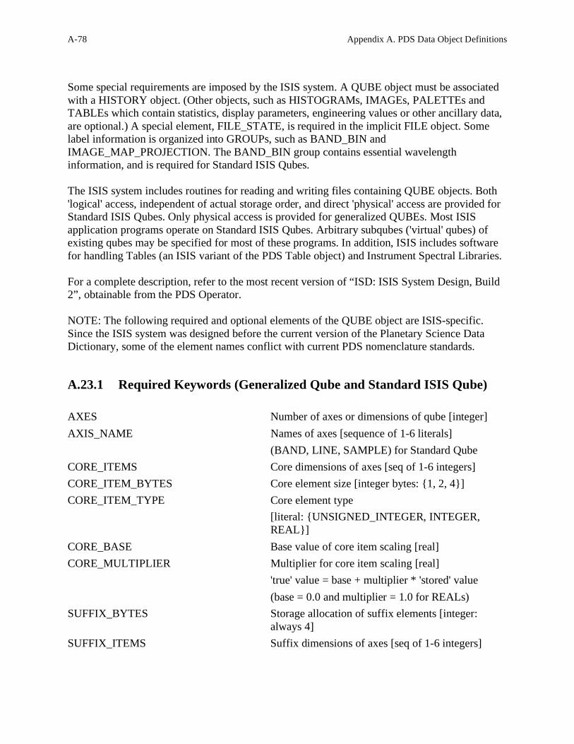
A-78 Appendix A. PDS Data Object Definitions
Some special requirements are imposed by the ISIS system. A QUBE object must be associated
with a HISTORY object. (Other objects, such as HISTOGRAMs, IMAGEs, PALETTEs and
TABLEs which contain statistics, display parameters, engineering values or other ancillary data,
are optional.) A special element, FILE_STATE, is required in the implicit FILE object. Some
label information is organized into GROUPs, such as BAND_BIN and
IMAGE_MAP_PROJECTION. The BAND_BIN group contains essential wavelength
information, and is required for Standard ISIS Qubes.
The ISIS system includes routines for reading and writing files containing QUBE objects. Both
'logical' access, independent of actual storage order, and direct 'physical' access are provided for
Standard ISIS Qubes. Only physical access is provided for generalized QUBEs. Most ISIS
application programs operate on Standard ISIS Qubes. Arbitrary subqubes ('virtual' qubes) of
existing qubes may be specified for most of these programs. In addition, ISIS includes software
for handling Tables (an ISIS variant of the PDS Table object) and Instrument Spectral Libraries.
For a complete description, refer to the most recent version of “ISD: ISIS System Design, Build
2”, obtainable from the PDS Operator.
NOTE: The following required and optional elements of the QUBE object are ISIS-specific.
Since the ISIS system was designed before the current version of the Planetary Science Data
Dictionary, some of the element names conflict with current PDS nomenclature standards.
A.23.1 Required Keywords (Generalized Qube and Standard ISIS Qube)
AXES Number of axes or dimensions of qube [integer]
AXIS_NAME Names of axes [sequence of 1-6 literals]
(BAND, LINE, SAMPLE) for Standard Qube
CORE_ITEMS Core dimensions of axes [seq of 1-6 integers]
CORE_ITEM_BYTES Core element size [integer bytes: {1, 2, 4}]
CORE_ITEM_TYPE Core element type
[literal: {UNSIGNED_INTEGER, INTEGER,
REAL}]
CORE_BASE Base value of core item scaling [real]
CORE_MULTIPLIER Multiplier for core item scaling [real]
'true' value = base + multiplier * 'stored' value
(base = 0.0 and multiplier = 1.0 for REALs)
SUFFIX_BYTES Storage allocation of suffix elements [integer:
always 4]
SUFFIX_ITEMS Suffix dimensions of axes [seq of 1-6 integers]

Appendix A. PDS Data Object Definitions A-79
CORE_VALID_MINIMUM Minimum valid core value -- values below this
value are reserved for 'special' values, of which 5
are currently assigned [integer or non-decimal
integer: these values are fixed by ISIS convention
for each allowable item type and size -- see ISD for
details]
CORE_NULL Special value indicating 'invalid' data
CORE_LOW_INSTR_SATURATION Special value indicating instrument saturation at the
low end
CORE_HIGH_INSTR_SATURATION Special value indicating instrument saturation at the
high end
CORE_LOW_REPR_SATURATION Special value indicating representation saturation at
the low end
CORE_HIGH_REPR_SATURATION Special value indicating representation saturation at
the high end
A.23.2 Required Keywords (Standard ISIS Qube) and Optional Keywords
(Generalized Qube)
CORE_NAME Name of value stored in core of qube [literal, e.g.
SPECTRAL_RADIANCE]
CORE_UNIT Unit of value stored in core of qube [literal]
BAND_BIN_CENTER Wavelengths of bands in a Standard Qube
[sequence of reals]
BAND_BIN_UNIT Unit of wavelength [literal, e.g. MICROMETER]
BAND_BIN_ORIGINAL_BAND Original band numbers, referring to a Qube of
which the current qube is a subqube. In the original
qube, these are sequential integers.[sequence of
integers]
A.23.3 Optional Keywords (Generalized Qube and Standard ISIS Qube)
BAND_BIN_WIDTH Width (at half height) of spectral response of bands
[sequence of reals]
BAND_BIN_STANDARD_DEVIATION Standard deviation of spectrometer values at each
band [sequence of reals]
BAND_BIN_DETECTOR Instrument detector number of band, where relevant
[sequence of integers]

A-80 Appendix A. PDS Data Object Definitions
BAND_BIN_GRATING_POSITION Instrument grating position of band, where relevant
[sequence of integers]
A.23.3.1 Required Keywords (for each suffix present in a 1-3 dimensional qube):
Note: These must be prefixed by the specific AXIS_NAME. These are SAMPLE, LINE and
BAND for Standard ISIS Qubes. Only the commonly used BAND variants are shown:
BAND_SUFFIX_NAME Names of suffix items [sequence of literals]
BAND_SUFFIX_UNIT Units of suffix items [sequence of literals]
BAND_SUFFIX_ITEM_BYTES Suffix item sizes [sequence of integer bytes {1, 2,
4}]
BAND_SUFFIX_ITEM_TYPE Suffix item types [sequence of literals:
{UNSIGNED_INTEGER, INTEGER, REAL, ...}]
BAND_SUFFIX_BASE Base values of suffix item scaling [sequence of
reals] (see corresponding core element)
BAND_SUFFIX_MULTIPLIER Multipliers for suffix item scaling [sequence of
reals] (see corresponding core element)
BAND_SUFFIX_VALID_MINIMUM Minimum valid suffix values
BAND_SUFFIX_NULL ...and assigned special values
BAND_SUFFIX_LOW_INSTR_SAT [sequences of integers or reals]
BAND_SUFFIX_HIGH_INSTR_SAT (see corresponding core
BAND_SUFFIX_LOW_REPR_SAT element definitions for
BAND_SUFFIX_HIGH_REPR_SAT details)
A.23.4 Example
The following label describes ISIS QUBE data from the Galileo NIMS experiment. The QUBE
contains 17 bands of NIMS fixed-map mode raw data numbers and 9 backplanes of ancillary
information. In other modes, NIMS can produce data qubes of 34, 102, 204 and 408 bands.
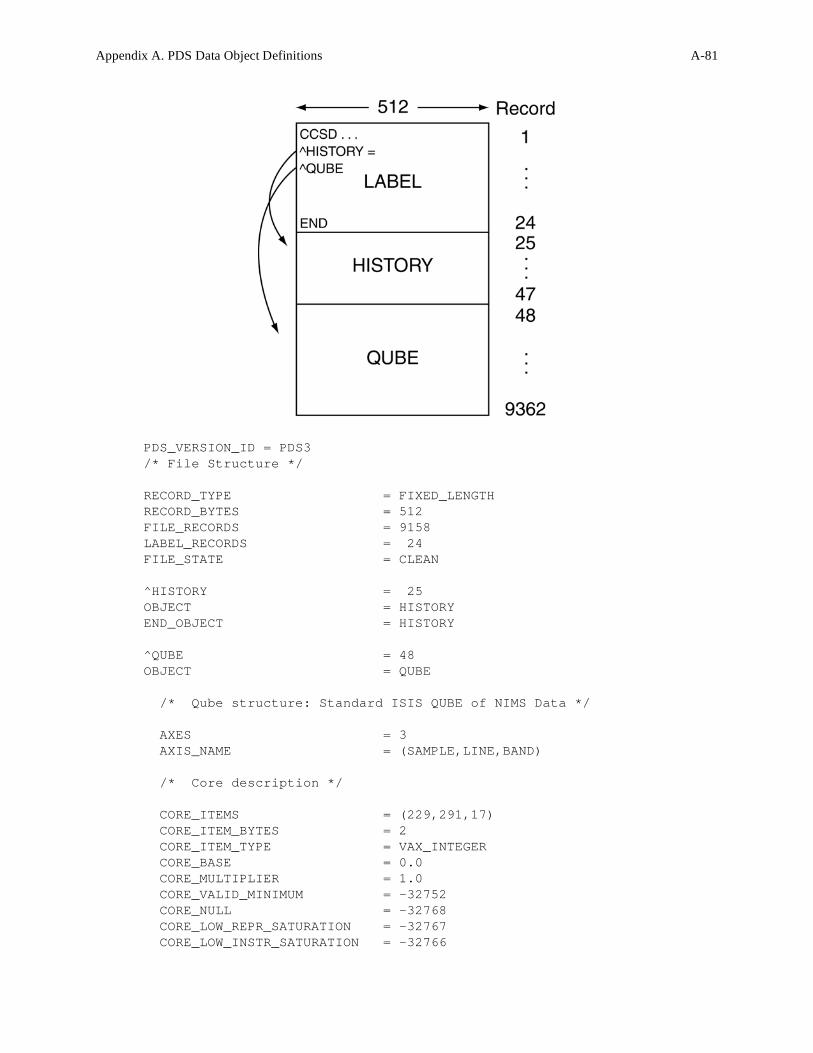
Appendix A. PDS Data Object Definitions A-81
PDS_VERSION_ID = PDS3
/* File Structure */
RECORD_TYPE = FIXED_LENGTH
RECORD_BYTES = 512
FILE_RECORDS = 9158
LABEL_RECORDS = 24
FILE_STATE = CLEAN
^HISTORY = 25
OBJECT = HISTORY
END_OBJECT = HISTORY
^QUBE = 48
OBJECT = QUBE
/* Qube structure: Standard ISIS QUBE of NIMS Data */
AXES = 3
AXIS_NAME = (SAMPLE,LINE,BAND)
/* Core description */
CORE_ITEMS = (229,291,17)
CORE_ITEM_BYTES = 2
CORE_ITEM_TYPE = VAX_INTEGER
CORE_BASE = 0.0
CORE_MULTIPLIER = 1.0
CORE_VALID_MINIMUM = -32752
CORE_NULL = -32768
CORE_LOW_REPR_SATURATION = -32767
CORE_LOW_INSTR_SATURATION = -32766

A-82 Appendix A. PDS Data Object Definitions
CORE_HIGH_INSTR_SATURATION = -32765
CORE_HIGH_REPR_SATURATION = -32764
CORE_NAME = RAW_DATA_NUMBER
CORE_UNIT = DIMENSIONLESS
PHOTOMETRIC_CORRECTION_TYPE = NONE
/* Suffix description */
SUFFIX_BYTES = 4
SUFFIX_ITEMS = (0,0,9)
BAND_SUFFIX_NAME = (LATITUDE,LONGITUDE, INCIDENCE_ANGLE,
EMISSION_ANGLE, PHASE_ANGLE, SLANT_DISTANCE, INTERCEPT_ALTITUDE,
PHASE_ANGLE_STD_DEV, RAW_DATA_NUMBER_STD_DEV)
BAND_SUFFIX_UNIT = (DEGREE, DEGREE, DEGREE, DEGREE, DEGREE,
KILOMETER, KILOMETER, DEGREE, DIMENSIONLESS)
BAND_SUFFIX_ITEM_BYTES = (4,4,4,4,4,4,4,4,4)
BAND_SUFFIX_ITEM_TYPE = (VAX_REAL, VAX_REAL, VAX_REAL, VAX_REAL,
VAX_REAL, VAX_REAL, VAX_REAL, VAX_REAL, VAX_REAL)
BAND_SUFFIX_BASE = (0.000000, 0.000000, 0.000000, 0.000000,
0.000000, 0.000000, 0.000000, 0.000000, 0.000000)
BAND_SUFFIX_MULTIPLIER = (1.000000, 1.000000, 1.000000, 1.000000,
1.000000, 1.000000, 1.000000, 1.000000, 1.000000)
BAND_SUFFIX_VALID_MINIMUM = (16#FFEFFFFF#, 16#FFEFFFFF#,
16#FFEFFFFF#, 16#FFEFFFFF#, 16#FFEFFFFF#, 16#FFEFFFFF#,
16#FFEFFFFF#, 16#FFEFFFFF#, 16#FFEFFFFF#)
BAND_SUFFIX_NULL = (16#FFFFFFFF#, 16#FFFFFFFF#,
16#FFFFFFFF#, 16#FFFFFFFF#, 16#FFFFFFFF#, 16#FFFFFFFF#,
16#FFFFFFFF#, 16#FFFFFFFF#, 16#FFFFFFFF#)
BAND_SUFFIX_LOW_REPR_SAT = (16#FFFEFFFF#, 16#FFFEFFFF#,
16#FFFEFFFF#, 16#FFFEFFFF#, 16#FFFEFFFF#, 16#FFFEFFFF#,
16#FFFEFFFF#, 16#FFFEFFFF#, 16#FFFEFFFF#)
BAND_SUFFIX_LOW_INSTR_SAT = (16#FFFDFFFF#, 16#FFFDFFFF#,
16#FFFDFFFF#, 16#FFFDFFFF#, 16#FFFDFFFF#, 16#FFFDFFFF#,
16#FFFDFFFF#, 16#FFFDFFFF#, 16#FFFDFFFF#)
BAND_SUFFIX_HIGH_INSTR_SAT = (16#FFFCFFFF#, 16#FFFCFFFF#,
16#FFFCFFFF#, 16#FFFCFFFF#, 16#FFFCFFFF#, 16#FFFCFFFF#,
16#FFFCFFFF#, 16#FFFCFFFF#, 16#FFFCFFFF#)
BAND_SUFFIX_HIGH_REPR_SAT = (16#FFFBFFFF#, 16#FFFBFFFF#,
16#FFFBFFFF#, 16#FFFBFFFF#, 16#FFFBFFFF#, 16#FFFBFFFF#,
16#FFFBFFFF#, 16#FFFBFFFF#, 16#FFFBFFFF#)
BAND_SUFFIX_NOTE = "The backplanes contain 7 geometric
parameters, the standard deviation of one of them, the standard
deviation of a selected data band, and 0 to 10 'spectral index'
bands, each a user-specified function of the data bands. (See
the BAND_SUFFIX_NAME values.)
Longitude ranges from 0 to 360 degrees, with positive direction
specified by POSITIVE_LONGITUDE_DIRECTION in the
IMAGE_MAP_PROJECTION group.
INTERCEPT_ALTITUDE contains values for the DIFFERENCE between
the length of the normal from the center of the target body to the
line of sight AND the radius of the target body. On-target points
have zero values. Points beyond the maximum expanded radius have

Appendix A. PDS Data Object Definitions A-83
null values. This plane thus also serves as a set of 'off-limb'
flags. It is meaningful only for the ORTHOGRAPHIC and
POINT_PERSPECTIVE projections; otherwise all values are zero. The
geometric standard deviation backplane contains the standard
deviation of the geometry backplane indicated in its NAME, except
that the special value 16#FFF9FFFF# replaces the standard
deviation where the corresponding core pixels have been 'filled'.
The data band standard deviation plane is computed for the NIMS
data band specified by STD_DEV_SELECTED_BAND_NUMBER. This may be
either a raw data number, or spectral radiance, whichever is
indicated by CORE_NAME.
The (optional) spectral index bands were generated by the Vicar F2
program. The corresponding BAND_SUFFIX_NAME is an abbreviated
formula for the function used, where Bn should be read 'NIMS data
band n'. For example: B4/B8 represents the ratio of bands 4 and
8."
STD_DEV_SELECTED_BAND_NUMBER = 9
/* Data description: general */
DATA_SET_ID = "GO-V-NIMS-4-MOSAIC-V1.0"
PRODUCT_ID = "XYZ"
SPACECRAFT_NAME = GALILEO_ORBITER
MISSION_PHASE_NAME = VENUS_ENCOUNTER
INSTRUMENT_NAME = NEAR_INFRARED_MAPPING_SPECTROMETER
INSTRUMENT_ID = NIMS
^INSTRUMENT_DESCRIPTION = "NIMSINST.TXT"
TARGET_NAME = VENUS
START_TIME = 1990-02-10T01:49:58
STOP_TIME = 1990-02-10T02:31:52
NATIVE_START_TIME = 180425.85
NATIVE_STOP_TIME = 180467.34
OBSERVATION_NAME = 'VPDIN1'
OBSERVATION_NOTE = "VPDIN1 / Footprint, Limbfit,
Height=50"
INCIDENCE_ANGLE = 160.48
EMISSION_ANGLE = 14.01
PHASE_ANGLE = 147.39
SUB_SOLAR_AZIMUTH = -174.74
SUB_SPACECRAFT_AZIMUTH = -0.80
MINIMUM_SLANT_DISTANCE = 85684.10
MAXIMUM_SLANT_DISTANCE = 103175.00
MIN_SPACECRAFT_SOLAR_DISTANCE = 1.076102e+08
MAX_SPACECRAFT_SOLAR_DISTANCE = 1.076250e+08
/* Data description: instrument status */
INSTRUMENT_MODE_ID = FIXED_MAP
GAIN_MODE_ID = 2

A-84 Appendix A. PDS Data Object Definitions
CHOPPER_MODE_ID = REFERENCE
START_GRATING_POSITION = 16
OFFSET_GRATING_POSITION = 04
MEAN_FOCAL_PLANE_TEMPERATURE = 85.569702
MEAN_RAD_SHIELD_TEMPERATURE = 123.636002
MEAN_TELESCOPE_TEMPERATURE = 139.604996
MEAN_GRATING_TEMPERATURE = 142.580002
MEAN_CHOPPER_TEMPERATURE = 142.449997
MEAN_ELECTRONICS_TEMPERATURE = 287.049988
GROUP = BAND_BIN
BAND_BIN_CENTER = (0.798777, 0.937873, 1.179840,
1.458040, 1.736630, 2.017250, 2.298800, 2.579060, 2.864540,
3.144230, 3.427810, 3.710640, 3.993880, 4.277290, 4.561400,
4.843560, 5.126080)
BAND_BIN_UNIT = MICROMETER
BAND_BIN_ORIGINAL_BAND = (1, 2, 3, 4, 5, 6, 7, 8, 9, 10, 11,
12, 13, 14, 15, 16, 17)
BAND_BIN_GRATING_POSITION = (16, 16, 16, 16, 16, 16, 16, 16, 16,
16, 16, 16, 16, 16, 16, 16, 16)
BAND_BIN_DETECTOR = (1, 2, 3, 4, 5, 6, 7, 8, 9, 10, 11,
12, 13, 14, 15, 16, 17)
END_GROUP = BAND_BIN
GROUP = IMAGE_MAP_PROJECTION
/* Projection description */
MAP_PROJECTION_TYPE = OBLIQUE_ORTHOGRAPHIC
MAP_SCALE = 45.000
MAP_RESOLUTION = 2.366
CENTER_LATITUDE = 12.00
CENTER_LONGITUDE = 350.00
LINE_PROJECTION_OFFSET = 149.10
SAMPLE_PROJECTION_OFFSET = 85.10
MINIMUM_LATITUDE = 11.71
MAXIMUM_LATITUDE = 13.62
MINIMUM_LONGITUDE = 349.62
MAXIMUM_LONGITUDE = 351.72
POSITIVE_LONGITUDE_DIRECTION = EAST
A_AXIS_RADIUS = 6101.000000
B_AXIS_RADIUS = 6101.000000
C_AXIS_RADIUS = 6101.000000
REFERENCE_LATITUDE = 0.000000
REFERENCE_LONGITUDE = 0.000000
MAP_PROJECTION_ROTATION = 0.00
LINE_FIRST_PIXEL = 1
LINE_LAST_PIXEL = 229
SAMPLE_FIRST_PIXEL = 1
SAMPLE_LAST_PIXEL = 291
END_GROUP = IMAGE_MAP_PROJECTION
END_OBJECT = QUBE
END

Appendix A. PDS Data Object Definitions A-85
The SERIES object is a sub-class of the TABLE object. It is used for storing a sequence of
measurements organized in a specific way (e.g., chronologically, by radial distance, etc.). The
SERIES uses the same physical format specification as the TABLE object with additional
sampling parameter information describing the variation between elements in the series. The
sampling parameter keywords are required for the SERIES object itself, but are optional for the
COLUMN sub-objects, depending on the data organization. The sampling parameter keywords in the SERIES object represent the variation between the
ROWS of data. For data with regularly-spaced rows, the
SAMPLING_PARAMETER_INTERVAL keyword defines the row-to-row variation. For data in
which rows are irregularly spaced, the SAMPLING_PARAMETER_INTERVAL keyword is
“N/A” and the actual sampling parameter is included as a COLUMN in the SERIES. When the data vary regularly across items of a single column, sampling parameter keywords
appear as part of the COLUMN sub-object. Data sampled at irregular intervals described as
separate columns may also provide sampling parameter information specific to each column. Optional MINIMUM_SAMPLING_PARAMETER and
MAXIMUM_SAMPLING_PARAMETER keywords should be added whenever possible to
indicate the range in which the data were sampled. For data sampled at a single point rather than
over a range, both the MINIMUM_SAMPLING_PARAMETER and
MAXIMUM_SAMPLING_PARAMETER are set to the specific value.
The object name “TIME_SERIES” is used when the series is chronological. In this case the label
keywords START_TIME and STOP_TIME are assumed to indicate the minimum and maximum
times in the file. If this is not the case, the MINIMUM_SAMPLING_PARAMETER and
MAXIMUM_SAMPLING_PARAMETER keywords should be used to specify the
corresponding time values for the series.
A.24.1 Required Keywords
1. INTERCHANGE_FORMAT
2. ROWS
3. COLUMNS
4. ROW_BYTES
5. SAMPLING_PARAMETER_NAME
6. SAMPLING_PARAMETER_UNIT
7. SAMPLING_PARAMETER_INTERVAL
A.24.2 Optional Keywords
A.24 SERIES

A-86 Appendix A. PDS Data Object Definitions
1. NAME
2. ROW_PREFIX_BYTES
3. ROW_SUFFIX_BYTES
4. MINIMUM_SAMPLING_PARAMETER
5. MAXIMUM_SAMPLING_PARAMETER
6. DERIVED_MINIMUM
7. DERIVED_MAXIMUM
8. DESCRIPTION
A.24.3 Required Objects
1. COLUMN
A.24.4 Optional Objects
1. CONTAINER
A.24.5 Example
This example illustrates the use of the SERIES object for data that vary regularly in two ways:
rows of data in the SERIES occur at 60 millisecond intervals, while the column values occur at
.03472222 millisecond intervals. Note that, as with other forms of the TABLE object, each row
in a SERIES may contain prefix or suffix bytes, indicated in this case by the
ROW_PREFIX_BYTES in the TIME_SERIES definition. The structure of the prefix is defined
by the ROW_PREFIX_TABLE object, for which the COLUMN definitions are stored in a
separate file (“ROWPRX.FMT”).

Appendix A. PDS Data Object Definitions A-87
PDS_VERSION_ID = PDS3
RECORD_TYPE = FIXED_LENGTH
RECORD_BYTES = 1820
FILE_RECORDS = 801
^ENGINEERING_TABLE = ("C0900313.DAT", 1)
^ROW_PREFIX_TABLE = ("C0900313.DAT", 2)
^TIME_SERIES = ("C0900313.DAT", 2)
/* Observation description */
DATA_SET_ID = "VG2-N-PWS-2-EDR-WFRM-60MS-V1.0"
PRODUCT_ID = "C0900313.DAT"
PRODUCT_CREATION_TIME = "UNK"
SPACECRAFT_NAME = VOYAGER_2
SPACECRAFT_CLOCK_START_COUNT = "09003.13.002"
SPACECRAFT_CLOCK_STOP_COUNT = "09003.13.002"
EARTH_RECEIVED_TIME = 1989-159T13:35:00.121
START_TIME = 1989-157T14:16:56.979
STOP_TIME = "N/A"
MISSION_PHASE_NAME = NEPTUNE_ENCOUNTER
TARGET_NAME = NEPTUNE

A-88 Appendix A. PDS Data Object Definitions
/* Instrument description */
INSTRUMENT_NAME = PLASMA_WAVE_RECEIVER
INSTRUMENT_ID = PWS
SECTION_ID = WFRM
/* Object descriptions */
OBJECT = ENGINEERING_TABLE
INTERCHANGE_FORMAT = BINARY
ROWS = 1
COLUMNS = 106
ROW_BYTES = 243
ROW_SUFFIX_BYTES = 1577
DESCRIPTION = "This table describes the format of
the engineering record which is included as the first record in
each PWS high rate waveform file. This record contains the first
242 bytes of data extracted from the Mission and Test Imaging System
(MTIS) header record on each file of an imaging EDR tape. A 243rd
byte containing some flag fields has been added to the table for all
data collected during the Neptune encounter."
^STRUCTURE = "ENGTAB.FMT"
END_OBJECT = ENGINEERING_TABLE
OBJECT = ROW_PREFIX_TABLE
INTERCHANGE_FORMAT = BINARY
ROWS = 800
COLUMNS = 47
ROW_BYTES = 220
ROW_SUFFIX_BYTES = 1600
DESCRIPTION = "This table describes the format of
the engineering data associated with the collection of each row of
waveform data (1600 waveform samples)."
^STRUCTURE = "ROWPRX.FMT"
END_OBJECT = ROW_PREFIX_TABLE
OBJECT = TIME_SERIES
NAME = WAVEFORM_FRAME
INTERCHANGE_FORMAT = BINARY
ROWS = 799
COLUMNS = 1
ROW_BYTES = 1600
ROW_PREFIX_BYTES = 220
SAMPLING_PARAMETER_NAME = TIME
SAMPLING_PARAMETER_UNIT = SECOND
SAMPLING_PARAMETER_INTERVAL = .06 /* 60 MS between rows */
DESCRIPTION = "This time_series consists of up to
800 records (or rows, lines) of PWS waveform sample data. Each
record 2-801 of the file (or frame) contains 1600 waveform samples,
prefaced by 220 bytes of MTIS information. The 1600 samples are
collected in 55.56 msec followed by a 4.44 msec gap. Each 60 msec
interval constitutes a line of waveform samples. Each file contains
up to 800 lines of waveform samples for a 48 sec frame."
OBJECT = COLUMN
NAME = WAVEFORM_SAMPLES

Appendix A. PDS Data Object Definitions A-89
DATA_TYPE = MSB_UNSIGNED_INTEGER
START_BYTE = 221
BYTES = 1600
ITEMS = 1600
ITEM_BYTES = 1
SAMPLING_PARAMETER_NAME = TIME
SAMPLING_PARAMETER_UNIT = SECOND
SAMPLING_PARAMETER_INTERVAL = 0.00003472222 /*time between samples*/
OFFSET = -7.5
VALID_MINIMUM = 0
VALID_MAXIMUM = 15
DESCRIPTION = "The 1-byte waveform samples
constitute an array of waveform measurements which are encoded into
binary values from 0 to 15 and may be re-mapped to reduce the
artificial zero-frequency component. For example, stored values can
be mapped to the following floating point values. The original 4-
bit data samples have been repackaged into 8-bit (1 byte) items
without modification for archival purposes.\n
0 = -7.5 1 = -6.5 2 = -5.5 3 = -4.5
4 = -3.5 5 = -2.5 6 = -1.5 7 = -0.5
8 = 0.5 9 = 1.5 10 = 2.5 11 = 3.5
12 = 4.5 13 = 5.5 14 = 6.5 15 = 7.5
"
END_OBJECT = COLUMN
END_OBJECT = TIME_SERIES
END
A-90 Appendix A. PDS Data Object Definitions
A.25.1 Introduction
Instruments classified as imaging spectrometers are increasingly being used in planetary
missions. Data from these instruments are simultaneously a set of images, at different
wavelengths, of the same target area, and a set of spectra at each point of the target area. In PDS
archives, these data may be stored as SPECTRAL_QUBEs, three-dimensional objects with two
spatial dimensions and one spectral dimension. In these three-dimensional structures, called
“qubes”, the axes have the interpretations “sample”, “line”, and “band”, respectively.
Each of the three axes in a PDS SPECTRAL_QUBE object may optionally include suffix data
that extend the length of the axis. Conceptually, this can be viewed as forming one or more
Suffix planes that are attached to the Core qube, as shown in the diagram below. Suffix planes
that extend the band dimension are called BACKPLANES. Suffix planes that extend the sample
dimension are called SIDEPLANES. Suffix planes that extend the line dimension are called
BOTTOMPLANES.
Note that these terms refer to the “logical” axes – that is, how the axes are conceptually modeled
– and are not necessarily related to the physical storage of the SPECTRAL_QUBE object. The
Suffix planes are used for storing auxiliary data that are associated with the core data. For
example, a backplane might be used for storing the latitude values for each spatial-spatial pixel.
Another backplane might be used for storing the wavelength of the deepest absorption feature
that was found in the spectrum at each spatial-spatial pixel. One or more SIDEPLANES might
be used for storing engineering data that are associated with each spatial line.
A.25.2 Logical Structure of a SPECTRAL_QUBE
As mentioned above, the logical structure of the SPECTRAL_QUBE is its conceptual model.
This is best presented visually, as is shown in the following diagrams;
A.25 SPECTRAL_QUBE

Appendix A. PDS Data Object Definitions A-91
Figure A.4 – Exploded Views of a SPECTRAL_QUBE Object
A.25.2.1 Pixel Coordinates
SAMPLE=1 is the left edge of the spatial-spatial core image. LINE=1 is the top edge of the
spatial-spatial core image. BAND=1 corresponds to the spatial-spatial images at the “front” of
the diagram. Core coordinates do not carry over to the suffix regions.
A.25.3 Physical Structure of a SPECTRAL_QUBE
A.25.3.1 Storage Orders
The file in which a PDS SPECTRAL_QUBE data object is stored is physically accessed as
though it were a one-dimensional data structure. Storing the PDS SPECTRAL_QUBE pictured
above thus requires that the “logical” three-dimensional structure be mapped into the one-
dimensional physical file structure. This involves moving through the three-dimensional
structure in certain patterns to determine the linear sequence of core and suffix pixel values that
occur in the file. In PDS SPECTRAL_QUBE files, this pattern is defined by specifying which

A-92 Appendix A. PDS Data Object Definitions
axis index varies fastest in the linear sequence of pixel values in the file, which axis varies
second fastest, and which axis varies slowest.
In PDS SPECTRAL_QUBE files, the names of the three axes are always SAMPLE, LINE, and
BAND. The AXIS_NAME keyword has an array of values that list the names of the axes in the
qube. The order of the names specifies the qube storage order in the file. The first axis is the
fastest varying, and the third axis is the slowest varying. The PDS SPECTRAL_QUBE supports
the following three storage orders:
• (SAMPLE, LINE, BAND) – Band Sequential (BSQ)
• (SAMPLE, BAND, LINE) – Band Interleaved by Line (BIL)
• (BAND, SAMPLE, LINE) – Band Interleaved by Pixel (BIP)
The lengths of the Core axes are given by the CORE_ITEMS keyword, and the lengths of the
Suffix axes are given by the SUFFIX_ITEMS keyword. Both these keywords have array values,
whose order corresponds to the order of the axes given by the AXIS_NAME keyword.
In the physical file storage, Suffix pixel data (if present) are interspersed with the associated
Core pixel data. For example, in a BSQ storage order file, the physical qube storage in the file
begins with the pixels in the first (top) line of the spatial-spatial image plane at the first
wavelength band. This is followed by the sideplane pixel values that extend this line of core
pixels. Next are the core pixels for the second line, followed by the sideplane pixels for the
second line. After the last line of this first core image plane (and its associated sideplane pixels)
come the bottomplane pixels associated with the first band. This is then repeated for the second
through last bands. Finally, all the backplane data are stored after all the core data and
associated sideplane and bottomplane pixels.
If a PDS SPECTRAL_QUBE file includes suffixes on more than one axis, then the region that is
the intersection between two (or all three) of the suffix regions is called a CORNER region. The
PDS requires that space for CORNER region data be allocated in the data files. However this
space is never actually used.
A.25.3.2 Pixel Storage Sizes
In a PDS SPECTRAL_QUBE file, core pixels can occupy one, two, or four bytes. All core
pixels within a single file must be of the same physical storage size. Suffix pixels can also
occupy one, two, or four bytes of storage in the file. All the suffix pixels within a single file
must be of the same physical storage size. Suffix pixels need not be the same size as core pixels.
Handling of different pixel data types is described in detail below.
A.25.3.3 Core Pixel Data Types

Appendix A. PDS Data Object Definitions A-93
In PDS SPECTRAL_QUBE files, core pixel values can be represented by one of several formats.
The formats available are dependent on the number of bytes used to store the values in the file.
The format is given by the CORE_ITEM_TYPE keyword and the number of bytes stored is
given by the CORE_ITEM_BYTES keyword. The following table shows the allowable formats
and the number of bytes of storage they use:

A-94 Appendix A. PDS Data Object Definitions
CORE_ITEM_BYTES CORE_ITEM_TYPE Type Conversion
Parameters
1, 2, or 4 UNSIGNED_INTEGER Yes
1, 2, or 4 MSB_UNSIGNED_INTEGER Yes
1, 2, or 4 LSB_UNSIGNED_INTEGER Yes
1, 2, or 4 INTEGER Yes
1, 2, or 4 MSB_INTEGER Yes
1, 2, or 4 LSB_INTEGER Yes
4 IEEE_REAL No
4 VAX_REAL No
4 PC_REAL No
As the table above indicates, stored integer values can be converted to real values, representing
the actual pixel. The type conversion parameters are given by the CORE_BASE and
CORE_MULTIPLIER keywords, and the real value being represented is determined as follows:
“real_value” = CORE_BASE + (CORE_MULTIPLIER * REAL(stored_value))
For 4-byte real formats, the stored values are floating point values that directly represent the
pixel values.
A.25.3.4 Suffix Pixel Data Types
The same data types and number of storage bytes that are shown in the above table are also
available to Suffix pixels. However, Suffix pixels need not be the same size or have the same
data type as the Core pixels. Therefore, there is a SUFFIX_ITEM_BYTES keyword to indicate
the number of bytes stored for Suffix pixels and a SUFFIX_ITEM_TYPE keyword to describe
the data type of the Suffix pixels. Each suffix plane within a single file can have a different data
format. Thus, the values of these keywords are arrays. Each element of the array refers to a
spearate suffix plane.
A.25.3.5 Aligning Suffix Pixels within Allocated Bytes
The SPECTRAL_QUBE allows the number of bytes used to store data in each Suffix pixel
(SUFFIX_ITEM_BYTES) to be less than the total number of bytes allocated to each Suffix pixel
(SUFFIX_BYTES). It is therefore necessary to describe how the stored bytes are aligned within
the allocated bytes. The BIT_MASK keyword is used for this purpose.
A.25.4 Data Dictionary Elements for the SPECTRAL_QUBE
The following section details the required and optional data dictionary elements that comprise
the SPECTRAL_QUBE.

Appendix A. PDS Data Object Definitions A-95
NOTE: Some of the following required and optional elements of the SPECTRAL_QUBE object
are ISIS-specific. Since the ISIS system was designed before the current version of the Planetary
Science Data Dictionary, some of the element names below conflict with current PDS
nomenclature standards.
A.25.4.1 Required Objects
None.
A.25.4.2 Optional Objects
Object Name Definition
IMAGE_MAP_PROJECTION Map projection information for the image planes.
A.25.4.3 Required Groups
Group Name Definition
BAND_BIN Group describing properties of each “bin” along the spectral axis.
A.25.4.4 Optional Groups
The following groups are optional, in that they describe optional Suffix axes. However, if the
named axis does appear, its descriptive keywords must be part of the appropriate group:
Group Name Definition
BAND_SUFFIX Group describing properties of the BAND Suffix plane (“BACKPLANE”).
LINE_SUFFIX Group describing properties of the LINE Suffix plane (“BOTTOMPLANE”).
SAMPLE_SUFFIX Group describing properties of the SAMPLE Suffix plane (“SIDEPLANE”).

A-96 Appendix A. PDS Data Object Definitions
A.25.4.5 Required Keywords – Outside of Groups
Keyword Name Definition Values
AXES Number of axes or dimensions of SPECTRAL_QUBE
3 (SPECTRAL_QUBEs are 3-dimensional by definition).
AXIS_NAME Names of axes in order of physical storage.
Literal values SAMPLE, LINE, and BAND in storage order. One of these three storage orders is required:
(SAMPLE, LINE, BAND) (BAND, SAMPLE, LINE) (SAMPLE, BAND, LINE).
CORE_ITEMS Number of pixels on each axis of the Core, in the same order as in AXIS_NAME
Sequence of three integers, e.g. (256, 512, 3).
CORE_ITEM_BYTES Number of bytes in each core pixel.
1, 2, or 4.
CORE_ITEM_TYPE Data type of core pixels. UNSIGNED_INTEGER, MSB_UNSIGNED_INTEGER, LSB_UNSIGNED_INTEGER, INTEGER, MSB_INTEGER, LSB_INTEGER, IEEE_REAL, VAX_REAL, PC_REAL.
SUFFIX_ITEMS Number of side (SAMPLE) suffix planes, bottom (LINE) suffix planes, and back (BAND) suffix planes, in same order as in AXIS_NAME.
Sequence of three integers. If there are no suffix planes, the value is (0, 0, 0).
If suffix planes are present:
SUFFIX_BYTES Number of bytes allocated for each suffix pixel.
1, 2, or 4. See also SUFFIX_ITEM_BYTES.
A.25.4.6 Required Keywords – In the *_SUFFIX Groups
If there are SUFFIX planes, then the following keywords are required. In order to avoid having
to create up to three instances of each one (e.g., BAND_SUFFIX_NAME,
LINE_SUFFIX_NAME, and SAMPLE_SUFFIX_NAME), the keywords must be nested in the
appropriate group (see section on Optional Groups):
BAND_SUFFIX group – if describing a BAND SUFFIX
LINE_SUFFIX group – if describing a LINE SUFFIX

Appendix A. PDS Data Object Definitions A-97
SAMPLE_SUFFIX group – if describing a SAMPLE SUFFIX
Keyword Name Definition Values
SUFFIX_NAME Name of suffix plane Literal, e.g. LATITUDE
SUFFIX_ITEM_BYTES Number of bytes used to store data in each suffix pixel; may be less than the number of bytes allocated for each pixel.
1, 2, or 4. See also SUFFIX_BYTES.
SUFFIX_ITEM_TYPE Data type of suffix pixels. UNSIGNED_INTEGER, MSB_UNSIGNED_INTEGER, LSB_UNSIGNED_INTEGER, INTEGER, MSB_INTEGER, LSB_INTEGER, IEEE_REAL, VAX_REAL, PC_REAL.
A.25.4.7 Required Keywords – In the BAND_BIN Group
Keyword Name Definition Values
BANDS Number of bands in SPECTRAL_QUBE (same as given for the BAND axis in CORE_ITEMS, repeated here for convenience).
Integer.
BAND_BIN_CENTER Wavelengths or frequencies at band centers.
Sequence of real values, one per band.
BAND_BIN_UNIT Unit of measurement of BAND_BIN_CENTER and BAND_BIN_WIDTH values.
For example, MICROMETER.
BAND_BIN_WIDTH Widths (at half height) of bands.
Sequence of real values, one per band.
Note: In the case where there are so many bands that the BAND_BIN group becomes
cumbersome in the label, it may be stored in a separate file indicated in the label by a structure
pointer, e.g. ^STRUCTURE = “BAND_BIN.FMT”.
A.25.4.8 Optional Keywords
The following keywords are optional for the PDS SPECTRAL_QUBE. Some of these keywords
must be used if the SPECTRAL_QUBE is designed for use with the Integrated Software for
Imagers and Spectrometers (ISIS). The column labeled ISIS indicates whether the keyword is

A-98 Appendix A. PDS Data Object Definitions
required by ISIS software. A “YES” means the keyword is required by ISIS, while a “NO”
means it is not:
Keyword Name Definition Values ISIS
ISIS_STRUCTURE_VERSION Version of ISIS software with which the SPECTRAL_QUBE’s physical structure is compatible.
2.1 (Only current valid version number)
YES
CORE_NAME Name of data value stored in the SPECTRAL_QUBE
Literal, e.g. SPECTRAL_RADIANCE.
YES
CORE_BASE Base value for scaling core pixels.
Real. YES
CORE_MULTIPLIER Multiplier for scaling core pixels.
Real. YES
CORE_UNIT Unit of measurement of core data values.
For example, ‘“WATT*M**-2*SR**-1*mM**-1’ (for spectral radiance) or ‘DIMENSIONLESS’ (for raw data).
YES
CORE_VALID_MINIMUM Minimum valid core value. Values below CORE_VALID_MINIMUM have special meaning.
YES
CORE_NULL Special value that indicates invalid data.
Must be less than CORE_VALID_MINIMUM.
YES
CORE_LOW_REPR_ SATURATION
Special value that indicates representation saturation at low end.
Must be less than CORE_VALID_MINIMUM.
YES
CORE_LOW_INSTR_ SATURATION
Special value that indicates instrument saturation at low end.
Must be less than CORE_VALID_MINIMUM.
YES
CORE_HIGH_REPR_ SATURATION
Special value that indicates representation saturation at high end.
Must be less than CORE_VALID_MINIMUM.
YES
CORE_HIGH_INSTR_ SATURATION
Special value that indicates instrument saturation at high end.
Must be less than CORE_VALID_MINIMUM.
YES
SUFFIX_BYTES Number of bytes allocated for each suffix pixel (required even if no suffix planes are present).
1, 2, or 4. See also SUFFIX_ITEM_BYTES.
YES
MD5_CHECKSUM MD5 checksum of all core and suffix bytes.
Character String. NO
LINE_DISPLAY_DIRECTION The preferred orientation of lines within an image for
DOWN, UP, LEFT, RIGHT. NO

Appendix A. PDS Data Object Definitions A-99
viewing on a display device. The default value is down, where lines are viewed top to bottom on the display.
SAMPLE_DISPLAY_DIRECTION The preferred orientation of samples within a line for viewing on a display device. The default is right, meaning samples are viewed from left to right on the display.
DOWN, UP, LEFT, RIGHT. NO
In BAND_SUFFIX, LINE_SUFFIX, and SAMPLE_SUFFIX groups:
BIT_MASK A series of binary digits defining the active bits in a value. Required when fewer bytes are used than are allocated.
A sequence of bits equal to the bit-length of the allocated storage.
NO
SUFFIX_BASE Base value for scaling suffix pixels.
Real. NO
SUFFIX_MULTIPLIER Multiplier for scaling suffix pixels.
Real. NO
SUFFIX_VALID_MINIMUM Minimum valid suffix value. Values below SUFFIX_VALID_MINIMUM have special meaning.
NO
SUFFIX_NULL Special value that indicates invalid data.
Must be less than SUFFIX_VALID_MINIMUM.
NO
SUFFIX_LOW_REPR_SAT Special value that indicates representation saturation at low end.
Must be less than SUFFIX_VALID_MINIMUM.
NO
SUFFIX_LOW_INSTR_SAT Special value that indicates instrument saturation at low end.
Must be less than SUFFIX_VALID_MINIMUM.
NO
SUFFIX_HIGH_REPR_SAT Special value that indicates representation saturation at high end.
Must be less than SUFFIX_VALID_MINIMUM.
NO
SUFFIX_HIGH_INSTR_SAT Special value that indicates instrument saturation at high end.
Must be less than SUFFIX_VALID_MINIMUM.
NO
SUFFIX_UNIT Unit of measurement of suffix data values.
For example, ‘DEGREE’, ‘DIMENSIONLESS’.
NO
In BAND_BIN group:
BAND_BIN_STANDARD_ DEVIATION
Standard deviations of spectrometer values at each band.
Sequence of real values, one per band.
NO

A-100 Appendix A. PDS Data Object Definitions
BAND_BIN_DETECTOR Instrument detector number of each band, where relevant.
Sequence of integers, one per band.
NO
BAND_BIN_GRATING_ POSITION
Instrument grating position of each band, where relevant.
Sequence of integers, one per band.
NO
BAND_BIN_ORIGINAL_BAND Where relevant, band numbers from the original qube of which the current qube is a subset. Band numbers in the original qube are sequential integers.
Sequence of integers, one per band, listed in storage order for the current qube.
NO
BAND_BIN_BAND_NUMBER List of band numbers corresponding to each band contained in the image. The band number is equivalent to the instrument band number.
Sequence of integers, one per band.
NO
BAND_BIN_FILTER_NUMBER List of filter numbers corresponding to each band contained in the image. The filter number describes the physical location of the band in the detector array. Filter 1 is on the leading edge of the array.
Sequence of integers, one per band.
NO
BAND_BIN_BASE The offset value for the stored data of each band listed in the BAND_BIN_BAND_NUMBER. The BAND_BIN_BASE value is added to the scaled data (see BAND_BIN_MULTIPLIER) to reproduce the true data.
Sequence of real values, one per band.
NO
BAND_BIN_MULTIPLIER The constant value by which the stored data of each band listed in the BAND_BIN_BAND_NUMBER is multiplied to produce the scaled data; the BAND_BIN_BASE value is added to the scaled data to reproduce the true data.
Sequence of real values, one per band.
NO

Appendix A. PDS Data Object Definitions A-101
A.25.5 Example label for a PDS SPECTRAL_QUBE
PDS_VERSION_ID = PDS3
/* File Identification and Structure */
RECORD_TYPE = FIXED_LENGTH
RECORD_BYTES = 644
FILE_RECORDS = 249888
/* Pointer to Data Object */
^SPECTRAL_QUBE = “SAMPLE1.QUB” /* Identification Data Elements */
DATA_SET_ID = PRODUCT_ID = INSTRUMENT_HOST_NAME = INSTRUMENT_NAME = TARGET_NAME = START_TIME = STOP_TIME = SPACECRAFT_CLOCK_START_COUNT = SPACECRAFT_CLOCK_STOP_COUNT = PRODUCT_CREATION_TIME = /* SPECTRAL_QUBE Object Description */
OBJECT = SPECTRAL_QUBE
AXES = 3
AXIS_NAME = (SAMPLE, LINE, BAND)
ISIS_STRUCTURE_VERSION = “N/A”
MD5_CHECKSUM = cf65a98aff4232f5ac5171406590a932
/* Core Description */
CORE_ITEMS = (320, 272, 224)
CORE_NAME = “CALIBRATED SPECTRAL RADIANCE”
CORE_ITEM_BYTES = 2
CORE_ITEM_TYPE = MSB_INTEGER
CORE_BASE = 0.000000
CORE_MULTIPLIER = 1.000000
CORE_UNIT = “WATT*CM**-2*SR**-1*UM**-1”
CORE_NULL = -32768
CORE_VALID_MINIMUM = -32752
CORE_LOW_REPR_SATURATION = -32767
CORE_LOW_INSTR_SATURATION = -32766
CORE_HIGH_REPR_SATURATION = -32765
CORE_HIGH_INSTR_SATURATION = -32764

A-102 Appendix A. PDS Data Object Definitions
/* Suffix Descriptions */
SUFFIX_ITEMS = (1, 1, 2)
SUFFIX_BYTES = 4
GROUP = SAMPLE_SUFFIX
SUFFIX_NAME = HORIZONTAL_DESTRIPE
SUFFIX_ITEM_BYTES = 4
SUFFIX_ITEM_TYPE = IEEE_REAL
SUFFIX_BASE = 0.000000
SUFFIX_MULTIPLIER = 1.000000
SUFFIX_VALID_MINIMUM = 16#FFEFFFFF#
SUFFIX_NULL = 16#FFFFFFFF#
SUFFIX_LOW_REPR_SAT = 16#FFFEFFFF#
SUFFIX_LOW_INSTR_SAT = 16#FFFDFFFF#
SUFFIX_HIGH_REPR_SAT = 16#FFFBFFFF#
SUFFIX_HIGH_INSTR_SAT = 16#FFFCFFFF#
END_GROUP = SAMPLE_SUFFIX
GROUP = LINE_SUFFIX
SUFFIX_NAME = VERTICAL_DESTRIPE
SUFFIX_ITEM_BYTES = 4
SUFFIX_ITEM_TYPE = IEEE_REAL
SUFFIX_BASE = 0.000000
SUFFIX_MULTIPLIER = 1.000000
SUFFIX_VALID_MINIMUM = 16#FFEFFFFF#
SUFFIX_NULL = 16#FFFFFFFF#
SUFFIX_LOW_REPR_SAT = 16#FFFEFFFF#
SUFFIX_LOW_INSTR_SAT = 16#FFFDFFFF#
SUFFIX_HIGH_REPR_SAT = 16#FFFBFFFF#
SUFFIX_HIGH_INSTR_SAT = 16#FFFCFFFF#
END_GROUP = LINE_SUFFIX
GROUP = BAND_SUFFIX
SUFFIX_NAME = (LATITUDE, LONGITUDE)
SUFFIX_UNIT = (DEGREE, DEGREE)
SUFFIX_ITEM_BYTES = (4, 4)
SUFFIX_ITEM_TYPE = (IEEE_REAL, IEEE_REAL)
SUFFIX_BASE = (0.000000, 0.000000)
SUFFIX_MULTIPLIER = (1.000000, 1.000000)
END_GROUP = BAND_SUFFIX
/* Band bin information */
/* For this example with 224 bands: */
/* The BAND_BIN group is stored in a separate file. */
^STRUCTURE = “BAND_BIN.FMT”
/* Map projection information */
OBJECT = IMAGE_MAP_PROJECTION
A_AXIS_RADIUS = 1737.4000000
B_AXIS_RADIUS = 1737.4000000
C_AXIS_RADIUS = 1737.4000000

Appendix A. PDS Data Object Definitions A-103
POSITIVE_LONGITUDE_DIRECTION = EAST
MAP_PROJECTION_TYPE = “SINUSOIDAL EQUAL AREA”
MAP_SCALE = 0.1000000
MAP_RESOLUTION = 303.2334900
EASTERNMOST_LONGITUDE = 126.0177002
WESTERNMOST_LONGITUDE = 120.0000000
MINIMUM_LATITUDE = 20.9867992
MAXIMUM_LATITUDE = 28.0000000
CENTER_LONGITUDE = 135.0000000
REFERENCE_LATITUDE = 0.0000000
REFERENCE_LONGITUDE = 0.0000000
MAP_PROJECTION_ROTATION = 0.0000000
LINE_PROJECTION_OFFSET = -8490.0381188
SAMPLE_PROJECTION_OFFSET = -4246.2684059
END_OBJECT = IMAGE_MAP_PROJECTION
END_OBJECT = SPECTRAL_QUBE
END
A.25.6 Contents of Example BAND_BIN.FMT
GROUP = BAND_BIN
BANDS = 224
BAND_BIN_UNIT = MICROMETER
BAND_BIN_CENTER = (
0.374370, 0.384460, 0.394120, 0.403770, 0.413430, 0.423090, 0.432750,
0.442420, 0.452080, 0.461750, 0.471410, 0.481080, 0.490750, 0.500410,
0.510080, 0.519760, 0.529430, 0.539100, 0.548780, 0.558450, 0.568130,
0.577810, 0.587490, 0.597170, 0.606850, 0.616530, 0.626210, 0.635900,
0.645580, 0.655270, 0.664960, 0.676310, 0.655020, 0.664890, 0.674430,
0.683970, 0.693520, 0.703070, 0.712620, 0.722170, 0.731730, 0.741290,
0.750860, 0.760420, 0.770000, 0.779570, 0.789150, 0.798720, 0.808310,
0.817890, 0.827480, 0.837070, 0.846670, 0.856270, 0.865870, 0.875470,
0.885080, 0.894690, 0.904300, 0.913920, 0.923540, 0.931740, 0.946990,
0.956410, 0.966100, 0.975560, 0.985010, 0.994470, 1.003930, 1.013390,
1.022840, 1.032300, 1.041760, 1.051210, 1.060670, 1.070130, 1.079590,
1.089040, 1.098500, 1.107950, 1.117410, 1.126870, 1.136320, 1.145780,
1.155240, 1.164690, 1.174150, 1.183600, 1.193060, 1.202520, 1.211970,
1.221430, 1.230890, 1.240340, 1.249800, 1.259770, 1.254350, 1.264320,
1.274300, 1.284270, 1.294240, 1.304210, 1.314180, 1.324150, 1.334130,
1.344100, 1.354070, 1.364040, 1.374010, 1.383980, 1.393950, 1.403920,
1.413880, 1.423850, 1.433820, 1.443790, 1.453760, 1.463720, 1.473690,
1.483660, 1.493620, 1.503590, 1.513560, 1.523520, 1.533490, 1.543450,
1.553420, 1.563380, 1.573350, 1.583310, 1.593270, 1.603240, 1.613200,
1.623160, 1.633130, 1.643090, 1.653050, 1.663010, 1.672970, 1.682930,
1.692900, 1.702860, 1.712820, 1.722780, 1.732740, 1.742700, 1.752650,
1.762610, 1.772570, 1.782530, 1.792490, 1.802450, 1.812400, 1.822360,
1.832320, 1.842270, 1.852230, 1.862190, 1.872140, .1882100, 1.880310,
1.890370, 1.900420, 1.910470, 1.920520, 1.930570, 1.940620, 1.950660,
1.960700, 1.970740, 1.980770, 1.990800, 2.000830, 2.010860, 2.020880,
2.030900, 2.040920, 2.050940, 2.060950, 2.070960, .2080970, 2.090970,
2.100980, 2.110980, 2.120970, 2.130970, 2.140960, 2.150950, 2.160940,

A-104 Appendix A. PDS Data Object Definitions
2.170920, 2.180900, 2.190880, 2.200860, 2.210830, 2.220810, 2.230770,
2.240740, 2.250700, 2.260660, 2.270620, 2.280580, 2.290530, 2.300480,
2.310430, 2.320370, 2.330320, 2.340260, 3.250190, 2.360130, 2.370060,
2.379990, 2.389920, 2.399840, 2.409760, 2.419680, 2.429600, 2.439510,
2.449420, 2.459330, 2.469240, 2.479140, 2.489040, 2.498940, 2.508830)
BAND_BIN_WIDTH = (
0.015450, 0.011530, 0.011380, 0.011230, 0.011090, 0.010960, 0.010830,
0.010710, 0.010590, 0.010490, 0.010380, 0.010290, 0.010200, 0.010120,
0.010040, 0.009970, 0.009910, 0.009850, 0.009800, 0.009760, 0.009720,
0.009690, 0.009660, 0.009640, 0.009630, 0.009630, 0.009630, 0.009640,
0.009650, 0.009670, 0.009700, 0.012670, 0.010880, 0.009560, 0.009520,
0.009500, 0.009480, 0.009470, 0.009470, 0.009470, 0.009490, 0.009510,
0.009540, 0.009580, 0.009620, 0.009680, 0.009740, 0.009810, 0.009890,
0.009970, 0.010070, 0.010170, 0.010280, 0.010390, 0.010520, 0.010650,
0.010790, 0.010940, 0.011100, 0.011260, 0.011440, 0.010160, 0.009210,
0.009790, 0.009440, 0.009440, 0.009430, 0.009420, 0.009410, 0.009410,
0.009400, 0.009400, 0.009390, 0.009390, 0.009380, 0.009380, 0.009380,
0.009380, 0.009380, 0.009380, 0.009380, 0.009380, 0.009380, 0.009380,
0.009390, 0.009390, 0.009390, 0.009400, 0.009410, 0.009410, 0.009420,
0.009430, 0.009430, 0.009440, 0.009450, 0.010090, 0.011130, 0.011140,
0.011150, 0.011150, 0.011160, 0.011160, 0.011170, 0.011170, 0.011180,
0.011180, 0.011180, 0.011190, 0.011190, 0.011190, 0.011190, 0.011190,
0.011200, 0.011200, 0.011200, 0.011200, 0.011200, 0.011190, 0.011190,
0.011190, 0.011190, 0.011190, 0.011180, 0.011180, 0.011180, 0.011170,
0.011170, 0.011160, 0.011160, 0.011150, 0.011140, 0.011140, 0.011130,
0.011120, 0.011110, 0.011110, 0.011100, 0.011090, 0.011080, 0.011070,
0.011060, 0.011050, 0.011040, 0.011030, 0.011010, 0.011000, 0.010990,
0.010980, 0.010960, 0.010950, 0.010930, 0.010920, 0.010910, 0.010890,
0.010870, 0.010860, 0.010840, 0.010820, 0.010810, 0.010790, 0.009980,
0.009970, 0.009950, 0.009940, 0.009930, 0.009910, 0.009900, 0.009890,
0.009880, 0.009860, 0.009850, 0.009840, 0.009820, 0.009810, 0.009800,
0.009790, 0.009770, 0.009760, 0.009750, 0.009730, 0.009720, 0.009710,
0.009700, 0.009680, 0.009670, 0.009660, 0.009650, 0.009630, 0.009620,
0.009610, 0.009600, 0.009580, 0.009570, 0.009560, 0.009550, 0.009530,
0.009520, 0.009510, 0.009500, 0.009490, 0.009470, 0.009460, 0.009450,
0.009440, 0.009420, 0.009410, 0.009400, 0.009390, 0.009380, 0.009360,
0.009350, 0.009340, 0.009330, 0.009320, 0.009300, 0.009290, 0.009280,
0.009270, 0.009260, 0.009250, 0.009230, 0.009220, 0.009210, 0.009200)
END_GROUP = BAND_BIN
A.25.7 Note on Using PDS SPECTRAL_QUBEs with ISIS Software
The Integrated Software for Imagers and Spectrometers (ISIS) system, developed by the U.S.
Geological Survey, uses image qubes as its principal data structure. The PDS
SPECTRAL_QUBE may be designed in such a way as to be suitable for use with ISIS. The
optional keyword ISIS_STRUCTURE_VERSION is used to indicate that the
SPECTRAL_QUBE is to be used with ISIS. As of this writing, “2.1” is the only valid ISIS
version that can be used for this keyword:

Appendix A. PDS Data Object Definitions A-105
ISIS_STRUCTURE_VERSION = “2.1”
This indicates that the PDS SPECTRAL_QUBE can be used with ISIS software version 2.1.
For data providers interested in producing PDS SPECTRAL_QUBEs with a physical data
structure compatible with ISIS, consider the following. In order for a SPECTRAL_QUBE object
to conform to the ISIS structure, the following are specifically required in addition to all other
PDS SPECTRAL_QUBE requirements:
• Record lengths must be 512, i.e., RECORD_BYTES = 512.
• Core pixels of type UNSIGNED_INTEGER must be a single byte value, i.e., if
CORE_ITEM_TYPE = UNSIGNED_INTEGER, then CORE_ITEM_BYTES = 1.
• Core pixels of type MSB_UNSIGNED_INTEGER, LSB_UNSIGNED_INTEGER,
INTEGER, MSB_INTEGER, or LSB_INTEGER must be a 2-byte value, i.e., if
CORE_ITEM_TYPE is one of these integer types, then CORE_ITEM_BYTES = 2.
• Suffix regions (if present) must allocate storage for 4.byte pixels.
Note: Conformance to these criteria ensures ISIS physical structure compatibility only. A fully
compliant ISIS label is generated within ISIS at the time of ISIS ingestion. Existing ISIS
ingestion software may need modifications to ingest specific PDS SPECTRAL_QUBEs, even
when the SPECTRAL_QUBE is physically structured for ISIS.
A.25.8 Example label for a PDS SPECTRAL_QUBE intended for use with
ISIS software
PDS_VERSION_ID = PDS3
/* File Identification and Structure */
RECORD_TYPE = FIXED_LENGTH
RECORD_BYTES = 512
FILE_RECORDS = 9650
/* Pointer to Data Object */
^SPECTRAL_QUBE = "SAMPLE2.QUB"
/* Identification Data Elements */
DATA_SET_ID =
PRODUCT_ID =
INSTRUMENT_HOST_NAME =
INSTRUMENT_NAME =
TARGET_NAME =
START_TIME =

A-106 Appendix A. PDS Data Object Definitions
STOP_TIME =
SPACECRAFT_CLOCK_START_COUNT =
SPACECRAFT_CLOCK_STOP_COUNT =
PRODUCT_CREATION_TIME =
/* SPECTRAL_QUBE Object Description */
OBJECT = SPECTRAL_QUBE
AXES = 3
AXIS_NAME = (SAMPLE, LINE, BAND)
ISIS_STRUCTURE_VERSION = "2.1"
MD5_CHECKSUM = cf65a98aff4232f5ac5171406590a929
/* Core Description */
CORE_ITEMS = (320, 272, 3)
CORE_NAME = "CALIBRATED SPECTRAL RADIANCE"
CORE_ITEM_BYTES = 2
CORE_ITEM_TYPE = MSB_INTEGER
CORE_BASE = 0.000000
CORE_MULTIPLIER = 1.000000
CORE_UNIT = "WATT*CM**-2*SR**-1*UM**-1"
CORE_NULL = -32768
CORE_VALID_MINIMUM = -32752
CORE_LOW_REPR_SATURATION = -32767
CORE_LOW_INSTR_SATURATION = -32766
CORE_HIGH_REPR_SATURATION = -32765
CORE_HIGH_INSTR_SATURATION = -32764
/* Suffix Descriptions */
SUFFIX_ITEMS = (1, 1, 2)
SUFFIX_BYTES = 4
GROUP = SAMPLE_SUFFIX
SUFFIX_NAME = HORIZONTAL_DESTRIPE
SUFFIX_ITEM_BYTES = 4
SUFFIX_ITEM_TYPE = IEEE_REAL
SUFFIX_BASE = 0.000000
SUFFIX_MULTIPLIER = 1.000000
SUFFIX_VALID_MINIMUM = 16#FFEFFFFF#
SUFFIX_NULL = 16#FFFFFFFF#
SUFFIX_LOW_REPR_SAT = 16#FFFEFFFF#
SUFFIX_LOW_INSTR_SAT = 16#FFFDFFFF#
SUFFIX_HIGH_REPR_SAT = 16#FFFBFFFF#
SUFFIX_HIGH_INSTR_SAT = 16#FFFCFFFF#
END_GROUP = SAMPLE_SUFFIX
GROUP = LINE_SUFFIX
SUFFIX_NAME = VERTICAL_DESTRIPE
SUFFIX_ITEM_BYTES = 4
SUFFIX_ITEM_TYPE = IEEE_REAL
SUFFIX_BASE = 0.000000

Appendix A. PDS Data Object Definitions A-107
SUFFIX_MULTIPLIER = 1.000000
SUFFIX_VALID_MINIMUM = 16#FFEFFFFF#
SUFFIX_NULL = 16#FFFFFFFF#
SUFFIX_LOW_REPR_SAT = 16#FFFEFFFF#
SUFFIX_LOW_INSTR_SAT = 16#FFFDFFFF#
SUFFIX_HIGH_REPR_SAT = 16#FFFBFFFF#
SUFFIX_HIGH_INSTR_SAT = 16#FFFCFFFF#
END_GROUP = LINE_SUFFIX
GROUP = BAND_SUFFIX
SUFFIX_NAME = (LATITUDE, LONGITUDE)
SUFFIX_UNIT = (DEGREE, DEGREE)
SUFFIX_ITEM_BYTES = (4, 4)
SUFFIX_ITEM_TYPE = (IEEE_REAL, IEEE_REAL)
SUFFIX_BASE = (0.000000, 0.000000)
SUFFIX_MULTIPLIER = (1.000000, 1.000000)
END_GROUP = BAND_SUFFIX
/* Band bin information */
GROUP = BAND_BIN
BANDS = 3
BAND_BIN_UNIT = MICROMETER
BAND_BIN_FILTER_NUMBER = (1, 2, 3)
BAND_BIN_BAND_NUMBER = (2, 3, 4)
BAND_BIN_CENTER = (6.78, 9.35, 14.88)
BAND_BIN_WIDTH = (1.01, 1.20, 0.87)
BAND_BIN_BASE = (0.0, 0.0, 0.0)
BAND_BIN_MULTIPLIER = (1.0, 1.0, 1.0)
END_GROUP = BAND_BIN
/* Map projection information */
OBJECT = IMAGE_MAP_PROJECTION
A_AXIS_RADIUS = 1737.4000000
B_AXIS_RADIUS = 1737.4000000
C_AXIS_RADIUS = 1737.4000000
POSITIVE_LONGITUDE_DIRECTION = EAST
MAP_PROJECTION_TYPE = "SINUSOIDAL EQUAL AREA"
MAP_SCALE = 0.1000000
MAP_RESOLUTION = 303.2334900
EASTERNMOST_LONGITUDE = 126.0177002
WESTERNMOST_LONGITUDE = 120.0000000
MINIMUM_LATITUDE = 20.9867992
MAXIMUM_LATITUDE = 28.0000000
CENTER_LONGITUDE = 135.0000000
REFERENCE_LATITUDE = 0.0000000
REFERENCE_LONGITUDE = 0.0000000
MAP_PROJECTION_ROTATION = 0.0000000
LINE_PROJECTION_OFFSET = -8490.0381188
SAMPLE_PROJECTION_OFFSET = -4246.2684059
END_OBJECT = IMAGE_MAP_PROJECTION
END_OBJECT = SPECTRAL_QUBE

A-108 Appendix A. PDS Data Object Definitions
END

Appendix A. PDS Data Object Definitions A-109
The SPECTRUM object is a form of TABLE used for storing spectral measurements. The
SPECTRUM object is assumed to have a number of measurements of the observation target
taken in different spectral bands. The SPECTRUM object uses the same physical format
specification as the TABLE object, but includes sampling parameter definitions which indicate
the spectral region measured in successive COLUMNs or ROWs. The common sampling
parameters for SPECTRUM objects are wavelength, frequency, or velocity. A regularly sampled SPECTRUM can be stored either horizontally as a one-row table with a
single column containing n samples (indicated in the COLUMN definition by “ITEMS = n”), or
vertically as a one-column table with n rows where each row contains a sample of the spectrum.
The vertical format allows additional columns to be defined for related parameters for each
sample value (e.g., error bars). These related columns may also be described in a separate
PREFIX or SUFFIX table. In the horizontal format, the sampling parameter specifications are included in the COLUMN
definition. For a vertically defined SPECTRUM, the sampling parameter information is provided
in the SPECTRUM object, since it is describing the spectral variation between the rows of the
data. An irregularly sampled SPECTRUM must be stored horizontally, with each specific
spectral range identified as a separate column.
A.26.1 Required Keywords
1. INTERCHANGE_FORMAT
2. ROWS
3. COLUMNS
4. ROW_BYTES
A.26.2 Optional Keywords
1. NAME
2. SAMPLING_PARAMETER_NAME
3. SAMPLING_PARAMETER_UNIT
4. SAMPLING_PARAMETER_INTERVAL
5. ROW_PREFIX_BYTES
6. ROW_SUFFIX_BYTES
7. MINIMUM_SAMPLING_PARAMETER
8. MAXIMUM_SAMPLING_PARAMETER
9. DERIVED_MINIMUM
10. DERIVED_MAXIMUM
11. DESCRIPTION
A.26 SPECTRUM

A-110 Appendix A. PDS Data Object Definitions
A.26.3 Required Objects
1. COLUMN
A.26.4 Optional Objects
1. CONTAINER
A.26.5 Example
This example illustrates a SPECTRUM data object stored in a vertical format. The data are
regularly sampled at intervals of 99.09618 meters/second and data samples are stored in
successive ROWS.
PDS_VERSION_ID = PDS3
RECORD_TYPE = FIXED_LENGTH
RECORD_BYTES = 2
FILE_RECORDS = 256
PRODUCT_ID = "RSSL007.DAT"
DATA_SET_ID = "IHW-C-RSSL-3-EDR-HALLEY-V1.0"
TARGET_NAME = "HALLEY"
INSTRUMENT_HOST_NAME = "IHW RADIO STUDIES NETWORK"
INSTRUMENT_NAME = "RADIO SPECTRAL LINE DATA"
OBSERVATION_ID = "621270"
START_TIME = 1985-11-10T00:43:12.000
STOP_TIME = 1985-11-10T00:43:12.000
PRODUCT_CREATION_TIME = "UNK"
/* Record Pointer to Major Object */
^TOTAL_INTENSITY_SPECTRUM = "RSSL0007.DAT"
/* Object Description */
OBJECT = SPECTRUM
INTERCHANGE_FORMAT = BINARY

Appendix A. PDS Data Object Definitions A-111
ROWS = 256
ROW_BYTES = 2
COLUMNS = 1
SAMPLING_PARAMETER_NAME = "VELO_COM"
MINIMUM_SAMPLING_PARAMETER = -1.268431E+04
SAMPLING_PARAMETER_INTERVAL = 9.909618E+01
SAMPLING_PARAMETER_UNIT = "METERS/SECOND"
DESCRIPTION = "Radio Studies; Spectral Line intensity
spectrum. Spectrum is organized as 1
column with 256 rows. Each row
contains a spectral value for the
velocity derived from the sampling
parameter information associated with
each row."
OBJECT = COLUMN
NAME = FLUX_DENSITY
DATA_TYPE = MSB_INTEGER
START_BYTE = 1
BYTES = 2
SCALING_FACTOR = 7.251200E-04
OFFSET = 0.000000E+01
DERIVED_MINIMUM = 2.380000E+01
DERIVED_MAXIMUM = 3.490000E+01
END_OBJECT = COLUMN
END_OBJECT = SPECTRUM
END
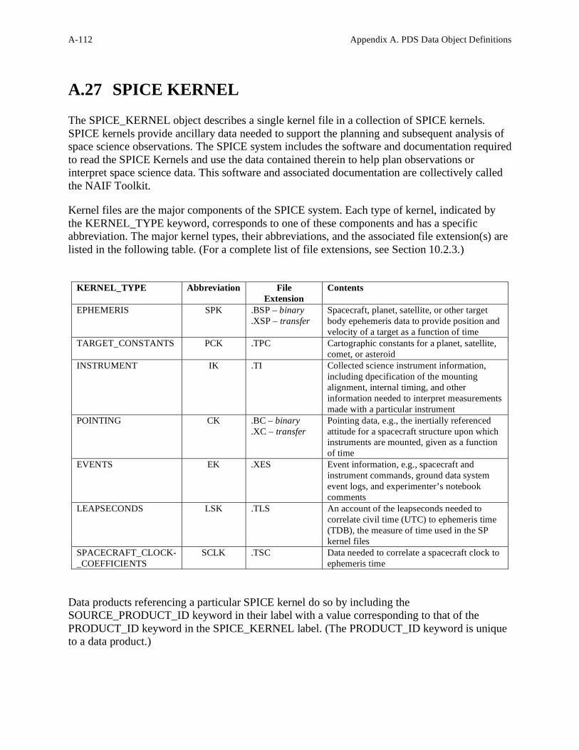
A-112 Appendix A. PDS Data Object Definitions
The SPICE_KERNEL object describes a single kernel file in a collection of SPICE kernels.
SPICE kernels provide ancillary data needed to support the planning and subsequent analysis of
space science observations. The SPICE system includes the software and documentation required
to read the SPICE Kernels and use the data contained therein to help plan observations or
interpret space science data. This software and associated documentation are collectively called
the NAIF Toolkit. Kernel files are the major components of the SPICE system. Each type of kernel, indicated by
the KERNEL_TYPE keyword, corresponds to one of these components and has a specific
abbreviation. The major kernel types, their abbreviations, and the associated file extension(s) are
listed in the following table. (For a complete list of file extensions, see Section 10.2.3.)
KERNEL_TYPE Abbreviation File
Extension
Contents
EPHEMERIS SPK .BSP – binary
.XSP – transfer
Spacecraft, planet, satellite, or other target
body epehemeris data to provide position and
velocity of a target as a function of time
TARGET_CONSTANTS PCK .TPC Cartographic constants for a planet, satellite,
comet, or asteroid
INSTRUMENT IK .TI Collected science instrument information,
including dpecification of the mounting
alignment, internal timing, and other
information needed to interpret measurements
made with a particular instrument
POINTING CK .BC – binary
.XC – transfer
Pointing data, e.g., the inertially referenced
attitude for a spacecraft structure upon which
instruments are mounted, given as a function
of time
EVENTS EK .XES Event information, e.g., spacecraft and
instrument commands, ground data system
event logs, and experimenter’s notebook
comments
LEAPSECONDS LSK .TLS An account of the leapseconds needed to
correlate civil time (UTC) to ephemeris time
(TDB), the measure of time used in the SP
kernel files
SPACECRAFT_CLOCK-
_COEFFICIENTS
SCLK .TSC Data needed to correlate a spacecraft clock to
ephemeris time
Data products referencing a particular SPICE kernel do so by including the
SOURCE_PRODUCT_ID keyword in their label with a value corresponding to that of the
PRODUCT_ID keyword in the SPICE_KERNEL label. (The PRODUCT_ID keyword is unique
to a data product.)
A.27 SPICE KERNEL

Appendix A. PDS Data Object Definitions A-113
A.27.1 Required Keywords
1. DESCRIPTION
2. INTERCHANGE_FORMAT
3. KERNEL_TYPE
A.27.2 Optional Keywords
Any
A.27.3 Required Objects
None
A.27.4 Optional Objects
None
A.27.5 Example
Following is an example of a SPICE CK (pointing) kernel label. This label would be attached to
the CK file, and thus would be immediately followed by the internal CK file header. (This
example was fabricated for use here based on existing examples.)
PDS_VERSION_ID = PDS3 RECORD_TYPE = STREAM MISSION_NAME = MARS_OBSERVER SPACECRAFT_NAME = MARS_OBSERVER DATA_SET_ID = "MO-M-SPICE-6-CK-V1.0" FILE_NAME = "NAF0000D.TC" PRODUCT_ID = "NAF0000D-CK" PRODUCT_CREATION_TIME = 1992-04-14T12:00:00 PRODUCER_ID = "NAIF" MISSION_PHASE_TYPE = "ORBIT" PRODUCT_VERSION_TYPE = "TEST" START_TIME = 1994-01-06T00:00:00 STOP_TIME = 1994-02-04T23:55:00 SPACECRAFT_CLOCK_START_COUNT = "3/76681108.213" SPACECRAFT_CLOCK_STOP_COUNT = "4/79373491.118" TARGET_NAME = MARS INSTRUMENT_NAME = "MARS OBSERVER SPACECRAFT" INSTRUMENT_ID = MO SOURCE_PRODUCT_ID =
{"NAF0000C.BSP","NAF0000C.TLS","NAF0000C.TSC"} NOTE = "BASED ON EPHEMERIS IN NAF0000C.BSP. FOR
SOFTWARE TESTING ONLY." OBJECT = SPICE_KERNEL

A-114 Appendix A. PDS Data Object Definitions
INTERCHANGE_FORMAT = ASCII KERNEL_TYPE = POINTING DESCRIPTION = "This is a SPICE kernel file, designed
to be accessed using NAIF Toolkit software. Contact your flight project representative or the NAIF node of the Planetary Data System if you wish to obtain a copy of the NAIF Toolkit. The Toolkit consists of portable FORTRAN 77 code and extensive user documentation."
END_OBJECT = SPICE_KERNEL END

Appendix A. PDS Data Object Definitions A-115
The SPREADSHEET is a natural storage format for data products in which the data rows are
sparsely populated or field values have variable lengths.
A SPREADSHEET definition describes a collection of logically uniform rows containing ASCII
values stored in variable-width fields separated by field delimiters. Each row within a
SPREADSHEET has the same number of fields, in the same field order; and each field contains
the same logical content. By definition, the SPREADSHEET object is used only to describe
ASCII data objects. Therefore, it is not necessary to include the INTERCHANGE_FORMAT
keyword within the object keyword list. The rows and fields of the SPREADSHEET object
provide a natural correspondence to the rows and columns of fixed-width tables. Each field is
defined by a variable width FIELD object (see section A.14); the value of the FIELDS keyword
is the total number of FIELD objects defined in the SPREADSHEET. All SPREADSHEET
objects have variable-length records and have rows delimited by carriage-return line-feed
(<CR><LF>) ASCII line termination characters.
A.28.1 Required Keywords
4. ROWS
5. ROW_BYTES
6. FIELDS
7. FIELD_DELIMITER
A.28.2 Optional Keywords
10. NAME
11. DESCRIPTION
12. PSDD
A.28.3 Required Objects
1. FIELD
A.28.4 Optional Objects
None
Notes:
A.28 SPREADSHEET

A-116 Appendix A. PDS Data Object Definitions
1. The RECORD_BYTES keyword in the implied file object definition of the PDS label
containing a SPREADSHEET object definition should specify the actual number of bytes
in the longest record within the file being described. If the file contains several
components, this longest record may not necessarily be in the SPREADSHEET.
2. The ROW_BYTES keyword within the SPREADSHEET object definition is used to
specify the maximum number of bytes that could be contained in a row in the
SPREADSHEET object (i.e. the sum of all the FIELD object BYTES values, plus the
number of delimiters and quotation marks, plus the 2 bytes for the <CR><LF> line
termination).
A.28.5 Required SPREADSHEET Formats
The SPREADSHEET is an ASCII data object. Its records contain fixed numbers of variable-
length fields and are delimited by carriage-return line-feed pairs. The FIELD delimiter can be
COMMA, SEMICOLON, TAB, or VERTICAL_BAR; subfields (if any) are delimited by the
same character.
The ASCII format makes the SPREADSHEET readable by both machines and humans. The
relative loss in human readability (compared to the TABLE object) is mitigated by more efficient
storage, especially for sparsely populated fields.
Several keywords take on special meanings in the SPREADSHEET context. BYTES (and
ITEM_BYTES, if used) gives the maximum allowable number of bytes in the FIELD (ITEM).
ROW_BYTES is the maximum allowable number of bytes in the row, including delimiters,
quotation marks, and the carriage-return line-feed pair. RECORD_TYPE within the implied
parent file object is always STREAM. RECORD_BYTES within the implied file is the actual
number of bytes in the longest record, including the carriage-return line-feed pair. If the file
contains more than the SPREADSHEET, however, the longest record may not be a
SPREADSHEET record.
A.28.6 Recommended SPREADSHEET Formats
The recommended format for SPREADSHEET objects is a comma-separated value format in
which string fields are enclosed in double quotes. This format can be imported directly into
many commercial data management systems and spreadsheet applications.
The recommended file name extension for files containing SPREADSHEET objects is CSV
(e.g., MYDATA.CSV), but the CSV extension does not necessarily imply that the field delimiter
is COMMA.
Example - Recommended SPREADSHEET

Appendix A. PDS Data Object Definitions A-117
The following example shows a sparse matrix described as a SPREADSHEET object. The
longest record is 85-bytes. Note that delimiters (double quotes and commas) and line
terminators (<CR><LF>) are included in the byte count for each record (RECORD_BYTES) and
row (ROW_BYTES).
Contents of file "MYDATA.CSV":
2004-03-04T00:00:00.012,0.45,"MODE 1",0,,,1,,,-1,12,5,1,2,1,1,0,1,3,1,0<CR><LF> 2004-03-04T00:00:01.012,0.45,"MODE 1",1,,,1,,,6,9,15,8,7,2,1,1,0,0,1,0<CR><LF> 2004-03-04T00:00:02.012,0.45,"MODE 1",2,,,5,,,25,15,10,4,2,1,1,1,1,0,1,1<CR><LF> 2004-03-04T00:00:03.012,0.45,"MODE 1",1,,,1,,,2,4,8,3,1,1,1,1,1,1,0,0<CR><LF> 2004-03-04T00:00:04.012,0.45,"MODE 5",1,1,3,1,1,2,3,1,1,2,2,1,4,3,1,1,4,1,1,0<CR><LF> 2004-03-04T00:00:05.012,0.45,"MODE 5",1,5,4,2,1,1,1,1,2,0,0,1,0,1,1,0,0,0,0,0<CR><LF> 2004-03-04T00:00:06.012,0.45,"MODE 5",1,6,3,5,4,3,1,,0,1,1,1,1,2,1,1,1,3,1,0<CR><LF> 2004-03-04T00:00:07.012,0.45,"MODE 6",,,,3,,,5,,1,,1,3,,2,3,,,,<CR><LF> 2004-03-04T00:00:08.012,0.45,"MODE 6",,,,,1,,,2,,1,,1,4,,1,2,,,,<CR><LF> 2004-03-04T00:00:09.012,0.45,"MODE 6",,,,1,,,,,1,1,1,,,1,,,,,<CR><LF> 2004-03-04T00:00:10.017,4.00,"MODE 11",,,,,8,15,14,21,24,18,15,10,8,9,11,6,-1,9,8,6<CR><LF> 2004-03-04T00:00:15.017,4.00,"MODE 11",,,,,8,12,17,35,20,12,5,1,2,1,1,8,11,7,8,6<CR><LF> 2004-03-04T00:00:20.017,4.00,"MODE 11",,,,,4,8,12,32,24,12,15,4,3,1,1,6,7,3,5,2<CR><LF> 2004-03-04T00:00:25.017,4.00,"MODE 13",,,,,1,5,12,12,14,12,5,1,1,7,2,4,,,,<CR><LF> 2004-03-04T00:00:30.017,4.00,"MODE 13",,,,,1,5,5,14,16,10,8,3,1,5,3,2,,,,<CR><LF> 2004-03-04T00:00:35.017,4.00,"MODE 13",,,,,1,2,3,2,19,43,21,17,4,8,3,1,,,,<CR><LF> 2004-03-04T00:00:40.017,4.00,"MODE 13",,,,,1,2,1,2,4,12,9,3,1,1,1,1,,,,<CR><LF> 2004-03-04T00:00:45.017,4.00,"MODE 13",,,,,1,3,1,-1,9,16,7,1,1,1,1,2,,,,<CR><LF> 2004-03-04T00:00:50.017,4.00,"MODE 13",,,,,1,2,1,2,4,12,5,1,1,1,1,1,,,,<CR><LF> 2004-03-04T00:00:55.017,4.00,"MODE 13",,,,,1,2,1,2,4,10,5,1,1,1,1,1,,,,<CR><LF>
MYDATA.CSV is an example data file described by a SPREADSHEET object definition within a PDS label. The longest record in this file is 85 bytes (record 11) and this value is assigned to the RECORD_BYTES keyword. However, records described by this SPREADSHEET definition could be as long as 163 bytes (see example label below). The value assigned to the ROW_BYTES keyword (163) is the maximum possible row size (bytes) described by the SPREADSHEET object definition. Bytes Field 23 - Time (23) 8 - delimiter + duration (7) 10 - delimiter + quotes(2) + mode string (7) 60 - delimiter + electrons (59) 60 - delimiter + ions (59) + 2 - CR + LF ----------------------- = 163 = ROW_BYTES Contents of file "MYDATA.LBL": PDS_VERSION_ID = PDS3 RECORD_TYPE = STREAM RECORD_BYTES = 85 /* Largest actual record in the file */ FILE_RECORDS = 20 ^SPREADSHEET = "MYDATA.CSV" DATA_SET_ID = "CO-S-INST-2-DUMMY-DATA-V1.0" SPACECRAFT_NAME = "CASSINI ORBITER" INSTRUMENT_NAME = "MY INSTRUMENT" TARGET_NAME = {"SATURN", "SOLAR_WIND"} PRODUCT_ID = "MYDATA.CSV"

A-118 Appendix A. PDS Data Object Definitions
PRODUCT_CREATION_TIME = 2004-08-04T11:15:00 START_TIME = 2004-03-04T00:00:00.012 STOP_TIME = 2004-03-04T00:00:55.017 DESCRIPTION = "This file contains an example sparse matrix data object (SPREADSHEET)." OBJECT = SPREADSHEET ROWS = 20 ROW_BYTES = 163 /* Size of longest possible row*/ FIELDS = 5 FIELD_DELIMITER = "COMMA" OBJECT = FIELD NAME = "TIME" DATA_TYPE = TIME FIELD_NUMBER = 1 BYTES = 23 DESCRIPTION = "Spacecraft event time (UT) for this data record." END_OBJECT = FIELD OBJECT = FIELD NAME = "DURATION" FIELD_NUMBER = 2 BYTES = 7 FORMAT = "F7.2" DATA_TYPE = "ASCII_REAL" UNITS = "SECOND" DESCRIPTION = "Time interval over which counting was performed (seconds)." END_OBJECT = FIELD OBJECT = FIELD NAME = "MODE" FIELD_NUMBER = 3 BYTES = 7 /* doesn’t count bytes occupied by double quotes*/ FORMAT = "A7" DATA_TYPE = "CHARACTER" DESCRIPTION = "Scan mode name. See the instrument description for
a complete list of scan mode names and properties."
END_OBJECT = FIELD OBJECT = FIELD NAME = "ELECTRON COUNTS" FIELD_NUMBER = 4 BYTES = 59 /* Maximum bytes including item delimiters */ ITEMS = 10 ITEM_BYTES = 5 /* Maximum item bytes */ FORMAT = "I5" DATA_TYPE = "ASCII_INTEGER" UNITS = "COUNTS" MISSING_CONSTANT = -1 DESCRIPTION = "This field contains electron counts from channels E1-E10. Items without values indicate channels not counted during the interval. Values of zero denote counted channels in which no electrons were detected. Values of -1 denote corrupted data,

Appendix A. PDS Data Object Definitions A-119
excluded from the data file (counted, but value undefined)."
END_OBJECT = FIELD OBJECT = FIELD NAME = "ION COUNTS" FIELD_NUMBER = 5 /* 5th FIELD object in label */ BYTES = 59 ITEMS = 10 ITEM_BYTES = 5 FORMAT = "I5" DATA_TYPE = "ASCII_INTEGER" UNITS = "COUNTS" MISSING_CONSTANT = -1 DESCRIPTION = "This field contains ion counts from channels D1- D10. Items without values indicate channels not
counted during the interval. Values of zero denote counted channels in which no ions were detected. Values of -1 denote corrupted data, excluded from the data file (counted, but value undefined)."
END_OBJECT = FIELD END_OBJECT = SPREADSHEET END

A-120 Appendix A. PDS Data Object Definitions
TABLEs are a natural storage format for collections of data from many instruments. They are
often the most effective way of storing much of the meta-data used to identify and describe
instrument observations.
The TABLE object is a uniform collection of rows containing ASCII or binary values stored in
columns. The INTERCHANGE_FORMAT keyword is used to distinguish between TABLEs
containing only ASCII columns and those containing binary data. The rows and columns of the
TABLE object provide a natural correspondence to the records and fields often defined in
interface specifications for existing data products. Each field is defined as a fixed-width
COLUMN object; the value of the COLUMNS keyword is the total number of COLUMN
objects defined in the label. All TABLE objects must have fixed-width records. Many variations on the basic TABLE object are possible with the addition of optional keywords
and/or objects. While it is possible to create very complex row structures, these are often not the
best choices for archival data products. Recommended ASCII and binary table formats are
described and illustrated below.
A.29.1 Keywords
A.29.1.1 Required Keywords
1. INTERCHANGE_FORMAT
2. ROWS
3. COLUMNS
4. ROW_BYTES
A.29.1.2 Optional Keywords
1. NAME
2. DESCRIPTION
3. ROW_PREFIX_BYTES
4. ROW_SUFFIX_BYTES
5. TABLE_STORAGE_TYPE
A.29.1.3 Required Objects
1. COLUMN
A.29.1.4 Optional Objects
A.29 TABLE

Appendix A. PDS Data Object Definitions A-121
1. CONTAINER
A.29.2 ASCII vs. BINARY formats
ASCII tables provide the most portable format for access across a wide variety of computer
platforms. They are also easily imported into a number of database management systems and
spreadsheet applications. For these reasons, the PDS recommends the use of ASCII table formats
whenever possible for archive products. ASCII formats are generally less efficient for storing large quantities of numeric data. In
addition, raw or minimally processed data products and many pre-existing data products
undergoing restoration are only available in binary formats.Where conversion to an ASCII
format is not cost effective or is otherwise undesirable, BINARY table formats may be used.
A.29.3 Recommended ASCII TABLE Format
The recommended format for ASCII TABLE files is a comma-separated value format in which
the string fields are enclosed in double quotes. ASCII tables must have fixed-length records and
should use carriage-return/linefeed (<CR><LF>) delimiters. Numeric fields are right-justified in
the allotted space and character fields are left-justified and blank padded on the right. This table
format can be imported directly into many commercial data management systems.
The field delimiters and quotation marks must occur between the defined COLUMNs. That is,
the START_BYTE for a string column should not point to the opening quotation mark, but the
first character in the field itself. Similarly, the BYTES values for the columns should not include
the commas at the end of the values. For example, a twelve character COLUMN called
SPACECRAFT_NAME would be represented in the table as "VOYAGER 1 " rather than " VOYAGER 1" or "VOYAGER 1".
The following label fragment illustrates the general characteristics of the recommended ASCII
TABLE format for a table with 1000-byte records:
RECORD_TYPE = FIXED_LENGTH
RECORD_BYTES = 1000
...
OBJECT = TABLE
INTERCHANGE_FORMAT = ASCII
ROW_BYTES = 1000
...
END_OBJECT = TABLE

A-122 Appendix A. PDS Data Object Definitions
A.29.3.1 Example - Recommended ASCII TABLE
The following example is an ASCII index table with 71-byte records. Note that for ASCII
tables, the delimiters (double quotes and commas) and line terminators (<CR><LF>) are
included in the byte count for each record (RECORD_BYTES). In this example, the delimiters
are also included in the byte count for each row (ROW_BYTES). The <CR><LF> characters
have been placed in columns 70 and 71.
Note: The example following is an INDEX_TABLE, a specific type of (ASCII)
TABLE object. Two rows of numbers indicating the byte count (read
vertically) have been added above the data file contents to facilitate
comparison with the label. These rows would not appear in the actual data
file.
Contents of file “INDEX.TAB”:
000000000111111111122222222223333333333444444444455555555556666666666 7 7
123456789012345678901234567890123456789012345678901234567890123456789 0 1
"F-MIDR ","F-MIDR.40N286;1 ","C", 42, 37,289,282,"F40N286/FRAME.LBL "<CR><LF>
"F-MIDR ","F-MIDR.20N280;1 ","C", 22, 17,283,277,"F20N280/FRAME.LBL "<CR><LF>
"F-MIDR ","F-MIDR.20N286;1 ","C", 22, 17,289,283,"F20N286/FRAME.LBL "<CR><LF>
"F-MIDR ","F-MIDR.00N279;1 ","R", 2, -2,281,275,"F00N279/FRAME.LBL "<CR><LF>
"F-MIDR ","F-MIDR.05N290;1 ","C", 7, 2,292,286,"F05N290/FRAME.LBL "<CR><LF>
"F-MIDR ","F-MIDR.05S279;1 ","R", -2, -7,281,275,"F05S279/FRAME.LBL "<CR><LF>
"F-MIDR ","F-MIDR.10S284;1 ","C", -7,-12,287,281,"F10S284/FRAME.LBL "<CR><LF>
"F-MIDR ","F-MIDR.10S290;1 ","R", -7,-12,292,286,"F10S290/FRAME.LBL "<CR><LF>
"F-MIDR ","F-MIDR.15S283;1 ","R",-12,-17,286,279,"F15S283/FRAME.LBL "<CR><LF>
"F-MIDR ","F-MIDR.15S289;1 ","R",-12,-17,291,285,"F15S289/FRAME.LBL "<CR><LF>
Contents of file “INDEX.LBL”:
PDS_VERSION_ID = PDS3
RECORD_TYPE = FIXED_LENGTH
RECORD_BYTES = 71
FILE_RECORDS = 10
^INDEX_TABLE = "INDEX.TAB"
DATA_SET_ID = "MGN-V-RDRS-5-MIDR-FULL-RES-V1.0"
VOLUME_ID = MG_7777
PRODUCT_ID = "FMIDR.XYZ"
SPACECRAFT_NAME = MAGELLAN
INSTRUMENT_NAME = "RADAR SYSTEM"
TARGET_NAME = VENUS
PRODUCT_CREATION_TIME = 1999-02-23t11:15:07
MISSION_PHASE_NAME = PRIMARY_MISSION
NOTE = "This table lists all MIDRs on this
volume. It also includes the latitude and longitude range for each
MIDR and the directory in which it is found."

Appendix A. PDS Data Object Definitions A-123
OBJECT = INDEX_TABLE
INTERCHANGE_FORMAT = ASCII
ROWS = 10
COLUMNS = 8
ROW_BYTES = 71
INDEX_TYPE = SINGLE
OBJECT = COLUMN
NAME = PRODUCT_TYPE
DESCRIPTION = "Magellan DMAT type code. Possible
values are F-MIDR, C1-MIDR, C2-MIDR,
C3-MIDR, and P-MIDR."
DATA_TYPE = CHARACTER
START_BYTE = 2
BYTES = 7
END_OBJECT = COLUMN
OBJECT = COLUMN
NAME = PRODUCT_ID
DESCRIPTION = "Magellan DMAT name of product.
Example: F-MIDR.20N334;1"
DATA_TYPE = CHARACTER
START_BYTE = 12
BYTES = 16
END_OBJECT = COLUMN
OBJECT = COLUMN
NAME = SEAM_CORRECTION_TYPE
DESCRIPTION = "A value of C indicates that cross-
track seam correction has been applied.
A value of R indicates that the
correction has not been applied."
DATA_TYPE = CHARACTER
START_BYTE = 31
BYTES = 1
END_OBJECT = COLUMN
OBJECT = COLUMN
NAME = MAXIMUM_LATITUDE
DESCRIPTION = "Northernmost frame latitude rounded to
the nearest degree."
DATA_TYPE = INTEGER
UNIT = DEGREE
START_BYTE = 34
BYTES = 3
END_OBJECT = COLUMN
OBJECT = COLUMN
NAME = MINIMUM_LATITUDE
DESCRIPTION = "Southernmost frame latitude rounded to
the nearest degree."
DATA_TYPE = INTEGER
UNIT = DEGREE
START_BYTE = 38

A-124 Appendix A. PDS Data Object Definitions
BYTES = 3
END_OBJECT = COLUMN
OBJECT = COLUMN
NAME = EASTERNMOST_LONGITUDE
DESCRIPTION = "Easternmost frame longitude rounded to
the nearest degree."
DATA_TYPE = INTEGER
UNIT = DEGREE
START_BYTE = 42
BYTES = 3
END_OBJECT = COLUMN
OBJECT = COLUMN
NAME = WESTERNMOST_LONGITUDE
DESCRIPTION = "Westernmost frame longitude rounded to
the nearest degree."
DATA_TYPE = INTEGER
UNIT = DEGREE
START_BYTE = 46
BYTES = 3
END_OBJECT = COLUMN
OBJECT = COLUMN
NAME = FILE_SPECIFICATION_NAME
DESCRIPTION = "Path and file name of frame table
relative to CD-ROM root directory."
DATA_TYPE = CHARACTER
START_BYTE = 51
BYTES = 18
END_OBJECT = COLUMN
END_OBJECT = INDEX_TABLE
END
A.29.4 Recommended BINARY TABLE Format
In the case of binary data, PDS recommends a format in which one data record corresponds to
one row in the TABLE. Unused or spare bytes embedded within the record should be defined as
COLUMNs (one for each chunk of contiguous unused bytes) named “SPARE”, both for
completeness and to facilitate automated validation of the TABLE structure. For reasons of
portability, BIT_COLUMN objects within COLUMNs are discouraged. Whenever possible, bit
fields should be unpacked into more portable, byte-oriented COLUMNS.

Appendix A. PDS Data Object Definitions A-125
The following label fragment illustrates the general characteristics of the recommended binary
TABLE format for a table with 1000-byte records:
RECORD_TYPE = FIXED_LENGTH
RECORD_BYTES = 1000
...
OBJECT = TABLE
INTERCHANGE_FORMAT = BINARY
ROW_BYTES = 1000
...
END_OBJECT = TABLE
A.29.4.1 Example - Recommended Binary TABLE
Following is an example of a binary table containing three columns of data. The first two
columns provide TIME information in both the PDS standard UTC format and an alternate
format. The third column provides uncalibrated instrument measurements for the given time.
The binary data reside in the file “T890825.DAT”. The detached label file, “T890825.LBL”
providing the complete description, is presented below.
Note: The label makes use of a format file, pointed to by the ^STRUCTURE
keyword in the TABLE definition, to include a set of column definitions held
in an external file (“CRSDATA.FMT”). The contents of this structure file are
also provided below.
This table could also be represented as a TIME_SERIES by the addition of
sampling parameter keywords to describe the row-to-row variation in the
table.
Contents of label file “T890825.DAT”:
Contents of label file “T890825.LBL”:

A-126 Appendix A. PDS Data Object Definitions
PDS_VERSION_ID = PDS3
/* File Characteristic Keywords */
RECORD_TYPE = FIXED_LENGTH
RECORD_BYTES = 36
FILE_RECORDS = 350
HARDWARE_MODEL_ID = "SUN SPARC STATION"
OPERATING_SYSTEM_ID = "SUN OS 4.1.1"
/* Data Object Pointers */
^TABLE = "T890825.DAT"
/* Identification Keywords */
DATA_SET_ID = "VG2-N-CRS-4-SUMM-D1-96SEC-V1.0"
SPACECRAFT_NAME = "VOYAGER 2"
INSTRUMENT_NAME = "COSMIC RAY SYSTEM"
TARGET_NAME = NEPTUNE
START_TIME = 1989-08-25T00:00:00.000
STOP_TIME = 1989-08-25T09:58:02.000
MISSION_PHASE_NAME = "NEPTUNE ENCOUNTER"
PRODUCT_ID = "T890825.DAT"
PRODUCT_CREATION_TIME = "UNK"
SPACECRAFT_CLOCK_START_COUNT = "UNK"
SPACECRAFT_CLOCK_STOP_COUNT = "UNK"
/* Data Object Descriptions */
OBJECT = TABLE
INTERCHANGE_FORMAT = BINARY
ROWS = 350
COLUMNS = 3
ROW_BYTES = 36
^STRUCTURE = "CRSDATA.FMT"
END_OBJECT = TABLE
END
Contents of file “CRSDATA.FMT”:
OBJECT = COLUMN
NAME = "C TIME"
UNIT = "SECOND"
DATA_TYPE = REAL
START_BYTE = 1
BYTES = 8
MISSING = 1.0E+32
DESCRIPTION = "Time column. This field contains time
in seconds after Jan 01, 1966 but is
displayed in the default time format
selected by the user."
END_OBJECT = COLUMN
OBJECT = COLUMN

Appendix A. PDS Data Object Definitions A-127
NAME = "PDS TIME"
UNIT = "TIME"
DATA_TYPE = TIME
START_BYTE = 9
BYTES = 24
DESCRIPTION = "Date/Time string of the form yyyy-mm-
ddThh:mm:ss.sss such that the representation of the date Jan 01,
2000 00:00:00.000 would be 2000-01-01T00:00:00.000."
END_OBJECT = COLUMN
OBJECT = COLUMN
NAME = "D1 RATE"
UNIT = "COUNT"
DATA_TYPE = "REAL"
START_BYTE = 33
BYTES = 4
MISSING = 1.0E+32
DESCRIPTION = "The D1 rate is approximately
porportional to the omnidirectional flux of electrons with kinetic
energy > ~1MeV. To obtain greater accuracy, the D1 calibration
tables (see catalog) should be applied."
END_OBJECT = COLUMN
A.29.5 TABLE Variations
This section addresses a number of variations on the basic TABLE object that arise when
TABLEs appear in data files with other objects, or where file attributes may differ from the one
row-one record approach recommended above. The variations discussed below are equally
applicable to the other TABLE-type objects, SERIES and SPECTRUM.
This section is not intended to be a complete reference for TABLE variations. Within the
following examples, some illustrate a recommended data modelling approach, some illustrate
alternate approaches, and other examples are included solely to document their existence.
A.29.5.1 Record blocking in Fixed Length TABLES
In the PDS recommended TABLE format, ROW_BYTES = RECORD_BYTES, but this is not
always achievable. TABLEs are sometimes packaged with other objects in the same file, or
binary data may be blocked into larger records, both resulting in cases where the TABLE row
size will not match the file record width. Rows in either ASCII or binary tables may be either larger or smaller than the physical record
size specified by the RECORD_BYTES keyword. Regardless of the relationship between row
size and record size, the RECORD_BYTES keyword must always reflect the actual physical
record size, while ROW_BYTES must always be the logical size of one row of the TABLE
object.

A-128 Appendix A. PDS Data Object Definitions
A.29.5.1.1 Example: Binary Table with ROW_BYTES > RECORD_BYTES
The following label fragment illustrates a case in which the record size of the file is smaller than
the row size of the TABLE. Note that the table rows may straddle record boundaries. Each
object, however, must begin on a record boundary, so it is possible that some padding may be
required between the end of the TABLE object and the beginning of the IMAGE object,
depending on the number of rows in the TABLE:
RECORD_TYPE = FIXED_LENGTH
RECORD_BYTES = 800
^TABLE =("IMAGE.IMG",1)
^IMAGE =("IMAGE.IMG",7)
...
OBJECT = TABLE
INTERCHANGE_FORMAT = BINARY
ROW_BYTES = 1200
...
END_OBJECT = TABLE
OBJECT = IMAGE
SAMPLES = 800
SAMPLE_BITS = 8
...
END_OBJECT = IMAGE
A.29.5.1.2 Example: ASCII Table with ROW_BYTES < RECORD_BYTES
The label fragment below illustrates a case in which the row size of the TABLE is smaller than
the record size of the file. It is not required that the file record size be an integral multiple of the
table row size; as illustrated above, table rows may straddle record boundaries. Also as above, it
is possible that some padding will be required to ensure that the subsequent SERIES object
begins on a record boundary.
RECORD_TYPE = FIXED_LENGTH
RECORD_BYTES = 800
^TABLE = ("EXAMPLE.TAB",1)
^SERIES = ("EXAMPLE.TAB",1214)
...
OBJECT = TABLE
INTERCHANGE_FORMAT = ASCII
ROW_BYTES = 400
...
END_OBJECT = TABLE
OBJECT = SERIES
INTERCHANGE_FORMAT = ASCII
ROW_BYTES = 800
...

Appendix A. PDS Data Object Definitions A-129
END_OBJECT = SERIES
A.29.5.1.3 Example: Binary Table with ROW_BYTES < RECORD_BYTES
It is often the case that a data object such as a TABLE is preceeded by a header containing
observational parameters or, as frequently happens with TABLEs, a set of column headings. The
label below illustrates a case in which a HEADER object containing a single 500-byte row
preceeds a TABLE having 1032-byte records. The file is physically blocked into records of
32,500 bytes. Note that in this case the HEADER record is not padded out to the full block size.
Instead, a byte offset (rather than a record offset) is used to indicate the start of the TABLE
object. (This example also includes COLUMN definitions contained in an external format file, a
fragment of the contents of which is also shown below, following the label.)
PDS_VERSION_ID = PDS3
/* FILE CHARACTERISTICS */
RECORD_TYPE = FIXED_LENGTH
RECORD_BYTES = 32500
FILE_RECORDS = 46
^HEADER = ("ADF01141.3",1)
^TABLE = ("ADF01141.3",501<BYTES>)
/* IDENTIFICATION KEYWORDS */
DATA_SET_ID = "MGN-V-RDRS-5-CDR-ALT/RAD-V1.0"
PRODUCT_ID = "ADF01141.3"
TARGET_NAME = VENUS
SPACECRAFT_NAME = MAGELLAN
INSTRUMENT_NAME = "RADAR SYSTEM"
MISSION_PHASE_NAME = PRIMARY_MISSION
PRODUCT_CREATION_TIME = 1991-07-23T06:16:02.000
ORBIT_NUMBER = 1141
START_TIME = UNK
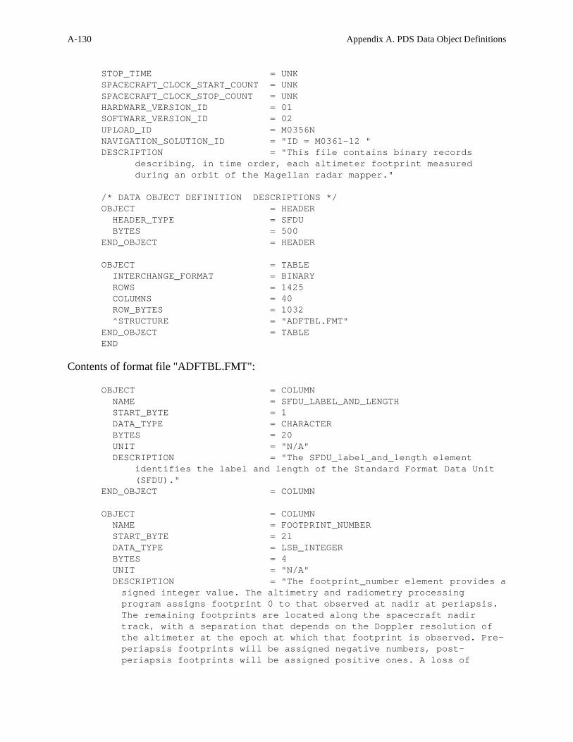
A-130 Appendix A. PDS Data Object Definitions
STOP_TIME = UNK
SPACECRAFT_CLOCK_START_COUNT = UNK
SPACECRAFT_CLOCK_STOP_COUNT = UNK
HARDWARE_VERSION_ID = 01
SOFTWARE_VERSION_ID = 02
UPLOAD_ID = M0356N
NAVIGATION_SOLUTION_ID = "ID = M0361-12 "
DESCRIPTION = "This file contains binary records
describing, in time order, each altimeter footprint measured
during an orbit of the Magellan radar mapper."
/* DATA OBJECT DEFINITION DESCRIPTIONS */
OBJECT = HEADER
HEADER_TYPE = SFDU
BYTES = 500
END_OBJECT = HEADER
OBJECT = TABLE
INTERCHANGE_FORMAT = BINARY
ROWS = 1425
COLUMNS = 40
ROW_BYTES = 1032
^STRUCTURE = "ADFTBL.FMT"
END_OBJECT = TABLE
END
Contents of format file "ADFTBL.FMT":
OBJECT = COLUMN
NAME = SFDU_LABEL_AND_LENGTH
START_BYTE = 1
DATA_TYPE = CHARACTER
BYTES = 20
UNIT = "N/A"
DESCRIPTION = "The SFDU_label_and_length element
identifies the label and length of the Standard Format Data Unit
(SFDU)."
END_OBJECT = COLUMN
OBJECT = COLUMN
NAME = FOOTPRINT_NUMBER
START_BYTE = 21
DATA_TYPE = LSB_INTEGER
BYTES = 4
UNIT = "N/A"
DESCRIPTION = "The footprint_number element provides a
signed integer value. The altimetry and radiometry processing
program assigns footprint 0 to that observed at nadir at periapsis.
The remaining footprints are located along the spacecraft nadir
track, with a separation that depends on the Doppler resolution of
the altimeter at the epoch at which that footprint is observed. Pre-
periapsis footprints will be assigned negative numbers, post-
periapsis footprints will be assigned positive ones. A loss of

Appendix A. PDS Data Object Definitions A-131
several consecutive burst records from the ALT-EDR will result in
missing footprint numbers."
END_OBJECT = COLUMN
...
OBJECT = COLUMN
NAME = DERIVED_THRESH_DETECTOR_INDEX
START_BYTE = 1001
DATA_TYPE = LSB_UNSIGNED_INTEGER
BYTES = 4
UNIT = "N/A"
DESCRIPTION = "The derived_thresh_detector_index
element provides the value of the element in
range_sharp_echo_profile that satisfies the altimeter threshold
detection algorithm, representing the distance to the nearest object
in this radar footprint in units of 33.2 meters, modulus a 10.02
kilometer altimeter range ambiguity."
END_OBJECT = COLUMN
A.29.5.1.4 Example: PDS Recommended Method for Dealing with Odd-Sized Headers
The preceding format may be difficult to deal with in some cases because of the odd-sized
header preceeding the TABLE object. The recommended approach to this situation is pad the
HEADER object out to an integral multiple of the TABLE row size, and then let
RECORD_BYTES = ROW_BYTES. Modifying the above case accordingly would yield the
following:
RECORD_TYPE = FIXED_LENGTH
RECORD_BYTES = 1032
FILE_RECORDS = 1426
^HEADER = ("ADF01141.3",1)
^TABLE = ("ADF01141.3",2)
...
/* DATA OBJECT DEFINITIONS */

A-132 Appendix A. PDS Data Object Definitions
OBJECT = HEADER
HEADER_TYPE = SFDU
BYTES = 500
END_OBJECT
OBJECT = TABLE
INTERCHANGE_FORMAT = BINARY
ROWS = 1425
COLUMNS = 40
ROW_BYTES = 1032
^STRUCTURE = "ADFTBL.FMT"
END_OBJECT
END
A.29.5.1.5 Alternate Format – Rows on Record Boundaries
The following label fragment and illustration provide a second alternate data organization for the
preceding example. In this example, a record size of 30,960 is used to hold 30 rows of the
TABLE. Again the 500-byte HEADER uses only a portion of the first record.
...
RECORD_TYPE = FIXED_LENGTH
RECORD_BYTES = 30960
FILE_RECORDS = 49
^HEADER = ("ADF01141.3",1)
^TABLE = ("ADF01141.3")
...
/* DATA OBJECT DEFINITIONS */
OBJECT = HEADER
HEADER_TYPE = SFDU

Appendix A. PDS Data Object Definitions A-133
BYTES = 500
END_OBJECT = HEADER
OBJECT = TABLE
INTERCHANGE_FORMAT = BINARY
ROWS = 1425
COLUMNS = 40
ROW_BYTES = 1032
^STRUCTURE = "ADFTBL.FMT"
END_OBJECT = TABLE
A.29.5.2 Multiple TABLEs in a Single Data File
A single data product file may contain several ASCII or binary TABLEs, each with a different logical row size. There are several possible approaches to formatting such a product file, depending on whether the product contains binary or ASCII data. When all the TABLEs in the data file are ASCII tables there are two formatting options: fixed-length file records or stream records. When binary data are involved, even if only in a single TABLE, fixed-length file records are mandatory.
A.29.5.2.1 Example: Multiple ASCII tables – Fixed-Length Records
In the case of a series of ASCII TABLE objects with varying ROW_BYTES values, a fixed-length record file may be generated by padding all rows of all TABLEs out to the length of the longest rows by adding blank characters between the end of the last COLUMN and the <CR><LF> record delimiters. When this approach is used, RECORD_TYPE is FIXED_LENGTH and RECORD_BYTES = ROW_BYTES.
RECORD_TYPE = FIXED_LENGTH
RECORD_BYTES = 1000
...
OBJECT = A_TABLE
INTERCHANGE_FORMAT = ASCII
ROW_BYTES = 1000
...
END_OBJECT = A_TABLE
OBJECT = B_TABLE
INTERCHANGE_FORMAT = ASCII
ROW_BYTES = 1000
...
END_OBJECT = B_TABLE
Note that each TABLE object has the same value of ROW_BYTES, even though in the smaller table the rightmost bytes will be ignored. Alternately, the filler bytes may be documented as ROW_SUFFIX_BYTES. Say, for example, that in the above case B_TABLE only required 780 bytes for its rows. The following definition for B_TABLE marks the last 220 bytes of each row as suffix bytes:

A-134 Appendix A. PDS Data Object Definitions
OBJECT = B_TABLE
INTERCHANGE_FORMAT = ASCII
ROW_BYTES = 780
ROW_SUFFIX_BYTES = 220
...
A.29.5.2.2 END_OBJECT = B_TABLE
A.29.5.2.2 Example: Multiple ASCII tables – Stream Records
Sometimes padding TABLE records out to a common fixed length creates more problems than it
solves. When this is true each TABLE should retain its own ROW_BYTES value, without
padding, and the file RECORD_TYPE is set to STREAM. RECORD_BYTES should be
omitted. The following label fragment illustrates this situation.
RECORD_TYPE = STREAM
...
OBJECT = A_TABLE
INTERCHANGE_FORMAT = ASCII
ROW_BYTES = 802
...
END_OBJECT = A_TABLE
OBJECT = B_TABLE
INTERCHANGE_FORMAT = ASCII
ROW_BYTES = 1000
...
END_OBJECT = B_TABLE
A.29.5.2.3 Example: Multiple Binary Tables – Fixed-Length Records
When binary data are involved the file records must be fixed-length.
The records of the smaller TABLE(s) are padded, usually with null
characters, out to the maximum ROW_BYTES value in the file. The
padding bytes are accounted for in the TABLE definition using one of
two methods: either by defining a COLUMN called “SPARE” to
define the number and location of these spare bytes, or by using the
ROW_SUFFIX_BYTES keyword, as in the case of multiple ASCII
tables. In the following example, the first table, A_TABLE, has a
logical row length of 800 bytes. Each row has been padded out to
1000 bytes, the length of the B_TABLE rows, with a 200-byte
SPARE column: RECORD_TYPE = FIXED_LENGTH
RECORD_BYTES = 1000

Appendix A. PDS Data Object Definitions A-135
...
OBJECT = A_TABLE
INTERCHANGE_FORMAT = BINARY
ROW_BYTES = 1000
...
OBJECT = COLUMN
NAME = "TIME TAG"
DATA_TYPE = TIME
START_BYTE = 1
BYTES = 23
END_OBJECT = COLUMN
...
OBJECT = COLUMN
NAME = "SPARE"
DATA_TYPE = "N/A"
START_BYTE = 801
BYTES = 200
END_OBJECT = COLUMN
END_OBJECT = A_TABLE
OBJECT = B_TABLE
INTERCHANGE_FORMAT = BINARY
ROW_BYTES = 1000
...
END_OBJECT = B_TABLE
A.29.5.3 ROW_PREFIX or ROW_SUFFIX Use
ROW_PREFIX_BYTES and ROW_SUFFIX_BYTES are provided for dealing with two
situations:
1. When a TABLE object is stored in parallel with another data object, frequently an
IMAGE. In this case, each physical record of the file contains a TABLE row as one part
of the record and an IMAGE line as the other part.
2. When a TABLE has had each of its rows padded out to a fixed length larger than the
logical row size of the table.
Each method is illustrated below.
A.29.5.3.1 Example: Parallel TABLE and IMAGE objects
The following label fragment illustrates a file with fixed-length records, each of which contains
one row of a TABLE data object and one line of an IMAGE object. This is a common format for
providing ancillary information applicable to each IMAGE line. In the TABLE object the bytes
belonging to the IMAGE are accounted for as ROW_SUFFIX_BYTES. In the IMAGE object the
bytes belonging to the TABLE row are accounted for as LINE_PREFIX_BYTES.

A-136 Appendix A. PDS Data Object Definitions
RECORD_TYPE = FIXED_LENGTH
RECORD_BYTES = 1000
...
OBJECT = TABLE
INTERCHANGE_FORMAT = BINARY
ROW_BYTES = 200
ROW_SUFFIX_BYTES = 800
...
END_OBJECT = TABLE
OBJECT = IMAGE
LINE_SAMPLES = 800
SAMPLE_BITS = 8
LINE_PREFIX_BYTES = 200
...
END_OBJECT = IMAGE
Note that in each object the total size of the logical record plus all prefix and suffix bytes is equal
to the file record size. That is:
RECORD_BYTES = ROW_BYTES + ROW_PREFIX_BYTES + ROW_SUFFIX_BYTES
and
RECORD_BYTES = (LINE_SAMPLES * SAMPLE_BITS / 8) + ROW_PREFIX_BYTES +
ROW_SUFFIX_BYTES
A.29.5.4 CONTAINER Object use
Complex TABLEs may contain a set of columns of different data types which repeat a number of
times in the row. In this case a CONTAINER object, which groups a set of inhomogeneous
COLUMN objects, may be used to provide a single definition for the repeating group. Section
A.8 contains an example of a TABLE object which makes use of a CONTAINER object.
A.29.5.5 Guidelines for SPARE fields
Some TABLE objects contain spare bytes embedded in the record but not included in any
COLUMN object definition. They may be there for spacing or alignment purposes, or they may
have been reserved in the original data record for future use. Regardless of their origin, PDS
recommends that all such spare bytes be documented as COLUMNs in the TABLE definition in
the interests of documentation and validation. Spare bytes may be included in both binary and
ASCII table objects. Guidelines for dealing with spare bytes in both cases follow.
A.29.5.6 SPARE fields - Binary Tables

Appendix A. PDS Data Object Definitions A-137
The following guidelines apply to spare byte fields in binary table objects:
• Embedded spare fields must be explicitly defined in COLUMN objects, except when the spare field appears at the beginning or end of a row where ROW_PREFIX_BYTES or ROW_SUFFIX_BYTES is used.
• Spare COLUMNs must have DATA_TYPE = “N/A”.
• Multiple spare COLUMNs may all specify NAME = “SPARE”.
• Spare bytes may occur as prefix or suffix bytes in the rows.
• Prefix or suffix spares may be identified either with a spare COLUMN object or by use of ROW_PREFIX_BYTES or ROW_SUFFIX_BYTES
The following examples illustrate the various situations.
A.29.5.6.1 Example: SPARE field embedded in a Binary TABLE
In the following label fragment, a spare column defines a series of bytes reserved for future use
in the middle of the data record:
RECORD_TYPE = FIXED_LENGTH
RECORD_BYTES = 1000
...
OBJECT = TABLE
INTERCHANGE_FORMAT = BINARY
ROW_BYTES = 1000
COLUMNS = 99
...
OBJECT = COLUMN
NAME = SPARE
COLUMN_NUMBER = 87
START_BYTE = 793
BYTES = 21
DATA_TYPE = "N/A"
DESCRIPTION = "Reserved for future user by Mission Ops."
END_OBJECT = COLUMN
...
OBJECT = COLUMN
...
END_OBJECT = TABLE
A.29.5.6.2 Example: Spares at end of a Binary TABLE – Explicit 'SPARE' Column

A-138 Appendix A. PDS Data Object Definitions
In this label fragment, spare bytes have been included on the end of each record of the table.
These bytes are described as an additional COLUMN at the end of the record.
RECORD_TYPE = FIXED_LENGTH
RECORD_BYTES = 1000
...
OBJECT = TABLE
INTERCHANGE_FORMAT = BINARY
ROW_BYTES = 1000
COLUMNS = 99
...
OBJECT = COLUMN
COLUMN_NUMBER = 1
NAME = "TIME TAG"
...
END_OBJECT
...
OBJECT = COLUMN
COLUMN_NUMBER = 99
NAME = SPARE
BYTES = 20
DATA_TYPE = "N/A"
START_BYTE = 981
...
END_OBJECT = COLUMN
END_OBJECT = TABLE
A.29.5.6.3 Example: Spares at end of a Binary TABLE - ROW_SUFFIX_BYTES use
This fragment illustrates the same physical file layout as the previous example, but in this case
the spare bytes are defined using the ROW_SUFFIX_BYTES keyword, rather than defining an
additional spare COLUMN.
RECORD_TYPE = FIXED_LENGTH
RECORD_BYTES = 1000
...
OBJECT = TABLE
INTERCHANGE_FORMAT = BINARY
ROW_BYTES = 980
ROW_SUFFIX_BYTES = 20
COLUMNS = 98
...
END_OBJECT = TABLE

Appendix A. PDS Data Object Definitions A-139
A.29.5.7 SPARE fields - ASCII Tables with Fixed Length Records
In ASCII tables, field delimiters (") and (,) and the <CR><LF> pair are considered part of the
data, even though the COLUMN objects attributes do not include them. Spare bytes in ASCII
tables may contain only the blank character (ASCII decimal code 32). The following guidelines
apply to spare byte fields in ASCII table objects:
• Embedded spares are not allowed.
• Spares are allowed at the end of each row of data.
• The <CR><LF> follows the spare data.
• There are no delimiters (commas or quotes) surrounding the spares.
• Spares at the end of the data can be ignored (like field delimiters and <CR><LF>) or they can be identified
(1) in the Table DESCRIPTION; or
(2) by using ROW_SUFFIX_BYTES (note that these bytes should not be included in the value of ROW_BYTES)
A.29.5.7.1 Example - SPARE field at end of ASCII TABLE - Table description note
RECORD_TYPE = FIXED_LENGTH
RECORD_BYTES = 1000
...
OBJECT = TABLE
INTERCHANGE_FORMAT = ASCII
ROW_BYTES = 1000
...
DECRIPTION ="This table contains 980
bytes of table data followed by 18 bytes of
blank spares. Bytes 999 and 1000 contain the
<CR><LF> pair."

A-140 Appendix A. PDS Data Object Definitions
A.29.5.7.2 Example - Spares at end of a ASCII TABLE - ROW_SUFFIX use
RECORD_TYPE = FIXED_LENGTH
RECORD_BYTES = 1000
...
OBJECT = TABLE
INTERCHANGE_FORMAT = ASCII
ROW_BYTES = 980
ROW_SUFFIX_BYTES = 20
...
DECRIPTION ="This table contains
980 bytes of table data followed by 20
bytes of spare data of which the last
two bytes, bytes 999 and 1000, contain
the <CR><LF> pair."
END_OBJECT = TABLE
A.29.5.8 SPARE fields - ASCII Tables with STREAM Records
Spare fields are not used with ASCII Tables in STREAM record formats. In STREAM files, the
last data field explicitly defined with a COLUMN object is followed immediately by the
<CR><LF> pair. Since there is no use for spares at the end of the data, and embedded spares are
not allowed in ASCII tables, spares are not applicable here.

Appendix A. PDS Data Object Definitions A-141
The TEXT object describes a file which contains plain text. It is most often used in an attached
label, so that the text begins immediately after the END statement of the label. PDS recommends
that TEXT objects contain no special formatting characters, with the exception of the carriage
return/line feed sequence and the page break. Tab characters are discouraged, since they are
interpreted differently by different programs.
Use of the carriage-return/line-feed sequence (<CR><LF>) is required for cross-platform
support. PDS further recommends that text lines be limited to 80 characters, with delimiters, to
facilitate visual inspection and printing of text files. NOTE: The TEXT object is most often used for files describing the contents of an archive
volume or the contents of a directory, such as AAREADME.TXT, DOCINFO.TXT,
VOLINFO.TXT, SOFTINFO.TXT, etc. These files must be in plain, unmarked ASCII text and
always have a file extension of “.TXT”. Documentation files that are in plain ASCII text, on the
other hand, must be described using the DOCUMENT object. (See the definition of the
DOCUMENT Object in Section A.12.) The required NOTE field should provide a brief introduction to the TEXT.
A.30.1 Required Keywords
1. NOTE
2. PUBLICATION_DATE
A.30.2 Optional Keywords
1. INTERCHANGE_FORMAT
A.30.3 Required Objects
None
A.30.4 Optional Objects
None
A.30 TEXT

A-142 Appendix A. PDS Data Object Definitions
A.30.5 Example
The example below is a portion of an AAREADME.TXT file.
PDS_VERSION_ID = PDS3
RECORD_TYPE = STREAM
OBJECT = TEXT
PUBLICATION_DATE = 1991-05-28
NOTE = "Introduction to this CD-ROM volume."
END_OBJECT = TEXT
END
GEOLOGIC REMOTE SENSING FIELD EXPERIMENT
This set of compact read-only optical disks (CD-ROMs) contains a data
collection acquired by ground-based and airborne instruments during the
Geologic Remote Sensing Field Experiment (GRSFE). Extensive
documentation is also included. GRSFE took place in July, September,
and October, 1989, in the southern Mojave Desert, Death Valley, and the
Lunar Crater Volcanic Field, Nevada. The purpose of these CD-ROMs is to
make available in a compact form through the Planetary Data System (PDS)
a collection of relevant data to conduct analyses in preparation for the
Earth Observing System (EOS), Mars Observer (MO), and other missions.
The generation of this set of CD-ROMs was sponsored by the NASA
Planetary Geology and Geophysics Program, the Planetary Data System
(PDS) and the Pilot Land Data System (PLDS).
This AAREADME.TXT file is one of the two nondirectory files located in
the top level directory of each CD-ROM volume in this collection. The
other file, VOLDESC.CAT, contains an overview of the data sets on these
CD-ROMs and is written in a format that is designed for access by
computers. These two files appear on every volume in the collection.
All other files on the CD-ROMs are located in directories below the top
level directory ....

Appendix A. PDS Data Object Definitions A-143
The VOLUME object describes a physical or logical unit used to store or distribute data products
(e.g., a magnetic tape, CD-ROM disk, or floppy disk) that contain directories and files. The
directories and files may include documentation, software, calibration and geometry information
as well as the actual science data.
A.31.1 Required Keywords
8. DATA_SET_ID
9. DESCRIPTION
10. MEDIUM_TYPE
11. PUBLICATION_DATE
12. VOLUME_FORMAT
13. VOLUME_ID
14. VOLUME_NAME
15. VOLUME_SERIES_NAME
16. VOLUME_SET_NAME
17. VOLUME_SET_ID
18. VOLUME_VERSION_ID
19. VOLUMES
A.31.2 Optional Keywords
13. BLOCK_BYTES
14. DATA_SET_COLLECTION_ID
15. FILES
16. HARDWARE_MODEL_ID
17. LOGICAL_VOLUMES
18. LOGICAL_VOLUME_PATH_NAME
19. MEDIUM_FORMAT
20. NOTE
21. OPERATING_SYSTEM_ID
22. PRODUCT_TYPE
23. TRANSFER_COMMAND_TEXT
24. VOLUME_INSERT_TEXT
A.31.3 Required Objects
2. CATALOG
3. DATA_PRODUCER
A.31 VOLUME

A-144 Appendix A. PDS Data Object Definitions
A.31.4 Optional Objects
2. DIRECTORY
3. FILE
4. DATA_SUPPLIER
A.31.5 Example 1 (Typical CD-ROM Volume)
Please see the example in Section A.5 for the CATALOG object.
A.31.6 Example 2 (Tape Volume)
The following VOLUME object example shows how directories and files are detailed when a
volume is stored on an ANSI tape for transfer. This form of the VOLUME object should be used
when transferring volumes of data on media which do not support hierarchical directory
structures (for example, when submitting a volume of data on tape for premastering to CDROM).
The VOLDESC.CAT file will contain the standard volume keywords, but the values of
MEDIUM_TYPE, MEDIUM_FORMAT and VOLUME_FORMAT should indicate that the
volume is stored on tape. In this example two files are defined in the root directory of the volume, VOLDESC.CAT and
AAREADME.TXT. The first DIRECTORY object defines the CATALOG directory which
contains meta data in the included, individual catalog objects. In this example, all the catalog
objects are concatenated into a single file, CATALOG.CAT. The second DIRECTORY object
defines an INDEX subdirectory containing three files: INDXINFO.TXT, INDEX.LBL, and
INDEX.TAB. Following that directory, the first data directory is defined. Note that the
SEQUENCE_NUMBER keyword indicates the physical sequence of the files on the tape
volume.
PDS_VERSION_ID = PDS3
OBJECT = VOLUME
VOLUME_SERIES_NAME = "MISSION TO MARS"
VOLUME_SET_NAME = "MARS DIGITAL IMAGE MOSAIC AND DIGITAL
TERRAIN MODEL"
VOLUME_SET_ID = USA_NASA_PDS_VO_2001_TO_VO_2007
VOLUMES = 7
VOLUME_NAME = "MDIM/DTM VOLUME 7: GLOBAL COVERAGE"
VOLUME_ID = VO_2007
VOLUME_VERSION_ID = "VERSION 1"
PUBLICATION_DATE = 1992-04-01
DATA_SET_ID = "VO1/VO2-M-VIS-5-DTM-V1.0"
MEDIUM_TYPE = "8-MM HELICAL SCAN TAPE"
MEDIUM_FORMAT = "2 GB"
VOLUME_FORMAT = ANSI
HARDWARE_MODEL_ID = "VAX 11/750"
OPERATING_SYSTEM_ID = "VMS 4.6"

Appendix A. PDS Data Object Definitions A-145
DESCRIPTION = "This volume contains the Mars Digital
Terrain Model and Mosaicked Digital Image Model covering the entire
planet at resolutions of 1/64 and 1/16 degree/pixel. The volume
also contains Polar Stereographic projection files of the north and
south pole areas from 80 to 90 degrees latitude; Mars Shaded Relief
Airbrush Maps at 1/16 and 1/ 4 degree/pixel; a gazetteer of Mars
features; and a table of updated viewing geometry files of the
Viking EDR images that comprise the MDIM."
MISSION_NAME = VIKING
SPACECRAFT_NAME = {VIKING_ORBITER_1,VIKING_ORBITER_2}
SPACECRAFT_ID = {VO1,VO2}
OBJECT = DATA_PRODUCER
INSTITUTION_NAME = "U.S.G.S. FLAGSTAFF"
FACILITY_NAME = "BRANCH OF ASTROGEOLOGY"
FULL_NAME = "Eric M. Eliason"
DISCIPLINE_NAME = "IMAGE PROCESSING"
ADDRESS_TEXT = "Branch of Astrogeology
United States Geological Survey
2255 North Gemini Drive
Flagstaff, Arizona. 86001 USA"
END_OBJECT = DATA_PRODUCER
OBJECT = CATALOG
^CATALOG = "CATALOG.CAT"
END_OBJECT = CATALOG
OBJECT = FILE
FILE_NAME = "VOLDESC.CAT"
RECORD_TYPE = STREAM
SEQUENCE_NUMBER = 1
END_OBJECT = FILE
OBJECT = FILE
FILE_NAME = "AAREADME.TXT"
RECORD_TYPE = STREAM
SEQUENCE_NUMBER = 2
END_OBJECT = FILE
OBJECT = DIRECTORY
NAME = CATALOG
OBJECT = FILE
FILE_NAME = "CATALOG.CAT"
RECORD_TYPE = STREAM
SEQUENCE_NUMBER = 3
END_OBJECT = FILE
END_OBJECT = DIRECTORY
OBJECT = DIRECTORY
NAME = DOCUMENT
OBJECT = FILE

A-146 Appendix A. PDS Data Object Definitions
FILE_NAME = "VOLINFO.TXT"
RECORD_TYPE = STREAM
SEQUENCE_NUMBER = 4
END_OBJECT = FILE
OBJECT = FILE
FILE_NAME = "DOCINFO.TXT"
RECORD_TYPE = STREAM
SEQUENCE_NUMBER = 5
END_OBJECT = FILE
END_OBJECT = DIRECTORY
OBJECT = DIRECTORY
NAME = INDEX
OBJECT = FILE
FILE_NAME = "INDXINFO.TXT"
RECORD_TYPE = STREAM
SEQUENCE_NUMBER = 6
END_OBJECT = FILE
OBJECT = FILE
FILE_NAME = "INDEX.LBL"
RECORD_TYPE = STREAM
SEQUENCE_NUMBER = 7
END_OBJECT = FILE
OBJECT = FILE
FILE_NAME = "INDEX.TAB"
RECORD_TYPE = FIXED_LENGTH
RECORD_BYTES = 512
FILE_RECORDS = 6822
SEQUENCE_NUMBER = 8
END_OBJECT = FILE
END_OBJECT = DIRECTORY
OBJECT = DIRECTORY
NAME = MG00NXXX
OBJECT = FILE
FILE_NAME = "MG00N012.IMG"
RECORD_TYPE = FIXED_LENGTH
RECORD_BYTES = 964
FILE_RECORDS = 965
SEQUENCE_NUMBER = 10
END_OBJECT = FILE
END_OBJECT = DIRECTORY
END_OBJECT = VOLUME
END
A.31.7 Example 3 (Logical Volumes in an Archive Volume)

Appendix A. PDS Data Object Definitions A-147
The following examples illustrate the use of the VOLUME object in the top level and at the
logical volume level of an archive volume. Note that the VOLUME object is required at both
levels. In these examples, the CD-ROM is structured as three separate logical volumes with root
directories named PPS/, UVS/ and RSS/. An additional SOFTWARE directory is supplied at
volume root for use with all logical volumes.
A.31.7.1 Logical Volumes – Volume Object (root level)
The example below, illustrates the use of the VOLUME object at the top level of a CD-ROM
(i.e., a physical volume) containing several logical volumes. Note the values of the keywords
DATA_SET_ID, LOGICAL_VOLUMES, and LOGICAL_VOLUME_PATH_NAME, which
list the complete set of values relevant to this volume.
PDS_VERSION_ID = PDS3
OBJECT = VOLUME
VOLUME_SERIES_NAME = "VOYAGERS TO THE OUTER PLANETS"
VOLUME_SET_NAME = "PLANETARY RING OCCULTATIONS FROM
VOYAGER"
VOLUME_SET_ID = "USA_NASA_PDS_VG_3001"
VOLUMES = 1
MEDIUM_TYPE = "CD-ROM"
VOLUME_FORMAT = "ISO-9660"
VOLUME_NAME = "VOYAGER PPS/UVS/RSS RING OCCULTATIONS"
VOLUME_ID = "VG_3001"
VOLUME_VERSION_ID = "VERSION 1"
PUBLICATION_DATE = 1994-03-01
DATA_SET_ID = {"VG2-SR/UR/NR-PPS-4-OCC-V1.0",
"VG1/VG2-SR/UR/NR-UVS-4-OCC-V1.0",
"VG1/VG2-SR/UR/NR-RSS-4-OCC-V1.0"}
LOGICAL_VOLUMES = 3
LOGICAL_VOLUME_PATH_NAME = {"PPS/", "UVS/", "RSS/"}
DESCRIPTION = "This volume contains the Voyager 1 and
Voyager 2 PPS/UVS/RSS ring occultation and ODR data sets. Included
are data files at a variety of levels of processing, plus ancillary
geometry, calibration and trajectory files plus software and
documentation.
This CD-ROM is structured as three separate logical volumes with
root directories named PPS/, UVS/ and RSS/. An additional SOFTWARE
directory is supplied at volume root for use with all logical
volumes."
OBJECT = DATA_PRODUCER
INSTITUTION_NAME = "PDS RINGS NODE"
FACILITY_NAME = "NASA AMES RESEARCH CENTER"
FULL_NAME = "DR. MARK R. SHOWALTER"
DISCIPLINE_NAME = "RINGS"
ADDRESS_TEXT = "Mail Stop 245-3
NASA Ames Research Center
Moffett Field, CA 94035-1000"

A-148 Appendix A. PDS Data Object Definitions
END_OBJECT = DATA_PRODUCER
OBJECT = CATALOG
DATA_SET_ID = "VG2-SR/UR/NR-PPS-4-OCC-V1.0"
LOGICAL_VOLUME_PATH_NAME = "PPS/"
^MISSION_CATALOG = "MISSION.CAT"
^INSTRUMENT_HOST_CATALOG = "INSTHOST.CAT"
^INSTRUMENT_CATALOG = "INST.CAT"
^DATA_SET_COLLECTION_CATALOG = "DSCOLL.CAT"
^DATA_SET_CATALOG = "DATASET.CAT"
^REFERENCE_CATALOG = "REF.CAT"
^PERSONNEL_CATALOG = "PERSON.CAT"
END_OBJECT = CATALOG
OBJECT = CATALOG
DATA_SET_ID = "VG1/VG2-SR/UR/NR-UVS-4-OCC-V1.0"
LOGICAL_VOLUME_PATH_NAME = "UVS/"
^MISSION_CATALOG = "MISSION.CAT"
^INSTRUMENT_HOST_CATALOG = "INSTHOST.CAT"
^INSTRUMENT_CATALOG = "INST.CAT"
^DATA_SET_COLLECTION_CATALOG = "DSCOLL.CAT"
^DATA_SET_CATALOG = "DATASET.CAT"
^REFERENCE_CATALOG = "REF.CAT"
^PERSONNEL_CATALOG = "PERSON.CAT"
END_OBJECT = CATALOG
OBJECT = CATALOG
DATA_SET_ID = "VG1/VG2-SR/UR/NR-RSS-4-OCC-V1.0"
LOGICAL_VOLUME_PATH_NAME = "RSS/"
^MISSION_CATALOG = "MISSION.CAT"
^INSTRUMENT_HOST_CATALOG = "INSTHOST.CAT"
^INSTRUMENT_CATALOG = "INST.CAT"
^DATA_SET_COLLECTION_CATALOG = "DSCOLL.CAT"
^DATA_SET_CATALOG = "DATASET.CAT"
^REFERENCE_CATALOG = "REF.CAT"
^PERSONNEL_CATALOG = "PERSON.CAT"
END_OBJECT = CATALOG
END_OBJECT = VOLUME
END
A.31.7.2 Logical Volumes – Volume Object (logical volume level)
The example below, illustrates the use of the VOLUME object required at the top level of a
logical volume. Note that at this level the keywords DATA_SET_ID and
LOGICAL_VOLUME_PATH_NAME contain only the values relevant to the current logical
volume. Also, the keyword LOGICAL_VOLUMES does not appear here.
PDS_VERSION_ID = PDS3
OBJECT = VOLUME
VOLUME_SERIES_NAME = "VOYAGERS TO THE OUTER PLANETS"
VOLUME_SET_NAME = "PLANETARY RING OCCULTATIONS
FROM VOYAGER"

Appendix A. PDS Data Object Definitions A-149
VOLUME_SET_ID = "USA_NASA_PDS_VG_3001"
VOLUMES = 1
MEDIUM_TYPE = "CD-ROM"
VOLUME_FORMAT = "ISO-9660"
VOLUME_NAME = "VOYAGER PPS/UVS/RSS RING
OCCULTATIONS"
VOLUME_ID = "VG_3001"
VOLUME_VERSION_ID = "VERSION 1"
PUBLICATION_DATE = 1994-03-01
DATA_SET_ID = "VG2-SR/UR/NR-PPS-4-OCC-V1.0"
LOGICAL_VOLUME_PATH_NAME = "PPS/"
DESCRIPTION = "This logical volume contains the
Voyager 2 PPS ring occultation data sets. Included are data files at
a variety of levels of processing, plus ancillary geometry,
calibration and trajectory files plus software and documentation."
OBJECT = DATA_PRODUCER
INSTITUTION_NAME = "PDS RINGS NODE"
FACILITY_NAME = "NASA AMES RESEARCH CENTER"
FULL_NAME = "DR. MARK R. SHOWALTER"
DISCIPLINE_NAME = "RINGS"
ADDRESS_TEXT = "Mail Stop 245-3
NASA Ames Research Center
Moffett Field, CA 94035-1000"
END_OBJECT = DATA_PRODUCER
OBJECT = CATALOG
DATA_SET_ID = "VG2-SR/UR/NR-PPS-4-OCC-V1.0"
LOGICAL_VOLUME_PATH_NAME = "PPS/"
^MISSION_CATALOG = "MISSION.CAT"
^INSTRUMENT_HOST_CATALOG = "INSTHOST.CAT"
^INSTRUMENT_CATALOG = "INST.CAT"
^DATA_SET_COLLECTION_CATALOG = "DSCOLL.CAT"
^DATA_SET_CATALOG = "DATASET.CAT"
^REFERENCE_CATALOG = "REF.CAT"
^PERSONNEL_CATALOG = "PERSON.CAT"
END_OBJECT = CATALOG
END_OBJECT = VOLUME
END

A-150 Appendix A. PDS Data Object Definitions
A
AAREADME.TXT, A-144
ALIAS object
definition, A-3
ARRAY object, A-1, A-36
definition, A-4
ASCII tables, A-124
AXIS_ITEMS, A-4
AXIS_NAME, A-80
B
BAND_BIN, A-78
BAND_STORAGE_TYPE, A-65
BANDS, A-65
binary tables, A-127
spare bytes, A-127
BIT_COLUMN object, A-18, A-127
definition, A-8
BIT_ELEMENT object, A-1
definition, A-11
BYTES, A-16, A-55, A-124
C
CATALOG object
definition, A-12
CHECKSUM, A-67
COLLECTION object, A-1, A-4, A-6, A-36
definition, A-15
COLUMN object, A-3, A-8, A-85, A-123
and CONTAINER, A-20
definition, A-16
vectors, A-16
CONTAINER object, A-16
definition, A-20
in TABLE, A-139
D
data objects, A-1
ALIAS, A-3
ARRAY, A-4

A-152 Appendix A. PDS Data Object Definitions
BIT_COLUMN, A-8
BIT_ELEMENT, A-11
CATALOG, A-12
COLLECTION, A-15
COLUMN, A-16
CONTAINER, A-20
DATA_PRODUCER, A-27
DATA_SUPPLIER, A-29
DIRECTORY, A-31
DOCUMENT, A-33
ELEMENT, A-36
FIELD, A-38
FILE, A-41
GAZETTEER_TABLE, A-45
HEADER, A-55
HISTOGRAM, A-57
HISTORY, A-60
IMAGE, A-64, A-74
INDEX_TABLE, A-69
PALETTE, A-74
QUBE, A-77
SERIES, A-85
SPECTRAL_QUBE, A-90
SPECTRUM, A-112
SPICE_KERNEL, A-115
SPREADSHEET, A-118
TABLE, A-123
TEXT, A-144
VOLUME, A-146
DATA_PRODUCER object, A-29
definition, A-27
DATA_SET object, A-41
DATA_SET_ID, A-150, A-151
DATA_SUPPLIER object, A-27
definition, A-29
DIRECTORY object, A-147
definition, A-31
DOCINFO.TXT, A-144
document
ASCII version, A-33
DOCUMENT object
definition, A-33
documentation
file labelling
DOCUMENT object, use of, A-33
documents

Appendix A. PDS Data Object Definitions A-153
and DOCUMENT object, A-33
E
ELEMENT object, A-1, A-6
definition, A-36
F
field delimiters, A-142
FIELD object
definition, A-38
example, A-39, A-40
in SPREADSHEET, A-38
FILE object, A-31
definition, A-41
implicit, A-41
table of required and optional elements, A-42
FILE_NAME, A-41
FILE_STATE, A-78
G
GAZETTEER_TABLE object
definition, A-45
GROUP
in HISTORY object, A-60
in QUBE, A-78
H
HEADER object, A-132
definition, A-55
HISTOGRAM object, A-78
definition, A-57
HISTORY object
and QUBE, A-78
definition, A-60
I
IMAGE object, A-74, A-78
and PALETTE, A-74
definition, A-64
stored with TABLE object, A-138
IMAGE_MAP_PROJECTION object, A-78
INDEX_TABLE

A-154 Appendix A. PDS Data Object Definitions
contents, A-69
INDEX_TABLE object
definition, A-69
INDEX_TYPE, A-69
Integrated Software for Imagers and Spectrometers (ISIS), A-107
INTERCHANGE_FORMAT, A-123
ISIS Software
QUBE object, A-77
ITEM_BITS, A-8
ITEM_BYTES, A-16
ITEM_OFFSET, A-8, A-16
ITEMS, A-8, A-16
K
KERNEL_TYPE
table of file extensions, A-115
L
line terminators and delimiters
vis-a-vis byte counts in objects
exclusion of line terminators and delimiters in objects, A-16
LINE_DISPLAY_DIRECTION, A-65
LINE_PREFIX_BYTES, A-64
LINE_SAMPLES, A-64
LINE_SUFFIX_BYTES, A-64
LINES, A-64
LOGICAL_VOLUME_PATH_NAME, A-150, A-151
LOGICAL_VOLUMES, A-150, A-151
M
MAXIMUM_SAMPLING_PARAMETER, A-85
MEDIUM_FORMAT, A-147
MEDIUM_TYPE, A-147
MINIMUM_SAMPLING_PARAMETER, A-85
N
NAIF Toolkit, A-115
NAME, A-41
O
object definitions
URL, A-1

Appendix A. PDS Data Object Definitions A-155
objects. See data object. See catalog objects
P
PALETTE object, A-78
definition, A-74
PDS objects. See data objects. See catalog objects
prefix or suffix data
in QUBE object, A-83
in TABLE object, A-139, A-143
primitive data objects, A-1
primitive objects
ARRAY, A-4
BIT_ELEMENT, A-11
COLLECTION, A-15
ELEMENT, A-36
PRODUCT_ID, A-115
Q
QUBE
SPECTRAL_QUBE, A-90
QUBE object
and HISTORY object, A-78
definition, A-77
R
RECORD_BYTES, A-130
RECORD_TYPE, A-42
REPETITIONS, A-21
ROW_BYTES, A-130
ROW_PREFIX_BYTES, A-64, A-86
use, A-138
ROW_SUFFIX_BYTES, A-64
use, A-138
S
SAMPLE, A-74
SAMPLE_BITS, A-64
SAMPLE_DISPLAY_DIRECTION, A-65
SAMPLE_TYPE, A-64
sampling parameter data
in SERIES object, A-89
SAMPLING_PARAMETER_INTERVAL, A-85
SCALING_FACTOR, A-67

A-156 Appendix A. PDS Data Object Definitions
SEQUENCE_NUMBER, A-31, A-147
sequential media, A-31
SERIES object, A-16, A-130
definition, A-85
TIME_SERIES, A-85
use of spare fields, A-143
SOFTINFO.TXT, A-144
SOURCE_PRODUCT_ID, A-115
SPARE bytes, A-127, A-139
spare fields
use in TABLE, SPECTRUM and SERIES objects, A-143
SPECTRAL_QUBE
compatibility with ISIS, A-107
labeling, A-97
SPECTRAL_QUBE object definition, A-90
SPECTRUM object, A-16, A-130
definition, A-112
use of spare fields, A-143
SPICE kernels
labelling, A-115
SPICE system
kernel file extensions, A-115
SPICE_KERNEL object
definition, A-115
SPREADSHEET object
CSV file format, A-119
definition, A-118
example, A-120
field delimiters, A-119
formats, A-119
START_BYTE, A-4, A-15, A-36, A-124
START_TIME, A-85
STOP_TIME, A-85
STRUCTURE pointer, A-128
T
TABLE object, A-16, A-64, A-78
and CONTAINER, A-139
ASCII field delimiters, A-142
ASCII tables, A-124
binary tables, A-127
definition, A-123
INDEX_TABLE, A-69
more than one in a single file, A-136
PALETTE, A-74
SERIES object, A-85

Appendix A. PDS Data Object Definitions A-157
SPARE bytes, A-127, A-139
SPECTRUM object, A-112
stored with IMAGE object, A-138
STRUCTURE pointer, A-128
use of spare fields, A-143
variations, A-130
tables
multiple tables in single file, A-136
text
plain text formatting, A-144
TEXT object
definition, A-144
V
VICAR headers, A-55
VOLDESC.CAT, A-12, A-147
VOLINFO.TXT, A-144
VOLUME object, A-12, A-27, A-29, A-31, A-41, A-150
definition, A-146
VOLUME_FORMAT, A-147