Temporal Logics as a formal language for specification of systems
Upload
khangminh22Category
view
0download
0
ap40Systems FurnitureSpecification Guide
Working With This Specification Guide
Eleven Tips: How to Get the Most Out of This Book 2
Things to Know About ap40 4
Additional Resources 5
Panels and Related Products 7
Worksurfaces and Related Products 57
Storage 83
Seating 111
Details Worktools 117
Surface Materials 127
Resources 133
Lock and Keying 134
Style Number Index 136
What’s New?Spec News is available on in2.steelcase.com. Go to Specification Guides-AdStock, under Sales Resources/Sales Marketing Materials,and download the current release's Spec News.
AvailabilityElectronic price list updated with release176.A (U.S.) and 144.A (Canada), dated April 16, 2012.
cFor a list of all trademarks,refer to the last page of thisspecification guide.
For Canadian Pricing Calculate in the following order to avoid rounding errors: • Multiply the base price and each option by 1.03. • Round each to the nearest dollar. • Add base and options for total list price.
��������
16 ap40 Specification Guide
...............................................................................................................................................
...............................................................................................................................................
...............................................................................................................................................
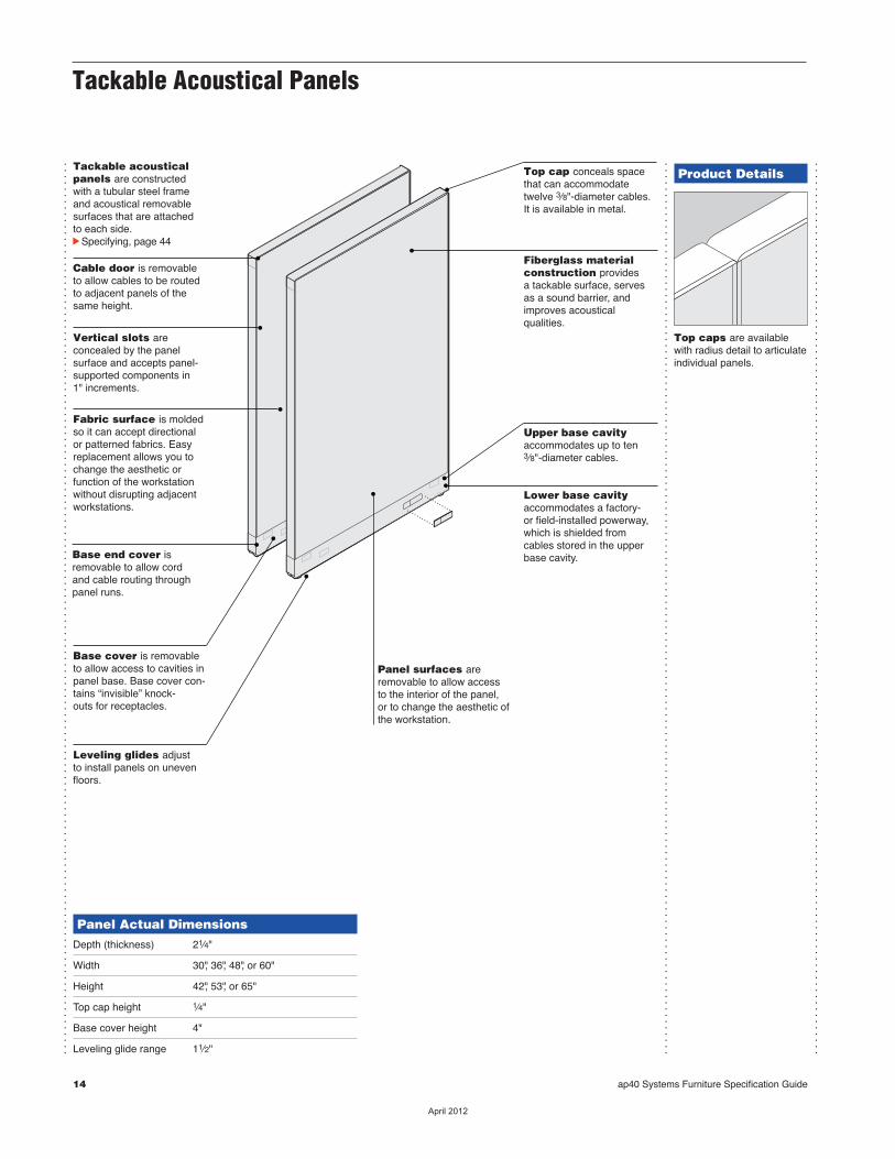
Tackable acousticalpanels are constructedwith a tubular steel frame and acoustical removablesurfaces that are attached to each side.cSpecifying, page 46
Cable door is removableto allow cables to be routedto adjacent panels of thesame height.
Vertical slots are concealed by the panel surface and accepts panel-supported components in1" increments.
Fabric surface is moldedso it can accept directionalor patterned fabrics. Easyreplacement allows you tochange the aesthetic orfunction of the workstationwithout disrupting adjacent workstations.
Base end cover isremovable to allow cordand cable routing throughpanel runs.
Base cover is removableto allow access to cavities inpanel base. Base cover con-tains “invisible” knock-outs for receptacles.
Leveling glides adjustto install panels on unevenfloors.
Top cap conceals spacethat can accommodatetwelve 3⁄8"-diameter cables.It is available in metal.
Fiberglass materialconstruction provides a tackable surface, servesas a sound barrier, andimproves acoustical qualities.
Upper base cavity accom-modates up to ten 3⁄8"-diam-eter cables.
Lower base cavityaccommodates a factory-or field-installed powerway,which is shielded fromcables stored in the upperbase cavity.
Panel Actual DimensionsDepth (thickness) 21⁄4"
Width 30" or 60"
Height 42", 53", or 65"
Top cap height 1⁄4"
Base cover height 4"
Leveling glide range 11⁄2"
Product Details
Top caps are availablewith radius detail to articulateindividual panels.
...............................................................................................................................................
...............................................................................................................................................
...............................................................................................................................................
...............................................................................................................................................
...............................................................................................................................................
...............................................................................................................................................
ap40 Specification Guide 17
Tackable AcousticalPanels
Pa
ne
ls
Connections
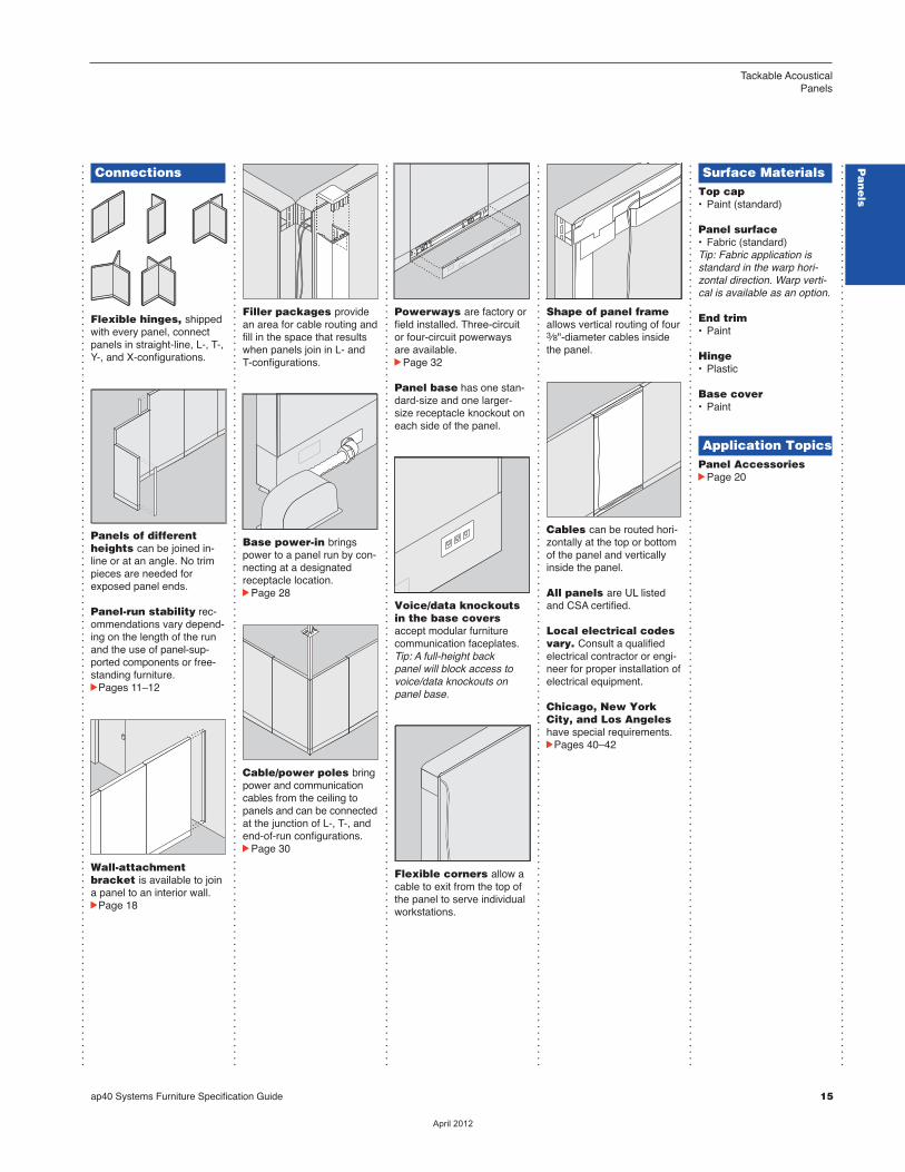
Flexible hinges, shippedwith every panel, connectpanels in straight-line, L-, T-,Y-, and X-configurations.
Panels of differentheights can be joined in-line or at an angle. No trimpieces are needed forexposed panel ends.
Panel-run stability rec-ommendations vary depend-ing on the length of the runand the use of panel-sup-ported components or free-standing furniture.cPages 12–13
Wall-attachmentbracket is available to joina panel to an interior wall.cPage 20
Filler packages providean area for cable routing andfill in the space that resultswhen panels join in L- andT-configurations.
Base power-in bringspower to a panel run by con-necting at a designatedreceptacle location.cPage 30
Power and cable polesbring power and communica-tion cables from the ceiling topanels and can be connectedat the junction of L- andT-configurations, and end-of-run configurations.cPage 32
Powerways are factory orfield installed. Three-circuitor four-circuit power-waysare available.cPage 34
Panel base has one stan-dard-size and one larger-size receptacle knockout oneach side of the panel.
Voice/data knockoutsin the base covers acceptmodular furniture communi-cation faceplates.Tip: A full-height back panel will block access tovoice/data knockouts onpanel base.
Flexible corners allow acable to exit from the top ofthe panel to serve individualworkstations.
Shape of panel frameallows vertical routing of four3⁄8"-diameter cables insidethe panel.
Cables can be routed hori-zontally at the top or bottomof the panel and verticallyinside the panel.
All panels are UL listedand CSA certified.
Local electrical codesvary. Consult a qualifiedelectrical contractor or engi-neer for proper installation ofelectrical equipment.
Chicago, New YorkCity, and Los Angeleshave special requirements.cPages 42–44
Surface MaterialsTop cap• Paint (standard)
Panel surface• Fabric (standard)Tip: Fabric application isstandard in the warp hori-zontal direction. Warp verti-cal is available as an option.
End trim• Paint
Hinge• Plastic
Base cover• Paint
Application TopicsPanel AccessoriescPage 22
Panel surfaces areremovable to allow accessto the interior of the panel, or to change the aesthetic ofthe workstation.
Tackable Acoustical Panels
2 ap40 Systems Furniture Specification Guide
Eleven Tips:How to Get the Most Out of This Book
...............................................................................................................................................
...............................................................................................................................................
...............................................................................................................................................
...............................................................................................................................................
Tip 1
Watch the tabs on the right-hand edges of the pages.Theyʼll always indicatewhich chapter you are in.
Tip 2
Review Things to KnowAbout pages for an intro-duction to ap40 and theproduct features that makeit a unique furniture system.cPage 4
Ch
ap
ter N
am
e
Tip 3
Use the Statement ofLine pages for an over viewof the available components,their sizes, and page refer-ences for additional infor-mation. Each Under standingchapter includes a state-ment of line after the table of contents.
Tip 4
Find cross referencesby looking for page numbersflagged with an arrow.
14 Ellipse
EllipseStatement of Line
Desks30"W 36"W 42"W 48"W 54"W 60"W 72"W
24"D • • • • • •30"D • • • • • • •36"D • •
Returns30"W 36"W 42"W 48"W 60"W
24"D • • • • •
Radius Junction Tops30"/30"D 30"/24"D 24"/30"D
90° Radius • • •60° Radius •
Triangular Junction Tops30"/30"D
90° Triangular •Reverse 90° Triangular •90° “H” Triangular •
Corner Conference Tables36"W
30"D •
Round and Rectangular Conference Tables42" Diameter 78"W
42"D • •
Understandingc Page 18
Specifyingc Pages 44–48
Understandingc Page 18
Specifyingc Pages 49–50
Understandingc Page 20
Specifyingc Pages 52–53
Understandingc Page 20
Specifyingc Pages 54–55
Understandingc Page 22
Specifyingc Page 56
Understandingc Page 22
Specifyingc Page 57
281/2"H 261/4"H or281/2"H
30"30"
30"24" 30"30"
24"30"
90°
90°90°
60°
30"30"
30"30"
30"30"
90°
90°
90°
281/2"H 281/2"H
281/2"H
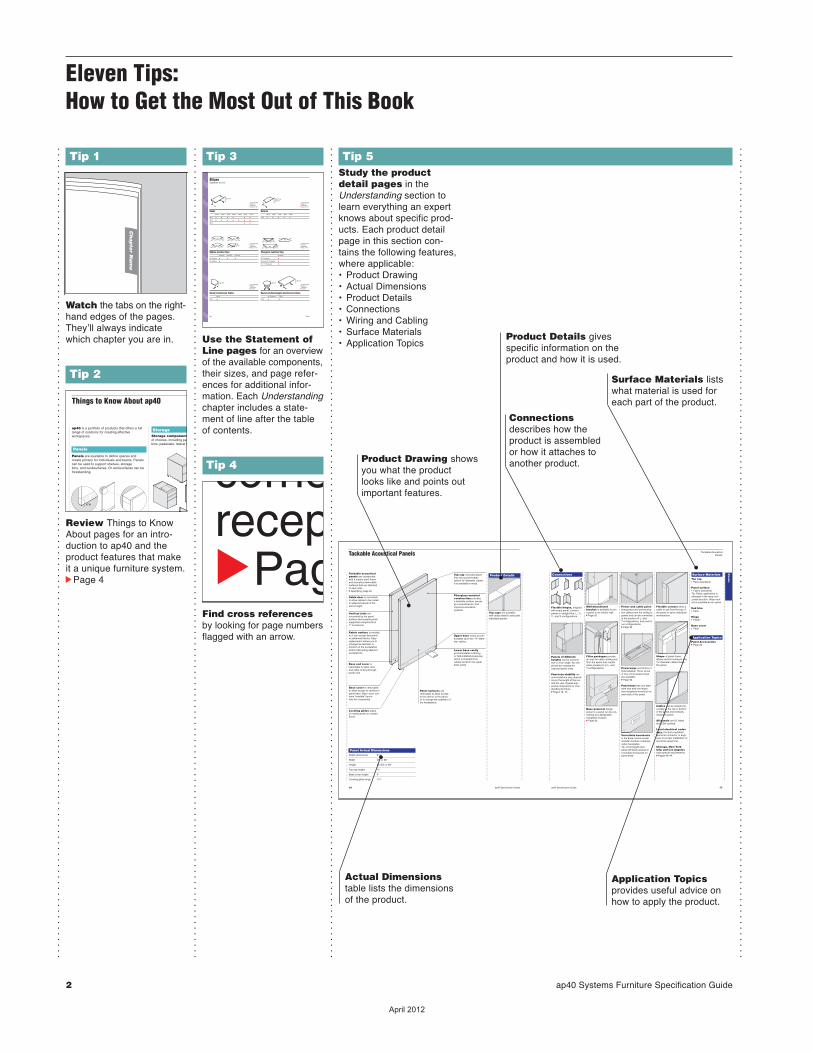
Tip 5Study the productdetail pages in theUnderstanding section tolearn everything an expertknows about specific prod-ucts. Each product detailpage in this section con-tains the following features,where applicable:• Product Drawing• Actual Dimensions• Product Details• Connections• Wiring and Cabling• Surface Materials• Application Topics
Product Drawing showsyou what the product looks like and points outimportant features.
Connections describes how theproduct is assembledor how it attaches toanother product.
Product Details givesspecific information on theproduct and how it is used.
Surface Materials listswhat material is used foreach part of the product.
Actual Dimensions table lists the dimensions of the product.
Application Topics provides useful advice onhow to apply the product.
��������
Tip 7
Italic typeface on speci-fying pages usually identi-fies wording that you shoulduse in your order.
Tip 8
Watch for tips through-out the text that give youexplanations and helpfulinstructions.
Tip 9
Learn what you cannotdo by looking for drawingscrossed out with an “X.”
Three-Panel Runs
Unstable. Requiresadditional support at endof panel run.
Tip: Fabric application is standard in the warp horizontal direction. Warp vertical is available as an option.
Tip: Filler package height must match height of tallest panel.
Specify with vertical application.
Required to Specify
Specify with 3-circuit powerway withshared neutral.Specify with 3-circuit powerway withseparate neutral.Specify with 4-circuit (3+D) powerwaSpecify with 4-circuit (2+2) powerway
Tip 10Use the surface materials listings in theSurface Materials section ofthis book to find surfacematerial color numbers.cPage 129
Tip 11
Refer to the style number index when youknow a style number andyou need to find the pagethat has more details aboutthe product.cPage 136
StyleNumber
TKTA4230
TKTA4260
TKTA5330
TKTA5360
TKTBC
TKTC
TKTFILL42
Page
58
58
58
58
61
52
53
Tackable Acoustical Panels
50 ap40 Specification Guide
Standard Includes Required to SpecifycNeed help?
Product details,page 20
• 65"H and shorter panel with fabric surfaces, fabricdirection with horizontal application*: fabric
• Radius top cap, end trim, and base covers withreceptacle knockouts: paint
• Hinge: plastic
1 Style number2 Fabric color number for surface3 Paint color number for top cap, end trim,
and base covers4 Plastic color number for plastic hinge5 Options, if selected (see below) cSee Surface Materials, page 460.
Tip: Fabric application isstandard in the warp hori-zontal direction.cSee SpecificationGuidelines for Vertical FabricApplications, page 470, fordetails on these exceptions.Warp vertical is available as an option.
T i p : Filler package heightmust match height of tallestp a n e l .
Options U.S. Price Required to SpecifySurface Fabric directionMaterials • Vertical application No cost Specify with vertical application.
Electrical Factory-installed powerwaycPage 418 • 3-circuit powerway with +$178 Specify with 3-circuit powerway with
shared neutral shared neutral.• 3-circuit powerway with +$205 Specify with 3-circuit powerway with
separate neutrals separate neutral.• 4-circuit (3+D) powerway +$205 Specify with 4-circuit (3+D) powerway.• 4-circuit (2+2) powerway +$243 Specify with 4-circuit (2+2) powerway.
Field-installed powerway • For use in New York City cMust specify powerway for field
installation only, page 92.
Factory-installed raceway • For use in Chicago with +$153 Specify with Chicago powerway.
power base covers
Related • Panel brackets cPage 81Products • Panel accessories cPage 84
• Panel wiring and cabling cPage 87
Specification Information
DWidth DStyle DU.S. d dNumber dBase d d dPriced d d
42"H Panels30" TKTA4230 $ 641
60" TKTA4260 $ 974d d d
53"H Panels30" TKTA5330 $ 703
60" TKTA5360 $1025d d d
65"H Panels30" TKTA6530 $ 839
60" TKTA6560 $1156d d d
ap40 Specification Guide cPanel Filler Packages, continued 51
Panel Filler Packages
Panel End-of-Run Filler Packages
Standard Includes Required to SpecifycNeed help?
Product details,page 28
• 42"H–65"H filler cover, fabric direction withhorizontal application: fabric
• Radius top cap and base cover: paint• Carrier: black paint only
1 Style number2 Fabric color number for filler cover3 Paint color number for top cap and base
cover4 Options, if selected (see below)cSee Surface Materials, page 460.
Options U.S. Price Required to SpecifySurface Fabric directionMaterials • Vertical application No cost Specify with vertical application.
Specification Information
DPanel DStyle DU.S.dHeight dNumber dPriced d d
Fabric-Covered Filler Covers42" TKERFILL42 $182
53" TKERFILL53 $188
65" TKERFILL65 $203d d d
T i p : Filler package heightmust match height of tallestp a n e l .cPage 28
Tip: Fabric application isstandard in the warp hori-zontal direction.cSee SpecificationGuidelines for Vertical FabricApplications, page 470, fordetails on these exceptions.Warp vertical is available as an option.
Panel Filler Packages
ap40 Systems Furniture Specification Guide 3
...............................................................................................................................................
...............................................................................................................................................
...............................................................................................................................................
...............................................................................................................................................
Eleven Tips:How to Get the Most
Out of This Book
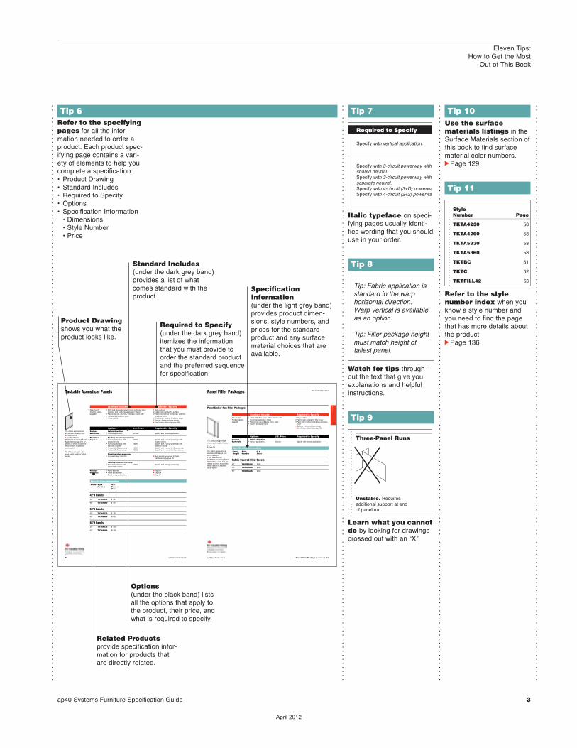
Product Drawing shows you what the product looks like.
Tip 6Refer to the specifyingpages for all the infor -mation needed to order aproduct. Each product spec-ifying page contains a vari-ety of elements to help you complete a specification:• Product Drawing• Standard Includes• Required to Specify• Options• Specification Information • Dimensions • Style Number • Price
Standard Includes(under the dark grey band)provides a list of whatcomes standard with theproduct.
Required to Specify(under the dark grey band)itemizes the informationthat you must provide toorder the standard productand the preferred sequencefor specification.
SpecificationInformation (under the light grey band)provides product dimen-sions, style numbers, andprices for the standardproduct and any surfacematerial choices that areavailable.
Options (under the black band) listsall the options that apply tothe product, their price, andwhat is required to specify.
Related Productsprovide specification infor-mation for products that are directly related.
��������
4 ap40 Systems Furniture Specification Guide
Things to Know About ap40
...............................................................................................................................................
...............................................................................................................................................
...............................................................................................................................................
...............................................................................................................................................
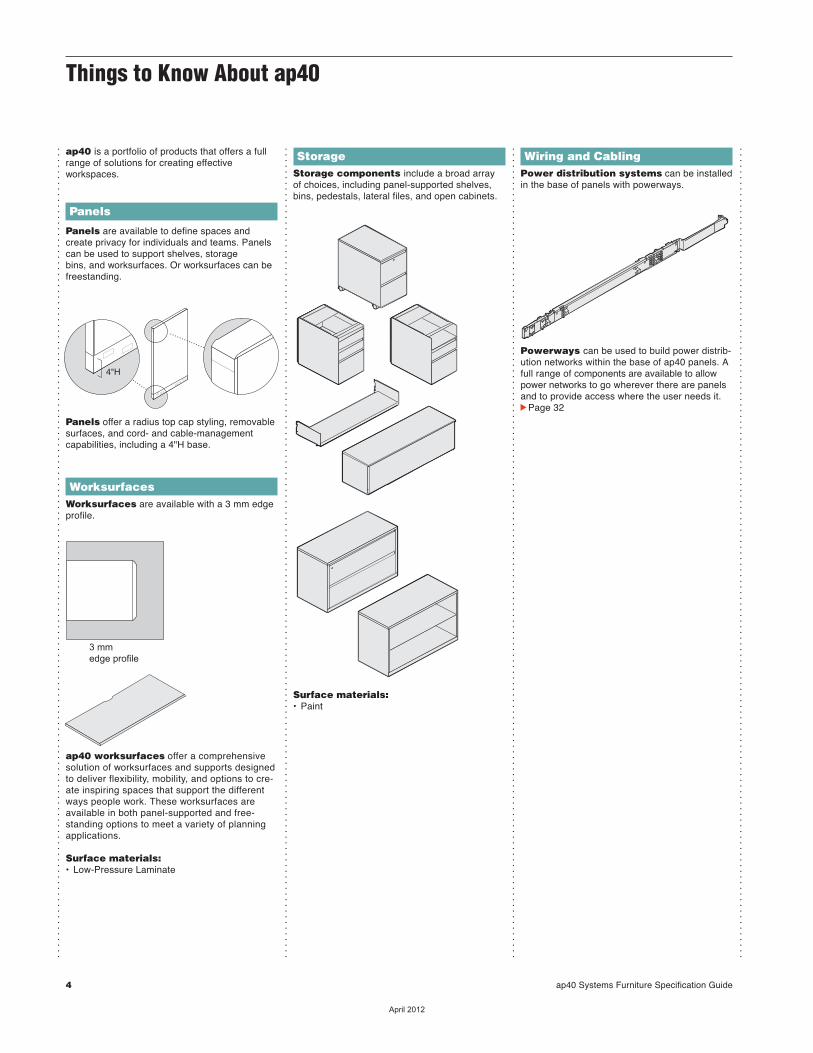
ap40 is a portfolio of products that offers a fullrange of solutions for creating effective workspaces.
Panels
Panels are available to define spaces andcreate privacy for individuals and teams. Panelscan be used to support shelves, storagebins, and worksurfaces. Or worksurfaces can befreestanding.
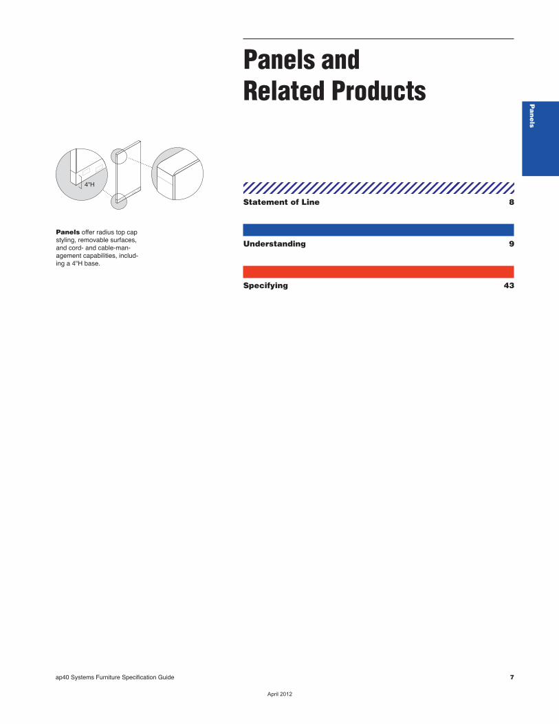
Panels offer a radius top cap styling, removablesurfaces, and cord- and cable-managementcapabilities, including a 4"H base.
WorksurfacesWorksurfaces are available with a 3 mm edgeprofile.
ap40 worksurfaces offer a comprehensivesolution of worksurfaces and supports designedto deliver flexibility, mobility, and options to cre-ate inspiring spaces that support the differentways people work. These worksurfaces areavailable in both panel-supported and free-standing options to meet a variety of planningapplications.
Surface materials:• Low-Pressure Laminate
3 mmedge profile
4"H
StorageStorage components include a broad arrayof choices, including panel-supported shelves,bins, pedestals, lateral files, and open cabinets.
Surface materials:• Paint
Wiring and CablingPower distribution systems can be installedin the base of panels with powerways.
Powerways can be used to build power distrib-ution networks within the base of ap40 panels. Afull range of components are available to allowpower networks to go wherever there are panelsand to provide access where the user needs it. cPage 32
��������

ap40 Systems Furniture Specification Guide 5
Additional ResourcesAdditional Resources
...............................................................................................................................................
...............................................................................................................................................
...............................................................................................................................................
...............................................................................................................................................
...............................................................................................................................................
...............................................................................................................................................
ap40 products are sup-ported with informationalmaterials, tools, and soft-ware to help you plan,specify, and order an instal-lation efficiently.
Product brochures andplanning tools can beordered through yourSteelcase area office bycalling 1.800.784.0358or through the SteelcaseMarketing CommunicationsWeb site atin2.steelcase.com.
Product Brochuresap40This brochure is designedto give you a generaloverview of ap40. Thisbrochure will help you thinkabout your office differentlyand illustrate applications tobest support your businessneeds.
The ap40 brochure is available for customizationthrough the Marketing onDemand tool.
ap40 Planning Ideasap40 Planning Ideasprovide specification anddesign support for applica-tions highlighted in the ap40brochure. Available atwww.steelcase.com/planning ideas.
Planning ToolsHeight AdjusTablesWorksurfaces BrochureProvides an overview of the advantages of usingDetails height-adjustableworksurfaces. Informationon user ergonomics andhow businesses can savemoney is included, alongwith visual and descriptiveoverviews of Details height-adjustable worksurfaces.Form number 08-0000914
Printed MaterialsSurface MaterialsReference ManualThis publication provides: • An explanation of the
surface materials program• “Available on” matrices • Vertical surface fabric
and seating upholsteryselection listing
• Technical data for surfacematerials
• Surface material care andcleaning instructions
Computer ToolsElectronic CatalogAccurate sales quotationsand purchase orders forSteelcase products are cre-ated with specification soft-ware that uses SteelcaseElectronic Catalog data. Usethe data to specify and pricestyle numbers and optionsfor every Steelcase product.The data is updatedbimonthly by Steelcase andprovided to software pro-grams including: theHedberg Business System,SmartTools– Steelcaseʼsdesign and specificationsoftware (for more informa-tion on SmartTools, pleaseemail [email protected]), the ProjectMatrixProjectSymbols libraries, aswell as 20-20 CAP Studio.
Furniture SymbolGraphic DataSteelcase creates 2D and3D furniture symbols (withattributes) for planning andinitially specifying Steelcaseproducts. This data is incor-porated into several add-onsoftware packages thatwork in either a Microstationor an AutoCAD draftingenvironment.
For more information aboutthese and other softwaretools to help you plan effective work environ-ments, please [email protected].
Product InfoElectronic versions of thisand many other specifica-tion guides in Acrobat PDF(Portable DocumentFormat) allow you to scan,search, and print any pageon virtually any computer.You can access these filesat the Steelcase.com Website or My Sales Online atin2.Steelcase.com.
Product Info
®
ap40 Product TrainingBasic training will be avail-able as part of the BuildingProduct Muscle (BPM) cur-riculum on the SteelcaseUniversity Web site atin2.steelcase.com.
Installation Trainingwill be available for sales-people.
SupportSteelcase CapabilitiesSteelcase products are distributed, installed, andserviced through a networkof more than 600 dealersworldwide. Steelcase is alsorepresented with offices andcorporate showrooms in 26U.S. cities, 4 Canadiancities, and in France,Germany, Great Britain, andJapan. Every Steelcaseproduct meets our excep-tionally high standards ofquality and durability andcomes with the Steelcaseassurance of excellence inservice.
For assistance, pleasecall your local dealer, theSteelcase SolutionsResource Team, or theSteelcase SolutionsFulfillment Team at1.888.STEELCASE(1.888.783.3522) or send an e-mail to [email protected].
Call the Steelcase SolutionsResource Team prior toplacing an order, whenworking on a bid, or whenyou need information aboutproduct applications andspecifications.
Call the Steelcase SolutionsFulfillment Team if you havesubmitted an order toSteelcase and you need tospeak to your SolutionsFulfillment TeamRepresentative about theorder. Also call if you haveany post-shipment qualityor warranty concerns or service parts questions.
Outside the U.S.A.,Canada, Mexico, PuertoRico, and the U.S. VirginIslands, call 1.616.247.2500.
For information aboutSteelcase, the name of yournearest Steelcase dealer,or for product literature, call1.800.333.9939, or visit ourWeb site: www.steelcase.com.
��������

6 ap40 Systems Furniture Specification Guide
��������
Panels and Related Products
ap40 Systems Furniture Specification Guide 7
Pa
ne
ls
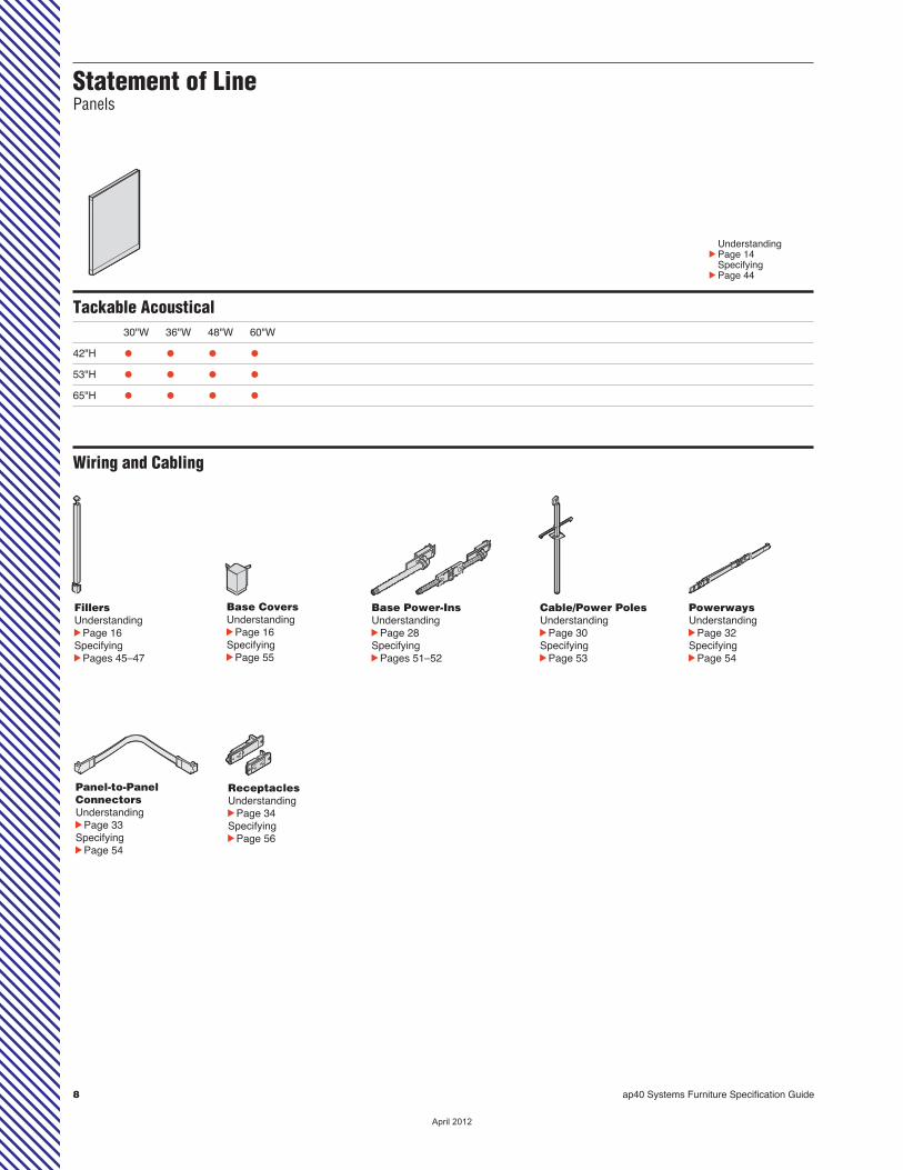
Statement of Line 8
Understanding 9
Specifying 43
4"H
Panels offer radius top capstyling, removable surfaces,and cord- and cable-man-agement capabilities, includ-ing a 4"H base.
��������
8 ap40 Systems Furniture Specification Guide
Tackable Acoustical
30"W 36"W 48"W 60"W 42"H • • • • 53"H • • • •65"H • • • •
UnderstandingcPage 14 SpecifyingcPage 44
Statement of Line Panels
FillersUnderstanding cPage 16Specifying cPages 45–47
Base Power-InsUnderstanding cPage 28Specifying cPages 51–52
Cable/Power PolesUnderstanding cPage 30Specifying cPage 53
PowerwaysUnderstanding cPage 32Specifying cPage 54
Panel-to-PanelConnectorsUnderstanding cPage 33Specifying cPage 54
ReceptaclesUnderstanding cPage 34Specifying cPage 56
Base CoversUnderstanding cPage 16Specifying cPage 55
Wiring and Cabling
��������
ap40 Systems Furniture Specification Guide 9
Pa
ne
ls
Understanding Panels and RelatedProducts
Panel Overview 10
Rules for Panel Stability 11
Rules for Panel Stability with Components 12
Panel Creep 13
Panels and Related Products
Tackable Acoustical Panels 14
Panel Filler Packages 16
Panel Brackets 18
Panel Accessories 20
Wiring and Cabling
Wiring and Cabling Overview 21
Steps to Plan an Electrical Network 24
Circuit Choices 25
Circuit Specifications 26
How to Calculate Power Needs 27
Base Power-Ins 28
Cable/Power Poles for Panels 30
Powerways 32
Base Covers and Receptacles 34
Understanding Building Wiring 36
Cable Capacities of Panels 38
Special Requirements for Chicago 40
Special Requirements for New York City 41
Special Requirements for Los Angeles 42
��������

10 ap40 Systems Furniture Specification Guide
Tackable Acoustical Panels
Widths available 30", 36", 48", and 60"
Heights available 42", 53", and 65"
Top cap height 1⁄4"
Base cover height 4"
Tackable Yes
Removable surfaces Yes
Horizontal cable routing Yes, beneath top cap and capability in upper base cavity
Vertical cable routing Yes, through recesses in frame
Accommodates powerways Yes, in lower base cavity of panels
Accommodates receptacles Yes, in base cover of panels
Accommodates voice/data Yes receptacles in base
Component attachment Yes
Accepts power or cable pole Yes
Accepts base power-in Yes
Panel surface Fabric
Fabric application Molded
...............................................................................................................................................
...............................................................................................................................................
Panel Overview
��������
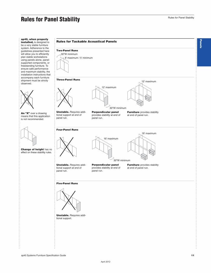
8' maximum / 5' minimum
30"W minimum
12' maximum
16' maximum
16' maximum
30"W minimum
30"W minimum
12' maximum
...............................................................................................................................................
...............................................................................................................................................
...............................................................................................................................................
ap40, when properlyinstalled, is designed tobe a very stable furnituresystem. Adherence to theguidelines presented herewill allow you to efficientlyplan stable workstationsusing panels alone, panel-supported components, orfreestanding furniture. Toensure safe performanceand maximum stability, theinstallation instructions thataccompany each furnitureshipment must be strictlyobserved.
An “X” over a drawingmeans that this applicationis not recommended.
Change of height has noeffect on these stability rules.
Rules for Tackable Acoustical Panels
Two-Panel Runs
Three-Panel Runs
Unstable. Requires addi-tional support at end ofpanel run.
Perpendicular panelprovides stability at end ofpanel run.
Furniture provides stabilityat end of panel run.
Four-Panel Runs
Unstable. Requires addi-tional support at end ofpanel run.
Perpendicular panelprovides stability at end ofpanel run.
Furniture provides stabilityat end of panel run.
Five-Panel Runs
Unstable. Requires addi-tional support.
Rules for Panel Stability
Rules for Panel Stability
Pa
ne
ls
ap40 Systems Furniture Specification Guide 11
��������
60" minimum
minimum two 30"W panel run-offs
8'W maximum panel run
dimension mustmatch worksurface
8'W maximum panel run
8'W maximum panel run
...............................................................................................................................................
...............................................................................................................................................
...............................................................................................................................................
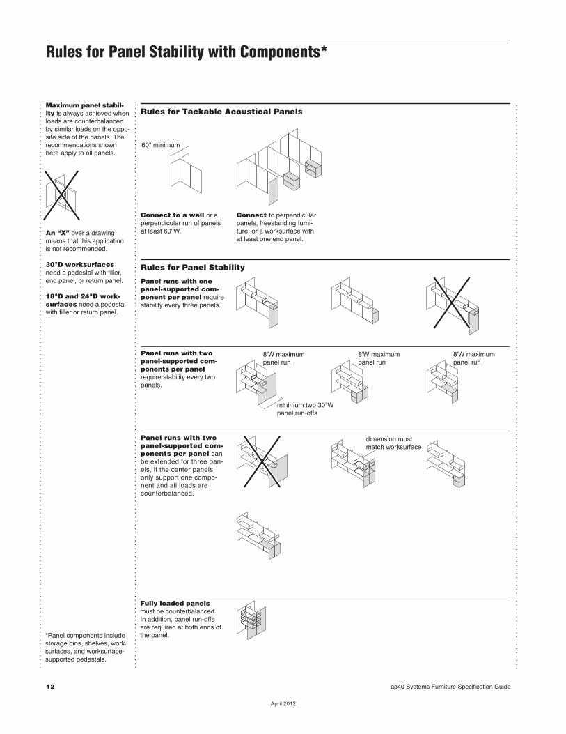
Maximum panel stabil-ity is always achieved whenloads are counterbalancedby similar loads on the oppo-site side of the panels. Therecommendations shownhere apply to all panels.
An “X” over a drawingmeans that this applicationis not recommended.
30"D worksurfacesneed a pedestal with filler,end panel, or return panel.
18"D and 24"D work-surfaces need a pedestalwith filler or return panel.
Rules for Tackable Acoustical Panels
Connect to a wall or aperpendicular run of panelsat least 60"W.
Connect to perpendicularpanels, freestanding furni-ture, or a worksurface withat least one end panel.
Rules for Panel Stability
Panel runs with onepanel-supported com-ponent per panel requirestability every three panels.
Panel runs with twopanel-supported com-ponents per panelrequire stability every twopanels.
Panel runs with twopanel-supported com-ponents per panel canbe extended for three pan-els, if the center panelsonly support one compo-nent and all loads arecounterbalanced.
Fully loaded panelsmust be counterbalanced. In addition, panel run-offsare required at both ends ofthe panel. *Panel components include
storage bins, shelves, work -
surfaces, and worksurface-supported pedestals.
Rules for Panel Stability with Components*
12 ap40 Systems Furniture Specification Guide
��������
Straight Connections...............................................................................................................................................
...............................................................................................................................................
...............................................................................................................................................
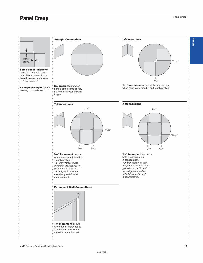
Some panel junctionsadd to the length of panelruns. The accumulation ofthese increments is knownas “panel creep.”
Change-of-height has nobearing on panel creep.
Panel creep
No creep occurs whenpanels of the same or vary-ing heights are joined withhinges.
L-Connections
3⁄32" increment occurs at the intersectionwhen panels are joined in an L-configuration.
3/32"
3/32"
T-Connections
3⁄16" increment occurswhen panels are joined in aT-configuration.Tip: Donʼt forget to addthe panel thickness (21⁄4")gained from L-, T-, andX-configurations when calculating wall-to-wall measurements.
21/4"
3/32"
3/32"
3/32"
X-Connections
3⁄16" increment occurs onboth directions of anX-configuration.Tip: Donʼt forget to addthe panel thickness (21⁄4")gained from L-, T-, andX-configurations when calculating wall-to-wall measurements.
3/32"
3/32"
21/4"
3/32"
Permanent Wall Connections
3⁄4" increment occurswhen panel is attached to a permanent wall with a wall-attachment bracket.
3/4"
Panel Creep
Panel Creep
Pa
ne
ls
ap40 Systems Furniture Specification Guide 13
��������
...............................................................................................................................................
...............................................................................................................................................
...............................................................................................................................................
Tackable acousticalpanels are constructedwith a tubular steel frame and acoustical removablesurfaces that are attached to each side.cSpecifying, page 44
Cable door is removableto allow cables to be routedto adjacent panels of thesame height.
Vertical slots are concealed by the panel surface and accepts panel-supported components in1" increments.
Fabric surface is moldedso it can accept directionalor patterned fabrics. Easyreplacement allows you tochange the aesthetic orfunction of the workstationwithout disrupting adjacent workstations.
Base end cover isremovable to allow cordand cable routing throughpanel runs.
Base cover is removableto allow access to cavities inpanel base. Base cover con-tains “invisible” knock-outs for receptacles.
Leveling glides adjustto install panels on unevenfloors.
Top cap conceals spacethat can accommodatetwelve 3⁄8"-diameter cables.It is available in metal.
Fiberglass materialconstruction provides a tackable surface, servesas a sound barrier, andimproves acoustical qualities.
Upper base cavityaccommodates up to ten3⁄8"-diameter cables.
Lower base cavityaccommodates a factory-or field-installed powerway,which is shielded fromcables stored in the upperbase cavity.
Panel Actual DimensionsDepth (thickness) 21⁄4"
Width 30", 36", 48", or 60"
Height 42", 53", or 65"
Top cap height 1⁄4"
Base cover height 4"
Leveling glide range 11⁄2"
Product Details
Top caps are availablewith radius detail to articulateindividual panels.
Panel surfaces areremovable to allow accessto the interior of the panel, or to change the aesthetic ofthe workstation.
Tackable Acoustical Panels
14 ap40 Systems Furniture Specification Guide
��������
...............................................................................................................................................
...............................................................................................................................................
...............................................................................................................................................
...............................................................................................................................................
...............................................................................................................................................
...............................................................................................................................................
Tackable AcousticalPanels
Pa
ne
ls
Connections
Flexible hinges, shippedwith every panel, connectpanels in straight-line, L-, T-,Y-, and X-configurations.
Panels of differentheights can be joined in-line or at an angle. No trimpieces are needed forexposed panel ends.
Panel-run stability rec-ommendations vary depend-ing on the length of the runand the use of panel-sup-ported components or free-standing furniture.cPages 11–12
Wall-attachmentbracket is available to joina panel to an interior wall.cPage 18
Filler packages providean area for cable routing andfill in the space that resultswhen panels join in L- andT-configurations.
Base power-in bringspower to a panel run by con-necting at a designatedreceptacle location.cPage 28
Cable/power poles bringpower and communica tioncables from the ceiling topanels and can be connectedat the junction of L-, T-, andend-of-run configurations.cPage 30
Powerways are factory orfield installed. Three-circuitor four-circuit powerwaysare available.cPage 32
Panel base has one stan-dard-size and one larger-size receptacle knockout oneach side of the panel.
Voice/data knockoutsin the base coversaccept modular furniturecommuni cation faceplates.Tip: A full-height back panel will block access tovoice/data knockouts onpanel base.
Flexible corners allow acable to exit from the top ofthe panel to serve individualworkstations.
Shape of panel frameallows vertical routing of four3⁄8"-diameter cables insidethe panel.
Cables can be routed hori-zontally at the top or bottomof the panel and verticallyinside the panel.
All panels are UL listedand CSA certified.
Local electrical codesvary. Consult a qualifiedelectrical contractor or engi-neer for proper installation ofelectrical equipment.
Chicago, New YorkCity, and Los Angeleshave special requirements.cPages 40–42
Surface MaterialsTop cap• Paint (standard)
Panel surface• Fabric (standard)Tip: Fabric application isstandard in the warp hori-zontal direction. Warp verti-cal is available as an option.
End trim• Paint
Hinge• Plastic
Base cover• Paint
Application TopicsPanel AccessoriescPage 20
ap40 Systems Furniture Specification Guide 15
��������
...............................................................................................................................................
...............................................................................................................................................
...............................................................................................................................................
...............................................................................................................................................
...............................................................................................................................................
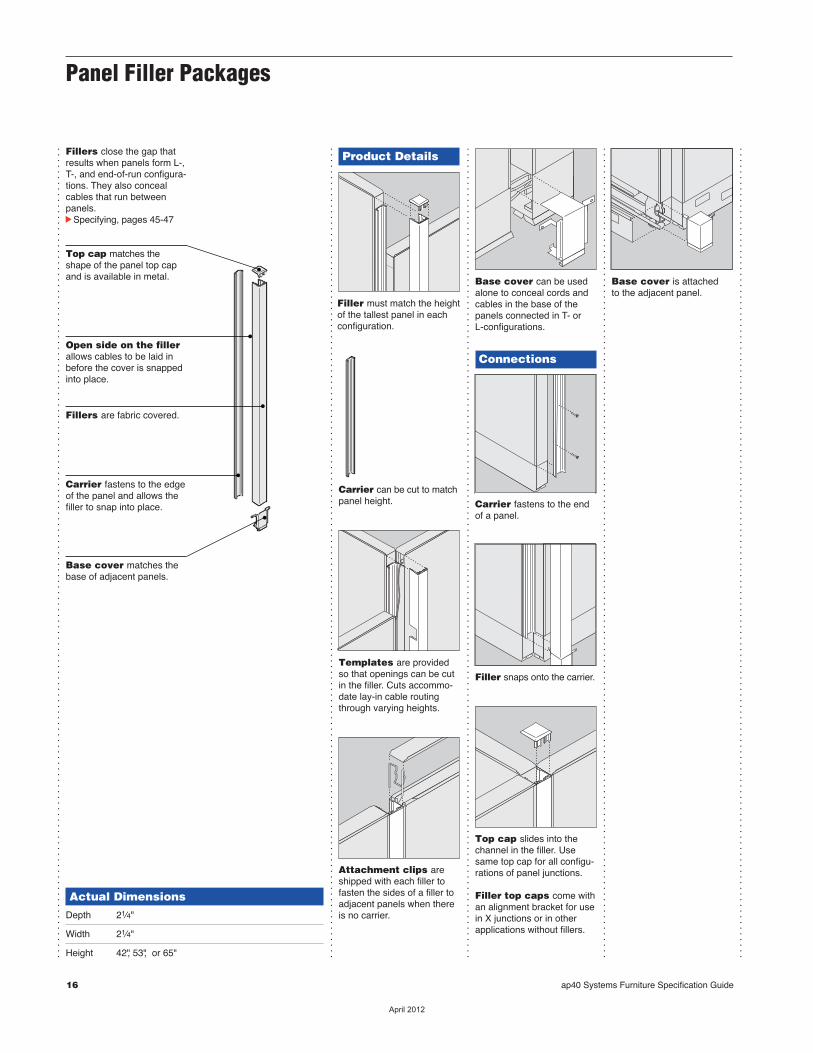
Fillers close the gap thatresults when panels form L-,T-, and end-of-run configura-tions. They also concealcables that run between panels.cSpecifying, pages 45-47
Actual DimensionsDepth 21⁄4"
Width 21⁄4"
Height 42", 53", or 65"
Product Details
Filler must match the heightof the tallest panel in eachconfiguration.
Carrier can be cut to matchpanel height.
Templates are providedso that openings can be cutin the filler. Cuts accommo -date lay-in cable routingthrough varying heights.
Attachment clips areshipped with each filler tofasten the sides of a filler toadjacent panels when thereis no carrier.
Base cover can be usedalone to conceal cords andcables in the base of thepanels connected in T- orL-configurations.
Connections
Carrier fastens to the endof a panel.
Filler snaps onto the carrier.
Top cap slides into thechannel in the filler. Usesame top cap for all configu-rations of panel junctions.
Filler top caps come withan alignment bracket for usein X junctions or in otherapplications without fillers.
Base cover is attached to the adjacent panel.
Top cap matches theshape of the panel top capand is available in metal.
Open side on the fillerallows cables to be laid inbefore the cover is snappedinto place.
Fillers are fabric covered.
Carrier fastens to the edgeof the panel and allows thefiller to snap into place.
Base cover matches thebase of adjacent panels.
Panel Filler Packages
16 ap40 Systems Furniture Specification Guide
��������
...............................................................................................................................................
...............................................................................................................................................
...............................................................................................................................................
Panel Filler Packages
Pa
ne
ls
Wiring & Cabling
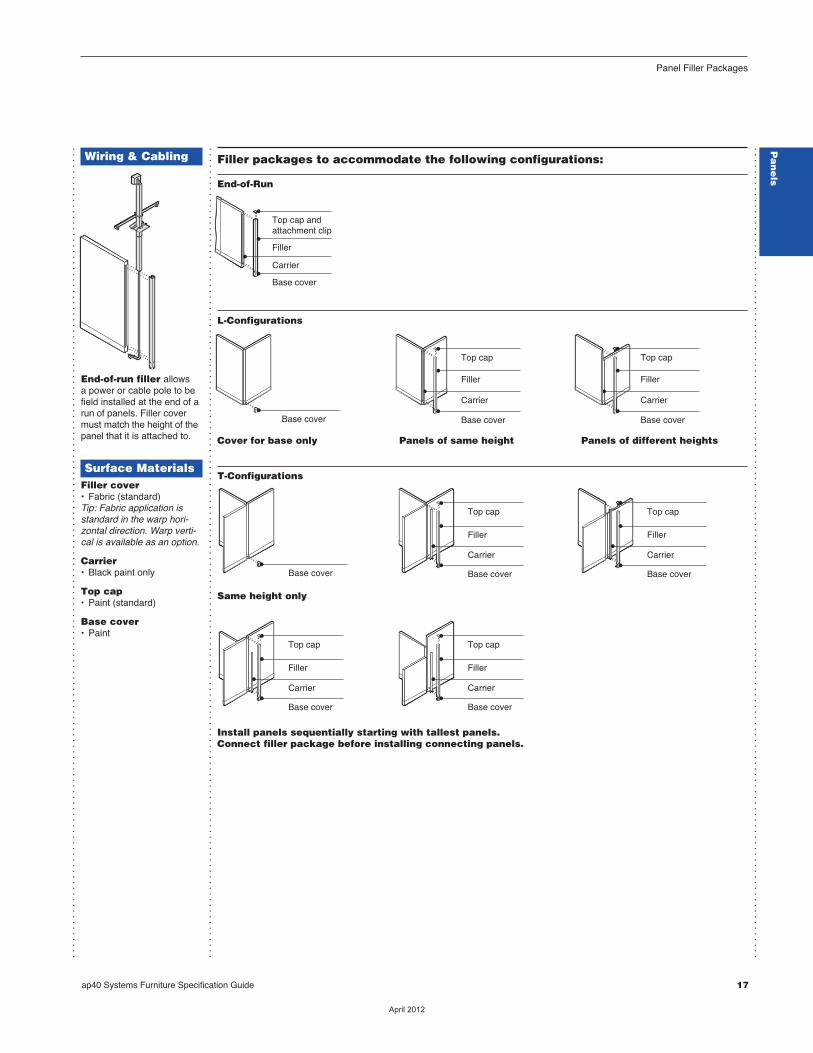
End-of-run filler allows a power or cable pole to befield installed at the end of arun of panels. Filler covermust match the height of thepanel that it is attached to.
Surface MaterialsFiller cover• Fabric (standard)Tip: Fabric application isstandard in the warp hori-zontal direction. Warp verti-cal is available as an option.
Carrier• Black paint only
Top cap• Paint (standard)
Base cover• Paint
Base cover Base cover
Top cap
Filler
Carrier
Base cover
Top cap
Filler
Carrier
Base cover
Top cap
Filler
Carrier
Base cover
Top cap
Filler
Carrier
Base cover
Top cap
Filler
Carrier
Base cover
Top cap
Filler
Carrier
Base cover
Base cover
Top cap andattachment clip
Filler
Carrier
ap40 Systems Furniture Specification Guide 17
Filler packages to accommodate the following configurations:
End-of-Run
L-Configurations
Cover for base only Panels of same height Panels of different heights
T-Configurations
Same height only
Install panels sequentially starting with tallest panels. Connect filler package before installing connecting panels.
��������
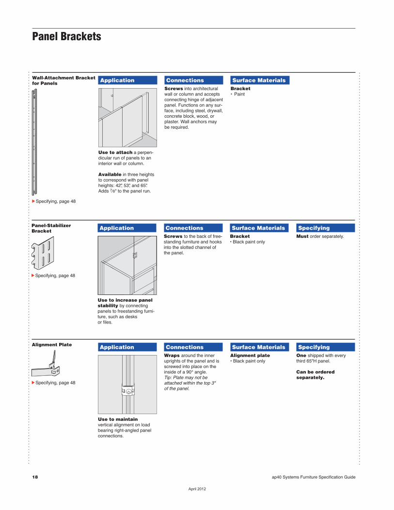
Wall-Attachment Bracketfor Panels Application
Use to attach a perpen -dicular run of panels to aninterior wall or column.
Available in three heights to correspond with panelheights: 42", 53", and 65".Adds 7⁄8" to the panel run.
ConnectionsScrews into architecturalwall or column and acceptsconnecting hinge of adjacentpanel. Functions on any sur-face, including steel, drywall,concrete block, wood, orplaster. Wall anchors maybe required.
Surface MaterialsBracket• Paint
cSpecifying, page 48
Panel-StabilizerBracket Application
Use to increase panelstability by connectingpanels to freestanding furni-ture, such as desks or files.
ConnectionsScrews to the back of free-standing furniture and hooksinto the slotted channel ofthe panel.
Surface MaterialsBracket• Black paint only
SpecifyingMust order separately.
cSpecifying, page 48
Panel Brackets
Alignment Plate Application
Use to maintain vertical alignment on loadbearing right-angled panelconnections.
ConnectionsWraps around the inneruprights of the panel and isscrewed into place on theinside of a 90° angle.Tip: Plate may not beattached within the top 3" of the panel.
Surface MaterialsAlignment plate• Black paint only
SpecifyingOne shipped with everythird 65"H panel.
Can be ordered separately.
cSpecifying, page 48
...............................................................................................................................................
...............................................................................................................................................
18 ap40 Systems Furniture Specification Guide
��������
Pa
ne
ls
...............................................................................................................................................
Panel Brackets
...............................................................................................................................................
Connections
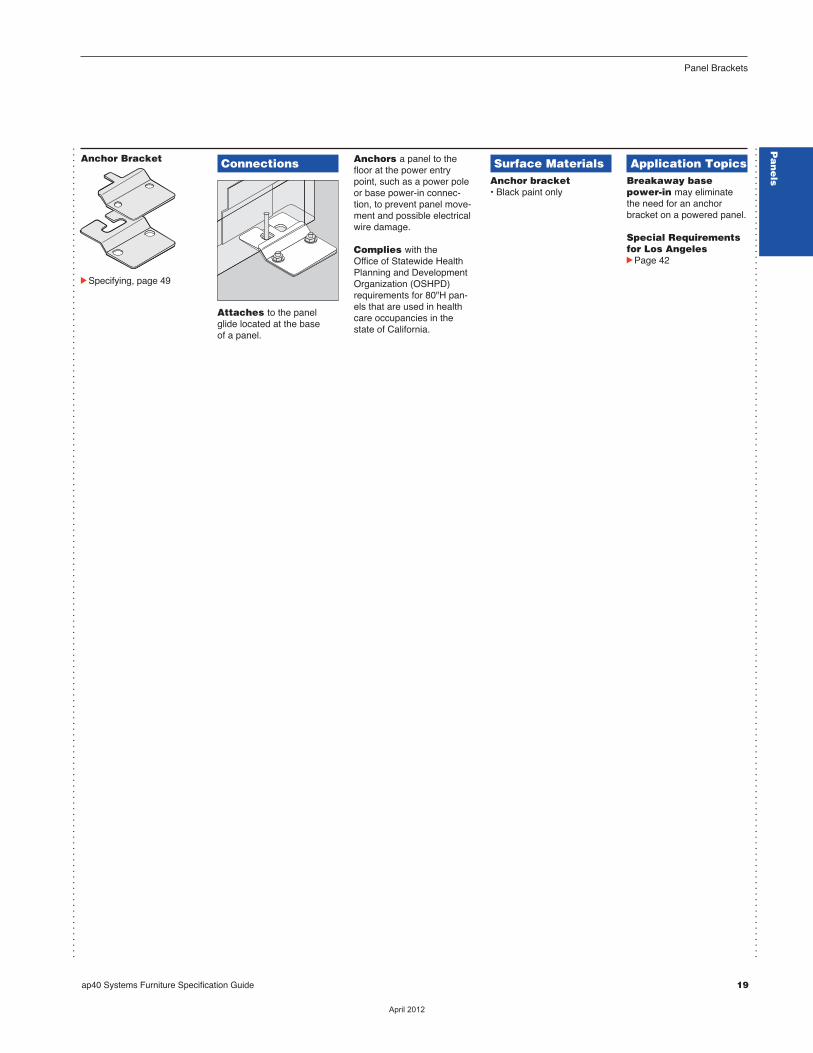
Attaches to the panelglide located at the base of a panel.
Anchors a panel to thefloor at the power entrypoint, such as a power poleor base power-in connec -tion, to prevent panel move -ment and possible electricalwire damage.
Complies with the Office of Statewide HealthPlanning and DevelopmentOrganization (OSHPD)requirements for 80"H pan-els that are used in healthcare occupancies in thestate of California.
Surface MaterialsAnchor bracket• Black paint only
Application TopicsBreakaway basepower-in may eliminatethe need for an anchorbracket on a powered panel.
Special Requirementsfor Los AngelescPage 42
cSpecifying, page 49
Anchor Bracket
Pa
ne
ls
ap40 Systems Furniture Specification Guide 19
��������
20 ap40 Systems Furniture Specification Guide
...............................................................................................................................................
...............................................................................................................................................
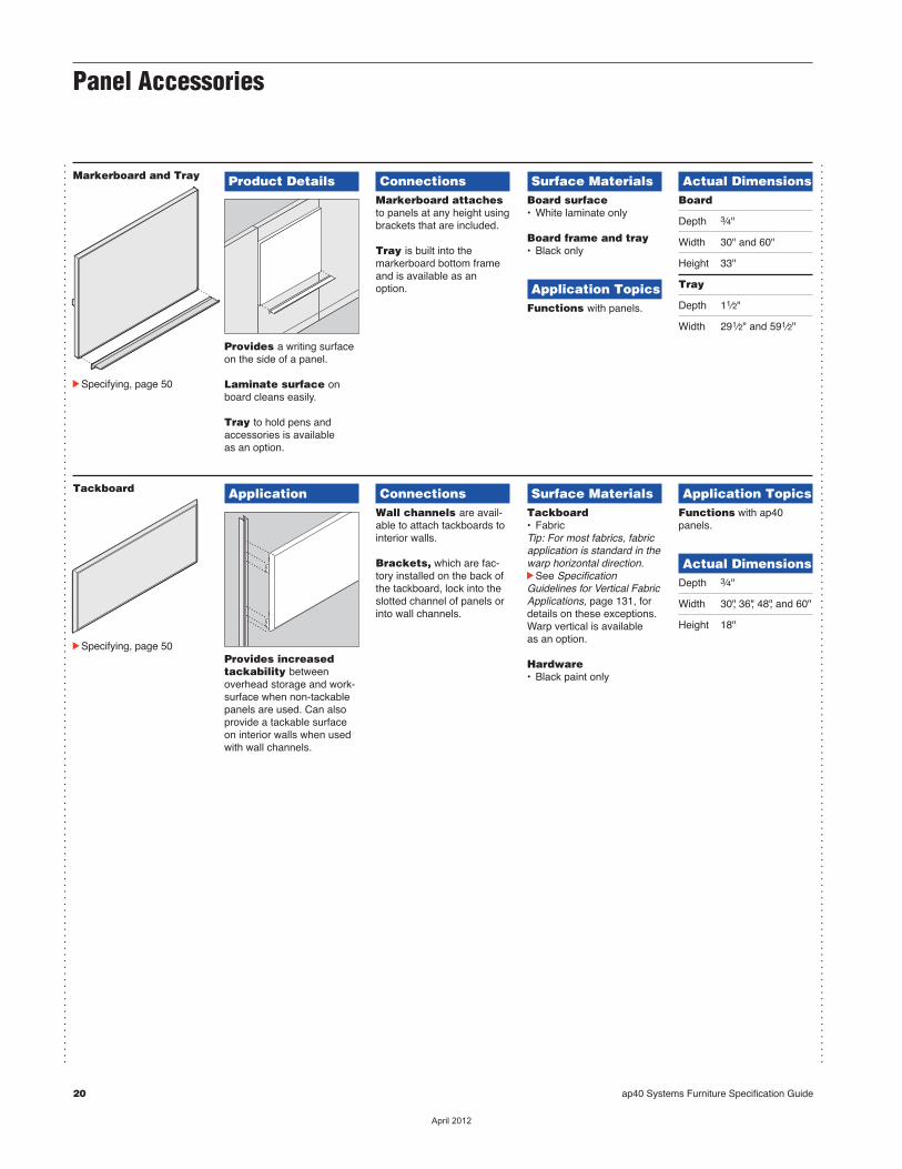
Markerboard and Tray Product Details
Provides a writing surfaceon the side of a panel.
Laminate surface onboard cleans easily.
Tray to hold pens andaccessories is available as an option.
ConnectionsMarkerboard attachesto panels at any height usingbrackets that are included.
Tray is built into themarker board bottom frameand is available as anoption.
Surface MaterialsBoard surface• White laminate only
Board frame and tray• Black only
Application TopicsFunctions with panels.
Actual DimensionsBoard
Depth 3⁄4"
Width 30" and 60"
Height 33"
Tray
Depth 11⁄2"
Width 291⁄2" and 591⁄2"
cSpecifying, page 50
Panel Accessories
Tackboard Application
Provides increasedtackability between overhead storage and work-surface when non-tackablepanels are used. Can alsoprovide a tackable surfaceon interior walls when usedwith wall channels.
ConnectionsWall channels are avail-able to attach tackboards tointerior walls.
Brackets, which are fac-tory installed on the back ofthe tackboard, lock into theslotted channel of panels orinto wall channels.
Surface MaterialsTackboard• FabricTip: For most fabrics, fabricapplication is standard in thewarp horizontal direction.cSee SpecificationGuidelines for Vertical FabricApplications, page 131, fordetails on these exceptions.Warp vertical is available as an option.
Hardware• Black paint only
Application TopicsFunctions with ap40 panels.
Actual DimensionsDepth 3⁄4"
Width 30", 36", 48", and 60"
Height 18"
cSpecifying, page 50
��������
ap40 Systems Furniture Specification Guide cWiring and Cabling Overview, continued 21
Wiring and Cabling Overview Wiring and Cabling Overview
...............................................................................................................................................
...............................................................................................................................................
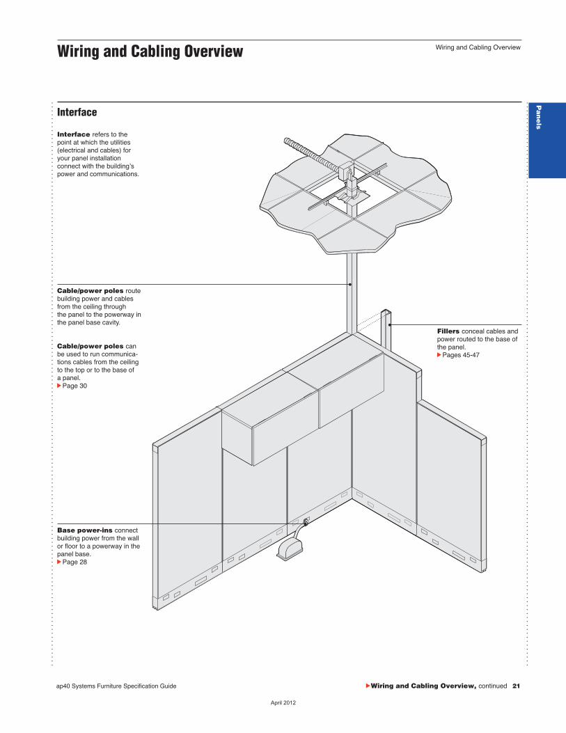
Cable/power poles route building power and cablesfrom the ceiling through the panel to the powerway inthe panel base cavity.
Cable/power poles canbe used to run communica - tions cables from the ceilingto the top or to the base ofa panel.cPage 30
Interface refers to thepoint at which the utilities(electrical and cables) foryour panel installation connect with the buildingʼspower and communications.
Base power-ins connectbuilding power from the wallor floor to a powerway in thepanel base.cPage 28
Fillers conceal cables andpower routed to the base ofthe panel.cPages 45-47
Interface
Pa
ne
ls
��������
Wiring and Cabling Overview, continued
...............................................................................................................................................
...............................................................................................................................................
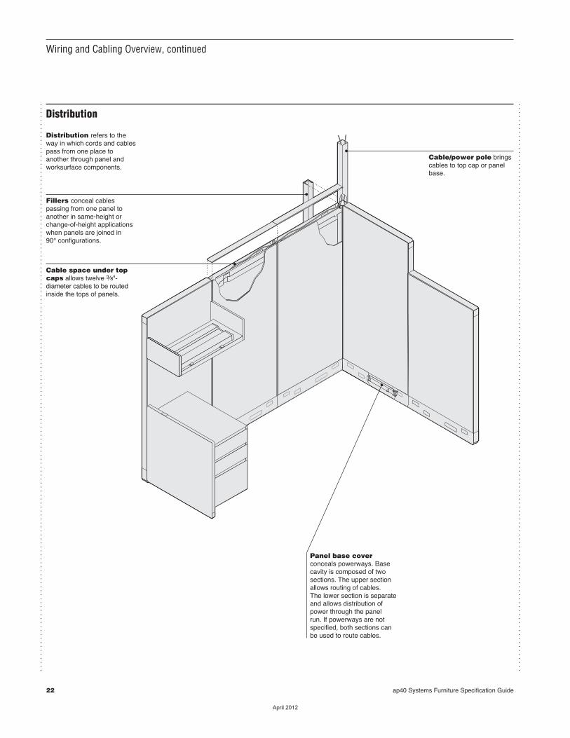
Distribution refers to theway in which cords and cablespass from one place toanother through panel andworksurface components.
Fillers conceal cables passing from one panel toanother in same-height orchange-of-height applicationswhen panels are joined in 90° configurations.
Cable space under topcaps allows twelve 3⁄8"-diameter cables to be routedinside the tops of panels.
Panel base cover conceals powerways. Basecavity is composed of twosections. The upper sectionallows routing of cables. The lower section is separateand allows distribution ofpower through the panel run. If powerways are notspecified, both sections canbe used to route cables.
Cable/power pole bringscables to top cap or panelbase.
Distribution
22 ap40 Systems Furniture Specification Guide
��������

Wiring and Cabling Overview
ap40 Systems Furniture Specification Guide 23
...............................................................................................................................................
...............................................................................................................................................
Access refers to the pointsat which youʼll place electri-cal outlets so people canplug in equipment. Accessalso includes the linksbetween communication andcomputer networks.
Storage refers to the waysin which you manage excesslengths of cords and cables.
Access and Storage
Flexible corners at thetop of the panel allowcables to enter or exit theinterior of the panel.
Knockouts for duplex-size voice/data recep-tacles are provided onpanel base covers.
Receptacles installed in the panel base provideaccess to power.
Pa
ne
ls
��������

24 ap40 Systems Furniture Specification Guide
...............................................................................................................................................
...............................................................................................................................................
1 3 2 1
3
31 2
3
D2
2D
1 3
1 3
2 1
1
3 1
3 1
1 2
1 2
D2
2D
1 3
1 3
2 1
2 1
3 1
3 1
1 2
1 2
Division between separate power-ins
2 D
2 D
D 2
D 2
Base power-in
= Standard receptacle = Large or Standard receptacle
2
There are four steps to plan-ning an electrical network.
1On a drawing of your panellayout, indicate where youwant receptacles.
2Designate which circuit (1, 2, 3, or dedicated) youwant each receptacle to link to. cFor more information about dedicated and designated circuits, see page 25.
3Determine how many power-ins are needed to supplyenough power to each clus-ter of workstations.cFor more information about calculating power needs, see page 27.
4Indicate the position of eachbase power-in, power pole,or cable pole on your floorplan.
cSee the next page for details.
Steps to Plan an Electrical Network
��������
ap40 Systems Furniture Specification Guide 25
Circuit ChoicesCircuit ChoicesPowerways and Strategies for Using Them
...............................................................................................................................................
...............................................................................................................................................
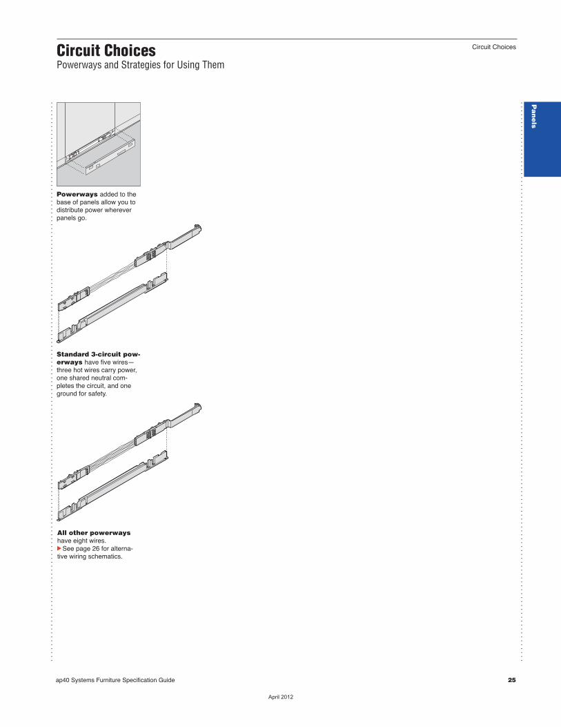
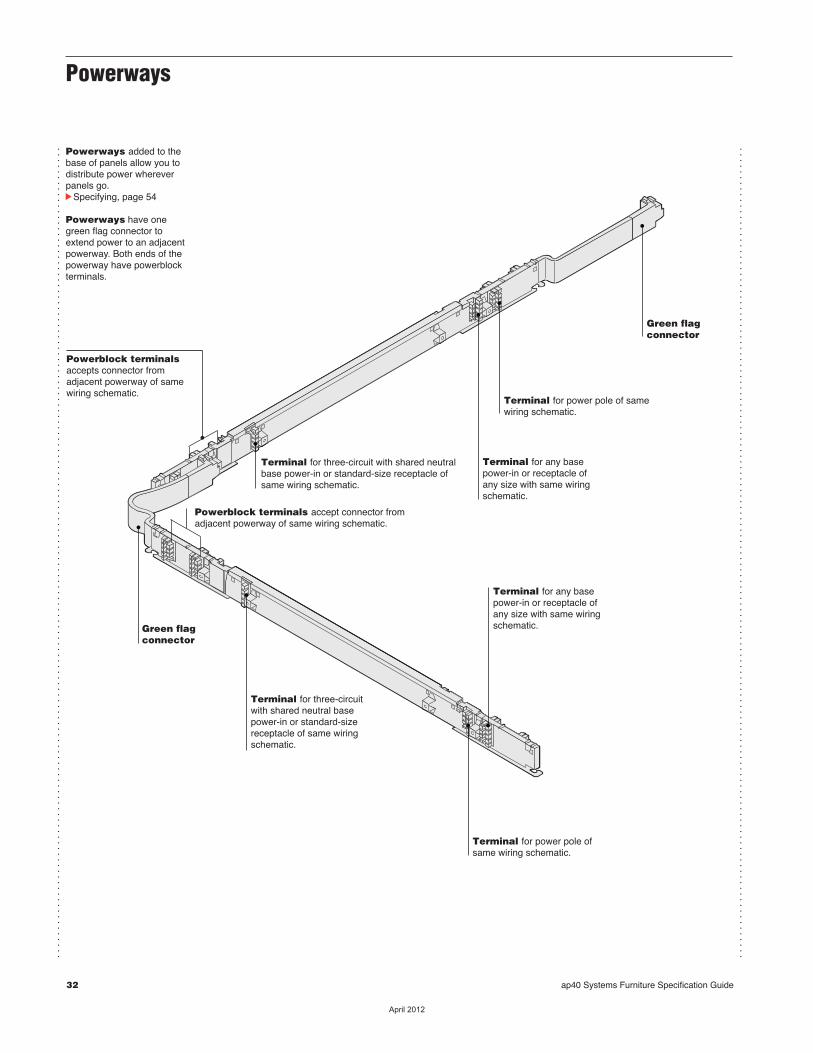
Powerways added to thebase of panels allow you todistribute power whereverpanels go.
Standard 3-circuit pow-erways have five wires—three hot wires carry power,one shared neutral com-pletes the circuit, and oneground for safety.
All other powerways have eight wires.cSee page 26 for alterna-tive wiring schematics.
Pa
ne
ls
��������

26 ap40 Systems Furniture Specification Guide
Circuit SpecificationsDetailed Information for the Electrical Engineer
...............................................................................................................................................
...............................................................................................................................................
...............................................................................................................................................
All the components inan electrical distribu-tion network must usethe same wiring schematic.The components (powerpoles, base power-ins, pow-erways, and receptacles)snap together and are keyedto make it impossible to con-nect mismatched parts.Color-coded and labeledcomponents make it easy forinstallers to identify whichwiring schematic each com-ponent is dedicated to.Color coding• 3 circuits shared = Black• 3 circuits separate = White• 4 circuits 3+D = Black• 4 circuit 2+2 = Grey
Overview
3 Circuit Shared Neutral, 5 Wires
Hot 1Hot 2Hot 3
Oversized NeutralSystem Ground
Three-circuit electricalcomponents withshared neutrals are stan-dard with 5 wires to providethree circuits that share oneoversized neutral and oneground. This is the traditional3-circuit power alternative.
Three-circuit with sepa-rate neutrals have 8 wiresproviding three circuits, eachwith its own separate neutral.The first two circuits share anisolated ground; the thirduses the system ground.
Four-circuit 3+D are stan-dard with 8 wires to providefour circuits. Three of thesecircuits share an oversizedneutral and a system groundwhile the remaining circuithas its own neutral and iso-lated ground. This is the tra-ditional 4-circuit power, alsoknown as 3+D.
Four-circuit 2+2 has 8wires but provide two circuitsthat share an oversized neu-tral and a system ground andan additional two circuits witha second oversized neutraland an isolated ground.
3 Circuit Separate Neutral, 8 Wires
Hot 1Neutral 1Hot 2Neutral 2Isolated Ground
Hot 3Neutral 3System Ground
4 Circuit 3+D, 8 Wires
Hot 1Hot 2Hot 3Oversized NeutralSystem Ground
Hot 4NeutralIsolated Ground
4 Circuit 2+2, 8 Wires
Hot 1Hot 2
Oversized NeutralSystem Ground
Hot 3Hot 4
Oversized NeutralIsolated Ground
��������
ap40 Systems Furniture Specification Guide 27
How to Calculate Power Needs
...............................................................................................................................................
...............................................................................................................................................
...............................................................................................................................................
...............................................................................................................................................
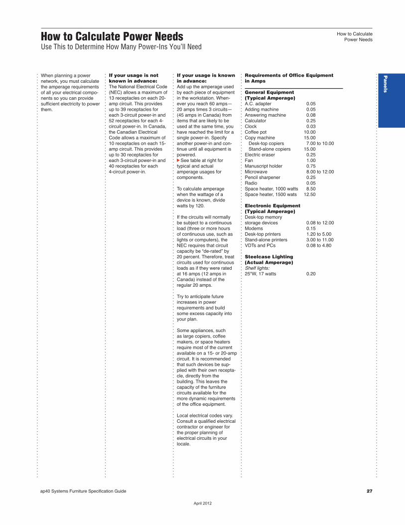
When planning a power network, you must calculatethe amperage requirementsof all your electrical compo-nents so you can providesufficient electricity to powerthem.
If your usage is notknown in advance: The National Electrical Code(NEC) allows a maximum of13 receptacles on each 20-amp circuit. This provides up to 39 receptacles foreach 3-circuit power-in and52 receptacles for each 4-circuit power-in. In Canada,the Canadian ElectricalCode allows a maximum of10 receptacles on each 15-amp circuit. This provides up to 30 receptacles foreach 3-circuit power-in and 40 receptacles for each 4-circuit power-in.
If your usage is knownin advance: Add up the amperage usedby each piece of equipmentin the workstation. When -ever you reach 60 amps— 20 amps times 3 circuits— (45 amps in Canada) fromitems that are likely to beused at the same time, youhave reached the limit for asingle power-in. Specifyanother power-in and con-tinue until all equipment ispowered.cSee table at right for typical and actual amperage usages for components.
To calculate amperage when the wattage of adevice is known, dividewatts by 120.
If the circuits will normally be subject to a continuousload (three or more hours of continuous use, such aslights or computers), theNEC requires that circuitcapacity be “de-rated” by 20 percent. Therefore, treatcircuits used for continuousloads as if they were rated at 16 amps (12 amps inCanada) instead of the regular 20 amps.
Try to anticipate futureincreases in power requirements and buildsome excess capacity intoyour plan.
Some appliances, such as large copiers, coffee makers, or space heatersrequire most of the currentavailable on a 15- or 20-ampcircuit. It is recommendedthat such devices be sup-plied with their own recepta-cle, directly from thebuilding. This leaves thecapacity of the furniture circuits available for themore dynamic requirementsof the office equipment.
Local electrical codes vary.Consult a qualified electricalcontractor or engineer forthe proper planning of electrical circuits in yourlocale.
Requirements of Office Equipment in Amps
General Equipment(Typical Amperage)A.C. adapter 0.05Adding machine 0.05Answering machine 0.08Calculator 0.25Clock 0.03Coffee pot 10.00Copy machine 15.00 Desk-top copiers 7.00 to 10.00 Stand-alone copiers 15.00Electric eraser 0.25Fan 1.00Manuscript holder 0.75Microwave 8.00 to 12.00Pencil sharpener 0.25Radio 0.05Space heater, 1000 watts 8.50Space heater, 1500 wats 12.50
Electronic Equipment(Typical Amperage)Desk-top memorystorage devices 0.08 to 12.00Modems 0.15Desk-top printers 1.20 to 5.00Stand-alone printers 3.00 to 11.00VDTs and PCs 0.08 to 4.80
Steelcase Lighting(Actual Amperage)Shelf lights:25"W, 17 watts 0.20
How to Calculate Power NeedsUse This to Determine How Many Power-Ins You’ll Need
...............................................................................................................................................
Pa
ne
ls
��������
Base Power-Ins
...............................................................................................................................................
...............................................................................................................................................
...............................................................................................................................................
...............................................................................................................................................
...............................................................................................................................................
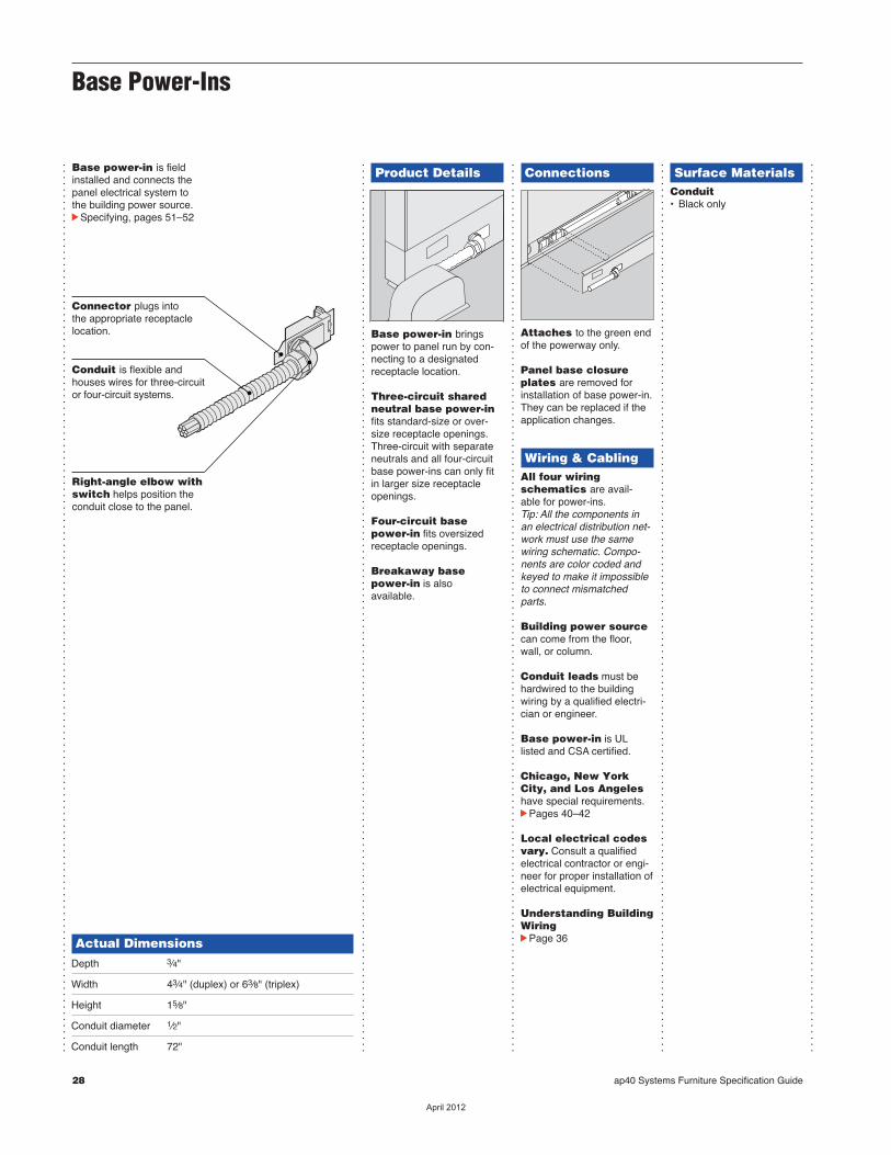
Base power-in is fieldinstalled and connects thepanel electrical system tothe building power source.cSpecifying, pages 51–52
Actual DimensionsDepth 3⁄4"
Width 43⁄4" (duplex) or 63⁄8" (triplex)
Height 15⁄8"
Conduit diameter 1⁄2"
Conduit length 72"
Product Details
Base power-in bringspower to panel run by con-necting to a designatedreceptacle location.
Three-circuit sharedneutral base power-infits standard-size or over-size receptacle openings.Three-circuit with separateneutrals and all four-circuitbase power-ins can only fitin larger size receptacleopenings.
Four-circuit basepower-in fits oversizedreceptacle openings.
Breakaway basepower-in is also available.
Connections
Attaches to the green endof the powerway only.
Panel base closureplates are removed forinstallation of base power-in.They can be replaced if theapplication changes.
Wiring & CablingAll four wiringschematics are avail -able for power-ins.Tip: All the components inan electrical distribution net-work must use the samewiring schematic. Compo -nents are color coded andkeyed to make it impossibleto connect mismatchedparts.
Building power sourcecan come from the floor,wall, or column.
Conduit leads must behardwired to the buildingwiring by a qualified electri-cian or engineer.
Base power-in is ULlisted and CSA certified.
Chicago, New YorkCity, and Los Angeleshave special requirements.cPages 40–42
Local electrical codesvary. Consult a qualifiedelectrical contractor or engi-neer for proper installation ofelectrical equipment.
Understanding BuildingWiringcPage 36
Surface MaterialsConduit• Black only
Connector plugs into the appropriate receptaclelocation.
Conduit is flexible andhouses wires for three-circuitor four-circuit systems.
Right-angle elbow withswitch helps position theconduit close to the panel.
28 ap40 Systems Furniture Specification Guide
��������

ap40 Systems Furniture Specification Guide 29
Base Power-Ins
Pa
ne
ls
��������
30 ap40 Systems Furniture Specification Guide
Cable/Power Poles for Panels
...............................................................................................................................................
...............................................................................................................................................
...............................................................................................................................................
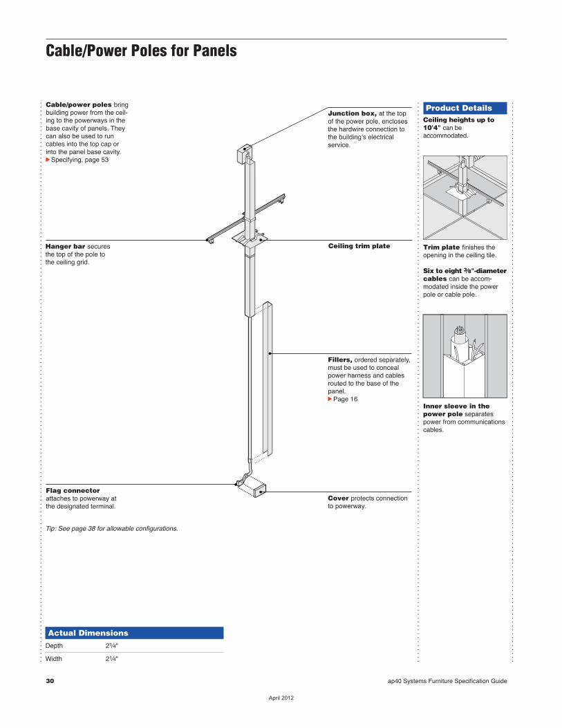
Cable/power poles bringbuilding power from the ceil-ing to the powerways in thebase cavity of panels. Theycan also be used to runcables into the top cap orinto the panel base cavity.cSpecifying, page 53
Actual DimensionsDepth 21⁄4"
Width 21⁄4"
Product DetailsCeiling heights up to10'4" can be accommodated.
Trim plate finishes theopening in the ceiling tile.
Six to eight 3⁄8"-diametercables can be accom-modated inside the powerpole or cable pole.
Inner sleeve in thepower pole separatespower from communicationscables.
Hanger bar securesthe top of the pole tothe ceiling grid.
Flag connectorattaches to powerway atthe designated terminal.
Junction box, at the topof the power pole, enclosesthe hardwire connection tothe buildingʼs electrical service.
Ceiling trim plate
Fillers, ordered separately,must be used to concealpower harness and cablesrouted to the base of thepanel.cPage 16
Cover protects connectionto powerway.
Tip: See page 38 for allowable configurations.
��������
ap40 Systems Furniture Specification Guide 31
...............................................................................................................................................
...............................................................................................................................................
...............................................................................................................................................
...............................................................................................................................................
...............................................................................................................................................
...............................................................................................................................................
Cable/Power Poles for Panels
Connections
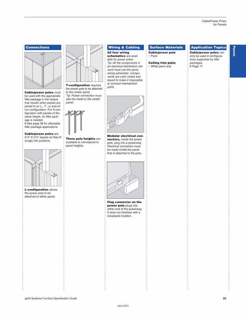
Cable/power poles mustbe used with the appropriatefiller package in the recessthat results when panels arejoined in an L-, T-, or end-of-run configuration. For X-con-figuration with panels of thesame height, no filler pack-age is needed.cSee page 38 for allowablefiller package applications.
Cable/power poles are21⁄4" X 21⁄4" square so they fitsnugly into junctions.
L-configuration allowsthe power pole to beattached to either panel.
T-configuration requiresthe power pole to be attachedto the center panel.Tip: Power connection mustalso be made to the centerpanel.
Three pole heights areavailable to correspond topanel heights.
Wiring & CablingAll four wiringschematics are avail -able for power poles.Tip: All the components inan electrical distribution net-work must use the samewiring schematic. Compo -nents are color coded andkeyed to make it impossibleto connect mismatchedparts.
Modular electrical con-nectors, inside the powerpole, plug into a powerway.Electrical connection mustbe made inside the panelthat is attached to the pole.
Flag connector on thepower pole plugs intoeither end of the powerway.It does not interfere with areceptacle location.
Surface MaterialsCable/power pole• Paint
Ceiling trim plate• White paint only
Application TopicsCable/power poles canonly be used in configura-tions supported by fillerpackages. cPage 17
Pa
ne
ls
��������
32 ap40 Systems Furniture Specification Guide
Powerways
...............................................................................................................................................
...............................................................................................................................................
Powerways added to thebase of panels allow you todistribute power whereverpanels go. cSpecifying, page 54
Powerways have onegreen flag connector toextend power to an adjacentpowerway. Both ends of thepowerway have powerblockterminals.
Powerblock terminalsaccepts connector fromadjacent powerway of samewiring schematic.
Powerblock terminals accept connector fromadjacent powerway of same wiring schematic.
Terminal for three-circuit with shared neutralbase power-in or standard-size receptacle ofsame wiring schematic.
Terminal for any basepower-in or receptacle ofany size with same wiringschematic.
Terminal for power pole of samewiring schematic.
Green flag connector
Terminal for any basepower-in or receptacle ofany size with same wiringschematic.
Terminal for three-circuitwith shared neutral basepower-in or standard-sizereceptacle of same wiringschematic.
Green flag connector
Terminal for power pole ofsame wiring schematic.
��������

ap40 Systems Furniture Specification Guide 33
Powerways
...............................................................................................................................................
...............................................................................................................................................
...............................................................................................................................................
...............................................................................................................................................
...............................................................................................................................................
...............................................................................................................................................
Product Details
Receptacles snap intoterminals and are held inplace with screws. 30"W and 60"W powerways havetwo receptacle locations oneach side.cPage 34
ConnectionsOne rule for joining power-ways applies to every instal-lation. There must be at leastone green end at each intersection.
Flag from the green endof powerway is connectedto power terminal on adja-cent powerway.
Straight connection is formed when a flag con-nector from one powerwayattaches to the secondpowerblock terminal on the end of the adjacent powerway.
L-connection is formedwhen flag connector turns toleft or right.
1 2
Green
Terminal
T-connection is formed by two flags that make rightturns.
X-connection is formedby three flags that makeright turns.
End-of-run is terminatedby folding the last flag backand connecting it to its ownpowerblock terminal.
Panel-to-panel connec-tor can be used to create apowerlink where no flag isavailable. It can also be usedto correct planning and instal-lation oversights without hav-ing to reconfigure.
Wiring & CablingAll four wiringschematics are avail -able for powerways.Tip: All the components inan electrical distribution net-work must use the samewiring schematic. Compo -nents are color coded andkeyed to make it impossibleto connect mismatchedparts.
All Steelcase electricalsystems are designed incompliance with the NationalElectrical Code (NEC) tofunction as a multi-wirebranch circuit. Installationsshould be made in accor-dance with the NEC provi-sions for multi-wire branchcircuits.
Chicago, Los Angeles,and New York City havespecial requirements.cPages 40–42
Local electrical codesvary. Consult a qualifiedelectrical contractor or engineer for the properinstallation of electricalequipment.
Surface MaterialsPowerways are con-cealed when they are prop-erly installed.
Application TopicsSteps to Plan anElectrical NetworkcPage 24
Pa
ne
ls
��������
34 ap40 Systems Furniture Specification Guide
Base Covers and Receptacles
...............................................................................................................................................
...............................................................................................................................................
...............................................................................................................................................
...............................................................................................................................................
...............................................................................................................................................
Actual DimensionsBase cover
Width 30", 36", 48", or 60"
Height 4"
Product Details
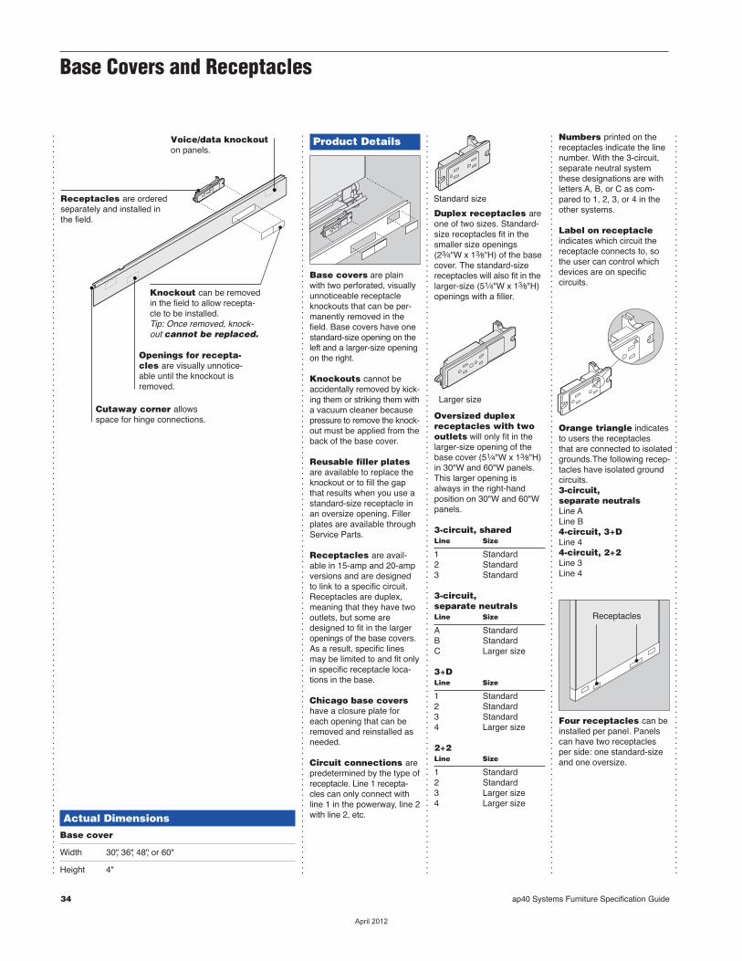
Base covers are plainwith two perforated, visuallyunnoticeable receptacleknockouts that can be per-manently removed in thefield. Base covers have onestandard-size opening on theleft and a larger-size openingon the right.
Knockouts cannot beaccidentally removed by kick-ing them or striking them witha vacuum cleaner becausepressure to remove the knock-out must be applied from theback of the base cover.
Reusable filler platesare available to replace theknockout or to fill the gapthat results when you use astandard-size receptacle inan oversize opening. Fillerplates are available throughService Parts.
Receptacles are avail-able in 15-amp and 20-ampversions and are designedto link to a specific circuit.Receptacles are duplex,meaning that they have twooutlets, but some aredesigned to fit in the largeropenings of the base covers.As a result, specific linesmay be limited to and fit onlyin specific receptacle loca-tions in the base.
Chicago base covershave a closure plate foreach opening that can beremoved and reinstalled asneeded.
Circuit connections arepredetermined by the type ofreceptacle. Line 1 recepta-cles can only connect withline 1 in the powerway, line 2with line 2, etc.
Duplex receptacles areone of two sizes. Standard-size receptacles fit in thesmaller size openings(23⁄4"W x 13⁄8"H) of the basecover. The standard-sizereceptacles will also fit in thelarger-size (51⁄4"W x 13⁄8"H)openings with a filler.
Oversized duplexrecep tacles with two outlets will only fit in thelarger-size opening of thebase cover (51⁄4"W x 13⁄8"H)in 30"W and 60"W panels.This larger opening isalways in the right-handposition on 30"W and 60"Wpanels.
3-circuit, sharedLine Size
1 Standard2 Standard3 Standard
3-circuit, separate neutralsLine Size
A StandardB StandardC Larger size
3+DLine Size
1 Standard2 Standard3 Standard4 Larger size
2+2Line Size
1 Standard2 Standard3 Larger size4 Larger size
Larger size
Standard size
Numbers printed on thereceptacles indicate the linenumber. With the 3-circuit,separate neutral systemthese designations are withletters A, B, or C as com-pared to 1, 2, 3, or 4 in theother systems.
Label on receptacleindicates which circuit thereceptacle connects to, sothe user can control whichdevices are on specific circuits.
Orange triangle indicatesto users the receptacles that are connected to isolatedgrounds.The following recep-tacles have isolated groundcircuits.3-circuit, separate neutralsLine ALine B4-circuit, 3+DLine 44-circuit, 2+2Line 3Line 4
Four receptacles can beinstalled per panel. Panelscan have two receptaclesper side: one standard-sizeand one oversize.
Receptacles
Voice/data knockouton panels.
Openings for recepta-cles are visually unnotice-able until the knockout isremoved.
Cutaway corner allowsspace for hinge connections.
Receptacles are orderedseparately and installed inthe field.
Knockout can be removedin the field to allow recepta-cle to be installed.Tip: Once removed, knock-out cannot be replaced.
��������
ap40 Systems Furniture Specification Guide 35
...............................................................................................................................................
...............................................................................................................................................
...............................................................................................................................................
Base Coversand Receptacles
Panels
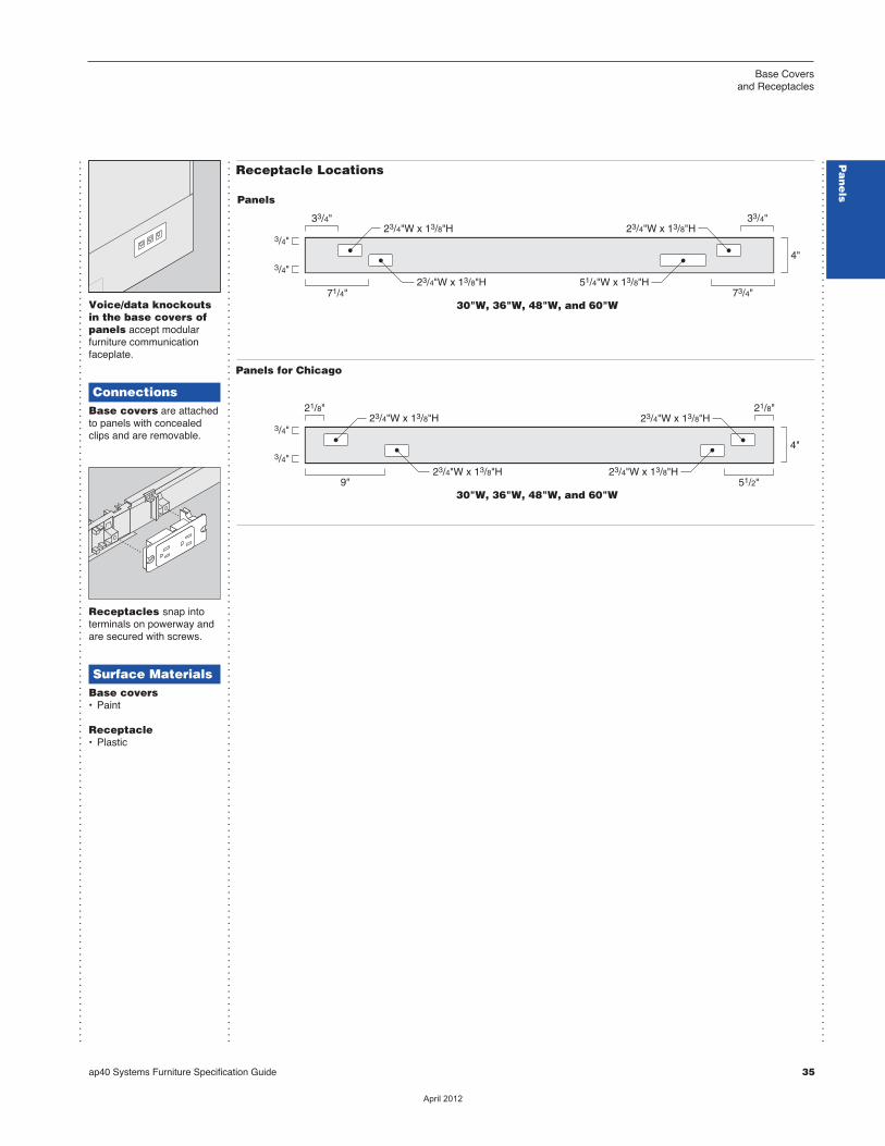
30"W, 36"W, 48"W, and 60"W
4"
23/4"W x 13/8"H
23/4"W x 13/8"H
23/4"W x 13/8"H33/4"
3/4"
3/4"
73/4"71/4"51/4"W x 13/8"H
33/4"
Panels for Chicago
30"W, 36"W, 48"W, and 60"W9"
23/4"W x 13/8"H
23/4"W x 13/8"H
23/4"W x 13/8"H
23/4"W x 13/8"H
4"3/4"
3/4"
21/8"21/8"
51/2"
Receptacle Locations
Voice/data knockoutsin the base covers ofpanels accept modular furniture communicationfaceplate.
ConnectionsBase covers are attachedto panels with concealedclips and are removable.
Receptacles snap intoterminals on powerway andare secured with screws.
Surface MaterialsBase covers• Paint
Receptacle• Plastic
Pa
ne
lsP
an
els
��������
Understanding Building Wiring
...............................................................................................................................................
...............................................................................................................................................
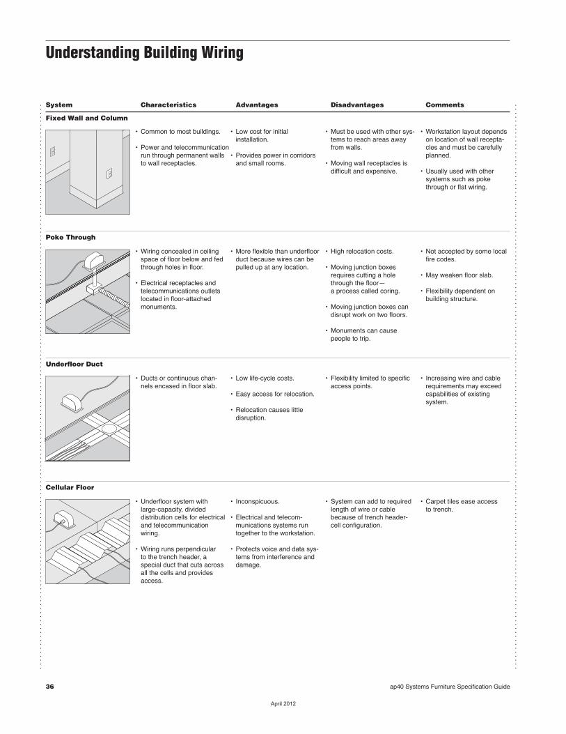
System Characteristics Advantages Disadvantages Comments
Fixed Wall and Column
• Common to most buildings.
• Power and telecommunicationrun through permanent wallsto wall receptacles.
• Low cost for initial installation.
• Provides power in corridorsand small rooms.
• Must be used with other sys-tems to reach areas awayfrom walls.
• Moving wall receptacles isdifficult and expensive.
• Workstation layout dependson location of wall recepta-cles and must be carefullyplanned.
• Usually used with other systems such as pokethrough or flat wiring.
Poke Through
• Wiring concealed in ceilingspace of floor below and fedthrough holes in floor.
• Electrical receptacles andtelecommunications outletslocated in floor-attachedmonuments.
• More flexible than underfloorduct because wires can bepulled up at any location.
• High relocation costs.
• Moving junction boxesrequires cutting a holethrough the floor—a process called coring.
• Moving junction boxes candisrupt work on two floors.
• Monuments can cause people to trip.
• Not accepted by some localfire codes.
• May weaken floor slab.
• Flexibility dependent onbuilding structure.
Underfloor Duct
• Ducts or continuous chan-nels encased in floor slab.
• Low life-cycle costs.
• Easy access for relocation.
• Relocation causes little disruption.
• Flexibility limited to specificaccess points.
• Increasing wire and cablerequirements may exceedcapabilities of existing system.
Cellular Floor
• Underfloor system withlarge-capacity, divided distribution cells for electricaland telecommunicationwiring.
• Wiring runs perpendicular to the trench header, a special duct that cuts acrossall the cells and providesaccess.
• Inconspicuous.
• Electrical and telecom-munications systems runtogether to the workstation.
• Protects voice and data sys-tems from interference anddamage.
• System can add to requiredlength of wire or cablebecause of trench header-cell configuration.
• Carpet tiles ease access to trench.
36 ap40 Systems Furniture Specification Guide
��������
ap40 Systems Furniture Specification Guide 37
Understanding BuildingWiring
...............................................................................................................................................
...............................................................................................................................................
System Characteristics Advantages Disadvantages Comments
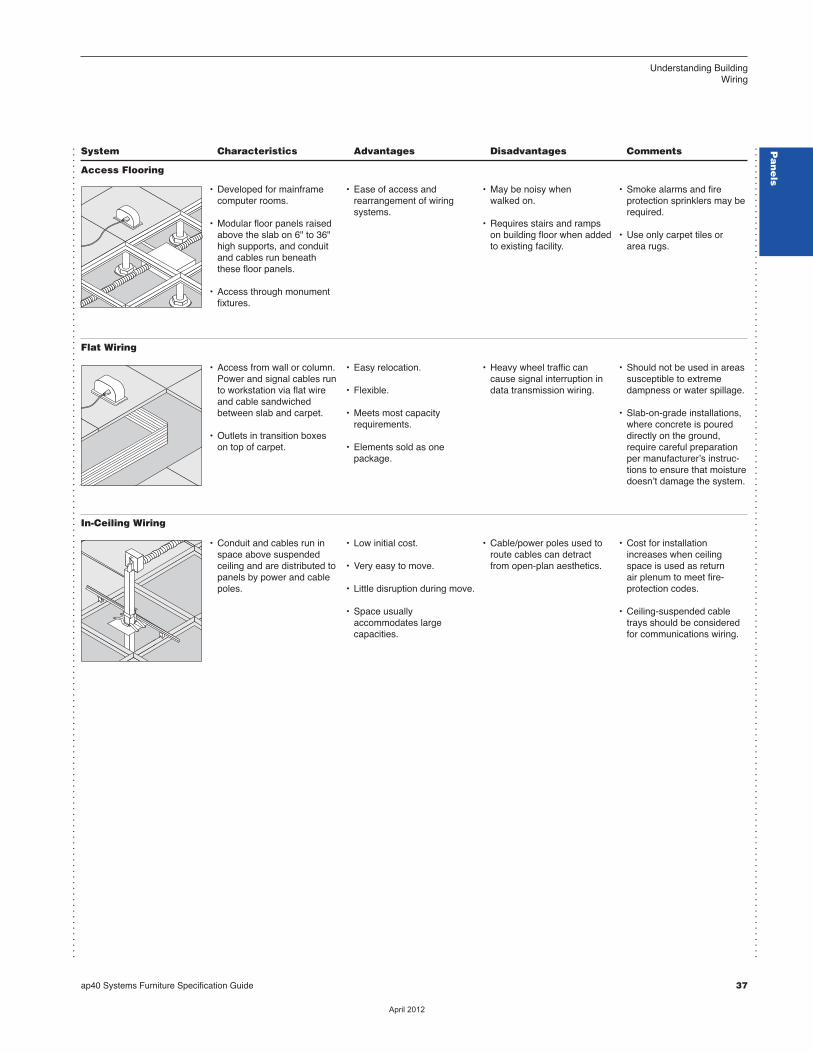
Access Flooring
• Developed for mainframecomputer rooms.
• Modular floor panels raisedabove the slab on 6" to 36"high supports, and conduitand cables run beneaththese floor panels.
• Access through monumentfixtures.
• Ease of access andrearrangement of wiring systems.
• May be noisy when walked on.
• Requires stairs and rampson building floor when addedto existing facility.
• Smoke alarms and fire protection sprinklers may berequired.
• Use only carpet tiles or area rugs.
Flat Wiring
• Access from wall or column.Power and signal cables runto workstation via flat wireand cable sandwichedbetween slab and carpet.
• Outlets in transition boxeson top of carpet.
• Easy relocation.
• Flexible.
• Meets most capacityrequirements.
• Elements sold as one package.
• Heavy wheel traffic cancause signal interruption indata transmission wiring.
• Should not be used in areassusceptible to extremedampness or water spillage.
• Slab-on-grade installations,where concrete is poureddirectly on the ground,require careful preparationper manufacturerʼs instruc-tions to ensure that moisturedoesnʼt damage the system.
In-Ceiling Wiring
• Conduit and cables run inspace above suspendedceiling and are distributed topanels by power and cablepoles.
• Low initial cost.
• Very easy to move.
• Little disruption during move.
• Space usually accommodates large capacities.
• Cable/power poles used toroute cables can detractfrom open-plan aesthetics.
• Cost for installationincreases when ceilingspace is used as return air plenum to meet fire-protection codes.
• Ceiling-suspended cabletrays should be consideredfor communications wiring.
Pa
ne
ls
��������
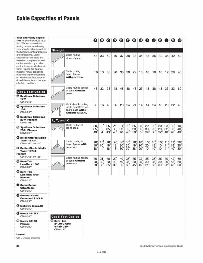
38 ap40 Systems Furniture Specification Guide
Cable Capacities of Panels
...............................................................................................................................................
...............................................................................................................................................
...............................................................................................................................................
Test and verify capaci -ties for your individual situa-tion. We recommend thattesting be conducted usingyour specific cable as well asthe furniture configuration youare consid ering. Cablecapacities in this table arebased on non-plenum-ratedcables install ed by a cablecontrac tor under ideal condi-tions. Figures are approxi -mations. Actual capacitiesmay vary slightly depend ingon which manufacturer pro-duced the cable and the spe-cific field conditions.
Cat 6 Test Cableså Systimax Solutions 1071 OD=0.215"
∫ Systimax Solutions 1081 OD=0.250"
ç Systimax Solutions 2071 Plenum OD=0.195"
∂ Systimax Solutions 2081 Plenum OD=0.240"
´ Belden/Nordx Media Twist 1872A OD=0.365" x 0.165"
ƒ Belden/Nordx Media Twist 1874APlenum OD=0.365" x 0.165"
© Berk-Tek Lan-Mark 1000 OD=0.230"
˙ Berk-Tek Lan-Mark 1000 Plenum OD=0.225"
ˆ CommScope UltraMedia OD=0.240"
Δ General Cable Command LINX 6 OD=0.250"
˚ Mohawk GigaLAN OD=0.240"
¬ Nordx 4812LX OD=0.245"
μ Nordx 4813X Plenum OD=0.230"
å ∫ ç ∂ ´ ƒ © ˙ ˆ Δ ˚ ¬ μ ˜
Straight Cable routing 44 33 42 40 37 38 33 34 33 36 32 38 42 50at top of panel
Cable routing 18 13 30 20 30 30 22 10 10 10 10 12 20 40base of panel with powerway
Cable routing at base 48 33 38 48 48 48 43 25 43 38 43 33 33 60of panel withoutpower
Vertical cable routing 30 16 40 26 20 24 24 14 14 24 18 20 22 40inside panel from top-cap to base with orwithout powerway
L, T, and X Cable routing at 30L 22L 25L 25L 24L 28L 25L 25L 22L 23L 20L 23L 30L 40L
top of panel 35T 30T 35T 30T 30T 30T 28T 25T 30T 28T 28T 32T 30T 40T
40X 34X 43X 40X 40X 40X 36X 35X 34X 36X 32X 40X 40X 40X
Cable routing at 18L 10L 18L 9L 30L 30L 18L 10L 10L 10L 10L 11L 11L 30L
base of panel with 18T 10T 18T 18T 30T 30T 19T 10T 20T 18T 10T 11T 18T 30T
powerway 18X 11X 18X 18X 30X 30X 38X 20X 10X 10X 10X 11X 40X 30X
Cable routing at base 30L 21L 30L 20L 40L 35L 35L 22L 35L 35L 38L 30L 42L 60L
of panel without 40T 30T 30T 40T 40T 35T 30T 25T 30T 35T 30T 30T 43T 60T
powerway 50X 33X 35X 35X 35X 60X 45X 45X 21X 35X 30X 22X 45X 60X
Cat 5 Test Cables˜ Berk–Tek 24 AWG CMR 4-Pair UTP* OD=0.190"
..................Legend
OD = Outside Diameter
��������
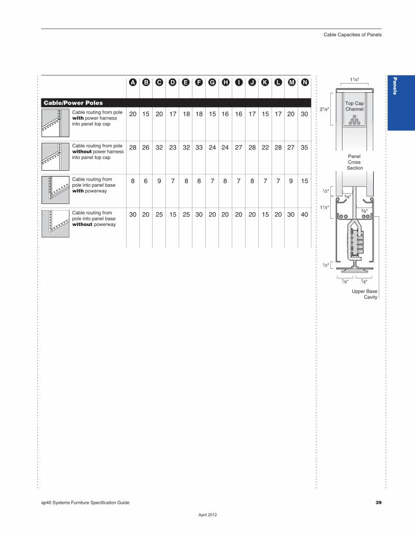
ap40 Systems Furniture Specification Guide 39
Cable Capacities of Panels
...............................................................................................................................................
...............................................................................................................................................
...............................................................................................................................................
å ∫ ç ∂ ´ ƒ © ˙ ˆ Δ ˚ ¬ μ ˜
Panel Cross Section
7⁄8"7⁄8"
5⁄8"
5⁄8"11⁄2"
1⁄2"
21⁄8"
11⁄4"
1⁄2"
Top CapChannel
Upper BaseCavity
Cable/Power Poles Cable routing from pole 20 15 20 17 18 18 15 16 16 17 15 17 20 30with power harness into panel top cap
Cable routing from pole 28 26 32 23 32 33 24 24 27 28 22 28 27 35without power harnessinto panel top cap
Cable routing from 8 6 9 7 8 8 7 8 7 8 7 7 9 15pole into panel base with powerway
Cable routing from 30 20 25 15 25 30 20 20 20 20 15 20 30 40pole into panel base without powerway
Pa
ne
ls
��������
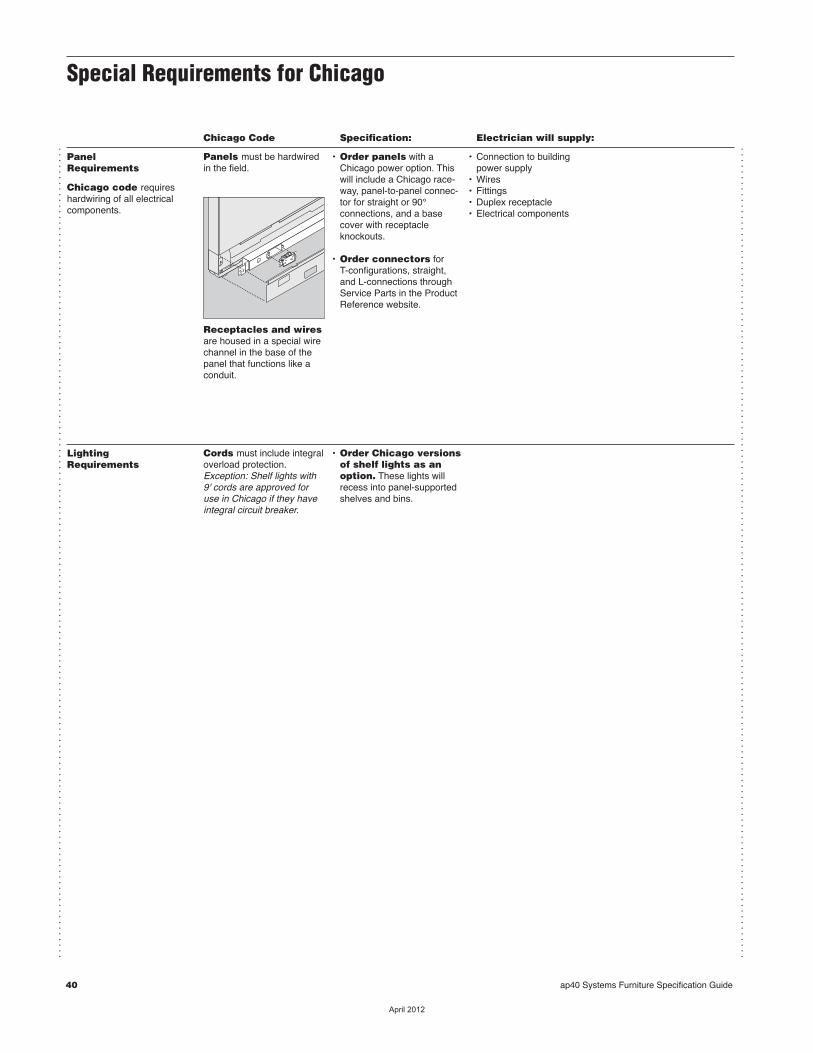
40 ap40 Systems Furniture Specification Guide
...............................................................................................................................................
...............................................................................................................................................
Special Requirements for Chicago
Chicago Code Specification: Electrician will supply:
PanelRequirements
Chicago code requireshardwiring of all electricalcomponents.
Panels must be hardwiredin the field.
Receptacles and wiresare housed in a special wirechannel in the base of thepanel that functions like aconduit.
• Order panels with aChicago power option. Thiswill include a Chicago race-way, panel-to-panel connec-tor for straight or 90°connections, and a basecover with receptacle knockouts.
• Order connectors for T-configurations, straight,and L-connections throughService Parts in the ProductReference website.
• Connection to buildingpower supply
• Wires• Fittings• Duplex receptacle • Electrical components
LightingRequirements
Cords must include integraloverload protection.Exception: Shelf lights with9' cords are approved foruse in Chicago if they haveintegral circuit breaker.
• Order Chicago versionsof shelf lights as anoption. These lights willrecess into panel-supportedshelves and bins.
��������
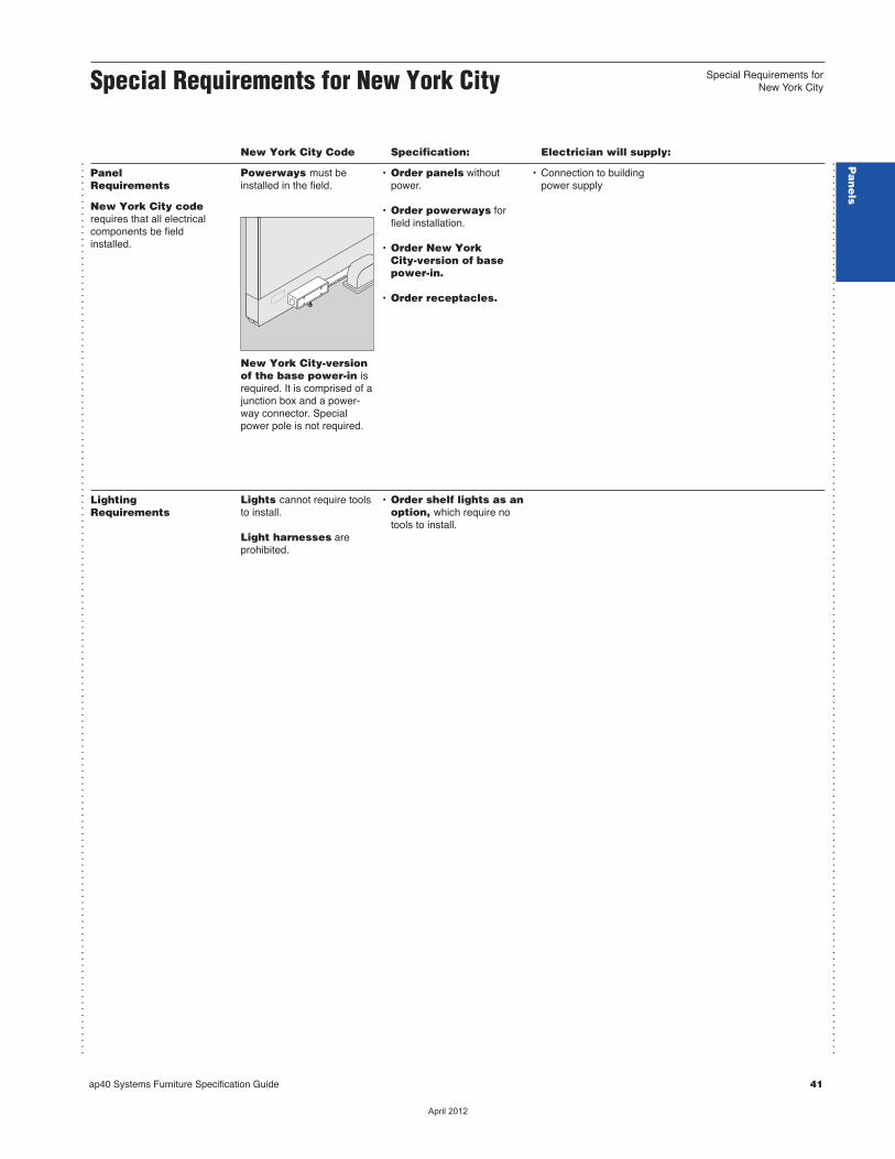
ap40 Systems Furniture Specification Guide 41
...............................................................................................................................................
...............................................................................................................................................
New York City Code Specification: Electrician will supply:
PanelRequirements
New York City coderequires that all electricalcomponents be fieldinstalled.
Powerways must beinstalled in the field.
New York City-versionof the base power-in isrequired. It is comprised of ajunction box and a power-way connector. Specialpower pole is not required.
• Order panels withoutpower.
• Order powerways forfield installation.
• Order New York City-version of base power-in.
• Order receptacles.
• Connection to buildingpower supply
LightingRequirements
Lights cannot require toolsto install.
Light harnesses are prohibited.
• Order shelf lights as anoption, which require notools to install.
Special Requirements for New York City
Pa
ne
ls
Special Requirements forNew York City
��������
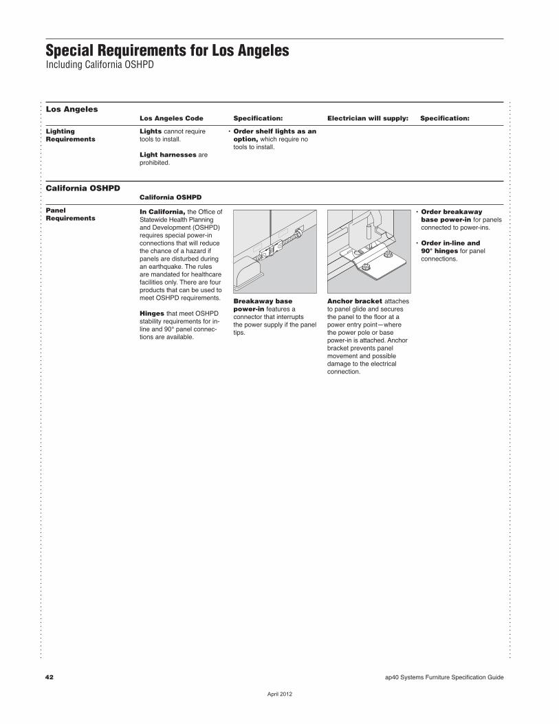
42 ap40 Systems Furniture Specification Guide
...............................................................................................................................................
...............................................................................................................................................
Special Requirements for Los AngelesIncluding California OSHPD
Los Angeles Los Angeles Code Specification: Electrician will supply: Specification:
LightingRequirements
Lights cannot require tools to install.
Light harnesses are prohibited.
• Order shelf lights as anoption, which require notools to install.
California OSHPD California OSHPD
PanelRequirements
In California, the Office ofStatewide Health Planningand Development (OSHPD)requires special power-inconnections that will reducethe chance of a hazard ifpanels are disturbed duringan earthquake. The rulesare mandated for healthcarefacilities only. There are fourproducts that can be used tomeet OSHPD requirements.
Hinges that meet OSHPDstability requirements for in-line and 90° panel connec-tions are available.
Breakaway basepower-in features a connector that interrupts the power supply if the paneltips.
Anchor bracket attachesto panel glide and securesthe panel to the floor at apower entry point—wherethe power pole or basepower-in is attached. Anchorbracket prevents panelmove ment and possibledamage to the electricalconnection.
• Order breakaway base power-in for panelsconnected to power-ins.
• Order in-line and 90° hinges for panel connections.
��������
Specifying Panels and RelatedProducts
ap40 Systems Furniture Specification Guide 43
Panels and Related Products
Tackable Acoustical Panels 44
Panel Filler Packages 45
Panel Brackets 48
OSHPD Panel Brackets 49
Panel Accessories 50
Panel Wiring and Cabling 51
Duplex Receptacle 56
Pa
ne
ls
��������

Tackable Acoustical Panels G4/13
44 ap40 Systems Furniture Specification Guide
Standard Includes Required to SpecifycNeed help?
Product details,page 14
• Panel with fabric surfaces, fabricdirection with horizontal application: fabric
• Radius top cap, end trim, and base covers withreceptacle knockouts: paint
• Hinge: plastic
1 Style number2 Fabric color number for surface3 Paint color number for top cap, end trim,
and base covers4 Plastic color number for plastic hinge5 Options, if selected (see below) cSee Surface Materials, page 129.
Tip: Fabric application isstandard in the warp hori-zontal direction. Warp verti-cal is available as an option.
Options U.S. Price Required to Specify Surface Fabric direction Materials • Vertical application No cost Specify with vertical application.
Electrical Factory-installed powerwaycPage 32 • 3-circuit powerway with +$185 Specify with 3-circuit powerway with shared neutral shared neutral. • 3-circuit powerway with +$213 Specify with 3-circuit powerway with separate neutrals separate neutral. • 4-circuit (3+D) powerway +$213 Specify with 4-circuit (3+D) powerway. • 4-circuit (2+2) powerway +$253 Specify with 4-circuit (2+2) powerway.
Field-installed powerway • For use in New York City cMust specify powerway for field installation only, page 54.
Factory-installed raceway • For use in Chicago with +$159 Specify with Chicago raceway. power base covers
Related • Panel brackets cPage 48 Products • Panel accessories cPage 50 • Panel wiring and cabling cPage 51
Specification Information
DWidth DStyle DU.S. d dNumber dBase d d dPrice d d d
42"H Panels30" TKTA4230 G4/13 $ 677
36" TKTA4236 G4/13 $ 745
48" TKTA4248 G4/13 $ 852
60" TKTA4260 G4/13 $1013 d d d
53"H Panels30" TKTA5330 G4/13 $ 731
36" TKTA5336 G4/13 $ 800
48" TKTA5348 G4/13 $ 908
60" TKTA5360 G4/13 $1066 d d d
65"H Panels30" TKTA6530 G4/13 $ 873
36" TKTA6536 G4/13 $ 951
48" TKTA6548 G4/13 $1052
60" TKTA6560 G4/13 $1202 d d d
For Canadian PricingMultiply U.S. Price by the Canadian price factor.
See page 1 for details.G4/13 = Last order entry
April 14, 2013
��������
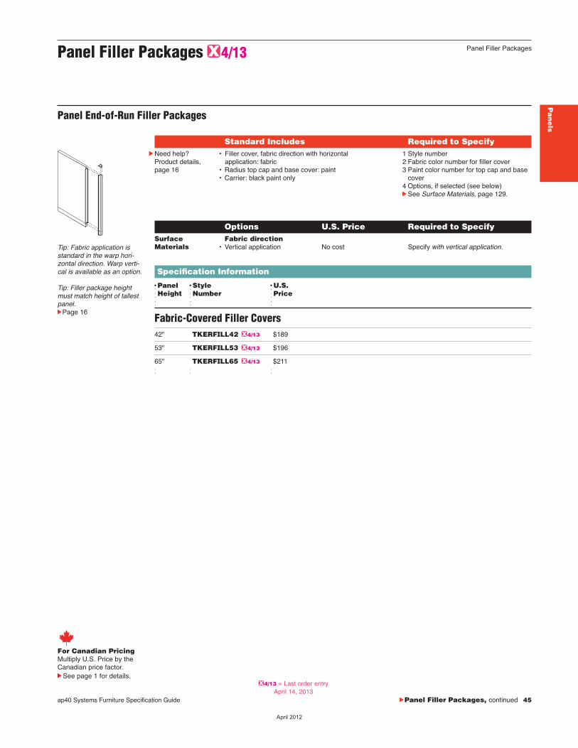
ap40 Systems Furniture Specification Guide cPanel Filler Packages, continued 45
Pa
ne
ls
Panel Filler Packages G4/13
Panel End-of-Run Filler Packages
Standard Includes Required to SpecifycNeed help?
Product details,page 16
• Filler cover, fabric direction with horizontal application: fabric • Radius top cap and base cover: paint• Carrier: black paint only
1 Style number2 Fabric color number for filler cover3 Paint color number for top cap and base
cover4 Options, if selected (see below)cSee Surface Materials, page 129.
Options U.S. Price Required to Specify Surface Fabric direction Materials • Vertical application No cost Specify with vertical application.
Specification Information
DPanel DStyle DU.S.dHeight dNumber dPriced d d
Fabric-Covered Filler Covers42" TKERFILL42 G4/13 $189
53" TKERFILL53 G4/13 $196
65" TKERFILL65 G4/13 $211 d d d
Tip: Fabric application isstandard in the warp hori-zontal direction. Warp verti-cal is available as an option.
Tip: Filler package heightmust match height of tallestpanel.cPage 16
Panel Filler Packages
For Canadian PricingMultiply U.S. Price by the Canadian price factor.
See page 1 for details.G4/13 = Last order entry
April 14, 2013
��������

46 ap40 Systems Furniture Specification Guide
Panel L-Configuration Filler Packages G4/13
Standard Includes Required to SpecifycNeed help?
Product details,page 16
• Filler cover, fabric direction with horizontal application: fabric • Radius top cap and base cover: paint• Carrier: black paint only
1 Style number2 Fabric color number for filler 3 Paint color number for base cover and
top cap4 Options, if selected (see below)cSee Surface Materials, page 129.
Options U.S. Price Required to Specify Surface Fabric direction Materials • Vertical application No cost Specify with vertical application.
Specification Information
DPanel DStyle DU.S.dHeight dNumber dPriced d d
42" TKLFILL42 G4/13 $189
53" TKLFILL53 G4/13 $196
65" TKLFILL65 G4/13 $211 d d d
Tip: Fabric application isstandard in the warp hori-zontal direction.Warp verti-cal is available as an option.
Tip: Filler package heightmust match height of tallestpanel.cPage 16
Panel Filler Packages, continued
Panel T-Configuration Filler Packages G4/13
Standard Includes Required to SpecifycNeed help?
Product details,page 16
• Filler cover, fabric direction with horizontal application: fabric • Radius top cap and base cover: paint• Carrier: black paint only
1 Style number2 Fabric color number for filler3 Paint color number for base cover and
top cap4 Options, if selected (see below)cSee Surface Materials, page 129.
Options U.S. Price Required to Specify Surface Fabric direction Materials • Vertical application No cost Specify with vertical application.
Specification Information
DPanel DStyle DU.S.dHeight dNumber dPriced d d
42" TKTFILL42 G4/13 $189
53" TKTFILL53 G4/13 $196
65" TKTFILL65 G4/13 $211 d d d
Tip: Fabric application isstandard in the warp hori-zontal direction.Warp verti-cal is available as an option.
Tip: Filler package heightmust match height of tallestpanel.cPage 16
For Canadian PricingMultiply U.S. Price by the Canadian price factor.
See page 1 for details.G4/13 = Last order entry
April 14, 2013
��������
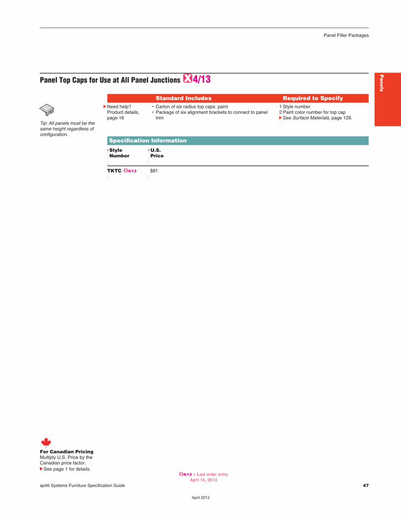
ap40 Systems Furniture Specification Guide 47
Pa
ne
ls
Panel Filler Packages
For Canadian PricingMultiply U.S. Price by the Canadian price factor.
See page 1 for details.
Panel Top Caps for Use at All Panel JunctionsG4/13
Standard Includes Required to SpecifycNeed help?
Product details,page 16
• Carton of six radius top caps: paint• Package of six alignment brackets to connect to panel
trim
1 Style number2 Paint color number for top cap cSee Surface Materials, page 129.
Specification Information
DStyle DU.S.dNumber dPriced d
TKTC G4/13 $81 d d
Tip: All panels must be thesame height regardless ofconfiguration.
G4/13 = Last order entryApril 14, 2013
��������
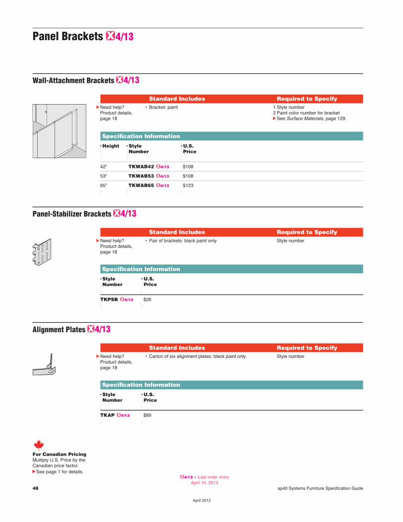
Panel Brackets G4/13
Wall-Attachment Brackets G4/13
Standard Includes Required to SpecifycNeed help?
Product details,page 18
• Bracket: paint 1 Style number2 Paint color number for bracketcSee Surface Materials, page 129.
Specification Information
DHeight DStyle DU.S.d dNumber dPriced d d
42" TKWAB42 G4/13 $108
53" TKWAB53 G4/13 $108
65" TKWAB65 G4/13 $123 d d d
48 ap40 Systems Furniture Specification Guide
Panel-Stabilizer Brackets G4/13
Standard Includes Required to SpecifycNeed help?
Product details,page 18
• Pair of brackets: black paint only Style number
Specification Information
DStyle DU.S.dNumber dPriced d
TKPSB G4/13 $26 d d
Alignment Plates G4/13
Standard Includes Required to SpecifycNeed help?
Product details,page 18
• Carton of six alignment plates: black paint only Style number
Specification Information
DStyle DU.S.dNumber dPriced d
TKAP G4/13 $89 d d
For Canadian PricingMultiply U.S. Price by the Canadian price factor.
See page 1 for details.G4/13 = Last order entry
April 14, 2013
��������
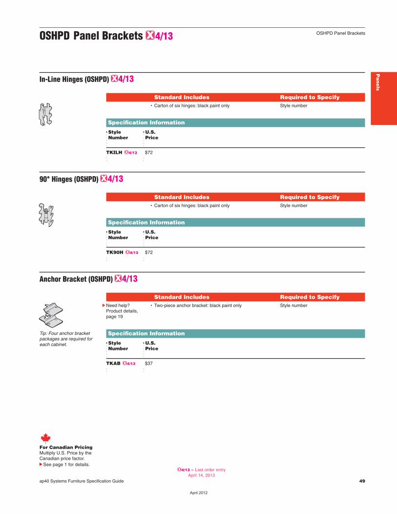
ap40 Systems Furniture Specification Guide 49
Pa
ne
ls
OSHPD Panel BracketsOSHPD Panel Brackets G4/13
In-Line Hinges (OSHPD) G4/13
Standard Includes Required to Specify• Carton of six hinges: black paint only Style number
Specification Information
DStyle DU.S.dNumber dPriced d
TKILH G4/13 $72 d d
90° Hinges (OSHPD) G4/13
Standard Includes Required to Specify• Carton of six hinges: black paint only Style number
Specification Information
DStyle DU.S.dNumber dPriced d
TK90H G4/13 $72 d d
Anchor Bracket (OSHPD) G4/13
Standard Includes Required to SpecifycNeed help?
Product details,page 19
• Two-piece anchor bracket: black paint only Style number
Specification Information
DStyle DU.S.dNumber dPriced d
TKAB G4/13 $37 d d
Tip: Four anchor bracketpackages are required foreach cabinet.
For Canadian PricingMultiply U.S. Price by the Canadian price factor.
See page 1 for details.G4/13 = Last order entry
April 14, 2013
��������
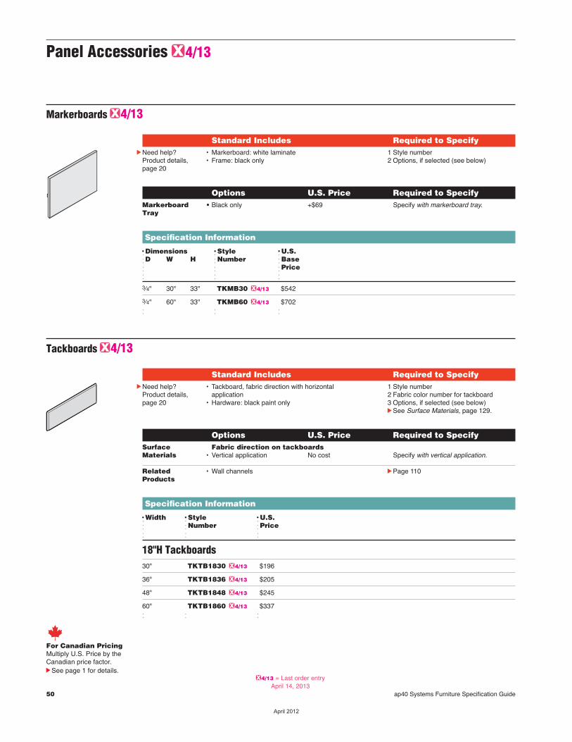
50 ap40 Systems Furniture Specification Guide
Markerboards G4/13
Standard Includes Required to SpecifycNeed help?
Product details,page 20
• Markerboard: white laminate• Frame: black only
1 Style number2 Options, if selected (see below)
Options U.S. Price Required to Specify Markerboard • Black only +$69 Specify with markerboard tray. Tray
Specification Information
DDimensions DStyle DU.S.dD W H dNumber dBased d dPriced d d
3⁄4" 30" 33" TKMB30 G4/13 $542
3⁄4" 60" 33" TKMB60 G4/13 $702 d d d
Panel Accessories G4/13
For Canadian PricingMultiply U.S. Price by the Canadian price factor.
See page 1 for details.
Tackboards G4/13
Standard Includes Required to SpecifycNeed help?
Product details,page 20
• Tackboard, fabric direction with horizontalapplication
• Hardware: black paint only
1 Style number2 Fabric color number for tackboard3 Options, if selected (see below)cSee Surface Materials, page 129.
Options U.S. Price Required to Specify Surface Fabric direction on tackboards Materials • Vertical application No cost Specify with vertical application.
Related • Wall channels cPage 110 Products
Specification Information
DWidth DStyle DU.S.d dNumber dPriced d d
18"H Tackboards30" TKTB1830 G4/13 $196
36" TKTB1836 G4/13 $205
48" TKTB1848 G4/13 $245
60" TKTB1860 G4/13 $337 d d d
G4/13 = Last order entryApril 14, 2013
��������
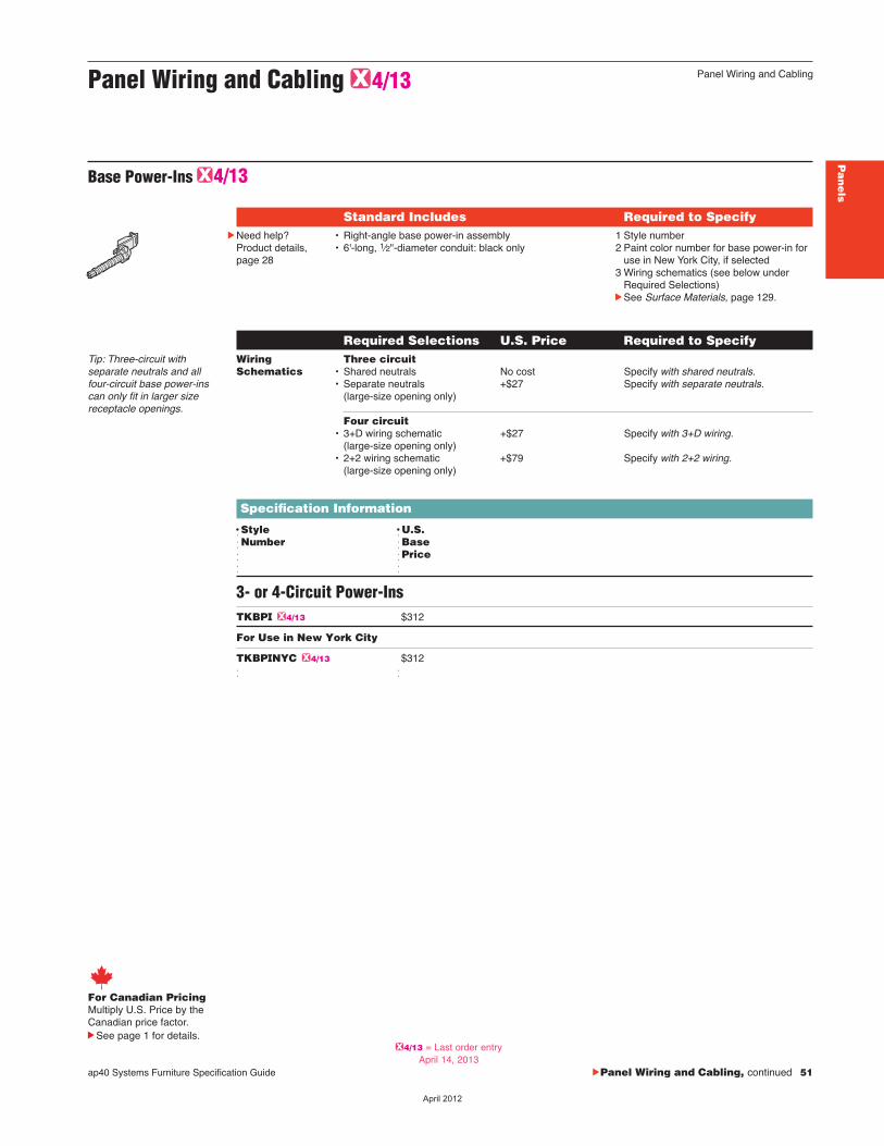
ap40 Systems Furniture Specification Guide cPanel Wiring and Cabling, continued 51
Pa
ne
ls
Panel Wiring and Cabling G4/13
Panel Wiring and Cabling
Base Power-Ins G4/13
Standard Includes Required to SpecifycNeed help?
Product details,page 28
• Right-angle base power-in assembly• 6'-long, 1⁄2"-diameter conduit: black only
1 Style number2 Paint color number for base power-in for
use in New York City, if selected3 Wiring schematics (see below under
Required Selections)cSee Surface Materials, page 129.
Required Selections U.S. Price Required to Specify Wiring Three circuit Schematics • Shared neutrals No cost Specify with shared neutrals. • Separate neutrals +$27 Specify with separate neutrals. (large-size opening only)
Four circuit • 3+D wiring schematic +$27 Specify with 3+D wiring. (large-size opening only) • 2+2 wiring schematic +$79 Specify with 2+2 wiring. (large-size opening only)
Specification Information
DStyle DU.S.dNumber dBased dPriced d
3- or 4-Circuit Power-InsTKBPI G4/13 $312
For Use in New York City
TKBPINYC G4/13 $312 d d
Tip: Three-circuit with separate neutrals and allfour-circuit base power-inscan only fit in larger sizereceptacle openings.
For Canadian PricingMultiply U.S. Price by the Canadian price factor.
See page 1 for details.G4/13 = Last order entry
April 14, 2013
��������
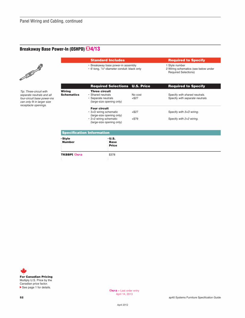
52 ap40 Systems Furniture Specification Guide
Panel Wiring and Cabling, continued
Breakaway Base Power-In (OSHPD) G4/13
Standard Includes Required to Specify• Breakaway base power-in assembly• 6'-long, 1/2"-diameter conduit: black only
1 Style number2 Wiring schematics (see below under
Required Selections)
Required Selections U.S. Price Required to Specify Wiring Three circuit Schematics • Shared neutrals No cost Specify with shared neutrals. • Separate neutrals +$27 Specify with separate neutrals. (large-size opening only)
Four circuit • 3+D wiring schematic +$27 Specify with 3+D wiring. (large-size opening only) • 2+2 wiring schematic +$79 Specify with 2+2 wiring. (large-size opening only)
Specification Information
DStyle DU.S.dNumber dBased dPriced d
TKBBPI G4/13 $378 d d
Tip: Three-circuit with separate neutrals and allfour-circuit base power-inscan only fit in larger sizereceptacle openings.
For Canadian PricingMultiply U.S. Price by the Canadian price factor.
See page 1 for details.G4/13 = Last order entry
April 14, 2013
��������
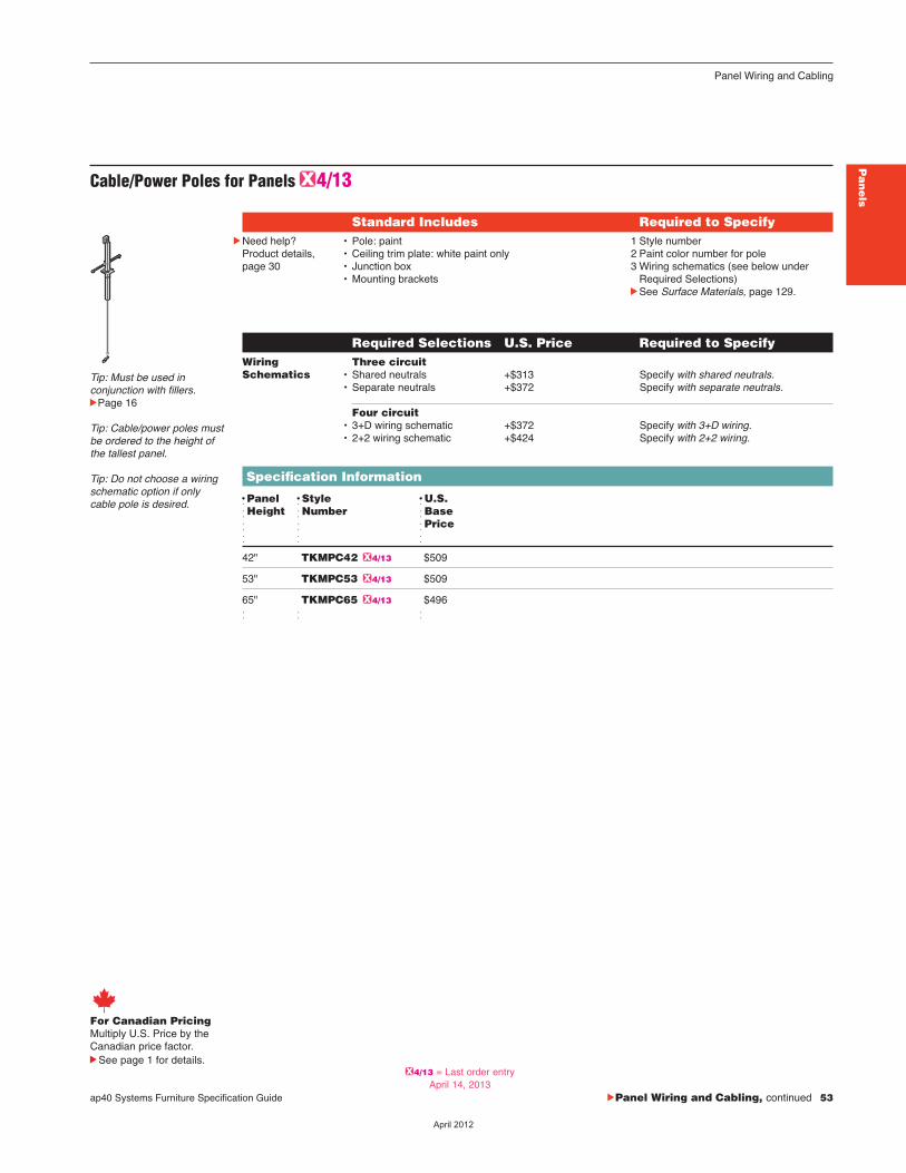
ap40 Systems Furniture Specification Guide cPanel Wiring and Cabling, continued 53
Pa
ne
ls
Panel Wiring and Cabling
Cable/Power Poles for Panels G4/13
Standard Includes Required to SpecifycNeed help?
Product details,page 30
• Pole: paint • Ceiling trim plate: white paint only• Junction box• Mounting brackets
1 Style number2 Paint color number for pole3 Wiring schematics (see below under
Required Selections)cSee Surface Materials, page 129.
Required Selections U.S. Price Required to Specify Wiring Three circuit Schematics • Shared neutrals +$313 Specify with shared neutrals. • Separate neutrals +$372 Specify with separate neutrals.
Four circuit • 3+D wiring schematic +$372 Specify with 3+D wiring. • 2+2 wiring schematic +$424 Specify with 2+2 wiring.
Specification Information
DPanel DStyle DU.S.dHeight dNumber dBased d dPriced d d
42" TKMPC42 G4/13 $509
53" TKMPC53 G4/13 $509
65" TKMPC65 G4/13 $496 d d d
Tip: Must be used in conjunction with fillers.cPage 16
Tip: Cable/power poles mustbe ordered to the height ofthe tallest panel.
Tip: Do not choose a wiringschematic option if onlycable pole is desired.
For Canadian PricingMultiply U.S. Price by the Canadian price factor.
See page 1 for details.G4/13 = Last order entry
April 14, 2013
��������
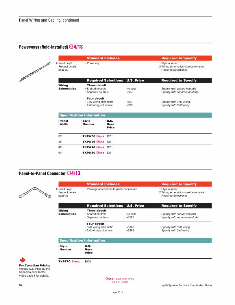
54 ap40 Systems Furniture Specification Guide
Panel Wiring and Cabling, continued
Powerways (field-installed) G4/13
Standard Includes Required to SpecifycNeed help?
Product details,page 32
• Powerway 1 Style number2 Wiring schematics (see below under
Required Selections)
Required Selections U.S. Price Required to Specify Wiring Three circuit Schematics • Shared neutrals No cost Specify with shared neutrals. • Separate neutrals +$37 Specify with separate neutrals. Four circuit • 3+D wiring schematic +$37 Specify with 3+D wiring. • 2+2 wiring schematic +$89 Specify with 2+2 wiring.
Specification Information
DPanel DStyle DU.S. dWidth dNumber dBase d d dPrice d d d 30" TKPW30 G4/13 $231
36" TKPW36 G4/13 $231
48" TKPW48 G4/13 $231
60" TKPW60 G4/13 $231 d d d
40%
Panel-to-Panel Connector G4/13
Standard Includes Required to SpecifycNeed help?
Product details,page 33
• Package of six panel-to-panel connectors 1 Style number2 Wiring schematics (see below under
Required Selections)
Required Selections U.S. Price Required to Specify Wiring Three circuit Schematics • Shared neutrals No cost Specify with shared neutrals. • Separate neutrals +$166 Specify with separate neutrals. Four circuit • 3+D wiring schematic +$166 Specify with 3+D wiring. • 2+2 wiring schematic +$288 Specify with 2+2 wiring.
Specification Information
DStyle DU.S. dNumber dBased dPriced d
TKPTPC G4/13 $505 d dFor Canadian Pricing
Multiply U.S. Price by the Canadian price factor.
See page 1 for details.G4/13 = Last order entry
April 14, 2013
��������

ap40 Systems Furniture Specification Guide 55
Pa
ne
ls
Panel Wiring and Cabling
Base Covers for Panels G4/13
Standard Includes Required to SpecifycNeed help?
Product details,page 16
• Carton of six base covers: paint 1 Style number 2 Paint color number for base covercSee Surface Materials, page 129.
Specification Information
DStyle DU.S.dNumber dPriced d
L-Base CoverTKLBC G4/13 $165 d d
T-Base CoverTKTBC G4/13 $165 d d
For Canadian PricingMultiply U.S. Price by the Canadian price factor.
See page 1 for details.G4/13 = Last order entry
April 14, 2013
��������
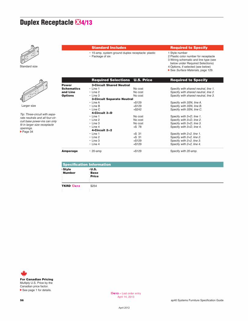
56 ap40 Systems Furniture Specification Guide
Duplex Receptacle G4/13
Specification InformationDStyle DU.S.dNumber dBased dPriced d
TKRD G4/13 $254 d d
Standard Includes Required to Specify• 15-amp, system ground duplex receptacle: plastic• Package of six
1 Style number2 Plastic color number for receptacle3 Wiring schematic and line type (see
below under Required Selections)4 Options, if selected (see below)cSee Surface Materials, page 129.
Required Selections U.S. Price Required to SpecifyPower 3-Circuit Shared NeutralSchematics • Line 1 No cost Specify with shared neutral, line 1.and Line • Line 2 No cost Specify with shared neutral, line 2.Options • Line 3 No cost Specify with shared neutral, line 3. 3-Circuit Separate Neutral • Line A +$129 Specify with 3SN, line A. • Line B +$129 Specify with 3SN, line B. • Line C +$242 Specify with 3SN, line C. 4-Circuit 3+D • Line 1 No cost Specify with 3+D, line 1. • Line 2 No cost Specify with 3+D, line 2. • Line 3 No cost Specify with 3+D, line 3. • Line 4 +$ 78 Specify with 3+D, line 4. 4-Circuit 2+2 • Line 1 +$ 31 Specify with 2+2, line 1. • Line 2 +$ 31 Specify with 2+2, line 2. • Line 3 +$129 Specify with 2+2, line 3. • Line 4 +$129 Specify with 2+2, line 4. Amperage • 20-amp +$129 Specify with 20-amp.
For Canadian PricingMultiply U.S. Price by the Canadian price factor.
See page 1 for details.
Larger size
Standard size
Tip: Three-circuit with sepa-rate neutrals and all four-cir-cuit base power-ins can onlyfit in larger size receptacleopenings.cPage 34
G4/13 = Last order entryApril 14, 2013
��������
ap40 Systems Furniture Specification Guide 57
Worksurfacesand Related Products
Un
iversa
lW
ork
surfa
ce
s
Understanding
Systems Worksurfaces 59
Specifying
Systems Worksurfaces 71
Wo
rksu
rfac
es
��������

58 ap40 Systems Furniture Specification Guide
��������
UnderstandingSystems Worksurfaces
ap40 Systems Furniture Specification Guide 59
Statement of Line 60
Product Details
Systems Worksurfaces — Full Depth 62
Transaction Worksurfaces 64
Panel-Mounted Systems Worksurface Supports 66
Tables 68
Worksurface Wiring and Cabling Accessories 69
Wo
rksu
rfac
es
��������
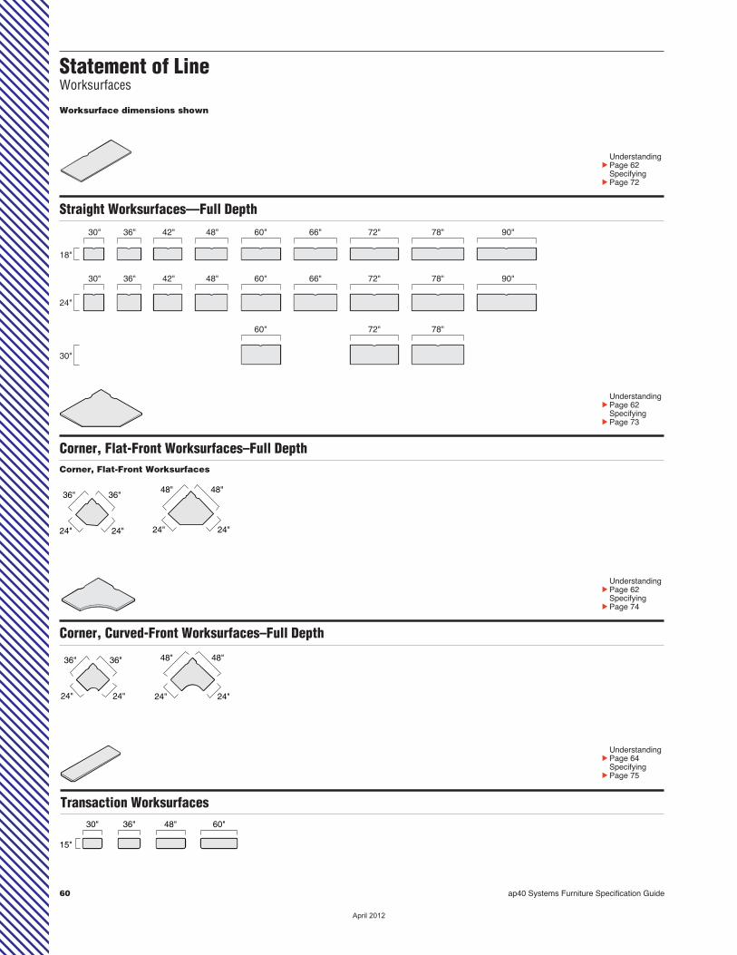
60 ap40 Systems Furniture Specification Guide
Straight Worksurfaces—Full Depth30"
18"
36" 42" 48" 60" 66" 72" 90"78"
30"
24"
36" 42" 48" 60" 66" 72" 90"78"
30"
60" 72" 78"
UnderstandingcPage 62 SpecifyingcPage 72
Worksurface dimensions shown
Statement of LineWorksurfaces
Corner, Flat-Front Worksurfaces–Full Depth
UnderstandingcPage 62 SpecifyingcPage 73
24"
48" 48"
24"
36"36"
24"24"
Corner, Flat-Front Worksurfaces
Corner, Curved-Front Worksurfaces–Full Depth
UnderstandingcPage 62 SpecifyingcPage 74
48"48"
24"24"
36"36"
24"24"
Transaction Worksurfaces 36" 48"30"
15"
60"
UnderstandingcPage 64 SpecifyingcPage 75
��������

ap40 Systems Furniture Specification Guide 61
Wo
rksu
rfac
es
Statement of LineStatement of LineTables
Straight Tables
30" 36"
UnderstandingcPage 68 SpecifyingcPage 79
Straight tables are available in Low-Pressure Laminate with3 mm edge. Tables come standard with four post legs.
UnderstandingcPage 68 SpecifyingcPage 80
Round Tables
Round tables are available in Low-Pressure Laminate with 3mm edge. Tables come standard with X-base.
593/4"
30"
593/4"
24"
713/4"
713/4"
��������

62 ap40 Systems Furniture Specification Guide
Systems Worksurfaces—Full Depth
Product Details
PVC-free, 3 mm edgeprofiles are proprietarypolyolefin blend for all solidcolors and 7 woodgrain fin-ishes. Matching 1 mm sideand back edges are alsoPVC-free. See surfacematerial listing in this bookfor specific PVC-free availability.
ConnectionsWorksurfaces are used inpanel-supported installations.
Supports are orderedseparately and installed inthe field.
For panel-supportedinstallations you can use:• Side support brackets• Cantilevers with tie plate• End panel• Center support panel with
tie plate• Pedestal with filler• Flush mount brackets• Post legs option for hybrid applicationscSee page 66 forPanel-Mounted SystemsWorksurface Supports.
...............................................................................................................................................
...............................................................................................................................................
Cable scallops allowcords and plugs to passbehind the worksurface.Cable scallops can be omitted as an option.
cSpecifying SystemsWorksurfaces—Full Depthpage 72
Systems worksur-faces—full depth areavailable in two depths,18"D and 30"D.
Front (user’s) edge is aplastic edge band with a 3mm radius. Back and sideedges are flat.
Worksurface has awood core with a Low-Pressure Laminate surfaceand is 13⁄16" thick.
Full-depth worksur-faces fit flush against panels. Cords and cablesare routed through cablescallops.
...............................................................................................................................................
��������
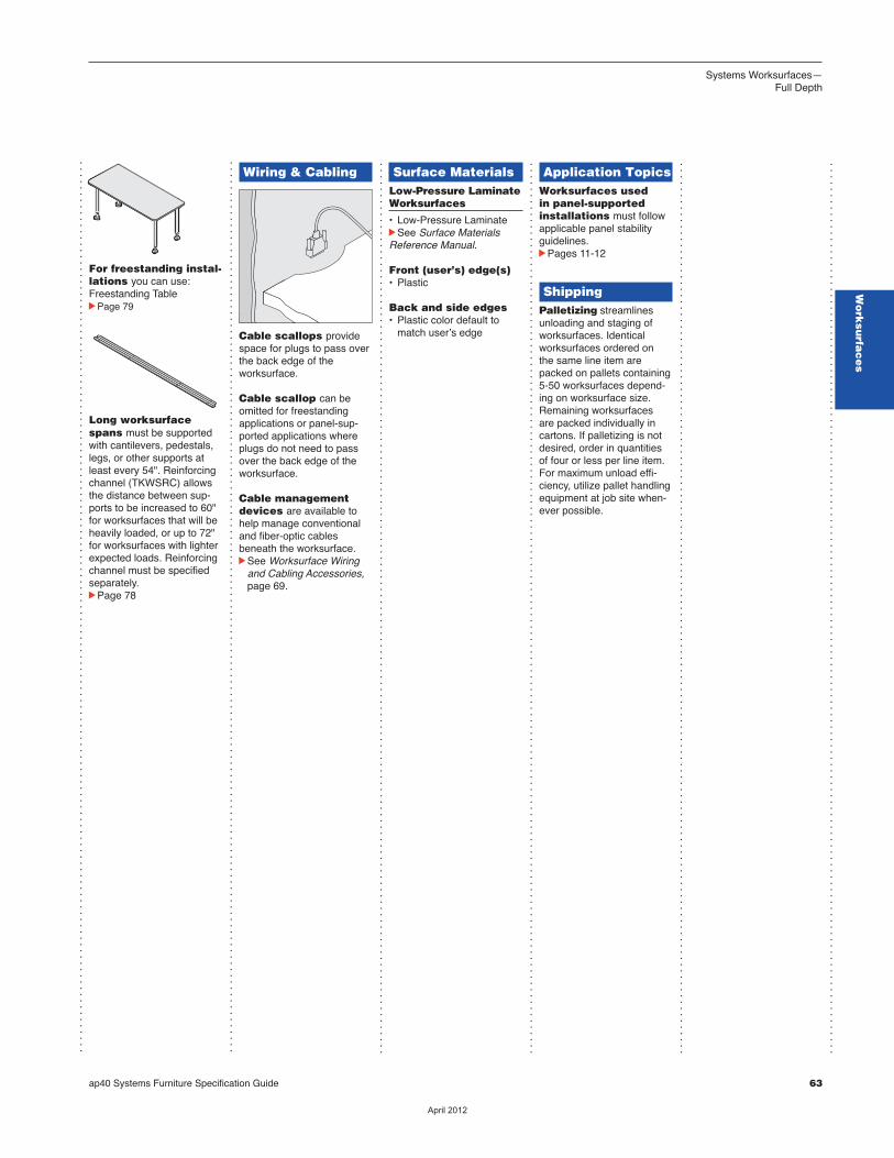
ap40 Systems Furniture Specification Guide 63
Wo
rksu
rfac
es
...............................................................................................................................................
...............................................................................................................................................
...............................................................................................................................................
...............................................................................................................................................
...............................................................................................................................................
...............................................................................................................................................
Systems Worksurfaces—Full Depth
For freestanding instal-lations you can use:Freestanding TablecPage 79
Long worksurfacespans must be supportedwith cantilevers, pedestals,legs, or other supports atleast every 54". Reinforcingchannel (TKWSRC) allowsthe distance between sup-ports to be increased to 60"for worksurfaces that will beheavily loaded, or up to 72"for worksurfaces with lighterexpected loads. Reinforcingchannel must be specifiedseparately.cPage 78
Surface Materials Low-Pressure LaminateWorksurfaces
• Low-Pressure LaminatecSee Surface MaterialsReference Manual.
Front (user’s) edge(s)• Plastic
Back and side edges• Plastic color default to match userʼs edge
Wiring & Cabling
Cable scallops providespace for plugs to pass overthe back edge of the worksurface.
Cable scallop can beomitted for freestandingapplications or panel-sup-ported applications whereplugs do not need to passover the back edge of theworksurface.
Cable managementdevices are available tohelp manage conventionaland fiber-optic cablesbeneath the worksurface.cSee Worksurface Wiring
and Cabling Accessories, page 69.
Application TopicsWorksurfaces usedin panel-supportedinstallations must followapplicable panel stabilityguidelines.cPages 11-12
ShippingPalletizing streamlinesunloading and staging ofworksurfaces. Identicalworksurfaces ordered on the same line item arepacked on pallets containing5-50 worksurfaces depend-ing on worksurface size.Remaining worksurfaces are packed individually incartons. If palletizing is notdesired, order in quantitiesof four or less per line item.For maximum unload effi-ciency, utilize pallet handlingequipment at job site when-ever possible.
��������
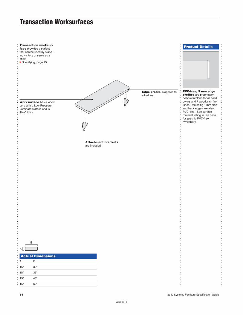
64 ap40 Systems Furniture Specification Guide
...............................................................................................................................................
...............................................................................................................................................
...............................................................................................................................................
Product Details
PVC-free, 3 mm edgeprofiles are proprietarypolyolefin blend for all solidcolors and 7 woodgrain fin-ishes. Matching 1 mm sideand back edges are alsoPVC-free. See surfacematerial listing in this bookfor specific PVC-free availability.
Transaction worksur-face provides a surfacethat can be used by stand-ing visitors or serve as ashelf.cSpecifying, page 75
Attachment bracketsare included.
Actual DimensionsA B
15" 30"
15" 36"
15" 48"
15" 60"
B
A
Worksurface has a woodcore with a Low-PressureLaminate surface and is13⁄16" thick.
Transaction Worksurfaces
Edge profile is applied toall edges.
��������
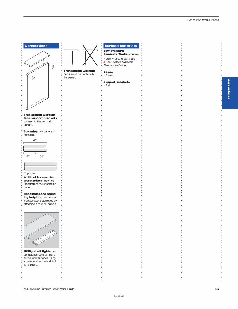
ap40 Systems Furniture Specification Guide 65
...............................................................................................................................................
...............................................................................................................................................
...............................................................................................................................................
...............................................................................................................................................
...............................................................................................................................................
...............................................................................................................................................
Transaction Worksurfaces
Connections
Transaction worksur-face support bracketsconnect to the verticalupright.
Spanning two panels ispossible.
Width of transactionworksurface matches the width of correspondingpanel.
Recommended stand-ing height for transactionworksurface is achieved byattaching it to 42"H panels.
Utility shelf lights canbe installed beneath trans-action worksurfaces usingscrews and keyhole slots inlight fixture.
Top view
60"
30" 30"
Transaction worksur-face must be centered onthe panel.
Surface MaterialsLow-Pressure Laminate Worksurfaces
• Low-Pressure LaminatecSee Surface MaterialsReference Manual.
Edges• Plastic
Support brackets• Paint
Wo
rksu
rfac
es
��������
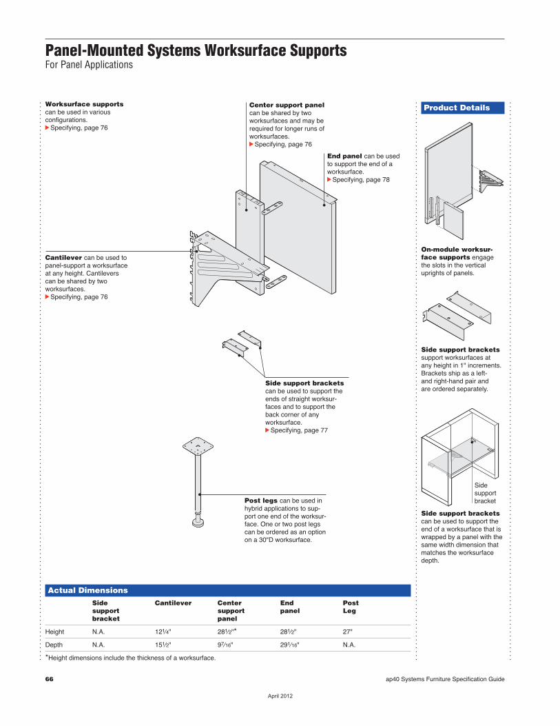
66 ap40 Systems Furniture Specification Guide
...............................................................................................................................................
...............................................................................................................................................
...............................................................................................................................................
Product Details
On-module worksur-face supports engage the slots in the verticaluprights of panels.
Side support bracketssupport worksurfaces at any height in 1" increments.Brackets ship as a left- and right-hand pair and are ordered separately.
Side support bracketscan be used to support theend of a worksurface that iswrapped by a panel with thesame width dimension thatmatches the worksurfacedepth.
Sidesupportbracket
Worksurface supportscan be used in various configurations.cSpecifying, page 76
Cantilever can be used topanel-support a worksurfaceat any height. Cantilevers can be shared by two worksurfaces.cSpecifying, page 76
Side support bracketscan be used to support theends of straight worksur-faces and to support theback corner of any worksurface.cSpecifying, page 77
End panel can be used to support the end of a worksurface.cSpecifying, page 78
Center support panelcan be shared by two worksurfaces and may berequired for longer runs ofworksurfaces.cSpecifying, page 76
Actual Dimensions Side Cantilever Center End Post support support panel Leg bracket panel
Height N.A. 121⁄4" 281⁄2"* 281⁄2" 27"
Depth N.A. 151⁄2" 97⁄16" 291⁄16" N.A.
*Height dimensions include the thickness of a worksurface.
Panel-Mounted Systems Worksurface SupportsFor Panel Applications
Post legs can be used inhybrid applications to sup-port one end of the worksur-face. One or two post legscan be ordered as an optionon a 30"D worksurface.
��������
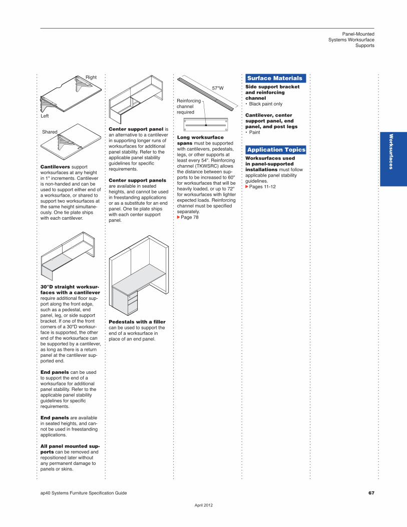
ap40 Systems Furniture Specification Guide 67
Panel-Mounted Systems Worksurface
Supports
...............................................................................................................................................
...............................................................................................................................................
...............................................................................................................................................
...............................................................................................................................................
...............................................................................................................................................
...............................................................................................................................................
Cantilevers support worksurfaces at any heightin 1" increments. Cantileveris non-handed and can beused to support either end ofa worksurface, or shared tosupport two worksurfaces atthe same height simultane-ously. One tie plate shipswith each cantilever.
30"D straight worksur-faces with a cantileverrequire additional floor sup-port along the front edge,such as a pedestal, endpanel, leg, or side supportbracket. If one of the frontcorners of a 30"D worksur-face is supported, the otherend of the worksurface canbe supported by a cantilever,as long as there is a returnpanel at the cantilever sup-ported end.
End panels can be usedto support the end of a worksurface for additionalpanel stability. Refer to theapplicable panel stabilityguidelines for specificrequirements.
End panels are availablein seated heights, and can-not be used in freestandingapplications.
All panel mounted sup-ports can be removed andrepositioned later withoutany permanent damage topanels or skins.
Left
Shared
Right
Center support panel isan alternative to a cantileverin supporting longer runs ofworksurfaces for additionalpanel stability. Refer to theapplicable panel stabilityguidelines for specificrequirements.
Center support panelsare available in seatedheights, and cannot be usedin freestanding applicationsor as a substitute for an endpanel. One tie plate shipswith each center supportpanel.
Pedestals with a fillercan be used to support theend of a worksurface inplace of an end panel.
Long worksurfacespans must be supportedwith cantilevers, pedestals,legs, or other supports atleast every 54". Reinforcingchannel (TKWSRC) allowsthe distance between sup-ports to be increased to 60"for worksurfaces that will beheavily loaded, or up to 72"for worksurfaces with lighterexpected loads. Reinforcingchannel must be specifiedseparately.cPage 78
57"W
Reinforcingchannelrequired
Surface MaterialsSide support bracketand reinforcing channel• Black paint only
Cantilever, center support panel, endpanel, and post legs• Paint
Application TopicsWorksurfaces usedin panel-supportedinstallations must followapplicable panel stabilityguidelines.cPages 11-12
Wo
rksu
rfac
es
��������
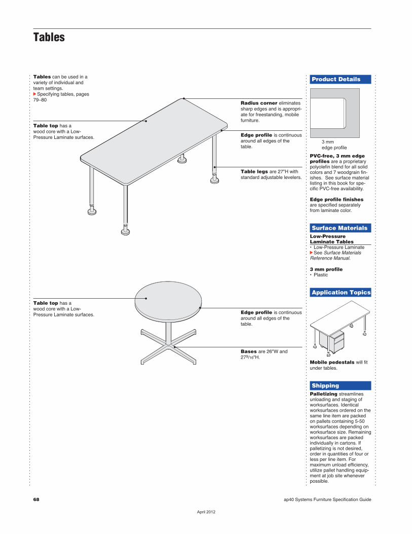
68 ap40 Systems Furniture Specification Guide
Tables
...............................................................................................................................................
...............................................................................................................................................
...............................................................................................................................................
Table top has awood core with a Low-Pressure Laminate surfaces.
Tables can be used in avariety of individual andteam settings.cSpecifying tables, pages79–80
Edge profile is continuousaround all edges of thetable.
Product Details
PVC-free, 3 mm edgeprofiles are a proprietarypolyolefin blend for all solidcolors and 7 woodgrain fin-ishes. See surface materiallisting in this book for spe-cific PVC-free availability.
Edge profile finishesare specified separatelyfrom laminate color.
Surface MaterialsLow-PressureLaminate Tables• Low-Pressure LaminatecSee Surface MaterialsReference Manual.
3 mm profile• Plastic
Application Topics
Mobile pedestals will fitunder tables.
ShippingPalletizing streamlinesunloading and staging ofworksurfaces. Identicalworksurfaces ordered on thesame line item are packedon pallets containing 5-50worksurfaces depending onworksurface size. Remainingworksurfaces are packedindividually in cartons. If palletizing is not desired,order in quantities of four orless per line item. For maximum unload efficiency,utilize pallet handling equip-ment at job site wheneverpossible.
3 mmedge profile
Radius corner eliminatessharp edges and is appropri-ate for freestanding, mobilefurniture.
Table legs are 27"H withstandard adjustable levelers.
Table top has awood core with a Low-Pressure Laminate surfaces. Edge profile is continuous
around all edges of thetable.
Bases are 26"W and279/16"H.
��������
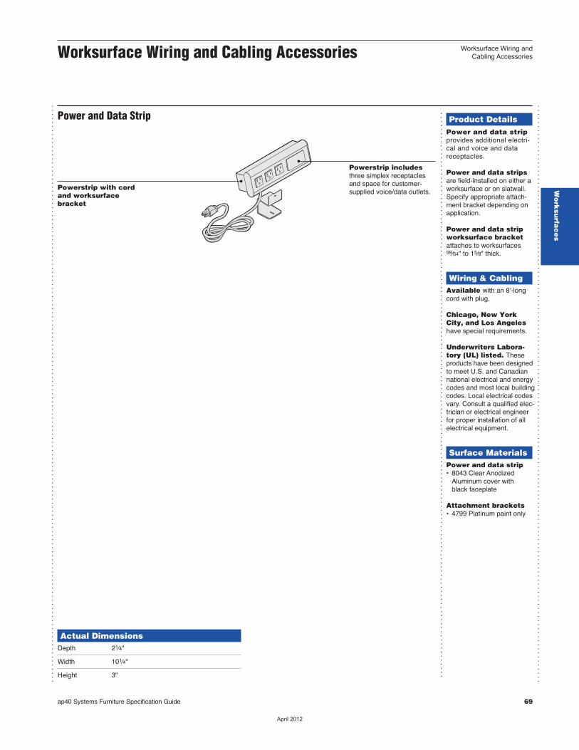
Worksurface Wiring andCabling AccessoriesWorksurface Wiring and Cabling Accessories
...............................................................................................................................................
Power and Data Strip
Actual DimensionsDepth 21⁄4"
Width 101⁄4"
Height 3"
...............................................................................................................................................
Product DetailsPower and data stripprovides additional electri-cal and voice and datareceptacles.
Power and data stripsare field-installed on either aworksurface or on slatwall.Specify appropriate attach-ment bracket depending onapplication.
Power and data stripworksurface bracketattaches to worksurfaces59⁄64" to 15⁄8" thick.
Wiring & CablingAvailable with an 8'-longcord with plug.
Chicago, New YorkCity, and Los Angeleshave special requirements.
Underwriters Labora - tory (UL) listed. Theseproducts have been designedto meet U.S. and Canadiannational electrical and energycodes and most local buildingcodes. Local electrical codesvary. Consult a qualified elec-trician or electrical engineerfor proper instal lation of allelectrical equipment.
Surface MaterialsPower and data strip• 8043 Clear Anodized Aluminum cover with black faceplate
Attachment brackets• 4799 Platinum paint only
............................................................................................................................................
Powerstrip with cordand worksurfacebracket
Powerstrip includesthree simplex receptaclesand space for customer-supplied voice/data outlets.
ap40 Systems Furniture Specification Guide 69
Wo
rksu
rfac
es
��������

70 ap40 Systems Furniture Specification Guide
��������
SpecifyingSystemsWorksurfaces
Straight Worksurfaces—Full Depth 72
Corner, Flat-Front Worksurfaces—Full Depth 73
Corner, Curved-Front Worksurfaces—Full Depth 74
Transaction Worksurfaces 75
Panel-Mounted Systems Worksurface Supports 76
Straight Tables 79
Round Tables 80
Power and Data Strip with Cord with Worksurface Attachment Bracket 81
ap40 Systems Furniture Specification Guide 71
ap40 U
nive
rsal
Work
surfa
ces
Work
surfa
ces
��������
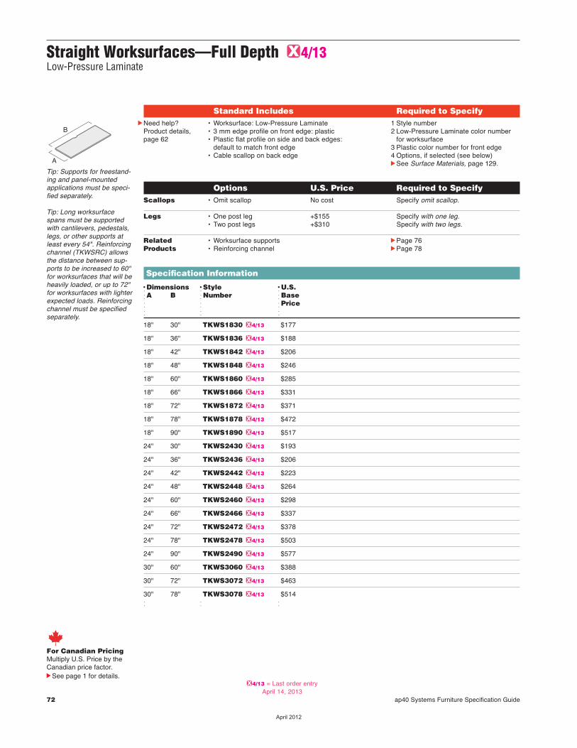
72 ap40 Systems Furniture Specification Guide
Straight Worksurfaces—Full Depth G4/13Low-Pressure Laminate
Options U.S. Price Required to Specify Scallops • Omit scallop No cost Specify omit scallop.
Legs • One post leg +$155 Specify with one leg. • Two post legs +$310 Specify with two legs.
Related • Worksurface supports cPage 76 Products • Reinforcing channel cPage 78
Specification Information
DDimensions DStyle DU.S. dA B dNumber dBase d d dPriced d d
18" 30" TKWS1830 G4/13 $177
18" 36" TKWS1836 G4/13 $188
18" 42" TKWS1842 G4/13 $206
18" 48" TKWS1848 G4/13 $246
18" 60" TKWS1860 G4/13 $285
18" 66" TKWS1866 G4/13 $331
18" 72" TKWS1872 G4/13 $371
18" 78" TKWS1878 G4/13 $472
18" 90" TKWS1890 G4/13 $517
24" 30" TKWS2430 G4/13 $193
24" 36" TKWS2436 G4/13 $206
24" 42" TKWS2442 G4/13 $223
24" 48" TKWS2448 G4/13 $264
24" 60" TKWS2460 G4/13 $298
24" 66" TKWS2466 G4/13 $337
24" 72" TKWS2472 G4/13 $378
24" 78" TKWS2478 G4/13 $503
24" 90" TKWS2490 G4/13 $577
30" 60" TKWS3060 G4/13 $388
30" 72" TKWS3072 G4/13 $463
30" 78" TKWS3078 G4/13 $514 d d d
Tip: Supports for freestand-ing and panel-mountedapplications must be speci-fied separately.
Tip: Long worksurfacespans must be supportedwith cantilevers, pedestals,legs, or other supports atleast every 54". Reinforcingchannel (TKWSRC) allowsthe distance between sup-ports to be increased to 60"for worksurfaces that will beheavily loaded, or up to 72"for worksurfaces with lighterexpected loads. Reinforcingchannel must be specifiedseparately.
A
B
Standard Includes Required to SpecifycNeed help?
Product details,page 62
• Worksurface: Low-Pressure Laminate• 3 mm edge profile on front edge: plastic• Plastic flat profile on side and back edges:
default to match front edge• Cable scallop on back edge
1 Style number2 Low-Pressure Laminate color number
for worksurface3 Plastic color number for front edge 4 Options, if selected (see below)cSee Surface Materials, page 129.
For Canadian PricingMultiply U.S. Price by the Canadian price factor.
See page 1 for details.G4/13 = Last order entry
April 14, 2013
��������
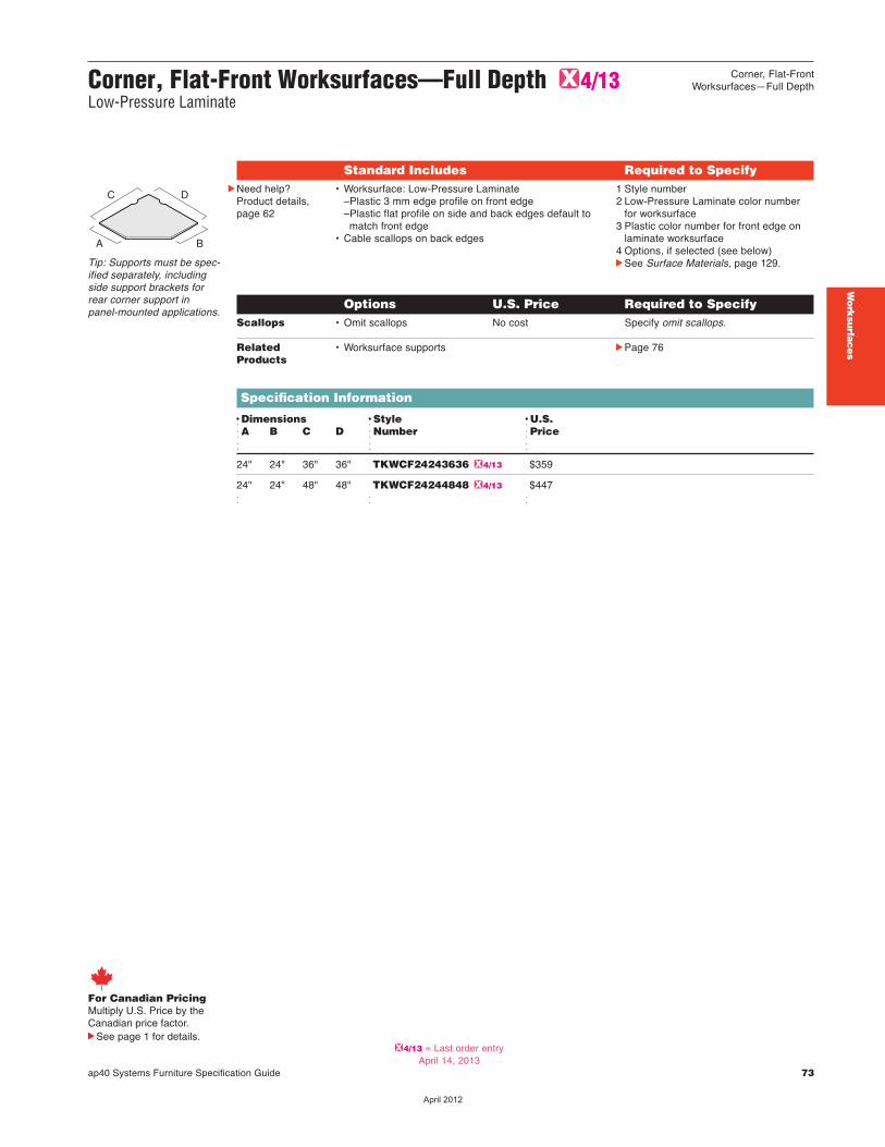
Work
surfa
ces
Corner, Flat-Front Worksurfaces—Full Depth G4/13Low-Pressure Laminate
Options U.S. Price Required to Specify Scallops • Omit scallops No cost Specify omit scallops.
Related • Worksurface supports cPage 76 Products
Specification Information
DDimensions DStyle DU.S. dA B C D dNumber dPriced d d
24" 24" 36" 36" TKWCF24243636 G4/13 $359
24" 24" 48" 48" TKWCF24244848 G4/13 $447 d d d
Tip: Supports must be spec-ified separately, includingside support brackets forrear corner support inpanel-mounted applications.
A B
C D
Standard Includes Required to SpecifycNeed help?
Product details,page 62
• Worksurface: Low-Pressure Laminate–Plastic 3 mm edge profile on front edge–Plastic flat profile on side and back edges default to match front edge
• Cable scallops on back edges
1 Style number2 Low-Pressure Laminate color number
for worksurface3 Plastic color number for front edge on
laminate worksurface4 Options, if selected (see below)cSee Surface Materials, page 129.
For Canadian PricingMultiply U.S. Price by the Canadian price factor.
See page 1 for details.
Corner, Flat-FrontWorksurfaces—Full Depth
ap40 Systems Furniture Specification Guide 73
G4/13 = Last order entryApril 14, 2013
��������
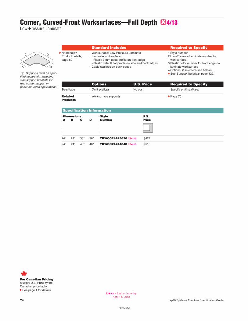
74 ap40 Systems Furniture Specification Guide
Corner, Curved-Front Worksurfaces—Full Depth G4/13Low-Pressure Laminate
Options U.S. Price Required to Specify Scallops • Omit scallops No cost Specify omit scallops.
Related • Worksurface supports cPage 76 Products
Specification Information
DDimensions DStyle U.S. dA B C D dNumber Price
d d d d d d
24" 24" 36" 36" TKWCC24243636 G4/13 $424
24" 24" 48" 48" TKWCC24244848 G4/13 $513 d d d
Tip: Supports must be spec-ified separately, includingside support brackets forrear corner support inpanel-mounted applications.
Standard Includes Required to SpecifycNeed help?
Product details,page 62
• Worksurface: Low-Pressure Laminate • Laminate worksurface:
–Plastic 3 mm edge profile on front edge–Plastic default flat profile on side and back edges
• Cable scallops on back edges
1 Style number 2 Low-Pressure Laminate number for
worksurface3 Plastic color number for front edge on
laminate worksurface4 Options, if selected (see below)cSee Surface Materials, page 129.
A B
C D
For Canadian PricingMultiply U.S. Price by the Canadian price factor.
See page 1 for details.G4/13 = Last order entry
April 14, 2013
��������
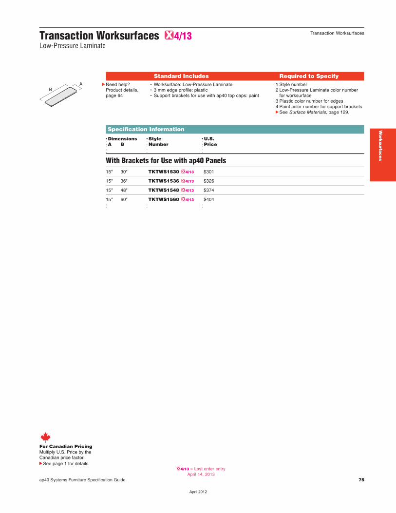
Work
surfa
ces
Transaction Worksurfaces G4/13Low-Pressure Laminate
Specification Information
DDimensions DStyle DU.S. dA B dNumber dPriced d d
With Brackets for Use with ap40 Panels15" 30" TKTWS1530 G4/13 $301
15" 36" TKTWS1536 G4/13 $326
15" 48" TKTWS1548 G4/13 $374
15" 60" TKTWS1560 G4/13 $404 d d d
AB
Standard Includes Required to SpecifycNeed help?
Product details,page 64
• Worksurface: Low-Pressure Laminate• 3 mm edge profile: plastic • Support brackets for use with ap40 top caps: paint
1 Style number 2 Low-Pressure Laminate color number
for worksurface3 Plastic color number for edges 4 Paint color number for support bracketscSee Surface Materials, page 129.
For Canadian PricingMultiply U.S. Price by the Canadian price factor.
See page 1 for details.
Transaction Worksurfaces
ap40 Systems Furniture Specification Guide 75
G4/13 = Last order entryApril 14, 2013
��������
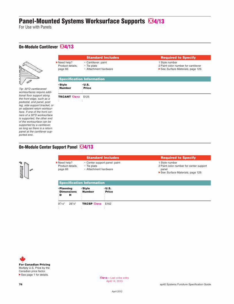
76 ap40 Systems Furniture Specification Guide
Panel-Mounted Systems Worksurface Supports G4/13 For Use with Panels
On-Module Center Support Panel G4/13
Standard Includes Required to SpecifycNeed help?
Product details,page 66
• Center support panel: paint• Tie plate• Attachment hardware
1 Style number2 Paint color number for center support
panelcSee Surface Materials, page 129.
Specification Information
DPlanning DStyle DU.S.dDimensions dNumber dPricedD H d dd d d
97⁄16" 281⁄2" TKCSP G4/13 $162 d d d
On-Module Cantilever G4/13
Standard Includes Required to SpecifycNeed help?
Product details,page 66
• Cantilever: paint• Tie plate• Attachment hardware
1 Style number2 Paint color number for cantilevercSee Surface Materials, page 129.
Specification Information
DStyle DU.S.dNumber dPriced d
TKCANT G4/13 $125 d d
Tip: 30"D cantileveredworksurfaces require addi-tional floor support alongthe front edge, such as apedestal, end panel, postleg, side support bracket, oran adjacent return worksur-face. If one of the front cor-ners of a 30"D worksurfaceis supported, the other endof the worksurface can besupported by a cantilever,as long as there is a returnpanel at the cantilever sup-ported end.
For Canadian PricingMultiply U.S. Price by the Canadian price factor.
See page 1 for details.G4/13 = Last order entry
April 14, 2013
��������
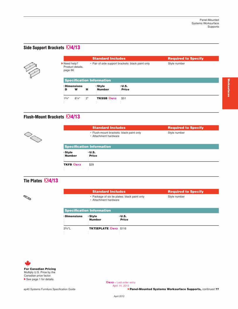
ap40 Systems Furniture Specification Guide cPanel-Mounted Systems Worksurface Supports, continued 77
Work
surfa
ces
Tie Plates G4/13
Standard Includes Required to Specify• Package of six tie plates: black paint only• Attachment hardware
Style number
Specification Information
DDimensions DStyle DU.S.d dNumber dPriced d d
33⁄4"L TKTIEPLATE G4/13 $116 d d d
Flush-Mount Brackets G4/13
Standard Includes Required to Specify• Flush-mount brackets: black paint only• Attachment hardware
Style number
Specification Information
DStyle DU.S.dNumber dPriced d
TKFB G4/13 $29 d d
Side Support Brackets G4/13
Standard Includes Required to SpecifycNeed help?
Product details,page 66
• Pair of side support brackets: black paint only Style number
Specification Information
DDimensions DStyle DU.S.dD W H dNumber dPriced d d
13⁄4" 81⁄4" 2" TKSSB G4/13 $51 d d d
For Canadian PricingMultiply U.S. Price by the Canadian price factor.
See page 1 for details.
Panel-Mounted Systems Worksurface
Supports
G4/13 = Last order entryApril 14, 2013
��������
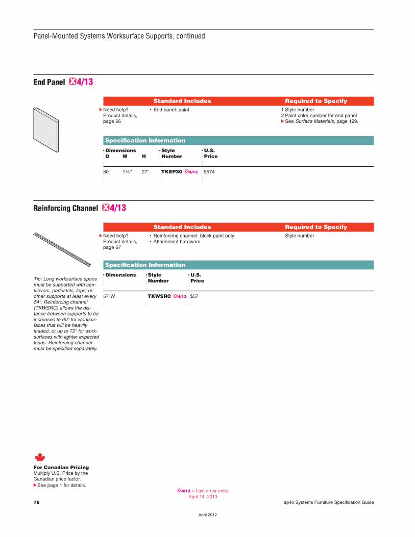
78 ap40 Systems Furniture Specification Guide
Panel-Mounted Systems Worksurface Supports, continued
For Canadian PricingMultiply U.S. Price by the Canadian price factor.
See page 1 for details.
End Panel G4/13
Standard Includes Required to SpecifycNeed help?
Product details,page 66
• End panel: paint 1 Style number2 Paint color number for end panelcSee Surface Materials, page 129.
Specification Information
DDimensions DStyle DU.S.dD W H dNumber dPriced d d
30" 11⁄8" 27" TKEP30 G4/13 $574 d d d
Tip: Long worksurface spansmust be supported with can-tilevers, pedestals, legs, orother supports at least every54". Reinforcing channel(TKWSRC) allows the dis-tance between supports to beincreased to 60" for worksur-faces that will be heavilyloaded, or up to 72" for work-surfaces with lighter expectedloads. Reinforcing channelmust be specified separately.
Reinforcing Channel G4/13
Standard Includes Required to SpecifycNeed help?
Product details,page 67
• Reinforcing channel: black paint only• Attachment hardware
Style number
Specification Information
DDimensions DStyle DU.S.d dNumber dPriced d d
57"W TKWSRC G4/13 $57 d d d
G4/13 = Last order entryApril 14, 2013
��������
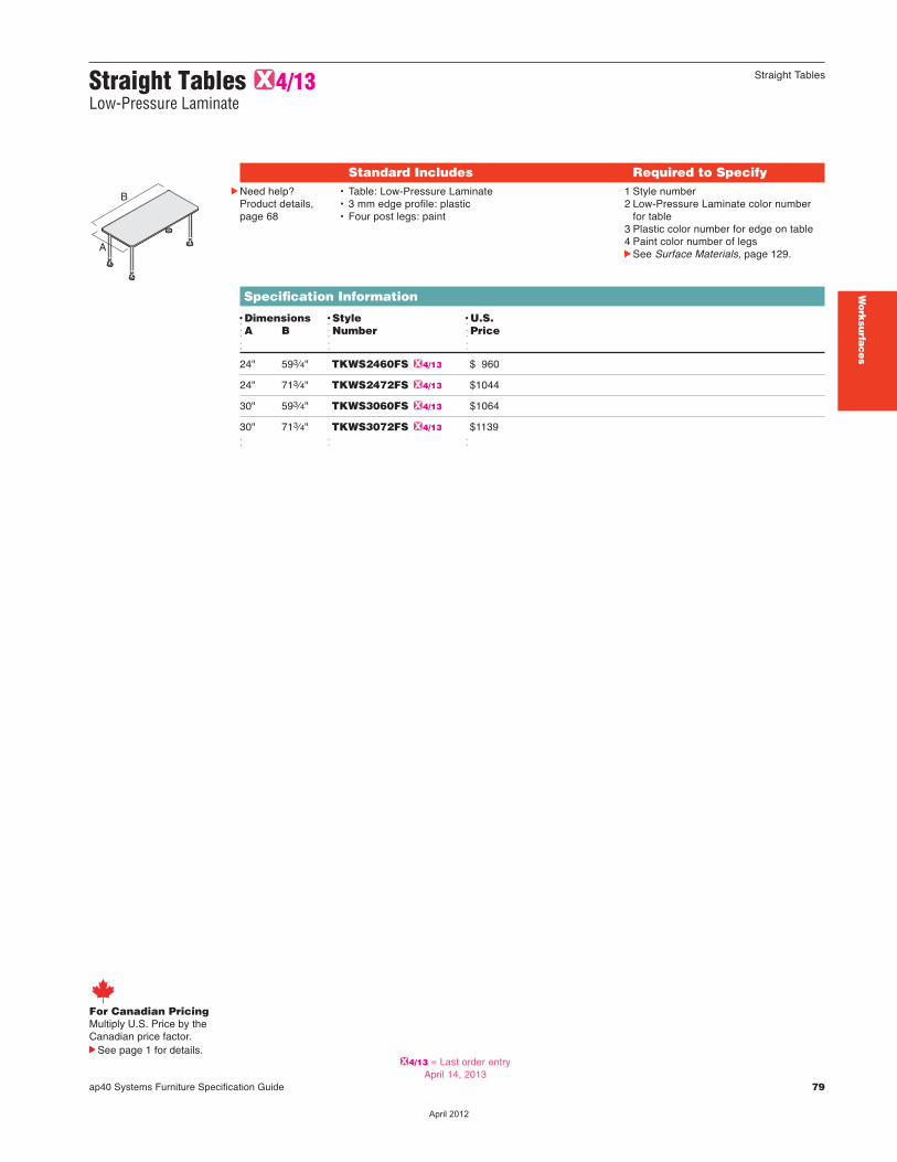
Straight Tables G4/13Low-Pressure Laminate
ap40 Systems Furniture Specification Guide 79
Work
surfa
ces
Straight Tables
Standard Includes Required to SpecifycNeed help?
Product details,page 68
• Table: Low-Pressure Laminate • 3 mm edge profile: plastic• Four post legs: paint
1 Style number2 Low-Pressure Laminate color number
for table3 Plastic color number for edge on table4 Paint color number of legscSee Surface Materials, page 129.
Specification Information
DDimensions DStyle DU.S. dA B dNumber dPrice d d d
24" 593⁄4" TKWS2460FS G4/13 $ 960
24" 713⁄4" TKWS2472FS G4/13 $1044
30" 593⁄4" TKWS3060FS G4/13 $1064
30" 713⁄4" TKWS3072FS G4/13 $1139 d d d
B
A
For Canadian PricingMultiply U.S. Price by the Canadian price factor.
See page 1 for details.G4/13 = Last order entry
April 14, 2013
��������
Round Tables G4/13
80 ap40 Systems Furniture Specification Guide
cNeed help?Product details,page 68
Specification Information
DDiameter DStyle DU.S. d dNumber dPriced d dd d d
30" TKRT30 G4/13 $723
36" TKRT36 G4/13 $750 d d d
Standard Includes Required to Specify• Table: Low-Pressure Laminate• Edge: plastic 3 mm edge profile• Base: paint
1 Style number2 Low-Pressure Laminate color number for worksurface3 Plastic color number for edge4 Paint color number for basecSee Surface Materials, page 129.
For Canadian PricingMultiply U.S. Price by the Canadian price factor.
See page 1 for details.G4/13 = Last order entry
April 14, 2013
��������
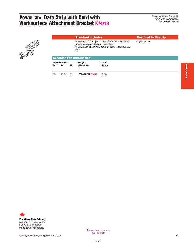
Power and Data Strip with Cord with Worksurface Attachment Bracket G4/13
ap40 Systems Furniture Specification Guide 81
Power and Data Strip withCord with Worksurface
Attachment Bracket
Work
surfa
ces
Specification Information
DDimensions DStyle DU.S.dD W H dNumber dPriced d d
21⁄4" 101⁄4" 3" TKWSPD G4/13 $275 d d d
Standard Includes Required to Specify• Power and data strip with cord: 8043 Clear Anodized
Aluminum cover with black faceplate• Worksurface attachment bracket: 4799 Platinum paint
only
Style number
For Canadian PricingMultiply U.S. Price by the Canadian price factor.
See page 1 for details.G4/13 = Last order entry
April 14, 2013
��������

82 ap40 Systems Furniture Specification Guide
��������
Specification Guide 83
Statement of Line 84
Understanding 85
Specifying 101
Storage
ap40 Systems Furniture Specification Guide 83
Sto
rag
e
��������

UnderstandingcPage 94 SpecifyingcPage 107
30"W, 36"W, 48"W
161/4"H
Over the Case Bins
30"W 36"W 48"W 60"W
153⁄4"D • • • •
84 ap40 Systems Furniture Specification Guide
Statement of Line Storage
Two-High Lateral Files
30"W 36"W
28"H • •
UnderstandingcPage 90 SpecifyingcPage 105
18"D
Integral pullsteel front
Fixed Pedestals 15"W
27"H •
UnderstandingcPage 86 SpecifyingcPage 102
Integral pullsteel front
171/2"D
Mobile Pedestal
15"W
21"H •
UnderstandingcPage 88 SpecifyingcPage 104
Integral pull steel front
171/2"D
Open Cabinets
30"W 36"W
28"H • •
UnderstandingcPage 92 SpecifyingcPage 106
18"D
UnderstandingcPage 96 SpecifyingcPage 108
71/2"H
Shelves
30"W 36"W 48"W 60"W
143⁄4"D • • • •
Integral pullsteel front
225/8"D
60"W
161/4"H
285/8"D
Integral pullsteel front
��������
ap40 Systems Furniture Specification Guide 85
Understanding Storage
Pedestals
Fixed Pedestals 86
Mobile Pedestal 88
Two-High Lateral Files 90
Open Cabinets 92
Over the Case Bins 94
Shelves 96
Plastic Vertical Wire Manager 98
Sto
rag
e
��������

86 ap40 Systems Furniture Specification Guide
Fixed Pedestals
...............................................................................................................................................
...............................................................................................................................................
...............................................................................................................................................
27"H fixed pedestalsare floor-standing and cansupport worksurfaces at281⁄2"H.cSpecifying, page 102
Actual DimensionsDepth with integral pull 171⁄2", 225⁄8", and 285⁄8"steel front
Width 15"
Height 27"
Finished back andsides are standard.
Top is open and accommo -dates attachment to aworksurface. Attachmenthardware is included.
Lock is standard onpedestals and secures all drawers. Lock is locatedin the top drawer. Locks arestandard factory-installed,keyed random.cLock and Keying, page135
Drawer fronts are steel.
3"H base is integral to27"H pedestal case.
Leveling glides adjust toinstall pedestals on unevenfloors. 27"H pedestals havea 17⁄8" adjustable gliderange.
Box and file drawers,which open 3⁄4 of their depth,are available on 225⁄8"D and285⁄8"D pedestals. Boxdrawers, file drawers, andshelves are available on171/2"D pedestals.
Pull is full width andintegral.
Product Details
Box drawers are awelded steel construction.
File drawers are a weldedsteel construction. Drawerbody sides are full heightand accom mo date front-to-back filing of hanging letter-size file folders.
Optional rails accommo -date side-to-side filing ofletter-, A4-, and legal-sizehanging folders.Exception: Legal-size filefolders cannot be filed in171⁄2"D and 225⁄8"Dpedestals.
Basic drawer interiorsare standard on pedestals.Rails, box drawer dividers,and pencil trays can beordered as options.
Label holders areavailable through ServiceParts. Label holder fitsinside the integral pull ofdrawers.
��������
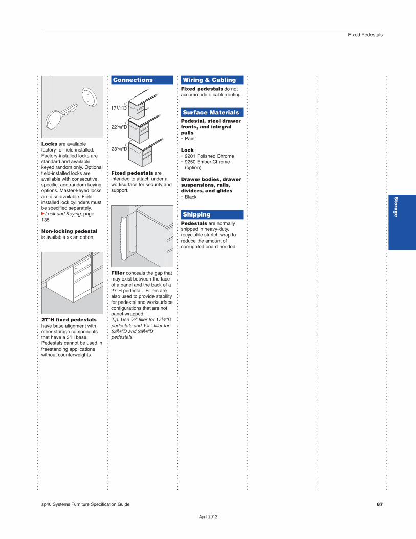
...............................................................................................................................................
...............................................................................................................................................
...............................................................................................................................................
...............................................................................................................................................
...............................................................................................................................................
...............................................................................................................................................
Connections
Fixed pedestals areintended to attach under aworksurface for security andsupport.
Filler conceals the gap thatmay exist between the faceof a panel and the back of a27"H pedestal. Fillers arealso used to provide stabilityfor pedestal and worksurfaceconfigurations that are notpanel-wrapped. Tip: Use 1⁄2" filler for 171⁄2"Dpedestals and 13⁄8" filler for225⁄8"D and 285⁄8"Dpedestals.
285/8"D
225/8"D
171/2"D
Wiring & CablingFixed pedestals do notaccommodate cable-routing.
Surface MaterialsPedestal, steel drawerfronts, and integralpulls• Paint
Lock • 9201 Polished Chrome• 9250 Ember Chrome (option)
Drawer bodies, drawersuspensions, rails,dividers, and glides• Black
ShippingPedestals are normallyshipped in heavy-duty,recyclable stretch wrap toreduce the amount ofcorrugated board needed.
Locks are availablefactory- or field-installed.Factory-installed locks arestandard and availablekeyed random only. Optionalfield-installed locks areavailable with consecutive,specific, and random keyingoptions. Master-keyed locksare also available. Field-installed lock cylinders mustbe specified separately.cLock and Keying, page135
Non-locking pedestalis available as an option.
27"H fixed pedestalshave base alignment withother storage compo nentsthat have a 3"H base.Pedestals cannot be used infreestanding applicationswithout counterweights.
3"H
ap40 Systems Furniture Specification Guide 87
Fixed Pedestals
Sto
rag
e
��������
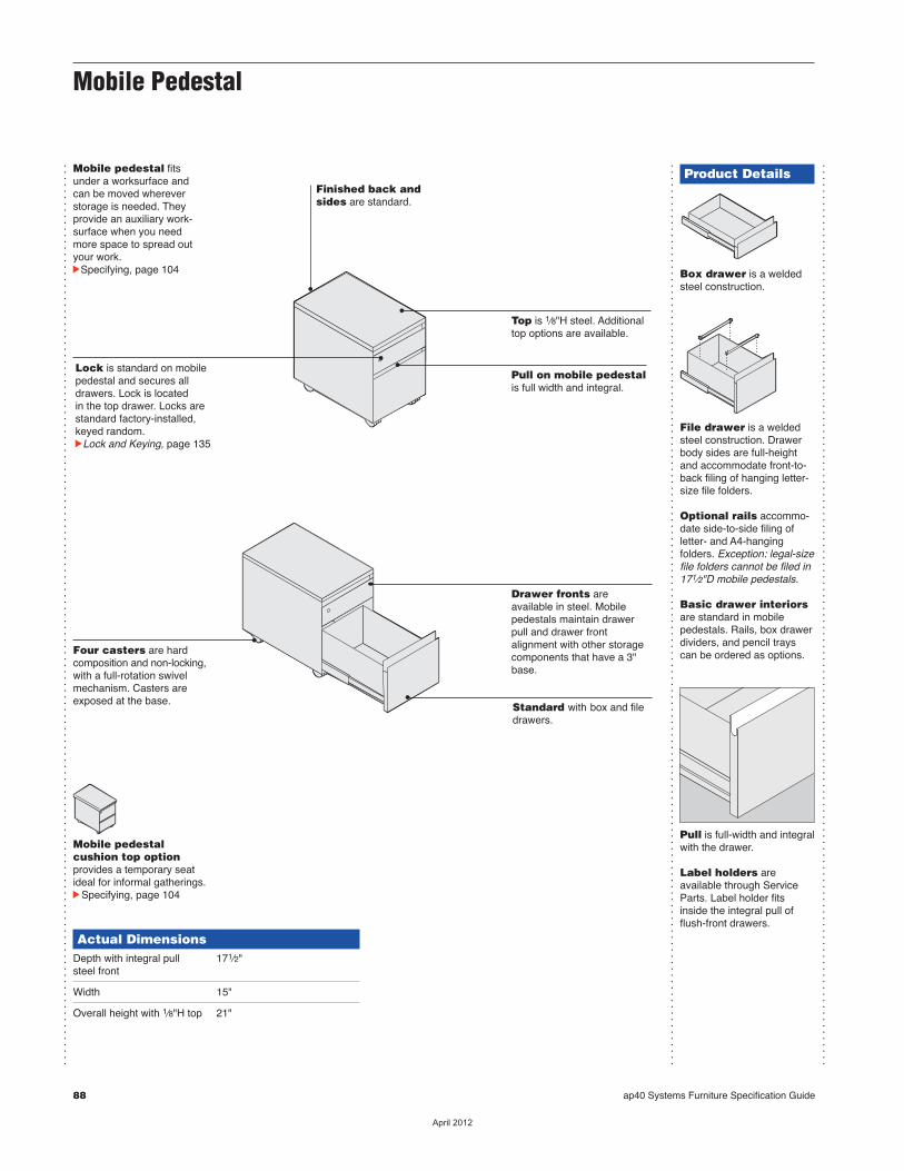
88 ap40 Systems Furniture Specification Guide
Mobile Pedestal
...............................................................................................................................................
...............................................................................................................................................
...............................................................................................................................................
Mobile pedestal fitsunder a worksurface andcan be moved whereverstorage is needed. Theyprovide an auxiliary work -surface when you needmore space to spread outyour work.cSpecifying, page 104
Actual DimensionsDepth with integral pull 171⁄2"steel front
Width 15"
Overall height with 1⁄8"H top 21"
Product Details
Box drawer is a weldedsteel construction.
File drawer is a weldedsteel construction. Drawerbody sides are full-heightand accom mo date front-to-back filing of hanging letter-size file folders.
Optional rails accommo -date side-to-side filing ofletter- and A4-hangingfolders. Exception: legal-sizefile folders cannot be filed in171⁄2"D mobile pedestals.
Basic drawer interiorsare standard in mobilepedestals. Rails, box drawerdividers, and pencil trayscan be ordered as options.
Pull is full-width and integralwith the drawer.
Label holders areavailable through ServiceParts. Label holder fitsinside the integral pull offlush-front drawers.
Standard with box and filedrawers.
Top is 1⁄8"H steel. Additionaltop options are available.
Lock is standard on mobilepedestal and secures alldrawers. Lock is located in the top drawer. Locks arestandard factory-installed,keyed random.cLock and Keying, page 135
Finished back andsides are standard.
Drawer fronts areavailable in steel. Mobilepedestals maintain drawerpull and drawer frontalignment with other storagecomponents that have a 3"base.
Four casters are hardcomposition and non-locking,with a full-rotation swivelmechanism. Casters areexposed at the base.
Mobile pedestalcushion top option provides a temporary seatideal for informal gatherings. cSpecifying, page 104
Pull on mobile pedestalis full width and integral.
��������

...............................................................................................................................................
ap40 Systems Furniture Specification Guide 89
Mobile Pedestal
...............................................................................................................................................
...............................................................................................................................................
...............................................................................................................................................
...............................................................................................................................................
...............................................................................................................................................
1"H steel and 1"Hcushion tops areavailable in place ofstandard 1⁄8"H steeltop.
Safety interlocksystem allows only onedrawer to be opened at atime for added stability.
Locks are available factory-or field-installed. Factory-installed locks are standardand available keyed randomonly. Optional field-installedlocks are available withconsecutive, specific, andrandom keying options.Master-keyed locks are alsoavailable. Field-installed lockcylinders must be specifiedseparately.cLock and Keying, page135
Counterweights areincluded to provide addedstability. All pedestals areshipped with a factory-installed counterweightpackage that meets orexceeds standards for theindustry.
Steel top1"H
Cushion top 1"H
ConnectionsMobile pedestals are notintended to directly interfacewith panels or other furniturecomponents.
Wiring & CablingMobile pedestals do notaccommodate cable routing.
Surface MaterialsMobile pedestal, steeldrawer fronts, andintegral pulls• Paint
Lock • 9201 Polished Chrome• 9250 Ember Chrome (option)
Cushion top• Upholstery
Drawer bodies, drawersuspensions, rails,dividers, and glides• Black
ShippingMobile pedestals arenormally shipped in heavy-duty, recyclable stretch wrapto reduce the amount ofcorrugated board needed.
Sto
rag
e
��������
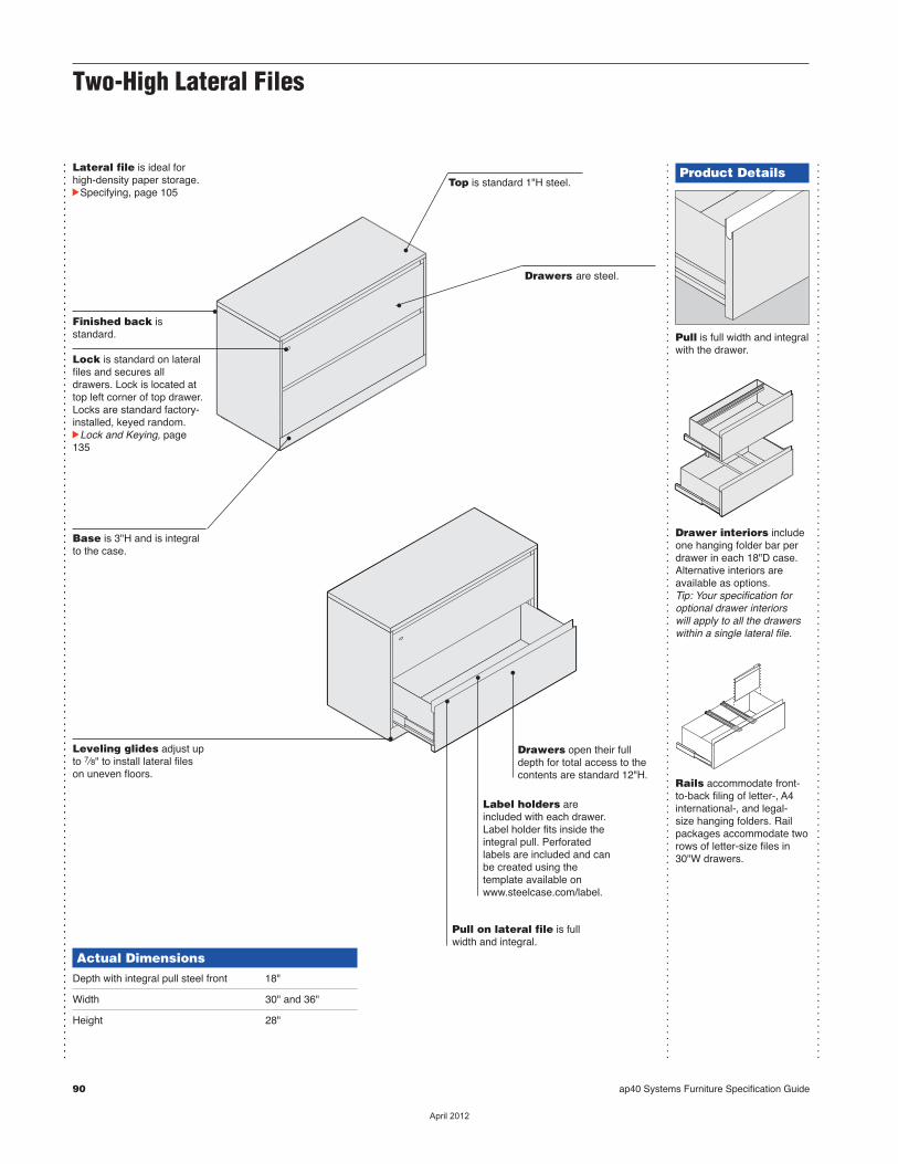
90 ap40 Systems Furniture Specification Guide
...............................................................................................................................................
...............................................................................................................................................
...............................................................................................................................................
...............................................................................................................................................
Lateral file is ideal forhigh-density paper storage.cSpecifying, page 105
Actual DimensionsDepth with integral pull steel front 18"
Width 30" and 36"
Height 28"
Finished back isstandard.
Pull on lateral file is fullwidth and integral.
Drawers open their fulldepth for total access to thecontents are standard 12"H.
Drawers are steel.
Lock is standard on lateralfiles and secures alldrawers. Lock is located attop left corner of top drawer.Locks are standard factory-installed, keyed random. cLock and Keying, page135
Label holders are included with each drawer.Label holder fits inside theintegral pull. Perforated labels are included and can be created using the template available onwww.steelcase.com/label.
Leveling glides adjust upto 7⁄8" to install lateral fileson uneven floors.
Base is 3"H and is integralto the case.
Top is standard 1"H steel.Product Details
Pull is full width and integralwith the drawer.
Drawer interiors includeone hanging folder bar perdrawer in each 18"D case.Alternative interiors areavailable as options. Tip: Your specification foroptional drawer interiors will apply to all the drawerswithin a single lateral file.
Rails accommodate front-to-back filing of letter-, A4international-, and legal-size hanging folders. Railpackages accommodate tworows of letter-size files in30"W drawers.
Two-High Lateral Files
��������

...............................................................................................................................................
...............................................................................................................................................
...............................................................................................................................................
...............................................................................................................................................
...............................................................................................................................................
...............................................................................................................................................
ap40 Systems Furniture Specification Guide 91
Two-High Lateral Files
Dividers accommodateside-to-side filing of expand -able folders and otherobjects. Divider packagesinclude three dividers andone hanging folder bar perdrawer and are specified asan option.
Safety interlocksystem allows only onedrawer to be opened at atime.
Locks are availablefactory- or field-installed.Factory-installed locks arestandard and availablekeyed random only. Optionalfield-installed locks areavailable with consecutive,specific, and random keyingoptions. Master-keyed locksare also available. Field-installed lock cylinders mustbe specified separately.cLock and Keying, page135
Counterweight pack -ages must be specified asan option for lateral filesthat are not ganged toanother case, attached toa worksurface, or bolted tothe floor or wall.
Connections
Ganging hardware isincluded to increase stabilityand maintain alignment byjoining adjacent componentsside by side, back to back,or both. Lateral files can alsobe bolted to the floor, orattached to a worksurface orwall for stability.
Surface MaterialsLateral file, includingsteel top, drawerfronts, and integralpulls• Paint
Lock • 9201 Polished Chrome• 9250 Ember Chrome (option)
Drawer bodies,hanging folder bars,rails, and dividers• Black
ShippingLateral files are normallyshipped in heavy-duty,recyclable stretch wrap toreduce the amount ofcorrugated board needed.
Counterweightpackages ship separatelyfrom case and must be field-installed.
Sto
rag
e
��������
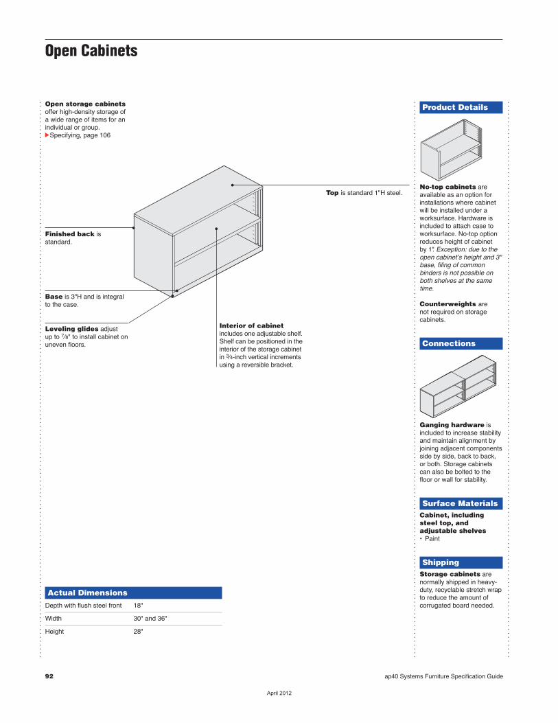
92 ap40 Systems Furniture Specification Guide
Product Details
No-top cabinets areavailable as an option forinstallations where cabinetwill be installed under awork sur face. Hardware isincluded to attach case toworksurface. No-top optionreduces height of cabinetby 1". Exception: due to theopen cabinetʼs height and 3"base, filing of commonbinders is not possible onboth shelves at the sametime.
Counterweights arenot required on storagecabinets.
Connections
Ganging hardware isincluded to increase stabilityand maintain alignment byjoining adjacent componentsside by side, back to back,or both. Storage cabinetscan also be bolted to thefloor or wall for stability.
Surface MaterialsCabinet, includingsteel top, andadjustable shelves• Paint
ShippingStorage cabinets arenormally shipped in heavy-duty, recyclable stretch wrapto reduce the amount ofcorrugated board needed.
...............................................................................................................................................
...............................................................................................................................................
...............................................................................................................................................
Open storage cabinetsoffer high-density storage ofa wide range of items for anindividual or group.cSpecifying, page 106
Actual DimensionsDepth with flush steel front 18"
Width 30" and 36"
Height 28"
Finished back isstandard.
Base is 3"H and is integralto the case.
Leveling glides adjust up to 7⁄8" to install cabinet onuneven floors.
Top is standard 1"H steel.
Interior of cabinetincludes one adjustable shelf.Shelf can be positioned in theinterior of the storage cabinetin 3⁄4-inch vertical incrementsusing a reversible bracket.
Open Cabinets
��������

ap40 Systems Furniture Specification Guide 93
Open Cabinets
Sto
rag
e
��������
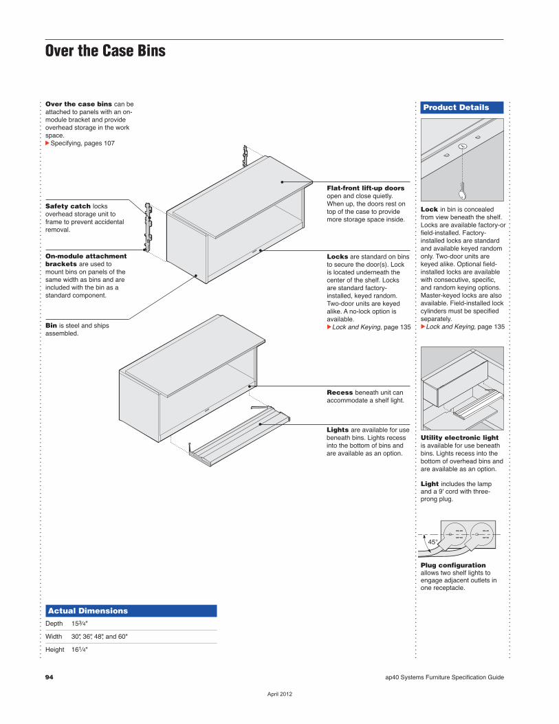
94 ap40 Systems Furniture Specification Guide
Over the Case Bins
Product Details
Lock in bin is concealedfrom view beneath the shelf.Locks are available factory-orfield-installed. Factory-installed locks are standardand available keyed randomonly. Two-door units arekeyed alike. Optional field-installed locks are availablewith consecutive, specific,and random keying options.Master-keyed locks are alsoavailable. Field-installed lockcylinders must be specifiedseparately.cLock and Keying, page 135
Utility electronic lightis available for use beneathbins. Lights recess into thebottom of overhead bins andare available as an option.
Light includes the lampand a 9' cord with three-prong plug.
Plug configurationallows two shelf lights toengage adjacent outlets inone receptacle.
45°
...............................................................................................................................................
...............................................................................................................................................
Actual DimensionsDepth 153⁄4"
Width 30", 36", 48", and 60"
Height 161⁄4"
Over the case bins can beattached to panels with an on-module bracket and provideoverhead storage in the workspace.cSpecifying, pages 107
Flat-front lift-up doorsopen and close quietly.When up, the doors rest ontop of the case to providemore storage space inside.
Recess beneath unit canaccommodate a shelf light.
Locks are standard on binsto secure the door(s). Lockis located underneath thecenter of the shelf. Locksare standard factory-installed, keyed random.Two-door units are keyedalike. A no-lock option isavailable.cLock and Keying, page 135
...............................................................................................................................................
Safety catch locksoverhead storage unit toframe to prevent accidentalremoval.
On-module attachmentbrackets are used tomount bins on panels of thesame width as bins and areincluded with the bin as astandard component.
Bin is steel and shipsassembled.
Lights are available for usebeneath bins. Lights recessinto the bottom of bins andare available as an option.
��������
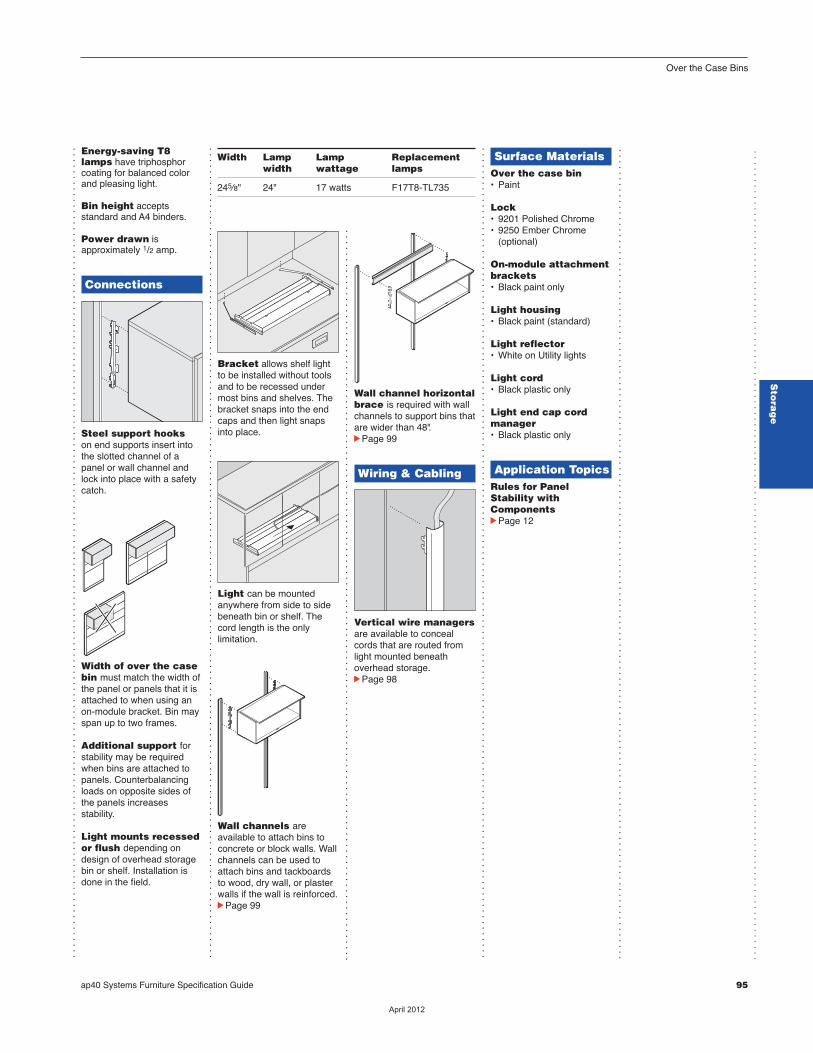
ap40 Systems Furniture Specification Guide 95
Wall channel horizontalbrace is required with wallchannels to support bins thatare wider than 48".cPage 99
Wiring & Cabling
Vertical wire managersare available to concealcords that are routed fromlight mounted beneath overhead storage.cPage 98
Bracket allows shelf lightto be installed without toolsand to be recessed undermost bins and shelves. Thebracket snaps into the endcaps and then light snapsinto place.
Light can be mountedanywhere from side to sidebeneath bin or shelf. Thecord length is the onlylimitation.
Wall channels areavailable to attach bins toconcrete or block walls. Wallchannels can be used toattach bins and tackboardsto wood, dry wall, or plasterwalls if the wall is reinforced.cPage 99
Energy-saving T8lamps have triphosphorcoating for balanced colorand pleasing light.
Bin height acceptsstandard and A4 binders.
Power drawn isapproximately 1/2 amp.
Connections
Steel support hooks on end supports insert intothe slotted channel of apanel or wall channel andlock into place with a safetycatch.
Width of over the casebin must match the width ofthe panel or panels that it isattached to when using anon-module bracket. Bin mayspan up to two frames.
Additional support forstability may be requiredwhen bins are attached topanels. Counterbalancingloads on opposite sides ofthe panels increasesstability.
Light mounts recessedor flush depending ondesign of overhead storagebin or shelf. Installation isdone in the field.
Surface MaterialsOver the case bin• Paint
Lock• 9201 Polished Chrome• 9250 Ember Chrome (optional)
On-module attachmentbrackets• Black paint only
Light housing• Black paint (standard)
Light reflector• White on Utility lights
Light cord• Black plastic only
Light end cap cordmanager• Black plastic only
Application TopicsRules for PanelStability withComponentscPage 12
.
.
.
.
.
.
.
.
.
.
.
.
.
.
.
.
.
.
.
.
.
.
.
.
.
.
.
.
.
.
.
.
.
.
.
.
.
.
.
.
.
.
.
.
.
.
.
.
.
.
.
.
.
.
.
.
.
.
.
.
.
.
.
.
.
.
.
.
.
.
.
.
.
.
.
.
.
.
.
.
.
.
.
.
.
.
.
.
.
.
.
.
.
.
.
.
.
.
.
.
.
.
.
.
.
.
.
.
.
.
.
.
.
.
.
.
.
.
.
.
.
.
.
.
.
.
.
.
.
.
.
.
.
.
.
.
.
.
.
.
.
.
.
...............................................................................................................................................
...............................................................................................................................................
...............................................................................................................................................
...............................................................................................................................................
Over the Case Bins
Sto
rag
e
Width Lamp Lamp Replacement width wattage lamps
245⁄8" 24" 17 watts F17T8-TL735
.................................................................................................................................
��������
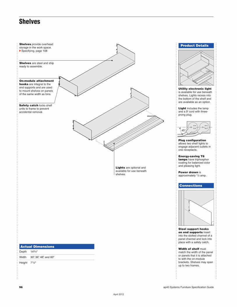
96 ap40 Systems Furniture Specification Guide
Shelves
...............................................................................................................................................
Shelves provide overheadstorage in the work space.cSpecifying, page 108
Actual DimensionsDepth 143/4"
Width 30", 36", 48", and 60"
Height 71/2"
Safety catch locks shelfunits to frame to preventaccidental removal.
On-module attachmenthooks are integral to theend supports and are usedto mount shelves on panelsof the same width as bins.
Product Details
Utility electronic lightis available for use beneathshelves. Lights recess intothe bottom of the shelf andare available as an option.
Light includes the lampand a 9' cord with three-prong plug.
Plug configurationallows two shelf lights toengage adjacent outlets inone receptacle.
Energy-saving T8lamps have triphosphorcoating for balanced colorand pleasing light.
Power drawn isapproximately 1/2 amp.
Connections
Steel support hooks on end supports insertinto the slotted channel of apanel channel and lock intoplace with a safety catch.
Width of shelf mustmatch the width of the panelor panels that it is attachedto with the on-modulebrackets. Shelves may spanup to two frames.
45°
...............................................................................................................................................
...............................................................................................................................................
Shelves are steel and shipready to assemble.
Lights are optional andavailable for use beneathshelves.
��������
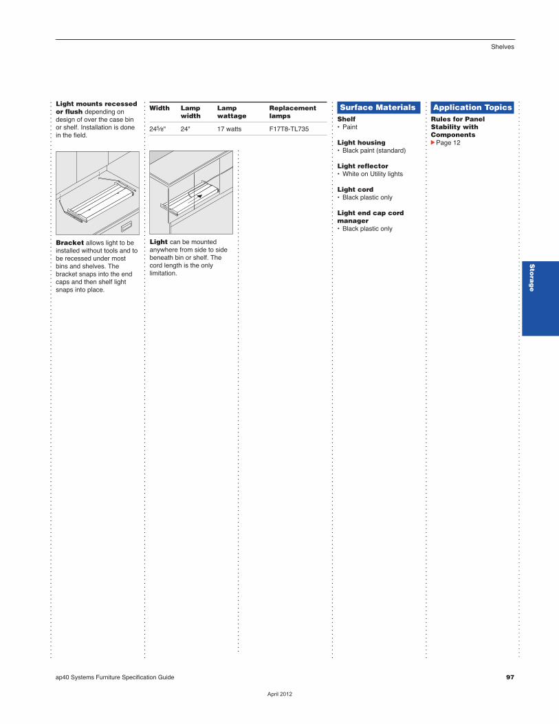
ap40 Systems Furniture Specification Guide 97
Shelves
Sto
rag
e
Light can be mountedanywhere from side to sidebeneath bin or shelf. Thecord length is the onlylimitation.
Light mounts recessedor flush depending ondesign of over the case binor shelf. Installation is donein the field.
Bracket allows light to beinstalled without tools and tobe recessed under mostbins and shelves. Thebracket snaps into the endcaps and then shelf lightsnaps into place.
Surface MaterialsShelf• Paint
Light housing• Black paint (standard)
Light reflector• White on Utility lights
Light cord• Black plastic only
Light end cap cordmanager• Black plastic only
Application TopicsRules for PanelStability withComponentscPage 12
.
.
.
.
.
.
.
.
.
.
.
.
.
.
.
.
.
.
.
.
.
.
.
.
.
.
.
.
.
.
.
.
.
.
.
.
.
.
.
.
.
.
.
.
.
.
.
.
.
.
.
.
.
.
.
.
.
.
.
.
.
.
.
.
.
.
.
.
.
.
.
.
.
.
.
.
.
.
.
.
.
.
.
.
.
.
.
.
.
.
.
.
.
.
.
.
.
.
.
.
.
.
.
.
.
.
.
.
.
.
.
.
.
.
.
.
.
.
.
.
.
.
.
.
.
.
.
.
.
.
.
.
.
.
.
.
.
.
.
.
.
.
.
...............................................................................................................................................
...............................................................................................................................................
...............................................................................................................................................
...............................................................................................................................................
.................................................................................................................................
Width Lamp Lamp Replacement width wattage lamps
245⁄8" 24" 17 watts F17T8-TL735
��������

Product Details
Cap finishes top edge whenwire manager extends to thetop cap of the panel. Cap isincluded.
48"H plastic wiremanager can be cut tomeet special requirements.
98 ap40 Systems Furniture Specification Guide
...............................................................................................................................................
...............................................................................................................................................
...............................................................................................................................................
...............................................................................................................................................
Plastic vertical wiremanager conceal cords,cables, and light harnessesthat are routed along theedge of panels. cSpecifying, page 109
ConnectionsHooks attach the verticalwire manager to the slottedchannel on a panel. Positionof hooks can be adjusted inthe field. 48"H vertical wiremanager ships with fourhooks.
Surface MaterialsVertical wire manager• Plastic (48"H only)
Cap• Black plastic only
Application Topics48"H plastic versioncan be cut to length.
Plastic Vertical Wire Manager
...............................................................................................................................................
��������

ap40 Systems Furniture Specification Guide 99
Storage AccessoriesWall ChannelsFor Use with ap40 Over the Case Bins, Shelves, and Tackboards
...............................................................................................................................................
...............................................................................................................................................
...................................................................................................
Surface MaterialsWall channel• Paint
Wall channel horizontalbrace• PaintTip: Horizontal brace will bevisible until hidden by contentsof shelf or storage bin.
...............................................................................................................................................
Wall hang channels forshelves, overhead storagebins, or tackboards cannotbe used with a wall startjunction.
Worksurfaces may beattached to wall channelswith cantilevers, subject tothe following applicationguidelines:• All worksurfaces must be 24"D or less.• Worksurfaces must be supported by a cantilever or legs every 42" or 48". Cantilevers can be shared when worksurfaces are adjacent.• Wall channel horizontal braces must be installed directly behind all wall- mounted worksurfaces, and also at the top of the wall channels.• Worksurface-supported pedestals cannot be hung from a wall-mounted worksurface.
...............................................................................................................................................
Limit to two panel-supported components foreach pair of wall channels.
Wall channel horizontalbrace is required toreinforce vertical wallchannels that supportstorage bins and shelvesthat are wider than 48"and are attached to walls.
Wall channelhorizontal brace isrequired for eachcomponent that is widerthan 48". The brace shouldbe positioned at the toplocation of each bin or shelfof the vertical wall channel.
Width of horizontalbrace must match width ofshelf of storage bin. Brace isnot required for applicationsthat involve shelves and binsthat are 48"W or less.
..................................................................................................................................
Product Details
Wall channel can bepositioned on wall at varyingheights.
Order wall channel heightaccording to its intendeduse. Cutting wall channels isnot recommended.
ConnectionsWall channels can beused to support shelves,storage bins, andtackboards.
Field install on:• Concrete walls: Hilti type anchors• Drywall or plywood: 5⁄8" thick, Toggler type 3⁄16" wall anchor• Steel and wood studs: #10 sheet metal or wood screws of appropriate lengthAnchors must be used oneach screw hole location ofthe wall channel.
Components attach at1" increments, but screwsblock some slot locations.
screw position
Slotted steel channelaccepts shelves, over thecase bins, or tackboards.cSpecifying, page 109
Actual DimensionsDepth 13⁄16"
Width 13⁄16"
Height 53" and 65"
Application TopicsReinforce wall bypositioning studs where wallchannels will be attached.See dimensions below.
Tip: Wall channels can be shared.
Distance between center lines of reinforced wall channels matcheswidth of overhead storage unit.
Top view
Storage Accessories
Sto
rag
e
��������

100 ap40 Systems Furniture Specification Guide
��������
SpecifyingStorage
Sto
rag
e
Pedestals
Fixed Pedestals 102
Pedestal Fillers 103
Mobile Pedestal 104
Two-High Lateral Files 105
Open Cabinets 106
Over the Case Bins 107
Shelves 108
Storage Accessories 109
ap40 Systems Furniture Specification Guide 101
��������

Fixed Pedestals G4/13
102 ap40 Systems Furniture Specification Guide
Standard Includes Required to SpecifycNeed help?
Product details,page 86
• Pedestal: paint • Drawer fronts with integral pulls: paint to match pedestal • Drawer interiors: black only• Lock, keyed random: 9201 Polished Chrome• Mounting hardware• Four adjustable leveling glides
Options U.S. Price Required to Specify Drawer Rails Accessories • Two side-to-side hanging +$ 26 Specify with rails. rails per file drawer
Drawer 171/2"D shelf/box/file, 225/8"D file/file, and 285/8"D box/box/file pedestals Interiors • Pencil tray and box +$ 43 Specify with pencil tray and box drawer drawer dividers dividers.
Counter- • Package +$130 Specify with counterweight. weights
Lock and Lock Keying • Ember Chrome No cost Specify with 9250 Ember Chrome lock. • No lock –$ 58 Specify with no lock.
Keying • Factory- and field-installed keying cPage 134
Related • Storage accessories cPage 109 Products
Specification Information
DDimensions DStyle DU.S. dD W H dNumber dBase d d dPriced d d
27"H Fixed Pedestals with 3" BaseTwo Shelves and One File Drawer
171⁄2" 15" 27" TKPF1827SSF G4/13 $530
One Shelf, One Box, and One File Drawer
171⁄2" 15" 27" TKPF1827SBF G4/13 $530
One Shelf and One File Drawer
171⁄2" 15" 27" TKPF1827SF G4/13 $530
Two Box and One File Drawers
225⁄8" 15" 27" TKPF2427BBF G4/13 $577
285⁄8" 15" 27" TKPF3027BBF G4/13 $702
Two File Drawers
225⁄8" 15" 27" TKPF2427FF G4/13 $577
285⁄8" 15" 27" TKPF3027FF G4/13 $702 d d d
1 Style number 2 Paint color number for pedestal 3 Options, if selected (see below)cSee Surface Materials, page 129.
Tip: Legal size file folderscannot be filed in 171⁄2"D or225⁄8"D pedestals.
G4/13 = Last order entryApril 14, 2013
��������
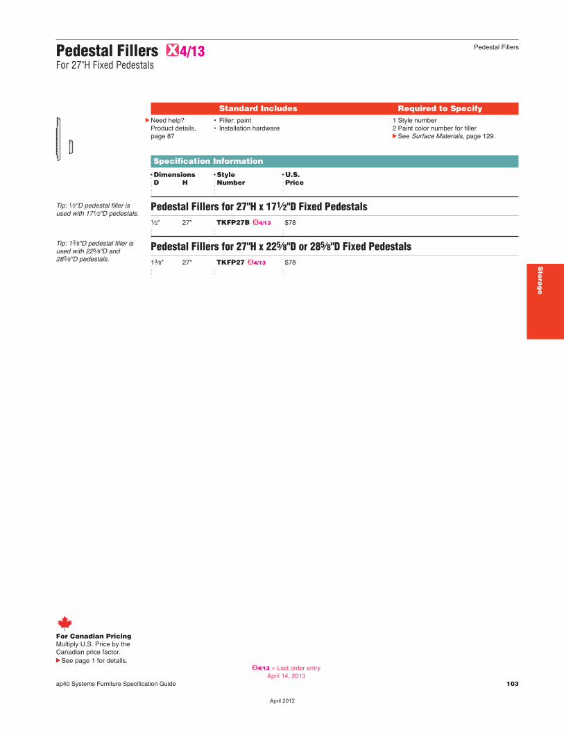
ap40 Systems Furniture Specification Guide 103
Pedestal Fillers G4/13For 27"H Fixed Pedestals
Standard Includes Required to SpecifycNeed help?
Product details,page 87
• Filler: paint • Installation hardware
1 Style number2 Paint color number for fillercSee Surface Materials, page 129.
Specification Information
DDimensions DStyle DU.S. dD H dNumber dPrice d d d
Pedestal Fillers for 27"H x 171⁄2"D Fixed Pedestals1⁄2" 27" TKFP27B G4/13 $78 d d d
Pedestal Fillers for 27"H x 225⁄8"D or 285⁄8"D Fixed Pedestals13⁄8" 27" TKFP27 G4/13 $78 d d d
Tip: 1⁄2"D pedestal filler isused with 171⁄2"D pedestals.
Tip: 13⁄8"D pedestal filler isused with 225⁄8"D and285⁄8"D pedestals.
For Canadian PricingMultiply U.S. Price by the Canadian price factor.
See page 1 for details.
Pedestal Fillers
Sto
rag
e
G4/13 = Last order entryApril 14, 2013
��������
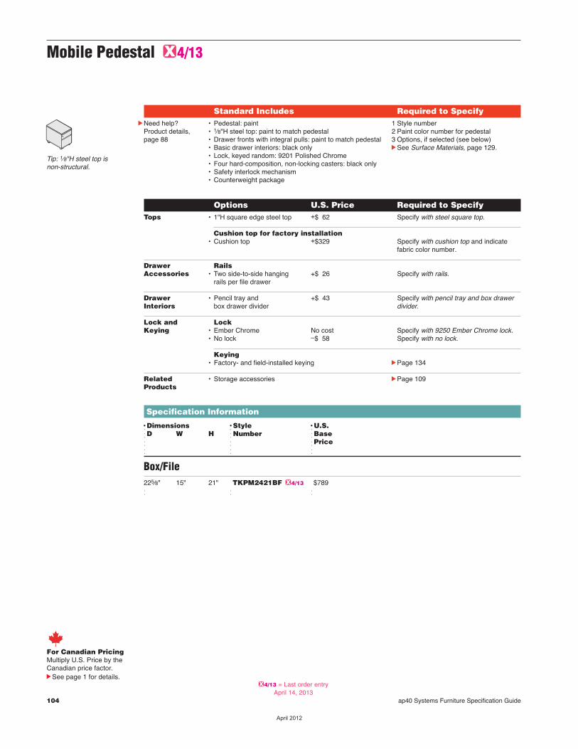
104 ap40 Systems Furniture Specification Guide
Mobile Pedestal G4/13
Standard Includes Required to SpecifycNeed help?
Product details,page 88
• Pedestal: paint • 1⁄8"H steel top: paint to match pedestal• Drawer fronts with integral pulls: paint to match pedestal• Basic drawer interiors: black only• Lock, keyed random: 9201 Polished Chrome• Four hard-composition, non-locking casters: black only• Safety interlock mechanism• Counterweight package
Options U.S. Price Required to Specify Tops • 1"H square edge steel top +$ 62 Specify with steel square top.
Cushion top for factory installation • Cushion top +$329 Specify with cushion top and indicate fabric color number.
Drawer Rails Accessories • Two side-to-side hanging +$ 26 Specify with rails. rails per file drawer
Drawer • Pencil tray and +$ 43 Specify with pencil tray and box drawer Interiors box drawer divider divider.
Lock and Lock Keying • Ember Chrome No cost Specify with 9250 Ember Chrome lock. • No lock –$ 58 Specify with no lock.
Keying • Factory- and field-installed keying cPage 134
Related • Storage accessories cPage 109 Products
Specification Information
DDimensions DStyle DU.S. dD W H dNumber dBase d d dPriced d d
Box/File225⁄8" 15" 21" TKPM2421BF G4/13 $789 d d d
1 Style number2 Paint color number for pedestal3 Options, if selected (see below)cSee Surface Materials, page 129.
Tip: 1⁄8"H steel top is non-structural.
For Canadian PricingMultiply U.S. Price by the Canadian price factor.
See page 1 for details.G4/13 = Last order entry
April 14, 2013
��������
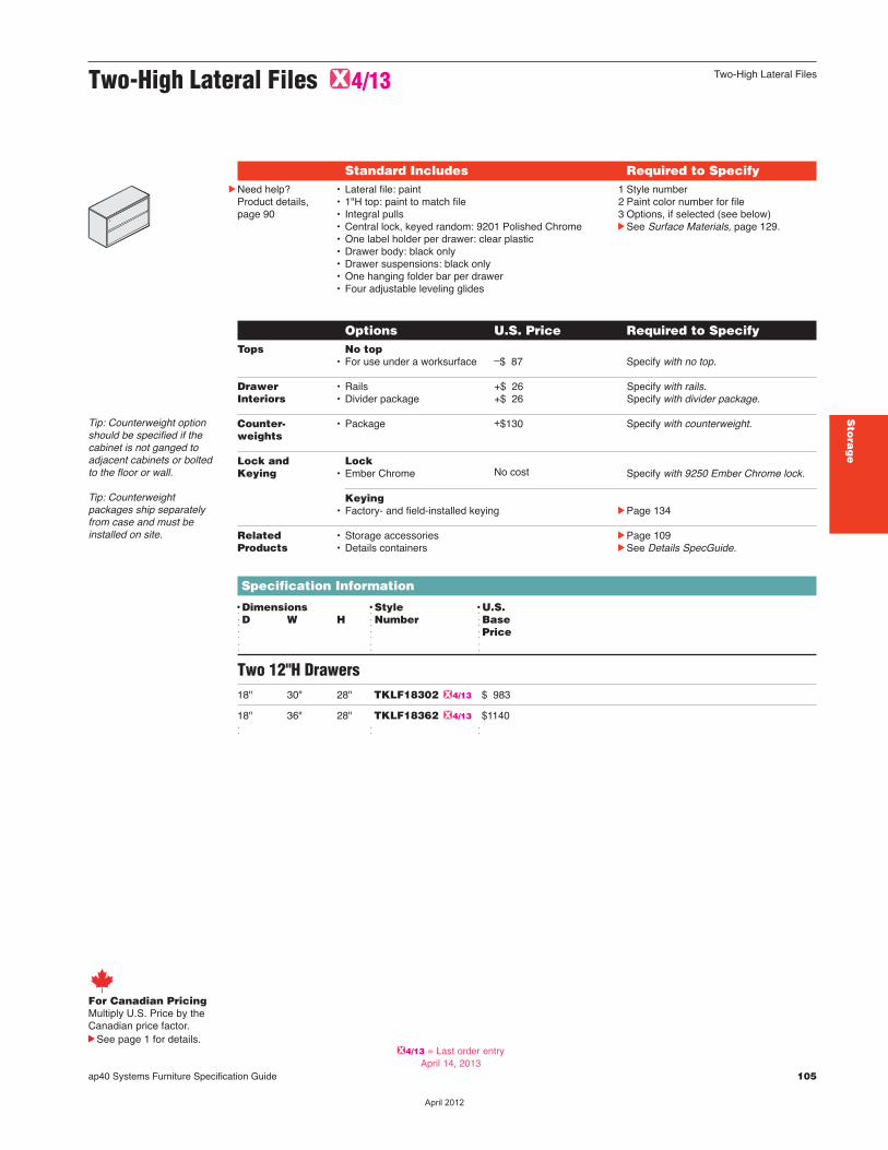
ap40 Systems Furniture Specification Guide 105
Two-High Lateral Files G4/13
Tip: Counterweight optionshould be specified if thecabinet is not ganged toadjacent cabinets or boltedto the floor or wall.
Tip: Counterweightpackages ship separatelyfrom case and must beinstalled on site.
Standard Includes Required to SpecifycNeed help?
Product details,page 90
• Lateral file: paint• 1"H top: paint to match file• Integral pulls • Central lock, keyed random: 9201 Polished Chrome• One label holder per drawer: clear plastic• Drawer body: black only• Drawer suspensions: black only• One hanging folder bar per drawer • Four adjustable leveling glides
1 Style number 2 Paint color number for file3 Options, if selected (see below)cSee Surface Materials, page 129.
Options U.S. Price Required to Specify Tops No top • For use under a worksurface –$ 87 Specify with no top.
Drawer • Rails +$ 26 Specify with rails. Interiors • Divider package +$ 26 Specify with divider package.
Counter- • Package +$130 Specify with counterweight. weights
Lock and Lock Keying • Ember Chrome No cost Specify with 9250 Ember Chrome lock.
Keying • Factory- and field-installed keying cPage 134
Related • Storage accessories cPage 109 Products • Details containers cSee Details SpecGuide.
Specification Information
DDimensions DStyle DU.S. dD W H dNumber dBase d d dPriced d d
Two 12"H Drawers18" 30" 28" TKLF18302 G4/13 $ 983
18" 36" 28" TKLF18362 G4/13 $1140 d d d
For Canadian PricingMultiply U.S. Price by the Canadian price factor.
See page 1 for details.
Two-High Lateral Files
Sto
rag
e
G4/13 = Last order entryApril 14, 2013
��������
106 ap40 Systems Furniture Specification Guide
For Canadian PricingMultiply U.S. Price by the Canadian price factor.
See page 1 for details.
Open Cabinets G4/13
Standard Includes Required to SpecifycNeed help?
Product details,page 92
• Storage cabinet: paint• 1"H top: paint to match cabinet• Adjustable shelf: paint to match cabinet• Brackets for adjustable shelves: black• Four adjustable leveling glides
1 Style number 2 Paint color number for cabinet3 Options, if selected (see below)cSee Surface Materials, page 129.
Options U.S. Price Required to Specify Tops No top • For use under a worksurface –$87 Specify with no top.
Related • Storage accessories cPage 109 Products • Details containers cSee Details SpecGuide.
Specification Information
DDimensions DStyle DU.S. dD W H dNumber dBase d d dPriced d d
18" 30" 28" TKCAB18302 G4/13 $888
18" 36" 28" TKCAB18362 G4/13 $966 d d d
G4/13 = Last order entryApril 14, 2013
��������
ap40 Systems Furniture Specification Guide 107
Over the Case Bins G4/13
Standard Includes Required to Specify• Over the case bin with lift-up door: paint• Recess beneath unit to accommodate shelf light• On-module attachment brackets with safety catch:
black paint only• Lock, keyed random: 9201 Polished Chrome
Options U.S. Price Required to Specify Shelf Lights • Utility with electronic ballast, 25" +$307 Specify with 25" light. • Utility with electronic ballast, 25" +$380 Specify with 25" Chicago light.
Lock and Lock Keying • No lock –$ 58 per door Specify with no lock. • Ember Chrome No cost Specify with 9250 Ember Chrome lock.
Keying • Factory- and field-installed keying cPage 134
Related • Storage accessories cPage 109 Products
Specification Information
DDimensions DNumber DStyle DU.S.dD W H dof Doors dNumber dBased d d dPrice d d d d
153⁄4" 30" 161⁄4" 1 TKBB30 G4/13 $ 582
153⁄4" 36" 161⁄4" 1 TKBB36 G4/13 $ 588
153⁄4" 48" 161⁄4" 1 TKBB48 G4/13 $ 595
153⁄4" 60" 161⁄4" 2 TKBB60 G4/13 $1047 d d d d
1 Style number2 Paint color number for bin3 Options, if selected (see below)cSee Surface Materials, page 129.
cNeed help?Product details,page 94
Tip: 60"W over the case binshave two doors and requiretwo locks, if selected.
For Canadian PricingMultiply U.S. Price by the Canadian price factor.
See page 1 for details.
Over the Case Bins
Sto
rag
e
G4/13 = Last order entryApril 14, 2013
��������

108 ap40 Systems Furniture Specification Guide
Shelves G4/13
Standard Includes Required to SpecifycNeed help?
Product details,page 96
• Shelf: paint• Recess beneath unit to accommodate shelf light• On-module attachment hooks with safety catch
Options U.S. Price Required to Specify Shelf Lights • Utility with electronic ballast, 25" +$307 Specify with 25" light. • Utility with electronic ballast, 25" +$380 Specify with 25" Chicago light.
Related • Storage accessories cPage 109 Products
Specification Information
DDimensions DStyle DU.S. dD W H dNumber dBase d d dPrice d d d
143⁄4" 30" 71⁄2" TKSH30 G4/13 $187
143⁄4" 36" 71⁄2" TKSH36 G4/13 $201
143⁄4" 48" 71⁄2" TKSH48 G4/13 $232
143⁄4" 60" 71⁄2" TKSH60 G4/13 $258 d d d d
1 Style number2 Paint color number for shelf3 Options, if selected (see below)cSee Surface Materials, page 129.
For Canadian PricingMultiply U.S. Price by the Canadian price factor.
See page 1 for details.G4/13 = Last order entry
April 14, 2013
��������
ap40 Systems Furniture Specification Guide cStorage Accessories, continued 109
Sto
rag
e
Storage Accessories G4/13
Storage Accessories
Bookends G4/13
Standard Includes Required to Specify• Package of two or twenty bookends: 6695 Midnight only Style number
Specification Information
DStyle DQuantity DU.S.dNumber d dPriced d d
TKDIV02 G4/13 2 $ 33
TKDIV20 G4/13 20 $316 d d d
Attachment Cable G4/13
Standard Includes Required to Specify• Attachment cable• Package of 1 or 25
Style number
Specification Information
DStyle DQuantity DU.S.dNumber d dPriced d d
TKPCAB1 G4/13 1 $ 17
TKPCAB25 G4/13 25 $345 d d d
Tip: For use withunderworksurface lateralfiles and pedestals.
Plastic Vertical Wire Manager G4/13
Specification Information
DHeight DWith DStyle DU.S.d dCap dNumber dPriced d d d
48" Yes TKVWM G4/13 $46 d d d d
Standard Includes Required to Specify• Vertical wire manager: black plastic• Cap for use when connecting with panel top cap,
on applicable models: black plastic only
Style number
For Canadian PricingMultiply U.S. Price by the Canadian price factor.
See page 1 for details.G4/13 = Last order entry
April 14, 2013
��������
110 ap40 Systems Furniture Specification Guide
Wall Channel Horizontal Braces G4/13For Use with Overhead Storage Products
Standard Includes Required to SpecifycNeed help?
Product details,page 99
• Horizontal brace: all paint price groups 1 Style number 2 Paint color number for bracecSee Surface Materials, page 129.
Specification Information
DWidth DStyle DU.S.d dNumber dPriced d d
48" TKWCHB48 G4/13 $96
60" TKWCHB60 G4/13 $96 d d d
Wall Channels G4/13For Use with ap40 Over the Case Bins, Shelves, and Tackboards
Standard Includes Required to SpecifycNeed help?
Product details,page 99
• Two wall channels: all paint price groups 1 Style number2 Paint color number for channelscSee Surface Materials, page 129.
Related Products • Tackboards cPage 50 • Over the Case Bins cPage 107 • Shelves cPage 108
Specification Information
DHeight DStyle DU.S.d dNumber dPriced d d
53" TKWC53 G4/13 $98
65" TKWC65 G4/13 $98 d d d
Tip: Horizontal brace isrequired for wall channelapplication supportingcomponents that are up to60"W.
For Canadian PricingMultiply U.S. Price by the Canadian price factor.
See page 1 for details.
Storage Accessories, continued
G4/13 = Last order entryApril 14, 2013
��������
ap40 Systems Furniture Specification Guide 111
Seating S
ea
ting
Statement of Line 112
Specifying 113
��������
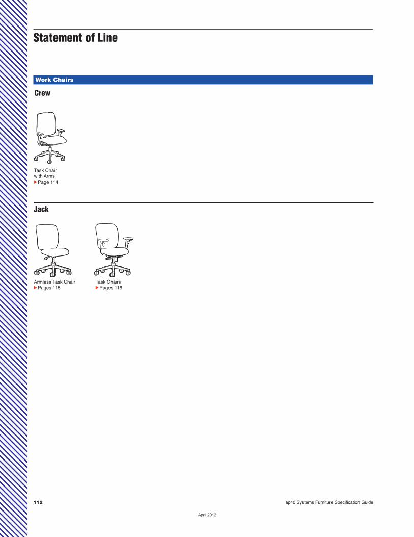
112 ap40 Systems Furniture Specification Guide
Statement of Line
Work Chairs
Crew
Task Chairwith ArmscPage 114
Jack
Armless Task ChaircPages 115
Task ChairscPages 116
��������
ap40 Systems Furniture Specification Guide 113
Se
atin
g
Specifying Seating
Crew 114
Jack Task Chair with Swivel-Only Mechanism 115
Jack Task Chair with Synchro-Tilt Mechanism 116
��������
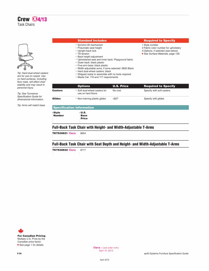
114 ap40 Systems Furniture Specification Guide
Standard Includes Required to Specify• Synchro-tilt mechanism• Pneumatic seat height• Upright back lock• Tilt tension• Back height adjustment• Upholstered seat and inner back: Playground fabric• Outer back: black plastic• Five-arm base: black plastic• Width-adjustable arms, if arms selected: 0835 Black• Hard dual-wheel casters: black• Shipped ready to assemble with no tools required• Meets Cal. 116 and 117 requirements
1 Style number2 Fabric color number for upholstery3 Options, if selected (see below)cSee Surface Materials, page 129.
Options U.S. Price Required to Specify Casters • Soft dual-wheel casters for No cost Specify with soft casters. use on hard floors
Glides • Non-marring plastic glides +$27 Specify with glides.
Specification Information
DStyle DU.S.dNumber dBased dPriced d
Full-Back Task Chair with Height- and Width-Adjustable T-ArmsTKTS30821 G4/13 $654 d d
Full-Back Task Chair with Seat Depth and Height- and Width-Adjustable T-ArmsTKTS30822 G4/13 $717 d d
Tip: Hard dual-wheel castersare for use on carpet. Useon hard surfaces, includingfloor mats, will affect chairstability and may result inpersonal injury.
Tip: See TurnstoneSpecification Guide fordimensional information.
Tip: Arms will match base.
Crew G4/13Task Chairs
For Canadian PricingMultiply U.S. Price by the Canadian price factor.
See page 1 for details.G4/13 = Last order entry
April 14, 2013
��������

ap40 Systems Furniture Specification Guide 115
Se
atin
g
Jack Task Chair
For Canadian PricingMultiply U.S. Price by the Canadian price factor.
See page 1 for details.
Standard Includes Required to Specify• Swivel-only mechanism• Pneumatic seat height• Armless• Upholstered seat and inner back: Playground fabric• Outer back: black plastic• Five arm base: reinforced black plastic• Hard dual-wheel casters: black• Shipped ready to assemble• Meets Cal. 116 and 117 requirements
1 Style number2 Fabric color number for upholstery3 Options, if selected (see below)cSee Surface Materials, page 129.
Options U.S. Price Required to Specify Casters • Soft dual-wheel casters for No cost Specify with soft casters. use on hard floors
Glides • Non-marring plastic glides +$27 Specify with glides.
Specification Information
DStyle DU.S.dNumber dBased dPriced d
Armless Full-Back Task ChairTKTS30301 G4/13 $276 d d
Tip: Hard dual-wheel castersare for use on carpet. Useon hard surfaces, includingfloor mats, will affect chairstability and may result inpersonal injury.
Jack Task Chair with Swivel-Only Mechanism G4/13
G4/13 = Last order entryApril 14, 2013
��������
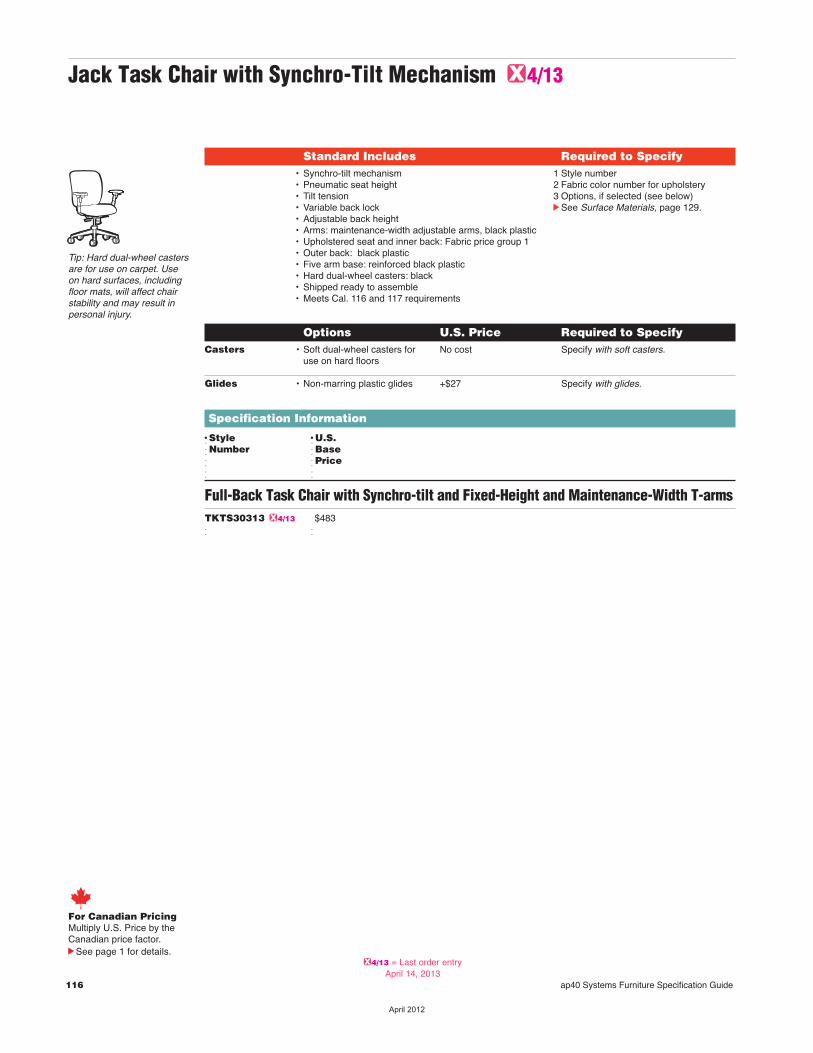
116 ap40 Systems Furniture Specification Guide
Jack Task Chair with Synchro-Tilt Mechanism G4/13
Standard Includes Required to Specify• Synchro-tilt mechanism• Pneumatic seat height• Tilt tension• Variable back lock• Adjustable back height• Arms: maintenance-width adjustable arms, black plastic• Upholstered seat and inner back: Fabric price group 1• Outer back: black plastic• Five arm base: reinforced black plastic• Hard dual-wheel casters: black• Shipped ready to assemble• Meets Cal. 116 and 117 requirements
1 Style number2 Fabric color number for upholstery3 Options, if selected (see below)cSee Surface Materials, page 129.
Options U.S. Price Required to Specify Casters • Soft dual-wheel casters for No cost Specify with soft casters. use on hard floors
Glides • Non-marring plastic glides +$27 Specify with glides.
Specification Information
DStyle DU.S.dNumber dBased dPriced d
Full-Back Task Chair with Synchro-tilt and Fixed-Height and Maintenance-Width T-armsTKTS30313 G4/13 $483 d d
Tip: Hard dual-wheel castersare for use on carpet. Useon hard surfaces, includingfloor mats, will affect chairstability and may result inpersonal injury.
For Canadian PricingMultiply U.S. Price by the Canadian price factor.
See page 1 for details.G4/13 = Last order entry
April 14, 2013
��������
Specification Guide 117
Statement of Line 118
Understanding 119
Specifying 123
Details Worktools
ap40 Systems Furniture Specification Guide 117
De
tails W
ork
too
ls
��������

UnderstandingcPage 122 SpecifyingcPage 125
Package 5
118 ap40 Systems Furniture Specification Guide
Statement of Line Worktools
Package 3
UnderstandingcPage 121 SpecifyingcPage 124
Package 1
UnderstandingcPage 120 SpecifyingcPage 124
Package 2
UnderstandingcPage 120 SpecifyingcPage 124
Package 4
UnderstandingcPage 121 SpecifyingcPage 125
��������
ap40 Systems Furniture Specification Guide 119
Understanding Details Worktools
Details Worktools Packages 120
De
tails W
ork
too
ls
��������
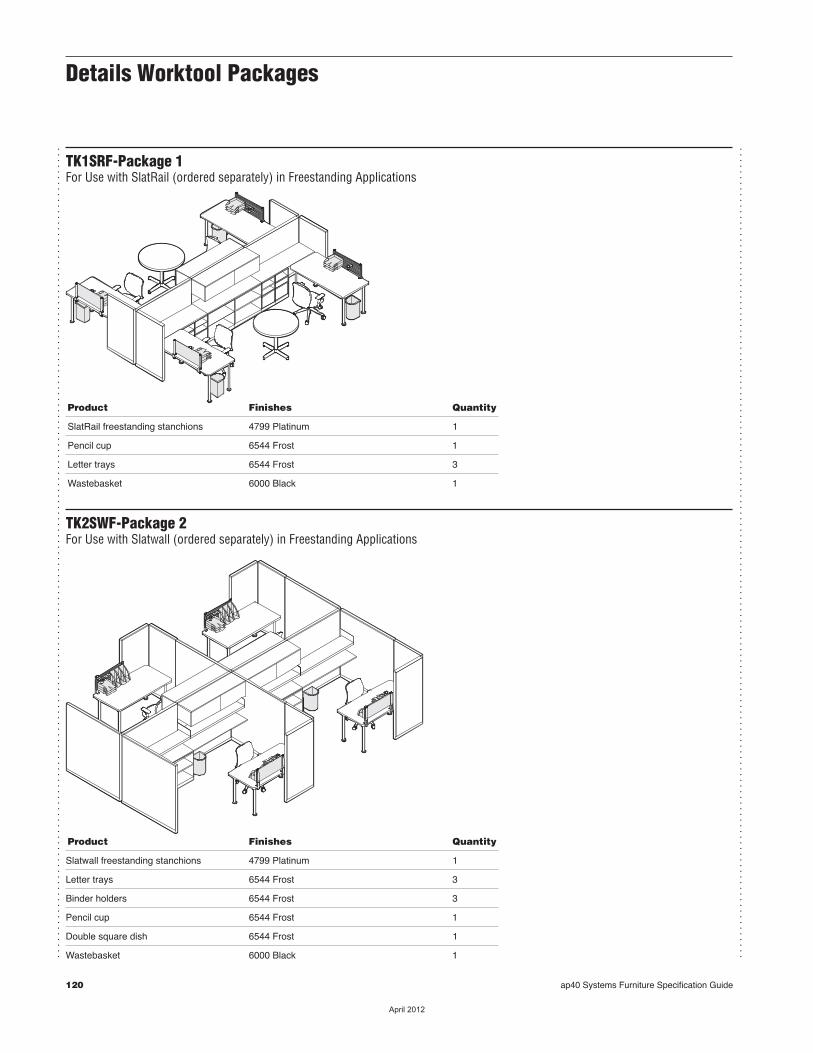
120 ap40 Systems Furniture Specification Guide
Details Worktool Packages
...............................................................................................................................................
...............................................................................................................................................
TK1SRF-Package 1For Use with SlatRail (ordered separately) in Freestanding Applications
Product Finishes Quantity
SlatRail freestanding stanchions 4799 Platinum 1
Pencil cup 6544 Frost 1
Letter trays 6544 Frost 3
Wastebasket 6000 Black 1
TK2SWF-Package 2For Use with Slatwall (ordered separately) in Freestanding Applications
Product Finishes Quantity
Slatwall freestanding stanchions 4799 Platinum 1
Letter trays 6544 Frost 3
Binder holders 6544 Frost 3
Pencil cup 6544 Frost 1
Double square dish 6544 Frost 1
Wastebasket 6000 Black 1
��������

ap40 Systems Furniture Specification Guide cDetails Worktool Packages, continued 121
Details Worktool Packages
...............................................................................................................................................
...............................................................................................................................................
TK3SRP-Package 3For Use with SlatRail (ordered separately) in Panel-Mounted Applications
Product Finishes Quantity
SlatRail panel-mount stanchions 4799 Platinum 1
Pencil cup 6544 Frost 1
Letter trays 6544 Frost 3
Wastebasket 6000 Black 1
TK4SWP-Package 4For Use with Slatwall (ordered separately) in Panel-Mounted Applications
Product Finishes Quantity
Slatwall panel-mount brackets 4799 Platinum 1
Letter trays 6544 Frost 3
Binder holders 6544 Frost 3
Pencil cup 6544 Frost 1
Double square dish 6544 Frost 1
Wastebasket 6000 Black 1
De
tails W
ork
too
ls
��������
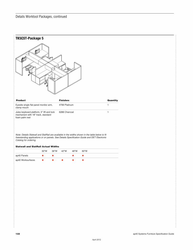
122 ap40 Systems Furniture Specification Guide
...............................................................................................................................................
...............................................................................................................................................
TK5CST-Package 5
Product Finishes Quantity
Eyesite single flat panel monitor arm, 4799 Platinum 1clamp mount
Jules keyboard platform, 5" lift and lock 6288 Charcoal 1mechanism with 18" track, standard foam palm rest
Details Worktool Packages, continued
Note: Details Slatwall and SlatRail are available in the widths shown in the table below to fitfreestanding applications or on panels. See Details Specification Guide and DET ElectronicCatalog for ordering.
Slatwall and SlatRail Actual Widths
30"W 36"W 42"W 48"W 60"W
ap40 Panels • • • •ap40 Worksurfaces • • • • •
��������
ap40 Systems Furniture Specification Guide 123
Specifying Details Worktools
Details Worktools 124
De
tails W
ork
too
ls
��������
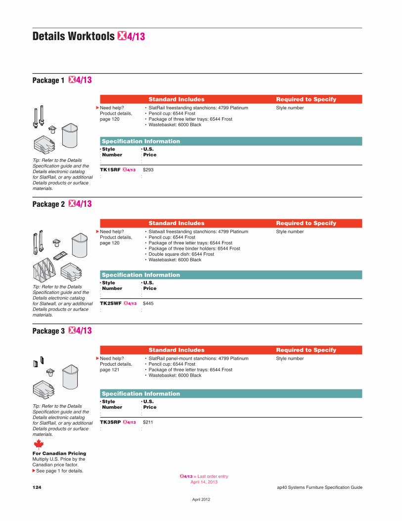
124 ap40 Systems Furniture Specification Guide
Details Worktools G4/13
Specification InformationDStyle DU.S.dNumber dPriced d
TK1SRF G4/13 $293 d d
Standard Includes Required to SpecifycNeed help?
Product details,page 120
• SlatRail freestanding stanchions: 4799 Platinum• Pencil cup: 6544 Frost• Package of three letter trays: 6544 Frost• Wastebasket: 6000 Black
Style number
Package 1 G4/13
Tip: Refer to the DetailsSpecification guide and theDetails electronic catalog for SlatRail, or any additionalDetails products or surfacematerials.
Specification InformationDStyle DU.S.dNumber dPriced d
TK2SWF G4/13 $445 d d
Standard Includes Required to SpecifycNeed help?
Product details,page 120
• Slatwall freestanding stanchions: 4799 Platinum• Pencil cup: 6544 Frost • Package of three letter trays: 6544 Frost• Package of three binder holders: 6544 Frost• Double square dish: 6544 Frost • Wastebasket: 6000 Black
Style number
Package 2 G4/13
Tip: Refer to the DetailsSpecification guide and theDetails electronic catalog for Slatwall, or any additionalDetails products or surfacematerials.
Specification InformationDStyle DU.S.dNumber dPriced d
TK3SRP G4/13 $211 d d
Standard Includes Required to SpecifycNeed help?
Product details,page 121
• SlatRail panel-mount stanchions: 4799 Platinum• Pencil cup: 6544 Frost • Package of three letter trays: 6544 Frost• Wastebasket: 6000 Black
Style number
Package 3 G4/13
Tip: Refer to the DetailsSpecification guide and theDetails electronic catalog for SlatRail, or any additionalDetails products or surfacematerials.
For Canadian PricingMultiply U.S. Price by the Canadian price factor.
See page 1 for details.G4/13 = Last order entry
April 14, 2013
��������
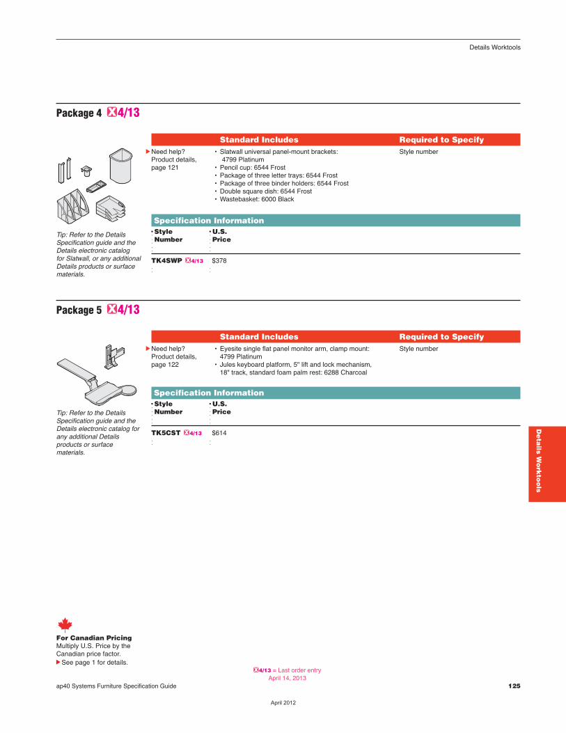
ap40 Systems Furniture Specification Guide 125
Specification InformationDStyle DU.S.dNumber dPriced d
TK4SWP G4/13 $378 d d
Standard Includes Required to SpecifycNeed help?
Product details,page 121
• Slatwall universal panel-mount brackets:4799 Platinum
• Pencil cup: 6544 Frost • Package of three letter trays: 6544 Frost• Package of three binder holders: 6544 Frost• Double square dish: 6544 Frost • Wastebasket: 6000 Black
Style number
Package 4 G4/13
Tip: Refer to the DetailsSpecification guide and theDetails electronic catalog for Slatwall, or any additionalDetails products or surfacematerials.
Specification InformationDStyle DU.S.dNumber dPriced d
TK5CST G4/13 $614 d d
Standard Includes Required to SpecifycNeed help?
Product details,page 122
• Eyesite single flat panel monitor arm, clamp mount: 4799 Platinum
• Jules keyboard platform, 5" lift and lock mechanism, 18" track, standard foam palm rest: 6288 Charcoal
Style number
Package 5 G4/13
Tip: Refer to the DetailsSpecification guide and theDetails electronic catalog forany additional Detailsproducts or surfacematerials.
Details Worktools
De
tails W
ork
too
ls
For Canadian PricingMultiply U.S. Price by the Canadian price factor.
See page 1 for details.G4/13 = Last order entry
April 14, 2013
��������

126 ap40 Systems Furniture Specification Guide
��������
Surface MaterialsS
urfa
ce
Ma
teria
ls
Surface Materials Overview 128
Surface Materials 129
Directional Laminate Grain Directions 130
Specification Guidelines for Vertical Fabric Applications 131
Color Coordination Matrices 132
ap40 Systems Furniture Specification Guide 127
��������
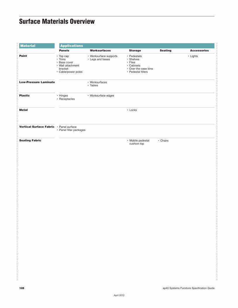
128 ap40 Systems Furniture Specification Guide
Surface Materials Overview
...............................................................................................................................................
...............................................................................................................................................
Material
Paint
ApplicationsPanels Worksurfaces Storage Seating Accessories
• Top cap• Trims• Base cover• Wall attachment bracket• Cable/power poles
• Worksurface supports• Legs and bases
• Pedestals• Shelves• Files• Cabinets• Over the case bins• Pedestal fillers
• Lights
• Worksurfaces• Tables
Low-Pressure Laminate
• Hinges• Receptacles
• Worksurface edgesPlastic
• LocksMetal
• Panel surface• Panel filler packages
Vertical Surface Fabric
• Mobile pedestal cushion top
Seating Fabric • Chairs
��������
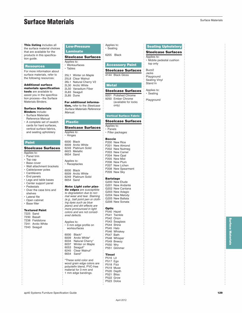
ap40 Systems Furniture Specification Guide 129
...............................................................................................................................................
...............................................................................................................................................
...............................................................................................................................................
...............................................................................................................................................
Surface Materials
This listing includes allthe surface material choicesthat are available for theproducts in this specifica-tion guide.
ResourcesFor more information aboutsurface materials, refer tothe following resources:
Additional surfacematerials specificationtools are available toassist you in the specifica-tion process—the SurfaceMaterials Binders.
Surface MaterialsBinders include:• Surface Materials
Reference Manual• A complete set of swatch
cards for hard surfaces,vertical surface fabrics,and seating upholstery
Paint
Steelcase SurfacesApplies to:• Panel trim• Top cap• Base cover• Wall attachment brackets• Cable/power poles• Cantilevers• End panels• Legs and table bases• Center support panel• Pedestals• Over the case bins and
shelves• Lateral file• Open cabinet• Base filler
Textured Paint7225 Sand 7230 Basalt7238 Fieldstone7241 Arctic White7243 Seagull
Low-PressureLaminate
Steelcase SurfacesApplies to:• Worksurfaces• Tables
25L1 Winter on Maple25L8 Clear Walnut26L1 Natural Cherry V22L30 Arctic White2L50 Vanadium Fiber2L83 Seagull2L85 Dune
For additional informa-tion, refer to the SteelcaseSurface Materials ReferenceManual.
Plastic
Steelcase SurfacesApplies to:• Hinges
6000 Black6009 Arctic White6249 Platinum Solid6623 Metallic6654 Sand
Applies to:• Receptacles
6000 Black6009 Arctic White6249 Platinum Solid6654 Sand
Note: Light color plas-tic edges are susceptibleto degradation due to nor-mal wear and tear. Staining(e.g., ball point pen or cloth-ing dyes such as bluejeans) and dirt effects aremore pronounced in lightcolors and are not consid-ered defects.
Applies to:• 3 mm edge profile on
worksurfaces
6000 Black*6009 Arctic White*6034 Natural Cherry*6037 Winter on Maple6053 Seagull*6245 Clear Walnut*6654 Sand*
*These solid color and wood grain edge colors arepolyolefin blend, PVC-free material for 3 mm and 1 mm edge bandings.
Applies to:• Seating
6205 Black
Accessory Paint
Steelcase Surfaces4144 Black Gloss
Metal
Steelcase Surfaces9201 Polished Chrome 9250 Ember Chrome (available for locks only)G
Vertical Surface Fabric
Steelcase SurfacesApplies to:• Panels• Filler packages
BoccieP200 New RiceP201 New AlmondP202 New NutmegP203 New CamelP204 New OpalP205 New MistP206 New PlumP207 New LichenP208 New SpearmentP209 New Sky
BariolageG200 New EtudeG201 New AndanteG202 New CantanaG203 New AdagioG204 New MelodyG205 New BallataG206 New Sonata
OpticP540 HazelP541 TwinkleP542 OrionP543 SeaglassP544 Shine P545 HaloP546 WhiskeyP547 BathP548 WhisperP549 BreezyP550 WryP551 Glimmer
Tinsel P516 LitP517 EgoP518 FizzP519 MuseP520 DepthP521 BlissP522 GrowP523 Dolce
Seating Upholstery
Steelcase SurfacesApplies to: • Mobile pedestal cushion
top only
Buzz2JacksPlaygroundSeating VinylStand In
Applies to:• Seating
Playground
...............................................................................................................................................
...............................................................................................................................................
Surface Materials
Su
rfac
e M
ate
rials
��������
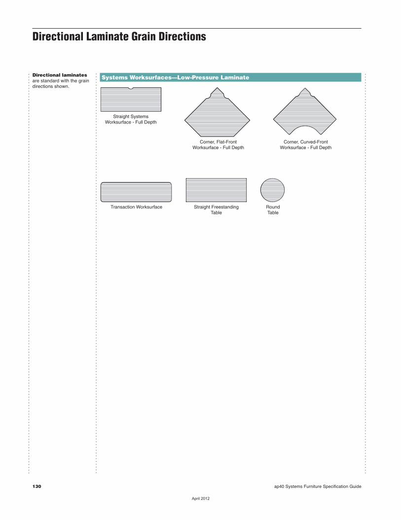
130 ap40 Systems Furniture Specification Guide
Straight SystemsWorksurface - Full Depth
Transaction Worksurface
Corner, Flat-FrontWorksurface - Full Depth
Corner, Curved-FrontWorksurface - Full Depth
Straight FreestandingTable
RoundTable
Directional Laminate Grain Directions
Directional laminatesare standard with the graindirections shown.
...............................................................................................................................................
Systems Worksurfaces—Low-Pressure Laminate...............................................................................................................................................
...............................................................................................................................................
��������

ap40 Systems Furniture Specification Guide 131
Specification Guidelines for Vertical Fabric Applications
...............................................................................................................................................
...............................................................................................................................................
...............................................................................................................................................
...............................................................................................................................................
...............................................................................................................................................
...............................................................................................................................................
What is the issue?Some textiles are simpleand look the same regard-less of how you apply themto a product. Many otherfabrics are patterned, tex-tured, or have luster that willhave a distinctly differentappearance if applied in dif-ferent directions on chairs orpanels. Because of thesedifferences, and the fact thatthere are limits to how somefabrics can be applied toSteelcase products, it isimportant to understand fab-ric application direction stan-dards at Steelcase in orderto avoid being disappointed.
Talking about directionFabrics come on rolls. Thelong yarns that run downthe length of the roll arecalled the “warp” yarns.These yarns are used todefine the direction you areviewing the fabric as it isapplied to a panel or chair.Fabric directionality isdetermined by how the fab-ric comes off the roll. It isNOT determined by the waythe pattern looks on theproduct (i.e., horizontalstripes do not mean the fab-ric was applied warp hori-zontal–it could have beenapplied warp vertical).
Warp horizontal application is the stan-dard application directionfor most Steelcase fabricson Steelcase panel andseating products. Horizontalapplication means that asyou view the panel or chairin its upright position, thewarp yarns of the fabric arerunning in the horizontaldirection.cSee Fabric ApplicationDirection for Systems,Casegoods, and Architecturematrix in the SurfaceMaterials Reference Manualfor details on these exceptions.
66" F
abric
Wid
th
Warp DirectionWarp Horizontal
Warp vertical applicationis the standard applicationdirection for any panelstaller than 68"H and a fewother exceptions. Verticalapplication means that asyou view the panel or chairin its upright position, thewarp yarns are running inthe vertical direction.cSee Fabric ApplicationDirection for Systems,Casegoods, and Architecturematrix in the SurfaceMaterials Reference Manualfor details on these exceptions.
Steelcase is notrespon sible forcharges associatedwith replace ment or reupholstery of prod-ucts due to incor rectspecifications.
Application TopicsSurface MaterialsRepresen ta tives areavailable to answer yourquestions and to provideclari fi cation. They can alsohelp with situations whereyou are using fabrics under66"W. Call 616.246.9822.
PriceNo additional cost tospecify warp direction.
66" Fabric
Width
War
p D
irect
ion
Warp Vertical How to SpecifyYou must specify warpdirection when you need todepart from the standard.Panels allow this option tobe selected electronically.On non-electronic orders forall panels, add a writtenspecification to each panelto indicate non-standardwarp directions.
For example:TKTA533053"H x 30"W tackableacoustical panelsSurface: fabric P505(Charm Shell) with warpvertical.
Specification Guidelines forVertical Fabric Applications
Su
rfac
e M
ate
rials
��������
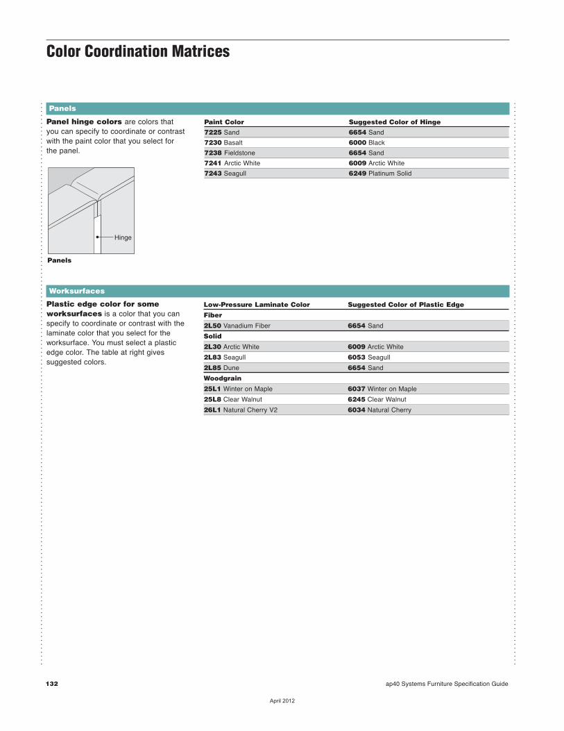
132 ap40 Systems Furniture Specification Guide
Panel hinge colors are colors that you can specify to coordinate or contrastwith the paint color that you select for the panel.
Hinge
Panels
...............................................................................................................................................
...............................................................................................................................................
Color Coordination Matrices
Paint Color Suggested Color of Hinge
7225 Sand 6654 Sand
7230 Basalt 6000 Black
7238 Fieldstone 6654 Sand
7241 Arctic White 6009 Arctic White
7243 Seagull 6249 Platinum Solid
Panels
Plastic edge color for someworksurfaces is a color that you canspecify to coord inate or contrast with thelaminate color that you select for theworksurface. You must select a plasticedge color. The table at right givessuggested colors.
Worksurfaces Low-Pressure Laminate Color Suggested Color of Plastic Edge
Fiber
2L50 Vanadium Fiber 6654 Sand
Solid
2L30 Arctic White 6009 Arctic White
2L83 Seagull 6053 Seagull
2L85 Dune 6654 Sand
Woodgrain
25L1 Winter on Maple 6037 Winter on Maple
25L8 Clear Walnut 6245 Clear Walnut
26L1 Natural Cherry V2 6034 Natural Cherry
��������
Re
sou
rce
s
Resources
Lock and Keying 134
Style Number Index 136
ap40 Systems Furniture Specification Guide 133
��������
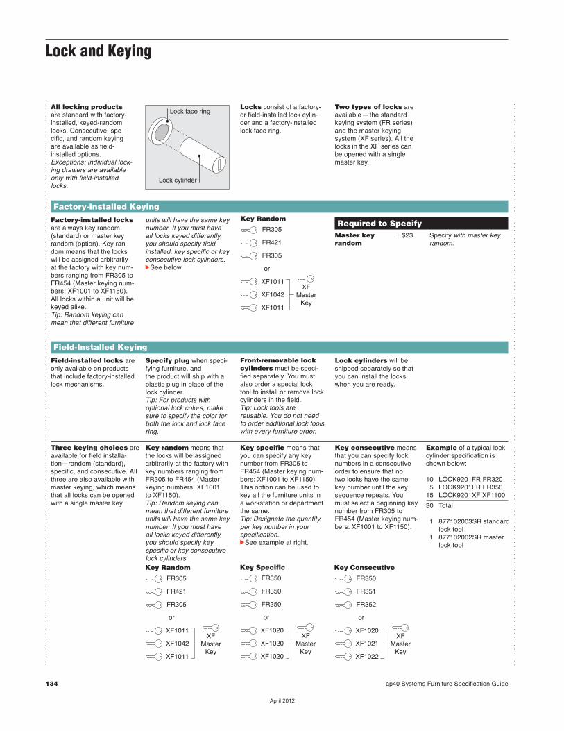
Lock and Keying
134 ap40 Systems Furniture Specification Guide
...............................................................................................................................................
...............................................................................................................................................
Factory-Installed Keying
All locking productsare standard with factory-installed, keyed-randomlocks. Consecutive, spe-cific, and random keyingare available as field-installed options. Exceptions: Individual lock-ing drawers are availableonly with field-installedlocks.
Lock face ring
Lock cylinder
Locks consist of a factory-or field-installed lock cylin-der and a factory-installedlock face ring.
Two types of locks areavailable—the standardkeying system (FR series)and the master keying system (XF series). All thelocks in the XF series can be opened with a singlemaster key.
Factory-installed locksare always key random(standard) or master keyrandom (option). Key ran-dom means that the lockswill be assigned arbitrarilyat the factory with key num-bers ranging from FR305 toFR454 (Master keying num-bers: XF1001 to XF1150).All locks within a unit will bekeyed alike.Tip: Random keying canmean that different furniture
XFMaster
Key
FR305
Key Random
or
FR421
FR305
XF1011
XF1042
XF1011
Field-Installed Keying
Field-installed locks areonly available on productsthat include factory-installedlock mechanisms.
Specify plug when speci-fying furniture, and the product will ship with aplastic plug in place of thelock cylinder.Tip: For products withoptional lock colors, makesure to specify the color forboth the lock and lock facering.
Front-removable lockcylinders must be speci-fied separately. You mustalso order a special locktool to install or remove lockcylinders in the field. Tip: Lock tools arereusable. You do not needto order additional lock toolswith every furniture order.
Lock cylinders will beshipped separately so thatyou can install the lockswhen you are ready.
Key specific means thatyou can specify any keynumber from FR305 toFR454 (Master keying num-bers: XF1001 to XF1150).This option can be used tokey all the furniture units ina workstation or departmentthe same.Tip: Designate the quantityper key number in yourspecification.cSee example at right.
Key consecutive meansthat you can specify locknumbers in a consecutiveorder to ensure that notwo locks have the samekey number until the keyse quence repeats. Youmust select a beginning keynum ber from FR305 toFR454 (Master keying num-bers: XF1001 to XF1150).
Example of a typical lockcylinder specification isshown below:
10 LOCK9201FR FR3205 LOCK9201FR FR350
15 LOCK9201XF XF1100
30 Total
1 877102003SR standard lock tool1 877102002SR master
lock tool
units will have the same keynumber. If you must have all locks keyed differently,you should specify field-installed, key specific or keyconsecutive lock cylinders.cSee below.
Required to Specify Master key +$23 Specify with master key random random.
Key random means thatthe locks will be assignedarbitrarily at the factory withkey numbers ranging fromFR305 to FR454 (Masterkeying numbers: XF1001 to XF1150). Tip: Random keying canmean that different furnitureunits will have the same keynumber. If you must have all locks keyed differently,you should specify key specific or key consecutivelock cylinders.
Three keying choices areavailable for field installa-tion—random (standard),specific, and consecutive. Allthree are also available withmaster keying, which meansthat all locks can be openedwith a single master key.
XFMaster
Key
FR350
Key Specific
or
FR350
FR350
XF1020
XF1020
XF1020
XFMaster
Key
FR305
Key Random
or
FR421
FR305
XF1011
XF1042
XF1011
XFMaster
Key
FR350
Key Consecutive
or
FR351
FR352
XF1020
XF1021
XF1022
��������
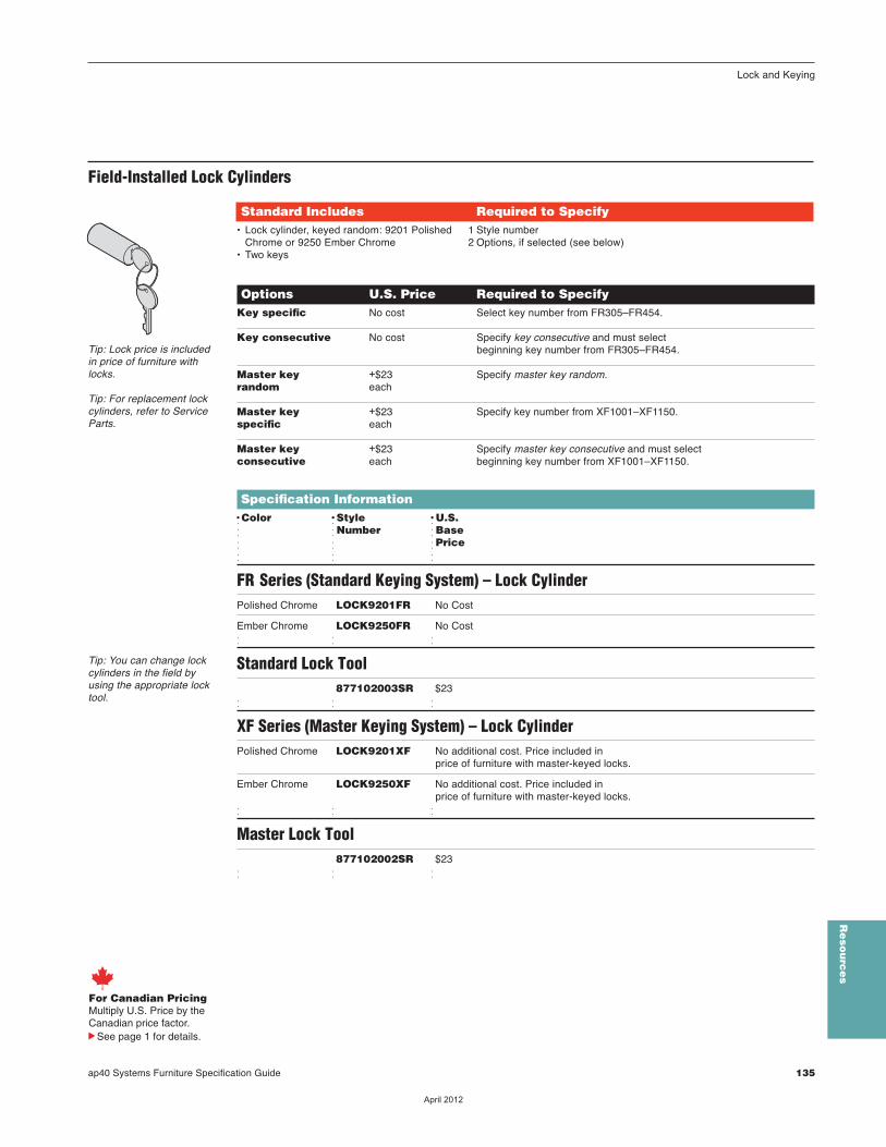
Lock and Keying
ap40 Systems Furniture Specification Guide 135
Tip: You can change lockcylinders in the field byusing the appropri ate locktool.
Options U.S. Price Required to Specify Key specific No cost Select key number from FR305–FR454. Key consecutive No cost Specify key consecutive and must select beginning key number from FR305–FR454. Master key +$23 Specify master key random. random each Master key +$23 Specify key number from XF1001–XF1150. specific each Master key +$23 Specify master key consecutive and must select consecutive each beginning key number from XF1001–XF1150.
Specification InformationDColor DStyle DU.S.d dNumber dBased d dPriced d d
FR Series (Standard Keying System) – Lock CylinderPolished Chrome LOCK9201FR No Cost
Ember Chrome LOCK9250FR No Cost d d d
Standard Lock Tool 877102003SR $23 d d d
XF Series (Master Keying System) – Lock CylinderPolished Chrome LOCK9201XF No additional cost. Price included in price of furniture with master-keyed locks.
Ember Chrome LOCK9250XF No additional cost. Price included in price of furniture with master-keyed locks.d d d
Master Lock Tool 877102002SR $23 d d d
Field-Installed Lock Cylinders
Standard Includes Required to Specify• Lock cylinder, keyed random: 9201 Polished
Chrome or 9250 Ember Chrome• Two keys
1 Style number2 Options, if selected (see below)
Tip: Lock price is includedin price of furniture withlocks.
Tip: For replacement lockcylinders, refer to ServiceParts.
For Canadian PricingMultiply U.S. Price by the Canadian price factor.
See page 1 for details.
Re
sou
rce
s
��������
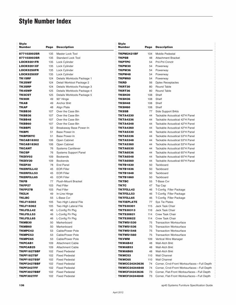
StyleNumber Page Description
StyleNumber Page Description
136 ap40 Systems Furniture Specification Guide
...............................................................................................................................................
...............................................................................................................................................
...............................................................................................................................................
877102002SR 135 Master Lock Tool
877102003SR 135 Standard Lock Tool
LOCK9201FR 135 Lock Cylinder
LOCK9201XF 135 Lock Cylinder
LOCK9250FR 135 Lock Cylinder
LOCK9250XF 135 Lock Cylinder
TK1SRF 124 Details Worktools Package 1
TK2SWF 124 Detail Worktool Package 2
TK3SRP 124 Details Worktools Package 3
TK4SWP 125 Details Worktools Package 4
TK5CST 125 Details Worktools Package 5
TK90H 49 90° Hinge
TKAB 49 Anchor Brkt
TKAP 48 Align Plate
TKBB30 107 Over the Case Bin
TKBB36 107 Over the Case Bin
TKBB48 107 Over the Case Bin
TKBB60 107 Over the Case Bin
TKBBPI 52 Breakaway Base Power-In
TKBPI 51 Base Power-In
TKBPINYC 51 Base Power-In
TKCAB18302 106 Open Cabinet
TKCAB18362 106 Open Cabinet
TKCANT 76 Systems Cantilever
TKCSP 76 Systems Support Panel
TKDIV02 109 Bookends
TKDIV20 109 Bookends
TKEP30 78 End Panel
TKERFILL42 45 EOR Filler
TKERFILL53 45 EOR Filler
TKERFILL65 45 EOR Filler
TKFB 77 Flush-Mount Bracket
TKFP27 103 Ped Filler
TKFP27B 103 Ped Filler
TKILH 49 In-Line Hinge
TKLBC 55 L-Base Cvr
TKLF18302 105 Two-High Lateral File
TKLF18362 105 Two-High Lateral File
TKLFILL42 46 L-Config Flr Pkg
TKLFILL53 46 L-Config Flr Pkg
TKLFILL65 46 L-Config Flr Pkg
TKMB30 50 Markerboard
TKMB60 50 Markerboard
TKMPC42 53 Cable/Power Pole
TKMPC53 53 Cable/Power Pole
TKMPC65 53 Cable/Power Pole
TKPCAB1 109 Attachment Cable
TKPCAB25 109 Attachment Cable
TKPF1827SBF 102 Fixed Pedestal
TKPF1827SF 102 Fixed Pedestal
TKPF1827SSF 102 Fixed Pedestal
TKPF2427BBF 102 Fixed Pedestal
TKPF2427FF 102 Fixed Pedestal
TKPF3027BBF 102 Fixed Pedestal
TKPF3027FF 102 Fixed Pedestal
TKPM2421BF 104 Mobile Pedestal
TKPSB 48 Attachment Bracket
TKPTPC 54 Pnl-Pnl Cnnctr
TKPW30 54 Powerway
TKPW36 54 Powerway
TKPW48 54 Powerway
TKPW60 54 Powerway
TKRD 56 Dplex Receptacles
TKRT30 80 Round Table
TKRT36 80 Round Table
TKSH30 108 Shelf
TKSH36 108 Shelf
TKSH48 108 Shelf
TKSH60 108 Shelf
TKSSB 77 Side Support Brkts
TKTA4230 44 Tackable Acoustical 42"H Panel
TKTA4236 44 Tackable Acoustical 42"H Panel
TKTA4248 44 Tackable Acoustical 42"H Panel
TKTA4260 44 Tackable Acoustical 42"H Panel
TKTA5330 44 Tackable Acoustical 53"H Panel
TKTA5336 44 Tackable Acoustical 53"H Panel
TKTA5348 44 Tackable Acoustical 53"H Panel
TKTA5360 44 Tackable Acoustical 53"H Panel
TKTA6530 44 Tackable Acoustical 65"H Panel
TKTA6536 44 Tackable Acoustical 65"H Panel
TKTA6548 44 Tackable Acoustical 65"H Panel
TKTA6560 44 Tackable Acoustical 65"H Panel
TKTB1830 50 Tackboard
TKTB1836 50 Tackboard
TKTB1848 50 Tackboard
TKTB1860 50 Tackboard
TKTBC 55 T-Base Cvr
TKTC 47 Top Cap
TKTFILL42 46 T-Config Filler Package
TKTFILL53 46 T-Config Filler Package
TKTFILL65 46 T-Config Filler Package
TKTIEPLATE 77 Sys Tie Plates
TKTS30301 115 Jack Task Chair
TKTS30313 116 Jack Task Chair
TKTS30821 114 Crew Task Chair
TKTS30822 114 Crew Task Chair
TKTWS1530 75 Transaction Worksurface
TKTWS1536 75 Transaction Worksurface
TKTWS1548 75 Transaction Worksurface
TKTWS1560 75 Transaction Worksurface
TKVWM 109 Vertical Wire Manager
TKWAB42 48 Wall-Atch Brkt
TKWAB53 48 Wall-Atch Brkt
TKWAB65 48 Wall-Atch Brkt
TKWC53 110 Wall Channel
TKWC65 110 Wall Channel
TKWCC24243636 74 Corner, Crvd-Front Worksurfaces—Full Depth
TKWCC24244848 74 Corner, Crvd-Front Worksurfaces—Full Depth
TKWCF24243636 73 Corner, Flat-Front Worksurfaces—Full Depth
TKWCF24244848 73 Corner, Flat-Front Worksurfaces—Full Depth
Style Number Index
��������
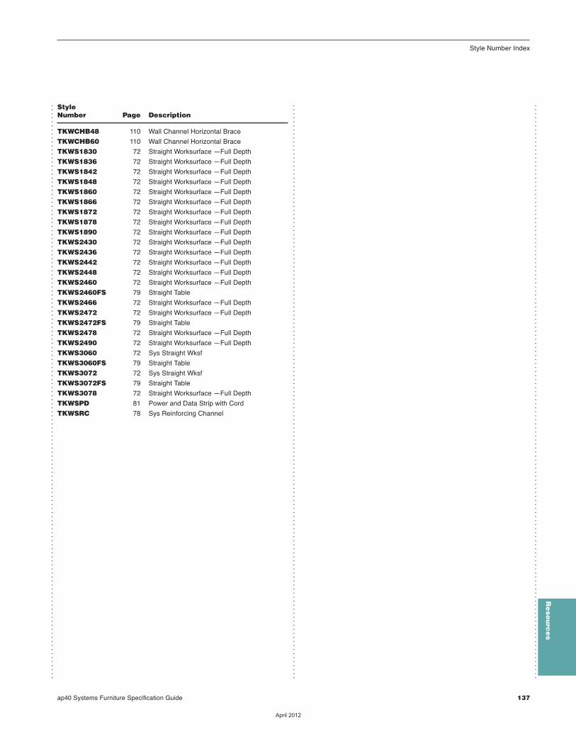
ap40 Systems Furniture Specification Guide 137
Style Number Index
Re
sou
rce
s
...............................................................................................................................................
...............................................................................................................................................
...............................................................................................................................................
TKWCHB48 110 Wall Channel Horizontal Brace
TKWCHB60 110 Wall Channel Horizontal Brace
TKWS1830 72 Straight Worksurface —Full Depth
TKWS1836 72 Straight Worksurface —Full Depth
TKWS1842 72 Straight Worksurface —Full Depth
TKWS1848 72 Straight Worksurface —Full Depth
TKWS1860 72 Straight Worksurface —Full Depth
TKWS1866 72 Straight Worksurface —Full Depth
TKWS1872 72 Straight Worksurface —Full Depth
TKWS1878 72 Straight Worksurface —Full Depth
TKWS1890 72 Straight Worksurface —Full Depth
TKWS2430 72 Straight Worksurface —Full Depth
TKWS2436 72 Straight Worksurface —Full Depth
TKWS2442 72 Straight Worksurface —Full Depth
TKWS2448 72 Straight Worksurface —Full Depth
TKWS2460 72 Straight Worksurface —Full Depth
TKWS2460FS 79 Straight Table
TKWS2466 72 Straight Worksurface —Full Depth
TKWS2472 72 Straight Worksurface —Full Depth
TKWS2472FS 79 Straight Table
TKWS2478 72 Straight Worksurface —Full Depth
TKWS2490 72 Straight Worksurface —Full Depth
TKWS3060 72 Sys Straight Wksf
TKWS3060FS 79 Straight Table
TKWS3072 72 Sys Straight Wksf
TKWS3072FS 79 Straight Table
TKWS3078 72 Straight Worksurface —Full Depth
TKWSPD 81 Power and Data Strip with Cord
TKWSRC 78 Sys Reinforcing Channel
StyleNumber Page Description
��������

Trademark List
...............................................................................................................................................
...............................................................................................................................................
...............................................................................................................................................
® The following are registered trademarks forproducts of Steelcase Inc. or one of its relatedcorporate entities: 4 oʼclock, 900 Series, à la carte, Airtouch, Ally, Amia, Answer,Archipelago, Avenir, Ballet, Bix, BraytonInternational, Cachet, Canopy, Canto,Chancellor, Coalesse, Confidante, Context,Convene, CopyCam, Criterion, Crushed Can,Currency, Designtex, Details, Detour, Drive,Elective Elements, Ellipse, Ember Chrome,Emerge, E-Table 2, FYI, Garland, Gentry,Ginkgo Biloba, Groupwork, Ideo, Jacket,Jenny, Jersey, Kart, Kick, LaCosta, Leap, Letʼs B, LiveBack, Max-Stacker, Metro,Migrations, Mitra, Montage, Nurture, Oriana,Parade, Pathways, PCT, Permiso, Player,PolyVision, Portal, Power Pincher, Progeny,Protégé, R2, Rally, Relevant, Reply, Rizzi Arc,Sensor, Series 9000, Siento, Sieste, Sine,Softcare, Springboard, Steelcase, SteelcaseDesign Partnership, Stella, Stow Davis,Swathmore, TeamWork, Technique, Texpress,Think, Thunder, Topo, Train, Turnstone,Underline, Unison, Vecta, Viridian, Walden,Werndl, and X-Stack.
® The following are a registered trademarks ofAWI Licensing Company, Dover, DE:SoundScapes, DuraBrite, BioBlock, andArmstrong.
® The following registered trademarks are underlicense from Byrne Electrical, Rockford, MI:Interport and Mini-Port.
® The following is a registered trademark ofDuPont, Wilmington, DE: Corian.
® The following is a registered trademark ofGenlyte Thomas Company, Louisville, KY:Lightolier.
® The following is a registered trademark of Hilti Corporation, FL-9494 Schaan, Principality of Liechtenstein: Hilti.
® The following is a registered trademark ofLeviton Manufacturing Company, Little Neck,NY: Decora.
® The following is a registered trademark ofMechanical Plactics Corp, Elmsford, NY:Toggler.
® The following is a registered trademark ofMicrosoft Corporation, Redmond, WA:Microsoft.
® The following is a registered trademark ofPanduit Corporation, Lockport, IL: Panduit.
® The following is a registered trademark of Trav (Press), Cuneo, Italy: Assisa.
® The following is a registered trademark ofVirtual Ink, Boston, MA: mimioActive.
® The following registered trademarks are underlicense from Wilkhahn Furniture Products:Avera, Senzo, Versal, and Wilkhahn FS.
® The following is a registered trademark ofWilsonart International, Temple, TX:Chemsurf.
® The following is a registered trademark ofWiremold, West Hartford, CT: Wiremold.
® The following is a registered trademark ofEMU Group S.P.A., Perugia, Italy: Emu
™ The following are trademarks for products ofSteelcase Inc. or one of its related corporateentities: Access, Active/Passive Shelf, Ainsley,Akira, Alcove, Alerion, alight, Amaris,American Elect, American Tradition, ap40,Arbor, Arriva, Asana, Ascot, Aspekt, Astor,Await, Bira, Bivi, Bottomline, Brook, Burton,c:scape, Calla, Calm, Camber, Campfire,Capa, Cappucino, Cesar, Chester, Chord,Circa, Clarendon, Classic Rectangular, cobi,Collaboration, Community, Company, Convey,Cortex, Coupe, Crea, Crew, Cura, Cypress,Davenport, Dearborn, Deck, Déjà, Denizen,Denska, Derby, Divisio, Donovan, Dune, Duo,e3, e3 ceramicsteel, e3 environmental ceramic-steel, Echo, Edge, Elsna, Empath, Empress,Enea, 3no, EnSync, Enviro, Escapade,Exchange, Exponents, Field, Flat Top,FlexFrame, Flip Top, Flute, Folio, FrameOne,FreeFlow, Frontier, Galilei, Ginger, Ginkgo, GoWall, Grip, Groove, Hatchback, Hawthorne,Hitch, Host Collection, Huddleboard, i2i,Impact, Indy, InfoLink, IOS, I-Solve, Jack,Jarrah, Jetty, Juice, Kami, Kast, Kathryn, Lark,LʼAttitude, LearnLab, Leela, Lincoln, Linden,LiveSeat, Loria, Lyric, Malibu, Malibu Too,Mansfield, Marathon, Martini, Mason, Masque,media:scape, Millbrae, Mineral, Mingle, Mistic,Mistic Metal, Mistic Wood, Montreal, Move,Nadia, Neighbor, nesso, Nickel, Nikko, Nod,node, Norfolk, Ontrak, Oom, Opus, Orchid,Outlook Collection, Ovation, Paloma,Paperflo, Parliament, Pasio, Passerelle,Patriarch, Payback, Peek, Pile File, Pisa,Pool, PUCK, Quba, Rave, Reed, Reunion,Ripple, Riser, Rocco, Rocky, RoomWizard,Runner, Satellite, Sawyer, ScapeSeries, Senti, Sentinel, Senza, Sequoia, Session,ShareLink, Shield, Sidewalk, Skylar, Slumber,Smoke, Snug, Soft Leaf, Sonata, Sorrel,SOTO, Stationkits, Stiletto, Surprise!, Switch,Symphony, Sync, Tava, Tenaro, Terrazzo,Theorem, Topaz, Touchdown, Tour, TowerToo, Trees, Trillium, Trolly, tX2, U-Free, Uno,Verge, Victor2, Visalia, Waldorf, Woodruff,Workspring, and X-tenz.
™ The following is a trademark of MicrosoftCorporation, Redmond, WA: Windows.
™ The following is a trademark of RodmanIndustries, Inc., Oconomowoc, WI:ResinCore1.
™ The following is a trademark of Ultrafabrics,LLC, Elmsford, NY: Ultraleather.
™ The following trademarks are used underlicense from Wilkhahn Furniture: Cana, Linus,Logon, Picto, Range, Stitz, Thema, Timetable,and Tubis.
™ The following is a trademark of MBDC,Charlottesville, VA: Cradle to Cradle.
™ The following trademarks are under licensefrom Walter Knoll: Andoo, Bob, Lazlo, Ribbon,and Together
™ The following trademarks are under licensefrom PP Mobler: Bar and Flag Halyard.
™ The following trademarks are under licensefrom Viccarbe: Davos, Holy Day, Last Minute,RS, and Wrapp.
™ The following trademarks are under licensefrom Carl Hansen: Elbow, Paddle, Shell, Wing,and Wishbone.
™ The following trademarks are under licensefrom Cambridge Sound Management, LLC,Cabridge, MA: Qt PRO Soundmasking, QtQuiet Technology, and Sonet Qt.
™ The following is a trademark of Electri-CableAssemblies, Shelton, CT: Interact.
Trademarks used here in are the property ofSteelcase, Inc. or of their respective owners.
...............................................................................................................................................
��������
Copyright © 2022 FDOKUMEN