
New and modified anodic alumina membranes Part I. Thermotreatment of anodic alumina membranes
Upload
stain-metroCategory
view
0download
0
Ž .Journal of Hazardous Materials B75 2000 99–113www.elsevier.nlrlocaterjhazmat
Anodic destruction of 4-chlorophenol solution
Mohammed O. Azzam a,), Mousa Al-Tarazi a, Yahya Tahboub b
a Department of Chemical Engineering, Jordan UniÕersity of Science and Technology, P.O. Box 3030,Irbid 22110, Jordan
b Department of Applied Chemistry, Jordan UniÕersity of Science and Technology, P.O. Box 3030,Irbid 22110, Jordan
Received 31 October 1999; received in revised form 22 February 2000; accepted 24 February 2000
Abstract
The electrochemical oxidation of 4-chlorophenol solutions was studied using a dimensionalŽ .stable anode DSA , made of pure titanium sheet mesh coated with TirTiO and RuO film. An2 2
electrochemical cell with one working electrode and two counter-electrodes was designed. A gascollecting system to collect the electrolysis gaseous products was also designed.
Ž 2. Ž .The influence of current density 6.51–21.58 mArcm , pH 2.0–12.6 and initial 4-chloro-Ž .phenol concentration 25–100 mgrl on the destruction was investigated. Complete elimination
was successfully achieved within 2 h for most investigated conditions. Highest rates of eliminationwere achieved at a pH of 12.6.
Ž .A new approach to calculate the current efficiency CE of the cell was proposed. The volumesof the gases produced at the anode and at the cathode were the basis for the new CE calculations.
It was observed that the worst CE was approximately 20% and the best CE was approximately89%. The most efficient pH was at 12.6 and the most efficient current density was at 11.39mArcm2. q 2000 Elsevier Science B.V. All rights reserved.
Keywords: 4-Chlorophenol; Anodic oxidation; Electrochemical destruction; Wastewater
1. Introduction
Phenolic wastes in wastewater arise in many segments of the process industryincluding oil refineries, coke plants, chemical and plastic plants. Phenols have been
Žclassified as one of the 65 priority pollutants. Present guidelines according to the.Jordanian Ministry of Water and Irrigation limit phenols concentration in wastewater to
) Corresponding author. Tel.: q962-2-709-5111 ext. 22380; fax: q962-2-709-5018.Ž .E-mail address: [email protected] M.O. Azzam .
0304-3894r00r$ - see front matter q 2000 Elsevier Science B.V. All rights reserved.Ž .PII: S0304-3894 00 00190-4
( )M.O. Azzam et al.rJournal of Hazardous Materials B75 2000 99–113100
less than 0.1 mgrl, where phenols here refer to aromatic derivatives that contain one ormore hydroxyl groups. When phenols contain halide compounds, the acceptable concen-
Ž .tration limit in wastewater falls to 0.02 mgrl 20 ppb .The most common process for treating phenol-laden industrial wastes are biological
Žtreatment often using an acclimated population of microorganisms due to phenol.toxicity , adsorption using proper adsorbent such as activated carbon, and advanced
oxidation processes, such as UVrO or H O rO . The choice of treatment method3 2 2 3
depends on the economics of the method as well as ease of control, reliability andtreatment efficiency.
Electrochemical methods for wastewater treatment, which could be considered as oneof the advanced oxidation processes, have recently attracted a great deal of attention.This is mainly because of their ease of control and the increased efficiency provided bythe use of compact bipolar electrochemical reactors and by the large surface area of
w xthree-dimensional electrodes 1 .Anodic oxidation of organic compounds has been extensively studied for synthesis of
compounds, reaction mechanism studies, fuel cell development and wastewater treat-w xment 2,3 .
w xDeSucre and Watkinson 4 studied the anodic oxidation of phenol for wastewatertreatment on lead dioxide packed bed anode cell which was operated in both batch andcontinuous modes with feed stream concentrations up to 1100 mgrl of phenol dissolvedin aqueous solutions of Na SO and H SO or NaOH. All the phenol in solution, which2 4 2 4
they used, could be readily oxidized. They found that the percent of oxidized phenolincreased with increased current, and decreased as the initial phenol concentration,electrolyte flow rate, pH and anode particle size were increased.
w xFranklin et al. 5 investigated the destruction of organic compounds in the presenceof barium peroxide as a mediator in aqueous sodium chloride containing cationicsurfactants. A reactive intermediate was formed, which destroyed chloroform, 1,2,4-tri-chlorobenzene, hexachlorobenzene and hexafluorobenzene. They carried out the elec-
Ž Ž ..trolysis both potentiostatically 0.9 V vs. saturated calomel electrode SCE andŽ 2 .galvanostatically 16.6 mArcm using graphite anode. They failed to destroy ethylene
diamine and aromatic nitrobenzenes by this technique.w xComninellis and Pulgarin 6 studied the electrochemical oxidation of phenol at a
platinum anode. The analysis of their reaction intermediates and carbon balance showedthat the reaction occurs by two parallel pathways, namely chemical oxidation withelectrogenerated hydroxyl radicals and direct combustion of adsorbed phenol andror itsaromatic intermediates to CO .2
w xFarmer et al. 7 studied mediated electrochemical oxidation methods for hazardouswaste treatment and for the conversion of mixed waste to low-level radioactive waste.
Ž .They used a rotating cylinder anode that operated under the limiting current of Ag IIgeneration. They measured the generation rate of CO and used it to calculate the2
Ž .destruction of the waste and the current efficiency CE of the process.w xFeng et al. 8 studied the electrochemical destruction of benzoquinone. They tested
Ž .several anode materials. They determined the chemical oxygen demand COD forbenzoquinone. Their objective was to find the optimal electrochemical conditions for theconversion of benzoquinone in acetate buffer to CO .2

( )M.O. Azzam et al.rJournal of Hazardous Materials B75 2000 99–113 101
w xJohnson et al. 9 studied the electrochemical destruction reaction of 4-chlorophenol.They identified 26 intermediate products. It took them 24 h of electrolysis to bring 108
Ž .mgrl 4-chlorophenol solution down to 1 mgrl total organic content TOC .This work includes a design of an electrochemical cell to study the effect of different
parameters on the anodic destruction of chlorinated phenols. Specifically, the effect ofpH, 4-chlorophenol concentration and current density on the destruction of 4-chlorophe-nol was investigated.
2. Theory
Several main reactions are believed to occur during the oxidation of phenol in thew x Ž . Ž .presence of KCl 2,10 . For basic solutions, reactions 1 – 4 take place at the anode,Ž .whereas reaction 5 takes place at the cathode.
yzey yzey
Phenol ™ oxidation intermediates O ™ final products 1Ž . Ž .x
Clyq2OHy™OClyq2ey 2Ž .
3y y y q y6OCl q3H O™2ClO q4Cl q6H q O q6e 3Ž .2 3 22
4OHy™2H OqO q4ey 4Ž .2 2
2H Oq2ey™H q2OHy 5Ž .2 2
Ž . Ž . Ž .On the other hand, in acidic solutions, reactions 1 , 6 and 7 are believed to occurŽ .at the anode, while reaction 8 takes place at the cathode.
2Cly™Cl q2ey 6Ž .2
2H O™O q4Hqq4ey 7Ž .2 2
2Hqq2eylH 8Ž .2
Ž .In addition to the reactions occurring at the anode and the cathode, reaction 9 takesŽ .place in basic solutions away from the surfaces of the electrodes, while reaction 10
takes place in acidic solutions.OCly OCly
Phenol™ oxidation intermediates O ™ final products 9Ž . Ž .x
PhenolqHq™protonated phenol 10Ž .
w xSome researchers 6 also believe that the hydroxyl radical formation at the electrodesurface is one of the mechanisms of oxidation. It is believed that the hydroxyl radical isformed by the electrochemical oxidation of water according to the following reaction:
2H O™2OH Øq2Hqq2ey. 11Ž .2
The hydroxyl radicals are then adsorbed at the electrode surface and react with theŽ . Ž .organic molecule phenol or its oxidation products according to reaction 12 , or can
Ž .subsequently react giving O according to reaction 13 :2
OrganicqOH Ø™products 12Ž .ads
1Ø2OH ™H Oq O . 13Ž .ads 2 22
( )M.O. Azzam et al.rJournal of Hazardous Materials B75 2000 99–113102
At the same time, organics are adsorbed at the electrode surface and oxidation to carbonŽ .dioxide occurs as shown in reaction 14 :
Organics ™CO qH O. 14Ž . Ž .ads 2 2
w xMany researchers 2,4,11 believe that the destruction of phenolic compounds is firstorder with respect to phenol concentration. Thus, increasing the concentration of phenolwill cause it to take a longer time to disappear from the solution. On the other hand,decreasing the phenol concentration, under the same current density and other condi-tions, leads to lower energy consumption, and therefore less time is required for thedisappearance of phenol from the solution.
The pH affects the electrochemical cell performance. Increasing the pH decreases theŽ . Ž .oxygen over potential h as apparent from Eq. 15 shown below. In addition, it will
Ž . Ž . Ždecrease the hydrogen potential ´ and so the cell potential ´ will decrease Eq.HŽ ..16 .
hs´y´ s´y0.961–0.059 pH 15Ž .O
RT RTq´ s ln a sy pH 16Ž . Ž .H HF 2.3F
The pH is expected to determine whether the products of the destruction process willadsorb to the anode surface for further oxidation, and therefore blocking some active
Ž .sites, or they the products will dissolve leaving the active sites for other phenolicw xspecies to be destroyed 6 . The pH also affects the stability of the oxide film at the
w xanode surface. Camara et al. 12 reported that for TirTiO electrode, the most stable2
oxide film takes place at a pH of 4, otherwise the film will dissociate into the solution ifa certain limit of current density is exceeded.
3. Current efficiency
There are two methods found in the literature to calculate the CE. The first method isw xthe COD 2 . In this method the COD is measured at different time intervals. The
Ž .instantaneous current efficiency ICE is then calculated as:
COD y CODŽ . Ž .Ž .t tqD tICEs FV . 17Ž .
8iD tŽ .The average current efficiency ACE is then calculated by:
t
ICEd tH0ACEs . 18Ž .
t
This method could be misleading, since it measures the CE with respect to the finalŽ .product carbon dioxide and not the amount of hydrocarbon that has been destroyed.
For example, if the hydrocarbon has been totally destroyed to some intermediateproducts other than carbon dioxide, the COD method would still give some value for the
ŽICE, while in reality the destruction is complete in the sense that no amount of the.initial compound of interest is found .

( )M.O. Azzam et al.rJournal of Hazardous Materials B75 2000 99–113 103
w xThe second method used to calculate the CE is the oxygen flow rate 2 . In thismethod, the sample that has been taken from the solution is exposed to a constant flowrate of oxygen, which oxidizes the organic material in the sample. The ICE is thencalculated as follows:
V y VŽ . orgO tICEs . 19Ž .
VO
The choice between the above two methods for measuring the CE depends on thesolubility of the electrolysis’ products. The oxygen flow rate method can be used forboth soluble and insoluble products, while the COD method is not recommended wheninsoluble products are present.
Another definition for the CE, which is based on the change of the concentration ofthe organic compound, is:
Experimental change in number of moles of organic materialCEs
Theoretical change in number of moles of organic material
y DnŽ . exps 20Ž .
DnŽ . th
where,
I D tacDn s . 21Ž . Ž .th ZF
Ž . Ž .Substituting Eq. 21 into Eq. 20 , gives:
DnŽ . expCEs ZF . 22Ž .
I D tac
Assuming constant solution volume leads to:
VZF DCŽ . expCEsy 23Ž .
I D tac
or,
V ZF dCICEsy . 24Ž .ž /A i d t expac
Ž .Knowing the actual reaction s during the electrochemical destruction of the organicŽ .compounds, Eq. 24 could be used to calculate the ICE.
This work introduces a new definition for CE. The new definition comes from theinterest of transforming the phenolic compounds into other non-phenolic compoundsthat are easier to treat. The new CE is calculated by:
V yVth wCEs 25Ž .
Vth

( )M.O. Azzam et al.rJournal of Hazardous Materials B75 2000 99–113104
Fig. 1. Schematic diagram for the cell system.

( )M.O. Azzam et al.rJournal of Hazardous Materials B75 2000 99–113 105
where V is the volume of gases that should be formed at the working electrode if noth
organic compounds are present in solution. This volume could be calculated by:
V s2V . 26Ž .th ca
The ACE is then calculated by:
t
CE D tÝ i i0ACEs . 27Ž .ÝD ti
Ž .Eqs. 25–27 assume that:
1. the cathode produces hydrogen gas only,2. the only gas produced at the anode is oxygen,3. the produced gases are ideal.
Fig. 2. Influence of current density on the destruction of 4-chlorophenol. Conditions: T s188C, pHs12.6, saltconcentrations67.1 mM, initial concentration of 4-chlorophenols100 mgrl, working electrodesDSA,counter-electrodescopper.
( )M.O. Azzam et al.rJournal of Hazardous Materials B75 2000 99–113106
4. Methodology
The experimental setup is divided into three main parts, namely,Ž .potentiostatrgalvanostat AMEL model 553-Potentiostat , the cell system and the gas
collecting system.Ž .A cylindrical glass cell see Fig. 1 was used with an outside diameter of 20 cm, a
wall thickness of 0.5 cm and a height of 24 cm. The gases that are produced at eachelectrode are separately collected. The top cover is made of Teflon. Three electrodesŽ .two counters and one working are fixed on the top cover in addition to a pressuregauge, salt bridge, mercury thermometer and an inletroutlet valve for a condenser. The
Žbottom cover is also made of Teflon. A Teflon mixer connected with a variable speed.motor is fixed at the center of the bottom cover on the cell side, 4 cm below the
electrodes. A drain and sampling valve is also fixed at the bottom of the cell. The abovecell is immersed in a water bath to allow studying the effect of higher temperatures onelectrolysis.
Ž .The working electrode is a dimensional stable anode DSA , manufactured byELTECH, which is made of pure titanium sheet mesh with TirTiO and RuO film and2 2
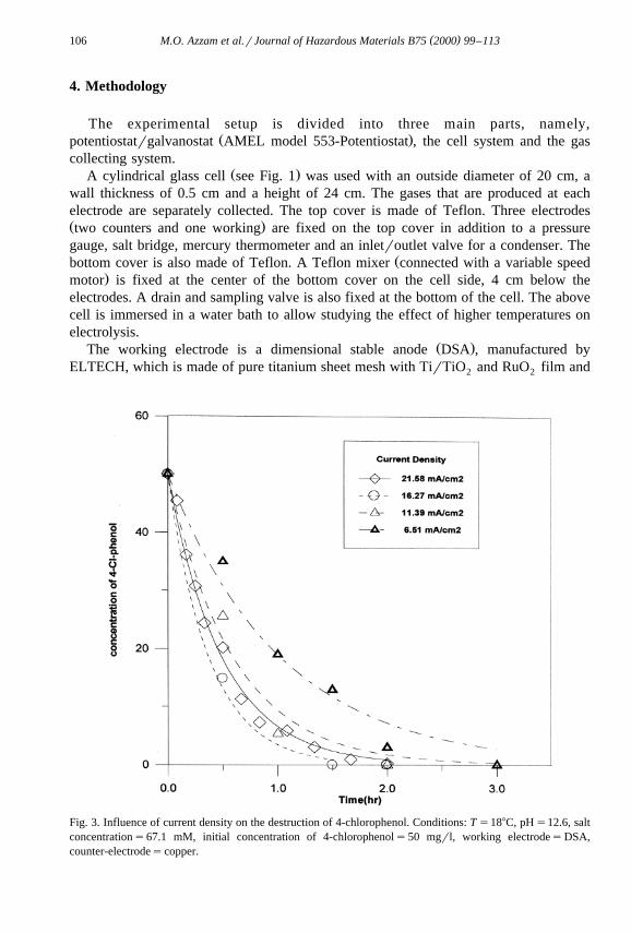
Fig. 3. Influence of current density on the destruction of 4-chlorophenol. Conditions: T s188C, pHs12.6, saltconcentrations67.1 mM, initial concentration of 4-chlorophenols50 mgrl, working electrodesDSA,counter-electrodescopper.

( )M.O. Azzam et al.rJournal of Hazardous Materials B75 2000 99–113 107
has dimensions of 3=5 cm and a thickness of 2 mm. A glass cylinder with a diameterof 4.4 cm surrounds the electrode, and is open from the top, to allow the produced gasesto escape to the gas collecting system.
Ž .There are also two copper )99% purity counter-electrodes, one to the right andanother to the left of the working electrode with dimensions of 3=5 cm, and 2 mmthick. Each counter-electrode is surrounded with a glass cylinder similar to the onesurrounding the working electrode. All glass cylinders are longer than the electrodes by2 cm in order to prevent gas bubbles, which are formed at the surface of the electrodes,from escaping to the solution. The distance between each counter-electrode and theworking electrode is 5 cm. Each counter-electrode is prepared by sanding, then byimmersion in concentrated NaOH solution, then by immersion in concentrated HClsolution, and then finally washed by distilled water.
The cell is usually filled with 4 l of electrolyte prepared using deionized doubleŽ . Ž .distilled water, 4-chlorophenol Sigma, C-4914 , KCl salt extra pure by Merck and
Ž . Ž .NaOH 98% Analar by BDH or HCl 37% assay by BDH . Solution concentrations of4-chlorophenol in the range of 25–100 mgrl were used. The pH of these solutions wasvaried between 2.0 and 12.6. Samples of 10-ml of treated solution were collected from asampling valve, at the bottom of the cell, at different times during the electrolysis
Fig. 4. Influence of current density on the destruction of 4-chlorophenol. Conditions: T s188C, pHs12.6, saltconcentrations67.1 mM, initial concentration of 4-chlorophenols25 mgrl, working electrodesDSA,counter-electrodescopper.

( )M.O. Azzam et al.rJournal of Hazardous Materials B75 2000 99–113108
process for analysis. The pH of the collected samples from the solution was measuredŽ .using a pH meter WPA-model CD7400 .
The disappearance of 4-chlorophenol during anodic oxidation was measured byVarian VISTA 5500 HPLC system, which consists of a single piston, reciprocatingpump driven by stepper motor, a Valco injector equipped with a 100-ml loop andUV-200 variable wavelength detector set at 280 nm connected to a Spectraphysicsintegrator. Operating conditions are programmed through an equipped keyboard. Separa-
Ž .tion were performed on analytical column 250=4.6 mm using Li-Chrosorb RP-8,Ž .10-mm stationary phase Merck, Darmstadt, Germany . The mobile phase consisted of
Ž .1% acetic acid in acetonitrile and water 50:50 vrv , at a flow rate of 2 mmrmin. Thecolumn temperature was 258C, while the column pressure was 195–200 atm.
The effluent gases, which are produced due mainly to water electrolysis on thecounter- and working electrodes, are collected separately in two cylinders of Plexiglas,which are initially filled with water. The produced gases will displace water in these twocylinders. Both of the above cylinders are placed in a water bath with a controlledtemperature.
Fig. 5. Influence of initial concentration on the destruction of 4-chlorophenol. Conditions: T s188C,pHs12.6, salt concentrations67.1 mM, set current density s11.39 mArcm2, working electrodesDSA,counter-electrodescopper.

( )M.O. Azzam et al.rJournal of Hazardous Materials B75 2000 99–113 109
5. Results and discussion
Experiments on the electrochemical destruction of 4-chlorophenol were carried out.Complete elimination was successfully achieved as would be seen below. The effect ofseveral current densities, pH values and initial 4-chlorophenol concentrations on thedestruction process was investigated. The accuracy of the reported concentrations in this
Žwork was within 1 mgrl. The experimental data was curve fitted shown by lines in. Ž .Figs. 2–7 by a one-parameter fit; of the form shown in Eq. 28 ; with one constraint:
CsC exp ybt . 28Ž . Ž .0
The influence of current density on the destruction of 4-chlorophenol, starting with100 mgrl is shown in Fig. 2. It is noticed that as the current density increases, the rate
w xof destruction increases; which is a natural and expected behavior 13 . The CE atdifferent current densities and different initial concentration of 4-chlorophenol is pre-sented in Table 1.
It is observed from Table 1 that the highest CE, for the 100 mgrl concentration, wasnot at the highest tested current density, rather it was highest for an intermediate valueŽ 2 .11.39 mArcm . It is expected that the current density affects the selectivity of the
Fig. 6. Influence of pH on the destruction of 4-chlorophenol. Conditions: T s188C, salt concentrations67.1mM, initial concentration of 4-chlorophenols50 mgrl, set current density s16.27 mArcm2, workingelectrodesDSA, counter-electrodescopper.

( )M.O. Azzam et al.rJournal of Hazardous Materials B75 2000 99–113110
Fig. 7. Influence of pH on the destruction of 4-chlorophenol. Conditions: T s188C, salt concentrations67.1mM, initial concentration of 4-chlorophenols50 mgrl, set current density s11.39 mArcm2, workingelectrodesDSA, counter-electrodescopper.
anode, which could explain the drop in the efficiency from 89% to 33% with increasingcurrent density for the case of 100 mgrl of 4-chlorophenol solution. The same behavior
Ž .and explanation could be said about the 50 mgrl case Fig. 3 .It is also observed from Table 1 that the CE increases with increasing initial
concentration of 4-chlorophenol for 11.39 mArcm2, which is in agreement with thew xgeneral observed behavior by Comninellis and Pulgarin 6 . On the other hand, the
above behavior is reversed for 6.51 and 16.27 mArcm2. In addition, changing the initialconcentration of 4-chlorophenol is expected to affect the intermediates of the destructionprocess, and therefore, affects the selectivity of the anode. The above reversed behaviormeans that the selectivity of the anode has changed.
Fig. 4 shows the effect of current density on the destruction of 4-chlorophenol withan initial concentration of 25 mgrl and the same conditions specified in Fig. 2. The rateof destruction is observed to be highest for 11.39 mArcm2, which is neither the highestnor the lowest tested current densities, which means that the selectivity of the anode hasa non-liner relation with the current density.
Polymerized intermediate compounds were noticed by HPLC analysis when thecurrent density was at 11.39 mArcm2, but these compounds disappeared after 1.5 h ofelectrolysis. The lower CE for the 11.39 mArcm2 could be due to the blocking of theactive sites at the working electrode by the intermediate polymerized compounds.

( )M.O. Azzam et al.rJournal of Hazardous Materials B75 2000 99–113 111
Table 1CE at different current densities and different initial concentrations of 4-chlorophenol
2Ž . Ž .Current density mArcm Initial 4-chlorophenol concentration mgrl
100 50 25
6.51 20 39 4511.39 89 49 3016.27 33 37 45
Fig. 5 shows the effect of initial concentration of 4-chlorophenol on its rate ofdestruction. It is obvious that increasing the initial concentration decreased the rate of
Ždestruction a similar behavior for anodic oxidation of phenol was reported by De Sucrew x.and Watkinson 4 . This could be due to the presence of intermediate products produced
during the electrolysis process at higher concentrations, which then could compete with4-chlorophenol and water for the active sites on the working electrode, or theseintermediate products may be insoluble in water and would block the working electrodeactive sites. It is worth noting that it was difficult to see any film formation on thesurface of the electrode, due to the large size of the cell, however when the cell isopened for cleaning purposes, a thin film was usually observed on parts of the surface ofthe electrode.
In addition, it is known that increasing the bulk solution concentration shouldincrease the rate of mass transfer. Therefore, the rate of destruction of 4-chlorophenolshould increase by increasing its bulk solution concentration if the destruction is masstransfer controlled. Fig. 5 shows that the rate of destruction of 4-chlorophenol isdecreased with increasing bulk solution concentration, which means that its rate ofdestruction is not mass transfer controlled.
The influence of the pH on the destruction of 4-chlorophenol at a current density of2 Ž .16.27 mArcm was investigated see Fig. 6 . It is observed that there was no
appreciable difference in the destruction at pH values between 2 and 8.9, while anappreciable difference was observed when the pH was increased to 12.6, at which therate of destruction was highest. This may be due to the fact that the 4-chlorophenol atthis pH will be in the anionic form, which enhances its oxidation. In addition, theformed chlorine will be in the form of hypochlorite, a known oxidizing agent, which
w xinvolves further oxidation of either 4-chlorophenol andror the intermediates 2 .It has been observed that when starting with a pH of 7 or 8.9, a decreased in the pH
was noticed during the electrolysis. It is has also been observed that when starting with apH of 4.7, the pH increased to reach 6.5 during the electrolysis process. This phe-
Žnomenon was not observed for higher pH values where the pH was constant throughout.the experiment . The main reason for this change in the pH is that the produced
intermediates are thought to have weak acid–base properties. These properties are notsignificant to produce a change in the pH at 2.4 or 12.6.
The HPLC analysis showed a formation of polymerized compounds only at a pH of2.4 during the electrolysis. The main reason for this formation of such compounds is theprotonation of 4-chlorophenol at low pH values. These compounds were destroyed by

( )M.O. Azzam et al.rJournal of Hazardous Materials B75 2000 99–113112
Table 2Percent CE at different current densities and pH values
Current density pH2Ž .mArcm
2.4 4.7 7.2 8.9 12.6
11.39 48 – 22 – 3116.27 48 48 19 19 37
further electrolysis as time passed. The potential of the working electrode was almostconstant for all the pH experiments.
Fig. 7 shows the effect of pH on the destruction of 4-chlorophenol using a currentdensity of 11.39 mArcm2. The same general behavior is noticed as that of Fig. 6. TheCE at different current densities and different pH values is presented in Table 2. It is
Ž .noticed from this table that the highest CE 48% was at a pH of 2.4 for both testedcurrent densities.
6. Conclusions
It is concluded from the data presented in this work that 4-chlorophenol could beeliminated completely by electrochemical techniques within 2 h for most investigatedcases. In addition, the current density and the pH affect the rate of the above destructionand the CE. The functionality of this dependency is not yet well established. At low4-chlorophenol concentration, the rate of destruction did not increase with increasingcurrent density. A CE as high as 89% was achieved.
Nomenclature
Ž 2 .A area of the anode mACE average current efficiency
Ž .qa activity of the hydrogen ions MH
b fitting parameterŽ .C concentration of 4-chlorophenol at any time mgrl
Ž .C initial concentration of 4-chlorophenol mgrl0
CE current efficiencyŽ .COD chemical oxygen demand mgrml
DSA dimensional stable anodeF Faraday constantHPLC high performance liquid chromatography
Ž .i current AacŽ 2 .I actual current used by the cell Arcmac
ICE instantaneous current efficiencyn moles of organic material

( )M.O. Azzam et al.rJournal of Hazardous Materials B75 2000 99–113 113
Ž .P pressure of the cell PaŽ .R universal gas constant Parmol K
r rate of reactionŽ .T temperature K
Ž .t time sŽ 3.V volume of cell m
Ž 3.V volume of gas collected at the cathode macØ 3Ž .V oxygen flow rate in the absence of phenol in the electrolyte m rsOØŽ .VV oxygen flow rate at a given time t in the presence of phenol in thet orgŽ 3 .electrolyte m rs
Ž 3.V volume collected at the anode in the absence of phenol mthŽ 3.V volume of gas collected at the anode mw
z valence
Greek symbolsŽ .´ cell potential V
Ž .´ hydrogen reversible potential VHŽ .´ reversible oxygen potential VO
Ž .h applied over potential, which is defined for O production V2
t time when ICE is almost zero
References
w x Ž .1 J. Bringmann, K. Ebert, U. Galla, H. Schmieder, J. Appl. Electrochem. 25 1995 846–851.w x Ž .2 C. Comninellis, A. Nerini, J. Appl. Electrochem. 25 1995 23–28.w x Ž . Ž .3 H. Hitmi, E.M. Belgsir, J.M. Leger, C. Lamy, R.O. Lezna, Electrochem. Acta 39 3 1994 407–415.w x Ž .4 V.S. DeSucre, A.P. Watkinson, Can. J. Chem. Eng. 59 1981 52–59.w x Ž . Ž .5 T.C. Franklin, J. Darlington, T. Solouki, N. Tran, J. Electrochem. Soc. 138 8 1991 2285–2288.w x Ž .6 C. Comninellis, C. Pulgarin, J. Appl. Electrochem. 21 1991 703–709.w x7 J.C. Farmer, F.T. Wang, R.A. Hawley-Fedder, P.R. Lewis, L.J. Summers, L. Foiles, J. Electrochem. Soc.
Ž . Ž .139 3 1992 654–662.w x Ž . Ž .8 J. Feng, L.L. Houk, D.C. Johonson, S.N. Lowery, J.J. Carey, J. Electrochem. Soc. 142 11 1995
3626–3632.w x Ž .9 S.K. Johnson, L.L. Houk, J. Feng, R.S. Houk, D.C. Johnson, Environ. Sci. Technol. 33 1999
2638–2644.w x10 A. Beknazarov, Theoretical Electrochemistry, Mir Publisher, Moscow, 1972.w x Ž . Ž .11 L.L. Stewart, D.N. Bennion, R.M. LaFollette, J. Electrochem. Soc. 141 9 1994 2416–2421.w x Ž . Ž .12 O.R. Camara, C.P. De Pauli, M.C. Giordano, Electrochim. Acta 29 8 1984 1111–1117.w x13 A.J. Bard, L.R. Faulkner, in: Electrochemical Methods Fundamentals and Applications, Wiley, New
York, 1980, p. 91.
Copyright © 2022 FDOKUMEN