analysis of torrent protective structures as a basic element of ...
12
ANALYSIS OF TORRENT PROTECTIVE STRUCTURES AS A BASIC ELEMENT OF THE HAZARD MAPPING PROCESS DETERMINING THE AS-IS-STATE OF 100 YEARS OLD CHECK DAMS MADE OF NATURAL STONE MASONRY Bernd Kister 1 , Markus Zimmermann 2 , Gabi Hunziker 3 , Bruno Zimmerli 4 and Walter Fellmann 5 ABSTRACT The natural hazard map for the villages of Schwanden, Hofstetten, Brienz and Brienzwiler (Bernese Alps, Switzerland) had to be revised as a consequence of large debris flows and flooding in August 2005, which caused huge damage. The more than 20 torrent control structures in the Lammbach gorge, constructed approximately 100 years ago, play a vital role for today’s safety on the fan of the Lammbach with extended housing estate and small-scale industry. This paper presents the general hazard mapping process and main results of the assessment and rating for the as-is-state of the old check dams. For the visual inspection of the natural stone masonry of the check dams the “Lucerne Rating System” has been used. Simple 2D-models as well as 3D-FEM have been applied to check structural safety as well as effectiveness of the structures. The results of structure assessments have been directly integrated into the hazard mapping process. Keywords: hazard, risk assessment, natural hazard map, torrent control structures, potential failure mechanism, natural stone masonry, as-is-state of structures, rating, 3D-FEM INTRODUCTION The torrents in the area of the villages Brienz, Schwanden and Hofstetten in the Bernese Alps, Switzerland (Fig. 1b), are well known for flooding and debris flows for hundreds of years. Fig. 1 a) geographical position of the project area, located north of the Lake Brienz, b) the mountain torrents of the Brienz area located at the southern slope of the Brienzergrat (Ryter, 2004). 1 Dr. Bernd Kister, Lucerne University of Applied Sciences and Arts, Technikumstrasse 21, CH - 6048 Horw, Switzerland (e-mail: [email protected]) 2 Dr. Markus Zimmermann, NDR Consulting GmbH, Riedstrasse 5, CH - 3600 Thun, Switzerland 3 Gabi Hunziker, Hunziker Gefahrenmanagement, Gärteli 19, CH - 3210 Kerzers FR, Switzerland 4 Prof. Dr. Bruno Zimmerli, Zimmerli Bauingenieure GmbH, Fliederstrasse 8a, CH – 6010 Kriens, Switzerland 5 Walter Fellmann, Fellmann Geotechnik GmbH, Bruchmatthalde 3, CH – 6003 Lucerne, Switzerland 12 th Congress INTERPRAEVENT 2012 – Grenoble / France Conference Proceedings www.interpraevent.at a) b) - 729 -
-
Upload
khangminh22 -
Category
Documents
-
view
0 -
download
0
Transcript of analysis of torrent protective structures as a basic element of ...

ANALYSIS OF TORRENT PROTECTIVE STRUCTURES AS A BASIC
ELEMENT OF THE HAZARD MAPPING PROCESS
DETERMINING THE AS-IS-STATE OF 100 YEARS OLD CHECK DAMS MADE OF
NATURAL STONE MASONRY
Bernd Kister1, Markus Zimmermann
2, Gabi Hunziker
3, Bruno Zimmerli
4 and Walter Fellmann
5
ABSTRACT
The natural hazard map for the villages of Schwanden, Hofstetten, Brienz and Brienzwiler (Bernese
Alps, Switzerland) had to be revised as a consequence of large debris flows and flooding in August
2005, which caused huge damage. The more than 20 torrent control structures in the Lammbach
gorge, constructed approximately 100 years ago, play a vital role for today’s safety on the fan of the
Lammbach with extended housing estate and small-scale industry. This paper presents the general
hazard mapping process and main results of the assessment and rating for the as-is-state of the old
check dams. For the visual inspection of the natural stone masonry of the check dams the “Lucerne
Rating System” has been used. Simple 2D-models as well as 3D-FEM have been applied to check
structural safety as well as effectiveness of the structures. The results of structure assessments have
been directly integrated into the hazard mapping process.
Keywords: hazard, risk assessment, natural hazard map, torrent control structures, potential failure
mechanism, natural stone masonry, as-is-state of structures, rating, 3D-FEM
INTRODUCTION
The torrents in the area of the villages Brienz, Schwanden and Hofstetten in the Bernese Alps,
Switzerland (Fig. 1b), are well known for flooding and debris flows for hundreds of years.
Fig. 1 a) geographical position of the project area, located north of the Lake Brienz, b) the mountain torrents of
the Brienz area located at the southern slope of the Brienzergrat (Ryter, 2004).
1 Dr. Bernd Kister, Lucerne University of Applied Sciences and Arts, Technikumstrasse 21, CH - 6048 Horw,
Switzerland (e-mail: [email protected]) 2 Dr. Markus Zimmermann, NDR Consulting GmbH, Riedstrasse 5, CH - 3600 Thun, Switzerland 3 Gabi Hunziker, Hunziker Gefahrenmanagement, Gärteli 19, CH - 3210 Kerzers FR, Switzerland 4 Prof. Dr. Bruno Zimmerli, Zimmerli Bauingenieure GmbH, Fliederstrasse 8a, CH – 6010 Kriens, Switzerland 5 Walter Fellmann, Fellmann Geotechnik GmbH, Bruchmatthalde 3, CH – 6003 Lucerne, Switzerland
12th
Congress INTERPRAEVENT 2012 – Grenoble / France
Conference Proceedings
www.interpraevent.at
a) b)
- 729 -

Fig. 2 Longitudinal section of the main part of the Lammbach gorge showing position and mode of action of
the check dams, cut-out of a plan dated 1913 (OIK)
Because of this, a risk assessment for that area had been done already in the period 1997 - 1998. But
due to large debris flows and flooding in August 2005 as well as the new discussion to take into
account the impact of protection measures (PLANAT, 2008), the natural hazard map of that area had
to be revised. In that revision process the Lammbach played a decisive role, because of the large
uncertainties concerning the options of scenarios the hazard map is based on. Those large
uncertainties traced back to the unknown as-is-state of the check dams which had been established in
the Lammbach gorge approximately 100 years ago.
The Lammbach was not active during the 2005 events, but during the past centuries there have been a
lot of examples for extremely dangerous debris flows and flooding. For example in 1499 the village
Kienholz and the manor house Kien had been destroyed by large debris flows and debris and mud had
been deposited up to a thickness of 10 m. The last large event occurred in the year 1896, when
disastrous debris flows emerged in the Lammbach gorge which destroyed several houses in the village
Kienholz, along with the track of the Swiss Federal Railway. The volumes of the last three incidents
have been reported as approximately 300'000 m3 of material covering land along a shoreline length of
120 m at Lake Brienz with an average debris thickness of about 2.5 to 4.0 m. In consequence of those
disastrous debris flows, a massive reforestation program had been started in the area and 20 torrent
control structures (check dams) had been installed in the Lammbach gorge in the period 1896 to 1913
to raise the streambed and stabilize the slopes (Fig. 2). These barriers consist of natural stone masonry
and have remarkable dimensions in part. The largest one, check dam IVa, has a span of 90 m and the
visible height at the downstream face is still 13 m today (Fig. 5).
Since the construction of those check dams no disastrous debris flow with origin at the Lammbach
valley has ever reached the villages. But on the other hand up to now by guess more than 500’000 m3
of debris has been accumulated behind the torrent control structures and at least the same quantity of
debris are deposited at the slopes of the Lammbach gorge. For this reason there is a potential for large
debris flows, especially if one or more of the check dams will fail to work. The structural safety of the
old torrent control structures is therefore of utmost importance. An essential part of the revision
process of the natural hazard map was therefore the assessment and rating of the old check dams made
of natural stone masonry with regard to their structural safety and fitness for purpose.
TOPOGRAPHY AND GEOLOGY OF THE PROJECT AREA
The watershed of the Lammbach is placed at the southern slope of the Brienzergrat (Fig. 1b) and
covers an area of approximately 3.2 km2. The area ranges from approx. 2’200 m altitude down to the
Lake Brienz at 578 m altitude.
- 730 -

The Brienzergrat consists of the cretaceous rocks of the so-called Wildhorndecke. At the ridge
siliceous limestone appear. Downhill the limestone is replaced by the marly layers of the Valangien.
The dark siliceous limestone is normally straticulated and alternates with layers of marl.
Compression, minor folds and buckling is very common in this geologic structure (Bauer, 1971). The
dip direction (DD) of the bedding plane in the project area is SE and the dip (D) is 25° to 35°. Three
main joint sets K1, K2 and K3 have been identified (Fig. 3, Tab. 1).
Fig. 3 Left: Example of thin to medium bedded limestone in the project area, right: Distribution of measured
joints and great circles of joint sets
Tab. 1 Dip Direction (DD) and Dip (D) of the three main joint sets in the project area
Joint set DD D
K1 242° 63°
K2 334° 70°
K3 171° 69°
The bedding planes have slightly rough surfaces while the joint surfaces can be described as rough.
The Geological Strength Index (GSI) is in the range of 35 to 45. The rock mass at the Lammbach
valley is in general vulnerable for weathering and erosion. Due to the existing joint system the
limestone degrades into cubical or block-shaped pieces with an edge length of 1 to 4 decimeters in the
majority of cases. The marly parts of the rock mass decays into fine grained sediments. At the surface
the fine-grained material is often eroded and only the blocky material is left. Therefore along the
streambed and at the slopes as well as with depth the composition of the debris varies.
IDENTIFICATION AND ASSESSMENT OF HAZARDS
Since more than 10 years the hazard mapping process in Switzerland has been done in a standardized
way consisting of 3 individual steps (BWW, BRP & BUWAL, 1997):
1. identification of hazards,
2. assessment of hazards and
3. transfer of scenarios into a hazard map.
The identification and assessment of hazards is in general in the own field of action of the
municipalities and the natural hazard map is part of the urban development. Normally the
municipalities place an order to a consultancy firm for doing the executive work. The working process
is attended by the cantonal specialist departments.
For the identification of hazards in a first step existing event registers are used. In Switzerland those
inventories exist at many places and they contain information about events occurred in the last
decades, sometimes in the last centuries. Especially events concerning torrents are very often well
documented. Additional information about potential loss events will be given by the geologic-
geomorphological analysis of the project area.
- 731 -

The essential parameters of a hazard process are the intensity and the return period. In Switzerland, a
hazard rating system is used, which defines different danger levels according to a combination of the
hazard probability (defined with a return period or frequency of occurrence) and the hazard intensity.
The hazard intensity is strongly linked to the magnitude of an event. In the Swiss recommendations
(BWW, BRP & BUWAL, 1997), the intensity for debris flows and related processes is expressed as a
function of impact pressure, flow velocity and/or flow depth. As flow depth is difficult to determine
in some cases, an estimated depth of deposition may be taken as an approximation. The relevant
return periods are defined as 30, 100 and 300 years. Additional an extraordinary event will be taken
into account in the assessment of hazards.
During the hazard assessment process a detailed geomorphological analysis will be done including
information about potential flow paths, flow velocities, range of coverage and transported volumes of
material. Empirical methods as well as numerical simulations are used for that work. Nevertheless the
uncertainties are high in the assessment of processes dealing with torrents (Zimmermann, 2006).
GEOMORPHOLOGICAL ANALYSIS
During the geomorphological analysis the circumstances in the catchment area of the Lammbach had
been studied in detail. Especially slope stability, potential processes like debris flow, bedload
transport and the concurrence of slope instabilities together with torrent processes have been
examined.
As already mentioned before, today a large quantity of debris is deposited behind the check dams and
along the slopes of the Lammbach gorge due to the geologic circumstances and weathering. All in all
a total quantity of approximately 1.5 million m3 of erodible debris is deposited here. Especially in the
middle part of the Lammbach gorge there is a chance that several 10’000 m3 of debris may move
downward into the streambed by slope failure. This may result in an afflux, which may on his part be
the origin of a large debris flow similar to those one of the Lammbach cataclysm of the year 1896.
A comparison of the gradient along the Lammbach gorge at different times shows also significant
changes. Fig. 4 shows on the left that the gradient was significantly reduced as a result of the
construction of the check dams in the years 1896 – 1913. This was one of the aims which had been
connected with the construction of the check dams. But today due to sedimentation of debris along the
Lammbach gorge the gradient is in many cases similar to that one before the construction of the check
dams. In the case of the upstream area of check dam IVa the gradient has been even increased in
comparison to the situation before dam construction (Fig. 4, right).
Fig. 4 Left: Comparison of the gradient before the installation of the check dams and the gradient expected due
to dam installation (cp. Fig. 3), right: Comparison of the gradient before the installation of the check dams and
the gradient measured by aerial survey in 2005 (legend: Sp = check dam, o = upstream, u = downstream)
The traces of former debris flows are only partial conserved on the alluvial fan of the Lammbach due
to building development. But taking into account the remaining traces of debris flows, it can be
suggested that the different events had been of large extend. Additional it is recognizable, that the
- 732 -

major part of the masses of former debris flows are located at the upper part of the alluvial cone. At
the lower part of the cone the thickness of former events is much less.
Today, the cone is incised up to 16 m deep, starting from the apex and making a strong bend towards
the west. Having a look on old maps it is clear, that this incision is a result of the events in 1896.
Before, the Lammbach was flowing more or less on the surface of the cone. Still in 1886 there was a
debris flow in eastward direction towards the village of Hofstetten. However, nowadays a large debris
flow might be able to fill up the deep cut and travel straight (south). Approximately 150’000 m3 of
debris are necessary for such change. The volume of debris for this process is available, particularly
in the middle part of the Lammbach, as described above. A failure of one or more check dams may
make this quantity of debris disposable.
ASSESSMENT OF THE LAMMBACH CHECK DAMS
The Lammbach check dams, constructed during the period 1896 to 1913, had been made of natural
stone masonry. Natural stone masonry is of course a durable construction material but even such a
material underlies weathering and aging. The lifespan of such constructions made of natural
stonework in general is specified with 60 to 80 years, maximum 100 years (e.g. Rudolf-Miklau &
Agerer, 2007). But that does not mean the construction will lose its structural safety and the fitness
for purpose automatically when a structure attained such an age. However the structural safety and the
fitness for purpose of the check dams had to be verified.
Additional to weathering and aging of the masonry, due to old plans there are some specifics
concerning the construction of the check dams:
• footing with wooden sleepers (check dams Ia, Ib, IIIa)
• wooden piles at the footing (check dam II)
• arch constructions within the masonry (check dams Ie, II, III, V).
Since the construction of the check dams, at some of them modifications had been done. So the check
dams I, Ic, II, IV, V, VII and VIII had been increased in height. The check dams III and IVa got partly
a concrete slab on downstream face with pre-stressed anchors (Fig. 5). Those modifications of the
dams are attended with changes of the applied loads as well as changes in the structural system.
Fig. 5 Check dam IVa with rehabilitation measures, middle part fixed by a concrete plate and pre-stressed
anchors in 1976, buttresses and pre-stressed anchors installed at the barrier wings in 2000
The Swiss National Platform for Natural Hazards (PLANAT) defines a 5 step procedure concerning
the assessment and the effect of protective structures (PLANAT, 2008). The steps are named as
follows: preliminary work, crude appraisal, arrangement assessment, outcome assessment and
preliminary work for urban and regional planning. Analogous to that, the assessment of the
Lammbach check dams and the preparation of the hazard map had been done also in a 5 step
procedure with the following steps:
- 733 -
1. evaluation of the basics
2. process assessment
3. arrangement assessment
4. outcome assessment
5. realization of the hazard map
EVALUATION OF THE BASICS
In the first step the available documentation has been analyzed, a geodetic survey has been done and
the barriers’ as-is state has been mapped. The last one has been done by using a special rating system
for natural stonework, which has been developed at the Lucerne University of Applied Sciences and
Arts in the last years (Kister et al, 2008). The rating system for natural stone masonry has been
developed based on our experience with rating systems in rock mechanics on one hand and our
experience with natural stonework on the other. Combining both and additionally taking into account
aspects of the surrounding area as topography, geology, groundwater and plant-cover, the assessment
and rating of old natural stonework has been put on a less subjective base.
Some adaptions had to be made for the check dams because the original rating system was developed
for retaining walls placed at traffic infrastructure. Nevertheless an assessment of the check dams made
of natural stone masonry has to keep in mind the same 3 general aspects:
• as-is state of the construction itself and the construction elements,
• constructiveness and
• properties of the surrounding area.
The as-is state of the construction implies the as-is state of the construction itself, as for example
break-outs in the masonry or damage due to settlement, but also the as-is state of the components
stone and mortar and the status of the drainage. The constructiveness sums up data concerning the
design and composition of the structure, such as ratio of masonry wall thickness to construction
height, size of stones and thickness of joints (Fig. 6). Plant cover, potholes, indication of slope
instabilities or indication of erosion for example are properties of the surrounding area. Fig. 7 shows
as an example for the summary of the rating of a Lammbach check dam the results for check dam I.
Maximum value for a rating value is 1.0, values less than 0.6 show damages, a value less than 0.5
show significant damages. In the case of the basic data low values show missing information, as for
example no information present on the anchoring depth.
Fig. 6 Left: Basic data for the assessment of the constructiveness of a retaining wall made of natural
stonework, right: Assessment criteria of the as-is state of a retaining wall (Kister et al., 2008)
Constructions made of natural stonework are partly large-sized and sometimes there is a change in
stone size or even in bond type within a construction. During the life cycle of a structure large-scale
- 734 -

changes may have happened, done with materials different to the original construction materials. In
all these cases one has to divide the structure in so-called homogeneous segments. Homogeneous
segments are characterized by the following features for example:
• same type of bond exists
• the structure of the masonry varies only marginal
• no significant changes in geometry
Fig. 7 Example for the rating system: missing information about the transverse bracing and large variation in
bloc size of check dam I induced a low value for rating RKG, check dam I shows significant water outlets at the
western part (circles), this results in a low value for the rating RZE (drains / water), indication for an undercutting
of the check dam led to a reduction of the rating RZU, BW: structure, HB: homogeneous segment
The evaluation of the basics includes also the determination of material parameters of the check dams
as well as of the rock mass. To do this, it had to be taken into account, that the access to the check
dams is only possible via hiking trail or by helicopter flight. Therefore easily manageable methods
and non-destructive methods have been preferred for this work. So for the determination of the
uniaxial compressive strength of the rock as well as of the mortar a Schmidt-hammer, type L, has been
used in the field. A small-sized drilling equipment has been transported by helicopter to check dams
IV and IVa and at each of both check dams a horizontal drilling was executed to get information about
the interior of the dams. Additionally the drillings have been inspected via a borehole camera.
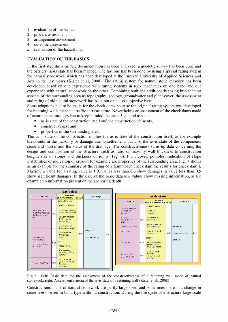
Another part of evaluation of the basics was to check the masonry status at the upstream face of some
of the check dams and to verify some structural elements. This was done by excavating trial pits as
spot samples at check dams IV and IVa (Fig. 8a). A walking excavator, the only construction machine
which was able to reach the check dams IV and IVa on its own, has been used to do this work. The
essential results of that work can be summarized as follows:
The status of the masonry at the upstream dam face was found better than that one at the downstream
face (Fig. 8, b and c). The decomposition of mortar in the masonry joints on the upstream face was
predominantly less than 10 cm. At the same check dam the decomposition of mortar in joints at the
downstream face often shows a greater depth, the maximum found at check dam IVa was 50 cm. The
excavation of the trial pits eliminated also some lack of clarity concerning the thickness of the
construction and the shape of the cross section.
During the drilling work water outlet at the masonry downstream side was detected approximately
1 m before the drilling bit reached the structure surface. Therefore it can be stated, that the depth of
weathering of the masonry is approximately 1 m.
The mortar found in the drillings can be described as a tamped concrete with coarse grained
aggregates and large porosity. This “mortar” is very much different from that found at the structure
surfaces. Two specimen for uniaxial compressive strength tests where obtained with the drillings. The
test result of the sample of check dam IVa was σd,R = 6 MN/m2, the test result of the sample of check
dam IV was σd,R = 15 MN/m2. In both cases the uniaxial compressive strength was very much smaller
than the values determined with the Schmidt-hammer on mortar at the check dam surfaces
- 735 -
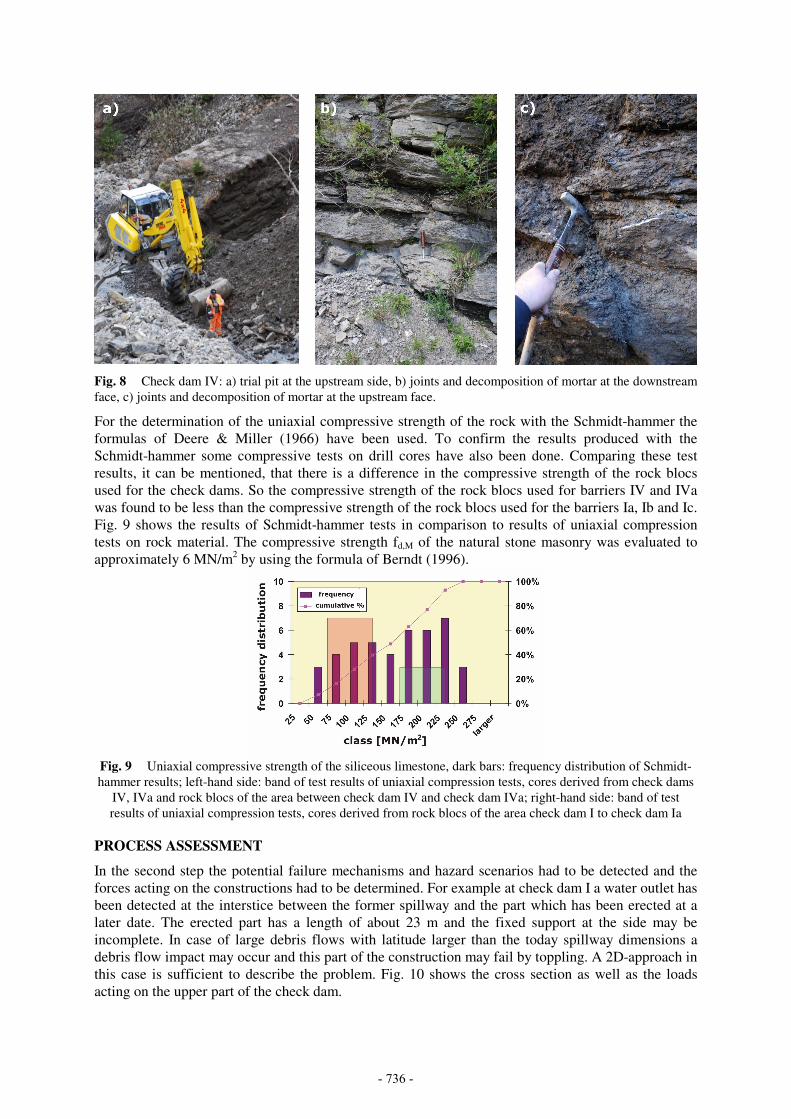
Fig. 8 Check dam IV: a) trial pit at the upstream side, b) joints and decomposition of mortar at the downstream
face, c) joints and decomposition of mortar at the upstream face.
For the determination of the uniaxial compressive strength of the rock with the Schmidt-hammer the
formulas of Deere & Miller (1966) have been used. To confirm the results produced with the
Schmidt-hammer some compressive tests on drill cores have also been done. Comparing these test
results, it can be mentioned, that there is a difference in the compressive strength of the rock blocs
used for the check dams. So the compressive strength of the rock blocs used for barriers IV and IVa
was found to be less than the compressive strength of the rock blocs used for the barriers Ia, Ib and Ic.
Fig. 9 shows the results of Schmidt-hammer tests in comparison to results of uniaxial compression
tests on rock material. The compressive strength fd,M of the natural stone masonry was evaluated to
approximately 6 MN/m2 by using the formula of Berndt (1996).
Fig. 9 Uniaxial compressive strength of the siliceous limestone, dark bars: frequency distribution of Schmidt-
hammer results; left-hand side: band of test results of uniaxial compression tests, cores derived from check dams
IV, IVa and rock blocs of the area between check dam IV and check dam IVa; right-hand side: band of test
results of uniaxial compression tests, cores derived from rock blocs of the area check dam I to check dam Ia
PROCESS ASSESSMENT
In the second step the potential failure mechanisms and hazard scenarios had to be detected and the
forces acting on the constructions had to be determined. For example at check dam I a water outlet has
been detected at the interstice between the former spillway and the part which has been erected at a
later date. The erected part has a length of about 23 m and the fixed support at the side may be
incomplete. In case of large debris flows with latitude larger than the today spillway dimensions a
debris flow impact may occur and this part of the construction may fail by toppling. A 2D-approach in
this case is sufficient to describe the problem. Fig. 10 shows the cross section as well as the loads
acting on the upper part of the check dam.
- 736 -

Fig. 10 water outlet and cross section of check dam I, position of the water outlet at 5 m below the capstone
In the literature different approaches can be found for the debris flow impact. In general one can
distinguish between hydrostatic and hydrodynamic approaches. The hydrostatic approach of
Lichtenhahn
MuMuMu hgkq ×××= ρ (1)
has been used as well as two hydrodynamic approaches (e.g. in Egli, 2006):
2
5.0 MuMudMu vcq ×××= ρ (2)
2
MuMuMu vaq ××= ρ (3)
Hereby qMu is the load due to debris flow impact, ρMu, hMu and vMu are the density, the height and the
velocity of the debris flow. The parameters k, cd and a may vary according to the properties of the
debris flow (coarse or fine grained material, low or high velocity of the debris flow, etc.).
In the case of the Lammbach check dams the area behind the spillway is completely filled up with
debris and a debris flow impact force as described before will therefore only act at the dam’s wings
where the backfilling is not completed up to the crest. At the spillway an overtopping of the check
dam by the debris flow will occur and the stress due to fluid shear acts on the check dam in this case.
Two different models have been studied in the project to estimate the fluid shear stress of a debris
flow. The first one is based on normal bedload transport (LfU, 2002):
bedMuMush hg Θ×××= sinρτ (4)
where ϴbed is the mean channel gradient. A second model was developed by Iverson (2005):
bedbedbedMuMush phg ϕρτ tan)cos'( 2×−Θ×××= (5)
Fig. 11 a) overtopping of a check dam by a debris flow (WSL, 2000), b) correlation of stress due to fluid shear
and slope angle, comparison of 2 models, marked area is decisive for the Lammbach check dams.
b) a)
- 737 -

This model takes into account the friction angle φbed as well as the pore pressure pbed in the boundary
layer between debris flow and subsoil. The pore pressure pbed was assumed to be 15 kN/m2 and was
taken from data measured by McArdell et al. (2007) at the Illgraben in Switzerland.
For a debris flow with a density ρMu = 1800 kg/m3 and a height hMu = 3 m the correlation of stress due
to fluid shear and channel gradient respective slope angle is shown for both models in Fig. 11. The red
marked area is the representative interval for the gradient in the Lammbach gorge.
ARRANGEMENT ASSESSMENT
The 3rd
step deals with the estimation of the functional capability of the adopted measure. The
structural safety as well as the fitness for purpose of the structures has to be checked. An example for
loss of effectiveness due to aggradation is check dam V. Today this barrier is covered by debris
except for a very small part at the eastern barrier wing (Fig. 12c). At the spillway the thickness of the
debris layer today is several meters. Therefore check dam V has lost its fitness for purpose according
to the primary design (cp. Fig. 2). But even in this status the check dam is of high importance for the
complete torrent control system because in case of a large debris flow it limits the erosion of material
to the level of the barrier’s crown.
Fig. 12 Changes at check dam V: a) when finished in 1904, b) increased in height in 1936, c) the only visible
part of check dam V today (OIK).
Check dams III and IVa are examples for an increasing load at the upstream side of the barriers due to
aggradation. The results of the photogrammetric survey in the Lammbach gorge show for example the
steady rise of material behind check dam IVa within a period of the last 65 years. Additional on both
check dams changes had been done at the supporting structure in the context of rehabilitation
measures. Because of the complexity in geometry, load cases and material behavior of those 2 large
check dams III and IVa, 3D-Finite-Element calculations had been chosen for the analysis of the
structural safety. Fig. 13a shows the 3D-FE-mesh of check dam IVa used for the calculations. It
consists of 25’160 3D-elements, 49 discrete anchor elements and 1’393 interface elements. The
calculations have been done using linear elastic and elastic-plastic material behavior for the check
dam. Mohr-Coulomb failure criterion and a tension-cut-off model as well as the multi-laminate model
have been used to simulate the masonry. For the subsoil and the securing mean (concrete slab,
buttresses and anchors) elastic behavior has been chosen.
The calculations for check dam IVa show a deformation which was less than 10 cm in maximum. The
anchor load show a value which is nearby, but lower than the tolerable value. Therefore even if the
water level rises up to the level of the spillway and a debris flow occur additionally the calculations
show no failure of check dam IVa.
- 738 -

Fig. 13 a) 3D-FE-mesh of check dam IVa and the subsoil, b) deformed mesh of check dam IVa for a calculation
with a tension cut-off model τTC = 10 kN/m2, shown is the last load case: overtopping by debris flow.
OUTCOME ASSESSMENT
The outcome assessment, the 4th step of the procedure, handles the evaluation of uncertainties and the
resulting risks. Uncertainties are given for example by incomplete project documentation of the
constructions and by variation in material parameters.
REALIZATION OF THE HAZARD MAP
Based on the results of the previous 4 steps different scenarios had been analyzed. The most likely
scenario acts on the assumption of the failure respectively partial failure of several dams, but check
dam IVa will remain stable. The scenario starts with a large landslide in the middle of the Lammbach
gorge. Approximately 50’000 m3 material of this landslide will form a debris flow running down the
valley and eroding further debris masses. This will result in
• an overtopping of check dam IVa by approximately 95’000 m3 of debris, but the dam itself
will remain stable,
• a debris flow of approximately 220’000 m3, which will reach the top of the fan.
This will be a scenario with a return period of 300 years. For an extraordinary event it is assumed that
all check dams will fail, i.e. check dam IVa too. In this case approximately 790’000 m3 of debris will
reach the top of the fan.
Fig. 14 Hazard maps obtained with different scenarios: a) failure of check dam IVa, debris flow volume at the
fan apex will be approx. 790'000 m3, b) check dam IVa remains stable, a debris flow volume of approx.
95'000 m3 is overtopping check dam IVa, a volume of 220’000 m
3 debris will reach the fan apex.
In comparison to a scenario taking into account the failure of all dams, the scenario of a 300 year
event shows a significant smaller so called “red area” in the hazard map, which is the area where the
construction of new buildings is prohibited (Fig. 14). To choose this scenario as the most likely
b) a)
b) a)
- 739 -

scenario was only possible due to the engineering assessment of the as-is-state of the 100 years old
Lammbach check dams.
CONCLUSIONS
The assessment of the 100-years old torrent control structures in the Lammbach gorge is a very
complex and ambitious task which necessitate the close collaboration of experts of different
disciplines. As shown before not all barriers in the Lammbach gorge show the fitness for purpose and
the structural safety after a period of 100 years. But with the reconditioning done in the past the
analysis of check dam IVa showed the structural safety of that barrier. And this results in a significant
reduction of the mass of a potential debris flow, which may reach the inhabited area at Lake Brienz in
case of a 300 year event.
Uncertainties are given especially by missing or ambivalent data concerning the barriers’ geometry
and composition. Not all of those uncertainties can be eliminated within reasonable operating expense
by exploration and investigation. Additionally there is an incomplete knowledge concerning debris
flows. Further research is needed to get a better understanding of the debris flow load cases and to
reduce uncertainties in this domain.
ACKNOWLEDGEMENTS
The authors would like to thank the local authorities of the villages Schwanden, Hofstetten, Brienz
and Brienzwiler as well as the Civil Engineering Office of the Canton Bern for the patronage and their
support in the project.
REFERENCES
Bauer W. (1971). Die Brienzer Wildbäche, Internationale Forschungsgesellschaft interpraevent.
Berndt E. (1996). Zur Druck- und Schubfestigkeit von Mauerwerk – experimentell nachgewiesen an
Strukturen aus Elbsandstein, Bautechnik, 73, Heft 4.
BWW, BRP & BUWAL (1997). Berücksichtigung der Hochwassergefahren bei raumwirksamen
Tätigkeiten, Empfehlungen. Bundesamt für Wasserwirtschaft (BWW), Bundesamt für
Raumplanung (BRP), Bundesamt für Umwelt, Wald und Landschaft (BUWAL):
www.bafu.admin.ch/publikationen.
Deere D.U., Miller R.P. (1966). Engineering classification and index properties for intact rock,
University of Illinois, Technical Report No. AFWL-TR-65-116.
Egli T. (2006). Wegleitung Objektschutz gegen gravitative Naturgefahren, Vereinigung Kantonaler
Feuerversicherungen (2nd edition), Bern.
Iverson R.M. (2005). Debris flow mechanics, in: Debris-flow hazards and related phenomena, Ed.:
Jakob, M, & Hungr, O.; Springer-Verlag.
Kister B., Zimmerli B., Fellmann W. (2008). Über die Problematik einer systematischen Bewertung
des Zustandes von älteren Stützbauwerken aus Natursteinmauerwerk, 6. Kolloquium Bauen in
Boden und Fels, Technische Akademie Esslingen.
LfU - Landesanstalt für Umweltschutz Baden-Württemberg (2002). Arbeitsanleitung Pegel- und
Datendienst Baden-Württemberg – Hydraulische Berechnung von Fliessgewässern.
McArdell B.W., Bartelt P., Kowalski J. (2007). Field observation of basal forces and fluid pore
pressure in a debris flow, Geophys. Res. Letters, Vol. 34.
OIK: Tiefbauamt des Kantons Bern, Oberingenieurkreis I, Schlossberg 20, CH-3601 Thun.
PLANAT (2008). Wirkung von Schutzmassnahmen, Projekt A 3, Schlussbericht 2. Phase, Test-
version Dezember 2008, Umsetzung des Aktionsplanes PLANAT 2005-2008.
Rudolf-Miklau F., Agerer H. (2007). Lebensbezogenes Management für Schutzmaßnahmen der
Wildbach und Lawinenverbauung: Strategische und praktische Dimension. Wildbach und
Lawinenverbau, Heft 155, 71. Jahrgang, Juni 2007, 30 – 42.
WSL: http://www.wsl.ch/fe/lms/prozesse/murgang/videos/index_DE
Zimmermann M. (2006). Prognose von Murganggefahren: Wie sicher ist sie? Bull. angew. Geol., Vol.
11/2: p. 65-73.
- 740 -