Analysis of Jet Fan Ventilation System installed in an ...
12
Journal of Sustainable Development of Energy, Water and Environment Systems http://www.sdewes.org/jsdewes Year 2018, Volume 6, Issue 2, pp 228-239 228 ISSN 1848-9257 Journal of Sustainable Development of Energy, Water and Environment Systems http://www.sdewes.org/jsdewes Analysis of Jet Fan Ventilation System installed in an Underground Car Park with Partition Walls Željko Špiljar *1 , Miodrag Drakulić 2 , Daniel Rolph Schneider 3 1 Invento Pro, Prilaz Ivana Visina 1-3, Zagreb, Croatia e-mail: [email protected] 2 CTP Projekt, Ulica Frana Vrbanića 22/II, Zagreb, Croatia e-mail: [email protected] 3 University of Zagreb, Faculty of Mechanical Engineering and Naval Architecture, Ivana Lučića 5, 10000 Zagreb, Croatia e-mail: [email protected] Cite as: Špiljar, Ž., Drakulić, M., Schneider, D. R., Analysis of Jet Fan Ventilation System installed in an Underground Car Park with Partition Walls, J. sustain. dev. energy water environ. syst., 6(2), pp 228-239, 2018, DOI: https://doi.org/10.13044/j.sdewes.d5.0180 ABSTRACT The jet fan ventilation system is one of various ventilation systems available for the purpose of carbon monoxide extraction in underground car parks. Such a system is dependent not only on the rules applied during the design, but also the architecture of the underground car park. This paper describes a numerical model used to analyse air stagnation areas, airflow and streamline patterns and the influence of partition walls on the jet fan ventilation system. Additional focus is on the validity of the choice of the jet fan ventilation system for the underground car parks with partition walls. Results show that jet fan ventilation system is not suitable for all underground car park architecture layouts. KEYWORDS Underground car park, Partition wall, Jet fan ventilation system, Numerical modelling. INTRODUCTION Ducted ventilation system, jet fan ventilation system and system with extraction fans are mechanical ventilation systems available for day-to-day ventilation in underground car parks. Mechanical ventilation systems depend on the rules applied during design and on the underground car park architecture. The main task of mechanical ventilation is to extract harmful exhaust gases from an underground car park. Exhaust gases, primarily Carbon monoxide (CO), Hydrocarbons (HC), Nitrogen oxides (NOx), Sulphur oxides (SOx) and Lead (Pb) cause poor air quality in an underground car park. CO is recognised as one of the most important pollutants, due to its toxicity and damaging impact on human health. This gas is colourless, odourless and tasteless, but highly toxic. Therefore, CO poisoning is the most common type of fatal air poisoning. If mechanical or natural ventilation is not sufficient in the enclosed environments, exhaust gas concentrations can cause problems to the human body and even lead to death [1]. * Corresponding author
-
Upload
khangminh22 -
Category
Documents
-
view
4 -
download
0
Transcript of Analysis of Jet Fan Ventilation System installed in an ...

Journal of Sustainable Development of Energy, Water
and Environment Systems
http://www.sdewes.org/jsdewes
Year 2018, Volume 6, Issue 2, pp 228-239
228
ISSN 1848-9257
Journal of Sustainable Development
of Energy, Water and Environment
Systems
http://www.sdewes.org/jsdewes
Analysis of Jet Fan Ventilation System installed in an Underground
Car Park with Partition Walls
Željko Špiljar*1, Miodrag Drakulić2, Daniel Rolph Schneider3
1Invento Pro, Prilaz Ivana Visina 1-3, Zagreb, Croatia e-mail: [email protected]
2CTP Projekt, Ulica Frana Vrbanića 22/II, Zagreb, Croatia e-mail: [email protected]
3University of Zagreb, Faculty of Mechanical Engineering and Naval Architecture, Ivana Lučića 5, 10000 Zagreb, Croatia
e-mail: [email protected]
Cite as: Špiljar, Ž., Drakulić, M., Schneider, D. R., Analysis of Jet Fan Ventilation System installed in an Underground Car Park with Partition Walls, J. sustain. dev. energy water environ. syst., 6(2), pp 228-239, 2018,
DOI: https://doi.org/10.13044/j.sdewes.d5.0180
ABSTRACT
The jet fan ventilation system is one of various ventilation systems available for the purpose of carbon monoxide extraction in underground car parks. Such a system is dependent not only on the rules applied during the design, but also the architecture of the underground car park. This paper describes a numerical model used to analyse air stagnation areas, airflow and streamline patterns and the influence of partition walls on the jet fan ventilation system. Additional focus is on the validity of the choice of the jet fan ventilation system for the underground car parks with partition walls. Results show that jet fan ventilation system is not suitable for all underground car park architecture layouts.
KEYWORDS
Underground car park, Partition wall, Jet fan ventilation system, Numerical modelling.
INTRODUCTION
Ducted ventilation system, jet fan ventilation system and system with extraction fans are mechanical ventilation systems available for day-to-day ventilation in underground car parks. Mechanical ventilation systems depend on the rules applied during design and on the underground car park architecture. The main task of mechanical ventilation is to extract harmful exhaust gases from an underground car park. Exhaust gases, primarily Carbon monoxide (CO), Hydrocarbons (HC), Nitrogen oxides (NOx), Sulphur oxides (SOx) and Lead (Pb) cause poor air quality in an underground car park. CO is recognised as one of the most important pollutants, due to its toxicity and damaging impact on human health. This gas is colourless, odourless and tasteless, but highly toxic. Therefore, CO poisoning is the most common type of fatal air poisoning. If mechanical or natural ventilation is not sufficient in the enclosed environments, exhaust gas concentrations can cause problems to the human body and even lead to death [1].
* Corresponding author

Journal of Sustainable Development of Energy, Water
and Environment Systems
Year 2018
Volume 6, Issue 2, pp 228-239
229
Different mathematical models for turbulence are used in Computational Fluid Dynamics (CFD). Their main objective is analysis of air stagnation areas, the influence of fans positioning in the underground car parks to reduce and eliminate air stagnation areas and, finally, mechanical ventilation system optimisation. Numerical modelling is of great importance in the design of mechanical ventilation enabling healthy air quality and sufficient air flow rate. Comparing results obtained with the standard k-ε turbulence model to the Large Eddy Simulation (LES) shows the sensitivity of the results on the mesh cell size [2]. Although there is a similarity between jet fan ventilation system in the underground car parks with longitudinal tunnel ventilation, because of differences in aspect ratio and mechanical ventilation systems, an extensive numerical simulation analysis has been performed with CFD [3].
In order to guarantee healthy air quality in an underground car park, a necessary extraction velocity is required. Such velocity depends on the interaction between ceiling jet and the flow driven by jet fans [4]. Parameters such as jet fan position, air velocity, fan orientations, inlet and outlet positions have to be carefully determined [5]. Effects of flow generated by jet fans cause dilution of the pollution peaks, but removal efficiency depends on the distance between jet fans [6]. Extraction position has great influence on the removal of pollutants from underground car parks [7]. CO concentration in the breathing zone has a strong relation to the fan position [8]. Stagnation areas, streamlines and air quality can be checked separately for any time interval in any section of an underground car park. One of the numerical modelling challenges is to recognise those fans that do not contribute to the mechanical ventilation efficiency [9]. CFD is a useful tool but requires validation by comparing the simulation results with the experimental data [10].
When the air quality in an underground car park is considered, Local Mean Age (LMA) is one of the most important parameters [11]. The LMA is defined as the average time for the air to reach the arbitrary point of the underground car park since air entry into the underground car park. The concept of LMA helps reposition and determine the optimal number of jet fans. Increasing the number of jet fans does not improve mechanical ventilation system efficiency. Using LMA concept in the design shows the length of the time of the stagnation areas in different sections in an underground car park [12]. To improve air quality in underground car parks, various mechanical ventilation strategies have been developed. Periodically Reversible Supply/extraction Ventilation (PRESEV) has a potential advantage compared to conventional mechanical ventilation [13], but the implementation of PRESEV strategy may have limitations [14]. Although CO is the most dangerous exhaust gas, SOx and NOx have an influence on air quality in the underground car parks as well [15]. Usually, mechanical ventilation is switched on when CO concentration increases to a certain level. Therefore, natural ventilation is important as well. But when the difference between indoor and outdoor temperatures is small, natural ventilation rate is the lowest [16]. In winter time, natural ventilation rate is significantly higher than in summer [17].
Accidents such as accidental releases of car air-conditioning refrigerants [18] or liquefied petroleum gas [19] also influence the air quality. The underground car parks for heavy duty lorries with diesel fuel engines have lower air quality and higher level of air pollutants compared to the public or residential underground car parks [20]. Research shows that homes with attached garages have a higher benzene level than homes with no attached garages and use of mechanical ventilation can reduce these benzene concentrations [21]. Current regulations are sometimes based on obsolete data. Therefore, in order to improve the mechanical ventilation system, it is necessary to analyse the factors that influence ventilation system [22]. The measurements of CO concentration, temperature and humidity show that the air quality in underground car parks has acceptable CO values [23].

Journal of Sustainable Development of Energy, Water
and Environment Systems
Year 2018
Volume 6, Issue 2, pp 228-239
230
People often do not spend much time in underground car parks, but if CO concentration increases to a dangerous level, it is necessary to evacuate people. The most important issue is the timely detection of an increase in CO levels. The same principles can be used for evacuation in the case of fire when people are expected to run to the exit [24]. Evacuation paths must be designed for all people, considering old and disabled [25].
JET FAN VENTILATION SYSTEM AND SIMULATION SETUP
In the past few decades, the practice of installing of jet fan mechanical ventilation system in underground car parks has increased. The fundamental characteristic of the jet fan ventilation system is that the jet fans are used to accelerate the air bellow the ceiling to a sufficient velocity in order to extract air pollutants from an underground car park. That particular velocity is the lowest velocity required to extract air pollutants, primarily CO. Jet fans are installed close to the ceiling and they push the air to the extraction points. It is very important that the air pollutants are effectively removed and that no significant air stagnation areas remain. Jet fan ventilation systems typically consist of three elements: fresh air supply elements, jet fans and extraction elements. Supply elements are, for example, entrance/exit ramps, ventilation shafts, side wall openings and rarely supply fans. Extraction elements can be extraction fans, ventilation shafts and wall openings.
At first sight, the jet fan ventilation system in an underground car park resembles tunnel longitudinal ventilation. However, there are differences between two systems. While tunnels typically have heights similar to widths and the lengths are very long, common underground car park heights are significantly smaller than widths, and lengths are similar to widths. In tunnels, vehicles movement is bi-directional at road speeds, while in the underground car parks is multidirectional at very low speeds. In the underground car parks passenger cars are dominant, while in the tunnels, lorries and buses account for a significant percentage. Due to an underground car park layout, airflow can be very complex. Therefore, jet fan positions, directions and speed must be carefully determined. The air flow in tunnels is essentially unidirectional, and mathematical models and equations developed for ventilation in the tunnels become unreliable for underground car parks. Numerical modelling is a more useful tool to accurately predict the air flow patterns.
These systems depend on the architecture of an underground car park. In this case study, numerical modelling has been deployed for an underground car park in Croatia. The main objective was to analyse air stagnation areas, airflow and streamline patterns and influence of partition walls on the jet fan ventilation system. Additional focus was on the validation of the choice of the jet fan ventilation system for ventilation of underground car parks with partition walls. Humans typically do not spend much time in the underground car parks and, therefore, carbon monoxide poisoning in the underground car parks is very rare. Thus, designs differ between day-to-day ventilation (carbon monoxide extraction) and smoke extraction ventilation (in the case of fire). Design differences are, for example, number of fans and fan positions. The jet fan ventilation system designed for smoke extraction must be also suitable for day-to-day ventilation.
In this case, installed jet fan ventilation system is used only for day-to-day ventilation and for carbon monoxide extraction. Smoke extraction is not considered in the modelling. Fire protection is provided with installed sprinkler installation. Therefore, installed fans are not high-temperature rated (neither extraction fans nor jet fans), and the jet fan positions are not designed for smoke extraction.
An underground car park features one underground level intended as a parking area, as shown in Figure 1. Vertical evacuation stairs are denoted with letters A-D. Evacuation stairs entrance directions are:

Journal of Sustainable Development of Energy, Water
and Environment Systems
Year 2018
Volume 6, Issue 2, pp 228-239
231
• Evacuation stairs A – “North”; • Evacuation stairs B – “East”; • Evacuation stairs C – “East”; • Evacuation stairs D – “East”.
Figure 1. Underground car park layout (case-study)
Vehicular movement is designated by one entrance/exit ramp. Design loads of upper floors are supported by partition walls and beams. The computational analysis took into account the geometrical complexity, including all vertical and horizontal obstructions to the air flow, partition walls and beams. An empty underground car park has been assumed to simplify the setup. Main underground car park geometric particulars are shown in Table 1.
Table 1. Main underground car park geometric particulars
Ordinal Title Symbol Value
1. Length [m] L 56.40 2. Width [m] B 67.75 3. Height [m] h 2.60 4. Net parking area [m2] A 2,651.8 5. Volume [m3] V 6,894.7
Extraction and jet fan technical data are shown in Table 2. Neither jet fans nor
extraction fans are reversible.
Table 2. Extraction and jet fan technical data
Jet fan Extraction fan Diameter [mm] Capacity [m3/h] Diameter [mm] Capacity [m3/h]
400 3.600 710 24.000

Journal of Sustainable Development of Energy, Water
and Environment Systems
Year 2018
Volume 6, Issue 2, pp 228-239
232
Fresh air ventilation shafts, entrance/exit ramp, extraction fans and jet fan positions are shown in Figure 2. Entrance/exit is modelled as the opening (width × height). All other openings have no influence on the mechanical ventilation system and are not considered. Underground car park floors analysed in this study are the below-ground level (−1) and the ground floor above the ceiling of −1 level. All walls and beams are made of concrete.
Figure 2. Ventilation shafts and fans position
Installed jet fan ventilation system provides 18 m3/h per m2 of floor area. Jet fans are mounted 0.05 m below the ceiling and jet fan outlets are equipped with deflectors, which direct outlet air flow at the angle of five degrees downward. Jet fan operating directions are shown in Figure 3.
Figure 3. Jet fan operating x and y directions
The CFD analysis has been carried out using commercial Ansys/Fluent software. The main features of numerical simulations were three-dimensional spatial discretization, unsteady time modelling scheme, viscous turbulent flow type and k-ε turbulence model. Analysis has been characterised by the acceleration of fluid inside of the domain via mechanical ventilation. Initial velocity field, induced by density gradient,
Journal of Sustainable Development of Energy, Water
and Environment Systems
Year 2018
Volume 6, Issue 2, pp 228-239
233
was superimposed on the velocity field caused by the mechanical ventilation system. Jet fans operated at maximum speed from the moment of activation to the end of the simulation. The mesh used for computations was of unstructured prismatic, tetrahedral and hexahedral type, consisting of approximately 2.3 million cells. Computational domain outline and detail are shown in Figure 4.
Figure 4. Computational domain outline and detail
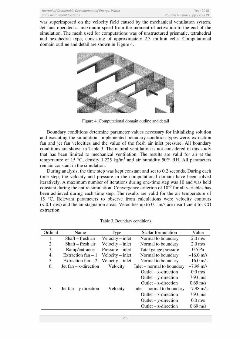
Boundary conditions determine parameter values necessary for initializing solution and executing the simulation. Implemented boundary condition types were: extraction fan and jet fan velocities and the value of the fresh air inlet pressure. All boundary conditions are shown in Table 3. The natural ventilation is not considered in this study that has been limited to mechanical ventilation. The results are valid for air at the temperature of 15 °C, density 1.225 kg/m3 and air humidity 50% RH. All parameters remain constant in the simulation.
During analysis, the time step was kept constant and set to 0.2 seconds. During each time step, the velocity and pressure in the computational domain have been solved iteratively. A maximum number of iterations during one-time step was 10 and was held constant during the entire simulation. Convergence criterion of 10−5 for all variables has been achieved during each time step. The results are valid for the air temperature of 15 °C. Relevant parameters to observe from calculations were velocity contours (< 0.1 m/s) and the air stagnation areas. Velocities up to 0.1 m/s are insufficient for CO extraction.
Table 3. Boundary conditions
Ordinal Name Type Scalar formulation Value
1. Shaft – fresh air Velocity ‒ inlet Normal to boundary 2.0 m/s 2. Shaft – fresh air Velocity ‒ inlet Normal to boundary 2.0 m/s 3. Ramp/entrance Pressure ‒ inlet Total gauge pressure 0.5 Pa 4. Extraction fan − 1 Velocity − inlet Normal to boundary −16.0 m/s
5. Extraction fan − 2 Velocity − inlet Normal to boundary −16.0 m/s 6. Jet fan – x-direction Velocity Inlet – normal to boundary −7.98 m/s
Outlet ‒ x-direction 0.0 m/s Outlet ‒ y-direction 7.93 m/s Outlet ‒ z-direction 0.69 m/s
7. Jet fan – y-direction Velocity Inlet – normal to boundary −7.98 m/s Outlet ‒ x-direction 7.93 m/s Outlet ‒ y-direction 0.0 m/s Outlet ‒ z-direction 0.69 m/s

Journal of Sustainable Development of Energy, Water
and Environment Systems
Year 2018
Volume 6, Issue 2, pp 228-239
234
RESULTS
In the Figures 5a, 5b, 6a, and 6b, air stagnation areas are presented through velocity contours at different heights. Velocity contours show the air movement in an underground car park. Different colours present velocity values between v = 0-0.1 m/s. Areas with no colour show velocities above 0.1 m/s. Due to the jet fan influence, velocity value at 2.0 m height is very high. It is observed that up to 45% of the air in an underground car park has velocity lower than 0.1 m/s.
Velocity v [m/s]
Velocity v [m/s]
Figure 5a. Air stagnation areas, height 0.5 m Figure 5b. Air stagnation areas, height 1.0 m
Velocity v [m/s]
Velocity v [m/s]
Figure 6a. Air stagnation areas, height 1.5 m Figure 6b. Air stagnation areas, height 2.0 m
In Table 4 air stagnation areas and maximum velocity values at different heights are
shown. Although maximum velocity values reach up to 2.6 m/s, almost 50% of the air has insufficient extraction velocity. Between partition walls, air movement is significantly low. Only the places in an underground car park with no partitions walls have sufficient extraction velocity. Beams have no influence on jet fan ventilation system in this case. Results in Table 4 show that air stagnation areas are smaller close to the floor of an underground car park. The largest air stagnation areas (44.74%) form in the breathing zone, at approximately 1.5 m height.

Journal of Sustainable Development of Energy, Water
and Environment Systems
Year 2018
Volume 6, Issue 2, pp 228-239
235
Table 4. Max. velocities and air stagnation areas
Ordinal Height from the floor
[m] Max. velocity
[m/s] Air stagnation area
[m2] Air stagnation area
[%] 1. 0.5 1.231 996.00 37.56 2. 1.0 1.578 1,165.00 43.93 3. 1.5 2.582 1,186.50 44.74 4. 2.0 17.016* 1,042.00 39.30
* Due to the jet fan influence, the velocity value at 2.0 m height is very high
Figures 7a and 7b show that, although air velocity increases closer to the ceiling
where jet fans are installed, the percentage of air stagnation areas increases as well. Only above 1.5 m, air stagnation area decreases, due to the jet fans influence. Air velocity in an underground car park increases from the floor to the ceiling, but that increase has no effect in reducing air stagnation area. Therefore, a huge impact of partition walls on jet fan mechanical ventilation system is obvious.
Figure 7a. Air velocity as a function of height Figure 7b. Air stagnation area as a function of height
In the Figures 8a, 8b, 9a and 9b, air flow patterns are presented via velocity contours at
different heights. Velocity contours show the air movement in an underground car park produced by both jet fans and extraction fans. Different colours present velocity values between v = 0-2.0 m/s. The huge stagnation air areas with no velocity at all are clearly visible. Only close to the jet fan outlets, air velocity is approximately up to 2.0 m/s. Even on the extraction fan inlets, air velocity cannot reach 1.5 m/s.
Velocity v [m/s]
Velocity v [m/s]
Figure 8a. Air flow pattern, height 0.5 m Figure 8b. Air flow pattern, height 1.0 m

Journal of Sustainable Development of Energy, Water
and Environment Systems
Year 2018
Volume 6, Issue 2, pp 228-239
236
Velocity v [m/s] Velocity v [m/s]
Figure 9a. Air flow pattern, height 1.5 m Figure 9b. Air flow pattern, height 2.0 m
Streamline patterns are presented in Figures 10a, 10b, 11a and 11b. Streamlines are curves drawn through a fluid to indicate the motion direction in various sections of a fluid system flow, in this case, air direction in an underground car park. Air movement produced only by extraction fans is shown in Figures 10a and 10b. In Figure 10a, air movement from the fresh air shaft is shown and Figure 10b depicts the air movement from the entrance/exit ramp, both produced only by extraction fans. Partition walls block air movement and direct air from shafts and entrance/exit ramp to the extraction fans. Obviously, that system is inappropriate for the underground car parks with partition walls. Only conventional ductwork system does not depend on the partition walls. The entire space between the partition walls can be covered with exhaust grills. Therefore, CO can be sufficiently extracted from the underground car park.
Figure 10a. Extraction fans/fresh air shafts Figure 10b. Extraction fans/ramp
Figure 11a shows air movement produced only by a jet fan in the horizontal direction and Figure 11b shows air movement produced by all jet fans. Jet fan installed to the right from the entrance/exit ramp, where no obstacles are present, provides sufficient air velocity for carbon monoxide extraction. Partition walls block the air movement produced by other jet fans and they do not contribute to the air movement, especially jet fan in the x-direction. Comparing Figures 11a and 11b, it is obvious that jet fan installed to the right from the entrance/exit ramp influences the air movement produced by a fan in the x-direction.

Journal of Sustainable Development of Energy, Water
and Environment Systems
Year 2018
Volume 6, Issue 2, pp 228-239
237
Figure 11a. Jet fan, x-direction Figure 11b. All jet fans
CONCLUSION
Various mechanical ventilation systems are available for air pollutant extraction in underground car parks: jet thrust fan systems, ducted ventilation systems and systems with extraction fans. Comparison of the extraction effectiveness of mechanical ventilation systems shows that the jet thrust fan system seems in many cases superior to the conventional ductwork system or to the system with extraction fans. But these systems depend not only on the rules applied during the design but also on the underground car park architecture. The hypothesis for this research is that jet fan ventilation system is not suitable for all underground car park architecture layouts. The main objective of the research has been to analyse the influence of partition walls on the jet fan ventilation system. Additional focus was on the validity of the choice of the jet fan ventilation system for the underground car parks with partition walls for day-to-day ventilation. An analysis of the influence of partition walls on jet fan ventilation system shows that selecting a jet fan ventilation system for underground car parks with partition walls is questionable. Up to 50% of the air in an underground car park has insufficient extraction velocity, especially in the breathing zone. Partition walls are obstacles to the air flow produced by both jet fans and extraction fans. The huge impact of partition walls on the air flow produced by jet fan mechanical ventilation system is demonstrated in the paper. If possible from the construction aspect, erect columns or walls with openings are preferred instead of partition walls. As the streamline pattern analysis showed, a system with only extraction fans is inappropriate for the underground car parks with partition walls as well. Only conventional ductwork system does not depend on the partition walls. If requested, all day-to-day ventilation systems can be part of active fire protection system. The main tasks of smoke extraction systems are life safety and reducing damage to the building in case of fire. Longer exposure of partition walls and ceiling to the hot gases can cause concrete spalling and dangerous conditions to the firemen. Therefore, the choice of the jet fan ventilation system as the mechanical system for ventilation in an underground car park with partition walls should be reconsidered.
REFERENCES
1. Demir, A., Investigation of Air Quality in the Underground and Aboveground Multi-Storey Car Parks in Terms of Exhaust emissions, Procedia – Social and
Behavioural Sciences, Vol. 195, pp 2601-2611, 2015, https://doi.org/10.1016/j.sbspro.2015.06.461
2. Deckers, X., Jangi, M., Haga, S. and Merci, B., Numerical Simulations of Flow Fields in Case of Fire and Forced Ventilation in a Closed Car Park, Proceedings of the 6th

Journal of Sustainable Development of Energy, Water
and Environment Systems
Year 2018
Volume 6, Issue 2, pp 228-239
238
International Seminar on Fire and Explosion Hazards, Leeds, UK, pp 1104-1115, 2010.
3. Tilley, N., Deckers, X. and Merci, B., CFD Study of Relation between Ventilation Velocity and Smoke Backlayering Distance in Large closed Car Parks, Fire Safety
Journal, Vol. 48, pp 11-20, 2012, https://doi.org/10.1016/j.firesaf.2011.12.005 4. Viegas, J. C., The use of Impulse Ventilation for Smoke Control in Underground Car
Parks, Tunnelling and Underground Space Technology, Vol. 25, No. 1, pp 42-53, 2010, https://doi.org/10.1016/j.tust.2009.08.003
5. Aveiro, J. L. and Viegas, J. C., Smoke Control in an Underground Car Park with Impulse Ventilation, V European Conference on Computational Fluid Dynamics, Lisbon, Portugal, 2010.
6. Viegas, J. C., The use of Impulse Ventilation to Control Pollution in Underground Parks, International Journal of Ventilation, Vol. 8, No. 1, pp 57-74, 2009, https://doi.org/10.1080/14733315.2006.11683832
7. Shang, S. W. and Xing, Y., Comparison of Air distribution of induced Ventilation System’s different Exhaust Way in Underground Garage, International Conference on
Advances in Energy and Environmental Science (ICAEES), Guangzhou, China, 2013, https://doi.org/10.4028/www.scientific.net/AMR.805-806.1547
8. Elsafty, A. F. and Abo Elazm, M. M., Improving Air Quality in enclosed Parking Facilities using Ventilation System design with the aid CFD Simulation, International
Review of Mechanical Engineering, Vol. 3, pp 796, 2009. 9. Immonen, E., CFD optimisation of Jet Fan Ventilation in a Car Park by Fractional
Designs and response Surface Methodology, Building Simulation, Vol. 9, No. 1, pp 53-61, 2016, https://doi.org/10.1007/s12273-015-0249-0
10. Brzezinska, D. and Sompolinski, M., The accuracy of mapping the Airstream of Jet Fan Ventilators by FDS, Science and Technology for the Built Environment, pp 1-12, 2016.
11. Gomma, S. M., Khalil, E. E., Fouad, M. and Medhat, A., Ventilation System design for Underground Car Park, Open Journal of Technology & Engineering Disciplines, Vol. 1, pp 30-41, 2015.
12. Gomma, S. M. and Fouad, M., Design of the Ventilation System in an Underground Car Park: Local Mean Age of Air, 13th International Energy Conversion Engineering
Conference, Orlando, USA, 2015, https://doi.org/10.2514/6.2015-4243 13. Chen, D., Periodically reversible Supply/exhaust Ventilation Strategy, Building and
Environment, Vol. 46, No. 12, pp 2590-2597, 2011, https://doi.org/10.1016/j.buildenv.2011.06.014
14. Said, A. O., Khalil, E. E., Medhat, A. and El-Bialy, E., Effect of using Grilles in Car Park through reversible Supply Exhaust Ventilation Strategy, Proceedings of the ASME 2014
12th Biennial Conference on Engineering Systems Design and Analysis, Copenhagen, Denmark, 2014, https://doi.org/10.1115/ESDA2014-20002
15. Izma, M., Nurfadhilah, O. and Khairul, B. B., Air Quality Profile in an enclosed Car Park, International Review of Mechanical Engineering, Vol. 3, pp 796-807, 2009.
16. Se-Jin, A., Hyuk-Min, K., Geum-Hee, K. and Jeong-Hoon, Y., Study of securing required Ventilation Rates and improving Mechanical Ventilation Systems for Underground Parking lots, Journal of Asian Architecture and Building Engineering, Vol. 15, No. 3, pp 659-665, 2016, https://doi.org/10.3130/jaabe.15.659
17. Ge, F. H., Liu, C. J., Yu, Q. S., Ma, C. X. and Wang, C. Q., Air pollution and Ventilation Rates in an Underground Car Park, 5th International Workshop on Energy and
Environment of Residential Buildings and 3rd International Conference on Built
Environment and Public Health, Guilin, China, 2009. 18. Koban, M. and Herrmann, D. D., Warming Potential Refrigerant HFO-1234yf in an
Automobile Garage, Process Safety Progress, Vol. 30, No. 1, pp 27-34, 2010, https://doi.org/10.1002/prs.10415

Journal of Sustainable Development of Energy, Water
and Environment Systems
Year 2018
Volume 6, Issue 2, pp 228-239
239
19. Brzezinska, D. and Markowski, A. S., Experimental investigation and CFD modelling of the Internal Car Park Environment in Case of Accidental LPG release (in press), Process
Safety and Environmental Protection, 2016, https://doi.org/10.1016/j.psep.2016.12.001 20. Li, H., Zhou, L., Ren, M., Fu, J. and Peng, P., Levels, Profiles and Gas Particle
distribution of Atmospheric PCDD/Fs in Vehicle Parking lots of a South China Metropolitan Area, Chemosphere, Vol. 94, pp 128-134, 2014, https://doi.org/10.1016/j.chemosphere.2013.09.061
21. Mallach, G., St-Jean, M., MacNeill, M., Aubin, D., Wallace, L., Shin, T., Van Ryswyk, K., Kulka, R., You, H., Fugler, D., Lavigne, E. and Wheeler, A. J., Exhaust Ventilation in attached Garages improves Residential Indoor Air Quality, International Journal of
Indoor Environment and Health, Vol. 27, No. 2, pp 487-499, 2016, https://doi.org/10.1111/ina.12321
22. Gil-Lopez, T., Sanchez-Sanchez, A. and Gimenez-Molina, C., Energy, Environmental and Economic analysis of the Ventilation System of enclosed Parking Garages: Discrepancies with the current Regulations, Applied Energy, Vol. 113, pp 622-630, 2014, https://doi.org/10.1016/j.apenergy.2013.08.012
23. Gladyszewska-Fiedoruk, K. and Nieciecki, M., Indoor Air Quality in a Multi-car Garage, International Scientific Conference “Environmental and Climate
Technologies”, Riga, Latvia, 2015. 24. Srinivasan, A. R., Karan, F. S. N. and Chakraborty, S., Pedestrian Dynamics with
explicit sharing of Exit Choice during egress through a long Corridor, Physica A:
Statistical Mechanics and its Applications, Vol. 468, pp 770-782, 2017, https://doi.org/10.1016/j.physa.2016.11.118
25. Boyce, M. W., Smither, J. and Fisher, D. O., Design of Instructions for evacuating disabled Adults, Applied Ergonomics, Vol. 58, pp 48-58, 2017, https://doi.org/10.1016/j.apergo.2016.05.010
Paper submitted: 03.05.2017 Paper revised: 08.07.2017
Paper accepted: 23.07.2017