Analysis of different types of braces and chord ... - IRJET
7
International Research Journal of Engineering and Technology (IRJET) e-ISSN: 2395-0056 Volume: 09 Issue: 06 | Jun 2022 www.irjet.net p-ISSN: 2395-0072 © 2022, IRJET | Impact Factor value: 7.529 | ISO 9001:2008 Certified Journal | Page 2816 Analysis of different types of braces and chord connection in (CFST) k -joints under various boundary conditions Anooja Mariya Jose 1 , Geethika.G. Pillai 2 , Dr. Ajmal Muhammad 3 1 M. Tech student, Dept. of Civil Engineering, Indira Gandhi Institute of Polytechnic & Engineering, Kerala, India. 2 Asst. Professor, Dept. of Civil Engineering, Indira Gandhi Institute of Polytechnic & Engineering, Kerala, India. 3 HOD, Dept. of Civil Engineering, Indira Gandhi Institute of Polytechnic & Engineering, Kerala, India. ---------------------------------------------------------------------***--------------------------------------------------------------------- Abstract - Reusing structural elements is an effective way to prompt sustainable development with reduced energy consumption and gas emission. In current practice, steel members can be easily deconstructed and reused whilst the recycling of structural materials in steel-concrete composite construction has been found challenging. With the increasing material consumption in composite construction due to their well-recognized structural benefits, it is essential to explore the demountability of such structures. Limited previous research indicates that there is a lack of understanding or mature design specification for demountable composite connections. This paper thus presents an innovative design of demountable K-joints with concrete-filled steel tubular (CFST) chords and circular hollow section (CHS) braces connected using blind bolts. A detailed finite element analysis (FEA) modelling was established and validated against reported test data on bolted CFST connections. The model was then used to investigate the performance of different shapes of braces in k- joint. Also, it was analysed to find out which brace angle of the k joint gives the better performance and for parametric investigation using the length (gap) between the braces. Key Words: FEA, CFST, k joint, CHS, demountability, composite construction. 1.INTRODUCTION Total world crude steel production in 2017 was 1689 million tones, approximately 50% of which was attributed to buildings and infrastructure. To reduce the negative environmental effect, it is encouraged worldwide to reuse constructional materials. The idea of reusing structural steel has been adopted in practical designs such as the Sydney Olympic stadium and temporary carpark in UK. Generally, the key design of such demountable structures lies in their deconstructive connections, which are usually achieved by using demountable shear connectors or blind bolts.[3] CFST (concrete-filled steel tubular) K-joint is joints with concrete-filled steel tubular (CFST) chords and hollow section braces connected using blind bolts. CFST K-joints formed by concrete filled chords and hollow section (CHS) braces are likely used in practice. The infilled chord concrete contributed to restraining the surface plasticity failure and enhanced the tensile performance for tubular connections and the overall structure. They are commonly used in large scale structures, e.g., long-span bridges and transmission towers, and temporary structures such as offshore platforms.[1] A tubular joint is one of the efficient joint forms commonly used in steel tubular structures. It has the advantages of less steel consumption, good mechanical behaviour, clear path of force transmission and large bearing capacity. Hybrid tubular K-joints with circular braces and square chord meet the requirements of structural form and mechanical properties and are easy to design and construct, which are widely used in practical engineering. On the other hand, stainless steel structures have the advantages of good durability, easy processing, high-temperature resistance, excellent mechanical properties and beautiful appearance. They have been paid more and more attention in architectural and structural designs. 1.1 Objective The main objectives of this study are: To investigate the performance of different shapes of braces in the K-joint. To examine which brace angle of the k joint gives the better performance. To study the performance of different gap distances between the braces in the K-joint. 1.2 Scope The study focuses on the finite element analysis of k - joint using different position, angles, cross section of braces under nonlinear conditions. The study is only limited to k-joint used for structural steel hollow sections. 2. VALIDATION In general, validation is the process of determining the extent to which the model represents the real-life situation. For validation the force verses displacement graph obtained
-
Upload
khangminh22 -
Category
Documents
-
view
7 -
download
0
Transcript of Analysis of different types of braces and chord ... - IRJET

International Research Journal of Engineering and Technology (IRJET) e-ISSN: 2395-0056
Volume: 09 Issue: 06 | Jun 2022 www.irjet.net p-ISSN: 2395-0072
© 2022, IRJET | Impact Factor value: 7.529 | ISO 9001:2008 Certified Journal | Page 2816
Analysis of different types of braces and chord connection in
(CFST) k -joints under various boundary conditions
Anooja Mariya Jose1, Geethika.G. Pillai2, Dr. Ajmal Muhammad3
1M. Tech student, Dept. of Civil Engineering, Indira Gandhi Institute of Polytechnic & Engineering, Kerala, India. 2Asst. Professor, Dept. of Civil Engineering, Indira Gandhi Institute of Polytechnic & Engineering, Kerala, India.
3 HOD, Dept. of Civil Engineering, Indira Gandhi Institute of Polytechnic & Engineering, Kerala, India. ---------------------------------------------------------------------***---------------------------------------------------------------------Abstract - Reusing structural elements is an effective way to prompt sustainable development with reduced energy consumption and gas emission. In current practice, steel members can be easily deconstructed and reused whilst the recycling of structural materials in steel-concrete composite construction has been found challenging. With the increasing material consumption in composite construction due to their well-recognized structural benefits, it is essential to explore the demountability of such structures. Limited previous research indicates that there is a lack of understanding or mature design specification for demountable composite connections. This paper thus presents an innovative design of demountable K-joints with concrete-filled steel tubular (CFST) chords and circular hollow section (CHS) braces connected using blind bolts. A detailed finite element analysis (FEA) modelling was established and validated against reported test data on bolted CFST connections. The model was then used to investigate the performance of different shapes of braces in k-joint. Also, it was analysed to find out which brace angle of the k joint gives the better performance and for parametric investigation using the length (gap) between the braces.
Key Words: FEA, CFST, k joint, CHS, demountability, composite construction.
1.INTRODUCTION Total world crude steel production in 2017 was 1689 million tones, approximately 50% of which was attributed to buildings and infrastructure. To reduce the negative environmental effect, it is encouraged worldwide to reuse constructional materials. The idea of reusing structural steel has been adopted in practical designs such as the Sydney Olympic stadium and temporary carpark in UK. Generally, the key design of such demountable structures lies in their deconstructive connections, which are usually achieved by using demountable shear connectors or blind bolts.[3] CFST (concrete-filled steel tubular) K-joint is joints with concrete-filled steel tubular (CFST) chords and hollow section braces connected using blind bolts. CFST K-joints formed by concrete filled chords and hollow section (CHS) braces are likely used in practice. The infilled chord concrete contributed to restraining the surface plasticity failure and
enhanced the tensile performance for tubular connections and the overall structure. They are commonly used in large scale structures, e.g., long-span bridges and transmission towers, and temporary structures such as offshore platforms.[1] A tubular joint is one of the efficient joint forms commonly used in steel tubular structures. It has the advantages of less steel consumption, good mechanical behaviour, clear path of force transmission and large bearing capacity. Hybrid tubular K-joints with circular braces and square chord meet the requirements of structural form and mechanical properties and are easy to design and construct, which are widely used in practical engineering. On the other hand, stainless steel structures have the advantages of good durability, easy processing, high-temperature resistance, excellent mechanical properties and beautiful appearance. They have been paid more and more attention in architectural and structural designs.
1.1 Objective
The main objectives of this study are: To investigate the performance of different shapes of
braces in the K-joint.
To examine which brace angle of the k joint gives the better performance.
To study the performance of different gap distances between the braces in the K-joint.
1.2 Scope
The study focuses on the finite element analysis of k - joint using different position, angles, cross section of braces under nonlinear conditions. The study is only limited to k-joint used for structural steel hollow sections.
2. VALIDATION In general, validation is the process of determining the extent to which the model represents the real-life situation. For validation the force verses displacement graph obtained

International Research Journal of Engineering and Technology (IRJET) e-ISSN: 2395-0056
Volume: 09 Issue: 06 | Jun 2022 www.irjet.net p-ISSN: 2395-0072
© 2022, IRJET | Impact Factor value: 7.529 | ISO 9001:2008 Certified Journal | Page 2817
from both experiment and numerical model from ANSYS is compared.
2.1 Geometry
The k joint consists of a chord having a span of 899mm and two circular braces of span 325mm each. The gap distance (g) of the gapped tubular K-joint was 72.6mm.
SPECIMEN: K-C-150 × 3-B-108 × 3 • Breadth of chord: 150.07 mm • Thickness of chord: 2.94 mm • Diameter of brace: 108.55 mm • Thickness of brace :2.82mm
Fig -1: Geometry of k joint
2.2 Boundary Conditions
Fig -2: Boundary conditions
A = Brace subjected to compression B = Brace subjected to tension C = chord subjected to axial displacement D = Fixed end
To stimulate the real conditions, k -joint is analysed with one side of square chord is fixed and load is applied as tension and compression on circular end plates and axial displacement on one side of square chord. The multilinear kinematic hardening rule was used for finite element analysis.
2.3 Validation Result Validation is an important part of the thesis. The geometrical dimensions and material properties of k joint was adopted from the journal referred. Finite element modelling of k joint is validated by comparing the force displacement graph of numerical model with that of experimental study as shown in chart 1 and 2. Comparing Chat – 1 and Chart – 2 it can be seen that force displacement graph from validation obtained is similar to that in the journal.
Chart -1: Force v/s displacement graph from paper [3]
Chart -2: Force v/s displacement graph from validation
3. MODELLING AND ANALYSIS The dimensions for all models were adopted from the journal and the boundary conditions was same for all models. For better understanding of the behavior of k – joints the Total deformation and equivalent stress distribution was also analysed for all the models.
International Research Journal of Engineering and Technology (IRJET) e-ISSN: 2395-0056
Volume: 09 Issue: 06 | Jun 2022 www.irjet.net p-ISSN: 2395-0072
© 2022, IRJET | Impact Factor value: 7.529 | ISO 9001:2008 Certified Journal | Page 2818
3.1 To investigate the performance of different shapes of braces in the K-joint
Fig -3: Total Deformation of k – joint with Circular braces
From the above figure it is observed that the maximum deformation of 60.973mm have been occurred at the bottom of brace. And the minimum deformation of 0.926mm have been occurred at the top of braces.
Fig -4: Equivalent stress distribution of k – joint with Circular braces
From the above figure it is observed that the maximum stress of 582.33MPa have been occurred at the bottom of braces and middle portion of the chords. And the minimum stress of 0.067MPa have been occurred at the top of braces and at the ends of chords. Table – 1: Comparison of Total deformation and Equivalent stress distribution for different shapes of braces in k - joint
Cross - section of
braces
Max value of Total Deformation in
mm
Max value of Equivalent stress in
Mpa
Circle 60.97 582.33
Rectangle 55.53 575.29
Hexagon 30.36 559.61
Pentagon 30.15 552.78
From the modelling and analysis of four different shapes of braces in the k – joint, Circular braces has the maximum stress of 582 kN and will undergo the maximum deformation of 60mm before failure.
3.2 To examine which brace angle of the k joint
gives the better performance
In the previous section, we have modelled and analysed the k – joints with 90° brace angle for investigating the performance of different shapes of braces in the K-joint. Hence in this section we have analysed Circular, Rectangular and Pentagonal braced k – joints with brace angle 70° and 110°.
Table – 2: Comparison of Total deformation and Equivalent stress distribution for different brace angles in
k – joint
Cross - section of
braces
Max value of Total Deformation in mm
Max value of Equivalent stress
in MPa
70° 90° 110° 70° 90° 110°
Circle 45 60 30 725 582 612
Rectangle 30 55 30 536 575 563
Pentagon 30 30 30 563 552 558
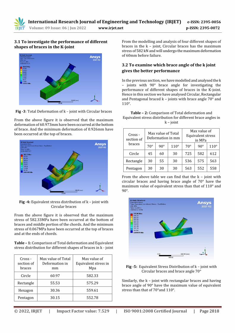
From the above table we can find that the k – joint with circular braces and having brace angle of 70° have the maximum value of equivalent stress than that of 110° and 90°.
Fig -5: Equivalent Stress Distribution of k – joint with Circular braces and brace angle 70°
Similarly, the k – joint with rectangular braces and having brace angle of 90° have the maximum value of equivalent stress than that of 70°and 110°.

International Research Journal of Engineering and Technology (IRJET) e-ISSN: 2395-0056
Volume: 09 Issue: 06 | Jun 2022 www.irjet.net p-ISSN: 2395-0072
© 2022, IRJET | Impact Factor value: 7.529 | ISO 9001:2008 Certified Journal | Page 2819
Fig -6: Equivalent Stress Distribution of k – joint with rectangular braces and brace angle 90°
And the k – joint with pentagonal braces and having brace angle of 70° have the maximum value of equivalent stress than that of 110° and 90°.
Fig -7: Equivalent Stress Distribution of k – joint with pentagonal braces and brace angle 70°
3.3 To study the performance of different gap distances between the braces in the K-joint
Table – 3: Comparison of Total deformation and Equivalent stress distribution for different brace gap
distance between the k – joint
Cross - section of
braces
Max value of Total Deformation
in mm
Max value of Equivalent
stress in Mpa
20mm 60.97 582.33
40mm 65.32 591.96
60mm 83.53 709.23
From the above table we can find that the k – joint with circular braces and gap distance of 60mm have the maximum value of equivalent stress.
Fig -8: Equivalent Stress Distribution of k – joint with circular braces and gap distance 60mm
4.RESULT AND DISCUSSION
4.1 Performance of different shapes of braces in the K-joint
The force – displacement graphs of different shapes of braces in k – joint with brace angle 90° which was obtained from ANSYS is shown below.
Chart -3: Performance of circular shaped braces in the k-joint
Chart -4: Performance of rectangular shaped braces in the k-joint

International Research Journal of Engineering and Technology (IRJET) e-ISSN: 2395-0056
Volume: 09 Issue: 06 | Jun 2022 www.irjet.net p-ISSN: 2395-0072
© 2022, IRJET | Impact Factor value: 7.529 | ISO 9001:2008 Certified Journal | Page 2820
Chart -5: Performance of pentagonal shaped braces in the k-joint
Chart -6: Performance of hexagonal shaped braces in the k-joint
The displacement applied and the corresponding forces obtained from ANSYS is summarized in the table below.
Table – 4: Comparison of shapes of braces in the k-joint
Shape of Braces Displacement
(mm) Force (KN)
Circular 30 295
Rectangular 30 94.636
Pentagon 30 85.628
Hexagon 30 84.335
From the table 4, it is clear that the best shape is choose to be circular. It holds maximum force value of 295 kN which is comparatively much higher than others.
4.2 Performance of different brace angles in the K-joint
For 30mm displacement applied the corresponding maximum forces obtained for brace angles :90°,70° and 110°
in the k -joint for circular, pentagonal and rectangular shaped braces with square chords are summarized below.
Table – 5: Comparison of max forces for different brace angles in k - joint
Cross - section of braces
Max force value from force - displacement graph in kN
70° 90° 110°
Circle 8.420 259 18.75
Rectangle 86.4 94.636 884
Pentagon 69.9 88.99 100
The force – displacement graphs of k – joints which can carry
maximum forces are illustrated below.
`
Chart -7: Performance of circular shaped braces in the k-joint with brace angle 90°
It can be concluded from the above data that k – joint with Circular shaped braces with brace angle 90° can carry max force of 259kN than other brace angles.
Chart -8: Performance of rectangular shaped braces in the k-joint with brace angle 110°

International Research Journal of Engineering and Technology (IRJET) e-ISSN: 2395-0056
Volume: 09 Issue: 06 | Jun 2022 www.irjet.net p-ISSN: 2395-0072
© 2022, IRJET | Impact Factor value: 7.529 | ISO 9001:2008 Certified Journal | Page 2821
Chart -9: Performance of pentagonal shaped braces in the k-joint with brace angle 110°
Also, k – joint with Rectangular and Pentagonal shaped braces with brace angle 110° can carry max forces than 70° and 90°.
4.3 Performance of different gap distances between the K-joint
The force - displacement graphs obtained from ANSYS for k – joints with circular shaped braces and gap distances of 20mm, 40mm and 60mm is illustrated below.
Chart -10: Performance of circular shaped braces in the k-joint with gap distance 20mm
Chart -11: Performance of circular shaped braces in the k-joint with gap distance 40mm
Chart -12: Performance of circular shaped braces in the k-joint with gap distance 60mm
The displacement applied and the corresponding maximum forces obtained for different gap distances in the k -joint for circular shaped braces with square chords are summarized in the table below.
Table – 6: Comparison of max forces for different gap distances in k - joint
Gap Distance (mm)
Displacement (mm)
Force (kN)
20 30 287
40 30 293
60 30 349
From the above table it is clear that k – joint with Circular shaped braces with 60mm gap distance can carry the max force of 349kN.
5. CONCLUSIONS The load carrying capacity of K- joint with circular braces
was higher, when compared with the other shapes of braces which can carry 295 kN at 30mm displacement.
K-joint with hexagon braces has less load carrying capacity compared to other shapes of braces which can take 83.335 kN at 30mm displacement.
K-joint with circular braces gives better performance at 90 ° brace angle. It can take 295 kN at 30mm displacement.
K-joint with other shapes of braces (rectangle, pentagon, and hexagon) gives the better performance at 110 ° brace angle. In these cases, as the angle between braces increases, the load carrying capacity also increases.
The load carrying capacity is higher in k – joint with gap distance 60 mm compared with 20mm and 40mm.

International Research Journal of Engineering and Technology (IRJET) e-ISSN: 2395-0056
Volume: 09 Issue: 06 | Jun 2022 www.irjet.net p-ISSN: 2395-0072
© 2022, IRJET | Impact Factor value: 7.529 | ISO 9001:2008 Certified Journal | Page 2822
REFERENCES [1] Basil T Babu, Manjusha Mathew, “Numerical Study of
CFST K-Joints with Different Connection Arrangements”, International Research Journal of Engineering and Technology (IRJET), Vol 8, Issue 7, pp. 1456 - 1460, 2021.
[2] Chao Hou, Lin-Hai Han, Ting-Min Mu, “Behaviour of CFDST chord to CHS brace composite K-joints: Experiments”, Journal of Constructional Steel Research, Vol 135, pp. 97-109, 2017.
[3] Dengyiding Jin, Chao Hou, Luming Shen, Lin-Hai Han, “Numerical investigation of demountable CFST K-joints using blind bolts”, Journal of Constructional Steel Research, Vol 160, pp. 428 – 443, 2019.
[4] Fang Li, Hong-zhou Deng, Xiao-yi Hu, “Design resistance of longitudinal gusset-tube K-joints with 1/4 annular plates in transmission towers”, Thin-Walled Structures, Vol 144, pp. 01-13, 2019.
[5] Ran Feng, Junwu Lina, “Numerical study of hybrid tubular K-joints with circular braces and square chord in stainless steel”, Thin-Walled Structures, Vol 145, pp.01-14, 2019.
[6] Wenwei Yang, Ruhao Yan, Yaqi Suo, Guoqing Zhang, Bo Huang, “Experimental Study on Hysteretic Behavior of the Overlapped K-Joints with Concrete Filled in Chord”, Applied Sciences, Vol 9, pp.01-17, 2019.
[7] Wenyuan Kong, Yongfa Huang, Zhan Guo, Xiaoyong Zhang, Yu Chen, “Experimental study on square hollow stainless steel tube trusses with three joint types and different brace widths under vertical loads”, Reviews on Advanced Materials Science :60, pp. 519-540, 2021.
[8] Jian Zheng, Shozo Nakamura, Kang-ming Chen and Qing-xiong Wu, ‘Numerical Parameter Analysis on Stress Concentration Factors of Concrete-filled Steel Tubular (CFST) K-joint under Axial Loading’, The 2017 World Congress on Advances in Structural engineering and Mechanics (ASEM17), September 2017.
[9] S. Saleh, C. Hou, L.H. Han, Y.X. Hua, “Numerical behaviour of composite K-joints subjected to combined loading and corrosive environment”, 12th International Conference on Advances in Steel-Concrete Composite Structures (ASCCS 2018), Spain, pp.557-564, June 2018.
[10] Ying Chen, Qingtao Yang, Dongchen Wang, “Finite Element Analysis and Optimization of the Planar Steel Tubular K-Joints”, 2021 International Conference on Intelligent Power and Systems, China, pp.01-08, 2021.