Analysis of a printed white loop antenna
7
IEEE TRANSACTIONS ON MICROWAVE THEORY AND TECHNIQUES, VOL. 42, NO. 2. FEBRUARY 1994 227 Analysis of a Printed Wire Loop Antenna Hassan A. N. Hejase Abshuct-The current distribution and radiation pattern of a printed thin-wire circular loop antenna are computed rigorously using an entire-domain moment method analysis. A computa- tionally efficient algorithm using the FFT is implemented. The input impedance of the loop and the far-zone radiation pattern are computed as a function of the substrate dielectric constant and thickness and as a function of the loop circumference. The space-wave launching efficiency and z-directed power gain of the antenna are also computed as a function of the substrate thickness. I. INTRODUCTION HE performance of a circular loop antenna above a T perfectly conducting ground plane has been well docu- mented in the literature [1]-[4]. In practice, the loop is usually supported by a dielectric substrate. The analysis of a printed wire loop antenna bas been done by many researchers [5]-[ 101 using subdomain basis and weighting functions (piece-wise sinusoidal, rooftop functions, etc.) to interpolate loop cur- rents. The moment method [ l l ] was then used to convert an electric field integral equation (EFIE) or a mixed potential integral equation (MPIE) into a matrix equation to solve for the unknown current coefficients. The major difficulty with printed antennas has been dealing with the Green's function containing Sommerfeld type integrals which require a careful numerical treatment. In this paper, a circular printed wire- loop antenna is analyzed rigorously using a Fourier series expansion for the current distribution [12]. The procedure becomes remarkably simple because of the orthogonality of the expansion functions. A Green's function technique is used in which a set of Pocklington type integral equations (EFIE) is derived and transformed using the method of moments into a set of simultaneous linear equations for the unknown current coefficients. The computation of the current coefficients is accelerated by using FFT algorithm. Numerical results illustrating the effect of loop size and substrate thickness and dielectric constant on the input and radiation characteristics of the printed loop antenna are pre- sented herein. The input current and impedance are computed as a function of loop size. The input impedance is also plotted as a function of the loop size with the dielectric constant as a parameter. The current distribution along a resonant loop is also presented. The far-zone radiation characteristics are obtained using the steepest descent technique [9]. The residue of the Sommerfeld integral contributes to TM and "E surface waves that propagate near the air-dielectric interface (0 2( 90'). The surface-wave power is considered as a Manuscript received February 28, 1992; revised April 6, 1993. The author is with the Department of Electrical Engineering, College of Engineering, University of Kentucky, Lexington, KY 405064046. IEEE Log Number 9214533. power loss contributing to the reduction of the antenna space- launching efficiency. The space-wave launching efficiency and z-directed power gain are computed as a function of the substrate thickness for various loop resonances. 11. m0RY The geometry of a circular wire-loop antenna, printed on a dielectric substrate of relative permittivity tp, with a wire and loop radii a and b, respectively, is shown in Fig. 1. It has been proven that a round wire of radius a approximates an infinitely thin flat strip of width 412 [13]. The loop is excited by a delta- gap source of unit voltage (V, = 1 volt). The wire radius is assumed to be very small compared to both the loop radius and the free-space wavelength (a << A , a << b) such that the thin-wire approximation can be applied. The loop current I(4) satisfies an EFIE [9] which after extensive manipulations could be expressed in the form (ejwt time dependence is assumed and omitted throughout) where Eimp is the tangential component of the impressed field and a = 4 - 4' with primed and unprimed coordinates denot- ing source and field coordinates, respectively. The constants k = 27r/A, and qo = 1207r['2] are the free-space wavenumber and intrinsic impedance, respectively. The kernels Gi (a); i = 1, 2, are defined as where the @-integration corresponds to the assumption of a distributed surface current along the loop wire surface, and Si(,, 6') = lim,,o S,(fi) where S,(fi) represent Sommer- feld type integrals [5, 91 of the form In (3), Hi2)(xR) is a Hankel function of the second kind and zero order, x = k,/k is a normalized integration v a r - able and R is the distance between the source and field points. k, is the complex radial component of the wavenum- ber k. In the evaluation of Si(a, e), R = klp - p'l = ,/[2kb sin (a/2)I2 + [2ka sin (0/2)lz where the source and 0018-9480/94$04.M) 0 1994 IEEE
Transcript of Analysis of a printed white loop antenna
IEEE TRANSACTIONS ON MICROWAVE THEORY AND TECHNIQUES, VOL. 42, NO. 2. FEBRUARY 1994 227
Analysis of a Printed Wire Loop Antenna Hassan A. N. Hejase
Abshuct-The current distribution and radiation pattern of a printed thin-wire circular loop antenna are computed rigorously using an entire-domain moment method analysis. A computa- tionally efficient algorithm using the FFT is implemented. The input impedance of the loop and the far-zone radiation pattern are computed as a function of the substrate dielectric constant and thickness and as a function of the loop circumference. The space-wave launching efficiency and z-directed power gain of the antenna are also computed as a function of the substrate thickness.
I. INTRODUCTION
HE performance of a circular loop antenna above a T perfectly conducting ground plane has been well docu- mented in the literature [1]-[4]. In practice, the loop is usually supported by a dielectric substrate. The analysis of a printed wire loop antenna bas been done by many researchers [5]-[ 101 using subdomain basis and weighting functions (piece-wise sinusoidal, rooftop functions, etc.) to interpolate loop cur- rents. The moment method [ l l ] was then used to convert an electric field integral equation (EFIE) or a mixed potential integral equation (MPIE) into a matrix equation to solve for the unknown current coefficients. The major difficulty with printed antennas has been dealing with the Green's function containing Sommerfeld type integrals which require a careful numerical treatment. In this paper, a circular printed wire- loop antenna is analyzed rigorously using a Fourier series expansion for the current distribution [12]. The procedure becomes remarkably simple because of the orthogonality of the expansion functions. A Green's function technique is used in which a set of Pocklington type integral equations (EFIE) is derived and transformed using the method of moments into a set of simultaneous linear equations for the unknown current coefficients. The computation of the current coefficients is accelerated by using FFT algorithm.
Numerical results illustrating the effect of loop size and substrate thickness and dielectric constant on the input and radiation characteristics of the printed loop antenna are pre- sented herein. The input current and impedance are computed as a function of loop size. The input impedance is also plotted as a function of the loop size with the dielectric constant as a parameter. The current distribution along a resonant loop is also presented. The far-zone radiation characteristics are obtained using the steepest descent technique [9]. The residue of the Sommerfeld integral contributes to TM and "E surface waves that propagate near the air-dielectric interface (0 2( 90'). The surface-wave power is considered as a
Manuscript received February 28, 1992; revised April 6, 1993. The author is with the Department of Electrical Engineering, College of
Engineering, University of Kentucky, Lexington, KY 405064046. IEEE Log Number 9214533.
power loss contributing to the reduction of the antenna space- launching efficiency. The space-wave launching efficiency and z-directed power gain are computed as a function of the substrate thickness for various loop resonances.
11. m 0 R Y
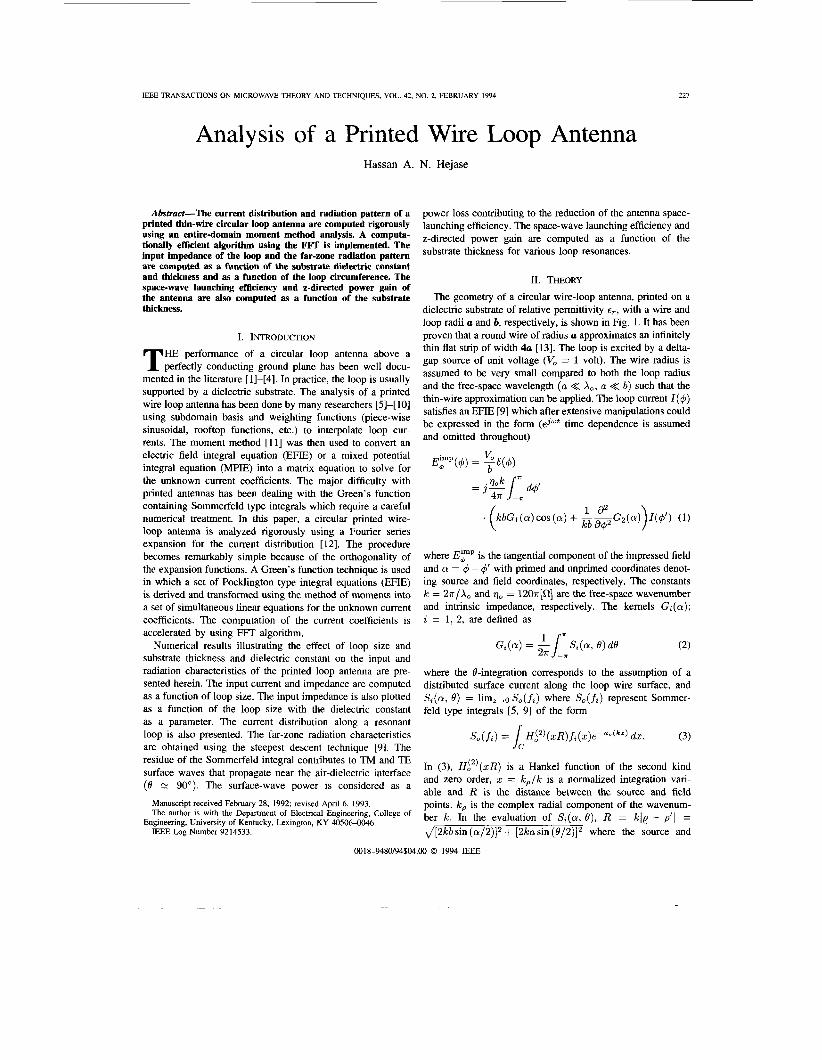
The geometry of a circular wire-loop antenna, printed on a dielectric substrate of relative permittivity tp, with a wire and loop radii a and b, respectively, is shown in Fig. 1. It has been proven that a round wire of radius a approximates an infinitely thin flat strip of width 412 [13]. The loop is excited by a delta- gap source of unit voltage (V, = 1 volt). The wire radius is assumed to be very small compared to both the loop radius and the free-space wavelength ( a << A,, a << b) such that the thin-wire approximation can be applied. The loop current I ( 4 ) satisfies an EFIE [9] which after extensive manipulations could be expressed in the form (ejwt time dependence is assumed and omitted throughout)
where Eimp is the tangential component of the impressed field and a = 4 - 4' with primed and unprimed coordinates denot- ing source and field coordinates, respectively. The constants k = 27r/A, and qo = 1207r['2] are the free-space wavenumber and intrinsic impedance, respectively. The kernels Gi (a); i = 1, 2, are defined as
where the @-integration corresponds to the assumption of a distributed surface current along the loop wire surface, and Si(,, 6') = lim,,o S,(fi) where S,(fi) represent Sommer- feld type integrals [5 , 91 of the form
In (3), Hi2) (xR) is a Hankel function of the second kind and zero order, x = k , / k is a normalized integration var- able and R is the distance between the source and field points. k, is the complex radial component of the wavenum- ber k. In the evaluation of Si(a, e) , R = klp - p'l = , / [2kb sin (a/2)I2 + [2ka sin (0/2)lz where the source and
0018-9480/94$04.M) 0 1994 IEEE

228 IEEE TRANSACITONS ON MICROWAVE THEORY AND TDZHNIQUES, VOL. 42, NO. 2, FEBRUARY 1994
t'
,//Lj;/;,! , T L X h
Gmundplaoe A pnnted circular wue-loop antenna. F I ~ . 1
observer are both located at the air-dielectric interface along the loop axis and surface, respectively. Also in (3), functions fi(x)(i = 1, 2) are given by
where
DTE = u, + ucot h(ukh) DTM = u,e, + utan h(ukh)
N = u,, + utanh(ukh). ( 5 )
DTM and DTE represent the characteristic equations of T E and TM surface waves in the dielectric substrate, normalized to k. u, = and u = d G ( x = k , / k ) are the normalized vertical (z-directed) propagation constants in the air and dielectric regions, respectively, and h is the substrate thickness. We have assumed that the substrate is thin enough to allow only the dominant T M , mode to propagate (h < X,,/4-). The integration path "C" in (3) was defined along the real axis (in the Cauchy sense), after sub- tracting the surface-wave poles, and on the proper Riemann Sheet (Re(uo, u) > 0) to satisfy the radiation condition (See [9] for more detail). The branch cuts at x = f l are removable singularities and could be dealt with by a proper variable transformation. The Sommerfeld integrals in (3) are very slowly convergent and hence require special numerical treatment [9], [lo]. The singularity extraction method as well as the subtraction of the static part [lo] were used to accelerate the convergence of our numerical algorithm.
The entire-domain moment method is applied be expanding the kemels Gi(a) , i = 1, 2, the impressed field Ebmp and the
current distribution I ( 4 ) into Fourier series as follows: m
Gi(o) = K?e-jma, (6) m=-m
where
Substituting (6)-(8) into (1) and integrating yields an expres- sion for the current coefficients of the form
(10) Vn zn I n - --, n = O , l , . . . , c o
where 2, and V, represent the impedance and voltage of the nth current mode, respectively, and are given by
and
V, = V, = 2?rbpn. (12)
Finally, (10)-(12) are substituted into (8) to compute the current distribution of the loop. In computing the current distribution from (8), only the first 20 summation terms (NMAX = 20) are sufficient for numerical convergence [12]. The main computational task lies in evaluating the KP coefficients. The &integration in (9) is needed to assure the convergence of K," coefficients as n becomes large [12]. The integral in (9) is evaluated by extracting the 1/R singularity (Static part when x = k , / k -+ 03) as 1141
where
tr i = 2 1 ' { 1 i = l er, =
&(a) = J ( 2 k b ~ i n ( a / 2 ) ) ~ + and R(a, e) has been defined earlier. The first integral in (13) is evaluated via a 64-point FFT algorithm [15] where the integrand is sampled at discrete a-points in [0, 2x1; Le., a k = 27rk/NFT, k = 0, l , . . . , NFT - 1, with N l T being the number of FFT samples. There is no need in this part to perform the &integration because computations with and

HWASE: ANALYSIS OF A PRINTED WIRE LOOP ANENNA 229
TABLE I ESTIMATION OF RESONANT LOOP CIRCUMFERENCE
( a = 10-4x,, lL = 0 . 1 0 1 ~ ~ ~ )
kb (resonance) % Difference (A) le - - @p x 100 A, - (B) €7
2.0 0.7981 0.8138 1.97%
3.0 0.6793 0.7036 3.58%
4.0 0.6wO 0.6287 4.78%
5.0 0.5456 0.5736 5.13
6.0 0.5099 0.5308 4.10
without the @-integration yield identical results. The second integral (static part) is evaluated analytically [16] and yields
whereCN = r+ln(4n)-2~m~\1/(2m+1),y = 0.5772... is Euler's constant, and I o ( n ( a / b ) ) and K,(n(a/b)) are zero- order modified Bessel functions of the first and second kind, respectively. The reader should refer to 191, [IO] for the evaluation of the Sommerfeld integrals in (3). The resulting FFT-based algorithm is computationally more efficient than Gauss-based integration techniques because only one FFT is needed to evaluate the integral for all significant values of n. Once the current coefficients are obtained from (10)-(12), we compute the current distribution around the loop using (8) with the input current being I,, = I( 4 = 0' ) . The input impedance (Zi, = Vo/Iz,) and input power (Pt, = 1/2Re {VJ;}) are then easily computed in terms of It,.
At resonance, it is possible to predict the resonant loop circumference from the guided wavelength Ag = A,/& on a strip of width w or an equivalent round-wire microstrip of radius a = w/4 [13]. A, is the free-space wavelength, and e e ~ [17] represents an effective dielectric constant that includes the effects of both air and dielectric regions, given by
Table I shows that the predicted (Ag/A,) and the computed (kb) resonant loop circumference agree to within a 5% relative error for the dielectric constant values considered (subject to k h m < a/2 with only the T M o mode propagating).
Radiation Pattem and Antenna Ejjiciency
Assuming the dielectric substrate and wire loop to be lossless, the contribution to the input power of the antenna is due to power radiated into space (space wave power Pr) and also to surface wave power (Psw) radiating as a result of the surface wave mode excitation in the dielectric substrate (Pi, = P, + Psw ). Usually, the space wave power represents the radiated power of interest and the surface wave power is
considered as a power loss with a consequent reduction of antenna efficiency.
The surface wave fields are determined by computing the residues from the poles or singularities of the Sommerfeld integrals appearing in (3). The residue contribution from the roots of DTM and DTE defined in ( 5 ) gives rise to TM and TE surface waves, respectively, propagating in the vicinity of the air-dielectric interface (0 + 7r/2). For thin and lossless dielectric substrates, i.e., kh- < a/2, only one D ~ h f root (real) exists which gives rise to a TM, surface-wave mode. The surface wave power is obtained by integrating the surface-wave Poynting vector (analytically) over a semiinfinite cylinder ( p + 03; -h < z < a), i.e.,
where Piw and P,", are the powers carried by the surface- wave modes inside (-h < z < 0) and outside (0 < z < co) of the dielectric substrate, respectively. Esw, and HSW+ are the fields of the T M , surface-wave mode (at x = xp) given by
-up tan h(upkh)e-uep(kz) if o < z < 03
if - h < z < O COS h{u k ( z + h ) } uoP COS h;up k h )
m
In (17), U = 60aJ;;(-l+ j ) , D k M ( x p ) = a D ~ ~ / a x l ~ = ~ , , uop = uo~z=zp and up = u(r=zp where zp is the normalized root of DTM defined in (5 ) . The infinite series in (17) is truncated to Nh4AX terms (series converge in about 20 terms) for numerical computations. It is noteworthy that for very thin substrates ( h << Ao), the major contribution to PSW comes from Psw in the air region, whereas for thick substrates the surface-wave power Pgw carried inside the dielectric substrate becomes the dominant component of Psw.
The radiated fields can be obtained by asymptotic evaluation (such as the method of stationary phase or steepest descent method [9]) of the Sommerfeld integrals defined by (3). The main contributions to the asymptotic expansion is from the saddle point and from the poles on the real axis (zp) which correspond, respectively, to the space-wave term and the surface-wave term. The residue contribution from the surface- wave pole will only contribute to the asymptotic expansions of the fields when 0 + a/2. The far-zone space-wave (radiated) electric field can be written in spherical coordinates (0 5 B < n/2) in the form

230 lEEE TRANSACTIONS ON MICROWAVE THEORY AND TECHNIQUES, VOL. 42, NO. 2. FEBRUARY 1994
where
2Tl COS 0 . T l = d Z Gs(B) = Tl - j ~ , cos 0 cot ( khTl) '
(20) and
2 cos 0 G95(0) = cos 0 - jT, cot (khT1).
Substituting (8) into (18) and (19) and integrating the resulting expressions yields
.{J,+l(k6sin0) + J,-l(kbsinB)} sinn4 (22)
and
.{ Jn+l(k6 sin 0) - J,-l(kb sin 0)} cos n4 (23)
where Jn denotes a Bessel function of the first kind and nth order. The infinite series in (22) and (23) are also truncated to NMAX (= 20) terms. The space-wave fields of (22) and (23) vanish near 0 = 7r/2 where only surface-wave power is important (Steepest descent method is valid for 0 5 0 < 0 p = sin-'(1/zp) whereas z p N 1 for very thin substrates). Once the surface-wave power is known, the space wave power can be calculated from P, = Pi, - PSW (assuming lossless dielectric and perfectly conducting loop). The space-wave launching efficiency is then computed from
where Pi, is equal to the total power radiated when the loop and dielectric axe assumed lossless. Finally, the z-directed space-wave power gain is defined as
where U, = (l/2qo){IE;l2 + lE;lz} is evaluated along the loop axis at 0 = 0'.
-3001 de
Fig. 2. Input impedance versus loop perimeter ( k b ) for h = 0.1016X0, a = 10-4X,, and er = 2.0.
-20 L 1-90 Fig. 3. Input current versus loop perimeter (kb ) for h = 0.1016X0,
a = 10-4X,, and e , = 2.0.
111. NUMEFUCAL RESULTS
The air-dielectric case (assume E, = 1.001) is first consid- ered to validate the computer program based on the results presented in Section 11. A comparison of our results with published data for a circular loop above a perfectly conducting ground plane [2], [3] shows excellent agreement.
Now, consider a printed wire-loop antenna (Fig. 1) with a wire radius a = a substrate thickness h = 0.1016X0 and dielectric permittivity = 2.0 (Teflon). These values are selected in order to compare our results with those in [6], [7]. The input impedance and current of the loop are computed as a function of the loop circumference (kb). Results are shown in Figs. 2 and 3. The resonant impedance is found to be approximately 65 0. Note, the show variation of the input resistance in comparison with the input reactance. Fig. 2 shows an excellent agreement between our results (lines) and those of Nakano et al. [6] (Symbols) who interpolated the current distribution of the loop in terms of piecewise sinusoidal functions. The input current is also plotted in magnitude and phase for 0.7 < k6 < 0.9, as shown in Fig. 3. The magnitude of the input current varies symmetrically about the resonant loop size (k6 = 0.7981) while the phase, as expected, becomes more capacitive as k6 increases from 0.7 to 0.9. The computer program based on this work requires only 17 seconds of virtual cpu time on a single processor IBM-3090 machine to compute the data for Figs. 2 and 3. Fig. 4 shows the current distribution for a resonant (kb = 0.7981, E, = 2,

HWASE ANALYSIS OF A PRINTED WIRE LOOP ANTENNA 231
Phi (Degrees)
Fig. 4. Current distribution for a resonant loop antenna with kb = 0.7981 tr = 2.0, h = O . l O l G X , , and a = 10W4X,.
Er = 2
F -inn
-400 -500 ..1 Input impedance versus loop perimeter ( k b ) with the dielectric
constant er as a parameter ( h = 0.1016X0,a = 10-4X,). Fig. 5.
and h = 0.1016X0). At resonance, the n = 1 current mode is dominant ( I ( 4 ) % 11 cos 4).
Fig. 5 shows the input impedance as a function of loop size kb with the dielectric constant cr as a parameter (eP = 2 ,4 and 6). Note, that the resonant loop size ( k b ) decreases from 0.7981 to 0.5099 as the dielectric constant increases from 2 to 6 ( h = 0.1016X0). The resonant input impedance increases from 65 R to 167 R. These results show a behavior similar to Nakano's results [7] for a resonant printed square loop antenna.
Next, the radiation pattern is computed in terms of the loop current coefficients. Fig. 6 shows plots of the radiation patterns in the E-plane (4 = 0') and H-plane (4 = 90') as a function of the loop resonant lengths kb = 0.5099(~, = 6) , 0.600(~, = 4), and 0.7981(tr = 2). The H-plane pattern is found to be independent of the relative permittivity. On the other hand, the half-power beamwidth (HPBW) in the E-plane increases from about 82" to 135" as t, increases from 2(kb = 0.7981) to 6 ( k b = 0.5099)). Obviously, an increase in E, will increase the surface-wave fields and hence reduce the space-wave field radiation. Fig. 7 shows the radiation pattern for the resonant case ( kb = 0.7981, tT = 2) when the substrate thickness h is varied from 0.025X0 to O.lX,. No notable change in the HPBW is observed in the E-plane. In the H-plane, we observe some narrowing of the half-power beamwidth as the substrate thickness increases which translates to a slow increase in
Fig. 6. Radiation patterns in the d = 0' plane (E-plane) and @ = 90' plane (H-plane) with the loop resonant perimeter (kb ) as a parameter ( h = 0.101GX0,a = 10-4X,).
u Fig. 7. Radiation patterns in the a5 = 0' plane (E-plane) and @ = 90' plane (H-plane) with the substrate thickness (h /X, ) as a parameter (kb = 0.7981,
= 2.0, a = ~ o - ~ x , ) .
directivity. It is important to note that space-wave radiated fields expressions in (22) and (23) are not valid in the vicinity of the air-dielectric interface (sin-'(1/Xp) < 0 < 7r/2) where the surface-wave fields are dominant. The z-directed space- wave power gain is calculated from (22) for the three resonant cases for values of substrate thickness h ranging from 0.01 to O.lX,. Results are shown in Fig. 8. Observe that the gain is nearly independent of the substrate thickness in the case of low dielectric constants ( E , = 2). Otherwise, the gain decreases linearly with the substrate thickness.
Figs. 9 and 10 show the radiated space-wave power P, and the TM, surface-wave power PSW as a function of the substrate thickness h/X, for the three resonant loop cases. Both P, and P,w reach peak values as the substrate thickness h/X, increases then they decrease with a further increase in h/X,. Because of a faster change in PSW with h/X, relative P,, and a little reduction in proximity from the ground plane, these peaks do not translate into peaks in the values of radiation efficiency, as seen in Fig. 11. Jackson and Alexopoulos [18] obtained approximate formulas for the radiated space-wave and surface-wave powers which are only

232 IEEE TRANSACTIONS ON MICROWAVE THEORY AND TECHNIQUES, VOL. 42, NO. 2, FEBRUARY 1994
!.bl ’ 0.b2 ’ 0.b3 ‘ 0.04 ’ 0.b5 ’ 0.b6 ’ 0.b7 ’ 0.b8 ’ 0.b9 ’ 0; 0
I
E a
18 - 16 - 14
12 - 10
-
- 8 -
1 -e- e,=2, kb=0.7981 I , .... a... e ~ 4 , kb=0.6000
6
4
2
$.Ol 0.02 0.03 0.04 0.05 0.06 0.07 0.08 0.09 0.10
Substrate Thickness hLL Substrate Thickness h&
Fig. 8. Z-directed space-wave power gain as a function of substrate thickness Fig. IO. Surface-wave radiated power versus substrate thickness ( h / X , ) foi h/X, for various loop resonances (a = 10-4X,). various loop resonances ( u = ~ o - ~ x , ) .
- 30 g 21
24 v
B g 21
18
? 15 .* 3 12
2 9
z 3 5 6
v)
8.01 0.02 0.03 0.04 0.05 0.06 0.07 0.08 0.09 0.10
Substrate Thickness hLL Substrate Thickness hn, Fig. 9. Space-wave radiated power versus substrate thickness (h/X,) for Fig. 1 I . Space-wave launching efficiency versus substrate thickness ( h / X , )
various loop resonances ( a = 1or4x,). for various loop resonances ( u = 1or4x,).
valid when the dielectric substrate thickness is very small. They found that the space-wave and surface-wave powers showed dependence on ( k l ~ ) ~ and (kh)3 , respectively. In fact, if our derived expressions are approximated as h/X, becomes very small, we will obtain a similar behavior as [18]. Fig. 11 shows a linear decay in the space-wave radiation efficiency (e = 1 - P , w / ( P , + Psw)) for very thin substrate thicknesses (h/X, < 0.04). One common way to increase the radiation efficiency is to add a dielectric cover on top of the loop (superstrate) and tune the substrate-superstrate dielectric constants and thicknesses in order to reduce the surface-wave power. This could be done using the analysis herein by modifying the Green’s function to account for the superstrate.
IV. CONCLUSIONS A rigorous analysis of a printed circular wire-loop an-
tenna is presented. The method of moments is applied using entire-domain functions (Fourier-series) to expand the cur- rent distribution of the loop, taking advantage of its circular symmetry. A computationally efficient FFT-based algorithm is implemented to compute the input and radiation characteristics
of the loop. The predicted resonant loop circumference values agree very well with the computed values. The effect of varying the substrate thickness and dielectric constant and loop perimeter is studied. It has been shown that using smaller resonant loop lengths will reduce the z-directed power gain and the radiation efficiency. The space-wave radiation efficiency and z-directed power gain can be controlled by varying the dielectric permittivity or substrate thickness.
REFEKENCES
[ I ] R. W. P. King and G. S. Smith, Antennas in Matter: Fundamentals, Theory and Applications.
[21 A. Shoamanesh and L. Shafai, “Characteristics of circular loop antennas above a lossless ground plane,” IEEE Trans. Antennas Propagat., vol. AF-29, pp. 528-529, May 1981.
[31 K. Iizuka, K. W. P. King, and C. W. Harrison, Jr., “Self- and mutual admittances of two identical circular loop antennas in a conducting medium and in air,” IEEE Trans. Antennas Propagat., vol. AF-14, pp. 4 4 W 3 , July 1966.
[4] L. N. An and G. S. Smith, “The horizontal circular loop antenna near a planar interface,” Radio Sci., vol. 17, pp. 483-502, May-June 1982.
[5] I. E. Kana and N. G. Alexopoulos, “Current distribution and input impedance of printed dipoles,” IEEE Trans. Antennas Pmpagat., vol. AP-29, pp. 99-105, Jan. 1981.
Cambridge, M A MIT Press, 1981.

HEJASE: ANALYSIS OF A PRINTED WIRE LOOP A N T t N N A 233
[61 H. Nakano, S. R. Kemer, and N. G. Alexopoulos, "The moment method solution for printed wire antennas of arbitrary configuration," IEEE Trans. Antennas Propagaf., vol. AP-36, pp. 1667-1673, Dec. 1988.
171 H. Nakano, K. Hirose, T. Suruki, S. R. Kerner, and N. G. Alexopoulos, "Numerical analyses of printed line antennas.'' IEE Proc., vul. I 36 PI H, pp. 98-104, Apr. 1989.
[SI H. Ragheb and L. Shafai, "Analysis of arbitrary shape printed line microstrip antennas;' IEEE Tram. Antennas Propapapot.. vul. 38. pp. 269-274. Feb. 1990.
[ 171 M. A. R . Guston, Microwaw Trrin.\~lisrion-Lb~e lnipedance Dora. London: Van Nostrand, 1972, p. 44.
1181 D. R. Jackson and N. G. Alexopoulos, "Simple approximate formulas for inpul resistance, bandwidth. and efficiency of a resonant rectangular patch," IEEE Trans. Antennas Propugor., vol. 39, pp. 407410, Mar. 1991.
191 J R Mosig and F E Gardiol, ' A dynamical model for miiro\trip \tructures Advances in Ne(tronrcs and Ekrro i i Phlsrc 5 New York Academic Press, 1982 pp 139-217
[IO] I R Mosig and T K Sarkar Comparihon of qudv ctatic and exact electromagnetic fields from d honzontal electric dipole above a loscy di electric haLked by an imperfect ground plane IEEE Trms M i ( m n a i r Theon Tech, vol M7T-14, pp 179-187, Apr 1986
1 1 1 I R F Hmington, Field Compufofion hb Moment Method7 Maldhar PL Kneger Co , 1987 (repnnt)
[I21 F Ito N Inagaki and T SekiguLhi 'An invc\tigdtion ot the .itray ot circular loo^ antennas, IEEE Trans Anrennris Propawif bo1 AP I9
Hasan A. N. Hejase ('3'85-M 88) was horn on Augu5t I0 1959 in Torreon Mexico He received the B S degree with honor\ in indu\trial electrical engineering from La Laguna Institute of Techno1 ogy, Torreon Mexico, in 1980, the M S E E degree from Monterrey In\titute of Technology (ITESM) Monterrey. Mexico in 1982, and the Ph D degree in clectrical engineering froin Syracuse Universeity Syracu\e, New York in 1987
From 1980 to 1982 he was d Part-Time Instructor . . pp. 469476 , July 1971.
[I31 C. A. Balanis, Antenna Theog: Analysi, ond / k r i , ~ n New York: Harper & Row Publishers, 1982, ch. 8.
[14J S . D. Gedney, "Solution of open region electromagnrtic scattering problems on hypercube multiprocessors," Ph.D. dis\ertation, Uni\. of Illinois at Urbana-Champaign, Urbana, IL, 1991, p. 37.
1151 S. D. Steams and D. A. Ruth, Signal Pmce.s ir ig Algrrirhm.5. Engle- wood Cliffs, NJ: Prentice-Hall, 1988.
[16] R. E. Collin and F. 1. Zucker, Anrrnno Theory: Port I . Yea York: McGraw-Hill. 1969, ch. I 1
of mathematics and physics at Monterrey Institute of Technology. In 1982, he was employed as an Electrical Design Engineer by HYLSA Steel Company, MonLerrey, Mexico. In 1983, he was employed as a Technical Marketing Engineer by PROLEC transformer company, Monterrey. Mexico. From 1984 lo 1987, he was a Graduate Research Assistant in the ECE Department at Syracuse University. working on radar signal processing and moment method applications 10 EM pruhlcnis. Since August 1987, he has heen with the faculty of Electrical Engineering at the Univcrsity of Kentucky, Lexington. His research interests include the application of computational methods (MOM) to EM problrms.