
Analysis and mitigation of transient overvoltage with integration of small scale power-electronic...
8
1 Abstract—As the amount of non-scheduled small scale distributed generation (DG) units are increasing, lack of fault ride through (FRT) capability of these generators may have an adverse affect on the overall power system. This study focuses on the basics of transient overvoltage issue arising under faulty condition with integration of power-electronic (PE) interface based DG units in a system. Reasons behind this overvoltage issue and its impact on DG integration with present grid standard have been investigated. A methodology has been utilized to overcome this overvoltage issue in a system, which has conventional generator as well as wide penetration of full- converter based solar and wind generation. An IEEE industrial test system with varieties of motor loads has been used to carry out the analysis and to verify the methodology. Index Terms-- Distributed Generation, Power-Electronic Interface, Overvoltage, STATCOM, Grid code, FRT, Voltage recovery. I. INTRODUCTION ARIOUS environmental and economic benefits for both consumer and network operator have led to wide-scale integration of distributed generation (DG) units around the world. This could include wind, solar, biomass, storage and other wide range of energy sources, which are not essentially generation in the conventional utility sense [1]. With increasing penetration of DG units, network operators will need to uphold control of overall power generation connected to the grid in a distributed manner. Severe voltage and dynamic stability problem may arise if DG units get disconnected for every fault condition. Large scale conventional synchronous generators are able to ride through such turbulent conditions and thus they can avoid tripping. Network operators demand similar FRT capability from other generators (including generation based on volatile resources such as wind and solar). FRT can be subdivided into Low Voltage Ride Through (LVRT) and High Voltage Ride Through (HVRT) [2]. Voltage at point of common coupling This work was supported by the CSIRO Intelligent Grid Flagship Collaboration Research Fund. Tareq Aziz ([email protected]), T. K. Saha ([email protected]) and N. Mithulananthan ([email protected]) are with the School of Information Technology and Electrical Engineering, The University of Queensland, Qld 4072, Australia. (PCC) must stay within these two limits to avoid unnecessary tripping. Hence, generators having FRT capability should stay connected to the network under short voltage abnormalities with temporary faults. American Wind Energy Association (AWEA) and the Western Electricity Coordinating Council (WECC) proposed LVRT requirements for all new generators greater than 20MW and no distinctions were made between conventional synchronous and inverter based variable speed generators [3]. North American Electric Reliability Council (NERC) also proposes a set of rules demanding LVRT capability from single generating unit greater than 20MW or aggregated generation greater than 75MW [4]. Similar sets of LVRT requirements have been issued by FERC orders no. 661 and 661-A for wind generators greater than 20MW. Recently, Australia and Spain have developed voltage–time profile for voltage swell conditions with large scale generator integration. Hence, FRT is a demand by grid operators and it is expected that large scale generation units should be equipped with this capability. In order to contribute more real power into the system and avoid controller interactions, small scale DG units are not permitted to operate in voltage control mode in most cases [5]. Moreover, they lack FRT capability too. Hence, proper reactive power planning with static and dynamic VAR devices can support them to adapt interconnection rules, which eventually results in increased DG integration [6], [7]. In recent years, along with existing synchronous and induction generator based DG, there has been an increased interest in power-electronic (PE) interfaced distributed generators. PE interfaced DG includes photovoltaic arrays, few types of wind turbines, fuel cells, micro-turbines and energy storage devices [8], [9]. However, with large scale penetration of these PE-interface DG units, power imbalance under faulty condition may give rise to transient overvoltage and this has been reported in [10], [11], [12]. While large scale DG units are facilitated with FRT capability, proper measures need to be taken with small scale DG units to avoid their tripping because of this overvoltage issue. This work presents an analytical study of overvoltage issue and a way of mitigating this issue with large penetration of PE-interfaced small scale DG units. Large penetration of wind and solar generation has been taken into account in presence of conventional synchronous generator in an IEEE industrial test system. Existing methodologies for mitigating overvoltage Analysis and Mitigation of Transient Overvoltage with Integration of Small Scale Power-Electronic Interfaced DG T. Aziz, Student Member, IEEE, Tapan K. Saha, Senior Member, IEEE and N. Mithulananthan, Senior Member, IEEE V 978-1-4673-2729-9/12/$31.00 ©2012 IEEE
Transcript of Analysis and mitigation of transient overvoltage with integration of small scale power-electronic...
1
Abstract—As the amount of non-scheduled small scale
distributed generation (DG) units are increasing, lack of fault
ride through (FRT) capability of these generators may have an
adverse affect on the overall power system. This study focuses on
the basics of transient overvoltage issue arising under faulty
condition with integration of power-electronic (PE) interface
based DG units in a system. Reasons behind this overvoltage
issue and its impact on DG integration with present grid
standard have been investigated. A methodology has been
utilized to overcome this overvoltage issue in a system, which has
conventional generator as well as wide penetration of full-
converter based solar and wind generation. An IEEE industrial
test system with varieties of motor loads has been used to carry
out the analysis and to verify the methodology.
Index Terms-- Distributed Generation, Power-Electronic
Interface, Overvoltage, STATCOM, Grid code, FRT, Voltage
recovery.
I. INTRODUCTION
ARIOUS environmental and economic benefits for both
consumer and network operator have led to wide-scale
integration of distributed generation (DG) units around the
world. This could include wind, solar, biomass, storage and
other wide range of energy sources, which are not essentially
generation in the conventional utility sense [1]. With
increasing penetration of DG units, network operators will
need to uphold control of overall power generation connected
to the grid in a distributed manner. Severe voltage and
dynamic stability problem may arise if DG units get
disconnected for every fault condition. Large scale
conventional synchronous generators are able to ride through
such turbulent conditions and thus they can avoid tripping.
Network operators demand similar FRT capability from other
generators (including generation based on volatile resources
such as wind and solar). FRT can be subdivided into Low
Voltage Ride Through (LVRT) and High Voltage Ride
Through (HVRT) [2]. Voltage at point of common coupling
This work was supported by the CSIRO Intelligent Grid Flagship
Collaboration Research Fund.
Tareq Aziz ([email protected]), T. K. Saha ([email protected]) and
N. Mithulananthan ([email protected]) are with the School of
Information Technology and Electrical Engineering, The University of
Queensland, Qld 4072, Australia.
(PCC) must stay within these two limits to avoid unnecessary
tripping. Hence, generators having FRT capability should stay
connected to the network under short voltage abnormalities
with temporary faults. American Wind Energy Association
(AWEA) and the Western Electricity Coordinating Council
(WECC) proposed LVRT requirements for all new generators
greater than 20MW and no distinctions were made between
conventional synchronous and inverter based variable speed
generators [3]. North American Electric Reliability Council
(NERC) also proposes a set of rules demanding LVRT
capability from single generating unit greater than 20MW or
aggregated generation greater than 75MW [4]. Similar sets of
LVRT requirements have been issued by FERC orders no. 661
and 661-A for wind generators greater than 20MW. Recently,
Australia and Spain have developed voltage–time profile for
voltage swell conditions with large scale generator integration.
Hence, FRT is a demand by grid operators and it is expected
that large scale generation units should be equipped with this
capability.
In order to contribute more real power into the system and
avoid controller interactions, small scale DG units are not
permitted to operate in voltage control mode in most cases [5].
Moreover, they lack FRT capability too. Hence, proper
reactive power planning with static and dynamic VAR devices
can support them to adapt interconnection rules, which
eventually results in increased DG integration [6], [7].
In recent years, along with existing synchronous and
induction generator based DG, there has been an increased
interest in power-electronic (PE) interfaced distributed
generators. PE interfaced DG includes photovoltaic arrays,
few types of wind turbines, fuel cells, micro-turbines and
energy storage devices [8], [9]. However, with large scale
penetration of these PE-interface DG units, power imbalance
under faulty condition may give rise to transient overvoltage
and this has been reported in [10], [11], [12]. While large
scale DG units are facilitated with FRT capability, proper
measures need to be taken with small scale DG units to avoid
their tripping because of this overvoltage issue.
This work presents an analytical study of overvoltage issue
and a way of mitigating this issue with large penetration of
PE-interfaced small scale DG units. Large penetration of wind
and solar generation has been taken into account in presence
of conventional synchronous generator in an IEEE industrial
test system. Existing methodologies for mitigating overvoltage
Analysis and Mitigation of Transient
Overvoltage with Integration of Small Scale
Power-Electronic Interfaced DG T. Aziz, Student Member, IEEE, Tapan K. Saha, Senior Member, IEEE and N. Mithulananthan, Senior
Member, IEEE
V
978-1-4673-2729-9/12/$31.00 ©2012 IEEE
2
have been summarized and effectiveness of index-based
placement of STATic synchronous COMpensator
(STATCOM) has been verified, which was previously used
for under-voltage ride through [13].
The paper is organized as follows. Section II gives a brief
description of PE-interfaced units used in this study. Section
III presents the analysis of overvoltage problem in small-scale
DG units under transient condition. Section IV focuses on the
HVRT requirement in existing grid standards. Section V
summarizes the existing techniques followed to mitigate
overvoltage at PCC along with brief description of index
based approach of voltage recovery. Section VI presents
results obtained through various fault simulations. Conclusion
in section VII highlights the contributions of present work.
II. DG WITH POWER ELECTRONIC INTERFACE
With the development of solid-state-based packages, PE
devices can now convert almost any form of electrical energy
to a more functional form. Along with flexibility in
operations, increased functionality through better power
quality, VAR support and reduced fault contributions have
worked as driving force behind getting increased attention of
this PE interface. This sort of interface contains necessary
power electronic circuitry to convert power from one form to
another. These may contain both a rectifier and an inverter or
simply an inverter. The inverter is adjusted to voltage and
frequency of the electric power system and contains the
necessary output filters for controlling harmonics. The
interface can also contain protective functions for both DG
unit and local electric power system that allow paralleling and
disconnection from system according to grid demand. Hence,
this type of interface ensures both: decoupled and fast
operation [9]. In present work, full-converter based DG units
have been used for simulation as explained below.
A. Full-power Converter Interfaced Wind Generator
Figure 1 shows block diagram of variable speed wind
turbine with full converter as interface to grid. Small scale
wind turbines are usually equipped with permanent magnet
synchronous generators because of higher efficiency, robust
rotor structure and high-power density. However, induction
generator along with gearbox can also be utilized to extract
energy from wind and finally grid side voltage source
converter (VSC) transfers that energy to grid.
Fig. 1. Block diagram for full converter interfaced wind generator [8].
B. Inverter Interfaced Photovoltaic Generator
Block diagram for basic Photovoltaic (PV) converter,
which can also be used for other technologies such as fuel cell
and battery storage, has been shown in Fig. 2. In most cases,
DC-DC converter with embedded high-frequency transformer
is used to ensure voltage boost and maximum power point
tracking (MPPT). DC output of the PV array/DC-DC
converter is connected across a filter capacitor and output of
the capacitor connects to a full-bridge VSC. A phase-locked-
loop (PLL) is utilized to synchronize the inverter output
voltage to system voltage. PV generation unit is then
connected through isolation transformer to utility grid.
Fig. 2. Block diagram of photovoltaic generator interface [8].
Complete decoupled operation of these VSC based DG
operation gives rise to overvoltage issue under transient
condition, which has been analytically explained in the next
section.
III. ANALYSIS OF OVERVOLTAGE ISSUE
Figure 3 illustrates the schematic diagram of DG unit with
PE interface to grid. This diagram can be utilized to analyze
the origin of overvoltage issue with small scale DG
integration.
Fig. 3. Schematic diagram of PE-interface for DG integration to grid.
Power transfer equation relating grid side VSC voltage to
PCC voltage can be expressed as:

3
3 sins ts
V VP
Xα=
(1)
Where sV and tV are rms values of PCC and VSC phase
voltages respectively, X is the coupling transformer
equivalent impedance with inductance L (neglecting
transformer losses) and α is the phase shift between the
mentioned phase voltages. In dq-frame, real and reactive
power exchanged at PCC can be expressed as [12]:
3( )
2s sd d sq qP V i V i= +
(2)
3
( )2
s sd q sq dQ V i V i= − +
(3)
With balanced PCC voltage, 0sqV = and ˆsd sV V= , where
ˆsV is peak amplitude of each phase voltage. Hence,
sP becomes proportional to di and can be written as:
3 ˆ2
s s dP V i= (4)
3 ˆ2
s s qQ V i= − (5)
When fault occurs in close electrical vicinity of generator
(i.e. at PCC or near to PCC), theory of symmetrical
components [14] can be utilized to formulate resulting
balanced/unbalanced voltage at PCC. Assuming reactive
power exchange 0sQ = at PCC, the dq-frame components of
PCC voltage can be expressed as:
0 0ˆ ˆ cos[2( ) ]sd s sV aV bV tω θ ψ= + + + (6)
0 0ˆ sin[2( ) ]sq sV bV tω θ ψ= − + + (7)
Where, 0ω and 0θ are fundamental frequency and phase
angle of voltage at PCC; ψ is the phase angle of negative
sequence component relative to positive sequence if voltage at
PCC is unbalanced. Coefficients a and b depend on the type
of fault. For balanced three phase case, 1a = and 0b = ,
whereas, for asymmetrical fault 1a < and 0b ≠ .
As 0sQ = , from Eqn. (5), 0qi = . Hence, from eqn. (2),
the actual real power exchanged at PCC under faulty
condition can be written as:
{ }0 0
3 ˆ ˆ cos 2( )2
sf s s dP aV bV t iω θ ψ! "= + + +# $ (8)
Substituting Eqn. (4) in Eqn. (8) results in,
{ }0 0cos 2( )sf s sP aP bP tω θ ψ= + + + (9)
With balanced condition, s sfP P= as 1a = and 0b = .
Now, power at DC link can be expressed as [12]: 2 2
2
3
ˆ4 3
d sdc sf L sf sf
s
di dPL LP P P P P
dt dtV= + = + = + (10)
DC link voltage dynamics can be formulated with the
following power balance equation:
2
( )2
dcext loss dc ext sf L
dVCP P P P P P
dt= − − ≈ − + (11)
Where, extP is the external power from generator side
converter and it is a function of generation technology and
available resources over time. Substituting Eqn. (10) in Eqn.
(11) results in:
2 2
2ˆ2 3
dc sext sf
s
dV dPC LP P
dt dtV
% &= − +' (' (
) *
(12)
Substituting eqn. (9) in eqn. (12) results in:
{ }2 2
0 02
2 2 2cos 2( )
ˆ3
dc sext s s
s
dV dPLP aP bP t
dt C C dt CVω θ ψ
! "% & ! "= − + + − + ++ ,' ( + ,' ( # $+ ,) *# $
(13)
0 0 0 0
2 2(2 ) 2 (2 ) 2
2
2 2 1 1. .
ˆ3
j j t j j tdc sext s s s
s
dV dPLP aP bPe e bPe e
dt C C dt C CV
θ ψ ω θ ψ ω+ − + −! "% & ! "
= − + + − −+ ,' ( + ,' ( # $+ ,) *# $
(14)
Eqn. (14) can be written as,
0 0 0 0
2(2 ) 2 (2 ) 20 1 1
. .j j t j j tdcs s
dV dybP e e bP e e
dt dt C C
θ ψ ω θ ψ ω+ − + −! "= + − −+ ,# $
(15)
In eqn. (15), DC link voltage dynamics have two
components: DC component is represented by 0dy
dt and
periodic AC component with frequency of 02ω is represented
by the rest of the expression.
From eqn. (9), a three phase solidly grounded fault in
electrical vicinity of generator will result in
0s sfP P= ≈ as ˆ 0sV ≈ . Eqn. (13) or (14) shows that, non-
zero value of extP will then result in
2
0dcdV
dt≠ , which
necessarily indicates developing overvoltage on DC link
terminal over time. For asymmetrical fault with 1a < and
0b ≠ , similar analysis can be derived from equations (13),
(14) and (15).
Once the fault is cleared, gating of power electronics for
grid side VSC are restored back to normal operation as it can
operate at much lower voltage [15]. Hence, assuming an ideal
pulse width modulation, the relation between converter
voltage and DC voltage can be expressed as:
0ˆt m dcV k P V= (16)
Where, mP and 0k define PWM index and DC to AC
conversion factor respectively.
As, ˆ ˆ .s t
diV V L
dt= −
!
, dynamics of overvoltage at DC link
according to eqn. (15) is reflected on ˆsV resulting overvoltage
problem at PCC. Besides this post-fault external power
injection and asymmetrical faults, overvoltage at PCC can also
be generated due to sudden load drops and switching of large

4
capacitor banks [16]. However, those situations are beyond
scope of the present work. The resulting may have various
magnitudes and durations depending on the contingency
situation. Particular segment of HVRT has been developed in
grid standards to address this issue for integration of
distributed generation.
IV. GRID STANDARDS FOR DG INTEGRATION
Grid interconnection standards specify the required
behaviour of renewable and non-renewable DG at PCC for
securing grids [17], [18]. To maintain voltage security, these
standards define continuous as well as transient voltage
requirements and they are constantly getting stringent because
of higher penetration of DG units. For continuous operation,
in most of the standards, it is expected that voltage remains
within the range of 90% to 110% of normal value at PCC
[17], [18].
IEEE and other standards demand small DG units to cease
energizing during abnormal system conditions according to
the clearing time shown in Table I [17].
TABLE I
DG RESPONSE TO ABNORMAL VOLTAGE [17]
Voltage Range (p.u.) Clearing time (sec)
V < 0.5 0.16
0.5 ! V < 0.88 2.00
1.1 < V < 1.2 1.00
V ! 1.2 0.16
The clearing time listed in Table I is a maximum threshold
for DG with capacity of 30 kW or less. For DG units with
generation capacity greater than 30 kW, the listed clearing
time is default value though this can vary with different utility
practices. Hence, regarding overvoltage limit, PCC voltage
needs to come down to 1.1pu within 1sec after the fault occurs
in generator vicinity.
In Australia, technical standard of connecting embedded
generators has been formulated by Australian Energy Market
Operator (AEMO) [19]. According to this standard, though
fault clearance time may vary from 80msec to 430msec
depending on voltage level and protection arrangement,
voltage at PCC must come back to 0.8pu within 2sec to avoid
tripping. Large scale generation units (listed as capacity of
30MW or more) have to be integrated with built-in capability
of LVRT to withstand this demand. Similar to LVRT,
Australia imposes HVRT requirement, which demands large
wind power plants to withstand voltage swell of 1.3pu up to
60msec and voltage at PCC must come back to 1.1pu within
1sec. LVRT and HVRT demand in Australia has been shown
in Fig. 4 [19], [20]. Hence, if necessary steps are not taken
due to transient overvoltage as explained in section III, small
scale generation units lacking FRT capability will result in
frequent tripping. Next section summarizes the existing
techniques followed to overcome this overvoltage issue with
PE-interface DG units.
Fig. 4. AEMO voltage ride through requirements [20].
V. MITIGATION OF OVERVOLTAGE PROBLEM
Number of measures has been proposed for large scale DG
units to avoid developing over voltage in dc-link and hence at
PCC to ensure HVRT. These methods can be grouped into
two classes - dissipation of excess energy at dc-link capacitor
through breaking resistor with full-rated DC chopper [21] and
reducing generator power by de-loading generator side
converter [22]. The braking resistor and chopper control need
careful design to avoid large transients and overheating.
As STATCOM can provide both capacitive and inductive
current, it has been found extensively in literature and practice
to support both LVRT and HVRT with integration of small
scale DG units [16], [23], [24],. However, in all these studies,
STATCOM has been placed at PCC with each DG unit. In a
system with multiple DG units, this approach would lead to
large number of STATCOMs along with controller
interactions due to their close vicinity in distribution level
[25].
In a recent study, an index based approach has been
developed to reduce number of STATCOM in a multiple-DG
integrated system [13]. According to this methodology,
STATCOM has been placed at a node with the most negative
value of sensitivity index "V/"IR in presence of fixed
capacitors. The methodology ensures grid-compatible fast
low-voltage recovery under worst case scenarios. In present
work, effectiveness of this methodology has been investigated
with large integration of PE-interfaced DG units. According to
the analysis in section III, overvoltage issue can arise with
decoupled operation of wind generators and photovoltaic
generators under faulty condition. Simulations have been
carried out with various faults to understand the problem and
possible solutions.
VI. SIMULATION RESULTS AND ANALYSIS
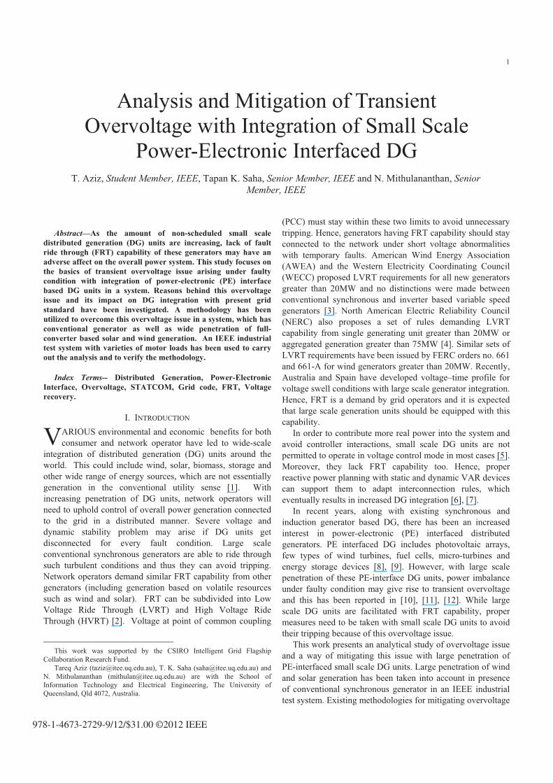
A. Test distribution System and Analytical Tool
An IEEE 43 bus industrial distribution system, shown in
Fig. 5 with a peak demand of 28.82 MW and 12.48 MVAr,
has been studied as test system [26]. This system has five
different levels of voltage rated at 69kV, 13.8kV, 4.16kV,
2.4kV and as low as 0.48kV. This test system is weakly
connected to grid with short circuit capacity of 300MVA and
grid X/R ratio of 4. Peak load condition has been considered
5
for simulation as it is the worst case scenario for voltage and
reactive power planning. Simulations have been carried out in
DIgSILENT PowerFactory 14.0 [27] platform.
Fig. 5. Test distribution system with disitributed generation units.
B. Distributed Generation Units
DG units considered in this study include conventional
synchronous generator along with large integration of wind
and solar generators. Ten wind turbines (each with 1MVA
rating) have been connected together at node 50 whereas; five
1MVA PV generators have been connected at node 19. DG
connection details have been listed in Table II. All these
generators are operating with unity power factor. Lack of
VAR generation leads to reactive power planning with fixed
capacitors and STATCOM.
TABLE II
DISTRIBUTED GENERATION: CAPACITY AND LOCATION
DISTRIBUTED
GENERATOR
DG1 DG2 DG3
Type Synchronous
Generator
Wind
Generator
Photovoltaic
Generator
Location bus 4 50 19
MVA rating 15 1.0×10 1.0×5
Power factor 1 1 1
C. STATCOM and Voltage Recovery
In order to fulfill primary requirement of ±10% of
continuous voltage at PCC, Reactive Tabu search technique
has been used for placing optimal capacitors and "V/"IR
values for all those optimal nodes are calculated with small
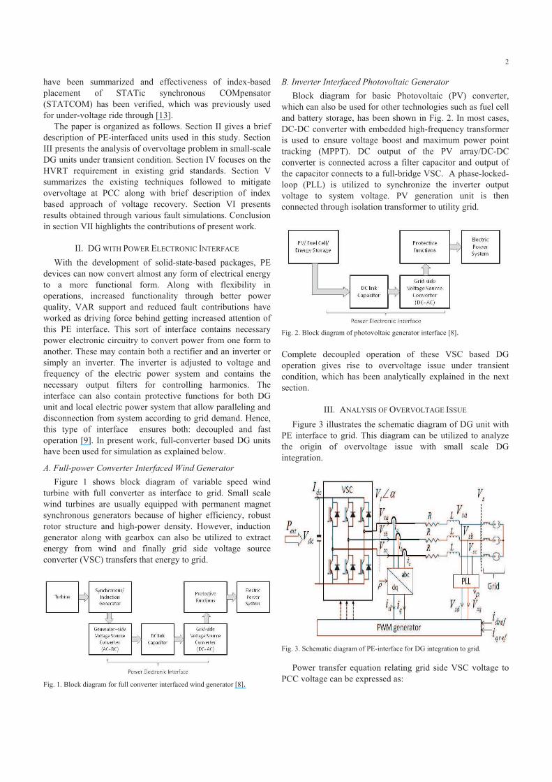
perturbations [13]. Fault simulation is performed with three
phase low-impedance fault at node 24 (at electrical vicinity of
DG1) at 1sec and it has been cleared after 10 cycles as shown
in Fig. 6. Simulation results show that without any VAR
support (i.e. without any capacitor and STATCOM), voltage
at PCC node 4 fails to recover within 2sec and demands
tripping of DG1. Among all the optimal capacitor nodes, the
most negative "V/"IR value (-0.162) has been found on node
27. Placing a STATCOM of zero reactive power set-point
along with optimal capacitor of 1.2MVAr on that node will
result in voltage recovery within 0.94sec satisfying grid
requirement in [17]. STATCOM parameters have been listed
in Table III in Appendix. Voltage at bus 4 does not cross
overvoltage limit in any of these cases because of the nature
of generation.
Fig. 6. Voltage recovery at PCC of synchronous generation unit (bus 4) with
balanced three phase fault at bus 24.
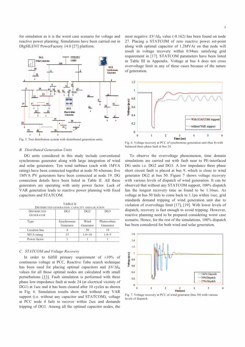
To observe the overvoltage phenomenon, time domain
simulations are carried out with fault near to PE-interfaced
DG units i.e. DG2 and DG3. A low impedance three phase
short circuit fault is placed at bus 9, which is close to wind
generator DG2 at bus 50. Figure 7 shows voltage recovery
with various levels of dispatch of wind generation. It can be
observed that without any STATCOM support, 100% dispatch
has the longest recovery time as found to be 1.16sec. As
voltage at bus 50 fails to come back to 1.1pu within 1sec, grid
standards demand tripping of wind generation unit due to
violation of overvoltage limit [17], [19]. With lower levels of
dispatch, recovery is fast enough to avoid tripping. However,
reactive planning need to be prepared considering worst case
scenario. Hence, for the rest of the simulations, 100% dispatch
has been considered for both wind and solar generation.
Fig. 7. Voltage recovery at PCC of wind generator (bus 50) with various
levels of dispatch.
6
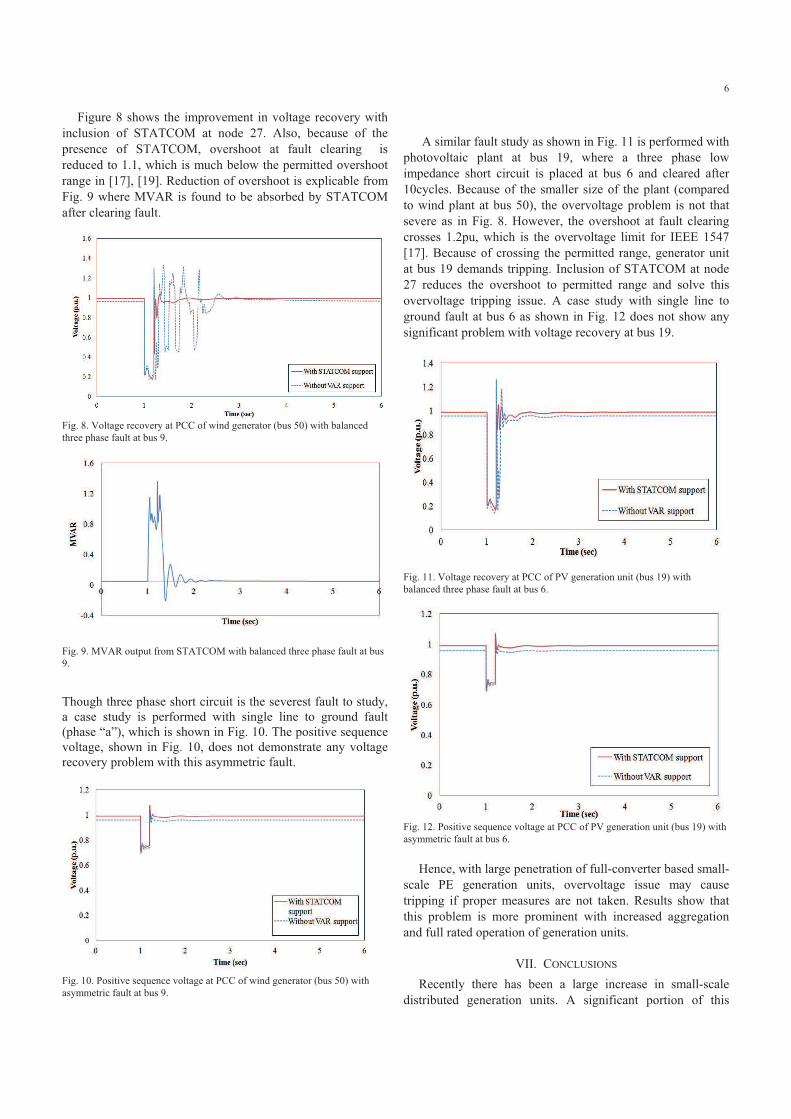
Figure 8 shows the improvement in voltage recovery with
inclusion of STATCOM at node 27. Also, because of the
presence of STATCOM, overshoot at fault clearing is
reduced to 1.1, which is much below the permitted overshoot
range in [17], [19]. Reduction of overshoot is explicable from
Fig. 9 where MVAR is found to be absorbed by STATCOM
after clearing fault.
Fig. 8. Voltage recovery at PCC of wind generator (bus 50) with balanced
three phase fault at bus 9.
Fig. 9. MVAR output from STATCOM with balanced three phase fault at bus
9.
Though three phase short circuit is the severest fault to study,
a case study is performed with single line to ground fault
(phase “a”), which is shown in Fig. 10. The positive sequence
voltage, shown in Fig. 10, does not demonstrate any voltage
recovery problem with this asymmetric fault.
Fig. 10. Positive sequence voltage at PCC of wind generator (bus 50) with
asymmetric fault at bus 9.
A similar fault study as shown in Fig. 11 is performed with
photovoltaic plant at bus 19, where a three phase low
impedance short circuit is placed at bus 6 and cleared after
10cycles. Because of the smaller size of the plant (compared
to wind plant at bus 50), the overvoltage problem is not that
severe as in Fig. 8. However, the overshoot at fault clearing
crosses 1.2pu, which is the overvoltage limit for IEEE 1547
[17]. Because of crossing the permitted range, generator unit
at bus 19 demands tripping. Inclusion of STATCOM at node
27 reduces the overshoot to permitted range and solve this
overvoltage tripping issue. A case study with single line to
ground fault at bus 6 as shown in Fig. 12 does not show any
significant problem with voltage recovery at bus 19.
Fig. 11. Voltage recovery at PCC of PV generation unit (bus 19) with
balanced three phase fault at bus 6.
Fig. 12. Positive sequence voltage at PCC of PV generation unit (bus 19) with
asymmetric fault at bus 6.
Hence, with large penetration of full-converter based small-
scale PE generation units, overvoltage issue may cause
tripping if proper measures are not taken. Results show that
this problem is more prominent with increased aggregation
and full rated operation of generation units.
VII. CONCLUSIONS
Recently there has been a large increase in small-scale
distributed generation units. A significant portion of this

7
generation is comprised of power-electronic interfaced solar
and wind plants. In this paper, we have investigated the
overvoltage issue that can be profound in a system with large
number of this type of decoupled generators. An analysis of
the origin and behavior of overvoltage dynamics have been
presented. Grid specifications due to overvoltage issue have
been discussed. An industrial system with large integration of
wind and solar has been utilized to demonstrate the
overvoltage problem. A sensitivity index "V/"IR based
reactive planning approach, previously used for providing
LVRT, has been utilized to solve the overvoltage tripping
problem. Results establish the effectiveness of the
methodology in handling overvoltage issue and offers flawless
integration of small-scale DG units with power-electronic
interface. Further studies will be carried out in future to obtain
more precise and quantitative relationship among disturbance
magnitudes, transient overvoltage and voltage recovery at
PCC.
VIII. APPENDIX
TABLE III
STATCOM PARAMETERS
Pow
er
Ratin
g
(MV
AR)
Reac
tive
powe
r set-
point
(MV
AR)
Transf
ormer
Kv
(p
u)
Tv
(s)
Kp
(p
u)
Tp
(s)
Kd
(p
u)
Td
(s)
Kq
(p
u)
Tq
(s)
1.2 0 13.8
kV/0.4
kV
0.4 0.0
02
10 0.0
02
0.6 0.0
02
0.6 0.0
1
IX. REFERENCES
[1] J. A. P. Lopes, N. Hatziargyriou, J. Mutale, P. Djapic and N. Jenkins,
"Integrating distributed generation into electric power systems: A review
of drivers, challenges and opportunities," Electric Power Systems
Research, vol. 77, pp. 1189-1203, 2007.
[2] S. Zhao, W. A. Qureshi and N. K. C. Nair, "Influence of DFIG models
on fault current calculation and protection coordination," in IEEE Power
and Energy Society General Meeting(PESGM'11), Detroit, Michigan,
USA, 2011..
[3] J. Keller and B. Kroposki, "Understanding Fault Characteristics of
Inverter-Based Distributed Energy Resources," National Renewable
Energy Laboratory, Colorado 80401-3393, Technical Report NREL/TP-
550-46698, January, 2010.
[4] R. Hudson , "PV Inverters with VAR Control, LVRT, and Dynamic
Control", High Penetration Photovoltaics Workshop, 2010. Available at:
http://www.nrel.gov/eis/pdfs/hppv_p3_t1_hudson.pdf
[5] C. Schauder, "Impact of FERC 661-A and IEEE 1547 on Photovoltaic
inverter design," in IEEE Power and Energy Society General Meeting
(PESGM'11), Detroit, Michigan, USA, 2011.
[6] F. A. Viawan and D. Karlsson, "Voltage and Reactive Power Control in
Systems With Synchronous Machine-Based Distributed Generation,"
IEEE Transactions on Power Delivery, vol. 23, no. 2, pp. 1079-1087,
2008.
[7] S. Foster, L. Xu and B. Fox, "Coordinated reactive power control for
facilitating fault ride through of doubly fed induction generator- and
fixed speed induction generator-based wind farms," IET Renewable
Power Generation, vol. 4, no. 2, pp. 128-138, 2010.
[8] B. Kroposki, C. Pink, R. DeBlasio, H. Thomas, M. Simoes and P. K.
Sen, "Benefits of Power Electronic Interfaces for Distributed Energy
Systems," IEEE Transactions on Energy Conversion, vol. 25, no. 3, pp.
901-908, 2010.
[9] J. M. Carrasco, L. G. Franquelo, J. T. Bialasiewicz, E. Galvan, R. C. P.
Guisado, M. A. M. Prats, J. I. Leon and N. Moreno-Alfonso, "Power-
Electronic Systems for the Grid Integration of Renewable Energy
Sources: A Survey," IEEE Transactions on Industrial Electronics, vol.
53, no. 4, pp. 1002-1016, 2006.
[10] V. Akhmatov, "Analysis of dynamic behavior of electric power systems
with large amount of wind power," PhD Thesis, Ørsted DTU, Denmark,
2003.
[11] Y. Jun, L. Hui, L. Yong and C. Zhe, "An Improved Control Strategy of
Limiting the DC-Link Voltage Fluctuation for a Doubly Fed Induction
Wind Generator," IEEE Transactions on Power Electronics, vol. 23, no.
3, pp. 1205-1213, 2008.
[12] A. Yazdani and R. Iravani, Voltage-sourced converters in power systems
: modeling, control, and applications. Oxford: Wiley, 2010.
[13] T. Aziz, U. P. Mhaskar, T. K. Saha, and N. Mithulananthan, "A Grid
Compatible Methodology for Reactive Power Compensation in
Renewable Based Distribution System," in IEEE Power and Energy
Society General Meeting (PESGM'11), Detroit, Michigan, USA, 2011.
[14] G. C. Paap, "Symmetrical components in the time domain and their
application to power network calculations," IEEE Transactions on
Power Systems, vol. 15, no. 2, pp. 522-528, 2000.
[15] N. R. J. Wright-Smith, J. A. Diaz de Leon II, "Single Point vs.
Distributed FACTS Installations.," presented at the CIGRE SCB4
Colloquium - HVDC and Power Electronics: Enhancing the
Transmission Networks, Brisbane, Australia, 2011.
[16] C. Wessels and F. W. Fuchs, "High voltage ride through with FACTS
for DFIG based wind turbines," in 13th European Conference on Power
Electronics and Applications(EPE '09), 2009.
[17] "IEEE Application Guide for IEEE Std 1547, IEEE Standard for
Interconnecting Distributed Resources with Electric Power Systems,"
IEEE Std 1547.2-2008, pp. 1-207, 2009.
[18] R. C. Dugan, T. S. Key, and G. J. Ball, "Distributed resources
standards," IEEE Industry Applications Magazine, vol. 12, pp. 27-34,
2006.
[19] A. E. M. Commission, "National Electricity Amendment (Technical
Standards for wind and other generators connections) Rule 2007," 8
March, 2007, www.aemc.gov.au.
[20] R. D. Narend Reddy, Addressing Global Wind Farm Interconnection
Challenges, American Superconductor (AMSC), 2009. Available at:
http://windenergy.org.nz/documents/conference08/davey.pdf
[21] J. F. Conroy and R. Watson, "Low-voltage ride-through of a full
converter wind turbine with permanent magnet generator," IET
Renewable Power Generation, vol. 1, no. 3, pp. 182-189, 2007.
[22] G. Ramtharan, A. Arulampalam, J. B. Ekanayake, F. M. Hughes, and N.
Jenkins, "Fault ride through of fully rated converter wind turbines with
AC and DC transmission," Renewable Power Generation, IET, vol. 3,
pp. 426-438, 2009.
[23] M. Molinas, S. Jon Are, and T. Undeland, "Low Voltage Ride Through
of Wind Farms With Cage Generators: STATCOM Versus SVC," IEEE
Transactions on Power Electronics, vol. 23, no. 3, pp. 1104-1117, 2008.
[24] Y. M. Alharbi, A. M. S. Yunus, and A. Abu-Siada, "Application of
STATCOM to Improve the High-Voltage-Ride-Through Capability of
Wind Turbine Generator," in IEEE PES Conference on Innovative Smart
Grid Technologies Asia 2011, Perth, Western Australia, 13-16
November, 2011.
[25] P. Rao, M. L. Crow, and Z. Yang, "STATCOM control for power system
voltage control applications," IEEE Transactions on Power Delivery,
vol. 15, no. 4, pp. 1311-1317, 2000.
[26] "IEEE Recommended Practice for Industrial and Commercial Power
Systems Analysis," IEEE Std 399-1997, p. I, 1998.
[27] DIgSILENTGmbH, "DIgSILENT PowerFactory V14.0 -User Manual,"
DIgSILENT GmbH, 2008.

8
X. BIOGRAPHIES
Tareq Aziz (M’09) was born in Dhaka, Bangladesh.
He completed his B.Sc. (Engg.) and M.Sc. (Engg.) in
Electrical & Electronic Engineering both from
Bangladesh University of Engineering & Technology
(BUET) in 2002 and 2005 respectively. Currently he
is doing his PhD in School of ITEE, The University
of Queensland, Australia. His research interests
include distributed generation, renewable energy
integration, power system stability and signal
processing.
Tapan Kumar Saha (M’93, SM’97) was born in
Bangladesh in 1959 and immigrated to Australia in
1989. He received B.Sc.Eng. Degree in 1982 from
Bangladesh University of Engineering &
Technology, Dhaka, Bangladesh, M.Tech. in 1985
from the Indian Institute of Technology, New Delhi,
India and PhD in 1994 from the University of
Queensland, Brisbane, Australia.
Tapan is currently a Professor in Electrical
Engineering in the School of Information Technology
and Electrical Engineering, University of Queensland, Australia. Previously
he has had visiting appointments for a semester at both the Royal Institute of
Technology (KTH), Stockholm, Sweden and at the University of Newcastle
(Australia). He is a Fellow of the Institution of Engineers, Australia. His
research interests include condition monitoring of electrical plants, power
systems and power quality.
Nadarajah Mithulananthan (M’02, SM’10)
received his Ph.D. from University of Waterloo,
Canada in Electrical and Computer Engineering in
2002. His B.Sc. (Eng.) and M. Eng. Degrees are from
the University of Peradeniya, Sri Lanka, and the
Asian Institute of Technology, Bangkok, Thailand, in
May 1993 and August 1997, respectively. He has
worked as an electrical engineer at the Generation
Planning Branch of the Ceylon electricity Board, and
as a researcher at Chulalongkorn University,
Bangkok, Thailand. Dr. Mithulan is currently a senior lecture at the University
of Queensland (UQ), Brisbane, Australia. Prior to joining UQ he was
associate Professor at Asian Institute of Technology, Bangkok, Thailand. His
research interests are integration of renewable energy in power systems and
power system stability and dynamics.