Analysis and Introduction of Effective Permeability with ...
12
Missouri University of Science and Technology Missouri University of Science and Technology Scholars' Mine Scholars' Mine Electrical and Computer Engineering Faculty Research & Creative Works Electrical and Computer Engineering 01 Dec 2019 Analysis and Introduction of Effective Permeability with Additional Analysis and Introduction of Effective Permeability with Additional Air-Gaps on Wireless Power Transfer Coils for Electric Vehicle Air-Gaps on Wireless Power Transfer Coils for Electric Vehicle based on SAE J2954 Recommended Practice based on SAE J2954 Recommended Practice Dongwook Kim Hongseok Kim Missouri University of Science and Technology, [email protected] Anfeng Huang Qiusen He et. al. For a complete list of authors, see https://scholarsmine.mst.edu/ele_comeng_facwork/4067 Follow this and additional works at: https://scholarsmine.mst.edu/ele_comeng_facwork Part of the Electrical and Computer Engineering Commons Recommended Citation Recommended Citation D. Kim et al., "Analysis and Introduction of Effective Permeability with Additional Air-Gaps on Wireless Power Transfer Coils for Electric Vehicle based on SAE J2954 Recommended Practice," Energies, vol. 12, no. 24, MDPI AG, Dec 2019. The definitive version is available at https://doi.org/10.3390/en12244797 This work is licensed under a Creative Commons Attribution 4.0 License. This Article - Journal is brought to you for free and open access by Scholars' Mine. It has been accepted for inclusion in Electrical and Computer Engineering Faculty Research & Creative Works by an authorized administrator of Scholars' Mine. This work is protected by U. S. Copyright Law. Unauthorized use including reproduction for redistribution requires the permission of the copyright holder. For more information, please contact [email protected].
-
Upload
khangminh22 -
Category
Documents
-
view
2 -
download
0
Transcript of Analysis and Introduction of Effective Permeability with ...

Missouri University of Science and Technology Missouri University of Science and Technology
Scholars Mine Scholars Mine
Electrical and Computer Engineering Faculty Research amp Creative Works Electrical and Computer Engineering
01 Dec 2019
Analysis and Introduction of Effective Permeability with Additional Analysis and Introduction of Effective Permeability with Additional
Air-Gaps on Wireless Power Transfer Coils for Electric Vehicle Air-Gaps on Wireless Power Transfer Coils for Electric Vehicle
based on SAE J2954 Recommended Practice based on SAE J2954 Recommended Practice
Dongwook Kim
Hongseok Kim Missouri University of Science and Technology kimhongmstedu
Anfeng Huang
Qiusen He
et al For a complete list of authors see httpsscholarsminemsteduele_comeng_facwork4067
Follow this and additional works at httpsscholarsminemsteduele_comeng_facwork
Part of the Electrical and Computer Engineering Commons
Recommended Citation Recommended Citation D Kim et al Analysis and Introduction of Effective Permeability with Additional Air-Gaps on Wireless Power Transfer Coils for Electric Vehicle based on SAE J2954 Recommended Practice Energies vol 12 no 24 MDPI AG Dec 2019 The definitive version is available at httpsdoiorg103390en12244797
This work is licensed under a Creative Commons Attribution 40 License
This Article - Journal is brought to you for free and open access by Scholars Mine It has been accepted for inclusion in Electrical and Computer Engineering Faculty Research amp Creative Works by an authorized administrator of Scholars Mine This work is protected by U S Copyright Law Unauthorized use including reproduction for redistribution requires the permission of the copyright holder For more information please contact scholarsminemstedu
energies
Article
Analysis and Introduction of Effective Permeabilitywith Additional Air-Gaps on Wireless Power TransferCoils for Electric Vehicle Based on SAE J2954Recommended Practice
Dongwook Kim 1 Hongseok Kim 2 Anfeng Huang 2 Qiusen He 3 Hanyu Zhang 3Seungyoung Ahn 1 Yuyu Zhu 3 and Jun Fan 2
1 Graduate School for Green Transportation Korea Advanced Institute of Science and TechnologyDaejeon 34141 Korea dwkim88kaistackr (DK) sahnkaistackr (SA)
2 Electromagnetic Compatibility Laboratory Missouri University of Science and TechnologyRolla MO 65401 USA ah4d8mstedu (AH) jfanmstedu (JF)
3 Electromagnetic Compatibility Research Center Southwest University of Science and TechnologyMianyang 621010 China qiusenheoutlookcom (QH) izhanghyhotmailcom (HZ)zhuyuyuswusteducn (YZ)
Correspondence kimhongmstedu
Received 31 October 2019 Accepted 13 December 2019 Published 16 December 2019
Abstract The wireless power transfer (WPT) method for electric vehicles (EVs) is becoming morepopular and to ensure the interoperability of WPT systems the Society of Automotive Engineers(SAE) established the J2954 recommended practice (RP) It includes powering frequency electricalparameters specifications testing procedures and other contents for EV WPT Specifically it describesthe ranges of self-inductances of the transmitting coil the receiving coil and coupling coefficient (k)as well as the impedance matching values of the WPT system Following the electrical parameterslisted in SAE J2954 RP is crucial to ensure the EV wireless charging system is interoperable Thispaper introduces a method for adjusting the effective permeability of the ferrite blocks in the standardmodel to tune the self-inductance of the coils as well as the coupling coefficient To guaranteethe given values of the self-inductance of the coil and coupling coefficient matched those in thestandard we slightly modified the air-gap between the ferrite tiles in a specific region Based onthis method it was possible to successfully tune the self-inductance of the transmitting coil andreceiving coil as well as the coupling coefficient The proposed method was verified by simulationand experimental measurements
Keywords SAE J2954 RP wireless power transfer (WPT) electric vehicles (EVs) effective permeabilityferrite block
1 Introduction
Electric vehicles (EVs) are increasingly popular and as their technology continuously advancesthey are becoming an essential part of transportation networks Because EVs only use electrical energyand not fuel to operate the adoption of EVs has significantly contributed to reducing greenhousegases EVs are powered by battery packs which are embedded on the EV chassis The driving rangeof EVs strongly depends on the capacity of the battery and battery research is also significantlyincreasing [1ndash6]
The limitations of present EV technology are the high cost of the battery and their relativelylimited driving range To overcome these issues hybrid electric vehicles (HEVs) and plug-in hybridelectric vehicles (PHEVs) have been introduced [12] PHEVs can be recharged using an external power
Energies 2019 12 4797 doi103390en12244797 wwwmdpicomjournalenergies
Energies 2019 12 4797 2 of 11
source like an EV However PHEVs are quite heavy because they have two operating systems electricmotor and internal combustion engine [3]
A number of new technologies are being introduced to address the mentioned shortcomings of EVand PHEV and to minimize dependency on battery systems One promising technique the wirelesspower transfer (WPT) system transfers electrical energy wirelessly for EV charging [4ndash9] The WPTsystem is convenient and because electric charge is transferred wirelessly it is safer with less risk ofelectric shock or electrostatic discharge problem In addition the WPT is an essential technology forfully autonomous EVs For these reasons WPT-based EV charging has been actively studied by manyresearch groups of various industries [7ndash9] The Society of Automotive Engineers (SAE) is a US-basedprofessional association and standards development organization for engineering professionals invarious industries Members include BMW Daimler Toyota Nissan Ford Delphi Jaguar WiTricityand the University of Auckland The SAE J2954 recommended practice (RP) standardized after 2018establishes a methodology for designing and testing WPT systems for EVs up to 11 kW power levels [10]SAE J2954 RP includes powering frequency electrical parameters specifications procedures andother factors to be evaluated It describes the specific dimensions for ground assembly (GA) andvehicle assembly (VA) components including the power transmitting coil (GA Coil) and receiving coil(VA Coil) respectively It also includes the ranges of inductances of the GA Coil (LGA) and VA Coil(LVA) and coupling coefficient (k) as well as the impedance matching values of the WPT system
Evaluating the LGA and LVA values at the given range listed in SAE J2954 is important to ensurethe interoperability of EV charging systems which is essential for EV wireless charging In additionout-ranged inductance values are also introduced as well as the out-ranged XGA and XVA valueswhich act as a filter on the charging circuit
Although the standard provides the dimensions of the GA coil and VA coil the inductance valuesof fabricated coils according to the specification are not always guaranteed to be within the rangespecified in the standard since there can be tolerance issue and unknown parameters which can affectthe LGA and LVA values Moreover once the GA and VA coils are fabricated the LGA and LVA valuescannot be changed easily [1112]
In this paper we introduce an air-gap adjusting method to control the effective permeability offerrite tiles so that the LGA and LVA values can be effectively fine-tuned To set the LGA and LVA valueswithin intended ranges we slightly adjust the air-gap lengths between the ferrite tiles in a specificregion Since these air-gap lengths are not specifically described in the standard it is reasonable to tunethese values to control the inductances of the GA and VA coils In the standard there are four- powerclassification for the vehicles According to the power transferring capacity and ground clearancerange the power class can be differed In this paper we consider the WPT2Z2 class which have 77 kWin input power with 140 mm to 210 mm ground clearance The proposed method was applied to aset of GA and VA coils for WPT2Z2 given in SAE J2954 RP to verify its feasibility By adjusting theair-gap lengths between ferrite blocks the LGA and LVA values were set close to the given ranges in thestandard The proposed concept was verified with simulations and experimental measurements basedon an SAE J2954 RP test bench
2 Dimensions of GA Coil and VA Coil on SAE J2954 RP
Referring to SAE J2954 the WPT for an EV is composed of a GA part and a VA part as shownin Figure 1a The GA part includes an ACDC converter a DCAC converter a filter for impedancecompensation and a GA coil The VA part includes the battery rectifier another filter for impedancecompensation in the VA part and the VA coil As shown in Figure 1a both the GA and VA coils areconnected to the impedance compensation parts the filters
Energies 2019 12 4797 3 of 11Energies 2019 12 x FOR PEER REVIEW 3 of 11
Figure 1 SAE J2954 wireless power transfer flow diagram (a) and equivalent circuit (b)
Referring to SAE J2954 the WPT for an EV is composed of a GA part and a VA part as shown in Figure 1a The GA part includes an ACDC converter a DCAC converter a filter for impedance compensation and a GA coil The VA part includes the battery rectifier another filter for impedance compensation in the VA part and the VA coil As shown in Figure 1a both the GA and VA coils are connected to the impedance compensation parts the filters
This system can be represented as the equivalent circuit in Figure 1b The LGA and LVA values can be used to derive the range of the XGA and XVA which are also restricted by the standard [12] The standard also provides the reference self-inductance range of the GA coil and VA coil as well as a coupling coefficient as listed in Table 1
Table 1 Self-inductance of GAVA coil and coupling coefficient (k)
Parameters LGA (Uh) LVA (Uh) k Minimum value 396 421 0094 Maximum value 425 437 0244
Figure 2 ground assembly (GA) coil and vehicle assembly (VA) coil referenced in SAE J2954 RP (a) Disassembled view of the GA coil The GA coil includes a GA aluminum plate GA ferrites GA winding and GA Litz tray (b) Disassembled view of the VA coil The VA coil includes a VA Litz tray VA winding VA ferrites VA aluminum plates an aluminum shield and a steel plate representing the vehicle chassis
Figure 2 illustrates the assembly of the GA coil and VA coil in the WPT2Z2 class In Figure 2a the GA aluminum plate prevents electromagnetic field (EMF) interference affected by the ground The GA coil is wound with two parallel 5 mm diameter Litz wire with 9 turns each A GA Litz tray
Figure 1 SAE J2954 wireless power transfer flow diagram (a) and equivalent circuit (b)
This system can be represented as the equivalent circuit in Figure 1b The LGA and LVA valuescan be used to derive the range of the XGA and XVA which are also restricted by the standard [12]The standard also provides the reference self-inductance range of the GA coil and VA coil as well as acoupling coefficient as listed in Table 1
Table 1 Self-inductance of GAVA coil and coupling coefficient (k)
Parameters LGA (Uh) LVA (Uh) k
Minimum value 396 421 0094Maximum value 425 437 0244
Figure 2 illustrates the assembly of the GA coil and VA coil in the WPT2Z2 class In Figure 2a theGA aluminum plate prevents electromagnetic field (EMF) interference affected by the ground TheGA coil is wound with two parallel 5 mm diameter Litz wire with 9 turns each A GA Litz tray is usedto mount the GA winding and hold the GA ferrite tiles 20 ferrite plates each 5 mm thick are locatedunder the GA coil to introduce a higher coupling coefficient between the GA coil and VA coil
Energies 2019 12 x FOR PEER REVIEW 3 of 11
Figure 1 SAE J2954 wireless power transfer flow diagram (a) and equivalent circuit (b)
Referring to SAE J2954 the WPT for an EV is composed of a GA part and a VA part as shown in Figure 1a The GA part includes an ACDC converter a DCAC converter a filter for impedance compensation and a GA coil The VA part includes the battery rectifier another filter for impedance compensation in the VA part and the VA coil As shown in Figure 1a both the GA and VA coils are connected to the impedance compensation parts the filters
This system can be represented as the equivalent circuit in Figure 1b The LGA and LVA values can be used to derive the range of the XGA and XVA which are also restricted by the standard [12] The standard also provides the reference self-inductance range of the GA coil and VA coil as well as a coupling coefficient as listed in Table 1
Table 1 Self-inductance of GAVA coil and coupling coefficient (k)
Parameters LGA (Uh) LVA (Uh) k Minimum value 396 421 0094 Maximum value 425 437 0244
Figure 2 ground assembly (GA) coil and vehicle assembly (VA) coil referenced in SAE J2954 RP (a) Disassembled view of the GA coil The GA coil includes a GA aluminum plate GA ferrites GA winding and GA Litz tray (b) Disassembled view of the VA coil The VA coil includes a VA Litz tray VA winding VA ferrites VA aluminum plates an aluminum shield and a steel plate representing the vehicle chassis
Figure 2 illustrates the assembly of the GA coil and VA coil in the WPT2Z2 class In Figure 2a the GA aluminum plate prevents electromagnetic field (EMF) interference affected by the ground The GA coil is wound with two parallel 5 mm diameter Litz wire with 9 turns each A GA Litz tray
Figure 2 Ground assembly (GA) coil and vehicle assembly (VA) coil referenced in SAE J2954 RP(a) Disassembled view of the GA coil The GA coil includes a GA aluminum plate GA ferrites GAwinding and GA Litz tray (b) Disassembled view of the VA coil The VA coil includes a VA Litz trayVA winding VA ferrites VA aluminum plates an aluminum shield and a steel plate representing thevehicle chassis
The VA part which receives a time-varying magnetic field is composed of five components aVA aluminum plate VA ferrite tiles VA winding a VA Litz tray an aluminum shield and steel plate
Energies 2019 12 4797 4 of 11
Figure 2b shows the dimensions of a VA coil in the WPT2Z2 class Like the GA coil configuration TheVA Litz tray is used to mount the VA winding VA ferrite tiles and VA aluminum plate To shield thevehicle from magnetic field leakage an aluminum shield is also applied In this study to represent thevehicle body a 13 m times 13 m size steel plate was applied The VA winding was wound with 5 mmdiameter Litz wires with 9 turns and 16 ferrite tiles whose thickness was 5 mm were located on top ofthe VA winding These dimensions of the GA coil and VA coil are predefined in the SAE J2954 standardHowever although these dimensions are given some discrepancies in the electric parameters canoccur including the resolution of the coil dimensions ferrite blocks arrangement joining screws andthe holes in the ferrite blocks and aluminumsteel plates Considering the manufacturing tolerance ofthe given design the fabricated GA and VA coil may have an out of range electrical parameter that isgiven in the standard especially in terms of inductances and coupling coefficient The self-inductanceand mutual inductance between the two coils are dimensionally defined including by the number ofturns the outerinner radius of a coil the thickness of the coil and coil to coil distances it is not easy tocontrol self-inductance once they are fabricated [1112]
3 Proposed Method to Tune the Self-Inductance and Coupling Coefficient by Modifying theEffective Permeability
Figure 3 illustrates the air-gap between the magnetic materials The magnetic field vectors passthrough the magnetic material and the hollow or air-gap between the magnetic materials causes areduction in relative permeability Hence the effective permeability of the magnetic material can bederived using Equation (1) according to [13]
microe f f =microcore
1 + microcoremiddot(lglc
) (1)
where microe f f microc lg and lc represent the effective permeability of the magnetic material the permeabilityof the core length of the gap and mean magnetic path length of the magnetic material respectivelyConsidering that the self-inductance of the coil and mutual inductance between the coils are proportionalto the permeability adding an air-gap decreases self-inductance as well as mutual inductance [12] Inthe case of a planar coil with a ferrite plate and ferrite blocks the air-gaps between the discrete ferriteblocks lower the effective permeability compared to the lumped ferrite plate model as illustrated inFigure 4
Energies 2019 12 x FOR PEER REVIEW 4 of 11
is used to mount the GA winding and hold the GA ferrite tiles 20 ferrite plates each 5 mm thick are located under the GA coil to introduce a higher coupling coefficient between the GA coil and VA coil
The VA part which receives a time-varying magnetic field is composed of five components a VA aluminum plate VA ferrite tiles VA winding a VA Litz tray an aluminum shield and steel plate Figure 2b shows the dimensions of a VA coil in the WPT2Z2 class Like the GA coil configuration The VA Litz tray is used to mount the VA winding VA ferrite tiles and VA aluminum plate To shield the vehicle from magnetic field leakage an aluminum shield is also applied In this study to represent the vehicle body a 13 m times 13 m size steel plate was applied The VA winding was wound with 5 mm diameter Litz wires with 9 turns and 16 ferrite tiles whose thickness was 5 mm were located on top of the VA winding These dimensions of the GA coil and VA coil are predefined in the SAE J2954 standard However although these dimensions are given some discrepancies in the electric parameters can occur including the resolution of the coil dimensions ferrite blocks arrangement joining screws and the holes in the ferrite blocks and aluminumsteel plates Considering the manufacturing tolerance of the given design the fabricated GA and VA coil may have an out of range electrical parameter that is given in the standard especially in terms of inductances and coupling coefficient The self-inductance and mutual inductance between the two coils are dimensionally defined including by the number of turns the outerinner radius of a coil the thickness of the coil and coil to coil distances it is not easy to control self-inductance once they are fabricated [1112]
3 Proposed Method to Tune the Self-Inductance and Coupling Coefficient by Modifying the Effective Permeability
Figure 3 Solenoid coil without gapped magnetic material and with gapped magnetic material
Figure 3 illustrates the air-gap between the magnetic materials The magnetic field vectors pass through the magnetic material and the hollow or air-gap between the magnetic materials causes a reduction in relative permeability Hence the effective permeability of the magnetic material can be derived using Equation (3) according to [13] 120583 1205831 120583 ∙ 119897 119897 (3)
where 120583 120583 119897 and 119897 represent the effective permeability of the magnetic material the permeability of the core length of the gap and mean magnetic path length of the magnetic material respectively Considering that the self-inductance of the coil and mutual inductance between the coils are proportional to the permeability adding an air-gap decreases self-inductance as well as mutual inductance [12] In the case of a planar coil with a ferrite plate and ferrite blocks the air-gaps between the discrete ferrite blocks lower the effective permeability compared to the lumped ferrite plate model as illustrated in Figure 4
Figure 3 Solenoid coil without gapped magnetic material and with gapped magnetic material
Applying this concept to the WPT coils in SAE J2954 RP is reasonable since the dimensions of theferrite blocks are not strictly described in the standard
Figure 5 illustrates the dimensions of the ferrite arrangement on the GA coil The boundary size ofthe GA ferrite blocks is 650 mm along the x-axis and 510 mm along the y-axis as described in Figure 6aTaking into account that the area of the ferrite blocks in the GA coil is 150 mm times 100 mm and theferrite blocks have even air-gaps the gaps between the outer ferrite blocks can be calculated to be125 mm and 25 mm as described in Figure 6b
Energies 2019 12 4797 5 of 11Energies 2019 12 x FOR PEER REVIEW 5 of 11
Figure 4 Planar coil with magnetic material (a) Planar coil with ferrite plate and (b) planar coil with ferrite blocks The air-gaps between the ferrite block decreased the effective permeability of the ferrite blocks
Applying this concept to the WPT coils in SAE J2954 RP is reasonable since the dimensions of the ferrite blocks are not strictly described in the standard
Figure 5 Ferrite block dimensions in the standard (a) GA coil ferrite block dimensions While the air-gaps between the outer ferrite blocks can be estimated by the given dimension the air-gap between the outer ferrite blocks and the inner ferrite blocks is not easy to estimate (b) VA coil ferrite block dimensions
Figure 5 illustrates the dimensions of the ferrite arrangement on the GA coil The boundary size of the GA ferrite blocks is 650 mm along the x-axis and 510 mm along the y-axis as described in Figure
Figure 4 Planar coil with magnetic material (a) Planar coil with ferrite plate and (b) planar coilwith ferrite blocks The air-gaps between the ferrite block decreased the effective permeability of theferrite blocks
Energies 2019 12 x FOR PEER REVIEW 5 of 11
Figure 4 Planar coil with magnetic material (a) Planar coil with ferrite plate and (b) planar coil with ferrite blocks The air-gaps between the ferrite block decreased the effective permeability of the ferrite blocks
Applying this concept to the WPT coils in SAE J2954 RP is reasonable since the dimensions of the ferrite blocks are not strictly described in the standard
Figure 5 Ferrite block dimensions in the standard (a) GA coil ferrite block dimensions While the air-gaps between the outer ferrite blocks can be estimated by the given dimension the air-gap between the outer ferrite blocks and the inner ferrite blocks is not easy to estimate (b) VA coil ferrite block dimensions
Figure 5 illustrates the dimensions of the ferrite arrangement on the GA coil The boundary size of the GA ferrite blocks is 650 mm along the x-axis and 510 mm along the y-axis as described in Figure
Figure 5 Ferrite block dimensions in the standard (a) GA coil ferrite block dimensions Whilethe air-gaps between the outer ferrite blocks can be estimated by the given dimension the air-gapbetween the outer ferrite blocks and the inner ferrite blocks is not easy to estimate (b) VA coil ferriteblock dimensions
Energies 2019 12 4797 6 of 11
Energies 2019 12 x FOR PEER REVIEW 6 of 11
6a Taking into account that the area of the ferrite blocks in the GA coil is 150 mm times 100 mm and the ferrite blocks have even air-gaps the gaps between the outer ferrite blocks can be calculated to be 125 mm and 25 mm as described in Figure 6b
On the other hand the air-gaps between the inner ferrite blocks and outer ferrite blocks are not clearly described For this study the gaps between the outer ferrite blocks and the inner ferrite blocks are designated 119897 and 119897 The boundary size of the VA ferrite blocks is 334 mm along the x-axis and 334 mm along the y-axis Because the VA coil has 4 x 4 ferrite tiles if the air-gaps on the VA ferrite block (119897 ) are assumed to be 0 mm the length of each of the ferrite blocks will accordingly be 835 mm
To verify the proposed method a simulation was conducted and the results were compared to those obtained in advance from experiments For the simulation a 3D finite element method solver ANSYS Electronics-Maxwell was used
Figure 6a presents the LGAs obtained by simulation and by experimental measurement The x-axis represents pairs of 119897 and 119897 with millimeter units respectively The black lines represent the self-inductance of the GA winding when the setup includes the GA ferrite and GA winding only When the aluminum shield is applied in this setup then the self-inductances are decreased as shown by the blue line As the 119897 becomes larger the self-inductance in both cases is decreased as well The difference in simulation and measurement values had an error rate lower than 5 which is reasonable considering likely measurement and calibration error
Figure 6b shows the simulated self-inductance of the VA coil depending on the different magnetic gaps The black solid points represent the self-inductance of the VA coil when the ferrite air-gap was zero Even a small air-gap 1-mm results in a 10 LGA reduction which closely approaches the given range in the standard These results confirm that controlling the air-gap between the ferrite blocks allows the self-inductance of the GA and VA coils to be controlled
Figure 6 Inductance variation introduced by air-gaps in the ferrite blocks in the GAVA coils (a) Self-inductance of the VG coil (LGA) depending on the air-gap between the ferrite tiles for various magnetic gaps (b) Self-inductance of the VA (LVA) coil Adding a 1-mm air-gap lowered the LVA value
4 Determining the Air-Gaps between the Ferrite Blocks
To determine the specific 119897 and 119897 to achieve the given range values of the LGA LVA and coupling coefficient all dimensions were considered in this work The designed dimensions strictly followed the given dimensions described in the SAE J2954 standard For detailed modeling of GA and VA both the GA and VA windings were drawn using the SolidWorks design tool as described in Figure 7
Figure 6 Inductance variation introduced by air-gaps in the ferrite blocks in the GAVA coils(a) Self-inductance of the VG coil (LGA) depending on the air-gap between the ferrite tiles for variousmagnetic gaps (b) Self-inductance of the VA (LVA) coil Adding a 1-mm air-gap lowered the LVA value
On the other hand the air-gaps between the inner ferrite blocks and outer ferrite blocks are notclearly described For this study the gaps between the outer ferrite blocks and the inner ferrite blocksare designated lGA1 and lGA2 The boundary size of the VA ferrite blocks is 334 mm along the x-axisand 334 mm along the y-axis Because the VA coil has 4 times 4 ferrite tiles if the air-gaps on the VA ferriteblock (lVA) are assumed to be 0 mm the length of each of the ferrite blocks will accordingly be 835 mm
To verify the proposed method a simulation was conducted and the results were compared tothose obtained in advance from experiments For the simulation a 3D finite element method solverANSYS Electronics-Maxwell was used
Figure 6a presents the LGAs obtained by simulation and by experimental measurement Thex-axis represents pairs of lGA1 and lGA2 with millimeter units respectively The black lines representthe self-inductance of the GA winding when the setup includes the GA ferrite and GA winding onlyWhen the aluminum shield is applied in this setup then the self-inductances are decreased as shownby the blue line As the lGA12 becomes larger the self-inductance in both cases is decreased as well Thedifference in simulation and measurement values had an error rate lower than 5 which is reasonableconsidering likely measurement and calibration error
Figure 6b shows the simulated self-inductance of the VA coil depending on the different magneticgaps The black solid points represent the self-inductance of the VA coil when the ferrite air-gap waszero Even a small air-gap 1-mm results in a 10 LGA reduction which closely approaches the givenrange in the standard These results confirm that controlling the air-gap between the ferrite blocksallows the self-inductance of the GA and VA coils to be controlled
4 Determining the Air-Gaps between the Ferrite Blocks
To determine the specific lGA12 and lVA to achieve the given range values of the LGA LVA andcoupling coefficient all dimensions were considered in this work The designed dimensions strictlyfollowed the given dimensions described in the SAE J2954 standard For detailed modeling of GAand VA both the GA and VA windings were drawn using the SolidWorks design tool as described inFigure 7
For the WPT2Z2 the suggested range of ground clearance is 140 mm to 210 mm and themaximum misalign values in the x-direction and y-direction are 75 mm and 100 mm respectively
Figure 8 illustrates some parameters including magnetic surface ground clearance and magneticgap of the standard These parameters are significant as the magnetic gap affect to the self-inductanceof GA and VA coils as well as coupling coefficient
Energies 2019 12 4797 7 of 11Energies 2019 12 x FOR PEER REVIEW 7 of 11
Figure 7 The simulation setup used to verify the proposed method All the described dimensions in the standard were strictly followed
For the WPT2Z2 the suggested range of ground clearance is 140 mm to 210 mm and the maximum misalign values in the x-direction and y-direction are 75 mm and 100 mm respectively
Figure 8 Defined parameters and dimensions of WPT2Z2 class on SAE J2954 RP
Figure 8 illustrates some parameters including magnetic surface ground clearance and magnetic gap of the standard These parameters are significant as the magnetic gap affect to the self-inductance of GA and VA coils as well as coupling coefficient
To reflect the GAVA magnetic surface of the fabricated Litz tray the distances between the magnetic surfaces of the GAVA coils in the designed model were 224 mm and 14 mm and the GA coil mounted height was 664 mm Accordingly the magnetic gap was derived from these values resulting in 974 mm 1424 mm and 1674 mm minimum ground clearance nominal ground clearance and maximum ground clearance respectively
To reflect the 85 kHz powering condition the simulation mode was set to the eddy current solution type Considering that the excited magnetic flux density is up to 100 mT the permeability of the commercial ferrite block was set to 3000 with reference to [14] Also the manual mesh options are applied to the aluminum shield and steel plate to take into account the eddy current effect on the metal plates We considered that the conductivity (σ and relative permeability (μ ) of aluminum and steel are 38000000 siemensm 5180000 siemensm 100 1001 respectively Under the frequency 119891 of 85 kHz by 120575 1μ119891σμ μ the evaluated skin depths (120575) are 02811 mm and
Figure 7 The simulation setup used to verify the proposed method All the described dimensions inthe standard were strictly followed
Energies 2019 12 x FOR PEER REVIEW 7 of 11
Figure 7 The simulation setup used to verify the proposed method All the described dimensions in the standard were strictly followed
For the WPT2Z2 the suggested range of ground clearance is 140 mm to 210 mm and the maximum misalign values in the x-direction and y-direction are 75 mm and 100 mm respectively
Figure 8 Defined parameters and dimensions of WPT2Z2 class on SAE J2954 RP
Figure 8 illustrates some parameters including magnetic surface ground clearance and magnetic gap of the standard These parameters are significant as the magnetic gap affect to the self-inductance of GA and VA coils as well as coupling coefficient
To reflect the GAVA magnetic surface of the fabricated Litz tray the distances between the magnetic surfaces of the GAVA coils in the designed model were 224 mm and 14 mm and the GA coil mounted height was 664 mm Accordingly the magnetic gap was derived from these values resulting in 974 mm 1424 mm and 1674 mm minimum ground clearance nominal ground clearance and maximum ground clearance respectively
To reflect the 85 kHz powering condition the simulation mode was set to the eddy current solution type Considering that the excited magnetic flux density is up to 100 mT the permeability of the commercial ferrite block was set to 3000 with reference to [14] Also the manual mesh options are applied to the aluminum shield and steel plate to take into account the eddy current effect on the metal plates We considered that the conductivity (σ and relative permeability (μ ) of aluminum and steel are 38000000 siemensm 5180000 siemensm 100 1001 respectively Under the frequency 119891 of 85 kHz by 120575 1μ119891σμ μ the evaluated skin depths (120575) are 02811 mm and
Figure 8 Defined parameters and dimensions of WPT2Z2 class on SAE J2954 RP
To reflect the GAVA magnetic surface of the fabricated Litz tray the distances between themagnetic surfaces of the GAVA coils in the designed model were 224 mm and 14 mm and the GAcoil mounted height was 664 mm Accordingly the magnetic gap was derived from these valuesresulting in 974 mm 1424 mm and 1674 mm minimum ground clearance nominal ground clearanceand maximum ground clearance respectively
To reflect the 85 kHz powering condition the simulation mode was set to the eddy current solutiontype Considering that the excited magnetic flux density is up to 100 mT the permeability of thecommercial ferrite block was set to 3000 with reference to [14] Also the manual mesh options areapplied to the aluminum shield and steel plate to take into account the eddy current effect on the metalplates We considered that the conductivity (σ) and relative permeability (micror) of aluminum and steel are38000000 siemensm 5180000 siemensm 100 1001 respectively Under the frequency ( f ) of 85 kHzby δ =
radic1micro fσmicrormicro0 the evaluated skin depths (δ) are 02811 mm and 00758 mm respectively When
it comes to the ferrite air gap on VA coil based on the results in Figure 6b the lVA was constrained to1 mm in this work
To examine how the air-gaps between the ferrite blocks affected the LGA value lGA1 and lGA2
were changed from 0 mm to 5 mm and from 0 mm to 3 mm respectively to determine their valueThe varied air-gap in the GA coil influenced not only the self-inductance of the GA coil but also theVA coil The coupling coefficient the self-inductances of the GAVA coils and the coupling coefficientwere also observed
Energies 2019 12 4797 8 of 11
Figure 9 illustrates the self-inductance of the GA coil under the full-setup conditions followingthe SAE J2954 standard For the ferrite blocks without the air-gap the self-inductance exceeded thegiven range in all ground clearance cases However the self-inductance of the GA coil decreased as thelGA1 and lGA2 increased as previously discussed The LGA became larger as the ground clearance ormagnetic gap increased due to the lessening of the VA coilrsquos effect Depending on the lGA1 and lGA2
changes the LGA changed by around 10
Energies 2019 12 x FOR PEER REVIEW 8 of 11
00758 mm respectively When it comes to the ferrite air gap on VA coil based on the results in Figure 6b the 119897 was constrained to 1 mm in this work
To examine how the air-gaps between the ferrite blocks affected the LGA value 119897 and 119897 were changed from 0 mm to 5 mm and from 0 mm to 3 mm respectively to determine their value The varied air-gap in the GA coil influenced not only the self-inductance of the GA coil but also the VA coil The coupling coefficient the self-inductances of the GAVA coils and the coupling coefficient were also observed
Figure 9 Simulation setup model used to determine the 119897 and 119897 The shaded region represents the reference range of the self-inductance of the GA coil in the standard (a) Minimum clearance condition (b) nominal clearance condition (c) maximum clearance condition
Figure 9 illustrates the self-inductance of the GA coil under the full-setup conditions following the SAE J2954 standard For the ferrite blocks without the air-gap the self-inductance exceeded the given range in all ground clearance cases However the self-inductance of the GA coil decreased as the 119897 and 119897 increased as previously discussed The LGA became larger as the ground clearance or magnetic gap increased due to the lessening of the VA coilrsquos effect Depending on the 119897 and 119897 changes the LGA changed by around 10
Figure 10 Simulation results model used to determine the 119897 and 119897 The shaded region represents the reference range of the self-inductance of the VA coil in the standard (a) Minimum clearance condition (b) nominal clearance condition (c) maximum clearance condition
Figure 10 describes the self-inductance of the VA coil depending on the air-gap of 119897 and 119897 The different effective permeability of the GA ferrite blocks also affected the self-inductance of the VA coil For this reason as the ground clearance increased the variation in the LVA values were negligible because the effect of the GA coil decreased significantly as illustrated in Figure 10c In the LVA cases the variation level was much lower compared to the LGA case achieving less than 15 variation
Figure 11 describes the self-inductance of the GA coil the VA coil and the coupling coefficient (k) between the two coils As the effective permeability decreased the coupling coefficient decreased Taking into account the discussed electric parameters the LGA LVA and coupling coefficient the reasonable values of 119897 and 119897 were determined to be 1 mm and 1 mm respectively
Figure 9 Simulation setup model used to determine the lGA1 and lGA2 The shaded region representsthe reference range of the self-inductance of the GA coil in the standard (a) Minimum clearancecondition (b) nominal clearance condition (c) maximum clearance condition
Figure 10 describes the self-inductance of the VA coil depending on the air-gap of lGA1 and lGA2 The different effective permeability of the GA ferrite blocks also affected the self-inductance of the VAcoil For this reason as the ground clearance increased the variation in the LVA values were negligiblebecause the effect of the GA coil decreased significantly as illustrated in Figure 10c In the LVA casesthe variation level was much lower compared to the LGA case achieving less than 15 variation
Energies 2019 12 x FOR PEER REVIEW 8 of 11
00758 mm respectively When it comes to the ferrite air gap on VA coil based on the results in Figure 6b the 119897 was constrained to 1 mm in this work
To examine how the air-gaps between the ferrite blocks affected the LGA value 119897 and 119897 were changed from 0 mm to 5 mm and from 0 mm to 3 mm respectively to determine their value The varied air-gap in the GA coil influenced not only the self-inductance of the GA coil but also the VA coil The coupling coefficient the self-inductances of the GAVA coils and the coupling coefficient were also observed
Figure 9 Simulation setup model used to determine the 119897 and 119897 The shaded region represents the reference range of the self-inductance of the GA coil in the standard (a) Minimum clearance condition (b) nominal clearance condition (c) maximum clearance condition
Figure 9 illustrates the self-inductance of the GA coil under the full-setup conditions following the SAE J2954 standard For the ferrite blocks without the air-gap the self-inductance exceeded the given range in all ground clearance cases However the self-inductance of the GA coil decreased as the 119897 and 119897 increased as previously discussed The LGA became larger as the ground clearance or magnetic gap increased due to the lessening of the VA coilrsquos effect Depending on the 119897 and 119897 changes the LGA changed by around 10
Figure 10 Simulation results model used to determine the 119897 and 119897 The shaded region represents the reference range of the self-inductance of the VA coil in the standard (a) Minimum clearance condition (b) nominal clearance condition (c) maximum clearance condition
Figure 10 describes the self-inductance of the VA coil depending on the air-gap of 119897 and 119897 The different effective permeability of the GA ferrite blocks also affected the self-inductance of the VA coil For this reason as the ground clearance increased the variation in the LVA values were negligible because the effect of the GA coil decreased significantly as illustrated in Figure 10c In the LVA cases the variation level was much lower compared to the LGA case achieving less than 15 variation
Figure 11 describes the self-inductance of the GA coil the VA coil and the coupling coefficient (k) between the two coils As the effective permeability decreased the coupling coefficient decreased Taking into account the discussed electric parameters the LGA LVA and coupling coefficient the reasonable values of 119897 and 119897 were determined to be 1 mm and 1 mm respectively
Figure 10 Simulation results model used to determine the lGA1 and lGA2 The shaded region representsthe reference range of the self-inductance of the VA coil in the standard (a) Minimum clearancecondition (b) nominal clearance condition (c) maximum clearance condition
Figure 11 describes the self-inductance of the GA coil the VA coil and the coupling coefficient(k) between the two coils As the effective permeability decreased the coupling coefficient decreasedTaking into account the discussed electric parameters the LGA LVA and coupling coefficientthe reasonable values of lGA1 and lGA2 were determined to be 1 mm and 1 mm respectively
The saturation of the ferrite block was also verified by simulation as the ferrite loses its magneticproperties when it is saturated Practically the current on the transmitting and receiving coils can beestimated up to 50 A-rms In this condition the magnetic flux from the GA is added to the magneticflux from the VA While this is the possible worst-case scenario in terms of current magnitudes thephase between the magnetic fields from GA and VA was set to zero to check the possibility of ferritesaturation For the ferrite blocks the magnetic characteristic of TDK N95 was used as the ferriteproperties to reflect a practical model As described in Figure 12 the maximum magnetic field of
Energies 2019 12 4797 9 of 11
100 mT was observed near the coil wire region Considering that the saturation point of ferrite is350 mT the proposed method is not expected to reach the saturation level [14]Energies 2019 12 x FOR PEER REVIEW 9 of 11
Figure 11 Simulation results of coupling coefficient according to the 119897 and 119897 The shaded region represents the reference range of coupling coefficient between GA and VA coil in the standard (a) Minimum clearance condition (b) nominal clearance condition (c) maximum clearance condition
The saturation of the ferrite block was also verified by simulation as the ferrite loses its magnetic properties when it is saturated Practically the current on the transmitting and receiving coils can be estimated up to 50 A-rms In this condition the magnetic flux from the GA is added to the magnetic flux from the VA While this is the possible worst-case scenario in terms of current magnitudes the phase between the magnetic fields from GA and VA was set to zero to check the possibility of ferrite saturation For the ferrite blocks the magnetic characteristic of TDK N95 was used as the ferrite properties to reflect a practical model As described in Figure 12 the maximum magnetic field of 100 mT was observed near the coil wire region Considering that the saturation point of ferrite is 350 mT the proposed method is not expected to reach the saturation level [14]
Figure 12 Simulated magnetic field distribution in the GA and VA ferrite blocks
5 Experimental Verification
To verify the evaluated air-gap values experiments were performed under the various ground clearance conditions The experiment setup used to verify the proposed method is illustrated in Figure 13 In this setup the 119897 and 119897 were varied from 0 mm to 5 mm and 0 mm to 4 mm respectively The results of these values were previously introduced in section 3 Figure 6a
Figure 11 Simulation results of coupling coefficient according to the lGA1 and lGA2 The shadedregion represents the reference range of coupling coefficient between GA and VA coil in the standard(a) Minimum clearance condition (b) nominal clearance condition (c) maximum clearance condition
Energies 2019 12 x FOR PEER REVIEW 9 of 11
Figure 11 Simulation results of coupling coefficient according to the 119897 and 119897 The shaded region represents the reference range of coupling coefficient between GA and VA coil in the standard (a) Minimum clearance condition (b) nominal clearance condition (c) maximum clearance condition
The saturation of the ferrite block was also verified by simulation as the ferrite loses its magnetic properties when it is saturated Practically the current on the transmitting and receiving coils can be estimated up to 50 A-rms In this condition the magnetic flux from the GA is added to the magnetic flux from the VA While this is the possible worst-case scenario in terms of current magnitudes the phase between the magnetic fields from GA and VA was set to zero to check the possibility of ferrite saturation For the ferrite blocks the magnetic characteristic of TDK N95 was used as the ferrite properties to reflect a practical model As described in Figure 12 the maximum magnetic field of 100 mT was observed near the coil wire region Considering that the saturation point of ferrite is 350 mT the proposed method is not expected to reach the saturation level [14]
Figure 12 Simulated magnetic field distribution in the GA and VA ferrite blocks
5 Experimental Verification
To verify the evaluated air-gap values experiments were performed under the various ground clearance conditions The experiment setup used to verify the proposed method is illustrated in Figure 13 In this setup the 119897 and 119897 were varied from 0 mm to 5 mm and 0 mm to 4 mm respectively The results of these values were previously introduced in section 3 Figure 6a
Figure 12 Simulated magnetic field distribution in the GA and VA ferrite blocks
5 Experimental Verification
To verify the evaluated air-gap values experiments were performed under the various groundclearance conditions The experiment setup used to verify the proposed method is illustrated inFigure 13 In this setup the and lGA2 were varied from 0 mm to 5 mm and 0 mm to 4 mm respectivelyThe results of these values were previously introduced in Section 3 Figure 6a
Energies 2019 12 x FOR PEER REVIEW 9 of 11
Figure 11 Simulation results of coupling coefficient according to the 119897 and 119897 The shaded region represents the reference range of coupling coefficient between GA and VA coil in the standard (a) Minimum clearance condition (b) nominal clearance condition (c) maximum clearance condition
The saturation of the ferrite block was also verified by simulation as the ferrite loses its magnetic properties when it is saturated Practically the current on the transmitting and receiving coils can be estimated up to 50 A-rms In this condition the magnetic flux from the GA is added to the magnetic flux from the VA While this is the possible worst-case scenario in terms of current magnitudes the phase between the magnetic fields from GA and VA was set to zero to check the possibility of ferrite saturation For the ferrite blocks the magnetic characteristic of TDK N95 was used as the ferrite properties to reflect a practical model As described in Figure 12 the maximum magnetic field of 100 mT was observed near the coil wire region Considering that the saturation point of ferrite is 350 mT the proposed method is not expected to reach the saturation level [14]
Figure 12 Simulated magnetic field distribution in the GA and VA ferrite blocks
5 Experimental Verification
To verify the evaluated air-gap values experiments were performed under the various ground clearance conditions The experiment setup used to verify the proposed method is illustrated in Figure 13 In this setup the 119897 and 119897 were varied from 0 mm to 5 mm and 0 mm to 4 mm respectively The results of these values were previously introduced in section 3 Figure 6a
Figure 13 Fabricated GA coils The ferrite gaps were changed to fit the LGA to the given range inthe standard
After confirming the proposed method was valid we conducted an experiment with a full-setupto verify the determined values of lVA lGA1 and lGA2 converged to 1 mm
Energies 2019 12 4797 10 of 11
Figure 14 represents the whole system measurement setup for securing self-inductance of GA coilVA coil and coupling coefficient between two coils All the measurement was conducted following thetest bench referred on standard dimension The wood blocks were used for supporting the GA coilsand to maintain the ground clearance refer to the standard the measurement was strictly conducted asshown in Figure 14b The GA coil mounted height and magnetic coil surface distance were measuredas 664 mm and 224 mm respectively while the VA coil magnetic surface distance was measured as14 mm
Energies 2019 12 x FOR PEER REVIEW 10 of 12
Figure 13 Fabricated GA coils The ferrite gaps were changed to fit the LGA to the given range in the standard
After confirming the proposed method was valid we conducted an experiment with a full-setup to verify the determined values of 119897 119897 and 119897 converged to 1 mm
Figure 14 SAE J2954 standard based test bench setup (a) Measurement setup of side view Notice that the measurement setup is inverted due to the stability of test bench (b) Measurement for ground clearance validation
Figure 14 represents the whole system measurement setup for securing self-inductance of GA coil VA coil and coupling coefficient between two coils All the measurement was conducted following the test bench referred on standard dimension The wood blocks were used for supporting the GA coils and to maintain the ground clearance refer to the standard the measurement was strictly conducted as shown in Figure 14b The GA coil mounted height and magnetic coil surface distance were measured as 664 mm and 224 mm respectively while the VA coil magnetic surface distance was measured as 14 mm
Figure 15 Measured value and expected value of the self-inductance of the GA the VA coil and the coupling coefficient Both of the 119897 and 119897 are set as 1 mm (a) Self-inductance of GA coil (b) Self-inductance of VA coil (c) Coupling coefficient (k) between GA coil and VA coil
Figure 15 illustrates the simulated and measured self-inductance values of the GA coil the VA coil and the coupling coefficient including all clearances as well as the maximum misalign condition (∆x = 75 mm ∆y = 100 mm) Based on the simulated results the 119897 and 119897 were set as 1 mm and 1 mm respectively For the measurement a TH2827C LCR meter was used at 85 kHz The errors between simulation and measurement were lower than 45 The highest out of range given in the SAE J2954 standard for the self-inductance of the GA VA and coupling coefficient were 05 28 and 56 respectively Since the coupling coefficient is obtained by 119896 M 119871 119871 the out-of-range inductances produce a lower coupling coefficient
6 Conclusions
Figure 14 SAE J2954 standard based test bench setup (a) Measurement setup of side view Noticethat the measurement setup is inverted due to the stability of test bench (b) Measurement for groundclearance validation
Figure 15 illustrates the simulated and measured self-inductance values of the GA coil the VAcoil and the coupling coefficient including all clearances as well as the maximum misalign condition(∆x = 75 mm ∆y = 100 mm) Based on the simulated results the lGA1 and lGA2 were set as 1 mm and1 mm respectively For the measurement a TH2827C LCR meter was used at 85 kHz The errorsbetween simulation and measurement were lower than 45 The highest out of range given in theSAE J2954 standard for the self-inductance of the GA VA and coupling coefficient were 05 28 and56 respectively Since the coupling coefficient is obtained by k = M
radicLGALVA the out-of-range
inductances produce a lower coupling coefficient
Energies 2019 12 x FOR PEER REVIEW 10 of 11
Figure 13 Fabricated GA coils The ferrite gaps were changed to fit the LGA to the given range in the standard
After confirming the proposed method was valid we conducted an experiment with a full-setup to verify the determined values of 119897 119897 and 119897 converged to 1 mm
Figure 14 SAE J2954 standard based test bench setup (a) Measurement setup of side view Notice that the measurement setup is inverted due to the stability of test bench (b) Measurement for ground clearance validation
Figure 14 represents the whole system measurement setup for securing self-inductance of GA coil VA coil and coupling coefficient between two coils All the measurement was conducted following the test bench referred on standard dimension The wood blocks were used for supporting the GA coils and to maintain the ground clearance refer to the standard the measurement was strictly conducted as shown in Figure 14b The GA coil mounted height and magnetic coil surface distance were measured as 664 mm and 224 mm respectively while the VA coil magnetic surface distance was measured as 14 mm
Figure 15 Measured value and expected value of the self-inductance of the GA the VA coil and the coupling coefficient Both of the 119897 and 119897 are set as 1 mm (a) Self-inductance of GA coil (b) Self-inductance of VA coil (c) Coupling coefficient (k) between GA coil and VA coil
Figure 15 illustrates the simulated and measured self-inductance values of the GA coil the VA coil and the coupling coefficient including all clearances as well as the maximum misalign condition (∆x = 75 mm ∆y = 100 mm) Based on the simulated results the 119897 and 119897 were set as 1 mm and 1 mm respectively For the measurement a TH2827C LCR meter was used at 85 kHz The errors between simulation and measurement were lower than 45 The highest out of range given in the SAE J2954 standard for the self-inductance of the GA VA and coupling coefficient were 05 28 and 56 respectively Since the coupling coefficient is obtained by 119896 M 119871 119871 the out-of-range inductances produce a lower coupling coefficient
6 Conclusions
Restricting the electrical parameters of an EV wireless charging system to the ranges provided in the SAE J2954 standard is critical to ensure it is interoperable and for system evaluation However
Figure 15 Measured value and expected value of the self-inductance of the GA the VA coil andthe coupling coefficient Both of the lGA1 and lGA2 are set as 1 mm (a) Self-inductance of GA coil(b) Self-inductance of VA coil (c) Coupling coefficient (k) between GA coil and VA coil
6 Conclusions
Restricting the electrical parameters of an EV wireless charging system to the ranges provided inthe SAE J2954 standard is critical to ensure it is interoperable and for system evaluation Howevertuning the self-inductance of a coil whose dimensions has already been fixed is difficult In this workby controlling the air-gap between ferrite blocks we controlled the effective permeability to fine-tunethe self-inductances of the GA coil and the VA coil as well as the coupling coefficient between the
Energies 2019 12 4797 11 of 11
two coils The optimal air-gap was determined using the 3D FEM solver ANSYS Maxwell and thenapplied to the WPT2Z2-class coils following the standard The proposed method was verified byboth simulation and measurement following the test bench configuration given in the standard Themaximum observed error was under 4 showing the feasibility of the proposed method
Author Contributions DK performed the modeling analyzed the data and prepared the manuscript HKidentified the problem first proposed the idea for the research and provided research supervision AH QHHZ and YZ carried out the experiments SA and JF helped identify the technical content of this study andcontributed to manuscript writing
Funding This work was supported by the National Research Foundation of Korea (NRF) grant funded by theKorea government (MSIT) (Grant number 2017R1A1A1A05001350) and National Research Foundation of Korea(NRF) grant funded by the Korean government (MSIP) (Grant number 2017R1A5A1015596)
Conflicts of Interest The authors declare no conflict of interest
References
1 Cao C Wang L Chen B Mitigation of Impact of High Plug-in Electric Vehicle Penetration on ResidentialDistribution Grid Using Smart Charging Strategies Energies 2016 9 1024 [CrossRef]
2 Aziz M Oda T Mitani T Watanbe Y Kashiwagi T Utilization of Electric Vehicles and Their UsedBatteries for Peak-Load Shifting Energies 2015 8 3720ndash3738 [CrossRef]
3 Solouk A Shahbakhti M Energy Optimization and Fuel Economy Investigation of a Series Hybrid ElectricVehicle Integrated with DiselRCCI Engines Energies 2016 9 1020 [CrossRef]
4 Covic GA Boys JT Inductive Power Transfer Proc IEEE 2013 101 1276ndash1289 [CrossRef]5 Kim J Kim J Kong S Kim H Suh IS Suh NP Cho DH Kim J Ahn S Coil Design and Shielding
Method for a Magnetic Resonant Wireless Power Transfer System Proc IEEE 2013 101 1132ndash1342 [CrossRef]6 Karam H Cho J Kim D Park J Kown JH Kwak SI Park HH Ahn S An Autonomous Coil
Alignment System for the Dynamic Wireless Charging of Electric Vehicles to Minimize Lateral MisalignmentEnergies 2017 10 315 [CrossRef]
7 Onar OC Campbell SL Seiber LE White CP Chinthavali M A High-Power Wireless ChargingSystem Development and Integration for a Toyota RAV4 Electric Vehicle In Proceedings of the 2016 IEEETransportation Electrification Conference and Expo Dearborn MI USA 27ndash29 June 2016
8 Ahmad A Alam MS Chabaan R A Comprehensive Review of Wireless Charging Technologies forElectric Vehicles IEEE Trans Transp Electrif 2018 4 38ndash63 [CrossRef]
9 Cirimele V Diana M Freschi F Mitolo M Inductive Power Transfer for Automotive ApplicationsState-of-the-Art and Future Trends IEEE Trans Ind Appl 2018 10 4069ndash4079 [CrossRef]
10 Wireless Power Transfer for Light-Duty Plug-InElectric Vehicles and Alignment Methodology SAE RecommendedPractice J2954 (rev 201711) SAE International Troy MI USA 2017
11 Luo Z Wei X Theoretical Analysis of Planar Spiral Coils Between Two Multilayer Media for Electric VehicleWireless Charging Energies 2018 11 693 [CrossRef]
12 Tavakkoli H Abbaspour-Sandi E Khalilzadegan A Abazari AM Rezazadeh G Mutual inductancecalculation between two coaxial planar spiral coils with an arbitrary number of sides Microelectron J 201985 98ndash108 [CrossRef]
13 Ayachit A Kazimierczuk MK Sensitivity of effective relative permeability for gapped magnetic cores withfringing effect IET Circuits Devices Syst 2017 11 209ndash215 [CrossRef]
14 TDK-Ferrites and Accessories-SIFERRIT Material N95 Available online httpswwwtdkelectronicstdkcomdownload52886673730346930dfce60e468312e5e3023epdf-n95pdf (accessed on 24 September 2019)
copy 2019 by the authors Licensee MDPI Basel Switzerland This article is an open accessarticle distributed under the terms and conditions of the Creative Commons Attribution(CC BY) license (httpcreativecommonsorglicensesby40)
- Analysis and Introduction of Effective Permeability with Additional Air-Gaps on Wireless Power Transfer Coils for Electric Vehicle based on SAE J2954 Recommended Practice
-
- Recommended Citation
-
- Introduction
- Dimensions of GA Coil and VA Coil on SAE J2954 RP
- Proposed Method to Tune the Self-Inductance and Coupling Coefficient by Modifying the Effective Permeability
- Determining the Air-Gaps between the Ferrite Blocks
- Experimental Verification
- Conclusions
- References
-
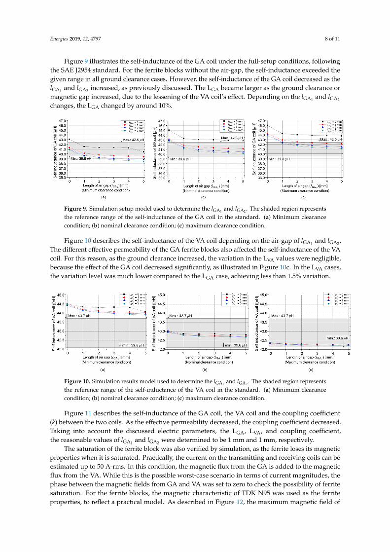