
Review and evaluation of hydrogen production methods for better sustainability
Upload
khangminh22Category
view
2download
0
Analysis and Evaluation of Methods for Activities in the Expanded
Requirements Generation Model (x-RGM)
Lester Oscar Lobo
Thesis submitted to the Faculty of
Virginia Polytechnic Institute and State University
in partial fulfillment of the requirements for the degree of
Master of Science in
Computer Science and Applications
Approved:
_________________________
James D. Arthur, Chair
_________________________ _________________________
Richard E. Nance Stephen H. Edwards
July, 2004
Blacksburg, Virginia
Keywords: Requirements Generation, Software Engineering, Methods, Techniques
Copyright 2004, Lester Lobo

Analysis and Evaluation of Methods for Activities in the Expanded
Requirements Generation Model (x-RGM)
Lester Oscar Lobo
(ABSTRACT)
In recent years, the requirements engineering community has proposed a number of
models for the generation of a well-formulated, complete set of requirements. However,
these models are often highly abstract or narrowly focused, providing only pieces of
structure and parts of guidance to the requirements generation process. Furthermore,
many of the models fail to identify methods that can be employed to achieve the activity
objectives. As a consequence of these problems, the requirements engineer lacks the
necessary guidance to effectively apply the requirements generation process, and thus,
resulting in the production of an inadequate set of requirements.
To address these concerns, we propose the expanded Requirements Generation Model
(x-RGM), which consists of activities at a more appropriate level of abstraction. This
decomposition of the model ensures that the requirements engineer has a clear
understanding of the activities involved in the requirements generation process. In
addition, the objectives of all the activities defined by the x-RGM are identified and
explicitly stated so that no assumptions are made about the goals of the activities
involved in the generation of requirements. We also identify sets of methods that can be
used during each activity to effectively achieve its objectives. The mapping of methods to
activities guides the requirements engineer in selecting the appropriate techniques for a
particular activity in the requirements engineering process. Furthermore, we prescribe
small subsets of methods for each activity based on commonly used selection criteria
such that the chosen criterion is optimized. This list of methods is created with the
intention of simplifying the task of choosing methods for the activities defined by the x-
RGM that best meet the selection criterion goal.

iii
ACKNOWLEDGEMENTS
I am thankful for the encouragements and guidance of my advisor, Dr. James Arthur,
who has continuously provided me with constructive and insightful feedback on my work.
I could always count on him for moral and intellectual support, and I owe him a great
deal more than just this thesis. I am thankful to Dr. Richard Nance and Dr. Stephen
Edwards for agreeing to participate in the evolution and evaluation of the research effort.
I am extremely grateful to my parents and loved ones, who have always supported and
encouraged me in my endeavors. In addition, I am thankful to the wonderful Indian
community that has helped me in adjusting and flourishing in a new environment.
Last but not least I am grateful to the computer science department, faculty, staff and
fellow graduate students who were an essential part of my overall learning experience.

iv
TABLE OF CONTENTS
1. Introduction.............................................................................................................. 1
1.1 State of Affairs in the Software Industry ............................................................ 1
1.1.1 Software Development Life Cycle Approach............................................. 2
1.1.2 Shifting Focus in the SDLC.................................................................... 3
1.2 Importance of Requirements............................................................................... 4
1.3 Problem Motivation ............................................................................................ 6
1.4 Problem statement............................................................................................... 8
1.4.1 Key Issues ................................................................................................... 9
1.5 Solution Approach ............................................................................................ 12
2. Background ............................................................................................................ 13
2.1 Requirements Engineering and the Development Life Cycle........................... 14
2.1.1 Waterfall Model ........................................................................................ 14
2.1.2 Prototyping Model .................................................................................... 16
2.1.3 Incremental Model .................................................................................... 17
2.1.4 Spiral Model.............................................................................................. 19
2.1.5 Extreme Programming (XP) ..................................................................... 21
2.2 Requirements Engineering Process and Models............................................... 23
2.2.1 Requirements Generation.......................................................................... 23
2.2.1.1 Requirements Elicitation......................................................................... 24
2.2.1.2 Requirements Analysis ........................................................................... 26
2.2.1.3 Requirements Specification .................................................................... 27
2.2.1.4 Requirements verification and validation ............................................... 29
2.2.1.5 Requirements Management .................................................................... 30
2.2.2 Requirement Models................................................................................. 31
2.2.2.1 Requirements Engineering Process Model ........................................... 32
2.2.2.2 Requirements Triage............................................................................. 34
2.2.2.3 Knowledge Level Process Model ......................................................... 36

v
2.2.2.4 Win-Win Spiral Model ......................................................................... 38
2.2.2.5 Process Framework............................................................................... 40
2.2.2.6 Requirements Generation Model (RGM) ............................................. 42
2.2.2.7 Comparison of the Requirement Engineering Models.......................... 43
2.3 Requirement Engineering Methods .................................................................. 45
2.3.1 Methods for Problem Synthesis ................................................................ 45
2.3.2 Methods for Requirements Elicitation ...................................................... 47
2.3.3 Methods for Requirements Analysis......................................................... 48
2.3.4 Methods for Requirements Specification.................................................. 49
2.3.5 Methods for Requirements Verification and Validation........................... 50
2.3.6 Methods for Requirements Management.................................................. 51
2.4 Research Issues Revisited ................................................................................. 52
2.4.1 Problem Statement and Issues ....................................................................... 52
3. The Expanded Requirements Generation Model (x-RGM) ............................... 54
3.1 Requirements Capturing ......................................................................................... 56
3.1.1 Customer / Requirements Engineer Indoctrination................................... 57
3.1.2 Requirements Elicitation Meeting ............................................................ 58
3.1.3 Local Analysis .......................................................................................... 61
3.1.3.1 Rationalization and Justification........................................................... 62
3.1.3.2 Prioritization ......................................................................................... 64
3.1.3.3 Verifying Quality Attributes ................................................................. 66
3.1.3.4 Stakeholder Validation.......................................................................... 68
3.2 Global Analysis................................................................................................. 70
3.2.1 Risk Analysis ............................................................................................ 71
3.2.2 Cost/Schedule Estimation ......................................................................... 73
3.2.3 Price Analysis ........................................................................................... 76
3.2.4 Feasibility Analysis................................................................................... 78
3.2.5 Conflict Resolution ................................................................................... 80
3.3 Organization and Compilation.......................................................................... 82
3.4 Confirmational Analysis ................................................................................... 84

vi
3.4.1 Quality Adherence .................................................................................... 85
3.4.2 Traceability Analysis ................................................................................ 87
3.4.3 Customer Validation Meeting................................................................... 89
3.4.4 Requirements Reformulation .................................................................... 91
3.5 Summary........................................................................................................... 92
4. Synchronization of Methods and Activities......................................................... 93
4.1 Methods for Requirements Capturing Phase .................................................... 94
4.1.1 Customer/requirements engineer Indoctrination....................................... 94
4.1.1.1 Print Material ........................................................................................ 95
4.1.1.2 Oral Presentation................................................................................... 96
4.1.2 Requirements Elicitation Meeting ............................................................ 97
4.1.2.1 Interviews.............................................................................................. 97
4.1.2.2 Observation ........................................................................................... 99
4.1.2.3 Task Demonstration ............................................................................ 100
4.1.2.4 Document Studies ............................................................................... 101
4.1.2.5 Questionnaires..................................................................................... 102
4.1.2.6 Brainstorming ..................................................................................... 103
4.1.2.7 Focus Groups ...................................................................................... 104
4.1.2.8 Requirements Workshops ................................................................... 105
4.1.2.9 Prototyping.......................................................................................... 106
4.1.3 Rationalization and Justification............................................................. 107
4.1.3.1 Brainstorming ..................................................................................... 107
4.1.3.2 I-Time ................................................................................................. 108
4.1.3.3 Task Oriented Discussion ................................................................... 109
4.1.3.4 IBIS ..................................................................................................... 110
4.1.4 Prioritization ........................................................................................... 111
4.1.4.1 Interview / Guided Discussion............................................................ 111
4.1.4.2 Analytic Hierarchy Process (AHP)..................................................... 112
4.1.4.3 Binary Search Tree ............................................................................. 113
4.1.4.4 Priority Groups.................................................................................... 113

vii
4.1.5 Verifying Quality Attributes ................................................................... 114
4.1.5.1 Round-Robin Review.......................................................................... 115
4.1.5.2 Inspections .......................................................................................... 116
4.1.5.3 Audits.................................................................................................. 117
4.1.6 Stakeholder Validation............................................................................ 118
4.1.6.1 Walkthroughs...................................................................................... 118
4.1.6.2 Scenarios ............................................................................................. 119
4.1.6.3 Storyboarding...................................................................................... 120
4.1.6.4 Interview, Prototyping and Guided Discussion .................................. 121
4.2 Methods for Global Analysis Phase................................................................ 121
4.2.1 Risk Analysis .......................................................................................... 122
4.2.1.1 Criticality Analysis ............................................................................. 123
4.2.1.2 Failure Modes, Effects and Criticality Analysis (FMECA)................ 124
4.2.1.3 Risk Reduction Leverage (RRL) ........................................................ 125
4.2.1.4 Fault Tree Analysis ............................................................................. 127
4.2.1.5 Event Tree Analysis............................................................................ 128
4.2.1.6 Monte Carlo Simulation...................................................................... 130
4.2.2 Cost Schedule Estimation ....................................................................... 131
4.2.2.1 Software Life Cycle Management (SLIM) ......................................... 131
4.2.2.2 Constructive Cost Model (COCOMO) ............................................... 132
4.2.2.3 COCOMO II ....................................................................................... 134
4.2.2.4 Functions Points.................................................................................. 135
4.2.2.5 Work Breakdown Structure ................................................................ 138
4.2.2.6 Gantt Chart.......................................................................................... 140
4.2.2.7 Program Evaluation and Review Technique (PERT) ......................... 141
4.2.2.8 Critical Path Method (CPM)............................................................... 143
4.2.3 Price Analysis ......................................................................................... 145
4.2.3.1 Comparative Price Analysis................................................................ 145
4.2.3.2 Comparisons to Independent Cost Estimates...................................... 147
4.2.3.3 Value Analysis .................................................................................... 148
4.2.3.4 Written Surveys / Questionnaires ...................................................... 149

viii
4.2.3.5 Oral Survey ......................................................................................... 150
4.2.3.6 Study of Similar Companies / Products .............................................. 151
4.2.3.7 Ask Suppliers ...................................................................................... 152
4.2.4 Feasibility Analysis................................................................................. 153
4.2.4.1 Decision Analysis under Uncertainty ................................................. 153
4.2.4.2 PMI ..................................................................................................... 156
4.2.4.3 Payback Period.................................................................................... 157
4.2.4.4 Net Present Value ............................................................................... 158
4.2.4.5 Internal Rate of Return........................................................................ 160
4.2.4.6 Pilot experiments ................................................................................ 161
4.2.5 Conflict Resolution ................................................................................. 161
4.2.5.1 Brainstorming / Interviews ................................................................. 162
4.2.5.2 Go-Around .......................................................................................... 163
4.2.5.3 Positional Bargaining.......................................................................... 164
4.2.5.4 Interest Based Bargaining ................................................................... 165
4.3 Methods for Organization and Compilation Phase......................................... 166
4.3.1 Affinity Analysis..................................................................................... 167
4.3.2 Functional Hierarchy Decomposition ..................................................... 168
4.4 Methods for Confirmational analysis Phase ................................................... 169
4.4.1 Quality Adherence .................................................................................. 169
4.4.2 Traceability Analysis .............................................................................. 170
4.4.2.1 Traceability Matrix ............................................................................. 170
4.4.2.2 Traceability Tree................................................................................. 172
4.4.2.3 Inspections / Round-Robin Review .................................................... 173
4.4.3 Customer Validation Meeting................................................................. 173
4.4.4 Requirements Reformulation .................................................................. 174
4.5 Selection of Methods for Optimization of Common Criteria ......................... 175
4.5.1 Methods Based on Time Criteria ............................................................ 175
4.5.2 Methods Based on Personnel Criteria..................................................... 180
4.5.3 Methods Based on Cost Criteria ............................................................. 187
4.5.4 Methods Based on Completeness Criteria .............................................. 193

ix
4.6 Summary......................................................................................................... 200
5. Summary and Future Work ................................................................................ 201
5.1 Summary......................................................................................................... 202
5.2 Contributions................................................................................................... 203
5.3 Future Work .................................................................................................... 207
References...................................................................................................................... 209
Appendix A: Organization Templates for Requirements ......................................... 232
Appendix B: The Expanded Requirements Generation Model................................ 237
Appendix C: Description of Activities in the x-RGM................................................ 241
Appendix D: Methods for Activities in the x-RGM....................................................249

x
LIST OF FIGURES
Figure 1.1 Waterfall model ............................................................................................ 2
Figure 1.2 Distribution of defects and effort distributions to fix defects....................... 5
Figure 2.1 Waterfall model .......................................................................................... 15
Figure 2.2 Prototyping model ...................................................................................... 16
Figure 2.3 Incremental model ...................................................................................... 18
Figure 2.4 Spiral model................................................................................................ 19
Figure 2.5 Requirements engineering phase in Extreme Programming ...................... 21
Figure 2.6 Requirements Engineering Process Model................................................. 32
Figure 2.7 Requirements Triage .................................................................................. 35
Figure2.8 Knowledge Level Process Model............................................................... 36
Figure 2.9 Win-Win Spiral Model ............................................................................... 38
Figure 2.10 Win-Win Negotiation Model...................................................................... 39
Figure 2.11 Requirements Engineering Process Framework........................................ 41
Figure 2.12 Requirements Generation Model............................................................... 42
Figure 2.13 Fishbone diagram ...................................................................................... 46
Figure 3.1 Expanded Requirements Generation Model.............................................. 55
Figure 3.2 Requirements capturing............................................................................. 56
Figure 3.3 Customer/requirements engineer indoctrination ....................................... 57
Figure 3.4 Requirements elicitation meeting .............................................................. 59
Figure 3.5 Local analysis ............................................................................................ 61
Figure 3.6 Rationalization and justification................................................................ 62
Figure 3.7 Prioritization .............................................................................................. 65
Figure 3.8 Verifying quality attributes........................................................................ 66
Figure 3.9 Requirements quality attributes ................................................................. 67
Figure 3.10 Stakeholder validation ............................................................................... 68
Figure 3.11 Global analysis phase ................................................................................ 70
Figure 3.12 Cost and price analysis .............................................................................. 77
Figure 3.13 Conflict resolution..................................................................................... 81

xi
Figure 3.14 Organization and compilation ................................................................... 83
Figure 3.15 Confirmational analysis............................................................................. 85
Figure 3.16 Quality attributes ....................................................................................... 86
Figure 3.17 Customer validation and reformulation..................................................... 90
Figure 4.1 Requirements capturing phase................................................................... 94
Figure 4.2 Global analysis phase .............................................................................. 122
Figure 4.3 Risk exposure contours............................................................................ 126
Figure 4.4 Simple fault tree ...................................................................................... 128
Figure 4.5 Event tree shown with fault trees used to evaluate probabilities of different
risk factors............................................................................................................... 129
Figure 4.6 Types of probability distributions ........................................................... 130
Figure 4.7 Gantt chart ............................................................................................... 140
Figure 4.8 PERT chart .............................................................................................. 142
Figure 4.9 Example decision tree.............................................................................. 154
Figure 4.10 Propagation of costs in the decision tree ................................................ 155
Figure 4.11 Functional hierarchy diagram................................................................. 168
Figure 4.12 Traceability matrix in Requisite Pro....................................................... 171
Figure 4.13 Traceability tree in Requisite Pro ........................................................... 172

xii
LIST OF TABLES Table 2.1 Input and output flows in the Knowledge Level Process Model................. 37
Table 2.2 Pros / cons and process coverage of requirement engineering models........ 44
Table 3.1 Activity characteristics ................................................................................ 55
Table 3.2 Comparison of needs and requirements....................................................... 60
Table 3.3 Comparison of traceability approaches [Kean 97] ...................................... 88
Table 4.1 Scale for pair-wise comparison.................................................................. 112
Table 4.2 Modes of development............................................................................... 133
Table 4.3 Values of a, b and c for the Basic COCOMO............................................ 133
Table 4.4 Weighting scale for the function types ...................................................... 136
Table 4.5 Complexity of the function types............................................................... 136
Table 4.6 Factors of influence ................................................................................... 138
Table 4.7 Example of using PMI technique............................................................... 157
Table 4.8 Calculations in the Net Present Value technique....................................... 159
Table 4.9 Calculations in the Internal Rate of Return technique............................... 160
Table 5.1 Activities identified in the x-RGM ............................................................ 204
Table 5.2 Number of methods identified for activities in the x-RGM....................... 206
Table 5.3 Number of methods identified based on selection criteria ........................ 207

Chapter 1. Introduction
1
Chapter 1
Introduction
1. Introduction This thesis presents the synchronization of methods/techniques with requirement
engineering activities, which are conducted by the requirements engineer to obtain a
well-defined requirement specification. This chapter motivates the need for this research,
and introduces the research issues involved and the solution approach taken to address
them.
1.1 State of Affairs in the Software Industry Beginning in the early seventies, the software industry has seen an increase in the
complexity of the applications developed. However, the software methodologies in the
seventies were inadequate for complex and large scale projects; this resulted in frequent
budget overruns and schedule delays. To overcome these problems, it was necessary to
modify software development approaches in order to cope with project complexities.
The software industry of the present day has a better understanding of the activities
involved in the development of software. The different phases of development have been
identified and organized in the form of life cycle models, which have provided a much
needed structure to the development process [Sud 2003]. In addition, several techniques
have been proposed to support the various activities in the software development life

Chapter 1. Introduction
2
cycle [Leffingwell 2000]. However, these advances have not ended the problems
encountered during software development; projects continue to exceed budget and
schedule constraints. An additional problem is that the software delivered often does not
meet the customer’s intent.
In the sections that follow, we provide a brief description of the software development
life cycle and its evolution.
1.1.1 Software Development Life Cycle Approach
In order to address the initial of lack of structure in the software development process,
several models were proposed. These models typically contained the following phases:
Requirements Analysis, Design, Implementation, Integration and Testing, and
Maintenance [Pressman 2001].
The first software development life cycle model (SDLC) that was proposed was the
Waterfall Model [Royce 70], which placed these phases in a sequential order as shown in
Figure 1.
Figure 1.1 Waterfall model
The objectives of each of these phases are given below:
• Requirements Analysis: This phase involves understanding the function,
behavior, performance and interface of the proposed system. In addition, the
software requirements are documented and reviewed by the customer.
• Design: It involves translating requirements into a system representation that can
be assessed for quality before coding begins. The focus is on data structures,
software architecture, interface representation and algorithmic details.
• Coding: This phase translates design into a machine readable form.
• Testing: This involves conducting tests to uncover errors in code and to ensure
that the results produced are correct for a given input.
Requirements Analysis
Design
Coding
Testing
Maintenance

Chapter 1. Introduction
3
• Maintenance: This phase is necessary to incorporate changes to the software.
The drawback to the waterfall model is its rigidity and its oversight of requirements creep
[Carter 2001]. However, the model did identify the major software development phases
which formed the core of the models proposed thereafter.
To overcome inadequacies of the waterfall model, several other models such as the
iterative enhancement model [Basili 75], prototyping model [Gomma 81], spiral model
[Boehm 88], and Extreme Programming [Beck 99] have been proposed.
1.1.2 Shifting Focus in the SDLC
With the advent of the SDLC models, the phases in the development process became
more apparent. However, the techniques and activities for these phases were still not
clearly defined; this resulted in the software engineer having difficulties in conducting the
different phases. Hence, it was crucial to begin refining the SDLC phases in order to
provide the necessary guidance on performing these phases during the development
process.
Although logic dictates that attention should be directed towards the first SDLC phase,
requirements analysis, most of the examination emphasis was initially placed on the end
product. As a result, we have seen the re-examination and phase refinement being
addressed in reverse order [Groener 2002]. Studies show that 60-70% of the product life
cycle is spent in the maintenance phase [Bravo 93]. The high cost and difficulty of
maintaining code prompted the software engineers to focus on the testing phase.
Techniques for black box and white box testing were identified and used extensively for
the detection on errors in code [IPL 96]. Testing was further facilitated by tools which
automated testing methods.
On analyzing the code during testing, it was realized that the code was being written in an
ad-hoc fashion, which made the code difficult to comprehend. Hence, coding guidelines
were developed; this improved the readability and understandability of the code.

Chapter 1. Introduction
4
Integrated Development Environments (IDE)1 were developed to help the programmers
in writing and debugging the code.
After the coding phase, the refinement focus shifted to the design phase. The design
phase was broken down to high level and low level phases on realizing that “step-wise”
refinement, (solving complex problems by breaking them down to smaller units) could be
successfully applied to design. The high level phase provides an abstract view of the
design whereas low level design is more detailed and refined [Robertson 99]. Besides this
development, new design paradigms, such as the object-oriented paradigm, were
proposed as it helped in adding better structure and maintainability to the code. Design
notations, such as those proposed by the Unified Modeling Language (UML), and
supporting tools were developed for better design representations [Jacobson 99].
The requirements analysis phase was the last phase to receive attention from the software
engineering community, and it is only in recent years that a meaningful refinement of this
phase is taking place. Prior to this, the somewhat inappropriate name “Requirements
Analysis” contributed to the perception that activities like problem analysis and
elicitation were minor ones [Davis 93].
1.2 Importance of Requirements
The focus on the requirements phase is crucial as a system is only as good as its
requirements. Moreover, all of the other phases in the SDLC depend on the requirements
phase in one way or another. The importance of requirements is continuously reinforced
as we recognize the manifold relationships between the quality of the product and the
quality of the requirements from which the product is developed [Sidky 2003]. In
addition, empirical studies have shown that incomplete, inconsistent or ambiguous
requirements have a critical impact on the quality of the developed product [Thayer 76].
The significance of requirements is succinctly captured by the following statement
[Brooks 87]:
1 IDEs provide an integrated set of tools and artifacts supporting a process; e.g. Microsoft’s Visual Studio

Chapter 1. Introduction
5
Distribution of Defects
��������������������������������������������� �� �� �� �����
��������������������������������
� ���� ���� ���� ������������������� ������������������������
����������������
������������������������ �� �� �� ������
� ���� ���� ���� �����������������������
��������������������
���������������������������������������������������������������������
Distribution of Effort to Fix Defects
“The hardest single part of building a software system is
deciding precisely what to build. No other part of the conceptual
work is as difficult as establishing the detailed technical
requirements, including all the interfaces to people, to machines,
and to other software systems. No part of the work so cripples
the resulting system if done wrong. No other part is more
difficult to rectify later”
- F.P. Brooks
Supporting the above statement, Boehm claims that corrections of faulty requirements
later in the life cycle could cost up to 200 times more than correction during the
requirements phase [Boehm 81]. The importance of requirements is further emphasized
by Figure 1.2, which depicts the distribution of defects in the SDLC and the effort needed
to fix those defects [Leffingwell 2000]. It can be clearly seen that the bulk of the effort
(82%) is attributed to fixing requirement errors.
Figure 1.2 Distribution of defects and effort distributions to fix defects
Several studies have been conducted which illustrate that requirements hold the key for
the success of a project. The CHAOS report states that five of the top eight causes for
project failure relate to requirements [Standish 95]. Also, the study conducted by
Williams cites poor requirements as the main risk factor for project success [Williams 98].

Chapter 1. Introduction
6
These studies indicate that a clear and complete set of requirements lays the foundation
for a successful project.
With greater awareness of requirements by the software engineering community, the
‘requirements analysis’ phase is now termed as ‘requirements engineering’ and comprises
the following activities [Thayer 97]:
• Requirements Elicitation: The process through which the customers and the
requirements engineer discover, articulate, record and understand the user needs
and constraints.
• Requirements Analysis: This involves examining the customers’ and users’
needs in order to obtain a set of requirements. This activity involves assessing the
risk, feasibility, cost, schedule and other factors which affect the requirements.
• Requirements Specification: This activity records the elicited and analyzed
requirements in a precise and unambiguous manner. The deliverable of this
activity is the software requirements specification (SRS), which is the binding
document between the customer and the developer.
• Requirements Verification: The process of ensuring that the SRS is compliant
with system standards, conformant to document standards, and is adequate
enough to support the design phase.
• Requirements Management: This activity involves the planning and controlling
of all the other requirement engineering activities. In addition, this activity
facilitates communication, in case any changes are made.
Software engineering researchers are now re-examining the activities in the requirements
engineering phase in order to make the task of conducting these activities easier.
1.3 Problem Motivation
Over the past few years, the software engineering community has acknowledged the
significance of research on requirements and, as a consequence, the present day software
industry has a better understanding of the requirements engineering phase. However, in

Chapter 1. Introduction
7
spite of the increased awareness, requirements engineering is still plagued with problems
which have hampered the effective application of this discipline in the software industry.
In this section, we highlight the hurdles in requirements engineering that motivate the
need for our research.
The main problem in applying requirements engineering in the industry is the lack of a
comprehensive requirements engineering model that can be followed to produce a good
requirements document [Bubenko 95]. Most of the literature describes requirements
models as being composed of activities such as elicitation, analysis, specification,
verification and management. These descriptions, however, are at a high level of
abstraction which makes it difficult to conduct them in real project scenarios. For
example, the analysis activity consists of several sub-activities to evaluate risk, cost,
feasibility, schedule, etc. Knowledge of the interaction among these sub-activities and the
sequence in which they are executed is necessary in order to achieve the goals of the
higher-level activities. In effect, the lack of specific details in the definition of the
requirements engineering model also results in unclear procedures for conducting the
required activities. Consequently, the requirements engineer faces several problems when
such an abstract model drives the requirements phase.
Another problem is that a majority of the requirements engineering models address only
portions of the complete requirements process. For example, the RE process model
proposed by Debbie Richards provides a set of guidelines for the elicitation and analysis
phases, but fails to address the verification and specification phases [Richards 2000]. The
integration of models focusing on different segments of the requirements process is a
difficult task because the models tend to overlap and have their own specific
characteristics. Moreover, such an amalgamation of different models can result in a loose
coupling of activities causing a loss of information as requirements evolve through the
engineering process. Finally, models that do address the entire requirements process often
lack the descriptive detail needed for the defined activities.
One last concern with existing requirement engineering models is that activity objectives
are often implied rather than explicitly stated. As a consequence, the requirements
engineer lacks a clear understanding of the appropriate objective(s) which, in turn, has a

Chapter 1. Introduction
8
negative impact on the outcome of the requirements engineering phase. Thus, the
problems with the current requirements engineering models strongly indicate the need for
a clear enunciation of activities and associated objectives.
An additional obstacle in requirements engineering is concerned with the selection of
methods to achieve the objectives of the activities defined by the requirements generation
process. Currently there exist a number of methods for the requirements engineering
process, but these methods are mapped to the high level activities (elicitation, analysis,
specification, verification and management); there is a lack of coordination of methods
with lower level activities. [Davis 2003]. For example, the literature specifies techniques
such as scenarios, interviews, and inspections, for the high level analysis activity.
Methods are not listed for evaluating the cost, rationale, feasibility as defined by lower
level activities. The consequence of methods being mapped to activities of higher-level
abstraction is that the requirements engineer has difficulty in selecting the appropriate
methods for a sub-activity. Hence, the requirements engineer often selects methods in an
ad-hoc fashion, resulting in an output which inadequately addresses the activity objective.
To compensate, an additional set of methods are applied, causing additional burden on
the budget and the schedule. Thus, it is crucial to map methods to activities of the
requirements process model, which also must be specified at the right level of granularity,
to aid the requirements engineer in his/her selection of methods.
This research is motivated by the need to solve the problems discussed above in order to
make the requirements engineering discipline easier to implement within the software
development life cycle.
1.4 Problem statement
The problems examined in the previous section have shown that the lack of a structured,
well-defined requirements engineering model can hamper the goal of obtaining a
complete and precise set of requirements. In addition, we note that the absence of
coupling methods and activities at the right level of decomposition affects the
requirements engineer in his decisions regarding the choice of methods. In effect, the
problems stem from the lack of an appropriately decomposed/refined requirement

Chapter 1. Introduction
9
engineering model, and from the lack of a well-defined mapping between methods and
activities of that model.
This research attempts to address these problems by defining a prescriptive model for the
selection of methods for various activities in the requirements engineering process, so
that the objectives of the activities are achieved. This model is prescriptive because it
prescribes an appropriate set of methods to be used for each activity defined at lower
levels of decomposition. In addition, the model further refines the selected set of methods
for each activity based on common selection criteria such as cost, time, etc. (detailed
explanation in Chapter 4)
The next two sections discuss the issues involved in solving the recognized problem and
the approach taken to obtain the solution.
1.4.1 Key Issues
To obtain the solution to the problems discussed, the following key issues need to be
addressed.
• Incomplete RE model
• Inadequate level of activity abstraction
• Implicit activity objectives
• Methods mapped to high level activities only
• Lack of guidance in selecting among methods for a specific RE activity
We explain each of these issues in detail in the next few paragraphs.
•••• Incomplete RE model: One of the research problems concerns the lack of a
comprehensive requirements engineering model. To overcome this obstacle, a
model is required which covers the entire requirements engineering process and
can accommodate change (decomposition / refinement). However, most of the
existing requirements engineering models are incomplete and / or ill-defined.
Many of the models consider only a subset of the major phases in the
requirements process. For example: Requirements Triage by Alan Davis covers

Chapter 1. Introduction
10
only the analysis activity and overlooks the other activities in the requirements
process [Davis 99]. Although there are models which address the complete
requirements engineering process, unfortunately they often are either overly
complicated, or difficult to change. For example, the Knowledge level process
model [Herlea 99] addresses the complete requirements process but the
interactions in the model are complex, which makes the task of decomposing the
model difficult. Thus, the first issue is the identification of a model which
encompasses all the major phases in the requirements process and accommodates
change.
•••• Inadequate level of activity abstraction: The high level abstraction of the
activities in the requirements engineering models is another factor which
complicates the application of these activities in a real project scenario. The high
level of abstraction at which these activities are defined results in the hiding of
sub-activities, their interrelationships and their sequence of execution. As a
consequence, the requirements engineer may skip crucial sub-activities, and can
adversely affect the outcome of the requirements phase. Hence, the second issue
is the decomposition of the high level activities to the right level of abstraction so
that the model covers all the important sub-activities. The decomposition should
be performed such that the activities are neither too high level (e.g. analysis
activity) nor too low level (e.g. steps within verification activity).
•••• Activity objectives implicit: Another aspect of the current requirements
engineering models that complicates the requirements engineering process is that
the activity objectives are often implied rather than stated. As the models are
highly abstract, the defined activities specify only the top level objective, while
the objectives of the lower level activities are either ignored or simply implied.
For example, the requirements engineering model proposed by Kotonya states
that the objective of the analysis phase is to establish a set of unambiguous
requirements that can be used as the basis for system development [Kotonya 98].
In this model, the lower level activity objectives are implied in the description of
the analysis phase. Thus, when such models are followed it is possible that some

Chapter 1. Introduction
11
of the objectives are overlooked, and this may prove to be critical. Hence, to make
the requirements engineering model easy to follow, it is necessary to present
activities at the right level of abstraction and to state their objectives explicitly.
•••• Methods mapped to high level activities: In the current requirements
engineering scenario, a major problem faced by the requirements engineers is the
selection of methods for achieving the objectives of the activities. This is mainly
because the methods are defined only for the high level activities in the
requirements engineering model. The mapping of methods to higher level
activities is a result of models being specified at a high level of abstraction. Thus,
the requirements engineer lacks the necessary guidance in selecting the
appropriate methods for particular lower level activities. Put in this situation, the
requirements engineer chooses the methods in an ad-hoc fashion; this may
compromise the quality of the requirements. Hence, in order to assist the
requirements engineer in choosing the appropriate methods to perform a particular
activity, the appropriate set of methods must be identified and synchronized with
the activity objectives.
•••• Lack of guidance in selecting among methods for a specific RE activity: Each
activity in the requirements engineering process can be performed using any
number of methods; each method has its own pros and cons, satisfying the activity
objectives to varying extents. The choice of method to use should be based on
some common selection criteria like time, cost, personnel needed, etc. For
example, for the elicitation activity, brainstorming is less time consuming when
compared to interviews. The task of selecting methods for a particular activity is
simplified if the requirements engineer is provided with a list of activity specific
methods that is organized according to the achievement of the selection criteria.
Thus, the final issue is to find such common selection criteria and determine the
path of methods for a requirements engineering process based on a chosen criteria.

Chapter 1. Introduction
12
1.5 Solution Approach
The solution approach consists of two major phases:
• Phase 1: Enhancement to the requirements engineering model – Involves
identifying requirements engineering model, identifying activities at the
appropriate level of abstraction and determining activity objectives
• Phase 2: Synchronization of the methods with activities – involves mapping
methods to activities and choosing methods based on selection criteria.
Phase 1: Enhancement to the requirements engineering model: The starting point of
this phase is the selection of a requirements engineering model which is well-defined and
complete. The Requirements Generation Model (RGM) [Arthur 99] is a partial answer to
this need as it includes all the major requirements engineering phases and is easy to
modify. In addition, the RGM has decomposed the requirements capturing activity into
its constituent sub-activities. However, the activities are still at a high level of abstraction
and hence, must be further decomposed and refined to reflect the appropriate level of
granularity. The objectives for the activities in the expanded RGM (x-RGM) must then be
identified and explicitly stated.
Phase 2: Synchronization of the methods with activities: After the requirements
engineering model is identified, the activities refined and the objectives determined,
phase 2 of the research commences. In this phase, methods used in the industry are
analyzed and their pros and cons are recorded. The methods are then mapped to the
activities of the x-RGM based on the activity objectives. Finally, commonly used criteria,
like time and effort, are identified and linked to methods that support them.

Chapter 2. Background
13
Chapter 2
Background
2. Introduction
The focus of this chapter is to present the background for the research described in this
thesis. Specifically, the contents of this chapter are structured to address four main
objectives:
• To provide a comprehensive description of the software development life cycle
models (SDLC) used in the industry, with the emphasis on the requirements phase.
The focus is on obtaining insights into the requirements process and how this
phase relates to these models.
• To present a literature review on different requirements engineering processes and
highlight the advantages of these processes. The positive features of the reviewed
requirement engineering models are useful in developing the expanded RGM.
• To describe the research conducted on identifying methods for the various phases
in the requirements generation process.
• To summarize the problems faced in the field of requirements engineering and the
issues that need to be addressed to obtain solutions.

Chapter 2. Background
14
The first objective is addressed in Section 2.1, where the role of requirements engineering
in the SDLC is explored. This section provides a description of the various SDLC models
and examines the integration of the requirements phase with the rest of the model. In
addition, the models are studied to gather insights about how the requirements
engineering phase is conducted.
Section 2.2 addresses the second objective and introduces the various requirements
engineering approaches presented in the literature. The main purpose of this section is to
provide an understanding of these approaches and also to emphasize on the pros and cons
of these approaches. The strengths and weaknesses of these approaches guide the
enhancement and refinement of the requirements model described in Chapter 3.
The third objective is covered in Section 2.3, where the research on identifying methods
for the requirements engineering phase is discussed. This section highlights the methods
proposed for the different requirement engineering activities, but does not provide
detailed description of these methods - this is the focus of Chapter 4.
Section 2.4 addresses the final objective and places it in context of the problems and
issues addressed in this research. This main purpose of this section is to serve as a
prelude for Chapter 3 and Chapter 4.
2.1 Requirements Engineering and the Development Life Cycle
In this section, we examine several life cycle models used in the industry and the role of
the requirements engineering phase in these models. Many models exist for the software
life cycle, the series of steps that a system goes through from the first realization of need,
through construction, operation and retirement [IEEE 90]. Due to the large number of
SDLC models, we briefly describe only a few of the better- known life cycle models.
2.1.1 Waterfall Model
The waterfall model suggests a linear, systematic and sequential approach to the
development of software as depicted in Figure 2.1. The model begins with the

Chapter 2. Background
15
Requirements Analysis
Design
Implementation
Integration and Test
Elicitation Analysis
Specification V&V
Management
requirements analysis phase and progresses through design, implementation, integration
and testing.
.
Figure 2.1 Waterfall model
The requirements phase appears at the start of the model and it culminates with the
production of the SRS. This phase is at a high level of abstraction and is not explained in
detail. The high level requirement objectives pertaining to the activities of elicitation,
analysis, specification, verification and validation (V&V), and management are identified.
However, neither the process of achieving these objectives nor the methods for this phase
are well-defined.
The waterfall model has been criticized for representing an unrealistic approach to
software development [Charette 86]. Software projects in industry seldom follow the
sequential pattern that the waterfall model proposes. To overcome this drawback, the
model can be modified to incorporate iteration. Because iteration is often indirectly
implemented, changes in specification and design can cause confusion as the project
proceeds [Pressman 2001]. Furthermore, the waterfall model stipulates that requirements
be completely specified before rest of the development can proceed. Freezing
requirements before design may be possible for some projects, but it is difficult for the
majority of the software projects because the user is often unsure about his/her
requirements. The waterfall model has problems in accommodating this uncertainty
during requirements analysis and the effective management of changing requirements. In

Chapter 2. Background
16
Management
Specification V&V
Analysis Elicitation
effect, the requirements engineering phase in this model is rigid and provides process
details at a high level of abstraction.
Despite these limitations, the waterfall model is the most widely used process model. It is
well suited for projects where the requirements are well understood. To provide
flexibility to the waterfall model, the literature includes a number of variations of this
model [Holt 97].
2.1.2 Prototyping Model
The goal of the prototyping model is to address several limitations of the waterfall model.
Instead of freezing the requirements before design, a throwaway prototype is developed
to help better understand the requirements. As a result, the model produces more stable
requirements that change less frequently.
Figure 2.2 Prototyping model
The prototyping model consists of an iterative requirements analysis phase as shown in
Figure 2.2. [Gomaa 81] Requirements analysis commences with the preliminary
requirements gathering activity. This is followed by a rapid design phase which focuses
on the parts of requirements that are visible to the users. The design results in the
construction of a prototype that is functionally a subset of the final product. The users
then allowed to “play” with the prototype and the feedback obtained is used to drive the
next iteration of the requirements phase. Prototypes are generally throwaways and it is

Chapter 2. Background
17
the responsibility of the software engineer to make the customer understand that the
product has to be rebuilt in order to maintain a high level of quality [Brooks 95]. The
prototyping cycle is repeated until, in the judgment of the software engineers, the benefit
from further changing the system and obtaining feedback is outweighed by the cost and
time involved in conducting the iteration [Jalote 99].
The requirements analysis phase in the prototyping model is highly iterative and
culminates with the generation of the SRS. Prototyping is an iterative cycle comprising
design, coding and testing. Thus, the requirements phase is like an iterative waterfall
model generating the SRS. An important characteristic of the prototyping model is that it
emphasizes user feedback to obtain a clear and stable set of requirements. The literature
does provide a description of the requirements generation process in the prototyping
model, but this description lacks the identification of activities, objectives and methods.
Prototyping is an attractive approach for complicated and large systems for which there
are no existing systems to help determine the requirements. In addition, prototypes are an
effective method to demonstrate project feasibility and identify risks associated with the
project.
2.1.3 Incremental Model
The incremental model combines the iterative process of prototyping and the linear
waterfall model [Basili 75]. The basic idea is that the software should be developed in
increments with each increment adding some functional capability to the product until the
complete system is developed. Thus, the incremental model applies the waterfall
approach in a staged fashion as time progresses, as shown in Figure 2.3. Each application
of the waterfall model results in a deliverable increment [McDermid 93]. In addition, the
incremental model is iterative with each increment providing user feedback for the next
iteration.
The first increment produced is the core product, which addresses the basic requirements;
supplementary features are delivered in the subsequent increments. Each of the developed
increments is used / evaluated by the user and the feedback obtained is used to drive the
Chapter 2. Background
18
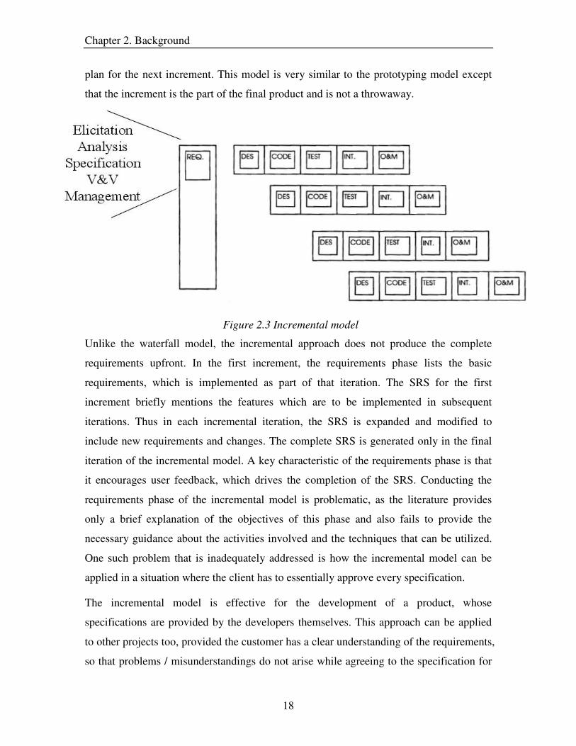
plan for the next increment. This model is very similar to the prototyping model except
that the increment is the part of the final product and is not a throwaway.
Figure 2.3 Incremental model
Unlike the waterfall model, the incremental approach does not produce the complete
requirements upfront. In the first increment, the requirements phase lists the basic
requirements, which is implemented as part of that iteration. The SRS for the first
increment briefly mentions the features which are to be implemented in subsequent
iterations. Thus in each incremental iteration, the SRS is expanded and modified to
include new requirements and changes. The complete SRS is generated only in the final
iteration of the incremental model. A key characteristic of the requirements phase is that
it encourages user feedback, which drives the completion of the SRS. Conducting the
requirements phase of the incremental model is problematic, as the literature provides
only a brief explanation of the objectives of this phase and also fails to provide the
necessary guidance about the activities involved and the techniques that can be utilized.
One such problem that is inadequately addressed is how the incremental model can be
applied in a situation where the client has to essentially approve every specification.
The incremental model is effective for the development of a product, whose
specifications are provided by the developers themselves. This approach can be applied
to other projects too, provided the customer has a clear understanding of the requirements,
so that problems / misunderstandings do not arise while agreeing to the specification for

Chapter 2. Background
19
each incremental cycle. The benefits of this model are better product testing and the
continuous incorporation of user feedback into the development cycle.
2.1.4 Spiral Model
The objective of the Spiral model is to combine the best features of the waterfall and
prototyping approaches, and add to it the element of risk analysis [Boehm 88]. This
model was proposed by Boehm and the idea is to minimize the risk through prototyping
[Pressman 2001]. Activities in the spiral model are organized in the form of a spiral that
has cycles. The radial dimension of the model represents the cumulative cost incurred in
conducting the steps performed thus far, and the angular dimension represents the
progress made in each spiral.
A simple explanation of this model is to look at it as the waterfall model with each phase
preceded by a risk analysis activity. Before the commencement of each phase, an attempt
is made to control or resolve the risks identified. If it is impossible to resolve the main
risks then the software engineer can decide to terminate the project [Schach 96]. At the
completion of each phase, the product developed is validated to obtain feedback, which is
useful in making the plans for the next spiral. (Figure 2.4)
Figure 2.4 Spiral model

Chapter 2. Background
20
The requirements phase in the spiral model is different from those in other SDLC models
in that this phase explicitly identifies the high level activities. The phase includes
customer communication, planning, analysis, and customer evaluation (validation). These
activities correspond closely to the activities in the general requirements engineering
process, which is explained in Section 2.2. Another positive feature of the requirements
phase is that it is iterative in nature and encourages user feedback. Even though this
model identifies the activities in the requirements phase, it fails to give an in-depth
explanation of these activities and the techniques that can be used to achieve the activity
objectives.
A drawback of the spiral model is that the customer communication activity does not
completely reflect the negotiations between the customer and the software engineer. This
shortcoming has been overcome by the Win-Win spiral model, which provides a better
representation of the customer communication activity by including the following sub
activities:
• Identifying stakeholders.
• Identifying stakeholder win conditions2.
• Reconciliation of win conditions.
Negotiation in the win-win spiral model is supported by the win-win negotiation model,
which specifies the steps for resolving conflicts. The negotiation model is well-defined
and can easily be incorporated into the requirements process to handle conflicts among
requirements.
The spiral model is a robust and realistic approach to software development and is
suitable for large scale software systems. Compared to the other SDLC models, the spiral
model has a better requirements phase. However, like the other models, the requirements
phase is not clearly described and there is inadequate information about the methods to be
used in this phase.
2 Win conditions capture the customer’s goals and concerns.

Chapter 2. Background
21
2.1.5 Extreme Programming (XP)
Extreme programming is one of the new SDLC models and is a light weight, low-risk and
flexible approach [Beck 99]. Extreme programming proposes a set of principles such as
on-site customer, no prototyping, simple design, small increments, no documentation, etc,
which form the essence of this approach.
The requirements phase in extreme programming includes elicitation, analysis, and
validation (Figure 2.5). Elicitation is performed with the on-site customer using
brainstorming techniques to obtain the customer needs in the form of stories/scenarios.
The customer, along with the requirements engineer, analyzes the stories and determines
the priority the elicited stories. Once prioritization is complete, the test cases for the
stories are determined and the stories are broken down into small tasks, which can be
taken up by the developers for design and coding [Clifton 2001]. Testing of the stories
provides customer feedback, which is useful for making necessary changes to the system
in the next iteration. Requirements documentation is skipped as it is considered to be a
factor for project delay and increase in cost [Horrian 2003]. Thus, the requirements phase
is iterative with an emphasis on continuous user involvement throughout the process.
Figure 2.5 Requirements engineering phase in Extreme Programming

Chapter 2. Background
22
Since XP is a new development model, an attempt is made to provide some structure to
the requirements phase. Thus, we see a decomposition of the phase into different sub-
activities. However, this decomposition is again at a high level of granularity with the
objectives still being abstract. This model (XP) proposes brainstorming as a technique for
elicitation but it fails to list the other possible methods. In addition, techniques for the
other activities in the requirements phase have not been adequately identified.
Extreme programming is a light-weight approach which is suitable for small to medium
projects. Handling large projects is problematic as one of the core concepts is “no
documentation” and without a clear requirements specification, confusion and
misunderstandings can arise.
In the previous sections, some of the better known development models are discussed.
The focus of this section is on understanding the requirements process in these models
and identifying the features that are useful for this research.
All of the models have a requirements phase under the name requirements analysis,
requirements definition, etc. While the waterfall, prototyping and incremental model have
a single activity for the requirements phase, the spiral and extreme programming model
have several activities for the generation of requirements. A common characteristic of all
the models reviewed is that the requirements phase is described briefly with the
objectives implied. Furthermore, the models have paid inadequate attention to methods
that can be used for the requirements phase. While some models do specify techniques,
the coverage of the methods is minimal. Moreover, the methods fail to address all the
requirements engineering objectives.
The SDLC models discussed provide some useful insights to the requirements process. A
majority of the models recognize the fact that requirements generation is not sequential
but an iterative process. Customer feedback is another aspect that is featured in all of the
models and the feedback often directs the next iteration. Extreme programming
emphasizes the importance of customer participation by including continuous customer
involvement as one of its core concepts. The negotiation model in the Win-Win spiral
approach is well-defined and can be a good inclusion to the requirements model.
Chapter 2. Background
23
The examination of different SDLC models shows that the requirements phase is
inadequate in two ways:
• Decomposition of the requirements process into activities, and
• Identification of methods for activities
The next section presents the research addressing the refinement of the requirements
process; Section 2.3 reviews the literature that identifies methods for the requirements
phase.
2.2 Requirements Engineering Process and Models
Models such as the spiral model and extreme programming have attempted to decompose
the requirements phase but this decomposition fails to consider all aspects of the
requirements process. To provide a better understanding of how requirements are
generated, we present the major phases of the requirements process in the next section.
We also describe research focusing on refining each of the phases within the
requirements generation process (Section 2.2.2).
2.2.1 Requirements Generation
Traditionally requirements engineering was considered as a fuzzy and rather “dirty” stage
of software development where a formal specification (SRS) is generated from some
possibly vague and informally expressed ideas. However, over the years the realization of
the importance of requirements and related research has resulted in a better understanding
of the requirements phase. This awareness in the software engineering community has
resulted in redefining the term “requirements engineering” as [IEEE 90]:
(1) The process of studying user needs to arrive at a definition of system, hardware, or
software requirements;
(2) The process of studying and refining system, hardware or software requirements.
Thus, the requirements phase focuses on generating a clear and well-defined set of
requirements, which specify what the system should implement, how the system should
behave and what constraints bound the system [Sommerville 97]. In the requirements
engineering literature, the phases or activities of the requirements process have been

Chapter 2. Background
24
given different names. Krasner identifies five phases of requirements engineering: need
identification and problem analysis, requirements determination, requirements
specification, requirements fulfillment, and requirements change management [Krasner
85]. Leite and Freeman proposes that requirements engineering activities be comprised of
elicitation and modeling activities, the former being concerned with fact finding,
communication and fact validation, and the latter with representation and organization of
requirements [Liete 91]. Davis developed a requirements model which included five
phases: problem recognition, evaluation and synthesis, modeling, specification, and
review [Davis 1993]. Apart from the above decompositions of the requirements phase,
there are several others, which are described in the literature [Sommerville 97a][Potts
94][Jirotka 94].
Even though the literature specifies diverse names for the requirements engineering
phases, the essence of these phases can be effectively captured by the following five
components of the requirements process:
• Requirements elicitation
• Requirements analysis
• Requirements specification
• Requirements verification and validation
• Requirements management.
Each of these phases is discussed in the sections that follow.
2.2.1.1 Requirements Elicitation
Requirements elicitation is the iterative process of seeking, uncovering, acquiring and
elaborating user needs and constraints. It is the means by which the requirements
engineer determines the problems and needs of the customers, so that system
development personnel can construct a system that actually resolves the problems and
addresses the customer’s needs [Davis 2003].
The requirements elicitation process comprises the following steps [Rzepka 89]:

Chapter 2. Background
25
• Identify the sources of requirements for the system. Sources include problem
owners, organizational documentation, end users, interfacing system and
environmental factors.
• Obtain the “wish-list” for each relevant party. This list is likely to be ambiguous,
incomplete, inconsistent, and untestable.
• Analyze, refine and document the “wish list” obtained. The refined “wish-list”,
henceforth called requirements, is precise and unambiguous.
• Finally the non-functional requirements such as reliability and performance, are
determined and documented
The steps described are common to most of the definitions of the requirements elicitation
process found in the literature. Methodologies such a as Joint Application Design (JAD),
Participatory Design (PD) [Carmel 93] and Facilitated Application Specification
Techniques (FAST) [Zahniser 90] are commonly used for the elicitation phase. These
methodologies employ various techniques to achieve the objectives of the elicitation
process and the choice of the method is based on criteria such as cost, ease of conducting,
time required, etc. Research related to the identification of methods for the elicitation
process is discussed in Section 2.3.
Several problems are faced by the requirements engineer in the process of eliciting
system requirements. These problems can be classified into three broad categories:
• Problems of scope – Requirements address too little or too much information.
• Problems of understanding – Occurrence of misunderstanding within groups and
between groups (e.g. customers and developers).
• Problems of volatility – Problems related to continuous change in requirements.
The problems that generally appear under these categories are listed below: [Christel 92].
Problems of scope
• The boundary of the system is ill-defined
• Unnecessary design information may be given
Problems of understanding
• Users have incomplete understanding of their needs
• Users have poor understanding of computer capabilities and limitations
• Analysts have poor knowledge of problem domain

Chapter 2. Background
26
• User and analyst speak different languages
• Ease of omitting “obvious” information
• Conflicting views of different users
• Requirements are often vague and untestable
Problems of volatility
• Requirements evolve over time
The problems listed above appear in some form or the other during the elicitation phase
of the requirements generation process. In spite of the large number of elicitation
techniques, the difficulties faced during elicitation cannot be completely overcome.
However, the problems can be minimized by involving the stakeholders throughout the
requirements elicitation process. This ensures that all the stakeholders have a better
understanding of the requirements process, and as a consequence, the task of obtaining a
stable and complete set of requirements becomes easier.
2.2.1.2 Requirements Analysis
Requirements analysis is the process of analyzing the users’ and customers’ needs to
obtain a definition of the software requirements. This phase includes representing the
requirements in different forms in order to facilitate the analysis of requirements from
different perspectives. Hence some authors refer to this phase as requirements modeling
[Greenspan 94] or conceptual modeling [Loucopoulos 92]. Requirements analysis entails
elaborating the alternative models for the target system and negotiating the conflicting
aspects of the models so that the final model is agreeable to the systems stakeholders.
Models that are explicit and sufficiently formal can be shared by a group of people and
can be used for reasoning about the requirements [Yeh et. al. 84].
Requirements modeling improves the communication between the customers and the
requirements engineer since graphic representations of the requirements are easier to
comprehend by the customer. Thus, any misunderstandings in the requirements are
identified early on in the requirements engineering life cycle. Modeling also helps the
requirements engineer to better comprehend the requirements and to identify the impact
of requirements changes more rapidly.

Chapter 2. Background
27
Another objective of requirements analysis is to analyze the requirements from different
perspectives. To accomplish this, it is necessary to identify requirement attributes such as
risk factors, importance of the requirement, value of the requirement to the product and
so on. These attributes are helpful while evaluating the requirements against factors like
risk, cost, schedule, etc [Nord 2003]. In addition, during the requirements analysis phase,
the requirements engineer has to decide whether or not to continue with the project.
Furthermore, the requirements analysis phase also identifies conflicts among
requirements and attempts to resolve them through negotiation techniques. Thus,
requirements analysis is concerned with the evaluation and modeling of the requirements.
Customer participation is critical for requirements analysis as the goal of this phase is to
ensure that all stakeholders arrive at a common understanding of what they will have
when the software is deployed [Weigers 2001]. Several authors have proposed techniques
to achieve the goals of the requirements analysis phase and this research is discussed in
Section 2.3. A detailed description of the methods for the different activities in the
requirements analysis phase is provided in Chapter 4.
2.2.1.3 Requirements Specification
In conjunction with requirements elicitation and analysis, it is necessary that the captured
requirements are also documented. During requirements specification, the requirements
are precisely and clearly recorded to act as a basis for a contract between the customer
and the problem solver/developer. The need for a well-defined requirements specification
has led to the emergence of several different specification languages such as
Requirements Specification Language (RSL) [Bixler 76], Gist [Balzer 82], Problem
Statement language (PSL) [Teichroew 1982], etc.
A well-defined software requirements specification (SRS) has the following benefits:
• Acts as a binding contract between the customers and the suppliers
• Reduces the effort needed for maintenance and changes
• Provides a basis for estimating costs and schedules
• Provides a baseline for verification and validation

Chapter 2. Background
28
The exact contents of the requirements specification varies from situation to situation.
However, the SRS should include the functionality of the system, description of the
environment and the system objectives, function and design constraints, and data and
communication protocols. In addition, the contents of the SRS should adhere to the
quality characteristics listed below [IEEE 93]:
• Correctness: Every stated requirement is one that the system shall meet.
• Unambiguity: Every stated requirement has only one interpretation.
• Completeness: Requirements capture all aspects of the system
• Consistency: Requirements stated have no conflicts
• Ordered: Requirements stated are ranked for importance and/or stability
• Verifiable: Each requirement should be testable of performing its function in a
given amount of time
• Modifiable: Structure and style of the SRS should be such that changes are
incorporated easily
• Traceable: Origin of each requirement should be traceable.
The content of the SRS can be presented in different formats and styles with the textual
format being the most commonly used in the industry. A textual format of the
requirements can be cumbersome to validate if the SRS is large and unstructured. In such
situations, other alternatives like prototypes or context diagrams may be advantageous.
Prototypes are best used for applications that include visual displays and interact heavily
with the user [Pressman 2001]. Context diagrams depict the product as a black box
surrounded by users and external system with which it interacts [Lauesen 2002]. The
focus is on the interfaces of the system, and thus it enables the users to easily identify
missing functionalities or interfaces. Use cases and scenarios provide a “story-like”
description of the system and this facilitates easier comprehension and validation.
However, translating these informal descriptions into design is difficult because of the
lack the formal structure and the potential for multiple interpretations.
Each of the above mentioned formats are suitable for the specification of requirements.
However, an ideal SRS should include a blend of these formats so that the specification
facilitates user validation and translation of requirements to design.

Chapter 2. Background
29
2.2.1.4 Requirements Verification and Validation
Verification is the process that ensures the high quality of the Software Requirements
Specification (SRS) and the adequacy of requirements to continue with design,
construction and testing. In addition, verification determines whether the requirements
are correctly derived from the system requirements. The compliance of the SRS with the
documentation standards is also checked during verification.
Verification examines the requirements as soon as they are generated and determines if
the requirements possess the desired quality attributes [Weigers 2001]. When
requirements elicitation is still under progress, quality attributes 3 like correctness,
verifiability, modifiability, etc. are considered for the verification of each individual
requirement. Other attributes like completeness and traceability are assessed only after
obtaining the complete set of requirements. Several techniques are used during
verification and the most widely used methods are internal and external reviews, audits,
walkthroughs and inspections.
Validation is the process which ensures that the requirements accurately capture the
customer’s intent/needs. Its main objective is to find if there are disagreements between
what the user desires and what the requirements state. Conflicts are identified for
corrections to the requirements in order to minimize the probability of changes made to
the SRS in the future.
Validation is conducted after verification at different stages in the requirements
engineering phase. Initially, when the subset of requirements is captured during the
elicitation phase, the requirements are first verified and then validated by the user.
Similarly, on obtaining the complete set of requirements, validation is once again
performed. Finally, at the end of the requirements engineering life cycle, validation is
carried out on the SRS, which is created as per the documentation standards and formats
[IEEE 98].
Commonly used techniques for validation are scenarios, walkthroughs, guided
discussions, prototyping, storyboarding, etc. Techniques should be chosen based on the 3 Quality attributes are explained in Section 2.2.1.3

Chapter 2. Background
30
stage in the requirements engineering life cycle and the product being validated. For
example, prototyping is better suited to validate the complete set of requirements than the
individual requirements. In addition, interactive applications are more easily validated
using prototypes than by other methods.
The terms verification and validation are sometimes used interchangeably in the literature
but as pointed out in this section, they are indeed different activities. The task of
verification is to ascertain that the SRS complies with standards, and is consistent,
complete and unambiguous. On the other hand, validation determines whether the
requirements satisfy the users’ intentions. Requirements verification and validation
(V&V) can uncover and rectify many deficiencies that may otherwise go undetected until
late in the development cycle, where the correction would be much more expensive. Thus,
requirements V&V has a critical impact on the outcome of the software development life
cycle and should be conducted carefully.
2.2.1.5 Requirements Management
Requirements managements refers to the set of procedures that assist in the management
of the requirements process and product as well as maintaining the evolution of the
requirements throughout the development life cycle. Effective requirements management
is essential for producing a good SRS and eventually a good quality product. The
activities in requirements management include planning, prioritization, traceability,
impact assessment of changing requirements, configuration control, and so on.
Requirements management encompasses the entire development life cycle, starting from
the requirements phase till the testing phase.
The main issues in the requirements management phase are
• Requirements traceability, and
• Change management
A requirement is traceable if one can discover who the owner of the requirement is, the
rationale behind the requirement, the relationships to other requirements, and how the
requirement relates to other artifacts such as design and documentation [Sawyer 97].
Requirements traceability is useful in determining the impact of requirements changes on

Chapter 2. Background
31
design and implementation. In addition, traceability facilitates the identification of
inconsistencies among requirements by linking all the requirements to the user needs.
Furthermore, traceability provides insights to non-functional components such as quality,
completeness, impact analysis and process improvement [Palmer 96].
Requirements are volatile in nature and it calls for effective change management in order
to maintain the consistency of the requirements. Once the requirements engineering phase
is completed, requirements management is mainly concerned with change management,
which includes the following activities:
• Identification of the required changes
• Impact analysis of the requirement changes
• Alternative ways of incorporating the requested changes
• Updating the SRS without causing any inconsistencies
• Recording the changes and its rationale
Documentation of the rationale and the traceability matrix are valuable artifacts in
handling changes to requirements. Recordings of tentative requirements4 [Robertson 99]
as well as discarded requirements 5 [Sommerville 97] are also useful strategies for
effective change management. To maintain the consistency of the SRS, several
approaches such as Software cost reduction (SCR) [Heitmeyer 96], Requirements state
machine language (RSML) [Heimdahl 95], etc, have been proposed.
Requirements management is a complex phase, which is supported by a number of tools
that are readily available in the software market. Tools such as Rational Suite, DOORS,
Caliber-RM, Omni Vista, etc. provide document templates, configuration control, visual
representations and other features, which make requirements management more effective
and easier to conduct.
2.2.2 Requirement Models
In this section, we present a survey of different requirements engineering models, which
attempt to refine the requirements process by decomposing the major phases – elicitation,
4 Requirements that are currently under consideration/negotiation 5 Requirements that have been proposed and subsequently rejected after analysis and negotiations
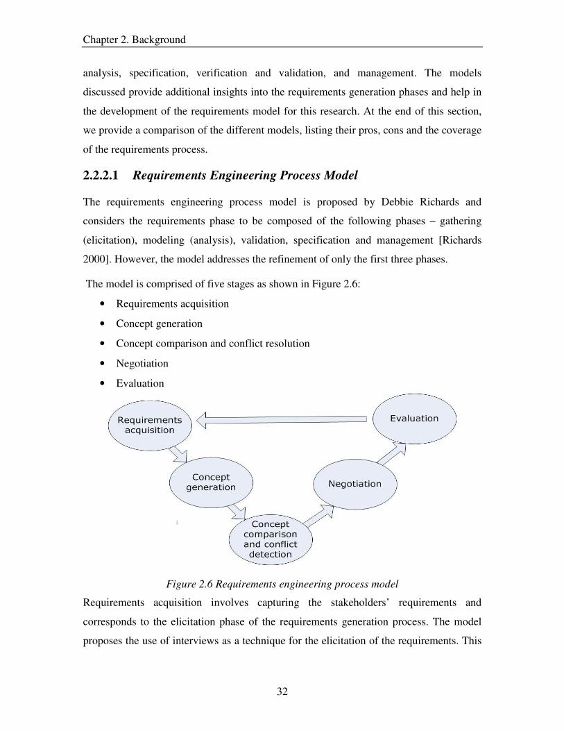
Chapter 2. Background
32
analysis, specification, verification and validation, and management. The models
discussed provide additional insights into the requirements generation phases and help in
the development of the requirements model for this research. At the end of this section,
we provide a comparison of the different models, listing their pros, cons and the coverage
of the requirements process.
2.2.2.1 Requirements Engineering Process Model
The requirements engineering process model is proposed by Debbie Richards and
considers the requirements phase to be composed of the following phases – gathering
(elicitation), modeling (analysis), validation, specification and management [Richards
2000]. However, the model addresses the refinement of only the first three phases.
The model is comprised of five stages as shown in Figure 2.6:
• Requirements acquisition
• Concept generation
• Concept comparison and conflict resolution
• Negotiation
• Evaluation
Figure 2.6 Requirements engineering process model
Requirements acquisition involves capturing the stakeholders’ requirements and
corresponds to the elicitation phase of the requirements generation process. The model
proposes the use of interviews as a technique for the elicitation of the requirements. This

Chapter 2. Background
33
activity results in the gathering of requirements in formats such as use case descriptions
and interview transcripts.
Concept generation is the second stage in this model and involves representing the
requirements of different stakeholders in the form of a table, which has requirement
objects as rows and object attributes as columns. The visual representation of the
viewpoints of different stakeholders helps in easier understanding and comparison of the
viewpoints.
Once the table representations of the requirements are generated, the tables are compared
for conflicts. Requirements which appear in the tables are classified as being in one of the
four states [Gaines 88]:
1. Consensus is the situation where the same requirement is described using the
same terminology.
2. Correspondence occurs when the same requirement is described using different
terminology.
3. Conflict is where different requirements are being described but the same terms
are used.
4. Contrast is where there is no similarity between requirements or the terminology
used.
States 2,3 and 4 correspond to misunderstandings among the viewpoints of different
stakeholders.
On detecting the conflicts, the next stage is to resolve them through different negotiation
techniques. This model adopts the five strategies of conflict resolution proposed by
Easterbook and Nuseibeh [Easterbook 96]:
• Resolving - remove inconsistency
• Ignoring - take no action
• Circumventing - don’t include
• Delaying - put on hold
• Ameliorating - reduce the degree of inconsistency

Chapter 2. Background
34
Evaluation is the last stage of the model and determines if another iteration of the model
is necessary. The requirements engineering process model uses the number of conflicts to
decide whether to go through another cycle of the model.
This model identifies activities in the requirements phase such as negotiation and conflict
detection. However, the model is inadequately decomposed and fails to identify all the
activities in the requirements phases, which the model attempts to refine. In addition, the
model covers only the elicitation, analysis (partly) and validation phases and overlooks
the management, verification and specification aspects. Methods are specified for each
stage or activity but the methods are limited to only one or two and this restricts the
application of the model. Furthermore, this model provides only an overview of the
activities and does not explicitly state the activity objectives.
2.2.2.2 Requirements Triage
Requirements triage is a requirements engineering model proposed by Alan Davis and it
is the process of deciding precisely what features the product will include in its
implementation. From a naïve development manager’s perspective, requirements triage
is simple. The time and effort needed to develop the features of a system are compared
with the project budget and schedule. If there is incompatibility of these project
parameters (time, effort, schedule, cost), then the features are removed so that the project
parameters synergize. However, this strategy completely overlooks the impact of market,
price, revenue and profit. To incorporate these features, the requirements triage considers
marketing, financial and development factors.
The requirements triage is a collection of activities, which fit into the requirements
analysis phase and the goal of this model is: a set of features, which can be developed
using available resources within acceptable levels of risk and which can be sold at an
acceptable price to a known market in sufficient quantities to achieve satisfactory levels
of profit and thus achieve a reasonable return on investment [Yourdon 99].
This model includes five activities (Figure 2.7), which are briefly described below:
• Risk analysis: Determines acceptable levels of risk for the requirements

Chapter 2. Background
35
• Cost and Schedule Estimation: Determines the effort and time required to
implement potential features of the system.
• Price Analysis: Determines the optimal price to charge customers.
• Market Analysis: Determines the types of customers, their numbers, their buying
power/capability, urgency for a particular feature, and so on.
• Feature Triage. The process which determines the features that are the right ones
to be developed.
Figure 2.7 Requirements triage
In order to achieve a balance of the market, financial and development factors, the
following variables need to be adjusted until a reasonable result is produced [Davis 99]:
• Add, delete or change a feature
• Make the delivery date earlier or later
• Increase or decrease the resources applied to development
• Increase or decrease the price
• Increase or decrease costs of good sold
• Increase or decrease the resources devoted to marketing and sales.

Chapter 2. Background
36
Several tools such as Omni-Vista SP6, Primavera Monte Carlo7, QSS TechPlan 28, etc.
have been developed to support the requirements triage model. These tools allow the
requirements engineer to visualize the effects of various factors like cost, schedule, price,
etc. on the development of the project.
The requirements triage model attempts to refine the analysis phase of the requirements
generation process. Specifically, the model focuses on the analysis portion where the
requirements are complete. The decomposition into activities is adequate and at the right
level of abstraction. However, the model fails to describe in detail what transpires within
each of these activities. In addition, since the model addresses only a portion of the
analysis phase, the applicability of the model is restricted and it has to be plugged into
other models for effective usage.
2.2.2.3 Knowledge Level Process Model
The knowledge level process model attempts to address the entire requirements
generation process and provides different levels of process abstraction as illustrated in
Figure 2.8.
Figure2.8 Knowledge level process model 6 See www.omni-vista.com/products 7 See www.primavera.com/products/monte.html 8 See www.qssinc.com/products/visiontools/techplan.html

Chapter 2. Background
37
As shown in the figure, the knowledge level process model is comprised of three
processes:
• Elicitation – It involves the identification of problems, elicitation of requirements
and scenarios from the stakeholders, and documentation of the domain knowledge.
• Manipulation of requirements and scenarios – It entails resolving the ambiguity
and inconsistency among the requirements and scenarios. In addition, this process
reformulates the informal requirements to semi-formal and formal requirements and
establishes the relationships between the requirements and the scenarios.
• Maintenance of requirements and scenario specification – This process involves
the configuration control of traceability information and documents containing the
requirements and scenarios.
Each of these processes is further broken down into activities and the inputs and outputs
for each of these activities are identified. The interfaces (input and output information) of
the high level process abstraction are shown in Table 2.1 [Herlea 99].
Process Input information type Output information type
Elicitation Requirements and scenarios
information
Elicitation results
Elicitation basic material (problem
description and domain knowledge)
Manipulation of
requirements and
scenarios
Elicitation results Requirements and scenarios
information
Maintenance of
requirements and
scenarios specification
Elicitation results
Requirements and scenarios
information
Elicitation basic material
Elicitation results
Requirements and scenarios
information
Elicitation basic material
Table 2.1 Input and output flows in the Knowledge Level Process Model
The knowledge level process model is a complex model, which addresses the complete
requirements generation process. It includes all the major requirements phases and refines

Chapter 2. Background
38
the elicitation, analysis and V&V (verification and validation) phases. The decomposition
of the requirement phases into activities is inconsistent as some of the activities are at a
low level of granularity (describing steps within activities) while others are highly
abstract (grouping of activities). Also, since the model is scenario based with the
requirements and scenario activities closely intertwined, it is difficult to incorporate
changes into the model. Another drawback is that even though the model identifies
activities in the requirements process, the literature fails to provide adequate information
about the activities and their objectives. Furthermore, this model skips the issue of
providing techniques for conducting the activities identified. Compared to the triage and
the requirements engineering process model, this model has better coverage of the
requirements process.
2.2.2.4 Win-Win Spiral Model
The spiral model discussed in Section 2.1.4 lacked the activities for customer negotiation
and, as a result, the Win-Win Negotiation model was developed to fill this gap. On
combining the two models, we have the Win-Win spiral model, which has a better
representation of the customer communication activity. The Win-Win spiral model has
been proposed as a requirements model because it incorporates the major components of
the requirements process (Figure:2.9):
Figure 2.9 Win-Win spiral model

Chapter 2. Background
39
The requirements generation process in the Win-Win spiral model comprises the
following steps:
• The first step is the identification of the stakeholders and their win conditions
(needs, requirements and concerns). This activity corresponds to the elicitation of
requirements form the stakeholders.
• The next step in the spiral is to resolve the conflicts in the requirements and
identify system constraints. In addition, the requirements are also evaluated for
risk and the system alternatives. These set of activities map to the analysis phase
in the requirements process.
• Finally the requirements are validated and reviewed; this step matches the
objectives of the requirements verification and validation phase.
The above mentioned steps are repeated until a complete and well-defined software
requirements specification (SRS) is obtained.
The negotiation model is based on four artifact types: Win conditions, issue, options and
agreements (see Figure 2.10) [Boehm et al., 1994].
Figure 2.10 Win-Win negotiation model

Chapter 2. Background
40
Win conditions capture the stakeholder goals and concerns with respect to a new system.
If a win condition (requirement) is non-conflicting, it is accepted and included in the
agreement/specification. Otherwise, an issue artifact is created that records the conflict
among the win conditions. To resolve the issues, the stakeholders are allowed to suggest
alternative solutions, which form the content of the options document. The solutions are
then evaluated and the option agreeable to the stakeholders is adopted in the agreement
artifact. The negotiation model includes a tailorable domain taxonomy, which links to the
artifacts and this ensures that the stakeholders have a unified understanding of the
artifacts generated during the negotiation process.
The Win-Win spiral model presents a general framework for the requirements process but
lacks the adequate decomposition of activities. Moreover, all the activities except
negotiation are briefly explained with their objectives being implied. Also, the issue of
identifying techniques for the activities is left unaddressed. The positive feature of this
model is the clearly defined negotiation activity, which can be adapted to the conflict
resolution activity in the requirements process.
2.2.2.5 Process Framework
The process framework attempts to address the issue of providing a framework for the
requirements generation process. This model consists of four main activities, which are
conducted iteratively until a precise and complete SRS is obtained (Figure 2.11) [Alcazar
2000]:
• Capture user requirements
• Analyze requirements
• Build solution specification
• Verify specification
Capture user requirements: This activity involves the elicitation of requirements and
other pertinent information such as business process, organization description,
stakeholders profile, etc. The model recommends the use of requirements lists, graphs,
and free texts for the representation of requirements.

Chapter 2. Background
41
Verify Specification
Build Solution Specification
Capture User Requirements
Analyze Requirements
Analyze requirements: This activity focuses on building a common understanding of the
requirements, problem domain, vocabulary and other relevant information among the
stakeholders. To capture this information, UML and ER diagrams have been prescribed
to the requirements engineer. A second objective of this activity is to classify the
requirements in a hierarchical order and to identify the relationship among the
requirements.
Build solution specification: The objective of this activity is to express what the system
has to accomplish in such a way that the requirements engineer and the customer get a
clear picture, and the latter accepts it. This model advocates the use of use cases
[Jacobson 92] for the presentation of requirements to the customer.
Verify specification: This activity allows the requirements engineer to confirm that all
the requirements have been captured and recorded. In addition, the requirements are
checked for adherence to the quality characteristics such as correctness, preciseness,
verifiability, etc.
Figure 2.11 Requirements engineering process framework
The process framework identifies the main phases of the requirements generation process
but fails to provide the decomposition of these phases. In addition, the activities are
explained briefly with the objectives being specified at a high level of abstraction. The
focus of this model seems to be on determining how the information generated from each
phase is to be represented rather than on the decomposition of the process itself.

Chapter 2. Background
42
2.2.2.6 Requirements Generation Model (RGM)
The requirements generation model provides a structured framework for the requirements
phase and identifies the major components of the requirements process (Figure 2.12).
[Arthur 99]. This model splits the requirements generation process into two parts:
• Requirements Definition, where the requirements are elicited and evaluated
iteratively until the exit criteria is satisfied.
• Requirements Analysis, where the complete set of requirements is analyzed,
documented, verified and validated.
Figure 2.12 Requirements generation model
The requirements definition phase is decomposed into indoctrination and an iterative
requirements capturing sub-phase. Indoctrination is concerned with familiarizing the
customer about the RGM, educating the requirements engineer about the problem domain,
and specifying the customer’s responsibilities. The requirements capturing phase is
further refined into sub-activities, which focus on obtaining requirements from the
customer and refining them in an iterative manner until the complete set of requirements
is collected. The RGM also provides protocols and guidelines to structure the activities
identified. Protocols define boundaries for the RGM within which the customer and the
requirements engineer must operate whereas guidelines are recommendations or
suggestions that are optional for the requirements engineer or the customer [Groner 2002].
The RGM identifies all the major requirements engineering phases – elicitation, analysis,
specification, verification and validation, and management. In addition, the model
R e q u i r e m e n t s M a n a g e m e n t
Requirements Definition

Chapter 2. Background
43
decomposes the capturing phase into activities, which are clearly defined. Furthermore,
the RGM specifies constraining and guiding components in the form of protocols and
guidelines, which help in effectively conducting the activities. The drawback of the RGM
is that the decomposition of the model into activities is inadequate and as a result the
objectives are stated at a high level of granularity. However, the RGM does facilitate
future decomposition by providing detailed explanations of the activities identified.
Another shortcoming of the RGM is that the techniques that can be applied to achieve the
objectives of the activities are not identified.
2.2.2.7 Comparison of the Requirement Engineering Models
Pros / Cons of Requirement Engineering models RE process
coverage
Requirements engineering process model +
-
Methods specified for each activity
Inadequate decomposition
Overview of activities
Single method specified for each activity
Overlooks phases of the requirements process
Elicitation
Analysis
Validation
Requirements triage model
+
-
Adequate decomposition of activities identified
Overview of activities
Methods not specified for the activities
Overlooks phases of the requirements process
Portion of
analysis
Knowledge level process model
+
-
Identifies all phases of the requirements process
Inadequate decomposition
Overview of activities
Methods not specified for the activities
Complex, difficult to change
Not general in nature (scenario based)
All phases
(Elicitation
Analysis
Specification
V&V
Management)

Chapter 2. Background
44
Pros / Cons of Requirement Engineering models RE process
coverage
Win-Win spiral model +
-
Clear and well defined negotiation activity
Inadequate decomposition
Overview of activities
Methods not specified for the activities
Overlooks phases of the requirements process
Elicitation,
Analysis
V&V
Process framework
+
-
Identifies all phases of the requirements process
Focus on documents produced
Inadequate decomposition
Overview of activities
Methods not specified for the activities
All phases
(Elicitation
Analysis
Specification
V&V
Management)
Requirements generation model
+
-
Identifies all phases of the requirements process
Detailed explanation of identified activities
Facilitates future decomposition
Inadequate decomposition
Methods not specified for the activities
All phases
(Elicitation
Analysis
Specification
V&V
Management)
Table 2.2 Pros/cons and process coverage of requirement engineering models
From Table 2.2, it is clear that only three models include all the phases of the
requirements generation process – Knowledge level process model, Process Framework
and Requirements Generation Model. All the three models inadequately decompose the
model and fail to specify methods for the activities identified. Among these models, the
process framework has the least amount of decomposition and the activities have a one to
one mapping to the phases of the requirements generation process. The knowledge level
process model is complex and is scenario based making it difficult to decompose and

Chapter 2. Background
45
incorporate changes. The RGM facilitates decomposition and provides a detailed
explanation of activities. Comparing the models, which cover all the phases in the
requirements process, the RGM looks most promising for decomposition.
Among the other models, which cover one or more phases of the requirement process, the
requirements triage and win-win spiral model provide useful insights. Requirements
triage examines and decomposes the portion of the analysis phase that evaluates the
complete set of requirements. This model considers the effects of financial, marketing
and development factors on the requirements and proposes activities at the right level of
abstraction. The win-win spiral model includes a well-defined negotiation activity that
synergizes comfortably with the conflict resolution activity of the requirements
generation process.
2.3 Requirement Engineering Methods
One of the drawbacks of the requirement engineering models is that they fail to specify
the techniques for the activities in the models. This section focuses on the research
conducted in identifying methods for the activities in the requirements phase. We do not
provide an explanation of the methods, as this is the objective of Chapter 4.
This section is structured according to the research conducted in the different phases of
the requirements engineering process. Prior to requirements elicitation, the needs of the
customer are determined and this is accomplished through the problem synthesis phase.
Section 2.3.1 will discuss the research on identifying methods for this phase. Subsequent
sections will present the literature review on method identification for the different
requirement phases.
2.3.1 Methods for Problem Synthesis
Problem synthesis is the phase that entails learning about the problem to be solved,
understanding the customer needs and identifying the constraints on the solution. The
problem synthesis phase includes two main activities:
• Problem analysis: Involves understanding and decomposing the problem in
addition to identifying the problem context and constraints.

Chapter 2. Background
46
Slow Response to Web Page Request
Network Overload
Slow CPU Inefficient Search Algorithm
Disk Access too Slow
• Needs generation: Involves elicitation, analysis and evaluation of the user needs.
Alan Davis identifies brainstorming and interviewing as the main techniques for
understanding the problem and the domain [Davis 90]. Brainstorming provides a number
of ideas in a short amount of time and it can bring out details which cannot be obtained
through a prolonged interview process. Brainstorming works well in understanding the
real problem if the customer is unsure about his/her problem. In order to determine the
needs of the customer, it is necessary to identify the cause of a particular problem and for
this purpose Leffingwell recommends the use of the Fish bone diagram [Leffingwell
2000]. Figure 2.13 illustrates how the Cause-Effect (or Fishbone Diagram) is used to
decompose the perceived problem into potential causes of that problem.
Figure 2.13 Fishbone diagram
Leffingwell also prescribes demographic studies and brainstorming for identifying the
stakeholder profiles and the constraints on the solution. Context free questions is another
method that poses high-level questions to understand the problem and its domain [Gause
89]. Furthermore, the walkthrough technique (WALT), which poses questions to the user
as s/he is guided through a description of the problem, is an effective method to obtain
information about the problem as a whole and the potential causes of the problem [Lenart
98].
Research on identifying methods for needs generation is less compared to problem
analysis. Techniques such as interviews, storyboarding, brainstorming, questionnaires,
etc, which apply to requirements elicitation can be used for capturing user needs [Davis
90]. Prioritization and conflict resolution techniques are useful during the analysis of the
user needs [Leffingwell 2000]. Inspection techniques are usually applied for the needs

Chapter 2. Background
47
evaluation activity, which separates the needs to be incorporated in the system from the
ones which are to be left out or delayed for the next release [Gilb 93].
2.3.2 Methods for Requirements Elicitation
Requirements elicitation is the process through which the customers and requirements
engineers of a software system discover, review, articulate, and understand the user needs
and constraints of the software and development activity [Thayer 97]. A number of
methods have been proposed to elicit requirements from the users and these techniques
are best used in combination with each other.
Requirements are usually elicited through discussion and interviews with the stakeholders
[Gause 89]. Workshops, brainstorming, storyboards, role playing and prototyping9 are
some of the other techniques for capturing requirements.[Leffingwell 2000]. Each of
these methods have their own advantages and disadvantages and the choice of the
techniques should be based on several factors such as type of application, technology
used, skill and sophistication of the customer, etc. Lauesen proposes methods such as
focus groups, questionnaires, observation, document studies and pilot experiments for
this phase [Lauesen 2002]. Scenarios [Weidenhaupt 98] and use cases [Cockburn 2002]
are some of the more recent techniques that have been found to be effective.
In addition to these methods, there are some other useful techniques that have emerged in
recent years from sociology and sociolinguistics that seem promising. Goguen examines
the elicitation phase from a social science perspective and discusses the use of techniques
like introspection, discussion, open ended interviews and protocol analysis [Goguen 93].
The Human Computer Interaction (HCI) community has also contributed to the research
on identifying methods for the elicitation phases. Techniques such as ethnography studies,
contextual inquiry [Holtzblatt 93], artifact analysis [Rosson 2002] and scenarios, which
are an integral part of usability engineering 10 , are now being used effectively for
requirements elicitation.
9 Techniques listed are explained in Chapter 4 10 Process that ensures that a system is easy to learn, pleasant to use, error-free and error-forgiving, easy to remember and efficient.

Chapter 2. Background
48
Apart form the methods listed in this section, there are several other elicitation techniques
and a detailed list of these is provided by [Young 2001] and [Sommerville 97].
2.3.3 Methods for Requirements Analysis
Requirements analysis is the process of analyzing the users’ and customers’ needs to
obtain a definition of the software requirements. The analysis phase encompasses a large
number of activities, which the current requirements engineering models fail to include.
As a consequence, most of the requirements engineering literature identify methods for
the high level objectives of the analysis phase. Hence, in this section, we review the
literature from various disciplines (including requirements engineering) and focus on the
research that identifies methods for objectives which map to the ones of the requirements
analysis phase.
One of the objectives in the analysis phase is to obtain the rationale for the requirements
and prioritize them. Techniques such as brainstorming, I-time, discussions and slip
method [NYS 2003] have been found effective in determining the rationale behind an
idea in the management industry. Prioritization techniques such as analytic hierarchy
process (AHP), priority groups, minimal spanning tree, etc. can be used to organize the
requirements as this helps in easier evaluation of the requirements [Wohlin 97].
Requirements can also be effectively organized based on prioritization scales such as
high, low, medium or essential, conditional, optional [Weigers 99].
Analysis also involves evaluation of the effects of factors like risk, cost, price, etc on the
elicited requirements. The software engineering community has classified the software
estimation techniques as: model based, expertise based, learning oriented, dynamics
based and regression based [Boehm 99]. Under each of these categories various methods
like COCOMO, SLIM, Delphi, etc have been proposed and successfully used in the
industry [Chulani 98]. Evaluation of the risk and feasibility of requirements can be
accomplished through techniques like decision tree analysis [Pfeiffer 97], net present
value, criticality analysis [MIL 80] and fault tree analysis [Elliot 98].
Conflict resolution is an integral part of requirements analysis as it is critical to resolve
misunderstandings in order to generate a good requirements specification. There are a

Chapter 2. Background
49
number of resolution methods, which include negotiation [Thomas 76], arbitration,
coercion and education [Strauss 78]. Furthermore, the software engineering literature
provides clear guidelines for each resolution technique [Easterbook 91].
2.3.4 Methods for Requirements Specification
Requirements specification is the development of a document that clearly and precisely
records each requirement of the software system [Dorfman 97]. This aspect of
requirements engineering is one of the most researched areas that has resulted in the
emergence of several specification techniques. However, the use of each method depends
on the type of requirements being specified.
Finite state machines have been used effectively for representing requirements which are
described in terms of input and output states [Whitis 81]. When it is necessary to describe
the behavior of a system and relate a set of conditions to prescribed actions, decision
table and decision tress are the most suitable [Matsumoto 77]. Decision trees capture the
same information as decision table but are more visual than the other. Even though both
of these techniques have been known for many decades, it was only in the past two
decades that its uses have been thoroughly explored [Chvalovsky 83].
Natural language, though inherently ambiguous, is the most commonly used technique
for requirements specification. This method facilitates easier comprehension but it makes
the task of translating requirements into design difficult. Another similar technique is the
program design language (PDL), which uses structured English and pseudo code for
representing requirements [McMenamin 84]. This results in a specification which is
neither too informal nor formal.
Finite state machines (FSM) were incapable of representing complex behavioral
requirements. Hence, they were extended by Harel, who proposes the statecharts for
specifying complex requirements [Harel 88]. The requirements engineering validation
system (REVS) [Davis 77] and requirements language processor [Davis 79] were
developed with the motivation of handling complex specifications.
Several specification languages such as specification and description language (SDL)
[Rockstrom 82], requirements specification language (RSL), etc., have been developed

Chapter 2. Background
50
with the intention of generating unambiguous and precise requirements. Other
specification techniques included in the literature are PAISLey11 [Zave 81], Petri nets
[PET 62] and Gist [Balzer 82].
2.3.5 Methods for Requirements Verification and Validation
Verification ensures that the requirements specification conforms to document standards,
and is an adequate basis for design. During the verification phase, the requirements are
checked for various quality characteristics like completeness, ambiguity, verifiability,
correctness, etc. Several techniques have been presented in the literature that enable
achieving the verification objectives effectively.
Sutcliffe discusses inspection as the main technique for ensuring the adherence of
requirements to the quality attributes [Sutcliffe 2003]. Inspection is a rigorous process
and identifies a high percentage of errors. Hence, inspection is the most widely used
method for the verification of requirements. The other techniques included in the
literature are reviews and walkthroughs [Melo 2001]. The walkthrough technique is an
informal process and involves the stakeholders in the verification process, unlike the
inspection method [Collofello 88]. Hence, walkthroughs are usually conducted to
supplement the inspections technique.
Validation is the process by which the stakeholders indicate the extent to which the
requirements reflect their intent and that the SRS describes the right system. Prototyping
is one of the most commonly used techniques to illustrate the capabilities of the system to
the customer [Luqi 93]. The customer get a “hands on” experience of the requirements
formulated and can recommend further changes to the requirements. Young describes the
use of scenarios and walkthroughs to effectively validate the requirements with the users
of the system [Young 2002]. The HCI community uses techniques such as storyboarding,
role playing, discussions, high/low fidelity prototyping and interviews, to obtain user
feedback on the requirements specification [Rosson 2002]. Some of the occasionally used
validation methods described in the literature are simulation [Lerch 95], animation
[Siddiqi 97] and formal reviews.
11 Process oriented, Applicative, and Interpretable Specification Language

Chapter 2. Background
51
2.3.6 Methods for Requirements Management
Requirements management is the process involving the planning and controlling of the
requirements elicitation, specification, analysis, and verification activities. The two main
concerns of requirements management are traceability and change management, and this
section focuses on methods for these issues.
Requirements traceability is defined as the ability to describe and follow the life of a
requirement, in both a forward and backward direction. Cross referencing is the simplest
technique to achieve traceability. This method involves embedding phrases like "see
section x" throughout the project documentation (e.g., tagging, numbering, or indexing of
requirements) [Kean 97]. Gotel recommends the restructuring method, which organized
the requirements in terms of an underlying graph to keep track of the requirements
changes [Gotel 95]. Another technique is the traceability framework that attempts to
capture links between the requirements by answering questions pertaining to rationale of
the requirements [Pohl 96]
Change management is concerned with ensuring the consistency of the SRS, in spite of
changes to the requirements. To achieve this objective, the impact of requirements
changes needs to be determined and this is accomplished through traceable requirements.
Automation of consistency checking stipulates that the SRS is expressed in formal
notation. Techniques such as Software Cost Reduction [Heitmeyer 96], requirements
state machine language (RSML) [Heimdahl 95], etc, represent the requirements in a form,
which can be automatically checked for inconsistency. Another technique for handling
changes to requirements is the logic based framework, which ensures that the
specification is complete and consistent.[Zowghi 99]. If the requirements specification is
checked manually for inconsistency, methods such as inspections, reviews, internal and
external audits and discussions can be used [Pressman 2001]. External audits and reviews
are usually performed to get a third party view of the consistency of the document and
this strengthens the confidence of the customer in the requirements specification (SRS).
In addition to these techniques, applications such as DOORS and Requisite Pro provide
graphical tools which ensure faster and efficient change management.

Chapter 2. Background
52
2.4 Research Issues Revisited
The previous sections in this chapter provided the necessary background for this thesis.
Research on the SDLC models, requirements engineering models, and methods for
requirements process activities was discussed. This section is a prelude to Chapter 3 and
4 and aims to provide a brief recapitulation of the issues12 addressed in this research.
2.4.1 Problem Statement and Issues
The literature review highlighted some of the problems faced in the requirements
engineering field. The first problem is concerned with the abstraction level of the
requirements phase and this hampers the effective implementation of the requirements
process. Most of the requirement engineering models consist of activities presented at a
high level of abstraction and fail to consider the entire requirement generation process.
The second problem in requirements engineering is that there is a lack of synchronization
between the methods and activities at the right level of decomposition. As a consequence,
the requirements engineer lacks the necessary guidance in the selection of methods for
achieving the objectives of a particular activity in the requirements generation process.
This research attempts to overcome these problems by decomposing the requirements
process to the right level of abstraction and mapping methods to the activities identified.
In order to achieve the proposed solution, the following steps must be taken:
1. Identify an amenable requirements engineering model: The foundation for this
research is a well defined requirements engineering model. After analyzing a
number of requirement engineering models (see Section 2.2), we chose RGM for
this research because it includes all the major requirement phases and facilitates
further decomposition
2. Decompose activities to proper level abstraction: The current requirement
engineering models provide activities at a high level of abstraction making it
necessary to decompose the requirements process to the right level of abstraction.
12 A detailed explanation of the issues is provided in Chapter 1

Chapter 2. Background
53
The decomposition should be such that the activities identified should neither be
too low level nor too high level and is discussed is Chapter 3.
3. Identify activity objectives: Another problem with the requirement engineering
models that was identified in the literature review was that the models express the
objectives of the activities implicitly. As a result, the requirements engineer may
overlook some objectives, which are crucial to the requirements phase. Hence,
along with the decomposition of the model, it is necessary to identify the
objectives of each activity and explicitly state them. This issue is also addressed
in Chapter 3.
4. Map methods to activity objectives: Since the requirement engineering models
lack the necessary level of decomposition, methods are synchronized with the
high level activities. Hence, the requirements engineer chooses methods in an as-
hoc manner, which may have a negative impact on the quality of the product.
Thus, it is necessary to map methods to the activities at the right level of
decomposition in order to assist the requirements engineer in his/her task of
selecting methods for activities and this issue is resolved in Chapter 4.
5. Method selection driven by priority criteria: The task of choosing methods for
activities is based on certain criteria like cost, time, etc. In order to simplify this
job of the requirements engineer, it is essential to identify the selection criteria
and determine the path of methods satisfying these criteria for the entire
requirements generation process. This issue is also addressed in Chapter 4.

Chapter 3. The Expanded Requirements Generation Model (x-RGM)
54
Chapter 3
The Expanded Requirements Generation
Model (x-RGM)
3. Introduction
The previous chapter highlights the issues that need to be addressed in order to solve the
problem of mapping methods to activities in the requirements process. This chapter
focuses on the first two of those issues: providing a well defined requirements
engineering model, and defining the objectives of activities. Chapter 4 will explain the
mapping of methods to the activities based on the activity objectives.
In order to avoid reinventing the wheel, a suitable requirements engineering model had to
be chosen as a starting point for the research. The RGM was selected over other
requirements engineering models for expansion as it covers all the major requirements
generation phases. An added advantage of the RGM is that it goes one step further and
decomposes the requirements capturing activity.
The objective of x-RGM is to provide a framework for the requirements engineering
process so that methods can be mapped to the activities in the model. In addition, the
x-RGM is intended to capture the positive features of the various models discussed in
Chapter 2 and to provide a much needed structure to the requirements engineering
process. Thus, with RGM as the basis, the x-RGM decomposes the requirements

Chapter 3. The Expanded Requirements Generation Model (x-RGM)
55
Requirements capturing
Global analysis Organization and compilation
Confirmational analysis
generation process to the right level of abstraction by identifying the necessary activities
and their objectives.
Note: The x-RGM has been developed for a contract based development project of a
medium to large size. The primary stakeholders in such a project are the user, customer
and developer. Furthermore, the customer is clearly identified and is an active participant
in the requirements generation process.
Components of the expanded Requirements Generation Model (x-RGM)
At the highest level, the x-RGM consists of four major phases: Requirements capturing,
global analysis, organization and compilation, and confirmational analysis shown below.
Figure 3.1 Expanded requirements generation model
The concept of “Separation of concerns” [ICSE 2001, OOPSLA 99, Hursh 95], which
focuses on identifying and satisfying a small set of concerns for organizing and
decomposing processes, is used for modeling the requirements engineering process. The
phases in the x-RGM are decomposed in such a way that activities have clear, well-
defined objectives, which drive the selection of methods. The activities in the x-RGM are
characterized by the following attributes [Kingston 96]:
����������� ���� ������������
��������� �� ������������������
����������� ���������������������������������������
����������� ��������������������������������������������������
��� ����������������������������
������������� �����������������������������
������������� Documents needed for the activity to begin
��������������� Documents produced at the completion of the activity
Table 3.1 Activity characteristics

Chapter 3. The Expanded Requirements Generation Model (x-RGM)
56
The decomposition of the phases into activities and the objectives identified for these
activities are discussed in detail in the sections that follow.
3.1 Requirements Capturing
Requirements capturing comes after the problem analysis phase, which encompasses
learning and understanding the problem, needs of the stakeholders, and constraints on the
solution [Davis 93]. The problem analysis phase produces the needs document, which
documents the customer problem and needs. In the requirements capturing phase, the
needs document drives the elicitation of requirements from the stakeholders. As
illustrated in Figure 3.2, prior to elicitation, there is a customer indoctrination activity,
which educates the customers about the requirements engineering model and their
responsibilities during the process. In addition, the indoctrination activity familiarizes the
requirements engineer with the customer problem and domain. Once the elicitation is
complete, the requirements are analyzed; and this entails identifying the rationale for
each requirement and justifying them with the stakeholders. In addition, the set of
requirements are evaluated for quality standards, which are decided in consultation with
the customer. Finally, the requirements are validated by the stakeholders.
Figure 3.2 Requirements capturing

Chapter 3. The Expanded Requirements Generation Model (x-RGM)
57
The subsequent sections elucidate the activities in the requirements capturing phase.
3.1.1 Customer/Requirements Engineer Indoctrination
This activity is performed after the needs generation phase [Song 2002] and can be
bypassed by directly performing the requirements elicitation activity. However, educating
the customer about the requirements engineering process helps in the goal of achieving a
good set of requirements. Familiarization with the process helps the customer appreciate
the importance of a particular activity, and his/her role in the activity. It is recommended
that the indoctrination be carried out not only for the customers but also for all the
stakeholders. (The customer is the organization paying for the software while the
stakeholders are the parties affected by the development. The stakeholders include
customer, user, developer, etc.) Indoctrination results in greater awareness about the
requirements process among all the stakeholders. As a consequence, the stakeholders
have a better understanding of the process being followed.
Figure 3.3 Customer/requirements engineer indoctrination
The requirements engineer should focus on the following points during indoctrination:
• A description of the software development life cycle and the importance of
requirements engineering

Chapter 3. The Expanded Requirements Generation Model (x-RGM)
58
• Explanation of what constitutes a good requirement and what does not
• Overview of the requirements generation model and the description of
responsibilities of each participant in the requirements process
• Preparation on the part of the participants for the upcoming elicitation activity
Preparation and readiness for requirements elicitation is critical in obtaining requirements
which reflect the needs of the customer. It is the responsibility of the requirements
engineer to accentuate the importance of ownership and preparation, and to maintain an
open communication channel with all participants.
Software projects are constrained by time and cost, and the stakeholders themselves may
be uninterested in spending time on this activity. Hence, the indoctrination of the
customer is not mandatory but is a guideline which helps in attaining a clear set of
requirements.
The indoctrination activity also involves the education of the requirements engineer that
is accomplished by the customer. The requirements engineer is presented with
information about the current system and how it provides for the customer needs. In
addition, the customer discusses the motivation for changes to the current system,
outlining the purpose and overall scope for the new system. The objective of educating
the requirements engineer is to provide them with as much preliminary information about
the current and proposed system, so that they ask relevant questions to the stakeholders as
the requirements are elicited and defined. Unlike the indoctrination of the customer, the
education of the requirements engineer is mandatory as it significantly affects the
outcome of the requirements phase.
3.1.2 Requirements Elicitation Meeting
The problem and the needs of the customer are identified in the needs generation phase,
which precedes the requirements capturing phase. Once the needs are finalized, the
requirements capturing phase commences with the elicitation meeting, which focuses on
the solution to the problem. The participants, i.e. customers, users and developers, need
to be prepared for the elicitation meeting. Hence, in order to facilitate the preparation of
the participants, we included the customer/requirements engineer indoctrination activity

Chapter 3. The Expanded Requirements Generation Model (x-RGM)
59
in this phase. The indoctrination of the participants prepares them for the elicitation
meeting, yet even the best prepared participants can make mistakes during the
requirements communication sessions [Arthur 99].
The objective of the requirements elicitation meeting is to correctly identify and capture
requirements of the stakeholders. The participants of the meeting may be unclear in the
description of the requirements. In addition, they may make certain assumptions about
the requirements. For example, a participant may assume that a requirement is trivial, and
hence may not convey it to the requirements engineer. Therefore, the task of identifying
the requirements is a difficult one for which the requirements engineer should be well
prepared. Several approaches such as Joint Application Design (JAD)[CMS 87] ,
Participatory Design (PD) [Floyd 89] and Facilitated Application Specification
Techniques (FAST) [Zahniser 90] have been proposed for requirements elicitation; the
choice of the approach taken is left to the requirements engineer.
Figure 3.4 Requirements elicitation meeting
The input to the elicitation meeting is the needs document which is produced after the
completion of the needs generation phase. There are some subtle differences between the
needs and requirements. This is described in the table below
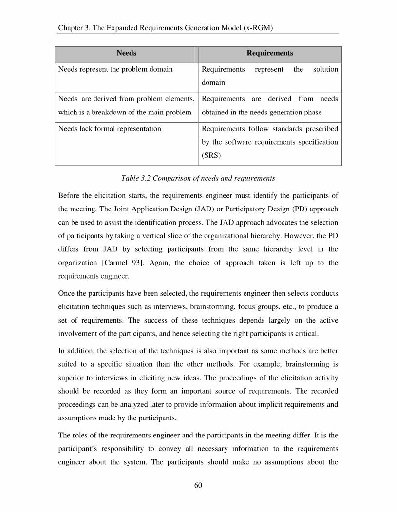
Chapter 3. The Expanded Requirements Generation Model (x-RGM)
60
Needs Requirements
Needs represent the problem domain Requirements represent the solution
domain
Needs are derived from problem elements,
which is a breakdown of the main problem
Requirements are derived from needs
obtained in the needs generation phase
Needs lack formal representation Requirements follow standards prescribed
by the software requirements specification
(SRS)
Table 3.2 Comparison of needs and requirements
Before the elicitation starts, the requirements engineer must identify the participants of
the meeting. The Joint Application Design (JAD) or Participatory Design (PD) approach
can be used to assist the identification process. The JAD approach advocates the selection
of participants by taking a vertical slice of the organizational hierarchy. However, the PD
differs from JAD by selecting participants from the same hierarchy level in the
organization [Carmel 93]. Again, the choice of approach taken is left up to the
requirements engineer.
Once the participants have been selected, the requirements engineer then selects conducts
elicitation techniques such as interviews, brainstorming, focus groups, etc., to produce a
set of requirements. The success of these techniques depends largely on the active
involvement of the participants, and hence selecting the right participants is critical.
In addition, the selection of the techniques is also important as some methods are better
suited to a specific situation than the other methods. For example, brainstorming is
superior to interviews in eliciting new ideas. The proceedings of the elicitation activity
should be recorded as they form an important source of requirements. The recorded
proceedings can be analyzed later to provide information about implicit requirements and
assumptions made by the participants.
The roles of the requirements engineer and the participants in the meeting differ. It is the
participant’s responsibility to convey all necessary information to the requirements
engineer about the system. The participants should make no assumptions about the

Chapter 3. The Expanded Requirements Generation Model (x-RGM)
61
requirements and should be precise in their description. The requirements engineer’s
responsibility is to capture the requirements and the context for each requirement
conveyed by the participants. Moreover, s/he should probe for more information if the
requirements are unclear. Thus the roles of the participants and the requirements engineer
for the elicitation meeting differ – one provides information, the other captures that
information.
3.1.3 Local Analysis
As depicted in Figure 3.2, the local analysis activity is conducted after the elicitation
activity. The elicitation activity produces small sets of requirements, and hence the
iteration of the elicitation meeting becomes inevitable in order to get the complete set of
requirements for the system. The term “Local” refers to the analysis being performed on
requirements as and when they are generated. The requirements are not for the whole
system, but may be for a single or several small components. The information collected
during this activity helps the “global analysis” phase, which analyzes the requirements in
its entirety. Local Analysis is further decomposed into subordinate activities as shown in
Figure 3.5.
Figure 3.5 Local analysis

Chapter 3. The Expanded Requirements Generation Model (x-RGM)
62
Local analysis begins with identifying the rationale of the requirements and confirming
the requirements with the stakeholders. The set of requirements is then prioritized,
verified and validated. Each of these activities is described in detail in the next few
sections.
3.1.3.1 Rationalization and Justification
On completion of a requirements elicitation meeting, a list of requirements is obtained
that should be examined with the stakeholders. The rationale of the requirements
gathered in the elicitation activity should be analyzed to determine whether the true
requirements are hidden in this rationale [Christel 92]. Moreover, identifying the
rationale helps in justifying whether a particular requirement is valid, i.e. the requirement
maps to a stakeholder need.
Besides attempting to find the rationale of the requirements from the stakeholders, this
activity also justifies the requirements identified during elicitation. If the requirements are
found to be of a high level, they are decomposed or refined after discussions with the
stakeholders. The requirements engineer is in control of this activity, and it is his/her
responsibility to identify the rationale behind the requirements from the stakeholders.
Figure 3.6 Rationalization and justification

Chapter 3. The Expanded Requirements Generation Model (x-RGM)
63
The inputs to this activity are the unstructured requirements list, domain information, and
the organization standards/regulations document as shown in Figure 3.6.
• Unstructured requirements list: This document consists of the list of
requirements obtained during the elicitation activity
• Domain information: It specifies the working environment of the system and the
constraints on the proposed system.
• Organization standards/regulations: This documents also specifies constraints
but from the management perspective.
These documents help in justifying the requirements obtained from the requirements
elicitation meeting.
The rationalization and justification activity begins with the requirements engineer
identifying the functional and non-functional requirements for the system components.
Once the identification is complete, the stakeholders are asked to answer the question
“why” underlying the requirements. This is usually accomplished during a meeting that is
headed by the requirements engineer. Several techniques like brainstorming, issue based
information system (IBIS) [Kunz 70], etc. are used for this activity. Stakeholder
participation is key to the success of this activity.
After the rationale has been collected and examined, the requirements engineer identifies
any hidden requirements, and also determines if the requirements conform to the system
and organizational constraints. If requirements are found within the rationale, then the
current requirement is at too high of a level and needs to be further decomposed or
refined. The stakeholders are involved when the requirement is changed in order to
develop the feeling of collective ownership of the requirement. An added benefit of
identifying the rationale is that the requirements engineer knows about the dependencies
between requirements and how they trace back to the needs. This helps in the later phase
of traceability analysis when the actual traceability document is created.
After rationalization, the requirements are examined by the stakeholders to determine if
the requirements satisfy the constraints specified for the system and organization. There
may be requirements that lack traceability to the needs; this lack of traceability indicates

Chapter 3. The Expanded Requirements Generation Model (x-RGM)
64
that either the requirements are unnecessary, or that the needs are incomplete. This
inconsistency must be conveyed to the stakeholders, and either the needs document or the
requirements list is updated depending on the stakeholders’ decision.
This is an iterative activity and it continues until the local set of requirements is justified
and their rationales identified. Before continuing further into the local analysis activity,
the requirements engineer should make sure that the requirements are at an acceptable
level of decomposition. Requirements should address “what” a system should do NOT
“how” to achieve it [Davis 90]. Also, the requirements should not be at too high of a level
which might allow latitude for misinterpretation. A fine balance between the two should
be achieved and, it is the responsibility of the requirements engineer to accomplish this
equilibrium.
3.1.3.2 Prioritization
The prioritization activity is conducted after the justification and rationalization of the
requirements identified during the elicitation activity. The objective of the prioritization
activity is to identify the pertinent attributes of the requirements and determine their
values. Requirements are also ranked based on the priority ratings given by the
stakeholders. The requirements engineer conducts this activity with active participation
from the stakeholders. Prioritization is an iterative activity as seen in Figure 3.7.
Meetings are held with the stakeholders to determine the objective of the activity and the
proceedings are documented for later reference. On completion of this activity, a
prioritized list of requirements is obtained and is then submitted to the next activity.
Several requirement attributes are identified and their values determined during the local
analysis activity. The major attributes are listed below:
• Risk factors – The stakeholders determine the main risk factors for a requirement,
e.g. cost, time, lack of expertise, etc
• User urgency – The user determines how important the requirement is to him/her.
A numerical rating scale is often used for this purpose.

Chapter 3. The Expanded Requirements Generation Model (x-RGM)
65
• Value to product – A customer representative determines the relative benefit that
each requirement provides to the customer or the business on a scale from 1 to 9,
with 1 indicating very little benefit and 9 being the maximum possible
benefit.[Weigers 99] These benefits indicate alignment with the product’s
business requirements.
• Effort – The developer determines the rough estimate for the work needed to
implement the requirement.
Figure 3.7 Prioritization
After obtaining requirement attributes, the requirements engineer asks the customer to
rank the requirements into high, medium and low priority categories. To prevent the
customer from ranking all requirements as high priority, the requirements engineer
provides an example of a requirement within each priority class. This gives the customer
an idea of the priority classes and assists him/her in ranking the requirements relative to
these requirements.

Chapter 3. The Expanded Requirements Generation Model (x-RGM)
66
The next activity, verifying quality attributes, begins after all of the requirements have
been ranked and their respective attributes determined. The output of the prioritization
activity is a list of ranked requirements with their associated attribute values.
3.1.3.3 Verifying Quality Attributes
After the prioritization of the requirements is completed, the next step is to verify the
local set of requirements for adherence to quality attributes. Verification enables the
identification of inconsistencies and redundancies in the requirements. The requirements
engineer can verify the requirements provided he has the necessary experience and
expertise. But usually, verification is performed by quality experts. As illustrated in
Figure 3.8, on completion of this activity, we have a local set of requirements verified for
quality attributes.
Figure 3.8 Verifying quality attributes
Before the verification of requirements begins, the quality attributes that need to be
verified must be identified. There are several sources which provide a number of
requirements quality attributes [IEEE 99]. Several of those attributes are shown in Figure
3.9. In order to conduct this activity, it is necessary to identify quality experts, who are
either internal or external to the organization.

Chapter 3. The Expanded Requirements Generation Model (x-RGM)
67
Correctness
Ambiguity
Ranked
Verifiable
Modifiable
Understandable
Testability
Necessity
Requirements
Figure 3.9 Requirements quality attributes
During local analysis not all quality attributes can be verified for the set of requirements
captured. Attributes such as completeness and consistency cannot be checked at this stage
as only small portions f the whole set of requirements are being examined. At this stage it
is recommended that the following attributes be examined
• Ambiguity – each requirement has one and only one possible interpretation
• Correctness – each requirement represents something required of the system to be
built
• Testability/verifiability – each requirement should be testable through inspection
or demonstration to perform its desired functionality within a reasonable amount
of time [Gröner 2002]
• Understandability – each requirement should be comprehendible by all classes of
readers (users, customers, developers, etc.)
• Precise – When appropriate each requirement should be stated in numerical terms,
and are at the right level of precision
Several techniques are used to perform the verification of requirements for the quality
attributes – the most common technique being inspections [Fagan 76]. After the
requirements are verified for quality adherence, the quality experts prepare reports stating
the extent to which the requirements satisfy the quality attributes. Requirements which
fail to meet the quality standards are also included in the reports. These documents are

Chapter 3. The Expanded Requirements Generation Model (x-RGM)
68
helpful when the decision regarding whether or not an additional iteration of the
requirements capturing phase is to be taken. After verification, the list of requirements is
analyzed with the stakeholders in the validation activity.
3.1.3.4 Stakeholder Validation
Validation is necessary to determine if the requirements captured meet the stakeholders’
intent. The main objective is to uncover disagreements between what the stakeholder
desires and what the requirements state. If the incorrect requirements have been elicited,
then validation identifies these discrepancies so that they can be rectified. The
requirements engineer conducts the stakeholder validation activity, which takes place
after verification of the requirements. At the end of validation, a decision is made by the
requirements engineer whether to continue to the next phase or to have another iteration
of the requirements capturing phase as shown in Figure 3.10.
Figure 3.10 Stakeholder validation
Validation at this stage in requirements generation is performed on individual sets of
requirements and not on the set as a whole. We propose early validation, as compared to
the conventional validation activity at the end of the process, because it reduces the
schedule and cost as inconsistencies are identified earlier in the life cycle. An added
Chapter 3. The Expanded Requirements Generation Model (x-RGM)
69
advantage is that the stakeholders now feel involved in the process and their confidence
in the requirements is also increased.
The proceedings of the validation activity and disagreements (on requirements) with the
stakeholders are recorded. If there is a misinterpretation of the stakeholders’ intent, it
indicates that elicitation was incomplete and that an additional iteration of the elicitation
meeting is necessary. This decision is made after the validation activity is completed.
Validation is a process which increases the confidence of the stakeholder in the
requirements. Hence, it is difficult to predict the right time to stop. However, in the real
world, time and cost act as principal controlling factors for validation. There are several
techniques for determining whether the stakeholders’ needs are met. Prototyping and
walkthroughs are the most commonly used methods for validation during the
requirements generation process.
Once the stakeholder validation activity is concluded, the requirements engineer must
decide whether to have an additional iteration through the requirements capturing process.
The requirements engineer, in consultation with the stakeholder, determines whether the
requirements capturing phase is complete. To answer this question, the following exit
criteria are examined. As described by Groener [Groener 2002], each criterion consists of
a checklist of items pertaining to:
• Inspecting quality attributes of requirements
• Ensuring no open or unresolved issues remain
• Finding agreement among all stakeholders that all requirements have been
collected
The first exit criterion is addressed in the verification activity; the requirements engineer
uses the report prepared by the quality expert(s) to answer the questions in the checklist.
The validation activity identifies unresolved issues or problems with requirements; the
outcome of this activity answers the second criterion. Finally, the stakeholders need to
answer questions whether their requirements and intent have been captured. If the answer
to any of the above criteria is in the negative, then it indicates that another iteration of the
capturing process is needed.

Chapter 3. The Expanded Requirements Generation Model (x-RGM)
70
The exit criteria listed above are necessary items to determine if the transition to the
global analysis phase can be made. This list is not a comprehensive list and we encourage
the users of x-RGM to include any additional items, which are necessary for their
development effort.
3.2 Global Analysis
Once the complete set of requirements have been captured and evaluated from a “local”
perspective, the next step is to evaluate the requirements as one whole set. The set of
activities which accomplish this task collectively form the global analysis phase. In effect,
it is in the global analysis phase where we analyze factors that globally affect the system
under development [Nord 2003]. In this phase, the requirements are examined from the
development, market, sales and management perspectives as seen in Figure 3.11.
Conflicts among stakeholders emerge during global analysis, and hence negotiation is an
integral part of this phase.
Figure 3.11 Global analysis phase

Chapter 3. The Expanded Requirements Generation Model (x-RGM)
71
Global analysis can be divided into two parts – the first part (adapter from [Davis 2003a])
analyzes the requirements and the second part resolves the conflicts. The input to the
activities at the start of global analysis comprises three documents – requirements list,
organizational factors document and technological factors document.
• Requirements list: It is the complete set of requirements obtained from the
requirements capturing phase.
• Organizational factors document: It arises from the business establishment and
has an external influence on the development of the system. These factors include
cost, profit margins, personnel available, etc., which constrain options in defining
the system.
• Technological factors document: This lays down the technological constraints
such as the availability of operating systems, hardware, etc. Just like the
organizational factors, technological factors affect the system externally, the
difference being that the technological factors affect the system throughout its
lifetime.
During the process of evaluating the complete set of requirements from the global
perspective, conflicts within the requirements are identified and documented. It is the
responsibility of the requirements engineer to resolve these conflicts with the
stakeholders in an amicable manner.
The sections which follow will explicate the activities in the global analysis phase in
detail.
3.2.1 Risk Analysis
One of the first activities in the global analysis phase is risk analysis. The objective of
this activity is to analyze the complete set of requirements for the risk factors identified
during local analysis. Risk factors are broadly classified into 3 categories - Product
engineering, development environment and program constraints [SEI 96].

Chapter 3. The Expanded Requirements Generation Model (x-RGM)
72
• Product engineering: The risk factors considered in this category pertain to
technical aspects of the work to be accomplished. Questions such as the following
are considered under this category:
o Are there requirements that are technically difficult to implement?
o Is the system size or complexity a concern?
o Does the hardware limit the ability to meet any requirements?
o Are the safety requirements infeasible and not demonstrable?
• Development environment: In this category, risk factors related to the
development process, management practices and work environment are examined.
A sample set of questions are listed below:
o Are there mechanisms for controlling changes in the product?
o Are the managers experienced in software development, software
management, the application domain, and the development process?
o Is there a non-productive, non-creative atmosphere?
• Program constraints: Risk factors associated with resources, contract and
stakeholders are examined in this category. Questions such as the following are
considered:
o Are the facilities inadequate for building and delivering the product?
o Is the funding insufficient or unstable?
o Does the contract include any inappropriate restrictions?
o Are there any customer problems such as a lengthy document-approval
cycle, poor communication, or inadequate domain expertise?
The person who analyzes the requirements for risk is usually an expert in risk analysis.
However, the requirements engineer can perform this activity provided s/he has the
necessary competence. The number of risk analysts needed depends on the size of the
project.

Chapter 3. The Expanded Requirements Generation Model (x-RGM)
73
During risk analysis, the risk analyst must review each risk factor, estimate the
probability of its occurrence, and the loss if the risk occurs. The loss could be represented
financially (in dollars) or on a scale of 1 to 10. The risk analyst then estimates the risk
exposure for the requirements. Risk exposure is defined as the product of the likelihood
that the risk will occur and the magnitude of the consequences of its occurrence. Once
this estimation is complete, requirements are ranked based on their risk exposure values.
The ranked list indicates the high risk requirements, which are at the top of the ordering.
This document is then reviewed by the analyst(s) for errors and is submitted as an input
for the feasibility analysis activity, where the requirements engineer in consultation with
the management decides whether or not to proceed with the project. In some cases, the
overall project risk exposure can be so high that the project intent cannot be attained at a
reasonably probable expense.
3.2.2 Cost/Schedule Estimation
Cost and schedule estimation can be performed in serial or in parallel with the risk
analysis activity. This activity is conducted by the requirements engineer in consultation
with the developers. The objective of this activity is to determine the cost of developing
the software components and the time needed for the implementation. The cost and
schedule estimates are critical to the success of the project as they affect the budgeting
decisions, project planning and control, and tradeoff analysis. In addition, these estimates
are one of the drivers for the feasibility analysis activity.
Cost estimation is the evaluation of separate elements (e.g. personnel experience,
platform difficulty, etc.) that affect the development of the system to determine if the
total cost estimate satisfies the customers’ budget. Put in simpler terms – cost estimation
is the process of predicting the amount of work or effort required in developing the
system.
There exist several techniques for estimating the cost of the requirements. Whichever
method is selected, the requirements engineer must pay attention to the following points
to get the best results [Leung 2002]:

Chapter 3. The Expanded Requirements Generation Model (x-RGM)
74
• Coverage of the estimate (some methods consider the effort for the whole life
cycle, while others leave out the requirements phase)
• Assumptions made by the technique
• Sensitivity of the estimate to the different cost parameters
• Deviation of the estimate from the actual cost
The size of the software is a major factor in determining the cost of the project. There are
several metrics for determining project size. The organization can choose any of these as
long as the metrics are used consistently throughout the project life cycle. The following
metrics are the most commonly used in industry:
Lines of code: This is referred to as LOC and it is the number of lines of delivered source
code, excluding the comments and blank lines [Fenton 97]. This is the most widely used
metric even though it is language dependent and can fail in providing consistently
accurate estimates.
Function Points: This metric measures the functionality of the system to determine the
cost. The functions of the system are classified under different categories such as user
output, user input, etc. Each of these functions are then weighed on a scale of 1 to 3
(1=simple, 2=medium, 3=complex). These weights are then used in a mathematical
formula to calculate the cost [Albrecht 83].
In addition to these metrics, there are several others which have been proposed as
extensions to the existing metrics. Function points have been extended to include
algorithms [Jones 97] and control aspects [St-Pierre 97] of the systems. Software science
is another metric, which estimates the cost based on code length and storage space used
by the implemented software [Halstead 77].
The requirements engineer should choose a metric which can provide an estimate closest
to the actual cost. A good cost estimate should be [Royce 98]:
• Conceived and supported by the development team and management
• Based on a well-defined cost technique, which has credibility in the industry
• Based on the knowledge of relevant projects

Chapter 3. The Expanded Requirements Generation Model (x-RGM)
75
• Defined in sufficient detail so that the key cost parameters are understood.
Schedule estimation involves determining the development time of the components and
identifying the critical components of the software system. The schedule estimate
document helps management in the planning phases as it shows the dependencies of the
various software components. In addition, schedule estimation enhances control over
complex development work and enables management to use resources in an appropriate
manner.
There are five inputs to schedule estimation – requirements list, constraints, resource
requirements, resource capabilities/availability and historical information [Burns 2003].
An organization may use one or more of the following approaches to get a good estimate
of the schedule.
• Expert judgment: Calculation of the schedule is performed based on the
knowledge of an expert in the field.
• Analogous estimating: Similar projects are considered and the time for
development of a similar component is used as the current estimate.
• Simulation: It calculates multiple durations for different assumptions.
A good schedule estimate should provide a range of the duration times. For example: a
GUI component may take one week plus or minus three days for development. Moreover,
schedule estimation must be performed aggressively i.e. the requirements engineer should
strive to get an estimate that deviates as little as possible from the actual time needed. If it
is estimated that a component will need two weeks instead of three weeks for
development, then there is a high probability that the task will take two weeks. People
tend to use the time allotted even if the task can be accomplished earlier. Hence, it is
important that the requirements engineer involves the right developers to get a good
estimate. On completion of the activity, a project schedule document is prepared,
reviewed and submitted as input for feasibility analysis.

Chapter 3. The Expanded Requirements Generation Model (x-RGM)
76
3.2.3 Price Analysis
Price analysis is the process of deciding a product price which is fair and reasonable,
without evaluating the separate cost components and proposed profit [FAST 2004]. In
addition, it also determines which functionalities are optional and can be dropped without
affecting the value of the product.
The concept of fairness is a relative term, and depends on the perspective of the different
party’s involved. The users’ perspective of a fair price is one that covers the maximum
number of functionalities desired. However, the customer’s perspective of fairness is a
price which provides maximum profit. This indicates that the customer desires a decrease
in implementation cost, perhaps at the expense of user functionality. It is the
responsibility of the requirements engineer to establish an equitable price which
synchronizes the concerns of the user with those of the customer. Reasonability of price
depends on the market environment – that is, what is reasonable today may not be so
tomorrow. The requirements engineer should examine factors such as supply, demand,
economic conditions and competitor’s price, before making a decision about the product
price.
While both cost estimation/analysis and price analysis deal with the total cost of the
product, they differ in their approach. Cost analysis looks at the total cost from the
developers’ perspective while price analysis is more from the management perspective.
Both activities complement each other as can be seen in the example provided in the
shaded box (Figure 3.12) [FAST 2004]. Even though cost analysis may provide the total
cost in terms of the individual components, the cost may still be unreasonable.
The requirements engineer conducts the price analysis activity and s/he relies on the
market survey data for the analysis. The market survey document should provide
information about the following factors of reasonability:
• Number of buyers and sellers in the market
• Prices of similar/competitor products
• Intensity of demand
• Quality of products in the market

Chapter 3. The Expanded Requirements Generation Model (x-RGM)
77
Background:
Suppose the Government wants to purchase a new vehicle for Government use
only. The Government decides to have a mechanic build the car from "scratch"
instead of buying a pre-assembled vehicle. Competitive quotes are received on
all the individual parts and necessary tooling. All workers receive minimum
wage, and the mechanic asks for a very small profit.
Evaluation:
• Even though cost analysis determined that the proposed costs for parts
and labor are reasonable, the final price of this car will be much more
expensive than a car bought off the assembly line.
• Parts purchased independently may be many times more expensive than
when bought in bulk quantities to support an assembly line.
• The entire cost of tooling will be charged to one car, instead of
thousands.
• Labor might be cheaper, but it will not be as efficient as assembly line
labor.
Conclusion:
Even though all parts were purchased from competitive quotes and the labor
rates are reasonable, this does not ensure the final price will be reasonable
In addition to this information, the requirements engineer should also be knowledgeable
about the production costs and the functionalities of the system. Several techniques such
as historical data, cost estimation relationships, etc. can be used in determining a fair and
reasonable price.
Figure 3.12 Cost and price analysis
The output of price analysis is a price estimate document, which is one of the inputs for
analyzing the feasibility of the project. This document should clearly state the proposed

Chapter 3. The Expanded Requirements Generation Model (x-RGM)
78
price, the functionalities for the proposed price, and the functionalities recommended for
implementation in later releases. Also, if the proposed price estimate conflicts with the
customer’s estimate, then it should be documented for discussion with the customer.
3.2.4 Feasibility Analysis
Feasibility analysis is performed during the global analysis phase, but after the
completion of the risk, cost and price analysis activities. It is the process by which the
requirements engineer examines how beneficial or practical the development of a system
will be to the customer organization. After evaluating the feasibility of the requirements
from the business, technological and cost perspective, a ‘go - no go’ decision is made at
the end of the activity. Since this activity involves managerial decisions, the requirements
engineer works with managers on this activity.
The previous activities in the global analysis phase provide estimates for the risk, cost,
schedule and the price. These estimates are used for the five types of feasibility tests –
Operational, Technical, Schedule, Economic, and Legal and Contractual feasibility.
Operational Feasibility: It deals with determining how well the solution will meet its
business objective and whether the users feel comfortable using it. Operational feasibility
is based on issues such as managerial support, training required, workforce reduction and
effects on customers and users. The solution should solve the business problems and at
the same time should help the users in their work rather than causing a hindrance.
Prototypes are often used to determine if the proposed solution satisfies its objective. If
the solution is for the entire organization, then the prototype is deployed only in a small
portion of the organization to examine how well it works. If the solution is for individual
users, then the prototype is tested for effectiveness by a sample of users. Usability is an
important factor during these tests and should be considered while evaluating the
prototypes.
Technical feasibility: The objective of technical feasibility is to determine the
development team’s ability to build the proposed system. The development team’s
understanding of the target hardware, software and operating environment is assessed. In

Chapter 3. The Expanded Requirements Generation Model (x-RGM)
79
addition, the group’s experience with systems of similar size and complexity is also
examined. Questions such as the following are analyzed:
• Is the proposed technology or solution practical?
• Do we currently possess the necessary technology?
• Do we possess the necessary technical expertise?
Expertise in the target software is essential, otherwise the learning curve will be longer
and can have an adverse affect on the schedule of the project.
Schedule feasibility: The schedule estimate that is determined during the cost and
schedule estimation activity is checked for reasonability. Factors such as the sensitivity to
variations, assumptions of methods, number of schedule parameters, expertise of the
participants involved, etc. are analyzed to determine a level of confidence in the estimate.
Economic feasibility: The purpose of economic feasibility is to evaluate whether or not
the projected benefits of the system outweigh the estimated cost of the system. It is
commonly referred to as cost-benefit analysis. To determine the economic feasibility,
costs for acquisition, development and maintenance is evaluated against the tangible and
intangible benefits. Tangible benefits are those which can be measured financially, e.g.
cost reduction and avoidance, error reduction, increased flexibility, improvement of
management planning and control. Intangible benefits are those which cannot be assessed
monetarily. They include competitive necessity, increased organizational flexibility,
promotion of organizational learning and understanding.
Legal and contractual feasibility: This is the process of assessing potential legal and
contractual ramifications due to the construction of a system. Considerations might
include copyright or nondisclosure infringements, labor laws, antitrust legislation, foreign
trade regulation, and financial reporting standards.
During feasibility analysis, the documents produced by the preceding activities (risk, cost
and schedule, price analysis) are analyzed. The requirements engineer has to determine if
all the risk items have been considered. The profit margin is the main concern of the
customer, and hence it is necessary to examine if the projected profits meet the customers
expectations. There is a possibility that the project may end up in losses if the technology

Chapter 3. The Expanded Requirements Generation Model (x-RGM)
80
is unavailable or if the product is ahead of the times. Schedule is another important aspect
to examine as customers want their products as early as possible - their time-lines,
however, may be unreasonable. As feasibility analysis progresses, the requirements
engineer observes conflicts with the customers requirements, and these are documented
for discussion with the customer. In addition, conflicts between requirements are also
detected as the activities – risk analysis, cost and schedule estimation, price analysis and
feasibility analysis – are used to evaluate the whole set of requirements. On completion
of feasibility analysis, the requirements engineer collects all the conflicting requirements
and documents them. The document also includes the decision whether to proceed with
the project and the reasons responsible for reaching this decision.
If the project is infeasible, then discussions can be held with the customer so that the
project expectations are made more realistic and practical. Even if the project is given the
“green light”, negotiations must be held with the stakeholders to smoothen out the
conflicts in the requirements.
3.2.5 Conflict Resolution
This is the final activity of the global analysis phase and is conducted by the requirements
engineer. The initial activities of global analysis identify requirements which are
inconsistent and are counter to the customer’s project constraints. Conflict resolution is a
process by which differences are negotiated to reach a satisfactory solution. The parties
involved usually communicate through face-to-face discussions and trade demands and
counter proposals.
The success of conflict resolution depends on the requirements engineer. S/he should
have good communication skills in addition to possessing the qualities of being honest
and respectful. A key concept of negotiation is group ownership of the decisions taken,
since solutions are agreed to and not imposed. There is a perceived commitment on the
part of all parties to reach an agreement through compromise. If an agreement cannot be
owned, the requirements engineer should examine alternative solutions.
Conflict resolution consists of three mains steps: Identify issues, Identify options and
Finalize agreements (Figure 3.13) [Boehm et al. 94].

Chapter 3. The Expanded Requirements Generation Model (x-RGM)
81
Figure 3.13 Conflict resolution
Issues specify the conflicts in requirements along with the arguments from the
stakeholders who own the requirements. The options specify various alternatives to
resolve the conflict. Agreements are the final solutions which are agreed upon by all the
stakeholders. Conflict resolution is a difficult activity to perform, and there is no single
clear-cut strategy which ensures that an agreement will be reached. If the discussion with
the stakeholders is in a deadlock situation, the requirements engineer has to approach a
higher authority who can make a decision on behalf of the stakeholders. (For example,
when the negotiation with the customer representatives is in a stalemate situation, then
the customer management can be contacted to intervene.) If the negotiation still fails,

Chapter 3. The Expanded Requirements Generation Model (x-RGM)
82
then the requirements engineer conveys the status of the negotiation to management so
that they can decide upon the appropriate action.
Before the meeting with the stakeholders, the requirements engineer has to plan for the
discussion. The conflicting requirements need to be prioritized so that the most critical
are addressed first. In addition, facts which highlight the pros and cons of the different
opinions should be collected and documented. Requirements which can(not) be
compromised are also listed. The requirements engineer also has to establish judgment
criteria. For example, a prioritized list of merits (cost, time, effort, etc.) for the evaluation
of the alternate options. These judgment criteria help participants in making consistent
judgments about different options [Sutcliffe 2002]. During the meeting with the
stakeholders, the requirements engineer has to exhibit his/her communication and
negotiation skills. A good strategy is to open the discussion with a position which the
stakeholder agrees to. Threats can play an important role if used minimally and carefully.
Negotiations should be under control so that it does not digress to an unrelated issue.
Once negotiations are complete, the agreements are documented and signed by all
participants. The global analysis phase is repeated if the conflict resolution activity
results in requirement updates or additions, whose impact has not been evaluated.
At the end of the global analysis phase, the conflict free requirements list is produced
which is then used by the next phase for structuring the requirements.
3.3 Organization and Compilation
After the conflict free requirements list is obtained, it needs to be organized and compiled
into a single unit such that it fits into the software requirements specification (SRS). This
phase consists of a single activity, which excludes any analysis of the requirements.
Hence this activity is neither grouped under global analysis nor confirmational analysis
phase so that there is a clear understanding of what each phase and its activities
accomplish. The specification of requirements, which is a section of the SRS, is the
output of the activity; the SRS is NOT the output. During the structuring of the
requirements list, the format for the requirements as specified by the SRS is followed.
The organization and compilation phase is shown in Figure 3.14

Chapter 3. The Expanded Requirements Generation Model (x-RGM)
83
Figure 3.14 Organization and compilation
Coming into this activity the requirements have been classified into functional and non-
functional requirements for the different system components during the rationalization
and justification activity. However, the requirements need to be organized in a manner
which is optimal for understanding. Modification of requirements should also be a
concern so that changes to requirements can be made easily, completely and consistently
while retaining the structure and style [IEEE 98a]. There are several ways in which the
requirements can be organized. Some of these are described below:
System mode: A system may have different behavior depending on the mode of
operation. For example, a critical control component may provide different sets of
functionalities depending on whether it is operating in normal or emergency mode of
operation. Thus, the requirements are structured according to the modes of operation. The
template for this organization is provided in A.1 of Appendix A.
User Class: A system may provide different functionality for different set of users. For
example, a web application provides different capabilities to users, database
administrators, maintenance personnel, etc. Section A.2 of Appendix A provides an
outline for the requirements organization based on user class.

Chapter 3. The Expanded Requirements Generation Model (x-RGM)
84
Stimulus: For some systems, stimulus is critical for the different operations. For example,
a control system can be perceived by the different trigger signals that it receives.
Requirements of such systems are best presented based on trigger classification, which is
outlined in section A.3 of Appendix A.
Response: Just like the organization based on stimulus, the requirements can also be
organized based on response. Requirements which are responsible for obtaining a
particular response are grouped under the same category. For example, in a web
application, all of the functional requirements responsible for generating the credit card
payment report can be clustered together. The template for this organization can be seen
in section A.4 of Appendix A.
Functional hierarchy: The overall functionality of a system can be structured into a
hierarchy of functions that reflect the information flowing in the system. For example, a
high level functionality could be database manipulation while a sub-function of this
functionality can be an authorization check. Section A.5 of Appendix A shows the outline
for this organization.
Any of these organizations can be selected for representing requirements - the choice is
left to the requirements engineer. The organization and compilation phase produces a
structured requirements list which forms a subset of the SRS. The organized requirements
list is now passed to the confirmational analysis, which forms the last phase of the
expanded requirements generation model (x-RGM).
3.4 Confirmational Analysis
This phase performs the final verification and validation of the complete set of
requirements. Traceability diagrams are created and the requirements are checked if they
trace back to the needs. In addition, minor changes to the requirements are made in
response to customer validation. Figure 3.15 shows the activities that comprise the
confirmational analysis phase.

Chapter 3. The Expanded Requirements Generation Model (x-RGM)
85
Figure 3.15 Confirmational analysis
On completion of this phase, the validated and structured list of requirements is ready to
be included into the SRS. The activities in the global analysis phase are explained in
more detail in the sections that follow.
3.4.1 Quality Adherence
This activity checks the requirements from the global perspective, and differs from the
quality adherence activity in the requirements capturing phase. The verification of quality
attributes in local analysis examines a small set of requirements, and hence attributes like
completeness and consistency cannot be evaluated. However, during confirmational
analysis the whole set of requirements can be analyzed for quality attributes since this
phase is entered only after all the requirements have been captured.
The adherence of requirements to quality attributes is verified by a quality expert.
However, a requirements engineer can perform the task provided he has the necessary
expertise. The quality analyst verifies additional quality attributes, some of which are
shown in Figure 3.16.

Chapter 3. The Expanded Requirements Generation Model (x-RGM)
86
Consistent
Concise
Modifiable
Non redundant
Organized
Complete
Requirements
Figure 3.16 Quality attributes
Consistent: The requirements are consistent if and only if no subset of individual
requirements conflict with each other [IEEE 84].
Concise: The requirements list is concise if it is as short as possible without adversely
affecting other quality attributes of requirements.
Modifiable: The collection of requirements is modifiable if its codified structure is such
that changes can be made easily, completely and consistently. This property is important
because requirements change frequently during the software life cycle and these changes
need to be incorporated with minimal effort.
Non redundant: Requirements should not be stated more than once in a document. This
may improve the readability of requirements but the problem arises when the
requirements are revised. If redundancy exists, then there is a possibility that the
requirements can become inconsistent on revision.
Organized: The requirements are organized if the grouping of requirements are easily
understood and the logical relationships between adjacent groupings and sections are
apparent.
Complete: The requirements are complete if everything that the software is supposed to
accomplish is included and is there are no “To be determined” requirements [Davis 90].
The attributes described form only a small portion of a long list of quality attributes
[Davis et al. 93]. In addition to checking the requirements for the attributes mentioned,
the quality analyst also has to confirm that during local analysis the requirements were
checked for ambiguity, correctness, etc (Figure 3.9) and this is done to ensure that there is

Chapter 3. The Expanded Requirements Generation Model (x-RGM)
87
no duplication of effort. The findings of this activity are documented so that any needed
action can be taken by the requirements engineer. After checking for the adherence to
quality attributes, the requirements list is used as input for the traceability analysis
activity.
3.4.2 Traceability Analysis
Traceability analysis is the activity by which the life of a requirement is described and
followed i.e. from its origins, through its development and specification, to its subsequent
deployment and use [Gotel 95]. This activity is performed after checking the
requirements for adherence to the quality attributes listed in Figure 3.15. The
requirements engineer conducts traceability analysis, which addresses the following
important questions:
• What need is addressed by a requirement?
• Are all requirements allocated?
• Has any need been overlooked?
• What is the impact of changing the requirement [SPS 94]?
Initially, the requirements engineer must determine dependencies or links between the
requirements. In addition, the links between the requirements and needs are also
identified. This linking of requirements is achieved by examining the results of the
rationalization and justification activity (requirements capturing phase), which analyzes
each requirement and identifies the rationale behind it. In effect, the rationale of the
requirement points to the need from which the requirement is derived, and it also helps in
identifying the links between the requirements.
Once the links have been identified, the approach for representing traceability must be
determined. One approach is the use of general purpose tools (word processors,
spreadsheets, etc.) which support cross linking of requirements among documents.
However, this approach is not scalable and is suitable for only small projects. The second
approach is the use of a dedicated workbench environment centered on a database
management system for the storage of requirements. This environment would provide

Chapter 3. The Expanded Requirements Generation Model (x-RGM)
88
tools for editing, storing, linking, organizing and managing requirements. The strengths
and weaknesses of each of these approaches are presented in Table 3.3
Approach Pros Cons
Readily available Limited integration with other
software tools
Good for small projects High maintenance cost for
traceability
Tools have to be configured
for supporting traceability
General purpose tools
Flexible
Limited control on the
traceability requirements
Provides a number of tools
for traceability maintenance
Expensive
Good for large projects Learning curve is bigger than
general purpose tools
Provides visualizations for
traceability
Requirement
Workbenches (includes
requirement
management tools)
Integrates with a number of
software tools
Rarely covers traceability in
the other phases
Table 3.3 Comparison of traceability approaches [Kean 97]
Most of the office tools available in the market have database and spreadsheet
capabilities, which can be configured to support requirements tracing. Moreover, there
are several products under the workbench category which support traceability [STSC 98].
Some of the requirement management tools available in the market are DOORS,
Requisite Pro, Caliber RTM, and so forth. The minimum functionality provided by these
tools is listed below:
• Bidirectional requirements tracing

Chapter 3. The Expanded Requirements Generation Model (x-RGM)
89
• Capture of requirements rationale and accountability
• Identification of inconsistencies
• History of requirement changes
• Verification of requirements
• Impact of requirements change
Traceability matrix and tree representations are the most commonly used in industry to
show the dependencies of the requirements. Once the traceability diagrams have been
created, the requirements engineer should review the traceability of the requirements for
errors. This helps in identifying if the requirements have “dangling pointers”, i.e. they do
not trace back to any need. In addition, inspection of the traceability helps in detecting
inconsistency problems in the requirements. The requirements engineer documents
his/her observations and passes the traceable requirements list to the next activity, which
is customer validation.
3.4.3 Customer Validation Meeting
Validation is a critical part of confirmational analysis as it determines if the customer
expectations are met by the requirements. This activity differs from the validation in the
local analysis in that the whole set of requirements are validated as compared to sets of
requirements that are validated during local analysis. The objective of the customer
validation meeting is to identify if there are disagreements between the customer needs
and the requirements. Validation at this stage identifies any remaining discrepancies in
the set of requirements. Upon completion of the customer validation activity, the
requirements engineer has to decide whether the confirmational analysis phase is
complete (Figure 3.17).
All validation discrepancies are recorded by the requirements engineer, and the necessary
changes to the requirements are made in the reformulation activity. Validation of the
whole set of requirements is accomplished using a number of techniques. The most
common method is prototyping because the customer “sees” what the proposed system
looks like, and because identifying flaws in the prototyped system is easier when

Chapter 3. The Expanded Requirements Generation Model (x-RGM)
90
compared to the use of other techniques. Besides prototyping, reviews and walkthroughs
are also popular methods for validation.
Figure 3.17 Customer validation and reformulation
The requirements engineer decides whether the confirmational analysis phase is complete
on the basis of the output from the quality adherence and customer validation meeting
activities. If the quality analyst determines that the requirements are incomplete or
inconsistent, iteration to previous phases will be needed. The requirements are
incomplete if some needs of the stakeholder are not addressed during elicitation. This
error is usually identified by the validation activity during local analysis. But in case such
an error does slip through, then the requirements engineer must perform an additional
iteration starting from the elicitation meeting in order to capture the requirements for the
needs that have been overlooked. The other possibility of iteration to previous phases is
when the requirements are inconsistent i.e. the requirements have conflicts with each
other. Even though the global analysis phase identifies conflicts and resolves them, there
is a likelihood that requirements conflicts can pass to the next phase unnoticed. In such a
situation, iteration back to the conflict resolution activity is necessary.
If the quality analyst is of the opinion that the requirements need some changes to meet
the other quality attributes (Figure 3.16), then as shown in Figure 3.17 the requirements

Chapter 3. The Expanded Requirements Generation Model (x-RGM)
91
document is passed to the reformulation activity. Similarly, if the customer is unhappy
with the phrasing of the requirements or if s/he needs to introduce in some minor changes
to the requirements, these problems are documented so that they can be addressed in the
reformulation activity.
The confirmational analysis phase is complete when all of the requirements satisfy the
quality attributes, and the customer agrees that his/her intent is captured by the
requirements.
3.4.4 Requirements Reformulation
This activity is conducted by the requirements engineer in order to rectify the
requirement problems identified by the quality analyst and the customer (Figure 3.17).
Such problems pertain to requirements quality and customers disagreement with the
requirements.
The requirements document may be organized in an improper fashion for the system
being built or it may have redundant requirements, which makes maintenance of the
document difficult. An additional quality concern is the verbosity of the requirements
document and its non-modifiability. If these concerns are overlooked, the requirements
engineer must modify the requirements in consultation with the quality expert.
Customers also play a role in the reformulation of the requirements. During validation,
some of the requirements may be unclear to the customer, and s/he may want to change
the requirements to make it more comprehensible. As the requirements generation
process is conducted, the customer acquires more knowledge about the solution and
his/her expectations also rise. Hence, while validation is performed using prototypes or
other techniques, the customer may want to make some minor additions to the
requirements. These changes to the document are performed during the requirements
reformulation activity. Once the updates have been completed, the document goes
through an iteration of the confirmational analysis phase, starting with the quality
adherence activity, but building on the results from all previous activities.

Chapter 3. The Expanded Requirements Generation Model (x-RGM)
92
3.5 Summary
This chapter focuses on the activities and their objectives in the Expanded Requirements
Generation Model (x-RGM). The model begins with the iterative requirements capturing
phase which elicits requirements and analyzes them from the local standpoint. This phase
is followed by global analysis where the requirements are analyzed as a complete set and
requirement conflicts are resolved. The organization and compilation phase structures the
requirements as a part of the SRS; the confirmational analysis phase verifies and
validates the complete set of requirements. The model terminates with the generation of
the requirements specification, which forms a section of the SRS. Creation of the SRS, its
validation and version control is not included in the x-RGM because the focus of this
model is on the generation of requirements and not the SRS. However, if necessary the
model can be easily extended to incorporate the generation of the SRS.
We are not aware of any shortcomings of the x-RGM. It was conceived as an expansion
of the requirements phase in the conventional waterfall model as depicted in the RGM.
The intent was to concentrate on identifying activities and objectives for the requirements
phase with minimal overlap between other phases. Even though the x-RGM in its current
form is incapable of addressing the other development paradigms such as OOA, XP, we
conjecture that the x-RGM can be adapted to accommodate them.
Chapter 4 examines the methods mapped to the different activities in the x-RGM. In
addition, the chapter explains the selection of method paths based on different “fitting”
criteria for the requirements generation process as a whole.

Chapter 4. Synchronization of Methods and Activities
93
Chapter 4
Synchronization of Methods and Activities
4. Introduction
Chapter 3 focused on the issues of developing a well-defined requirements engineering
model and identifying the objectives of the activities in the proposed model (x-RGM).
This chapter addresses the second phase of our solution approach and focuses on
identifying methods for the activities in the x-RGM and determining a path of methods
for the entire requirements generation process based on some commonly used selection
criteria.
This chapter is organized such that Sections 4.1 – 4.4 describe the methods that can be
used to achieve the objectives of the activities comprising the different requirement
engineering phases (Requirements capturing phase, Global analysis phase, Organization
and compilation phase, Confirmational analysis phase). Section 4.5 addresses the issue of
identifying the selection criteria and the path of methods which optimize the different
selection criteria. Appendix D provides a summary of the pros and cons of the methods
mapped to the activities in the x-RGM.

Chapter 4. Synchronization of Methods and Activities
94
4.1 Methods for Requirements Capturing Phase
The requirements capturing phase begins after the generation of the needs document in
the problem analysis phase. This phase is iterative in nature and involves the elicitation,
analysis, verification and validation of requirements as shown in Figure 4.1. During the
requirements capturing phase, requirements are gathered and analyzed in increments, and
on completion of this phase a complete set of requirements is obtained.
Figure 4.1 Requirements capturing phase
In the sections that follow, we discuss the methods used to achieve the objectives of the
activities in the requirements capturing phase.
4.1.1 Customer/requirements engineer Indoctrination
Customer indoctrination is an optional activity, which is performed with the intention of
educating the customer about the requirements engineering process. During this activity,
the requirements engineer provides the following information to the customer:
• A description of the software development life cycle and the importance of
requirements engineering.

Chapter 4. Synchronization of Methods and Activities
95
• Explanation of what constitutes a good requirement and what does not.
• Overview of the requirements generation model and the description of
responsibilities of each participant in the requirements process.
In addition, this activity involves the education of the requirements engineer about the
problem domain and user needs. The communication of information in this activity is
accomplished through techniques discussed in the subsequent sections.
4.1.1.1 Print Material
Print material is one of the most common methods used in the industry for the purpose of
education. Printed material provides a comprehensive coverage of the information that
needs to be understood by the readers.
The printed material should follow certain guidelines in order to convey the information
effectively. It is crucial that the objective of the document is understood and stated in a
clear and precise manner. In addition, the document should be organized so that the
readers can easily follow the flow of information. Diagrams should be used to explain
difficult concepts and font size should be large enough to read from a fair distance. The
document should also include an index and appendix, which provides supplementary
information to the data presented. Furthermore, the language level used in the document
should be in harmony with the reader’s expertise in the language. For example, if the
readers’ native language is not English, it is highly recommended to create a document
using simple English vocabulary rather than complex terminology.
Well planned and worded documents are informative and cover a lot of information. Also,
this method can reach large numbers of people at low cost, since the only effort needed is
in creating the document [Stocks 99]. In addition, print material (documents) allows
people time to digest information and return to it for future reference whenever necessary.
The downside of this method is that it involves one way communication, which does not
encourage questioning, clarification or feedback [EPA 2003]. In addition, it is difficult to
create a document which interests every reader because different people respond to
different writing styles, language and tone. There is also the risk that the reader may get
frustrated with the bulk of information presented, and as a consequence, some of the

Chapter 4. Synchronization of Methods and Activities
96
important details may be overlooked by the reader. Furthermore, this technique puts the
burden of understanding the material on the readers. Hence, this method requires
significant amount of time to convey the information to the audience / readers
4.1.1.2 Oral Presentation
The purpose of using the oral presentation technique is to eliminate, or greatly reduce, the
need for written material, where information can be conveyed in a more meaningful and
efficient way through visual and verbal means. Nothing has more impact, or is quite as
impressive, as a well-delivered oral presentation [PAHO 2003].
During the customer indoctrination activity, the requirements engineer presents his/her
knowledge about the requirements process and the life cycle models in general. However,
for this presentation to be effective, proper planning and preparation is necessary. The
following guidelines should be adhered to for a good presentation.
• Understand the context for the presentation
• Analyze the audience
• Understand and articulate the purpose of the presentation clearly
• Develop sufficient and appropriate supporting material
• Organize the material so it is easy for the audience to follow
• Choose a speaking style, level of language, approach to the subject, and tone
suitable to the occasion and environment
• Select graphics that enhances the audience's understanding of the message.
The design of the slides is also crucial in getting the attention of the audience. Some of
the design tips commonly followed in the industry are as follows [UTK 2003]:
• Avoid busy, confusing backgrounds
• Use a font large enough to be seen from the back of the room. Use a color for the
text that has a very high contrast to the background. Background colors that
transition from dark to light can make words difficult to read as the contrast
changes.
• Keep the background simple.
• Animations should be minimal.

Chapter 4. Synchronization of Methods and Activities
97
• Use bar graphs, pie charts and line graphs to show trends and statistics.
• Use contrasting, bright colors to delineate between categories.
• Simplify graphs, and only present one graph or figure per slide.
• Handouts of the presentation should include details or explanations.
The advantage of presentations is that they cover the essential points in a shorter time
span than the document studies technique. In addition, the audience grasps more
information as this technique allows for questioning and clarification of difficult concepts.
Furthermore, this method is cost effective and is useful in establishing relationships with
the audience. The disadvantage of presentations is that the information will not reach
large numbers unless a series of presentations are scheduled. Also, the effectiveness of
presentations depends heavily on the speakers, and hence, it is necessary that the
presenters spend considerable time on their presentation. Furthermore, the speaker should
be adept in managing the time in order to balance the audience needs for discussion and
the speaker's needs to cover all the key issues. One more disadvantage is that the
information coverage is not complete, and as a consequence, some of the important
details may not reach the audience [EPA 2003a].�
4.1.2 Requirements Elicitation Meeting
The requirements elicitation meeting focuses on correctly identifying and capturing the
requirements of the stakeholders. During this activity, it is the stakeholder’s
responsibility to convey all the necessary information about the system to the
requirements engineer. On the other hand, it is the responsibility of the requirements
engineer to capture all the requirements along with their related information (contextual
details). In order to achieve the objective of this activity, the requirements engineer can
employ several techniques, which we describe in the sections that follow.
4.1.2.1 Interviews
Interviews are perhaps the most common technique for elicitation and have been
effectively employed in a large number of domains [Moser 71]. If the stakeholders are
asked the right questions, the interview technique can provide valuable information about

Chapter 4. Synchronization of Methods and Activities
98
the system and its problems. While the questions play a critical role in the success of an
interview, the social aspects of dealing with the stakeholders are also equally important
[Zucconi 89].
The interview method begins by asking broad questions known as context free questions,
which do not suggest a particular response from the stakeholder [Gause 89]. Context free
questions pertain to day-to-day work, day-to-day problems, critical tasks, and so forth.
For example, who is the client for this system? What is the real reason for wanting to
solve this problem? What environment is this product likely to encounter? What kind of
product precision is required? These questions enable the identification of critical issues,
which are probed further through detailed questions at a later time.
Interviews can be conducted on a one to one or group basis. The advantage of
interviewing a group of people is that they can inspire each participant to remember
critical issues and describe day-to-day work [Lausen, 2002]. As a consequence, the
requirements engineer can get more information about the system and its problems.
However, it is important that a balance in participation is maintained so that no one
person dominates the interaction process.
Interviews are advantageous because it is a mature technique and there is lots of literature
on how to conduct them [Christel 92]. Also, this method requires little or no equipment
except for the interviewer and an interviewee. As a result, the cost involved in conducting
interviews is minimal. However, the time taken is considerably long because the
requirements engineer has to interview the stakeholders on an individual basis. This holds
for the group interviews too, because each interviewee is required to answer the question
either by consenting to the previous answers or by adding to it. Another drawback of the
interview technique is the tremendous responsibility placed on the requirements engineer,
who has the critical task of framing the interview questions. Furthermore, this technique
assumes that the interviewee has access to conscious accurate knowledge [Maiden 96].
However, a lot of information is tacit and is held back from the interviewer because the
interviewees find it difficult to explain.

Chapter 4. Synchronization of Methods and Activities
99
4.1.2.2 Observation
Observation is useful in understanding the users’ domain, main tasks and priorities, and
work habits that the users themselves are unaware of such as workarounds, failures, and
exceptions. In addition, this technique helps in determining the context around the use of
a particular system and the relationship of the system with the other systems in the
environment [HExp 2001].
One example of a task that the user is unaware of is finding a section in a manual, novel
or any book. It would seem logical that people would use the index to find a particular
section. On the contrary, observation shows that in most cases, people skim through the
book assuming that they know where the section is. Only when their efforts fail do they
actually refer the index for a particular section.
This method is intended to obtain information by observing what actually transpires in
the work environment. Hence, to conduct this technique, the observer / analyst visits the
work site and takes notes about the system and its interactions. Observation is easy to
perform and does not require much training and preparation. Furthermore, it does not
require any special equipment and can be conducted by a single person. However, the use
of technology such as a video camera is beneficial as it provides a better coverage of the
system and also allows the analyst to examine the collected data later.
The main advantage of the observation technique is its simplicity and cost effectiveness.
Though video cameras can be used in this method, it is not compulsory. Another aspect
which brings down the cost further is the possibility of conducting this method by a
single person. Another advantage is that this method effectively enhances the knowledge
on the current system and the related work problems. The problem with the observation
technique is that it usually cannot collect information about events / interactions that
happen rarely, because the observer can spend only a specific amount of time in the work
environment of the target system [Lauesen 2002]. Since this method requires that the
analyst be present in the actual work environment of the system, there might be problems
regarding access to the sites and workplaces. Another drawback of the observation

Chapter 4. Synchronization of Methods and Activities
100
technique is that it can generate a lot of unnecessary information and take a long time to
perform if complete coverage of the system is required [Maiden 96].
4.1.2.3 Task Demonstration
This method is a variant of the interview and observation technique and involves the
study of what a user is required to do, in terms of actions and / or cognitive processes, to
achieve a task objective [Kirwan 92]. In many situations, users cannot explain the tacit
knowledge that they posses, but they are able to demonstrate how a particular task is
performed - this enables the observer / analyst to get a better understanding of the user’s
knowledge. Task demonstration can be applied to studying how users use existing
products. Such an analysis helps in identifying the difficulties the users face in using
existing products, and improvements that might be needed [Rauterberg 2003].
Task demonstration technique requires the users to perform tasks while describing what
they are doing and why. The other alternative is to have the analyst perform the tasks
with the users commenting and guiding him/her. Video cameras may be used to record
the session so that they can be referred for later analysis. The information collected by
this method is usually evaluated by the requirements engineer to obtain the initial set of
requirements for the system. This method has many similarities to the think aloud
protocol technique used in usability engineering [Lindgaard 94] and typically produces
the following information:
• Roles and related tasks
• Sequences of events and relationships between them
• Objects involved in tasks and their attributes
• Users' actions and resulting behavior
• Breakdowns and problems
The main benefit of the task demonstration technique is a better understanding of the
user's mental model and interaction with the product. Thus, the use of this technique is
largely limited to eliciting requirements for interactive applications. Another advantage is
that this method takes less time to perform because the user usually performs all the tasks
in one session. Furthermore, since no expensive equipment is employed, the cost of this
technique is also less and is comparable to that of the observation method. The drawback
Chapter 4. Synchronization of Methods and Activities
101
of this method is that the success of the technique depends heavily on the tasks assigned
to the users [Dumas 93]. Hence, it is very important to create the right tasks for a
particular application.
4.1.2.4 Document Studies
An effective elicitation activity often involves a certain level of the study of documents
such as business plans, market studies, contracts, requests for proposals, statements of
work, existing guidelines, analyses of existing systems, and procedures [Hofmann 2001].
Hence, document studies are essential in providing a complete coverage of the
requirements for the system under development.
Documents provide information about the current system and its functionalities. In
addition, the documents also explicate the need for a particular feature and the arguments
against a rejected / delayed functionality. Furthermore, domain information such as the
relationship and interaction of the system with the other components, and organizational
work procedures are clearly outlined in the documents. Thus, the analyst can obtain
considerable amounts of useful information from the study of documents.
The main advantage of the document studies technique is that it provides the analyst with
useful insights about the system and its domain. This technique can be effectively used to
cross check the information elicited from users through methods such as interviews,
brainstorming, and so forth. In addition, this technique allows the analyst to study the
documents at his/her own leisure. Document studies are usually conducted by a single
analyst, and hence, is cost effective like the other elicitation methods described in the
previous sections. However, this method can be time consuming depending on the
number of documents examined by the analyst. The drawback of the document studies
technique is that the communication is one sided and impeded the clarification of and
questioning about the information presented. Another disadvantage is that the analyst
may get overwhelmed by the available information and, as a result, may skip certain
important aspects / details of the system. Furthermore, document studies are more useful
as a supplementary technique than as a primary method for requirements elicitation.

Chapter 4. Synchronization of Methods and Activities
102
4.1.2.5 Questionnaires
Questionnaires are written lists of questions that are distributed to a large number of
people. Depending on the information that needs to be elicited, the analyst formulates the
questions as either open-ended or closed. Questionnaires with closed questions can be
statistically analyzed whereas open-ended questionnaires can be difficult to interpret
[Lauesen 2002].
Closed question questionnaires are suited for situations where it is necessary to obtain
statistical evidence for assumptions. The questions provide the respondents with a set of
alternatives as answers, and hence, the results are easier to evaluate statistically. An
example of a closed question is: “Is the length of time the most important problem at
work: Yes / No”. However, because the questions are closed, the respondents have no
latitude in explaining their choices. Furthermore, it is also possible that the respondents
can misunderstand the question and make a wrong selection.
Questionnaires with open-ended questions give the respondents the freedom to answer in
any way that s/he chooses. This type of questionnaire is best suited for eliciting opinions
and suggestions. Such questionnaires enable the respondents to convey their reasoning
for the choice they make for a particular question. However, in this case there is not only
the risk that the respondents misunderstand the questions, but also that the analyst
misinterprets the answers [Berntsen 2003].
Even though the writer of the questions has a clear understanding, the respondents may
perceive the questions in a different way. Hence, it is critical that the author is
knowledgeable about the product domain and is skilled at writing clear and unambiguous
questions. A precaution that is highly recommended for preventing misunderstandings is
to use the questionnaire on a sample group before distributing it to the respondents.
Questionnaires are an effective way of reaching a large number of people quickly.
Among the elicitation techniques, this method covers the largest number of subjects in
order to collect information. In addition, this method is cost effective because the only
effort involved is in creating the questionnaires and distributing it either through post or
through the internet. The drawback is that the results may be misleading because the

Chapter 4. Synchronization of Methods and Activities
103
respondents may misunderstand the questions and respond incorrectly. Moreover,
misinterpretation of the answers by the analyst can also impact the reliability of the
results.
4.1.2.6 Brainstorming
Brainstorming is a conference technique by which a group attempts to find a solution for
a specific problem by amassing spontaneous ideas by its members [Osborn 53]. This
method has been employed successfully by many industrial and research organizations
involving business, engineering, scientific, and management problems.
The steps involved in a brainstorming session are given below [Lewis 2003]:
• The group leader writes the problem for which solutions are sought on the
blackboard or conference pad. The problem should be brief, specific, and
stimulating.
• The reasoning and background information for the problem is conveyed to the
group.
• The Ground Rules for "brainstorming" are clearly explained. These include:
o Every idea is acceptable.
o Neither verbal evaluation nor nonverbal expressions of approval or
disapproval is permitted during the brainstorming session.
o The quantity of ideas is the main goal of brainstorming. This concept is
called "freewheeling."
o Building on the ideas of others, referred to as "hitchhiking," is encouraged.
o A time limit for the "brainstorming" stage should be set.
• The brainstorming session usually begins with a spurt of ideas and then slows
down as the meeting progresses. The group leader lists each idea on a board or
pad as soon as it is mentioned and should not hesitate in his/her action as this can
give the impression of disapproval. Furthermore, the ideas are written exactly as
spoken by the group member. The brainstorming session continues till all ideas
have been exhausted.

Chapter 4. Synchronization of Methods and Activities
104
The brainstorming session is usually followed by a discussion where the most promising
ideas are identified and ranked. Ideas should not be discarded as it is extremely
demoralizing for the group members who have suggested those ideas.
Brainstorming is the most time efficient technique compared to the other elicitation
methods. In addition, the brainstorming session is also one of the cheapest methods to
perform because of its simple procedure. An added benefit is that this technique promotes
creativity and co-operation among the group members. The drawback of this method is
that it needs to be followed up by some additional effort to filter out the unrealistic ideas.
Furthermore, the effectiveness of the technique depends largely on the knowledge and
management skills of the leader / analyst.
4.1.2.7 Focus Groups
Focus groups are in-depth, qualitative interviews with a small number of carefully
selected people brought together to discuss a host of topics [Patton 90]. Thus, focus
groups combine elements of both interviewing and participant observation. Unlike the
one-way flow of information in a one-to-one interview, focus groups generate data and
insights through the give and take concept of group interaction [Templeton 94].
The questions posed during the focus group technique should be open-ended so that the
participants can generate several ideas. Short answer questions that can be answered with
“Yes / No” and leading questions that suggest the leaders opinion, should be avoided.
Questions should be [ASA 97]:
• Clearly formulated and easily understood
• Neutral so that the question does not influence the answer
• Carefully sequenced with easier, general questions preceding more difficult ones
• Ordered so that less intimate topics precede the more personal questions
Focus groups are usually comprised of eight to twelve people. The discussion begins with
the moderator’s introduction which should include the following:
• Explanation of the purpose of the group
• Description of some basic ground rules for group participation and interaction
• Introduction of the moderator and any co-moderators

Chapter 4. Synchronization of Methods and Activities
105
• Explanation of how and why the group members were invited to participate
• Description of the purpose of note-taking
After the introduction, the moderator presents a set of questions related to the problem.
As the group responds to each question, the moderator can probe for detailed information,
and ask follow up questions to elicit more discussion. Focus groups are generally
scheduled for two hours and conclude with the moderator summing up the major points
of the discussion [Morgan 88].
Focus groups are effective in collecting a wide range of information and are more flexible
compared to interviews. In addition, this technique can be conducted in a short duration
of time similar to that of the brainstorming method. Focus groups are beneficial to the
organization because they ensure greater involvement and co-operation among the
members. However, this technique is criticized because the information gathered is based
on the views of a small sample, which may not be representative of the target population.
Also, the quality of the data elicited is influenced by the skills and motivation of the
moderator. Another drawback of this method is the high cost involved because the group
members are carefully picked people, who need to be paid for their time, energy and
creativity.
4.1.2.8 Requirements Workshops
Requirements workshop is perhaps the most powerful elicitation technique and is
designed to encourage consensus on the requirements of a particular application in a very
short time frame. This technique involves gathering the key stakeholders together for a
short, intensive period, typically for one to two days. The workshop is best facilitated by
an outside expert, who focuses on the elicitation of requirements [Young 2002]. The
responsibilities of the facilitator are to:
• Establish a professional and objective tone for the meeting
• Establish and enforce the rules for the meeting
• Manage the timing of the meeting
• Facilitate the decision making process and avoid pushing his / her ideas
• Ensure that the meeting is on track
• Control disruptive or unproductive behavior

Chapter 4. Synchronization of Methods and Activities
106
The most important part of the workshop is the elicitation of ideas; this is accomplished
in a manner similar to brainstorming. It involves a group setting, where the moderator
asks open-ended questions while the participants answer the questions with spontaneous
ideas. The difference between the workshop and brainstorming is the preparation for the
group session. Requirements workshop involves sending out background material in
advance to the participants while brainstorming does not. On obtaining the ideas, the
group focuses on classifying, filtering and prioritizing the ideas. After the workshop, the
facilitator distributes the minutes and outputs of the meeting to all the attendees
[Leffingwell 2000].
Requirements workshops are advantageous because they assist in building a co-operative
team, having a sole purpose – the success of the project. It is one of the best methods
compared to all the other elicitation techniques. In addition, requirements workshops
require a smaller time frame compared to the interview and observation techniques. The
drawback of this method is that it is cost intensive because a lot of effort and expense is
needed in preparing and conducting the workshop. Moreover, if the facilitator is an
outside expert, s/he has to be paid for services provided.
4.1.2.9 Prototyping
Prototyping is used to better understand the poorly defined and fuzzy requirements of the
system. This technique involves creating a partial implementation of the system in order
to help the developers, users, and customers understand the requirements.
A prototype should avoid implementing well-understood requirements as this is a waste
of resources. For example, if a system is to be extended, there is no need for prototyping
because it is clear what most of the new functionalities need to be. However, the well-
defined requirements may have to be prototyped to understand the fuzzy needs of the
customers and users.
Once the prototype is built, the users of the system should ‘play’ with the prototype in an
environment which closely simulates the target setting of the final system. This enables
observing the influence of the environmental and other external factors that affect the
system [Leffingwell 2000]. Furthermore, for the results to be reliable it is recommended

Chapter 4. Synchronization of Methods and Activities
107
that various types of users be selected for exercising the prototype. After using the
prototype, the users usually give a “Yes, But” response, which makes the unknown user
needs visible. In addition, the users and the analyst now have a better picture of what the
system requirements are.
The result of prototyping can be two kinds of requirements [Lauesen 2002]:
• Product-level requirements: These are requirements for the product
functionalities, which have been shown to be realistic and useful by the prototype
• Design-level requirements: These are requirements which specify that the real
product should have an interface exactly or similar to that of the prototype
Prototyping is a useful technique in situations where the users are unclear about their
needs and requirements. This method is also effective in eliciting requirements for new
and innovative applications. The main drawbacks of this technique are the high demands
of cost and time. This is because of the need to implement a rough version of the
application. However, it is argued that since this technique involves the customer early in
the development process, fewer change requests will be made at a later stage, and this
might eventually reduce the project time and cost [Sommerville 2001].
4.1.3 Rationalization and Justification
This activity aims to find the rationale of the requirements and also justify the
requirements identified during elicitation. In addition, if the requirements are found to be
of a high level, they are decomposed or refined in consultation with the stakeholders. In
this section, we describe the techniques that can be employed for achieving the objective
of the ‘rationalization and justification’ activity.
4.1.3.1 Brainstorming
This method involves a group session, where the participants interact and provide ideas
spontaneously without the fear of being ridiculed. When used in the rationalization and
justification activity, the brainstorming technique raises questions about the rationale of
the requirements identified by the stakeholders.

Chapter 4. Synchronization of Methods and Activities
108
This technique is advantageous because of its cost-effectiveness, simplicity, and time
efficiency. The drawbacks of this method include the dependency on the moderator’s
management skills for success, and the need to filter out unreasonable ideas through
additional supplementary techniques.
A detailed description of this technique is provided in Section 4.1.2.6
4.1.3.2 I-Time
I-Time is commonly used for determining the rationale of the requirements and is
referred to as individual time or introvert time. In this technique, the participants spend a
few quiet moments reflecting on the question and problems. This method involves a
group session that is usually non-interactive.
I-Time is conducted using the following steps [NYS 2003a]:
• Give a brief introduction of the topic / issue (requirements whose rationale is to be
determined)
• Instruct team members to either sit quietly or leave the room briefly to find space
where they can concentrate and focus
• Establish a time limit depending on the topic or question the team is considering
• Repeat the question or instructions, or display them on a slide or overhead during
the break
• The participants present their ideas after the break and this process is repeated in
subsequent rounds
This technique should be used depending on the characteristics of the group members. If
the participants have not had the opportunity to think about the problem or issue at hand,
then this method is effective in avoiding an embarrassing situation for the group members.
Also, if the team members are diverse or introverts, I-Time allows the participants to be
alone with their thoughts without feeling pressured to come up with ideas or push their
way into a conversation.
I-Time is effective when participants need time to think about the question or when they
are introverts. This method is easy to perform and requires almost the same amount of

Chapter 4. Synchronization of Methods and Activities
109
time as brainstorming. Another benefit is the low cost involved in conducting this method
because there is a minimal need for resources. On the downside, the success of this
method depends heavily on the questions posed and the management skills of the
facilitator.
4.1.3.3 Task Oriented Discussion
This technique, also known as directed or guided discussion, can be used to identify the
rationale of the requirements and to justify them. Moreover, they are often used as a
follow-up for techniques such as brainstorming and I-time, which only identify the
rationale of the requirements and fail to justify them.
In a task-oriented discussion, the moderator (usually an external expert) plays an
important role in guiding the group towards a goal, overcoming obstacles and
disagreements, keeping to a schedule and reaching an agreeable conclusion. One of the
important skills that the moderator must possess is the ability to ask the right questions,
which [MAHR 2003]:
• increase comprehension
• monitor and evaluate the group's level of perception
• help guide the group, i.e. when the group doesn't understand something,
additional questions may cover more territory in areas that require assistance
• focus the group's attention on the relevant topic
The guided discussion is conducted through the following steps [DoD 99]:
• Prepare an open-ended question for each of the topics to be discussed
• Give introductory background information and briefly mention each topic or
issue that will be covered during the discussion. State the amount of time that
will be allowed for each topic or issue
• Ask the first question and observe the proceedings intently. Guide the
discussion without being involved in the content. Intervene whenever it is
necessary to assist the discussion process
• Monitor the time and move to the next topic using a transition statement
• Ask the question for the next topic

Chapter 4. Synchronization of Methods and Activities
110
• If discussion digresses from the topic, bring it back on track without stifling
additional ideas
• After discussing all topics, give a quick summary of the ideas presented and
decisions made. Express appreciation for the group's participation
The advantage of guided discussion is that it encourages co-operation and interaction,
which in turn leads to better understanding and commitment to the decisions taken. In
addition, this technique enables free interchange of ideas, stimulates and clarifies
thinking. Task oriented discussion takes more time than brainstorming and I-Time
because it not only identifies different ideas but also determines the solution. As a
consequence, more effort is needed making this method more expensive than the
brainstorming and I-Time techniques. Furthermore, discussions may suppress convictions
resulting in the first solution being accepted [USMC 98].
4.1.3.4 IBIS
The Issues Based Information System (IBIS) method can be used effectively to achieve
the objective of the rationalization and justification activity. It is similar to the task
oriented discussion technique but is more structured with a number of guidelines.
This technique consists of the following steps [Armstrong 2001]:
• Discussions are led by a moderator
• Every issue begins with one or more questions
• More questions are asked whenever appropriate
• As answers are proposed, they are grouped under the question
• Pro's (arguments for) and con's (arguments against) are listed under each answer
• Additional information is added anywhere it makes sense
• A decision cannot be reached until all answers and arguments have been
evaluated
When used for the rationalization and justification activity, this technique focuses on
identifying the rationale of different requirements through discussions. Once the rationale
is obtained, the technique attempts to justify the requirements by eliciting the positions /
opinions of the participants on a particular requirement. The participants are also required

Chapter 4. Synchronization of Methods and Activities
111
to justify their stand through arguments, which are discussed and analyzed to determine
whether or not the requirement is necessary [Conklin 88].
IBIS discussions tend to be calm and rational without heated battles. This is mainly
because ideas are not discarded and every argument is considered. In addition, a decision
is never reached until all the arguments are evaluated. The IBIS method covers all aspects
of the rationalization and justification activity and is the best technique to achieve the
objective of this activity. On the downside, this method is time consuming because it
involves the evaluation of all the generated ideas and arguments. As a result, the cost of
conducting this method is also more than the other techniques for this activity.
4.1.4 Prioritization
The prioritization activity is intended to identify the attributes of the requirements and
determine the values of these attributes. In addition, this activity also involves the ranking
of the requirements based on the priority ratings given by the stakeholders. Thus, this
section discusses techniques which are useful in identifying requirement attributes as well
as methods which help in prioritizing requirements.
4.1.4.1 Interview / Guided Discussion
Interviews and guided discussions are effective in determining the value of the
requirements attributes. Guided discussion or task oriented discussion is better suited if
the stakeholders are participative and interactive. On the other hand, interviews appeal to
people, who are comfortable when spoken to on an individual basis. Interviews are cost
effective compared to discussions since there is no overhead cost involved in hiring an
external moderator. However, interviews take a longer time to elicit information than
guided discussions. The pros and cons of both the techniques should be taken into
consideration while selecting a method for the prioritization activity.
A detailed description of the interview technique is provided in Section 4.1.2.1. Guided /
task oriented discussion is explained in Section 4.1.3.3.

Chapter 4. Synchronization of Methods and Activities
112
4.1.4.2 Analytic Hierarchy Process (AHP)
The Analytic Hierarchy Process can be used in prioritizing requirements if the complete
set of requirements is obtained in one execution of the elicitation activity. It involves
comparing all unique pairs of requirements to determine which of the two is of higher
priority. Thus, if a software project consists of n requirements, the requirements engineer
must make n(n-1)/2 pair wise comparisons to rank the requirements. This is feasible for a
small project, but as n becomes large, the effort required dramatically increases. However,
the resultant ranking is trustworthy and can be helpful to the management in deciding
which features to implement first.
This technique consists of three major steps [Saaty 80]:
• Outline all unique pairs of requirements
• Compare the pairs using the scale in Table 4.1. The comparison results in a
hierarchy structure.
• Estimate the relative priority of each requirement on the basis of the hierarchy.
Intensity of importance Description
1 Of equal importance
3 Moderate difference in importance
5 Essential difference in importance
7 Major difference in importance
9 Extreme difference in importance
Reciprocals If requirement ‘a’ has one of the above numbers assigned to it when compared with another requirement ‘b’, then ‘a’ has the reciprocal value of that of ‘b’.
Table 4.1 Scale for pair-wise comparison
The only advantage of this technique is that it provides the priorities of each requirement
relative to every other requirement. The disadvantage is that it is time consuming and
cost intensive. In addition, it is not applicable to project which elicit requirements in
iterations.

Chapter 4. Synchronization of Methods and Activities
113
4.1.4.3 Binary Search Tree
Like the AHP, the binary search tree is a ranking technique applicable to projects, whose
requirements are not obtained in increments. Prioritizing n requirements using this
technique involves the construction of a binary search tree consisting of n nodes. Initially,
the tree is composed of one node representing the first requirement. The next requirement
is then compared to the top node in the tree. If the requirement is of lower priority than
the node, it is compared to the node’s left child, and so forth. If the requirement is of
higher priority than the node, it is compared to the node’s right child, and so forth. The
comparison continues until a position is reached where the requirement can be inserted
into the tree.
This method uses three steps in determining the priorities of the requirements [Wohlin
97]:
• Outline the candidate requirements
• Create the binary search tree from the requirements
• Traverse the list inorder13 and add it to a list. The requirements in the list are then
given a priority value
The number of comparisons required by this technique to create the tree structure for n
requirements is approximately (N log N), which is an improvement over the analytic
hierarchy process method. Another advantage is that the requirements are ranked relative
to one another. However, the relative ranking of requirements makes this technique
unsuitable for projects whose requirements are obtained through several iterations of the
elicitation activity. Furthermore, this method is still cost and time intensive even though
the number of comparisons required is less than that of AHP.
4.1.4.4 Priority Groups
The drawback of AHP and binary search tree technique is overcome through the use of
priority groups, where the requirements are categorized into different priority groups.
Thus, there is no need to compare the requirements with each other and as a consequence
13 Inorder refers to when the root is processed in between its two subtrees

Chapter 4. Synchronization of Methods and Activities
114
this method is applicable to incrementally elicited requirements. The number of priority
groups chosen depends on the situation and the knowledge of the stakeholders, who
determine the priority of the requirements [Karlsson 96]. A simple strategy is to classify
the requirements into three distinct priority groups: low, medium and high. Such a scale
for the requirements illustrates the features which are critical for the success of the
project.
Thus the prioritization of requirements using this technique is accomplished in three steps:
• Outline the candidate requirements
• Put each requirement into one of the priority groups.
• All the requirements in a particular group are assigned the same priority.
If there are a large number of requirements in a particular group, the requirements
engineer can create a few more subgroups and allocate the requirements to each of these
sub groups. To ensure that the stakeholders do not assign high priority to all the
requirements, it is necessary to provide a sample requirement for each priority group. The
stakeholders can then assign the priorities relative to the sample requirements provided
by the requirements engineer.
The main advantage of this method is its applicability to projects which are developed
incrementally. In addition, the priority groups technique requires very little effort and
time to prioritize the requirements. As a result, the cost of this technique is the least
among the methods for requirements prioritization. The disadvantage of this method is
that the requirements within a particular priority group are unranked, which can lead to a
lower priority requirement being implemented ahead of a higher priority requirement.
4.1.5 Verifying Quality Attributes
This objective of this activity is to ensure that the requirements adhere to the quality
characteristics such as ambiguity, correctness, understandability, preciseness, and so forth.
The subsequent sections elaborate on the techniques that are commonly used for the
verification activity.

Chapter 4. Synchronization of Methods and Activities
115
4.1.5.1 Round-Robin Review
This technique does not involve group discussions like the other verification techniques and
it gives each reviewer an equal opportunity to study and present the evaluation of the
product. It involves circulating the work product in round robin fashion among the
reviewers for their comments [Hart 82]. Over the years, the round-robin review technique
has undergone several changes spawning new review methods, most of which emphasize
the importance of interaction during the meetings.
The usual number of personnel involved in this type of peer review is four to six. Each
reviewer is given the work product two to three days prior to the meeting. Reviewers
should make notes of any errors or inconsistencies, from the most minor details all the
way up to major conceptual problems. In the requirements phase, the main focus of the
reviewers is to identify requirements which do not satisfy the quality attributes. During
the review meeting, each reviewer gets to present their comments on the product in a
sequential order. On getting their turn, the reviewer should not mention issues that have
already been raised. However, they are allowed to present related issues, or raise a
different view of the same defect as an issue. If a reviewer has no additional issue, then
s/he may pass when their turn comes around. At the end of the review, all the major
comments are summarized and the group decides on one of the following
recommendations [Leif 95]:
• Accept: to accept the product / requirements as is with no changes
• Re-Review: to reject the product and require another review before acceptance
• Simple Check: to reject the product and require a simple conformance check
against any identified issues before acceptance
Round-robin reviews take less time to perform the quality check on the requirements
because the method involves minimal discussions during the meeting. In addition, this
technique is cost effective because it is conducted by peers, and as a result, no cost is
incurred in arranging for the reviewers. The drawback of this method is that it does not
provide any checklists to support the task of verification. As a consequence, the result of
this technique solely depends on the expertise of the reviewers. Due to these
disadvantages, this method is unsuitable for large or critical projects.

Chapter 4. Synchronization of Methods and Activities
116
4.1.5.2 Inspections
Inspection is a formal technique, which was first performed by Fagan at IBM [Fagan 76].
This method is the most commonly used technique for the verification of requirements
because it ensures the detection of a high percentage of errors. There are several
variations of the inspection technique such as phased inspection, N-fold inspection, Gilb
inspection, FTarm, etc, but they all retain the essence of the classical inspection technique,
which is described here.
Inspections are conducted by a team of four to six members for any software
development work product such as requirements specification, design specification, or
code. The inspection process typically goes through the following phases:
1. Overview: In phase I, the members of the inspection team are given an overview of
the work product / module to be inspected. The module characteristics such as
purpose, logic and related documentation are distributed to all participants for study
purposes.
2. Preparation: In phase II, the team members prepare individually for the inspection
by examining the work product in detail. The moderator arranges the inspection
meeting with an established agenda and chairs it in phase III.
3. Inspection: In phase III, one of the team members, referred to as the reader,
summarizes the purpose of the meeting and briefly introduces the work product. The
inspection team is aided by a checklist of queries during the fault finding process.
Each of the faults that are identified is recorded in a report immediately after the
meeting.
During the meeting, the team discusses the problems identified and attempts to determine
the remedies. If there is an impasse, then it is the responsibility of the moderator to come
up with a possible solution to the problem [Wixon 94]. Furthermore, as in the previous
technique, the team also decides on one of the following recommendations: Accept, re-
review and simple check.
Inspection is the most effective technique for identifying the faults in the requirements. In
addition, it uses elaborate checklists which help in the preparation of the reviewers for the

Chapter 4. Synchronization of Methods and Activities
117
meeting [Susan 94]. The main drawback of this technique is that it is cost and time
intensive because it involves the rigorous analysis of the work product.
4.1.5.3 Audits
An audit is a technique through which the work product / system is checked for
conformance to documented quality characteristics and standards. Unlike inspections,
audits are performed by a single person, who is independent of the work product, process,
or function being reviewed.
There are three different types of audits [NCCL 96]:
• First party audits: These are conducted by the company itself and the auditor is
an employee of the company. The results of such audits are generally not trusted
by the customer.
• Second party audits: These are performed by the customer or a representative of
the customer. However, the developers tend to lack confidence in the results as
the auditors could be biased in their review.
• Third party audits: These are performed by agencies, which are independent of
the customer and the developer. Since these agencies have no stake in the project,
the results are valued by both customer and developer.
Audits are usually performed by third party auditors, who use detailed checklist to
identify the faults in the work products. The auditor also suggests possible fixes for the
faults in his/her final report on the work product. In addition, s/he also recommends
whether to accept or re-audit the product based on the number of faults detected and their
seriousness.
This technique (third party audits) is advantageous because it gives a non-biased opinion
which is unaffected by organizational politics. Moreover, customers tend to have more
confidence in the results generated by third party audits. Furthermore, this method
requires lesser time and cost to perform than the inspection method, yet these values (cost
and time) are much higher than those of round-robin reviews.

Chapter 4. Synchronization of Methods and Activities
118
4.1.6 Stakeholder Validation
The stakeholder validation activity attempts to uncover disagreements between what the
stakeholder desires and what the requirements state. This objective can be achieved
through several techniques, which we describe in the sections that follow.
4.1.6.1 Walkthroughs
Walkthroughs can be viewed as presentation reviews in which a review participant,
usually the requirements engineer / developer, provides a narrative description of the
software / work product and the rest of the group provides their feedback throughout the
presentation. This technique is called a presentation review because feedback is obtained
only for the material that is presented [Yourdon 78].
A walkthrough team consists of a moderator and four to eight other members. The roles
of the different members are listed below:
• Presenter: most often is the software developer / requirements engineer
• Coordinator: Organizes, moderates, and follows up the walkthrough activities
and is usually from the SQA department or an external expert
• Scribe: Documents the proceedings of the meeting
• Maintenance Oracle: Considers long-term implications
• Standards Bearer: Concerned with adherence to standards
• User / Customer Representative: Reflects the needs and concerns of the user
and customer
• Other Reviewers: (e.g., auditors)
The coordinator contacts participants, prepares and distributes documentation, and selects
a schedule for the walkthrough meeting. Participants spend time preparing for the
walkthrough by examining the product and related information. Although the meeting is
opened by the coordinator, the presenter is responsible for leading the group through the
product [Freedman 82]. In the case of requirements walkthrough, the presenter has to
present the requirements in such a way that each participant can comment on the product
based on his/her areas of specialization. A list of problems is maintained, and at the end

Chapter 4. Synchronization of Methods and Activities
119
of the meeting the participants sign the list indicating whether the product is accepted as
is, accepted with recommended changes, or rejected.
Walkthroughs are effective in obtaining the feedback of all the stakeholders and not just
the customer. Also, since all the stakeholders are involved, the participants can learn from
each other, resulting in a better understanding of the product [Melo 2001]. The
walkthrough meeting is time efficient and can be conducted in a few hours. However, it
requires considerable preparation on the part of the participants and, as a result, this
method is fairly expensive. Another drawback is that feedback is elicited for only the
material that is presented, and hence, the advance preparation of the participants is often
not detectable. In addition, this technique can be stressful to the presenter as s/he is the
producer of the product.
4.1.6.2 Scenarios
Scenarios are descriptions of how the users can interact with the system in different
situations. This method makes it easier for a user to visualize system interactions and
provide feedback about them. When used for the validation of requirements, the analyst
needs to create scenarios for the requirements which are often complex and difficult to
understand by the user / customer.
A scenario provides the sequence of steps in the interaction between the system and the
end user. Scenarios can be generated in different formats, but they should at least have
the following information:
• A description of the state of the system before entering the scenario.
• The normal flow of events in the scenario.
• Exceptions to the normal flow of events.
• Information about other activities which might be going on at the same time.
• A description of the state of the system after completion of the scenario.
The cost of using scenarios include the cost of training the staff in writing scenarios and
the cost of actually using scenarios. For large projects, the number of scenarios is

Chapter 4. Synchronization of Methods and Activities
120
considerably large and it may take several months of work [Sawyer 97]. Hence, this
technique is more suitable for smaller size projects.
The main advantage of scenarios is that it enables the users to understand the work
product (system / requirements) better. As a consequence, the users provide better
feedback about the work product and this reduces the occurrence of change requests in
future. Furthermore, scenarios help the user to identify any features that have been
overlooked by the requirements engineer. The drawback of scenarios is that it is time
consuming and cost intensive because of the large amount of effort involved in creating
the scenarios.
4.1.6.3 Storyboarding
Storyboarding involves creating drawings depicting a set of user activities that occurs in a
particular system. In simpler words, a storyboard is a visual representation of a scenario.
When employed in the stakeholder validation activity, the storyboarding technique
involves representing the complex requirements through dialogs, toolbars, pictures, etc.,
for better user comprehension and feedback.
Storyboards are grouped into three types based on the mode of interaction with the user
[Leffingwell 2000]:
• Passive storyboard: In this kind of storyboard, the requirements engineer simply
walks the user through the interactions, with a “when you do this, this happens”
explanation.
• Active storyboard: These provide an automated description of the way the
system interacts in a typical usage scenario.
• Interactive storyboard: It allows the user to experience the system interactions
and comes close to being a throwaway prototype.
While creating the storyboards, the requirements engineer should follow the guidelines
listed below:
• Do not invest too much in a storyboard.
• Make the storyboards easy to modify to incorporate user feedback

Chapter 4. Synchronization of Methods and Activities
121
• Whenever possible, make the storyboard interactive
Storyboarding is a simple and effective validation technique, which enhances the user
comprehension of the requirements. Like scenarios, storyboarding also helps to identify
features that have been missed by the requirements engineer through “Yes, But”
responses. Furthermore, the time and cost involved in this method is comparable to that
of the scenario technique.
4.1.6.4 Interview, Prototyping and Guided Discussion
Interviews, prototyping and guided discussions are other methods that can be employed
for the stakeholder validation activity. We have grouped them together as these methods
have been described in the previous sections (4.1.2.1, 4.1.2.9, 4.1.3.3).
Interviews are occasionally used for the validation of requirements. During the interview
process, the requirements engineer asks the user whether the product requirements meet
their needs. The framing of the questions, both open-ended as well as closed, is critical to
the success of this technique.
Prototyping is the most effective validation technique and it allows the user to ‘play’ with
a partial implementation of the system. At this stage in the requirements phase
(stakeholder validation activity), it is beneficial to build a low fidelity prototype such as a
paper prototype, rather than a high fidelity one.
Guided discussion involves all the stakeholders in the validation of the requirements.
This technique results in obtaining a better feedback than interviews, because a group
effort produces better results than an individual effort. However, guided discussions are
more expensive than interviews because more work is involved in conducting this
technique and also additional cost is incurred in payment to the moderator.
4.2 Methods for Global Analysis Phase
The global analysis phase, which comes after the requirements capturing phase, consists
of activities that examine the requirements from the development, market, sales and
management perspectives, as seen in Figure 4.2. During this phase, inconsistencies

Chapter 4. Synchronization of Methods and Activities
122
among the requirements are identified and are resolved through the negotiation activity.
Thus, the objective of the global analysis phase is to analyze factors that globally affect
the system under development [Nord 2003].
In the sections that follow, we describe the methods for the different activities in the
global analysis phase.
Figure 4.2 Global analysis phase
4.2.1 Risk Analysis
Risk analysis involves evaluating the complete set of requirements for risk factors
identified during the prioritization activity of the previous phase. The risk factors are
generally concerned with product engineering, development environment and program
constraints 14[SEI 96]. The software engineering literature includes several techniques for
performing the risk analysis activity. Each of these methods is explained in this section.
14 Explanation of the different categories of risk factors is provided in Section 3.2.1

Chapter 4. Synchronization of Methods and Activities
123
One or more of these methods can be utilized by the risk analyst to effectively achieve
the objectives of this activity.
4.2.1.1 Criticality Analysis
Criticality analysis is a technique which ranks the item under consideration (requirements)
according to the combined influence of the severity and probability of occurrence of the
risk factors [MIL 77].
The MIL-STD-1629A document describes two types of criticality analysis: quantitative
and qualitative. The steps involved in using the quantitative criticality analysis technique
are as follows [Weibull 92]:
• Define the reliability/unreliability for each item
• Determine the portion of the item’s unreliability that can be attributed to each risk
factor.
• Rate the probability of loss that will result from each risk factor occurring.
• Calculate the criticality for each risk factor by:
Risk factor criticality = Item unreliability x Ratio of unreliability associated
with the risk factor x Probability of loss
• Calculate the criticality of each item by obtaining the sum of criticalities for each
risk factor that has been identified for the item:
Item Criticality = SUM of risk factor criticalities
The steps involved for the qualitative criticality analysis are:
• Rate the severity of the potential risk factors
• Rate the likelihood of occurrence of each risk factor.
• Compare the risk factors via a Criticality Matrix, which identifies severity on the
horizontal axis and occurrence on the vertical axis!�
Upon completion of this technique, the risk involved in the development of the
requirements elicited is determined and the high risk requirements are identified.
The advantage of this technique is that it is easy to perform and time efficient. This
method provides a good estimate of the risk, provided all the important risk factors are

Chapter 4. Synchronization of Methods and Activities
124
identified and their values accurately estimated. Since it is difficult to obtain an exact
estimate of the risk factors, a value close to the correct estimate is acceptable during risk
analysis. A drawback of criticality analysis is that it relies heavily on the expertise of the
risk analyst to provide suitable values for the risk factors. Furthermore, since each risk
factor has a single estimate rather than a range of values, this technique is not considered
as a rigorous risk analysis method. Another disadvantage of this method is that it assumes
that all the risk sources / factors have been identified - this can reduce the effectiveness of
the risk estimate if certain risk factors have been overlooked.
4.2.1.2 Failure Modes, Effects and Criticality Analysis (FMECA)
FMECA identifies all the sources of risk before attempting to determine the risk estimate.
This overcomes one of the drawbacks of criticality analysis. The basic steps involves in
FMECA are:
• Assemble the team of risk analysts
• Identify items (requirements) to be analyzed
• Identify failure (s), effect(s) of failure, cause(s) of failure for each item to be
analyzed through discussions among the risk analysts and requirement engineers.
• Evaluate the risk associated with the items under analysis
• Prioritize and assign corrective actions
The standard MIL-STD-1629A provides the detailed guidelines for performing this
technique [MIL 77]. In addition to calculating the risk through criticality analysis,
FMECA proposes the use of risk priority numbers (RPN) to calculate risk, as an
alternative to criticality analysis. The risk estimate for the requirements using RPNs is
determined through the following steps:
• Rate the severity of each risk factor
• Rate the likelihood of occurrence of each risk factor
• Rate the likelihood of detecting the problem before it reaches the end user or
customer
• Calculate the RPN using the formula:
RPN = Severity x Occurrence x Detection

Chapter 4. Synchronization of Methods and Activities
125
Risk Exposure (RE) = Probability (UO) x Loss (UO)
Risk Reduction Leverage (RRL) = (RE Before – RE After) / Risk Reduction Cost
The risk estimate is obtained by the summation of the RPNs of all risk factors.
FMECA has the same drawbacks as criticality analysis except that the risk factors
identified are more comprehensive. In addition, FMECA is costlier than criticality
analysis because of the added effort in identifying the risk factors. This method is easy to
perform and time efficient, although it takes longer to perform than criticality analysis.
4.2.1.3 Risk Reduction Leverage (RRL)
RRL is a technique which not only determines the risk of the items under consideration
but also determines the risk of the various alternatives when the risk estimate is high.
This technique involves the calculation of two values:
Risk Exposure is the product of the probability of an unsatisfactory outcome (risk factor)
occurring and the loss incurred due to the occurrence of the outcome. The requirements
engineer has to calculate the Risk Exposure for each risk factor and determine an
acceptable threshold. If the estimate crosses this ceiling, the requirements engineer has to
reduce the probability of the risk factor occurring or / and the loss associated with the risk
factor as shown in Figure 4.3 [Moores 96]. For each alternative, which reduces the risk,
the Risk Reduction Leverage is calculated, which takes into account the Risk Exposure
before and after risk resolution, and the cost incurred in the attempt to mitigate the risk.
Thus, the overall risk estimate for an item is obtained by summing up the Risk Exposure
values associated with all the risk factors. The Risk Reduction Leverage (RRL) illustrates
how a large estimate coupled to a risk factor can be reduced. All the estimates calculated
are documented for consideration by the management and the customer.
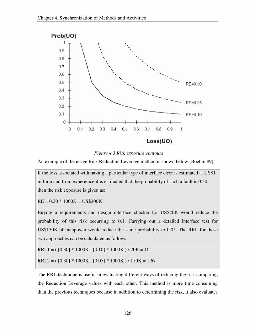
Chapter 4. Synchronization of Methods and Activities
126
Figure 4.3 Risk exposure contours
An example of the usage Risk Reduction Leverage method is shown below [Boehm 89].
If the loss associated with having a particular type of interface error is estimated at US$1
million and from experience it is estimated that the probability of such a fault is 0.30,
then the risk exposure is given as:
RE = 0.30 * 1000K = US$300K
Buying a requirements and design interface checker for US$20K would reduce the
probability of this risk occurring to 0.1. Carrying out a detailed interface test for
US$150K of manpower would reduce the same probability to 0.05. The RRL for these
two approaches can be calculated as follows:
RRL1 = ( [0.30] * 1000K - [0.10] * 1000K ) / 20K = 10
RRL2 = ( [0.30] * 1000K - [0.05] * 1000K ) / 150K = 1.67
The RRL technique is useful in evaluating different ways of reducing the risk comparing
the Reduction Leverage values with each other. This method is more time consuming
than the previous techniques because in addition to determining the risk, it also evaluates

Chapter 4. Synchronization of Methods and Activities
127
the alternatives for reducing the risk estimate. Similar to the other techniques, this
method depends solely on the expertise of the analyst to obtain a good risk estimate and
considers a single value for the probability of occurrence of each risk factor. Compared to
FMECA and criticality analysis, this technique produces a weaker risk estimate since
only two variables (probability of occurrence and loss) are considered in the risk
estimation formula.
4.2.1.4 Fault Tree Analysis
Fault tree analysis was developed in 1962 at Bell Telephone Laboratories. A fault tree is a
graphical representation of certain relations which traces an undesirable outcome (risk factor)
backwards to search for all its possible causes. Such an outcome is named as the top event of the
fault tree. Traditionally, quantitative analysis evaluates the probability of the occurrence of the
top event in which case the probability of each basic event is already known or guesstimated.
Thus, during the risk analysis of the requirements, a fault tree is created for each risk factor and
the probability of the risk factor occurring is determined from the causes for this risk factor
[Cheng 2000].
Fault tree analysis consists of the following steps [TWCC 2002]:
• Define the top event / risk factor
• Understand the system and its environment
• Construct the fault tree (Construction guidelines provided in [Zio 2002].
• Validate the tree for completeness and accuracy.
• Perform quantitative analysis (i.e. determine the probability).
The calculation of the probability for the top event in a simple fault tree (see Figure 4.4)
is given below:
Top Event T = X1 U A1 U A2 (Union of inputs due to the OR gate)
Where A1 = X2 � X3 (Intersection of inputs due to the AND gate)
A2 = X4 U X5 (Union of inputs due to the OR gate)
If Pxi denotes the probability of the occurrence of the cause xi, then probability of the top
event would be
Pt = 1 – { (1 – PX1) (1 – PA1) (1 – PA2) } where

Chapter 4. Synchronization of Methods and Activities
128
PA1 = PX2PX3
PA2 = 1 – { (1 – PX4) (1 – PX5) }
Figure 4.4 Simple fault tree
Fault tree analysis provides a better estimate of the risk compared to the previous
techniques discussed because it considers several probability estimates in the risk
calculation procedure. This technique is rigorous and involves construction of fault trees
for each risk factor, which are assumed to be complete. Hence, fault tree analysis is more
time consuming and costlier than the other techniques. The analyst is crucial in this
method as s/he has to foresee all the causes for the undesirable events and also determine
the probability estimates of these causes.
4.2.1.5 Event Tree Analysis
Event tree analysis is complementary to the fault tree analysis technique [Zio 2002a].
This technique provides an overview of the possible risk factors which affect the system
under analysis. Thus, this method is useful in the scenario where the risk factors for the
requirements are incomplete. Event tree analysis is based on binary logic, in which an
event either has or has not happened or a component has or has not failed. It is valuable
in analyzing the consequences arising from a failure or undesired event [Raafat 89].

Chapter 4. Synchronization of Methods and Activities
129
Fault Trees
An event tree is constructed by first identifying an initiating event or an undesirable
outcome. This event is either absorbed (success state) or aggravated (failure state) by the
system. The branches in the event tree represent the consequences as a result of the
initiating event. Each of the failure states correspond to the risk factors, which are
evaluated using fault trees15 as shown in Figure 4.5.
Figure 4.5 Event tree shown with fault trees used to evaluate probabilities of different risk factors
The advantage of this technique is that it gives on overview of all the risk factors
affecting the system. Furthermore, since this method is easy to perform, a single risk
analyst having knowledge about the system is sufficient for conducting this technique. By
itself, this method fails to provide a good risk estimate and hence, this method is used
along with the fault tree analysis technique. Another drawback of this technique is that
the event trees can get very large and complicated to handle.
15 Fault tree analysis explained in Section 4.2.1.4

Chapter 4. Synchronization of Methods and Activities
130
4.2.1.6 Monte Carlo Simulation
Simulation is any analytical method meant to imitate a real-life system, especially when
other analyses are too mathematically complex or too difficult to reproduce. Monte Carlo
simulation is a form of simulation that randomly generates values for uncertain variables
(risk factors) over and over to simulate a model [Goldman 2000].
For each risk factor, Monte Carlo simulation allows the requirements engineer to define a
range of possible values with a probability distribution. A distribution is an equation that
describes shape and range that represent the natural uncertainty around the input value.
The type of distribution can be one of the following types:
Figure 4.6 Types of probability distributions
During the simulation, the values generated for the different risk factors are evaluated and
the overall risk estimate is calculated. This is repeated for several thousands of sample
input values and the output is usually graphically displayed for better comprehension and
analysis.
Monte Carlo simulation results in a far more rigorous risk analysis compared to other
techniques discussed in this section. As the values are represented in ranges, this method
is not completely dependent on the expertise of the risk analyst. However, this method
needs reasonable range values for the risk factors from the analyst to perform effectively.
Furthermore, this method is the fastest of all the risk analysis techniques because it is
automated. A disadvantage of this method is its dependency on a large number of
samples to provide accurate results. Hence, a wrong choice for the sample size can result
in misleading risk estimates. Another drawback is that the effectiveness of the results
generated by this method is dependent on the risk analyst’s proficiency in analyzing the
output. Furthermore, since Monte Carlo simulation is computer based, the initial
investment in this technique is much larger than the other risk analysis methods. However,
this investment is recovered in the long run and is beneficial to the organization.

Chapter 4. Synchronization of Methods and Activities
131
K = ( LOC / ( C * t4/3 )) * 3
K � Total effort in terms of years
C � Technology constant, which combines the effect of using tools, languages,
methodology, quality assurance procedures, standards etc. It is determined on
the basis of historical data (past projects).
t � Development time in years
LOC � Size estimate in terms of lines of code
4.2.2 Cost Schedule Estimation
Cost estimation is the process of determining the amount of work and effort needed to
implement a system. It involves the evaluation of factors such as personnel experience,
platform difficulty, etc., that affect the system development to determine whether the
total cost estimate satisfies the customers’ budget. The objective of the schedule
estimation activity is to determine the development time of the components and to
identify the critical components of the software system. This section focuses on the
techniques which effectively achieve these objectives.
4.2.2.1 Software Life Cycle Management (SLIM)
Software Life Cycle Management (SLIM) is one of the first techniques for estimating the
cost associated with the project [Putnam 78]. It is generally known as a macro estimation
model and is based on the Norden/Rayleigh function.
SLIM uses the following formula to calculate the effort needed for the development of a
system / component:
The value of the technology constant depends on the readiness of the project relative to
existing technology and is assigned according to the scale:
C= 2000 -- poor, C = 8000 -- good, C = 11000 – excellent
Thus, for an assignment, which is easy or similar to a successfully completed project in
the past, the value of C is high and is around 11000. Once the effort is calculated, the cost
estimate is obtained by multiplying the effort with the cost per working year.

Chapter 4. Synchronization of Methods and Activities
132
The SLIM technique is easy to perform as it involves few parameters in the calculation of
the effort. In addition, this method consumes very little time and is suitable for large
projects. On the downside, the SLIM technique produces a cost estimate which is
extremely sensitive to the technology factor; this uncertainty in the cost makes it
unsuitable for small projects.
4.2.2.2 Constructive Cost Model (COCOMO)
COCOMO is one of the most widely used techniques for cost and effort estimation [Boehm 81].
This method is also referred to as COCOMO ’81 and consists of three different variants: basic,
intermediate and advanced.
• The basic COCOMO'81 computes software development effort (and cost) as a
function of program size expressed in estimated thousand delivered source
instructions (KDSI).
• The intermediate COCOMO'81 computes software development effort as a
function of program size and a set of fifteen "cost drivers" that include subjective
assessments of product, hardware, personnel, and project attributes.
• The advanced COCOMO'81 incorporates all characteristics of the intermediate
version with an assessment of the cost driver’s impact on each step (analysis,
design, etc.) of the software engineering process.
COCOMO depends on two main equations:
Development effort: MM = a * KDSI b
MM - man-month / person month / staff-month is one month of effort by one person. In
COCOMO, there are 152 hours per Person month and this value may change by 10% to
20% depending on the organization
Effort and development time (TDEV): TDEV = 2.5 * MM c
The coefficients a, b and c depend one of the three modes of the development as shown in
the Table 4.2. Once the development mode is identified, the values of a. b and c are

Chapter 4. Synchronization of Methods and Activities
133
determined from the Table 4.3. The cost estimate is obtained by multiplying the effort
estimate in terms of person months with the cost incurred for each person month.
Project Characteristics Development
Mode Size Innovation Deadline /
Constraints
Dev. Environment
Organic Small Little Not tight Stable
Semi-detached Medium Medium Medium Medium
Embedded Large Greater Tight Complex hardware /
customer interfaces
Table 4.2 Modes of development
Basic COCOMO a b c
Organic 2.4 1.05 0.38
Semi-detached 3.0 1.12 0.35
Embedded 3.6 1.2 0.32
Table 4.3 Values of a, b and c for the Basic COCOMO.
In the intermediate COCOMO, the same basic equation is used, but fifteen cost drivers
are rated on a scale of 'very low' to 'very high' to calculate the total EAF (Effort
Adjustment Factor). The adjustment factor is 1 for a cost driver that's judged as normal.
Thus, for the intermediate COCOMO, we use the following formula:
MM = EAF * a * KDSI b
The Advanced COCOMO model computes the EAF by having the cost drivers weighted
according to each phase of the software lifecycle.
The advantage of COCOMO is that it is simple, easy and time efficient. The cost drivers
in the intermediate and advanced COCOMO identify factors affecting the project costs
and help in obtaining a better cost estimate. The drawback of the COCOMO technique is

Chapter 4. Synchronization of Methods and Activities
134
Effort = 2.94 * EAF * (SLOC)E
Where
EAF Is the Effort Adjustment Factor derived from the Cost Drivers
E Is an exponent derived from the five Scale Drivers
SLOC Is the source lines of code
that it is hard to accurately estimate KDSI early on in the project. Also, the COCOMO
defines KDSI as a length measure rather than a size measure. Furthermore, this technique
is extremely vulnerable to misclassification of the development mode, resulting in
misleading cost estimates.
4.2.2.3 COCOMO ���
The COCOMO II method is the enhanced version of COCOMO ’81 and it produces a
better cost estimate. It defines the size of the project in terms of source lines of code
(SLOC) such that:
• Only Source lines that are DELIVERED as part of the product are included -- test
drivers and other support software is excluded
• SOURCE lines are created by the project staff -- code created by applications
generators is excluded
• One SLOC is one logical line of code
• Declarations are counted as SLOC
• Comments are not counted as SLOC
The effort estimate is calculated using the formula:
COCOMO II replaces the development modes in COCOMO ’81 with scale drivers,
which are used in determining the exponent E. In addition, COCOMO II provides a set of
17 cost drivers16, which help in calculating the EAF.
As an example [Softstar 2003], a project with all Nominal Cost Drivers and Scale Drivers
would have an EAF of 1.00 and exponent, E, of 1.0997. Assuming that the project is
16 See http://ksi.cpsc.ucalgary.ca/courses/451-96/mildred/451/CostEffort.html

Chapter 4. Synchronization of Methods and Activities
135
Duration = 3.67 * (Effort)SE
Where
Effort Is the effort from the COCOMO II effort equation
SE Is the schedule exponent derived from the five Scale Drivers
projected to consist of 8,000 source lines of code, COCOMO II estimates that 28.9
Person-Months of effort is required to complete it:
Effort = 2.94 * (1.0) * (8)1.0997 = 28.9 Person-Months
COCOMO II also calculates the duration of the project using the equation:
Continuing with the example, and substituting the exponent of 0.3179 that is calculated
from the scale drivers, we have an estimate of just below a year, and an average staffing
of between 2 to 3 people:
Duration = 3.67 * (28.7)0.3179 = 10.66 months
Average staffing = (28.7 Person-Months) / (10.6 Months) = 2.6 people
COCOMO II has the same advantages as COCOMO ’81 though it takes more time to
perform the estimation than the latter. It also overcomes the drawbacks of COCOMO ’81
by including scale drivers and SLOC instead of development modes and KDSI. It
provides a good cost estimate and a reasonable time estimate. A drawback is that the
calculations can get very complicated because of the number of factors to be considered
to obtain the estimate. Also, it has been shown that the duration estimate is unreasonable
for small projects [Merlo 2002].
4.2.2.4 Functions Points
Allan Albrecht, in collaboration with John Gaffney, Jr., designed Function Points as a
direct measure of functionality [Albrecht 83]. Function Points are used in two ways:
• As a measure of the "size", calculated from a functional, or user, point of view.
• As metrics used in conjunction with estimation variables to develop cost and
effort projections.
In order to obtain the function points, the systems functionality is broken down into five
basic categories [Heller 2002]. Two of these address the data requirements of an end user

Chapter 4. Synchronization of Methods and Activities
136
and are referred to as Data Functions. The remaining three focus on the user's need to
access data and are referred to as Transactional Functions.
Data Functions
• Internal Logical Files – Functions handling files/data invisible outside the system
• External Interface Files – Functions handling files shared with other software
systems
Transactional Functions
• External Inputs – Functions allowing read / write capabilities
• External Outputs – Functions displaying reports, messages, etc
• External Inquiries – Functions handling interactive inputs needing a response
The Function point technique counts the functions under each category. These counts are
then multiplied by a weighting scale (Table 4.4) based on the complexity of the functions
(Table 4.5). On multiplying the counts with the weights, the resultant values are summed
up to produce Unadjusted function points (UFP) estimate.
Function Type Low Average High
Internal Logical Files 7 10 15
External Interface Files 5 7 10
External Input 3 4 6
External Input 4 5 7
External Inquiry 3 4 6
Table 4.4 Weighting scale for the function types
1-5 Data element
types
6-19 Data element
types
20+ Data
element types
0-1 File types referenced Low Low Average
2-3 File types referenced Low Average High
4+ File types referenced Average High High
Table 4.5 Complexity of the function types
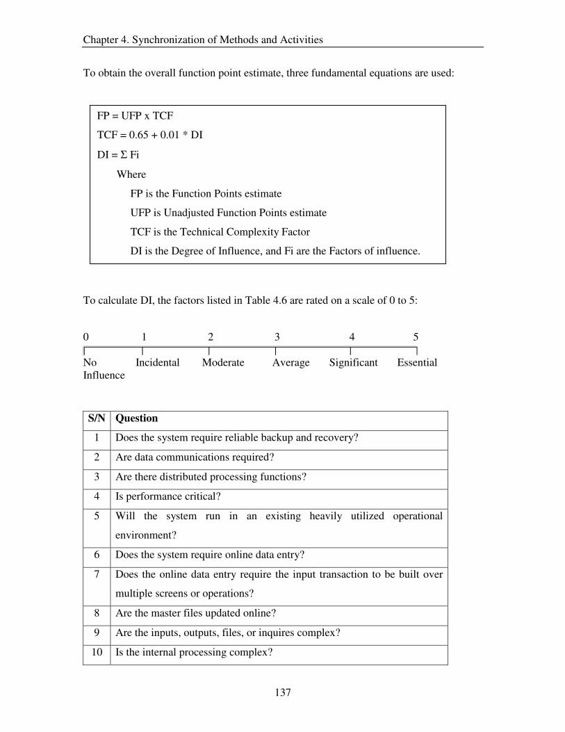
Chapter 4. Synchronization of Methods and Activities
137
FP = UFP x TCF
TCF = 0.65 + 0.01 * DI
DI = Σ Fi
Where
FP is the Function Points estimate
UFP is Unadjusted Function Points estimate
TCF is the Technical Complexity Factor
DI is the Degree of Influence, and Fi are the Factors of influence.
To obtain the overall function point estimate, three fundamental equations are used:
To calculate DI, the factors listed in Table 4.6 are rated on a scale of 0 to 5:
0 1 2 3 4 5
No Incidental Moderate Average Significant Essential Influence
S/N Question
1 Does the system require reliable backup and recovery?
2 Are data communications required?
3 Are there distributed processing functions?
4 Is performance critical?
5 Will the system run in an existing heavily utilized operational
environment?
6 Does the system require online data entry?
7 Does the online data entry require the input transaction to be built over
multiple screens or operations?
8 Are the master files updated online?
9 Are the inputs, outputs, files, or inquires complex?
10 Is the internal processing complex?

Chapter 4. Synchronization of Methods and Activities
138
11 Is the code designed to be reusable?
12 Are conversion and installation included in the design?
13 Is the system designed for multiple installations in different
organizations?
14 Is the application designed to facilitate change and ease of use by the
user?
Table 4.6 Factors of influence
The function point estimate can be used to calculate the cost estimate in two ways. The
first option is to assume a certain cost estimate for each function point. The second option
is to convert the function point count into an equivalent number of lines of code and use a
macro estimating model like COCOMO [Heller 2002].
The advantage of the function point method is that it is independent of the computer
language, code, development methodology, technology or capability of the project team
used to develop the application. In addition, it is more accurate than using the LOC
estimate for size. The disadvantage is that this method is hard to automate and difficult to
compute. Hence, compared to the other techniques discussed, this method is costlier and
more time consuming. Furthermore, this technique is subjective in the counting of
functions and is oriented more towards traditional data processing applications.
4.2.2.5 Work Breakdown Structure
The work breakdown structure is an expertise based technique which organizes the
project elements / components into a hierarchy for budget estimation and control. If cost
is associated with each element in the hierarchy, an overall cost estimate for the project
development can be determined traversing the tree bottom up [Baird 89]. Expertise
comes into play in this method when identifying the components of the hierarchy and
determining the estimates of the individual elements.
A work break down structure consists of two hierarchies, one representing the product
and the other illustrating the activities needed to develop the product [Boehm 81]. The
product hierarchy identifies the components in the software product and describes the

Chapter 4. Synchronization of Methods and Activities
139
basic structure of the overall system. The activity hierarchy shows the various activities
that may be associated with a given software component.
The steps involved in defining the work breakdown structure hierarchy and then using it
for estimation purposes are listed below:
1. Understand project related information such as project goals and objectives,
the scope, etc.
2. Identify all major activities that will be required to achieve the goals and
objectives (Activity hierarchy).
3. Identify all major components of the software product (product hierarchy)
4. Refine and decompose the hierarchies.
5. Continue step 4 until fairly sure that everything has been accounted for
6. Determine the effort required for each of the lowest level tasks / elements in
the hierarchy. One practical way to do this is to have the people involved
provide the following estimates of time:
To = an optimistic estimate of how long the task will take
Tp = a pessimistic estimate of how long the task will take
Tm = the most probably estimate of how long the task will take
Then determine the expected time Te by using the following formula
Te = (To + 4 Tm + Tp ) / 6
7. Multiply the estimates by either the cost of the actual person responsible or by
an average staff cost and combine the estimates for all elements in the
hierarchy.
8. Add the costs of equipment or any materials not covered by the tasks. This
will provide the cost estimate for the entire project.
The work breakdown structure method provides a good schedule estimate and a
reasonable cost estimate. This method is comparable to the COCOMO technique in terms
of time efficiency. However, the work breakdown structure needs more effort than the
COCOMO method because of the additional task of creating the hierarchies and hence, is
costlier than the latter. The drawback of this technique is that it fails to provide factors
(e.g. COCOMO II), which guide the analyst in his/her estimations.

Chapter 4. Synchronization of Methods and Activities
140
4.2.2.6 Gantt Chart
The Gantt chart was developed as a production control technique in 1917 by Henry L.
Gantt, an American engineer and social scientist. It provides a graphical illustration of a
schedule that helps in the following tasks:
• Planning out the tasks that need to be completed
• Determining the schedule of the different tasks.
• Planning the allocation of resources needed to complete the project
A Gantt chart is a matrix, which lists on the vertical axis all the tasks to be performed as
shown in Figure 4.7. The tasks include the activities necessary for the development of the
system requirements / components. The horizontal axis is headed by columns indicating
estimated duration for the completion of each task. Gantt charts may also include skill
level needed to perform the task, as well as the name of the person assigned to the task.
Task duration may be expressed in hours, days, weeks, months, and other time units.
Figure 4.7 Gantt chart
The construction of the Gantt chart and the schedule estimation is accomplished through
the following steps:
• List all the tasks of the system and identify whether they need to be developed in
sequential order.
• Plot each task on a graph paper, starting on the earliest possible date length of the
task bar being the duration of the task. Above the task bars, mark the time taken to
complete them. This results in the rough draft of the Gantt chart.

Chapter 4. Synchronization of Methods and Activities
141
• Schedule the tasks in such a way that sequential activities are carried out in the
required sequence. Ensure that dependent activities do not start until the activities
they depend on have been completed. In addition, schedule tasks in parallel
without interfering with the other activities in the chart. The sum of all the
durations along the horizontal axis gives the schedule estimate for the entire
project
Gantt chart is a graphical scheduling technique, which is simple to use and understand.
Hence, this method is time efficient as well as cost effective. Furthermore, Gantt charts
show the sequence in which the tasks are conducted and this can be useful in project
tracking. However, this method fails to show the interrelationships among the tasks and
the critical path in a chain of activities. Another disadvantage is that the activity times are
deterministic, which reduce the level of confidence in the overall schedule estimate, and
hence, this technique is not recommended for systems with critical deadlines.
4.2.2.7 Program Evaluation and Review Technique (PERT)
A Program evaluation and review technique (PERT) chart is a project management
technique developed by the U.S. Navy in the 1950s to manage the Polaris submarine
missile program. PERT charts are used to schedule, organize, and coordinate tasks
within a project.
The PERT technique for estimating the schedule consists of the following steps:
• Identify the tasks involved in developing the requirements.
• Determine the proper sequences of activities (sequential / parallel).
• Construct the PERT chart / activity diagram.
• Estimate the time for each activity
• Determine the critical path.
The PERT chart is drawn based on the knowledge of the serial and parallel activities.
Each task in the chart is depicted by arrowed lines and milestones are represented by
bubbles or circles as illustrated in Figure 4.8. In addition, each arrow (task) in the chart is

Chapter 4. Synchronization of Methods and Activities
142
identified by a task name and duration. Software applications simplify this task of
generating the PERT charts automatically converting the tabular activity information.
Figure 4.8 PERT chart
The duration of each task is calculated using the formula:
Optimistic time + 4 x likely time + longest time Expected time (te)= ----------------------------------------------------------- 6
Optimistic time: Shortest time in which an activity can be completed. It can be
obtained under unusual, good luck situations.
Likely time: Normal time that an activity will take, a result which is most likely to
happen.
Pessimistic time: Maximum time that an activity will take, a result which can occur,
only if unusually bad luck is experienced

Chapter 4. Synchronization of Methods and Activities
143
The critical path in the PERT chart is obtained by summing up the times for the activities
in each sequence and determining the longest path in the project. The duration of the
critical path gives the time needed for the completion of the component / project. If any
event on the critical path slips beyond its expected date of completion, then the final
event can be expected to slip a similar amount. The amount of time that a non-critical
path activity can be delayed without delaying the project is referred to as slack time,
which is useful in the management of resources allocated to the activities [NetMBA
2002]. Thus, PERT not only estimates the overall schedule but also helps in better
management and control of the activities.
PERT charts are advantageous because they show the dependencies of the various tasks
and identify the critical activities of the project. This method enables management to use
the resources wisely and improves control over complex and large development projects.
Furthermore, PERT charts are easy to understand because they provide a visual
representation of the tasks [Bedworth 87]. The drawback of this method is that
considerable effort is involved in creating the activity diagrams and verifying them for
non-existence of cycles (job ‘a’ is a predecessor for ‘b’, ‘b’ is a predecessor for ‘c’, and
‘c’ is a predecessor for ‘a’). As a result, this technique is time consuming and costly.
Another disadvantage is that the activity times are subjectively estimated and even if they
are well-estimated, PERT assumes a beta distribution for the time estimates (te), but the
actual distribution may be different [Stamatis 97]. In addition, this method fails to give
attention to the calculation of the cost estimate, and hence is best used in combination
with other techniques.
4.2.2.8 Critical Path Method (CPM)
Critical Path Method (CPM) charts are similar to PERT charts and are sometimes known
as PERT/CPM. The critical-path method (CPM), developed by Du Pont and Remington
Rand, is a powerful, but basically simple technique for analyzing, planning, and
scheduling large, complex projects [Wickwire 89]. This method provides a means for
determining:
• How long the project will take to complete
Chapter 4. Synchronization of Methods and Activities
144
• Which jobs or activities are "critical" in their effect on the total project time?
If information about the cost of each activity and how much it costs to speed up each
activity is provided, CPM can determine [Baker 2004]:
• Whether it is beneficial to speed up the project, and, if so,
• What is the optimal plan for speeding up the project?
The steps involved in the CPM method are similar to that of PERT and are as follows:
• Identify the tasks involved in developing the requirements.
• Determine the proper sequences of activities (sequential / parallel).
• Construct the network diagram.
• Estimate the completion time for each activity.
• Determine the critical path (longest path in the network).
• Determine how best to schedule all jobs in the project in order to meet a target
date at minimum cost
Thus, CPM differs from PERT in two aspects:
• The use of a single time estimate for each activity
• The inclusion of a procedure for time/cost tradeoff to determine the scheduling of
activities.
The advantages of the CPM technique are the same as PERT. An added benefit of this
method is its ability to schedule the activities based on the costs. A drawback of CPM is
that it fails to consider the effects of variability in path completion times, since it uses a
single time estimate for the tasks [Hulett 95]. As a result, the schedule estimate of CPM is
not as reliable as the one generated by PERT. Another disadvantage of CPM is that it is
cost intensive and time consuming [Jaafari 84].
Since the PERT technique has a better schedule estimating process and CPM has a good
time/cost tradeoff procedure, an ideal work strategy would be to combine the best
features of both these methods to produce optimum project duration and cost.

Chapter 4. Synchronization of Methods and Activities
145
4.2.3 Price Analysis
Price analysis is the process of determining the product price, which is fair and
reasonable to the market as well as the management [FAST 2004]. It also entails
determining the features which could be dropped for the current delivery but included in
future releases, without affecting the product value. In order to achieve this objective, it is
necessary to obtain information about the market needs. Hence, in this section we not
only discuss techniques which help in determining the product price, but also examine
methods which elicit market information.
4.2.3.1 Comparative Price Analysis
Comparative price analysis involves the comparison of the proposed product price with
quotes or prices for the same or similar items. Several factors need to be considered by
the analyst during the comparison of prices. Some of the factors are listed below:
• Number of competitors in the market
• Intensity of demand
• Inflation / deflation of the currency
• Market trends, etc.
For the purpose of comparison, this technique considers prices of:
• Older, similar / same functionality products (historical prices).
• Competitor’s products
• Products’ having a few features in common.
Hence, it is necessary to adjust these prices in order to make a fair direct comparison of
prices. This method balances the prices through the use of indices, trends analysis, and
product variance.
Price index numbers are ratios, usually expressed as percentages, indicating changes in
values, quantities, or prices, with respect to the base year. These indices are useful in
manipulating the prices to reflect the inflation / deflation of the currency to facilitate
direct comparison. An example of the use of indices to inflate the price of a product for

Chapter 4. Synchronization of Methods and Activities
146
Use of Indices
Product: Computer Monitor Objective: Adjust 2003 price to the 2004 price level by using ratio analysis Available data: 2003 price (unadjusted) 2004 price index = Adjusted price to 2004 2003 price index 2003 price 110 = Adjusted price to 2004 105 100
$104.76 = Adjusted price to 2004
comparison is shown below [FAST 2004]:
Trends analysis is based on the assumption that the trends reported in the past will
continue in the future. The analysis of the market can provide insights into the price
patterns and this can be used in predicting the price of a product or service.
Product variance analyzes the technical differences among the various products (whose
prices are being compared) and based on this evaluation the prices are compared. For
example, consider a high resolution and a low resolution monitor. The price of the former
will definitely be greater than the latter, and hence it is imperative to analyze the products
technical aspects with respect to the costs, before weighing the product prices against
each other.
This technique is the most commonly used method in the industry for predicting the
prices of products / services. It is a comprehensive method and provides a good price
estimate for the product. Furthermore, the comparative price analysis technique
determines the prices for various combinations of product features to match different
desirability levels of the users / market. The drawback of this technique is that it fails to
determine whether a particular feature is desirable or not. In addition, this method can get
complicated if several comparison factors and product prices are considered. Moreover,
the comparative price analysis technique assumes that the market information already
exists, and hence, this method needs to be supported by market analysis techniques. As a
consequence, this method is time consuming and expensive.

Chapter 4. Synchronization of Methods and Activities
147
4.2.3.2 Comparisons to Independent Cost Estimates
Independent cost estimate (ICE) is the assessment of the total cost incurred if the product
is developed. The Comparison to independent cost estimates technique ensures that the
proposed price is greater than the cost of development and, at the same time, is
reasonable to the user. Since, obtaining cost estimates of similar/same products
developed by other organizations is difficult, this method uses the cost estimates of
products that have already been developed by the current organization. However, it is
necessary that the product under analysis is compared with a very similar past product;
otherwise the cost estimates of the previous project will not be applicable to the current
one.
The Comparison to independent cost estimates technique is useful in situations where the
current project is very similar to a previous one. The cost estimate of the previous project
is utilized for the current project and the price is then tested for reasonability and fairness.
As a consequence, it becomes unnecessary to conduct the cost analysis activity. For
example, a company may develop e-commerce websites for its customers. The
characteristics of all these websites are more or less the same. Hence, if the cost for the
development of one website is done thoroughly, the estimate can then be used for
subsequent efforts.
To determine if the basis of the independent cost estimate is reliable and can be used as a
standard for comparison, the analyst must examine the following factors [FAST 2004]:
• Is the product comparable?
• What information and techniques were used?
• How reliable were earlier estimates?
• Is the cost estimate based upon the same technical approach as the current product
or service?
The cost estimates may have to be adjusted due to the inflation of the currency, and this
can be accomplished through the use of value indices explained in the previous section.
Once the cost estimate is obtained, the analyst determines the reasonability of the
proposed price by comparing it with the cost estimate and also accounting for factors
such as the user demand, urgency of the user, and competitors in the market.

Chapter 4. Synchronization of Methods and Activities
148
This technique can be used effectively for a particular set of situations such as the
repetitive development of similar software. It is faster and more cost effective than
comparative price analysis because there is no effort involved in comparing prices of
several similar / same products. An added advantage is that this method proposes a price
which is definitely profitable and reasonable. The drawback of this technique like the
previous method is that it fails to determine whether a particular feature is desirable or
not. In addition, the ‘Comparison to independent cost estimates’ technique assumes that
the previous cost estimates are applicable to the current project. This may not hold true if
there are changes to the technology, organizational procedures, and so forth.
4.2.3.3 Value Analysis
Value analysis is an auxiliary technique to the methods discussed above and attempts to
overcome one of their drawbacks – determining whether a particular product feature is
desirable or not. This method involves a systematic and objective evaluation of the
functionality of the product and its related costs. The objective of value analysis is to
eliminate the superfluous product features and thus reduce the costs involved. In order to
achieve this objective, the analyst should be knowledgeable about the product, its features
/ functions, and its use.
Value analysis is performed after the market information has been elicited. It analyzes
whether each functionality of the product is necessary and how desirable it is to the user.
In addition, this method determines the contribution of each feature to the product’s value.
If a particular functionality provides no additional value, it is dropped from the product
feature list. Furthermore, value analysis also attempts to reduce costs by examining
various alternatives to perform the functions and the possibility of purchasing the
software components of the product from an external organization.
Thus, the requirements engineer should consider the following factors during the analysis
of the product [USAID 2002]:
• What must the product do?
• Which features are essential, desirable, and unwanted?
• What are the other ways that a function can be performed?
• Can any part of the product be eliminated without affecting its market appeal?

Chapter 4. Synchronization of Methods and Activities
149
• Can a lower cost component be procured rather than developed?
• What are the product’s operation and maintenance costs?
• What will the alternatives cost?
Value analysis is an effective technique in identifying features which do not add value to
the product and thus, helps in reducing the product related costs. On the downside, this
method cannot predict the product price and hence, is used as a supplementary method to
other price analysis techniques. Another drawback of value analysis is that it assumes that
the market information is available beforehand; thus making it necessary to precede this
method with market analysis techniques. This adds to the cost and effort of conducting
the value analysis method, and hence, it is considered to be one of the costliest price
analysis techniques.
4.2.3.4 Written Surveys/Questionnaires
Written survey is one of the most commonly used technique for eliciting market
information as it facilitates contacting a large section of the society/market [Angus 53]. A
questionnaire, or written survey, can be a written document or an online questionnaire
that is completed by the person being surveyed.
Written surveys are usually one of the following types:
• Mail Surveys – Involves sending the survey questions to the people through post
[Bourque 95].
• Drop-off Surveys – Similar to mail surveys but involves meeting the person and
giving the questionnaire.
• Electronic surveys – questionnaires distributed through the World Wide Web.
Questionnaires can be used in two ways – to get statistical evidence for an assumption, or
to elicit opinions and suggestions. In the first case, the questionnaire includes closed
questions such as: “How easy is it to get the precise information using product X: very
difficult, difficult, easy, and very easy.” For the second case, we include open ended
questions such as: “what are your suggestions to improve the product X?”. Closed
questions have a high risk of misinterpretation and hence, the questions should be
carefully examined before passing it on to the people [Converse 86]. The answers to open

Chapter 4. Synchronization of Methods and Activities
150
ended questions can give good insights, but at the same time they can be vague and
confusing [Weissberg 86].
The advantage of surveys is that they are cost-effective and allow responses to be
obtained from a large number of people. In addition, many questions can be asked about
a given topic, giving considerable flexibility to the analysis. The disadvantage of this
method is that the results can be misleading because the respondents may misinterpret the
questions and give wrong or inappropriate answers. Furthermore, a particular section of
the contacted people may be more participative than the others, resulting in responses
which cannot be generalized.
4.2.3.5 Oral Survey
Oral surveys are considered to be more personal than the written surveys / questionnaires.
The oral survey technique can be administered in the following ways:
• Group Interview: It involves gathering a select group of people and instead of
handing them a written questionnaire, the questions are posed verbally. The
respondents are allowed to work in groups to answer these questions while one
person takes notes of the proceedings.
• Phone survey: It involves contacting people over the telephone line, and is
generally used to get short one word answers such as Yes/No and occasionally
longer ones [Oishi 95].
As in written surveys, the questions that are posed can be either open ended or closed.
However, compared to written surveys the information obtained is better understood as
oral survey techniques provide the flexibility to react to the respondent's situation, probe
for more detail, seek more reflective replies and ask questions which are complex or
personally intrusive [Glastonbury 91]. Thus, oral surveys are communicative sessions,
which need to be well managed since it is easy for the respondents to diverge from the
topic under discussion.
Oral surveys are advantageous over written surveys as it gives the interviewer the ability
to answer questions from the participant. If the participant, for example, misunderstands a
question or needs further explanation on a particular issue, it is possible to converse with

Chapter 4. Synchronization of Methods and Activities
151
the participant. Another advantage of this technique is that the requirements engineer has
more control over the response rate compared to the written surveys. The main drawback
of this method is the large amount of time needed to obtain complete results; as a result
this technique is costly. Also, certain types of questions17 are inconvenient for this type
of survey, particularly for phone surveys where the respondent does not have a chance to
look at the questionnaire [Dillman 78]. For example, if the respondent has a choice of
five different answers, it will be very difficult for the respondents to remember all of the
choices, as well as the question, without a visual reminder [CSU 97]. Another drawback
is that a face-to-face interview survey may introduce bias, either from the interviewer or
the respondent.
4.2.3.6 Study of Similar Companies/Products
Determining a reasonable and fair price for the product requires the knowledge of the
competitors, their products and their development processes. A study of the competitor’s
procedures provides realistic ideas about handling various product related problems. In
addition, the competitors may have more experience with the specific product and the
knowledge about their processes may provide insights about how the current
development process can be enhanced. This technique employs various strategies to
obtain information about the competitor’s processes and products.
Competitors may not be forthright with the information about the procedures they follow.
In that case, the analyst can approach certain international auditing and consultancy firms,
which have a benchmark database with performance figures for companies in the same
field. Performance is measured for various internal processes such as IT support,
maintenance, and so forth. These statistics of the competitors can indicate which
processes need to be improved. Furthermore, the consultancy may give a clue about how
the processes can be enhanced for a fee [Lauesen 2002].
This method also focuses on identifying the main features of the competitor’s products
and their appeal to the users. The analyst achieves this objective by analyzing the sales of
different products and the marketing strategies of the competitors. On examining the ads
17 See http://writing.colostate.edu/references/research/survey/com4a2a.cfm

Chapter 4. Synchronization of Methods and Activities
152
of the products it is possible to determine the features which are emphasized by the
competitor. Furthermore, the popular products and their features can be evaluated to
determine the features which are desirable to the public.
The advantage of this method is that it provides realistic ways of enhancing the
development procedures and handling product related problems. In addition, it
determines the advantages and disadvantages of similar products in the market. In turn,
this provides ideas for improving the product. The drawback of this method is that it is
difficult to procure information of the competitor’s development procedures. Furthermore,
the analysis of various similar products and their features is time consuming. The
difficulty in obtaining competitor information and the lengthy period of operation makes
this method one of the costliest market analysis techniques.
4.2.3.7 Ask Suppliers
This technique gathers information about the suppliers of software components /
functionalities in the market. It provides ideas about new functionalities and helps in
deciding whether the functionality should be developed in-house or procured from a
supplier. The ‘Ask Suppliers’ method supplements the value analysis technique, which
focuses on reducing product related costs.
Suppliers know a great deal about how the customers use their products. This information
may be helpful in identifying new functionality for the system, thereby increasing the
value of the product [Lauesen 2002]. In addition, each supplier provides a long list of
features of the product they sell. Comparing the list of features of several suppliers helps
in determining the best product satisfying the budget. Furthermore, if the prices of the
products are beyond the budget limit and the cost of in-house product development is
lower, then the analyst may decide to develop the product internally. Thus, information
collected from suppliers facilitates decision making on issues related to enhancement of
product value and reduction in development costs (using COTS18).
18 Commercial off the shelf components: commercial items already developed and readily available for purchase.

Chapter 4. Synchronization of Methods and Activities
153
The advantage of this method is that it provides comprehensive information about the
supplier’s products and their features. In addition, this technique is an effective
complementary method to value analysis. The ‘Ask Suppliers’ technique is cost effective
even though it may take a long period to collect all the information. This is because the
information collected is dependent on the supplier’s response and the suppliers may take
time to respond.
4.2.4 Feasibility Analysis
Feasibility analysis determines how beneficial or practical the development of a system
will be to the customer, by evaluating for:
• Operational feasibility
• Technical feasibility
• Schedule feasibility
• Economic feasibility
Thus, feasibility analysis involves examining the requirements of the system through
business, technological and cost perspectives and this evaluation is achievable through
various techniques, which are discussed in this section.
4.2.4.1 Decision Analysis Under Uncertainty
Decision analysis under uncertainty is also known as the Expected monetary value (EMV)
technique. It provides a highly organized structure within which various options can be
laid out and investigated [Howard 88]. Hence, given an infeasible project, the
requirements engineer can utilize the decision analysis method to choose the right
alternative that is economically and practically sound.
Decision analysis begins with the construction of the decision tree, which consists of
solution alternatives represented as lines [Clemen 96]. If the result of taking a decision /
alternative is uncertain, a small circle is drawn. If the result is another decision that is to
be taken then a square is drawn as shown in Figure 4.9 [Mindtools 95]. At each circle,

Chapter 4. Synchronization of Methods and Activities
154
possible outcomes are drawn and the probability / cash value of each outcome is
guesstimated.
Figure 4.9 Example decision tree
Once the decision tree is constructed, it is evaluated backwards by multiplying the cash
values of the outcomes with their probabilities. Thus from Figure 4.8, the value for ‘new
product’ through development is:
0.4 (probability good outcome) x $500,000 (value) = 200,000
0.4 (probability moderate outcome) x $25,000 (value) = 10,000
0.2 (probability poor outcome) x $1,000 (value) = 200
Total value $210,200
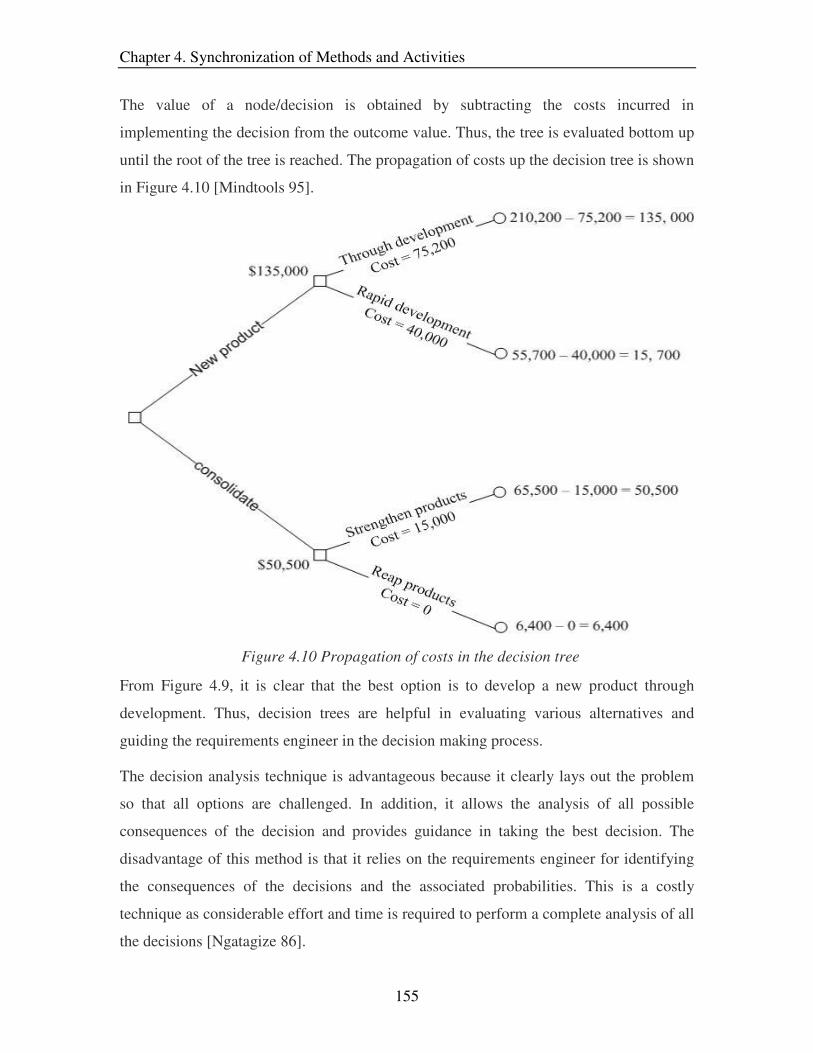
Chapter 4. Synchronization of Methods and Activities
155
The value of a node/decision is obtained by subtracting the costs incurred in
implementing the decision from the outcome value. Thus, the tree is evaluated bottom up
until the root of the tree is reached. The propagation of costs up the decision tree is shown
in Figure 4.10 [Mindtools 95].
Figure 4.10 Propagation of costs in the decision tree
From Figure 4.9, it is clear that the best option is to develop a new product through
development. Thus, decision trees are helpful in evaluating various alternatives and
guiding the requirements engineer in the decision making process.
The decision analysis technique is advantageous because it clearly lays out the problem
so that all options are challenged. In addition, it allows the analysis of all possible
consequences of the decision and provides guidance in taking the best decision. The
disadvantage of this method is that it relies on the requirements engineer for identifying
the consequences of the decisions and the associated probabilities. This is a costly
technique as considerable effort and time is required to perform a complete analysis of all
the decisions [Ngatagize 86].

Chapter 4. Synchronization of Methods and Activities
156
4.2.4.2 PMI
PMI stands for 'Plus/Minus/Implications' and is the most commonly used technique for
feasibility analysis [Bono 92]. It is a decision making technique which helps evaluate the
pros and cons of any item (requirements and its global factors19) under consideration.
The PMI technique starts with the drawing of a table with the headings: Plus, Minus and
Implications. In the column underneath ‘Plus’ all the positive aspects of the item / project
are included. For example, the requirements engineer may list out all points which make
the project technically, operationally and economically feasible [Frame 2002]. Under the
column ‘Minus’, the negative aspects of the project are listed. The last column,
‘Implications’, records the effects (either positive or negative) which are expected to
occur when the product is completed and delivered. Examples of project implications
could be: capturing a large percentage of the market share or the necessity to include
localization features.
Once the table is filled, each of the points listed are subjectively assigned a positive or
negative score. The scores are then added up to determine if the project is feasible or not.
A strong positive tally indicates that the project is feasible while a high negative count
alerts the requirements engineer about the non-practicality of the project [Mindtools 95].
On completion of the PMI technique, if a project is found to be infeasible, the decision
analysis method can be employed to identify means by which the project can be made
more attractive for development. An example of the usage of this technique is provided in
the table below [McGuire 2002]:
Take up new post in London?
Plus Minus Implications
Better social life +5 Have to sell house -6 Better promotion
opportunities +2
Change of scenery +4 More pollution -5 Meet more people +2
Higher salary +4 Higher cost of living -6
19 Global factors include risk, price and schedule

Chapter 4. Synchronization of Methods and Activities
157
Let’s assume that Jim's Printing is considering the purchase of a new printing press.
The press will cost $2000 to produce and will generate cash flows of $900 per year for
3 years.
Payback Period = 2.22 years.
During the first year $900 of the $2000 is paid back. This leaves $1100. Then during
the second year another $900 is paid back, leaving $200 of the initial investment yet to
be recovered. Assuming the $900 comes in evenly throughout the year, it will take 2/9
or .22 of the last year to pay back the initial $2000.
Further away from friend and
family -5
Less disposable income -3
Total score = 17 – 25 = -8 (Analysis loaded against going to London)
Table 4.7 Example of using PMI technique
The PMI technique is the most popular method in the software industry for
feasibility analysis as it is simple, cost effective and time efficient. However, this
method is unclear about the weighting of points and relies heavily on the
experience of the analyst. As a consequence, the results obtained can be
misleading if this method is performed by inexperienced analysts.
4.2.4.3 Payback Period
The payback period technique estimates the economic feasibility of the product by
measuring the amount of time it would take to earn back the initial investment in the
project. This is the simplest of the feasibility techniques and is usually used for small
investments. The payback period is calculated using the following formula:
Initial Investment Payback Period (years) = ---------------------------------- Annual net benefits
A project is termed ‘economically feasible’ if the payback period is less than the critical
value. In addition if there are mutually exclusive projects which achieve the same
objective, the one with the lower payback period is selected for development [Bracker
2003]. An example of the usage of this technique is given below:

Chapter 4. Synchronization of Methods and Activities
158
Payback period is advantageous because of its simplicity and easiness of application. In
addition, it is easy to understand and time efficient. Furthermore, this method provides
information about how long the funds will be tied up in a project and this can be a useful
statistic for the management. There are two primary situations when payback period can
be useful. The first situation is when the distant cash flows are highly uncertain. For
instance, the projected life span of a technology dependent project may be six years but
after two years of development there is a possibility that the technology becomes obsolete.
In a situation like this, it would be extremely helpful to have had the entire project paid
back by the end of the second year. The second situation where Payback Period is
extremely helpful is when the firm is facing significant financial problems. For example,
a company having financial problems should preferably avoid investing in a project
which has very low cash flows in the first couple years and high cash flows in the later
years. Ideally, such an organization should look for early payback of the investment to
prevent bankruptcy.
The disadvantage of this method is that it ignores cash flows after the payback period
[deNeufville 90]. Moreover, this method assumes that cash flows come in evenly
throughout the year and this may result in misleading estimates. Furthermore, the
payback period method uses an arbitrarily chosen cut off period value for accepting or
rejecting the project. Because of these limitations, this technique is biased against long
term capital intensive projects.
4.2.4.4 Net Present Value
Net present value (NPV) is widely used by industry to determine the profitability of a
project. The net present value of a project is the present value of all cash flows less the
initial investment. Cash flow is defined as the benefits minus the cost incurred in each
period. Net present value can be calculated as follows:
NPV = CF0 + CF1/(1+r) + CF2/(1+r)2 +. . . + CFn/(1+r) n.
Where NPV ���� Net present value (dollars)
CF ���� Cash flow
r ���� Discount rate

Chapter 4. Synchronization of Methods and Activities
159
As seen in the formula, the cash flow for each year is discounted by a discount rate [r],
which represents the conversion of future year money to current year money. Discount
rate is the measure of the value of money over time, that is, a dollar today is worth more
than a dollar tomorrow because one can invest the dollar today and have more tomorrow.
The choice of the discount rate plays a critical role in the feasibility analysis of projects
competing for funding. Low discount rates favor capital intensive projects with low
operating costs while high discount rates support solutions with lower investment costs
but higher operating costs [OMB 2000]. The rate for the commercial industry is typically
between 10% and 15% depending on the risk and stability of the industry.
If a project has a positive Net present value, it indicates that the project is profitable and
if funded, will increase the value of the company. If there are two projects competing for
funding, then the one with greater Net present value should be selected. An example
showing the calculations involved in the application of the Net present value technique is
presented below [Williamson 2001]:
Year
Cash
Flows
($)
Discount
Factors
(15%)
Present
Values
($)
0 -25,000 1.0000 -25,000.00
1 20,000 0.8696 17,391.30
2 25,000 0.7561 18,903.59
3 12,500 0.6575 8,218.95
4 9,000 0.5718 5,145.78
Net Present Value 24,659.63
Table 4.8 Calculations in the Net Present Value technique
The Net Present Value method addresses the value of money over time, considers all cash
flows, and acknowledges the risk involved in cash flows by incorporating discount rates.
As a result, compared to other techniques for estimating economic feasibility, this
technique is the most effective and widely used. The drawback is that this method
requires more time and effort than the other techniques because of its comprehensive

Chapter 4. Synchronization of Methods and Activities
160
evaluation. In addition, this technique fails to specify the size of the investment required
to achieve the results [DoD 2001].
4.2.4.5 Internal Rate of Return
While the net present value technique estimates an absolute value for the returns, internal
rate of return (IRR) provides a relative measure of the value. This technique calculates
the discount rate at which the net present value becomes zero [Baker 97].
NPV = CF0 + CF1/(1+r) + CF2/(1+r)2 +. . . + CFn/(1+r) n = 0
Where NPV ���� Net present value (dollars)
CF ���� Cash flow
r ���� Discount rate
As seen from the above formula, the discounted cash flows (CF) together equal the
present value of the investment in the project. The feasibility of the project is determined
on the basis of the discount rate [r]. If the estimated rate is higher than the required rate of
return, the project is said to be financially feasible. The computations involved in this
technique are shown in the following table.
Year
Cash
Flows
($)
Discount
Factors
(r=13.114%)
Present
Values
($)
0 -$3,000 1.00 -3,000.00
1 1,500 .884063865 1,326.10
2 1,200 .781568917 937.88
3 800 .690956837 552.77
4 300 .610849972 183.25
Net Present Value 0
Table 4.9 Calculations in the Internal Rate of Return technique

Chapter 4. Synchronization of Methods and Activities
161
The table is the same as that for net present value, but in this method the focus is on
estimating the value of r in order to obtain a value of zero for the net present value. This
difference is highlighted in Figure 4.9.
The IRR technique is an effective method for determining the economic feasibility of a
project. It also provides the same advantages as that of the net present value technique.
However, compared to the net present value method, this technique is more complicated
and time consuming. Moreover, there is a possibility of dealing with multiple internal
rates of return if there is a change in sign of the cash flows after the initial cash outflow
[DSU 2003].
4.2.4.6 Pilot Experiments
In some projects, the main risk is whether the customer organization can adapt to the final
product. For such projects, determining the operational feasibility is critical before
developing the product. This objective is effectively achieved through pilot experiments.
In order to determine the operational feasibility using this technique, a working system
needs to be developed, preferably through the use of COTS components. A small part of
the target organization tries this system on a trial basis using real production data. In
order to incorporate the system efficiently, the organization needs to make certain
changes in the working procedures [Lauesen 2002]. The requirements engineer observes
the results and evaluates the benefits and costs of deploying the real system. Analysis of
the project feasibility is done in a way similar to that of the PMI technique.
Pilot experiments are useful in situations where the organizations adaptability to the
system is a major risk factor. It is an elaborate technique which is time consuming as the
requirements engineer has to observe the system in its real environment. Furthermore,
this is an expensive method because the system has to be developed using COTS
components and deployed in the customer organization.
4.2.5 Conflict Resolution
Conflict resolution is a process by which conflicts in requirements are resolved to reach a
solution agreeable to all parties. This activity consists of three major steps: identify issues,

Chapter 4. Synchronization of Methods and Activities
162
identify options and finalize agreements. Issues specify the conflicts in requirements
along with the arguments from the stakeholders, who own the requirements. The options
list various alternatives to resolve the identified conflicts. Agreements are the final
solutions which are approved by all the stakeholders.
In this section, we discuss different techniques employed by the software industry to
perform the three steps -identify issues, identify options and finalize agreements, which
constitute the backbone of the conflict resolution activity.
4.2.5.1 Brainstorming/Interviews
Both of these techniques have been explained under the requirements elicitation meeting
activity in Sections 4.1.2.1 and 4.1.2.6. Hence, in this section, we will provide a brief
recapitulation of each method and highlight their pros and cons.
In the conflict resolution activity, brainstorming and interview techniques are effective in
capturing the stakeholders’ viewpoints and their solutions for the various conflicts. Both
these methods have their own characteristics and should be employed based on the
situation.
Brainstorming consists of gathering the stakeholders, creating a stimulating atmosphere,
and letting the participants come up with spontaneous ideas without the fear of being
ridiculed. On the contrary, interview is a face-to-face session, where the participant is
briefed about the conflicting interests and his/her arguments are recorded.
Brainstorming takes lesser time and cost to perform compared to interviews and is
effective in identifying innovative ideas / solutions. However, interviews are more
personal than brainstorming and allow for discussion between the analyst and the
stakeholder. Since brainstorming generates ideas that are not criticized, several unrealistic
solutions may be proposed that need to be filtered out and this requires some additional
effort. Furthermore, the success of the interview and brainstorming techniques depend on
the questions asked and the management skills of the moderator / analyst.

Chapter 4. Synchronization of Methods and Activities
163
4.2.5.2 Go-Around
This technique attempts to combine the positive features of interviewing and
brainstorming methods. In a go-around, the facilitator sequentially asks each participant
to submit his/her viewpoint. If a person doesn't have anything to say, s/he can pass during
a round. Team members can also rejoin the process and contribute on subsequent rounds
of the technique [NYS 2003b].
The Go-Around technique consists of the following steps during conflict resolution:
• Give a brief introduction to the conflicting items
• Give the members a break (around five minutes) to collect their thoughts
• In the first round, ask each member to state their position on the conflict and the
arguments associated with their decision.
• Clarify / discuss the unclear arguments of the participants in the next round.
• In the subsequent rounds, assist and encourage people to find ways to overcome
the conflict. The proceedings of each round are recorded by a scribe.
The industry uses several variations of the Go-Around technique such as Take five,
Constructive response, and Nominal group technique20 [DoD 99]. The ‘take five’ method
proposes notifying the participants of the conflicting issues before the meeting takes
place. It also includes a break of five minutes before commencing each round.
Constructive response technique is very similar to Go-around with the addition being the
use of chalkboards for a visual representation of the member viewpoints and concerns.
The nominal group technique has the same steps as Go-around but in addition it provides
a simple voting procedure to resolve the conflicts. Thus, we see that each of these
methods build on top of the Go-Around technique, providing a few additional
enhancements.
This technique allows introverted people the chance to provide input without having to
"push" their way into the conversation. Furthermore, since the participants are given time
to think about the conflicts, the ideas contributed are likely to be more realistic. This
method requires more time than brainstorming but lesser time than interviewing. In
20 See http://instruction.bus.wisc.edu/obdemo/readings/ngt.html
Chapter 4. Synchronization of Methods and Activities
164
addition, this technique builds team spirit and requires lesser effort than the interview
method. The drawback is that this method relies heavily on the facilitator for the success
of the group session.
4.2.5.3 Positional Bargaining
Positional bargaining, also known as distributive negotiation, is a conflict resolution
strategy which involves each party taking a stand and arguing for their position regardless
of any underlying interests. This technique consists of three basic steps:
• take a position
• argue for this position
• make concessions to reach a compromise
Positional bargaining tends to be the first strategy employed by people when they enter
into a negotiation. This can result in problems, because as the negotiation proceeds the
participants get more committed to their positions, continually restating and defending
them. A strong commitment to a position often results in lack of attention to the
participants underlying interests. Therefore, any agreement that is reached will "probably
reflect a mechanical splitting of the difference between final positions rather than a
solution carefully crafted to meet the legitimate interests of the parties” [Fisher 81].
We see many examples in the real world that illustrate the use of this method [Spangler
2003]. For instance, at a flea market, a man offers a vendor $10 for a rug he has for sale.
The vendor asks for $30, so the customer offers $15. The merchant then says he will
accept $25, but the customer says the highest he will go is $20. The vendor agrees that
$20 is acceptable and the sale is made at $20. So the customer pays $10 more than he
originally wanted and the vendor receives $10 less.
Positional bargaining focuses on the issues rather than the interests of the parties involved
in the negotiation. Issues are universal and are shared between each party in a conflict,
while interests are specific to each party. In the example outlined above, what the
customer wants is a bargain, while what the seller wants is a profit.
This technique is advantageous for situations that involve extremely conflicting interests
[Lax 91]. For example, suppose two nations are in a dispute over water rights. They also

Chapter 4. Synchronization of Methods and Activities
165
have a difference in opinion on issues such as trade, religion, etc. Broadening the debate
to include all the underlying interests may further polarize the countries. It is much easier
to reach an agreement by negotiating one particular issue at a time in terms of positions.
The drawback of positional bargaining is the inflexibility of positions of both parties.
This may result in bad feelings between the parties. This technique is inefficient because
it may take a long time to reach a compromise in the event the opening positions are
extreme. Furthermore, the method focuses on splitting the differences between parties
rather than on the development of a solution beneficial to both sides.
4.2.5.4 Interest Based Bargaining
The main difference between positional bargaining and interest based bargaining is the
underlying assumption that each party brings to the negotiation table. While the former
focuses on position, the latter concentrated on the interests of the two sides. This
technique attempts to create a win-win situation, where both sides have the impression of
being on the winning side of the negotiation [Palmer 2000].
Interest-based bargaining goes by a host of names such as “consensus bargaining”,
“problem-solving negotiations,” “win-win,” “mutual gains,” “collaborative bargaining,”
and “principled negotiations”. This technique has the following characteristics
[Hammond 95]:
• People: View the problem as that which needs to be resolved rather than viewing
someone holding a contrary viewpoint as a person to be defeated [Cohen 2002]
One specific technique that can work is to make both the parties face a flip chart
or blackboard where the problem is presented, rather than facing each other as
opponents.
• Interests: Take care of the human needs of the participants by identifying each
side's needs, desires, concerns and fears.
• Options: Invent alternatives for mutual gain. The interests and options can be
elicited from the participants through techniques such as interviewing,
brainstorming or Go-around.

Chapter 4. Synchronization of Methods and Activities
166
• Criteria: Develop objective criteria for judging merits of agreement such as
market value, precedent, scientific judgment, professional standards, efficiency,
costs, tradition, reciprocity, equal treatment, and time.
This technique examines all the identified options keeping in mind the interests of both
parties and analyzes each option against the selection criteria. Once an option is selected,
an agreement is prepared that clearly states the resolutions arrived at during the
negotiation.
Interest based bargaining is an effective technique in finalizing an agreement for conflicts
among different parties. This technique focuses on the underlying concerns of the
disputing parties and hence, there is very little scope to develop bad feelings towards the
other party [Sebenius 86]. In addition, this method fosters co-operation among the
participants in an informal atmosphere. Compared to positional bargaining, this technique
is more likely to reach an agreement, which is beneficial to both the sides. Furthermore,
interest based bargaining requires lesser effort, cost and time than positional bargaining
because it is more structured and has clear guidelines for identifying and finalizing
agreements. A possible drawback of this method is that it requires the two parties to trust
each other, which is not often the case.
4.3 Methods for Organization and Compilation Phase
This phase consists of a single activity, which is concerned with grouping the complete
set of requirements in a manner which is optimal for understanding. Requirements can be
classified based on user class, stimulus, response, system mode21, etc. The organization
and compilation phase / activity produces a structured requirements list, which represents
a sections of the final SRS.
This section describes methods that can be employed for structuring the requirements list
based on the type of classification.
21 See Section 3.3 for more details.

Chapter 4. Synchronization of Methods and Activities
167
4.3.1 Affinity Analysis
Affinity analysis is a categorization method where users sort various concepts into
several groups. This is an effective technique to use when there is a large amount of data
that needs to be classified. Basically this technique involves writing each concept on a
Post-It note and sticking it on a wall or board. The team then moves the notes around to
form groups based on how they feel the concept relates to the others.
The steps involved in affinity analysis are as follows [Brassard 88]:
• Form a team of four to six people so that there is good mix of experience and
perspectives.
• Clearly state what the team is trying to accomplish and what the end result of the
exercise should be.
• Use Post-It notes to record concepts (requirements) in whole and not just as a
single word.
• Tack cards to wall or whiteboard in no particular order.
• The team members sort the cards into groups based on their intuition. No person
should influence the other person’s decision.
• For each group, create header cards which concisely describe what each group
represents. The header cards should be single word titles and meaningful. Rite
sub-header cards for subgroups, if necessary.
• Connect the related headers and sub-headers with lines to generate the affinity
diagram.
Affinity analysis is an effective method for classifying requirements so that they are easy
to comprehend. It is a simple technique which can be performed in a short time frame.
The drawback of affinity analysis is that for large amount of data, a huge canvas is
necessary to conduct this method. In addition, this method is fairly expensive because it
involves approximately six people and a moderator, who manages the proceedings of the
meeting.

Chapter 4. Synchronization of Methods and Activities
168
4.3.2 Functional Hierarchy Decomposition
Functional hierarchy decomposition represents the data / requirements in terms of what
the system must perform. Thus, this technique is applicable when the requirements are to
be organized based on the functional hierarchy of the system. In order to facilitate the
organization, this method necessitates the creation of a hierarchy diagram similar to the
one illustrated in Figure 4.11
Figure 4.11 Functional hierarchy diagram
The overall functionality of a system can be structured into a hierarchy of functions to
illustrate the information flow in the system. Thus, the root node in the hierarchy
represents the system objective. The second tier of the hierarchy includes those
components / functionalities that help in achieving the system objective [CMSD 2003].
For example, a high level functionality could be database manipulation while a sub-
function of this functionality could be an authorization check. The functionalities are
decomposed successively until the leaf nodes represent the smallest unit of functionality
(requirements). Each high level node represents a grouping of lower level nodes. This
hierarchy is used in organizing the requirements.

Chapter 4. Synchronization of Methods and Activities
169
Functional hierarchy decomposition is beneficial only for the situation where
requirements need to be organized in a hierarchy of functions. This technique is simple
and is generally performed by a single person. It is cost effective, but time consuming
because the task is performed by a single person. A disadvantage of this method is that its
success is dependent on the product knowledge and expertise of the analyst /
requirements engineer. Hence, it is imperative that s/he have a clear understanding of the
system and its functions.
4.4 Methods for Confirmational analysis Phase
This phase creates the traceability diagrams and determines whether the requirements
trace back to user needs. In addition, this phase performs the final verification and
validation on the complete set of requirements. This phase concludes with the generation
of the validated and structured requirements list, which is ready for inclusion in the SRS.
In the sections which follow, we describe the methods that achieve the objectives of this
phase.
4.4.1 Quality Adherence
This activity verifies the total set of requirements for quality characteristics such as
completeness and consistency. These quality characteristics cannot be checked earlier in
the ‘verifying quality attributes’ activity because they can be determined only when the
entire set of requirements is elicited. However, the techniques that are applicable to the
‘verifying quality attributes’ activity are effective for the ‘quality adherence’ activity too.
Thus, the techniques that can be used to achieve the objectives of this activity are:
Inspections, round robin reviews and audits (from Section 4.1.5)
Inspection is a formal technique, which is widely used to verify the requirements
because it detects the most number of errors. Inspections are conducted using a group of
about six people, who refer to elaborate checklists to determine the adherence of the
requirements to the quality characteristics. The main drawback is that this technique is
time consuming and cost intensive because of its rigorous nature.

Chapter 4. Synchronization of Methods and Activities
170
Round robin reviews involves circulating the requirements among the reviewers for
their comments on the quality attributes of the requirements. The unique feature of this
method is the lack of discussion among the reviewers. Compared to the other verification
techniques, round-robin reviews require the least amount of time and money for
performing the quality check on the requirements. However, this method is not as
effective as inspections in detecting faults.
Audits, unlike the previous methods, are performed by a single person, who is
independent of the project being reviewed. Like inspections, audits use checklists during
the verification of requirements. In terms of time and money required, this technique lies
in between inspections and round-robin reviews. The main advantage of this technique is
that the customers tend to have a strong belief / confidence in the generated results.
4.4.2 Traceability Analysis
Traceability analysis involves the creation of traceability diagrams, which show the
function decomposition dependencies among the elicited requirements. In addition, once
the traceability diagrams have been generated, the requirements engineer should verify
the traceability of the requirements for errors. Hence, in this section we describe
techniques which help in depicting the traceability as well as for verifying the
requirements dependencies.
4.4.2.1 Traceability Matrix
A traceability matrix illustrates the dependency relationship between two requirements in
the form of a matrix. Each requirement in the matrix should have the following
information [DoE 2002]:
• A unique identification number by which it can be referred to.
• The requirement statement.
• Requirement source (Developer, customer, Configuration Control Board, etc.).
• Software Requirements Specification paragraph number containing the
requirement.
• Design Specification paragraph number containing the requirement.

Chapter 4. Synchronization of Methods and Activities
171
• Program Module containing the requirement.
• Test Specification containing the requirement test.
• Test Case number(s) where requirement is to be tested (optional).
• Verification of successful testing of requirements.
• Modification field - Requirement changed, eliminated, or replaced
• Remarks
All the above information cannot be obtained in the requirements phase and is
incorporated into the matrix throughout the product development life cycle. In the
requirements phase, the analyst creates the matrix and identifies the links between the
requirements. The ID number and requirements statement is also incorporated into the
matrix. The software industry uses several different formats of the traceability matrix.
One of the most popular formats for the matrix is the one included in Requisite Pro and is
shown in Figure 4.12
Figure 4.12 Traceability matrix in Requisite Pro

Chapter 4. Synchronization of Methods and Activities
172
Tree dependency structure
The advantage of the traceability matrix is that it shows all the requirements on the
matrix and is very comprehensive. Moreover, the matrix shows the same requirements
along the rows and columns and this ensures that no dependency is overlooked. The
drawback of this method is that the matrix can get very large and difficult to handle. Also,
this technique is time consuming because each requirement is checked against every
other requirement for dependencies.
4.4.2.2 Traceability Tree
Traceability tree is another technique for representing the dependencies among the
requirements. Each requirement in the traceability tree possesses the same information as
that in the traceability matrix. The only modification is in the representation of the links
so that the diagram becomes more manageable [Letelier 2003]. Thus, instead of having
the matrix structure, the dependencies are represented in the form of a tree. An example
of the traceability tree used in Requisite Pro22 is shown in Figure 4.13.
Figure 4.13 Traceability tree in Requisite Pro
The advantage of this technique is that the diagram is smaller than the traceability matrix
and hence, is more manageable. Also, this method requires lesser time to create the tree
structure because the links are created by the analyst based on his/her understanding of
22 For more details see www.ibm.com/software/awdtools/reqpro

Chapter 4. Synchronization of Methods and Activities
173
the system. However, this can be disadvantageous because the analyst may now
unknowingly overlook certain dependencies. The cost of using this technique is almost
the same as that of the traceability matrix because the main investment is in the software
which facilitates the creation of these diagrams.
4.4.2.3 Inspections/Round-Robin Review
Inspections and round robin reviews are effective in verifying the traceability of
requirements in the traceability diagrams. Sections 4.1.5.1 and 4.1.5.2 describe these
techniques in detail.
Inspection is the commonly used technique for identifying errors in a work product
(traceability diagrams.). It involves several people, who use detailed checklists for
identifying faults in the traceability diagrams. However, the drawback of inspections is
that it is time consuming and cost intensive.
Round robin reviews involves the verification of the product individually and not as a
group. This technique is not as rigorous as inspections and hence, involves lesser cost and
time. Also, this technique does not employ checklists - it depends entirely on the
expertise of the reviewer to identify the errors.
4.4.3 Customer Validation Meeting
This activity differs from the validation in local analysis in that the whole set of
requirements are validated, compared to component sets of requirements that are
validated during local analysis. The objective of the customer validation meeting is to
identify disagreements between the customer needs and the requirements. The techniques
applicable to the ‘stakeholder validation’ activity of the requirements capturing phase can
be used for this activity, too. Detailed explanations of the methods are provided in
Section 4.1.6. In this section, we present only a brief description of these methods.
Walkthroughs, also referred to as presentation reviews, involve a group meeting in
which the requirements engineer presents the requirements to the participants. The group
consists of company employees, managers, users, customers and reviewers.

Chapter 4. Synchronization of Methods and Activities
174
Walkthroughs require a lot of preparation before the group meeting and this is
responsible for high cost involved. In addition, the feedback is obtained only for the
material presented by the requirements engineer. The main advantage of this method is
that its time efficiency and involvement of all the stakeholders.
Scenarios describe how the users can interact with the system in different situations
while storyboarding transforms the textual scenarios into pictures, drawings, etc. Both
of these techniques make it easier for the user to visual the interactions with the system.
However, both methods are time consuming and cost intensive because of the large
amount of work involved in creating scenarios and storyboards.
Interviews and guided discussions are occasionally used for validating requirements.
While interviews involve individual face-to-face sessions, guided discussions involve
interactive group meetings. Guided discussions require lesser time to validate the product
compared to interviews. However, cost wise guided discussions are more expensive to
conduct than interviews.
Prototyping is the most commonly used technique for validating a product /
requirements. It allows the user to visualize how the final system will look like. This
enhances the user understanding of the system requirements. The prototype developed at
this stage of the requirements phase is usually a high fidelity prototype. As a result,
prototyping is the most expensive and time consuming validation technique.
4.4.4 Requirements Reformulation
This activity is conducted by the requirements engineer in order to rectify the
requirement problems identified by the quality analyst and the customer. These problems
should be relatively minor and pertain to requirements quality and customer disagreement
with the requirements. Requirements are often reformulated to overcome identified
problems.
Guided discussion is the commonly used technique for this activity to resolve the minor
problems of the customer. The discussion occurs in an informal atmosphere and the
various solutions (reformulation) to the problems are analyzed. Guided discussion takes
around two hours to perform and hence, is time efficient. The technique is fairly

Chapter 4. Synchronization of Methods and Activities
175
expensive if the moderator is from an external agency. Several other techniques may be
employed, but they all include some form of a discussion to resolve the customer
problems.
4.5 Selection of Methods for Optimization of Common Criteria
The previous sections described the techniques that can be used to achieve the objectives
of the activities defined by the x-RGM. Each activity can be performed by any of several
methods and the choice of a particular method is a difficult task. We aim to simplify this
task of the requirements engineer by identifying commonly used selection criteria and
filtering out methods which do not satisfy these criteria. We choose to illustrate the
selection process by example. In particular, for each selection criteria, we identify the set
of methods for all activities defined by the x-RGM that best meet the selection criteria
goal. Furthermore, the requirements engineer may have to employ one or more of the
prescribed set of methods in order to achieve the objective of a particular activity.
We chose the following four criteria for the selection of methods:
• Time - Selection based on the amount of time needed to perform the technique.
• Cost - Selection based on the expenses involved in conducting the method
• Personnel - Selection based on the number of staff needed and their expertise.
• Completeness - Selection based on the coverage of the activity objectives
In the subsequent sections, we list the methods for each activity in the x-RGM based on
the selection criteria and record the pros and cons of each approach.
4.5.1 Methods Based on Time Criteria
Often the requirements engineer has very limited time to perform a particular activity. In
such a situation, it is necessary to employ the best possible technique, which achieves the
objective in the least amount of time. However, many of the methods which satisfy the
time criteria introduce compromises on other factors such as cost and completeness.

Chapter 4. Synchronization of Methods and Activities
176
In this section, we record the methods that achieve the activity objectives in the least
amount of time along with their benefits and drawbacks.
Activity Name Methods Pros / Cons
Requirements Capturing Phase
+ Cost effective
Better comprehension
- May skip necessary information
Audience coverage is limited
Customer Indoctrination
Oral Presentation
Dependent on moderators skills
+ Suited for interactive applications
Cost effective, simple
Task Demonstration
- Success dependent on tasks assigned
+ Large user coverage
Cost effective, simple
- Results may be misleading
Questionnaires
Success dependent on the questions
+ Elicits news ideas, cost effective, simple
Promotes creativity, team spirit
- Needs good management
Brainstorming
Should be followed by idea reduction techniques
+ Promotes co-operation
- Participants may not be representative of users
Focus groups
Needs management, cost intensive
+ Elicits maximum information
Promotes co-operation
- Cost intensive
Requirements Elicitation Meeting
Requirements Workshops
Needs management

Chapter 4. Synchronization of Methods and Activities
177
Activity Name Methods Pros / Cons
+ Elicits news ideas , cost effective, simple
Promotes creativity, team spirit
- Needs good management
Brainstorming (elicits only rationale)
Should be followed by idea reduction techniques / discussion
+ Effective on closed participants
Cost effective, simple
- Questions posed are critical to success
I-Time (elicits only rationale)
Needs to be followed by a discussion
+ Encourages co-operation
Cost effective
- May opt for first available solution
Rationalization and Justification
Task oriented discussion
Needs management
+ Encourages co-operation
Cost effective
- May opt for first available solution
Needs management
Guided discussion (elicits requirement attributes)
Followed by ranking techniques
+ Simple, Cost effective
Prioritization
Priority Groups
- Priorities not relative to each other
+ Cost effective
- Cannot detect all errors
Dependent on reviewer’s expertise
Verifying Quality Attributes
Round – Robin Review
Minimal discussion among reviewers
+ Participation of all stakeholders
- Cost intensive
Stakeholder validation
Walkthroughs
Validation only for material presented
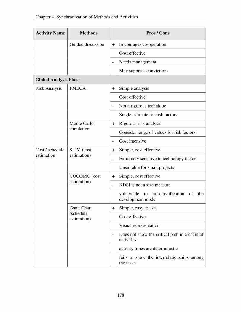
Chapter 4. Synchronization of Methods and Activities
178
Activity Name Methods Pros / Cons
+ Encourages co-operation
Cost effective
- Needs management
Guided discussion
May suppress convictions
Global Analysis Phase
+ Simple analysis
Cost effective
- Not a rigorous technique
FMECA
Single estimate for risk factors
+ Rigorous risk analysis
Consider range of values for risk factors
Risk Analysis
Monte Carlo simulation
- Cost intensive
+ Simple, cost effective
- Extremely sensitive to technology factor
SLIM (cost estimation)
Unsuitable for small projects
+ Simple, cost effective
- KDSI is not a size measure
COCOMO (cost estimation)
vulnerable to misclassification of the development mode
+ Simple, easy to use
Cost effective
Visual representation
- Does not show the critical path in a chain of activities
activity times are deterministic
Cost / schedule estimation
Gantt Chart (schedule estimation)
fails to show the interrelationships among the tasks

Chapter 4. Synchronization of Methods and Activities
179
Activity Name Methods Pros / Cons
+ Cost effective
Provides a good estimate
- Not applicable to innovative projects
Previous estimate may not hold
Comparison to independent cost estimates
Cannot elicit market information
+ Large user coverage
Cost effective, simple
- Results may be misleading
Price Analysis
Questionnaires (market information)
Success dependent on the questions
+ Cost effective
Easy, simple
- Weighing of points is not clear
Can be misleading if not done with a unbiased mind
PMI
Needs to determine cost feasibility through other methods
+ Cost effective
Provides a good estimate for small investments
- Ignores cash flows after the payback period
Feasibility Analysis
Payback Period (cost feasibility)
Results can be misleading
+ Elicits news ideas, cost effective, simple
Promotes creativity, team spirit
- Needs good management
Brainstorming (elicits arguments and options)
Should be followed by idea reduction
+ Focuses on concerns
Fosters co-operation
Conflict Resolution
Interest Based Bargaining (finalizes agreements) - Requires both parties to trust each other

Chapter 4. Synchronization of Methods and Activities
180
Activity Name Methods Pros / Cons
Organization and Compilation Phase
+ Simple, Fosters team spirit
- Difficult to manage for large amount of data
Organization and Compilation
Affinity analysis
Fairly expensive
Confirmational analysis Phase
Quality Adherence
Same as the ‘Verifying quality attributes’ activity
+ Easy to comprehend and use
Easily manageable structure
Traceability Tree ( dependency creation)
- Certain links may be overlooked
+ Cost effective
- Cannot detect all errors
Dependent on reviewer’s expertise
Traceability Analysis
Round – Robin Review ( traceability verification)
Minimal discussion among reviewers
Customer Validation Meeting
Same as the ‘Stakeholder validation’ activity
+ Encourages co-operation
Cost effective
- May suppress participant convictions
Requirements Reformulation
Guided discussion
Needs management
. 4.5.2 Methods Based on Personnel Criteria
Personnel is a common criteria used in the industry for the selection of methods because
a project usually has limited work staff. Hence, in this section, we list those techniques
which require minimum staff and expertise, and thus, aim to provide the necessary
guidance to the requirements engineer. Most of the techniques listed below are conducted
/ supported by a single person (requirements engineer), unless explicitly stated.

Chapter 4. Synchronization of Methods and Activities
181
Activity Name Methods Pros / Cons
Requirements Capturing Phase
+ Cost effective, Time efficient
- May skip necessary information
Audience coverage is limited
Oral Presentation
Dependent on moderators skills
+ Provides comprehensive information
Cost effective
Documents can be read in leisure
- Involves one-way communication
Reader may get frustrated
Customer Indoctrination
Print material
Takes a long time to read the documents
+ Large user coverage
Cost effective, fast to perform
- Results may be misleading
Questionnaires
Success dependent on the questions
+ Elicits new ideas
Promotes creativity, team spirit
Cost effective, time efficient
- Needs good management
Brainstorming
Should be followed by idea reduction techniques
+ Cost effective
Provides opportunity to explore topics in depth
- Time consuming
Interview questions are critical for success
Requirements Elicitation Meeting
Interviews
Assumes interviewee has access to accurate knowledge

Chapter 4. Synchronization of Methods and Activities
182
Activity Name Methods Pros / Cons
+ Simple, cost effective
Can study documents in leisure
- Involves one-way communication
Reader may get frustrated
Document studies
Takes a long time to read the documents
+ Elicits news ideas , cost effective, simple
Promotes creativity, team spirit
Time efficient
- Needs good management
Brainstorming (elicits only rationale)
Should be followed by idea reduction techniques / discussion
+ Encourages co-operation
Cost effective, time efficient
- May opt for first available solution
Rationalization and Justification
Task oriented discussion
Needs management
+ Cost effective
Provides opportunity to explore topics in depth
- Time consuming
Interview questions are critical for success
Assumes interviewee has access to accurate knowledge
Interviews
Cannot perform ranking of requirements
+ Simple, Cost effective Priority Groups
- Priorities not relative to each other
+ Provides relative priorities
- Time consuming, cost intensive
Prioritization
AHP or Binary Search Tree
Applicable if requirements obtained in a single iteration

Chapter 4. Synchronization of Methods and Activities
183
Activity Name Methods Pros / Cons
+ Cost effective, time efficient
- Cannot detect all errors
Dependent on reviewer’s expertise
Round – Robin Review ( 4-6 peers)
Minimal discussion among reviewers
+ Detects maximum errors
- Time consuming
Inspections ( 4-6 peers)
Cost intensive
+ Customers have confidence in the results
Non biased opinion
- Auditors need to be highly experienced
Verifying Quality Attributes
Audits (single expert)
Cost and time intensive
+ Cost effective
Provides opportunity to explore topics in depth
- Time consuming
Interviews
Interview questions are critical for success
+ Easy to comprehend
Better feedback from users
Stakeholder validation
Scenarios or storyboarding
- Cost and time intensive
Global Analysis Phase
+ Rigorous technique, time efficient
Consider range of values for risk factors
Monte Carlo simulation
- Cost intensive
+ Simple, cost effective, time efficient
- Assumes all risk factors are known before analysis
Risk Analysis
Criticality Analysis
Single estimate for risk factors

Chapter 4. Synchronization of Methods and Activities
184
Activity Name Methods Pros / Cons
+ Simple, cost effective
Time efficient
- Extremely sensitive to technology factor
SLIM (cost estimation)
Unsuitable for small projects
+ Simple, cost effective
Time efficient
- KDSI is not a size measure
COCOMO (cost estimation)
Vulnerable to misclassification of the development mode
+ Independent of language and code
More accurate than LOC estimate of size
- Cost and time intensive
Functions Points (cost estimation)
Difficult to automate
+ Simple, cost effective
Visual representation
- Does not show the critical path in a chain of activities
Activity times are deterministic
Cost / schedule estimation
Gantt Chart (schedule estimation)
Fails to show the interrelationships among the tasks
+ Cost effective, Time efficient
Provides a good estimate
- Not applicable to innovative projects
Previous estimate may not hold
Comparison to independent cost estimates
Assumes market information already exists
+ Produces a good price estimate
- Cannot determine if a feature is desirable
Assumes market information already exists
Price Analysis
Comparative Price Analysis
Time consuming and expensive

Chapter 4. Synchronization of Methods and Activities
185
Activity Name Methods Pros / Cons
+ Determines if a feature is desirable or not
- Auxiliary technique, time consuming
Value Analysis
Assumes market information already exists
+ Large user coverage
Cost effective, Time efficient
- Results may be misleading
Questionnaires (market information)
Success dependent on the questions
+ Provides information about product alternatives
- Difficult to obtain information
Study of similar companies / products (market information)
Time consuming
+ Cost effective, simple
- Weighing of points is not clear
Can be misleading if not done with a unbiased mind
PMI
Needs to determine cost feasibility through other methods
+ Cost effective
Provides a good estimate for small investments
- Ignores cash flows after the payback period
Payback Period (cost feasibility)
Results can be misleading
+ Generates good estimates
- Cost and time intensive
Feasibility Analysis
Internal Rate of Return (or) Net Present Value (cost feasibility) Calculation can get complex
+ Elicits news ideas, cost effective, simple
Promotes creativity, team spirit
- Needs good management
Conflict Resolution
Brainstorming (elicits arguments and options)
Should be followed by idea reduction

Chapter 4. Synchronization of Methods and Activities
186
Activity Name Methods Pros / Cons
+ Cost effective
Provides opportunity to explore topics in depth
- Time consuming
Interviews (elicits arguments and options)
Interview questions are critical for success
+ Applicable to situations that involve extremely conflicting interests
- inflexibility of positions
Time consuming
Positional Bargaining (finalizes agreements)
Focus on splitting differences between parties
+ Focuses on concerns
Fosters co-operation
Can be conducted in a shorter time frame than positional bargaining
Interest Based Bargaining (finalizes agreements)
- Requires both parties to trust each other
Organization and Compilation Phase
+ Simple, Fosters team spirit
Can be conducted in a short time frame
- Difficult to manage for large amount of data
Affinity analysis (4-6 peers)
Fairly expensive
+ Applicable for organizing requirements into a hierarchy of functions
Cost effective
- Time consuming
Organization and Compilation
Functional Hierarchy Decomposition (single expert)
Dependent on expertise of analyst
Confirmational analysis Phase
Quality Adherence
Same as the ‘Verifying quality attributes’ activity

Chapter 4. Synchronization of Methods and Activities
187
Activity Name Methods Pros / Cons
+ Easy to comprehend and use
Time efficient
Easily manageable structure
Traceability Tree ( dependency creation)
- Certain links may be overlooked
+ Easy to comprehend and use
Ensures links are not overlooked
- Difficult to manage
Traceability Matrix ( dependency creation)
Time consuming
+ Cost effective, time efficient
- Cannot detect all errors
Dependent on reviewer’s expertise
Round – Robin Review ( 4-6 peers) [Traceability verification]
Minimal discussion among reviewers
+ Detects maximum errors
- Time consuming
Traceability Analysis
Inspections ( 4-6 peers) [Traceability verification] Cost intensive
Customer Validation Meeting
Same as the ‘Stakeholder validation’ activity
+ Encourages co-operation
Cost effective
- May suppress participant convictions
Requirements Reformulation
Guided discussion
Needs management
4.5.3 Methods Based on Cost Criteria
Cost involved in conducting a method is another important criterion for selecting a
particular method for an activity. This section lists the methods, which achieve the
objectives of the activities in the x-RGM at a minimal cost.

Chapter 4. Synchronization of Methods and Activities
188
Activity Name Methods Pros / Cons
Requirements Capturing Phase
+ Time efficient
Better comprehension
- May skip necessary information
Audience coverage is limited
Oral Presentation
Dependent on moderators skills
+ Provides comprehensive information
Documents can be read in leisure
- Involves one-way communication
Reader may get frustrated
Customer Indoctrination
Print material
Takes a long time to read the documents
+ Large user coverage
Time efficient
- Results may be misleading
Questionnaires
Success dependent on the questions
+ Elicits news ideas
Promotes creativity, team spirit
Time efficient
- Needs good management
Brainstorming
Should be followed by idea reduction techniques
+ Provides opportunity to explore topics in depth
- Long execution time frame
Interview questions are critical for success
Requirements Elicitation Meeting
Interviews
Assumes interviewee has access to accurate knowledge

Chapter 4. Synchronization of Methods and Activities
189
Activity Name Methods Pros / Cons
+ Provide comprehensive information
Can study documents in leisure
- Involves one-way communication
Reader may get frustrated
Document studies
Takes a long time to read the documents
+ Suited for interactive applications
Time efficient
Task Demonstration
- Success dependent on tasks assigned
+ Elicits news ideas , simple, time efficient
Promotes creativity, team spirit
- Needs good management
Brainstorming (elicits only rationale)
Should be followed by idea reduction techniques / discussion
+ Effective on closed participants
Time efficient
- Questions posed are critical to success
I-Time (elicits only rationale)
Needs to be followed by a discussion
+ Encourages co-operation
Time efficient
- May opt for first available solution
Rationalization and Justification
Task oriented discussion
Needs management
+ Provides opportunity to explore topics in depth
Allows clarification of answers
- Time consuming
Interview questions are critical for success
Prioritization Interviews (elicits requirement attributes)
Cannot perform ranking of requirements

Chapter 4. Synchronization of Methods and Activities
190
Activity Name Methods Pros / Cons
+ Encourages co-operation
Time efficient
- May opt for first available solution
Needs management
Guided discussion (elicits requirement attributes)
Cannot perform ranking of requirements
+ Simple, time efficient
Priority Groups
- Priorities not relative to each other
+ time efficient
- Cannot detect all errors
Dependent on reviewer’s expertise
Verifying Quality Attributes
Round – Robin Review
Minimal discussion among reviewers
+ Provides opportunity to explore topics in depth
Allows clarification of answers
- Time consuming
Interviews
Interview questions are critical for success
+ Encourages co-operation
Time efficient
- Needs management
Stakeholder validation
Guided discussions
May suppress convictions
Global Analysis Phase
+ Simple, time efficient
- Provides a reasonable estimate
FMECA
Single estimate for risk factors
+ Simple, cost effective, time efficient
- Assumes all risk factors are known before analysis
Risk Analysis
Criticality Analysis
Single estimate for risk factors

Chapter 4. Synchronization of Methods and Activities
191
Activity Name Methods Pros / Cons
+ Simple, time efficient
- Extremely sensitive to technology factor
SLIM (cost estimation)
Unsuitable for small projects
+ Simple, time efficient
- KDSI is not a size measure
COCOMO (cost estimation)
vulnerable to misclassification of the development mode
+ Simple, easy to use
Time efficient
Visual representation
- Does not show the critical path in a chain of activities
activity times are deterministic
Cost / schedule estimation
Gantt Chart (schedule estimation)
fails to show the interrelationships among the tasks
+ Time efficient
Provides a good estimate
- Not applicable to innovative projects
Previous estimate may not hold
Comparison to independent cost estimates
Cannot elicit market information
+ Large user coverage
Cost effective, simple
- Results may be misleading
Questionnaires (market information)
Success dependent on the questions
+ Determines if a feature is desirable or not
- Cannot predict the price estimate
Auxiliary technique
Price Analysis
Value Analysis
Assumes market information already exists

Chapter 4. Synchronization of Methods and Activities
192
Activity Name Methods Pros / Cons
+ Time efficient
Easy, simple
- Weighing of points is not clear
Can be misleading if not done with a unbiased mind
PMI
Needs to determine cost feasibility through other methods
+ Time efficient
Provides a good estimate for small investments
- Ignores cash flows after the payback period
Feasibility Analysis
Payback Period (cost feasibility)
Results can be misleading
+ Elicits news ideas, cost effective, simple
Promotes creativity, team spirit
- Needs good management
Brainstorming (elicits arguments and options)
Should be followed by idea reduction
+ Allows clarification of interviewee answers
Provides opportunity to explore topics in depth
- Time consuming
Interviews (elicits arguments and options)
Interview questions are critical for success
+ Focuses on concerns
Fosters co-operation
Conflict Resolution
Interest Based Bargaining (finalizes agreements) - Requires both parties to trust each other
Organization and Compilation Phase
+ Simple, Fosters team spirit
Time efficient
- Difficult to manage for large amount of data
Organization and Compilation
Affinity analysis
Fairly expensive

Chapter 4. Synchronization of Methods and Activities
193
Activity Name Methods Pros / Cons
+ Applicable for organizing requirements into a hierarchy of functions
- Time consuming
Functional Hierarchy Decomposition
Dependent on expertise of analyst
Confirmational analysis Phase
Quality Adherence
Same as the ‘Verifying quality attributes’ activity
+ Easy to comprehend and use
Easily manageable structure
Traceability Tree (dependency creation)
- Certain links may be overlooked
+ Time efficient
- Cannot detect all errors
Dependent on reviewer’s expertise
Traceability Analysis
Round – Robin Review (traceability verification)
Minimal discussion among reviewers
Customer Validation Meeting
Same as the ‘Stakeholder validation’ activity
+ Encourages co-operation
Time efficient
- May suppress participant convictions
Requirements Reformulation
Guided discussion
Needs management
.
4.5.4 Methods Based on Completeness Criteria
In some projects, it is necessary that the objective of each activity is completely met
before proceeding to the next activity. In such situations, the completeness criterion is
used to determine the methods that will be employed in the project. This section attempts
to facilitate the above cause by providing a list of methods that will satisfy the objective
of the requirements engineering activities to the maximum extent.

Chapter 4. Synchronization of Methods and Activities
194
Activity Name Methods Pros / Cons
Requirements Capturing Phase
+ Provides comprehensive information
Cost effective
Documents can be read in leisure
- Involves one-way communication
Reader may get frustrated
Customer Indoctrination
Print material
Takes a long time to read the documents
+ Promotes co-operation
- Participants may not be representative of users
Needs management
Focus groups
Cost intensive
+ Elicits maximum information
Promotes co-operation
- Cost intensive
Requirements Workshops
Needs management
+ Cost effective
Provides opportunity to explore topics in depth
- Time consuming
Interview questions are critical for success
Requirements Elicitation Meeting
Interviews
Assumes interviewee has access to accurate knowledge
+ Rigorous technique
Fosters co-operation and team spirit
- Cost and time intensive
Need management
Rationalization and Justification
IBIS
Dependent on expertise of the analyst

Chapter 4. Synchronization of Methods and Activities
195
Activity Name Methods Pros / Cons
+ Encourages co-operation
Cost effective, time efficient
- May opt for first available solution
Task oriented discussion
Needs management
+ Cost effective
Provides opportunity to explore topics in depth
- Time consuming
Interview questions are critical for success
Assumes interviewee has access to accurate knowledge
Interviews (elicits requirements attributes)
Cannot perform ranking of requirements
+ Provides opportunity to explore topics in depth
Allows clarification of answers
- Time consuming
Interview questions are critical for success
Guided discussion (elicits requirements attributes)
Cannot perform ranking of requirements
+ Simple, Cost effective
Time efficient
Prioritization
Priority Groups
- Priorities not relative to each other
+ Detects maximum errors
- Time consuming
Inspections ( 4-6 peers)
Cost intensive
+ Customers have confidence in the results
Non biased opinion
- Auditors need to be highly experienced
Verifying Quality Attributes
Audits (single expert)
Cost and time intensive

Chapter 4. Synchronization of Methods and Activities
196
Activity Name Methods Pros / Cons
+ Involves the participation of all stakeholders
Time efficient
- Cost intensive
Walkthroughs
Validation only for material presented
+ Provides good user feedback
Helps user in comprehending the requirements
Prototyping
- Cost and time intensive
+ Easy to comprehend
Useful for interactive applications
Better feedback from users
Stakeholder validation
Scenarios or storyboarding
- Cost and time intensive
Global Analysis Phase
+ Rigorous technique
Time efficient
Consider range of values for risk factors
Monte Carlo simulation
- Cost intensive
+ Considers several probability values in calculating the estimate
- Time and cost intensive
Dependent on expertise of analyst
Fault Tree analysis
Assumes all risk factors are identified
+ Identifies most of the risk factors
Easy to perform
- Auxiliary technique to FTA
Cannot estimate risk by itself
Risk Analysis
Event Tree Analysis
Event trees can get large and complicated

Chapter 4. Synchronization of Methods and Activities
197
Activity Name Methods Pros / Cons
+ Cost effective, time efficient
- Calculations can get complicated
COCOMO II (cost estimate)
Schedule estimate is not accurate
+ Focuses attention on critical aspects
Enables management to use resources more wisely
Shows the dependencies of the various tasks
- Time and cost intensive
PERT (schedule estimate)
beta distribution formula for the time estimate may not hold true
+ Schedule the activities based on the costs
Identifies critical activities
Shows the dependencies of the various tasks
- Time and cost intensive
Cost / schedule estimation
CPM (schedule estimation)
Schedule estimate is not as reliable as that of PERT
+ Produces a good price estimate
- Cannot determine if a feature is desirable
Assumes market information already exists
Comparative Price Analysis (CPA)
Time consuming and expensive
+ Determines if a feature is desirable or not
- Auxiliary technique to CPA
Value Analysis
Assumes market information already exists
+ Large user coverage
Cost effective
Time efficient
- Results may be misleading
Price Analysis
Questionnaires (market information)
Success dependent on the questions

Chapter 4. Synchronization of Methods and Activities
198
Activity Name Methods Pros / Cons
+ Provides information about product alternatives
Often used with Value analysis method
- Difficult to obtain information
Study of similar companies / products (market information)
Time consuming
+ Covers a large number of users
Users misunderstandings can be clarified
Cost effective
- Time consuming
Oral Survey (market information)
Responses could be influenced
+ Cost effective, simple
- Weighing of points is not clear
Can be misleading if not done with a unbiased mind
PMI
Needs to determine cost feasibility through other methods
+ Rigorous technique
Evaluates all consequences of a decision
- Time and cost intensive
Dependent on the expertise of the analyst(s)
Decision Analysis
Needs to determine cost feasibility through other methods
+ Generates good estimates
- Cost and time intensive
Feasibility Analysis
Internal Rate of Return (or) Net Present Value (cost feasibility) Calculations can get complex
+ Elicits news ideas, cost effective, simple
Promotes creativity, team spirit
- Needs good management
Conflict Resolution
Brainstorming (elicits arguments and options)
Should be followed by idea reduction

Chapter 4. Synchronization of Methods and Activities
199
Activity Name Methods Pros / Cons
+ Fosters co-operation
Effective with closed participants
- Requires more time than brainstorming
Dependent on the expertise of the moderator
Go-Around (elicits arguments and options)
Needs management
+ Focuses on concerns
Fosters co-operation
Can be conducted in a shorter time frame than positional bargaining
Interest Based Bargaining (finalizes agreements)
- Requires both parties to trust each other
Organization and Compilation Phase
+ Simple, Fosters team spirit
Can be conducted in a short time frame
- Difficult to manage for large amount of data
Organization and Compilation
Affinity analysis (4-6 peers)
Fairly expensive
Confirmational analysis Phase
Quality Adherence
Same as the ‘Verifying quality attributes’ activity
Activity Name Methods Pros / Cons
+ Easy to comprehend and use
Time efficient
Easily manageable structure
Traceability Tree ( dependency creation)
- Certain links may be overlooked
+ Easy to comprehend and use
Ensures links are not overlooked
- Difficult to manage
Traceability Analysis
Traceability Matrix ( dependency creation)
Time consuming

Chapter 4. Synchronization of Methods and Activities
200
Activity Name Methods Pros / Cons
+ Detects maximum errors
- Time consuming
Inspections ( 4-6 peers) [Traceability verification] Cost intensive
Customer Validation Meeting
Same as the ‘Stakeholder validation’ activity
+ Encourages co-operation
Cost effective
- May suppress participant convictions
Requirements Reformulation
Guided discussion
Needs management
4.6 Summary
This chapter addressed the issue of mapping methods to the activities in the x-RGM.
Sections 4.1 to 4.4 describe in detail the techniques that achieve the objectives of the
various activities. In order to facilitate the task of selecting methods for the activities, we
have listed a set of techniques for each activity based on certain criteria, which are widely
used in the industry. This list includes the popular as well as several other techniques and
is NOT a comprehensive list. The intention behind creating this list is to provide the
requirements engineer with some reference for selecting methods since the current RE
literature fails to provide the necessary guidance.

Chapter 5. Summary and Future Work
201
Chapter 5
Summary and Future Work
5. Introduction
This research describes a solution to the problem in the field of requirements engineering
that is concerned with the mapping of methods to activities in the requirements
generation process. Chapter 1 motivates the need for this research, defines the problem
and highlights the research issues. In Chapter 2, we discussed the relevant background,
which reveals the absence of a well defined requirements process model. Furthermore,
the literature illustrates the unsynchronized and inadequate attempts at mapping methods
to the right level of activities in the requirements engineering process. Chapter 3
presented the x-RGM as the solution for a structured and well-defined requirements
engineering model. Finally, in Chapter 4, we describe various methods for achieving the
objectives of the activities in the requirements generation model, and prescribe a list of
methods for the entire requirements engineering process on the basis of some common
selection criteria. This chapter summarizes the research work conducted and presents the
future opportunities of work.

Chapter 5. Summary and Future Work
202
5.1 Summary
This research is motivated by the problems faced by the requirements engineer in
implementing the requirements engineering process. The main problem is the absence of
a well-defined and comprehensive requirements process model. Adding to that problem
list is the lack of coordination between methods and activities in the requirements model.
As a consequence of these obstacles, the requirements engineer is often hindered in the
effective application of the requirements generation process to the real world projects.
The solution of the problems listed above needs to consider several issues such as23:
• Incomplete requirements engineering model
• Inadequate level of activity abstraction
• Implicit activity objectives implicit
• Methods mapped primarily to high level activities
• Lack of reasoned guidance in selecting methods to achieve activity objectives
The solution was deployed in two phases. In the first phase, the focus was on developing
a well-defined process model (addresses first three issues), and in the second phase, the
emphasis was on synchronizing methods to activities (addresses last two issues).
The Requirements Generation Model (RGM) serves as the foundation for our research
and has been decomposed to a more appropriate activity level based on the concept of
“Separation of concerns” [ICSE 2001, OOPSLA 99, Hursh 95], which stresses on
identifying and satisfying a small set of concerns for the purpose of organizing and
decomposing different processes. In designing the proposed model (expanded
Requirements Generation Model [x-RGM]), we evaluated several existing requirements
engineering processes and approaches. The best features of these models are incorporated
in the x-RGM. The x-RGM is composed of four main phases:
• Requirements capturing: elicits requirements and analyzes them from the local
standpoint
• Global analysis: analyzes the complete set of requirements and resolves any
requirement conflicts 23 See Section 1.4.1 for detailed description of the issues

Chapter 5. Summary and Future Work
203
• Organization and Compilation: structures the requirements as a part of the SRS
• Confirmational analysis: implements traceability and performs the final
verification and validation on the complete set of requirements
Each of these phases is decomposed into a detailed set of activities; the objectives of
these activities are also identified and explicitly stated.
In order to map methods to activities, we conducted a literature review on the methods
used in various disciplines for the purpose of generating requirements. These methods
have been mapped to the activities defined by the x-RGM based on their objectives.
Furthermore, in order to simplify the task of choosing methods for the activities, we
prescribed a smaller set of methods for each activity on the basis of commonly used
selection criteria such as time, cost, and so forth.
The x-RGM was conceived as the expansion of the requirements phase in the
conventional waterfall model. The intent was to concentrate on identifying activities and
objectives for the requirements engineering phase while attempting to minimize the
impact on the other phases. Even though the x-RGM in its current form is not designed to
accommodate other development paradigms such as OOA, XP, etc. we do conjecture that
it can be adapted for them. We also note that the list of methods included in this research
is not intended to be comprehensive; the intention is to provide the requirements engineer
with some basic reference to and an approach for selecting methods.
5.2 Contributions
The contributions of this research to the field of requirements engineering and computer
science in general are:
• The expanded Requirements Generation Model (x-RGM): As seen from the
literature review, the current requirements engineering models either provide a high
level of abstraction or focus on only portions of the entire requirements engineering
process. Hence, it was necessary to develop a model having the right level of
decomposition in order to map methods to the activities. For the decomposition of the
requirements engineering process, we chose the RGM as the basis. This model
(RGM), in its basic form, includes three activities and attempts to decompose only the

Chapter 5. Summary and Future Work
204
capturing phase of the requirements generation process. However, the proposed x-
RGM, which builds on top of the RGM, consists of sixteen activities and addresses
the entire requirements engineering process. The decomposition of the requirements
generation process into activities of the x-RGM is illustrated below:
Phase name # of activities Activity name
Requirements
Capturing
6 • Customer/requirements engineer
indoctrination
• Requirements elicitation meeting
• Rationalization and justification
• Prioritization
• Verifying quality attributes
• Stakeholder validation
Global Analysis 5 • Risk analysis
• Cost/schedule estimation
• Price analysis
• Feasibility analysis
• Conflict resolution
Organization and
Compilation
1 • Organization and compilation
Confirmational
Analysis
4 • Quality adherence
• Traceability analysis
• Customer validation meeting
• Requirements reformulation
Table 5.1 Activities identified in the x-RGM

Chapter 5. Summary and Future Work
205
• Identification of activity objectives: For each of the sixteen activities identified in
the x-RGM, the objectives are determined and explicitly stated, unlike in the other
models where the objectives are often implied. The identification of objectives is
imperative because methods are mapped to the requirements engineering process
activities based on the achievement of their objectives. Thus, the x-RGM is better
defined and more comprehensive than the other requirement generation models not
only because of a refined level of abstraction, but also due to the explicit specification
of objectives.
• Synchronization of methods and activities: A drawback of the current requirements
engineering literature is that it focuses on identifying methods for the high level
activities in the requirements generation process, but the techniques for the sub-
activities are often ignored. As a consequence, the requirements engineer lacks
guidance in choosing methods for the various requirement engineering activities. This
research addresses this void in requirements engineering by identifying methods from
various disciplines, and suggests their application for achieving the defined objectives
of the x-RGM activities. In this thesis, for each activity in the x-RGM, we identify the
principal techniques which are most accepted in the industry. Table 5.2 depicts the
number of techniques identified for the various activities in the x-RGM.
Activity Name Number of Methods
identified
Customer/requirements engineer indoctrination 2
Requirements elicitation meeting 9
Rationalization and justification 4
Prioritization 5
Verifying quality attributes 3
Stakeholder validation 6
Risk analysis 6

Chapter 5. Summary and Future Work
206
Activity Name Number of Methods identified
Cost/schedule estimation 8
Price analysis 7
Feasibility analysis 6
Conflict resolution 5
Organization and compilation 2
Quality adherence 3
Traceability analysis 4
Customer validation meeting 6
Requirements reformulation 1
Table 5.2 Number of methods identified for activities in the x-RGM
• Selection of methods to optimize common criteria: In the industry, often
techniques for various activities are chosen based on certain selection criteria.
However, the current requirements engineering literature fails to incorporate such
criteria into the process of identifying techniques for performing activities of the
requirements generation process. In this research, we attempt to overcome this
shortcoming by identifying four commonly used criteria for the selection of methods
– cost, time, personnel and completeness. For each of these criteria, we identify a set
of methods for the entire requirements generation process, such that the chosen
criterion is optimized and at the same time the objectives of the activities are achieved.
Thus, this list of techniques provides the necessary guidance to the requirements
engineer in the selection of methods for the various activities in the requirements
generation process (x-RGM). The following table shows the number of methods
selected for the x-RGM based on the four selection criteria.
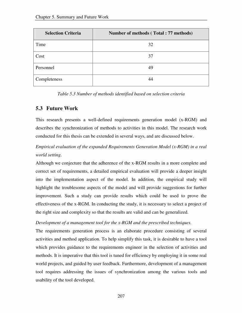
Chapter 5. Summary and Future Work
207
Selection Criteria Number of methods ( Total : 77 methods)
Time 32
Cost 37
Personnel 49
Completeness 44
Table 5.3 Number of methods identified based on selection criteria
5.3 Future Work
This research presents a well-defined requirements generation model (x-RGM) and
describes the synchronization of methods to activities in this model. The research work
conducted for this thesis can be extended in several ways, and are discussed below.
Empirical evaluation of the expanded Requirements Generation Model (x-RGM) in a real
world setting.
Although we conjecture that the adherence of the x-RGM results in a more complete and
correct set of requirements, a detailed empirical evaluation will provide a deeper insight
into the implementation aspect of the model. In addition, the empirical study will
highlight the troublesome aspects of the model and will provide suggestions for further
improvement. Such a study can provide results which could be used to prove the
effectiveness of the x-RGM. In conducting the study, it is necessary to select a project of
the right size and complexity so that the results are valid and can be generalized.
Development of a management tool for the x-RGM and the prescribed techniques.
The requirements generation process is an elaborate procedure consisting of several
activities and method application. To help simplify this task, it is desirable to have a tool
which provides guidance to the requirements engineer in the selection of activities and
methods. It is imperative that this tool is tuned for efficiency by employing it in some real
world projects, and guided by user feedback. Furthermore, development of a management
tool requires addressing the issues of synchronization among the various tools and
usability of the tool developed.

Chapter 5. Summary and Future Work
208
Adapting the model to other software development paradigms
The x-RGM has been developed assuming that all the requirements are generated upfront
before the commencement of the design phase. Hence, this model is more suitable in an
environment which follows the waterfall development paradigm. A possible extension to
this model is to adapt it to suit other development paradigms, such as the evolutionary
and spiral approaches. This would require considering the requirements engineering
process not as an isolated phase, but as one which overlaps with the rest of the software
development phases – design, coding, and testing.
Determining the content and format of information generated by the activities
The current requirements engineering literature focuses on specifying the content and
format of the software requirements specification (SRS) and neglects the presentation of
the intermediate requirement forms generated during the requirements engineering
process. The identification of the content and format of the intermediate documents and
its synchronization with the x-RGM can result in a more comprehensive and complete
requirements generation model. The major issue that this research needs to address is the
identification of the different representations of the intermediate requirements so that
there is minimal / no loss of information as the requirements evolve during the
requirements generation process.

References
209
References
[Albrecht 83] A. J. Albrecht, and J. E. Gaffney, "Software function, source lines of
codes, and development effort prediction: a software science
validation", IEEE Trans Software Eng. SE-9, 1983, pp.639-648.
[Alcazar 2000] Garcia Alcazar, E.; Monzon, A.; A process framework for
requirements analysis and specification, Requirements Engineering,
2000. Proceedings. 4th International Conference on , 19-23 June
2000 Page(s): 27 -35
[Angus 53] Campbell, Angus, A., ∧ Katona, Georgia. (1953). The Sample
Survey: A Technique for Social Science Research. In Newcomb,
Theodore M. (Ed). Research Methods in the Behavioral Sciences.
The Dryden Press: New York. pp 14-55.
[Armstrong 2001] Eric Armstrong, A Simple Collaboration System (Proposal),
http://www.treelight.com/software/collaboration/ProjectConcept.htm
l, 2001.
[Arthur 99] Arthur, J.D. and Markus K. Groener, 1999, An Operational Model
Supporting the Generation of Requirements that Capture Customer
Intent, Proceedings of the Pacific Northwest Software Quality
Conference, Portland OR, October 1999, pp. 286-302.
[ASA 97] American Statistical Association, What is a Survey?, ASA Series,
1997.
[Baird 89] Baird, B. (1989), Managerial Decisions Under Uncertainty, Baird,
B., John Wiley & Sons, 1989.
[Baker 2004] Samuel L. Baker, Critical Path Method,
http://hspm.sph.sc.edu/Courses/J716/CPM/CPM.html, 2004.
[Baker 97] Samuel L. Baker, Internal Rate of Return,
http://hadm.sph.sc.edu/COURSES/ECON/irr/irr.html, 1997.

References
210
[Basili 75] V.R. Basili, A.Turner, Iterative Enhancement- a Practical Technique
for Software Development, IEEE Transactions on Software
Engineering, SE-1(4), Dec 1975
[Beck 99] Kent Beck, Extreme Programming Explained: Embrace Change,
Addison-Wesley, 1999.
[Bedworth 87] Bedworth, David D. and James E. Bailey. Integrated Production
Control Systems. New York: John Wiley & Sons, 1987.
[Berntsen 2003] Fredrik Berntsen, Introducing technique choice support into an
existing requirement acquisition process, Masters thesis, Lund
Institue of Technology, May 2003.
[Boehm 81] B. Boehm. Software Engineering Economics. Prentice-Hall, 1981.
[Boehm 88] Barry Boehm, A Spiral Model of Software Development and
Enhancement, IEEE Computer, pp 61-72, May 1988.
[Boehm 89] Boehm, B.W. (1989) Tutorial: Software Risk Management, IEEE
Computer Society Press.
[Boehm et al, 94] Boehm, B.W., Bose, P., Horowitz, E., Lee, M.J. “Software
Requirements As Negotiated Win Conditions”, Proceedings of
ICRE, April 1994, pp.74-83.
[Boehm 98]. Barry Boehm, Using the Win-Win Spiral Model: A Case Study.
IEEE Computer, Vol 31, No. 7, July 1998, pp 33-44.
[Boehm 99] Barry Boehm, Chris Abts, Software Development Cost Estimation
Approaches,- A Survey, University of Southern California, 1999.
[Bono 92] Edward de Bono, Serious Creativity, HarperBusiness, New York,
US, 1992.
[Bourque 95] Bourque, Linda B. & Fiedler, Eve P. (1995).How to Conduct Self-
Administered and Mail Surveys. Sage Publications: Thousand Oaks.

References
211
[Bracker 2003] Kevin Bracker, http://www.pittstate.edu/econ/ch9326.html,
Department of Economics, Pittsburh State University, 2003
[Brassard 88] Brassard, Michael, ed. 1988. The Memory Jogger: A Pocket Guide
of Tools for Continuous Improvement. Methuen, MA: Goal/QPC.
[Bravo 93] E. Bravo, “The hazards of leaving out the users,” in Participatory
Design: Principles and Practices, D. Schuler and A. Namioka, Eds.
Hillsdale, New Jersey: Lawrence Erlbaum Associates, Inc.
Publishers, 1993, pp. 3-11.
[Brooks 87] Brooks F.P., Jr., 1987, No silver bullet: essence and accidents of
software engineering, Computer, v.20 n.4, p.10-19, April 1987.
[Brooks 95] F. P. Brooks. The Mythical Man-Month. Addison-Wesley, 20th
anniversary edition, 1995.
[Boehm et al., 1994] Boehm, B.W., Bose, P., Horowitz, E., Lee, M.J. “Software
Requirements As Negotiated Win Conditions”, Proceedings of
ICRE, April 1994, pp.74-83.
[Bubenko 95] [Bubenko 95] Janis A. Bubenko, Challenges in Requirements
Engineering, IEEE Computer, 1995
[Burns 2003] James R. Burns, Chapter 8:Project and Process Management,
http://burns.ba.ttu.edu/Isqs4350/Chapter%208.pdf, 2003
[Carmel 93] Carmel E., R.D. Whitaker, and J.F. George, 1993, PD and Joint
Application Design: A Transatlantic Comparison, Communications
of the ACM, Vol. 36, No. 4, June 1993.
[Carter 2001] Carter, R.A.; Anton, A.I.; Dagnino, A.; Williams, L., 2001,
Evolving beyond requirements creep: a risk-based evolutionary
prototyping model, Requirements Engineering, 2001. Proceedings,
Fifth IEEE International Symposium on, Vol., Iss., 2001, pg. 94-
101.

References
212
[Charette 86] R.N. Charette. Software Engineering Environments, Concepts and
Technology, Mc Graw Hill, 1986.
[Cheng 2000] Yue-Lung Cheng, Uncertainties in Fault Tree Analysis, Tamkang
Journal of Science and Engineering, April 10, 2000.
[Christel 92] Michael G. Christel, Kyo C.Kang, Issues in Requirements
Elicitation, Technical Report, SEI -92-TR-12, September 1992.
[Chulani 98] Clark, B., Chulani, S. and Boehm, B. (1998), “Calibrating the
COCOMO II Post Architecture Model,” Clark, B., Chulani, S. and
Boehm, B., International Conference on Software Engineering, Apr.
1998.
[Chvalovsky 83] V. Chvalovsky, Decision Tables, Software Practice and Experience,
pp.423-429, 1983
[Clemen 96] R.T. Clemen, Making Hard Decision: An Introduction to Decision
Analysis, 2nd Edition, Belfont, California, Duxbury Press, 1996.
[Clifton 2001] Marc Clifton, Jdunlap, What is Extreme Programming?,
http://www.codeproject.com/gen/design/XP.asp
[CMS 87] CM Solutions, Joint Application Design (JAD) Session,
http://cm-solutions.com/cms/tools/application_development/
joint_application_design-jad.htm, 1987
[CMSD 2003] ����������������������"�������������#�"������ �$�����
%����������#�http://www.science.doe.gov/SC-80/sc-
81/PDF/pract6.pdf#�&''(!�
[Cockburn 2002] Alistair Cockburn, Writing Effective Use Cases, Addison Wesley,
2002.
[Cohen 2002] Steven Cohen, 2002, Focusing On Interests Rather Than Positions --
Conflict Resolution Key, http://www.mediate.com/articles/tnsc.cfm.

References
213
[Collofello 88] James Collofello, The Software Technical Review Process, SEI
Curriculum Module SEI-CM-3-1.5, Software Engineering Institute,
June 1988.
[Conklin 88] Jeff Conklin, Michael Begeman, glBIS: A Hypertext Tool for
Exploratory
Policy Discussion, ACM Transactions on Office Information
Systems, Vol. 6, No. 4, October 1988, Pages 303-331.
[Converse 86] Converse, J. M., & Presser, S. (1986). Survey questions:
Handcrafting the standardized questionnaire. Newbury Park, CA:
Sage.
[CSU 97] Colorado State University, Oral Surveys,
http://writing.colostate.edu/references/research/survey/pop3b.cfm,
1997.
[Davis 79] Alan Davis, T.G. Rauscher, Formal Techniques and Automatic
Processing to Ensure Correctness in Requirements Specifications, In
IEEE Specificaitons of Reliable Software Conference, Washington
D.C, PP. 15-35. 1979
[Davis 90] Alan Davis, Software Requirements: Analysis and Specification,
Prentice Hall, New Jersey, 1990.
[Davis 93] Alan Davis, Software Requirements: Objects, Functions, & States,
Prentice-Hall, Upper Saddle River, New Jersey. 1993
[Davis et al. 93] Alan Davis et al, Identifying and measuring quality in a software
requirements specification, Proceedings of the 1st International
Software Metrics Symposium, pp 141-152, 1993.
[Davis 99] Davis A., R. Fairley, E. Yourdon, 1999, Software Product Planning,
Omni-Vista White Paper #99-002, http://hpsearch.uni-trier.de/hp/a-
tree/d/Davis:Al.html, October 1999

References
214
[Davis 2003] Alan Davis, Elicitation Technique Selection: How Do Experts Do
IT?, Proceedings of the 11th IEEE International Requirements
Engineering Conference, IEEE Computer, 2003.
[Davis 2003a] Alan Davis, “The Art of Requirements Triage", IEEE Computer,
March 2003, pp. 42-48.
[deNeufville 90] Richard deNeufville, Applied Systems Analysis: Engineering
Planning and Technology Management. McGraw Hill, 1990.
[Dillman 78] Dillman, D.A. (1978). Mail and telephone surveys: The total design
method. New York: John Wiley & Sons.
[DoD 99] Department of Defense, Course on Facilitation Skills,
http://www.au.af.mil/au/awc/awcgate/facilitation/4122.htm#basics,
1999.
[DoD 2001] Department of Defense, Executive Summary,
http://www.acq.osd.mil/dpap/Docs/incentivesguide-0201.pdf, 2001.
[DoE 2002] US Department of Energy, Requirements Traceability Matrix
Template, http://cio.doe.gov/ITReform/sqse/download/reqtrc.doc,
September 2002.
[Dorfman 97] Richard Thayer, Merlin Dorfman, Software Requirements
Engineering, Second edition, IEEE Computer Society, 1997
[DSU 2003] Dakota State University, Capital Budgeting,
http://www.students.dsu.edu/walshc/Business%20Finance%20310/,
2003
[Dumas 93] Dumas, JS, and Redish, Janice, A Practical Guide to Usability
Testing, Ablex, Norwood, NJ, ISBN 0-89391-991-8, 1993.
[Easterbook 91] Easterbrook, Steve (1991) Elicitation of Requirements from Multiple
Perspectives PhD Thesis,Department of Computing, Imperial
College of Science, Technology and Medicine, University of
London, London SW7 2BZ.
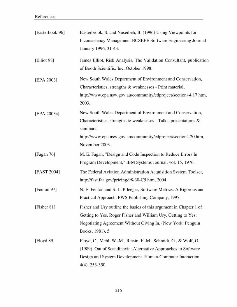
References
215
[Easterbook 96] Easterbrook, S. and Nuseibeh, B. (1996) Using Viewpoints for
Inconsistency Management BCSEEE Software Engineering Journal
January 1996, 31-43.
[Elliot 98] James Elliot, Risk Analysis, The Validation Consultant, publication
of Booth Scientific, Inc, October 1998.
[EPA 2003] New South Wales Department of Environment and Conservation,
Characteristics, strengths & weaknesses - Print material,
http://www.epa.nsw.gov.au/community/edproject/section+4.17.htm,
2003.
[EPA 2003a] New South Wales Department of Environment and Conservation,
Characteristics, strengths & weaknesses - Talks, presentations &
seminars,
http://www.epa.nsw.gov.au/community/edproject/section4.20.htm,
November 2003.
[Fagan 76] M. E. Fagan, "Design and Code Inspection to Reduce Errors In
Program Development," IBM Systems Journal, vol. 15, 1976.
[FAST 2004] The Federal Aviation Administration Acquisition System Toolset,
http://fast.faa.gov/pricing/98-30-C5.htm, 2004.
[Fenton 97] N. E. Fenton and S. L. Pfleeger, Software Metrics: A Rigorous and
Practical Approach, PWS Publishing Company, 1997.
[Fisher 81] Fisher and Ury outline the basics of this argument in Chapter 1 of
Getting to Yes. Roger Fisher and William Ury, Getting to Yes:
Negotiating Agreement Without Giving In. (New York: Penguin
Books, 1981), 5
[Floyd 89] Floyd, C., Mehl, W.-M., Reisin, F.-M., Schmidt, G., & Wolf, G.
(1989). Out of Scandinavia: Alternative Approaches to Software
Design and System Development. Human-Computer Interaction,
4(4), 253-350
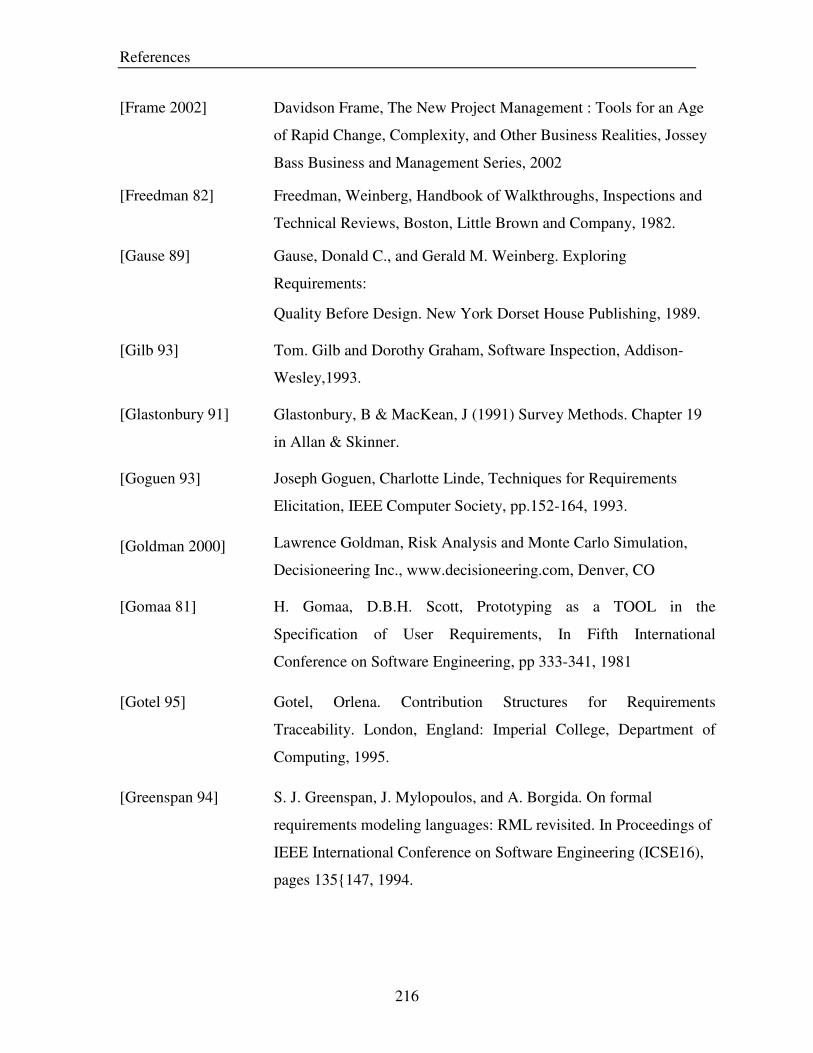
References
216
[Frame 2002] Davidson Frame, The New Project Management : Tools for an Age
of Rapid Change, Complexity, and Other Business Realities, Jossey
Bass Business and Management Series, 2002
[Freedman 82] Freedman, Weinberg, Handbook of Walkthroughs, Inspections and
Technical Reviews, Boston, Little Brown and Company, 1982.
[Gause 89] Gause, Donald C., and Gerald M. Weinberg. Exploring
Requirements:
Quality Before Design. New York Dorset House Publishing, 1989.
[Gilb 93] Tom. Gilb and Dorothy Graham, Software Inspection, Addison-
Wesley,1993.
[Glastonbury 91] Glastonbury, B & MacKean, J (1991) Survey Methods. Chapter 19
in Allan & Skinner.
[Goguen 93] Joseph Goguen, Charlotte Linde, Techniques for Requirements
Elicitation, IEEE Computer Society, pp.152-164, 1993.
[Goldman 2000] Lawrence Goldman, Risk Analysis and Monte Carlo Simulation,
Decisioneering Inc., www.decisioneering.com, Denver, CO
[Gomaa 81] H. Gomaa, D.B.H. Scott, Prototyping as a TOOL in the
Specification of User Requirements, In Fifth International
Conference on Software Engineering, pp 333-341, 1981
[Gotel 95] Gotel, Orlena. Contribution Structures for Requirements
Traceability. London, England: Imperial College, Department of
Computing, 1995.
[Greenspan 94] S. J. Greenspan, J. Mylopoulos, and A. Borgida. On formal
requirements modeling languages: RML revisited. In Proceedings of
IEEE International Conference on Software Engineering (ICSE16),
pages 135{147, 1994.

References
217
[Groner 2002] Markus K. Groner, Capturing Requirements Meeting Customer
Intent:A Structured Methodological Approach, PhD dissertation ,
Virginia Tech, http://scholar.lib.vt.edu/theses/available/etd-5232002-
234024/unrestricted/Markus_K._Groener_Dissertation.pdf, 2002
[Halstead 77] H. Halstead, Elements of software science, Elsevier, New York,
1977.
[Hammond 95] D. P. Hammond, Interest-based Bargaining . American Federation of
State, County and Municipal Employees (AFSCME). Collective
Bargaining Reporter. Available at:
http://www.afscme.org/wrkplace/cbr495_1.htm, 1995.
[Harel 88] D. Harel, STATEMATE: a Working Environment for the
Development of Complex Reactive Systems, In 10th IEEE
Conference on Software Engineering, Washington D.C, IEEE
Computer Society, 1988
[Hart 82] Hart, J. ‘‘The Effectiveness of Design and Code Walkthroughs.’’
Proceedings of COMPSAC ’82.IEEE Computer Society’s Sixth
International Computer Software and Applications Conference.
Silver Spring, MD: IEEE Computer Society Press, Nov.1982, 515-
522.
[Heimdahl 95] M. P. E. Heimdahl and N. Leveson. Completeness and consistency
analysis of state based requirements. In Proceedings of the 17th
International Conference on Software Engineering (ICSE'95), pages
3{14, Seattle, Washington, 1995
[Heitmeyer 96] C. L. Heitmeyer and D. Mandrioli, editors. Formal methods for
Real-Time Computing. Wiley, 1996.
[Heller 2002] Roger Heller, An Introduction to Function Point Analysis,
http://www.qpmg.com/fp-intro.htm, 2002.

References
218
[Herlea 99] Herlea, D.E., Jonker, C.M., Treur, J., and Wijngaards, N.J.E., 1999,
A Formal Knowledge Level Process Model of Requirements
Engineering, In Proceedings of the 12th International Conference on
Industrial and Engineering Applications of AI and Expert Systems,
IEA/AIE'99.
[HExp 2001] Human Expression, Requirement Gathering,
http://www.humanxpression.com, 2001.
[Hofmann 2001] Hofmann, Hubert F., and Franz Lehner. "Requirements Engineering
as a Success Factor in Software Projects." IEEE Software July/Aug.
2001: 58-66
[Holt 97] J. Holt, Current Proactice in Software Engineering: A Survey,
Computing and Control Engineering, pp 167-172, 1997.
[Holtzblatt 93] K. Holtzblatt, H. Beyer, Making cCustomer-Centered Design Work
for Teams, Communications of the ACM 10: 93-103, 1993
[Horrian 2003] Hossein Horrian, Shafquat Mahmud, Srinivasan Karthikeyan,
Requirements Engineering in Agile methods, Dept. of Computer
Science, University of Calgary, Canada, 2003.
[Howard 88] R.A. Howard, Decision Analysis: Practice and Promise,
Management Science 34:6: 679- 695, 1988.
[Hulett 95] Hulett, David T. (1995). “Project schedule risk assessment”, Project
Management Quarterly, 26 (1), March, 21-31.
[Hursh 95] Walter Hursh and Christina Lopes, “Separation of Concerns”
(Technical Report), College of Computer Science, Northeaster
University, 1995.
[ICSE 2001] Workshop on Advanced Separation of Concerns in Software
Engineering at ICSE 2001 (W17) ,
http://www.research.ibm.com/hyperspace/workshops/icse2001, 2001

References
219
[IEEE 84] IEEE, IEEE Guide for Software Requirements Specification, Std
830-1984, New York, IEEE Computer Society Press, 1984.
[IEEE 90] IEEE Standard 610.12-90. IEEE Standard Glossary of Software
Engineering Terminology, IEEE, New York, NY, 1990.
[IEEE 93] IEEE Recommended Practice for Software Requirements
Specifications, IEEE Computer Society, 1993.
[IEEE 98] [IEEE 98] “IEEE Guide for Developing System Requirements
Specifications” IEEE Computer Scociety
[IEEE 98a] IEEE, IEEE Recommended Practice for Software Requirements S
pecification, IEEE Std 830-1998, IEEE Computer Society, 1998
[IEEE 99] IEEE, IEEE Standards Software Engineering Collection. New York,
NY: IEEE, 1999.
[IPL 96] IPL Information Processing Ltd., Designing unit test cases, 1996.
[Jacobson 92] I. Jacobson, Object-Oriented Software Engineering, Addison-
Wesley / ACM Press, 1992
[Jacobson 99] Rumbaugh, James, Ivar Jacobson, and Grady Booch. 1999. The
Unified Modeling Language Reference Manual. Reading, MA:
Addison-Wesley.
[Jaafari 84] Jaafari, Ali. (1984). “Criticism of CPM for Project Planning
Analysis”, Journal of Construction Engineering and Management,
110 (2), June, 222-233.
[Jalote 99] Pankaj Jalote, An Integrated Approach to Software Engineering,
Narosa Publications, 1999.
[Jirotka 94] M. Jirotka and J. A. Goguen. Introduction. In M. Jirotka and J. A.
Goguen, editors, Requirements Engineering Social and Technical
Issues, pages 1-13. Academic Press, Great Britain, 1994.

References
220
[Jones 97] C. Jones, Applied Software Measurement, Assuring Productivity and
Quality, McGraw-Hill, 1997.
[Karlssson 96] J. Karlsson, P. Carlshamre, A Usability Oriented Approach to
Requirements Engineering, Proceedings of ICRE 96, IEEE
Computer Society Press, pp. 145-152, 1996.
[Kean 97] Liz Kean, Requirements Tracing – An Overview, Carnegie Mellon
SEI, http://www.sei.cmu.edu/str/descriptions/reqtracing_body.html,
Jan 1997
[Kingston 96] John Kingston and Terri Lydiard, Multi-Perspective Models of the
Air Campaign Planning process, AIAI, University of Edinburgh,
1996
[Kirwan 92] Kirwan and Ainsworth (Eds), A Guide to Task Analysis, Taylor and
Francis, London, 1992.
[Kotonya 98] Kononya G. & Sommerville I., (1998). Requirements Engineering –
Processes and Techniques. John Wiley & Sons. Chichester. 282pp.
[Krasner 85] H. Krasner. Requirements dynamics in large software projects, a
perspective on new directions in the software engineering process. In
Proceedings of IFIP, pages 211{216, New York, 1985. Elsevier}
[Kunz 70] Werner Kunz and Horst W. J. Rittel, Issues as Elements of
Information systems, Working papre 131, University of California,
Berkeley, July 1970
[Lauesen 2002] Lauesen S., 2002, Software Requirements: Styles and Techniques,
Addison Wesley Publishing Co.
[Lax 91] David A. Lax and James K. Sebenius, "Interests: The Measure of
Negotiation." In Negotiation Theory and Practice, eds. J. William
Breslin and Jeffrey Z. Rubin, (Cambridge: The Program on
Negotiation at Harvard Law School, 1991), 165.

References
221
[Leffingwell 2000] Leffingwell D, D. Widrig, 2000, Managing Software Requirements:
A Unified Approach, Addison Wesley Publishing Co. , 2000.
[Leif 95] Leif Bennett, Round-Robin Review Training Plan,
http://alumnus.caltech.edu/~leif/OO/ReviewTraining.html, 1995.
[Lenart 98] Lenart, M. and Ana Pasztor (1998). “A Participatory Design
Requirement Engineering System,”
www.cs.fiu.edu/~pasztora/design/padre/aid98.ps
[Lerch 95] F. J. Lerch, D. J. Ballou, and D. E. Harter. Using simulation-based
experiments for software requirements engineering. Annals of
Software Engineering, special issue on Software Requirements
Engineering, 3:345{366, 1997.
[Letelier 2003] Patricio Letelier, Requirements Traceability, Universidad Politécnica
de Valencia, www.dsic.upv.es/~letelier/pub, 2003.
[Leung 2002] Leung, H. and Z. Fan (2002). Software Cost Estimation. Handbook
of Software Engineering and Knowledge Engineering. S. K. Chang.
2002
[Lewis 2003] R. Lewis, E. Thomas, Brainstorming,
http://www.dos.uci.edu/publications/guides/b3.html, 2003.
[Liete 91] J. C. S. P. Leite and P. A. Freeman. Requirements validation through
viewpoints resolution. IEEE Transactions on Software Engineering,
17(12):1253{1269, 1991.
[Lindgaard 94] Lindgaard, G., Usability Testing and System Evaluation: A Guide
for Designing Useful Computer Systems, 1994, Chapman and Hall,
London, U.K. ISBN 0-412-46100-5
[Loucopoulos 92] P. Loucopoulos. Conceptual Modelling, Databases and CASE: An
Integrated View of Information System Development. Wiley, 1992.
References
222
[Luqi 93] Luqi. How to use prototyping for requirements engineering. In
Proceedings of the IEEE International Symposium on Requirements
Engineering (RE93), page 229, 1993.
[MAHR 2003] Minnesota Advocates for Human Rights, Tips on Guided
Discussion,
http://www.stopvaw.org/Tips_on_Guided_Discussion.html,2003.
[Maiden 96] N.A.M. Maiden & G. Rugg, ACRE: selecting methods for
requirements acquisition, Software Engineering Journal, 1996.
[Matsumoto 77] Y. Matsumoto, A Method For Software Requirements Definitions in
Process Control, In IEEE COMPSCA 1977, Washington D.C, IEEE
Computer Society, pp. 128-132, 1977
[McDermid 93] McDermid, P. Rook, Software Development Process Models, In
Software Engineer’s Reference Book, CRC , 1993, PP 15/26 – 28.
[McGuire 2002] Ruth McGuire, Decision Making, Pharmaceutical Journal, Vol. 269,
November 2002.
[McMenamin 84] McMenamin, J. Palmer, Essential System Analysis, Englewood
Cliffs, N.J. Prentice Hall, 1984
[Melo 2001] Walcelio Melo, Forrest Shull, Guilherme Travossos, Software
Review Guidelines, Technical Report ES- 556/01, August 2001.
[Merlo 2002] Nancy Merlo, Schett, 2002, COCOMO (Constructive Cost Model),
Seminar on Software Cost Estimation WS 2002 / 2003, 2002.
[MIL 77] Military Standard, Procedures for Performing a Failure Mode,
Effects and Criticality Analysis, MIL-STD-1629A, 12 June 1977.
[MIL 80] Military Standard, Procedures for Performing a Failure Mode,
Effects and Criticality Analysis, MIL-STD-1629A, Novemebr 1980.
[Mindtools 95] Mindtools, PMI- Weighing the Pros and Cons of a Decision,
http://www.mindtools.com/pages/article/newTED_05.htm, 1995.

References
223
[Morgan 88] David L. Morgan, Focus Groups as Qualitative Research, Sage,
1988.
[Moser 71] Claus Moser and Graham Kalton_ Survey Methods in Social
Investigation, Gower, 1971.
[Moores 96] Moores TT and Champion REM. ‘A Methodology for Measuring the
Risk Associated with a Software Requirements Specification’,
Australian Journal of Information Systems (1996).
[NCCL 96] The National Computing Center Limited, Internal Quality Audits:
What They Are and How To Carry Them Out?, 31 July, 1996.
[NetMBA 2002] NetMBA, PERT, www.netmba.com/operations/project/pert/, 2002.
[Ngatagize 86] P.K Ngatagize, J.B. Kaneene, S.B. Harsh, Decision Analysis in
Animal Health Programs: Merits and Limitations, Preventive
Veterinary medicine 4: 187 – 197, 1986.
[Nord 2003] R. L. Nord, D. Soni, Experience with Global Analysis: A Practical
Method for Analyzing Factors that Influence Software Architectures,
STRAW'03 : Second International SofTware Requirements to
Architectures Workshop located at ICSE'03, 1, Portland, OR, USA,
pp. 34-40, 2003
[NYS 2003] NYS Governor's Office of Employee Relations, 2003
http://www.goer.state.ny.us/Train/onlinelearning/FTMS/300s8.html,
[NYS 2003a] NYS Governor's Office of Employee Relations, I-Time Tools and
Techniques,
http://www.goer.state.ny.us/train/onlinelearning/FTMS/300s3.html,
2003.
[NYS 2003b] NYS Governor's Office of Employee Relations, Go-Around Tools
and Techniques,
www.goer.state.ny.us/Train/onlinelearning/FTMS/300s4.html,

References
224
[Oishi 95] Oishi, Frey, James H., Sabine Mertens. (1995). How To Conduct
Interviews By Telephone and In Person. Sage Publications:
Thousand Oaks.
[OMB 2000] White House Office of Management and Budget (OMB), Circular
Number A-94, Guidelines and Discount Rates for Benefit-Cost
Analysis of Federal Programs, 29 October 1992,
http://www.whitehouse.gov/OMB/circulars/a094/a094.html (30
October 2000)
[OOPSLA 99] First Workshop on Multi-Dimensional Separation of Concerns in
Object-oriented Systems, http://www.cs.ubc.ca/%7Emurphy/multid-
workshop-oopsla99.
[Osborn 53] Osborn, A. F. Applied Imagination. New York: Charles Scribner’s
Sons, 1953.
[PAHO 2003] Pan American Health Organization, Convincing Through Effective
Digital Presentations, http://intranet.paho.org/DPI/pptguide2.pdf, 03.
[Palmer 96] J. D. Palmer. Traceability. In M. Dorfman and R. H. Thayer, editors,
Software Engineering, pages 266{276. IEEE Computer Society
Press, 1996.
[Palmer 2000] Michael Palmer, "Problem-Solving Negotiation: What's In It for You
and Your Clients." In 26 Oct. Vermont B. Journal 1, 2000
[Patton 90] Patton, M.Q. (1990). Qualitative Evaluation and Research Methods,
2nd Ed. Newbury Park, CA: Sage.
[Pfeiffer 97] Dirk Pfeiffer, Decision Analysis and Risk Analysis, From R.
Ruppanner, Risk Analysis and Animal Health – A Course Manual,
Dubendorf, Switzerland, pp. 867- 877, 1997.
[Pohl 96] K. Pohl. Process-centred requirements engineering. Wiley, 1996.
[Potts 94] C. Potts, K. Takahashi, and A. I. Anton. Inquiry-based requirements
analysis. IEEE Software, 11(2):21-32, 1994.

References
225
[Pressman 2001] R. S. Pressman, Software Engineering: A Practitioner’s Approach,
5th ed. New York, NY: McGraw-Hill, 2001.
[Putnam 78] Putman(1978) : A general empirical solution to the macro software
sizing and estimating problem. IEEE Trans. On Softw. Eng.,
Volume 4, No 4, pp 345-61, April 1978.
[Raafat 89] H.M.N. Raafat, Risk Assessment and Machinery Safety, Journal of
Occupational Accidents, pp. 37-50, 1989.
[Rauterberg 2003] M. Rauterberg, Task Analysis, 2003,
http://www.ipo.tue.nl/homepages/mrauterb/lecturenotes/UFTtask-
analysis.pdf,
[Richards 2000] Debbie Richards, A Process Model for Requirements Elicitation, In
Proceeding of the 11th Australasian Conference on Information
Systems, December 6-8, Brisbane.
[Robertson 99] S. Robertson and J. Robertson. Mastering the Requirements Process.
Addison-Wesley, 1999.
[Rockstrom 82] Rockstrom, R. Saracco, SDL-CCITT Specification and Description
Language, IEEE Transactions on Communications 30, 1982
[Rosson 2002] Mary Beth Rosson, John M, Carrol, Usability Engineering –
Scenario Based Development of Human-Computer Interaction,
Morgan Kaufman Publishers, 2002.
[Royce 70] W. W. Royce, "Managing the Development of Large Software
Systems: Concepts and Techniques," presented at WESCON, 1970.
[Royce 98] W. Royce, Software project management: a unified framework,
Addison Wesley, 1998

References
226
[Rzepka 89]
Rzepka, William E. A Requirements Engineering Testbed: Concept,
Status and First Results. In Bruce D. Shriver (editor), Proceedings
of the Twenty-Second Annual Hawaii International Conference on
System Sciences, 339-347. IEEE Computer Society, 1989.
[Saaty 80] T.L. Saaty, The Analytic Hierarchy Process, McGraw-Hill, Inc.
(1980).
[Sawyer 97] I. Sommerville and P. Sawyer. Viewpoints: principles, problems and
a practical approach to requirements engineering. Annals of
Software Engineering, special issue on software requirements
engineering, 3:101{130, 1997.
[Schach 96] S. R. Schach. Classical and Object-Oriented Software Engineering.
McGraw-Hill, third edition, 1996
[Sebenius 86] J. K. Sebenius, Lax, D. A., The Manager as Negotiator, (New York:
Free Press, 1986.
[SEI 96] SEI Software Risk Taxonomy, Technical Report CMU/SEI-96-TR-
012, June 1996.
[Siddiqi 97] J. Siddiqi, I. C. Morrey, C. R. Roast, and M. B. Ozcan. Towards
quality requirements via animated formal speci_cations. Annals of
Software Engineering, special issue on Software Requirements
Engineering, 3:131{155, 1997.
[Sidky 2003] Ahmed Sidky, RGML: A Specification Language that Supports the
Characterization of Requirements Generation Processes, Master
thesis, Virginia Tech, 2003,
http://scholar.lib.vt.edu/theses/available/etd-07292003-112122/
[Softstar 2003] Softstar Systems, Overview of COCOMO,
http://www.softstarsystems.com/overview.htm, December 2003.
References
227
[Sommerville 97] Sommerville, Ian, and, Pete Sawyer, 1997, Requirements
Engineering: A Good Practice Guide. Chichester, England: John
Wiley & Sons.
[Sommerville 97a] I. Sommerville and P. Sawyer. Viewpoints: principles, problems and
a practical approach to requirements engineering. Annals of
Software Engineering, special issue on software requirements
engineering, 3:101-130, 1997.
[Sommerville 2001] Sommerville, Ian. Software Engineering. 6th ed. Harlow, England:
Addison-Wesley, 2001
[Song 2002] Chen Song, Problem Analysis and Needs Generation Process,
Technical report, Virginia Tech, 2002
[Spangler 2003] Brad Spangler, Positional Bargaining,
http://www.beyondintractability.org/m/positional_bargaining.jsp,
2003.
[SPS 94] Analysis of Automated Requirements Management Capabilities.
Melbourne, FL: Software Productivity Solutions, 1994.
[Stamatis 97] Stamatis, D.H. TQM Engineering Handbook. New York: Marcel
Decker, Inc. , 1997
[Standish 95] The CHAOS report, Standish Group, 1995,
http://www.standishgroup.com/sample_research/chaos_1994_1.php.
[Stocks 99] J. Tim Stocks, Document Studies,
http://www.msu.edu/course/sw/832/units/06qua/1doc04.htm, 1999.
[St-Pierre 97] D. St-Pierre, M Maya, A. Abran, J. Desharnais and P. Bourque, Full
Function Points: Counting Practice Manual, Technical Report 1997-
04, University of Quebec at Montreal, 1997.
[Strauss 78] Strauss, A. (1978) Negotiation: Varieties, Contexts, Processes and
Social Order Jossey-Bass Publishers, San Francisco, CA.

References
228
[STSC 98] Software Technology Support Center. Requirements Management
Tools [online]. http://www.stsc.hill.af.mil/RED/LIST.HTML (1998).
[Sud 2003] Rajat Sud, A Synergistic Approach to Software Requirements
Generation: The Synergistic Requirements Generation Model
(SRGM), and An Interactive Tool for Modeling SRGM (itSRGM),
Master’s Thesis, Virginia Tech, 2003
http://scholar.lib.vt.edu/theses/available/etd-05182003-111744/
[Susan 94] Susan H. Strauss and Robert G. Ebenau, Software Inspection
Process, McGraw Hill, 1994.
[Sutcliffe 2002] Alistair Sutcliffe, User-Centered Requirements Engineering- Theory
and Practice, Springer-Verlag London Limited, 2002.
[Sutcliffe 2003] Alistair Sutcliffe, Scenario Based Requirements Engineering, RE
2003 Mini Tutorial, University of Manchester Institute of Science &
Technology (UMIST), Manchester, UK
[Teichroew 1982] Teichroew, D., Hersey III, E.A., “PSL/PSA: a computer-aided
technique for structured documentation and analysis of information
processing systems”, in Advanced System Development/ Feasibility
Techniques, Wiley, New York, pp 315-329 (1982).
[Templeton 94] Templeton, Jane F., The Focus Group : A Strategic Guide to
Organizing, Conducting and Analyzing the Focus Group Interview,
1994, Probus Pub Co; ISBN: 1557385300
[Thayer 76] Bell T. E. , T. A. Thayer, 1976, Software requirements: Are they
really a problem?, Proceedings of the 2nd international conference
on Software engineering, p.61-68, October 13-15, 1976, San
Francisco, California, United States.
[Thayer 97] Richard Thayer, Merlin Dorfman, Software Requirements
Engineering, Second edition, IEEE Computer Society, 1997

References
229
[Thomas 76] Thomas, K. (1976) Conflict and Conflict Management In Duneette
(ed) Handbook of Industrial and Organizational Psychology Rand
McNally College Publishing Co.
[TWCC 2002] Texas Workers’ Compensation Commission, Fault Tree Analysis,
http://www.twcc.state.tx.us/information/videoresources/stp_fault_tre
e.pdf, 2002
[USAID 2002] USaid, Primer and Checklist for Conducting Cost and Price Analysis
for Interagency Agreements,
http://www.usaid.gov/policy/ads/300/306maa.pdf, October 2002.
[UTK 2003] University of Tennessee, Tips on preparing and giving oral
presentations, 2003,
http://eeb.bio.utk.edu/weltzin/GenEcol03/presentation_tips.htm.
[USMC 98] United States Marine Corps, Discussion Leading Techniques,
http://www.mcu.usmc.mil/mcu/reading/core/Chap01.PDF, 1998.
[Weibull 92] Reliasoft Corporation, FMEA and FMECA,
http://www.weibull.com/basics/fmea.htm, 1992.
[Weidenhaupt 98] K. Weidenhaupt, K. Pohl, M. Jarke, and P. Haumer. Scenarios in
system development: Current practice. IEEE Software, 15(2), 1998.
[Weigers 99] Karl Weigers, First Things First: Prioritizing Requirements,
Software Development, September 1999
[Weigers 2001] Weigers K.E., 2001, Software Requirements, Microsoft Press, 2001.
[Weissberg 86] Weissberg, H.F., Krosnick , J.A., & Bowen, B.D. (1989). An
introduction to survey research and data analysis. Glenview, IL.
[Whitis 81] V.S. Whitis, W.N. Chiang, A State Machine Development for Call
Processing Software, In IEEE Electro 1981 Conference,
Washington D.C, IEEE Computer Society, 1981.

References
230
[Wickwire 89] Wickwire, Jon M., Warner, Tony, and Berry, Mark R. (1999).
“Chapter 17—Construction Scheduling”, Construction Law
Handbook edited by Cushman, Robert F. and Myers, James J.,
Aspen Law & Business, Gaithersburg, NY.
[Williams 98] What Do You Mean You Can’t Tell Me If My Project Is in
Trouble?, First European Conference on Software Metrics (FESMA
98), Antwerp, Belgium, 1998
[Williamson 2001] Duncan Williamson, Capital Budgeting: The Key Numerical
techniques, http://www.duncanwil.co.uk/invapp.html, October 2001.
[Wixon 94] Wixon, Dennis, et. al., "Inspections and Design Reviews:
Framework, History, and Reflection," in Nielsen, Jakob, and Mack,
R. eds, Usability Inspection Methods, John Wiley and Sons, New
York, NY. ISBN 0-471-01877-5 , 1994.
[Wohlin 97] Claes Wohlin, Joachim Karlsson, Bjorn Regnell, An evaluation of
methods for prioritizing software requirements ,Information and
Software Technology, pp 939-947, 1997.
[Yeh et. al. 84] R. T. Yeh, P. Zave, A. P. Conn, and G. E. Cole. Software
requirements: New directions and perspectives. In C. R. Vick and C.
V. Ramamoorthy, editors, Handbook of Software Engineering, pages
519{543. Van Nostrand Reinhold, New York, 1984.
[Young 2001] Young, Ralph R. Effective Requirements Practices. Boston:
Addison- Wesley, 2001.
[Young 2002] Ralph R. Young, Recommended Requirement Gathering Practices,
Cross Talk – The Journal of Defense Software Engineering, 2002.
[Yourdon 99] Davis, A. E. Yourdon, Ann S. Zweig, Requirements Management
Made Easy, Omni-Vista White Paper #99-002,

References
231
[Zahniser 90] Zahniser R.A., 1990, Building Software in Groups, American
Programmer, vol. 3, nos. 7-8, July-August, 1990.
[Zave 81] Pamela Zave, R.T. Yeh, Executable Requirements for Embedded
Systems, in Fifth International Conference on Software Engineering,
pp. 295-304, 1981
[Zowghi 99] Didar Zowghi, A Logic Based Framwork for the Management of
Changing Software Requirements, PhD dissertation, Macquarie
University, June 1999.

Appendix A: Organization Templates for Requirements
232
Appendix A: Organization Templates for Requirements
A.1 Template for requirements list organized by mode
• Specific requirements
o External interface requirements
� User interfaces
� Hardware interfaces
� Software interfaces
� Communication interfaces
• Functional requirements
o Mode 1
� Functional requirement 1
� .
� .
� Functional requirement n
o Mode m
� Functional requirement 1
� .
� .
� Functional requirement n
• Performance requirements
• Design constraints
• Software system attributes
• Other requirements

Appendix A: Organization Templates for Requirements
233
A.2 Template for requirements list organized by user class
• Specific requirements
o External interface requirements
� User interfaces
� Hardware interfaces
� Software interfaces
� Communication interfaces
• Functional requirements
o User class 1
� Functional requirement 1
� .
� .
� Functional requirement n
o User class m
� Functional requirement 1
� .
� .
� Functional requirement n
• Performance requirements
• Design constraints
• Software system attributes
• Other requirements

Appendix A: Organization Templates for Requirements
234
A.3 Template for requirements list organized by stimulus
• Specific requirements
o External interface requirements
� User interfaces
� Hardware interfaces
� Software interfaces
� Communication interfaces
• Functional requirements
o Stimulus 1
� Functional requirement 1
� .
� .
� Functional requirement n
o Stimulus m
� Functional requirement 1
� .
� .
� Functional requirement n
• Performance requirements
• Design constraints
• Software system attributes
• Other requirements

Appendix A: Organization Templates for Requirements
235
A.4 Template for requirements list organized by response
• Specific requirements
o External interface requirements
� User interfaces
� Hardware interfaces
� Software interfaces
� Communication interfaces
• Functional requirements
o Response 1
� Functional requirement 1
� .
� .
� Functional requirement n
o Response m
� Functional requirement 1
� .
� .
� Functional requirement n
• Performance requirements
• Design constraints
• Software system attributes
• Other requirements

Appendix A: Organization Templates for Requirements
236
A.5 Template for requirements list organized by functional hierarchy
• Specific requirements
o External interface requirements
� User interfaces
� Hardware interfaces
� Software interfaces
� Communication interfaces
• Functional requirements
o Functionality 1
� Functional requirement 1
� .
� .
� Functional requirement n
o Functionality m
� Functional requirement 1
� .
� .
� Functional requirement n
• Performance requirements
• Design constraints
• Software system attributes
• Other requirements
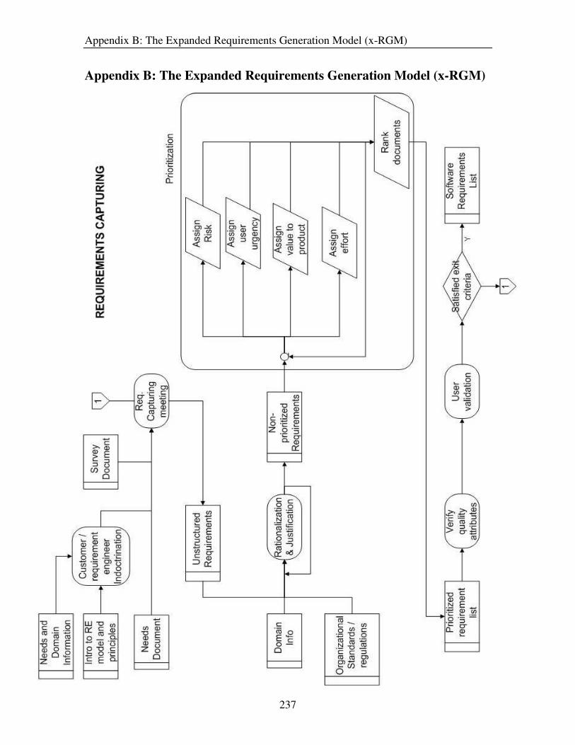
Appendix B: The Expanded Requirements Generation Model (x-RGM)
237
Appendix B: The Expanded Requirements Generation Model (x-RGM)

Appendix B: The Expanded Requirements Generation Model (x-RGM)
238

Appendix B: The Expanded Requirements Generation Model (x-RGM)
239
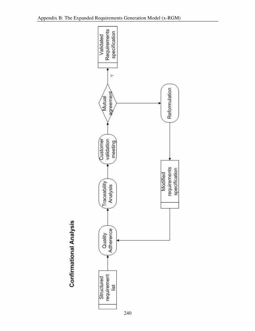
Appendix B: The Expanded Requirements Generation Model (x-RGM)
240

Appendix C: Description of Activities in x-RGM
241
Appendix C: Description of Activities in x-RGM�
Activity Name Customer / requirements engineer indoctrination
Objective Familiarizing the user to the RE process Educating the requirements engineer about the customer’s domain Emphasis on the importance of the role of the participant
Action Points • A brief introduction about RE, the importance of requirements, and what represent a requirement
• An overview of the Requirements Generation Model
• The importance of the role of participants in the RE process
• The preparation involved when participants are requested to attend elicitation meetings
• Introduction to the problem, user needs and problem domain
Pre-condition Needs generation phase is completed
Doer Requirements Engineer
Participants Customer (other stakeholders are optional)
Resource/Input docs
Requirements engineering model and process principles, needs and domain information
Effect/Output docs
None
Activity Name Requirements elicitation meeting
Objective Identify and capture requirements from stakeholders
Action Points • Identify primary stakeholders
• Capture stakeholders requirements
• Record the meeting proceedings
• Identify system constraints
Pre-condition Needs generation phase is completed
Doer Requirements Engineer
Participant Customer, user, developer
Input docs Document, Market Survey document
Effect/Output docs
Unstructured list of requirements

Appendix C: Description of Activities in x-RGM
242
Activity Name Rationalization & Justification
Objective Find rationale, justify, refine and decompose requirements
Action Points • Identify classification of requirements
• addressing the question “why” underlying the requirements
• Identify requirements which are high level or unspecific
• Justify the requirements
• Refine and decompose the high level requirements
Pre-condition Elicitation activity completed
Doer Requirements Engineer
Participant User, customer, developer
Resource/Input docs
Unstructured requirements, Domain Info, Organizational standards and regulations
Effect/Output docs
Non-prioritized requirement list
Activity Name Prioritization
Objective Rank requirements based on requirement attributes
Action Points • Identify requirement attributes (risk factors, value to product, user urgency …..)
• Estimate attribute values
• Rank requirements based on stakeholder priorities.
Pre-condition Rationalization and justification completed
Doer Requirements Engineer
Participant User, customer, developer
Resource/Input docs
Non-prioritized requirement list
Effect/Output docs
Prioritized requirement list

Appendix C: Description of Activities in x-RGM
243
Activity Name Verifying quality attributes
Objective Check quality attributes of local set of requirements
Action Points • Determine quality attributes to be examined
• Arrange for QA experts
• Verify and establish the adherence of quality attributes
Pre-condition Prioritization completed
Doer QA experts
Participants Requirements engineer
Resource/Input docs
Prioritized requirement list
Effect/Output docs
Quality assessed requirements list
Activity Name Stakeholder validation
Objective Check if the individual requirements reflect the right product
Action Points • Determine whether requirements capture stakeholders needs and intent
• Record proceedings
Pre-condition Verifying quality attributes completed and quality control satisfactory
Doer Requirements Engineer
Participants Customer, user, developer
Resource/Input docs
Quality assessed requirements list
Effect/Output docs
Software requirements list

Appendix C: Description of Activities in x-RGM
244
Activity Name Risk analysis
Objective Determine the risk for requirements from the global perspective
Action Points • Arrange for risk analysts
• Assess risks for requirements from global outlook
• Determine requirements which are controversial (high risk)
Pre-condition Requirements capturing phase completed
Doer Risk analyst
Participants Requirements engineer (optional)
Resource/Input docs
Software requirements list, Organizational factors, Technological factors
Effect/Output docs
Risk assessment document
Activity Name Cost and schedule estimation
Objective Determine cost and time estimate for requirements
Action Points • Perform cost analysis on individual functionality/components
• Estimate time schedule for individual functionality /components
• Determine if total cost and schedule meet customer’s needs
Pre-condition Requirements capturing phase completed
Doer Requirements Engineer
Participant Developers
Resource/Input docs
Software requirements list, Organizational factors, Technological factors
Effect/Output docs
Cost and schedule document

Appendix C: Description of Activities in x-RGM
245
Activity Name Price analysis
Objective Examining and evaluating proposed price and demand (balance of functionality and desirability)
Action Points • Assess market demand
• Compare prices of similar products
• Determine if price is reasonable
Pre-condition Requirements capturing phase completed
Doer Price analyst
Participants Requirements Engineer, developer
Resource/Input docs
Software requirements list, Organizational factors, Technological factors, cost and schedule document (optional), market demand info.
Effect/Output docs
price analysis document
Activity Name Feasibility analysis
Objective Determine if product is feasible (Business/technology/cost)
Action Points • Assess market demand
• Determine if the product is profitable enough
• Determine if risks are accounted for
• Decide whether to continue with the software cycle
Pre-condition Requirements capturing phase completed
Doer Requirements Engineer
Participants Developer, Manager
Resource/Input docs
Software requirements list, Organizational factors, Technological factors, market demand info., risk assessment document, price analysis document, cost and schedule document,
Effect/Output docs
feasibility analysis document (go/no-go decision), conflicting requirements list

Appendix C: Description of Activities in x-RGM
246
Activity Name Conflict resolution
Objective Negotiate requirement conflicts
Action Points • Identify stakeholder win conditions
• Identify issues
• Identify options
• Finalize agreements
Pre-condition Feasibility analysis completed
Doer Requirements Engineer
Participants customer, developer, user, manager
Resource/Input docs
Conflicting requirements l ist
Effect/Output docs
Conflict free requirements document/updated requirements list
Activity Name Organization and Compilation
Objective Structure requirements for better comprehension
Action Points • Identify organization mode of requirements
• Grouping of requirements according to the identified categorization
• Document the requirements
Pre-condition Analysis Phase completed
Doer Requirements Engineer
Participants -
Resource/Input docs
Conflict free requirements document
Effect/Output docs
Structured requirements list

Appendix C: Description of Activities in x-RGM
247
Activity Name Quality adherence
Objective Quality control for requirements from global perspective
Action Points • Verify that quality control performed in local analysis phase
• Determine quality attributes to be tested
• Verify quality adherence of requirements
Pre-condition Specification phase complete
Doer QA experts
Participants Requirements Engineer
Resource/Input docs
Structured requirements list
Effect/Output docs
Quality assessed requirements specification
Activity Name Traceability analysis
Objective Linking requirements and verifying the matrix
Action Points • Map the requirements to needs
• Determine the dependency of requirements (resulting in a traceable diagram)
• Verify the Traceability diagram
Pre-condition Quality adherence activity completed
Doer Requirements Engineer
Participants -
Resource/Input docs
Software requirements list
Effect/Output docs
Traceability document/matrix, conflict free requirements list

Appendix C: Description of Activities in x-RGM
248
Activity Name Customer validation meeting
Objective Check if the requirements list captures customers needs right
Action Points • Determine whether requirements capture customer intent
• Determine requirements to be changed, if necessary
Pre-condition Specification phase complete
Doer RE engineer
Participants Customer
Resource/Input docs
Quality assessed requirements specification
Effect/Output docs
validated requirements specification / list of modifications to requirements
Activity Name Reformulation
Objective Overcoming customer disagreement with requirements
Action Points • Identify options
• Finalize reformulation of requirements
Pre-condition user validation complete and customer specifies certain modifications to the requirements
Doer RE engineer
Participants Customer, QA experts
Resource/Input docs
Customer disagreement with requirements specification
Effect/Output docs
modified requirements specification

Appendix D: Methods for Activities in the x-RGM
249
Appendix D: Methods for Activities in the x-RGM

Appendix D: Methods for Activities in the x-RGM
250

Appendix D: Methods for Activities in the x-RGM
251

Appendix D: Methods for Activities in the x-RGM
252

Appendix D: Methods for Activities in the x-RGM
253

Appendix D: Methods for Activities in the x-RGM
254

Appendix D: Methods for Activities in the x-RGM
255

Appendix D: Methods for Activities in the x-RGM
256
Copyright © 2022 FDOKUMEN