Analog-to-Digital with Two IC's - Segal and Associates
124
WORLD'S LARGEST- SELLING ELECTRONICS MAGAZINE SEPTEMBER 1978/$1 Analog-to-Digital with Two IC's Converting Schematics to PC Patterns NEW! ,METAL. NEW! 'Hi- A visi.iu NEW! PLUS! 'MME DISCO PREAMP/ MIXEI bi -fet pre -amp 14024 14278 Populo Ele,rronlcs IotiLE hi 60 [ discoemixer] "Class D" Switching Amplifier AL)30 QT Sbbtzi96 )0 916uó9 r0 Voice "Series II" Speaker Systems I I Panasonic 5 -Band Portable Receiver www.americanradiohistory.com
-
Upload
khangminh22 -
Category
Documents
-
view
4 -
download
0
Transcript of Analog-to-Digital with Two IC's - Segal and Associates
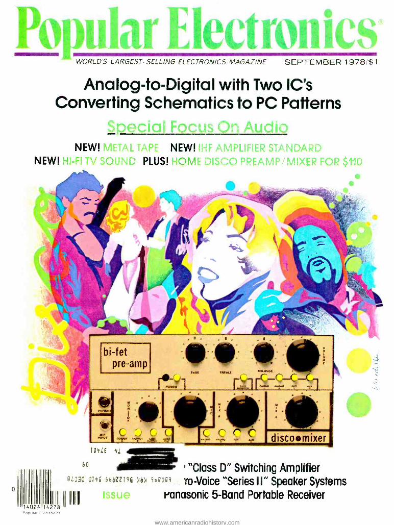
WORLD'S LARGEST- SELLING ELECTRONICS MAGAZINE SEPTEMBER 1978/$1
Analog-to-Digital with Two IC's Converting Schematics to PC Patterns
NEW! ,METAL. NEW! 'Hi- A visi.iu NEW! PLUS! 'MME DISCO PREAMP/ MIXEI
bi -fet pre -amp
14024 14278 Populo Ele,rronlcs
IotiLE hi
60
[ discoemixer]
"Class D" Switching Amplifier AL)30 QT Sbbtzi96 )0 916uó9 r0 Voice "Series II" Speaker Systems I I Panasonic 5 -Band Portable Receiver
www.americanradiohistory.com

FOR THOSE OF YOU WHO ARE HAVING SECOND THOUGHTS ABOUT YOUR FIRST CB.
Move up to the all -new Cobra 29GTL. It's the third generation of the trucker -proven Cobra 29. And like the 29 and the 29XLR before it, it advances the state of the art.
Transmitter circuitry has been refined and updated to improve performance.
Receiver circuits have been redesigned to include dual FET mixers, a monolithic crystal filter and a ceramic filter to reduce inter- ference and improve reception.
By improving the transmitter circuitry the 29GTL keeps you punching through loud and clear. By incorporating new features for better reception everything you copy comes back loud and clear.
So if you're having second thoughts about your first CB, make your next CB the Cobra 29GTL.
We back it with a guaranteed warranty and a nationwide network of Authorized Service Centers where factory -trained technicians are available to help you with installation, service and advice.
But more important than that, we sell it at a price you won't have second thoughts about.
ôbra Punches through loud and clear.
Cobra Communications Products DYNASCAN CORPORATION
6460 W Cortland St., Chicago, Illinois 60635 Write for color brochure
EXPORTERS: Empire Plainview, N Y CANADA: Atlas Electronics Ontario
CIRCLE NO. t ON FREE INFORMATION CARO
www.americanradiohistory.com

Burglar Alarm Breakthrough A new computerized burglar alarm requires no installation and protects your home or business like a thousand dollar professional system.
Its a security system computer. You can now protect everything- windows, doors, walls, ceilings and floors with a near fail -safe system so advanced that it doesn't require installation.
The Midex 55 is a new motion -sensing com- puter. Switch it on and you place a harmless invisible energy beam through more than 5,000 cubic feet in your home. Whenever this beam detects motion, it sends a signal to the computer which interprets the cause of the motion and triggers an extremely loud alarm.
The system's alarm is so loud that it can cause pain -loud enough to drive an intruder out of your home before anything is stolen or destroyed and loud enough to alert neighbors to call the police.
The powerful optional blast horns can also be placed outside your home or office to warn your neighbors.
Unlike the complex and expensive corn - mercial alarms that require sensors wired into every door or window, the Midex requires no sensors nor any other additional equipment other than your stereo speakers or an optional pair of blast horns. Its beam actually pene- trates walls to set up an electronic barrier against intrusion.
NO MORE FALSE ALARMS The Midex is not triggered by noise, sound,
temperature or humidity -just motion -and since a computer interprets the nature of the motion, the chances of a false alarm are very remote.
An experienced burglar can disarm an ex- pensive security system or break into a home or office through a wall. Using a Midex system there is no way a burglar can penetrate the protection beam without triggering the loud alarm. Even if the burglar cuts off your power, the four -hour rechargeable battery pack will keep your unit triggered, ready to sense motion and sound an alarm.
DEFENSE AGAINST PEEPING TOMS By pointing your unit towards the outdoors
from your bedroom and installing an outside speaker, light, or alarm, your unit can sense a peeping Tom and frighten him off. Pets are no problem for the Midex. Simply put them in one section of the house and concentrate the beam in another.
When the Midex senses an intruder, it re- mains silent for 20 seconds. It then sounds the alarm until the burglar leaves. One minute
after the burglar leaves, the alarm shuts off and resets, once again ready to do its job. This shut -off feature, not found on many expensive systems, means that your alarm won't go wail- ing all night long while you're away. When your neighbors hear it, they'll know positively that there's trouble.
PROFESSIONAL SYSTEM Midex is portable so it can be placed any-
where in your home. You simply connect it to your stereo speakers or attach the two op- tional blast horns.
Operating the Midex is as easy as its instal- lation. To arm the unit, you remove a specially coded key. You now have 30 seconds to leave your premises. When you return, you enter and insert your key to disarm the unit. You have 20 seconds to do that. Each key is regis- tered with Midex, and that number is kept in their vault should you ever need a duplicate. Three keys are supplied with each unit.
As an extra security measure, you can leave your unit on at night and place an optional panic button by your bed. But with all its optional features, the Midex system is com- plete, designed to protect you, your home and property just as it arrives in its wellprotected carton.
The Midex 55 system is the latest electronic breakthrough by Solfan Systems, Inc. -a corn -
pany that specializes in sophisticated profes- sional security systems for banks and high security areas. JS &A first became acquainted with Midex after we were burglarized. At the time we owned an excellent security system, but the burglars went through a wall that could not have been protected by sensors. We then installed over $5,000 worth of the Midex corn - mercial equipment in our warehouse. When Solfan Systems announced their intentions to market their units to consumers, we immedi- ately offered our services.
COMPARED AGAINST OTHERS In a recent issue of a leading consumer publication, there was a complete article written on the tests given security devices which were purchased in New York. The Midex 55 is not available in New York stores, but had it been compared, it would have been rated tops in space protection and protection against false alarms -two of the top criteria used to evaluate these systems. Don't be confused. There is no system under $1,000 that provides you with the same protection.
YOU JUDGE THE QUALITY Will the Midex system ever fail? No product
is perfect, but judge for yourself. All com- ponents used in the Midex system are of aero- space quality and of such high reliability that they pass the military standard 883 for thermal shock and burn -in. In short, they go through the same rugged tests and controls used on components in manned spaceships.
Each component is first tested at extreme CIRCLE NO 28 ON FREE INFORMATION CARD
The Midex security computer looks like a handsome stereo system component and measures only 4"x 101/2"x 7."
tolerances and then retested after assembly. The entire system is then put under full elec- trical loads at 150 degrees Fahrenheit for an entire week. If there is a defect, these tests will cause it to surface.
PEOPLE LIKE THE SYSTEM Wally Schirra, a scientist and former astro-
naut, says this about the Midex 55. "I know of no system that is as easy to use and provides such solid protection to the homeowner as the Midex. I would strongly recommend it to any- one. I am more than pleased with my unit."
Many more people can attest to the quality of this system, but the true test is how it per- forms in your home or office. That is why we provide a one month trial period. We give you the opportunity to see how fail -safe and easy to operate the Midex system is and how thoroughly it protects you and your loved ones.
Use the Midex for protection while you sleep and to protect your home while you're away or on vacation. Then after 30 days, if you're not convinced that the Midex is nearly fail -safe, easy to use, and can provide you with a
security system that you can trust, return your unit and we'll be happy to send you a prompt and courteous refund. There is absolutely no obligation. JS &A has been serving the con- sumer for over a decade - further assurance that your investment is well protected.
To order your system, simply send your check in the amount of $199.95 (Illinois resi- dents add 5% sales tax) to the address shown below. Credit card buyers may call our toll -free number below. There are no- postage and handling charges. By return mail you will receive your system complete with all con- nections, easy to understand instructions and a one year limited warranty. If you do not have stereo speakers, you may order the optional blast horns at $39.95 each, and we recom- mend the purchase of two.
With the Midex 55, JS &A brings you: 1) A
system built with such high quality that it com- plies with the same strict government stan- dards used in the space program, 2) A system so advanced that it uses a computer to deter- mine unauthorized entry, and 3) A way to buy the system, in complete confidence, without even being penalized for postage and hand- ling charges if it's not exactly what you want. We couldn't provide you with a better oppor- tunity to own a security system than right now.
Space -age technology has produced the ultimate personal security computer. Order your Midex 55 at no obligation, today.
o NATIONAL
O SALES ® GROUP
Dept. PE One JS &A Plaza Northbrook, Ill. 60062 (312) 564 -7000
Call TOLL -FREE 800 323 -6400 In Illinois Call (312) 498 -6900
©JS &A Group, Inc.,1978
www.americanradiohistory.com

The XSV /3000 is the source of perfection in stereo sound!
Four big features ... all Pickering innovations over the past 20 years ... have made it happen. 1976: Stereohedron® This patented Stylus tip assures super traceAbilityTM,and its larger bearing radius offers the least record wear and longest stylus life so far achievable.
1975: High Energy Rare Earth Magnet Another Pickering innovation, enabling complete miniaturization of the stylus as- sembly and tip mass through utilization of this type of magnet.
1968: Dustamatic® Brush This Pickering patented invention dynamic- ally stabilizes the cartridge -arm system by damping low frequency resonance. It im- proves low frequency tracking while playing irregular or warped records. Best of all, it provides record protection by cleaning in front of the stylus.
STEREOHEDRON STYLUS TIP
AREA OF CONTACT WITH GROOVE WALL `1,"
TRACING RADIUS .0003"
SCALE 1000:1
CONTACT OR BEARING RADIUS .0028"
1. Technical drawing of the Stereohedron shape.
35
40 T' - 45
50
55
-60
65
70
-75
80
85
100 1000 10000 20000 FREQUENCY IN CYCLES PER SECOND
2. Typical frequency response and channel separation curves of the XSV /3000.
1959: Record Static Neutralizer The patented V -Guard Record Static Neutralizer has been a feature of all Pickering cartridges since 1959. It eliminates electrostatic dust attraction at the stylus and discharges record static harmlessly into the grounded playback system.
PICKERING for those who can hear the difference"
db
10
5
0
5
BRUSH orWITHOUT
W :BRUSH
1 1 1 I 1 l I
4 5 7 10Hz 20 30 40
3. Damping effect on tonearm resonance.
4. V -Guard Static Neutralizer, "Where the Stylus meets the groove.
For further information write to Pickering & Co., Inc., Dept. PE , 101 Sunnyside Blvd., Plainview, N.Y. 11803
CIRCLE NO 46 ON FREE INFORMATION CARO f. Pickering & Co. Inc.. 1978
2 POPULAR ELECTRONICS
www.americanradiohistory.com

SEPTEMBER 1978
VOLUME 14, NUMBER 3
Coming Next Month
A PERSONAL MICROWAVE COMMUNICATIONS SYSTEM
DESIGNING FOR "WORST CASE" OPERATION
SECRETS OF THE NEW AMATEUR CODE EXAMS
TEST REPORTS: JVC Model JT -V77
Stereo FM Tuner Acoustic Research Model
AR -9 Speaker System Shure SME 3009 Series III
Tonearm
Cover Art by Dennis Wunderlin
POPULAR ELECTRONICS, September 1978, Volume 14, Number 3. Published monthly at One Park Avenue. New York, NY 10016. One year sub- scription rate for U.S. and Possessions, $13.00: Canada, $16.00; all other countries, $18.00 (cash orders only, payable in U.S. currency) Second Class postage paid at New York, NY and at addi- tional mailing offices. Authorized as second class mail by the Post Office Department, Ottawa, Cana- da, and for payment of postage in cash.
POPULAR ELECTRONICS including ELECTRON- ICS WORLD. Trade Mark Registered. Indexed in the Reader's Guide to Periodical Literature.
COPYRIGHT 1978 BY ZIFF -DAVIS PUBLISH- ING COMPANY. ALL RIGHTS RESERVED.
Ziff -Davis also publishes Boating, Car and Driv- er. Cycle. Flying, Popular Photography, Skiing, Stereo Review, Electronic Experimenter's Hand- book, Tape Recording 8 Buying Guide, Stereo Di- rectory 8 Buying Guide, and Communications Handbook
Material in this publication may not be repro- duced in any form without permission. Requests for permission should be directed to Jerry Schneider, Rights and Permissions, Ziff -Davis Publishing Co., One Park Ave., New York, NY 10016.
Editorial correspondence: POPULAR ELEC- TRONICS, 1 Park Ave., New York, NY 10016. Edi- torial contributions must be accompanied by re- turn postage and will be handled with reasonable care, however, publisher assumes no responsi- bility for return or safety of manuscripts. art work. or models.
Forms 3579 end all subscription corre- spondence: POPULAR ELECTRONICS. Circulation Dept., P.O. Box 2774, Boulder, CO 80302. Please allow at least eight weeks for change of address. Include your old ad- dress, enclosing, if possible, an address label from a recent issue.
The publisher has no knowledge of any proprietary rights which will be violated by the making or using of any items disclosed in this issue.
Member Audit Bureau Of Circulations
Popular Electronics® WORLD'S LARGEST -SELLING ELECTRONICS MAGAZINE
Feature Articles 26 AUDIO AMPLIFIER CLASSES / Julian Hirsch
50 HOW TO DESIGN PC BOARDS FROM A 'THEMATIC / James Barbarello
80 USE AN INTERFACE PANEL AND END TEST -LEAD CLUTTER / Robert Shaw
Construction Articles 45 BUILD A LOW -COST A/D CONVERTER / William L Green
Two -chip converter works with any 8 -bit computer.
78 A LOW -COST DOT /BAR GENERATOR / James B. Penny Inexpensive color -TV servicing instrument.
Special Focus on Audio 54 A NEW IHF STANDARD FOR AMPLIFIER MEASUREMENT / Leonard Feldman
61 BUILD A DISCO PREAMP /MIXER l John Roberts Preamp /mixer project for home discotheque use.
72 NOW YOU CAN ENJOY HI -FI TELEVISION SOUND / Myles H Marks System allows networks to send audio and video on one cable
73 METAL CASSETTE TAPE DUBUTS I Alexander W. Burawa
Fine -metal tape may revolutionize cassette deck design.
74 BUILD A SUPER AUDIO FILTER / Robert R. Faulkner Multiplier reduces hum in hi-fi equipment by 80 dB.
75 PROTECTION FOR DC- COUPLED SPEAKERS / Jerald M. Cogswell
Columns 22 STEREO SCENE / Ralph Hodges
Your Show of Shows...
87 SOLID STATE / Lou Garner Solid (State) Security.
92 EXPERIMENTER'S CORNER l Forrest M Mims Analog to Digital Converters. Part 1.
99 HOBBY SCENE O &A / John McVeigh
106 DX LISTENING / Glenn Hauser Changes With the Sunspots.
108 COMPUTER BITS / Hal Chamberlin
111 Computer Arithmetic -Multiply & Divide.
AMATEUR RADIO / Karl T. Thurber, Jr. The Antenna -Getting Out the Signal.
Julian Hirsch Audio Reports 32 SONY MODEL TA -N88 BASIC POWER AMPLIFIER
36 ELECTRO -VOICE INTERFACE: B SERIES II SPEAKER SYSTEM
Electronic Product Test Report 100 PANASONIC RF -2800 5 -BAND PORTABLE COMMUNICATION RECEIVER
Departments 4 EDITORIAL / Art Salsberg
The Software Rights Dilemma.
6 LETTERS
12 NEW PRODUCTS
18 NEW LITERATURE
1 10 SOFTWARE SOURCES
SEPTEMBER 1978 3
www.americanradiohistory.com

Popular Electronics JOSEPH E. MESICS
ARTHUR P. SALSBERG Editorial Director
LESLIE SOLOMON Technical Director
JOHN R. RIGGS Managing Editor
IVAN BERGER Senior Editor
ALEXANDER W. BURAWA Features Editor
EDWARD I. BUXBAUM Art Director
JOHN McVEIGH Assistant Technical Editor
ANDRE DUZANT Technical Illustrator
CLAUDIA TAFARO Production Editor
RUTH POLSKY Editorial Assistant
Contributing Editors Hal Chamberlin, Lou Garner, Glenn Hauser Julian Hirsch, Ralph Hodges, Forrest Mima
CARMEN VELAZQUEZ Assistant to the Editor
LINDA BLUM Advertising Service Manager
KATHERINE REINHARDSEN Executive Assistant
EDGAR W. HOPPER Publishing Director
ZIFF -DAVIS PUBLISHING COMPANY Philip B Korsant, President
Furman Hebb, Executive Vice President John R Emery, Sr Vice President, Finance
Phillip T. Heffernan, Sr Vice President Edward D Muhlfeld, Sr Vice President
Philip Sine, Sr. Vice President, Secretary Lawrence Sporn, Sr Vice President, Circulation and Marketing
Arthur W. Butzow, Vice President. Production George Morrissey, Vice President Sydney H. Rogers, Vice President
Sidney Holtz, Vice President Albert S Trains. Vice President Paul H Chook, Vice President
Edgar W Hopper. Vice President Robert N Bavier. Jr , Vice President
Selwyn Taubman, Treasurer
W Bradford Briggs, Vice Chairman
ZIFF CORPORATION William Ziff, Chairman
I Martin Pompadur, President Hershel B Sarbin, Executive Vice President
ZIFF -DAVIS PUBLISHING COMPANY Editorial and Executive Offices
One Park Avenue, New York, New York 10016 212- 725 -3500
Joseph E Mesics (725 -3568) John J Corton (725 -3578) Bonnie Kaiser (725 -3580)
Midwestern Office Suite 1400, 180 N. Michigan Ave., Chicago, IL60601 (312- 346 -2000)
Midwest Representative' Harry L. Vincent
Western Office 9025 Wilshire Boulevard. Beverly Hills, CA 90211
213- 273 -8050; BRadshaw 2 -1161 Western Advertising Manager Bud Dean
Western Representative Norm Schindler Suite 205. 20121 Ventura Blvd
Woodland Hills, CA 91364 (213- 999 -1414)
Japan James Yagi, Oli Palace Aoyama, 6 -25, Minarm Aoyama, 6 Chome. Minato -Ku,
Tokyo. 407- 1930/6821.582 -2851
Editorial
THE SOFTWARE RIGHTS DILEMMA
How does one protect intellectual property rights such as computer programs? In many instances, only with hope and prayer!
Since 1972, efforts to patent software have not met with success. In June, 1978, the U.S. Supreme Court ruled that yet another computer program involved in a case it considered could not be patented because its only distinctive feature was the algorithm. (The first Supreme Court software patent denial occurred in 1972, owing to simply an unusual mathematical algorithm -In re Benson and Tabbot: Converting binary coded decimal signals into binary number signals.)
Doubtlessly, there are some computer programs out there that will eventually stand the test of patentability. But, would it really be worth the effort to obtain such a patent given the reluctance of the Patent Office to issue software protection, and the history of denials by the Court of Customs and Patent Appeals right through to the U.S. Supreme Court?
Well, there's an alternative that can be used to protect proprietary rights: the copyright. This is the route suggested by the National Bureau of Standards, which recommended that a copyright for a program's source language should also cover machine -code copies made from it. (For more information, buy the NBS Study, Special Publication 500 -17, Copyright in Computer - Readable Works, from the Superintendent of Documents, U.S. Government Printing Office, Washington, DC 20402. Cost is $4, and ordering number is 003 -003 -01843 -1.)
This second source of protection has a term that's three times that of a patent. Moreover, it's easy to register within the copyright program under the classification of "books." This form of protection, however, is not particularly sound since a
unique concept is not a consideration here. Thus, ripoffs are easier to accomplish. For an IBM, this is no problem. It's staffed to diligently pursue any infringement. In
fact, IBM prefers to copyright programs rather than try to patent them, and has even argued amicus curiae against patenting computer programs!
In light of the foregoing problems related to statutory methods of protecting com- puter programs, what can the small software developer do to inexpensively protect his investment? At the moment, very little. In many instances, however, it's not a
severe problem since it really doesn't pay to photocopy some 30 pages of docu- mentation for a $5 or $10 package. Moreover, some software is designed to com- plement only specific hardware and language variations. In other cases, some positive action is necessary.
Clearly, the new software technology is something that the patent and copyright offices should address without delay. With an estimated $20- billion invested annu- ally in software development, and almost $1- billion in 1977 packaged software sales, we're talking about big bucks that are getting bigger every day. Furthermore, I believe that protecting one's innovative work and investment will provide an in- centive for others to advance the technology as well as to continue to write new, useful programs.
4 POPULAR ELECTRONICS
www.americanradiohistory.com

tigët .2, 2'ï"6` 1 f ^ 'SRiaara.
SW.. .. The
C2 -4P The Professional Portable by Ohio Scientific
Ohio Scientific now offers you the world's most powerful portable personal computer in both BASIC -in -ROM and mini- floppy configurations.
C2-4P Mod 2 Standard Features
Minimally equipped with 8K BASIC-in- FOIN, 4K RAM, machine code monitor, video display interface, cassette interface and keyboard with upper and lower case characters. (Video monitor and cassette recorder optional extras.)
The fastest full feature BASIC in the microcomputer industry.
The C2-4P Mod 2 features the most sophisticated video display in personal computing with 32 rows by 64 columns of upper case, lower case, g-aphics and gaming characters for an effective screen resolution of 256 by 512 elements.
The CPU's direct screen access, coupled with its ultra - fast BASIC and high resolution, makes the C2 -4P capable of spectacular video animation directly in BASIC.
The C2 -4P features computer "BUS" architecture. It internally utilizes a 4 slot backplane. Two slots are used in the base machine leaving 2 slots open for expansion.
SEPTEMBER 1978
Comes fully assembled and tested. BASIC and machine code are always accessible immediately after powerup.
A new high density static RAM board and two econom- ical minifloppy options give the C2 -4P tremendous expansion capability without sacrificing portability.
The C2 -4P offers the user mainframe performance in a portable package. This performance makes the C2 4P suitable for use in home computing, education, scientific and industrial research and small business applications.
Other small personal computers can satisfy the requirements of the computer novice, but no other personal portable can match the C2 -4P in professional and computer enthusiast applications.
Yet the C2 -4P and its accessories are priced only slightly above the mass marketed "beginner" or "home" computers.
For more information, contact your local Ohio Scientific dealer or the factory at (216) 562 -3101.
30IENTIFM 1333 S. Chillicothe Road Aurora, Ohio 44202
5
www.americanradiohistory.com

Hobbiests! Engineers! Technicians! Students!
Write and run machine language programs at home, display video graphics on your TV set and design microprocessor circuits -the very first night -even if you've never used a computer before!
.... ELF 11 featuring
RCA COSMAC microprocessor /mini-
computer $9995
ELF II
by NETRONICS as featured In
POPULAR ELECTRONICS
shown with optional 4k
Memory Boards, GIANT
BOARD' ", Kluge
Board and ASCII
Keyboard
SPECIFICATIONS ELF II features an RCA COSMAC COS /MOS 8 -bit microprocessor addressable to 64k hytes with DMA, interrupt, 16 registers, ALU, 256 byte RAM, full hen keyboard, two digit hex output display, 5 slot plug -in expansion bus (less connectors), stable crystal clock for timing purposes and a double- sided, plated- through PC board plus RCA 1861 video IC to display any segment of memory on a video monitor or TV screen
EXPANSION OPTIONS ELF I1 GIANT BOARD'" with cassette 1'O.
RS 232 -C /TTY 8 -bit P I /O, decoders for 14
separate l'O instructions and a system monitor /editor. Turns ELF II into the heart of a
full -size system with massive computing power' $39.95 kit.
4k Static RAM. Addressable to any 4k page to 64k. Uses low power 2102's. Chip select circuit allows original 256 bytes to be used Fully buffered Onboard 5 volt regulator. $89.95 kit.
Prototype (Kluge) Board accepts up to 36 tC.'s including 40, 24, 22, 18, 16, 14 pin. Space available for onboard regulator. S17.00.
Gold plated 86 -pin connector. S5 70. EI.F II Full ASCII Keyboard. Upper and lower
case $64.95 kit. 5 amp Expansion Power Supply. Powers the
entire ELF II Not required unless adding 4k RAM boards.) 534.95 kit.
All 0) ,he above PC hoards plug directli uuo ELF ll's erpansiur, hits
ELF II TINY BASIC Communicate with ELI- 11 in BASIC' ELF II Tins BASIC is compatible with either ASCII keyboard and TV screen or standard teletype -video terminal utilizing RS 232 -C or 20 mil TTY interlace Commands include SAVE and LOAD for storing programs on standard cassettes, a plot command to display graphic information and special commands for controlling ELF II I/O devices. 16 -bit integer arithmetic, t x, - . (1. 26 variables A -Z. Other commands include LET. IF /THEN, INPUT, PRINT. GO TO. GO SUB, RETURN, END, REM: CLEAR. LIST. RUN, PLOT. PEEK, POKE. Conies with maintenance documentation and excellent user's manual that allows even beginners to use ELF II for sophisticated applications. (4k memory required )
$14.95 on cassette tape. (timing Soon ... D -A, A -D Converter Controller Board Cabinet Light Pen (Lets you wnte or draw anything on a TV screen Imagine having a "magic wand" that writes like a crayon')
6
Get "hands on experience with a computer for lust $99.95. Then, once you're mastered computer fundamentals. expand ELF II with low cost add -ons and you've got an advanced personal computer powerful enough to solve business, industrial or scientific problems.
Learning Breakthrough! A Short Course On
Microprocessor And Computer Programming
Written for anyone! Minimal background needed!
Using advanced computers is now as easy as driving a
car with an automatic transmission We will teach you. step by step. instruction by instruction, how to use an RCA
COSMAC computer Not only does our short course explain computers. it
helps anyone write and run programs and solve complex problems requiring a computer Knowing how a computer works can help you
(l) Spot situations where a computer can assist you in
business, industry, personal applications, etc (2) Select the
most economical computer for microprocessor) and related hardware for your specific needs. (3) Write and run the
programs you need, and (4) Keep your computer costs down This course was written tor ELF II users but it's a
blockbuster for every RCA COSMAC user or owner,
Stop reading about computers and get your hands on one. ELF II is an outstanding trainer
for anyone who needs to use a computer to maximize his or her personal effectiveness But ELF II
isn't lust a trainer Expanded. it becomes the heart of a powerful computer system
For $99.95 l'ou (.et All This- No other small personal computer offers video output and ELF II's expansion capabilities
for anywhere near 599.95 ELF II can create graphics on your TV screen and play electronic
games! It pays for itself over and over again in the fun it provides for your whole family Engineers and hobbiests can use ELF II in microprocessor -based circuits as a counter alarm,
lock. thermostat. timer, telephone dialer. etc The possibilities are endless!
The ELF II Explodes Into A Giant! Once you've mastered computer fundamentals, ELF II can give you POWER! Plug in the
GIANT BOARD'" and you can record and play back your programs. edit and debug programs.
communicate with remote devices and make things happen in the real world Add Kluge Board to
solve specific problems such as operating a more complex alarm system or controlling a printing press 4k memory units let you write longer programs and solve even more sophisticated business. industrial, scientific and personal finance problems
Add ELF II Tim BASIC And Ke)board! To make ELF II easier to use. we've developed ELF II Tiny Basic It lets you program ELF II
with simple words you can type out on a keyboard such as PRINT, RUN and LOAD ELF II responds
by displaying answers on your printer, video monitor or TV screen
Write And Run Programs The Very First Night! The ELF II kit includes all components and everything you need to write and run your own
programs plus the new Pixie Graphics chip that lets you display any 256 byte segment of memory
on a video monitor or TV screen No wonder ELF II is now being used as a trainer in many high
schools and universities Easy instructions get you started right away even if you've never used a computer before
The newly expanded ELF II Manual covers assembly, testing, programming. video graphics and
games ELF II can be assembled in a single evening and you'll still have time to run programs
including games, video graphics etc before going to bed!
SEND TODAY! I NETRONICS R &D LTD., Dept. PE9 (203) 354 -9375
333 Litchfield Road, New Milford, CT 06776 YES! I want to run programs at home and have enclosed: L I $99.95 plus 53
p&h for RCA COSMAC ELF II kit. ET $4.95 for power supply, required for ELF II kit
$5 00 for RCA 1802 User's Manual.
$4 95 for Short Course on Microprocessor & Computer Programming ELF II connects to the video input of your TV set If you preferto connect ELF II to your
antenna terminals instead. enclose $8.95 for RF Modulator
$39.95 plus $2 p&h for ELF GIANT BOARD`' kit. 4k Static RAM kit, $89.95 ea. plus $3 p&h.
$17.00 plus Si p &h for Prototype (Kluge) Board
$34.95 plus $2 p &h for Expansion Power Supply kit.
Gold plated 86 -pin connectors at $5 70 ea
$64 95 plus $2 p &h for ASCII Keyboard kit.
$14 95 for ELF II Tiny BASIC cassette I want my ELF I I wired and tested with the power transformer, RCA 1802 User's Manual and Short Course on Microprocessor 8 Computer Program- ming for $149.95 plus $3 p&h.
Total enclosed (Conn. res add tax) 5 r7 Check here if you are enclosing
Money Order or Cashier's Check to expedite shipment
NAME
ADDRESS
CITY
STATE ZIP L. tr_ - atra - Dealer Inquiries Invited! in tra tra tra ran CIRCLE NO 37 ON FREE INFORMATION CARD
LAO Letters
PC PATTERN PATENTS I am writing in response to a letter that ap-
peared in the May 1978 Letters column re- garding my "Transfer of PC Patterns" article that appeared in the February 1978 issue. In
his letter, Mr. Cannon states that U.S. Patent #3,791,905 covers the process described in my article. He noted further that he did not promote his own version of the process be- cause he "did not have the legal right to do so." After researching it, my patent attorney sees no conflict with my patent application. The results of this are due shortly and I am quite optimistic that I will be granted a patent on this process. -G.D. Fisher, Printed Cir- cuit Products Co., Helena, MT.
LIFE BEGINS AT FORTY
Late last year, I purchased an Elf mi-
crocomputer kit and now, at age 44, I am into a whole new hobby. Until I purchased my Elf, I had no knowledge or interest in micro- processors. Since that time, POPULAR ELEC-
TRONICS has been my sole source of informa- tion on the 1802 microprocessor. -Rich- ard A. DeForest, Fulton, NY.
A 9 -MHZ PIANO NOTE?
As a former piano student, I had always been satisfied with a frequency range of from
27.5 to 8720 Hz. Now, in your June 1978 Edi- torial, you tell me that the range goes all the way up to 9 MHz! - Wilfred J. Cote Ill, Stock- ton, CA.
Sorry about the "typo." Obviously, we
meant "9 kHz." not "9 MHz."
DIAGRAM AND TABLE NOT IN AGREEMENT While reading "Microprocessor Mi-
crocourse. Part 2" (April 1978) on basic digi- tal logic, I realized that the description for a D-
type latch /flip -flop does not match Fig. 13
and the truth table. Which is correct? -B. Ma- lik, Tehran, Iran.
The diagram shown in Fig. 13 is correct. However, the Q and Q in the truth table in Fig.
13 were accidentally transposed.
Out of Tune In the July "Experimenter's Corner," in Fig.
4, the poles of the switches should be con- nected to the 2k resistors and the logic -1 po-
sitions to the positive terminal of the battery.
POPULAR ELECTRONICS
www.americanradiohistory.com

801 -400 p.- Master Handbook of Ham Radio Circuits ($12.95)
ELLORjT N
101-416 p.- Electronic Circuit Design Handbook -4th Edi- tion ($17.95) (81/2"x11 ')
An Extraordinary Offer to introduce you to the benefits of Membership in
ELECTRONICS BOOK CLUB take of these 22 unique any electronics books
(values to 4785) for only each with a Trial Membership in the Book Club that guarantees to save you 25% to 75 °/o on a wide selection of electronics books
INITERNATIONA FET SELECTOR
ff 8yy29 -196 p.- Impedance (S8.9ó)
it iJ - 1016 -140 p.- Towers International FET Selector (S7.95)
1 ¡i r. ¡i^1 ¡i
800 -602 p.- Master Handbook of 1001 Practical Electronic Circuits (S12.95)
Ñ Master Handbook
of
t3 #10 ai Practical
Electronic Circuits
1009 -294 p. -Closed- Circuit TV Installation, Maintenance & Repair ($12.95)
926 -308 p. -Model Railroad Electronics ($8.95)
111d 1I.1,1'1100 ití
I . 5:jja` iiT,1
;.0 li tl i7
f7;;41,J).11
1056 -364 3. -How to Install Every. thing Ele :tronic in Cars. Boats. Planes. "[sucks. & RVs (SI0.95)
/Haft °')tÇ Mas -9i tal VAX Di' it:V (ions:
874 -392 p -Master Hardbook of Dig tal Logic Applications (512.95)
EIects & for 5
SYmbO "°
750 -224 p -Electronic Conver- sions, Symbols & Formulas (S8.95)
997 -432 p.-The Handboo< of Tele phones & Accessories (S14.95)
THE HANDBOOK OF
EEEPNONES
pc.E550RIE5
1005 -196 p. -Solar Flare Monitor - ng & Propagation Forecasting Handbook ($9.95)
DICTI TRAM
OF
EEE
30-420 p.- Dictionary of Electronics ($10.95)
971 -192 p.- Miniprocessors. Fron Calculators to Computers ($9.95)
882 -252 p.- Transistor Ignition Systems ($8.95)
5 á
Ntn
l e ie4
Ys
i
c Power Sup¡., ;
yB
_,,i 1 ,, 975-322 p. -The "Compulat r' Book ($10.95)
954.406 p.- Practical CB Radio Troubleshooting & Repair ($11.951
110M TO DESIGN 6 BUILD
ELECTRONIC INSTRUMENTATION
MILD i'O1.'-B
OWN N'11111+1A t tnnDtlT
1C12 -420 p. -How to De 1 sign & Build E,ectronic
Instrumentation :514.95) rte-
841 -236 p. -Build Your Own Working Robot (58.95)
891-196 p.- Practical Solid -State DC Power Supplies (59.95)
iv u trend you y of n choice of 3 of ihese pra M e o-
tical time -and -money -saving hooks as part of an unusual offer of a I rial Membership in Elec- tronics Book Club"
Here are quality hardbound volumes. each especially designed to help you increase your know -how, earning power, and enjoyment of elec- tronics. Whatever your interest in electronics. you'll find Electronics Book Club offers practical. quality hooks that you can put to immediate use and benefit.
This extraordinary otTer k intended to prove to you through your own experience. that these very real advantages can be yours...that it Is possible to keep up with the literature published in your areas of interest, and to save substantially while so doing. As part of your Trial Membership, you need pur- chase as few as four books during the coming 12
months. You would probably buy at least this many anyway, without the substantial savings offered through Club Membership.
To start your Membership on these attractive terms, simply fill out and mail the coupon today. You will receive the books of your choice for 10 -day inspection. YOU NEED SEND NO MONEY. If you're not delighted, return the books within IO days and your Trial Membership will be cancelled without cost or obligation. ELECTRONICS BOOK CLUB, Blue Ridge Summit, Pa. 17214
SEPTEMBER 1978
960 -224 p. -IC Functioi Locator ($8.95)
Facts About Club Membership The 3 introductory books of your choice carry publishers
retail prices of up to $47 85 They are yours for only 494 each (plus postage /handling) with your Trial Membership
You will receive the Club News, describing the current
Seledion Alternates and other books, every 4 weeks (13x times a year)
If you want the Selection, do nothing, it will be sent to you
automatically It you do not wish to receive the Selection, or if
you want to order one of the many Alternates offered. you
simply give instructions on the reply form (and in the en
velope) provided. and return it to us by the date specified This date allows you at least 10 days in which to return the form II
because of late mail delivery. you do not have 10 days to make a decision and so receive an unwanted Selection. you may
retum r at Club expense To complete your Trial Membership, you need buy only tour
additional monthly selections or alternates during the next 12
months You may cancel your Membership any time after you
purchase these four books All books -including the introductory Offer -are fully re-
turnable after 10 days if you're not completety satisfied All books are offered at low Member prices. plus a small
postage and handling charge Continuing Bonus If you continue after this Trial Member-
ship. you will earn a Dividend Certificate for every book you purchase Three Certificates plus payment of the nominal sum of $1 99 will entitle you to a valuable Book Dividend of your choice which you may choose from a list provided Members
CIRCLE NO IF ON FREE INFORMATION CARD
UNDERSTANDING
SOUND. ILM R C RDLNE,
1017 -140 p.-Understand- mg Sound. Video. & Film Recording (S8.95)
E R WA 1111 IIII IM ORI M MO
ELECTRONICS BOOK CLUB
1
1
1
I 1
1 1
Blue Ridge Summit, Pa. 17214 Please open my Trial Membership in ELECTRONICS
BOOK CLUB and send me the 3 books circled below. I
understand the cost of the books I have selected is
only 49C each, plus a small shipping charge. If not delighted, I may return the books within 10 days and owe nothing, and have my Trial Membership cancel- led. I agree to purchase a: least four additional books during the next 12 months, after which I may
cancel my membership at any time. 101 300 750 800 801 829 841 874
882 891 526 954 960 971 975 997 1005 1009 1012 1016 1017 1056
Name Phone
Address
I City
I State Zip (Valid for new Members only. Forei8n and Canada add 10°0) PE -98
7
www.americanradiohistory.com

8
NRI training in TV and Audio Servicing keeps up with the state of the art.
Now you can learn to service video cassette
and disc systems.
POPULAR ELECTRONICS
www.americanradiohistory.com

You build color TV, hi -fi, professional instruments.
Now, in addition to learning color TV and audio systems servicing, you get state -of- the -art lessons in maintaining and repairing video cas- sette recorders, playbacks and the amazing new video disc players, both mechanical and laser -beam types.
Learn at Home in Your Spare Time
And you learn right at home, at your own convenience, without quitting your job or going to night school. NRI "bite- size" lessons make learning easier... NRI
"hands -on" training gives you practical bench experience as you
progress. You not only get theory, you actually build and test electronic circuits, a complete audio system,
even a color TV.
Build Color TV, 4- Channel Audio
As part of your training in
NRI's Master Course in TV and Audio Servicing, you actually as-
semble and keep NRI's exclusive,
designed- for -learning 25" diagonal color TV. As you build it, you intro- duce and correct electronic faults, study circuits to gain a better under- standing of what they're for and how they interface with others.
Likewise, as part of your audio training, you construct a 4- channel stereo amplifier and tuner, complete with cabinet and speakers. You even assemble professional -grade test in- struments, so you know what makes them tick, too. Then you use them in
your course, keep them for actual TV
and audio servicing work.
NRI Includes the Instruments You Need
You start by building a transis- torized volt -ohm meter which you use for basic training in electronic theory. Then you assemble a digital CMOS
frequency counter for use with lessons in analog and digital circuitry, FM
principles. You also get an integrated circuit TV pattern generator, and an advanced design solid -state 5" trig- gered -sweep oscilloscope. Use them for learning, then use them for
earning.
NRI Training Works... Choice of the Pros More than 60 years and a
million students later, NRI is still first
choice in home study schools. A na- tional survey of successful TV repair- men shows that more than half have had home study training, and among them, it's NRI 3 to 1 over any other school. (Summary of survey
on request.)
That's because you can't beat the training and you can't beat the value! For hundreds of dollars less
than competing schools, NRI
gives you both color TV and audio...and now includes training in video cassette and
disc systems. Send for our free
catalog and see for yourself why NRI works for you.
mom 0.R/ OA' ova -. a
Other NR1 training includes Computer technology,
Complete Communications Electronics.
Free Catalog... No Salesman Will Call
Our free 100 -page catalog com- pletely describes all the equipment and every lesson. You can choose from five
different TV and audio courses. Or ex- plore the opportunities in other NRI
home study courses like Computer Technology, CB and Mobile Radio, Aircraft and Marine Radio or Com- plete Communications. Send the postage -paid card today and get a head start on the state of the art.
If card has been removed, write to:
NRI NRI- Schools McGraw Hill Continuing
Education Center
3939 Wisconsin Ave.
Washington, D.C. 20016
Learn at home at your convenience.
SEPTEMBER 1978 11
www.americanradiohistory.com

New Products Additional information on new products covered in this section is available from the manufacturers. Either circle the item's code number on the Free Information Card or write to the manufacturer ut the
address given.
Bang & Olufsen FM Receiver The Beomaster 2400 is a uniquely styled stereo -FM receiver with remote control, rated at 30 watts per channel continuous power into 4 ohms. The remote control, in- cluded, can be used to select any of four preset FM stations, adjust the volume, switch from FM to phono input, and turn
the receiver on and off. An illuminated pan- el on the receiver includes displays that allow control status to be read from across the room, plus touch -sensor controls du- plicating the remote -control functions, with the added choice of one more input (tape) and one more FM station. Additional con- trols for bass, stereo balance, FM- preselect settings and manual tuning are beneath a hinged top cover. Amplifier spe- cifications include less than 0.2% distor- tion, and S/N better than 65 dB. FM sensi- tivity ratings are: 19.2 dBf (5.0 µV) mono- phonic usable sensitivity; 50 -dB quieting sensitivities of 18.5 dBf (4.6 µV) mono and 38.9 dBf (48 µV) stereo. FM S/N is 80 dB in mono, 66 dB in stereo. Dimensions are 21/2' Hx241 /4 "Wx93 /a "D(6x62x25cm). $595.
CIRCLE NO 88 ON FREE INFORMATION CARD
through the use of twin ceramic selectivity filters, switchable noise -blanker /ANL sys- tem. Controls include three -position range switch, delta tune switch, tone, CB /PA switch, and calibrated squelch. The Viking 260's cabinet is covered with leather -tex- tured black vinyl (other colors available). $199.95.
CIRCLE NO 89 ON FREE INFORMATION CARD
Microcomputer /TV Receiver Interface ATV Research's "Micro -Verter' interfaces microcomputers to standard color or monochrome TV receivers. It accepts
niv iveus isiartQ-V£Rr£R
video input and generates modulated r -f
output above uhf channel 14 to avoid im- age degradation from computer switching harmonics. It's tunable over at least four channels. In most cases, r -f is coupled to a
uhf tuner input through a 1 -cm stub at the back of the device. The r -f modulator is
powered by four self- contained "AA" cells (not supplied) and comes with video cable and r -f output stub coupler. Dimensions are 2.2" x 3.3" x 4.5" (5.5 x 8.5 x 11.5 cm). $35. Address: ATV Research, 13th &
Broadway, Dakota City, NB 68731.
sponse is said to be 30- 18,000 Hz ±3 dB with CrO2 tape. Separate front panel, three -position bias and equalizer switching is provided. Other features include full log- ic controls, stereo mike and headphone jacks, three -digit tape counter, dual switch - able peak /VU meters, L/R line and mike/ DIN record controls. and single output con- trol. $495.00.
CIRCLE NO 91 ON FREE INFORMATION CARD
Work Surface Traction Pad "Slidestop" is a high traction plastic materi- al which prevents tools and parts from slip- ping or sliding. Available in rolls, the flex- ible material is non -sticky, for easy remov- al of objects placed upon it, yet has suffi- cient traction to hold objects even when the surface is nearly vertical. Prices range from $22 for an 8" x 2.2 -yd. roll to $139 for a roll 16" wide by 10 yds. Colors include green, red, blue, yellow and white. Ad- dress: Kager International, Suite 710, 1180 South Beverly Dr., Los Angeles, CA 90035.
Johnson Mobile CB Transceiver E. F. Johnson's Viking 260 AM mobile CB transceiver features LED numeric channel display with an automatic LED brightness control circuit. Discrete LED's are also used to form a bar -graph S /r -f meter. Inter- ference problems are said to be reduced
Hitachi 3 -Head Cassette Deck Hitachi's Model D 900 is a front -loading, three -head stereo casette deck with Dolby noise reduction and calibration. Rated wow and flutter of the dual capstan servo drive system is ±0.05 %. Frequency re-
12
Koss Stereophone The new Koss K /6ALC Stereophone has a
low -angle 2.5" (63 mm) diameter driver in
each earcup. Rated sensitivity for 100 -dB SPL is 0.14 V rms (1 kHz sine wave). THD is said to be below 1% with 100 -dB SPL (1
kHz), and impedance is 94 ohms. A slide-
type volume /balance control is provided for each earcup. Earcushions are foam - filled vinyl, and the headband is sponge - cushioned nylon with pivoting, self- adjust- ing yokes. A three -conductor coiled 10 -ft cord is supplied. Weight is 14 oz (390 g)
less cord. $34.95. CIRCLE NO 92 ON FREE INFORMATION CARD
8 -Track Tape Amplifier Converter Shur -Lok's "Star -Trak" converter permits use of any 8 -track tape playback system for audio and musical instrument amplifica- tion. No wiring is necessary since it inserts into the tape player's cartridge slot. Four
POPULAR ELECTRONICS
www.americanradiohistory.com

LA
Sensitive tuners, plus DC amplifiers that help eliminate sonic backlash.
If you've ever Iis-e-eJ, b a JVC mcsic system with a separate tune- and amplifie-, and thought, `One of these days ..."
Well that day s here. The newJA -S44 DC integrated sterec amplifier, with its erclust:e built -in SEA graphic equalizer and dual power meters, provides clean uncannily - accurate music reproduction, with all the power you're ever likely to need.*
Our `Tri -DC' design in the JVC ,1A-S55 and JA-S77 further eliminates Jisto-tion- causing capacitor witt-iin the DC phono equalizer, DC tone control and DC power amplifier sections Froriding frequency response from 5H2- to 100kHz ( +0, -1.CrdB). And they I-ave dual Fewer supplies -not one toil each chanre , as in conventiona designs -but one-fo the Class A- cperatedoreamp /tine con- trol section, and a sEccnd which perormseven neaaie- cut, for the Class Boperated DC power amplifier sectio--_ -his unique de- sign practically elimina:es both inter- and intra-channelcrosstalk and distortion, o- what the call "sonic backlash." The results: increased tonal 'Jefirition and brilliance espeziallywth high - level transient signals.
The new JVCJT-V22 AM /FM stereo tuner is a standout in its
. 7
"+ fi f=
class. With an FM front erxl hat uses ar F=- RF amplifier, combined with a3- anc tuning capactcr, the JT -V22 brings in the mosttirrid FM stations and -makes there sound as though the re jus- arounc 1f a corner..
C0-, i' you re in an area where Ft.l stations area hairline away from each othe- on the dial, it
cleliwers clear, iiterierenae- free reception. Then, to help y_umake sure you're on tar -
get, i- has both signal strength arc] certer- chamel tuning meters.
J' Probab y the most signi -icant f advance in recent FP. :uner
tecl'noogy s JVC s Phase T-aik- ing Locp ciruitry In our new top
yodel--V77. This advanced circut: provides high signal -to -noise ratio as well asarcellent interfe-ence rejec- -ion and 'reedom from mult pain effects and airecerl cheri- nel interference. It's still ancthet example of JVC.'s innova:Ns engineering. But sounds speak laude than wc-ds. See and
hear these magnifice -:l7- designed separates at wourJVCdealer soon.
Jti'C High Fidel ty Division, JS JVC, Corn., 58 -75 Queens IVidtcuwn Excressway, Maspeth N.Y. -1378 Canaca:JVC Electronics of Canaca. Ltd. Ont.
We build In what he . hers leave ou
o wrcoanT7
45watts'Chenfel.mn. RN6. Wars. leWet 20Hz-20k Hz . will nC no e ha^0 C2 '< TIC, Racv.m»n Waite ancho ni- aran=abinetsoptvw34.
ZIFICLf NG. 63 GN ARE INFORMATION CARO.
www.americanradiohistory.com

How close can hi -fi get to an
authentic musical experience?
ASlip on new Audio -Technica Stereophones and hear for yourself,
If you want to find out how good the new Audio -Technica Stereophones really are, don't just compare them with other headphones. Put them up against the very finest speaker systems. But don't just listen to the equipment. Listen to the music. And be ready for a surprise!
Judged on the basis of flatness of response, freedom from distortion, transient response, sensitivity, and independence from room acoustics, these new dynamic and electret condenser models are perceptibly better sounding than speaker systems costing hundreds of dollars more.
And if you think that great performance can only come from heavy, bulky stereophones, get ready for another surprise. Our heaviest model is less than 71/2 ozs. and our lightest is an incredible 43% ounces light Comfort that lasts an entire opera if you wish.
For all the facts, send for our catalog. But for the revealing truth about stereophone performance, listen and compare at your nearby Audio -Technica showroom. It will be a great musical experience.
Model ATH -7 Our finest Electret Condenser with LED peak level indicators $149.95
Model ATH -1 The moving coil dynamic stereo - phone that weighs just 43/4 oz. $29 95
audio technica INNOVATION o PRECISION o INTEGRITY
14 AUDIO -TECHNICA U.S., INC., Dept. 98P, 33 Shiawassee Avenue, Fairlawn, Ohio 44313 Available in Canada from Superior Electronics, Inc.
.4" phono jack inputs are provided. Signals from any instrument are processed by
"Star -Trak" and transduced to the tape unit's pick -up head for stereo reproduction. $49.95. Address: Shur -Lok Mfg. Co., Inc., 412 N Main, Hutchins, TX 75141.
Variable -Power Soldering Station American Beauty's V -3600 is a solid- state, continuously variable power unit for any 15 -to -60 -watt soldering iron. It is said to be capable of delivering zero to 100 percent
of line voltage. Other features are a built -in
sponge tip cleaner, and a ventilated iron
holder. The unit is available with or without soldering iron. Dimensions are 8.5" x 4" x
6" (22 x 10 x 15 cm). CIRCLE NO 93 ON FREE INFORMATION CARD
Advent/ 1
Loudspeaker The Advent /1 is a two -way "bookshelf" speaker system with 10" acoustic suspen- sion woofer and 1' /R" ferro -fluid- damped cone tweeter. Minimum recommended in-
put is 15 watts /channel. Dimensions of this
POPULAR ELECTRONICS
www.americanradiohistory.com

IF YOU'RE WAITING FOR SOLDERLESS BREADBOARDS TO BE
FASTER, EASIER, MORE VERSATILE AND LOWER-PRICED...
Incredibly inexpensive. EXPERIMENTOR solderless sockets begin at $5.50* ($4.00* for the 40 tie -point quad bus strip). Aspool of solder costs more.
Microprocessors and other complex circuits are easy to develop. Each EXPERIMENTOR quad bus gives you four bus lines. By combining quads, 8 -, 12- and 16 -line address and data buses can be created, simplifying complex data /address circuits.
Infinitely flexible. Circuits can go in
any direction, up to any size. All EXPERI- MENTOR sockets feature positive inter- locking connectors that snap together. Horizontally and/or vertically. And un- snap to change a circuit whenever you wish.
Easy Mounting. Use 4 -40 screws from the front or 6 -32 self- tapping screws from the rear. Insulated backing lets you mount on any surface.
Mix and match. Use large and small chips in the same circuit without problems. There are two sizes of EXPERIMENTOR sockets with 0.3" and 0.6" centers.
Full fan -out. A CSC exclusive. The only solderless breadboard sockets with full fan -out capabilities for micro- processors and other larger (0.6 ") DIP's.
EXPERIMENTOR QUAD BUS ' STRIP. $4.00 Four 40 -point bus strips 3/e x 6 x 3/4"
rirî EXPERIMENTOR 350. $5.50 "46 five -
point terminals plus two 20 -point bus strips. 0.3 "centers; 3/e x 31 x 2 ".
EXPERIMENTOR 650. $6.25 "46 five- point terminals plus two 20 -point bus strips. 0.6 "centers; 3/e x 31/2 x 21/4 ".
s Designated tie -points. Sim- plify translation from bread- board to PC- boards or wiring tables.
EXPERIMENTOR 600. $10.95" 94 five -point termi- nals plus two 40 -point bus strips. 0.6" centers; 3/e x 6 x
21/4 ".
Accepts all standard components. EXPERIMENTOR sockets conform to an 0.1" grid and are D P compatible. Also accept IC's, transistors, diodes, LED's, resistors, capacitors, transformers, pots, etc.
Easy hookup. Components push in and pull out instantly. Use #22 -30 solid AWG wire for Jumpers.
Rugged, dependable construction. Sockets are constructed from abrasion resistant materials and withstand 100 °C. Each one features non -corrosive nickel- silver contacts.
EXPERIMENTOR 300. $9.95" 94 f ive- point terminals plus two 40 -point bus strips. 0.3 " centers; 3/e x 6 x 2 ".
WHAT ARE YOU WAITING FOR? Discover today how solderless breadboarding can save time and money on every circuit you build. Get
acquainted with EXPERIMENTORTM socketst and how they simplify circuit design, assembly and testing. Eliminate the hassles and component damage of soldering. No special hardware or jumper cables
required, eithe And the price is so low, it's hard to believe. "Order today. Call 203 -624 -3103 (East Coast) or 415 -421 -8872 (West Coast): 9 a.m. -5 p.m. local time.
Major credit cards accepted. Or see your CSC dealer. Prices slightly higher outside USA" CONTINENTAL SPECIALTIES CORPORATION =0=
70 Fulton Terrace, Box 1942, New Haven, CT 06509, 203- 624 -3103 TWX 710-465-1227 WEST COAST: 351 California St., San Francisco, CA 94104, 415 -421 -8872 TWX 910- 372 -7992
GREAT BRITAIN CSC UK LTD., Spur Road, North Feltham Trading Estate, Feltham, Middlesex, England, 01- 890 -0782 Intl Telex: 851-881-3669
U,S Patent No D235,554 CANADA: Len Finkler Ltd.; Ontario CIRCLE NO II ON FREE INFORMATION CARD
SEPTEMBER 1978 15
'Manufacturer's recommended resale.
O 1977, Continental Specialties Corporation
www.americanradiohistory.com

1 Your records will last longer. Empire car-
tridges are designed to track at lower forces. This imposes less weight on the record insuring longer record life.
2 Your records will sound better. Distortion is a
mere .0005 at standard groove velocity. Therefore, reproduc- tion is razor sharp with no wavering or fuzziness.
3 More cartridge for your money. We use
4 poles, 4 coils and 3 magnets in our cartridges (more than any other brand).
4 Inspection from head to toe. Every Empire
cartridge, regardless of price, is fully inspected both visually and technically. Tests include frequency response, output balance, channel separation and tracking.
5 Diamond control. At Empire we cut,
grind, polish and mount the diamonds to our own exacting specifications. We insure total quality of the product from start to finish by buying only the highest quality gems.
For more good reasons to buy an Empire cartridge, write for your free catalogue: EMPIRE SCIENTIFIC CORP. Garden City, N.Y. 11530
Mfd. U.S.A. EIVPIFE CIRCLE NO 18 ON FREE INFORMATION CARD
16
8 -ohm system are 22" H x 13.25" W x
9.25" D (55.9 x 33.7 x 23.5 cm). Two fin- ishes are available: walnut -grain vinyl, $99.95; walnut veneer, $120.
CIRCLE NO 94 ON FREE INFORMATION CARD
Yaesu Communications Receiver The FRG -7000 is a new shortwave receiv- er from Yaesu featuring five -digit numeric frequency display. It offers continuous cov- erage of 0.25 to 29.9 MHz in five ranges and operates in AM, SSB, and CW modes.
On the front panel are: an hours- minutes- seconds timer with numeric readout, main and fine tuning controls, AM and switch, preselector, tone controls, S- meter, and headphone jack. It includes a built -in speaker and a 2 -watt output audio amplifi- er. Rated AM and SSB /CW sensitivities are 0.7 and 2 µV, respectively, for 10 dB S /N. The 6- and 50 -dB selectivity points are *- 1.5 and t4 kHz (SSB /CW), ±3 and
7 kHz (AM). Drift is said to be less than 500 Hz during any 30- minute period after
warm -up. Dimensions are 4.9" H x 14.2" W x 11.6" D (12.5 x 36 x 29.5 cm).
CIRCLE NO 95 ON FREE INFORMATION CARD
controls are at 15, 120, 500, 2000, 5000, and 25,000 Hz. Maximum equalization is
44 dB at 15 Hz and , 33 dB at 25,000 Hz. When the controls are set to zero, fre- quency response is claimed to be flat to 1
dB. THD is rated at 0.03% with 7.8 V (1
kHz). An input level slide control and tape monitor switch are provided. Dimensions are 1.5 "H x 4.75 "W x 7.375 "D (3.8 x 12.1 x 18.7 cm).
.IRCLE NO 97 ON FREE INFORMATION CARO
Phase Linear Power Amplifier The New Phase Linear Model 400 Series Two amplifier has a rated power output of 210 watts rms /channel into 8 ohms over 20- 20,000 Hz with no more than 0.09% THD. It has BI -FET high -loop gain circuitry
and electronic energy limiters said to pre- vent overload damage. Dual peak- reading LED meters and twin input sensitivity con- trols are mounted on the front panel. $599.95.
CIRCLE NO 98 ON FREE INFORMATION CARD
Tonearm Shell A universal tonearm shell, the AT -N, has been introduced by Audio -Technica. The
shell is said to mate with virtually all Japa- nese and most European tonearms. The AT -N facilitates changing cartridges when more than one is used. $5.95.
CIRCLE NO 96 ON FREE INFORMATION CARO
Burwen Remote Equalizer Burwen's "Remote Variable Field Equaliz- er" consists of a base power system joined to a hand -held control unit by a 20 -ft cord so that one can make adjustments while located anywhere in a room. There are six bands per channel, controlled by horizon- tal slides. Frequency range is said to be 15- 25,000 Hz. Combination peaking /shelf
Kantronics Portable CW Receiver The Kantronics 8040 -A CW receiver offers coverage of 3.65 to 3.75 and 7.05 to 7.15 MHz for monitoring and code practice. This lightweight unit operates from two 9 -volt batteries. Front -panel controls include au- dio gain and a preselector. It also features vernier dial action. A standard phono jack allows connection of an 8 -ohm speaker or monophonic headphone (not supplied). The 8040 -A is said to provide readable au- dio output with a 1 -µV input signal; selec- tivity is rated as - 6 dB at ±500 Hz. Dimen- sions are 2.9" H x 6.6" W x 6" D (7.4 x 16.8 x 15.2 cm). $59.
CIRCLE NO 99 ON FREE INFORMATION CARO
M &K Passive Crossover M&K's LP -1 is a totally passive crossover system which provides separate drive to sub -woofer and mid -range /high- frequency amplifiers for bi- amping. The LP -1 follows the preamplifier in the signal path and is
said to have virtually no transmission loss in its passband. Crossover rates are 12
dB /octave from low -pass to high cutoff and 18 dB /octave from high -pass to low cutoff. On the front panel are tape input, bass and treble outputs, and bass and treble level controls. $120.
CIRCLE NO 100 ON FREE INFORMATION CARO
POPULAR ELECTRONICS
www.americanradiohistory.com

A fantastic base antenna encounter.
Superb CB performance plus great FM reception. Unreal!
STF.RDJSTEF II cutperforms any 5.3 wave omni -directioral CB antennE at horizcr ga r eves designed- but that's only half the story. We also designed it to work simultaneously on 88 -108 MHz FM. It recei/es FM broadcasts right alongside your CB rig so you get superb _ouole duty f-om one, Brea- antenna.
FM recepticrl s vertically pola-izec for a perfect omni pattern. Tuned taps 3-1c »as rg co I prov de excellent performance across the enti -e bond. And )rcu stil get tre STARDUSTER'S fantast o CB performance-tremendous SdB gain with ou- oriçinal full ape-ture design tti t cunches your siaral farther cut on the -horizon
Installation? ET.ARDUS -ER Il's sager lightweight and corpaa -w3 ghs ust E1/4 pouncs. STARDLSTER IL You've reached the outer limit it oe antenna performance. 'FM /FJ STEREO 6AIPJ IS. LNlY
Model M -800
the antenna -160/ specialists co.
a -nerrtier of 'The Al en Group Inc. 12435 Euclic fikveinLe Clevela id. Ohio 44136 Export 2200E`8-re: Drive Westbury. L CJew York 11590
Canact: A. C. 3Fnnords & Sais. Ltd.
IN 25 YEARS ..WE'VE NEV'E'R BEEN OUTDISTANCED.
CIRCLE NO 6 ON FREE INNORMJTION CARD
www.americanradiohistory.com

New Literature TURNER COMMUNICATION CATALOG
Turner Division of Conrac Corporation has is- sued a 28 -page catalog covering their CB product line. Included are microphones, stainless steel antennas, fiberglass antennas and accessories. Featured is a section on Turner's new no- solder microphone connec- tor program, "The Turner Connection." Gen- eral information and engineering specs are also included. Address: Turner Division Con - rac Corp., 716 Oakland Rd., N.E., Cedar Rapids, IA 52402.
SIMPSON INSTRUMENT CATALOG 4700
Simpson Electric Company has available a
60 -page catalog listing its line of stock analog and digital panel meters, meter relays, con- trollers and test instruments. New products include the model 461 digital multimeter and
the series 2860 digital panel meters. Ad- dress: Simpson Electric Co., 853 Dundee Ave., Elgin, IL 60120.
MOUSER SEMICONDUCTOR CATALOG
An 88 -page catalog from Mouser Electronics describes its lines of zener, germanium, and
silicon diodes, rectifiers, and TO -18 and TO -92 transistors. Low -, medium -, and high - current triacs, logic triacs, and triacs with in-
ternal diacs are also presented. The catalog covers an expanded line of quality IEE LED's, Including sockets. Address: Mouser Electron- ics, 11511 Woodside Avenue, Lakeside, CA 92040.
HEATH SOLDERING MANUAL
Heath Company announces its new, self - instructional Soldering Manual El -3133. It
covers the basic aspects of learning to sol- der, and uses programmed instruction tech- niques. This self -learning manual contains a
comprehensive final exam and a complete glossary of soldering terms. An accompany- ing practice kit gives "hands -on" experience in soldering and unsoldering. Price: $9.95. Address: Heath Company, Dept. 350 -380, Benton Harbor, MI 49022.
TRANSFORMER BULLETIN
Hammond Bulletin 117 describes the new
117 series of line- matching transformers for sound distribution. The transformers couple 3.2 -, 8 -, and 16 -ohm speakers to 25- or 70 -V line outputs of amplifiers, and feature two - winding construction. Address: Hammond Manufacturing Co., Inc., 385 Nagel Dr., Buf- falo, NY 14225.
TEXAS TUNER GUIDE
Texas Tuner Service has announced availa- bility of its new list of both new and rebuilt tun- ers for popular TV sets. Address: Texas Tun- er Service, 4210 N.E. 28th St., Fort Worth, TX 76117.
NATIONAL MICROPROCESSOR REFERENCE GUIDE
A reference guide to National Semiconduc- tor's 8080A microprocessor family of over 60 bus -compatible parts is now available. The booklet gives an overview of National's 8080A family, describing the basic functions of each component, the pin numbers and sig- nal names and how the components interface to National's system bus -the Microbus.TM A description of the 8080A CPU group, as well as its series of peripheral control, communi- cations, digital input /output, and memory components is included. Address: Nationa Semiconductor Corp., 2900 Semiconductor Dr., Santa Clara, CA 95051.
Circuits happen Faster and Easier with Super -Ship:
As little as
$17
Now, whenever you'd like to give a circuit a try, you can build it up nearly as fast as you can dream it up with Super- StripsTM, the faster, easier and less expensive solderless breadboards from A P
Products. When you build your circuit on a Super - Strip, everything stays as good as new. Once you're through, you can use everything again and again. In- stantly. Put a Super -Strip to work for you. Eight dis- tribution lines handle signal and power, and 128 five - tie -point terminals can handle 9 ICs and then some. It's a whole lot easier than printing a circuit and a whole lot handier than haywire.
Part Number
Model Number
Terminal Type
Price Each
923252 SS -2 nickel -silver $17.00 923748 SS -1 gold -plated $24.95
Order from your A P distributor today. Our distributor list is growing daily. For the name of the distributor nearest you call Toll -Free 800 -321 -9668.
Send for our complete A P catalog, the Faster and Easier Book.
A P PRODUCTS INCORPORATED Box 110 72 Corwin Drive Painesville, OH 44077 (216) 354 -2101 TWX: 810 -425 -2250
18 CIRCLE NO 3 ON FREE INFORMATION CARD
POPULAR ELECTRONICS
www.americanradiohistory.com

Respect. It's been part of the Marines for oser 200 years. It comes from a job well done. And whether that jot is leading a squad of l2 Marines, or mastering a complex radar system, we'll make sure you get the skills to doit best. If respect is part of your job requirements. mail the card. Or call 801423 -2h00, toll free. In California, 800- 252 -0AL
Maybe you can be 1 The Few. one of us , A The Proud.
The Marines. CIRCLE NO 60 Ch FREE INFORMATION CARO
www.americanradiohistory.com

Stereo Scene
YOUR SHOW OF SHOWS
N ITS desire over the years to better IN position at audio shows, the hi -fi in-
dustry has sought a "show of shows ": a
venue that would attract -because of its favorable conditions -a maximum of ex- hibitors and visitors. Then, presumably, everyone would be able to concentrate on the "main event" and reduce or even cease his participation in the others.
For some years the summer Consum- er Electronics Show in Chicago has been the "main event." During this show's history, high -fidelity equipment has grown from just another part of an exhibition of numerous consumer appli- ances and entertainment products to be- come the dominant force. Today, a seg- ment of the high -fidelity industry feels that the Chicago show and its facilities have been outgrown. The response -on the part of the Institute of High Fidelity (IHF) -has been to establish the Inter- national High Fidelity Show, which de- buted in late May of this year in Atlanta.
Was it your show of shows "? Not this time around, everyone seems to agree; but later years will decide the issue. In
the meantime, many manufacturers took it seriously enough to make major prod- uct introductions.
The High -Low Game. For a large and successful manufacturer of "popu- larly priced" audio components who wants to enlarge his market, the logical direction to move is probably up. For an established purveyor of very high -end goods seeking similar expansion, mightn't the right direction be down? These philosophies are going to be giv- en a thorough test by the arrival of (1) a
new company titled Series 20 and (2) a new product line from SAE.
It is an open secret that the Series 20 line consists of the "audiophile" compo- nents manufactured by Pioneer of Ja- pan and shown here briefly by U.S. Pio- neer a few years ago. Prominent among the offerings are the M -22 class -A power
22
By Ralph Hodges
amplifier at 30 watts per channel with no more than 0.01 percent total harmonic distortion, the C -21 preamplifier, and a $1000 FM -only tuner, the F -26. Class - AB power and integrated amplifiers, both 120 watts per channel, also occupy the line, together with a quartz -locked manual turntable and accessories such as an electronic crossover.
SAE's new line, with all components priced between $200 and $400, is man- ufactured in Japan under the company's supervision. It presently consists of a re- ceiver (30 watts), integrated amplifier (50 watts), tuner, semi -automatic turnta- ble, and a solenoid- switched cassette deck, the Model C3D.
And speaking of cassette decks, Hita- chi, in addition to augmenting its line of electronics, turntables, and speakers by at least eight new models, announced production readiness for a cassette deck employing the company's exclusive Hall- effect playback head. The model number is D7500.
Perhaps the show's most interesting amplifier was the Threshold STASIS 1, a 175 -watt $2500 mono design that actu- ally consists of two amplifiers, a corn - paratively conventional high- current gain stage plus a "stasis" amplifier in which current /voltage parameters are held constant. The high linearity of the stasis amplifier, which functions only to correct the output of the high- current amplifier through error -cancellation techniques, is said to be responsible for the unit's exceptional performance.
The show's most imposing amplifier may have been the Electro Research A- 75V1, 85 pounds of massively con- structed class -A design on the hoof, of- fering 75 watts per channel into 8 ohms and 300(!) watts per channel into 1.25 ohms. Another new amplifier, this one intimately bound up with a loudspeaker system, was announced for use with the unique ESS Transar/atd full -range Heil loudspeaker. It is a current -source de-
vice designed to maintain full output in
the face of the Transar woofer's high impedance at resonance frequency.
The General Deluge. JVC evidently led the pack in terms of sheer numbers of new product introductions at the show, introducing nearly 30 hi -fi compo- nents by my rough count, including re- ceivers, integrated amplifiers, equaliz- ers, turntables, cassette decks, and a
small speaker system. "Tri -DC" is a term JVC has begun using in connection with some of its integrated amplifiers, perhaps referring to the fact that the phono, high -level, and output stages are all dc designs.
Harman Kardon presented an unex- pectedly deep line of new components, too. They included four receivers and two integrated amplifiers, all of moder- ate power, a tuner, and three cassette decks, the HK 3500, is a two -motor three -head design. Dual, in its turn, an- nounced a pair of new cassette decks - front- loading machines somewhat less expensive than the existing top -of -line Model 939. They go by the designations 819 and 809.
In addition, this West German manu- facturer, known for its tendency to spring an entirely new turntable line on the world at the drop of a hat, did not disap- point at this show. The standouts among the new items were certainly the top -of- line CS714Q and CS731Q. Both of these have new quartz -locked direct - drive systems integrated with the vari- able pitch controls and strobe indicators. They also have mechanical filters built into the counterweights that are tunable by the user to the mass /compliance characteristics of the cartridge used. Fi- nally, they are available with a pre - installed "optimum" cartridge, the ULM60E (ULM standing for "ultra low mass "), the result of a joint effort of Dual and Ortofon. In addition, the CS731 Q has a pitch- change indicator calibrated in percent and solenoid- operated con- trols, all of which are accessible when the dust cover is closed (some controls are duplicated on the motorboard).
Visonik is also known for its suddenly appearing new turntable lines. At IHF it
presented five freshly conceived models led by the DD -8200, also with elaborate pitch -altering facilities and front -edge- mounted controls. Micro Seiki upheld its tradition of striking appearance in turnta- bles with the DQX -500, something of a
minimalist design, with little more visible than a platter, an outrigger tonearm plat- form, and a completely external control
POPULAR ELECTRONICS
www.americanradiohistory.com

About the only thing I have that's better than a Koss Pro/4 Iriple A are some extremely expensive electrostatics."
e asáeii
Ili I think the Pro /4 Triple A sounds really
similar to an electrostatic headphone, very crisp, very
good in the midrange and the highs, yet very dynamic and full in the bass. S
There are few stereo -
phones of any kind that can
match the full- bandwidth sound of the new Pro /4 Triple A. That's because the Triple A's oversized voice coil and extra large diaphragm reproduce recorded material with a life -like intensity and minimal distortion never before available with
dynamic stereophones. (j. If there's any clipping,
it's in your amp... With a frequency
response from 10Hz to
22KHz, a highly efficient
element and a perfect seal for low bass response to
below audibility, the new Triple A lets every note blossom to its fullest
ìi it
harmonic growth. You'll hear so much more of your favorite music you'll think you're listening to a whole new record.
6$ The pneumalite ear -
cushions do three things;
they're a lot more comfort-
able, they eliminate listening fatigue, and they develop a
deep, clean bass response... What more can we
say except that the unique dual suspension headband makes the Triple A one of
the most perfectly fitting, perfectly comfortable stereophones you'll ever
slip on.
66 I talk a lot about the private listening experience. Especially with couples where she wants to watch a
TV program and he wants to listen to Bach. They can
be together and still do
their own thing... One of the beautiful
things about the Sound of Koss stereophones is that
Audio Salesman Los Angeles. California
you can listen to your favorite music at any volume
without disturbing anyone else. And that's beautiful. j. The workmanship of
the Triple A is beautiful. Even the inside which most
of my customers never see
is very machined, very
precision made... Why not stop by your
audio dealer and take a good, long look at the new Koss Pro /4 Triple A.
And while you're there listen to the Koss CM line of loudspeakers. They're in a class by themselves, too.
Or write c/o Virginia Lamm for our free full -color catalogue. Better yet, listen
to a live demonstration of the Sound of Koss with
your own favorite record or tape. We think you'll agree with David, that when it
comes to the Pro /4 Triple
A, and other Koss stereo - phones and speakers: hearing is believing.
K O S S stereophones /loudspeakers hearing is believing
CIRCLE NO 32 ON FREE INFORMATION CARD
KOSS CORPORATION, 4129 N. Port Washington Ave, Milwaukee. Wisconsin 53212 International Headquarters Milwaukee facilities Canada France Germany Ireland Japan
www.americanradiohistory.com

It sounds like music An incredibly solid 30 Hz low end gives you bass response not found in any other speaker of this size. This is clean bass. It isn't phony. There is no "hump" around 80 Hz to give the impression of bass when there really isn't any. What's on your source material is what you're going to hear - accurately.
There is no sacrifice at the high end either. Both front and rear -firing tweeters give you the uniform total acoustic power output that takes you into a "live- music" environment.
When you buy your next pair of speakers, do your- self a favor - audition the Interface:B's. If your criteria is musical accuracy, the Interface:B's are what you'll buy.
Ey
Electrol/olce® agulton comPorn
600 Cecil Street Buchanan, Michigan 49107
24 CIRCLE NO 17 ON FREE INFORMATION CARD
box. The drive is a quartz -locked servo - controlled system, and the extremely unobtrusive base /subframe is said to have beneficial effects on resonance problems. A number of other new mod- els of a more conventional bent back up the DQX -500. There is also a new tone - arm, the MA -707, which can be mass - tuned to suit various cartridges.
Kenwood's new turntables numbered two, a direct -drive and a belt -drive mod- el, the former employing Kenwood's res- in- concrete base and selling for an at- tractive $260. Kenwood also showed a new 125 -watt -per -channel receiver, the KR -8010, two new cassette decks, and four 2- and 3 -way speaker systems.
Getting back to tape, the contributions of Teac for this show were four cassette decks and a replacement for the aston- ishingly popular A -3340 four -channel multitrack machine, the new A -3440. The foremost of the cassette units, the C -1, has three heads, three motors, solenoid switching, an attractive low -sil- houette rack -mountable front -panel, and an instrument -type support bracket for shelf installation. Optional dbx noise - reduction modules are available, as are interchangeable modules to match the deck's electronics to various tape types. Other new decks include three- and two - head models, one with automatic re- verse in playback.
JBL announced it will now sell its pro- fessional line of monitor loudspeakers through selected hi -fi dealers, and also noted that the popular, recently discon- tinued L100 consumer loudspeaker will be replaced by the Model 4311, its pro- fessional counterpart. The company also introduced a new low -price speaker and an interesting new "state -of- the -art" design, the L220, the first deliberate at- tempt on JBL's part to align the acoustic centers of the various drivers for syn- chronized arrival times at the listener's ear. One design objective was to achieve this goal without breaking up the front -panel surface.
Dynaco chose the show as the proper place to unveil its new "non -kit" series, beginning with four models sporting en- tirely new front -panel styling. There is a preamplifier, the Model 2510, a tuner with a varactor front end, and integrated and power amplifiers, each rated at 100 watts per channel. Proposed price range is from $500 to $800.
Transduction, Anyone? Thorens has integrated moving -coil cartridges with its Isotrack tonearms to create the TMC 63 and TMC 70, plug -in arm -car-
tridge modules for the newer Thorens turntables. The company has also intro- duced two receivers, the AT -410 and AT -403, at 50 and 20 watts, respective- ly. Finally, the company also introduced two speaker systems, called "Sound Walls," about which absolutely no infor- mation was available at show time ex- cept for a nominal impedance of 4 ohms. Two new turntables, the TD -115C and TD -110C, both incorporating a new sus- pension system, should be noted.
The Sonus cartridge line has been en- tirely revamped with models that have evolutionary improvements in new materials and techniques. A top -of -line series of three, the Sonus Golds, are identical except for stylus tip configura- tion, as are the two Sonus Silvers, which have somewhat lower compliance. Else- where in cartridges, ESS has recaptured the Dynavector moving -coil cartridge line and is pressing ahead with it.
The day will surely come when new loudspeaker designs outnumber the people at one of these shows. To touch briefly on some of the highlights: Bozak, newly reorganized, has embarked on the phase /time- corrected approach with the LS -300, a $250 design that sounded quite respectable. Win Burhoe of The Little Speaker Company has come up with yet another new tweeter, a 1 -inch design with a compound diaphragm cur- vature and frequency- response and dis- persion characteristics confidently spec- ified up to 25,000 Hz.
Cerwin -Vega has a remarkable look- ing new truncated -pyramid system that was being demonstrated with a sub - woofer-a cabinet containing an 18 -inch driver with the center of its cone bolted stationary. Cizek also had a new sub - woofer, employing two 10 -inch drivers in
a sealed cabinet, as did Audioanalyst. I
noted two new full -range electrostatic designs, the Acoustat Monitor and the "naked" Dayton- Wright, which not only lacks the gas- filled envelopes of the original but also any vestige of grille cloth or cabinetry. And an Israeli compa- ny marketing under the name of Ramko displayed a rather extensive line of mostly ported designs.
If all this has proven too much for you, Bose can simplify your life with the Mod- el 360 compact system (really a pre- packaged turntable- receiver -speaker ensemble) that will take you back to the days of "buy it, plug it in, and listen." But whatever happens, don't let anyone ruin your day by springing on you the reason for the new GAS tuner's being named Charlie. Tuner = "tuna." Get it?
POPULAR ELECTRONICS
www.americanradiohistory.com

New Scott amps are loaded with extras.
Twin log*rithmic Op Amp meters.
raves Visually monitor bìlity, the peak average Inds power amplifier uency output of each
sponse, and channel in both duce TH and watts and dBW.
distortion.
Attenuated volume control calibrated in dl. Makes precise volume level selection and exact duplication of previous volume settings.
Bi-modal electro- sensor relay protection. Protects amplifier as well as speakers from all conceivable malfunctions.
;c1-range control. In addition to the trthle and bass cotmis, you can adjust the mid frequencies to add ex l-a presence and richness.
Complete axé monitoring and two -way copy capability. Listen, record, monitor or copy from Tape I, Tape II, Tuner, Aux, or two phono inputs in any combination.
Capacitan _e and Impetkance Adjustments.. Maintain accurate frequency response by adjusting for various phono cartridge requirements.
Two independent phono equalizer pre -amps. Use both pht no inputs at the same time; listen to one while recording the other, or vice versa. impossible with other comparably priced amps.
Front Panel Accessory Switch. Control accessory equipment with the flick of a switch.
IC SCOTT INTEGRATED AMPLIFIER 400A
POWER Co PRO1[C1CN
r.
VOLUME
or °! 61,-PAS E 98
P141.401 6
/ e O v1NIlT
RECORD LECTOR
TOERIP
loot i i
NC1C1 NCD F .
NCM) CAMCIT,WCE OAKO
ROC
Toole
MO -: TME
PLANCE rFATERT LOUD ACC 6CECMC MW IMAIWUR O11T
VOW
When you consider separates, you wa all the extras you can get for your money. And no one gives you more than Scott.
lust take our new 480A integrated amplifier. 85 watts per channel min. RMS, at 8 ohms from 20- 20,000 Hz with no more than 0.03% THD.
It's the only amplifier in its price class that gives you two independent phono preamps. Now you can record one phono while listening to the other. Or vice versa.
All our amps boast dozens of other advantages you simply can't find in com- parably priced units. Our state -of- the -art circuitry gives you plenty of power with very low distortion. And our features and functions give you full flexibility in producing the sound you like best.
When you move up to separates, move up to Scott. Where all the extras don't cost extra.
460A Integrated AmpliH 7C watts per channel min. RMS. at 8 ohms from 2C- 20,00(1 Hz with no more than 0.04% THD
Z+r+ ;ñ 1-1- -Seat 440]vï* -:° in r : er
5E watts per channel min. RMS, at 8 ohms from 2C- 20,000 Hz with no more than 0.05% THD
Scott's unique, gold warranty card. individual- ized with your warranty, model and serial num- bers, and expiration date. Scott's fully transferable, three-.v ear parts a id labor- limited warranty is your assurance of lasting pleasure.
C SCOTT Warranty Identification Card
A- HI MT% Number 32461 :Niodpl: 480A Amplifier
tirnal \'umher: 403 8372/626 ':pcml R 1)ale September 15, 1981
For specifications or our complete line of audio components, contact your nearest Scott dealer, or write H.H. Scott, Inc. Corporate Headquarters, 20 -K Commerce Wa,, Woburn, MA 01801. In Canada: Paco Electronics, Ltd., Quebec, Canada.
Now Scott 420A Integrated Amplifier 4C watts per channel min. RMS. at 8 ohms from 2C- 20,000 Hz with no more than 0.08°! THD
Ihown with optional rack mount handles.
CIRCLE NO 53 ON Riff INFORMATION GAD
www.americanradiohistory.com

HIRSCH /HOUCK LABORATORIES
Julian Hirsch Audio Report
1/ . . 'new'
amplifier classes . . represent
efforts to combine high
short -term power capability
with a small power supply."
Audio Amplifier Classes
SINCE the earliest days of vacuum - tube amplifiers, designers have
been trying to increase amplifier efficiency without sacrificing perfor- mance quality. The first audio amplifi- ers used what we refer to as "class -A" operation, and were characterized by good linearity (freedom from distor- tion) and low efficiency. However, a considerable power input had to be supplied to the tube in order to obtain a relatively small useful output. Most of the power input (typically 75% to 80 %) was dissipated as heat from the tube anodes; the result was a large, heavy and costly amplifier with low power output.
From an electrical standpoint. a
class -A amplifier stage is one which is biased to conduct current throughout the entire signal waveform cycle. It is never driven to saturation or to cut -off. The next step was to use two tubes in "push- pull," each biased to conduct during one half of the signal cycle. In other words, one tube amplified the positive half -cycles and the other amplified the negative half -cycles. This "class -B" amplifier design is much more efficient than a class -A amplifier since the tubes use little or no plate power while signal levels are low (a class -A amplifier draws the same pow- er from its supply whether or not a sig- nal is present). Under the most favor- able conditions, a class -B amplifier can he about 65% efficient.
As a rule, a class -B amplifier has higher distortion than a class -A amplifier. The tube characteristics be- come nonlinear near the cut -off region, and it is difficult to match the two tubes so that their distortions cancel (as they do in an ideal case). To deal with this problem, they are usually biased to conduct for somewhat more than half a
cycle, minimizing the crossover distor- tion that takes place during the transi- tion of conduction from one tube to the other. This bias condition is known as "class -AB" operation, and results in an operating efficiency intermediate be- tween that of class A and class B.
Although we have used vacuum tubes in these examples, for historical perspective, the operation of transistor amplifiers is fundamentally the same. Practically all of today's high -fidelity power amplifiers use class -AB opera- tion in their output stages. They are de- signed to run at a fairly cool tempera- ture under low- signal conditions (which is the way home music system amplifiers operate most of the time) and to dissipate more heat from their output devices as the power output is in- creased. The adoption of the FTC rules on advertised power ratings a few years ago caused consternation among many amplifier manufacturers when it was found that the required one -hour pre- conditioning period in which the amplifier operates at one -third of rated power coincidentally placed a class -AB or class -B stage close to its condition of maximum power dissipation (which is at about 40% of full power). Not all amplifiers could withstand an hour of this treatment without overheating, so there was an industry -wide "beefing up" of output stages and heat dissipat- ing systems that speedily solved the problem.
Among some audio purists, there is a tendency to return to pure class -A am- plification, sometimes in combination with novel circuits that attempt to re- duce the quiescent dissipation of the amplifier. Fairly high power levels are the norm today, and a class -A amplifier able to deliver more than 100 watts per channel is a formidable unit in regard
26 POPULAR ELECTRONICS
www.americanradiohistory.com

to size, weight, and price. The son- ic qualities of a fully class -A de- sign are still the subject of some debate, but their physical bulk and heat dissipation are not.
More recently, two "new" amplifier classes appeared on the market in commercial form. Actu- ally, it is debatable whether they should be considered as bona fide "classes" of operation, but both represent efforts to combine a high short -term power capability with the smaller power supply and heat sink of a lower -power amplifier. These are not necessarily incom- patible conditions. As we men- tioned before, a hi -fi amplifier usu- ally operates at a small fraction of its full capability, and is only called upon to deliver full power peaks for brief, infrequent periods. The Hitachi "Class -G" amplifier and the Soundcraftsmen "Class - H" amplifier are two very different approaches to this problem.
Both of the above are successful, although they work no miracles. By using a second set of output transistors, separately powered, to handle only the high -level por- tions of a signal waveform, Hitachi has been able to nearly double its long -term power for the brief peri- ods required by a music waveform. However, the key word is "brief," since the higher power can be maintained only for a matter of milliseconds. The Soundcraftsmen circuit increases the power supply voltages to a conventional output transistor configuration as re- quired to accommodate large volt- age swings, while keeping the voltage (and power dissipation) 'relatively low during most of the time when high power is not re- quired. This amplifier can deliver its maximum power for a sus- tained period of time necessary, but is a relatively large, heavy am pl i fier.
During the past several years, we have been hearing of the efforts of several manufacturers to develop switching amplifiers, often re- ferred to as "class D." In a class -D amplifier, the output devices are always either fully on or cut -off. Such an amplifier dissipates very little power under low- signal con- ditions, since at cutoff there is no
current flowing in the transistors, and in saturation the voltage drop across the transistor is very small. In an ideal case, there would be no power dissipated in the transis- tors. But even in practical amplifi- ers, the dissipation is far less than in any of the linear classes of amplifier operation.
With no input signal, the output of a class -D amplifier is a high -fre- quency square -wave signal. This serves as a carrier for the program information, which modulates the square -wave signal in any of a number of ways. Some of the pos- sible techniques include pulse - code modulation, pulse- frequency modulation, pulse -position modu- lation, and pulse -width modula- tion. The latter is one of the sim- pler methods. Here, the relative widths of the positive and negative portions of the square -wave carrier are varied in accordance with the instantaneous amplitude and po- larity of the audio input signal. Since the carrier frequency is many times higher than the high- est modulation frequency, it can be removed at the amplifier output by a low -pass filter, leaving only the amplified signal waveform. This is the method used in the Sony TA- N88 PWM amplifier that is re- viewed here this month.
Although output transistor lin- earity is no longer of any impor- tance in a class -D amplifier, this re- sponsibility has been transferred to the modulating circuit, which controls the pulse width in accord- ance with the input waveform. Any departure from ideal opera- tion here will have much the same effect as ordinary amplifier non - linearities in a class -AB amplifier. Also, the ideally high efficiency of a class -D amplifier can only be realized to the extent that its tran- sistors simulate a perfect switch, either full on or off. However, even in practical amplifiers it is possible to achieve impressive reductions in size and weight, as compared to any conventional linear amplifier of similar power ratings.
Apparently, the most severe problem to be overcome in the de- sign of a class -D amplifier is not re- lated to its sound quality or ampli- fying performance. Containing, as
it does, very powerful amplifiers which are continuously driven to their limits by square waves in the range of hundreds of kilohertz, a class -D amplifier must be shielded with extreme care. The carrier waveform has strong harmonics that extend into the hundreds of megahertz, posing a potential in- terference problem to FM and TV receivers, and the only barrier be- tween this waveform and the speaker output terminals is a low - pass filter. The extensive shielding and filtering that must be applied to all parts of a class -D amplifier give it many of the mechanical properties of a high grade laborato- ry r -f signal generator. These steps include seamless cast chassis, multiple layers of copper shield- ing, and extensive filtering of ev- ery lead going into or out of the cabinet- signal input, speaker out- puts, and ac line input. With these comes a high price, at least in the amplifiers shown so far.
The Sony TA -N88 is the first commercial version of a class -D amplifier to reach us for testing. As our test data show, it is a most im- pressive device, when one consid- ers its power ratings in relation to its size and weight. Not only is it small and light, but under normal conditions it runs cooler than any conventional amplifier of compa- rable power ratings.
Although our early sample of the TA -N88 exhibited a slight r -f radiation problem, we have no doubt that this is not typical of a normal production amplifier. We understand that Sony plans to in- corporate the class -D amplifier in some future receiver designs (where its size -reducing benefits would be obvious) and this would not be possible if r -f leakage could not be controlled. To us, the de- gree to which the harmonics of the switching waveform have been suppressed and contained is far more impressive than the small de- gree to which they have leaked out. Although a substantial price reduction will be required to make the class -D amplifier competitive with conventional linear amplifi- ers, technology is certain to pro- vide the means for that soon.
(Audio Test Reports begin on page 32.)
SEPTEMBER 1978 27
www.americanradiohistory.com

"If you're going to learn electronics, you might as well learn it right!"
"Don't settle for less. Especially when it comes to career training... because
everything else in your life may depend on it. That's
why you ought to pick CIE!"
www.americanradiohistory.com

you've probably seen ad- vertisements from other
electronics schools. Maybe you think they're all the same. They're not!
CIE is the largest indepen- dent home study school in the world that specializes exclu- sively in electronics.
Meet the Electronics Specialists.
When you pick an electronics school, you're getting ready to invest some time and money. And your whole future depends on the educa- tion you et in return.
That s why it makes so much sense to go with number one ... with the specialists ... with CIE!
There's no such thing as bargain education.
If you talked with some of our graduates, chances are you'd find a lot of them shopped around for their training. Not for the lowest priced but for the best. They pretty much knew what was available when they picked CIE as number one.
We don't promise you the moon. We do promise you a proven way to build valuable career skills. The CIE faculty and staff are dedicated to that. When you graduate, your di- ploma shows employers you know what you're about. Today, it's pretty hard to put a price on that.
Because we're special- ists, we have to stay ahead.
At CIE, we've got a position of leadership to maintain. Here are some of the ways we hang onto it .. .
Our step -by -step learning includes "hands -on" training.
At CIE, we believe theory is important. And our famous Auto- Programmed® Lessons teach you the principles in logical steps.
But professionals need more than theory. That's why some of our courses train you to use tools of the trade like a 5 MHz triggered- sweep, solid -state oscilloscope you build yourself- and use to practice trouble- shooting. Or a beauty of a 19 -inch diagonal Zenith solid -state color TV you use to perform actual service operations. Our specialists offer you personal attention.
Sometimes, you may even have a question about a specific lesson. Fine. Write it down and mail it in. Our experts will answer you promptly in writing. You may even get the specialized knowledge of all the CIE specialists. And the answer you get becomes a part of your per- manent reference file. You may find this even better than having a class- room teacher.
Pick the pace that's right for you.
CIE understands people need to learn at their own pace. There's no pressure to keep up ... no slow learners hold you back. If you're a beginner, you start with the basics. If you already know some elec- tronics, you move ahead to your own level.
Enjoy the promptness of CIE's "same day" grading cycle.
When we receive your lesson before noon Monday through Satur- day, we grade it and mail it back - the same day. You find out quickly how well you're doing!
CIE can prepare you for your FCC License.
For some electronics jobs, you must have your FCC License. For others, employers often consider it a mark in your favor. Either way, it's government -certified proof of your specific knowledge and skills!
More than half of CIE's courses prepare you to pass the government - administered exam. In continuing surveys, nearly 4 out of 5 CIE gradu- ates who take the exam get their Licenses! For professionals only.
CIE training is not for the hobby- ist. It's for people who are willing to roll up their sleeves and go to work
. to build a career. The work can be hard, sure. But the benefits are worth it. Send for more details and a FREE school catalog.
Mail the card today. If it's gone, cut out and mail the coupon. You'll get a FREE school catalog plus com- plete information on independent home study. For your convenience, we'll try to have a CIE representa- tive contact you to answer any ques- tions you may have.
Mail the card or the coupon or write CIE (mentioning name and date of this magazine) at: 1776 East 17th Street, Cleveland, Ohio 44114.
Patterns shown on TV and oscilloscope screens are simulated.
1 CIE
, , , , , 1
Cleveland Institute of Electronics, Inc. 1776 East 17th Street, Cleveland, Ohio 44114
Accredited Member National Home Study Council
YES ... I want the best of everything! Send ntc my FREE CIE school catalog - including details about troubleshooting courses -plus my FREE package of home study information. PE -70
Print Name
Address
City
State
Age Check box for G.I. Bill information: MAIL TODAY:
Phone (area code ) Veteran Active Duty
Apt.
Zip
www.americanradiohistory.com

Audio Test Reports
Sony Model TA -N88 Basic Power Amplifier
SONY
Sony's Model TA- N88 basic power amplifier has a
160- watt /channel rating into 8 -ohm
loads from 20 to 20,000 Hz at no more than 0.5% THD. The novel aspect about this amplifier, however, is not in what it
does, but in how it does it. This is a
pulse- width -modulated (also called class D) amplifier!
Except for its input stage, it has no conventional linear amplifier circuits. High -speed vertical FET's (VFET's) am- plify a 500 -kHz square -wave signal whose width (duty cycle) varies in pro- portion to the amplitude of the signal. The switching frequency is removed from the amplifier's output by a low -pass filter, leaving a greatly amplified audio signal to drive the speaker systems.
The amplifier is powered by a novel switching power supply that operates at a nominal frequency of 20,000 Hz. The space and weight saved in power trans- former and filter capacitors at this fre- quency, compared to a conventional 60 -Hz power supply, are considerable. The result is a high -power amplifier that is smaller than many preamplifiers and not much heavier. The Model TA -N88 amplifier measures 18' /s "W x 141/4 "D x 31/2'H (47.9 x 36.2 x 7.9 cm) and weighs 23 lb (10.4 kg). Suggested retail price is $1000.
General Description. The compact size of the amplifier is made possible by the high efficiency of its circuits. The cir- cuits do not require the usual large heat sinks to dissipate heat from the output transistors and power supply compo- nents. In fact, there are no visibly identi-
32
HIRSCH HOUCK LABORATORIES
"Class D" pulse - width -modulated power amplifier delivers 160 watts /channel and is smaller than many preamplifiers.
fiable heat sinks internally or externally. The eight vertical FET's (VFET's) that make up the output circuit and other heat -producing components are ther- mally coupled to a rugged die casting that forms a chassis pan and acts as an r -f shield for the amplifier. In the power supply section, a tiny ferrite -core power transformer operates at about 20,000 Hz instead of the usual 60 Hz. This means that correspondingly smaller fil- ter capacitors are needed to filter the ul- trasonic ripple from the dc output.
The amplifier's Pulse- Locked Power Supply (PLPS) is said to reduce the volt- age variation to 1% or less. (The varia- tion in power supply voltage in most am- plifiers can be as great as 10 %.) This limits the possibility of hum, enhances transient response, and helps to provide a well- defined bass.
Multiple protection circuits are used throughout the amplifier. Current sen- sors shut down the input drive to the am- plifier in less than 1 u.s in the event excessive current is drawn by the output transistors. This is accomplished by a
fast -acting FET attenuator in the input stage. The temperature of the output transistors is also monitored. If it be- comes excessive or if a significant dc component appears at the speaker out- put terminals, the amplifier is shut down and the speakers are disconnected by a
relay. (This relay also provides a few seconds of delay when the amplifier is
initially turned on to prevent transients from reaching the speakers.) A separate thermal protection system shuts down the power supply's transistors if they be- come too hot, a condition that can occur only following long periods of operation at full power.
The input and output connectors for the amplifier are located on the sides of the cabinet. Only the socket for the plug - in ac power cord is located on the rear apron. The input connectors are gold plated, and a somewhat unconventional insulated pressure connector makes very positive contact with the stripped ends of the speaker cables.
The amplifier is completely devoid of
such adornments as meters, lights, con- trol knobs, and switches that are cur- rently a part of conventional amplifier styling. Its front panel contains only a
small rotary POWER switch and a barely visible power -on indicator. Metric hex - head screws discourage casual removal of the side panels and protective covers. We removed the bottom plate, but all we were able to see was a heavy copper shield plate fastened to the cast alumi- num chassis with an impressive number of screws. This, of course, is necessary to maintain the r -f shielding integrity of the amplifier.
Laboratory Measurements. Unlike conventional amplifiers, the Model TA- N88 does not dissipate its maximum power at about 40% of its rated output. It
runs coolest under no- signal conditions, and its power dissipation rises steadily with increasing output power. When we subjected the amplifier to the FTC pre- conditioning period of 1 hour at 33% rat- ed power (about 53 watts into 8 ohms), it became quite warm due to its small size and lack of heat sinks. But it was no hot- ter than most similarly rated power am- plifiers of conventional design, with large heat sinks.
The 1000 -Hz THD was about 0.01% at 1 watt. It increased smoothly with in-
POPULAR ELECTRONICS
www.americanradiohistory.com

CONTINUOUS AND EQUIVALENT SINE -WAVE POWER OUTPUT PER CHANNEL IN WATTS
THDaa2d IM distortion at 8 ohm s.
creasing power to 0.04% at 100 watts, to 0.075% at the rated 160 watts, and to 0.1`)/0 at 180 watts. The output waveform clipped at 200 watts /channel. We no- ticed a small burst of high- frequency sig- nal, apparently at the 500 -kHz switching rate, on the peaks of the audio signal when the output exceeded 150 or 160 watts /channel.
A spectrum analyzer examination of low -level distortion was made to check out a detectable amount of r -f leakage from the pulse signals in the power sup- ply and amplifier circuits. We detected components at 23,000 and 46,000 Hz in
the speaker outputs. There were doubt- lessly higher harmonics above the 50,000 -Hz upper limit of the analyzer. Each of the components we saw was about 72 dB below 1 watt.
The IM distortion varied in much the same way as the harmonic distortion over the power range of the amplifier. It
was 0.011% at 0.1 watt, 0.115% at 160 watts, and 0.17% at 180 watts. The am- plifier was stable with capacitive loads up to 2 µF in parallel with an 8 -ohm re- sistor load. In fact, we found it beneficial to use about 0.22 µF across the speaker outputs to reduce the level of 500 -kHz leakage that was present in sufficient amounts to affect our low -level distortion measurements. (The output reading on a wideband voltmeter was 100 mV with no signal input.)
Although the amplifier is rated primari- ly for use with 8 -ohm loads (with 16
ohms a maximum figure), we checked its performance with 4- and 16 -ohm loads. The amplifier delivered 138 watts per channel into 16 ohms. When we checked it with 4 -ohm loads, the protective circuits shut down the am-
SEPTEMBER 1978
05
SONY TA -N85 RE ERENCE POWER (160W)
. ROLF POWER ( -3061 - -- -LOW POWER
I -1008)
.
. ... j . . ..... ..-
1
,._ -.. 500 1ER, 2.Pt 5.: 10wn:
FREQUENCY IN Hz (CYCLES PER SECOND)
Percent harmonic distnrtio)I ut three power levels at 8 ohms.
plifier at 182 watts, before any visible waveform clipping occurred. An input signal level of 0.11 volt drove the amplifi- er to a 1 -watt output. Amplifier noise in
the audio band, unweighted, was 160 µV,or 85 dB below 1 watt.
The distortion at rated power was less than 0.04% from 20 to 1000 Hz. It rose to 0.15% at 2000 Hz, 0.24% at 10,000 Hz, and 0.43% at 20,000 Hz. At half and one -tenth power, the distortion curves were similar, but the measured values were lower. The IHF clipping headroom,
referred to 160 watts, was 1.0 dB, and the dynamic headroom was 1.83 dB. (The output on a 20 -ms burst was 244 watts at the clipping point.) The output with a 1000 -Hz square -wave input sig- nal revealed a few cycles of ringing at an ultrasonic frequency, and we observed a 4 -ps risetime. The slew rate of the am- plifier was 6 V /µs.
The low -level frequency response of the amplifier was flat within +0/ - 0.4 dB from 5 to 10,000 Hz. It was -1.6 dB at 20,000 Hz and +1.6 dB at 40,000 Hz.
Performance Specifications i Specification
Power output (8 ohms)
Harmonic distortion
IM distortion
Frequency response
S/N ratio
Damping factor
Input
Output
Rating
160 watts per channel, 20- 20,000 Hz at less than 0.5% THD
Less than 0.5% at rated output
Less than 0.1% at rated output
5 Hz to 40 kHz, +0.5/ -1 dB (8 ohms)
Noise less than 1.00 µV (8 ohms, A- weighted)
20 (8 ohms at 1000 Hz)
1.4 V for rated output 50,000 ohms
Speakers, 8 -16 ohms
Measured
Confirmed
0.43% (20,000 Hz)
0.115%
±1.6dB
160µV unweighted (audio band)
Not Measured
0.11 V for 1 watt
33
www.americanradiohistory.com

Sony's Model TA -N88 is a class -D am- plifier that employs pulse width modula- tion (PWM). Class -D circuits function like switches. They are either fully on or com- pletely cut off. Consequently, there is no wasted energy. The circuits convert rela- tive amplitude into time. The higher the amplitude of a signal, the longer the time during which current flows. This time is
called the "pulse width." The output from the Class -D system is a train of square waves of varying widths.
An internal 500 -kHz oscillator, common to both channels, develops a carrier that is
converted to a square -wave signal by a
differential clipping amplifier. It is then converted to a sawtooth waveform by an integrator and summed linearly with the audio input signal. The composite signal is continuously compared to a precision reference voltage in the next stage. The output of the comparator is a square -wave signal whose duty cycle is determined by the instantaneous amplitude and polarity of the input signal's waveform.
After further amplification, the PWM sig- nal drives an output stage that consists of
INPUT
Product Focus
four vertical -FET (VFET) transistors con- nected in push -pull parallel. The VFET's are driven into saturation and cutoff by the PWM signal. They have a very fast (50 -ns) switching time. The 160 -volt peak -to -peak output square -wave signal then goes through a low -pass filter that removes the ultrasonic component, leaving the ampli- fied audio signal to drive the speaker sys- tems. Since the passband's flatness di- rectly affects the amplifier's overall fre- quency response, the filter is designed to have a flat response to 40,000 Hz when terminated in 8 ohms and to have a high rejection at 500 kHz and above.
The amplifier is operated from a
high- frequency switching power supply that eliminates the need for a heavy power transformer and huge filter capacitors that are part of every conventional high -power amplifier. The ac line voltage goes directly to a rectifier that supplies a dc output be- tween 110 and 140 volts. After passing through a switching voltage regulator, which maintains a constant 110 -volt dc output, it powers a 20 -kHz oscillator whose circuit includes a ferrite -core trans-
Input high. speed attenuator VFET
gate.drue circuit --y Integrator
circuit Highspeed comparato cncwt
SOOYHt c er r,er oscillator circuit
\\
No signal
In signal PWM waveto,m
2 sec..-
LJ L 7 sec.-
V FETs
former. A winding on this transformer sup- plies the feedback control voltage to the regulator stage so that the voltage in- duced into its other secondary windings is
maintained constant over a wide range of line- voltage variations. (The transformer and oscillator are capable of supplying far more power than the amplifier circuits ever require, and there is no problem with regulation during changes in load imped- ance.) The output of the principal second- ary winding is rectified by a second rectifi- er to produce t80 volts dc for the VFET's. Other windings supply lower voltages to
the other stages in the amplifier. Compared to a conventional 60 -Hz
power supply, the switching supply in this
amplifier is far lighter and smaller. Like the amplifier itself, however, the power supply must be carefully shielded and filtered to
prevent harmonics of the 20 -kHz switch- ing frequency from leaking out. Because the power supply is a true dc-to-dc con- verter, it can operate with equal effective- ness from ac line inputs of 90 to 130 volts over a power frequency range from 50 to
400 Hz or a 110 -to- 140 -volt dc supply.
Current I NMO O'80V
DC sensor
Thermal sensor
Current senSor
80V
80V\
Protection and muting circuits
Block diagram of power amplifier showing push -pull parallel VFET's. Analog input is converted to variable -width pulses to drive power output stage, after which low -pass filter removes carrier component.
Power supply accepts ac or dc input and uses switching voltage regulator to drive 20 -kHz power oscillator.
Ac for dc input Ac line filter
--kSilr_ ..._2551..t_
2OmseC (50Hx1
Primary rectifier circuit
Thermal senso
Pulse. width control logic crccuit
500Nc (20tH:)
Sync 20kHe
Starting want
34 POPULAR ELECTRONICS
www.americanradiohistory.com
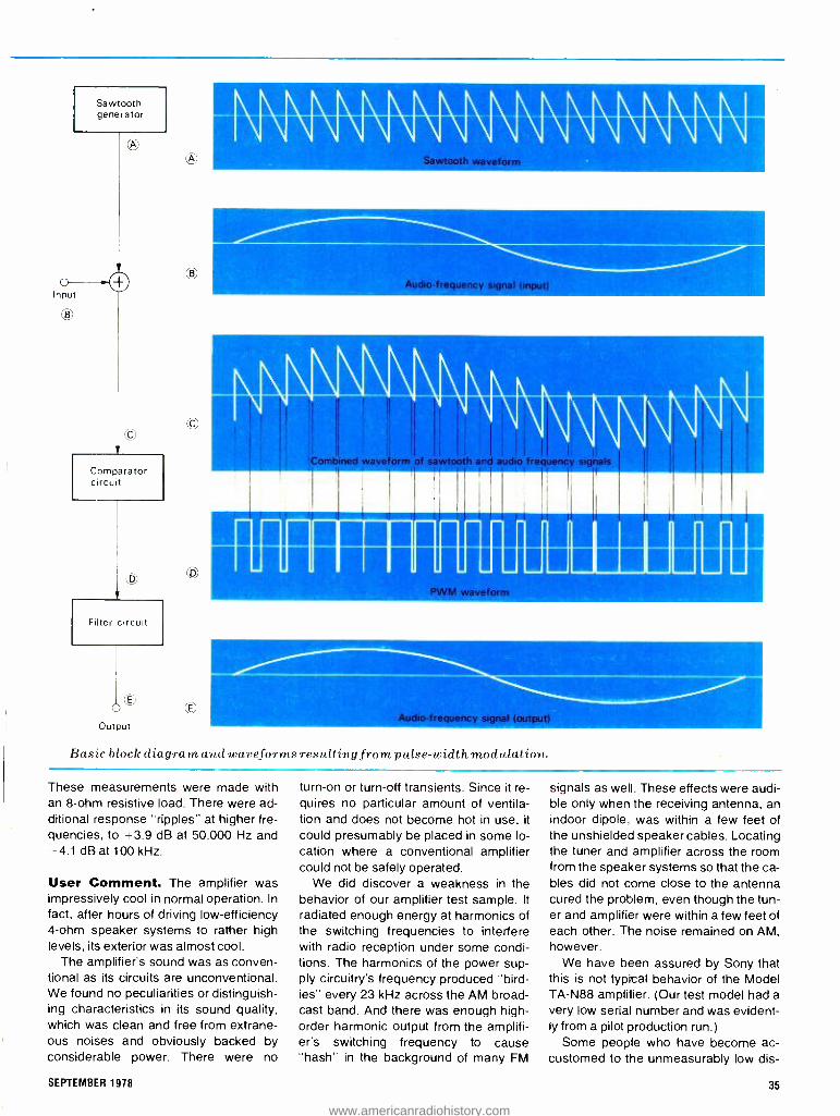
Sawtooth generator
O Input
O
O
Comparator circuit
Filter circuit
Output
Basic block diagram and waveforms resulting from pulse -width modulation.
11111111 11111 1111 1111111111 11111
" AiN=MENiail Audio- frequency signal (input)
1113111MINMIllp
111111M11111111 I II PWM waveform PWM waveform
These measurements were made with an 8 -ohm resistive load. There were ad- ditional response "ripples" at higher fre- quencies, to +3.9 dB at 50,000 Hz and -4.1 dB at 100 kHz.
User Comment. The amplifier was impressively cool in normal operation. In
fact, after hours of driving low- efficiency 4 -ohm speaker systems to rather high levels, its exterior was almost cool.
The amplifier's sound was as conven- tional as its circuits are unconventional. We found no peculiarities or distinguish- ing characteristics in its sound quality, which was clean and free from extrane- ous noises and obviously backed by considerable power. There were no
turn -on or turn -off transients. Since it re- quires no particular amount of ventila- tion and does not become hot in use, it
could presumably be placed in some lo- cation where a conventional amplifier could not be safely operated.
We did discover a weakness in the behavior of our amplifier test sample. It
radiated enough energy at harmonics of the switching frequencies to interfere with radio reception under some condi- tions. The harmonics of the power sup- ply circuitry's frequency produced "bird- ies" every 23 kHz across the AM broad- cast band. And there was enough high - order harmonic output from the amplifi- er's switching frequency to cause "hash" in the background of many FM
signals as well. These effects were audi- ble only when the receiving antenna, an indoor dipole, was within a few feet of the unshielded speaker cables. Locating the tuner and amplifier across the room from the speaker systems so that the ca- bles did not come close to the antenna cured the problem, even though the tun- er and amplifier were within a few feet of each other. The noise remained on AM, however.
We have been assured by Sony that this is not typical behavior of the Model TA -N88 amplifier. (Our test model had a
very low serial number and was evident- ly from a pilot production run.)
Some people who have become ac- customed to the unmeasurably low dis-
SEPTEMBER 1978 35
www.americanradiohistory.com

tortion and frequency- response varia- tions of some of the better conventional separate power amplifiers may look askance at the specifications of the Model TA -N88 amplifier. Its frequency response, unlike that of an ideal linear amplifier, can be directly affected to some degree by the variations in speak- er- system impedance that occur at the higher end of the audio range. These variations might or might not be detect- able in an A -B comparison against other amplifiers with some speaker systems. Even if they were detectable, there is no reason to assume that they would de- tract from the sound quality of the sys- tem. To us, there was no evidence of
any response aberrations when listening to the amplifier with several types of speaker systems, although we did not attempt to make A -B comparisons with other amplifiers. Similarly, the high -fre- quency harmonic distortion, although it was greater than we have measured in
other top- ranking amplifiers, is still well below the threshold of audibility. Anyone who is more concerned with sound than with specifications will find little to criti- cize in the performance of the Model TA- N88 amplifier.
We believe that the significance of this amplifier is not in its actual performance (which is fine), but in its small size, cool operation, and in what it portends for the
CIRCLE NO 101 ON FREE INFORMATION CARD
future. It is really remarkable to see and hear how much clean audio power can be delivered by this very compact piece of equipment. The amp can be stowed in
small spaces where no other type can. Accordingly, we can visualize a high - power receiver in the near future with a
pulse -width -modulation amplifier tucked away into its compact interior. It is obvi- ous, however, that a sizable price reduc- tion will be required for such amplifiers to come into common use, but we are confident that technology will provide an answer to this in due course. Mean- while, our compliments to Sony's re- search and development engineers in
Shibaura, Tokyo.
Electro -Voice Interface: B Series II Speaker System
HIRSCH- HOUCK
Electro- Voice's Inter- face series was among the first com- mercial speaker sys- tems to be based on
the analysis of vented loudspeaker op- eration published by the Australian A.N. Thiele. Thiele showed how to establish the detailed interrelationships between enclosure volume, port dimensions, low- frequency response, speaker effi- ciency, and driver parameters. His work effectively dispelled the belief that vent- ed (bass -reflex) enclosures were neces- sarily an inferior approach to generating clean low- frequency audio.
When the original E -V Interface:A ap- peared several years ago, it was widely recognized for the fine bass perfor- mance it delivered from a very small en- closure, with assistance from an out- board equalizer. E -V later added the In- terface:B, which was larger and more ef-
High- efficiency, vented, floor speaker system uses passive radiator and equalizer for extended bass response.
ficient than the Interface:A. Now, the In- terface line has been expanded and im- proved. It consists of four models desig- nated as the "Series II."
The lnterface:B Series Il reviewed here is a medium -size floor- standing speaker system that's sold in pairs with a separate, special -purpose equalizer. Compared to the original Interface:B, the Series II's midrange response is flat- ter, and its deep -bass response is slight- ly better. It's also somewhat larger. The system's walnut- finished cabinet mea- sures 291/4"H x 16 "W x 101 "D (74.3 x 40.6 x 26 cm) and weighs 42 lb (19.1 kg). The suggested retail price of a com- plete lnterface:B Series Il stereo speak- er system, consisting of two speaker systems and an equalizer, is $675.
General Description. The Series II
is basically a two -way speaker system. It contains an 8" (20.3 -cm) woofer that
crosses over at 1500 Hz to a 21/2" (6.35 - cm) tweeter. This tweeter radiates through a felt- and plastic -foam acoustic lens to improve its dispersion at high fre- quencies. A second similar tweeter, this time without the lens, radiates from the rear of the enclosure at frequencies beyond 8000 Hz to augment the output in the highest audible octave.
The Series Il is a vented system. To obtain the desired 30 -Hz bass response in an enclosure of its compact size, how- ever, would normally require an impossi- bly large vent. E -V's solution, following Thiele's guidelines, has been to use what the company calls a "vent substi- tute," or passive radiator, instead of an
open port. The passive radiator looks much like a conventional 12" (30.5 -cm) driver sans voice coil and magnet, but with a large metal plug in its center to in- crease its mass. The effective acoustic crossover from the 8" driven woofer to
36 POPULAR ELECTRONICS
www.americanradiohistory.com

We've done the impossible again! A versatile and superior frequency counter kit for only $89.95
Now you can forget about price /performance trade -offs when you select a frequency counter. In Sabtronics' Model 8100 you get features you once expected to pay several hundreds of dollars for. But you pay only our low, low price of $89.95!
Dare to Compare. This frequency counter, using LSI technology, has the performance and input character- istics you demand. Note the specifications: You will see that the frequency range is guaranteed all the way to 100 MHz; and a high or low input impedance allows you to select for high- frequency operation. And you'll see a sensitivity that holds well over the frequency range; con- venient selectable gate -time for best resolution; and selectable attenuation; and even an optional pre -scaler. Note the highly accurate time base, and its excellent ageing and temperature characteristics. And a full 8 -digit LED display with floating decimal point, leading zero suppression, and overflow indicator.
You would expect to find all these features together only on a much higher -priced instrument. But Sabtronics' ad- vanced digital technology combines with your own skill - you assemble this kit from our easy -to- follow instruc- tions - to make it possible for you to have this fine frequency counter at a fraction of what you would other- wise expect to pay.
Free 10 -day trial Examine the 8100 Frequency Counter Kit for 10 days. If not completely satisfied, return unassembled for full refund of $89.95 purchase price.
sabtronics INTERNATIONAL INC. INTERNATIONAL INC.
13426 Floyd Circle Dallas, Texas 75243 Telephone 214/783 -0994
CIRCLE NO 50 ON FREE
Brief Specifications Frequency Range: 20 Hz to 100 MHz guaranteed (10
Hz to 120 MHz typical) Sensitivity: 25 mV RMS, 20 Hz to 70 MHz (20 mV typical); 45 mV RMS, 70 MHz to 120 MHz (30 mV typical) Selectable Impedance: 1 MR at 25 pF, or 50 4 Selectable Attenuation: X1, X10, or X100
Accuracy: ± 1 Hz plus time -base accuracy Ageing
rate: 5 ppm /yr Temperature stability: ± 10 ppm, 0° to 50 °C Selectable Gate -time: 0.1 sec, 1 sec., or 10 sec. 8 -digit LED display with floating D.P., overflow indication Input: 9 -15 VDC, 350 mA (550 mA with op- tional prescaler) Input protection: 150 V RMS, 20 Hz to 10 kHz; 30 V RMS to 2 MHz; and 3 V RMS to 100 MHz
Optional prescaler extends frequency range to 650 MHz. (Available soon)
r- To: Sabtronics International, Inc. PE 9
13426 Floyd Circle, Dallas, TX 75243
Please send me Sabtronics Model 8100 Frequency Counter Kit(s) at $89.95 each $
Texas Residents add Sales Tax $
Shipping and handling, $5.00 per unit (USA only)* $
Payment enclosed $
Charge my Master Charge Visa
Account No. - Exp. Date
Name
Street
City
State Zip Canada $6.50. All other countries $/9.00 Airmail.
INFORMATION CARD
i
www.americanradiohistory.com

Advanced Electronic Career
ANNOUNC ING ...ANew
CREI Program: Minicomputer &
Microprocessor Technolo
Including A Microprocessor
Laboratory
Now you can learn at home the new technology that is revolutionizing electronics
The microprocessor has ushered in the age of microtechnology and electronics will never again be the same. The micro- processor has made possible the placing of an entire computer on a silicon chip one quarter inch square. The microproc- essor "miracle chip" is in the process of changing the world. Soon all technical personnel in electronics will have to un- derstand and work with the microproc- essor. It is invading virtually every area of electronics. And it is profoundly affect- ing your electronics career.
Brand New Program CREI has a brand new program to help you learn how to work effectively with this revolutionary electronics develop- ment. CREI's new program in Minicom- puter and Microprocessor Technology is designed to prepare you for this field by giving you the education and practical experience you need.
The program provides solid prepara- tion in electronics engineering technol- ogy with a specialization in minicomput- ers and microprocessors. In addition, it includes a microprocessor laboratory which features a fully programmable microcomputer which utilizes the Mo- torola 6802 microprocessor chip. This is an extremely important element of your program.
Programming Essential As you may well know, you must learn how to program the microprocessor in order to design, service or troubleshoot microprocessor electronic systems. There is only one effective way to learn this all- important skill of programming, and that is by actually doing it. CREI's new program gives you this opportunity as you work with the exciting micro - processor laboratory.
Programming Is Easy With CREI's new program, learning the skill of programming is simple. Within a few hours you'll be programming the microprocessor and in a short time you'll learn how to program it in three lan- guages: BASIC, assembly and machine languages. In addition, you will learn how to interface the microprocessor with other systems and to test and debug specialized programs.
38 POPULAR ELECTRONICS
www.americanradiohistory.com

Preparation at Home
Wide Choice of Programs Please note, however, that CREI's new program is only one of 16 state- of -the- art programs in advanced electronic technology offered by CREI. So even if you choose not to specialize in micro- processor technology, CREI has an ad- vanced electronics program to meet your needs.
With CREI, you may choose from any of the following areas of specialization in advanced electronics:
Microprocessor Technology Computer Engineering Communications Engineering Digital Communications Electronic Systems Automatic Controls Industrial Electronics Television Engineering Microwave Engineering Cable Television Radar and Sonar Nuclear Instrumentation Satellite Communications Aeronautical and Navigational Solid State Theory Nuclear Engineering
Unique Lab Program An exclusive option available with CREI programs in electronic engineering tech- nology is CREI's unique Electronic De- sign Laboratory program. It gives you actual experience in designing practical electronic circuits. It also helps you to understand the theories of advanced electronics and gives you extensive ex- perience in such areas as tests and mea- surements, breadboarding, prototype construction, circuit operation and be- havior, characteristics of electronics components and how to apply integrated circuits. Only CREI offers this unique Lab Program.
Practical Engineering CREI programs give you a practical en- gineering knowledge of electronics. That is, each part of your training is planned for your "use on the job." By using your training, you reinforce the learning proc- ess. And by demonstrating your in- creased knowledge to your employer, you may qualify for faster career ad- vancement.
Free Book There isn't room here to give you all of the facts about career opportunities in advanced electronics and how CREI prepares you for them. So we invite you to send for our free catalog. This fully illustrated, 56 page book describes in detail the programs, equipment and serv- ices of CREI.
Qualifications You may be eligible to take a CREI college -level program in electronics if you are a high school graduate (or the true equivalent) and have previous train- ing or experience in electronics. Program arrangements are available depending upon whether you have extensive or minimum experience in electronics.
Send for this FREE Book describing your opportunities and CREI college -level programs in electronics
`gEi Home Study Programs in
ECYRON%C ENGINEERING
TECHMOIDGY
CREI introduces Program 680:
MINICOMPUTER & MICROPROCESSOR
TECHNOLOGY INCLUDING MICROPROCE 3SOR
LABORATORY PROGRAM
McGraw -KM GontirsOng
Etl =lawn, Ganter Washington.° C.
2,00,6
Mail card or write describing qualifications to
0H01 CAPITOL RADIO ENGINEERING INSTITUTE
McGraw -Hill Continuing Education Center 3939 Wisconsin Avenue Northwest Washington, D.C. 20016
Accredited Member National Home Study Council
Gli Bill CREI programs are approved fier training of veterans und servicemen rouler the G.I. Bill.
SEPTEMBER 1978 41
www.americanradiohistory.com
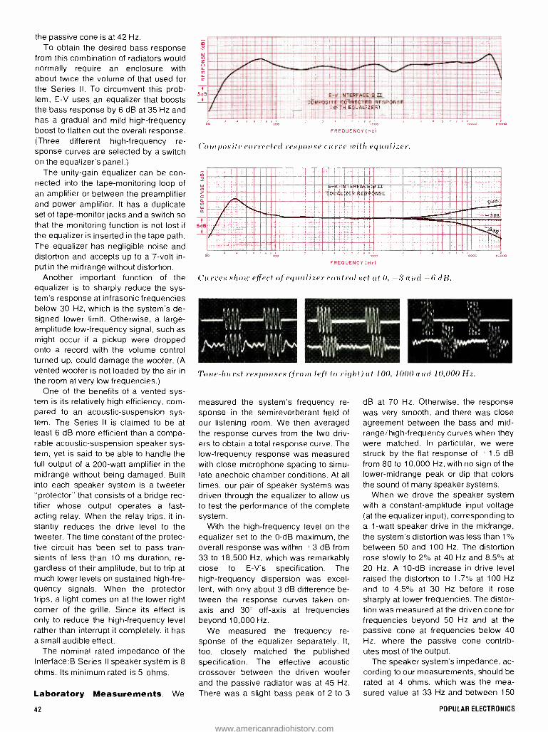
the passive cone is at 42 Hz. To obtain the desired bass response
from this combination of radiators would normally require an enclosure with about twice the volume of that used for the Series II. To circumvent this prob- lem, E -V uses, an equalizer that boosts the bass response by 6 dB at 35 Hz and has a gradual and mild high- frequency boost to flatten out the overall response. (Three different high- frequency re- sponse curves are selected by a switch on the equalizer's panel.)
The unity -gain equalizer can be con- nected into the tape- monitoring loop of an amplifier or between the preamplifier and power amplifier. It has a duplicate set of tape- monitor jacks and a switch so that the monitoring function is not lost if
the equalizer is inserted in the tape path. The equalizer has negligible noise and distortion and accepts up to a 7 -volt in- put in the midrange without distortion.
Another important function of the equalizer is to sharply reduce the sys- tem's response at infrasonic frequencies below 30 Hz, which is the system's de- signed lower limit. Otherwise, a large - amplitude low- frequency signal, such as might occur if a pickup were dropped onto a record with the volume control turned up, could damage the woofer. (A vented woofer is not loaded by the air in the room at very low frequencies.)
One of the benefits of a vented sys- tem is its relatively high efficiency, com- pared to an acoustic- suspension sys- tem. The Series Il is claimed to be at least 6 dB more efficient than a compa- rable acoustic -suspension speaker sys- tem, yet is said to be able to handle the full output of a 200 -watt amplifier in the midrange without being damaged. Built into each speaker system is a tweeter "protector" that consists of a bridge rec- tifier whose output operates a fast - acting relay. When the relay trips, it in- stantly reduces the drive level to the tweeter. The time constant of the protec- tive circuit has been set to pass tran- sients of less than 10 ms duration, re- gardless of their amplitude, but to trip at much lower levels on sustained high -fre- quency signals. When the protector trips, a light comes on at the lower right corner of the grille. Since its effect is only to reduce the high- frequency level rather than interrupt it completely, it has a small audible effect.
The nominal rated impedance of the Interface:B Series II speaker system is 8
ohms. Its minimum rated is 5 ohms.
Laboratory Measurements. We
42
L :
E-V INT.ERFAGE.5 OM.PpStTE COR&E+"TEQ RESPONSE
( W;TH k:R)_
....
FREQUENCY(Hx)
Composite corrected response curve with equalizer.
0.0
E -' -INT.,REACE 'E 1
EQUALIZER RESPONSE
I 1 1 1 1
FREQUENCY (Hz)
f7 -3 á
._. .....: .....60ti
Curves show effect of equalizer control set at 0, -3 and -6 dB.
10000
Tone -burst responses (from left to right) at 100, 1000 and 10,000 Hz.
measured the system's frequency re- sponse in the semireverberant field of our listening room. We then averaged the response curves from the two driv- ers to obtain a total response curve. The low- frequency response was measured with close microphone spacing to simu- late anechoic chamber conditions. At all times, our pair of speaker systems was driven through the equalizer to allow us to test the performance of the complete system.
With the high- frequency level on the equalizer set to the 0 -dB maximum, the overall response was within 3 dB from 33 to 18,500 Hz, which was remarkably close to E -V's specification. The high- frequency dispersion was excel- lent, with only about 3 dB difference be- tween the response curves taken on- axis and 30° off -axis at frequencies beyond 10,000 Hz.
We measured the frequency re- sponse of the equalizer separately. It,
too, closely matched the published specification. The effective acoustic crossover between the driven woofer and the passive radiator was at 45 Hz. There was a slight bass peak of 2 to 3
dB at 70 Hz. Otherwise, the response was very smooth, and there was close agreement between the bass and mid- range /high- frequency curves when they were matched. In particular, we were struck by the flat response of ± 1.5 dB from 80 to 10,000 Hz, with no sign of the lower- midrange peak or dip that colors the sound of many speaker systems.
When we drove the speaker system with a constant -amplitude input voltage (at the equalizer input), corresponding to a 1 -watt speaker drive in the midrange, the system's distortion was less than 1%
between 50 and 100 Hz. The distortion rose slowly to 2% at 40 Hz and 8.5% at
20 Hz. A 10 -dB increase in drive level raised the distortion to 1.7% at 100 Hz and to 4.5% at 30 Hz before it rose sharply at lower frequencies. The distor- tion was measured at the driven cone for frequencies beyond 50 Hz and at the passive cone at frequencies below 40 Hz, where the passive cone contrib- utes most of the output.
The speaker system's impedance, ac- cording to our measurements, should be
rated at 4 ohms, which was the mea- sured value at 33 Hz and between 150
POPULAR ELECTRONICS
www.americanradiohistory.com

Performance Specifications
Specification Frequency response
(anechoic) Total acoustic power output
(SPL at 1 meter, 1 W in.) Recommended amplifier power Long -term average power
handling capacities 30 -1500 Hz 1500 -20,000 Hz
Crossover frequencies
Impedance: nominal minimum
Equalizer Midband gain Maximum equalization Maximum input signal
80 -3000 Hz 35- 20,000 Hz
Noise output (20- 20,000 Hz) THD (3.5 V rms input)
Accessory outlet Dimensions
Rating 30- 18,000 Hz it 3 dB
92 dB
3.6 to 200 watts
20 watts 20 watts, to 5 watts/ 10 kHz 42 Hz (acoustic) 1500 Hz and 800 Hz
(electrical) 8 ohms 5 ohms
Measured 33- 18,500 Hz ±3 dB
92.5dB
4 ohms 4 ohms
1.0
6 dB ra 35 Hz fixed Confirmed
7 volts 3.5 volts -80 dB re 200 mV Less than 0.05% 20- 20,000 Hz 200 watts, unswitched 2 x 8 x 7 in.
and 200 Hz. The impedance was 12
ohms at the 22 -Hz lower -bass reso- nance, 20 ohms at 58 Hz, and 18 ohms at 2200 Hz. At other frequencies, it was typically 7 to 8 ohms. The system's tone - burst response, although not exception- al, was good throughout. Its efficiency was very high, as claimed: An input of 2.8 volts of random noise in the octave centered at 1000 Hz, corresponding to 1
watt into 8 ohms, produced a 92.5 -dB sound pressure level (SPL) at a distance of 1 meter from the grille.
User Comment. Before we measured the response of this speaker system, we spent some time listening to it alone and in comparisons with other good speaker systems we had on hand. Hence, our test results came as no surprise.
This speaker system has a delightfully smooth and transparent sound. Many if not most speaker systems have suffi- cient coloration in the lower midrange and upper -bass range, between 80 and 200 Hz, to make voices sound unnatural and in general impair the clarity of music reproduced. This one, however, is about as flat throughout this range as any
SEPTEMBER 1978
speaker system known to us. The system's low bass is clean and
powerful, with no trace of artificial heavi- ness. The highs are strong and crisp, without ever being strident or overbear- ing. E -V points out that the -3 -dB equal- izer setting would be considered as "normal" by many people and probably gives the best overall sound with most high -quality recordings. The 0 -dB set- ting can give startlingly realistic effects with the finest source material, but it can be merciless in revealing any faults in
the program itself. Very few speaker systems are capable of delivering the flat response to the highest audible fre- quencies that the Series II does with its 0 -dB setting. It is worth hearing even if it is too much for ordinary listening. Al- though we drove the Series II to very high levels from a 200 -watt amplifier, we never tripped its tweeter protector.
In conclusion, E -V's Interface: B Se- ries II is a speaker system we really en- joyed listening to. The Interface:B, with its equalizer, is certainly worthy of seri- ous consideration for matching to any low -power to medium -high -power am- plifier.
CIRCLE NO 102 ON FREE INFORMATION CARD
ìdeal,
all- around
iron
Wiener
FOR ELECTRONIC SOLDERING
Model WP -25. Popular 25 -watt, pencil - type iron for general purpose work. Handy size: 7%e" long. Lightweight: 13/4 oz. Comfortable to hold. Perfect for crowded areas. Easily stored. Long - life, double -coated, 1146" screwdriver tip quickly changed to other available styles and sizes. Rugged stainless steel barrel. Use with or without op-
tional, mounted or free -standing bench
stand PH -25.
Ask your local distributor or write...
' TheCooperGroup 1 Electronics Division s
WELLER' WISS' XCELITE' PO BOX 728. APEX. NORTH CAROLINA 27502. 919/362.7511
CIRCLE NO 12 ON FREE INFORMATION CARD
43
www.americanradiohistory.com

A $$ COMPETITIVE SVSTEM YOU CAN OWN A VERSATILE
6800 COMPUTER SYSTEM
FOR AS LITTLE AS $799.50! MP -68/1 Computer Kit $395.00 CT -64 Terminal Kit (less monitor) $325.00 AC -30 Cassette Interface Kit $ 79.50
You can add a 40- column printer and a professional quality data terminal monitor for only $460.00
PR -40 Printer Kit $250.00 MP -L Interface Kit $ 35.00 CT -VM Data Terminal Monitor $175.00
You can expand to a full -scale personal computer system with dual disk drives for only $1,445.00
MF -68 Dual Disk System Kit $995.00 MP -16 16K Memory (assembled) $450.00
...OR buy the complete system at our special low price of $2,595.00
YOU GET: A 20K byte computer A true "stand alone" data terminal
and monitor / A 40- column dot matrix printer / A dual drive 200K byte disk system
Disk BASIC with file handling
These are the same proven, reliable components used in our industrial and business systems.
Why settle for the limitations of a so- called "personal computer" or hobby system?
SOUTHWEST TECHNICAL PRODUCTS CORPORATION 219 W. RHAPSODY SAN ANTONIO, TEXAS 78216
44 CIRCLE NO 55 ON FREE INFORMATION CARD
POPULAR ELECTRONICS
www.americanradiohistory.com

Popular Electronics SEPTEMBER 1978
BUILD A LOW -COST A/D CONVERTER
INTERFACING a digital computer with the "real" world requires some means
of converting analog (slowly varying) signals into a digital form that can be used by a computer. The low -cost ($30) analog -to- digital (A /D) converter de- scribed here can accept up to four chan- nels of analog data, spanning from 0 to +2 volts dc, and change this information into 31/2 digits of BCD data.
With such a converter, a computer need not be limited to keyboard entry for many game programs. Now, joysticks or potentiometers can be used. And such real -world sensing of variables like volt- age, current, temperature, frequency, and various levels of acidity, salinity, and chemical concentrations can make your computer a powerful and versatile controller. As a bonus, the A/D convert- er, becomes a powerful test instrument for circuit design and troubleshooting. In
this application, up to four channels of voltage, current, and resistance can be monitored with proper input adapters.
Technical Details. The converter produces five conversions per second. It
has four input channels and 31 digits of BCD data output. It is also TTL compat- ible in input and output and will work with
any 8 -bit computer that has a latched output port and a three -state input port. Digit and channel selection is under soft- ware control. Since the circuit is all CMOS, very little power is required.
As shown in Fig. 1, the A/D converter employs two IC's and a handful of pas- sive components. One of the four input switch 1C2 to form the input for A/D con- verter ICI. The analog switches are set by data written out by the latched output port of the computer. Resistors R6 through R9 provide pullup for the analog switch select lines.
A/D converter IC/ is a pulse- modula- tion type. Its chip contains the conver- sion circuitry, an addressable digit latch, multiplexer, BCD encoder, and system clock.
Conversion control, output digit se- lect, and the output latch are connected to the computer's output port. Data writ- ten to this port controls the data placed on the four output lines of ICI. The four data output lines from IC/ are connect- ed to the computer's three -state input port's lower four bits (DO through D3). The upper four bits (D4 through D7) are grounded.
Trimmer potentiometer R1 deter - (Continued on page 47)
iltlitl Ii111Ill
SEPTEMBER 1978
Two -chip, four -channel converter works with any 8 -bit computer.
BY W. L. GREEN 45
www.americanradiohistory.com

+ 5v
I
ANALOG 12 INPUTS
0 TO +2V13 4
GND
e
II
7 44
RI C4 PARTS LIST 5K
R5 C3
IOOK '22yF
+ 5V41
16 2
9
20 21
-/IO{`
VF
+
ICI 3511
7
C .22yF 1004`
18
4
3
24
2i I
R3 47011
14 15
MMNJI R2
6.BK
111--AAnntiv--1/ -- -WNW,
R6-R9 IK D0 DI D2 D3 D4 05 D6 D7 EN D0 DI D2 03
FROM LATCHED COMPUTER OUTPUT
PORT
Fig. 1. Analog switch IC2 selects the input drive for A/D converter IC1. Up to four inputs can be used.
R41 O 10 K
1111 D4 D5 06 D7
TO THREE STATE COMPUTER INPUT
PORT
C'1- 100-pF disc C2. C3 -O.22- &F. I0 -volt Mylar C4- 10 -p.F. 10 -volt electrolytic ICI -3511 A/D converter (National) IC2 -4066 quad analog switch R1-5000-ohm. 10 -turn trimmer pot. R2 -6800 -ohm. 1/4 -watt resistor R3-470-ohm. Vs-watt resistor R4, R5- 100.000 ohm. 1/4-watt resistor R6 through R9 -1000 -ohm, 1/4 -watt resistor Misc.- Printed circuit board; edge connector;
multilead ribbon connector; IC sockets (op- tional); hookup wire; solder; etc.
Note -The following is available from Alpha Electronics. Box 1005, Merritt Island. FL 32952 (tel. 305- 453- 3534): complete kit of parts, excluding wire and sockets, No. A /D4. for $29.95 plus 3.50 postage and handling. Also available separately: pc
board No. PC178 for S9.00 + 1.00 p&h; and ICI, No. 3511, for $15.00 + 1.00 p &h.
CHANNEL SELECT 1 . i 4
c & 6?
L) U7 D4 ó " D8113
1 0000 011110711041i4ORH G 2 0001 IIH 12H 141 IRH
I 3 0010 7114I771.24H 7RH T 4 0011 .71110?11.14H.3RH,
(A)
IOR INPUT V /10
V SO CONVERTER SWITCH
(B)
INPUT F/V CONVERTER
(C)
TO CONVERTER
SWITCH
INPUT
TO HARREL
TO -CONVERTER
SWITCH
+SV 330yÁ CURRENT
REGULATOR DIODE
2N2222
(D)
RSHUNT
(E)
+5V
3.3K 3.3K
TO CONVERTER SWITCH
(F)
TO ...-CHANNEL
2
SPARES
(4
ANALOGA INPUTS)2
3
R7 RR I
GND
+5V
FROM TO FROM TO OUT N OUT IN D I0300 D3D2? 7D465 61 60
GIRD
J -Rb-
SPARES
11
- ' C2 -14-
Cl
Fig. 3. Actual -size foil pattern (below) and component layout (above).
Fig. 2. Channel -digit select is shown at (A); a 10:1 voltage divider is at (B); a frequency -to- voltage scheme at (C); temperature converter (D); current measurement (E); and joystick input (F).
46 POPULAR ELECTRONICS
www.americanradiohistory.com

TABLE 1-8080 ASSEMBLY LISTING Assembly listing for 8080 (IMSAI). Inputs three most significant digits and writes to front panel,
4000 3E 11 BGN MVI A, 11H Load A with Dig2, Ch1 4002 CD3840 CALL INPUT 4005 32 35 40 STA DIG2 4008 3E 21 MVI A, 21H Dig3, Ch1 400A CD3840 CALL INPUT 400D 32 36 40 STA DIG3 4010 3E 31 MVI A,31H Dig4, Ch1 4012 CD 38 40 CALL INPUT 4015 32 37 40 STA DIG4 4018 3E 00 MVI A, 00H 401A 2A 35 40 LHLD DIG2 Dig2 L, Dig3 H
401D BC CMP H Compare H for 0 401E 0600 MVI B, 00H Clear B
4020 C4 4A 40 CNZ SUB Gosub if H #0 4023 3A 37 40 LDA DIG4 4026 FE 00 CPI 00H 4028 CA2D40 JZ WRT If A-0, fall thru 402B 3E 64 MVI A, 64H 402D 80 WRT ADD B A =A +B
402E 2F CMA Invert data 402F D3 FF OUT OFFH Write it 4031 C3 00 40 JMP BGN Do again 4034 STR DS 01 4035 DIG2 DS 01 4036 DIG3 DS 01 4037 DIG4 DS 01 4038 D310 INPUT OUT 10H Setup port 10H 403A CD 40 40 CALL DLY A/D settling time 403D DB 10 IN 10H Input A/D data 403F C9 RET 4040 11 00 30 DLY LXI D, 3000H 200 -ms delay 4043 1B UP DCX D
4044 7A MOV A, D
4045 B3 ORA E
4046 C2 43 40 JNZ UP If D>0 do again 4049 C9 RET 404A C6 0A SUB ADI OAH A+A+O AH 404C 25 DCR H H=H-1 404 C2 4A 40 JNZ SUB If H>0, do again 4050 85 ADD L A=A+L 5051 47 MOV B, A B=A 4052 C9 RET 4053 76 H LT
TABLE I1 --6800 OP CODE LISTING
Op code listing for 6800 BCD format.
01 02 03 04 05 06 07 08 09 10 11
12 13 14 15 16 17 18 19 20 21 22 23 24 25 26 27 28
BDN
DIG1 DIG2 DIG3 DIG4 INPUT
DLY UP UP1
Inputs four digits from channel 1 and stores data in memory in
LDAA 01H BSR INPUT STAA DIG1 LDAA 11H BSR INPUT STAA DIG2 LDAA 21H BSR INPUT STAA DIG3 LDAA 31H BSR INPUT STAA DIG4 JMP BGN RES 01 RES 01 RES 01 RES 01 STAA insert BSR DLY LDAA insert RTS LDAA --
LDAB SUBB 01 BGT UP1 SUBA 01 BGT UP RTS
Load digit 1, channel 1 into A
Store A in memory
Do again Res -reserves one byte of memory
output port 200 -ms delay for A/D settling input port o
enter values here and 23 to create a 200 -ms delay
do until 13=0
do until A =0
TABLE Ill- ASSEMBLY LISTING FOR 2650 Assembly listing for 2650 (Central Data). Inputs three most significant digits and writes to data bus on WRTD instruction. Converts to hex before outputting data.
1600 75 FF CPSL FF
1602 05 11 BGN LODI, 1 11
1604 3B 20 BSTR,3 INPUT 1606 CA iB STRR,2 DIG2 1608 05 21 LODI, 1 21
160A 3B 1A BSTR,3 INPUT 160C CA 16 STRR, 2 DIG3 160E 05 31 LODI, t 31 1610 3B 14 BSTR,3 INPUT 1612 CA 11 STRR, 2 DIG4 1614 08 OD LODR,O DIG2 1616 OB OC LODR,3 DIG3 1618 B8 24 BSFR, 0 SUB 161A OB 09 LODR, 3 DIG4 161C 18 02 BCTR, 0 WRT 161E 84 64 ADDI, 0 64 1620 FO WRT WRTD, 0 1621 1B 5F BCTR,3 BGN 1623 00 DIG2 RES 01 1624 00 DIG3 RES 01 1625 00 DIG4 RES 01 1626 D5 00 INPUT WRTE, 1 00 1628 3B 03 BSTR,3 DLY 162A 56 00 REDE,2 00 162C 17 RETC, 3
162D 77 10 DLY PPSL 10 162F 05 FF LODI, 1 FF 1631 AS 01 UP SUBI, 1 01
1633 06 40 LODI, 2 40 1635 A6 01 UPI SUBI, 2 01 1637 5A 7C BRNR, 2 UP1 1639 59 76 BRNR, 1 UP 1638 75 10 CPSL 10 163D 17 RETC, 3
163E A7 01 SUB SUBI, 3 01 1640 84 OA ADDI, 0 OA 1642 58 7A BRNR,3 SUB 1644 17 R ETC, 3 1645 40 HALT
Clear PSL and setup register bank 0
Setup for channel 1, digit 2
BR if DIG30
BR if DIG4=0
Write it do again RES 01 reserve one byte
Setup port 00 A/D settling time delay read port 00 into R2
select register bank 01 gives 200 ms delay with 1633
do again until R2 =0 do until R1 =0 select register bank 00
R3 =R3 -1; converts BCD to hex RO =R0 +0A do until R3 =0
(Continued from page 45)
mines the reference voltage used by ICI. The other passive components de- termine clock frequency, provide signal filtering, and interconnect ICI.
Software. The digit and channel se- lect codes are shown in Fig. 2A. The val- ues shown are in hexadecimal code. To use the table, move down the rows until the proper digit is located. Then move over until the proper channel is located. The hex number at this point is the data to be written to the output port to set up the converter. The strobe that enables the output port (EN) must be active low when connected to the converter. if nec- essary, an inverter can be wired into the circuit to perform the inversion.
When reading data from the convert- er, it is necessary to access only the cor- rect input port. Examples of programs written for an 8080, 6800, and 2650 are shown in Tables I through Ill. The pro- gram flow is essentially the same for any 8 -bit computer. The digit /channel infor- mation is loaded into a register and then the program is stepped to a subroutine (INPUT) and outputs that register to the output port. A 200 -ms delay (DLY) sub- routine is used to allow the A/D convert- er to settle. Then the data is read from the input port into a register.
Upon returning from the INPUT sub- routine, the BCD digit is stored in memo- ry (DIGX) and is repeated for each digit required before branching back to the
EPTEMBER 1978 47
www.americanradiohistory.com

TABLE Iv -BASIC SAM GAME
SAM (surface -to -air missile) GAME Central Data Basic (2650)
0000 RESTORE 0010 READ, R, W, M, P, Z 0020 DATA 0, -1, 0, 11, 0 REM sets up port 0, chan #1, digit #3 0100 EXTOUT 0, 33 0105 X= SIN(1) REM delay for A/D settling 0110 EXTIN 0, B REM reads port 0, chan #1, digit#3 into B 0120 EXTOUT 0, 49 0125 EXTIN 0, A 0130 EXTOUT 0, 34 0135 X= SIN(1) 0140 EXTIN O, D 0150 EXTOUT 0, 50 0155 EXTIN 0, C 0160 A =INT IA10 +61'.81 +1
0165 C= (C10 +D14 0170 ERASE REM clears screen 0175 IF R>17 GOTO 1010 0200 w =w +1
0210 P =P -1 0220 IF W>10 W =10 0230 I F P<0 P =0 0240 PRINT @14, 15' MISSILES FIRED'#W 0250 PRINT @15,15' MISSILES LEFT'#P 0300 PRINT @13,9'1' 0310 PRINT @14, 8'1' 0320 PRINT @15, 5'11111' 0330 PRINT @10, 50'11 l' 0340 PRINT @11, 50'1111111' 0400 Z =Z +4 0410 Y= 1 +INTIRND)7)) 0500 PRINT @Y, Z' + + + + + +' 0510 PRINT @Y -1, Z' +' 0520 PRINT @Y +1, Z' +' 0530 IF Z>50 GOTO 0900 0600 READ Q, V, L 0610 DATA 12, 9, 1
0620 RESTORE 0610 0630 I F W =0 GOTO 0800 0640 PRINT @Q, V't 0650 IF C +1 >19 L =3 0660 IF C +1 >31 L =6 0670 IF V>C +1 V =V -1 0680 IF V<C +1 V =V +L 0700 Q =Q -1 0710 IF Q =A IF V =C +1 GOTO 0740 0720 IF Q<A GOTO 0740 0730 GOTO 0640 0740 PRINT @A, C +1'X' 0800 PRINT @14, 40'TARGET: RANGE' #Y' BEARING' #Z 0810 PRINT @15, 40'MISSILE: RANGE' #A' REARING'#C +1
0820 IF C>Z IF C <Z +6 GOTO 0880 0825 I F P =0 M =1
0830 I F M =1 GOTO 0170 0835 I F R>0 GOTO 0850 0840 INPUT' FIRER 0845 IF R =22 GOTO 0100 0850 R =R -1 0860 I F R <0 GOTO 0800 0870 GOTO 0100 0880 PRINT @A.0 +1'X DESTROYED' 0890 PRINT @15,5 0895 GOTO 1000 0900 PRINT @11, 50'DESTROYED' 0910 PRINT @15,5 1000 STOP 1010 PRINT @A, C +1'X' 1020 PRINT @15,40'MISSILE: RANGE' #A' BEARING'#C +1
1030 R =R -1 1040 I F R>17 GOTO 0100 1050 R =0 1060 GOTO 0840 1070 END
This program prints a missile launching site, a factory, an airplane (bomber), and a printout of the airplane's and missile's range and bearing. When FIRE appears at the bottom of the screen, type a number (1 through 10) for the number of missiles you wish to fire. The missiles will fire in sequence. Type 22 to clear the screen and display the missile range and bearing adjustments. You may then adjust the controls to alter these values. After 5 shots, the program will return to FIRE. If you input 1 (CRLF), then carriage- return /line -feed, an arrow will print the track of the missile until it reaches its range, and an X will appear to simulate an explosion. The object is to hit the plane on its fuselage, in which case, X DESTROYED will be printed. You have 10 missiles. If you do not destroy the plane in 10 shots, or if the plane reaches space 50 on the screen before you destroy it, the plane will destroy the factory. The aircraft will progress across the screen at the rate of 4 spaces for each missile fired. However, the plane will move up and down by a random amount (line 0410 controls this).
Note that the FIRE 22 routine does not subtract from the missiles remaining, but you cannot destroy the plane in this routine either. All entries must be followed by CRLF. After each missile is fired, and FIRE is displayed, you can adjust the range and bearing controls to alter the missiles course and range.
48
beginning (BGN). The 8080 listing also includes a routine to convert the three most significant digits into hex code and place the result in storage (STR). When programming, allow for the fact that this data has no decimal point.
Some typical input adapters are shown in Fig. 2B through 2F; B, C, and E
are conventional, while D illustrates a
temperature converter. If you use this or a similar circuit, allow for any voltage off- set in this type of converter. Also, keep in mind that only the two least significant digits are required for a temperature reading. This data should be viewed as relative and not absolute. Decisions should be based on exceeding a relative number, rather than a specific number of degrees. For example, if the tempera- ture converter is adjusted for an output of 1.050 volts at 25° C and the voltage decreases by 2.3 mV / °C, the program can be written to do something when the temperature is 20° C, or 1.039 volts. The 1.039 volts is related to the temperature but is not actually in degrees.
Figure 2F illustrates a joystick (or two independent potentiometers) for use in
game programs. A BASIC program to play the game
SAM is shown in Table IV. Note that the data written to the output port (EXTOUT) is in decimal, rather than in hex. The REM statements should help explain the program. Table V illustrates a 4- channel DVM program, which is also written in
BASIC.
Construction. An actual -size etching and drilling guide and a component - installation diagram for the A/D convert- er are shown in Fig. 3. During assembly, note the polarity of C4 and, if you wish, use sockets for the IC's. Note also that there are provisions on -board for option- al inverters (IC's or discrete transistors); these can be Wire Wrapped.
When installing the IC's, observe the usual precautions for handling MOS de- vices. Since the 5 -volt power supply is
also used as the reference, make sure it
is well regulated and stable. After as- sembly, adjust R1 for as near to an ex- act 2.000 volts at pin 16 as possible.
If your system employs an active high strobe, use an inverter. Flat ribbon cable can be used to interconnect the convert- er to the host computer. If desired, a 16-
pin socket can be mounted at one of the extra positions on the board, and, with Wire Wrap, it can be used to make the external connections instead of the edge connector shown.
Testing. After assembling the board
POPULAR ELECTRONICS
www.americanradiohistory.com

TABLE V -4- CHANNEL DVM PROGRAM
4- Channel DVM Program Central Data Basic (2650), Version 1.2
000 RESTORE 010 DATA 1, 17, 33, 49, 1, 2, 18, 34, 50, 2, 4, 20, 36, 52, 3, 8, 24, 40, 56, 4
020 READ A, B, C, D, E REM A= ChnDigit 1 :B= ChoDigit 2:C =Ch Digit 3:D= Ch;Digit 4:E =Chsr
030 GOSUB 100 040 IF E=4 GOTO 000 050 GOTO 010 100 EXTOUT 0, A 110 S=SIN11) 120 EXTIN 0, 7-
130 EXTOUT 0, B
140 EXTIN 0, Y 150 EXTOUT 0, C
160 EXTIN 0, X 170 EXTOUT 0, D
180 EXTIN 0, W
REM sets up I/O port Ch &digo REM delay for AiD settling time REM reads port 0 into Z
190 PRINT @E, 5'CHANNELZ'- E' =' =1W '1000 +X100 +Y10 +Z)' MILLIVOLTS' REM prints at line E, character position 5,
channel r.E= (voltage) MILLIVOLTS 200 300 310
RETURN STOP END
and adjusting R1 for the 2 -volt refer- ence, load a driver program and check the system for accuracy. If the data ap- pears to be unstable, check the 200 -ms
delay between the output port strobe and the input port strobe. You may have to vary the values loaded into the DLY routine until the correct delay is ob-
tained. This delay is required only when the channel information is first changed. If only one channel is used, the delay need be used only the first time the channel is selected.
The 6800 program shown is not exact; it is given here as an example of a driver routine for the 6800 CPU. The 8080 pro- gram. tested in an 8080 -based comput- er, uses I/O port 10H and a delay (DLY) routine for a 2 -MHz system. The CMA and OUT -OFFH instruction invert the data and write it into the front panel. Lo- cation 4034 reserves one byte of memo- ry that can be used to store the hex data, if desired. The 2650 program was writ- ten for and tested on a Central Data computer. The port used here was 00H, and the DLY routine is for a 1.25 - MHz clock.
The A/D converter offers the comput- er user an inexpensive way for his com- puter to "communicate" with the analog happenings that dominate our lives. It
offers a multitude of ways of sensing and measuring analog data not possible in a simple keyboard -entry system. O
May The SOURCE Be With You . .
THE SOURCE of your semicon- ductor information for the future has now been published by HEP in two new, expanded books. Not since long ago in a galaxy faraway, has so much valuable enlighten- ment been so easily available for your specific needs:
MOTOROLA HEP DATA BOOK AND
SELECTOR GUIDE Find your device fast in the Selector Guide - from Small -Signal Transistors to RF Power, including all popular Digital Logic families. A Source that also brings you detailed specifications of all HEP parts . with applications information on many devices.
MOTOROLA HEP SEMICONDUCTOR
CROSS -REFERENCE GUIDE More parts are cross -referenced than ever before! This Source includes well over 100,000 devices, from the most popular to the most obscure.
Both books coming soon to an authorized HEP distributor near you!!! Or to order by mail, send $2.00 for each title desired to:
Motorola Mail Order Sales P.O. Box 27605 Tempe, Arizona 85282.
MOTOROLA
HER SEMICONDUCTORS
OMOTOROLA Semiconductor Products Inc.
SEPTEMBER 1978
CIRCLE NO 36 ON FREE INFORMATION CARO
49
www.americanradiohistory.com

41
N
R7
/ EYT
TRIG
RB
cz 1(
IC b9
4-V
R9
pz
RIS RIZ SZ
Z our 3
Ri3 DEr ̂ ''
i (
r R
+v
RI
L_,
HOW TO DESIGN PC
BOARDS FROM
A SCHEMATIC
MANY GOOD electronic project de- signs never get built because the
usual methods of making printed- circuit boards are just too laborious for one- time projects. In this article, we will de- scribe a design- and -fabrication system that can take much of the time and effort out of making pc boards. Using the procedure outlined here, you can, with a
few simple and inexpensive tools, lay
out and fabricate a pc board in about the same time it would take you to build a
circuit using point -to -point wiring.
Initial Phase. Once you have com- pleted your circuit design, breadboard the circuit and thoroughly check out its
operation. Only when you are satisfied with the circuit's operation can you draw up a full working schematic diagram.
To illustrate the etching- and -drilling
50
Simple, inexpensive procedure
takes much of the time and effort
out of making pc boards.
BY JAMES BARBARELLO
guide layout procedure, we will use the sample schematic diagram shown in
Fig. 1. (This circuit is a different configu- ration of the Snare Accessory featured in the September 1977 "Cabonga" arti- cle; see "How It Works" box for descrip- tion of circuit operation.) Tape a sheet of
tracing paper over your schematic dia- gram or make a photocopy of the dia- gram. Then start your layout by drawing the IC's as they physically appear with their leads pointing toward you While you can work directly on graph paper, sizing and spacing your layout for the specific components you will be using, you can also use plain blank paper.
The next step is to draw in the other components near the IC's to which they will be connected. As you draw in each component and complete each intercon- nection, keep tabs of your progress on
POPULAR ELECTRONICS
www.americanradiohistory.com

c/
R7 ---`/`---
i Eri"
TRIG
RJ -ANNA"-
CZ
(S/ TR/XE CANG.EL
-y
RiS
- C6
K /2.
R,3 pEc,a Y
l iv
Fig. 1. Example of circuit for which pc hoard is to be made. See "How It Works" on next page for circuit details.
the schematic's tracing paper or the photocopy. Bear in mind that for every connection you must enter a dot. For ex- ample, pins 6 and 7 of 1C3 and the top of Rl I in Fig. 1 must each have a dot in-
dicated (see Fig. 2). If connecting lines cannot be made
without crossing previously drawn lines, try to rearrange the components and /or reroute the lines to eliminate the cross- overs. However, if repeated attempts fail to eliminate crossovers, you must use jumpers. You do this by indicating two dots and a line labelled "J" for each jumper you must use. Do not hesitate to use jumpers where necessary; a medi- um -sized pc board with 10 to 20 jumpers is not uncommon.
While lines between components can- not be interconnected without using
"I
sz fU..rEk
jumpers, connecting lines can pass be- tween the dots in the areas that will be occupied by resistors, capacitors, di- odes, etc., since the component and the connecting line will be on opposite sides of the board. A good example of this is
the V line that passes between the pads for R4, R5, and D1 in Fig. 2.
The connections between the pc board and external components J1, SI, R13, and R6 are shown originating from dots on the pc guide and terminating at
the external components via curved lines. Note, too, that all components on the guide are identified, either by symbol number (ICI, R2, D1, etc.) or by compo- nent value (10 N.F, 100K, etc.).
In most cases, you will discover that the physical layout of the etching -and- drilling guide closely resembles the lay-
NC
fRr3
-,- - - - - -- pc 'loAaD PP.e,We'.e
Fig. 2. Redraw circuit as it will he laid out physically. SEPTEMBER 1978
e ?J2.
AI Y S!I I(2
I L `-1 t - rn/ NC I -- -- -J
HOW IT WORKS
Transistor 01 serves as a noise source that generates a constant approximation of a white -noise signal. The signal is coupled through Cl to the input of summing amplifi- er 1CIA.
A positive -going trigger pulse applied to
JI is routed *.o the base of 02 where it is in-
verted and coupled through C3 to pin 2 of
one -shot timer 1C3. The inverted pulse trig- gers 1C3 to produce a 0.25- second posi- tive -going output pulse that is coupled to
the input of 1CIA and also quickly charges C6 through R15. Capacitor C6 immediate- ly begins to discharge at an exponential rate determined by the values of R12 and R15 and the setting of DECAY control R13. Diode D1 reverse biases as the potential across C6 decays. thus isolating the output of 1C3, which would tend to maintain a full charge on C6. In this manner, a voltage envelope with a very fast attack time and an adjustable exponentially decaying re- lease time is generated and used to control the gain of transconductance amplifier IC2.
The gain of 1C2 is set by the level of the voltage envelope and the value of R14. The output of 1C2 is a combination of the noise signal and the pulse from 1C3 (a
drum -stick- strike sound) whose voltage envelope is the control voltage described above. Resistor R5 serves as the load for 1C2. Integrated circuit IC1B buffers the sig- nal and D2 clips the negative portion of the 1C1B output to produce a realistic sound effect. Potentiometer R6 provides for a
variable output level.
out of the schematic diagram's compo- nents. You can check this by comparing Fig. 1 with Fig. 2.
At this point, it is best to breadboard your circuit once again, carefully follow- ing the layout just drawn. Power the cir- cuit up and again check its operation. In
some rare cases, you may have to rear- range component placement and /or re- route conductors to eliminate unwanted effects. For example, in very high gain audio circuits, you want to get the inputs and outputs as far apart from each other as possible to prevent feedback. Also, in
vhf and uhf circuits, you want lead lengths and component spacing as short as possible to prevent excessive signal losses and reduce the chances of in-
teractions. This done, you can proceed to the final layout phase.
(Continued on page 521
51
www.americanradiohistory.com

TO
TO
--- R9
i
C3
-,_ -- __
R10
_.- '
C2
k
I
5
-
R7
(
R R
4
+
R5
t
12 _ -TO
IC2 -. R4
R13
l
C .
f .
TO -V
To
-TO R6
R
. .
TO GND
Y
Rl
.R2 CI.-
Q1 -
e
b
1-
R8
02 e
c . .
b -----
I
C 3
D1
o
FOLD LINE
Fig. 3. Final artwork laid out exactly to scale. It helps to use 10 x 10 squares -per -inch graph paper for accurate placement of pads.
Finalizing the Layout. The final lay- out of the etching and drilling guide is
essentially a redrawing of the rough lay- out to the exact scale of the components you plan to use. You can do the layout
oATÓRS
TR/MMED LAYOUr (UNFO<-DED )
T,Q/MMED <-4yOUT (FOz_oED
Fig. 4. Trim and fold final artwork as illustrated here.
directly on graph paper and use it as a
guide for drilling holes and transferring to the pc blank simple circuit designs with an etch -resist pen. For more com- plex and critical layouts, it is best to tape a sheet of clear Mylar over the graph pa- per and use pc artwork aids (donuts, IC
pad patterns, tapes, etc.) to lay out the guide. This guide can then be used di- rectly to expose positive photoresist treated pc blanks. For the remainder of this article, we will concentrate on the use of the paper guide. Mylar film guides are used in the traditional manner.
As you work up your layout, plot your progress on either the rough layout or a
piece of tracing. paper taped over the rough layout.
TYPICAL DIMENSIONS FOR PC ARTWORK
Component
'i4 -watt resistor, signal diode
1/2-watt resistor, power rectifier diode
Disc capacitors
Radial -lead electrolytic capacitors
Other resistors, capacitors Transistors (small signal)
DIP IC's with up to 18
pins
DIP IC's with more than 18 pins
Distance between pc copper conductors
Spacing between component pads
Note: Number of boxes is for 10 box /in
Spacing
0.4" (4 boxes) between leads
0.5" (5 boxes) between leads
0.3" (3 boxes) between leads
0.2" (2 boxes) between leads
Measure for spacing 0.2" (2 boxes) between
leads 0.1" (1 box) between
pins, 0.3" (3 boxes) between rows of pins
0.1" (1 box) between pins, 0.6" (6 boxes) between rows of pins
0.05" ('h box) minimum, 0.1" (1 box) standard
0.05" ('h box) minimum, 0.1" (1 box) standard
graph paper only.
52
Typical spacing between component lead pad centers and copper foil con- ductor widths and spacings between foil conductors are detailed in the Table. For components not listed, take the dimen- sions directly from the actual compo- nents you will be using in your project.
When the final layout is completely drawn up, indicate all component loca- tions by schematic designation and orientation. See Fig. 3 for details.
Making the PC Board. Trim and fold your final layout as illustrated in Fig. 4. Then cut the pc blank to the exact size of the folded guide and remove any burrs from the cut edges with a file. Fold the guide over the pc blank with the copper side of the blank directly under the guide. Secure the loose tabs of the guide to the blank side of the pc blank with masking tape (Fig. 5).
Lightly indent the pc blank in the cen- ter of every hole location with a sharp - pointed center punch or an awl. Drill a
hole at every hole location through both the guide and the board.
When all holes are drilled, carefully re- move the guide from the blank and store it away for later reference. Give the pc blank a thorough cleaning with No. 00 steel wool (do not use the type of steel wool that comes saturated with its own soap). Once the blank is cleaned, han- dle it only by its edges.
The pad- and -conductor pattern on the guide can easily be reproduced on the pc blank with a resist pen because the drilled holes themselves provide a
"map" on which to build. In most cases, the resist pattern can be laid down with nothing more than the resist pen, work- ing freehand. If you have a relatively complex pattern that must accommo- date many IC's, you can speed the oper- ation with the aid of rub -down pads and fill conductor lines and discrete -compo-
POPULAR ELECTRONICS
www.americanradiohistory.com
nent pads freehand with the resist pen. As you work, be certain to fill in the areas around the drilled holes with resist to assure that, during etching, excessive copper will not be removed.
When you are finished reproducing the pattern on the pc blank, carefully compare it with your final -layout guide. The two must be identical. If you have
A. PLACE- PC 61-ANA. IN TR/404E9 i-AYo u r
B, FOI-D F LAPS aW06R
ApswiNV TAPE
C. SECURE F-4P5 ,W,TN MASK/N6 7.9PE
Fig. 5. Cover pc blank with trimmed artwork (A), fold flaps under (B), secure with tape (C).
made an error, you can correct it by erasing with an ordinary pencil eraser and laying down new resist.
Pour pc etchant (ferric chloride or am- monium persulfate) into a plastic or glass tray to a depth of about 1/4" (6.4 mm). Place the prepared pc blank cop- per -side down into the tray and slowly agitate the solution by rocking the tray gently. Periodically check your progress with the etching action by carefully lifting one end of the pc blank with a toothpick. When etching is complete, all the copper cladding from the uninked areas will be etched away. At this point, you can re- move the pc board from the etchant and thoroughly rinse it under running water. (Discard the used etchant. Don't try to save it for re -use.)
Now remove the etch -resist ink from the copper pattern remaining on the board. Use scouring powder and steel wool under running water for this. Then pat the board dry with a paper towel.
The only thing remaining now is to in- stall and solder into place the compo- nents that go on the board. Use your fi- nal- layout guide as a reference to com- ponent locations and orientations. O
SEPTEMBER 1978
Put a benchtop DMM in your pocket.
Only $169.
Our new 8020A digital multimeter puts typical benchtop -type measure- ment capability in your pocket, your briefcase or your tool kit. And it puts true Fluke value in your hand.
At only $1697 the 8020A has fea- tures you won't find on any other mul- timeter, at any price.
Features like 26 ranges for seven functions, including conductance that measures leakage to 10,000 Mfg. De- pendable CMOS LSI single -chip inno- vation, custom designed for the 8020A.
It's only 13 ozs. of reliable, shock - resistant measurement perfection. All guaranteed for a full year, including specs and its NBS- traceable calibra-
tion. Benchtop performance for $169*
And Fluke's dedication to after -sale support, with service centers located worldwide for fast, cost- effective sup- port. A priceless combination.
Call (800) 426 -0361, toll free. We'll tell you the location of the closest Fluke office or distributor for a personal feel for the best DMM value around.
*U.S. price.
Command Performance: Demand the Fluke 8020A. 2509 -7102
FLUKE CIRCLE NO 19 ON FREE INFORMATION CARD
53
www.americanradiohistory.com

ANDARDF BUILD A DISCO PREAMP /MIXER NOW YOU CAN ENJOY HI -FI TELEVISION SOUND METAL CASSETTE TAPE DEBUTS BUILD A SUPER AUDIO FILTER PROTECTION FOR DC- COUPLED SPEAKERS
EAS
BY LEN FELDMAN
A New IHF Standard for Amplifier Measurement
Latest standard reflects advances in audio technology and understanding of psychoacoustics.
AMPLIFIER specification sheets will soon be more meaningful than ever
before, thanks to the new amplifier mea- surement standard recently approved by the Institute of High Fidelity. Officially entitled "Standard Methods of Measure- ment for Audio Amplifiers, IHF -A -202 1978," it spells out test conditions and procedures covering each aspect of am- plifier performance considered by the In- stitute to be significant in high -fidelity ap- plications. In all, the standard describes 28 ratings.
For a power amplifier to carry an IHF rating, a few primary specifications must be listed:
Continuous Average Power Output Dynamic Headroom Frequency Response Sensitivity A- Weighted Signal -to -Noise Ratio
A preamplifier specification sheet must include:
Frequency Response Maximum Output Voltage Total Harmonic Distortion Sensitivity A- Weighted Signal -to -Noise Ratio Maximum Input Signal Input Impedance
Integrated or control amplifier litera- ture should contain the following pre- ferred specifications: Continuous Aver- age Power Output (including the rated bandwidth, load impedance and total
harmonic distortion); Dynamic Head- room; Frequency Response; Sensitivity; A- Weighted S /N; Maximum Input Sig- nal; and Input Impedance.
In addition, there are a number of sec- ondary disclosures that can be included at the manufacturer's option. Let's ex- amine the key primary specifications first and then briefly look at some of the secondary disclosures.
Continuous Average Power Out- put has been included in the new stand- ard to satisfy the Federal Trade Corn - mission's 1974 "Power Rule." It speci- fies the minimum continuous output power each amplifier channel can deliv- er into a given load (usually 8 ohms re- sistive) over a specified bandwidth (usu- ally 20 to 20,000 Hz) with a given total harmonic distortion content (in percent) when all channels are driven simultane- ously. Thus, continuous average power output informs the prospective purchas- er how much power the amplifier can de- liver over the long term.
It is a well -known characteristic of many amplifiers, however, that they can generally provide more output power for brief intervals than they can on a con- tinuous basis. The earlier IHF standard, which had been in use since 1966, pro- vided for two power specifications-con - tinuous power and "IHF Dynamic (or Music) Power, both measured in watts.
The latter was intended to give the pur- chaser an idea of how much power the amplifier could deliver for brief intervals. To avoid confusion, IHF -A -202 1978 specifies only continuous average pow- er output in watts. A new specification has been developed to describe the am- plifier's short-term power capability.
Dynamic Headroom is the name of this new amplifier specification. Rated in
dB, dynamic headroom expresses the ratio of an amplifier's power output for short periods of time to its continuous power capability. Accordingly, if an am- plifier has a dynamic headroom of 3 dB, it can deliver twice its continuous power rating for brief intervals. The nature of high -fidelity program material -low av- erage levels accompanied by occasion- al high -level transients -makes this specification of special interest to the audiophile. Here's why.
In a typical home audio system, one watt or less per channel of average, con- tinuous power output is enough to drive the speakers to normal listening levels. Transient peaks of, say, 20 dB will call on the amplifier to briefly supply 100 watts to each speaker. If the amplifier can deliver such power levels, it will not "clip" the transient peaks. Therefore, the speakers will be able to generate a
pleasing, full sound. If the amplifier clips the peaks, the sound will lack depth; if
54 POPULAR ELECTRONICS
www.americanradiohistory.com

You know what Technics quartz-locKed direct drive does for records. Now listen to what it does for cassettes.
(¢V?iñC8
v...
curacy gccd enough for even the most demanding irofeess ono' that's what Technics quartz- locked
cirect-a-i./e -,rrtab es are all about. Any that's why siatiors use them and discos abuse them.
Now y:u can record your records as accurately cs a echnics -u-ntoble plays then. With the RS -M85, cu- ie quc-tz- ocked direct -drive casse-te deck. Not cn y does it `ave the kind of transport accuracy -hat's Fa-c -o beat t -as-hat k nd of pr ce, too. The reason -or el this accuracy: The performance o: Technics cirecldrive corroíned with the precision of our cuarz oscill: o-
The RS -Me5's servo- zont-olled system compares tie rno-or rotation with the unwavering frequency of nE qua -tz oscil'ator and instcn-ly applies corrective
-orq,e if one speed deviations are detected. Tc co-nple-lent that accuracy, Tec ^nics RS -M85
has a Serdust head with o h gh -end frequency onse of 18,' :00 Hz, low distortion aid excellent
c;+namic -ange. Si -ice there's nothing orcirary about the RS -M85's
performance, there's nothing o-dinary cbDui meters The RS -M85 featu-es Fluorescert Bar -G-aph meters They're complete -., electronic and therefore highly accurcte. Response time is a mere 5µS. There's also a peak -check mode plus two sel =ctoole brightness esels.
To all his sophisticciion, the RS -M35 aids all this: A separcte, coreless DC motor for -eel drive. Dolby NR* Full IC logic cantro in all modes A low noise, sign -I nearity ampi fier section. And a 3- position bics /EQ selec-Dr with bias fine ccjust -Went.
Also available is Tecnnics RP -070. An optional fc11 Function infrared wireless remote carrc .
Techn cs RS -M85. Compare specifications Compare or ces.
PREP. RESP (Cr02): 20- 18,000 Hz. WOW AND FLU -TER: C.325% WRMS. S/N RATIO (DCLB'r : eS dB. SPEED DEVIA-10N: No mo -e thcn 0.3 %.
Tech -i cs RS -M85. A -are combinat on cf cL cilo technology new stand:rd of audio excellence.
'Crolb; is a trajemark of Dolby Laboratories, nc.
Technics Professional Series
OR,LE NO 57 ON FRE INFORMATION CARD
www.americanradiohistory.com

clipping is severe, it'll be very distorted. As an example of the foregoing, let's
examine a hypothetical system with a
peak output power requirement of 100 watts for undistorted sound reproduction of each channel. There are two ways to get this amount of output power- either purchase an amplifier whose continuous power output is 100 watts /channel, or choose an amplifier with a lower con- tinuous power output rating but with suf- ficient dynamic headroom to reach 100 watts /channel on peaks. For example, a 50- watt /channel (continuous) amplifier with 3 dB of dynamic headroom will pro- vide the needed 100 watts /channel on a momentary basis.
Both amplifiers will sound equally loud because perceived loudness is a func- tion of average audio output. This is il-
lustrated by the heavily compressed au- dio tracks of some television and radio commercials. These messages sound louder than normal program material be- cause their average levels are higher. Peaks, however, are the same for both -they must not exceed FCC modu- lation limits. Depending on its dynamic headroom, the higher -power amplifier might be able to provide even more out- put on peaks, but in our application this reserve might never be tapped. Also, this amplifier will loaf along most of the time, delivering its rated (continuous) power for only brief intervals of time.
Dynamic headroom is really a function of voltage regulation in the amplifier's power supply. A typical amplifier's sup- ply might consist of a power transformer, a full -wave or bridge rectifier, and two fil- ter capacitors. The supply is designed to deliver a bipolar dc output, +Vcc and -Vcc, to a complementary- symmetry amplifier circuit. Charge is delivered to the two filter capacitors at a 120 -Hz rate. When the amplifier is first turned on (but before any input signals are applied), the capacitors are charged up to a given voltage.
Under quiescent (no signal) condi- tions, the rectifier can supply more than enough charge to the capacitors to make up for that drawn by the amplifier circuit. Thus, voltages across the filter
56
capacitors, +Vcc and -Vcc, remain constant. (We are assuming that the amplifier is operating in the Class AB or B mode.) However, when the amplifier is driven so that it is providing appreciable amounts of output power, the rectifier is not able to replenish the capacitors' charge as fast as the amplifier is deplet- ing it. Therefore, + Vcc and - Vcc de- crease until equilibrium is reestablished.
For example, assume that the quies- cent voltages across the capacitors are
40 volts. This implies that the amplifier will be able to deliver an 80 -volt peak -to- peak or 28.3 -volt rms sine -wave output, or 100 watts continuous into 8 ohms. Placing a voltmeter across the power supply output, however, shows us that the voltages drop to, say, i35 volts when the amplifier is being heavily and continuously driven. The amplifier can therefore deliver a 70 -volt peak -to -peak or 24.7 -volt rms sine -wave output, which corresponds to 76.5 watts continuous into 8 ohms, before it starts to clip the waveform.
If the amplifier under consideration is
driven to maximum output by narrow pulses or transient spikes, 4- Vcc and -Vcc remain at their quiescent values. The low duty cycle of such an input waveform keeps appreciable amounts
3
2
1
of charge from being drained from the capacitors. As a result, a full 80 -volt peak -to -peak (or 100 watts peak into 8
ohms) output can be obtained without clipping. Because musical waveforms resemble such input signals, 100 watts of output power on musical peaks can also be obtained. Such an amplifier, therefore, has a dynamic headroom of 20 log (28.3 V/24.7 V), 10 log (100 W/76.5 W), or 1.16 dB.
If an amplifier's power supply is stiffly regulated, either by using massive filter capacitors which can store very large amounts of charge, by the use of zener diodes or IC regulators and pass transis- tors, or by a combination of both tech- niques, its output voltages will vary little, if at all, when large demands are placed on it. This amplifier will have a dynamic headroom of 0 dB. This means that no more power is available on peaks of a low- duty -cycle waveform (such as mu- sic) than is available on a continuous, steady -state sine -wave basis.
Test Procedure. To make dynamic headroom a meaningful audio specifica- tion, the IHF devised a test signal and procedure which approximates what happens to an amplifier when it is driven by music signals. A photograph of the
tonionoloong
,ittltilÏÌiliiÏiilÍ
Fig. 1
Fig. 2
First 60 ms of the Dynamic Headroom test signal.
The amplifier is driven to rated continuous output by 1000 -Hz sine wave.
Fig . 3 The "burst " portion of DH test signal drives amplifier beyond rated output.
POPULAR ELECTRONICS
www.americanradiohistory.com
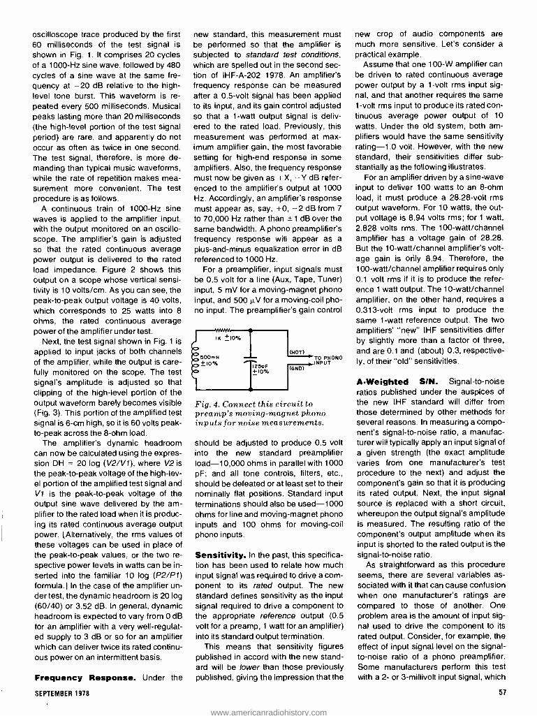
oscilloscope trace produced by the first 60 milliseconds of the test signal is
shown in Fig. 1. It comprises 20 cycles of a 1000 -Hz sine wave, followed by 480 cycles of a sine wave at the same fre- quency at -20 dB relative to the high - level tone burst. This waveform is re-
peated every 500 milliseconds. Musical peaks lasting more than 20 milliseconds (the high -level portion of the test signal period) are rare, and apparently do not occur as often as twice in one second. The test signal, therefore, is more de- manding than typical music waveforms, while the rate of repetition makes mea- surement more convenient. The test procedure is as follows.
A continuous train of 1000 -Hz sine waves is applied to the amplifier input, with the output monitored on an oscillo- scope. The amplifier's gain is adjusted so that the rated continuous average power output is delivered to the rated load impedance. Figure 2 shows this output on a scope whose vertical sensi- tivity is 10 volts /cm. As you can see, the peak -to -peak output voltage is 40 volts, which corresponds to 25 watts into 8
ohms, the rated continuous average power of the amplifier under test.
Next, the test signal shown in Fig. 1 is
applied to input jacks of both channels of the amplifier, while the output is care- fully monitored on the scope. The test signal's amplitude is adjusted so that clipping of the high -level portion of the output waveform barely becomes visible (Fig. 3). This portion of the amplified test signal is 6 -cm high, so it is 60 volts peak - to -peak across the 8 -ohm load.
The amplifier's dynamic headroom can now be calculated using the expres- sion DH = 20 log (V2 /V1), where V2 is
the peak -to -peak voltage of the high -lev- el portion of the amplified test signal and V1 is the peak -to -peak voltage of the output sine wave delivered by the am- plifier to the rated load when it is produc- ing its rated continuous average output power. [Alternatively, the rms values of these voltages can be used in place of the peak -to -peak values, or the two re- spective power levels in watts can be in- serted into the familiar 10 log (P2 /P1) formula.] In the case of the amplifier un- der test, the dynamic headroom is 20 log (60/40) or 3.52 dB. In general, dynamic headroom is expected to vary from 0 dB
for an amplifier with a very well- regulat- ed supply to 3 dB or so for an amplifier which can deliver twice its rated continu- ous power on an intermittent basis.
Frequency Response. Under the
new standard, this measurement must be performed so that the amplifier is
subjected to standard test conditions, which are spelled out in the second sec- tion of IHF -A -202 1978. An amplifier's frequency response can be measured after a 0.5 -volt signal has been applied to its input, and its gain control adjusted so that a 1 -watt output signal is deliv- ered to the rated load. Previously, this measurement was performed at max- imum amplifier gain, the most favorable setting for high -end response in some amplifiers. Also, the frequency response must now be given as +X, -Y dB refer- enced to the amplifier's output at 1000 Hz. Accordingly, an amplifier's response must appear as, say, +0, -2 dB from 7
to 70,000 Hz rather than ± 1 dB over the same bandwidth. A phono preamplifier's frequency response will appear as a
plus- and -minus equalization error in dB referenced to 1000 Hz.
For a preamplifier, input signals must be 0.5 volt for a line (Aux, Tape, Tuner) input, 5 mV for a moving- magnet phono input, and 500 µV for a moving -coil pho- no input. The preamplifier's gain control
TO PHONO INPUT
Fig. 4. Connect this circuit to preamp's moving- magnet phono inputs for noise measurements.
should be adjusted to produce 0.5 volt into the new standard preamplifier load -10,000 ohms in parallel with 1000 pF; and all tone controls, filters, etc., should be defeated or at least set to their nominally flat positions. Standard input terminations should also be used -1000 ohms for line and moving- magnet phono inputs and 100 ohms for moving -coil phono inputs.
Sensitivity. In the past, this specifica- tion has been used to relate how much input signal was required to drive a com- ponent to its rated output. The new standard defines sensitivity as the input signal required to drive a component to the appropriate reference output (0.5 volt for a preamp, 1 watt for an amplifier) into its standard output termination.
This means that sensitivity figures published in accord with the new stand- ard will be lower than those previously published, giving the impression that the
new crop of audio components are much more sensitive. Let's consider a
practical example. Assume that one 100 -W amplifier can
be driven to rated continuous average power output by a 1 -volt rms input sig- nal, and that another requires the same 1 -volt rms input to produce its rated con- tinuous average power output of 10
watts. Under the old system, both am- plifiers would have the same sensitivity rating -1.0 volt. However, with the new standard, their sensitivities differ sub- stantially as the following illustrates.
For an amplifier driven by a sine -wave input to deliver 100 watts to an 8 -ohm load, it must produce a 28.28 -volt rms output waveform. For 10 watts, the out- put voltage is 8.94 volts rms; for 1 watt, 2.828 volts rms. The 100 -watt /channel amplifier has a voltage gain of 28.28. But the 10- watt /channel amplifier's volt- age gain is orìly 8.94. Therefore, the 100 -watt /channel amplifier requires only 0.1 volt rms if it is to produce the refer- ence 1 watt output. The 10- watt /channel amplifier, on the other hand, requires a
0.313 -volt rms input to produce the same 1 -watt reference output. The two amplifiers' "new" IHF sensitivities differ by slightly more than a factor of three, and are 0.1 and (about) 0.3, respective- ly, of their "old" sensitivities.
A- Weighted SIN. Signal -to -noise ratios published under the auspices of the new IHF standard will differ from those determined by other methods for several reasons. In measuring a compo- nent's signal -to -noise ratio, a manufac- turer will typically apply an input signal of a given strength (the exact amplitude varies from one manufacturer's test procedure to the next) and adjust the component's gain so that it is producing its rated output. Next, the input signal source is replaced with a short circuit, whereupon the output signal's amplitude is measured. The resulting ratio of the component's output amplitude when its input is shorted to the rated output is the signal -to -noise ratio.
As straightforward as this procedure seems, there are several variables as- sociated with it that can cause confusion when one manufacturer's ratings are compared to those of another. One problem area is the amount of input sig- nal used to drive the component to its rated output. Consider, for example, the effect of input signal level on the signal - to -noise ratio of a phono preamplifier. Some manufacturers perform this test with a 2- or 3- millivolt input signal, which
SEPTEMBER 1978 57
www.americanradiohistory.com

is enough to drive the preamplifier to its rated output with the volume (gain) con- trol at its maximum setting. Others, rec- ognizing that most moving- magnet car- tridges produce considerably higher out- puts when they track heavily recorded passages, apply 10 mV to the phono in- put. They then advance the volume con- trol until the preamplifier produces its rated output.
Obviously, applying a greater input signal to the preamplifier means that less gain is required if the preamplifier is to produce its rated output. This results in a greater signal -to -noise ratio be- cause the noise, most of which is gener- ated in the input circuit before the vol- ume control, will be amplified less. Also, referencing a component's signal -to- noise ratio to its rated output makes comparison to the signal -to -noise ratio of another component misleading un- less both have the same rated output or a corrective factor is introduced to put both components on an equal footing.
The new standard attempts to set matters right by dictating that signal -to- noise measurements be performed in
accord with the standard test conditions mentioned earlier. Input levels are to be 5 mV for moving- magnet phono inputs,
m o
H 0
E 20
-30
-40
500 mV for line level inputs, and 500 µV for moving -coil phono inputs. A compo- nent's gain control is to be adjusted so that the appropriate reference output level (0.5 volt for a preamp, 1 watt for an amplifier) is presented to the standard load impedance.
The way in which a component's in- puts are terminated has also complicat- ed matters. Most noise measurements are made with the inputs shorted to ground. However, the impedance seen by the preamp when driven by an actual cartridge is by no means a short circuit. Measurements made when a cartridge is connected to the preamp's inputs can vary considerably from those obtained when the inputs are shorted.
To approximate the effect of a phono cartridge, the new standard specifies that the network shown in Fig. 4 be con- nected to each channel's moving -mag- net phono input when noise measure- ments are performed. Moving -coil inputs are to be terminated with a 100 -ohm re- sistor and line level inputs with a 1000 - ohm resistor. Standard output termina- tions are also to be used.
Another key area in which signal -to- noise specifications published under the new standard differ is in the area of weighting. The philosophy behind weighting is that not all noise signals are equally annoying to the listener. The fa- mous Fletcher- Munson curves clearly indicate that, at low listening levels, the human ear is considerably more sensi- tive to midrange frequencies than to bass and, to a lesser extent, treble fre- quencies. Weighting, therefore, is an at- tempt to take this characteristic of the ear into account when measuring a
10 50 100 500 I K
FREQUENCY IN HERTZ
5K IOK
047pF
TO DEVICE UNDER
60071 .33yF I .33yF
soon I.8K 1.8K
IOK
2200DF IOOK
TO MEASURING
EINSTRUMENT
Fig. 5. The "A" weighting curve (top) reflects the ear's sensitivity vs. frequency at listening level of 70 phons. Circuit below provides "A" weighting and matches 60 -ohm output to high- impedance instrument.
58
quantity such as signal -to -noise ratio. The goal is to make specifications more meaningful so far as "real life" audibility is concerned, not to make the "num- bers" look better.
Accordingly, the new standard calls for the use of the ANSI "A" weighting curve shown in Fig. 5A. This curve cor- responds to the sensitivity of the human ear at a listening level of 40 phons. It
peaks at about 2000 Hz and rolls off (at different rates) above and below that fre- quency. Weighting can be accomplished by inserting a suitable network between the output of the device under test and the measuring instrument.
Shown in Fig. 5B is an RC network which will provide "A" weighting and also match a 600 -ohm output imped- ance to a test instrument (such as a
VTVM) with a high input impedance. If a
voltmeter is used to measure noise, the greatest reading will be obtained if the bulk of the noise components are at mid- range frequencies. Noise consisting mainly of hum at the power -line frequen- cy or its second harmonic and high -fre- quency hiss will produce lower readings.
Total Harmonic Distortion. The new standard changes the definition of this key specification. It states that the spectrum analyzer, as opposed to the "old reliable" nulling distortion analyzer, is the preferred instrument to be used to measure THD. Total harmonic distortion in percent is determined as follows.
The amplitudes in rms volts of the fun- damental frequency and its harmonics appearing at the output of the device un- der test are to be measured using a
spectrum analyzer. Then the amplitudes of the harmonics are squared, added, and the square root of the resulting sum extracted. The square root is divided by the rms amplitude of the fundamental and the quotient multiplied by 100.
The older method of determining THD, namely by taking the reading from a conventional distortion analyzer, was flawed because it included residual noise in the "distortion." (The output of the conventional analyzer is now de- fined as total harmonic distortion plus noise, THD + N.) When measuring dis- tortion at low output power levels, it was difficult to satisfy the FTC requirement that rated distortion not be exceeded at any power level from 0.25 watt to the rat-
ed continuous power output. The problem is illustrated in the fol-
lowing practical example. An amplifier was driven to a high output level by a
1000 -Hz sine wave so that its output had
POPULAR ELECTRONICS
www.americanradiohistory.com

a THD content of 1 %, as indicated on a
conventional harmonic distortion analyz- er. (The conventional analyzer nulls out the fundamental component of the am- plifier output, measuring the amplitude of remaining signal components.) The amplifier's output is shown as the top os-
cilloscope trace in Fig. 6, and the output of the distortion analyzer as the lower trace. The output signal was then ap- plied to a spectrum analyzer. The 1000 -Hz fundamental of the input signal appears at the center of the spectrum analyzer's output (Fig. 7), and the har- monics to the right. The THD of the am- plifier output was calculated to be 1% by including the amplitudes of all harmon- ics which were less than 10 dB below the strongest harmonic (3000 Hz) in the algorithm previously described. Cal- culated distortion agreed closely with the reading on the conventional distor- tion analyzer.
Next, the level of the input signal was reduced so that the output of the amplifi- er was only 0.25 watt. The output was sampled by the distortion analyzer, and a reading of 1% was obtained. Some- thing was obviously wrong!
Applying this low -level output signal to the input of the spectrum analyzer while monitoring amplifier and distortion analyzer outputs on a scope, revealed the reason for the puzzlingly high distor- tion reading. (The top trace in the scope photo of Fig. 8 is the amplifier output, with vertical sensitivity increased; the lower trace shows the distortion analyz- er's output. Fig. 9 displays a CRT trace on a spectrum analyzer.)
The false distortion analyzer reading was actually caused by the low -level noise in the amplifier output, not by har- monic components. At this low power level, the noise produced by the amplifi- er was -40 dB referenced to the ampli- fied test signal. The THD content, how- ever, is substantially better (about -70 dB). Clearly, the distortion products were masked by noise. For this reason, the new standard defines the conven- tional distortion analyzer's reading as THD + N.
Input Impedance. As a rule, the out- put impedance of one audio component is not closely matched to the input impedance of the component it is driv- ing. For example, the output impedance of a preamplifier is usually low, on the order of a few hundred ohms, but the in-
put impedance of a power amplifier is
high, commonly tens of kilohms. How- ever, the components are compatible.
SEPTEMBER 1978
Fig. 6. Amplifier output driven to m ild clipping (top) has a THD content of 1% as indicated by a distortion analyzer, whose output is shown at bottom.
Fig. 7. Spectral analysis of the amplifier output 01,0 141111
as top trace in Fig 6.
Fig. 8. When amplifier output is reduced to 0.25 watt (top), output of nulling distortion analyzer (bottom) consists almost entirely of noise.
Fig. 9. Spectral analysis of low -level amplifier
output shows that any ha rmon is distortion
products are so low as to he below "grass" of noise floor.
The exception to this rule is the junc- tion of the phono preamplifier and car- tridge. Most moving- magnet cartridges perform optimally only when they see a
specific preamp input impedance. typi- cally 47,000 ohms resistive shunted by a
small amount of capacitance. The exact amount varies from one cartridge to the
next, but is usually within the 200 - to- 500 -pF range. If the cartridge is not
properly loaded, aberrations in its fre-
quency response will occur. The new standard takes the critical
nature of phono input impedance match- ing into account by requiring that the in-
put impedance be measured at several
59
www.americanradiohistory.com

frequencies. If it can be accurately de- scribed as a parallel RC circuit, then the R and C values are to be given as the rated input impedance. If the impedance is too complex to be modelled by a sim- ple RC network, it is to be rated as the magnitude of the impedance in ohms at 1000 Hz.
Secondary Disclosures. In addition to primary specifications, the new stand- ard also includes many secondary dis- closures any or all of which may be pub- lished at the manufacturer's option. Many of these specifications are similar to those published in earlier standards, so most readers are probably acquaint- ed with at least a few of them. However, several new ones have been developed in response to advances in both amplifi- er technology and our understanding of psychoacoustics. Let's look at a few of these new specifications.
Clipping Headroom. Most amplifier manufacturers have been rating con- tinuous average power outputs of their products at THD levels that are un- detectable by the human ear. However, it's useful to know when an amplifier's power output is exceeded to the point of clipping, which grossly (and audibly) dis- torts the input signal. That's what a clip- ping headroom spec reveals. It is the ratio (expressed in dB) of the continuous average power output at actual clipping to the rated continuous average power output of the amplifier.
Damping Factor. The new standard defines damping factor as the ratio of 8
ohms to the output impedance of the amplifier. Output impedance is to be measured while a standard output cur- rent is flowing from the amplifier into the load to simulate typical operating condi- tions. There are two damping factors which can be published. An amplifier's wideband damping factor is the mini- mum damping factor measured over its rated power bandwidth. The amplifier's low- frequency damping factor is mea- sured at 50 Hz, the resonant frequency of a typical speaker system. Previously,
an amplifier's damping factor was rated at 1000 Hz. The new spec is an im- provement because a high damping fac- tor can be more important in the bass re- gion than in the midrange, and an am- plifier's damping factor is not necessarily constant with frequency.
Intermodulation Distortion. Two methods of measuring IM distortion are specified in IHF -A -202 1978. In the old method, low- and high- frequency test signals were applied, and the output sampled. Here, if the amplifier is nonlin- ear, the high- frequency tone will be modulated to an extent by the low -fre- quency signal. Products will appear at the sum and difference frequencies. This method is called SMPTE -IM be- cause the Society of Motion Picture and Television Engineers developed it.
Recent investigations, however, indi- cate that intermodulation of two relative- ly high- frequency tones may be more audibly significant. Accordingly, the new method, called IHF -IM, employs test sig- nals at two frequencies which are swept across the audio band so that the differ- ence between them remains a constant 1000 Hz. The mean frequency is to be swept from 2500 Hz to the upper limit of the amplifier's rated power bandwidth.
All IM products up to the fifth order within the 20 -to- 20,000 -Hz band are to be measured and combined using an algorithm similar to that for THD calcula- tions to determine IHF -IM in percent. Measurements can be made at a series of power levels to produce a family of IM distortion vs. frequency curves. Either a
For those wanting more complete information on the new amplifier standard, Standard Methods of Measurement for Audio Amplifiers, IHF -A -202 1978, is available for $7.50 from the Institute of High Fi- delity, 489 Fifth Avenue, New York, NY 10017.
spectrum analyzer (the most convenient instrument) or a swept filter and oscillo- scope (or voltmeter) can be used to per- form IHF -IM measurements.
Transient and Slew Specifica- tions. The importance of an amplifier's ability to respond accurately to short- lived musical transients has been recog- nized in recent years. Two new specifi-
cations which help to rate transient -han- dling ability are Transient Overload Re- covery Time and Slew Factor.
To measure an amplifier's transient overload recovery time, the test signal shown in Fig. 1 (the same one used in
the dynamic headroom test) is applied to its input. The amplitude of the input sig- nal is then adjusted so that the low -level trailing portion is amplified to -10 dB relative to the rated continuous average power output of the amplifier. This means that the high -level, 20 -mil- lisecond "burst" portion of the test signal drives the amplifier 10 dB into overload.
The portion of the output signal im- mediately after the trailing elge is scruti- nized on a scope. The time in mil- liseconds required by the amplifier to re- cover so that there is no visible distortion on the oscilloscope is measured for each input. The worst -case result (long- est recovery period) is the rated tran- sient overload recovery time.
The second transient -related specifi- cation is slew factor. This new term should not be confused with the more fa- miliar slew rate, which is the maximum time rate of change in voltage at the out- put of the amplifier. There are several ways to measure slew rate, but not all of them will yield the same result. For this reason, the new standard speaks in
terms of slew factor rather than slew rate.
Slew factor is a ratio which describes the highest frequency (normalized to 20,000 Hz) that can be applied to the in- put of a component and be presented in amplified form at the output with a THD content of not more than 1 percent. The slew factor is obtained by dividing the highest frequency that satisfies these conditions by 20,000 Hz. The test is per- formed by applying a 1000 -Hz input sig- nal and adjusting its level so that the component delivers its rated output. The input signal is maintained at this level as it is swept upward in frequency. Har- monic distortion measurements are made as outlined earlier.
In Conclusion. The new IHF standard should do much to dispel the ambigui- ties encountered by prospective pur- chasers when comparing the specifica- tions of preamplifiers, power amplifiers, and integrated amplifiers that are pro- duced by different manufacturers. Per- haps its greatest accomplishment is to bring printed specifications into closer agreement with what we actually hear, thereby allowing the consumer to make a fully informed buying decision.
60 POPULAR ELECTRONICS
www.americanradiohistory.com

TYPICAL audio system is not suit- /Potable for disco applications. It lacks the mixing, monitoring, and microphone preamps normally found in such facili- ties. The Disco Mixer presented here is
a special -purpose audio preamplifier/ mixer with a number of attractive and unusual features. It has two indepen- dent phono preamplifiers employing the new IEC equalization characteristic, two IC- buffered auxiliary inputs, a low -noise microphone preamplifier, switching and mixing capability for multiple inputs, and the traditional preamp's bass, treble, balance, and volume controls. The Dis- co Mixer also contains a monitor circuit that allows the user to cue records or lis- ten to one program source while another is driving the system's power amplifier.
You can build either a preamp /mixer or a preamplifier only. A kit for the preamp /mixer is $110, while one for the preamp alone is just $70.
The Disco Mixer is designed around six integrated circuits. Thanks to the ad- vent of specialized IC's, signal process- ing functions previously performed by dozens of discrete components can now be accomplished by single chips. In
many cases, both stereo channels can be handled by one IC.
High -level signals in this project are processed by members of a new family of high -performance op amps that are fabricated by "BIFET" technology. This is a process which allows diffusion of
Build a Disco Preamp /Mixer
Provides multi- source inputs and
mixing /fading for your home disco.
both junction -field -effect and bipolar - junction transistors on the same chip. These op amps exhibit the excellent in-
put characteristics of JFET's and the highly desirable output characteristics of BJT's -literally, the best of both worlds. BIFET op amps have higher slew rates and cause less TH and IM distortion than common bipolar IC's (see Fig. 1).
About the Circuit. A block diagram of the complete mixer /preamplifier is
shown in Fig. 2. Functionally, the Disco Mixer can be considered to be made up of three types of circuits: input condition- ing, high -level processing, and output conditioning. Let's examine each.
Input conditioning for the line -level auxiliary inputs, which would typically be driven by a tuner or tape deck, consists of simple unity -gain inverting buffers. One of the four buffers included in the preamp is shown in Fig. 3. An RC net- work at the buffer input acts as a high - pass filter to prevent the passage of a dc level or infrasonic ac signals. One sec- tion of a quad BIFET operational amplifi- er, 1C3, presents an inverted version of the input signal to the switching matrix composed of S2 and S4. This buffer dis- plays a relatively high impedance (about 50,000 ohms) to the program source and a very low output impedance to the switching matrix. This avoids loading down the signal source and prevents in- teraction in the mixing process.
bi -fet pre -amp
?MC INPUT discoomixer
BY JOHN ROBERTS
10
%TOTAL HARMONIC DISTORTION
0.1
0.01
0.001
10
%TOTAL I NTERMODUL AT ION
DISTORTION I
0.1
0.01
0.001
10
FREOUENCY(kHZt 100
lo FREOUENCY(kHZ)
Fig. 1. TI's TL074 BIFET op amp generates less distortion than common bipolar linear IC's.
100
The signal conditioning stage for the microphone input must be able to ampli- fy signals generated by the microphone by 60 dB (1000 V /V) or more. An
NE5534N integrated circuit was select- ed for this task (Fig. 4) because it has a
high open -loop voltage gain and a very low input noise voltage. The open -loop gain -the gain of the device in the absence of feedback -must sufficiently exceed the closed -loop gain selected by the proper choice of feedback compo- nents if the amplifier is to exhibit gain ac- curacy and low distortion. (An amplifier's closed -loop distortion is its open -loop distortion divided by the ratio of open - loop to closed -loop gain.) The micro- phone preamp's input noise voltage is of critical importance because this noise signal will be amplified along with the millivolt -level microphone output signal.
With an open -loop gain of 6000 V/V at
10,000 Hz and less than one microvolt of input noise, the NE5534 (1C7) meets the foregoing requirements easily. The noninverting microphone preamp fea-
61
www.americanradiohistory.com
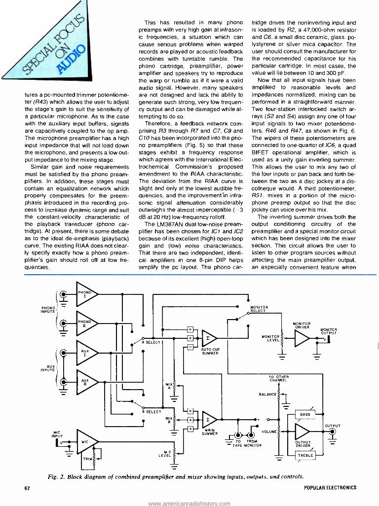
c4 4
tures a pc- mounted trimmer potentiome- ter (R43) which allows the user to adjust the stage's gain to suit the sensitivity of a particular microphone. As is the case with the auxiliary input buffers, signals are capacitively coupled to the op amp. The microphone preamplifier has a high input impedance that will not load down the microphone, and presents a low out- put impedance to the mixing stage.
Similar gain and noise requirements must be satisfied by the phono pream- plifiers. In addition, these stages must contain an equalization network which properly compensates for the preem- phasis introduced in the recording pro- cess to increase dynamic range and suit the constant -velocity characteristic of the playback transducer (phono car- tridge). At present, there is some debate as to the ideal de- emphasis (playback) curve. The existing RIAA does not clear- ly specify exactly how a phono pream- plifier's gain should roll off at low fre- quencies.
This has resulted in many phono preamps with very high gain at infrason- ic frequencies, a situation which can cause serious problems when warped records are played or acoustic feedback combines with turntable rumble, The phono cartridge, preamplifier, power amplifier and speakers try to reproduce the warp or rumble as if it were a valid audio signal. However, many speakers are not designed and lack the ability to generate such strong, very low frequen- cy output and can be damaged while at-
tempting to do so. Therefore, a feedback network corn -
prising R3 through R7 and C7, C9 and C10 has been incorporated into the pho- no preamplifiers (Fig. 5) so that these stages exhibit a frequency response which agrees with the International Elec- trochemical Commission's proposed amendment to the RIAA characteristic. The deviation from the RIAA curve is
slight and only at the lowest audible fre- quencies, and the improvemenrin infra- sonic signal attenuation considerably outweighs the almost imperceptible ( -3 dB at 20 Hz) low- frequency rolloff.
The LM387AN dual low -noise pream- plifier has been chosen for ¡Cl and IC2 because of its excellent (high) open -loop gain and (low) noise characteristics. That there are two independent, identi- cal amplifiers in one 8 -pin DIP helps simplify the pc layout. The phono car-
tridge drives the noninverting input and is loaded by R2, a 47,000 -ohm resistor and C6, a small disc ceramic, glass, po- lystyrene or silver mica capacitor. The user should consult the manufacturer for the recommended capacitance for his particular cartridge. In most cases, the value will lie between 10 and 300 pF.
Now that all input signals have been amplified to reasonable levels and impedances normalized, mixing can be performed in a straightforward manner. Two four -station interlocked switch ar- rays (S2 and S4) assign any one of four input signals to two mixer potentiome- ters, R46 and R47, as shown in Fig. 6.
The wipers of these potentiometers are connected to one quarter of IC6, a quad BIFET operational amplifier, which is
used as a unity gain inverting summer. This allows the user to mix any two of the four inputs or pan back and forth be- tween the two as a disc jockey at a dis- cotheque would. A third potentiometer, R51, mixes in a portion of the micro- phone preamp output so that the disc jockey can voice over his mix.
The inverting summer drives both the output conditioning circuitry of the preamplifier and a special monitor circuit which has been designed into the mixer section. This circuit allows the user to listen to other program sources without affecting the main preamplifier output, an especially convenient feature when
PHONO INPUTS
(
INPUTS
MIX B
MIC LEVEL
u AUTO CUE SUMMER
MONITOR SELECT
MONITOR LEVEL
MONITOR DRIVER
MONITOR OUTPUT
TO OTHER CHANNEL
BALANCE
MAIN SUMMER
TO TO FROM - TAPE MONITOR
VOLUME
OUTPUT
Fig. 2. Block diagram of combined preamplifier and mixer showing inputs, outputs, and controls.
62 POPULAR ELECTRONICS
www.americanradiohistory.com

J2 +
RIO RI I
10OK I00K
O TO
CI21 IyF
O 0K jR9 (6,9,13)
2
3
5)0,
12)
IC3=TL074
+ISV
4
I/4
IC3
+ 11
-15V
1
7,9,14 O
O
52, S4
C13
Fig. 4. Microphone preamp features
high gain and sensitivity control.
4- 25V
J3
V R12
Fig. 3. Schematic of one of four auxiliary input buffers which employ the new BIFET IC.
+15V
100K
C1+ 41 2205F
ce
Re IOOK
R13 R43 R15 IC7=NE5534N ton
TO 52, S4
10K IOOK
Fig. 5. One of four phono preamps with IEC equalization. Capacitive coupling is used as in all other inputs.
TO R51
cueing up special record cuts or verify- ing the desired operation of a program source before routing it to the output.
A four -station interlocked switch ar- ray, S5, selects the monitoring mode. The user can monitor the A mixer input only, the B input only, the main pream- plifier output (highly desirable if he is in a booth away or acoustically isolated from the sound system), or monitor in the "Auto -Cue" mode. Auto -Cue monitoring means that the user is listening to the exact opposite of his mix settings. For example, if mix A potentiometer R46 is
at its maximum setting and MIX B poten- tiometer R47 is at its minimum setting, he will hear the Mix B signal through the monitor if S5 is in the Auto -Cue position. Then, if the Mix A potentiometer is rotat- ed fully counterclockwise and Mix B fully clockwise, Mix A will be heard. This mode is very useful in two -turntable sys- tems because it allows the deejay to al- ways listen to the one being cued.
The level of the monitor signal is con- trolled by MONITOR LEVEL potentiometer R48. A dual 2 -watt audio amplifier, 105,
amplifies the monitor signal and delivers it to J4, a stereo phone jack. Either a pair of headphones or small monitor speak- ers can be plugged into J4. The audio IC, an LM377N, has internal current lim- iting and thermal protection so that, if
overloaded, it will shut itself off until it
CI, C2, C3, C20 *, C25- 1000 -1,,F, 16 -volt electrolytic
C4, CI4- 220 -µF, 35 -volt electrolytic C5 *, C21, C22, C26-0.1 -p,F, 50 -volt disc
ceramic C6 * *- I0 -to- 300 -pF (see text) C7 * *- 22 -p.F, 16 -volt electrolytic C8 * *, C I 1 * *- 4,7 -.LF, 16 -volt electrolytic C9 * *- 2200 -pF, 5% tolerance polystyrene C I0* *- 8200 -pF, 5% tolerance polystyrene C12 * *, C13, C17 *, C18 -1 -p,F, 16-volt elec-
trolytic C 15 *- 0. I -tLF, 10% tolerance Mylar C 16 *x.01 -p.F, 10% tolerance Mylar C 19 *- 100 -pF disc ceramic C23, C24-0.01 -µF disc ceramic C27 *- I 0 -pF disc ceramic DI through D6- IN4001 rectifier Fl -,- ampere fast -blow fuse ICI, 1C2- LM387AN dual low -noise pre-
amplifier (National Semiconductor) IC3, IC4, IC6- TL074CN BIFET quad opera-
tional amplifier (Texas Instruments) IC5- LM377N dual 2 -watt audio amplifier
(National Semiconductor) IC7- NE5534N low -noise preamplifier (Sig -
netics) J 1 * *- insulated phono jack 12 * *,J5 *,J6 *,17 *,J8 *- phonojack J3 -1/4-inch phone jack J4-1/4-inch stereo phone jack LEDI -20 -mA light emitting diode The following are 1/4-watt. 5% tolerance car-
bon -film resistors.
SEPTEMBER 1978
PARTS LIST
RI *, R13, R40-10 ohms R2 * *- 47,000 ohms R3* *43,000 ohms R4* * -360 ohms R5 * *- 33,000 ohms R6 * *- 390,000 ohms R7 ** -3600 ohms R8 * *, R9 * *, R10 * *, R11 * *, R1295, R15,
R174, R204, R27 *, R28 *, R29 *, R30 *, R31 *, R329, R33 *, R34 *, R35 *, R36 *,
R37 *, R38, R41*, R42- 100,000 ohms RI6 *, R26* -100 ohms R 19 *- 24,000 ohms R21*, R22 *, R23* -5600 ohms R14, R24 *, R25*-I800 ohms R43 -10,000 -ohm linear -taper printed circuit
trimmer potentiometer R44- 100,000 -ohm linear -taper potentiometer R45 through R48 -50,000 -ohm dual audio -
taper potentiometer R49, R50- 50,000 -ohm dual linear -taper po-
tentiometer R51- 50,000 -ohm audio -taper potentiometer S I , S3 -Dpdt pushbutton switch S2, S4, S5- four -station dpdt interlocked
pushbutton swich TI -24 -volt, 100 -mA center -tapped trans-
former (Signal Transformer Co. #241-4-20)
Misc.- Printed circuit boards and standoffs, IC sockets or Molex Soldercons (if desired), shielded cable, LED holder, hookup wire,
suitable enclosure, machine hardware, line cord and strain relief or grommet, solder, etc.
Note -The following are available from Phoe- nix Systems, 375 Springhill Road, Monroe, CT 06468, (203) 261 -4904: Complete kit of parts including enclosure for preamp /mixer, No. P- 1130 -DM, for $110.00; complete kit of parts including enclosure for preamp only, No. P- 1130 -PA, for $70.00; etched and drilled preamplifier pc board, No. P- I130 -BPA, for $7.50; etched and drilled mixer pc board, No. P- 1130 -BDM, for $7.50; power transformer TI, No. P- 1130 -T, for $6.00; dpdt pushbutton switch, No. P- 1130 -SWI $1.00; four -sta- tion dpdt interlocked switch, No. P -1130- SW2, for $4.00; BIFET quad op amp, No. P- 1130- C- TL074CN, for $3.50; dual low - noise amplifier, No. P- 1130- C- LM387AM, for $3.50; dual 2 -watt audio amplifier, No. P- 1130 -C- LM377N, for $3.00; and low - noise, high -gain op amp, No. P- 1130 -C- NE5534, for $3.00. All integrated circuits are fully tested. Please allow six weeks for delivery. Connecticut residents add 7% sales tax; COD charge $0.85. Handling charge is $1.00 for orders of less than $10.00. No shipping charges within conti- nental U.S.
* -two of each component required for full stereo preamp /mixer.
** -four of each component required for full stereo preamp /mixer.
63
www.americanradiohistory.com

Train with NTS for the Microcomputers, digital
the first name
Microcomputers
The world of electronics is daily becoming more challenging. Technology is growing more specialized, and the importance of digital systems increases every day. Test instruments, home entertainment units and industrial control systems are all going digital. And now, NTS training programs include a wider choice of solid -state and digital equipment than ever before offered in any home study course: Advanced NTS /Heath digital color TV (25" diagonal with optional programming capability), NTS /Heath microcomputer, digital test equipment, digital stereo receiver (70 watts per channel), NTS compu- trainer, plus much more state -of- the -art equipment to make your training exciting and relevant.
The equipment you receive with NTS training programs is selected to provide you with a solid
64
background in electronic systems. Kits and lessons are designed to work together to demonstrate electronic principles and applications. The kit -building not only shows you how electronic hardware functions, but how various circuit designs accomplish different purposes. Your lessons guide you through any number of experiments associated with many projects. This is the Project- Method, and it works. Step -by -step, you learn how and why digital electronics has become a part of our world, and the even bigger role it is sure to play in the future.
Whether you are looking for training in Consumer, Commercial, or Industrial electronics, NTS offers fourteen courses, some basic, many advanced, in
several areas of electronics. An all -new full -color NTS catalog shows you what each course covers,
POPULAR ELECTRONICS
www.americanradiohistory.com

electronics of the future. systems and more...from In home study.
/ ®ßt8°
and every piece of equipmert included.
Send for it today, and see for yourself what's really happening in electronics training technology at NTS. Find out how much has changed, and what new directions the field is taking. You'll probably want to be a part of it.
It's free. Just mail the card or coupon. Today.
NO OBLIGATION. NO SALESMAN WILL CALL. APPROVED FOR VETERAN TRAINING.
NATIONAL TECHNICAL SCHOOLS TECHNICAL -TRADE TRAINING SINCE 1905
Resident and Home -Study Schools 4000 South Figueroa St.. Los Angeles. Calif. 90037
SEPTEMBER 1978
. NATIONAL TECHNICAL SCHOOLS Dept. 205 -098 4000 South Figueroa Street. Los Angeles, California 90037
Please send FREE Color Catalog and Sample Lesson.
Color TV Servicing B & W TV and Radio Servicing FCC License Course Electronic Communications Electronics Technology Audio Electronics Servicing Digital Electronics MicroComputers /MicroProcessors
1
1
1
1
1
1
1
Name
Address -
-
Apartment Number -
Age __
City _ State _Zip
if interested in G.I Bill information. LCheck if interested ONLY in classroom training in Los Angeles
i 1
1
1
1
1
1
67
www.americanradiohistory.com

cools down, thus avoiding thermal self - destruction.
The output of the mixer is applied to
TO PHONO I PRE AMP
TO PHONO II PREAMP
TO AUX I PREAMP
TO AUX II PREAMP
TO PHONO I ®0 PREAMP 0 0
AA BB
00 S2 TO AUX I S2 PREAMP
TO AUX II, 00 1 PREAMP
00 100
1100 11100
100 00. 00. 00
TO PHONO II
PREAMP ~
TO PIN 6
R16 10011
IC 7
S2 R46
1
154
50K MIX A
the output conditioning section of the preamplifier (Fig. 7). Switch S3 provides tape monitor facilities. Potentiometers R44 and R45 are balance and volume controls, respectively. A BIFET buffer amplifies the signal and presents it to the output stage in which the tone con- trols are found. Drive signals for the sys- tem's power amplifier(s) are available at jacks J7 and J8.
The excellent power supply rejection of the integrated circuits employed in
OUTPUT A
R47 50K
MIX B
TO PP OUTPUT REAM ~
AUTO CUE
+15 V
10
(I 2) 4
S5
9
R27 IOOK
R29 IOOK
R30 IOOK
R48 50K
MONITOR LEVEL
R51 50K MIC
LEVEL
TO
OTHER CHANNEL
R34 1001<
IC5=LM377N IC6=TL074CN
R44 IOOK
BALANCE
S3 - RIB
RI? IOK A
IOOK
p 50K (, _ VOLUME
J5 J6 TO - FROM TAPE MONITOR
1ODU D5
iN400i121 Dfi
1 +25v C4 220yF
R35 IOOK
R20 I OO K
this project eliminates the need for a
regulated supply. As shown in Fig. 8,
two full -wave rectifiers and filter capaci- tors furnish the ± 15 volts required by the BIFET operational amplifiers and the microphone preamp. The + 15 -volt line is tapped to power the monitor audio driver. A voltage doubler composed of C3, C4, D5 and D6 develops the +25 volts required by the phono preamps.
Construction. Printed circuit assem-
+
+15V
R40 1011
}
TIpF IOOK MOO S TpF 2
C17 IyF
(9) 14 1O00NF TO J4 R36 I/2 2
MONITOR } IOOK + OUTPUT
R37 100K
R39 R4 10K IOOK
C19 100pF
Fig. 6. Schematic diagram of the miring and monitoring circuits (one channel shown). BIFET op amps perform the mixing and an audio IC provides monitor output.
C15
J7
IC4=TL074CN
R24 1.8K
950 50K
TREBLE
R25 1.8K
Fig. 7. Output stages of the preamplifie, for one channel. Conventional bass and treble tone controls are included. as well as a tape monitor loop.
Fig. 8. Schematic of power supply. which delivers three voltages required by the disco mixer stages ( + 15. -15 and +25 V).
OUTPUT
68 POPULAR ELECTRONICS
www.americanradiohistory.com

bly techniques are strongly recom- mended. Although it is possible to em- ploy perforated board and point -to -point wiring, the layout of the high -gain stages (phono and microphone preamplifiers) is
critical. These circuits are very sensitive to ground loops, hum fields and stray feedback paths. Extensive power supply decoupling is called for because the IC's
-CS- -R3 R6
I -R4- -RS- ° v
I ~</ \ -C9- imó á -R7- z=
°H -R2- I
\/ -° ÿ- I\ -C9- im° <
J n -R8- -R8- -R7- I
-- -R4- -R5- -R3- -R6-
-R3- -R4-
J C Vo -C9- im _R7- I
- R2 -RB-
N -RB- R2 I -R7-
C6 V -C9- %m
° -0R4- -RS-
° -R3- -R6- 1
n0-- -RII- -RIO- XSc b- N- -R9-
IT, N R9- + - m/ cm Ñ°/ -RIO- ti H -RII-
-05- -R6 -R5- °
Ó
-R20- o-- -R19- o- -RI9- -R20-
-C26-
w H
W
e
N -RII- -0 I I I I -RIO- v A:. 7, a -R9- 1 m m m m - R9 - 1 I I
-RIO- -R21- R -RII n a
-R24- Y- CI5- ( R22- v N I _16_ ° v= R26- -:I
c-i m 'I -R23--R25- -m 1
-R23- -R25- o Th o x -R26- -!:,,I; F.,
I ° R22- -mm v tC15-¡ -R24-
x
7u- ó A
-R21- -C21 - -R14- II < o o
W II I I o v 0
-C4- i -C3- I I
-CI- -C2-
LTI PRIMARY 117 VAC
FI
m
_ o z ñ
Fig. 9. Actual -size etching and drilling guide for the pc board for the preamplifier is shown at left. A diagram for components placement is above.
employed in this project have very high gain- bandwidth products and can break into oscillation very easily.
Suitable etching and drilling and parts placement guides for the preamp and mixer boards are snown in Figs. 9 and 10, respectively. If mixing facilities are not desired, the preamp board can be used on its own as a high -quality stereo
preamplifier. You will notice that both the schematic diagrams and the pc guides contain numerous points labelled with letters of the alphabet. These have been included to ease interconnections be- tween the boards, and the boards and the jacks, switches and potentiometers. Most of these connections can be made
(Continued on page 71)
SFPTEMRFR 197R 69
www.americanradiohistory.com

Due to the nature of cutting heads, play- back cartridges, and the recording medium it- self, a precise amount of pre- emphasis and de- emphasis is introduced in the record/ playback process. The pre- emphasis charac- teristic attenuates low frequencies so that "cutover" (the excursion of the cutting stylus through the wall of one groove into the wall of the preceeding one) is avoided and boosts high frequencies to improve the signal -to- noise ratio. During playback, a mirror image de- emphasis characteristic must be intro- duced so that a flat overall frequency re- sponse is achieved.
Exactly how much pre- emphasis and de- emphasis is used has for many years been determined by the RIAA (Recording Industry Association of America) standard. The stan- dard has been universally accepted -even the state recording labels of Eastern Europe- an countries (Melodiya, USSR; Supraphon, Czechoslovakia; Hungaroton, Hungary; etc.) employ it. This world -wide acceptance of one recording standard has resulted in benefits to the recording industry and the consumer.
Recently, however, this unquestioned ac- ceptance has been challenged by a proposal from the International Electrochemical Com- mission. This group has suggested an amendment to the existing RIAA standard which incorporates two modifications. The proposed changes are slight, as shown in the Figure, but a discussion of them is warranted.
The existing RIAA recording and playback curves have been around so long that they cover a frequency range of only 30 to 15,000 Hz. No one will take issue with the IEC pro- posal to extrapolate the existing curves to 20,000 Hz. In fact, phono preamp designers have been doing it for years. The amendment will merely give this practice official sanction.
The really controversial part of the IEC pro- posal deals with the lower end of the equali- zation characteristic. The Commission is sug- gesting a low frequency rolloff -down 3 dB at 20 Hz and having a 6 -dB /octave slope be- low that frequency. Informally, circuit design- ers have extrapolated the curve to 20 Hz, but there has been no general consensus as to what should be done below that frequency. It
is below 20 Hz that serious difficulties are en- countered.
Phono Equalization Time For a Change?
Record Warps. The gradual but continuing deterioration -on some labels, at least -of record quality has made warped discs the rule rather than the exception. Spectral anal- ysis indicates that the waveforms caused by warps possess significant amounts of energy in the 5- to -10 -Hz region even though their fundamentals lie octaves lower at about 0.03 Hz. Ten hertz is below the response of the human ear and that of most audio systems, and playback at moderate sound levels should not and usually does not present any difficulty. Problems can arise, however, when sound levels are increased or signal process- ing is introduced.
For example, a warp waveform superim- posed on an audio signal can cause a tape recorder to saturate the tape, resulting in a very disturbing amplitude modulation and /or distortion. Furthermore, nonlinear signal processors such as noise reduction units can be tricked into interpreting the warp as a valid audio signal during encoding. This by itself is not a problem until an attempt is made to de- code the signal and the infrasonic signal has been lost to the tape medium's limited low- frequency response. The resulting output signal is the audio signal modulated by the in- frasonic warp which is no longer present even though it is really required for proper de- coding. The infrasonic signal is long gone, but the modulation or distortion it has caused remains.
In straight playback situations, the effects of record warps on signal processors are not encountered but other serious problems can
i>=2
En aa Jh ó
+20
+15
+10
+5
o
5
io
15
20
crop up, especially at high listening levels. The power amplifier, if its frequency response extends sufficiently low, cannot discriminate between audible and infrasonic signals and will try to drive the speakers with an amplified version of whatever is applied to its input jacks. The possible deleterious effects of excessive speaker cone excursion and am- plifier clipping are well -known and can result in permanent speaker damage and /or objec- tionable levels of distortion.
The ideal solution to the record warp prob- lem would be an improvement in the manu- facture and quality control procedures at the record plant. However, in the design of the Disco Mixer, a more realistic approach has been taken. RC networks have been included in the project's phono preamplifiers to give a de- emphasis characteristic coinciding with the IEC proposal. The difference in bass re- sponse between the existing and proposed standards is so slight ( -1 dB at 40 Hz, 3 dB at 20 Hz) as to be barely audible, and will cer- tainly not render obsolete existing record col- lections.
Probably the only people who will be upset by the IEC characteristic are those who put more faith in figures that they read rather than in the sounds that they hear. Of course, such people could be satisfied by a phono preamp with switchable equalization. But they should be warned to pay close attention to the set- ting of the equalization switch. It will be very difficult for them to tell the difference solely on the basis of what they hear -they are listen- ing to a warped record!
RIAA de- emphasis shown in black and IEC amendments in color.
T
10 20 50 100 200 500 1000 2000 FREQUENCY IN HERTZ
5000 10,000 20,000
70 POPULAR ELECTRONICS
www.americanradiohistory.com
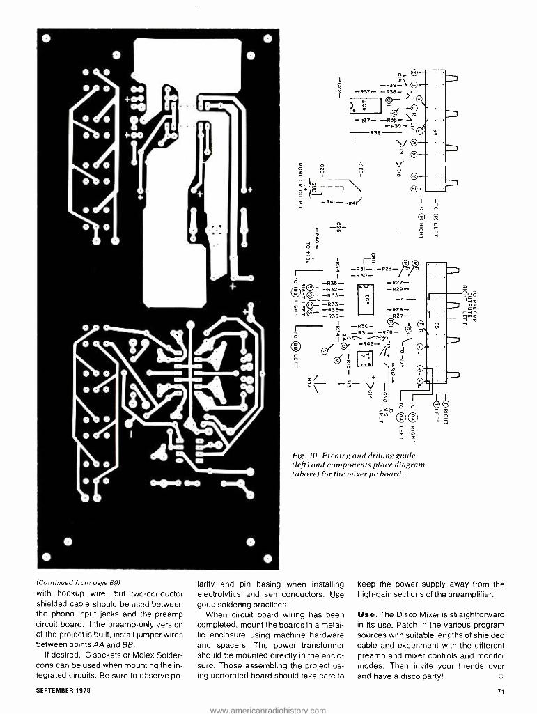
n I
m\ Ñ -R39- ^> -R37-
I O- >-40 H
r 1
-R37- -R36-,
A 0
O 1
+ -
R38
G)
ró
-R39-
,Wp -R31- -828- % -1 I -R30- O -1235- -827- -
;i0"-- m ÿ o -R33- ,3
ml'- -R33- i R32- -R29- H
v
CHi
m
-R29-
-R30-
o
(Continued from page 69)
with hookup wire, but two conductor shielded cable should be used between the phono input jacks and the preamp circuit board. If the preamp -only version of the project is built, install jumper wires between points AA and BB.
If desired, IC sockets or Molex Solder - cons can be used when mounting the in- tegrated circuits. Be sure to observe po-
r m T 1 =
H
Fig. 10. Etching and drilling guide (left) and components place diagram (above) for the mixer pc hoard.
larity and pin basing when installing electrolytics and semiconductors. Use good soldering practices.
When circuit board wiring has been completed, mount the boards in a metal- lic enclosure using machine hardware and spacers. The power transformer should be mounted directly in the enclo- sure. Those assembling the project us- ing Derforated board should take care to
keep the power supply away from the high -gain sections of the preamplifier.
Use. The Disco Mixer is straightforward in its use. Patch in the various program sources with suitable lengths of shielded cable and experiment with the different preamp and mixer controls and monitor modes. Then invite your friends over and have a disco party! O
SEPTEMBER 1978 71
www.americanradiohistory.com

BY MILES H. MARKS
Now You Can Enjoy Hi -Fi Television Sound
Diplexed program transmission system allows networks to send audio and video on one cable
and offers viewers high -quality sound.
oN January 23, 1978, in a concerted effort to reduce operating costs, the
three major television networks began to use the "Farinon FV -43 FM Transmis- sion Channel System." This is a diplex- ed method of transmitting audio and video signals on the same coaxial cable. Previously, audio and video were trans- mitted separately from the point of origin to local network affiliates via AT &T wire and microwave links. The old system had two serious disadvantages -the high cost of maintaining two separate transmission lines and the low- fidelity sound that was actually delivered. The new method, however, not only saves the networks money but also delivers high -fidelity FM sound to local studios!
Very little (if any) fanfare accompa- nied the changeover, so most people don't realize the hi -fi capabilities of TV audio. And given the crude audio provi- sions in many television receivers, most viewers are unaware that the potential for hi -fi is there.
Actually, the frequency response of network audio program material now de- livered to local studios is 50 to 15,000 Hz t0.3 dB (Fig. 1) and its THD content at 1000 Hz and + -18 dBm is less than -54 dB. The networks had originally planned to start using the new system a
VIDEO INPUT
AUDIO INPUT
CHAN I
AUDIO INPUT
CHAN 2
72
r TRANSMIT TERMINAL
DIPLEXER
few weeks earlier than they did. How- ever, CBS requested a delay to ensure that the old, proven system would deliv- er the audio portion of its "Super Bowl" coverage (the most widely watched pro- gram of the year) without interruption.
- Q
w cc -0.5- /
50 100 7.5K I4K 15K FREQUENCY (Hz)
Fig. 1. Frequency response of demodulated audio of FV -43.
How It Works. A block diagram of the FV -43 FM Transmission Channel Sys- tem is shown in Fig. 2. It provides trans- mission facilities for one or two high - quality audio channels, positioned im- mediately above the standard video baseband -channel 1 at 5.8 MHz and channel 2 at 6.4 MHz. These channels provide low- noise, low- distortion, and wide- bandwidth audio program facilities that can be transmitted simultaneously with a video signal. Each requires an FM
7
L J
TRANSMISSION MEDIUM -}-II (RADIO LINK OR VIDEO
CABLE)
BA SE BAND SPECTRUM
VIDEO
4.2MHz lllIl IMI
15.8 MHz 6.4MHzt
FM SUBCARRIER FREQUENCIES
channel transmitter at the point of origin and an FM channel receiver at the dis- tant terminal.
The diplexer passes video compo- nents below 5 MHz. There is at least 40 dB of video attenuation at the transmis- sion channel sub -carrier frequencies. The diplexer is carefully designed to minimize video signal degradation. Wideband amplifiers, low- ripple filters, and equalizers provide very good ampli- tude response. The input and the output of the diplexer are direct -coupled to min- imize bounce and variations in low -fre- quency response. Filtering in the video line at the transmit terminal rejects spuri- ous signals at FM channel sub -carrier frequencies. An identical filter in the video path at the receiving terminals prevents FM channel sub -carriers from entering the video output line.
In the diplexer, the video signal passes through a transient voltage sup- pression network and an impedance matching network to the input of a differ- ential amplifier. The amplifier output is
filtered and equalized to compensate for phase distortion. caused by the filter. The equalized signal is then applied to the in-
put of a second differential amplifier which boosts it to standard line level. The output of the FM channel transmit-
RECEIVE TERMINAL
DIPLEXER 1
Fig. 2. Block diagram of the FV -43 FM Transmission Channel System.
VIDEO OUTPUT
AUDIO OUTPUT CHAN I
AUDIO OUTPUT CHAN 2
POPULAR ELECTRONICS
www.americanradiohistory.com

ter is applied to the other input of the second differential amplifier. The base - band signal and the FM channel subcar- riers leave the diplexer through either a
balanced or unbalanced output.
FM Channel Transmitter and Re- ceiver. In the FM channel transmitter, an applied audio signal is amplified and receives pre- emphasis before it is used to modulate a voltage -controlled oscilla- tor (vco). The frequency -modulated os- cillator signal is filtered to suppress os- cillator harmonics and reduced in ampli- tude by a variable attenuator to the de- sired output level. Frequency stability of the transmitter is obtained by phase - locking the vco to a crystal -controlled reference oscillator.
In an FM receiver, a signal from the di- plexer is first applied to an attenuator
pad and then to a bandpass filter that selects the appropriate FM channel sub - carrier. The receiver circuits following the filter limit and demodulate the sub - carrier, add de- emphasis, and amplify the recovered audio program material.
The Future. The FV -43 FM Transmis- sion Channel System opens up a whole new dimension in television receiver de- sign and product appeal. Now television manufacturers can bring the audio sec- tions of their products to a level that matches the technology of their video counterparts. Existing television receiv- ers can be modified for high -fidelity re- production by tapping the audio at the output of the FM detector and feeding it
to an external audio system. To maintain isolation between the re-
ceiver and the audio system, an inter-
stage audio transformer or an emitter or voltage follower is needed. If the televi- sion is transformerless (chassis tied di- rectly to one side of the ac line), do not connect its chassis to the chassis of the preamplifier or integrated amplifier un- less you either use a coupling transform- er on the audio line or an isolation trans- former on the television's power line.
Interestingly, the FV -43 system incor- porates provisions for two audio chan- nels, leaving open the options of stereo- phonic sound for television, off-line data communications or even computer con- trol. One needn't wait for TV models with hi -fi audio provisions or modify present receivers, however. At least two compa- nies offer separate tuners for TV audio only- Pioneer and Rhoades -which can do the hi -fi trick with no muss or fuss. O
BY ALEXANDER W. BURAWA Features Editor
Metal Cassette Tape Debuts Fine -metal formulation tape may revolutionize cassette deck design.
EVER since its introduction, magnetic recording tape has used metal ox-
ides in one form or another for the re- cording material. Now, a new type of re- cording material made up of fine metal - not metal- oxide -particles is expected to make a tremendous impact in audio and video recording. The new tape is
said to produce a level of performance that surpasses that of the best conven- tional metal -oxide tapes. Although the metal tapes are playback -compatible with current tape decks equipped with
Fig. 1. Maximum output levels as ftauction of bias.
70 -µs playback equalization (the Cr02 setting), satisfactory recording will re- quire new recording equipment.
One of the first of the new metal tapes to come on the consumer audio market is 3M Company's Scotch brand "Meta - fine" in the popular cassette format. (Other tape manufacturers are sure to market their own versions soon.) At a re-
cent press conference, a Metafine audio cassette was recorded, erased, and
played back on a tape deck that was specially modified to accommodate its
characteristics. The cassette delivered a
maximum output 5 to 10 dB greater than typical chrome tapes and 3 to 7 dB greater than Scotch Master II tape. This means that maximum output is at least double that of other tapes, depending upon the frequency selected.
Lower distortion, additional high -fre- quency response, improved S /N, and increased maximum output are among the benefits it is claimed one will realize with metal tapes.
Exact increases in performance will depend upon the selection of benefits manufacturers build into future tape re- corders, of course.
Metal tape is said to permit higher per- formance characteristics at present tape speeds and packing densities. Accord-
ingly, it also opens the way for dramatic changes in speed, format, and compo- nent size without sacrificing perfor- mance capabilities.
Technical Details. The level and fre- quency distribution of the new metal tapes are similar to those for Cr02 tapes. A 70 -µs equalization was select- ed to minimize noise, while new metal - tape recorders will utilize Sendust heads because they do not saturate as easily as other types of heads. Because of its
10
MAXIMUM MooLa "
LEVEL
.. / aaoóoEa "o
vs ''
V Fí61 (w 4
0 .1 .< .6 .6 .10
Hin. AMPLITUDE n0
05,4
Fig. 2. Maximum modulation and harmonic distortion. levels.
SEPTEMBER 1978 73
www.americanradiohistory.com

high- density recording capability, it has been suggested that a 15/16 -ips record- ing speed is possible, providing better sound quality than is obtainable at to- day's 3 -/ ips!
The characteristics of metal -tape au- dio cassettes are best realized at a re- cording bias significantly different from those of present recorders, which is one of the reasons new equipment is neces- sary for recording. Another is that a
stronger erase current is required. One has only to look at the specifica-
tions in the table for various tapes to see the superiority of metal tapes.
The curves in Fig. 1 show compara- tive output levels for Scotch Metafine and a top Cr02 audio tape The max- imum output level at saturation at 12,500 Hz is 7 dB greater for Metafine at the optimum bias for each tape. Figure 2
have its Metafine tape on the consumer market before the end of this year. It will first be introduced in the popular C -90 cassette size and will carry a list price of about $10. So far, there is at least one manufacturer who announced produc-
TAPE SPECIFICATION COMPARISONS
Retentivity Remanence Coercivity (gauss) (lines /4 in.) (oersted)
Typical Chrome 1400 0.43 550 Scotch "Master II" 1500 0.60 550 Scotch " Metafine" 3400 0.80 1000
illustrates comparative modulation and harmonic -distortion levels for the same tapes. The maximum modulation level (3% third -order harmonic distortion at 333 Hz) is up to 9 dB greater for Meta - fine tape.
The Agenda. 3M Company (and un- doubtedly other manufacturers) plans to
tion of a cassette deck to accommodate the new metal tape for both playback and recording. It is the Model TCD 340 AM three -motor /three -head cassette deck from Tandberg. And $1300 is the suggested retail price. Other recorder manufacturers will likely follow and may already be offering for sale metal -tape recorders by the time you read this. O
BY ROBERT R. FAULKNER
Build a Super Audio Filter Capacitance multiplier reduces hum in hi -fi equipment by 80 dB.
Although most dc power supplies have a very low hum level, there
are many applications that require as pure a dc as possible. Among these are high -gain preamplifiers, and phono am- plifiers, as well as instrumentation am- plifiers and many types of digital circuits.
The obvious answer to a slight amount of hum (ripple) in a dc power supply is to add more filter capacitance. However, there is an easier and better way -add the "Super Filter' described in this article.
The circuit shown in Fig. 1 is a simple
Photo shows layout 0.10 uthor's prototype filte r.
ripple filter, sometimes called capaci- tance multiplier. It can reduce hum level by a factor of 250:1. For example, if the ripple is 250 mV peak -to -peak, the use of this filter will reduce the hum to 1 mV or less. Obviously, the better the power supply is filtered, the smoother the out- put when using Super Filter.
Ripple voltage should not exceed 3
volts peak -to -peak and the new filter will handle up to 35 volts at 2 amperes, with- out a heat sink. Insertion loss is about 1.1 volt.
Construction. The circuit can be built using the full -size foil pattern shown in Fig. 2, along with the component instal- lation. When completed, the small pc board can be mounted within a small shielded metal enclosure whose case is connected to chassis ground.
Use. Connect the filter to the dc output of the power supply, observing the cor- rect polarity. Connect an ac voltmeter, or an oscilloscope, to the output of 02.
74 POPULAR ELECTRONICS
www.americanradiohistory.com

+IN
GND
RI 3011
R5 I
+
CI io00F
02
Fig. 1. Schematic diagram shows the circu't is a simple ripple filter or capacitance multiplier.
GND
PARTS LIST CI . C2, C3-1000-vii. 35 -volt electrolytic Q I . Q2- -2N3054 transistor R I 30 -ohm, 5 -watt resistor R2, R4- -1000- ohm, 2 -watt resistor R3-10-ohm, '/z -watt resistor R5 -1000 -ohm, 5 -watt linear taper WW po-
tentiometer R6- 27,10(1 -ohm, 1/2-watt resistor Misc. -small metal enclosure, mounting hard-
ware, etc. Note -The following are available from Rob-
ert R. Faulkner, Box 26, Redondo Beach, CA 90277: pc board at S6; board and com- ponents, $19.95. California residents, please add sales tax.
Fig. 2. Full -size foil pattern for filter pc board and component placement diagram are shown above.
01 02
o OUT .0
R4
o
o
Carefully adjust potentiometer R5 for a
minimum reading on the meter, or mini- mum display on the scope. This adjust- ment should decrease the hum level by
at least 80 dB. The leads to the audio ac voltmeter, or scope, should be well shielded and as short as possible. O
BYJERALD M. COGSINELL
Protection for DC- Coupled Speakers Direct coupling of the output stages of an audio amplifier has its advantages, but speaker system protection should be provided.
DIRECT- COUPLED output stages are commonly found in contempo-
rary audio amplifiers. Although there are definite advantages associated with dc
coupling, there is also a danger -a col - lector-to- emitter short in an output tran- sistor will impress the full power -supply voltage across the speaker terminals.
Under such conditions, a speaker's voice coil will quickly burn out. The proj- ect presented here can save your speakers from destruction by removing
SEPTEMBER 1978 75
www.americanradiohistory.com

ac power from the amplifier if a dc level appears across the speaker outputs.
Technical Details. The relatively simple circuit of the speaker protector is shown schematically in the diagram. Output signals from the amplifier are coupled to the protector by R1 and R2. A symmetrical audio (ac) signal will not cause Cl or C2 to accumulate any steady- state, unbalanced charge. How- ever, a positive dc level will cause C1 to charge to a given voltage. A negative dc level will similarly cause C2 to acquire a charge. Diodes D1 and D2 protect the electrolytic capacitors from reverse - polarity voltages.
An unbalanced charge results in a positive or negative voltage across the series connection of Cl and C2. This
voltage is applied to the noninverting in- put of ICI via R3. The amplified voltage appearing at the output of the op amp triggers thyristor 01, which conducts and energizes the coil of relay K1. The relay then interrupts the flow of current from the ac power source to the amplifi- er. A LED is also included to act as a vi- sual indication that the circuit has been activated. Diode D3 protects the LED from inductive spikes generated as the relay is activated.
The author has selected a triac as the device controlling relay current for two reasons. First, the latching characteristic of the thyristor keeps the relay coil ener- gized even after power has been re- moved from the amplifier. To reset the circuit, current flow from the +12 -volt source to the triac must be interrupted.
Secondly, although the device need only conduct in one direction (implying the suitability of an SCR), it must be able to latch on when triggered by either a positive or negative pulse of gate cur- rent. This the SCR cannot do, but is a fundamental property of the triac. That's why this application, which involves a power amplifier having a bipolar power supply, dictates the use of a triac.
Construction. The project can be as- sembled using printed circuit, point -to-
RI LEFT 470K
AMPLIFIER OUTPUTS R2
RIGHT 470K
IN914
02 1N914
COMMON
+I2V
1003F
1005E
R5 R6 47K 27011
An unbalance across capacitors Cl and C2 triggers Q1 and energizes Kl to shut off the amplifier power.
PARTS LIST CI,C2 I(X) -pF, 35 -volt tantalum capacitor
(see text) DI ,D2,D3 1 N914 silicon diode ICI p.A741CV operational amplifier K1-12-volt dc relay, 10- ampere contacts,
600 ohms max. coil resistance (Radio Shack 275 -208 or equivalent)
LED I-20-mA light emitting diode QI SK3506(RCA)triacorequivalent. The following are I/4 -watt, 10% tolerance car-
bon- composition resistors:
01 5K3506
SOI
II7VAC
RI,R2- 470,00( ohms R3,R4 -I000 ohms R5-47,000 ohms R6 -270 ohms R7-680 ohms Sol -1 17 -V ac power socket Misc.- Printed circuit or perforated hoard,
12 -volt regulated power source, suitable enclosure, harrier strip, IC socket, relay socket (included with K)), line cord, strain relief, hookup wire, hardware, etc.
76
point, or Wire -Wrap techniques. Use ap- propriate sockets for the op amp and re- lay. The project board and a suitable power supply should be mounted in a suitable enclosure, taking care to avoid shock hazards. A barrier strip or push- button terminals can be mounted on the enclosure to simplify connections to the speaker outputs of the power amplifier.
You will note that Cl and C2 are spec- ified in the parts list as tantalum capaci- tors. This was done to avoid the wide tol- erances ( -50 %, +100 %) of common aluminum electrolytic components which could disturb the symmetry of the input circuit. Tantalum capacitors are typically rated at ±20% or better, but you might have a hard time finding compo- nents with the specified capacitance. This can be easily overcome by parallel- ing smaller values, say, two 47 -µF capa- citors. However, it is not critical to have 100 µF of capacitance. Smaller values will work well, but will reduce the time constant of the RC input network.
Checkout and Use. After you have finished building the speaker protector, examine it for cold solder joints, incor- rect wiring, and semiconductors and electrolytic capacitors with reversed po- larity. Then plug an incandescent lamp into socket SO1 and apply power to the circuit. The lamp will glow. Using two flashlight batteries in series, apply 3 volts dc across either the left or right channel protector inputs. After three to five seconds, the relay will be energized, a click will be heard, and the lamp will darken. The glowing LED will also indi- cate that the triac has been triggered.
Next, disconnect the speaker protec- tor from its power supply, remove the batteries from the input and discharge Cl and C2. Reverse the polarity of the batteries, connect them to the same in- put as before, and apply power to the protector circuit. After a short delay, the same sequence of events will occur as described earlier. Repeat this test procedure for the other channel's input.
You have now verified proper circuit behavior, and the speaker protector is
ready for use. Remove the test lamp's power plug from SO1 and replace it with that from your audio amplifier. Intercon- nect the amplifier's speaker outputs and the input barrier strip of the speaker pro- tector with lengths of zipcord. Be sure to observe proper phasing. Do not attempt to test the circuit while the speakers are connected because flashlight batteries cannot deliver their rated voltage into such a low impedance.
POPULAR ELECTRONICS
www.americanradiohistory.com

The difference bet±en these cassette decks
isni sound.
see WO
There's lard y an auci3 enthusiast alive who doesn't admire the Nakamichi 100011.
But at $I,65^*admirr ng it is about all most Feople can
That's w-ty Pioneer cleated the new C1- F1000. A cassette deck that offers all the features and performance of the Nakamichi 10001:, but costs Elmost $1,000 less.
(We realize this is hard to believe, but be patien -. The hots bear us cut.)
It s a fact that the $600 * Pioneer CT -F1 CCO and the $1,650 Nakamichi 100011 are ho :h hone st th-ee headed cassette decks than le: you rron.orright of the tape as you record..
B 3th fea_-ure separate Dolby systems for the playbEck and recording heads. So when ¡ou're recording with the Dolby on, you can mon tor the same way.
And both are filled w.th all the remar;able features you'c expect to find on cassete decks of this caliber: there's everytiing from tarn -proof solenoid logic controls, to rrultipiex filte-s for making cleaner FM recordrgs, to memories that
It's value.
The Nakamichi 100011: $1,E 50
The Pioneer CT- F1000: $600"
autorraticallN é ° w to Lack to a particular spot on the tape.
The con- pariscn holds up equally well when it comes tc performance.
The CT- F1000and tf-e Nakamichi 10001 both have total harmonic distortion levels of less thai L5 %.
Both have all but conquered the proble m of wow and flutt~r. (An identical 0.05 for ea :h dec<.)
And bon haie signal to noise ratios that a-e so si-nilar only sophisticated laboratory ecuipment car tell them apart.
lithe incredible value of the CT -F1000 stil; scunds e bit hard to )relieve, we suggest you go hear i: lot ' ourself at any Pioneer dealer.
C3ur vievpoiat is simple: if you can't hear ne diffe ren _e, why Fay the difference?
V? PIONEER® We brir g it bac< alive.
-8107811.. Pioneer ELaroncs Ir_ -., 85 Ostod Drive, Moonachie, N.I. 07074. ?,:ardaßurer's suggested ,tall price. Hanies optional at extra cosy.
CIRCLE NO +1 ON FREE MEORMATION CARO
www.americanradiohistory.com

BY JAMES B. PENNY
A 60W-COST DOT/BAR
GENERATOR ADOT /BAR video signal generator
is an essential piece of test equip- ment for the setup and convergence of a
color -TV receiver or monitor. The gener- ator can also be used to adjust horizon- tal and vertical linearity of monochrome receivers and monitors.
The circuit (Fig.1) shown here can be built for about $15, and is small enough to be permanently installed in a color -TV cabinet. It can also be housed in a small case (including a 9 -volt battery) for port- able use. Since the output is video, some form of FCC -approved r -f modula- tor is required if you wish to inject the signal into the antenna of a TV receiver.
Circuit Operation. Oscillator ¡Cl is
preset to 251,752 Hz (16 times the hori- zontal scanning rate) by the setting of potentiometer R1. When a 555 is oper- ated with D17 as shown, the data sheet formulas for frequency are not valid, and the frequency of oscillations becomes more dependent on the supply voltage. The output of IC1 (pin 3), drives 12-
stage counter 1C2 to generate the other frequencies required to create the com- posite video output signal. Various IC2 outputs are diode OR'ed to produce the proper pulse widths.
Horizontal and vertical video compo- nents are combined in NOR gate IC3A, while the horizontal and vertical sync components are mixed in IC3B. Output transistors Q1 and 02, arranged as an AND gate, combine video and sync into
78
composite video and provide sufficient drive for a 75 -ohm output load.
With S1 in its center (off) position, the video display will be white dots on a
black background. The other positions of 51 yield horizontal or vertical white bars on a black field. These are the out- put signals most commonly used for static and dynamic convergence of color receivers. They can also be used to set linearity of monochrome receivers.
The values of R9 and R10 determine the base currents of 01 or 02, and their connections to 1C3 determine positive or negative video. Resistor R11 deter- mines the blanking (black) level of the display. Resistor R12 determines the peak -to -peak output voltage level, while R13 determines the output impedance.
When powered by 9 volts, the values shown for R9 through R13 provide a
nominal one volt peak -to -peak compos- ite video with negative -going sync into a
75 -ohm load. If R9 is disconnected, the unit be-
comes a sync generator. Increasing the value of R3 (retuning R1) will increase the width of the bars or dots. Eliminating D9 will increase the height of the bars or dots.
Construction. The circuit can be as- sembled using any type of wiring tech- nique; the foil pattern shown in Fig. 2
may be used. This illustration also shows component installation.
With the generator powered and S1 in
Build this essential instrument for setup and convergence of color TV for $15.
PARTS LIST CI- 100 -pF, disc ceramic C2 -0. I -p.F, disc ceramic C3- 220 -pF, 35 -volt electrolytic (optional) DI through D17-1N914 silicon diode ICI -555 timer IC2- CD4040, I2 -stage ripple counter
(CMOS) 1C3- CD400I, quad 2 -input NOR gate
(CMOS) Q 1 , Q2- 2N5449 npn silicon transistor The following resistors are 1 -watt, I0 %: R2- 10,000 ohms R3,R13 -75 ohms R4, R 11-2200 ohms R5, R6, R7- 100,000 ohms R8- 27,000 ohms R9, R10 -1000 ohms R12-470 ohms R I- 10.000 -ohm trimmer potentiometer SI -Spdt, center -off switch Misc.- battery holder, suitable enclosure, in-
terconnect cable, mounting hardware, etc.
Note -A complete kit of parts including drilled pc hoard, is available for $14.95 plus $1.50 P +H within the continental US from ABCOR Inc., Box 58216, Houston, TX 77058. Texas residents, please add 5% sales tax. The r -f modulator is available from AB- COR. or M &R Enterprises, PO Box 101 I ,
Sunnyvale. CA 94088 for $24.95 with 60- dB isolation switch and cables. Modulator only is $14.95.
POPULAR ELECTRONICS
www.americanradiohistory.com

HORIZ VIDEO 16 LINES 103 WIDE
1 9
x.61. 462Hz 1407 ALL DIODES =IN9I4
+32 RI 10K R2
10K
8
R3 R4 ICI 7511 2.2K 555
C2 .IyF
6
3 5
CI 100DF
D17 251,752Hz
01
02
0
04
IC2 CD4040
08
09
010
011
012
IC3=CD4001
4
9 f4D15
7 D14
6 013
5 15734.5Hx
3 D9
2 DB
3
12 ..491.70H
4
f u D10
R8 27K
57 100K
VERT VIDEO ~B BARS, 2 LINES WIDE
HOR Z SYNC
3.92j S
VIDEO
1R5 100K
196 IOOK
+9V
- IS D3 VERT SYNC 4 LINES
K K K K K
D15 ( D14I 02 I
I D4D3
D2 R6I
J
R7 D13
I
DII OI 08 6I DI R5 K IKIKKIK 1K
IKIKIKIKI
K 017
IO2 C
K -016-+ -C2-
OUTPUT 2
- R3
RIO R9
I I
Q1 02 -R2- -RI- -R12-
I -RII- L C3
J OUTPUT
lJ
IC3 R4
Fig 2. Actual -size foil pattern and component
installation for the generator. The two large
end bars are used for mounting, and are not
required for operation.
SEPTEMBER 1978
R13 - R8
SYNC l
SYNC
R9
01 2N7449
R12 47011
02
RI 2.2K
R13 7511
L OUT1
// VIDEO
(73".- OUT \C3 2
220 yF
Fig. 1. Sync and video information are decoded from IC2. Output is video, not r -f.
the center position, connect the genera- tor to the video input of the receiver to be checked, and turn on the power. Adjust R1 until the sync locks and a stable pat- tern appears on the screen.
With the manual provided by the col - or-TV receiver manufacturer or other source, the generator can now be used for convergence. In a monochrome sys- tem, the bars or dots can be used in con-
junction with the linearity controls to set up the screen for proper proportions.
Two video outputs are provided: One (out 1) is dc coupled to the output stage, while the other (out 2) is dc isolated from the output stage. Use either one, de- pending on the type of input required. If
the video stage will not tolerate a dc off- set, then use output 2. If the video stage has capacitor input, use output 1.
79
www.americanradiohistory.com

USE AN
INTERFACE PANEL And End Test -Lead Clutter
ONE OF THE biggest problems when working with two or more
pieces of test equipment at the same time is the messy tangle of test leads that often results. Because most test leads look alike, it is easy to lose track of which set goes to a given instrument. One practical way to avoid this mess and confusion is to use a "patch panel." What makes this scheme practical is the fact that most test instruments have un- balanced inputs and /or outputs.
The secret to making a reliable patch panel is to employ good grounding and shielding practices. A properly fabricat- ed patch panel will accommodate audio signal levels as low as -70 dB at 1 meg- ohm impedance, provided all outputs are spaced at least 1" (25.4mm) away from the low -level inputs. For higher lev- els, between -60 and X45 dB, no spe- cial precautions are required, even at high impedances. The only time safety becomes a factor is when signal levels approach 100 volts. And the patch panel can easily handle signal frequencies up to about 500 kHz.
Putting It Together. The prototype patch panel, shown in the photo, was built on a front -panel plate taken from a
sturdy steel instrument enclosure. At the center of the panel is a large solderless socket that greatly simplifies hook -ups to instruments and has the added advantage of providing a breadboarding medium for inserting all types of net- works between instruments and equip- ment under test. The solderless socket selected for the prototype was the larg- est one available. It has 64 sets of five parallel- connected solderless plug -in holes on each side of a center slot, plus a number of parallel- connected "buses" running down each side of the main socket. Of course, smaller sockets can be used in less elaborate setups.
The best way to mount the solderless
80
BY ROBERT SHAW
socket is to orient it vertically on the pan- el's plate. The bottom of the socket is fully insulated. So there is no need to use spacers; just bolt it directly to the plate. Label one side of the panel IN-
PUTS, and label the other side OUTPUTS. Now, determine which items of test
equipment you have to go to the patch panel, keeping in mind the upper fre- quency limit of 500 kHz. Such equip- ment might include: VOM's; VTVM's, TVM's, or DMM's; audio signal genera- tors; low- frequency oscilloscopes; sweep generators; intermodulation and total- harmonic distortion meters; power meters; low- voltage power supplies; etc. Account for every input and output (if any) for each instrument. (Don't forget the Z -axis input for the oscilloscope.)
Once you know how many input and
INTERFACE U N 1 T -
BRUSH MCD 00 op GROUND
MZM dX-YPURTER ® ® ® ®
¡ X rrfN
SIS 0000000 1 1 1 1 T M
STORAGE
SWEEP Of
ÑP AID AMP
COUNTER
VAR DOER
BATS AMP -SPAR
1S3* PATCH O 0 n v v
S OO AC VM 0
OOTP TS
o o RI PWR
o OTS3PWR
0000 Sa ! CH1 V A n
0 0 0 0 STORAGE DC AC A n
o SWEEP GEN
0 NPASa AMP
AG-E SINE GEN
VAR FILTER
SOTS
SINE GEN
o 00 PATCH O O V
e 3100 AC TM
o !MD ANALYZER
o THO ANALYZER
O HOC VT V01
e FLUTTER
O
IMO ANALYZER
THIS ANALYZER
o
0
a ICC VIVA 0000 V C Á
FLUTTER 0 0 . IN A
vI SELECTIVE AC VM o
ti
output tie points you need, drill holes for mounting standard push -in solderless terminal pins in the panel. Use a 0.136" (3.454 -mm) drill for the holes. Push the pins into the holes until they are solidly seated against the panel. The insulating plastic around the pins will swell to form a tight mechanical fit. Mount some BNC and phono -jack connectors along the bottom of the panel, with the "hot" lead of each connector going to a separate press -in terminal. Then use a good - quality dry- transfer lettering kit to label all input and output points on the panel.
The test instruments are connected to the solderless pins from the back of the patch panel via high -quality slender coaxial cable that is properly terminated at the instrument ends. The shields of the cable go to a common ground bus, while the hot conductors go to the ap- propriate press -in pins. Plan to have all multimeter test -lead points "floating." You can use the BNC and phono -jack connectors for the cables going to and coming from the equipment being ser- viced and for test equipment not other- wise terminated on the patch panel.
Using the Patch Panel. Because all the front panel terminations are solder - less, you will need a supply of short lengths of No. 22 or No. 24 solid insulat- ed hook -up wire for making the various interconnections between solderless pins and the socket. Strip about 1/4" to a /K'
(6.35 to 9.53 mm) of insulation from each end of the wires.
Mount the patch panel on your work- bench in a location where it will be con- veniently accessible under all working conditions. Place the device or equip- ment to be tested on the bench and con- nect its inputs and outputs to the BNC and /or phono -jack connectors, or simply plug them into the holes in the large socket. Then, using lengths of prepared hookup wire, it becomes very simple to interconnect the test instruments as needed. Because each row of connec- tors on the socket has five parallel -con- nected tie points, you can couple to the equipment being tested up to four instru- ments to the inputs and four more to the outputs without having to jumper to another set of terminals.
The solderless socket is designed to accommodate the leads of low- wattage resistors, most capacitors, transistors, diodes, and the pins of IC's. The solder - less socket and connector pins (from E &L, Continental Specialties, or AP Products), and the other connectors, are available at most electronic parts stores or in hobby electronics catalogs.
POPULAR ELECTRONICS
www.americanradiohistory.com
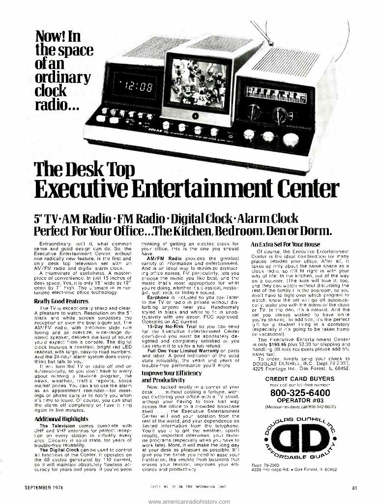
Now! In the space of an ordinary clock radio...
The Desk Top Executive Entertainment Center 5" TVAM Radio FM Radio Digital Clock .Alarm Clock Perfect For Your Office.. .The Kitchen, Bedroom, Den or Dorm.
Extraordinary, isn't it, what common sense and good design can do. So, the Executive Entertainment Center, without one radically new feature, is the first and only desk top television set with an AM /FM radio and digital alarm clock.
A triumvirate of usefulness. A master- piece of convenience. In just 15 inches of desk space. Yes, it is only 15" wide by 12" deep by 7" high. The ultimate in minia- turized electronic office technology.
Really Good Features The TV is exceptionally sharp and clear.
A pleasure to watch. Resolution on the 5" black and white screen surpasses the reception on even the best bigger set. The AM /FM radio, with precision slide rule tuning and an oversize, wide -range dy- namic speaker, delivers the kind of sound you'd expect from a console. The digital clock features a constant, bright red LED readout, with large, easy -to -read numbers. And the 24 -hour alarm system does every- thing but talk to you.
It will turn the TV or radio off and on automatically, so you don't have to worry about missing a favorite program, the news, weather, traffic reports, stock market prices. You can also use the alarm as an appointment reminder -for meet- ings or phone calls or to notify you when it's time to leave. Of course, you can shut the alarm off completely or have it ring again in five minutes.
Additional Highlights The Television comes complete with
UHF and VHF antennas for perfect recep- tion on every station in virtually every area. Circuitry is solid state, for years of trouble -free reliability.
The Digital Clock can be used to control all functions of the Center. It operates on the 60 cycles generated by 110 current, so it will maintain absolutely flawless ac- curacy for years and years. If you've been
SEPTEMBER 1978
thinking of getting an electric clock for your office, this is the one you should have.
AM /FM Radio provides the greatest variety of information and entertainment. And is an ideal way to minimize distract- ing office noises. FM particularly, lets you choose the music you like best, and the music that's most appropriate for what you're doing, whether it's classical, nostal- gic, soft rock or today's sound.
Earphone is included so you can listen to the TV or radio in private without dis- turbing anyone near you. Handsomely styled in black and white to fit in unob- trusively with any decor. FCC approved. Operates on AC current.
15 -Day No -Risk Trial so you can send for the Executive Entertainment Center confident you must be absolutely de- lighted and completely satisfied or you can return it to us for a full refund.
Full One Year Limited Warranty on parts and labor. A good indication of the solid state reliability, the years and years of trouble -free performance you'll enjoy.
ImpmveYour Efficiency and Productivity
Now, tucked neatly in a corner of your desk ... without costing a fortune, with- out cluttering your office with a TV stand, without your having to look half way across the office to a crowded bookcase shelf . the Executive Entertainment Center will end your isolation from the rest of the world, and your dependence on limited information from the telephone. You'll use it to get the weather, sports results, important interviews, your favor- ite programs (especially when you have to work late). More, it will make the long day at your desk as pleasant as possible. It'll give you the break you need to ease your frustration, the respite from business that erases your tension, improves your effi- ciency and productivity.
CIRCLE NO 70 ON FREE INFORMATION CARO
An Extra Set For Your House Of course, the Executive Entertainment
Center is the ideal combination for many places besides your office. After all, it takes up only about the same space as a clock radio, so it'll fit right in with your way of life: In the kitchen, out of the way on a counter. (The kids will love it, too, and they can watch without disturbing the rest of the family.) In the bedroom, so you don't have to fight over which program to watch, know the set will go off automati- cally, wake you with the alarm or the radio or TV. In the den, it's a natural. And the set you always wished to have while you're shaving. In addition, it's the perfect gift for a student living in a dormitory (especially if it's going to be taken home on vacations!).
The Executive Entertainment Center is only $199.95 plus $3.99 for shipping and handling (Illinois residents please add 5% sales tax).
To order, simply send your check to DOUGLAS DUNHILL, INC., Dept.79 -2303, 4225 Frontage Rd., Oak Forest, IL 60452.
CREDIT CARD BUYERS may call our toll -free number
800 -325 -6400 OPERATOR #03
(Missouri residents call 800-342-6600)
JGrLAS our-f(4. o
O
4P0ABL.E QuPV, Dept. 79 -2303 4225 Frontage Rd. Oak Forest, IL 60452
81
www.americanradiohistory.com
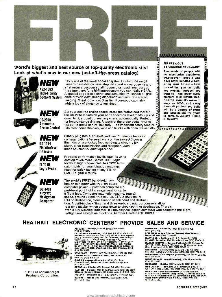
World's biggest and best source of top -quality electronic kits! Look at what's new in our new just- off -the -press catalog!
NEW ASX -1383 High -Fidelity Speaker System
NEW CS -2048 Automatic Cruise Control
NEW GD -1114 FM Wireless Intercom
NEW IT -1410 Logic Probe
NEW OC -1401 Aircraft Navigation Computer
Easily one of the finest speaker systems in its price range! Linear Phase design uses stepped speaker components and a 1st order crossover so all frequencies reach your ears at the same time; for a hi -fi improvement you can really HEAR. A special edge -free cabinet and acoustically "invisible" grill cloth provide outstanding dispersion and accurate stereo imaging. Great looks too. Brazilian Rosewood cabinetry adds a look of elegance to any decor.
Set your desired cruise speed, press the button and that's it - the CS -2048 maintains your car's speed on level roads, up and down hills, around curves, anywhere, automatically. Perfect for long- distance driving. A touch of the brake pedal returns the car to pedal control instantly - an important safety feature. Fits most domestic cars, vans and trucks with open driveshafts.
Simply plug into AC outlets and use for reliable two -way communications between units on the same AC power line. Has phase -locked loop solid -state circuitry for clean, clear transmission and reception; auto- matic squelch for quiet operation.
Provides performance levels equal to units costing much more. Shows TRUE logic levels at high frequencies, has TWO indi- cator lights for unambiguous readings. Ideal for quick testing of any TTL or CMOS digital circuits.
The world's FIRST hand -held nav- igation computer with true, on -board computer power - provides complete air - port-to- airport flight management for up to 9 flight legs. Computes magnetic heading, true air speed, ground speed, true course, ETA to checkpoint, ETA to destination, clock time to check point and destina- tion. A built -in clock /timer and three on -board microprocessors allow real time display which counts down to check point or destination. There's even a fuel warning indicator. It's the only navigation computer with complete pre -flight, in- flight and navigation functions. Another Heath EXCLUSIVE!
NO PREVIOUS EXPERIENCE NECESSARY
Thousands of people with no electronics experience whatsoever - people who have never handled a sold- ering iron before - have proved that you can build any Heathkit product you want to - and enjoy every moment of it! Simple step - by -step manuals make it easy as 1 -2 -3, and every Heathkit product you build will be a source of pride and satisfaction for years to come as you say "I built it myself "!
HEATHKIT ELECTRONIC CENTERS* PROVIDE SALES AND SERVICE
*Units of Schlumberger Products Corporation.
82
ARIZONA - Phoenix, 2727 W. Indian School Rd. (602) 279 -6247. CALIFORNIA - Anaheim, 330 E. Ball Rd. (714) 776 -9420; El Cerrito, 6000 Potrero Ave. (415) 236 -8870; Los Angeles, 2309 S. Flower St. (213) 749 -0261; Pomona, 1555 Orange Grove Ave. N. (714) 623 -3543; Redwood City, 2001 Middlefield Rd. (415) 365 -8155; Sacramento, 1860 Fulton Ave. (916) 486 -1575; San Diego (La Mesa), 8363 Center Dr. (714) 461 -0110; San Jose (Campbell), 2350 5. Bascom Ave. (408) 377 -8920; Woodland Hills, 22504 Ventura Blvd. (213) 882 -0531. COLORADO - Denver, 5940 W. 38th Ave. (303) 422 -3408. CONNECTICUT - Hartford (Avon), 395 W. Main St. (Rte. 44) (203) 678 -0323. FLORIDA - Miami (Hialeah), 4705 W. 16th Ave. (305) 823 -2280; Tampa, 4019 West Hillsborough Ave. (813) 886 -2541. GEORGIA - Atlanta, 5285 Roswell Rd. (404) 252 -4341. ILLINOIS - Chicago, 3462 -66 W. Devon Ave. (312) 583 -3920; Chicago (Downers Grove), 224 Ogden Ave. (312) 852 -1304. INDIANA - Indianapolis, 2112 E. 62nd St. (317) 257 -4321.
KANSAS - Kansas City (Mission), 5960 Lamar Ave. (913) 362 -4486.
KENTUCKY - Louisville, 12401 Shelbyville Rd. (502) 245 -7811. LOUISIANA - New Orleans (Kenner), 1900 Veterans Memorial Hwy. (504) 722 -6321. MARYLAND - Baltimore, 1713 E. Joppa Rd. (301) 661 -4446; Rockville, 5542 Nicholson Lane (301) 881 -5420. MASSACHUSETTS - Boston (Peabody), 242 Andover St. (617) 531 -9330; Boston (Wellesley), 165 Worcester Ave. (Rte. 9 just west of Rt. 128) (617) 237 -1510. MICHIGAN - Detroit, 18645 W. Eight Mile Rd. (313) 535 -6480; E. Detroit,18149 E. Eight Mile Rd. (313) 772 -0416. MINNESOTA - Minneapolis (Hopkins), 101 Shady Oak Rd. (612) 938 -6371. MISSOURI - St. Louis (Bridgeton), 3794 McKelvey Rd. (314) 291 -1850. NEBRASKA - Omaha, 9207 Maple St. (402) 391 -2071. NEW JERSEY- Fair Lawn, 35 -07 Broadway (Rte. 4) (201) 791 -6935; Ocean, 1013 State Hwy. 35 (201) 775 -1231. NEW YORK - Buffalo (Amherst), 3476 Sheridan Dr. (716) 835 -3090; Jericho, Long Island, 15 Jericho Turnpike (516) 334 -8181; Rochester, 937 Jefferson Rd. (716) 244 -5470; White Plains (North White Plains), 7 Reservoir Rd. (914) 761 -7690.
POPULAR ELECTRONICS
www.americanradiohistory.com

If quality.. value...and the pride of craftsmanship turn you on, get your NEW HEATHKIT®
CATALOG!
DISCOVER THE FUN AND SATISFACTION
OF BUILDING YOUR OWN ELECTRONIC PRODUCTS FOR HOME, AUTO, SHOP
AND HOBBY...
SEND FOR YOUR FREE HEATHKIT CATALOG TODAY!
COAST -TO -COAST OHIO - Cincinnati (Woodlawn), 10133 Springfield Pike (513) 771 -8850; Cleveland, 5444 Pearl Rd. (216) 886 -2590; Columbus, 2500 Morse Rd. (614) 475 -7200; Toledo, 48 S. Byrne Rd. (419) 537 -1887. PENNSYLVANIA - Philadelphia, 6318 Roosevelt Blvd. (215) 288 -0180' Frazer (Chester Co.), 630 Lancaster Pike (Rt. 30) (215) 647 -5555; Pittsburgh, 3482 Wm. Penn Hwy. (412) 824 -3564. RHODE ISLAND - Providence (Warwick), 558 Greenwich Ave. (401) 738.5150. TEXAS - Dallas, 2715 Ross Ave. (214) 826 -4053; Houston, 3705 Westheimer (713) 623 -2090. San Antonio, 7111 Blanco Rd. (512) 341 -8876. VIRGINIA - Alexandria, 6201 Richmond Hwy. (703) 765 -5515; Norfolk (Virginia Beach), 1055 Independence Blvd. (804) 480 -0997. WASHINGTON - Seattle, 505 8th Ave. North (206) 682 -2172. WISCONSIN - Milwaukee. 5215 W. Fond du Lac (414) 873 -8250.
SEPTEMBER 1978
HEATH
Schlumberger Heath Company, Dept. 010 -450 Benton Harbor, Michigan 49022
Please send me my FREE Heathkit Catalog. I am not on your mailing list.
Name
Address
City State
1 GX -352 Zip
NOTE: This FREE Catalog Coupon can also be redeemed at any of the Heathkit Electronic Centers` nationwide. (See list at left) ------ iÌÌ--- l
CIRCLE NO 5 ON FREE INFORMATION CARD
85
www.americanradiohistory.com

'Ears for your house We've had our ears on you. Listening to your CB base station wants and needs, and delivering the power and performance features to fill them.
Like Midland's new 78 -999 Single -Sideband base station, the top of the Number 1- selling CB line in America. In terms of advanced technology, this is HomeBase.
NUMBER 1 FEATURES. All- channel Single -Sideband and AM operation. Separate meters for modulation, SWR /power and signal strength.
Mike gain and RF gain controls. ANL, noise blanker
and high frequency filter controls.
An antenna switch to make use of either of two antennas if you wish.
Still, it's just one of many Midland Power HomeBases. For instance, there's one with a unique variable noise blanker. Even a basic AM Midland designed to be your economical first HomeBase.
SERIOUS CB. And Midland base -station accessories and options Midland are engineered to deliver all the Midland Power performance you
of innovation that's kept us Number 1 all these years.
Midland HomeBase CB. Take it from C. W. McCall, America's Number 1 CBer: "You can't get mightier, more advanced ears for your house."
See your Midland CB dealer now. And while you're there, ask about the new Midland Mobile Audio AM /FM car stereo line, with MicroPrecisionTM Tuning.
a for with the Home Base CB
same kinwd Run with Number l.
A.14. * f
ió1.7äruq MODEL 70 -990 898 /AM TRANSCEIVER
MC
44%.1.1r0"101.... 11191101.14.0111
AF GAIN
;,L
SQUELCH CLARIFIER
1_I I I LI
CHANNEL. SELECTOR
RF GAIN
11 MC GAIN TONE
M i DLAN D ®CB A member of the Beneficial Corporation Family.
CIRCLE NO 35 ON FREE INFORMATION CARD
www.americanradiohistory.com

77%? Solid State SOLID (STATE) SECURITY
CHANCES are well never know who invented the first se- curity alarm system. We know, of course, that trained ani-
mals have been used as living intruder alarms, and early cave dwellers doubtlessly sprinkled dry twigs or other objects at the openings of their dwellings to alert the occupants to possible entry by a potential enemy. Time moves on, however, and life styles, situations and technologies change.
Our dwellings today, unlike the ancient caves, often have multiple entrances (front and rear doors, windows, and maybe a basement or garage door), all of which should be protected. There are other dangers as well. Our modern homes are liter- ally crammed with inflammable goods. As a result, danger from fire in some areas may be much greater than that from burglars or other intruders. The fire danger is so great, in fact, that some localities have enacted laws requiring the installa- tion of adequate fire or smoke alarms in all new buildings, in- cluding private homes.
Fortunately, the assembly and /or installation of burglar and fire alarm systems are well within the capabilities of most elec- tronics hobbyists. Where there are no local laws requiring such equipment, a carefully chosen and properly installed system can bring peace of mind and a sense of security to the home owner and may even save a loved one's life. Here, a system may be assembled either from "scratch" or using a kit. Optionally, a commercially manufactured system may be in- stalled. On the other hand, if local ordinances mandate the use of protective equipment, such as smoke alarms, it may be necessary to use only specially approved factory -built units in
the installation. The basic circuit for an inexpensive, but quite reliable, solid -
state combination fire and burglar alarm system is given in
Fig. 1. Easily assembled in two or three evenings using non- critical, readily available components, the system is designed to serve as a fire alarm at all times and as a combination fire and burglar alarm during the night. It is fail safe in that it pro- vides protection even during power line failures, and will sound an alarm if there is an "open" anywhere in the alarm sensor line, as by an intruder cutting or breaking a wire. Once the alarm is activated, it will continue sounding until the bat - tery'(B1) is discharged, unless deliberately switched off or re- set using a key or hidden switch.
Referring to the schematic diagram, the fuse, switch (S1), neon pilot light assembly transformer (T1), bridge rectifier (RECT1 ), and current -limiting resistor (R1) form a simple line - operated trickle charger for rechargeable battery (B1). The latter serves as the main power source for the system. The alarm system itself includes a key- operated spst power /reset switch (S2), a separate (optional) pilot lamp circuit (R2/ LED1), an audible alarm, such as a horn, buzzer or bell (LOAD), a silicon controlled rectifier (SCR1), a gate current - limiting resistor (R3), a spst pushbutton Panic or TEST switch (S3), a spdt NIGHT /DAY switch (S4), a group of series -con- nected NC magnetic switches, and a group of series- connect-
SEPTEMBER 1978
By Lou Garner
ed NC thermostatic switches or fusible links. The magnetic switches are used to protect access openings to the guarded area, such as doors and windows or, in the cases of apart- ments and offices, even larger air conditioner or ventilator reg- isters. The temperature sensitive devices are installed in heat "wells" (areas where heat is likely to accumulate, such as at the top of stair wells) and in fire -prone areas, such as kitchens and furnace rooms.
In operation, the SCR normally is in a nonconducting or high- impedance state, for its gate current source, R3, is effec- tively shorted to its cathode through the closed sensor circuit, comprising switch S3 and the NC magnetic and temperature sensitive switches. Switch S4 shorts out the magnetic switches during the day, permitting access to the protected area while maintaining normal operation of the fire alarm sys- tem. If an open occurs anywhere in the sensor line, as by de- pressing S3, cutting or breaking the interconnecting wire, or opening either the magnetic (S4 in the night position) or tem- perature sensitive switches, gate current will be supplied to the SCR through R3, causing this device to "fire." In the con- ducting state, it supplies current to the alarm device (horn, buzzer, bell, etc.) serving as its load. Thereafter, the SCR will continue to conduct, even if the sensor line continuity is re- stored, until B1 is discharged or until the system is reset by opening the key operated power /reset switch, S2.
Component values are not specified in the schematic dia- gram because they are not critical and depend on the build- er's choice of major devices. As a general rule, however, the trickle charger circuit will be designed to match the character- istics of the power supply battery, B1, which may be a 3- to -12- volt nickel- cadmium or a conventional lead -acid storage bat- tery, depending on the power requirements of the alarm de- vice serving as the SRC's load. Similarly, R2's value will de- pend on the supply voltage and the LED's maximum current rating. In most applications, the SCR will be a low- voltage, sensitive -gate type, with a current rating adequate to handle the load device used.
If the alarm device is an "interrupter" -type electromechani-
FUSE SI
NEON' ASSEMBLY._
MAGNETIC REED
SWITCHES
NIGHT
54 DAY
TEMPERATURE SENSITIVE SWITCHES
Fig. 1. Combination fi>e and burglar alarm circuit. 87
www.americanradiohistory.com

r SOCKET SALE WIRE WRAP SOCKETS 14 Pin Wire Wrap 16 Pin Wire Wrap
30 .27/400 .32 .29/350
EDGE CARD CONNECTORS 44 Pin ST Edge Card Connector 1.75 1.50/10
100 Pin ST Edge Card Connector 3.50 3.00/10 100 Pin WW Edge Card Connector 3.50 3.00/10
All Sockets & Connectors Include Gold.
SOLDERLESS 2.2" x 6.5"
BREADBOARDS SK 10 $16.50 INCLUDING: Over 100 pieces of precut wire in assorted lengths - free! Choose 1 color: Red, Black, Blue. Yellow, Green, White, Orange Or Assortment.
PAGE DIGITAL ELECTRONICS
135 E. Chestnut Street 4A Monrovia, California 91016
Phone (213) 357 -5005 L.
ORDERING INFORMATION Orders under $25 and COD's, add $2 All others. shipped Ppd m U S via UPS For Blue Label (Air) or 1st Class. add $1 We accept Visa & Master Charge Most orders shipped same day
Dealer Inquiries Invited
CIRCLE NO. 45 ON FREE INFORMATION CARD
CB ANTENNA
1).
ASTRO- FANTOM" Mounts on glass! Transmits and receives thru glass!
Easy Installation Takes only 5 min. Mounts Anywhere there's a metal frame window including fiberglass bodies. Clearer Communications Rejects static 360° Signal Full 1/2 wave design
Great for auto, truck, RV, marine, motorcycle and home use
1 340 Stewart Ave.
J Addison, IL 60101 Cavantl. antennas
88 CIRCLE NO 7 ON FREE INFORMATION CARD
cal unit, it may be necessary to add a moderately large by- pass capacitor across the terminals to maintain an adequate current through the SCR. This will prevent its switching back to a nonconducting state when the alarm's internal contacts open. Gate resistor R3's value must be large enough to limit the SCR's gate current to the maximum value specified for the type of device used. Switch S3 is a NC momentary- contact pushbutton type and may be located either on the main con- trol panel as a test switch or remotely, as by the householder's bed, as a panic switch, permitting the alarm to be activated manually for other emergencies. If desired, several such switches may be installed at various locations, provided they are all wired in series. The alarm device may be mounted within the main cabinet or installed in a remote location, as preferred. If a remote installation is used, the connections to the main control should be through armored cable or conduit to prevent An intruder from disabling the alarm by cutting wires. For maximum protection, the entire circuit, except for external sensors, panic switch(es), and remote alarm (if used), should be assembled in a sturdy, wall- mounted, key - locked metal cabinet, preferably in a semi -hidden location, such as a closet.
In those areas where the dangers of fire are more of a threat than burglars and housebreakers, smoke detector alarms have become increasingly popular. Generally, these are self- contained units intended for mounting on the ceilings of individual rooms, with from two to six or more units per household. The potential market for these instruments is so large that several major semiconductor manufacturers, in- cluding Motorola Semiconductor Products, Inc. (3501 Ed Bluestein Blvd., Austin, TX 78721) and the National Semicon- ductor Corporation (2900 Semiconductor Drive, Santa Clara, CA 95051), have introduced special -purpose IC's designed specifically for use in smoke detector alarms. Motorola offers two devices, types MC14461 and MC14462; both are assem- bled in standard 16 -pin plastic DIP's and are fabricated using CMOS MSI technology. Both devices are designed for use with standard ionization chambers and for operation on either 9- or 12.6 -V dc supplies. The MC14462 features an on -chip MOSFET preamp for the external ionization chamber while the MC14461 requires a separate preamp but, otherwise, the two devices are quite similar. National's entry, the LM1801, is designed for use with either ionization type (with external preamp) or photoelectric smoke detectors and, if desired, can be adapted for use as an intrusion alarm. The LM1801 is sup- plied in a 14 -pin plastic DIP.
Featuring the MC14461, the circuit shown in Fig. 2A em- ploys an MFE825 MOSFET as a preamp for the smoke detec- tor ionization chamber. An MDS -D05 npn transistor is used to drive the signal horn, for the IC output current should be limit- ed to approximately 12 mA. Except for an optional IN4001 re- verse battery protection diode, all other active devices are contained within the IC chip. The second circuit, Fig. 2B, is similar, but features the MC14462 and, therefore, does not re- quire an external preamp for the ionization chamber. Both cir- cuits are designed for operation on standard 9 -volt dc sources. And both have adjustable sensitivity (via 5- megohm potentiometers), and both will emit short warning "beeps" when the battery supply nears the end of its useful life, indicat- ing that replacement is necessary for continuing protection.
With neither layout nor lead dress overly critical, the Moto- rola circuits may be assembled using either pc or pert board construction techniques. The signal paths must be kept as short and direct as practicable, however, and special care
POPULAR ELECTRONICS
www.americanradiohistory.com

The Sinclair PDM35. A personal digital MultiMeter for only s599:
Now everyone can afford to own a digital multimeter
A digital multimeter used to mean an expensive, bulky piece of equipment.
The Sinclair PDM35 changes that. It's got all the functions and features you want in a digital multimeter, yet they're neatly packaged in a rugged but light pocket -size case, ready to go anywhere.
The Sinclair PDM35 gives you all the benefits of an ordinary digital multimeter - quick clear readings, high accuracy and resolution, high input impedance. Yet at $59.95 it costs less than you'd expect to pay for an analog meter!
The Sinclair PDM35 is tailor -
made for anyone who needs to make rapid measurements. Development engineers, field service engineers, lab technicans, computer specialists, radio and electronic hobbyists will find it ideal.
With its rugged construction and battery operation, the PDM35 is perfectly suited for hand work in the field, while its angled display and optional AC power facility make it
just as useful on the bench.
What you get with a PDM35 31/2 digit resolution. Sharp, bright, easily read LED display, reading to ± 1.999. Automatic polarity selection. Resolution of 1 mV and 0.1 nA (0.0001µA). Direct reading of semiconductor forward voltages at 5 different currents. Resistance measured up to 20 MO .
1% of reading accuracy.
SEPTEMBER 1978
Operation from replaceable battery or AC adapter. Industry standard 10 Mfg input impedance. Compare it with an analog meter!
The PDM35's 1% of reading compares with 3% of full scale for a comparable analog meter. That makes it around 5 times more accurate on average.
The PDM35 will resolve 1 mV against around 10 mV for a comparable analog meter - and resolution on current is over 1000 times greater.
The PDM35's DC input impedance of 10 M û is 50 times higher than a 20 kD /volt analog meter on the 10 V range.
The PDM35 gives precise digital readings. So there's no need to in- terpret ambiguous scales, no parallax errors. There's no need to reverse leads for negative readings. There's no delicate meter movement to damage. And you can resolve current as low as 0.1 nA and measure transistor and diode junctions over 5
decades of current.
rS+ershirl>e Group.
Technical specifications DC Volts (4 ranges) Range: 1 mV to 1000 V. Accuracy of reading 1.0% ±-1 count. Note: 10 Mn input impedance. AC Volts (40 Hz -5 kHz) Range: 1 V to 500 V. Accuracy of reading: 1.0% ±2 counts. DC Current (6 ranges) Range: 1 nA to 200 mA. Accuracy of reading: 1.0% ±
1 count. Note: Max. resolution 0.1 nA. Resistance (5 ranges) Range: 111 to 20M f2 .
Accuracy of reading: 1.5% -±-1 count. Also provides 5 junction -test ranges. Dimensions: 6 in. x 3 in. x 11/2 in. Weight: 61/2 oz. Power supply: 9 V battery or Sinclair AC adapter. Sockets: Standard 4 mm for resilient plugs. Options: AC adapter for 117 V 60 Hz power. De -luxe padded carrying wallet. 30 kV probe. The Sinclair credentials
Sinclair have pioneered a whole range of electronic world- firsts - from programmable pocket calculators to miniature TVs. The PDM35 embodies six years' experience in digital multimeter design, in which time Sinclair have become one of the world's largest producers. Tried, tested ready to go!
The Sinclair PDM35 comes to you fully built, tested calibrated and guaranteed. It comes complete with leads and test prods, operating instructions and a carrying wallet. And getting one couldn't be easier. Just fill in the coupon, enclose a cheque /MO for the correct amount (usual 10 -day money -back undertaking, of course), and send it to us.
We'll mail your PDM35 by return! For Instant Service, CALL TOLL FREE: 1- 800 -528 -6050, EXT. 1052. Ariz. Res. Call Collect 602- 955 -9710 or send coupon:
Dept. 470, 924 Anacapa Street, Santa Barbara, Calif. 93101 Please promptly send Sinclair PDM35 Digital Multimeter is)Cá'559.95 (plus S3 shipping and insurance)each. I have the option of returning it within 1 week of receipt loran immediate refund.
Also Send AC Adaptor(s) @ 54.95 ea. Also Send Deluxe Padded Carrying Case at 54.95 ea. Also Send 30 kV probe @ 529.95 Check or Money order End. (Calif. Res. add 6"/. Sales Tax) Charge to The Credit Card Checked Below: BankAmericard /Visa MasterCharge (Interbank # American Express Carte Blanche Diners Club
Credit Card # Exp Date Name Address City /State /Zip
L Signature
89
www.americanradiohistory.com

must be exercised to minimize pin -to -pin and board leakage currents near the input terminal (pin 1). If a PC board is used, a guard ring should be etched around pin 1 and the ionization input terminal (pad), connected to pin 2. The customary pre- cautions required when working with MOS devices should be observed during the installation and wiring of the IC's and MOSFET (if used). In the case of the MC14462, this device is
protected by a shorting bar between pins 1 and 2 which should be broken only after the wiring is completed and checked. In addition, Motorola suggests that a 0.001 -µF ca-
5 M
V Ref
6.8 M
MFEB25
R2
-C 22M
A I (vss)
1
2
3 MC 14461
4
5
6
VDD=9V
1
'
16
15
14
13
12
11
10
9
J MDS-D05
AF
0.001
~ R3
/.1
R4
L n Mñ R' 1' 1 C
270 k 0.0018
5 M
Fig. 2. Ionization-chamber smoke detector circa its featuring Motorola devices: (A) with separate MOSFET prearnp, and (B) with on -chip preamp.
In contrast, the photoelectric alarm circuit shown in Fig. 3B does not require a "low- battery warning" because it is de- signed for operation on a standard 120 -V ac power line. Here, smoke is detected as a decrease in the light transmission be- tween the NSL5020 LED light source and the CL904 photore- sistor. Alarm threshold sensitivity is controlled by 1- megohm potentiometer R7. This circuit also features a high -power 120 -V ac horn, controlled by an external 2N5064 SCR which, in turn, is activated by the IC when it switches to an alarm mode. In addition to detecting smoke, the circuit will sound an alarm in the event of an LED failure. Finally, it can be adapted for use as an intrusion alarm by placing the LED light source and photoresistor on the opposite sides of the window, door,
1N4001 Reverse Battery Protection Diode
d
V Ref
B
pacitor be connected between VDD and ground near the IC to bypass transients that may be generated in the power source connection leads by peak currents in the horn driver loop.
Although primarily designed for operation on 9- to 14 -volt battery supplies, National's LM1801 smoke detector IC fea- tures an on -chip zener voltage regulator which, combined with its rugged construction, permits operation on ac power line sources. It includes the customary low- battery detector alarm and, in addition, offers an output stage capable of furnishing currents of up to several hundred mA. This eliminates the need for an external power amplifier to drive typical low -volt- age 85 -dB horns. The versatile LM1801 may be used in either the ionization -chamber or photoelectric type of smoke alarm. Both types of circuits are illustrated in Fig. 3.
In Fig. 3A, the battery- operated design employs a standard ionization chamber in conjunction with an NF5301 JFET preamp. Alarm threshold sensitivity is adjustable by means of 5- megohm potentiometer R4. Other features include provi- sions for a manual test (via an NO momentary- contact spst pushbutton switch) and for interconnecting two or more alarms so that all will sound if any one is activated. For the lat- ter mode of operation, a single pair of wires is used to parallel all 10 IC pins and ground. The low- battery "beep" alarm will sound only on the individual units, however. The low- battery alarm level is set by the ratio of R1 and R2 so that the voltage at pin 12 is equal to the oscillator trip voltage when the battery voltage nears its low limit. With the resistor values specified in
the diagram, the alarm will sound when the battery voltage drops to approximately 8.2 volts.
90
R2
22 M
(V85)
VDD=9 V
16
2 15
3 14 0.001 µF
I 1N4001 Reverse
MC 14462 R3 TI Battery 4 13
5 3'9Ó y
MDS-005 Protection Diode 12
R4 A/- 6 11
10
9
1 o M 1-
RI 270k 0.0018µF
or other access opening requiring protection. Depending on the distance(s) involved, it may be necessary, in some cases, to add a lens system direct and focus the LED's radiation on the photo detector. Once installed and adjusted, the system will respond with an alarm when the light beam is broken by an intruder.
Reader's Circuit. Dale McClintock (c /o Heil Sound, Ltd., Marissa, IL 62257) was one of a number of readers respond- ing to our discussion of solid -state motor controls in last June's column. Dale has been seeking- without much suc- cess-a solid -state design to replace the inefficient rheostats used for controlling miniature electric racing cars. The circuits he has tried have failed to provide the realistic action achieved with pot controls, yet he feels there must be "a better way."
The problem is not as simple as it may appear at first glance, for there are three important factors to consider: (1) maximum speed, (2) acceleration, and (3) braking. Unless the design chosen takes these three factors into account, the re- sults are likely to be disappointing. First, consider the max- imum speed possible with a given design. If a rheostat is
used, it will provide full source voltage across the motor when turned to zero resistance. A series transistor used as a control element cannot apply full source voltage to its load,- even at saturation currents, due to the inherent voltage drop across the transistor itself. This may be small, perhaps only a fraction of a volt, but is enough to limit the maximum motor speed. Ac- celeration is another problem which, interestingly, can be
POPULAR ELECTRONICS
www.americanradiohistory.com

10,F -
RSET ION
/ 1
LM1101
W BATTER DETECTOR
ANO OSCILLATOR
REF
RI
2 TM
TO COMMON ALARMS
TE
IsurrLY
CO
0 01
R6
070
16tl0 NORA / \
V
NE6001
IONIZATION CORNIER
A
A1M
9V
MALLORY MNI604 = PANASONIC 0061 OR EQUIVALENT
NslsmO LEO 11141061
Fig. 3. Smoke detector circuits using National's LM1801: (A) ion izatioi- chamber type, and (B) photoelectric type.
solved more easily with solid -state designs than with a con- ventional rheostat. The third and final problem, braking, is
achieved with rheostat design by providing an electrical load (essentially, a short circuit) across the motor when source power is removed. Here, the dc motor acts as a loaded gener- ator and provides the desired braking action. A similar tech- nique can be used with solid -state circuits.
A circuit which should satisfy Dale's requirements (and those of other model racing car enthusiasts) is illustrated in
Fig. 4. In the circuit, Q1 is a high -gain npn Darlington transis- tor and should have a maximum current capability of (at least) 10 to 15 amperes. Speed control R1 will range in value from a
few hundred to a few thousand ohms, depending on the tran- sistor's gain. Series resistor R2 is chosen to limit Ql's max- imum base current to the value recommended by the transis- tor manufacturer. Shunt capacitor Cl is a relatively large elec- trolytic, perhaps as high as 500 to 2000 µF, but its actual val- ue will depend on R2's value; that is, the larger R2, the small- er the capacitor's value. Control switch S1A /SIB is a ganged dual spst switch wired so that one section closes when the second opens, and vice -versa. Finally, the power supply, B1, is chosen to provide a higher voltage than normally is speci- fied for the motor used and thus compensate for the voltage drop across Q1 at saturation. Generally, adding a single cell to a battery supply will be adequate (i.e., using a 14 -volt source instead of a 12.6 -volt source) for most applications.
In operation, closing SBA opens SIB and the motor current, hence speed, will depend on RI's adjustment. If R1 is turned up (toward the positive battery terminal), Cl will act as a mo-
SEPTEMBER 1978
Fig. 4. Reader's do motor control circuit with accelerator and braking action.
B
20 VAL
mentary short to Q1's base, providing a momentary "boost" in
current. This, in a fashion, is analogous to the action of the ac-
celerator pump in an automobile's carburetor. When SBA is
opened, SIB closes, shorting the motor terminals and provid- ing the desired braking action.
Device /Product News. You can add life to your pilot lights by using a flashing LED introduced recently by Litronix, Inc.
(19000 Homestead Road, VALLCO Park, Cupertino, CA 95014). Identified as type FLR -4403, the new device corn - prises a gallium- arsenide -phosphide LED and integral IC chip in a single T1 -3 /a package. The IC flashes the LED on and off at approximately three times per second. Directly compatible with standard TTL and CMOS circuits, the FRL -4403 lists for less than a dollar each in unit quantities.
RCA's Solid State Division (Box 3200, Somerville, NJ
08876) has announced a new family of high -voltage npn sili- con power transistors. Designated the "SwitchMax" series, the initial offering includes eight devices, types 2N6671 through 2N6678. Of these, types 2N6671 -3 are rated for a sa- turation current of 5 A, types 2N6674 -5 for 10 A, and types 2N6676 -8 for 15 A. The devices have VcEV ratings of 450 to 650 volts, and are particularly suited to such applications as off -line power supplies, inverter /converter circuits, and pulse - width- modulated regulators. The new transistors are supplied in standard JEDEC TO -204MA (TO -3) metal packages.
Motorola Semiconductor Products, Inc. (P.O. Box 20912, Phoenix, AZ 85036) is offering a new automotive tempera- ture- range, single -supply, dual op amp. Featuring a low cur- rent drain over a wide voltage range, the LM2904, basically similar to the LM158 series, is ideal for automotive and other battery operated systems where available voltages from 3.0 to 26 and temperatures from -40° C to +85° C are encoun- tered. In many such systems, the most solid ground reference is also the negative battery terminal, making the LM2904's common -mode input range especially useful in simplifying ex- ternal biasing. Depending on suffix designation, the LM2904 is available in a metal TO -100 can (H), 8 -pin ceramic DIP (J), or 8 -pin plastic DIP (N).
91
www.americanradiohistory.com

NEW EKO 480 TRIGGERED SWEEP
10 MHz SCOPE 100% Solid State Includes 10:1 Probe
r
More Professional scope perfor- mance for your money! DC to 10 MHz bandwidth, AC and DC coup- ling, 11 position calibrated atten- uator, 10 mV /cm sensitivity, push- button operation. Outstanding features: Built -in TV Sync Separa- tor; Digitally controlled trigger cir- cuits; reference baseline display; calibrated 21 step sweep speed; Fully regulated power supply; Cus- tom Bezel for standard camera mounting. Assembled $425.00
FREE '78 EICO CATALOG Check reader service card or send 50c for first class mall. See your local EICO Dealer or call (516) 681-9300, 9 00 a m. -5:00 p.m. EST. Major credit cards accepted EICO -10B New South Rd. Hicksville, N.Y. 11801
CIRCLE NO
E/CO
14 (Nr f REE INFOR Al ION CARD
J
Thousands of Communications Electronics customers
OWN A BEARCAP SCANNER. But since we've introduced the Bearcat' 250 crystalless 15,600 frequency. 50 channel synthesized scanner. our specifications have been improved'
Sensitivity 0.4 microvolts for 12dB SINAD on VHF bands. UHF band slightly less
Selectivity Better than -60dB @ ±25 KHz
Audio Output At least 2.0 Watts rms
Audio Quality The BC -250 audio is more noise -free and suffers less distortion than comparable models by a margin of 10dB or more
Image Rejection The BC -250 rejects image frequencies by at least 8dB better in all bands than comparable models.
This month, we've got a special price on the Bearcat 250. Now. you can own this fantastic professional monitor for only $319 00. That's a
savings of over $80.00. To start Bearcatting. Master Charge and Visa card
holders may call and order toll free 800 -521 -4414 Outside the U.S. and Michigan dial 313-994-4441. To order by mail, send $319.00 plus $5.00 for U. S
U.P.S. shipping. Foreign orders invited at slightly higher cost. Mail your orders or requests for a free catalog completely describing all Bearcat® scanners to Communications Electronics, Box 1002. Dept. CEM. Ann Arbor, Michigan 48106 U.S.A Bearcat Is a registered trademark of Masco Corporation of Indiana
Copynght `197/4 Communications Electronics]
CIRCLE NO 68 ON FREE INFORMATION CARD
92
AAExperimenter's Corner
ANALOG TO DIGITAL CONVERTERS, PART 1
(N JULY and August we examined some of the basic characteristics of
digital -to- analog (D /A) converters. Now we're going to devote equal time to ana- log-to- digital (A /D) converters.
Both D/A and A/D converters play key roles in such applications as digital multimeters, solid -state data loggers, speech synthesizers, digital communi- cations devices, motor speed controllers and many others. In all these applica- tions the converter interfaces the analog world of continuously variable informa- tion and signals such as temperature, voltage, velocity, force and light intensity with the two -state binary operation of digital circuits.
We've already seen how a simple D/A converter can convert a four -bit binary code into a voltage to vary the bright- ness of a lamp or the speed of a motor, generate waveforms, etc. An A/D con- verter performs the mirror image task of transforming a variable signal like the voltage from a pressure transducer into the binary format that a digital circuit can process. Probably the best -known ap- plication for the A/D converter is the dig- ital multimeter, but such converters can be found in other applications working with a variety of digital circuits.
The digital circuit associated with the A/D converter can be as simple as a
INPUT
vnLTAGE D/V/DER
COMPqeRTORS rz^/
...--ri IA 55
ENCODER
N-8/T 8/NARY Ot/TPtIT
L L 55
Fig. I. Block diagram of parallel or flush A/D converter.
By Forrest M. Mims
RAM and a counter that together store a
series of analog measurements for later retrieval (a data logger). Alternatively, it
might be a sophisticated flat- screen, sol- id -state oscilloscope that uses an array of hundreds of LED's in place of a bulky cathode ray tube. It could just as well be a microcomputer programmed to moni- tor and make decisions about various analog signals, trends or events.
/ay 8V 6V 4
/OV +IEI
Fit;. 2. Schematic diagram showing huts (1 voltage divider storks.
Types of A/D Converters. Convert- ing an analog signal into digital form is
not as easy as converting a set of binary digits into an analog voltage. Neverthe- less, several ingenious methods of achieving A/D conversion have been
zv Ov
IK /K
o
R/
+SV
5
i
Rz /5
R3 /K
+ 3 //4 Z
LM 339
I/4 LM339
84 /K //
/D
ANAL06 vOLrA6E RS /N /K
o
//4 LM339
//4 LM339
R6 LED 4 3 ''Ofl
R7 ED 3 390.2
R8 LED z. 390n
R9 /z LED/ 39011
Fig. 3. LED thermometer -style hurgruph readout.
POPULAR ELECTRONICS
www.americanradiohistory.com

EW! "INDUSTRIAL" WIRE -WRAPPING
MODEL BW928 TOOL
$4995 BATTERIES NOT INCLLEED
BIT & SLEEVE NOT INCLUDED
BATTERY OPERATED (2) Standard "C" Ni Cad Batteries (not included)
INTERCHANGEABLE BITS & SLEEVES (not included)
REVERSIBLE ROTATION For unwrapping, reverse batteries
BACKFORCE OPTIONAL Model BW928 -B F $52.95
4 POSITIVE INDEXING
LEIGHT WEIGHT *LEXAN Housing
'LEXAN " GENERAL ELE7.TRIC
OK MACHINE & TOOL CORPORATION 3455 Conner St., Bronx, N.Y. 1047 5 (212) 994.6600 TELEX 125091
CIRCLE NO 40 ON FREE INFORMATION CARD
www.americanradiohistory.com

fact: the iV does more... much more!
Era IV begins! The new Shure V15 Type IV phonograph cartridge is an altogether new phono cartridge system that exceeds previous per- formance levels by a significant degree - not merely in one parameter but in totality. The Type IV offers:
Demonstrably improved tracka- bility across the entire audible spectrum. Dynamically stabilized tracking overcomes record -warp caused problems, such as fluctuating tracking force, varying tracking angle, and wow. Electrostatic neutralization of the record surface minimizes clicks and pops due to static dis- charge, electrostatic attraction of the cartridge to the record, and attraction of dust to the record. An effective dust and lint re- moval system. A Hyperelliptical stylus tip con- figuration dramatically reduces both harmonic and intermodula- tion distortion. Ultra -flat response - individu- ally tested.
V15 Type IV SUPER TReZCIC1U
Stereo Dynetie Phono Cartridge
94
For complete details on this remarkable new cartridge write for the V15 Type IV Product Brochure (ask for AL569) and read the exciting facts on the V15 IV for yourself.
S H U R Shure Brothers Inc.
222 Hartrey Ave., Evanston, IL 60204 In Canada:
A. C. Simmonds & Sons Limited Manufacturers of high fidelity compo- nents, microphones, sound systems, / and related circuitry. / CIRCLE NO 67 ON FREE INFORMATION CARO
o
4. 3-V
1
/00E
Rz /.c
K3 /K
7
//
ANALOG VOLTAGE ES N /K
o
3 //4 '
LA/339
t
//,/ LM33
-z
/y
/ /Lj 7yoo
5 74o
//y7 / LM339 t
v 3 v / LM 339 t /2.
fSY
LED 4
9 /O /2.
fl ED 3
tsY +/tl
'N\N /z e
742o LED z /3
7 LED/
Fig. 4. A NAND gate decoder converts 4- element bargraph output into 1 -of -4 moving dot readout.
developed. One of the simplest of these employs a D/A converter and a counter. The counter is initially cleared so that all its outputs are at logic zero, A clock in- crements the counter, and each succes- sive count is converted into an analog voltage by the D/A converter and ap- plied to an op amp comparator along with the incoming analog signal. When the two analog signals are equal, the comparator changes states and inhibits
R/ /OWE
f5V
A 3
///,. LM339
t z R2.
/K
LM339 s
R3 /5 9 8 /0
//µ /4/ LAI
t 339 /3
4 /K
i
l/LL / LM339 // t /z o
ANALOG VOLTAGE QS /N /5 o
R6 390
the clock. The binary word stored in the counter is the digital equivalent of the analog input signal.
Although this method of conversion is
simple, it's very slow. The time for a con- version can range from no clock period (0 volts in) to 2N clock periods where N is the counter's capacity in bits. Thus, an 8 -bit counter would require between 0
and 256 clock periods for a single data conversion.
+5V
7 9 /o /z /3 LED /
Fig. 5. An A/D converter with binary output is made by adding a 2 -hit encoder as shown here.
POPULAR ELECTRONICS
www.americanradiohistory.com
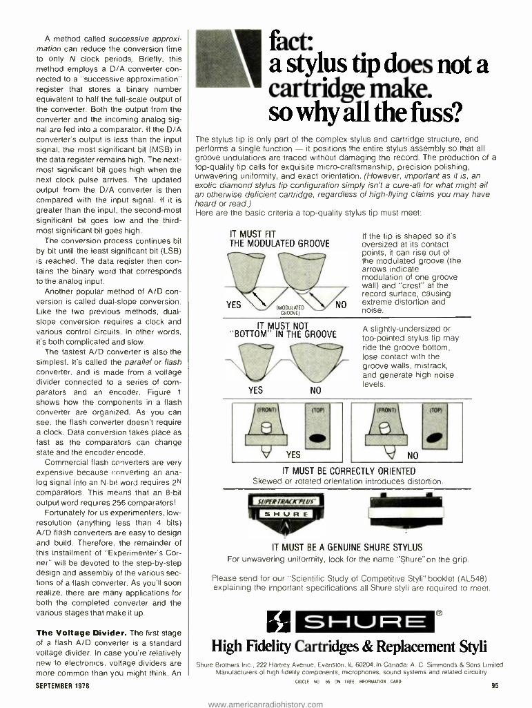
A method called successive approxi- mation can reduce the conversion time to only N clock periods. Briefly, this method employs a D/A converter con- nected to a "successive approximation" register that stores a binary number equivalent to half the full -scale output of the converter. Both the output from the converter and the incoming analog sig- nal are fed into a comparator. It the D/A converter's output is less than the input signal, the most significant bit (MSB) in
the data register remains high. The next - most significant bit goes high when the next clock pulse arrives. The updated output from the D/A converter is then compared with the input signal. If it is
greater than the input. the second -most significant bit goes low and the third - most significant bit goes high.
The conversion process continues bit by bit until the least significant bit (LSB) is reached. The data register then con- tains the binary word that corresponds to the analog input.
Another popular method of A/D con- version is called dual -slope conversion. Like the two previous methods, dual - slope conversion requires a clock and various control circuits. In other words. it's both complicated and slow.
The fastest A/D converter is also the simplest. It's called the parallel or flash converter, and is made from a voltage divider connected to a series of com- parators and an encoder. Figure 1
shows how the components in a flash converter are organized. As you can see. the flash converter doesn't require a clock. Data conversion takes place as fast as the comparators can change state and the encoder encode.
Commercial flash converters are very expensive because converting an ana- log signal into an N -bit word requires 2N
comparators. This means that an 8 -bit output word requires 256 comparators!
Fortunately for us experimenters, low - resolution (anything less than 4 bits) A/D flash converters are easy to design and build. Therefore, the remainder of this installment of "Experimenter's Cor- ner " will be devoted to the step -by -step design and assembly of the various sec- tions of a flash converter. As you'll soon realize, there are many applications for both the completed converter and the various stages that make it up.
The Voltage Divider. The first stage of a flash A/D converter is a standard voltage divider. In case you're relatively new to electronics. voltage dividers are more common than you might think. An
SEPTEMBER 1978
fact: a stylus tip does not a cartridge make. so why all the fuss?
The stylus tip is only part of the complex stylus and cartridge structure, and performs a single function - it positions the entire stylus assembly so that all groove undulations are traced without damaging the record. The production of a top -quality tip calls for exquisite micro -craftsmanship, precision polishing, unwavering uniformity, and exact orientation. (However, important as it is, an exotic diamond stylus tip configuration simply isn't a cure -all for what might ail an otherwise deficient cartridge, regardless of high -flying claims you may have heard or read.) Here are the basic criteria a top -quality stylus tip must meet:
IT MUST FIT THE MODULATED GROOVE
(MODULATED GROOVE)
If the tip is shaped so it's oversized at its contact points, it can rise out of the modulated groove (the arrows indicate modulation of one groove wall) and "crest" at the record surface, causing extreme distortion and noise.
IT MUST NOT "BOTTOM" IN THE GROOVE
YES NO
A slightly- undersized or too -pointed stylus tip may ride the groove bottom, lose contact with the groove walls, mistrack, and generate high noise levels.
IT MUST BE CORRECTLY ORIENTED Skewed or rotated orientation introduces distortion.
IT MUST BE A GENUINE SHURE STYLUS
For unwavering uniformity, look for the name "Shure "on the grip.
Please send for our "Scientific Study of Competitive Styli" booklet (AL548) explaining the important specifications all Shure styli are required to meet.
H High Fidelity Cartridges & Replacement Styli
Shure Brothers Inc . 222 Harirey Avenue, Evanston. IL 60204. In Canada A C Simmonds & Sons Limited Manufacturers of high fidelity components. microphones. sound systems and related circuitry
CIRCLE NO 66 ON FREE INFORMATION CARO 95
www.americanradiohistory.com
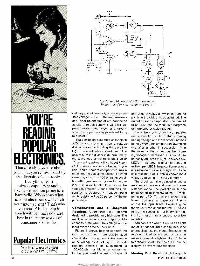
YOU'RE
READING
POPULAR
ELECTRONICS. That already says a lot about
you. That you're fascinated by the diversity of electronics.
Everything from microcomputers to audio,
from construction projects to ham radio. Who knows what area of electronics will catch your interest next? That's why
you read P.E. To keep in touch with all that's new and best in the many worlds of
consumer electronics.
Popular Electronics World's largest -selling electronics magazine
RI /00K
R2
fsv
/4/
//4/ 740 Ó
//4, \ 6 //S4 s 74,00
LM339 +
R3 /K
2 //3
9
//4, LM339
/4 /3 74/O
O
ANALOC vOC7A6E R4
o
t /Z
f SY
Fig. 6. Simplification of A/D converter by elimination of one NAND gate in Fig. 5
ordinary potentiometer is actually a vari- able voltage divider. If the end terminals of a linear potentiometer are connected across a 10 -volt supply, 5 volts will ap- pear between the wiper and ground when the wiper has been rotated to its mid -point.
You can begin assembly of the flash A/D converter and see how a voltage divider works by building the circuit in Fig. 2 on a solderless breadboard. The accuracy of the divider is determined by the tolerances of the resistors. Five or 10- percent resistors will work, but 1 -per- cent resistors are much better. If you can't find 1- percent components, use a
multimeter to select five resistors having values as close to 1000 ohms as possi- ble. After you connect power to the div- ider, use a multimeter to measure the voltages between ground and the junc- tions of the resistors. The voltage across each resistor will be 20 percent of the in- put voltage.
Comparators and a Bargraph Readout. A comparator is an op amp designed to provide very high gain. The result is a stage whose output rapidly changes state when the voltage at one input exceeds the second input.
Figure 3 shows how to connect the four comparators in an LM339 quad comparator to a slightly modified version of the voltage divider of Fig. 2. The mod- ification consists of substituting a 100,000 -ohm or higher potentiometer for the uppermost fixed resistor to permit
the range of voltages available from the points in the divider to be adjusted. The output of each comparator is connected to an LED, and the result is a bargraph or thermometer -style readout.
Since the inputs of each comparator are connected to both the incoming analog voltage and the resistor junctions in the divider, the comparators switch on one after another in succession, from the lowest to the highest, as the incom- ing voltage is increased. The circuit can be easily adjusted to light up successive LED's in increments of as little as one millivolt per LED if the potentiometer has a resistance of several megohms. If you calibrate the circuit with a known input voltage you can Ilse it for a voltmeter.
The circuit can also be used as both a
resistance indicator and timer. In the re- sistance mode, the potentiometer can be adjusted to indicate up to 10 meg- ohms per LED. To use the circuit as a timer, connect a capacitor directly across the input leads. Depending on the value of the capacitor, the LED's will turn on in succession at intervals rang- ing from less than a second to a few minutes.
You can even use the circuit as a light meter by connecting a cadmium -sulfide photocell across the inputs. Because the readout is luminescent you can use the meter in very dim light -but you'll have to optically isolate the photocell from the display to prevent false readings.
Moving Dot Readout. A bargraph
96 POPULAR ELECTRONICS
www.americanradiohistory.com
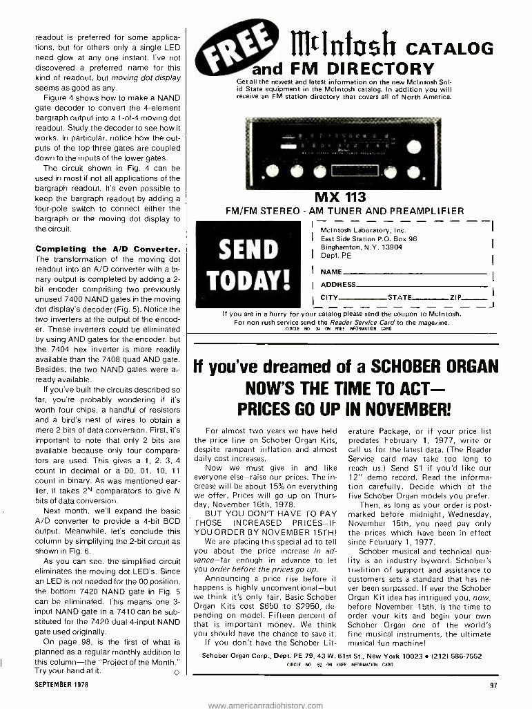
readout is preferred for some applica- tions, but for others only a single LED need glow at any one instant. I've not discovered a preferred name for this kind of readout, but moving dot display seems as good as any.
Figure 4 shows how to make a NAND gate decoder to convert the 4- element bargraph output into a 1 -of -4 moving dot readout. Study the decoder to see how it works. In particular, notice how the out- puts of the top three gates are coupled down to the inputs of the lower gates.
The circuit shown in Fig. 4 can be used in most if not all applications of the bargraph readout. It's even possible to keep the bargraph readout by adding a four -pole switch to connect either the bargraph or the moving dot display to the circuit.
Completing the A/D Converter. The transformation of the moving dot readout into an A/D converter with a bi- nary output is completed by adding a 2- bit encoder comprising two previously unused 7400 NAND gates in the moving dot display's decoder (Fig. 5). Notice the two inverters at the output of the encod- er. These inverters could be eliminated by using AND gates for the encoder, but the 7404 hex inverter is more readily available than the 7408 quad AND gate. Besides, the two NAND gates were al- ready available.
If you've built the circuits described so far, you're probably wondering if it's worth four chips, a handful of resistors and a bird's nest of wires to obtain a
mere 2 bits of data conversion. First, it's important to note that only 2 bits are available because only four compara- tors are used. This gives a 1, 2, 3, 4
count in decimal or a 00, 01, 10, 11
count in binary. As was mentioned ear- lier, it takes 2N comparators to give N bits of data conversion.
Next month, we'll expand the basic A/D converter to provide a 4 -bit BCD output. Meanwhile, let's conclude this column by simplifying the 2 -bit circuit as shown in Fig. 6.
As you can see, the simplified circuit eliminates the moving dot LED's. Since an LED is not needed for the 00 position, the bottom 7420 NAND gate in Fig. 5
can be eliminated. This means one 3- input NAND gate in a 7410 can be sub- stituted for the 7420 dual 4 -input NAND gate used originally.
On page 98, is the first of what is planned as a regular monthly addition to this column -the "Project of the Month." Try your hand at it.
SEPTEMBER 1978
IlltIntosh CATALOG and FM DIRECTORY
Get all the newest and latest information on the new McIntosh Sol- id State equipment in the McIntosh catalog. In addition you will receive an FM station directory that covers all of North America.
MX 113 FM /FM STEREO - AM TUNER AND PREAMPLIFIER
SEND
TODAY!
McIntosh Laboratory, Inc. East Side Station P.O. Box 96 Binghamton, N.Y. 13904 Dept. PE
NAME
ADDRESS
CITY STATE ZIP
If you are in a hurry for your catalog please send the coupon to McIntosh. For non rush service send the Reader Service Card to the magazine.
CIRCLE NO 34 ON FREE INFORMATION CARD
If you've dreamed of a SCHOBER ORGAN
NOW'S THE TIME TO ACT - PRICES GO UP IN NOVEMBER!
For almost two years we have held the price line on Schober Organ Kits, despite rampant inflation and almost daily cost increases.
Now we must give in and -like everyone else -raise our prices. The in- crease will be about 15% on everything we offer. Prices will go up on Thurs- day, November 16th, 1978.
BUT YOU DON'T HAVE TO PAY THOSE INCREASED PRICES -IF YOUORDER BY NOVEMBER 15TH!
We are placing this special ad to tell you about the price increase in ad- vance -far enough in advance to let you order before the prices go up.
Announcing a price rise before it happens is highly unconventional -but we think it's only fair. Basic Schober Organ Kits cost $650 to $2950, de- pending on model. Fifteen percent of that is important money. We think you should have the chance to save it.
If you don't have the Schober Lit-
erature Package, or if your price list predates February 1, 1977, write or call us for the latest data. (The Reader Service card may take too long to reach us.) Send $1 if you'd like our 12" demo record. Read the informa- tion carefully. Decide which of the five Schober Organ models you prefer.
Then, as long as your order is post- marked before midnight, Wednesday, November 15th, you need pay only the prices which have been in effect since February 1, 1977.
Schober musical and technical qua- lity is an industry byword. Schober's tradition of support and assistance to customers sets a standard that has ne- ver been surpassed. If ever the Schober Organ Kit idea has intrigued you, now, before November 15th, is the time to order your kits and begin your own Schober Organ -one of the world's fine musical instruments, the ultimate musical fun machine!
Schober Organ Corp., Dept. PE -79, 43 W. 61st St., New York 10023 (2121 586 -7552 CIRCLE NO 52 ON FREE INFORMATION CARD
97
www.americanradiohistory.com

BACK -AND -FORTH SEQUENTIAL FLASHER
THIS IS the first in a planned series of monthly additions to the "Experiment-
er's Corner" -the "Project of the Month." Many different projects of an experimental nature, using a variety of circuits and con- struction methods, will be described in fu- ture issues.
This first project was suggested by read- er Al Rieke of Santa Isabel, Puerto Rico. Al writes that he's familiar with circuits that sequentially flash each LED in a row in one direction only. But he's not been able to find a back -and -forth sequential flasher in his ten -year collection of back issues of POPULAR ELECTRONICS.
The circuit that should solve Al's prob- lem is shown in Fig. A. A 555 timer con- nected as an astable multivibrator supplies clock pulses to a 74193 4 -bit (0000 -1111) up /down counter through a pair of gates in
a 7400. The output from the counter is fed into a 74154 decoder that lights one of 16 LED's.
The inputs of an RS flip -flop (or latch) made from the remaining two gates in the 7400 are connected to the 0 (0000) and 15 (1111) outputs of the decoder. This pro- vides electronic limits that switch the coun- ter between its up and down modes .as it
ROJECT
011TH
o
reaches its upper (1111) and lower (0000) limits. The actual switching is accom- plished by steering the clock signal to either the up or down input through the first two gates according to the status of the latch's outputs.
Front and back views of a Wire - Wrapped prototype version of the circuit are shown in the photos. The prototype was assembled on a 4- x- 8.5 -cm rectangle of perforated board with copper solder pads and bus strips (Radio Shack 276 -152 or similar cut to size).
Note how R1, R2 and Cl (a miniature tantalum capacitor) are inserted in the un- used portion of the 555's socket. Not hav- ing a 24 -pin, Wire -Wrap socket handy, I
+ 3 ! V ]
,
t.
itS= t
5 + x
f a a
y 4 1 , 4E../r , A.,o: It At At At A 9 Z ^ n a \ . 4 e
Photos of the front and back of the prototype project show how Wire - Wrapped connections were used. It was assembled on perforated hoard with copper solder pads and bus strips.
Note: The Project of the Month is
planned as a regular feature of the Ex- perimenter's Corner. This "Back -and- Fourth Sequential Flasher" circuit is the first.
Fig. A. Schematic of the flasher circuit. A 555 used as a
nu ltivibratorsupplies clock pulses to a counter.
98
t5V
R/ loo
R2 /K
6
T'
-
5-55-
wrapped wires directly to the pins of the 74154 without any problems. The anodes of the LED's were soldered to a common bus strip. All other connections were made with wrapped wire.
You can change the speed of the mov- ing dot display by substituting a 1- megohm potentiometer for R1. Mount the LED's in
various configurations for special effects. When arranged vertically, the column of LED's becomes a "bouncing ball" display. When arranged horizontally, it can be called a "Ping -Pong" or "pendulum" dis- play. For a more realistic pendulum effect, mount the LED's in an arc.
An interesting way to simulate the swing of a real pendulum is to replace R1 with a
high dark resistance cadmium sulfide pho- tocell and place the cell near the center of the display. The room lights should be dimmed.
The resistance of the cell is decreased by the presence of light, and this increases the clock speed. Therefore the moving dot will speed up as it passes by the cell and slow down at either end of its "swing."
The photocell can also be used to simu- late a bouncing ball. (Can you figure out how to do it ?) Both applications provide in- teresting experiments in mechanical simu- lation and optoelectronic feedback, so try them after you assemble the circuit. O
+
S //4
tl 7400 r z
1.4,4 / 7400
7
W
/6
DOWN
C
74/93 8
/v q
CLEAR /4 8
6 a/
2 12
23
/L
a
C
e
A
'1
IIRl LED /6 /0
//4 7400
f3V
/2
3 //4
7400
POPULAR ELECTRONICS
www.americanradiohistory.com

Hobby Scenes
By John McVeigh
LIGHT DIMMER RFI
Q. 1 purchased a light dimmer and mounted it in a light switch box in the wall. The dimmer creates a buzz and static in any AM radio in the house that is turned on at the same time as the dimmer. Varying the brightness control has no effect on the interfer- ence. Using a transistor radio as a signal sniffer, I found that the noise is loudest near the switch box, and is also loud when I follow the wiring in the wall up to the bulb. The dimmer doesn't cause any interference to my FM radio. What can I do to remedy this situation ?-Duane Anderson, Leeds, ND.
A. I have discussed the problem of light dimmer RFI in previous columns, but re- cently a batch of letters on this subject has been received. So, it seems appro- priate to deal with it again. The informa- tion that follows and the schematics are abstracted from the RCA Transistor, Thyristor, and Diode Manual.
The fast switching action of triacs con- nected to resistive loads causes the cur- rent through them to rise to a certain lev- el in a very brief time interval. Triacs typ- ically transit from the high to the low impedance state within one or two mi- croseconds. This rapid switching gener- ates a current step function (an almost instantaneous jump from zero) which is largely composed of high- frequency har- monics. The amplitude of these harmon- ics varies inversely with frequency.
In phase -control applications such as light dimming, this current step is pro- duced each half cycle of the line voltage. Because the triac switches on and off many times each second, a noise pulse is generated which can affect amplitude - sensitive devices such as AM radios. The amplitude of the vhf harmonics is so small that they generally do not interfere with television reception or with FM ra- dios, which have the additional advan- tage of having a limiter stage. Limiting gives the FM receiver a high degree of
120 VAC OR
240 VAC 60 Hz
A
LOAD
SEPTEMBER 1978
C =
I00µ H
THYRISTOR AND
CONTROL CIRCUIT
1 I
120 VAC OR
240 VAC 60 Hz
B
50µH
THYRISTOR AND
CONTROL CIRCUIT
50µH
immunity to impulse noise signals. There are two basic types of RFI as-
sociated with triac switching. One, ra- diated RFI, consists of the high- frequen- cy energy radiated by the triac- equipped appliance. In most cases, this radiated RFI is insignificant unless the radio is lo- cated very close to the source of radia- tion.
Of more significance is conducted RFI, which is carried along the power line and affects equipment connected to it. Because the current waveform con- tains high- frequency energies, a simple choke placed in series with the load will increase the current's rise time and re- duce the amplitude of the higher -order harmonics. To be effective, however, the choke must be quite large.
A more effective filter, one that has been found to be adequate in most light dimming applications, is shown at A. An alternative design is shown at B. The in- ductors attenuate the harmonic signals and reduce the noise interference to a low level. The capacitor bypasses the harmonics so that they are not passed to any external circuits connected to the power line.
At C, a triac control circuit is shown which includes an RFI suppression net- work for the purpose of minimizing high- frequency interference. The values indicated are typical of those used in lamp dimmer circuits. The two -terminal semiconductor is a bilateral trigger di- ode, and the triac is usually chosen to handle a given load demand, say, 600 watts or 6 amperes. In all these circuits, bypass capacitors should be rated at 1000 volts minimum and approved for power -line bypass applications.
Have a problem or question on circuitry, compo- nents, parts availability, etc? Send it to the Hobby Scene Editor, POPULAR ELECTRONICS, One Park Ave., New York, N.Y. 10016. Though all letters can't be answered individually, those with wide interest will be published.
Put Professional Knowledge and a
COLLEGE DEGREE in your Electronics Career through
HOME i
STUDY . ..,r'......;,r '
Earn Your
DEGREE by correspondence, while continuing your present job. No commuting to class. Study at your own pace. Learn from complete and explicit lesson materials, with additional assistance from our home -study instructors. Advance as fast as you wish, but take all the time you need to master each topic. Profit from, and enjoy, the advantages of directed but self -paced home study.
The Grantham electronics degree pro- gram begins with basics, leads first to the A.S.E.T. degree, and then to the B.S.E.E. degree. Our free bulletin gives complete details of the program itself, the degrees awarded, the requirements for each degree, and how to enroll. Write for Bulletin E78 .
Grantham College of Engineering 2000 Stoner Avenue
P. O. Box 25992 Los Angeles, CA 90025
Worldwide Career Training thru Home Study CIRCLE NO 22 ON FREE INFORMATION CARD
BLANK TAPES & ACCESSORIES
AT WHOLESALE PRICES! -- -ate BLANK TAPES CASSETTE TAPES TAPES Tg,', gc9zo 156
Ampee Grandmaster C 90 2.79 70K D C 1801180 minutes, 288 BASF St odor C 90 2 39 TDK AD C 60 1 62 BASF Professional TDK ADC 90 2 40
I r r 1 1 1 C 9 0 299 TDK ADC 120 330 Maaell LID O. Ior11C60 207 TDK SAC60 198 Maael, UD %L 1w 11C 90 .347 TDK SA C 90 288
2 84 nriomotre DC903 ow 5.99 fora REEL -TO -REEL Scotch C903Pk, 499 for 3 Scotch 2071 .00 it 499 Scotch Sony Fru.olmerC19090 322 TDKcL 1800/8000 464
Write for our SUPER low prices on other Maxell Tapes not listed.
Minimum Order 12 Tapes - 100% Guaranteed.
CARTRIDGES audio- technica. {y ..
AT20SLA 12000 `4Y AT 1S SA 7800 li AT 14 SA 4500 AT 12 SA 2900 AT 10 r 2 00
STANTON ill S t--1 V F1 E 8815 7250 V15 Ty, IV 9000 681EEE5 5500 6a1EEE 4258 V15111 2350
680EE 20.80 2650
500E 1440 M81ED yp1100 1313I FE 0 PICKERIING
2000z Y6 6000 45V 3000 42 95 20m0T 3000 %V 15 1200E 3440 2000E111 16.25 XV 15 615E 19 18 2000E11 1500 %V 15 400E 163S
HEADPHONES audio- technica. v% i AT 701 2640 KOSS ! AT 702 20 AT 703 Sr 51 20 0.4 4AA 37 05 AT 705 6390 No AAAIrw1 45.00 AT 706 9588 MVI 269]
47}SENINHEISER HviiC áéi MD 400 24 99 K6LC 20 97 MD 4140 3997 TECH VFR 4800 HD 424% 59 95 Phe44/2 51 00
HOW TO ORDER For shipment within 48 hours. send money order at certified check Two weeks delay on personal checks. Please add 52.50 per order for shipping d handling. (55.50 for orders outside U. S.) .. N.Y . S. residents add tax No C.O.D.'s. All merchandise 100% guaranteed. brand new & factory fresh.
\ l C WORW
33 Park Row, Dept. PE, N.Y.C. 10038 (212) 732 -8600 -Write For Free Catalog.
CIRCLE NO 27 ON FREE INFORMATION CAR
www.americanradiohistory.com

Product Test Reports
PANASONIC MODEL RF28OO 5-BAND RECEIVER Low -cost, m lt2 -baizd portable has digital LED frequency readout on shortwave.
THE SOLID -STATE portable Model RF -2800 receiver from Panasonic
provides continuous coverage of the 3.2 -to -30 -MHz shortwave bands and also covers the standard AM and FM broadcast bands. SW coverage is in five selectable bands.
The RF- 2800's LED numeric frequen- cy display, for the SW bands only, pro- vides accurate tuning to any given fre- quency in the receiver's range and af- fords exact resettability to any SW sta- tion. This eliminates the hit -or -miss tun- ing usual with nondigital dials.
The receiver also offers a choice of two i -f bandwidth positions on the AM bands only; treble and bass controls; calibration setup; variable bfo with prod- uct detector for CW and SSB; two -speed tuning; afc on /off on FM; r -f and audio gain controls; built -in ferrite -core for the AM broadcast band and telescoping whip for the other bands; provision for an external antenna; built -in speaker with jacks for external speaker (or ear- phone), multiplex -FM reception, and re- cording outputs; operation from 117 volts ac or six "D" cells (supplied); panel light switch; signal strength and battery - condition meter; and carrying handle.
The receiver measures nominally 144"W x 10 "H x 41/2"D (37.5 x 25.4 x 11.3 cm) and weighs 8.6 lb (3.9 kg) with batteries installed. Price is $250.
General Description. Double con- version to 2 MHz and 455 kHz is used for the AM SW bands. Single conversion
100
to 455 kHz is employed for the standard AM broadcast band and to 10.7 MHz on the FM broadcast band. AM selectivity is obtained with multituned i -f circuits and a ceramic filter that is switched in and out according to the desired selectivity. Ceramic filters are switched in for FM.
Separate FET -type r -f input amplifiers are provided for the AM and FM bands to ensure good signal -handling capabili- ties. An IC -type balanced mixer for the signal is used on the AM bands to mini- mize spurious responses. Incorporated here is the local heterodyning oscillator that is tuned simultaneously with the r -f input circuits. The r -f output circuit (mix- er input) is not similarly gang- tuned, which results in some degradation in im- age rejection. A transistor oscillator and mixer are used for FM, with the circuits simultaneously tuned.
The remainder of the lineup is con- ventional, with AM detector, audio am- plifiers (without noise limiter), agc, bfo (with product detector), FM detector (with limiters), de- emphasis amplifiers, afc circuit, etc. When the bfo is switched on, the product detector is automatically engaged on CW and SSB.
The digitally generated numeric dis- play is obtained from a divide -by -16 counter with a 5 -MHz time base.
The receiver is housed in an all -black case, including the control panel, which has high- contrast white lettering. The frequency display is behind a two -part window. A drum dial with scales calibrat- ed for the FM and AM broadcast bands
as well as scales for the three SW sec- tions are at the left behind the window. (Calibrations for the SW sections are only approximate and located just at strategic points.) To the right of the drum dial is a five -decade LED display.
The exact frequency for only the SW bands appears in the LED display. The frequency is displayed to the nearest 1000 Hz. A switch permits the display to be turned off to conserve battery power once the desired frequency is tuned in. This switch also has a spring- return po- sition to permit momentary frequency checks after the display has been switched off.
Slow -speed tuning is recommended on the SW bands. This is accomplished by pulling out on the large spinner -type TUNING knob. Another large control knob is used on the VOLUME control, presum- ably to readily distinguish it from the oth- er less frequently used controls.
The meter operates in the reverse di- rection from that usually encountered. Pointer deflection is minimum at the right index of the meter scale and max- imum at the left index. Calibrations are in linear units from 0 through 10. The telescoping whip antenna can be orient- ed vertically or horizontally.
When the receiver is initially set to one of the SW bands, the frequency display must be calibrated against a signal of known frequency, such as WWV or CHU. This is done by adjusting the sw CAL control while tuning the signal until the display coincides with the known fre- quency. Best accuracy is obtained by si- multaneously observing the meter for maximum signal strength while tuning, using the narrow -bandwidth mode. If the meter's pointer swings fully upscale, the r -f gain can be reduced to yield a more precise setting. Since the signal may register quite broadly, the display might vary by 2 or 3 kHz. However this is close enough for all practical tuning purposes.
CW and SSB signals are copied by switching on the bfo and varying it for the desired pitch or sideband. (The BFO
PITCH control is labelled for the LSB and USB directions.) More precise frequency calibration is obtained with the bfo tuned for zero beat.
When the receiver is operated in the FM mode, the BANDWIDTH switch is
used only to switch in and out automatic frequency control (Arc on the switch). The bandwidth in the FM mode does not change.
Laboratory Measurements. Sensi- tivity for 10 dB (S + N) /N (30% modula- tion at 1000 Hz and in the wideband
POPULAR ELECTRONICS
www.americanradiohistory.com

31 ways you can Save up to 50% on your
favorite magazines.
(08) Psychology Today. (40) Time. Pay only Pay only $6.97. Save: $5.03 $14.97. Save: $10.03
Here's your chance for a real bar- gain bonanza on your favorite
magazines. Select as many as five at the special introductory rates shown -up to 50% off! To order, insert magazine code number(s) on the attached card.
(21) Apartment Life. Pay only $7.97. Reg. Rate: 24 Issues /$14.97
(22) Better Homes & Gardens. Pay only $8.00. Newsstand Rate: 12 Issues/$11.40
(48) Business Week. Pay only $26.00. (Reg. Rate) Newsstand Rate: 51 Issues /$63.75
(70) Car Classics. Pay only $4.50. Newsstand Rate: 6 Issues /$9.00
(02) Car & Driver. Pay only $4.99. Reg. Rate: 12 Issues/ $9.98
(03) Cycle. Pay only $4.99. Reg. Rate: 12 Issues /$9.98
(49) Esquire. Pay only $10.00. Newsstand Rate: 16 Issues /$20.00 (43) Field & Stream. Pay only $5.97. Reg. Rate: 18 Issues /$11.93
(71) Four Wheeler. Pay only $4.50. Reg. Rate: 12 Issues /$9.00
SEPTEMBER 1978
(41) TV Guide. Pay only $9.53. (56) Rolling Stone. Pay Lowest Available Sub Rate only $12.00. Save: $6.00
(28) Mechanix Illustrated. Pay only $5.96. Reg. Rate: 18lssues /$11.90
(47) Ms. Pay only $5.97. Reg. Rate: 12 Issues /$10.00
(44) Newsweek. Pay only $12.99. Newsstand Rate: 23 Issues /$23.00
(34) Playboy. Pay only $14.00. Newsstand Rate: 12 Issues /$25.00
(06) Popular Electronics. Pay only $8.97. Reg. Rate: 12 Issues /$13.00
(07) Popular Photography. Pay only $6.99. Reg. Rate: 12 Issues / $13.98
(08) Psychology Today. Pay only $6.97. Reg. Rate: 12 Issues /$12.00
(37) Redbook. Pay only $11.93. Newsstand Rate: 18 Issues /$22.50
(56) Rolling Stone. Pay only $12.00. Reg. Rate: 26 Issues /$18.00
(88) The Runner. Pay only $8.97. Reg. Rate: 9 Issues / $13.50
(85) Science Digest. Pay only $7.97. Newsstand Rate: 12 Issues /$9.00
(09) Skiing. Pay only $5.99. Reg. Rate: 7 Issues /$8.98
(38) Sports Illustrated. Pay only $12.77. (Reg. Rate) Newsstand Rate: 26 Issues /$26.00
(34) Playboy. Pay only S14.00. Save: $11.00
(75) Sports Afield. Pay only $7.50. Reg. Rate: 12 Issues / $15.00
(11) Stereo Review. Pay only $4.99. Reg. Rate: 12 Issues /$9.98
(40) Time. Pay only $14.97. Newsstand Rate: 25 Issues /$25.00
(41) TV Guide. Pay only $9.53. Lowest Available Sub Rate /32 Issues
(86) Us. Pay only $8.97. Lowest Available Sub Rate/ 15 Issues
Guaranteed Satisfaction. If you are ever dissatisfied with a subscription or- dered through Magazines At Discount, we guarantee a prompt refund on all un- mailed copies.
Save even more on longer -term subscriptions! (90) Esquire. Pay only $16.25. Newsstand Rate: 26lssues /$32.50 (10) Psychology Today. Pay only $13.87. Reg. Rate: 24 Issues /$23.00 (91) Runner. Pay only $13.50. Reg. Rate: 12 Issues /$18.00 (99) TV Guide. Pay only $15.50. Lowest Available Sub Rate /52 Issues
MAGAZINES AT DISCOUNT A Division of Ziff -Davis Publishing Company, P.O. Box 601, Broomall, Pennsylvania 19008
103
www.americanradiohistory.com

mode) on the low SW band (SW1) was 2 µV at 3.2 MHz and 1.3 p V at 8 MHz. On SW2, it was 2 µV at 8 MHz and 1 µV at 16 MHz, while on SW3, it was 1.4 µV at 16 MHz and 2 p V at 30 MHz. CW and SSB sensitivity were about 6 dB better in
all cases. Image rejection at 6, 12, and 24 MHz
was 25, 20, and 20 dB, respectively. Variations in sensitivity and image rejec- tion occur at other frequencies, due to changes in gain and circuit tuning.
FM sensitivity measured 1.5 p5V for 15 dB of noise quieting, and image rejec-
tion (from the high -side signal) was 40 dB, measured at 108 MHz.
The overall AM response, including that resulting from the i -f selectivity, was 120 to 1800 Hz at the 6 -dB down points in the wideband mode and 110 to 1500 Hz in the narrow -band mode. These tests were made with the bass control set to maximum and the treble control set to minimum.
The maximum sine -wave audio output measured about 1.5 watts at less than 10% THD with a 1000 -Hz test signal into 8 ohms. Because the performance of
NEW LSI TECHNOLOGY
FREQUENCY COUNTER TAKE ADVANTAGE OF THIS NEW STATE -OF- THE -ART
COUNTER FEATURING THE MANY BENEFITS OF
CUSTOM LSI CIRCUITRY.
KIT #FC -50C KIT #PSL -650 650 MHZ PRESCALER [NOT SHOWN) 29.95
MODEL #FC-50WT 60 MHZ COUNTER WIRED. TESTED & CAL. 165.95 MODEL #FC- 50 /600WT.. 600 MHZ COUNTER WIRED, TESTED & CAL. 199.95
FEATURES AND SPECIFICATIONS: DISPLAY: 6 RED LED DIGITS .4" CHARACTER HEIGHT GATE TIMES: , SECOND AND 1110 SECOND PRESCALER WILL FIT INSIDE COUNTER CABINET RESOLUTION: 1 HZ AT 1 SECOND, 10 HZ AT 1110 SECOND. FREQUENCY RANGE. 10 HZ TO 60 MHZ. 165 MHZ TYPICAL(. SENSITIVITY: 10 MV RMS TO 50 MHZ. 20 MV RMS TO 60 MHZ TYP. INPUT IMPEDANCE: 1 MEOOHM AND 20 PF.
(DIODE PROTECTED INPUT FOR OVER VOLTAGE PROTECTION.] ACCURACY: , PPM(! 0001 %!;AFTER CALIBRATION TYPICAL. STABILITY: WITHIN I PPM PER HOUR AFTER WARM UP 1.001% XTALI IC PACKAGE COUNT: B ALL SOCKETED( INTERNAL POWER SUPPLY: S V DC REGULATED. INPUT POWER REQUIRED: R.IA VDC OR 115 VAC AT 50160 HZ. POWER CONSUMPTION: A WATTS
KIT C50C 15 COMPLETE WITH PREDRILLED CHASSIS ALL HARDWARE ANO STEP.BY -STEP INSTRUCTIONS WIRED 6 TESTED UNITS ARE CALIBRATED AND GUARANTEED.
60 MHZ COUNTER WITH CABINET & P.S..8 8 1995COMPLETE!
AUTO BURGLAR ALARM KIT AN EASY TO ASSEMBLE ANO EASY TO INSTALL ALARM PROVIDING MANY FEATURES NOT NORMALLY FOUND KEYLESS ALARM HAS PROVISION FOR POS A GROUNDING SWITCHES OR SENSORS WILL PULSE HORN RELAY AT IHZ RATE OR DRIVE SIREN KIT PROVIDES PROGRAMMABLE TIME DELAYS FOR EXIT ENTRY L ALARM PERIOD UNIT MOUNTS UNDER DASH - REMOTE SWITCH CAN BE MOUNTED WHERE DESIRED CMOS RELIABILITY RESISTS FALSE ALARMS A
PROM ES FOR ULTRA DEPENDABLE ALARM SONO BE FOOLED BY LOW PRICES. THIS ISA TOP QUALITY COMPLETE KIT WITH ALL PARTS INCLUDING DETAILED DRAWINGS AND IN- STRUCTIONS OR AVAILABLE WIRED AND TESTED
SEE THE WORKS Clock Kit Clear Plexiglas Stand
R6819 .4" digits 12 or 24 hr. time
3 set switches Plug transformer .all parts included
Plexiglas is Pre -cut & drilled
Kit #850 -4 CP
Size: 6 "H,41/2 "W,3 "D
#ALR-1WT WIRED& $19.95 TESTED
60 HZ. XTAL TIME BASE
Will enable Digital Clock Kits or Clock- Calendar Kits to operate from 12V DC. 1 "x2 "PC Board
Complete Kit Sr
Power Rea 5 -15V (2.5 MA. TYP.) Easy 3 wire hookup Accuracy ± 2PPM
#TB -1 (Adjustable)
Wir & Cal $9.95
PLEXIGLAS CABINETS
34509 .1,1
Great for Clocks or any LED Digital project. Clear -Red Chassis serves as Bezel to increase contrast of digital
ABINET I dlsplaVs
3BFH,6y41I4,51/2RR0 Black, White or
CABINET II Clear Cover
2%"H,5 "W,4"D $6.50 ea
RED OR GREY PLEXIGLAS FOR DIGITAL BEZELS
3 "X6x1 /6 956 ea 4/9 VARIABLE REGULATED
1 AMP POWER SUPPLY KIT VARIABLE FROM 4 to 14V
SHORT CIRCUIT PROOF 723 IC REGULATOR 2N3055 PASS TRANSISTOR CURRENT LIMITING AT 1 Am
KIT IS COMPLETE INCLUDING DRILLED 6 SOLDER PLATED FIBERGLASS PC BOARD AND ALL PARTS (Less TRANS. FORMER) KITBPS -01 S8.9S TRANSFORMER 24V CT will provide 300MA RI 12V and
1 Ampa15V. 53.50
104
Fairchild Super Digit FND -359
411 Our. Ht. 7 segment LED RED Can. CMII.
Direct On nrplacenent for
Popular F110.70.
95 ea, 1048.50
SETOF6 FND -359 WITH MULTIPLEX PC BOARD $6.95
1111_1,-.11_.- LEU _ __1_
4124 "DOTS ! MODEL 12 VOLT AC or
#2001 DC POWERED 0135
JUMBO .4" RED LED'S BEHIND RED FILTER LENS WITH CHROME RIM SET TIME FROM FRONT VIA HIDDEN SWITCHES 12I2Á -H,. TIME FORMAT STYLISH CHARCOAL GRAY CASE OF MOLDED HIGH TEMP. PLASTIC BRIDGE POWER INPUT CIRCUITRY - TWO WIRE NO POLARITY HOOK -U OPTIONAL CONNECTION TO BLANK DISPLAY! O W Nn K, 00 In Ca,, EIR.I TOP OULITY PC BOARDS I COMPONENTS INSTRUCTIONS. MOUNTING BRACKET INCLUDED
AIT NLI $2786
, OB $25B6 ":...260 COMPLETE Kii
EA MORE eB. TACT EA.
ASSEMBLED UNITS WIRED E TESTED A3716 l OR i 55 BATTERY] MORE 35B. Wi,eE lo, 12 Hr Op it nol olne,wise s AcliEa
OPTOELECTRONICS, INC. 5821 N.E. 14TH AVE. FORT LAUDERDALE, FLA. 33334 PHONE (305) 771 -2050 / 771 -2051
ORDERS TO USA & CANADA ADD 5% FOR SHIPPING, HANDLING & INSURANCE. ALL OTHERS ADD 10%. ADDITIONAL $1.00 CHARGE FOR ORDERS UNDER 515.00 - COD FEE $1.00. FLA. RES. ADD 4% TAX.
CIRCLE NO 42 ON FREE INFORMATION CARD
master amigo
BANKAMERI CARO
the agc system varied according to fre- quency, we did not perform our usual test. However, our listening test indicat- ed that the performance was relatively flat over a wide range.
User Comment. We found the stabil- ity and calibration to conform with the published specifications ( ±1 kHz for each 30- minute period after warmup). The stability was good for holding SSB signals without frequent retuning.
The product detector did not function as a true product detector on SSB; it
allowed AM to be reproduced as well as SSB. This resulted in some SSB audio distortion, particularly at the lower audio frequencies. Even so, we were able to satisfactorily "read" SSB signals by properly setting the bfo and using the narrow bandwidth mode.
During tuning on the FM band, the afc snapped in quite positively as the signal was approached. Due to the excellent stability of this receiver, we generally found it unnecessary to engage the afc to hold the signal on frequency. (The r -f gain control does not function on FM.)
As can be noted from our lab mea- surements, the AM audio response ex- tends slightly into the low frequencies, resulting in a tendency toward bassy sounding reception at times. Neverthe- less, SW reception was somewhat more intelligible than we have usually ex- perienced. Standard AM broadcast quality was also good. Switching in the narrow bandwidth selectivity made no practical improvement in minimizing in- terference, its effectiveness being most- ly in reducing heterodyning beat notes.
FM reception quality was excellent, given speaker and amplifier limitations.
The unusual features and perfor- mance capability of this 5 -band receiver make it stand out among other porta- bles. Basic SW reception, even with the built -in whip antenna, was comparable to that obtained with several communi- cations receivers that cost appreciably more. Of course, the Model RF -2800 does not include some sophisticated SW receiver features such as a noise limiter or blanker, variable avc, antenna trimmer, etc. But its portability and mod- est price preclude such provisions.
Accordingly, if one wants an all -band portable and has a serious interest in re- ceiving international shortwave broad- casts, the Panasonic RF -2800 is cer- tainly a most impressive value. The 5- digit LED frequency display, in particu- lar, takes the hassle out of tuning.
CIRCLE NO 104 ON FREE INFORMATION CARD
POPULAR ELECTRONICS
www.americanradiohistory.com

One -Stop lum-pak Com onent Center p
electronic components AUTHORIZED DEALERS ALABAMA Cropwell Mobile ALASKA Anchorage ARIZONA Flagstaff Fountain Hills Tempe Sierra Vista Yuma CALIFORNIA Bellflower Berkeley Brea Cypress El Monte Fontana Fullerton Glendale Lake Tahoe, South Lancaster Long Beach Mission Viejo Modesto Monterey Oceanside Palmdale Palo Alto Pasadena Riverside Sacramento Sacramento Sacramento San Bernardino
San Carlos San Diego San Diego San Fernando San Francisco San Francisco San Jose San Luis Obispo San Rafael Santa Barbara Santa Cruz Santa Maria Santa Monica Sunnyvale Torrance Vallejo Van Nuys Ventura Walnut Creek Westminster Whittier Whittier COLORADO Aurora Steamboat Springs CONNECTICUT Bridgeport FLORIDA Ft. Lauderdale Gainesville Lakeland Orlando Tampa Tampa GEORGIA Atlanta HAWAII Aiea Honolulu IDAHO Boise Ca /dwell Idaho Falls ILLINOIS Carbondale Evanston Evanston Granite City Groveland Mount Prospect Niles Oak Park Rock ford Schaumburg INDIANA East Chicago Hammond IOWA Clinton Davenport Indianola KANSAS Kansas City
Tucker Bros. Lafayette Radio Electronics
Electronics Corp. of Alaska
Jim's Audio & Stereo Repair P & C Communications
Computerworld Inc. B & S Electronics Yuma Electronics
Earl's Hobby Shop Al Lasher Electronics
Century Electronics SCR Electronics Kimball & Stark
Fontana Electronics Orvac Electronics Inc.
Eagle Electronics CalPine Electronics
Consumer Electronics Scott Radio Supply Inc. Tower Electronics Corp.
Computer Magic Zackit
Electronic Center Radio Shack A.S.C. Palmdale
Zack Electronics Dow Radio Inc.
Computer Center Heathkit Electronic Center
The Radio Place Zackit
Inland Computer & Electronics
J & H Outlet Store Radio Shack A.S.C. Mira Mesa
Radio- Tronics Inc. San Fernando Electronics
Zack Electronics Zenith Distributing Corp.
Quement Electronics Mid -State Electronic Supply
Electronics Plus Lombard Electronics
Santa Cruz Electronics Caps Electronics Mission Control
Sunnyvale Electronics SE Electronics
Zackit Thrifty Electronics Supply Lombard's Electronics Inc. Byte Shop of Walnut Creek
JK Electronics D & S Electronics
Whittier Electronics Co.
Corn Co Electronics Norm's TV & Electronics
Bridgeport Computer
Computers For You Lafayette Radio
Lakeland Specialty Electronics Altair Computer Center
AMF Electronics Microcomputer Systems
Atlanta Computer Mart
Delcoms Hawaii Integrated Circuit Supply
Custom Electronics A -Gem Supply Inc.
Audiotronics
Lafayette Radio Itty Bitty Machine Co.
Tri -State Electronic Corp. Computer Systems Center
Moyer Electronics Tri -State Electronic Corp.
Computer Land Spectronics Inc.
Imperial Computer Systems Data Domain
Acro Electronics Corp. Quantum Computer Works
Bridge Elec. Computer Center Computer Store of Davenport
Electronix Limited
Electronic Surplus Sales
KANSAS (Continued) Manhattan Communications Specialties Ltd. Wichita Amateur Radio Equipment Company KENTUCKY Lexington Radio -Electronic Equipment Co. LOUISIANA Baton Rouge Davis Electronics Supply Co. New Orleans Wm. B. Allen Supply Co. MARYLAND Baltimore Computer Workshop
of Baltimore Everything Electronic
J & M Electronics Computer Workshop
Computers Etc. Baynesville Electronic Inc.
Computers Etc.
Baltimore La Vale Rockville Silver Spring Towson Towson MASSACHUSETTS Medford Tufts Electronics North Adams Electronics Supply Center Waltham Computer Mart Inc. Worcester RM Electronics Inc. MICHIGAN Ann Arbor Airway Electronic Communications Flint Hobby Electronic Center Grand Rapids Micro Computer World Lansing Fulton Radio Supply Co. Mt. Clemens The Computer Store
MINNESOTA Duluth Eagan Hopkins St. Paul MISSOURI El Dorado Springs Florissant Park ville
MONTANA Billings Bozeman
Northwest Radio of Duluth Computer Room Inc.
Heathkit Electronic Center Heathkit Electronic Center
Beckman Electronics Computer Country
Computer Workshop o f Kansas City
Conley Radio Supply Electronic Service & Distributing
NEBRASKA Lincoln Altair Computer Center North Platte Scott Radio Supply Corp. Omaha Omaha Computer Store NEVADA Las Vegas Century 23 NEW JERSEY Bayville A.R.S. Communications Services Bricktown Radio Shack Associate Store Cherry Hill The Computer Emporium Hoboken Hoboken Computer Works Paterson All- tronics Pompton Lake Computer Corner
of New Jersey Ramsey Typetronic Computer Store
NEW YORK Albany Kingston New York
Fort Orange Electronics Grey lock Electronics
Computer Mart of New York
NEW YORK (Continued) Rensselaer Rochester Troy Utica White Plains Williamsville NORTH CAROLINA Durham Greensboro Raleigh NORTH DAKOTA Fargo OHIO Bucyrus Cincinnati Columbus Dayton Reynoldsburg OKLAHOMA Guymon Oklahoma City Tulsa OREGON Albany Coos Bay Med ford Ontario Portland Salem PENNSYLVANIA Drexel Hill Erie Hershey Murraysville
Phoenixville Pittsburgh Wilkesbare York RHODE ISLAND Cranston Pawtucket SOUTH CAROLINA North Charleston TENNESSEE Chattanooga Clarksville Knoxville Memphis Memphis Oak Ridge TEXAS Amarillo Dallas Houston Houston San Antonio UTAH Provo VIRGINIA Alexandria Alexandria Alexandria Charlottesville Hampton Richmond Roanoke Springfield
Virginia Beach WASHINGTON Kennewick Longview Pasco Richland Seattle Seattle Spokane WEST VIRGINIA Morgantown Morgantown Ripley Wheeling
Corn-Tech Electronics 2001 Microsystems Trojan Electronics
Am -Com Electronics The Computer Corner
Hirsch Sales Co.
Future world Byte Shop
Byte Shop of Raleigh
The Computer Company
Mead Electronics Digital Design
Heathkit Electronic Center Altair Computer Center
Universal Amateur Radio
Sound Service Bits, Bytes & Micros
High Technology
Oregon Ham Sales Herrick Electronix
Portland Radio Supply Miller Electronics
Portland Radio Supply Computer Pathways
Kass Electronic Distributors Warren Radio
Microcomputer Systems Inc. Computer Workshop
of Pittsburgh Stevens Electronics Tydings Company
Hamlin Electronics G. Y.C. Company
Jabbour Electronics City Jabbour Electronics City
Technical Services Inc.
William's Data Comp Division Mass tronics Byte Shop
Bluff City Electronics Sere -Rose & Spencer Electronics
Computer Denn
Computer Encounters Inc. CornpuShop
Altair Computer Center Interactive Computers
Sherman Electronics Supply Inc.
CANADA Alberta (Calgary) Ontario (Williowdale) Quebec (Montreal)
PANAMA Panama City Panama City
FRANCE Paris
SINGAPORE SINGAPORE
Alpine Electronic Supply Co.
Computer Hardware Store Computers Plus Inc.
Heathkit Electronic Center Lafayette Electronics
Lafayette Radio Computers -To -Go
The Computer Place Computer Workshop
of North Virginia Heathkit Electronic Center
C & J Electronics Progress Electronics
Riverview Electronics C & J Electronics
C -Com Empire Electronics
Personal Computers
The Computer Corner Electro Distributing Co.
Thompson's Radio Shack Lafayette Radio Asso. Store
SEE YOUR LOCAL , DEALER TODAY!
The Computer Shop Home Computer Centre
Wang's Microcen ter
Electrotecnia S.A. Sonitel, S.A.
Computer Boutique
Inter -Trade (PTE) Ltd. Systems Technology Ltd.
For Dealer Information, write or phone JIM -PAK , 1021 Howard Ave., San Carlos, California 94070 (415) 592 -8097
SEPTEMBER 1978 CIRCLE NO 30 ON FREE INFORMATION CARD 105
www.americanradiohistory.com

tiI\\ ill II IIIV\VL d«Mfm"'" P1 DX
Listening
CHANGES WITH THE SUNSPOTS
AS THE sunspot count rapidly climbs, the high- frequency bands
become increasingly efficient for inter- national shortwave broadcasting, while lower bands become less and less effi- cient. So stations are all moving from 6
up to 21 MHz, right? Wrong! Some are, but far from all. Thus we can observe which countries are on the ball, and which are stuck in a frequency rut.
Except during the increasingly fre- quent blackouts, you can tune across the 21 -MHz band any time during the North American morning and hear a
multitude of signals, mostly from Eu- rope. But with the exception of France on 21,645 kHz, not one of those trans- missions is intended to be received in
North America! Instead, transmissions are directed to Asia, the Middle East, or Africa. As a result, the band is getting more crowded and the jamming level is
rising. This is a shame, but inevitable. Still, there is room for a few more sta- tions to use the band, beaming toward North America. Why aren't they using it?
There is a hard -to -break tradition of not using the 21 -MHz band for Europe - to -North America -though the VOA has long used it over the reciprocal path. A
rather small number of European coun- tries trying to reach North America in our mornings feel safer using the crowded and propagationally inferior 15- and 17-
MHz bands. It is a fact that channels on the 21-
MHz band not beamed to North America often provide better reception here than channels from the same station on lower bands, which are beamed here. Switzer- land and the BBC are good examples.
One often -heard excuse for avoiding the 21 -MHz band is that there aren't enough receivers which can be tuned this high. If this were ever true, it is defi- nitely less so now. And it's certainly dif- ficult to believe that receivers with 21- MHz bands are more widespread in
Africa, the Middle East, and Asia (for which Europeans used 21 MHz even
By Glenn Hauser
during the solar cycle trough) than they are in North America.
Another factor that overseas stations tend to overlook is that during the sum- mer, thunderstorms in North America keep a high noise level on all the bands below 15 MHz. So even if a lower band were propagationally ideal, there would still be a higher noise level to cope with than on a higher band.
Favoring the 21 -MHz band has other advantages: it is currently 300 kHz wide, while 17 MHz is only 200 kHz wide. Sig- nals at 21 MHz penetrate steel -frame buildings significantly better than 15-
and 17 -MHz signals. Both transmitting and receiving antennas are smaller, more efficient and less expensive at
higher frequencies. There have been times when the only shortwave station I
could receive well enough to listen to on an insensitive portable in my office was the BBC on 21,710 kHz, off the back of
their beam in the opposite direction! Maximum usable frequency (MUF)
charts, as a rule, show higher frequen- cies over north -south paths than over east -west paths, partly because of the lack of auroral absorption. A 25 -MHz MUF is not unusual between the USA and Argentina, for instance. Yet, is any broadcasting done on the 21 -MHz band between these two areas, let alone on 25 MHz? No, none at all! Moreover, it is
a well -known fact that frequencies near the MUF are best from the standpoint of signal strength and minimum fading. Nevertheless, Argentina sticks to its pe- rennial, but heavily interfered 11,710 kHz for its 2300 broadcast in English. However, they could use lower power, and get much better resuks at the same time on 21 MHz.
South American stations are really scarce on the 17- and 21 -MHz bands. (Colombia has registered 25,750 kHz, but never uses it.) There were none at all on 21 MHz, until HCJB activated 21,480 this summer (for Europe, not North America); and on 17 MHz, only
HCJB, the Voice of Chile, and one Bra- zilian, Radio Cultura, Sao Paulo. The latter does quite well with only one kilo- watt when 17,815 is free of interference. Many more South American stations could use the 17- and 21 -MHz bands to great advantage.
A similar situation exists in our even- ings. Countries such as Belgium, Austria and Germany stick to the noisy and in- terference -laden 6- and 9 -MHz bands for North American broadcasts. Others, such as Italy, Hungary, Sweden, Fin- land, and Switzerland quickly realized the superior potential of the 15 -MHz band, which now is ideal, though just a
year ago it was at the upper fringe of re- ception possibility.
Future Plans. Austrian Radio should be thinking about the present -using the 15 -MHz band to North America in our evenings and the 21 -MHz band in the mornings. Instead, they are planning to modify their antennas and build a cou- pling unit so that two 100 -kW transmit- ters can be combined on one frequency. The Voice of America is looking into building a new relay station in Botswana to improve its coverage in southern Africa.
Scheduling Problems. Our twice - yearly daylight time shift causes prob- lems for DX listeners. Since it is an artifi- cial measure, not a single overseas sta- tion changes its broadcast scheduling to compensate. As a result, everything seems to be an hour later during half the year, by the local clock, while transmis- sions remain at the same time by GMT.
Just when trans -Atlantic conditions improved to allow reliable Europe -to- North America paths in our afternoons, Radio Nederland dropped its 2130 GMT broadcast to North America as of this summer, converting it into a daily Dutch service for Surinam. Of course, even in
the EDT zone, 2130 GMT (5:30 p.m.) is
a bit early for some people. However, now the first broadcast for us does not begin until 0230 GMT, or 10:30 p.m. EDT. This is too late for many listeners.
I sent Radio Nederland an urgent pro- posal that an additional English broad- cast be scheduled at 2330 or 0030 GMT (7:30 or 8:30 p.m. EDT). If this were done via Bonaire, it would probably mean bumping a Spanish or Dutch broadcast. However, transmitters in Hol- land itself are normally silent after 2320 GMT so if they were left on the air an
hour longer, we could easily have anoth- er English broadcast in the early eve-
106 POPULAR ELECTRONICS
www.americanradiohistory.com
ning, on the 15- or 11 -MHz bands. But the 2130 transmission was dropped be- cause Radio Nederland's only English - speaking announcers on duty at that hour are Africans, whose accent is un- suitable for American ears.
Listening Tips. One DW program not to be missed by those thirsting for the light side of the news is Larry Wayne's "Germany This Week" each Saturday evening. Radio Australia has begun a
similar show, "The Week Here and There," Saturdays at 10:40 p.m. (EDT).
Switzerland has been using 21,585 kHz for South America from 1530 to 2245 GMT, also providing excellent re- ception in eastern North America, in- cluding English at 1815 -1845; and at 2205 -2215, Esperanto on Mondays, Thursdays and Saturdays, with Ro- mansh on Tuesdays and Fridays. Es- perantists can hear another weekly ten - minute program from Radio Portugal during the last portion of Sunday eve- ning broadcasts.
Uganda is the latest country to start a
service to the USA. Idi Amin has had a
250 -kW transmitter for several years, but only last May began to use it to im- prove his image over here. Tests were run on 15,325 kHz between 0300 and 0400; and 1800 -1900 GMT.
Another station which surprised us with an English mailbag program is Ra- dio Republik Indonesia, Sorong, West Irian, Saturdays at 1230 -1300 GMT on 3364 and 4875 kHz.
BBC has been testing from its newest shortwave relay site, Masirah Island, off the Arabian peninsula. Since more than one site is customarily used on a single frequency don't assume you have heard Masirah without further evidence. The summer schedule was: on 7250 kHz at 1545 -2030 GMT; 11,780 at 0545 -0815; 11,910 at 1330 -1645; 11,955 at 0200 -0430; and 15,310 at 0845 -1515. Both English and South Asian lan- guages are used, effective August 1.
English Language Broadcasts. You were expecting, maybe, the English Language Broadcasts schedule, which normally appears in the September is- sue? We decided to publish them one month later than previously, in the Octo- ber, December, April and June issues, so that the information contained can be more up -to -date. This DX Listening col- umn will appear in most other issues, in- cluding some schedule changes.
Here are a few tentative changes planned for the broadcasting season,
beginning Sept. 3. Change Radio Cana- da International, at 1800 -1830 GMT, &
1900 -1930 to Africa, to 17.75 MHz (pre- viously 17.78). At 1900 -1930 to Europe, add 11.855. At 2130 -2200, on 15.15 and 9.745, instead of 15.105 and 9.53. At 0100 -0130, on 9.755 instead of 9.535. And at 0200 -0230 and 0300 -0330, on 9.755 instead of 11.94.
For Radio Norway, at 1600 -1630 add 17.795. At 2200 -2230, on 9.55 instead of 17.795. At 0000 -0030, add 6.08. At 0200 -0230, on 6.18 and 9.55, instead of 9.61 and 11.735. At 0400 -0430, on 6.18 instead of 11.86. At 0600 -0630, on
9.645 instead of 11.895. (English Sun- days and GMT Mondays only).
Change Radio RSA at 2100 -2150 to 17.78 and 15.155 from 9.585 and 11.80; and at 2230 -2320 to 15.155 and 11.80 from 5.98 and 9.65.
Change Radio Sweden at 0030 -0100 to 9.59 from 11.905; and at 0230 -0300 to 11.705 from 11.80.
This year should see fewer shifts to lower frequencies for fall and winter than in previous years. Although there will be
the same amount of darkness to tra- verse, the increasing sunspot count should keep higher bands open during the night.
SAVE!' MONEY TIME FREIGHT
QUALITY STEREO EQUIPMENT AT LOWEST PRICES.
kYOUR REQUEST FOR QUOTA- TION RETURNED SAME DAY. FACTORY SEALED CARTONS - GUARANTEED AND INSURED.
I SAVE ON NAME BRANDS LIKE:
PIONEER SANSUI
KENWOOD DYNACO
SHURE SONY
MARANTZ KOSS
AND MORE THAN 50 OTHERS
BUY THE MODERN WAY BY MAIL -FROM
.Q ilinov aud'a 12 East Delaware
Chicago, Illinois 60611
312 -664 -0020
CIRCLE NO 25 ON FREE INFORMATION CARD
The Computer Revolution Read about it in ... oi i r rnitir
AGE nor
Di u i cnrrL C
r
Don't miss a single issue.
Subscribe NOW. Your future may depend on
it. Every issue jam -packed with articles on:
r -I Fundamentals of Computers Software Programs & Games
Languages & Systems Designs L Exciting New Products
Computing for Home and Business Applications.
Please enter my subscription to Interface Age for: -t
1 year U.S. $14.00 LJ Canada /Mexico $16.00 L] International $24.00 Surface Mail EJ International $50.00 Airmail
Make Check or Money Order (U.S. Funds drawn on U.S. Bank) payable to:
INTERFACE AGE MAGAZINE P.O. Box 1234, Dept.pEgCerritos, CA 90701
Charge my: _J Visa Card _ Master Charge C American Express
O 2 years U.S. $24.00 C Canada /Mexico $28.00
GO Mg/
Card No.
Signature
Expiration Date
Name (print)_
Company Title
Address
City _ _ State _ Zip 1
SEPTEMBER 1978 107
www.americanradiohistory.com

Computer Bits
By Hal Chamberlin
COMPUTER ARITHMETIC- MULTIPLY AND DIVIDE
'N OUR July column, the simpler multi- ple precision arithmetic operations
were described. This month, we will dis- cuss multiple precision multiplication and division. These two operations, which are invariably absent even in sin- gle precision form on 8 -bit processors, make the difference between simple number shuffling and really sophisticat- ed computing.
Unlike addition, subtraction, and the other operations described earlier, multi- plication and division are iterative in na- ture. Although both could be done by successive addition and subtraction re- spectively, a very slow routine would be the result. For example, 16 -bit by 16 -bit multiplication could require over 30,000 iterations with straight successive addi- tion and take well over a second even on a fast microprocessor. Much faster methods using addition /subtraction along with shifting can cut the same op- eration down to 16 somewhat more complex iterations requiring about 850 microseconds total. However, even this is too slow for some applications, so hardware multiplication /division boards, or newer 16 -bit microprocessors with multiply and divide instructions built -in, become very attractive.
Another complication is that the result of, say, a 16 -by -16 -bit multiplication will very likely require more than 16 bits to represent. In fact, the product of two 16- bit integers can require as many as 32 bits. Division conversely always forms a quotient that will fit in half as many bits as the dividend and the divisor is re- stricted to half the length of the dividend. Thus a double precision (16 -bit) multiply
PROD
MPCD
ZEROES BEFORE MULTIPLY
+I +2
MULTIPLIER
+3
routine would take two 2 -byte factors and produce a 4 -byte product.
A division routine would accept a 4- byte dividend and 2 -byte divisor and generate a 2 -byte quotient and possibly a 2 -byte remainder. Often 4 -byte addi- tion, subtraction, etc. is needed in a dou- ble precision package to facilitate han- dling 4 -byte intermediate results without loosing accuracy.
Multiplication. The shift and add multiplication algorithm to be described is the fastest for software implementa- tion on a microprocessor. For simplicity and generality, the routine is designed to multiply unsigned numbers. The more usual signed operands and result are handled by correcting the unsigned product.
The multiply routine uses two pseudo registers in memory. MPCD is two bytes long and holds the multiplicand. PROD must be 4 bytes long as discussed ear- lier. Before multiplication, the least sig- nificant two bytes of PROD hold the mul- tiplier and the most significant two bytes are normally zero. If desired, a 2 -byte number can be placed there and it will be automatically added to the product with no extra execution time required. After multiplication, PROD contains the 4 -byte product; MPCD is unchanged.
The actual multiplication proceeds much like a decimal multiplication on pa- per. Each digit of the multiplier multiplies the entire multiplicand creating a series of partial products which are staggered left and added up to give the full product. For binary numbers however, each par- tial product is either zero for a zero mul-
8 BITS
i 1 +11 i
ADD MULTIPLICAND TO UPPER PRODUCT WHEN MULTIPLIER BIT IS A ONE
MULTIPLICAND
Fig. 1. Multiply subroutine pseudo registers. 108
FLC AG
MULTIPLIER BITS SHIFTED OUT
DVND
MPCD
C NTRV
ZERO UPPER
PRODUCT
SET 17
ITERATION COUNT
QUAD SHIFT PROD RIGHT
1 BIT
DECREMENT ITERATION
COUNT
ADD MPCD TO UPPER
PROD
EXIT
Fig. 2. Multiply flowchart.
tiplier bit or equal to the multiplicand for a one multiplier bit. Also, it is more effi- cient to add the partial products into a running total as they are formed. Bit -by- bit examination of the multiplier and staggered positioning of the partial prod- ucts as they are added are both handled by quadruple shifting PROD alone.
A register diagram and a flowchart of the multiply routine are shown in Figs. 1
and 2. Sixteen full iterations are required to form the product, while a seventeenth iteration performs a final shift to position it properly. Each iteration starts with a
right shift of all 4 bytes of PROD. This action simultaneously shifts the current sum of partial products right and puts the next multiplier bit to be examined into the carry flag where it is easily test- ed. After testing for completion, the carry
REMAINDER AFTER DIVISON QUOTIENT AFTER DIVISON
+1 +2 +3
8 BITS
i i i
SUBTRACT DIVISOR +FROM UPPER DIVIDEND IF IT DOES NOT CAUSE UNDERFLOW
DIVISOR
C FLAG
QUOTIENT BITS SHIFTED IN
Fig. 3. Divide subroutine pseudo registers. POPULAR ELECTRONICS
www.americanradiohistory.com

flag (which holds the current multiplier bit) is tested. If it is a zero, the iteration is
complete. If it is a one, then the multipli- cand is double -precision added to the upper 2 bytes of PROD. Quad -precision addition of partial products is not needed which is one reason for the efficiency of this algorithm.
It is possible however for this addition to overflow. Fortunately, the overflow bit is retained in the carry flag and it will be shifted into the most significant bit of PROD during the next iteration. As the multiplication progresses, the multiplier is pushed off the right end of PROD while the product expands. There is nev- er any interference between the two.
The correction needed for signed ope- rands is actually quite simple. First, the numbers are multiplied together as -is with the above unsigned multiply sub- routine. After multiplication, the sign bit of each factor is tested. If a factor is neg- ative, the other factor is double- preci- sion subtracted from the upper half of the product. The final result is a properly signed product. If signed fractional num- bers were being multiplied, it is neces- sary to shift the product left one position after correction. The signed fractional result then is the leftmost two bytes of PROD.
Division. Division (Figs. 3 and 4) is the
EXAMPLES OF MULTIPLY AND DIVIDE SUBROUTINES
2
3
4
5
6
7
8 0000 A900 9 0002 8565 10 0004 8566 11 0006 A211
12 0008 18
13 0009 204800 14
15 000C CA
16 000D FOIA
17 000F 90FA
18
19 0011 A566
20 0013 18
21 0014 656A 22 0016 8566 23 0018 A565 24 OOIA 6569
25 OO1C 8565
26 001E 4COB0U 27 0021 60
28
29
30
31
32
33 34
35
36 0022 A211
37 0024 18
38 0025 A56C 39 0027 38
40 0028 E570 41 002A A8 42 0028 A568 43 002D E56F 44 002F 9013 45 0031 856F 46 0033 98
47 0034 8570 48 0036 205800 49
50 0039 CA 51 003A 00F1 52 003C 60
53
54
55
56
57
58
59 0038 6665 SRQL:
60 003F 6666
61 0041 6667
62 0043 6668 63 0045 60 64
65
66
67
68
69
70 0046 2668 RLQL:
71 0048 2667 72 004A 2666 73 004C 2665 74 004E 60
75
76
77
78 004F 00000000 PROD:
79 0053 0000 MPCD: 80 0055 00000000 DVND:
81 0059 0000 NOR: 82 0000
16 X 16 UNSIGNED MULTIPLY SUBROUTINE ENTER WITH UNSIGNED MULTIPLIER IN PROD +2 AND PROD +3
ENTER WITH UNSIGNED MULTIPLICAND IN MPCD AND MPCD +1
RETURN WITH 16 BIT UNSIGNED PRODUCT IN PROD (HIGH) THROUGH
PROD +3 (LOW)
UNSMPY: LDA #0
STA PROD
STA PROD +1
UNSMO: LDX #17
CLC
UNSM1: JSR SRQL
DEX BEQ UNSM2
BCC UNSM1
LDA PROD +1
CLC
ADC MPCD +1
STA PROD +1
LDA PROD
ADC MPCD
STA PROD
JMP UNSMI
UNSM2: RTS
CLEAR UPPER PRODUCT
SET 17 MULTIPLY CYCLE COUNT INITIALLY CLEAR CARRY SHIFT MULTIPLIER AND PRODUCT RIGHT 1
PUTTING A MULTIPLIER BIT IN CARRY DECREMENT AND CHECK CYCLE COUNT JUMP OUT IF DONE
SKIP MULTIPLICAND ADD IF MULTIPLIER BIT
IS ZERO ADD MULTIPLICAND TO UPPER PRODUCT
; GO FOR NEXT CYCLE ; RETURN
DOUBLE PRECISION UNSIGNED DIVIDE SUBROUTINE
ENTER WITH UNSIGNED DIVIDEND IN DVND (HIGH) THROUGH DVND +3 (LOW
ENTER WITH UNSIGNED DIVISOR IN DVSR AND DVSR,'
EXIT WITH UNSIGNED QUOTIENT IN DVND +2 AND DVND +3 AND UNSIGNED
exact reverse of multiplication. Again, an unsigned algorithm will be used with cor- rection applied for signed operands. For clarity, a different set of pseudo registers will be used but in practice they would occupy the same memory locations as those for multiply. DVND is 4 bytes long and holds the quad precision dividend. DVSR is two bytes and holds the divisor. After division, the quotient is in the low two bytes of DVND and the remainder is
in the high two bytes. A division iteration starts by subtract-
ing the divisor from the high two bytes of the dividend and saving the difference. An underflow, evidenced by the carry flag being off after the subtraction, pre- vents updating of the upper divisor and a
zero quotient bit to be recorded. If there was no underflow, the subtraction result is copied into the upper divisor and a
quotient bit of one is produced. Follow- ing this the entire dividend is shifted left and the quotient bit, which is contained in the carry flag, is shifted in on the right. Only zeroes are ever shifted out at the left. As the division progresses, the divi-
REMAINDER TIMES 2 IN DVND AND DVND +1 AND CARRY FLAG
NO CHECK FOR OVERFLOW OR DIVIDE BY 0
UNSDIV: LOX #17 ; SET DIVIDE CYCLE COUNT CLC ; INITIALLY CLEAR CARRY
UNSDVI: LDA DVND +1 ; SUBTRACT DIVISOR FROM HIGH DIVIDEND YES SEC
SBC DVSR +1 ; AND SAVE DIFFERENCE IN Y AND A
TAY
LDA DVND
SBC DVSR
BCC UNSDV2 ; SKIP IF UNDERFLOW STA DVSR ; UPDATE HIGH DIVIDEND IF NOT
TYA STA DVSR +1
UNSDV2: JSR RLQL ; SHIFT DIVIDEND LEFT 1 BRINGING IN
; QUOTIENT BIT DEX ; DECREMENT CYCLE COUNT BNE UNSDV1 ; LOOP IF NOT DONE
RTS ; RETURN
QUAD SHIFT RIGHT SUBROUTINE
ENTER AT RRQL TO SHIFT IN THE CARRY ENTER WITH QUAD PRECISION VALUE TO SHIFT IN PROD THROUGH PROD +3
RETURNS BIT SHIFTED OUT IN CARRY
ROR
ROR
ROR ROR
RTS
PROD
PROD +1
PROD +2
PROD +3
; ROTATE RIGHT ENTRY
; RETURN
QUAD SHIFT LEFT SUBROUTINE
ENTER AT RLQL TO SHIFT IN THE CARRY ENTER WITH QUAD PRECISION VALUE TO SHIFT IN DVND THROUGH DVND +3
RETURNS BIT SHIFTED OUT IN CARRY
ROL ROL ROL
ROL RTS
PROD +3
PROD +2
PROD +1
PROD
; ROTATE LEFT ENTRY
; RETURN
STORAGE FOR THE MULTIPLY AND DIVIDE SUBROUTINES
.BYTE 0,0,0,0 ; 4 BYTES FOR MULTIPLIER AND PRODUCT
.BYTE 0,0 ; 2 BYTES FOR MULTIPLICAND
.BYTE 0,0,0,0 ; 4 BYTES FOR DIVIDEND, QUOTIENT, AND REM
.BYTE 0,0 ; 2 BYTES FOR DIVISOR
.END
(ENTRY)
SET ITERATION COUNT TO 17
SUBTRACT DIVISOR FROM DIVIDEND
UPDATE DIVIDEND
WITH DIFFERENCE
QUAD SHIFT DIVIDEND LEFT 1 BIT
DECREMENT ITERATION COUNT
NO
Fig. 4. Divide flowchart. SEPTEMBER 1978 109
www.americanradiohistory.com

dend is progressively eaten away as it
shifts left and the quotient grows as ad- ditional bits are shifted in on the right. When complete, the quotient fills the right half of DVND and the remainder occupies the left half. As before there is
no interference between the two num- bers sharing DVND.
The most straightforward way of divid- ing signed operands is to compute their absolute values and record their signs. After dividing what are now signed pos- itive numbers, the proper sign of the re- sult is determined by applying the rules of algebra. Actually this amounts to nothing more than exclusive -OR'ing the
sign bits of the original operands togeth- er to get the sign of the result. If this indi- cates that the quotient should be nega- tive, then it is negated. When dividing signed fractions, it is necessary to shift the quotient right one position before do- ing the sign correction. Also, the frac- tional dividend is placed in the upper 2
bytes of the dividend and the lower 2
bytes are zeroed. Unlike multiplication, it is possible for
division to overflow. To avoid overflow, the upper two bytes of the dividend must be smaller than the divisor. This is easy to test for in the division routine itself and is often included.
.4Jrertieeimnt
CALIFORNIA Rainbow Computing, Inc. Complete Apple II Line 10723 White Oak Avenue Granada Hills, CA 91344 (213) 360-2171
COLORADO Byte Shop Complete Apple Il Line 3464 South Acoma Street Englewood, CO 80110
ILLINOIS American Microprocessors Equipment and Supply Corp. At the Chicagoland Airport 20 North Milwaukee Avenue Half Day, Illinois 60069 (312) 634 -0076
American Microprocessors Equipment and Supply Corp. 6934 North University Peoria, IL 61614 (309) 692-5852
MICHIGAN Computer Mart From Personal Computers to Professional Systems 1800 West 14 Mile Royal Oak, MI 48073 (313) 576-0900
United Microsystems Corporation The Professional Computer Store 2601 South State Street Ann Arbor, MI 48104 (313) 668 -6806
MISSOURI Computer Systems of St. Louis, Inc. Horizon, Apple, Cromemco, SWTPC 13461 Olive Road Chesterfield, MO 63017 (314) 576 -5020
NEW JERSEY Computer Mart of New Jersey The Microcomputer PeoplerM 50 Route 27 Iselin, NJ 08830 (201) 283 -0600
NEW YORK Byte Shop of New York The Affordable Computer Store 130 East 40th Street New York, NY 10016 (212) 889 -4204
Computer Mart of New York First in the East 118 Madison Avenue (30th Street Entrance) New York, NY 10016 (212) 686 -7923
OKLAHOMA Microlithics, Inc. Medical Systems- Differential Diagnosis 2918 MacArthur Boulevard Oklahoma City, OK 73127 (405) 947 -5646
PENNSYLVANIA Personal Computer Corporation First in Pennsylvania Frazer Mall Lancaster Avenue & Route 352 Frazer, PA 19355 (215) 647.8463
WASHINGTON Microcomputer Center Pet, Commodore Dealers 11822 North East 8th Bellevue, WA 98005 (206) 455 -3710
Dealers: For information about how to have your store
listed in THE MICROCOMPUTER MART, please contact:
POPULAR ELECTRONICS, One Park Ave., New York, N.Y. 10016 (212) 725 -7056
Software Sources -
6800 and 6502 Calculator Pro- grams. HUEY and HUEY LXVIII are cal- culator programs for the 6502 and 6800. re-
spectively. Such functions as sine. exponent. log. arc tangent and others are pre -pro- grammed, and the user can program other functions. Program area required is 2.25K. HUEY LXVIII. the 6800 version. resides at 1000 to 18FF hex. Hex listing with basic in-
struction is $10, and a manual containing commented disassembly and instructions on adding your own functions is $20. HUEY 6502 is available as a commented manual. with a zero -page location. for $20. Either ver- sion can also be custom -reassembled for any memory location for $5.00 above cost of the manual. or $25 total. The Bit Stop. P.O. Box 973. Mobile. AL 36601.
8080/Z80 Word Processing Sys- tern. The Electric Pencil II is a character -ori- ented word processing system. Lines are not delineated. so any number of characters. words, lines or paragraphs may be inserted or deleted anywhere in the text. which opens up or closes as needed. Text lines are auto- matically formatted, with no typing of carriage returns required. Words partially completed when the end of a line is reached are shifted to the beginning of the following line. Text may be examined at will with variable -speed forward and reverse scrolling. Commands allow text strings to be located and /or re-
placed as desired. In printing. the Electric Pencil Il automatically inserts carriage re-
turns where they are needed with right - column justification. page numbering and page titling available. Diablo versions also in-
clude character spacing. bold face, mul- ticolumn and bidirectional printing. Hardware requirements are 8080 or Z80 processor, printer. video display, and disk or cassette in-
terface. Base price. in Cuter or Tarbell cas- sette formula, for TTY or similar printers. is
$100. Add $50 for Diablo Hy -term, $25 for North Star disk; CP /M compatible diskette systems are available for an additional $125, with such added features as file manage- ment, page -at -a -time scrolling, automatic word and record number tally, and others. From dealers or Michael Shrayer Software, 3901 Los Feliz Blvd., Los Angeles, CA 90027.
110 POPULAR ELECTRONICS
www.americanradiohistory.com

Amateur Radio
By Karl T. Thurber, Jr., WSFX
THE ANTENNA: GETTING OUT THE SIGNAL
OBTAINING the best station equip- ment is pointless if the signal isn't
radiated properly. Fortunately, getting the signal out of the rig and into the air is
not difficult at all, unless one lives under particularly restrictive conditions such as in a trailer park or an apartment where outside antennas are frowned upon or flatly prohibited. Assuming that you are not limited in this way, you would do well to stick with either a basic half -wave di- pole antenna designed for single -band operation on your favorite band. a "trap" dipole for mulit -band work, or a multi - band vertical.
Simple Dipoles. The proper dimen- sions for a half -wave dipole can be easi- ly calculated or found in the ARRL Radio Amateurs Handbook or the ARRL An- tenna Book, so we won't repeat them here. What bears repeating is that the antenna should be mounted as high and in the clear as possible, free of bends, and fed with good quality 75 -ohm coax. At hf, RG -59/U is perfectly capable of handling more than 250 watts of power with very moderate line loss, even at 10
meters. Within the Novice subbands, a
properly 'pruned' dipole (adjusted using an SWR bridge or directional wattmeter) should easily take power from the trans- mitter's pi output network without the aid of an antenna tuner.
Multi -band operation is possible by paralleling individual dipoles cut for the desired bands. The shorter dipoles can be suspended from the lowest- frequen- cy (longest) one. You can use 4 -wire ro- tator cable, cutting the longest conduc- tors for the 80 -meter band and cutting back the others to the proper length for resonant operation on the higher bands. All four wires are then joined on each side at the center point. The four dipoles will thus be fed with a single transmis- sion line. This system generally works well, as the nonresonant dipoles are
j
"not there" electrically speaking. How- ever, one should be prepared to have to
carefully prune dipole lengths after the antenna has been installed to get a low SWR because there is some electrical interaction between the dipoles. An an- tenna coupler is recommended for use with this antenna for two reasons: the antenna easily radiates unwanted har- monics of the fundamental frequency (which can lead to FCC citations known as "Pink Slips ") and it is sometimes dif-
Hustler :s Model 4 -BTV truer vertical corers 40 through 10 meters.
ficult to load up the transmitter on all bands. Commercially available trap di- poles generally work well unless they are physically very short for the lowest band in use (usually 80 meters ). Unless operations are restricted to relatively narrow frequency ranges, trap dipoles require an antenna coupler for good transmitter loading.
Verticals. The mulit -band vertical working against a good ground /radial system is an excellent radiator, and is
well suited for DX chasing. It is very practical when space is at a premium, especially when the length of a 40- or 80 -meter dipole would preclude its erec- tion on a small city or suburban lot. All that's needed is vertical space and some room for radial wires, which can be fairly short if necessary. Hy -Gain, Mosley, and Gotham all make excellent verticals. They are generally mounted at ground level, using one or more long ground rods to get a low- resistance earth return in conjunction with four to a
dozen or more buried radials. The radi- als may not be necessary in all cases. You may find the ground rod alone will provide good results, especially in areas
with high ground conductivity, although theory dictates the installation of as many radials as possible to prevent the waste of r -f energy through ground losses. As in the case of the dipole, the vertical should be mounted in as clear an area as possible, away from TV an- tennas, power and telephone lines, and other signal obstacles. It should also be fenced -in or otherwise blocked off to prevent children from coming into con- tact with the antenna and suffering r -f
burns. The Hy -Gain 18AVT, fed with 50- ohm coax, is a favorite among Novices and is well -known for excellent perfor- mance on 80 through 10 meters and its sturdy construction. The advanced Nov- ice interested in chasing DX might con- sider Gotham's relatively inexpensive ($60) three -band (10/15/20 meters) quad which should work very well on 15
and 10 meters and come in handy once the license is upgraded.
Those able to erect full -size, single - band dipoles and verticals should cer- tainly do so. Although there are literally hundreds of various hf antenna designs described in the amateur literature - more than enough to thoroughly confuse the beginner -the newcomer is best advised to 'keep it simple." Zepps, ran- dom wires, rhombics and other exotica have their places, but lead to poor re- sults when tried by the beginner, usually due to problems associated with match- ing and transmitter loading. The apart- ment dweller may have to experiment with loops, random wires and indoor di- poles, and should study the literature thoroughly before trying to pump power into a haywire antenna. He might even want to consider a window -mounted mo- bile antenna and loading coil arrange- ment if antenna space is a severe prob- lem. I have found many interesting and novel antenna designs for "problem cases" in the paperback, Ham Antenna Construction Projects by J. A. Stanley, available from Howard W. Sams and Co. This little gem has some good ideas, particularly on "invisible" and restricted space antennas. The ARRL Antenna Book and the 73 Magazine series of an- tenna publications also provide some very good ideas for difficult antenna in- stallations.
Matching and Coupling. After the station has been set up and the antenna erected, the beginner sometimes finds that he just can't make any contacts. Most often the problem lies in matching the pi- network output circuit of the trans- mitter or transceiver to the antenna. If
SEPTEMBER 1978 111
www.americanradiohistory.com

AC TUNER SUB COMBO $24.95
This is a wired and tested combination VHF/ UHF tuner sub unit that has its own AC power supply and works equally well on color or b /w...tube or transistor sets...The VHF tunes channels 2 thru 13...The UHF is a detent (the kind that clicks for each channel) and tunes 14 thru 83.
It would be very easy to put in a letter file box from the dime store or any other case. It comes with instructions and is transformer powered for isolation safety...The knobs can be scrounged from an old TV.
Really fellows...This unit is not a toy...lt works and works well...11 will make you money...If you are not completely satisfied, re- turn within 10 days for full refund.
The supply is limited and when these are gone...there will be no more, so order today. Simply say "Send me the tuner sub com- bo "...All orders will be shipped the same day received.
Send $24.95 and we pay shipping or we will ship COD.
MASTER CHARGE & VISA EXCEPTEL
TEXAS TUNER SUPPLY 4210 N.E. 28th St., Fort Worth, TX 76117
CALL TOLL FREE 1- 800 -433 -7124 CIRCLE NO. 59 ON FREE INFORMATION CARD
DON'T BUY IMITATIONS!
YOU DESERVE THE BEST CB ANTENNA 1 fPAL
`Firestiks' 5-YEAR*
UNCONDITIONAL WARRANTY ON
ALL PAL WHIPS - 1 YEAR ON
ALL ACCESSORIES
SEND FOR FREE FULL -LINE
CATALOG AND DECAL
PAL
DEALER & DISTRIBUTOR INQUIRIES INVITED
PAL `Firestik' Antenna Corp.
2614 EAST ADAMS PHOENIX. ARIZONA 85034
(602) 273 -7151 Our 16th Year Serving the CB Market
'FO or,gmai purCndSar Witt, ,ece.pt allei 1 y
1
CIRCLE NO 44 ON FREE INFORMATION CARD
IMINIIMMIIMMUMIIIMMINIM 1
1
1
1
1
1
1
1
1
1
1
1
1
1
1
1
1
1
1
1
1
The leading magazine in the personal computer field BYTE is the magazine for the creative home computer experimenter. BYTE tells you everything you want to know about personal computers, including how to con- struct and program your own system.
Home computers are now practical and affordable. Low cost peripherals have resulted in more hardware and soft- ware, more applications than you could imagine. BYTE brings it all to you. Every issue filled with stimulating, timely articles by professionals, computer scientists and serious amateurs.
n o ...
U.
Fill in the coupon today. Read your first copy of BYTE; if it's everything you expected, honor our invoice. If it isn't, just write "CANCEL" across the invoice and mail back. You won't be billed, and the copy is yours. Allow 6 to 8 weeks for processing.
© BYTE Publications, Inc., 1978
BYTE Subscription Dept. P.O. Box 590 Martinsville, NJ 08836
PLEASE ENTER MY SUBSCRIPTION FOR: The Small Systems Journal One year $15 112 issues) Two years $27 Three years $39 Check enclosed (entitles you to 13 issues for price of 12)
Bill Visa/BankAmedcard Bill Master Charge Bill me
Card Number I I I l 1 1 1 I I I I I I I I
Signature
Address
Expiration Date -- Name (please print)
City State /Country FOREIGN RATES (Please remit in U.S. Funds)
Canada or Mexico $17.50 - One year Two years $32 Three years $46.50
Europe $25 - One year (Air delivered) All other countries except above $25 - One year (Surface delivery)
Air delivery available on request
Code
7398
112 CIRCLE NO. 9 ON FREE INFORMATION CARD
1
1
1
1
1
1
1
1
1
1
1
1
impedances are mismatched, there will be an inefficient transfer of power from the transmitter to the antenna. Adjusting feed -line lengths can sometimes make loading easier, but contrary to a popular misconception, nothing can be done at the transmitter, including lengthening or shortening the feed line, to reduce a
high SWR (standing wave ratio) on the transmission line. If a high SWR is in- dicated, one must go to the antenna to find the cause.
When multi -band trap dipoles or verti- cals are used, the SWR can often be brought down to reasonable levels, say, less than 3:1, but no lower. This is espe- cially true at the band edges, and results in an inability to load the transmitter to full power. This problem can usually be alleviated by using a coax -to -coax an- tenna coupler such as the R. L. Drake Models MN -4 and MN -2000 which are designed to accommodate moderate mismatches and allow the transmitter to see the ideal 50 ohms into which it can deliver its full rated power. The MN -4 is popular among Novices as it allows either straight- through or coupler opera- tion at the flick of a switch, has a built -in SWR bridge and wattmeter, and permits selection of one of several antennas or a
dummy load used in tuning up the trans- mitter. Price class is about $120 for the MN -4. Although that might seem expen- sive, an antenna tuner provides operat- ing flexibility and can help prolong the lives of final amplifier tubes, too!
The Ioide -range Johnson Matchbox is. found on Used equipment market.
A fancier antenna coupler or "trans - match" is required when nonresonant antennas such as "random wires ", or
Zepp antennas with balanced feeders such as 300 -ohm TV twinlead, or 600 - ohm open -wire line are used. In these situations wide -range tuners must be used. These are more expensive, but have more flexibility, usually being able
POPULAR ELECTRONICS
www.americanradiohistory.com

AMAZING EARADIOD 1: ̂ -N, THIS IS PROBABLY 1HE WORLD'S SMALLEST RADIO. IT WEIGHS ONLY 1/2 0 NCE AND IS '
WORN BEHIND THE EAR. CONTAI S AN IC AND 4, 5.95 SEVERAL DISCRE E DEVICES TO GIVE AN EQUI- VALENT OF 12 T ANSISTORS. I E RADIO HAS A l.R,f. DESIGN OPERATI G FROM 1 STA DARD S13E 1.5V HEARING AID 9A TERY (INCLUD D). IT PROVIDES GOOD VOLUME TO EARPHONE ON EVERAL STATIONS IN
METROPOLITAN A EAS. DOESN'T REQUIRE ANY ANTENNA, GROUND OR OTHE ADDITIONAL WIRES - FULLY SELF CONTAINED 6 'LNABLE. SIZE: 1 1 /e "Al 1 /411z3/Ea.
Crystal Oscillator 14.04 Mhz , ', ..
$198
I1 r'n AYA in
áz ñ$.T El 'or 51.00
8 N tsosnl 11 cou a r« sA
preen Neon, :7;,::::" ,/I
Ñ t1 .,. +gBv 8 ,, N1AA
25 -o..®
TUOI$wee M m I.AO M
roí
c sill'
79e
LASCR 1
+'¿..y(` 3W VOLT
III .3 AMP 100
100M PNOTOfLR/N Kit p ' ; SIM °LE TO ASSEr1BLE KIT ..,Z INCLUDES PRE -ASSEMBLED CIRCUIT BOARD, CAPACI',",', FLASHTUBE, REFLECTOR, SWITCH AND HOOKUP DIAGRAM. LESS CASE, BATTERY HOLDER, 023435
AND BATTERIES (OPERATES i1, $2.95 ', AA CELLS). GUIDE V2F A,
ASA U. /., -
in - /TRO6E /NUTTER CORO /. sat. --i'41 $1
Strobe Light Kit Electronic Warning Flasher Kit
a .r., $6.95
PNOTOfLA/H CAP/ 350 mf 330V 100
720 mf 360V 1.50
1600 mf 360V 52.25
0 CALCULATOR LEBER
BOARDS '
TI LISFLAY LESS KEYBOARD , N AND CASE (AS tat is) SE IA
STROBE TUBE ASST. Band new Inc t-
e . -_-
ó tubes. Assortment C23280
5 AI,OTle rub" $ 3,00 sch
MIMATURE REitECTC«
App. size 1-7/16"L . I R IS , 3/4 "D
C23227 $ 1,00
,e
Y
Minimum order $5.00
CHANEY Pieria include $1 for postage Visa, MC and COD accepted.
electronics Phone orders are welcome. ` O BO% 27038. DENVER , CO 80227 Ph 130319731052+ en or our
CIRCLE NO 10 ON FREE
o unique , ems
INFORMATION CARD
Have decorating fun with this amazing array of phones you can really own. Styles and colors to express your every mood. Elegant onyx, 24 K gold - plate, polished wood; nostalgic 20's 'n 30's styles; contemporary acrylic 'n chrome and frankly functional .. .
from $17.95 to $2,500. All govern- ment FCC approved, ready for existing jack. Answering machines, dialers and telephone accessories, too. Write today for 16 page, full color catalog. FREE.
THE TELEPHONE BOOTH One Tandy Center, Dept. AY,
Fort Worth, Texas 76102
A Division of Tandy Corporation
CIRCLE NO 58 ON FREE INFORMATION CARD
to match practically any type of load - balanced line, coax, or random wires and the like. Murch Electronics, Den - tron, and Nye Viking all make very com- petitive multi -purpose tuners, some of which can handle well over 2 kW and feature built -in SWR bridges or, better
Heathkit's inexpensive Cantenna &laws tuneup oft the air.
yet, directional wattmeters. Some even have built -in dummy loads. For the ad- venturous Novice, Apollo Products of Vaughnsville, OH make a wide -range tuner kit, the Model 2500X -2 "Trans Systems Tuner," which has met with good acceptance. A number of tuner de- signs suitable for home brewing can be found in ham literature. A standard and basic design is Lew McCoy's "Ultimate Transmatch" described in the ARRL Ra- dio Amateur's Handbook.
A directional wattmeter or SWR bridge is a must when using an antenna coupler to insure that it is properly ad- justed. In using a coupler, one should keep in mind that its basic purpose is to facilitate the transfer of power from the transmitter or transceiver to the feedline and antenna, and should not be expect- ed to compensate for a poor antenna. Some wide -range antenna tuner manu- facturers boast that their products will enable you to "load a bedspring." How- ever, that ability does not guarantee good signal reports!
Another item that belongs in every ham shack is a good dummy load. The load makes it possible for you to tune the transmitter for a 50 -ohm load without putting a signal on the air and possibly causing interference to other hams. Af- ter the transmitter has been tuned for maximum output power, the transmatch can be adjusted for a perfect match be- tween the rig and feedline. All trans - match adjustments should be made with the transmitter's r -f level control backed down as far as possible. Only after these adjustments have been made should the transmitter's r -f output be brought to maximum again.
AMERICA'S #1 VALUE LEADER STEREO CORPORATION
WE'RE BEST Our prices are the lowest!
you buy any stereo equipment. opportunity to beat the able to find. We weren'R
WRITE OR CALL FER
STEREO PRICE
We discount over 60 major We're one of the oldest audio mail -order houses in the U.S.A.
Largest inventory/lowest prices! We get the best deals from
manufactures, you get the
deals from us.
OF AMERICA
THE i PROVE IT'
Check with us before Give us the
best deal you've been rated #1 for nothing.
OUR CURRENT
FLYER!!!
brands! ``GDPIONEen 'b..)
--"---_
the
best AKAI
WRITE US NOW FOR THE LOWEST PRICE QUOTE!
EXCLUSIVE! Night Owl Order Line! (212) 253 -8911 '3^ 5 -9 P.M. Mon. - IM Thurs. only! Orders /Quotes Only!
SHOP BY PHONE! (212) 253 -8888
9 -5 Mon. thru Sat. N.V. time
Master Charge BankAmericard
STEREO CORPORATION OF AMERICA
Lm. PE - 1629 Flatbush Ave ciz m Brooklyn, New York 11210
CIRCLE NO 56 ON FREE INFORMATION CARD
CRAIG ANDERTON MEETS
COMBO ORGAN,
THE RESULT:
ORG NTUA BMA
M
from FORGET ABOUT THIN -SOUNDING
COMBO ORGANS; ORGANTUA HAS: THREE INDIVIDUAL RANKS (EACH WITH 5 POSITION OCTAVE SELECT SWITCHES) FOR A RICH, THICK SOUND.
ORGANTUA REPRESENTS THE FIRST MAJOR ADVANCE IN COMBO ORGANS IN 10 YEARS, SEND FOR OUR INSTRUC- TION MANUAL IT TELLS THE FULL STORY.
no.6780 - ORGANTUA KIT - $279.95 (shipped freignt collect)
ALSO AVAILABLE CUSTOM ASSEMBLED
( ) I'm convinced - Send Organtua Kit ($279. 95 enclosed)
( ) Send Organtua Instruction Manual ($5 refundable with kit purchase)
( ) Send FREE Catalog name: Address: City: State: Zip:
DEPT.9 P ,1020W. WILSHIRE,
OKLAHOMA CITY, OK 73116 CIRCLE NO 13 ON FASE INFORMATION CARD
113
www.americanradiohistory.com

SEE ECONORAM" IN PERSON AT A STORE
NEAR YOU. We want to be your memory sup-
plier: and that means offering a superior product at the lowest possi- ble price.
These static memory kits deliver outstanding performance at prices even the dynamics can't match. What others consider "extras" we consider necessities, such as buffering on all lines, reliable DMA, sockets, gold -plated card fingers ... and all the other signs of quality that make up an Econoram.
More good news: Our memory kits (except Econoram II) are now "Unkits ". All sockets and bypass caps are pre -soldered into place, turning an otherwise tedious assembly job in- to a pleasurable, one evening project. 1
24K ECONORAM VIITM 5445 1 1 1 1
1 1 1 1 1 1 1 1
1
1 1
1 1
1 1
1
1
1
A dense and flexible S -100 board that draws less than 2000 mA. Configured as two 8K and two 4K blocks with independent addressing and protection. Use with or without phantom lines. Add $40 for assembled /tested.
16K ECONORAM IVTM $279 Ideal for S -100 buss system builders who need a big chunk of memory that draws less than 2000 mA. Manual write protect for 4K blocks; use with or without phantom line. Add $35 for assembled /tested.
8K ECONORAM IITM $ 135 Just try to find a more cost -effective S -100 package! Better yet, get 3 kits (24K of memory) for only $375. Add $20 per board for assembled /tested.
®DC3C1 BILL GODBOUT ELECTRONICS
BOX 2355, OAKLAND AIRPORT, CA 94614
TERMS: Please allow up to 5% for shipping; excess refunded. Add $1 handling for orders under $10. Cal res add tax. COD OK with street address for UPS. For VISAA' /Mastercharge° orders ($15 min) call our 24 hr. order desk at (415) 562 -0636. Prices good through cover month of magazine.
CIRCLE NO 21 ON FREE INFORMATION
1 1 1 1
1 1 1 1
1
1
1
1 1 1
1
1
1
1 1
1 1 1
1
1
ALABAMA
COMPUTER CENTER 433 VALLEY AVE. BIRMINGHAM, ALA. 35209 1205) 9428567
ICP, COMPUTERLAND 1507 CHAMBLISS LANE BIRMINGHAM, ALA. 35226 (2051 979-0707
ARIZONA
B ITS 8 BYTES COMPUTER 6819 -C NORTH 21ST AVE. PHOENIX, AZ 85015 (602) 242.2507
PERSONAL COMPUTER PLACE 1840 W. SOUTHERN MESA, AZ 85202
1602) 8338949
CALIFORNIA B YTE SHOP OF BERKELEY 1514 UNIVERSITY AVE. BERKELEY, CA 94703
1415) 845-8368
B YTE SHOP OF CITRUS HEIGHTS 6041 GREENBACK LANE CITRUS HEIGHTS. CA 95610 (916) 961-2983
B YTE SHOP OF FAIRFIELD 87 ALDER STREET SUISUN CITY, CA 94585 (707) 422-3515
B YTE SHOP OF LAWNDALE 16508 HAWTHORNE BLVD. LAWNDALE, CA 90260 (213) 371.2421
BYTE SHOP OF LONG BEACH 5453 E. STEARNS LONG BEACH, CA 90815 (213) 597 -7771
BYTE SHOP OF PASADENA 496 SOUTH LAKE AVE. PASADENA, CA 91101 (213) 6843311
B YTE SHOP OF SAN DIEGO 8250 H VICKERS ST. SAN DIEGO, CA 92111 (714) 5658060
BYTE SHOP OF SAN JOSE 2628 UNION AVE. SAN JOSE, CA 95124 (408) 377-4685
BYTE SHOP OF SANTA BARBARA 4 WEST MISSION SANTA BARBARA, CA 93101 18051 966-2638
BYTE SHOP OF SANTA CLARA 3400 EL CAMINO REAL SANTA CLARA, CA 95051 (408) 2494221
BYTE SHOP OF TARZANA 18424 VENTURA BLVD. TARZANA, CA 91356 (213) 343-3919
BYTE SHOP OF THOUSAND OAKS 2707 THOUSAND OAKS BLVD. THOUSAND OAKS, CA 91360 (805) 497 -9595
BYTE SHOP OF TUSTIN 674 EL CAMINO REAL TUSTIN, CA 92680 (714) 731 -1686
B YTE SHOP OF WALNUT CREEK 2989 NORTH MAIN WALNUT CREEK, CA 94596 (415) 933-6252
BYTE SHOP OF WESTMINSTER 14300 BEACH BLVD. WESTMINSTER. CA 92683 (714) 8949131
COMPUTERLAND OF DUBLIN 6743 DUBLIN BLVD. DUBLIN, CA 94566 (415) 828-8090
COMPUTERLAND OF INGLEWOOD 8840 LA CIENEGA BLVD. INGLEWOOD, CA 90302 (213) 7768080
COMPUTERLAND OF SAN DIEGO 4233 CONVOY STREET SAN DIEGO, CA 92111 (714) 560 -9912
COMPUTER COMPONENTS 5848 SEPULVEDA BLVD. VAN NUYS, CA 91411 1213) 786-7411
COMPUTER STOP CORP. 16919 HAWTHORNE BLVD. LAWNDALE, CA 90260 (213) 3714010
HALTEK ELECTRONICS 1062 LINDA VISTA MT. VIEW, CA 94040 (415) 969-0510
I.C. ELECTRONICS SUPPLY 619 W. KATILLA AVE. ORANGE, CA 92867 (714) 6332382
I.C. ELECTRONICS SUPPLY 4861 CONVOY STREET SAN DIEGO, CA 92111 (714) 292 -5484
I.C. ELECTRONICS SUPPLY 16723 ROSCOE BLVD. VAN NUYS, CA 91406 (213) 894.8171
ODD ASSORTMENT 4980 B PACHECO BLVD. PACHECO, CA 94553 (415) 2284180
P.C.E. ELECTRONICS 4782 DEWEY DRIVE FAIR OAKS (SACTO), CA 95628 (916) 966-7033
CARO
CANADA ORTHON HOLDINGS LTD. 12411 STONY PLAIN ROAD EDMONTON. ALBERTA CANADA T5N 3N3 (403) 488.2921
PACOM DISTRIBUTORS, INC. 4509 RUPERT STREET VANCOUVER, B.C. CANADA V5R 2J4 (604) 435 -3282
TJB MICROSYSTEMS LTD. 10991 124TH ST. EDMONTON, ALBERTA CANADA TBE 5G7 (403) 4555298
COLORADO
POOR RICHARD'S CALCULATOR CO. 204 WEST LAUREL FT. COLLINS, CO 80521 (303) 221.1778
SOUND'TRONIX 900 9TH AVE. GREELEY, CO 80831 1303) 356 -1588
FLORIDA
ALTAIR COMPUTER CENTER 6220 SO. ORANGE BLOSSOM TRAIL SUITE #802 ORLANDO, FL 32809 (305) 851 0913
COMPUTER STORE 1549 W. BRANDON BLVD. BRANDON FL 33511 (813) 6857659
GEORGIA
DATAMART, INC. 3001 N. FULTON DR. ATLANTA, GA 30305 (404) 266 -0336
HAWAII
COMPACT COMPUTERS 1009 UNIVERSITY' AVE. HONOLULU, HI 96826 (8081 949.1557
SMALL COMPUTER SYSTEMS 3149 C WAIALAE AVE. HONOLULU, HI 96818 (808) 732.5246
ILLINOIS BYTE SHOP OF ILLINOIS 1602 S. NEIL STREET CHAMPAIGN, ILL 61820 (217) 352 -2323
ILLINI MICRO COMPUTERS 612 E. OGDEN NAPERVILLE, ILL 60540 (312) 4208813
IOWA
BRIDGE ELECTRONICS 216 - 8TH AVE. SO CLINTON, IOWA 52732 (319) 243 -8282
COMPUTER STORE OF DAVENPORT 4128 BRADY STREET DAVENPORT. IOWA 52806 (319) 386 -3330
KENTUCKY
CONTEMPORARY COMPONENT SALES, INC BOWMAN FIELD ADMINISTRATION BLDG. LOUISVILLE, KY 40205 (502) 4584848
LOUISIANA
COMPUTER SHOPPE, INC. 3828 VETERANS BLVD. METAIRIE, LA 70002
(5041 454.6600
MICHIGAN
COLOMA COMPUTER CO. 5847 JILL ANN DRIVE COLOMA MI 49038 (818) 4864145
COMPUTER MART 1800 W. 14 MILE ROYAL OAK. MI 48073 (313) 578 -0900
DOUG BRINKS SOUND 675 WEST RIVER ROAD KAWKAWLIN, MI 48631 (517) 682 -6767
LUZIER ELECTRONICS 22530 GORDON ST. CLAIR SHORES, MI 48081 (3131 773.9535
MICRO COMPUTER WORLD 313 MICHIGAN NE GRAND RAPIDS, MI 49503 (616) 451-8972
MINNESOTA
P.S. INC. - RES. LABS 1625 FIRST AVE. NO. MOORHEAD, MINN 56560 (218) 233.6682
NEBRASKA
BYTE SHOP OF OMAHA 8523 PARK DRIVE OMAHA NE 68127 (4021 339 -7350
NEVADA
CENTURY 23 4566 SPRING MOUNTAIN ROAD LAS VEGAS. NV 89102 (7021 8767997
NEW JERSEY
COMPUTER EMPORIUM BLVD. 103 - AVE. OF COMMERCE 2428 ROUTE 38 CHERRY HILL, NJ 08002 (809) 667 -7555
5.100 INC. 7 WHITE PLACE CLARK, NJ 07066 (201) 382-1318
NEW YORK
COMPUTER MICRO SYSTEMS 1311 NORTHERN BLVD. MANHASSETT,NY 11030
(5161 6273640
COMPUTER STORE OF NEW YORK 55 WEST 39TH STREET NEW YORK, NY 10018 (212) 221 -1404
COMPUTER TREE, INC. 409 HOOPER ROAD ENDWELL, NY 13780 (6071 748.1223
COMPUWORLD INC. 2930 W. HENRIETTA ROAD ROCHESTER, NY 14623 (7161 424 -1300
MEMORY MERCHANTS, INC. 1350 BUFFALO ROAD ROCHESTER, NY 14624 (716) 3265585
NORTH CAROLINA
BYTE SHOP OF GREENSBORO 218 N. ELM STREET GREENSBORO. NC 27401 (919) 2752983
BYTE SHOP OF RALEIGH 1213 HILLSBOROUGH ST. RALEIGH, NC 27605 (919) 833-0210
ROM'S N RAM'S CRABTREE VALLEY MALL RALEIGH, NC 27612 (918) 781-0003
OHIO
BYTE SHOP OF OHIO 19524 CENTERRIDGE ROAD ROCKY RIVER, OHIO 44116 (21 B) 3333281
CYBERSHOP 1451 SOUTH HAMILTON COLUMBUS, OHIO 43227 (614) 2398081
OKLAHOMA BITS, BYTES S MICROS 2918 N. MACARTHUR BLVD. OKLAHOMA CITY, OK 73127 (405) 947.5646
OREGON
ALTAIR COMPUTER CENTER 8105 5W NIMBUS AVE. BEAVERTON, OR 97005 (503) 6442314
PENNSYLVANIA
ERIE COMPUTER CO. 1253 WEST 8TH ERIE PA 18502 (814) 4548891
MICROCOMPUTER PRODUCTS, INC. 116 SOUTH PUGH ST. STATE COLLEGE, PA 16801 (814) 238-7711
PERSONAL COMPUTER CORP. FRAZER MALL FRAZER, PA 18355 1215) 6478463
TEXAS
COMPUTERLAND OF AUSTIN 3300 ANDERSON LANE AUSTIN, TX 78757 1512) 452.5701
COMPUTER PORT 926 N. COLLINS ARLINGTON, TX 76011 (817) 4691502
COMPUTER SHOP OF SAN ANTONIO 6812 SAN PEDRO SAN ANTONIO. TX 78215 (512) 828-0553
COMPUTERS 'N THINGS 2825 HANCOCK DRIVE AUSTIN, TX 78731 (512) 4535970
MICRO COMPUTER SHOP 5301 EVERHART ROAD CORPUS CHRISTI, TX 78411 (512) 8554516
NEIGHBORHOOD COMPUTER STORE 4902 - 34TH ST., SUITE 20 LUBBOCK, TX 79410 (8061 797.1468
UNITED KINGDOM
COMPUTER CENTRE 20 DURNSFORD AVE. FLEET, HANTS UNITED KINGDOM GU13 9TB 02514.29607
VIRGINIA
HOME COMPUTER CENTER, INC. 2927 VIRGINIA BEACH BLVD. VIRGINIA BEACH, VA 23452 (804) 3401977
WASHINGTON
COMPUTER SHOP OF SPOKANE S. 107 WALL STREET SPOKANE. WA 99204 (509) 456-0311
PERSONAL COMPUTERS SO. 104 FREYA SPOKANE, WA 99202 (509) 534 -3955
RETAIL COMPUTER STORE 410 NE 77TH STREET SEATTLE, WA 98115 (206) 524-4101
YE OLDE COMPUTER SHOPPE, INC. 1301 GEORGE WASHINGTON WAY RICHLAND, WA 99352 (509) 946.3330
WEST VIRGINIA
COMPUTER STORE OF CHARLESTON SUITE #5. MUNICIPAL PARKING BLDG. CHARLESTON, W. VA 25301 (304) 3461380
CIRCLE NO 23 ON FREE INFORMATION CARO -i www.americanradiohistory.com

PLETE SATISFACTION IS OUR GUARANTEE
NEW ADDRESS ANEW RETAIL
LOCATION
i
YOUR COMPLETE SATISFACTION IS OUR GUARANTEE YOUR COMPLETE SATISFACTION
HOBBY
KITS WAMECO S -100 P.C. Boards
8K RAM 28.00 8080 CPU 28.00 12 -Slot Mother
Board 33.00 ITHACA AUDIO S100 P.C. Boards
8K RAM 28.00 Z -80 CPU 28.00 2708/2716 EPROM
Boards (New) 28.00 W/W Prototype
Board (New) 25.00 SOLID STATE MUSIC S -100 Kits &
Bare Boards MB6A8K Kit 129.95 STATIC RAM Bare Board 25.95 MB7 16K STATIC RAM
Kit 435.00 Bare Board 25.95
MB8 8K/16 K EPROM USES 2708's Kit Less EPROMs 75.95
74L$00 TTL
74L500 .21 74L$138 .70 74L$02 21 74L$139 .70 74L $04 .24 74L$151 .65 74LS08 .21 74L$153 .66 74L$10 .21 74L$154 1.00 74L$14 .85 74L$157 .62 74L$20 .23 74L$150 .82 74L$21 .23 74L$151 .82 74L$22 .23 74L$152 82 74L830 .23 74L$153 .82 74L$32 .30 74L$154 .98 74L$37 .31 74L$174 .75 74L$38 .31 74L$175 .79 74L842 .60 74Lß130 .90 74L547 .75 74L$191 90 74LS48 .72 74L$192 .90 74LS73 .35 74L$196 .80 741_874 .35 74L$197 .80
74L$76 .37 74L$221 1.06
74L$86 36 74L$257 .71
74L$90 .52 741_8258 .70 74L$266 .26
74L$92 .52 74LS283 .72 74L$93 .52 74L$365 .55 74L$109 .36 74L$366 .55 74L$112 .36 74L5367 .55 74L$113 .36 74L$368 .55 74L$114 .36 74L$386 .39 74L5125 .46 81L$95 .77 74L$126 .46 811_896 .77 74L5132 .75 81L$97 .77
81L$98 .77
Huge Discounts!
ELECTRONICS Sadings up -o 70% on major brand IC parts anc computer
kits. For complete IC listings write for our catalog.
7h h /rit Sl3o 00)
9 OR ryas n/Y 0 /7k
BOOKS The Basic Workbook Programming
BASIC Proverbs
Discovering with Style
Advanced BASIC Standard Dictionary of Computers
& Information Processing 16.95 Game Playing with Computers 16.95 Game Playing with BASIC Minicomduters Microprocessors Digital E <periments Digital S gnal Analysis Digital Troubleshooting 110 CMOS Digital IC Projects 400 Ideas for Design, Volume 2 Analysis and Design of
Digital Circuits and Computer Systems
Telephore Accessories You Can Build
Basic Electronic Switching for Telephone Systems
Basic Carrier Telephony
S 5.50 6.95 6.85 6.95 7.95
13.95 10.95 8.95
19.95 9.95 5.95
13.75
22.50
4.95
6.95 6.85
KITS SOLID STATE MUSIC VB1B V DEO INTERFACE
Kit 129 95 Bare Board 25 95
RF Modula -or TV -1 Converts Video OutpLt to RF For TV antenna terminals, complete Kit 895
NEW FFOM CYBERCOM DIV OF SEM MB8A-2708 16K EPRCM with
Vec-or Jump Kit 85 00 OB -1 'lector Jurrp & Prototype
Kit 49 00 Board 25 95
104 2 +2 ItO Kit 139 95 SYNTHESIZER SB -1 MUSIC
Kit will Software
MT -1
(Continued i 8080 Machine Languages
Programming 6.96 Robots At Your Doorstep 6.96
BEGINNERS BOOKS Beginning BASIC 9.95 Home Computer Beginners
Glossary and Guide Basic BASIC Introduction to BASIC Home Computers: 210 Questions
and Answers Volume 2: Software 6.9E
Microcomputer Dictionary and Guide 19.95
Microprocessor Basics 1C'.95 Home Computers: 210 Questions
and Answers Volume 1: Hardware 7.95
Understanding Integrated Circuits 4.95
Semiconductor Circuit Elenents E.95 Fundamentals and Applications
of Digital Logic Circu is 7.95
s E.9E 8.95 6.95
SUPPORT DEVICES
6820 8.00 6850 8.00 8212 3.45 MENORY 8214 8.00 1702A 3.75 8216 3.75 2708 11.50 8224 3.50 2716 TI 22.50 8228 6.25 21L0245Dns 1.25 8226 3.85 21L02 257ns 1.60 8238 7.95 2114 8.50
MICROPROCESSOR 8080A 11.50 Z-80 24.95 Z-80A 34.95 6800 16.50
please specify
NEW ADDRESS NEW PHONE
master charge
SAN N AME RIC ARD
VISA
Cash COD
Charge My
M.C. BAC (VISA)
New Products Now Available
Through Hobby World
Continental Specialties: 5% discount
OK® Wire Wrap: 5% discount
Fresh Off The Presses From Digital World:
Digital Instrumentation for Car and Marine Applications: $5.95
19355 Business Center Dr 46E-1 Send your complete catalog, North'idge CA 91324 quickly.
TELEPHONE ORDERS: O Please send Tie the following
Inside Calif 213 886 -9200 items I have listed below:
Outside Calif :800 423-57 Qty stool. No. Price
Exp Date'
t - -
Sig
Name Postage /Handling $1.50
Address Satisfaction 100% Guaranteed
City State Zip California Residents Add 6% Sales Tax
I Note: Minimum Drder $10.00, 5% Discount over $100.00 en I.C:s only. ============== - - - - - - - - N - - - I - - - - - No
IS OUR GUARANTEE YOUR COMPLETE
14500 15 -Slot Mother Board 39 95
XB -1 EXTENDER BOARD Bare Board 8 99
SSM 8080 MONITOR JI ON 2 -2708 47 00 ON 8 -1702A 47 00
74XX 7400 .11 7482 7401 .13 7483 7402 .13 7485 7403 .13 7486 7404 .15 7489 7405 13 7490 7406 16 7491 7407 .23 7492 7408 17 7493 7409 17 7494 7410 13 7495 7411 18 7496 7412 13 74107 7413 25 74109 7414 61 74121 7416 24 74122 7417 .22 74123 7420 13 74132 7423 7425
25 25
74141 74145
7426 .22 74150 7427 17 74151 7430 13 74153 7432 23 74154 7437 .21 74157 7438 21 74161 7439 25 74163 7440 7441
13 70
74164 74165
7442 37 74170 7443 59 74173 7444 59 74174 7445 65 74175 7446 62 74176 7447 59 74177 7448 60 74180 7450 13 74181 7451 13 74190 7453 13 74191 7454 13 74192 7460 14 74193 7470 26 74195 7472 21 74221 473 ;
474 21
27 74251 74365
7475 45 74366 7476 28 74367 7480 31 74368 7481 95
NEW 1978
IC MASTER Over 4C,000 IC's I sted. Over 2,000 pages.
Retyil Value Your Price
50 62 75 26 75 40 51 40 40 60 60 60 28 22 29 38 48 .65 70 65 .88
.61
61 95 55 55 55 85 90 69 10 85 75 69 70 65 75 95 95 79 80 49 86 00 62 62 62 62
Updated every 90 days.
$55.00 $39.99
Check catalogue for more list nos on linears, voltage regulators, resistor books. IC sockets and more.
v
r1_
u. -r C7
C z v C C z
SATISFACTION IS OUR GUARANTEE YOUR COMPLETE SATISFACTION IS OUR GUARANTEE
www.americanradiohistory.com

7400 TTL i010%dë
SN7400N 6
SN7470N SN7472N
29 29 5N74160N 89
SN7401N ;
18 SN7473N 35 SN74161N 89
SN7402N 18 557474N 35 SN74162N 195 SN7403N 18 9474755 49 SN14163N 89 5N7404N 18 5074760 35 SN74164N 89 5N7405N 20 5074790 5 00 SN74165N 89 SN7406N 29 SN7480N 50 5N74166N 1 25
SN'407N 29 5N7482N 99 SN74167N 1 95 SN7408N 20 5474835 59 SN74170N 1 59 5574095 20 9474855 79 5074172N 6 00 SN7110N 18 5074865 35 SN74173N 125 SN7411N 25 91748914 175 SN14174N B9
SN 74125 25 SN7490N 45 SN74175N 79
SN'413N 40 5N74910 59 SN74176N 79
SN7414N 70 SNP492N 43 5074177N 79
SN7416N 25 SN7493N 43 SN74179N 1 95 55'417N 25 5074940 65 5N741800 79
3574200 20 51474955 65 9N74181N 1 95
5N7421N 29 SN7496N 65 SN74182N /9 5N7422N 39 50749714 3 00 5N74184N 195 557423N 25 5N74100N 89 5574185N 1 95 5074250 29 5N74107N 35 SN74186N 9 95 5574265 29 SN74109N 59 SN74188N 3 95 5504270 25 55741165 1 95 5N74190N 1 25
5074290 39 SN741215 35 SN74191N 1 25
SN1430N 20 5N74122N 39 SN74192N 79
6074325 25 SN14123N 49 SN74193N 79
SN1437N 25 SN74125N 49 SN74194N 89
5N7438N 25 SN74126N 49 SN74195N 69 SN7439N 25 SN74132N 75 5N74196N 89 $4'440N 20 54741365 ]5 SN74197N 89
5474415 89 50741415 79 SN14198N 1 49 SN'442N 49 SN14142N 295 SN74199N 1 49
'5 75
51414143N
5014144N 2 95
2 95
SN74200N
55712515 5 59 I 79
'.1455 75 SN74145N 79 SN74279N 79
69 50141475 1 95 50742831 2 25
59 SNI4148N 1 29 SN74284N 3 95 79 SN74150N 89 5NI42894 3 95 20 SN74151N 59 SN74365N 69 20 SN74153N 59 SN74365N 69 20 6574,545
-1155N 99
79
SN74367N SN743680
60
59 .-459A SriN 19 SN74390N 1 95
4'.'4601v . '.575 65 5574393N 1 95
20% Discount 100 pc s combined order 25% -1000 pee combined order
î400O 004001 23 C/MOS 004070
C04011 55
23
004002 23 Lb4:'s 89 004072 49
C04006 1 19 004029 119 CD4076 1 39
004007 25 C04030 49 004081 23
[0409 49 C04035 99 C04002 23
49 C04040 119 004093 99
23 C04011 1 25 004098 2 49
25 C04042 99 MC14409 14 95
39 CD4043 89 MC14410 14 95
39 004044 89 MC14411 14 95
119 004046 179 MC14419 4 95
5 49 C04047 2 50 9014433 1995 C04017 1 19 004048 1 35 0014506 15
CD4018 99 004049 49 9014507 99
C0e019 49 C04050 49 MC14562 I 50
004020 1 19 c04051 1 19 8014583 50
CD4021 1 39 004053 1 19 C04508 95
CD4022 1 19 004056 2 95 C04510 39
004023 23 C04059 9 95 CD4511 29
004024 79
004025 23 004060 1 49
004066 79
C04515 - 959
29
C04026 2 25 004058 39 C04520 29
004027 69 004069 45 C04566 - 25
74C00 39 74002 55 74C00
673 3 740164
00
25
74004 75 74089 140173 60
740013 75 74090 00 140192 49 74010 65 51093 00 740193 75
74C14 300 74095 00 740195 75
74020 65 740107 25 140922 95
65 2 15
740151
740154 90 00
740923
740925 95
I 95
4 '5 740157 15 740926 I 95
1 50 740160 25 80095 50
1 15 740161 80097 50 1 75 M733N 100
80
35 LINEAR 4973914
0074104 119 35
35
75 0513407.8 1 25 LM741CN LM741-14N
35
39 1 00 551340T 12 1 25 LM747H 79
60 LM3407.15 1 25 LM747N 19
N H 35 49340T 18 125 LM148M 39 00 LM3402-24 I 25 LM748N 39
'14875 1 00 5M3500 I 00 LM1303N 90 LM3095 1 10 LM351CN 65 LM1304N 1 19
5M309K t 25 31310N 1 15 LM10059 I 40 1.M310CN 1 15 LM313N 3 25 LM1307N 85 4513114 90 LM377N 4 00 LM1310N 2 95 49311N 90 55138014 I 25 LM 13515 1 65 LM311K 50 LM380CN 99 7914145 1 75
LM318CN 50 5938114 1 79 LM1458CN.N 59 493190 30 56138261 1 79 M014885 1 95 LM32015 35 NE5015 8 00 MC1489N 1 95 LM3201(.5 2 35 NE5104 6 00 LM1496N 95 554320K-12
LM3208-15 35
35
NE529A 4 95 NE5319 3.00
LM15564 9017415CP
1 75
3 00 1.643201( 18 35 5E5361 6 00 4829015 2.95 L9320K-24 35 5E5401 6 00 LM3053N 1 50 L61320T-5 25 NE550N 130 LM3065N 69 LM3207.5 2 25 NE555V 39 LM3900N13401i 49 L93207-8 25 NE556N 99 LM3905N .89 LM320T-12 25 505600 00 4939095 1 25 08320T-15 25 NE5618 00 aA055584 1 00 LM320T.18 25 NE5628 00 LM7525N 90 LM320T-24 25 585659 75 45175345 75
583236-5 95 NE565N 25 803BB 4 95 15132461 80 NE566CN 75 LM75450N 50 ,1Á339N 99 51567M 25 7545105 39 L93406 5 35 N1561V 99 7545205 39
t' 3408-6 35 NE5705 i .50 7545305 39 M340K.8 as 561703C14H 45 7545405 39
,ra340K12 ?5 1.6470911 29 7549105 19
79340K,15 35 LM109N 29 ]5492CN 89 15340K-18 .35 LMItON 79 7545405 89 L1d3404-24 35 LM711N 39 RC4151 5.95
613401.5 25 7147234 55 904194 5 95 M3401 25 LM123N 55 RC4195 4 49
747500 74LS00 TTL,S;Sy '40501 74LS02
23
23 145551 .23 1455155 69 69
4LS03 741304
to 29
745554 745555
23 23
7413157 7455160
69 89
'4LS05 747500
29 23
745573 747574
35 35
7475161 1455162
89 89
74[509 741310
29 23
745575 747576
49 35
74LS163 7445164
09 99
74L513 744514
49 gg
747583 745585
75 99
7413175 7455181
79 2 49
74L515 741520
29 .23
747586 745590
35 49
7475190 7455191
89 89
74LS21 744522
2g 29
74LS92 745593
59 .59
7475192 1455193
89 89
'4L526 74LS2]
29 .29
745595 745596
79 89
7455194 7455195
89 89
741620 747530
29 23
7455107 7455109
35 35
7455253 7455257
79 69
747532 741.537
29 05
7455112 7415123
35 99
7455260 74LS279
55 59
744540 745542
29 .69
74LS132 7455136
.79 ON
7455367 1455368
59
.59
14L547 69 7455138 .69 7455670 1 95
BUGBOOKe Continuing Education Series
11
The
lIB 0
^ THE 555 TIMER APPLICATIONS 55.95 SOURCEB00K WITH EXPERIMENTS by Howard M. Berlin W3H0
.n :1 e á nPoô 04 a
wows powerefors power sc.. measuoe.nt and wont pr.. gam
INSTRUCTOR'S MANUAL 33.51 Bugboa o and 11 Answers vetoes
experiments sugersenns for tonne, reading phrrosopny c' authow appura cc 10
r n moot r feat, rndmduars
OP AMP MANUAL by Howard M. Berlin WM B $9.00
t opemt old, os Ove. 25 exile woe gu nchases 0
app n n m
DWGna $5.00 CMOS -Ma- 005160ER5 PRIMER
ogn tar enlemg. eeougg 4 , a ARO HANDBOOK New expanded ventun
Wseritly language 0.1.4. os at LINK strum. of CMOS dev
BUGBOOK81 and II S/740 per sal by PM R. Remy. Due p. Ume. MOM sold as set
oe.t all eewn resa to mow about anl 951ace ps'to 00íI m e Conn
gleam de ottexmtLEDgd0 prays PAMas lathes POM
about
ana .much` much
840000k Ile $5.00 te Prow R. Ra, 0.94 0. Lin..
and your meopcornpolef aoso covers
ihos volume wIl on... you to the WO.. OMIT rep - mat all omppriani
ontedme between Oat M PS PVC
al nacet d rd P n Hoy e mm d
r any Á11v emmasaal
050000k III 515.00 a P.O, R. Rory, Ovid 0 Lawn, mom. meet A. 71004
Here os toe no. mat pies a Iogemer Resges having much v Ole I
Mew ace O expenmenrs in who. the reader completely explores the
9080 chop series
ponby pm and ¡traduces you to We Man BO mrcrowmpuler, a
ended Thal you had the ham ground onsthe SWOONS damn before p1oae4,ng wan 91.14800k lli
BUG800K V and W 019.05 per sel by PAM O. Lanes, war R Racy, uNV A Taw
Fxpnmms on s AOBO programmono ana m
POMP a. a ra SeII.mMrunea
amgnand SOWS ...at programming Pug.. Vy integrates Me eeModal concepts of BuoSOOF V into atnalmenl o 8030A movocomputer procommong at ndedaeno Detail 6 Nbora ra
WIRE -WRAP KIT - WK -2 -W WRAP STRIP UNWRAP
Tool for 30 AWG Wire
Roll of 50 Ft. White or Blue 30 AWG Wire
50 pcs. each 1. 2 3 8 4 lengths - pre -stripped woe.
$12.95 `® s'3f WIRE WRAP TOOL WSU -30 / WRAP STRIP UNWRAP -$6.95
WIRE WRAP WIRE - 30 AWG 255 min. $1.25 5011 $1.95 1008 $2.95 10005. $15,00 SPECIFY COLOR - White - Yellow - Red - Green - Blue o Black
WIRE DISPENSER - WD -30 50 5. roll 30 AWG KYNAR wire wrap wire $3.95 ea. Cuts wire to desired length Strips 1" of insulation Specify - Blue -Yellow- White -Red
egrabon o.
011.50 REPLACEMENT DISPENSER SPOOLS FOR WO 30
Specify blue, yellow, white or red 31.98/spool
COMPLETE MANUAL FOR DIGITAL CLOCKS by John Weiss and John Brooks
1amobarves lechm pan or no188181 win base 11100es benmo mottai docks IncluIS Trouble mpoung godes 7aa[ [earacierlshcs 01 clocks Soldering techniques clock Component data sheets and cons1744III Ii ps 53.95
125 dia
80209 Red 5S1 60209 Green 4 SI 60209 Yellow 4 St
200 dia
XC22 Red ' SI XC22 Green 91
5C22 Yellow 4 51
554,22 RT 4 SI
41/
DISCRETE LEDS 90111 XC1 Ii x0111
200 dia 185 dia 57556 Rea 5' Si
SC526 Red 551 47556 1:110 10058 9C526 Red 10058 40556 Green 4 SI
10526 Green 4' Si 50556 Yellow 4 S1
X0526 Yellow 4x51 00556 Orange 4 51
4(782, Clem 4 Si 40556 Ceal 'Si
190" dMa.
Red 551 Green 4 SI Yellow 4 51
085" da MV50 Rev 4 Si
170' dia MVIO Red 4 át
'NipA EC _0
I1,, 541 00
0922060A $14.95 002206103 $19.95 Function Generator Kit EXA R Function Generator Kit (includes chip, P C. (Includes all components, Board and inslructionsi P Board and instructions)
XR -L555 $1.50 Micro-Power version of the popular 555 Timer and directly interchangeable. Dissipates 1/15th the power and operates down to 2 7 volts Perfect for aattery operation and CMOS cir- cuits
XR2242CP $1.50 Precision timing 1110111 for generating timing pulses in mi- nutes, hours and days or up to
1 year by using two Reduces cost of time delay circuits Basic 555 Timer with bunt -in 8 -b1t Counter
DISPLAY LEDS TYPE POLARITY MT
MAN 1 Common Anode -Ces 270
MAN 2 5 k 7 Dot Mallo, red 300
MAN 3 Common Callade. red 125
MAN 4 Common Cathode -red 187
MAN 52 Common Anode -green 300
MAN 71 Common Anode -red 300
MAN 72 Common Anodered 300
MAN 74 Common Cathode -red 300
MAN 81 Common Anode- yellow 300
MAN 82 Common Anone. yellow 300 MAN 84 Common Calnadeyellow 300
MAN 3620 Common Anode -orange 300
MAN 3630 Common Anode- orange - I 300
MAN 3640 Common Cathode- orange 300
MAN 4610 Common knoll 41173e 300
MAN 4640 Common Cathode- orange 400
MAN 4710 Common Anode red - 1 400
MAN 4730 Common Anode red 407
MAN 4740 Common Cathode red 400
MAN 4810 Common Anode yellow 400
MAN 6670 Common Anode-010141 -D 0 560 MAN 6630 Common Anode orange 560
MAN 6640 Common Cathode -orange -D 560 MAN 6650 Common 04111oele-oran9e - 1 560 MAN 6660 Common Anode -Orange 560
PRICE
2 95 4 95
25
1 95 125 125
99 125
99
99
99
99
99
99 99
99
99
99
99
99
99
99
99
99
99
TYPE POLARITY NT PRICE
MAN 6680 Common Cathode.olange 560 99
MAN 6710 Common Anode -red.O 0 560 99
MAN 6730 Common Anode red - 560 99
MAN 6740 Common Cathode -red -O O 560 99
MAN 6750 Common Calnodered "1 560 99
MAN 6760 Common Anode -Cede 560 99
MAN 6780 Common Callers, red 560 99
01701 Common Anode -red
I
300 99
OL702 Common Cathode -red 300 1 25
D4704 Common Cathode red 300 99
20107 Common Anode red 300 99
21741 Common Anode -red 600 125
OL746 Common Anode -red - T 630 1 49
OL747 Common Anode -led 600 1 49
04749 Common Cathode red 1 630 1 49
01750 Common Cathode red 600 149
07339 Common Cathode red 110 35
15070 Comnon CalndOe 250 69 150359 Cori "In, 4
100503 Common [aisade, INO500r 500 99
FNO507 Common Anode 1E505101 500 99
50827300 4 e 7 Sol Drgrl,Rn /P 600 19 95
50827302 4 9 7 Sgl 091 -LHDP 600 19 95
50827304 Overr4nge character i t i 600 15 00
5082 -7340 4 n 7 SgI Oigd- H1040,1 oral Soo 22 50
X0205 S 8 40
X0210 40 X0215 4 40
X0320 1 55
45555 39
90555 99
54557CP 99 4056771 1 25
KR13107 1 30
0R1468CN 3 85
411488 1 39
051489 111000 112206 512207 602205 012209 X02211
X02212 X12240
X92264
I 39
3 20
4 40
3 85
5 20 175
5 25 4 35
345 4 25
X02556 502557 503403 XR4136 054151 944194 X04202 594212 954550 904739 04741
5 3 20
2 99 125 125 2 85 145 3 60
2 05
75 1 15
1 47
RCA LINEAR CA3013 2.15 CA2023 2.56 CA3035 2.48 CA3039 1.35 CA3046 1 30 CA3059 3.25 CA3060 3.25 CA3080 85 CA3081 2.00
CA3082 CA3083 CA3086 CA3089 CA3130 CA3140 CA3160 CA3401 CA3600
200 1 60
85 375 1.39 1 25 1 25
49 3 50
CALCULATOR CHIPS AND DRIVER
0703817 5 5 00
MM5725 .' 95
MM5736 1 95
MM5738 DM8864 008865 DM8887 DM8889 5030
2 95
2 00
Si 1
795
CLOCK CHIPS 5195309 5995 51515311 4 95
51M5ì1' 495 MM5 ßt4 ,195
9950'5 695 ''05319 9 95
1569 :' 95
001
ZENERS - DIODES - RECTIFIERS TYPE VOLTS W PRICE TYPE VOLTS W IN746 3 3 400m 1 00 154005 600 PIV 1 AMP 157510 5 I 40011 1 00 154006 800 PIS 1 AMP 10052 5 6 40Orn
1 00 154007 1000 PIV 1 AMP 15753 6 2 40001 1 00 153600 50 200m 15754 6 8 400m I 00 154148 75 10m 15959 8 2 40On 100 154154 35 lOm IN9658 15 40011 I 00 1N4505 75 25m '05232 56 500an 28 154734 56 1w
155234 61 500m 28 154735 62 Iw 105255 6 8 500m 28 154736 6 8 1e 155236 7 5 500m 28 104738 8 2
15456 25 40m 6 1 00 154742 12 tw
15458 150 Tm 6 1 00 154744 15
154854 180 IOln 5 1 DO 151183 50 POI 35 AMP 154001 50 PIV I AMP 12 1 00 151184 100 PIS 35 AMP IN4002 700 PIV 1 AMP 12 1 00 151185 150 Phi 35 AMP 154000 200 Pl,
1 AMP 12 1 00 151186 200 Pt/ 35 AMP 154004 400 PIV t AMP 12 1 00 151188 400 PIV 35 AMP
PRICE
10100 10100 10 100 6100
15100 12100 20 1 00
28
28
28
28
28
28 1 60 1 70
70
180 3 00
SCR AND FW BRIDGE RECTIFIERS C360 154 C^. 4004 SCR1257045
038M 354 @ 6005 SCR
252328 164 @ 3007 500
MOO 980 -1 724 A 505 SW BRIDGE ROC
MDA 980 -3 124 2004 1W BRIDGE REC
50
95
1 95
9574 - '-segment LED 27
rrimmon anode LID; S .99
1 -24 8 pin LP Ott
14 pin LP 20 16 pin LP 22 18 pin LP 29
20 pin LP 34
14 pin ST 5.27 16 pin 5T 30
18 pin ST 35
24 pin ST 49
8 pin 50 510 14 pin 5G 35 16 ten9G 38 18 pin SG 52
8 pin WW 5.40 10 pin WIN 45
14 pin WW 39 16 pin WW 43
18 pin WW 75
IC SOLDERTAIL - LOW PROFILE (TIN) SOCKETS 25 -49 50 -100 I -24
16 15 2 pin LP 3 37
19 18 4 p LP 38
21 20 8 PM LP 45
28 27 6 pin LP 60
52 30 SOLDERTAIL STANDARD (TIN( 4' PII LP 63
25 27
32 45
27
32 35
.47
24 25 30 42
24
29 32 43
38 35 41 37
3B 37
42 41 68 62
111.111 28 pin ST S. 99
36 pin ST 1.39
40 pin ST 1 59
SOLDERTAIL STANDARD (GOLD)
11.11 28 pin SG 5 10
20 pin SG 110 36 pin SG 1 75
40 pin SG 1 75
WIRE WRAP SOCKETS
(GOLD) LEVEL a3 22 Pm WW 3 95 24 pin WW 1.05 gm 36 pin WW 1.59 36 pin WW 1.40 40 pin WW 1.75
25 -49 50 -100
36 35 37 38 44 43 59 58 62 61
90 81
1.26 115 145 1 30
63 57 1.00 90 1 40 1.26
1.59 1 45
85 75
95 B5
1.25 110 145 1.30
1.55 140
00419 40.1
`Á7S2 î69 52484 10!905
'4290' 'N2925 511E2955
2N30S3
Sn TRANSISTORS 3C 241055 89
MJE 1055 T 00
'N3192 5 100 1 !41198 5 1 00
3100 6x 4 1 00
00 t184 5 1 00
5100 5100 5' 00
5100 05 5100
5100 e
06 5100 5100 5100
A 65 A 1 00
5 1 00 253,2 2 25 I25 243623 100
2 1 00 25 1903 4 1 00
253904 253905 2N3906 2N4013 '44123 P44249 PN4250 204400 2W401 244402 !44403 2N4409 245086 2N508' 205080 255089 255129 PN5134
PN5138
255139 245210
255449 245951
4100 4I00 4100 3100 6100 4100
1 00 4100 4100 4100
I 00 1 00
00 1 00 1 00 i 00 I 00
1 00
1 00 T DO
1 00 1 00 1 OD
50 PCS. RESISTOR ASSORTMENTS $1,755 PER ASST.
ASST. 1 5 ea
ASST. 2 5 ea
ASST. 3 5 ea
ASST. 4 5 ea
ASST. 5
ASST.6
OHM. 1/4 WATT 5
174 WATT 5
r. 174 WATT 5%
tris 114 WATT 5
114 WATT 5% 5 ea 56 n 829
oos
5 ea 9100 --... .7 0 19174 0,74 ill WATT 5°° 50 PCS
IM 2M '5M '8M ?2M ASST. 7 5 ea 7M 1M i 9M 1 -M nM 111 wail 5 50PCS
ASST. 8R Includes Resistor Assortments 1-7(350 PCS.) $9.95 ea.
50 PCS
50 PCS
50 PCS
50 PCS
50 PCS
S5.00 Minimum Order- U.S. Funds Only California Residents - Add 6% Sales Tax
Spec Sheets -25c 1978 A Catalog Available -Send 410 stamp
lameco ELECTRONICS
PHONE ORDERS
WELCOME (415) 592 -8097
MAIL ORDER ELECTRON /C'S - WORLDWIDE 1021 HOWARD AVENUE, SAN CARLOS. CA 94070
Advertised Prices Good Thru September
CAPACITOR 50 VOLT CERAMIC
OISC CAPACITORS
19 I 9 100 1 -9 10 -99 10p 05 4 03 00Ia.F 05 04
22 p 05 4 03 0047HF 05 04 4] p 05 4 03 01PF 05 04
100 p 05 4 03 022,F 06 05 220 p 05 4 03 047P7 06 05 470 p 05 4 D35 luS 12 09 075
100 VOLT MYLAM FILM CAPACITORS 001111 12 0 07 022111 13 11 08 0022 12 0 07 047111 21 17 13
0047111 12 0 07 1ml 27 23 17 01111 12 0 07 22m1 33 27 22
+20% DI PEO TANTALUMS 1001101 CAPACITORS 135V 28 3 17 1 5,354 30 26 21 15.354 28 3 17 2.2,254 31 27 22 22 35V 28 3 17 3 3/254 31 27 22 33 354 28 3 17 4 7 25V 32 28 23 47 35V 28 3 17 6 81254 36 31
68'354 28 3 17 10 254 40 35 10354 28 3 17 151254 63 50 40
MINIATURE ALUMINUM ELECTROLYTIC CAPACITORS Axial Lea Radial Lud
47,504 15 3 10 47 254 15 13 10 1 0,504 16 4 II 47 504 16 II II
3 3,504 2 09 I 0 16V 15 13 10
4 725V 15 3 10 I.0, 254 16 14 II 10 25V 15 3 10 10 50V 16 14 11
IDS 50V 16 4 12 4 7 16V 15 13 10
22254 17 5 12 4 7 25V 15 13 10
22504 24 0 18 4.7:507 16 14 11
41'25V 19 7 15 10/154 14 12 09
4750V 25 1 19 10/255 15 13 10
10025V 24 0 18 10/505 16 14 12
100:504 35 0 28 47/504 24 21 19
220 25V 32 8 25 100 /164 19 15 14
220 504 45 1 38 100/254 24 20 18 470254 33 29 27 100 /504 35 30 28 1000,164 55 50 45 220/164 23 17 16
2200,164 70 62 55 470/254 31 28 26
CORNER 100
035 035 035 04
04
25
116 POPULAR ELECTRONICS
www.americanradiohistory.com

ELPAC POWER
SUPPLIES
Completely Assembled SPECIFICATIONS: 105. 125/210 -250 Vac, 47 -440 Hz input:
Line Regulation -0.1 Load Regulation r0.1 r no -load to rated -load Output Ripple and Noise -0.1 /.p -p,dc to 10 MHz Input7Output Isolation 100 megohm dc, 900 Vac
Short Circuit Current 35% rated current
PART NO. RATINGS PRICE
WATTS VOLTS AMPS
SOLV15 -5' 15 5 3 $36.95 SOLV15 -12' 15 12 1.5 36.95 SOLV30 -5 30 5 6 59.95 SOLV30 -12 30 12 3 59.95 OVP1 over voltage protection for SOLV30 -5, -12 9.95
'SOLV15 -5, 12 includes OVP installed
MICROPROCESSOR $29 95 1095
4 95 7.95 4.95
595 5.95 9.95
1095
P8085 CPU
80804 CPU
8212 8 -Bit Input /Output
8214 Priority Interrupt Control 8216 Bi- Directional Bus Duvet 8224 Clock Generator /Driver 6228 System Controller /Bus Orlver 8251 Prop. Comm. Interface 8255 Pro, Periph Interlace
COMPONENTS CDP 1802 CPU
Z80 CPU
2650 MPU MC6800 MPU MC6810API 128 x 8 Static Ram
MC6820 Periph. Interface Adapter MC6821 Perph. Interface Adapter MC6830L8 1024 e 8 Bit ROM MC6850 Asychronous Comm Adapter
$19 95
2495 26 50 19 95
595 7 95
11 50
14.95 14 95
NEW! BULB -ENERGY SAVER BULB- ENERGY SAVERS used Ior years by YIr
5 home on office use
users
use Butb Saye s can cub elect
Ilalor
rI trice, bills by as much as 3, BULB/SAVERS lengthens light life by
Bulb lasts 3 or 1 Acting as an eieOlrical shock absorber
re limes longer turns the buts on Slowly. eliminating the
Fits Sandart Socket therms, shock Bulb irte increases 300 per-
- w: d. to 705 watts cent 2 Banishes Curtent'Surges Cushions line
1 -9 10+ voltage surges when other loads cut power
BB-1 ne 1.39 ea 1 20 3 Reduces Energy Consumption
1101
1103
2101
2102 2107/5280 2111
2112
2114
2114E
2114 -3
21145/3 7489
8101
8111 256 e 4 5tabc 8599 16 e 4 Static
21102 1024 x 1 Stalc 74200 256 e 1 Static 93421 255 x 1 Static
2 24 e 1 Dynamic MK4027(UP414) 4K DYNAMIC 16 PIN
0541161UPO4161 16K DYNAMIC 16 PIN
TMS4044.45NL 4K STATIC
RAM'S 256 r 1 Static s 1 49
1024 o 1 Dynamic 99
256 e a Static 595 1024 e 1 Srarl< 175 4096 a 1 Dynamic 4.95 256 x 4 Static 6.95 256 e 4 Static 5 95
4K e 1 Static 45015 9 95
4K x 1 Static 45Ons Low Power 10.95 15 x a SOSO 300ná 10.95
15 e 4 Static 300ns Low Power 11 95
16 e 4 Static 1 75
256. x 4 Static 5.95 6 95
3 49
1 95
6 95
2 95
310 59
29 95 to 95
2513121401
2513(30211 2516 MM5230N
1802M Z80M 2650M
ROWS
Character Generator (uppercase) Character Generator (lower case(
Character Generator
2048 Bit Read Only Memory
USER MANUALS
C0P1802 Manual 280 Manual 2650 Manual
s 995 9.95
10 95
1 95
s750 7 50
5 00
PROMS 1702A 2048 x t Famous
5203 2048 o 1 Famous
82523 32 e 8 Open C
820115 4096 a 1 Bipolar
825123 32 e 8 Tnstale 745287 1024 r 1 Static 2708 BK EPROM
27161.1 165 EPROM
2716 Intel 12516 1 . -615 EPROM
6301 -1 1024 r 1 Tn-Stare Bipolar 6330 -1 256 o 1 Open C Bipolar 74186 512 e I nL Open Collector 74188 256 x 1 TTL Open Collector
SHIFT REGISTERS MM5O13N 1024 B- ACCumulalor Dynamic MM5016H 500 512 B0 Dynamic MM50176 Dual 500/512 Bit Dynamic
250aT 1024 Dynamic
2518 Hex 32 Bit Static
2519 Her 40 Bit Static
2522 Dual 132 en Static 2524 512 Dynamic 2525 1024 Dynamic 2527 Dual 256 Bit Static 2528 Dual 250 Stella 2529 Duar 240 B4 Static 2532 Ouad BO en Static 2533 1024 Static
3341 Fits 1015011 4 x 4 Fegi<tnr
OART'S Ay 5 lot3 30K BAUD
S 5 95
14 95
5 00 19 95
5 00
7 95
10 95
29 95
59 95
3 49
2 95
9 95
3 95
2 95
89
2 95
3 95
4 95
4 00
2 95
99
2 95
2 95 4 0 a 00
2 95
2 95
6 95 1 95
S 5 95
The Incredible
"Pennywhistle 103"
$139.95 Kit Only The Peenywmette 103 is capable of cool data to and from audio tape without
cnlical speed regurremenls or the recorder and 5 is able lo communicate directly
with another modem and terminal tor telephone hamming and communications for the teal In addition it is tree of critical adlustmenlc and is bmn wrtn no *precision readily available pane Data Treeemifeice Method FreguencShin Keying. lull-duolec (nail- duplex.
celeclabiel Maximum Data Rate..... ..., 300 Baud Data Format Asynchronous Serial (return to hark least required
between each charaeten Receive Channel Frequencies 2025 Hz for space 2225 Hz for mark
Transmit Channel Frequencies Switch selectable Low (normal 1070 space. 1270 mark. High - 025 space. 2225 mark
Receive Sensitivity 46 elbm accouslically coupled Transmit Lead . 15 05m nommai Adluslabie Iron 6
m
m dbi^.
to 200ó Receive Frequency Tolerance Frequency reference automatically adlusts to
allow for o0Eration between 1800 Hz and 2400 07
Digital Data Interlace EIA RS-232C Or 20 mA current soap irecewer is
omciioialed ana non- potari
Power Requirements 120 VAC single phase 1) wan; Physical All components mount on a single 5 by 9
printed circuit board All components included Requires a vOM 4u no Dsciilalor l'eguency Co,ter anis o 001ircicope to align
CRYSTALS \ THESE FREQUENCIES ONLY
PART NO. FREQUENCY CASE
CY1A CY1 84
CY2A
CY2 01
CY2 50 CY3.27
CY3 57
CY3A CY4 91
CY7A
CY5 18
CY6 14
CY6 40
CY6.55 CY12A CY14A CY19A CY18 43 CY22A CY30A
1 000MHz 1 8432MHz
2 000MHz 2 010MHz 2 500MHz 3 2768MHz 3.579545MHz 4 000MHz 4 916MHz
5 000MHz 5 185MHz 6 144MHz 6 400MHz 6 5536MHz 10 000MHz 14 31818MHz 18 000MHz 18 432MHz 20 000MHz 32 000MHz
HC33
HC33 HC33
HC33 HC33
HC33 HC33
HC18
HC18
HC18 HC18
HC18
HC18
HC18
HC18
HC18
HC18 HC18
HC18
HC18
PRICE
595 595 595 1.95 4.95 4 95 495 4.95 4 95
495 4 95 4 95 4 95 4.95 4.95 4.95 4.95 4.95 4.95 4 95
TELEPHONE
KEYBOARD CHIPS AV -5 -9100 Sla 95 00. 59200 14 95
AY/5.9500 4 95
0.5.2376 14 95 HD0155 95 74C922 9 95
SPECIAL REQUESTED ITEMS ICM CHIPS HMOS READ ONLY MISCELLANEOUS
ICM70a5 524 95 MEMORIES ICM7205 19 95 MCM6571 513 50
ICM7207 7 50 MCM6574 13 50
1CM7208 19 95 MCM5575 13 50
1CM7209 6 95
N GAME CHIP SET
AY 3.850C- Chu and 2 010 MH2 Crosta, $1.95
11C90 519.95 8540240 5f1.50 MC3061P 11 95 050026C0 3.15 MC140817 4 95 TIL308 10 20 MC1408L8 5 75 95N90 11 95
LDI10i111 525 00/set MC40161744161 7.50 aN33 3 95
tng e'Po the 3rd Hand ¡1
$9.95 each l' Leaves two hands tree for working Clamps on edge of bench. table
P Pr
ositio wook
n board 'a on angle or flat
eh, 3 HpOe . Stuedyn faluminumnconrstrpption for hobbyist, manufacturer or
e school rooms
TRIMMERS 10MM size trimmers .394 Dia.
Part No 1 -9 10 -24 25 -49 100+ TR- 11(valve). 35 30 25 20
Resistance values - 100 500 1K 20 5K 10K 005 51 -1 "D'k 1 eg
T452/fjp TRIMPOTS
Single -Turn - 1/2 Watt Square - Top Adjust - 3/8" Size
Part No. 1 -9 10 -24 25 -49 50 -99 840P(value) .99 89 .80 .70
Resistance Values -50.100 500 15.05 55.105 205. 50K 100K 200K 500K. 1meg
15 -Turn - 3/4 Watt IftioRectangular Side Adjust 3/4' X 1/4" Size
Part No. 1 -9 10 -24 25 -49 50 -99 830P(value) 1.35 1.25 1.20 1.15
1105151d0 Ca Values 50.100.500.15.OK. 5K. 10K. 20K. 50K. 1000. 200K. 500K. I meg
1/16 VECTOR BOARD 0 1 Hole Spacrnq P Pattern
Tlrrl,: Part No up
PHENOLIC 64044 0625040 4 50 6 50 1 72 1 54
169P44 062XXXP 450 1700 369 332 EPDXY 6aP44 062WE 4 50 6 50 2 07 1 86
GLASS 84044 062WE 4 50 8 50 2.56 2 31
169044 062W1 a 50 17 00 5 04 4 53 169084 062WE 6 50 17 00 9.23 8 26
EPDXY GLASS 169P44 062WEC1 4 50 17 00 6 BO 6 12
COPPER CLAD
The Sinclair PDM35. A personal digital
multimeter for only $59"
PART NO
PDM35 PDM -AC PDM -DP
DESCRIPTION PRICE
Digital Multimeter ie..H a -.w 559.95 II7volt AC Adapter 6.95 Deluxe padded carrying case 6.95
.Peam.nxa. Dc Wm r`.r1 Range I
Note l.w M,nr
AC,. (44 Hai kH.) Han, \ ro 510 \'
IX: Curmntennaul Nailer. I rte rit -W mA
Rasiaunae t5 cuate) wner Iii tal 2O.Mu
Dimension.: e in. , in , I ..n
PwlalreuPPl,r:r\'b
Sockets: 1ran4aN 4 mm hn
MDorny.rrtklu l .rn+.Nei
DIGITAL STOPWATCH e Biign I Dig, LED Display
lo 59 minutes 59 59 seconds
Crystal Controlled Time Base . Three Stopwatches in One
Times Single Ere. - Split 6 Taylor . Sle 45 x215 x 90 ounces, ..Ises 3 Pen!ite Get
Kit - $39.95 Assembled - $49.95 Heavy Duty Carry Case $5.95
Stop Watch Chip Only (7205) $19.95
Model 2800 $99.95
ten tell ipan operating ma,'
31 /z -Digit Portable DMM
Barlery Tir AC noeratio, aulx 2ermng
IVs D I mien esolwiu' ange reading
10 meg input impenitence
C Arc[Iracy 1`, typica' Ranges - OC V.:age 0 1000,
nnaage 0 1000V
--ro Response 50 400 HZ
DCA AC Current 0100mÁ Resistance 0 Ill -nag ohm site 64 .44 x2
Accessories:
AC Adapter BC -28 $9.00 Rechargeable
Batteries BP -26 20.00 Carrying Case LC -28 7.50
100 MHz 8 -Digit Counter 20 lit 100 MHz Range . Four power soutes, i e
6' LEO 0150100 batteries 110 or 220V with Crystal- controlled limebese charger 12V will auto Fully Automatic lighter adapter ano calcina Portable - camplelely 7 2 10 power supply sell contained MAX -100 Size -1 75 x 7 38 $134.95
5 63
weit ACCESSORIES FOR MAX 100: Mobile Charger Eliminator use power from car batten Model 100 - CLA s3 95
Charger /Eliminator ese 110 v AC Model 100 CA, 59 95
¡''C 31 /2DIGIT DPM KIT
Pit New Bipolar Unit Auto Polarity Auto Zeroing Low Power .5rr LED Single IC Unit
Model KB500 DPM Kit $49.00 Model KB503 5V Power Kit $17.50
JE700 CLOCK
115 VAC KIT ONLY $16 95
i
1 CONNECTORS 25 Pin-D Subminiature
De25Plas pictured) 0825S 0851226.1
PLUG $3 25
SOCKET 4.95 Cover for DB25 P or S 1.75
MOLEX CONNECTOR PINS
n}ttlttfttttirl iNhìttt
Pre -packaged In strips
M -530 -1 $1.95/100 pins
(minimum order)
$16.00/1000 pins
63 -Key Unencoded I KEYBOARIW Hexadecimal Encoder
This is a 63 -key, terminal keyboard newly manufactured by a large computer manufac- turer. It is unencoded with SPST keys. unat- tached to any kind of PC board. A very solid
molded plastic 13 x 4' base suits most applica- tion. IN STOCK $29.95 /each
19 -key pad includes 1 -10 keys.
ABCDEF and 2 optional keys and a
shift key. $10.95 /each
JE803 PROBE
$9.95 Per Kit printed circuit board
TaL 5V 1A Supply supply us rig Ih? weil
egteato'IC to pr ovide a solid1 1M 0 of current a5 o hing: easy tor you by naiv d ^.l
package including the harOVed,
JE225 $9.95 Per Kit
INSTRUMENT/ CLOCK CASE Injection molded and
Completewith red bezel.
4 N "í4-z1 -9I
v` $3.49'
SEPTEMBER 1978
$5.00 Minimum Order - U.S. Funds Only California Residents - Add 6% Sales Tex
1NEW
NM°
Spec Sheets - 25d 1978 A Catalog Available -Send 41c stamp
jameco ELECTRONICS
PHONE ORDERS
WELCOME (415) 592 -8097
MAIL ORDER ELECTRONICS - WORLDWIDE 1021 HOWARD AVENUE, SAN CARLOS, CA 94070
Advertised Prices Good Thru September
=0= PROTO BOARD 6
515.95 i6 mug x t WIdeI
yrva0a 5G
PROTO BOARDS
PB100 - 4.5' x 6- $ 19 95
PB101 - 5.8- x 4.5- 29 95
P8102-7"x45 3995 P8103-9"x6- 5995 PB104-9.5- x8- 7995 PB203 - 9.75 x 61/2 x 2-3/4 80.00 P8203A - 9.75 X 61/2 x 2A. 129.95
:,ides power supply,
.w
MINIM
PROTO CLIPS 14 PIN S4 50
16 PIN 4 75
24 PIN 8.500) 40 PIN 13 75
CIRCLE NO 31 ON FREE INFORMATION CARD
117
E
I
www.americanradiohistory.com

ß3o10 HUT 1-800-527-23021
Use Oar Toll Free Walls Line For Master Charge and BankAmericard Orders
VISA
Jumbo LED Car Clock Kit FEATURES s A Bowmar Jumbo 5 inch LED array. K r' B. MOSTEK - 50250 - Super clock chip !/!. W C On board precision crystal hme base. yes D. 12 or 24 hour Real Time format. . Y E. Perfect for cars. boats. vans, etc. F. PC board and all parts (less case) inc. Alarm option - $1 50 $16.95 AC XFMR - $1 50
MUSICAL HORN One tune supplied with each kit. Additional tunes - $6.95 each. Special tunes available. Standard tunes now available: - Dixie - Eyes of Texas -- On Wisconsin - Yankee Doodle Dandy - Notre Dame - Pink Panther - Aggie War Song - Anchors Away - Never on Sunday - Yellow Rose of Texas - Deep in the Heart of Texas - Boomer Sooner - Bridge over River Kwai. Special Design Assembled CAR & BOAT KIT HOME KIT Case 53.50 & Tested
34.95 29.95 Add $10.00
TELEPHONE RELAY Ili
,J ,J Assembled & Tested $29.95 Automatically Starts & Stops Tape Recorders Surreptitious Interception of telephone conversation Is a
violation of Federal Law and this device Is not Intended for such use.
6 DIGIT ALARM CLOCK KIT Features: Litronix dual /i displays, Mostek 50250 super clock chip, single I.C. segment driver, SCR digit drivers. Kit includes all ne- cessary parts (except case). Xfmr Optional Eliminate the hassle. AC XFMR - 51.50 Case 53.50 12.95
\ b
into wphoM speaker of any Scanner Guaranteed to 1065 call
NEW IMPROVED UNSCRAMBLER!
$25 $25.00 Punched and Printed Case
o est. w Ea i y tuned or Monitor. Full Insvuci on rnclud.d
unscramble .ny Drilled IA./glass P C Board OM Hour Assembly
12V 1 AMP POWER SUPPLY INPUT VOLTAGE 25V MAX. OUTPUT CUR - RENT 1 AMP. MAX. LOAD REGULATION 50mV. OUTPUT VOLTAGE 12V. LINE REGULA- TION 0.01 %. KIT CONTAINS ALL PARTS EXCEPT FOR LINE CORD AND TRANS - FORMER.
ONLY $4.50
7400 TTL DIGITAL CIRCUITS 7401 7442 57 749065 74156
55 740+ 13 ]04J 59 7491 61 7402 13 7444 59 7492 43 74160 55 7a04 13 7aa7 68 7a94 43 74161 65 7a1a 19 7458 13 7495 67 74163 65 ]a LO4 29 7x50 17 7x95 67 74164 85 7450a 44 7x51 13 7a9667 74165 89 7406 16 7453 13 7410030 74174 85 7408 19 7460 19 74104 a9 74175 85 7410 13 7470 27 7410728 74180 67 7411 18 7472 25 74109 31 74181 1 93 7412 26 7473 29 74121 29 74182 68 74tó 15 7474 29 74123 48 74191 98 7420 13 7475 47 74132 99 74192 79 7a23 25 7476 Sr 74136 99 74193 Br 7425 29 7480 .31 745138195 7ar94 81 7a33 26 ]481 55 7q1á175 7aí95 69 7437 23 7482 57 74151 61 9316 8' 7438 23 7483 67 74153 9601 3 /31 74a0 13 7485 89 74154 98 9104 35 7441 76 7489 1 25 74155 89
LINEARS 709 Operational Amplifier 25 710
r Dual Different.' Comparators 35
712 Hail Adder P
25 749 Stereo Pre -Amp by Fairchild 2 /S1 LM 301 Operational Amplifier 30 LM 307 Operational Amplifier 30
LM 308 Operational Ampld;er 95 LM 309K SV Lamp Regulator r 49 LM 710 Vonaço comparator 25 LM 311 Voltage Comparator eh LM31e Operational Amplifier , 15
LM 723 Voltage Comparator 59, LM 324 Oued Operational Am Lille% 120
P LM 377 Dual 2W Amplifier LM 3900 Ouad Op- Amplifier i 40 1M 741 Operational Amplifier 25 LM 748 Operational Amplifier 25 NE 553 Ouad Timer 195 NE 555 Timer 40 NE 556 Dual Timer 95 NE567 Tone Decoder t 25 1458 Dual Op- Amplifier 55 15491 Ouse S°9"'"' Driver 35 75492 Hes Digit Driver 35 3043 iF A Amplifier 75 BO)e voila Cons Ou 3 95 9e
,
MICROPROCESSOR SUPPORT CHIPS
8212 -I /O port 3.50 8214 - P.I.C. 12.95 8216 - Non Invert Bus 4.95 8224 - Clock Gen. 4.95 8226 - Invert Bus 3.95 PlO for Z -80 14.95
CTC for Z -80 14 95 8228 Sys. Controller 8.20 8251 Pro comm. interface 10.95 g' 8255 Prog. perp. interface 13.50 8820 Dual Line Recr. 1.75 8830 Dual Line Or. 1.75 2513 Char. Gen. 7.50 8838 Clued Bus. Recur. 2.00
8797-Hex -1 /8 decoder .99
8797 -Hex Tri -State Buffer 1.25 1488/1489 RS232 1.50 TR1602B Uart 3.95 TEKI863 Uar1 e so
CLOCK &COUNTER CHIPS MK50252 Clock Cnip 5499
SEG7't. NfK50250 Alarm Clock 375 15 y+.E
KE OC Alarm CM701100 Direct Dove Ctock Chip 4.95 stN tC St O MK5005 4 Olga Counter w /Latch 8.50 1S 5
FOPCHPSE gi JP MK5002 4 Digit Counter 895 ENP KtC
MK50395 6 Digit UP/Down Counter 1295 '01Hs$ICL MK50397 6 Digit Elapsed Timer 8.95 CT5e05 Calculator Chip w /Specs t. 25 MK5021 Cal Chip wisp rt 250
HOUSE #TTL IC's 7400 tort 00 Please specify 7437 6 100 7404 10/1 00 7438 6 100 7408 10 /100 i"al You 74141 3,00 7420 1011 00 are ordering 74153 3 1 00
House Number TTL
CRYSTALS 300 KHz St 50 3 57945 1 25
TRANSISTORS INTERSIL DUAL TRANSISTORS
Originally Cost $3 each Similar to 2N913
2 Par Pack 21$1
GENERAL PURPOSE POWER TRAM N 1905 PNP 4 5' 1 V NPN 95
2s 3904 NPN 64' T101029 291 6E9671 NPN 4.51 25 3906 PNP 6 5. TIP 301EP92e PNP a sr 2N 3392 Pre-Amp 25 5` 711,31 PC Leads NPN 5.51 2N ccO2 NPN 10 E` 2532370 3,51 MJE 1N 4402 PNP 10 S' 2N 3055 75 EN 2222 NPN BE, TN 202 By RCA 95 EN 7907 PNP eS, FET 71515 HOUSE SI$1
74LS00 LOW POWER SCHOTTKY 741500 21 741547 73 7415138 37 7415158 71 74L502 21 741$51 26 74151 38 71 741S260 26 741503 21 741954 26 74LS139 71 741$266 26 751504 29 741$55 26 74151 45 t W 7415279 55 741505 28 741573 35 74151 51 70 7415290 75 741508 21 741574 35 7áL5153 70 7áL5293 Sr 741509 28 741576 49 7415155 69 7415295 95 741510 21 741583 73 7415156 70 7415298 95 741511 21 741585 135 7415157 75 7a15365 55 741513 45 741586 36 7415158 71 7415366 55 741514 99 741590 55 7415160 .85 7415367 55
741320 24 741593 55 7415162 85 7415390175 741521 28 7415109 38 7415163 85 7415393 1 as 741522 28 7415112 38 7415164 1 49 7415670 2 30
741527 32 7415114 38 7415169 85 74LS193 95 741530 26 4415122 49 7415170169 74LS194 95 74LS32 32 741$124 99 7415173110 7415/95 85 141537 32 7415125 47 7418174 1 00 741_5196 85 741538 32 7415126 47 7415175 81 7415197 85
aL5 2 65 74LS133 35 7aL5491 95 7415253 85
7415257 71
PROMS 1702A - 1 K - 1 .Sus 3.95 or 10/35. 2708 - 8K Intel -450ns 14.95 5204 -4K 7.95 825129 - 1K 2.50 27085 -8K signet ics 650ns 9.95
TTL SPECIAL! 9002/7400 10 /100
9D041742Ó foil 160 9Up,.nest, 91706,7460 6 /1.00 R,atrpm 9007/7430 10/1 00 v tot 0'6 900917440 06/740
10/1 8/1 00
Pat, -- w
to 9024/74109 3 /100 come005e' 9300,74195 3/1 W 1
DIODES
IN 4004 1 Amp 400V PIV 15/51 IN 4007 1 Amp 1000V 10/$1
GERMANIUM 0100E5
18 54A $8/51
ZENER DIODES
N 746 3.3V 400M 4/$1 N 752 5.6V 400M 4/$1
N 5259 39V 500M 10/$1 N 5271 100V 500M 10 /Sl N 5280 180V 500M 10 /01
HOUSE # ZENER
4.7V 500 MW 10/01 9. V 500 MW 10/$1
10V 1 Watt 8/01 15V 500 MW 10 /$1 22v 5 Watt 6/51
SWITCHING DIODES IN 4148/IN914 Long Leads 20/51 IN 4 148 /189 14 Cut Leads 40/51 IN 41á8/4N914 PC Leads 100/52
VOLTAGE REGULATORS 99
7806 Pos 6V t Amp 99 7824 Pos 2 V t Amp 99 7Pos BV 1 Amp 99 7905 Neg SV 1 Amp 110 78/2 PoS 12V Amp 99 7912 Neg 12Ví Amp 110 7815 Pos 15V 1 Amp 99 7915 Neg 15V t Amp t 10
723 VOLTAGE REGULATORS Output voltages vanabie from 2 volts to 37 volts A very versatile and popular device -14 PIN DIP
ago
MOTOROLA VOLTAGE REGULATOR MC1d69R 70-66 9 lead package for 3 to 20V nu1- puts using sin ao external power dirans
output q
or Regular catar
log price - Ea 00 each, With specs S1.9seanh
ITT LED DRIVERS
TT 501 Ouad Seg Dr 75 3p0ó TT 502 Hen Digit Dr 49 Boave op TT 503 Ouad Seg. Dr. 49 `':6,01-15'.., n TT 506 Hen Digit Dr 49
p ,ted 0s TT5088 Digit Dr. 49 t5 ale 775098 Seg Dr 49 ,3818 va' me TT511 Oued seg Dr 55 í00 v" TT5148Dig,iOr 59
CMOs CD400 19 CD4Ot ] 95 CDaOa0 1 CO CD4071 19 CD4001 19 CD4018 95 CD40ar 69 CD4081 19 CD4002 19 CD4019 19 CDa042 69 CD4507 35 CD4006 120 CD4020 97 CD40a3 60 1Dá007 t9 CD4021 97 CD4044 60 CO4510 100 cD4009 47 CD4022 97 CD4046 1.39 CD4512 t 10 C04010 39 CD4023 19 CD40a7 t 50 CD4516 79 CD4o11 19 CD4024 75 CO4049 35 CD4518 110 CD4012 29 CD4025 19 CD4050 39 004520 69 004013 32 CD4027 39 CD4051 119 CD4528 85 004014 78 004028 85 CD4053 119 74CO2 45 Coa01s 78 0D4029 99 CD4056 1 1s 74034 32 C04016 32 CD4030 35 CD4066 78 740107 79
TO -5 HEATSINKS Similar to Thermalloy 2205G
Finned with insert. 5/$1. / TO -5 HEATSINKS
STANDARD SLIP - ON 6 /fil. HEATSINKS FOR VOLTAGE
REGULATORS Black anodized aluminum "U" shaped. p
Fits TO -220 cases. 4 FOR $1.00
- FAIRCHILD RTL's
The most popular digital IC's ever Produced. Very hard to find!
UL914 DUAL 2 INPUT NOR .99 UL923 JK FLIP FLOP $1.191
SOCKETS 8 Pin Low Pror .r IC ,B P - Low Profile 30
:,4 P..n Law Prone 22 26 e - Low Profite 69 161'. Ls. Prone 20 40P -Lev. ,ol.le 89
Bowmar 4 Digit LED Readout Array Full 1/2" Litronix Jumbo Dual
Digit LED Displays 4 JUMBO .50" DIGITS ON ONE STICK! WITHCOLONSSAMIPMINDICATOR
53.95
CAPACITORS ELECTROLYTIC
AXIAL TYPE RADIAL TYPE 20MFD 250V 5/51 47MFD 35V PC Leads 10/51
MF 35V 5ßi 6BMFD 25V PC Leads 541 500MFD 35V Sß1
,030000MFD 35V PC Leads aß1 50 PF MICA 5% oß
COMPUTER il 362 1,900MFD 35WVDCMlnn
8,000MFD tSWVDC 95 cents each 33.000MFD 40WVDC 54.00 Each
1MFD20W TANTALUM
DC PC Leads 1561 PF 50V BB OOIMFD 50V 4 7MFD 1OWVDC PC Leads 541 tOOPF 100V 002FMD 200V
22PFD010WVDC ,6Ká 220PF 50V á1MFO V 330PF 50V 3.3PF 500V
001MFD 500V 100PF 500X PC Lads 25/89 cents NO Mi
BRIDGE RECTIFIERS
1 . -- 200V Sill óAmp 90V 110
25 Amp 50V 1
RAMS 21102 -500N$ 8/11.50 21102 -250NS 8115.95
1101A 4256 8754.95 1103 -1K .35 MK 4115 -BK 19.45 745 200 - 256 3.95 DL 722 - C.C. DL 728 - C.C.
DL 721 8 C.A. DL 727 - C.A. 99c Si 29 - 60 Hz. Crystal Time Base =
for Digital Clocks $4.50 za 50 - - 4
Buy 2 for $8. \j - A 60 H4 pulp °, with accuracy comparable to adrgrtA = watch = B Direcuy interlace, wren all MOS clock chips -
o C Sucer low power consumptton (1
mete., ma lYPe I
D Uses latest MOS t7 sups divider IC E Eliminates forever the problem of AC line glitches
desks at ham held Bays _ F Perfect hafieldd ompes,aevenlapola0e
= G Small size, can be used m existing enclosures
a SPECS.0 BOARD = = PLUSNALL/NECESSARY
DIVIDER
UNMARKED 1702A EPROMS
3.50 Ea. or 10/$32.00 LIMITED SUPPLY
* *JOYSTICKS* * FOUR 100 K -OHMS
POTS Ideal for electronic
games $3.95
MICRO -DIP $1.95 New - series 2330
The World's Smallest Coded BCD Dual-In-Line
Switch! PC Mount 2300 02G BCD 1 -2 -4 2300 12G BCD 1 -2 -4-8
Compliment
I M SAI SPECIAL,
S -100 Connector $3.95 Ea.
RADIO (All thou subject to change
without prior notice.) Money back guarantee. NO COD'S. Texas residents add 5% sales tax. Add 5% of order for - P.O. BOX 38323D postage and handling Orders under $15.00 add 75 cents. Foreign orders add 20% for postage.
HUT DALLAS, TEXAS 75238 For your convenience. call your Bank Americard or Master Charge orders in on our Toll Free
AN EMPIRE IND. CO. Watts Line: 1 -800- 527 -2304. Texas residents call collect: 1- 214 -271 -8423.
111b # 118 CIRCLE NO 49 ON FREE INFORMATION CARD POPULAR ELECTRONICS
www.americanradiohistory.com

95.ß /
POLY, PAKS' ly, REBELLION_E WE'RE FIGHTING BACK INFLATION WITH THIS EXCLUSIV
BUY 1 AT SALE PRICE, GET 2ND FOR IC MORE!!!
LED WATCH GUTS
1.95 2tot $1.96
tE
Factory .lay sauna.." Do they work} Who lances! A micro digital technician. banana.. Th complet. guts r. the... With black calm and lealher.H. bend. S functions: HOURS, MINUTES, SECONDS. MONTH. 4 DATE. Sorry, no specs. Cat. No. DE5267 Wt A or.
PARTS & SEMI "ONE CENTERS" Quaw. Description (Order by Cat No. M parenthesis) Sale IOSALE
1 -40 CB SELECTOR, w /knob, for PLL circuits 1.9E50451 1.00 2 for 1.01 1.23 CHANNEL CB SELECTOR. w /knob, for PLL 6 o1a1 1)8E50441 1 00 20 for 1.01 15-"POP" OPTICAL LENSES, p10ne-cenve., 1" dl., plastic 1.9E5043) 1.19 2 for 1.20 10-IC "DICE ", ml lc circuit., /each.. theory 1.9E50651 1.19 2 for 1.20 1.8" HI -FI SPEAKER, lull rontc for car -"-home 1.(5294) 4,95 2 for 414 1 -LED WATCH GUTS. man's, how good? W. don't line. 19E52671 1.95 2 for 1.96 1 -UHF TUNER. solid , standard type 1.9E2927) 1 00 2 for 1.01 10 -SLIDE SWITCHES, asst pop style. 1.9E14951 100 20 for 1.01 4- TANTALUM CAPACITORS. 4S uF 35V, dipped 1.9E52511 1.00 a for 1.01 5-PANCAKE PHOTOCELLS, 800 to 156 ohm. 19E29391 1.00 10 for 1.01 1.100KHZ MARKER CRYSTALS. appro. for marker g... 19E38141 1.9S 2 for 1.54 I- MOTHERBOARD EDGE CONNECTOR. 106 pins, .125' (.9E39171 3.50 1 for 3.51 1-411.-PIN EDGE CONNECTOR, .156" spacing 1.8E3163! 1.95 2 for 1.96 1- METER, SOA, Iv)" .guar., 0.20db 1.9E37051 1.19 2 for 1.20
,. 1 -SPST RELAY, norm, open 12 -24 VDC, 1250 ohm. dip style 1.9E51751 1.00 2 for 1.01 c -. 1VEEOER ROOT COUNTER, 000-999, reseti.ble, panel m1. 1.9E50811 1.49 2 for 1.50 c'. 2 -DUAL GATE MOSFET, sins. to 35200. 31187, for RF K Mio., (.9E51011 1 00 for 1.01 c 2 -LCD THERMAL INDICATORS. 48 -101'F, 701 ", fieaih10 19E5195) 1.00 4 for 1.01
1- JOYSTICK, lour 10011 pot., with knob 1.9E390041 4.95 2 for 4.96 1-EECO THUMBWHEEL SWITCH, BCD, 0 -7 1.9E297041 1.49 2for 1.50 I-PLESSEY TV SIDERAND FILTER, for chap. 3 or 4 iv 9E39751 1 95 2 for 1.54 2.90 NI-CAD CHARGER PAK, plug -in, 125ma, 125 VAC prl 1.9E409$) 1 49 2 for 1.50 20 -DATA PUSH. SWITCHES, spat norm opon for keyboards (9E52791 2.00 40 for 2.01 75- 507400 TTL ICs, untested 50%+ yield. pop types 1.9(2415) 2.00 ISO for 2.01
' 100 -MINI DIP IC., II unt.01.A 50%+ yield, pop types 1 =(3245) 2.00 150 for 2.01
30 -LM340 AUDIO IC', 2 watt. on -a -dip SO %+ yield 1.9E52041 2 00 6O for 2.01 ', 75-LINEARS, OP AMPS, untested SOS+ yield, emos-di,.-minidips (9E24161 2.00 ISO for 2.01
100 -TTL. A LINEAR MIXED, with 7400s, 505+ yield (.9E2431) 2.00 200 for 2.01 1- JOYSTICK, two 10K pots. for computers. TV games 1.9E50371 2.95 2 for 2.96 1-11-TRACE TAPE HEAD. with plug' n' cord 1.9034111 2.50 2 for 2.51 150 -PREFORMED DISC CAPACITORS. marh-d values. assl'd 1.9E20051 2.00 300 for 2.01
r. 150-TRIMMER CAPACITORS, mica cam p,... ion. piston, .sl'd. 1.9E3714 2.00 120 for 2.01 [. 60- YELLOW JACKET MYLAR CAPACITORS, marked, pop values í09E3478 2.00 150 for 2.01
150 -GLASS ZEMERS 400 MW. untested, better than SO% yield ("62740) 2.00 300 for 2.01 7S- CARBOFILM RESISTORS. ., v) watt. 5 8 10%. marked. east's 1.0(3534) 2.00 150 for 2.01 204-UNMARKED CAPACITORS, polystyrene. molded pop values í'9E39031 2.00 SOO for 2.01 300- SILICON SIGNAL DIODES. micro glans, tool SO% yield 19026211 200 600 for 2.01 41C SOCKETS, 14, IS pin, ...Miff tall. 1.9E36211 2.00 16 for 2.01 101- 1N4140/914 SWITCHING DIODES, 50%+ ylold. Untested! 101(2411) 2.00 200 for 2.01 30 -PC TRIM POTENTIOMETERS, Ihurnbwheel, screwdriver as0't. (09E334S1 2.00 60 for 2.01
[: IS -SLIDE VOLUME CONTROLS. .seta value.. duels. singles (9530071 2.00 30 for 2.01 75 -4" CABLE TIES, plastic, like "Ty -crap" I =95521/1 2.00 ISO for 2.01 10- CRYSTALS. may include CB. Ham a more 1.91132501 2.00 20 for 2.01 100 -TERMINAL STRIPS, from 2 lugs OR 1.9E3136/ 2.00 200 for 2.01 30- NE -2NEON LAMPS, II 100% good 1.9E26131 2.00 60 for 2.01 40 -ft. SHIELDED CABLE, 1 cone, mikes. phonon, ,.9535771 2.00 SO ft. for 2.01 3-SOUND TRIGGERS, sound triggers acr w /amp 1.1E3425) 2.00 6 for 2.01 10 -CB CRYSTALS. for phase lock loop, HAM, HC /11 (.9E50501 2 00 20 for 2.01 100 -DISC CAPACITORS, long leads, marked, aset'd 1^952391 2.00 200 for 2.01 100-CAPACITOR SPECIAL, disc, mylar, lytica, more I.9E2731) 2.00 200 for 2.01 10- VOLTAGE REGULATORS, hobby LM320, 340 70.3 1.9E33301 2.00 2414 2.01 30 -PANEL SWITCHES, slide., ,Oterle.. mod. etc 1.9E3261C 2.00 60 for 2.01 200-RESISTOR SPECIAL. 'i. to 1 W. carbon. metal 1.9E3054 2.00 400 for 2.01 200-HALF W eisters, carbon, metal 1.9E30461 2.00 400 for 2.01 100- NATIONAL IC BONANZA, Ilneare, 7400a ROMS 1.9E21001 2.00 200 for 2.01 15- LM340T VOLTAGE REGULATORS, S to 24V, 70.220 1.9E2635) 2.00 30 for 2.01 100 -POLYSTYRENE CAPS. aast'd values, voltage, hi -Q ('952729) 2.00 200 for 2.01 50- THERMISTORS, ra.iatore that change with temp 1.9E4089/ 2.00 100 Ior 2.01 20-BRIDGES. untested, 2. 4, 8, amp, lull wave 1.(4822) 2.00 40 for 2.01
I' 25- LAMP'N'SOCKET SETS, micro, 1.55, T2 1.9E39571 2.00 SO for 2.01 n 15 -MIXED READOUTS, hobby, untested, .127, .3..5, otc. (.9E3619/ 2.00 30 for 2.01
100- WAITERS, rasi , metal film (9(34131 2.00 300 for 2.01 r: 100- PLASTIC TRANSISTORS, . 10.92 1.9E26041 2.00 200 for 2.01
200- PREFORMED RESISTORS. w, V., 1W. marked N'd 1.9E280111 2.00 400 for 2.01 0 200- PRECISION RESISTORS, 'A, ih, 1W, IX. 2% marked iv9E24211) 2.00 400 for 201 n 60-DIPPED MYLARS, shiny finish. asst'd value. - 9E2597) 2 00 120 for 2.01 El 30- VOLUME CONTROLS. udio. linear. asst'd value. 1.9E24211 2 00 60 for 2.01 [ :. 30 -CLOCK CHIPS, National, hobby I unlted, alarm 1.9E50891 2.00 60 for 2.01 0 30 MM5282 2K RAMS, hobby. untested (.9(39401 2 00 60 for 2.01 c 10 -PUSH SWITCHES, pushto -brash, pat, alarms I.9ES2191 2.00 20 for 2.01
25- CD4000 SERIES CMOS. , 50% useable yield 1.9E5214) 2.00 50 for 2.01 1. CHARACTER GENERATOR. So 7 M MK 2002P 1.9E31198) 4.95 2 for 4.96 !CONDENSER MIKES. seositive. 500 ohm. 1.5 Volts 1.1E3171 95 2 for 4.14
7- SEGMENT READOUTS ONE CENT SALE 3V. DIGIT LCD WRISTWATCH DISPLAY (.9E3900) 3 for $1.19 6 for 51.20
FLAT NIXIES, orange, .3" dual digit 1(5014) 3 for 1.19 6 for 1.20 FLAT NIMES, or.nge..3 ", 11/2 dig (.(50151 3 for 1.18 8 for 1.20
MAN -3 BURBLE READOUT, .19" red. corn, Goth. 10(3338) B for 1.00 12 for 1.01 MAN -4 READOUTS. bubble, red, corn. nod4 .19" 1.9E15031 2 for 1.00 4 for 1.01 FND -10 BLOCK READOUT, .122' cant cathode 1.9E20421 2 for 1.19 4 for 1.20 I -DIGIT READOUT. led, corn cathode, rod (o9E51901 1 for 1.95 2 for 1.96 FND -503, .5' rod, tom cathode. 7 -seg. (.962149) 1.50 1 for 1.51 FD -500, .5" red. corn .node. 7 e.``. 1.9E29501 1.50 2 for 1.51 FND -1100..5" rod. common .nod, (o9E30301 3.95 2 for 3.9 FNO -902 .8" red. common cathode, 1.9(33271 3.95 2 for 3.96
RELAYS! Each 2f. 0 I.SPST 24V REED RELAY, norm wen, dip styla, 1250 ohm. 1.9E5170) 1.49 1.50
AMPLIFIERS! Each 2 for 0 9 WATTS ON A CHIP, Tohlba TA7205 1"9550571 4.95 454 o 3 WATTS ON A CHIP, GE PA 263 (9E1522) 1.50 1.51
DIP ' wITI'HL:S! Cach 2 for 0 2 SWITCHES ON A DIP "9E 366$ 5 .77 9 .7H . FULL WAVE BRIDGE
3 SWITCHES ON A
DIP e9(E 3671 1 221 1.30
30 AMP RECTIFIERS! Order by Cat. Mo. 9E2447 8 .otage
Sale 2 for
4II5 MINI.DIP í0(2l23) 4 fer 01.19 t fer $1.20
PRV
100 SO $129 $1.30
1.49 1.50 LAPIN DIP .(1301 3 for 1.19 6 fer 1.20 200 1.69 1.70 ISPIM DIP x9(1309 S fer 1.19 t fer 1.20 400 1.99 2.00 14PIN DIP "993371 419r 1.19 12 for 1.20 600 2.25 2.26 ]PIN Mfl /DIP o(3a40' 2 fer 1.19 Eater 1.20 $00 2.50 231 2F /IN 501/DIP 0951487 2 for 1.19 fer 1.20 ¡ 01001 2.7S 2.76
IC SOCKETS!
Terms: Add postage Rated: net 30 Bf Phone : Wakefield, Mass, (617) 245 -3826 O.VE,U
YOUR CHOICE 5 for 53.00
MINIMUM Retail.lfi IN Uri
ORDER me St Wakefield, I 1e SALE tO fer51.01
- . order by
t
No. roPNAY RED
"9:1701 MICHO p CLOUDY .(1793 JUMBO YAPE
PIN RED
o9 1002 MICRO Wt.. .961141 MICIO YELLOW
.962/35 JUMBO TMEI RED
.(2130 JUMBO
. IED
.(27117 MICRO
o 9[27w JUMBO NED CLEAR
POLY PAKS Send lar FREE
P.O. BOX 942 -E9 LYNNFIELD, MA.
CATALOG /II' (11941)
SEPTEMBER 1978
r IMAGINE GETTING A CALCULATOR REJECT FOR ONLY A PENNY!" Y °gr Chnlre
2 for LED OR FLUORESCENT $5.95 $5'96 I CALCULATOR GAMBLE! PARTS "fhe isle u(a hletme. SOIr ALONE r ^T LOSE' FacUSy dumps his productiiomhne , er and tun/grime, tumer mums Wh 'are these WORTH rejects" Mostly keyboard
MORE these ems. we told. Rut at
Prices, are.
, s! Vest THAN 1""etr:ee ,nly lsr'xel "deep PRICE! J 95292 run n 9E5291
I l )
fluorescent ire r^, L ylr, r¡RF:F:Iv'
all iPïleil,m'd, r,:,.",i,,if.iF. (ea tium n digits. _. key.., 4 ri hmelu- runchnr 4 memory runcnn.s
equulr. incur All un U complete plrntte, md include ,nperáni(n wd Rneler's ,n 4udedl. Wl s
Order By Cat. No. (1941 8 Type No.
TTL'S AT Each 2 For
"CENT-CIBL Typo No. Each 2 for
E" PRICES Type No. Each 2 fer
557400 9 .19 9 .20 5117445 .19 .20 0574153 1.29 1.30 !157401 .19 .20 5*17479 .19 .20 $174154 1.75 1.78 557403 657404
.25
.19 .24 .20
507471 557472
35 .19
.36
.20 611741M 79
.39 .4 .40
647406 .19 .20 067474 .59 .50 .99 1.00 0117401 .19 .20 067475 .69 .70 11174111 .99 1.00 647407 $57401
.39
.39 .40 .40
557440 057452
.19
.29 .20 .90
1.25 139
1.26 1.40
5117414 .25
. 36 .26 .38
967483 507486
.14
.49 1.00 .50
5574154 5174165
.79 99
.4 1.00
0117417 .36 .34 $57480 79 .90 5574154 1.99 200 017420 .32 .33 507489 3.49 3.50 61174173 .99 1.00 647421 5117423
.49
.29 .50 .30
991744 557491
.99 129
1.00 1.30 1N74175
1.79 .99
ISO 1.00
$57420 .19 .20 0117492 .79 .50 01174177 .79 .00 057430 057437
.29
.19 .30 .20
1117493 5117494
.69 TO
.70
.$0 5474190 1.99 .49
2.00 .50
0N7431 .25 .211 59 .60 $1174152 .49 .50 057440 9117443
.19
.59 .20 .90
511749 155749
.29
.79 .30 ,90
51174190 11174191
1.14 1.75
200 1.76
0117444 .19 .20 5574107 .29 .]0 61174192 .95 .14 5N7446 1.25 1.54 5574113 .39 .40 5174193 .99 1.00 957400 .19 .20 .25 .24 6674114 1.25 1.25
19 .20 5574121 .59 .90 .75 .76 557453 .19 .20 5074123 .69 .70 507415$ 1.54 1.51 557454 .29 .30 5074124 .5$ 1.9 5174200 3.50 3.51 95746S 557490
.19
.36 .20 .36
$074135 51174140
.49
.49 .90 .50
5574251 1574254
79 5.5$
.90 890
$57402 .35 .36 .69 .70 $074255 3.75 3.76 017454 .19 .20
POP -AMPS AT "CENT- CIBLE" PRICES Case I 1(1-2711 I:II+. V 11111i dip. li
Typo No. Each 2 for Ype No. Each 2 for LM300H S .79 5 .80 LM340T-5 1.49 1.50 LM300N .49 .50 LM340T3 1.49 1.50 LM301V .45 .46 LM340T-8 1.49 1.50 LM301H LM307V
.45
.45 .46 .46
LM340T-12 LM340T-15
1.49 1.49
1.50 1.50
LM3O8V LM308H
29 .69
.30
.70 LM340T-18 LM340T-24
1.49 1.49
1.50 1.50
LM309K 1.49 1.50 LM350N .49 .50 LM311V .29 .30 LM376V .29 .30 LM311H LM318V
1.49 .99
1.50 1.00
LM377N LM380N
2.25 1.39
2.26 1.40
LM32014-5 .99 1.00 LM381N 1.99 2.00 LM320H12 LM320H15
.99
.99 1.00 1.00
LM386N LM531H
1.49 1.49
1.50 1.50
LM320T-6 1.49 130 LM532N .25 .26 LM322N LM324N
1.19 1.79
1.20 1.80
LM532H NE540H
.25 5.95
.26 5.96
LM339N 1.79 190 LM555V .75 .76 LM340K-5 LM3405ó
1.49 1.49
1.50 1.50
LM556N LM558V
1.79 .39
180 .40
LM340114-8 LM3401-12
1.49 1.49
1.50 1.50
LM558H LM561N
.39 1.00
.40 1.01
LM34011-15 LM340K-18
1.49 1.49
1.50 1.50
LM565N LM565H
1.00 1.00
1.01 1.01
LM3405-24 1.49 1.50 LM566 LM567
2.49 2.39
2.50 240
PENNIES FOR YOUR MEMORIES! Order by TO -92 Caw, 2115060 asrle..
1() 1.11 Type
1 14 N MI' I'
Each 2 fer LM703N .59 .60 LM70414 .19 .20 LM709H .19 .20 LM709N .49 .50 LM733N .79 80 LM741V .25 .26 LM741H .30 .31 LM747H .59 .60 LM 1304 1.49 1.50 LM1310 1.79 130 LM1312 2.49 2.50 LMI414V .19 .20 LMI458V .39 .40 LM1800N .79 30 LM3O28H .65 .66 LM3900N .49 SO LM3909V 1.25 1.26 4.1114250 1.20 1.21 LM75451 .69 .70 LM75453 .69 .70 LM75491 .80 31 LM75492 .80 .81 LM75494 .60 .61 PA263 1.50 1.51 DM8864N 1.29 1.30
1 AMP SCR'S Type Description Sale IC Sale! Order by C.1 Mo. 957317
ri 1103 IN Dynamic RAM 1.29 1.30 Cat No. and voltage I/ 5202 2K Prom 2.95 2.5$ 9[3459 8 30 4 Ion 51 I for 1.01 c 5282 2K o 1 Dynamic RAM .99 1.00 - 00 3 for SI 6 for 1,01
1702A 256 a t EPROM 4.95 4.96 Type No. l00 3 /or f 1
64
Ior I.01 MMS2110' AK a 1 Dynamic RAM 3.93 3.96 150 2Ior 31 for 1,01
Ante 'Remov.d from now Hated equipment 200 1 tor 51 2 fer 1.01
IN4000 Epoxy Re tiers der by Cat. N°. and ox 25 AMP BRIDGE Cat. No. Type Vohs Sale IC SALE! Type RECTIFIERS
9902378 154001 50 10 for S .75 20 for S .76 r No. 9E
si
1N4002 100 10 for 95 20 for .$6 V E14h227l i vSALE o 92379 1N4003 200 10 for .95 20 for .96 1.5 50 51.85 2 for $1.9
0(2380 154004 400 10 for 1.19 20 for 1.20 rnp O 100 IÁ9 2 for 1.50 154005 600 101or 1.39 20 for 1./0 Mini 200 1.68 2 feo 1.70
BULLET RJEC17FIERS!
9E22303 1 7 .000000 10 for 1.49 20 for 1.50 atom' 40051 Ion 10 for 59 20 for 1.60
001 Your Choice 2 for 91.50 4 for 91.51
CERMET TRIM POTENTIOMETERS
Order by Cat No. 9E60884 and voltage 1.5 AMP
O 5OV 10 for 5.59 20 for 5.60 100V 10 for .69 20 for .70 200V 10 for .79 20 for 30 400V 10 for 39 20 for .90
Imi - IRNIt@a. single tarn
o90 m 0600) o750 ha) o211(s) o2051s) o20m o200m o1Km o!1{101 02001(..)o119(m) oM'm o101a) 2091m o1M.tIMI 04»4. OrNr 19. 915334 and val9e 0~01110.B4.0e4
I 10 AMP POWER TABS! 9E 1730. SCR'S 9:1448 - TRIACS
9E1590- QUADRACS
Sale 2 for S .55 S .56
.69 .70 1.10 1.11 1.60 1.11
LYTIC KLINIC Order . No. 9E3269 and value Ewpac'óra
OF V Style Sale IC SALE o 10 16 P.C. 10 for $1.90 20 for $1.01 o SO IS P.C. for 1.00 16 fee 1.01 o IS 25 P.C. /for 1.00 14 for 1.01 0 50 25 P.C. 6 for 1.00 12 for 1.01 0 100 25 P.C. 5 for 1.00 10 for 1.01
CONDENSER MIKE r`\ fir, ''TIE-PIN'' TYPE i á
:ao:.nn (" (' " ° "Ir bmpin FéP sir
. inro nno: a.as p. 2d-
n x, Lsup reep,n or 7/16" x i-.. c ohs/ -
r. 7/S" IONly ñeae {tais 4095
2 for $4.96
ZENERS! 0 der by Cat. No. 9E5210A 8 voltage 8 wattage
1 Wan Sale IC SALE E 7.59 5 mer SI. 10 for 81.01 c 1.1V Slot 1. 10 for 1.01 c 10 V 5 for 1. 10 for 1.01 c 11.0 5 fer 1. 10 for 1.01
11.y 5 lee 1. 10 for 1.01 c 12.V 5 for 1. 10 for 101 c 15.V Sfer 1. 10 for 1.01
Order by Cat. Ne. 962105 5 WATTS Sale 11 SALE
5. V 3for 1. 6 for 1.01 5.4V 3 fer 1. 6 for 1.01
35. V 3 toy 1. 6 for 1.01 IS. V 3 for 1. 6 for 1.01 24. V 3 fer 1. 6 for 1.01 3Q, V 3 fer 1.6154 1.01
CIRCLE NO 47 ON FREE INFORMATION CARD COPYRIGHT 1978 - POLY PAKS INC-
121
www.americanradiohistory.com

COMPUTER INTERFACES & PERIPHERALS E For free catalog including parts lists and schematics, send a self- addressed stamped envelope. E
APPLE II SERIAL I/O INTERFACE *
Part no. 2
Baud rate is continuously adjustable from 0 to 30,000 Plugs into any periph- eral connector Low current drain. RS- 232 input and output Or board switch selectable 5 to 8 data bits, 1 or 2 stop bits, and parity or no parity either odd or even Jumper selectable address SOFTWARE Input and Output routine from monitor or BASIC to teletype or other serial printer
Program for using an Apple II for a video or an intelli- gent terminal. Also can output in correspondence code to interface with some selectrics. Board only - $15.00. with parts - $42.00; assembled and tested - $62.00
MODEM* Part no. 109
Type 103 Full or half duplex Works up to 300 baud Originate or Ans- wer No coils, only low cost components TTL input and output -serial Connect 8 ohm speaker and crystal mic. directly to board Uses XR FSK demodulator Requires +5 volts Board $7.60; with parts $27.50
T.V. TYPEWRITER
Part no. 106 Stand alone TVT 32 char /line, 16
lines, modifications for 64 char/ line in- cluded Parallel ASCII (TTL) input Video output 1K on board memory Output for compu- ter controlled cur -
ser Auto scroll Non- destructive curser Curser inputs: up, down, left, right, home, EOL, EOS Scroll up, down Requires +5 volts at 1.5 amps, and -12 volts at 30 mA All 7400, TTL chips Char. gen. 2513 Upper case only Board only $39.00; with parts $145.00
8K STATIC
RAM
Part no. 300 8K Altair bus memory
Uses 2102 Static memory chips Mem- ory protect Gold contacts Wait states On board regulator S -100 bus compatible Vector input option TRI state buffered Board only $22.50; with parts $160.00
TIDMA*
DC POWER SUPPLY* Part no. 6085
Board supplies a regulated +5 volts at 3 amps., +12, -12, and -5 volts at 1 amp. Power required is8 volts AC at 3 amps., and 24 volts AC C.T. at 1.5
amps. Board only $12.50; with parts excluding transformers $42.50
Part no. 112 Tape Interface Direct Memory Access Record
and play programs without bootstrap loader (no prom) has FSK encoder /decoder for direct con- nections to low cost recorder at 1200 baud rate, and direct connections for inputs and outputs to a digital recorder at any baud rate. S -100 bus com- patible Board only $35.00; with parts $110.00
RF MODULATOR*
Part no. 107 Converts video to AM modu-
lated RF, Channels 2 or 3. So powerful almost no tuning is re- quired. On board regulated power supply makes this ex- tremely stable. Rated very highly in Doctor Dobbs' Journal. Recommended by Apple. Power required is 12 volts AC C.T., or +5 volts DC Board $7.60; with parts $13.50
TAPE INTERFACE * Part no. 111
Play and record Kansas City Standard tapes Converts a low cost tape recorder to a digital re- corder Works up to 1200 baud Digital in and out are TTL -serial Output of board connects to mic. in of recorder Earphone of recorder connects to input on board No coils Requires +5 volts, low power drain Board $7.60; with parts $27.50
UART & BAUD RATE GENERATOR* Part no. 101
Converts serial to parallel and parallel to serial Low cost on board baud rate generator Baud rates: 110, 150, 300, 600, 1200, and 2400 Low power drain +5
volts and -12 volts required TTL compatible All characters contain a start bit, 5 to
8 data bits, 1 or 2 stop bits, and either odd or even parity. All connections go to a 44 pin gold plated edge connec-
tor Board only $12.00; with parts $35.00 with connector add $3.00
RS 232 /TTY INTERFACE
Part no. 600 Converts RS -232 to 20mA
current loop, and 20mA current loop to RS -232 Two separate circuits Requires +12 and -12 volts Board only $4.50, with parts $7.00
RS 232 /TTL* INTERFACE
Part no. 232 Converts TTL to RS -232,
and converts RS -232 to TTL Two separate circuits
Requires -12 and +12 volts All connections go to a 10 pin gold plated edge
connector Board only $4.50; with parts $7.00 with connector add $2.00
ELECTRONIC SYSTEMS Dept. PE, P.O. Box 21638, San Jose, CA. USA 95157
To Order: Mention part number and description. For parts kits add "A" to part number. In USA, shipping paid for orders accompanied by check, money order, or Master Charge, BankAmericard, or VISA number, expiration date and signature. Shipping charges added to C.O.D. orders. California residents add 6.5% for tax. Outside USA add 10% for air mail postage, no C.O.D.'s. Checks and money orders must be payable in US dollars. Parts kits include sockets for all ICs, components, and circuit board. Documentation is included with all products. All items are in stock, and will be shipped the day order is received via first class mail. Prices are in US dollars. No open accounts. To eliminate tariff in Canada boxes are marked "Computer Parts" Dealer inquiries invited. 24 Hour Order Line: (408) 226 -4064 * Circuits designed by John Bell
www.americanradiohistory.com

IM. IM=MO Order. Accepted by Phone or 78401
erChare BenbAmricord COD Chock Money Order 11 P.O o 077, 71,1e1 River Fells. Minn 50701 4218) AA 6614 41111,
DIGI-KEY CORPORATION
Quality Electronic Component.
TOLL I FREE MINNESOTA RESIDENTS 218 -681 -6674
DON'T FORGET OUR DISCOUNTS WHEN COMPARING PRICES
D IR 74 COO
1480 11
7401 21
7402 1
7403 11
7401 11
7405 21
7406 25 710] 25 7400 11 7409 11
7410 .]3 7411 11 1411 11
7113 15 7414 89 7416 15 7417 .25 7410 21
3231 25
7423 35 25 35
7426 25 7421 33 >41e za
iá115ó7Oó1 7
)44307 74150/ 711505 74608 745970
ä1S10 1551 741511 741513 743114 7615 7164 74621 743511 )1616 74627 74610 741530 741.531 11233
37 ]14' 741538
t6
28
18 18 w
70
28
1 02
.29
33 33
33
1431 .5 7433 .30 74640 .28 7437 25 74617 1430 15 74W1 7439 Sp IWB 440 21 11551
7141 U 74251 28
NS 70 1d3155 .28 7146 0 NI 70
0 .21 741575 53
]ä5] .11 7á16í78 ]Ó 7454 21 741.583 7480 11 L585
7477 30 4286
7473 30 46W 1474 30 71692 1415 19 7695 7480 31 746%
480 70 7121m 703 70 ]485 89
% 748a ] 7400 7491 .1A04 712116 ,99
2491 1e31131 fit
7193 H )á6 .
136 .39 ä9d 70 15138 3
7446 70 712139 .73
33 33
3
61 79 77
á 148 7sp
)44674 2)1 7
142)4
30 3v 30
9
39
57 57
746109 .l5 746111 39
116113 .39 6114 30
716125 49
11100 128
74109 .33
74116 176
21
44 7
74172 74125 41 74125 40 74176 48 74128 70 74132 70
4141 70 74145 70 74147 1.63 11140 1.10 )1150 116
7415153 75 716151 1.10 742155 75 746156 75 741515]
75 742158 ]12160 1
1
01 74161 02 ]161413 101
461 161 01 146168 1.11 746165 1.14 1115170 1.73
112113 131 1461]1 I OL
7415175 .M
I4153 65 Ì461W 1.10 74154103 716191 I38 )4155 70 ,41.9.`72 .W 7á156
70 746193 L ae )4160 BB 116111 .88
11161 88 742195 86
0M 71162 88 161% .M 1
74163 .08 71311a1 6 741M Oa 746107 .N 14165115146241 490 74166126 7415241 1.90
;74'17,7'5 ?i'47770
746241 1.70 116148 I)0
14174 90 746241 179
] 475 9) 7á62147 79 1447a 79 240 .79
74181 70 746219 .70
74180 79 Ïá3153 11791 1.15 741.5157 75
7á181 79 115258 .75
7415280 74105 210
14ü 4 1,Ww
74180 3 50 711 W 1
13 746773 1.70 71191 1.13 70
97 'M 1á62W .s514515 711 9] .80 6297 5 1516 71191 80 146205 1.10 14195 .80 746108 1.30 741% .80 7415365 67
]á1 % 1.99 746366 46341 67
w 1 19 i46360 67 1e111 .86 7125317 1 50
151 1.09 746JN 30 v0 05 711.5305 I A
1á1N 4 1113070 2.34
7466M65 ái 812232 23
84361 .67 01607 71 74368 .61 01159P 77
740004 25
)á(0fN ]7 74(00N ]S
> 0484 iÚ 11(109 25
14CBCIN 25 1e0284 15
740429 % 8 3 (1
71)404 1.039
11 11[119 48 14C749 7
143830 1 J8
Ì4AOC866i5i 1.438 0 1,0900 OB
11C95N 1 0 1a(107x 0
74C150/1 1.90 151N 190 1411501 2.90
74C1574 190 71C1607 1.18
74C1 614 1.10
1401614 1 IB
71C1634 I18 140648 I10 14C1653 1.10
MCI 73N 1.3 1401746 1 16 14C115N 1.16 74019711 1 39 7I3136 138
ICIVSN 110 1471219 1 90 000959 48 B0(%N 18 90C917 48
22R,33: 48 48
247W9N .48
74C9JDN '7
8 4(916N 00 =in
4001 4001 4006
23 23
1 23 4007 7] 4008 9
4000 44 4010 44 4011 23
4013 4011 73
0 ama 9e
4015 96 4016 4017 4018 401,
101Aí
4022
1021 4025 4016 4027 4018 4019 4030 4033 4034 4035 4010 4041 4041
áO46 1
049 4050
4051 051 4053 4060 4066 4071 4072 4073 4075 4081 4002 3
50 0 151
á5l4 511
PRE 'At pNIPPINGA9 1. . E
4510 5A
7 45138
80w04
8005 8006 á417
g96
75451
96 A 01
23
13
7v
11 80
1100
I Id id
1 68
40 10
67
éi e0 61
I3dti 61 61
1540' 540-
81 7
)5494 I0V 75.494 1 19 M(14MN MC1489N W iL )5
43086 50 53519 76 F35a7
120 F351N A N3711 76 70301611 44 1030714 .64 M109N 100
90 M31 )1
4 40 AV11MP W M318N ] 10 MDAMP.S 130 M310M11E 1.30 M110MPb 1.30 M1207059 1.30 M110M0.111.30
M120MP-151.30 18310MP.181 30 M120MP.101 30 M320M11-241 30 M313K 1 50
M321N 12 1.53755 2.70
M316N 2.10 M311N 270 M330N 15
/03401.5 .25 I8131016 1.25 M31018 1.25 N00018 M3407-10 125 000010 M3401.12 175 00022))4 181401.18
125 40.15
25 40513694 M3e0320a7A 340124 125 40003791
M3.1117.5 00 40753101 C
M31154, N 40P51391 ROO 04 418 M053305
M341070 98 MP53561 5
10311P12 W 47001565 6 5
853415.15 N 5305374 6 5
M3410.18 98 69833641 1 55 IU M341P 14 98 6983.1001 16 5510 M318N 160 55 M3499 100 33004 6 5510 853587 72 184114 I4 55
10 MÌ54 8S 2841126 le 551 310N 84 7841407 16 5t 0 13 60
M1600N 84 7841403 16 55 '111
13 00:
M18014 1 70 281110 55 13 60 M1812N 480 2N5081 55 10 13 60 M1830N 1.3p 1H5000 I6 55 10 IJ 60 MIMON 1 p0 1M5110 I 55 10 13 60
.371119 1 15 791055 9Ó p 1n 85 00 1129079 I 50 M1W 102 J6 15 10 30 60 M2011N 1.50
IA'1 A1 18 2 60 10 24 00 M3089N 1 b 1N2955 v0 910 0 85 n0
M1900N 80 183000N 80 L M3W50 I 48 / ¡/ I 50
MC1440 56V 1.00 b '
MCIASBV .53 4y MfSM
MCII%N 70 Sae Our Catalog MC3302P 1.15 or Mors NES367 1.50 -1-'5'4" Toel NE5101 01 NE555V 18
NE556A 88 995584 2.40 NE559N 2.0 9E5600 2.50 NE5618 2.50
NESe70 2.50 ¡ N[565A 1 25 11E566V I.10
NEë)V UA)09CV
4ill(Y UA>IIC4
I.C.'S RESISTORS TRANSISTORS CAPACITOR DIODES I.C. SOCKETS & PINS SWITCHES CLOCK MODULES OPTOELECTRONICS BREADBOADING l TESTING DEVICES DRAFTING SUPPLIES DATA BOOKS HEAT SINKS WIRE TOOLS ... AND MORE ... WRITE FOR FREE CATALOG
The "NIBBLER" MP TER AT A MI R :"
D19í -Key l new law Cast petsannl hobby computer Based on Natlonnl Semi, 373íe tat s
SC MP -II m 110715cessor the NIBBIER includes 4K NIB! Basir in ROM and 2K of RAM. The NIBBLER reaune3 5 volts at SOP providing 110 baud ser ell ASCII hi h 0 w L re Pnvly interfered With a CRT or teletype. And our low price of S149. 95 is for an assembled and tested 7674911
107000re. Hardware manual included with NIBBLER
available separately for S5.00
SILICON TRANSISTORS 5
55 1a
55 E 1
I0
55 m 1i6ó 55 1 41 1160-
760 55 uI q on
IJ6a- 13 60 1360
S3 UA123CA 6O 04132CA .75
UA7110V .41 OI0 DAA7I7CA
7 M 48C /
UA1805N 25 UA7806(U IS UA780B7U 31A7812CU 25 UA181aCu UA181501 9' uA7818(u '
114740 06788120541.1 C3 41
1.10761063C3 A 11378108472 4
U3701103C1 4
04)01114(2 +
0478315ACI 114781180(I 1
0478174E2 4
U4)WS(u u37006CU
U47000(u U411(W(U U470tr1
B>OY DAN
I.C. SOCKETS l4
45 C
MOLEX I.C. SOCKET PINS 8 7 75 nn 5016
MICROPROCESSORS OOBOA 8.411-CPU 477Ó73 CCYCIf
0716 41-01RERIONAl 817 OP WM 8724 CLOCK R
CONTROLLER 8228 SYSTEM .0151 COMMUNICANONSINTERFACF 8755 1 INTERFACE 47 TR EPROM 1 USK
1108 N EPROM 450 NSF( 210739.41 IK LOW POWER 450 MK RAM S 18.05 VOLT Si MP CPO 2650 MIOWROCESSSR 115 MI1.7 CLIX440011
25 15
6.00 a sD 0 50 575 575 1 69
:ó5
1/ WATT SEMEN DIODES SILICON DIODES
15 130,D II .
13351268 3.3V 1957]IB 3.6V
1N52308 7]9 785
O 4
4 7V 3V
11452318 S.1V 1351328 5 69 1532336 O N57490 Iv 1852318 6 2V N75r10 110v 1851350e °'v 7s1B 72v 1762760 : ' .'S24 14v
1N51Á0. . Ss UT 75V
1,
5534]8 12v 90244 13v
524434 14V 52458 52460 ISV nv 52410 1. V
4",
ME
16
10 l5 10 10
}1 35
PRI FEATURES:
Assembled and Tested, yet only $149.95 Standard 4.511 by 6.511 card with 72 pin edge connector pattern All IC's are socketed for easy maintenance Memory expandable to 28K 110 Baud Serial I/O It Speaks Basic Beautifully 4K NIBL Basic in ROM and 2K of RAM Easily Interfaced with CRT or Teletype
CATALOG NUMBER NIB1 -ND 1 ., , Ina dis,ounmblel
SOFTWAREHARDWARE MANUAL MAN1 -ND $5.00 In01 dis ounlublel
1111 1 8ùkí7 Graphic. 3 .r
... ,e a.... 4.41... 12.50
la a -, S6.95 ., 77 57.95
STRIPS - WRAPS - UNWRAPS
PANA Call or Write for e A t,L.
the Digi -Key Catalog for Penavise 0: tail
DATA BO K IMP 111 DAM BOOK 5' NAT SEMI 14. LINEAR GASA 44 052 P NAT. SEMI. . 90118 54.00 CMOS 2479 BK 78 4517 755 P NAT SEMI 90128 53 00 POWER 57465167044 151 PIANAS 5EM1 90148 53 00 MEMORY DATA 84. 592 P T SEMI 90148 00 M0ó151 0454000 7137 801 SEMI
13
IN70f4CF DAT4 O1Í. 4617 NAS 90150 44.00 90144 04 00
VOLSAGEREG BK 128 P NAS SEMI 901]0 53.00 IAN AAPPUC 0R VOL 1 437 P Na, SEMI 00100 34 00 I N ASPRO BK OI 2 216 P AT. SEMI 00108 $4 00 S111010 HANDBOOK 1N9N NAT AS /181 00208 SI 00 UMP MICRO P OBK N SEMI 00228 55 00
MAl010 0.R4" W9N DI95
- / OWERACE 103,,,,.,
RA E 101 POWERACE 102
103 $124.96 ,',.;-11,(:)1/1/E . ;923102 $114.95 923101 .$84.95
POWERACE -lot lost solderers Drruu and testing. G1 models will accept 911 DIP saes --plus 00 5 a and dlsrretes ell leads to 031" diameter POWERACE 101 Ms a variable 5 15 VDC 600 mo power supply. P40
plus E 102 features o 6644
7C 103 Dower supply. antl PO ,8403E 10311., a Deed 5400 750 m0 Dower supply, A fired plus 15VOC 250 mo power su0Dly ondalieetl ISVO(p0.er supply at 150 m0
:rR
ssstsssmsi mss2 '"
S% CARBON FILM RESISTORS . WATT MOTOR AS
SAMS BOOKS 177,77 muaunlame
ELECTROLTEIC CAPACITORS 681AI 11405
13 110 I10< u nom
RS175
RSTTS ,WA33 RESISTOR ASSORTMENTS
RSI SO
19154 p
LED DI r -' LAMPS-
CLOCK MODULES Prices Slashed
Beyond All Recognition A10023 6....4m t...,e-.. "tr1
MA1007C SIT V:,.. 4111003 .
OA SET
/4.1010E SET
444.4 7.95 WWI 9.95
Vilef 15.95 4i. 9.95 ,Moi 11.95 44.94 9.95 91414 11.95
JMJ DIGITAL DISPLAY II1*447
no 10 16 .161/100
1 an 10 16 00/100 SD DISPIATS
MICE
Chi
6777.1 :t Cenar
DgNKEYIMANLOUALRY PRODUCTS
8080A CHIP SET
'"6WEA 8212. 8224
d 8228 PLUS SIXTEEN
2102ÁN -4L
ALL FOR -
PATENTED CRROM4Fl8E1 SCION. DE CAST METAL MAO MOUNTS IN 744455 UP TO 3116" TNIO NO EXPOSED H*RDW0R SOATO R815TANT AND 40507 CLEANED. ELIMINATES GLARE.
MWNNW AD48T05 AVARANE TO 51/040 MOUNTING AND ASSURE PERFECT 41IGNMD47
IN NM WIN RED 8111 4. 4N MWMSND 4048188 701 MAI001 8 MAI00... AA
MLILL
L 1411111
IA MI6 I
CA MUT!
CC Mal CA NM.
CC MUTT
d Ou
18
DIgl.KPY SIa4Y4 N
cePNOny uPro4leNxme. AP In
DOUBLE DIGIT DISCOUNTS SAVE YOU EVEN MORE!
$44.95 IMMITLEM
4 5(RLw
iSfRÉW 65 C
?IfRIW )t (
7101I0 90 R1W 00 4-
Si of.NI11 55l in ét (
WASHER 85 C
0450FR 45 C Piói.w45HER 45 N4sHLe 45 c
HANDLING CHARGES
s 0.004 4.99... Add 52.00 S 5.00.524.99... Add $0.75 S 25.00449.99... Add $0.50 S S0.00- $99.99... Add $0.25 $100.00 L Up ... No Charge
VOLUME DISCOUNT40 NANDIINO CHANCI
All items except Mote mtb catalog numbers ending WM the ,u8ú444 may be Combined for discoure. F4747 -73541 ail 4,1154504 it r 44978 ele vol 11 dlu3077 TMn 048 I9 this sub WW1 Ile mMorge.
This items. Add
toe 60t1Nútp 017944*, This is your total T W pay all sbgpiry n. 08303408
to addn3us.in Me U.SA. old Camda.
VOLUME DISCOUNT
f 0.00.5 24.99 NET
f 25.004 99.99 . Less 10% S 100.00.5499.99 . Less 15% f 500.004999.99 . less 20% 51000.00 L Up ... Less 25%
w w V IINv CORPORATION
Quality Electronic Components P.O. Box 677 TIME River Falb, MN 56701 (2101 601 -6674
Bishop COOLGLO Light Table
110 vor I8 "610 Portable 11gbl Table
Cet. W. 5244.0 ...1158.40
- 50 VOLT DISCS ,00Pf la: 0 3301(
70 PE á0a 0 3 50C )OP{ 0 p 350;(
001 UE 40 0 3 SOiC 0017 U4 40 0 3 50.0 0017 Ili 40 0 3 50.0 01 GA 45 0 3 4510 02710 50 0 4 0070 00 Uf JO 0 5 4010 I US I 35 o u S0.0
STRANDED HOOK UP WIRE
20 075002 50 100 la 00 500 22 7072(7 80 10 I 1 23'500' 14 W PVC200 100 II 25 500
ÌMÑERIMÓ3FO 1oaxl
41es
BC Sd 4RRm01s 71177: "ni NBC 5 Of VINTOO1
tSKterO NtRE515iNs
HOW TOUR 1/111.11170-711.131 71.77.117S
101::1171,7 NORM
07720:,,,S0110 STATE [ANN I 07S1.
4 ON
1.40,7:01700011. WM.
7.1r117:7'11111r0On' NM
4:01'01"="1 711.0 7 75 20117. S 75
OW OWNIONNITIt 21403 ND 1 75.
°7éé- ó 1. 77 p770.11 5 50
23010-M0 6
ii1 NEO R
6'51 3 :,49 COMM AAR An DinflAnn AS, NO 7
Alh WAN:
111 791, x405 Sn 5O
tr.!. 0,717NN/ 7111704.4.1473 70011 ND 7 SO
Ixa tul l3OVON10 77110.140 E 41
zwlrw 71175.00
10421.80
ADAM OSBORNE MICROPROCESSOR BOOKS 0t Dv
4éo-.R:MN`n3tAm`Rrlá;óia:431
DA.41.70.77,071 WIND
DUI. MM. 501711IONS
ADV.. inTELtATED CIRCUITS IONADErnmulni 00.047.4.43
gain. ilitragraluTio t401MmirtlDáW 15CWf[pmN
000617.0 7 50
7777011-7.12 7 57
57547n. 4 NO
MI nuie NS 0,80AN NO 1 15
nuDDI NO 5 75 3.7.117H NG 4 75
CIRCLE NO 13 ON AREE INFORMATION CARD
www.americanradiohistory.com

B &K- PRECISION'S NEW 31/2 DIGIT DMM B &K- PRECISION's new Model 2800 portable
DMM teatur es 3 -1 /2 digit display, auto- zeroing and 100% overrange reading for only $99.95. Basic DC
accuracy is 1 %. Twenty -two ranges read up to 1000 volts DC or AC, 1000mA and 10 megohms.
All ranges are well protected against overloads. Even If you should accidentally apply +1000VDC to the 2800 while switched to an ohms range, no instru- ment damage will result. All DC and AC voltage ranges are protected up to =1000 volts DC or AC. The current ranges receive the double protection of diodes and a
series f use.
Model 2800 $99.95
VIM -1 THE COMPLETE
)MICROCOMPUTER SYSTEM
le-, that features KIM It 1.t t
nine the powerful 6502 Micro yrucessor The VIM I at
gibes -a 28 double function keypad twdh audio responses
easy 19-oleo, 6 rbgr HEX LED dismay - t ree ,,n board
o
a
mahne interval tole, -4K byte ROM resident loo
dot -1K bytes of 2119 stat.c RAM lexnandable to OK
bytes , odard - 3 PROM%ROM .10, tor 2316 2332 2716 EPROMs Standard interlace rit
crude - Audio Cassette Recorder Interlace l,s, Modes, 135 Baud KIM I cnm athle and H, speed 2400
Band) - Full Duplex 20 ma TTY Interlace - System Expansion Bus Interface )KIM 1 rnmoabblel - TV
CornrolIe, Boars! Inte,Ica - CRT rv,n wtible Interlace - Adddional Altl,ri r tee P.. t h 15 Eh do.,
honor ITC lines tar user apphcar.ons. Requires a single 5 Volt supply
Planned VIM Expansion Features - TV Interlace Card Iwrth ASCH Keyboard VIM -1 and Numeric Pad) - Basic Interseeter - Resident Assembler /Editor - Port Ex
pennon Kit - RAM Expansion Kn $269 00
LEARNoMPuTERS M¡ c r o G Teaches , epr, of micro
volume and lempo controls
22900 n g
g m " ar 10( 33B MICROCOMPUTER
$ , .,...... COMPLETELY ASSEMBLED -READY TU USE
SOLVE YOUR TEST COO N(NJCCirIION
PRROO ßLC/hs U/IhIñI
EZ-HOOK AVAILABLE IN 10 RETMA COLORS:
Red, black, blue, green, orange, yellow, white, violet, brown or gray
EDGE CONNECTORS I00 W,e0r111 MP012540oW5 5470 H411121 18 S231
MP-010022OW5 53.00 MP.0125-500W 5 5.60 0411121 22 214 MP 010005 DW5 330 156 Wpewrap H411121 25 307 MP0100.360W5 4.30 MP0156180W5 340 MP-012550055 550 MP-0100 40DW-5 470 MP 0156.22 DW 5 370 1565,11101Eye
MP 0100-50-0W 5 570 MP 0156-36-0W5 4.90 041113110 137
125 Wnewrap MP0156430W 5 5.90 H41113115 198 MP-012522DW.5 2.90 156SolderTail H41113118 231
MP 0125310W 5 3.90 11411121-10 137 H41113122 274 MP012536 SSW 5 430 041112115 198 H411131 75 ]0/
ANCRONA =TOP QUALITY CALL TOLL FREE 800 -421 -6813
Use a POWERACE for faster and easier prototyping of all types of electronic circuits
CHECK THESE IMPORTANT FEATURES
POWERACE 103 5124.95
TRIPLE-OUTPUT POWER SUPPLY has outputs of 5 VDC at 750 ink 115 VOC at 250 mA. and -15 VOC at 250 mA. Ripple /noise is =30 mV at full load for all outputs. Line and load reulation is <1% for all outputs. I¶5 -volt outputs track.
METER is built n 15.0.15 VDC. Input is accessible at tie point block on control panel which albws monitoring power soonhes or circuits. Meter accuracy is 5 %af lull scale.
TWO LOGIC INDICATORS (LED's) have buffered inputs that require 1 micrnamp max.
TWO LOGIC SWITCHES momentary, with debounce circuitry. Both 0 and 0 outputs can sink 15 mA, and source 5 mA.
TWO DATA SWITCHES with logic 1 and logic O outputs have unlimited sinking capabilities and can source 10 mA.
1850 soNwNSI, plap-In tie punts... will held
up to 11 11 pin OIP's.
Breadboard elements accept all DIP size includeM RTL, OIL, TIE and CMOS Mores. TO 5' one etc new It I d eI 532 "d
All connections m /)rom switches, indicators. pawn swim and mates are made via sniderless,
{due in, tie -peint blocks on control oriel.
Interconnect with any solid 20 to 30 AWG wire.
Skint-cacao-proof fused power supelws.
Operela on 110/0130 VAC at 50 Ha.
Breadboard element rte mourned an ground
planes... Waal for hiebfreauency and
hybspeed/law -neisa circuits.
Seace -age compact styling and ngh1nde components permit convenient orgahaed
and gunk erotsyp,M.
ALSO AVAILABLE FROM ANCRONA
POWE RACE 101 S 84.95
POWE RACE 102 3114.95
50 VOLT CERAMIC OISC CAPACITORS $1.00 Per Package
Sol 9 /pkg 220{1 8/pkg .001mid 9 /pkg .015mfd B /pkg 15pí 9 /pkg 270pí 7 /pkg .0015míá 9 /pkg .02mfd 8 /pkg 25pí 9 /pkg 300pí 7 /pkg .0022mí0 9 /pkg .022rnfd 8 /pkg 27pí 9 /pkg 330p1 7 /pkg .003m44 9 /pkg .03mfd B /pkg 47p1 8 /pkg 390pí 7 /pkg 0047mfd 9 /pkg .039mfd 7 /pkg 68pí 8/pkg 470pí 7 /pkg 005mfd 9 /pkg .047mfd 7 /pkg
100pí 8 /pkg 560pf 7 /pkg 01mfd B /pkg .lmfd 6 /pkg 150pí B/pk9 89001 7 /pkg
MICRO HOOK - MINI HOOK
%M 5 MICRO HOOK SET
MFp
.001
0012 .0015 .0018 .0022 .0027 .0033 .0039 .0047 .0056
PLESSEY POLYESTER MINI -BOX CAPACITORS 51.25 Per Package
OTV
B/pkg
8/pkg 8/pkg 8/okg 8/pkg B/pkg
8/pkg B/pkg
8/pkg 8/pkg
MFD
0068 .0082 .01
012 015 .018 .022 .027
033
pTV
B/pkg
8/pkg 8/pkg
8/pkg 7/pkg
7/pkg 7/pkg 7/pkg 7/okg
MFD
038 .047
.056
.068
.082
.1
.12
.15
.18
OTY
7/okg 7/okg 7/pkg 7/pkg 7/pkg 7/okg 8/okg 6/pkg 5/pkg
MFD
.22
.27
33
.39
.47
.56
.6B
.82 1,0
DTY
5/pkg 4/pkg 4/pkg 3/pkg 3/pkg 3/pkg 2/pkg 2/Pkg 2/pkg
EXTRA LONG MINI HOOK
r!
USE OUR TOLL FREE LINE FOR ORDERING
XR -2242 LONG RANGE TIMER . Applications Long delay generation -sequential timing -precision toning-
ultra low frequency oscillator. Use two of these cascaded to generate tune delays or timing Intermit up to one year
OR 2242CP 124 $1.50 25up 51.10 100up $20
ALUMINUM ELECTROLYTIC (RADIAL LEAD) 0uantity per Package/ Plot
MFO 10 roll 16 roll 2S voll 35 volt 50 0011
1 8/5100 7121.00 7/51.00 7/S1.00 6/57.00
4.7 7ISI.00 131.00 6/51.00 5181.00 4/57.00
10 731.00 7151.00 6 /51.00 5151.00 437.00
11 7/5100 6/51.00 5/8100 4151.00 4 /51,00
33 6/51.00 5 /51.00 4 /51.00 4/51.00 4 /51.00
47 6/51.00 5/51.00 4751.00 4/51.00 3151.00
100 5751.00 5/51.00 4151.00 4/51.25 3/51.00
220 4151.00 415100 3/51.00 3/51.25 2151.00
330 315100 3151.00 3/51.25 2/51.00 2/51.00
470 731.00 3/51.25 2/51.00 2/5125 5 .8O
1000 - 2/51.15 S 80 S1.20
2200 II 30 El 60 52.50
CARBON FILM RESISTORS 15 %1
Only rit Mu /0p /es oP 100 pct per value !ohms) `OSW... 51.69 per 100 15W...$1.79 per 100
10 100 .0K 10K 100K .OM 11 110 1K 11K 110K 1M 12 120 .2K 12K 120K 2M 13 130 3K 13K 130K 3M 15 150 5K 15K 150K 5M 16 160 6K 16K 160K 6M 18 180 8K 18K 180K BM 20 200 OK 20K 200K OM 22 220 2K 22K 220K 2M 24 140 4K 34K 240K 4M 27 270 7K 27K 270K 7M 30 300 OK 30K 300K OM 33 330 3K 33K 3301c 3M 36 360 6K 36K 360K 6M 39 390 9K 39K 390K 9M 3 430 3K 43K 430K 3M 47 470 7K 7K 70K 7M 51 510 1K 51K 510K 1M 56 560 6K 56K 560K 6M 62 620 2K 62K 620K 2M 68 680 85( 68K 680K BM 75 750 5K 75K 750K 5M 82 820 2K 82K 820K 2M 91 910 1K -1K 910K 1 O
DIP SWITCHES SPOT SLIDE 1S8722.01 -01'UD 308722-06
JS872202 108 JS8722 07 JS8722'03 1.40 20812208 75872204 1.70 358722-09
358122.05 1.75 398722.10 DASH NO INDICATES NUMBER OF SWITCHES
51.80 1.85 1.95 2.00 220
SOM. HYBRID AUDIO POWER
AMPLIFIERS
SI -1010G 110W output) SI-1020G 120W output) A-SI -8 (Socket for above) SI -103G (30W output) SI 1050G (50W output) A -SI -10 (Socket for above) Data with Application Notes
$ 6.90 $13.95
.95 $19,00 $27.80
.95 50
NEW from FLUKE MODEL 8020A THE DMM FOR THE PROFESSIONAL
200 -Hr. Battery Life 26 Ranges for 7 Functions 2000 Count Resolution H gh Low Power -Ohms Autozero and Auto polarity MOV protected to 6000V against hidden transients and overload protection to 300V AC Diode Test Function Conductance Function checks leakage resistance to 10,000 meg ohms Size HWL (7.1 X3.4 X 1.8 IN.)
(18.OX86X4. 5cm) Weight 13 oz. ONLY $169.00
Intersil 31/2 DIGIT PANEL METER
LCD ,n
or 0 LED KITS
,I)
BUILD A WORKING DPM IN 1/2 HOUR WITH THESE COMPLETE EVALUATION KITS
Test these new parts for yourself wlm Intersll's low COSt
prototyping kits. complete with A/O converter and LCD display (lor the 7106) or LED display for the 7107) Kits provide all materials, including PC board. for a functioning panel meter
ICL7106EV (LCD) $29.95 ICL7107 (LED) $24.95
FLOATING POINT MATH SOFTWARE In a 2308 )ROM version of the 2708 EPROM). The FP708 is the asist way to implement floating point arithmetic and conversion
functions rit n 8080/8085 or ZBO microcomputer system. Soft- ware operates in OCOOH to OFFFH memory space. Instructions on use are included with purchase of IC.
e
$35 Order Part Number FF708
Soft -Touch TONE DIAL Convect stendmd rotary phones into Taucb Tone.
Improved microphone for better audio.
Solid State reliability.
Convenient operation,
Utilize for tone signalling also.
Five second installation:
Unscrew the mou Mpnce an ISIepnnn,
and drop out she carbon microphone disk.
Screw on the San.Taam unit end you are
ready to 1170
Ceres in Six colors -Black, Tan, Red, Green
White and Yellow. Order roan today.
Order Pan Number 2006Cn1ar $34.95
HIGH QUALITY CARBON FILM 1/4 WATT RESISTOR
PS14 25 S2a90
» t
COMPLE TS Vol1M- STORAGE SIN
ANCRONA Send) Check or Money Order to.
P.O. Box 2208P, Culver City, Calif. 90230. Calif. residents add 6% sales
tax. Minimum Order $10.00. ADD $1.00 to cover postage and handling. Master Charge and Bankamericard welcomed (include your card number and exp. date).TELEPHONE ORDERS: California customers 1213) 641 -4064 Out of State Toll Free 800 -421 -6813
VISIT ONE OF OUR STORES TODAY ARIZONA ANCRONA
4518 E Broardway Tucson. AZ 85711
(602) 881 -2348
CALIFORNIA ANCRONA
11080 Jefferson Blvd Culver City CA 90230
(213) 390 -3595
CALIFORNIA ANCRONA
1300 E. Edinger Ave Santa Ana. CA 92705
(714) 547 -8424
CALIFORNIA ANCRONA
1054 E El Camino Real Sunnyvale, CA 94087
CANADA, B.C. ANCRONA
5656 Fraser SI Vancouver. 8 C
v5w 2V4 (6041 324-0707
GEORGIA ANCRONA
3330 Regiment Rd. NE Atlanta. GA 30305
14041 261 7100
OREGON ANCRONA
1 125 N E 82nd Ave Portland. OR 97220
(503) 254 -5541
TEXAS ANCRONA
2649 Richmond Houston. TX 77098
17131 529 -3489
CIRCLE NO 15 014 FREE INFORMATION CARD
www.americanradiohistory.com

AME RICANI E)OPPE55
PLACE ORDERS T O L L FREE: 800/262 -1710 inside California 810/423-5809 all other states
1702A 6502 2706 (450ns) 21L02 (2bOns1 E -PROM Microprocessor EPROM Static Rams $4.75 ea. 5 @ $11.00 ea. 8 @ $7.50 ea. 100 @ $1.25 ea.
TMS 4044 8 for $8.25 ea. 0 sI
iii 25
,> 58.00 u.i
MICROPROCESSORS F8 Z80 Z8 0 A 1802 2650 AM2901 6502 6800 6802 8008-1 8035 8080A 8085 8748 TMS9900
8080A
16.95 20.00 25.00 19.95 24.95 22.95 10.95 17.95 24.95 12.00 22.00
9.95 27.00 60.00 67.00
SUPPORT DEVICES 8212 3.00 8214 8.50 8216 3.75 8224 3.50 8224 -4 9.95 8226 3.95 8228 7.95 8238 7.50 8251 8.75 8253 20.95 8255 11.00 8257 19.95 8259 19.95 8275 75.00 8279 20.00 6800 SUPPORT 6810P 4.95 68B10P 6.00 6820P 7.50 6821P 7.50 6828P 11.25 6834P 16.95 6850P 9.75 6852P 11.75 6860P 10.00 6862P 14.50 6871P 28.00 6875P 8.75 6880 2.00
CHARACTER GEN. 2513 U/L 6.75 2513(5v) U/C 9.75 2513(5v) L/C 10.95 6571 10.95 6571A 10.95 6574 13.25
DYNAMIC RAMS 416D (200ns) 4116 (200ns) 2104/4096 2107B-4 TMS4027 TMS4050 TMS4060 4096 MM5270
PROMS 1702 A 2516(5v) 27.08 2716 (TI) 2716 (INTEL) 2758
STATIC RAMS
20.00 20.00
4.00 3.95 4.00 4.00 4.50 4.00 4.50
5.00 50.00 9.00 30.00 50.00 26.60
1-63 64 up 21L02 (45 (450ns) 1.50 1.18 21 L02 (250ns) 1.75 1.50 4100 10.00 8.50 2101-1 2.95 2.50 2102 1.25 .90 2111-1 3.25 2.65 2112-1 2.75 2.35 2114 (300ns) 10.00 8.25 2114 64 (450ns) 9.00 7.69 2125L TMS404411.00
8.30 sñ
(250ns) 8.95 8.00;éó TMS4044 .60 (450ns) 8.20 7.4000 4200A 10100 8.60.be TMS4045 .25 (250ns) 8.95 8.00 .3°
TMS4045 (450ns) 8.20 7.40
FLOPPY DISC CHIPS 1771B-01 39.95 KEYBOARD ENKODERS AY -5 -2376 12.75 AY -5 -3600 13.75
i
21L02 (35ons) Static Rams 120 @ $1.00 ea.
L -8 U
Microprocessor 5 (a $20.00 ea.
MM5257 lo pw repl.sTMS4 04 4
8 for $8.00ea. 2114 L (250 ns) 4200A (200ns)
Static Rams S I C 00 oz.
Z-80 A Microprocessor 5 @ $25.00 ea.
4116 (200ns) 16K Dvn. Ram 8 @ $20.00 ea.
SHUGART 801R
8" FLOPPY DISC DRIVE.
$550.00
KIM - 1
Assembled and Tested
$245.00
MEMORY PLUS for KIM -1
BK RAM 121L02í SK EPROM
ASSEMBLED & TESTED S245 00
THE APPLE II COMPUTER One of the best "Total Package" home and business computers on the market. "Basic " in ROM, Color Graphics, Floating Point Basic Package, etc.
16K version only $1,095.00
416D 16K x 1
Dynamic Ram Chip can be used for expanding Apple II Memory or the TRS -80 (200ns)
8 for 16 for
$20. 00ea. $18. 00ea.
Call for quote on larger quantities
full ASCII
PROFESSIONAL KEYBOARDS * Full 128 Character ASCII * Tri -Mode FNsJ OS Encoding * MOS/DTL TTL Compatable Output * Two -key Rollover MODEL * Level and Pulse Strobe * Shift and Alpha Lock 756 * Selectable parity (56 keys) * Positive or Negative Logic.
PRICING INFORMATION Model 756 (assembled) $59.95 Model 756K (kit) $49.95 Model 702 enclosure $29.95 Model 710 numeric pad $9.95 Model 756MF Mtg.Frame $8.95
MOTHER BOARDS - S100 STYLE 9 slot "Little Mother" $35.00
Assembled and Tested $75.00 13 slot with front panel slot Bare board $35.00 Kit $70.00 Assembled & Tested $110.00 22 slot Assembled & Tested $149.95
CONNECTORS
DB -25P $2.25 DB -25S $3.25 COVER $1.50
44 Pin - PC & EYE 44 Pin - WW 86 Pin - (6800) PC 86 Pin - (COSMAC ELF) PC 100 Pin - (Altair) PC 100 Pin (lmsail WW
100 Pin - (IMSAI) PC
$1.95 $2.50 $5.00 $5.00 $4.50 $4.25
$3.25
MODEL 801R Shugart Disc with Cabinet
Includes Cabinet, Disc Drive, Power Supply, Cable, Fan & Data Cable. Has AC line filter. Cabinet size 10 "H x 10 "W x 16"D MODEL DM 2700 -S $750.00
FLOPPY DISC INTERFACE JADE Floppy Disc I Tal bell Board)
KIT $175.00 ea. S.D. Computer Products Versa Floppy Kit $149.00 ea.
Assembled & Tested $189.00 ea.
STATIC RAM BOARDS ASSEMBLED & TESTED 8K Ram 8 (250ns) $169.95 Ram 8B (450ns) $139.95 250ns KIT Mem -1 $169.95 450ns KIT Mem -1 $125.00 BARE BOARD $25.00
16K Uses 2114 (lo pwr.) Ram 16 (25ons) $375.00 Ram 16B (45ons) $325.00 MEM -2 Kit (25ons) $285.00 32K Assembled & Tested by
SEALS ELECTRONICS JG -32 (25ons) $795.00 JG -32B (450ns) $725.00 25ons KIT $575.00 6800 Adapter - adapts Mem -1 8K board to Motorola MEK 6800D2 evaluation kit.
16K STATIC BOARD with memory management can be used with Alpha Micro or Cromenco Systems. ASSEMBLED & TESTED
RAM 651250ns) $390.00 RAM 65B (450ns) $350.00
E -PROM BOARDS MR -8 (8K uses 2708) KIT $99.50
with 1K RAM MR -16T (16K uses 2716) KIT $99.50
with 1K RAM EPM -1 (uses up to 4K of 1702) $59.95 RAM /N /ROM (16K uses
any E -PROM) KIT $117.00 JG -8/16 (uses 2708 or
2716) KIT $59.95 BARE BOARD $30.00 EXPANDABLE E -PROM -
S.D. Computer Products 16K or 32K EPROM $49.95 without
EPROM Allows you to use either 2708's for 16K of Eprom or 2716's for 32K of EPROM.
COMPUTER MAINFRAME Includes: $295.00 Power Supply +8v at 18amps
.±16v at 2 amps Mother Board - 12 slots with connectors Assembled & Tested Has Whisper Quiet Fan & AC Line Filter Cabinet size 7 "H x 19 "W x 22" D
DYNAMIC RAM BOARD by S. D. Computer Products
On board refresh is provided with no wait states or cycle stealing required. +8 V DC 400MADC,+18VDC400MA and -18 V DC 30 MA DC. EXPANDABLE 32K uses 4115 (2oons) 8K Kit $151.00 24K Kit $325.00 16K Kit $240.00 32K Kit $400.00 EXPANDABLE 64K uses 4116 (200ns) 16K Kit $250.00 48K Kit $675.00 JADE 16 K DYNAMIC KIT uses 4096 (300ns) $200.00 32K Kit $475.00 64K Kit $875.00
JADE Z80 KIT with PROVISIONS for ONBOARD 2708 and POWER ON JUMP
(2MHZ) Assembled & Tested 14MHZ)
Assembled & Tested Bare Board
$135.00ea. $170.00ea. $149. 95ea
$184.95eä. $35.00 ea
JADE VIDEO INTERFACE KIT KIT $99.95 Assembled & Tested $139.95
5 -100 Bus compatible 32 or 64 Characters per line - 16 lines Graphics (128 x 48 matrix) Parallel & compositive video On board low -power memory Powerful software included for cursor, home, EOL, Scroll Graphics /Character Upper case, lower case and Greek. Black -on -white & White -on- black.
JADE PARALLEL /SERIAL INTERFACE KIT
KIT $124.95 Assembled & Tested $154.95
S -100 * 2 Serial interfaces with RS232 inter -
interfaces or 1 Kansas City cassette interface.
* Serial interfaces are crystal controlled * Selectable baud rates.
Cassette works up to 1200 baud. 1 Daral el port.
Tu-i Convert T.V set to Video Monitor KIT ... $8.95
JADE 8080A KIT $100 00
$30.00
SA 31130E Computer Products
4901 W. Rosecrans Hawthorne, Calif. 90250
Freight Charge $2.00 less than 10 -lbs.
NEW CATALOG NOV, AvAii AULE
Cards Welcome
12Z "7"14
CIRCLE NO 29 ON FREE INFORMATION CARD
www.americanradiohistory.com

--s _.,-
Radio Shack: No. 1 Parts Place Low Prices and New Items Everyday!
Top -quality devices, fully functional, carefully inspected. Guaranteed to meet all specifications, both electrically and mechanically. All are made by well -known American manufacturers, and all have to pass manufacturer's quality control procedures. These are not rejects. not fallouts. not seconds. In fact, there are none better on the market! Always count on Radio Shack for the finest quality electronic parts!
Linear ICs By National Semiconductor and Motorola - first quality
Type car N,
301CN 276-017 324N 276-1711 339N 276-1712 386CN 276-1731 555CN 276-1723 556CN 276-1728 566CN 2761724 567CN 276-1721 723CN 276-1740 741CN 276-007 741H 276010 3900N 2761713 3909N 276-1705 3911N 276-1706 4558CN 276-038 75491 276-1701 75492 276 -1702 7805 276 -1770 7812 2761771 7815 276.1772
ONLY 494
1 49 149 99e 790 1.39 1.69 1.99 69e 490 490 990 990 1.99 790 990 994 1.29 1.29 1 29
NEW Digital IC
Logic Probe
Multi -Logic 95 Compatibility from 5 -15VDC
Detects one -shot, low -repetition -rate. narrow pulses ordinary scopes miss. Combined level detector, pulse detector and pulse stretcher. Nonsymmetrical duty cycles of less than 30°° light Lo -LED. over 70°C light Hi -LED. Input impedance. 300K ohms. Overload and reverse - polarity protected. With 36" cables. 22-300 24.95 r
Wire Wrapping Accessories
orallowl
IC Socket W apping Tool. Strips and wraps 0-gauge wire. 27615 0 6.95 14 -Pin Will Wrapping Sockets. 276 -1993 2 1.29 16 -Pin Wire Wrapping Sockets 2761994 2;1.39 01P Reader. 6 pins 2761980 1.29 50 Red 301 xynar Win. 278 -501 1.99 50 While 30 ga. ltynar Wire. 278.502 1.99 50 Blue 30 -ga. Miner Wire 276503 1 99
Computer Chip
8 -Bit Data Bus, 16 -Bit Address Bus 8080A Microprocessor. 100% prime CPU handles up to 65K bytes memory 276 -2510. Reg 17 95 12.95
RAM Memory IC
Under 4 Access Time
2102 1K Static RAM. Low power ver- y on 16 pin DIP. Buy 8 and save' 276 -2501 2.49 Ea. or 8/14.95
NEW IC Breadboard Lc Sockets
Modular boards snap togethe and feature standard 0.3" center. Ac- cepts 22 through 30 -gauge solid hookup wire. A. 550 connections in 2 bus strips of 40 tie points each with 47 rows of 5 connected tie points. 2'iex6 '1 276-174 9 95
S. 270 connections in 2 bus strips of 40 tie points each with 23 rows of 5 connected tie points. 2'.hx3sr6' 276-175 5 95 t. Mini- Socket. 22 rows of 5 tie points each. plus 2 bus strips with 10 connections each. 2, °xi re" 276-176 3.95
Metal Project Cabinets
NEW A", Slope Front. Sloping top panel - ideal for lab protects. Pe to 24.ix7'ex5'e" 270 -265. 6.99 Project Cabinet. 20 ga steel cover with 16 ga aluminum chassis 2'hsx4'hsx61h: 270-268 5.99 3'/ax7'rex5 "hs. 270 -269 7.99
TTL and CMOS Logic ICs
Full -Spec Devices ' 7't#7 Direct from Motorola and National Semiconductor
Low -Cost Power Transformers Primaries Designed to Operate from 120VAC, 60 Hz
Solder Lugs for Easy Wiring or PC Board Mounting
Volts Current Cat. No Each Votts Current Cat No. Each
6.3 1.2A 273 -050 2.49 6.3 CT 3A 273 -1510 3.99 6.3 300 mA 273 -1384 1.99 12.6 CT 3A 273 -1511 4.69 12 300 mA 273 -1385 1.99 25.2 CT 2A 273 -1512 4.99 24 300 mA 273 -1386 2.49 12 5A 273 -1513 8.95 24 1.2A 273 -1480 2.99 18 CT 4A 273 -1514 8.95 12.6 CT 1.2A 273 -1505 2.89 18 CT' 2A 273 -1515 4.99
-Ideal for 5V (using CT) o 12V solid -state regulators
Solar Cell
NEW AIM IMMIN aimMINI MN&
21/4' Round ttttttl Silicon = Device = U
-rEER =NW
High efficiency - provides approxi- mately 0.5 volt at 400 mA. For higher voltage or current outputs use several in series or parallel. 276-121 5.99
Type Cat No ONLY 7400 7402 7404 7406 7410 7413 7420 7427 7432 7441 7447 7448 7451 7473 7474 7475 7476 7485 7486 7490 7492 74123 74145 74150 74154 74192 74193 74194 74196 4001 4011 4013 4017 4020 4027 4049 4050 4511 4518
276 -1801 276-1811 276-1802 276-1821 276-1807 276 -1815 276-1809 276-1823 276-1824 276-1804 276-1805 276-1816 276-1825 276-1803 276-1818 276-1806 276-1813 276-1826 276-1827 2761808 276-1819 276-1817 276-1828 276-1829 276-1834 2761831 276-1820 276-1832 276-1833 276-2401 276-2411 276-2413 276-2417 276-2420 276 -2427 276-2449 276-2450 276-2447 276-2490
35e 390 350 494 390 794 390 490 490 99c 994 99C 39C 490 49C 790 59e 1.19 490 790 690 990 1.19 1.39 1.29 1.19 1.19 1.19 1.29 490 49e 89C 1.49 1.49 690 690 690 1.69 1.49
Radio Shack Reference Books Digital Integrated Circuits. Complete specs. AC test circuits. waveforms. 62-1370 3 95 Voltage Regulator Handbook. 62 -1371 2.95 Linear Integrated Circuits. Covers op -amps. voltage regulators. more 62-1372 3.95 Linear Applications. Fully indexed and cross -referenced. 62- 1373.. ....2.95 Linear Applications, Vol. 2. The latest data sheets. applications 62 -1374 2.95
CMOS Integrated Circuits. Covers 740 series. CD4000 with data specs. 62 -1375 3.95 Memory Data Book. 62 -1376 3.95 Intel' 8080i8085 Programming Man- ual. Uses Intel s assembly language 62-1377 3.95 Intel Memory Design Handbook. Companion to Data Catalog. below 62 -1378 3.95 Intel Data Catalog. 928 pages of corn - plete specs on most Intel standard de- vices. 62-1379 4.95
Electret Mike Element
NEW
Condenser mike element for new or replacement use Built -in FET preamp. 30- 15,000 Hz audio response Requires 2 to 10VDC. 270 -092 2.49
Epoxy -Glass ,,,m.!`"'"'"' Plug-In
PC Boards
NEW For 22 -pin connectors. 4'7x4
grid 3 styles available Standard. 276-155 4.49 Digital. 276 -156 4.49 Op -Amp. 276 -157 4.49 22 -Pin Dual Connector. 276 -1551 2.99
8- Rocker DIP Switch
Standard s. .100x.300'"
DIP
Designed for easy change of preset logic states in digital cir- cuits. Fits 16 -pin IC socket or mounts on PC board. 275-1301 1.99
Test Lead Jumper Cables
Low As
269 Pack
Handy Hookups Easily Set of 10 Color -Coded Leads. 14" long with insulated clips. 278 -1156 2.69
8 -Pack of 24'" Cables. 4 colors 278 -1157 ...2.99
WHY WAIT FOR MAIL ORDER DELIVERY? IN STOCK NOW AT OUR STORE NEAR YOU!
Prices may vary at individual stores and dealers
126
adre IhaeK A DIVISION OF TANDY CORPORATION FORT WORTH, TEXAS 76102
OVER 7000 LOCATIONS IN NINE COUNTRIES
POPULAR ELECTRONICS
www.americanradiohistory.com

1.98 4.95 1.98 2.75 1.98 4.75 4.75 5.95
14.95 5.95 9.95
14.95
3.95 4.95 5.95 5.9551
POPHELD ULAR OVER BY Jill
TTL HIGH SPEED
PLASTIC DUAL -IN -LINE
r+ ,
I.V. S
Stock level Part No.
46000 74H00 1300 74H01
11600 74H02 8900 74H03
51000 74H04 9000 74H05 1500 74H08
17000 74H10 4400 74H11 1000 74H12
Price
.16
.16
.16
.16
.17
.17
.22
.16
.22
.16
Stock level Part No.
4000 74H15 12000 74H2O
6000 74H22 2000 74H30
24000 74H40 3000 74H50 2000 74H51 1000 74H52 6000 74H53 1000 74H54
Price
.17
.16
.16
.18
.16
.16
.17
.17
.17
.18
Stock level Part No.
200C 74H55 300C 74H60 200C 74H61 2000 74H62 200C 74H64 600C 74H65 100C 74H71 200C 74H72 200C 74H73
24000 74H74
Price
.18
.18
.18
.18
.16
.16 .35 .31 .49 .24
Stock level Part No. Price 1200 74H76 .55 1000 74H78 .55 1500 74H87 2.75 1000 74H101 .35 1000 74H102 .35 1000 74H103 .50 2000 74H106 .45 1000 74H108 .49 3000 74H113 .24 2000 74H114 .24 1200 74H183 2.25
TTL PLASTIC
DUAL - IN -LINE
I.C.'s Lowest Prices Ever Offered Anywhere
Stock level Part No. Price Stock level Part No. Price Stock level Part No, Price
36000 7400 .09 15000 7480 .19 41000 74162 22000 7404 .09 26000 7482 .15 90000 74174
6800 7423 .07 56000 7491 .19 21000 74175 13000 7425 .12 45000 74150 .39 11000 74180 43000 7437 .09 69000 74151 .29 13000 74181 57000 7438 .09 12000 74152 .89 31000 74182 22000 7443 .15 90000 74153 .29 30000 74190 38000 7445 .19 33000 74154 .49 48000 74191 23000 7454 .07 2900 74155 .29 16000 74194 32000 7460 .07 23000 74156 .19 56000 74195 41000 7472 .12 42000 74157 .29 8000 74199
33000 74283
.34
.39
.39
.34
.79
.29
.34
.34
.34
.29
.69
.49
NEW 1978 CATALOGUE
Our new and expanded comprehensive 1978
catalogue (144 pages), listing complete
descriptions, illustrations and monolithic pricing on over 10,000 items is
available on request.
Subject to prior sale Prices valid only till October 15th. 1978
Standard 1978 catalogue prices on the above devices will once again take effect October 15th. 1978
UV EPROM Stock level Part No. Price
11900 2708 8.45
MOS Static RAM's Stock level Stock level
13500 84600 Part No. Part No. 2102 LFPC 2114 1K 35ONS
4K 450NS (Low Powert
Price 99[r 7.95 Price 1.19
MOS Dynamic RAM's
Stock level Stock level
7200 2800 Part No. Part No.
4060 416 4K 300NS 16K 250NS Price 3.95 Price 9:e6 14.95
UART's Stock level Stock level
16500 12300 Part No Part No.
AY5 -1013A AY3 -1015 P ice 4.95 Price 5.95
MICROPROCESSOR CHIPS
CPU's Stock level Part No Pnce
7100 8080A UK 6.95 5500 6800 al 8.95
Interface Support Circuits
Stock level Part No Pro c
8300 8212 3500 8214
25200 8216 3300 8224 2400 8226 3100 8228 1400 8238 5700 8251 1100 8253 2700 8255 1000 8257 840 8259
4500 8000 9600 1500
6810 6820 6850 6852
I! Dual In -line Sockets
Finest Quality Sockets Available Anywhere PLUGGABLE SOCKET FOR IC PACKAGES WITH LEADS HIGH RELIABILITY GASTIGHT JOINT FOR "GOOD AS GOLD" PERFORMANCE COMPACT . LOW PROFILE DESIGN NO WICKING WHEN SOLDERED TO PC BOARD FLAMMABILITY RATING - UL 94V.6
Slockrevel Con Sts Pries 185,000 8 PIN .11 245,001) 14 PIN .13 190,000 16 PIN .15 29,000 18 FIN .19 80,500 22 PIN .27 60,000 24 PIN .28 30,000 28 PIN .36 65,000 40 FIN .48
NM N19 8 IC MASTER Complete integrated circuit data selector. New 1978 edition (2200 pages) is twice as big as last year. Master guide to the latest I.C's including microprocessors and consumer circuits.
Free quarterly updates.
$24.95 Lowest price available
P O BOX 1035 FRAMINGHAM MASSACHUSETTS 01701 f Over the counter sales,
12 Mercer Rd.. Natick. Mass 01760
*IFTlectronic Behind Zayres on Rte 9
Saleso
Telephone Orders & Enquires (8171879:0077
Sales Corp. IN CANADA 3 LOCATIONS
SEPTEMBER 1978
Baxter Centre 5651 Ferrer St 4800 Dufterin Rd.. 1050 Baxter Road Montreal. Quebec Downsview. Ont.. Ottawa, Ontario Tel.
1 514 1 735 6425 Tel: 1416) 6753311 Tel: (613) 820.94'1
CIRCLE NO 4 ON FREE INFORMATION CARO
MINIMUM ORDER $10.00 ADD $2.00 TO COVER POSTAGE & HANDLING Canadian customers add 30% for exchange and handling. All federal and provincial taxes extra. Foreign customers please WTI, payment on an international bank draft orinternahonal postal money order in American dollars.
127
www.americanradiohistory.com
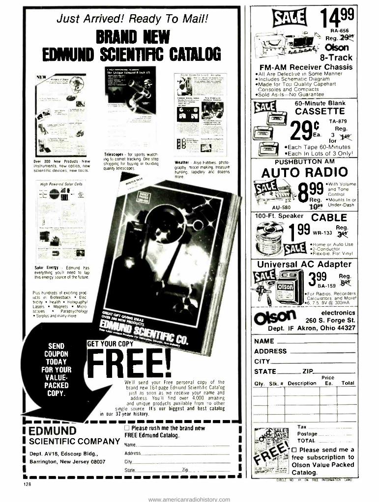
Just Arrived! Ready To Mail!
EDMUND
r4,444 44444.-:444.4
Over 200 New Products - New instruments, new optics, new scientific devices, new tools.
High Powered Solar Cells
BRAND NEW
SCIENTiFIC CATALOG
Telescopes for sports watch IN to comet tracking One stop shopping for buying or building quality telescopes
Weather Also hobbies. photo graphy model making, treasure hunting. lapidary and dozens more
Salar Energy Edmund has everything you'll need to tap this energy source of the future
Plus hundreds of exciting prod ucts in Biofeedback Elec trlclty Health Holography/ Lasers Magnets Micro scopes Parapsychology
Surplus and many more
SEND COUPON
TODAY FOR YOUR
VALUE - PACKED
COPY.
GET YOUR COPY
FREE.
I EDMUND
We'll send your Free personal copy of the brand new 164-page Edmund Scientific Catalog
just as soon as we receive your name and address. You'll find over 4,000 amazing
and unique products available from no other single source. It's our biggest and best catalog
in our 31-year history.
Please rush me the brand new
I FREE Edmund Catalog.
SCIENTIFIC COMPANY ; ' Dept. AV18, Edscorp Bldg.,
Name
Address
I Barrington, New Jersey 08007 City
State Zip
ti ri t - t mee mi m m a tr to em ra lim m ll m m t inns tm i 128
SALE 99 14 w
RA -656
11 f -
Olson e dlìPl' Olso e
- , 8 -Track FM -AM Receiver Chassis
AII Are Defective in Some Manner Includes Schematic Diagram Made for Top Quality Capehart Consoles and Compacts
Sold As -Is -No Guarantee
SALE 60- Minute Blank
G CASSETTE ® TA -879
295. 3 9
limy,. for Each Tape 60- Minutes Each In Lots of 3 Only'
PUSHBUTTON AM
AUTO RADIO F
SAE- 99 With Volume
{`,,/ Tone l
and ç 4 tit , Control ' p :,: Reg. Mounts In or
AU -580 logg Under -Dash
100 -Ft. Speaker CABLE # 199wR.133 1
SAE Home or Auto Use
'oil 2- Conductor Flexible. Flat Vinyl
Universal SAS y=
AC Adapter 399 Reg.
BA 159
For Radios, Recordr'r' Calculators. and Mon , 7.5. 9V (off 300mA
electronics 260 S. Forge St.
Ohio 44327
:(
Dept.
'won "
IF Akron,
NAME
ADDRESS
CITY
STATE ZIP Price
Qty. Stk. H Description Ea. Total
!,
a"''-'
.-r. v i
_..0
J
Tax Postage TOTAL _ Please send me a
free subscription to Olson Value Packed Catalog.
CIRCLr NO 41 ON RiEE INFORMATION CARD
www.americanradiohistory.com
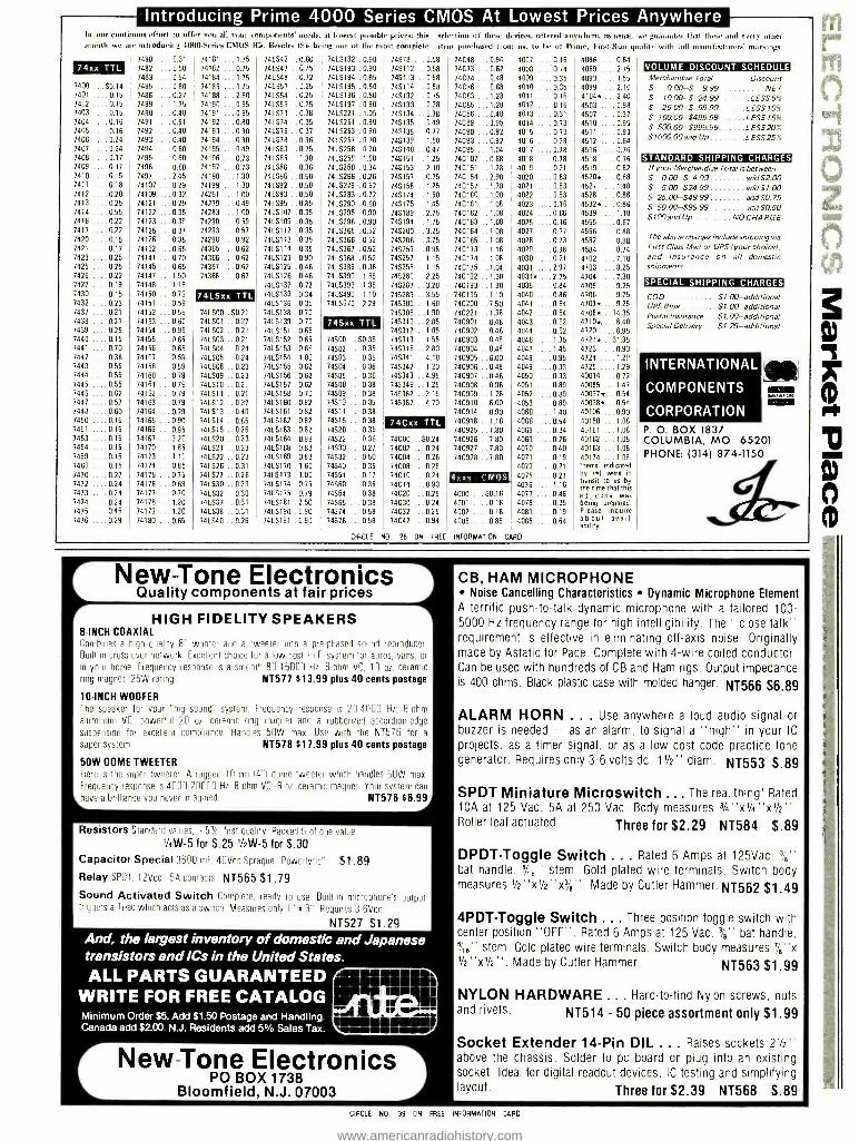
Introducing Prime 4000 Series CMOS At Lowest Prices Anywhere In our contemns effort to offer you all your components' needs, at lowest possible Prices: this selection of these devices, offered anywhere, as usual, we guarantee that these and ever, other month we are introducing 4000- Series CMOS ICs. Besides this being one of the most complete item purchased front us, to be of Prime, First -Run qualit) with full manufacturers' markings.
7480 ....0.31 74181 ...1.75 74LS42 .. 0.60 74L$192 0.90 74578 ...0.58 74xx TTL 7482 ....0.50 74182 ...0.75 74LS47 . . 0.75 74LS193 0.90 745112 ..0.58
7483 ....0.54 74184 ...1.75 74LS48 ..0.72 74L$194 0.85 745113 ..0.58 7400 $0.14 7485 ....0.80 74185 ... 1.75 74LS51 ..0.25 741.0195 0.50 745114 ..0.58 7401 . 0.15 7486 ....0.27 74188 ...2.80 74L$54 ..0.25 74LS196 0.80 745132 ..0.75 7402 . 0.15 7489 ....1.75 74190 ...0.95 74L$55 .. 0.25 74LS197 0.80 745133 ..0.38 7403 . 0.15 7490 ....0.40 74191 ...0.95 74LS73 .. 0.38 74LS221 1.05 745134 ..0.38 7404 .0.16 7491 ....0.51 74192 ...0.80 74LS74 .. 035 74LS251 0.80 74S135 ..0.49 7405 . 0.16 7492 ....0.40 74193 ...0.80 74L576 .. 0.37 74LS253 0.80 745138 ..0.77 7406 . 0.24 7493 ....0.40 74194 ...0.80 74LS78 .. 0.36 74LS257 0.70 745139 ..1.50 7407 .0.24 7494 ....0.60 74195 ...0.49 74LS83 .. 0.75 74LS258 0.70 745140 ..0.47 7408 . 0.17 7495 ....0.60 74196 ...0.73 74L$85 .. 1.30 74LS259 1.60 745151 ..1.25 7409 . 0.17 7496 ....0.60 74197 ...0.73 74LS86 .. 0.36 74LS260 0.34 745153 ..2.10 7410 . 0.15 7497 ....2.45 74198 ...1.30 74LS90 .. 0.50 74L5266 0.26 745157 ..0.75 7411 . 0.18 74107 ...0.29 74199 ...1.30 74LS92 . . 0.50 74LS279 0.52 745158 ..1.25 7412 . 020 74109 ...0.32 74251 ... 1.00 74LS93 .. 0.50 74LS283 0.72 745174 ..1,50 7413 . 0.25 74121 ...0.29 74279 ...0.49 741S95 ..0.85 74L$290 0.60 745175 ..1.45 7414 . 0.55 74122 ...0.35 74283 ... 1.00 74LS107 .0.35 74LS295 0.90 745189 ..2.75 7416 . 0.22 74123 ...0.39 74290 ...0.59 74LS109 .0.35 74L$298 0.90 745194 ..1.75 7417 . 0.22 74125 ...0.37 74293 ...0.57 74LS112 .0.35 74LS365 0.52 745200 .. 3.25 7420 . 0.15 74126 ...0.38 74298 ...0.92 74L5113 .0.35 74L5366 0.52 745206 .. 3.75 7421 .0.17 74132 ...0.65 74365 ...0.62 74LS114 .0.35 74LS367 0.52 745253 .. 0.95 7423 . 0.25 74141 ...0.70 74366 ...0.62 74L5123 .0.90 74LS368 0.52 74$257 ..1.15 7425 0.25 74145 ...0.65 74367 ...0.62 74LS125 .0.46 74LS386 0.36 745258 ..1.15 7426 . 0.22 74147 ...1.50 74368 ...0.62 74LS126 .0.46 74L$390 1.65 745280 .. 2.25 7427 . 0.19 74148 ...1.15 74LS132 .0.72 74LS393 1.35 745287 .. 3.20 7430 0.15 74150 ...0.79 74LSxx TTL 74LS133 .0.34 74LS490 1.10 745289 ..3.55 7432 .0.23 74151 ...0.59 74LS136 .0.35 74L$670 2.29 745300 ..1.60
74LS00 S0.21 7437 .0.21 74152 ...0.59 74LS138 . 0.70 745305 ..1.90 7438 .0.21 74153 ...0.60 74LS01 . 0.27 74LS139 .0.70 74Sxx TTL 745310 ..2.85 7439 . 0.25 74154 ...0.95 74LS02 . 0.21 74LS151 .0.65 745312 .. 1.05
74500 $0.35 7440 . 0.15 74155 ...0.65 74LS03 .0.21 74LS152 .0.65 745313 ..1.55 7441 .0.70 74156 ...0.65 74LSO4 . 0.24 74LS153 .0.66 74502 . 0.35 745316 ..2.80 7442 . 0.38 741E7 ...0.59 74LS05 . 0.24 74LS154 . 1.00 74503 . 0.35 745341 ..4.10 7443 . 0.55 74158 ...0.59 74LSOB . 0.23 74LS155 .0.62 74504 . 0.36 745342 .. 1.20 7444 . 0.55 74160 ...0.79 74LS09 . 0.23 74LS156 .0.62 74005 . 0.36 745343 .. 4.95 7445 . 0.55 74161 ...0.79 74LS10 . 0.21 74LS157 . 0.62 74508 0.38 745346 .. 1.25 7446 . 0.62 74162 ...0.79 74LS11 . 0.21 74LS158 .0.70 74509 0.38 745362 ..2.15 7447 . 0.57 74163 ...0.79 74LS12 . 0.27 74LS160 . 0.82 74510 . 0.35 745387 ..4.70 7448 . 0.60 74164 ...0.79 74LS13 . 0.40 74LS161 .0.82 74511 . 0.38 7450 . 0.15 74165 ...0.90 74LS14 . 0.85 74L5162 . 0.82 74515 . 0.38 74Cxx TTL 7451 .0.15 74166 ...0.95 74LS15 . 0.26 74LS163 . 0.82 74520 . 0.35
74000 $0.24 7453 . 0.15 74167 ...3.20 74LS20 . 0.23 74LS164 . 0.98 74522 . 0.36 7454 .0.15 74170 ...1.85 74LS21 023 74LS168 0.83 74530 . 0.27 74CO2 . 0.14 7459 .0.15 74173 ...1.10 74LS22 . 0.23 74LS169 .0.83 74S32 . 0.50 74004 . 0.26 7460 ....0.15 74174 ...0.85 74LS26 . 0.31 74LS170 .1.60 74540 .0.35 74008 . 0.25 7470 , ... 0.27 74175 ...0.75 74LS27 . 0.26 74LS173 . 1.00 74051 . 0.17 74010 . 0.24 7472 ....0.24 74176 ...0.69 74LS30 . 023 74LS174 . 0.75 74560 . 0.35 74014 . 0.90 7473 ....0.24 74177 ...0.70 74LS32 . 0.30 74LS175 .0.79 74564 . 0.38 74C20 . 0.25 7474 ....0.24 74178 ...1.20 74LS37 . 031 74LS181 .2.50 74565 . 0.38 74C30 . 0.24 7475 ....0.45 74179 ...1.20 74LS38 . 0.31 74LS190 . 0.90 74574 . 0.58 74C32 . 0.25 7476 ....0.29 74180 ...0.65 74LS40 0.26 74LS191 .0.90 74576
CIRCLE NO 26 ON FREE
74048 ...0.96 74C73 ...0.62 74074 ...0.48 74C76 ...0.68 74C83 ...1.28 74C85 ... 1.20
74086 ...0.40 74089 ...3.95 74090 ...0.92 74093 ...0.92 74095 ...1.04 740107 ..0.68 740151 ..1.78 740154 ..2.90 740157 ..1.78 74C160 ..1.08 74C161 ..1.08 74C162 ..1.08 740163 .. 1.08
740164 .. 1.08
740165 .. 1.08
740173 ..1.16 740174 .. 1.08
740175 ..1.04 740192 ..1.30 740193 .. 1.30
740195 .. 1.10
740200 ..7.50 740221 .. 1.38
740901 ..0.48 740902 .. 048 740903 .. 0.48 740904 .. 0.48 74C905 .. 000 740906 .. 0.48 740907 .. 0.48 740908 ..036 74C909 ..1.78 740910 ..6.00 740914 ..0.90 74C918 ..1.16 740925 .. 7.80 74C926 .. 7.80 74C927 _7.80 74C928 .. 7.80
4r.xx CMOS
4000 ...$0.16 4001 ....0.16 4002 ....0.16 4006 ....0.85
4007 ....0.16 4008 ...:0.74 4009 ....0.35 4010 ....0.35 4011 ....0.16 4012 ....0.16 4013 ....0.31 4014 ....0.73 4015 ....0.73 4016 ....0.28 4017 ....0.78 4018 ....0.78 4019 ....0.21 4020 ....0.83 4021 ....0.83 4022 ....0.83 4023 ....0.16 4024 ....0.66 4025 ....0.16 4027 ....0.37 4028 ....0.73 4029 ....0.98 4030 ....0.21 4031 ....2.97 40340.... 2.75 4035 ....0.84 4040 ....0.86 4041 ....0.64 4042 ....0.64 4043 ....0.62 4044 ....0.62 4046 ....1.35 4047 ....1.45 4048 ....0.95 4049 ....0.33 4050 ....0.33 4051 ....0.89 4052 ....0.89 4053 ....0.89 4060 ....1.40 4066 ....0.54 4068 ....0.34 4069 ....0.26 4070 ....0.40 4071 ....0.19 4073 ....0.21 4075 ....0.21 4076 .... 1.16
4077 ....0.46 4078 ....0.35 4081 ....0.19 4085 ....0.64
INFORMATION CARD
4086 ....0.64 4089 2 75
4093 ...1.55 4099 ...2.10 4104*.... 2.40 4503 ....0.98 4507 ....0.37 4510 ....0.95 4511 ....0.93 4512 ....0.64 4516 ....0.76 4518 ....0.76 4519 ....0.62 4520*.... 0.68 4527 ...1.48 4528 ....0.86 4532 *.... 0.86 4539 ....1.10 4555 ....0.67 4556 ....0.88 4582 ....0.88 4584 ...0.74 4702 ...7.10 4703 ....8.25 4704 ....7.30 4705 ....9.25 4706 ...9.75 4707*.... 9.25 4708*... 14.35
4710*.... 6.40 4720 ....6.95 47210... 31.35 4723 ....0.93 4724 ....1.29 4725 ....1.29 40014 ..0.72 40085 ...1.47 40097 *... 0.54 400980... 0.54 40106 ...0.90 40160 ... 1.08
40161 ...1.08 40162 ...1,08 40163 ...1.08 40174 ... 1.08 Items indicated by 1 *1 were in transit to its by the time that this ad copy was being prepared. Please inquire about avail. ability.
VOLUME DISCOUNT SCHEDULE Merchandise Total Discount 5 0.00 -$ 9.99 NET S 10.00 -$ 24.99 LESS5% $ 25.00 -$ 99.99 LESS 10%
S 10000 -5499.99 LESS 15%
$ 500.00 -5999.99 LESS 20% $1000.00and Up LESS25%
STANDARD SHIPPING CHARGES If your Merchandise Total is between.' S 000 -$ 4.99 add $2.00 $ 5.00- $24.99 add $1.00 $ 25.00- $49.99 add $0.75 $ 50.00- $99.99 add $0.50 $100 and Up NO CHARGE
The above charges include shipping via First Class Mail or UPS (your choice), and insurance on all domeste shipments.
SPECIAL SHIPPING CHARGES
COD $1.00- additional UPS Blue 01.00- additional Postal Insurance $1.00- additional Special Delivery 01.25- additional
INTERNATIONAL
COMPONENTS
CORPORATION P. O. BOX 1837 COLUMBIA, MO 65201 PHONE: (314) 874 -1150
New Tone Electronics Quality components at fair prices
HIGH FIDELITY SPEAKERS 8 -INCH COAXIAL Combines a high quality 8' woofer and a tweeter Into a pre phased sound reproducer Built In cross -aver network Excellent choice for a low cost Hi Fi system for autos, vans, or
In your home. Frequency response is a smooth 80 15000 Hz. Bohm VC, 10 oz ceramic ring magnet 25W rating NT577 $13.99 plus 40 cents postage
10INCH WOOFER The speaker for your "big sound" system. Frequency response is 20 4000 Hz, 8 ohm
aluminum VC, powerful 20 oz ceramic ring magnet and a rubberized accordion edge
suspension for excellent compliance Handles 50W max. Use with the NT5 76 for a
super system NT578 817.99 plus 40 cents postage
50W DOME TWEETER Here is the super rweeICf A rugged 10 cm 14 "I dome tweeter which handles 50W max
Frequency response is 4000 20000 Hz 8 ohm VC, B oz ceramic magnet Your system can
have a brilliance you never imagined. NT576 $6.99
Resistors Standard values, n 5%, first quality. Packed 5 of one value
1/4W -5 for S.25 1/2W-5 for 5,30 Capacitor Special 3600 mF, 40Vdc Sprague ' Powerlytic" $1.89 Relay SPLIT, 12Vdc 5A contacts NT565 $1.79 Sound Activated Switch Complete, ready to use Built in microphone's output triggers a Triac which acts as a switch Measures only l" e 3° Requires 3 6Vdc.
NT527 $1.29 And, the largest inventory of domestic and Japanese transistors and ICs in the United States. ALL PARTS GUARANTEED
WRITE FOR FREE CATALOG Minimum Order $5. Add $1.50 Postage and Handling. Canada add $2.00. N.J. Residents add 5% Sales Tax.
MIR ii
NIP wr. re r Nef -* 11 r.l lil .eF.^..
r New -Tone Electronic PO BOX 1738
Bloomfield, N.J. 07003
CB, HAM MICROPHONE Noise Cancelling Characteristics Dynamic Microphone Element
A terrific push -to -talk dynamic microphone with a tailored 100- 5000 Hz frequency range for high intelligibility. The "close talk" requirement is effective in eliminating off -axis noise. Originally made by Astatic for Pace. Complete with 4 -wire coiled conductor. Can be used with hundreds of CB and Ham rigs. Output impedance is 400 ohms. Black plastic case with molded hanger. NT566 $6.89
ALARM HORN ... Use anywhere a loud audio signal or buzzer is needed - as an alarm, to signal a "high" in your IC
projects, as a timer signal, or as a low cost code practice tone generator. Requires only 3 -6 volts dc. 11/2" diam. NT553 $.89
SPDT Miniature Microswitch ... The real thing! Rated 10A at 125 Vac, 5A at 250 Vac. Body measures 3/4 ''x1/4 "x1/2 ''. Roller leaf actuated. Three for $2.29 NT584 $.89
DPDT -Toggle Switch ... Rated 6 Amps at 125Vac. 3/8"
bat handle, 5/;¡" stem. Gold plated wire terminals. Switch body measures 1/2 "X1/2 "X3 /8 ". Made by Cutler Hammer. NT562 $1.49
4PDTToggle Switch ... Three position toggle switch with center position "OFF ". Rated 6 Amps at 125 Vac. 3/8" bat handle, 5/,8" stem. Gold plated wire terminals. Switch body measures 7 /8 "x 1/2"x1/2". Made by Cutler Hammer. NT563 $1.99
NYLON HARDWARE ... Hard -to -find Nylon screws, nuts and rivets. NT514 - 50 piece assortment only $1.99
Socket Extender 14-Pin DIL ... Raises sockets 21/2" above the chassis. Solder to pc board or plug into an existing socket. Ideal for digital readout devices, IC testing and simplifying layout. Three for $2.39 NT568 $.89
CIRCLE NO 39 ON FREE INFORMATION CARD
www.americanradiohistory.com

Rv BUY J
G5= CONTINENTAL SPECIALTIES
100 MHz 8 -Digit Counter 20 H r 100 MHI Hr000 f Lf U U"u'.av Fud m Aul.nial .'» Irdul.i odel
MAX-100
PKPRECISION 3'/2 -Digit Portable DMM
Overhead Protected Battery of
AC operation 3" high LEO Display
Auto Zeroing Model 2800
coes nmpletewith test $85 leads^overall, manual and sImm tus,
31/2 Digit DMM 1lasinng Ove, Range Indicaloi Auto Polarity overload Prot, te
Model 270 wired Reg $en un
\. Kit $65.00
Weller %Xcelite
MODEL
5 MHz Mini Oscilloscope
$27.95 $26.95
Service Master Attache Style.
Tool Kit Tool Cases '.Model Mode199SM MODEL TC 100/ST 99PR
Model MS 15 $39.95
$246.50 MODEL
WA 508
Reg s,B300 Roll Kit $239.50 $13.95
Model 7500 Cordleu
Soldering Iron $11.95
. Model 5800 Thermal Spot
Cocoil Tolle, 822.50
Ovum of nue sync modes Automatic and line
,han IS W Power consumption
Vertical Gain O 01 to 50 voltudoe 12 satiny
External or infernal trigger Reg .5795 OU
NOW AVAILABLE MS-215 S349.95
(Dual Trace Version of MS -15)
li
Los Probe
$40.00 complete Model LP -1
Compact, it powered 112 HtL (,MO,
cam use.
Or, c,s pulses as,niii, as SU
e;0W1ia,hni4,flil_'. . OT 59S
20 MHz. Dual Trace
Add subtract modes on
LOgtc ° niter . Amomaticapy
0t5P avs tau L.
lvn5mc 205'5 Works Ifi FEO drsplav
ITL ene CMOS complete Hi L. 1J
e ce't pOMo det LsNt
01 590 Ol
i- B
358
S 51iilï:" 75
0i 125 O !7' 4 ; OT 125
OT85 OT-IS
.-.. n1, Re9 SrG9 Jb
R I g CR2 $615.96 Fom panel X V ''M'" Ith accessues 17 5 cSet rise eme
as
dus slop 470
bus sino 350 bus strip
e0
120
70
PnN r 50
2 50
1000 2 25
8 50
2 00 ode,
BSR 129
$24.95
Voltage Spike Protector
Transistor Tester Model 100
9 en tiane, $22.00 o udp
prd ms to Movable erie
and
le
10 5 TO 18 and small01
of celcue , s 0perales un contact
I:e +e suea,o toi e
ni
o visita Mse, etons Io make
oanu n, a
might damage egupmeni Plugs
0. any 120 volt grounded AC
Model GESP152 'yc $7.95
Complete line available
520 MHz !1odel 1050
Frequency Ri.g 545080
Counter $382.50
GlRljl
MORE NEW ITEMS!
700 Serles P,ec ,n groind end paus eil
22W 19 Codmesllumemen,
Magnifier LAMP g
Model MG 10A
$42.50
20 K ohm /v VOM
Multimeter 55
$17.95 mca:1ed
529 le. -%
Mnimum Order 550.00
20 QN LJ1 FSIRMAIN CARD
- CaII TOLL FREE 1978 (800) 645-9518 Cal
N ,S161 752 -0050
Before you buy test equipment any make or model check our prices
Master Cnarp 90komeuca,d ö C U L , atautrr,
FICIRDHAivi VISA
855 Conklin SI Farmingdale, N Y 11735
New York Statelesi dents add aOP,op sales lax
Add 1300 for sh,Pding and i nsurancelcontmen la USA owy
JUMBO LED READOUT ARRAY By Bowmar..5 in. character common cathode. Designed for use with multi- plexed clock chips 4 digits in 1 pack!
ri Itttteffttttttt -
$195 LIMITED STOCK
MICRO -MINI TOGGLE SWITCH SPDT. By RAYTHEON. MADE IN USA! WITH HDWR. 990
EACH 6 FOR $5
NATIONAL SEMICONDUCTOR JUMBO CLOCK MODULE
ASSEMBLED! NOT A KIT!
ZULU VERSION! We have a limited number of the 24 HR Real time version of this module ,n stock sI
MA1008D - $9.95
INTEL 2102 RAM SPECIAL Brand New 2102A -4. "A" version for use in battery back -up. Factory Prime. These parts have been screened to meet LOW POWER specs. (40 MA. Max, 28 MA. Typical) FAST: 450 NS
8 FOR $7.95 32 FOR $28
$695
(AC XFMR $1.95)
COMPARE AT UP TO TWICE OUR PRICE!
PERFECT FOR USE WITH A TIMEBASE.
EXPERIMENTER'S CRYSTAL
262. 144KHZ. This frequency Is 2
to the 18511 power. Easily divided down to any power of 2, and even to 1HZ. New by CTS- Knight A $5
value!
$1.25 each
MA1008A BRAND NEW!
FEATURES' FOUR JUMBO 'n INCH LED DISPLAYS 12 HR REAL TIME FORMAT 24 HR ALARM SIGNAL OUTPUT 50 OR 60 Hz OPERATION LED BRIGHTNESS CONTROL POWER FAILURE INDICATOR
a SLEEP H SNOOZE TIMERS a DIRECT LED DRIVE (LOW RFI)
COMES WITH FULL DATA
MANUFACTURER'S CLOSEOUT!
SALE! 1N4148 DIODES
High speed switching diodes. Silicion. Same as 1N914.
Brand New. Full Leads. Prime!
100 FOR $2 1000 FOR $17.50
FAIRCHILD JUMBO READOUTS
.5 Inch Char. High Efficiency, END-503-Common Cathode END-SW-Common Anode
YOUR CHOICE 69C
10 FOR $5.75
DISC CAPACITORS .1 MFD 16V. P.C. leads. Most popular value! By Sprague.
20 for $1.00
FullWaveBridge 4 Amp 200 PIV 690ea. 10/5.75
MALLORY POWER SUPPLY CAPACITOR
1500 MFD 16 WVDC
3/$1.00 10/$2.95 FACTORY FRESH, SMALL SIZE
2N3904-House No. TO-92. NPN. VCEO-45.
H F E 100 to 300 10 tor $1.00
FET SALE! 2N4304. Brand New
N Channel, Junction Fet BVGDO -30V IDSS -15 MA Typ. 1500 uMHOS. TO -18 Plastic
Case. Mfg. by Teledyne.
6 FOR $1
Motorola PNP Power! 2N4905 TO -3 case. 90W
VCEO -60. HFE -100 max. at
2.5A. Good mate for the
2N3055. PRIME!
75¢ ea. 4/$2.50
COMPUTER CAPACITOR
By GE. 36,000 MFD 15W VDC. Small Size- 43 x 176 Inches, SUPER DEALI $2.95 Each
3 FOR $8
LS SERIES TTL 74LS00 -33c 74L574 -49c 741_502 -35c 74LS90 -69c 74L504 -35c 741_5138 -89c 74 LS0 8 -35c /4L5154-5.49 4L51 74L510 -33c 74LS175 -1.10 74L520 -33c 74L5367 -75c 74LS73 -49c 74LS368 -85c
Motorola Quad Op- Amp MC3401. Pin for Pin Sub for popular LM3900.
3/$1.00 w _ I Research Corporation
(OF TEXAS) P. O. BOX 401247 A GARLAND, TEXAS 75040 (214) 271 -2461
TERMS: Add 30e postage, we pay balance. Orders under $15 add 756 handling. No C.O.D. We accept Visa, Master - charge, and American Express cards. Tex. Res. add 5% Tax. Foreign orders (except Canada) add 20% P & H. 90 Day Money Back Guarantee on all items.
CIRCLE NO 62 ON FREE INFORMATION CARD
www.americanradiohistory.com

}114FB4FB&FB4FB4FB4FB4FB4FB&FB&FB4F84F84FB&F84F a O
W o Z Z O 9 .e.. . . '. .y,--.. . le
O A
In
SPEAKER KITS SENSIBLE SPEAKER KIT Fantastic enclosures and matching com- ponents to build your own pair of superb full -range 3 -way speaker systems. Kit in- cludes enclosures, 10" foam edge woof- ers, 5" middlers, 4" super dome tweeter% crossovers, damping, hardware and in- structions, PLUS: sculptured foam grills! Qty. Ltd., so order NOW! Cabinet size: 21x12x10. 50 Lbs /pr.
#8Z30338 only $99.88 /Pair O In
W MOTOROLA® PIEZO- ELECTRIC TWEETERS! ® HORNS, SUPER- HORNS, Q & DIRECT RADIATORS! 4 Unique tweeters give all
the things you'll want from a hi -freq speaker, plus flax - a
H ibility for the do- it -your- Z self designers.
0 ULTRASONIC Q m
s4
O This alarm sensor tills the protected area
Q with an energy screen that cannot be
z seen, felt or heard. Triggers your alarm 6 whenever burglar moves through detect-
or field. Mounts on ceiling, wall, desk, O shelf etc. Optional delay mode, auto- 11 reset. Operates on 12.5 VDC.A close -out
that originally sold for $179. 00! 3 Lbs.
MOTION DETECTOR
Qty. Ltd. #8D30336.... $49.88
TINY TRANSMITTER & SEISMIC SENSOR Unique military surplus <M troop movement detector. Compact 2" long unit con- f
tains tiny xmitter, a motion j
sensor and battery pack... but looks like a rock or a
glob of mud! (We guess that bett's may be dead). New surplus, w /data. 8 oz.
#8M10356 $4.88 ea.
Use Your BA -MC or AE for telephone orders. No C.O.D.'s please.
Please add POSTAGE 'PS or Parr. Post.
Ñ - No Crossover needed - High Impedance - High Output ¿1 - Flat Resp. 2K -20K Hz. - Low Harmonic Dist. W
V FOR COMPLETE INFO it
Circle Reader Service Card for FREE CATALOG
D z
e z is i n e
D
Shown - 3`h" SUPER HORN: #8E30248 . $7.88 ea or
$14.88 /Pair (2 Lbs)
AM /FM STEREO RECEIVER /AMP CHASSIS
p Ñ
I 0 0
3
A F
Send orders to: D
B &F ENTERPRISES X
Dept. P -9 p
119 Foster Street E
Peabody, MA 01960 (617) 531 -5774
-I r. JifSRE SUPPLUS REIGNS SUPREME Ill
Surplus Brand -name receiver /amplifier chassis, including bulls -eye stereo light on tuning needle, slide controls, amp & tuner (no case). Mfr.'s "questionables ", may need repair. You fix & save! Qty. is limited. AS IS (no returns). W /data. 5 Lbs .... 8K30357 . - $19.88 ea.
CIRCLE READER SERVICE CARD FOR FREE JUMBO CATALOG "tax CIRCLE NO 8 ON FREE INFORMATION CARD
1TEEThTE 0.12 ELEEThflFliES 540 Weddell Drive, #4, Sunnyvale, CA 94086 (408)734 -8470
CMOS 4000 4001 4002 4007 4010 4011 4012 4013 4014 4015 4016 4017 4018 4019 4020 4022 4023 4024 4025 4027 4028 4029 4030 4035 4040 4041 4042 4044 4049 4051 4066 4068 4069 4075 4082 74C00 74CO2 74C04
.15
.20
.20
.20
.36
.20
.20
.35
.80
.80
.35
.92
.92
.20 1.00 .83 .21 .75 .20 .34 .79
1.00 .20 .95
1.00 1.00
.70
.60
.35 1.10
.70
.40
.40
.20
.23
.25 -45 .32
74C08 74C10 74C14 74C20 74C30 74C32 74C42 74C48 74C73 74C74 74C86 74C90 74093 74C151 74C154 74C157 740160 74C162 74C164 740165 74C174 74C902 74C904 74C905 740914
65 .25
1.75 .26 .26 .30
1.40 2.75 1.25
.75 1.00 1.10 1.25 2.75 3.00 2.10 1.40 1.70 1.75 1.75 1.50 .85 .85
3.00 1.95
74007E 7401 7403 7404 7406 7407 7409 7410 7413 7414 7417 7420 7421
.16
.17
.17
.19
.40
.40
.25
.18
.78
.68
.38
.18
.35
7427 7430 7432 7437 7440 7442 7445 7446 7448 7450 7451 7453 7454 7460 7472 7473 7474 7475 7476 7483 7485 7486 7489 7492 7493 7495 7496 74121 74122 74123 74126 74132 74141 74145 741481 74150 74153 74154 74155 74157
.35
.15
.30
.44
.18 1.00
.70
.70
.70
.25
.25
.25
.35
.22
.40
.40
.40
.55
.45 1.05 1.10
.43 2.00
.75
.65
.78
.85
.35
.49
.65
.65 1.25 1.15 1.10 1.20
.90 1.10 1.25
.75 1.00
For more 74LSxx, refer to our ad in the June issue of this magazine.
74161 1.00 74163 1.30 74164 1.45 74165 1.35 74166 1.20 74173 1.70 74175 1.05 74117 .90 74182 .95 74191 1.20 74192 1.45 74193 1.35 74195 1.00 74196 1.10 74197 1.10 74199 2.25 74367 .90
Interface 0025 3.50 0026 1.75 8640 1.25 8641 2.75 8806 3.00 8819 1.25 8820 5.00 8830 4.90 8833 2.45 8835 245 8836 1.25 8837 2.45 8838 2.45 8859 1.50 8865 1.50 6666 1.50 8867 1.85 8869 1.75 8879 2.25 8880 2.75 8884 2.45
8973 2.95 8974 2.95 8976 2.95 75107 3.25 75450 1.00 75451 .80 75452 .80 75453 .80 75491 1.25 75492 1.40 75494 1.50
Peripheral 8212 3.50 8214 8.50 8216 3.75 8224 4.75 8228 9.90 8251 11.50 8255 10.50 2513 9.50 2516 9.50 1013 6.50
8000 TTL 8T20 3.25 8197 1.75 8092 .95 8094 .60 8095 .80 8096 .90 8098 .90
21 2.25 681136 3.25 8220 3.25 8231 2.25 8242 1.75 8250 1.75 8260 2.25 8281 1.00
8334 4.00 8553 6.50 8556 3.25 8599 3.25
LINEAR 301N .35 307N .35 308H 1.00 309K 1.25 3091: 1.00 318H 1.50 320M -5 .88 3207.5 1.25 3207 -12 1.25 324N 1.75 34075 1.25 3407'12 1.25 3401 -15 1.25 3407.24 1.25 38774 1.25 388N 1.15 555N .35 556N .85 558N 2.80 561N 5.00 566N 1.70 567N 1.65 709N .30 741H .25 3035 2.40 3401 1.25
74LSxx 74 LS00 .25
through
74 LS670 3.95
If what you need is not listed, ask for it. Send self- addressed stamped envelope.
SPECIAL - - 21L02/450ns (1.50 /tOup; t.35/50up; 1 25 /IOOup) t3 Digit A/D LD130 $5.50 MM5865 Universal Timer $7.50
Minimum order $5.00 US currency. Check or money order only. Add 5% to cover shipping and handling charges. Calif. residents add 6% sales tax. Santa Clara County residents add 6.5% sales tax.
CIRCLE NO 24 ON FREE INFORMATION CARD
UNIVERSAL 4Kx8 MEMORY BOARD KIT 669.95
32-2102-1 fully bufleied, 16 address lines, on board decoding for any 4 of 64 pages, standard 44 pin buss, may be used with F -8 & KIM
EXPANDABLE F8 CPU BOARD KIT $99.00
fa r mi Faiibuy PSU. 1 K- f static rain. RS 232 intr1.rtac , dnrrmrrntalio , 64 BYTE rers,s.er
C /MOS (DIODE CLAMPED) 4001 18 4019 37 4049 - 35 74C73 65 4002 18 4020 90 4050 35 74C74 45 4006 95 4021 - 90 4053 1.10 74083 1 15 4007 18 4022 - 90 4055 1 25 74C86- 40 4009 37 4023 18 4065 70 74C93 75 4010 37 4024 75 4071 18 700151 1 4U 4011 18 4025 18 4076 97 740160 105 4012 18 4027 37 4518 1 00 74C161 105 4013 29 4028 80 74000 22 74C174 105 4014 75 4029 95 700O2 22 740175 105 4015 75 4030 33 74004 24 74C193 1.20 4016 29 4035 97 74008 22 740901 48 4017 90 4042 65 74010 27 74C902 08 0018 90 4046 1 35 74042 - 85 740914 1.70
ecriaMiss ..
7102 0 1 54 508 s 11 2,07 1 aast
iiz aoóxox xi oval
2101
t 1256 er BAL'O'XS tason,l
5204 4K O 132523 8229
BINARY
51
a Bit A oCONVERTER S1750 50 BOMA S
s3 95 B32B f 495
is S2 29
S 745 sl
S1 245 745
S 75 850 740
s3 fa f1 S]
C R y 51 7r700 10014 i' ea.
6,000 MHI 6.144 MHI 0.000 MH:
10,000 MHI
RIRBIIN EABLF E LAT ICOLOR CODs
A30 WIRE
40 l':u 1
:,nd. - 90 /Pei fool
CTS 2068 mph, pos tien dip switch .... $1.60 C15.206-4 lour POSI ioP dip switch ....$1.45
ACTVAT ED SCRs 1018. 200V 1A S 1.10
SILICON SOLAR CELLS 2'/." diameter .4V at 500 ma 54.00
END 359 C.C..4" 5.50 LED READOUTS FCS 8024 4 r1,iir DL -704 C.A..3r $ 75 C C 8" display 5595 DL 747 C A 6" 51.25 END 503 C.C. 5" S 85 END BOO C 8" SI 95 END 510 C -A. 5" $ 85 END 807 C. A. 8" $1.95 DL 704.3" C.C. $ 85
PRINTED CIRCUIT BOARD 4 1 2 61 2
$60 au I 1h -
7V
5'52.60
7 WATT L D -65 LASER DIODE I R 5895 2N 382, 25 5457'. F-
252646 wT FR 901) f HIG(,EH DIODES 20 6078 000G UJT
S 45 5 45
S 45 0 S1 On
S 65
MINIATURE MULTI.TURN TRIM POTS 100, 1K, 2K, 5K, 10K, 20K, 50K, 100K, 200K. 500K, 1 Meg, 2Meg, $.75 euch 3/$2.00
CHARGED COUPLE DEVICES CCD 321 AH2 512 audio analcg S.R. $95 00 CCD 201C 100x100 Image Sensor $95 00 CCD 202C 1004100 Image Sensor $145.00 VERIPAX PC BOARD $4.00 This board 1'16 sm91e sided 1 04y board 4',"x6'00' DRILLED and ETCHED which win hold i9 to 21 single 14 ,nn IC's or 8.16 or Lsl DIP IC's wilt, hisses for power supply co 7nector
RED YELLOW GREEN or AMBER LARGE LED's 2" 6.51.00
TI L-118 OPTO.ISOLATOR $ 75
MOLEX PINS . 100:51.00 100058 00
1 WATT ZENFRS 33.1 7 56.91.10. I? 15 'l 1'V 6:51.00
MC6860 MODEM CHIP 09,95 MCM 6571A 7 x 9 ch.,iacrer gen 810.75
Silicon Power Rectifiers
4
41A 10211 65
SAO 1024 -a REDICON 1024 stage analog-Bucket 014,05' shlf1 register. $18.95
15 4148 1 5914' 15 51 20
RS232 DB 25P male 52,95 CONNECTORS 06 25S female $3.50
REGULATORS 309Y. 5 95 340K-1 2.15 723 $ .50 or 24V 5 95 LM 376 . 5 .60 3407-5. 6. 8, 12 320T 5, 15 15,18 or 24V 5 95
or 24V $ .95 78 MG . .$1.35 79 MG $1.35
Tenne: FOB Cambridge, Mass. Send 257 for our catalog featuring Send Check or Money Older. Transistors and Rectifiers Include Postage Minimum 145 Hampshire St., Cambridge, Mass Order $5.00, COO'S $20.00
TRANSISTOR SPECIALS 2N6233 -NPN SWITCHING POWER S 1.95 MRF -8004 e CB RF Transistor NPN S 1.50 203772 NPN S. TO 3 $ 1.00 2741546 PNP GE TO -3 $ .75 204908 PNP S. 1O 3
256056 NPN S IU 3 O5,59, 7745086 P,P S. TO 92 2743137 NPN SI RF
203919 NPN Si TO 3 1-11
2N14?0 NPN Si TO 5 . . . . .
2N3767 NPD Si TO 66 257222 NPN Si TI) 18 253055 NI'N S. TO 3
203904 NPN Si TU 92 253906 PNP Si TO 97 2N5796 NPN Si I O 220 25610'1 PNP S. TO 221)
-'N363; I"vP S. lO'-i fv1PSA 13 NPN Si
It10 S I 70
4 S 100 $ 85
S 1 50 3/$ 1.00
S 10
55 100 5 50
6/$ 1.00 6/S 1.00
S 50 S 55
r S 1 00
471S 1 OU
TTL IC SERIES 5- 7400- .13 7447446- .68
65
7401- .13 7447- 58 7402- .13 7448- .68 7003- 13 7450- 15 ]400- 15 7472- 25 7405- .13 7473- .28 7406- 16 7474- .28 7407- 20 7475- 45 7408- 18 7476- 30 7409- .18 7480- .31 7410- .13 7483- 65 7411- .18 7485- .87 7412- 13 7486- 28 7413- 36 7489 1.25 7414- .60 7490- 42 7416- 22 7491- 58 7417- 25 7492- 43 7420- .13 7493- 43 7425- 25 7494- .67 7426- 22 7495- 65 7427- .19 7096- 65 7430- 13 74107- 28 7432- 22 74121- 29 7437- .21 74122- 38 7438-- 21 70123- 45 7440- 13 74125- 40 7441- 70 74126- 40 7042- 37 74150- 94
74151- 61 74153- 61 74154 - 90 74155- 58 74157- 55 74161- 55 74163- 55 74164 85 74165- .95 74170- 1.68 74173- 1.20 74174- 95 74175- 85 74176- 75 74177- 75 74180- 65 74181- 1 90 74190- 1 00 74191- 1.00 74192- 79 74193- 79 74194- 80 75325- 1.50 74196- 86 74279- 55 74367- 50 75491- 50 75492- .50
22 44 Pin Sold,; Tail 156" Donn $1.95
MM 5387AA new clock chip which will directly dr.re LED's 12/24 hrs., 1 supply & alarm $5.95
NO. 30 WIRE WRAP WIRE SINGLE STRAND 100' $1.40
ALTO MINIATURE TOGGLE SWITCHES IOTA 106 SPOT S .95 r,1TA 206 DPDT S 170 MTA 206 P -DPDI CENTER OFF $ 1,8s MOD 206 P -DPDT CENTER OFF LEVER SWITCH $ 1.85
SOLID STATE SALES P.O. BOX 74A
SOME R V I LLE, MASS. 02143 TEL. (617) 547 -7053
Full Wave Bridges _ARV 2A 6A 25A 100 1 J 200 .75 1.25 2.00 400 .95 I.50 3.00 400 1.20 1.75 4.00
DIP SOCKETS 0 PIN I7 2 PIN J5
14 PIN JO 28 PIN Ad 16 PIN 22 -/0 1 N 60 18 PIN
SANKEN AUDIO POWER AMPS Si 1010 G 10 WATTS 5 7.811
S. 1320 S 20 WATTS $15.70 S 1'50 G 50 WATTS $28.50
TANTULUM CAPACITORS 22Ut 35V 5 Si 00 6851 35V 4 S1 00 47UE 350 5 Si 00 10UF 10V $ .25 68UF 35V 5 51 00 22UF 25V 5 40 1U1 35`: S1 00 15UF 35V 3/$1.00
2 I 2005 Si 00 30137 65' 5/$1.00 3EUE 20V 45100 IMF 20V 6 .35 4 7U 15V 5)01.00 68 UF 15V $ .50
100 UF 10V $ .40 LS RIES
74151 IX /0
7.505 ISA 54
/4141' 77175161 14
74L514 .1 IALSI62
747 S.76 7,5174 114
7475 14,18, 7 00
/47517 17 7,5141
IC 54. 14151. 77.541
7474.715 747 SBE
/AI 547
717 64
511
IS
TRIACS PRV IA 10A 25A
100 40 70 1.30 200 70 1 10 1.75 400 1 10 1.60 2.60
R CIRCUITS M101 - 75
301-748 75 61307 30
61308 - 75 311 - 75
M318 - 1.20 61319 - 05 ]74 - 70
M339 -110 m358 70 11320 115
]77 - 160 M 380 - 95 M381 -175
61
387 - 1 25 537 -250
61
553 - 3 50 555 - 39
M 556 - 85 E540L -225
560 7 00 565 - 95 566 Sfi7 -I10 703 - 90 709 25 710 35 41CorV 25
747 .50 M1310 250
1456 95 1458 50
CA3046 75 3900 40 8038CC -3.90 791 - 1 95 LF356H - 1.20
SCR'S 15A SA 35A 40 50 1 20
1.00 1 20 2.20
WE SHIP OVER 95% OF OUR ORDERS THE
DAY WE RECEIVE THEM
8.1txci
CIRCLE NO 54 ON FREE INFORMATION CARD
www.americanradiohistory.com

Electronics Classified REGULAR CLASSIFIED: COMMERCIAL RATE: For firms or individuals offering commercial products or services, $2.40 per word. Minimum order $36.00. EX-
PAND -AD' "' CLASSIFIED RATE: $3.60 per word. Minimum order $54.00. Frequency discount: 5% for 6 months; 10% for 12 months paid in advance. PERSONAL
RATE: For individuals with a personal item to buy or sell, $1.40 per word. No minimum! DISPLAY CLASSIFIED: 1" by 1 column (2 -1/4" wide), $280.00. 2" by 1
column, $560.00. 3" by 1 column, $840.00. Advertiser to supply film positives. For frequency rates, please inquire. COLOR: Color avail. for all classified ad styles at
earned rate plus additional 25 %. Color choice Publisher's option and subject to availability. Publisher reserves right to run ad in black if color not avail. on classifed
pages. In such cases color charge will be refunded or credited. GENERAL INFORMATION: Ad copy must be typewritten or clearly printed. Payment must accompany copy except when ads are to be billed on credit cards - American Express, Diners Club, Master Charge, VISA - or when ads are placed by accredited advertising
agencies. First word in all ads set in caps. All copy subject to publisher's approval. All advertisers using Post Office Boxes in their addresses MUST supply publisher
with permanent address and telephone number before ad can be run. Advertisements will not be published which advertise or promote the use of devices for the
surreptitious interception of communications. Ads are not acknowledged. They will appear in first issue to go to press after closing date. Closing Date: 1st of the 2nd
month preceding cover date (for example, March issue closes January 1st). Send order and remittance to Classified Advertising, POPULAR ELECTRONICS, One Park
Avenue, New York, N.Y. 10016. For inquiries, contact Gladys Mathieu at (212) 725 -3926.
FOR SALE
FREE! Bargain Catalog- I.C.'s, LED's, readouts, fiber optics, calculators parts & kits, semiconductors, parts. Poly Paks, Box 942PE, Lynnfield, Mass. 01940.
GOVERNMENT and industrial surplus receivers, transmitters, snooperscopes, electronic parts, Picture Catalog 25 cents. Meshna, Nahant, Mass. 01908.
LOWEST Prices Electronic Parts. Confidential Catalog Free. KNAPP, 4750 96th St N., St. Petersburg, FL 33708.
ELECTRONIC PARTS, semiconductors, kits. FREE FLYER. Large catalog $1.00 deposit. BIGELOW ELECTRONICS, Bluffton, Ohio 45817.
RADIO -T.V. Tubes -36 cents each. Send for free catalog. Cornell, 4213 University, San Diego, Calif. 92105.
AMATEUR SCIENTISTS, Electronics Experimenters, Sci- ence Fair Students ... Construction plans - Complete, in- cluding drawings, schematics, parts list with prices and sources ... Robot Man - Psychedelic shows - Lasers Emotion /Lie Detector - Touch Tone Dial - Quadraphonic Adapter - Transistorized Ignition - Burglar Alarm - Sound Meter ... over 60 items. Send 50 cents coin (no stamps) for complete catalog. Technical Writers Group, Box 5994, Uni- versity Station, Raleigh, N.C. 27607.
ROTARY SWITCH 4P11P 5/$5; 6P11P 5/$7.25. Dip Switch 10 -SPST 10/$15. Transformers 12.2 V CT -6A plus 8.5V -5A $6.95. 24V-5A $5.95. 10' RG58C /U 12/$10. Fertiks, 5400 Ella St., Philadelphia, PA 19120.
SOUND SYNTHESIZER KITS -Surf $14.95, Wind $14.95, Wind Chimes $19.95, Musical Accessories, many more. Catalog free. PAIA Electronics, Box J14359, Oklahoma City, OK 73114.
HEAR POUCE I FIRE Dispatchers! Catalog shows exclusive directories of "confidential" channels, scanners. Send post- age stamp. Communications, Box 56-PE, Commack, N.Y. 11725.
UNSCRAMBLERS: F55 any scanner or monitor, easily ad- justs to all scrambled frequencies. Only 4" square $29.95, fully guaranteed. Dealer inquiries welcomed. PDQ Elec- tronics, Box 841, North Little Rock, Arkansas 72115.
TELETYPE EQUIPMENT for sale for beginners and exper- ienced computer enthusiast. Teletype machines, parts, supplies. Catalogue $1.00 to: ATLANTIC SALES, 3730 Nautilus Ave., Brooklyn, NY 11224. Tel: (212) 372 -0349.
WHOLESALE C.B., Scanners, Antennas, Catalog 25 cents. Crystals: Special cut, $4.95, Monitor $3.95. Send make, model, frequency. G. Enterprises, Box 461P, Clearfield, UT 84015.
ORGAN KITS KEYBOARDS
THE ULTIMATE IN DESIGN AND SOUND
Demo Record 8 Brochure $1.00 Wunitzr reproduction.
021 DEVTRONIX ORGAN PRODUCTS, Dept. C
5872 Amapola Dr. San Jose, CA 95129
UNSCRAMBLE CODED MESSAGES from Police, Fire
and Medical Channels. Same day service. Satisfac- tion guaranteed. Don Nobles Electronics, Inc., Rt. 7,
Box 265B, Hot Springs, Arkansas 71901. (501)
623 -6027.
NAME BRAND Test Equipment. Up to 50% discount. Free catalog. Salen Electronics, Box 82, Skokie, Illinois 60076.
132
BUILD AND SAVE TELEPHONES, TELEVISION, DETEC- TIVE, BROADCAST Electronics. We sell construction plans with an Engineering Service. Speakerphones, Answering Machines, Carphones, Phonevision, Dialers, Color TV Con- verters, VTR, Games, $25 TV Camera, Electron Microscope, Special Effects Generator, Time Base Corrector, Chroma Key. Engineering Courses in Telephone, Integrated Circuits, Detective Electronics. PLUS MUCH MORE. NEW Super Hobby Catalog PLUS year's subscription to Electronic News Letter, $1.00. Don Britton Enterprises, 6200 Wilshire Blvd., Los Angeles, Calif. 90048.
SURPLUS COMPONENTS, Communication and test equip- ment. Illustrated catalog 25 cents. E. French, P.O. Box 249, Aurora, Illinois 60505.
TELEPHONES UNLIMITED, Equipment Supplies. All
types, Regular, Keyed, Modular. Catalog 50 cents.
Box 1147E, San Diego, California 92112.
CARBON FILM RESISTORS 1/4W, 1/2W - 1.7 cents each. FREE sample I specifications. Other components. COMPO- NENTS CENTER, Box 295, W. Islip, New York 11795.
WEATHER MAP RECORDERS: Copy Satellite Photo-
graphs, National -Local Weather Maps. Learn How!
$1.00. Atlantic Sales, 3730 Nautilus Ave., Brooklyn,
N.Y. 11224. Tel: (212) 372 -0349.
AUDIO EXPERIMENTERS, Serious Music Synthesizer
Stuff: literature, kits, components. circuits and
more. Send SASE for FREE INFO. CFR Associates,
POB F, Newton, NH 03858.
NAME BRAND TEST EQUIPMENT at discount prices. 72 page catalogue tree. Write: Dept. PE, North American Elec- tronics, 1468 West 25th Street, Cleveland, OH 44113.
UNSCRAMBLERS FOR any scanner. Several models avail- able. Free literature. Capri Electronics, 8753T Windom, St. Louis, MO 63114.
RADIO SHACK Authorized Sales Centel offering 10% dis- count off catalog prices. $25.00 or more delivered. 1117 Con- way, Mission, TX 78572.
TRANSISTORS FOR CB REPAIR, IC's and diodes. TV
audio repairs, 2SC799 - $3.00, 2SC1306 - $2.95, 2SC1307 - $3.85, TA7205 - $3.50, more.
Free catalog and transistor. B &D Enterprises, Box
32, Mt. Jewett, PA 16740.
UNSCRAMBLER KIT. Tunes all scramble frequencies, may be built -in most scanners, 2 -3/4 x 2 -1 /4 X 1/2. $19.95. Factory built Code -Breaker. $29.95. Free Catalog: KRYSTAL KITS, Box 445, Bentonville, Ark. 72712. (501) 273 -5340.
ELECTRONIC
SURPLUS FREE CATALOGS
ETCO ELECTRONICS, Dept. EB North Country Shopping Center Rt. 9N, Plattsburgh, N.Y. 12901
B&K Test Equipment. Free catalog. Free Shipping. Dinosaur discounts. Spacetron -AJ, 948 Prospect, Elmhurst, IL 60126.
BUILD THE ARTISAN ELECTRONIC ORGAN ... The 20th century successor to the classic pipe organ. Kits feature mod- ular construction, with logic controlled stops and RAM Pre -Set Memory System. Be an ar- ti -san. Write for our free brochure. AOK Manufacturing, Inc., Box 445, Kenmore, WA 98028.
SURPLUS ELECTRONICS ATTENTION HOBBYISTS - SEND FOR
YOUR FREE CATALOG Great buys in tape drives, keyboards, power supplies, and transformers. We also have heat sinks, steel cabinets, I/O terminals, video dis- plays, printers, and equipment cases. And of course components, fans, wire, and cable. Write now to 10 Flagstone Drive
Worldwide Electronics Hudson, NH 03051
THE UNRUSTABLES rrr
4401, Oil
4 .4 eli
NOW carry up to 40 extra gallons with
. auxiliary tanks econo-tank - for Pickups & Vans a
r DETROIT APPROVED: No rust or weld sediment 1 Install one hour - lightweight, no bodywork
required Complete Kit Guaranteed life of I vehicle Meets Federal á State standards F FR C 800 433 2
(In TEXAS call 817/756 -6221) 1 I PICKUP & VAN EQUIPMENT CO. Dept. PE , P.O. Drawer C, Hewitt, TX 76643
I=IM1==-- - - - --ME
or EE Cat al og-TOLL FREE /433-2386
SMALL expensive. imported miniature
WONDER stru,e only costs
it in less than an hour with only a tube of
you ,an net a v , special adhesive. See it in our 54- tual wall of sound pane,olor catalog/manual of kits. out of two -element raw speakers and accessories h,rih fidelity +tereo Send 50C to speaker, only ten
arid dome tweeter Dept. PE -S,
end ak the Speakerlab Point 735 N. Northlake Way one out performs the Seattle, WA 98103
SUMMER SPECIAL! Complete CARTRIVISION TELEVI- SION RECORDER ELECTRONIC ASSEMBLY. (See previ- ous issues) $11.50 plus $3.50 S&H. Master Charge, Bank - Americard. M.E.C., 369, Madison, Alabama 35758.
THE BEST CB ANTENNA SEND FOR FREE PAL FULL LINE
CATALOG AND DECAL
`Firestik' Antenna Corp. PAL
2614 EAST ADAMS PHOENIX. ARIZONA 85034
PRINTED CIRCUITRY. From copying without photography to
gold plating. Catalog $1.00 refundable. CIRCOLEX. Box 198,
Marcy. NY 13403.
TANDY TRS -80, HEATH H -8 Adapters to S -100 bus,
$49.95 kit. MINIMART,1618 James, Syracuse, N.Y.
13203.
SAVE 15% or more NORTHSTAR, CROMEMCO,
others. MINI MICRO MART, 1618 James, Syracuse,
N.Y. 13203. (315) 422 -4467.
SCANNER RADIOS GALORE! Catalogs- $1.00. The News- room, Inc., Dept. PEPI, 1973 S. State College Blvd., Anaheim, CA 92806.
POPULAR ELECTRONICS
www.americanradiohistory.com

POLICE /FIRE SCANNERS, crystals, antennas, CBs, Radar Detectors. HPR, Box 19224, Denver, CO 80219.
ELECTRONIC EQUIPMENT HOTLINE is a new classified advertising newsletter for buying and selling professional, in- dustrial, and surplus electronic equipment. Subscriptions $6 /year, ads 500 /word. Prepublication offer: $1.00 off sub- scriptions and 20% off all ads postmarked before October 1, 1978. Electronic Equipment Hotline, PO Box 4768, Panorama City, CA 91402.
SEND for free C.B. & HI -Fl catalog, top value prices. Mesa Enterprises, Rt. 4, Box 273B, Tucumcari, New Mexico 88401.
CONNECTORS, UHF, BNC, and audio types. Low Prices, Free Catalog. Coakit, Box 101 L, Dumont, New Jersey 07628.
SANKEN 50 WATT POWER AMP $22.50 Postpaid, 50 Volt Transformer for above $8.00 Postpaid, 100 Watt Stereo Basic Amplifier Kit, Complete $99.50. Prarie Sounds, PO Box 982, Champaign, IL 61820.
ELECTROMAGNETIC SPECTRUM CHART. Frequency allo- cation of broadcast, short wave, TV, CB, microwave etc listed. $2.00. D. Stephen, Box 1525, Station B, Montreal, Quebec, Canada H3B 2K9. U.S. Inquiries.
EXCESS TEST EQUIPMENT Tektronix, H -P, Fluke, more. List free. CLE, 3518 Riverside, Columbus, Ohio 43221.
MORSE CODE GENERATOR - produce morse code with a press of a finger. $74.95 wired and tested. Free literature. S.J. Engineering, Box 442, Canton, Mass. 02021.
FREE CATALOG, TOP QUALITY, Import Kits, IC's,
Transistors. International Electronics, Box 289,
Getzville, NY 14068.
SEEKING ORIGINAL JAPANESE TRANSISTORS FOR CB, TV, STEREO REPAIR? Request complete list. Compare 1 to 9 prices: 2SC710 $0.45, 2SC517 $3.95, 2SC799 $3.60, 2SC1306 $2.90, 2SC1678 $2.25, TA7205P $2.90, BA521 $2.90, SG613 $5.95. Fuji -Svea Enterprise, Dept. P, P.O. Box 40325, Cincinnati, OH 45240.
POWERFUL NEGATIVE ION GENERATORS and acces- sories. (Fascinating Details - $1.00). Golden Enterprises, Box 1282 -PE, Glendale, AZ 85311.
CORVAIR PARTS - 4500 item, giant catalog rushed $2.75, Clark's Corvair Parts, Shelburne, Mass. 01370. 413 -625- 9092.
1802 EXTENDED MONITOR. Relocatable, K.C. tape routines, 18 powerful subroutines, requires 1K memory. K.C. tape $20.00, paper tape $18.00, w /manual and listing. Infor- mation sase. Benchmark Computer Systems, 17 Hanover Place, Hicksville, L.I., N.Y. 11801.
CUSTOM ENGRAVED PANELS make your project look
great! 30¢ square inch! Sample plus guide, 50¢. Tag Your Gear! 11/2" x 3" plastic with strap 4 lines 6/$7.50, sample $2.25. Pomaski, 1761 Kaiwiki, Hilo, Hawaii 96720.
TEST EQUIPMENT CATALOG listing used Tektronix, HP and GR- equipment at bargain prices. PTI, Box 8699, White Bear Lake, MN 55110. Price $1.00 refundable with first order.
COSMAC 1802 SOFTWARE Displays, Music, Diagnostics Timers Listings, Documentation $3.00. Hillesland's, Box 105, Parkers Prairie, MN 56361.
DIGITAL REVERB. Creates concert hall effects. Fully Elec- tronic. Plans $5.00. With PCB $16.50. Neves, Box 10327, Stanford, CA 94305.
O C1 n
DON'T BE SHOCKED! Solid State Tester checks home appliances N -Air conditioners. etc. No
technical knowledge required. Simple lights indicate unsafe condition. Send check or money order today for $24.95 plus $1.50 shipping and handling to Mop Associates Inc., 1049 No. State Road 7, Margate, FL 33063.
NTERESTING COMPUTER PROGRAMS written in Basic. Free list. Software, 4914 Inwood PI., Santa Barbara, CA 93111.
TELEMETRY TRANSMITTER KIT, $7.00; Transmits tone to ordinary FM radio. Many practical applications. Kit contains parts and assembly instructions. Include payment with order to: OMNI -TEK INC., Box 726, Loveland, CO 80537.
Amazing new model features ultra -
miniature size, hl -fi sound and a battery saving El on -off switch. Picks up B transmits sounds with-
out wires up to 300 ft. through any FM radio. Use as remote mike, intercom, baby sitter, alertialarm syst, hot line, etc For fun, home B office. Great at parties. FCC appd. Battery included. Money back guar. Only 519.95 +$1.50 post-hdlg. Mass. res.
add tax. Order today. Oty. disc. avail. ® MU INDUSTRIES, Dept. PE9 50 Hunt St., Watertown. Mass. 02172
SEPTEMBER 1978
iñ
CRYSTAL CONTROLLED DIGITAL CROSSHATCH /DOT GENERATOR. Kit $31.95, built $41.95. Free Catalog. PHOTOLUME CORP., 118 East 28 Street, New York, NY 10016.
PLANS AND KITS
QUALITY KITS, over 7,000 schematics. $1 (refundable) for illustrated catalog. Tek -Devices, Box 19154c, Honolulu, HI
96817.
N.N. 0303,
TE
DIS CN MO
CA
AMAZING ELECTRONIC V. PRODUCTS LASERS SUPER POWERED, RIFLE, PISTOL POCKET SEE IN DARM PfC5.
CHecAL DEBUGGING. UNCRAMeLER6- CUNT TESLA . STuCCAND TV
RUPTER . ENERGY PRODUCING, SCIENTIFIC DETECTION, ELECTRIFYING, EMicas. ULTRASONIC, ce, Aces, AUTO AND MECH DEVICES, HUNDREDS RE - Ru. NEW PLUS INFO UNLTO PARTS SERVICE.
INFORMATION unrirnitvd Tcuss Al Box 626 Lord Jeffery P2. Wiest,
FREE KIT Catalog contains Test and Experimenter's
Equipment. Dage Scientific Instruments, Box
1054P, Livermore, CA 94550.
TIGER SST SIMPLI -KIT
THE DO- IT- YOURSELFER
NOW! a high quality CD Electronic Ignition System in kit form. Contains all components and solder to build complete Solid -State Electronic CD Ignition System for your car. As- sembly requires less than 3 hours. Increases MPG 15% Eliminates 4 of 5 tune -ups Increases horsepower 15% Instant starting, any Plugs and Points last weather 50,000 miles Dual system switch
Fits only 12 volt neg. ground Only $x1.95 postpaid
Star Corporation P.O. Box 1727 Grand Junction, Colorado 81501
BUILD YOUR OWN SYMPHONY OF SOUND!
IVs fun and easy -takes just min- utes a day! Complete kits for organs, pianos, strings, rhythms, amplifiers, synthesizers. Also factory assembled. 104 -page catalog $2.00
OWER5I Wersi Electronics, Inc.
Dept. ZD, 1720 Hempstead Road Lancaster, PA 17601
CB /HAM HIGH GAIN ANTENNAS. Modulation boost-
ing VOX- COMPRESSOR. Portable 300MHz COUNTER
with memory! Plans $3.00 ea. $7.50/all. Many
others, catalog with order, PANAXIS, Box 5516 -A9,
Walnut Creek, CA 94596.
KITS. 500 MHz Frequency Counter $79.95. 650 MHz pre - scaler, $17.95. Flashing LED, $1.000. SASE, Lectronix, Box 42, Madison Heights, MI 48071.
ELECTRONIC HELP JUST A PHONE CALL AWAY. We'll help you design projects, find components, advice. Low rates, first 2 minutes free. 24 hours a day, 7 days a week. BAC, VISA, MASTERCHARGE; Don Britton Enterprises, (808) 395 -7458.
PROJECTION TV ... Convert your TV to project 7 foot pic- ture. Results equal to $2,500 projector. Total cost less than $20.00. PLANS & LENS $16.00. Illustrated information FREE. Macrocomc, Washington Crossing, Pennsylvania 18977.
MODIFY YOUR P.L.L. or Crystal Synthesis C.B. for extra channels, linear and antenna tips. Send
$12.95 for instruction book. Action Protection Sys-
tems, RD1, Box 6003, Milford, PA 18337.
"FUNDAMENTALS" OF ROBOT DESIGN $10.00. Write: Ad- vanced Research Scientific, P.O. Box 19041 -R, Detroit, Michigan 48219.
KITS DESIGNED FOR ELECTRONICS STUDENTS, free flyer, Austin Electronics, 1242 El Vago St., La Canada, CA 91011.
TELEPHONES & PARTS
CORDLESS TELEPHONES: Operate 300 ft. from base. Fac- tory rechecked, schematics included for personal mainte- nance. Originally $399.50 - now $179.00. Check, M.O. or Credit Card. Telephone Marketers, P.O. Box 216, Brookfield, WI 53005.
TELEPHONES, CORDS, PLUGS, JACKS, Etc. Direct to Hobbyists. Free catalog. Remco, 20272 37th Ave. N.E., Seat- tle, WA 98155.
ALARMS
QUALITY BURGLAR -FIRE ALARM EQUIPMENT at discount prices. Free Catalog! Steffens, Box 624K, Cranford, N.J. 07016.
DON'T PURCHASE alarm equipment before getting our free value packed catalog. Sasco, 5619 -C St. John, Kansas City, MO 64123. (816) 483 -4612.
PROFESSIONAL ALARM EQUIPMENT at Below- Wholesale Prices. Catalog S1.00 (Refundable). CAPCO, Drawer 5980P9, Inclines, Nev. 89450.
Burglar . Fire . Smoke Alarm Catalog
Billions of dollars lost annually due to lack of protective warning alarms.
FREE CATALOG Shows you how to protect your home, business and person. Wholesale prices. Do -it- yourself. Free
engineering service.
Box 82802 PE -098 Lincoln, Ne. 68501
MUSICAL INSTRUMENTS
UP TO 60% DISCOUNT. Name brand instruments catalog. Freeport Music, 114 G, Mahan St., W. Babylon, N.Y. 11704.
HIGH FIDELITY
DIAMOND NEEDLES and Stereo Cartridges at Discount prices for Shure, Pickering, Stanton, Empire, Grado and ADC. Send for free catalog. LYLE CARTRIDGES, Dept. P, Box 69, Kensington Station, Brooklyn, New York 11218. For Fast Ser- vice call Toll Free 800 -221 -0906.
MICROCOMPUTERS
MICROCOMPUTER: BUILD, LEARN! Save Money!! Com- plete System Design Plans. Catalog $1.00. Design Re- sources, Box 4991PS, Thousand Oaks, CA 91360.
WANTED
GOLD, Silver, Platinum, Mercury, Tantalum wanted. Highest prices paid by refinery. Ores assayed. Free circular. Mercury Terminal, Norwood, MA 02062.
POEMS, SONGS WANTED. Songs recorded -published. Radio released. Broadway Music Productions, Box 7438 -CM, Sarasota. FL 33578.
WANTED! CB DEALERS AND DISTRIBUTORS
`Firestik' Antenna Corp.
2614 EAST ADAMS PHOENIX. ARIZONA 5503A
PAL
133
www.americanradiohistory.com

TUBES
RADIO & T.V. Tubes-36 cents each. Send for free Catalog. Cornell, 4213 University, San Diego, Calif. 92105.
TUBES: "Oldies ", Latest. Supphes, components, schematics. Catalog Free (stamp appreciated). Steinmetz, 7519 -PE Ma- plewood, Hammond, Ind. 46324.
TUBES -RECEIVING, Industrial and Semiconductors Factory Boxed. Free price sheet including TV, Radio and audio parts list. Low, low prices. Transelectronic, Inc., 1365 39th St., Brooklyn, New York 11218. Telephone: (212) 633 -2800. Toll free: 800 -221 -5802.
TUBES 29 cents up, also have industrials, obsoletes. 25 cents for catalog and $1 credit certificate. Connolly, Box 1333P, Sun Valley, CA 91352.
TUBES - Send 10 cents for large conclusive list. Low Prices. T -J Specialties, Box 43, Bradley Beach, New Jersey 07720. (201) 774 -8429.
TAPE AND RECORDERS
8 -TRACK and CASSETTE BELTS - money back guarantee. Long wearing. Free Catalog - $3 minimum order. PRB Corp., Box 176, Whitewater, Wisconsin 53190. (800) 558 -9572 ex- cept WI.
TAPE HEAD CLEANER. 8 oz. - $2.30. Includes postage and handling. Write: "Cleaner ", Box 176, Whitewater, WI 53190. 800- 558 -9572 except WI.
RECORDS - TAPES! Discounts to 73 %; all labels, no purchase obligations; newsletter; discount dividend certifi- cates; 100% guarantees. Free details. Discount Music Club, 650 Main St., Dept. 5 -0978, New Rochelle, New York, N.Y. 10801.
PARANOID ABOUT SPECS? Prove or disprove playback performance cassette or record player with surprising new technique developed by Emory Cook. Test cassette or record, instructions $3.95 (Connecticut residents add tax). COOK LABORATORIES, Inc., 375 Ely Avenue, Norwalk, CT 06854.
"CASSETTE RECORDER TUNE -UP TIPS." Do- it- yourself! Save! Illustrated guidebook $2.00 postpaid. Rishell's, 2060 Sunderland, Maitland, FL 32751.
GOVERNMENT SURPLUS
MANUALS for Govt Surplus radios, test sets, scopes. List 50 cents (coin). Books, 7218 Roanne Drive, Washington, D.C. 20021.
JEEPS -$59.30! - CARS -$33.50! - 200,000 ITEMS! - GOVERNMENT SURPLUS - Most COMPREHENSIVE DI- RECTORY AVAILABLE tells how, where to buy - YOUR AREA - $2.00 - MONEYBACK GUARANTEE - Govern- ment Information Services, Department GE -35, Box 99249, San Francisco, California 94109 (433 California).
GOVERNMENT SURPLUS. Buy in your Area. How, where. Send $2.00. Surplus, 30177 -PE Headquarters Building, Washington, D.C. 20014.
PERSONALS
MAKE FRIENDS WORLDWIDE through international corres- pondence, illustrated brochure free. Hermes -Verlag. Box 110660/Z, D -1000 Berlin 11, Germany.
INSTRUCTION
SCORE high on F.C.C. Exams ... Over 300 questions and answers. Covers 3rd, 2nd, 1st and even Radar. Third and Second Test, $14.50; First Class Test, $15.00. All tests, $26.50. R.E.I., Inc., Box 806, Sarasota, Fla. 33577.
UNIVERSITY DEGREES BY MAIL! Bachelors, Mas-
ters, Ph.D's. Free revealing details. Counseling, Box
317 -PE09, Tustin, California 92680.
SELF -STUDY CB RADIO REPAIR COURSE. THERE'S MONEY TO BE MADE REPAIRING CB RADIOS. This easy - to -learn course can prepare you for a career in electronics enabling you to earn as much as $16.00 an hour in your spare time. For more information write: CB RADIO REPAIR COURSE, Dept. PE098, 531 N. Ann Arbor, Oklahoma City, Okla. 73127.
LEARN WHILE ASLEEP! HYPNOTIZE! Astonishing details, strange catalog free! Autosuggestion, Box 24 -ZD, Olympia, Washington 98507.
GRANTHAM'S FCC LICENSE STUDY GUIDE - 377 pages, 1465 questions with answers /discussions - covering third, second, first radiotelephone examinations. $13.50 postpaid. GSE, P.O. Box 25992, Los Angeles, California 90025.
INTENSIVE 5 week course for Broadcast Engineers. FCC First Class license. Student rooms at the school. Radio En- gineering Inc., 61 N. Pineapple Ave., Sarasota, FL 33577 and 2402 Tidewater Trail, Fredericksburg, VA 22401.
UNIVERSITY DEGREES BY MAIL: Bachelors, Masters,
Ph.D.'s. Any subject. Fast. Easy. legal. Education,
1132 Henderson Avenue, Menlo Park, CA 94025.
1978 "TESTS - ANSWERS" for FCC First Class License. Plus - "Self Study Ability Test." Proven!
$9.95 Moneyback Guarantee. Command Produc-
tions, Box 26348 -P, San Francisco, CA 94126.
BROADCAST STATION: Start your own. Home, school,
church, business operation. Get free equipment, records. Details free. "Broadcasting", Box 5516 -
A9, Walnut Creek, CA 94596.
FCC License Study Course prepares you to pass examina- tions for 1st, 2nd, 3rd and radar. Study Guide manual gives examples, problems and solutions. Question- Answer manual provides hundreds of practice questions. $9.95 each or both manuals $14.95. Postpaid. Oeffinger, Box 1240, Garden Grove, Calif. 92642.
LEARN ELECTRONICS Capsule Course basic d.c. textbook plus taped instruction. Details send to: Box 4457, Ind. Sta., St. Paul, MN 55104.
INVENTIONS WANTED
RECOGNITION ...FINANCIAL REWARD-OR CREDIT
FOR "INVENTING IT FIRST' MAY BE YOURS!
If you have an idea for a new product, or a way to make an old product better, contact us, "the idea people" Well develop your idea, introduce it to industry. negotiate for cash sale or royalty licensing.
Write now without cost or obligation for free information. Fees are charged only for contracted services. So send for your FREE "Inventor's Kit." It has important Marketing Information, a special "Invention Record Form" and a Directory of 1001 Corporations Seeking New Products.
RAYMOND LEE ORGANIZATION 230 Park Avenue North.NewYork.NY 10017
At no cost or obligation, please rush my FREE "inventor's Kit No. A -112 "
I Name
Address
City
Phone No, Area C ^oe
State Z p
YOU CAN make money from your ideas" FREE details. Write: Advanced Research Scientific, P.O. Box 19041 -R, De- troit, MI 48219.
INVENTORS: SELL YOUR PRODUCTS DIRECT. Free info: Early Bird Consumer's Report, 4021 Stevely Ave., L.A., CA 90008.
FREE PAMPHLET: "Tips on Marketing Your Invention ", from an experienced fee -based invention service company. Write: United States Inventors Service Company, Dept. T. 1435 G
Street NW, Washington, DC 20005.
BUSINESS OPPORTUNITIES
I MADE $40,000.00 Year by Mailorder! Helped others make money! Free Proof. Torrey, Box 318 -NN, Ypsilanti, Michigan 48197.
PROFrEABLE ONE -MAN ELECTRONIC FACTORY Investment unnecessary, knowledge not required, sales handled by professionals. Postcard brings facts about this unusual opportunity. Write today! Berta- DI , Box 248, Walnut Creek, CA 94597.
GET RICH!!! Secret law erases debts. Free report exposes millionaire'$$ secrets. Blueprints, No. EE9, 453 W. 256, NYC 10741.
NEW LUXURY Car Without Cost. Free Details! Codex -ZZ, Box 6073, Toledo, Ohio 43614.
$650 WEEKLY for beginners!! Free report: Mailorder Consul- tants MEE9, 453 W256, NYC 10471.
DISTRIBUTORS AND WHOLESALERS OF COMPUTER SUPPLIES: Major supplier of computer -digital cassettes is now offering low price high quality computer -digital cassettes specifically designed for use in hobby computers and small business computers, presently looking for distributors and wholesale outfits for this product line. Contact: Magnetic In- formation Systems, Inc., 415 Howe Ave., Shelton, CT 06484. Tel: 203 -735 -6477.
FANTASTIC! $500.00 WEEKLY easily mailing circulars! Free information! Wayne, Box 644 -ZD, Ottawa, KS 66067.
MECHANICALLY INCLINED individuals desiring ownership of Small Electronics Manufacturing Business - without in- vestment. Write: BUSINESSES, 92 -K2 Brighton 11th, Brook- lyn, New York 11235.
MILLIONS in Mail!!! Free Secrets. Transworld -17, Box 6226, Toledo, OH 43614.
EXPORT OPPORTUNITY: DUTCH DISTRIBUTOR SEEKS American Companies in electronics and audio field, for mar- keting your products: Hamelton Parks, P.O. Box 3067, Ar- nhem, Holland.
MAKE durable building plastic easily. Waterproof, Fireproof, Economical. Bays Laboratory, Rt. 1, Box 168, Cedaredge, Colo. 81413.
EARN $1000 MONTHLY - Unique Mailing Program! No
Gimmicks! Guaranteed!! Write: L.O.E., Box ZD- 06108, Port-
land, OR 97206.
RENT LEASE TV'S ANYONE CAN! Easy to start and operate. Even from your home. Send $2.00 for basic information. Per - ry's TV, P.O. Box 1407, Santa Maria, CA 93454.
DO -IT- YOURSELF
MODULAR TELEPHONES now available. Sets and compo- nents, compatible with Western Electric concept. Catalog 50 cents. Box 1147W, San Diego, California 92112.
REAL ESTATE
BIG ... FREE ... CATALOG! Over 2,500 top values coast to coast!! UNITED FARM AGENCY, 612 -EP, West 47th, Kansas City, MO 64112.
RUBBER STAMPS
RUBBER STAMPS, BUSINESS CARDS. Many new prod- ucts. Catalog. Jackson's, Dept. K, Brownsville Rd., Mt. Ver- non, Ill. 62864.
REPAIRS AND SERVICES
SERVICEMEN - Cleaners, Lubricants, Adhesives for all electronic repairs. Write for FREE catalog. Projector -Recorder Belt Corp., Box 176, Whitewater, WI 53190. 800 -558 -9572 except WI.
PCB DESIGN AND DRAFTING SERVICE. Fast service,
low rates. Enertic, POB 2436, San Jose, CA 95109.
PRINTED CIRCUIT BOARDS from sketch or Artwork. Kit
Projects. Free details. DANOCINTHS, Inc. Box 261, West- land, MI 48185.
EMPLOYMENT OPPORTUNITIES
ELECTRONICS /AVIONICS EMPLOYMENT OPPOR- TUNITIES. Report on jobs now open. Details FREE. Aviation Employment Information Service, Box 240E, Northport, New York 11768.
ELECTRONICS TECHNICIANS. Min. Experience. No De- gree. Start as high as $21,000 yr. or more! Jobs throughout U.S. Free details. Write: TJM, Box 13832, Sacramento, CA 95813.
OVERSEAS JOBS! Unlimited Opportunity! All Occupations. Large Company Listings. Personalized Service. $2.00. Over- seas National. 2313 Huntridge, Clifton Park, N.Y. 12065.
MAGNETS
MAGNETS. All types. Specials -20 disc, or 10 bar, or 2 stick or 8 assorted magnets. $1.00. Magnets, Box 192 -H, Ran - dallstown, Maryland 21133.
134 POPULAR ELECTRONICS
www.americanradiohistory.com

--ABOUT YOUR SUBSCRIPTION
Your subscription to POPULAR ELECTRONICS is maintained on one of the world's most modern, efficient computer systems, and if you're like 99% of our subscribers, you'fl never have any reason to complain about your subscription service.
We have found that when com- plaints do arise, the majority of them occur because people have written their names or addresses differently at different times. For example, if your subscription were listed under "William Jones, Cedar Lane, Mid- dletown, Arizona," and you were to renew it as "Bill Jones, Cedar Lane, Middletown, Arizona," our computer would think that two separate sub- scriptions were involved, and it would start sending you two copies of POPULAR ELECTRONICS each month. Other examples of combinations of names that would confuse the com- puter would include: John Henry Smith and Henry Smith; and Mrs. Joseph Jones and Mary Jones. Minor differences in addresses can also lead to difficulties. For example, to the computer, 100 Second St. is not the same as 100 2nd St.
So, please, when you write us about your subscription, be sure to enclose the mailing label from the cover of the magazine -or else copy your name and address exactly as they appear on the mailing label. This will greatly reduce any chance of error, and we will be able to ser- vice your request much more quickly.
MOTION PICTURE FILMS
AUGUST CLOSEOUTS! Brand New S8 400' Sound Feature Films: Sweet Charity, Shirley Maclaine; Thoroughly Modern Millie, Julie Andrews I Mary Tyler Moore; '76 World Series (Yanks /Reds), $42.95 ea PPD (save $7. + $1.50 pstg). Fail Safe, Walter Mathau; Creature with the Atom Brain (Sci F); Charles Bronson in "Breakout.' - S8 400' B/W Snd $32.95 ea + $1.25 ship. (save $7.). Baseball Sports Specials: '71
World Series (R. Clemente, Pirates /Orioles) 200' S8 Color $14.95 + $1.00 ship (save $5.); S8 B/W choice of '71 or '74 (A's /Dodgers) $5.95 ea + $0.75. Ali /Inoki (Japanese Wres- tler) 200' S8 Color $14.95 (save $5.) or S8 BM 200' $5.95 +
$0.75 ship. Penny Pinchers - Egg Nappers Universal 8
Funny Fable Cartoons & Chili Willie in Clash & Carry, 200' Se color silent, $14.95 ea + $0.75 ship. '72 Super Bowl (Dolphins / Cowboys) St 8 200' Color (can be played on Dual 8 proj) $8.95 ea add $0.75 ship (save $11.). 64 -pg Universal Color catalog $1.00 USA; Outside USA send $2.00. Columbia, Sportlite, Ring Classics & Universal order forms, $0.35 set. SPORTLITE FILMS, Elect -9/78, PO Box 24 -500, Speedway, IN 46224.
HYPNOTISM
FREE Hypnotism. Self- Hypnosis. Sleep Learning Catalog! Drawer H400, Ruidoso, New Mexico 88345.
BOOKS AND MAGAZINES
FREE book prophet Elijah coming before Christ. Wonderful bible evidence. MEGIDDO Mission, Dept. 64, 481 Thurston Rd., Rochester, N.Y. 14619.
IT'S THE UNEXCELLED FM STATION REFERENCE! The
FM Atlas and Station Directory -112 pages of programming, technical information on nearly 5,000 stations of North America. $3.95. FM Atlas, Adolph, Minnesota 55701.
MISCELLANEOUS
MPG INCREASED! Bypass Pollution Devices easily. RE- VERSIBLY!! Free details - Posco GEE9, 453 W. 256, NYC 10471.
SEPTEMBER 1978
OUTSIDE OF JAPAN... NEW-TONEELECTRONICS Has the Largest Inventory of Original Japanese Components
Anywhere!
,, ,,.,:. NECHITACNJMITSUMI SHINDENGENMITSUBISHI FUJITSUFUJI-TENJRC SANYOR-OHMUNIDEN PANASONICCYBERNET SANKENNPCORIGIN PARTIAL LIST - CALL US FOR ALL YOUR DEVICE NEEDS
2SA49 .49 258492 t 00 2SC775 1 90 2SC1628 1 10 40081 1 50 S6087A 3.80 2SA101 .49 2SB495 75 2SC776 2.50 2SC1669 1 25 40082 3.00 56087B 380 2SA102 .49 258507 1 40 2SC777 4.95 2SG1674 .49 AN136 2.90 STK011 7.50 2SA200 .49 2SB511 1 50 2SC778 3.50 25G1675 .49 AN214 3.35 STK015 6.50 2SA221 .79 2SB528 1 40 2SC781 2.50 2SC1678 2.00 AN239 6 50 STK025 12.50 2SA234 .59 2SB536 150 2SC783 2.95 2SC1679 2.95 AN241 240 STK032 14.20 2SA353 .69 2SB539A 4 70 2SC784 49 2SC1684 .49 AN245 5.50 STK036 19.00 2SA377 1.89 2SB541 4 70 2SC785 .65 2SC1728 1.85 AN247 4 80 STK050 24.50 2SA387A .69 2SB554 8 00 2SC788 2 95 2SC1730 .95 'AN271 3 20 STK056 11.35 2SA473 1.25 2S13561 60 2SC789 1.00 2SC1756 2.75 AN289 7.90 STK405 9.20 2SA483 2,79 2SB627 295 2SC790 1 50 2SC1760 160 AN315 350 STK415 8.50 2SA484 2.44 2SC793 2 50 2SC1816 3.50 AN331 5 40 STK433 9.25 2SA485 1.95 2SC32 1 35 2SC798 3 95 2SC1908 .49 AN343 3 90 STK435 9 50 2SA489 1.39 2SC116 3.00 25C799 3 25 2SC1909 3.75 AN360 2 50 STK437 11 50 2SA495 .60 2SC172 175 2SC815 55 2SC1957 1,00 AN380 750 STK439 11 60 2SA496 .99 2SC206 250 2SC828 49 2SC1964 3.95 BA302 2.50 TA7028M 3.50 2SA497 1.44 2SC237 1.75 2SC829 49 2SC1969 4.70 BA511 3.00 TA7045M 3 25 2SA509 .50 2SC281 50 2SC830 2 95 2SC1973 90 BA521 3.40 TA7051P 3.00 2SA525 1.95 2SC284 120 2SC838 50 2SC1974 3.50 C3001A 2.95 TA7054P 3.05 2SA537A 195 2SC287 125 2SC839 50 2SC1975 3.50 CX075B 2.95 TA7055P 3.00 2SA539 .60 2SC291 395 2SC853 90 2SC2020 4.95 CX100D 8.50 TA7060P 1.40 2SA561 .48 2SC325 395 2SC866 500 2SC2027 6.00 CX101G 8.50 TA7061P 1.50 2SA562 45 2SC367 85 2SC867 600 25C2028 .80 CX103D 8.50 TA7062P 1 50 2SA564 .50 2SC371 .49 2SC870 50 2SC2029 3.40 CX104A 8.50 TA7063P 1.50 2SA565 1.05 2SC372 .49 2SC871 50 2SC2034 2 95' CX121A 7.50 TA7072 3.00 2SA566 3.20 2SC373 .49 2SC900 50 2SC2074 2.50 CX130A 7.00 TA7074 2.90 2SA606 1.69 2SC374 49 2SC922 69 2SC2075 4.00 CX148 11.70 TA7075 3.75 2SA624 .99 2SC375 49 2SC929 .49 2SC2091 2 50 CX149A 14.00 TA7076 3.75 2SA628 .49 2SC380 49 2SC930 49 2SC2092 3.25 DN834 1.50 TA7089 2.90 2SA634 1.00 2SC381 .50 2SC938 .95 2SC2098 3 90 DN835 1.60 TA7102P 5 80 2SA636 1.25 2SC382 55 2SC943 1.00 2SC2166 3 75 DN837 1 50 TA7106P 3 25 2SA640 49 2SC384 60 2SC945 .49 2SD45 4.95 DN838 t.70 TA7120P 1.50 2SA643 .60 2SC385 .70 2SC959 1.35 2SD68 .90 HA1151 3.20 TA7122 1.50 2SA659 .49 2SC386 70 2SC960 2.95 2SD72 .80 HA1157 4.20 TA7124 1.85 2SA663 4.75 2SC387 50 2SC984 .80 : 2SD77 1.50 HA1158 4.20 TA7146P 3.75 2SA666 .69 2SC394 .49 2SC1000 .49 ' 2SD81 3.95 HA1159 5.00 TA7148 3.90 2SA671 1.50 2SC403 .50 2SC1013 95 2SD88 4.80 HA1199 325 TA7149P 3.90 2SA672 .70 2SC454 .49 2SC1014 95 2SD118 3.00 HA1202 2.20 TA7150P 3.75 2SA673 70 2S0458 .49 2SC1017 1.20 25D130 1.20 HA1306 4.90 TA7153 6.90 2SA678 .65 2SC460 49 2SC1018 1 00 2SD170 1.50 HA1308 4 50 TA7167 6.20 2SA679 4.95 2SC461 49 2SC1030 2.80 25D180 250 HA1312 3.40 TA7200P 3.50 2SA680 4.95 2SC478 80 2SC1034 560 25D187 49 HA1314 420 TA7201P 4.50 2SA682 1.49 2SC481 1.50 2SC1047 .59 2SD188 2.70 HA1316 3.50 TA7202 4.50 2SA683 .60 2SC482 1.40 2SC1060 1 40 - 2SD201 4 50 HA1318 5 00 TA7203 4.25 2SA684 60 2SC484 2 60 2SC1061 1.25 2SD213 4 95 HA1322 4.20 TA7204 3.70 2SA695 .60 2SC485 i 40 2SC1079 3.95 250217 3.80 HA1325 3.20 TA7205 3 60 2SA699 1.30 2SC486 1 50 2SC1080 3 95 2S0218 3 90 HA1339A 4 95 TA7207 3 50 2SA699A 1.45 2SC493 3 50 2SC1096 80 2SD227 48 HA1342 4.50 TA7208 3.50 2SA705 75 2SC494 4 50 2SC1098 1.00 2S0234 85' HA1366 4.20 TA7209 3.80 2SA706 1.45 2SC495 85 2SC1114 4.92 2SD235 85 HA11112 8.90 TA7210 6.50 2SA715 1.35 2SC496 85 2SC1115 3 00 250257 3.50 HA11113 6 50 TBA800 4.40 2SA719 59 2SC497 140 2SC1116 4.25 2SD261 100 HD3113 4.90 TBA810DS 4.40 2SA720 59 25C502 150 2SC1116A 4.75 250287 370 HD3127 780 TC4081P 1.75 2SA721 59 2SC503 175 2SC1124 1.20 2SD288 150 LA1201 425 TC5080P 5.80 2SA733 49 2SC504 1 75 2S01162 100 2SD313 1.05 LA1240 3.30 TC5081P 3.60 2SA740 1.95 2SC509 75 2SC1166 48 25D314 150 LA1364 3 70 TC5082P 4.00 2SA745 4.50 2SC515 195 2SC1170B a.95 250315 120 LA1366 4.25 TC9100P 8.50 2SA747 5.75 2SC517 360 2SC1172 525 25 0318 195 LA1369 4.25 TD3400P 1.55 2SA750 49 2SC535 55 2SC1173 75 25D325 90 LA3155 2 25 1D3441A.P 5.10 2SA756 3.30 2SC536 49 2SC1175 75 2SD330 1.50 LA3201 195 TM4312P 1.00 2SA758 560 2SC537 49 2SC1209 .75 2SD331 1.50 LA3301 340 UH1C001 6.50 2SA777 99 2SC538 60 2SC1211 59 25D356 1.00 LA3310 4.20 UH 1C003 650 2SA816 .70 2SC563 90 2SC1212 1.65. 2SD358 1.10 LA3350 3.30 UH1C004 6.50 2SA839 195 2SC580 195 2SC1213 59 2SD360 1.05 LA4000 750 UH 1C005 650
2SC608 595 2SC1226A 85 2SD382 1.20 LA4030 5.40 UH10006 6.50 2S622 65 2SC609 5 95 2SC1237 4 00 2SD427 2 55 LA4031P 3 20 UPC16C 2 50 2SB54 49 2SC614 395 2SC1239 350 2SD525 t 50 LA4032P 420 UPC20C 3.75 2S1356 95 2SC619 65 2SC1306 350 2SCF6 1.25 LA4051P 320 UPC30C 3.75 26875 .48 2SC620 49 2SC1307 4 75 2SCF8 3 50 LA4101 3 20 UPC41C 2.80 2SB77 .48 2SC627 2 95 2SC 1308 5 75 2SF8 3.00 LA4201 3 25 UPC48C 3.95 2SB111 59 2SC632 60 2SC1312 49 2SK19 1.25 LA4400 3.40 UPC157CA 2.50 2SB156 95 2SC634A 60 2SC1313 49 2SK23A 100 LA4420 3.40 UPC554C 250 2S6172 .60 2SC644 49 2SC1317 49 2SK30A 75 LAD001 320 UPC555H 2.20 2SB175 60 2SC645 60 2SC1318 49 2SK33 90 LD3040 1.60 UPC563H2 8.00 2SB186 .49 2SC674 .60 2SC1327 49 2SK34 .90 L03120 2.40 UPC566H 1.25 2S6187 55 2SC680 2.60 2SC1330 1 35 2SK40 1 30 M5112 8 40 UPC573C 3.25 2SB202 1 50 2SC684 1 20 2SC1342 49 2SK55 1 00 M5151PR 7.80 UPC575C 2.60 2SB227 2.95 2SC693 49 2SC1344 49 3SK22 2.20 M5152L 2.75 UPC576 3.25 2SB234 2.95 2SC696 1.75 2SG1347 85 3SK22Y 2.20 M5192 4.80 UPC587C2 2.95 256235 7.95 2SC699 5.95 2SC1359 65 3SK35 200 M51171L 2.00 UPC592H2 1.40 2S8270 79 2SC708 1.75 2SC1360 95 3SK39 2.00 M51513L 5.10 UPC595C 2.95 2SB303 .49 2SC710 .49 2SC1362 52 3SK40 200 MB3705 3.35 UPC596C 2.75 2SB324 .60 2SC711 .49 2SC1364 1 10 3SK41 2 20 MN3001 19-50 UPC1001H2 3 50 2SB337 135 2SC712 .49 2SC1377 480 3SK45 2.20 MN3002 11 70 UPC1008C 5.75 258370 .65 2SC715 69 2SC1382 95 3SK49 2.20 MN3003 9.45 UPC1020H 4.25 2SB405 .60 2SC717 50 2SC1383 50 JSP7001 75 MN3004 17.95 UPC1025H 3.50 2SB407 1.35 2SC730 4.15 2SC1384 80 MA26 .28 MN3005 75.00 UPC1026H 3.10 2SB415 65 250731 3.00 2SC1402 3.60 MPS8000 125 MN6040 16.75 UPC1152H 3.95 2SB434 1 15 2SC732 .49 2SC1403 3 60 MPS8001 1.25 MN6040A 16 75 UPC1154H 3.95 2SB435 135 2SC733 49 2SC1419 95 MPSUO2 50 UPC1155H 3.95 2SB440 60 2SC734 49 2SC1447 .90 MPSU31 400 PLLC1A 13.50 UPC1156H 450 2S6461 1.60 2SC735 .49 2SC1448 100 MRF8004 300 PLL02A 8.50 UPC1380C 9.50 2SB463 1.40 2SC738 .49 2SC1449 85 SD1074 1995 PLL02A-G 8,50 UPC78L05 1.40 256471 140 2SC756A 2.40 2SC1475 1.25 SD1076 2895 SG609 4.80 UPD277C 4.50
.256472 2.60 2SC763 .49 2SC1507 1 40 4004 3 00 SG613 6.75 UP0857C 15 50 2S13474 1.10 2SC773 60 2SC1509 .85 4005 3 00 56080A 3.75 UPD858C 9.50 2SB481 1.50 2SC774 1.50 2SC1624 1.10 40080 1.25 S6080B 3.80 1JP0861C 18.50
MINIMUM ORDER S5.00 All orders add 51.00 Postage and Handling. NEW TONE Canada 51.50
J. Residents add 5°o sales tax
DEALERS: Write on letterhead for confidential price list. ELECTRONICS
24 HOUR SHIPMENT ON ALL DEVICES IN STOCK. P.O.Box 1738A, Bloomfield, N.J. 07003 ALL PARTS GUARANTEED - COD ORDERS WELCOME Phone: (201) 748-6171, 2, 3
CIRCLE NO 38 ON FREE INFORMATION CARD 135
www.americanradiohistory.com

New Cosmac Super }'ELF" RCA CMOS expandable to 64K micro- computer w /HEX keypad input and video output for graphics. Just turn on and start loading your program using the resi- dent monitor on ROM. Pushbutton selec- tion of all four CPU modes. LED indicators of current CPU mode and four CPU states. Single step op. for program debug. Built in pwr. supply, 256 Bytes of RAM, audio amp. & spkr. Detailed assy. man. w /PC board & all parts fully socketed. Comp. Kit $106.95. High address display option 8.95: Low address display option 9.95: Custom hardwood cab.: drilled front panel 19.75; Nicad Battery Backup Kit w /all parts 4.95: Fully wired & tested in
cabinet 151.70: 1802 software club. 10- 12 pg. monthly publication 12.00 per yr.
4K Elf Expansion Board Kit with Cassette I/F $79.95 Available on board options: 1K super ROM monitor $19.95 Parallel I/O port $7.95 RS232 I/F $3.50 TTY 20 ma I/F $1.95 S -100 Memory I/F $4.50
Tiny Basic for ANY 1802 System Cassette $10.00. On ROM Monitor 538.00. Super Elf owners, 30' ott. Object code listing or paper tape with manual $5.50.
Original ELF Kit Board $14.95
Digital Temperature Meter Kit Indoor and outdoor Switches back and forth. Beautiful. 50' LED readouts. Noth- ing like it available. Needs no additional parts for complete. full operation. Will measure -100° to *200T, tenths of a de- gree,air or liquid. Very accurate. $39.95 Beautiful hardwood case w /bezel $11.75
PLANNING TO
C C r
Let us know 8 weeks in advance so that you 1 City won't miss a single issue of POPULAR I
ELECTRONICS. Attach old label where indicated and print new address in space provided. Also include your mailing label whenever you write con- cerning your subscription. It helps us serve you promptly.
Write to: P.O. Box 2774, Boulder, CO 80322 giving the following information:
Change address only Extend my subscription
ENTER NEW SUBSCRIPTION I year $13.00 Payment enclosed
Allow 30 -60 days for (1 extra BONUS issue) delivory. Bill me later
FAFFIX OLD LABEL - -- If you have no label handy, print OLD address here. I
I I
Name please print l Address
I S t a t e - - - - - - - - - NEW ADDRESS HERE
Zip
0225
Name
Address Apt
City
please print
State Zip Additional postage on foreign orders'. add $3 a year for Canada, $5
a year for all other countries outside the U.S. and its possessions. Cash only on foreign orders, payable in U.S. currency,
P.O. Box 4430C Santa Clara, CA 95054 For will call only: (408) 988 -1640
2322 Walsh Ave. Same day shipment. First line parts only. Factory tested. Guaranteed money back. Quality IC's and other components at factory prices. INTEGRATED CIRCUITS co4vs ; 52 . 4
C0416 1 10 Me. u6 00645t08 1 01 151J0
,5 10 L01520 t 02 M1M02 1'51519;1 .1B f0 C0a527 1 Si 5261
3aOoaDX 0 17 74`SIOH 15 l]40T24 10 CM08 COa528 Y MM5180
:4025 17 164 53JN 39 1M3a3N 'A LOJd001 50 L0a551 5 75 N S110
;404N r9 3dL538N JO LM310 y CD1000 6 0064566 115 MMUIO 14095 23 7d s146
i) LM3p 50 co., 21 c0as8l 750 PD4rOJ :40N 7640515N
LM379 W C04002 21 CD4585 1 0 PW:iO.a
lM)BOM W cDep06 , 10 C0640192 ]W
Ì<Si19 69 i:LS9riJ'Nr si am, W CO4pD1 21 c00 18 64
14226 1 39 79 59511 I 99 382 60 C064UO8 21 7aC01 33 81525 0 a306 20 74L5t076 35 LM7U3N 0 04009 39 71C10 28 9.02A 4420 50 74L51120 35 LM709 28 C07010 39 1IC14 210 Hp0165-5
04 79 69 74151136 35 LM723H6 50 LD101, 21 74C20 IB 57r00
1 60 7I351129 .1 1M73]N 67 Lo64012 Ir 24CJ0 1B =re' 74486 14506 69 74L51066 67
lM1arCN 15 CM', % MrMB 1 95 LM657ra
LM1641N 25 gig 86 1aL74 25 aYB
24746 29 741.51556 611M1641HN 61 Co640r5 086 14[16 :a0 747511 9 1525/575 67
3M74BN l5 crini, 3E )IL90 1 15
CLOCKS 7485N ri ]IL51fi2N II r103N 82 co4o17 94 IIL93 r
M5J09 7M9N 200 1d251616 91 LM1xM O CD64018 9a
2:C, 1 300
M 511, ' 90N 1 7dL51245 95 CDd019 1t 5 91MS1r2
76492, 43 1)LSr90, r W LM00) 2 133 Co64020 r 02 ) [tfi5 2On MSJ11
74976 4l 74352216 95 M,3 0 2!5 C064011 r 02 04Cr91 0 0 MM53 4
'64956 69 7/151586 67 LMr 58 1064012 B6 64C221 MM5315
Ia100x 90 764LS361N 89 145 C04023 21 7dC905 3013 MM5316
M107N 19 l 1012 ] 50 COep24 5 2aC906 1 50
MM51 8
7641216 34 LINEAR LM18B9 .300 0D1015 21 ]IC9r4 1 95
LB, LA1045 90 LM2101 175 CD1026 :5r 190922 T 50 MMS&1
'4r25x 39 52046 67 1.912902 i 5n C04021 36 1640921 150 MM5865 »Oh
s,505 95 wool 180 l 39005 60 CD4028 9 74c925 1050
LrioO+ 895 C63082 190 3M3905 1.5 CD4029102 7dC9261050 271671 22
59 Á3O89 295 l 39095 fir Lp1030 21 74C927 1050 Cr.OtO 895
N 3s CM58V 50 CU4035 r 02 57,6 7 25 CONNECTORS
67 NE5403 2 89 CD4010 , 02 IMIERFACF MMSJ75M N 1; 15 NE550, 65 CND. 71 8095 fi5 MM5175a8 N 90
4:::::;.3,22 q
8096 65 7105 16 50 100 qn e0-e 25
+ 65 NE556a I? C040643 61 9097 65 RCN 3 75 CRáTALE
1.65 NE565A r 00 0DI0646 r 67 a098 65 MIIp56cN 3 25 MH7
HN NE566v , 15 co640r9 M 9r09 15 53104 250 áMH, 2 91 M56Y ' 20 CD4o50 M 9110
41
50 IL SOCRE55 MH7 ', x
15 MS%OB 500 101051 13 B51J J0U Ew1ar'T1P 1.Pw Pn81e 5 MH M]2OK.5 i 20 MSP eo CD4g60 1 42 8130 S 50 MN UP PM 2UP l0 MN7
1M123K5 695 7l m[0640fi6 1 8r3J llo g 15 22 30 18MN7
191320A11 78LOB 60 co4068 4n 8T24 350 11 8 21 35 NMH7 66 L J10K.15 1 19L05 70 CD4i169 40 8r25 319 16 2O 28 11 11 MN[ 66 2NJ2J15 r 60 78M05 85 CD4070 0 8126 69 - 27 16 58 32268 H4
66 1M32018 60 05496CN
1
SÓ Co64071 11 Br2B 2 75 2g 29 10 57 8792 MNt
1432011i 50 CD1072 11 BT97 169 J5793MH eh 15492C5 55 CD64073 21 Br98 1 69 1 11
15
0100 MH 7549eCN 89 MORYFMORY 7 4^"u.'Pop^ 097151MN7
55 A le D CONVERTER ç D Or6 1 75 RAM YICROPROCEEOpR 11576 NH[ 10 8018 4 50 CD4U78 40 21011 3 95 6900 950 J 2168 NH
ro 81WCr 13 95 C04007 21 2102.1 20 BpBpA mite an 95 S 0688 MH NI 810003 321M 004082 11 210263.41 60 IM 2995 SrB5MN7
t08DÌ10 995 LD<490550 21f02 ,85 82'2 2 90 5114JMH[ ID
10 9400CJV1 7 40 C04507 1 00 1,o4a.4 4 95 82': 8 W 6 5536 MH7
14 u W CD4509 4 25 1101B
4 ói B0.'4 2 9900 M II
031 MHzN4 ; 11 ' r 1O4'"0. r
82-6 ]. .+iA4MNi
1 649
9;; ipp 0251 00 623 '21D
6255 915 X195 CDP1a02CD 2995
390 COPIOSI° 1500
y 00510861 295 bq, naso 995
99 fi650 rew 6502 Á91T MPO
358 Al, ogle 750
14 1, 695
3 ri PROP
e- 1020 395 3 60 ,62523 2 95
398 X02106 175 X0825129 1 75
Sri X825131 915
1 58251]] ,995
nI
0 ]5
M8572 r290 sea
e, ELECTRONICS
SPECIAL PRODUCTS X5865 Stopwatch Timer 9 CD
PC boar CLOCK MODULES ComMele alarmniUSOO 3 Nchmd Mom Pushbutton '.Ï] MO 10 nook up with transformer and 3 pos slide 25
e5 Very corneae! with SC' and anew 00165 -5 695 sé! 01gns 3 131911 Velrenm MA1002A, C or E ri /395 Grandee Ron} IN M2Pb04, 0,1mw 1- 8 Van OL to 5 MHz
MAIO0r C or E N 11.95 rya¡ n125' LEO }splay 30.60
10252 rouleau 2.25 9 In ac1Ot170 0M1ch 50
Special trantOrmn end my "MOM Pe1Iyo.I ei 1000 Logic
when purchased wPnpWle 295 aNW. KS 0199.00 1A41093 ear molle .B" Mmel 10 nipper
-ran Kmr. dlplry 15.ri Erp64ner Kd S279 00
Mo'cg 150 bus
RESISTORS , watt 54. Grlbbn xn $369 00
O Per Ipe 03 1350per type 011 5MR2PONMERS
25 per type 1125 350 rvn <oaa ii óe 300 ma r410151mer 325
1W M1ryee 13,5 5per rvpe 615 iOBUCi60oma 325 KEYBOARDS UV 250 ro Nall plug 2 95
`PCeybbard S10 95 Fuev encoded 6 12V Cr 250 ma wan plu. 150
board.S and instructs $25 95
f4my ABCll Iey0wrdnt 5500 1ov 652 mpmwail pm° a 0955
50 my munched 6503 E5000114 1495 1w6mg 1295
1e0í0108 5 MIAS)A5 LEOS
CA 3 2911
Gren, Orange. Yellow 7018 20 MANO CO 125 39 Gmoo Rea 20 X172 74 CA CA 300 i 00
reen. Mgt. COON Jun, 25 111.204 Le 100 1 25
á o Cllp0le LEO ng Clips 5'51 25 01202107075 CA 300 1 OO
Ispecity red ember green, yeamy clear, 01727 729 CA CC 500 190
4 25 CONTINENTAL tPECLALTIES M mom 011)77,1 CA CC 600 195
425 Compels line of breadboard test ego. 01150 CC 600.195 15 Oak. E digit Ems. Ctr. SIMS FNOJ59 CC 357 70
190 OA WIRE WRAP TOOLS In Mee
EN0500502 COCA 400, 35
J 90 Portable M0111ne1w 09100 c505 V0 CC CA 9O
ari 3500000 CC CA BW 2.0 W DIGITAL THERMOMETER 58.60 agit
bubble FA
450 Ban open General purpose or medical geeov Ml
20 12 -2301LD Disposable probe cover - 2 06 B FluO.escenl 1 75
a22í in compact case DC1O Fluorescent 5
550 COMPUTER R0AR0 KITS s 4911 1a qn duper W
a 50 BM RAM Board Kif 5134 55 65669 9 Moil Mt,. 60
4 50 OK EPROM,} 1 55 7520 Lunn p Litho ris 39
450 TO Board Kit a 60 í1L311 Ho 950 4 50 Extender Board w:connector 12 5o IC Tam Clips
50 VNIeo SOU Se board Mn 125 00
4 50 16K EPROM board M wee PROMS 74 50 Red
'5I'1 125 611 Steno RAM board Hr 395 00 Black
4 50 North Sial p,IOPpÑ DM NM 9665 00 Reycn 7104]
s0a7 sock
1440150
SI, OC
012EOOTTI LM320115 4150011 25 lMJt9,
7415025 25 1611399 74`5015 25 LM140K.5 745055 25 LM3dOh8
140S6 0N 25 IM340K 15
7425136 40 1M140A24 2)L51d5 90 LM3101 5
]4t520N .. 1M]4or-P
Sinclair 3n/2 Digit Multimeter Batt. /AC open. 1 mV and .1 NA resolution. Resistance to 20 meg. 1%accuracy. Small, portable. completely assem. in case. 1 yr.
guarantee. Best value ever, $59.95
Not a Cheap Clock Kit $14.95 Includes everything except case. 2 -PC
boards. 6 -.50" LED Displays. 5314 clock chip, transformer, all components and full instrucs. Green and orange displays also avail. Same kit w /.80" displays. $21.95
NiCad Batt. Fixer /Charger Kit Opens shorted cells that won't hold a
charge and then charges them up, all in
one kit w /full parts & instruc. 57.25
RCA Cosmac VIP Kit 275.00 Video computer with games and graphics.
'78 IC Update Master Manual 1978 IC Update Master Manual 530.00 Complete IC data selector 2175 pg. Mas-
ter reference guide. Over 42,000 cross references. Free update service through 1978. Domestic postage $3.50. Foreign
L$6.00. Final 1977 Master closeout $15.00
PROM Eraser Ultraviolet, assembled $49.95
Video Modulator Kit $8.95 Convert your TV set into a high quality monitor without affecting normal usage. Complete kit with full instructions.
60 Hz Crystal Time Base Kit $4.40 Converts digital clocks from AC line frequency to crystal time base. Outstanding accuracy. KR includes: PC board, MM5369, crystal, resistors. capacitors and trimmer.
Clock Calendar Kit $23.95 CT7015 direct drive chip displays date and time on .6" LEDS with AM -PM indi- cator. Alarm /doze feature includes buz-
zer. Complete with all parts, power supply and instructions, less case.
2.5 MHz Frequency Counter Kit Complete kit less case S37.50
30 MHz Frequency Counter Kit Complete kit less case $47.75 Prescaler Kit to 350 MHz 519.95
Stopwatch Kit $26.95 Full six digit battery operated. 2 -5 volts 3.2768 MHz crystal accuracy. Times to
59 min., 59 sec., 991 /100 sec. Times std.. split and Taylor. 7205 chip, all compo- nents minus case. Full instruc.
Auto Clock Kit $15.95 DC clock with 4 -.50" displays. Uses National MA -1012 module with alarm option. Includes light dimmer, crystal timebase PC boards. Fully regulated, comp. instructs. Add $3.95 for beautiful dark gray case. Best value anywhere.
TERMS: $5.00 min. order U.S. Funds. Calif residents add 6% tax. FREE: Send for your copy of our NEW 1978
BankAmericard and Master Charge accepted. OUEST CATALOG. Include 285 stamp. Shipping charges will be added on charge cards.
CIRCLE NO 48 ON FREE INFORMATION CARD
Popular Electronics ADVERTISERS INDEX
READER SERVICE NO. ADVERTISER PAGE NO.
3 AP Products Incorporated 18 4 Active Electronic Sales Corp. 127
15 Ancrona Corp. 124 6 Antenna Specialists Co. 17
Audio -Technica U.S., Inc. 14 7 Avanti Research & Development, Inc . 88 8 B & F Enterprises 131 9 Byte 112
CREI, Capitol Radio Engineering Institute 38, 39, 40, 41
10 Chaney Electronics 113 Cleveland Institute of
Electronics Inc. 28, 29, 30, 31 1 Cobra, Product of
Dynascan SECOND COVER 68 Communications Electronics 92 11 Continental Specialties Corporation 15 12 Cooper Group, The 43 13 Digi -Key Corporation 123 62 Digital Research Corp. 130 69 Discwasher THIRD COVER 70 Douglas Dunhill 81 14 EICO 92
Edmund Scientific Co. 128 16 Electronics Book Club 7
Electronic Systems 122 17 Electro- Voice, Inc. 24 18 Empire Scientific Corp. 16 19 Fluke 53 20 Fordham Radio Supply 130 21 Godbout Elecs., Bill 114 22 Grantham College of Engineering 99
5 Heath Company 82, 83, 84, 85 36 HEP 49 23 Hobby World 115 24 I E Integrated Electronics 131 25 Illinois Audio 107
Interface Age 107 26 International Components Corp. 129 27 J & R Music World 99 28 JS&A National Sales Group 1
63 JVC America 13 29 Jade Computer Products 125 30 Jameco Electronics 105 31 Jameco Electronics 116 -117 32 Koss Corporation 23
2 Lafayette Radio Electronics FOURTH COVER
34 McIntosh Laboratory Inc. 97 Micro Computer Mart 110
35 Midland International 86 NRI Schools 8, 9, 10, 11 National Technical
Schools 64, 65, 66, 67 37 Netronics R & D Ltd. 6 39 New -Tone Electronics 129 38 New -Tone Electronics 135
4 OK Machine & Tool Corporation 93 Ohio Scientific Instrument 5
41 Olson Electronics 128 42 Optoelectronics 104 43 PAIA Electronics, Inc. 113 44 PAL "Firestik" Antenna Corp. 112 45 Page Digital Electronics 88 46 Pickering & Co. 2 47 Poly Paks 121 48 Quest Electronics 136 49 Radio Hut 118
Radio Shack 126 50 Sabtronics 37 52 Schober Organ Corp., The 97 53 Scott, Inc., H.H. 25 66 Shure Brothers Inc. 95 67 Shure Brothers Inc. 93 54 Solid State Sales 131 55 Southwest Technical Products Corp. 44
Starshine Inc. 89 56 Stereo Corp. of America 113 57 Technics by Panasonic 55 58 Telephone Booth 113 59 Texas Tuner Service 112 60 U.S. Marine Corp. 19, 20, 21 61 U.S. Pioneer Electronics 77
POPULAR ELECTRONICS
www.americanradiohistory.com

Select what you want in a record cleaner.
Convenience in use and storage. You shouldn't need a separate shelf, elaborate mo- tions or an act of Congress to clean your records. A comfortable, hand -held instrument that works best on a rotating turntable is ideal.
Effectiveness against micro -dust. Tiny, invisible dust particles hide in delicate record grooves and can be ground into the vinyl. Only a slanted (directional) fiber using special ultra -small fiber tips can scoop up, rather than rearrange, this micro -dust contamination.
n Effectiveness against chemical contamination. Fingerprints and vapor -borne oils will deposit into channels of a record groove. Such contamination hides from adhesive rollers and all dry cleaning systems. Only a special fluid plus micro-fibers can safely remove such audible, impacted deposits.
Total removal of contamination /fluid. Capillary action -the lifting of fluid by small fiber surface tension -is totally effective. You want to get contamination off the record, along with any fluid traces.
n Lasting construction. You want quality. A record cleaner can last a life- time. A plastic wonder can crack into oblivion -or you can purchase the hand -rubbed elegance of mill- ed walnut befitting the rest of your audio system. n Ultimate economy. The value of a truly fine record cleaner is justified by the cost of replacing your record collection. Fifteen dollars is a small investment in long- term protection.
n All of the above. DISCWASHER, the Superior Record Cleaner. See the finer audio dealers for a demonstration.
discwasher, ir_-c. _407 N Providence Rd., Columbia, MO 65201 CHICLE NO 69 0N FREE INFORMATION CARD
www.americanradiohistory.com
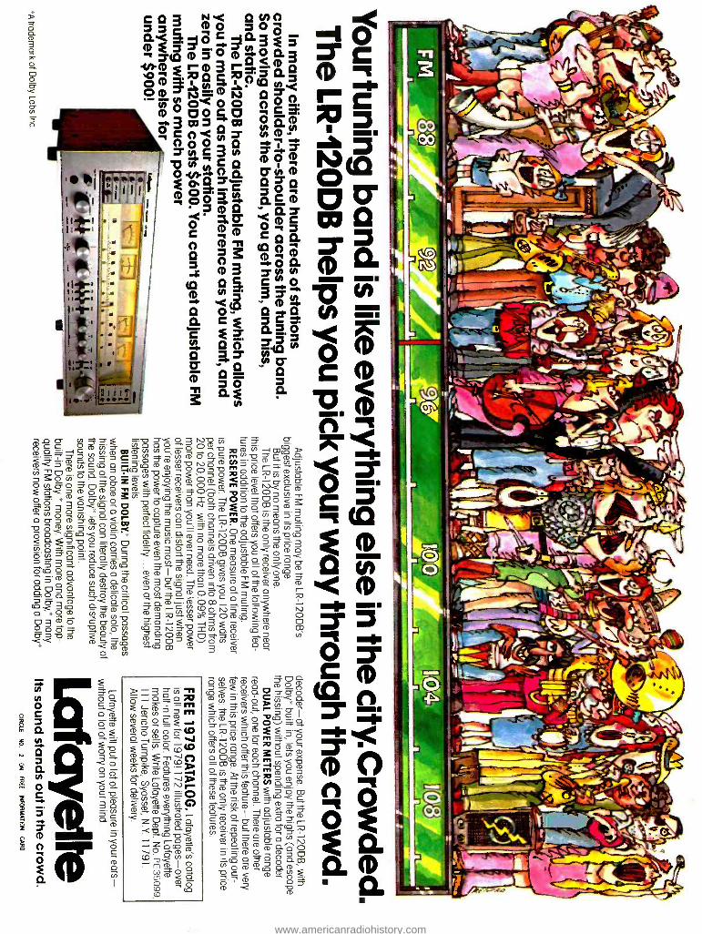
3 Nrc QHCi 00 O á'-ó-+a3i5 (D 3 7 .s -tQ(DO(DOa 03 váQ Fin 7Ñ'0 ÑA Q ` ényOOO 0c3:
<D 0 p0 %0 ó3voQoo 000 C p`< y " rt
4 TÑC3iQA rt? <D O Óñ. Qÿ713 ofl OO_n _co, ,ODQ
ES Q C
c
ó C p CQ0. n " (00-1 E H 0
4n=
CO 2 .4( tQ ° fD r O. Cg á3ó c ? Q ó H
Q cD
Q -n ó. 3 H
D c c ó?* ó ó ó° 3 pm vi c5 CD O j y Ñ CD W j CO Ç
Ñ CD Ó O Cn 0 CD W(O ñ ° c m. cñ T7
m° o°Cñ m-OO
m ó Ó-° mó m rm CO D 0My O n,0 CD N O p D C*D COD r¿ <ñcD ?Qñ Q O C// QO p0 TC<D CDKÑ i-.O T C<D N C CD o Ç 0 < Q 0;^ f° C<D 0 2 Ó Ó ,_.,..<
p C T m 3 3 cc G m o cñ ° r m ó ó°D.3 m
CnOO ÿ-ó°O ocDCocrrocnma'3 O QO D 0'O <, ñ 3 O c .op=0 _ O Ó O. O y 00 Ó c c 0- 0' ° O CD O O Cj1
p O(0c0< 0 5 * ñCD N C4 CD 0 j INá(n O O-pC° :ó;ócócp 0<OÓ0v0-ió`Dó=mci'3 3 c m o
>>3? n«m m.00,1:0,,..,-.-c-,0_,..< c°Q°c<°c °(O'Ñ ñ COD nO CI) CD w 0_CD
C<D C T0 O.00O
0 0 < Cn CD n° CD 3 orca.._, °= N D m 0 ÇD
CD 0-02,0 c m c> > 0 ° ° ó O K m p r qó n= ó cï ó3:ó -óó c o 3 ° . có Q o
ci- c' ncD.m ooD_,o- O O Cf°D NcD O
C 5 D
( -0 r- ,,,c N m y 3 -m 3SOmco *. g O ° O?. O ñNO 2cn cOi c O W
(D 0 Cl)_ < ° FD"
CD c c 5 ° m ó < ó ó O O 3 m
O
7 O
Ó OC p n Ó CD O ñ < mnCQo
co m y ga n r (n c/'òm ç Ì . _ pTC
CD N - 0 70
T y O pCp 00 Ç 4_
WCD T O D O O (p C 0
m ó Ñ ñ m FA
O O 0 ' fO -°< (D . C CD O (g (D r` O ° D ? cD0 I nQcp Qm
D CD. c7, CD óc° tn D
a) c
O Q O y N O CD D O >>DOCDmcp o 5 O ó 0. co
O D m nCD Ç CD CD Cf)
CD I
a)
www.americanradiohistory.com