An X-Windows monitoring system for SunOS MINIX - CORE
112
AN X-WINDOWS MONITORING SYSTEM FOR SUNOS MINIX A THESIS SUBMITTED IN PARTIAL FULFILMENT OF THE REQUIREMENTS FOR THE DEGREE OF MASTER OF SCIENCE IN COMPUTER SCIENCE IN THE UNIVERSITY OF CANTERBURY by Daniel Francis Ayers University of Canterbury 1995
-
Upload
khangminh22 -
Category
Documents
-
view
1 -
download
0
Transcript of An X-Windows monitoring system for SunOS MINIX - CORE

AN X-WINDOWS MONITORING SYSTEM
FOR SUNOS MINIX
A THESIS
SUBMITTED IN PARTIAL FULFILMENT
OF THE REQUIREMENTS FOR THE DEGREE
OF
MASTER OF SCIENCE IN COMPUTER SCIENCE
IN THE
UNIVERSITY OF CANTERBURY
by
Daniel Francis Ayers
University of Canterbury
1995


Abstract
Most operating systems instructors recognise the value of practical work in their
courses. Laboratory-style practical work offers the student the opportunity to put
their theoretical knowledge into practice. The incorporation of laboratory work
into an operating systems course requires the use of practical aids that illustrate or
reinforce the important concepts of operating systems theory.
The design and implementation of such an aid, the Sun OS MINIX Monitoring
System, is described. This system is based on SunOS MINIX, a. version of the MINIX
instructional operating system that runs as a user process under SunOS.
The aim of this project was to take advantage of the hosted nature of SunOS
MINIX by constructing a communications interface that would permit it to be mon
itored and controlled by external (SunOS) processes.
The monitoring system includes a set of tools allowing a user to inspect, monitor
and control a running instance of the SunOS MINIX operating system.

11

Contents
1 Introduction
2 Operating Systems Instruction
3
2.1 ·what do operating systems do?
2.1.1 The Process
2.1.2 Memory ..
2.1.3 File Systems .
2.2 Summary .
Related Work
3.1
3.2
Classifications
3.1.1 Simulation .
3.1.2 Source Inspection
3.1.3 Modification .
Related Work .... 3.2.1 Operating System Simulator for the Macintosh .
3.2.2 OSP ..
3.2.3 VXINU
3.2.4 MINIX .
3.2.5 SunOS MINIX
3.3 Summary . . . . . . .
4 MINIX and SunOS MINIX
4.1 MINIX .......... .
4.1.1 System calls and messages
4.2 SunOS MINIX ....... .
iii
1
3
4
4
5
6
7
9
9
10
11
11
12
12
15
17
17
19
20
21
21
22
23

iv
5
4.2.1 SunOS MINIX boot sequence ...... .
4.2.2 Writing user programs for SunOS MINIX.
4.2.3 SunOS MINIX Projects
4.3 Summary ........... .
Design of the Monitoring System
5.1 Motivation .
5.2 Goals.
5.2.1 Desired User Interface
5.3 Design .. . .
5.3.1 The Server.
5.3.2 SunOS MINIX Modifications .
5.3.3 Tools . ..
5.3.4 Communication
5.4 Summary .. . .
6 Communications
6.1 Monitoring Message Protocol
6 .1.1 Message Format .
6.1.2 Message Types
6.2 Transport Library ...
6.2.1 Connection types (media)
6.2.2 Additional Functions ...
7 SunOS MINIX modifications and instrumentation
7.1 Modifications to bootstrap loader and kernel initialization
7.2 Niodifications to allow information gathering
7. 2.1 Instrumentation for monitoring mode
7.3 Reception and processing of Control Requests
7.3.1 New SIGIO handler .
7.3.2 The SERVER task
7.4 New code added to kernel
CONTENTS
24
25
26
26
27
27
28
29
30
31
32
32
33
34
35
35
36
38
42
43
44
47
48
48
49
51
52
53
54

CONTENTS v
8 The Server 57
8.1 Overview. . . . • ' •• 0 • 0 •• 57
8.2 Functions and Responsibilities . 58
8.2.1 Control of SunOS MINIX 58
8.2.2 Reception of Monitoring Information 58
8.2.3 Distribution of Monitoring Information 59
8.2.4 Handling of Control Requests 60
8.3 Operation ............... 60
8.3.1 Server startup ......... 60
8.3.2 Communication with SunOS MINIX 61
8.3.3 Communication with tools 61
8.4 Structure . . . .... . .... 63
9 Tools 65
9.1 Overview. 66
9.2 Tool Design 66
9.2.1 Tool States 66
9.2.2 Communication with server 67
9.2.3 Services available to tools 68
9.3 User Interface I 0 0 0 0 0 0 o o o 68
9.3.1 Graphical Interface Construction 69
9.3.2 Limits of Tcl/Tk ... 70
9.3.3 The two-process model 71
9.3.4 The G UI process ... 72
9.3.5 The Controlling Process 75
9.3.6 Communication between the tool processes . 76
9.4 Description of Tools . 76
9.4.1 Control Panel 77
9.4.2 Process Monitor . 82
9.4.3 TTY Monitor . 90
9.4.4 Message Tracer 91
9.4.5 Data Structure Browser 91
9.5 Summary ............. 93

vi CONTENTS
10 Conclusions 95
10.1 ·work Completed 95
10.2 ·work to be done 96
10.3 Conclusion . 97
Bibliography 99

List of Tables
6.1 Event Messages .. 39
6.2 Advisory Messages 39
6.3 Control Requests 40
6.4 Control Responses 41
6.5 Inspection Requests . 41
6.6 Inspection Responses 42
6.7 Transport library address formats 43
6.8 Transport library functions .... 46
9.1 Control requests originated by the control panel 83
Vll

Vlll

List of Figures
4.1 Internal structure of MINIX 0 * 0 0 0 0 0 0 0 0 0 I 0 22
5.1 Structure of the SunOS MINIX Monitoring System 31
9.1 The Control Panel in an unconnected state . 77
9.2 The Control Panel connected to a server .. 78
9.3 The Control Panel connected to a server running SunOS MINIX 79
9.4 The Process Monitor connected to a server running SunOS MINIX 84
9.5 The Process Monitor tree view . . . 85
9.6 Output from the message trace tool 92
9.7 A monitoring session using multiple tools. 94
lX

X

Chapter 1
Introduction
Most operating systems instructors recognise the value of practical work in their
courses. Laboratory-style practical work offers the student the opportunity to put
their theoretical knowledge into practice.
The incorporation of laboratory work into an operating systems course requires
the use of practical aids. In this context a practical aid may be source code for the
student to study, an operating system utility such as ps or a sample program written
by the instructor.
Such practical aids should reinforce and illustrate the important concepts of
operating system theory.
A number of researchers have produced practical aids for use in operating system
courses. Aids produced to date have tended to be simulators of some sort. These
simulators are effective in some situations, but fail to provide a realistic experimental
environment.
Andrew Tanenbaum's MII\IX is a useful example of a working operating system
designed strictly for educational use. It is not a simulator, but a full operating
system similar to Version 7 1;:'-l'IX. Source code is supplied and may be studied or
modified as desired.
MINIX was written originally for the IBM PC, and later ported to a few other
platforms. SunOS MINIX, a port of MINIX to run as a process inside SunOS, was
developed at the University of Canterbury by Peter Smith. This port of MINIX is
unusual in that it is hosted inside another operating system. Other ports of MINIX,
with the exception of the Apple :Macintosh version, replace the usual operating
1

2 Chapter 1. Introduction
system and run on the bare hardware.
The hosted nature of Sun OS MINIX creates an opportunity to devise a new type
of practical aid for use in operating system courses: programs that run outside of
a hosted operating system, like SunOS MINIX, yet interface with it as it executes.
These programs could be used to examine the running operating system, produce
displays of its internal state and even allow for some control over the running system.
This opportunity is the basis of the work described in this thesis.
The monitoring system implemented as part of this research has shown that it
is possible to instrument a hosted operating so that external programs may monitor
and control it.
The system described here is able to present textual, graphical and animated
displays of the state of SunOS MINIX while it is in execution. The monitoring
system also gives the user control over SunOS MINIX, allowing them to freeze and
examine it in detail if desired.
The design of this system is open, making other forms of monitoring and control
simple to implement.
This thesis is organised into ten chapters. Chapter 2 addresses the question
of which operating system concepts are important and should be highlighted by
practical tools. Tools produced by other researchers are discussed in Chapter 3 .
.\IIi'\IX and SunOS MINIX form the basis of this work, and are described further in
chapter 4.
Chapter 5 presents the design of the SunOS MINIX Monitoring System, an
extension to Sun OS MINIX to permit the examination and control of it by programs
running under SunOS. Chapters 6 through 9 describe the design and implementation
of the monitoring system's component parts.
Chapter 10 concludes this thesis with a summary of the work completed.

Chapter 2
Operating Systems Instruction
Before designing practical tools to assist with operating systems instruction, it is
prudent to ask "What are the most important operating system concepts?" This
question is important because the answer influences what displays and facilities
should be provided by systems that support operating systems instruction. Such
systems should reinforce and highlight these important ideas.
This chapter presents one view of what operating system concepts are important,
with guidance from three textbooks[9, 13, 15] on the subject.
In each of these texts, the chapter titles and relative sizes were a good indication
of the author's opinion of vvhat was important.
Silberschatz and Galvin[9] divide their text into parts devoted to topics like1:
• Process Management
• Storage ~~Ianagement
• Protection and Security
• Distributed Systems
Tanenbaum's 1987 text[13], in which MINIX features strongly, has chapters en
titled:
• Processes
1These lists of topics are not exhaustive.
3

4 Chapter 2. Operating Systems Instruction
• Input/Output
• Memory Management
• File Systems
Tanenbaum's later text[15] has similar coverage, with the addition of much ma
terial on distributed operating systems.
Using the above sources as a guide, this chapter seeks to explain the important
functions of operating systems. These are the areas that aids to operating system
instruction should illustrate and explain.
2.1 What do operating systems do?
Operating systems manage hardware and provide abstractions. This simplifies user
processes since many of the complexities and low-level details of the hardware are
hidden by the operating system.
Most operating systems texts, including the three consulted, discuss the three
main abstractions provided by modern operating systems: the process, the process
address space and the file system.
2.1.1 The Process
The process is probably the most important operating system concept.
A process is a program being executed. It is represented by its instructions,
data, stack and machine registers.
The process model allows many independent processes to execute, and sometimes
cooperate, on a single processor. The techniques employed to make this possible are
described below.
2.1.1.1 Multiprogramming
The technique of multiprogramming allows multiple streams of instructions (ie. mul
tiple processes) to execute on a single CPU by rapidly switching between them. At
any instant only one instruction stream is being executed, but the switching is so

2.1. What do operating systems do? 5
rapid that it appears to the user (and to the processes) that all are in execution
simultaneously.
2.1.1.2 Inter-process Communication
It is sometimes necessary for processes to synchronise and cooperate with each other.
This is called inter-process communication (IPC).
Processes may communicate using message passing, by sharing resources like
memory or by using operating system facilities such as signals.
2.1.1.3 Concurrency
When processes cooperate, they are not totally independent. In this case it is often
necessary to coordinate their operation, particularly when a shared resource is being
accessed or modified. The process of meeting this goal is called concurrency control.
Semaphores are a common method of achieving concurrency control. The code
fragment containing accesses to the shared resource is called the critical section.
Semaphores are used to ensure that a maximum of one process is executing inside
the critical section at all times .
. 2.1.2 Memory
An operating system is also responsible for managing the computer's memory. This
memory is used to hold executable code and program data.
The most important memory abstraction is that of the address space. Other
important ideas are virtual memory, a technique for handling the case when physical
memory is too small, and memory protection.
2.1.2.1 Address Space and Segmentation
A process' view of its memory is called its address space. The management of a
process' address space is the responsibility of the operating system.
The related concept of segmentation is the practice of dividing the allocated
memory (address space) according to its purpose. There are commonly segments
for: code, initialized data, uninitialized data and stack.

6 Chapter 2. Operating Systems Instruction
There are two reasons for dividing the address space of a process in this fashion.
Firstly, it improves the operation of virtual memory. Secondly, certain types of
memory accesses may be denied in some segments.
2.1.2.2 Virtual Memory
It is possible that the physical memory available in a machine is not sufficient to
satisfy the requirements of the processes executing within it. In this situation, a
technique called virtual memory may be used.
Virtual memory makes the computer appear to have more physical memory than
it actually does have. This is achieved through the use of a secondary storage device,
such as a hard disk, to hold the overflow from physical memory. This is called the
swap area.
2.1.3 File Systems
A file system is an abstract way of organising data stored on a random-access device,
such as a hard or floppy disk. The file system allows users and processes to organise
and name their data in a convenient fashion, and provides the services they need to
access it.
2.1.3.1 File Structures
The concept of a file is another important abstraction provided by the operating
system. A file is a collection of data elements stored by the operating system's file
system on the behalf of a user or process.
The operating system often does not know anything about the structure of the
data in the file, it merely arranges for its storage.
Operating systems also provide users and processes with a way of naming files
they store. vVhen a new file is created, the process creating it supplies a name by
which the file is to be known. The operating system knows the physicallocation(s)
of the data on the storage device, and forms an association between that and the
file's name.
When the file is accessed in the future, the operating system translates the name
into the device-level storage information. The use of names hides these complexities

2.2. Summary 7
from users and processes and makes a degree of device independence possible.
When the number of files stored becomes large, it is often convenient to arrange
them in a structured way. Most operating systems support the idea of a directory,
which allows related files (and directories) to be grouped together. Users may use
directories to organize their files in a hierarchical fashion.
2.1.3.2 Device Drivers
The code responsible for implementing abstractions related to files and hardware
devices is the device driver. Device drivers handle the low-level complexities the
operating system seeks to hide from user processes.
According to Tanenbaum[13], there is little theory about device drivers but they
are important nevertheless. He feels that low-level hardware topics like these are
often ignored by operating system instructors.
2.2 Summary
This. chapter has presented an overview of the most important concepts related to
operating systems. Any intermediate or advanced course in operating systems should
cover this material in detail. It is therefore important that designers of practical
aids to assist with this instruction cater for the important concepts listed here.

8

Chapter 3
Related Work
This project is concerned with the design and construction of software aids for
operating systems courses. These ·aids may be working programs or just a collection
of source code to be examined by students. Following chapters discuss the design and
implementation of our "SunOS MINIX Monitoring System". This chapter presents
a brief survey of similar vvork from other researchers.
The work discussed is diYided into three classifications: operating system sim
ulators, source code projects and modification projects. Each class is discussed in
general and some selected examples are presented.
3.1 Classifications
Software aids for operating system instruction may be divided into the following
three categories:
• Simulators. Tools in this category simulate the behaviour of an operating
system, but do not operate internally like an operating system and are in
capable of executing user-developed programs. Simulators normally accept a
set of parameters describing the workload and system to be simulated and
produce either a set of statistics or an animated representation of the "run".
• Source Code. A set of source code files from either a real or hypothetical
operating system can be provided to students for examination. The students
can thus learn the internal structure of an operating system and gain insight
9

10 Chapter 3. Related Work
into the implementation of selected operating system features. The student is
not expected to write any code of their. own.
• Modification. The final category covers cases when the student is expected
to modify or rewrite components of a real or simulated operating system.
Particular systems can fall into more than one of the above categories depending
on how they are used by the instructor.
Individual systems drawn from the above categories are presented as examples.
Included is MINIX, the system on which SunOS MINIX and in turn the work pre
sented in this thesis is based.
Each approach and system has its mvn advantages and disadvantages. While
accepting that some of the tools presented below are only intended to instruct stu
dents in quite specific areas, one criteria used to evaluate them is that of "realism".
Tools are considered to be "realistic" if they operate like a real operating system,
or at least appear as such to the user. Tools are "unrealistic" if they bear little
resemblance to an operating system from the user's point of view. A realistic envi
ronment is important because it allows the student to develop an understanding of
how the theoretical and practical concepts under study relate to the operation of a
real operating system[13].
3.1.1 Simulation
Simulators are the least realistic kind of tool. A simulator is not a real operating
system at all; it merely simulates some aspects of the behaviour of an operating
system. The simulation designer can easily omit or gloss over aspects of operating
systems that are irrelevant or difficult to handle.
Because of this, simulators are easy to develop. The author need only write the
functions to support the intended simulation(s) and can ignore all other functions
of operating systems.
Likewise, simulators are easy for the student to understand and operate. They
are only as complex as they need to be. There is nothing to distract or unnecessarily
confuse the student.
Because of their simplicity, simulators are suitable for introductory courses in
operating systems. They can be effectively used to demonstrate the consequences

3.1. Classifications 11
of various design and configuration choices.
3.1.2 Source Inspection
Another approach is to provide students with the source code to an operating system.
This allows them to see the "nuts and bolts" of a system and learn how the system's
services and abstractions are implemented. The student is then able to compare
their theoretical knowledge with the source thereby improving their understanding
of the practical aspects of operating systems.
There are drawbacks to this method. Most production systems do not come with
source code, indeed the source is usually considered to be proprietary information.
The source code for early versions of the UNIX operating system was used in this
fashion until AT&T decided tha~ UNIX was a valuable commercial product and
restricted access to its source code[8].
Even if students could obtain the source for a production system, it would not
be ideal for educational purposes. The source would likely be too large and complex
to be easily understood. Many hours of studying the code would be required before
any progress could be made.
This problem is addressed by so-called "educational operating systems"; working
systems developed from scratch as educational tools. Tanenbaum's MINIX operating
system and accompanying text[13] is an excellent example of such a tool.
Simple source code projects would be appropriate for intermediate-level courses
in operating systems, where students could be expected to read and understand all
or part of the source to a real system without having to make modifications or write
new code.
3.1.3 Modification
In modification projects, student(s) write new code either additional to or as a
replacement for code supplied by the instructor.
The implementation of a new fully-functional system from scratch is prohibitively
complicated. Students can be asked to add a new feature to an existing system, or
modify the implementation of an existing feature (perhaps to change from one policy
or algorithm to another).

12 Chapter 3. Related Work
Modification projects are a logical follow-on from source code inspection projects.
Once students are familiar with operating system code, they can be asked to put this
knowledge into practice by modifying or extending the code they haYe studied. This
method has been used in third-year software engineering courses at the University
of Canterbury for some years.
If an existing system is being modified then source code is required, so this
approach has all of the drawbacks associated with source code inspection projects.
3.2 Related Work
A survey of tools for use in operating system laboratories is now presented. Each
system is described briefly, with emphasis on the advantages and disadvantages of
the approach taken.
3.2.1 Operating System Simulator for the Macintosh
The "Operating System Simulator for the Apple Macintosh" [10, 11 J was developed
at the University of Wollongong, Australia, by Gary J. Stafford. It is a set of 10
graphically-oriented applications, each simulating the behaviour of one part of an
operating system.
The simulations are:
• Disk Seeks. Displays a picture of hard disk platters and heads. Simulates the
operation of a hard disk with a certain ( configurable) queue length and under
a ( configurable) workload. The student assesses the overall performance of the
hard disk subsystem under each set of operating parameters and through that
learns how those factors affect the performance of' hard disks.
• Dispatcher. Displays a process table, CPU and disk utilisation meters, ready
and I/0 queues and various system statistics. Simulates an operating system
scheduler with parameters of workload type and scheduling algorithm. The
student evaluates the performance of the simulated system under these condi
tions and learns about scheduling algorithms.

3.2. Related ~Vork 13
• Backups. Simulates a computer backup strategy, using full and incremental
backups. Demonstrates to the student the difference between these backup
types, and shows the process required to retrieve a file from backup.
• Networks. Displays connections between a set of machines and the messages
sent between them. The student may select the network configuration and
network load. Instructs the student in the possible configurations of a network
and demonstrates the strengths and weaknesses of the configuration under
various loads.
• Virtual Memory. Displays the state of system memory, I/0 queue for
paging requests and memory maps of running processes. Also CPU and disk
usage meters and related statistics. The student configures various memory
allocation parameters and learns about virtual memory.
• Paging. Displays a memory map, divided into pages of fixed size, and four
meters showing memory usage statistics. Student can configure the page and
process sizes. When run, the simulation animates the loading of programs and
displays graphs showing the memory usage and overhead. Teaches the student
about page allocation and fragmentation.
• Segmentation. Displays a memory map with various programs loaded and
memory statistics and meters. Simulates loading and unloading of programs
of configurable size, with configurable allocation strategies and compaction
methods. Demonstrates further memory management issues.
• Deadlocks. Simulates resource contention problems using a railroad metaphor.
where trains are animated travelling on tracks between stations. Five deadlock
handling methods can be simulated. The simulation displays a graph sho·wing
the average travel delays between all the stations shown for each handling
method.
• File Space. Displays a simulated hard disk and graphical view of the associ
ated file system. The student may configure the methods used to manage free
space, allocated files and the size of the buffer cache. The simulator displays
graphs showing the number of disk requests and the performance of the cache.

14 Chapter 3. Related Work
• Encryption. Not really a simulator, more a tool to aid in the manual de
cryption of files.
All simulations are highly graphical and most are animated. This provides ex
cellent visual feedback to aid the learning process and partially compensates for the
fact that the simulations are often quite artificial.
The student is able to modify the simulation parameters and easily view the
effects of their modifications in the simulation results. They can then learn from
those results and perhaps modify their choices for the next simulation run - thus
creating a feedback loop, which is an excellent way for students to learn.
Each simulation poses a number of questions to the student and records the
answers on the student's floppy disk, which is later collected for marking.
3.2.1.1 Evaluation
The operating system simulator for the Macintosh simulates key algorithms found
inside operating systems in a way that allo-ws students to learn about them by
observing the animated simulations and resulting statistics. The system is excellent
for demonstrating the effects of modifying operating system algorithms and policies.
Since the simulation modules are standalone, and because of their graphical and
animated nature, the "Operating System Simulator for the Apple Macintosh" would
be suited to use in introductory and intermediate courses in operating systems. In
such courses the instructor's goal is usually a basic understanding of the key concepts
rather than a detailed knowledge of implementation-level issues.
The "simulated operating system" largely remains a "black box".
The Macintosh simulator does not look or work like and operating system, and
gives no insight into operating system internals. The student is able to influence
the operation of the system and view the results (by way of statistics and graphi
cal output). The animations do give some insight into the implementation of these
algorithms, but the high-level abstract nature of the animations means that little
understanding is gained into the specifics of operating system design and implemen
tation.
The facility to ask students questions, and to collect, mark and process results
would be very useful to many instructors.

3.2. Related ~Vork 15
3.2.2 OSP
OSP, "An Environment for Operating System Projects" [5], is the product of research
by Michael Kifer and Scott A. Smolka of SUNY at Stony Brook. OSP is a set
of software modules that together make up a simulated operating system. The
central module, SIMCORE, generates a simulated workload that is handled by the
8 simulation modules.
The source code of simulation modules may be viewed, modified or rewritten by
the student. OSP can therefore facilitate projects of all three types discussed above:
simulation, source inspection and modification/implementation.
The simulation modules are:
• Interrupts. Handles hardware interrupts (timer, page fault, devices) and mon
itor calls (I/0 and process control).
• Memory Management. Implements virtual memory and paging.
• CPU Scheduling. Handles ready-queue management and dispatches runnable
processes.
• Device ~'lanagement. Manages secondary storage devices (disks). Performs
seek optimisations.
• File System. Implements a flat directory structure (no subdirectories) con
taining non-permanent files. (Files are discarded at the end of the simulation
run).
• Resource Management. Manages the allocation of resources to user processes.
Provides deadlock detection and resolution.
• Inter-process communication. Implements inter-process communication based
upon a simplified ·version of Berkeley UNIX sockets.
• Protocols. Protocol (stream or datagram) support for the IPC module.
These simulation modules react to stimuli generated by the simulation driver
module, SIMCORE, according to simulation parameters chosen by the user. The
DIALOG module is used to display information and simulation results to the user.

16 Chapter 3. Related Work
For source inspection purposes, each module could be considered in isolation as
an example implementation in the chosen area. For implementation projects, any
or all of the above 8 simulation modules can be modified or re-implemented by the
student using the well-defined inter-module interfaces as the starting point.
OSP provides error checking to detect and handle errors in code written or
modified by students. This helps to ensure the correctness of student code, and
helps both the student and marker find problems in an implementation.
OSP can display system state information during the simulation run, and detailed
statistics and results once the run is complete.
3.2.2.1 Evaluation
OSP is intended to support the modification and reimplementation of the 8 simu
lation modules described above. Because of this, and also due to the lack of the
graphical and animated presentations of the Mac OS simulator, it is not suitable for
use in introductory courses. OSP is more suited to use in intermediate and higher
level courses, and only as a vehicle for supporting code-level projects.
The simulation modules are realistic implementations of common operating sys
tem algorithms. When considered in isolation, these modules provide good oppor
tunities for source code inspection, modification and re-implementation projects.
OSP is quite versatile since it belongs to all three categories discussed here: It sim
ulates the operation of an operating system, source code of simulation modules can
be provided to students for study and it is designed to allow the modification and
re-implementation of the existing simulation modules.
Even though it is a simulator, OSP well and truly breaks the operating system
"black box". While the system is simulated, its ·workings are revealed at the source
level and can be subjected to study and modification.
OSP is not capable of executing user programs.
OSP supports the gathering of statistics on OS operation (similar to the Mac
OS simulator, but without the graphical presentation) but it is more difficult to
experiment with different OS policies and algorithms. Changing algorithms would
require at least re-linking OSP, and probably the recompilation of some modules.

3.2. Related Work 17
3.2.3 VXINU
VXING(12) is a hosted version of XINU that runs as a UNIX process. Detailed
investigations of VXINU have not been possible to date because all material available
is written in Japanese. However, the information available suggests that XINU and
VXINU have similarities to MINIX and SunOS MINIX.
3.2.4 MINIX
MINIX(13, 14) is a UNIX-like operating system developed by Andrew Tanenbaum
at the Vrije Universiteit in Amsterdam. Tanenbaum originally developed MINIX
as an educational tool to supplement the largely theoretical instruction commonly
found in operating system courses.
Releases of AT&T UNIX prior to Version 7 were widely used as examples in
operating system courses. At that time, the source code was available to educa
tional institutions for research and teaching purposes. Students were able to gain
familiarity with AT&T UNIX (as users) and then view and modify the source code
to the very same system.
As the popularity of UNIX increased, AT&T came to realise its value as a com
mercial product. From Version 7, the UI\IX source code was considered to be
proprietary information and access to it was therefore restricted(8]. The source was
no longer available for use by educational institutions. Many instructors were forced
to eliminate that practical component from their courses.
Tanenbaum contends that this and other factors have led to a bias in operating
systems courses towards teaching theory. He believes that many theoretical topics,
his example being scheduling algorithms, are not particularly complex or interesting
in practice and have been given too much coverage in operating systems courses.
He believes that other less theoretical topics, such as I/0 programming, are equally
important even though they tend to feature little in courses because there is little
theory associated with them.
NII='JIX is Tanenbaum's attempt to address these problems. From the user's
viewpoint, MINIX looks very similar to UNIX. Its system call and shell interfaces
are almost identical to that of Version 7 UNIX. MINIX, however, has a very different
internal structure, being modular and making use of message passing for internal

18 Chapter 3. Related Work
communication. Tanenbaum has taken care to make the operating system small and
simple enough for students to be able to understand (relatively) easily. It is also
modest in its hardware requirements, MINIX is designed to run on a dual-floppy
IBM XT computer.
MINIX is distributed by Prentice Hall. Because its focus is educational rather
than commercial, full source code is included with MINIX. Every single line of source
code supplied with 1HNIX has been written from scratch- there is no AT&T code
whatsoever. Students are able to examine the assembler and (mostly) C source code
to the operating system as they run it. Moreover, it is possible for students to make
their own modifications and extensions to the operating system.
MINIX was originally written for IBM compatible computers. Versions have
been ported to other platforms, including:
• Commodore Amiga
• Apple Macintosh
• Atari ST
• Sun Sparcstation 1
On all of these machines, with the exception of the Apple Macintosh, MINIX
replaces the usual operating system and assumes total control of the computer. On
the Apple Macintosh ?\III\IX is hosted (runs as an application under) the Macintosh
operating system.
MINIX features prominently in Tanenbaum's 1987 operating system textbook[13),
which uses MINIX to illustrate important theoretical concepts. This combination
of textbook and "educational" operating system is ideal for use in operating system
courses.
3.2.4.1 Evaluation
MINIX has advantages over simulators like OSP and the Macintosh based simulator.
Most importantly 1II:\IX is not a simulator. It is a real, working, operating system
that students can examine (at the source code level) and even extend and modify.
MINIX permits the student to relate their user-centered understanding of operating
systems with that of an operating system designer and with the source code itself.

3.2. Related Work 19
When viewed as an educational tool, MINIX also has drawbacks. Firstly, MINIX
requires one desktop computer per student in attendance. Many educational insti
tutions do not have ready access to sufficient numbers of computers that can run
:MINIX.
Secondly, MINIX is unable to provide the detailed statistics offered by simulators.
Processes running under MINIX cannot easily analyse the operation of the system
since their very presence affects the results. Likewise, MINIX processes cannot debug
or breakpoint MINIX because they will themselves be affected if MINIX execution
stops.
3.2.5 SunOS MINIX
SunOS MINIX(l] is a port of MINIX that runs as a user mode process under the
Sun OS operating system. This port is the result of work undertaken at the Univer
sity of Canterbury by Peter Smith.
Instead of directly accessing hardware devices, SunOS MINIX uses SunOS sys
tem calls to provide its tasks and processes with an operating environment almost
identical to that of ordinary ?\UNIX. SunOS MINIX is said to be "hosted" under
Sun OS.
Hosting the operating system under SunOS offers a number of advantages:
• Each student no longer requires their own desktop computer on which they
run MINIX. An entire laboratory class could be supported by one or more Sun
computers, the number of computers required depending on their performance,
workload and the requirements of the students.
• Since SunOS MINIX is an ordinary user mode SunOS process, it is possible
to run supporting programs outside MINIX (under SunOS). These support
ing programs would not operate within the SunOS MINIX environment and
would not be constrained by it -they could continue execution while SunOS
MINIX was suspended, they could examine and display the contents of Sun OS
MINIX's address space and data structures and could exert some control over
Sun OS MINIX. This raises the possibility of implementing programs that mon
itor or control the running SunOS lVIINIX.

20 Chapter 3. Related Work
SunOS MINIX is not distributed by Prentice Hall. It is available as a set of
patches that may be applied to the IBM or :Macintosh versions of standard MINIX.
Consequently, SunOS MINIX may only be used by MINIX owners who have the
source to apply the patches to.
Even though it operates in quite a different environment, SunOS MINIX is very
similar to standard MINIX in the way it works internally. Since SunOS MINIX
is hosted under SunOS, and substitutes SunOS system calls for direct hardware
programming, there is some loss of realism at the device driver level. Despite that,
much of the MINIX material in Tanenbaum's texts applies directly to SunOS 1t!INIX.
Sun OS MINIX retains most of the advantages of MINIX, while addressing some
of its shortcomings. Its ability to support many students on a single Sun computer
is a definite advantage, particularly for university departments with Sun computers
who would otherwise be unable to run MINIX.
Since SunOS MINIX is hosted under SunOS, it can interact with SunOS pro
cesses that are not reliant on the SunOS MI.:.JIX environment. Such processes can
debug and breakpoint SunOS MINIX without being affected themselves. This opens
up a number of avenues of research, including the topic of this thesis.
3.3 Summary
In this chapter, a classification scheme for operating system instruction tools was
introduced. A number of examples were presented and related to this classification
scheme.
· Each of the systems discussed has its own advantages and disadvantages. Trade
oft's between simplicity and realism were evident in most of these systems.
MINIX is a promising development, especially when a real operating system is to
be studied. SunOS MINIX provides the opportunity to develop separate programs
that are able to interact with and control it.
This opportunity is the basis of this project. The next chapter provides a more
detailed treatment of MINIX and SunOS ~viiNIX, since these are the basis of this
work. Following chapters describe the work undertaken to produce operating system
instruction aids based upon SunOS MINIX.

Chapter 4
MINIX and SunOS MINIX
MINIX and SunOS Mll'\IX were introduced in the previous chapter. Since they
form the basis for the work described in this thesis, they will now be discussed in
greater detail. The goal of this chapter is to furnish the reader with a more detailed
understanding of MINIX and (in particular) SunOS MINIX.
4.1 MINIX
MINIX has a system call interface almost identical to that of Version 7 UNIX. Its
internal structure is very different, having been developed from scratch to adhere to
software engineering principles and to be easier for the beginner to understand.
Most notably, MINIX is completely modular. The operating system is con
structed from separately-compiled modules which communicate using message pass
ing. These modules are organised into layers, with each layer building upon the
services provided by the layer belo-w.
These layers, shown in figure 4.1, are:
• Layer 1, Interrupt Handlers.
The bottom layer handles all interrupts and traps and provides the higher
layers with the process abstraction and message-passing facilities.
• Layer 2, Device Drivers (Tasks).
The second layer contains 1/0 device drivers, which in MINIX terminology
are called tasks. The tasks in Layer 2 benefit from the environment provided
21

22 Chapter 4. MINIX and SunOS MINIX
Layer 4 User-Mode Processes
Layer 3 Memory Manager File Systerr
Layer 2 Tasks
Idle Cleek Disk IPrin t I Sys TTY Flopp
Layer 1 Interrupt Handlers
Figure 4.1: Internal structure of MINIX
by Layer 1: they execute as independent processes, using messages to com
municate with interrupt handlers in Layer 1 and server processes in Layer
3.
• Layer 3, Servers.
There are two server processes in Layer 3: the memory manager and the file
system. These servers execute outside the kernel. Between them they handle
all MINIX system calls.
• layer 4, User Processes.
All other processes in the system belong in Layer 4, user processes.
While the two bottom-most layers (layers 1 and 2) are logically separate, they
are linked together into a single program - the kernel.
The layer a process belongs in determines its priority. MINIX schedules processes
in round-robin fashion within a layer, and gives lower layers priority over higher
layers. That means that, after the interrupt handlers (Layer 1) which naturally
have ultimate priority, the tasks (Layer 2) have the highest priority in the system,
followed by the servers (Layer 3) and then the user mode processes (Layer 4).
4.1.1 System calls and messages
MINIX provides a set of system calls almost identical to those in Version 7 UNIX.
Internally however, these system calls are mapped onto messages that are passed

4.2. SunOS MINIX 23
from the calling process, via the kernel, to the appropriate server (memory manager
or file system). The file system handles all file-related system calls (messages) and
the memory manager is responsible for memory and process management.
For example, a process wishing to read from a terminal line executes a read()
system call. This results in a message being sent from that process to the file system.
If no input is immediately available, the file system sends a message to the TTY task
which is responsible for character input and output. After the message has been
sent, the calling process is blocked awaiting a response.
\iVhen the file system receives a read request from a process, it examines the
input buffer for that descriptor. If sufficient characters are available immediately,
they are copied into a reply message that is sent to the caller straight away. If there
is not enough input available to satisfy the read request, the file system does not
reply to the calling process. The caller remains blocked pending the reply message,
which will not be sent until enough data has become available to satisfy the read
request.
Messages are also generated inside MINIX when certain interrupts occur. For
example, when a key is pressed on the keyboard a message is generated by the MINIX
kernel and sent to the TTY task. Asynchronous interrupts are thereby converted to
synchronous messages by layer l.
4.2 SunOS MINIX
SunOS MINIX is unusual in that it is a hosted operating system. Unlike most
operating systems, including the original MINIX, it does not work with the bare
hardware on the computer it is running on. Instead, SunOS system calls are used
to simulate the various hardware devices as described below.
• Disks.
Each SunOS ?\II~IX disk partition is stored as a SunOS file. When SunOS
MINIX needs to read a disk block, the appropriate area is read from the Sun OS
file holding the data for that partition.
The internal structure of SunOS MINIX partitions is identical to the disk
format used by other versions of MINIX. The lower-level driver software is

24 Chapter 4. MINIX and Sun OS .MINIX
naturally very different from that in MINIX, being Sun OS read() and write()
system calls and completely synchronous. The disk drivers make no use of
interrupts whatsoever.
The server processes in SunOS MINIX remain unchanged.
• Memory.
The physical memory of SunOS MINIX is a section of the virtual memory
of a SunOS process. The system memory size is set at start time from the
configuration file. The SunOS MINIX bootstrap program allocates a block of
memory of that size to serve as SunOS MINIX's memory.
• CPU.
The CPU cycles that are allocated by SunOS MINIX to processes and tasks
running inside it are the CPU cycles allocated to the SunOS process run
ning MINIX. The timeslices provided to SunOS MINIX by SunOS are further
subdivided by SunOS MINIX into timeslices for 1!JINIX processes.
• Devices
Hardware devices, such as the terminal lines, timers and interrupts are mapped
onto SunOS system calls. For example, the SunOS MINIX console is the con
trolling tty of the Sun OS MII\IX bootstrap loader. The timer is implemented
using the SunOS SIGALRM system call. Additional TTY sessions are imple
mented using UNIX domain sockets.
4.2.1 SunOS MINIX boot sequence
The compilation of SunOS MINIX yields a binary program, minix, that contains
the SunOS MINIX bootstrap loader. This executable does not contain the MINIX
kernel, servers or init. They are concatenated together to make a file called image
which is not a SunOS MINIX executable file, but is read into memory (and relocated)
by the bootstrap loader.
The user invokes MINIX by typing minix. The bootstrap loader begins execution
and the following steps occur:

4.2. SunOS MLVIX 25
1. The bootstrap loader interprets its command line, which can be used to affect
the SunOS MINIX startup process.
2. The bootstrap loader executes a fork() system call. This creates a second
copy of itself, the child. The child continues execution from this point, as
described below. The parent, the original invocation of minix, modifies the
parameters of the controlling TTY and suspends itself until the child process
exits. When the child does exit, the TTY parameters are restored and control
is returned to the shell.
3. The child begins the process of starting SunOS MINIX proper. An area of
memory is allocated that will become the SunOS MINIX physical memory.
4. Loader routines are invoked to read the image file into the memory just al
located. The image file contains the executable images of the SunOS MINIX
kernel, the memory manager (MM), the file system (FS) and the INIT process
concatenated together.
5. Any parameters supplied on the minix command line now take effect, the
bootstrap loader manipulates SunOS 1IIXIX (kernel) globals accordingly.
6. The bootstrap loader transfers control to the kernel entry point. SunOS
MINIX begins execution.
4.2.2 Writing user programs for SunOS MINIX
SunOS MINIX is almost functionally identical to Tanenbaum's original f..IINIX. One
difference is the lack of a C compiler inside SunOS MINIX. Since it is important to
be able to compile C programs to run inside :\IE\IX (in fact this is a requirement of
the installation, since many MINIX utilities must be compiled to run inside SunOS
MINIX) a conYersion program is supplied that allows programs compiled with the
standard SunOS C compiler cc to be converted to run inside SunOS lVIINIX.
The procedure for compiling a SunOS MI~IX program written in C is:
1. Compile the code under SunOS
2. Use the supplied conversion utility, cv, under SunOS to convert the resulting
executable to a format compatible with SunOS MINIX.

26 Chapter 4. MINIX and SunOS MINIX
3. Inside SunOS MINIX, use the sunread command to read the converted exe
cutable into SunOS MI~IX.
4. Run the converted executable inside SunOS MINIX.
4.2.3 SunOS MINIX Projects
SunOS MINIX has been the subject of a number of undergraduate-level projects at
the University of Canterbury in recent years. Those projects were:
• Memory protection assignment.
Students were provided with the source code to SunOS MINIX and attended
a brief introductory laboratory where they were shown how to use and re
compile it. The students were given t\vo tasks. The first was to examine and
understand the Sun OS :\UNIX source code. The second task was to implement
varying levels of memory protection in the operating system.
This project was challenging because the students had to read and under
stand portions of the SunOS MINIX source and then code and debug their
extensions. Debugging an operating system is not a simple task.
• Race conditions assignment.
This assignment required students to examine the source code for the SunOS
MINIX kernel and document any race conditions that existed.
4.3 Summary
MINIX and SunOS f..tiiNIX are good environments for source code and modifica
tion/implementation projects. SunOS J\IINIX has been developed and used at the
University of Canterbury with good results.
There is scope for using SunOS MINIX as the basis for a more novel approach,
integrating it with Sun OS programs to enhance its use as an educational tool. This
has been our approach, and is the subject of the following chapters.

Chapter 5
Design of the Monitoring System
The hosted nature of SunOS MINIX offers an opportunity to develop programs
that interface to a running operating system. We have taken advantage of this
opportunity and developed the SunOS MINIX Monitoring System. This system is a
set of programs that interface with and extract information from a running instance
of the SunOS MINIX operating system.
This chapter relates the motivation that led us to develop this system, and
describes its goals and the resulting design. Each component of the monitoring
system is introduced and placed within the context of the whole.
Following chapters describe each component and the methods they used to com
municate in more detail.
5.1 Motivation
A number of researchers have been searching for ways to incorporate practical work
into operating system courses[1, 5, 10, 13, 14]. Doing so is desirable because prac
tical work provides a way of reinforcing the student's theoretical understanding[7].
Practical work can also be used for assessment purposes[ll].
Most of the tools produced to date have been simulators[5, 10]. These are ac
ceptable in some situations, but tend to restrict the instructor to those operating
system features supported by the simulator. None of the simulators investigated
look or behave like a real operating system.
Tanenbaum's MINIX[13, 14] addresses the problems with simulators. MINIX is
27

28 Chapter 5. Design of the Monitoring System
a fully functional operating system that may be studied, modified and extended by
students. This in itself makes MINIX a useful educational tool.
But this realism has a price. Students using operating system simulators run
them multiple times, perhaps with different policy choices in effect, and judge the
performance of the system by viewing the statistics produced. This cannot be done
with MINIX. Short of recompiling the kernel, system policies cannot be changed.
Policies certainly cannot be changed as the system executes. MINIX has no ability
for producing detailed statistics. MINIX cannot be paused and subjected to exam
ination. Shutting MINIX down and restarting it is a laborious process. And most
importantly, MINIX lacks the kind of output produced by simulators ( eg. anima
tions, statistics) that can be used by the student to keep track of what is happening
inside the operating system.
Sun OS MINIX[l], Peter Smith's port 'of MINIX to run as a user process under
SunOS, builds on the success and promise of lVHNIX. SunOS MINIX is a useful
instructional aid in its own right, and its hosted nature raises the possibility of
developing programs that run outside SunOS MINIX that are able to interface with
and control SunOS MINIX.
Such programs could address some of the deficiencies of MINIX (and SunOS
MINIX) when compared to the simulators. External programs could provide the user
with a degree of control over the operating system while it was running. They could
gather information from SunOS MINIX and produce statistics, display animations,
and allow a student to inspect the operating system's internal data structures while
it executes.
These external programs could make SunOS MINIX a versatile educational aid
and give it many of the capabilities of the simulators while retaining its realism.
5.2 Goals
The goal of this project is to enhance SunOS I'vliNIX by finding a way for it to
communicate with the kind of "external programs" envisaged in the previous section.
These external programs, henceforth called tools, could take advantage of com
monly available windowing systems, such as X-Vlindows[4], to produce graphical
displays of information gathered from SunOS MINIX while it is in execution.

5.2. Goals 29
SunOS MINIX together with the tools associated with it forms the "SunOS
MINIX Monitoring System". The design objectives of this system were:
• To design and implement a mechanism allowing tools to extract information
from SunOS MINIX while the latter is in execution.
• To make this mechanism general enough to allow the operation of many tools
at any one time, and to permit the future implementation of tools not yet
envisaged.
• To include in this mechanism a means of controlling SunOS MINIX and to
allow for the repetitive launching and shutting down of SunOS :t\HNIX for
experimental purposes.
• To produce tools that use this mechanism to display information extracted
from SunOS MINIX or to illustrate a function of the operating system.
• To make use of graphical displays, where appropriate.
• To permit the student to view a number of tools on their display at once, in
addition to their SunOS l\IINIX terminal session.
• Whenever possible, a tool's display should update continuously so that the
latest information is always displayed. In such cases the user would not be
required to manually request an update.
• The integration of the monitoring system into SunOS MII\IX should not ad
versely affect the performance or functionality of the latter.
The monitoring system was required to run under the SunOS operating system
and interface to SunOS MINIX.
5.2.1 Desired User Interface
After defining the goals of the monitoring system, the next step was to decide on
the most appropriate user interface for the system as a whole.

30 Chapter 5. Design of the Monitoring System
SunOS MINIX operates in a terminal session. If the user has an X-windows
display, which can be assumed since that is the environment the monitoring system
is intended to work in, SunOS MINIX will appear to the user in a terminal window.
The main monitoring tools should be X-Windows applications. The user can
operate and position these independently, and have a number of them on their
screen at once. Tools should occupy the smallest screen area possible. This affords
the user the maximum flexibility and ease of use.
The user would be able to run SunOS MINIX in a terminal session and have the
desired set of monitoring tools visible on their screen at the same time. They would
be able to view and interact with SunOS MINIX in the usual way via the terminal
session, while using the monitoring tools to analyse the operation of Sun OS MINIX.
This approach retains the realism of using a true operating system while provid
ing the visual feedback and control previously only possible with simulators.
5.3 Design
It was clear from the outset that the monitoring system would be a complex dis
tributed program, containing a number of processes communicating in some fashion.
SunOS MINIX was two processes, although one (the parent of the actual oper
ating system process) was idle during SunOS J\IL'UX execution and existed only to
restore the terminal parameters for SunOS MIKIX's console TTY.
Each tool would have to be a separate process, and there would have to be a
way for the tools to communicate with SunOS l\IINIX.
SunOS MINIX would require modification, if not for the extraction of informa
tion then certainly to allow external control of the operating system. These modifi
cations were a source of concern, since they could easily increase the complexity of
the operating system and impact upon its performance.
There would have to be some way the aboYe components could communicate
with each other, and exchange monitoring information and other protocol traffic.
The monitoring system would operate in two modes. In monitoring mode, in
formation about SunOS MINIX execution is continuously transmitted to tools. In
inspection mode, SunOS MINIX is suspended while its address space is subjected
to examination by the user.

5.3. Design
L-----'......, Layer 4
..... ....._~ Layer3
.., ~ Server ~--• ~----1 GUI Tool k' .., ,If Layer 2
" " "
Text Tool I Too 1 Proc. I ;.."
Server/SunOS MINIX
Communication (Pipes)
Server/Tool Communication
(TCP/IP) +--...
Layer 1
SunOS MINIX
Controlling Process/GUI
Communication
31
Figure 5.1: The structure of the SunOS MINIX Monitoring System, showing (left to right): two graphical and one text tool, the server and SunOS MINIX.
The design that was finally implemented is discussed in following sections. A
diagram showing the components discussed below may be found in figure 5.1.
5.3.1 The Server
The key component in the final design of the monitoring system is a process called
the server. The server is located at the centre of the monitoring system and acts as a
communications hub, it has direct communication links with every other component
of the monitoring system.
The server is the only process that communicates directly with SunOS MINIX.
It is responsible for extracting from SunOS MINIX all the information required by
the monitoring system and distributing that information to the tools that need it.
The server must maintain a connection to each of a potentially large number of
tools. If the server did not exist, each tool would have to communicate directly with
SunOS MINIX. This ·would result in extra complexity in either or both of SunOS
MINIX and the tools. This communication could also have adverse effects on the
performance of SunOS MINIX. SunOS MINIX would be started by the server as a
child process.
If Sun OS MINIX was to be repeatedly started and terminated, direct connections

32 Chapter 5. Design of the Monitoring System
with tools would have to be re-established each time. With the server, the tools
would not directly connect to SunOS MINIX and not be affected if it was restarted.
The implementation and operation of the server is discussed in chapter 8.
5.3.2 SunOS MINIX Modifications
By concentrating the responsibility for information gathering and distribution in the
server, the size and complexity of the modifications to SunOS MINIX is reduced.
Sun OS MINIX would need to be modified to provide to the server the information
required by the monitoring system. Using the terminology of (3], this information
gathering code was called instrumentation. The information would need to be col
lected from within SunOS MINIX, arranged into a form meaningful to the rest of
the monitoring system and then transmitted to the server for distribution.
If the monitoring system was to control SunOS MINIX, code would need to be
added to accept and act upon requests received from the server.
The server would be an invisible process with no user interface. It would be
controlled using a tool called the control panel. The control panel is one of the tools
discussed in chapter 9.
The modifications to SunOS MINIX are described in chapter 7.
5.3.3 Tools
Each tool would be implemented as a separate process that communicates with the
server. Tools would not communicate directly with SunOS MINIX.
Tvw types of tools have been envisaged, graphical and textual. Textual tools
operate in a terminal session and output only ASCII text. This type of interface is
easy to develop.
Graphical tools use the facilities of the X-·window system to present a graphical
interface to the user. Graphical interfaces are difficult to implement. A special tech
nique had to be developed to fit the requirements and constraints of the monitoring
system. This involved separating the user interface from the remainder of the tool.
The graphical interface was then written using a scripting language designed for
that purpose. The remainder of the tool was written in C. This resulted in each
graphical tool being implemented as two processes.

5.3. Design 33
The design and use of those tools developed to date may be found in chapter 9,
together with a discussion on the implementation of graphical tool interfaces.
5.3.4 Communication
The monitoring system components described above need to communicate with each
other. SunOS MINIX communicates only with the server. The server communicates
with every component of the monitoring system - Sun OS MINIX and every active
tool.
Protocols would need to be devised to define how these components would com
municate.
Three factors were involved in the choice of the communication medium:
• The type of data to be transmitted.
The communication links would be required to carry the following types of
data:
- Monitoring information - data collected from within SunOS MINIX.
This includes SunOS MINIX messages, information generated by instru
mentation added to Sun OS MINIX and arbitrary blocks of Sun OS MINIX
memory.
- Other information regarding the status of SunOS MINIX, generated by
both SunOS MINIX and the server.
- Requests for information and services, responses to those requests and
other protocol traffic.
• The amount of data to be transmitted .
. The protocol messages exchanged between the monitoring system processes
would be small and infrequent. Monitoring information, generated by the
instrumentation added to SunOS MINIX, would occupy more bandwidth. The
instrumentation points inside SunOS MINIX were likely to be triggered many
thousands of times a minute. Some of these would require the transmission of
blocks of SunOS MINIX memory (eg. for SunOS MINIX messages).

34 Chapter 5. Design of the lVfonitoring System
• The degree of coupling between processes.
SunOS MINIX and the server would necessarily be tightly coupled, SunOS
MINIX would execute as a child process of the server.
Conversely, the design requires that the server and tools be loosely coupled.
Tools can be started at will, disconnected from and reconnected to the server
as desired. Tools should not therefore have to be child processes of the server,
indeed load balancing requirements might dictate that tools need to be on
another host computer.
There are two types of communication involved: communication between the
server and SunOS MINIX and communication between the server and the tools.
The requirements of both types agree on the first two issues above, but disagree on
the third.
The server will exchange a similar type and volume of data with SunOS MINIX
as it will with each tool, the difference being how closely tied the server is to each
of those.
With these issues in mind, the following communication methods were chosen:
• Server and SunOS MINIX communication.
Since SunOS MINIX was to be a child process of the server, the most conve
nient way to establish communication between the two was to use a pair of
pipes. One pipe was to be used for communication in each direction.
• Server and tool communication.
The only communication medium available that fits the requirements for the
server/tool communication is internet-domain sockets over TCP /IP.
The implementation of this communication is described in chapter 6.
5.4 Summary
This chapter has detailed the goals and overall design of the SunOS MINIX mon
itoring system. The following four chapters describe the communication between
these components, the modifications to SunOS MINIX, the server process and the
tools.

Chapter 6
Communications
This chapter describes the interfaces between the components of the monitoring
system and the transport library, used to provide the inter-process communication
in the monitoring system.
The interface between the server and all other components of the monitoring
system (SunOS MINIX and the tools) is defined by the monitoring message protocol.
The server communicates with these other components by exchanging messages with
them according to this protocol.
The actual communication links between the server, SunOS MINIX and the
tools are provided by the transport library. This library provides the abstraction of
full-duplex communication, currently realized using pipes and TCP /IP sockets.
This chapter contains descriptions of the monitoring message protocol and the
transport library.
6.1 Monitoring Message Protocol
The monitoring message protocol is a crucial component of the monitoring system,
as it governs the communication between SunOS MINIX and the server and in turn
between the server and any connected tools.
Every monitoring message has the same basic format - a header optionally
followed by a block of data. There are many message types, arranged into six
message classes:
• messages containing information from SunOS MINIX (event messages)
35
36 Chapter 6. Communications
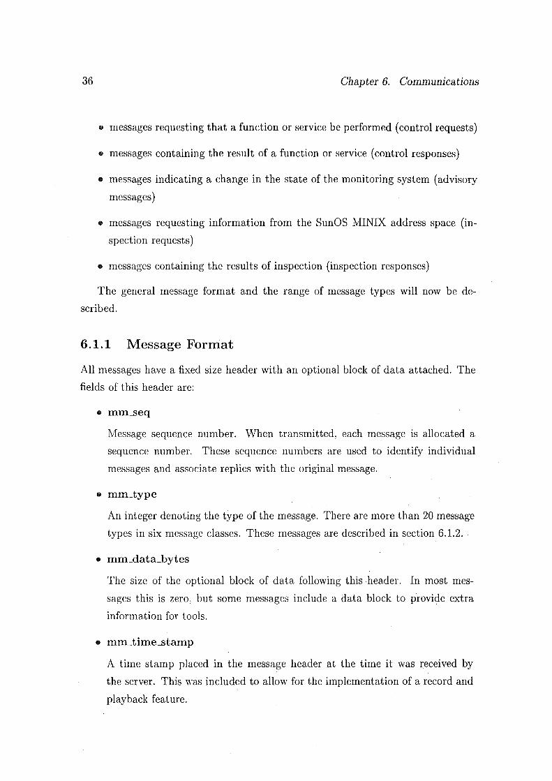
• messages requesting that a function or service be performed (control requests)
• messages containing the result of a function or service (control responses)
• messages indicating a change in the state of the monitoring system (advisory
messages)
• messages requesting information from the SunOS MINIX address space (in
spection requests)
• messages containing the results of inspection (inspection responses)
The general message format and the range of message types will now be de
scribed.
6 .1.1 Message Format
All messages have a fixed size header with an optional block of data attached. The
fields of this header are:
• mm_seq
Message sequence number. vVhen transmitted, each message is allocated a
sequence number. These sequence numbers are used to identify individual
messages and associate replies with the original message.
• mm_type
An integer denoting the type of the message. There are more than 20 message
types in six message classes. These messages are described in section 6.1.2.
• mm_data_bytes
The size of the optional block of data following this header. In most mes
sages this is zero, but some messages include a data block to provide extra
information for tools.
• mm_time_stamp
A time stamp placed in the message header at the time it was received by
the server. This was included to allow for the implementation of a record and
playback feature.

6.1. Monitoring Message Protocol 37
• mm_sender and mm_receiver.
When a SunOS MINIX message is passed, an event of type MM_LMESSAGE is
generated. The entire Sun OS MINIX message is attached to the header of the
monitoring event message. To simplify the event selection procedures, the slot
numbers of the sending and receiving SunOS MINIX processes are copied into
these fields.
• mm_sec_type
A secondary type field. This field is also included in the message header to
simplify the event selection module, and to provide more information about
failed control requests in control response messages. In a control response, this
field contains the message ty.pe from the original control request which failed.
More information about control responses may be found in section 6.1.2.4.
• mm_reason
Used only in control responses, messages sent by the server as responses to
control requests. This field tells the message sender why the request failed.
• mnLcheck
A simple checksum. If this is not valid, the message receiver discards the
message and reports an error. This allows message receivers to detect a cor
rupted message stream quickly and terminate gracefully with a meaningful
error message.
While the transport library provides a reliable communication path, software
errors (particularly incorrect values ofmm_data_bytes) can confuse the message
receiver. This field provides a way for the receiver to gracefully detect this
situation and terminate the connection. This field was mainly used during the
implementation and testing of the monitoring system, but remains to assist
with the testing of new tools and the detection of any remaining software
errors.

38 Chapter 6. Communications
6.1.2 Message Types
There are six classes of messages. Each class is comprised of a set of related message
types. The six message classes are: events, advisory messages, control requests,
control request responses, inspection requests and inspection request responses.
6.1.2.1 Events
Event messages, shown in table 6.1, are generated by SunOS MINIX. Each event
message corresponds to one execution of one instrumentation point1 . Each message
type within this class is generated in exactly one place in the SunOS MINIX ker
nel, with one trivial exception- MM_E_PROC messages are generated during SunOS
:MINIX startup to make the server processes and INIT visible to tools. All other
MM_E_FROC messages are generated by the memory manager when a process image is
loaded.
Event messages are used to gather information from a running SunOS MINIX.
A tool may specify to the server the type(s) of events it wishes to receive. The
server will comply by only forwarding to the tool event types that it is interested
in receiving, thereby reducing the complexity of the tools (they need not handle
messages they do not understand) and reducing network traffic (fewer event messages
are transmitted).
Event messages can appear in the message stream only while monitoring is in
progress - between MM_A_LAUNCH and MM_A_END advisory messages, signalling the
in\'ocation and termination of SunOS MINIX respectively. Event messages are sent
to the server by SunOS MINIX and to tools by the server, never in the opposite
direction. A tool will only be sent those types of messages it has requested to receive.
6.1.2.2 Advisory Messages
Advisory messages are generated by either SunOS MINIX or by the server when
something happens to change the state of the monitoring system. The server trans
mits these advisory messages to all tools.
For example, an advisory message is generated by SunOS MINIX when the
1 An instrumentation point is a location within Sun OS MINIX that has been modified to send information to the server whenever it is executed.

6.1. Monitoring lv!essage Protocol 39
I Symbolic N arne I Description
MM_NULL Null event, for protocol use only. Ignored by receiver. MM_E_SNDJ3LK A SunOS MINIX process has blocked trying to send
a message MM_E_RECJ3LK A SunOS MINIX process has blocked waiting to
receive a message MM_E_MESSAGE A message transfer (rendezvous) has occurred MM_E_SENDREC The previous MM_E_MESSAGE related to a SunOS
MINIX sendrec() - a reply should be expected. M:tvLE_PROC A process image has been loaded using exec() MM_E_TTY Characters have been written to a TTY device
Table 6.1: Monitoring messages- events
J Symbolic N arne I Description I Generated by M:tvLA_LAUNCH SunOS MINIX has been launched Server Mi\LA_END Shutdown of SunOS MINIX. SunOS MINIX Mi\LA_pAUSED SunOS MINIX has been paused SunOS MINIX Mi\LA_RESUMING SunOS MINIX is resuming execution SunOS MINIX
after being paused MlVLA_SHUTDOvVN Shutdown of entire monitoring system Server
Server about to exit.
Table 6.2: Monitoring messages- advisory messages
reboot() system call is invoked to shut down the operating system. The type of
this advisory message is MM_A_END and it serves as an end-of-file marker for the
monitoring message stream.
Advisory messages are sent to the server by SunOS MINIX and in turn by the
server to all connected tools. All tools are required to understand all types of
advisory messages. The advisory messages are listed in table 6.2.
Advisory messages may appear in the message stream at any time, although
not all combinations are possible. For example, a MM_A_END message (signalling the
termination of SunOS MINIX) cannot occur unless SunOS MINIX is already active.

40 Chapter 6. Communications
I Symbolic Name I Description I Generated by j MM_C_NULL Null request, no effect MM_C_SHUTDOWN Request to shut down monitoring system Tools
including server and SunOS MINIX. MM_C_START _MIN Request to launch SunOS MINIX Tools MM_C_START _PLYB Request to start playback of recorded Kot used
event stream MM_C_STOP Request to shut down SunOS MINIX Tools
and Server MNLC_FAUSE Request to pause SunOS MINIX execution Tools
and Server MM_C_RESUJ\IE Request to resume SunOS MINIX execution Tools
and Server
Table 6.3: Monitoring messages- control requests
6.1.2.3 Control Requests
Control requests are mostly issued by tools and sent to the server, although the
server occasionally submits a control request to SunOS MINIX. Control requests
are a means of requesting a service from another entity in the monitoring system.
The entity will respond to the request by sending back a control response, which
indicates the success or failure of the original request.
Control requests may only be submitted to the server by tools that have re
quested and been granted (as part of the tool connection protocol, described in
chapter 9) permission to control SunOS J\IINIX execution. Except for the null
request MM_C_NULL, which is ignored by the recipient, and MM_C_SHUTDOWN, which
terminates the monitoring system, control requests can only be issued when the
server is in the correct state: MM_C_STARLMIN is only valid when SunOS \IINIX is
not already running. MM_C_STOP and MM_CYAUSE are valid only when SunOS MINIX
is running. MM_C_RESUME may only be sent '.Yhen SunOS MINIX is paused.
The control requests are shown in table 6.3.
6.1.2.4 Control Request Responses
These messages are sent in response to a control request. There are two message
types in this class, indicating successful and unsuccessful execution of a control

6.1. Monitoring Message Protocol 41
I Symbolic Name I Description I Generated by I :\1M_R_OK Generic success message Server :\1IvLR_FAIL Generic failure message Server
Table 6.4: Monitoring messages - control responses
I Symbolic Name I Description I Generated bv I . MM.LGET _SYM Request to look up symbol table Tools MM_LREAD Read portion of SunOS MINIX core Tools
Table 6.5: Monitoring messages - inspection requests
request. The response messages contain some of the fields from the original request
and a failure code so that the receiver can determine which request this response
pertains to and what error occurred.
A control response is sent only to the tool that originated the request. Control
responses may be sent by the server at any time, following the reception of a control
request from a tool.
The control responses are summarised in table 6.4.
6.1.2.5 Inspection Requests
Inspection requests are used to look up symbols in the symbol tables of the SunOS
MINIX executables (MM_LGET _SYM) and to read portions of the Sun OS 1HI\IX ad
dress space (MM_LREAD). These requests, tabulated in table 6.5, are submitted to
the server by tools.
Inspection requests may be submitted to the server only when SunOS :\IINIX
execution is paused, and only by tools that have requested and been granted (as
part of the tool connection protocol) permission to inspect SunOS MINIX.
The server responds to inspection requests by sending an inspection response
message. If the request was successful, this message will have a block of data at
tached containing the requested symbol or segment of Sun OS MINIX address space.

42 Chapter 6. Communications
J Symbolic Name I Description I Generated by I MM_R_SYMBOL Response to symbol lookup Server MM_RJNSPECT Response to core memory read Server
Table 6.6: Monitoring messages - inspection responses
6.1.2.6 Inspection Responses
Inspection responses are sent by the server in response to one of the two inspection
requests. The response is sent only to the tool originating the request.
If the request was successful, a block of data will be attached containing the
information requested by the tool. If the request was not successful an error indi
cation is returned. Successful responses are possible only when the submitting tool
has inspection permission and when SunOS MINIX is in the paused state.
The two inspection response messages are shown in table 6.6.
6.2 Transport Library
The transport library is an important component of the monitoring system. This
library is used by all components of the system (the server and tools, and a cut-down
version is linked with SunOS MINIX) to provide the abstraction of a full-duplex 8-
bit-clean communication channel between two processes.
The transport library was originally written to provide the server with a con
venient interface to the TCP /IP communication facilities of Sun OS. Support was
then added to allow for communication via pipes when that method was chosen
to interface the server with SunOS MINIX. It was soon apparent that the high
level medium-independent communication facilities afforded by the transport library
would be useful in every process in the monitoring system. A cut down version (with
out TCP /IP support) was added to SunOS MINIX, and the ability to communicate
with a child process (by connecting its standard input and output to pipes) was
included when the library was used by tools. Additional features, such as the ability
to re-assemble messages received via TCP /IP and the ability to multiplex input and
output on many connections, were added later to hide these complexities from the
server and tools.
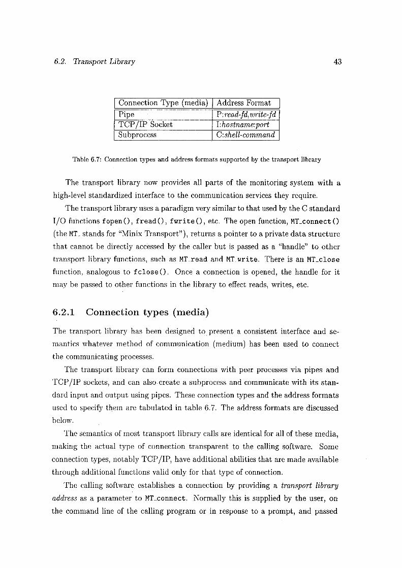
6.2. Transport Library 43
I Connection Type (media) I Address Format
Pipe P: read-fd, write-fd TCP /IP Socket I:hostname:port Subprocess C: shell-command
Table 6.7: Connection types and address formats supported by the transport library
The transport library now provides all parts of the monitoring system with a
high-level standardized interface to the communication services they require.
The transport library uses a paradigm very similar to that used by the C standard
I/0 functions fopen (), fread 0, fwri te (), etc. The open function, MLconnect ()
(the ML stands for "Minix Transport"), returns a pointer to a private data structure
that cannot be directly accessed by the caller but is passed as a "handle" to other
transport library functions, such as MLread and MLwri te. There is an MLclose
function, analogous to fclose 0. Once a connection is opened, the handle for it
may be passed to other functions in the library to effect reads, writes, etc.
6.2.1 Connection types (media)
The transport library has been designed to present a consistent interface and se
mantics whatever method of communication (medium) has been used to connect
the communicating processes.
The transport library can form connections with peer processes via pipes and
TCP /IP sockets, and can also create a subprocess and communicate with its stan
dard input and output using pipes. These connection types and the address formats
used to specify them are tabulated in table 6. 7. The address formats are discussed
below.
The semantics of most transport library calls are identical for all of these media,
making the actual type of connection transparent to the calling software. Some
connection types, notably TCP /IP, have additional abilities that are made available
through additional functions valid only for that type of connection.
The calling software establishes a connection by providing a transport library
address as a parameter to MLconnect. Normally this is supplied by the user, on
the command line of the calling program or in response to a prompt, and passed

44 Chapter 6. Communications
through by the calling program untouched and un-interpreted. This address consists
of a single character identifying the type of connection media and then a medium
specific address, the two parts being separated by a colon.
The valid address formats are listed in table 6. 7. Transport addresses for pipe
connections are prefixed with "P:" and contain the file descriptors (integers) for
the read end of the inbound pipe and the write end of the outbound pipe. Socket
addresses are prefixed with "I:" (signifying internet-domain sockets) and contain the
host name of the destination machine, or it's IP address in dotted-decimal format,
and the port number to connect to. Subprocess addresses are prefixed by "C:" and
contain the shell command that should be executed to start the child process.
A list of the functions provided by the transport library may be found in table 6.8.
6.2.2 Additional Functions
Besides providing communication facilities, the transport library can assist with a
number of common tasks required of by the tools and (in particular) the server.
6.2.2.1 Re-assembly of messages sent via TCP /IP
The transport library is most commonly used to transmit and receive a series of
monitoring messages, as described in the previous section of this chapter.
A monitoring message consists of fixed-size message header optionally followed
by a block of additional data. At any time, a receiving process knows the size of the
next block of data expected on a connection2 .
TCP /IP socket connections do not preserve message boundaries - a single block
of data transmitted via a TCP connection will not necessarily arrive as a single
block at the receiver. It may be arbitrarily fragmented during transmission, with
each read() system call on the receiving end yielding only one fragment. Multiple
reads may be required to get the full message.
The transport library is able to re-assemble messages of known size on the fly.
The calling process need only inform the library of the size of the expected message.
The transport library will re-assemble any received fragments into the original mes
sage before returning it to the calling program, effectively hiding this complication
2 Most messages are only a header and have no additional data attached. Therefore, the size of the next data block to be received is normally the size of a message header.

6.2. Transport Library 45
from the caller.
6.2.2.2 Input/Output multiplexing
The monitoring system makes heavy use of inter-process communication. Many
processes in the system, the server in particular, must maintain communication with
more than one process. Messages must be processed as soon as they are received,
and in many cases replies need to be sent in response to the original message.
Processes communicating with more than one peer cannot block while trying to
send or receive data. If that happens, messages from other peers cannot be processed
until the blocked send or receive is completed. Such processes therefore require the
ability to multiplex their multiple connections.
The transport library is able to multiplex full duplex data over a large number
of connections. Programs using this facility issue a call to the transport library to
get the next inbound message from any connection. This call blocks until a message
becomes available (from any source). The program then processes the message, and
if necessary can queue data for transmission to a connected peer.
Queueing the data cannot block, since the transport library does not attempt to
write the data until the next call to get messages is made. At that time, the trans
port library finds out which connections are readable (because they have pending
messages) and writable (able to accept queued data without blocking). Data is fed
out to writable connections while further inbound messages are processed. This is
accomplished using the Sun OS select() system call.

46 Chapter 6. Communications
I Function I Description
MT_connect Establishes a connection and returns a "handle" to it MT_close Close a connection MT _write Write a block of data to a connection MT_read Read a block of data from a connection MT_gets Read an EOLN-terminated line of text from a connection MT _smart_read Read a block of data, allows for partial reads
and timeouts MT _queue_data Add a block of data to the queue of data waiting
to be sent through a connection MT Jiush_queue Ensure that all queued data is written MTJisten Establish a TCP /IP listen socket MT_accept Accept a connection on a TCP /IP listen socket MTJnitJist Set up a list of client connections MT _destroy Jist Destroy a list of client connections MT_addJist Add a connection to a client list MT_delJist Remove a connection from a client list MT _searchJist Search a client list for a connection MT_check Check client status MT _next_client Iterate through readable or writable client connections MT _reset_alist Reset list of readable/writable clients MT _get ..handle Get the transport handle for a client MT _get_peer Find the address of the other end of a connection MT_select Perform input/output multiplexing MT _set_deblock Set the size of the next message from a client MT_deblock Assemble messages from client, accounting for
arbitrary fragmentation caused by TCP /IP MT _set_async Enable or disable the delivery of SIGIO MT _peek_chars Examine the next characters waiting to be read MT _get_pid Get the process ID of a subprocess connection
Table 6.8: Functions provided by the transport library

Chapter 7
SunOS MINIX modifications and
instrumentation
Modifications were made to SunOS MINIX to facilitate its integration into the mon
itoring system. Minimising the modifications to SunOS MINIX was an important
consideration in this task.
This chapter describes these modifications, ·which are of the following general
types:
• Modifications to the SunOS MINIX bootstrap loader and the kernel initializa
tion. These modifications mostly relate to the initialization of global variables
required by the monitoring extensions and the setting up of communication
links between SunOS MINIX and the server.
• Modifications to the SunOS MINIX kernel (and to a much lesser degree, the
memory manager and file system) to allow for the collection of information.
• Modifications to the SunOS MINIX kernel to allow it to receive and process
monitoring messages sent to it by the server. Relatively few messages are sent
from the server to Sun OS MINIX, but these are required if the server and tools
are to control SunOS MINIX execution.
These modifications are detailed in the following sections.
47

48 Chapter 7. SunOS MINIX modifications and instrumentation
7.1 Modifications to bootstrap loader and kernel
initialization
The SunOS MINIX bootstrap loader was modified to initialize the monitoring ex
tensions to Sun OS MINIX. These modifications mostly relate to the parsing of new
command-line arguments and the resulting initialization of SunOS MINIX globals.
The same executable program is used for both monitored and standalone invoca
tions of SunOS MINIX. The monitoring extensions are activated by a parameter on
the Sun OS MINIX command line. The form of this parameter is -pipes: X, Y where
X and Y are file descriptors (integers) associated with the read end of the inbound
(server to MINIX) pipe and the write end of the outbound (MINIX to server) pipe
respectively.
If this option is present, SunOS MINIX will enable the monitoring extensions
and communicate with the server via those descriptors. If this option is not present,
the monitoring extensions are not enabled and SunOS MINIX behaves as normal.
7. 2 Modifications to allow information gathering
The Sun OS MINIX monitoring system supports two modes for gathering information
from SunOS MINIX.
In monitoring mode the execution of a strategically placed instrumentation point
constitutes an event. At each instrumentation point a call is made to newly-added
code that constructs an event message (as per the monitoring message protocol) for
transmission to the server. Instrumentation points have been placed at key points in
the SunOS MINIX kernel. This information is generated only when SunOS MINIX
is in execution.
In inspection mode, SunOS MINIX execution is suspended while tools retrieve
portions of its address space for analysis and display. SunOS MINIX was modified
to allow the server and tools to control its execution (that is to pause it, resume it
and cancel execution entirely). No modifications were required to provide access to
Sun OS MINIX's address space since the Sun OS ptrace () interface already allows
the server to do this. Inspection may only be performed while SunOS MINIX is in
the paused state. This ensures that a consistent view of the Sun OS MINIX internal

7.2. Modifications to allow information gathering 49
data structures is seen.
7.2.1 Instrumentation for monitoring mode
In monitoring mode, information is transmitted to the server by SunOS MINIX as
instrumentation points are executed and as other important system events occur.
Messages from two of the message classes introduced in chapter 6 convey the
monitoring information. The execution of an instrumentation point results in the
generation of an event message. A major change in the state of SunOS MINIX
(such as a pause, resume or shutdown) prompts SunOS MINIX to send an advisory
message to the server.
Both classes of message are created by invoking a software module, new to Sun OS
MINIX, that builds monitoring :q1essages. Both classes of message are eventually
transmitted to the server using the transport library, included in SunOS MINIX
in cut-down form. Event messages are passed through the event selection module,
which discards event messages that are not required by the server or tools.
The code added to SunOS MINIX to perform these functions is described in the
following subsections.
7.2.1.1 Advisory Messages
Advisory messages are generated by SunOS MINIX to inform the server and all
connected tools of a change in the SunOS MINIX state. This occurs when SunOS
MINIX execution is paused, when it is subsequently resumed and when SunOS
MINIX ends execution.
The advisory messages are listed in table 6.2 on page 39.
Code to generate advisory messages has been placed at strategic locations inside
the SunOS MINIX kernel. Advisory messages are generated in the same way as
event messages (using a utility routine) and then passed to the transport library for
transmission. Advisory messages are not subject to event selection.
7.2.1.2 Instrumentation Points and Message Construction
The Sun OS MINIX kernel and servers (currently only the memory manager) have
been modified by the addition of instrumentation points. An instrumentation point

50 Chapter 7. SunOS MLVIX modifications and instrumentation
is actually a call to a C function that constructs an event message to be transmitted
to the server. Each event message contains information about the type of event and
other information specific to that event type.
Optionally, a block of event data may be attached to the event message. This
provides a further means that can be used to send event-specific information to the
server and tools. A list of the various event messages was presented in table 6.1 on
page 39.
For example, one particularly important instrumentation point is located in the
kernel function cp..llless (). This function is called once for each message that is
sent within Sun OS MINIX. It copies the message data from the address space of the
sender into the address space of the receiver.
The actual instrumentation is a call to a routine that assembles event messages.
In addition to an integer identifying the type of event, this call passes a pointer to
SunOS MINIX message structure that is being copied by cp..llless (). The Sun OS
MINIX message becomes event data that is attached to the event message header.
This instrumentation point generates event messages of type MM_E__MESSAGE. Us
ing this one event type, tools have access to every message exchanged within SunOS
MINIX. The accompanying event message header tells the tool which SunOS MINIX
process or task is the sender and which is the recipient of the message. Since SunOS
MINIX is modular in design and relies heaYily on message passing, this one event
type can provide a great deal of information about what is happening inside SunOS
MINIX.
7.2.1.3 Event Selection
Event selection is necessary to minimise the overhead that results from the poten
tially high volume of communication betvv'een SunOS MINIX and the server. If
every event message that was generated by SunOS MINIX was sent to the server a
huge volume of data would result, much of which may not be needed by the server
or any tools. High data volumes between SunOS MINIX and the server cause high
system load and result in SunOS MINIX being blocked more frequently \Vaiting for
the server to consume the data that is being sent. All these factors result in poorer
SunOS MINIX performance.
Event selection was implemented following an investigation into the rate at which

7.3. Reception and processing of Control Requests 51
monitoring messages would be generated by a running SunOS MINIX. This inves
tigation showed that message rates in excess of thousands of messages per minute
could be expected.
This problem is solved by transmitting only monitoring messages that are likely
to be useful to the server or tools. All advisory messages are sent, because these
normally signal a change in the state of SunOS MINIX (paused, resumed, shut
down, etc). All responses to control requests are sent, since these are required by
the serveL The event selection scheme is used to select those event messages that
are "interesting" to the server or tools. Each tool tells the server what event message
types it wishes to receive. The server also requires some event messages for its own
use, primarily to maintain a record of the current process table. The server forms
the union of the event messages required by itself and the tools, and then requests
that SunOS MINIX provide it with those message types. All other event messages
are discarded by SunOS MINIX before they are transmitted to the server.
Event selection uses a series of predicates to determine which event messages
should or should not be transmitted. These predicates are supplied to Sun OS MINIX
by the server, and may contain constraints on the values of any field of the monitoring
message headeL This header was described in chapter 6.
7.3 Reception and processing of Control Requests
One major modification to SunOS MINIX was the addition of code to receive and
process control requests sent to SunOS MINIX by the server. The server uses these
requests to ask SunOS MINIX to pause, resume and terminate execution. An added
complication was the requirement that these messages be received by SunOS MINIX
asynchronously.
This section details the modifications made to SunOS MINIX to support these
control requests. The modifications were:
• The existing SIGIO handler was rewritten so that SunOS SIGIO signals could
be used to notify SunOS MINIX when a message was pending from the server.
• A new kernel task, SERVER, was created to process messages received from
the server.

52 Chapter 7. SunOS MINIX modifications and instrumentation
7.3.1 New SIGIO handler
For SunOS MINIX to react to messages from the server, it must first determine
when the server is sending a message down the pipe that connects the two. One
option is polling, regularly trying to read data from the pipe to see if anything is
there. The other option is to arrange for the delivery of a SIGIO signal from the
kernel when the pipe file descriptor becomes readable.
Originally, SunOS MINIX used the SIGIO signal to indicate that input was avail
able on one of the four SunOS MINIX TTY lines. When the signal was delivered,
Sun OS 1vii:.JIX polled each of the four descriptors and processed any input that was
available.
A new SIGIO handler was written that was to be triggered when data became
available on any of the four SunOS :tviiNIX terminal lines or on the pipe from the
server. Instead of polling all four TTY file descriptors1 and the pipe descriptor when
the signal was delivered, the new handler uses the Sun OS select() system call to
determine ·which file descriptors are readable.
SunOS MINIX also used to poll the file descriptor associated with the UNIX
domain listen socket used to accept inbound mlogin2 connections. The new SIGIO
handler was also configured to accept SIGIO signals relating to that descriptor,
eliminating the need to poll it.
When input is detected on a SunOS MINIX terminal line, the new SIGIO handler
behaves exactly the same as the old handler. vVhen input is detected on the pipe
from the server, which means that the server is sending a message to SunOS MINIX,
a (SunOS \IINIX) message is sent to the new SERVER task. This message informs
the task that a message is arriving and prompts it to read the message from the
pipe. \Vhen the UNIX-domain listen socket becomes readable, a new remote login
session is initiated.
The SIGIO handler does not read any information from the pipe, it just notifies
the SERVER task that data is arriving.
1SunOS :.\IIJ\IX TTY lines are really SunOS file descriptors referencing either the SunOS MINIX controlling terminal or a UNIX-domain socket.
2 MINIX remote logins

7.3. Reception and processing of Control Requests 53
7 .3.2 The SERVER task
A new task, SERVER, was added to the SunOS MINIX kernel. This task receives
messages originated by the SIGIO handler when data is available from the server.
This is effectively a new type of SunOS MINIX interrupt.
It was necessary to add a new task to take the processing of messages received
from the server out of the interrupt/signal handlers. These handlers run at high
priority with interrupts/signals disabled, so are not an appropriate place to process
messages from the server.
The SERVER task works much like the other SunOS MINIX tasks. It sits blocked
waiting to receive a message from the SIGIO handler3 .
The server task is only prepared to receive HARD_INT messages from the HARD
WARE task (really the SIGIO handler in disguise). vVhen such a message arrives,
the SERVER task reads from the (inbound) pipe whatever data is available. This
block of data may be part of a message or it may be a number of messages concate
nated, so the SERVER task must reassemble the messages as they are received.
If the data received from the server does not make a complete message, it is
stored in a buffer and the SERVER task waits for the next message fragment to
arrive. This allows normal SunOS 1-IINIX execution to continue while the next
fragment is on the way and prevents SunOS MINIX being blocked for long periods
of time waiting for the rest of the message to be delivered.
When a complete message is available, the SERVER task processes it. The
following three messages, all control requests, are understood by the SERVER task:
• MM_C_STOP
This control request is sent by the server when it wishes SunOS MINIX to
terminate execution. When this message is received by SunOS MINIX, it
transmits the MM_A_END advisory message to the server and then executes
a wreboot () system call that results in its termination. The MM_A_END
advisory message will be broadcast to all tools by the server to indicate that
SunOS MINIX has terminated.
3 All Sun OS MINIX messages must have a sender that is a task or process, so messages from the SIGIO handler appear to have originated from the HARDWARE task. This is consistent with the method SunOS MINIX uses to deliver messages to the TTY task from the SIGIO handler.

54 Chapter 7. SunOS MINIX modifications and instrumentation
• MM_C_FAUSE
This control request is sent when a tool requires that SunOS MINIX pause
execution. This pause is required to allow the user to examine SunOS MINIX
or to permit the inspection of its address space. The SERVER task disables
asynchronous I/0 handling (ie. the SIGIO handler) and sets a flag for the
CPU scheduler to indicate that the operating system should be paused next
time no kernel processes (tasks an::l servers) are runnable4.
• MM_C_.RESUME
This control request is sent to revive SunOS MINIX from its paused state. The
asynchronous I/0 handers are re-enabled and the aforementioned scheduler
flag is cleared.
7.4 New code added to kernel
Aside from the modifications noted above, some completely new code was added to
the SunOS MINIX kernel to support the operation of the monitoring system.
This new code was organised into software modules to maximise reusability. The
new modules added to the SunOS MINIX kernel were:
• Transport Library
The transport library, described in an earlier chapter, is included in the SunOS
MINIX kernel in a cut-down form. No TCP /IP support is provided. The
transport library is used by the SunOS MINIX kernel to set up and manage
the two pipes that allow it to communicate with the server.
• Event Selection
The event selection library is used to filter the stream of monitoring messages
sent to the server. The server informs SunOS MINIX which message types
are required (by forming the union of the message types required by itself and
all tools) and the event selection module is used to remove all other message
types from the stream of messages sent to the server ..
4This ensures that the kernel is in an internally consistent state when SunOS i\IINIX is paused

7.4. New code added to kernel 55
• Event Construction
The event construction library is called at each instrumentation point to build
an event message for transmission to the server. Data values supplied by the
instrumentation call are copied into the event message. If the instrumentation
call specifies it, a block of data can also be attached to the newly created event
message.
It is the event construction library that invokes the event selection library
to decide whether the event message should be transmitted, and then the
transport library to transmit it to the server.

56

Chapter 8
The Server
The server is the huh of the monitoring system, and the most complex program
within it. This chapter describes the server in detail, with sections on the server's
design, its communication with SunOS MINIX and the tools and its role within the
monitoring system.
8.1 Overview
The server communicates directly with every other component of the monitoring
system (SunOS MINIX and every tool). Its main responsibility is to distribute
to tools information obtained from SunOS MINIX. The server also accepts control
requests from tools and· arranges for them to be carried out. This concentration of
complexity in the server has in turn simplified the tools and the modifications to
SunOS MINIX.
The server is usually the first component of the monitoring system started by
the user1. It is started by typing server (with optional command line arguments)
at the shell prompt. The server is otherwise invisible to the user and has no other
user interface.
1The server does not have to be started first, but that is the most convenient option
57

58 Chapter 8. The Server
8.2 Functions and Responsibilities
The server has many responsibilities, including the control of SunOS MINIX, the
distribution of monitoring information to the tools and the handling of control re
quests from tools. All of these functions may be performed simultaneously by the
server.
8.2.1 Control of SunOS MINIX
At the command of the user, the server starts execution of SunOS MINIX. This
command is received in the form of a control request message from one of the tools
connected to the server. SunOS MINIX is started as a child process2 of the server.
Once SunOS MINIX is running, the server is able to control its execution by
sending messages to it. The server can pause and then resume SunOS MINIX and
terminate it entirely. The server only exercises this control on the behalf of tools.
The server can only support one invocation of SunOS MINIX at any time. How
eYer SunOS MINIX may be started, monitored, shut down and restarted as many
times as required. The user need not restart the server or tools when SunOS MINIX
is restarted.
8.2.2 Reception of Monitoring Information
The server receives monitoring information transmitted by Sun OS MINIX via one of
the two pipes that connect them. The communication over these pipes is governed
by the monitoring message protocol, described in chapter 6. Monitoring information
is received from SunOS MINIX in the form of event messages, each corresponding
to the execution of one instrumentation point inside SunOS MINIX.
SunOS MINIX sends advisory messages to the server when certain events occur.
These messages signal a change in SunOS MINIX state and are an additional source
of information not related to any instrumentation points.
The server can also obtain monitoring information by reading directly from the
Sun OS MINIX address space using the facilities of the ptrace () system call. This
inspection is performed only when SunOS MINIX has been placed in the paused
2SunOS MINIX is two processes: a bootstrap process and SunOS MINIX itself. There are therefore three processes involved: the server, SunOS MINIX bootstrap and SunOS MINIX.

8.2. Functions and Responsibilities 59
state to ensure that a consistent view of its data structures is obtained. Inspection
via the Sun OS ptrace () mechanism is performed by the server on the behalf of a
tool that has submitted an inspection request.
The server is able to read symbols from the symbol tables of the SunOS MINIX
kernel, memory manager and file system. This is also done in response to a request
from a tool, and allows tools to retrieve variable values from SunOS MINIX. The
symbol table lookup is used to turn the variable name into a memory address and
then inspection in performed to return the portion of Sun OS MINIX memory holding
that variable.
8.2.3 Distribution of Monitoring Information
The server's most important task is to distribute monitoring information to tools
that are connected to it. Each tool communicates with the server via a TCP /IP
connection. The communication over this connection is governed by the monitoring
message protocol, described in chapter 6. The server is designed to support many
such connections, and therefore many tools, at once.
The connection of a tool to the server is governed by the tool connection protocol,
described later in this chapter. During the connection phase a tool may inform the
server of the types of event messages the tool wishes to receive.
All information about SunOS MINIX available to tools is provided by the server
in the form of monitoring messages. This includes event information (event mes
sages), changes in SunOS MINIX state (advisory messages) and inspection informa
tion (symbol table values and blocks of SunOS MINIX memory, contained within
responses to inspection requests).
When the server receives an event message from SunOS IvHNIX, it distributes
the message to any tools that have expressed an interest in receiving that type of
message. Advisory messages are transmitted to all tools, and all tools are required
to accept and understand them.
Inspection information (symbol table values and blocks of SunOS MINIX mem
ory) is transmitted only to the tool requesting the information.

60 Chapter 8. The Server
8.2.4 Handling of Control Requests
Control requests are monitoring messages that request information or the per
formance of a service. They are similar to a remote procedure call in that the
caller/ sender can provide parameters and the receiver actions the request and re
turns a reply message containing output and result information.
Control requests are sent from tools to the server and from the server to SunOS
MINIX. Tools are not able to directly send requests to SunOS MINIX.
Tools may use control requests to control the execution of Sun OS MINIX, if the
server has granted them permission to do so. There are requests to suspend and
resume SunOS MINIX execution and to shut it down altogether. The entire function
of the control panel tool, described in chapter 9, is to send control requests to the
server in response to user input.
The server sends control requests to SunOS MINIX to request that it suspend,
resume or terminate execution. It would be possible for the server to achieve the
same effect using SunOS signals, but by sending requests as part of the message
stream it is possible for SunOS MINIX to decide ·when it should pause or terminate.
The timing of pauses in execution is important, because SunOS 11INIX's internal
data structures must be in a consistent state when it is paused for inspection.
8.3 Operation
The server is a complex single-threaded program that performs input and output
multiplexing and message passing. It distributes information received from SunOS
MINIX and performs control requests on behalf of tools.
This section describes how the server performs the important tasks of: server
startup, communication with SunOS MINIX, communication with tools, handling
of control requests and distribution of monitoring information.
8.3.1 Server startup
When the server is started, it performs some initialisation steps. The Sun OS MINIX
configuration file is read so that the server knows the location of the Sun OS MINIX
image file. This file is a concatenation of the four executable programs initially

8.3. Operation 61
loaded into SunOS MINIX: the SunOS MINIX kernel, the memory manager, the file
server and the "init" process.
Finally, the server creates a TCP /IP socket that is used by tools wishing to
initiate communication with the server. It is the address of this socket the user
must specify to tools when connecting to this server.
When its startup is complete, the server waits for incoming tool connections.
8.3.2 Communication with SunOS MINIX
The server starts SunOS MINIX when an MM_C_LAUNCH message is received from a
tool authorised to issue that request. SunOS MINIX is started as a child process
of the server and communication between the two is established via a pair of pipes,
one for communication in each direction. These pipes are managed by the transport
library.
When the Sun OS MINIX kernel has completed initialization it sends to the server
a block of data containing various system parameters, including the number of task
and process slots in its process table. These parameters are required by the server
and tools for their internal tables, and are not hard coded in order to reduce the
coupling between SunOS MINIX and the server and tools.
Once that initial block of data has been sent, the communication between Sun OS
MINIX and the server is governed by the monitoring message protocol, with event
and advisory messages sent from SunOS MINIX to the server.
The communications link between SunOS MINIX and the server remains until
either or both of the server and SunOS MINIX terminate.
8.3.3 Communication with tools
The server communicates with each tool using the monitoring message protocol
over a TCP connection. This connection is set up according to the tool connection
protocol:
1. The tool opens a connection to the server's published TCP /IP address.
2. The connecting tool transmits to the server a "client information" record (de
fined as a C structure). This structure contains the name of the tool, the

62 Chapter 8. The Server
name of the user running the tool and a mask of attribute bits. The attribute
bits provide additional information about the tool and also allow the tool to
request from the server additional options, services or capabilities.
3. If appropriate, additional data may be sent by the tool if certain bits are set
in the attribute mask. For example, the tool can send "interest records" to
the server listing the types of event messages the tool wishes to receive.
4. The server considers the information and requests received from the new tool
and decides upon its reply. If the server does not wish to communicate with
the tool, it can simply close the connection.
5. If the server wishes to communicate, it responds by sending a "source infor
mation" record. This record (another C structure) tells the tool about the
current state of the monitoring system, in particular the status of the associ
ated Sun OS MINIX. This allows the tool to initialise itself to a state consistent
with that of the monitoring system.
6. In certain circumstances (in particular, if certain bits are set in the tool's
attribute mask) there may be additional data transfer from the server to the
tool. One example of the use of this facility is the transmission of a copy
of the SunOS MINIX process table if the CA_WANLPROCTAB bit is set in the
tool's attribute word. The tool can use this to find out what processes exist
in SunOS MINIX at the time of its connection to the server.
Once communication has been established using the tool connection protocol,
messages are then exchanged according to the monitoring message protocol.
The server sends to the tool all advisory messages received from Sun OS MINIX,
the responses to control requests submitted by the tool and v,rhatever event messages
the tool has requested to receive.
The tool may submit control requests to the server at any time. Some of these
control requests are only valid in certain states of the monitoring system. For
example, the MM_CYAUSE control request (requesting that Sun OS :MINIX execution
be paused) is invalid unless SunOS MINIX is in execution.
Tools must ensure that SunOS MINIX is invoked and in the paused state before
issuing any inspection requests.

8.4. Structure 63
The server's communications link with a tool will remain until the tool discon
nects or until the server shuts down. During this time, many successive invocations
of SunOS MINIX may be monitored.
8.4 Structure
The server is the largest single component of the monitoring system. After startup,
its execution centres around a loop that processes incoming messages.
Heavy use is made of the facilities of the transport library. Not only does this
library provide the communications services, it manages connections to the tools by
keeping track of which tools are sending messages, which have permission to perform
certain operations and by spooling data sent to each tool so that it is sent as the
tool is ready to receive it.
The event selection library is also used by the server. This library filters a
stream of monitoring messages given a set of predicates that specify which messages
are to be pas'sed to a tool and which are not. These predicates are supplied by each
individual tool, making this a simple but flexible method for tools to control the
event messages they receive.
A library has been developed that maintains a shadow copy of the Sun OS MINIX
process table from a stream of event messages Using this library, the server knows
at any instant what processes are present inside SunOS MINIX. This information
can be provided to tools at the time of connection.

64

Chapter 9
Tools
A tool is a program that allows the user to interact with and view information from
the monitoring system. The tools are the user interface to the monitoring system.
They are designed to be used together, as part of a monitoring session.
This chapter describes the elements of design common to all tools and also dis
cusses the implementation of the tools developed to date. The general design of
graphical tools and the method used to build their graphical user interfaces (GUis)
is described.
A description of the following tools is included:
• The control panel, the user interface to the server.
• The process monitor, a tool to display a continuously updated view of the
SunOS MINIX process table.
• The TTY monitor, a tool to show the activity on one of the SunOS MINIX
terminal lines.
• The message tracer, a tool that logs every message it receives.
• The initial design of the data structure browser, a tool for viewing the
internal data structures of a paused SunOS MINIX. This tool has not been
implemented.
65

66 Chapter 9. Tools
9.1 Overview
The tools are the user interface of the monitoring system. They are the realization of
many of the goals listed in chapter 5, allowing the user to view information gathered
via the server from SunOS MINIX. Some tools also give the user the ability to control
SunOS MINIX and the server.
The monitoring system is designed to allow the concurrent operation of many
different tools. The same tool may be invoked many times to display different objects
or.different views of the same object.
It is intended that each tool is, from the user's point-of-view at least, a relatively
simple program. Each tool should display one kind of information to the user in one
or two different ways.
All tools connect to the server via TCP /IP. A tool may connect to and disconnect
from the server at any time without affecting the operation of the monitoring system.
If possible, tools should be able to connect to the server at any time and immediately
show useful information.
A tool's TCP /IP connection to the server may remain active for many successive
restarts of Sun OS MINIX. This ability is often desirable in an experimental situation
where repeated invocations of SunOS MINIX are required.
9.2 Tool Design
This section describes those design elements that are common to all tools. The
states of a tool, the tool's communication with the server and its use of monitoring
messages are all discussed.
User interface issues are addressed in section 9.3.
9.2.1 Tool States
A tool's state is derived from the state of its connection to a server, and if connected
the state of the associated Sun OS MINIX. Monitoring cannot occur unless a tool is
connected to a server and unless the associated SunOS MINIX is in execution or is
paused (for inspection).
The possible states of a tool are:

9.2. Tool Design 67
• Unconnected.
The tool is not currently connected to a server. No monitoring can take place.
The tool can only connect to a server or terminate.
• Connected, idle.
The tool is connected to a server, but that server is not currently controlling
an instance of SunOS MINIX. No monitoring can occur, but the tool can be
configured and it can send control requests to the server. The tool can also
disconnect from the server or terminate entirely.
• Connected, monitoring.
The tool is connected to a server and that server is controlling a running
instance of SunOS l'viiNIX. Monitoring can occur. The tool may receive mon
itoring information, send control requests, terminate or disconnect from the
server.
• Connected, paused.
The tool is connected to a server, that server is controlling a paused SunOS
MINIX. The tool may issue control and inspection requests, terminate or dis
connect from the server.
These states are related to the states of SunOS MINIX, described in chapter 5.
9.2.2 Communication with server
Each tool initiates communication with the chosen server by opening a connection
to its known TCP /IP address.
At present, this address is provided by the user in a format understood by the
transport library, either on the command line or in response to a dialog box dis
played by a graphical tool. It would be desirable for a future version to use more
user-friendly addresses, but a distributed method of resolving high-level names to
transport library addresses would be required. This has been considered, but not
implemented.
The initial communication between a tool and the server is governed by the tool
connection protocol, described in chapter 8. This protocol dictates the exchange

68 Chapter 9. Tools
of information that leads to a successful tool connection. The tool and the server
negotiate over the parameters of the connection - the tool first requesting various
options and abilities and the server replying with which of those are permitted.
Once a tool has established a connection to the server, the ongoing communica
tion is governed by the monitoring message protocol described in chapter 6. This
protocol allows the tool to receive monitoring information and submit inspection
and control requests to the server.
9.2.3 Services available to tools
The server offers tools a number of services. These services are accessed through the
tool connection and monitoring message protocols, and form an interface tools may
use to interact with, control and obtain information from the monitoring system.
Tools wishing to control the monitoring system request permission to do so when
they connect to the server.
The server may grant or deny this permission, although at present no such re
quests are refused. It would be possible to add security and authorization features
to the server in the future, the server would then deny requests from tools or users
without the proper authorization.
If a tool is permitted to control the monitoring system, it may issue control
requests to the server. The server will process these requests and reply with messages
(control responses) indicating success or failure.
Tools requiring information from the monitoring system can request permission
from the server to issue inspection requests and/or request that the server forward
them certain types of event messages.
9. 3 User Interface
Tools \Vith different purposes have different requirements from their user interface.
A textual interface may be adequate for some tools, while others require a graphical
interface to present information clearly to the user.
Tools with both types of interfaces have been developed as part of the monitoring
system. These tools are described later in this chapter.

9.3. User Interface 69
Textual interfaces are simple to implement. The remainder of this section is
concerned with the design and implementation of graphical user interfaces for mon
itoring system tools.
The first subsection below discusses the difficulties faced when implementing
graphical user interfaces in the SunOS environment. Later subsections describe the
approach taken to deal with these problems.
9.3.1 Graphical Interface Construction
Graphical user interfaces are difficult to implement from scratch due to their com
plexity.
A common solution to this problem is to make use of a GUI library package,
containing reusable interface components that can be relatively easily pieced to
gether into a working user interface. This approach is less complex than writing an
interface from scratch, but most GUI packages are still difficult to learn.
An alternative approach is to take advantage of a user interface construction pro
gram, such as XF[2], which allows the programmer to construct the desired interface
using an interactive program that outputs source code for use in the program. This
machine-generated source code output by this program was complex, and difficult
to modify by hand. The system described in [2] was investigated but not used.
The tk GUI package, built on top of the Tel scripting language and together
referred to as Tcl/Tk[6], is surprisingly easy to learn and use. This ease of use is
partly due to the interpreted nature of Tcl/Tk, and also to the rich set of features
offered by Tk.
Tk was chosen as the GUI library for the development of the graphical tools.
Other libraries considered include: InterViews, Xlib, XAw and Xview/OLIT. Xlib,
the low-level X-Windows interface, was ruled out because of the complexity of code
required for even the simplest graphical interface. It was felt that Xaw was too
rudimentary, and X view /OLIT are no longer supported by their vendors. InterViews
was considered more seriously, but it lost out to Tk because the latter was much
simpler and quicker to use.

9.3.2 Limits of Tcl/Tk
Tcl/Tk was the chosen environment for the implementation of the graphical tool
interfaces and displays. But it was not possible to implement graphical tools entirely
in Tcl/Tk, for the following reasons:
• Difficulty of representing low-level data
Since they are analysing a running operating system, tools must work with
low-level data whose structure is defined in terms of C structures. The only
data type available to a Tcl/Tk program is "string". These strings can be used
to represent lists, and then arrays and structures, but translating between this
representation and that used by SunOS MINIX and the monitoring system is
complex and time consuming.
In short, the information transmitted around the monitoring system cannot
satisfactorily be represented within Tcl/Tk.
• Performance.
Tools must be able to receive and process messages from the server at least
as quickly as they are generated. While Tcl/Tk performance is good, it is not
sufficient to keep up with the data likely to be transmitted by the server.
Early on in the course of this research a brief investigation was conducted into
the message rates resulting from SunOS MINIX monitoring. These investi
gations showed that message rates in excess of many thousands of messages
per minute were normal when monitoring was in progress. The transmission
and processing of these messages resulted in a significant CPU load on the
host computer. This discovery led to the implementation of event selection
in SunOS MINIX and the server to ensure that only useful messages were
transmitted.
It was clear that an interpreted scripting language, such as Tcl/Tk, was not
able to process messages at the rate the server was likely to send them. This
would be especially true if each received message had to be translated into a
Tcl/Tk representation.

9.3. User Interface 71
In light of the above, it was necessary to implement the data reception and
processing functions of a tool in C for both efficiency and convenience (since the
information received was defined by C structures).
9.3.3 The two-process model
These two approaches (Tcl/Tk graphical interface and C data reception and pro
cessing) had to be integrated into what would appear to be a single tool from the
user's point of view.
The solution to this problem was simple. Each tool would comprise two pro
cesses: one Tcl/Tk "GUI" process and one C "controlling" process. The GUI pro
cess would manage the user interface. The controller process would contain the
remainder of the tool code, and would communicate with the GUI process to receive
user input and arrange for the display of output.
This design has a number of advantages:
• It is possible to reap the benefits of both Tcl/Tk (easily developed graphical
interfaces) and C (fast and flexible code).
• The tool design is forced to be modular, with the user interface clearly decou
pled from the remainder of the tool.
• A degree of multi-threading is possible, since each tool is two processes. Each
can continue to execute even when the other is blocked. The tool (controlling
process) can be receiving the next message from the server while the user
interface (Tcl/Tk process) is displaying the previous message.
• The tool and its user interface can be developed, tested and debugged sepa
rately.
The controlling process uses the "GUI management library" to invoke and man
age the GUI process. The communication between the two process, a pair of pipes,
is realized using the transport library.

72 Chapter 9. Tools
9.3.4 The GUI process
The user interface component of graphical tools is managed by a separate process.
This process is under the control of a "controlling process" , between them they
comprise a graphical tool.
The user interface of a graphical tool is implemented using extended versions of
the Tk widget set and Tel scripting language. The extended version of Tel used was
known as TclX, likewise the extended Tk was called TkX.
A new shell interpreter, called tooLshell, was developed to execute the scripts
for the graphical user interfaces. This interpreter understands both TelX and TkX
commands in addition to one new command, transport, giving tooLshell scripts
access to some of the features of the transport library.
A "GUI process" is a tooLshell interpreter executing scripts containing TelX,
TkX and transport commands.
The tooLshell interpreter and the GUI scripts are discussed in the following
subsections.
9.3.4.1 Tcl/Tk interpreter- tooLshell
A new windowing shell, similar to wish, was developed to execute the Tel/Tk scripts
used to build the graphical user interface. This shell, called tooLshell, contains
the following:
• A TelX interpreter. TelX is "extended Tel", a superset of standard Tel con
taining additional commands providing enhanced access to operating system
functions.
• A TkX interpreter. TkX is "extended Tk", an enhanced version of Tk.
• The transport library, allowing the GUI process to communicate with the
controlling process. The subset of the library functions required by the GUI
processes have been made available as a new Tel command called "transport".
The transport library was linked with tooLshell, instead of using the communica
tion primitives provided by TelX, to maintain the same communication code across
the entire monitoring system and because the TclX code was not adequate for the

9.3. User Interface 73
purpose. It was felt that buffering problems could occur since there appeared to be
no way to control the buffering of stdin or stdout from within TclX.
9.3.4.2 Generic Tool Script
There is one tooLBhell script executed by all GUI processes during their startup.
This is called the generic tool script, because it is used by all graphical tools. This
script defines a set of useful procedures for managing the user interface and com
munication with the controlling process.
The generic tool script contains code to perform the following functions:
• Set up and maintain the communication link with the controlling process.
• Arrange for a SIGIO signal to be delivered whenever data is waiting to be read
from the controlling process.
• Define a handler, written in TclX, for the SIGIO signal. This handler reads
a tooLshell command from standard input and passes it to the interpreter for
execution.
• Notify the controlling process when the user interacts with the user interface.
• Display a dialog box to request input from the user, and pass the entered value
to the controlling process.
The only parameter required by the generic tool script is the filename of a
tooLshell script to set up the user interface for the tool being started. The choice
of this second script determines which tool will be created.
9.3.4.3 Tool-specific script
A tool-specific script is a tooLshell script that constructs the user interface for one
particular kind of tool. Each different tool has its own tool-specific script.
The tool-specific scripts contain TkX commands to create the user interface
components, TkX widgets, that the user will see on their display. The script may
also define procedures for its own use. This is often useful when scroll-bars and
canvases are being used.

74 Chapter 9. Tools
The graphical tools implemented to date have made use of a wide range of TkX
widgets, including:
• Buttons. Each button contains a text label describing the function that is
invoked when that button is pressed. Buttons may be enabled, meaning they
may be selected by the user, or disabled. Enabled buttons have black labels,
the labels on disabled buttons are "greyed-out".
• Labels. Labels are used to display single-line text messages and status indi
cations.
• Frames. Frames are invisible TkX. widgets that serve only as containers for
other widgets. They are used to position other widgets in rows and columns.
• Scroll Bars. Scroll bars allow portions of large widgets to be shown in small
areas. The user may manipulate the scroll bar to view other parts of the large
widget.
• Canvases. A canvas is a multi-purpose widget that may contain text, lines,
shapes and other widgets. The process monitor uses a canvas widget to draw
the SunOS IvliNIX process tree.
• Toplevels. Toplevel widgets are used to construct independent floating win
dows. The process monitor uses a toplevel widget to make the tree view a
separate floating window.
The user may interact with any visible widget, these interactions are handled by
the TclX/TkX code provided by the generic and tool-specific scripts.
In the tools currently implemented, the controlling process needs to be notified
of interactions with buttons and dialog boxes only.
vVh~n a button is created, it is assigned a unique textual name that is used
to identify it to the controlling process. vVhen that button is pressed, a message
containing that name is sent to the controlling process to notify it. For example,
·when the "Launch" button on the control panel is pressed the GUI process sends
the following to the controlling process:
#launch#

9.3. User Interface 75
The controlling process knows the button's full TkX name, so it can send com
mands to manipulate it (greying it out for example, or changing its text).
The generic tool script contains procedures that may be invoked by the control
ling process to cause the display of a dialog box. The dialog box is modal - the
user cannot interact with the tool until the dialog is dismissed, at which time the
controlling process is notified of what value the user entered.
9.3.5 The Controlling Process
As its name suggests, the controlling process has overall control of a graphical tool.
Each tool has its own controlling process. It is the executable program invoked by
the user, and is responsible for starting the user interface process.
The controlling process has no user interface, and does not communicate with
the user except by reading its command line and for the generation of error messages
if the tool suffers a fatal error.
The controlling process communicates with the GUI process to update and re
ceive input from the graphical user interface. It also communicates with the server
via a TCP connection using the tool connection and monitoring message proto
cols. This communication occurs asynchronously; the controlling process must be
prepared to accept messages from either source at any time.
Using this latter connection, the controlling process receives information from
the server for processing and display to the user. It requests the message types it
needs from the server and issues any control and inspection requests. It must receive
and interpret the responses to these requests.
Many of the functions required to start and control the user interface process
are provided in the GUI management library. This library makes use of the trans
port library for communications, and allows a controlling process to assemble and
transmit commands to a user interface process. The GUI management library also
provides functions to manage the tool's state information and to ensure that the
correct commands are sent to the user interface when state transitions occur.

76 Chapter 9. Tools
9.3.6 Communication between the tool processes
The GUI and controlling processes do not communicate using the monitoring mes
sage protocol.
The controlling process manipulates the GUI process by sending TclX or TkX
commands to it. The GUI process reads commands from its standard input, con
nected to the controlling process via a pipe, one line at a time. Once a line is
received, it is passed to the tooLshell interpreter for execution. The controlling
process has a great deal of control over the GUI process, as it may send any legal
tooL.shell command to the GUI for execution. These commands may update the
GUI display, call a procedure defined by the generic or tool-specific script (this is
the method used to request information from the user via dialog boxes) or add and
remove objects from the user interface.
The GUI process informs the controlling process of the user's interaction with
the user interface. When buttons are pressed or information is entered into a dialog
box, the GUI sends a message to its standard output. These messages are line-based
ASCII text and include a short name identifying the button or field concerned,
9.4 Description of Tools
The remainder of this chapter describes the tools that have been implemented to
date. Each description includes an explanation of the tool's purpose, a section on
how the tool is used and a list of the messages generated and accepted by the tool.
The first tool to be developed was the Control Panel. The Control Panel was
required to provide the control over SunOS MINIX necessary for the operation of
other tools.
The next tool to be developed was the Process Monitor. The construction of
this tool was considered a high priority since it displayed the operation of processes
inside SunOS MINIX. This was an important display to provide, since the process
concept is fundamental. The important operating system concepts were described
in Chapter 2.
The Message Tracer tool was produced to aid in the understanding and de
bugging of the monitoring message protocol. This tool is also useful for debugging
SunOS MINIX, since every SunOS MINIX message may be monitored with the tool.

9.4. Description of Tools 77
II il
Connect I Not connected to server
Launch I Pf~{yb~~~k PaUS(~ I S1op
~>~u~1~!ow~~ Quit
Figure 9.1: The control panel, before connection to a server
Other tools were considered, the next being an interactive data structure browser.
This browser would allow users to view the internal data structures of a paused
SunOS MINIX. Unfortunately this. tool could not be implemented in the time avail
able.
9.4.1 Control Panel
The control panel is the user interface to the server. Its purpose is to allow the user
to control the monitoring system. This section describes the function of the control
panel, how it was implemented and the monitoring messages it uses to achieve its
purpose.
9.4.1.1 Use of the control panel
The control panel's controlling process is an executable program called Lcontrol.
The user invokes the control panel by typing this at their shell prompt. Optionally,
the transport library address of a server may be specified on the command line. If
such an address is present, the control panel automatically attempts to connect to
a server at that address. Otherwise the control panel remains in an unconnected
state.
When a control panel is not connected to a server, the user can only establish a
connection or terminate the control panel. These options are available by pressing
the "Connect" or "Quit" buttons. All other buttons are shown in grey and cannot
be pressed.
Figure 9.1 shows the control panel before a server connection is established.

78 Chapter 9. Tools
II i1
No data source
Disconnect ] Connected to server at I :huia:6000
Launch I Playback P<~US(~ I S1o~~
Shutdown Quit
Figure 9.2: The control panel, connected to a server with no running SunOS MINIX
To start a control panel and connect to a server running on a machine called
"huia" a user would type:
X_control I:huia:6000 &
The transport library address consists of the machine name (huia), a TCP /IP
port number (by default, the server listens for incoming connections on port 6000
- this is easily changed by a command line option when the server is invoked) and
an uppercase "I" meaning internet-domain sockets should be used to establish the
connection.
Once the control panel is connected to a server, it displays the address of that
server and a description of the server's state. If the server is not running SunOS
MINIX, the control panel says "No data source". This is shown in figure· 9.2. Once
a server connection has been established, the "Connect" button changes to say
"Disconnect". Pressing this button now causes the control panel to disconnect from
the server and return to the disconnected state shown in figure 9.1.
When the control panel is connected to a server without a SunOS MINIX, the
"Launch" and "Playback" buttons are shown as being available (in black). The user
may press the launch button to start SunOS MINIX running. The playback feature
is currently not implemented. The "Shutdown" button is also active, when pressed
this shuts down the entire monitoring system - terminating SunOS MINIX, the
server and all tools.
When the control panel is connected to a server running SunOS MINIX, the user
may press the "Pause" button to suspend execution of Sun OS MINIX. In the paused

9.4. Description of Tools 79
r; il
Monitoring Sun OS MINIX on huia (daniel)
Disconnect I Connected to server at I :huia:6000
t<~unch I P1~~yb~~tk Pause I Stop
Shutdown Quit
Figure 9.3: The control panel, connected to a server running SunOS MINIX
state, the "Pause" button changes to "Resume". Pressing it will resume execution
of SunOS MINIX.
The user may also press the "Stop" button, causing SunOS MINIX to terminate
itself as if a SunOS MINIX shutdown command had been issued.
Figure 9.3 depicts a control panel connected to a server running SunOS MINIX.
Any number of control panel tools may be connected to a single server. Their
displays and controls will be synchronized and they may be used interchangeably to
control the server and SunOS MINIX.
It is unlikely that a single user will find multiple control panels useful. However
it is possible for one monitoring system to be used by many users, each with tools
on their X displays connected to a single server. In this situation it is possible for
them to share control of the monitoring system by each having their own control
panel.
A user may disconnect a. control panel tool at any time by pressing the "Dis
connect" button (the same button that says "Connect" when the control panel is
not connected). Disconnecting a control panel has no effect on the operation of the
monitoring system. The user may reconnect the control panel at any time and it
will continue to operate as if it had never been disconnected.
9.4.1.2 Structure of Control Panel
The control panel is a graphical tool implemented using the two-process model
described previously.
The controlling process, a C program compiled into an executable called Lcontrol,

80 Chapter 9. Tools
communicates with the server and controls the graphical user interface.
The user interface is managed by a separate tooLshell process. This process
runs scripts containing TkX commands to construct and manage the user interface
and TclX and transport library commands to communicate with the controlling
process.
9.4.1.3 Controlling Process
The control panel's controlling process, Lcontrol, is started by the user. It uses
the facilities of the GUI management library to create a child process to execute as
the tooLshell user interface process. The controlling process supplies the name of
a tooLshell script that constructs the user interface required for the control panel.
This script is executed as part of the GUI process initialization.
The control panel, like all tools, has a number of states. These states are defined
by the state of the tool's connection to a server and the state of the SunOS MINIX
associated with that server.
If the user supplied a transport address on the Lcontrol command line, the
control panel attempts to connect to a server at that address. If that connection
is successful, communication is initiated using the tool connection protocol. If the
connection is not successful, or if no address was supplied, the control panel remains
in the unconnected state.
When connecting to a server, the control panel indicates that it requires the
ability to control SunOS MI~IX and the monitoring system. This ability must
be specifically requested by setting a bit in the attributes word of the data packet
sent by the control panel as part of the tool connection protocol. At present the
server accepts all of these requests, but in the future some form of security and
authentication could be added to restrict this access.
Once the tool connection protocol has successfully completed, the tool is con
nected to the server and communication using the monitoring message protocol
begins. At this time the tool changes from the unconnected state into one of the
other states, exactly which depends on the state of the monitoring system the control
panel has just connected to.
When connected to a server, the control panel accepts monitoring messages and
generates control requests. The control panel does not require any event messages,

9.4. Description of Tools 81
since its role is to control the monitoring system rather than to display information.
The control panel does accept advisory messages, as these cause state changes in
the control panel whenever SunOS MINIX is paused, resumed or terminated.
When the control panel is in any of the connected states1 , the activation of any
button, except "Disconnect", results in the transmission of a control request to the
server. A list of the monitoring messages generated by the control panel may be
found in section 9.4.1.5.
The control panel does not keep track of which control requests have been sent
-there is no state inside the tool that represents the fact that a control request has
been sent and a reply has not yet been received. Such state cannot be kept in a tool
because at the time a control request is transmitted to the server, there may be a
series of monitoring messages in the process of being transmitted to the tool. If the
tool behaved as if the control request had been actioned immediately, any buffered
messages (generated before the control request was transmitted) would be received
by the tool in the ·wrong context.
If a control request is successful, a response will be received from the server in
sequence with the rest of the monitoring messages. The reception of that response
informs the control panel that the control request was successful and prompts it to
take .whatever further action is necessary.
The controlling process of the control panel therefore interacts with the server
in two independent ways. One part sends control requests when the user interface
signals that particular buttons have been pressed, while another receives control
responses and advisory messages from the server and takes whatever action is nec
essary to update the control panel. The two parts are independent; the control panel
does not notice if a transmitted control request is ignored by the server and the re
ceiving part does not knmv whether any received messages resulted from requests
originated by itself.
These properties allow control panels to coexist with each other and any other
tool in the monitoring system.
1 Any state except unconnected

82 Chapter 9. Tools
9.4.1.4 User Interface Process
The control panel's graphical user interface is managed by a separate process run
ning TclX, TkX and transport commands inside a tooLshell interpreter. An
introduction to this method was presented in section 9.3.
When the user interface process is started by the controlling process, the tooLshell
interpreter executes a start-up script common to all tools. This script defines anum
ber of useful procedures and sets up the interface to the controlling process.
When the start-up script has completed, a tool-specific script is executed. The
name of this script is specified by the controlling process, it creates the user interface
for the control panel.
The controlling process has full control of the user interface. It may send com
mands to be executed by the user interface at any time. These commands may
be TclX commands to set global variables or TkX commands to manipulate the
graphical interface.
9.4.1.5 Use of monitoring messages
The control panel sends control requests to the server when the user interface indi
cates that the user has pressed a button. These control requests are tabulated in
table 9.1.
The control panel ignores any control responses received from the server. All of
the control requests originated by the control panel result in the transmission of an
advisory messages if they are successful. The control panel recognises these advisory
messages and updates its user interface to match the new state of the monitoring
system. This occurs when SunOS MINIX is started, paused, resumed or terminated.
Any advisory messages that are received may or may not relate to control requests
originated by this control panel.
All other tools also track advisory messages to monitor the state of SunOS
1HNIX.
9.4.2 Process Monitor
The process monitor tool allows a user to see what processes are currently active
inside the monitored SunOS MINIX. This information is essentially the contents of

9.4. Description of Tools 83
I Message I When sent Ml'vLC_START _MIN When user presses "Launch" button Ml'vLC_PAUSE When user presses "Pause" button while SunOS MINIX . .
1s runnmg. Ml'vLC_RESUME When user presses "Resume" button while SunOS MINIX
is paused. Ml'vLC_STOP When user presses "Stop" button Ml'vLC_SHUTDOWN When user presses "Shutdown" button
Table 9.1: Control requests originated by the control panel
the SunOS MINIX process table. The processes may be shown either as a table or
as a tree showing the parent and child relationships. Both types of display can be
viewed at the same time, and both are continuously updated while SunOS MINIX
is running.
The process monitor is a graphical tool, and displays either one or two windows
on the user's X display. The main window contains a list of processes in table form
above a set of buttons used for controlling the tool. If enabled, a second "floating"
window shows the processes in tree form. If the process monitor is not connected
to a server, or if it is connected to a server that is not running SunOS MINIX, the
table and tree display areas are blank.
Figure 9.4 shows the main process monitor window while monitoring SunOS
MINIX and figure 9.5 shows the corresponding tree window.
The process monitor is implemented using the two-process model described pre
viously. Even though two independent X windows may be displayed, both are
controlled by one user interface process.
9.4.2.1 Use of the process monitor
The controlling process of the process monitor is an executable program called
Lproc. The user starts the process monitor by typing this command at their shell
prompt. Again, the transport address of the required server may be included on the
command line.
The process monitor has the same states as the control panel, described in sec
tion 9.4.1. The manner in which the process monitor is connected and disconnected

84 Chapter 9. Tools
l'i iii
Monitoring Sun OS MINIX on huia (daniel)
Disconnect I SLOT PID PPID 2 1 1 4 7 1 3 10 1 5 11 1 6 12 1 7 13 1 8 15 10 9 16 15 10 17 16 11 18 10 12 19 15 13 20 16
Connected to server at I :huia:GOOO
PROCESS INIT update sh login login login sh sh cat g:rep so:rt mo:re
~--------------------------------------~v Tree mode I Quit
Figure 9.4: The process monitor (main window), connected to a server running SunOS MINLX. The details of a number of processes may be seen in the centre window.

9.4. Description of Tools 85
0 8 update sh
EJ EJ sh grep
EJ sort
cat more
'I
Figure 9.5: The process monitor (tree window), connected to a server running SunOS MINIX. The tree representation shown matches the table view in figure 9.4.

86 Chapter 9. Tools
to/from a server is also similar. The user may connect and disconnect the pro
cess monitor at any time without affecting the operation of the monitoring system.
·when connected, the process monitor always shows the current state of the SunOS
MINIX process table.
The process monitor provides no means of controlling SunOS MINIX. There are
no buttons allowing the user to pause, resume or terminate SunOS MINIX. These
functions are handled by the control panel - the user must use that tool for those
control functions.
Like the control panel, the process monitor has two text fields showing the status
of the tool's connection to a server and, when connected, the state of the SunOS
MINIX associated with that server.
When the process monitor is started, only the main window is displayed. The
main window contains the tool's control buttons and the table view of Sun OS MINIX
processes. Pressing the "Tree Mode" button displays the tree representation of the
SunOS MINIX process table in a separate floating window. Pressing that button
again removes the tree display.
The user may press the "Quit" button at any time to terminate the process
monitor. Doing so will not affect the operation of the monitoring system.
9.4.2.2 Information Displayed
The process monitor displays information in two forms- a table view, listing the
active processes insiqe SunOS MINIX, and a tree view showing the parent-child
relationships between those processes.
The process monitor table view shmrs the following information:
• Slot Number
The slot number is the index into SunOS MINIX's internal process table. Slot
numbers are used to reference processes from within SunOS MINIX messages
and from \Vithin the kernel; they are not normally visible to SunOS MINIX
user processes. Slot numbers are the only way to identify kernel tasks as they
do not have process IDs.
When a process exits, its process table entry (and therefore its slot number)
may be reused for a later process.

9.4. Description of Tools 87
• Process ID
The process ID is an integer used, outside of the SunOS MINIX kernel, to
identify a particular process. Process IDs are used as arguments in SunOS
MINIX system calls.
When a process exits, its process ID is not reused until the entire 16-bit un
signed range has been used.
• Parent Process ID
The parent process ID identifies the creator of the process in question.
• Process N arne
The process name is the filename of the executable image the process was
loaded from.
The table view shows the above information for each SunOS MINIX process.
The entries are sorted in ascending order of process ID.
The tree view shows, in a separate window, the parent-child relationships be
tween the processes shown in the table view. Each process is represented by a
square, with the process ID shown inside the square and the process name imme
diately below the square. Each process is connected to its parent with a straight
line.
9.4.2.3 Structure of Process Monitor
The process monitor is structured as two processes, a controlling process and a GUI
process, as described in section 9.3.3.
The controlling process communicates with the server and receives event mes
sages (containing information for display) and advisory messages (indicating that
SunOS MINIX has been paused, resumed or shut down).
The GUI process maintains the tool's graphical user interface, consisting of the
main window (containing the table view) and the separate tree window.
The operation of each of these processes will now be described.

88 Chapter 9. Tools
9.4.2.4 Controlling Process
The controlling process analyses the messages received from the server and deter
mines what action should be taken. Most event messages received by the controlling
process indicate that a SunOS MINIX process has been created or destroyed. In
these cases an update to the display is required.
The controlling process updates the user interface, both the table and tree dis
plays, by constructing tooLshell commands and sending them to the GUI process.
Both table and tree views are updated each time a process is created or destroyed
inside SunOS MINIX.
9.4.2.5 User Interface Process
The user interface of the process monitor is maintained by a separate "GUI pro
cess". This process is a tooLshell interpreter running Tcl/Tk scripts, as described
in section 9.3.4.1.
The process monitor has two independent windows, only one of which is displayed
when the tool is started. This window contains the table view of the Sun OS MINIX
process table and a set of buttons for controlling the Process Monitor.
The use of the connect/disconnect button is the same as for the control panel,
described earlier. The process monitor also has the same display of server address
and SunOS MINIX state.
The "Show Tree" button near the bottom of the main window toggles the display
of the tree window. When the tree window is not visible, this button is marked
"Show Tree" and pressing it will make the tree window visible. When the tree
window is shown, the button is marked "Hide Tree" and pressing it will remove the
tree window from the display.
The tree window contains one TkX canvas widget and horizontal and vertical
scroll bars. The canvas widget is used for displaying the process tree. An example
of this is shown in figure 9.5.
9.4.2.6 Use of Monitoring Messages
All information displayed by the process monitor is obtained by interpreting moni
toring messages received from the server by the controlling process.

9.4. Description of Tools 89
To maintain an accurate picture of the processes inside SunOS MINIX, the pro
cess monitor must detect the three following occurrences: a process being created1
a process loading a new executable image and a process exiting.
The process monitor tracks these occurrences in the following way:
• Process being created.
When a process is created, a SunOS MINIX SYS_FORK message2 is sent to the
SYSTEM task. This message tells the system task the slot numbers of the parent
and child process and the process ID of the new process.
The process monitor requests the server to send it copies of all SYS_FORK
messages sent to the system task. These messages tell the process monitor
when a SunOS 1\HNIX process has executed a fork() system call. The fields
of the message provide all of the information required to update the table and
tree views of the process table.
• Process exiting.
When a process exits, a SunOS MINIX sys_xrT message is sent to the SYSTEM
task. This message gives the slot number of the process that has terminated.
The process monitor also requests notifications of every SYS_XIT message sent
to the system task. This means it can track process terminations and update
the table and tree displays.
• Process ·loading new executable.
When a Sun OS MINIX process executes an exec() system call, an MM_E_PROC
event message is generated from inside the memory manager. This message
includes information on the new process image, including its name.
The process monitor requests all MM_E_FROC messages from the server.
In addition to the monitoring messages noted above, advisory messages are used
to know when SunOS MINIX has been started, terminated, paused and resumed.
Each of these messages causes a state transition within the process monitor.
2This is an internal SunOS MINIX message, not a monitoring message.

90 Chapter 9. Tools
The Process Monitor sets the CLWANLPROCTAB bit in its attribute word passed
to the server during connection. In response the server sends a snapshot of the
Sun OS MINIX process table.
The process monitor does not issue control requests.
9.4.3 TTY Monitor
The TTY monitor is not a graphical tool like the Control Panel and Process Monitor.
It is a text-based tool operating within a terminal window on the user's screen.
The TTY monitor performs a simple function. It displays output sent to a
selected SunOS MINIX terminal line. It is useful in situations when the monitoring
system is being used to demonstrate the operation of SunOS MINIX to a laboratory
class. Each student may have one or more monitoring tools on their screen, and
a TTY monitor displaying activity on the SunOS MINIX console. The students
can use these monitors to see the commands typed by the instructor and view their
results using the monitoring tools.
The following sections describe the use of the TTY monitor, how it is structured
and what use it makes of monitoring messages.
9.4.3.1 Use of the TTY Monitor
There is only one SunOS MINIX console. It appears in the terminal session the
server was started from. In a laboratory demonstration situation this would most
likely be on the screen of the laboratory instructor. The TTY monitor allows the
laboratory students to see what the instructor is typing by echoing the output to a
selected SunOS MINIX terminal line to their screens. By default, the SunOS MINIX
console is echoed.
Students in the laboratory group can then have a TTY monitor running in a
terminal session plus a number of other monitoring tools on their screens. For
example, if the instructor was demonstrating the creation of new processes to a
class of ten students, they could each have a process monitor (displaying the Sun OS
MINIX process table) and a TTY monitor (showing them what was happening on
the SunOS IviiNIX console). In this situation there would be a total of 22 tool
connections to the one server, which is well within its design limits.

9.4. Description of Tools 91
9.4.3.2 Structure of the TTY Monitor
The TTY monitor differs from the Control Panel and the Process Monitor in that
it does not have a graphical user interface. It therefore does not require the GUI
process, so is implemented as a single process written in C.
The structure of the TTY monitor process is very similar to that of the controlling
processes of the Process Monitor and Control Panel.
9.4.3.3 Use of Monitoring Messages
The TTY monitor uses only one monitoring message - MM_E_TTY. This message
allows tools to obtain a copy of all data written to any SunOS MINIX terminal line.
The TTY monitor asks the server to send it all MM_E_TTY messages relating to
the terminal line in question. When messages are received, their contents are simply
written to the TTY monitor's terminal.
9.4.4 Message Tracer
The Message Tracer tool is used to produce a log of all monitoring messages received
by the server. It is useful for performing a detailed examination of SunOS MINIX
or for debugging SunOS MINIX or the monitoring system.
The message tracer is not a graphical tool. It outputs to the terminal session it
was started from. One line is used for each message received.
Each time it receives a message from the server, the message tracer displays the
message number (a sequential number), the symbolic name of the message and other
information as appropriate for that message type.
Sample output from the message trace tool is shown in figure 9.6.
9.4.5 Data Structure Browser
The Data Structure Browser tool was designed but not fully implemented. This
browser would allow the user to view the internal data structures of a paused SunOS
MINIX. Structures like the process tables3, cache buffers and file tables could be
viewed. 3SunOS MINIX has three process tables, one in each of the kernel, memory manager and file
system.

92 Chapter 9. Tools
II il
4349 MM_E_MESSAGE 4350 MM_E_REC_BLK 4351 MM_E_MESSAGE 4352 MM_E_REC_BLK 4353 MM_E_MESSAGE 4354 MM_E_REC_BLK 4355 MM_E_MESSAGE 4356 MM_E_REC_BLK 4357 MM_E_MESSAGE 4358 MM_E_REC_BLK 4359 MM_E_MESSAGE 4360 MM_E_REC_BLK 4361 MM_E_MESSAGE 4362 MM_E_REC_BLK 4363 MM_E_MESSAGE 4364 MM_E_REC_BLK 4365 MM_E_MESSAGE 4366 MM_E_REC_BLK 4367 MM_E_MESSAGE 4368 MM_E_REC_BLK 4369 MM_E_MESSAGE 4370 MM_E_REC_BLK 4371 MM_E_REC_BLK I
! Process 4 to process 0, message t~pe 27 ! Process 4 waiting for process 0 ! Process 0 to process -3, message t~pe 1 ! Process 0 waiting for process -3 : Process -3 to process 0, message t~pe 0 : Process -3 waiting for process 132 : Process 0 to process 4, message t~pe 0 ! Process 0 waiting for process 132 : Process 4 to process 0, message t~pe 48 : Process 4 waiting for process 0 ! Process 0 to process 4, message t~pe 0 ! Process 0 waiting for process 132 ! Process 4 to process 0, message t~pe 27 : Process 4 waiting for process 0 : Process 0 to process -3, message t~pe 1 : Process 0 waiting for process -3 : Process -3 to process 0, message t~pe 0 : Process -3 waiting for process 132 : Process 0 to process 4, message t~pe 0 : Process 0 waiting for process 132 ! Process 4 to process 0, message t~pe 29 ! Process 4 waiting for process 0 ! Process 0 waiting for process 132
Figure 9.6: Output from the message trace tool

9.5. Summary 93
This facility would be implemented using the inspection facilities provided by
the server. These facilities have been implemented, and are available through the
use of the MM_LGET _SYM and MM_LREAD inspection requests described in chapter 6.
The data structure browser would need to know the name of the symbol associ
ated with each table available for browsing. That symbol could be converted into
a location within SunOS MINIX's address space using the MM_LGELSYM request.
The structures at those addresses could then be read from SunOS MINIX using the
MM_LREAD inspection request.
The Data Structure Browser could also provide hypertext-style linking between
SunOS MINIX data structures.
We are not aware of any other system or tool able to offer these facilities.
The implementation of this tool was not completed due to a lack of time.
9.5 Summary
This chapter has described the general design of the SunOS MINIX monitoring
tools. The general methods used to monitor and control SunOS J\UNIX have been
discussed.
The Control Panel, Process Monitor, TTY monitor and Message Tracer have
been discussed in detail. These tools are designed to be used together as part of
a monitoring session. Figure 9. 7 shows a monitoring session using all of the tools
implemented.

'Tj c)q" c ..., (!)
c.o --'1
> s 0 :::!. ,..,. 0 ...., s·
Q'q
en (!) en en a· :;l
c en s·
Q'q
[ c+ .a· c;; c+ 0 0 Cil
@) l'rocess Monitor
Monitoring SunOS MINIX on huia (daniel)
Connected to server at l:huia:GOOO
PROCESS INIT update sh login login login sh more cat Mrt
MH_E_MESSAGE HH_E_REC_BLK HH_E_HESSAGE HH_E_REC_BLK HH_E_HESSAGE HH_E_REC_BLK HH_E_HESSAGE HH_E_REC_BLK HH_E_HESSAGE HH_E_REULK HH_E_HESSAGE HH_E_REC_BLK HH_E_HESSAGE HH_E_REG_BLK MH_E_HESSAGE MH_E_REC_BLK MH_E_REC_BLK MH_E_HESSAGE HH_E_REC_BLK
Process 0 to process 4, mess<!ge tl:jpe 0 Process 0 W<!iting for process 132 Process 4 to process 0, 111essage tl:jpe 48 Process 4 wai tins for process 0 Process 0 to process 4, llleSSa96 tl:jpe 0 Process 0 waiting for process 132 Process 4 to process 0, Jllessage tl:jpe 27 Process 4 wai tins for process 0 Process 0 to process -3, llless<~ge tl:!Pe 1 Process 0 ~iting for process -3 Process -3 to process 0, P~essage tl:jpe 0 Process -3 waiting for process 132 Process 0 to process 4, 01essage tl:jpe 0 Process 0 waiting for process 132 Process 4 to process 0, .. essage tl:jpe 29 Process 4 wal ting for process 0 Process 0 wai tl ng for process 132 Process -1 to process 0, message tl:jpe 64 Process -3 w<!iting for process 132
Control Panel
@) Process Monitor- Tree Window
~
0 G EJ EJ sh update
~ login login
• •
EJ sh
A EJ EJ cat sort
• ls -laig total 215
1 drwxr-xr-x 9 bin 1 drwxr-xr-x 9 bin
62 -rw-rw-rw- 1 root 2 drwxr-xr-x 2 bin 3 drwxr-xr-x 2 bin 4 drwxr-xr-x 2 bin
56 -rw-rw-rw- 1 root 55 -rw-rw-rw- 1 root 5 drwxr-xr-x 2 bin
59 -rw-rw-rw- 1 root 6 drwxrwxrwx 3 bin
79 drwxr-xr-x 5 root 1 drwxrwxrwx 9 bIn
bin bin root Sl:jS
Sl:jS Sl:jS root root Sl:jS root Sl:jS
root bin
EJ more
240 Jul 8 1994 • 240 Jul 8 1994 •• 17 Jul 8 1994 .profile
208 Aug 25 1993 bin 336 Ha~:~ 7 1992 dev 384 Jun 8 1994 etc
76456 Oct 26 1993 fs 89872 Oct 26 1993 kernel
80 Jun 16 1992 lib 39476 Oct 26 1993 ....
96 Dec 8 13:44 t..p 80 Nov 29 1993 users
144 H<~r 1 1993 usr
EJ login
co ~
g ~ ,..... ~ ~
~ ~

Chapter 10
Conclusions
This chapter summarises the material presented in this thesis, discusses what has
and has not been done and presents the final conclusions of the project.
The basic goal of this project was to find a way to extract and display information
about the internals of a running instance of SunOS MINIX, and also to provide the
user with a means of controlling SunOS MINIX. This work was undertaken in the
hope of improving the practical aids available to instructors of operating system
courses.
Chapters 1 and 2 introduced the topic of this project and put it in context.
The work of other researchers was discussed in Chapter 3, and MINIX and SunOS
MINIX were introduced in Chapter 4. An opportunity for the development of a
novel practical aid for operating systems was identified.
The design of the Sun OS MINIX Monitoring System was presented in Chapter 5.
Chapters 6 through 9 described the design and implementation of each component
of the monitoring system.
10.1 Work Completed
Over the course of this project, a means of gathering information from a running
SunOS 1viiNIX has been developed. This has been made possible through modifi
cations to SunOS MINIX that give external programs access to information about
the state of the operating system.
These external programs are the monitoring system server and a collection of
95

96 Chapter 1 0. Conclusions
tools. The server collects information from SunOS MINIX and distributes it to tools.
The tools display the information they receive to the user in a variety of ways. The
monitoring system allows the user to exercise control over SunOS MINIX while it
is running. SunOS MINIX may be paused, resumed, terminated and restarted as
desired.
The SunOS MINIX Monitoring System is a complex distributed program, one
component of which is a fully functional operating system. Much of the effort in this
project has been devoted to the design and implementation of the various protocols
that govern communication between the processes in the monitoring system.
The monitoring message protocol is used for communication between SunOS
MINIX, the server and active tools. This protocol is simple, but its implementation
was more difficult than expected. The implementation must allow for the bidirec
tional exchange of messages, possibly at a very high rate, between a number of
processes each with its own protocol state.
The difficulties with the implementation of the monitoring message protocol are
reflected in the complexity of the server. The server is the hub of the monitoring
system, maintaining communication with every other component using the monitor
ing message protocol. The implementation of a program to communicate with an
unknown, and possibly high, number of peers using a message-based protocol was a
difficult task.
A useful method of producing graphical user interfaces has been devised. This
involves the use of TclX/TkX interpreters running as separate processes. The im
plementation of an averagely-complex new graphical interface is as simple as writing
a 50-line tooLshell script.
The current implementation of the SunOS MINIX Monitoring System works
well. It fulfils all of the objectives listed in chapter 5. The monitoring system offers
animation and clarity of display previously only possible with simulators like [10],
but in conjunction with a fully functional operating system.
10.2 Work to be done
Because of the difficulty of implementing the monitoring message protocol, less de
velopment effort has been devoted to monitoring tools. The tools developed, notably

10.3. Conclusion 97
the Process Monitor, demonstrate the effectiveness of the approach described in this
thesis.
More tools need to be developed before the monitoring system can be of practical
use. The development of new tools would be a fairly straightforward task, since the
supporting infrastructure already exists. Textual tools are simple to produce, and a
straightforward means of producing effective graphical interfaces has been developed.
Allowances have been made for a "record and playback" feature where monitoring
messages received by the server are time-stamped and stored in a file. This file could
then be "played back" through the server to the connected tools, giving the same
result as if a live data source was present. This facility would be useful for laboratory
demonstrations.
10.3 Conclusion
The work presented here demonstrates that it is possible to construct new kinds of
practical aids for operating systems instruction. These aids, called tools, are able to
display information gathered from a running operating system. They are also able
to control that operating system while it executes. This is possible because these
tools are executing outside of the operating system under scrutiny.
The current system could be easily extended to support breakpointing of SunOS
MINIX, browsing of internal data structures, on-the-fly modification of operating
system policies and parameters. The communication mechanisms are already in
place to make this possible. The open architecture of the Sun OS MINIX monitoring
system simplifies the implementation of new tools.
These tools are useful because they allow students in a laboratory situation to
view textual, graphical and animated representations of the state of a real operating
system while they are working with it. This immediate visual feedback can greatly
enhance the student's understanding of operating system internals.

98

Bibliography
[1] Paul Ashton, Daniel Ayers, and Peter Smith. SunOS MINIX: A tool for use in
operating system laboratories. Australian Computer Science Communications,
16(1):259-269, January 1994.
[2] Sven Delmas. XF - design and implementation of a programming environ
ment for interactive construction of graphical user interfaces. Technical report,
Technische Universitat Berlin, March 1993.
[3] Domenico Ferarri, Giuseppe Serazzi, and Alessandro Zeigner. Measurement
and Tuning of Computer Systems. Prentice Hall, 1983.
[4] Jim Gettys, Phil Karlton, and Scott McGregor. The X window system, version
11. Software Practice and Experience, 20(S2), October 1990.
[5] Michael Kifer and Scott A. Smolka. OSP: An Environment for Operating Sys
tem Projects. Addison-Wesley, 1991.
[6] John Ousterhaut. An Introduction to Tel and Tk. Addison-Wesley, 1994.
[7] John Penny and Paul Ashton. Laboratory-style teaching of computer science.
In Daniel T. Joyce, editor, SIGCSE Bulletin, volume 22, pages 192-196. Asso
ciation for Computing Machinery, ACM Special Interest Group on Computer
Science Education, February 1990.
[8] Peter H. Salus. A Quarter Century of Unix. Addison-Wesley, 1994.
[9] Avi Silberschatz and Peter Galvin. Operating System Concepts. Addison
Wesley, 4th edition, 1994.
99

100 BIBLIOGRAPHY
[10] Gary J. Stafford. An operating system simulator for the apple macintosh.
Technical Report 91/06, University of \Vollongong Department of Computer
Science, December 1991.
[11] Gary J. Stafford. Csci212 assignments- instructors manual. Technical Report
92/05, University of Wollongong Department of Computer Science, August
1992.
[12] Yoshikatsu Tada. A virtual operating system, VXINU, its implementation and
problems. Transactions of the Institute of Electronics, Information and Com
munication Engineers, J75-D-I(1):10-18, January 1992.
[13] Andrew S. Tanenbaum. Operating Systems: Design and Implementation. Pren
tice Hall, 1987.
[14] Andrew S. Tanenbaum. A unix clone with source code for operating systems
courses. Operating Systems Review, 21(1):20-29, January 1987.
[15] Andrew S. Tanenbaum. Modern Operating Systems. Prentice Hall, 1992.