An object-oriented framework for the integration of interactive animation techniques
8
@ @ Comcwter Graphics, Volume 25, Number 4. Julv 1991 An Object-Oriented Framework for the Integration of Interactive Animation Techniques Robert C. Zeleznik, D. Brookshire Conner, Matthias M. Wloka, Daniel G, Aliaga, Nathan T. Huang, Philip M, Hubbard, Brian Knep, Henry Kaufman, John F. Hughes and Andnes van Dam Department of Computer Science Brown University Providence, RI 02912 ABSTRACT We present an interactive modeling and animation system that fa- cilitates the integration of a variety of simulation and animation paradigms. This system permits the modeling of diverse objects that change in shape, appearance, and behavior over time. Our system thus extends modeling tools to include animation controls. Changes can be effected by various methods of control, including scripted, gestural, and behavioral specification. The system is an extensible testbed that supports research in the interaction of dis- parate control methods embodied in controller objects. This paper discusses some of the issues involved in modeling such interactions and the mechanisms implemented to provide solutions to some of these issues, The system’s object-oriented architecture uses delegation hier- archies to let objects change all of their attributes dynamically. Objects include displayable objects, controllers, cameras, lights, renderers, and user interfaces. Techniques used to obtain interac- tive performance include the use of data-dependency networks, lazy evaluation. and extensive caching to exploit inter- and intra-frame coherency. CR Categories and Subject Descriptors 1.3.2 Graphics Systems; 1.3.4 Graphics Utilities, Application Pack- ages, Graphics Packages; 1.3.7 Three-Dimensional Graphics and Realism, Animation; 1.6,3 Simulation and Modeling Applications; D.3.3 Language Constructs Keywords Real-time animation, object-oriented design, delegation, simula- tion, user interaction, electronic books, interactive illustrations. 1 Introduction Over the last two decades, graphics research has concentrated on three main areas, loosely categorized as image synthesis, shape modeling, and behavioral modeling. While image synthesis (ren- dering) was stressed in the late 70s and early 80s, the emphasis has recently shifted to the modeling of various objects and phenomena — indeed, many researchers believe that graphics today is model- ing. We wish to expand the definition of “modeling” to include the realms of simulation, animation, rendering, and user interaction. f%rmission to copy withom tcc all or part {It’th]s matcotd is granted provided that the copies arc not made or chstributedfor dircc[ cmnmcrciid advantage.ihc ACMcopyrigh~noticeandthe titIcc~fthe putslica[ionumt its ctttlcappear, md notw ii given [hat copying is h] permissl~mtf the Ass(~i~tion for Compu[lng Machinery, T{} c{Ipy othcrwlw. {w tt~republish, requires a fee andjor \pecilic pcrm]sii[m Since the mid-60s, our research has focused on tools for creating electronic books, specifically hypermedia documents with interac- tive illustrations [21 ]. Such illustrations allow readers to interact not just with a canned “movie” but with a stored, parameterized model of a phenomenon they are trying to understand. Interactive illustra- tions require simulation and animation of the underlying model in an interactive, real-time environment. Because we want to create interactive illustrations for a wide range of topics, our modeling tools must handle large (and exten- sible) sets of objects and operations on those objects that change any of their physical attributes over time. We need a rich collection of methods for controlling the time-varying structure and behavior of the objects, especially as they interact under various application- dependent systems of rules. In other words, we cannot use a single. “silver-bullet” modeling or animation technique. The essence of animation control is the specification of time- varying properties. Traditional graphics package~ (such as PHIGS+, Dorf, and RenderMan), however, have no explicit notion of time. In these packages, time can be specified only implicitly, as the byproduct of a sequence of editing operations on the database or display-list representation. While today “s animation systems do allow time to be explicitly specified, they generally permit only a subset of an object’s propetiies to vary over time, They also tend to be restricted in the objects, properties and behaviors they sup- port. Most limiting, they force the designer to conceptualize the animation process as a traditional pipeline of modeling, animation. and rendering phases. By contrast, we have concentrated on inte- grating modeling, animation, and rendering into a unified. coherent framework. 2 An Overview Our system provides a general and extensible set of objects that may have geometric. algorithmic, or interactive (i.e.. user-interface- controlled) properties, Geometric objects include quadrics, su- perqttadncs, constructive solid geometry objects (C3GS) and other hierarchical collections of objects, spline patches, objects of revo- lution, prisms, generalized cylinders or ducts [9] (objects obtained by extruding a varying cross-section along a spline path), and im- plicit surfaces. Non-geometric objects include cameras, lights, and renderers. Behaviors such as gestural controls. spring constraints, finite-element techniques for cloth simulation [ 19], dynamics [131, inverse kinematics [4] [ 14], and constraint solvers [3] are also en- capsulated as objects. Objects can send and receive messages. These messages are persistent — a copy of each message is retained in the receiving object. They provide information on how an object should change itself over time. Objects can also inquire information from each other, information that depends on the nature and content of the messages a particular object has retained. Through messages, ob- jects can be transformed (with scales. rotations, trwmlatiom. shears. 1, ,Iy)l AcM-()-x97Yl -436-x#9)oo7()lo.5 W 75 105
Transcript of An object-oriented framework for the integration of interactive animation techniques
@ @ Comcwter Graphics, Volume 25, Number 4. Julv 1991
An Object-Oriented Framework for the Integration of InteractiveAnimation Techniques
Robert C. Zeleznik, D. Brookshire Conner,Matthias M. Wloka, Daniel G, Aliaga, Nathan T. Huang, Philip M, Hubbard,
Brian Knep, Henry Kaufman, John F. Hughes and Andnes van Dam
Department of Computer Science
Brown UniversityProvidence, RI 02912
ABSTRACT
We present an interactive modeling and animation system that fa-cilitates the integration of a variety of simulation and animationparadigms. This system permits the modeling of diverse objectsthat change in shape, appearance, and behavior over time. Oursystem thus extends modeling tools to include animation controls.Changes can be effected by various methods of control, includingscripted, gestural, and behavioral specification. The system is anextensible testbed that supports research in the interaction of dis-parate control methods embodied in controller objects. This paperdiscusses some of the issues involved in modeling such interactionsand the mechanisms implemented to provide solutions to some ofthese issues,
The system’s object-oriented architecture uses delegation hier-archies to let objects change all of their attributes dynamically.Objects include displayable objects, controllers, cameras, lights,renderers, and user interfaces. Techniques used to obtain interac-tive performance include the use of data-dependency networks, lazyevaluation. and extensive caching to exploit inter- and intra-framecoherency.
CR Categories and Subject Descriptors
1.3.2 Graphics Systems; 1.3.4 Graphics Utilities, Application Pack-ages, Graphics Packages; 1.3.7 Three-Dimensional Graphics andRealism, Animation; 1.6,3 Simulation and Modeling Applications;D.3.3 Language Constructs
Keywords
Real-time animation, object-oriented design, delegation, simula-tion, user interaction, electronic books, interactive illustrations.
1 Introduction
Over the last two decades, graphics research has concentrated onthree main areas, loosely categorized as image synthesis, shapemodeling, and behavioral modeling. While image synthesis (ren-dering) was stressed in the late 70s and early 80s, the emphasis hasrecently shifted to the modeling of various objects and phenomena— indeed, many researchers believe that graphics today is model-ing. We wish to expand the definition of “modeling” to include therealms of simulation, animation, rendering, and user interaction.
f%rmission to copy withom tcc all or part {It’th]s matcotd is grantedprovided that the copies arc not made or chstributedfor dircc[cmnmcrciid advantage.ihc ACMcopyrigh~noticeand the titIc c~ftheputslica[ionumt its ctttlcappear, md notw ii given [hat copying is h]permissl~mtf the Ass(~i~tion for Compu[lng Machinery, T{} c{Ipyothcrwlw. {w tt~republish, requires a fee andjor \pecilic pcrm]sii[m
Since the mid-60s, our research has focused on tools for creatingelectronic books, specifically hypermedia documents with interac-tive illustrations [21 ]. Such illustrations allow readers to interact notjust with a canned “movie” but with a stored, parameterized modelof a phenomenon they are trying to understand. Interactive illustra-tions require simulation and animation of the underlying model inan interactive, real-time environment.
Because we want to create interactive illustrations for a widerange of topics, our modeling tools must handle large (and exten-sible) sets of objects and operations on those objects that changeany of their physical attributes over time. We need a rich collectionof methods for controlling the time-varying structure and behaviorof the objects, especially as they interact under various application-dependent systems of rules. In other words, we cannot use a single.“silver-bullet” modeling or animation technique.
The essence of animation control is the specification of time-varying properties. Traditional graphics package~ (such as PHIGS+,Dorf, and RenderMan), however, have no explicit notion of time.In these packages, time can be specified only implicitly, as thebyproduct of a sequence of editing operations on the database ordisplay-list representation. While today “s animation systems doallow time to be explicitly specified, they generally permit only asubset of an object’s propetiies to vary over time, They also tendto be restricted in the objects, properties and behaviors they sup-port. Most limiting, they force the designer to conceptualize theanimation process as a traditional pipeline of modeling, animation.and rendering phases. By contrast, we have concentrated on inte-grating modeling, animation, and rendering into a unified. coherentframework.
2 An Overview
Our system provides a general and extensible set of objects thatmay have geometric. algorithmic, or interactive (i.e.. user-interface-controlled) properties, Geometric objects include quadrics, su-perqttadncs, constructive solid geometry objects (C3GS) and otherhierarchical collections of objects, spline patches, objects of revo-lution, prisms, generalized cylinders or ducts [9] (objects obtainedby extruding a varying cross-section along a spline path), and im-plicit surfaces. Non-geometric objects include cameras, lights, andrenderers. Behaviors such as gestural controls. spring constraints,finite-element techniques for cloth simulation [ 19], dynamics [131,inverse kinematics [4] [ 14], and constraint solvers [3] are also en-capsulated as objects.
Objects can send and receive messages. These messages arepersistent — a copy of each message is retained in the receivingobject. They provide information on how an object should changeitself over time. Objects can also inquire information from eachother, information that depends on the nature and content of themessages a particular object has retained. Through messages, ob-jects can be transformed (with scales. rotations, trwmlatiom. shears.
1, ,Iy)l AcM-()-x97Yl-436-x#9)oo7()lo.5 W 75 105
SIGGRAPH ’91 Las Veqas, 28 JuIY-2 August 1991
and rstlections), deformed (with bends, twists, tapers, waves [2],and free-form deformations [16]), colored, shaded [171, texture-mapped, dynamically moved (with forces, torques, velocities, andaccelerations), and volumetrically carved [8].
Messages are functions of time and, since objects retain them,they may be edited. An object’s list of messages describes theobject’s time-varying structure and behavior. By editing this list,through inserting, deleting, adding, or modifying messages, thatstructure and behavior can be altered. Editing can be performedeither by objects or by entities (e.g., a user) external to the set ofobjects comprising the model.
Our objects have several important characteristics. First, sincethey can have interactive properties, any object can have a graphicaluser interface as one of its attributes. Typically, an object supportsa user interface for its own specialized information, for instance, adynamics simulator may permit a user to specify its initial conditionswith sliders. Other objects are primarily interactive, such as anobject encapsulating a mouse which is queried by other objects forposition information, or an object encapsulating constraints editor.
Second, objects exploit communication, because they contain in-formation that is often essential to other objects. A renderer needsinformation from other objects in order to make global lighting cal-culations. Constraint methods also require information from manyobjects to perform their calculations. Constructive solid geometryobjects need information about the boundary representation of theircomponent objects in order to compute their own boundary repre-sentations. A camera needs to know the position of another objectin order to track it.
Finally, an object in our system is not part of a classical class-instance hierarchy, such as is found in the C++ and Smalltalk pro-gramming languages. The constantly changing nature of our mod-els makes a static relationship such as class-instance too restrictive,since, for example, transforming a sphere into a torus would typi-cally require a change in class. Instead, our system is a delegationsystem [I g] [10]. In a class-instance system, objects have two SOttSof associations: the association of an instance with its class and theassociation of a class with its super-class. A delegation system, onthe other hand, has only one relation, that between an object andits prototype. An object, termed the extension, can be created fromanother object, its pro/otype; an object in a delegation system inter-prets a message by using one of its prototype’s techniques. Changesto the prototype affect both objects, but changes to the extensionaffect only the extension. Although it has been suggested [5] [20]that delegation might provide a simpler and more elegant methodof solving computer graphics problems, we are not aware of workprior to ours incorporating delegation into animation and modelingsystems.
3 The System Architecture
3.1 Control points
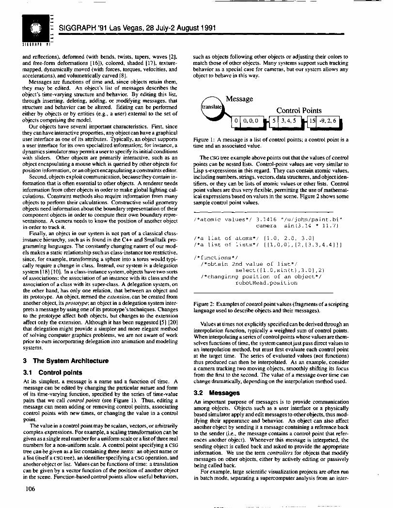
At its simplest, a message is a name and a function of time. Amessage can be edited by changing the particular nature and formof its time-varying function, specified by the series of time-valuepairs that we call control poinfs (see Figure 1). Thus, editing amessage can mean adding or removing control points, associatingcontrol points with new times, or changing the value in a controlpoint.
The value in a control point maybe scalars, vectors, or arbitrarilycomplex expressions. For example, a scaling transformation can begiven as a single real number for a uniform scale or a list of three realnumbers for a non-unifotm scale. A control point specifying a CSGtree can be given as a list containing threeitems: an object name ora list (itself a CSGtree), anidentifierspecifying a CSGoperation, andanother object or list. Values can be functions of time: a translationcan be given by a vector function of the position of another objectin the scene. Function-based control points allow useful behaviotw
106
such as objects following other objects or adjusting their colors tomatch those of other objects. Many systems support such trackingbehavior as a special case for cameras, but our system allows anyobject to behave in this way.
n Message
Control Points
Figure 1: A message is a list of control points; a control point is atime and an associated value.
The CSGtree example above points out that the values of controlpoints can be nested lists. Control-point values are very similar toLisp s-expressions in this regard. They can contain atomic values,including numbers, srnngs, vectors, data structures, and object iden-tifiers, or they can be lists of atomic values or other lists. Controlpoint values are thus very flexible, permitting the use of mathemat-ical expressions based on values in the scene. Figure 2 shows somesample control point values.
/*atomic values*/ 3.1416 “/u/j ohn/paint .bi”camera sin (3.14 * 11.7)
/*a list of atoms*/ [1.0, 2.0, 3.01/*a list of lists*/ [[1, 0,0], [2, [3.3,4.4]]]
/*functions*//*obtain 2nd value of list*/
select ([l.O, sin(t) ,3.0], 2)/*changing position of an object*/
robot Head. pos i t i on
Figure 2: Examples of control point values (fragments of a scriptinglanguage used to describe objects and their messages).
Values at times not explicitly specified can be derived through aninterpolation function, typically a weighted sum of contrul points.When interpolating a series of control points whose values are them-selves functions of time, the system cannot just pass direct values toan interpolation method, but must first evaluate each control pointat the target time. The series of evaluated values (not functions)thus produced can then be interpolated. As an example, considera camera tracking two moving objects, smoothly shifting its focusfrom the first to the second. The value of a message over time canchange dramatically, depending on the interpolation method used.
3.2 Messages
An important purpose of messages is to provide communicationamong objects. Objects such as a user interface or a physicallybased simulator apply and edit messages to other objects, thus mod-ifying their appearance and behavior. An object can also affectanother object by sending it a message containing a reference backto the sender (i.e., the message contains a control point that refer-ences another object). Whenever this message is interpreted, thesending object is called back and asked to provide the appropriateinformation. We use the term controllers for objects that modifymessages on other objects, either by actively editing or passivelybeing called back.
For example, large scientific visualization projects are often runin batch mode, separating a supercomputer analysis from an inter-
@ @ ComDuter GraDhics, Volume 25. Number 4. JUIV1991
active visualization of the results. A simple controller could read inthe results of such batch simulations, obtaining a list of positions (orwhatever information is appropriate) and creating a list of messagesfrom it. These messages could then be given to the appropriate ob-jects, telling each how to behave in order to represent the scientificdata [6]. Other more sophisticated controllers can apply and thenedit a set of messages, adding new messages as they derive newresults. Controllers will be discussed in more detail in Section 5.
Our system has a variety of messages to support its many kinds ofobjects, Highly specialized messages can provide information for anunusual object (for example, the parameters of an implicit equationor the tolerances of a constraint solver). More general changes, suchas transformations. deformations, and dynamics (force or torque),provide a diverse class of changes applicable to more commonobjects.
3.3 Objects
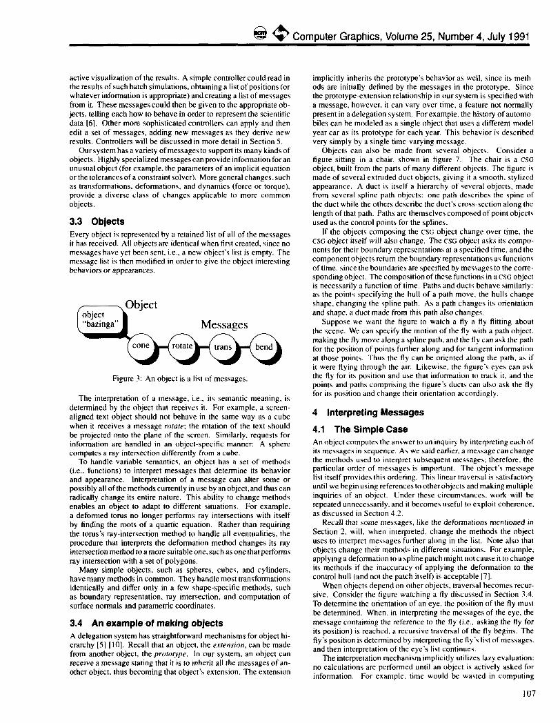
Every object is represented by a retained list of all of the messagesit has received. Allobjects are identical when first created, since nomessages have yethensent, i.e., anew object's list is empty. Themessage list isthenmodified inorder togivethe object interestingbehaviors or appearances.
Figure3: Anobject isalist of messages.
The interpretation of a message, i.e., its semantic meaning, isdetermined by the object that receives it. Forexample, a screen-aligned text object should not behave in the same way as a cubewhen it receivesa message roruw; the rotation of the text shouldbeprojected onto theplane of the screen. Similarly, requests forinformation are handled in an object-specific mannen A spherecomputes aray intersection differently from a cube.
To handle variable semantics, an object has a set of methods(i.e., functions)to interpret messages that determine its behaviorand appearance, Interpretation of a message can alter some orpossibly all of the methods currently in use by an object, and thus canradically change its entire nature, This ability to change methodsenables an object to adapt to different situations. For example,a deformed torus no Ionger performs ray intersections with itselfby finding the roots ofaquartic equation. Rather than requiringthe torus’s ray-intersection method to handle all eventualities, theprocedure that interprets the deformation method changes its rayintersection method to a more suitable one, such as one that performsray intersection with a set of polygons.
Many simple objects, such as spheres, cubes, and cylinders,have many methods in common. They handle most transformationsidentically and differ only in a few shape-specific methods, suchas boundary representation, ray intersection, and computation ofsurface normals and parametric coordinates.
3.4 Anexample ofmaking objects
A delegation system has straightforward mechanisms for object hi-erarchy [5] [10]. Recall that anobject. theex[ensimr, can bernadefrom another object, theprorofype. In our system, an object canreceive a message stating that it is to inherit all the messages of an-other object, thus becoming that object’s extension. The extension
implicitly inherits the prototype’s behavior as well, since its meth -ods are initially defined bythe messagesin the prototype. Sincethe prototype-extension relationship in our system is specified withamessage, however. it can vary overtime, a feature not normallypresent inadelegation system. Forexample, thehistory ofautomo-biles can be modeled as a single object that uses a different modelyearcar asitsprototype for each year. This behavior is describedvery simply by a single time-varying message,
Objects can also be made from several objects. Consider afigure sitting in a chair, shown in figure 7. The chair is a CSG
object, built from the parts ofmany different objects. The tigure ismade ofseveral extruded duct objects, giving it a smooth, stylizedappearance. A duct is itself a hierarchy of several objects, madefrom several spline path objects: onepathdescnbes the spine ofthe duct while the others describe the duct’s cross-section along theIengthofthat path. Paths arethemselves composed ofpoint objectsused as the control points for the splines.
lftheobjects composing the CStlobject change overtime, theCSGobject itself will also change. The CsGobject asks itscompc-nents for their boundary representations at a specified time, and thecomponent objects return the boundary representations as function~of time. since the boundaries are specified by messages to the corre -spondingobject. Thecomposition of these functions inacsc objectisnecessarily afunction of time. Paths andducts behave similarly:as the points specifying the hull of a path move, the hulls changeshape, changing the spline path. As a path changes its orientationandshape, aduct made from this path also changes.
Suppose we want the figure to watch a fly a fly flitting aboutthe scene. Wecanspecify themotionof the fly with a path object.making the fly move along a spline path. and the fly can ask the pathfor the position of points further along and for tangent informationat those points. Thus the fly can be oriented along the path, as ifit were flying through the air. Likewise, the figure’s eyes can askthe fly forits position and use that information to track it, and thepoints and paths comprising the tigure’s ducts can also ask the flyfor its position and change their orientation accordingly.
4 Interpreting Messages
4.1 The Simple Case
An object computes the answer to an inquiry by interpreting each ofits messages in sequence. As we said earlier, a message can changethe methods used to interpret subsequent messages: therefore, theparticular order of messages is important. The object’s messagelist itself provides this ordering. This linear traversal is satisfactoryuntil we begin using references to other objects and making multipleinquiries of an object. Under these circumstances, work will berepeated unnecessarily, and it becomes useful to exploit coherence.as discussed in Section 4.2.
Recall that some messages, like the deformations mentioned inSection 2, will, when interpreted, change the methods the objectuses to interpret messages further along in the list, Note also thatobjects change their methods in different situations. For example,applying a deformation to a spline patch might not cause it to changeits methods if the inaccuracy of applying the deformation to thecontrol hull (and not the patch itself) is acceptable [7].
When objects depend on other objects. traversal becomes recur-sive. Consider the figure watching a fly discussed in Section 3.4.To determine the orientation of an eye, the position of the fly mustbe determined. When. in interpreting the messages of the eye, themessage containing the reference to the fly (i.e., asking the fly forits position) is reached, a recursive traversal of the fly begins. Thefly’s position is determined by interpreting the fly’s list of messages.and then interpretation of the eye’s list continues.
The interpretation mechanism implicitly utilizes lazy evaluation:no calculations are performed until an object is actively asked forinformation. For example, time would be wasted in computing
107
SIGGRAPH ’91 Las Veqas, 28 JuIY-2 Auwst 1991
polygonal boundary representations of CSG objects if all inquiriesconcerned the tree hierarchy of the object. We use lazy evaluationand the caching scheme described next to simultaneously avoid un-necessary computation and exploit inter- and intra-frame coherency.
4.2 Caching
Messages can be used to store arbitrary information. Objects cansend messages to themselves in order to cache useful but computa-tionally expensive data. Since such data is a function of time andmessages are also functions of time, messages are an appropriatemechanism for data caching.
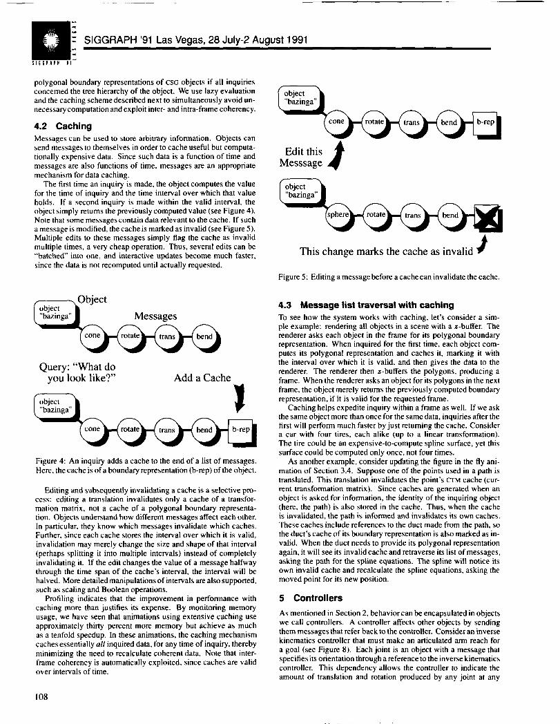
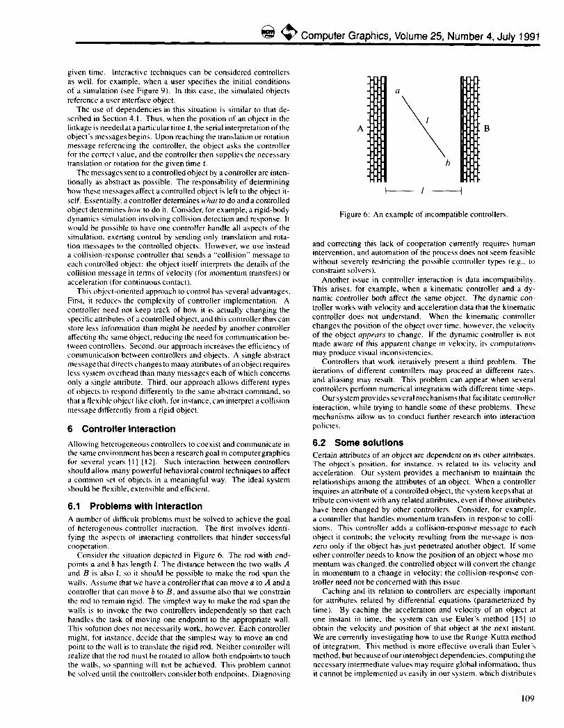
The first time an inquiry is made, the object computes the valuefor the time of inquiry and the time interval over which that valueholds. If a second inquiry is made within the valid interval, theobject simply returns the previously computed value (see Figure 4).Note that some messages contain data relevant to the cache. If sucha message is modified, the cache is marked as invalid (see Figure 5).Multiple edits to these messages simply flag the cache as invalidmultiple times, a very cheap operation. Thus, several edits can be“batched’ into one, and interactive updates become much faster,since the data is not recomputed until actually requested.
%
Ouerv: “What do‘yo~ look like?” Add a Cache
!b-rep
Figure 4: An inquiry adds a cache to the end of a list of messages.Here, the cache is of a boundary representation (b-rep) of the object.
Editing and subsequently invalidating a cache is a selective pro-cess: editing a translation invalidates only a cache of a transfor-mation matrix, not a cache of a polygonal boundary representa-tion. Objects understand how different messages affect each other.[n particular, they know which messages invalidate which caches.Further, since each cache stores the interval over which it is valid,invalidation may merely change the size and shape of that intewal(perhaps splitting it into multiple intervals) instead of completelyinvalidating it. If the edit changes the value of a message halfwaythrough the time span of the cache’s interval, the interval will behalved. More detailed manipulations of intervals are also supported,such as scaling and Boolean operations.
Profiling indicates that the improvement in performance withcaching more than justifies its expense. By monitoring memoryusage, we have seen that animations using extensive caching useaPPmximately thirty percent more memory but achieve as muchas a tenfold speedup. In these animations, the caching mechanismcaches essentially all inquired data, for any time of inquiry, therebyminimizing the need to recalculate coherent data. Note that inter-frame coherency is automatically exploited, since caches are validover intervals of time.
*
Edit thisMesssage #
Ab-rep
This change marks the cache as invalid $
Figure 5: Editing a message before a cache can invalidate the cache.
4.3 Message list traversal with caching
To see how the system works with caching, let’s consider a sim-ple example: rendering all objects in a scene with a z-buffer. Therenderer asks each object in the frame for its polygonal boundaryrepresentation. When inquired for the first time, each object com-putes its polygonal representation and caches it, marking it withthe interval over which it is valid, and then gives the data to therenderer. The renderer then z-buffers the polygons, producing aframe. When the renderer asks an object for its polygons in the nextframe, the object merely returns the previously computed boundaryrepresentation, if it is valid for the requested frame.
Caching helps expedite inquiry within a frame as well. If we askthe same object more than once for the same data, inquiries after thefirst will perform much faster by just returning the cache. Considera car with four tires, each alike (up to a linear transformation).The tire could be an expensive-to-compute spline surface, yet thissurface could be computed only once, not four times.
As another example, consider upd’sting the figure in the fly ani-mation of Section 3.4. Suppose one of the points used in a path istranslated. This translation invalidates the point’s CTMcache (cur-rent transformation matrix). Since caches are generated when anobject is asked for information, the identity of the inquiring object(here, the path) is also stored in the cache. Thus, when the cacheis invalidated, the path is informed and invalidates its own caches.These caches include references to the duct made from the path, sothe duct’s cache of its boundary representation is also marked as in-valid. When the duct needs to provide its polygonal representationagain, it will see its invalid cache and retraverse its list of messages,asking the path for the spline equations. The spline will notice itsown invalid cache and recalculate the spline equations, asking themoved point for its new position.
5 Controllers
As mentioned in Section 2, behavior can be encapsulated in objectswe call controllers. A controller affects other objects by sendingthem messages that refer back to the controller. Consider an inversekinematics controller that must make an articulated arm reach fora goal (see Figure 8). Each joint is an object with a message thatspecifies its orientation through a reference to the inverse kinematicscontroller. This dependency allows the controller to indicate theamount of translation and rotation produced by any joint at any
108
@ @ Computer Graphics, volume 25, Number 4, July 1991
given time. Interactive techniques can be considered controllersas well, for example, when a user specifies the initial conditionsof a simulation (see Figure 9). In this case, the simulated objectsreference a user interface object.
The use of dependencies in this situation is similar to that de-scribed in Section 4.1, Thus. when the position of an object in thelinkage is needed at a particular time t, the serial interpreta~ion of theobject’s messages begins. Upon reaching the translation or rotationmessage referencing the controller, the object asks the controllerfor the correct value. and the controller then supplies the necessarytranslation or rotation for the given time t.
The messages sent to a controlled object by a controller are inten-tionally as abstract as possible. The responsibility of determininghow these messages affect a controlled object is left to the object it-self, Essentially, a controller determines M>//atto do and a controlledobject determines ltmr to do it. Consider, for example, a rigid-bodydynamics simulation involving collision detection and response, Itwould be possible to have one controller handle all aspects of thesimulation. exerting control by sending only translation and rota-tion messages to the controlled objects. However, we use insteada collision-response controller that sends it “collision” message toeach controlled object: the object itself interprets the details of thecollision message in terms of velocity (for momentum transfers) oracceleration (for continuous contact).
This object-oriented approach to control has several advantages.First, it reduces the complexity of controller implementation. Acontroller need not keep track of how it is actually changing thespecitic attributes of a controlled object, and this controller thus canstore less information than might be needed by another controlleraffecting the same object, reducing the need for communication be-tween controllers. Second, our approach increases the efficiency ofcommunication between controllers and objects. A single abstrdctmessage that directs changes to many attributes of an object requiresless system overhead than many messages each of which concernsonly a single imribute. Third. our approach allows different typesof objects to respond differently to tbe same abstract command, so(hai a flexible object like cloth, for instiotce, can interpret a collisionmessage ditierently from a rigid object,
6 Controller Interaction
Allowing heterogeneous controllers to coexist and communicate inthe same environment has been a research goal in computer graphicsfor several years [1] [12]. Such interaction between controllersshould allow many powerful behavioral control techniques to affecta common set of objects in a meaningful way, The ideal systemshould be flexible. extensible and efficient.
6.1 Problems with interaction
A number of difficult problems must be solved to achieve the goalof heterogeneous controller interaction. The first involves identi-fying Ihe aspects of interacting controllers that hinder successfulcooperation.
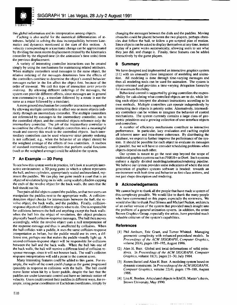
Consider the situation depicted in Figure6. The rod with end-points aandbhaslengthl. Thedistance between thetwowallsdand B is also 1, so it should bepossible to make the rod span thewalls, Assume that we have d controller that can move a to A and acontroller that can move b to B, and assume also that we constrainthe rod to remain rigid, The simplest way to make the rod span theWUIISis to invoke the two controllers independently so that eachhandles the task of moving one endpoint to the appropriate wall.This solution does not necessarily work, however. Each controllermight, for instance, decide that the simplest way to move an end-point to tbe wall is to tmnslate the rigid rod. Neither controller willrealize that the rod must be rotated to allow both endpoints to touchthe walls, so spanning will not be achieved. This problem cannotbe solved until tbe controllers consider both endpoints. Diagnosing
A
I
u
\
1
h
Figure 6: An example of incompatible controllers.
and correcting this lack of cooperation currently requires humanintervention, and automation of the process does not seem feasiblewithout severely restricting the possible controller types (e.g., toconstraint solvers).
Another issue in controller interaction is data incompatibility.This arises, for example. when a kinematic controller and a dy-namic controller both affect the same object. The dynamic con-troller works with velocity and acceleration data that the kinematiccontroller does not understand. When the kinematic controllerchanges the position of the object over time. however. the velocityof the object appears to change. If the dynamic controller is notmade aware of this apparent change in velocity, its computationmay produce visual inconsistencies.
Controllers that work iteratively present a third problem. Theiterations of different controllers may proceed at different rates.and aliasing may result. This problem can appear when severalcontrollers perform numerical integration with different time step~.
Our system provides several mechanisms that facilitate controllerinteraction, while trying to handle some of these problems. Thesemechanisms allow us to conduct further research into interactionpolicies.
6.2 Some solutions
Certain attributes of an object are dependent on its other attributes.The object’s position, for instance, is related to its velocity andacceleration. Our system provides a mechanism to maintain therelationships among the attributes of an object. When a controllerinquires an attribute of a controlled object, the system keeps that at-tribute consistent with any related attributes, even if those attributeshave been changed by other controllers. Consider, for example,a controller that handles momentum transfers in response to colli-sions. This controller adds a collision-response message to eachobject it controls; the velocity resulting from the message is non-zero only if the object has just penetrated another object. If someother controller needs to know the position of an object whose mmmentum was changed, the controlled object will conven the changein momentum to a change in velocity; the colli>ion-response con-troller need not be concerned with this issue.
Caching and its relation to controllers are especially importantfor attributes related by differential equations (parametenzed bytime). By caching the acceleration and velocity of an object atone instant in time, the system can use Euler’s method [15] toobtain the velocity and position of that object at the next instant.We are currently investigating how to use the Runge-Kutta methodof integration. This method is more effective overall than Euler’smethod. but because of our interobject dependencies, computing thenecessary intermediate values may require global information: thusit cannot be implemented as easily in our system, which distributes
I09
I!l%<..
sl!6n APHtl -
SIGGRAPH ’91 Las Vegas, 28 July-2 August 1991
this global information and its interpretation among objects.Caching is also useful for the numerical differentiation of at-
tributes, helpful in solving the data incompatibility between kine-matics and dynamics mentioned at the start of this section. Avelocity corresponding to a kinematic change can be approximatedby dividing the most recent displacement created by the kinematicscontroller by the elapsed time (in the animation’s time units) fromthe previous displacement.
A variety of interesting controller interactions can be createdsimply by using the mechanisms for maintaining related attributes.When multiple controllers send messages to the same object, therelative ordering of the messages determines how the effects ofthe controllers combine to determine the object’s overall behaviocmessages earlier in the list affect the object first, because of theorder of traversal. We call this type of interaction srrict priorityordering. By allowing different orderings of the messages, thesystem can provide different effects, since messages are in generalnon-commutative (e.g., a translate followed by a rotate is not thesame as a rotate followed by a translate).
A more general mechanism for controller interaction is supportedby allowing multiple controllers to affect one or more objects indi-rectly through an intermediary controller. The multiple controllersare referenced by messages to the intermediary controller, not tothe controlled object, and the controlled objects reference only theintermediary controller. The job of the intermediary controller isto combine the effects of the multiple controllers into a meaningfulresult and convey this result to the controlled objects. Such inter-mediary controllers can be used whenever strict priority orderingis not sufficient, e.g., when the behavior of an object should bethe weighted average of the effects of two controllers. A toolboxof standard intermediary controllers that perform useful functions(such as the weighted average) could be added to the system.
7 An Example — 3D Pong
To see how this system works in practice, let’s look at a sample inter-active environment: a 3D pong game in which a sphere representsthe ball, and two cylinders, appropriately scaled and translated, rep-resent the paddles. We can play our game inside a court that is anobject of revolution lying on its side, using scaled cylinders cappingthe ends of the revolve object for the back walls, the ones that theball should not hit.
Two pairs of dial objects control the paddles, so that two users canmanipulate the paddles next to the appropriate walls. A collision-detection object checks for intersections between the ball, the re-volve object, the back walls, and the paddles. Finally, collision-response objects tell different objects what to do, One is responsiblefor collisions between the ball and anything except the back walls:when the ball hits the object of revolution, this object producesphysically based collision-response messages. The ball then movesaccordingly, while the revolve object uses a null interpretation ofthe response message and thus is unaffected by collisions. Whenthe ball collides with a paddle, it uses the same collision-responseinterpretation as before, but the paddle would use its own, a dif-ferent one, perhaps one that makes the paddle visually light up. Asecond collision-response object will be responsible for collisionsbetween the ball and the back walls. When the ball hits one ofthe back walls, the ball will receive a different kind of collision re-sponse message, since it will not bounce back. The wall’s collisionresponse interpretation will add a point to the current score.
Many interesting features could be added to this game. For ex-ample, the walls of the court could change as the game progressed(possibly in response to collisions with the ball). The ball couldmove faster when hit by a faster paddle, despite the fact that thepaddles are under kinematic control and have no intrinsic notion ofvelocity. Users could control their paddles in different ways, for ex-ample, using polar coordinates or Euclidean coordinates, simply by
changing the messages between the dials and the paddles. Movingobstacles could be placed between the two players, perhaps obsta-cles that follow the ball, or follow a pre-scnpted plan of motion.Since objects can be asked to display themselves at any time, instantreplay of a game works automatically, allowing users to see whatthey just did, and change it. Finally, these features can be addedinteractively by the game players.
8 Summary
We have designed and implemented an interactive graphics system[11 ] with an unusually close integration of modeling and anima-tion. All modeling is done through time-varying messages andthus all modeling tools can be used for animation. The system isobject-oriented and provides a time-varying delegation hierarchyfor maximum flexibility.
Behavioral control is supported by giving controllers the respon-sibility for calculating what controlled objects are to do, while let-ting each object interpret the abstract instructions according to itsown methods. Multiple controllers can operate independently byinstructing their objects in priority order. Alternatively, intenrtedi-ary controllers can be written to integrate the behavior of controlmechanisms. The system currently contains a large class of geo-metric primitives and a growing collection of user-interface objectsand controllers.
A number of efficiency mechanisms contribute to interactiveperformance. In particular, lazy evaluation and caching exploitall inherent inter- and intra-frame coherence. By distributing thedatabase, we expect to further improve the performance of the sys-tem. It should be possible for each object to evaluate its messagesin parallel, but we will have to consider scheduling problems whenobjects depend on each other.
Our system is meant to go the next step beyond the scope oftraditional graphics systems such as PHIGS+ or Dor& Such systemsenforce a rigidly divided modeiingfanimation/rendering pipeline.We believe our system provides some indications of where the nextgeneration of graphics systems software is headed: towards anenvironment with both time and behavior as first-class notions, andnot just shape description and rendering.
9 Acknowledgements
We cannot begin to thank all the people that have made a system ofthis complexity possible. We would like to thank the many peoplewho have commented on this paper, especially the reviewers. Wewould also like to thank Paul Strauss and Michael Natkin, architectsof an earlier version of the system that provided much insight intothe problem of a general animation system. In addition, the entireBrown Graphics Group, especially the artists, have provided muchvaluable criticism of the system’s capabilities.
References
[1]
[2]
[3]
[4]
Phil Ambum, Eric Grant, and Turner Whitted. Managinggeometric complexity with enhanced procedural models. InProceedings of the ACM SIGGRAPH, Computer Graphics,volume 20(4), pages 189-195, August 1986.
Alan H. Barr. Global and local deformations of solid prim-itives. In Proceedings of the ACM SIGGRAPH, ComputerGraphics, volume 18(3), pages 2 1–30, July 1984.
Ronen Barzel and Alan H. Barr. A modeling system based ondynamic constraints. In Proceedings of the ACM SIGGRAPH,Compurer Graphics, volume 22(4), pages 179–I 88, August1988.
Lisa K. Borden. Articulated objects in BAGS. Master’s thesis,Brown University, May 1990.
110
@ @ Computer Graphics, Volume 25, Number 4, July 1991
[5] A. H, Boming. Classes versus prototypes in object-orientedlanguages. In IEEEIACM Fall Joint Computer Conference,pages 36-40, 1986.
[6] Ingfei Chen and David Busath. Animating a ceIIular transpotlmechanism. Pixel Magazine, 1(2), 1990.
[7] Gerald Farin. Curves and Surfaces for Computer-Aided Gee-memic Design. Academic Press, second edition, 1990.
[8] Tinsley A. Galyean. Sculpt: Interactive volumetric modeling.Master’s thesis, Brown University, May 1990.
[9] Andrew Glassner, editor. Graphics Gems. Academic Press,1990,
[10] Brent Halperin and Van Nguyen. A model for object-basedinheritance. In Peter Wegner and Bruce Shriver, editorx, Re-search Directions in Object-Oriented Programming. The MITpreSS, 1987.
[11 ] Philip M. Hubbard, Matthias M. Wloka, Robert C. Zeleznik,Daniel G. Aliaga, and Nathan Huang. UGA: A unified graph-ics architecture. Technical Report CS-91 -30, Brown Univer-sity, 1991.
[12] Devendra Kalra. A Un@ed Framework for Constraint-BasedModeling. PhD thesis, California Institute of Technology,1990.
[13] Matthew Moore and Jane Wilhelms. Collision detection andresponse for computer animation. In Proceedings ofrhe ACMSIGGRAPH, Computer Graphics, volume 22(4), pages 289-298, August 1988,
[14] Cary B. Phillips, Jianmin Zhao, and Norman I. Badler. hrter-active real-time articulated figure manipulation using multiplekinematic constraints. In Proceedings of the Symposium oninteractive 3D Graphics, pages 245-250, 1990.
[15] William H. Press, Brian P. Flannery, Saul A. Teukolsky, andWilliam T. Vetterling. Numerical Recipes in C. CambridgeUniversity Press, 1988.
[ 16] T. W. Sederberg and S. R. Parry. Free-form deformation ofsolid geometric models. In Proceedings of the ACM SIG-GRAPH, Computer Graphics, volume 20(4), pages 151-160,August 1986.
[17] Paul S. Strauss. A realistic lighting model for computer an-imators. IEEE Computer Graphics and Applications, 10(6),November 1990.
[18] Peter Wegner. The object-oriented classification paradigm. InPeter Wegner and Bruce Shriver, editors, Research Directionsin Object-Oriented Programming. The MIT Press, 1987.
[19] Jerry Weil. A simplified approach to animating cloth objects.Unpublished report written for Optomystic, 1988.
[20] Peter Wisskirchen. Object-Oriented Graphics. Springer-Verlag, 1990.
[2 1] N. Yankelovich, N. Meyrowitz, and Andries van Dam. Read-ing and writing the electronic book. fEEE Computer, 18(10),October 1985.
111
: SIGGRAPH ‘91 Las Vegas, 28 July-2 August 1991
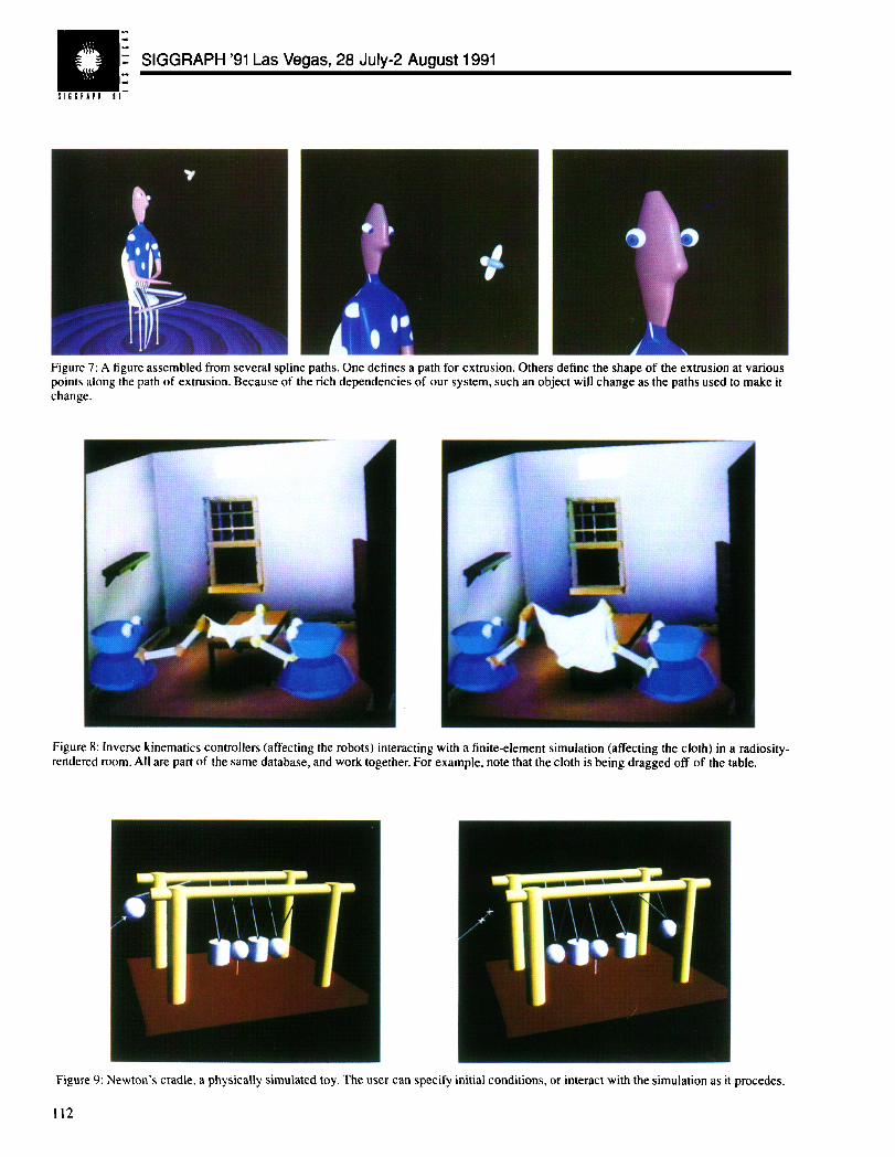
Figure 7: A figure assembled from several spline paths. One defines a path for extrusion. Others define the shape of the extrusion at variouspoints along the path of extrusion. Because of the rich dependencies of our system, such an object will change as the paths used to make itchange.
Figure 8: Inverse kinematics controllers (affecting the robots) interacting with a finite-element simulation (affecting the cloth) in a mdiosity-rendered room. All are part of the same database, and work together. For example, note that the cloth is being dragged off of the table.
Figure 9: Newton’s cradle, a physically simulated toy. The user can specify initial conditions, or interact with the simulation as it procedes.
112