
An introduction to physics
248
AN INTRODUCTION m\ PHYSICS FOR TECHNICAL STUDENTS HALER and STUART
-
Upload
khangminh22 -
Category
Documents
-
view
0 -
download
0
Transcript of An introduction to physics

AN INTRODUCTION
m\ PHYSICSFOR TECHNICAL STUDENTS
HALER and STUART


AN INTRODUCTION TO PHYSICS
FOR TECHNICAL STUDENTS


AN INTRODUCTION TO
PHYSICSFOR TECHNICAL STUDENTS
BY
P. J. HALER, M.B.E., B.Sc., MEM.AM.Soc.M.E.,
A.M.I.MECH.E., A.I.E.E.
PRINCIPAL, LEYTON TECHNICAL INSTITUTE ; SUPERVISOR OF EVEHING STUDIES,LEYTON ; JOINT AUTHOR OF " A FIRST COURSE IN ENGINEERING SCIENCE,"
" A FIRST COURSE IN MATHEMATICS FOR TECHNICAL STUDENTS,"" A SECOND COURSE IN MATHEMATICS FOR TECHNICAL STUDENTS "
AND
A. H. STUART, B.Sc., F.R.A.S.
DEPUTY HEAD MASTER, DAY TECHNICAL SCHOOL, L.C.C. HACKNEY INSTITUTHJ
JOINT AUTHOR OF " A FIRST COURSE IN ENGINEERING SCIENCE,"" A FIRST COURSE IN MATHEMATICS FOR TECHNICAL STUDENTS,"" A SECOND COURSE IN MATHEMATICS FOR TECHNICAL STUDENTS "
LONDON
TTfoe niibrars press Olimitefc
26, PORTUGAL STREET, W.C. 2
1921

THE LONDON AND NORWICH PRESS, LIMITED, LONDON AND NORWICH, ENGLAND

PREFACE
PHYSICS is generally acknowledged to be essential to the
equipment of every technical student, and the subject forms
part of the curriculum of most Junior Day Technical Schools
and Trade Schools.
In the following pages a scheme of the subject is developed,which forms a two-year course when two or three hours a
week are devoted to the subject.
Since most technical students take Applied Mechanicsand Electricity as separate subjects, the portions of Physics
usually treated under .these heads have been purposelyomitted from this course and thus the danger of overlappinghas been avoided.
Apart from these omissions the whole of the elements of
the subject have been passed under review, and if the treat-
ment of certain portions is brief, it is hoped that the breadthof outlook which the student derives from such a runningsurvey will be considered sufficient compensation.
The experimental work has been confined to such as
requires only the very simplest apparatus. Home-madeappliances have a very distinct advantage over the more
professional type at this stage of the student's work.
Sections I., II., and III. form a suitable course for the
first year, and Sections IV. and V. may be completed duringthe second year.
As one of the authors is in the employment of the London
County Council it is necessary in accordance with regulationsto state that the London County Council is in no way re-
sponsible for the contents of this book.P.J.H.
August, 1921. A. H. S.

A FOREWORD TO THE STUDENT
MANY students of all ages and of all types show a marked
tendency to regard certain subjects as being "useful," andothers as being the reverse. No policy could have a moresinister influence on progress or place such a final limit onthe student's actual usefulness in his vocation.
If any of the great discoveries or inventions which haverevolutionised civilisation be examined and tracked backto its source, we invariably find a man working in some
apparently quite useless field of research, with no object in
view other than the acquisition of knowledge. Utility neverenters his head, for the stage of the work engaging his immedi-ate attention is such that no living man is in a position to
say what is"useful
" and what is not. The useless of to-daymay be of paramount importance to-morrow.When Volta in 1800 made his voltaic pile and obtained
a feeble current of electricity, and Oersted in 1820 discoveredthe action of a current on a magnet ; when Davy in 1821demonstrated the power of a current to magnetise steel, and
Faraday in 1831 showed that a current in one circuit couldinduce a current in another circuit, no one could foretell
that these discoveries would lead to the production of a
dynamo which, when rotated at Chelsea, could propel anelectric train at Hampstead.The contemporaries of the pioneers just mentioned may
have said to them :
" This is all very interesting, but whatis the use of it ?
"If they had answered :
" In less than a
century these principles will enable a man in London to
speak to a man in Paris," they would have been laughed at.
Again, we may note that great discoveries and inventionshave seldom if ever been made by one man. They are all
8 A FOREWORD TO THE STUDENT
the results of the cumulative efforts of many workers. Wegenerally associate the steam turbine with the name of
Parsons, yet the turbine was only made possible by the
development of the thermo-dynamics of steam carried out
by Kelvin, Rankin, and others.
The course of Physics which is expanded in the following
pages is intended for technical students, chiefly those associ-
ated with engineering. Yet its object is not to teach engi-
neering ;it is not primarily to teach physics. The object
which Ihe authors have had constantly in mind is to giveto the student the outlook of a physicist upon engineering.
Education in any sphere does not consist in committinga number of facts to memory : it aims at producing an outlook
on life or an attitude of mind. The mental attitude of a
physicist is one of quantitative observation. He looks out
on Nature and measures what he sees, and as physics deals
chiefly with the sources of energy, it has, in the past, con-
tributed much of value to engineering, and doubtless has moreto offer in the future.

CONTENTSPAOB
A FOREWORD TO THE STUDENT . . 7
LIST OF TABLES OF PHYSICAL CONSTANTS. . . 10
SECTION I. THE PROPERTIES OF MATTERCHAPTER
I. UNITS.OF MEASUREMENT . . . .11II. PROPERTIES OF SOLIDS .... 20
III. PROPERTIES OF LIQUIDS .... 28IV. PROPERTIES OF GASES . . . .44
SECTION II. PERIODIC MOTIONV. SIMPLE HARMONIC MOTION.... 64
SECTION III. SOUNDVI. VIBRATION AND THE MUSICAL SPALE . . 77VII. HARMONICS AND RESONANCE ... 88VIII. VIBRATION OF REEDS AND GAS COLUMNS . 94
SECTION IV. LIGHTIX. PHOTOMETRY . . . . . .104X. REFLECTION 112XI. REFRACTION . . . . . .121XII. IMAGES 132
SECTION V. HEATXIII. THERMOMETRY ..... . 146XIV. EXPANSION OF MATTER BY HEAT . .161XV. SPECIFIC HEAT 180XVI. LATENT HEAT 195XVII. CONDUCTION, CONVECTION, AND RADIATION . 210XVIII. THE CONSERVATION OF ENERGY . . 222
ANSWERS ....... 233INDEX 239

LIST OF TABLES OF PHYSICALCONSTANTS
PAGE
UNITS -. 15
EQUIVALENT VALUES 15
VOLUME OF REGULAR SOLIDS . . . . .21THE MUSICAL SCALE . . . . . .81REFRACTIVE INDICES . . . . . .127
TEMPERATURES . . . . . . .157
SPECIFIC HEATS (METAJLS) 186
SPECIFIC HEATS (GASES) . . . . . .187
RATIO OF SPECIFIC HEATS OF GASES . . .188
VAPOUR PRESSURE OF WATER .... 202
THERMAL CONDUCTIVITIES . . . . .211
CALORIFIC VALUES OF FUELS 227

AN INTRODUCTION TO PHYSICS
SECTION L THE PROPERTIES OF MATTER
CHAPTER I
UNITS OF MEASUREMENT
Units. Physics is the science in which the properties of
matter and the properties of energy are investigated quanti-
tatively. All measurement involves a comparison betweenthe thing to be measured and some standard quantity of the
same nature, this standard being called the"unit."
It is very desirable that the number of different units
employed in our measurements should be as small as possible,and it will be a further advantage if new units, as they become
necessary, are made to depend upon those already in use.
Fundamental Units. A fundamental unit is one whichis necessarily independent of the others. For example,length is a measurement of a fundamental nature. In this
country the unit of length defined by Act of Parliament is the
yard. Multiples or submultiples of this are, of course, em-
ployed according to the magnitude of the thing to be measured.The foot (i.e., one third of a yard) is frequently employed in
scientific measurement.Another unit of length (defined by the law of France) is
the metre. One hundredth part of this, called a centimetre,is the unit of length adopted in many physical measurements.
Mass, the amount of matter in a body, is another funda-mental unit. The units of mass commonly used are the
pound (in the British system) and the gramme (in the metric
system).Time is another fundamental idea of which we require
a unit. In physics the second, which is 8 ei 00 * a mean s lar
day, is universally used.
11

12 AN INTRODUCTION TO PHYSICS
Derived Units. The units just described deal with three
quite independent ideas. If, however, we turn to ideas of
area and volume it is unnecessary to define new independentunits, for these quantities can be measured by the repeateddetermination of length. Thus for area we naturally usethe square foot or the square centimetre as a unit, while thecubic foot or the cubic centimetre is a suitable unit of volume.These are called derived units.
The^e are a great many derived units, for experience hasshown that almost anything may be measured in units
derived from the fundamental units of length, mass, andtime.
These derived units may be divided into two classes.
(1) Those using the foot, the pound, and the second,
belong to the"F.P.S. system."
(2) Those using the centimetre, the gramme, and the second,
belong to the C.G.S. "system."
Weight and Mass. If we take a 1 Ib. weight we may saythat it contains one pound of matter. If we hang it on a
spring balance the latter records the fact that this piece of
matter "weighs
" one pound.Suppose we take the arrangement on to a lift. As the
lift commences to rise the recorded weight of the body wouldbe more than 1 Ib., while as the lift was about to stop againthe balance would show a weight of less than 1 Ib.
Again, if we carried the balance and weight about the surface
of the earth, we should have recorded more than 1 Ib. near
the poles of the earth, and less than 1 Ib. near the equator.Or -yet another case. If the test were made on a high
mountain or at the bottom of a deep pit, the balance wouldindicate a weight than less 1 Ib.
It appears therefore that the weight of a body may varyfrom place to place, since it depends upon the attraction of
the earth, which is known to vary in intensity. But it is
contrary to sense for the amount of matter (or mass) to vary.In using 1 Ib. or 1 gramme as the unit of mass, the unit is
defined as the weight of a standard at a certain place and at a
certain level, such as sea level at Greenwich.
UNITS OF MEASUREMENT 13
Engineers sometimes find it convenient to use the poundas the unit of weight and g Ibs. as the unit of mass, g (the
acceleration caused by the earth's gravity) being defined
below.
Velocity. Velocity may be defined as the rate of changeof position. The units commonly employed are one foot
per second, and one centimetre per second. A velocity of
1 foot per second indicates that the body is increasing its
distance from some point of reference at the rate of one foot
in every second.
Acceleration. Acceleration is the rate of change of velocity.
Thus, if a body at a particular instant of time is movingwith a velocity of 5 feet per second, and after a period of
4 seconds its velocity has increased to 17 feet per second,the amount of change of velocity is 12 feet per second, andthis change has taken place in 4 seconds. The change has,
therefore, been at the average rate of 3 feet per second eachsecond. This is usually written : 3 feet per second persecond.
The units of acceleration commonly employed in physicsare the foot per second per second, and the centimetre persecond per second.
If a body be allowed to fall freely to the earth, its velocity
constantly increases during its fall, owing to the persistentattraction which the earth exerts. Experiment shows that,
falling freely from rest, a body acquires a velocity of about32 -2 ft. per second in the first second, and at the end of twoseconds its velocity has become 64*4 ft. per second, and so on.
Hence we see that the acceleration is at the rate of 32 -2 ft.
per second per second.
This value is generally denoted by the letter g. Measuredin C.G.S. units its value is 981 centimetres per second persecond.
Force. Force is that which tends to overcome inertia.
If one pushes or pulls at an obstacle with a force equal to
the weight of one pound, a force is exerted, but the resistance
to motion may or may not be overcome. The unit of force
14 AN INTRODUCTION TO PHYSICS
is sometimes a force equal to the weight of one pound (orone gramme).
In many cases, however, it is convenient to define the
unit of force as that which, acting on unit mass for unit
time, gives it unit velocity. From this definition it is easyto see that F=Ma, where F is the force which, acting on Munits of mass, produces in it a units of acceleration.
In the F.P.S. system this unit is called the poundal, andin the C.G.S. system it is called the dyne. It follows that
there are g poundals in a force equal to one pound, and g
dynes in a force equal to one gramme. For :
F (in poundals)=M (in lbs.)xa (in ft. per sec. per sec.),
also F (in dynes) =M (in grammes) X a (in cms. per sec. persec.).
Work. Work is done when resistance is overcome. Theunit of work is done when unit force acts through unit distance.
Thus the foot-pound is the work done by a force of one poundacting through one foot, and the foot-poundal is the workdone by a force of one poundal acting through one foot.
An erg is the C.G.S. unit of work, and is the work done bya force of one dyne acting through a distance of one centi-
metre.
Energy. Energy is that which is capable of doing work.
Thus a rotating flywheel possesses kinetic energy. A weightraised above the earth's surface possesses potential energyin virtue of its position, and this energy is converted into
kinetic energy when the body is allowed to fall to earth.
Heat is a form of energy which is converted into kinetic
energy by a steam or internal combustion engine, and electri-
city is another form of energy which may be converted into
heat by a resistance or into kinetic energy by an electric
motor. Coal and petrol both possess chemical energy, whichis converted into heat by combustion.
$IEnergy may be measured in the same units as work, since
the*energy of a body is expressed by the amount of work it
can do.

UNITS OF MEASUREMENT 15
COLLECTED RESULTS.
Units of the Units of theC.G.S. System. F.P.S. System.
Length . . Centimetre. Foot.
Mass . . Gramme. Pound.
Time . . Second. Second.
Area . . Sq. cm. Sq. ft.
Volume . . Cub. cm. Cub. ft.
Velocity . . Cm. per sec. Ft. per sec.
Acceleration . Cm. per sec. per sec. Ft. per sec. per sec.
Force . . Dyne. Poundal.
Work . . Erg. Ft.-poundal.
Energy . . Erg. Ft.-poundal.
N.B. The poundal and the foot-poundal are the true
F.P.S. units of force and work respectively, although the
pound and the foot-pound are often used by engineers.
EQUIVALENT VALUES.
Length .
Mass
Area
Volume .

16 AN INTRODUCTION TO PHYSICS
Ex. 1. Express a velocity of 50 miles per hour in feet persecond and cms. per second.
Space
__50 miles
1 hour.
^50x1760x3 ft.
60x60 sees.
=73*3 ft. per sec.
Again 73*3 ft. ^73-3x30 '48 cms.
1 sec. 1 sec.
=2235 cms. per sec.
Ex. 2. At a given instant a train is travelling with a
velocity of 24 miles per hour. Five minutes later the velocityis 46 miles per hour. Express the acceleration in (a) miles
per hour per hour, (b) feet per second per second, (c) cms. persecond per second.
The train gains 22 miles per hour in one-twentieth of anhour. The average acceleration is therefore 440 miles perhour per hour.
The student should note that while it is possible for atrain to accelerate at this rate for a few minutes, the influence
of friction is such that the acceleration cannot be maintanedfor anything like an hour and hence the train never attains
a velocity of 440 miles per hour.
440 milesNow acceleration -JT^:
--^2
(1 hour)2
_ 440x1760x3 ft.
(60x60 sees.)2
^.440x1760x3"3600x3600=0*179 ft. per sec. per sec.
Also 0-179 ft. _0-179x 30-48 cms.
"(1 sec.)2
(1 sec.)2
5*45 cms. per sec, per sec.
'
UNITS OF MEASUREMENT 17
Ex. 3. The average pressure of the atmosphere at sea
level is 14*7 Ibs. per sq. in. Express this in dynes per sq.
cm.14-7 Ibs.
Pressure= -n~ ^ 9
(1 m.)2
14-7xgXl-38xlQ4dynes
(2-54 cms,)2
_14-7 X 32-2x1 '38 xlO4dynes
6*45 sq. cms.
=l'014x 10 dynes per sq. cm.
Or approximately a million dynes per square centimetre.
Ex. 4. A weight of 7 Ibs. is raised vertically through 4 ft.
Express the work done in foot-pounds, foot-poundals, and
ergs.Work done=1 Ibs. X 4 ft.
=28 ft.-lbs.
=28x32'2ft.-pdls.=901 ft.-pdls.
=901x4-21 XlO5ergs.
=3 '8 XlO8ergs.
Exercises 1.
1. Convert the following measurements from inches to
millimetres : 1.^, 2TV, 3 T y. Check the results graphically.
2. Convert the following measurements from millimetres
to inches : 3 '175, 4 '762, 307 '97. Check the results graphic-
ally.
3. Convert the following measurements from metres to
feet: 1-1, 1-5, 3 '9.
4. Convert the following areas from square centimetres to
square inches : 1'2, 2 '6, 9 '7. Check the results graphically.
5. If 1 pound =0*45359 kilogramme, convert the follow-
ing readings in pounds to kilogrammes : I'l, 2 '5, and 4 '7.
18 AN INTRODUCTION TO PHYSICS
6. If 1 kilogramme = 2 '2046 pounds, convert the followingreadings from kilogrammes to pounds : 5*1, 6 '5, 7*7.
7. How many poundals are represented by the followingpounds weight : 1'5, 2 '8, and 3 '7 ?
8. Express a velocity of 60 miles per hour in feet per secondand centimetres per second.
9. A 'bus is travelling at the rate of 12 miles per hour.What is this velocity in feet per minute ?
10. Observations were taken to determine the velocity of
a part of a mechanism and the following results were obtained :
Time in minutes . . .012345Space passed over in inches .0 3 6 9 12 15
Plot a space-time graph. If space divided by time = velocity
(when the velocity is uniform), determine the velocity for
each minute, and plot a velocity-time graph.
11. The previous experiment was repeated on another pieceof mechanism and results were obtained as follows :
Time intervals in minutes .1 23 4
Space passed over in inches . 3'65 7 '30 10'95 14'6
Plot a graph of time and space. What is the velocity in
feet per minute for every minute ? Plot a graph of velocityand time.
12. Express a velocity of 30 miles per hour in feet per minuteand centimetres per minute.
13. A wheel of 4 ft. 3 ins. diameter makes 200 revolutions
per minute. What is the velocity of a point on the rim, in
feet per second ?
14. At a given instant a train is travelling at the rate of
30 miles per hour and 5 minutes later the velocity is 35
miles per hour. Express the average acceleration (a) in
miles per hour per hour, (6) feet per second per second, (c)
centimetres per second per second.
15. A piece of steel is stressed to 2 tons per square inch.
Express this stress in dynes per square centimetre.

4
UNITS OF MEASUREMENT 19
16. The pressure in a boiler is 100 Ibs. per square inch.
Express this in dynes per square centimetre.
17. A weight of 4 pounds is raised through a vertical heightof 8 feet. Express the work done in foot-pounds, foot-poundalsand ergs.
18. It is noted that in 65 seconds a car has travelled onekilometre. Express the velocity in kilometres per hour andmiles per hour.
CHAPTER II
PROPERTIES OF SOLlftS
Matter. Matter is generally considered as that which
possesses weight. It is conveniently divided into three
classes, known as solids, liquids, and gases.
Solids. A solid is that form of matter which may besubmitted to compression without lateral support. Thus, iron
being a solid, it is possible to take an iron cylinder, stand it
on its base and place a weight on the top. The iron is nowin compression, and, provided the weight is not excessive in
relation to the dimensions of the cylinder, no appreciabledeformation is produced.
Here we have a solid in compression without lateral sup-
port. Water, on the other hand, being a liquid, could not be
treated thus. One cannot have a"cylinder of water
"unless
the water is supported by a vessel of some solid material.
If we wish to compress a liquid or a gas it must be supportedin a tube or other vessel.
Light and Heavy Solids. Aluminium is spoken of as a
"light" metal, and lead is said to be "heavy." Both these
expressions are intended to give an indication of the weightof a piece of matter in relation to its volume. For a pound of
aluminium weighs as much as a pound of lead, but the former
occupies nearly 4| times the volume of the latter.
Specific Gravity. The specific gravity of a body is its
weight compared with the weight of an equal volume of
something else. Thus it would be legitimate to say that
the specific gravity of lead is 4|, meaning that it is 4J times
as heavy as an equal volume of aluminium. But if it were
compared with iron, the specific gravity would be only about
1J, whereas compared with platinum it would be about J.
20

PROPERTIES OF SOLIDS 21
For the numerical value of the specific gravity of a bodyto be of any practical use, it is necessary to have some standard
substance with which all other bodies may be compared.Water has been selected for this purpose and hence we have :
The Specific Gravity of a body is the weight of that body
compared with the weight of an equal volume of water.
It will be seen in Chapter XV that this definition, to be
complete, must state the temperature of the water (whichshould be at 4 C.), but the student may neglect this pointat the present stage of his work.
Density. The Density of a substance is the weight of unit
volume of that substance.
It will be seen that whereas the specific gravity of a sub-
stance has a constant numerical value, the Density will
vary with different units. Thus the specific gravity of
copper is 8*93, which means that a piece of copper weighs8 '93 times as much as an equal volume of water.
The Density of copper is 555-lbs. per cub. ft. and 0'321-lb.
per cub. in., and 8 '93 grammes per c.c. We might add to these
VOLUME OF REGULAR SOLIDS.
Solid.

22 AN INTRODUCTION TO PHYSICS
by changing the units. The student should note carefullythat specific gravities may be expressed by mere numberswithout the mention of any units, but in expressing a densitythe units employed must be stated.
From the foregoing it will be clear that in the practicaldetermination of specific gravities and densities it is only
necessary to find the volume and weight of a specimenof the material. If the specimen is a regular solid such as
a cube or a cylinder, the volume may be calculated from oneor two simple measurements.The table on p. 21 will be of use to those who are not yet
familiar with the methods employed in finding the volumesof regular solids.
Determination of Weight. The weight of a body may bedetermined in two ways :
(1) By noting the deformation of a spiral spring when the
latter is put into tension or compression by the bodyin question.
(2) By balancing it with standard weights.
In the first case the spring has usually been calibrated,and the weight is recorded by a needle passing over a gradu-ated dial.
In the second case a pair of scales and a set of weights maybe used, similar to those employed in many shops.
In either case the weight recorded is only an approximationand such methods should only be employed when a roughdetermination is required on a comparatively large quantityof matter, say a pound or two. For more accurate work achemical balance should be used.
The Balance. This instrument is similar in general prin-
ciple to that of a pair of scales, but a high degree of precisionis maintained in every detail of it. Gramme weights are gener-ally employed in connection with a balance of this nature.The student should examine carefully a balance and a boxof gramme weights and note their arrangement. In using abalance it is necessary to observe certain rules, as a balanceis such a delicate piece of mechanism that it is easily damaged.

PROPERTIES OF SOLIDS 23
RULES TO BE OBSERVED WHEN USING A BALANCE.
1. See that the box of weights is complete.2. See that the base of the balance is level as indicated
by the spirit level or plumb bob. If not, adjust the levellingscrews.
3. Never place anything on a pan or remove anythingfrom it unless the beam is resting on its supports.
4. When operating the lever which raises the beam fromits supports never make a "
jerky" movement. Endeavour
to bring the beam in contact with its supports when the
needle indicates that the beam is horizontal.
5. Raise the beam and observe the swing of the needle.
It should swing an equal number of divisions of the scale
on either side of the centre mark. If it does not do this the
balance needs adjusting by means of the screw providedfor the purpose. Students should, however, remember that
this adjustment should not frequently be necessary, and in
any case it should only be made by a person of experience.6. No substance which is at all likely to injure the balance
pan should ever be placed on the bare pan. Such substanceshould be weighed on a watch glass of known weight.
7. It is convenient to place the body to be weighed on theleft-hand pan of the balance. The weights can then be operatedby means of the forceps in the right hand, while the left
hand operates the lever which raises the beam.8. Don't guess at suitable weights. Find one which is too
heavy, after which every weight below this one should be
placed, separately, on the pan and the beam raised. The
weight is allowed to remain if the weight total is too small,and removed to the box if the weight total is too great.
9. Every weight should be either on the pan or in the box.10. Never put weights on the pan carrying the body to be
weighed. It is quite unnecessary.11. The' weights are correct when the needle swings an
equal number of divisions on either side of the centre mark.Don't wait for the beam to come to rest.
12. Never leave the beam unsupported longer than is
absolutely necessary.

24 AN INTRODUCTION TO PHYSICS
13. Determine the total of the weights by examining the
spaces in the box.
14. Replace the weights in the box, totalling them as youdo so. The totals should of course agree.
15. Every balance is designed to carry not more than a
certain load on each pan. This is often 250 or 500 grammes.Great care must be taken never to over-load a balance.
Carelessness on this point may cause permanent injury to
the balance.
Ex. 5. A solid cylinder of brass is 3*5 cms. long, and has
a diameter of 1'37 cms. It weighs 43 '873 grams. Find its
density in grams per c.c. and in Ibs. per cubic in. Also find
its specific gravity.
Area of circular base = '7854 (1'37)2sq. cms.
Volume of cylinder = -7854 (I'37)2 x3'5 c.c.
Weight 43'873
Volume~
'7854 (I'37)2 x3'5
= 8*5 grams per c.c.
8*5 gramsDensity =
1 c.c.
8-5
453-6Ibs.
16-39
8-5 X 16-39
cub. in.
Ibs. per cub. in.453-6
= '307 Ibs. per cub. in.
Since 1 c.c. of water weighs 1 gramme it follows that the
specific gravity of any body is numerically equal to the
density expressed in grammes per c.c.
Hence the specific gravity of the brass of which this cylinder
is made is 8 '5.

PROPERTIES OF SOLIDS 25
Irregular Solids. The methods adopted for the determina-
tion of the density of irregular solids will be more convenientlyconsidered in Chapter III.
Experiment 1.
Determine the density in grammes per c.c., and Ibs. percub. in. of the material composing any regular solids, suchas cubes, cylinders, spheres, etc., which are available.
Exercises 2.
1. Determine the volume of the following cubes, dimensions
being given in centimetres in each case : 1*9, 2*4, 4*3, 0'45.
2. Determine the volume of the following cylinders, each
cylinder being 1" long and the diameters as given : 0*1",
1-2", 3-3", 4*5".
3. Determine the volume of the following spheres, thediameters being given in inches : 0*1", 0*4", 2 *5", 8 '7".
4. An indiarubber stopper weighs 26*545 grammes and its
volume is 18*195 cubic centimetres. Determine its densityin grammes per cubic centimetre and its specific gravity.
5. A piece of steel I" wide, \" thick and 12" long weighs0'85 Ibs. Determine its density in Ibs. per cubic inch, its
volume in cubic centimetres, and its weight in grammes.What is the specific gravity ?
6. Determine the density in Ibs. per cubic inch of the follow-
ing pieces of mild steel.
Breadth in ins. Thickness in ins. Length in ins. Weight in Ibs.
1 i 12 0*85
H -A 12 1*2
It f 12 1*59
7. Determine the density of the following pieces of mildsteel, each piece being square in cross-section: Length of edge,iV, i", and -,y. Each piece is 12" long and weighs 0*12,0*213, and 0*651 Ibs. respectively.

26 AN INTRODUCTION TO PHYSICS
8. Find the density of cylindrical bars 12" long and of the
following diameters and weights, f" dia., 1*912 Ibs. |f" dia.,
2-245 Ibs., and | dia., 2'603 Ibs.
9. The density of the following substances is given in
Ibs. per cubic foot. Determine the density in grammes percubic centimetre : Water 62*4, aluminium 161*7, antimony417, and bismuth 613.
10. The mass of a cubic foot of water is nearly 1000 ozs.
(998*6 ozs.), so it often said that a cubic foot of water weighs1000 ozs. A litre of water weighs 1000 grammes. Deter-
mine the density of water in Ibs. per cubic foot and in grammesper cubic centimetre.
11. The relative density of a substance is the ratio of the
mass of the body composed of it to the mass of an equalvolume of the standard substance. For the purposes of this
question take the standard substance as water at 62 F.,
weighing 62*355 pounds per cubic foot. What is the relative
density of the following substances, whose weights are givenin Ibs. per cubic foot ? Aluminium, 160
; brass, 530;
copper, 555;
mild steel, 480. What is another name for
relative density ?
12. The average weight in Ibs. of one cubic foot of various
substances is given. Determine the specific gravity in each case.
Chalk, 156. Flint, 162. Pure cast gold, 1,204. Wroughtiron, 480. Silver, 655.
13. A table is given showing the weight per square foot
for material of the thicknesses shown. Determine the densityhi Ibs. per cubic inch in every case.
Material.
PROPERTIES OF SOLIDS 27
14. Determine the specific gravity of the following timbers,
given their weight in Ibs. per cubic foot :
Alder, 42. Apple, 47. Ash,. 45. Beech, 46. Birch, 41.
15. The specific gravity of the following liquids taken at
60 F. is given : Nitric acid, 1 '54. Sulphuric acid, 1 '849.
Pure alcohol, 0-794. Ammonia (27 '90 per cent.), '891. Deter-
mine in each case the weight of a cubic foot.
CHAPTER III
PROPERTIES OF LIQUIDS
Fluids. A fluid is the general class name given to anyform of matter which flows. The class includes gases, vapours,and liquids.
Liquids. A liquid is a form of fluid which has a definite
volume. It takes the shape of the vessel into which it is
put, but does not expand to fill the vessel as does a vapour or
a gas.
Density Of a Liquid. In determining the density of a liquidthe method already applied to solids is used. Two measure-
ments have to be made : 1. The volume of the liquid in
question must be obtained. 2. The weight of this volume of
the liquid must be determined. The calculation is then madeas in determining the density of a solid.
A liquid cannot of course be measured except in a contain-
ing vessel, and it is necessary that the measurements of
volume and weight should both be made while
the liquid is in the same containing vessel, since
liquid transferred from one vessel to another
always diminishes in quantity owing to some
remaining on the"wet "
sides of the former
vessel.
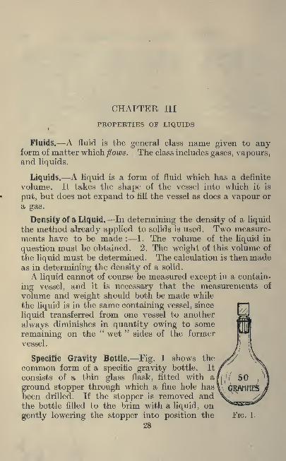
Specific Gravity Bottle. Fig. 1 shows the
common form of a specific gravity bottle. It
consists of a thin glass flask, fitted with a
ground stopper through which a fine hole has
been drilled. If the stopper is removed andthe bottle filled to the brim with a liquid, on
gently lowering the stopper into position the
28
FIG. 1.

PROPERTIES OF LIQUIDS 29
superfluous liquid flows through the fine hole in
the stopper. The bottle is now exactly"
full,"
and if it is made to hold a specified amount
(usually 25 c.c.) we know the volume withoutfurther effort.
If a specific gravity bottle is not available acommon 1 oz. stoppered bottle forms a good sub-
stitute, provided the stopper has been grooveddown its side by means of a triangular file. (See
Fig. 2.) In this case, however, the bottle mustbe calibrated for volume. An example will makethis clear.
FIG. 2.
Ex. 6. A stoppered bottle weighs, when empty, 16 '835
grms. Filled with pure cold water it weighs 43 '728 grms.Find its capacity.
Weight of bottle and water . . . =43*728 grms.Weight of bottle alone . . . =16-835
Weight of water alone 26-893
Since 1 c.c. of water weighs 1 grm. the capacity of thebottle is 26-89 c.c.
Ex. 7. Using the bottle mentioned in Example 6, it wasfound that the weight when rilled with lard oil was 41*457
grms. Find the specific gravity of the oil.
Weight of bottle and oil
Weight of bottle alone
Weight of oil
41*457 grms.16-835
24-622
Now the result of Example 6 showed that the capacityof this bottle was 26 -89 c.c.
24*622Hence 1 c.c. of lard oil weighs -^
-grins.= 0'916 grms.
per c.c.
The specific gravity of lard oil is therefore 0'916.
30 AN INTRODUCTION TO PHYSICS
Experiment 2.
Obtain a 1 oz. stoppered bottle and having cut a groove in
the stopper calibrate it for volume by the method indicated
in Example 6. If a. specific gravity bottle of the patternshown in Fig. 1 is to be used, it, too, should be calibrated in
case the volume marked upon it is not quite correct.
Experiment 3.
Prepare a saturated solution of common salt in water.
Find the density of this solution by the method indicated in
Example 7.
Experiment 4.
Take some of the saturated solution of salt already pre-
pared and mix with it an equal volume of water. Havingthoroughly mixed these two liquids, find the density of the
mixture. Is the density the mean of the density of waterand that of the salt solution ?
Experiment 5.
Find the density of alcohol. (If alcohol is not available,
common methylated spirit may be used. This is an impureform of alcohol.)
Experiment 6.
Mix alcohol and water together in equal parts and find the
density of the mixture. Is the density the mean of those of
alcohol and water ?
Experiment 7.
If the results of experiments 4, 5, and 6 appear at all
confusing, test whether on mixing, say, 50 c.c. of water andsalt solution, or water and alcohol, 100 c.c. of mixture is
obtained. It will be a wise precaution to have a thermometerin. the liquids to ensure that all measurements are made at
the same temperature.
Level. A "level
"surface may be defined as one which
is everywhere at right angles to the direction in which the
earth's gravitational force acts. Where only small areas

PROPERTIES OF LIQUIDS 31
are being considered a level surface maybe regarded as being
"flat
"or
"plane,"
but when we are dealing with extensive
areas, such as the surface of a lake, it is
necessary to remember that a level surface
is bound to approximate to the shape of
the earth and is therefore a portion of a
spherical surface.
There is a popular saying that"water FIG. 3.
finds its own level." All liquids have this
property, which amounts only to a tendency to flow in the
containing vessel until the free surfaces ajre level.
Fig. 3 shows a U-tube containing a little liquid. The free
surface is here broken into two owing to the shape of the
containing vessel. Yet these two
// portions are each level when con-
// sidered separately and they are both
// ^ on the same level when considered
Lr . -^3 together.
JS ^^T If the tube is tilted, as shown in
^l ^^T Fig. 4, the level of the water is
^R^tol^pr maintained although the vessel is
now in a different position.FIG. 4. Liquids which wet the surface of
a containing vessel show a tendencyto creep up the side of the vessel. This results in the liquid
being not quite level near the edge of the vessel.
Fig. 5 shows a few cases. It will be seen that if the vessel
is large (as at A) the surface of the liquid is level exceptnear the edge. As the surface becomes smaller, however, theeffect is greater,until in very nar-
row tubes (as C) a
liquid will appearto have a surface
which is whollycurved.
When makingmeasurements of
32 AN INTRODUCTION TO PHYSICS
FIG. 6.
columns of liquids the measurement is
always made from the lowest part of thecurved surface in the case of liquids whichwet the vessel.
Liquids which do not wet the vessel, suchas mercury, have a curved surface whichis convex (as D in Fig. 5).
In such cases measurements are madefrom the upper part of the curve.
Another modification of this phenomenon is observedwhen a tube (open at both ends) is placed in a vessel of
liquid as shown in Fig. 6. The liquid creeps up the tube,the distance depending upon the diameter of the tube andthe nature of the liquid.
Experiment 8.
By means of a few pieces of glass tube of different bores,
observe the phenomena just described. Use a number of
liquids, such as mercury, water, and various solutions.
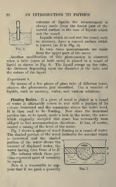
Floating Bodies. If a piece of wood is placed in a vessel
of water it ultimately comes to rest with a portion of its
volume immersed and the remainder above the water level.
It is then said to be floating. Now since the immersed
portion has, so to speak, made a hole in the water, the water
which originally occupied this space has necessarily been
obliged to find accommodation elsewhere. It has, of course,
caused a raising of the level of the water.
Fig. 7 shows a sphere of wood floating in a vessel of water.
The shaded portion of the wood indicates the amount which
is immersed and the shaded
portion of the water shows the
amount of displaced water, the
water having risen from A to B.
The volumes which these por-tions represent must of necessitybe equal.Now it is reasonable to sup-
pose that if we push a quantity FIG. 7.

PROPERTIES OF LIQUIDS 33
FIG. 8.
of water out of the position it
naturally occupies, it will makean effort to return. Hence the
weight of the displaced water
forms a force which tends to
push the wood out of the
water. Since the wood is float-
ing at rest it follows that :
Weight of wood= weight of
displaced water.
If a sphere of cork of the same size as that of the woodwere placed in water, it would float with less of its volume
immersed, for, since cork is specifically lighter than wood,a smaller volume of water is required to yield a force equalto the weight of the cork (see Fig. 8).
If a sphere of iron were placed in water it would pass into
the water until the whole of its volume was immersed, andeven then the weight of the displaced water would be less
than the weight of the iron ; consequently the iron wouldnot be supported but would sink to the bottom of the vessel.
Only bodies whose specific gravity is less
than unity will float in water. Generally we
may say, that bodies will float in a liquid
provided the specific gravity of the body is
less than that of the liquid.
Experiment 9.
The Hydrometer. Take a piece of glass
tubing about 8 inches long and seal up oneend. Place in it a few lead shot and abovethese a paper scale. (A roll of ordinarysquared paper makes a suitable scale.)
If such a tube be placed in a vessel of
water as shown in Fig. 9 the tube will float
according to the law already given. That is,
the immersed portion will displace a volumeof water equal in weight to the weight of the
FIG. 9. tube, etc,

34 AN INTRODUCTION TO PHYSICS
It is readily seen that the position of the level of the liquidas shown by the scale enclosed in the tube depends upon the
specific gravity of the liquid. The denser the liquid the less
will the tube need to sink in the liquid. Such a tube is called
a hydrometer.By varying the quantity of shot, a number of hydrometers
may be constructed to suit liquids ranging from very low
to very high specific gravities.If the records of these instruments are compared with the
specific gravity of the liquids obtained by means of a specific
gravity bottle it is possible to replace the arbitrary scale of
squared paper by a scale directly recording specific gravities.
Ex. 8. The following table shows the arbitrary readingsof a glass tube hydrometer in liquids of known specific gravity.
Prepare a scale of specific gravities for the hydrometer :
Specific gravity . . 1* 1*15 1*21.T T OK" K "I
" K Q "
Reading . . .36 61 o o .
First plot a graph of these results.
SPECIFIC GRAVITY,
1-0 1-05 1-1 1-15
FIG. 10.
1-2 1-25
This is shown in Fig. 10, and it will be seen that in this
case it is a straight line. From the graph it is possible to
read the specific gravity corresponding to any scale readings.
Thus we may compile a table as follows ;

PROPERTIES OF LIQUIDS 35
Specific gravity.
1-00
1-05
1-10
1-15
1-20
1-25
Corresponding Scale
Reading.3 -5*
4-05"
4-6"
5-1"
5-7*
6-25".
If a scale is now prepared on which the above specific
gravities replace the positions originally occupied by the
corresponding scale readings we have a hydrometer whichwill record specific gravities directly.
It may be mentioned that a hydrometer may be mademore sensitive by having a bulb blown at or near the bottom.Of course, the more sensitive wemake the instrument, the smaller
will be the range of its readings.
Determination of the Densityof Irregular Solids. We are nowin a position to determine the
density of solids of irregularform. Consider a piece of iron
whose volume is, say, 10 c.c. If
this be dropped into water it
will displace 10 c.c. of waterwhich will weigh 10 grammes.As we have seen, this displacedwater will exert an upward thrust
of 10 grammes on the iron. Asthe iron itself weighs more thanthis the force will be insufficient
to float the iron. Nevertheless,if the iron were weighed while
it was suspended in water it
would be found to weigh 10
grms. less than its normal weight.We can make use of this fact
to obtain the volume of an FIG. 11,
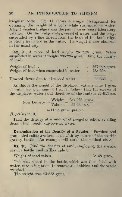
36 AN INTRODUCTION TO PHYSICS
irregular body. Fig. 11 shows a simple arrangement for
obtaining the weight of a body while suspended in water.A light wooden bridge spans the pan of an ordinary laboratorybalance. On the bridge rests a vessel of water, and the body,suspended by a fine thread from the hook of the knife edge,is wholly immersed in the water. Its weight is now obtainedin the usual way.
Ex. 9. . A piece of lead weighs 257*928 grms. Whensuspe'nded in water it weighs 235*295 grms. Find the densityof lead.
Weight of lead 257 '928 grms.Weight of lead when suspended in water . 235*295 ,,
Upward thrust due to displaced water . . 22*633 ,,
As this is the weight of the displaced water and as 1 grm.of water has a volume of 1 c.c. it follows that the volume of
the displaced water (and therefore of the lead) is 22*633 c.c.
Weight 257*928 grins.Now Density = ==-=Volume 22*633 c.c.
= 11*38 grms. per c.c.
Experiment 10.
Find the density of a number of irregular solids, avoidingthose which would dissolve in water.
Determination of the Density of a Powder. Powders and
granulated solids are best dealt with by means of the specific
gravity bottle. An example will make the method clear.
Ex. 10. Find the density of sand, employing the specific
gravity bottle used in Example 6.
Weight of sand taken .... 3'148 grms.
This was placed in the bottle, which was then filled with
water, care being taken to remove air bubbles, and the whole
weighed.The weight was 45*523 grms,

PROPERTIES OF LIQUIDS 37
Using the data of Example 6.
Weight of bottle and water . . . 43 '728 grms.
Weight of sand . . 3 '148
Adding we get 46 '876
The actual combined weight was . . 45*523
Difference . . . 1*353
This difference is due to the fact that the sand occupies
space and therefore the bottle holds less water.
The weight of water displaced = 1 *353 grms.The volume of this water (and therefore of the sand) is
1*353 c.c.
WeightDensity =^rVolume.
_3*148 grms.1*353 c.c.
=2*32 grms. per c.c.
Determination of the Density of a Soluble Solid. Solids
which are soluble in water have applied to them one of the
above methods, with the exception that a liquid in which thesolid will not clissolve is substituted for water.
Ex. 11. A lump of salt weighs 18*412 grms. When sus-
pended in alcohol of specific gravity 0*71 it weighs 14*108
grms. Find the density of the salt.
Weight of salt . 18*412 grms.
Weight of salt suspended in alcohol . . 14*108 ,,
Upward thrust due to displaced alcohol . 4*304 ,,
Weight of displaced alcohol . . . 4*304
Weight in grammes.Volume m c.c. =Specific gravity.
_4*3040-71
= 6*06 c.c.

38 AN INTRODUCTION TO PHYSICS
This being the volume of displaced alcohol is likewise; thevolume of the salt.
WeightNow density =^^TVolume.
_ 18 -412 grms.6-06 e.c,
=3 '04 grms. per c.c.
Hare's Apparatus. Let two glass tubes be supportedvertically with their lower ends respectively in two beakers
containing different liquids as shown in Fig. 12, A and B.Let the upper ends of the tubes be joined by a T piece
(C) fitted with a tap. If the tap be opened to the air the
liquid in the tubes will stand at the same height as that in
its beaker (except for the creeping
up effect called"capillary attrac-
tion," and this will be negligibleunless the tubes are very narrow).
Suppose air is withdrawn fromthe tubes by suction through Cand the tap closed. A certain
amount of each liquid will bedrawn into the tubes, and since
the remaining air is free to passfrom one tube to the other it
follows that the two supportedcolumns of liquid must balance.
If therefore the vertical heightof each column above the level
of the liquid in the beaker bemeasured it is possible to comparethe density of the two liquids.
In Fig. 12 let the tube A dipinto pure water and the tube Binto a solution of salt. Sincethe latter solution is specifically
FIG. 12. heavier it follows that a shorter

PROPERTIES OF LIQUIDS 39
column of it will be supported. It is easy to see that theA
specific gravity of the salt solution is given by -=-
This is quite obvious if the two tubes are of exactly the
same bore, but experiment shows that it is also true when the
tubes are of different bore. It is not even necessary for the
tubes to be of uniform bore. An explanation of this will
be given in the next chapter.
Experiment 11.
Make a Hare's apparatus using two tubes of the samebore and find the specific gravity of salt water.
Repeat the experiment, using tubes of different bore, butthe same salt water. Compare results.
In experiments of this nature the student should not be
satisfied with a result obtained from a single reading. Several
readings should be taken with columns of different heightsand a mean value secured.
The Syphon. Fig. 13 illustrates two syphons, whichconsist of bent pieces of tube each having one limb longerthan the other. If such a tube be filled with a liquid andthe short limb placed in a vessel of the liquid, the columns,
being unequal in length, will not balance. The longer one,
falling, wifi pull the shorter one after it, and thus liquid will

40 AN INTRODUCTION TO PHYSICS
be drawn out of the vessel. It will be shown subsequentlythat it is the vertical height of such a column which is effective,and thus the two syphons illustrated would be of equalefficiency.The difference in the lengths of a and 6 represents a column
of liquid, the weight of which gives the effective suction.
Experiment 12.
Make a number of syphons and compare the amount of
water which is taken from a vessel per minute with the valueof (b a) in Fig. 12.
Exercises 3.
1. 25 cubic centimetres of copper sulphate solution were
poured into a weighed evaporating basin. Determine the
density of the solution from the following results : weightof basin 55*152 grammes, weight of basin plus 25 cubic centi-
metres of copper sulphate solution, 83 '805 grammes.2. A steel ball 10 millimetres in diameter was placed in a
burette containing water and its volume was found to be0*35 cubic centimetres. Is this correct ? The weight of the
ball was 4 '47 grammes. Determine the true density of the
ball.
3. A specific gravity bottle weighs 15*67 grammes andcontains 66 cubic centimetres of water when full. Somevaseline was warmed until it flowed readily and then pouredinto the specific gravity bottle until it was full. The weightof the bottle was then found to be 72*372 grammes. Deter-
mine the density of the vaseline.
4. In determining the density of mercury by the "U"tube method the following readings were obtained, measure-ments being taken from the same level in each case. Heightof water, 15*5 centimetres. Height of mercury, 1*14 centi-
metres. Determine the density of mercury.
5. An experiment was carried out to determine the densityof mercury and the following results were obtained : Weightof beaker 29 '21 grammes. Volume of mercury weighed, 19

OF LIQUIDS 41
cubic centimetres. Weight of the beaker and the 19 c.c.
of mercury 285 '2 grammes. Determine the density of the
mercury from these results and explain how you would
carry out a similar experiment.
6. Sketch and describe Hare's apparatus and explain how
you would determine the density of mercury with this ap-
paratus. The following results were obtained with the
apparatus : Height of water 24 '5 centimetres, height of
mercury 1/8 centimetres. Calculate the density of mercuryfrom these results.
7. A piece of iron weighed 26 -734 grammes in air and 23 '319
grammes when weighed in water. Determine its specific
gravity.
8. The specific gravity of a piece of wood was required andthe following experimental results were obtained :
Weight of the body in air, 7 '735 grammes.Weight of the sinker in air, 26 '735 grammes.Weight of body plus the sinker in water, 16*05 grammes.Weight of the sinker in water, 23 '32 grammes.Determine the specific gravity of the material and explain
with the aid of sketches how you would carry out a similar
experiment.
9. Hare's apparatus was used to compare the density of
benzine with turpentine, and in carrying out the experimentthe following readings were noted : Height of benzine llf",
height of turpentine 9fV'. Compare the density of benzine
with that of turpentine and the converse.
A further experiment was carried out with benzine and waterand the following readings were taken : Height of benzine11 "6", height of water 10 '2". Determine the density of the
benzine.
10. The following results were obtained after carrying out
the experiment in question 1. Weight of the beaker holding
copper sulphate 41 '1 grammes. Weight of the beaker plus
copper sulphate solution 155 '13 grammes. Volume of the
weighed copper sulphate solution 100 cubic centimetres.
Determine the density.
42 AN INTRODUCTION TO PHYSICS
At the completion of the test 100 cubic centimetres of
water were added to the copper sulphate solution, and the
weight of the beaker and solution, plus added water, was now255*075 grammes. Determine the new density. Is the
density the mean of the density of water and that of the
copper sulphate solution ?
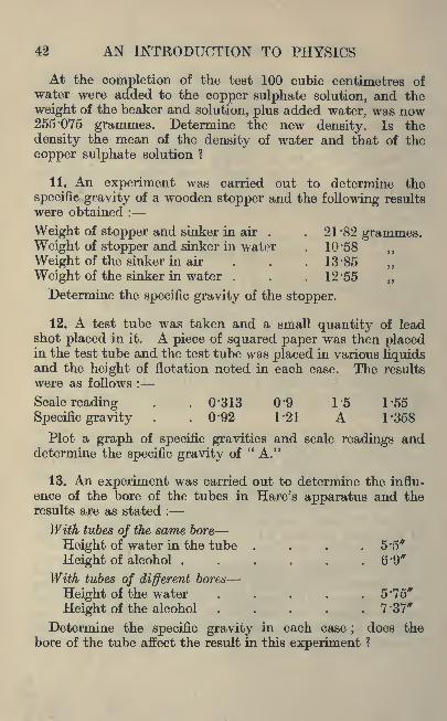
11. An experiment was carried out to determine the
specific gravity of a wooden stopper and the following results
were obtained :
Weight of stopper and sinker in air . . 21 '82 grammes.Weight of stopper and sinker in water . 10 '58 ,,
Weight of the sinker in air . . . 13 '85
Weight of the sinker in water . . . 12 '55
Determine the specific gravity of the stopper.
12. A test tube was taken and a small quantity of leadshot placed in it. A piece of squared paper was then placedin the test tube and the test tube was placed in various liquidsand the height of flotation noted in each case. The results
were as follows :
Scale reading . . 0'313 0'9 1'5 T55Specific gravity . . 0'92 1-21 A 1*358
Plot a graph of specific gravities and scale readings anddetermine the specific gravity of "A."
13. An experiment was carried out to determine the influ-
ence of the bore of the tubes in Hare's apparatus and theresults are as stated :
With tubes of the same bore
Height of water in the tube . . . .5*5*Height of alcohol . . < . . . G'9"
With tubes of different bores
Height of the water ..... 5 '15"
Height of the alcohol . . . 7 '37*
Determine the specific gravity in each case;
does the
bore of the tube affect the result in this experiment ?

PROPERTIES OF LIQUIDS 43
14. An experiment was carried out to determine the effect
of altering the bore of the tubes on the quantity of water
delivered by various syphons. (See Fig. 13.)
First ExperimentBore of the tube, 2 millimetres.
Difference of vertical heights, 0'66".
Outflow in cubic centimetres per minute =75.
Second ExperimentBore of tube, 4 '5 mm.Difference of the vertical heights 1 '5".
Outflow in c.c. per min. = 142.
Third ExperimentBore of tube, 4 '5 mm.Difference of vertical heights, 1 '15".
Outflow in c.c. per min. =412.
Carefully examine these results and state what deductions
can be made.
15. An experiment was carried out to determine the specific
gravity of glass and the weight of the glass in air was 2*85
grammes. The weight of the glass in water was 1 '687 grammes.Determine the specific gravity of the glass.
CHAPTER IV
PROPERTIES OF GASES
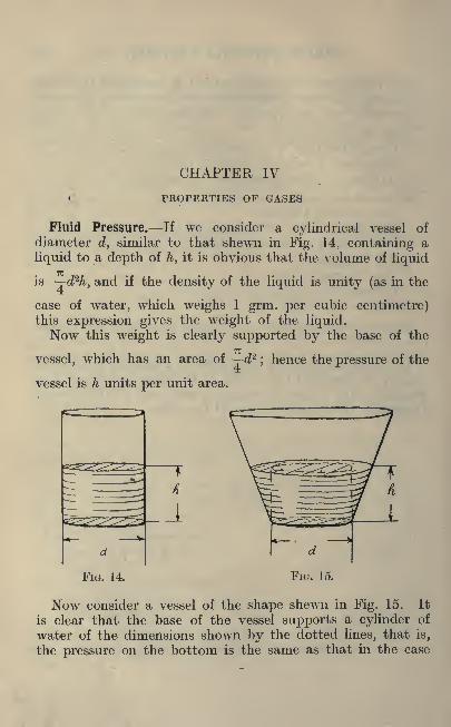
Fluid Pressure. If we consider a cylindrical vessel of
diameter d, similar to that shewn in Fig. 14, containing a
liquid to a depth of h, it is obvious that the volume of liquid
is ~rd2h, and if the density of the liquid is unity (as in the
case of water, which weighs 1 grm. per cubic centimetre)this expression gives the weight of the liquid.Now this weight is clearly supported by the base of the
vessel, which has an area of d2;hence the pressure of the
vessel is h units per unit area.
d
Jb'io. 14.
Now consider a vessel of the shape shewn in Fig. 15. It
is clear that the base of the vessel supports a cylinder of
water of the dimensions shown by the dotted lines, that is,
the pressure on the bottom is the same as that in the case

PROPERTIES OF GASES 45
just considered. The additional water is in this case sup-
ported by the sides.
Consider a point P which lias a depth of x units of waterabove it. If a small hole could be pierced in the walls of
the vessel at this point the water would issue normally to the
wall of the vessel with a force proportional to the depth x.
We may say therefore that in this case at least the obliquesides of the vessel are subjected to a pressure which is directly
proportional to the depth of water at the point consideredand acts normally, that is, at right angles, to the surface of
the vessel at the point.
Lastly, consider a vessel of the shape shown in Fig. 16.
Here a concentric circle in the base sup-
ports a complete cylinder of water andthe pressure on this is obviously the sameas in the previous examples. The annular
space round this circle has above it water
varying in depth from o to h. Consider
a given point. Here the pressure is
again normal, that is, perpendicular to
the surface. Furthermore, it is, as in
the last example, proportional to the
depth of wrater at this point.Now it is an established principle in
mechanics that every force is met by a FIG. 1C.
reaction equal in magnitude and oppositein direction. Hence at a given point the wall of the vessel
must be pressing downwards with a force equal to the pressureof the water upwards. Hence if the downward pressure at
this point is X units, this added to the column of waterof y units immediately below it, makes a total pressure onthe bottom of the vessel of X-\-y units, which is equal to h.
It appears therefore that the pressure on the bottom of
the vessel is everywhere the same, namely, h units per unit
area. It obviously must be so, for if it were not, waterwould flow from the region of high pressure to one of lower
pressure, until equality of pressure was established.
We have seen that the total pressure on the base of the
vessel in Fig. 16 is the same as that represented in Fig. 14,

46 AN INTRODUCTION TO PHYSICS
yet the weight of water in the conical vessel is less than thatin the cylindrical vessel. This is sometimes a little confusingto a student, but it is similar in principle to the case of acommon lever. Here a small force applied at one end becomesa large force at the other, but the work done at both endsis equal. The question of work has, so far, not entered intoour consideration of fluid pressure.
Properties of Gases. A gas is another form of fluid, buta gas can not only flow ;
it has also the special property of
filling its containing vessel, irrespective of the quantity of
gas or the size of the vessel; that is, there is no level surface
terminating a quantity of gas such as we found in the case of a
liquid.Now if we put a pint of gas into a quart bottle the latter
is only"
full"in the sense that the gas is equally distributed
all over the bottle. There is no space which contains moreor less gas per unit volume than any other space. There is,
however, nothing to prevent another pint of gas being putinto the same bottle and a further pint after that. Thus a
bicycle tyre is capable of holding a very variable quantity of
air.
Experience shows, however, that the more air one pumpsinto a bicycle tyre the
"harder
"it gets : in other words,
the higher the pressure of the air rises.
Another point which experience has established is that theair in a bicycle tyre will escape from a hole made in any partof the tyre. For a liquid to escape from a vessel it is neces-
sary for the hole to be below the level of the liquid ;but a
gas exerts its pressure equally in all directions, hence it
will pass through a hole in the top or side of a vessel as readilyas through a hole in the bottom.
Atmospheric Pressure. Gases, like other forms of matter,
possess weight. It is true that their density is comparativelysmall, but it is by no means negligible. Air, for example,under normal atmospheric conditions, has a density of about0'08 Ibs. per cubic foot. In other words a cube of edge 2 ft.
4 ins, contains about 1 Ib, of air.

PROPERTIES OF GASES 47
Now just as a liquid exerts a pressure on the bottom of its
containing vessel, so we may expect the air at the earth's
surface to be affected by the weight of the air above it.
The case is not, however, quite so simple, for the air in the
lower regions, being subject to the pressure due to the weightof the air above it, is compressed, and is therefore muchdenser than the air in higher regions. Liquids, on the other
hand, are almost incompressible.
The Barometer. In considering Fig. 14 we saw that the
total pressure on the base of the vessel was equal to the
weight of the water. As a matter of fact, to this amountmust be added the pressure of the air on the surface of the
water. It is clear, therefore, that the reaction of the force
on the base of any vessel containing a liquid is acting vertic-
ally upwards and is equal to the pressure due to the liquid
plus the pressure of the air.
Now if we could remove the atmospheric pressure from a
portion of the liquid surface, the liquid immediately belowthe surface should be forced up. Such conditions can be
partially obtained by placing a tube in a basin of water and
sucking some of the air out of the tube. The water at once
passes up the tube under the action of the force.
If we had a very long tube it is obvious that we mightreach a limit where the pressure due to the column of water
would be equal to the pressure of the air. No amount of
suction could draw water up the tube beyond this limit.
This principle may be utilised to measure the pressure of
the air. In order to avoid the use of very long tubes it is
usual to employ a liquid of a density much higher than that
of water : mercury, for example.
Experiment 13.
Obtain a piece of barometer tube about 33 ins. long. This
tube has stout walls to give strength. The bore dependsupon the quantity of mercury available, but for experimental
purposes a bore of 3 or 4 millimetres is sufficient. One endof this tube should be sealed in a blowpipe flame.
This tube has now to be filled with mercury and certain
precautions should be taken whenever mercury is used.

48 AN INTRODUCTION TO PHYSICS
Precautions in the Use of Mercury. Mercury is the onlymetal which is liquid at the ordinary temperature of the air.
It readily amalgamates with certain other metals and should,therefore, be kept out of contact with other metals. In this
connection it is a source of danger in a laboratory sink, as
it is liable to amalgamate with (and destroy) the lead drainagepipes.As mercury is very costly it is desirable to support any
apparatus containing it in a deep wooden tray made for the
purpose. If any mercury is spilled, it is then caught in the
tray.
Mercury does not " wet " most surfaces, and consequentlywhen dropped on to a flat surface, gathers itself up into numer-ous little globules which are not readily collected.
If in spite of precautions mercury does get into a sink,it may be removed by means of a small piece of zinc whichhas been dipped in dilute sulphuric acid. The mercuryreadily amalgamates with the zinc and is thus removed. If
sufficient mercury is involved it may be obtained by dissolv-
ing the zinc in dilute sulphuric acid, after which the mercurymay be washed with water and dried.
If mercury becomes mixed with moisture or dirt it may becleansed by allowing it to pass through a funnel fitted witha filter paper in the apex of which a small hole has been
pierced. The dirt adheres to the paper and the clean mercurypasses through.When a long tube has to be filled with mercury, the tube
should if possible be supported in a slanting position, and in
any case the mercury should be allowed to pass in very slowlyand in small quantities at a time. Mercury has so high a
density that any considerable quantity of it falling verticallydown a long tube strikes the end with such force that there
is a danger of the tube breaking.
Try to avoid air bubbles in a mercury column. With
patience and a little gentle tapping they can generally be
removed.
Returning to our barometer tube, when the tube is com-
pletely filled with mercury, the open end should be temporarilyclosed (this is generally done by the thumb of the right hand),

PROPERTIES OF OASES
the tube inverted and the openend placed below the surface of a
little mercury contained in a
vessel, as shown in the left-hand
portion of Fig. 17.
Now it is clear that no air can
enter the barometer tube;hence
there can be no air pressure onthe surface of the mercury over
which the tube is placed ;but
when all flowing has ceased the
pressure must be equal at all
points of the surface, so that there
will remain in the barometer tubea column of mercury which exerts
the same pressure as that whichthe air is exerting on the outside
surface.
This column is generally in the
neighbourhood of 760 mm. or
slightly under 30 inches, and is
shown by h in Fig. 17. It
should be noted that the height of the mercury column is
measured from the level of the mercury in the dish and notfrom the bottom of the tube. It is clear that the portionof the tube above the mercury column cannot contain any-
thing except the vapour of mercury, which at ordinary tem-
peratures is quite insignificant.If the pressure of the air changes, mercury will flow into
or out of the tube until the mercury column again balances
the pressure.Thus we speak of the pressure of the air being indicated
by the"height of the barometer."
If a barometer tube be inclined as shown on the right handside of Fig. 17 we find that the mercury remains at the samelevel. In other words, it is the vertical height of the columnof mercury which records the atmospheric pressure.
Fig. 18 shows another type of mercury barometer, workingon what is known as the
"syphon
"principle. Although
FIG. 17.

50 AN INTRODUCTION TO PHYSICS
FIG. 18.
somewhat different in form the actual principleis the same. The air exerts a pressure on the
open surface of the mercury at B and supportsa column h units high. For purpose of gradu-ation any point A is selected and scales proceedupwards and downwards from this point. Thelevels of the two surfaces of mercury are readon these scales and added together. Obviouslyx-\-y=h. When a permanent barometer is
made for purposes where some degree of ac-
curacy is required, it is necessary to boil the
mercury in the tube to expel all air bubbles.This is an operation calling for skill and ex-
perience and should not be undertaken withoutsuitable supervision.A portable form of barometer is made in
which the principle involved is quite different.
A small flat vessel made of corrugated metal has the air
extracted from its interior and is then sealed. The air
pressure on the outside will depress its flat surfaces to a
degree depending on the magnitude of the pressure. Themovement is of course very small, but by a system of levers
it is magnified into a suitable movement of a needle over ascale which may be graduated in any desired units. Thisinstrument is called an " Aneroid Barometer."
Ex. 12. The normal height of the barometer is 760 mm.At sea level it seldom sinks below 725 or rises above 785 mm.Express these pressures in Ibs. per sq. in.
Consider a tube whose sectional area is 1 sq. cm.The volume of mercury in the three columns is respectively
76, 72-5, and 78-5 c.c.
Mercury has a density of 13*58 grms. per c.c. The weightof the column is therefore respectively :
76 x 13 -58= 1,032 grms.72-5x13-58= 984
78-5x13-58= 1,066
These weights represent the pressure per sq. cm.

PROPERTIES OE GASES 51
Now 1 kilogram per sq. cm. is equivalent to 14*22 Ibs.
per sq. inch. The pressures given above are, therefore,
equivalent to :
10*32- X 14-22 = 14-67 Ibs. per sq. ins.1000
984
1000
1066
1000
X 14-22= 14-0
X 14-22 = 15-17
Ex. 13. What would be the normal height of a barometerin which water was used instead of mercury ?
Since mercury is 13 '58 times as dense as water it follows
that a column of water equal in pressure to that of mercurymust be 760xl3'58 mm. or 33J ft.
It may be mentioned here that no suction pump can"
lift"water to a height greater than this.
Relation between Volume and Pressure of a Gas. We have
already seen that when the pressure of a gas is increased (as
in pumping up a bicycle tyre) its volume is diminished. It
remains to find the relationship which exists between the
pressure and volume.Most operators of a bicycle pump will have noticed that
when air is rapidly compressed it becomes hot, and since heat is
likely to affect the volume of a gas, it is desirable that we should
investigate changes one at a time. In the following experi-
ment, therefore, steps must be taken to secure that the
temperature remains constant.
Experiment 14.
Find the relation between the pressure and volume of a
given mass of gas when the temperature remains constant.
Fig. 19 shows a suitable form of apparatus. It consists
of a piece of stout glass tube bent in the form of a U, of whichone limb is much longer than the other. The short limb is
sealed.

52 AN INTRODUCTION TO PHYSICS
A little mercury is poured into the tube
through the open end, and falling into the
bend of the U imprisons a quantity of air in
the short limb.
As more mercury is poured into the tube
this air is compressed into a piece of tube of
length I while the pressure exerted upon it is
the atmospheric pressure plus a column of
mercury of height h.
It is convenient to record pressure in termsof the length of a column of mercury instead
of Ibs. per sq. in. ;a transformation of units
can readily be made when necessary.
Owing to the method of applying the
pressure in this experiment the process is
necessarily a slow one, and the very small
quantity of heat which is produced by the
small pressures involved has ample opportunity of passing to
the surrounding air. It is not, therefore, necessary in this
case to employ any special means of maintaining the tem-
perature constant.
A number of readings should be made, commencing if
possible with one in which the pressure is below the atmo-
spheric pressure. This can be obtained by having the mercurylevel in the open limb lower than that in the closed limb. The
height h would then be called a"negative head."
The following is a typical set of results :
Reading of barometer, 765 mm.
FIG. 19.
Length I in mm.

PROPERTIES OF GASES 53
1941

54 AN INTRODUCTION TO PHYSICS
Pumps. A pump is a mechanical device for transportinga fluid from one place to another. Pumps may convenientlybe divided into two classes, rotary and reciprocating. Inthe former, all the moving parts rotate, while in the latter
some at least of the moving parts"reciprocate
";that is,
move to and fro along a straight line.
Valves are always associated with reciprocating pumps,a valve being a passage through which the fluid can flow onlyin one direction.
A common type of pump for dealing with air is the bicycle
pump which is illustrated in Fig. 20. It consists of a cylinderwith a plunger or piston. The latter consists of a disc of
thin leather formed into the shape of a cup, the edges of whichare turned towards the delivery end of the pump.On the downward stroke M
the edges of this piston are
pressed against the sides of
the cylinder so that no air can
pass. Thus the air is com- JTIG> 20.
pressed into the lower part of
the pump until the pressure is reached which is necessary to
open the valve of the tyre. (This pressure of course dependsupon the pressure of the air already in the tyre.)On the upward stroke, since no air can enter the pump
from the delivery end (owing to the valve in the tyre) the
pressure of the little air remaining in the pump soon falls,
and is less than atmospheric pressure (that is, there is a
partial vacuum). In consequence air pushes past the skirts
of the piston, since these are not now being pushed againstthe cylinder walls, from the upper part of the pump whichis open to the air. Thus one gets a cylinder full of air readyfor the next compression stroke.
It is easy to see that as the pressure in the tyre gets greater,more and more of the compression stroke will have to be
performed before the pressure rises sufficiently high to openthe tyre valve, and the higher will be the pressure of the
residual air left in the base of the pump.
A Common Air Pump. A bicycle pump is used to pump

PROPERTIES OF GASES 55
air into a receptacle, and may be called a"compressor." Fig. 21 shows a type of air
pump which is used to extract air from a vessel
and may be called a"decompressor."
Again it consists of a cylinder and piston.There is one valve at the end of the cylinder Aand another in the piston B. These valves
generally consist of a small hole over which a
piece of oiled silk is stretched, this being placedw
on the side away from the vessel to be exhausted.
On the outward stroke, valve A opens and Bcloses. A partial vacuum is created in the
cylinder and air flows from the vessel to the
cylinder. On the return stroke A closes andB opens, and this air passes out into the
atmosphere.It is clear that as the pressure in the vessel
falls, a higher and higher degree of vacuum hasto be created in the cylinder before valve A will
open, and thus the pump becomes less and less
effective as the operation proceeds.
A Lift Pump for Water. Fig. 22 shows a common form of
water pump. There are two valves, both of
which can only open upwards. They are often
flap valves which operate after the manner of
a door and normally remain closed by the
operation of their own weight. One valve is
^aa=e\ placed at the bottom of the cylinder and theother is in the piston.The diagram shows the piston on its down
stroke. This causes the bottom valve to close
and the water in the cylinder (being practically
incompressible) opens the valve in the pistonand flows through and ultimately passes out
through the spout.On the up stroke the valve in the piston is
closed and as soon as a partial vacuum is
FIG. 22. created in the cylinder the lower valve opens

56 AN INTRODUCTION TO PHYSICS
and water flows up (or is "lifted"). Thisflow is due entirely to the pressure of theair and hence it is impossible to
"lift
"
water to a height greater than 33^ feet (the
height of a"water barometer ").
Since such a pump could never produce a
perfect vacuum the limit of lift in practiceis very much less than this amount.
A Force Pump for Water. When waterhas to be raised from a deep well or a
mine, it is necessary to have a force pump.Such a pump is shown in Fig. 23, and it
will be observed that there is no valve in
the piston. The valves are fitted, one atA opening inwards and one at B opening outwards. The
pump must be placed sufficiently near the water for thesuction stroke to lift it.
The diagram shows the piston on the up stroke. A is
open and B closed and water is flowing into the cylinder.When the piston reaches the top the cylinder is full of water.
On the downward stroke the compressiqn causes valve Ato close and valve B to open. Hence the water flows throughB and up the outlet pipe, which ^may rise to any height whatever,
provided the power supplied to
the pump is sufficient to force
the water out of the cylinder.
A Power-Driven Air Compressor.
Compressed air is used for so
many purposes in modern en-
gineering practice that it is
necessary to have power-drivenair compressors. A diagrammaticillustration of such a pump is
shown in Fig. 24.
It is fitted with two valves
of mushroom shape which lift FIG. 24.

PROPERTIES OF GASES 57
under air pressure against the action of a spring which
normally keeps them closed. The piston is shown on the
down stroke and air is being forced out of the cylinder into
a receptacle. On the return stroke the outlet valve closes
and the inlet valve opens, enabling air to be drawn into
the cylinder ready for compression on the followingstroke.
As these pumps often work at high pressures and speeds,the compressed air becomes very hot and is liable to givetrouble. To meet this difficulty it is a common practiceto place round the cylinder a jacket through which a streamof cold water is passed in the direction indicated by the
arrows in the diagram.Sometimes air is compressed in a pump of this nature,
then cooled and passed into another pump which compressesit to a still higher pressure. This is called a
" two stage
compressor."
Diffusion. Vessels made of unglazed earthenware andcalled
"porous pots
"are used in connection with the making
up of electric cells. If one of these (preferably a small
cylindrical one) is taken and fitted with a cork through whicha glass tube passes it will be found that by blowing down thetube the cylinder appears to be
"air tight." Indeed, it is
possible to maintain a considerable pressure in such a vessel
for some time.
If, however, such a vessel is filled with water it . will befound that in an hour or two damp patches appear on theouter surface, showing that the walls of the vessel possesssmall pores through which water can pass, although the
process is a very slow one.
If a porous pot, fitted with a cork and tube, be supportedin an inverted position with the open end of the tube belowthe surface of a little water (preferably containing colouringmatter) as shown in Fig. 25, the pressure of the gas withinthe porous pot cannot change without a visible movementin the water. That is, if the pressure rises, bubbles will passfrom the tube through the water, while a fall of pressure will
cause the water to pass up the tube.
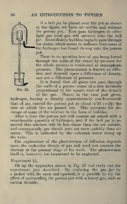
58 AN INTRODUCTION TO PHYSICS
FIG. 25.
If a bell jar be placed over the pot as shownin the figure, we have air within and withoutthe porous pot. Now pass hydrogen or other
light gas (coal gas will answer) into the bell
jar. Immediately bubbles begin to pass throughthe water, which seems to indicate that some of
the hydrogen has found its way into the porouspot.There is no question here of gas being forced
through the walls of the vessel by pressure for
the whole process is conducted at atmosphericpressure. The phenomenon is known as diffu-
sion and depends upon a difference of density,and not a difference of pressure.
It is found that all gases can pass throughthe walls of a porous vessel at a rate inversely
proportional to the square root of the densityof the gas. Hence, in the case just given,
hydrogen, having a density approximate^ one-fourteenth
that of air, entered the porous pot at about A/14 (=3|) the
rate at which the air passed out. This accounts for the
escape of some of the mixture in the form of bubbles.
After a time the porous pot will contain air mixed with a
considerable quantity of hydrogen, and if the bell jar is re-
moved this mixture will be less dense than the air outside,and consequently gas should pass out more quickly than air
enters. This is indicated by the coloured water rising upthe tube.
The explanation of the phenomenon of diffusion dependsupon the molecular theory of gas and need not concern the
student at the present stage of his work. The phenomenonitself is, however, too important to be neglected.
Experiment 15.
Fit up the apparatus shown in Fig. 25 and carry out the
experiment just described. By replacing the gas jar bya jacket with its open end upwards, it is possible to try the
effect of surrounding the porous pot with a heavy gas, such as
carbon dioxide.

PROPERTIES OF GASES 59
Exercises 4.
1. A cylindrical tank is 2' 3" in diameter and 2' 6" deep,and is full of water. Determine the pressure per squareinch on the base.
2. A rectangular tank is 4' 6" long and 2' wide, and 1J"
deep. Determine the pressure per sq. in. on the base.
3. The absolute pressure in a condenser may be measured
by means of a glass rod standing vertically in a bowl of
mercury. When the upper end of the tube is connectedwith the condenser the mercury rises up the tube. If it
rose 21" on a day when the barometer stood at 758 mm.,find the absolute pressure in the condenser.
4. The barometric pressure is 29 '5" of mercury. There is
a vacuum in the condenser of 25" of mercury. Find the
atmospheric pressure and absolute pressure in the condenserin Ibs. per sq. in.
5. Water is contained in a tank at the top of a building andthe surface of the water is 30' above ground level. Determinethe height of a mercury column just to balance this head of
water at ground level.
6. In a test on a small blower a " U "tube containing water
was used to measure the difference of pressure between theair in and outside a large box. The following readings weretaken : "395, '43 1
,'464 inches of water. If the barometer
was at 760 mm. determine the excess pressure inside thebox.
7. The following readings of pressure and volume wereobtained with a Boyle's Law apparatus. From these results
determine the average value of the constant and plot a graphof pressures and volumes.
Pressure cms.of mercury.
60 AN INTRODUCTION TO PHYSICS
8. By means of the" U "
tube determine the pressure of
the coal gas supply from the main, in inches of water.
9. In a boiler test the force of the draught in inches of water
was 0'38. What is the pressure in Ibs. per sq. in. ?
10. Give a sectional drawing of a bicycle pump. Assumingthe pump described has 100% efficiency, measure the diameterand stroke of such a pump and state what volume of air at
standard temperature and pressure it can supply each stroke.
11. Explain by the aid of sketches how any small glassworks.
12. Give a diagrammatic sketch of a self-filling fountain
pen and explain its action.
13. In using a pipette explain why the liquid flows upwardwhen the air is sucked away from the top of the tube. Whydoes the liquid stop running out of the pipette when the
finger is placed over the top ?
14. A cylindrical tin can is filled with water and the lid
is soldered on. A small hole is then bored in one end near
the outside rim. The can is placed in a horizontal
position with the hole near the ground. Will all the water
run out of the can ? Carry out the experiment. Explainwhat must be done to get liquid out of a barrel after the
tap has been fixed in position.
15. A " U "tube containing oil was used to measure the
pressure inside a box as compared with that of the outside
air;
the air being taken from the outside air into the boxand thence going to a gas engine. The oil in the
" U "tube
had a head of oil 0'16.
Determine the equivalent water column in inches, if the
specific gravity of the oil was 0*9.
16. Take an ordinary leather"sucker." Calculate the
maximum weight it can lift. Test this experimentally.
Assuming that the leather is 2" dia. determine the weight
you would expect this to lift.
17. Take a tin can with a narrow neck such as a"Filtrate
Oil"can, and clean it. Add a little water and boil the water

PROPERTIES OF GASES 61
for somethe neck,
ally.
time. Remove the flame and insert a cork into
What will happen to the can ? Try this experiment -
18. Two surface plates as used in the metal workshop are
placed with their finished faces together. What happenswhen you try and pull them apart ? Repeat this experimentwith two pieces of plate glass and determine the force persq. in. required to separate the two pieces.
19.
Barometerreadings.

62 AN INTRODUCTION TO PHYSICS
Convert the readings of pressures into millimetres of
mercury, and those of temperature into degrees Centigrade.Express your results graphically.
22. Determine how many inches of mercury the followingpressures in millibars are equal to :
100 120 140 160 and 180.
23. A bicycle pump has a stroke of 11 -5" and a bore of
0'55"i What is the displacement of the pump ?
24. A bicycle tyre has a mean dia. of 26". It is circular
in cross-section and 1-14" diameter. How much air at
atmospheric pressure and temperature will it hold ?
25. 1 gramme per cubic centimetre= 62 -43 pounds percubic foot. Density of mercury at C. = 13*5955 grammesper cubic centimetre.
Express the following barometer readings in millimetres
as pressure in Ibs. per sq. inch : 735 742 758 765 770780.
26. In a table giving the thermal properties of waterthe following figures are given. Complete the table.
DENSITY.
lbs./(feet).3

PROIJERTIES OF GASES 63
Plot a curve of probable actual lift and vacuum in suction
pipe in inches of mercury and state what lift you expect at30
"vacuum.Vacuum in suction pipe Theoretical lift Probable actual lift
in ins. of mercury. in feet. in feet.
2 2-2 1-8
6 6-7 5-410 11-3 9-014 15'8 12-6
18 20'2 16-1
20 22-5 18-024 27-0 21-528 31-6 25-229 32-7 26-1
30
29. Give sketches illustrating any type of pump used inmotor -car engines to keep the cooling water for the enginejacket in circulation.

SECTION II. PERIODIC MOTION
CHAPTER V
SIMPLE HARMONIC MOTION
Periodic Motion. If a uniformly rotating steam engine is
observed, it will be seen that the cross-head (which connectsthe piston-rod with the connecting-rod) moves to and fro withinits guides with a velocity which is very far from uniform.The movement is usually too fast for measurements to be
made while the engine is running, but data for a space-timegraph may be obtained by rotating the crank -shaft by handthrough intervals of 30 (commencing with the crank at rightangles to the axis of the cylinder), and recording the corre-
sponding position of the cross -head. The following results
were obtained on an engine having a stroke of 135 mm.
Crank Angle .

SIMPLE HARMONIC MOTION 65
regarded as positive and those are taken as negative whichhave been measured inwards from the initial position.
Fig. 26 shows a graph of these results, and deserves careful
study. It will be observed that the slope of the graph (whichindicates the velocity of the cross-head) is constantly changing.Also note that the distance moved from the initial positionto the outer dead centre is considerably less than that fromthe initial position to the inner dead centre.
FIG. 26.
The graph possesses many features of irregularity. It
will be seen that at the points marked A, B, and C on the
graph the cross-head is in its initial position. At B the con-
ditions are different from those of A in that the cross-head
is travelling in the opposite direction.
At (7, however, the cross-head is not only in its initial
position, but all the conditions are exactly the same as thosewhich obtained when the cross -head was at the point repre-sented by A in the graph. In other words, if the readingswere continued, the graph would repeat itself over and over
again.

66 AN INTRODUCTION TO PHYSICS
A graph which possesses this property is called a"periodic -
graph" and the motion which it expresses is called
"periodic
motion."
Simple Harmonic Motion. Fig. 27 shows the space -time
graph of another body whose movement possessed fewer
WAVE LENGTH \FIG. 27.
irregularities. The first half of the graph is symmetricalabout the line P Q and the whole graph is symmetricalabout the line R S except that the latter half is below the
axis X.This graph is called a
"sine curve
"
and any moving body whose space-timecurve is a sine curve is said to possess"simple harmonic motion."
Ex. 15. Draw any circle having a dia-
meter about 3" long. Draw a horizontal
diameter as shown in Fig. 28. Mark a
point P vertically above the centre and
suppose that this point P travels roundthe circumference of the circle with FIG. 28.
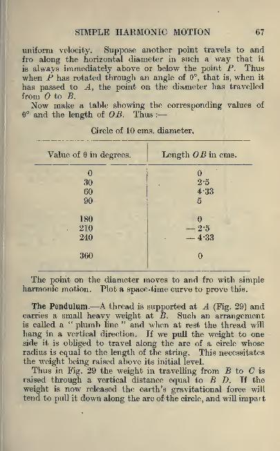
SIMPLE HARMONIC MOTION 67
uniform velocity. Suppose another point travels to andfro along the horizontal diameter in such a way that it
is always immediately above or below the point P. Thuswhen P has rotated through an angle of 6, that is, when it
has passed to A, the point on the diameter has travelled
from to B.
Now make a table showing the corresponding values of
and the length of OB. Thus :
Circle of 10 cms. diameter.
Value of 6 in degrees.

AN INTRODUCTION TO PHYSICS
to it such a velocity that when B is
reached the weight cannot stop, but is
carried up an arc on the other side of
the initial position until all its kinetic
energy is expended. It now repeats the
swing in the opposite direction.
We have here a"pendulum." If
the thread possesses certain properties
(among them no weight), and if the sus-
pended weight has no size, the systemis called a
"simple pendulum ;
"other-
wise it is called a"compound pendulum."
For most practical purposes a small
metal weight attached to a piece of
thread or cotton may be regarded as a
simple pendulum.
Experiment 16.
Suspend a 5 or 10 gramme weight bya length of about 40 or 50 cms. of cotton.
The point of suspension is loest secured
by clamping the cotton between two
strips of wood.Now measure the length of the pendulum from the point
of support to the centre of the weight. Call this length /.
The pendulum should now be made to swing over a small
arc and the time required for it to make, say, 20 completeswings noted. (A complete swing is a swing to and fro.)
If this time is divided by the number of swings we obtain
the"period
"(expressed in seconds), called t.
Now change the weight, using a 20 or 50 gramme weight,but keeping the length as nearly as possible unchanged.Repeat the experiment and ascertain whether the magnitudeof the weight has any influence on the period.
Experiment 17.
Set a pendulum swinging and record the time taken to
accomplish 10 swings. The pendulum will now be swingingover a smaller arc, owing to friction. Without touching it,
FIG.
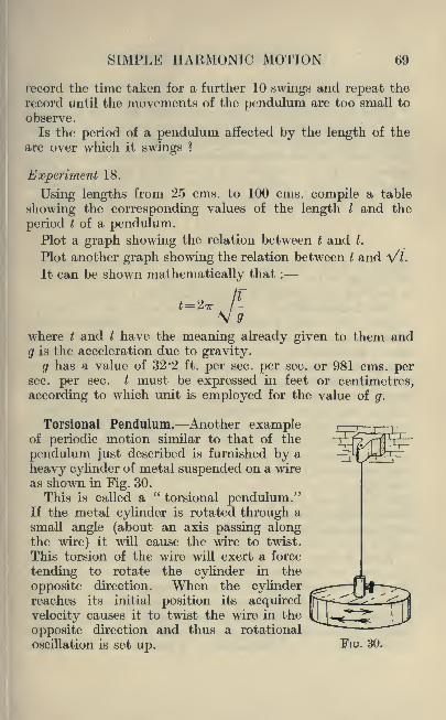
SIMPLE HARMONIC MOTION 69
record the time taken for a further 10 swings and repeat the
record until the movements of the pendulum are too small to
observe.
Is the period of a pendulum affected by the length of the
arc over which it swings ?
Experiment 18.
Using lengths from 25 cms. to 100 cms. compile a table
showing the corresponding values of the length I and the
period t of a pendulum.Plot a graph showing the relation between t and I.
Plot another graph showing the relation between t and V^L
It can be shown mathematically that :
t=2
where t and I have the meaning already given to them and
g is the acceleration due to gravity.
g has a value of 32 '2 ft. per sec. per sec. or 981 cms. persec. per sec. I must be expressed in feet or centimetres,
according to which unit is employed for the value of g.
Torsional Pendulum. Another exampleof periodic motion similar to that of the
pendulum just described is furnished by a
heavy cylinder of metal suspended on a wire
as shown in Fig. 30.
This is called a"torsional pendulum."
If the metal cylinder is rotated through a
small angle (about an axis passing alongthe wire) it will cause the wire to twist.
This torsion of the wire will exert a force
tending to rotate the cylinder in the
opposite direction. When the cylinderreaches its initial position its acquired
velocity causes it to twist the wire in the
opposite direction and thus a rotational
oscillation is set up.
r~~r
FIG. 30.
70 AN INTRODUCTION TO PHYSICS
Experiment 19.
Construct a torsional pendulum and find its period t.
Does the weight or size of the cylinder or the length or diameterof the suspending wire have any influence on the value of t ?
(Students who are interested in the mathematical or mech-anical side of the subject will find a fuller treatment of this
subject in the authors' Second Course in Mathematics
for Technical Students, Chapter viii. It may be shown that
I-* IT-
where 7 is the moment of inertia of the cylinder and c is
the value of the restoring couple due to the torsion of thewire when the cylinder is rotated through 1 radian.)
The Balance-Wheel. Lastly, as an example of periodicmotion, me ntion maybe made of the
"balance-wheel."
This consists of a delicately-balanced wheel, which in rotatinghas to overcome the resistance of a spring. This resistance
brings the wheel to rest, and the action of the spring rotates
the wheel in the opposite direction. It"over-shoots the
mark "so to speak, as in the previous cases, and the spring
pulls it back again. Thus an oscillatory motion is established.
The regularity of the periodic motions just considered
has been applied to the purpose of controlling the movementof time-keepers. The common pendulum was first used for
this purpose by Galileo during the latter part of the sixteenth
century.The torsional pendulum has been used in certain forms of
clocks during recent years. The balance-wheel is employedin watches and portable clocks.
Wave Motion. If a rope is secured to some elevated posi-tion and the free end pulled moderately tight and shaken," waves "
appear to run along the rope towards the fixed
end. The form of the waves in the rope is shown in Fig. 31.
Now it is clear that the material of which the rope is madecannot be travelling along towards the fixed end, otherwise
there would be an accumulation of material at that point.

SIMPLE HARMONIC MOTION 71
A little thought should make it clear that any particle in
the rope merely moves up and down on a path similar to
that shown as XY in Fig. 31. Hence the wave travels alongthe length of the rope, but any particle of the rope merelymoves to and fro along a comparatively short path at right
angles to the direction in which the wave is moving.
FIG. 31.
Transverse Wave Motion. Such u wave propagation as that
just described in a rope is called a transverse wave motion,because the particles of the medium conveying the wraveare moving in a direction transverse (or at right angles) to
the direction of the wave motion.Another example of transverse wave motion is furnished
by the waves formed on the surface of a liquid. The sea,viewed from the end of a pier, often has the appearance of
flowing rapidly in a certain direction, but if a cork is droppedon to the surface of the water it usually rides up and downonly, while the waves themselves pass on. Again, wind
forming waves on the surface of a river often gives it the
appearance of flowing up-stream. In this case the wavesare travelling in one direction while the water itself is trav-
elling in the opposite direction.
Longitudinal Wave Motion. When a train consisting of a
large number of trucks with link couplings is travelling withuniform velocity the links are all in tension. If the engine-driver now shuts off steam and applies the brakes to his engine

72 AN INTRODUCTION TO PHYSICS
for a moment, the velocity of the engine is reduced and thefirst truck in the train bumps into the rear of the engine,and rebounds. This action impairs the velocity of that truckand the second truck bumps into the rear of the first and sothe bumping process is earned right through the train.
Such a motion is another form of wave motion, but since
the motion of the particles of the medium is in the samedirection as the motion of the wave it is called longitudinalwaveimotion.
If a series of little balls were suspended on threads of equallength at equal distances apart, they would have the appear-ance of the row of dots in the upper part of Fig. 32. If
now the end ball were set swinging after the manner of a
pendulum so that the plane of its motion was the same as
ABC f
FIG. 32.
that containing the centres of the balls, it would bump into
the second ball and set it swinging, and this would conveythe motion to number three and so forth, very much after
the manner of the bumping trucks in the train.
Now suppose at a particular moment the row of balls were
photographed instantaneously, they would present an appear-ance similar to that in the lower part of Fig. 32. It will beseen that instead of the balls being equidistant they are
crowded together at certain points, such as B, and spreadout at others such as C.
A crowded group, such as B, would appear to travel through-out the row, just as the crest of a wave appears to travel
over the surface of water, but actually each ball moves over
a very short path only. For example, the ball at F has its
position of rest at G and its next movement will be back to
6r, and then an equal distance beyond G.
Amplitude and Wave Length. In both forms of wavemotion the maximum distance which a particle moves from
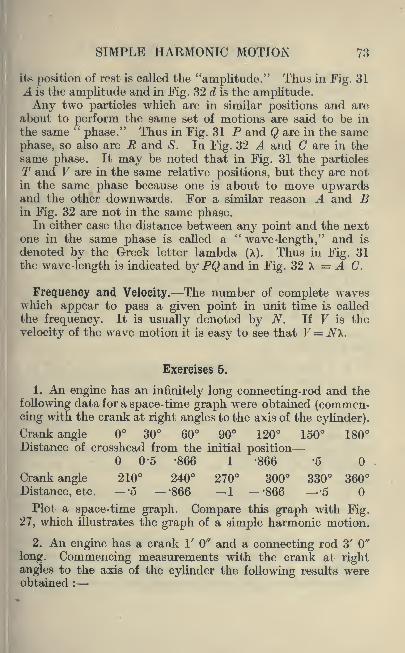
SIMPLE HARMONIC MOTION 73
its position of rest is called the "amplitude." Thus in Fig. 31
A is the amplitude and in Fig. 32 d is the amplitude.Any two particles which are in similar positions and are
about to perform the same set of motions are said to be in
the same "phase." Thus in Fig. 31 P and Q are in the same
phase, so also are R and S. In Fig. 32 A and C are in the
same phase. It may be noted that in Fig. 31 the particlesT and V are in the same relative positions, but they are notin the same phase because one is about to move upwardsand the other downwards. For a similar reason A and Bin Fig. 32 are not in the same phase.
In either case the distance between any point and the nextone in the same phase is called a
"wave-length," and is
denoted by the Greek letter lambda (X). Thus in Fig. 31the wave-length is indicated by PQ and in Fig. 32 X = A C.
Frequency and Velocity. The number of complete waveswhich appear to pass a given point in unit time is called
the frequency. It is usually denoted by N. If V is the
velocity of the wave motion it is easy to see that V= JVX.
Exercises 5.
1. An engine has an infinitely long connecting-rod and the
following data for a space-time graph were obtained (commen-cing with the crank at right angles to the axis of the cylinder).
Crank angle 30 60 90 120 150 180Distance of crosshead from the initial position
0-5 -866 1 -866 '5
Crank angle 210 240 270 300 330 360
Distance, etc. -'5 '866 1 -'866 '5
Plot a space-time graph. Compare this graph with Fig.27, which illustrates the graph of a simple harmonic motion.
2. An engine has a crank 1' 0" and a connecting rod 3' Q"
long. Commencing measurements with the crank at rightangles to the axis of the cylinder the following results wereobtained :

74 AN INTRODUCTION TO PHYSICS
Crank angle 30 60 90 120 150 180 210Distance of the crosshead from the initial position
'45 -725 -825 '725 '45 '55
Crank angle 240 270 300 330 360
Position, etc. 1 M75 1 '55
Plot a space-time graph. Compare the graph with Fig. 27.
Describe any difference you note between this graph andthe graph in the preceding question.
3. Draw a horizontal line OX on a piece of paper. Takea thin piece of wood and fix a pin at the point and 2"
away from O fix a drawing-pin at P, carrying a piece of
cotton, to which a weight is attached. Place the pin at
O in the line X and revolve the wood OP, noting every 30where the plumb line fixed at P intersects the line OX.Call the distance OM . Tabulate the results as follows :
Angle OP makes with OX 30 60 90 120Distance OM measured from 2" 1-732 1"
Complete the graph of the two results and compare the graphwith Fig. 27.
4. A steel ball 10 millimetres in diameter was placed in aconcave lens of 7 '709 centimetres radius and given a gentle
push. It was found to make 10 oscillations in 6 '5 seconds.
What was the periodic time ?
The periodic time can be calculated from the followingformula : T= 277^0-4347?.
Where R=the radius of the concave surface minus the
radius of the steel ball and all measurements are taken in
feet.
Does the periodic time as calculated agree with the time as
determined from the experiment ? Carry out similar experi-ments.
5. A spiral spring had a weight Z placed on the end and was
given a pull to set it in oscillation. The spring made 48
oscillations in 10 seconds. Determine the periodic time.
After completing the experiment it was found that F Ibs.

SIMPLE HARMONIC MOTION 75
X ffx32-2
extended the spring To feet. If R= _*_ (poundals), deter-*4. 12
V-JJf-=--tv
Z=51bs., J=0'5 Ibs., and z=0'05. Does the calculated
periodic time agree with the experimental time ?
6. A "IT" tube containing water. to a depth of 6 inches
was slightly displaced from its mean position. The water
was set in oscillation and made 20 oscillations in 11 seconds.
What is the periodic time ? Calculate the periodic time from
the formula T= -r-^/ a where a is taken in feet end repre-
sents the depth of the water.
7. Weights of 10, 20, 50 and 100 grammes were suspendedby equal lengths of cotton (44. cms.). The following table
gives the time of swing in each case. Determine the time of
swing and state what conclusions could be drawn if a numberof other experiments gave similar results.
Weight in grammes 10 20 50 100
No. of swings ... 42 42 42 42
Time to complete swings in
seconds... .60 60 60 60
8. The swings per minute of a pendulum were recorded,and are as follows : First minute 44 swings, second minute44 swings, third minute 44 swings. It was noted that the
arc of swing became smaller. Is the time of swing altered
by the length of arc of swing ? Repeat this experiment.
9. A number of pendulums of different lengths were selected
and the following results were obtained :
Length of pendulum in centimetres :
20 40 60 80 100Period of oscillation in sees. :
0-85 1-3 1-6 1-8 1-88
Plot a graph of these results and state what appears to bethe general effect of shortening the length of the pendulum.

76 AN INTRODUCTION TO PHYSICS
10. Taking the formula, t= 2n I ---, determine the time
V yof oscillation or period of the pendulums in the precedingquestion. Plot a graph of t and *.
11. Place some water in a" U "
tube and by blowing downone limb set the water in oscillation. Determine the periodictime of the oscillation. Carry out a number of experimentsand see whether the following formula gives the same results.
=-j--\/ a where a is the length in feet of the water column.
12. Take a straight steel spring or a uniform thin strip of
wood; fasten one end in the vice. Set the rod in vibration
and determine the periodic time. Fasten to the free end of
the rod a small camel hair brush which is just arranged totouch a piece of cardboard. Dip the end of the brush in inkand move the cardboard rapidly and uniformly along in thedirection of the length of the spring. Give a sketch of thecurve produced. Fill a funnel having a narrow outlet withsand and suspend as a pendulum. What figure is traced outif a piece of cardboard is placed just below the pendulum ?
Is the figure of uniform thickness ?
13. Repeat the above experiment but now move the card-
board at a uniform rate at right angles to the plane of the
swing of the pendulum. What diagram is traced out in this
case ?
14. How many vibrations per minute would a pendulum39" long make at a place where g=32 '2 feet per sec. per sec. ?
15. Determine the length in inches of a seconds pendulum,given the value of g in British units as 32-1740 feet per sec.
per sec.
16. A clock loses 5 minutes per day ;the pendulum should
beat seconds. Determine the alteration in length requiredto make the clock keep correct time. Take g as equal to
32-174 feet per sec. per sec.
SECTION III. SOUND
CHAPTER VI
VIBRATION AND THE MUSICAL SCALE
Propagation of Sound. If one watches- the firing of a
distant gun, the flash of the explosion is seen and after an
appreciable interval the sound is heard . Since it is known that
the flash and the noise occurred together, it follows that lighttravels very much more quickly than sound, and that the
latter, at any rate, does not travel instantaneously.If between the gun and the observer there is an obstacle
(a building for example) the flash of the gun is not seen, butthe sound is still heard. From this it follows that lightcannot ordinarily travel round an obstacle, whereas sounddoes do so.
Lastly, if the ear is placed to the earth it often happensthat a distant sound is heard which would have been inaudible
through the air. It is seen', therefore, that sound can travel
through solid matter (like the earth) as well as, and perhapsbetter than it travels through the air.
Experiment has shown that matter of some kind is neces-
sary for the propagation of sound, for if an electric bell is
hung in the bell -jar of an air-pump the sound reaches theoutside very readily so long as the bell -jar contains air, butas a vacuum is produced the intensity of the sound rapidlydiminishes.
Vibration. If we observe very closely a piano wire after
it has been struck it will be seen that it is"vibrating ;
"that
is, it is moving very rapidly from side to side. The noteor sound which the wire is producing continues to be audible
so long as the vibration continues, and it is obvious to the
77

78 AN INTRODUCTION TO PHYSICS
most casual observer that the volume of the sound is moreor less directly proportional to the extent of the movementof the wire in its vibration.
Now the beating of this wire against the air sets up a series
of" waves "
similar in many respects to the wave of bumpingtrucks in the train illustration of the last Chapter.
In other words longitudinal wave motion is set up in the
air, ,and it is by this means that the vibration is conveyed to
our ear and the sensation of sound produced. The wave-
length is certainly long, often several feet, and the fre-
quency is very high, usually several hundreds per second.
The Velocity of Sound. We have already seen that althoughsound travels very rapidly its progress is not instantaneous.
Before considering the measurement of its velocity it is
advisable to determine whether all kinds of sound travel
at the same rate. Does a"high
"note, for example, travel
more or less rapidly than a"low
"note ?
If a band is playing at a distance it is obvious that we hear
the notes some time after they are actually played. Nowif different notes had different velocities, notes which were
played together would not be heard together and the harmonywould be upset. Such is not the case, and it is therefore safe
to assume that sound of different frequencies has the same
velocity.
To obtain a value for the velocity of sound, in air, it is
only necessary to record the time occupied by sound to travel
over a measured distance. Thus if we record with a stop-watch the interval between the flash of a gun at a knowndistance and the moment when the noise of the explosionbecomes audible, we have the necessary data.
Since the sound is propagated by the actual vibration
of the air particles it follows that if there is any wind it will
affect the result. Naturally one chooses for such an experi-ment a day when there is as little wind as possible, but even
so it is impossible to ensure perfectly still air.
This difficulty is readily overcome by having two guns,one at each end of a measured line. The velocity of sound is
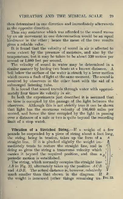
VIBRATION AND THE MUSICAL SCALE 79
then determined in one direction and immediately afterwards
in the opposite direction.
Thus any assistance which was afforded to the sound waves
by an air movement in one determination would be an equalhindrance in the other
;hence the mean of the two results
gives a reliable value.
It is found that the velocity of sound in air is affected to
some extent by the presence of moisture, and also by the
temperature, but it may be taken to be about 330 metres persecond or 1,080 feet per second.
The velocity of sound in water may be determined in asimilar manner by having two boats at a known distance. Abell below the surface of the water is struck by a lever motionwhich causes a flash of light at the same moment. The sound is
received by observers in the other boat with the aid of a
submerged listening tube.
It is found that sound travels .through water with approxi-
mately four times its velocity in air.
In both the experiments just described it is assumed that
no time is occupied by the passage of the light between the
observers. Although this is not strictly true it can be shownthat light has the enormous velocity of 186,600 miles persecond, and hence the time occupied by the light in passingover a distance of a mile or two is quite beyond the recordinglimit of a stop watch.
Vibration of a Stretched String. If a weight of a few
pounds be suspended by a piece of string about a foot long,the string, being in tension, takes up the form of a A
straight line. If it is plucked slightly the weight im-
mediately tends to restore the straight line, and in '
doing so gives the string a transverse velocity which '
carries it beyond the required position, and thus a^'periodic motion is established.
The string, which normally occupies the straight line
AB in Fig. 33, alternately takes up the position ACE\
and ADB. The actual distance is, however, relativelymuch smaller than that shown in the diagram. If
the weight is increased (other things remaining un- FIG. 33.

80 AN INTRODUCTION TO PHYSICS
changed) the string will be given a greater velocity, that is,
its"frequency
"will be raised.
The Monoehord. The monochord, shown in Fig. 34, is a
suitable instrument for investigating the laws governing thevibration of a stretched string or wire. It consists of a stripof wood (or a box open at one end) about a yard long and a
few inches wide. This is fastened to a bench, and a wire or
string, secured at A, passes over a fixed"bridge
"B, then
over a movable bridge C, and finally over a pulley D to
carry a scale-pan on which a weight W may be placed. Various
pieces of string and wire should be tried, but avoid very stiff
wire which it is difficult to bend. The bridges should bemade of hard wood, or if soft wood is used a piece of steel
wire should be fixed along the ridge.
IB \c
FIG. 34.
Experiment 20.
Fit up a monochord, and keeping the load W constant,find the effect of altering the length I between the bridges.Next keep I constant and vary the load W. Lastly, keepload and length constant, find the effect of substituting a
thinner or a thicker wire of the same material.
Musical Note. The ear readily detects the difference
between a noise and a musical note. Physically the differ-
ence is that a musical note is propagated by a longitudinalvibration of regular frequency and wave-length. A noise is
also propagated by a longitudinal vibration, but both the
frequency and the wave-length are irregular.A musical note possesses three qualities : (i) pitch (i. e.,
the note is"high
"or
" low "), (ii) intensity (i,e., the not^e
is"loud
"or
"soft "), (iii) timbre or quality.

VIBRATION AND THE MUSICAL SCALE 81
The pitch of a note depends upon the frequency of the
vibration causing it. The more rapid the vibration the"higher
"the note. The intensity of the note depends
upon the amplitude of the vibration. The conditions decidingtimbre will be considered later.
The Musical Scale. In the upper part of Fig. 35 is shown a
portion of the keyboard of a piano. This section of notes
is called an "octave
"because it contains eight white notes.
The letters which are
used to designate these
eight notes are shown,as is also the notation
used in music.
If two notes have the
same frequency they are
said to be in"unison
";
if they have different
frequencies the ratio of
the frequencies is called
the"interval
"between
the notes.
At the bottom of Fig.35 a row of numbers is;
given which show the
relative frequencies of
the eight notes of the
octave shown. It will
be seen that the interval between C and D is 27/24ths or
9/8ths. Between D and E it is 10/9ths and between E and F16/15ths. Following on we have intervals of 9/8ths, 10/9ths,
9/8ths, and 16/15ths.Certain intervals are given names. For example, an
interval of 9/8ths is called a"major tone," while an interval
of 10/9ths is called a " minor tone." The interval of 16/15thsis called a
t:diatonic semitone."
The numbers given express only relative frequencies, andthese always hold good. The actual frequency of a notevaries slightly. The frequencies of all notes are fixed when
RELATIVE FREQUENCY OF DIATONICSCALE.
FIG. 35.

82 AN INTRODUCTION TO PHYSICS
the actual frequency of one is given, and for this purpose theC nearest the middle of a piano manual is generally used.It is called
"Middle C."
In physics the frequency of middle C is generally taken as
256 vibrations per second. Modern concert pitch makes it
276. The French standard pitch has 261, while the Stuttgartpitch (adopted by the Society of Arts) makes it 264.
"Knel-
ler Hall," a pitch largely adopted by military bands, givesmidclle C a frequency of 269 vibrations per second.
Knowing the pitch of one note and the interval betweenthis and another note it is easy to find the pitch of the latter.
nft
Thus the frequency of G (concert pitch) is x 276 = 414vibrations per second.
The scale just described is called the"Natural Scale."
A slightly modified scale is now used in music. This is called
the"Tempered Scale." It makes the interval of a
"half
tone"the same in all parts of the scale. Thus the following
intervals are equal : C and C$ 9E and F, B\> and B. The
following frequencies are useful for comparison.
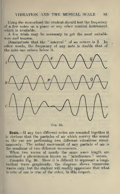
VIBRATION AND THE MUSICAL SCALE 83
Using the monochord the student should test the frequencyof a few notes on a piano or any other musical instrument
which is available.
A few trials may be necessary to get the most suitable
wire and tension.
Demonstrate that the"interval
"of an octave is 2. In
other words, the frequency of any note is double that of
the note one octave below it.
A A
B
7\A A A -A A A .AV V V V V V V
/\. A
FIG. 36.
Beats. If any two different notes are sounded together it
is obvious that the particles of air which convey the sound
to the ear are performing two different vibrations simul-
taneously. The actual movement of any particle of air. is
the resultant of two different movements.When two waves of nearly the same wave length are
combined a phenomenon known as"interference
"occurs.
Consider Fig. 36. Since it is difficult to represent a longi-tudinal wave graphically, the diagram shows transverse
waves only, but the student will readily appreciate that whatis true of one is true of the other, in this respect.

84 AN INTRODUCTION TO PHYSICS
The graphs A and B show waves of nearly the same wave
length, A being slightly the longer. It will be observed that
at the beginning they are"in phase," but owing to the
difference of wave length the two waves gradually get outof phase until at the point P they are in opposite phase.That is to say, a particle conveying such a pair of waveswould at this point be called upon to move equally in oppositedirections, the result being no movement at all. At Q the
waves are back in phase again, the longer having completedfive waves while the shorter has completed six.
At C is shown the sum of the two graphs A and B. Fre-
quent points have been selected and the distance of each
graph measured from the zero line. Distances above this
line are taken as positive while those below are negative.The algebraic sum provides the data for graph C.
It will be observed that the amplitude (which is responsiblefor the intensity or loudness of a note) is greatly augmentedwhen the original vibrations are in phase, but it sinks almost
to nothing when the vibrations are in opposite phase.The effect of this is to produce an unpleasant beating on
the ears, the note being alternately very loud and very soft.
Fig. 36 makes it clear that a"beat
"or loud effect occurs
every time the shorter wave gains one complete vibration.
Hence if we are producing a note of 256 vibrations a second
and another note is produced which causes one beat persecond it follows that the frequency of the latter is either
255 or 257.
Experiment 22.
Fix two monochord wires to produce two notes exactly in
unison. Then move very slightly one of the bridges so that
beats are produced. What is the effect of moving the bridge
slightly farther in the same direction ?
Beats may be produced very effectively by employingtwo tuning forks of the same pitch and slightly decreasingthe frequency of one by loading one of its prongs.
This may be done by attaching a small strip of lead or evena bead of wax at the free end of one prong.

VIBRATION AND THE MUSICAL SCALE 85
Exercises 6.
1. Give six sketches showing parts of mechanisms whichare vibrating in equal intervals of time.
2. Give the periodic time in each of the above cases. If
you do not know the exact periodic time give the average.Take the periodic time to be the time taken to complete oneto and fro movement.
3. The vibration frequency may be defined as the numberof periods in one second. State the average vibration fre-
quency in Question 1.
4. Take a piece of wood of suitable length and of cross -
section f"by J" ;
fasten one end in a vice. Determine the
period and frequency of the free end. Repeat the experi-
ment, taking the same length and the cross-section |" by J".
What can you deduce from this experiment ?
5. What do you understand by a vibratory motion ?
6. Describe the way in which sound is propagated throughair.
7. Distinguish between longitudinal and transverse vibra-
tions and illustrate your answer by sketches.
8. Define frequency, amplitude, and wave-length.
9. The following figures show the velocity of sound in feet
per second. Express them in metres per second.
Velocity of sound in air, 1,080 ;in water, 4,900 ;
in wet
sand, 825;
in granite, 1,664 ;in iron, 17,500 ;
in copper,10,378 ;
in pine wood 11,000.
10. Boys are placed at two successive telephone poles andone of the poles is struck by a blow. Will the sound trans-
mitted through the wood and wire be heard before the soundtransmitted through the air ? Use the figures in the preced-
ing example to give an approximate result.
11. Explain how you would perform a series of experimentson a monochord and show from the results of your experi-ments that the following statements are true ::

86 AN INTRODUCTION TO PHYSICS
(1) The frequency is inversely proportional to the lengthof the string.
(2) The frequenqy is inversely proportional to the diameterof the string.
(3) The frequency is inversely proportional to the squareroot of the density of the material of which the string is made.
(4) The frequency is directly proportional to the square root
of the tension by which the string is stretched.
12. Assuming that the middle C has a frequency of 256vibrations per second, determine the note emitted when acard touches a wheel with 64 teeth revolving at the rate of
8 revolutions per second.
13. In a mechanism, one of the wheels has 32 teeth andis revolving 16 times per second. If the tip of the wheelrubs against a piece of material so that a musical note is
produced, state what is the note ? How many revolutions
per second must the wheel make to produce the middle B ?
14. The following table shows the vibrations per second of
the sequence of the white notes on the piano commencingwith the middle C :
Notes C D E F G A B C'
Vibrations per second256 288 320 341 '3 384 426 '6 480 512
What is the interval between each of the notes as comparedwith C ? Express your results as vulgar fractions expressedin their simplest forms.
15. If the middle C has a frequency of 256 show the posi-tion on the treble musical stave of notes having the following
frequencies : 320, 384, 512.
16. The humming noise which accompanies the flight of
certain flies is caused by the beating of their wings. The
following information is supplied : The wings of a gnat make50 per second beats, of a wasp, 110, and of the common house
fly, 330. From your own experience state what is the
approximate note in each case and explain how the figures
supplied bear on your answer.

VIBRATION AND THE MUSICAL SCALE 87
17. It has been noted that a series of taps will blend into
a musical note when their number exceeds 20 per second.
Using this information state which of the following machines
will be likely to cause a musical note :
Ingersoll"Eclipse Rock Drills
"
Size and type . . . B2 C6 E3 FAStrokes per minute . . .500 375 350 300
Petrol enginesMaximum strokes per minute of the valve tappets
725 925 625 1050
18. A wheel with 64 teeth revolves at 4 revolution^ persecond and a card just touches the wheel. What note is
produced ? If some of the teeth are now broken off in an
irregular mariner, state how the sound produced will bealtered.
19. What is the difference between a musical sound and a
noise ?
20. A gas engine discharges its exhaust gases at a pressureof 25 Ibs. per sq. in. above atmosphere into a long exhaust-
pipe 65 feet long. Oscillations or waves of pressure are set
up in the exhaust-pipe. If the engine exhausts 80 times perminute, give a sketch of the pressure wave and state whatwill be its frequency.
21. Discuss the use of the"silencer
" on a motor cycle.
Why is there a difference in the noise produced by the exhaustwhen the
"cut-out
"is used ?

CHAPTER VII
HARMONICS AND RESONANCE
Nbdes and Loops. When a length of wire is vibratingthere are certain points which do not move at all and certain
others which move a maximum amount. The former are
called"nodes
" and the latter"loops." In Fig. 33, which
showed the simplest form of vibration, it is seen that wehave nodes at the points where the wire crosses the bridgesand a loop at a point mid-way between the bridges.Whatever else happens it is obvious that nodes must occur
at the points where the wire crosses the bridges, but theymay occur elsewhere also. For example, it is quite possible
by gently touching a wire midway between the bridges and
bowing it (with a violin bow) at a point about one quarterof its length from one bridge, to induce it to vibrate in a
manner shown in Fig. 37.
If such an effect is produced the note emitted is foundto be an octave above that given by the simple vibration
(which is called the"fundamental "). In other words, the
frequency of this note is exactly double that
of the fundamental.It is possible to produce a vibration in
the wire similar to that shown in Fig. 38,
in which there are three additional nodes. It
is found, however, that the conditions for
this vibration are much more difficult to
obtain than those in the previous case. It
is readily seen that other vibrations wouldbe possible if the conditions for producingthem could be obtained.
Now it has been shown that a stretched
FIG. 37. wire can vibrate in several ways at once Fiu. 38.
88

HARMONICS AND RESONANCE 89
and in fact always does so. The "note
"which is heard is
usually the fundamental, but more complex vibrations are
taking place at the same time, although the amplitude of
these is usually very small indeed compared with the ampli-tude of the fundamental. It is for this reason that we donot hear as such the notes produced by these small vibra-
tions, but the sound which they produce goes to make upthe quality or timbre of the note.
Harmonics. These small complex vibrations which are
nearly always present in a note are called"harmonics "
or"overtones." The vibrations shown in Figs. 37 and 38
would be called the first and third harmonics (or more cor-
rectly the"harmonics of the second and fourth orders ")
respectively.If
"middle C "
be sounded on a piano and the note is
taken up and produced in exact unison by other instruments,such as a violin and a cornet, the note is still middle C, andas such its frequency is 256 vibrations per second. Thethree notes, however, are very far from being alike in quality.
This difference of quality is due to the presence of a different
set of harmonics in each case. Students who play the violin
will be familiar with the formation of harmonics. Normallya violinist presses a string down with his fingers and the bowsets up a vibration in the portion of the string between his
finger and the violin bridge. This is a fundamental vibra-
tion. In such cases he obtains a note of higher frequencyby actually reducing the length of the string which vibrates.
When, however, the violinist wishes to produce a harmonic,he just touches the string at a certain point and bows verygently and the whole string is set in vibration : that is, thevibration is not confined to the portion of the string betweenhis finger and the bridge.
Resonance. If a very long and very heavy pendulum is
erected, it requires a considerable effort to set it in motion.
If, however, it is found either by trial or calculation that the
period of such a pendulum is, say, 5 seconds, it is possibleto set the pendulum swinging by applying to the bob a
comparatively small force at regular intervals of 5 seconds.
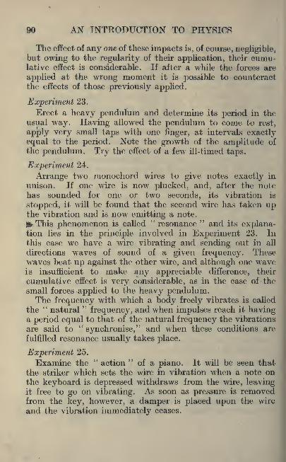
90 AN INTRODUCTION TO PHYSICS
The effect of any one of these impacts is, of course, negligible,but owing to the regularity of their application, their cumu-lative effect is considerable. If after a while the forces are
applied at the wrong moment it is possible to counteractthe effects of those previously applied.
Experiment 23.
Erect a heavy pendulum and determine its period in theusual way. Having allowed the pendulum to come to rest,
apply very small taps with one finger, at intervals exactlyequal to the period. Note the growth of the amplitude of
the pendulum. Try the effect of a few ill-timed taps.
Experiment 24.
Arrange two raonochord wires to give notes exactly in
unison. If one wire is now plucked, and, after the notehas sounded for one or two seconds, its vibration is
stopped, it will be found that the second wire has taken upthe vibration and is now emitting a note.
!*r This phenomenon is called"resonance
" and its explana-tion lies in the principle involved in Experiment 23. Inthis case we have a wire vibrating and sending out in all
directions waves of sound of a given frequency. Thesewaves beat up against the other wire, and although one waveis insufficient to make any appreciable difference, their
cumulative effect is very considerable, as in the case of the
small forces applied to the heavy pendulum.The frequency with which a body freely vibrates is called
the"natural
"frequency, and when impulses reach it having
a period equal to that of the natural frequency the vibrations
are said to"synchronise," and when these conditions are
fulfilled resonance usually takes place.
Experiment 25.
Examine the"action
"of a piano. It will be seen that
the striker which sets the wire in vibration when a note onthe keyboard is depressed withdraws from the wire, leavingit free to go on vibrating. As soon as pressure is removedfrom the key, however, a damper is placed upon the wire
and the vibration immediately ceases.

HARMONICS AND RESONANCE 91
If a key is depressed very slowly the striker fails to reach
the wire and no note is emitted, but so long as the key is
kept down the damper is raised from the wire.
Depress middle C in this way, and while it is held downstrike the C below it, hold it down for a second or two, andthen release it. Middle C will now be sounding.Here we have a case in which the first harmonic of the
lower C (which is equal in frequency to middle C) has syn-chronised with the fundamental of middle C and set the wire
in vibration.
Again, having silently depressed middle (7, strike the
C above it, allow it to sound for a second or two, and release
it. It will be found that middle C is now emitting a note of
an octave higher. In this case the vibrations of the funda-mental of upper C synchronised with the first harmonic of
middle C and hence set the wire in vibration of the formshown in Fig. 37.
Note. The student will find a certain amount of mathe-matical treatment of harmonics in the authors' Second Coursein Mathematics for Technical Students, chapter x. Alsothe author's paper on
"Vibration of Spars in Aircraft,"
published in Engineering, vol. CIX., page 201, gives some
practical applications of harmonics.
Exercises 7.
1. Show by the aid of sketches what you understand by the
terms," node " and "
loop."
2. Show by the aid of a sketch a wire vibrating in such amanner as to sound its fundamental note. What difference
in the sound is caused by the wire vibrating in 2, 3, or 4
separate portions respectively ?
3. The same note is sounded on a piano and a violin.
Explain why it is easy to distinguish the two types of instru-
ments although the same note has been sounded in each case
4. What do you understand by the following statement :
In the case of vibrating strings the frequencies of the sue-

92 AN INTRODUCTION TO PHYSICS
cessive overtones are as the series of the natural numbers.Give drawings to illustrate your answer.
5. Experiment 21 gives the following formula :
N= /^21 V ra
The density of the following materials, in grammes percubic centimetre, is as follows : Aluminium 2 '58, copper8 '93, mild steel 7 '68, wrought iron 7 '8, cast steel 7 *9. You are
given wires made of these materials of the same diameterand length and loaded with the same weight. An experimentis then performed on the monochord with each of these wires
;
arrange the metals in sequence, placing the wire which givesthe highest note at the top. Show that experiment and cal-
culation give the same result.
6. A common shop method of distinguishing bars of metalis to listen to the note sounded when the bar is struck. If
equal bars of mild steel, wrought iron and cast steel are pro-vided state how you would distinguish them by this method.
7. In any note sounded by an open organ pipe the harmonics
may have waves of frequencies of 2n, 3n, 4nt etc., where n
is the frequency. In a closed pipe only frequencies of 3n} 5n,
etc., exist. The lack of even harmonics in the latter case
gives a nasal quality to the tone. Show diagrammaticallythe harmonics in the two types of pipes.
8. In preparing the foundations of engines it is verynecessary to arrange that any vibrations arising from want of
balance should not be transmitted to the rest of the building.One method adopted is first to fix concrete foundations for
the engine, then to place a layer of compressed felt betweenbed plate of the engine and the concrete face. Give reasons
to show why the felt should help to prevent the transmission
of vibration.
9. Show by the aid of sketches how vibration is produced in
the following cases : (a) by blowing sharply across the endof the hole in a key, (6) in an ordinary tin Avhistle.

HARMONICS AND RESONANCE 93
10. When two notes are not quite in tune the resultingsound is found to alternate between a maximum and aminimum of loudness which recurs periodically. Show by the
aid of a diagram how this is caused.
11. An aeroplane with two engines is heard some distance
away and the sound is heard as a succession of beats. It is
known that the engines are not making exactly the samenumber of revolutions per minute, but the average numberof revolutions is 2,000 per minute. Give explanations whythe sound is heard in beats.
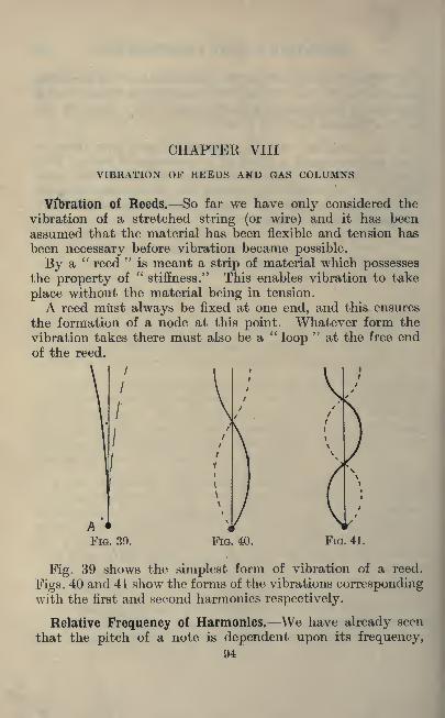
CHAPTER VIII
VIBRATION OF REEDS AND GAS COLUMNS
Vibration of Reeds. So far we have only considered the
vibration of a stretched string (or wire) and it has been
assumed that the material has been flexible and tension has
been necessary before vibration became possible.
By a"reed
"is meant a strip of material which possesses
the property of"
stiffness." This enables vibration to take
place without the material being in tension.
A reed must always be fixed at one end, and this ensures
the formation of a node at this point. Whatever form the
vibration takes there must also be a "loop
"at the free end
of the reed.
\
FIG. 40. FIG. 41.
Fig. 39 shows the simplest form of vibration of a reed.
Figs. 40 and 41 show the forms of the vibrations correspondingwith the first and second harmonics respectively.
Relative Frequency of Harmonics. We have already seen
that the pitch of a note is dependent upon its frequency,94
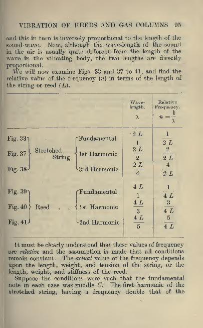
VIBRATION OF REEDS AND GAS COLUMNS 95
and tills in turn is inversely proportional to the length of the
sound-wave. Now, although the wave-length of the soundin the air is usually quite different from the length of the
wave in the vibrating body, the two lengths are directly
proportional.We will now examine Figs. 33 and 37 to 41, and find the
relative value of the frequency (n) in terms of the length of
the string or reed (L).
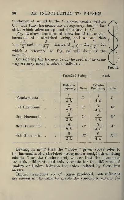
96 AN INTRODUCTION TO PHYSICS
fundamental, would be the C above, usually writtenC'. The third harmonic has a frequency double thatof C', which takes us up another octave to C".
Fig. 42 shows the form of vibration of the secondharmonic of a stretched string, and we see that
f\ T Q I O- and n = '
Hence> if = 24) = 72'
which a reference to Fig. 35 will show is the /*

VIBRATION OF REEDS AND GAS COLUMNS 97
series if he wishes. The designer of musical instruments
has to study which harmonics give a pleasant and which an
unpleasant quality to a note and he then has to foster the
former and eliminate the latter by suitable design in
the instrument.
Experiment 26.
Obtain a strip of steel (or a steel knitting-needle) and fix
it in a vice so that the free portion will emit a note whenmade to vibrate. Make a table showing the relation betweenthe length of the reed which emits any note and the lengthwhich emits the octave of that note. (Remember that if
N is the frequency of any note the octave above has a fre-
quency of 2 N and the octave below a frequency of \ N.)
Tuning Forks. The vibration of a tuning fork is only a
special case of the vibration of a reed. It may be regardedas two reeds, attached at one end. Fig. 43 shows -
the form of vibration. The two prongs alternately
approach and recede from each other.
A fork of this nature has two advantages overa single reed. Its n&te is sustained : that is, the
vibration continues much longer than it would in
a single reed, and unless the vibration is violent
the note emitted is singularly"pure." In other
words, harmonics are almost absent.
Tuning forks of standard pitch may be obtainedand these form a convenient standard of reference.
Forks may be set in vibration by gently striking,but a better method is to draw a violin bow across FIG. 43.
one prong. If a fork is placed with its base on a
piece of wood, or better still a wooden box, the vibrations of
the fork are conveyed to the wood and the volume of soundemitted is greatly increased.
The Vibration of a Column of Gas. So far we have onlyconsidered the vibration of solid matter, and its power to
vibrate has been due to its possessing the property of elas-
ticity. An elastic body is one which, when deformed by
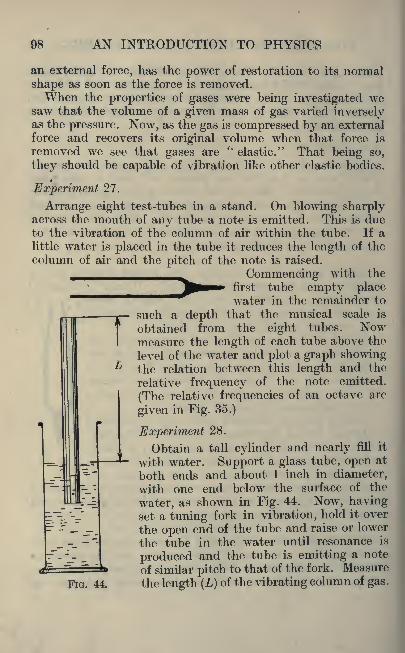
98 AN INTRODUCTION TO PHYSICS
an external force, has the power of restoration to its normal
shape as soon as the force is removed.When the properties of gases were being investigated we
saw that the volume of a given mass of gas varied inverselyas the pressure. Now, as the gas is compressed by an external
force and recovers its original volume when that force is
removed we see that gases are"
elastic." That being so,
they should be capable of vibration like other elastic bodies.
Experiment 27.
Arrange eight test-tubes in a stand. On blowing sharplyacross the mouth of any tube a note is emitted. This is dueto the vibration of the column of air within the tube. If alittle water is placed in the tube it reduces the length of the
column of air and the pitch of the note is raised.
Commencing with the
^^^ first tube empty placewater in the remainder to
such a depth that the musical scale is
obtained from the eight tubes. Nowmeasure the length of each tube above the
level of the water and plot a graph showingthe relation between this length and the
relative frequency of the note emitted.
(The relative frequencies of an octave are
given in Fig. 35.)
Experiment 28.
Obtain a tall cylinder and nearly fill it
with water. Support a glass tube, open at
both ends and about 1 inch in diameter,
with one end below the surface of the
water, as shown in Fig. 44. Now, havingset a tuning fork in vibration, hold it over
the open end of the tube and raise or lower
the tube in the water until resonance is
produced and the tube is emitting a note
of similar pitch to that of the fork. Measure
FIG. 44, the length (L) of the vibrating column of gas.

VIBRATION OF REEDS AND GAS COLUMNS 99
If forks of other frequencies are available the experimentshould be repeated, and a graph plotted showing the relation
between length of column and frequency.Now let us consider in detail what is happening in this
experiment when resonance occurs. Suppose at a particularmoment the lower prong of the tuning fork is moving down-
wards. This impact on the adjacent air particles will start
a compression wave down the tube. This wave will be re-
flected at the surface of the water and return up the tube.
For resonance to take place the wave must reach the lower
prong of the fork as it moves upwards.If the frequency of the fork be N vibrations per second
it will be seen that the interval between the prong moving
downwards and its commencing to move upwards is-^-^
seconds. In this interval the sound wave has moved downthe tube and up again, a distance of 2 L.
Now velocity= -1^
time.
2 L.*. Velocity of sound= 1
T~N.=4 LN.
This method of determining the velocity of sound is not
very accurate. A certain amount of disturbance takes
place at the open end of the tube. A closer approximationis given by :
Velocity=4 N (L+0'4 d).
where d diameter of tube.
The student should obtain a value for the velocity of
sound by this method. It should not be necessary to addthat all measurements of length should be made in the sameunit : say the foot or the centimetre.
The student should note that the column of gas producingthe sound in the preceding experiment was vibrating witha longitudinal vibration, and not transversely as in the case
of a stretched string or a reed. It is convenient neverthe-

100 AN INTRODUCTION TO PHYSICS
less to speak of nodes and loops. In thecase under consideration there was anode at the closed end of the tube (i.e.
at the water surface) and a loop at the
open end. This is represented in Fig. 45,the letters N and L representing nodeand loop respectively. The arrows re-
present the direction of motion of theair particles.
Organ Pipes. Fig. 46 shows a section
of a simple organ pipe made of wood.FIG. 45. Air passes from the wind chamber
through the inlet A and passing up thechannel shown, impinges on the lip B. This causesthe column of air within the pipe to vibrate, butunlike the column of air in the tube in Experiment
FlG - 46 -
28 this pipe is open at both ends and there musttherefore be a loop at both ends of the pipe. The form of
vibration for the fundamental note is shown in Fig. 47.
The forms of vibration for the 1st and 2nd harmonics are
shown in Figs. 48 and 49 respectively, and it will be notedthat there is a loop at both ends of the pipe in all cases.
Closed Pipes. The organ pipe just considered is known as
an "open pipe." On a modern organ, however, there are
li
\\
\\L
FIG. 47.
L

VIBRATION OF REEDS AND GAS COLUMNS 101
always a certain number of pipes exactly similar to Fig. 46,
but having a tightly-fitting stopper driven into the top.These are known as stopped or closed pipes.The effect on the nature of the vibration is to make a
node at the closed end of the pipe. The form of vibration
for the fundamental is shown in Fig. 50, while Figs. 51 and52 show the forms of vibrations of the first and secondharmonics.
Letting L represent the length of the pipe we may nowcompile a table similar to that referring to the vibration of
stretched strings and reeds.
102 AN INTRODUCTION TO PHYSICS
that the harmonics differ, and hence the note, although of
the same pitch, is of quite different quality, as every organistknows.
Exercises 8.
1. A piece of thin wood was fixed in the vice and set in
vibration. This experiment was repeated 4 times for the
following lengths : % 0", I' 6", 1' 0", 6".
1If the frequency =-rr=-(7,
where =the length, and C equals a constant, determine the
frequency ratio between the 2'-0" and the other three bars.
2. Give a sectional sketch of a mouth-organ and markclearly the vibrating tongue.
3. Examine, if possible, an oboe, a bassoon, and a clarinet.
Give sectional sketches showing diagrammatically the air
current and the reed.
4. If the vibration number of the lowest note on the piano,A4 ,
is 27, and the speed of sound in air is 1,130 feet per second,find the wave-length of the note as it travels through the air.
5. A thunderclap was heard 4} seconds after the accom-
panying lightning- flash was seen. How far away did the
flash occur ?
6. On a still day the human voice may be heard for 150
yds. and rifle fire for 5,300 yds. Assuming the usual velocityof sound in air state what time sound will take in travellingthe distances given.
7. A flat disc has 30 holes, spaced equally, with the centres
of the holes on the same circle. If the disc is rotated rapidlyand a jet of air is blown through a small glass tube and madeto impinge on these holes, state what will happen :
(a) When the disc runs at a uniform speed.
(b) A variable speed.
(c) Double the speed in (a).
VIBRATION OF REEDS AND GAS COLUMNS 103
8. In the above question state how many revolutions perminute the disc must make to give the following notes of
standard musical pitch :
Note C' D' E' C"
Frequency per second . . 261 293 328 '9 522
9. Explain why the sirens used in steamers and manu-
facturing works often give sounds which vary between alow note and a shrill shriek.
10. Explain, by the aid of sketches, why musical sounds
may be produced on a tin whistle and not when air is blown
through a parallel piece of tubing of the same diameter and
length as the whistle.
11. Describe an experimental method for obtaining the
number of vibrations per second made by a tuning fork.
12. Explain why the pitch of the sound rises as water is
poured into a deep vessel.
13. On starting an electric motor it will be noted that the
pitch of the sound gradually rises. Why is this ?
14. Make a sketch of a bugle. Mark off the length of theair column. Explain why this instrument, which has afixed length, can produce several notes.
15. Make a sectional sketch of the mechanism for theformation of sounds in a gramophone.
16. The velocity of sound in air (V) depends on the
temperature and may be calculated from the formula :
= 330 y'l _)_ 0'004. Where V is measured in metres persec., t is the temperature in degrees Centigrade. CalculateV for 10, 25 and 30 C.

SECTION IV. LIGHT
CHAPTER IX
PHOTOMETRY
Propagation of Light. It is common experience that a
body exists in the direction in which we "see
"it, that is,
in the direction of the rays of light which pass from the
body to our eye. From this it follows that light travels in
straight lines.
Light travels by means of a wave motion, and in this
respect is similar to sound, but the wave motion whichtransmits light differs in three important particulars fromthat by which sound is conveyed.
(1) It is a transverse wave motion, whereas sound wavesare longitudinal.
(2) It can traverse a vacuum, which sound waves cannot do.
(3) The waves are very much shorter, and the motion
very much quicker than is the case with sound.The form of transverse wave motion was shown in Fig. 31.
The wave length of light depends upon its colour, red light
having the longest and violet the shortest wave. Yellow
light, which is of medium wave -length, has a wave which is
rather less than 0*00006 cms. long. In other words, there
are about 43,000 complete waves of yellow light in one inch.
It has already been mentioned that light has a velocity of
about 186,600 miles per second.
We are able to see the sun, moon, and stars by means of
the light which proceeds from them. We know, however, that
the earth's atmosphere is confined to a comparatively shallow
layer. Away out in space we have the absence of all forms
of matter, that is, a vacuum. Yet light passes through it
quite readily.
Hence, whatever it is that conveys the transverse wave104
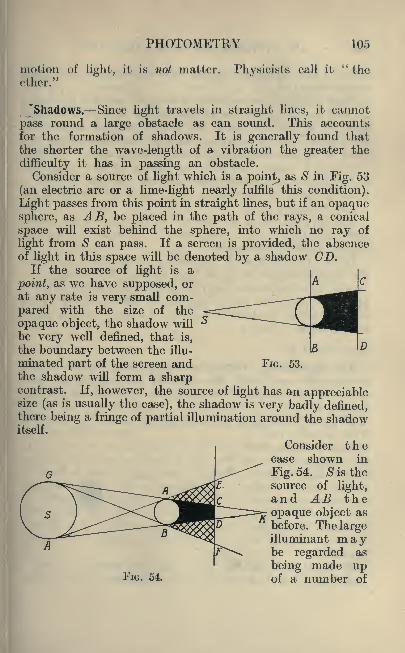
PHOTOMETRY 105
motion of light, it is not matter. Physicists call it"the
ether."
"Shadows. Since light travels in straight lines, it cannot
pass round a large obstacle as can sound. This accountsfor the formation of shadows. It is generally found thatthe shorter the wave-length of a vibration the greater the
difficulty it has in passing an obstacle.
Consider a source of light which is a point, as $ in Fig. 53
(an electric arc or a lime-light nearly fulfils this condition).
Light passes from this point in straight lines, but if an opaquesphere, as AB, be placed in the path of the rays, a conical
space will exist behind the sphere, into which no ray of
light from S can pass. If a screen is provided, the absenceof light in this space will be denoted by a shadow CD.
If the source of light is a
point, as we have supposed, or
at any rate is very small com-
pared with the size of the
opaque object, the shadow will
be very well defined, that is,
the boundary between the illu-
minated part of the screen and FIG. 53.
the shadow will form a sharpcontrast. If, however, the source of light has an appreciablesize (as is usually the case), the shadow is very badly defined,there being a fringe of partial illumination around the shadowitself.
, Consider thecase shown in
Fig. 54. Sis thesource of light,and AB theopaque object as
before. The largeilluminant maybe regarded as
being made upof a number ofFIG. 54.

106 AN INTRODUCTION TO PHYSIOS
points. Let us think of two extreme cases, namely, the
points G and H.
Rays of light passing from G will fall on AB in such a
way as to cast a shadow on the screen at CF, while raysfrom H will fail to reach the portion of the screen DE.Since these are the extreme cases for the illuminant, theymust be the extreme cases for the shadows also.
Now it is easily seen that the portion of the screen CDis in shadow for all cases, the portions CE and DF are in
shadow for some cases only, while the screen outside EFis not in shadow at all.
The dark portion of the shadow( CD) is called the umbra,
while the fringe which diminishes in intensity toward the
odge is called the penumbra.It will be seen that if the source of light is larger than
the opaque object (as is the case in Fig. 54) the umbra is
formed by a cone converging to a point at K. If the screen is
placed beyond this point, there is no umbra shown at all,
but a nebulous shadow in the form of a ring. This is called
an "annular
"shadow.
Experiment 29.
The Photometer. Obtain an opaque rod about an inch
in diameter, and fix it in a vertical position with a small
screen of white paper or other suitable material a few inches
behind it.
If now a small light (for example, a candle) be placed in
front of the rod, a
shadow is formed onthe screen. If a
second light (say, a
small electric bulb)be placed in front of
the rod, but not in
line with the candle,another shadow is
produced.If the lights are
placed as A and B FIG. 65.

PHOTOMETRY 107
in Fig. 55, it is possible to have the two shadows side by side
and just in contact. It is clear from this diagram that the
part of the screen represented by DF is illuminated by the
light A only, while the portion DE receives light only from B.
Hence if the relative position of the lights is so adjustedthat the two shadows appear of equal intensity, it is obvious
that the screen is receiving an equal illumination from both
lights.We can use this fact to compare the relative intensities
of the two illuminants.
First let us consider Fig. 56, in which S is a point of lightfrom which rays are passing in all directions. If a squarescreen is placed at A, the amount of light which illuminates
the surface of the screen is conveyed by the rays passingwithin the pyramid formed by joining the point S to the four
corners of the screen.
If a screen were placed at B instead of A, it is easy to
see that the same amount of light would now fall on a screenof much larger dimensions. If the distance SB is doublethat of S A the side of the square B will be double that of
A, That is, the area of B will be four times as great as thearea of A, and since the same amount of light falls on both
screens, it is clear that the illumination of B will be only a
quarter as bright as that of A.
Law of Inverse Squares. From the foregoing it is clear
that, other things being equal, the intensity of illumination

108 AN INTRODUCTION TO PHYSICS
of a screen varies inversely as the square of the distance fromthe illuminant to the screen.
Thus in Fig. 55, if P1
is the power of the light at A andP2 that at B, and the distance from the screen to A and Bis respectively Dl
and D2 , we have :
Candle-Power. The common unit of intensity of a sourceof light is that given by a candle of a certain type. The"standard candle," as it is called, is made of spermaceti
wax, has a diameter of f inch and burns at the rate of 120
grains per hour.
As a matter of fact this standard has now fallen into
disuse for accurate work owing to its being somewhat un-
certain, the light given depending to some extent on thecondition of the atmosphere.
In modern work a form of burner is used which is fed with
pentane (a very volatile paraffin). The Harcourt pentaneburner gives 10 candle-power, and this is now used as the
international standard.
Ex. 16. In Fig. 55 let the source of light at A be a standard
candle, and that at B be of unknown power. The distance
from A to the screen is 56 cms., and from B to the screen
85 cms. Find the candle-power of B.
Candle-power of B 85 2
1~
56"
Candle-power of B = I -
J
= (1-517)2
= 2-3
The advantage of this type of photometer is that it is not
necessary to work in an entirely dark room. The presenceof another light in the room will not affect the result, pro-vided that the additional shadow produced does not overlap

PHOTOMETRY 109
the two which are being compared. A disadvantage of the
method lies in the difficulty experienced when the sources of
light are not approximately points.
Experiment 30.
The Grease-Spot Photometer. Make a small screen of
white blotting-paper and drop a spot of oil on it. Erect
it in a darkened room, and place a light on one side of it.
Viewed from the side on which the light is placed the
oiled spot appears dark on a white ground. This is due to
the fact that, the spot being translucent, the light passes
through it, while it is reflected from the rest of the paper.Viewed from the other side, however, the spot appears
bright on a dark ground. Assuming that all the light fallingon the unoiled screen is reflected, and that that falling onthe oiled spot is wholly diffused, it is clear that the spotshould appear as bright in the second case as the remainderof the screen did in the first case.
Now place another light on the side of the screen oppositeto the first light, adjusting the second light until the grease
-
spot is not distinguishable from the rest of the screen. Sincethe illumination must now be equal on both sides of thescreen it is possible to compare illuminating powers as before.
If this method were perfect, the spot, having been madeindistinguishable from the remainder of the screen whenviewed from one side, should appear so when viewed from theother side. Such, however, is seldom the case. This is
due to the fact that the light is more scattered by reflection
from the white paper than it is by diffusion through the
grease-spot.In practice, therefore, one should aim, not at getting the
grease spot to disappear, but producing a like contrastbetween spot and screen when viewed from both sides.
Exercises 9.
1. Light has a velocity of about 186,600 miles per second.What is the velocity in centimetres per second ?
2. Give simple experiments which prove that light travelsin straight lines.

110 AN INTRODUCTION TO PHYSICS
3. The following wave-lengths in"tenth metres
"(1O10
metres) of characteristic bands and lines in the solar spectrum,are given : 4861 '496, hydrogen. 4307 "9, calcium. 5167 '5,
magnesium. 3820 '56, iron. Express these wave-lengths asdecimals of a metre.
4.^If the wave-length is expressed in
"seventh metres
"
(10~7metres), express the following wave lengths in decimals
of a centimetre : 4 '86, 8, 20, and 25.
5. Give a list of materials grouped under the followingheadings : opaque, translucent, and transparent.
6. If it is approximately 93,000,000 miles from the earth tothe sun, determine how long light will be in travelling fromthe sun to the earth.
7. A candle is viewed through a pin-hole camera. Explainwhy the image is inverted.
8. A point source of light is S (Fig. 53), and a cardboarddisc A B, 2" diameter, is placed with its vertical diameter 6"
from S with (a) the surface of the disc parallel to the wall
CD, (b) with the edge of the disc as shown in the figure.If the horizontal distance between B and D is 3", determine
graphically the shape and size of the shadow cast on CD in
the two cases.
9. By the aid of sketches show how transverse wave motiondiffers from longitudinal wave motion.
10. Give some common illustrations to prove that lighttravels faster than sound.
11. A candle flame J" high is placed 4" from a pin-holein a screen. Find the size of the image produced on screens
which are placed at distances of 3" and 8" respectively fromthe pin hole.
12. Draw up a table, giving your impression of the sensitive
sensation of brightness of the following : A piece of white-
hot iron, a carbon filament, a metallic filament and a gas-filled metallic filament lamp, an acetylene lamp, an oil lamp,a frosted incandescent electric lamp. The light giving the

PHOTOMETRY 111
impression of the highest brilliancy should be placed at the
top of the table.
13. A ball 1" in diameter is held 2" from a luminous pointof light. Give a drawing showing the shape of the shadowwhich is cast on a wall 1J" from a vertical diameter of the
ball. Will there be a penumbra ?
14. What do you understand by the"law of inverse
squares"
as applied to photometry ?
15. The Hefner lamp is used as the German standard of
candle power and the Hefner standard is equal to 0'9 Inter-
national Candles. A test was carried out on Osram lampsand the following results represent Hefner units of candle
power : 36-3 29'7, I'O, 22'7, 30'7. What will be the valueof these results in International Candle Power ?
16. Experimental observation shows that a white surface
illuminated by one candle at a distance of one foot appearsequally bright if illuminated by four candles at a distance of
2 ft., or nine candles at a distance of 3 ft. State what law
you would deduce from these observations.
17. The intensity of illumination produced by the StandardCandle at the distance of one foot has been adopted as a
practical unit of intensity of illumination and is called the
''foot candle." How many "candle metres" are equal toone foot candle ?
18. Intrinsic brilliancy is a term used to express the degreeof brightness of a light and is usually given in candle powerper square inch of the luminous area. Molesworth givesthe following values : Carbon filament lamp, 375 c.p. persq. in.
;metallic filament lamp (vacuum), 800 to 1000 c.p.
per sq. in.;
metallic filament lamp, gas filled, 3,500 c.p.
per sq. in.; acetylene lamp, 100; oil flame, 3 '8; gas flame,2 '5. What reasons are there for defining Intrinsic Brilliancy ?
Contrast these results with your answer to Question 12.

CHAPTER XREFLECTION
taws of Reflection. No one can witness a game of billiards
without coming to the conclusion that in rebounding from the
raised edge of the table the ball obeys definite laws. These
laws may be called the laws of reflection, and they apply
equally well to a beam of light falling on a mirror and a
smoothly rolling billiard ball.
Mirrors. For light to be reflected under conditions render-
ing measurement possible, it is necessary for the reflectingsurface to be smooth, and free from irregularities. A pieceof thin plate glass carrying a deposit of silver forms a suitable
mirror. The surface of the silver next to the glass is the
brighter, but it has the disadvantage of having the glass in
front of it. For many purposes this disadvantage is not
serious, especially if the glass is not very thick.
A beam of sunlight passing through a chink in a blind
is readily reflected from a mirror, and the approximatedirection of the reflected beam is indicated by the positionof the spot of light which the reflected rays cast on the wall.
This phenomenon is not readi-
ly adapted to measurement,but it is possible to get there-
from a general idea of the
laws involved.
In Fig. 57 the horizontal
line represents the reflecting
surface of a mirror. A beamof light travelling in the
. direction BP meets the mirror
P at P, and the light is deviated
FIG. 57. in the direction PC.
112

REFLECTION 113
P is called the"point of incidence," and a line BP passing
along the direction of the beam represents the path of the
"incident ray," while the line PC represents that of the"reflected ray."A line drawn from the point of incidence at right angles
angles to the surface of the mirror (as PA) is called the"normal."The angle between the incident ray and the normal (the
angle BP A) is called the "angle of incidence," while the
angle between the reflected ray and the normal (the angleCP A) is called the
"angle of reflection."
We are now in a position to state the laws of reflection.
The Laws of Reflection. (1) The incident ray, the normal,and the reflected ray lie in the same plane.
(2) The angle of incidence and the angle of reflection are
equal.The following experiment should make this clear.
Experiment 31.
Obtain a strip of mirror about one inch wide and two or
three inches long, a few pins and a sheet of paper. Fastenthe paper to a drawing-board and by means of any suitable
support cause the mirror to rest upon its edge with its re-
flecting surface at right angles to the surface of the paper.Place a pin vertically in the
drawing-board and close to the
surface of the mirror (as F in Fig.
58, in which AB represents the
mirror). Now place another pinabout two inches from the mirror,and to one side of the first pin (as
C). If now the eye be placed in a
position such as D, the reflection of /JT""1
the rays of light passing from the
pin C will cause an image of the
pin to be seen (apparently behind !>
the mirror) in the direction DE. 9^
I
Place a pin near the eye (at D) FIG. 58.

114 AN INTRODUCTION TO PHYSICS
so that it, the pin at F, and the image appear in a straightline. By drawing a pencil-line along the edge of the mirror,and joining the points CF and FD, we have a record of the
path of the incident ray and the reflected ray.Draw the normal FG at right angles to AB, and measure
the angle of incidence (CFG) and the angle of reflection
(DFG). Repeat the experiment for several positions of C.
Experiment 32.
Fix a mirror and the pins F and G (Fig. 58) as in Experi-ment 31. Place the eye at D. Now take a long pin and
place it behind the mirror so that the top of it (which shouldbe seen above the mirror) is in line with the pin F and the
image of C. Move the eye from side to side a few times,and if the top of the long pin gets out of alignment when the
eye is moved, the pin should be moved until no such separa-tion occurs.
When this condition is secured, we know that the longpin is not only in the direction of the image of (7, but is actually
occupying the position of that image, as E in Fig. 58. JoinEF and CE.By measurement demonstrate that the distance from D
to the image at E is equal to the distance from D to the pinC measured along the path which the light has actuallytraversed, namely, CF and FD. Again, show that the
image E is always as far behind the mirror as the pin C is
before it, and that the line joining the pin C and its imageE is perpendicular to the surface of the mirror.
Curved Mirrors. The two laws of reflection given aboveare applicable to all cases, but so far we have only considered
the case of reflection from a plane (i.e. flat) mirror. Wewill now consider one or two simple cases of reflection froma curved mirror.
Any curved surface may be regarded as composed of aninfinite number of very small flat surfaces. Therefore, if
a ray of light falls on a curved mirror, it behaves as it wouldif it had fallen on a plane mirror which was tangential to
the curve at the point of incidence.

REFLECTION 115
Concave and Convex Mirrors. Most of the curved mirrors
with which the student will deal at this stage of his workwill be portions of the surfaces of spheres, and may be called
spherical mirrors. If the reflecting surface is on the
inside of the sphere, the mirror is said to be concave;
if
the outside of the sphere is the reflecting surface we have aconvex mirror.
The arc of a circle shown in Fig. 59 represents a section of
the reflecting surface of a concave spherical mirror. O is the
centre of the sphere. It is clear that if P is the point of
incidence of a ray of light the behaviour of the ray will besuch as one would obtain from a plane mirror which was
FIG. 59. FIG. 60.
tangential to the sphere at the point P, that is, the radius
OP will be the normal.If AP is the incident ray the angle APO is the angle of
incidence, and on making the angle OPB equal to this wehave the angle of reflection and the path of the reflected
ray PB.Fig. 60 represents a convex spherical mirror. is the
centre of the sphere, and P is the point of incidence of the
incident ray BP. This time we must produce the radius
OP to A, to obtain the normal. The angles BPA and APCare respectively the angles of incidence and reflection, andare of course equal as before.
Experiments and further particulars referring to sphericalmirrors will be given in Chapter XII.

116 AN INTRODUCTION TO PHYSICS
FIG. 61.
Effect of Rotating a
Mirror. Consider a mir-
ror AB in Fig. 61 witha ray of light FP falling
upon it. Since PE is
the normal the reflected
, ray will pass along PG.Now suppose the
mirror is turned througha small angle into anew position CD, the
incident ray remainingstationary. PH will nowbe the normal, and the
angle of incidence will have been increased by an amount
equal to the angle through which the mirror has been turned.
Since the angles of incidence and reflection are equal, thelatter will be increased by an equal amount also. Thus the
reflected ray now passes along P J. It is easily seen that the
angle through which the reflected ray has been turned (viz.
GPJ) is twice the angle through which the mirror wasturned (viz. APC).
Experiment 33.
Repeat Experiment 31. Then rotate the mirror throughabout 20 without changing the position of the pins repre-
senting the incident ray. Record the path of the reflected
ray as before and measure the angle through which thereflected ray has been deviated and compare it with the
angle of rotation of the mirror. Repeat this experiment,using a number of different positions of the mirror. Tabulate
your results.
Reflection from a Rough Surface. If we place an electric
light in front of a mirror the rays of light which, after reflec-
tion from the mirror, enter the eye actually form an image of
the light itself. If the mirror is replaced by a piece of paperof the same size and shape, no image of the light is produced,but the paper is
"illuminated."

REFLECTION 117
Now the rays of light passing from the electric lamp to the
paper are exactly similar to those which fell on the mirror,
yet the visual effect is very different.
Owing to the smoothness of the reflecting surface of the
mirror the reflected rays occupied a relationship to each other
similar to that which existed before the mirror was reached,and hence they entered the eye under conditions very like
those which would obtain if they had passed directly fromthe lamp to the eye.The paper, on the other hand, has a surface very far removed
from perfect smoothness, and although each individual ray
obeys the laws of reflection, the angle of incidence at anyparticular point may be anything, depending upon the
formation of the paper at that point. Hence the reflected
rays have no relation to each other in any way resemblingthe initial conditions, and thus no image can be formed.
Exercises 10.
1. A ball is travelling in a straight line on a plane surface
and comes in contact with a plane at right angles to the
first surface. By the aid of diagrams trace the path of the
ball under the following circumstances :
(a) The ball strikes the surface normally and returns
along the original path.
(6) The ball strikes the surface at an angle of 30 with thenormal and returns along a path which makes 30 with the
normal and 60 with the original path.
(c) As above, but the surface is struck at an angle of 60with the normal and it returns along a path making 120with the original direction.
2. A horizontal ray of light strikes a vertical mirror
normally. Construct a diagram and state which is the
Incident Ray, the Reflected Ray, the Normal, the angle of
incidence and the angle of reflection.
3. Give a clear account of any experiment you have per-formed which proves that the angle of incidence is equal to
the angle of reflection.

118 AN INTRODUCTION TO PHYSICS
4. A horizontal ray of light comes from a point on a wall
and strikes a vertical mirror so that the angle of incidence
is 30. Show, by means of a scale drawing, where the reflected
ray will hit the wall if the distance of the wall from the mirroris 10 feet.
5. Taking the data as given in the above question, show
by means of scale drawings where the light strikes the wall
for the following cases :
'(a) Mirror and wall parallel, the light striking the mirror
normally.(6) The ray of light strikes the mirror normally ;
the
mirror is kept vertical, but swung through 30 in a clockwise
direction.
6. Measure the angle moved by the mirror in the abovecase and state whether the following statement is provedin this particular instance :
" When the mirror rotates
through any angle, the reflected beam rotates through twice
the angle."
7. A light wooden framework is built up in the form of an
equilateral triangle ABC. Half-way down the side AB a small
mirror is fixed at D with its plane parallel to the side AC.Pivoted at A is a framework A' C', C' B', resting on A C,
CB, a mirror being fixed to the point A which moves as
A' C', C' B' is moved. A horizontal ray of light E A strikes
the mirror at A and is reflected to the mirror at D. State
the inclination of the mirror at A to the base BC in order
that the ray of light may leave parallel to the side BC.In connection with this question the student is advised
to examine if possible the construction of a sextant.
8. The curvature of a concave mirror is equal to one
divided by the radius. Express as a decimal of an inch
the curvature of the following concave mirrors : Radiusof the mirrors to be 12", 8", 200 millimetres and 80 millimetres,
respectively.
9. Make scale drawings of the following concave mirrors
of radius respectively 4 '5", 7*5", 90 millimetres and 70
millimetres.

REFLECTION 119
10. In each of the mirrors in Question 9 assume that
a ray of light proceeds from a point f" above and parallel
to a radius. Draw in every case the ray and mark the anglesof incidence and reflection. Measure the angles with a
protractor and give their approximate values.
11. State the laws of reflection of light and explain with the
aid of a diagram the formation of an image in a concave
mirror.
12. In a lighting scheme for a drawing office, the followingsurfaces were fixed behind the half-watt lamps used for
lighting : (a) Brightly polished metal reflectors. (6) Iron
plates coated with aluminium paint on the underside, (c)
6 with a final coat of light dull-finished buff-coloured paint.In the latter case it was found that the favourable char-
acteristics were freedom from glare and excellent diffusion.
Give explanation of this.
13. Give an explanation as to why a beam of sunlight,admitted through a narrow slit to a darkened room, is rendered
visible. What bearing has the following statement on youranswer :
" In ordinary circumstances there are about 25,000dust particles per cubic centimetre of air, rising to about
250,000 in the neighbourhood of large towns."
14. A ray of light makes an angle of 10 with the horizontal
and strikes the mirror of a microscope, which is inclined at
25 to the horizontal. Will the light be reflected vertically ?
If not, state the angle of the mirror necessary to accomplishthis. Illustrate your answer by drawings.
15. What difference would you expect in the character
of the light as reflected from (a) a conical white enamelled
iron shade, 10" lower dia., 1 J hole at the top, and 5" vertical
depth. (6) As above, but made of opal glass.
16. Explain why light is reflected differently from planeand ground glass.
17. Why is a room with white walls much lighter than a
similar room with dark green walls ?

120 AN INTRODUCTION TO PHYSICS
18. A piece of shafting is firmly fixed at one end and
supported freely at the other. The free end has an over-
hanging arm attached to it, just outside the bearing. Neareach end of the shaft, small mirrors are attached and aboveeach mirror a reading microscope with a scale is fixed. Whenthe scale is illuminated the image of the scale can be seen bythe microscope. A cross-hair indicates the position on the
scale. Explain what will happen when the shaft is slightlytwisted by means of weights attached to the overhangingarm.*
Show approximately by means of sketches how the twist
of the shaft is magnified.
19. Show how you would fix a pair of mirrors parallel to
each other and one vertically above the other, in order to
form a simple form of periscope.
20. Describe experiments by which you would demonstratethe two laws which show how a ray of light is reflected froma smooth surface.
21. Rays of light strike a horizontal plane mirror at the
following angles : 10, 15, 30, 45, 60 and 75. Show
graphically the angle of deviation. Assume that the angles
given are angles with the horizontal.
22. In the above question show how you would arrange a
second mirror in order that the deviated ray may finally be
deflected from the second mirror horizontally. Make a
drawing in each case.
23. A building is surrounded by high walls. Give sugges-tions and sketches showing how you would get as muchreflected light as possible into the rooms.
24. A number of rooms receive the whole of their light
from a rectangular well, open to the air. It is noted that
the walls of the well are made of white enamelled brick.
Why is this ?

CHAPTER XI
REFRACTION
CONSIDER Fig. 62, in which AB represents a line of menmarching with uniform speed. When the line reaches
CD, it will be parallel to A B, and its direction of motion will
be unchanged. Suppose, however, that in this position theextreme left-hand man is about to step into water about afoot deep. This will, of course, impede his progress, and hewill consequently lag behind his fellows.
When the line reaches EF, half the men will have enteredthe water, but the man at F will have been in it longest,and will have lagged farthest behind. That is, the line will
have been bent as shown, and although the two portions of
the line will still be straight, the position representing themen in the water will indicate a change of direction in theforward motion.We have already seen that sound does not travel with the
same velocity in air andin water, and it is foundthat while a number of
bodies are"transparent,"
that is, are capable of
transmitting light, theydo not permit the lightto travel with the same
velocity. Thus light tra-
vels more rapidly in
vacuo than it does in air,
and again, its velocity is
greater in air than in
glass.
Hence, a wave-front of
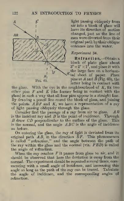
122 AN INTRODUCTION TO PHYSICS
light passing obliquely fromair into a block of glass will
have its direction of motion
changed, just as the line of
men were diverted from their
original path by their obliqueentrance into the water.
Experiment 34.
Refractio n. Obtain ablock of plate glass about3" X 2" X 1", and place it withthe large face on a horizon-
tal sheet of paper. Place
pins at A andB (Fig. 63), thelatter being in contact with
the glass. With the eye in the neighbourhood of K, fix twoother pins F and K (the former being in contact with the
glass) in such a way that all four pins appear in a straight line.
By drawing a pencil line round the block of glass, and joiningthe points ABF and K, we have a representation of a rayof light passing obliquely through the glass.
Consider first the passage of a ray from air to glass. ABis the incident ray and B is the point of incidence. ThroughB draw CD perpendicular to the surface of the glass. This,
is the normal, and the angle ABC is the angle of incidence
as before.
On entering the glass, the ray of light is deviated from its
original path AB, in the direction BF. This phenomenonis called
"refraction," and the angle between the path of
the ray within the glass and the normal (viz. FBD) is called
the angle of refraction.
When the ray reaches F it passes from glass to air, and it
should be observed that here the deviation is away from the
normal. The experiment should be repeated several times, com-
mencing with a small angle of incidence, and increasing this
angle so long as the path of the ray can be traced. Tabulate
the angle of incidence, and the corresponding angles of
refraction.
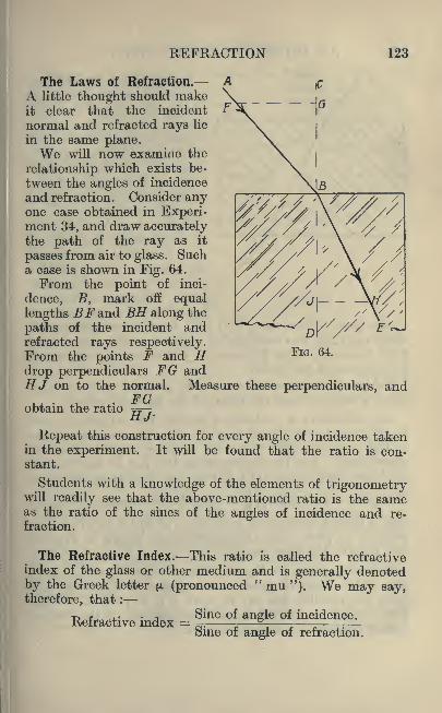
REFRACTION 123
The Laws of Refraction.
A little thought should makeit clear that the incident
normal and refracted rays lie
in the same plane.We will now examine the
relationship which exists be-
tween the angles of incidence
and refraction. Consider anyone case obtained in Experi-ment 34, and draw accuratelythe path of the ray as it
passes from air to glass. Sucha case is shown in Fig. 64.
From the point of inci-
dence, B, mark off equal
lengths BF and BH along the
paths of the incident andrefracted rays respectively.From the points F and Hdrop perpendiculars FG andHJ on to the normal. Measure these perpendiculars, and
FGobtain the ratio ^r-
12 J'
Repeat this construction for every angle of incidence takenin the experiment. It will be found that the ratio is con-stant.
Students with a knowledge of the elements of trigonometrywill readily see that the above-mentioned ratio is the sameas the ratio of the sines of the angles of incidence and re-
fraction.
The Refractive Index. This ratio is called the refractiveindex of the glass or other medium and is generally denotedby the Greek letter jx (pronounced
" mu "). We may say,therefore, that :
Refractive index = Sine of angle of incidence.
Sine of angle of refraction.
FIG. 64.

124 AN INTRODUCTION TO PHYSICS
If the experiment had beenconducted under conditions
which would have allowed the
ray of light to pass from avacuum to the glass, the result
would have been very slightlydifferent. The difference,however, is so small as to be
wholly negligible for most
practical purposes.
Again, the refractive indexof a substance depends to
some extent on the colour of
the light used, being least for
red and greatest for violet
light. A very accurate deter-
mination on a specimen of
crown glass gave a value of 1'5137 for the refractive indexwhen red light was used, and a value of 1 '5331 when violet
light was used. The difference it will be seen, is only about
1J per cent, of the whole.
Tables of refractive indices usually give the value of yellow
light, which is about the mean of the extreme values.
Fig. 65 shows a method of finding the refractive indexwhich may be employed instead of the construction givenin Fig. 64. The path of the ray is traced in and out of the
glass block. The line representing the ray at exit is then
produced backwards until it cuts the normal as shown in
the figure. The ratio 7T^ is the refractive index. Students
FIG.
with a little knowledge of geometry will find it an interesting
problem to prove that the constructions shown in Figs. 64and 65 give the same result.
Referring again to Fig. 63, the student should observe
that if the block of glass is rectangular, or if the oppositefaces are parallel, the ray of light FK is parallel to AB.This should be verified by an examination of the various
figures obtained in Experiment 34.

REFRACTION 125
Passage of a Ray of Light through a Prism. In Fig. 66,
ABC indicates a prism of glass whose section is an equi-lateral triangle. If a ray of light fall on one face of this
prism in a direction DE, it will, on entering the glass, be
refracted towards the normal and follow a path EG.At G it passes from glass to air, and it will consequently
be refracted away from the normal, as C J.
Now it has already been mentioned that the refractive
index of a medium depends to some extent on the colour
of the light used. Hence, if DECJ represent the path of
a ray of red light, it is clear that if violet light were employedthe angle through which it would be refracted would in
both cases be greater and its path would have been similar to
DEKL.
FIG. 66.
Now if a beam of white light is passed through a prism in
the direction of DE in Fig. 66, a band of colour is produced,
commencing with red at J and passing through the other
"colours of the rainbow "orange, yellow, green, blue,
indigo and apparently ending with violet at L.
This indicates that"white
"light (for example, sun-
light) is composed of many colours, and if light of these
colours be suitably merged together it is possible to producewhite light. This band of colour is called the continuous
spectrum.
Experiment 35.
Trace a ray of light through a prism of glass by meansof pins, placing pins at DEG and J, so as to appear in a
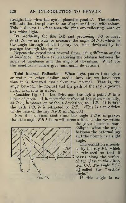
126 AN INTRODUCTION TO PHYSICS
straight line when the eye is placed beyond J. The studentwill note that the pins at D and E appear fringed with colour.
This is due to the fact that the pins are reflecting more or
less white light.
By producing the line DE and producing JG to meetit at N, we are able to measure the angle MNJ, which is
the angle through which the ray has been deviated by its
passage through the prism.
Repeat the experiment several times, using different anglesof incidence. Make a table showing the relation between the
angle of incidence and the angle of deviation. What are
the conditions which give minimum deviation ?
Total Internal Reflection. When light passes from glassor water or other similar media into air, we have seen
that it is deviated away from the normal. That is, the
angle between the normal and the path of the ray is greaterin air than it is in water.
Consider Fig. 67. Let light pass through a point P in ablock of glass. If it meet the surface of the glass normally,as PA, it passes on without deviation, as AE. If it take
the path PB, it is refracted to BF. (This is a repetitionof the case of the ray BFK in Fig. 63.)Now it is obvious that since the angle FBK is greater
than the angle PBJ there will come a time, as the ray within
the glass becomes more
oblique, when the anglebetween the external rayand the normal is a right
angle.This condition is reach-
ed by the ray PC, whichis refracted so that it
G passes along the surface
of the glass in the direc-
tion CO. The angle PCLis| called the
"critical
angle."If this angle is ex-

REFRACTION 127
ceeded, as in the case of PDtthe
ray fails to pass into the air and"total internal reflection
"occurs,
as DH.This mode of reflection of light is
the most perfect known and is
utilised in the reflecting prism whichis shown in Fig. 68. It consists of a
glass prism whose section is a right-
angled triangle.If light strikes the side of the
prism, represented by A B, normally,it passes into the glass without deviation,the ray DE. This light has an angle of
FIG. 68.
as shown byincidence on
the hypotenuse EG which is above the critical angle. Hence,the whole of the light is reflected in the direction EF, andsince it strikes the side C A of the prism normally no deviation
is produced by the exit of the light from the glass.
The following table showing the indices of refraction of a
few common media will be useful for reference :
Substance. Refractive Index.
Glasses
128 AN INTRODUCTION TO PHYSICS
Experiment 36.
Examine a reflecting prism. Trace the path of a ray of
light through it by means of pins. What happens if the
incident ray does not fall on the first face of the prism nor-
mally ? Is it possible to select an angle of incidence so
that total internal reflection does not occur ?
Exercises 11.<
1. Give an account of any experiment which you havecarried out which proves the following general law for refrac-
tion : When light travels obliquely from one medium into
another in which the speed is less, it is bent towards the
perpendicular, and when it passes from one medium to
another in which the speed is greater, it is bent away fromthe perpendicular produced into the second medium.
2. A penny was placed at the bottom of a bowl in such a
position that the edge just hid the coin from the observer.
Explain why it becomes visible when water is poured into
the bowl.
3. Why does a stick held in water appear bent to the
observer ?
4. A ring is at the bottom of a pond one foot deep andlies two feet from the observer. Give a diagram to scale,
showing its apparent position to the observer.
5. A boy holds a penholder at the back of a piece of glassand looks through the glass obliquely. Give a diagram to
show what he sees.
6. A diver is being lowered into the sea and the life-line
is held vertically above him. Give a drawing to show howthe line looks to the diver.
7. In a house there are two windows, one being made from
glass having a plane surface and the other being made from
cheap glass, having a surface which is not quite plane, but
has small depressions in it. Explain why a person in the
street looks distorted through one window and not throughthe other.
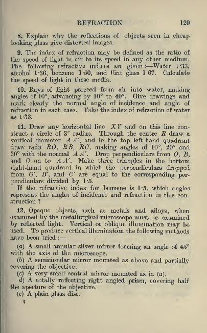
REFRACTION 129
8. Explain why the reflections of objects seen in cheaplooking-glass give distorted images.
9. The index of refraction may be defined as the ratio of
the speed of light in air to its speed in any other medium.The following refractive indices are given: Water 1'33,
alcohol 1*36, benzene 1'50, and flint glass 1*67. Calculate
the speed of light in these media.
10. Rays of light proceed from air into water, makingangles of 10, advancing by 10 to 40. Give drawings andmark clearly the normal angle of incidence and angle of
refraction in each case. Take the index of refraction of wateras 1-33.
11. Draw any horizontal line XY and on this line con-
struct a circle of 3" radius. Through the centre R draw avertical diameter A A'
tand in the top left-hand quadrant
draw radii RO, RB, EG, making angles of 10, 20 and30 with the normal A A'. Drop perpendiculars from 0, B y
and C on to A A' . Make three triangles in the bottom
right-hand quadrant in which the perpendiculars droppedfrom 0', B'
',and C' are equal to the corresponding per-
pendiculars divided by 1*5.
If the refractive index for benzene is 1-5, which angles
represent the angles of incidence and refraction in this con-struction ?
12. Opaque objects, such as metals and alloys, whenexamined by the metallurgical microscope must be examinedby reflected light. Vertical or oblique illumination may beused. To produce vertical illumination the following methodshave been tried :
(a) A small annular silver mirror forming an angle of 45with the axis of the microscope.
(6) A semicircular mirror mounted as above and partiallycovering the objective.
(c) A very small central mirror mounted as in (a).
d) A totally reflecting right angled prism, covering halfthe aperture of the objective.
(e) A plain glass disc,

130 AN INTRODUCTION TO PHYSICS
Assuming a highly polished specimen and a horizontalbeam of light, show diagrammatically in each case how the
light is reflected to the eye. The beam of light is admittedto the tube of the microscope through a hole in its side, is
reflected downwards by the reflector, through the objective,and thence is reflected back to the eye by the object.
13. Air changes in density as the pressure and temperaturevary. When high atmospheric altitudes are reached the
index of refraction of the air becomes less, owing to the
diminution in density. Show by diagrams the real and
apparent positions of a star, (a) at its zenith, (6) just belowthe horizon.
14. Explain, by means of a diagram, the term "critical
angle."
15. A coin lies at the bottom of a pond which is 2 feet deep.
Explain by means of a diagram why it appears at a less
depth to an observer in a boat. Calculate its apparent
depth from the formula given :
Real depth of the water.Index of refraction=-r
Apparent depth of the water.
16. If a body be viewed through a plate of transparent
material, it appears to be nearer to the observer than it
really is. Taking the following formula :
Real thickness of mediumIndex of retraction mi^T" 7~n
Apparent thickness of the medium
calculate the apparent depth or thickness of the following
media, assume that the real depth in each case is 6" : Indices
of refraction, diamond 2*44, flint glass 1'58, crown glass
1*5, carbon bisulphide 1'68, water 1*33.
17. Taking other media, give a simple illustration to
show that the foliowhig statement is likely to be true :
"Rays
of starlight passing through the atmosphere are refracted or
curved downwards. The effect is to make objects appear
higher than they really are."

REFRACTION 131
18. Give a description of the simplest form of heliographwith which you are familiar.
19. During an ordnance survey it was necessary to pickout a distant station. A cone of burnished tin was hoisted
on a pole. Explain how this would help.
20. A beam of light is directed through rectangularvessels with glass sides containing the following liquids :
water, alcohol, and cedar wood oil. Show diagrammaticallythe path of the beam given the following refractive indices :
water 1'333, alcohol 1'36, and cedar-wood oil, the same as
glass.

CHAPTER XII
,IMAGES
The Formation of Images. Everyone is familiar with the
formation of an "image
" on a screen, for we see it in the
projection of an optical lantern and its modern developmentthe cinematograph. A magnified
"image
"of an object
is also seen when one applies the eye to a telescope or micro-
scope. We will now consider the formation of images,first by the reflection, and second by the refraction of the
rays of light which emanate from the object.
The Focal Length of a Spherical Mirror. Consider a
concave spherical mirror indicated by the arc ABC in Fig. 69.
FIG. 69.
O is the centre of the sphere. The line passing throughO and the middle (B) of the mirror is called the axis of the
mirror.
If an incident ray DE is parallel to the axis it will bereflected along a path EF such that the angles of incidence
and reflection are equal. EO is, of course, the normal.
132

IMAGES 133
Provided that the arc ABC is only a very small portionof the whole sphere (in other words, if the curvature of the
mirror is not very great) it is found that all incident rayswhich are parallel to the axis are reflected along lines which
pass through the common point F. This point is called the
focus, and the distance from the mirror to the focus (namely,
BF) is called the"focal length
"of the mirror.
In Fig. 70 ABC represents a convex spherical mirror,
BO is the axis and the centre of the sphere. The incident
'ray DE is reflected along EJ (OE produced being the
normal).
FIG. 70.
Now it is obvious that, since these rays are divergent,
they will never meet in the direction in which they are
travelling. But if the lines are produced backwards, theymeet at F. So F is the focus of this mirror and BF is its
focal length.It is necessary to emphasize that this convergence of
parallel rays to a point only occurs when the mirror is a
very small portion of a sphere. If this condition is fulfilled,
the focal length is found to be half the radius of curvature.
Hence in Figs. 69 and 70, BF is half the length of BO.
Real Images. In Fig. 71 a concave mirror is shown havingits focus at F, and the centre of the sphere at O. A brightobject is placed in front of the mirror, the object beingindicated in the diagram by the arrow AB.

134 AN INTRODUCTION TO PHYSICS
We may assume that rays of light are being sent out fromthis object in all directions. Some of these rays will fall
on the mirror. Consider the ray AG. This, being parallelto the axis of the mirror, will be reflected in a direction CD,passing through the focus F. Another ray passing from Awill strike the mirror at the middle point E, and will bereflected along EG (the angle of incidence AEO being equalto the angle of reflection GEO). These lines intersect at
H, a^id if 'other rays from A were drawn, careful construc-
tion would show that they are all reflected along lines
passing through H.
H, we may therefore assume, is the position of the arrow-
head in the image. The ray BE, since it strikes the mirror
FIG. 71.
normally, will be reflected back along its own course. Theposition of the tail of the arrow is therefore obviously at J.
Experiment 37.
A 4-volt electric bulb forms a very convenient"object
"
for experimental work in optics. Failing this a light maybe enclosed in a box and the rays allowed to 'escape onlythrough a hole about half an inch square, the hole beingcovered with wire gauze.
Various forms of mirror-holders are purchasable, but it
should not take long for an ingenious student to see the
possibilities of a cork and a piece of plastic wax or clay.A suitable screen consists of a piece of white card about3 inches square. It may be mounted in a split cork.Now place the
"object
" on a table in a darkened roomand place a concave mirror about a foot in front of it. Movethe screen to and fro until the
"image
"is seen. If an

IMAGES 135
electric bulb is being used the image should be the filament
of the lamp. By a careful adjustment of the screen the
image may be"focussed," that is, it may be made to appear
quite sharp and well-defined.
It is obvious that the screen must not obstruct the raysof light passing from the object to the mirror, hence it is
necessary slightly to twist the mirror so that its axis passesbetween the object and the screen.
Measure the distance from object to mirror, and frommirror to image. Also measure the length of the objectand image. Repeat the experiment several times, placingthe object at a different distance from the mirror in eachcase. Tabulate the measurements mentioned above for
future reference.
The Spherometer. This instrument is employed for thedetermination of the radius of curvature of spherical sur-
faces. It consists of a very small steel tripod whose feet
form an equilateral triangle. A fourth foot which formsthe base of a micrometer screw passes through the middleof this triangle.The instrument is first placed on a sheet of plate glass,
and the micrometer adjusted so that the central (movable)foot just touches the glass. It is thentransferred to the spherical surfaceand the micrometer again adjusted for
contact. The difference in the micro-meter readings gives the difference
between the level of the tripod feet
and that of the micrometer foot, dueto the curvature of the surface.
In Fig. 72, let ADE represent thecurved surface. Let B represent the
point of contact of one of the tripodfeet, and let D be the point of contact of the micrometer foot.GD= difference of micrometer readings. Denote this by h.
CB= distance from a tripod foot to the micrometer foot,which may be measured on the spherometer. Denotethis by d.
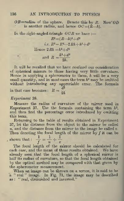
136 AN INTRODUCTION TO PHYSICS
0jB=radius of the sphere. Denote this by R. Now'ODis another radius, and hence OC= (R h).
In the right-angled triangle OCB we have :
i.e.R 2=R 2 2Rh+h2+d*Hence 2Rh =h2+d2
h2+d2
and R =2h.
It will be recalled that we have confined our considerationof spherical mirrors to those having very little curvature.
Hence in applying a spherometer to them, h will be a verysmall quantity, and in most cases the term h2 may be omittedwithout introducing any appreciable error. The formula
in that case becomes : R = ^rn
Experiment 38.
Measure the radius of curvature of the mirror used in
Experiment 37. Use the formula containing the term h2,
and then find the percentage error introduced by omittingthis term.
Returning to the table of results obtained in Experiment37, let the distance from the object to the mirror be called
u, and the distance from the mirror to the image be called v.
Then denoting the focal length of the mirror by / it can be
,shown that :
-- =1
/ u v
The focal length of the mirror should be calculated for
each case, and the mean of these results obtained. We have
already seen that the focal length of a spherical mirror is
half its radius of curvature, so that the focal length obtained
by the optical method may be compared with that given bythe spherometer measurement.When an image can be thrown on a screen, it is said to be
a "real" image. In Fig. 71, the image may be described
as :
"real, diminished and inverted."

IMAGES 137
Virtual Images. We will now consider the behaviour of aconvex mirror. This is shown in Fig. 73. Again AB repre-sents the object, and F the focus. The ray A C being parallelto the axis is reflected in the direction CD and the ray AEpasses along EG (the angle AEB being equal to the angleBEG}.Now these two reflected rays are divergent, and will
therefore meet only if produced backwards. The intersection
takes place at H, which determines the position of the headof the image.
Since this image is behind the mirror, it is obviouslyimpossible to throw it on to a screen, and hence it cannotbe called
"real
"in the sense that the last image was.
This is a case of a"virtual
"image. If the eye is placed
in front of the mirror, the virtual image is seen, and in the
case illustrated in Fig. 73 the image may be described as"virtual, diminished and erect."
Lenses. A lens is a piece of transparent material (usually
glass) having a curved surface (usually spherical). Fig. 74shows the form in section of a number of common lenses.
In A both surfaces are convex, and such a lens is called a"bi-convex lens." In B both are concave, and hence it is
called a"bi-concave lens." In C and D one surface is
flat (or plane) and the other spherical. C is a"plano-
convex lens," and Da" plano-concave lens." In E andF both surfaces are spherical, but one is concave and the
other convex,lenses."
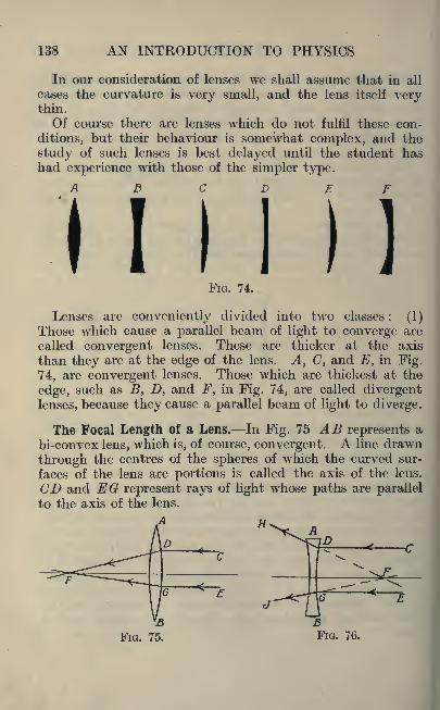
138 AN INTRODUCTION TO PHYSICS
In our consideration of lenses we shall assume that in all
cases the curvature is very small, and the lens itself verythin.
Of course there are lenses which do not fulfil these con-
ditions, but their behaviour is somewhat complex, and the
study of such lenses is best delayed until the student hashad experience with those of the simpler type.
f\ U
1 1
z r
MFIG. 74.
Lenses are conveniently divided into two classes: (1)
Those which cause a parallel beam of light to converge are
called convergent lenses. These are thicker at the axis
than they are at the edge of the lens. A, C, and E, in Fig.
74, are convergent lenses. Those which are thickest at the
edge, such as B, D, and F, in Fig. 74, are called divergentlenses, because they cause a parallel beam of light to diverge.
The Focal Length of a Lens. In Fig. 75 AB represents a
bi-convex lens, which is, of course, convergent. A line drawn
through the centres of the spheres of which the curved sur-
faces of the lens are portions is called the axis of the lens.
CD and EG represent rays of light whose paths are parallel
to the axis of the lens.
FIG. 76.

IMAGES 139
When these rays pass into the lens they are refracted in amanner similar to that in which a ray is refracted by a prism.It is found that all such rays pass through a point F on the
axis, called the focus of the lens. The distance from the
lens to the focus is called the focal length of the lens.
In Fig. 76, AB represents a divergent lens. In this case
the rays CD and EG, which are parallel to the axis, are re-
fracted by the lens so that their paths diverge as shown.All such rays, however, on being produced backwards pass
through the common point F, which is the focus of this lens,
and again the distance from the lens to the focus is called the
focal length.
Strictly speaking, part of the deviation of a ray of light
passing through a lens takes place at the front surface and
part at the back surface of the lens. This is not shown in the
diagrams.
Images Formed by Lenses. In Fig. 77 let AB represent a
convergent lens of which the focus lies at F. Let CD be an
object. Considera ray passingfrom C parallelto the axis. Thiswill be refracted
through thefocus. Another
ray from C is
shown passing
through the mid-dle of the lens.
If, as we have assumed, the lens is thin, and not deeplycurved, this ray suffers practically no deviation, but passeson in a straight line as shown.These two rays meet at E, and this is the position of the
head of the image.
Experiment 39.
Mount a convergent lens, a screen and an "object
"in
a darkened room as in Experiment 37. The screen and

140 AN INTRODUCTION TO PHYSICS
object must, of course, be on opposite sides of the lens.
Again measure the distance u (from object to lens) and v
(from lens to image) for a number of cases. If / is the focal
length of the lens calculate its value in each case and obtain
the mean. The formula : r = 1
/ u v
is still true as in the case of the concave spherical mirror.
Experiment 40.
Having obtained the focal length of a convergent lens in
Experiment 39, take the same lens into the sunlight (which
may be regarded as parallel rays of light). These rays
converge to a point, which appears as a bright spot of light.This is, of course, the focus of the lens, and the focal length
may, therefore, be measured directly.
Since the lens concentrates the sun's heat rays as well as
the light rays, the spot of light is likely to be hot. Thestudent should have no difficulty in testing whether this
is so.
Experiment 41.
Using the same lens, hold it near the wall of a room oppositethe window. With a little adjustment an image of the
window is obtained on the wall. This is very similar to the
darkened room experiment except that the distance u is
very great, and consequently is . very small indeed and
may be neglected without serious error.
Hence the formula becomes : *- = - - and / = v.
f v
The distance from the lens to the wall is, therefore, the
focal length of the lens.
The student is now in a position to verify the fact that the
ratio of the sizes of object and image is the same as the ratio
of their respective distances from the lens or mirror. In othei
words the"magnification
"of the image is equal to .

IMAGES 141
FIG. 78.
If this fraction is less
than unity the image is
diminished. A magni-fied image will be indi-
cated by this ratio being
greater than unity.A divergent lens is
indicated by AB in Fig.
78, the focus of whichis shown at F. CD is
an object as before. The ray from C which is parallel to
the axis is refracted in the direction EG (note that GEproduced passes through F). The ray from C which passes
through the middle of the lens proceeds in the direction of
H without deviation.
Intersection takes place at */, and JK is therefore the
image. Note that it is virtual (and therefore cannot bethrown on a screen, but if the eye be placed between G andH it can be seen), diminished and erect.
The Magnifying Glass. Referring back to Fig. 77 it will
be seen that the distance from the object to the lens was
greater than the focal length of the lens. We will now find
the effect of making this distance less than the focal length.
Fig. 79 shows the lens AB with its focus at F. CD is
the object. Using the same construction we find that the
G
fH
FIG. 79.

142 AN INTRODUCTION TO PHYSICS
rays which before converged to form a"real
"image are
now divergent and the virtual image GH is produced. Notethat this image is magnified and erect.
If the eye be placed between F and E this magnifiedvirtual image is seen, and this is the explanation of the
magnifying glass or simple microscope.
Exercises 12.
1. Draw a concave mirror of 4" radius, and with a 2" arc.
Mark on the drawing (a), (6), and (c) as defined.
(a) Centre of curvature is the centre of the sphere of whichthe mirror forms part.
Bisect the arc of the mirror and join to the centre. The
point where the radius cuts the arc or middle point of the
mirror is called the pole (6).
(c) The principal focus is midway between the centre of
curvature and the pole. The focal length is the distance fromthe pole to the principal focus, and if the focal length of the
mirror is called / and the radius of curvature r, insert measure-
ments in your drawing and show that r=2f.
2. Repeat the above example for concave mirrors of 3",
3J", and 5" radius with 2" arcs.
3. Take concave mirrors of 2 '75", 3 -25" and 3 '375" radius
and in each case with arcs 2 '5" long show where rays
parallel to the principal axis intersect the principal axis
after reflection.
4. A luminous point O is situated on the principal axis of
the mirrors in the preceding question and lies 1" behind the
centre. A ray of light proceeding from this point strikes
the mirror 1" above the principal axis. Show graphicallywhere the reflected ray intersects the principal axis.
5. The following information is supplied in a cataloguewith regard to a series of concave mirrors :
Diameter in millimetres . 50 63 75 100 150
Focal length in millimetres 75 75 80 100 180
Determine graphically in each case the radius of curvature.

IMAGES 143
6. Similar information to that of the preceding example is
supplied in respect of convex mirrors :
Diameter in millimetres . . 50 63 75 100
Focal length in millimetres . .75 75 80 100
Find the radius of curvature in each case.
7. Measurements were taken of a number of spherical
watch-glasses and the following readings were noted :
Spherometer readings Chordal diameterin mm. in cm.
Case 1 . . 4-26 6'4
4-42
Case 2 . . 6-88 5
Case 3 . . 1'49 10
-1-42
Case 4 . . 1'99 11
-2-19
Taking the distance GB as 2 '25 cms. calculate the inside andoutside radius of the sphere which forms the watch-glass.Make a scale drawing in each case.
8. In case 1, 3 and 4 of the above question, the inside of the
watch-glass was blackened. The outside curve was then usedas a convex mirror. Show graphically how a ray of light
parallel to the principal axis is reflected in each case.
9. Make sketches of any spherometer you have used andname the different parts.
10. The following results were obtained with a spherometer :
Distance from tripod foot to micrometer foot, 3*1 cms.Difference of micrometer readings for a concave mirror,0*15 cms. ; difference of micrometer readings for a concave
mirror, 0'127 cms. Calculate the radius of curvature for
each mirror.
11. Make sketches of reflectors used for bicycle, motor car
and railway lamps and electric light. Give sectional viewswherever possible and state what are the approximate shapes.

144 AN INTRODUCTION TO PHYSICS
12. The inside of each of the watch-glasses in Question 7
is blackened and they are then used as convex mirrors.
Show how a ray of light 1 cm. from the principal axis is
reflected in each case. Neglect the slight difference of
curvature between the two surfaces.
13. A lens which changes a parallel beam of light into a
convergent beam is caUed a"converging or convex lens."
These lenses are always thickest in the centre. Draw andname three types.
14. A lens which changes a parallel beam of light into a
divergent beam is called a diverging or concave lens. Theselenses are always thinnest in the centre. Draw and namethree types.
15. Define the"focus
"of a lens.
16. An experiment was performed to find the focal lengthof a convex lens. The lens was fixed and a pin was placedat some distance from it Another pin was placed on the
other side of the lens until the image and the pin-head -ap-
peared together. The following results were obtained :
u, distance from object 49 '2 cms. v, distance from image22-5 cms.
35-6 25 cms.
Determine the focal length of the lens.
17. This experiment was then performed with the objectnearer to the convex lens than the principal focus. Give
drawings, showing the image of the pin in this case. Is the
image real or virtual ?
18. An experiment was performed to determine the focal
length of a convex lens. The lens was placed in front of
the screen and a strongly illuminated pin was placed at the
other side of the lens The lens was moved until a sharp
image was obtained on the screen. The following results
were obtained :
uy42 cms., u, 61*5 cms. v, 67 cms., v, 43*3 cms.
Determine the focal length of this lens.

IMAGES 145
19. Describe, with the aid of sketches, why the image of
a pin as seen in a plane glass mirror differs from that seen onthe ground-glass screen of a camera.
20. Why is a magnifying glass sometimes called a"burn-
ing glass"
? Show how you would find the principal focus
of a Ions by means of the sun.
21. An arrow 1J" long is 2" from the pinhole in a pinholecamera. If the arrow is vertical, show by means of a diagramthe image formed on a screen 3" away from the pinhole.

SECTION V. HEAT
CHAPTER XIIII
THEBMOMETRY
Heat and Cold. From our early days we are accustomedto associate certain sensations with heat and cold. Suchsensations are, however, not very trustworthy, for in certain
circumstances two men may not be in agreement about the
heat (or coldness) of a body.
Experiment 42.
Take three basins, and into No. 1 put hot water. InNo. 2 put some ice-cold water and fill No. 3 with lukewarmwater.
Now place the left hand in the hot water in No. 1, andthe right hand in the cold water in No. 2, and leave themthere for one or two minutes.
Then put both hands into the tepid water in No. 3.
This water will feel cold to the left hand and warm to the
right hand.This experiment shows how unreliable is the sense of
touch as an indication of heat or cold.
Because the left hand was hotter than the warm water,heat flowed from the hand to the water and the hand felt
the loss of heat as a sensation of coldness. The right hand
being colder than the water, heat flowed into it from the
water, and this acquisition of heat gave the sensation of
warmth.
Temperature. The degree (or intensity) of heat (which is
quite distinct from the amount of heat) is commonly denoted
by the term"temperature."
146

THERMOMETRY 147
Experiment 43.
Obtain a cylindrical rod of metal with trued ends, also
a piece of sheet metal cut to the form shown hi Fig. 80, the
dimension of which are such that the rod will just pass into
the gap in the sheet metal and the end of the rod will justenter the circular hole.
Now hold the rod in the flame of a Bunsen burner for aminute or two. It will be found that it will neither passwithin the gap nor enter the hole while it is hotter than the
o
FIG. 80.
sheet metal, but will do so when it has cooled to approxim-ately the same temperature again.The two foregoing experiments establish two facts :
(1) When two bodies, of different temperatures, are in con-
tact, heat flows from that at the higher temperature to thatat the lower temperature, with a tendency to establish
equality.
(2) The dimensions of a body depend upon the tempera-ture. In most cases the dimensions increase as the tem-
perature rises.
It is obviously quite possible (though perhaps not verypracticable) to use a rod of iron as a thermometer. Since

148 AN INTRODUCTION TO PHYSICS
the length of the rod is a function of its temperature, all
that is necessary is to measure the length of the rod anddetermine the temperature corresponding to this length.
This method has two very grave disadvantages : (i)
the iron rod in absorbing heat necessarily reduces the tem-
perature of the body whose temperature it is required to
determine; (ii) the increase in length for any reasonable
rise of temperature is so small that accurate measurement is
extremely difficult. Moreover, the measure will be affected
by heat.
Although a rod of iron is practically useless as a ther-
mometer the general principle described is that on whichmost modern thermometers are constructed.
For a thermometer to be suitable for common use, it must,
firstly, be of such a nature that it absorbs very little heat
from the body to which it is applied, and, secondly, its
change in length (or volume) must be indicated in a manner
easily visible.
Experiment 44.
The Making of a Mercury Thermometer. Obtain a pieceof capillary glass tube about a foot long, and test it for uni-
formity of bore. To do this suck a short thread of mercuryabout an inch long into the bore and measure its lengthas accurately as you are able.
Now gently blow down the tube and force the thread of
mercury to a new position and measure it again. Repeatthis several times so as to bring the whole length of the tube
under examination.
Obviously if the bore is uniform the length of the mercurythread will be constant. If in any part the bore of the tube
is increased it will be indicated by a shortening of the lengthof the thread of mercury, and, on the other hand, if the bore
is constricted in any part it will cause the mercury thread to
become longer.
If the piece of tube has a uniform bore it is fit for use in the
construction of a thermometer. If the bore is irregular,the tube is useless.

THERMOMETRY 149
Experiment 45.
Having obtained a piece of capillary tube which has a
satisfactorily uniform bore, hold one end of it in a blow-pipeflame until the end is sealed up. By cautiously blowing downthe tube through the other end it is possible while the glassis still hot enough to be plastic to blow a bulb on the sealed
end.
The size of the bulb is decided by the type of ther-
mometer desired. A large bulb will give a very large
range of temperature record, but a very poor degreeof sensitiveness. High sensitiveness and small rangeare associated with a small bulb.
When the tube is cool enough to handle, the blow-
pipe flame should be applied at a point about oneinch from the open end, and the tube nearly pulled
apart. This will produce a constricted part (as shownin Fig. 81) which can easily be sealed up when
required.The next step is to introduce some mercury. Most
people have experienced the difficulty of filling a
narrow-necked bottle under a common water-tap.Water cannot enter the bottle without air passingout, and the narrow neck does not provide a passagefor both.
This difficulty is met with in a very aggravatedform in the case of the thermometer tube. It is
overcome by expelling some of the air first.
By gently heating the bulb the contained air is
made to expand and some of it passes out of the
tube. If the open end of the tube is now placed in
a bowl of mercury, as the heated air within the J^Q. gj.
tube contracts the reduced pressure will cause a little
mercury to flow into the tube. With perseverance a few
drops of mercury can be forced into the bulb.
When this is accomplished the bulb is held in the flameuntil the mercury boils. The mercury vapour producedreplaces the air originally in the tube, and if the open end of
the tube is now held below the surface of some mercury, the
150 AN INTRODUCTION TO PHYSICS
tube will be completely filled with mercury when the enclosed
vapour condenses.
The thermometer is now raised to a temperature somewhatin excess of the highest temperature it is desired to record,and a small blow-pipe flame is applied to the constricted partof the tube and the upper portion pulled off. The bulb andtube are now completely filled with mercury and hermeticallysealed.
tfhe Principle of the Mercury Thermometer. As the mercurycools it of course contracts, and thus leaves the upper partof the bore of the stem unoccupied. A very little thoughtshould make it clear that, since the temperature of the
mercury influences its volume, the temperature is indicated
by the position of the mercury in the stem.
This type of instrument has several merits which will
repay a little consideration. In the first place a very small
quantity of mercury is employed, and thus it acquires the
temperature of the surrounding medium without the absorp-tion of much heat. Hence in most cases there is no appre-ciable fall of temperature of the body on the introduction of
the thermometer.
Secondly, the major part of the mercury is contained in
the bulb f the instrument, yet any increase in volume is
accommodated in the fine bore of the stem. A small increase
in volume is therefore indicated by a comparatively largemovement of the mercury.
Again, mercury remains liquid over a very large range of
temperatures, and thus mercury thermometers are available
for a great variety of purposes.
Lastly, experiment has shown that mercury expands very
uniformly with a rising temperature. That is, equal rises
of temperature are indicated by equal increases of volume.
The Graduation of a Thermometer. The stems of mercurythermometers are marked off into equal divisions called"degrees," and the numbers by which they are designated
have been determined by common practice. There are at
the present time two scales with which the student should be
familiar.

THERMOMETRY 151
There are certain temperatures, such as the
melting points of common solids, and the boil-
100 ||212 ing points of well-known liquids which are, so
to speak, outstanding features in any tempera-ture scale. Of these the temperature at whichice melts and that at which water boils undernormal atmospheric pressure are perhaps the
best known.The Centigrade scale, as its name suggests,
has a hundred divisions between the melting
32 point of ice (or, what is the same thing, the
freezing point of water), and the boiling pointof water. The former is denoted by zero and is
written C., and the latter is therefore 100 C.
On the Fahrenheit scale these two tempera-FIG. 82. tures are respectively 32 and 212. Thus C.
and 32 F. are equal temperatures and denotethe temperature at which ice and water can exist together.
Experiment 46.
Support a large funnel in a
stand, and having filled it withsmall lumps of ice and placed a
vessel to catch the water as the
ice melts, place the ungraduatedthermometer made in Experi-ment 45 with its bulb well withinthe ice as shown in Fig. 83.
Since the experiment is likelyto be conducted in a room whose
temperature is sufficient to causethe ice to melt, the thermometerwill gradually acquire the tem-
perature of melting ice.
Watch the mercury carefullyand do not mark its positionuntil no further movement canbe detected.
This point on the stem of the

152 AN INTRODUCTION TO PHYSICS
thermometer represents the freezing point of water, and maybe marked if a Centigrade thermometer is required, or32 if it is desired to have it record temperatures on theFahrenheit scale.
Experiment 47.
Fit a flask with a cork through which two holes havebeen bored, one to carry the thermometer, and the othera bent glass tube as shown in Fig. 84.
Erect the whole on a stand, and
having placed a little water in theflask apply the flame of a Bunsenburner until the water boils.
The thermometer and the watershould be in such relative positionsthat the bulb of the former is at
least an inch above the surface of
the water.
As the steam is formed some of
it will condense on the bulb of thethermometer and gradually raise
the temperature of the mercury upto that of the condensing point of
steam (or boiling point of water).Wait until the mercury ceases to
rise any further, and then mark its
position on the stem and designateit 100 C. or 212 F. as the case
may be.
The distance on the stem be-
tween the freezing point and boiling
point of water may now be divided into equal divisions
or degrees. Note that there are 100 divisions in this interval
on the Centigrade scale and 180 divisions on the Fahrenheit
scale.
Conversion of Temperatures. Generally speaking, the
Centigrade scale is used for scientific purposes throughoutthe world. In this country the Fahrenheit scale is exten-
FIG. 84.

THERMOMETRY 153
sively used for commercial purposes, and very largely in
engineering work.It frequently happens, therefore, that a temperature on
one scale is required on the other, and thus a ready meansof conversion is needed.
It is, of course, only a case of simple proportion, but the
student should remember that it is absolutely necessary to
work with the number of degrees above or below some fixed
point, usually the freezing point of water.
It will be seen that between the freezing point and boiling
point on a Fahrenheit thermometer there are 180 degrees,and since these are equal to 100 degrees on the Centigradescale, it follows that each Fahrenheit degree is equal to {jths
of a Centigrade degree.
Ex. 17. Convert 15 C. and 87 F. to corresponding read-
ings on the other scale.
(1) 15 C. = 15 degrees above the freezing point.A
and 1 degree C. = -degree F.
9x15 .
15 =g degrees F.
= 27
This 27 degrees F. is 27 degrees above the freezing point,which is 32.
/. 15 C. = 27+32 degrees F.= 59 F.
(2) 87 F. =87 32 degrees above the freezing point.ttCM-' j> )>
And 1 degree J1
,= -
degree C.y
5x55 ,
55 = degrees C.
This 30J degrees is above the freezing point, which is
on the Centigrade scale. Thus 87 F.=30J C.

154 AN INTRODUCTION TO PHYSICS
A graph may be constructed for these transformations.
Since both scales are uniform the graph is a straight line,
and it is, therefore, only necessary to fix two points. Fig. 85shows such a graph in which the two points selected are the
freezing and boiling points.
0V
f

THERMOMETRY 155
part of the scale. This temperature would be referred to
as"minus ten degrees Centigrade
" and written 10C.Ice mixed with some other substances will produce tem-
peratures below that obtained by ice and salt, and certain
mechanical means are capable of producing temperaturesconsiderably lower.
Now we shall see later that heat is a form of energy. Whenwe cool a body we take energy from it. It is quite reasonable
to suppose that energy cannot be extracted from a bodyindefinitely. There naturally comes a time when there is
none left, and since no chemical or mechanical device canextract what isn't there, the body may be said to be devoidof all heat.
Under these conditions the temperature is said to be"absolute zero." This temperature has not yet been reached,
although some experiments have got very near to it. Thereare many reasons, however, for believing that absolute
zero would be reached at 273 C.
For some purposes it is convenient to construct a scale
of temperature on which this point is denoted by 0. Thesize of the degrees is not of so much importance, but the
centigrade degree is very suitable.
Such a scale is called the absolute scale of temperature,and it is easy to see that any temperature on this scale is
obtained by adding 273 to the reading on the Centigradescale. Thus 15 C. is equal to 288 degrees absolute. This
may be written 288 A.
Engineers sometimes find it desirable to use Fahrenheit
degrees on the absolute scale. Since absolute zero on the
Fahrenheit scale is 459 F., we obtain the absolute tem-
perature on this scale by adding 459 to the Fahrenheit read-
ing. Thus 32 F. is equal ^to491 on this type of absolute
scale.
Fig. 86 shows two graphs. One gives the relation between
temperatures on the Centigrade and Absolute scales, andthe other indicates the relation between Fahrenheit andAbsolute temperatures.These graphs are of interest because they intersect at a
point representing 40 C. and 40 F. and 233 A. Thus

156 AN INTRODUCTION TO PHYSICS
-40 C. is equal to -40 F. The student should consider
carefully why this is so.
Other Thermometers. Mercury is not the only substancethat can be used in a thermometer. For very low tem-
100
80
60
20
20
60
Z10
1
I
DEGREES
f
300ABSOLUTE
FIG. 86.
peratures mercury is unsuitable, since it freezes at 39 C.
Thermometers for low temperatures are often filled withalcohol (usually coloured with a little dye in order that it
may be easily seen).For extremely low temperatures, and for temperatures
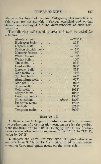
THERMOMETRY 157
above a few hundred degrees Centigrade, thermometers of
this type are not suitable. Various electrical and opticaldevices are employed for the determination of such tem-
peratures.The following table is of interest and may be useful for
reference :
Absolute zero .... 273 C.
Hydrogen boils .... -253Oxygen boils . . . . -183Carbon dioxide boils . . .
- 78
Mercury freezes .... - 39Water freezes ....Water boils ..... 100Tin melts 232Lead melts 327
Mercury boils .... 357Zinc melts 419
Sulphur boils . . . . 445Aluminium melts .... 657Zinc boils 918Silver melts .... 961Gold melts 1062
Copper melts .... 1083Pure iron melts .... 1500Silica softens . . . about 1500Platinum melts .... 1750Tin boils 2270
Tungsten melts .... 3000
Exercises 13.
1. Draw a line 5" long and graduate one side to representthe graduations of a Centigrade thermometer ;
let the gradua-tions rise from C. to 100 C., rising by 10 C ; the gradua-tions on the other side to represent from 32 F. to 212 F.,
rising by 20 F.
2. Repeat the above exercise with .the graduations onone side from 32 F. to 150 F., rising by 20 F., and corre-
sponding Centigrade graduations on the other side.

158 AN INTRODUCTION TO PHYSICS
3. Draw a line 4" long and graduate one side to representfrom F. to 150 F., graduated every 20 F. On the otherside draw a suitable Centigrade scale to correspond.
4. Repeat the above exercise, but graduate one side from10 C. to 80 C., rising by 10 C. On the other side draw asuitable Fahrenheit scale.
5. Describe, with sketches, the construction of an ordinarymerdurial thermometer.
6. Define the terms"freezing point
" and "boiling point
"
of a thermometer.
7. Describe how you would determine the"fixed points
"
on a mercury thermometer.
8. By means of a large-scale graph of your own construc-
tion, convert the following temperatures : 120 C., 135 C.,
87 C., 36 C., 25 C. to Fahrenheit readings. Convert the
following readings Fahrenheit into Centigrade : 29, 36,65, 85, 115, and 205. Check each result by calculation.
9. Why are thermometer tubes usually made with a veryfine bore ?
10. Convert all the temperatures given in the table at the
end of this chapter into degrees Fahrenheit.
11. State in your own words what you understand by the
word "temperature."
12. A student is performing an experiment, and to take
readings of the thermometer he lifts it out of the liquidwhose temperature is required. Criticise his method.
13. In 1911 Kamerlingh Onnes liquified helium and the
temperature attained was 271*3 C. How far was he fromthe absolute zero of temperature ?
14. The normal temperature of the human body is 98*4 F. ;
the normal room temperature is 68 F. Convert these tem-
peratures into degrees C.

THERMOMETRY 159
15."Segar cones
"(fusion thermometers) are used for
measuring high temperatures, and the following are somecone numbers and their estimated softening-points :
Estimated softening-point in degrees C.
590 620 710 800 920 950 1090 1150 1250Cone numbers
022 021 018 015 Oil 010 03 1 6
Give these temperatures in degrees Fahrenheit and degreesabsolute Centigrade.
16. White and Taylor give the following colour scale :
Name of the colour. Degrees CJ.
Dark red heat 566Dark cherry red ..... 635
Cherry, full red 746
light red ....... 843
Orange . . ... . . 899
Light orange . . . . . 941
Yellow 966White 1,205
Give these values in degrees P.
17. The following boiling points of non-metallic elementsare given : Argon, 186 C. Chlorine, 33 '6 C. Krypton,-151*7 C., and Neon, 239'0 C. Express these results in
degrees F. absolute.
18. The following figures are taken from a steam table :
Absolute pressurein Ibs. per sq. in.

160 AN INTRODUCTION TO PHYSICS
19. The critical temperature of a gas is that temperatureabove which no pressure suffices to produce a liquid. Convertthe following table of critical temperatures in degrees C. andcritical pressures in atmospheres into critical temperaturesin degrees F. absolute and pressures in Ibs. per sq. in.
j
Substance.'^^roSS*
i

CHAPTER XIV
EXPANSION OF MATTER BY HEAT
Linear Expansion. We have already seen in a general
way that bodies mostly expand when their temperature is
raised. We will now consider this matter in a little moredetail.
In an investigation of this nature, it is always desirable
to inquire into the simplest cases first. Hence we will
commence with solids, and even so we will consider only their"linear
"expansion, that is, their expansion in length.
A great many types of apparatus are in use for the measure-ment of the expansion of metal rods. That shown in Fig. 87
is a suitable form for the purpose.
FIG. 87.
The metal rod under investigation is generally about
50 cms. long and has pointed ends. These fit into conical
recesses in the metal plugs which are shown in Fig. 87 at
the ends of a metal cylinder.
L 161
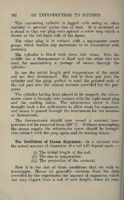
162 AN INTRODUCTION TO PHYSICS
This containing cylinder is lagged with string or other
material to prevent undue loss of heat. It is mounted ona stand so that one plug rests against a screw stop which is
shown at the left-hand side of the figure.
The other plug is in contact with a micrometer screw
gauge, which enables any movement to be determined with
accuracy.
The cylinder is fitted with three side tubes. Into the
middle one a thermometer is fixed and the other two are
used for maintaining a passage of steani through the
cylinder.
In use the initial length and temperature of the metalrod are first determined. The rod is then put into the
cylinder and the plugs pushed in until the pointed ends of
the rod pass into the conical recesses provided for the pur-
poses.
The cylinder having been placed in its support, the micro-
meter screw is brought into contact with the right-hand plugand the reading taken. The micrometer screw is then
brought back a few millimetres to allow room for expansion,and steam is passed through the instrument for ten minutesor thereabouts.
The thermometer should now record a constant tem-
perature not far removed from 100 C. Without interruptingthe steam supply the micrometer screw should be broughtinto contact with the plug again and its reading taken.
The Coefficient of Linear Expansion. It is obvious that
the actual amount of expansion of a rod will depend upon :
(i) The initial length of the rod.
(ii) The rise in temperature,
(iii) The properties of the material.
Now it is the last of these conditions that we wish to
investigate. Hence we generally calculate from the data
provided by the experiment the amount of expansion whichone may expect from a rod of unit length, when its tern-

EXPANSION OF MATTER BY HEAT 163
perature is raised one degree. This quantity is called the"coefficient of linear expansion."
Ex. 18. Find the coefficient of linear expansion of brass
from the following data :
Initial length of brass rod . . 50 cms.
Initial temperature of rod . . 17 C.
Temperature recorded by thermometerin steam chamber.... 99 C.
Initial reading of micrometer . . 0'78mm.Final reading of micrometer . . 1'55 mm.
We see that the amount of expansion is 1*55 0'78=0'77mm. Converting this to centimetres we get 0*077.
The rise of temperature was 99 17 = 82 degrees. Assuming
that the expansion is uniform we have an expansion of ^-cms. for each degree.
But the rod was 50 cms. long, and if it had only had a
length of 1 cm. the expansion would have been only l-50th
of that measured.
Hence the coefficient of linear expansion of brass is
From this example it is easy to see that :
Measured ExpansionCoefficient of linear expansion= . . rr~
Original length x Degrees rise.
Experiment 48.
Determine the coefficient of expansion of a number of
different metals.
The results may be compared with those given in the
following table, which will also be useful for reference.

164 AN INTRODUCTION TO PHYSICS
COEFFICIENT OF LINEAR EXPANSION.
Metal.

EXPANSION OF MATTER BY HEAT 165
clear that these terms have so small a value as to be quite
negligible.
Thus we may say that unit volume expands 3a units whenthe temperature is raised one degree. Hence the coefficient
of cubical expansion is 3a. But this is three times the valueof the coefficient of linear expansion.
The Expansion of Liquids. Just as normal work demands aconsideration of the linear expansion of metals, so it requiresdata referring to the cubical expansion of liquids.
Experiment 49.
Determine the coefficient of cubical expansion of water.
The density bottle described in Chapter III is suitable for
this purpose. First clean and dry the bottle and weigh it.
Then fill it with cold water at a known temperature and
weigh again.
The whole is now immersed in a vessel of water in which athermometer is suspended. This water is slowly raised to a
temperature of 50 or 60 C., care being taken to keep thewater in the vessel well stirred. In this way the waterwithin the density bottle acquires the temperature of the
outside water.
The bottle is now removed, the outside is dried, and whencool it is again weighed. An example should make the
method clear.
Ex. 19. Find the coefficient of cubical expansion of waterfrom the following data :
Weight of empty density bottle, 9 '842 grins.bottle full of water at 16 C., 34'839 grins.
,, ,, bottle and water after heating to 54C. =34*518grms.
As the water in the bottle was heated it expanded, andsome of it therefore flowed out through the small channelin the stopper. Thus the final weighing is less by an amount
representing the weight of the expelled water.
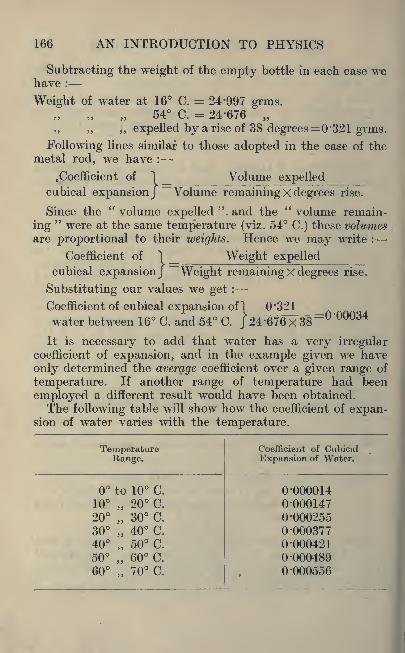
166 AN INTRODUCTION TO PHYSICS
Subtracting the weight of the empty bottle in each case wehave :
Weight of water at 16 C. = 24*997 grms.54 C. = 24-676
,, ,, ,, expelled by a rise of 38 degrees =0*321 grms.
Following lines similar to those adopted in the case of themetal rod, we have :
.Coefficient of "1 Volume expelledcubical expansion/ "Volume remaining x degrees rise.
Since the" volume expelled
" and the"volume remain-
ing"were at the same temperature (viz. 54 C.) these volumes
are proportional to their weights. Hence we ma}^ write :
Coefficient of 1 _ Weight expelledcubical expansion/ Weight remaining x degrees rise.
Substituting our values we get :
Coefficient of cubical expansion of 1 0'321
water between 16 C. and 54 C. J24;676x38
=
It is necessary to add that water has a very irregularcoefficient of expansion, and in the example given we have
only determined the average coefficient over a given range of
temperature. If another range of temperature had been
employed a different result would have been obtained.
The following table will show how the coefficient of expan-sion of water varies with the temperature.
TemperatureRange.

EXPANSION OF MATTER BY HEAT 167
Water is an exceptional substance in this respect, mostother liquids being much more regular. The following table
gives the coefficient of expansion of mercury over the same
range of temperature.
Temperature.

168 AN INTRODUCTION TO PHYSICS
FIG. 88.
Experiment 50.
Expansion of Gases. Obtain a piece of
thin glass tube of not more than 2 mm.bore and about 30 or 40 cms. long. Drawa short thread of mercury into one endand seal up the other end in a Bunsenflame.
We now have a quantity of air enclosedin the tube by the mercury thread, thevolume of the air being indicated by the
length of the tube which it occupies.The tube is supported in a large beaker
of water which also contains a thermo-meter as shown in Fig. 88.
The water is slowly heated with con-
stant stirring to keep its temperatureuniform. The length (I) of the air columnand the temperature of the water are
recorded at frequent intervals.
We will again illustrate the method byan example.
Ex. 20. The following table gives corresponding readingsof temperature and length of air column in Experiment 50.
Find the coefficient of cubical expansion of air.
Temperature 16 C.
Length in cms. 24 '5
25 C. 35 C. 45 C. 55 C.
25-25 26-2 27 '0 28 -0
A very casual glance at these numbers is sufficient to showthat we are here dealing with expansion the magnitude of
which is greatly in excess of anything hitherto experienced.
First express the results by means of a graph, which is
shown in Fig. 89. The points lie very close about a straight
line, and it will be observed that the graph has been pro-duced backwards so as to include the temperature of C.
If a little ice is available this point may be obtained ex-
perimentally, and should certainly be included if means
permit.
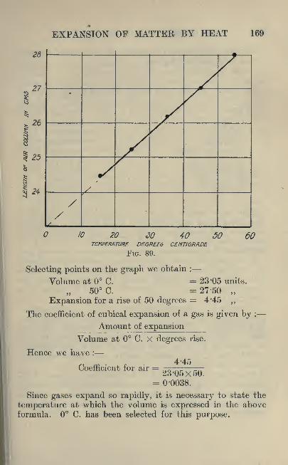
EXPANSION OF MATTER BY HEAT 169
26
26
1*
24
10 20 30 40 50TEMPERATURE DEGREES CENTIGRADE
FIG. 89.
60
Selecting points on the graph we obtain :
Volume at C. = 23-05 units.
50 C. = 27-50
Expansion for a rise of 50 degrees = 4*45
The coefficient of cubical expansion of a gas is given by :
Amount of expansion
Volume at C. X degrees rise.
Hence we have :
Coefficient for air = ^Jjg;= 0-0038.
Since gases expand so rapidly, it is necessary to state the
temperature at which the volume is expressed in the aboveformula. C. has been selected for this purpose.
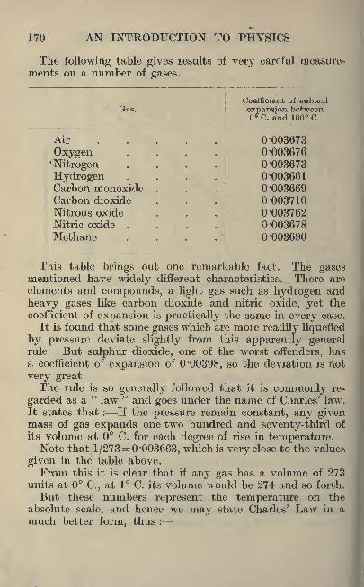
170 AN INTRODUCTION TO PHYSICS
The following table gives results of very careful measure-
ments on a number of gases.
Coefficient of cubicalGas. expansion between
C. and 100 C.
Air
Oxygen'Nitrogen
0-0036730-0036760-003673
Hydrogen .... '003661
Carbon monoxide 0*003669Carbon dioxide
Nitrous oxide0-0037100-003762
Nitric oxide .... 0*003678Methane .... '003690
This table brings out one remarkable fact. The gasesmentioned have widely different characteristics. There are
elements and compounds, a light gas such as hydrogen and
heavy gases like carbon dioxide and nitric oxide, yet the
coefficient of expansion is practically the same in every case.
It is found that some gases which are more readily liquefied
by pressure deviate slightly from this apparently generalrule. But sulphur dioxide, one of the worst offenders, hasa coefficient of expansion of '00398, so the deviation is not
very great.The rule is so generally folloAved that it is commonly re-
garded as a" law " and goes under the name of Charles' law.
It states that : If the pressure remain constant, any givenmass of gas expands one two hundred and seventy-third of
its volume at C. for each degree of rise in temperature.Note that 1/273=0 '003663, which is very close to the values
given in the table above.
From this it is clear that if any gas has a volume of 273units at C., at 1 C. its volume would be 274 and so forth.
But these numbers represent the temperature on the
absolute scale, and hence we may state Charles' Law in a
much better form, thus :

EXPANSION OF MATTER BY HEAT 171
If the pressure remain constant, the volume of a givenmass of gas varies directly as the absolute temperature.
Since the volume of all gases is affected to so large anextent by variations of temperature and pressure it is neces-
sary to state all volumes under some agreed standard con-
ditions of temperature and pressure, and not under the
conditions under which a gas happens to be measured.The standard conditions which have been agreed upon
are a temperature of C. and a pressure corresponding to acolumn of mercury 760 mm. high. These are denoted byN.T.P. or normal temperature and pressure.
Ex. 21. Some coal-gas was measured at a temperature of
18 C. under atmospheric pressure and found .to have avolume of 875 c.c. The barometer stood at 752 mm. Reducethe measured volume to N.T.P.
Let V= volume at C.
and v volume at t C.
The absolute temperature at C.=273 A.The absolute temperature at t C. = (273+0 A -
Now since the volume varies directly as the absolute
temperature we have :
V 273
therefore V =
273+*273?;
273+t
Again, if v1=volume of some gas when the pressure is p1
and v2= volume of the same gas when the pressure changesto p2 by Boyle's law (see Chapter IV) we have :
Vi Pi =
Hence v,=
Now ifjp = 760 mm. we et :
-
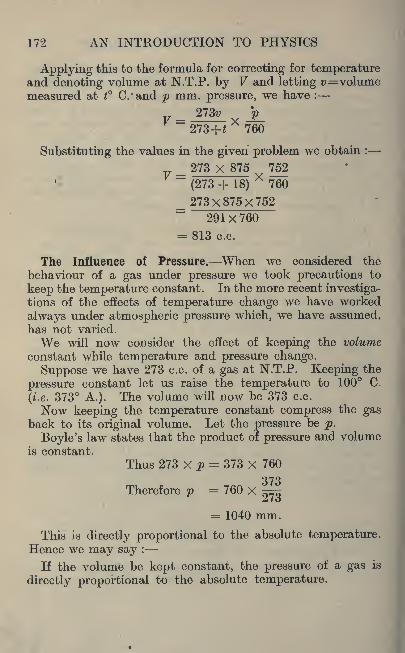
172 AN INTRODUCTION TO PHYSICS
Applying this to the formula for correcting for temperatureand denoting volume at N.T.P. by V and letting v=volumemeasured at t C/and p mm. pressure, we have :
_~273+J
X760
Substituting the values in the given problem we obtain :
_ 273 X 875 752~
(273 + 18)X
760
_ 273x875x752291X760
= 813 c.c.
The Influence of Pressure. When we considered the
behaviour of a gas under pressure we took precautions to
keep the temperature constant. In the more recent investiga-tions of the effects of temperature change we have worked
always under atmospheric pressure which, we have assumed,has not varied.
We will now consider the effect of keeping the volume
constant while temperature and pressure change.
Suppose we have 273 c.c. of a gas at N.T.P. Keeping the
pressure constant let us raise the temperature to 100 C.
(i.e. 373 A.). The volume will now be 373 c.c.
Now keeping the temperature constant compress the gasback to its original volume. Let the pressure be p.
Boyle's law states that the product of pressure and volumeis constant.
Thus 273 X p = 373 X 760
373Therefore p = 760 X 5=5Zio
= 1040 mm.
This is directly proportional to the absolute temperature.Hence we may say :
If the volume be kept constant, the pressure of a gas is
directly proportional to the absolute temperature.

EXPANSION OF MATTER BY HEAT 173
The Gas Equation. Let V=volume of a gas at N.T.P.
For a given mass of any given gas this will, of course, be
constant.) Let v=the volume of this gas when the pressurejs p and the absolute temperature is T.
It will be recalled that we obtained a formula for reducingvolumes to N.T.P. in which
273^ j>_
273+* 760
Now (273+0 is the absolute temperature at t C. and maybe written T,
T/Hence v "'-
pv 7607Therefore
p- =
-^-760 V
But F is a constant, and therefore the expressionis a constant. It is usually denoted by the letter R.
Thus ? =,
or pv= .flT.
This equation is known as the" Gas Equation." It is,
however, only another form of the formula developed in
Example 21.
Exercises 14.
1. A man is making a ring gauge and he is using J" diametercast steel check pins ;
their measured lengths at 62 F.are 8 '0000" and 8*0005", if he holds the pins in his hands until
the average temperature rises to 72 F., calculate the newlength of the pins. Show by sketches some simple methodof overcoming this alteration in length. The coefficient of
expansion of cast steel is 1-17 x 10'5 per degree centigrade.
2. Repeat the above example, with pins 4-9995" and 5 '0000"
long and the same rise of temperature.
3. A number of standard cast steel check gauges of the
following lengths, 2", 4", 6", and 8" have been certified as
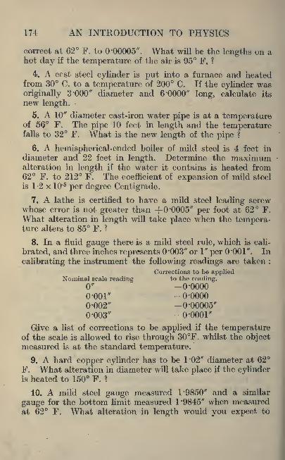
174 AN INTRODUCTION TO PHYSICS
correct at 62 F. to '00005 ". What will be the lengths on ahot day if the temperature of the air is 95 F, ?
4. A cast steel cylinder is put into a furnace and heatedfrom 30 C. to a temperature of 200 C. If the cylinder was
originally 3 'GOO" diameter and 6 -0000" long, calculate its
new length.-
5. A 10" diameter cast-iron water pipe is at a temperatureof 5(? F. The pipe 10 feet in length and the temperaturefalls to 32 F. What is the new length of the pipe ?
6. A hemispherical-ended boiler of mild steel is 4 feet in
diameter and 22 feet in length. Determine the maximumalteration in length if the water it contains is heated from62 F. to 212 F. The coefficient of expansion of mild steel
is 1-2 x 10'5 per degree Centigrade.
7. A lathe is certified to have a mild steel leading screwwhose error is not greater than -f0*0005" per foot at 62 F.
What alteration in length will take place when the tempera-ture alters to 85 F. ?
8. In a fluid gauge there is a mild steel rule, which is cali-
brated, and three inches represents "003" or \" per -001". In
calibrating the instrument the following readings are taken :
Corrections to be appliedNominal scale reading to the reading.
0" -0-0000o-ooi* -o-oooo0-002" -0-00005"0-003" -0-0001"
Give a list of corrections to be applied if the temperatureof the scale is allowed to rise through 30F. whilst the objectmeasured is at the standard temperature.
9. A hard copper cylinder has to be 1*02" diameter at 62
F. What alteration in diameter will take place if the cylinderis heated to 150 F. ?
10. A mild steel gauge measured 1-9850" and a similar
gauge for the bottom limit measured 1 -9845" when measuredat 62 F. What alteration in length would you expect to

EXPANSION OF MATTER BY HEAT 175
find if the man using these gauges held them in his handuntil they reached a temperature of 89 F. ?
11. A horseshoe gauge has to measure 6 -965" inside the
jaws and has been made accurate at 62 F. What will be
the percentage error caused by an alteration in the tempera-ture of the gauge of 20 F, ? Assume the gauge is mild steel
and only the jaws are cast steel.
12. A tyre is to be put on a wheel and the wrought-iron
hoop is made slightly less in internal diameter than the outside
of the wheel. Give reasons for this and explain how the hoopis placed on the wheel.
13. A compound bar consists of two strips, one of brass
and the other of mild steel, rivetted together. The bar is
placed edgewise in a Bunsen flame, so that both metals are
heated equally. Give sketches, showing how the metalbends when heated and cooled.
14. Why is a space left between the ends of railway lines ?
Give sketches of the side-plates, bolts and bolt-holes whichfasten the ends of the rails together.
15. A railway bridge is built up of joists and is 27 feet
long. What alteration in length will take place if the lengthis 27 feet at a temperature of 62 F. and there are then
temperature changes ranging from 32 F. to 95 F. ?
16. The compensated balance-wheel of a watch is madewith the arcs of the wheel of metals of different coefficients
of expansion. The metal with the smaller coefficient is the
inner metal. Make a sketch and explain the action.
17. Explain, by the aid of sketches, six uses to which the
property of the expansion of metals with heat is put.
18. Explain by the aid of sketches six common dis-
advantages which occur in practical working owing to the
expansion of metals with heat.
19. Give reasons to show why it is advisable to have fire-
bars in boilers loosely fitting.
20. Describe any experiment you have performed to deter-
mine the coefficient of expansion of metals.

176 AN INTRODUCTION TO PHYSICS
21. The pattern-maker uses a special rule called the"con-
traction rule." ]?or cast iron this rule is"
per foot longerthan the ordinary rule. Cast iron melts at 1,500 C. Assumingthat the coefficient of contraction is constant throughoutthe cooling range (this is not true in practice) determinehow much a rod of cast iron one foot long at the temperaturegiven will contract. Let the final temperature be 35 C.
22. Describe in detail some method for keeping constant
the fate of a clock. Variations in temperature ^must not
have any effect on the length of the pendulum.
23. Explain what you mean when you say that '02 carbonsteel has a mean coefficient of expansion of 11 '8 x 10~6 betweenthe temperatures of 15 and 200 C.
24. The distance between telephone posts is 80 yardsand the wire used is copper. What difference in the lengthof the wire would you expect between C. and 30 C. ?
25. Convert the table given on page 164 from a table of
linear expansion to a table of cubical expansion.
26. The coefficient of linear expansion of aluminium is
'0000231. Determine the cubical expansion of a cube of
aluminium of 3" side if the temperature of the cube is raised
20 C.
27. Platinite is an alloy of iron with 42% nickel. This
alloy has the same coefficient of expansion and contraction
at atmospheric temperature as glass. Discuss the use of
this alloy as a wire mesh for the manufacture of armoured
glass. What difference would you expect if ordinary wire
netting were used instead ?
28. In the manufacture of electric lamps a small pieceof platinum is fused into the glass. Why is platinum used
in preference to cheaper metals ?
29. Invar is an alloy of iron with 36% nickel and the
coefficient of expansion with ordinary atmospheric changes of
temperature is smaller than that of any other metal. The linear
coefficient of expansion ranges from 0*000000374 to '00000044

EXPANSION OF MATTER BY HEAT 177
for changes of 1 C. How does this compare with mild steel ?
Express the comparison as a vulgar fraction in its simplestform.
30. In surveying it is important that there should be as
little alteration in length as possible in the steel tape used.
Discuss the advantages of a steel tape 100 feet long made of
invar as against one made of a low carbon steel.
31. The following table gives the relative volumes of waterat different temperatures, compared with its volume at 4 C.
Degrees Centigrade4 10 20 30 40 50 70
Volume1-000 1-00025 1-00171 1*00425 1 "00767 1 -01180 1-02241
If the weight of one cubic foot of water at 4 C. is equal to
62*4245 Ibs., plot a curve of the temperature and weight of
one cubic foot of water.
32. An experiment was carried out on a brass rod to deter-
mine its coefficient of expansion and the following results
were obtained :
Length of the rod at 18 C. . . 50 '084 cms.
Length of the rod at 98'5 C. . . 50'159 cms.
Determine the coefficient of linear expansion.
33. An experiment was carried out to determine the
average coefficient of expansion of water. A bottle weightedwith shot was weighed in air, the bottle was then Aveighed in
water at a given temperature and then in water at a higher
temperature. The following are the results :
True weight of the bottle in air . . . 82-01 gram.Weight of the bottle in water at a temp, of 10 C. 10'91
Weight of the bottle in water at 25 C. . . 11 '05
Determine the average coefficient of expansion of waterbetween the temperatures given.
34. An experiment, to determine the coefficient of expan-M
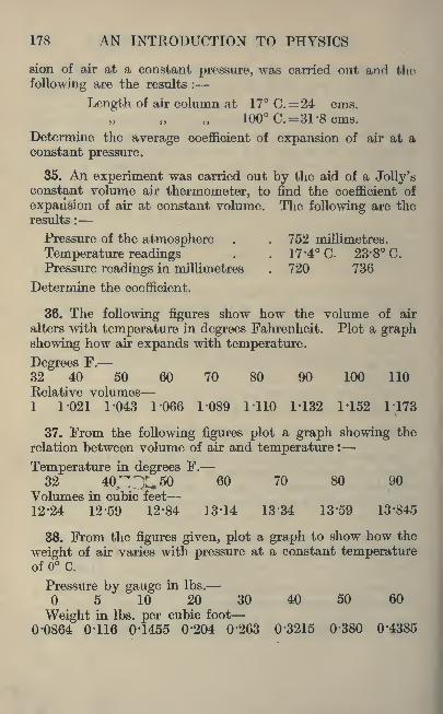
178 AN INTRODUCTION TO PHYSICS
sion of air at a constant pressure, was carried out and the
following are the results :
Length of air column at 17 C.=24 cms.100 C.= 31 -8 cms.
Determine the average coefficient of expansion of air at aconstant pressure.
35. An experiment was carried out by the aid of a Jolly'sconstant volume air thermometer, to find the coefficient of
expansion of air at constant volume. The following are theresults :
Pressure of the atmosphere . . 752 millimetres.
Temperature readings . . 17 -4 C. 23-8 C.
Pressure readings in millimetres . 720 736
Determine the coefficient.
36. The following figures show how the volume of air
alters with temperature in degrees Fahrenheit. Plot a graphshowing how air expands with temperature.
Degrees F.
32 40 50 60 70 80 90 100 110Relative volumes1 1-021 1-043 1-066 1-089 1-110 M32 M52 1-173
37. From the following figures plot a graph showing the
relation between volume of air and temperature :
Temperature in degrees F.
32 40;TX50 60 70 80 90
Volumes in cubic feet
12-24 12-59 12-84 13'14 13'34 13'59 13'845
38. From the figures given, plot a graph to show how the
weight of air varies with pressure at a constant temperatureof C.
Pressure by gauge in Ibs.
5'
10 20 30 40 50 60
Weight in Ibs. per cubic foot
0-0864 0-116 0-1455 0'204 0*263 0'3215 0'380 0*4385

EXPANSION OF MATTER BY HEAT 179
39. From the figures given, plot a graph to show how the
weight of air varies with temperature, with a constant gaugepressure of 5 Ibs. per sq. in.
Temperature <of air in degrees F.
-20 -10 20 30 40 50 60
Weight in Ibs. per cubic foot
0-1205 -1184 -1455 '1395 -1366 -1388 -1310 -1283
40. Plot a graph of barometric pressure in inches of mercuryand altitude in feet.
Altitude in feet
1000 2000 3000 4000 5000 6000 7000 8000Barometric pressure in inches of mercurv
30 28-88 27-8 26'76 25'76 24-79 23'86 22'97 22-11
41. 150 cubic centimetres of air are measured at 30 C.
If the temperature be raised to 60 C., determine the volume,
assuming the pressure remains constant.
42. 150 cubic centimetres of air are measured at 30 C.
and then cooled down to 30 C. By how much will thevolume diminish ?
43. A long narrow tube was filled with mercury and in-
verted in a trough. At each experiment a little of the mercurywas run out and the volume of the air measured. Thepressure was determined in the usual way and the followingresults are given :
Pressure in inches of mercury29-2 25 21 15 10
Volume as measured4-812 5-62 6-7 9'4 14
Plot a graph of pressure and volume and determine thevalue of pv.

CHAPTER XVSPECIFIC HEAT
Quantity of Heat. If a few cubic centimetres of water are
placed in a test-tube and about a litre of water is put into a
flask, on the application of a Bunsen flame to each for the
space of one minute, a rise of temperature will result in bothcases.
But whereas the small quantity of water is boiling, the
larger quantity is still comparatively cold. Yet the flame
had the same opportunity of imparting heat in both cases.
We see therefore that a high temperature does not neces-
sarily indicate a large amount of heat. Quantity of heat,while depending upon temperature differences, depends uponother things too.
The Calorie. The unit of quantity of heat generally adoptedfor scientific purposes is called the
"calorie." It is defined
as the quantity of heat which is required to raise one grammeof water through one degree Centigrade. Strictly speaking,it should be from 15 C. to 16 C.
This quantity is not materially affected by temperature,but in the definition it is desirable to state the interval of
15 to 16, as the quantity of heat required to raise one
gramme of water through one degree Centigrade is slightlydifferent at other temperatures. The difference is, however,so slight as to be quite negligible except for very accurate
work.Where very large quantities of heat have to be dealt with,
as in engineering work, it is desirable to have a larger unit
and the" Grand Calorie
"is employed. It is equal to 1000
calories.
180

SPECIFIC HEAT 181
The British Thermal Unit. In technical work in this
country the"British Thermal Unit
"is commonly em-
ployed. It is the quantity of heat required to raise one poundof water through one degree Fahrenheit. It is often written
as B.Th.U.Since the variation due to temperature is so extremely small
it is permissible to multiply a weight of water by its tem-
perature change to express the number of units of heat
gained or lost.
Experiment 51.
The Water Equivalent of a Vessel. Obtain a thin metalcanister with a capacity of about half a litre. Copper is a
very suitable metal, but failing everything else a glass beaker
may be used. Place it inside a larger vessel and pack the
space between the two vessels with cotton wool.
A stirrer should be made by bending a piece of stiff copperwire into a suitable loop, and the addition of a thermometer
completes the equipment.This simple apparatus is called a calorimeter. Its use is
best illustrated by considering an example.
Ex. 22. The inner vessel of a calorimeter was weighedand 64*98 grammes was the weight recorded. About 150 c.c.
of cold water were added and the whole now weighed 215*76
grammes. The thermometer in the calorimeter registered15 C. A quantity of heated water was added (whose tem-
perature was 82 C.) and after stirring the temperature of
the mixture was found to be 45 C. When cool the vessel
and water were weighed, the whole weighing 344*12 grammes.Subtracting the weight of the vessel from the first weighing
we get :
Weight of water at 15 C. = 150*78 grammes.The weight of water added at 82 C. = 128*36 grammes.Now the heat gained or lost by any quantity of water is
the product of its weight and its temperature change.
Hence heat gained bythe cold water . . = 150*78 x (4515) =4,523 calories.
Heat lost by the hot water= 128'36 X (8245) =4,749 calories.
182 AN INTRODUCTION TO PHYSICS
It will be observed that the hot water lost 226 more units of
heat than were absorbed by the cold water, and since experi-ment has shown that energy in any form cannot be createdout of nothing nor destroyed (in the sense of turning it into
nothing), it follows that these 226 calories must be accountedfor.
A little thought should make it clear that whereas the
calorimeter, the thermometer and the stirrer were initiallyat the temperature of the cold water (viz. 15 C.) at the endof the experiment they were at the temperature of the mixture
(viz. 45 C.). In other words, these things had been raised
30 degrees. It is reasonable to suppose that the 226 calories
of heat were utilized for this purpose.It is a very convenient practice to estimate how much
additional cold water would have absorbed the same amount226
of heat, under the same conditions. Obviously- = 7'5
grammes is the required amount.This 7 '5 grammes is called the
"water equivalent
"of the
calorimeter. It means that in all subsequent experimentswith this calorimeter, thermometer and stirrer, the heatwhich they absorb will be the same as that which 7 *5 grammesof cold water would absorb.
Specific Heat. We have already seen that the unit of heatis the amount of heat required to raise unit weight of water
through unit temperature.Now water is an unusually difficult substance to make
warm. That is to say, most other substances are raised
through a given range of temperature by the absorption of
less heat than is required to raise an equal quantity of water
through the same range of temperature.The amount of heat which is required to raise unit weight
of a substance through unit temperature is called the"
specificheat
"of that substance. We will now consider one or two
methods by which the specific heat of a substance may bedetermined.
Ex. 23. A quantity of glycerine was placed in the calori-
meter previously used (weight 64 '98 grammes). The whole
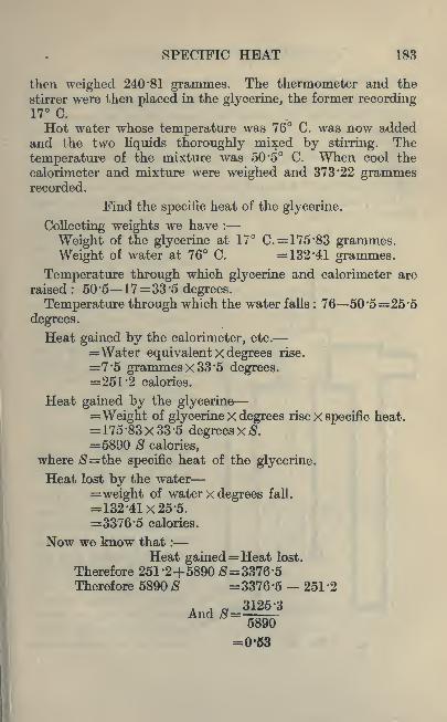
SPECIFIC HEAT 1R3
then weighed 240*81 grammes. The thermometer and the
stirrer were then placed in the glycerine, the former recording17 C.
Hot water whose temperature was 76 C. was now addedand the two liquids thoroughly mixed by stirring. The
temperature of the mixture was 50*5 C. When cool the
calorimeter and mixture were weighed and 373*22 grammesrecorded.
Find the specific heat of the glycerine.
Collecting weights we have :
Weight of the glycerine at 17 C. = 175*83 grammes.Weight of water at 76 C. =132*41 grammes.
Temperature through which glycerine and calorimeter are
raised: 50*5 17=33*5 degrees.
Temperature through which the water falls : 76 50*5=25*5
Heat gained by the calorimeter, etc.
=Water equivalent X degrees rise.
=7*5 grammes x 33*5 degrees.=251*2 calories.
Heat gamed by the glycerine=Weight of glycerine x degrees rise x specific heat.= 175*83x33*5 degrees xS.=5890 S calories,
where $=the specific heat of the glycerine.
Heat lost by the water=weight of water x degrees fall.
= 132*41x25*5.=3376*5 calories.
Now we know that :
Heat gained=Heat lost.
Therefore 251*2+5890 =3376*5Therefore 5890 S =3376*5 - 251 *2
3125*3
^-5890=0*53

184 AN IOTRODUCTION TO PHYSICS
Experiment 52.
Find the specific heat of any liquid (which is not acted
upon chemically by water) by the method illustrated in
Example 23.
The Specific Heat of Metals. For this purpose a knownweight of the metal is usually heated to a known temperatureand dropped into a calorimeter containing cold water.
It js very necessary for accurate work to provide somemeans of heating the metal so that it may be transferred
from the heater to the
calorimeter without loss
of heat.
Fig. 90 shows a suit-
able form of heater. It
consists of a cylindrical
copper vessel providedwith another cylinder in-
^^^^ side so that there is anII IM annular space throughIM-- rJll which steam may be
FIG. 90.
An opening at the to
is provided with a cor
through which two holes
are pierced. One of these
carries a thermometer
(T), and the other is
closed with a short glass
plug which secures a pieceof thread on which the
metal (M) is suspendedso that it hangs near the
bulb of the thermometer.After steam has been
passing through such avessel for ten or fifteen
minutes, the metal will be
raised to a temperature
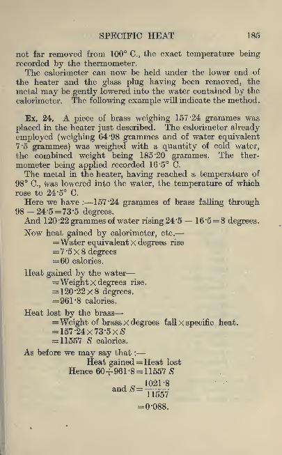
SPECIFIC HEAT 185
not far removed from 100 C., the exact temperature beingrecorded by the thermometer,The calorimeter can now be held under the lower end of
the heater and the glass plug having been removed, the
metal may be gently lowered into the water contained by the
calorimeter. The following example will indicate the method.
Ex. 24. A piece of brass weighing 157*24 grammes was
placed in the heater just described. The calorimeter already
employed (weighing 64 '98 grammes and of water equivalent7*5 grammes) was weighed with a quantity of cold water,the combined weight being 185*20 grammes. The ther-
mometer being applied recorded 16*5 C.
The metal in the heater, having reached a temperature of
98 C., Was lowered into the water, the temperature of whichrose to 24*5 C.
Here we have : 157*24 grammes of brass falling through98-24*5=73*5 degrees.And 120*22 grammes of water rising 24*5 16*5= 8 degrees.
Now heat gained by calorimeter, etc.
=Water equivalent X degrees rise
=7*5x8 degrees=60 calories.
Heat gained by the water=Weight x degrees rise.
= 120*22x8 degrees.=961*8 calories.
Heat lost by the brass=Weight of brass X degrees fall X specific heat.= 157*24x73'5x= 11557 8 calories.
As before we may say that :
Heat gained=Heat lost
Hence 60+961*8= 11557 81021*8
=0*088.

186 AN INTRODUCTION TO PHYSICS
Experiment 53.
Find the specific heat of a number of solids, including as
many metals as are available.
Students of chemistry will find it of interest to plot a grapli
showing the relation between the specific heat of various
metals and their atomic weights. A table should also bemade giving the product of the atomic weight and specificheat 'of the metals he has experimented upon. This productis sometimes called the
"atomic heat."
The specific heat of all substances varies with the tem-
perature to a greater or less extent. The following table
gives the specific heat of a number of common substances at
the approximate working temperature of a laboratory. It
will be useful for reference.
Substance.

SPECIFIC HEAT 187
The Specific Heat of a Gas. The general principle under-
lying the method of determining the specific heat of a gas is
the same as that already described in the case of solids or
liquids. The technical details of the apparatus are, however,much more complex, as a gas occupies such a large volume
compared with its weight.Just as in the case of other substances the specific heat of
a gas depends to some extent on the temperature, but andthis is not the case with other substances the pressure here
plays an important part.The following table gives the specific heat of a few common
gases at the average temperature and pressure of the atmo-
sphere.
Substance.

188 AN INTRODUCTION TO PHYSICS
Of course this is true also of solids and liquids, but in thesecases the expansion is so small that the energy thus absorbedis entirely negligible.From what has been said, it will be seen that if a gas is
so enclosed that it cannot expand, that is, if its volume is
kept constant, the specific heat will be less.
Although it is possible directly to measure the specificheat at constant volume, it is often more practicable to deter-
mine* the ratio of the specific heat at constant pressure to
that at constant volume.The following table gives an indication of the quantities
in question.
Substance.

SPECIFIC HEAT 189
Students of chemistry will notice that the ratio is greaterin the case of elements than in the case of compounds.Experiment has shown that the ratio depends on the con-
stitution of the molecule, becoming less as the molecule
becomes more complex.
Isothermal Expansion. It will be recalled that when
Boyle's law was the subject of investigation in Chapter IVthe gas was expanded (or compressed) very slowly in order
to maintain a constant temperature. Such a process is called"isothermal
"expansion. For a gas to expand isothermally,
time and facilities must be given for the heat to flow into
the gas in order to keep the temperature up.On the other hand, if it is desired to compress the gas
isothermally, time and facilities must be provided for heat to
flow out of the gas.
Adiabatic Expansion. If a gas is expanded (or compressed)with extreme rapidity there is no time for heat to flow into
(or out of) the gas. In such cases the expanded gas becomes
colder, or, if compression has taken place, the gas has becomehotter.
This is called"adiabatic
"expansion (or compression).
Few experimental processes are sufficiently rapid to get
perfect adiabatic expansion, but the process is approximatelyapproached in the expansion of the working fluid in the
cylinders of some* high-speed engines.
Exercises 15.
1. Determine the number of calories and grand calories
in the following cases :
1. 20 Ibs. water, Rise in temp, in degrees Centigrade 302. 56 Ibs. water 543. 37 -5 Ibs. water ,. 854. 42-5 Ibs. water 100.
2. In the above examples determine the number of B.Th.U.of heat given to the water.
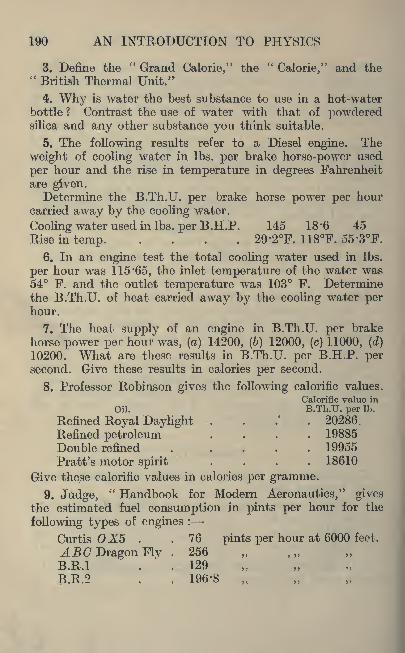
190 AN INTRODUCTION TO PHYSICS
3. Define the" Grand Calorie," the
"Calorie," and the
"British Thermal Unit."
4. Why is water the best substance to use in a hot-waterbottle ? Contrast the use of water with that of powderedsilica and any other substance you think suitable.
5. The following results refer to a Diesel engine. The
weight of cooling water in Ibs. per brake horse-power used
per hour and the rise in temperature in degrees Fahrenheitare given.Determine the B.Th.U. per brake horse power per hour
carried away by the cooling water.
Cooling water used in Ibs. per B.H.P. 145 18'6 45
Rise in temp. . 29'2F. 118F. 55'3F.
6. In an engine test the total cooling water used in Ibs.
per hour was 115 '65, the inlet temperature of the water was54 F. and the outlet temperature was 103 F. Determinethe B.Th.U. of heat carried away by the cooling water perhour.
7. The heat supply of an engine in B.Th.U. per brake
horse power per hour was, (a) 14200, (6) 12000, (c) 11000, (d)
10200. What are these results in B.Th.U. per B.H.P. persecond. Give these results in calories per second.
8. Professor Robinson gives the following calorific values.
Calorific value in
Oil. B.Th.U. per Ib.
Refined Royal Daylight . 20286.
Refined petroleum .... 19885
Double refined 19955
Pratt's motor spirit .... 18610
Give these calorific values in calories per gramme.
9. Judge," Handbook for Modern Aeronautics," gives
the estimated fuel consumption in pints per hour for the
following types of engines :
Curtis X5 . . 76 pints per hour at 6000 feet.
ABC Dragon Fly . 256
B.R.I . . 129
B.R.2 , 196-8
SPECIFIC HEAT 191
Assuming that petrol of 0'68 specific gravity and having a
heat value of 19200 B.Th.U. per Ib. was used; determine
the B.Th.U. used per hour.
10. Determine the water equivalent of 0*75 Ibs. of each
of the following metals : Aluminium, copper, iron, lead,
magnesium, tin, and zinc.
11. Explain what is meant by"
specific heat."
12. A gas ring weighs 3 pounds and is at 62 F. After
boiling water its temperature is 150 F. What is the water
equivalent of the ring and how many B.Th.U. has it absorbed ?
13. In an experiment to determine the mechanical equiva-lent of heat the following results were obtained :
Water in the drum, 300 grammes.Water equivalent of the drum and thermometer, 40*75 grms.
Original temperature of the water, 15*92 C.
Final temperature of the water, 16*95 C.
Determine the calories of heat generated.
14. An experiment was carried out to determine the
specific heat of iron tacks. The following are the results :
Weight of the copper calorimeter, 67*135 grammes.Weight of calorimeter and water, 101*43 grammes.Original temperature of the water, 13 C.
Temperature of the tacks before dropping into the water,97 C.
Temperature of the water and tacks after mixing, 16*2 C.
Weight of the calorimeter, water and tacks, 111 *75 grammes.Determine the specific heat of the tacks.
15. An experiment was carried out to determine the water
equivalent of a copper calorimeter.
Weight of the calorimeter, 107*65 grammes.Initial temperature of the calorimeter, 13 C.
Temperature of warm water before placing in the calori-
meter, 41*3 C.
j*Final temperature of water and calorimeter, 39 C.
MWeight of the calorimeter and the water, 236*22 grammes.Determine the water equivalent from these results andalso by assuming the specific heat of copper.

192 AN INTRODUCTION TO PHYSICS
16. An experiment was carried out to determine the
specific heat of copper and the results are as follows :
Weight of the copper cylinder in grammes, 93 '71.
Weight of the inner cylinder or calorimeter, 107 '65 grammes.Weight of the calorimeter plus added water, 292:5 grammes.Initial temperature of the water in the calorimeter, 12 '5 C.
Temperature of the copper cylinder, 99*7 C.
Final temperature of the water and the copper cylinder,16-5 C.
Determine the specific heat of the copper cylinder.
17. To take into account the variation of specific heat with
temperature, the specific heat of copper may be written as
follows :
Specific heat of copper at t C.,=0-0917+0-000048t.Calculate the specific heat of copper for the following
temperatures : 50, 100, 150, 200, 250, and 300 C. Plot a
graph of temperature and specific heat.
18. A glass vessel at 30 C. weighs 980 grammes. If 2000
grammes of water at 40 C. are poured into the glass vessel,
determine the final temperature of the water. Take the
specific heat of the glass as 0'12.
19. Determine the B.Th.U. of heat carried away per hour
by the cooling water in a 50 I.H.P. gas engine. Use the
following formula :
OOAAAw t t
l = 0-30 X I.H.P. X ~ X 60.
Where w=lbs. of water per hour.
t= final temperature Fahrenheit.
tl= initial temperature Fahrenheit.
I.H.P. = indicated horse power.
20. In a gas engine the heat distribution is as follows :
Work as indicated horse power . . 27*1%Carried away by the jacket water . . 49*5%Carried away by the exhaust gases . . 23 '4%
Total 100%
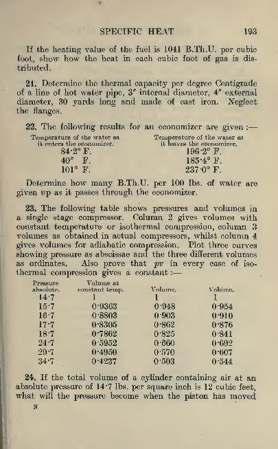
SPECIFIC HEAT 193
If the heating value of the fuel is 1041 B.Th.U. per cubic
foot, show how the heat in each cubic foot of gas is dis-
tributed.
21. Determine the thermal capacity per degree Centigradeof a line of hot water pipe, 3" internal diameter, 4" external
diameter, 30 yards long and made of cast iron. Neglectthe flanges.
22. The following results for an economizer are given :
Temperature of the water as Temperature of the water asit enters the economizer. it leaves the economizer.
84-2 F. 196-2 F.40 F. 185-4 F.
101 F. 237 -0F.
Determine how many B.Th.U. per 100 Ibs. of water are
given up as it passes through the economizer.
23. The following table shows pressures and volumes in
a single stage compressor. Column 2 gives volumes withconstant temperature or isothermal compression, column 3volumes as obtained in actual compressors, whilst column 4
gives volumes for adiabatic compression. Plot three curves
showing pressure as abscissae and the three different volumesas ordinates. Also prove that pv in every case of iso-
thermal compression gives a constant :
Pressure Volume atabsolute. constant temp. Volume. Volume.14-7 1 1 1
15-7 0-9363 0-948 0'95416-7 0-8803 0-903 0'91017-7 0-8305 0-862 0'87618-7 0-7862 0-825 0-841
24-7 0-5952 0'660 069229-7 0-4950 0'570 0'60734-7 0-4237 0'503 0'544
24. If the total volume of a cylinder containing air at anabsolute pressure of 14*7 Ibs. per square inch is 12 cubic feet,what will the pressure become when the piston has moved
N
194 AN INTRODUCTION TO PHYSICS
so as to reduce this volume to 5 cubic feet, the compressionbeing isothermal ?
25. With isothermal compression pv=C. Plot graphsof pressure and volume for the following gases : air, oxygenand nitrogen. Let the gas be at 14 "7 Ibs. per sq. in. pressureand take pressure increasing by 5 Ibs. to 34*7.
Atmospheric air at 14 '7 Ibs. per sq. in. and 62 F. occupiesa volume of 13 '14 cubic feet for 1 Ib.
Oxygen as above 11*88 and nitrogen 13*54.

CHAPTER XVI
LATENT HEAT
Experiment 54.
Change of State. Arrange the apparatus shown in Fig. 84so that the flask is about half full of cold water, and the
thermometer has its bulb just below the surface of the
water.
Place a small flame of a Bunsen burner beneath the flask,
and read the thermometer at regular intervals, say everyhalf minute.
Commencing with the water cold, continue the readings for
a few minutes after the water has boiled.
Plot a graph showing the relation between the time and the
temperature.Now a consideration of this graph will show us that at
first the rate at which the water gains heat is fairly uniform,and if the weight of the water is known it is possible to state
the number of calories per minute which are absorbed by the
water.
Near the boiling point, however, the rate of absorption
appears to fall off, and when the water actually begins to
boil the temperature remains constant.
Now it is unreasonable to suppose that the burner ceased
to supply heat at the moment when the water boiled. Yetif the heat is supplied we must decide on its destination.
Latent Heat. The behaviour of the water is explained thus :
At first the heat supplied to the water was employed in
increasing its temperature. This heat is called"sensible
heat," because it is heat which is recognized by our sense
of touch.
When the water commenced to boil the heat which passed195
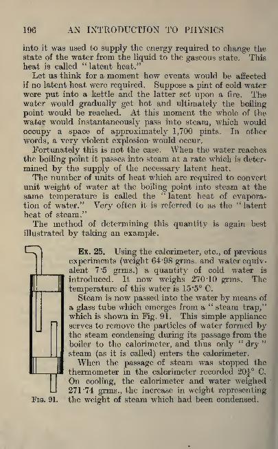
196 AN INTRODUCTION TO PHYSICS
into it was used to supply the energy required to change thestate of the water from the liquid to the gaseous state. Thisheat is called
"latent heat."
Let us think for a moment how events would be affected
if no latent heat were required. Suppose a pint of cold waterwere put into a kettle and the latter set upon a fire. Thewater would gradually get hot and ultimately the boiling
point would be reached. At this moment the whole of the
water would instantaneously pass into steam, which would
occupy a space of approximately 1,700 pints. In other
words, a very violent explosion would occur.
Fortunately this is not the case. When the water reaches
the boiling point it passes into steam at a rate which is deter-
mined by the supply of the necessary latent heat.
The number of units of heat which are required to convertunit weight of water at the boiling point into steam at the
same temperature is called the"latent heat of evapora-
tion of water." Very often it is referred to as the"latent
heat of steam."The method of determining this quantity is again best
illustrated by taking an example.
Ex. 25. Using the calorimeter, etc., of previous
experiments (weight 64*98 grms. and water equiv-alent 7*5 grms.) a quantity of cold water is
introduced. It now weighs 270*10 grms. The
temperature of this water is 15*5 C.
Steam is now passed into the water by means of
a glass tube which emerges from a" steam trap,"
which is shown in Fig. 91. This simple applianceserves to remove the particles of water formed bythe steam condensing during its passage from the
boiler to the calorimeter, and thus only"dry
"
steam (as it is called) enters the calorimeter.
When the passage of steam was stopped the
thermometer in the calorimeter recorded 20 C.
On cooling, the calorimeter and water weighed271*74 grms., the increase in weight representing
FIG. 91. the weight of steam which had been condensed.
D
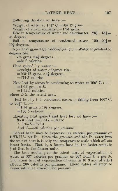
LATENT HEAT 197
Collecting the data we have :
Weight of water at 15 C.=205'12 grms.
Weight of steam condensed= ! 64 grms.Rise in temperature of water and calorimeter 20J 15J=
4J degrees.Fall in temperature of condensed steam 100 20J=
79| degrees.
Now heat gained by calorimeter, etc. =Water equivalent Xdegrees rise.
7 '5 grms. x4J degrees.=35 -6 calories.
Heat gained by water :
= weight of water X degrees rise.
=205 '12 grms.x4| degrees.=974-3 calories.
Heat lost by steam in condensing to water at 100 C. :
= 1-64 grrns.x.L.= 1*64L calories.
where L is the latent heat.
Heat lost by this condensed steam in falling from 100 C.
to 20i C. :
= 1-64 grins. x79f degrees.= 130 '5 calories.
Equating heat gained and heat lost we have :
And jL = 536 calories per gramme.Latent heats may be expressed in calories per gramme or
B.Th.U.'s per Ib. Since the gramme and the Ib. enter into
the unit of heat it is only the temperature scale which affects
latent heats. That is, a latent heat in the latter units is
? of that in the former units.
The best results give the latent heat of vaporisation of
water as 537 calories per gramme or 967 B.Th.U.'s per Ib.
The latent heat of vaporisation of ether is 91 '3 and of ethylalcohol 206 calories per gramme. These values all refer to
vaporisation at atmospheric pressure.

198 AN INTRODUCTION TO PHYSICS
Experiment 55.
Find the latent heat of evaporation of water by the methoddescribed in Example 25.
Latent Heat of Fusion. Just as it needs heat to convert
water into steam after it has been raised to the boiling point,so it needs heat to melt a solid after it has been raised to the
melting point. The number of units of heat which are
necessary to convert unit weight of a solid into a liquid at
the melting point is called the"latent heat of fusion
"of
that solid.
Ex. 26. The calorimeter, weighing 64 '98 grms. (of water
equivalent 7 '5) had some water placed in it and its weightrecorded. The combined weight was 192*39 grms., the
temperature being 18 C.
A small lump of ice was carefully dried by means of blotting-
paper and dropped into the calorimeter. The water wasstirred until the ice melted, and its temperature was then
12 C. The weight was now 201 '8 grms.To find the latent heat of fusion of ice, first collect data
as follows :
Weight of water at 18 C.= 127*41 grms.
Weight of ice =9*41 grms.
Rise of temperature of melted ice = 12 degrees.Fall of temperature of water= (18 12) = 6 degrees.
Heat gained by ice in melting and thus changing from ice
at C. to water at C. :
=Weight of ice X latent heat.
= 9'41 grms.x L.
=9*41L calories.
Heat gained by melted ice in rising from C. to 12 C. :
=Weight of ice x degrees rise.
=9'41 grms.X 6 degrees.=56 '5 calories.

LATENT HEAT 199
Heat lost by calorimeter, etc. :
=Water equivalent X degrees fall.
= 7'5 grms.xG degrees.=45 calories.
Heat lost by water :
=Weight of water X degrees fall.
= 127 '41 grms. X 6 [degrees.=764 '5 calories.
Now heat gained=heat lost.
.-. 9-41Z,+56-5=45+764-5.9'41L=753.
/. L=80 calories per gramme.
The best experiments give a value for the latent heat of
fusion of ice of 79 '7 calories per gramme, which is equivalentto 143-3 B.Th.U. per Ib.
Experiment 56.
Find the latent heat of fusion of ice by the method described
in Example 26.
In cold weather it may be desirable slightly to heat the
water in the calorimeter. It should be done after weighing,and the temperature to which it is raised should not be
over 20 C.
It will be observed that the temperature of the ice is
assumed to be C. This will be so unless the room in whichthe experiment is conducted is at a temperature well belowthe freezing point. This is not likely to be the case.
Any solid which can be melted has, of course, a latent heatof fusion. The following table gives the melting point andthe latent heat of fusion of a number of common metals.
The method adopted in the determination of these latent
heats varies with the nature of the metal. In no case,
however, does the determination form a suitable experimentfor the student at this stage of his work.
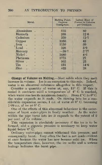
200 AN INTRODUCTION TO PHYSICS
Metal.

LATENT HEAT 201
Just as great pressure applied to water will prevent its
freezing, so a similar pressure applied to ice will melt it.
If a large block of ice be supported on two trestles as shownin Fig. 92, a steel wire may be passed over it and the free
ends joined underneath so as to support a heavy weight.
(A half hundred-weight forms a suitable load.)The pressure of the wire on the upper surface of the ice
is usually sufficient to melt the ice immediately beneath it,
and the wire of course sinks into the narrow channel of
water which it produces.
/7\
ICE
FIG. 92.
But ice cannot melt without the absorption of its latent
heat, and since this is not forthcoming from external sourcesit has to supply the heat itself. Hence the water which is
produced is at a temperature well below the freezing point.Since this water is now above the wire it is no longer
subjected to pressure, and it therefore immediately returnsto the solid state, that is, ice.
The process is continued, and in time the wire will passentirely through the block of ice without cutting it into
two pieces.
Freezing Water by Boiling. We have already seen that the
boiling point of water depends upon the pressure to which it

202 AN INTRODUCTION TO PHYSICS
is subjected. The following tables show the boiling pointof water at various pressures, commencing with the normalatmospheric pressure in each case.
Pressures below one Atmosphere.
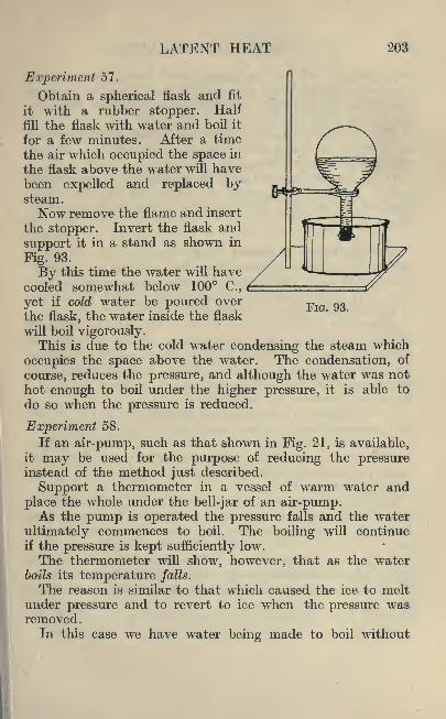
LATENT HEAT 203
FIG. 93.
Experiment 57.
Obtain a spherical flask and fit
it with a rubber stopper. Half
fill the flask with water and boil it
for a few minutes. After a time
the air which occupied the space in
the flask above the water will havebeen expelled and replaced bysteam.
Now remove the flame and insert
the stopper. Invert the flask and
support it in a stand as shown in
Fig. 93.
By this time the water will havecooled somewhat below 100 C.,
yet if cold water be poured over
the flask, the water inside the flask
will boil vigorously.This is due to the cold water condensing the steam which
occupies the space above the water. The condensation, of
course, reduces the pressure, and although the water was not
hot enough to boil under the higher pressure, it is able to
do so when the pressure is reduced.
Experiment 58.
If an air-pump, such as that shown in Fig. 21, is available,it may be used for the purpose of reducing the pressureinstead of the method just described.
Support a thermometer in a vessel of warm water and
place the whole under the bell-jar of an air-pump.As the pump is operated the pressure falls and the water
ultimately commences to boil. The boiling will continueif the pressure is kept sufficiently low.
The thermometer will show, however, that as the waterboils its temperature falls.
The reason is similar to that which caused the ice to meltunder pressure and to revert to ice when the pressure wasremoved.
In this case we have water being made to boil without

204 AN INTRODUCTION TO PHYSICS
supplying it with the necessary latent heat. Hence every
gramme of water which is converted into steam under these
conditions has to take over 500 calories of heat from the
remaining water.
This, of course, causes a considerable fall of temperature.In addition it makes it necessary to reduce the pressurestill further if the boiling is to continue.
It will readily be seen that if the pump were approximatelyperfect it would be possible to reduce the temperature to
such' an extent that the remaining water would begin to
freeze.
Another Effect of Latent Heat. Most bathers have ex-
perienced conditions when it has felt warmer in the waterthan in the air. This is often the case when a wind is blow-
ing. Yet a thermometer frequently shows that the reverse
is actually 'the case.
When the surface of one's body is beneath the water, it"
feels"
the temperature of the water. When it is exposedto the air, however, the film of water commences to evaporate
(especially if there is a"dry
"wind), and the latent heat
which is necessary for this vaporisation is taken from one's
body and produces the sensation of cold.
It will be seen that the actual temperature of the air has
very little influence on this sensation.
In certain hot countries (e.g. Portugal) coarse earthen-
ware jars are used to keep drinking-water cool. These jars
are very porous, and when filled with water some of it soaks
through to the outside.
This film of water readily evaporates in the dry air, and the
latent heat (or at any rate a large proportion of it) is absorbed
from the water within the jar. Thus the latter is keptcool.
It has been said that it is not"hot enough
"in this country
to use this method of cooling water. It would probably be
more correct to say that the air is not often sufficiently
dry.

LATENT HEAT 205
Exercises 16.
1. Describe in detail a method of determining the latent
heat of steam. Point out the principal sources of error in
the experiment and the precautions to be taken to minimize
them.
2. In the above experiment state how the results are
affected by using steam that is not"dry."
3. Suppose that you have a small quantity of ice at the
melting temperature, and that you gradually melt it. Whatchanges of temperature and volume does the ice undergo ?
4. Describe fully how you determine the melting point of
paraffin. What are the changes that you observe duringthe change of state ?
5. State how you would determine the latent heat of
paraffin.
6. An experiment was carried out to determine the latent
heat of steam and the following were the results obtained :
Weight of copper calorimeter in grammes, 82*5.
Weight of water used for condensing the steam, 98*4
grammes.Initial temperature of the above water, 17 '3 C.
Maximum temperature of the water after condensing the
steam 58 C.
Weight of the condensed steam, 7*4 grammes.Determine the latent heat of steam in calories per gramme
and B.Th.U. per Ib.
7. An experiment was carried out to determine the latent
heat of ice and the following are the results :
Weight of the copper calorimeter, 105 '87 grammes.Weight of the calorimeter and the water, 274 '7 grammes.Original temperature of the water in the calorimeter, 30 C.
Final temperature of the water after mixing well with the
dry ice, 20 C.
Weight of the water, ice, and calorimeter, 292*7 grammes.Determine the latent heat of ice in calories per gramme.
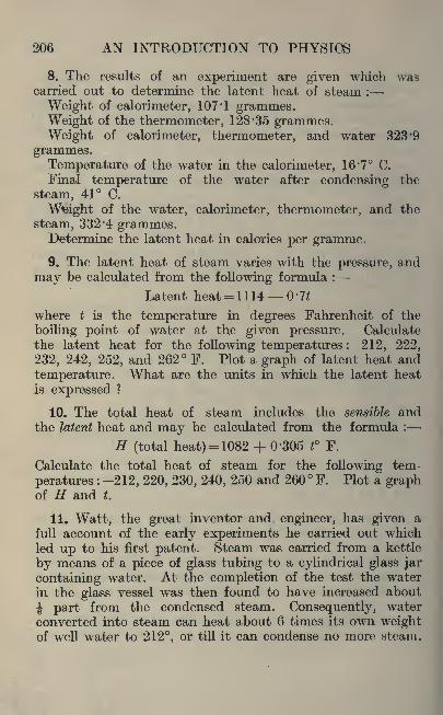
206 AN INTRODUCTION TO PHYSIOS
8. The results of an experiment are given which wascarried out to determine the latent heat of steam :
Weight of calorimeter, 107'1 grammes.Weight of the thermometer, 128*35 grammes.Weight of calorimeter, thermometer, and water 323 '9
grammes.Temperature of the water in the calorimeter, 16 %
7 C.
Final temperature of the water after condensing the
steam, 41 C.
Weight of the water, calorimeter, thermometer, and the
steam, 332*4 grammes.Determine the latent heat in calories per gramme.
9. The latent heat of steam varies with the pressure, and
may be calculated from the following formula :
Latent heat= 1114 0*7^
where t is the temperature in degrees Fahrenheit of the
boiling point of water at the given pressure. Calculate
the latent heat for the following temperatures : 212, 222,
232, 242, 252, and 262 F. Plot a graph of latent heat and
temperature. What are the units in which the latent heat
is expressed ?
10. The total heat of steam includes the sensible andthe latent heat and may be calculated from the formula :
H (total heat) = 1082 + 0'305 t F.
Calculate the total heat of steam for the following tem-
peratures : 212, 220, 230, 240, 250 and 260 F. Plot a graphof H and t.
11. Watt, the great inventor and engineer, has given a
full account of the early experiments he carried out whichled up to his first patent. Steam was carried from a kettle
by means of a piece of glass tubing to a cylindrical glass jar
containing water. At the completion of the test the water
in the glass vessel was then found to have increased about
J part from the condensed steam. Consequently, water
converted into steam can heat about 6 times its own weightof well water to 212, or till it can condense no more steam.

LATENT HEAT 207
Watt had to ask Dr. Black to explain this. Give yourexplanation.
12. In a lecture by Geo. Babcock at Cornell Universityon
" The Theory of Steam Making," the following occurs :
" It follows that if we could reduce steam at atmosphericpressure to water, without loss of heat, the heat stored within
it would cause the water to be red hot;and if we could,
further, change it to a solid, like ice, without loss of heat,the solid would be white-hot, or hotter than melted steel,
it being assumed that the specific heat of water remainednormal/' Explain this.
13. The following also occurs in the same lecture :
" Theheat which has been absorbed by one pound of water to
convert it into one pound of steam at atmospheric pressureis sufficient to have melted 3 pounds of steel or 13 poundsof gold/' Taking the necessary figures from the tables given
prove the truth of this statement.
14. If some volatile liquid is placed on the hand, the handfeels cold. Explain this.
15. A person has a headache and places a handkerchiefwith eau de Cologne on it across his forehead. Give reasons
for this.
16. Experiments were carried out to determine the
efficiency of small oil furnaces (see article by the authors,
English Mechanic, June, 1912), and the following are someresults :
Weight of metal Weight of petroleumMaterial. melted. used.
Cast iron 5 Ibs. 4 Ibs.
Aluminium 2 1*2
Lead 4 0*416
Taking the petroleum as having a calorific value of 18,500B.Th.U per lb., determine the B.Th.U. used in melting themetal. Determine the B.Th.U. required to melt each batch of
metal. If the thermal efficiency is the B.Th.U. required to
melt the metal divided by the B.Th.U. used, determine the
thermal efficiency in each case.

208 AN INTRODUCTION TO PHYSICS
17. A test was carried out in a cupola and 1,232 Ibs. of
coke were required to melt 20,160 Ibs. of cast-iron. Deter-mine the total heat required to melt this quantity of metal,the total heat in the coke and the thermal efficiency. Thecalorific value of coke is 13,000 B.Th.U. per Ib.
18. The table here given shows how the sensible and latent
heats of steam vary with the pressure :
Pressure in Ibs. per sq. in. Temperature F. Latent heat.
1 101-99 1043-02 126-27 1026-1
5 162-34 1000-8
10 193-25 979-0
15 213-03 965-1
20 227-95 954-6
30 250-27 938-9
40 267-13 927
Plot a graph of pressure and temperature of boiling
(column 2) and a graph of pressure and latent heat.
19. What is meant by the"boiling point
"of a liquid ?
How is it affected by change of pressure ?
20. Describe any form of boiler you have seen and state
how the pressure is kept from rising to a dangerousamount.
21. Give a sketch of a domestic hot-water supply systemand explain how the pressure is prevented from rising.
22. The following statement is given in a catalogue :
"Well designed boilers under successful operation will
evaporate from 7 to 10 pounds of water per pound of first-
class coal."
Suppose that the boiler is working at 150 Ibs. per sq. in.
and the total heat given to the steam per Ib. of water is 1,191 '2
B.Th.U., whilst the calorific value of the coal is 13,800 B.Th.U.,determine the thermal efficiency for the two cases given.
23. Ten pounds of water are enclosed in a small steam
boiler, the temperature of the water is 68 F. How much
LATENT HEAT 209
heat must be given to the water to generate 8 pounds of
steam at atmospheric pressure ?
24. Twelve pounds of steam at 100 C. are blown into atank containing 300 Ibs. of water at 40 C. Find the resulting
temperature.

CHAPTER XVII
, CONDUCTION, CONVECTION, AND RADIATION
Conduction. We have frequently mentioned the fact that
heat"flows
" from one body to another according to tem-
perature differences. In this chapter we will consider the
methods by which heat can pass from one body to another.
Experiment 59.
Obtain a few pieces of thick wire of different metals, butof the same dimensions, about 5 or 6 inches long. Holdingeach specimen by one end, apply the other end to the Bunsenflame.
It will be observed that the heat absorbed from the flame
travels along the wire and ultimately reaches the fingers.The student should find no difficulty in discerning between
"good conductors
"like copper and those metals which
convey heat less readily.The property which all forms of matter possess in a greater
or less degree, which enables the individual particles to passheat from one to another, is known as
"conduction."
Of course, there are good conductors and bad conductors.
Generally speaking, all metals are good conductors, althoughsome are better than others
; gases, on the other hand, are
very bad conductors of heat.
For purposes of comparison we use a quantity which is
called the"thermal conductivity
"of a substance. It is
the number of units of heat which, in unit time, will passacross a cube of unit edge, when the opposite faces are at
temperatures differing by one degree.
Thus, in the C.G.S. system it is the number of calories of
heat which will pass in one second across a cube of one centj-
210

CONDUCTION, CONVECTION, AND RADIATION 211\
metre edge when the opposite faces are at temperaturesdiffering by 1 C.
The following table gives the thermal conductivity in
C.G.S. units for a number of substances.
Substance.

212 AX INTRODUCTION TO PHYSICS
FIG. 94.
Having supported the test-tube in a
slanting position, apply a small flame of a
Bunsen burner near the top of the tube,
just below the surface of the water, as
shown in Fig. 94.
Heat can only reach the ice by conduc-tion through the water or the glass, andsince the latter is very thin the majority of
the conduction takes place through the
water. It will be found possible to boil
the "water at the top of the tube for someconsiderable time before the ice melts, thus
showing water to be a very poor conductor.
Experiment 61.
Convection Currents. Support a beaker, half full of water,on a tripod with the small flame of a Bunsen burner beneathit. A few fragments of some light material should be putinto the water
; tiny pieces of red blotting-paper are verysuitable.
As the water is heated it will be observed that there is an
upward current of water immediately above the flame,while near the outer edge there is a downward current.
These movements of the water will be rendered visible bythe motion of the particles of blot-
ting-paper which have been put into
the water. Fig. 95 shows the
general arrangement.If a thermometer is supported
with its bulb at the point marked
A, while another thermometer has
its bulb at B, a considerable differ-
ence of temperature will be noticed.
It will be seen that the heat of
the flame passes through the glass
by conduction and heats the film
of water in contact with the glass.
Expansion necessarily takes placewhich renders the warm water lighterthan the surrounding water. FIG. 95.

CONDUCTION, CONVECTION, AND RADIATION
iJwqTEK SUPPLY I
Hence the warm water rises in a constant stream up themiddle. The colder water at the edges has no option but toflow in and take its place.
This in turn gets heated and rises, and so the circulation
continues. These currents are known as"convection
currents."
It will be observed that in the case of conduction of heat,the heat is passed on from particle to particle. With con-
vection, however, a particle absorbs a certain amount of
heat and then moves off, carrying the heat with it.
Domestic Hot Water Systems. In many kitchen rangesthere is fitted a small iron boiler (B, Fig. 96), between the
grate and the flue. One pipe passes from the top of this tothe storage tank (C) in the upper part of the house. Thetank is generally con-
nected with a constant
level cistern.
As the water in the
small boiler becomeshot it ows up one
pipe (shown black) to'
the storage tank (7,
'
while cold water flows
from the latter, downthe other pipe, into
the boiler.
Here we have circu-
lation maintained bymeans of convection
currents. Taps are fit-
ted, where needed, onthe
"hot
"pipe, that
is, the one up whichthe hot water flows.
A general arrange-ment of such a systemis shown in Fig. 96.
Of course, convection FIG. 96.

214 AN INTRODUCTION to
currents can be produced in any fluid. Winds are largely con-
vection currents in the atmosphere and many forms of
ventilation are an application of this phenomenon.
Formation of Ice on Water. It will be convenient here to
revert to the effects of the abnormal behaviour of waterunder change of temperature. Consider a river in frostyweather. As the water cools it contracts, and because it is
specifically heavier than the water beneath it, it sinks to
the Bottom and the warmer water rises to the surface, and is
cooled in its turn.
After a time the whole of the water is at a temperature of
4 C. Now it will be recalled that at this temperaturewater attains its maximum density. Hence, as the surface
water is cooled still further it expands, and this, making it
specifically lighter, causes it to remain on the surface.
After a time the uppermost layer of water has been cooled
to C., and on the withdrawal of more heat a film of ice is
formed.
As soon as the surface of the water is covered with a film
of ice, no more ice can be formed except by the withdrawalof the latent heat by conduction through the ice alreadyformed.
The thermal conductivity of ice is 0'0022, and hence wesee why it is that a prolonged frost is necessary to producethick ice.
If water behaved in a manner similar to that of most other
liquids, that is, if it contracted as the temperature fell rightdown to freezing point and then contracted still further on
solidification, ice would be specifically heavier than water.
This would cause ice to form at the bottom of the rivers
first and solidification would then take place upwards.
If such conditions prevailed a quite ordinary winter wouldbe sufficient to freeze most rivers solid. Experiment 60 will
show with what difficulty the ice would be melted by the
application of heat from above.

CONDUCTION, CONVECTION, AND RADIATION 215
Experiment 62.
Half fill a test-tube with paraffin wax cut up in pieces aboutthe size of a pea.
Very slowly melt the wax by the application of heat.
Note that the solid material is heavier than the liquid,since it sinks in the liquid.Now allow the wax to cool until it is solid again. Note
how the surface shrinks down as the solidification proceeds,
showing that a marked contraction occurs on passing fromthe liquid to the solid state.
Articles made of cast iron are always more or less roughowing to the sand used, but to prevent the molten iron
from shrinking away from the mould, all large castings are"fed." The slowly-cooling iron is forced into the mould by
an iron rod worked up and down.The pattern-maker has to make the pattern somewhat
larger than the required size of the casting because the liquidiron contracts on solidification.
Radiation. So far as we have considered the question,whether heat is transferred by conduction or by convection
currents, matter in some form is necessary for the process.Radiation is the name given to a process by which heat
can travel without the aid of matter in any form.
Radiant heat, as it is called, is a transverse wave motion
exactly similar to that of light. In fact, radiant heat is
sometimes spoken of as"invisible light."
Heat rays may be reflected, refracted, transmitted andabsorbed exactly like light rays.
If we make a bar of iron white hot it emits light rays like
any other source of light. It also emits heat rays, and althoughthev do not affect the eye in the same way as light, they canbe felt.
If the iron were heated to a temperature of 200 to 300 C.
it would not emit any light rays, but the hand placed at a
distance of a few inches would be able to detect the presenceof heat rays.The heat which we feel from a fire is very largely due to
radiation. Air, as we have seen, is a very bad conductor of

216 AN INTRODUCTION TO PHYSIOS
heat, and the convection currents which are set in motion bythe fire cause the hot gases to flow up the chimney. Hence
very little heat reaches us from the fire by either conductionor convection.
Experiment 63.
Obtain a bright tin canister and make a mark on theinside about three-quarters of the distance up.Stand the tin on a block of wood and pour boiling water
into the tin up to the mark.Place a thermometer, with its bulb in water, and record
the temperature every half minute. Plot a graph showingthe relation between time and temperature.A little thought should make it clear that the slope or
steepness of the curve is an indication of the rate of cooling.The tin (and similar tins) should now be treated in different
ways. One may be painted white, another black;some may
be lagged with paper of different thicknesses.
Cooling curves should be obtained for each case and fromthese an opinion may be formed as to the best methods of
encouraging or preventing radiation, according to the needsof the case.
Experiment has shown that the rate of radiation dependsupon :
(1) The difference between the temperature of the radiating
body and that of the surrounding bodies.
(2) The area of the surface from which the radiation is
taking place.
(3) The nature of the radiating surface.
Generally speaking, a smooth and shiny surface is a bad
radiator, while a rough surface is a good radiator. Whitesurfaces are not such good radiators as black, other things
being equal.
Experiment 64.
Melt the wax in the test-tube used in Experiment 62 and
place the bulb of a thermometer in the liquid. Having sup-
ported the tube so that it is suspended in still air, take the

CONDUCTION, CONVECTION, AND RADIATION 217
temperature every half minute until the wax has all solidified.
Express the results graphically.
Fig. 97 shows the graph of a typical set of results. Observethat the left-hand portion of the curve is very steep. Herewe have the hot liquid radiating its heat very quickly, since
the difference of temperature between it and the surroundingobjects is considerable.
TEMPERATURE
DEGREES
C.
*
&
$
3
218 AN INTRODUCTION TO PHYSICS
heat of the liquid paraffin. For the next eight or nine
minutes the latent heat of the solidifying liquid was radiated.
It is only after the whole of the liquid has solidified that
cooling, as we generally understand it, takes place again.The sensible heat of the solid paraffin is then radiated.
The temperature at which the graph flattens (in this case
52 C.) is the melting point of the wax.
Exercises 17.t
1. A rod 1" diameter is made partly of iron and partly of
wood. If paper is wrapped tightly round the rod and a
Bunsen flame is passed along the rod, state what will be
observed. What does this experiment prove ?
2. On a cold morning the fitter finds that his chisel appearsto be much colder than his hammer handle. Give the
explanation of this.
3. An iron tube, 0*95" diameter and 15" long, had a numberof brass fins fixed to it, 2" square. The tube was heated andthen allowed to cool and the following readings of temperaturein degrees F. were taken with time intervals of 1 minute.
Plot time and temperature, heating and cooling curves.
Heating curve, 1 minute intervals :
61, 71, 79, 88, 99, 112, 124, 137, 150, 156, 164, 175, 184.
Cooling curve, 1 minute intervals :
150, 139, 129, 126, 122, 118, 114, 111, 108, 105, 102, 98,
96, 94, 92, 90, 88, 87, 86, 85, 84, 83, 82, 81, 80, 79, 78, 76, 75.
4. The following results give data for the heating and coolingcurves of a saturated solution of salt and water. Oneminute interval was allowed between each reading. Plot time
and temperature (Centigrade) for both the heating and
cooling curves.
Heating curve :
14, 18, 28, 37-5, 47, 56, 65, 74, 81, 88, 91 '5, 106, 106 '5,
107, 107.

CONDUCTION, CONVECTION, AND RADIATION 219
Cooling curve*.
104, 102, 101, 100, 98, 96, 94, 92, 90, 88, 86, 84, 82, 80, 77,
74, 72, 69-5, 68, 65'5, 63, 61, 59, 57'55, 53, 52, 51, 50.
5. Steam has to be carried by piping a considerable distance
away from a boiler. Explain why it is necessary to lag the
pipes.
6. Give sketches showing the methods of cooling the
cylinders of motor cycle engines. On your sketches note
whether the heat is conducted away by radiation, conduction,or convection.
7. Explain why an eiderdown quilt makes a good bed-
covering in winter.
8. Apparatus for making ice cream consists of a thick woodbucket and an inner can of thin metal. Explain why.
9. Explain the principles underlying the vacuum-flask.
10. A room is heated by means of an open fire. Explainwith the aid of sketches the various ways in which the heatis transmitted to the room.
11. In order to economise fuel, food is sometimes cooked
by means of a"hay box." Explain the underlying principles.
12. A series of experiments was carried out by Brill to
determine the value of various commercial coverings of
steam pipes. A length of piping 60' long was used and theheat loss was determined by the condensed steam. Thefollowing are some of the results :
Thickness of B.Th.U. radiated.Kind of covering. covering. per sq. ft. per min.
Bare pipe 12'27
Magnesia 1 "25" 1 -74
Mineral wool 1'30" 1'29
Fire felt 1'30" 2-28
Hair felt 0'82" 1-91
Explain how heat is lost from steam pipes and state whatyou can deduce from the above figures.

220 AN INTRODUCTION TO PHYSICS
13. A cooling curve was taken for melted tallow. Tempera-tures were measured in degrees Centigrade, and time intervals
of one minute were allowed between each reading. Plot a
graph of time and temperature.Cooling of melted liquid. 145, 140, 140, 134, 128-5, 122,
116, 110, 105, 100, 95, 90, 85-5, 81, 76, 72, 68, 64, 60, 58, 56,
52, 50, 47-5, 45, 42-5, 40, 38-5, 37;
solidification starts ;
35, 33-5, 33, 32, 31, 30*5; thin layer of solid crust; 30, 30,
29-5, 29, 28, 27 '5, 27, 27, 26*5.
14.'From the following figures, plot a graph, showing howthe weight of water varies with temperature :
Temperature. Weight in Ibs. per cub. ft.
32 F. 62-42
52 62-4
62 62-36
72 62-3
82 62-21
92 62-11
102 62-0
122 61-7
142 61-34
162 60-94
182 60-5
202 60-02
212 59-76
15. Give sketches of a small chamber, suitable for providingcold storage for a butcher. Explain the principles upon whichit works.
16. Tests were carried out with vessels of different metals to
see how much steam per hour per square foot they were cap-able of condensing. The following are some results :
Iron, 7-5. Brass, 12'5. Copper, 14'5.
What can be deduced from these figures ?
17. In a test to determine the specific heat of mild steel it
was found that the water equivalent of the calorimeter was14'2 grammes, 121 '685 grammes of water at a temperature

CONDUCTION, CONVECTION, AND RADIATION 221
of 17C. were placed in the calorimeter and 38*85 grammes of
mild steel at a temperature of 100 C. were dropped into the
water and the water rose in temperature to 20 C. What is
the specific heat of the mild steel ?
18. Define the"thermal conductivity
"of a substance.
19. It is known that the freezing point of a salt solution is
lower than that of pure water. Will this fact help you to
explain why salt is often thrown on slippery frozen pavements ?
20. Give reasons to show why lakes freeze more readilythan oceans.
21. Kent gives the following figures :
Per cent, of salt by weight in water
1 5 10 15 20 25
Freezing point in degrees Fahrenheit
31-8 25-4 18-6 12'2 6'86 1
Plot a graph of per cent, of salt by weight and freezing
point.
22. What weight per cent, of salt will be found in sea waterif it freezes at 27 F., assuming sea water to be a commonsalt solution ?
23. When strong sulphuric acid is poured into a glass vessel
containing water it often happens that the vessel breaks, andin any case a big rise in temperature is noted. Can youaccount for the glass cracking ?
CHAPTER XVIII
THE CONSERVATION OF ENERGY
Energy. We have on one or two occasions referred to heatas a " form of energy." It is proposed here to consider thisidea in a little more detail.
It is a' matter of common experience that all the bodieswith which we deal offer a resistance to motion. This re-
sistance may be due to the gravitational force of the earth
(if any vertical motion is attempted), or it may be due tofriction between the body and its support.
In any case the resistance is there, and we define"force
"
as that which tends to overcome resistance.
It should be observed that a force may be applied without
overcoming the resistance. For example, a force of 10 Ibs.
applied to a railway truck would be insufficient to move it.
That is, the resistance in this case would not be overcome.When resistance is overcome, we say that
" work "is done,
and the amount of work done is indicated by the product of
the magnitude of the force and the distance through whichit acts.
Now "energy
"is denned as that which is capable of
doing work. There are a great many forms of energy. Amoving weight is capable of doing work, and is said to possess"
kinetic energy." A weight raised to a height above the
earth's surface (e.g. a lake on a mountain side) possesses whatis called
"potential energy."
Heat and electricity are forms of energy. The formercan be made to do work by means of a heat engine, while
the latter can operate an electric motor and thus do work.A piece of coal possesses what is called
"chemical energy."
When it burns it combines chemically with the oxygen of
the air and heat is produced.222
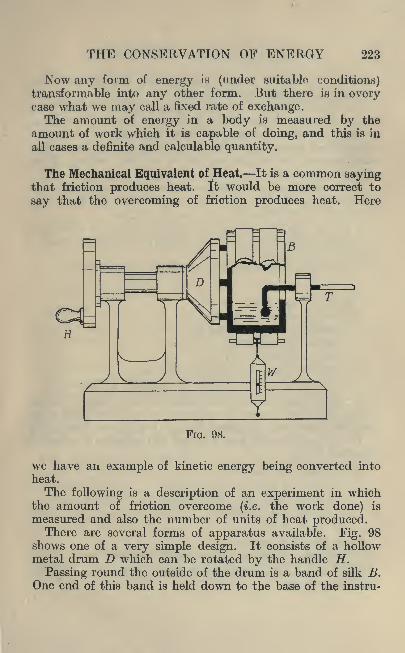
THE CONSERVATION OF ENERGY 223
Now any form of energy is (under suitable conditions)transformable into any other form. .But there is in everycase what we may call a fixed rate of exchange.The amount of energy in a body is measured by the
amount of work which it is capable of doing, and this is in
all cases a definite and calculable quantity.
The Mechanical Equivalent of Heat. It is a common sayingthat friction produces heat. It would be more correct to
say that the overcoming of friction produces heat. Here
FIG. 98.
we have an example of kinetic energy being converted into
heat.
The following is a description of an experiment in whichthe amount of friction overcome (i.e. the work done) is
measured and also the number of units of heat produced.There are several forms of apparatus available. Fig. 98
shows one of a very simple design. It consists of a hollowmetal drum D which can be rotated by the handle H.
Passing round the outside of the drum is a band of silk B.One end of this band is held down to the base of the instru-
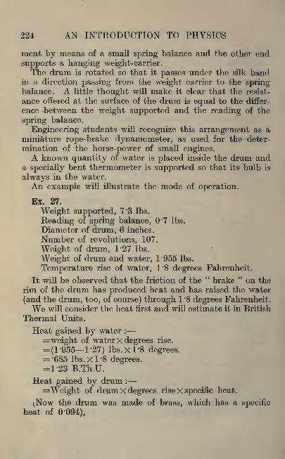
224 AN INTRODUCTION TO PHYSICS
inent by means of a small spring balance and the other end
supports a hanging weight-carrier.The drum is rotated so that it passes under the silk band
in a direction passing from the weight carrier to the springbalance. A little thought will make it clear that the resist-
ance offered at the surface of the drum is equal to the differ-
ence between the weight supported and the reading of the
spring balance.
Engineering students will recognize this arrangement as aminiature rope-brake dynamometer, as used for the deter-
mination of the horse-power of small engines.A known quantity of water is placed inside the drum and
a specially bent thermometer is supported so that its bulb is
always in the water.
An example will illustrate the mode of operation.
Ex. 27.
Weight supported, 7*3 Ibs.
Beading of spring balance, 0*7 Ibs.
Diameter of drum, 6 inches.
Number of revolutions, 107.
Weight of drum, T27 Ibs.
Weight of drum and water, 1 '955 Ibs.
Temperature rise of water, 1*8 degrees Fahrenheit.
It will be observed that the friction of the"brake " on the
rim of the drum has produced heat and has raised the water
(and the drum, too, of course) through 1 '8 degrees Fahrenheit.
We will consider the heat first and will estimate it in British
Thermal Units.
Heat gained by water :
=weight of water x degrees rise.
= (1-955 1-27) Ibs. X 1*8 degrees.= '685 Ibs. X 1 '8 degrees.= 1-23 B.Th.U.
Heat gained by drum :
=Weight of drum X degrees rise X specific heat.
^Now the drum was made of brass, which has a specificheat of 0-094),
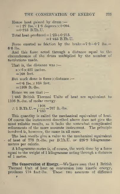
THE CONSERVATION OF ENERGY 225
Hence heat gained by drum :
= 1-27 Ibs. X 1-8 degrees X 0-094.
=0-215 B.Th.U.
Total heat produced= 1-23+0 '215.
= 1-445 B.Th.U.
Force exerted as friction by the brake =7 '3 0'7 lbs.=
6-6 Ibs.
And this force acted through a distance equal to thy
circumference of the drum multiplied by the number of
revolutions made.
That is, the distance was :
TTX 6x107 inches.
= 168 feet.
But work done is force x distance :
=6-6 Ibs. X 168 feet.
= 1108 ft.-lbs.
Hence we see that :
1-445 British Thermal Units of heat are equivalent to
1108 ft.-lbs. of molar energy.
/. 1 B.Th.U.= =767 ft.-lbs.T44o
This quantity is called the mechanical equivalent of heat.
Of course the instrument described above does not give the
most reliable results, as it lacks the somewhat complicatedrefinements of the more accurate instrument. The principleinvolved is, however, the same in all cases.
The best results give a value to the mechanical equivalentof heat of 778 ft.-lbs. per B.Th.U. or 426 '9 kilogramme-metres per calorie.
A kilogramme-metre is, of course, the work done by a force
equal to the weight of 1 kilogramme acting through a distance
of 1 metre.
The Conservation of Energy. We 'have seen that 1 British
Thermal Unit of heat on conversion into kinetic energy,
produces 778 foot -Ibs."
These two amounts of different

226 AN INTRODUCTION TO PHYSICS
types of energy are interchangeable. It makes no difference
whether heat is being converted into kinetic energy or vice
versa, the equivalent is never varied. Nor is it affected bythe mode of transformation.
Of course our ignorance or carelessness may result in someof the energy reaching a destination which is not intended.
For instance, in the experiment described in Example 27,
it is quite possible that some of the heat produced by the
brake was radiated into the air, and therefore failed to reach
the water, where it would have been measured.
Again, a steam engine converts heat into kinetic energy,but some of the heat produced in the furnace passes up the
chimney-stack, and some remains in the exhaust steam, notto mention other means of escape. Hence only a portion(and in this case a very small portion) of the heat producedis actually converted into kinetic energy.
In a modern steam engine about 10 per cent, of the heat
produced in the furnace is converted into useful energy.The remaining 90 per cent, is there, but at present we do notknow how to use it.
The 10 per cent, in this case is called the"thermal effi-
ciency"
of the engine. Some types of heat engine (notablythe internal combustion engine) have improved on this to
some extent. The student should, however, grasp the fact
that no amount of mechanical improvement or novel designcan make an engine with a thermal efficiency of over 100
per cent, and a great advance is necessary before this degreeof efficiency is remotely approached.No mere mechanism can withdraw from a body more
energy than it contains.
Calorific Value of Fuels. If we take 1 Ib. of coal and burn
it, heat is produced. This heat may be measured with a
suitable calorimeter, and the result is known as the calorific
value of the coal.
Of course the numerical value depends upon the com-
position of the coal, but for a given coal it is an absolutelyfixed quantity. The number of thermal units produced
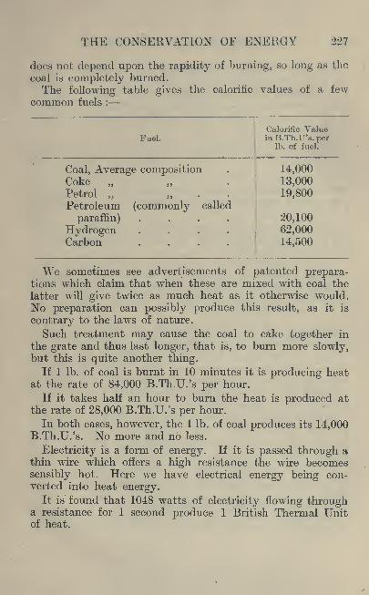
THE CONSERVATION OF ENERGY 227
does not depend upon the rapidity of burning, so long as the
coal is completely burned.
The following table gives the calorific values of a few
common fuels :
Fuel.

228 AN INTRODUCTION TO PHYSICS
Again, if electricity is passed through an electric motor,the latter revolves and may be made to do work. Here wehave electrical energy being converted into kinetic energy.
It is found that 1 watt of electricity flowing for 1 second,if wholly converted into kinetic energy, is capable of doing0-742 ft.-lbs. of work.Hence we have :
1 watt-second of electricity is equivalent to 0'742 ft.-
lbs. of work..'. 1048 watt-seconds of electricity are equivalent to
1048x0-742 ft.-lbs. of work. =778 ft.-lbs.
But 1048 watt-seconds of electricity are equivalent to
1 B.Th.U. of heat.
/. 1 B.Th.U. of heat is equivalent to 778 ft.-lbs. of work.This will be recognised as the mechanical equivalent of
heat already mentioned.We see, therefore, that energy may be transformed from
one form to another. This may be done in a great varietyof ways, but there is no known method whereby energy maybe created out of nothing. Nor can we destroy energy, that
is, turn it into nothing.
Efficiency. Of course, we are seldom able to effect a
complete transformation of the kind which we desire.
Thus, if we deliver 1048 watt-seconds of electricity to
any motor we shall get rather less than 778 ft.-lbs. of workfrom the motor, because some of the electricity will be
transformed into heat, and in that case will not be available for
transformation into kinetic energy also.
Suppose in the case considered the motor is found" to
give 645 ft.-lbs. of work. We see that electricity equivalentto 133 ft.-lbs. has been lost (not destroyed). Perhaps it has
become heat.
In any case the ratio of work obtained to work supplied is
645__- =0'83. -This is generally expressed as 83 per cent., and/7o
is called the"efficiency
"of the motor.
It indicates that, of the energy supplied to the motor,83 per cent, is converted into the form in which we require it.

THE CONSERVATION OF ENERGY 229
Exercises 18.
1. Determine the work done in the following cases :
Load in pounds . . 121'5 89 356'9 302-6
Vertical distance moved in
feet .... 29 32 52 9 '2
2. A tug-of-war is in progress and for three minutes each
side pulls with an exactly equal force of 495 pounds. Howmuch work is done ?
3. A stone weighs 225 pounds and a man pulls at the stone
for 2 '4 minutes with a force of 110 pounds and fails to moveit. How much work has the man done ?
4. A man removes four shovels full of sand from the groundon to a platform 3' 6" high. By the aid of sketches and
approximations show how much work the man does.
5. A man is sandpapering a board which is 3' 6" long and12" wide. He rubs in one direction with a force of 23 pounds.If the rubber is 3" wide, how much work in foot pounds will
the man do in order to rub each part of the board once ?
6. A man is filing a piece of metal and on each forwardstroke he applies a horizontal force of 15 pounds with a stroke
of 6*5". If he makes 22 strokes, how much work in foot
pounds will the man do ?
7. A man stretches up his arms to hold a heavy weight.At the end of 5 minutes he feels tired. If the weight was37 pounds, state the work done in foot-pounds. Write ashort essay showing the difference between the idea of
" work "
in a popular and a scientific sense.
8. Illustrate with the aid of sketches a number of cases
where work is being done by manual labour. In your sketch
show the distance moved and the mass. Give approximateanswers for the work done in 5 minutes hi each case.
9. What do you understand by the term " work ?"
State whether work is done in the following cases and give
approximate answers :

230 AN INTRODUCTION TO PHYSICS
^1) boring a hole with a brace and bit.
(2) carrying a load of 7 pounds 7 feet horizontally.(3) lifting 7 pounds vertically through 3 feet.
(4) A string holding up a weight of 14 pounds.
10. In a test of lifting tackle, the following results wereobtained :
Load lifted in pounds . .25 50 100 150Effort to move load . . 5J 7J 13J 19
If th$ effort moves 20 times as fast as the load, determinethe work done by the load and the effort when the load hasmoved 1'5 feet. Plot a graph of load and effort.
11. In a test on pulley blocks it was found that the effort
moved 4 times as fast as the load. Assuming that the loadmoved 4 feet, determine the foot-pounds of work done in
moving the load and the effort through their respectivedistances. Plot curves of load and effort. The following are
the figures required :
Load in pounds5 10 15 20 25 30
Effort in pounds3-8 6-3 8-9 11-0 12-6 14'7
12. In a worm gearing it was found that the effort moved31 times as fast as the load. If the effort moved one foot,
determine the number of foot-pounds of work utilized in
moving the load through one foot. Plot a graph of load andeffort."
Load in pounds 4 6 8 10
Effort in pounds . 0'3 0'5 0'75 0'9
13. The following calorific values in B.Th.U. per Ib. are
given : Texas oil, 10,800 ;Trinidad crude, 10,200 ; shale
oil, 10,120 ; heavy tar oil, 8,916. Convert these values into
calories per gramme and equivalent foot-pounds of work.
14. The following theoretical maximum combustion tem-
peratures are given : Natural gas and air, 1,086 C. ; Thermit,
2,694 C.; oxyhydrogen flame, 3,190C. Convert these values
into Fahrenheit degrees.

THE CONSERVATION OF ENERGY 231
15. In a determination of the electric horse-power of amotor the following observations were made :
Volts . . . 490 490 490 490
Amps. . . . 1-8 2-2 2 -6 2 '8
Since amps. X volts = watts, determine the number of foot-
pounds of work done per minute in each case.
16. In a further test on the above motor, the brake horse-
power was found to be as follows : 0'48, 0*73, and 0'95.
If 33,000 ft. Ibs. per minute is equal to one horse-power,determine the foot-pounds of work per minute in each case.
17. In a gas engine test the following heat distribution
was obtained :
Work obtained as indicated horse-power . 21*5%Lost in the jacket water . ... . 50*4Lost in the exhaust gas..... 25Balance of the losses 3*1
100
If the total indicated horse-power is 2 '3, determine theseratios as foot-pounds of work per minute.
18. The average heating value of the following gases is
given in B. Th.U. per cubic foot : Illuminating gas, 600 ; cokeoven gas, 650
; producer gas from coke, 135 ;blast furnace gas,
100. Determine the equivalent values in foot-pounds of
work.
19. An engine is directly coupled to a generator and it is
found that the engine develops 50 indicated horse-power.Neglecting all losses in engine and dynamo, determine the
foot-pounds of work and the watts generated per second. If
the work available from the engine is only 80 % of the I.H.P.and the efficiency of the generator is 95 %, how many wattsare generated per second ?
20. Wherever energy is used to produce motion, some of
the energy is wasted. Write a short essay, illustrated bysketches, showing cases where energy is being wasted, andexplain what becomes of the wasted work.

232 AN INTRODUCTION TO PHYSICS
21. An experiment was carried out to determine the mech-anical equivalent of heat and the following are the results :
Weight of bottom cup of copper, 41 '15 grammes.Weight of top cup and water, 71*25 grammes.Weight of top cup, 55*4 grammes.Original temperature of the water, 17*5 C.
Final temperature of water 30 '2 C.
To cause this rise of temperature the apparatus made2,420 revolutions, a load of 0*155 Ibs. being applied to the rimof a 'wheel whose circumference is 800 millimetres. Deter-
mine the mechanical equivalent of heat in ft.-lbs. per B.Th.U.
22. In another experiment performed with a similar piece of
apparatus the following results were obtained :
Weight of two brass cones, 164*1 grammes.Weight of contained water, 21*35.
Suspended mass, 300 grammes at the rim of a wheel whosecircumference was 78*4 centimetres. The total number of
revolutions was 1,852 and the temperature rise was 24 CC.
Determine the mechanical equivalent of heat.
23. Zinc is dissolved by the action of dilute sulphuric acid,and the final product is zinc sulphate, hydrogen, and water.
The chemical energy of the products is less than that of
the original substances. In carrying out this experimentexplain what you have noticed. Where has the lost energygone ?
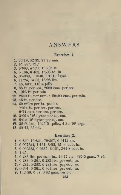
ANSWERS
Exercises 1.
1. 26-19,52-39, 77 -79 mm.2. r, A', 121*.3. 3-609, 4-921, 12-795 ft.
4. 0-186,0-403, l-506sq. in.
5. 0-4989, 1-1340, 2-1319 kgms.6. 11-24, 14-33, 16-98 Ibs.
7. 48, 89-6, 118-4 pdls.8. 88 ft. per sec., 2680 cms. per sec.
9. 1026 ft. per min.
12. 2640 ft. per min. ; 80400 cms. per min.
13. 45 ft. per sec.
14. 60 miles per hr. per hr.
0*024 ft. per sec. per sec.
0*74 cms. per sec. per sec.
15. 3*09 X 107dynes per sq. cm.
16. 6*9 X 106dynes per sq. cm.
17. 32 ft.-lbs., 1025 ft.-pdls., 4'3x 10⁸ergs.
18. 55-43, 33-43.
Exercises 2.
1. 6-859, 13-824, 79'507, 0'9112 c.c.
2. 0-007854, 1-131, 8'55, 15'90 cub. in.
3. 0-000523, 0-0335, 8-181, 344-8 cub. in.
4. 1-45.
5. 0-283 Ibs. per cub. in., 49'17 c.c., 385'5 gms., 7'85.
6. 0-283, 0-284, 0'283 Ibs. per cub. in.
7. 0-284, 0-283, 0'283 Ibs. per cub. in.
8. 0-361, 0-361, 0-361 Ibs. per cub. in.
9. 1, 2-59, 6-68, 9'82 gms. per c.c.
233

234 ANSWERS
10. 62 '5 Ibs. per cub. ft., 1 gm. per c.c.
11. 2.57, 8-5, 8-9, 7*7.
12. 2-5, 2-6, 19-26, 7 -69, 10'5.
13. 0-283, 0-277, 0'314, 0*297 Ibs. per cub. in,
14. 0-67, 0-75, 0-72, 0'74, 0'66.
15. 96, 115-3, 49-5, 55 '6 Ibs.
Exercises 3.
1. 1*14 gms. per c.c.
2. 8-55
3. 0-859
4. 13-59
5. 13-47
6. 13-61
7. 7-82
8. 0-52
9. 0-818, 1-22,0-87.10. 1'06 gms. per c.c.
11. 0-8.
12. 1-34.
13. 0-78.
15. 2*41 gms. per c.c.
Exercises 4.
1. I'll Ibs. per sq. in.
2. 0-039 Ibs. per sq. in.
3. 4*3 Ibs. per sq. in.
4. 14 '5, 2-2 Ibs. per sq. in.
5. 26-5".
6. 0-0141, 0-0154, 0-0159 Ibs. per sq. in.
7. 1798.
9. 0*014 Ibs. per sq. in.
15. 0-144".
16. Less than 46 Ibs.
19. 0-491.
20. 29-9, 26-55, 23'45, 20'6, 18'15 inches.
21. 559, 564, 569, 574 mm.91-64, 91-87, 92-11, 92*34 C.
22. 2-95, 3-55, 4'14. 4'73, 5'32 inches.

ANSWERS 235
23. 2-73 cub. in.
24. 83-4 cub. in.
25. 14-22, 14-35, 14'67, 14'80, 14*90, 15'08 Ibs. per sq. in.
26. 0-99909, 0'99989, 1 '00005 gms. per c.c.
27. 50 cub. ft.
28. 26-1 ft.
Exercises 5.
4. 0-65 sec. 14. 2 sees.
5. 1-25 sec. 15. 9'8".
6. 0-55 sec. 16. 0'073"
Exercises 6.
9. 329, 1493, 251, 507, 5340, 3165, 3352 metres per sec.
12. C'.
13. Middle C. 14*9 revs, per sec.
\ 4 _ 83 -
34 list'
-' i 313 is 9*" ^.->i;> 45 ">';> 6" > 2> 128 > 8 "*
15. E, G. C'.
16. C,,,, A//5E.
18. Middle C.
20. 200 feet per sec.
Exercises 8.
1. 1, 2, 4.
4. 41 -9 ft.
5. 1620 yds.6. 0-416, 14-7 sees.
16. 336-5, 346, 349 metres per sec.
Exercises 9.
3. 0-0000004861, 0*0000004308, 0-0000005167, 0*000000382metre.
4. 0-0000486, 0-00008, 0'0002, 0'00025 cm.6. 8*3 minutes.
8. Circle of 3" diameter.
Vertical line 3" long.11. Y'/' or r.15. 32-7,26-7,0-9, 20 '4, 27 -6.
17. 0-093.
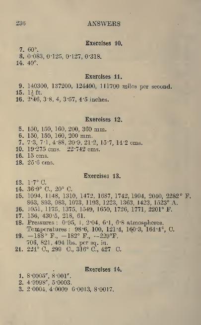
236 ANSWERS
Exercises 10.
7. 60.8. 0-083, 0*125, 0-127, 0'318.
14. 40.
Exercises 11.
9. 140300, 137200, 124400, 111700 miles per second.15. Hft.16. 2*46, 3'8, 4, 3'57, 4'5 inches.
Exercises 12.
5. 150, 150, 160, 200, 360 mm.6. 150, 150, 160, 200 mm.7. 7-3, 7-1, 4-88, 20*9, 21'2, 15'7, 14*2 cms.
10. 19-275 cms. 22-742 cms.16. 15 cms.
18. 25-6 cms.
Exercises 13.
13. 1-7C.14. 36-9 C., 20 C.
15. 1094, 1148, 1310, 1472, 1687, 1742, 1994, 2040, 2282 F.
863, 893, 983, 1073, 1193, 1223, 1363, 1423, 1523 A.16. 1051, 1175, 1375, 1549, 1650, 1726, 1771, 2201 F.
17. 156, 430-5, 218, 61.
18. Pressures : 0'95, 1, 2'04, 6 !
1, 6*8 atmospheres.Temperatures: 98 -6, 100, 121 '4, 160'3, 164'4, C.
19. -188 F., -182 F., -229F.706, 821, 494 Ibs. per sq. in.
21. 224 C., 299 C., 316 C., 427 C.
Exercises 14.
1. 8-0005", 8-001".
2. 4-9998", 5-0003.
3. 2-0004, 4-0009 6'0013, 8-0017.
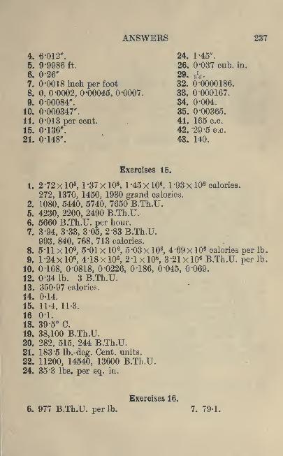
ANSWERS 237
4. 6-012". 24. 1-45".
5. 9-9986 ft, 26. 0-037 cub. in.
6. 0-26" 29. ,V7. 0-0018 inch per foot 32. 0-0000186.
8. 0, 0-0002, 0-00045, O'OOOT. 33. 0-000167.
9. 0-00084". 34. 0'004.
10. 0-000347". 35. 0'00365.
11. 0-013 per cent. 41. 165 c.c.
15. 0-136". 42. '29-5 c.c.
21. 0-148". 43. 140.
Exercises 15.
1. 2-72 xlO5, 1-37X106
, 1-45X106,1 93 XlO8 calories.
272, 1370, 1450, 1930 grand calories.
2. 1080, 5440, 5740, 7650 B.Th.U.5. 4230, 2200, 2490 B.Th.U.6. 5660 B.Th.U. per hour.
7. 3-94, 3-33, 3 -05, 2 -83 B.Th.U.
993, 840, 768, 713 calories.
8. 5-11 X 106,5-01 X 10 6
, 5-03 X 106, 4'69x 103 calories per Ib,
9. l-24x 106, 4-18X 106
,2-1 x 10*, 3'21 x 106 B.Th.U. per Ib,
10. 0-168, 0-0818, 0-0226, 0-186, 0'045, 0'069.
12. 0-34 Ib. 3 B.Th.U.13. 350-97 calories.
14. 0-14.
15. 11-4, 11-3.
16 0-1.
18. 39-5 C.
19. 38,100 B.Th.U.20. 282, 515, 244 B.Th.U.21. 183-5 Ib.-deg. Cent, units.
22. 11200, 14540.. 13600 B.Th.U.24. 35-3 Ibs. per sq. in.
Exercises 16.
6. 977 B.Th.U. per Ib. 7. 79-1.

238 ANSWERS
8. 518.
16. 1405, 875, 106 B.Th.U.
0-019, 0-039, 0-014,
17. 6-74 xlO6B.Th.U., 1-6 X 10⁷ B.Th.U.
0-42.
22. 0-604, 0-864.
23. 9176 B.Th.U.24. 63 C.
'
Exercises 17.
17. 0-13. 22. 4 per cent.
Exercises 18.
1. 3525, 2848, 18550, 2780.
5. 322 ft.-lbs.
6. 178-7 ft.-lbs.
10. Work on load : 37*, 75, 150, 225 ft.-lbs.
Work by effort : 167J, 225, 397^, 570 ft.-lbs.
11. Work on load : 20, 40, 60, 80, 100, 120 ft.-lbs.
Work by effort : 61, 101, 142, 176, 202, 235 ft.-lbs.
12. 0-129, 0-193, 0-258, 0'328 ft.-lbs.
13. 2 -72 x 106,2 -57 X 106
,2 -6 X 10⁶
, 2 '25 X 108 calories.
8 -4 XlO8, 7-94X106
, 7'88xl08, 6 '94 x 106 B.Th.U.
14. 1987 F., 4881 F., 5774 F.
15. 39300, 48000, 56800, 61100 ft.-lbs.
16. 15840, 24090, 31350 ft.-lbs.
17. 16330, 38300, 18980, 2290 ft.-lbs. per minute.18. 466800, 505700, 105030, 77800 ft.-lbs.
19. 27500 ft.-lbs. per sec.
37100 watts, 28150 watts.
21. 784 ft.-lbs. per B.Th.U.22. 0'36 kgm.-metres per calorie.

INDEX
Absolute temperature, 154
Acceleration, 13
Adiabatic expansion, 189
Amplitude, 72
Atmospheric pressure, 46
Balance, the, 22Balance wheel, 70
Barometer, 47
Beats, 83
Boyle's Law, 53British Thermal Unit, 181
Calorie, 180Calorific value of fuels, 226Candle power, 109
Centigrade temperature, 151
Coefficient of expansion, 162
Conduction, 210Conservation of energy, 225Convection currents, 212
Density, 21
Diffusion, 57
Efficiency, 228
Energy, 14, 222
Expansion, 161
Fahrenheit temperature, 151
Floating bodies, 32Fluid pressure, 44
Fluids, 28
Focus, 138
Force, 13
Frequency, 73
Fusion, 198
Gas equation, 173
Gases, 46
Hare's apparatus, 38
Harmonics, 89
Heat, 146
Hydrometer, 33
Images, 132Inverse squares, 107
Isothermal expansion, 189
Latent heat, 195
Length, 11
Lenses, 137
Level, 30
Light, 104
Loops, 88
Magnifying glass, 141
Mass, 11
Matter, 20Mechanical equivalent of
heat, 223
Melting, 200
Mercury, precautions in the
use of, 48
Mirrors, 112, 133
239

240 INDEX
Monochord, 80Musical scale, 81
Nodes, 88
Organ pipes, 100
Pendulum, 67Periodic motion, 64
Photometer, 106
Prisms, 125
Pumps, 54
Radiation, 215
Reeds, 94
Reflection, 112
Refraction, 121
Refractive index, 123
Resonance, 89
Shadows, 105
Simple harmonic motion, 66
Sound, 77
Specific gravity, 20
Specific gravity bottle, 28
Specific heat, 180t
Spherometer, 135
Syphon, 39
Temperature, 147
Thermometer, 148
Time, 11
Total internal reflection, 126
Tuning forks, 97
Units, 11
Velocity, 13
Vibration, 77Virtual images, 137
Water equivalent, 181
Wave length, 72Wave motion, 70
Weight, 12
Work, 14
THE LONDON AND NORWICH PRESS, LIMITED, LONDON AND NORWICH. ENGLAND


&
I0$I
University of Toronto
library
DO NOTREMOVETHECARDFROMTHIS
Acme Library Card Pocket
Under Pat. "Ref. Index File"
Made by LIBRARY BUREAU