
An efficient mechanism for establishing IP connectivity in next-generation networks
24
INTERNATIONAL JOURNAL OF COMMUNICATION SYSTEMS Int. J. Commun. Syst. (2009) Published online in Wiley InterScience (www.interscience.wiley.com). DOI: 10.1002/dac.1092 An efficient mechanism for establishing IP connectivity in next-generation networks Rui Campos ∗, † and Manuel Ricardo INESC Porto, Faculdade de Engenharia, Universidade do Porto, Rua Dr. Roberto Frias, 378 4200-465 Porto, Portugal SUMMARY The changes in the communication paradigm envisioned for next-generation networks (NGNs), with peer- to-peer/symmetric attachments gaining momentum and two Internet Protocol (IP) versions coexisting, will pose new challenges to mobile communication networks. Traditional IP auto-configuration mechanisms will not work properly, since they were designed mostly having in mind a client–server/asymmetric attachment model, they assume a single IP version paradigm, and they target the auto-configuration of devices only. The IST Ambient Networks (ANs) project has introduced a new concept—the AN—that enables handling every communication entity, either a single device or an entire network, as an AN. This paper describes a new efficient mechanism, named Basic Connectivity (BC) mechanism, for auto- configuring IP connectivity between attaching ANs. A proof-of-concept prototype, experimental results, and theoretical analysis show that BC suites the future networking paradigm and represents a solution more efficient than the current trial-and-error mechanism for auto-configuring IP connectivity. Copyright 2009 John Wiley & Sons, Ltd. Received 31 March 2009; Revised 20 October 2009; Accepted 25 October 2009 KEY WORDS: Ambient Network; IP connectivity; auto-configuration 1. INTRODUCTION In recent years, we have witnessed the deployment of many communication and networking tech- nologies, from which the wireless field is a prominent example. Heterogeneity in communication and networking implies interworking problems. These problems are now being faced in Internet Protocol networks. Two IP versions are expected to coexist for a long time and multiple IP auto- configuration mechanisms may be in place, bringing up problems either concerning the intercon- nection of simple devices or entire networks. Additionally, the common thinking that the transition to IPv6 would be based on the dual-stack model and that most devices would become dual-stack, ∗ Correspondence to: Rui Campos, INESC Porto, Faculdade de Engenharia, Universidade do Porto, Rua Dr. Roberto Frias, 378 4200-465 Porto, Portugal. † E-mail: [email protected] Copyright 2009 John Wiley & Sons, Ltd.
-
Upload
independent -
Category
Documents
-
view
5 -
download
0
Transcript of An efficient mechanism for establishing IP connectivity in next-generation networks
INTERNATIONAL JOURNAL OF COMMUNICATION SYSTEMSInt. J. Commun. Syst. (2009)Published online in Wiley InterScience (www.interscience.wiley.com). DOI: 10.1002/dac.1092
An efficient mechanism for establishing IP connectivity innext-generation networks
Rui Campos∗,† and Manuel Ricardo
INESC Porto, Faculdade de Engenharia, Universidade do Porto, Rua Dr. Roberto Frias,378 4200-465 Porto, Portugal
SUMMARY
The changes in the communication paradigm envisioned for next-generation networks (NGNs), with peer-to-peer/symmetric attachments gaining momentum and two Internet Protocol (IP) versions coexisting, willpose new challenges to mobile communication networks. Traditional IP auto-configuration mechanismswill not work properly, since they were designed mostly having in mind a client–server/asymmetricattachment model, they assume a single IP version paradigm, and they target the auto-configuration ofdevices only. The IST Ambient Networks (ANs) project has introduced a new concept—the AN—thatenables handling every communication entity, either a single device or an entire network, as an AN.This paper describes a new efficient mechanism, named Basic Connectivity (BC) mechanism, for auto-configuring IP connectivity between attaching ANs. A proof-of-concept prototype, experimental results,and theoretical analysis show that BC suites the future networking paradigm and represents a solutionmore efficient than the current trial-and-error mechanism for auto-configuring IP connectivity. Copyrightq 2009 John Wiley & Sons, Ltd.
Received 31 March 2009; Revised 20 October 2009; Accepted 25 October 2009
KEY WORDS: Ambient Network; IP connectivity; auto-configuration
1. INTRODUCTION
In recent years, we have witnessed the deployment of many communication and networking tech-nologies, from which the wireless field is a prominent example. Heterogeneity in communicationand networking implies interworking problems. These problems are now being faced in InternetProtocol networks. Two IP versions are expected to coexist for a long time and multiple IP auto-configuration mechanisms may be in place, bringing up problems either concerning the intercon-nection of simple devices or entire networks. Additionally, the common thinking that the transitionto IPv6 would be based on the dual-stack model and that most devices would become dual-stack,
∗Correspondence to: Rui Campos, INESC Porto, Faculdade de Engenharia, Universidade do Porto, Rua Dr. RobertoFrias, 378 4200-465 Porto, Portugal.
†E-mail: [email protected]
Copyright q 2009 John Wiley & Sons, Ltd.
R. CAMPOS AND M. RICARDO
before running out of IPv4 addresses, did not confirm [1]. The fast approaching exhaustion ofIPv4 addresses, that could happen in 2010 or 2011 [1], will lead to the deployment of IPv6-onlynetworks. Also, IPv6 has not been the subject of widespread adoption so far; IPv4-only networksare still dominant. Thereby, IPv4-only and IPv6-only networks are envisioned to coexist for a longtime. This leads to inefficient network attachments when dual-stack devices are considered. Onthe other hand, new networking paradigms increasingly assume a symmetric, peer-to-peer rela-tionship between communicating peers, and network components that start having dynamic roles.For instance, a device may act as a simple terminal at a given moment and also as an IP gatewayat a subsequent moment, for providing Internet access within a Personal Area Network (PAN)[2, 3]. Legacy attachment procedures are typically asymmetric and obey to a client–server model.Also, the roles of each party and the network services they offer are pre-defined. For example, aterminal (the client) attaches to an infrastructure network (the server) and runs a Dynamic HostConfiguration Protocol (DHCP) [4] client to acquire IP configuration parameters from the DHCPserver running in the infrastructure. Within the Internet Engineering Task Force (IETF) there havebeen efforts to standardize protocols able to support both IPv4 and IPv6. Examples are exten-sions to Mobile IPv6 and Network Mobility (NEMO) [5] and dual-stack DHCP [6]. Yet, none ofthese solutions considers the efficient establishment of IP connectivity either between devices ornetworks within the future envisioned communication scenario.
The communication paradigm assumed within the IST Ambient Networks (ANs) project [7]considers both asymmetric and symmetric attachments between ANs, a new concept introduced bythe project that enables handling every communicating entity as an AN. In symmetric attachment,peers have similar capabilities and both can request/offer network services; for example, withina PAN every device may be able to run a DHCP server for auto-configuring IP connectivity[2, 3]. In the AN paradigm, attaching devices and/or networks cannot assume any type of networkconfiguration service to be deployed by its peer, since there are multiple possibilities. Even whenthere is a clear definition of roles, such as in the case of a terminal attaching to an infrastructurenetwork, the coexistence of two IP versions and multiple auto-configuration mechanisms mayrender IP connectivity auto-configuration difficult and inefficient. Using state-of-the-art solutions,terminals try every possible local auto-configuration mechanism until a mechanism hopefullysucceeds. This is not the most efficient solution, namely when the frequency of attachments anetwork device may perform is high, such as in scenarios where mobility and dynamics are present.
Concerning the attachment between networks, network layer heterogeneity brings up furtherproblems. For instance, when networks with incompatible address spaces attach, some mechanismneeds to be provided for internetworking.Moreover, plug and play attachment between the networksis expected to be supported, in a new paradigm where user configuration efforts should be avoided.Nowadays, there is not a generic solution solving these problems. A mechanism was defined bythe IETF to enable internetworking between IPv4 and IPv6 networks, named Network AddressTranslation—Protocol Translation (NAT-PT) [8]. Nonetheless, it suffers from the same problems asthe IPv4 NAT [9], namely it limits end-to-end connectivity and, in its simplest form, it only providesone-way connectivity between an IPv6 network and a peer IPv4 network. On the other hand, theusage of private IP address spaces may cause that two attaching ANs run on overlapping addressspaces. Currently, there is no standard solution addressing this problem. In the IETF MANETAUTOCONF, the problem has been raised regarding the merging of mobile adhoc networks(MANETs) [10] and draft solutions have been proposed [11]. They are based on defining MANETauto-configuration mechanisms that (1) assign statistically unique addresses to each MANETdevice in order to avoid duplicate addresses when network merging occurs; (2) provide means for
Copyright q 2009 John Wiley & Sons, Ltd. Int. J. Commun. Syst. (2009)DOI: 10.1002/dac

AN EFFICIENT MECHANISM FOR ESTABLISHING IP CONNECTIVITY
duplicate address detection (DAD) on a per-device basis, so that address conflicts are detected andsolved when network merging occurs. Still, these proposals target MANET scenarios in particular.The assumption of assigning statistically unique addresses is not applicable in general.
These problems represent a motivation for defining a new mechanism coping with new commu-nication paradigms. We propose the basic connectivity (BC) mechanism that enables plug and playand efficient IP connectivity establishment between attaching peers, either devices or networks.The BC mechanism does not assume any particular migration path from IPv4 to IPv6. Regardingthe attachment of networks it assumes dual-stack border nodes (BNs), since that is the only meansto enable internetworking between networks supporting different IP versions. When it comes to theauto-configuration of terminals, the BC mechanism simply takes into account the current reality:almost every operating system (OS) running in IP terminals is dual-stack (the current iPhone OSis the exception). Our proof-of-concept prototype demonstrates that the BC mechanism suites theenvisioned networking scenarios. Additionally, experimental results and theoretical analysis showthat the BC mechanism represents a solution more efficient than the current IP auto-configurationtrial-and-error mechanism.
The remainder of the paper is organized as follows. Section 2 presents the most commonauto-configuration mechanisms used in IP networks. Section 3 explains the current trial-and-errorauto-configuration mechanism used when two IP versions and multiple IP auto-configuration mech-anisms coexist, and Section 4 mentions the related work. Section 5 describes the BC mechanism,Section 6 presents the BC mechanism proof-of-concept prototype, and Section 7 provides theevaluation of the mechanism through theoretical analysis and experimental results. Section 8 drawsthe conclusions.
2. IP AUTO-CONFIGURATION MECHANISMS
This section describes the most common IP auto-configuration mechanisms defined for both IPv4and IPv6.
Dynamic configuration of IPv4 link-local addresses: The dynamic auto-configuration of IPv4link-local addresses was deployed by the IETF Zeroconf Work Group [12] and is now availableas an IETF RFC [13]. Multiple OSs, such as Windows XP and Linux, already implement it asan alternative solution to DHCP. This solution defines how a host can automatically configurean IPv4 address within the 169.254/16 prefix being valid for communication with other devicesin the same link. First, the host generates a random IP address in the 169.254/16 range. Next,it performs DAD by sending out multiple (usually three) gratuitous address resolution protocol(ARP REQUEST) messages [14], in order to assess if the address is already in use; if a reply isreceived, the address is being used by other terminal and a new address must be tried. Finally,the host assigns the IP address to the local network interface, and link-local connectivity becomespossible.
IPv6 stateless address auto-configuration: This solution, specified in [15], defines the stepscarried out by a host to auto-configure its network interfaces in IPv6, without using a centralizedservice. The auto-configuration process comprises the generation of a link local and a globaladdress, and a DAD procedure, performed using Neighbour Solicitation (NS) messages of theNeighbour Discovery Protocol (NDP) [16], in order to verify the uniqueness of the tentativeaddress; if a reply is received—a Neighbour Advertisement (NA) message—the tentative addressmust be considered to be in use by other device and it cannot be configured. Before sending out
Copyright q 2009 John Wiley & Sons, Ltd. Int. J. Commun. Syst. (2009)DOI: 10.1002/dac

R. CAMPOS AND M. RICARDO
the NS message, the host shall join the solicited-node multicast address of the tentative address,computed as a function of the tentative address, so that it is able to detect the presence of a peerusing the address [15]. This is performed by sending out multiple Multicast Listener Discovery(MLD) Report messages [17]. The auto-configuration of a link-local address is carried out uponnetwork interface activation, and after combining the well-known prefix FE80::0/10 with theinterface identifier (ID), based on the MAC address. The configuration of a global address isaccomplished by combining the prefix announced by a local router, using the Router Advertisement(RA) messages defined in [16], with the interface ID. Still, this is only accomplished if the Mflag included in the RA message is inactive; otherwise, the host is intended to use DHCPv6 (seebelow). The RA message also includes a so-called O flag, which informs the host whether it shoulduse DHCPv6 to obtain optional information, when the IP address auto-configuration is performedbased on the prefix announced in the RA message.
Dynamic host configuration protocol: The DHCP [4] provides a framework for passing config-uration information to hosts, using a client/server model. It is based on the exchange of foursignalling messages. The client broadcasts a DHCP DISCOVER message in order to discoveravailable servers; it may receive one or more DHCP OFFER messages. Based on the configura-tion parameters included in these messages, the DHCP client selects one of the DHCP servers.Afterwards, it broadcasts a DHCP REQUEST containing the identification of the selected server.Finally, the server will reply with a DHCP ACK message containing the assigned address andoptional information. Before configuring the assigned IPv4 address, hosts have to run the DADprocedure. With the advent of IPv6, a new DHCP version (DHCPv6) [18] came up, consideringa different operation model: (1) a well-known multicast address is used by clients to address allthe servers in the link, instead of broadcasts; (2) unlike DHCPv4, which is used to perform thewhole host configuration, DHCPv6 can be used to just complement the stateless mechanism; (3)the messages defined for DHCPv6 are different in name and format. In real implementations,DHCPv4 and DHCPv6 are used independently for dual-stack hosts. A possible solution to integratethe two mechanisms is suggested in [6]. Still, it only brings up more efficiency when the two IPversions are simultaneously available. As mentioned above, this is not the typical case expectedfor next-generation networks (NGNs).
3. TRIAL-AND-ERROR MECHANISM
Currently, a dual-stack device runs both IPv4 and IPv6 auto-configuration mechanisms, whethertwo IP versions are supported by its communicating peer or not. A trial-and-error mechanism isused. In what follows, we describe the IPv4 and IPv6 auto-configuration mechanisms commonlyused today, based on the auto-configuration solutions mentioned in Section 2.
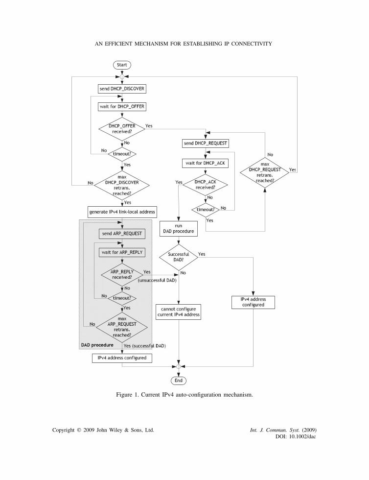
The flowchart of Figure 1 shows the current auto-configuration procedure for IPv4, when adevice is attaching to a given peer device or network. The device starts the auto-configurationprocess by sending a DHCP DISCOVER message. If one or more DHCP OFFER messagesare received, the device sends a DHCP REQUEST to the selected DHCP server, as describedin Section 2, and awaits for the corresponding DHCP ACK message sent by the server; if noDHCP ACK is received before a timeout, a new DHCP REQUEST is sent, if the maximumnumber of DHCP REQUEST messages has not yet been reached. Otherwise, it keeps sendingDHCP DISCOVER messages until DHCP OFFER messages are received or the maximum numberof retransmissions for DHCP DISCOVER is reached. In this case, the Dynamic Configuration
Copyright q 2009 John Wiley & Sons, Ltd. Int. J. Commun. Syst. (2009)DOI: 10.1002/dac
AN EFFICIENT MECHANISM FOR ESTABLISHING IP CONNECTIVITY
Figure 1. Current IPv4 auto-configuration mechanism.
Copyright q 2009 John Wiley & Sons, Ltd. Int. J. Commun. Syst. (2009)DOI: 10.1002/dac

R. CAMPOS AND M. RICARDO
of IPv4 Link-Local Addresses procedure is invoked. In both cases, DAD is performed in orderto check the uniqueness of the IPv4 address to be configured. The DAD procedure consists ofthe following steps. The node testing the uniqueness of IP addresses either locally generated orassigned by the DHCP server, sends out an ARP REQUEST message addressed to that IP address.If an ARP REPLY is received before a timeout, the DAD procedure ends with the result ‘Unsuc-cessful DAD’. Otherwise, after the timeout a new ARP REQUEST message is sent if the maximumnumber of ARP REQUEST messages (usually 3) was not yet reached. If the maximum number isreached, the DAD procure ends with the result ‘Successful DAD’. When no duplicate address wasdetected, the IP address is assigned to the corresponding network interface.
The flowcharts of Figure 2 illustrate the IPv6 auto-configuration mechanism. The auto-configuration of a link-local address is always performed first (Figure 2(a)); in Section 2, we havedescribed how the IPv6 link-local address is generated. Before the address is assigned, a DADprocedure is also run, which is similar to the DAD procedure described for IPv4; the differencehas to do with the use of the NDP protocol. If the DAD procedure ends with the result ‘SuccessfulDAD’, the IPv6 link-local address is assigned to the local network interface; else, no IPv6 link-localaddress is configured. Afterwards, the device starts the auto-configuration of a global IPv6 address(Figure 2(b)). As a first step, it sends an RS message and awaits for the corresponding RA message.If an RA is received, the flag M included in this message (see Section 2) is checked, so that thedevice knows the means available to configure the global IPv6 address: (1) using the RA messagesent out by the on-link IPv6 router; (2) using DHCPv6. If flag M is equal to 0, the first option isused; otherwise, DHCPv6 shall be used. If an RA message is not received after a given timeout, anew RS is issued; this process is repeated until the maximum number of RS messages is reached.In that case, DHCPv6 is tried. The procedure using DHCPv6 is similar to that using DHCPv4, asit can be verified in the flowchart. However, in this case, if the DAD procedure ends with the result‘Unsuccessful DAD’ while using DHCPv6, the DHCPv6 client will issue a DHCP DECLINEmessage, so that the server is informed that the client could not configure the assignedaddress.
The auto-configuration mechanisms illustrated in Figures 1 and 2 are run in parallel by a dual-stack device. Therefore, if, for instance, the device is attaching to an IPv4-only access network,supporting DHCP, a set of signalling messages will be wasted in the auto-configuration process.On the other hand, if the device is attaching to a peer that only supports the Dynamic Configurationof IPv4 Link-Local Addresses auto-configuration mechanism, both time and signalling messageswill be wasted; similar reasoning could be elaborated if an IPv6-only peer was considered. Thecurrent IP auto-configuration approach considers a dual-stack model and the need to have IPv4 andIPv6 connectivity established simultaneously. Within the current and the future IP communicationparadigm this may not be required, due to the deployment of IPv4-only and/or IPv6-only networks.Additionally, in the current approach, it is assumed that in general a device will attach to a networkinfrastructure running a DHCPv4/v6 server or IPv6 stateless auto-configuration. This is not alignedwith the new envisioned peer-to-peer, symmetric communication paradigm, where both parts canrun a DHCP server, for instance.
4. RELATED WORK
The trial-and-error mechanism described in Section 3 is not the most efficient solution fordoing IP auto-configuration in a context where IPv4 and IPv6 may coexist. On the other hand,
Copyright q 2009 John Wiley & Sons, Ltd. Int. J. Commun. Syst. (2009)DOI: 10.1002/dac

AN EFFICIENT MECHANISM FOR ESTABLISHING IP CONNECTIVITY
(a) (b)
Figure 2. Current IPv6 auto-configuration mechanism: (a) link-local addressauto-configuration; (b) global address auto-configuration.
auto-configuration for attaching networks is currently incipient. Auto-configuration is essentiallypossible when it comes to the routing issue, using the well-known Border Gateway Protocol [19],but does not address the issues we have mentioned in Section 1, for instance, the attachmentbetween adjacent IP networks running on distinct addressing schemes. In this section, we presentthe solutions that have been proposed so far to deal with these aspects.
The 6 to 4 mechanism [20] was proposed to enable internetworking between IPv6 realms thatcan transparently communicate over existing IPv4 networks. Still, this solution does not solve thespecific problem of adjacent attaching networks, it does not deal with the auto-configuration of IPconnectivity between such networks, and it addresses a specific scenario. In addition, it is unableto automatically adapt to different networking contexts, as it is required in NGNs. For instance,if two IPv6 networks previously connected over IPv4 become adjacent (e.g. because one of them
Copyright q 2009 John Wiley & Sons, Ltd. Int. J. Commun. Syst. (2009)DOI: 10.1002/dac
R. CAMPOS AND M. RICARDO
moved), the 6to4 mechanism is unable to identify that an IPv6-only setup is possible to enable IPconnectivity between the two adjacent networks.
The Ad-Hoc Configuration Protocol (AHCP) is a recent protocol proposed to address IP auto-configuration in multi-hop mesh networks. It aims at replacing the classical auto-configurationprotocols, such as DHCPv4 and DHCPv6, in networks where they are difficult or impossible todeploy. Yet, this is just another IP auto-configuration, that has the same advantages as the dual-stackDHCP solution referred in Section 2. Also, like the latter, it only leads to greater efficiency whenthe two IP versions are simultaneously available, which is not the common scenario envisionedfor NGNs (see Section 1). In addition, AHCP does not cope with the auto-configuration betweenattaching networks.
MANET auto-configuration is a hot research topic in the IETF and several solutions havebeen proposed in the last few years [11]. However, these are yet other auto-configurationsolutions targeting the MANET-specific scenario. On the other hand, the IPv4 and IPv6coexistence is not properly addressed; For example, no solution is defined to address thescenario of two attaching MANETs running on different IP versions. On the other hand,the auto-configuration solutions defined so far are also inefficient when two IP versionscoexist.
In the past, the authors proposed a solution for addressing the efficient auto-configuration ofdual-stack terminals, called Meta Auto-configuration Framework (MAF) [21]. Still, MAF does notaddress the auto-configuration of networks, namely the auto-configuration issues arising when twoadjacent networks attach. Moreover, it is just a preliminary auto-configuration solution for NGNswithout any practical evaluation. The auto-configuration solution for NGNs proposed herein—theBC mechanism—represents an evolution from MAF, where both terminals and networks comeinto play. The BC mechanism is described in the next section.
5. BC MECHANISM
The BC mechanism proposed here deals with the problems mentioned in Section 3 andaddresses peer-to-peer, symmetric attachments between devices or networks. The BC Manager(BCM) is the central entity of the BC mechanism. It manages the establishment of IP connec-tivity between attaching peers. BCM communicates with peer BCMs for negotiating theproper IP version, auto-configuration mechanism, and addressing scheme (when establishingconnectivity between networks). Furthermore, it interacts with peer BCMs to coordinate theconfiguration of the local services and resources, network layer, and local auto-configurationmechanisms accordingly. The BC mechanism does not implement any auto-configurationmechanism by itself. Rather, it selects the proper local auto-configuration mechanism, suchas DHCP [4] or IPv6 Stateless Address Auto-configuration [15], and relies on it for estab-lishing IP connectivity. The flexibility of the BC mechanism allows easy integration of newauto-configuration mechanisms, e.g. MANET auto-configuration mechanism, and permits theselection of the proper auto-configuration according to the different contexts of a networknode. For instance, if a specific node is connecting to a MANET, it shall use a MANETauto-configuration mechanism; conversely, if it is connecting to a node deploying the DynamicConfiguration of IPv4 Link-local Addresses mechanism [13], it has to use this mechanisminstead.
Copyright q 2009 John Wiley & Sons, Ltd. Int. J. Commun. Syst. (2009)DOI: 10.1002/dac
AN EFFICIENT MECHANISM FOR ESTABLISHING IP CONNECTIVITY
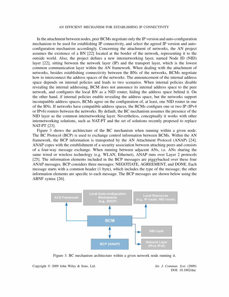
In the attachment between nodes, peer BCMs negotiate only the IP version and auto-configurationmechanism to be used for establishing IP connectivity, and select the agreed IP version and auto-configuration mechanism accordingly. Concerning the attachment of networks, the AN projectassumes the existence of a BN [22] located at the border of the network, representing it to theoutside world. Also, the project defines a new internetworking layer, named Node ID (NID)layer [22], sitting between the network layer (IP) and the transport layer, which is the lowestcommon communication layer within the AN framework. When dealing with the attachment ofnetworks, besides establishing connectivity between the BNs of the networks, BCMs negotiatehow to interconnect the address spaces of the networks. The announcement of the internal addressspace depends on internal policies and leads to two scenarios. When internal policies disablerevealing the internal addressing, BCM does not announce its internal address space to the peernetwork, and configures the local BN as a NID router, hiding the address space behind it. Onthe other hand, if internal policies enable revealing the address space, but the networks supportincompatible address spaces, BCMs agree on the configuration of, at least, one NID router in oneof the BNs. If networks have compatible address spaces, the BCMs configure one or two IP (IPv4or IPv6) routers between the networks. By default, the BC mechanism assumes the presence of theNID layer as the common internetworking layer. Nevertheless, conceptually it works with otherinternetworking solutions, such as NAT-PT and the set of solutions recently proposed to replaceNAT-PT [23].
Figure 3 shows the architecture of the BC mechanism when running within a given node.The BC Protocol (BCP) is used to exchange control information between BCMs. Within the ANframework, the BCP information is transported by the AN Attachment Protocol (ANAP) [24].ANAP copes with the establishment of a security association between attaching peers and consistsof a four-way message exchange. When running between adjacent ANs, i.e. ANs sharing thesame wired or wireless technology (e.g. WLAN, Ethernet), ANAP runs over Layer 2 protocols[25]. The information elements included in the BCP messages are piggybacked over these fourANAP messages. BCP considers three messages: NEGOTIATE, AGREEMENT, and DONE. Eachmessage starts with a common header (1 byte), which includes the type of the message; the otherinformation elements are specific to each message. The BCP messages are shown below using theABNF syntax [26].
Figure 3. BC mechanism architecture within a given network node running it.
Copyright q 2009 John Wiley & Sons, Ltd. Int. J. Commun. Syst. (2009)DOI: 10.1002/dac
R. CAMPOS AND M. RICARDO
The NEGOTIATE message is defined as follows:
NEGOTIATE = message-typenode-typenetwork-layer-versions-supportedautoconf-mechanisms-supported[address-space-type][netmask-length][subnet-address]
where node-type (1 byte) defines the type of device sending the message, a stand-alone node or aBN of an AN, and network-layer-versions-supported (1 byte) and autoconf-mechanisms-supported(1 byte) specifies the network layer versions (e.g. IPv4), and auto-configuration mechanismssupported by the current node, respectively. The address-space-type (1 byte), e.g. IPv4 addressspace, the netmask-length (1 byte), and subnet-address (variable length), e.g. 192.168.10.0, areoptional information elements that refer to attachments performed between networks (ANs). Thus,the size of the NEGOTIATE message depends on the type of node running the BC mechanism. Ifthe mechanism is run by a stand-alone node, the size of the message is equal to 4 bytes. Conversely,if the mechanism is run by a BN, the optional information elements are in place and the size isgreater. The actual size of the message depends on the type of address space. For instance, for anIPv4 address space the size of the message is 10 bytes, whereas for an IPv6 address space it is 22bytes.
The AGREEMENT message includes the following information elements:
AGREEMENT = message-typenetwork-layer-versionautoconf-mechanismlocal-remote-autoconf-server
where network-layer-version (1 byte) is the network layer version agreed to be used for estab-lishing connectivity between the communicating peers, autoconf-mechanism (1 byte) specifies theauto-configuration mechanism to be used for address configuration, and local-remote-autoconf-server (1 byte) defines which peer deploys the server part of the auto-configuration mechanism, ifapplicable (e.g. DHCP). The size of the message is 4 bytes.
Finally, the DONE message includes the message-type field only, since no further informationneeds to be transferred between the peers. This message is used for terminating the process.
The execution of the BC mechanism is illustrated in Figure 4 considering a symmetric scenarioof two attaching terminals. One of the terminals is dual-stack and the other is IPv4-only. Only theright IP auto-configuration mechanism (the Dynamic Configuration of IPv4 Link-Local Addresses[13]) is run over the local link. The size (in bytes) of the ANAP messages and the BCP informationelements are shown between parentheses.
In its current version, the BC mechanism targets single-homed terminals and networks. However,it can also deal with multi-homed terminals/multi-homed networks, if a BCM is run per networkinterface. In that case, the BCM for each interface is in charge of negotiating with the peer BCMsthe proper auto-configuration mechanism to be used. Still, this is not the most efficient approach.An approach where a single BCM deals with the whole set of network interfaces may make thenegotiation process more efficient. For example, if two attaching multi-homed devices have morethan one communication technology in common, a single communication link may be used to
Copyright q 2009 John Wiley & Sons, Ltd. Int. J. Commun. Syst. (2009)DOI: 10.1002/dac

AN EFFICIENT MECHANISM FOR ESTABLISHING IP CONNECTIVITY
Figure 4. Message sequence chart illustrating the execution of the BCmechanism when two terminals attach.
negotiate the IP auto-configuration mechanism(s) to be used over each communication link. Thisapproach will be considered in the next version of the mechanism.
6. BC MECHANISM PROTOTYPE
We have implemented the BC mechanism under FreeBSD OS, using C++. Figure 5 showsthe class diagram of the BC mechanism prototype. Below, we provide a brief description ofeach class:
• CBcm is the core class. It implements the procedures assigned to the BCM in the overall BCmechanism and interacts with the other classes of Figure 5.
• CBcp implements the BCP protocol. When CBcm needs to send signalling information to apeer BCM, it passes the corresponding information elements to CBcp, which is responsiblefor creating the proper BCP message and to send it towards the peer. On the other hand,CBcp is in charge of (1) handling incoming BCP messages to retrieve information elementstransported on it, and (2) passing these elements to CBcm.
• CLocalconf deals with the interaction with local resources and auto-configuration mecha-nisms. After the negotiation phase, CBcm interacts with this class in order to perform therequired configurations, such as ‘start DHCP server’ and ‘configure IPv4 router’.
• CBcmdb reads a local configuration file specifying the characteristics of the current node andthe characteristics of the network to which it belongs, when the node is a BN. Informationpresent in this configuration file includes type of node (single node or BN), local IP versionsand auto-configuration mechanisms supported and, if applicable, the address space being usedwithin the network to which the BN belongs to.
Copyright q 2009 John Wiley & Sons, Ltd. Int. J. Commun. Syst. (2009)DOI: 10.1002/dac

R. CAMPOS AND M. RICARDO
Figure 5. BC mechanism architecture.
• CNotify copes with notifications towards the Ambient Control Space [24]. Differentnotification mechanisms are used depending on the entity being notified; CNotify deals withthis in order to render the process fully transparent from CBcm’s standpoint.
The BC prototype makes part of the overall AN prototype [27], and it was demonstrated at thefinal audit of the project. The deployment of the BC mechanism allowed us to prove that (1)it does work in practice, both in stand-alone mode and in conjunction with the other softwaremodules developed in the context of the project, and (2) that its implementation and integrationwith legacy IP auto-configuration solutions is a straightforward process. Although the main goalof the prototype was to be used as a proof-of-concept, it was also useful to get some experimentalresults, as we will see in Section 7.
7. EVALUATION
This section is devoted to the evaluation of the BC mechanism. Our purpose is to evaluate thebenefits of considering the BC mechanism as part of the attachment procedure defined by the ANAPprotocol within the AN framework [24]. We name the trial-and-error mechanism used to establishIP connectivity, when multiple IP versions are present, as legacy mechanism. In order to comparethe two mechanisms, the ANAP protocol is used in both mechanisms, for establishing a securityassociation between attaching peers (ANs), as defined in [24]. The comparison is performed basedon the overhead, auto-configuration delay, and energy consumption. The evaluation of BC fromthe functional point of view was carried out using the BC prototype.
7.1. Scenarios
The scenarios shown in Figure 6 were considered for evaluating the BC mechanism from afunctional point of view. Scenario 1 consists of the attachment of two nodes connected to thesame link. As shown in Figure 6(a), in this scenario, both nodes support a DHCP client and aDHCP server. Using the legacy mechanism, either IP connectivity was not established or it wasestablished but two IP networks were created over the link, which is clearly unnecessary. In the
Copyright q 2009 John Wiley & Sons, Ltd. Int. J. Commun. Syst. (2009)DOI: 10.1002/dac

AN EFFICIENT MECHANISM FOR ESTABLISHING IP CONNECTIVITY
(a)(b)
Figure 6. Scenarios used for evaluating the BC mechanism from the functionalpoint of view: (a) Scenario 1 and (b) Scenario 2.
first case, the DHCP clients running in each node accepted the DHCP OFFER sent by the DHCPserver running in the same node and no IP connectivity was configured at all. In the second case,each DHCP client accepted the DHCP OFFER of the server running in the peer node, and two IPnetworks were established over the same link; this problem would also be observed for DHCPv6 orif the attachment between IPv6 routers was considered. The BC mechanism solved the problem bydefining, during the negotiation phase, the node running the DHCP client and the node running theDHCP server; it guaranteed that a single DHCP server was running after the attachment procedurecompleted, and that a single IP network was created.
In order to demonstrate that the BC mechanism also works for the attachment between networks,Scenario 2 (Figure 6(b)) was also tested using the BC prototype. After running the BC mechanismbetween the BNs of each network (in this case, Node2@Network1 and Node3@Network2) wehave verified that (1) the BNs could establish IP connectivity between them, as it happens for theattachment between stand-alone nodes; (2) the BNs were able to negotiate the final addressingscheme and the configuration of each BN after attachment—in this case, the address spaces ineach network were maintained and Node 2 was configured as an IPv4 router between the subnets192.168.20.0/24 and 172.16.0.0/16; (3) Node 1 and Node 4 were directly connected at IP levelafter the BC mechanism completed its job. If the networks had incompatible or overlapping addressspaces, the only difference would be the local configurations at each BN which, in turn, wouldinfluence the type of connectivity established between Node 1 and Node 4. In those cases, eitherone BN or both had to be configured as NID routers instead of IP routers and Node 1 and Node4 would be directly connected only at NID level, after the BC mechanism completed.
The three scenarios illustrated in Figure 7 (Scenario 3, 4, and 5) were used to compare the twomechanisms. Scenario 3 is purely symmetric and refers to the creation of a PAN, using one or morewireless technologies. Scenario 4 is purely asymmetric and considers the attachment of multipleterminals to an 802.11 access network; the message sequence charts illustrating the execution ofthe BC mechanism in Scenarios 3 and 4 can be found in [22]. Finally, Scenario 5 considers aprominent scenario for NGNs: the extension of a wired access network by means of an 802.11s[28] Wireless Mesh Network (WMN), where terminals attach to the Mesh Access Points (MAPs)
Copyright q 2009 John Wiley & Sons, Ltd. Int. J. Commun. Syst. (2009)DOI: 10.1002/dac

R. CAMPOS AND M. RICARDO
(c)
(a) (b)
Figure 7. Scenarios used for comparing the BC and legacy mechanisms:(a) Scenario 3; (b) Scenario 4; and (c) Scenario 5.
[28] and MAPs form a square lattice topology. In the three scenarios, we assume the devices aredual-stack. IPv4 and IPv6 and their auto-configuration mechanisms were considered in the analysis.For IPv4, the DHCP protocol [4] and the Dynamic Configuration of IPv4 Link-Local Addresses[13] along with the Address Resolution Protocol (ARP) [14], used for DAD, were considered.For IPv6, the IPv6 Stateless Address Auto-configuration [15] and DHCPv6 [18], together with theNDP [16] and the MLD protocol [17] were considered.
7.2. Mathematical expressions
This section formalizes some of the concepts used in the theoretical analysis of the legacy andBC auto-configuration mechanisms. We first refer to the expression used to compute the overheadreduction (OR) provided by the BC mechanism. Then, we provide the expressions defined in [29]for calculating the energy consumed by an 802.11b Network Interface Card (NIC) to send/receiveunicast/broadcast frames. Finally, we derive the expressions used for calculating the energy wastedwhen the legacy mechanism is used in Scenarios 4 and 5.
The Overhead Reduction OR provided by the BC mechanism is defined as follows:
OR(%)= Lo−BCo
Lo×100 (1)
Copyright q 2009 John Wiley & Sons, Ltd. Int. J. Commun. Syst. (2009)DOI: 10.1002/dac

AN EFFICIENT MECHANISM FOR ESTABLISHING IP CONNECTIVITY
Table I. Energy consumed by an 802.11b NIC as a function of the size of theunicast/broadcast frame being sent/received.
Action Managed mode (�J ) Ad-hoc mode (�J )
Unicast send 0.74×S+431 3.85×S+431Broadcast send 2.36×S+272 5.47×S+272Unicast recv 0.38×S+316 3.49×S+316Broadcast recv 0.52×S+50 3.63×S+50
where Lo and BCo represent the overhead—total number of bytes or total number of signallingframes exchanged—for the legacy and BC mechanisms, respectively.
The energy consumed by an 802.11b NIC to send/receive unicast/broadcast frames hasbeen analysed in [29]. Different linear equations are provided for each case: (1) unicast frametransmission; (2) unicast frame reception; (3) broadcast frame transmission; and (4) broadcastframe reception. Table I summarizes those equations.
In order to evaluate the energy wasted when using the legacy mechanism in practice, concretescenarios need to be considered. In what follows, we derive the mathematical expressions forcomputing the energy wasted per frame in Scenarios 4 and 5.
The total energy wasted in Scenario 4 per broadcast frame (Ew4) can be computed using thefollowing equation:
Ew4(J/frame)= Esb,m+N∑
i=1Erb,m,i (2)
where N defines the number of terminals already attached to the access network, Esb,m representsthe energy consumed by an 802.11 NIC to send a given broadcast frame in managed mode, andErb,m,i represents the energy consumed to receive the same broadcast frame in managed mode forterminal i . These two values can be easily computed using the equations in Table I.
The total energy wasted per broadcast frame in Scenario 5 (Ew5) within the WMN can bedefined as follows:
Ew5(J/frame) = s2n .Esb,a+4(2.Erb,a)+4(sn−2)(3Erb,a)
+(sn−2)2.(4Erb,a)+Erb,a,∀sn ∈N∧sn�2 (3)
where sn denotes the number of WMN nodes in a side of the square lattice (e.g. a 4-node WMNhas sn =2 and a 9-node WMN has sn =3), Esb,a is the energy consumed to send a broadcast framein ad-hoc mode, and Erb,a is the energy consumed to receive a broadcast frame in ad-hoc mode.Equation (3) considers the energy consumed to send a broadcast frame within the WMN using aflooding mechanism, as defined in [28], and the energy consumed to receive the same frame. Thenumber of broadcast frames received by each WMN node depends on its number of neighbours.For the square lattice topology considered here, a WMN node can have 2, 3, or 4 neighbours. Thenumber of times the WMN node receives the broadcast frame is equal to its number of neighbours,due to the flooding mechanism. The proof that the expressions included in Equation (3) for thenumber of nodes with 3 and 4 neighbours hold for sn�2 can be found in the appendix; the numberof nodes with 2 neighbours is always 4 (the WMN nodes in the corners of the square lattice). The
Copyright q 2009 John Wiley & Sons, Ltd. Int. J. Commun. Syst. (2009)DOI: 10.1002/dac

R. CAMPOS AND M. RICARDO
Table II. Message sizes and corresponding number of retransmissions considered in the theoretical analysis.
Message Size (bytes) No. of retrans.
ARP REQUEST 28 2DHCP4 DISCOVER 321 2DHCP4 OFFER 368 —DHCP4 REQUEST 365 —DHCP4 ACK 302 —DHCP6 SOLICIT 176 2DHCP6 ADVERTISE 221 —DHCP6 REQUEST 198 —DHCP6 REPLY 241 —I1 20 —I2 720 —MLD REPORT 126 1NDP NEIGHBOR SOLICITATION 64 2NDP ROUTER ADVERTISEMENT 104 —NDP ROUTER SOLICITATION 56 2R1 640 —R2 60 —
last term in Equation (3) is related to the energy required to receive the frame from a node outsidethe WMN, as it happens when a WMN is used to extend a wired infrastructure; if the WMN is astand-alone network, this term disappears.
7.3. Results
This section presents the results obtained for Scenarios 3, 4, and 5. We characterize the auto-configuration delay, the OR provided by the BC mechanism, and the wasted energy when thelegacy mechanism is used. Overheads do not consider Layer 2 headers, so the results are madeindependent of the medium used. The analysis was performed using messages sizes accordingto the specifications [4, 13–18, 30, 31], or according to the typical sizes found in practice whenstandards leave values as open. Table II summarizes the size of the messages and the correspondingnumber of retransmissions considered in our analysis. The results provided herein are meant togive insights on the differences between the use of the legacy and BC mechanisms.
The plots of Figure 8 show the total overhead incurred by the attachment process when thelegacy and the BC mechanisms are used in Scenarios 3, 4, and 5 and IPv6 is used to establishIP connectivity; similar plots for IPv4 can be found in [22]. For Scenario 3, the total overheadrepresented by the curves considers one attachment per device performed while forming thePAN. There is a significant saving provided by the BC mechanism. For instance, for a PANof 30 devices, the BC mechanism saves about 60 kB of signalling, whereas for 50 devices itcan save about 100 kB. The OR is shown in Table III. The reduction is slightly higher whenIPv4 is used to establish IP connectivity within the PAN. For Scenario 4, it is worth notingthat the BC mechanism saves about 0.5 and 1MB of signalling when 500 and 1000 terminals,respectively, perform a single attachment to the access network. The saving is even more relevantif we consider multiple attachments per terminal. For instance, if 10 attachments per terminal areconsidered, the BC mechanism saves about 5MB for 500 attaching terminals and about 10MB
Copyright q 2009 John Wiley & Sons, Ltd. Int. J. Commun. Syst. (2009)DOI: 10.1002/dac

AN EFFICIENT MECHANISM FOR ESTABLISHING IP CONNECTIVITY
0
50
100
150
200
0 10 20 30 40 50 60
Tota
l Ove
rhea
d (k
B)
Number of PAN Devices
Legacy
BC
0
1
2
3
4
5
0 200 400 600 800 1000 1200
Tota
l Ove
rhea
d (M
B)
Number of Terminals
Legacy
BC
0
0.5
1
1.5
2
5 10 15 20 25 30 35
Tota
l Ove
rhea
d (M
B)
Number of MAPs
Legacy
BC
0
200
400
600
800
1000
1200
0 10 20 30 40 50 60
Tota
l Ove
rhea
d (n
o. o
f fra
mes
)
Number of PAN Devices
Legacy
BC
0
5000
10000
15000
20000
25000
30000
0 200 400 600 800 1000 1200
Tota
l Ove
rhea
d (n
o. o
f fra
mes
)
Number of Terminals
Legacy
BC
0
2000
4000
6000
8000
10000
5 10 15 20 25 30 35
Tota
l Ove
rhea
d (n
o. o
f fra
mes
)
Number of MAPs
Legacy
BC
Figure 8. Total overhead incurred by each mechanism for Scenarios 3, 4, and 5, when IPv6is used for establishing IP connectivity: (a) Scenario 3 (no. of bytes); (b) Scenario 4 (no. ofbytes); (c) Scenario 5 (no. of bytes); (d) Scenario 3 (no. of frames); (e) Scenario 4 (no. of
frames); and (f) Scenario 5 (no. of frames).
Table III. Overhead reduction when using the BC mechanism forScenarios 3, 4, and 5.
Overhead reduction (%)
Scenario Active Version Bytes Frames
3 IPv4 58 67IPv6 53 57
4 IPv4 28 50IPv6 23 30
5 IPv4 28 50IPv6 23 30
for 1000 attaching terminals. The OR provided by the BC mechanism with respect to the legacymechanism is also shown in Table III. As in Scenario 3, the reduction is slightly higher whenIPv4 is the active version. Finally, for Scenario 5, the same OR of Scenario 4 is achieved (seeTable III). The curves shown in Figure 8 were obtained considering that, on average, ten 802.11terminals per MAP perform one attachment to the WMN. They represent the signalling overheadgenerated by each mechanism within a WMN. It can be observed that, for instance, for a 16-node WMN, BC saves 150 kB of signalling for a single attachment per terminal, while for a32-node WMN (the maximum size targeted for an 802.11s WMN [28]), it can save 300 kB ofsignalling.
Copyright q 2009 John Wiley & Sons, Ltd. Int. J. Commun. Syst. (2009)DOI: 10.1002/dac
R. CAMPOS AND M. RICARDO
For some communication media, it is more suitable to consider the overhead expressed in thenumber of frames, instead of the number of bytes, since the medium access overhead contributesthe most to both the time and energy required to transmit a frame; the size of the frame is asecond-order factor. This is the case of 802.11. Table III provides the OR regarding the numberof signalling frames. The plots of Figure 8(d)–(f) show the number of signalling frames sent byeach mechanism in each scenario. For Scenario 4, 3000 and 6000 frames are saved by the BCmechanism when 500 and 1000 terminals are considered, respectively. It is interesting to notethat this amount of frames could be used for transporting about 4.3 and 8.6MB of user data,respectively, if frames of 1500 bytes were considered. These are much higher values than the valuesmentioned above, expressed in number of bytes. The same type of reasoning could be performedfor Scenarios 3 and 5.
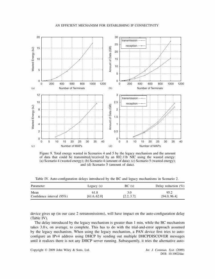
In order to assess the energy wasted by the legacy mechanism, due to the use of a trial-and-error approach, we have considered Scenarios 4 and 5; IPv4 connectivity is established in bothcases. This energy is saved by the BC mechanism and can be used to send user data instead.The additional energy required to transmit the BCP information elements piggybacked over theattachment protocol is negligible, since the fixed energy cost of transmitting/receiving frames ismore significant [29]. The plots of Figure 9 show the amount of energy wasted when using thelegacy mechanism in these scenarios, and the amount of data that could be transmitted/received byan 802.11b NIC using the wasted energy. The plots were obtained using the equations provided inSection 7.2. In our calculations for Scenarios 4, we considered that terminals attach sequentially;as such, the number of nodes receiving the broadcast messages sent out by an attaching terminalincreases linearly as new devices attach. For Scenario 5, the average number of terminals perMAP attaching to the WMN was set to 10. In both scenarios, we evaluated the energy consumedalong 30 days, assuming a single attachment per terminal per day. The plots in Figure 9(a),(c)were obtained by considering all the unnecessary messages broadcasted by the legacy mechanismin each scenario. These messages are both unnecessarily transmitted by a node and received bythe nodes attached to the same link; both transmission and reception of messages contribute tothe total wasted energy [29]. For Scenario 4, the total wasted energy increases exponentially withthe number of attaching terminals. For 1000 terminals, about 17.3 kJ of energy is wasted whenusing the legacy mechanism, which corresponds to the energy required by an 802.11b NIC totransmit more than 15 GB of data and receive more than 27GB (cf. Figure 9(b)). For Scenario 5,we analysed the energy wasted within the WMN; the energy wasted by the terminals attachingto the WMN is not taken into account. The total wasted energy increases exponentially with thenumber of MAPs forming the WMN. For a 25-node WMN, 4.6 kJ of energy is wasted by thelegacy mechanism. With this amount of energy, an 802.11b NIC could transmit more than 2GBof data and receive about 2.5GB, as shown in Figure 9(d). These results are mostly relevant forenergy constrained WMNs, such as emerging solar-powered WMNs [32]. Different results forboth scenarios would be obtained if other NIC was considered; here we aim at reasoning aboutthe order of magnitude of the wasted energy.
We now present the auto-configuration delay introduced by each mechanism in Scenario 3.The delay per PAN device during the auto-configuration of an IPv4 address was measuredexperimentally using Ethereal [33]; the logs are available at [34]. Ten samples were takeninto account. Table II presents the measured mean delay and the corresponding 95% confi-dence interval, as well as the delay reduction—the difference between delays normalized to thelegacy mechanism delay. It is important to realize that these values are implementation depen-dent; for instance, the number of retransmissions of the DHCPDISCOVER message before the
Copyright q 2009 John Wiley & Sons, Ltd. Int. J. Commun. Syst. (2009)DOI: 10.1002/dac
AN EFFICIENT MECHANISM FOR ESTABLISHING IP CONNECTIVITY
0
5
10
15
20
0 200 400 600 800 1000 1200
Was
ted
Ene
rgy
(kJ)
Number of Terminals
0
5
10
15
20
25
30
0 200 400 600 800 1000 1200
Am
ount
of D
ata
(GB
)
Number of Terminals
transmission
reception
0
2
4
6
8
10
12
0 5 10 15 20 25 30 35 40
Was
ted
Ene
rgy
(kJ)
0
0.5
1
1.5
2
2.5
3
0 5 10 15 20 25 30 35 40
Am
ount
of D
ata
(GB
)
Number of MAPsNumber of MAPs
transmission
reception
Figure 9. Total energy wasted in Scenarios 4 and 5 by the legacy mechanism and the amountof data that could be transmitted/received by an 802.11b NIC using the wasted energy:(a) Scenario 4 (wasted energy); (b) Scenario 4 (amount of data); (c) Scenario 5 (wasted energy);
and (d) Scenario 5 (amount of data).
Table IV. Auto-configuration delays introduced by the BC and legacy mechanisms in Scenario 2.
Parameter Legacy (s) BC (s) Delay reduction (%)
Mean 61.8 3.0 95.2Confidence interval (95%) [61.6,62.0] [2.2,3.7] [94.0,96.4]
device gives up (in our case 2 retransmissions), will have impact on the auto-configuration delay(Table IV).
The delay introduced by the legacy mechanism is greater than 1 min, while the BC mechanismtakes 3.0 s, on average, to complete. This has to do with the trial-and-error approach assumedby the legacy mechanism. When using the legacy mechanism, a PAN device first tries to auto-configure an IPv4 address using DHCP by sending out multiple DHCPDISCOVER messagesuntil it realizes there is not any DHCP server running. Subsequently, it tries the alternative auto-
Copyright q 2009 John Wiley & Sons, Ltd. Int. J. Commun. Syst. (2009)DOI: 10.1002/dac
R. CAMPOS AND M. RICARDO
configuration mechanism and configures an IPv4 link-local address. The BC mechanism saves58.8 s, on average, by negotiating in advance the proper auto-configuration mechanism to beused. During the negotiation phase, BCMs can conclude that IP address auto-configuration canonly be performed using the Dynamic Configuration of IPv4 Link-Local Addresses mechanism.Consequently, the delay introduced by the attempt to auto-configure IP connectivity through DHCPis eliminated from the BC mechanism.
7.4. Discussion
The heterogeneity currently found in IP networks and the advent of a new communication paradigmbrings up new problems. State-of-the-art solutions either do not deal with these problems at all ordo not deal with them in the most efficient way. The BC mechanism addresses the new problemsand represents a solution more efficient than the legacy mechanism used to auto-configure IPconnectivity.
By testing Scenarios 1 and 2, we have confirmed that the BC mechanism can address the newenvisioned communication paradigm, where symmetric attachments can take place, devices mayhave dynamic roles, and two IP versions and corresponding auto-configuration mechanisms arepresent. We have demonstrated that the BC mechanism can establish IP connectivity in scenarioswhere the legacy mechanism cannot. On the other hand, through experimental and theoreticalanalysis, we verified that the BC mechanism is significantly more efficient than the legacy mech-anism. The BC mechanism avoids both the transmission and reception/processing of unnecessarymessages by each network device connected to the link over which IP connectivity is being config-ured. This allows energy and CPU time saving, an important issue namely for devices with limitedresources and running on battery power, such as handheld, sensor devices, and solar-poweredaccess points [32]. In addition, the BC mechanism avoids the auto-configuration delay that maybe introduced by the legacy mechanism, which renders IP auto-configuration a slow process; forexample, the bootstrapping of a PAN may take more than 1 min. Still, we shall observe that theactual overhead and delay reduction provided by the BC mechanism depends on multiple factors,such as the scenario being considered, the network layer, and the corresponding auto-configurationmechanism used for IP connectivity configuration. Also, the actual energy saving depends on thehardware and the specific technology(ies) considered.
In the evaluation presented, we considered IPv4 and IPv6 for establishing IP connectivity andtheir corresponding auto-configuration mechanisms. Moreover, we evaluated the BC mechanismfor three representative scenarios. For these scenarios, the BC mechanism provides significantreductions in overhead and auto-configuration delay, and it may save a considerable amount ofenergy. The benefits of BC would be even more significant if: (1) further possible network layersand/or auto-configuration mechanisms were considered; (2) the number of retransmissions of theDHCPDISCOVER message, while attempting to auto-configuring IP connectivity using DHCP,was higher. Our analysis considered two retransmissions, according to [4]. In practice, highernumber of retransmissions may take place. For instance, the DHCP implementation under LinuxOS considers five retransmissions. In that case, the overhead and delay reductions and the wastedenergy would be higher.
Although the BC mechanism was designed having ANs in mind, and with the purpose of beingintegrated into the AN framework [24], it can be used in other setups. BC can be integrated in anyexisting attachment procedure. For instance, it could be integrated within the 802.11 attachmentprocedure usually carried out using the Extensible Authentication Protocol (EAP) [35], with the
Copyright q 2009 John Wiley & Sons, Ltd. Int. J. Commun. Syst. (2009)DOI: 10.1002/dac
AN EFFICIENT MECHANISM FOR ESTABLISHING IP CONNECTIVITY
BCP information elements piggybacked over the EAP messages. On the otherhand, it is not limitedto work together with the NID internetworking solution. Solutions such as NAT64 and othersreferred in [22] can be employed as well.
8. CONCLUSION
The paradigm in mobile communication networks is changing, with symmetric attachment betweenpeers gaining momentum and two IP versions coexisting. In this paper, we presented the BCmechanism, a new efficient mechanism used to establish IP connectivity between communicatingpeers (ANs). By using a proof-of-concept prototype, experimental results, and theoretical analysis,we showed the usefulness of the mechanism, both from the efficiency and functional points ofview. Its deployment allowed us to prove that it does work in practice and that its implementationand integration with legacy IP auto-configuration solutions is a straightforward process. The anal-ysis herein performed focused on overhead, auto-configuration delay, and energy consumption.The obtained results give the first insights on the real benefits provided by the BC mechanism.The BC mechanism is significantly more efficient than the legacy mechanism. It avoids both thetransmission and reception/processing of unnecessary messages and avoids the auto-configurationdelay that may be introduced by the legacy mechanism. Although this mechanism was designedhaving ANs in mind, it can be used in other setups. BC can be integrated in any existing attach-ment procedure. Also, it can work together with internetworking solutions other than the NIDinternetworking layer defined in the AN overall architecture.
As future work, we shall consider the extension of the BC mechanism to address multi-homeddevices and networks more efficiently and the renegotiation of the auto-configuration methodsused in each concrete scenario to establish IP connectivity. Although the current results are alreadyrelevant and prove the benefits of the BC mechanism, the extension of the analysis to moredynamic scenarios where, for instance, the underlying IP auto-configuration legacy mechanism arerenegotiated, may further emphasize its advantages; this is left for future work too.
APPENDIX A
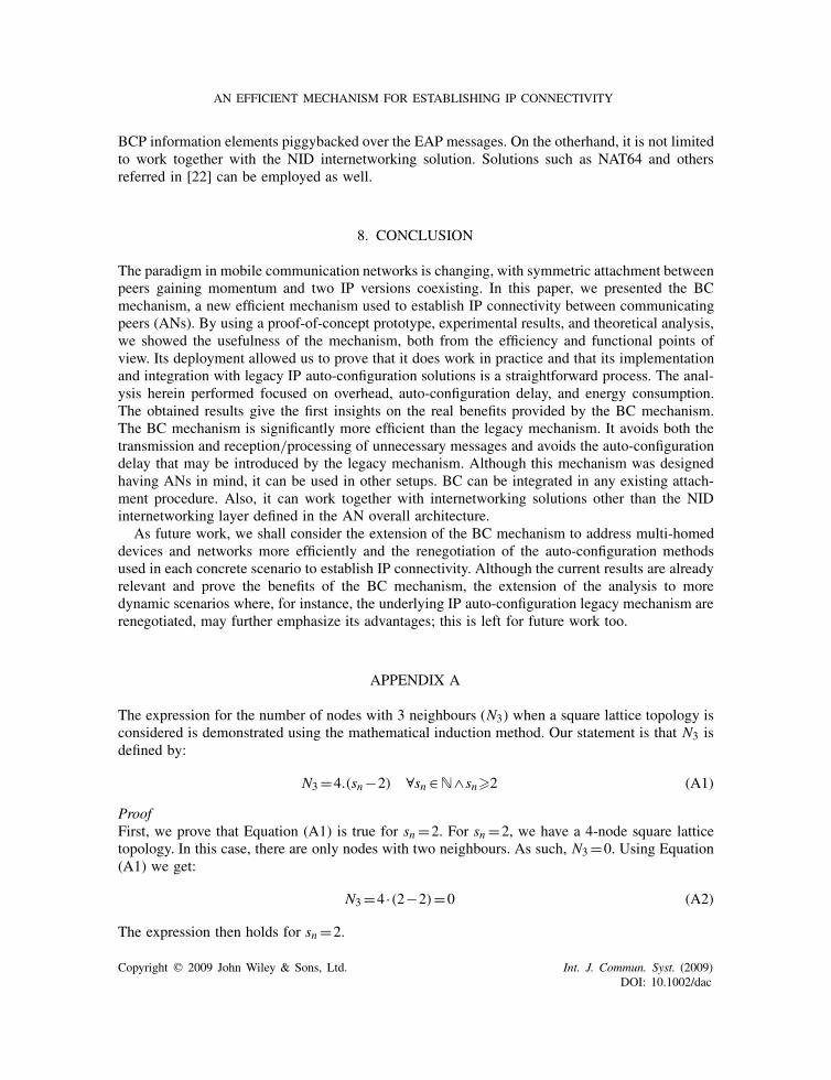
The expression for the number of nodes with 3 neighbours (N3) when a square lattice topology isconsidered is demonstrated using the mathematical induction method. Our statement is that N3 isdefined by:
N3=4.(sn−2) ∀sn ∈N∧sn�2 (A1)
ProofFirst, we prove that Equation (A1) is true for sn =2. For sn =2, we have a 4-node square latticetopology. In this case, there are only nodes with two neighbours. As such, N3=0. Using Equation(A1) we get:
N3=4 ·(2−2)=0 (A2)
The expression then holds for sn =2.
Copyright q 2009 John Wiley & Sons, Ltd. Int. J. Commun. Syst. (2009)DOI: 10.1002/dac

R. CAMPOS AND M. RICARDO
We now need to prove that the equation is valid for sn =k+1, assuming that it is valid forsn =k. For sn =k we get:
N3(k)=4 ·(k−2) (A3)
For sn =k+1 we have:
N3(k+1)=4 ·(k+1−2)=4 ·(k−1) (A4)
But, N3(k+1) can also be defined as a function of N3(k):
N3(k+1)=N3(k)+4 (A5)
since when the side of the square lattice is increased by one, one node per side is added to theset of nodes having 3 neighbours. If Equation (A5) is simplified we can prove that it leads to thesame result obtained using Equation (A1):
N3(k+1)=4 ·(l−2)+4=4 ·(l−2+1)=4 ·(l−1) (A6)
Thus, the expression holds for all sn .The expression for the number of nodes with 4 neighbours (N4) when a square lattice topology
is considered is demonstrated using the same method. Our statement is that N4 is defined by:
N4= (l−2)2 ∀sn ∈N∧sn�2 (A7)
ProofFirst, we prove that Equation (A7) is true for sn =2. For sn =2, we have a 4-node square latticetopology. In this case, N4 =0, as there are only nodes with two neighbours. Using Equation (A7)we get:
N4= (2−2)2=0 (A8)
The expression then holds for sn =2.
We need to prove that the equation is valid for sn =k+1 too, assuming that it is valid for sn =k.For sn =k we get:
N4(k)= (k−2)2 (A9)
For sn =k+1 we have:
N4(k+1)= (k+1−2)2= (k−1)2 (A10)
But, N4(k+1) can also be defined as a function of N4(k):
N4(k+1)=N4(k)+(k+1−2)2−(k−2)2 (A11)
where (k+1−2)2−(k−2)2 represents the number of nodes added to the set of nodes having 4neighbours, when the side of the square lattice is increased by one. If Equation (A11) is simplifiedwe can prove that it leads to the same result obtained using Equation (A7):
N4(k+1)= (k−2)2+(k+1−2)2−(k−2)2= (k+1−2)2= (k−1)2
Thus, the expression holds for all sn .
Copyright q 2009 John Wiley & Sons, Ltd. Int. J. Commun. Syst. (2009)DOI: 10.1002/dac
AN EFFICIENT MECHANISM FOR ESTABLISHING IP CONNECTIVITY
ACKNOWLEDGEMENTS
This paper describes work undertaken in the context of the Ambient Networks project, which is part ofthe EU’s IST program. Over 30 organizations from Europe, Canada, and Australia are involved in thisIntegrated Project, which runs in 2006–2007 in its second phase. The views and conclusions containedherein are those of the authors and should not be interpreted as necessarily representing the AmbientNetworks Project.
The authors thank the anonymous reviewers for their fruitful comments which contributed to improvethe quality of this paper.
REFERENCES
1. Durand A, Droms R, Haberman B, Woodyatt J. Dual-stack Lite Broadband Deployments Post IPv4 Exhaustion.IETF Internet Draft, draft-ietf-softwire-dual-stack-lite-00, March 2009.
2. Campos R et al. Dynamic and automatic interworking between personal area networks using composition.Proceedings of 16th Annual IEEE International Symposium on Personal Indoor and Mobile Radio Communication,Berlin, Germany, September 2005.
3. Campos R, Ricardo M. Dynamicand automatic connection of personal area networks to the global internet.Proceedings of ACM IWCMC’06, Vancouver, Canada, July 2006.
4. Droms R. Dynamic Host Configuration Protocol. IETF RFC 2131, March 1997.5. Soliman H. Mobile IPv6 Support for Dual Stack Hosts and Routers. IETF Internet Draft, draft-ietf-mext-nemo-
v4traversal-09, February 2009.6. Chown T, Venaas S, Strauf C. Dynamic Host Configuration Protocol (DHCP) : IPv4 and IPv6 Dual-Stack Issues.
IETF RFC 4477, May 2006.7. IST FP6 Ambient Networks. Available from: http://www.ambient-networks.org [31 March 2009].8. Tsirtsis G, Srisuresh P. Network Address Translation—Protocol Translation (NAT-PT). IETF RFC 2766, February
2000.9. Srisuresh P, Holdrege M. IP Network Address Translator (NAT) Terminology and Considerations. IETF RFC
2663, August 1999.10. Baccelli E. Address Autoconfiguration for MANET: Terminology and Problem Statement. IETF Internet Draft,
draft-ietf-autoconf-statement-04, February 2008.11. Bernardos C, Calderon M, Moustafa H. Ad Hoc IP Address Autoconfiguration. IETF Internet Draft, draft-
bernardos-manet-autoconf-survey-04, November 2008.12. Zeroconf Work Group. Available from: http://www.zeroconf.org [31 March 2009].13. Cheshire S, Aboba B, Guttman E. Dynamic Configuration of IPv4 Link-Local Addresses. IETF RFC 3927, May
2005.14. Plummer D. An Ethernet Address Resolution Protocol. IETF RFC 826, November 1982.15. Thomson S, Narten T. IPv6 Stateless Address Autoconfiguration. IETF RFC 4862, September 2007.16. Narten T, Nordmark E, Simpson W. Neighbor Discovery for IP Version 6 (IPv6). IETFRF C4861, September
2007.17. Vida R, Costa L. Multicast Listener Discovery Version 2 (MLDv2) for IPv6. IETF RFC3810, June 2004.18. Droms R et al. Dynamic Host Configuration Protocol for IPv6 (DHCPv6). IETF RFC 3315, July 2003.19. Rekhter Y, Li T, Hares S. A Border Gateway Protocol 4 (BGP-4). IETF RFC4271, January 2006.20. Carpenter B, Moore K. Connection of IPv6 Domains via IPv4 Clouds. IETF RFC 3056, February 2001.21. Campos R, Ricardo M. Dynamic autoconfiguration in 4G networks: problem statement and preliminary solution.
Proceedings of the 1st International ACM Workshop on Dynamic Interconnection of Networks (DIN’05), Cologne,Germany, September 2005.
22. Ahlgren B et al. Connectivity and Dynamic Internetworking Prototype and Evaluation. FP6-CALL4-027662-ANP2/D23-E.2, V1.0, Ambient Networks project public deliverable, December 2007.
23. Wing D, Ward D, Durand A. A Comparison of Proposals to Replace NAT-PT. IETF Internet Draft, draft-wing-nat-pt-replacement-comparison-02, September 2008.
24. Johnsson M et al. Ambient Network System Description. FP6-CALL4-027662-AN P2/ D07-A2, V7.0, December2007.
25. Rinta-aho T, Campos R, Mehes A, Meyer U, Sachs J, Selander G. Ambient network attachment. Proceedings ofIST Summit, Budapest, July 2007.
Copyright q 2009 John Wiley & Sons, Ltd. Int. J. Commun. Syst. (2009)DOI: 10.1002/dac

R. CAMPOS AND M. RICARDO
26. Crocker D, Overell P. Augmented BNF for Syntax Specifications: ABNF RFC 4234, October 2005.27. Rembarz R. D17-H.4 Ambient Control Space Prototype Design. FP6-CALL4-027662-AN P2/D17-H.4, V1.0,
June 2007.28. Bahr M. Update on the hybrid wireless mesh protocol of IEEE 802.11s. Proceedings of MASS 2007, Pisa, 2007.29. Feeney L, Nilsson M. Investigating the energy consumption of a wireless network interface in an ad hoc
networking environment. Proceedings of INFOCOM 2001, Anchorage, U.S.A., 2001.30. Alexander S, Droms R. DHCP Options and BOOTP Vendor Extensions. IETF RFC 2132, March 1997.31. Droms R. DNS Configuration Options for Dynamic Host Configuration Protocol for IPv6 (DHCPv6). IETF
RFC3646, December 2003.32. Todd T, Sayegh A, Smadi M, Zhao D. The need for Access point power saving in solar powered WLAN mesh
networks. IEEE Network 2008; 22(3):4–10.33. Network Protocol Analyzer. Ethereal. Available from: http://www.ethereal.com [31 March 2009].34. Log files. Available from: http://telecom.inescporto.pt/∼rcampos/logsIPautoconf.zip.35. Aboba B et al. Extensible Authentication Protocol (EAP). IETF RFC 3748, June 2004.
AUTHORS’ BIOGRAPHIES
Rui Campos received a Diploma degree in Electrical and Computer Engineering in 2003from the University of Porto, Portugal. He works as a researcher at INESC Porto and ispursuing his PhD in Electrical and Computer Engineering. His research interests includemobile communications, network autoconfiguration, and spanning tree algorithms.
Manuel Ricardo received a Diploma degree in 1988, an MS in 1992, and a PhD in2000, all in Electrical and Computer Engineering from the University of Porto, Portugal.He is an associate professor at the University of Porto, where he gives courses in mobilecommunications and computer networks. He also leads the Communication Networksand Services Area at INESC Porto.
Copyright q 2009 John Wiley & Sons, Ltd. Int. J. Commun. Syst. (2009)DOI: 10.1002/dac