
An effective optimization algorithm for multipass turning of flexible workpieces
10
J Intell Manuf DOI 10.1007/s10845-013-0838-7 An effective optimization algorithm for multipass turning of flexible workpieces Kaibo Lu · Minqing Jing · Xiaoli Zhang · Guihua Dong · Heng Liu Received: 13 June 2013 / Accepted: 17 September 2013 © Springer Science+Business Media New York 2013 Abstract Excessive deformations and chatter vibrations are two main obstacles frequently encountered in turning of long slender workpieces. So far, there is seldom reported research using optimization techniques to cope with those difficulties. This paper introduces a new method for optimiz- ing the machining parameters and the sequence of cutting passes in turning of a slender rod to control the deforma- tion and chatter. The mathematical model is formulated, in which the deformation and chatter constraints are intensively derived. The optimization problem is solved in two phases. The first phase is to determine the minimum production time for an individual cutting pass for the predefined depths of cut. A hybrid solver combining a genetic algorithm and sequen- tial quadratic programming technique is adopted to accom- plish this step. In the second phase, a dynamic programming technique is employed to achieve the optimal sequential sub- division of the total depth of cut. A simulation experiment illustrates the methodology in detail. The inclusion relation of the solutions and the effect of the defined series for depth of cut are discussed. This proposed method has been proved effective and of generality in comparison with the previous works. Keywords Optimization · Flexible workpieces · Chatter · Deformation · Multipass turning · Cutting sequence · Dynamic programming K. Lu · M. Jing (B ) · G. Dong · H. Liu School of Mechanical Engineering, Xi’an Jiaotong University, Xi’an 710049, China e-mail: [email protected] K. Lu · X. Zhang Division of Engineering and Physics, Wilkes University, Wilkes-Barre, PA 18766, USA Introduction Machining plays an important part in manufacturing activ- ities. The ultimate purpose of a machining operation is to produce parts that meet all the required specifications (dimen- sional tolerance, surface characteristics, physical property requirement, etc.) in the minimum possible time or at the lowest possible cost (Drozda and Wick 1983). During turn- ing of slender workpieces, flexural deformations and vibra- tions are frequently met due to the low stiffness and damp- ing of the workpiece, which reduce the geometric accuracy and dynamic stability of the machining process. Generally, the following techniques are utilized to ensure the quality of the production including the machining process moni- toring (Liang et al. 2004), control techniques (Altintas and Weck 2004; Siddhpura and Paurobally 2012), and perfor- mance prediction and optimization techniques (Mukherjee and Ray 2006; Chandrasekaran et al. 2010). The purpose of this study is to optimize the machining parameters to sup- press the vibration and deformation of slender workpieces in turning operations at the lowest cost. Machining optimization problems have long been a con- cern for many researchers. In the earlier works, optimiza- tion of single-pass turning operations has been studied. How- ever, multipass turning operations comprising a number of roughing passes and a finishing pass are more widely con- ducted on the shop floor. Relatively, the introduction of the stochastic variable of multiple cutting passes makes the optimization problem much more complex. Researchers have usually adopted mathematical programming techniques (Hinduja et al. 1985; Agapiou 1992; Shin and Joo 1992; Gupta et al. 1995), probabilistic or heuristic methods (Chen and Tsai 1996; Zhang et al. 2006; Wang 2007), and hybrid algorithms (Abburi and Dixit 2007; Costa et al. 2011; Yildiz 2013; Lu et al. 2013) to optimize the machining parameters 123
Transcript of An effective optimization algorithm for multipass turning of flexible workpieces
J Intell ManufDOI 10.1007/s10845-013-0838-7
An effective optimization algorithm for multipass turningof flexible workpieces
Kaibo Lu · Minqing Jing · Xiaoli Zhang ·Guihua Dong · Heng Liu
Received: 13 June 2013 / Accepted: 17 September 2013© Springer Science+Business Media New York 2013
Abstract Excessive deformations and chatter vibrationsare two main obstacles frequently encountered in turningof long slender workpieces. So far, there is seldom reportedresearch using optimization techniques to cope with thosedifficulties. This paper introduces a new method for optimiz-ing the machining parameters and the sequence of cuttingpasses in turning of a slender rod to control the deforma-tion and chatter. The mathematical model is formulated, inwhich the deformation and chatter constraints are intensivelyderived. The optimization problem is solved in two phases.The first phase is to determine the minimum production timefor an individual cutting pass for the predefined depths of cut.A hybrid solver combining a genetic algorithm and sequen-tial quadratic programming technique is adopted to accom-plish this step. In the second phase, a dynamic programmingtechnique is employed to achieve the optimal sequential sub-division of the total depth of cut. A simulation experimentillustrates the methodology in detail. The inclusion relationof the solutions and the effect of the defined series for depthof cut are discussed. This proposed method has been provedeffective and of generality in comparison with the previousworks.
Keywords Optimization · Flexible workpieces · Chatter ·Deformation · Multipass turning · Cutting sequence ·Dynamic programming
K. Lu · M. Jing (B) · G. Dong · H. LiuSchool of Mechanical Engineering, Xi’an Jiaotong University,Xi’an 710049, Chinae-mail: [email protected]
K. Lu · X. ZhangDivision of Engineering and Physics, Wilkes University,Wilkes-Barre, PA 18766, USA
Introduction
Machining plays an important part in manufacturing activ-ities. The ultimate purpose of a machining operation is toproduce parts that meet all the required specifications (dimen-sional tolerance, surface characteristics, physical propertyrequirement, etc.) in the minimum possible time or at thelowest possible cost (Drozda and Wick 1983). During turn-ing of slender workpieces, flexural deformations and vibra-tions are frequently met due to the low stiffness and damp-ing of the workpiece, which reduce the geometric accuracyand dynamic stability of the machining process. Generally,the following techniques are utilized to ensure the qualityof the production including the machining process moni-toring (Liang et al. 2004), control techniques (Altintas andWeck 2004; Siddhpura and Paurobally 2012), and perfor-mance prediction and optimization techniques (Mukherjeeand Ray 2006; Chandrasekaran et al. 2010). The purpose ofthis study is to optimize the machining parameters to sup-press the vibration and deformation of slender workpieces inturning operations at the lowest cost.
Machining optimization problems have long been a con-cern for many researchers. In the earlier works, optimiza-tion of single-pass turning operations has been studied. How-ever, multipass turning operations comprising a number ofroughing passes and a finishing pass are more widely con-ducted on the shop floor. Relatively, the introduction ofthe stochastic variable of multiple cutting passes makesthe optimization problem much more complex. Researchershave usually adopted mathematical programming techniques(Hinduja et al. 1985; Agapiou 1992; Shin and Joo 1992;Gupta et al. 1995), probabilistic or heuristic methods (Chenand Tsai 1996; Zhang et al. 2006; Wang 2007), and hybridalgorithms (Abburi and Dixit 2007; Costa et al. 2011; Yildiz2013; Lu et al. 2013) to optimize the machining parameters
123
J Intell Manuf
to satisfy an economic objective with practical machiningconstraints. It is found that the hybrid methods have gainedmore attention in recent years.
Shin and Joo (1992) used an elimination method (Rao1978) known as Fibonacci search method to subdivide thetotal depth of cut (stock to be removed). The optimizationof the multipass turning processes was decomposed intotwo separate optimization subproblems for rough and finishcutting operations. The optimization of the finishing opera-tion was determined prior to that of the roughing operation.And an equal depth of cut strategy for each roughing passwas adopted. On the basis of Shin and Joo’s approach, Guptaet al. (1995) introduced an updated method to pursue the opti-mization. First, the separate minimum production costs forthe individual roughing and finishing passes were calculatedand tabulated for various fixed allowable values of depth ofcut. Secondly, an integer programming technique was imple-mented to allocate the optimal depths of cut for multipassturning operations. Instead of using integer programming,Bhaskara et al. (1998) chose the genetic algorithm (GA) toachieve the optimal combination of depths of cut in multipassturning operations. Satishkumar et al. (2006) employed non-traditional optimization techniques like genetic algorithms,simulated annealing, and ant colony optimization to optimizethe multipass turning operations, respectively. It is noted thata constant diameter of the workpiece was used in the objec-tive function and for the calculation of the optimal cuttingparameters in these studies (Shin and Joo 1992; Gupta et al.1995; Bhaskara et al. 1998; Satishkumar et al. 2006). Abburiand Dixit (2007) presented an optimization scheme of thecombination of a real-parameter genetic algorithm (RGA)and a sequential quadratic programming (SQP) to minimizethe production cost, which could yield better solutions thanthe techniques proposed by other researchers (Gupta et al.1995; Bhaskara et al. 1998). Besides, they proved that thishybrid algorithm outperformed the solo GA approach. Equaldepths of cut for roughing passes, however, were also appliedin this method. Recently, Lu et al. (2013) proposed a hybridalgorithm for solving the optimization of multipass turningoperations, in which a dynamic programming (DP) tech-nique different from Agapiou (1992) was carried out to obtainthe optimal sequential subdivision of the total depth of cut.Compared with the prior methods, this method has beenproved of a more general nature in optimization of machiningprocesses.
A significant amount of effort has been done on the opti-mization of turning operations; however, the unique and chal-lenging case of flexible workpieces turning has seldom beeninvolved. To the best of the authors’ knowledge, the sequenceof the subdivision of the depth of cut in turning has alwaysbeen ignored, although this issue is as important as the sub-division of the total depth of cut in turning of slender work-pieces. From a mathematical point of view, the subdivision
of the total depth of cut should be a permutation problemrather than a combination problem. The reason is that theoptimized objective function is generally associated with thecurrent job diameter, which is decreased and dependent onthe conducted depths of cut in the previous passes. In addi-tion, from the practical point of view it is commonly knownthat the depth of cut has to be reduced during the last cuttingpasses to avoid the large deformation of the workpiece orchatter vibrations, since the successive decreased diameterleads to the low stiffness of the workpiece. The strategy ofequal depth of cut for rough machining could be either uneco-nomical or infeasible in some practical cases. This phenom-enon, especially, occurs in multipass turning of long slenderworkpieces (Lu et al. 2012).
In this paper, to constrain the deformation and chatter inturning of slender workpieces economically, we present anovel method not only for determining the optimal alloca-tion of the total depth of material to be removed, but foroptimizing the sequence of these machining passes. The min-imization of the production time per unit piece is obtained intwo phases. In the first phase, the minimum production timefor an individual cutting pass is determined and tabulated forvarious equally-spaced fixed depths of cut. A hybrid solverconsisting of a GA and SQP is used to accomplish this step. Inthe second phase, a DP technique is proposed to ascertain theoptimal sequential assigned depths of cut for cutting passes,the number of cutting passes, as well as the minimization ofthe production time per unit piece. An example solved withthe entire methodology is demonstrated. The discussions andconclusions are given afterwards.
Mathematical modeling
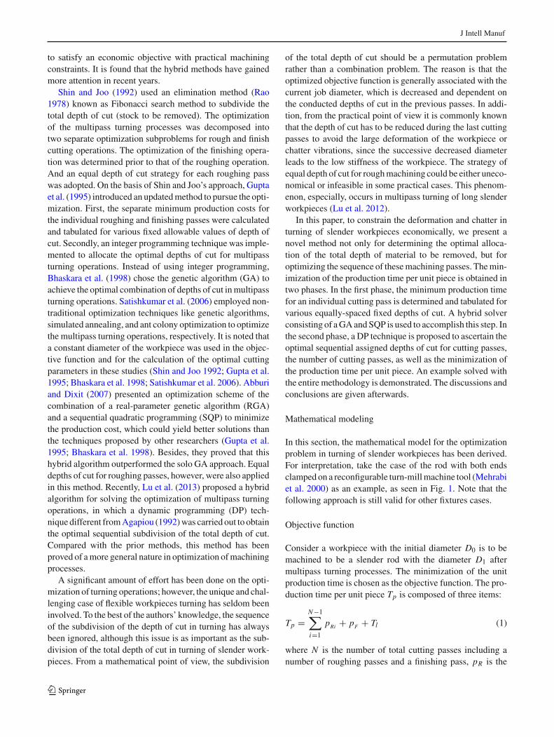
In this section, the mathematical model for the optimizationproblem in turning of slender workpieces has been derived.For interpretation, take the case of the rod with both endsclamped on a reconfigurable turn-mill machine tool (Mehrabiet al. 2000) as an example, as seen in Fig. 1. Note that thefollowing approach is still valid for other fixtures cases.
Objective function
Consider a workpiece with the initial diameter D0 is to bemachined to be a slender rod with the diameter D1 aftermultipass turning processes. The minimization of the unitproduction time is chosen as the objective function. The pro-duction time per unit piece Tp is composed of three items:
Tp =N−1∑
i=1
pRi + pF + Tl (1)
where N is the number of total cutting passes including anumber of roughing passes and a finishing pass, pR is the
123
J Intell Manuf
X
Z
YX
vTool
fChuck Chuck
X - Y
Yv
δd
taF
taFraF
raF
Fig. 1 Deflection-dependent cutting force model
production time for a single roughing pass, pF is the pro-duction time for the finishing pass, and Tl is the loading andunloading job time. The subscripts of “R” and “F” refer tothe rough and finish machining, respectively.
For an individual roughing pass the production time pR
can be expressed as
pR = π L D
1000v f
(1 + tc
TR
)+ ts (2)
where L is the rod length, D is the rod diameter at the begin-ning of that pass, v is the cutting speed, f is the feedrate, tcis the time for tool replacement, TR is the tool life for roughmachining, and ts is the tool setting time per pass.
Similarly, the production time for the finish machining pF
can be expressed as
pF = π L D
1000v f
(1 + tc
TF
)+ ts (3)
where TF is the tool life for finish machining.The tool life can be estimated by Taylor’s tool life equation
T = C
vm f qds(4)
where d is the depth of cut, and C, m, q, s are constants.
Constraints
In the formulated optimization problem, five decision vari-ables are considered: the subdivisions of the depth of cut d,cutting speed v, feedrate f , the number of cutting passesN , and the sequence of cutting passes. These variables aresubject to the constraints as below.
Tolerance constraint
To constrain the deflection of the tool or workpiece, a con-stant maximum cutting force is usually defined in most prior
research works. However, it seems unreliable to transplantsuch an approach to our case. This is because it is reason-able to assume that the slender job is the only flexible partcompared to the tool and the job stiffness changes duringmachining. Cylindricity tolerance is considered to limit thedeflection of the workpiece in this study. Furthermore, a sci-entific constraint condition herein is deduced.
Initially, the deflection-dependent cutting force expres-sions are formulated. The tangential cutting force Ft is mod-eled by the empirical equation
Ft = K f αdβ (5)
where K , α, and β are constant coefficients. The radial cut-ting force Fr is usually estimated as (Drozda and Wick 1983)
Fr = Ft/3 (6)
Due to the deformation of the workpiece in turning, the actualdepth of cut equals d0 = d − δ, as shown in Fig. 1. Note thatthe depth variation, caused by the tangential cutting force,can be neglected in comparison with the deformation δ in theradial direction induced by the radial cutting force. By usingEqs. (5) and (6), the actual radial cutting force Fra reads
Fra = K f α(d − δ)β/3 (7)
Expanding in Taylor series at d and retaining the first orderterm, we obtain
Fra = Ft (1 − βδ/d)/3 (8)
Secondly, the maximum deflection equation of the workpieceis investigated. References (Lee et al. 1988; Katz et al. 1988)have proven that an Euler-Bernoulli beam model, withoutconsidering the dynamic effects of the shear deformation androtational speed, is adequate to calculate the response of theslender workpiece in conventional turning processes. Thusthe maximum deflection δ which occurs at the midpoint ofthe rod has
δ = Fra L3
192E I(9)
where E is the Young’s modulus of the workpiece, I =π D4/64 is the area moment of inertia for a round work crosssection.
Finally, substituting Eq. (8) into Eq. (9) and consideringthe limitation of cylindricity tolerance yields the toleranceconstraint
δ = 0.3333Ft L3
192E I + 0.3333Ft L3β/d≤ δmax (10)
Chatter-free constraint
Chatter is another hindrance in turning processes of slenderlong workpieces. Regenerative effect, referring to the cutting
123
J Intell Manuf
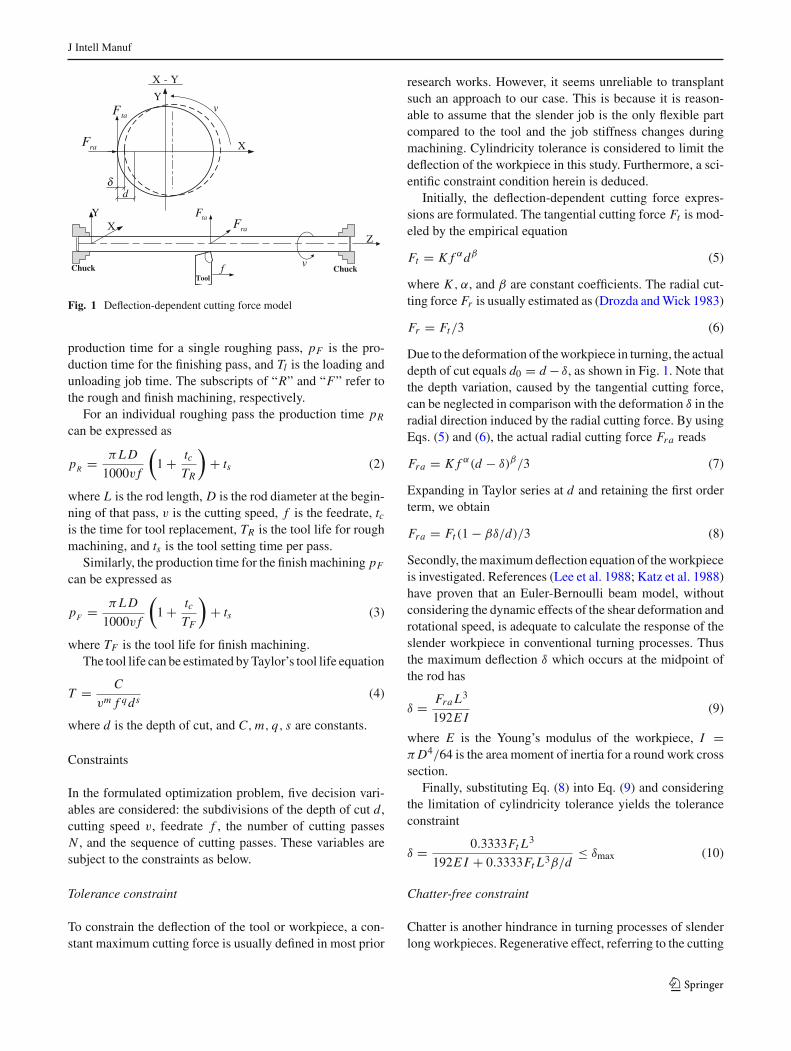
Fig. 2 Typical stability lobes of the chatter system
force variation due to the dynamic chip thickness formed byregeneration of waviness on both sides of the chip surface,is the most commonly accepted mechanism of this phenom-enon. Regard the flexible workpiece as a single degree of free-dom system, the corresponding mathematical chatter modelis a delayed differential equation (DDE),
x(t) + 2ωnζ x(t) + ω2n x(t) = ω2
n K f d
ke[μx(t − Td) − x(t)]
(11)
where ke, ζ, ωn are the equivalent modal parameters of theworkpiece, Td = 60π D/v is the time delay, μ is the overlapfactor (Stepan 2001), and K f is a constant coefficient relatedto cutting conditions.
Investigating the DDE by the use of the Laplace transformor control theory (Altintas and Weck 2004; Siddhpura andPaurobally 2012), one can attain the corresponding stabilitychart expressions as follows,
v = 0.06ωπ D2iπ+θ
i = 0, 1, 2, . . .
d = − 2ζωkek f μωn sin θ
⎫⎬
⎭ (12)
where θ = sin−1 2ζωnω
μ√
(2ζωnω)2+(ω2n−ω2)2
− cos−1 ω2n−ω2√
(2ζωnω)2+(ω2n−ω2)2
, ω is the chatter frequency.
Based on the expressions, the stability lobes of the cuttingsystem can be drawn, as shown in Fig. 2. Bellow the boundarycurves, the cutting operation is stable; above them, chatterarises. The minimum value of the depth of cut can be foundfor some critical cutting speeds, and is the same for eachlobe. Accordingly, the chatter-free condition for turning ofslender workpieces reads
d ≤ dmax (13)
Other physical constraints
Other machining constraints are listed as follows,Tool life constraint:
Tmin ≤ T ≤ Tmax (14)
Machine power constraint:
K f αR dβ
RvR
6 × 10⁴η≤ Pmax
K f αF dβ
FvF
6 × 10⁴η≤ Pmax (15)
where K , α, β are cutting coefficients, and η is the machinetool transmission efficiency.
Geometric relation:
N−1∑
i=1
2dRi + 2dF = D0 − D1 (16)
Machining parameters bounds:
vmin ≤ vR , vF ≤ vmax
fmin ≤ fR , fF ≤ fmax
dmin ≤ dR , dF (17)
Surface roughness constraint for finishing:
f 2F
8Rt≤ Rmax (18)
where Rt is the nose radius of the tool.Variable type:
N is an integer. (19)
Proposed methodology
In the multipass turning processes, decisions on whatmachining parameters should be selected have to be madewith each different cutting pass. The DP technique, makinguse of the concept of suboptimization and Bellman’s princi-ple of optimality, is a suitable technique for solving problemsin which decisions are to be made at multiple stages (Bellman1957). This technique is an implicit enumeration approachthat can formulate a recursive procedure to reduce thecomputational effort. It breaks down the original multistageoptimization problem into subproblems that also exhibit opti-mal properties and then solves these subproblems sequen-tially and recursively. The principle of optimality describesthe phenomenon that enables problems to be viewed as asequence of succession of decision problems, each one build-ing on the last, until the problem is solved. It states that anoptimal policy (or a set of decisions) has the property that
123
J Intell Manuf
Start
2
1
2
j
2
11
2
End
1
jjj
1 2 N-1 N
p1
(1,0)
0
p2
(1,0)
pj
(1,0)
p1
(2,1) p1
(N,1)
pj
(2, j ) pj( N, j )
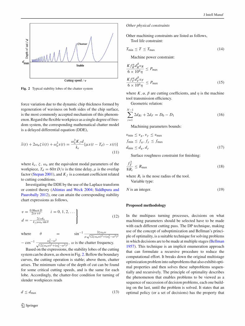
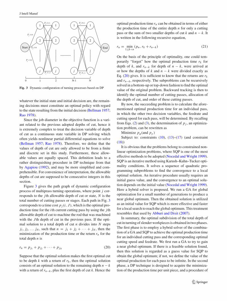
Fig. 3 Dynamic configuration of turning processes based on DP
whatever the initial state and initial decision are, the remain-ing decisions must constitute an optimal policy with regardto the state resulting from the initial decision (Bellman 1957;Rao 1978).
Since the job diameter in the objective function is a vari-ant related to the previous adopted depths of cut, hence itis extremely complex to treat the decision variable of depthof cut as a continuous state variable in DP solving whichoften yields nonlinear partial differential equations to solve(Bellman 1957; Rao 1978). Therefore, we define that thevalues of depth of cut are only allowed to be from a finiteand discrete set in this study. Furthermore, these allow-able values are equally spaced. This definition leads to arather distinguishing procedure in DP technique from thatby Agapiou (1992), and may be more simplified and com-prehensible. For convenience of interpretation, the allowabledepths of cut are supposed to be consecutive integers in thissection.
Figure 3 gives the path graph of dynamic configurationprocess of multiprass turning operations, where point j cor-responds to the j th allowable depth of cut or state, N is thetotal number of cutting passes or stages. Each path in Fig. 3corresponds to a time cost p j (i, J ), which is the optimal pro-duction time for the i th current cutting pass by using the j thallowable depth of cut to machine the rod that was machinedwith the J th depth of cut in the previous pass. If the opti-mal solution to a total depth of cut n divides into N stepsj1, j2, . . . jN , such that n = j1 + j2 + · · · + jN , then theminimization of the production time or the return rn for thetotal depth n is
rn = p j1 + p j2 + · · · + p jN (20)
Suppose that the optimal solution makes the first optimal cutto be depth k with a return of rk , then the optimal solutionconsists of an optimal solution to the remaining depth n − kwith a return of rn−k , plus the first depth of cut k. Hence the
optimal production time rn can be obtained in terms of eitherthe production time of the entire depth n for only a cuttingpass or the sum of two smaller depths of cut k and n − k. Itis written in the following recursive equation,
rn = min1≤k<n
(pn, rk + rn−k) (21)
On the basis of the principle of optimality, one could tem-porarily “forget” how the optimal production time rk fordepth of k, and rn−k for depth of n − k, were arrived ator how the depths of k and n − k were divided exactly asEq. (20) gives. It is sufficient to know that the returns are rk
and rn−k , respectively. The subproblems can be recursivelysolved in a bottom-up or top-down fashion to find the optimalvalue of the original problem. Backward tracking is then toidentify the optimal number of cutting passes, allocation ofthe depth of cut, and order of these cutting passes.
By now, the succeeding problem is to calculate the afore-mentioned optimal production time for an individual pass,in which the other two decision variables, the feedrate andcutting speed for each pass, will be determined. By recallingfrom Eqs. (2) and (3), the determination of p j , an optimiza-tion problem, can be rewritten as
Minimize pR (and pF )
Subject to: constraints (10), (13)–(17) (and constraint(18))
It is obvious that the problems belong to constrained non-linear optimization problems, where SQP is one of the mosteffective methods to be adopted (Nocedal and Wright 1999).SQP is an iterative method using Karush–Kuhn–Tucker opti-mality conditions. It solves a sequence of quadratic pro-gramming subproblems to find the convergence to a localoptimal solution. An iterative procedure usually requires aninitial guess value, and the convergence to an optimal solu-tion depends on the initial value (Nocedal and Wright 1999).Here a hybrid solver is proposed. We run a GA for globaloptimization for a small number of generations to produce anear global optimum. Then the obtained solution is utilizedas an initial value for SQP which is more effective and fasterfor a local search to reach the global optimum. This treatmentresembles that used by Abburi and Dixit (2007).
In summary, the optimal subdivision of the total depth ofcut in turning of slender workpieces is obtained in two phases.The first phase is to employ a hybrid solver of the combina-tion of a GA and SQP to achieve the optimal production timefor an individual cutting pass and the corresponding optimalcutting speed and feedrate. We first run a GA to try to gaina near global optimum. If there is a feasible solution found,then this solution is regarded as a guess value for SQP toobtain the global optimum; if not, we define the value of theoptimal production for each pass to be infinite. In the secondphase, a DP technique is designed to acquire the minimiza-tion of the production time per unit piece, and a procedure of
123
J Intell Manuf
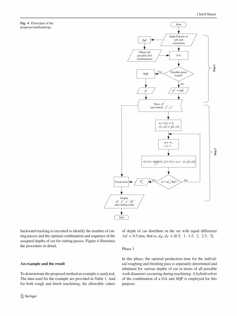
Fig. 4 Flowchart of theproposed methodology
Start
Input Params of job and
constraints
GA
Feasible point found?
SQP
Store and related
?Track back
Output
and cutting order
End
dΔ
Obtain all possible D/d combinations
No
Yes
*p * infp =
* *,f v
*p
1; 1;(:, ) (:, )
n ir n p n
= ==
;ni
+ ++ +
( , ) min[ ( , ) ( , ), ( , )]j n
r i n r i j r i j n j p i n<
= + + −
tn d d= ΔYes No*pT
* * * *, , ,d f v N
pet S2
Step
1
backward tracking is executed to identify the number of cut-ting passes and the optimal combination and sequence of theassigned depths of cut for cutting passes. Figure 4 illustratesthe procedure in detail.
An example and the result
To demonstrate the proposed method an example is analyzed.The data used for the example are provided in Table 1. Andfor both rough and finish machining, the allowable values
of depth of cut distribute in the set with equal differenced = 0.5 mm, that is, dR, dF ∈ [0.5, 1, 1.5, 2, 2.5, 3].
Phase 1
In this phase, the optimal production time for the individ-ual roughing and finishing pass is separately determined andtabulated for various depths of cut in terms of all possiblework diameters occurring during machining. A hybrid solverof the combination of a GA and SQP is employed for thispurpose.
123

J Intell Manuf
Table 1 Experimental dataD0 = 30 mm D1 = 20 mm vmax = 500 m/min vmin = 50 m/min
fmax = 0.9 mm/rev fmin = 0.1 mm/rev dmax = 3 mm dmin = 0.2 mm
Pmax = 10 kW Tmax = 45 min Tmin = 25 min Rt = 0.8 mm
ts = 0.545 min/pass α = 0.75 β = 0.95 η = 0.8
tc = 1.5 min/edge m = 5 q = 1.75 s = 0.75
δmax = 23 μm Rmax = 10 μm C = 6 × 10¹¹ K = 3, 240 N/mmα + β
Tl = 0.75 min/piece L = 350 mm E = 2.06 × 10⁵ MPa
Table 2 Optimal productiontime per cutting pass p(i, j)(min) for various combinationsof the allowable depths of cutand the initial rod diameters(Matrix D − d)
D(i) (mm) d( j) (mm)
0.5 1 1.5 2 2.5 3
30 0.8283 0.9016 1.0776 1.252 1.4252 1.5974
29 0.8188 0.9327 1.1241 1.3136 1.5019 1.6892
28 0.8094 0.9678 1.1764 1.3831 1.5885 1.7927
27 0.7999 1.0075 1.2357 1.4618 1.6864 1.9098
26 0.7985 1.0526 1.3031 1.5512 1.7977 /
25 0.8243 1.1042 1.3801 1.6535 / /
24 0.8539 1.1634 1.4685 / / /
23 0.888 1.2318 1.5708 / / /
22 0.9278 1.3114 / / / /
21 0.9974 / / / / /
The diameter of the rod before a cutting pass happening istime-variant during turning processes, so the matching rela-tion of the rod diameter D and depth of cut d should be a2-dimensional matrix. This is distinct from the one providedby Gupta et al. (1995). Since both the common difference andthe smallest value of the allowed depths of cut are 0.5 mmand the total depth to be removed is 5 mm, thus all possiblediameters locate at the range from 30 to 21 mm at interval1 mm. In the present study, starting with a stochastic popula-tion and the initial population size of 50, the GA is run at mostup to 150 generations until one of the terminating conditionsis satisfied. A feasible point is found if the improvement inthe fitness value is less than 10−6 for 50 consecutive gener-ations, then this solution as an initial estimate is input to aSQP algorithm for more efficient search computation. Theresults of the optimal production time for a single cuttingpass p(i, j) for various depths of cut are given in Table 2,in which i indicates the i th rod diameter at the beginningof a machining pass, i = 1, 2, . . . 10; j indicates correspon-dence to the j th allowable depth of cut, j = 1, 2, . . . 6. Itis noted that the corresponding optimal cutting speed v∗ andfeedrate f ∗ are also obtained in this phase. Also, no whatorder the workpiece is machined in, the final cutting pass,i.e., the finishing pass, only possibly exists in one of the con-ditions in bold as shown in Table 2. Hence the optimizationproblem under these conditions should be imposed by thesurface roughness constraint except for all the constraintsfor the rough machining.
The symbol “/” in Table 2 indicates there is no feasi-ble solution found in that the corresponding practical con-straints are violated. The corresponding p(i, j) in such caseis defined to be infinite. Take p(6, 5) as an example, it is easyto verify by using Eq. (10) that the workpiece with the initialdiameter 25 mm, machined at depth of cut 2.5 mm, constantlysuffers from exceeding deflection at any given feedrate. Itindicates that the larger depths of cut could be automaticallyexcluded from the candidates of the allowable depths of cutwhen the job diameter is reduced to a certain extent. Thisconclusion is in agreement with the empirical experience,and the approach by Hinduja et al. (1985) that the depth ofcut and feedrate in the finishing pass are artificially confinedin smaller ranges than those in roughing passes.
From Table 2, it can be proved that the sequence of cuttingpasses usually affects the value of the objective function inturning processes. Regarding this example, if the sequenceof depths of cut, first 2.5 mm then 1 mm and finally 1.5 mm,is performed, the total production time without consideringthe loading and unloading job time Tl is p(1, 5) + p(6, 2) +p(8, 3), that is, 4.1001 min. Reversing the last two depths ofcut, we can get the result is p(1, 5)+ p(6, 3)+ p(9, 2) equalto 4.1167 min. Whereas the policy exchanging the first depthof cut with the last one is completely infeasible. The reasonhas been explained above.
Although it is possible that the given optimization prob-lem can almost be solved by simply enumerating all possiblecombinations of the solutions in Table 2 and examining which
123
J Intell Manuf
Table 3 Optimal production time per unit piece r(i, k) (min) without Tl for various combinations of the total stocks and the initial rod diameters
D(i)(mm) dt (k)(mm)
0.5 1 1.5 2 2.5 3 3.5 4 4.5 5
30 0.8283 0.9016 1.0776 1.252 1.4252 1.5974 2.4513 2.6943 2.9874 3.9848
29 0.8188 0.9327 1.1241 1.3136 1.5019 1.6892 2.5772 2.8425 3.26 /
28 0.8094 0.9678 1.1764 1.3831 1.5885 1.7927 2.7191 3.1041 / /
27 0.7999 1.0075 1.2357 1.4618 1.6864 1.9098 2.9072 / / /
26 0.7985 1.0526 1.3031 1.5512 1.7977 2.7952 / / / /
25 0.8243 1.1042 1.3801 1.6535 2.6509 / / / / /
24 0.8539 1.1634 1.4685 2.4246 / / / / / /
23 0.888 1.2318 1.5708 / / / / / / /
22 0.9278 1.3114 / / / / / / / /
21 0.9974 / / / / / / / / /
Table 4 Optimal subdivisions for various combinations of the total stocks and the initial rod diameters
D(i) (mm) dt (k) (mm)
0.5 1 1.5 2 2.5 3 3.5 4 4.5 5
30 p(1,1) p(1,2) p(1,3) p(1,4) p(1,5) p(1,6) r (1,6) + r (7,1) r (1,2) + r (3,6) r (1,3) + r (4,6) r (1,3) + r (4,7)
29 p(2,1) p(2,2) p(2,3) p(2,4) p(2,5) p(2,6) r (2,6) + r (8,1) r (2,2) + r (4,6) r (2,6) + r (8,3) /
28 p(3,1) p(3,2) p(3,3) p(3,4) p(3,5) p(3,6) r (3,1) + r (4,6) r (3,6) + r (9,2) / /
27 p(4,1) p(4,2) p(4,3) p(4,4) p(4,5) p(4,6) r (4,6) + r (10,1) / / /
26 p(5,1) p(5,2) p(5,3) p(5,4) p(5,5) r (5,5) + r (10,1) / / / /
25 p(6,1) p(6,2) p(6,3) p(6,4) r (6,4) + r (10,1) / / / / /
24 p(7,1) p(7,2) p(7,3) r (7,1) + r (8,3) / / / / / /
23 p(8,1) p(8,2) p(8,3) / / / / / / /
22 p(9,1) / / / / / / / /
21 p(10,1) / / / / / / / / /
one is the best, this process always results in an exponen-tial run time and hence is not feasible. A more proceduralapproach to reducing the computation is given in the follow-ing phase.
Phase 2
In this phase, the optimal sequential subdivision of the totaldepth of cut is determined by a DP technique, along withthe minimization of the production time per unit piece. Byconsidering the recursive formula (21), it can be seen thatthe subproblems are overlapping. Here a bottom-up fashionis chosen to solve the problem: first we solve smaller totalstock subproblems and store the corresponding depth divi-sion information; then, these solutions are used to constructthe solutions to the bigger total depths of cut subproblems;finally the division information is invoked to trace the opti-mal cutting sequence. This procedure enables to diminish therun time from exponential to polynomial.
To achieve the solution to the given total stock of 5 mm inthis example, the smaller total depths of cut, ranging from 0.5to 4.5 mm at interval of the common difference of 0.5 mm,should be obtained in succession initially. Table 3 gives theoptimal production time per unit piece r(i, k) without Tl forvarious total depths of cut, in which k implies the correspon-dence to the kth smaller total depth of cut, k = 1, 2, . . . 10;i is the same as above. The value of 3.9848 in bold is theoptimal production time without Tl for this example. Afteradding Tl equal to 0.75 min, the optimal production time perpiece T ∗
p equals 4.7348 min.The assignment information of the total depth of cut is
shown in Table 4, in which p(i, k) means no further subdivi-sion took place, that is, r(i, k) = p(i, k). For the given opti-mization problem, the subdivision information correspond-ing to the combination of the initial diameter 30 mm and thetotal stock 5 mm reads as r(1, 3)+ r(4, 7), representing firstthe depth of cut 1.5 mm should be cut and then 3.5 mm. Sincer(1, 3) is equal to p(1, 3), so the pass with the depth of cut1.5 mm will be regarded as a member of the optimal cutting
123
J Intell Manuf
Table 5 Optimal machining conditions for turning of the slender rod
Cutting order d∗ (mm) v∗ (m/min) f ∗ (mm/rev) p∗ (min)
1 1.5 149.5423 0.4390 1.0776
2 3 223.8579 0.1030 1.9098
3 0.5 213.8530 0.2530 0.9974
passes. The depth of 3.5 mm obviously needs to be furtherdivided. By the use of backward tracking, the subdivisioninformation on r(4, 7) gives r(4, 6) + r(10, 1), representingthe depth of cut 3 mm should be cut first and then 0.5 mm. Itis observed that both of the two smaller depths of cut do notrequire further division. So far, three depths of cut, in boldin Table 4, are found, and the tracking process terminates.Finally, the optimal sequence of the cutting passes can bedetermined by sorting the related job diameter in descendingorder. Accordingly, the optimal number of passes is 3. Theoptimal assignment strategy is that the depths of cut for thefirst two roughing passes are 1.5 and 3 mm, respectively, andthe depth of cut for finishing pass is 0.5 mm. In brief, thesolution to the original problem is summarized in Table 5.
Discussions
Partition of the restrained interval of depth of cut
In the previous example, the allowable depths of cut are cho-sen as [0.5, 1, 1.5, . . . 3] mm. Here other two partitions ofthe restrained interval of depth of cut are also adopted forcalculating on an Intel Core i5 computer. The results arecompared in Table 6. It can be seen that with finer partitionof the interval, the more near optimal value can be reached.Correspondingly, the running time is increased dramatically,which is attributed to “the curse of dimensionality” of the DPtechnique (Bellman 1957; Rao 1978), as well as the increasednumerical computation in the first phase. This limitation iseased promisingly with the improvement of computer per-formance.
Inclusion relation
To solve the given problem, a DP technique in bottom-uprecursion is carried out to optimize the allocation of the totalstock, following a hybrid solver for acquiring the minimum
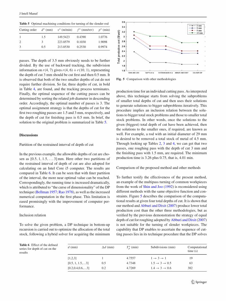
Fig. 5 Comparison with other methodologies
production time for an individual cutting pass. As interpretedabove, this technique starts from solving the subproblemsof smaller total depths of cut and then uses their solutionsto generate solutions to bigger subproblems iteratively. Thisprocedure implies an inclusion relation between the solu-tions to bigger total stock problems and those to smaller totalstock problems. In other words, once the solutions to thegiven (biggest) total depth of cut have been achieved, thenthe solutions to the smaller ones, if required, are known aswell. For example, a rod with an initial diameter of 29 mmis desired to be removed a total stock of metal of 4.5 mm.Through looking up Tables 2, 3 and 4, we can get that twopasses, one roughing pass with the depth of cut 3 mm andthe finishing pass with 1.5 mm, are required. The minimumproduction time is 3.26 plus 0.75, that is, 4.01 min.
Comparison of the proposed method and other methods
To further testify the effectiveness of the present method,an example of the multipass turning of common workpiecesfrom the work of Shin and Joo (1992) is reconsidered usingdifferent methods with the same objective function and con-straints. Figure 5 describes the comparison of the computa-tional results at given four total depths of cut. It is shown thatour method and Abburi and Dixit (2007) produce lower totalproduction cost than the other three methodologies, but asverified by the previous demonstration the strategy of equaldepth of cut for roughing adopted by Abburi and Dixit (2007)is not suitable for the turning of slender workpieces. Thecapability that DP enables to ascertain the sequence of cut-ting passes lies in its technique procedure that the DP solves
Table 6 Effect of the definedseries for depth of cut on theresults
d (mm) d (mm) T ∗p (min) Subdivisions (mm) Computational
time (s)
[1,2,3] 1 4.7557 1 → 3 → 1 19
[0.5, 1, 1.5,…3] 0.5 4.7348 1.5 → 3 → 0.5 63
[0.2,0.4,0.6,…3] 0.2 4.7269 1.4 → 3 → 0.6 382
123
J Intell Manuf
turning process optimization problems at multiple stages orrecursively. Comparatively, the presented methodology inthis paper is of a more general nature.
Conclusions
In order to maximize the machining efficiency and guar-antee the product quality in turning of flexible workpieces,we introduce an effective hybrid method for optimizing thesequence of cutting passes and the machining parameters inturning of a slender rod. The mathematical model is estab-lished, in which the deformation and chatter constraints areintensively deduced. The optimization problem is solved intwo phases. The first phase is to determine the minimumproduction time per cutting pass corresponding to all feasi-ble work diameters for various equally spaced depths of cut.The method of the combination of GA and SQP techniquesis utilized. In the second phase, a DP technique is proposedto ascertain the optimal sequential subdivision of the totaldepth of cut and the minimization of the production time perunit piece. It has been proved that the sequence of machiningpasses generally has an effect on the result of the optimiza-tion, and with finer partition of the restrained interval of depthof cut, the more near optimal value of the objective functioncan be achieved. For other machining processes the proposedmethod in this study still holds.
Acknowledgments The first author is a visiting scholar at WilkesUniversity, which has been sponsored by the China Scholarship Council.This work has been supported by the National Key Technologies R&DProgram under Grant No. 2012ZX04001-012. The authors also thankMr. K. Topfer for his kind help.
References
Abburi, N. R., & Dixit, U. S. (2007). Multi-objective optimizationof multipass turning processes. International Journal of AdvancedManufacturing Technology, 32(9–10), 902–910.
Agapiou, J. S. (1992). The optimization of machining operations basedon a combined criterion, part 2: Multipass operations. Journal ofEngineering for Industry, 114(4), 508–513.
Altintas, Y., & Weck, M. (2004). Chatter stability of metal cutting andgrinding. CIRP Annals-Manufacturing Technology, 53(2), 619–642.
Bellman, R. (1957). Dynamic programming. Princeton: Princeton Uni-versity Press.
Bhaskara, S. V., Shunmugam, M. S., & Narendran, T. T. (1998). Optimalsubdivision of depth of cut to achieve minimum production cost inmulti-pass turning using a genetic algorithm. Journal of MaterialsProcessing Technology, 79(1), 101–108.
Chandrasekaran, M., Muralidhar, M., Murali, K. C., & Dixit, U. S.(2010). Application of soft computing techniques in machining per-formance prediction and optimization: A literature review. Inter-national Journal of Advanced Manufacturing Technology, 46(5–8),445–464.
Chen, M. C., & Tsai, D. M. (1996). A simulated annealing approach foroptimization of multi-pass turning operations. International Journalof Production Research, 34(10), 2803–2825.
Costa, A., Celano, G., & Fichera, S. (2011). Optimization of multi-pass turning economies through a hybrid particle swarm optimiza-tion technique. International Journal of Advanced ManufacturingTechnology, 53(5–8), 421–433.
Drozda, T. J., & Wick, C. (1983). Tool and manufacturing engineershandbook, Vol. 1-Machining. Dearborn: Society of ManufacturingEngineers.
Gupta, R., Batra, J. L., & Lal, G. K. (1995). Determination of optimalsubdivision of depth of cut in multi-pass turning with constraints.International Journal of Production Research, 33(9), 2555–2565.
Hinduja, S., Petty, D. J., Tester, M., & Barrow, G. (1985). Calculationof optimum cutting conditions for turning operations. Proceedingsof the Institution of Mechanical Engineers, Part B: Journal of Engi-neering Manufacture, 199(2), 81–92.
Katz, R., Lee, C. W., Ulsoy, A. G., & Scott, R. (1988). The dynamicresponse of a rotating shaft subject to a moving load. Journal ofSound and Vibration, 122(1), 131–148.
Lee, C. W., Katz, R., Ulsoy, A. G., & Scott, R. (1988). Modal analy-sis of a distributed parameter rotating shaft. Journal of Sound andVibration, 122(1), 119–130.
Liang, S. Y., Hecker, R. L., & Landers, R. G. (2004). Machining processmonitoring and control: The state-of-the-art. Journal of Manufactur-ing Science and Engineering, 126(2), 297–310.
Lu, K. B., Jing, M. Q., Liu, H., & Zhang, X. (2012). A reconfigurablesystem of chatter stability evaluation and monitoring for industrialmachining processes. International Journal of Mechatronics andAutomation, 2(4), 277–285.
Lu, K. B., Jing, M. Q., Zhang, X., & Liu, H. (2013). Optimization ofsequential subdivision of depth of cut in turning operations usingdynamic programming. International Journal of Advanced Manu-facturing Technology, 68(5–8), 1733–1744.
Mehrabi, M. G., Ulsoy, A. G., & Koren, Y. (2000). Reconfigurable man-ufacturing systems: Key to future manufacturing. Journal of Intelli-gent Manufacturing, 11, 403–419.
Mukherjee, I., & Ray, P. K. (2006). A review of optimization techniquesin metal cutting processes. Computers & Industrial Engineering,50(1–2), 15–34.
Nocedal, J., & Wright, S. J. (1999). Numerical optimization. New York:Springer.
Rao, S. S. (1978). Optimization: Theory and applications. New York:Wiley.
Satishkumar, S., Asokan, P., & Kumanan, S. (2006). Optimization ofdepth of cut in multi-pass turning using nontraditional optimizationtechniques. International Journal of Advanced Manufacturing Tech-nology, 29(3–4), 230–238.
Shin, Y. C., & Joo, Y. S. (1992). Optimization of machining condi-tions with practical constraints. International Journal of ProductionResearch, 30(12), 2907–2919.
Siddhpura, M., & Paurobally, R. (2012). A review of chatter vibra-tion research in turning. International Journal of Machine Tools andManufacture, 61, 27–47.
Stepan, G. (2001). Modelling nonlinear regenerative effects in metalcutting. Philosophical Transactions: Mathematical, Physical andEngineering Sciences, 359(1781), 739–757.
Wang, Y. C. (2007). A note on ‘Optimization of multi-pass turning oper-ations using ant colony system’. International Journal of MachineTools & Manufacture, 47(12–13), 2057–2059.
Yildiz, A. R. (2013). Hybrid Taguchi-differential evolution algorithmfor optimization of multi-pass turning operations. Applied Soft Com-puting, 13(3), 1433–1439.
Zhang, J. Y., Liang, S., Yao, J., Chen, J. M., & Huang, J. L. (2006). Evo-lutionary optimization of machining processes. Journal of IntelligentManufacturing, 17, 203–215.
123