An automatic service for the personalization of ventricular
9
rsif.royalsocietypublishing.org Research Cite this article: Lamata P et al. 2014 An automatic service for the personalization of ventricular cardiac meshes. J. R. Soc. Interface 11: 20131023. http://dx.doi.org/10.1098/rsif.2013.1023 Received: 5 November 2013 Accepted: 18 November 2013 Subject Areas: biomechanics, biomedical engineering, biometrics Keywords: computational physiology, cardiac modelling, computational mesh Author for correspondence: Pablo Lamata e-mail: [email protected] An automatic service for the personalization of ventricular cardiac meshes Pablo Lamata 1,2 , Matthew Sinclair 1 , Eric Kerfoot 1 , Angela Lee 1 , Andrew Crozier 1 , Bojan Blazevic 1 , Sander Land 1 , Adam J. Lewandowski 3 , David Barber 4 , Steve Niederer 1 and Nic Smith 1 1 Department of Biomedical Engineering, King’s College of London, St Thomas’ Hospital, London SE1 7EH, UK 2 Department of Computer Science, University of Oxford, Oxford OX1 3QD, UK 3 Division of Cardiovascular Medicine, Radcliffe Department of Medicine, University of Oxford, Oxford OX3 9DU, UK 4 Department of Cardiovascular Science, University of Sheffield, Royal Hallamshire Hospital, Sheffield S10 2JF, UK Computational cardiac physiology has great potential to improve the man- agement of cardiovascular diseases. One of the main bottlenecks in this field is the customization of the computational model to the anatomical and physiological status of the patient. We present a fully automatic service for the geometrical personalization of cardiac ventricular meshes with high- order interpolation from segmented images. The method is versatile (able to work with different species and disease conditions) and robust (fully auto- matic results fulfilling accuracy and quality requirements in 87% of 255 cases). Results also illustrate the capability to minimize the impact of seg- mentation errors, to overcome the sparse resolution of dynamic studies and to remove the sometimes unnecessary anatomical detail of papillary and trabecular structures. The smooth meshes produced can be used to simulate cardiac function, and in particular mechanics, or can be used as diagnostic descriptors of anatomical shape by cardiologists. This fully auto- matic service is deployed in a cloud infrastructure, and has been made available and accessible to the scientific community. 1. Introduction The field of computational physiology has progressively accelerated over the last four decades. Its importance is particularly significant for modelling the elec- tromechanical function of the heart [1,2], as an aid to clinicians in stratifying disease through novel indices [3], in the design of mechanical reinforcement of infarct regions [4], in predicting cardiac outcomes [5] and also in patient selection for procedures such as cardiac resynchronization therapy [5–8]. However, the full clinical translation of these modelling techniques still requires remaining challenges to be addressed. In particular, these include determining the appropri- ate computational complexity of the biophysical models and the need for model personalization. Customization of computational models involves two main aspects: to capture the patient-specific anatomy of interest and to estimate the par- ameters of the constitutive biophysical laws that govern the equations of the model. This article focuses on the geometrical aspect of personalization and on specific high-order interpolation meshes used for mechanical simulations. Computational meshes define a geometric representation of anatomy, pro- viding the domain for solving the mathematical description of physiological processes. They are required to be both geometrically accurate and to provide good numerical stability when used to solve governing equations. For many physiological simulations, the computational domains are described using unstructured linearly interpolated tetrahedral meshes. This is primarily owing to the availability of tools for automatic meshing of complex geometries, such & 2013 The Authors. Published by the Royal Society under the terms of the Creative Commons Attribution License http://creativecommons.org/licenses/by/3.0/, which permits unrestricted use, provided the original author and source are credited.
Transcript of An automatic service for the personalization of ventricular

rsif.royalsocietypublishing.org
ResearchCite this article: Lamata P et al. 2014 An
automatic service for the personalization of
ventricular cardiac meshes. J. R. Soc. Interface
11: 20131023.
http://dx.doi.org/10.1098/rsif.2013.1023
Received: 5 November 2013
Accepted: 18 November 2013
Subject Areas:biomechanics, biomedical engineering,
biometrics
Keywords:computational physiology, cardiac modelling,
computational mesh
Author for correspondence:Pablo Lamata
e-mail: [email protected]
& 2013 The Authors. Published by the Royal Society under the terms of the Creative Commons AttributionLicense http://creativecommons.org/licenses/by/3.0/, which permits unrestricted use, provided the originalauthor and source are credited.
An automatic service for thepersonalization of ventricularcardiac meshes
Pablo Lamata1,2, Matthew Sinclair1, Eric Kerfoot1, Angela Lee1,Andrew Crozier1, Bojan Blazevic1, Sander Land1, Adam J. Lewandowski3,David Barber4, Steve Niederer1 and Nic Smith1
1Department of Biomedical Engineering, King’s College of London, St Thomas’ Hospital, London SE1 7EH, UK2Department of Computer Science, University of Oxford, Oxford OX1 3QD, UK3Division of Cardiovascular Medicine, Radcliffe Department of Medicine, University of Oxford, Oxford OX3 9DU, UK4Department of Cardiovascular Science, University of Sheffield, Royal Hallamshire Hospital, Sheffield S10 2JF, UK
Computational cardiac physiology has great potential to improve the man-
agement of cardiovascular diseases. One of the main bottlenecks in this
field is the customization of the computational model to the anatomical
and physiological status of the patient. We present a fully automatic service
for the geometrical personalization of cardiac ventricular meshes with high-
order interpolation from segmented images. The method is versatile (able to
work with different species and disease conditions) and robust (fully auto-
matic results fulfilling accuracy and quality requirements in 87% of 255
cases). Results also illustrate the capability to minimize the impact of seg-
mentation errors, to overcome the sparse resolution of dynamic studies
and to remove the sometimes unnecessary anatomical detail of papillary
and trabecular structures. The smooth meshes produced can be used to
simulate cardiac function, and in particular mechanics, or can be used as
diagnostic descriptors of anatomical shape by cardiologists. This fully auto-
matic service is deployed in a cloud infrastructure, and has been made
available and accessible to the scientific community.
1. IntroductionThe field of computational physiology has progressively accelerated over the
last four decades. Its importance is particularly significant for modelling the elec-
tromechanical function of the heart [1,2], as an aid to clinicians in stratifying
disease through novel indices [3], in the design of mechanical reinforcement of
infarct regions [4], in predicting cardiac outcomes [5] and also in patient selection
for procedures such as cardiac resynchronization therapy [5–8]. However, the
full clinical translation of these modelling techniques still requires remaining
challenges to be addressed. In particular, these include determining the appropri-
ate computational complexity of the biophysical models and the need for model
personalization. Customization of computational models involves two main
aspects: to capture the patient-specific anatomy of interest and to estimate the par-
ameters of the constitutive biophysical laws that govern the equations of the
model. This article focuses on the geometrical aspect of personalization and on
specific high-order interpolation meshes used for mechanical simulations.
Computational meshes define a geometric representation of anatomy, pro-
viding the domain for solving the mathematical description of physiological
processes. They are required to be both geometrically accurate and to provide
good numerical stability when used to solve governing equations. For many
physiological simulations, the computational domains are described using
unstructured linearly interpolated tetrahedral meshes. This is primarily owing
to the availability of tools for automatic meshing of complex geometries, such

input output
1. binary mask 1. personalized mesh
2. characteristics—accuracy—mesh quality
2. user choices—mesh topology—mesh resolution—basis function—level of detail
1. shapeanalysis 2. registration
warping field
tailoredtemplate
3. meshwarping
4. qualityenhancement
Figure 1. Overview of the mesh customization service. User provides the definition of myocardial domain by a binary image (from any modality), and a set ofchoices depending on his/her specific requirements. The service then performs: (1) a shape analysis to customize an idealized template; (2) an image registration toassess the deformation field between template and provided anatomy; (3) a variational mesh warping to deform the high-order interpolation mesh and (4) apostprocessing linearizing step to enhance the quality of the mesh. (Online version in colour.)
rsif.royalsocietypublishing.orgJ.R.Soc.Interface
11:20131023
2
as TetGen (http://tetgen.org) or Tarantula [9], their relative
simplicity and their well-characterized properties [10]. Never-
theless, linear interpolation schemes in tetrahedral elements
have convergence disadvantages and can introduce significant
numerical errors in calculating solutions for the important class
of incompressible soft tissue deformation simulations [11].
An alternative solution is the use of meshes with high-order
interpolation, such as cubic Hermite and cubic Lagrange
meshes. These schemes provide an efficient representation of
the mechanical state of an organ as well as improved accuracy
[12]. They also enable a much more compact and geometrically
smooth and continuous representation, and thus a reduction
of the computational cost in simulations. For these reasons,
high-order interpolation meshes are a popular choice for the
simulation of cardiac mechanics [3,4,6,8].
There are two broad approaches for the personalization of
geometrical meshes: the direct construction of a mesh from seg-
mented images [13,14] and the customization of a mesh from an
existing mesh model [13,15]. Whereas the literature for linear
meshes is extensive [10], the translation of these techniques to
meshes with higher order of interpolation remains to be fully
developed. Recent advances have solved the integration of
image registration methods by a variational warping technique
[15], have developed a topological solution to represent the
four-chamber cardiac anatomy [16] and have proposed extra-
ordinary vertices in order to represent atrial chambers [14].
However, despite these efforts, no robust and automated tools
are currently available for the personalization of ventricular
meshes with high-order interpolation required for clinical
application or large population analyses. Furthermore, while
stability and convergence of mechanical simulations are depen-
dent on the regularity and quality of mesh elements, there are
currently no mesh generation tools that seek to guarantee
these properties.
This article presents a versatile and fully automatic meshing
solution for cubic Hermite and cubic Lagrange cardiac ven-
tricular meshes maximizing both anatomical accuracy and
simulation stability. The two main methodological contributions
are a robust strategy of template synthesis and alignment in
order to maximize image registration convergence, and a
mesh postprocessing step in order to improve mesh quality.
The method is thoroughly tested with a wide set of cases,
evaluating its versatility, accuracy, quality, robustness and
computational time. All resulting meshes are published, and
the proposed solution is deployed as a web service using
cloud technology, enabling easy access and use by the
scientific community.
2. Material and methodsA binary mask describing the domain of the ventricular anatomy
is the only data required for the mesh personalization, which is
performed with the combination of four main steps: (i) the analy-
sis of the myocardial shape in order to tailor a template mesh,
(ii) a fast and robust binary image registration, (iii) a variational
technique for mesh warping and (iv) a postprocessing step to
improve mesh quality. The result is a cubic interpolation mesh
(in EX format, see FieldML standard [17] and cmGui [18] as a
tool to visualize and convert) fitted to the domain described by
the binary mask.
In the process, the user can choose topology, basis functions
and resolution of the computational mesh, and the balance
between quality and the level of detail (LoD) in which to capture
the anatomy. An overview of the methodology is presented in
figure 1, and the description of its main functional blocks is
provided below.
2.1. Shape analysis for a tailored template meshVentricular anatomy is synthesized with truncated ellipsoids, with
user-defined topology and number of elements in each local
material direction, as illustrated in figure 2. Valve planes are thus
not represented by this topology. Meshes are structured and
have local material coordinates aligned with the main directions
of the left ventricular anatomy (circumferential, longitudinal and
radial), and collapsed elements in the apex.
The anatomical variability of the biventricular (BiV) shape in
humans and other species makes the use of a single template
mesh problematic for embedding within a robust meshing sol-
ution. The strategy adopted here is thus to tailor the template
mesh to a set of measurements from the binary mask used as
input (another approach is the choice of the most similar refer-
ence from a database [20]). This significantly increases the rate
of convergence and accuracy of the subsequent image regis-
tration, and the quality of the resulting mesh, as the initial
regular template is much closer to the final solution.

Figure 2. Examples of template meshes of the LV and the BiV anatomy withdifferent resolutions and dimensions of the right ventricular blood pool.Bottom row highlights in green the squared insertion line of the RV intothe LV (line that joins the ventricular cusps referred in [19]).
2. first characteristicorientation axis
2. basal plane
4. truncation plane3. L
V le
ngth
3. R
V le
ngth
5m
m
1. LV
A B
C
1. RV
1. valve planes:A. mitralB. aorticC. pulmonaryD. tricuspid (not shown)LV main axis
of inertia
Figure 3. Shape analysis of a BiV binary mask, with numbers illustrating itssequential steps. Note how the main axis of inertia of the LV is not alignedwith the perpendicular to the basal plane. (Online version in colour.)
rsif.royalsocietypublishing.orgJ.R.Soc.Interface
11:20131023
3
The geometrical features extracted from the input image are
wall thickness and relative size of the right ventricle (RV) to the
left ventricle (LV). The analysis is done with a combination of
steps (figure 3): (i) identification of the blood pools and valve
planes from the image, (ii) estimation of the spatial orientation
of the heart, (iii) computation of geometrical dimensions of RV
and LV and (iv) an optional truncation of the basal anatomy.
Blood pools and valve planes are identified in the binary
mask by computing the convex hull of the shape and finding
the two main cavities and openings in the shape through a com-
bination of morphological (erosion) operations. Characteristic
axes of the cardiac anatomy are used to define spatial orientation.
The main vertical axis is defined perpendicular to the basal
plane, which is defined as the plane that minimizes the distances
to voxels labelled as part of the valves in the previous step.
The second left-to-right axis is computed as the projection in
the basal plane of the vector joining the centre of mass of LV and
RV. The spatial orientation of the heart is completed by the cross
product of these two main axes. In the case of datasets with a
large distance between slices, for example short axis cine-MRI
acquisition, the first axis is defined by the normal to the image
slice plane. The variance of the points in each of these three
directions leads to the definition of an anisotropic scaling factor.
The size of the RV and LV is computed by the projection of
the shape of the blood cavities into the characteristic axes of
spatial orientation. The variance of the coordinates in the direc-
tion of characteristic axes defines the size of the ellipsoidal
shapes used to synthesize the RV and LV. The length of the RV
defines the insertion level where the apex of the RV attaches to
the LV. Finally, the optional truncation of basal anatomy is
defined at 5 mm below the basal plane.
2.2. Image registration and level of detailThe warping function between the shape of the patient’s anatomy
and a synthesized template is obtained by image registration. This
meshing service uses ShIRT, the Sheffield Image Registration
Toolkit, a robust and efficient registration engine. The initial align-
ment between images is set by the affine transformation defined by
the characteristic orientation axes and scaling factors extracted
from the input image (see previous section).
The details of the underlying image registration algorithm
used in this paper and examples of its use are presented in
[21]. The fitting accuracy and quality (numerical stability) of
the resulting mesh strongly depend on this registration step.
These two qualities are in typically in tension [22], and thus a
parameter named LoD is provided to the user to balance
these two important characteristics. LoD ranges from 1, coarse
and most stable, to 5, accurate but with lowest chances of
stability. The internal parameters that control this choice are
the number of registration passes and the node spacing, the
distance between each pair of adjacent control nodes that
define the set of degrees of freedom in the registration process
(see [21] for further details about this registration parameter).
Thus, LoD 1 to 5 has 1 to 5 registration passes, respectively,
and the node spacing in each pass decreases from 10 to two
voxels, in steps of two voxels.
In many clinical situations, only a few short or long axis slices
are available, most commonly in dynamic studies. The solution
adopted for these cases exploits the versatility of ShIRT to specify
the image domain where the similarity metric is computed.
A nearly isotropic resolution image from the original data is
built, and the registration is only guided by the slices that have
original data (there is thus no need to interpolate these data,
the new voxel locations are filled with null intensity values).
2.3. Mesh warpingOnce the warping function between the template and patient’s
anatomy has been calculated by image registration, the template
mesh is warped using an accurate variational technique. The key
in this step is that a mesh is deformed, not by an independent
and local warping of each of its nodal degrees of freedom, but
by warping the whole domain that these degrees of freedom rep-
resent, the whole continuum. This technique calculates the
projection of the deformation field into the degrees of freedom
(a) (b)
(c) (d)
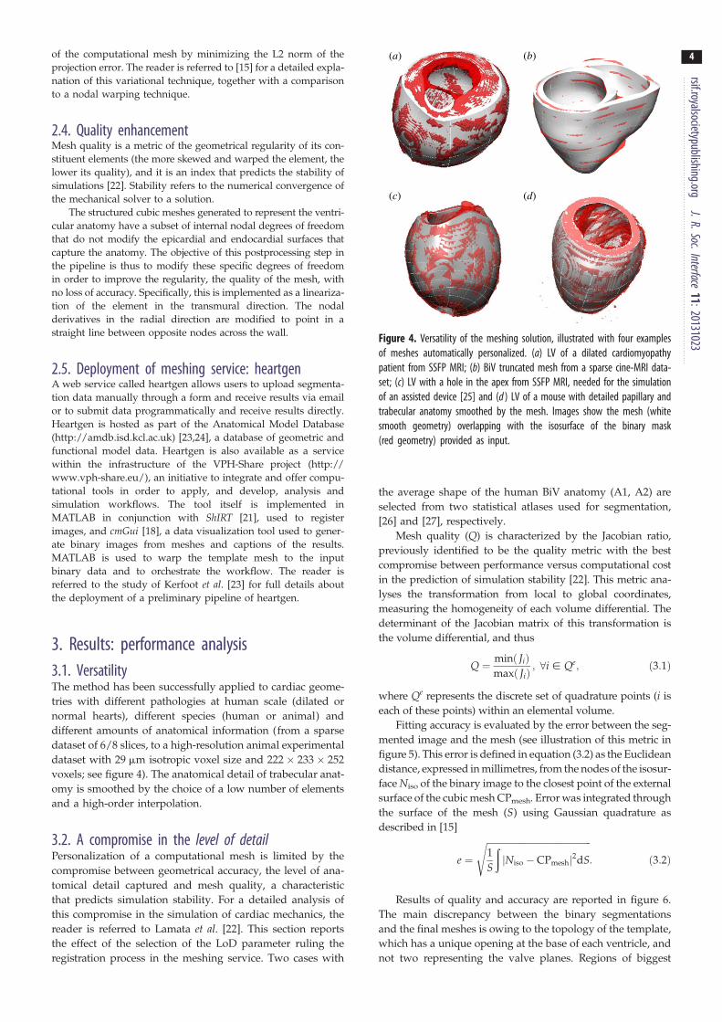
Figure 4. Versatility of the meshing solution, illustrated with four examplesof meshes automatically personalized. (a) LV of a dilated cardiomyopathypatient from SSFP MRI; (b) BiV truncated mesh from a sparse cine-MRI data-set; (c) LV with a hole in the apex from SSFP MRI, needed for the simulationof an assisted device [25] and (d ) LV of a mouse with detailed papillary andtrabecular anatomy smoothed by the mesh. Images show the mesh (whitesmooth geometry) overlapping with the isosurface of the binary mask(red geometry) provided as input.
rsif.royalsocietypublishing.orgJ.R.Soc.Interface
11:20131023
4
of the computational mesh by minimizing the L2 norm of theprojection error. The reader is referred to [15] for a detailed expla-
nation of this variational technique, together with a comparison
to a nodal warping technique.
2.4. Quality enhancementMesh quality is a metric of the geometrical regularity of its con-
stituent elements (the more skewed and warped the element, the
lower its quality), and it is an index that predicts the stability of
simulations [22]. Stability refers to the numerical convergence of
the mechanical solver to a solution.
The structured cubic meshes generated to represent the ventri-
cular anatomy have a subset of internal nodal degrees of freedom
that do not modify the epicardial and endocardial surfaces that
capture the anatomy. The objective of this postprocessing step in
the pipeline is thus to modify these specific degrees of freedom
in order to improve the regularity, the quality of the mesh, with
no loss of accuracy. Specifically, this is implemented as a lineariza-
tion of the element in the transmural direction. The nodal
derivatives in the radial direction are modified to point in a
straight line between opposite nodes across the wall.
2.5. Deployment of meshing service: heartgenA web service called heartgen allows users to upload segmenta-
tion data manually through a form and receive results via email
or to submit data programmatically and receive results directly.
Heartgen is hosted as part of the Anatomical Model Database
(http://amdb.isd.kcl.ac.uk) [23,24], a database of geometric and
functional model data. Heartgen is also available as a service
within the infrastructure of the VPH-Share project (http://
www.vph-share.eu/), an initiative to integrate and offer compu-
tational tools in order to apply, and develop, analysis and
simulation workflows. The tool itself is implemented in
MATLAB in conjunction with ShIRT [21], used to register
images, and cmGui [18], a data visualization tool used to gener-
ate binary images from meshes and captions of the results.
MATLAB is used to warp the template mesh to the input
binary data and to orchestrate the workflow. The reader is
referred to the study of Kerfoot et al. [23] for full details about
the deployment of a preliminary pipeline of heartgen.
3. Results: performance analysis3.1. VersatilityThe method has been successfully applied to cardiac geome-
tries with different pathologies at human scale (dilated or
normal hearts), different species (human or animal) and
different amounts of anatomical information (from a sparse
dataset of 6/8 slices, to a high-resolution animal experimental
dataset with 29 mm isotropic voxel size and 222 � 233 � 252
voxels; see figure 4). The anatomical detail of trabecular anat-
omy is smoothed by the choice of a low number of elements
and a high-order interpolation.
3.2. A compromise in the level of detailPersonalization of a computational mesh is limited by the
compromise between geometrical accuracy, the level of ana-
tomical detail captured and mesh quality, a characteristic
that predicts simulation stability. For a detailed analysis of
this compromise in the simulation of cardiac mechanics, the
reader is referred to Lamata et al. [22]. This section reports
the effect of the selection of the LoD parameter ruling the
registration process in the meshing service. Two cases with
the average shape of the human BiV anatomy (A1, A2) are
selected from two statistical atlases used for segmentation,
[26] and [27], respectively.
Mesh quality (Q) is characterized by the Jacobian ratio,
previously identified to be the quality metric with the best
compromise between performance versus computational cost
in the prediction of simulation stability [22]. This metric ana-
lyses the transformation from local to global coordinates,
measuring the homogeneity of each volume differential. The
determinant of the Jacobian matrix of this transformation is
the volume differential, and thus
Q ¼ minð JiÞmaxð JiÞ
; 8i [ Qe; ð3:1Þ
where Qe represents the discrete set of quadrature points (i is
each of these points) within an elemental volume.
Fitting accuracy is evaluated by the error between the seg-
mented image and the mesh (see illustration of this metric in
figure 5). This error is defined in equation (3.2) as the Euclidean
distance, expressed in millimetres, from the nodes of the isosur-
face Niso of the binary image to the closest point of the external
surface of the cubic mesh CPmesh. Error was integrated through
the surface of the mesh (S) using Gaussian quadrature as
described in [15]
e ¼
ffiffiffiffiffiffiffiffiffiffiffiffiffiffiffiffiffiffiffiffiffiffiffiffiffiffiffiffiffiffiffiffiffiffiffiffiffiffiffiffiffiffiffiffiffiffi1
S
ðjNiso � CPmeshj2dS
s: ð3:2Þ
Results of quality and accuracy are reported in figure 6.
The main discrepancy between the binary segmentations
and the final meshes is owing to the topology of the template,
which has a unique opening at the base of each ventricle, and
not two representing the valve planes. Regions of biggest

A1
A2
LoD = 1 LoD = 5
Figure 5. Personalization results from the two average anatomies (A1, A2)with the two extreme values of LoD, the parameter that controls the com-promise between accuracy and stability of the resulting mesh. Imagesrepresent the final mesh (white surface) with the fitting error colourcoded from blue (error ¼ 0 mm) to red (error ¼ 1 mm).
0.45 2.5A1A2
2.0
1.5
1.0
0.5
0.40
mes
h qu
ality
(Ja
cobi
an r
atio
)
fitti
ng e
rror
(m
m)
0.35
0.30
0.251 2 3
level of detail4 5
Figure 6. Impact of the choice of the LoD in geometrical accuracy (lines withcrosses), characterized by the average fitting error (see equation (3.1)), andmesh quality (lines with circles), characterized by the Jacobian ratio (seeequation (3.2)), in the two average anatomies (A1, A2). Horizontal dashedline is the empirical threshold of mesh quality [22]. (Online version in colour.)
Figure 7. Quality mesh enhancement in the meshing pipeline (step 4 infigure 1): comparison of the output of the warping step (red) and improvedmesh (green) for case A1 with LoD ¼ 3.
15
10
5
0
0.4
0.2
0
–0.2
gain
in q
ualit
y (%
)
incr
emen
t of
fitti
ng e
rror
(%
)
1 2 3level of detail
4 5
Figure 8. Impact of the mesh enhancement in the meshing pipeline (step 4in figure 1) for each LoD. Values represent the mean results in the two aver-age anatomies (A1, A2), quality in dashed line, and fitting error in solid line.(Online version in colour.)
rsif.royalsocietypublishing.orgJ.R.Soc.Interface
11:20131023
5
fitting error are thus at this basal site (figure 5). Note that the
fitting error results reported in figure 6 will be significantly
lower if the binary segmentation is cropped at the base to
remove the valve planes, see an example in figure 4b. The
apex of the RV is the other region with the biggest errors
when using small values for the LoD.
Mesh quality values are low compared with standard
thresholds of the Jacobian ratio in the literature owing to the
presence of collapsed elements in the apex of the LV. An
empirical threshold of this quality metric for the cardiac BiV
anatomy is 0.33 (horizontal dashed-dotted line in figure 6),
with sensitivity of 78% and specificity of 58% for the
simulation of a heartbeat [22].
3.3. Improving quality without accuracy lossMeshes of the previous section with the two average ana-
tomies (A1, A2) are generated again, this time without
linearization of the transmural degrees of freedom, the pro-
cess illustrated in figure 7. Comparison results are reported
in figure 8. Average accuracy for all LoD is decreased by a
nominal amount (0.006 mm) owing to the flattening of the
basal external surface. Average mesh quality is improved
by 8.7% (an increment of 0.028 of the average Jacobian ratio).
3.4. Performance with sparse datasetsThe performance of the meshing service with sparse datasets
(i.e. with a large distance between image slices) is tested in a
set of cases generated from the two average anatomies (A1,
A2). The anatomy from 1 � 1 � 1 mm isotropic resolution is
oriented in the direction of the LV axis of inertia, and a stack
of short axis slices is generated, with increasing interslice dis-
tance, from 4 to 20 mm. Meshes are built with an LoD 3, and
degradation in terms of accuracy and quality is characterized
by the average performance of these two cases. Geometrical
fitting error is evaluated against the original image with isotro-
pic resolution. Results illustrate the gradual degradation of
performance in terms of fitting error with decreasing amounts
of anatomical information (figure 9).
3.5. RobustnessRobustness of the meshing service is tested in a set of 216 and
39 cases of the left and BiV anatomy, respectively. LV cases
are manually segmented from short axis stacks of 7/8 slices
at end diastole from dynamic MRI studies (the reader is
referred to [28] for a full description of this cohort). BiV

5 0.40
0.35
0.30
0.25
0.20
4
3
2
1
0 10
fitti
ng e
rror
(m
m)
mes
h qu
ality
20inter slice distance
0 10 20inter slice distance
(b)
(a)
Figure 9. Performance with sparse datasets generated with increasedinterslice distance from the two average anatomies (A1, A2): (a) accuracyand mesh quality from a stack of short axis slices (solid line) comparedwith the result from full isotropic 1 � 1 � 1 mm resolution (dashedline). (b) Result with an interslice distance of 9 mm in the two average ana-tomies (red isosurface is the anatomical data, and white surface is theresulting mesh).
4.5 0.5
0.4
0.3
0.2
0.1
4.0
3.5
3.0
2.5
2.0
1.5
1.0
0.5
0 0LV BiV LV BiV
mes
h qu
ality
(Ja
cobi
an r
atio
)
fitti
ng e
rror
(m
m)
Figure 10. Box plot of the meshing accuracy (characterized by the fittingerror) and quality results on the cohorts of 216 left ventricular (LV) and39 BiV cases. Outliers in fitting errors in the LV cohort are owing to sliceshifts (see an example in figure 11). (Online version in colour.)
(a) (b)
(c) (d)
Figure 11. Illustration of accuracy results in the best (a,b) and worst (c,d)case of each cohort, with average errors of 0.62, 0.74, 4.2 and 3.1 mm for(a – d ), respectively. (a,c) illustrate the original data (red isosurface) andfinal mesh (white), and (b,d ) show the geometrical fitting error colourcoded from blue (0 mm) to red (1 mm or more). Large fitting error forthe LV in (c) is owing to a heavy slice shift. The RV region has the biggesterrors in case of the BiV in (d ).
rsif.royalsocietypublishing.orgJ.R.Soc.Interface
11:20131023
6
cases are automatically segmented with methods described in
[20] from whole-heart MRI images captured by a balanced
steady-state free precession (b-SSFP) protocol, with average
dimensions of 153 � 363 � 396 voxels and average spacing
of 1.278, 0.850, 0.850 mm. Binary masks of BiV cases are
cropped at the base in order to remove the valve planes
and represent the same topology of the template mesh. LoD
1 and 2 are chosen for the LV and BiV cases, respectively.
Mesh resolution is 1, 12, 6 and 2, 9, 8 elements in radial, cir-
cumferential and longitudinal directions for LV and BiV
cases, respectively.
All 255 meshes were fully automatically fitted to the seg-
mented anatomy with good performance: LV meshes had a
median error and quality of 1.18 mm and 0.37, respectively,
and 1.62 mm and 0.37 for BiV meshes (see figure 10 for a
complete description of the distribution of errors and quality).
The best and worst cases in each cohort are shown in figure 11.
Defining success as a combination of an average error smaller
than the voxel diagonal size and mesh quality above the
empirical threshold of 0.33 [22], 87% and 84% of LV and BiV
cases, respectively, were successfully personalized.
3.6. Computational costComputational cost depends mainly on the resolution of the
input image, and on the numberof elements of the computational
mesh. Current implementation (running on a conventional desk-
top machine) takes between 5 and 25 min to personalize each
anatomical case.
4. DiscussionThe automatic method for personalization of cardiac ventricu-
lar meshes is versatile (able to work with different species and
disease conditions) and robust (able to work with sparse data-
sets, and obtaining fully automatic results fulfilling accuracy
and quality requirements in 87% of cases). This tool is now
available for the scientific community.
The computational meshes built using the proposed
method are smooth, owing to the small number of elements
and use of high-order interpolation, and remove the some-
times undesired anatomical detail in the heart (see removal
of trabecular anatomy in figure 4, and note that these anatom-
ical structures can play a significant role in electrophysiological
phenomena [29,30]).
The geometrical smoothing also acts as a regularization
that alleviates shape bias introduced by segmentation errors
or by the presence of slice shift common in short axis acqui-
sitions (figure 11). Another benefit of the use of smoothing
meshes is the relaxation of requirements in accuracy for the

(a) (b) (c)
Figure 12. Three mesh template topologies for an LV using structuredelements with high-order interpolation. (a) With collapsed elements in theapex; (b) with an apical hole and (c) with a squared patch of elements atthe apex. (Online version in colour.)
rsif.royalsocietypublishing.orgJ.R.Soc.Interface
11:20131023
7
image segmentation step. These characteristics make thismeshing solution an attractive choice for the description of
anatomy, with the approach having already been successfully
applied to reveal shape differences between populations with
distinct gestational ages [28].
Another strength is the ability to work with very sparse
anatomical data from dynamic cardiac imaging studies,
where only a few slices are available (figure 9). An alternative
approach is the use of image interpolation [31], where recent
advances using patch matching are reporting reasonable
results at the apex of the ventricles [32]. It should be noted
that the proposed mesh fitting method finds an approximate
description of the anatomy and does not guarantee the pres-
ervation of the original segmentation contours.
The tool is versatile in order to fit a wide range of user
requirements, especially for the compromise between fitting
accuracy and simulation stability governed by the input par-
ameter LoD. A small LoD is suggested for cases with a
limited amount of data, such as dynamic imaging studies
with only a few slices or for cases with segmentation errors.
Larger values of LoD can be adopted to maximize the ana-
tomical accuracy if there is no need for simulation stability
(e.g. shape analysis).
To our knowledge, this is the first solution proposed for
the automatic construction of high-order interpolation cardiac
meshes from a binary image. Our described methods can be
seamlessly integrated with any image segmentation solution
that produces a binary mask of the ventricular anatomy, and
it is thus complementary with recent advances in automatic
cardiac segmentation [19,20,26,27] (note that shape models
used for segmentation can also produce a computational
mesh, but, to date, only models with linear tetrahedral
elements have been employed [19,26,27]). Our solution can
also be complemented with methods to align microscopic ana-
tomical data [29], where image registration techniques are also
employed to geometrically align myocardial domains (for
example, the large deformation diffeomorphic mapping [33]).
The choice of the mesh topology in the template
(figure 12a) is motivated by a set of requirements for the simu-
lation of mechanics. This simplified structured ventricular
topology has been a common choice since early works in the
field [34,35]. Removal of the valve basal anatomy in order to
have a flat horizontal plane at the base is convenient for the
prescription of mechanical boundary conditions [3,6,8], and
also for better element quality (because thin and skewed
elements will be required to represent valve anatomy). This
topology has the benefit of the direct mapping between the
local and global material coordinates (longitudinal, circumfer-
ential and radial) but at the cost of needing collapsed elements
at the LV apex. Note that not all solvers will be able to work
with collapsed elements, and some authors have circumvented
this issue with an apical hole [8] (figure 12b). An alternative top-
ology uses a squared patch of elements at the apex with an
aspect ratio bounded under grid refinement [36] (figure 12c),
but at the cost of missing the direct mapping between local
and global coordinates.
The main limitation of our choice of a structured BiV top-
ology is the RV apex: the line of insertion of the RV into the
LV has a squared shape (figure 2), whereas the anatomy
shows that the RV apex is approximately an ellipse [37], as
discussed in [22]. As a consequence, the points where the
RV attaches to the LV are anatomically incorrect near the
RV apex in all meshes with this topology.
Mesh requirements for simulation of electrophysiology,
blood flow or perfusion (vasculature) can be very different,
with specific requirements for the level of anatomical and
physiological detail. The methodology proposed here is
aimed at mechanical simulations, with application also
including continuum approaches for perfusion modelling
[38]. The definition of minimum information required to per-
sonalize a mesh will depend on the anatomical accuracy
needed for the posterior simulation or analysis. The solution
proposed here is versatile to adapt to any imaging modality
input from which anatomical information is available to
reconstruct the three-dimensional shape (a single short axis
slice is typically insufficient).
Proposed mesh personalization solution does not guaran-
tee an exact anatomical correspondence between different
cases. Further work is thus required to improve this corre-
spondence, and one solution is the inclusion of fiducial
anatomical markers, such as the insertion of the RV into the
LV or hinges of valve planes [39]. Another limitation of the
study is that results on method robustness are dependent
on the thresholds set for accuracy and quality, and these
may change depending on application requirements. Specifi-
cally, mesh quality threshold in this work is based on an
empirical study with specific cardiac mesh and simulation
conditions [22] and its generalization has not been analysed.
This service can easily be generalized and extended to
other anatomical structures (such as the atria or entire heart
[16]) and/or topological requirements (such as the different
topologies illustrated in figure 12 or the inclusion of the
valve planes). The process will require the definition of a suit-
able template and an algorithm for initial alignment in order
to fall into the capture range of the image registration step.
The deployment of this personalization service as part of
the VPH-Share cloud infrastructure (http://www.vph-share.
eu/) aims to be part of a toolkit for the scientific community
to accelerate the clinical translation and provide a research
and diagnostic paradigm based on biomedical modelling
and simulation of cardiac physiology.
Acknowledgements. We thank A. Nasopoulou from KCL for her help inthe synthesis of ventricular templates and to M. Zuluaga from UCLfor fruitful discussions about mesh initial alignment.
Funding statement. This work was supported in part by the EuropeanCommunity’s Seventh Framework Program under Grant agreements

rsif.royals
8
224495, 250429 and 269978, in part by the United Kingdom EPSRC(EP/G007527/2, EP/H02025X/1, WT 088641/Z/09/Z), in part bythe Department of Health via the National Institute for HealthResearch (NIHR) comprehensive Biomedical Research Centre awardto Guy’s & St Thomas’ NHS Foundation Trust in partnership withKing’s College London and Kings College Hospital NHS FoundationTrust, and in part by the Centre of Excellence in Medical Engineeringfunded by the Wellcome Trust. P.L. holds a Sir Henry Dale Fellow-ship jointly funded by the Wellcome Trust and the Royal Society(grant no. 099973/Z/12/Z).
ocietypublish
References
ing.orgJ.R.Soc.Interface
11:20131023
1. Smith N et al. 2011 euHeart: personalized andintegrated cardiac care using patient-specificcardiovascular modelling. Interface Focus 1,349 – 364. (doi:10.1098/rsfs.2010.0048)
2. Trayanova NA. 2011 Whole-heart modeling:applications to cardiac electrophysiology andelectromechanics. Circ. Res. 108, 113 – 128. (doi:10.1161/CIRCRESAHA.110.223610)
3. Xi J et al. 2013 The estimation of patient-specificcardiac diastolic functions from clinicalmeasurements. Med. Image Anal. 17, 133 – 146.(doi:10.1016/j.media.2012.08.001)
4. Fomovsky G, Macadangdang J, Ailawadi G, Holmes J.2011 Model-based design of mechanical therapies formyocardial infarction. J. Cardiovasc. Transl. Res. 4,82 – 91. (doi:10.1007/s12265-010-9241-3)
5. Sermesant M et al. 2012 Patient-specificelectromechanical models of the heart for theprediction of pacing acute effects in CRT: apreliminary clinical validation. Med. Image Anal. 16,201 – 215. (doi:10.1016/j.media.2011.07.003)
6. Niederer SA, Plank G, Chinchapatnam P, Ginks M,Lamata P, Rhode KS, Rinaldi CA, Razavi R, Smith NP.2011 Length-dependent tension in the failing heartand the efficacy of cardiac resynchronizationtherapy. Cardiovasc. Res. 89, 336 – 343. (doi:10.1093/cvr/cvq318)
7. Tobon-Gomez C et al. 2013 Understanding themechanisms amenable to CRT response: from pre-operative multimodal image data to patient-specificcomputational models. Med. Biol. Eng. Comput.51, 1235 – 1250. 1 – 16. (doi:10.1007/s11517-013-1044-7)
8. Kerckhoffs RCP, Lumens J, Vernooy K, Omens JH,Mulligan LJ, Delhaas T, Arts T, McCulloch AD,Prinzen FW. 2008 Cardiac resynchronization: insightfrom experimental and computational models. Prog.Biophys. Mol. Biol. 97, 543 – 561. (doi:10.1016/j.pbiomolbio.2008.02.024)
9. Prassl AJ, Kickinger F, Ahammer H, Grau V,Schneider JE, Hofer E, Vigmond EJ, Trayanova NA,Plank G. 2009 Automatically generated,anatomically accurate meshes for cardiacelectrophysiology problems. IEEE Trans. Bio-med.Eng. 56, 1318 – 1330. (doi:10.1109/TBME.2009.2014243)
10. Du Q, Wang D. 2006 Recent progress in robust andquality Delaunay mesh generation. J. Comput. Appl.Math. 195, 8 – 23. (doi:10.1016/j.cam.2005.07.014)
11. Pathmanathan P, Gavaghan D, Whiteley J. 2009 Acomparison of numerical methods used for finiteelement modelling of soft tissue deformation.J. Strain Anal. Eng. Des. 44, 391 – 406. (doi:10.1243/03093247JSA482)
12. Zienkiewicz OC, Taylor RL, Nithiarasu P. 2005 Thefinite element method for fluid dynamics. Oxford,UK: Elsevier.
13. Fernandez JW, Mithraratne P, Thrupp SF, TawhaiMH, Hunter PJ. 2004 Anatomically based geometricmodelling of the musculo-skeletal system and otherorgans. Biomech. Model Mechanobiol. 2, 139 – 155.(doi:10.1007/s10237-003-0036-1)
14. Gonzales MJ et al. 2013 A three-dimensional finiteelement model of human atrial anatomy: newmethods for cubic Hermite meshes withextraordinary vertices. Med. Image Anal. 17,525 – 537. (doi:10.1016/j.media.2013.03.005)
15. Lamata P, Niederer S, Nordsletten D, Barber DC, RoyI, Hose D, Smith N. 2011 An accurate, fast androbust method to generate patient-specific cubicHermite meshes. Med. Image Anal. 15, 801 – 813.(doi:10.1016/j.media.2011.06.010)
16. Zhang Y et al. 2012 An atlas-based geometrypipeline for cardiac Hermite model constructionand diffusion tensor reorientation. Med. ImageAnal. 16, 1130 – 1141. (doi:10.1016/j.media.2012.06.005)
17. Britten RD, Christie GR, Little C, Miller AK, Bradley C,Wu A, Yu T, Hunter P, Nielsen P. 2013 FieldML, aproposed open standard for the Physiome projectfor mathematical model representation. Med. Biol.Eng. Comput. 51, 1191 – 1207. (doi:10.1007/s11517-013-1097-7)
18. Christie GR, Bullivant DP, Blackett SA, Hunter PJ.2002 Modelling and visualising the heart. Comput.Vis. Sci. 4, 227 – 235. (doi:10.1007/s00791-002-0079-3)
19. Zheng Y, Barbu A, Georgescu B, Scheuering M,Comaniciu D. 2008 Four-chamber heart modelingand automatic segmentation for 3-D cardiac CTvolumes using marginal space learning andsteerable features. IEEE Trans. Med. Imaging 27,1668 – 1681. (doi:10.1109/TMI.2008.2004421)
20. Zhuang X, Rhode KS, Razavi RS, Hawkes DJ,Ourselin S. 2010 A registration-based propagationframework for automatic whole heart segmentationof cardiac MRI. Med. Imaging IEEE Trans. 29,1612 – 1625. (doi:10.1109/TMI.2010.2047112)
21. Barber DC, Oubel E, Frangi AF, Hose DR. 2007Efficient computational fluid dynamics meshgeneration by image registration. Med. Image Anal.11, 648 – 662. (doi:10.1016/j.media.2007.06.011)
22. Lamata P, Roy I, Blazevic B, Crozier A, Land S,Niederer S, Hose DR, Smith NP. 2013 Quality metricsfor high order meshes: analysis of the mechanicalsimulation of the heart beat. IEEE Trans. Med.Imaging 32, 130 – 138. (doi:10.1109/TMI.2012.2231094)
23. Kerfoot E, Lamata P, Niederer SA, Hose DR, Spaan J,Smith NP. 2012 Share and enjoy: anatomical modelsdatabase—generating and sharing cardiovascularmodel data using web services. Med. Biol. Eng.Comput. 51, 1181 – 1190. (doi:10.1007/s11517-012-1023-4)
24. Gianni D, McKeever S, Yu T, Britten R, Delingette H,Frangi A, Hunter P, Smith N. 2010 Sharing andreusing cardiovascular anatomical models over theWeb: a step towards the implementation of thevirtual physiological human project. Phil.Trans. R. Soc. A 368, 3039 – 3056. (doi:10.1098/rsta.2010.0025)
25. McCormick M, Nordsletten DA, Kay D, Smith NP.2013 Simulating left ventricular fluid – solidmechanics through the cardiac cycle under LVADsupport. J. Comput. Phys. 244, 80 – 96. (doi:10.1016/j.jcp.2012.08.008)
26. Ecabert O et al. 2008 Automatic model-basedsegmentation of the heart in CT images. Med.Imaging IEEE Trans. 27, 1189 – 1201. (doi:10.1109/TMI.2008.918330)
27. Ordas S, Oubel E, Leta R, Carreras F, Frangi AF. 2007A statistical shape model of the heart and itsapplication to model-based segmentation. Prog.Biomed. Opt. Imaging Proc. SPIE, 6511, 65111K.
28. Lewandowski AJ et al. 2013 Preterm heart in adultlife: cardiovascular magnetic resonance revealsdistinct differences in left ventricular mass,geometry, and function. Circulation 127, 197 – 206.(doi:10.1161/CIRCULATIONAHA.112.126920)
29. Plank G et al. 2009 Generation of histo-anatomicallyrepresentative models of the individual heart:tools and application. Phil. Trans. R. Soc. A 367,2257 – 2292. (doi:10.1098/rsta.2009.0056)
30. Kim Y-H et al. 1999 Role of papillary muscle in thegeneration and maintenance of reentry duringventricular tachycardia and fibrillation in isolatedswine right ventricle. Circulation 100, 1450 – 1459.(doi:10.1161/01.CIR.100.13.1450)
31. Penney GP, Schnabel JA, Rueckert D, Viergever MA,Niessen WJ. 2004 Registration-based interpolation.Med. Imaging IEEE Trans. 23, 922 – 926. (doi:10.1109/TMI.2004.828352)
32. Shi W et al. 2013 Cardiac image super-resolutionwith global correspondence using multi-atlaspatchmatch, pp. 9 – 16, vol. 8151, Berlin, Germany:Springer.
33. Vadakkumpadan F, Arevalo H, Ceritoglu C, Miller M,Trayanova N. 2012 Image-based estimation ofventricular fiber orientations for personalizedmodeling of cardiac electrophysiology. IEEE Trans.Med. Imaging 31, 1051 – 1060. (doi:10.1109/TMI.2012.2184799)

rsif.royalsocietypublishing.org
9
34. Costa KD, Hunter PJ, Wayne JS, Waldman LK,Guccione JM, McCulloch AD. 1996 A three-dimensional finite element method for large elasticdeformations of ventricular myocardium: prolatespheroidal coordinates. J. Biomech. Eng. 118,464 – 472. (doi:10.1115/1.2796032)35. Nielsen PM, Le Grice IJ, Smaill BH, Hunter PJ. 1991Mathematical model of geometry and fibrousstructure of the heart. Am. J. Physiol. Circ. Physiol.260, 1365 – 1378.
36. Nordsletten D, McCormick M, Kilner PJ, Hunter P, Kay D,Smith NP. 2011 Fluid – solid coupling for theinvestigation of diastolic and systolic humanleft ventricular function. Int. J. Numer. Methods Biomed.Eng. 27, 1017 – 1039. (doi:10.1002/cnm.1405)
37. Casero R, Burton RB, Quinn TA, Bollensdorff C, HalesP, Schneider J, Grau V. 2010 Towards high-resolutioncardiac atlases: ventricular anatomy descriptors for astandardized reference frame, pp. 75 – 84. Berlin,Germany: STACOM/CESC, Springer.
38. Michler C et al. 2013 A computationally efficientframework for the simulation of cardiac perfusionusing a multi-compartment Darcy porous-mediaflow model. Int. J. Numer. Methods Biomed. Eng.29, 217 – 232. (doi:10.1002/cnm.2520)
39. Medrano-Gracia P, Cowan BR, Bluemke DA, Finn JP,Lima JAC, Suinesiaputra A, Young AA. 2013 Large scaleleft ventricular shape atlas using automated modelfitting to contours. Lect. Notes Comput. Sci. 7945,433 – 441. (doi:10.1007/978-3-642-38899-6_51)
J.
R.Soc.Interface11:20131023