An Architecture for an Integrated Fire Emergency Response System for the Built Environment
12
An Architecture for an Integrated Fire Emergency Response System for the Built Environment ROCHAN UPADHYAY 1 , GAVIN PRINGLE 2 , GEORGE BECKETT 2 , STEPHEN POTTER 3 , LIANGXIU HAN 4 , STEPHEN WELCH 1 , ASIF USMANI 1 and JOSE TORERO 1 1 BRE Centre for Fire Safety Engineering, 2 Edinburgh Parallel Computing Centre, 3 Artificial Intelligence Applications Institute, 4 National e-Science Centre The University of Edinburgh, Edinburgh, UK ABSTRACT: FireGrid is a modern concept that aims to leverage a number of modern technologies to aid fire emergency response. In this paper we provide a brief introduction to the FireGrid project. A number of different technologies such as wireless sensor networks, grid-enabled High Performance Computing (HPC) implementation of fire models, and artificial intelligence tools need to be integrated to build up a modern fire emergency response system. We propose a system architecture that provides the framework for integration of the various technologies. We describe the components of the generic FireGrid system architecture in detail. Finally we present a small-scale demonstration experiment which has been completed to highlight the concept and application of the FireGrid system to an actual fire. Although our proposed system architecture provides a versatile framework for integration, a number of new and interesting research problems need to be solved before actual deployment of the system. We outline some of the challenges involved which require significant interdisciplinary collaborations. KEYWORDS: FireGrid, emergency response system, technology integration, system architecture, demonstration experiment. INTRODUCTION Due to their increasing scale and density, human settlements and transport infrastructures are becoming more prone to be adversely affected by natural or anthropogenic disasters. The response to these disasters is also changing as local resources are often not sufficient for dealing with the nature and scope of the emergency and hence coordination is required among various local, regional or global agencies. Limitations in the current practices of dealing with emergencies in modern society have been exposed by tragic events such as the Asian Tsunami disaster, Hurricane Katrina and the terrorist attacks on the World Trade Center. Consequently there have been an increasing number of studies that deal with modern approaches to various types of emergency responses (e.g. [1]). A major issue that arises during the post- disaster analyses is whether the information that was available to the responders at the site was sufficient to tackle the emergency. In a majority of cases the information is insufficient and the inter-communications between different agencies dealing with the emergency are inadequate which leads to compounding failure and a potentially huge loss of life and resources. In this work we focus on FireGrid, which is a modern integrated emergency response system for fires in built environments [2], [3]. The need for a new approach for tackling fires in built environments arose after a careful evaluation of the deficiencies in responding to the fires in cases such as the World Trade Center [4], the Mont Blanc tunnel fire and numerous other recent incidents. The broad objective is to provide fire fighters with as much useful information as possible that enables them to make sound and informed judgements while tackling the fire. To achieve this goal requires the continuous assessment of the state of the building, forecasting the likelihood of future events and most importantly effectively conveying this information to the responders at the scene. Hence buildings would have to be equipped with a dense network of sensors for rapid detection of the fire and for collection of continuous information about the state of the building during the progression of the fire ([5]). Even with modest sensor coverage, the volume of data that is generated in a large building can be enormous, particularly with high bandwidth devices such as video cameras ([6]). These excessively large volumes of data need to be stored in a structured database so that the relevant information can be rapidly retrieved and direct queries on the database can be supported. The system should be able to integrate fire, structure and egress models that predict the future evolution of the smoke and fire movement and structural behaviour of the building, as well as enable different evacuation strategies to be simulated. These simulations would have to be done in super real time
-
Upload
independent -
Category
Documents
-
view
1 -
download
0
Transcript of An Architecture for an Integrated Fire Emergency Response System for the Built Environment

An Architecture for an Integrated Fire Emergency Response System for the Built Environment
ROCHAN UPADHYAY1, GAVIN PRINGLE2, GEORGE BECKETT2, STEPHEN POTTER3, LIANGXIU HAN4, STEPHEN WELCH1, ASIF USMANI1 and JOSE TORERO1 1BRE Centre for Fire Safety Engineering, 2Edinburgh Parallel Computing Centre, 3Artificial Intelligence Applications Institute, 4National e-Science Centre The University of Edinburgh, Edinburgh, UK
ABSTRACT: FireGrid is a modern concept that aims to leverage a number of modern technologies to aid fire emergency response. In this paper we provide a brief introduction to the FireGrid project. A number of different technologies such as wireless sensor networks, grid-enabled High Performance Computing (HPC) implementation of fire models, and artificial intelligence tools need to be integrated to build up a modern fire emergency response system. We propose a system architecture that provides the framework for integration of the various technologies. We describe the components of the generic FireGrid system architecture in detail. Finally we present a small-scale demonstration experiment which has been completed to highlight the concept and application of the FireGrid system to an actual fire. Although our proposed system architecture provides a versatile framework for integration, a number of new and interesting research problems need to be solved before actual deployment of the system. We outline some of the challenges involved which require significant interdisciplinary collaborations. KEYWORDS: FireGrid, emergency response system, technology integration, system architecture, demonstration experiment.
INTRODUCTION
Due to their increasing scale and density, human settlements and transport infrastructures are becoming more prone to be adversely affected by natural or anthropogenic disasters. The response to these disasters is also changing as local resources are often not sufficient for dealing with the nature and scope of the emergency and hence coordination is required among various local, regional or global agencies. Limitations in the current practices of dealing with emergencies in modern society have been exposed by tragic events such as the Asian Tsunami disaster, Hurricane Katrina and the terrorist attacks on the World Trade Center. Consequently there have been an increasing number of studies that deal with modern approaches to various types of emergency responses (e.g. [1]). A major issue that arises during the post-disaster analyses is whether the information that was available to the responders at the site was sufficient to tackle the emergency. In a majority of cases the information is insufficient and the inter-communications between different agencies dealing with the emergency are inadequate which leads to compounding failure and a potentially huge loss of life and resources.
In this work we focus on FireGrid, which is a modern integrated emergency response system for fires in built environments [2], [3]. The need for a new approach for tackling fires in built environments arose after a careful evaluation of the deficiencies in responding to the fires in cases such as the World Trade Center [4], the Mont Blanc tunnel fire and numerous other recent incidents. The broad objective is to provide fire fighters with as much useful information as possible that enables them to make sound and informed judgements while tackling the fire. To achieve this goal requires the continuous assessment of the state of the building, forecasting the likelihood of future events and most importantly effectively conveying this information to the responders at the scene. Hence buildings would have to be equipped with a dense network of sensors for rapid detection of the fire and for collection of continuous information about the state of the building during the progression of the fire ([5]). Even with modest sensor coverage, the volume of data that is generated in a large building can be enormous, particularly with high bandwidth devices such as video cameras ([6]). These excessively large volumes of data need to be stored in a structured database so that the relevant information can be rapidly retrieved and direct queries on the database can be supported. The system should be able to integrate fire, structure and egress models that predict the future evolution of the smoke and fire movement and structural behaviour of the building, as well as enable different evacuation strategies to be simulated. These simulations would have to be done in super real time
(i.e. faster than the development of the actual fire) and hence would require huge computational resources which are instantly available.
The data output from the sensors and fire models would be very large. However, a deluge of data is not what is needed by the responders at the scene. These human agents require specific information ([7]) that needs to be displayed clearly and concisely. Fire fighting involves a number of coordinated actions among different agents and systems. Thus interactions between fire fighters and other components of the FireGrid architecture such as fire models, sensor data etc. should be facilitated.
These considerations lead to specific requirements for the FireGrid system architecture. The architecture must be highly scalable to reflect the growing size and complexity of modern built environments. It needs to bring together distributed resources, as locally available resources are usually insufficient to deal with the emergency. It should be capable of supporting a high degree of interoperability due to the communication between different entities such as sensors from different vendors, different fire/structure models running on different platforms as well as different teams of emergency responders. In the remainder of the paper, we enumerate the different types of technology integrations required for FireGrid and propose a generic system architecture that supports these integrations. We further elaborate on the various component technologies that we have introduced that make up FireGrid. We focus particularly on how recent and ongoing developments in these technologies can be leveraged in the FireGrid architecture. We demonstrate the application of the FireGrid architecture in a small-scale scenario. We shall show that, in spite of its simplicity, this Case Study incorporates a number of technological integrations that can be extended into the complete FireGrid system. Finally, we outline ongoing efforts to develop FireGrid into a fully functional prototype fire response management technology.
TECHNOLOGY INTEGRATIONS AND THE GENERIC FIREGRID SYSTEM ARCHITECTURE
The first step in designing a system such as FireGrid would be to develop a framework for integrating the various technologies that we briefly introduced in the previous section. Figure 1 shows a flow diagram outlining the overall strategy. The most challenging integrations include the ‘sensor computation integration’ and ‘simulation output filtering & Command/Control (C/C)’ and require a significant amount of further research. These issues are discussed at greater length in Welch et al. ([3]). The objective of the current work is to propose a generic system architecture that serves as a framework for enabling all the technological integrations outlined in Fig. 1. We shall demonstrate that the proposed architecture is distributed, heterogeneous, flexible, dynamic and scalable enough to incorporate all the necessary integrations when the capabilities have been developed.
The proposed high-level system architecture is illustrated in Fig. 2. This diagram shows sample components – represented by square and elliptic boxes – plus the data and control connections between them, given in black and grey respectively. The left-hand side of the architecture consists solely of the sensing and data storage components. The right-hand side of the database consists of the data interpretation units (DIUs) and other Command, Control, Communications and Intelligence (C3I) components. Essentially, the DIUs interpret the data in the database with respect to the overall objectives of the FireGrid system in question. The Building Command, Control, Communications and Intelligence (BC3I) is the component that provides the interface with the end user. Its main role is to organize the various interactions between the DIUs and the end user. In particular, the BC3I also supplements the information received from the DIUs with knowledge of standard emergency response procedures to suggest plans of action for tackling the emergency. The database occupies the central role as a repository of all the measured data. In the most simplistic sense, one can think of the FireGrid architecture function in terms of ‘pushing’ and ‘pulling’ of data streams. The left-hand side is exclusively pushing information into the database. The right side is pulling the data from the database and processing it. The distributed nature of the architecture must be stressed. The sensors would be fitted in a particular building, the database could be housed in a remote location, the DIUs that include the fire and structures simulation models could be run in distributed high performance computing resources worldwide while the BC3I would be located in the building or a duplicate BC3I at the local fire brigade. We now provide a brief description of the roles of the different components of the architecture. Further elaboration of the technologies will be provided later.

Fig. 1. Technology integrations required to develop FireGrid.
Sensors-Data Acquisition Unit (DAU)-Data Translation Unit (DTU)-Data Grading Unit (DGU)
We define three different generic types of sensors: Type 1, where data is simply pulled at a fixed rate; Type 2, where data can be pulled at variable rates and where the sensor can accept action requests (i.e. switch off); and Type 3, a variant on Type 2 where the sensor has local memory (see upper left-hand side of Fig. 2). Examples of Type 1 sensors would be thermocouples, heat flux meters etc., that passively sense temperatures. Type 2 sensors could be more sophisticated Type 1 sensors that can be polled at variable rates, while Type 3 sensors could be some types of modern smoke detectors that store the history of obscuration, smoke concentration etc. which can later be retrieved for forensic analysis. While Type 1 sensors have been used for fire tests ([8], [9]), modern communication protocols should be able to support Type 2 sensors, where the transmission bit rate can be increased during critical events such as growth of the fire and its movement from the point of origin throughout the building. Furthermore, the use of Type 3 sensors in wireless sensor networks is potentially feasible. For example the open source TinyOS [10] operating system supports limited memory for the wireless sensors and also enables inter-node communications. Sensors can be connected via a wired link and/or wirelessly to the Data Acquisition Unit (DAU). Raw data (in the form of voltage readings, typically in the range 0V to +/-5V) is pulled from each sensor by the DAU. The data gathered is pushed from the DAU to the Data Translation/Data Grading Unit (DTU/DGU), eventually reaching the database. Modern fire protection systems could also employ cameras, webcams etc. The lower right-hand side of Fig. 1 shows three different types of cameras each feeding data to a Camera Data Acquisition System (CDAU). As with other sensors, there could be three generic types of cameras: Type 1 is fixed and feeds data to the Camera Data Acquisition Unit (CDAU); Type 2 can react to requests from the CDAU to, for instance, redirect its line-of-sight to focus on a stairwell or the fire itself, etc; while Type 3 camera is, basically, a Type 2 camera with local memory. Proprietary restrictions may prevent integration of the data coming from the camera feeds into the FireGrid database for access by all the DIUs. In this case the camera feed will have to be relayed directly to the BC3I when a request is made. The CDAU could also contain Particle Image Velocimetry (PIV) software in case a PIV system is used to measure air velocities.
The Data Translation Unit (DTU) is the computer interface that consumes output from both the DAU as well as the CDAU. The key requirement of the DTU is to transform the raw data coming from the DAU

into a form that is appropriate for interpretation, e.g. conversion of voltages from the thermocouples to temperatures, raw data acquired from the digital cameras into a formatted movie file such as mpeg. Information from the DTU should also be time-stamped, e.g. using the enhanced Unix time representation. The time-stamping will help the subsequent analysis determine the exact time at which critical events took place. The Data Grading Unit (DGU) assesses the data coming from the DTU for accuracy and reliability, and grades each data row before storing it in the database. This step is necessary due to the limited reliability of sensors that are operating in a harsh environment such as a fire as well as errors in configuration of the sensors. Since it is of interest to pass critical information to the database quickly for use by the DIUs, it is desirable to keep the DGU as lightweight as possible.
Fig. 2. Generic FireGrid system architecture.
Database
The database is the centralised repository for all the information generated by the FireGrid system for a particular building. The structure of the database is discussed in greater detail in the next section. Two types of information are stored in the database: namely static data and dynamic data. Static data is (reasonably) time-invariant data such as geometry/layout of the building, types of sensors and their location, types and material of furniture/fire suppression systems. Apart from physical and material properties, static data may also include pre-computed scenarios of fire development. Dynamic data is the information that is continuously fed into the database by the sensor network. It is time-stamped and provides the data for both continuous monitoring of the state of the building and as input to HPC (High Performance Computing) simulations of the future.
Data Interpretation Units (DIUs)
The data stored in the database is ultimately to be used by the BC3I for command and control applications. However direct use of the data by the BC3I is neither feasible nor desirable and the data has to be processed by some agents that can make sense of the data and to provide “expert” interpretation to the BC3I. In the FireGrid architecture these agents are called DIUs (Data Interpretation Units). In our current version of the architecture, we consider three generic types of DIUs. Type 1 DIUs take the output from queries which reside in the database and push data to the BC3I without any specific query, as the query is

continually launched from within the database. Type 2 DIUs query the database directly and receive data and push it to the BC3I. They are not queried by the BC3I but are pre-programmed to sample data from the database and perform specific interpretations. Type 3 DIUs also query the database and export data. Unlike Type 2 DIUs they are activated by a request from the BC3I. A major research objective in FireGrid is to develop an ontology (bodies of knowledge and definition of concepts) for describing the content of communications that take place between the BC3I and the Type 3 DIU.
The Type 3 DIU interprets the raw data available in the database to provide expert information about the fire in response to queries originating from the BC3I. For example, the Type 3 DIUs could monitor the sensor information and provide information about the state of the building of most interest to emergency responders as well as the people remaining inside. They could also invoke fire models to run in super-real-time to predict the future state of the building, the likely development of the fire as well as formulate and assess egress strategies. It is important to note that the Type 3 DIUs include the fire models running on distributed High Performance Computing (HPC) resources as well as the pre-processors and post-processors that create the input/output files for the models based on queries received from the BC3I. The structure and implementation of a typical Type 3 DIU is discussed in the case study.
The C3I Layer
The C3I layer presents the gateway for the FireGrid architecture to interact with human responders. It consists of two primary components: the Building C3I (BC3I) and the e-Response C3I (eRC3I). As seen in Fig. 2, the BC3I is concerned with a number of tasks. Firstly it monitors the state of the building by looking at the outputs of the Type 2 DIUs. Secondly, it can display live video feed that is coming directly from the CDAU. Thirdly, it can initiate early response to an emergency. This may be done through a number of actions such as triggering automatic fire suppression systems, triggering a Type 3 DIU to provide predictions of the future course of the emergency and invoking the eRC3I. The eRC3I is brought into play if the severity of the incident is beyond the level that can be tackled by the BC3I alone. Hence a significant difference between the BC3I and the eRC3I is that the BC3I is local to the building and so contains full historical information about the building whereas the eRC3I is introduced externally to an incident and therefore needs to be briefed by the BC3I. The eRC3I contains information external to the FireGrid architecture such as knowledge of fire-fighters, Standard Operating Procedures etc. Information would normally be passed back and forth between the BC3I and eRC3I. The Fire Fighters and/or the Incident Commander communicating with the eRC3I would get crucial information about the state of the building from the BC3I. The BC3I in communication with the eRC3I would have information about the changes in the state of the building induced by the actions of the external emergency responders. The method of sharing data/information between the two C3I agents represents a significant and interesting research challenge in itself.
The above include the major components in the FireGrid system architecture. Due to the distributed nature of the architecture, the components could be located in remote locations. They would normally need to communicate over the Internet and/or Intranets. A collection of compute/data nodes, connected via Intra- and Internet technologies can be referred to as a Grid. Grid technologies, (described in the next section), provide the interface for the communications.
TECHNOLOGY COMPONENTS IN FIREGRID
As outlined in the previous section FireGrid requires the integration of different components that use modern technologies. In this section we briefly describe some of the major technological developments that enable their use in a system such as FireGrid. We outline these developments that have been or could possibly be directly leveraged into the system as well as potential technical problems that need to be solved before they can be integrated into the system.
Wireless Sensor Networks
FireGrid aims to go beyond the current practice of having one or two sensors (particularly point smoke detectors) per compartment and instead envisages a dense pool of heterogeneous sensors that provide a better description of the system. Currently a dense sensor network only exists in very security-critical infrastructures such as nuclear power plants, art museums etc. Fire experiments reported in ([8], [9]) are the
first to assess the benefits of collecting large quantities of data for understanding and predicting fire behaviour. However, in all these tests, a wired infrastructure was used in which all the sensors were connected by wires to a central data logging unit that was protected from the fire. This approach is not generally feasible for actual deployment in a large building as the wiring costs are not expected to go down, the arrangement is bulky, inflexible and vulnerable to fire. There is thus a major impetus on developing wireless sensor networks specifically tailored for fire detection and monitoring ([5]). However dense and frequent sampling can cause severe performance degradation in wireless sensors due to battery depletion leading to limited life and problems caused by collisions of packets due to simultaneous transmissions, especially for bandwidth intensive applications. Therefore there is a need to design communication protocols that leverage the spatial and temporal correlations present in the source data ([11]). However due to the paucity of actual fire data that is both densely distributed in space and frequently sampled, one needs to establish the statistical properties of the sensor signals using simulated data. We are using data obtained from the Fire Dynamics Simulator (FDS) and other codes subjected to different signal analysis techniques to create a suitable statistical model for the typical signals measured in a fire environment that can then be used to design and simulate the performance of the communication protocol.
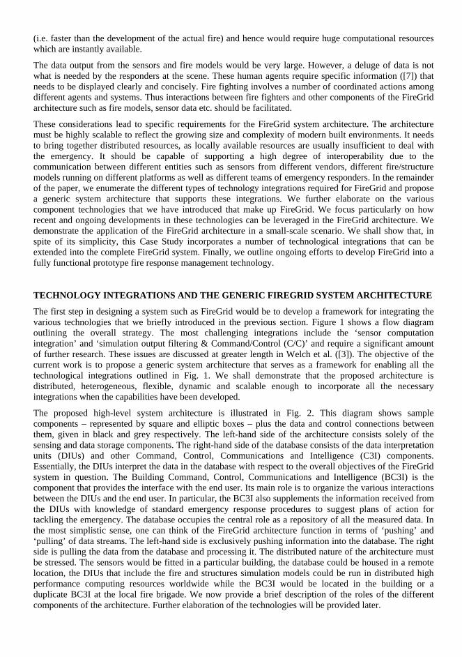
Fig. 3. Example of the FireGrid database structure.
Database Management System
As discussed earlier, the quantity of sensor data that needs to be handled in a system such as FireGrid can be very large. We will show that the data needs to be accessed by a number of DIUs ‘Data Interpretation Units’ and therefore the data needs to be stored in an ordered structure for ease of the retrieval and processing of queries. We use PostgreSQL (http://www.postgresql.org/) that is a relational database management system, RDMS, [12] and can support SQL (Structured Query Language) [13]. An RDMS has a number of features that enable rapid storage and retrieval of large quantities of data. Figure 3 shows the FireGrid database structure. As for any RDMS it consists of a number of tables, each containing a subset of the data that we require. Some tables contain dynamic data, i.e., time dependant data fed in by the sensors. Other tables contain static data such as building properties, location, type and properties of sensors etc. In the example shown in Fig. 3, the FireGrid architecture is used for fire experiments and not a real fire monitoring application. Thus, there is a table labelled experiments that distinguishes between different tests that are made on the system. The sensor data, building properties data etc. can be different for each experiment. However the linking structure between the different tables for each experiment would be the

same. Data in multiple tables can be linked together by a field (or “row”) that is common to each table. These are shown by arrows between rows with the characters 1 and N at the start and end of each arrow that specify whether the relationship is one-to-one (1-1), one-to-many (1-N) or many-to-many (N-N). For example, the line that connects the row labelled sensor_id in the dau_sensor_data table to the row labelled id in the Sensors table denotes that there can be more than one sensor reading for each sensor. Different queries on the database can be executed in a highly efficient manner due to the pre-defined relations between the entities in the different fields of each table. For example, we may wish to monitor the thermocouple readings in a particular area of a particular compartment of a multi-storey building. A brief and compact statement can be written in SQL that first locates the coordinates of the spatial location in ‘Building properties’ table then matches the sensor identification numbers (ids) corresponding to those coordinates in the ‘Sensors’ table and finally looks up the values stored for the particular sensor ids in the ‘thermocouple_data’ corresponding to each sensor id.
Fig. 4. Schematic showing the grid interface for fire simulation model execution.
Grid-enabled high performance computing
Fire in a modern building necessarily generates a large amount of data. For instance, at the onset, the fire is small and contained to a particular region and therefore needs a small number of variables or sensors to monitor it. However as the fire grows, the information required to describe and control it goes up dramatically. For a FireGrid application, fire-induced phenomena such as the movement of smoke, ignition of secondary objects, movement of people, flashover and possible ultimate collapse of buildings needs to be predicted faster than real time. Due to the highly uncertain nature of these events, stochastic methods may have to be used in which case an ensemble of simulations would have to be performed. This requires instant and on-demand access to large amounts of computational resources that may not be available locally. The grid provides the tool for the identification and securing of these distributed computational resources. The main functional requirements are provision of a job execution service for running fire simulation models on remote resources, staging input files of simulation models to the remote host before job execution, transferring of the relevant parts of the output files on the remote host back to the client after job completion, monitoring the status of running jobs and providing authentication, authorisation, and data security services. Figure 4 shows the grid-enabled architecture for supporting a fire simulation model execution at remote distributed computing resources. For our purposes, the grid-enabled architecture is a part of the functional components of the Type 3 DIU integrated into the system architecture in Fig. 2. For
security reasons, an end user needs to get a certificate for the authorization of the system first. On receiving a request from the BC3I, the query manager, that is an agent of I-X (to be discussed in the next subsection will then submit a job to the remote site that hosts HPC resources. The current architecture integrates the off-the-shelf grid middleware: Globus toolkit and can support a job submission through both the Linux and Windows platforms. This satisfies the requirements of users of different platforms.
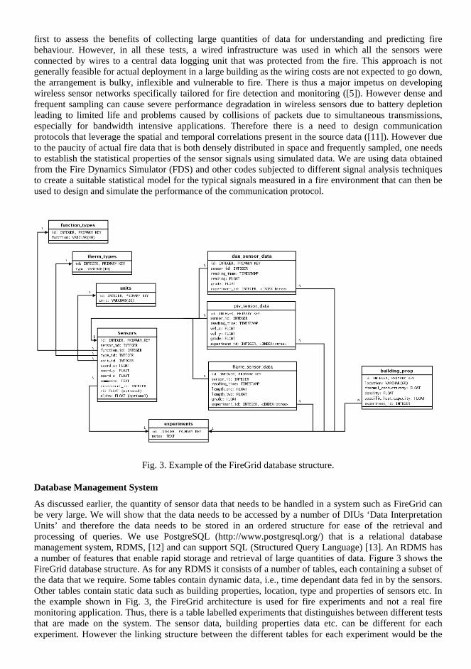
Fig. 5. Simulated Building C3I Process Panel and map-based state visualisation.
I-X toolkit for the C3I layer
The role of the C3I layer in the FireGrid system was introduced in earlier. One of the main goals of this layer is to help coordinate the activities of different agents, both human and computer, in their response to the fire. I-X [14] is a generic systems integration architecture (and accompanying tool-suite) that can be used for the formulation and enactment of the emergency response plan. The I-X process panel is a generic human interface used for task planning and coordination among the different agents. We are in the process of designing a process panel specifically tailored to fire emergencies based on discussions with and feedback from the local fire authorities. Figure 5 shows a mock-up BC3I panel interface; the “Activities” area of the Panel shows the user stepping through a simple ‘standard operating procedure’ for responding to a fire. The I-X system is based on the <I-N-C-A> (Issues-Nodes-Constraints-Annotation) framework for structuring the information that passes between different agents during the emergency response [15]. In a system such as FireGrid that involves humans and other technologies, the content of the messages that pass should be very carefully defined. Consider that, the data that is measured by the sensors are time series of physical variables such as temperatures, smoke concentrations, etc. Fire models based on physical principles might process this data to predict the evolution of these physical variables. However, responders require answers to questions such as whether it is safe to enter the room to fight the fire and whether the structural integrity of the building will remain tenable for the next N minutes while they implement a search and rescue operation. For example, how can a fire model prediction that says that the heat flux to the walls of a compartment in 10 minutes will reach 20kW/m2 be used to answer the question posed by the emergency responder as to whether it is safe to enter the compartment and undertake a standard search and rescue operation that may take 15 minutes? In the terminology of Artificial Intelligence (AI), this is an example of two different ontologies for the same domain (the fire); a process of knowledge engineering is required to reconcile the information content of the fire models/data and the requirements of the responders.

This is a non-trivial task and requires consideration of several issues. Firstly, due to the incomplete understanding of fire phenomena, the fire modelling will have to rely on sensor data to not only define the intial conditions but also correct the models in real time to make future predictions, a technique in wide use in weather forecasting. Further discussion on this issue is provided in [16]. Secondly, since model predictions are a factor in the decisions made by emergency personnel, the uncertainty inherent in fire modelling predictions needs to be quantified. Errors in the fire models are caused by uncertainties in the inputs, uncertainties in the parameters and discretization errors introduced in the computation. Fire simulation codes typically do not provide an indication of error in approximation and hence an important requirement is to quantify the uncertainty of fire model predictions. In any case, we would expect that if more information regarding the current and predicted future state of the building and the uncertainty inherent in that information could be made available to the emergency service personnel, then the errors in their subjective judgement would be reduced. Of course, due to the severe consequences of mistakes, it is unwise to rely exclusively on conclusions drawn by the AI. In the first stages, we envisage the use of appropriately interpreted results of fire models to augment and support the tactical decisions made by the fire fighters. A qualitative discussion on the role and use of fire models to assist in emergency response is provided in [17]. Despite inherent difficulties, this is a critical requirement for systems such as FireGrid and requires dialogues between fire modellers, AI researchers and the emergency responders to determine the relationships between the knowledge expressed by fire models and that contained in existing fire fighting strategies. The shared FireGrid ontology can then be used within the <I-N-C-A> framework to accurately represent and transmit information within the system.
A CASE STUDY
In the previous sections we have proposed the generic FireGrid architecture, defined its components and further elaborated on some research problems and technological developments that are necessary before actual deployment of the FireGrid system. In this section we describe a case study that illustrates the approach we have used for some of the major technological integrations. Let us consider an example in which a fire Modeller wants to check the effectiveness of a fire model in real time for predicting some physical characteristics of a fire experiment. The fire experiment consists of setting up a heptane pool fire in a small (roughly 2m x 2m x 2m) compartment. Forty thermocouples mounted in 4 thermocouple racks are used to monitor the gas temperature from which the smoke layer height is computed. Concurrently a 2 equation zone model is run to obtain a prediction of the smoke layer height. One should note that this is not a traditional ‘fire experiment’ where one desires to isolate and study a particular physical property of the pool fire. Rather the fire experiment is a scenario where the performance of the FireGrid system architecture can be tested. We therefore omit details of the experiment and instead present an illustration of some aspects of the FireGrid concept.
1. At the beginning of the experiment: all sensors are activated and periodically transmitting data to the FireGrid database; a Fire Alarm DIU is running; and there is no fire in the compartment. The Modeller ignites the pool fire and retires from the compartment to stand in front of the BC3I panel. After a short time, the Fire Alarm DIU detects the presence of the fire and sends an alert to the BC3I.
2. When the Modeller notes this alert, he/she makes a query to the Query Manager for a prediction of the height of the smoke, in the compartment, in N seconds from that time.
3. The Query Manager builds a workflow to implement this query. The workflow incorporates the Fire Model, which is installed on a remote resource and supported by appropriate pre- and post-processing units. The Query Manager launches the workflow. Once the workflow has completed, the Query Manager returns the prediction for the smoke height to the BC3I.
4. The Modeller observes the fire until the time for which the smoke height prediction has been made. Then the Modeller queries the Query Manager for the actual smoke height at that time.
5. The Query Manager builds a workflow to implement the query. This workflow involves a simple DIU that computes the smoke height based on live sensor readings. The Query Manager launches the workflow. Once the workflow has completed, the Query Manager returns the actual smoke height to the BC3I.
6. The Modeller compares the predicted smoke height against the actual computed value. The fire is extinguished and the experiment ends.
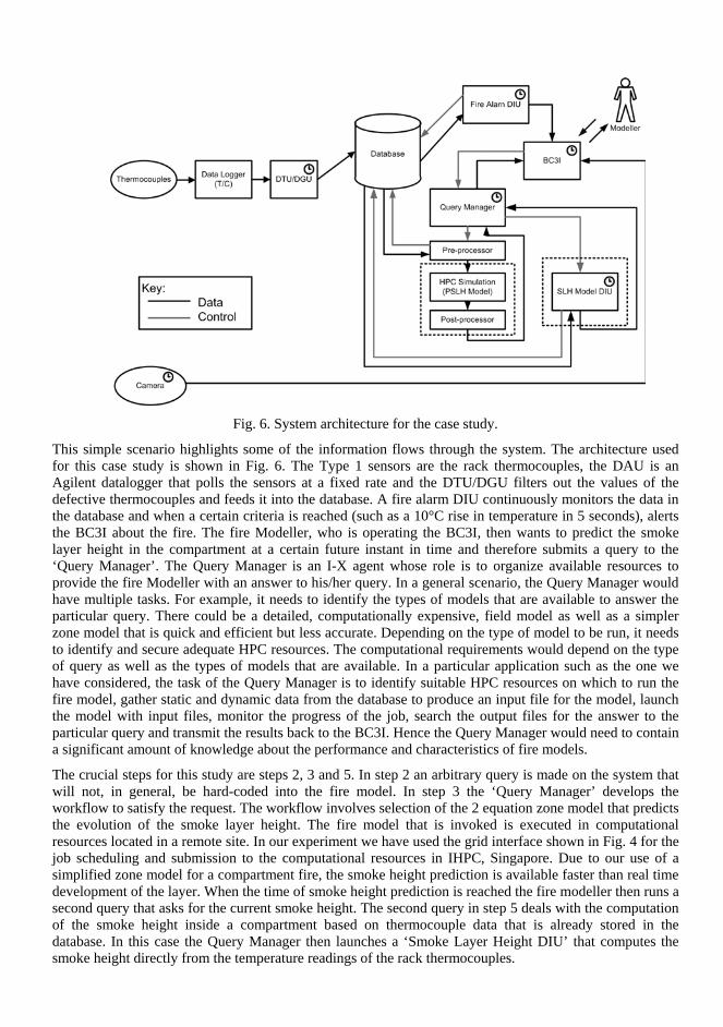
Fig. 6. System architecture for the case study.
This simple scenario highlights some of the information flows through the system. The architecture used for this case study is shown in Fig. 6. The Type 1 sensors are the rack thermocouples, the DAU is an Agilent datalogger that polls the sensors at a fixed rate and the DTU/DGU filters out the values of the defective thermocouples and feeds it into the database. A fire alarm DIU continuously monitors the data in the database and when a certain criteria is reached (such as a 10°C rise in temperature in 5 seconds), alerts the BC3I about the fire. The fire Modeller, who is operating the BC3I, then wants to predict the smoke layer height in the compartment at a certain future instant in time and therefore submits a query to the ‘Query Manager’. The Query Manager is an I-X agent whose role is to organize available resources to provide the fire Modeller with an answer to his/her query. In a general scenario, the Query Manager would have multiple tasks. For example, it needs to identify the types of models that are available to answer the particular query. There could be a detailed, computationally expensive, field model as well as a simpler zone model that is quick and efficient but less accurate. Depending on the type of model to be run, it needs to identify and secure adequate HPC resources. The computational requirements would depend on the type of query as well as the types of models that are available. In a particular application such as the one we have considered, the task of the Query Manager is to identify suitable HPC resources on which to run the fire model, gather static and dynamic data from the database to produce an input file for the model, launch the model with input files, monitor the progress of the job, search the output files for the answer to the particular query and transmit the results back to the BC3I. Hence the Query Manager would need to contain a significant amount of knowledge about the performance and characteristics of fire models.
The crucial steps for this study are steps 2, 3 and 5. In step 2 an arbitrary query is made on the system that will not, in general, be hard-coded into the fire model. In step 3 the ‘Query Manager’ develops the workflow to satisfy the request. The workflow involves selection of the 2 equation zone model that predicts the evolution of the smoke layer height. The fire model that is invoked is executed in computational resources located in a remote site. In our experiment we have used the grid interface shown in Fig. 4 for the job scheduling and submission to the computational resources in IHPC, Singapore. Due to our use of a simplified zone model for a compartment fire, the smoke height prediction is available faster than real time development of the layer. When the time of smoke height prediction is reached the fire modeller then runs a second query that asks for the current smoke height. The second query in step 5 deals with the computation of the smoke height inside a compartment based on thermocouple data that is already stored in the database. In this case the Query Manager then launches a ‘Smoke Layer Height DIU’ that computes the smoke height directly from the temperature readings of the rack thermocouples.

Note that the system is now being operated by a fire modeller to validate a model during the actual run of the fire experiment. Usually the model validation process would involve analysing the results after the experiment is performed. The admittedly contrived scenario that we have used is closer to the desired mode of operation of FireGrid as an emergency response system. During the actual deployment of the FireGrid system, possibly fire fighters would be making the queries. However for particular queries that involve a simulation of the fire using a computational model or the searching of data for real-time information on the building, the workflow would not be significantly different.
CONCLUSIONS AND FURTHER WORK
In this paper we discuss some requirements for a modern fire emergency response system. We outline various technologies that are available or require further research and development and the integrations among them that would be needed for an integrated fire emergency system such as FireGrid. We admit that some of the technology integrations are still in the development stage. However, we propose a generic system architecture that would enable the different technology integrations to be performed seamlessly. We outline some aspects of the architecture that need further development. Finally we describe a ‘FireGrid demonstration experiment’ that we have completed that highlights a particular application for which FireGrid could be used.
It is apparent that FireGrid is at present just a conceptual model of a more effective fire emergency response procedure. Before such a system can be implemented it is necessary to determine whether a complex emergency response system is more valuable than existing alarm/sprinklers systems. As mentioned earlier in numerous cases, such as the WTC towers, existing response systems have proved inadequate. The approach outlined in this work is an attempt to harness and transmit the enormous amount of information generated during a fire in a modern building. Discussion of the various economic, ethical and legalistic issues in the implementation of the system is not part of this work. The different end uses of the system are discussed in greater detail in [2]. In this study, we work under the premise that the proposed system has the potential to support and improve upon existing fire fighting strategies and tactics. However implementation of this concept raises a number of technical challenges that cannot be tackled by fire safety engineers alone. One of the objectives of this paper is to set the problems of fire safety engineering (FSE) in a multi-disciplinary context and suggest ways in which the profession can engage the expertise of researchers working in other fields. The process leads to the discovery of interesting and important research problems that are outside the more widely investigated areas in FSE. As examples, one can consider (i) the development of a shared ontology that can potentially provide fire emergency responders with expert information obtained using fire simulation models, (ii) design of communication protocols that enable denser sampling of the building with wireless sensors, (iii) dynamic discovery of distributed resources for scheduling of computing jobs, using grid technologies that can handle the escalation of complexity in computational models running in real (or super-real) time and (iv) a further assessment and clarification of the methodology for fire modelling within the context of an integrated emergency response system.
Acknowledgements
The work reported in this paper has formed part of FireGrid, www.firegrid.org. This research has been funded by the Technology Strategy Board along with contributions from the other partners in FireGrid. The authors would like to thank Dave Berry, Mark Bull and Cecilia Abecassis Empis for their inputs on the development of the system architecture, Adam Cowlard, Thomas French, Gerhard Wickler, Stephen Czuprynski, and Jianping Yuan for their help with the demonstration experiment and Athanasia Tsertou for discussions on the wireless sensor networks.
References
[1] Stoltman, J.P., Lidstone, J., and DeChano, M.L., “Capacity Building, Education and Technical Training,” International Perspectives on Natural Disasters: Occurrence, Mitigation and Consequences, Stoltman, J.P., Lidstone, J., and DeChano, M.L. (eds.), Advances in Natural and Technological Hazards Research, Kluwer Academic Press, Dordrecht, 2004, p. 457/463.

[2] Berry, D. et al., “FireGrid: Integrated emergency response and fire safety engineering for the future built environment,” Proceedings of the UK e-Science Programme All Hands Meeting (AHM-2005), Nottingham, UK 2005.
[3] Welch, S. et al., “Introduction to FireGrid,” The Dalmarnock Fire Tests: Experiments and Modelling, Rein, G., Abecassis Empis, C., and Carvel, R. (eds.), School of Engineering and Electronics, University of Edinburgh, Edinburgh, 2007, p. 7/30.
[4] Usmani, A.S., Chung, Y.C., and Torero, J.L., (2003) How did the Towers Collapse- a New Theory, Fire Safety Journal 38:501-533, http://doi:10.1016/S0379-7112(03)00069-9.
[5] Tsertou, A., Upadhyay, R., Laurenson, D., and McLaughlin, S., “Towards a Tailored Sensor Network for Fire Emergency Monitoring in Large Buildings,” Proceedings of the 1st IEEE International Conference in Wireless Rural and Emergency Communications (WRECOM’07), Rome, Italy, September 2007.
[6] Reszka, P. et al., “Experimental Layout and Description of the Building,” The Dalmarnock Fire Tests: Experiments and Modelling, Rein, G., Abecassis Empis, C., and Carvel, R. (eds.), School of Engineering and Electronics, University of Edinburgh, Edinburgh, 2007, p. 31/62.
[7] Jones, W., Holmberg, D., Davis, W., Evans, D., Bushby, S., and Reed, K., “Workshop to Define Information Needed by Emergency Responders during Building Emergencies,” National Institute of Standards and Technology Report NISTIR 7193, Gaithersburg, MD, 2005.
[8] Welch, S., Jowsey, A., Deeny, S., Morgan, R., and Torero, J.L., (2007) BRE large compartment fire tests—Characterising post-flashover fires for model validation, Fire Safety Journal 52:548-567, http://doi:10.1016/j.firesaf.2007.04.002.
[9] Abecassis Empis, C., Reszka, P., Steinhaus, T., Cowlard, A., Biteau, H., Welch, S., Rein, G. and Torero, J.L., (2008) Characterisation of Dalmarnock Fire Test One, Experimental Thermal and Fluid Science (in press), http://doi:10.1016/j.expthermflusci.2007.11.006.
[10] Hill, J., Szewczyk, R., Woo, A., Hollar, S. Culler, D. E., and Kristofer, S. J. P., “System Architecture Directions for Networked Sensors,” Proceedings of the 9th International Conference on Architectural Support for Programming Languages and Operating Systems (ASPLOS-IX), Cambridge, MA, USA, November 12-15, 2000.
[11] Vuran, M. C., Akan, O. B., and Akyildiz, I. F., (2004) Spatio-temporal correlation: theory and applications for wireless sensor networks, Computer Networks 45:245-259, http://doi:10.1016/j.comnet.2004.03.007.
[12] Codd, E. F., (1970) A Relational Model of Data for Large Shared Data Banks, Communications of the ACM 13(6): 377-387.
[13] Chamberlin, D.B. and Boyce, R.F., “SEQUEL: A Structured English Query Language,” Proceedings of the 1974 ACM SIGFIDET Workshop on Data Description, Access and Control, Ann Arbor, Michigan, May 1-3, 1974.
[14] Potter, S., Tate, A. and Wickler, G., “Using I-X Panels as Intelligent To-Do Lists for Agent Coordination in Emergency Response,” Proceedings of the 3rd International ISCRAM Conference, Newark, NJ, USA, 2006, p. 272-281.
[15] Tate, A., “ <I-N-C-A>: an Ontology for Mixed-Initiative Synthesis Tasks,” Proceedings of the Workshop on Mixed-Initiative Intelligent Systems (MIIS) at the International Joint Conference on Artificial Intelligence (IJCAI-03), Acapulco, Mexico, August 2003.
[16] Koo, S.H., Fraser-Mitchell, J., Upadhyay, R. and Welch, S., “Sensor-linked fire simulation using a Monte-Carlo approach,” accepted for the 9th IAFSS Symposium, Karlsruhe, Germany, 2008.
[17] Potter, S. and Wickler, G., “Model-Based Query Systems for Emergency Response,” Proceedings of the 5th International Conference on Information Systems for Crisis, Response and Management (ISCRAM 2008), F. Fiedrich and B. Van de Walle (eds.), Washington DC, USA, May 2008.