An Analytical Model for Pipe-Soil-Tunneling Interaction - CityU ...
10
An analytical model for pipe-soil-tunneling interaction Wang, Y.; Wang, Q.; Zhang, K. Y. Published in: Procedia Engineering Published: 01/01/2011 Document Version: Final Published version, also known as Publisher’s PDF, Publisher’s Final version or Version of Record License: CC BY-NC-ND Publication record in CityU Scholars: Go to record Published version (DOI): 10.1016/j.proeng.2011.07.393 Publication details: Wang, Y., Wang, Q., & Zhang, K. Y. (2011). An analytical model for pipe-soil-tunneling interaction. Procedia Engineering, 14, 3127-3135. https://doi.org/10.1016/j.proeng.2011.07.393 Citing this paper Please note that where the full-text provided on CityU Scholars is the Post-print version (also known as Accepted Author Manuscript, Peer-reviewed or Author Final version), it may differ from the Final Published version. When citing, ensure that you check and use the publisher's definitive version for pagination and other details. General rights Copyright for the publications made accessible via the CityU Scholars portal is retained by the author(s) and/or other copyright owners and it is a condition of accessing these publications that users recognise and abide by the legal requirements associated with these rights. Users may not further distribute the material or use it for any profit-making activity or commercial gain. Publisher permission Permission for previously published items are in accordance with publisher's copyright policies sourced from the SHERPA RoMEO database. Links to full text versions (either Published or Post-print) are only available if corresponding publishers allow open access. Take down policy Contact [email protected] if you believe that this document breaches copyright and provide us with details. We will remove access to the work immediately and investigate your claim. Download date: 31/01/2022
-
Upload
khangminh22 -
Category
Documents
-
view
2 -
download
0
Transcript of An Analytical Model for Pipe-Soil-Tunneling Interaction - CityU ...

An analytical model for pipe-soil-tunneling interaction
Wang, Y.; Wang, Q.; Zhang, K. Y.
Published in:Procedia Engineering
Published: 01/01/2011
Document Version:Final Published version, also known as Publisher’s PDF, Publisher’s Final version or Version of Record
License:CC BY-NC-ND
Publication record in CityU Scholars:Go to record
Published version (DOI):10.1016/j.proeng.2011.07.393
Publication details:Wang, Y., Wang, Q., & Zhang, K. Y. (2011). An analytical model for pipe-soil-tunneling interaction. ProcediaEngineering, 14, 3127-3135. https://doi.org/10.1016/j.proeng.2011.07.393
Citing this paperPlease note that where the full-text provided on CityU Scholars is the Post-print version (also known as Accepted AuthorManuscript, Peer-reviewed or Author Final version), it may differ from the Final Published version. When citing, ensure thatyou check and use the publisher's definitive version for pagination and other details.
General rightsCopyright for the publications made accessible via the CityU Scholars portal is retained by the author(s) and/or othercopyright owners and it is a condition of accessing these publications that users recognise and abide by the legalrequirements associated with these rights. Users may not further distribute the material or use it for any profit-making activityor commercial gain.Publisher permissionPermission for previously published items are in accordance with publisher's copyright policies sourced from the SHERPARoMEO database. Links to full text versions (either Published or Post-print) are only available if corresponding publishersallow open access.
Take down policyContact [email protected] if you believe that this document breaches copyright and provide us with details. We willremove access to the work immediately and investigate your claim.
Download date: 31/01/2022

Available online at www.sciencedirect.com
The Twelfth East Asia-Pacific Conference on Structural Engineering and Construction
An Analytical Model for Pipe-Soil-Tunneling Interaction
Y. WANG1a, Q. WANG2, and K. Y. ZHANG3
1Department of Building and Construction, City University of Hong Kong, China 2Hangzhou Metro Group CO., LTD, Hangzhou, China
3Institute of Geotechnical Engineering, Hohai University, Nanjing, China
Abstract
The underground space in urban areas is frequently congested with utilities, including pipelines and conduits that are affected by underground construction, e.g., tunneling. This paper develops a Winkler-based pipe-soil-tunneling interaction model for estimating pipe responses to tunneling-induced ground movement. Efforts are focused on different pipe-soil interaction in relative uplift and downward pipe movements. Governing equations are derived, and their closed-form solutions are provided. The closed-form solutions are then validated against finite element simulations. Finally, the effects of different pipe-soil interactions in relative uplift and downward pipe movements are explored. The effect of different pipe-soil interaction is shown to be significant, and it should be properly accounted for in the analysis.
Keywords: Pipe; Ground Movement; Uplift; Downward Movement; Tunnel
1. INTRODUCTION
The underground space in urban areas is frequently congested with utilities, including pipelines and conduits that are affected by underground construction, e.g., tunneling. Tunneling-induced ground movements cause pipeline deformation that may disrupt the conveyance of important services and resources (e.g., water, electric power, and telecommunications) and threaten the safety and security of urban inhabitants (e.g., flooding and leakage of combustible gas from ruptured or leaking mains). To evaluate the effects of tunneling-induced movements on underground utilities, it is necessary to account rationally for the interaction between pipeline and soil associated with tunneling-induced patterns of soil movement.
The pipe-soil-tunneling interaction has attracted increasing research attention recently. Attewell et al. (1986) proposed a Winkler-based model in which the soil subgrade modulus is used to account for soil-
aCorresponding author and presenter: Email: [email protected]
1877–7058 © 2011 Published by Elsevier Ltd.doi:10.1016/j.proeng.2011.07.393
Procedia Engineering 14 (2011) 3127–3135
Open access under CC BY-NC-ND license.

3128 Y. WANG et al. / Procedia Engineering 14 (2011) 3127–3135
pipe interaction in response to a Gaussian settlement profile. Wang et al. (2010) extended the Winkler-based model for a Gaussian settlement profile to one that can deal with an arbitrary ground settlement profile. Vorster et al. (2005) developed an elastic continuum method for evaluating the interaction between buried continuous pipelines and Green field settlement from tunneling and compared with the results of centrifuge experiments. Klar et al. (2005) further compared the elastic continuum method with the Winkler-based approach proposed by Attewell et al. (1986). Although these models are different in many aspects, they share one common assumption, e.g., the pipe-soil interaction is identical in relative uplift and downward pipe movements. However, it has been well recognized that soil resistance in uplift is different from that associated with downward movements, particularly for pipes buried at shallow depths (Trautmann et al. 1985, Committee on Gas and Liquid Fuel Lifelines 1984, Honegger and Nyman 2004).
Figure 1: Pipe-Soil-Tunneling Interaction; (a) Schematic View; (b) Winkler-Based Model
This paper develops a Winkler-based model that accounts for different pipe-soil interaction in relative uplift and downward pipe movements. After this introduction, the previous work on Winkler-based pipe-soil-tunneling interaction model is briefly reviewed. Then, the different pipe-soil interactions in relative uplift and downward pipe movements are highlighted, and a Winkler-based model and its closed-form analytical solutions are developed to account for such difference. The closed-form solutions are validated against finite element simulation results. Finally, the effects of different pipe-soil interaction in relative uplift and downward pipe movements are explored.
2. WINKLER-BASED MODEL
Figure 1a shows a schematic view of pipe-soil-tunneling interaction model, in which a tunnel is excavated below an existing pipeline (Wang et al. 1010). The tunneling process deforms the soil

Y. WANG et al. / Procedia Engineering 14 (2011) 3127–3135 3129
surrounding the existing pipeline, and through the soil, imposes an equivalent distributed load in the pipeline. As shown in Figure 1b, Winkler-based model (e.g., Attewell et al., 1986) considers the pipeline as an infinite Winkler beam that is supported by an elastic medium with a supporting force proportional to the deflection, v(x), of the pipe at the supporting point with a coordinate x. The equivalent distributed load induced by tunneling is proportional to the Green field soil settlement S(x). The governing differential equation can be expressed as (Attewell et al., 1986):
)(4)(4)( 44
4
4
xSxvx
xv (1)
where 4 4 p pK E I , Ep is Young’s modulus of the pipe, Ip is the moment of inertia of the pipe, and K is the subgrade modulus that represents the pipe-soil interaction. In other words, the pipe-soil-tunneling interaction is modeled as a Winkler beam subjected to a distributed load equal to KS(x). On the other hand, an arbitrary settlement profile, S(x), can be represented mathematically by an n-order polynomial series, i.e.,
n
i
ii xaxS
0
)( , where ai are constants in the polynomial series. When the arbitrary settlement profile S(x) is imposed on pipeline, the Winkler model can be divided into three regions, as shown in Figure 1b. The corresponding governing equations for these three regions are given as,
04 44
4
vx
v ax or xb (Regions I or III)
)(44 444
4
xSvx
v bxa (Region II) (2)
General solutions for Equation (2) are given as following (Hetenyi 1946),
xCxCexCxCev xx sincossincos 14131211 ax
*24232221 sincossincos n
xx vxCxCexCxCev bxa
xCxCexCxCev xx sincossincos 34333231 xb (3)
where C11, C12, C13 , C14, C21, C22, C23 , C24, C31, C32, C33 , C34 are integration constants, and *nv is a
particular solution for S(x). *nv is an n-order polynomial series and is obtained using the method of
undetermined coefficients (Wang et al. 2010). There are twelve integration constants in Equation (3), C11,C12, C13 , C14, C21, C22, C23 , C24, C31, C32, C33 , C34, and they can be interpreted from corresponding boundary conditions. Detailed equations and their implementation in Matlab (Mathworks Inc 2007) are referred to Wang et al. (2010).
3. DIFFERENT PIPE-SOIL INTERACTION IN RELATIVE UPLIFT AND DOWNWARD PIPE MOVEMENTS
It has been well recognized that soil resistance in uplift is different from that associated with downward movements, particularly for pipes buried at shallow depths typical of most utilities (Trautmann et al. 1985, Committee on Gas and Liquid Fuel Lifelines 1984, Honegger and Nyman 2004). Generally speaking, the soil subgrade modulus (Ku) in relative pipe uplift is smaller than the soil subgrade modulus (Kd) in relative pipe downward movement, as shown in Figure 2. The Ku and Kd can be estimated
3130 Y. WANG et al. / Procedia Engineering 14 (2011) 3127–3135
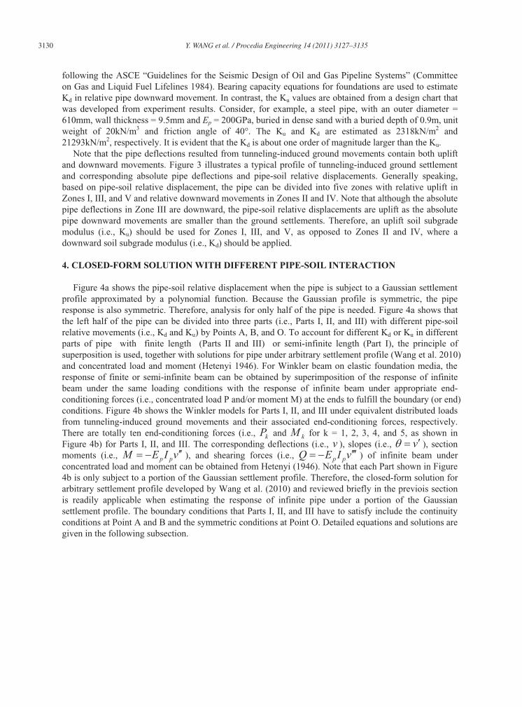
following the ASCE “Guidelines for the Seismic Design of Oil and Gas Pipeline Systems” (Committee on Gas and Liquid Fuel Lifelines 1984). Bearing capacity equations for foundations are used to estimate Kd in relative pipe downward movement. In contrast, the Ku values are obtained from a design chart that was developed from experiment results. Consider, for example, a steel pipe, with an outer diameter = 610mm, wall thickness = 9.5mm and Ep = 200GPa, buried in dense sand with a buried depth of 0.9m, unit weight of 20kN/m3 and friction angle of 40°. The Ku and Kd are estimated as 2318kN/m2 and 21293kN/m2, respectively. It is evident that the Kd is about one order of magnitude larger than the Ku.
Note that the pipe deflections resulted from tunneling-induced ground movements contain both uplift and downward movements. Figure 3 illustrates a typical profile of tunneling-induced ground settlement and corresponding absolute pipe deflections and pipe-soil relative displacements. Generally speaking, based on pipe-soil relative displacement, the pipe can be divided into five zones with relative uplift in Zones I, III, and V and relative downward movements in Zones II and IV. Note that although the absolute pipe deflections in Zone III are downward, the pipe-soil relative displacements are uplift as the absolute pipe downward movements are smaller than the ground settlements. Therefore, an uplift soil subgrade modulus (i.e., Ku) should be used for Zones I, III, and V, as opposed to Zones II and IV, where a downward soil subgrade modulus (i.e., Kd) should be applied.
4. CLOSED-FORM SOLUTION WITH DIFFERENT PIPE-SOIL INTERACTION
Figure 4a shows the pipe-soil relative displacement when the pipe is subject to a Gaussian settlement profile approximated by a polynomial function. Because the Gaussian profile is symmetric, the pipe response is also symmetric. Therefore, analysis for only half of the pipe is needed. Figure 4a shows that the left half of the pipe can be divided into three parts (i.e., Parts I, II, and III) with different pipe-soil relative movements (i.e., Kd and Ku) by Points A, B, and O. To account for different Kd or Ku in different parts of pipe with finite length (Parts II and III) or semi-infinite length (Part I), the principle of superposition is used, together with solutions for pipe under arbitrary settlement profile (Wang et al. 2010) and concentrated load and moment (Hetenyi 1946). For Winkler beam on elastic foundation media, the response of finite or semi-infinite beam can be obtained by superimposition of the response of infinite beam under the same loading conditions with the response of infinite beam under appropriate end-conditioning forces (i.e., concentrated load P and/or moment M) at the ends to fulfill the boundary (or end) conditions. Figure 4b shows the Winkler models for Parts I, II, and III under equivalent distributed loads from tunneling-induced ground movements and their associated end-conditioning forces, respectively. There are totally ten end-conditioning forces (i.e., kP and kM for k = 1, 2, 3, 4, and 5, as shown in Figure 4b) for Parts I, II, and III. The corresponding deflections (i.e., v ), slopes (i.e., v ), section moments (i.e., vIEM pp ), and shearing forces (i.e., vIEQ pp ) of infinite beam under concentrated load and moment can be obtained from Hetenyi (1946). Note that each Part shown in Figure 4b is only subject to a portion of the Gaussian settlement profile. Therefore, the closed-form solution for arbitrary settlement profile developed by Wang et al. (2010) and reviewed briefly in the previois section is readily applicable when estimating the response of infinite pipe under a portion of the Gaussian settlement profile. The boundary conditions that Parts I, II, and III have to satisfy include the continuity conditions at Point A and B and the symmetric conditions at Point O. Detailed equations and solutions are given in the following subsection.

Y. WANG et al. / Procedia Engineering 14 (2011) 3127–3135 3131
Figure 2: Different Pipe-Soil Interaction in Uplift and Downward Pipe Movements; Figure 3: Relative Pipe-Soil Movements
Figure 4: Winkler Model with Different Pipe-Soil Interaction; (a): Overview; (b) Detailed Models for Three Parts
4.1. Governing Equations
To facilitate derivation of the governing equations for Parts I, II, and III, a series of notations are defined. The responses of an infinite pipe to an arbitrary settlement profile S(x) are denoted as pipe deflection j
Sv , slope j
S , moment j
SM , and shearing force j
Sq . The subscript “S” represents that the pipe responses are caused by settlement profile S(x) and are obtained from the closed-form solution developed by Wang et al. (2010). The superscript “ j” can be either “ u” or “ d” representing pipe-soil relative uplift (i.e., Ku) or downward (i.e., Kd) movements, respectively. Similarly, the responses of an infinite pipe to end-conditioning forces kP and kM are denoted as j
kPv , j
kMv , j
kP , j
kMj
kPM , j
kMM ,j
kPQ , and j
kMQ . The subscript “ kP ” and “ kM ” represents that the pipe responses are caused by end-conditioning forces kP or kM .
There are three sets of equations for Parts I, II, and III, respectively. For Part I ( Axx ),
uuu
I MPSI vvvv11; uuu
I MPSI 11; uuu
I MPSI MMMM11
; uuu
I MPSI QQQQ11
(4)
For Part II ( BA xxx ),
ddddd
II MPMPSII vvvvvv3322; ddddd
II MPMPSII 3322;
ddddd
II MPMPSII MMMMMM3322
; ddddd
II MPMPSII QQQQQQ3322
(5)

3132 Y. WANG et al. / Procedia Engineering 14 (2011) 3127–3135
For Part III ( 0xxB ),
uuuuu
III MPMPSIII vvvvvv5544
; uuuuu
III MPMPSIII 5544;
uuuuu
III MPMPSIII MMMMMM5544
; uuuuu
III MPMPSIII QQQQQQ5544
(6)
Substituting the infinite pipe responses j
kPv , j
kMv , j
kP , j
kMj
kPM , j
kMM , j
kPQ , and j
kMQ (for j = u or d and k = 1, 2, 3, 4, and 5) from Hetenyi (1946) into Equation groups 4-6 leads to the following equation group for Parts I, II, and III, respectively. For Part I ( Axx ),
xu
u
xu
uxSI uu
u
IB
K
MA
K
Pvv
211
2;
xu
u
xu
u
xSI uu
u
IC
K
MB
K
P 31
21 ;
xxu
xSI uu
u
ID
MC
PMM
2411 ;
xu
xxSI uu
u
IA
MD
PQQ
2211 (7)
For Part II ( BA xxx ),
xd
d
xd
d
xd
dx
d
dxSII dddd
d
IIB
K
MB
K
MA
K
PA
K
Pvv
23
2232
22;
xd
d
xd
d
xd
d
xd
d
xSII dddd
d
IIC
K
MC
K
MB
K
PB
K
P 33
32
23
22 ;
xxxd
xd
xSII dddd
d
IID
MD
MC
PC
PMM
22443232 ;
xdxdxxxSII dddd
d
IIA
MA
MD
PD
PQQ
22223232 (8)
For Part III ( 0xxB ),
xu
u
xu
ux
u
u
xu
uxSIII uuuu
u
IIIB
K
MA
K
PB
K
MA
K
Pvv
255
244
22;
xu
u
xu
u
xu
u
xu
u
xSIII uuuu
u
IIIC
K
MB
K
PC
K
MB
K
P 35
25
34
24 ;
xxu
xxu
xSIII uuuu
u
IIID
MC
PD
MC
PMM
24245544 ;
xuxxuxxSIII uuuu
u
IIIA
MD
PA
MD
PQQ
22225544 (9)
where xxeA jjx
xj
jsincos , xeB j
xx
j
jsin , xxeC jj
xx
j
jsincos , and
xeD jx
xj
jcos . Note that the unknowns in Equation groups 7-9 include ten end-conditioning forces
(i.e., P1, P2, P3, P4, P5, M1, M2, M3, M4, and M5) and xA and xB.The boundary conditions that the aforementioned equation groups have to satisfy include symmetric
conditions at Point O (i.e., 0OIII and 0OIIIQ ) and continuity conditions at Points A and B. At Point A (i.e., x = xA), the pipe deflections, slopes, section moments, and shearing forces calculated from the solutions for Part I must equal to those calculated from the solutions for Part II (i.e., AIIAI vv ,
AIIAI , AIIAI MM , and AIIAI QQ ). Similarly, four equations at Point B (i.e., BIIIBII vv ,
BIIIBII , BIIIBII MM , and BIIIBII QQ ) can be established. Therefore, for given Points A and B
Y. WANG et al. / Procedia Engineering 14 (2011) 3127–3135 3133
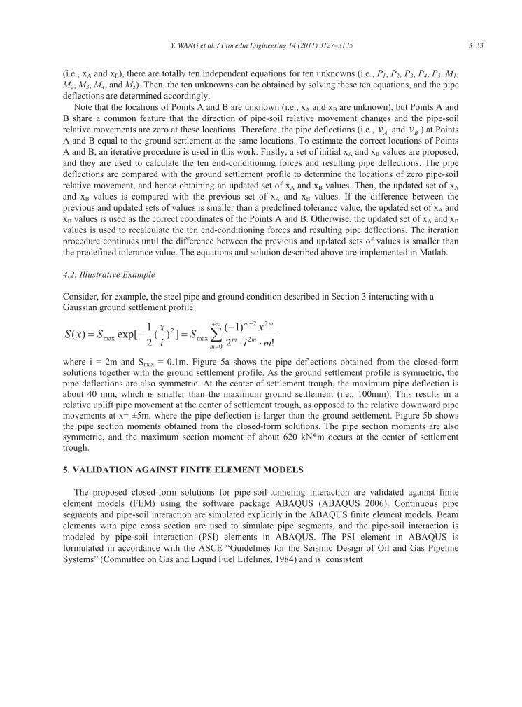
(i.e., xA and xB), there are totally ten independent equations for ten unknowns (i.e., P1, P2, P3, P4, P5, M1,M2, M3, M4, and M5). Then, the ten unknowns can be obtained by solving these ten equations, and the pipe deflections are determined accordingly.
Note that the locations of Points A and B are unknown (i.e., xA and xB are unknown), but Points A and B share a common feature that the direction of pipe-soil relative movement changes and the pipe-soil relative movements are zero at these locations. Therefore, the pipe deflections (i.e., Av and Bv ) at Points A and B equal to the ground settlement at the same locations. To estimate the correct locations of Points A and B, an iterative procedure is used in this work. Firstly, a set of initial xA and xB values are proposed, and they are used to calculate the ten end-conditioning forces and resulting pipe deflections. The pipe deflections are compared with the ground settlement profile to determine the locations of zero pipe-soil relative movement, and hence obtaining an updated set of xA and xB values. Then, the updated set of xA
and xB values is compared with the previous set of xA and xB values. If the difference between the previous and updated sets of values is smaller than a predefined tolerance value, the updated set of xA and xB values is used as the correct coordinates of the Points A and B. Otherwise, the updated set of xA and xB
values is used to recalculate the ten end-conditioning forces and resulting pipe deflections. The iteration procedure continues until the difference between the previous and updated sets of values is smaller than the predefined tolerance value. The equations and solution described above are implemented in Matlab.
4.2. Illustrative Example
Consider, for example, the steel pipe and ground condition described in Section 3 interacting with a Gaussian ground settlement profile
02
22
max2
max !2)1(
])(21
exp[)(m
mm
mm
mi
xS
i
xSxS
where i = 2m and Smax = 0.1m. Figure 5a shows the pipe deflections obtained from the closed-form solutions together with the ground settlement profile. As the ground settlement profile is symmetric, the pipe deflections are also symmetric. At the center of settlement trough, the maximum pipe deflection is about 40 mm, which is smaller than the maximum ground settlement (i.e., 100mm). This results in a relative uplift pipe movement at the center of settlement trough, as opposed to the relative downward pipe movements at x= ±5m, where the pipe deflection is larger than the ground settlement. Figure 5b shows the pipe section moments obtained from the closed-form solutions. The pipe section moments are also symmetric, and the maximum section moment of about 620 kN*m occurs at the center of settlement trough.
5. VALIDATION AGAINST FINITE ELEMENT MODELS
The proposed closed-form solutions for pipe-soil-tunneling interaction are validated against finite element models (FEM) using the software package ABAQUS (ABAQUS 2006). Continuous pipe segments and pipe-soil interaction are simulated explicitly in the ABAQUS finite element models. Beam elements with pipe cross section are used to simulate pipe segments, and the pipe-soil interaction is modeled by pipe-soil interaction (PSI) elements in ABAQUS. The PSI element in ABAQUS is formulated in accordance with the ASCE “Guidelines for the Seismic Design of Oil and Gas Pipeline Systems” (Committee on Gas and Liquid Fuel Lifelines, 1984) and is consistent

3134 Y. WANG et al. / Procedia Engineering 14 (2011) 3127–3135
-120
-80
-40
0
40
-20 -15 -10 -5 0 5 10 15 20
Pipe Length x (m)
Pip
e D
efle
ctio
n (m
m)
Ground SettlementClosed-Form Solution ResultsFEM Results
-2,000
-1,500
-1,000
-500
0
500
1,000
-20 -15 -10 -5 0 5 10 15 20
Pipe Length x (m)
Mom
ent M
(kN
*m)
Closed-Form Solution Results
FEM Results
(a) Pipe Deflections (b) Section Moments
Figure 5: Comparison of Results from Closed-Form Solutions and Finite Element Models
-120
-80
-40
0
40
-20 -15 -10 -5 0 5 10 15 20
Pile Length x (m)
Pip
e D
efle
ctio
n (
mm
)
K = Kd = 21293 kN/m2
K = Ku = 2318 kN/m2
Kd = 21293 kN/m2, Ku = 2318 kN/m2
-2,000
-1,500
-1,000
-500
0
500
1,000
-20 -15 -10 -5 0 5 10 15 20
Pipe Length x (m)
Mom
ent
M (
kN
*m)
K = Kd = 21293 kN/m2
K = Ku = 2318 kN/m2
Kd = 21293 kN/m2, Ku = 2318 kN/m2
(a) Pipe Deflections (b) Section Moments
Figure 6: Effect of Different Pipe-Soil Interactions
with estimate of Ku and Kd for relative uplift and downward pipe movements in the closed-form solutions. The tunneling-induced ground displacements are imposed on the PSI elements as distributed displacement boundary conditions. Figure 5 also includes the FEM results, and it is evident that the FEM results (i.e., both pipe deflections and section moments) are virtually identical to those from closed-form solutions.
6. EFFECTS OF DIFFERENT PIPE-SOIL INTERACTIONS
The effects of different pipe-soil interactions in relative uplift and downward pipe movements are then explored. Figure 6 compares the results in Figure 5 (i.e., with different pipe-soil interactions) with those from two sets of analyses that do not consider different pipe-soil interactions (i.e., only one subgrade modulus K is considered, and K = Kd = 21293kN/m2 or K = Ku = 2318kN/m2). It is obvious that their maximum pipe deflections and moments differ significantly. When K = Kd = 21293kN/m2, the maximum pipe deflections and moments are almost twice larger than those with different pipe-soil interaction (i.e.,

Y. WANG et al. / Procedia Engineering 14 (2011) 3127–3135 3135
use both Kd = 21293kN/m2 and Ku = 2318kN/m2). It is interesting to note that, even when K = Ku = 2318kN/m2, the corresponding maximum pipe deflection is larger than that with different pipe-soil interaction. The effect of different pipe-soil interaction is significant, and it should be properly accounted for in the analysis.
7. CONCLUSIONS
This paper developed a Winkler-based pipe-soil-tunneling interaction model for estimating pipe responses to tunneling-induced ground movement. Efforts have been focused on different pipe-soil interaction in relative uplift and downward pipe movements. According to direction of pipe-soil relative displacement, the pipes are divided into several segments, and different soil subgrade modulus for uplift or downward movements are adopted accordingly. The response of these several segments of pipes are obtained by superposition of the response of infinite pipe under the same loading conditions with the response of infinite beam under appropriate end-conditioning forces (i.e., concentrated load P and/or moment M) at the ends to fulfill the boundary conditions, such as continuity conditions. Governing equations and their closed-form solutions were derived. The closed-form solution results are shown to be in good agreement with the finite element simulations results. Then, the effects of different pipe-soil interactions in relative uplift and downward movements are explored. The effect of different pipe-soil interaction is shown to be significant, and it should be properly accounted for in the analysis.
ACKNOWLEDGMENTS
The work described in this paper was supported by a grant from the Research Grants Council of the Hong Kong Special Administrative Region, China [Project No. 9041260 (CityU 121307)]. The authors would also like to thank Mr Aijun Zhang for his assistance in the research described in this paper.
REFERENCES
[1] Attewell PB, Yeates J, and Selby AR (1986). Soil Movements Induced by Tunneling and Their Effects on Pipelines and
Structures, Blackie and Son Ltd., London.
[2] Committee on Gas and Liquid Fuel Lifeline. (1984). Guidelines for the Seismic Design of Oil and Gas Pipeline Systems,
American Society of Civil Engineers, New York
[3] Hetenyi M. (1946). Beams on Elastic Foundation, University of Michigan Press, Ann Arbor, Mich.
[4] Honegger D and Nyman DJ (2004). Guidelines for the seismic design and assessment of natural gas and liquid hydrocarbon
pipelines. Catalog No. L51927, Pipeline Research Council International, Houston, TX.
[5] Klar A, Vorster TEB, Soga K, and Mair RJ (2005). Soil-pipe-tunnel interaction: Comparison between Winkler and elastic
continuum solutions. Geotechnique, 55(6), 461-466.
[6] Mathworks Inc. (2007). MATLAB – the language of technical computing, <http://www.mathworks.com/products/matlab/>
(March 9, 2007).
[7] Trautmann CH, O’Rourke TD, and Kulhawy FH (1985) Uplift force-displacement response of buried pipe. Journal of
Geotechnical Engineering, ASCE, 111(9), 1061-1076.
[8] Vorster TEB, Klar A, Soga K, and Mair RJ (2005). Estimating the effects of tunneling on existing pipelines. Journal of
Geotechnical and Geoenvironmental Engineering, 131(11), 1399-1410.
[9] Wang Y, Wang Q, and Zhang KY (2010). Tunneling effect on underground pipelines – a closed-form solution. Proceedings
of the International Geotechnical Conference: Geotechnical Challenges in Megacities, Moscow, Russia, June 2010, Vol. 3, pp.
814-819.