AMU Powercon O p erato r's M an u al - SWAN Analytical
72
AMU Powercon Version 6.20 and higher A-96.250.331 / 230320 Operator’s Manual
-
Upload
khangminh22 -
Category
Documents
-
view
6 -
download
0
Transcript of AMU Powercon O p erato r's M an u al - SWAN Analytical

AMU PowerconVersion 6.20 and higher
A-96.250.331 / 230320
Ope
rato
r’s M
anua
l

© 2019, SWAN ANALYTISCHE INSTRUMENTE AG, Switzerland, all rights reserved
subject to change without notice.
Customer SupportSWAN and its representatives maintain a fully trained staff of technical specialists around the world. For any technical question, contact your nearest SWAN representative, or the manufacturer:SWAN ANALYTISCHE INSTRUMENTE AGStudbachstrasse 138340 HinwilSwitzerlandInternet: www.swan.chE-mail: [email protected]
Document Status
Title: AMU Powercon Operator’s Manual
ID: A-96.250.331
Revision Issue
00 Sept. 2006 First Edition
01 March 2013 Update to FW release 5.30
02 July 2019 Update to FW release 6.20

AMU Powercon
A-96.250.331 / 230320 1
Table of Contents
1. Product Description. . . . . . . . . . . . . . . . . . . . . . . . . . . . 31.1. Description of the System . . . . . . . . . . . . . . . . . . . . . . . . 31.2. Single Components . . . . . . . . . . . . . . . . . . . . . . . . . . . . . 61.2.1 AMU Powercon Transmitter . . . . . . . . . . . . . . . . . . . . . 61.2.2 Swansensor UP-Con1000 . . . . . . . . . . . . . . . . . . . . . . 81.2.3 Flow Cells . . . . . . . . . . . . . . . . . . . . . . . . . . . . . . . . . . 9
2. Installation . . . . . . . . . . . . . . . . . . . . . . . . . . . . . . . . . . . 102.1. Installation Checklist . . . . . . . . . . . . . . . . . . . . . . . . . . . . 102.2. Dimensions of the AMU Transmitter . . . . . . . . . . . . . . . . 112.3. Install the Flow Cell . . . . . . . . . . . . . . . . . . . . . . . . . . . . . 122.4. Connecting Sample Inlet and Outlet . . . . . . . . . . . . . . . . 142.4.1 Swagelok Fitting Stainless Steel at Sample Inlet . . . . . 142.4.2 FEP Tube at Sample Outlet . . . . . . . . . . . . . . . . . . . . . 152.5. Install the Conductivity Sensor. . . . . . . . . . . . . . . . . . . . . 152.6. Installation of Cation Exchanger . . . . . . . . . . . . . . . . . . . 162.7. Electrical Connections . . . . . . . . . . . . . . . . . . . . . . . . . . . 172.8. Power supply . . . . . . . . . . . . . . . . . . . . . . . . . . . . . . . . . . 192.9. Sensor . . . . . . . . . . . . . . . . . . . . . . . . . . . . . . . . . . . . . . . 192.10. Flow Meter . . . . . . . . . . . . . . . . . . . . . . . . . . . . . . . . . . . . 192.11. Input . . . . . . . . . . . . . . . . . . . . . . . . . . . . . . . . . . . . . . . . . 192.12. Relay Contacts. . . . . . . . . . . . . . . . . . . . . . . . . . . . . . . . . 202.12.1 Alarm Relay . . . . . . . . . . . . . . . . . . . . . . . . . . . . . . . . . 202.12.2 Relay 1 and 2. . . . . . . . . . . . . . . . . . . . . . . . . . . . . . . . 202.13. Signal Output 1 and 2 (current outputs). . . . . . . . . . . . . . 202.14. Interfaces . . . . . . . . . . . . . . . . . . . . . . . . . . . . . . . . . . . . . 212.14.1 RS232 Interface . . . . . . . . . . . . . . . . . . . . . . . . . . . . . . 212.14.2 Profibus (optional) . . . . . . . . . . . . . . . . . . . . . . . . . . . . 212.14.3 Modbus (optional) . . . . . . . . . . . . . . . . . . . . . . . . . . . . 22
3. Instrument Setup . . . . . . . . . . . . . . . . . . . . . . . . . . . . . . 233.1. Establish sample flow . . . . . . . . . . . . . . . . . . . . . . . . . . . 233.2. Programming . . . . . . . . . . . . . . . . . . . . . . . . . . . . . . . . . . 23
4. Operation . . . . . . . . . . . . . . . . . . . . . . . . . . . . . . . . . . . . 254.1. Keys. . . . . . . . . . . . . . . . . . . . . . . . . . . . . . . . . . . . . . . . . 254.2. Display . . . . . . . . . . . . . . . . . . . . . . . . . . . . . . . . . . . . . . . 264.3. Software Structure . . . . . . . . . . . . . . . . . . . . . . . . . . . . . . 274.4. Changing Parameters and values . . . . . . . . . . . . . . . . . . 28

2 A-96.250.331 / 230320
AMU Powercon
5. Maintenance . . . . . . . . . . . . . . . . . . . . . . . . . . . . . . . . . . 295.1. Maintenance Schedule. . . . . . . . . . . . . . . . . . . . . . . . . . . 295.2. Stop of Operation for Maintenance . . . . . . . . . . . . . . . . . 295.3. Maintenance of the Sensor . . . . . . . . . . . . . . . . . . . . . . . 305.3.1 Remove the Sensor from the Flow Cell . . . . . . . . . . . . 305.3.2 Install the Sensor into the Flow Cell . . . . . . . . . . . . . . . 305.4. Changing the Ion Exchanger . . . . . . . . . . . . . . . . . . . . . . 315.5. Changing the inlet filter . . . . . . . . . . . . . . . . . . . . . . . . . . 335.6. Calibration . . . . . . . . . . . . . . . . . . . . . . . . . . . . . . . . . . . . 345.7. Longer Stop of Operation. . . . . . . . . . . . . . . . . . . . . . . . . 35
6. Error List . . . . . . . . . . . . . . . . . . . . . . . . . . . . . . . . . . . . . 367. Program Overview . . . . . . . . . . . . . . . . . . . . . . . . . . . . . 397.1. Messages (Main Menu 1). . . . . . . . . . . . . . . . . . . . . . . . . 397.2. Diagnostics (Main Menu 2) . . . . . . . . . . . . . . . . . . . . . . . 407.3. Maintenance (Main Menu 3) . . . . . . . . . . . . . . . . . . . . . . 417.4. Operation (Main Menu 4) . . . . . . . . . . . . . . . . . . . . . . . . . 417.5. Installation (Main Menu 5) . . . . . . . . . . . . . . . . . . . . . . . . 42
8. Program List and Explanations . . . . . . . . . . . . . . . . . . 441 Messages . . . . . . . . . . . . . . . . . . . . . . . . . . . . . . . . . . . 442 Diagnostics . . . . . . . . . . . . . . . . . . . . . . . . . . . . . . . . . . 443 Maintenance . . . . . . . . . . . . . . . . . . . . . . . . . . . . . . . . . 454 Operation . . . . . . . . . . . . . . . . . . . . . . . . . . . . . . . . . . . 465 Installation . . . . . . . . . . . . . . . . . . . . . . . . . . . . . . . . . . . 47
9. Material Safety Data sheets. . . . . . . . . . . . . . . . . . . . . . 599.1. Cation Exchanger Resin SWAN. . . . . . . . . . . . . . . . . . . . 59
10. Default Values . . . . . . . . . . . . . . . . . . . . . . . . . . . . . . . . 6011. Index . . . . . . . . . . . . . . . . . . . . . . . . . . . . . . . . . . . . . . . . 6312. Notes . . . . . . . . . . . . . . . . . . . . . . . . . . . . . . . . . . . . . . . . 65

AMU PowerconSafety Instructions
A-96.250.331 / 230320 3
AMU Powercon–Operator’s ManualThis document describes the main steps for instrument setup, oper-ation and maintenance.
1. Safety Instructions
General The instructions included in this section explain the potential risks associated with instrument operation and provide important safety practices designed to minimize these risks.If you carefully follow the information contained in this section, you can protect yourself from hazards and create a safer work environ-ment.More safety instructions are given throughout this manual, at the respective locations where observation is most important.Strictly follow all safety instructions in this publication.
Targetaudience
Operator: Qualified person who uses the equipment for its intended purpose.Instrument operation requires thorough knowledge of applications, instrument functions and software program as well as all applicable safety rules and regulations.
OM Location The AMI Operator’s Manual shall be kept in proximity of the instru-ment.
Qualification,Training
To be qualified for instrument installation and operation, you must: read and understand the instructions in this manual as well as
the Material Safety Data Sheets. know the relevant safety rules and regulations.

4 A-96.250.331 / 230320
AMU PowerconSafety Instructions
1.1. Warning NoticesThe symbols used for safety-related notices have the following sig-nificance:
DANGER
Your life or physical wellbeing are in serious danger if such warnings are ignored. Follow the prevention instructions carefully.
WARNING
Severe injuries or damage to the equipment can occur if such warnings are ignored. Follow the prevention instructions carefully.
CAUTION
Damage to the equipment, minor injury, malfunctions or incor-rect process can be the consequence if such warnings are ig-nored. Follow the prevention instructions carefully.
MandatorySigns
The importance of the mandatory signs in this manual.
Safety goggles
Safety gloves

AMU PowerconSafety Instructions
A-96.250.331 / 230320 5
Warning Signs The importance of the warning signs in this manual.
1.2. General Safety RegulationsLegal
RequirementsThe user is responsible for proper system operation. All precau-tions must be followed to ensure safe operation of the instrument.
Spare Partsand
Disposables
Use only official SWAN spare parts and disposables. If other parts are used during the normal warranty period, the manufacturer’s warranty is voided.
Modifications Modifications and instrument upgrades shall only be carried out by an authorized Service Technician. SWAN will not accept responsi-
Electrical shock hazard
Corrosive
Harmful to health
Flammable
Warning general
Attention general

6 A-96.250.331 / 230320
AMU PowerconSafety Instructions
bility for any claim resulting from unauthorized modification or alter-ation.
WARNING
Electrical Shock HazardIf proper operation is no longer possible, the instrument must be disconnected from all power lines, and measures must be taken to prevent inadvertent operation. To prevent from electrical shock, always make sure that
the ground wire is connected. Service shall be performed by authorized personnel only. Whenever electronic service is required, disconnect in-
strument power and power of devices connected to.– relay 1,– relay 2,– alarm relay
WARNING
For safe instrument installation and operation you must read and understand the instructions in this manual.
WARNING
Only SWAN trained and authorized personnel shall perform the tasks described in this document.
DownloadMSDS
The current Material Safety Data Sheets (MSDS) for the Reagents listed below are available for downloading at www.swan.ch.
Product name: Cation Exchange ResinCatalogue number: A-82.841.030 and A-82.841.031

AMU PowerconProduct Description
A-96.250.331 / 230320 3
1. Product Description
1.1. Description of the SystemThis instrument is applicable for the measurement of conductivity in high purity water applications.The AMU Powercon measures the specific (total) conductivity or the acid (cation) conductivity of a sample. For the measurement of the acid conductivity a cation exchanger bottle is necessary. The transmitter can be used with a two-electrode conductivity sensor with an integrated Pt1000 temperature sensor, e.g. Swansensor UP-Con1000.
ApplicationRange
The conductivity is a parameter for the total quantity of ions present in the solution. It can be used for the controlling of: the condition of waters water purification water hardness completeness of ion analysis
SpecialFeatures
Many temperature compensation curves for specific conductivity measurement: none Coefficient Neutral salts High-purity water Strong acids Strong bases Ammonia, Eth. am. Morpholine
SignalOutputs
Two signal outputs programmable for measured values (freely scal-able, linear, bilinear, log) or as continuous control output (control parameters programmable).Current loop: 0/4–20 mAMaximal burden: 510 Ω
Relays Two potential-free contacts programmable as limit switches for measuring values, controllers or timer for system cleaning with au-tomatic hold function.Maximum load: 100 mA/50 V

4 A-96.250.331 / 230320
AMU PowerconProduct Description
Alarm Relay One potential free contact. Summary alarm indication for program-mable alarm values and Instrument faults.Available in two configurations: Normally open*: Closed during normal operation, open in case of
error or power loss. Normally closed: Open during normal operation, closed in case
of error or power loss*Standard configuration. To order the version with normally closed alarm relay, contact your dealer in advance.Maximum load: 100 mA/50 V
Input One input for potential-free contact to freeze the measuring value or to interrupt control in automated installations. Programmable as HOLD or OFF function.
Communica-tion interface
RS232 for logger download with HyperTerminal RS485 with Fieldbus protocol Modbus or Profibus DP (optional)
SafetyFeatures
No data loss after power failure. All data is saved in non-volatile memory.Over voltage protection of in- and outputs.Galvanic separation of measuring inputs and signal outputs.
Measuringprinciple
When a voltage is set between two electrodes in an electrolyte solution, the result is an electric field which exerts force on the charged ions: the positively charged cations move towards the neg-ative electrode (cathode) and the negatively charged anions to-wards the positive electrode (anode). The ions, by way of capture or release of electrons at the electrodes, are discharged and so a current I flows through this cycle and the Ohms law V = I×R ap-plies. From the total resistance R of the current loop, only the resis-tance of the electrolyte solution, respectively its conductivity 1/R, is of interest.The cell constant of the sensor is determined by the manufacturer and is printed on the sensor label. If the cell constant has been pro-grammed in the transmitter, the instrument measures correctly. Measuring unit is S/cm or S/m.
SpecificConductivity
Conductivity from all ions in the sample, mainly the alkalization agent. The contribution of impurities is masked by the alkalization agent.
Cation Con-ductivity (AcidConductivity):
The alkalization agent is removed in the cation column. All cationic ions are exchanged with H+, all anionic impurities (ions with nega-tive charge) pass through the column unchanged.

AMU PowerconProduct Description
A-96.250.331 / 230320 5
Temperaturecompensation
The mobility of ions in water increases with higher temperature, which enlarges the conductivity. Therefore, the temperature is mea-sured simultaneously by an integrated Pt1000 temperature sensor and the conductivity is compensated to 25 °C. Several temperature compensation curves, designed for different water compositions, can be chosen.After cation exchanger (cation conductivity), the temperature com-pensation curve strong acids has to be set.For more information see: Wagner, Heinz: Influence of Tempera-ture on Electrical Conductivity of Diluted Aqueous Solutions, PowerPlant Chemistry 2012, 14(7), 455-469.
StandardTemperature
The displayed conductivity value is compensated to 25 °C standard temperature.

6 A-96.250.331 / 230320
AMU PowerconProduct Description
1.2. Single Components
1.2.1 AMU Powercon Transmitter
General Electronics housing:Protection degree:Ambient temperature:Humidity:Display:Dimensions:Weight:
Noryl® resinIP54 (front)-10 to +50 °C10–90% rel., non condensingbacklit LCD, 75 x 45 mm96 x 96 x 120 mm (DIN 43700)0.45 kg
Power supply Voltage:
Power consumption:
100–240 VAC (±10%)50/60 Hz (±5%)or 24 VDC (±15%)max. 8 VA
Conductivitysensor type
2-electrode sensor

AMU PowerconProduct Description
A-96.250.331 / 230320 7
Measuringrange
Range0.005–0.999 µS/cm1.00–9.99 µS/cm10.0–99.9 µS/cm100–999 µS/cm1.00–2.99 mS/cm3.0–9.9 mS/cm10–30 mS/cm
Resolution0.001 µS/cm0.01 µS/cm0.1 µS/cm
1 µS/cm0.01 mS/cm0.1 mS/cm
1 mS/cmAutomatic range switching. Values for a cell constant of 0.0415 cm-1 (Swansensor UP-Con1000).Accuracy ±1% of measured value ±1 digit.
Sensor cellconstant
0.005–10 cm-1
Temperaturecompensation
none Coefficient Neutral salts High-purity water Strong acids Strong bases Ammonia, Eth. am. Morpholine
Temperaturemeasurement
Pt1000 type sensor (DIN class A)Measuring range:Resolution:
-30 to +250 °C0.1 °C
Sample flowmeasurment
with digital SWAN sample flow sensor
8 A-96.250.331 / 230320
AMU PowerconProduct Description
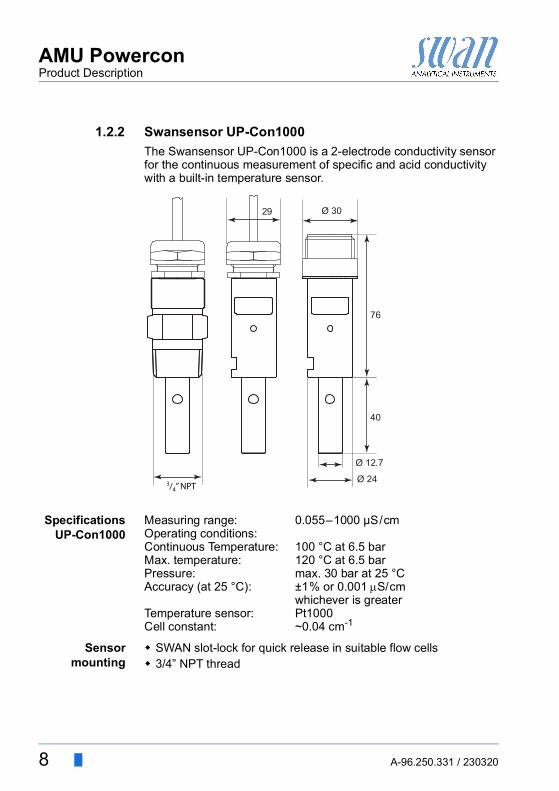
1.2.2 Swansensor UP-Con1000The Swansensor UP-Con1000 is a 2-electrode conductivity sensor for the continuous measurement of specific and acid conductivity with a built-in temperature sensor.
SpecificationsUP-Con1000
Measuring range: 0.055–1000 μS/cmOperating conditions:Continuous Temperature: 100 °C at 6.5 barMax. temperature: 120 °C at 6.5 barPressure: max. 30 bar at 25 °CAccuracy (at 25 °C): ±1% or 0.001 S/cm
whichever is greaterTemperature sensor: Pt1000Cell constant: ~0.04 cm-1
Sensormounting
SWAN slot-lock for quick release in suitable flow cells 3/4” NPT thread
Ø 3029
Ø 12.7
40
76
Ø 243/4” NPT
AMU PowerconProduct Description
A-96.250.331 / 230320 9
1.2.3 Flow CellsThe following flow cells can be used:For a slot-lock sensor: B-Flow UP-Con-SL. Q-Flow UP-Con-SL with integrated flow sensor. QV-Flow UP-Con-SL with integrated flow sensor and flow
regulating valve. Catconplus-SL with a built-in cation exchanger and flow regu-
lating valve.
For a 3/4” NPT thread UP-Con1000 sensor: B-Flow UP-Con. Q-Flow UP-Con with integrated flow sensor. QV-Flow UP-Con with integrated flow sensor and flow regu-
lating valve. Catcon with a built-in cation exchanger. Catconplus with a built-in cation exchanger and flow regulat-
ing valve.

10 A-96.250.331 / 230320
AMU PowerconInstallation
2. Installation
2.1. Installation Checklist
Check Instrument’s specification must conform to your AC power ratings. Do not turn on power until instructed to do so.
Installation The transmitter is intended for panel mounting. The dimensions are shown under Dimensions of the AMU Transmitter, p. 11.
Electrical con-nections
Connect all external devices, see Electrical Connections, p. 17.Connect the power cord, but do not switch on power until all exter-nal devices are connected.
Power-up Open sample flow and wait until flow cell is completely filled.Switch on power.Adjust sample flow.
Instrument setup
Program all sensor parameters see Sensor parameters, p. 23.Program the required temperature compensation.Program all parameters for external devices (interface, recorders, etc.).Program all parameters for instrument operation (limits, alarms).
Run-in period If the conductivity value of the sample is very low, the sensor might need some time until the correct reading is displayed.

AMU PowerconInstallation
A-96.250.331 / 230320 11
2.2. Dimensions of the AMU Transmitter
96 mm
89.8 mm
89.8
mm
112 mm
7 mm
96 m
m
92 m
m
92 mm

12 A-96.250.331 / 230320
AMU PowerconInstallation
2.3. Install the Flow CellExample 1
B-FlowUP-CON-SL
Technical Data Flow cell made of stainless steel SS316L. Insert for sensor with patented SWAN slotlock adapter for quick
sensor release. Operating temperature: up to +130 °C Operating pressure: max. 10 bar at +130 °C Process connections at inlet and outlet 2 x 1/8“ female ISO tapered thread
Installation The maximal recommended cable length is 15 m, select the instal-lation location accordingly. The flow cell must be aligned in exactly vertical position.
72
161 85
35
45
46
28

AMU PowerconInstallation
A-96.250.331 / 230320 13
Example 2Catcon+ SL The Flow cell Catcon+ SL is used for the measurement of the acid
(cation) conductivity. Only one sensor can be used together with the AMU Powercon. Therefore the left hand bore has to be closed with a blind plug.
Sampleconditions
Temperature: up to 50 °C Inlet pressure: 0.2 to 2 bar Outlet pressure: ambient pressure Sample flow: 5 to 20 l/h
Sampleconnection
Inlet: ¼" Swagelok tube adapter (SS) Outlet: 8/6 mm Serto tube adapter (PVDF)
Installation The maximal recommended cable length is 15 m, select the instal-lation location accordingly. The flow cell must be aligned in exactly vertical position.
235
38
5.362
361

14 A-96.250.331 / 230320
AMU PowerconInstallation
2.4. Connecting Sample Inlet and Outlet
2.4.1 Swagelok Fitting Stainless Steel at Sample InletPreparation Cut the tube to length and deburr it. The tube must be straight and
free from blemishes for approximately 1,5 x tube diameter from the end.Lubrication with lubricating oil, MoS2, Teflon etc. is recommended for the assembly and reassembly of bigger sized unions (thread, compression cone).
Installation 1 Insert the compression ferrule [C] and the compression cone [D] into the union nut [B].
2 Screw on the union nut onto the body, do not tighten it. 3 Push the stainless steel pipe through the union nut as far as it
reaches the stop of the body.4 Mark the union nut at 6 o’clock position.5 While holding the fitting body steady, tighten the nut union 1¼
rotation using an open ended spanner.
ABC
Stainless steel tubeUnion nutCompression ferrule
DEF
Compression coneBodyTightened connection
12
3
9
6
A B C D E
F

AMU PowerconInstallation
A-96.250.331 / 230320 15
2.4.2 FEP Tube at Sample Outlet
FEP flexible tube 6 mm
Connect the tube to the Serto elbow union and Insert it into an at-mospheric drain of sufficient capacity. Max. tube length is 1.5 m. Do not connect longer tubes.
2.5. Install the Conductivity Sensor
1 Make sure that the locking mechanism is in unlocked position (locking pin in position [G] and security screw in position [H]).
2 Put the sensor into the flow cell with the alignment marks [E] in line.
3 Turn the locking screw with a 5 mm allen key clockwise 180°.The locking pin moves up in lock position.
ABCD
Ellbow unionCompression ferruleKnurled nutFlexible tubeB
C
D
A
ABCDEFGH
Blind plugLocking pin lockedLocking screw closedFlow cellAlignment marksConductivity sensorLocking pin unlockedLocking screw openA
C
B
D
G
E
H
F
E

16 A-96.250.331 / 230320
AMU PowerconInstallation
2.6. Installation of Cation ExchangerCation ex-
changer bottleThe bottle containing the cation exchanger is delivered, but not in-stalled into the flow cell. For transport, an empty bottle has been installed into the flow cell.
Install cationexchanger
bottle
Install the resin bottle as follows:
1 Unscrew and remove the empty bottle [E] from the bottle holder [B].
2 Fill high purity water into the cation exchanger bottle [C], until the water level in the bottle reaches the beginning of the thread.
3 Carefully, without spilling water, push the cation exchanger bot-tle over the inlet filter holder [D] into the bottle holder [B].
4 Screw the cation exchanger bottle into the bottle holder.Do not tighten the bottle too firmly, this could damage the gasket.
ABCDE
Flow cellBottle holderCation exchanger bottleInlet filter holderEmpty bottle
A
BC
E
D

AMU PowerconInstallation
A-96.250.331 / 230320 17
2.7. Electrical Connections
CAUTION
Use only the terminals shown in this diagram, and only for the mentioned purpose. Use of any other terminals will cause short circuits with possible corresponding consequences to material and personnel.

18 A-96.250.331 / 230320
AMU PowerconInstallation
Rear viewof AMU
Transmitter
1
L
RS232
(+) (-)N
2 3 4 5 6 7 8 9
RON OFF A/PB B/PB
10 11 12 13 14
242322212019

AMU PowerconInstallation
A-96.250.331 / 230320 19
2.8. Power supply
CAUTION
Do not apply power to the transmitter until all electrical connec-tions have been made.
Installationrequirements
The installation must meet the following requirements: Mains cable according to standards IEC 60227 or IEC
60245; flammability rating FV1 Mains equipped with an external switch or circuit-breaker
– near the instrument– easily accessible to the operator– marked as interrupter for AMU Powercon
2.9. SensorConnect the sensor to the AMU transmitter according to the con-nection diagram, see Electrical Connections, p. 17.For sensor settings, see Programming, p. 23.
2.10. Flow MeterConnect the flow meter (if any) to the AMU transmitter according to the connection diagram, see Electrical Connections, p. 17.
2.11. Input
NOTICE: Use only potential-free (dry) contacts.Terminals 10/11For programming see Program List and Explanations, p. 44.
ABC
Power supply connectorPhase conductorNeutral conductorA
B
C

20 A-96.250.331 / 230320
AMU PowerconInstallation
2.12. Relay Contacts
2.12.1 Alarm Relay
NOTICE: Max. load 100 mA/50 VAlarm output for system errors. Error codes see Error List, p. 36.
2.12.2 Relay 1 and 2
NOTICE: Max. load 100 mA/50 VRelay 1: Terminals 1/2Relay 2: Terminals 3/4For programming see Program List and Explanations, p. 44, Menu Installation
2.13. Signal Output 1 and 2 (current outputs)
NOTICE: Max. burden 510 ΩIf signals are sent to two different receivers, use signal isolator (loop isolator).
Signal output 1: Terminals 13 (+) and 12 (-)Signal output 2: Terminals 14 (+) and 12 (-)For programming see Program List and Explanations, p. 44, Menu Installation
Terminals DescriptionNC a)
Normally Closed
a) As defined when ordering
5/6 Active (opened) during normal operation.Inactive (closed) on error and loss of power.
NO a)
Normally Open
5/6 Active (closed) during normal operation.Inactive (opened) on error and loss of power.

AMU PowerconInstallation
A-96.250.331 / 230320 21
2.14. Interfaces
2.14.1 RS232 InterfaceThe RS232 interface is located on the back of the AMU transmitter.
The RS232 interface is used for logger download and firmware up-load.
2.14.2 Profibus (optional)
To connect several instruments by means of a network or to config-ure a PROFIBUS DP connection, consult the PROFIBUS manual. Use appropriate network cable.
NOTICE: The switch must be ON if only one instrument is installed, or on the last instrument in the bus

22 A-96.250.331 / 230320
AMU PowerconInstallation
2.14.3 Modbus (optional)
To connect several instruments by means of a network consult the MODBUS manual. Use appropriate network cable.
NOTICE: The switch must be ON if only one instrument is installed, or on the last instrument in the bus

AMU PowerconInstrument Setup
A-96.250.331 / 230320 23
3. Instrument Setup
3.1. Establish sample flow
1 Open flow regulating valve.2 Wait until the flow cell has been completely filled.3 Switch on power.4 Adjust sample flow.5 Let the instrument run-in for 1 h.
This recommendation is valid for rinsed cation exchanger resin (nuclear grade) delivered by Swan. Not rinsed cation exchanger resin from other suppliers may require a run-in period of several hours to several days.
3.2. ProgrammingSensor
parametersProgram all sensor parameters in Menu 5.1.2.1,<Installation> <Sensors> <Sensor parameters>:
The sensor characteristics are printed on the label of each sensor.
Enter the: Cell constant [cm-1] Temperature correction [°C] Cable length Temperature compensation
87-344.203 UP-Con1000SL Sensor typeSW-xx-xx-xx ZK = 0.0417 Cell constantSWAN AG DT = 0.06 °C Temperature correction

24 A-96.250.331 / 230320
AMU PowerconInstrument Setup
Measuring unit Menu 5.1.1.2 Set the <Measuring unit> according to your requirements: S/cm S/m
Externaldevices
Program all parameters for external devices (interface, recorders, etc.) See program list and explanations 5.2 Signal Outputs, p. 48 and 4.2 Relay Contacts, p. 46.
Limits Alarms Program all parameters for instrument operation (limits, alarms). See program list and explanations 4.2 Relay Contacts, p. 46.
Temp.Compensation
Menu 5.1.3Choose between: none Coefficient Neutral salts High-purity water Strong acids Strong bases Ammonia, Ethanolamine Morpholine

AMU PowerconOperation
A-96.250.331 / 230320 25
4. Operation
4.1. Keys
ProgramAccess, Exit
A to exit a menu or command (rejecting any changes)to move back to the previous menu level
B to move DOWN in a menu list and to decrease digitsC to move UP in a menu list and to increase digitsD to open a selected sub-menu
to accept an entry
Exit Enter
A B C D
25.4°C
RUN
9 l/h
14:10:45R1
0.178 SR2
1
InstallationOperation
DiagnosticsMessages
Maintenance
Main MenuEnter
Exit

26 A-96.250.331 / 230320
AMU PowerconOperation
4.2. Display
Relay status, symbols
A RUN normal operationHOLD input closed or cal delay: Instrument on hold (shows
status of signal outputs).OFF input closed: control/limit is interrupted (shows status
of signal outputs).B ERROR Error Fatal Error
C Keys locked, transmitter control via ProfibusD TimeE Process valuesF Sample temperatureG Sample flowH Relay status
upper/lower limit not yet reachedupper/lower limit reachedcontrol upw./downw. no action
control upw./downw. active, dark bar indicates control intensity
motor valve closedmotor valve: open, dark bar indicates approx. positiontimertimer: timing active (hand rotating)
RUN 15:20:18
R1
R2
9.5 l/h 21.8°C
µS0.178
A B D
H
G
EE
F
C

AMU PowerconOperation
A-96.250.331 / 230320 27
4.3. Software Structure
Menu Messages 1Reveals pending errors as well as an event history (time and state of events that have occurred at an earlier point of time). It contains user relevant data.
Menu Diagnostics 2Provides user relevant instrument and sample data.
Menu Maintenance 3For instrument calibration, relay and signal output simulation, and to set the instrument time. It is used by the service personnel.
Menu Operation 4User relevant parameters that might need to be modified during daily routine. Normally password protected and used by the process-operator.Subset of menu 5 - Installation, but process-related.
Menu Installation 5For initial instrument set up by SWAN authorized person, to set all instrument parameters. Can be protected by means of password.
1
Messages
OperationMaintenanceDiagnostics
Main Menu
Installation
1.1
Pending ErrorsMessages
Message List
2.1
InterfaceI/O StateSample
IdentificationSensors
Diagnostics
3.1
CalibrationMaintenance
Set Time 23.11.12 16:30:00Simulation
4.1
LoggerRelay ContactsSensorsOperation
5.1
InterfaceMiscellaneousRelay Contacts
SensorsSignal Outputs
Installation

28 A-96.250.331 / 230320
AMU PowerconOperation
4.4. Changing Parameters and valuesChanging
parametersThe following example shows how to set the Q-Flow sensor:
Changingvalues
1 Select the parameter you want to change.
2 Press <Enter>
3 Press [ ] or [ ] key to highlight the required parameter.
4 Press <Enter> to confirm the se-lection or <Exit> to keep the previ-ous parameter).
The selected parameter is indicated (but not saved yet).
5 Press <Exit>.
Yes is highlighted.6 Press <Enter> to save the new pa-
rameter. The system reboots, the new
parameter is set.
5.1.1SensorsFlow NoneSensor parameters
Quality AssuranceTemp. Compensation
Sensor parameters
Quality AssuranceTemp. Compensation
5.1.1SensorsFlow NoneFlow
NoneQ-Flow
5.1.1SensorsFlow Q-FlowSensor parameters
Quality AssuranceTemp. Compensation
Sensor parameters
Quality AssuranceTemp. Compensation
5.1.1SensorsFlow Q-Flow
No
Save ?Yes
1 Select the value you want to change.
2 Press <Enter>.3 Set required value with [ ] or
[ ] key.
4 Press <Enter> to confirm the new value.
5 Press <Exit>.Yes is highlighted.
6 Press <Enter> to save the new value.
5.3.1.1.1
Alarm High 300mSAlarm Conductivity
Alarm Low 0.000 SHysteresis 1.00 SDelay 5 Sec
5.3.1.1.1Alarm Conductivity
Alarm Low 0.000 SHysteresis 1.00 SDelay 5 Sec
Alarm High 120 mS

AMU PowerconMaintenance
A-96.250.331 / 230320 29
5. Maintenance
WARNING
Stop operation before maintenance. Stop sample flow. Shut off power of the instrument.
5.1. Maintenance SchedulePreventive maintenance frequency depends on water quality, on the application, and on national regulations.
Reagentconsumption
A 1 l resin bottle delivered by Swan lasts at 1 ppm alcalizing re-agent (pH 9.4) for: 4 months at sample flow 10 l/h 5 months at sample flow 5 l/h
5.2. Stop of Operation for Maintenance
1 Stop sample flow.2 Shut off power of the instrument.
Monthly Check sample flow. Check cation exchanger resin (if any). The resin color
changes to red/orange if exhausted.
If required Clean conductivity sensor. Replace the inlet filter of the cation exchanger bottle (if
any).

30 A-96.250.331 / 230320
AMU PowerconMaintenance
5.3. Maintenance of the Sensor
5.3.1 Remove the Sensor from the Flow CellTo remove the sensor from the flow cell proceed as follows:
1 Press the locking pin [G] down.2 Turn the locking screw [H] counterclockwise 180° using a 5 mm
Allen key.The locking pin remains down.
3 Remove the sensor.
Cleaning If the sensor is slightly contaminated, clean it with soapy water and a pipe cleaner. If the sensor is strongly contaminated, dip the tip of the sensor into 5% hydrochloric acid for a short time.
5.3.2 Install the Sensor into the Flow Cell
1 Make sure that the locking mechanism is in unlocked position (locking pin in position [G] and security screw in position [H]).
2 Put the sensor into the flow cell with the alignment marks [E] in line.
3 Turn the locking screw clockwise 180° using a 5 mm Allen key.The locking pin moves up in lock position.
ABCDEFGH
Blind plugLocking pin lockedLocking screw closedFlow cellAlignment marksConductivity sensorLocking pin unlockedLocking screw openA
C
B
D
G
E
H
F
E

AMU PowerconMaintenance
A-96.250.331 / 230320 31
5.4. Changing the Ion ExchangerThe resin of the ion exchanger changes its color from dark violet to brown if the capacity is exhausted. The resin should be changed before no violet resin is left or the cation conductivity rises above the normal value. At a concentration of 1 ppm alcalizing reagent, one resin filling will last for roughly 4 months if sample flow is 10 l/h, or 5 months if sample flow is 5 l/h.
1 Stop sample flow. 2 Slightly squeeze the exhausted cation exchanger bottle [E] be-
fore removing. Thus no water will spill out of the flow cell when loosening
the bottle.3 Unscrew and carefully remove the exhausted cation exchanger
bottle [E].4 Fill high purity water into the new cation exchanger bottle [C],
until the water level in the bottle reaches the beginning of the thread.
5 Carefully, without spilling water, push the cation exchanger bot-tle over the inlet filter holder [D] into the bottle holder [B].
6 Screw the cation exchanger bottle into the bottle holder.Do not tighten the bottle too firmly, this could damage the gasket.
7 Open and adjust the sample flow.
ABC
DE
Flow cellBottle holderNew cation exchanger bottleInlet filter holderExhausted cation exchanger bottle
A
B
DC
E

32 A-96.250.331 / 230320
AMU PowerconMaintenance
8 Pre-rinse the new cation exchanger resin until the display shows stable measuring values.
Operation time 1 liter Swan resinThis graphic shows the average exhaust time (flow 6 l/h) and must be verified by the user.
Cation Conductivity.Operational Days for 1 l of Cation Exchange Resin with an Ex-change Capacity of 1.8 eq/l.Flow Rate 6 l/h Alkalization with Ammonia. (Safety Margin of 15% Subtracted).
08.8 9.0 9.2 9.4 9.6 9.8 10.0 10.2
pH
Days
100
200
300
400
500
600
700

AMU PowerconMaintenance
A-96.250.331 / 230320 33
5.5. Changing the inlet filterThe inlet filter of the cation exchanger prevents the resin from en-tering the flow cell. It is located in the inlet filter holder [B].
1 Stop sample flow. 2 Slightly squeeze the cation exchanger bottle [E] before remov-
ing. Thus no water will spill out of the flow cell when loosening
the bottle.3 Unscrew and carefully remove the cation exchanger bottle.4 For better access to the Allen screws [C] unscrew and remove
the filter holder [B] from the bottle holder [A].5 Loosen the 4 Allen screws with a 1.5 mm Allen key.6 Carefully remove the inlet filter [D] with a screw driver no.0 from
the inlet filter holder.7 Insert a new inlet filter.8 Tighten the 4 Allen screws slightly.9 Screw the cation exchanger bottle into the bottle holder.
Do not tighten the bottle too firmly, this could damage the gasket.
ABCD
Bottle holderInlet filter holderAllen screwsInlet filter
A
B
C
D

34 A-96.250.331 / 230320
AMU PowerconMaintenance
5.6. CalibrationIf you use a UP-Con1000 sensor it is not necessary to calibrate the instrument. A zero measurement is automatically performed every day at 00:30 AM.A calibration is necessary if the cell constant of a sensor is not known. To perform a calibration proceed as follows:
1 Stop the sample flow.2 Navigate to menu Maintenance /Calibration.3 Press [Enter] and follow the dialog on the display.4 Remove the sensor from the flow cell.5 Clean the sensor carefully and rinse it with clean water, see
Maintenance of the Sensor, p. 30.6 Use a one liter beaker and fill it with one liter of calibration solu-
tion.7 Put the sensor into the beaker filled with calibration solution.
8 Wait at least 5 minutes to permit temperature equilibration between sensor and calibration solution.
9 Start the calibration procedure.
10 Press [Enter], to save the values if the calibration was successful.
11 Install the sensor into the flow cell.
3.1.5CalibrationClean the sensor
and place it instandard solution
<Enter> to continue
3.1.5CalibrationSensor must have amin. distance of 3 cm
from the beakers edge
<Enter> to continue
3.1.1CalibrationStandard solution 1.41 mSCurrent Value 10.07 SCell constant 0.406 cm-1
Progress
AMU PowerconMaintenance
A-96.250.331 / 230320 35
NOTICE: The temperature algorithm of the 1.413 mS/cm at 25 °C calibration solution is stored in the AMU Powercon transmitter. Provided that the calibration solution has a temperature between 5 °C and 50 °C, and the built-in temperature sensor is in temperature equilibrium with the solution by waiting at least 5 minutes, a correct calibration will be made (independent of the chosen temperature compensation set in menu 5.1.3.1). During calibration, control is interrupted. The signal outputs are frozen if hold has been programmed (menu 4.2.4.2). Otherwise the outputs track the measuring value. Hold after calibration is indicated by Hold on the display.
5.7. Longer Stop of Operation
1 Stop sample flow. 2 Slightly squeeze the ion exchanger bottle.
Thus no water will spill out of the flow cell when loosening the bottle.
3 Unscrew and carefully remove the ion exchanger bottle with the exhausted resin.
4 Close the ion exchanger bottle with the screw cover and store it in a frost-protected room.
5 Screw on an empty bottle.6 Shut off power of the instrument.
36 A-96.250.331 / 230320
AMU PowerconError List
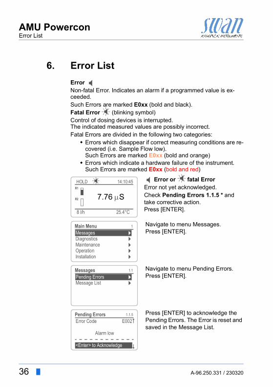
6. Error ListError Non-fatal Error. Indicates an alarm if a programmed value is ex-ceeded.Such Errors are marked E0xx (bold and black).Fatal Error (blinking symbol)Control of dosing devices is interrupted.The indicated measured values are possibly incorrect.Fatal Errors are divided in the following two categories: Errors which disappear if correct measuring conditions are re-
covered (i.e. Sample Flow low).Such Errors are marked E0xx (bold and orange)
Errors which indicate a hardware failure of the instrument.Such Errors are marked E0xx (bold and red)
Error or fatal ErrorError not yet acknowledged.Check Pending Errors 1.1.5 * and take corrective action.Press [ENTER].
Navigate to menu Messages.Press [ENTER].
Navigate to menu Pending Errors.Press [ENTER].
Press [ENTER] to acknowledge the Pending Errors. The Error is reset and saved in the Message List.
25.4°C
HOLD
8 l/h
14:10:45R1
7.76 SR2
1
InstallationOperation
DiagnosticsMessages
Maintenance
Main Menu
1.1
Pending ErrorsMessage List
Messages
1.1.5Pending ErrorsError Code E002
Alarm low
<Enter> to Acknowledge

AMU PowerconError List
A-96.250.331 / 230320 37
Error Description Corrective actionE001 Cond. Alarm high – check process
– check programmed value, see 5.3.1.1, p. 53
E002 Cond. Alarm low – check process– check programmed value, see 5.3.1.1,
p. 53
E007 Sample Temp. high – check process– check programmed value, see 5.3.1.3,
p. 53
E008 Sample Temp. low – check process– check programmed value, see 5.3.1.3,
p. 53
E009 Sample Flow high – check sample inlet pressure– check programmed value, see
5.3.1.2.2, p. 53
E010 Sample Flow low – check sample inlet pressure– Check flow regulating valve– check programmed value, see
5.3.1.2.35, p. 53
E011 Temp. shorted – Check wiring of temperature sensor– Check temperature sensor
E012 Temp. disconnected – Check wiring of temperature sensor– Check temperature sensor
E013 Case Temp. high – check case/environment temperature– check programmed value, see 5.3.1.4,
p. 54
E014 Case Temp. low – check case/environment temperature– check programmed value, see 5.3.1.5,
p. 54
E017 Control time-out – Check control device or programming in Installation, Relay contact, Relay 1/2 5.3.2/3, p. 54
E018 Quality Assurance – Perform QA Procedure using reference instrument, e.g. AMI Inspector
38 A-96.250.331 / 230320
AMU PowerconError List
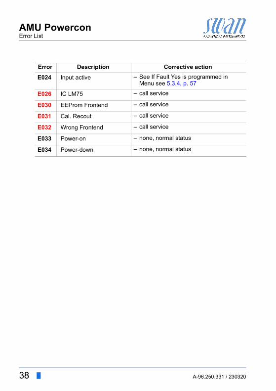
E024 Input active – See If Fault Yes is programmed in Menu see 5.3.4, p. 57
E026 IC LM75 – call service
E030 EEProm Frontend – call service
E031 Cal. Recout – call service
E032 Wrong Frontend – call service
E033 Power-on – none, normal status
E034 Power-down – none, normal status
Error Description Corrective action
AMU PowerconProgram Overview
A-96.250.331 / 230320 39
7. Program Overview
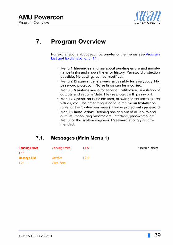
For explanations about each parameter of the menus see Program List and Explanations, p. 44.
Menu 1 Messages informs about pending errors and mainte-nance tasks and shows the error history. Password protection possible. No settings can be modified.
Menu 2 Diagnostics is always accessible for everybody. No password protection. No settings can be modified.
Menu 3 Maintenance is for service: Calibration, simulation of outputs and set time/date. Please protect with password.
Menu 4 Operation is for the user, allowing to set limits, alarm values, etc. The presetting is done in the menu Installation (only for the System engineer). Please protect with password.
Menu 5 Installation: Defining assignment of all inputs and outputs, measuring parameters, interface, passwords, etc. Menu for the system engineer. Password strongly recom-mended.
7.1. Messages (Main Menu 1)
Pending Errors Pending Errors 1.1.5* * Menu numbers1.1*Message List Number 1.2.1*1.2* Date, Time

40 A-96.250.331 / 230320
AMU PowerconProgram Overview
7.2. Diagnostics (Main Menu 2)
Identification Designation AMU Powercon * Menu numbers 2.1* Version V6.20-07/16
Factory Test Instrument 2.1.3.1*2.1.3* Motherboard
Front EndOperating Time Years / Days / Hours / Minutes / Seconds 2.1.4.1*2.1.4*
Sensors Cond. Sensor Current value2.2* 2.2.1* Raw value
Cell constantCal. History Number, Date, Time 2.2.1.5.1*2.2.1.5*
Miscellaneous Case Temp. 2.2.2.1*2.2.2*
Sample Sample ID 2.3.1*2.3* Temperature
(Pt1000)Sample FlowRaw value
I/O State Alarm Relay 2.4.1*2.4* Relay 1 /2 2.4.2*
InputSignal Output 1/2
Interface Protocol 2.5.1*2.5* Baud rate
AMU PowerconProgram Overview
A-96.250.331 / 230320 41
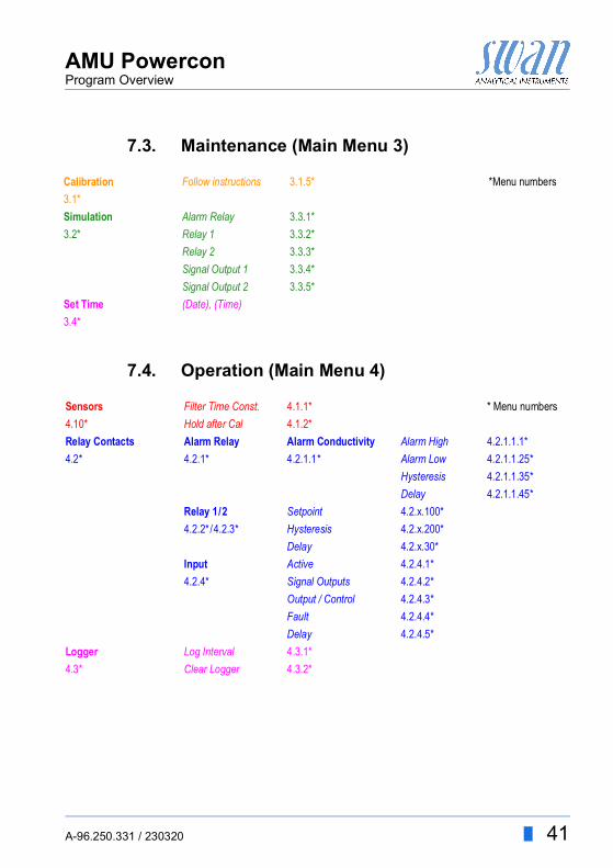
7.3. Maintenance (Main Menu 3)
7.4. Operation (Main Menu 4)
Calibration Follow instructions 3.1.5* *Menu numbers3.1*Simulation Alarm Relay 3.3.1*3.2* Relay 1 3.3.2*
Relay 2 3.3.3*Signal Output 1 3.3.4*Signal Output 2 3.3.5*
Set Time (Date), (Time)3.4*
Sensors Filter Time Const. 4.1.1* * Menu numbers4.10* Hold after Cal 4.1.2*Relay Contacts Alarm Relay Alarm Conductivity Alarm High 4.2.1.1.1*4.2* 4.2.1* 4.2.1.1* Alarm Low 4.2.1.1.25*
Hysteresis 4.2.1.1.35*Delay 4.2.1.1.45*
Relay 1/2 Setpoint 4.2.x.100*4.2.2*/4.2.3* Hysteresis 4.2.x.200*
Delay 4.2.x.30*Input Active 4.2.4.1*4.2.4* Signal Outputs 4.2.4.2*
Output / Control 4.2.4.3*Fault 4.2.4.4*Delay 4.2.4.5*
Logger Log Interval 4.3.1*4.3* Clear Logger 4.3.2*

42 A-96.250.331 / 230320
AMU PowerconProgram Overview
7.5. Installation (Main Menu 5)
Sensors Flow None *Menu numbers5.1* 5.1.1* Q-Flow
Sensor parameters Cell Constant 5.1.2.1*5.1.2* Temp. Corr. 5.1.2.2*
Cable length 5.1.2.3*Meas. unit 5.1.2.4
Temp.Compensation Comp. none5.1.3* 5.1.3.1* Coefficient
Neutral saltsHigh-purity waterStrong acidsStrong bassAmmonia, EthamMorpholine
Quality Assurance Level 0: Off5.1.4* 5.1.4.1* 1: Trend
2: Standard3: Crucial
Signal Outputs Signal Output 1/2 Parameter 5.2.1.1/5.2.2.1* 5.2* 5.2.1 /5.2.2* Current Loop 5.2.1.2/5.2.2.2*
Function 5.2.1.3/5.2.2.3*Scaling Range Low 5.2.x.40.10/11*5.2.x.40 Range High 5.2.x.40.20/21*
Relay Contacts Alarm Relay Alarm Conductivity Alarm High 5.3.1.1.1.1* 5.3* 5.3.1* 5.3.1.1* Alarm Low 5.3.1.1.1.25*
Hysteresis * 5.3.1.1.1.35Delay 5.3.1.1.1.45*
Sample Flow Flow Alarm 5.3.1.2.1*5.3.1.2* Alarm High 5.3.1.2.2
Alarm Low 5.3.1.2.35Sample Temp. Alarm High 5.3.1.3.1*5.3.1.3* Alarm Low 5.3.1.3.25*Case Temp.high 5.3.1.4*Case Temp.low 5.3.1.5*

AMU PowerconProgram Overview
A-96.250.331 / 230320 43
Relay 1 /2 Function 5.3.2.1 / 5.3.3.1* * Menu numbers5.3.2 /5.3.3* Parameter 5.3.2.20/ 5.3.3.20*
Setpoint 5.3.2.300 / 5.3.3.301*Hysteresis 5.3.2.400/ 5.3.3.401*Delay 5.3.2.50/ 5.3.3.50*
Input Active 5.3.4.1*5.3.4* Signal Outputs 5.3.4.2*
Output/Control 5.3.4.3*Fault 5.3.4.4*Delay 5.3.4.5*
Miscellaneous Language 5.4.1*5.4* Set defaults 5.4.2*
Load Firmware 5.4.3*Password Messages 5.4.4.1*5.4.4* Maintenance 5.4.4.2*
Operation 5.4.4.3*Installation 5.4.4.4*
Sample ID 5.4.5*Interface Protocol 5.5.1*5.5* Device Address 5.5.21*
Baud Rate 5.5.31*Parity 5.5.41*

44 A-96.250.331 / 230320
AMU PowerconProgram List and Explanations
8. Program List and Explanations
1 Messages1.1 Pending Errors
1.1.5 Provides the list of active errors with their status (active, acknowl-edged). If an active error is acknowledged, the alarm relay is active again. Cleared errors are moved to the Message list.
1.2 Message List1.2.1 Shows the error history: Error code, date / time of issue and status
(active, acknowledged, cleared). 65 errors are memorized. Then the oldest error is cleared to save the newest error (circular buffer).
2 DiagnosticsIn diagnostics mode, the values can only be viewed, not modified.
2.1 IdentificationDesig.: Designation of the instrument.Version: Firmware of the instrument (e.g. V6.20-07/16)
2.1.4 Factory Test: Test date of the instrument, motherboard and frontend
2.1.5 Operating Time: years / days / hours / minutes / seconds
2.2 Sensors2.2.1 Cond. Sensor
Current value in µSRaw value in µSCell Constant
2.2.1.4 QA History: Review the QA values (Number, Date-Time, Deviation Conductivity, Deviation Temperature) of the last quality assurance procedures. Only for diagnostic purpose. Max. 65 data records are memorized.
2.2.1.5 Cal. History: Review diagnostic values of the last calibrations.Only for diagnostic purpose.Number; Date, TimeCell constantMax. 64 data records are memorized. One process calibration cor-responds to one data record.

AMU PowerconProgram List and Explanations
A-96.250.331 / 230320 45
2.2.2 Miscellaneous:2.2.2.1 Case Temp: Shows the current temperature in [°C] inside the trans-
mitter.
2.3 Sample2.3.1 Sample ID: Shows the identification assigned to a sample. This
identification is defined by the user to identify the location of the sample.Temperature: Shows the current sample temperature in °C.(Pt 1000): Shows the current temperature in Ohm.Sample Flow: Shows the current sample flow in l/h and the raw value in Hz.
2.4 I/O StateShows current status of all in- and outputs.
2.4.1/2.4.2
2.5 InterfaceOnly available if optional interface is installed.Review programmed communication settings.
3 Maintenance3.1 Calibration
Follow the commands on the screen. Save the value with the <en-ter> key.
3.2 SimulationTo simulate a value or a relay state, select the alarm relay, relay 1 and 2 signal output 1 and 2
with the [ ] or [ ] key.Press the <Enter> key.Change the value or state of the selected item with the [ ] or [ ] key. Press the <Enter> key.
Alarm Relay: Active or inactive.Relay 1 and 2: Active or inactive.Input: Open or closed.Signal Output 1 and 2: Actual current in mA

46 A-96.250.331 / 230320
AMU PowerconProgram List and Explanations
The value is simulated by the relay/signal output.
At the absence of any key activities, the instrument will switch back to normal mode after 20 min. If you quit the menu, all simulated val-ues will be reset.
3.3 Set TimeAdjust date and time.
3.3 Quality Assurance3.4.5 Follow the commands on the screen. Save the value with the
<Enter> key.
4 Operation4.1 Sensors
4.1.1 Filter Time Constant: Used to damp noisy signals. The higher the filter time constant, the slower the system reacts to changes of the measured value.Range: 5–300 Sec
4.1.2 Hold after Cal.: Delay permitting the instrument to stabilize again af-ter calibration. During calibration plus hold-time, the signal outputs are frozen (held on last valid value), alarm values, limits are not ac-tive.Range: 0–6‘000 Sec
4.2 Relay ContactsSee Relay Contacts, p. 20
4.3 LoggerThe instrument is equipped with an internal logger. The logger data can be downloaded to a PC using the built-in RS232 interface.The logger can save approx. 1500 data records. The Records con-sists of: Date, time, alarms, measured value, measured value un-compensated, temperature, flow.Range: 1 second to 1 hour
Alarm Relay: Active or inactive.Relay 1 and 2: Active or inactive.Signal Output 1 and 2: Actual current in mA

AMU PowerconProgram List and Explanations
A-96.250.331 / 230320 47
4.3.1 Log Interval: Select a convenient log interval. Consult the table be-low to estimate the max logging time. When the logging buffer is full, the oldest data record is erased to make room for the newest one (circular buffer).
4.3.2 Clear Logger: If confirmed with yes, the complete logger data is de-leted. A new data series is started.
5 Installation5.1 Sensors
5.1.1 Flow: None Q-Flow
Select “Q-Flow” if the sample flow should be monitored and shown on the display and when using a SWAN flow cell.
5.1.2 Sensor parameters5.1.2.1 Cell Constant: Enter the cell constant printed on the sensor label.
Range: 0.005000 cm-1–11.00 cm-1
5.1.2.2 Temp. Corr: Enter the temperature correction printed on the sensor label.Range: -2 °C to 2 °C
5.1.2.3 Cable length: Enter the cable length.Range: 0.0 m to 30.0 m
5.1.2.4 Meas. unit: Select the measuring unit as S/cm or as S/m.
Interval 1 s 5 s 1 min 5 min 10 min 30 min 1 h
Time 25 min 2 h 25 h 5 d 10 d 31 d 62 d
48 A-96.250.331 / 230320
AMU PowerconProgram List and Explanations
5.1.3 Temp. comp:5.1.3.1 Comp.: Available compensation models are:
none Coefficient Neutral salts High purity water Strong acids Strong bases Ammonia, Eth.am. Morpholine
5.1.4 Quality Assurance: Switch the Quality Assurance on or off.5.1.4.1 Level: Select quality level:
Level 0: OffQuality assurance procedure switched off. Any additional QA menus are hidden.
Level 1: Trend Level 2: Standard Level 3: Crucial Level 4: User
Edit user specific limits in menu 5.1.4.2
5.2 Signal Outputs
NOTICE: The navigation in the menu <Signal Output 1> and <Signal Output 2> is equal. For reason of simplicity only the menu numbers of Signal Output 1 are used in the following.
5.2.1 Signal Output 1: Assign process value, the current loop range and a function to each signal output.
5.2.1.1 Parameter: Assign one of the process values to the signal output.Available values: Conductivity Temperature Sample flow Cond. uc
5.2.1.2 Current Loop: Select the current range of the signal output.Make sure the connected device works with the same current range.Available ranges: 0–20 mA or 4–20 mA
AMU PowerconProgram List and Explanations
A-96.250.331 / 230320 49
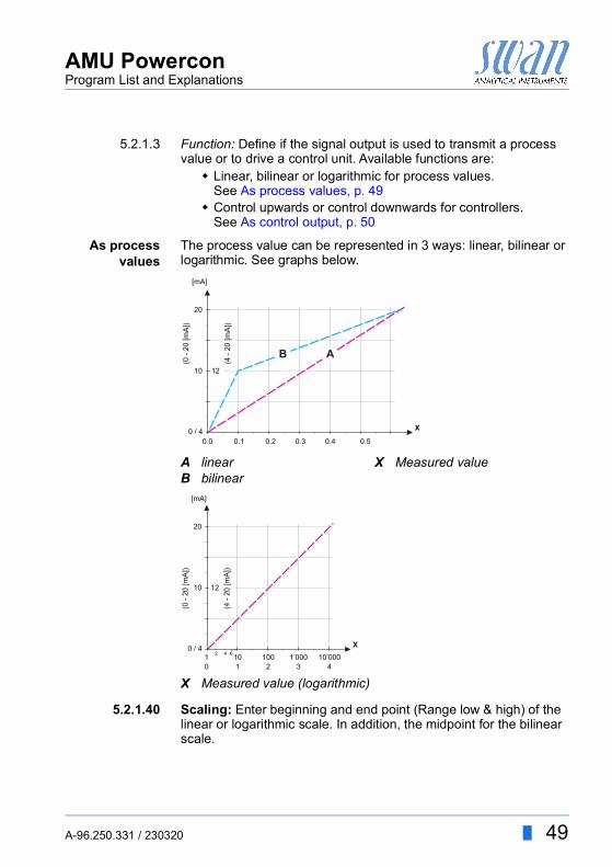
5.2.1.3 Function: Define if the signal output is used to transmit a process value or to drive a control unit. Available functions are: Linear, bilinear or logarithmic for process values.
See As process values, p. 49 Control upwards or control downwards for controllers.
See As control output, p. 50
As processvalues
The process value can be represented in 3 ways: linear, bilinear or logarithmic. See graphs below.
5.2.1.40 Scaling: Enter beginning and end point (Range low & high) of the linear or logarithmic scale. In addition, the midpoint for the bilinear scale.
AB
linearbilinear
X Measured value
X Measured value (logarithmic)
20
0.0 0.1 0.2 0.3 0.4 0.5
10 12
(0 -
20 [m
A])
0 / 4
(4 -
20 [m
A])
[mA]
X
AB
20
10 1 2 3 4
10 100 1’000 10’000
10 12
(0 -
20 [m
A])
0 / 442 6
(4 -
20 [m
A])
[mA]
X

50 A-96.250.331 / 230320
AMU PowerconProgram List and Explanations
Parameter Conductivity:5.2.1.40.10 Range low: 0 S–300 mS5.2.1.40.20 Range high: 0 S–300 mS
Parameter Temperature5.2.1.40.11 Range low: -25 to +270 °C5.2.1.40.21 Range high: -25 to +270 °C
Parameter Sample flow5.2.1.40.12 Range low: 0–50 l/h5.2.1.40.22 Range high: 0–50 l/h
Parameter Cond. uc:5.2.1.40.13 Range low: 0 S–300 mS5.2.1.40.23 Range high: 0 S–300 mS
As controloutput
Signal outputs can be used for driving control units. We distinguish different kinds of controls: P-controller: The controller action is proportional to the devia-
tion from the setpoint. The controller is characterized by the P-Band. In the steady-state, the setpoint will never be reached. The deviation is called steady-state error.Parameters: setpoint, P-Band
PI-controller: The combination of a P-controller with anI-controller will minimize the steady-state error. If the reset time is set to zero, the I-controller is switched off.Parameters: setpoint, P-Band, reset time.
PD-controller: The combination of a P-controller with a D-controller will minimize the response time to a fast change of the process value. If the derivative time is set to zero, the D-controller is switched off.Parameters: setpoint, P-Band, derivative time.
PID-controller: The combination of a P-, an I- and a D-control-ler allows a proper control of the process.Parameters: setpoint, P-Band, reset time, derivative time.
Ziegler-Nichols method for the optimization of a PID controller:Parameters: Setpoint, P-Band, Reset time, Derivative time

AMU PowerconProgram List and Explanations
A-96.250.331 / 230320 51
The point of intersection of the tangent with the respective axis will result in the parameters a and L.Consult the manual of the control unit for connecting and program-ming details. Choose control upwards or downwards.
Control upwards or downwardsSetpoint: User-defined process value for the selected parameter.P-Band: Range below (upwards control) or above (downwards con-trol) the set-point, within the dosing intensity is reduced from 100% to 0% to reach the setpoint without overshooting.
5.2.1.43 Control Parameters: if Parameters = Conductivity5.2.1.43.10 Setpoint
Range: 0 S–300 mS5.2.1.43.20 P-Band:
Range: 0 S–300 mS
5.2.1.43 Control Parameters: if Parameters = Temperature5.2.1.43.11 Setpoint
Range: -25 to +270 °C5.2.1.43.21 P-Band:
Range: 0 to +100 °C
ABX
Response to maximum control outputTangent on the inflection pointTime
XpTnTv
= 1.2/a= 2L= L/2
X
Y
B A
L
a
52 A-96.250.331 / 230320
AMU PowerconProgram List and Explanations
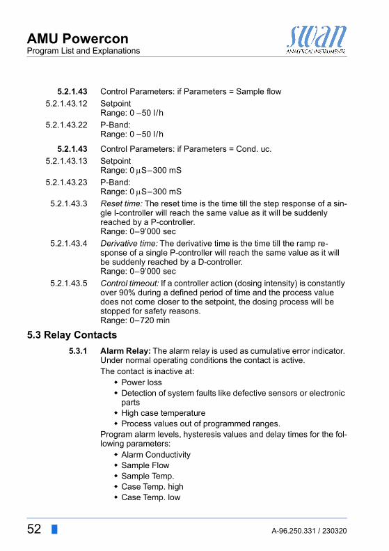
5.2.1.43 Control Parameters: if Parameters = Sample flow5.2.1.43.12 Setpoint
Range: 0 –50 l/h5.2.1.43.22 P-Band:
Range: 0 –50 l/h
5.2.1.43 Control Parameters: if Parameters = Cond. uc.5.2.1.43.13 Setpoint
Range: 0 S–300 mS5.2.1.43.23 P-Band:
Range: 0 S–300 mS5.2.1.43.3 Reset time: The reset time is the time till the step response of a sin-
gle I-controller will reach the same value as it will be suddenly reached by a P-controller.Range: 0–9’000 sec
5.2.1.43.4 Derivative time: The derivative time is the time till the ramp re-sponse of a single P-controller will reach the same value as it will be suddenly reached by a D-controller.Range: 0–9’000 sec
5.2.1.43.5 Control timeout: If a controller action (dosing intensity) is constantly over 90% during a defined period of time and the process value does not come closer to the setpoint, the dosing process will be stopped for safety reasons.Range: 0–720 min
5.3 Relay Contacts5.3.1 Alarm Relay: The alarm relay is used as cumulative error indicator.
Under normal operating conditions the contact is active.The contact is inactive at: Power loss Detection of system faults like defective sensors or electronic
parts High case temperature Process values out of programmed ranges.
Program alarm levels, hysteresis values and delay times for the fol-lowing parameters: Alarm Conductivity Sample Flow Sample Temp. Case Temp. high Case Temp. low

AMU PowerconProgram List and Explanations
A-96.250.331 / 230320 53
5.3.1.1 Alarm Conductivity5.3.1.1.1 Alarm High: If the measured value rises above the alarm high val-
ue, the alarm relay is activated and E001, is displayed in the mes-sage list.Range: 0 S–300 mS
5.3.1.1.25 Alarm Low: If the measured value falls below the alarm low value, the alarm relay is activated and E002 is displayed in the message list.Range: 0 S–300 mS
5.3.1.1.35 Hysteresis: Within the hyst. range, the relay does not switch. This prevents damage of relays contacts when the measured value fluc-tuates around the alarm value.Range. 0 S–300 mS
5.3.1.1.45 Delay: Duration, the activation of the alarm relay is retarded after the measuring value has risen above/fallen below the programmed alarm.Range: 0–28‘800 Sec
5.3.1.2 Sample Flow: Define at which sample flow an alarm should be is-sued.
5.3.1.2.1 Flow Alarm: Program if the alarm relay should be activated if there is a flow alarm. Choose between yes or no. The flow alarm will always be indicated in the display, pending error list, saved in the message list and the logger.Available values: Yes or no
NOTICE: Sufficient flow is essential for a correct measurement.We recommend to program yes.
5.3.1.2.2 Alarm High: If the measuring values rises above the programmed value E009 will be issued.Range: 10–50 l/h
5.3.1.2.35 Alarm Low: If the measuring values falls below the programmed value E010 will be issued.Range: 0–9 l/h
5.3.1.3 Sample Temp.5.3.1.3.1 Alarm High: If the measured value rises above the alarm high val-
ue, the alarm relay is activated and E007, is displayed in the mes-sage list. Range: 30–200 °C

54 A-96.250.331 / 230320
AMU PowerconProgram List and Explanations
5.3.1.3.25 Alarm Low: If the measured value falls below the alarm low value, the alarm relay is activated and E008 is displayed in the message list.Range: -10 to +20 °C
5.3.1.4 Case Temp. high: Set the alarm high value for temperature of elec-tronics housing. If the value rises above the programmed value E013 is issued.Range: 30–75 °C
5.3.1.5 Case Temp. low: Set the alarm low value for temperature of elec-tronics housing. If the value falls below the programmed value E014 is issued.Range: -10 to +20 °C
5.3.2/3 Relay 1 and 2: The function of relay contacts 1 or 2 is defined by the user.
NOTICE: The navigation in the menu <Relay 1> and <Relay 2> is equal. For reason of simplicity only the menu numbers of Relay 1 are used in the following.
1 First select the functions as:- Limit upper/lower, - Control upwards/downwards, - Timer - Fieldbus
2 Then enter the necessary data depending on the selected func-tion. The same values may also be entered in menu 4.2 Relay Contacts, p. 46
When the relays are used as upper or lower limit switches, program the following:
5.3.2.20 Parameter: select a process value5.3.2.300 Setpoint: If the measured value rises above respectively falls below
the set-point, the relay is activated.
5.3.2.1 Function = Limit upper/lower:
Parameter Range Conductivity 0 S–300 mSTemperature -25 to +270 °CSample flow 0–50 l/hCond. uc 0 S–300 mS

AMU PowerconProgram List and Explanations
A-96.250.331 / 230320 55
5.3.2.400 Hysteresis: within the hysteresis range, the relay does not switch. This prevents damage of relay contacts when the measured value fluctuates around the alarm value.
5.3.2.50 Delay: Duration, the activation of the alarm relay is retarded after the measuring value has risen above/fallen below the programmed alarm.Range. 0–600 Sec
The relays may be used to drive control units such as solenoid valves, membrane dosing pumps or motor valves. When driving a motor valve both relays are needed, relay 1 to open and relay 2 to close the valve.
5.3.2.22 Parameter: Choose on of the following process values. Conductivity) Temperature Sample Flow Cond. uc
5.3.2.32 Settings: Choose the respective actuator: Time proportional Frequency Motor valve
Examples of metering devices that are driven time proportional are solenoid valves, peristaltic pumps.Dosing is controlled by the operating time.
5.3.2.32.20 Cycle time: duration of one control cycle (on/off change).Range: 0–600 sec.
5.3.2.32.30 Response time: Minimal time the metering device needs to react. Range: 0–240 sec.
Parameter RangeConductivity 0 S–300 mSTemperature 0–100 °CSample flow 0–50 l/hCond. uc 0 S–300 mS
5.3.2.1 Function = Control upwards/downwards:
5.3.2.32.1 Actuator = Time proportional

56 A-96.250.331 / 230320
AMU PowerconProgram List and Explanations
5.3.2.32.4 Control ParametersRange for each Parameter same as 5.2.1.43, p. 51.
Examples of metering devices that are pulse frequency driven are the classic membrane pumps with a potential free triggering input. Dosing is controlled by the repetition speed of dosing shots.
5.3.2.32.21 Pulse frequency: Max. pulses per minute the device is able to re-spond to. Range: 20–300/min.
5.3.2.32.31 Control ParametersRange for each Parameter same as 5.2.1.43, p. 51.
Dosing is controlled by the position of a motor driven mixing valve.5.3.2.32.22 Run time: Time needed to open a completely closed valve.
Range: 5–300 Sec.5.3.2.32.32 Neutral zone: Minimal response time in % of the runtime. If the re-
quested dosing output is smaller than the response time, no change will take place.Range: 1–20 %
5.3.2.32.4 Control ParametersRange for each Parameter same as 5.2.1.43, p. 51.
The relay will be activated repetitively depending on the pro-grammed time scheme.
5.3.2.24 Mode: Operating mode (interval, daily, weekly)5.3.2.340 Interval/Start time/Calendar: Dependent on options operating
mode.5.3.2.44 Run time: time the relay stays active.
Range: 5–32’400 Sec5.3.2.54 Delay: during run time plus the delay time the signal and control
outputs are held in the operating mode programmed below.Range: 0–6’000 Sec
5.3.2.32.1 Actuator = Frequency
5.3.2.32.1 Actuator = Motor valve
5.3.2.1 Function = Timer:

AMU PowerconProgram List and Explanations
A-96.250.331 / 230320 57
5.3.2.6 Signal Outputs: select the behavior of the signal outputs when the relay closes. Available values: cont., hold, off
5.3.2.7 Output/Control: select the behavior of the control outputs when the relay closes. Available values: cont., hold, off
The relay will be switched via the Profibus input. No further param-eters are needed.
5.3.4 Input: The functions of the relays and signal outputs can be de-fined depending on the position of the input contact, i.e. no function, closed or open.
5.3.4.1 Active: Define when the input should be active:
5.3.4.2 Signal Outputs: Select the operation mode of the signal outputs when the relay is active:
5.3.4.3 Output/Control: (relay or signal output):Continuous:Controller continues normally.Hold: Controller continues on the last valid value.Off: Controller is switched off.
5.3.4.4 Fault:
5.3.2.1 Function = Fieldbus:
No: Input is never active.When closed Input is active if the input relay is closedWhen open: Input is active if the input relay is open
Continuous: Signal outputs continue to issue the measured value.
Hold: Signal outputs issue the last valid measured value.Measurement is interrupted. Errors, except fatal errors, are not issued.
Off: Set to 0 or 4 mA respectively. Errors, except fatal errors, are not issued.
No: No message is issued in pending error list and the alarm relay does not close when input is active. Message E024 is stored in the message list.
Yes: Message E024 is issued and stored in the mes-sage list. The Alarm relay closes when input is active.

58 A-96.250.331 / 230320
AMU PowerconProgram List and Explanations
5.3.4.5 Delay: Time which the instrument waits, after the input is deactivat-ed, before returning to normal operation.Range: 0–6‘000 Sec
5.4 Miscellaneous5.4.1 Language: Set the desired language.
Available settings: German /English/French/Spanish/Italian5.4.2 Set defaults: Reset the instrument to factory default values in three
different ways: Calibration: Sets calibration values back to default. All other
values are kept in memory. In parts: Communication parameters are kept in memory. All
other values are set back to default values. Completely: Sets back all values including communication
parameters.5.4.3 Load Firmware: Firmware updates should be done by instructed
service personnel only.5.4.4 Password: Select a password different from 0000 to prevent unau-
thorized access to the menus “Messages”, “Maintenance”, “Opera-tion” and “Installation”.Each menu may be protected by a different password.If you forgot the passwords, contact the closest SWAN representa-tive.
5.4.5 Sample ID: Identify the process value with any meaning full text, such as KKS number.
5.5 InterfaceSelect one of the following communication protocols. Depending on your selection, different parameters must be defined.
5.5.1 Protocol: Profibus5.5.20 Device address: Range: 0–1265.5.30 ID-Nr.: Range: Analyzer; Manufacturer; Multivariable5.5.40 Local operation: Range: Enabled, Disabled
5.5.1 Protocol: Modbus RTU5.5.21 Device address: Range: 0–1265.5.31 Baud Rate: Range: 1 200–115 200 Baud5.5.41 Parity: Range: none, even, odd
5.5.1 Protocol: HyperTerminalBaud Rate: Range: 1200–115200 Baud

AMU PowerconMaterial Safety Data sheets
A-96.250.331 / 230320 59
9. Material Safety Data sheets
9.1. Cation Exchanger Resin SWANProduct name: Cation Exchange ResinCatalogue number: A-82.841.030 and A-82.841.031
DownloadMSDS
The current Material Safety Data Sheets (MSDS) for the above list-ed Reagents are available for downloading at www.swan.ch.

60 A-96.250.331 / 230320
AMU PowerconDefault Values
10. Default Values
Operation:Sensors Filter Time Const.:...................................................................... 10 s
Hold after Cal.:......................................................................... 300 sRelay Contacts Alarm Relay .................................................. same as in Installation
Relay 1/2 ...................................................... same as in InstallationInput.............................................................. same as in Installation
Logger Logger Interval:..................................................................... 30 minClear Logger: ................................................................................no
Installation:Sensors Flow: ........................................................................................ None
Sensor Parameters; Cell Constant ...............................0.0415 cm -1
Sensor Parameters; Temp. corr. ...........................................0.00 °CSensor Parameters; Cable length............................................0.0 mSensor Parameters; Meas. unit ............................................. µS/cmTemp. Compensation; Comp. ...................................................noneQuality Assurance; Level ......................................................... 0: Off
Signal Output 1 Parameter: .................................................................... ConductivityCurrent loop: ......................................................................4–20 mAFunction: .................................................................................. linearScaling: Range low: ........................................................... 0.000 µSScaling: Range high:................................................................ 1 mS
Signal Output 2 Parameter: ....................................................................TemperatureCurrent loop: ......................................................................4–20 mAFunction: .................................................................................. linearScaling: Range low: ...................................................................0 °CScaling: Range high:................................................................50 °C
Alarm Relay Alarm Conductivity:Alarm high:........................................................................... 300 mSAlarm low: .......................................................................... 0.000 µSHysteresis: ........................................................................... 1.00 µSDelay:........................................................................................... 5 sSample Flow:Flow Alarm .................................................................................. yesAlarm high:.............................................................................. 20 l/hAlarm low: ................................................................................. 5 l /hSample Temp:Alarm High: ............................................................................160 °CAlarm Low:.................................................................................0 °C
AMU PowerconDefault Values
A-96.250.331 / 230320 61
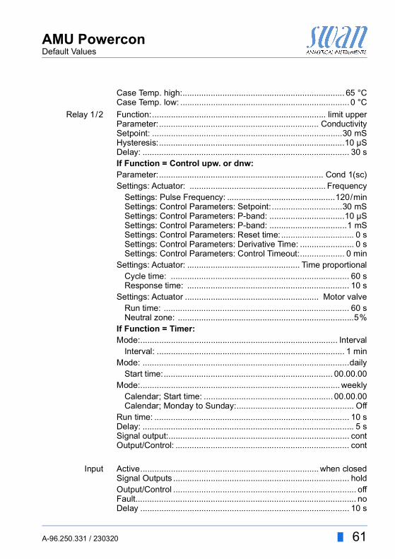
Case Temp. high:..................................................................... 65 °CCase Temp. low: ........................................................................0 °C
Relay 1/2 Function:.......................................................................... limit upperParameter:.................................................................... ConductivitySetpoint: .................................................................................30 mSHysteresis:...............................................................................10 µSDelay: ........................................................................................ 30 sIf Function = Control upw. or dnw:Parameter:...................................................................... Cond 1(sc)Settings: Actuator: .......................................................... Frequency
Settings: Pulse Frequency: ..............................................120/minSettings: Control Parameters: Setpoint:..............................30 mSSettings: Control Parameters: P-band: ................................10 µSSettings: Control Parameters: P-band: .................................1 mSSettings: Control Parameters: Reset time:............................... 0 sSettings: Control Parameters: Derivative Time: ....................... 0 sSettings: Control Parameters: Control Timeout:................... 0 min
Settings: Actuator: ................................................ Time proportionalCycle time: ............................................................................ 60 sResponse time: ..................................................................... 10 s
Settings: Actuator ......................................................... Motor valveRun time: ............................................................................... 60 sNeutral zone: ...........................................................................5%
If Function = Timer:Mode:.................................................................................... Interval
Interval: ................................................................................ 1 minMode: ........................................................................................daily
Start time:........................................................................ 00.00.00Mode:..................................................................................... weekly
Calendar; Start time: ....................................................... 00.00.00Calendar; Monday to Sunday:.................................................. Off
Run time: ................................................................................... 10 sDelay: .......................................................................................... 5 sSignal output:............................................................................. contOutput/Control: .......................................................................... cont
Input Active............................................................................ when closedSignal Outputs ........................................................................... holdOutput/Control .............................................................................. offFault.............................................................................................. noDelay ......................................................................................... 10 s

62 A-96.250.331 / 230320
AMU PowerconDefault Values
Miscellaneous Language:............................................................................. EnglishSet default:....................................................................................noLoad firmware: ..............................................................................noPassword: ........................................................... for all modes 0000Sample ID: ....................................................................... - - - - - - - -
Interface Protocol:..................................................................... Hyperterminal

A-96.250.331 / 230320 63
AMU PowerconIndex
11. Index
AAlarm Relay . . . . . . . . 4, 20Application range . . . . . . . 3
CCation Conductivity . . . . . . 4cell constant . . . . . . . . . . 4Changing parameters . . . . 28Changing values. . . . . . . 28Checklist . . . . . . . . . . . 10Cleaning . . . . . . . . . . . 30
DDefault Values . . . . . . . . 60
EElectrical wiring . . . . . . . 10Error List . . . . . . . . . . . 36
FFlow cells
B-Flow UP-Con. . . . . . 9B-Flow UP-Con-SL. . . . 9Catcon . . . . . . . . . . . 9Catconplus . . . . . . . . 9Catconplus-SL . . . . . . 9Q-Flow UP-Con . . . . . 9Q-Flow UP-Con-SL . . . 9QV-Flow UP-Con. . . . . 9QV-Flow UP-Con-SL . . 9
IInput . . . . . . . . . . . . . 4, 19Install cation exchanger bottle 16Installation . . . . . . . . . . 10Instrument setup. . . . . . . 10
Interface . . . . . . . . . . . . 4Interfaces
Modbus . . . . . . . . . 22Profibus . . . . . . . . . 21RS232 . . . . . . . . . . 21
MMeasuring principle . . . . . . 4Measuring unit . . . . . . . . 24Modbus . . . . . . . . . . . . 22
PPower Supply . . . . . . . . 18Power supply. . . . . . . . . 19Power-up . . . . . . . . . . . 10Pre-rinse setup. . . . . . . . 16Profibus . . . . . . . . . . . . 21Program Access . . . . . . . 25
QQuality Assurance . . . . . . 24
RReagent consumption. . . . 29Relays. . . . . . . . . . . . . . 3RS232. . . . . . . . . . . . . 21Run-in period. . . . . . . . . 10
SSafety Features . . . . . . . . 4Sensor mounting . . . . . . . 8Sensor parameters . . . . . 23Setup . . . . . . . . . . . . . 23Signal Outputs . . . . . . . . . 3Software . . . . . . . . . . . 27Special Features. . . . . . . . 3

AMU PowerconIndex
64 A-96.250.331 / 230320
Specific Conductivity. . . . . . 4Specifications
AMI Transmitter . . . . . . 6Swansensor RC U . . . . 8Swansensor RC UT . . . 8
Standard. . . . . . . . . . . . . 5Standard Temperature . . . . 5
System, Description of . . . . 3
TTemperature compensation. . 5Terminals . . . . . . . . 17, 20

AMU PowerconNotes
A-96.250.331 / 230320 65
12. Notes

66 A-96.250.331 / 230320
AMU Powercon
SWANis represented worldwide by subsidiary companies and distributors.
cooperates with independent representatives all over the world.
SWAN Products
Analytical Instruments for:
High Purity Water
Feedwater, Steam and Condensate
Potable Water
Pool and Sanitary Water
Cooling Water
Waste Water and Effluents
Made in Switzerland