WCDMA : KPI ANALYSIS & OPTIMIZATION Network planning& Optimization
Upload
independentCategory
view
2download
0
ED01P04 RRH60_21ASB Test Strategy
RRH60_21ASB Test
Strategy_ED01P06.DOC 22/07/2010 3BK 11251 0398 BEZZA 1/49
All
right
s re
serv
ed. P
assi
ng o
n an
d co
pyin
g of
this
do
cum
ent,
use
and
com
mun
icat
ion
of it
s co
nten
ts
not p
erm
itted
with
out w
ritte
n au
thor
izat
ion
from
ALU
Site SH
ALCATEL-LUCENT
Originators LIU Zehong, ZHOU Xia, SHEN Wei,Zhang KE,
Zhao hui,jia jun
RRH60_21ASB Test Strategy
System : WCDMA NodeB Sub-system : RRH Document Category : System Test
ABSTRACT
The present document describes the test strategy of China WRRH system.
Approvals
Name App.
ZHANG Jianlin TPM
LI Chunting TPM
HUANG Jincao TPL
REVIEW
Ed. 01 Proposal 01 2009-07-27 Common platform internal review
HISTORY
Ed. 01 Proposal 01 2009-07-27 Initialize the contents. Ed. 01 Proposal 02 2009-08-10 Modification according to the design optimization Ed. 01 Proposal 03 2009-08-24 Include the thermal test and modification according to the
architecture Ed. 01 Proposal 04 2009-09-14 Updating according to the modification of the power supply test
and reliability test Ed. 01 Proposal 05 2009-09-24 Updating according to the modification of the SIT3 environment
test Ed. 01 Proposal 06 2009-11-11 Updating according to the modification of the SIT1/SIT2/SIT3 test
plan modification
ED01P04 RRH60_21ASB Test Strategy
RRH60_21ASB Test
Strategy_ED01P06.DOC 22/07/2010 3BK 11251 0398 BEZZA 2/49
All
right
s re
serv
ed. P
assi
ng o
n an
d co
pyin
g of
this
do
cum
ent,
use
and
com
mun
icat
ion
of it
s co
nten
ts
not p
erm
itted
with
out w
ritte
n au
thor
izat
ion
from
ALU
TABLE OF CONTENTS
TABLE OF CONTENTS.....................................................................................................................................2
LIST OF FIGURES.............................................................................................................................................4
LIST OF TABLE .................................................................................................................................................5
REFERENCED DOCUMENTS...........................................................................................................................5
PREFACE...........................................................................................................................................................6
1 SCOPE ..........................................................................................................................................................7
2 GENERAL .....................................................................................................................................................8 2.1 RRH Architecture and Requirements.................................................................................................8 2.2 Test Definition ......................................................................................................................................9 2.3 Test Work Flow ..................................................................................................................................10
3 SIT1 .............................................................................................................................................................12 3.1 TRX Board Test ..................................................................................................................................12
3.1.1 Test Configuration .....................................................................................................................12 3.1.2 Test Equipment and Tool ..........................................................................................................14 3.1.3 Test Domain ..............................................................................................................................14 3.1.4 SIT1 TRX board PQ SW Test ...................................................................................................17
3.2 Power Amplifier Test .........................................................................................................................19 3.2.1 Test Configuration .....................................................................................................................19 3.2.2 Test Equipment and Tool ..........................................................................................................20 3.2.3 Test Domain ..............................................................................................................................21
3.3 FEU board Test ..................................................................................................................................22 3.3.1 Test Configuration .....................................................................................................................22 3.3.2 Test Equipment and Tool ..........................................................................................................23 3.3.3 Test Domain ..............................................................................................................................24
3.4 Mainframe/TRX/PA/FEU Reliability Test .........................................................................................25 3.4.1 EMC Test(Zhang ke) .................................................................................................................25 3.4.2 Safety Test(Zhang ke) ...............................................................................................................26 3.4.3 Lightning Protection Test(Zhang ke) .........................................................................................26 3.4.4 Thermal Test(JIA JUN)..............................................................................................................26 3.4.5 Environment test(Zhao hui) .......................................................................................................26
4 SIT2 .............................................................................................................................................................29 4.1 DL Pre-integration Test .....................................................................................................................29
4.1.1 Test Equipment and Tool ..........................................................................................................29 4.1.2 Test Equipment and Tool ..........................................................................................................30 4.1.3 Test Domain ..............................................................................................................................31
4.2 UL Pre-integration Test .....................................................................................................................32 4.2.1 Test Configuration .....................................................................................................................33 4.2.2 Test Equipment and Tool ..........................................................................................................34 4.2.3 Test Domain ..............................................................................................................................34
4.3 SW Pre-integration Test ....................................................................................................................34 4.3.1 Test Configuration .....................................................................................................................34 4.3.2 Test Equipment and Tool ..........................................................................................................34 4.3.3 Test Domain ..............................................................................................................................34
5 SIT3 .............................................................................................................................................................34 5.1 RRH Standalone Initial Test ..............................................................................................................34
5.1.1 Test Configuration .....................................................................................................................34 5.1.2 Test Equipment and Tool ..........................................................................................................34 5.1.3 Test Domain ..............................................................................................................................34
5.2 RRH Functional Test..........................................................................................................................34
ED01P04 RRH60_21ASB Test Strategy
RRH60_21ASB Test
Strategy_ED01P06.DOC 22/07/2010 3BK 11251 0398 BEZZA 3/49
All
right
s re
serv
ed. P
assi
ng o
n an
d co
pyin
g of
this
do
cum
ent,
use
and
com
mun
icat
ion
of it
s co
nten
ts
not p
erm
itted
with
out w
ritte
n au
thor
izat
ion
from
ALU
5.2.1 Test Configuration .....................................................................................................................34 5.2.2 Test Equipment and Tool ..........................................................................................................34 5.2.3 Test Domain ..............................................................................................................................34
5.3 RRH Reliability Test...........................................................................................................................34 5.3.1 EMC Test...................................................................................................................................34 5.3.2 Safety Test.................................................................................................................................34 5.3.3 Lightning Protection Test ...........................................................................................................34 5.3.4 Thermal Test .............................................................................................................................34 5.3.5 Environment test........................................................................................................................34
6 REFERENCE: .............................................................................................................................................34
7 GLOSSARY AND ABBREVIATIONS .........................................................................................................34
ED01P04 RRH60_21ASB Test Strategy
RRH60_21ASB Test
Strategy_ED01P06.DOC 22/07/2010 3BK 11251 0398 BEZZA 4/49
All
right
s re
serv
ed. P
assi
ng o
n an
d co
pyin
g of
this
do
cum
ent,
use
and
com
mun
icat
ion
of it
s co
nten
ts
not p
erm
itted
with
out w
ritte
n au
thor
izat
ion
from
ALU
LIST OF FIGURES FIGURE 2-1 RRH ARCHITECTURE ........................................................................................................................................ 8 FIGURE 2-2 TEST WORK FLOW .......................................................................................................................................... 11 FIGURE 3-1 CPRI L1/L2 INTEGRATION.............................................................................................................................. 12 FIGURE 3-2 TRX SIT1 TEST CONFIGURATION................................................................................................................... 13 FIGURE 3-3 TRX SIT1 CPRI INTERFACE TEST CONFIGURATION....................................................................................... 14 FIGURE 3-4 PQ SW TEST ENV........................................................................................................................................... 17 FIGURE 3-5 PA TEST BENCH 1 .......................................................................................................................................... 19 FIGURE 3-6 PA TEST BENCH 2 .......................................................................................................................................... 20 FIGURE 3-7 FEU TEST BENCH 1 ........................................................................................................................................ 23 FIGURE 3-8 FEU TEST BENCH 2 ........................................................................................................................................ 23 FIGURE 3-9 RRH ENVIRONMENT AND TEMPERATURE TEST ......................................................................................... 26 FIGURE 4-1 DL PRE-INTEGRATION TEST CONFIGURATION................................................................................................. 30 FIGURE 4-2 UL PRE-INTEGRATION TEST CONFIGURATION................................................................................................. 33 FIGURE 4-3 SW PRE-INTEGRATION TEST CONFIGURATION ................................................................................................ 34 FIGURE 5-1 RRH STANDALONE TEST CONFIGURATION ..................................................................................................... 34 FIGURE 5-2 RRH ENVIRONMENT TEST CONFIGURATION................................................................................................... 34
ED01P04 RRH60_21ASB Test Strategy
RRH60_21ASB Test
Strategy_ED01P06.DOC 22/07/2010 3BK 11251 0398 BEZZA 5/49
All
right
s re
serv
ed. P
assi
ng o
n an
d co
pyin
g of
this
do
cum
ent,
use
and
com
mun
icat
ion
of it
s co
nten
ts
not p
erm
itted
with
out w
ritte
n au
thor
izat
ion
from
ALU
LIST OF TABLE TABLE 2-1 RRH FEATURE LIST ........................................................................................................................................... 9 TABLE 2-2 UNIT TEST DEFINITION....................................................................................................................................... 9 TABLE 2-3 SIT1 DEFINITION ............................................................................................................................................. 10 TABLE 2-4 SIT2 DEFINITION ............................................................................................................................................. 10 TABLE 2-5 SIT3 DEFINITION ............................................................................................................................................. 10 TABLE 3-1 SIT1 TRX BOARD TEST TOOL LIST ................................................................................................................. 14 TABLE 3-2 SIT1 TRX BOARD TEST DOMAIN LIST ............................................................................................................ 17 TABLE 3-3 SIT1 TRX BOARD PQ SW TEST TOOL LIST..................................................................................................... 17 TABLE 3-4 SIT1 TRX BOARD PQ SW TEST DOMAIN LIST ................................................................................................ 18 TABLE 3-5 SIT1 PA TEST TOOL LIST ................................................................................................................................ 20 TABLE 3-6 SIT1 PA TEST DOMAIN LIST............................................................................................................................ 22 TABLE 3-7 SIT1 FEU TEST TOOL LIST.............................................................................................................................. 24 TABLE 3-8 SIT1 FEU TEST DOMAIN LIST ......................................................................................................................... 25 TABLE 3-9 SIT1 ENVIRONMENT TEST TOOL LIST.............................................................................................................. 27 TABLE 3-10 SIT 1 ENVIRONMENT TEST DOMAIN LIST ...................................................................................................... 28 TABLE 4-1 SIT2 DL TEST TOOL LIST ................................................................................................................................ 31 TABLE 4-2 SIT2 DL TEST DOMAIN LIST ........................................................................................................................... 32 TABLE 4-3 SIT2 UL TEST TOOL LIST ................................................................................................................................ 34 TABLE 4-4 SIT2 UL TEST DOMAIN LIST ........................................................................................................................... 34 TABLE 4-5 SIT2 C&M TEST TOOL LIST ........................................................................................................................... 34 TABLE 4-6 SIT2 C&M TEST DOMAIN LIST....................................................................................................................... 34 TABLE 5-1 SIT3 STANDALONE TEST TOOL LIST................................................................................................................ 34 TABLE 5-2 SIT3 STANDALONE TEST DOMAIN LIST ........................................................................................................... 34 TABLE 5-3 SIT3 FUNCTIONAL TEST TOOL LIST ............................................................................................................... 34 TABLE 5-4 SIT3 FUNCTIONAL TEST DOMAIN 1............................................................................................................... 34 TABLE 5-5 SIT3 FUNCTIONAL TEST DOMAIN 2............................................................................................................... 34 TABLE 5-6 SIT3 ENVIRONMENT TEST TOOL LIST ............................................................................................................ 34 TABLE 5-7 SIT3 ENVIRONMENT TEST DOMAIN LIST ....................................................................................................... 34
REFERENCED DOCUMENTS [ 1 ] 3BK 10239 0041 DCZZA RRH60_21ASB documentation plan
[ 2 ] 3BK 10239 0044 QMZZA RRH60_21ASB quality plan
[ 3 ] 3BK 11251 0385 DRZZA RRH60_21ASB technical feature list
[ 4 ] 3BK 11251 0386 DTZZA RRH60_21ASB technical feature description
[ 5 ] 3BK 11251 0387 EBZZA RRH60_21ASB architecture specification
RELATED DOCUMENTS [ 1 ] 3BK 11251 0401 BEZZA RRH60_21ASB E2E test strategy
ED01P04 RRH60_21ASB Test Strategy
RRH60_21ASB Test
Strategy_ED01P06.DOC 22/07/2010 3BK 11251 0398 BEZZA 6/49
All
right
s re
serv
ed. P
assi
ng o
n an
d co
pyin
g of
this
do
cum
ent,
use
and
com
mun
icat
ion
of it
s co
nten
ts
not p
erm
itted
with
out w
ritte
n au
thor
izat
ion
from
ALU
PREFACE
The present document describes the test strategy of ASB 60W RRH system. The information contained in this document should allow the test engineer to develop test plan and related test tools. This document should be used:
- As an input to create the test cases and test plan
- As an input to build the test configurations and test environments
- As an input to estimate the test tools and test instruments.
ED01P04 RRH60_21ASB Test Strategy
RRH60_21ASB Test
Strategy_ED01P06.DOC 22/07/2010 3BK 11251 0398 BEZZA 7/49
All
right
s re
serv
ed. P
assi
ng o
n an
d co
pyin
g of
this
do
cum
ent,
use
and
com
mun
icat
ion
of it
s co
nten
ts
not p
erm
itted
with
out w
ritte
n au
thor
izat
ion
from
ALU
1 SCOPE
The present document describes the test strategy of ASB self-developed 60W WCDMA RRH. All the necessary tests during RRH development will be described in this document, which including:
- The unitary chip level functional test (Called ‘Unit Test’), which focus on unitary analog, digital components or software functional test on host. The Unit Test carry out in the design teams in the design evaluation phase and the detail is not include in this document.
- Chip group level functional test (Called ‘SIT1’), which focus on one functional module constructed by group of chips and circuit. Reliability test of some critical RRH asset is also included in this phase.
- Board level functional test (Called ‘SIT2’), which focus on RRH internal DL/UL/C&M functional module integration test.
- RRH subsystem integration test (Called ‘SIT3’), which focus on RRH standalone initial test, RRH downlink/uplink function, and pre-qualification test of whole RRH subsystem.
For “Unit Test”, as it has tight relationship with design, the test itself is a part of development activity. So the test strategy of this test will be defined in related design documents and it is out of the present document scope. For each of the other up-mentioned tests, the test domain/requirements, test environment and related test tools should be included. The integration test with NodeB (d2U V2) is also out of this document scope, it will be included in “RRH60_21ASB E2E test strategy” [ 1 ].
ED01P04 RRH60_21ASB Test Strategy
RRH60_21ASB Test
Strategy_ED01P06.DOC 22/07/2010 3BK 11251 0398 BEZZA 8/49
All
right
s re
serv
ed. P
assi
ng o
n an
d co
pyin
g of
this
do
cum
ent,
use
and
com
mun
icat
ion
of it
s co
nten
ts
not p
erm
itted
with
out w
ritte
n au
thor
izat
ion
from
ALU
2 GENERAL
2.1 RRH Architecture and Requirements
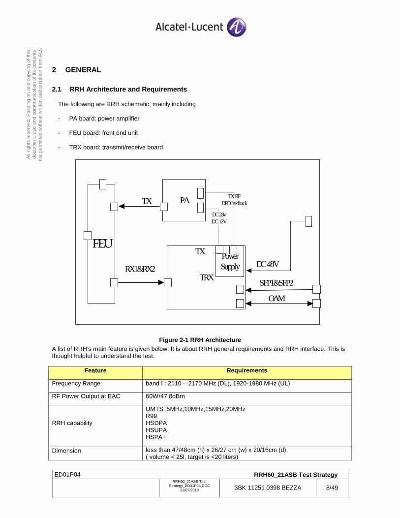
The following are RRH schematic, mainly including
- PA board: power amplifier
- FEU board: front end unit
- TRX board: transmit/receive board
FEU
PA
TRX
DC 48V
TX
RX1&RX2
TX
SFP1&SFP2
OAM
DC 28vDC 12V
TX RFDPD feedback
Power Supply
Figure 2-1 RRH Architecture A list of RRH’s main feature is given below. It is about RRH general requirements and RRH interface. This is thought helpful to understand the test.
Feature Requirements
Frequency Range band I : 2110 – 2170 MHz (DL), 1920-1980 MHz (UL)
RF Power Output at EAC 60W/47.8dBm
RRH capability
UMTS 5MHz,10MHz,15MHz,20MHz R99 HSDPA HSUPA HSPA+
Dimension less than 47/48cm (h) x 26/27 cm (w) x 20/16cm (d), ( volume < 25l, target is <20 liters)
ED01P04 RRH60_21ASB Test Strategy
RRH60_21ASB Test
Strategy_ED01P06.DOC 22/07/2010 3BK 11251 0398 BEZZA 9/49
All
right
s re
serv
ed. P
assi
ng o
n an
d co
pyin
g of
this
do
cum
ent,
use
and
com
mun
icat
ion
of it
s co
nten
ts
not p
erm
itted
with
out w
ritte
n au
thor
izat
ion
from
ALU
(mounting kit excluded, solar shield included)
CPRI interface Main CPRI Interface: SFP Daisy-chained CPRI Interface: SFP
Power interface 2 DC Grounding terminal / 2 hole lug
RF interface
2 external antenna connectors : 7/16 female Allow AISG signal and power transmitted through the Tx antenna feeder : Internal Bias-T 2 auxiliary antenna connectors : SMA female, (for antenna sharing, optional )
AISG interface/User Alarm interface
Compliant to AISG v2.0. 4 user alarm DB15 in service door
Maintenance/Configuration/Test interfaces
External_reference (15MHz) External_triger RJ45 for OCI / Debug
Table 2-1 RRH Feature List
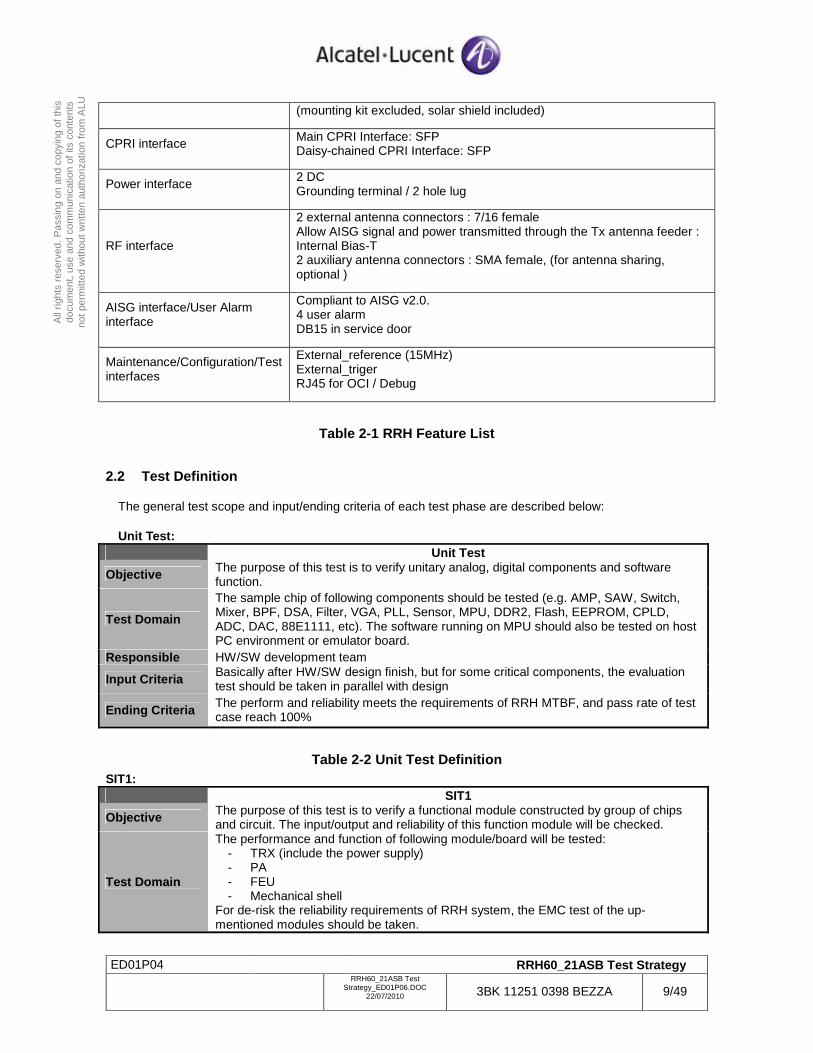
2.2 Test Definition
The general test scope and input/ending criteria of each test phase are described below:
Unit Test: Unit Test
Objective The purpose of this test is to verify unitary analog, digital components and software function.
Test Domain
The sample chip of following components should be tested (e.g. AMP, SAW, Switch, Mixer, BPF, DSA, Filter, VGA, PLL, Sensor, MPU, DDR2, Flash, EEPROM, CPLD, ADC, DAC, 88E1111, etc). The software running on MPU should also be tested on host PC environment or emulator board.
Responsible HW/SW development team
Input Criteria Basically after HW/SW design finish, but for some critical components, the evaluation test should be taken in parallel with design
Ending Criteria The perform and reliability meets the requirements of RRH MTBF, and pass rate of test case reach 100%
Table 2-2 Unit Test Definition SIT1: SIT1
Objective The purpose of this test is to verify a functional module constructed by group of chips and circuit. The input/output and reliability of this function module will be checked.
Test Domain
The performance and function of following module/board will be tested: - TRX (include the power supply) - PA - FEU - Mechanical shell
For de-risk the reliability requirements of RRH system, the EMC test of the up-mentioned modules should be taken.
ED01P04 RRH60_21ASB Test Strategy
RRH60_21ASB Test
Strategy_ED01P06.DOC 22/07/2010 3BK 11251 0398 BEZZA 10/49
All
right
s re
serv
ed. P
assi
ng o
n an
d co
pyin
g of
this
do
cum
ent,
use
and
com
mun
icat
ion
of it
s co
nten
ts
not p
erm
itted
with
out w
ritte
n au
thor
izat
ion
from
ALU
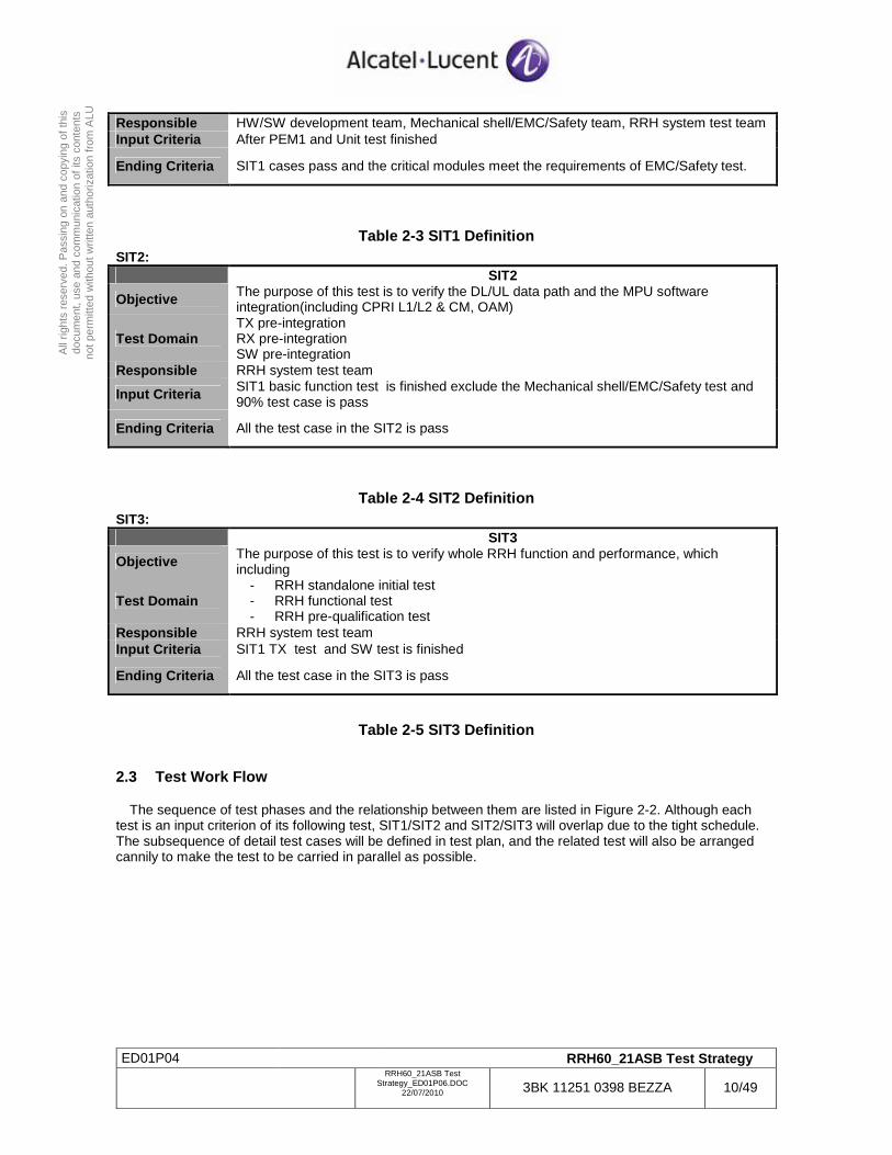
Responsible HW/SW development team, Mechanical shell/EMC/Safety team, RRH system test team Input Criteria After PEM1 and Unit test finished
Ending Criteria SIT1 cases pass and the critical modules meet the requirements of EMC/Safety test.
Table 2-3 SIT1 Definition SIT2: SIT2
Objective The purpose of this test is to verify the DL/UL data path and the MPU software integration(including CPRI L1/L2 & CM, OAM)
Test Domain TX pre-integration RX pre-integration SW pre-integration
Responsible RRH system test team
Input Criteria SIT1 basic function test is finished exclude the Mechanical shell/EMC/Safety test and 90% test case is pass
Ending Criteria All the test case in the SIT2 is pass
Table 2-4 SIT2 Definition SIT3: SIT3
Objective The purpose of this test is to verify whole RRH function and performance, which including
Test Domain - RRH standalone initial test - RRH functional test - RRH pre-qualification test
Responsible RRH system test team Input Criteria SIT1 TX test and SW test is finished
Ending Criteria All the test case in the SIT3 is pass
Table 2-5 SIT3 Definition
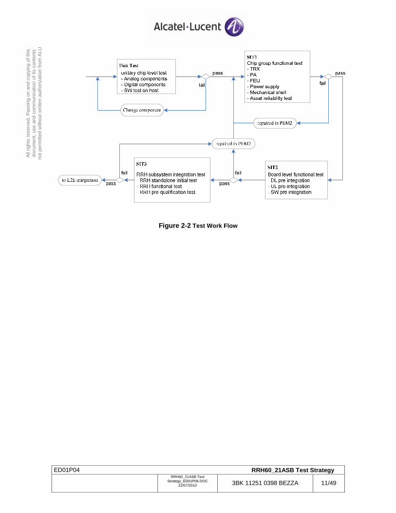
2.3 Test Work Flow
The sequence of test phases and the relationship between them are listed in Figure 2-2. Although each test is an input criterion of its following test, SIT1/SIT2 and SIT2/SIT3 will overlap due to the tight schedule. The subsequence of detail test cases will be defined in test plan, and the related test will also be arranged cannily to make the test to be carried in parallel as possible.
ED01P04 RRH60_21ASB Test Strategy
RRH60_21ASB Test
Strategy_ED01P06.DOC 22/07/2010 3BK 11251 0398 BEZZA 11/49
All
right
s re
serv
ed. P
assi
ng o
n an
d co
pyin
g of
this
do
cum
ent,
use
and
com
mun
icat
ion
of it
s co
nten
ts
not p
erm
itted
with
out w
ritte
n au
thor
izat
ion
from
ALU
Figure 2-2 Test Work Flow
ED01P04 RRH60_21ASB Test Strategy
RRH60_21ASB Test
Strategy_ED01P06.DOC 22/07/2010 3BK 11251 0398 BEZZA 12/49
All
right
s re
serv
ed. P
assi
ng o
n an
d co
pyin
g of
this
do
cum
ent,
use
and
com
mun
icat
ion
of it
s co
nten
ts
not p
erm
itted
with
out w
ritte
n au
thor
izat
ion
from
ALU
3 SIT1
3.1 TRX Board Test
TRX board is the main asset of RRH system, which terminating CPRI interface at NodeB side, providing one TX channel to PA and two RX channels to LNA at the other side. The general architecture of TRX is illustrated in [ 5 ]. In this test, the outside interfaces will be simulated and the internal behaviour of TRX will be checked.
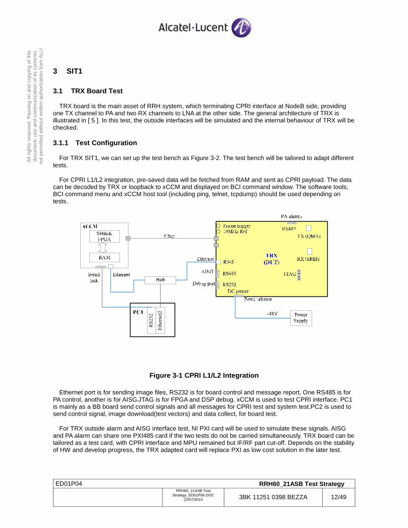
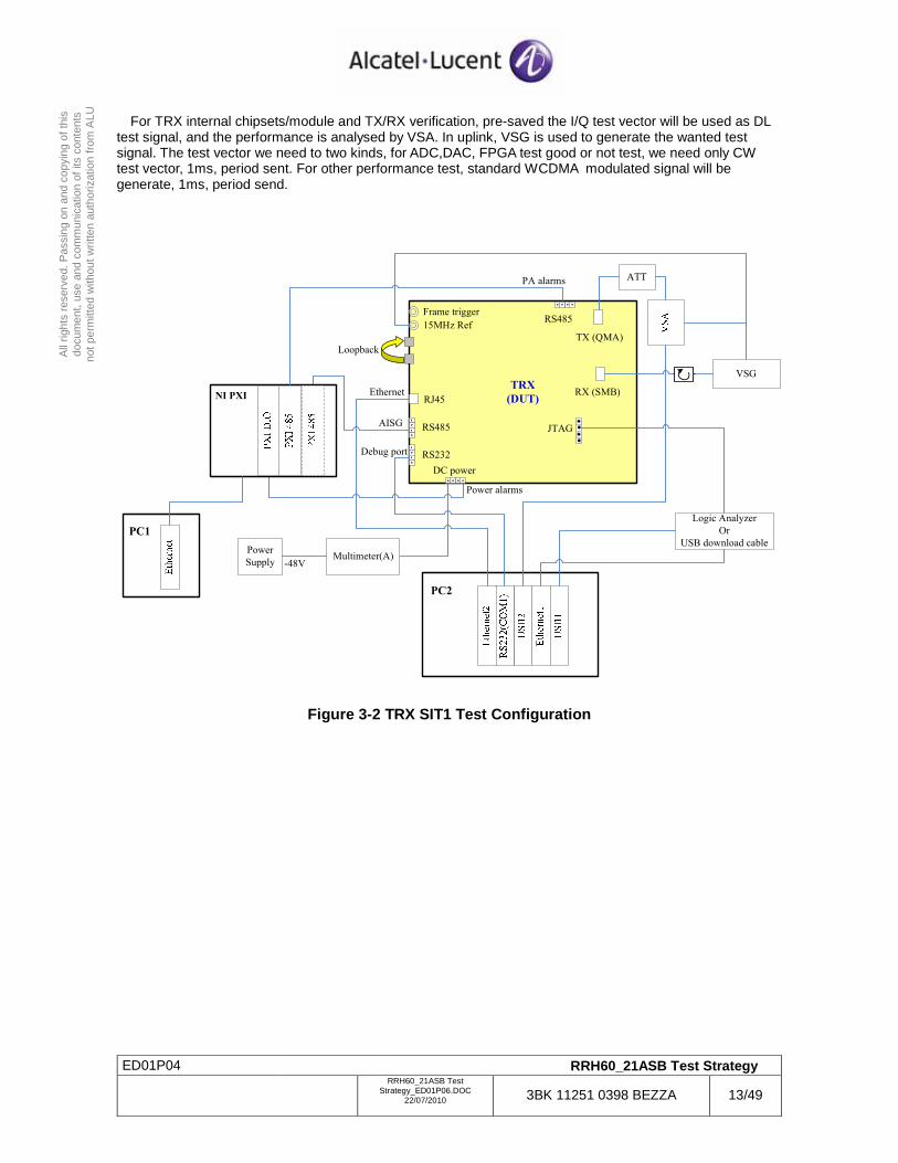
3.1.1 Test Configuration
For TRX SIT1, we can set up the test bench as Figure 3-2. The test bench will be tailored to adapt different tests.
For CPRI L1/L2 integration, pre-saved data will be fetched from RAM and sent as CPRI payload. The data can be decoded by TRX or loopback to xCCM and displayed on BCI command window. The software tools, BCI command menu and xCCM host tool (including ping, telnet, tcpdump) should be used depending on tests.
Ethernet2
RS232
Figure 3-1 CPRI L1/L2 Integration
Ethernet port is for sending image files, RS232 is for board control and message report, One RS485 is for PA control, another is for AISG.JTAG is for FPGA and DSP debug. xCCM is used to test CPRI interface. PC1 is mainly as a BB board send control signals and all messages for CPRI test and system test.PC2 is used to send control signal, image download(test vectors) and data collect, for board test.
For TRX outside alarm and AISG interface test, NI PXI card will be used to simulate these signals. AISG and PA alarm can share one PXI485 card if the two tests do not be carried simultaneously. TRX board can be tailored as a test card, with CPRI interface and MPU remained but IF/RF part cut-off. Depends on the stability of HW and develop progress, the TRX adapted card will replace PXI as low cost solution in the later test.
ED01P04 RRH60_21ASB Test Strategy
RRH60_21ASB Test
Strategy_ED01P06.DOC 22/07/2010 3BK 11251 0398 BEZZA 13/49
All
right
s re
serv
ed. P
assi
ng o
n an
d co
pyin
g of
this
do
cum
ent,
use
and
com
mun
icat
ion
of it
s co
nten
ts
not p
erm
itted
with
out w
ritte
n au
thor
izat
ion
from
ALU
For TRX internal chipsets/module and TX/RX verification, pre-saved the I/Q test vector will be used as DL test signal, and the performance is analysed by VSA. In uplink, VSG is used to generate the wanted test signal. The test vector we need to two kinds, for ADC,DAC, FPGA test good or not test, we need only CW test vector, 1ms, period sent. For other performance test, standard WCDMA modulated signal will be generate, 1ms, period send.
TRX
(DUT)
RS232
RS485
RJ45
DC power
15MHz Ref
Frame trigger
JTAG
Power
Supply
Logic Analyzer
Or
USB download cable
Power alarms
RS485
TX (QMA)
AISG
Ethernet
Debug port
-48V
PA alarms
PC2
PC1
NI PXI RX (SMB)
VSG
Multimeter(A)
ATT
Loopback
Figure 3-2 TRX SIT1 Test Configuration
ED01P04 RRH60_21ASB Test Strategy
RRH60_21ASB Test
Strategy_ED01P06.DOC 22/07/2010 3BK 11251 0398 BEZZA 14/49
All
right
s re
serv
ed. P
assi
ng o
n an
d co
pyin
g of
this
do
cum
ent,
use
and
com
mun
icat
ion
of it
s co
nten
ts
not p
erm
itted
with
out w
ritte
n au
thor
izat
ion
from
ALU
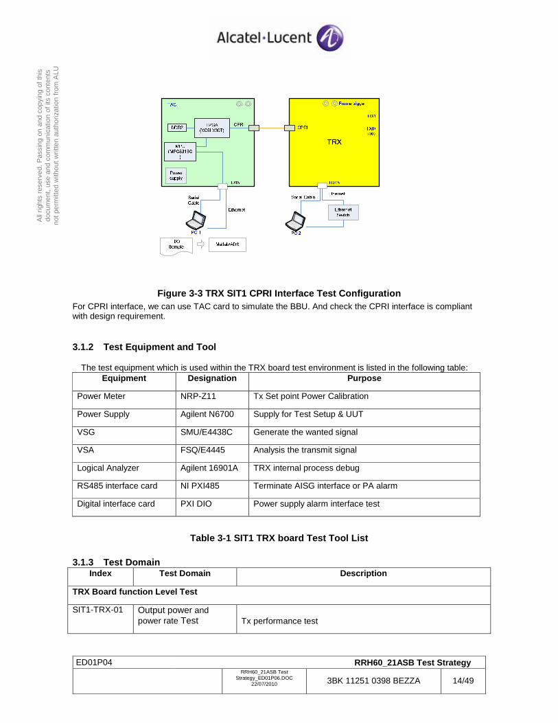
Figure 3-3 TRX SIT1 CPRI Interface Test Configuration For CPRI interface, we can use TAC card to simulate the BBU. And check the CPRI interface is compliant with design requirement.
3.1.2 Test Equipment and Tool
The test equipment which is used within the TRX board test environment is listed in the following table: Equipment Designation Purpose
Power Meter NRP-Z11 Tx Set point Power Calibration
Power Supply Agilent N6700 Supply for Test Setup & UUT
VSG SMU/E4438C Generate the wanted signal
VSA FSQ/E4445 Analysis the transmit signal
Logical Analyzer Agilent 16901A TRX internal process debug
RS485 interface card NI PXI485 Terminate AISG interface or PA alarm
Digital interface card PXI DIO Power supply alarm interface test
Table 3-1 SIT1 TRX board Test Tool List
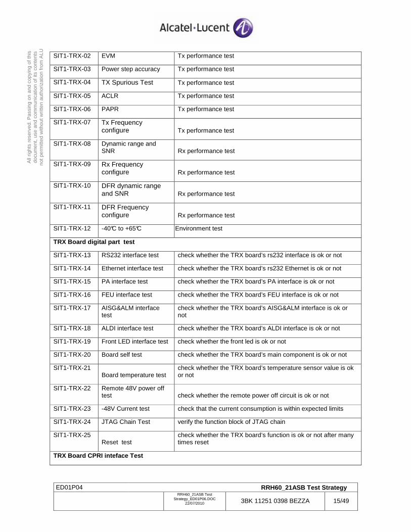
3.1.3 Test Domain Index Test Domain Description
TRX Board function Level Test
SIT1-TRX-01 Output power and power rate Test Tx performance test
ED01P04 RRH60_21ASB Test Strategy
RRH60_21ASB Test
Strategy_ED01P06.DOC 22/07/2010 3BK 11251 0398 BEZZA 15/49
All
right
s re
serv
ed. P
assi
ng o
n an
d co
pyin
g of
this
do
cum
ent,
use
and
com
mun
icat
ion
of it
s co
nten
ts
not p
erm
itted
with
out w
ritte
n au
thor
izat
ion
from
ALU
SIT1-TRX-02 EVM Tx performance test
SIT1-TRX-03 Power step accuracy Tx performance test
SIT1-TRX-04 TX Spurious Test Tx performance test
SIT1-TRX-05 ACLR Tx performance test
SIT1-TRX-06 PAPR Tx performance test
SIT1-TRX-07 Tx Frequency configure Tx performance test
SIT1-TRX-08 Dynamic range and SNR Rx performance test
SIT1-TRX-09 Rx Frequency configure Rx performance test
SIT1-TRX-10 DFR dynamic range and SNR Rx performance test
SIT1-TRX-11 DFR Frequency configure Rx performance test
SIT1-TRX-12 -40°C to +65°C Environment test
TRX Board digital part test
SIT1-TRX-13 RS232 interface test check whether the TRX board’s rs232 interface is ok or not
SIT1-TRX-14 Ethernet interface test check whether the TRX board’s rs232 Ethernet is ok or not
SIT1-TRX-15 PA interface test check whether the TRX board’s PA interface is ok or not
SIT1-TRX-16 FEU interface test check whether the TRX board’s FEU interface is ok or not
SIT1-TRX-17 AISG&ALM interface test
check whether the TRX board’s AISG&ALM interface is ok or not
SIT1-TRX-18 ALDI interface test check whether the TRX board’s ALDI interface is ok or not
SIT1-TRX-19 Front LED interface test check whether the front led is ok or not
SIT1-TRX-20 Board self test check whether the TRX board’s main component is ok or not
SIT1-TRX-21 Board temperature test
check whether the TRX board’s temperature sensor value is ok or not
SIT1-TRX-22 Remote 48V power off test check whether the remote power off circuit is ok or not
SIT1-TRX-23 -48V Current test check that the current consumption is within expected limits
SIT1-TRX-24 JTAG Chain Test verify the function block of JTAG chain
SIT1-TRX-25 Reset test
check whether the TRX board’s function is ok or not after many times reset
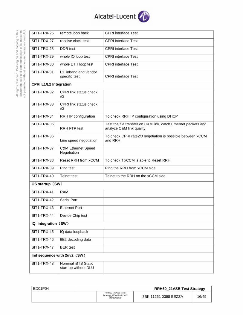
TRX Board CPRI inteface Test
ED01P04 RRH60_21ASB Test Strategy
RRH60_21ASB Test
Strategy_ED01P06.DOC 22/07/2010 3BK 11251 0398 BEZZA 16/49
All
right
s re
serv
ed. P
assi
ng o
n an
d co
pyin
g of
this
do
cum
ent,
use
and
com
mun
icat
ion
of it
s co
nten
ts
not p
erm
itted
with
out w
ritte
n au
thor
izat
ion
from
ALU
SIT1-TRX-26 remote loop back CPRI interface Test
SIT1-TRX-27 receive clock test CPRI interface Test
SIT1-TRX-28 DDR test CPRI interface Test
SIT1-TRX-29 whole IQ loop test CPRI interface Test
SIT1-TRX-30 whole ETH loop test CPRI interface Test
SIT1-TRX-31 L1 inband and vendor specific test CPRI interface Test
CPRI L1/L2 Integration
SIT1-TRX-32 CPRI link status check #2
SIT1-TRX-33 CPRI link status check #2
SIT1-TRX-34 RRH IP configuration To check RRH IP configuration using DHCP
SIT1-TRX-35 RRH FTP test
Test the file transfer on C&M link, catch Ethernet packets and analyze C&M link quality
SIT1-TRX-36 Line speed negotiation
To check CPRI rate2/3 negotiation is possible between xCCM and RRH
SIT1-TRX-37 C&M Ethernet Speed Negotiation
SIT1-TRX-38 Reset RRH from xCCM To check if xCCM is able to Reset RRH
SIT1-TRX-39 Ping test Ping the RRH from xCCM side
SIT1-TRX-40 Telnet test Telnet to the RRH on the xCCM side.
OS startup((((SW))))
SIT1-TRX-41 RAM
SIT1-TRX-42 Serial Port
SIT1-TRX-43 Ethernet Port
SIT1-TRX-44 Device Chip test
IQ integration((((SW))))
SIT1-TRX-45 IQ data loopback
SIT1-TRX-46 9E2 decoding data
SIT1-TRX-47 BER test
Init sequence with 2uv2((((SW))))
SIT1-TRX-48 Nominal iBTS Static start-up without DLU
ED01P04 RRH60_21ASB Test Strategy
RRH60_21ASB Test
Strategy_ED01P06.DOC 22/07/2010 3BK 11251 0398 BEZZA 17/49
All
right
s re
serv
ed. P
assi
ng o
n an
d co
pyin
g of
this
do
cum
ent,
use
and
com
mun
icat
ion
of it
s co
nten
ts
not p
erm
itted
with
out w
ritte
n au
thor
izat
ion
from
ALU
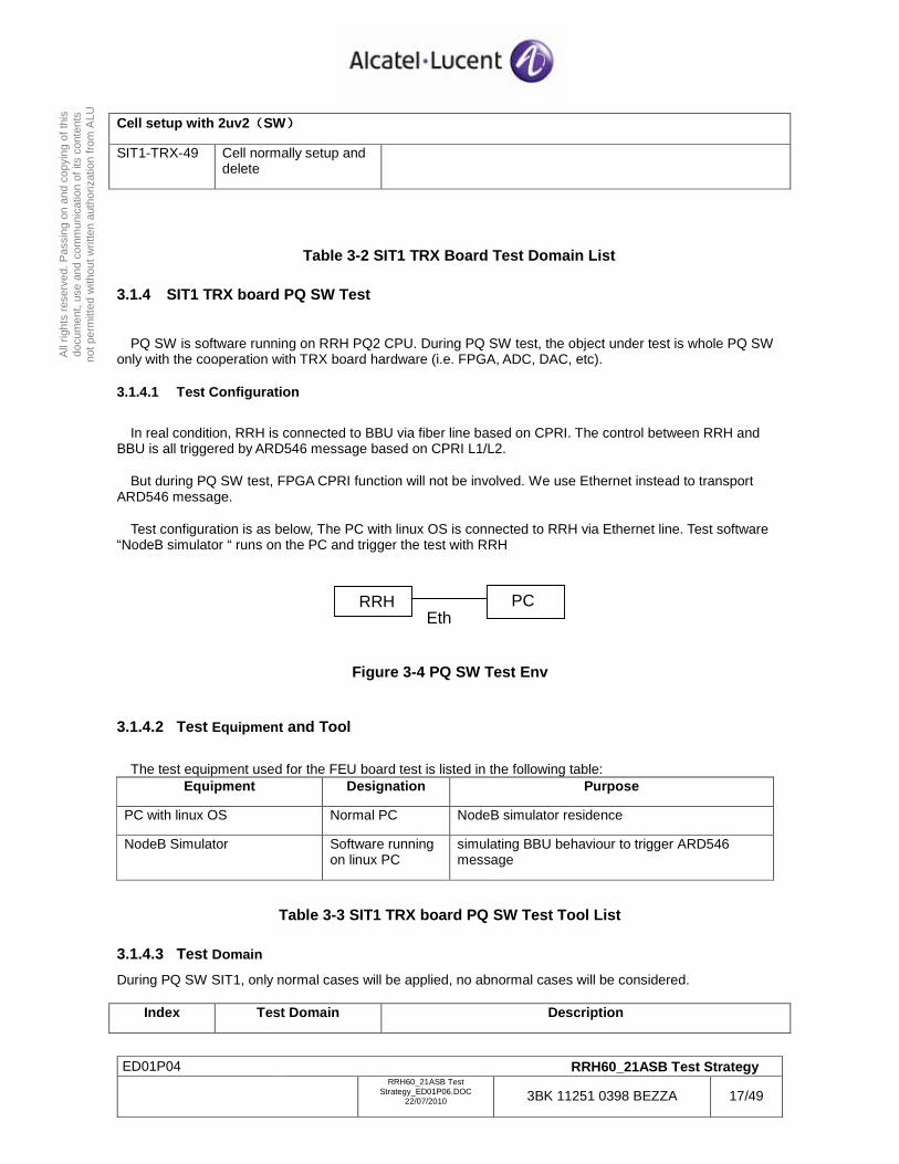
Cell setup with 2uv2((((SW))))
SIT1-TRX-49 Cell normally setup and delete
Table 3-2 SIT1 TRX Board Test Domain List
3.1.4 SIT1 TRX board PQ SW Test
PQ SW is software running on RRH PQ2 CPU. During PQ SW test, the object under test is whole PQ SW only with the cooperation with TRX board hardware (i.e. FPGA, ADC, DAC, etc).
3.1.4.1 Test Configuration
In real condition, RRH is connected to BBU via fiber line based on CPRI. The control between RRH and BBU is all triggered by ARD546 message based on CPRI L1/L2.
But during PQ SW test, FPGA CPRI function will not be involved. We use Ethernet instead to transport ARD546 message.
Test configuration is as below, The PC with linux OS is connected to RRH via Ethernet line. Test software “NodeB simulator “ runs on the PC and trigger the test with RRH
Figure 3-4 PQ SW Test Env
3.1.4.2 Test Equipment and Tool
The test equipment used for the FEU board test is listed in the following table: Equipment Designation Purpose
PC with linux OS Normal PC NodeB simulator residence
NodeB Simulator Software running on linux PC
simulating BBU behaviour to trigger ARD546 message
Table 3-3 SIT1 TRX board PQ SW Test Tool List
3.1.4.3 Test Domain
During PQ SW SIT1, only normal cases will be applied, no abnormal cases will be considered.
Index Test Domain Description
RRH PC Eth
ED01P04 RRH60_21ASB Test Strategy
RRH60_21ASB Test
Strategy_ED01P06.DOC 22/07/2010 3BK 11251 0398 BEZZA 18/49
All
right
s re
serv
ed. P
assi
ng o
n an
d co
pyin
g of
this
do
cum
ent,
use
and
com
mun
icat
ion
of it
s co
nten
ts
not p
erm
itted
with
out w
ritte
n au
thor
izat
ion
from
ALU
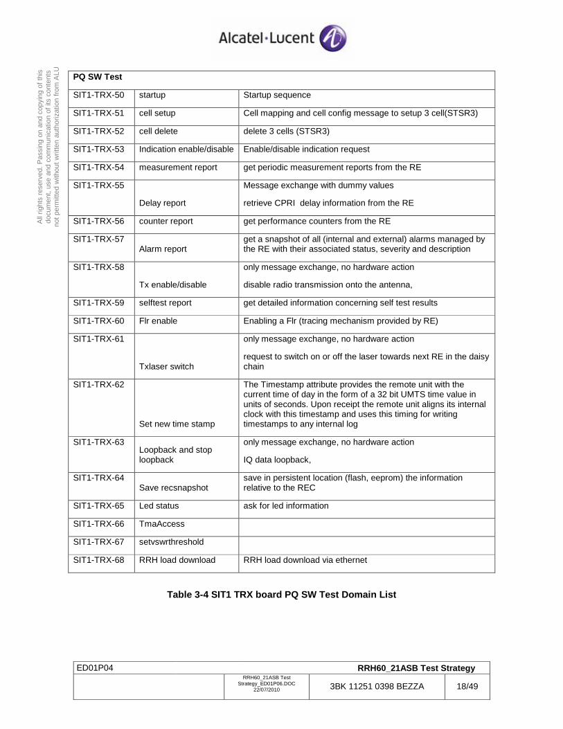
PQ SW Test
SIT1-TRX-50 startup Startup sequence
SIT1-TRX-51 cell setup Cell mapping and cell config message to setup 3 cell(STSR3)
SIT1-TRX-52 cell delete delete 3 cells (STSR3)
SIT1-TRX-53 Indication enable/disable Enable/disable indication request
SIT1-TRX-54 measurement report get periodic measurement reports from the RE
SIT1-TRX-55
Delay report
Message exchange with dummy values
retrieve CPRI delay information from the RE
SIT1-TRX-56 counter report get performance counters from the RE
SIT1-TRX-57 Alarm report
get a snapshot of all (internal and external) alarms managed by the RE with their associated status, severity and description
SIT1-TRX-58
Tx enable/disable
only message exchange, no hardware action
disable radio transmission onto the antenna,
SIT1-TRX-59 selftest report get detailed information concerning self test results
SIT1-TRX-60 Flr enable Enabling a Flr (tracing mechanism provided by RE)
SIT1-TRX-61
Txlaser switch
only message exchange, no hardware action
request to switch on or off the laser towards next RE in the daisy chain
SIT1-TRX-62
Set new time stamp
The Timestamp attribute provides the remote unit with the current time of day in the form of a 32 bit UMTS time value in units of seconds. Upon receipt the remote unit aligns its internal clock with this timestamp and uses this timing for writing timestamps to any internal log
SIT1-TRX-63 Loopback and stop loopback
only message exchange, no hardware action
IQ data loopback,
SIT1-TRX-64 Save recsnapshot
save in persistent location (flash, eeprom) the information relative to the REC
SIT1-TRX-65 Led status ask for led information
SIT1-TRX-66 TmaAccess
SIT1-TRX-67 setvswrthreshold
SIT1-TRX-68 RRH load download RRH load download via ethernet
Table 3-4 SIT1 TRX board PQ SW Test Domain List
ED01P04 RRH60_21ASB Test Strategy
RRH60_21ASB Test
Strategy_ED01P06.DOC 22/07/2010 3BK 11251 0398 BEZZA 19/49
All
right
s re
serv
ed. P
assi
ng o
n an
d co
pyin
g of
this
do
cum
ent,
use
and
com
mun
icat
ion
of it
s co
nten
ts
not p
erm
itted
with
out w
ritte
n au
thor
izat
ion
from
ALU
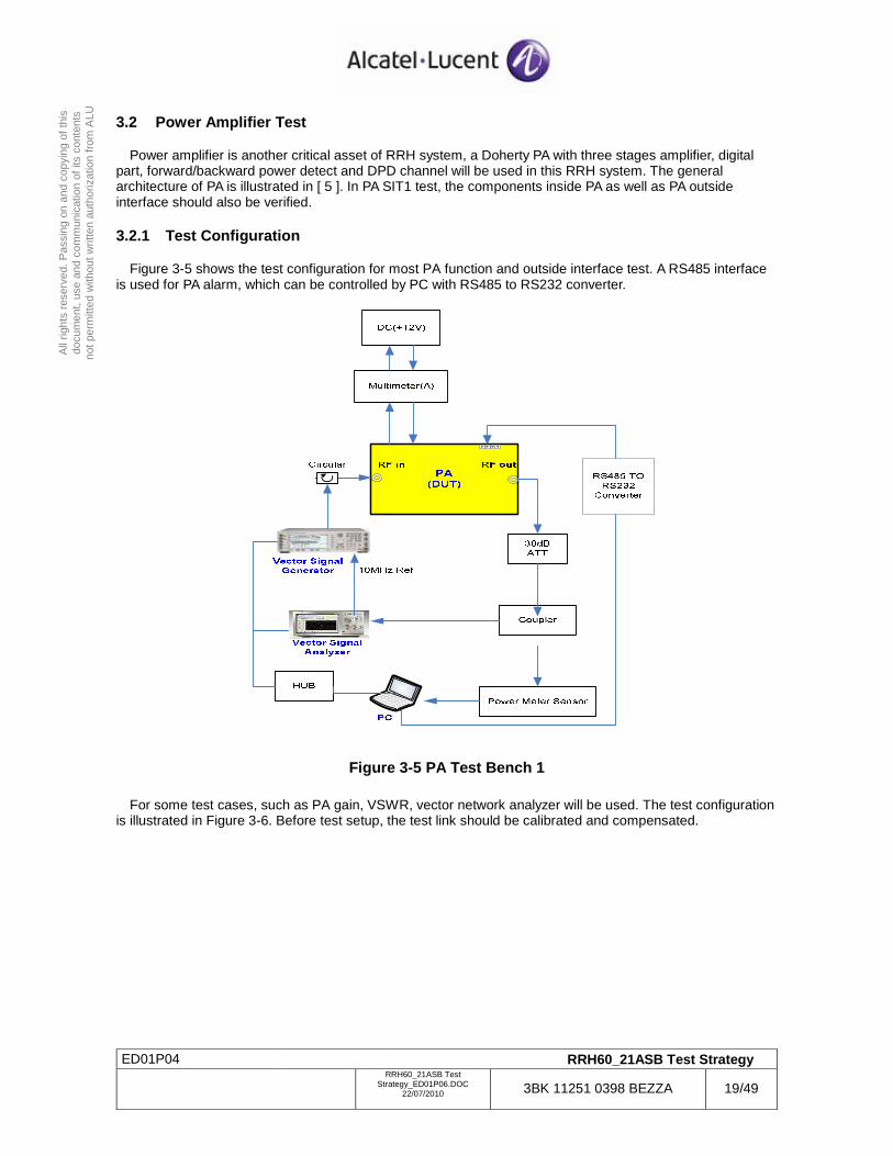
3.2 Power Amplifier Test
Power amplifier is another critical asset of RRH system, a Doherty PA with three stages amplifier, digital part, forward/backward power detect and DPD channel will be used in this RRH system. The general architecture of PA is illustrated in [ 5 ]. In PA SIT1 test, the components inside PA as well as PA outside interface should also be verified.
3.2.1 Test Configuration
Figure 3-5 shows the test configuration for most PA function and outside interface test. A RS485 interface is used for PA alarm, which can be controlled by PC with RS485 to RS232 converter.
Figure 3-5 PA Test Bench 1
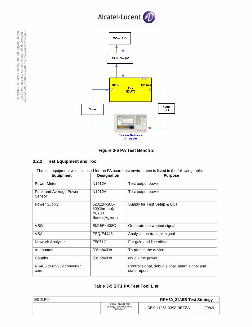
For some test cases, such as PA gain, VSWR, vector network analyzer will be used. The test configuration is illustrated in Figure 3-6. Before test setup, the test link should be calibrated and compensated.
ED01P04 RRH60_21ASB Test Strategy
RRH60_21ASB Test
Strategy_ED01P06.DOC 22/07/2010 3BK 11251 0398 BEZZA 20/49
All
right
s re
serv
ed. P
assi
ng o
n an
d co
pyin
g of
this
do
cum
ent,
use
and
com
mun
icat
ion
of it
s co
nten
ts
not p
erm
itted
with
out w
ritte
n au
thor
izat
ion
from
ALU
Figure 3-6 PA Test Bench 2
3.2.2 Test Equipment and Tool
The test equipment which is used for the PA board test environment is listed in the following table: Equipment Designation Purpose
Power Meter N1912A Test output power
Peak and Average Power Sensor
N1912A Test output power
Power Supply 62012P-100-50(Chroma)/ N6700 Series(Aglient)
Supply for Test Setup & UUT
VSG SMU/E4438C Generate the wanted signal
VSA FSQ/E4445 Analysis the transmit signal
Network Analyzer E5071C For gain and line offset
Attenuator 30Db/40Db To protect the device
Coupler 30Db/40Db couple the power
RS485 to RS232 converter card
Control signal, debug signal, alarm signal and state report
Table 3-5 SIT1 PA Test Tool List
ED01P04 RRH60_21ASB Test Strategy
RRH60_21ASB Test
Strategy_ED01P06.DOC 22/07/2010 3BK 11251 0398 BEZZA 21/49
All
right
s re
serv
ed. P
assi
ng o
n an
d co
pyin
g of
this
do
cum
ent,
use
and
com
mun
icat
ion
of it
s co
nten
ts
not p
erm
itted
with
out w
ritte
n au
thor
izat
ion
from
ALU
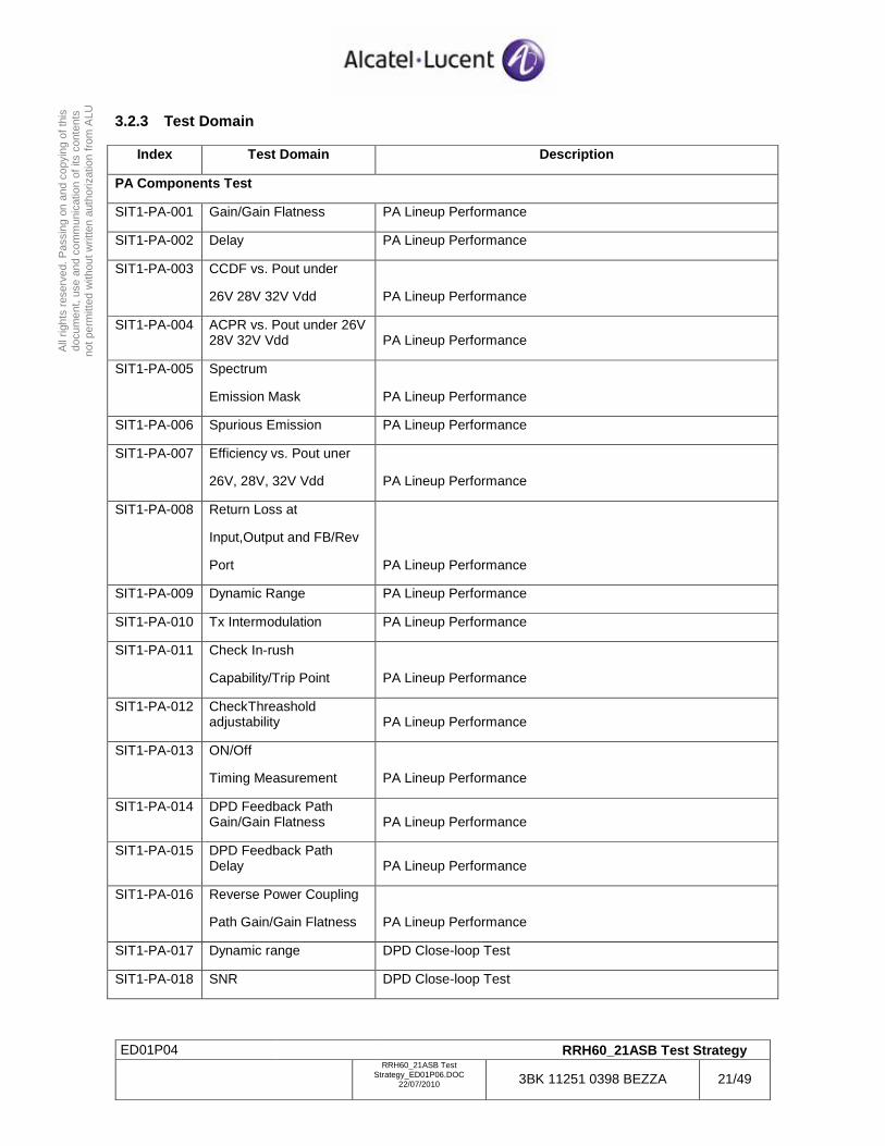
3.2.3 Test Domain
Index Test Domain Description
PA Components Test
SIT1-PA-001 Gain/Gain Flatness PA Lineup Performance
SIT1-PA-002 Delay PA Lineup Performance
SIT1-PA-003 CCDF vs. Pout under
26V 28V 32V Vdd PA Lineup Performance
SIT1-PA-004 ACPR vs. Pout under 26V 28V 32V Vdd PA Lineup Performance
SIT1-PA-005 Spectrum
Emission Mask PA Lineup Performance
SIT1-PA-006 Spurious Emission PA Lineup Performance
SIT1-PA-007 Efficiency vs. Pout uner
26V, 28V, 32V Vdd PA Lineup Performance
SIT1-PA-008 Return Loss at
Input,Output and FB/Rev
Port PA Lineup Performance
SIT1-PA-009 Dynamic Range PA Lineup Performance
SIT1-PA-010 Tx Intermodulation PA Lineup Performance
SIT1-PA-011 Check In-rush
Capability/Trip Point PA Lineup Performance
SIT1-PA-012 CheckThreashold adjustability PA Lineup Performance
SIT1-PA-013 ON/Off
Timing Measurement PA Lineup Performance
SIT1-PA-014 DPD Feedback Path Gain/Gain Flatness PA Lineup Performance
SIT1-PA-015 DPD Feedback Path Delay PA Lineup Performance
SIT1-PA-016 Reverse Power Coupling
Path Gain/Gain Flatness PA Lineup Performance
SIT1-PA-017 Dynamic range DPD Close-loop Test
SIT1-PA-018 SNR DPD Close-loop Test
ED01P04 RRH60_21ASB Test Strategy
RRH60_21ASB Test
Strategy_ED01P06.DOC 22/07/2010 3BK 11251 0398 BEZZA 22/49
All
right
s re
serv
ed. P
assi
ng o
n an
d co
pyin
g of
this
do
cum
ent,
use
and
com
mun
icat
ion
of it
s co
nten
ts
not p
erm
itted
with
out w
ritte
n au
thor
izat
ion
from
ALU
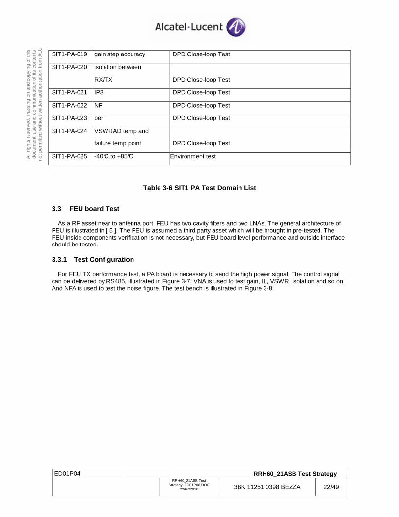
SIT1-PA-019 gain step accuracy DPD Close-loop Test
SIT1-PA-020 isolation between
RX/TX DPD Close-loop Test
SIT1-PA-021 IP3 DPD Close-loop Test
SIT1-PA-022 NF DPD Close-loop Test
SIT1-PA-023 ber DPD Close-loop Test
SIT1-PA-024 VSWRAD temp and
failure temp point DPD Close-loop Test
SIT1-PA-025 -40°C to +85°C Environment test
Table 3-6 SIT1 PA Test Domain List
3.3 FEU board Test
As a RF asset near to antenna port, FEU has two cavity filters and two LNAs. The general architecture of FEU is illustrated in [ 5 ]. The FEU is assumed a third party asset which will be brought in pre-tested. The FEU inside components verification is not necessary, but FEU board level performance and outside interface should be tested.
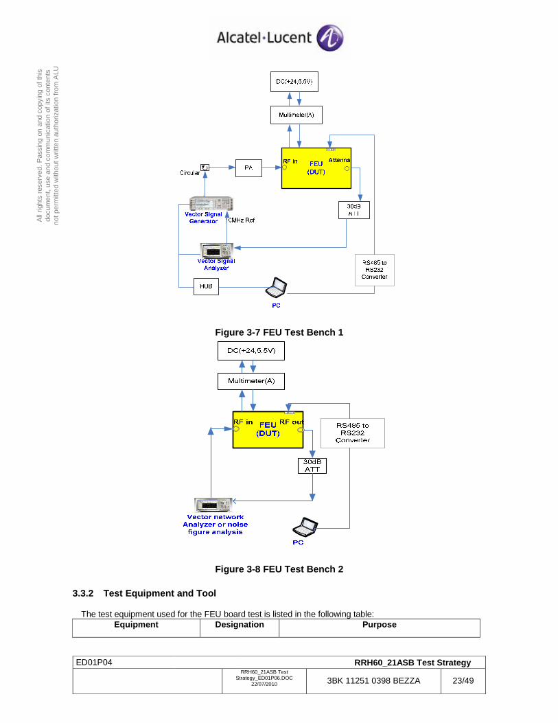
3.3.1 Test Configuration
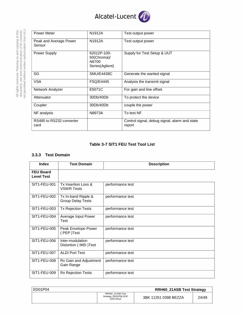
For FEU TX performance test, a PA board is necessary to send the high power signal. The control signal can be delivered by RS485, illustrated in Figure 3-7. VNA is used to test gain, IL, VSWR, isolation and so on. And NFA is used to test the noise figure. The test bench is illustrated in Figure 3-8.
ED01P04 RRH60_21ASB Test Strategy
RRH60_21ASB Test
Strategy_ED01P06.DOC 22/07/2010 3BK 11251 0398 BEZZA 23/49
All
right
s re
serv
ed. P
assi
ng o
n an
d co
pyin
g of
this
do
cum
ent,
use
and
com
mun
icat
ion
of it
s co
nten
ts
not p
erm
itted
with
out w
ritte
n au
thor
izat
ion
from
ALU
Figure 3-7 FEU Test Bench 1
Figure 3-8 FEU Test Bench 2
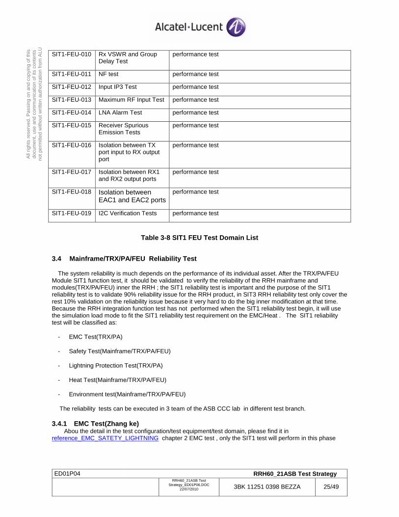
3.3.2 Test Equipment and Tool
The test equipment used for the FEU board test is listed in the following table: Equipment Designation Purpose
ED01P04 RRH60_21ASB Test Strategy
RRH60_21ASB Test
Strategy_ED01P06.DOC 22/07/2010 3BK 11251 0398 BEZZA 24/49
All
right
s re
serv
ed. P
assi
ng o
n an
d co
pyin
g of
this
do
cum
ent,
use
and
com
mun
icat
ion
of it
s co
nten
ts
not p
erm
itted
with
out w
ritte
n au
thor
izat
ion
from
ALU
Power Meter N1912A Test output power
Peak and Average Power Sensor
N1912A Test output power
Power Supply 62012P-100-50(Chroma)/ N6700 Series(Aglient)
Supply for Test Setup & UUT
SG SMU/E4438C Generate the wanted signal
VSA FSQ/E4445 Analysis the transmit signal
Network Analyzer E5071C For gain and line offset
Attenuator 30Db/40Db To protect the device
Coupler 30Db/40Db couple the power
NF analysis N8973A To test NF
RS485 to RS232 converter card
Control signal, debug signal, alarm and state report
Table 3-7 SIT1 FEU Test Tool List
3.3.3 Test Domain
Index Test Domain Description
FEU Board Level Test
SIT1-FEU-001 Tx Insertion Loss & VSWR Tests
performance test
SIT1-FEU-002 Tx In-band Ripple & Group Delay Tests
performance test
SIT1-FEU-003 Tx Rejection Tests performance test
SIT1-FEU-004 Average Input Power Test
performance test
SIT1-FEU-005 Peak Envelope Power ( PEP )Test
performance test
SIT1-FEU-006 Inter-modulation Distortion ( IMD )Test
performance test
SIT1-FEU-007 ALDI Port Test performance test
SIT1-FEU-008 Rx Gain and Adjustment Gain Range
performance test
SIT1-FEU-009 Rx Rejection Tests performance test
ED01P04 RRH60_21ASB Test Strategy
RRH60_21ASB Test
Strategy_ED01P06.DOC 22/07/2010 3BK 11251 0398 BEZZA 25/49
All
right
s re
serv
ed. P
assi
ng o
n an
d co
pyin
g of
this
do
cum
ent,
use
and
com
mun
icat
ion
of it
s co
nten
ts
not p
erm
itted
with
out w
ritte
n au
thor
izat
ion
from
ALU
SIT1-FEU-010 Rx VSWR and Group Delay Test
performance test
SIT1-FEU-011 NF test performance test
SIT1-FEU-012 Input IP3 Test performance test
SIT1-FEU-013 Maximum RF Input Test performance test
SIT1-FEU-014 LNA Alarm Test performance test
SIT1-FEU-015 Receiver Spurious Emission Tests
performance test
SIT1-FEU-016 Isolation between TX port input to RX output port
performance test
SIT1-FEU-017 Isolation between RX1 and RX2 output ports
performance test
SIT1-FEU-018 Isolation between EAC1 and EAC2 ports
performance test
SIT1-FEU-019 I2C Verification Tests performance test
Table 3-8 SIT1 FEU Test Domain List
3.4 Mainframe/TRX/PA/FEU Reliability Test
The system reliability is much depends on the performance of its individual asset. After the TRX/PA/FEU Module SIT1 function test, it should be validated to verify the reliability of the RRH mainframe and modules(TRX/PA/FEU) inner the RRH ; the SIT1 reliability test is important and the purpose of the SIT1 reliability test is to validate 90% reliability issue for the RRH product, in SIT3 RRH reliability test only cover the rest 10% validation on the reliability issue because it very hard to do the big inner modification at that time. Because the RRH integration function test has not performed when the SIT1 reliability test begin, it will use the simulation load mode to fit the SIT1 reliability test requirement on the EMC/Heat . The SIT1 reliability test will be classified as:
- EMC Test(TRX/PA)
- Safety Test(Mainframe/TRX/PA/FEU)
- Lightning Protection Test(TRX/PA)
- Heat Test(Mainframe/TRX/PA/FEU)
- Environment test(Mainframe/TRX/PA/FEU)
The reliability tests can be executed in 3 team of the ASB CCC lab in different test branch.
3.4.1 EMC Test(Zhang ke) Abou the detail in the test configuration/test equipment/test domain, please find it in reference_EMC_SATETY_LIGHTNING chapter 2 EMC test , only the SIT1 test will perform in this phase
ED01P04 RRH60_21ASB Test Strategy
RRH60_21ASB Test
Strategy_ED01P06.DOC 22/07/2010 3BK 11251 0398 BEZZA 26/49
All
right
s re
serv
ed. P
assi
ng o
n an
d co
pyin
g of
this
do
cum
ent,
use
and
com
mun
icat
ion
of it
s co
nten
ts
not p
erm
itted
with
out w
ritte
n au
thor
izat
ion
from
ALU
3.4.2 Safety Test(Zhang ke) Abou the detail in the test configuration/test equipment/test domain, please find it in reference_EMC_SATETY_LIGHTNING chapter 3 safety test, only the SIT1 test will perform in this phase
3.4.3 Lightning Protection Test(Zhang ke) Abou the detail in the test configuration/test equipment/test domain, please find it in reference_EMC_SATETY_LIGHTNING chapter 4 lightning protection test , only the SIT1 test will perform in this phase
3.4.4 Thermal Test(JIA JUN) In SIT1, it only perform the thermal simulation test in the system thermal design , and no thermal test in the real environment in the SIT1 phase.
3.4.5 Environment test(Zhao hui)
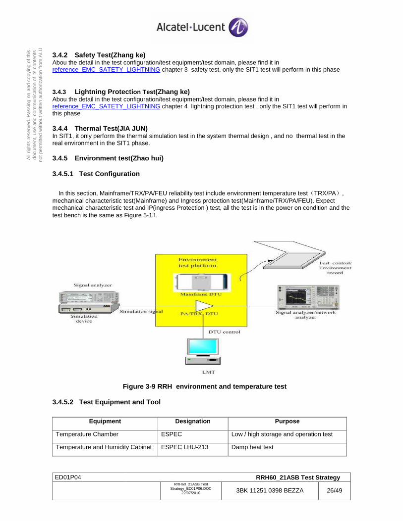
3.4.5.1 Test Configuration
In this section, Mainframe/TRX/PA/FEU reliability test include environment temperature test(TRX/PA), mechanical characteristic test(Mainframe) and Ingress protection test(Mainframe/TRX/PA/FEU). Expect mechanical characteristic test and IP(ingress Protection ) test, all the test is in the power on condition and the test bench is the same as Figure 5-13.
Figure 3-9 RRH environment and temperature test
3.4.5.2 Test Equipment and Tool
Equipment Designation Purpose
Temperature Chamber ESPEC Low / high storage and operation test
Temperature and Humidity Cabinet ESPEC LHU-213 Damp heat test
ED01P04 RRH60_21ASB Test Strategy
RRH60_21ASB Test
Strategy_ED01P06.DOC 22/07/2010 3BK 11251 0398 BEZZA 27/49
All
right
s re
serv
ed. P
assi
ng o
n an
d co
pyin
g of
this
do
cum
ent,
use
and
com
mun
icat
ion
of it
s co
nten
ts
not p
erm
itted
with
out w
ritte
n au
thor
izat
ion
from
ALU
Thermal Cycle Temp Chamber ESPEC SET-Z-080U Thermal cycle and temp fast change test
Vibration Machine WXASPR RT-50A Vibration test
Mechanical Shock Machine EPCU SD-24 Mechanical shock test
Drop Machine WXASPR PK-318 Free fall test
Transport Simulation Machine WXASPR PK-1000 Transport simulation test
Salt Frog Corrosion Chamber WXASPR AHL-60-SS Salt mist cycle test
Mildew Cultivation Chamber WXASPR MC-225 Mildew test
Rain Simulation Chamber WXASPR RI-1000 Rain simulation test
Sand Dust Chamber WXASPR SD-1500 Sand dust test
Table 3-9 SIT1 Environment Test Tool List
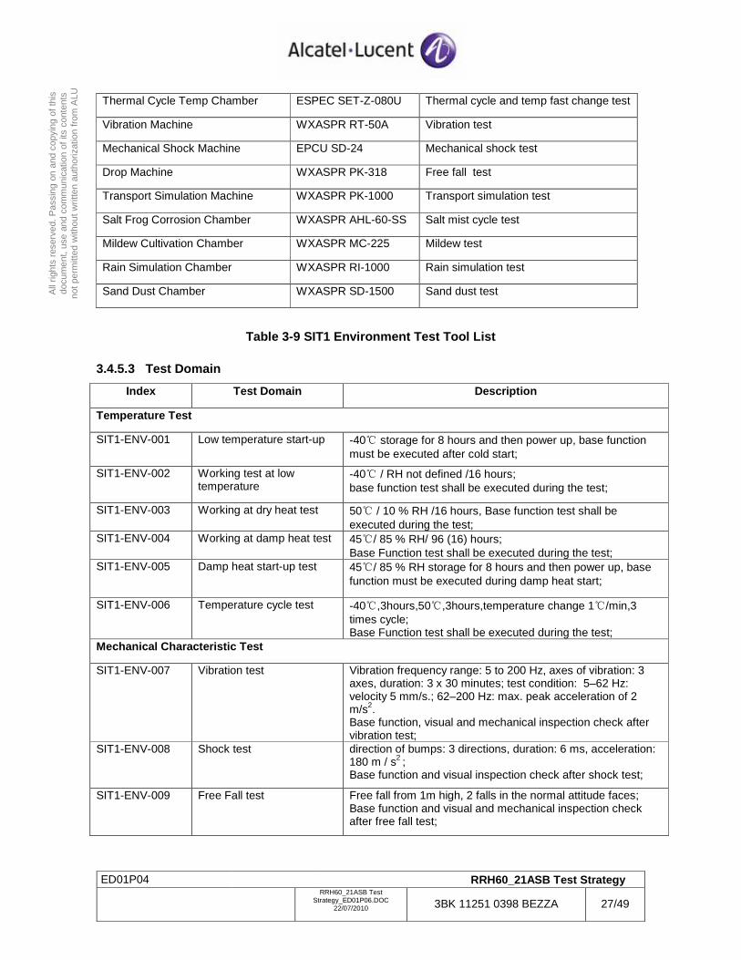
3.4.5.3 Test Domain
Index Test Domain Description
Temperature Test
SIT1-ENV-001 Low temperature start-up -40 storage for 8 hours and then power up, base function must be executed after cold start;
SIT1-ENV-002 Working test at low temperature
-40 / RH not defined /16 hours; base function test shall be executed during the test;
SIT1-ENV-003 Working at dry heat test 50 / 10 % RH /16 hours, Base function test shall be executed during the test;
SIT1-ENV-004 Working at damp heat test 45/ 85 % RH/ 96 (16) hours; Base Function test shall be executed during the test;
SIT1-ENV-005 Damp heat start-up test 45/ 85 % RH storage for 8 hours and then power up, base function must be executed during damp heat start;
SIT1-ENV-006 Temperature cycle test -40,3hours,50,3hours,temperature change 1/min,3 times cycle; Base Function test shall be executed during the test;
Mechanical Characteristic Test
SIT1-ENV-007 Vibration test Vibration frequency range: 5 to 200 Hz, axes of vibration: 3 axes, duration: 3 x 30 minutes; test condition: 5–62 Hz: velocity 5 mm/s.; 62–200 Hz: max. peak acceleration of 2 m/s2. Base function, visual and mechanical inspection check after vibration test;
SIT1-ENV-008 Shock test direction of bumps: 3 directions, duration: 6 ms, acceleration: 180 m / s2 ; Base function and visual inspection check after shock test;
SIT1-ENV-009 Free Fall test Free fall from 1m high, 2 falls in the normal attitude faces; Base function and visual and mechanical inspection check after free fall test;
ED01P04 RRH60_21ASB Test Strategy
RRH60_21ASB Test
Strategy_ED01P06.DOC 22/07/2010 3BK 11251 0398 BEZZA 28/49
All
right
s re
serv
ed. P
assi
ng o
n an
d co
pyin
g of
this
do
cum
ent,
use
and
com
mun
icat
ion
of it
s co
nten
ts
not p
erm
itted
with
out w
ritte
n au
thor
izat
ion
from
ALU
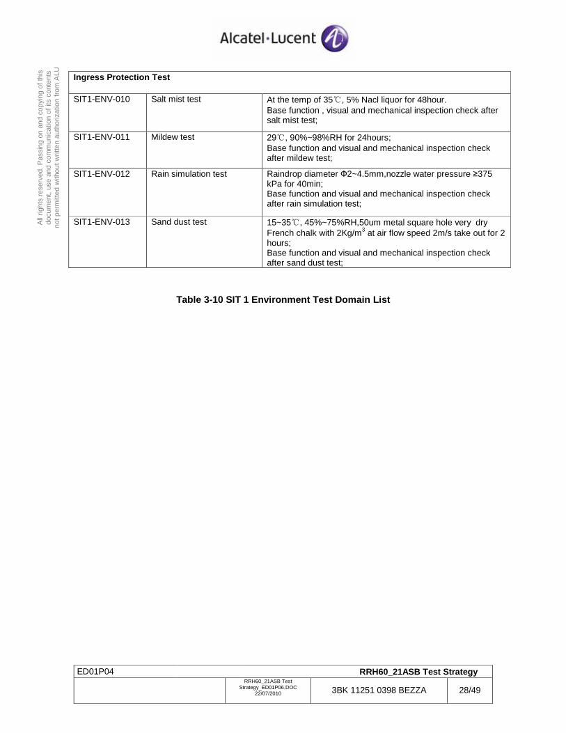
Ingress Protection Test
SIT1-ENV-010 Salt mist test At the temp of 35, 5% Nacl liquor for 48hour. Base function , visual and mechanical inspection check after salt mist test;
SIT1-ENV-011 Mildew test 29, 90%~98%RH for 24hours; Base function and visual and mechanical inspection check after mildew test;
SIT1-ENV-012 Rain simulation test Raindrop diameter Ф2~4.5mm,nozzle water pressure ≥375 kPa for 40min; Base function and visual and mechanical inspection check after rain simulation test;
SIT1-ENV-013 Sand dust test 15~35, 45%~75%RH,50um metal square hole very dry French chalk with 2Kg/m3 at air flow speed 2m/s take out for 2 hours; Base function and visual and mechanical inspection check after sand dust test;
Table 3-10 SIT 1 Environment Test Domain List
ED01P04 RRH60_21ASB Test Strategy
RRH60_21ASB Test
Strategy_ED01P06.DOC 22/07/2010 3BK 11251 0398 BEZZA 29/49
All
right
s re
serv
ed. P
assi
ng o
n an
d co
pyin
g of
this
do
cum
ent,
use
and
com
mun
icat
ion
of it
s co
nten
ts
not p
erm
itted
with
out w
ritte
n au
thor
izat
ion
from
ALU
4 SIT2
After SIT1, each asset of RRH is verified individually. And in this test phase, all the assets are put together for first pre-integration. The RRH inner interface between two assets will be checked to verify the middle results satisfy the designed performance.
SIT2 focus on these aspects about the RRH inner integration and validation:
- RRH inner module and connection integration
- RRH DL function process validation except the SFP module connection on the CPRI interface
- RRH UL function process validation except the SFP module connection on the CPRI interface
- RRH OAM function process validation except the SFP module connection on the CPRI interface
- SFP module connection loop test and FPGA L1/L2 process validation of the CPRI interface
4.1 DL Pre-integration Test
After the SIT1 validation, the TRX board and PA module and FEU module and Power module pass the module individual test. All of these modules will assemble in the RRH rack and connect together with the RF/Power/Control cable. About the RRH DL function, the following tests will be performed in the SIT2:
- Modules Power On and initialization after the assembly and connection
- Power supply module validation when all the module is power-on
- Module temperature validation when all the module is power-on and load current warm up
- Module input/output signal and impedance matching validation
- PA and DPD algorithm in the TRX integration and validation
DL IQ SFP module connection loop test and FPGA L1/L2 process validation of the CPRI interface
4.1.1 Test Equipment and Tool
ED01P04 RRH60_21ASB Test Strategy
RRH60_21ASB Test
Strategy_ED01P06.DOC 22/07/2010 3BK 11251 0398 BEZZA 30/49
All
right
s re
serv
ed. P
assi
ng o
n an
d co
pyin
g of
this
do
cum
ent,
use
and
com
mun
icat
ion
of it
s co
nten
ts
not p
erm
itted
with
out w
ritte
n au
thor
izat
ion
from
ALU
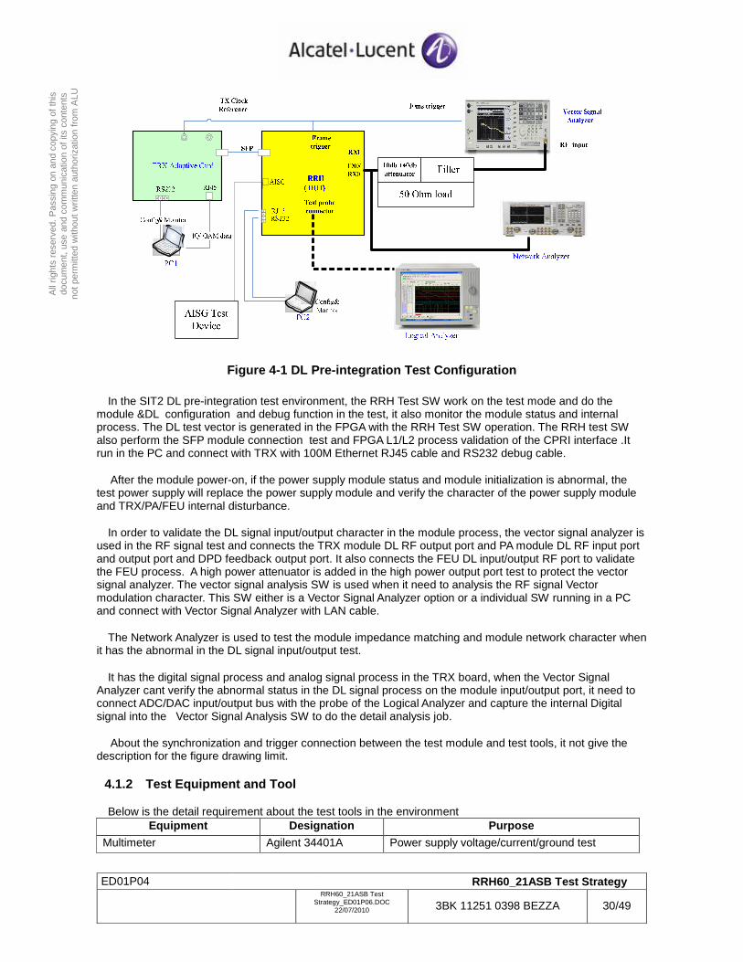
Figure 4-1 DL Pre-integration Test Configuration
In the SIT2 DL pre-integration test environment, the RRH Test SW work on the test mode and do the module &DL configuration and debug function in the test, it also monitor the module status and internal process. The DL test vector is generated in the FPGA with the RRH Test SW operation. The RRH test SW also perform the SFP module connection test and FPGA L1/L2 process validation of the CPRI interface .It run in the PC and connect with TRX with 100M Ethernet RJ45 cable and RS232 debug cable.
After the module power-on, if the power supply module status and module initialization is abnormal, the test power supply will replace the power supply module and verify the character of the power supply module and TRX/PA/FEU internal disturbance.
In order to validate the DL signal input/output character in the module process, the vector signal analyzer is used in the RF signal test and connects the TRX module DL RF output port and PA module DL RF input port and output port and DPD feedback output port. It also connects the FEU DL input/output RF port to validate the FEU process. A high power attenuator is added in the high power output port test to protect the vector signal analyzer. The vector signal analysis SW is used when it need to analysis the RF signal Vector modulation character. This SW either is a Vector Signal Analyzer option or a individual SW running in a PC and connect with Vector Signal Analyzer with LAN cable.
The Network Analyzer is used to test the module impedance matching and module network character when it has the abnormal in the DL signal input/output test.
It has the digital signal process and analog signal process in the TRX board, when the Vector Signal Analyzer cant verify the abnormal status in the DL signal process on the module input/output port, it need to connect ADC/DAC input/output bus with the probe of the Logical Analyzer and capture the internal Digital signal into the Vector Signal Analysis SW to do the detail analysis job.
About the synchronization and trigger connection between the test module and test tools, it not give the description for the figure drawing limit.
4.1.2 Test Equipment and Tool
Below is the detail requirement about the test tools in the environment Equipment Designation Purpose
Multimeter Agilent 34401A Power supply voltage/current/ground test
ED01P04 RRH60_21ASB Test Strategy
RRH60_21ASB Test
Strategy_ED01P06.DOC 22/07/2010 3BK 11251 0398 BEZZA 31/49
All
right
s re
serv
ed. P
assi
ng o
n an
d co
pyin
g of
this
do
cum
ent,
use
and
com
mun
icat
ion
of it
s co
nten
ts
not p
erm
itted
with
out w
ritte
n au
thor
izat
ion
from
ALU
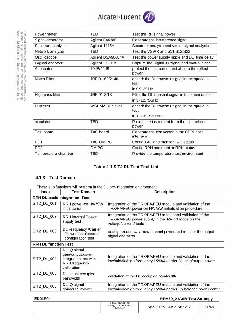
Power meter TBD Test the RF signal power
Signal generator Agilent E4438C Generate the interference signal
Spectrum analyzer Agilent 4445A Spectrum analysis and vector signal analysis
Network analyzer TBD Test the VSWR and S11/S12/S22
Oscilloscope Agilent DSA90604A Test the power supply ripple and DL time delay
Logical analyzer Agilent 17901A Capture the Digital IQ signal and control signal
Attenuator 10dB/40dB protect the instrument and absorb the reflect power
Notch Filter JRF-01-60/2140 absorb the DL transmit signal in the spurious test in 9K~3GHz
High pass filter JRF-01-3/13 Filter the DL transmit signal in the spurious test
in 3~12.75GHz
Duplexer WCDMA Duplexer absorb the DL transmit signal in the spurious test in 1920~1980MHz
circulator TBD Protect the instrument from the high reflect power
Test board TAC board Generate the test vector in the CPRI optic interface
PC1 TAC OM PC Config TAC and monitor TAC status
PC2 OM PC Config RRH and monitor RRH status
Temperature chamber TBD Provide the temperature test environment
Table 4-1 SIT2 DL Test Tool List
4.1.3 Test Domain
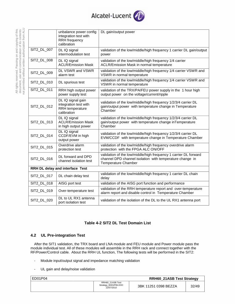
These sub functions will perform in the DL pre-integration environment Index Test Domain Description
RRH DL basic integration Test
SIT2_DL_001
RRH power-on HW/SW initialization
Integration of the TRX/PA/FEU module and validation of the TRX/PA/FEU power-on HW/SW initialization procedure
SIT2_DL_002
RRH internal Power supply test
Integration of the TRX/PA/FEU moduleand validation of the TRX/PA/FEU power supply in the RF-off mode on the voltage/current/ripple
SIT2_DL_003
DL Frequency /Carrier /Power/Gain/control configuration test
config frequency/carrier/channel power and monitor the output signal character
RRH DL function Test
SIT2_DL_004
DL IQ signal gain/outputpower integration test with RRH frequency calibration
Integration of the TRX/PA/FEU module and validation of the low/middle/high frequency 1/2/3/4 carrier DL gain/output power
SIT2_DL_005
DL signal occupied bandwidth validation of the DL occupied bandwidth
SIT2_DL_006 DL IQ signal gain/outputpower
Integration of the TRX/PA/FEU module and validation of the low/middle/high frequency 1/2/3/4 carrier un-balance power config
ED01P04 RRH60_21ASB Test Strategy
RRH60_21ASB Test
Strategy_ED01P06.DOC 22/07/2010 3BK 11251 0398 BEZZA 32/49
All
right
s re
serv
ed. P
assi
ng o
n an
d co
pyin
g of
this
do
cum
ent,
use
and
com
mun
icat
ion
of it
s co
nten
ts
not p
erm
itted
with
out w
ritte
n au
thor
izat
ion
from
ALU
unbalance power config integration test with RRH frequency calibration
DL gain/output power
SIT2_DL_007
DL IQ signal intermodulation test
validation of the low/middle/high frequency 1 carrier DL gain/output power
SIT2_DL_008
DL IQ signal ACLR/Emission Mask
validation of the low/middle/high frequency 1/4 carrier ACLR/Emission Mask in normal temperature
SIT2_DL_009 DL VSWR and VSWR alarm test
validation of the low/middle/high frequency 1/4 carrier VSWR and VSWR in normal temperature
SIT2_DL_010 DL spurious test validation of the low/middle/high frequency 1/4 carrier VSWR and VSWR in normal temperature
SIT2_DL_011
RRH high output power power supply test
validation of the TRX/PA/FEU power supply in the 1 hour high output power on the voltage/current/ripple
SIT2_DL_012
DL IQ signal gain integration test with RRH temperature calibration
validation of the low/middle/high frequency 1/2/3/4 carrier DL gain/output power with temperature change in Temperature Chamber
SIT2_DL_013 DL IQ signal ACLR/Emission Mask in high output power
validation of the low/middle/high frequency 1/2/3/4 carrier DL gain/output power with temperature change inTemperature Chamber
SIT2_DL_014 DL IQ signal CCDF/EVM in high output power
validation of the low/middle/high frequency 1/2/3/4 carrier DL EVM/CCDF with temperature change in Temperature Chamber
SIT2_DL_015 Overdrive alarm protection test
validation of the low/middle/high frequency overdrive alarm protection with the FPGA ALC ON/OFF
SIT2_DL_016 DL forward and DPD channel isolation test
validation of the low/middle/high frequency 1 carrier DL forward channel DPD channel isolation with temperature change in Temperature Chamber
RRH DL delay and interface Test
SIT2_DL_017 DL chain delay test validation of the low/middle/high frequency 1 carrier DL chain delay
SIT2_DL_018 AISG port test validation of the AISG port function and performance
SIT2_DL_019 Over-temperature test validation of the RRH temperature report and over-temperature alarm report and disable control in Temperature Chamber
SIT2_DL_020 DL to UL RX1 antenna port isolation test validation of the isolation of the DL to the UL RX1 antenna port
Table 4-2 SIT2 DL Test Domain List
4.2 UL Pre-integration Test
After the SIT1 validation, the TRX board and LNA module and FEU module and Power module pass the module individual test. All of these modules will assemble in the RRH rack and connect together with the RF/Power/Control cable. About the RRH UL function, The following tests will be performed in the SIT2:
- Module input/output signal and impedance matching validation
- UL gain and delay/noise validation
ED01P04 RRH60_21ASB Test Strategy
RRH60_21ASB Test
Strategy_ED01P06.DOC 22/07/2010 3BK 11251 0398 BEZZA 33/49
All
right
s re
serv
ed. P
assi
ng o
n an
d co
pyin
g of
this
do
cum
ent,
use
and
com
mun
icat
ion
of it
s co
nten
ts
not p
erm
itted
with
out w
ritte
n au
thor
izat
ion
from
ALU
- 2 UL channel balance validation
- UL IQ SFP module connection loop test and FPGA L1/L2 process validation of the CPRI interface
4.2.1 Test Configuration
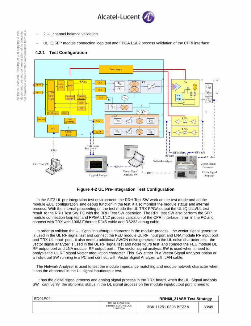
Figure 4-2 UL Pre-integration Test Configuration
In the SIT2 UL pre-integration test environment, the RRH Test SW work on the test mode and do the module &UL configuration and debug function in the test, it also monitor the module status and internal process. With the internal proceeding on the test mode the UL TRX FPGA output the UL IQ data/UL test result to the RRH Test SW PC with the RRH Test SW operation. The RRH test SW also perform the SFP module connection loop test and FPGA L1/L2 process validation of the CPRI interface .It run in the PC and connect with TRX with 100M Ethernet RJ45 cable and RS232 debug cable.
In order to validate the UL signal input/output character in the module process , the vector signal generator is used in the UL RF signal test and connect the FEU module UL RF input port and LNA module RF input port and TRX UL input port . it also need a additional AWGN noise generator in the UL noise character test. the vector signal analyzer is used in the UL RF signal test and noise figure test and connect the FEU module DL RF output port and LNA module RF output port . The vector signal analysis SW is used when it need to analysis the UL RF signal Vector modulation character. This SW either is a Vector Signal Analyzer option or a individual SW running in a PC and connect with Vector Signal Analyzer with LAN cable.
The Network Analyzer is used to test the module impedance matching and module network character when it has the abnormal in the UL signal input/output test.
It has the digital signal process and analog signal process in the TRX board, when the UL Signal analysis SW cant verify the abnormal status in the DL signal process on the module input/output port, it need to
ED01P04 RRH60_21ASB Test Strategy
RRH60_21ASB Test
Strategy_ED01P06.DOC 22/07/2010 3BK 11251 0398 BEZZA 34/49
All
right
s re
serv
ed. P
assi
ng o
n an
d co
pyin
g of
this
do
cum
ent,
use
and
com
mun
icat
ion
of it
s co
nten
ts
not p
erm
itted
with
out w
ritte
n au
thor
izat
ion
from
ALU
connect ADC output bus with the probe of the Logical Analyzer and capture the internal Digital signal into the Vector Signal Analysis SW to do the detail analysis job.
About the synchronization and trigger connection between the test module and test tools, it not give the description for the figure drawing limit.
4.2.2 Test Equipment and Tool
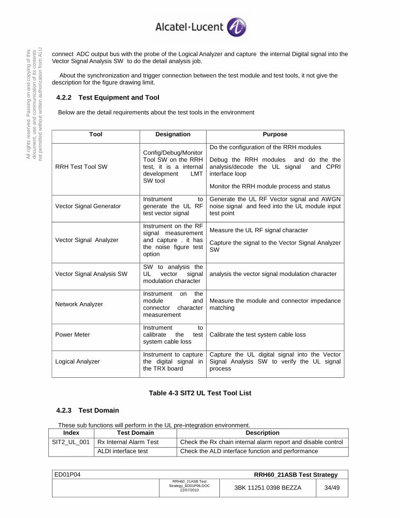
Below are the detail requirements about the test tools in the environment
Tool Designation Purpose
RRH Test Tool SW
Config/Debug/Monitor Tool SW on the RRH test, it is a internal development LMT SW tool
Do the configuration of the RRH modules
Debug the RRH modules and do the the analysis/decode the UL signal and CPRI interface loop
Monitor the RRH module process and status
Vector Signal Generator Instrument to generate the UL RF test vector signal
Generate the UL RF Vector signal and AWGN noise signal and feed into the UL module input test point
Vector Signal Analyzer
Instrument on the RF signal measurement and capture . it has the noise figure test option
Measure the UL RF signal character
Capture the signal to the Vector Signal Analyzer SW
Vector Signal Analysis SW SW to analysis the UL vector signal modulation character
analysis the vector signal modulation character
Network Analyzer
Instrument on the module and connector character measurement
Measure the module and connector impedance matching
Power Meter Instrument to calibrate the test system cable loss
Calibrate the test system cable loss
Logical Analyzer Instrument to capture the digital signal in the TRX board
Capture the UL digital signal into the Vector Signal Analysis SW to verify the UL signal process
Table 4-3 SIT2 UL Test Tool List
4.2.3 Test Domain
These sub functions will perform in the UL pre-integration environment. Index Test Domain Description
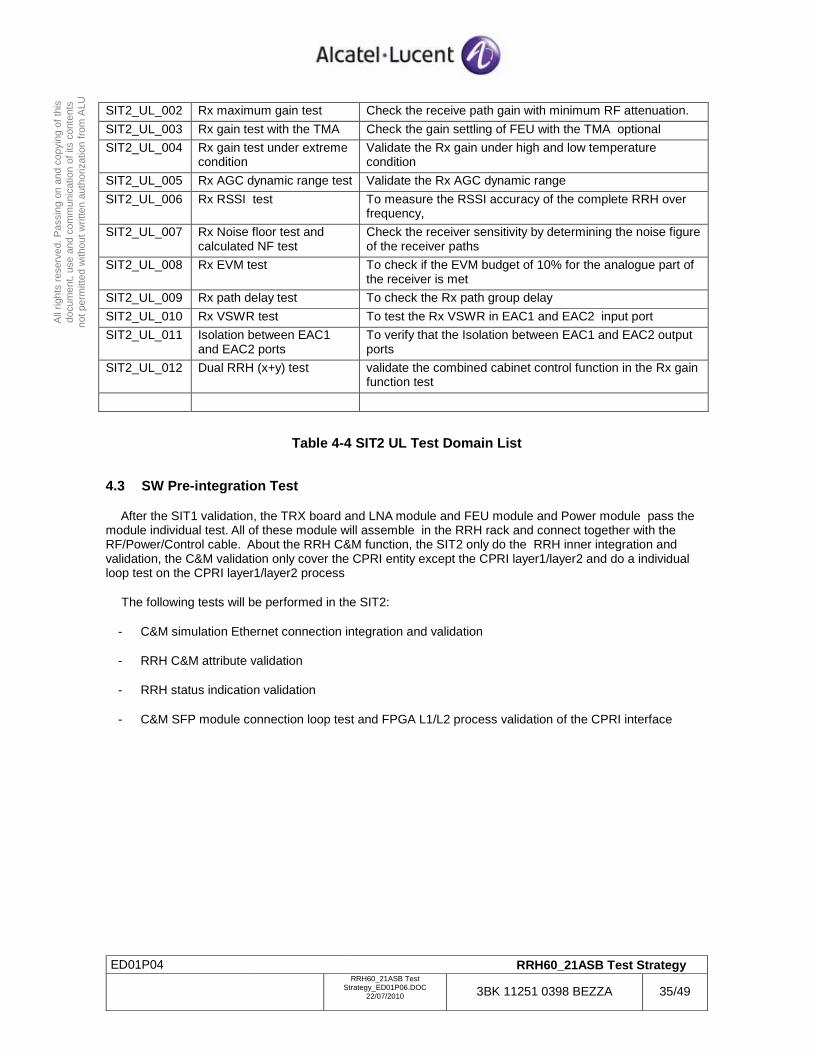
Rx Internal Alarm Test Check the Rx chain internal alarm report and disable control SIT2_UL_001
ALDI interface test Check the ALD interface function and performance
ED01P04 RRH60_21ASB Test Strategy
RRH60_21ASB Test
Strategy_ED01P06.DOC 22/07/2010 3BK 11251 0398 BEZZA 35/49
All
right
s re
serv
ed. P
assi
ng o
n an
d co
pyin
g of
this
do
cum
ent,
use
and
com
mun
icat
ion
of it
s co
nten
ts
not p
erm
itted
with
out w
ritte
n au
thor
izat
ion
from
ALU
SIT2_UL_002 Rx maximum gain test Check the receive path gain with minimum RF attenuation.
SIT2_UL_003 Rx gain test with the TMA Check the gain settling of FEU with the TMA optional
SIT2_UL_004 Rx gain test under extreme condition
Validate the Rx gain under high and low temperature condition
SIT2_UL_005 Rx AGC dynamic range test Validate the Rx AGC dynamic range
SIT2_UL_006 Rx RSSI test To measure the RSSI accuracy of the complete RRH over frequency,
SIT2_UL_007 Rx Noise floor test and calculated NF test
Check the receiver sensitivity by determining the noise figure of the receiver paths
SIT2_UL_008 Rx EVM test To check if the EVM budget of 10% for the analogue part of the receiver is met
SIT2_UL_009 Rx path delay test To check the Rx path group delay
SIT2_UL_010 Rx VSWR test To test the Rx VSWR in EAC1 and EAC2 input port
SIT2_UL_011 Isolation between EAC1 and EAC2 ports
To verify that the Isolation between EAC1 and EAC2 output ports
SIT2_UL_012 Dual RRH (x+y) test validate the combined cabinet control function in the Rx gain function test
Table 4-4 SIT2 UL Test Domain List
4.3 SW Pre-integration Test
After the SIT1 validation, the TRX board and LNA module and FEU module and Power module pass the module individual test. All of these module will assemble in the RRH rack and connect together with the RF/Power/Control cable. About the RRH C&M function, the SIT2 only do the RRH inner integration and validation, the C&M validation only cover the CPRI entity except the CPRI layer1/layer2 and do a individual loop test on the CPRI layer1/layer2 process
The following tests will be performed in the SIT2:
- C&M simulation Ethernet connection integration and validation
- RRH C&M attribute validation
- RRH status indication validation
- C&M SFP module connection loop test and FPGA L1/L2 process validation of the CPRI interface
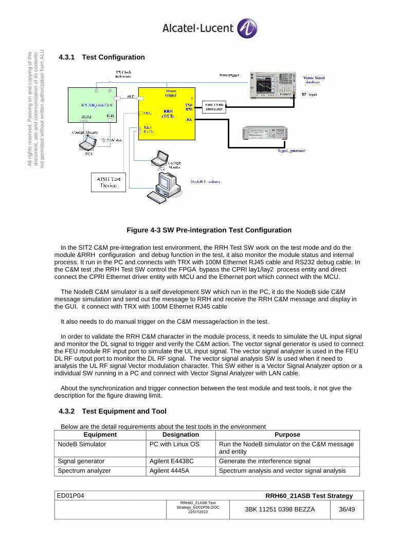
ED01P04 RRH60_21ASB Test Strategy
RRH60_21ASB Test
Strategy_ED01P06.DOC 22/07/2010 3BK 11251 0398 BEZZA 36/49
All
right
s re
serv
ed. P
assi
ng o
n an
d co
pyin
g of
this
do
cum
ent,
use
and
com
mun
icat
ion
of it
s co
nten
ts
not p
erm
itted
with
out w
ritte
n au
thor
izat
ion
from
ALU
4.3.1 Test Configuration
Figure 4-3 SW Pre-integration Test Configuration
In the SIT2 C&M pre-integration test environment, the RRH Test SW work on the test mode and do the module &RRH configuration and debug function in the test, it also monitor the module status and internal process. It run in the PC and connects with TRX with 100M Ethernet RJ45 cable and RS232 debug cable. In the C&M test ,the RRH Test SW control the FPGA bypass the CPRI lay1/lay2 process entity and direct connect the CPRI Ethernet driver entity with MCU and the Ethernet port which connect with the MCU.
The NodeB C&M simulator is a self development SW which run in the PC, it do the NodeB side C&M message simulation and send out the message to RRH and receive the RRH C&M message and display in the GUI. it connect with TRX with 100M Ethernet RJ45 cable
It also needs to do manual trigger on the C&M message/action in the test.
In order to validate the RRH C&M character in the module process, it needs to simulate the UL input signal and monitor the DL signal to trigger and verify the C&M action. The vector signal generator is used to connect the FEU module RF input port to simulate the UL input signal. The vector signal analyzer is used in the FEU DL RF output port to monitor the DL RF signal. The vector signal analysis SW is used when it need to analysis the UL RF signal Vector modulation character. This SW either is a Vector Signal Analyzer option or a individual SW running in a PC and connect with Vector Signal Analyzer with LAN cable.
About the synchronization and trigger connection between the test module and test tools, it not give the description for the figure drawing limit.
4.3.2 Test Equipment and Tool
Below are the detail requirements about the test tools in the environment Equipment Designation Purpose
NodeB Simulator PC with Linux OS Run the NodeB simulator on the C&M message and entity
Signal generator Agilent E4438C Generate the interference signal
Spectrum analyzer Agilent 4445A Spectrum analysis and vector signal analysis
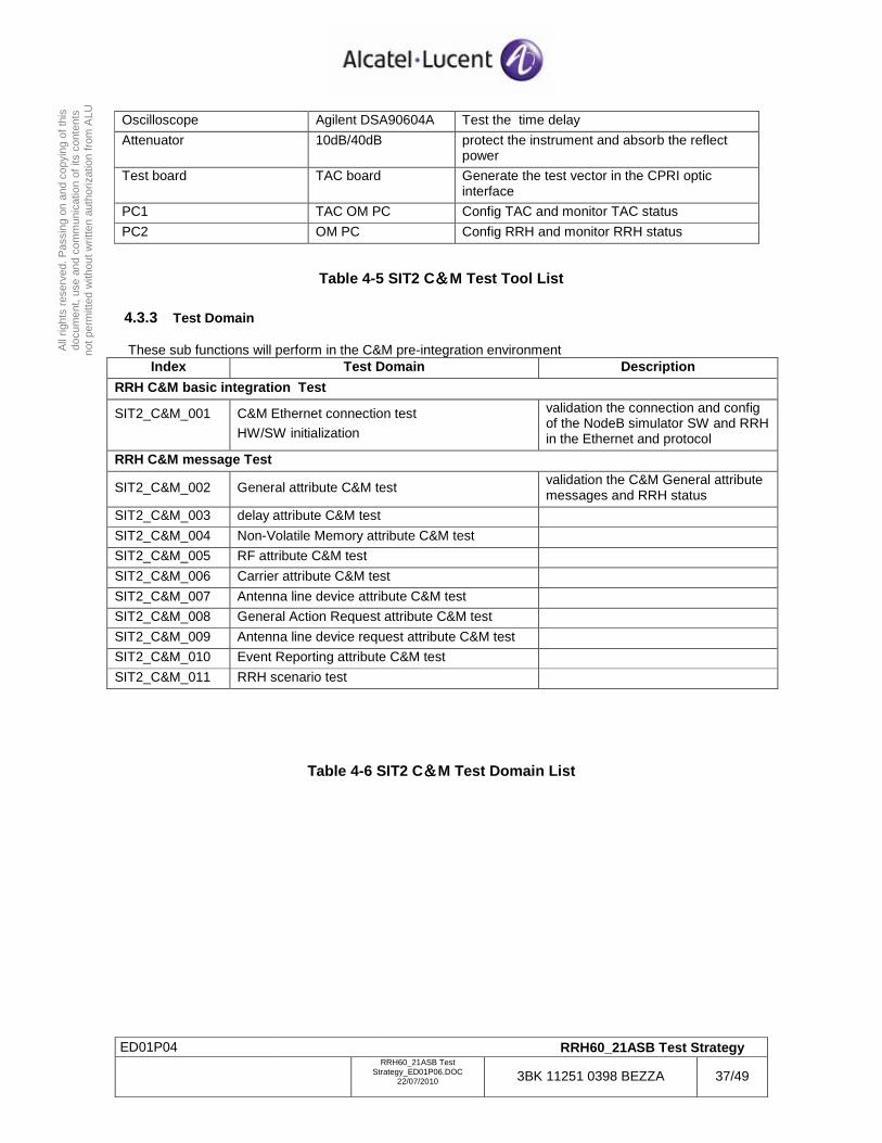
ED01P04 RRH60_21ASB Test Strategy
RRH60_21ASB Test
Strategy_ED01P06.DOC 22/07/2010 3BK 11251 0398 BEZZA 37/49
All
right
s re
serv
ed. P
assi
ng o
n an
d co
pyin
g of
this
do
cum
ent,
use
and
com
mun
icat
ion
of it
s co
nten
ts
not p
erm
itted
with
out w
ritte
n au
thor
izat
ion
from
ALU
Oscilloscope Agilent DSA90604A Test the time delay
Attenuator 10dB/40dB protect the instrument and absorb the reflect power
Test board TAC board Generate the test vector in the CPRI optic interface
PC1 TAC OM PC Config TAC and monitor TAC status
PC2 OM PC Config RRH and monitor RRH status
Table 4-5 SIT2 C&&&&M Test Tool List
4.3.3 Test Domain
These sub functions will perform in the C&M pre-integration environment Index Test Domain Description
RRH C&M basic integration Test
SIT2_C&M_001
C&M Ethernet connection test
HW/SW initialization
validation the connection and config of the NodeB simulator SW and RRH in the Ethernet and protocol
RRH C&M message Test
SIT2_C&M_002 General attribute C&M test validation the C&M General attribute messages and RRH status
SIT2_C&M_003 delay attribute C&M test
SIT2_C&M_004 Non-Volatile Memory attribute C&M test
SIT2_C&M_005 RF attribute C&M test
SIT2_C&M_006 Carrier attribute C&M test
SIT2_C&M_007 Antenna line device attribute C&M test
SIT2_C&M_008 General Action Request attribute C&M test
SIT2_C&M_009 Antenna line device request attribute C&M test
SIT2_C&M_010 Event Reporting attribute C&M test
SIT2_C&M_011 RRH scenario test
Table 4-6 SIT2 C&&&&M Test Domain List
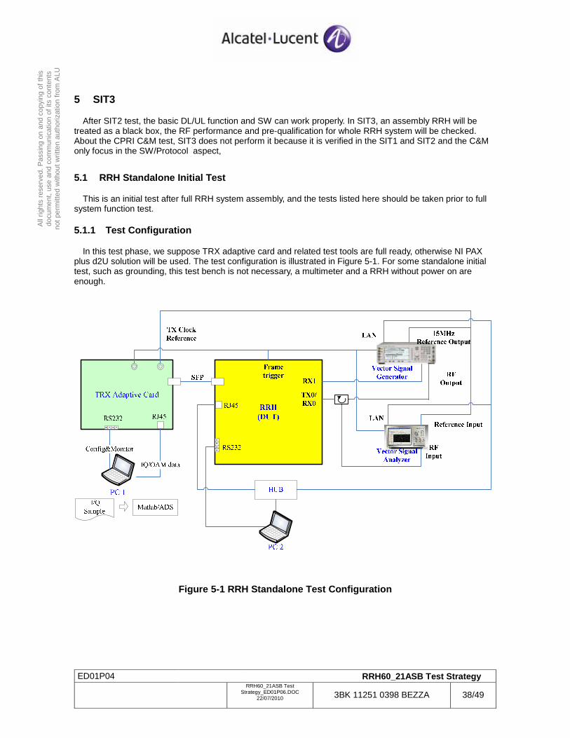
ED01P04 RRH60_21ASB Test Strategy
RRH60_21ASB Test
Strategy_ED01P06.DOC 22/07/2010 3BK 11251 0398 BEZZA 38/49
All
right
s re
serv
ed. P
assi
ng o
n an
d co
pyin
g of
this
do
cum
ent,
use
and
com
mun
icat
ion
of it
s co
nten
ts
not p
erm
itted
with
out w
ritte
n au
thor
izat
ion
from
ALU
5 SIT3
After SIT2 test, the basic DL/UL function and SW can work properly. In SIT3, an assembly RRH will be treated as a black box, the RF performance and pre-qualification for whole RRH system will be checked. About the CPRI C&M test, SIT3 does not perform it because it is verified in the SIT1 and SIT2 and the C&M only focus in the SW/Protocol aspect,
5.1 RRH Standalone Initial Test
This is an initial test after full RRH system assembly, and the tests listed here should be taken prior to full system function test.
5.1.1 Test Configuration
In this test phase, we suppose TRX adaptive card and related test tools are full ready, otherwise NI PAX plus d2U solution will be used. The test configuration is illustrated in Figure 5-1. For some standalone initial test, such as grounding, this test bench is not necessary, a multimeter and a RRH without power on are enough.
Figure 5-1 RRH Standalone Test Configuration
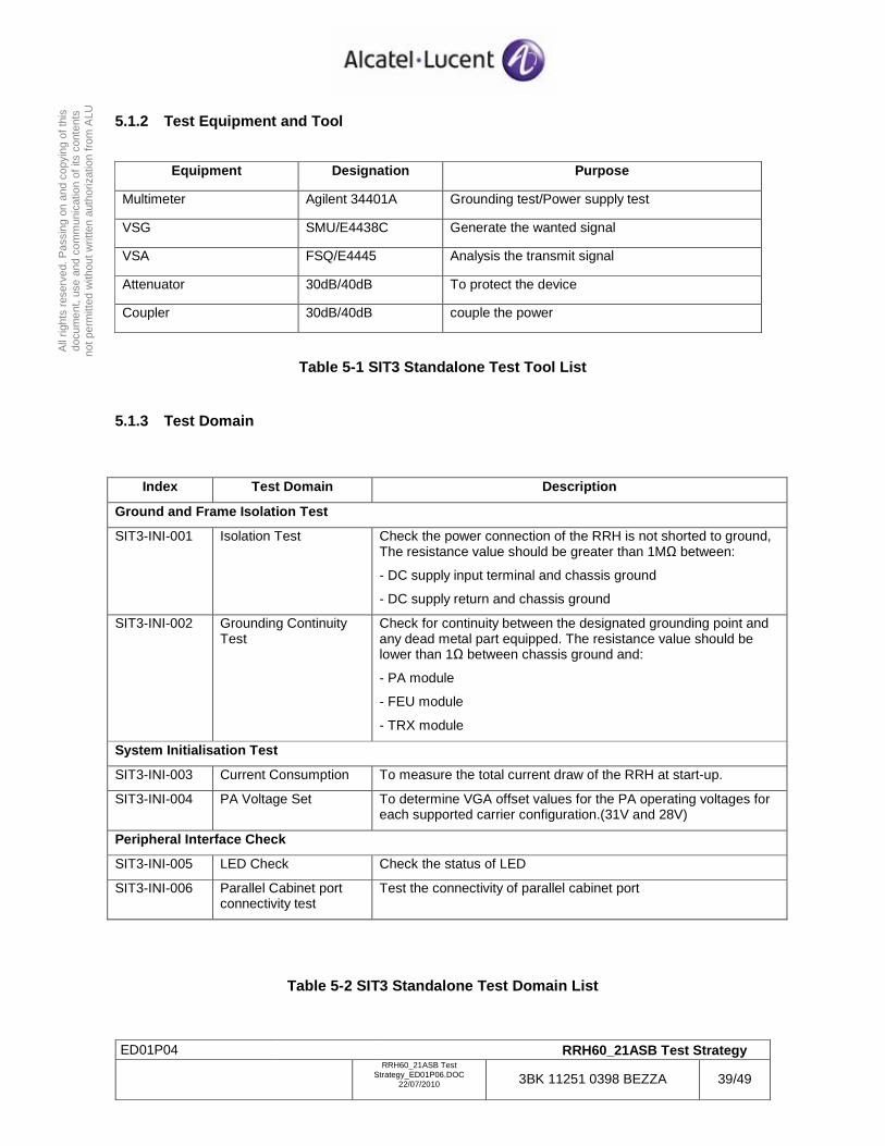
ED01P04 RRH60_21ASB Test Strategy
RRH60_21ASB Test
Strategy_ED01P06.DOC 22/07/2010 3BK 11251 0398 BEZZA 39/49
All
right
s re
serv
ed. P
assi
ng o
n an
d co
pyin
g of
this
do
cum
ent,
use
and
com
mun
icat
ion
of it
s co
nten
ts
not p
erm
itted
with
out w
ritte
n au
thor
izat
ion
from
ALU
5.1.2 Test Equipment and Tool
Equipment Designation Purpose
Multimeter Agilent 34401A Grounding test/Power supply test
VSG SMU/E4438C Generate the wanted signal
VSA FSQ/E4445 Analysis the transmit signal
Attenuator 30dB/40dB To protect the device
Coupler 30dB/40dB couple the power
Table 5-1 SIT3 Standalone Test Tool List
5.1.3 Test Domain
Index Test Domain Description
Ground and Frame Isolation Test
SIT3-INI-001 Isolation Test Check the power connection of the RRH is not shorted to ground, The resistance value should be greater than 1MΩ between:
- DC supply input terminal and chassis ground
- DC supply return and chassis ground
SIT3-INI-002 Grounding Continuity Test
Check for continuity between the designated grounding point and any dead metal part equipped. The resistance value should be lower than 1Ω between chassis ground and:
- PA module
- FEU module
- TRX module
System Initialisation Test
SIT3-INI-003 Current Consumption To measure the total current draw of the RRH at start-up.
SIT3-INI-004 PA Voltage Set To determine VGA offset values for the PA operating voltages for each supported carrier configuration.(31V and 28V)
Peripheral Interface Check
SIT3-INI-005 LED Check Check the status of LED
SIT3-INI-006 Parallel Cabinet port connectivity test
Test the connectivity of parallel cabinet port
Table 5-2 SIT3 Standalone Test Domain List
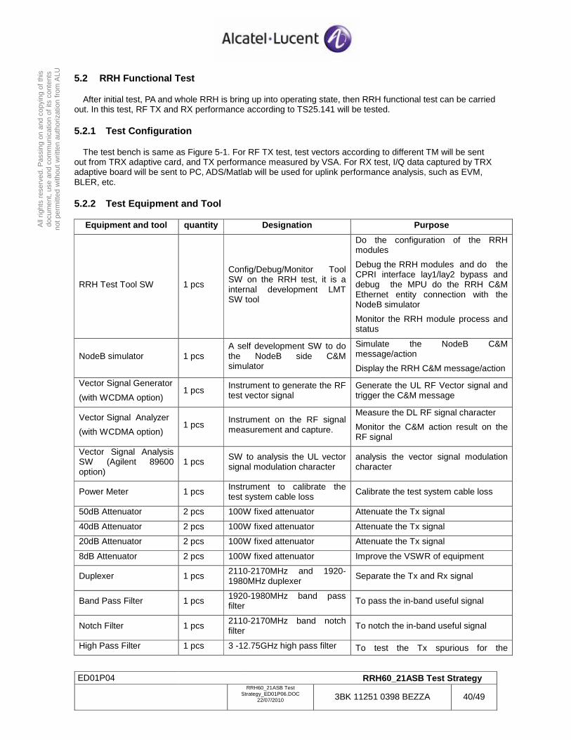
ED01P04 RRH60_21ASB Test Strategy
RRH60_21ASB Test
Strategy_ED01P06.DOC 22/07/2010 3BK 11251 0398 BEZZA 40/49
All
right
s re
serv
ed. P
assi
ng o
n an
d co
pyin
g of
this
do
cum
ent,
use
and
com
mun
icat
ion
of it
s co
nten
ts
not p
erm
itted
with
out w
ritte
n au
thor
izat
ion
from
ALU
5.2 RRH Functional Test
After initial test, PA and whole RRH is bring up into operating state, then RRH functional test can be carried out. In this test, RF TX and RX performance according to TS25.141 will be tested.
5.2.1 Test Configuration
The test bench is same as Figure 5-1. For RF TX test, test vectors according to different TM will be sent out from TRX adaptive card, and TX performance measured by VSA. For RX test, I/Q data captured by TRX adaptive board will be sent to PC, ADS/Matlab will be used for uplink performance analysis, such as EVM, BLER, etc.
5.2.2 Test Equipment and Tool
Equipment and tool quantity Designation Purpose
RRH Test Tool SW 1 pcs
Config/Debug/Monitor Tool SW on the RRH test, it is a internal development LMT SW tool
Do the configuration of the RRH modules
Debug the RRH modules and do the CPRI interface lay1/lay2 bypass and debug the MPU do the RRH C&M Ethernet entity connection with the NodeB simulator
Monitor the RRH module process and status
NodeB simulator 1 pcs A self development SW to do the NodeB side C&M simulator
Simulate the NodeB C&M message/action
Display the RRH C&M message/action
Vector Signal Generator
(with WCDMA option) 1 pcs Instrument to generate the RF
test vector signal Generate the UL RF Vector signal and trigger the C&M message
Vector Signal Analyzer
(with WCDMA option) 1 pcs
Instrument on the RF signal measurement and capture.
Measure the DL RF signal character
Monitor the C&M action result on the RF signal
Vector Signal Analysis SW (Agilent 89600 option)
1 pcs SW to analysis the UL vector signal modulation character
analysis the vector signal modulation character
Power Meter 1 pcs Instrument to calibrate the test system cable loss
Calibrate the test system cable loss
50dB Attenuator 2 pcs 100W fixed attenuator Attenuate the Tx signal
40dB Attenuator 2 pcs 100W fixed attenuator Attenuate the Tx signal
20dB Attenuator 2 pcs 100W fixed attenuator Attenuate the Tx signal
8dB Attenuator 2 pcs 100W fixed attenuator Improve the VSWR of equipment
Duplexer 1 pcs 2110-2170MHz and 1920-1980MHz duplexer
Separate the Tx and Rx signal
Band Pass Filter 1 pcs 1920-1980MHz band pass filter To pass the in-band useful signal
Notch Filter 1 pcs 2110-2170MHz band notch filter To notch the in-band useful signal
High Pass Filter 1 pcs 3 -12.75GHz high pass filter To test the Tx spurious for the
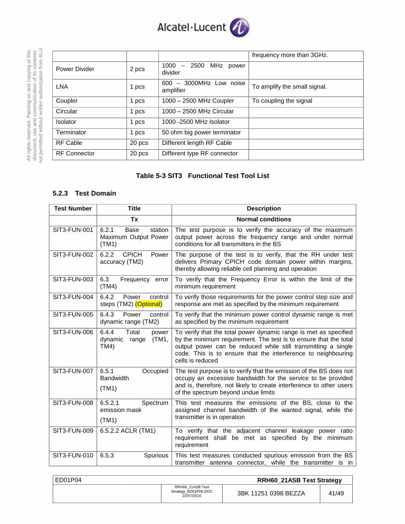
ED01P04 RRH60_21ASB Test Strategy
RRH60_21ASB Test
Strategy_ED01P06.DOC 22/07/2010 3BK 11251 0398 BEZZA 41/49
All
right
s re
serv
ed. P
assi
ng o
n an
d co
pyin
g of
this
do
cum
ent,
use
and
com
mun
icat
ion
of it
s co
nten
ts
not p
erm
itted
with
out w
ritte
n au
thor
izat
ion
from
ALU
frequency more than 3GHz.
Power Divider 2 pcs 1000 – 2500 MHz power divider
LNA 1 pcs 600 – 3000MHz Low noise amplifier To amplify the small signal.
Coupler 1 pcs 1000 – 2500 MHz Coupler To coupling the signal
Circular 1 pcs 1000 – 2500 MHz Circular
Isolator 1 pcs 1000 -2500 MHz Isolator
Terminator 1 pcs 50 ohm big power terminator
RF Cable 20 pcs Different length RF Cable
RF Connector 20 pcs Different type RF connector
Table 5-3 SIT3 Functional Test Tool List
5.2.3 Test Domain Test Number Title Description
Tx Normal conditions
SIT3-FUN-001 6.2.1 Base station Maximum Output Power (TM1)
The test purpose is to verify the accuracy of the maximum output power across the frequency range and under normal conditions for all transmitters in the BS
SIT3-FUN-002 6.2.2 CPICH Power accuracy (TM2)
The purpose of the test is to verify, that the RH under test delivers Primary CPICH code domain power within margins, thereby allowing reliable cell planning and operation
SIT3-FUN-003 6.3 Frequency error (TM4)
To verify that the Frequency Error is within the limit of the minimum requirement
SIT3-FUN-004 6.4.2 Power control steps (TM2) (Optional)
To verify those requirements for the power control step size and response are met as specified by the minimum requirement
SIT3-FUN-005 6.4.3 Power control dynamic range (TM2)
To verify that the minimum power control dynamic range is met as specified by the minimum requirement
SIT3-FUN-006 6.4.4 Total power dynamic range (TM1, TM4)
To verify that the total power dynamic range is met as specified by the minimum requirement. The test is to ensure that the total output power can be reduced while still transmitting a single code. This is to ensure that the interference to neighbouring cells is reduced
SIT3-FUN-007 6.5.1 Occupied Bandwidth
(TM1)
The test purpose is to verify that the emission of the BS does not occupy an excessive bandwidth for the service to be provided and is, therefore, not likely to create interference to other users of the spectrum beyond undue limits
SIT3-FUN-008 6.5.2.1 Spectrum emission mask
(TM1)
This test measures the emissions of the BS, close to the assigned channel bandwidth of the wanted signal, while the transmitter is in operation
SIT3-FUN-009 6.5.2.2 ACLR (TM1) To verify that the adjacent channel leakage power ratio requirement shall be met as specified by the minimum requirement
SIT3-FUN-010 6.5.3 Spurious This test measures conducted spurious emission from the BS transmitter antenna connector, while the transmitter is in
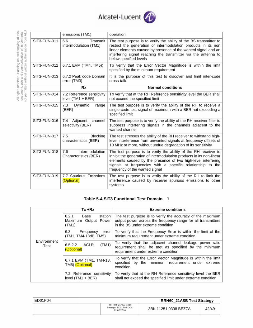
ED01P04 RRH60_21ASB Test Strategy
RRH60_21ASB Test
Strategy_ED01P06.DOC 22/07/2010 3BK 11251 0398 BEZZA 42/49
All
right
s re
serv
ed. P
assi
ng o
n an
d co
pyin
g of
this
do
cum
ent,
use
and
com
mun
icat
ion
of it
s co
nten
ts
not p
erm
itted
with
out w
ritte
n au
thor
izat
ion
from
ALU
emissions (TM1) operation
SIT3-FUN-011 6.6 Transmit intermodulation (TM1)
The test purpose is to verify the ability of the BS transmitter to restrict the generation of intermodulation products in its non linear elements caused by presence of the wanted signal and an interfering signal reaching the transmitter via the antenna to below specified levels
SIT3-FUN-012 6.7.1 EVM (TM4, TM5)) To verify that the Error Vector Magnitude is within the limit specified by the minimum requirement
SIT3-FUN-013 6.7.2 Peak code Domain error (TM3)
It is the purpose of this test to discover and limit inter-code cross-talk
Rx Normal conditions
SIT3-FUN-014 7.2 Reference sensitivity level (TM1 + BER)
To verify that at the RH Reference sensitivity level the BER shall not exceed the specified limit
SIT3-FUN-015 7.3 Dynamic range (BER)
The test purpose is to verify the ability of the RH to receive a single-code test signal of maximum with a BER not exceeding a specified limit
SIT3-FUN-016 7.4 Adjacent channel selectivity (BER)
The test purpose is to verify the ability of the RH receiver filter to suppress interfering signals in the channels adjacent to the wanted channel
SIT3-FUN-017 7.5 Blocking characteristics (BER)
The test stresses the ability of the RH receiver to withstand high-level interference from unwanted signals at frequency offsets of 10 MHz or more, without undue degradation of its sensitivity
SIT3-FUN-018 7.6 Intermodulation Characteristics (BER)
The test purpose is to verify the ability of the RH receiver to inhibit the generation of intermodulation products in its non-linear elements caused by the presence of two high-level interfering signals at frequencies with a specific relationship to the frequency of the wanted signal
SIT3-FUN-019 7.7 Spurious Emissions (Optional)
The test purpose is to verify the ability of the RH to limit the interference caused by receiver spurious emissions to other systems
Table 5-4 SIT3 Functional Test Domain 1
Tx +Rx Extreme conditions
6.2.1 Base station Maximum Output Power (TM1)
The test purpose is to verify the accuracy of the maximum output power across the frequency range for all transmitters in the BS under extreme condition
6.3 Frequency error (TM1, TM4-18dB, TM5)
To verify that the Frequency Error is within the limit of the minimum requirement under extreme condition
6.5.2.2 ACLR (TM1) (Optional)
To verify that the adjacent channel leakage power ratio requirement shall be met as specified by the minimum requirement under extreme condition
6.7.1 EVM (TM1, TM4-18, TM5) (Optional)
To verify that the Error Vector Magnitude is within the limit specified by the minimum requirement under extreme condition
Environment Test
7.2 Reference sensitivity level (TM1 + BER)
To verify that at the RH Reference sensitivity level the BER shall not exceed the specified limit under extreme condition
ED01P04 RRH60_21ASB Test Strategy
RRH60_21ASB Test
Strategy_ED01P06.DOC 22/07/2010 3BK 11251 0398 BEZZA 43/49
All
right
s re
serv
ed. P
assi
ng o
n an
d co
pyin
g of
this
do
cum
ent,
use
and
com
mun
icat
ion
of it
s co
nten
ts
not p
erm
itted
with
out w
ritte
n au
thor
izat
ion
from
ALU
Table 5-5 SIT3 Functional Test Domain 2
5.3 RRH Reliability Test
In order to identify the system design bugs as early as possible and repair these bugs in PEM2, the RRH Reliability will be carried in this test phase based on PEM1. Basically the test cases listed below do not depend on d2U environments. The complete qualification test will be defined in IT1 and tested with d2U connected. Though SIT reliability test have validate the module level reliability, the RRH black box level test is needed to validate the RRH general reliability in the real load environment. The RRH reliability test will be classified as:
- EMC Test(RRH)
- Safety Test(RRH)
- Lightning Protection Test(RRH)
- Thermal Test(RRH)
- Environment test(RRH)
The reliability tests can be executed in 3 team of the ASB CCC lab in different test branch.
5.3.1 EMC Test About the detail in the test configuration/test equipment/test domain, please find it in reference_EMC_SATETY_LIGHTNING chapter 2 EMC test , only the SIT3 test case will perform in this phase
5.3.2 Safety Test About the detail in the test configuration/test equipment/test domain, please find it in reference_EMC_SATETY_LIGHTNING chapter 3 safety test, only the SIT3 test case will perform in this phase
5.3.3 Lightning Protection Test About the detail in the test configuration/test equipment/test domain, please find it in reference_EMC_SATETY_LIGHTNING chapter 4 lightning protection test , only the SIT3 test case will perform in this phase
5.3.4 Thermal Test About the detail in the test configuration/test equipment/test domain, please find it in reference_Thermal
5.3.5 Environment test
5.3.5.1 Test Configuration
In this section, RRH reliability test include environment temperature test, mechanical characteristic test and Ingress protection test. Expect mechanical characteristic test and IP(ingress Protection ) test, all the test is in the power on condition and the test bench is the same as Figure 5-12.
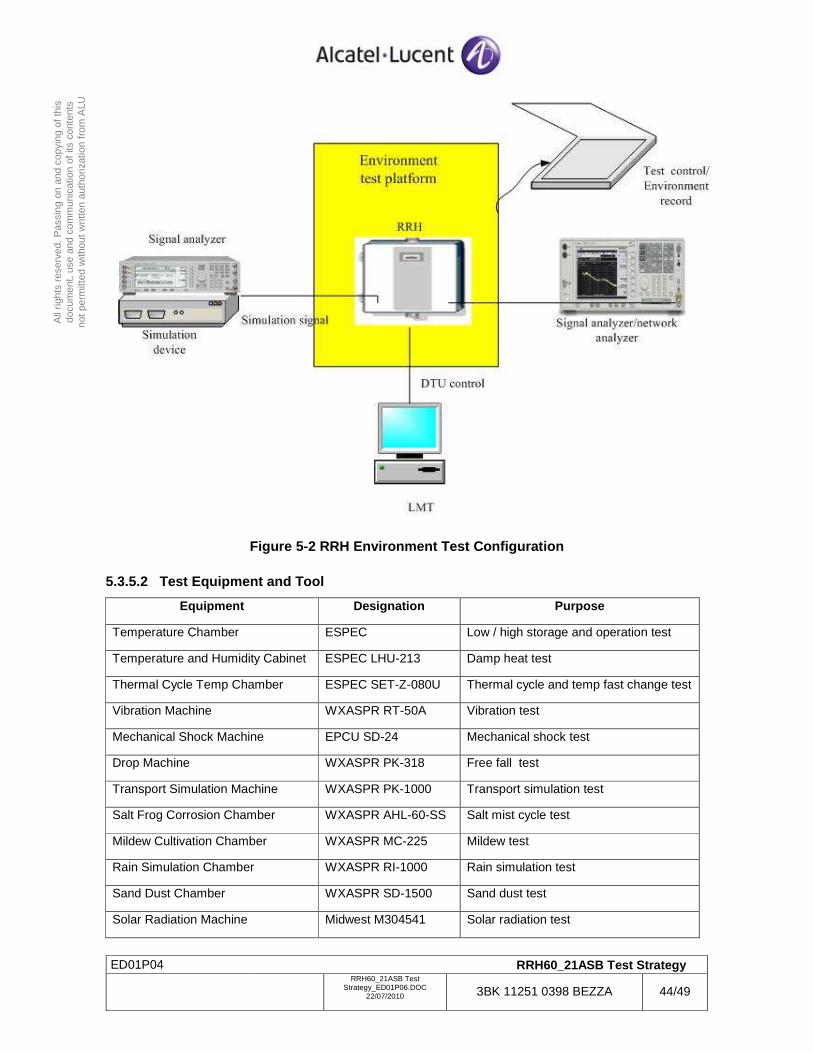
ED01P04 RRH60_21ASB Test Strategy
RRH60_21ASB Test
Strategy_ED01P06.DOC 22/07/2010 3BK 11251 0398 BEZZA 44/49
All
right
s re
serv
ed. P
assi
ng o
n an
d co
pyin
g of
this
do
cum
ent,
use
and
com
mun
icat
ion
of it
s co
nten
ts
not p
erm
itted
with
out w
ritte
n au
thor
izat
ion
from
ALU
Figure 5-2 RRH Environment Test Configuration
5.3.5.2 Test Equipment and Tool
Equipment Designation Purpose
Temperature Chamber ESPEC Low / high storage and operation test
Temperature and Humidity Cabinet ESPEC LHU-213 Damp heat test
Thermal Cycle Temp Chamber ESPEC SET-Z-080U Thermal cycle and temp fast change test
Vibration Machine WXASPR RT-50A Vibration test
Mechanical Shock Machine EPCU SD-24 Mechanical shock test
Drop Machine WXASPR PK-318 Free fall test
Transport Simulation Machine WXASPR PK-1000 Transport simulation test
Salt Frog Corrosion Chamber WXASPR AHL-60-SS Salt mist cycle test
Mildew Cultivation Chamber WXASPR MC-225 Mildew test
Rain Simulation Chamber WXASPR RI-1000 Rain simulation test
Sand Dust Chamber WXASPR SD-1500 Sand dust test
Solar Radiation Machine Midwest M304541 Solar radiation test
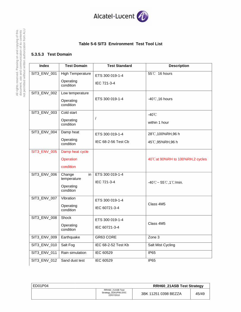
ED01P04 RRH60_21ASB Test Strategy
RRH60_21ASB Test
Strategy_ED01P06.DOC 22/07/2010 3BK 11251 0398 BEZZA 45/49
All
right
s re
serv
ed. P
assi
ng o
n an
d co
pyin
g of
this
do
cum
ent,
use
and
com
mun
icat
ion
of it
s co
nten
ts
not p
erm
itted
with
out w
ritte
n au
thor
izat
ion
from
ALU
Table 5-6 SIT3 Environment Test Tool List
5.3.5.3 Test Domain
Index Test Domain Test Standard Description
SIT3_ENV_001 High Temperature
Operating condition
ETS 300 019-1-4
IEC 721-3-4
55 16 hours
SIT3_ENV_002 Low temperature
Operating condition
ETS 300 019-1-4 -40 , 16 hours
SIT3_ENV_003 Cold start
Operating condition
/ -40
within 1 hour
SIT3_ENV_004 Damp heat
Operating condition
ETS 300 019-1-4
IEC 68-2-56 Test Cb
28,100%RH,96 h
45,95%RH,96 h
SIT3_ENV_005 Damp heat cycle
Operation
condition
40at 90%RH to 100%RH,2 cycles
SIT3_ENV_006 Change in temperature
Operating condition
ETS 300 019-1-4
IEC 721-3-4 -40 ~ 55 , 1 /min.
SIT3_ENV_007 Vibration
Operating condition
ETS 300 019-1-4
IEC 60721-3-4 Class 4M5
SIT3_ENV_008 Shock
Operating condition
ETS 300 019-1-4
IEC 60721-3-4 Class 4M5
SIT3_ENV_009 Earthquake GR63 CORE Zone 3
SIT3_ENV_010 Salt Fog IEC 68-2-52 Test Kb Salt Mist Cycling
SIT3_ENV_011 Rain simulation IEC 60529 IP65
SIT3_ENV_012 Sand dust test IEC 60529 IP65

ERROR: typecheckOFFENDING COMMAND: setcolor
STACK:
[/DeviceRGB ]/DeviceGray /DeviceGray
Copyright © 2022 FDOKUMEN