AGRICULTURAL TRACTORS - Ag Safety and Health
78
AGRICULTURAL TRACTORS Learning Goals To describe how tractors vary in size, shape and age To describe how tractors are designed for work Related Task Sheet: Tractor Hazards 4.2 In 1892 a man named John Froelich developed a successful tractor to power a grain thresher. By 1918 a PTO shaft was used to power equipment drawn behind the tractor. Before these time periods, farm work was done by hand, by horse, or by huge stationary steam engines. You will be operating a tractor designed to accomplish greater amounts of work than ever thought possible in the early 1900s. The speed, power, flexibility, adaptability, and handling ease of modern tractors is what makes them valuable and indispensable for modern day farming. This task sheet describes agricultural tractors, with an emphasis on what tractors are designed to do. Tractor Types/Sizes Tractors have both narrow and wide front ends, use both wheels and tracks, and can be two-wheel drive, four-wheel drive, or articulated. A narrow front end ( “tricycle”) will be an older tractor, as they have not been produced this way since the 1960s. Articulated tractors are usually very large (at least 250 hp) and are usually operated only by very experienced farmers. Young and inexperienced tractor drivers usually operate tractors ranging from lawn and garden-size (~ 20 hp) to large two- and four- wheeled drive tractors (around 150 hp). Many older and smaller tractors will not have a rollover protective structure (ROPS), while most new tractors will have a ROPS and seat belt. Introduction Figure 4.1.b. Tractors should be used for their designed purpose. Tractors are work horses, not race horses. NATIONAL SAFE TRACTOR AND MACHINERY OPERATION PROGRAM HOSTA Task Sheet 4.1 Tractor Purposes Farm tractors were designed for four primary purposes: 1. Load Mover (High Lift) 2. Remote Power Source (PTO) 3. Implement Carrier (3 Pt. Hitch) 4. Transport Unit (Drawbar Unit) Understanding that ordinary farm tractors are not recreational vehicles is very important. Farm tractors are not to be used for fun, play, or for mud-bogging or racing, unless specifically modified for that purpose. You must use the tractor only for work purposes. Other uses can increase the chance of injury to you or others, or to the tractor, implements, and other property. Figure 4.1.a. Tractors come in all shapes and sizes. © The Pennsylvania State University 2013 Cooperation provided by The Ohio State University and National Safety Council. Core
-
Upload
khangminh22 -
Category
Documents
-
view
0 -
download
0
Transcript of AGRICULTURAL TRACTORS - Ag Safety and Health

AGRICULTURAL TRACTORS
Learning Goals To describe how tractors vary in
size, shape and age
To describe how tractors are
designed for work
Related Task Sheet:
Tractor Hazards 4.2
In 1892 a man named John Froelich developed a successful tractor to power a grain thresher. By 1918 a PTO shaft was used to power equipment drawn behind the tractor. Before these time periods, farm work was done by hand, by horse, or by huge stationary steam engines.
You will be operating a tractor designed to accomplish greater amounts of work than ever thought possible in the early 1900s. The speed, power, flexibility, adaptability, and handling ease of modern tractors is what makes them valuable and indispensable for modern day farming. This task sheet describes agricultural tractors, with an emphasis on what tractors are designed to do.
Tractor Types/Sizes
Tractors have both narrow and wide front ends, use both wheels and tracks, and can be two-wheel drive, four-wheel drive, or articulated. A narrow front end ( “tricycle”) will be an older tractor, as they have not been produced this way since the 1960s. Articulated tractors are usually very large (at least 250 hp) and are usually operated only by very experienced farmers. Young and inexperienced tractor drivers usually operate tractors ranging from lawn and garden-size
(~ 20 hp) to large two- and four-wheeled drive tractors (around 150 hp). Many older and smaller tractors will not have a rollover protective structure (ROPS), while most new tractors will have a ROPS and seat belt.
Introduction
Figure 4.1.b. Tractors should be used for their designed purpose.
Tractors are
work horses,
not race
horses.
NATIONAL SAFE TRACTOR AND MACHINERY OPERATION PROGRAM
HOSTA Task Sheet 4.1
Tractor Purposes Farm tractors were designed for four primary purposes:
1. Load Mover (High Lift)
2. Remote Power Source (PTO)
3. Implement Carrier (3 Pt. Hitch)
4. Transport Unit (Drawbar Unit)
Understanding that ordinary farm tractors are not recreational vehicles is very important. Farm tractors are not to be used for fun, play, or for mud-bogging or racing, unless specifically modified for that purpose. You must use the tractor only for work purposes. Other uses can increase the chance of injury to you or others, or to the tractor, implements, and other property.
Figure 4.1.a. Tractors come in all shapes and sizes.
© The Pennsylvania State University 2013 Cooperation provided by The Ohio State University and National Safety Council.
Core

Page 2 AGRICULTURAL TRACTORS
1. Farm and Ranch Safety Management, John Deere Publishing, 2009.
References
1. Take photos or video camera footage of tractors being used for the four intended purposes. Make a display for your club or classroom or employee lunch room where you work.
2. Collect newspaper and magazine articles on farm tractor safety. Share the main points of the articles with classmates.
3. Locate a farmer in your community who has been injured with a tractor or farm machine and see if they will discuss the incident with you.
4. Use the Internet to find information on tractor safety. Find articles that describe people injured by a trac-tor because they were not using it for its designed purpose.
5. Do a survey of tractors at area farms or at an equipment dealer’s lot and record how many tractors: a) have a tricycle or wide front end; b) have a ROPS with seat belt; c) have wheels or a track; if it has wheels, is it a two-wheel, four-wheel, or an articulated tractor? Also record the engine horsepower and tractor age.
Safety Activities
Adjustable drawbar hitch
Power controls to increase pulling power
Potential to add or subtract weights for ballast
Hydraulic system for added power source
PTO shaft to transfer power to towed machine
Differential lock for added traction
Adapted to carry or pull equipment
Fitted with a Rollover Protective Structure (ROPS) or a Falling Object Protective Structure (FOPS)
Here are some design elements of a tractor.
Rear wheels adjustable for width
“Turn-on-a-dime” steering
High-powered engine with many gear ranges for relatively low speeds
Great clearance beneath the tractor
More weight over traction wheels
Individual brakes for each rear wheel
Tractor Characteristics
A tractor is
designed to
do work. Use
the tractor
only for this
purpose!
National Safe Tractor and Machinery Operation Program The Pennsylvania State University Agricultural and Biological Engineering Department 246 Agricultural Engineering Building University Park, PA 16802 Phone: 814-865-7685 Fax: 814-863-1031 Email: [email protected]
Contact Information
Developed by WC Harshman, AM Yoder, JW Hilton and D J Murphy, The Pennsylvania State University. Reviewed by TL Bean and D Jepsen, The Ohio State University and S Steel, National Safety Council. Revised 3/2013 This material is based upon work supported by the National Institute of Food and Agriculture, U.S. Department of Agriculture, under Agreement Nos. 2001-41521-01263 and 2010-41521-20839. Any opinions, findings, conclusions, or recommendations expressed in this publication are those of the author(s) and do not necessarily reflect the view of the U.S. Department of Agriculture.
Credits
© The Pennsylvania State University 2013 Cooperation provided by The Ohio State University and National Safety Council.

Learning Goals
• To recognize and avoid those
hazardous situations which can result
in exposure to overturns, runovers,
PTO entanglements, and older tractor
safety deficiencies.
Related Task Sheets:
Reaction Time 2.3
Mechanical Hazards 3.1
Agricultural Tractors 4.1
Tractor Stability 4.12
Using the Tractor Safely 4.13
Using PTO Implements 5.41
Tractors are a primary source of
work-related injury on farms,
however, not all of the injuries
happen while the tractor is being
used for work.
Nationally, nearly one-third of all
farm work fatalities are tractor-
related. Injuries occur for a variety
of reasons and in a number of
different ways. This task sheet will
describe types of tractor hazards
and the nature and severity of
injuries associated with using farm
tractors.
Hazard Groups There are several hazards
associated with tractor operation.
Tractor hazards are grouped into
the following four categories:
1. Overturns
2. Runovers
3. Power Take-Off Entanglements
4. Older Tractors
Each of these is discussed briefly
in this task sheet. Other task sheets
will cover some of these topics in
more detail.
Tractor overturns is one major
hazard group and accounts for the
most farm-work fatalities.
Approximately 50% of tractor
fatalities come from tractors
turning over either sideways or
Introduction
Figure 4.2.a. Tractor overturns can occur with high speed sharp turns. Avoid sudden sharp movements in all tractor work. Safety Management for Landscapers,
Grounds-Care Businesses, and Golf Courses, John Deere Publishing, 2001. Illustrations reproduced by permission. All rights reserved.
Top-heavy,
powerful
tractors can
upset if used
improperly.
TRACTOR HAZARDS
NATIONAL SAFE TRACTOR AND MACHINERY OPERATION PROGRAM
HOSTA Task Sheet 4.2
Overturn
backward. There are dozens of
examples of tractor turnover
situations. Most are preventable if
operators follow good safe tractor
operation practices. Some
common examples of tractor
overturns include:
• Turning or driving too
close to the edge of a bank
or ditch
• Driving too fast on rough
roads and lanes and running
or bouncing off the road or
lane
• Hitching somewhere other
than the drawbar when
pulling or towing objects
• Driving a tractor straight up
a slope that is too steep
• Turning a tractor sharply
with a front-end loader
raised high
A rollover protective structure
(ROPS), a structural steel cage
designed to surround the
operator—particularly one that is
built into an enclosed cab—can
protect the operator from being
killed when a tractor overturns.
This is especially true if the
operator has fastened the seat belt.
Remember, though, that a ROPS
can protect you from injury but
cannot keep the tractor from
overturning in the first place. This
explains the importance of
operating a tractor safely even if
the tractor has a ROPS.
© The Pennsylvania State University 2013 Cooperation provided by The Ohio State University and National Safety Council.
Core

Page 2 TRACTOR HAZARDS
tractor. Thus they can be easily
thrown from the tractor.
Another runover incident involves
the tractor operator either falling
off the tractor as it is operating or
being knocked out of the seat by a
low-hanging tree branch or other
obstacle. This most often happens
on older tractors that do not have a
ROPS and have an older seat that
has no arm or back rest (often
called pan seats). A person can
more easily lose his or her balance
and be knocked off or bounced out
of a pan seat. An operator can also
be run over while trying to mount
or dismount a moving tractor. This
type of incident can occur when
the operator leaves the tractor seat
without first shutting off the tractor
and setting the brake or placing it
in PARK, and the tractor moves
unexpectedly. This may happen
during the hitching and unhitching
of equipment. Shut off the tractor
before dismounting for any reason.
There are three basic types of
tractor runover incidents. One is
when a passenger (extra rider) on
the tractor falls off. Extra rider
incidents happen because there is
only one safe place for a person to
be on a tractor, and that is in the
operator’s seat. Some new, larger
tractors have an extra seat for
temporary instructional purposes,
but only if the tractor has an
enclosed ROPS cab. The tractors
that most young and inexperienced
operators drive will have only one
seat—the operator’s seat. Standing
on the tractor drawbar, axle
housing, side links of three-point
hitches, rear-wheel fenders, and the
area immediately around the
operator’s seat are common
locations unsafely occupied by
extra riders. Extra riders rarely
keep a tight handgrip on the
Runover
Follow this
rule! One seat
on a tractor
means one
rider only– the
operator.
Keep all
others away.
Figure 4.2.b. Tractor runovers have claimed many lives. Extra riders can slip from the tractor and be crushed before the operator can stop. Say no to your friends who want to hitch a ride.
The third type of runover incident
involves a person who is on the
ground near a tractor. This may
include the tractor operator who
tries to start a tractor from the
ground while the tractor is in gear.
This usually involves an older
tractor that can be started in gear or
a newer tractor when an operator
attempts to bypass a newer
tractor’s safe start-up design.
Bypass starting hazards are
discussed in more detail in Task
Sheet 4.8.
Small children, often under the age
of 5, are sometimes run over by a
tractor (and equipment) as it is
moved around the farmstead.
Often, the tractor operator is
unaware that the child is near the
tractor. A loud noise, such as the
start up of a tractor, is often
attractive to a young child, and he
or she may run toward it as it starts
or begins to move.
© The Pennsylvania State University 2013 Cooperation provided by The Ohio State University and National Safety Council.

Page 3 HOSTA TASK SHEET 4.2
The tractor power take-off (PTO)
stub is another major hazard. The
PTO stub transfers power from the
tractor to PTO-powered
machinery. The PTO stub
normally turns between 540 and
1,000 revolutions per minute. At
this rate, the stub is turning from 9
to 17 times per second. This is
much faster than a human being
can react if he or she is caught and
pulled into or around the PTO stub
or shaft. A person can have an arm
or leg wrapped around a PTO stub
shaft before they know they are in
danger. A PTO master shield
protects a person from the PTO
stub. Some tractors have PTO stub
guards that fasten to the PTO stub.
All tractors should have a PTO
master shield to protect the tractor
operator and helpers.
rests (pan seat)
• Seat does not adjust easily or at
all
• Absence of a safety start
system
• No bypass starting protection
• Rear brakes and brake pedals
do not operate properly
• Front wheels do not turn as
quickly as the steering wheel
turns
• Tractor has no warning flashers
or the flashers do not work
• PTO master shield is missing
or does not offer adequate
protection
Young and inexperienced workers
may be given older tractors to
operate in many cases. The older
tractor is best suited for the types
of jobs a young or inexperienced
operator is hired to do. These
tractors are best suited for raking
hay, hauling wagons, and mowing
fields or pastures. Young and
inexperienced operators should be
given newer tractors to operate
when possible. Older tractors should always be
included when talking about tractor
hazards. Many farm tractors still
used for work may be 30 to 40
years old or older. These older
tractors are often less safe to
operate because they do not have
modern safety features, and
because some parts of the older
tractor may not have been
maintained in good working
condition. A list of reasons why
older tractors may be less safe to
operate includes:
• Lack of ROPS and seat belt
• A seat without arm and back
Power Take-Off (PTO)
Entanglement
Older Tractors
PTO shafts kill
or cripple
countless
victims. Some
of these victims
most likely live
in your
community.
Figure 4.2.d. Older tractors are often assigned to younger drivers to do less heavy chores. Raking hay, pulling wagons, and hauling feed to livestock does not require the most powerful tractor. Older tractors may have safety deficiencies due to age and missing safety features. This tractor does not have a ROPS or seat belt.
Figure 4.2.c. Power take-off stub and PTO shaft must be properly guarded to prevent entanglements. Locate the PTO area on every tractor you operate. Check whether or not that area is safely guarded.
© The Pennsylvania State University 2013 Cooperation provided by The Ohio State University and National Safety Council.

1. Safety Management for Landscapers, Grounds-Care Businesses, and Golf Courses, John Deere Publishing, 2001. Illustrations reproduced by per-mission. All rights reserved.
2. Farm and Ranch Safety Management, John Deere Publishing, 2009.
References
Page 4 TRACTOR HAZARDS
1. Match the tractor hazard with the safety situation. (Some choices may be used more than once.)
___A. Overturn 1. High lift carried in raised position in transit
___B. Runover 2. Pet dog was tied to wagon
___C. PTO entanglement 3. Bypass starting
___D. Older tractor deficiency 4. PTO stub shaft missing
5. Driving too close to ditch embankment
6. A friend is helping to drop the hitch pin
2. Write a letter to your best friend explaining why you won’t let him/her ride on the fender of the tractor to
go to the field to help you make hay.
3. Explain how people are run over when they choose to bypass the ignition switch to start the tractor engine.
4. Learn more about the hazards of bypass starting a tractor engine by contacting a tractor salesperson or
mechanic.
Safety Activities
National Safe Tractor and Machinery Operation Program The Pennsylvania State University Agricultural and Biological Engineering Department 246 Agricultural Engineering Building University Park, PA 16802 Phone: 814-865-7685 Fax: 814-863-1031 Email: [email protected]
Contact Information
Developed by WC Harshman, AM Yoder, JW Hilton and D J Murphy, The Pennsylvania State University. Reviewed by TL Bean and D Jepsen, The Ohio State University and S Steel, National Safety Council. Revised 3/2013
This material is based upon work supported by the National Institute of Food and Agriculture, U.S. Department of Agriculture, under Agreement Nos. 2001-41521-0126 and 2010-41521-20839. Any opinions, findings, conclusions, or recommendations expressed in this publication are those of the author(s) and do not necessarily reflect the view of the U.S. Department of Agriculture.
Credits
© The Pennsylvania State University 2013 Cooperation provided by The Ohio State University and National Safety Council.

Related Task Sheets:
Safety and Health Regulations 1.2
Injuries Involving Youth 2.1
Age Appropriate Tasks 2.4
Are your skills and
age matched to
the appropriate
tractor and task
you are doing?
Farm families often provide much
of the labor for the operation of the
farm. Farm work may start early in
a child’s life as a means of learning
responsibility and contributing to
the productivity of the farm.
Tractor operation can come at an
early age for many farm youth
because tractors are a large part of
how farm work is done. Tractor
work can range from the simple to
the complex.
This task sheet presents a Tractor
Operation Chart as a guide to
appropriate tractor work for young
tractor operators.
Youth and Tractors
Examples of common jobs
performed by youth operating
tractors include:
• Mowing pastures, fields, yards
and lanes
• Raking and baling hay and
straw
• Towing hay and grain wagons
between fields and storage
• Picking rocks and other
obstacles from fields using a
front-end loader
• Scraping manure from barn
floors with a tractor-mounted
blade
• Using the tractor to power
augers and elevators during
unloading operations
• Pulling old fence posts and tree
stumps out of the ground with
log chains
Several hazards can arise during
the course of these and other jobs
that involve tractor use. Many
times the larger the tractor, the
more complex the operation of that
tractor becomes. Additionally,
large and complex equipment may
be attached to and powered by the
tractor.
Young tractor operators do not
usually have the experience needed
to skillfully and safely operate
large and complex combinations of
tractors and machinery.
North American Guidelines for
Children's Agricultural Tasks
(NAGCAT) Tractor Operation
Chart
Farm injury prevention specialists
from the U.S. and Canada have
developed consensus opinion that a
guide to tractor operations by age
groups is a way of matching
youthful capabilities with tractor
operation jobs. The NAGCAT
chart is presented on the reverse
side of this task sheet.
You can use this chart:
• To see if you have been doing
jobs with the size tractor that
matches your age
• To guide an employer in
determining what they can
reasonably expect a person of
your age to do with various
types and sizes of tractors
It is common for youths to be over
confident in their ability to react
safely to new or unexpected hazard
situations with tractors.
NATIONAL SAFE TRACTOR AND MACHINERY OPERATION PROGRAM
HOSTA Task Sheet 4.3
NAGCAT TRACTOR OPERATION
CHART
Learning Goal
• To review safety recommendations in
matching tractor size and tasks with
the age of the tractor operator
Introduction
Figure 4.3.a. Oftentimes the youthful farm work-er is willing to do more work than his or her men-tal and physical maturity will safely permit. Youth should never operate a tractor without a ROPS and seat belt.
© The Pennsylvania State University 2013 Cooperation provided by The Ohio State University and National Safety Council.
Related Task Sheets:
Safety and Health Regulations 1.2
Injuries Involving Youth 2.1
Age-Appropriate Tasks 2.4
Core

Page 2 NAGCAT TRACTOR OPERATION CHART
1. www. nagcat.org/Click on Guidelines/Select T1 Tractor Operation Chart, February 2013.
2. Cooperative Extension Service of your State’s Land Grant University.
References National Safe Tractor and Machinery Operation Program The Pennsylvania State University Agricultural and Biological Engineering Department 246 Agricultural Engineering Building University Park, PA 16802 Phone: 814-865-7685 Fax: 814-863-1031 Email: [email protected]
Contact Information
Developed by WC Harshman, AM Yoder, JW Hilton and D J Murphy, The Pennsylvania State University. Reviewed by TL Bean and D Jepsen, The Ohio State University and S Steel, National Safety Council. Revised 3/2013
This material is based upon work supported by the National Institute of Food and Agriculture, U.S. Department of Agriculture, under Agreement Nos. 2001-41521-01263 and 2010-41521-20839. Any opinions, findings, conclusions, or recommendations expressed in this publication are those of the author(s) and do not necessarily reflect the view of the U.S. Department of Agriculture.
Credits
© The Pennsylvania State University 2013 Cooperation provided by The Ohio State University and National Safety Council.

Learning Goals
• To understand the instruments and
gauges used to monitor the tractor’s
operation and performance
• To be able to make operating
decisions based upon the information
and gauges provide to the operator
Related Task Sheets:
Preventative Maintenance and Pre-operation Checks
4.6
Fuel, Oil, and Coolant Levels 4.6.1
Lead Acid Batteries 4.6.2
Instruments, or gauges, on the
tractor control panel tell the driver
about the operating conditions
within and around the tractor. All
tractor drivers should know what
instruments are available to
indicate that the tractor is operating
properly.
When tractor systems are not
working properly, continued
operation may cause costly repairs
and possible injury.
This task sheet will identify and
explain instruments and gauges
commonly found on tractors. Using
tractor Owners’ Manuals and
obtaining the help of an
experienced tractor operator will
help you to learn the information in
this task sheet.
Instruments and
Gauges
Instruments can be warning
lights, analog gauges, computer
digital displays, buzzers, or
standard gauges.
It is important for the beginning
operator to develop the habit of
regularly checking the instrument
panel. Check the gauges:
• At start up
• At regular intervals during
operation
• When changes occur in the
normal sounds of operation
Introduction
Figure 4.4.a. The modern tractor instrument pan-el may appear as complex as the cockpit controls of a jet airliner. The operator must know what each instrument or gauge is telling him/her about operating conditions.
Learn which
warning lights,
gauges, and
digital displays
are on your
tractor.
Abnormal gauge readings, plus
changes in operating sounds,
indicate that there is a problem.
You should immediately stop the
engine in a safe place, and seek
help from the owner or an
experienced operator.
Instruments you will use may
include the following (there may
be many more):
• Engine speed indicator
(Tachometer)
• Oil Pressure Indicator
• Engine Temperature Indicator
• Fuel Gauge
• Air Filter Condition Indicator
• Transmission Temperature
Indicator
• Hydraulic System Oil Level
Indicator
• Hour meter
• Charge Indicator
Each of these instruments is
important to the safe tractor
operation as well as avoiding
damage to the tractor. Other
gauges may be found on the tractor
you operate. Be sure to understand
the meaning of all instruments,
gauges and warnings before
operating a tractor.
TRACTOR INSTRUMENT PANEL
SAFE TRACTOR AND MACHINERY OPERATION PROGRAM
HOSTA Task Sheet 4.4
© The Pennsylvania State University 2013 Cooperation provided by The Ohio State University and National Safety Council.
Core

Page 2 TRACTOR INSTRUMENT PANEL
er gear and beginning to pull a
heavy load can stall the engine.
High-engine speed with a low gear
while attached to a heavy load can
also create enough torque
(rotational force) to tip the tractor
backward. Accelerating quickly
with a heavy load going up a slope
can cause the tractor to rear up and
tip backward.
Engine RPMs must also match
PTO-driven machine requirements.
Speed up the engine before
engaging the PTO to operate an
implement. Low-engine speed
could stall the tractor. High-engine
speed could shear off the
implements safety shear pin if the
pin was already under load.
(Example: a plugged hay baler).
Follow the manufacturer’s
recommendations for engine speed
selection.
Tachometers show revolutions per
minute (RPM). Engine RPM must
be matched to the job being done.
Incorrect RPM can lead to:
• Engine damage
• Driveline and PTO damage
• Hazardous situations
Low engine speed while in a high-
Tachometer (Engine
Speed Indicator) Engine speed
must match
the work
being done to
be safe and
to avoid
engine and
driveline
damage.
Figure 4.4.c. Check the manufacturer’s RPM recommendations for various jobs to be done. Tachometers may be a gauge type or a digital display as shown above.
Figure 4.4.b. You may find indicator lights, standard gauges, computerized digital displays, and buzzers as instruments to show operating conditions.
Indicator Light
Gauge
Digital Display
© The Pennsylvania State University 2013 Cooperation provided by The Ohio State University and National Safety Council.

Page 3 HOSTA TASK SHEET 4.4
Charge Indicator
The charge indicator, or ammeter,
shows whether the alternator or
generator is charging the battery
properly. Each time the tractor is
started, the battery is discharged.
During operation, the battery is
recharged. Gauges will indicate +
or - charge. Lights will show red at
low charge. If the battery is
discharging, find out the problem.
The engine may not start the next
time due to a low battery.
Oil Pressure Indicator (Oil Light
or Gauge)
This indicator is important to the
long life of an engine. If oil
pressure falls because of an oil leak
or low oil levels, the light or gauge
shows you must stop the engine
immediately. Never operate the
engine with low oil pressure or oil
levels. Oil lubricates the internal
parts of the engine and prevents
major repair expense.
engines can overheat if coolant is
lost, radiators become clogged with
debris, or the radiator leaks.
If the engine overheats, stop the
engine, allow it to cool, then check
for the problem.
Never open the radiator cap while
the engine is hot. Scalding from
extremely hot water can result.
Fuel Gauge
Check the fuel gauge before
leaving for the field. Running out
of fuel is inconvenient. On some
tractors, running out of fuel
(diesel) means time-consuming
bleeding of air from the fuel lines
in order to be able to start the
tractor again.
Other Gauges
Tractors may come equipped with
instruments to monitor air filter
conditions, transmission
temperatures, hydraulic system oil
levels, and of course hours of work
(hour meter). Become familiar with
all instruments before operating the
tractor.
Engine Temperature Indicator
The engine must be cooled to
prevent damage. Water-cooled
Charge Indicator and
Oil Pressure Indicator
Engine Temperature
and Other Gauges
Never open the
radiator cap
when the
tractor engine
is hot. Scald
injury can
occur.
Figure 4.4.e. Wait until the engine is cool to remove the radiator cap. Safety Management for Land-
scapers, Grounds-Care Businesses, and Golf Courses, John Deere Publishing, 2001. Illustrations reproduced by permission. All rights reserved.
Figure 4.4.d. If low or zero oil pressure is indicated, shut down the tractor engine immediately to avoid costly engine rebuilds.
© The Pennsylvania State University 2013 Cooperation provided by The Ohio State University and National Safety Council.

1. Safety Management for Landscapers, Grounds-Care Businesses, and Golf Courses, John Deere Publishing, 2001. Illustrations reproduced by per-mission. All rights reserved.
2. Operator’s Manuals from various tractor
manufacturers
References
Page 4 TRACTOR INSTRUMENT PANEL
Answer these questions
1. If you are operating the tractor in the field and the oil light comes on, what should you do?
a. drive to the shop b. stop and let the engine idle
c. shut down immediately c. shut off the engine until it cools and then restart
2. What can happen if you remove a radiator cap from an overheated tractor’s coolant system?
a. nothing b. explosive pressure can hurt you
c. a fire may start d. you can be scalded by hot steam
3. When pulling a heavy load of hay up a hill, which gear/RPM (engine speed) combination should you
use?
a. 5th gear/high RPM b. lower gear with medium RPM
c. highest gear with lowest RPM
4. The letters RPM represent:
a. ground speed measurement b. oil pressure measurement
c. engine speed measurement
Activities:
1. Demonstrate to your teacher how many hours of use have been placed on the tractor by showing the
hour-meter reading for that tractor.
2. Demonstrate to your teacher how to scroll through the various computer digital read-outs to show
engine RPM, engine temperature, and hours of use information on that tractor.
Safety Activities
National Safe Tractor and Machinery Operation Program The Pennsylvania State University Agricultural and Biological Engineering Department 246 Agricultural Engineering Building University Park, PA 16802 Phone: 814-865-7685 Fax: 814-863-1031 Email: [email protected]
Contact Information
Developed by WC Harshman, AM Yoder, JW Hilton and D J Murphy, The Pennsylvania State University. Reviewed by TL Bean and D Jepsen, The Ohio State University and S Steel, National Safety Council. Revised 3/2013
This material is based upon work supported by National Institute of Food and Agriculture, U.S. Department of Agriculture, under Agreement Nos. 2001-41521-01263 and 2010-41521-20839. Any opinions, findings, conclusions, or recommendations expressed in this publication are those of the author(s) and do not necessarily reflect the view of the U.S. Department of Agriculture.
Credits
© The Pennsylvania State University 2013 Cooperation provided by The Ohio State University and National Safety Council.

Learning Goals
• To identify tractor controls by their
color coding
• To identify what action will result
when a control is moved in a
particular direction
Related Task Sheets:
Engine Stop Controls 4.5.1
Ground Motion Controls 4.5.2
Engagement Controls 4.5.3
Positioning and Adjusting Controls
4.5.4
To help tractor drivers identify
controls and use them correctly,
many tractor manufacturers use the
same color code for specific tractor
controls. The direction that you
move controls have also become
standardized.
Many older tractors do not have
controls with uniform color coding.
Sometimes those colors wear off
or a control is replaced with a
irregular color control knob.
Moving a control that is not color-
coded may not result in the
expected operation.
This task sheet will identify the
four main groups of tractor
controls, their colors, and their
direction of movement. Each
group of controls will be discussed
in more detail in their own task
sheet.
Introduction
Fig 4.5.a. Know where each control is located and what it controls. Color codes will help you learn the function of each control.
The same control
on an older
tractor may not
produce the same
result as on a
newer tractor.
Controls and Colors
The American Society of
Agricultural Engineers (ASAE)
has published standards for tractor
controls (standards are widely
accepted rules set in place by
experts). The four main groups of
color-coded controls are
discussed below.
Commit this color code to
memory. You will use this
information to operate a modern
tractor.
Color Coding for Controls -
STOP ENGINE—RED color
GROUND MOTION- ORANGE
color (engine speed, PARK-Lock,
transmission)
POWER ENGAGEMENT –
YELLOW color (engage PTO or
remote power sources)
POSITIONING and
ADJUSTING– BLACK color
(choke the engine, turn lights on)
Remember that older tractors may
not use these colors, or you may
not be able to see them. If the
tractor you need to use does not
have color controls, take time to
learn about the controls on that
tractor.
TRACTOR CONTROLS
NATIONAL SAFE TRACTOR AND MACHINERY OPERATION PROGRAM
HOSTA Task Sheet 4.5
© The Pennsylvania State University 2013 Cooperation provided by The Ohio State University and National Safety Council.
Core
Page 2 TRACTOR CONTROLS
1. American Society of Agricultural and Biological Engineers, ANSI/ASABE, EP443.1 Color Coding of Hand Controls, St. Joseph, MI.
2. Owners’ Manuals for Specific Tractors.
3. Farm and Ranch Safety Management, John Deere Publishing, 2009.
References
1. Matching color with function. (Place the letter of the correct color next to the control function.)
____Engage PTO A. Red
____Lift a High-Lift Bucket B. Orange
____Throttle Up C. Yellow
____Stop the Diesel Engine D. Black
2. Identify as many specific controls as you can on one or more tractors, and group them by control function.
3. What will happen if you pull an orange-colored control in order to stop the tractor engine?
Safety Activities
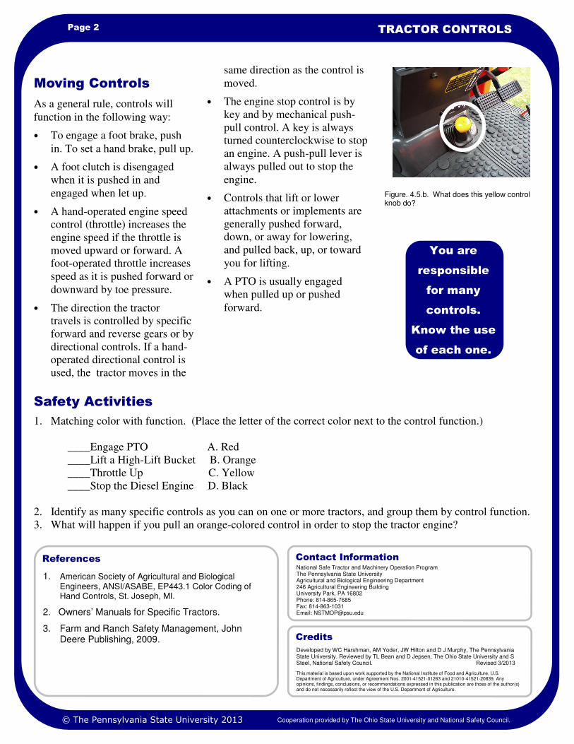
same direction as the control is
moved.
• The engine stop control is by
key and by mechanical push-
pull control. A key is always
turned counterclockwise to stop
an engine. A push-pull lever is
always pulled out to stop the
engine.
• Controls that lift or lower
attachments or implements are
generally pushed forward,
down, or away for lowering,
and pulled back, up, or toward
you for lifting.
• A PTO is usually engaged
when pulled up or pushed
forward.
As a general rule, controls will
function in the following way:
• To engage a foot brake, push
in. To set a hand brake, pull up.
• A foot clutch is disengaged
when it is pushed in and
engaged when let up.
• A hand-operated engine speed
control (throttle) increases the
engine speed if the throttle is
moved upward or forward. A
foot-operated throttle increases
speed as it is pushed forward or
downward by toe pressure.
• The direction the tractor
travels is controlled by specific
forward and reverse gears or by
directional controls. If a hand-
operated directional control is
used, the tractor moves in the
Moving Controls
You are
responsible
for many
controls.
Know the use
of each one.
Figure. 4.5.b. What does this yellow control knob do?
National Safe Tractor and Machinery Operation Program The Pennsylvania State University Agricultural and Biological Engineering Department 246 Agricultural Engineering Building University Park, PA 16802 Phone: 814-865-7685 Fax: 814-863-1031 Email: [email protected]
Contact Information
Developed by WC Harshman, AM Yoder, JW Hilton and D J Murphy, The Pennsylvania State University. Reviewed by TL Bean and D Jepsen, The Ohio State University and S Steel, National Safety Council. Revised 3/2013
This material is based upon work supported by the National Institute of Food and Agriculture, U.S. Department of Agriculture, under Agreement Nos. 2001-41521-01263 and 21010-41521-20839. Any opinions, findings, conclusions, or recommendations expressed in this publication are those of the author(s) and do not necessarily reflect the view of the U.S. Department of Agriculture.
Credits
© The Pennsylvania State University 2013 Cooperation provided by The Ohio State University and National Safety Council.

Learning Goals
• To identify tractor engine stop
controls used on modern tractors by
their color
• To identify the results when an
engine stop control is moved in a
particular direction
Other related sheets:
Tractor Controls 4.5
“How do I stop the engine?” What
is a routine operation on one
tractor can be a little confusing on
a different tractor.
For many years, tractor
manufacturers have used the same
color for certain controls to help
drivers identify controls and use
them correctly. This task sheet
discusses the “Stop Engine”
control.
The Color Red
Red is the color code for the single
purpose of “Stop Engine” control.
Whether it is a gasoline engine
tractor, a diesel engine tractor, or
an alternative fuel engine, the color
red indicates a stop engine
function.
Gasoline Engine—Red letters on
key switch.
Diesel Engine—Red fuel shut-off
switch (Remember, most diesel
engines are shut off with the fuel
shut-off switch, not by the ignition
key.)
Some Rules for “Red”
Here are a few more points to
remember for the red engine stop
control. If a mechanical push-pull
fuel switch is used, it must:
• Be within 6 inches of the key
switch
Introduction
Figure 4.5.1.a. Remember, diesel engines are often shut off with the fuel shut-off switch, not by the ignition key. Newer diesel engines may be shut off by the key only.
A red control knob means
“Stop the Engine.”
• Be pulled to stop
• Be labeled “Pull to Stop
Engine”
• Remain in the stop position
without continued effort
Key switch controls turn
counterclockwise to stop the
engine.
Some newer diesel engines are also
stopped simply by turning the key
counterclockwise to the off
position.
Ignition key
Fuel shut-off switch
ENGINE STOP CONTROLS
NATIONAL SAFE TRACTOR AND MACHINERY OPERATION PROGRAM
HOSTA Task Sheet 4.5.1
© The Pennsylvania State University 2013 Cooperation provided by The Ohio State University and National Safety Council.
Core

Page 2 ENGINE STOP CONTROLS
1. American Society of Agricultural and Biological Engineers, ANSI/ASABE, EP443.1 Color Coding of Hand Controls, St. Joseph, MI.
2. Owners’ Manuals for Specific Tractors.
3. Farm and Ranch Safety Management, John Deere Publishing, 2009.
References
1. Compare the ignition switch and stop engine control methods of diesel and gasoline engine tractors by
tracing the wiring of each.
2. Find the oldest tractor model you can in your community, and determine if color-coding would indicate how
to stop the engine. Record the following information:
Tractor Model Approximate Age of Tractor Color-Coded Stop Control Y/N
____________ ________ _______________________
____________ ________ ———————————–
Safety Activities
Pictorial Study
A similar colored
control on an older
tractor may not
have the same
result as the
control on a newer
tractor.
Figure 4.5.1.d. Quiz time. What if the red color is missing on older tractors?
Push-Pull Switch
Figure 4.5.1.c. Key switch on lower left of older tractor. Push-pull switches may be found also.
Figure 4.5.1.b. Diesel engines are often stopped by shutting off the fuel flow from the fuel pump.
National Safe Tractor and Machinery Operation Program The Pennsylvania State University Agricultural and Biological Engineering Department 246 Agricultural Engineering Building University Park, PA 16802 Phone: 814-865-7685 Fax: 814-863-1031 Email: [email protected]
Contact Information
Developed by WC Harshman, AM Yoder, JW Hilton and D J Murphy, The Pennsylvania State University. Reviewed by TL Bean and D Jepsen, The Ohio State University and S Steel, National Safety Council. Revised 3/2013
This material is based upon work supported by the National Institute of Food and Agriculture, U.S. Department of Agriculture, under Agreement Nos. 2001-41521-01263 and 2010-41521-20839. Any opinions, findings, conclusions, or recommendations expressed in this publication are those of the author(s) and do not necessarily reflect the view of the U.S. Department of Agriculture.
Credits
© The Pennsylvania State University 2013 Cooperation provided by The Ohio State University and National Safety Council.

Learning Goals
• To identify tractor ground motion
controls by the orange color coding
• To identify what action results when a
ground motion control is moved in a
particular direction
Other related sheets:
Tractor Controls 4.5
“How do I get this tractor to
move?” “How do I stop this
operation?” For many years, tractor
manufacturers have used the same
color for certain controls to help
drivers identify and use them
correctly. This task sheet discusses
“Ground Motion” controls.
The Color Orange
Orange is the color code for tractor
ground motion controls. Ground
motion controls include:
• Engine Speed
• Transmission Controls
• Parking Brake or Park-
Lock
• Independent Emergency
Brakes
• Differential Lock
You can easily become confused if
you are not familiar with the
tractor. Do not hesitate to ask for a
demonstration of the controls and
job you will be doing.
Some Rules for
“Orange”
Here are more important points to
remember for orange ground
motion controls.
• Engine speed controls are
operated with the right hand
and/or right foot.
• Transmission gearshift patterns
must be clearly and
permanently identified.
• Differential lock controls are
engaged with a forward or
downward motion.
• Brake locks may be a
mechanical lock on the drive
train versus a lock on the axle.
Introduction
Figure 4.5.2.a. Ground motion controls include transmission controls, park-lock, and gear-shift levers.
An orange control knob
shows you where to
control ground motion.
GROUND MOTION CONTROLS
NATIONAL SAFE TRACTOR AND MACHINERY OPERATION PROGRAM
HOSTA Task Sheet 4.5.2
© The Pennsylvania State University 2013 Cooperation provided by The Ohio State University and National Safety Council.
Core

Page 2 GROUND MOTION CONTROLS
1. American Society of Agricultural and Biological Engineers, ANSI/ASABE, EP443.1 Color Coding of Hand Controls, St. Joseph, MI.
2. Owners’ Manuals for Specific Tractors.
3. Farm and Ranch Safety Management, John Deere Publishing, 2009.
References
1. Ask the farmer/owner if you can inspect all the tractors on a farm. Note the orange color-coded controls.
What does each control do? Make a comparison of how older model tractor controls are identified for ease
of recognition compared with newer model tractors.
2. Identify as many ground motion controls as you can on several different tractors. Compare their locations
and the direction in which they are moved.
Safety Activities
Pictorial Study
A similar colored
control on an older
tractor may not
produce the same
result as the
control of a newer
tractor.
Figure 4.5.2.d. Quiz time What if the orange color is missing on older tractors?
Figure 4.5.2.b. The foot throttle on the tractor is orange in color. Orange is the color code for ground motion controls.
Figure 4.5.2.c. Brakes are locked together and the orange lever is for setting the brakes on this tractor.
National Safe Tractor and Machinery Operation Program The Pennsylvania State University Agricultural and Biological Engineering Department 246 Agricultural Engineering Building University Park, PA 16802 Phone: 814-865-7685 Fax: 814-863-1031 Email: [email protected]
Contact Information
Developed by WC Harshman, AM Yoder, JW Hilton and D J Murphy, The Pennsylvania State University. Reviewed by TL Bean and D Jepsen, The Ohio State University and S Steel, National Safety Council. Revised 3/2013
This material is based upon work supported by the National Institute of Food and Agriculture, U.S. Department of Agriculture, under Agreement Nos. 2001-41521-01263 and 2010-41521-20839 . Any opinions, findings, conclusions, or recommendations expressed in this publication are those of the author(s) and do not necessarily reflect the view of the U.S. Department of Agriculture.
Credits
© The Pennsylvania State University 2013 Cooperation provided by The Ohio State University and National Safety Council.

Learning Goals
• To identify tractor power-
engagement controls on modern
tractors by their color coding
• To identify what action results when
a power-engagement control is
moved in a particular direction
Related Task Sheets:
Tractor Controls 4.5
“How do I get this implement to
run? How can I stop this machine?
Where is the PTO control for this
tractor?”
For many years, tractor
manufacturers have used the same
color for certain controls to help
drivers identify and use them
correctly. This task sheet discusses
the “Power Engagement” control.
The Yellow Color
Yellow is the color code for the
controls which engage mechanisms
using the tractor as a remote power
source. The same color coding is
used for self-propelled machines.
Here are a few of the power
engagement-type controls:
• PTO
• Cutterheads
• Feed Rolls
• Elevators
• Winches
• Unloading Augers
You can easily become
confused if you are unfamiliar
with a tractor. A quick review
of the Owner’s Manual will
help identify controls and their
function. Do not hesitate to ask
for a demonstration of the job
you will be doing.
Some Rules for
“Yellow”
Here are a few more points to
remember for yellow power-
engagement controls. These controls
can be knobs, toggle or rocker
switches, levers, or pedals.
1. PTO controls are designed to
move to the rear or downward to
disengage the PTO.
2. Horizontal-mounted rocker
switches use the right side to
begin normal machine operation.
3. Vertical-mounted rocker switches
use the upper side of the switch to
begin normal machine operation.
Introduction
Figure 4.5.3.a. Yellow color-coded controls engage accessories. This is often done through the PTO.
A yellow-
colored control
knob means
“engage
remote power”
to a machine.
POWER ENGAGEMENT CONTROLS
NATIONAL SAFE TRACTOR AND MACHINERY OPERATION PROGRAM
HOSTA Task Sheet 4.5.3
© The Pennsylvania State University 2013 Cooperation provided by The Ohio State University and National Safety Council.
Core

Page 2 POWER ENGAGEMENT CONTROLS
1. American Society of Agricultural and Biological Engineers, ANSI/ASABE, EP443.1 Color Coding of Hand Controls, St. Joseph, MI.
2. Owners’ Manuals for Specific Tractors.
3. Farm and Ranch Safety Management, John Deere Publishing, 2009.
References
1. Ask the farmer/owner if you can inspect all the tractors on the farm. Note the yellow color-coded controls.
What does each control do? Make a comparison of how older model tractor controls are identified for ease
of recognition when compared with newer model tractors.
2. Identify as many power-engagement controls as you can on several different tractors, and compare their
locations and the directions in which they move.
Safety Activities
Pictorial Study
A similar colored
control on an older
tractor may not
produce the same
result as the control
on a newer tractor.
Quiz time? What if the yellow color is missing on older tractors? How would you find the PTO control? Make a sketch here of an older PTO control.
Figure 4.5.3.b. Most control levers are right-side mounted.
Figure 4.5.3.c. Some control levers may be left-side mounted.
Figure 4.5.3.d. Rocker arm switches may be used. If you find a control feature with which you are unfamiliar, ask for instructions before operating costly equipment.
National Safe Tractor and Machinery Operation Program The Pennsylvania State University Agricultural and Biological Engineering Department 246 Agricultural Engineering Building University Park, PA 16802 Phone: 814-865-7685 Fax: 814-863-1031 Email: [email protected]
Contact Information
Developed by WC Harshman, AM Yoder, JW Hilton and D J Murphy, The Pennsylvania State University. Reviewed by TL Bean and D Jepsen, The Ohio State University and S Steel, National Safety Council. Revised 3/2013
This material is based upon work supported by the National Institute of Food and Agriculture, U.S. Department of Agriculture, under Agreement Nos. 2001-41521-01263 and 2010-41521-20839. Any opinions, findings, conclusions, or recommendations expressed in this publication are those of the author(s) and do not necessarily reflect the view of the U.S. Department of Agriculture.
Credits
© The Pennsylvania State University 2013 Cooperation provided by The Ohio State University and National Safety Council.

Learning Goals
• To identify tractor positioning and
adjusting controls on modern tractors
by their color coding
• To identify what action will result
when a position/adjustment control is
moved in a particular direction
Related Task Sheets:
Tractor Controls 4.5
“Every control knob seems to be
black in color except that red,
orange, and yellow one. I want to
lift the scraper blade to clean the
free stall alley like the owner told
me to do. Let’s see…which one of
these levers will I use?”
For many years, tractor
manufacturers have used the same
color for certain controls to help
drivers identify and use them
correctly. This task sheet discusses
“Positioning and Adjusting”
controls.
The Black Color
Black is the color code for the
many controls which position or
adjust tractor work accessories. A
few of the positioning/adjusting
controls are:
• Remote hydraulic control
• Implement hitches
• Unloading components on self-
propelled equipment
• Engine chokes and steering
column position
• Lights, flashers, and signals
• Cab comforts (fans, radio, etc.)
You can easily become confused if
you are unfamiliar with a tractor.
Do not hesitate to ask for a
demonstration of the controls to
use for the job you will be doing.
Some Rules for
“Black”
Here are a few more rules to help you
use the black color coded controls.
These controls can be knobs, toggle or
rocker switches, levers, or pedals.
1. Lift controls operated from the
tractor seat must be clearly
identified and are found on the
right side of the cab.
2. Front-end loader controls must be
located on the right side of the
operator.
3. Foot controls must be pushed
forward to lower equipment.
Introduction
Figure 4.5.4.a. Black controls adjust accessory position and control electrical components. They also show choke location as pictured here. Graphic courtesy of Hobart Publications.
A black control
knob means
“position or
adjust.”
POSITIONING AND ADJUSTING
CONTROLS
NATIONAL SAFE TRACTOR AND MACHINERY OPERATION PROGRAM
HOSTA Task Sheet 4.5.4
© The Pennsylvania State University 2013 Cooperation provided by The Ohio State University and National Safety Council.
Core

Page 2 POSITIONING AND ADJUSTING CONTROLS
1. American Society of Agricultural and Biological Engineers, ANSI/ASABE, EP443.1 Color Coding of Hand Controls, St. Joseph, MI.
2. Owners’ Manuals for Specific Tractors.
3. Farm and Ranch Safety Management, John Deere Publishing, 2009.
References
1. Ask a farmer/owner if you can inspect all the tractors on the farm. Note the black color-coded controls.
What does each control do? Make a comparison of how older model tractor controls are identified for ease
of recognition compared with newer model tractors.
2. Obtain a tractor’s Operator’s Manual and read the instructions for setting the 3-point hitch for depth control
of plows or scraper blades.
Safety Activities
Figure 4.5.4.d. There are many seat adjust-ments shown here. Seat positioning and adjusting is coded with black knobs.
Figure 4.5.4.b. High lift controls are color-coded black.
Figure 4.5.4.c. The light control switch is a black rocker switch.
Pictorial Study
A similar colored
control on an older
tractor may not
produce the same
result as the
control on a newer
tractor.
Figure 4.5.4.e. What if the black color is missing on older tractors? Where is the light switch?
National Safe Tractor and Machinery Operation Program The Pennsylvania State University Agricultural and Biological Engineering Department 246 Agricultural Engineering Building University Park, PA 16802 Phone: 814-865-7685 Fax: 814-863-1031 Email: [email protected]
Contact Information
Developed by WC Harshman, AM Yoder, JW Hilton and D J Murphy, The Pennsylvania State University. Reviewed by TL Bean and D Jepsen, The Ohio State University and S Steel, National Safety Council. Revised 3/2013.
This material is based upon work supported by the National Instiute of Food and Agriculture, U.S. Department of Agriculture, under Agreement Nos. 2001-41521-01263 and 2010-41521-20839. Any opinions, findings, conclusions, or recommendations expressed in this publication are those of the author(s) and do not necessarily reflect the view of the U.S. Department of Agriculture.
Credits
© The Pennsylvania State University 2013 Cooperation provided by The Ohio State University and National Safety Council.

Learning Goals
• To identify the location of major
operating controls on tractors
• To move a tractor’s major operating
controls to obtain a desired function
Related Task Sheets:
Tractor Controls 4.5
Engine Stop Controls 4.5.1
Ground Motion Controls 4.5.2
Power Engagement Controls 4.5.3
Positioning and Adjusting Controls
4.5.4
Tractors are designed for multiple
tasking (doing many jobs at once).
Several functions may occur at the
same time. A safe operator will be
able to maintain control of each
function. For example, you are
mowing hay with a 12-ft. wide
mower-conditioner. As you
approach an uphill grade, you must
downshift (ground motion control).
A huge rock in the field also means
you must raise the mower head to
avoid damage to the knife guards
and knife sections (machine
positioning control). You are
steering, shifting, and using remote
hydraulic controls simultaneously.
This task sheet will identify several
important tractor controls and their
direction of movement.
Tractor manufacturers have tried to
help tractor drivers identify
controls and use them correctly for
many years. For example, specific
controls are located on the same
side of the operator’s seat and
move in the same direction to
obtain a desired effect. Similar to
the color-coding of main groups of
controls, many older tractors may
have controls or directions of
movements that are not the same as
newer tractors.
Three common types of control
devices are used on a tractor.
Introduction
Figure 4.5.5.a. Tractor controls are placed in specific locations so that operators do not have to search for them. Older tractors may have controls placed in various locations. How the control is used may be entirely different from tractor to tractor.
Tractor controls allow you
to multi-task.
LOCATION AND MOVEMENT OF
TRACTOR CONTROLS
NATIONAL SAFE TRACTOR AND MACHINERY OPERATION PROGRAM
HOSTA Task Sheet 4.5.5
Control Devices
and Functions
They are:
1. Foot Controls—Pedals
2. Hand Controls—Levers,
toggles, switches, knobs, and
buttons
3. Combination Hand and
Foot—Engine throttles
These controls apply brakes,
operate the clutch, speed the
engine, change gears, lock the
differential, steer, stop the engine,
lift implements, engage the PTO,
and control electrical and hydraulic
flow. Computer functions are also
part of the control panel on modern
tractors.
© The Pennsylvania State University 2013 Cooperation provided by The Ohio State University and National Safety Council.
Core

Page 2 LOCATION AND MOVEMENT OF TRACTOR
Figure 4.5.5.b. Brake control—
Foot brake pedals must be located
on the right side. Push the brake
forward and/or downward to
engage. If a hand brake is
provided, it can be on either side
and must be pulled to be set. Brake
locks may be lifted to be set.
The same location and direction of
motion for controls makes it easier
to operate the tractor safely and
efficiently. The ASABE standard
for location and direction of
motion for tractor controls is listed
in the reference section. Below are
the most common rules for the
location and direction of motion
for tractor controls, including some
combinations of control functions.
There are several exceptions to
these rules. Study the Owner’s
Manual for all the tractors you
operate. Consult the tractor owner
to be sure you know where a
control is located and what
happens when you move a control.
Do this before operating the
tractor.
Movement and
Location of Controls
A control on
an older
tractor may
not do what
you expect it
to do.
Combination clutch and brake—A
foot-operated combination will be
found on the left side and moved
forward and/or downward to cause
clutch disengagement and brake
engagement.
Figure 4.5.5.c. Clutch control– A
foot clutch pedal must be located
on the left side. The pedal is
moved forward or downward for
disengagement. A hand-operated
clutch can be located on either
side and must be moved toward
the operator to be disengaged.
Figure 4.5.5.d. Power Take-Off
(PTO) control—A hand-operated
PTO control can be located on
either side and will be moved
upward or forward for
engagement and rearward or
downward for disengagement.
Combination clutch and PTO
control—A foot-operated
combination will be on the left
side and moved forward and/or
downward to cause clutch and
PTO disengagement.
Figure 4.5.5.e. Engine speed
control—The control is located
on the right side. If the hand-
operated control is located next to
the tractor seat, the direction of
motion must be forward or
upward to increase engine speed
and rearward or downward to
slow engine speed.
© The Pennsylvania State University 2013 Cooperation provided by The Ohio State University and National Safety Council.

Page 3 HOSTA TASK SHEET 4.5.5
A foot-operated combination
direction and variable speed
control(s) must be on the right side.
If a single pedal is used, it must
produce forward motion with a
forward or downward toe motion,
and move in reverse with a
rearward or downward heel
motion. If two pedals are used, the
inner pedal must be moved forward
or downward for forward motion,
and the outer pedal must be moved
forward or downward for backing
up. Also, the forward or downward
pressure on both pedals must
increase speed and automatically
return to a neutral position when a
foot is taken off the pedal.
Figure 4.5.5.f. Ground speed
control—A hand-operated forward
-reverse (non-variable speed)
directional control must be moved
forward for forward travel and
rearward for reverse. A hand-
operated variable speed control
must be moved forward and/or
upward to increase speed and
rearward and/or downward to
decrease speed.
A hand-operated combination
direction and variable speed
control must be moved forward or
away from the operator—from the
neutral position—for forward
travel and increasing speed. To
reverse and to increase reverse
speed, the control is moved
rearward or toward the operator,
from a neutral position.
Figure 4.5.5.g. Differential lock
control—A differential lock must
be moved forward or downward for
engagement.
Figure 4.5.5.h. Engine stop
control—A key switch must be
rotated counterclockwise to stop
the engine. A mechanical pull-
push control must be within 6
inches of the key switch and
pulled to stop the engine. Engine
stop and ground speed controls
that are combined into a single
lever must move in the same
direction to first slow ground
speed and then stop the engine.
Figure 4.5.55.i. Lift controls for
implements or attachments—Lift
controls must be located on the
right side. A hand-operated
control must be moved forward,
downward, or away from the
operator for lowering, and
backward, upward or toward the
operator for lifting.
If the hand-operated speed control
is located near the steering wheel,
the direction of motion must be
rearward and/or downward to
increase speed and forward and/or
upward to slow engine speed.
If a foot-operated control is
provided, it must be on the right
side and moved forward and/or
downward to increase speed.
© The Pennsylvania State University 2013 Cooperation provided by The Ohio State University and National Safety Council.

1. American Society of Agricultural and Biological Engineers, ANSI/ASABE, S335.4 Operator Controls on Agricultural Equipment, St. Joseph, MI.
2. Various Owners’ Manuals for Specific Tractors 3. Farm and Ranch Safety Management, John
Deere Publishing, 2009.
References
Page 4 LOCATION AND MOVEMENT OF TRACTOR
1. Visit area farms or equipment dealers and review with the farmer or dealers how the major controls operate.
Make a record of which ones follow ASAE standards for location and direction of motion.
2. Solve this word search puzzle on tractor controls and color coding.
Words to Use:
Black Control Gearshift Red Engine Stop
Brakes Lift Control Throttle
Differential Orange Control Yellow Control
Foot Pedal PTO
Safety Activities
Tractor Controls
National Safe Tractor and Machinery Operation Program The Pennsylvania State University Agricultural and Biological Engineering Department 246 Agricultural Engineering Building University Park, PA 16802 Phone: 814-865-7685 Fax: 814-863-1031 Email: [email protected]
Contact Information
Developed by WC Harshman, AM Yoder, JW Hilton and D J Murphy, The Pennsylvania State University. Reviewed by TL Bean and D Jepsen, The Ohio State University and S Steel, National Safety Council. Revised 3/2013.
This material is based upon work supported by the National Institute of Food and Agriculture, U.S. Department of Agriculture, under Agreement Nos. 2001-41521-01263 and 2010-41521-20839. Any opinions, findings, conclusions, or recommendations expressed in this publication are those of the author(s) and do not necessarily reflect the view of the U.S. Department of Agriculture.
Credits
© The Pennsylvania State University 2013 Cooperation provided by The Ohio State University and National Safety Council.

Learning Goals
• To recognize the messages that trac-
tor operation symbols are conveying
in normal tractor use
• To recognize the messages that trac-
tor operation symbols are conveying
in order to react to possible
malfunctions
Other related sheets:
Hazard Warning Signs 2.8
Tractor Instrument Panel 4.4
Tractor Controls 4.5
Operational symbols were
designed to promote and improve
tractor and equipment use and
safety in the agricultural
workplace. Operational symbols
were developed to show tractor and
equipment operating functions.
Operation symbols are pictures
used to transmit information with
minimal use of words and are
displayed in a standard way.
This task sheet discusses uniform,
tractor operation symbols that
workers on farms should recognize
and understand. Use Owners’
Manuals to learn more about these
symbols.
Tractor Operation
Symbols
Symbols are designed to draw your
attention to operating functions and
alert you to malfunctions. These
symbols may be found on
agricultural, construction, and
industrial equipment. Owners’
Manuals detail operating symbols
of particular importance to your
tractor or machine.
Symbols quickly help a person to
recognize a function or
malfunction. Learn what each
symbol communicates. This
information can help you prepare
for work or respond to a
malfunction. Use the reference
section to find a complete exhibit
of tractor and equipment operation
symbols.
This symbol represents diesel fuel.
Be sure of which fuel you are
putting into the tank. From this
pictorial, can you identify the type
of fuel pump and the type of fuel
supplied?
This symbol serves as a reminder
to use the seat belt. A tractor
equipped with a ROPS can save
your life when used with the seat
belt.
This symbol is an ALERT for a
malfunction. Alert symbols usually
are found in conjunction with
another symbol.
Introduction
Figure 4.5.6.a. The symbol for oil should draw your attention to checking the oil or the oil fill area. You will see this symbol with engine lubricant and hydraulic systems.
Tractor operation
symbols provide
quick information
regarding
operating
functions and
malfunctions.
TRACTOR OPERATION SYMBOLS
NATIONAL SAFE TRACTOR AND MACHINERY OPERATION PROGRAM
HOSTA Task Sheet 4.5.6
© The Pennsylvania State University 2013 Cooperation provided by The Ohio State University and National Safety Council.
Core

Page 2 TRACTOR OPERATION SYMBOLS
The throttle symbol reminds us of
the slow turtle and fast rabbit story,
or speed control.
The engine oil pressure and
ammeter symbols are used to draw
your attention to malfunctions
during operations. An oil pressure
gauge that begins to show red
lighting is an indication to stop the
engine immediately. A red glowing
ammeter light display indicates the
battery is not charging properly.
The operator could still use the
tractor with a low battery, but the
problem must be fixed soon.
During tractor operation, these
symbols will indicate what to do or
what is happening.
This symbol will show you what
the engine speed is.
The PTO symbol indicates an
engaged/disengaged function.
Operating Symbols
An oil light or
gauge that
indicates low oil
pressure is a
message to
stop the engine
immediately.
Major repairs
will occur if you
do not react.
Figure 4.5.6.c. This symbol shows the only recommended lift point to attach a chain for moving a heavy weight. Damage or injury can occur if any other lift point is used.
Figure 4.5.6.b. Universal symbols provide operating information. The oil can symbol may be used to indicate frequency of oil changes and the SAE number of oil to use. This picture would represent a SAE 20 oil changed at 50 hours. The grease gun shaped object shows a grease point and how often to apply the lubricant.
© The Pennsylvania State University 2013 Cooperation provided by The Ohio State University and National Safety Council.

Page 3 HOSTA TASK SHEET 4.5.6
.
This symbol shows engine coolant
level. If an oil drop was shown in
the center of the engine block
form, what would this symbol
represent?
This symbol represents the clutch.
If you do not know how the clutch
engages the transmission to the
engine, find someone who can
explain this operation to you.
This symbol indicates that the
resulting operation will tilt the high
-lift bucket to the rear.
Some symbols may be more
difficult to understand. This sign
tells you that this is an engage
control function. Recall that
engagement controls are yellow in
color. Remote power operation
occurs.
This sign tells you this is a
disengage control function.
Engagement controls are yellow in
color.
You may not encounter all the
symbols used, but you should
study them for future reference.
You may need to use the
accessories on a tractor. Operation
symbols will be found on the
equipment as well as on the tractor.
This symbol indicates that the
resulting operation will raise the
high-lift bucket. This is a
positioning and adjusting control
symbol.
Other Operation
Symbols
More Operation Symbols
Make an
effort to
learn all the
symbols.
Owners’
Manuals can
be helpful.
In the space above, draw an operation symbol that would show someone that the engine oil filter needs to be checked. Check the asae.org website to compare the standard to what you have drawn.
Figure 4.5.6.d. Older tractors will not have operation symbols. What will you find on this tractor to tell you the information you need about oil pressure and engine temperature?
© The Pennsylvania State University 2013 Cooperation provided by The Ohio State University and National Safety Council.

1. American Society of Agricultural and Biological
Engineers, ANSI/ASABE, S304 Graphic Symbols for Operator Controls and Displays on Agricultural Equipment, St. Joseph, MI.
2. Farm and Ranch Safety Management, John Deere Publishing, 2009.
References
Page 4 TRACTOR OPERATION SYMBOLS
1. List the top 5 operating symbols you would locate and respond to before you start a tractor. Tell why you
think these 5 symbols are important. (There is no wrong answer for this discussion.)
2. You are assigned to rake hay in a field one mile from the farm shop. The engine oil pressure light comes on.
Draw the symbol that shows this malfunction.
3. In problem 2, what should be done with the tractor when the problem is observed?
a. drive it back to the farm shop
b. continue to rake hay
c. shut down immediately
d. let the tractor idle while you use the cell phone to notify the owner of the tractor
4. A tractor you are using begins to show a low-battery charge problem. What should you do?
a. return to the shop area without finishing to rake the hay
b. shut down immediately
c. return to the shop area after finishing to rake the hay
d. none of these
5. Use the Internet website shown in the reference section to locate the ASABE Graphic Symbols for Operator
Controls and Displays on Agricultural Equipment section. Print out this information to share with your
class, group, or club. (There are 32 pages to print. Ask your leader or instructor for permission to print first.)
Safety Activities
National Safe Tractor and Machinery Operation Program The Pennsylvania State University Agricultural and Biological Engineering Department 246 Agricultural Engineering Building University Park, PA 16802 Phone: 814-865-7685 Fax: 814-863-1031 Email: [email protected]
Contact Information
Developed by WC Harshman, AM Yoder, JW Hilton and D J Murphy, The Pennsylvania State University. Reviewed by TL Bean and D Jepsen, The Ohio State University and S Steel, National Safety Council. Revised 3/2013.
This material is based upon work supported by the National Institute of Food and Agriculture, U.S. Department of Agriculture, under Agreement Nos. 2001-41521-01263 and 2010-41521-20839. Any opinions, findings, conclusions, or recommendations expressed in this publication are those of the author(s) and do not necessarily reflect the view of the U.S. Department of Agriculture.
Credits
© The Pennsylvania State University 2013 Cooperation provided by The Ohio State University and National Safety Council.

Learning Goals
• To conduct pre-operation checks on a
daily basis to reduce repair costs and
downtime
Related Task Sheets:
Fuel, Oil, Coolant Levels 4.6.1
Lead Acid Batteries 4.6.2
Tire and Wheel Condition 4.6.5
The Operator Platform 4.6.6
John is a part-time farmer. Two
years ago he purchased a small
utility tractor with backhoe and
scraper blade for $12,000. He
wanted to push snow, clean the
barn, and do odd jobs on his
property. While driving his tractor
down the road, the engine
overheated, began to make noise,
lost power, and shut down. A
neighbor stopped by and John
asked, “What could be the
problem?” He was already pouring
water in the radiator. “Could it be
the hydrostatic transmission?” he
asked as he checked that dipstick.
The neighbor suggested the engine
oil, but John didn’t know where to
find that dipstick, which turned out
to be hidden by the high-lift arms.
The dipstick registered no oil at all.
Performing tractor maintenance is
a critical task for every tractor
operator. This task sheet discusses
the proper way to maintain a
tractor to avoid costly and
unnecessary repairs.
A good operator uses a daily
checklist of items and systems to
inspect before starting the tractor.
This is often called a pre-operation
checklist. Many drivers write down
what needs to be inspected and
then check off the list as they
examine each item.
Introduction
If you were to buy a
new, expensive
tractor, what would
you want your
friends to check
before they started
the engine?
PREVENTIVE MAINTENANCE AND
PRE-OPERATION CHECKS
NATIONAL SAFE TRACTOR AND MACHINERY OPERATION PROGRAM
HOSTA Task Sheet 4.6
Pre-Operation Checks
Things to check include:
• Fuel level
• Coolant level
• Engine oil level
• Hydraulic oil level
• Battery condition
• Lug nuts and wheels
• Tire condition
• Loose or defective parts
• SMV emblem
• Fluid leaks
• Operators platform/steps
• Seat/Adjustment
• Seat belt
• Fire extinguisher
• Lighting/Flashers
• Visibility from operator’s seat
Some Practical Hints
Here are several things to look for
as you perform a pre-operation
check:
• Low tires and leakage from the
valve stem
• Oil or hydraulic leaks on the
ground beneath the tractor
• A frayed or worn fan belt
• Corroded battery terminals
• Loose bolts or lug nuts on
wheels
• Dirty cab windows that
obstruct your vision
• Headlights or warning lights
with broken bulbs or glass
• An SMV emblem that is faded
or distorted in either color or
shape
• A fire extinguisher with a
pressure gauge in the
“recharge” range
• Several tools or supplies on the
operator platform
© The Pennsylvania State University 2013 Cooperation provided by The Ohio State University and National Safety Council.
Core

1. Farm and Ranch Safety Management, John Deere Publishing, 2009.
2. Owners’ Manuals for specific tractors.
References
Page 2 PREVENTIVE MAINTENANCE AND PRE-OPERATION CHECKS
1. Make a chart of maintenance items to be done on your tractor. Use the following format, or develop your
own chart. If you have a computer, make a spreadsheet or database project to help with maintenance
records.
Tractor Maintenance Log
Date Item Checked Problem Found Corrective Action
2. Help someone change the oil and oil filter on a tractor.
3. Help someone change an air filter on a tractor.
4. Call a tractor dealer/service center, and ask for any maintenance charts or record forms that they can send to
you.
5. Memorize the “pre-op” checklist, and recite this list as you conduct a pre-operation inspection for your class
or an interested adult.
6. Math Problem: You forgot to check the engine oil in the tractor before starting. When the oil light came on,
you continued working. Now the engine must be rebuilt to the amount of $5000. This is the only tractor that
can pull the forage harvester and chop 40 acres per day for the next 5 days. An estimated nutrient loss value
of $10 per acre will occur due to the delay in harvest. Calculate the dollar loss to the producer.
Safety Activities
Safe Starts
Some newer utility or lawn tractors
may have safety start systems. If
so, the owner should also have in
good working order one or both of
the following items:
Seat Switch/Safety Interlock that
prevents starting the tractor if the
operator is not in the seat
Neutral-Start Safety Switch that
prevents the tractor from starting if
the tractor is in gear
A good operator
takes
responsibility for
the tractor he or
she operates.
Don’t start the
engine until you
have completed the
“walk-around”
inspection and are
sure all systems are
ready to work for
you.
National Safe Tractor and Machinery Operation Program The Pennsylvania State University Agricultural and Biological Engineering Department 246 Agricultural Engineering Building University Park, PA 16802 Phone: 814-865-7685 Fax: 814-863-1031 Email: [email protected]
Contact Information
Developed by WC Harshman, AM Yoder, JW Hilton and D J Murphy, The Pennsylvania State University. Reviewed by TL Bean and D Jepsen, The Ohio State University and S Steel, National Safety Council. Revised 3/2013.
This material is based upon work supported by the National Institute of Food and Agriculture, U.S. Department of Agriculture, under Agreement Nos. 2001-41521-01263 and 2010-41521-20839. Any opinions, findings, conclusions, or recommendations expressed in this publication are those of the author(s) and do not necessarily reflect the view of the U.S. Department of Agriculture.
Credits
© The Pennsylvania State University 2013 Cooperation provided by The Ohio State University and National Safety Council.

Learning Goals
• To understand how to check fuel
levels of common engines
(alternative fuels excluded here)
• To safely check coolant levels of
liquid cooled engines
• To correctly check oil levels of any
engine
Related Task Sheets:
Tractor Instrument Panel 4.4
A tractor is a huge investment to
make farm work more efficient.
Even a mid-size tractor may cost
$40,000 or more.
The tractor must be kept in top
operating condition. Downtime for
engine and tractor repairs are
costly. An engine rebuild may cost
over $5000 in parts and labor. A
crop in the field may be lost
because of harvest delays. Crop
losses can lead to increased costs
to purchase replacement feeds or
protein supplements.
Therefore, tractor and equipment
pre-operation checks are an
economic necessity. A damaged
engine or an empty fuel tank at the
farthest field from the barn is no
excuse for the skilled operator.
This task sheet discusses the
importance of checking the fluid
levels of the
• fuel
• coolant, and
• oils
before you touch the tractor
ignition switch. Developing this
habit will help you to understand
that the tractor engine is ready for
field work.
What to Do
Introduction
Figure 4.6.1.a. Before driving the tractor to the field, check for the possibility of an empty fuel tank. If you run out of fuel during a workday, you are causing downtime losses.
Save an engine from costly
repairs; check the fuel,
coolant, and oil levels
before starting the engine.
FUEL, OIL, AND COOLANT LEVELS
NATIONAL SAFE TRACTOR AND MACHINERY OPERATION PROGRAM
HOSTA Task Sheet 4.6.1
Fig. 4.6.1.b. Check the fuel level.
Fig. 4.6.1.c. Check the oil level.
Fig. 4.6.1.d. Check the coolant level with the engine cold.
© The Pennsylvania State University 2013 Cooperation provided by The Ohio State University and National Safety Council.

Page 2 FUEL, OIL, AND COOLANT LEVELS
1. Safety Management for Landscapers, Grounds-Care Businesses, and Golf Courses, John Deere Publishing, 2001. Illustrations reproduced by permission. All rights reserved.
2. Farm and Ranch Safety Management, John Deere Publishing, 2009.
3. Owners’ Manuals of Several Tractors.
References
1. Park the tractor at the farthest field from the barn, and time your walk back to the farm shop or fuel area.
This is wasted time or downtime when cropping work could be completed.
2. Call a tractor dealer’s service department to ask about the cost to rebuild a tractor engine damaged from lack
of oil. Provide this information to your class and instructor.
3. Using a hydrometer (device to measure specific gravity of coolant or antifreeze for level at which the liquid
would freeze), test engine coolant for level of temperature protection that coolant would provide.
4. Explain the meaning of the term “oil viscosity.”
5. Describe the difference between diesel fuel and gasoline. How does the storage of these fuels differ?
Safety Activities
engine oil allows engine parts to
overheat, expands them, and
“seizes” the engine. Overfilling the
engine oil results in oil seal
damage.
Use the oil dipstick daily to prevent
engine damage.
Coolant
Coolant fluid (water and
antifreeze) carries engine heat
away from the engine. Air flowing
across the radiator then reduces the
coolant temperature. Lack of
coolant causes overheating of the
engine. Water used as a coolant by
itself will cause rust in the water
pump.
Check coolant levels while the
engine is cold to prevent severe
scalds.
Fuel
Check the fuel level before leaving
the barnyard or shop area. You
cannot assume that someone else
has done this job. Failure to check
the fuel level may result in lost
field time. Or it may result in the
need to mechanically bleed air
from diesel fuel lines in some older
tractors.
Be sure you do not fill diesel fuel
tanks with gasoline and vice versa.
Oil
Oil bathes metal surfaces to
prevent the heat of friction from
damaging the moving parts. Low
Why You Should
Check Fuel, Coolant
and Oil Levels
If the engine oil
light comes on
while you are
operating the
tractor, shut down
immediately.
Figure 4.6.1.e. Never remove a radiator cap from a hot engine. Steam and hot water from the radiator can scald your skin. Safety Management
for Landscapers, Grounds-Care Businesses, and Golf Courses, John Deere Publishing, 2001. Illustrations reproduced by per-mission. All rights reserved.
National Safe Tractor and Machinery Operation Program The Pennsylvania State University Agricultural and Biological Engineering Department 246 Agricultural Engineering Building University Park, PA 16802 Phone: 814-865-7685 Fax: 814-863-1031 Email: [email protected]
Contact Information
Developed by WC Harshman, AM Yoder, JW Hilton and D J Murphy, The Pennsylvania State University. Reviewed by TL Bean and D Jepsen, The Ohio State University and S Steel, National Safety Council. Revised 3/2013.
This material is based upon work supported by the national Institute of Food and Agriculture, U.S. Department of Agriculture, under Agreement Nos. 2001-41521-01263 and 2010-41521-20839. Any opinions, findings, conclusions, or recommendations expressed in this publication are those of the author(s) and do not necessarily reflect the view of the U.S. Department of Agriculture.
Credits
© The Pennsylvania State University 2013 Cooperation provided by The Ohio State University and National Safety Council.

Learning Goals
• To identify battery parts and functions
• To become familiar with hazards of lead
acid batteries
• To use safe practices in working with and
caring for batteries
Related Task Sheets:
Using a Battery Charger 4.6.3
Using Jumper Cables 4.6.4
Lead acid batteries provide a
source of electrical current to start
an engine and power tractor
accessories, such as lights,
emergency flashers, instrument
panel gauges and meters,
computerized digital read-outs, and
other machine functions. Tractor
electrical power may be used to
operate and monitor functions of
towed equipment.
Battery electrical current results
from a chemical reaction produced
by sulfuric acid and water mixture. This chemical solution, called
electrolyte, can burn your skin and
eyes. The energy produced is
stored as positive (+) and negative
(-) electrical charges on the battery
plates. An explosive gas is
produced by this reaction as the
battery charges and discharges.
Modern tractors may have one or
two batteries to provide current to
the starting motor (starter).
Correct battery care and use will
provide countless starts of the
tractor engine in a safe manner.
This task sheet discusses battery
construction, battery hazards, and
battery care and safety.
Parts of a Battery
Introduction
Use of safety
goggles and
protective clothing
is a must when
working with a lead
acid battery.
Battery Part What it Does
Battery Case A container to hold the battery acid solution and
electrical storage plates
Battery Plate Holds electrical charges (+) and (-)
Terminals Connected to the storage plates and become the
connecting points for battery cables leading to the
starter (+) and the ground (-)
Fig. 4.6.2.a. Battery Construction. Inside the battery case are plates, which hold the electrical charges (+) and (-) and sulfuric acid-water mix. Also in the battery case are the connections to the battery terminals (posts). These terminals also extend outside the battery case. Battery cables connect the posts to the starter motor and a grounding surface.
Plates
Battery Case
Terminal or Post
LEAD ACID BATTERIES
NATIONAL SAFE TRACTOR AND MACHINERY OPERATION PROGRAM
HOSTA Task Sheet 4.6.2
© The Pennsylvania State University 2013 Cooperation provided by The Ohio State University and National Safety Council.

Page 2 LEAD ACID BATTERIES
1. www.ACDelco.com
2. Farm and Ranch Safety Management, John Deere Publishing, 2009.
3. www.ask.com
References
1. Check the fluid (electrolyte) level in your family’s car, truck, riding mower, or tractor if it has fluid fill caps.
If there are no fill caps, observe how the battery is checked for electrolyte. Use eye and skin protection.
2. With the help of an adult supervisor, clean the battery terminals of a corroded battery by removing the battery
cables (ground cable first and positive or “hot” cable last). Use a battery terminal cleaner or mixture of
baking soda and water. Re-attach battery cables with the “hot” or positive first and the ground cable last.
3. Search the Internet to learn more about batteries. One source is www.ACDelco.com. You can also use
www.ask.com to ask questions about the batteries, their construction and operation.
Safety Activities
working near it.
3. When removing a battery for
replacement or bench work,
remove the ground cable first.
4. When replacing a battery,
install the ground cable last.
5. Use safety goggles, long
sleeves, and rubber gloves
when refilling battery liquid.
Distilled water is recommended
for the refill. Any clean water
1. Check battery fluid levels
often. Low electrolyte levels
increase the space where
hydrogen gas can accumulate.
2. Prevent electrical sparks by
keeping tools and parts away
from the positive (+) terminal.
The battery cable leading to the
starter is usually the positive,
or “hot” wire. Cap it with an
insulating material when
Battery Hazards
can be used in an emergency if
the battery is nearly dry.
6. Keep battery terminals clean of
corrosion for best electrical
contact. Prevent the corroded
material from getting on your
skin or in your eyes.
7. If you spill battery acid on your
skin, flush it off with water
immediately.
8. If you splash battery acid in
your eyes, flush with warm
water for at least 15 minutes.
Seek medical attention.
Battery Safety Practices
Hazard Definition Safety Precautions
EXPLOSIONS Battery acid produces hydrogen gas, which is explosive. A spark can lead to fire (dust, chaff, etc., around the battery) or explosion of hydrogen gas from the battery itself.
Check fluid level often to prevent gas buildup. Maintenance of fluid levels reduces the space in a battery where gases can accumulate.
CHEMICAL BURNS
The electrolyte solution in a battery is caustic to the skin and eyes and can burn holes through clothing.
Use splashproof safety goggles and rubber gloves. Keep the battery posts clean of corrosion.
ELECTRICAL SHOCK
The electrical charge of a battery may be only 12-26 volts, but with the effects of the ignition coil on spark ignition engines may produce voltages in the range of 100,000 volts. You can receive a severe shock. Wiring and electrical parts can be damaged.
Keep tools and parts away from the positive (+) terminal. It is best to remove the ground cable first when removing a battery or working on any part of the electrical system. When replacing the battery, connect the ground cable last.
National Safe Tractor and Machinery Operation Program The Pennsylvania State University Agricultural and Biological Engineering Department 246 Agricultural Engineering Building University Park, PA 16802 Phone: 814-865-7685 Fax: 814-863-1031 Email: [email protected]
Contact Information
Developed by WC Harshman, AM Yoder, JW Hilton and D J Murphy, The Pennsylvania State University. Reviewed by TL Bean and D Jepsen, The Ohio State University and S Steel, National Safety Council. Revised 3/2013.
This material is based upon work supported by the National Institute of Food and Agriculture, U.S. Department of Agriculture, under Agreement Nos. 2001-41521-01263 and 2010-41521-20839. Any opinions, findings, conclusions, or recommendations expressed in this publication are those of the author(s) and do not necessarily reflect the view of the U.S. Department of Agriculture.
Credits
© The Pennsylvania State University 2013 Cooperation provided by The Ohio State University and National Safety Council.

Learning Goals
• To safely use a battery charger to
charge a weak battery
• To use all safety procedures to prevent
chemical burn, explosion or fire, and
electrical shock
Related Task Sheets:
Lead Acid Batteries 4.6.2
Using Jumper Cables 4.6.4
If batteries are not cared for
properly (see Task Sheet 4.6.2.), or
if they are nearing the end of their
useful life expectancy, (a 60-month
guaranteed battery, which has 54
months of use), you can expect that
the battery may fail to start the
tractor. Many times that failure
will come at the onset of cold
weather when greater current
demands are placed on the battery.
Batteries can also lose a charge
when not used for extended time
periods.
Often the battery can be
recharged to prolong its usefulness.
This task sheet discusses the
correct procedure to charge a 6- or
12-volt battery. For other voltage
situations, consult the battery
manufacturer’s recommendations
or your tractor Operator’s Manual.
Some chargers can also be used to
jumpstart a battery.
Introduction
Battery Charging:
The red cable goes to the
POSITIVE (+) battery terminal,
and the black cable goes to
the NEGATIVE (-) battery
terminal.
Figure 4.6.3.a. Battery Polarity: A battery has two poles or posts. The positive battery post is usually marked POS, P, or (+ ) and is larger than the negative post which is usually marked NEG, N, or (-).
Battery Charging Procedures
Tools You Will Need:
• Safety glasses
• Approved battery charger
• Wrenches to remove battery cables
• Battery terminal cleaner
• Rubber gloves
USING A BATTERY CHARGER
NATIONAL SAFE TRACTOR AND MACHINERY OPERATION PROGRAM
HOSTA Task Sheet 4.6.3
© The Pennsylvania State University 2013 Cooperation provided by The Ohio State University and National Safety Council.

Page 2 USING A BATTERY CHARGER
1. www.ask.com
2. www.autoeducation.com
3. www.battery-chargers.com
4. www.autobatteries.com
References
1. With the help of an adult mentor, use a battery charger to charge a weak battery as described in this task
sheet.
2. Use the Internet site www.autoeducation.com to ask questions about charging a battery.
3. Identify all the ways a battery’s posts may be labeled to identify the positive and negative battery poles.
Safety Activities
STEP 2. TURNING THE
CHARGER ON:
• If equipped with a voltage
switch, set the switch to the
voltage of the battery (normally
6 to 12 volts).
• If equipped with a rate switch,
set the switch for the desired
charge rate: normally 2, 6, 12,
30 amps.
• If equipped with a timer, set the
timer to the charge time
desired.
• Plug the AC cord into a
grounded outlet. Stand away
from the battery.
• Do not touch the charger clips
when the charger is on.
• The charger should now be on
and the ammeter showing the
rate at which the battery is
charging.
• The initial rate may be
somewhat higher or lower than
the charger's nameplate rating
depending on battery condition
and AC voltage at the outlet.
If the tractor has a negative
ground (most tractors do, but if
you are not sure have it checked).
STEP 1. CONNECTING THE
CHARGER TO BATTERY:
• If the charger has a switch with
an OFF position, it MUST be
set to OFF.
• The AC power cord to the
charger MUST be unplugged.
• Connect the POSITIVE (RED)
charger clip to the POSITIVE
post of the battery.
• Next connect the NEGATIVE
(BLACK) charger clip to the
frame or engine block away
from the battery.
CAUTION: Do not connect clip to
carburetor, fuel lines, or sheet
metal body parts. Connect to a
heavy gauge metal part of the
frame or engine block. This
prevents sparks at the battery
terminals, which can ignite
hydrogen gas produced by the
battery during a rapid charging
situation.
Steps in Charging
a Battery
Connect the
battery charger
using the correct
procedure to
avoid sparks and
possible
explosions.
STEP 3. TURNING THE
CHARGER OFF:
• Set the selector switch to OFF.
• Unplug the AC power cord
from the outlet.
• Remove black charger clip
connected to frame. If charging
a battery outside of a vehicle,
remove clip connected away
from battery.
• Remove clip connected to
positive battery post.
National Safe Tractor and Machinery Operation Program The Pennsylvania State University Agricultural and Biological Engineering Department 246 Agricultural Engineering Building University Park, PA 16802 Phone: 814-865-7685 Fax: 814-863-1031 Email: [email protected]
Contact Information
Developed by WC Harshman, AM Yoder, JW Hilton and D J Murphy, The Pennsylvania State University. Reviewed by TL Bean and D Jepsen, The Ohio State University and S Steel, National Safety Council. Revised 3/2013.
This material is based upon work supported by the National Institute of Food and Agriculture, U.S. Department of Agriculture, under Agreement Nos. 2001-41521-01263 and 2010-41521-20839. Any opinions, findings, conclusions, or recommendations expressed in this publication are those of the author(s) and do not necessarily reflect the view of the U.S. Department of Agriculture.
Credits
© The Pennsylvania State University 2013 Cooperation provided by The Ohio State University and National Safety Council.

Learning Goals
• To safely use booster cables to jump-
start a weak battery
• To use all safety procedures to prevent
chemical burn, explosion or fire, and
electrical shock
Related Task Sheets:
Lead Acid Batteries 4.6.2
Using a Battery Charger 4.6.3
If batteries are not cared for
properly (see Task Sheet 4.6.2) or
if they are nearing the end of their
useful life expectancy, (e.g., a 60-
month guaranteed battery which
has 54 months of use), the battery
may fail to start the tractor. Many
times battery failure will come at
the onset of cold weather.
Batteries can also lose a charge
when not used for extended time
periods. Using a booster battery
and jumper (booster) cables to start
the tractor, truck, or car may be
necessary.
This task sheet discusses the
correct procedures to boost or
jumpstart a 6- or 12-volt battery to
start an engine. For other voltage
ratings, consult the tractor’s or
battery’s Owner’s Manual or
manufacturer recommendations.
Introduction
Jumpstarting a tractor:
The red cable goes to the
POSITIVE (+) battery
terminal, and the black
cable goes to the
NEGATIVE (-) battery
terminal on the good
(charged) battery.
Tools you will need:
• Safety glasses
• Approved booster cables of 4-, 6-, or 8- gauge wire. Lighter wire (higher wire gauge number) will not carry enough current to jumpstart the battery.
• Wrenches to remove battery cables
• Battery terminal cleaner
• Booster battery usually from another tractor or vehicle.
• Rubber gloves
Figure 4.6.4.a. Battery Polarity: A battery has two poles or posts. The positive battery post is usually marked POS, P, or (+ or red) and is larger than the negative post, which is usually marked NEG, N, or (- or black). Connect positive to positive and negative to negative terminals to jumpstart the battery.
Battery Jumping Diagram
USING JUMPER CABLES
NATIONAL SAFE TRACTOR AND MACHINERY OPERATION PROGRAM
HOSTA Task Sheet 4.6.4
Red or yellow Black
© The Pennsylvania State University 2013 Cooperation provided by The Ohio State University and National Safety Council.

Page 2 USING JUMPER CABLES
1. www.ask.com
2. www.autoeducation.com
3. www.battery-chargers.com
4. www.autobatteries.com
References
1. With the help of an adult mentor, use booster cables to boost a weak battery.
2. Use the Internet site www.autoeducation.com to ask questions about boosting a battery.
Safety Activities
4. Connect the negative (- or
black) clamp of the cable to the
negative terminal of the booster
battery.
5. Connect the other negative (- or
black) clamp of the cable to the
vehicle's engine block or other
metal surface of the tractor to
be started away from the
drained battery. This serves as
your ground or connection
point.
CAUTION: Do not connect clamp
to carburetor, fuel lines, or sheet
metal body parts. Connect to a
heavy gauge metal part of the
frame or engine block.
6. Make certain all cables are
clear of fan blades, belts and
other moving parts of both
engines and that everyone is
standing away from the
vehicles.
7. Start the tractor with the
booster battery.
8. Allow 1-5 minutes for the
drained battery to accept a
charge.
9. Try to start the tractor with the
drained battery.
Jumpstarting an engine with a
drained battery is the same whether
the drained battery is in a tractor,
truck or car. Normally, you will
use another tractor, truck or car
battery to try and start the tractor
with the drained battery.
IMPORTANT: Most vehicles have
negative ground batteries. Be sure
both the drained battery and the
booster battery have negative
grounds.
Follow these steps for jump-
starting a tractor with a drained
battery:
1. Pull the tractors next to each so
they are not touching, and turn
off both ignitions.
2. Connect the positive (+, yellow
or red) clamp of the jumper
cable to the drained battery's
positive terminal.
3. Connect the other positive (+,
yellow or red) clamp of the
cable to the positive terminal of
the booster battery.
Steps to Jumping a
Battery
Be sure to connect the
jumper cables using the
correct procedure to
avoid sparks and damage
to the battery or yourself.
IF VEHICLE STARTS:
Allow the engine to return to idle
speed. Remove the cables in the
reverse order that you put them on.
1. Remove the negative (- or
black) clamp from the frame of
the vehicle with the drained
battery.
2. Remove the negative (- or
black) clamp from the booster
battery.
3. Remove the positive (+, yellow
or red) clamp from the booster
battery.
4. Remove the positive (+, yellow
or red) clamp from the
formerly drained battery.
IF ENGINE DOES NOT START:
Wait a few moments and try again.
If it still doesn’t start, check for
other problems.
National Safe Tractor and Machinery Operation Program The Pennsylvania State University Agricultural and Biological Engineering Department 246 Agricultural Engineering Building University Park, PA 16802 Phone: 814-865-7685 Fax: 814-863-1031 Email: [email protected]
Contact Information
Developed by WC Harshman, AM Yoder, JW Hilton and D J Murphy, The Pennsylvania State University. Reviewed by TL Bean and D Jepsen, The Ohio State University and S Steel, National Safety Council. Revised 3/2013.
This material is based upon work supported by the National Institute of Food ad Agriculture, U.S. Department of Agriculture, under Agreement Nos. 2001-41521-01263 and 2010-41521-20839. Any opinions, findings, conclusions, or recommendations expressed in this publication are those of the author(s) and do not necessarily reflect the view of the U.S. Department of Agriculture.
Credits
© The Pennsylvania State University 2013 Cooperation provided by The Ohio State University and National Safety Council.

Learning Goals
• To identify faulty tire and wheel situ-
ations and take corrective action to
remedy the problem
Related Task Sheets:
Preventative Maintenance and Pre-operation Checks
4.6
Tractors are traction machines!
Better traction comes from good
tires.
Tractor tires can cost several
hundred dollars each. Estimates
show that tractor tire repair and
replacement comprise nearly 30%
of the total repair costs during a
tractor’s lifetime.
You are responsible for protecting
this valuable traction component.
This task sheet discusses tractor
tire and wheel conditions for safe
tractor operation.
Tire and Wheel
Hazards Tractors are not built for high
speed. High speeds on paved roads
reduce tire life. Unpaved roads can
do the same and also increase the
chance for large stones to damage
the tire as well.
Foreign objects can puncture tires.
All farms have their share of sharp
rocks, hidden field objects, and
construction debris. Fields near
rural roads may have glass bottles
and metal cans which can cut tires.
Be alert for those objects which
can damage tires.
Improper use can ruin tires.
Turning too tight and gouging the
tire into towed equipment leads to
cut tires. Most tractors have no
shock absorbers; so the tire must
absorb all ground shocks. Tire
sidewall breaks can occur when
objects are impacted.
Introduction
Figure 4.6.5.a. Tractor tire components include the tire, the rim or wheel, an inner tube with valve, and, many times, a calcium solution filling about 80% of the inner tube.
Some rear tractor tires
are filled with a calcium
solution to add weight to
the tractor to improve
traction.
These simple activities can extend
the life of tractor tires:
• Check tire pressure regularly.
• Use wheel weights to reduce
excess slippage, which can
damage the tire.
• Drive carefully to avoid
damaging objects.
• Make tire repairs promptly.
Tire Basics
TIRE AND WHEEL CONDITION
NATIONAL SAFE TRACTOR AND MACHINERY OPERATION PROGRAM
HOSTA Task Sheet 4.6.5
Tire
Rim
Calcium fill line is 80% if calcium or similar solution is used.
Valve Stem
© The Pennsylvania State University 2013 Cooperation provided by The Ohio State University and National Safety Council.

Page 2 TIRE AND WHEEL CONDITION
1. Farm and Ranch Safety Management, John Deere Publishing, 2009.
2. Safety Management for Landscapers, Grounds-Care Businesses and Golf Courses, 2001, 1st Edition, John Deere Publishing, Moline, Illinois.
References
1. Call a local tire dealer who specializes in tractor tires, and ask for the price of a tractor tire that fits your
tractor. For comparison purposes, call several dealers.
2. Have an adult mentor, leader, or teacher show you how to check air pressure in a calcium-filled tractor tire.
3. Find out how much a rear tractor tire weighs when it is filled with a calcium solution. You can use the
Yellow Pages of the phone book to find a tractor tire repair service or tire dealer.
4. Ask a local tractor tire dealer what the recommendations are for filling tractor tires with liquid ballast
(calcium solution, or similar solution).
5. Learn about the purpose of tractor ballast.
Safety Activities
Tire and Wheel
Defects
Tractor tires are
expensive. They may
cost hundreds of
dollars to repair or
replace.
Fig. 4.6.5.b. Worn treads and dry rot make for poor traction and risk for downtime due to a blowout.
Fig. 4.6.5.c. Damaged rims from careless use may cause damaged tire beads and flat tires. Fig. 4.6.5.d. A leaking valve stem
released calcium solution which rust-ed the rim. A major expense will be incurred, as well as a severe safety hazard in using this tractor.
National Safe Tractor and Machinery Operation Program The Pennsylvania State University Agricultural and Biological Engineering Department 246 Agricultural Engineering Building University Park, PA 16802 Phone: 814-865-7685 Fax: 814-863-1031 Email: [email protected]
Contact Information
Developed by WC Harshman, AM Yoder, JW Hilton and D J Murphy, The Pennsylvania State University. Reviewed by TL Bean and D Jepsen, The Ohio State University and S Steel, National Safety Council. Revised 3/2013.
This material is based upon work supported by the National Institute of Food and Agriculture, U.S. Department of Agriculture, under Agreement Nos. 2001-41521-01263 and 2010-41521-20839. Any opinions, findings, conclusions, or recommendations expressed in this publication are those of the author(s) and do not necessarily reflect the view of the U.S. Department of Agriculture.
Credits
© The Pennsylvania State University 2013 Cooperation provided by The Ohio State University and National Safety Council.

Learning Goals
• To understand the need to keep
steps and platform clear of tools and
debris at all times
• To adjust the tractor seat and seat
belt to safely reach all controls while
your seat belt is buckled
Related Task Sheets:
Preventative Maintenance and Pre-Operation Checks
4.6
If you compare the tractor operator
platform to the cockpit of a jet
fighter plane, both the tractor and
jet fighter have:
• Steps to climb on board
• Adjustable operator seat
with seat belt
• Multiple controls at hand and
foot positions
• High visibility from the
operator’s seat
Keep these similar work areas free
of obstructions for safe operation.
Could the pilot of the jet plane be
able to fly to our defense in a
moment’s notice if:
• The steps were covered
with mud and manure?
• The cockpit was filled
with chains, grease guns,
tools, and hitch pins?
• The windows were
covered with pesticide
spray drift or other materials?
• The pilot could not reach the
controls because of a poorly
adjusted seat?
This task sheet discusses the need
for a clear tractor operator platform
and an adjustable seat to safely
reach the operating controls.
Operator Platform
Workplace
Figure 4.6.6.b. Falls account for many farm injuries. Keep the steps and platform clean of mud, manure, and tools.
Figure 4.6.6.c. Tractors with ROPS come equipped with seat belts. Use them.
Figure 4.6.6.d. Keep windows and mirrors clean for good visibility.
Introduction
Figure 4.6.6.a. The operator’s platform is not a tool box. You must have room to operate hand and foot controls. PTO levers, differential locks, foot throttles, and brake locks have to be engaged from the floor position. Soda cans and tobacco snuff containers can roll under control pedals and prevent correct, timely operation.
The tractor
platform serves
as the cockpit
of this farm
tool.
THE OPERATOR PLATFORM
NATIONAL SAFE TRACTOR AND MACHINERY OPERATION PROGRAM
HOSTA Task Sheet 4.6.6
© The Pennsylvania State University 2013 Cooperation provided by The Ohio State University and National Safety Council.

Page 2 THE OPERATOR PLATFORM
1. www.cdc.gov/niosh/injury/trauma
2. Owners’ Manuals for Specific Tractors.
3. Farm and Ranch Safety Management, John Deere Publishing, 2009. Illustrations reproduced by permission. All rights reserved.
References
1. Select any tractor at the farm where you work, and clean the tractor steps and platform. List how many
different objects you can find there.
2. Use the NIOSH website to locate data on injuries due to falls in agricultural work. Are falls from getting on
or off tractors considered a problem? If so, describe how serious it is.
3. Conduct a farm survey in the area with the help of your club or class members to determine how many
tractors have seats or seat belts that can be easily adjusted.
Safety Activities
Each person who operates the
tractor will be a different size and
weight. Check and adjust the seat
adjustment so that you can
comfortably reach all controls.
Seat controls may be levers or
knobs and will be black in color.
They may:
1. Release the seat to tilt it away
from rain if the tractor is sitting
outside.
2. Position the seat higher, lower,
closer, farther, or to a different
tilt position from the steering
wheel and foot pedals.
3. Adjust the seat for the weight
of the operator.
4. Be sure the seat belt is also
adjusted for the seat.
Seat Adjustment
Seat belts keep
tractor drivers from
being thrown out of
the cab or off the
seat during
roll-overs.
Wear your seat belt!
Figure 4.6.6.e. Locate seat adjustments and know how they work. You may need the Operator’s Manual.
Farm and Ranch Safety Management, John Deere Publishing, 2009. Illustrations reproduced by permission. All rights reserved.
National Safe Tractor and Machinery Operation Program The Pennsylvania State University Agricultural and Biological Engineering Department 246 Agricultural Engineering Building University Park, PA 16802 Phone: 814-865-7685 Fax: 814-863-1031 Email: [email protected]
Contact Information
Developed by WC Harshman, AM Yoder, JW Hilton and D J Murphy, The Pennsylvania State University. Reviewed by TL Bean and D Jepsen, The Ohio State University and S Steel, National Safety Council. Revised 3/2013.
This material is based upon work supported by the National Institute of Food and Agriculture, U.S. Department of Agriculture, under Agreement Nos. 2001-41521-01263 and 2010-41521-20839. Any opinions, findings, conclusions, or recommendations expressed in this publication are those of the author(s) and do not necessarily reflect the view of the U.S. Department of Agriculture.
Credits
© The Pennsylvania State University 2013 Cooperation provided by The Ohio State University and National Safety Council.
Figure 4.6.6.f. The steering wheel should be adjusted as soon as you are seated. In the correct position, your arms are bent at a 90- degree angle as you hold the steering wheel. Your legs should remain slightly angled while the foot pedals are fully depressed.

Learning Goals
• To safely start and stop the engine of
a gasoline tractor
• To safely start and stop the engine of
a diesel tractor
• To explain the differences between
gasoline and diesel engines
Related Task Sheets:
Tractor Instrument Panel 4.4
Engine Stop Controls 4.5.1
Mounting and Starting the Tractor
4.8
Starting an engine is more than
turning the ignition key. The safe
operator is prepared to think
clearly and to react to all the
conditions surrounding the tractor
being operated. Tractors may vary
in design and layout of the
instrument panel and ignition
system, but starting and stopping
gasoline and diesel engines
involves only slightly different
procedures. This task sheet
discusses how to start and stop
both diesel and gasoline tractor
engines.
Before You Start
the Engine
Review gasoline engine operation:
• Starter motor spins the engine
• Fuel and air mix enters
combustion chamber; spark
plug ignites mix
• Engine starts
OR
Review diesel engine operation:
• Starter motor spins the engine
and activates the fuel pump
• Fuel droplets are sprayed into
super hot combustion chamber
• Engine starts
Introduction
Figure 4.7.a. Whether it is an older tractor or right out of the showroom, it may not be easy to see how to start the tractor without a demonstration or reading the owner’s manual. If you are not sure, have someone show you first. That’s the smart thing for a beginning operator to do.
Do not start any
engine inside a
building—gasses
may kill you.
STARTING AND STOPPING DIESEL
AND GASOLINE ENGINES
NATIONAL SAFE TRACTOR AND MACHINERY OPERATION PROGRAM
HOSTA Task Sheet 4.7
For both engines make a
pre-operation check:
1. Check oil, fuel, and coolant
level (cold engine only)
2. Check the tires
3. Check the controls for neutral
positions
For all engines, avoid bypass
starting. Many tractors have had
their safe start systems bypassed.
This is an unsafe practice. If the
tractor is in gear, the tractor will
move forward and crush you. Start
the tractor from the seat only. The
bypass starting hazard is discussed
in Task Sheet 4.8.
Starting the
engine is more
than turning the
ignition key.
© The Pennsylvania State University 2013 Cooperation provided by The Ohio State University and National Safety Council.
Core

Page 2 STARTING AND STOPPING DIESEL AND GASOLINE ENGINES
To stop the gasoline engine:
1. Throttle back to idle speed.
2. Place tractor in PARK or neutral
and set brakes.
3. Turn off ignition key, and
remove the key to prevent
accidental starting by an
untrained person.
4. If parking on a hill, place the
transmission in a low gear
with brakes set.
Follow these steps after you have
fastened your seat belt.
1. Push the clutch in, and check
that the tractor is in a neutral
gear.
2. Adjust throttle to 1/3 open.
3. Choke the engine on cool days.
4. Turn starter key to “on.”
5. Check indicator lights/gauges
for oil pressure, temperature,
and electrical charge.
6. Turn key to “start” position,
but do not crank the engine for
more than 10-30 seconds to
avoid damage to the starter or
running down the battery.
7. Re-check gauges—especially
the oil gauge.
8. Warm up the engine at 800-
1000 RPMs for a few minutes.
Starting and Stopping
Gasoline Engines A cold engine
must be
choked to
start easily.
Choking
increases the
fuel to air
ratio during
cold weather.
Figure 4.7.b. Choke the engine on cold days to allow more fuel than air to enter the combustion chamber. Release the choke after the engine has started as the fuel rich mixture will foul the spark plugs and valves of the engine.
Graphic courtesy of Hobart Publications
Figure 4.7.c. Set the throttle to 1/3 of the working range.
Graphic courtesy of Hobart Publications
Figure 4.7.d. Turn the ignition key to the start position. Do not hold the key there for extended periods of time. This can burn up the starter motor or drain the battery of its charge.
Graphic courtesy of Hobart Publications
ROPS and seat belt not shown
ROPS and seat belt not shown
© The Pennsylvania State University 2013 Cooperation provided by The Ohio State University and National Safety Council.

Page 3 HOSTA TASK SHEET 4.7
6. Re-check gauges—especially
oil gauge.
7. Warm up the engine at 800-
1000 RPMs for a few minutes.
To stop the diesel engine:
1. Throttle back to idle speed.
2. Place tractor in PARK or
neutral and set brakes.
3. Turn off ignition key, and
remove it to prevent accidental
starting by some untrained
person.
4. Pull the “red” fuel pump shut
-off control rod.
5. If parking on a hill, place the
transmission in a low gear with
brakes set.
Follow these steps after you have
fastened your seat belt.
1. Push the clutch in, and check
that the tractor is in a start or
neutral gear.
2. Adjust throttle to 1/3 of the
working range.
3. On cold days, turn ignition key
to warm the glow plug (glow
plugs pre-heat the combustion
chamber air). Do not use an
ether starter fluid.
4. Check indicator lights/gauges
for oil pressure, temperature,
and electrical charge.
5. Turn key to “start” position,
but do not crank the engine for
more than 10-30 seconds to
avoid damage to the starter or
running down the battery.
Starting and Stopping
Diesel Engines
Turning the key
to the “off”
position usually
does not stop a
diesel engine.
You must shut
off the fuel
pump also.
Figure 4.7.e. Be sure fuel pump shut- off knob is in the “on” position. If the conditions are cold, turn the ignition key to the glow plug setting and hold until the indicator shows that the com-bustion chamber is hot enough to ignite the diesel fuel droplets. If you don’t know how to do this, ask someone to show you.
Figure 4.7.f. Set the throttle to 1/3 of its working range.
Figure 4.7.g. Turn the ignition key clockwise to the start position. Do not hold it there for extended periods of time. This can damage the starter motor or drain the battery of its charge.
© The Pennsylvania State University 2013 Cooperation provided by The Ohio State University and National Safety Council.

1. Farm and Ranch Safety Management, John Deere Publishing, 2009.
2. Safety Management for Landscapers, Grounds-Care Businesses and Golf Courses, 2001, First Edition, John Deere Publishing, Moline, Illinois
References
Page 4 STARTING AND STOPPING DIESEL AND GASOLINE ENGINES
1. Using the procedures listed earlier, practice starting and stopping gasoline and diesel tractor engines.
2. Trace the linkage of the choke lever on the gasoline engine from the carburetor to the instrument panel.
Draw a sketch of that linkage path.
3. Trace the linkage of the diesel fuel flow from the fuel tank to the fuel pump to the injectors. Draw a sketch of the linkage which leads from the fuel pump to the “red” fuel shut-off switch located on the operator’s
platform or instrument panel.
4. Answer these questions:
A. True or False? Gasoline engines do not give off dangerous fumes.
B. Choking an engine to start it on a cold morning means:
1. Holding the key in the start position for as long as it takes.
2. Providing more fuel than air for better ignition.
3. Gassing the engine by pumping the throttle.
4. Pouring extra fuel into the air cleaner to start the engine.
C. Diesel engines do not have spark plugs. How is diesel fuel ignited in the cylinder?
D. Why should a cold engine be allowed to warm up before pulling a heavy load?
E. What can happen to the tractor’s parts if you crank the starter motor too long?
F. True or False? Diesel engines do not give off carbon monoxide.
G. True or False? Diesel engines give off carbon dioxide gasses.
H. What are the lethal gasses given off by a gasoline engine called?
1. Carbon dioxide 2. Carbon trioxide 3. Carbon monoxide
I. Where are glow plugs found, and what do they do?
Safety Activities
National Safe Tractor and Machinery Operation Program The Pennsylvania State University Agricultural and Biological Engineering Department 246 Agricultural Engineering Building University Park, PA 16802 Phone: 814-865-7685 Fax: 814-863-1031 Email: [email protected]
Contact Information
Developed by WC Harshman, AM Yoder, JW Hilton and D J Murphy, The Pennsylvania State University. Reviewed by TL Bean and D Jepsen, The Ohio State University and S Steel, National Safety Council. Revised 3/2013.
This material is based upon work supported by the National Institute of Food and Agriculture, U.S. Department of Agriculture, under Agreement Nos. 2001-41521-01263 and 2010-41521-20839. Any opinions, findings, conclusions, or recommendations expressed in this publication are those of the author(s) and do not necessarily reflect the view of the U.S. Department of Agriculture.
Credits
© The Pennsylvania State University 2013 Cooperation provided by The Ohio State University and National Safety Council.

MOUNTING AND STARTING THE
TRACTOR
Learning Goals
• To mount a tractor safely
• To understand the hazards of
bypass starting
• To know safe tractor startup
procedures
Related Task Sheets:
Starting and Stopping Diesel and Gasoline Engines
4.7
Stopping and Dismounting the Tractor
4.9
Safe tractor operation includes
climbing onto the tractor in a safe
way. Many operators have bruised
shins and broken bones from
slipping and falling while
recklessly climbing or jumping
onto tractors. Specific tractor pre-
operation checks have been
discussed, but there are other items
to consider to safely start the
tractor. This task sheet identifies
the safe way to mount a tractor and
the starting procedures to use.
Safe Tractor Mounting
Establish yourself as a good tractor
operator by using these procedures
each time you climb onto and sit
down on a tractor seat.
• Keep the operator platform free
of tools, equipment, mud or
other debris.
• Use handholds and steps as you
mount the tractor. Try to keep
three points (two hands and one
foot or two feet and one hand)
on the tractor at all times.
• Adjust the seat and steering
wheel (if necessary).
• Adjust and buckle the seat belt
(if the tractor has ROPS).
• Check the major controls
(PTO, hydraulics, gearshift
stick) for the neutral (or
PARK) position.
The safe operator will then think
about and check many things
before turning the key.
1. Is the area immediately around
the tractor clear of persons and
animals?
2. Is the tractor inside a building?
If yes, is the building as open
as possible to avoid a carbon
monoxide fume buildup?
3. Do you understand the tractor’s
instrument panel?
4. Have pre-operation checks
been made?
Now you are ready to start the
tractor.
Introduction
Figure 4.8.a. Mount a tractor safely by using the handholds and steps. Scraped shins, along with worse injuries, have occurred when handholds and footsteps are not used.
Always take
your time and
mount the
tractor safely.
NATIONAL SAFE TRACTOR AND MACHINERY OPERATION PROGRAM
HOSTA Task Sheet 4.8
Before You Start the
Engine
© The Pennsylvania State University 2013 Cooperation provided by The Ohio State University and National Safety Council.
Core

Page 2 MOUNTING AND STARTING THE TRACTOR
1. Owners’ Manuals for Specific Tractors. 2. Safety Management for Landscapers, Grounds-
Care Businesses, and Golf Courses, John Deere Publishing, 2001. Illustrations reproduced by permission. All rights reserved.
References
1. Practice your safe mounting technique in front of a parent, instructor or classmate. Explain each step as you
complete it.
2. Visit area farms and equipment dealers, and record how many tractors have some type of safety start
system. See how many different systems you can find.
3. What are the dangers of bypass starting?
Safety Activities
There are ways to bypass safe start
systems. Unfortunately, the same
operator who makes this mistake in
judgment is also the operator who
misjudges the location of the
gearshift and has the tractor in gear
while attempting to bypass start the
tractor. The result is a tractor that
lurches forward with the rear wheel
running over and crushing the
operator. Every year, experienced
and inexperienced tractor operators
die from bypass starting. Do not be
one of them!
Safety start systems have been in
tractors for many years. The most
common example of the safety
start system is when the gearshift
must be in neutral and the clutch
must be depressed for the tractor to
start. Some newer tractors may
also have a switch in the seat that
prevents the tractor from starting if
the operator is not sitting in the
seat. Safety start systems
encourage operators to start their
tractors while in the tractor seat—
the safe place to be.
Bypass Starting
Dangers
Start the
tractor engine
from the seat
only.
Figure 4.8.b. Newer tractors have covers on the starters to prevent bypass starting. Do not attempt to bypass start any tractor. Safety Management for
Landscapers, Grounds-Care Businesses, and Golf Courses, John Deere Publishing, 2001. Illustrations reproduced by permission. All rights reserved.
National Safe Tractor and Machinery Operation Program The Pennsylvania State University Agricultural and Biological Engineering Department 246 Agricultural Engineering Building University Park, PA 16802 Phone: 814-865-7685 Fax: 814-863-1031 Email: [email protected]
Contact Information
Developed by WC Harshman, AM Yoder, JW Hilton and D J Murphy, The Pennsylvania State University. Reviewed by TL Bean and D Jepsen, The Ohio State University and S Steel, National Safety Council. Revised 3/2013.
This material is based upon work supported by the National Institute of Food an Agriculture, U.S. Department of Agriculture, under Agreement Nos. 2001-41521-01263 and 2010-41521-20839. Any opinions, findings, conclusions, or recommendations expressed in this publication are those of the author(s) and do not necessarily reflect the view of the U.S. Department of Agriculture.
Credits
© The Pennsylvania State University 2013 Cooperation provided by The Ohio State University and National Safety Council.

STOPPING AND DISMOUNTING
THE TRACTOR
Learning Goals
• To know safe tractor shutdown
procedures
• To learn to dismount a tractor
safely
Related Task Sheets:
Starting and Stopping Diesel and Gasoline Engines
4.7
Mounting and Starting the Tractor
4.8
Stopping and shutting off a tractor
at the end of a day or for an
extended period of time involves
some specific procedures. Safe
tractor operation includes climbing
down from the tractor in a safe
way. Many operators have ended
up with twisted or broken bones
from slipping and falling while
recklessly jumping off tractors.
This task sheet identifies safe
tractor shutdown procedures and
the safe way to dismount from a
tractor.
Shutting Down the
Tractor
At the end of a day, there are many
things to think about as you
prepare to park and shut the tractor
off for a period of time or for the
night.
• Engine cool down—
Manufacturers suggest cooling
the engine for several minutes
at a fast idle (800-1200 RPM)
to prevent internal damage to
hot engine parts. While letting
the engine idle to cool, check
all systems on the tractor. Then
stop the engine.
• Hydraulic system—Even if you
did not use the hydraulic
system recently, static pressure
keeps hydraulic lines
pressurized. Work the
hydraulic controls to relieve
that pressure. It will be easier
to attach the hydraulic lines
later.
• Stop and park on the most level
ground possible. Set the brakes
(both brakes should be locked
together) or place the gearshift
in PARK.
• Lower all attached equipment
to the ground.
• Place all controls and switches
in an off, neutral, or locked
position.
• Chock wheels if a heavy load is
attached to the tractor to
prevent runaways.
Introduction
Figure 4.9.a. To prevent falls, use the handholds and footsteps provided to dismount from the trac-tor. Falls while dismounting account for many farm injuries each year.
Stopping the
tractor is more
than turning the
ignition key to the
“off” position.
NATIONAL SAFE TRACTOR AND MACHINERY OPERATION PROGRAM
HOSTA Task Sheet 4.9
© The Pennsylvania State University 2013 Cooperation provided by The Ohio State University and National Safety Council.
Core

Page 2 STOPPING AND DISMOUNTING THE TRACTOR
1. Owners’ Manuals for Specific Tractors. 2. Farm and Ranch Safety Management, John
Deere Publishing, 2009
References
1. Practice your safe tractor shutdown procedure in front of a parent, instructor or classmate. Explain each step
as you complete the procedure.
2. Ask the tractor owner(s) what policy they have for removing the keys from tractor ignition switches when
the tractor is not in use.
3. If chock blocks are not available for wagons and implements at home, manufacture chock blocks in your
school shop or home shop area.
Safety Activities
The keys to safely dismounting
are:
• Keep the operator platform free
of tools, equipment, mud or
other debris.
• Face the tractor, and use
handholds and steps that are
provided. Try to keep three
points (two hands and one foot
or two feet and one hand) on
the tractor at all times.
• Take the key with you.
Untrained operators, children,
and visitors cannot accidentally
start the engine if the keys are
removed.
Safe Tractor
Dismounting
Remove ignition key to prevent untrained
persons from starting the tractor.
Figure 4.9.b. The key has been removed from the ignition. Untrained operators and little children cannot start the tractor if the key is removed from the ignition.
National Safe Tractor and Machinery Operation Program The Pennsylvania State University Agricultural and Biological Engineering Department 246 Agricultural Engineering Building University Park, PA 16802 Phone: 814-865-7685 Fax: 814-863-1031 Email: [email protected]
Contact Information
Developed by WC Harshman, AM Yoder, JW Hilton and D J Murphy, The Pennsylvania State University. Reviewed by TL Bean and D Jepsen, The Ohio State University and S Steel, National Safety Council. Revised 3/2013
This material is based upon work supported by the National Institute of Food and Agriculture, U.S. Department of Agriculture, under Agreement Nos. 2001-41521-01263 and 2010-41521-20839. Any opinions, findings, conclusions, or recommendations expressed in this publication are those of the author(s) and do not necessarily reflect the view of the U.S. Department of Agriculture.
Credits
© The Pennsylvania State University 2013 Cooperation provided by The Ohio State University and National Safety Council.

Learning Goals
• To move a tractor without stalling or
jerking through proper use of the clutch
control pedal or lever
• To steer a tractor without damaging the
tractor or towed or attached machine
Related Task Sheets:
Ground Motion Controls 4.5.2
Operating a Manual Shift Transmission
4.10.1
Operating the Tractor on Public Roads
4.14
Connecting Implements to the Tractor
5.1
Tractor Transmissions 4.10.2
A safe and effective tractor
operator can move the tractor in
the proper direction and maneuver
around field obstacles without
damage. A well- trained operator
can:
• Start the tractor moving
without stalling, jerking, or
lunging
• Steer the tractor with attached
implements in and around
buildings, fences, and crops
without damage to the tractor,
equipment, or property
Important: Tractors are traction
machines. They are not made for
speed or for fun. “Popping the
clutch” or doing “wheelies” to
show off can result in damage,
injury or death. You must be able
to move the tractor without rearing
up the front end of the tractor.
Important: Tractors and
implements are wider and longer
than cars. You must judge how
much room you need to turn or to
drive between objects.
This task sheet discusses moving
and steering the tractor by
smoothly engaging the drive train
and paying attention to the space
occupied by the equipment.
Before the Tractor
Moves
Do you know what makes the
tractor move forward or backward?
The power train provides a means
of transmitting power from the
engine to the point of use (drive
wheels). The mechanism that
functions as a switch to disconnect
the rotating crankshaft of the
engine from the transmission gears.
may be a clutch, a hydraulic
device, or an electro-hydraulic
mechanism. These serve three
purposes:
• Allow for a smooth start
• Interrupt power while changing
gears
• Interrupt power when stopping
There may be a foot control pedal
or hand control lever(s)/joysticks
to control tractor movement.
Remember that these are orange
color-coded controls. Ask for help
if you do not understand the task.
Introduction
Figure 4.10.a. Start the tractor moving smoothly. Excessive engine speed can the cause the tractor to start with a jerk. Farm and Ranch Safety Management, John Deere Publishing, 2009. Illustrations reproduced by permission. All rights reserved.
An expert tractor
operator moves
the tractor
without stalling
or jerking.
MOVING AND STEERING THE
TRACTOR
NATIONAL SAFE TRACTOR AND MACHINERY OPERATION PROGRAM
HOSTA Task Sheet 4.10
© The Pennsylvania State University 2013 Cooperation provided by The Ohio State University and National Safety Council.

Page 2 MOVING AND STEERING THE TRACTOR
2. Start the engine with the brake
and clutch fully depressed You
may need to be in PARK or a
neutral-start position on many
tractors.
3. Select a low starting gear to
begin moving the tractor with or
without a load.
4. After checking the area around
the tractor, increase engine speed
slightly; slowly engage the
transmission until you feel the
tractor begin to move.
5. Release the clutch and brakes
fully when you are moving. Partial
engagement (riding the clutch) can
heat and place wear on the clutch
parts
6. Increase speed and change gears
as the task requires.
7. To stop movement activate the
clutch control pedal or lever and
apply the brakes.
8. When stopped place the shift
lever in the Park position. Lock the
brakes.
Before attempting this skill, examine
the Operator’s Manual and have a
qualified operator demonstrate what
you must do.
To start moving the tractor:
1. Check the controls as you have
learned in Task Sheet 4.5.2, adjust the
seat, and fasten the seat belt.
Transmission and
clutch types you may
use
Use speeds
appropriate to
the task.
Excessive ground
speed can affect
the operation of
towed
equipment.
Figure 4.10.b. Remember that ORANGE colored control levers indicate ground motion controls (Task Sheet 4.5.2). Study the gear shift pattern on the tractor you are operating. Use a lower gear to start the tractor moving. Use a higher gear for operation. Higher gear use with heavy loads may stall the engine or can cause rearward overturns. If the shift pattern is hard to locate, ask someone who is familiar with the tractor to show you the shift pattern.
© The Pennsylvania State University 2013 Cooperation provided by The Ohio State University and National Safety Council.
Transmissions can be divided into
three general categories. They
include:
• Manual shift transmissions,
where the operator uses one or
more shift levers to change
gears and power range.
• Hydrostatic transmissions,
where the operator pushes a
control lever or pedal which
engages a hydraulic pump to a
hydraulic motor which turns the
drive wheels.
• A combination of gear driven
and hydraulically-assisted
transmissions, where the
transmission speeds can be
altered by lever or button
control and the direction of
travel changed by way of a
shuttle shift lever (reverser).
These units may have a clutch
pedal for stopping movement.
Tractor manufacturers may use
combination of clutches and
transmission controls, therefore you
must be willing to ask your
supervisor how to operate the spe-
cific model of tractor.
Skills for moving the
tractor

Page 3 HOSTA TASK SHEET 4.10
Steering involves several concepts
each dealing with spacing. You
must have knowledge of the:
• Width and length of the tractor.
• Width and length of the tractor
and an attached implement.
• Space needed to corner the
tractor and equipment around a
building or object.
• Differences in the turning
radius of narrow front-end
versus wide front-end tractor
steering.
• Individual wheel brakes on the
tractor that can also be used to
steer or control slippage on
steeper slopes.
Brakes can help make steering
corrections in tight places. Since
the tractor’s brakes may be used to
brake each wheel separately, they
can be used to make slight steering
adjustments. Do not overdo this
practice, as brakes can wear out
quickly.
Caution: Lock brakes together for
highway travel. Pushing one brake
at high speeds can cause the tractor
to be thrown sideways resulting in
a side overturn.
implement. Too tight of a turn can
cause the implement to pinch and
possibly tear the tractor tire.
To turn a corner with the tractor
and towed implement:
• Move as far away from a
building and object as the
roadway will permit.
• Drive in a long arc around the
corner to prevent jack-knifing
the tractor and machine.
• Observe the inside turning
radius of the tractor and
implement. Too tight of a turn
can cause damage to the
tractor, the tires, or to the
towed equipment.
• As you complete the turn,
observe the outside or opposite
side of the tractor to be sure it
has clearance from any other
objects.
Before attempting this skill, have a
qualified operator demonstrate
what you must do before you
attempt cornering. Each tractor and
implement will occupy a different
space and corner differently as
well. Know the relationship
between the tractor and any towed
Steering Involves
Many Concepts
Cornering
Wide turns on
public roads will
place the tractor
and equipment
into the opposite
lane of traffic.
This creates a
hazard.
Figure 4.10.d. Too tight of a turning radius can damage tractor, tires, or implement.
Figure 4.10.c. Use both hands to steer the tractor. If you hit a hole in the field, the wheel can be jerked from your hand.
© The Pennsylvania State University 2013 Cooperation provided by The Ohio State University and National Safety Council.

1. Farm and Ranch Safety Management, John Deere Publishing, 2009. Illustrations reproduced by permission. All rights reserved.
2. Operator’s Manual for the model tractor you will operate
References
Page 4 MOVING AND STEERING THE TRACTOR
For Moving and Steering the Tractor:
1. On the tractor to which you are assigned, learn where the ground motion controls are found. This includes:
• Clutch control pedal or lever
• Gear shift pattern
• Shuttle shift and/or shift lever
2. In a large open area, practice starting a tractor, moving it forward, and slowly steering it in a figure 8 pattern.
Then place the tractor in reverse gear and slowly back through the figure 8 pattern. Use a low range gear and
a low-speed throttle adjustment.
3 Ask an experienced operator to show you how to move a tractor and implement uphill and downhill from a
standing start.
For Steering the Tractor:
1. Use a 4-H or FFA Tractor Driving Course layout to practice driving a tractor through the course. You can
also use the Driving Course Exam Layout from this program or develop your own challenging course..
2. Complete the obstacle course by using the reverse gear and backing through the course using the tractor
alone.
3. Make the obstacle course a little larger (Use the course lay-out guide to determine the size of the driving
course as described in the NSTMOP Program); repeat the practice with a tractor towing a two-wheeled
implement.
As you develop skill, reduce the size of the opening and practice further. You may make the course smaller
as you achieve greater skill.
Safety Activities
National Safe Tractor and Machinery Operation Program The Pennsylvania State University Agricultural and Biological Engineering Department 246 Agricultural Engineering Building University Park, PA 16802 Phone: 814-865-7685 Fax: 814-863-1031 Email: [email protected]
Contact Information
Developed by WC Harshman, AM Yoder, JW Hilton and D J Murphy, The Pennsylvania State University. Reviewed by TL Bean and D Jepsen, The Ohio State University and S Steel, National Safety Council. Revised 3/2013
This material is based upon work supported by the National Institute of Food and Agriculture, U.S. Department of Agriculture, under Agreement Nos. 2001-41521-01263 and 2010-41521-20839. Any opinions, findings, conclusions, or recommendations expressed in this publication are those of the author(s)
Credits
© The Pennsylvania State University 2013 Cooperation provided by The Ohio State University and National Safety Council.

OPERATING A MANUAL SHIFT
TRANSMISSION
Learning Goals
• To be able to select and use the
various gears of the standard shift transmission effectively without damage to the tractor.
To many people this is called a
“stick shift”. A gear shift lever on
the tractor operator’s platform
allows the operator a choice of
gears and speeds. The tractor
operator must manually shift the
gears to change speeds of the
tractor. There is a skill involved in
doing this task. If done properly a
smooth change is noticed; if done
improperly, gears will clash and
transmission wear will increase.
This task sheet will assist the
operator in being able to move a
manual shift equipped transmission
tractor smoothly with minimal
transmission gear wear or damage.
How it works
When you push in on the clutch
pedal you are disengaging the
friction disk (clutch plate) that
turns between the transmission
and the engine. This allows the
engine to continue to run, but the
gears will stop turning.
As the gears slow down, the gear
shift lever can be used to slide
other gears into place to change
direction (reverse) or change
ground speeds. There may be only
a few choices such as: reverse, 1st
gear, 2nd gear, and 3rd gear, or
twice as many gear choices if the
tractor is equipped with a high
and low range (using a second
shift lever) transmission.
As you sit in the operator’s seat,
find the gear shift lever. Notice that
it operates within a notched device
that holds the gear shift in that
position until you wish to change
gears. You may find that this
notched part has a lettered decal or
numbers embossed into the steel
case or in the shift lever knob.
Sometimes these are worn to the
point you cannot see them. Usually
the gear shift pattern resembles the
letter H. (Figure 1 A,B, and C)
If you cannot see a pattern, ask
your supervisor to show you. If no
one is available to show you the
gear shift pattern follow these
steps:
1. Hold the brake tight.
2. Place the tractor in a gear while
releasing the clutch slowly to
see what direction or speed
begins to occur. Try each gear.
Introduction
Figure 4.10.1.a. A). The typical “H” pattern gear shift choice. B). There may be 5 or 6 gear choices as well. C). A high-low range shift lever found near the “stick” shift provides a faster or slower speed for a particular gear. The middle or N position is neutral. These symbols may be missing or worn causing the operator to have to ask for assistance, or to locate the gear pattern themselves.
If you don’t know/
can’t find the gear
shift pattern, ask
your supervisor to
show you.
NATIONAL SAFE TRACTOR AND MACHINERY OPERATION PROGRAM
HOSTA Task Sheet 4.10.1
Related Task Sheets:
Moving and Steering the Tractor 4.10
© The Pennsylvania State University 2013 Cooperation provided by The Ohio State University and National Safety Council.
Gear shift pattern
A
C
B
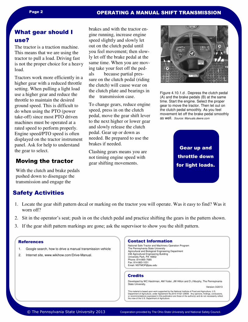
Page 2 OPERATING A MANUAL SHIFT TRANSMISSION
1. Google search, how to drive a manual transmission vehicle
2. Internet site, www.wikihow.com/Drive-Manual.
References
1. Locate the gear shift pattern decal or marking on the tractor you will operate. Was it easy to find? Was it
worn off?
2. Sit in the operator’s seat; push in on the clutch pedal and practice shifting the gears in the pattern shown.
3. If the gear shift pattern markings are gone; ask the supervisor to show you the shift pattern.
Safety Activities
The tractor is a traction machine.
This means that we are using the
tractor to pull a load. Driving fast
is not the proper choice for a heavy
load.
Tractors work more efficiently in a
higher gear with a reduced throttle
setting. When pulling a light load
use a higher gear and reduce the
throttle to maintain the desired
ground speed. This is difficult to
do when using the PTO (power
take-off) since most PTO driven
machines must be operated at a
rated speed to perform properly.
Engine speed/PTO speed is often
displayed on the tractor instrument
panel. Ask for help to understand
the gear to select.
What gear should I
use?
Gear up and
throttle down
for light loads.
National Safe Tractor and Machinery Operation Program The Pennsylvania State University Agricultural and Biological Engineering Department 246 Agricultural Engineering Building University Park, PA 16802 Phone: 814-865-7685 Fax: 814-863-1031 Email: [email protected]
Contact Information
Developed by WC Harshman, AM Yoder, JW Hilton and D J Murphy, The Pennsylvania State University. Version 3/2013
This material is based upon work supported by the National Institute of Food and Agriculture, U.S. Department of Agriculture, under Agreement No.2010-41521-20839. Any opinions, findings, conclusions, or recommendations expressed in this publication are those of the author(s) and do not necessarily reflect the view of the U.S. Department of Agriculture.
Credits
© The Pennsylvania State University 2013 Cooperation provided by The Ohio State University and National Safety Council.
Figure 4.10.1.d . Depress the clutch pedal (A) and the brake pedals (B) at the same time. Start the engine. Select the proper gear to move the tractor. Then let out on the clutch pedal smoothly. As you feel movement let off the brake pedal smoothly as well. Source: Manuals.deere.com
Moving the tractor
With the clutch and brake pedals
pushed down to disengage the
transmission and engage the
brakes and with the tractor en-
gine running, increase engine
speed slightly and slowly let
out on the clutch pedal until
you feel movement; then slow-
ly let off the brake pedal at the
same time. When you are mov-
ing take your feet off the ped-
als because partial pres-
sure on the clutch pedal (riding
the clutch) will cause wear on
the clutch plate and bearings in
the transmission case.
To change gears, reduce engine
speed, press in on the clutch
pedal, move the gear shift lever
to the next higher or lower gear
and slowly release the clutch
pedal. Gear up or down as
needed. Be prepared to use the
brakes if needed.
Clashing gears means you are
not timing engine speed with
gear shifting movements.

Learning Goals
• To emphasize the need for on-going
training in the many types of
transmissions found on farm tractors.
Related Task Sheets:
Moving and Steering a Tractor 4.10
Operating a Manual Shift Transmission
4.10.1
“Jump on that tractor and move it
to the next farm down the road”
said the supervisor. That should be
a simple task for anyone who has
driven a tractor. Maybe not!
Tractor transmissions have come a
long way since the manual stick
shift. This task sheet briefly
discusses tractor transmissions.
There are many transmission types
and combinations on the market
and newer ones are introduced
regularly. The operator should be
trained on each tractor with a
different transmission that he or
she is expected to operate.
Advice for beginners
With the many variations in
transmission shift patterns, ask the
tractor dealer, or employer to show
you how the tractor is effectively
shifted for various tasks.
Use the Operator’s Manual for the
specific tractor to learn more about
the transmission use.
Use an Internet search tool such as
“Google” to help you understand a
specific type of transmission.
To prevent injury to yourself or
others, and to prevent damage to
the tractor or other property, ask
for training before using the
tractor.
Introduction
Figure 4.10.a. A tractor with a High-Low Range transmission has two shift levers (A). The transmission may have 3-5 gears with a high and low range for each. To start the tractor both shift levers may have to be in neutral. The shift pattern decal may be worn or missing requiring the operator to ask the employer for this information.
Know the gear
shift pattern and
how to smoothly
shift gears
without
clashing.
TRACTOR TRANSMISSIONS
NATIONAL SAFE TRACTOR AND MACHINERY OPERATION PROGRAM
HOSTA Task Sheet 4.10.2
There are many “stick shift”
tractors still in use and entry level
employees may be assigned to
these tractors until experience is
gained.
Review Figure 4.10.s.a. for a
reminder of what a stick shift gear
pattern may look like, as well as
where the gear shift lever is
located.
The gear shift lever and high-low
range shift is normally found on
the transmission housing and
between the operator’s legs.
See Task Sheet 4.10.1, Operating
a Manual Shift Transmission for
more information.
Manual Transmissions
© The Pennsylvania State University 2013 Cooperation provided by The Ohio State University and National Safety Council.
B.
C.
D.
A.

Page 2 TRACTOR TRANSMISSIONS
Changing gears with a stick shift is
inefficient. Tractor manufacturer’s
developed a means of “shifting on
the go” to improve tractor
efficiency and increase operator
comfort. The clutch pedal may still
be used to disengage the clutch
between the transmission and the
engine, but chances are the newer
model tractors will not use a pedal
for shifting gears at all. Once on
the move the simple movement of
the power (gear) shift lever gives a
greater range of power and speed.
There are many variations shown
here. You must become familiar
with the transmission you will be
using. Study the Operator’s
Manual and ask for assistance from
a knowledgeable person.
Transmissions other
than standard or stick
shift
Always look for
the “orange”
colored controls.
Some may be
faded or nearly
invisible.
© The Pennsylvania State University 2013 Cooperation provided by The Ohio State University and National Safety Council.
Figure 4.10.2.c. Look on the left side of the steering column. The shuttle shift lever, sometimes called the reverser, allows for ease of changing direction without using the clutch. This lever may serve as the positive park to be used with the parking brake. Some may have to be in a neutral position for the tractor to start. This may be the only time that the clutch pedal is used.
Figure 4.10.2.b. A synchronized shift transmission permits the operator to shift on the go within a range of “synchronized” gears.
Figure 4.10.2.f. The tractor should always be left in the positive park position with the parking brake locked (circled). The shift lever is moved from “P”, park, to forward or reverse position. A range of numbers and/or letters (1-2-3-4, A-B-C-D) provides the power and speed ranges for the task.
Figure 4.10.2.e. A single orange colored proportional travel lever (shift lever) may be used to move the tractor forward or in reverse. There may be an adjustment knob or button built into the shift lever to further set the range of power and speed. The foot and hand accelerator are orange colored also.
Figure 4.10.2.d. The clutch pedal on the left side of the floor may be used only to start the tractor and may not be used again until stopping.

Page 3 HOSTA TASK SHEET 4.10.2
It is wise to ask
for a
demonstration of
how the
transmission of
the tractor works.
Tractors are a
large investment
which can be
damaged if not
used properly.
The newer model tractor
transmissions not only combine
hydraulic power with a
synchronized gear train, but have
added an electronic monitoring
system to further make for
efficient, fuel-saving usage.
Here are a few of the
possibilities:
• Electronic monitoring of 100
checks per second to modify
tractor engine speed in
relation to power
requirements of the job.
• A de-clutch button to enable
gear shifting on the go
without depressing the clutch
pedal. It conveniently allows
the operator to increase
transport performance and
comfort, helping to save
additional time.
• Electro-hydraulic Hi-Lo range
selection with the push of a
button.
• Standard creeper range for
work where slower speeds are
required.
© The Pennsylvania State University 2013 Cooperation provided by The Ohio State University and National Safety Council.
Continued
transmission
evolution expected
Figure 4.10.2.g. Visual monitoring of speed and power ranges are made to assist the operator in efficient operation. Someone must explain the system to you so that you can properly operate the tractor.
Figure 4.10.2.h. Sophisticated controls and monitoring systems are found in the contemporary tractor’s operator’s station. Use the Operator’s Manual plus ask a reliable person to explain the tractor’s operation.

1. Operator’s Manuals from various tractor manufacturers, specifically the tractor which you will operate.
2. Internet sources for various tractor manufacturers.
3. Knowledgeable, trained individuals who can demonstrate how and why the transmission is used for a specific tractor.
References
Page 4 TRACTOR TRANSMISSIONS
1. Locate the speed and power shift control lever on the tractor which you will operate. Was it easy to find?
What color is that control lever? Was the color worn to the point that you could not tell what color it was?
2. Sit in the operator’s seat. Is there a clutch pedal? Can you move the speed and power control lever(s) while
the engine is not running? Can you locate the shuttle shift, or reverser lever? Where is the shuttle shift, or
reverser lever?
3. Try starting the tractor. Did it start when you followed the directions in the Operator’s Manual? If it did not
start, can you explain why it did not start?
4. On late model tractors, use the Operator’s Manual to locate information that would tell you what speed and
power setting to use for various field operations. Answer these:
Field work to be done Transmission setting Engine RPM
A. Light load _______________ ________
B. Heavy load _______________ ________
Safety Activities
National Safe Tractor and Machinery Operation Program The Pennsylvania State University Agricultural and Biological Engineering Department 246 Agricultural Engineering Building University Park, PA 16802 Phone: 814-865-7685 Fax: 814-863-1031 Email: [email protected]
Contact Information
Developed by WC Harshman, AM Yoder, JW Hilton and D J Murphy, The Pennsylvania State University. Version 3/2013
This material is based upon work supported by the National Institute of Food and Agriculture, U.S. Department of Agriculture, under Agreement No. 2010-41521-20839. Any opinions, findings, conclusions, or recommendations expressed in this publication are those of the author(s) and do not necessarily reflect the view of the U.S. Department of Agriculture.
Credits
© The Pennsylvania State University 2013 Cooperation provided by The Ohio State University and National Safety Council.
Figure 4.10.2.i. Tractor’s imported into the USA may not use the same color coding standards for controls as tractors manufactured for the US market. Request training before using imported tractors. You won’t be dismissed from your work by asking questions.

Learning Goals
• To safely drive a tractor in reverse
gear to a specific location with few
directional corrections
• To spot the tractor drawbar to the
hitch of the machine with no more
than three changes of direction
Related Task Sheets:
Mounting and Starting the Tractor
4.8
Stopping and Dismounting the Tractor
4.9
Moving and Steering the Tractor 4.10
Being able to steer the tractor in the
proper direction of operation
without damage to the tractor and
machinery is important. The safe
and effective tractor operator can
make the tractor move where it is
supposed to go.
Not all operations will be in a
forward direction. You must be
able to operate the tractor and
equipment in the reverse direction.
Hitching to equipment, backing
equipment, unloading crops, and
even storing machinery is done in
reverse.
Reverse travel and steering is
generally done without looking at
the direction of the steered wheels.
These wheels will usually be out of
your line of sight. You must master
the concept that the steered wheels
are pointing the rear of the tractor
in the direction you want it to go.
To back safely, check your line of
travel, back slowly, and have
someone help direct you if needed.
This task sheet instructs how to
correctly steer a tractor in reverse.
Master this task without any
equipment hooked to the tractor
before beginning to back a two-
wheel or four-wheel machine or
implement.
Reverse Direction
Hazards
People, animals, or other objects
may be in the line of travel. As you
look from the front of the machine
to the rear, you may lose sight of
such obstacles. Skid loaders and
industrial equipment have reverse
gear alarms to warn others, but
tractors usually do not.
Workers who help you by hitching
the implement to the tractor can be
crushed if your foot slips from the
clutch pedal, if you are driving too
fast in reverse, or if you fail to
steer in the correct direction in
reverse. Do not permit the helper to
go between the tractor and
implement to be hitched before you
stop the tractor and turn off the
engine.
There is a tendency to shift slightly
from the operator’s seat when
looking to the rear. You must stay
in good contact with foot and hand
controls to be safe.
Introduction
Figure 4.11.a. Which way should I turn the steering wheel to make the tractor turn to the left when using the reverse gear?
Imagine which way
the rear end of the
tractor will go as
you turn the steering
wheel when moving
in reverse.
OPERATING THE TRACTOR IN
REVERSE
NATIONAL SAFE TRACTOR AND MACHINERY OPERATION PROGRAM
HOSTA Task Sheet 4.11
© The Pennsylvania State University 2013 Cooperation provided by The Ohio State University and National Safety Council.
Core

Page 2 OPERATING THE TRACTOR IN REVERSE
1. Farm and Ranch Safety Management, John Deere Publishing, 2009.
References
1. With a clutch-type tractor, practice pushing the clutch in all the way and then releasing the clutch slowly to
get the feel of the clutch pressure. Do this without starting the tractor; then practice this task in a clear area
with the engine running.
2. Practice starting a tractor, moving it forward, slowly steering in a figure 8. Place tractor in reverse gear and
slowly back in a figure 8 pattern. Use a low-range, low-throttle adjustment.
3. Ask an experienced operator to demonstrate how to back a two-wheeled implement.
4. Practice turning and backing with a two-wheeled implement attached to the tractor.
Safety Activities
steering wheel to the right.
5. To back with a two-wheeled
implement, you must use the rear
of the tractor to force the
implement to go where you want
it. To move the implement to the
left, steer the tractor to the right.
To move the implement to the
right, steer the tractor to the left.
This must be done slowly.
Follow these safety tips when
driving a tractor in reverse without
an implement:
1. Be sure seat and controls are
adjusted for you.
2. Be sure all persons, animals,
and objects are clear of the
tractor.
3. Engage the clutch slowly, use a
low engine speed, and maintain
foot contact with the clutch and
brake.
4. Turn the top of the steering
wheel in the direction you want
the rear of the tractor to move.
If you wish to move the rear of
the tractor to the left, move the
steering wheel to the left. If
you wish to move the rear of
tractor to the right, move the
Tips for Backing a Tractor
With an Implement
Remember, when
backing an
implement, turn the
steering wheel in
the opposite
direction.
Figure 4.11.b Which way would you turn the steering wheel of this tractor to back the manure spreader to the right?
National Safe Tractor and Machinery Operation Program The Pennsylvania State University Agricultural and Biological Engineering Department 246 Agricultural Engineering Building University Park, PA 16802 Phone: 814-865-7685 Fax: 814-863-1031 Email: [email protected]
Contact Information
Developed by WC Harshman, AM Yoder, JW Hilton and D J Murphy, The Pennsylvania State University. Reviewed by TL Bean and D Jepsen, The Ohio State University and S Steel, National Safety Council. Revised 3/2013.
This material is based upon work supported by the National Institute of Food and Agriculture, U.S. Department of Agriculture, under Agreement Nos. 2001-41521-01263 and 2010-41521-20839. Any opinions, findings, conclusions, or recommendations expressed in this publication are those of the author(s) and do not necessarily reflect the view of the U.S. Department of Agriculture.
Credits
© The Pennsylvania State University 2013 Cooperation provided by The Ohio State University and National Safety Council.

Learning Goals
• To explain the role that center of
gravity plays in tractor overturns
• To list reasons the center of
gravity moves within a stability
baseline
• To explain how to be protected
during a tractor overturn
Related Task Sheets:
Agricultural Tractors 4.1
Tractor Hazards 4.2
Moving and Steering the Tractor 4.10
Using the Tractor Safely 4.13
Operating the Tractor on Public Roads
4.14
No other machine is more
identified with the hazards of
farming as the tractor. Nearly 50%
of tractor fatalities come from
tractor overturns. Tractors are used
for many different tasks. Because
the tractor is a versatile machine,
operators sometimes stretch the use
of the tractor beyond what the
machine can safely do. For
example, an operator may turn a
corner too quickly for the tractor to
stay upright. The use of a rollover
protective structure (ROPS) and a
seat belt can save your life if a
tractor overturns while you are
driving. .
This task sheet explains the four
major reasons and forces that allow
tractors to overturn, gives rules for
how to prevent tractors from
overturning, and discusses the use
of tractor ROPS with a seat belt.
Center of gravity (CG). A center
of gravity is the point where all
parts of a physical object balance
one another. When you balance a
pencil on your finger, you have
found the pencil’s CG. This is the
part of the pencil that is resting on
your finger. On a two-wheel drive
tractor, CG is about 10 inches
above and 12 inches in front of the
rear axle. Figure 4.12.a shows the
normal position of a tractor’s CG.
Look at Figure 4.12.b. This shows
Introduction
Figure 4.12.b. The tractor’s center of gravity is inside the stability baseline.
CG
Center of
Gravity
TRACTOR STABILITY
NATIONAL SAFE TRACTOR AND MACHINERY OPERATION PROGRAM
HOSTA Task Sheet 4.12
How Tractors Overturn
that the CG is inside a tractor’s
stability baseline. Drawing a line to
connect all the wheels of the
tractor as the wheels set on level
ground forms a tractor stability
baseline. The line connecting the
rear tire ground contact points is
the rear stability baseline. The lines
connecting the rear and front tire
on the same side are the right and
left side stability baselines. Front
stability baselines exist but have
limited use in tractor overturn
discussions.
There are two very important
points to remember about tractor
CG and stability baselines:
• The tractor will not overturn if
the CG stays inside the stability
baseline.
• The CG moves around inside
the baseline area as you operate
the tractor.
As you can see in figure 4.12.b, a
wide front-end tractor provides
more space for the CG to move
around without going outside the
stability baseline.
Figure 4.12.a. Expected position of a tractor’s center of gravity. Safety Management for Landscapers,
Grounds-Care Businesses, and Golf Courses, John Deere Publishing, 2001. Illustrations reproduced by permission. All rights reserved.
© The Pennsylvania State University 2013 Cooperation provided by The Ohio State University and National Safety Council.
Core

Page 2 TRACTOR STABILITY
When a tractor is on a slope, the
distance between the tractor’s CG
and stability baseline is reduced.
Figure 4.12.c shows how this
occurs. On steep slopes, the tractor
is already close to an overturn. A
small bump on the high side, or a
groundhog hole on the low side,
may be all that is needed for the
tractor to overturn.
A front-end loader or other
attachment mounted on a tractor
can raise the tractor’s CG. When
the bucket is raised high, the
balance point for the whole tractor
is also raised. Figure 4.12.d shows
how a raised CG makes it easier
for a tractor to turn over sideways.
There are five main reasons why a
tractor’s CG moves outside the
stability baseline.
1. The tractor is operated on a
steep slope.
2. The tractor’s CG is raised
higher from its natural location
10 inches above the rear axle.
3. The tractor is going too fast for
the sharpness of the turn.
4. Power is applied to the
tractor’s rear wheels too quick-
ly.
5. The tractor is trying to pull a
load that is not hitched to the
drawbar.
Reasons the CG
Moves Around
Figure 4.12.c. When a tractor is on a slope, the distance between the tractor’s CG and stability baseline is reduced.
How Center of Gravity
and Centrifugal Force
Result in an Overturn
bouncing and landing in a turned
position. If the tractor starts to
veer off the road, over correction
of steering can result in side
overturns. Centrifugal force is
often a factor in tractor side
overturns. When the distance
between the tractor’s CG and side
stability baseline is already
reduced from being on a hillside,
only a little CF may be needed to
push the tractor over.
Engaging the clutch of a tractor
results in a twisting force, called
torque, to the rear axle. Under
normal circumstances, the rear axle
(and tires) should rotate and the
tractor will move ahead. If this
occurs, the rear axle is said to be
rotating about the tractor chassis.
If the rear axle cannot rotate, then
the tractor chassis rotates about the
axle. This reverse action results in
the front end of the tractor lifting
off the ground until the tractor’s
CG passes the rear stability
baseline. At this point, the tractor
will continue rearward from its
own weight until the tractor
crashes into the ground or other
obstacle. See Figure 4.12.e.
Figure 4.12.d. A raised CG makes it easier for a tractor to turn over sideways. Safety Management for
Landscapers, Grounds-Care Businesses, and Golf Courses, John Deere Publishing, 2001. Illustrations reproduced by permission. All rights reserved.
Centrifugal force (CF) is the
outward force nature exerts on
objects moving in a circular
fashion. During tractor overturns,
CF is that force trying to roll the
tractor over whenever the tractor
is turning. Centrifugal force
increases both as the turning
angle of the tractor becomes
sharper (decreases), and as the
speed of the tractor increases
during a turn. For every degree
the tractor is turned tighter, there
is an equal amount of increased
CF.
The relationship between CF and
tractor speed, however, is
different. Centrifugal force varies
in proportion to the square of the
tractor’s speed. For example,
doubling tractor speed from 3
mph to 6 mph increases the
strength of CF four times (22 = 2
x 2 = 4). Tripling tractor speed
from 3 mph to 9 mph increases
CF nine times (32 = 3 x 3 = 9).
Centrifugal force is what usually
pushes a tractor over when the
tractor is driven too fast during a
turn or during road travel. During
road travel, rough roads may
result in the tractor’s front tires
© The Pennsylvania State University 2013 Cooperation provided by The Ohio State University and National Safety Council.

Page 3 HOSTA TASK SHEET 4.12
The CG of a tractor is found closer
to the rear axle than the front axle.
A tractor may only have to rear to
about 75 degrees from a level
surface before its CG passes the
rear stability baseline and the
tractor continues flipping over.
This position is commonly called
the “point of no return.” As Figure
4.12.e shows, this point can be
reached more quickly than an
operator can recognize the
problem.
Common examples of this type of
tractor overturn are: the rear tires
are frozen to the ground; tires stuck
in a mud hole; or tires blocked
from rotating by the operator. Rear
overturns can also happen on a
slope if an operator applies too
much power too quickly to the rear
axle. When a tractor is pointed up a
slope, there is less rise needed to
reach the point of no return
because the CG has already moved
closer to the stability baseline.
Figure 4.12.f shows how this
occurs.
When a two-wheel drive tractor is
pulling a load, the rear tires push
against the ground. At the same
time, the load attached to the
tractor is pulling back and down
Figure 4.12.e. The point of no return is reached in 3/4 of a second. Safety Management for Landscapers,
Grounds-Care Businesses, and Golf Courses, John Deere Publishing, 2001. Illustrations reproduced by permission. All rights reserved.
Figure 4.12.f. When a tractor is pointed up a slope, the CG is closer to the rear stability baseline.
against the forward movement of
the tractor. The load is described
as pulling down because the load
is resting on the earth’s surface.
This backward and downward
pull results in the rear tires
becoming a pivot point, with the
load acting as a force trying to tip
the tractor rearward. An “angle
of pull” is created between the
ground’s surface and the point of
attachment on the tractor.
A tractor, including the drawbar,
is designed to safely counteract
the rearward tipping action of
pulled loads. When loads are
attached to a tractor at any point
other than the drawbar, the safety
design of the tractor for pulling
loads is defeated.
The heavier the load and the
higher the “angle of pull,” the
more leverage the load has to tip
the tractor rearward. Figures
4.12.g, 4.12.h, and 4.12i. show
important information about safe
hitching points.
Figure 4.12.g. Only hitch to the drawbar. Safety
Management for Landscapers, Grounds-Care Businesses, and Golf Courses, John Deere Publishing, 2001. Illustrations reproduced by permission. All rights reserved.
Figure 4.12.h. Never hitch to the top link of a 3-point hitch. Safety Management for Landscapers, Grounds-
Care Businesses, and Golf Courses, John Deere Publishing, 2001. Illustrations reproduced by permission. All rights reserved.
Figure 4.12.i. The angle of pull should be kept to a minimum.
© The Pennsylvania State University 2013 Cooperation provided by The Ohio State University and National Safety Council.

1. Safety Management for Landscapers, Grounds-Care Businesses, and Golf Courses, John Deere Publishing, 2001. Illustrations reproduced by permission. All rights reserved.
2. www.cdc.gov/Type agriculture tractor overturn hazards
in search box/Click on 1 0.67 Tractor Overturn Hazards, August 2002.
3. Farm and Ranch Management, John Deere
Publishing, 2009.
References
Page 4 TRACTOR STABILITY
1. Use a toy scale model or a full-size tractor to illustrate the five main reasons tractors overturn.
2. Invite a farmer whom you know who has survived a tractor rollover to speak to the class about the experi-
ence.
3. Conduct a survey of area farm people to find out instances of tractor overturns in the last five years. How
many overturns resulted in a fatality? How many survived an overturn? Did a ROPS play a role in their
Safety Activities
The rollover protective structure
(ROPS) and seat belt, when worn,
are the two most important safety
devices to protect operators from
death during tractor overturns.
Remember the ROPS does not
prevent tractor overturns, but can
prevent the operator from being
crushed during an overturn. The
operator must stay within the
protective frame of the ROPS
(Zone of Protection) in order for
the ROPS to work as designed.
This means the operator must wear
the seat belt. Not wearing the seat
belt may defeat the primary
purpose of the ROPS.
A ROPS often limits the degree of
rollover, which may reduce the
probability of injury to the
operator. A ROPS with an
enclosed cab further reduces the
Protect Yourself in a
Tractor Overturn
likelihood of serious injury
because the sides and windows of
the cab protect the operator. This
assumes that cab doors and
windows are not removed.
To prevent tractors from
overturning in the first place,
follow the safety recommendations
that are illustrated in Task Sheet
4.13.
Note: ROPS are available in
folding and telescoping versions
for special applications, such as
orchards and vineyards and low-
clearance buildings. Some ROPS
may be a protective frame only
and not an enclosed cab.
Figure 4.12.j. A rollover protective structure (ROPS) and a seat belt can protect you in the event of an overturn. If you are in the cab of a ROPS-equipped tractor, fasten the seat belt. Safety Management for
Landscapers, Grounds-Care Businesses, and Golf Courses, John Deere Publishing, 2001. Illustrations reproduced by permission. All rights reserved.
National Safe Tractor and Machinery Operation Program The Pennsylvania State University Agricultural and Biological Engineering Department 246 Agricultural Engineering Building University Park, PA 16802 Phone: 814-865-7685 Fax: 814-863-1031 Email: [email protected]
Contact Information
Developed by WC Harshman, AM Yoder, JW Hilton and D J Murphy, The Pennsylvania State University. Reviewed by TL Bean and D Jepsen, The Ohio State University and S Steel, National Safety Council. Revised 3/2013.
This material is based upon work supported by the National Institute of Food and Agriculture, U.S. Department of Agriculture, under Agreement Nos. 2001-41521-01263 and 2010-41521-20839. Any opinions, findings, conclusions, or recommendations expressed in this publication are those of the author(s) and do not necessarily reflect the view of the U.S. Department of Agriculture.
Credits
© The Pennsylvania State University 2013 Cooperation provided by The Ohio State University and National Safety Council.

Learning Goals
• To recognize proper uses of the tractor
• To recognize improper uses of the
tractor
Related Task Sheets:
Agricultural Tractors 4.1
Tractors can be operated safely if
they are used as designed and
operated following recommended
practices.
There are an estimated 300 farm
tractor fatalities each year. Read
these short examples.
• Teenager killed using tractor to
spotlight deer in the woods.
• Man killed when tractor rolled
onto him while dragging logs
in the woods.
• Grandfather killed, but
passenger grandson lives when
tractor goes over an
embankment while going for a
fun ride.
• Tractor overturns while towing
stalled pickup full of firewood.
• Tractor upsets sideways while
high lift bucket is in a raised
position while traveling across
a rough slope.
This task sheet will identify several
proper and improper uses of
tractors.
Proper Use Defined
Tractors are made to work, not to
be treated as ATVs, four-wheelers,
dune buggies, or as other
recreational vehicles.
Tractors serve four purposes:
1. They are a remote power
source.
2. They carry/pull machines.
3. They move loads.
4. They transport materials.
If you are not sure of a specific use
for your tractor, consult the
Owner’s Manual.
Introduction
Figure 4.13.a. When tractors are operated for their intended purpose, the American farm worker produces more food than in any other country in the world.
A tractor is
designed to
do work.
USING THE TRACTOR SAFELY
NATIONAL SAFE TRACTOR AND MACHINERY OPERATION PROGRAM
HOSTA Task Sheet 4.13
© The Pennsylvania State University 2013 Cooperation provided by The Ohio State University and National Safety Council.
Core

Page 2 USING THE TRACTOR SAFELY
Recognize
when a
driver is
operating
the tractor
in an unsafe
manner.
Proper Use Means Avoiding Improper Use
Figure 4.13.b. Tractors are designed for the operator only. No passengers allowed!
Figure 4.13.c. Tractors provide remote power to machinery. This turning shaft, the PTO, must be guarded to prevent entanglement hazards such as this.
Figure 4.13.d. Hitch loads only to the drawbar. The drawbar has been engineered to pull heavy loads without risking a rear overturn hazard. Safety
Management for Landscapers, Grounds-Care Businesses, and Golf Courses, John Deere Publishing, 2001. Illustrations reproduced by permission. All rights reserved.
Figure 4.13.e. If you are stuck or need to be towed, you will need help from a second tractor. Use the strongest and best tow strap, cable, or chain that is available. Hitch only to the drawbar. The best advice for a young operator is to get adult help to pull the disabled or stuck tractor. Farm and Ranch Safety Management, John Deere Publishing, 1994. Illustrations reproduced by permission. All rights reserved.
© The Pennsylvania State University 2013 Cooperation provided by The Ohio State University and National Safety Council.

Page 3 HOSTA TASK SHEET 4.13
Figure 4.13.f. Avoid ditch embankments. Tractors are heavy and embankments can give way. For example, if the ditch is 6 feet deep, stay back at least 6 feet. Safety
Management for Landscapers, Grounds-Care Businesses, and Golf Courses, John Deere Publishing, 2001. Illustrations reproduced by permission. All rights reserved.
Figure 4.13.g. High speeds while making a turn can cause a sideways overturn. Make sure brakes are locked together. Reduce speed before entering the turn. Safety
Management for Landscapers, Grounds-Care Businesses, and Golf Courses, John Deere Publishing, 2001. Illustrations reproduced by permission. All rights reserved.
Figure 4.13.h. Avoid obstacles as you operate the tractor. Some tractor operators will check the field before beginning the operation. Stumps, rocks, animal dens, etc, can upset a tractor.
Figure 4.13.i. Tractors are powerful, but each one has a limit to its pulling power. Overloading a tractor could stall the engine, but rearward overturns can occur as well. Farm and Ranch Safety Management,
John Deere Publishing, 1994. Illustrations reproduced by permission. All rights reserved.
Figure 4.13.j. Field conditions pose special hazards to tractor operation. The operator must know where these obstructions and depressions are located. Farm and Ranch Safety
Management, John Deere Publishing, 1994. Illustrations reproduced by permission. All rights reserved.
Figure 4.13.k. When operating a high-lift bucket with a load or without a load, keep the bucket as low to the ground as possible while in transport. Sideway overturns are possible if you try to travel with the bucket in the up position. Farm and Ranch Safety Manage-
ment, John Deere Publishing, 1994. Illustrations reproduced by permission. All rights reserved.
© The Pennsylvania State University 2013 Cooperation provided by The Ohio State University and National Safety Council.

1. The Ten Commandments of Tractor Safety, 1999, Kubota Tractor Corp., Compton, California.
2. www.cdc.gov/niosh/injury/traumagric.html, September 2002.
3. Safety Management for Landscapers, Grounds-Care Businesses, and Golf Courses, John Deere Publishing, 2001. Illustrations reproduced by permission. All rights reserved.
4. www.cdc.gov/niosh/nasd/At search box, type tow ropes, cables and chains.
5. Farm and Ranch Safety Management, John Deere Publishing, 2009. Illustrations reproduced by permission. All rights reserved.
References
Page 4 USING THE TRACTOR SAFELY
1. Start a collection of farm accident reports from magazines, newspapers, and farm newsletters.
2. Using a camera or video recorder, take photos or video film of unsafe tractor use situations. Make a display
for your club, classroom, employee room or farm shop.
3. Try this Word Search Game to find words related to proper tractor use. Words or phrases may be spelled
forward, backward, up, down, or diagonally.
S A D Z C D E F G H
J A T T I T U D E I
K N F D L M G N O P
Y O V E R T U R N X
T R T E T S A Y R Q
U I V P R Y R O W X
D D C S E B D A Z Y
L E F W L G S H I J
K R L O A M N O P Q
T S V L V W X Y Z R
Use this word list: attitude, safety, guards. no riders, overturn, alert, low speed, pto
Safety Activities
Figure 4.13.l. A tractor stuck in mud is immovable without help. Adult supervision is necessary.
Figure 4.13.m. Avoid overhead power lines while transporting equipment to avoid risk of electrocution.
National Safe Tractor and Machinery Operation Program The Pennsylvania State University Agricultural and Biological Engineering Department 246 Agricultural Engineering Building University Park, PA 16802 Phone: 814-865-7685 Fax: 814-863-1031 Email: [email protected]
Contact Information
Developed by WC Harshman, AM Yoder, JW Hilton and D J Murphy, The Pennsylvania State University. Reviewed by TL Bean and D Jepsen, The Ohio State University and S Steel, National Safety Council. Revised 3/2013.
This material is based upon work supported by the National Institute of Food and Agriculture, U.S. Department of Agriculture, under Agreement Nos. 2001-41521-01263 and 2010-41521-20839. Any opinions, findings, conclusions, or recommendations expressed in this publication are those of the author(s) and do not necessarily reflect the view of the U.S. Department of Agriculture.
Credits
© The Pennsylvania State University 2013 Cooperation provided by The Ohio State University and National Safety Council.
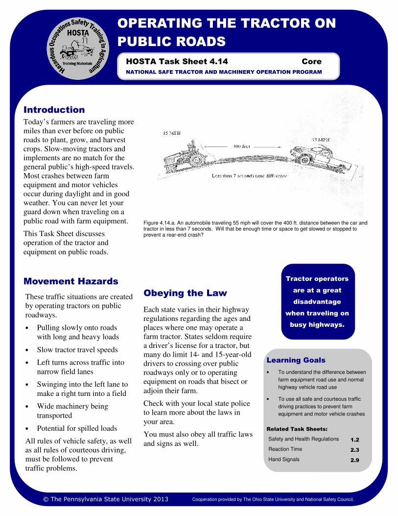
Learning Goals
• To understand the difference between
farm equipment road use and normal
highway vehicle road use
• To use all safe and courteous traffic
driving practices to prevent farm
equipment and motor vehicle crashes
Related Task Sheets:
Safety and Health Regulations 1.2
Reaction Time 2.3
Hand Signals 2.9
Today’s farmers are traveling more
miles than ever before on public
roads to plant, grow, and harvest
crops. Slow-moving tractors and
implements are no match for the
general public’s high-speed travels.
Most crashes between farm
equipment and motor vehicles
occur during daylight and in good
weather. You can never let your
guard down when traveling on a
public road with farm equipment.
This Task Sheet discusses
operation of the tractor and
equipment on public roads.
Obeying the Law
Each state varies in their highway
regulations regarding the ages and
places where one may operate a
farm tractor. States seldom require
a driver’s license for a tractor, but
many do limit 14- and 15-year-old
drivers to crossing over public
roadways only or to operating
equipment on roads that bisect or
adjoin their farm.
Check with your local state police
to learn more about the laws in
your area.
You must also obey all traffic laws
and signs as well.
Introduction
Figure 4.14.a. An automobile traveling 55 mph will cover the 400 ft. distance between the car and tractor in less than 7 seconds. Will that be enough time or space to get slowed or stopped to prevent a rear-end crash?
Tractor operators
are at a great
disadvantage
when traveling on
busy highways.
OPERATING THE TRACTOR ON
PUBLIC ROADS
NATIONAL SAFE TRACTOR AND MACHINERY OPERATION PROGRAM
HOSTA Task Sheet 4.14
These traffic situations are created
by operating tractors on public
roadways.
• Pulling slowly onto roads
with long and heavy loads
• Slow tractor travel speeds
• Left turns across traffic into
narrow field lanes
• Swinging into the left lane to
make a right turn into a field
• Wide machinery being
transported
• Potential for spilled loads
All rules of vehicle safety, as well
as all rules of courteous driving,
must be followed to prevent
traffic problems.
Movement Hazards
© The Pennsylvania State University 2013 Cooperation provided by The Ohio State University and National Safety Council.
Core

Page 2 OPERATING THE TRACTOR ON PUBLIC ROADS
standards? If not, can the
equipment be improved with
retrofit kits of lights and reflectors?
Although not included in the
ASAE standard, rotary beacons
and back-up alarms are optional
accessories which may be add-ons
depending upon your needs. If
accessories have been added, they
should be in working order.
American Society of Agricultural
Engineers (ASAE) Standards for
lighting and marking are
summarized in Table 4.14.a. Most
farm equipment delivered from the
factory today will have used these
standards. Does the equipment that
you will use measure up to these
Lighting and Marking Using the proper
lighting and marking
standards gives
motorists ample
warning that farm
equipment is using
the public roadway.
Figure 4.14.c. Be sure that a work light that points to the rear is off during road travel at night. Single white lights may not be recognized as slow-moving or as a tractor light. Also if SMV emblems are worn or obsolete, replace them with newer more reflective SMV emblems.
Figure 4.14.b. Lighting and marking standards may or may not be the standards for your state. Check your state laws.
Work light
Item Recommendation
Headlights Two white lights mounted at the same level
Taillights Two red lights mounted at the rear
Hazard Flashers
Two or more lamps with amber color to the front and red color to the rear
Turn Indicators
Two amber to the front and two red-colored lights to the rear mounted with flashers
SMV Emblem One visible at 1000 ft. mounted to the rear and 2-10 ft. above the ground
Reflectors Two red reflectors (on rear outside corners) and 2 yellow reflectors (on the front outside corners) of the machine
Conspicuity Material
Red retro-reflective and red-orange fluorescent color visible to mark the rear. Yellow retro-reflective material to mark the
Table 4.14.a. Recommendations from ASAE for lighting and marking.
© The Pennsylvania State University 2013 Cooperation provided by The Ohio State University and National Safety Council.

Page 3 HOSTA TASK SHEET 4.14
Figure 4.14.f. SMV emblems are required on vehicles designed to travel less than 25 mph while occupying public roadways. SMV emblems should be visible from no less than 1000 feet to the rear of the tractor or towed implement. Therefore, mounting height may vary from 2 to 10 feet above the road surface. Replace faded, damaged SMV emblems.
Towing Safety
General Practices for
Tractors on Highways
Pull completely off
the road to let traffic
flow past if possible.
DO NOT SIGNAL
THEM TO PASS YOU.
Signaling to
motorists to pass
makes you
responsible for them.
Figure 4.14.h. Use accepted hand signals to inform other drivers of your intentions. Safety Management for Landscapers, Grounds-Care Businesses, and Golf Courses,
John Deere Publishing, 2001. Illustrations reproduced by permission. All rights reserved.
Figure 4.14.g. A best practice for transporting wide loads on a public roadway is to use an escort vehicle to assist in alerting other motorists. Be a courteous tractor operator to bring good public relations to the farm community.
Figure 4.14.d. Secure hitch pins with locking clips as shown.
Figure 4.14.e. Use safety chains to insure load hitching safety when possible. Trucks pulling farm loads should have safety chains also. Safety Management for Landscapers, Grounds-Care Businesses, and Golf Courses, John Deere Publishing, 2001. Illustrations reproduced by permission. All rights reserved.
Think about the following when
traveling on the highway with farm
machinery.
• Time of day–Is it possible to
avoid the busy times of the day
to move equipment? Hauling
large loads during early
morning or late afternoon
while people hurry to and from
work creates traffic problems
for both of you. Moving loads
after nightfall may be better
timing, but lighting becomes a
necessary consideration.
• Courtesy– Try to be as
watchful of others as possible.
Let the high-speed traffic go
first. Your best manners on the
highway will be the first safe
practice to follow.
• Blind spots– Are there
locations which pose problems
with visibility? Avoid them if
possible.
• Shifting loads– If you upset a
load of hay, spill a load of
manure or a tank of pesticide
mixture, or coat the road with
mud from the field, you are
responsible for getting help for
cleanup and alerting traffic to
be cautious. If manure or
chemical spills endanger
waterways, notify your
employer who may have
reporting requirements with
state environmental officials.
• Safe Equipment– Your walk-
around inspection should have
shown you if you have
damaged equipment. Be sure
damaged equipment does not
create a road hazard. For
example, a loose wheel on a
hay rake could cause a disaster.
© The Pennsylvania State University 2013 Cooperation provided by The Ohio State University and National Safety Council.

1. Safety Management for Landscapers, Grounds-Care Businesses, and Golf Courses, John Deere Publishing, 2001. Illustrations reproduced by permission. All rights reserved.
2. Farm and Ranch Safety Management, John Deere Publications, 2009.
3. State Laws and Regulations.
References
Page 4 OPERATING THE TRACTOR ON PUBLIC ROADS
1. Measure the length of the longest tractor and implement combination with which you will work. Then have
someone time how long it takes you to move the front end of that tractor to the rear end of the towed
implement past a point or across the highway in front of the farm. How many seconds did it take to cross the
road? ___________seconds.
2. A car approaching the farm driveway is traveling at 60 mph. How many feet will that car travel in 1
second? _________seconds.
Hint: 60 mph =1 mile/minute Calculate what distance in feet will be covered in 1 second.
Remember that 5,280 feet equals 1 mile.
1 mile / minute = ___________ feet / second.
3. Multiply the answer (feet/second) in question number 2 by the time you recorded in question number 1.
This is the distance the car going 60 mph will travel in the time it takes you to cross the road.
Record the answer here. _________ Can you see that far as you pull out to cross the roadway?
4. Conduct a survey of the lighting, marking, and hitching of the tractors on your farm or farm of
employment. Does it meet the safety requirements of your state?
5. Practice the hand signals for right, left, and stop that you will use while operating a tractor not equipped
with turn signals.
Safety Activities
National Safe Tractor and Machinery Operation Program The Pennsylvania State University Agricultural and Biological Engineering Department 246 Agricultural Engineering Building University Park, PA 16802 Phone: 814-865-7685 Fax: 814-863-1031 Email: [email protected]
Contact Information
Developed by WC Harshman, AM Yoder, JW Hilton and D J Murphy, The Pennsylvania State University. Reviewed by TL Bean and D Jepsen, The Ohio State University and S Steel, National Safety Council. Revised 3/2013.
This material is based upon work supported by the National Institute of Food and Agriculture, U.S. Department of Agriculture, under Agreement Nos. 2001-41521-01263 and 2010-41521-20839. Any opinions, findings, conclusions, or recommendations expressed in this publication are those of the author(s) and do not necessarily reflect the view of the U.S. Department of Agriculture.
Credits
© The Pennsylvania State University 2013 Cooperation provided by The Ohio State University and National Safety Council.

LIGHTING AND MARKING
Learning Goals
• To understand the recommendations
for lighting and marking of farm
tractors and machinery
Related Task Sheets:
Safety and Health Regulations 1.2
State Vehicle Codes 1.2.5
Hand Signals 2.9
Operating the Tractor on Public Roads
4.14
OSHA Act 1.2.2
Today’s farmers are traveling more
miles on public roads than ever
before to tend to livestock and
plant, grow, and harvest crops.
Slow-moving tractors and
implements are no match for the
public’s high-speed travels.
Most crashes between farm
equipment and motor vehicles
occur during daylight hours and in
good weather. You must be careful
when traveling on public roads
with farm equipment. Tractors and
equipment must be clearly
identified as slow-moving vehicles
using recognizable lighting and
marking.
This task sheet discusses lighting
and marking as it relates to moving
tractors and equipment on public
roadways.
Lighting and Marking
The American Society of
Agricultural Engineers (ASAE)
Standard for Lighting and
Marking are summarized in Table
4.14.1.a. See the reference section
to access the asae.org information.
Most farm equipment
manufactured today will use this
standard. Exceptions to the
standard may occur with
equipment manufactured outside
the United States. Many states
use a similar standard in their
Motor Vehicle Codes to specify
lighting and marking of slow-
moving vehicles and farm
equipment.
Lighting and marking on older
equipment can be improved to
meet this standard with add-on
lights and reflectors kits.
Introduction
Figure 4.14.1.a. Use of public roadways dictates that farm tractors and equipment be visible and identified as slower moving and wider than the usual vehicle traveling the road.
Proper equipment
marking and
lighting is a must
for roadway travel.
NATIONAL SAFE TRACTOR AND MACHINERY OPERATION PROGRAM
HOSTA Task Sheet 4.14.1
Item Recommendations
Headlights Two white lights mounted at the same level
Taillights Two red lights mounted at the rear
Hazard Flashers Two or more lamps with amber color to the front and red color to the rear
Turn Indicators Two amber lamps to the front and two red- colored lights to the rear mounted with flashers
SMV Emblem One visible at 1000 ft. mounted to the rear and 2-10 ft. above the ground
Reflectors Two red reflectors (on rear outside corners) and two yellow reflectors (on the front out-side corners) of the machine
Conspicuity Material Red retro-reflective and red-orange fluores-cent color visible to mark the rear. Yellow retro-reflective material to mark the front.
Table 4.14.1.a Recommendations from ASAE for lighting and marking
© The Pennsylvania State University 2013 Cooperation provided by The Ohio State University and National Safety Council.
Core
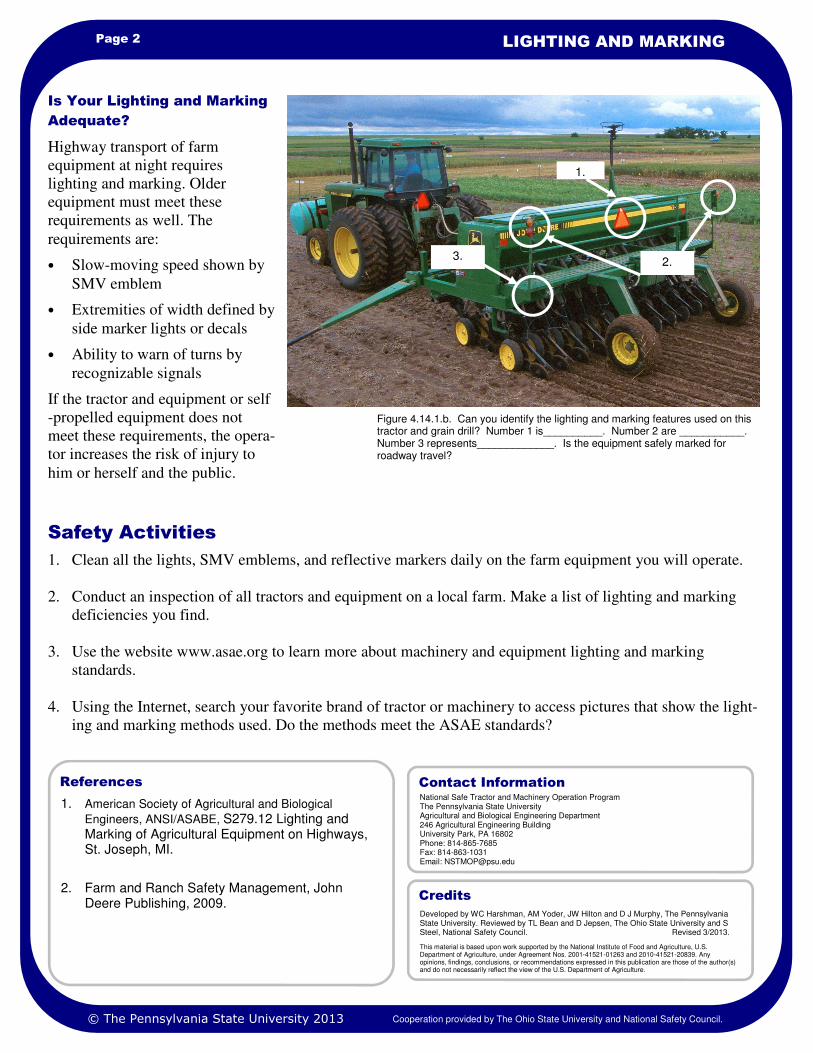
Page 2 LIGHTING AND MARKING
1. American Society of Agricultural and Biological
Engineers, ANSI/ASABE, S279.12 Lighting and Marking of Agricultural Equipment on Highways, St. Joseph, MI.
2. Farm and Ranch Safety Management, John Deere Publishing, 2009.
References
1. Clean all the lights, SMV emblems, and reflective markers daily on the farm equipment you will operate.
2. Conduct an inspection of all tractors and equipment on a local farm. Make a list of lighting and marking
deficiencies you find.
3. Use the website www.asae.org to learn more about machinery and equipment lighting and marking
standards.
4. Using the Internet, search your favorite brand of tractor or machinery to access pictures that show the light-
ing and marking methods used. Do the methods meet the ASAE standards?
Safety Activities
Highway transport of farm
equipment at night requires
lighting and marking. Older
equipment must meet these
requirements as well. The
requirements are:
• Slow-moving speed shown by
SMV emblem
• Extremities of width defined by
side marker lights or decals
• Ability to warn of turns by
recognizable signals
If the tractor and equipment or self
-propelled equipment does not
meet these requirements, the opera-
tor increases the risk of injury to
him or herself and the public.
Is Your Lighting and Marking
Adequate?
Figure 4.14.1.b. Can you identify the lighting and marking features used on this tractor and grain drill? Number 1 is__________. Number 2 are ___________. Number 3 represents_____________. Is the equipment safely marked for roadway travel?
1.
2. 3.
National Safe Tractor and Machinery Operation Program The Pennsylvania State University Agricultural and Biological Engineering Department 246 Agricultural Engineering Building University Park, PA 16802 Phone: 814-865-7685 Fax: 814-863-1031 Email: [email protected]
Contact Information
Developed by WC Harshman, AM Yoder, JW Hilton and D J Murphy, The Pennsylvania State University. Reviewed by TL Bean and D Jepsen, The Ohio State University and S Steel, National Safety Council. Revised 3/2013.
This material is based upon work supported by the National Institute of Food and Agriculture, U.S. Department of Agriculture, under Agreement Nos. 2001-41521-01263 and 2010-41521-20839. Any opinions, findings, conclusions, or recommendations expressed in this publication are those of the author(s) and do not necessarily reflect the view of the U.S. Department of Agriculture.
Credits
© The Pennsylvania State University 2013 Cooperation provided by The Ohio State University and National Safety Council.