
Ag/AgCl Reference Electrode for Use in PWR Coolants
13
Proceedings of the Korean Nuclear Society Spring Meeting Kori, Korea, May 2000 Ag/AgCl Reference Electrode for Use in PWR Coolants C. B. Bahn, N. Y. Lee, and I. S. Hwang Department of Nuclear Engineering, Seoul National University San 56- 1, Shinlim-dong, Kwanak-gu, Seoul 151-742, Korea S. Jegarl Korea Electric Power Research Institute 103- 16 Munji-dong, Yusong-gu, Taejon 305-380, Korea Abstract To predict the corrosion behavior of metals the potential measurement is very imp ortant. our goal is the development of electrochem ical corrosion potential (E CP ) electrodes for condition m onitoring and lif e management of secondary systems. The external pressure-balanced A g/ A g Cl (0.1 M K Cl) reference electrode was developed. The potential of A g/ A g Cl electrode vs. S CE at ambient temperature was calculated and compared with the measured values, which showed good agreement with calculated values within ±1 mV. The A g/ A g Cl electrode p erformance test in reducing condition at low temperature was conducted. The A g/ A g Cl electrode did not show any potential drift within one day of test period. The potential of Pt electrode was more positive than the predicted value. The causes of the difference may be the uncertainty of hydrogen fugacity value or temperature instability. But more analysis is need. The high temperature/ high pressure autoclave test for A g/ A g Cl reference electrode in reducing environment is planned.
-
Upload
khangminh22 -
Category
Documents
-
view
6 -
download
0
Transcript of Ag/AgCl Reference Electrode for Use in PWR Coolants
Proceedin g s of the Korean Nuclear S ociety Sprin g M eet ingKori, Korea , M ay 2000
A g / A g Cl Re feren c e E le c trode for U s e in P W R Co o lant s
C. B. Bahn, N. Y. Lee, and I. S . Hw ang
Department of Nuclear Engineering , Seoul National Univer sitySan 56- 1, Shinlim- dong , Kw anak- gu, Seoul 151- 742, Korea
S. Jegarl
Korea Electric Power Research Institute103- 16 Munji- dong, Yusong- gu, T aejon 305- 380, Korea
A bs tract
T o p redict the corros ion behav ior of m etals the p otential m eas urem ent is
very imp ortant. our g oal is the develop m ent of electrochem ical corros ion
p otent ial (E CP ) electrodes f or condit ion m onitoring and lif e manag em ent of
s econdary sys tem s. T he ex ternal p ress ure - balanced A g/ A g Cl (0.1 M K Cl)
ref erence electrode was develop ed. T he p otent ial of A g/ A g Cl electrode vs.
S CE at am bient temp erature was calculated and compared with the m easured
values, which showed g ood ag reem ent with calculated values within ±1 m V.
T he A g/ A g Cl electrode p erf ormance tes t in reducing condition at low
temp erature was conducted. T he A g/ A g Cl electrode did not show any
p otent ial drif t within one day of tes t p eriod. T he p otent ial of P t electrode was
m ore p os itive than the p redicted value. T he caus es of the diff erence may be
the uncertainty of hy drog en f ugacity value or temp erature ins tability . B ut
m ore analys is is need. T he hig h temp erature/ hig h p ressure autoclave tes t f or
A g/ A g Cl ref erence electrode in reducing env ironm ent is p lanned.

1. Introduction
T he corrosion of metals in PWR oper ating w ater is the primary causes of
the degradation and fouling of steam gener ator (SG), piping , and turbine. As
the results of research about corrosion of metals in high temperature/ high
pressure (HT / HP ) w ater , we can predict the corrosion behavior of metals as
function of electrochemical corrosion potential (ECP) and pH. Based on these
results , our goal is the development of ECP electrodes for condition monitoring
and life management of secondary systems . Also, electrodes having advanced
performance will be developed.
T he purpose of reference electrode is to measure st able and reproducible
potential to particular electrodes . A major problem in all high temperature
electrochemical studies a aqueous system is choosing a suit able reference
electrode[1]. General description for reference electrodes have been st ated by
Ives and Janz[2]. T he designs and performances of reference electrodes for
high temperature aqueous electrochemical studies are reviewed by
Macdonald[1]. Many kinds of reference electrodes for high temperature system
have been developed. For examples, hydrogen - hydrogen ion electrode is the
most suit able reference electrode for high temperature aqueous work [1]. But in
spite of many advantages, due to the problem of hydrogen fugacity
measurement this electrode is not widely used except for thermodynamic
studies . T he silver - silver halide reference electrodes have been extensively
studied[1]. Ag/ AgCl reference electrode is well- defined, widely used, and very
reliable electrode for high temperature work [3- 9]]. But in high temperature and
reducing environment , provided that the AgCl surface is not well protected,
the decomposition r ate of AgCl is very high [7]. T o solve this problem the
external reference electrode of which AgCl part w as maintained in ambient
temper ature w as developed. T he electrode design with heat - shrinkable
polytetrafluoroethylene (PT FE ) body and a porous zirconia plug for liquid
junction w as est ablished. T he Ag/ AgCl- Sapphire reference electrode by
replacing PT FE with sapphire w as developed and successfully applied to
boiling w ater reactors [8]. And a buffered tungsten reference electrode also w as

developed[10]. T he main feature of this electrode is the potential stability in
high reducing environments .
2 . Ex perim ent al
2.1 T hermodynamic Calculation
When we measure the potential by using Ag/ AgCl reference electrode in
HT/ HP systems , it is needed to transform the measured potential into the
thermodynamically meaningful values . T he potential to standard hydrogen
electrode (SHE ) scale is usually used. T herefore it is needed to know the
potential difference between Ag/ AgCl electrode and SHE at the temperature of
interest . Fig . 1 show s the inter - relationship among Ag/ AgCl electrode, SHE,
and working electrode (WE). T he observed potential by using the external
Ag/ AgCl electrode can be shown as follow s .
(1)E E xobs = E S H E ( T ) - E A g / A g C l( T ) + E T h
where , E E xobs = the m easu red poten tia l of a n work ing e lectrode E - E A g / A g C l(25℃)
E SH E ( T ) = the poten tia l of the work ing e lectrode ag a inst the SH Eu n der the sam e con d itions
E A g / A g C l( T ) = the isotherm a l poten tia l of the A g / A g Cl e lectrode vs . theSHE at the temperatu re of in terest
E T h = the poten tia l of the therm a l ce ll A g - A g C l(25℃) / K C l( M ) /A g - A g Cl( T )
Potentials for the symmetrical thermocell Ag- AgCl(25℃)/ KCl/ Ag- AgCl(T ℃),
ΔET h have been determined by Macdonald et al.[11]. ΔEA g / A g C l (T ) has been
measured by Greeley et al.[12]. By using the measured thermocell potential
and ΔEA g / A g C l (T ) Macdonald has constructed the polynomial equation showing
the relationship between external Ag/ AgCl electrode and ΔE S H E (T ).
(2)E S H E ( T ) = E E x
obs + E A g / A g C l( T ) - E th
E S H E ( T ) = E E xobs + D o + D 1 T + D 2 T 2 + D 3 T 3
where , T = T - 25℃
T able 1 show s the coefficient s of Eq. (2), and Fig . 2 show s ΔE S H E (T ) as the

function of temperature with Eq. (2). In Fig . 2, 'Extr apolated region ' means
that in this region it exceeds the experimental r ange.
2.2 Experimental Apparatus and Procedures
We adopted the external electrode design for Ag/ AgCl reference electrode,
which we named EREP (External Reference Electrode with PT FE ). Fig . 3
show s the schematic diagr am of the developing Ag/ AgCl reference electrode,
which is primarily based on Danielson ' s design [4]. T he heat - shrinkable PT FE
tube has the temperature limit , and the joint with zirconia liquid junction is
loosened and the electrolyte leakage problems is caused. T o mitigate this
problem, it can be possible to insert the zirconia plug part into the Rulon
adaptor and compress the adaptor with high pressure fitting . T he procedures
for making the electrode is briefly described as follow s . 1/ 8" OD Ag rod doped
with AgCl is inserted into the PT FE tube filled with the 0.1 M KCl. For high
pressure application it is compressed with Swag elok fittings and aluminium
retainer is applied to prevent ejection of the silver rod. Ag/ AgCl electrode
should be cooled to maintain the ambient temperature. A glass wick which is
wetted and then inserted into the electrode is also employed.
EREP performance test w as carried out at low temper ature. T he testing
EREP does not have the rulon adaptor . If the EREP passes in the low
temper ature test , it can be tested in high temper ature autoclave. Fig . 4 show s
the schematic diagram of experimental system . T he potential variation of
EREP and Pt electrode vs . saturated calomel electrode (SCE) w as measured.
T he electric heater w as located around the test glass cell and the potential
variation with temper ature also w as measured. 0.01 M H 3BO3 and 0.01 M
LiOH mixed solution w as used. T he test solution pH w as 9.25 at 24.5 ℃ but
by other work, pH is 10.62 at 25 ℃[13]. T he cause of the difference between
measured value and reference value will be analyzed later .
At the aerated condition the potential w as measured. And as the test
solution w as purged with 4% hydrogen and 96% argon continuously , the
potential variation measured. T he gas flow r ate w as maint ained at about 150
cc/ min through the experiment .

3 . Re s ult s and Dis cus s ion
3.1 EREP vs . SCE in the Satur ated KCl Solution
T he potential of EREP vs . SCE in the saturated KCl solution w as measured.
As a result , the measured value w as 46 mV at 25 ℃. T he theoretical potential
difference between Ag/ AgCl electrode vs . SCE w as calculated.
(3)
Hg 2 Cl2 ( s) + 2e - 2Hg ( l) + 2Cl - ( aq)
= o -R T2F
ln a 2C l - , o = + 0 .2676 V
(4)A g Cl( s) + e - = A g ( s) + Cl - ( aq)
= o - R TF
ln a C l - , o = + 0 .222 V
If we know the activity and concentration of chlorine ion, the half- cell
potential can be calculated by Eq. (3) and (4). But it can be possible to
calculate the potential with the mean ionic activity coefficient data. T able 2
show s the solubility of KCl and T able 3 show s the mean ionic activity
coefficient of KCl.
(5)= o - 2 .303 R TF
log m
For SCE @ 25 ℃,
= 0 .2676 - 2 .303(8 .314) (2 98 . 15)
96485log (0 .590 4 .811)
= 0 .24 1 V
For SCE @ 12 ℃,
= 0 .2676 - 2 .303(8 .314) (2 85 . 15)
96485log (0 .5634 4 .27)
= 0 .246 V
For Ag/ AgCl/ Cl- (0.1m ) @ 25 ℃,
= 0 .222 - 2 .303( 8 .314) (2 98 . 15)
96485log ( 0 .768 0 . 10)
= 0 .288 V
For Ag/ AgCl/ Cl- (0.1m ) @ 12 ℃,

= 0 .222 - 2 .303(8 .314)( 2 85 . 15)
96485log (0 .7697 0 . 10)
= 0 .285 V
T he calculated and predicted values are summarized in T able 3. T he
calculated values show good agreement with the predicted values within ±1
mV.
3.2 EREP Performance T est
Fig . 5 show s the potential of EREP and Pt electrode vs . SCE with
temper ature variation . In Fig . 5, 'Ag/ AgCl T emper ature ' means the w all
temper ature of the external Ag/ AgCl electrode part exposed to air . And ' SCE
T emperature ' means the w all temperature of the SCE part exposed to air .
At the aerated condition, the potential of EREP vs . SCE w as +51 mV and
+283 mV for Pt electrode. After the solution w as purged with 4% hydrogen
gas, EREP potential showed no drift of potential and w as maint ained st ably .
T he potential of Pt electrode w as dropped dr astically to the negative direction,
and readily stabilized at - 678 mV vs . SCE . We can calculate the potential of
Pt electrode provided that the fugacity of hydrogen and pH of solution is
known.
(6)
2H + + 2e - H 2 (g ) , E o = 0 .0 V
E = E o - R T2F
lnf H 2
a H +2
= - R T2F
ln f H 2+ R T
Fln a H +
= - 2 .303 R T2F
log f H 2- 2 .303 R T
FpH
Above Eq. (4) the hydrogen fugacity can be calculated by below Eq. (5)[2].
(7)
f H 2= P H 2
eB P H 2
R T
P H 2= P ressure of hydrog en , J/ cm 3
R = Un iversal gas constan t , J/ m ol KT = T emperature , KB = The second vir ial coef f icien t f or hydrogen , cm 3 / m ol
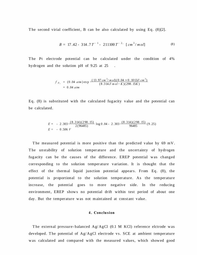
T he second virial coefficient , B can be also calculated by using Eq. (8)[2].
(8)B = 17 .42 - 314 .7 T - 1 - 211100 T - 2 , [ cm 3 / m ol]
T he Pt electrode potential can be calculated under the condition of 4%
hydrogen and the solution pH of 9.25 at 25 ℃.
f H 2= (0 .04 a tm ) ex p
( 13 .97 cm 3 / m ol) ( 0 .04 0 . 1013J/ cm 3)( 8 .314 J/ m ol K ) (298 . 15K )
= 0 .04 a tm
Eq. (8) is substituted with the calculated fugacity value and the potential can
be calculated.
E = - 2 .303( 8 .314) (2 98 . 15)
2 (96485)log 0 .04 - 2 .303
(8 .314) (2 98 . 15)96485
(9 .25)
E = - 0 .506 V
T he measured potential is more positive than the predicted value by 69 mV.
T he unstability of solution temper ature and the uncert ainty of hydrogen
fugacity can be the causes of the difference. EREP potential w as changed
corresponding to the solution temper ature variation . It is thought that the
effect of the thermal liquid junction potential appear s . From Eq. (8), the
potential is proportional to the solution temper ature. As the temperature
increase, the potential goes to more negative side. In the reducing
environment , EREP show s no potential drift within test period of about one
day . But the temperature w as not maint ained at const ant value.
4 . Conclu s ion
T he external pressure- balanced Ag/ AgCl (0.1 M KCl) reference elctrode w as
developed. T he potential of Ag/ AgCl electrode vs . SCE at ambient temperature
w as calculated and compared with the measured values, which showed good

agreement with calculated values within ±1 mV. EREP performance test in
reducing condition at low temperature w as conducted. EREP did not show any
potential drift within one day of test period. T he potential of Pt electrode w as
more positive than the predicted value. T he causes of the difference may be
the uncert ainty of hydrogen fugacity value or temperature inst ability . But more
analysis is need. T he HT / HP autoclave test for EREP in reducing
environment is planned.
A cknow ledg em ent
Financial support of the Korea Electric Power Research Institute (KEPRI) is
acknowledged.
Ref erence s
1. Digby D . M acdonald , "Reference Electrodes for High T em perature A qu eou s Sy st em s - A
Review an d A sses sm ent ", Corrosion , Vol. 34, N o. 3, pp .75- 84, (1978).
2. David J . G. Ives and George J . Janz ed., "Reference Electrodes - T heory and
Practice", Academic Press, 1961.
3. A . K . A graw al and R. W . Staehle, "A Silv er - Silv er Chloride Reference E lectrode for th e
High T em perature and High Pres sure Electroch em istry ", Corrosion , Vol. 33, N o. 11,
pp .218- 219, (1977).
4. M . J . Danielson , "T he Con stru ct ion and T h erm odynam ic P erform an ce of an A g - A gCl
Referen ce E lectrode for U se in High T em perature A queou s Environm ent s Contain in g H 2 and
H 2S ", Corrosion , V ol. 35, N o. 5, pp .200- 204, (1979).
5. Digby D . M acdon ald , Arthur C. S cot t , an d P aul W entr cek , "Ex t ernal Referen ce Electrodes
for U se in High T em perature A queou s Sy st em s", J . Electrochem . S oc., Vol. 126, No. 6,
pp .908- 911, (1979).
6. M . J . Danielson , "A Long - Liv ed Ex tern al A g/ A g Cl Referen ce Electrode for U se in High
T emperature/ P ressure Environm ent s", Corrosion , Vol. 39, N o. 5, pp .202- 203, (1983).
7. "Referen ce Electrode for P W Rs", EPRI NP - 5155, F in al Report , Electr ic P ow er Research
In st itut e, M ay 1987.
8. S . N . Lv ov , H . Gao, and D. D. M acdonald, "A dv an ced F low - T hrou gh Ext ern al
Pres sure - Balan ced Referen ce E lectrode for P ot entiom etr ic and pH Studies in High
T emperature A queou s S olut ion s ", J . Electroan al. Chem ., V ol. 443, 186- 194, (1998).
9. M . E . Indig , "T echnology T ran sfer : A qu eou s E lectrochem ical M easurem ent s Room
T emperature t o 290 ℃", Corrosion , V ol. 46, No. 8, pp .680- 686, (1990).
10. I. S . H w an g , J . O. Out w ater , an d M . J . Driscoll, "A Buffered T ung st en Reference Electrode

for LW R A pplication ", AN S T ran sact ion s , Jun e 1992.
11. Digby D. M acdon ald, Arthur C. S cot t , an d P aul W entr cek , Silv er - Silv er Chloride
T herm ocells an d T herm al Liquid Junct ion P ot entials for P ot as sium Chloride S olution s at
E lev ated T em peratures", J . E lectrochem . S oc ., V ol. 126, No. 9, pp .1618- 1624, (1979).
12. Richard S . Greely , et al., "Electrom otiv e F orce Stu dies in A qu eou s S olut ion s at E lev ated
T em peratures . I. T he St andard P ot ent ial of th e Silv er - Silv er Chloride Electrode", J . Phy s .
Ch em ., V ol. 64, pp .652- 657, (1960).
13. Prob es for Corrosion - Related Variables in LW R Coolant ", EPRI NP - 5372, Int er im Report ,
E lectr ic P ow er Research In st itut e, Au gu st 1987.
14. Paul Cohen ed., "T he ASME Handbook on Water T echnology for T hermal Power
Systems", T he American Society of Mechanical Engineers , 1989, Chapter 8.

T albe 1. T h e coefficient s for the polynomial equ at ion for ΔE S H E (T )- ΔE o b sE x [11].
M (m ole/ kg ) D o 103 D 1 105 D2 108 D3
0.010 0.343185 - 1.005690 0.054081 - 0.549061
0.102 0.286637 - 1.003217 0.017447 - 0.303004
T able 2. S olubility of KCl[14].
T em p. (℃) S olubility (g/ 100g of H2O)
0 28.07
12 31.81
25 35.87
T able 3. M ean Ionic A ct iv ity Coefficient of KCl (aq )[14].
M olality(m ol/ k g )
T em peratureCom m ent
25 ℃ 12 ℃
0.1 0.768 0.7697
4.0 0.578 0.5603
4.27 0.582 0.5634 KCl solubility @ 12℃
4.5 0.585 0.5661
4.811 0.590 0.5705 KCl solubility @ 25℃
5.0 0.593 0.5731
T able 4. P otent ial differ en ce bet w een A g/ A gCl (0.1 M KCl)an d S CE .
T em peratureP ot ent ial (V )
S CE A g/ A g Cl Δφp r e . Δφm e a s .
25 ℃ 0.241 0.288 0.047 0.046
12 ℃ 0.246 0.285 0.039 0.040±0.001
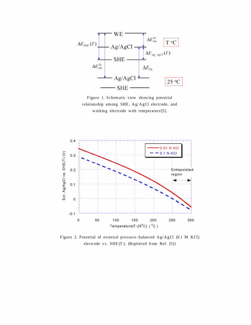
F igure 1. S chem atic view sh ow ing pot ential
r elat ion ship am ong SHE , A g/ A g Cl electrode, and
w orkin g electrode w ith t em perature [5].
F igure 2. P otent ial of ex tern al pressure - balanced A g/ A g Cl (0.1 M KCl)
electrode v s . SHE (T ). (Replot t ed from Ref. [5])

# M at erials Descript ionDim en sion or
Com positionCom m ent
1 Zir conia liquid junct ion 3 m m dia .2 S w agelok Union F it t in g 1/ 4"3 Rulon adapt er4 Heat - shrinkable PT F E5 S S tube 1/ 4" OD 316S S6 Electroly t e 0.1 M KCl7 Glas s w ick8 S w agelok F em ale A dapt er9 Cooler10 A g/ A gCl electrode 1/ 8" Dia .11 S w agelok Union F it t in g 1/ 4"12 Rulon A dapt er
13 Restr ainerAl plate &
threaded rod
Figure 3. Schematic diagram and part list of EREP.
F igure 4. Ex perim ent al apparatu s for EREP t est
in r educing env ironm ent .

Figure 5. Potential of EREP and Pt electrode v s . SCE with temperature variation .