


Bahasa
Halaman
Hukum

Proceedin g s of the Korean Nuclear S ociety Sprin g M eet ingKori, Korea , M ay 2000
A g / A g Cl Re feren c e E le c trode for U s e in P W R Co o lant s
C. B. Bahn, N. Y. Lee, and I. S . Hw ang
Department of Nuclear Engineering , Seoul National Univer sitySan 56- 1, Shinlim- dong , Kw anak- gu, Seoul 151- 742, Korea
S. Jegarl
Korea Electric Power Research Institute103- 16 Munji- dong, Yusong- gu, T aejon 305- 380, Korea
A bs tract
T o p redict the corros ion behav ior of m etals the p otential m eas urem ent is
very imp ortant. our g oal is the develop m ent of electrochem ical corros ion
p otent ial (E CP ) electrodes f or condit ion m onitoring and lif e manag em ent of
s econdary sys tem s. T he ex ternal p ress ure - balanced A g/ A g Cl (0.1 M K Cl)
ref erence electrode was develop ed. T he p otent ial of A g/ A g Cl electrode vs.
S CE at am bient temp erature was calculated and compared with the m easured
values, which showed g ood ag reem ent with calculated values within ±1 m V.
T he A g/ A g Cl electrode p erf ormance tes t in reducing condition at low
temp erature was conducted. T he A g/ A g Cl electrode did not show any
p otent ial drif t within one day of tes t p eriod. T he p otent ial of P t electrode was
m ore p os itive than the p redicted value. T he caus es of the diff erence may be
the uncertainty of hy drog en f ugacity value or temp erature ins tability . B ut
m ore analys is is need. T he hig h temp erature/ hig h p ressure autoclave tes t f or
A g/ A g Cl ref erence electrode in reducing env ironm ent is p lanned.

1. Introduction
T he corrosion of metals in PWR oper ating w ater is the primary causes of
the degradation and fouling of steam gener ator (SG), piping , and turbine. As
the results of research about corrosion of metals in high temperature/ high
pressure (HT / HP ) w ater , we can predict the corrosion behavior of metals as
function of electrochemical corrosion potential (ECP) and pH. Based on these
results , our goal is the development of ECP electrodes for condition monitoring
and life management of secondary systems . Also, electrodes having advanced
performance will be developed.
T he purpose of reference electrode is to measure st able and reproducible
potential to particular electrodes . A major problem in all high temperature
electrochemical studies a aqueous system is choosing a suit able reference
electrode[1]. General description for reference electrodes have been st ated by
Ives and Janz[2]. T he designs and performances of reference electrodes for
high temperature aqueous electrochemical studies are reviewed by
Macdonald[1]. Many kinds of reference electrodes for high temperature system
have been developed. For examples, hydrogen - hydrogen ion electrode is the
most suit able reference electrode for high temperature aqueous work [1]. But in
spite of many advantages, due to the problem of hydrogen fugacity
measurement this electrode is not widely used except for thermodynamic
studies . T he silver - silver halide reference electrodes have been extensively
studied[1]. Ag/ AgCl reference electrode is well- defined, widely used, and very
reliable electrode for high temperature work [3- 9]]. But in high temperature and
reducing environment , provided that the AgCl surface is not well protected,
the decomposition r ate of AgCl is very high [7]. T o solve this problem the
external reference electrode of which AgCl part w as maintained in ambient
temper ature w as developed. T he electrode design with heat - shrinkable
polytetrafluoroethylene (PT FE ) body and a porous zirconia plug for liquid
junction w as est ablished. T he Ag/ AgCl- Sapphire reference electrode by
replacing PT FE with sapphire w as developed and successfully applied to
boiling w ater reactors [8]. And a buffered tungsten reference electrode also w as

developed[10]. T he main feature of this electrode is the potential stability in
high reducing environments .
2 . Ex perim ent al
2.1 T hermodynamic Calculation
When we measure the potential by using Ag/ AgCl reference electrode in
HT/ HP systems , it is needed to transform the measured potential into the
thermodynamically meaningful values . T he potential to standard hydrogen
electrode (SHE ) scale is usually used. T herefore it is needed to know the
potential difference between Ag/ AgCl electrode and SHE at the temperature of
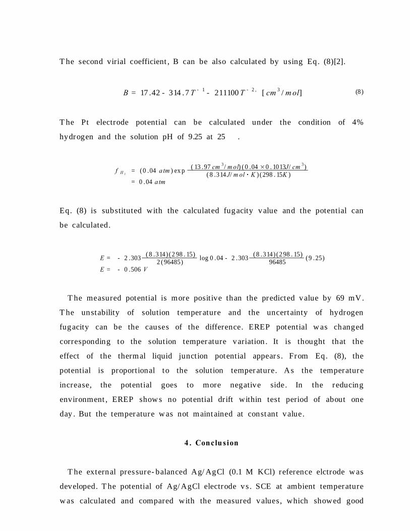
interest . Fig . 1 show s the inter - relationship among Ag/ AgCl electrode, SHE,
and working electrode (WE). T he observed potential by using the external
Ag/ AgCl electrode can be shown as follow s .
(1)E E xobs = E S H E ( T ) - E A g / A g C l( T ) + E T h
where , E E xobs = the m easu red poten tia l of a n work ing e lectrode E - E A g / A g C l(25℃)
E SH E ( T ) = the poten tia l of the work ing e lectrode ag a inst the SH Eu n der the sam e con d itions
E A g / A g C l( T ) = the isotherm a l poten tia l of the A g / A g Cl e lectrode vs . theSHE at the temperatu re of in terest
E T h = the poten tia l of the therm a l ce ll A g - A g C l(25℃) / K C l( M ) /A g - A g Cl( T )
Potentials for the symmetrical thermocell Ag- AgCl(25℃)/ KCl/ Ag- AgCl(T ℃),
ΔET h have been determined by Macdonald et al.[11]. ΔEA g / A g C l (T ) has been
measured by Greeley et al.[12]. By using the measured thermocell potential
and ΔEA g / A g C l (T ) Macdonald has constructed the polynomial equation showing
the relationship between external Ag/ AgCl electrode and ΔE S H E (T ).
(2)E S H E ( T ) = E E x
obs + E A g / A g C l( T ) - E th
E S H E ( T ) = E E xobs + D o + D 1 T + D 2 T 2 + D 3 T 3
where , T = T - 25℃
T able 1 show s the coefficient s of Eq. (2), and Fig . 2 show s ΔE S H E (T ) as the

function of temperature with Eq. (2). In Fig . 2, 'Extr apolated region ' means
that in this region it exceeds the experimental r ange.
2.2 Experimental Apparatus and Procedures
We adopted the external electrode design for Ag/ AgCl reference electrode,
which we named EREP (External Reference Electrode with PT FE ). Fig . 3
show s the schematic diagr am of the developing Ag/ AgCl reference electrode,
which is primarily based on Danielson ' s design [4]. T he heat - shrinkable PT FE
tube has the temperature limit , and the joint with zirconia liquid junction is
loosened and the electrolyte leakage problems is caused. T o mitigate this
problem, it can be possible to insert the zirconia plug part into the Rulon
adaptor and compress the adaptor with high pressure fitting . T he procedures
for making the electrode is briefly described as follow s . 1/ 8" OD Ag rod doped
with AgCl is inserted into the PT FE tube filled with the 0.1 M KCl. For high
pressure application it is compressed with Swag elok fittings and aluminium
retainer is applied to prevent ejection of the silver rod. Ag/ AgCl electrode
should be cooled to maintain the ambient temperature. A glass wick which is
wetted and then inserted into the electrode is also employed.
EREP performance test w as carried out at low temper ature. T he testing
EREP does not have the rulon adaptor . If the EREP passes in the low
temper ature test , it can be tested in high temper ature autoclave. Fig . 4 show s
the schematic diagram of experimental system . T he potential variation of
EREP and Pt electrode vs . saturated calomel electrode (SCE) w as measured.
T he electric heater w as located around the test glass cell and the potential
variation with temper ature also w as measured. 0.01 M H 3BO3 and 0.01 M
LiOH mixed solution w as used. T he test solution pH w as 9.25 at 24.5 ℃ but
by other work, pH is 10.62 at 25 ℃[13]. T he cause of the difference between
measured value and reference value will be analyzed later .
At the aerated condition the potential w as measured. And as the test
solution w as purged with 4% hydrogen and 96% argon continuously , the
potential variation measured. T he gas flow r ate w as maint ained at about 150
cc/ min through the experiment .

3 . Re s ult s and Dis cus s ion
3.1 EREP vs . SCE in the Satur ated KCl Solution
T he potential of EREP vs . SCE in the saturated KCl solution w as measured.
As a result , the measured value w as 46 mV at 25 ℃. T he theoretical potential
difference between Ag/ AgCl electrode vs . SCE w as calculated.
(3)
Hg 2 Cl2 ( s) + 2e - 2Hg ( l) + 2Cl - ( aq)
= o -R T2F
ln a 2C l - , o = + 0 .2676 V
(4)A g Cl( s) + e - = A g ( s) + Cl - ( aq)
= o - R TF
ln a C l - , o = + 0 .222 V
If we know the activity and concentration of chlorine ion, the half- cell
potential can be calculated by Eq. (3) and (4). But it can be possible to
calculate the potential with the mean ionic activity coefficient data. T able 2
show s the solubility of KCl and T able 3 show s the mean ionic activity
coefficient of KCl.
(5)= o - 2 .303 R TF
log m
For SCE @ 25 ℃,
= 0 .2676 - 2 .303(8 .314) (2 98 . 15)
96485log (0 .590 4 .811)
= 0 .24 1 V
For SCE @ 12 ℃,
= 0 .2676 - 2 .303(8 .314) (2 85 . 15)
96485log (0 .5634 4 .27)
= 0 .246 V
For Ag/ AgCl/ Cl- (0.1m ) @ 25 ℃,
= 0 .222 - 2 .303( 8 .314) (2 98 . 15)
96485log ( 0 .768 0 . 10)
= 0 .288 V
For Ag/ AgCl/ Cl- (0.1m ) @ 12 ℃,

= 0 .222 - 2 .303(8 .314)( 2 85 . 15)
96485log (0 .7697 0 . 10)
= 0 .285 V
T he calculated and predicted values are summarized in T able 3. T he
calculated values show good agreement with the predicted values within ±1
mV.
3.2 EREP Performance T est
Fig . 5 show s the potential of EREP and Pt electrode vs . SCE with
temper ature variation . In Fig . 5, 'Ag/ AgCl T emper ature ' means the w all
temper ature of the external Ag/ AgCl electrode part exposed to air . And ' SCE
T emperature ' means the w all temperature of the SCE part exposed to air .
At the aerated condition, the potential of EREP vs . SCE w as +51 mV and
+283 mV for Pt electrode. After the solution w as purged with 4% hydrogen
gas, EREP potential showed no drift of potential and w as maint ained st ably .
T he potential of Pt electrode w as dropped dr astically to the negative direction,
and readily stabilized at - 678 mV vs . SCE . We can calculate the potential of
Pt electrode provided that the fugacity of hydrogen and pH of solution is
known.
(6)
2H + + 2e - H 2 (g ) , E o = 0 .0 V
E = E o - R T2F
lnf H 2
a H +2
= - R T2F
ln f H 2+ R T
Fln a H +
= - 2 .303 R T2F
log f H 2- 2 .303 R T
FpH
Above Eq. (4) the hydrogen fugacity can be calculated by below Eq. (5)[2].
(7)
f H 2= P H 2
eB P H 2
R T
P H 2= P ressure of hydrog en , J/ cm 3
R = Un iversal gas constan t , J/ m ol KT = T emperature , KB = The second vir ial coef f icien t f or hydrogen , cm 3 / m ol
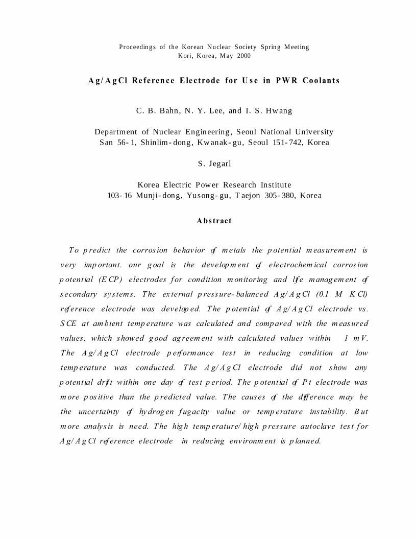
T he second virial coefficient , B can be also calculated by using Eq. (8)[2].
(8)B = 17 .42 - 314 .7 T - 1 - 211100 T - 2 , [ cm 3 / m ol]
T he Pt electrode potential can be calculated under the condition of 4%
hydrogen and the solution pH of 9.25 at 25 ℃.
f H 2= (0 .04 a tm ) ex p
( 13 .97 cm 3 / m ol) ( 0 .04 0 . 1013J/ cm 3)( 8 .314 J/ m ol K ) (298 . 15K )
= 0 .04 a tm
Eq. (8) is substituted with the calculated fugacity value and the potential can
be calculated.
E = - 2 .303( 8 .314) (2 98 . 15)
2 (96485)log 0 .04 - 2 .303
(8 .314) (2 98 . 15)96485
(9 .25)
E = - 0 .506 V
T he measured potential is more positive than the predicted value by 69 mV.
T he unstability of solution temper ature and the uncert ainty of hydrogen
fugacity can be the causes of the difference. EREP potential w as changed
corresponding to the solution temper ature variation . It is thought that the
effect of the thermal liquid junction potential appear s . From Eq. (8), the
potential is proportional to the solution temper ature. As the temperature
increase, the potential goes to more negative side. In the reducing
environment , EREP show s no potential drift within test period of about one
day . But the temperature w as not maint ained at const ant value.
4 . Conclu s ion
T he external pressure- balanced Ag/ AgCl (0.1 M KCl) reference elctrode w as
developed. T he potential of Ag/ AgCl electrode vs . SCE at ambient temperature
w as calculated and compared with the measured values, which showed good

agreement with calculated values within ±1 mV. EREP performance test in
reducing condition at low temperature w as conducted. EREP did not show any
potential drift within one day of test period. T he potential of Pt electrode w as
more positive than the predicted value. T he causes of the difference may be
the uncert ainty of hydrogen fugacity value or temperature inst ability . But more
analysis is need. T he HT / HP autoclave test for EREP in reducing
environment is planned.
A cknow ledg em ent
Financial support of the Korea Electric Power Research Institute (KEPRI) is
acknowledged.
Ref erence s
1. Digby D . M acdonald , "Reference Electrodes for High T em perature A qu eou s Sy st em s - A
Review an d A sses sm ent ", Corrosion , Vol. 34, N o. 3, pp .75- 84, (1978).
2. David J . G. Ives and George J . Janz ed., "Reference Electrodes - T heory and
Practice", Academic Press, 1961.
3. A . K . A graw al and R. W . Staehle, "A Silv er - Silv er Chloride Reference E lectrode for th e
High T em perature and High Pres sure Electroch em istry ", Corrosion , Vol. 33, N o. 11,
pp .218- 219, (1977).
4. M . J . Danielson , "T he Con stru ct ion and T h erm odynam ic P erform an ce of an A g - A gCl
Referen ce E lectrode for U se in High T em perature A queou s Environm ent s Contain in g H 2 and
H 2S ", Corrosion , V ol. 35, N o. 5, pp .200- 204, (1979).
5. Digby D . M acdon ald , Arthur C. S cot t , an d P aul W entr cek , "Ex t ernal Referen ce Electrodes
for U se in High T em perature A queou s Sy st em s", J . Electrochem . S oc., Vol. 126, No. 6,
pp .908- 911, (1979).
6. M . J . Danielson , "A Long - Liv ed Ex tern al A g/ A g Cl Referen ce Electrode for U se in High
T emperature/ P ressure Environm ent s", Corrosion , Vol. 39, N o. 5, pp .202- 203, (1983).
7. "Referen ce Electrode for P W Rs", EPRI NP - 5155, F in al Report , Electr ic P ow er Research
In st itut e, M ay 1987.
8. S . N . Lv ov , H . Gao, and D. D. M acdonald, "A dv an ced F low - T hrou gh Ext ern al
Pres sure - Balan ced Referen ce E lectrode for P ot entiom etr ic and pH Studies in High
T emperature A queou s S olut ion s ", J . Electroan al. Chem ., V ol. 443, 186- 194, (1998).
9. M . E . Indig , "T echnology T ran sfer : A qu eou s E lectrochem ical M easurem ent s Room
T emperature t o 290 ℃", Corrosion , V ol. 46, No. 8, pp .680- 686, (1990).
10. I. S . H w an g , J . O. Out w ater , an d M . J . Driscoll, "A Buffered T ung st en Reference Electrode

for LW R A pplication ", AN S T ran sact ion s , Jun e 1992.
11. Digby D. M acdon ald, Arthur C. S cot t , an d P aul W entr cek , Silv er - Silv er Chloride
T herm ocells an d T herm al Liquid Junct ion P ot entials for P ot as sium Chloride S olution s at
E lev ated T em peratures", J . E lectrochem . S oc ., V ol. 126, No. 9, pp .1618- 1624, (1979).
12. Richard S . Greely , et al., "Electrom otiv e F orce Stu dies in A qu eou s S olut ion s at E lev ated
T em peratures . I. T he St andard P ot ent ial of th e Silv er - Silv er Chloride Electrode", J . Phy s .
Ch em ., V ol. 64, pp .652- 657, (1960).
13. Prob es for Corrosion - Related Variables in LW R Coolant ", EPRI NP - 5372, Int er im Report ,
E lectr ic P ow er Research In st itut e, Au gu st 1987.
14. Paul Cohen ed., "T he ASME Handbook on Water T echnology for T hermal Power
Systems", T he American Society of Mechanical Engineers , 1989, Chapter 8.

T albe 1. T h e coefficient s for the polynomial equ at ion for ΔE S H E (T )- ΔE o b sE x [11].
M (m ole/ kg ) D o 103 D 1 105 D2 108 D3
0.010 0.343185 - 1.005690 0.054081 - 0.549061
0.102 0.286637 - 1.003217 0.017447 - 0.303004
T able 2. S olubility of KCl[14].
T em p. (℃) S olubility (g/ 100g of H2O)
0 28.07
12 31.81
25 35.87
T able 3. M ean Ionic A ct iv ity Coefficient of KCl (aq )[14].
M olality(m ol/ k g )
T em peratureCom m ent
25 ℃ 12 ℃
0.1 0.768 0.7697
4.0 0.578 0.5603
4.27 0.582 0.5634 KCl solubility @ 12℃
4.5 0.585 0.5661
4.811 0.590 0.5705 KCl solubility @ 25℃
5.0 0.593 0.5731
T able 4. P otent ial differ en ce bet w een A g/ A gCl (0.1 M KCl)an d S CE .
T em peratureP ot ent ial (V )
S CE A g/ A g Cl Δφp r e . Δφm e a s .
25 ℃ 0.241 0.288 0.047 0.046
12 ℃ 0.246 0.285 0.039 0.040±0.001
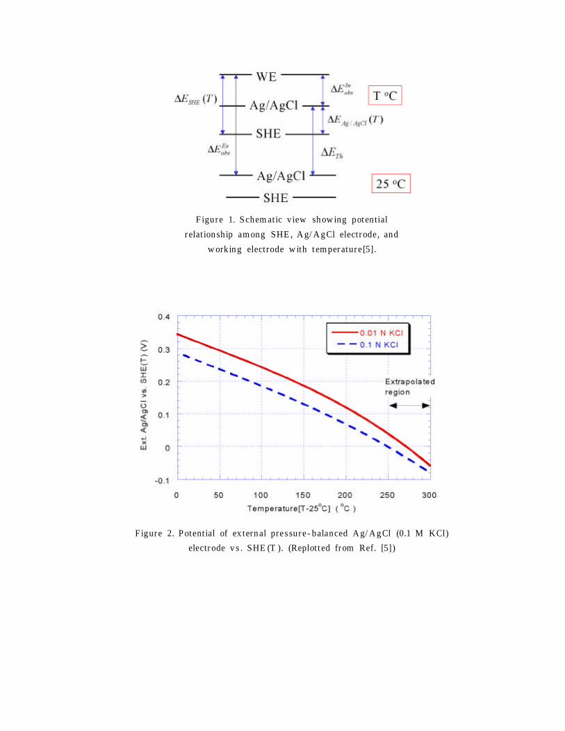
F igure 1. S chem atic view sh ow ing pot ential
r elat ion ship am ong SHE , A g/ A g Cl electrode, and
w orkin g electrode w ith t em perature [5].
F igure 2. P otent ial of ex tern al pressure - balanced A g/ A g Cl (0.1 M KCl)
electrode v s . SHE (T ). (Replot t ed from Ref. [5])

# M at erials Descript ionDim en sion or
Com positionCom m ent
1 Zir conia liquid junct ion 3 m m dia .2 S w agelok Union F it t in g 1/ 4"3 Rulon adapt er4 Heat - shrinkable PT F E5 S S tube 1/ 4" OD 316S S6 Electroly t e 0.1 M KCl7 Glas s w ick8 S w agelok F em ale A dapt er9 Cooler10 A g/ A gCl electrode 1/ 8" Dia .11 S w agelok Union F it t in g 1/ 4"12 Rulon A dapt er
13 Restr ainerAl plate &
threaded rod
Figure 3. Schematic diagram and part list of EREP.
F igure 4. Ex perim ent al apparatu s for EREP t est
in r educing env ironm ent .

Figure 5. Potential of EREP and Pt electrode v s . SCE with temperature variation .
Copyright © 2022 FDOKUMEN

