AF-600 FPTM Fan & Pump Drive - geindustrial.com | ABB US
121
AF-600 FP TM Fan & Pump Drive Design and Installation Guide GE
-
Upload
khangminh22 -
Category
Documents
-
view
1 -
download
0
Transcript of AF-600 FPTM Fan & Pump Drive - geindustrial.com | ABB US
AF-600 FPTM
Fan & Pump Drive Design and Installation Guide
The instructions do not purport to cover all details or variations in equipment nor to provide for every possible contingency to be met in connection with installation, operation or maintenance. Should further information be desired or should particular problems arise which are not covered sufficiently for the purchaser’s purposes, the matter should be referred to the GE company.
AF-600 FP is a trademark of the General Electric Company.
GE41 Woodford AvenuePlainville, CT 06062
www.geelectrical.com/drives
130R0412 *MG14F302*
DET-768b
GE
Safety
WARNINGHIGH VOLTAGEFrequency converters contain high voltage whenconnected to AC mains input power. Installation, start up,and maintenance should be performed by qualifiedpersonnel only. Failure to perform installation, start up, andmaintenance by qualified personnel could result in deathor serious injury.
WARNINGUNINTENDED STARTWhen the frequency converter is connected to AC mains,the motor may start at any time. The frequency converter,motor, and any driven equipment must be in operationalreadiness. Failure to be in operational readiness when thefrequency converter is connected to AC mains could resultin death, serious injury, equipment, or property damage.
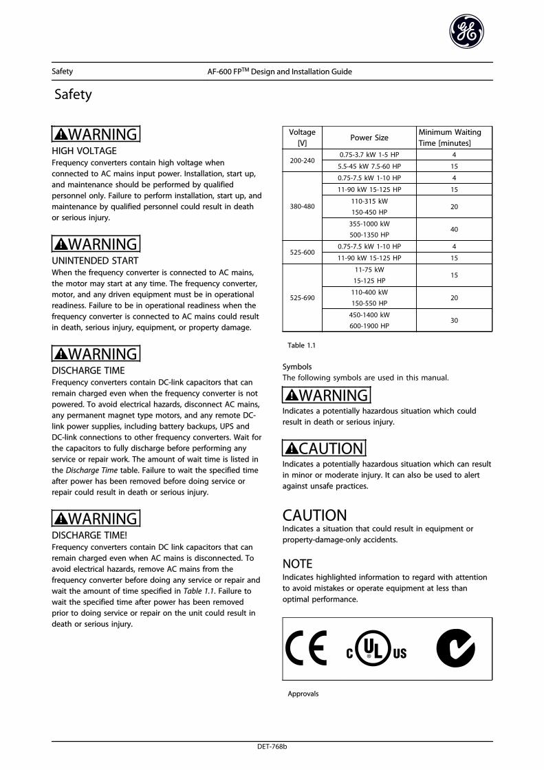
WARNINGDISCHARGE TIMEFrequency converters contain DC-link capacitors that canremain charged even when the frequency converter is notpowered. To avoid electrical hazards, disconnect AC mains,any permanent magnet type motors, and any remote DC-link power supplies, including battery backups, UPS andDC-link connections to other frequency converters. Wait forthe capacitors to fully discharge before performing anyservice or repair work. The amount of wait time is listed inthe Discharge Time table. Failure to wait the specified timeafter power has been removed before doing service orrepair could result in death or serious injury.
WARNINGDISCHARGE TIME!Frequency converters contain DC link capacitors that canremain charged even when AC mains is disconnected. Toavoid electrical hazards, remove AC mains from thefrequency converter before doing any service or repair andwait the amount of time specified in Table 1.1. Failure towait the specified time after power has been removedprior to doing service or repair on the unit could result indeath or serious injury.
Voltage[V]
Power SizeMinimum WaitingTime [minutes]
200-2400.75-3.7 kW 1-5 HP 4
5.5-45 kW 7.5-60 HP 15
380-480
0.75-7.5 kW 1-10 HP 4
11-90 kW 15-125 HP 15
110-315 kW150-450 HP
20
355-1000 kW500-1350 HP
40
525-6000.75-7.5 kW 1-10 HP 4
11-90 kW 15-125 HP 15
525-690
11-75 kW
15-125 HP15
110-400 kW150-550 HP
20
450-1400 kW600-1900 HP
30
Table 1.1
SymbolsThe following symbols are used in this manual.
WARNINGIndicates a potentially hazardous situation which couldresult in death or serious injury.
CAUTIONIndicates a potentially hazardous situation which can resultin minor or moderate injury. It can also be used to alertagainst unsafe practices.
CAUTIONIndicates a situation that could result in equipment orproperty-damage-only accidents.
NOTEIndicates highlighted information to regard with attentionto avoid mistakes or operate equipment at less thanoptimal performance.
Approvals
Safety AF-600 FPTM Design and Installation Guide
DET-768b

Safety AF-600 FPTM Design and Installation Guide
DET-768b
Contents
1 Introduction 5
1.1 Exploded Views 5
1.2 Purpose of the Manual 11
1.3 Additional Resources 11
1.4 Product Overview 11
1.5 Internal Frequency Converter Controller Functions 11
2 Installation 12
2.1 Installation Site Check List 12
2.2 Frequency Converter and Motor Pre-installation Check List 12
2.3 Mechanical Installation 12
2.3.1 Cooling 12
2.3.2 Cooling and Airflow (125 HP and above) 14
2.3.3 Lifting 14
2.3.4 Mounting 15
2.4 Acoustic Noise 15
2.5 Electrical Installation 16
2.5.1 Requirements 17
2.5.2 Earth (Grounding) Requirements 17
2.5.2.1 Leakage Current (>3.5 mA) 18
2.5.2.2 Grounding Using Shielded Cable 18
2.5.3 Motor Connection 18
2.5.4 AC Mains Connection 19
2.5.4.1 External Fan Supply (Unit Sizes 51 and 52) 19
2.5.5 Knock-outs (Unit Sizes 15, 21, 22, 31, and 32) 19
2.5.8 Control Wiring 20
2.5.8.1 Access 20
2.5.8.2 Control Terminal Types 21
2.5.8.3 Wiring to Control Terminals 22
2.5.8.4 Using Screened Control Cables 22
2.5.8.5 Control Terminal Functions 23
2.5.8.6 Terminal 53 and 54 Switches 23
2.5.9 Serial Communication 24
3 Start Up and Functional Testing 25
3.1 Pre-start 25
3.1.1 Safety Inspection 25
3.2 Applying Power 27
3.3 Basic Operational Programming 27
3.4 Auto Tune 27
Contents AF-600 FPTM Design and Installation Guide
DET-768b 1
3.5 Check Motor Rotation 28
3.6 Local-control Test 28
3.7 System Start Up 29
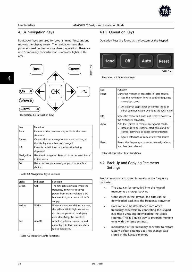
4 User Interface 30
4.1 Keypad 30
4.1.1 Keypad Layout 30
4.1.2 Setting Keypad Display Values 31
4.1.3 Display Menu Keys 31
4.1.4 Navigation Keys 32
4.1.5 Operation Keys 32
4.2 Back Up and Copying Parameter Settings 32
4.2.1 Uploading Data to the Keypad 33
4.2.2 Downloading Data from the Keypad 33
4.3 Restoring Default Settings 33
4.3.1 Recommended Initialisation 33
4.3.2 Manual Initialisation 33
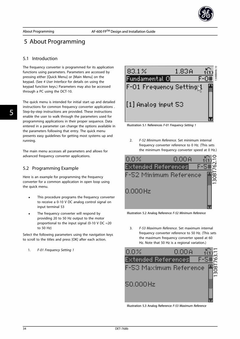
5 About Programming 34
5.1 Introduction 34
5.2 Programming Example 34
5.3 Control Terminal Programming Examples 36
5.4 International/North American Default Parameter Settings 36
5.5 Parameter Menu Structure 37
5.5.1 Quick Menu Structure 37
5.5.2 Main Menu Structure 38
5.6 Remote Programming with DCT-10 42
6 Application Set-Up Examples 43
6.1 Introduction 43
6.2 Application Examples 43
6.3 Advantages 47
6.3.9 Application Examples 50
7 Installation Consideration 57
7.1 General Aspects of EMC 57
7.2 Immunity Requirements 59
7.3 General Aspects of Harmonics Emission 60
7.4 Galvanic Isolation (PELV) 61
7.4.1 PELV - Protective Extra Low Voltage 61
7.5 Derating 62
7.6 Motor Insulation 63
Contents AF-600 FPTM Design and Installation Guide
2 DET-768b
7.7 Motor Bearing Currents 63
8 Status Messages 64
8.1 Status Display 64
8.2 Status Message Definitions 64
9 RS-485 Installation and Set-up 67
9.1 Installation and Set-up 67
9.1 Network Configuration 67
9.1.1 Frequency Converter with Modbus RTU 67
9.1.2 How to Access Parameters 67
9.1.2.1 Parameter Handling 67
9.1.2.2 Storage of Data 67
9.1.2.3 IND 67
9.1.2.4 Text Blocks 67
9.1.2.5 Conversion Factor 67
9.1.2.6 Parameter Values 68
9.2 Drive Control Profile 68
9.2.3 Bus Speed Reference Value 71
10 Warnings and Alarms 72
10.1 System Monitoring 72
10.2 Warning and Alarm Types 72
10.3 Warning and Alarm Displays 72
10.3.1 Warnings/Alarm Messages 73
10.4 Warning and Alarm Definitions 77
11 Basic Troubleshooting 83
11.1 Start Up and Operation 83
12 Terminal and Applicable Wire 86
12.1 Cables 86
13 Specifications 87
13.1 Power-dependent Specifications 87
13.1.1 Power, Currents and Enclosures 87
13.1.2 Dimensions, Unit Size 1x 89
13.1.3 Dimensions, Unit Size 2x 91
13.1.4 Dimensions, Unit Size 3x 93
13.1.5 Dimensions, Unit Size 4xh 95
13.1.6 Dimensions, Unit Size 5x 97
13.1.7 Dimensions, Unit Size 6x 98
13.2 General Technical Data 100
Contents AF-600 FPTM Design and Installation Guide
DET-768b 3

13.3 Fuse Specifications 104
13.3.2 Recommendations 104
13.3.3 CE Compliance 104
13.3.4 Fuse Specifications 105
13.3.5 NEC and UL Compliance 108
Index 114
Contents AF-600 FPTM Design and Installation Guide
4 DET-768b
1 Introduction
1.1 Exploded Views
Illustration 1.1 Exploded View Unit Size 12 and 13
1 Keypad 10 Motor output terminals 96 (U), 97 (V), 98 (W)
2 RS-485 serial bus connector (+68, -69) 11 Relay 1 (01, 02, 03)
3 Analog I/O connector 12 Relay 2 (04, 05, 06)
4 Keypad input plug 13 Brake (-81, +82) and load sharing (-88, +89) terminals
5 Analog switches (A53), (A54) 14 Mains input terminals 91 (L1), 92 (L2), 93 (L3)
6 Cable strain relief/PE ground 15 USB connector
7 Decoupling plate 16 Serial bus terminal switch
8 Grounding clamp (PE) 17 Digital I/O and 24 V power supply
9 Shielded cable grounding clamp and strain relief 18 Control cable cover plate
Table 1.1 Legend to Illustration 1.1
Introduction AF-600 FPTM Design and Installation Guide
DET-768b 5
1 1
Illustration 1.2 Exploded View Unit Sizes 15, 21, 22, 31, and 32
1 Keypad 11 Relay 2 (04, 05, 06)
2 Cover 12 Lifting ring
3 RS-485 serial bus connector 13 Mounting slot
4 Digital I/O and 24 V power supply 14 Grounding clamp (PE)
5 Analog I/O connector 15 Cable strain relief / PE ground
6 Cable strain relief/PE ground 16 Brake terminal (-81, +82)
7 USB connector 17 Load sharing terminal (DC bus) (-88, +89)
8 Serial bus terminal switch 18 Motor output terminals 96 (U), 97 (V), 98 (W)
9 Analog switches (A53), (A54) 19 Mains input terminals 91 (L1), 92 (L2), 93 (L3)
10 Relay 1 (01, 02, 03)
Table 1.2 Legend to Illustration 1.2
Introduction AF-600 FPTM Design and Installation Guide
6 DET-768b
11
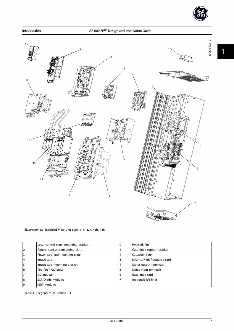
Illustration 1.3 Exploded View Unit Sizes 41h, 42h, 43h, 44h
1 Local control panel mounting bracket 10 Heatsink fan
2 Control card and mounting plate 11 Gate drive support bracket
3 Power card and mounting plate 12 Capacitor bank
4 Inrush card 13 Balance/High frequency card
5 Inrush card mounting bracket 14 Motor output terminals
6 Top fan (IP20 only) 15 Mains input terminals
7 DC inductor 16 Gate drive card
8 SCR/Diode modules 17 (optional) RFI filter
9 IGBT modules
Table 1.3 Legend to Illustration 1.3
Introduction AF-600 FPTM Design and Installation Guide
DET-768b 7
1 1
Illustration 1.4 Compact IP21 (NEMA 1) and IP54 (NEMA 12), UnitSizes 41, 42, 43, 44, 51, 52
1) AUX Relay
01 02 03
04 05 06
2) Temp Switch 6) SMPS Fuse (see 13.3 Fuse Specifications for part number)
106 104 105 7) AUX Fan
3) Line 100 101 102 103
R S T L1 L2 L1 L2
91 92 93 8) Fan Fuse (see 13.3 Fuse Specifications for part number)
L1 L2 L3 9) Mains ground
4) Load sharing 10) Motor
-DC +DC U V W
88 89 96 97 98
T1 T2 T3
Table 1.4 Legend to Illustration 1.4
Introduction AF-600 FPTM Design and Installation Guide
8 DET-768b
11
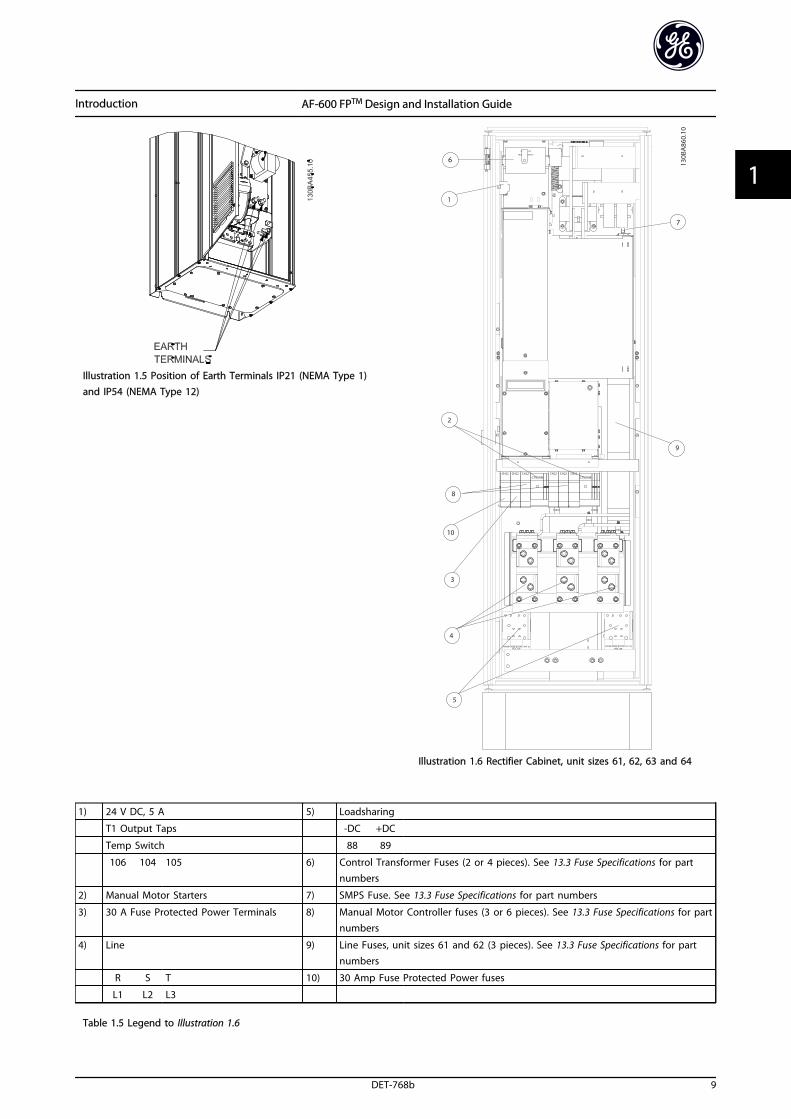
Illustration 1.5 Position of Earth Terminals IP21 (NEMA Type 1)and IP54 (NEMA Type 12)
Illustration 1.6 Rectifier Cabinet, unit sizes 61, 62, 63 and 64
1) 24 V DC, 5 A 5) Loadsharing
T1 Output Taps -DC +DC
Temp Switch 88 89
106 104 105 6) Control Transformer Fuses (2 or 4 pieces). See 13.3 Fuse Specifications for partnumbers
2) Manual Motor Starters 7) SMPS Fuse. See 13.3 Fuse Specifications for part numbers
3) 30 A Fuse Protected Power Terminals 8) Manual Motor Controller fuses (3 or 6 pieces). See 13.3 Fuse Specifications for partnumbers
4) Line 9) Line Fuses, unit sizes 61 and 62 (3 pieces). See 13.3 Fuse Specifications for partnumbers
R S T 10) 30 Amp Fuse Protected Power fuses
L1 L2 L3
Table 1.5 Legend to Illustration 1.6
Introduction AF-600 FPTM Design and Installation Guide
DET-768b 9
1 1
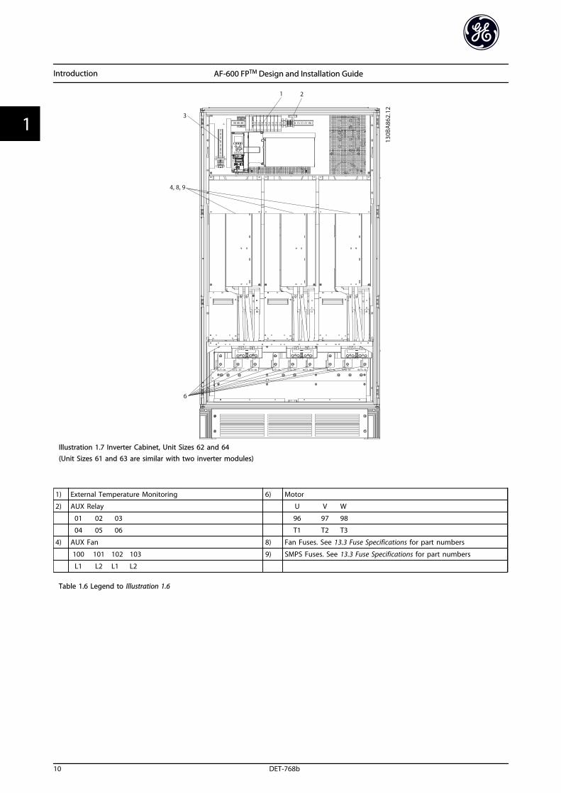
Illustration 1.7 Inverter Cabinet, Unit Sizes 62 and 64(Unit Sizes 61 and 63 are similar with two inverter modules)
1) External Temperature Monitoring 6) Motor
2) AUX Relay U V W
01 02 03 96 97 98
04 05 06 T1 T2 T3
4) AUX Fan 8) Fan Fuses. See 13.3 Fuse Specifications for part numbers
100 101 102 103 9) SMPS Fuses. See 13.3 Fuse Specifications for part numbers
L1 L2 L1 L2
Table 1.6 Legend to Illustration 1.6
Introduction AF-600 FPTM Design and Installation Guide
10 DET-768b
11
1.2 Purpose of the Manual
This manual is intended to provide detailed information forthe installation and start up of the frequency converter. provides requirements for mechanical and electrical instal-lation, including input, motor, control and serialcommunications wiring and control terminal functions. provides detailed procedures for start up, basic operationalprogramming, and functional testing. The remainingchapters provide supplementary details. These detailsinclude user interface, detailed programming, applicationexamples, start-up troubleshooting, and specifications.
1.3 Additional Resources
Other resources are available to understand advancedfrequency converter functions and programming.
• The AF-600 FP Programming Guide, DET-620provides greater detail on working withparameters and many application examples.
• Optional equipment is available that may changesome of the procedures described. Reference theinstructions supplied with those options forspecific requirements. Contact the local GEsupplier or visit the GE website for downloads oradditional information.
1.4 Product Overview
A frequency converter is an electronic motor controllerthat converts AC mains input into a variable AC waveformoutput. The frequency and voltage of the output areregulated to control the motor speed or torque. Thefrequency converter can vary the speed of the motor inresponse to system feedback, such as changingtemperature or pressure for controlling fan, compressor, orpump motors. The frequency converter can also regulatethe motor by responding to remote commands fromexternal controllers.
In addition, the frequency converter monitors the systemand motor status, issues warnings or alarms for faultconditions, starts and stops the motor, optimizes energyefficiency, and offers many more control, monitoring, andefficiency functions. Operation and monitoring functionsare available as status indications to an outside controlsystem or serial communication network.
1.5 Internal Frequency Converter ControllerFunctions
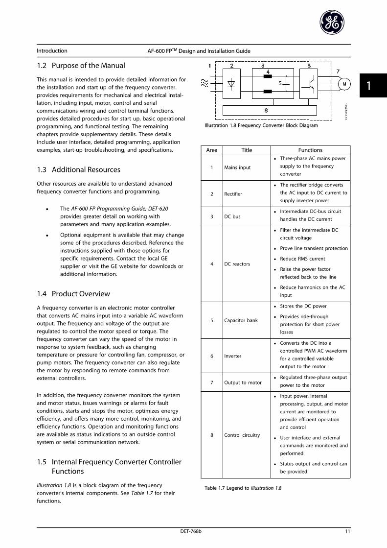
Illustration 1.8 is a block diagram of the frequencyconverter's internal components. See Table 1.7 for theirfunctions.
Illustration 1.8 Frequency Converter Block Diagram
Area Title Functions
1 Mains input
• Three-phase AC mains powersupply to the frequencyconverter
2 Rectifier
• The rectifier bridge convertsthe AC input to DC current tosupply inverter power
3 DC bus• Intermediate DC-bus circuit
handles the DC current
4 DC reactors
• Filter the intermediate DCcircuit voltage
• Prove line transient protection
• Reduce RMS current
• Raise the power factorreflected back to the line
• Reduce harmonics on the ACinput
5 Capacitor bank
• Stores the DC power
• Provides ride-throughprotection for short powerlosses
6 Inverter
• Converts the DC into acontrolled PWM AC waveformfor a controlled variableoutput to the motor
7 Output to motor• Regulated three-phase output
power to the motor
8 Control circuitry
• Input power, internalprocessing, output, and motorcurrent are monitored toprovide efficient operationand control
• User interface and externalcommands are monitored and
performed
• Status output and control canbe provided
Table 1.7 Legend to Illustration 1.8
Introduction AF-600 FPTM Design and Installation Guide
DET-768b 11
1 1
2 Installation
2.1 Installation Site Check List
• The frequency converter relies on the ambient airfor cooling. Observe the limitations on ambientair temperature for optimal operation
• Ensure that the installation location has sufficientsupport strength to mount the frequencyconverter
• Keep the manual, drawings, and diagramsaccessible for detailed installation and operationinstructions. It is important that the manual isavailable for equipment operators.
• Locate equipment as near to the motor aspossible. Keep motor cables as short as possible.Check the motor characteristics for actualtolerances. Do not exceed
• 300 m (1000 ft) for unshielded motorleads
• 150 m (500 ft) for shielded cable.
• Ensure that the ingress protection rating of thefrequency converter is suitable for the installationenvironment. IP55 (NEMA 12) or IP66 (NEMA 4)enclosures may be necessary.
CAUTIONIngress protectionIP54, IP55 and IP66 ratings can only be guaranteed if theunit is properly closed.
• Ensure that all cable glands and unused holes forglands are properly sealed.
• Ensure that the unit cover is properly closed
CAUTIONDevice damage through contaminationDo not leave the frequency converter uncovered.
2.2 Frequency Converter and Motor Pre-installation Check List
• Compare the model number of unit on thenameplate to what was ordered to verify theproper equipment
• Ensure each of the following are rated for samevoltage:
Mains (power)
Frequency converter
Motor
• Ensure that the frequency converter outputcurrent rating is equal to or greater than motorfull load current for peak motor performance
Motor size and frequency converterpower must match for proper overloadprotection
If frequency converter rating is less thanmotor, full motor output cannot beachieved
2.3 Mechanical Installation
2.3.1 Cooling
• To provide cooling airflow, mount the unit to asolid flat surface or to the optional back plate(see 2.3.4 Mounting)
• Top and bottom clearance for air cooling must beprovided. Generally, 100-225 mm (4-10 in) isrequired. See Illustration 2.1 for clearancerequirements
• Improper mounting can result in over heatingand reduced performance
• Derating for temperatures starting between 40 °C(104 °F) and 50 °C (122 °F) and elevation 1000 m(3300 ft) above sea level must be considered.
Installation AF-600 FPTM Design and Installation Guide
12 DET-768b
22
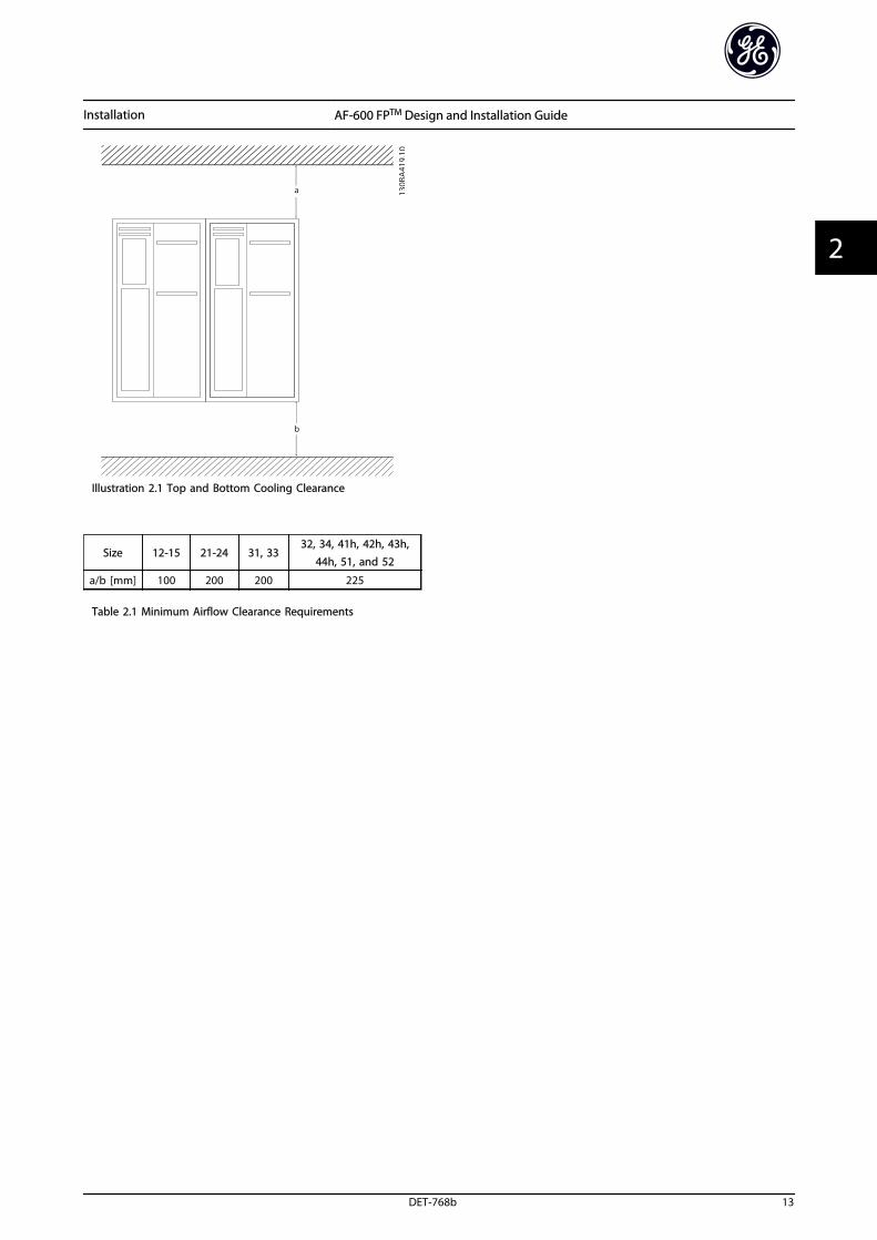
Illustration 2.1 Top and Bottom Cooling Clearance
Size 12-15 21-24 31, 3332, 34, 41h, 42h, 43h,
44h, 51, and 52
a/b [mm] 100 200 200 225
Table 2.1 Minimum Airflow Clearance Requirements
Installation AF-600 FPTM Design and Installation Guide
DET-768b 13
2 2
2.3.2 Cooling and Airflow (125 HP and above)
CoolingCooling can be obtained in different ways, by using the cooling ducts in the bottom and the top of the unit, by taking airin and out the back of the unit or by combining the cooling possibilities.
Duct coolingA back-channel cooling kit is available to direct the heatsink cooling air out of the panel when an IP20/chassis frequencyconverters is installed in a Rittal enclosure. Use of this kit reduces the heat in the panel and smaller door fans can bespecified on the enclosure.
Back coolingThe back channel cooling air can be ventilated out of the room so that the heat from the back channel is not dissipatedinto the control room. A door fan(s) is required on the enclosure to remove the heat not contained in the backchannel ofthe frequency converters and any additional losses generated by other components inside the enclosure. The total requiredair flow must be calculated so that the appropriate fans can be selected.
AirflowThe necessary airflow over the heat sink must be secured. The flow rate is in Table 2.2.
Protection Unit size Door fan(s)/Top fan Heatsink fan(s)
IP20/Chassis43h 102 m3/hr (60 CFM) 420 m3/hr (250 CFM)
44h 204 m3/hr (120 CFM) 840 m3/hr (500 CFM)
IP00/Chassis 51 340 m3/h (200 cfm) 1445 m3/h (850 cfm)
IP21/Nema 1
41h 102 m3/hr (60 CFM) 420 m3/hr (250 CFM)
42h 204 m3/hr (120 CFM) 840 m3/hr (500 CFM)
52 255 m3/h (150 cfm) 1445 m3/h (650 cfm)
61, 62, 63, 64 700 m3/h (412 cfm)* 985 m3/h (580 cfm)*
IP54/Nema 12
41h 102 m3/hr (60 CFM) 420 m3/hr (250 CFM)
42h 204 m3/hr (120 CFM) 840 m3/hr (500 CFM)
52 255 m33/h (150 cfm) 1445 m3/h (650 cfm)
61, 62, 63, 64 525 m3/h (309 cfm)* 985 m3/h (580 cfm)*
Table 2.2 Heatsink Airflow
* Airflow per fan. Unit Sizes 6X contain multiple fans.
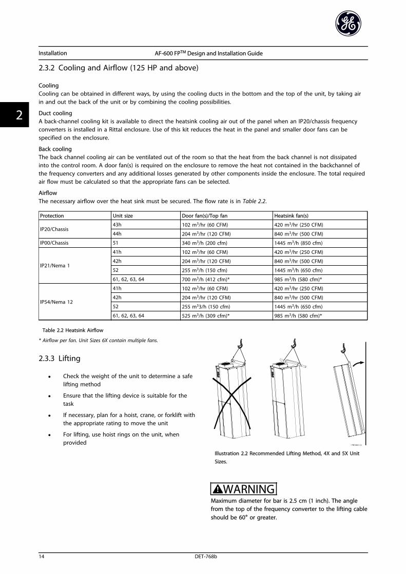
2.3.3 Lifting
• Check the weight of the unit to determine a safelifting method
• Ensure that the lifting device is suitable for thetask
• If necessary, plan for a hoist, crane, or forklift withthe appropriate rating to move the unit
• For lifting, use hoist rings on the unit, whenprovided
Illustration 2.2 Recommended Lifting Method, 4X and 5X UnitSizes.
WARNINGMaximum diameter for bar is 2.5 cm (1 inch). The anglefrom the top of the frequency converter to the lifting cableshould be 60° or greater.
Installation AF-600 FPTM Design and Installation Guide
14 DET-768b
22
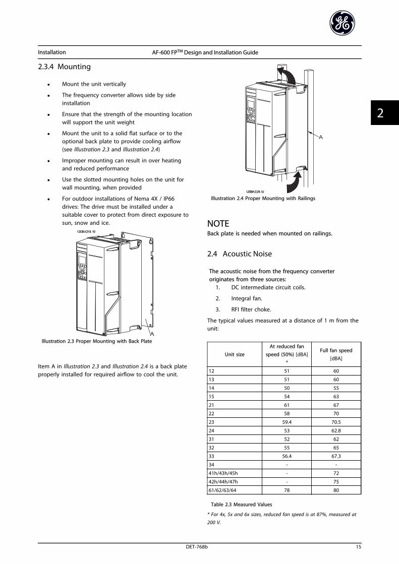
2.3.4 Mounting
• Mount the unit vertically
• The frequency converter allows side by sideinstallation
• Ensure that the strength of the mounting locationwill support the unit weight
• Mount the unit to a solid flat surface or to theoptional back plate to provide cooling airflow(see Illustration 2.3 and Illustration 2.4)
• Improper mounting can result in over heatingand reduced performance
• Use the slotted mounting holes on the unit forwall mounting, when provided
• For outdoor installations of Nema 4X / IP66drives: The drive must be installed under asuitable cover to protect from direct exposure tosun, snow and ice.
Illustration 2.3 Proper Mounting with Back Plate
Item A in Illustration 2.3 and Illustration 2.4 is a back plateproperly installed for required airflow to cool the unit.
Illustration 2.4 Proper Mounting with Railings
NOTEBack plate is needed when mounted on railings.
2.4 Acoustic Noise
The acoustic noise from the frequency converteroriginates from three sources:
1. DC intermediate circuit coils.
2. Integral fan.
3. RFI filter choke.
The typical values measured at a distance of 1 m from theunit:
Unit sizeAt reduced fan
speed (50%) [dBA]*
Full fan speed[dBA]
12 51 60
13 51 60
14 50 55
15 54 63
21 61 67
22 58 70
23 59.4 70.5
24 53 62.8
31 52 62
32 55 65
33 56.4 67.3
34 - -
41h/43h/45h - 72
42h/44h/47h - 75
61/62/63/64 78 80
Table 2.3 Measured Values
* For 4x, 5x and 6x sizes, reduced fan speed is at 87%, measured at200 V.
Installation AF-600 FPTM Design and Installation Guide
DET-768b 15
2 2
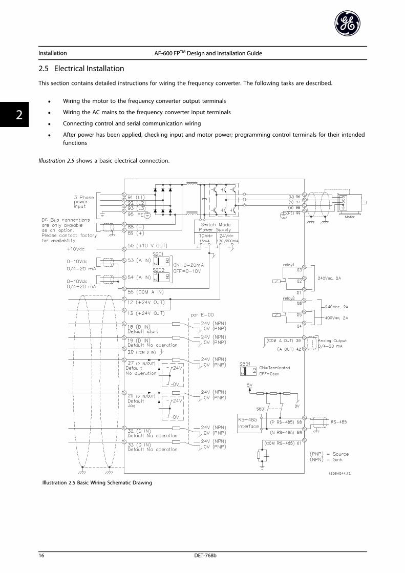
2.5 Electrical Installation
This section contains detailed instructions for wiring the frequency converter. The following tasks are described.
• Wiring the motor to the frequency converter output terminals
• Wiring the AC mains to the frequency converter input terminals
• Connecting control and serial communication wiring
• After power has been applied, checking input and motor power; programming control terminals for their intendedfunctions
Illustration 2.5 shows a basic electrical connection.
Illustration 2.5 Basic Wiring Schematic Drawing
Installation AF-600 FPTM Design and Installation Guide
16 DET-768b
22
2.5.1 Requirements
WARNINGEQUIPMENT HAZARD!Rotating shafts and electrical equipment can be hazardous.All electrical work must conform to national and localelectrical codes. It is strongly recommended that instal-lation, start up, and maintenance be performed only bytrained and qualified personnel. Failure to follow theseguidelines could result in death or serious injury.
CAUTIONWIRING ISOLATION!Run input power, motor wiring and control wiring in threeseparate metallic conduits or use separated shielded cablefor high frequency noise isolation. Failure to isolate power,motor and control wiring could result in less thanoptimum frequency converter and associated equipmentperformance.
For your safety, comply with the following requirements.
• Electronic controls equipment is connected tohazardous mains voltage. Extreme care should betaken to protect against electrical hazards whenapplying power to the unit.
• Run motor cables from multiple frequencyconverters separately. Induced voltage fromoutput motor cables run together can chargeequipment capacitors even with the equipmentturned off and locked out.
Overload and Equipment Protection
• An electronically activated function within thefrequency converter provides overload protectionfor the motor. The overload calculates the level ofincrease to activate timing for the trip (controlleroutput stop) function. The higher the currentdraw, the quicker the trip response. The overloadprovides Class 20 motor protection. See 10 Warnings and Alarms for details on the tripfunction.
• Because the motor wiring carries high frequencycurrent, it is important that wiring for mains,motor power, and control are run separately. Usemetallic conduit or separated shielded wire.Failure to isolate power, motor, and controlwiring could result in less than optimumequipment performance.
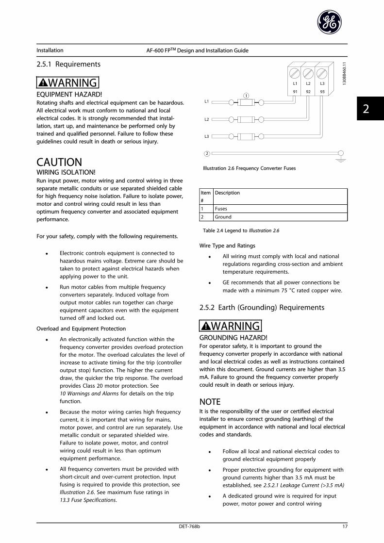
• All frequency converters must be provided withshort-circuit and over-current protection. Inputfusing is required to provide this protection, seeIllustration 2.6. See maximum fuse ratings in 13.3 Fuse Specifications.
Illustration 2.6 Frequency Converter Fuses
Item#
Description
1 Fuses
2 Ground
Table 2.4 Legend to Illustration 2.6
Wire Type and Ratings
• All wiring must comply with local and nationalregulations regarding cross-section and ambienttemperature requirements.
• GE recommends that all power connections bemade with a minimum 75 °C rated copper wire.
2.5.2 Earth (Grounding) Requirements
WARNINGGROUNDING HAZARD!For operator safety, it is important to ground thefrequency converter properly in accordance with nationaland local electrical codes as well as instructions containedwithin this document. Ground currents are higher than 3.5mA. Failure to ground the frequency converter properlycould result in death or serious injury.
NOTEIt is the responsibility of the user or certified electricalinstaller to ensure correct grounding (earthing) of theequipment in accordance with national and local electricalcodes and standards.
• Follow all local and national electrical codes toground electrical equipment properly
• Proper protective grounding for equipment withground currents higher than 3.5 mA must beestablished, see 2.5.2.1 Leakage Current (>3.5 mA)
• A dedicated ground wire is required for inputpower, motor power and control wiring
Installation AF-600 FPTM Design and Installation Guide
DET-768b 17
2 2
• Do not ground one frequency converter toanother in a “daisy chain” fashion
• Using high-strand wire to reduce electrical noiseis recommended
• Follow motor manufacturer wiring requirements
• Use the clamps provided with on the equipmentfor proper ground connections to obtain a lowHF impedance
• Keep the ground wire connections as short aspossible to reduce the conductor impedance
2.5.2.1 Leakage Current (>3.5 mA)
Follow national and local codes regarding protectiveearthing of equipment with a leakage current > 3.5 mA.Frequency converter technology implies high frequencyswitching at high power. This will generate a leakagecurrent in the earth connection. A fault current in thefrequency converter at the output power terminals mightcontain a DC component which can charge the filtercapacitors and cause a transient earth current. The earthleakage current depends on various system configurationsincluding RFI filtering, screened motor cables, andfrequency converter power.
EN/IEC61800-5-1 (Power Drive System Product Standard)requires special care if the leakage current exceeds 3.5 mA.Earth grounding must be reinforced in one of thefollowing ways:
• Earth ground wire of at least 10 mm2
• Two separate earth ground wires both complyingwith the dimensioning rules
See EN 60364-5-54 § 543.7 for further information.
Using RCDsWhere residual current devices (RCDs), also known as earthleakage circuit breakers (ELCBs), are used, comply with thefollowing:
Use RCDs of type B only which are capable ofdetecting AC and DC currents
Use RCDs with an inrush delay to prevent faultsdue to transient earth currents
Dimension RCDs according to the system configu-ration and environmental considerations
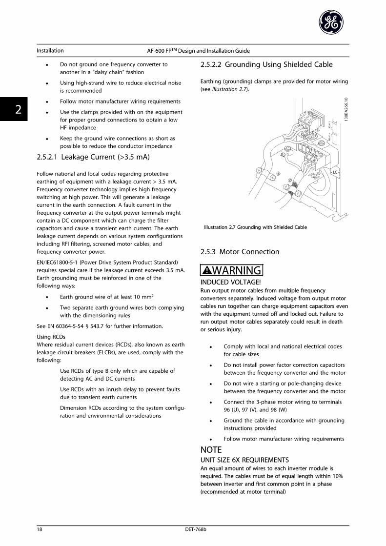
2.5.2.2 Grounding Using Shielded Cable
Earthing (grounding) clamps are provided for motor wiring(see Illustration 2.7).
Illustration 2.7 Grounding with Shielded Cable
2.5.3 Motor Connection
WARNINGINDUCED VOLTAGE!Run output motor cables from multiple frequencyconverters separately. Induced voltage from output motorcables run together can charge equipment capacitors evenwith the equipment turned off and locked out. Failure torun output motor cables separately could result in deathor serious injury.
• Comply with local and national electrical codesfor cable sizes
• Do not install power factor correction capacitorsbetween the frequency converter and the motor
• Do not wire a starting or pole-changing devicebetween the frequency converter and the motor
• Connect the 3-phase motor wiring to terminals96 (U), 97 (V), and 98 (W)
• Ground the cable in accordance with groundinginstructions provided
• Follow motor manufacturer wiring requirements
NOTEUNIT SIZE 6X REQUIREMENTSAn equal amount of wires to each inverter module isrequired. The cables must be of equal length within 10%between inverter and first common point in a phase(recommended at motor terminal)
Installation AF-600 FPTM Design and Installation Guide
18 DET-768b
22
2.5.4 AC Mains Connection
• Size wiring based upon the input current of thefrequency converter.
• Comply with local and national electrical codesfor cable sizes.
• Connect 3-phase AC input power wiring toterminals L1, L2, and L3.
• Connect 1-phase AC input power wiring toterminals L1 and L2. Only on single-phase rateddrives.
• Input power will be connected to the mains inputterminals.
• Ground the cable in accordance with groundinginstructions provided in 2.5.2 Earth (Grounding)Requirements
• All frequency converters may be used with anisolated input source as well as with groundreference power lines. When supplied from anisolated mains source (IT mains or floating delta)or TT/TN-S mains with a grounded leg (groundeddelta), set SP-50 RFI Filter to OFF. When off, theinternal RFI filtercapacitors between the chassisand the intermediate circuit are isolated to avoiddamage to the intermediate circuit and to reduceearth capacity currents in accordance with IEC61800-3.
2.5.4.1 External Fan Supply (Unit Sizes 51and 52)
In case the frequency converter is supplied by DC or if thefan must run independently of the power supply, anexternal power supply can be applied. The connection ismade on the power card.
Terminal No. Function
100, 101
102, 103
Auxiliary supply S, T
Internal supply S, T
Table 2.5
The connector located on the power card provides theconnection of line voltage for the cooling fans. The fansare connected from factory to be supplied form a commonAC line (jumpers between 100-102 and 101-103). If externalsupply is needed, the jumpers are removed and the supplyis connected to terminals 100 and 101. A 5 Amp fuseshould be used for protection. In UL applications thisshould be LittleFuse KLK-5 or equivalent.
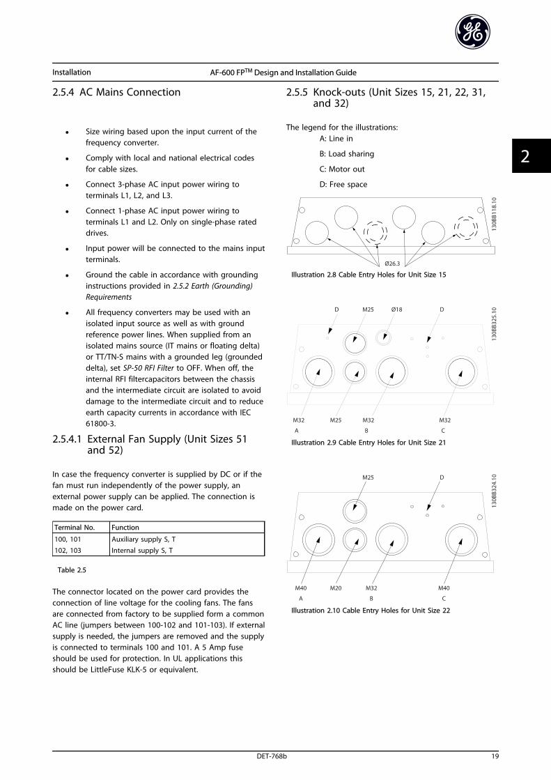
2.5.5 Knock-outs (Unit Sizes 15, 21, 22, 31,and 32)
The legend for the illustrations:A: Line in
B: Load sharing
C: Motor out
D: Free space
Illustration 2.8 Cable Entry Holes for Unit Size 15
Illustration 2.9 Cable Entry Holes for Unit Size 21
Illustration 2.10 Cable Entry Holes for Unit Size 22
Installation AF-600 FPTM Design and Installation Guide
DET-768b 19
2 2

Illustration 2.11 Cable Entry Holes for Unit Size 31
Illustration 2.12 Cable Entry Holes for Unit Size 32
2.5.6 Removal of Knockouts for ExtraCables
1. Remove cable entry from the frequency converter(Avoiding foreign parts falling into the frequencyconverter when removing knockouts)
2. Cable entry has to be supported around theknockout you intend to remove.
3. The knockout can now be removed with a strongmandrel and a hammer.
4. Remove burrs from the hole.
5. Mount Cable entry on frequency converter.
2.5.7 Gland/Conduit Entry (Unit Sizes 41h,42h, and 51)
Cables are connected through the gland plate from thebottom. Remove the plate and plan where to place theentry for the glands or conduits. Prepare holes in themarked area on the drawing.
NOTEThe gland plate must be fitted to the frequency converterto ensure the specified protection degree, as well asensuring proper cooling of the unit. If the gland plate isnot mounted, the frequency converter may trip on Alarm69, Pwr. Card Temp
2.5.8 Control Wiring
• Isolate control wiring from high powercomponents in the frequency converter.
• If the frequency converter is connected to athermistor, for PELV isolation, optional thermistorcontrol wiring must be reinforced/doubleinsulated. A 24 V DC supply voltage isrecommended.
2.5.8.1 Access
• Remove access cover plate with a screw driver.See Illustration 2.13.
• Or remove front cover by loosening attachingscrews. See Illustration 2.14.
Illustration 2.13 Control Wiring Access for IP20/Open ChassisEnclosures
Installation AF-600 FPTM Design and Installation Guide
20 DET-768b
22
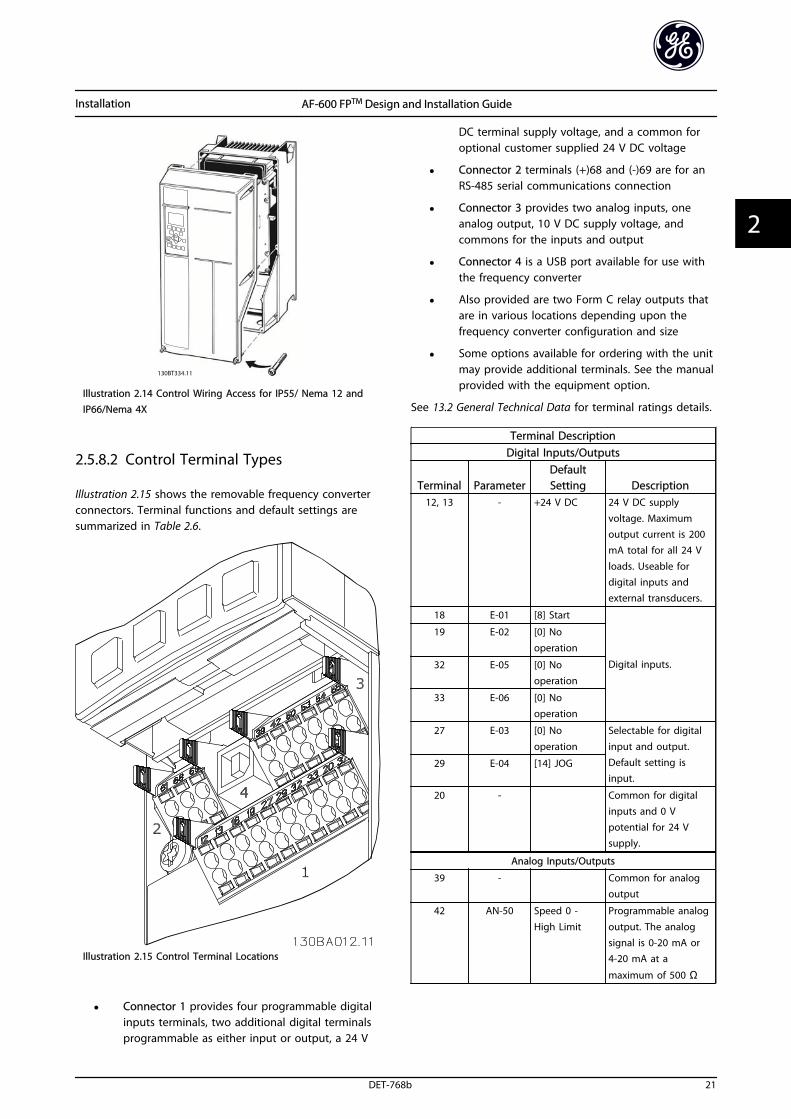
Illustration 2.14 Control Wiring Access for IP55/ Nema 12 andIP66/Nema 4X
2.5.8.2 Control Terminal Types
Illustration 2.15 shows the removable frequency converterconnectors. Terminal functions and default settings aresummarized in Table 2.6.
Illustration 2.15 Control Terminal Locations
• Connector 1 provides four programmable digitalinputs terminals, two additional digital terminalsprogrammable as either input or output, a 24 V
DC terminal supply voltage, and a common foroptional customer supplied 24 V DC voltage
• Connector 2 terminals (+)68 and (-)69 are for anRS-485 serial communications connection
• Connector 3 provides two analog inputs, oneanalog output, 10 V DC supply voltage, andcommons for the inputs and output
• Connector 4 is a USB port available for use withthe frequency converter
• Also provided are two Form C relay outputs thatare in various locations depending upon thefrequency converter configuration and size
• Some options available for ordering with the unitmay provide additional terminals. See the manualprovided with the equipment option.
See 13.2 General Technical Data for terminal ratings details.
Terminal DescriptionDigital Inputs/Outputs
Terminal ParameterDefaultSetting Description
12, 13 - +24 V DC 24 V DC supply
voltage. Maximumoutput current is 200mA total for all 24 V
loads. Useable fordigital inputs andexternal transducers.
18 E-01 [8] Start
Digital inputs.
19 E-02 [0] Nooperation
32 E-05 [0] Nooperation
33 E-06 [0] Nooperation
27 E-03 [0] No
operation
Selectable for digital
input and output.Default setting isinput.
29 E-04 [14] JOG
20 - Common for digitalinputs and 0 Vpotential for 24 Vsupply.
Analog Inputs/Outputs
39 -
Common for analogoutput
42 AN-50 Speed 0 -
High Limit
Programmable analog
output. The analogsignal is 0-20 mA or4-20 mA at a
maximum of 500 Ω
Installation AF-600 FPTM Design and Installation Guide
DET-768b 21
2 2
Terminal DescriptionDigital Inputs/Outputs
Terminal ParameterDefaultSetting Description
50 - +10 V DC 10 V DC analogsupply voltage. 15 mAmaximum commonlyused for potenti-ometer or thermistor.
53 AN-1# Reference Analog input.Selectable for voltageor current. SwitchesA53 and A54 selectmA or V.
54 AN-2# Feedback
55 -
Common for analoginput
Serial Communication
61 -
Integrated RC-Filter
for cable screen. ONLYfor connecting thescreen when experi-
encing EMC problems.
68 (+) O-3# RS-485 Interface. A
control card switch isprovided fortermination resistance.
69 (-) O-3#
Relays
01, 02, 03 E-24 [0] [0] Alarm Form C relay output.Usable for AC or DCvoltage and resistiveor inductive loads.
04, 05, 06 E-24 [1] [0] Running
Table 2.6 Terminal Description
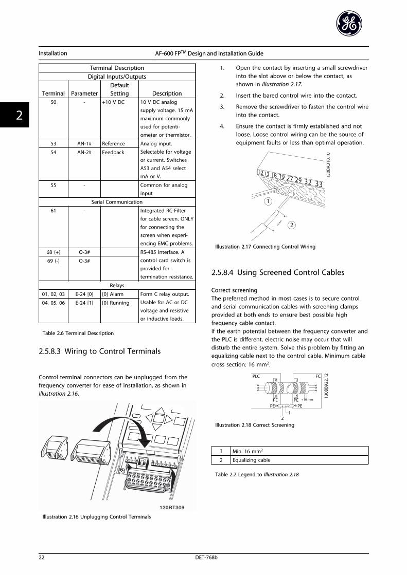
2.5.8.3 Wiring to Control Terminals
Control terminal connectors can be unplugged from thefrequency converter for ease of installation, as shown inIllustration 2.16.
Illustration 2.16 Unplugging Control Terminals
1. Open the contact by inserting a small screwdriverinto the slot above or below the contact, asshown in Illustration 2.17.
2. Insert the bared control wire into the contact.
3. Remove the screwdriver to fasten the control wireinto the contact.
4. Ensure the contact is firmly established and notloose. Loose control wiring can be the source ofequipment faults or less than optimal operation.
Illustration 2.17 Connecting Control Wiring
2.5.8.4 Using Screened Control Cables
Correct screeningThe preferred method in most cases is to secure controland serial communication cables with screening clampsprovided at both ends to ensure best possible highfrequency cable contact.If the earth potential between the frequency converter andthe PLC is different, electric noise may occur that willdisturb the entire system. Solve this problem by fitting anequalizing cable next to the control cable. Minimum cablecross section: 16 mm2.
Illustration 2.18 Correct Screening
1 Min. 16 mm2
2 Equalizing cable
Table 2.7 Legend to Illustration 2.18
Installation AF-600 FPTM Design and Installation Guide
22 DET-768b
22
50/60 Hz ground loopsWith very long control cables, ground loops may occur. Toeliminate ground loops, connect one end of the screen-to-ground with a 100 nF capacitor (keeping leads short).
Illustration 2.19 50/60 Hz Ground Loops
Avoid EMC noise on serial communicationThis terminal is connected to earth via an internal RC link.Use twisted-pair cables to reduce interference betweenconductors. The recommended method is shown inIllustration 2.20:
Illustration 2.20 Twisted-pair Cables
1 Min. 16 mm2
2 Equalizing cable
Table 2.8 Legend to Illustration 2.20
Alternatively, the connection to terminal 61 can beomitted:
Illustration 2.21 Twisted-pair Cables without Terminal 61
1 Min. 16 mm2
2 Equalizing cable
Table 2.9 Legend to Illustration 2.21
2.5.8.5 Control Terminal Functions
Frequency converter functions are commanded byreceiving control input signals.
• Each terminal must be programmed for thefunction it will be supporting in the parametersassociated with that terminal. See Table 2.6 forterminals and associated parameters.
• It is important to confirm that the controlterminal is programmed for the correct function.See 4 User Interface for details on accessingparameters and 5 About Programming for detailson programming.
• The default terminal programming is intended toinitiate frequency converter functioning in atypical operational mode.
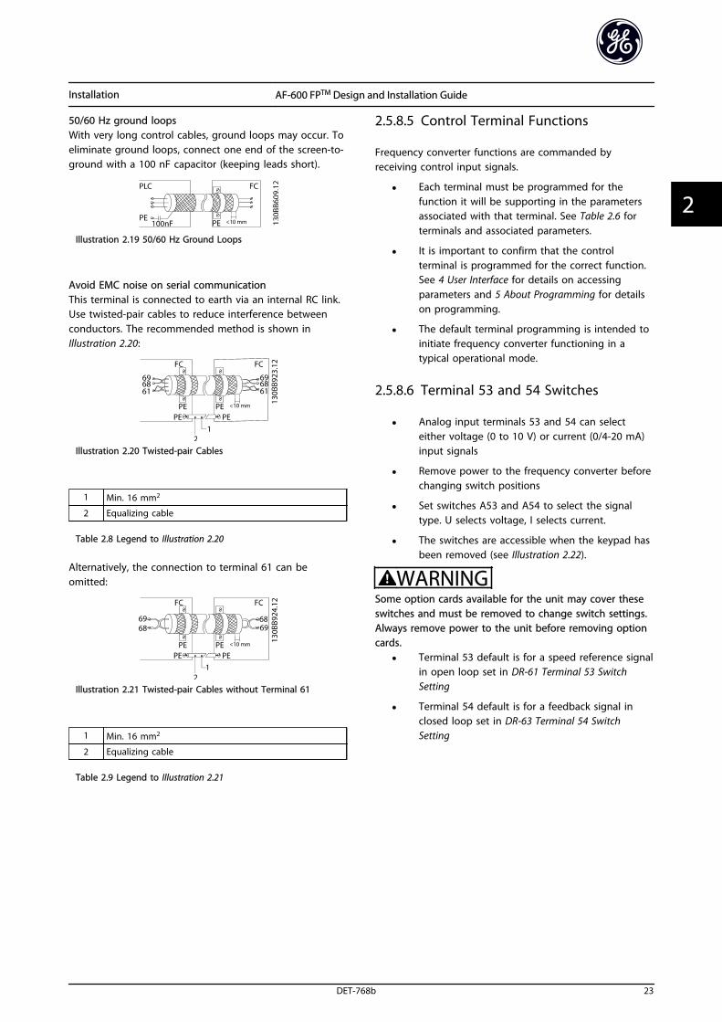
2.5.8.6 Terminal 53 and 54 Switches
• Analog input terminals 53 and 54 can selecteither voltage (0 to 10 V) or current (0/4-20 mA)input signals
• Remove power to the frequency converter beforechanging switch positions
• Set switches A53 and A54 to select the signaltype. U selects voltage, I selects current.
• The switches are accessible when the keypad hasbeen removed (see Illustration 2.22).
WARNINGSome option cards available for the unit may cover theseswitches and must be removed to change switch settings.Always remove power to the unit before removing optioncards.
• Terminal 53 default is for a speed reference signalin open loop set in DR-61 Terminal 53 SwitchSetting
• Terminal 54 default is for a feedback signal inclosed loop set in DR-63 Terminal 54 SwitchSetting
Installation AF-600 FPTM Design and Installation Guide
DET-768b 23
2 2
130BT310.10
Illustration 2.22 Location of Terminals 53 and 54 Switches
2.5.9 Serial Communication
RS-485 is a two-wire bus interface compatible with multi-drop network topology, i.e. nodes can be connected as abus, or via drop cables from a common trunk line. A totalof 32 nodes can be connected to one network segment.Repeaters divide network segments. Note that eachrepeater functions as a node within the segment in whichit is installed. Each node connected within a given networkmust have a unique node address, across all segments.Terminate each segment at both ends, using either thetermination switch (S801) of the frequency converters or abiased termination resistor network. Always use screenedtwisted pair (STP) cable for bus cabling, and always followgood common installation practice.Low-impedance earth (ground) connection of the screen atevery node is important, including at high frequencies.Thus, connect a large surface of the screen to earth(ground), for example with a cable clamp or a conductivecable gland. It may be necessary to apply potential-equalizing cables to maintain the same earth (ground)potential throughout the network. Particularly in instal-lations with long cables.To prevent impedance mismatch, always use the sametype of cable throughout the entire network. Whenconnecting a motor to the frequency converter, always usescreened motor cable.
Cable Screened twisted pair (STP)
Impedance 120 ΩMax. cablelength [m]
1200 (including drop lines)500 station-to-station
Table 2.10 Cable Information
Installation AF-600 FPTM Design and Installation Guide
24 DET-768b
22
3 Start Up and Functional Testing
3.1 Pre-start
3.1.1 Safety Inspection
WARNINGHIGH VOLTAGE!If input and output connections have been connected improperly, there is potential for high voltage on these terminals. Ifpower leads for multiple motors are improperly run in same conduit, there is potential for leakage current to chargecapacitors within the frequency converter, even when disconnected from mains input. For initial start up, make noassumptions about power components. Follow pre-start procedures. Failure to follow pre-start procedures could result inpersonal injury or damage to equipment.
1. Input power to the unit must be OFF and locked out. Do not rely on the frequency converter disconnect switchesfor input power isolation.
2. Verify that there is no voltage on input terminals L1 (91), L2 (92), and L3 (93), phase-to-phase and phase-to-ground,
3. Verify that there is no voltage on output terminals 96 (U), 97 (V), and 98 (W), phase-to-phase and phase-to-ground.
4. Confirm continuity of the motor by measuring ohm values on U-V (96-97), V-W (97-98), and W-U (98-96).
5. Check for proper grounding of the frequency converter as well as the motor.
6. Inspect the frequency converter for loose connections on terminals.
7. Record the following motor-nameplate data: power, voltage, frequency, full load current, and nominal speed. Thesevalues are needed to program motor nameplate data later.
8. Confirm that the supply voltage matches voltage of frequency converter and motor.
CAUTIONBefore applying power to the unit, inspect the entire installation as detailed in Table 3.1. Check mark those items whencompleted.
Inspect for Description Auxiliary equipment • Look for auxiliary equipment, switches, disconnects, or input fuses/circuit breakers that may reside
on the input power side of the frequency converter or output side to the motor. Ensure that theyare ready for full speed operation.
• Check function and installation of any sensors used for feedback to the frequency converter
• Remove power factor correction caps on motor(s), if present
Cable routing • Ensure that input power, motor wiring and control wiring are separated or in three separate metallicconduits for high frequency noise isolation
Control wiring • Check for broken or damaged wires and loose connections
• Check that control wiring is isolated from power and motor wiring for noise immunity
• Check the voltage source of the signals, if necessary
• The use of shielded cable or twisted pair is recommended. Ensure that the shield is terminatedcorrectly
Cooling clearance • Measure that top and bottom clearance is adequate to ensure proper air flow for cooling
EMC considerations • Check for proper installation regarding electromagnetic compatibility
Start Up and Functional Tes... AF-600 FPTM Design and Installation Guide
DET-768b 25
3 3
Inspect for Description Environmental consider-ations
• See equipment label for the maximum ambient operating temperature limits
• Humidity levels must be 5-95% non-condensing
Fusing and circuitbreakers
• Check for proper fusing or circuit breakers
• Check that all fuses are inserted firmly and in operational condition and that all circuit breakers arein the open position
Earthing (Grounding) • The unit requires an earth wire (ground wire) from its chassis to the building earth (ground)
• Check for good earth connections (ground connections) that are tight and free of oxidation
• Earthing (grounding) to conduit or mounting the back panel to a metal surface is not a suitableearth (ground)
Input and output powerwiring
• Check for loose connections
• Check that motor and mains are in separate conduit or separated screened cables
Panel interior • Inspect that the unit interior is free of dirt, metal chips, moisture, and corrosion
Switches • Ensure that all switch and disconnect settings are in the proper positions
Vibration • Check that the unit is mounted solidly or that shock mounts are used, as necessary
• Check for an unusual amount of vibration
Table 3.1 Start Up Check List
Start Up and Functional Tes... AF-600 FPTM Design and Installation Guide
26 DET-768b
33
3.2 Applying Power
WARNINGHIGH VOLTAGE!Frequency converters contain high voltage whenconnected to AC mains. Installation, start-up andmaintenance should be performed by qualified personnelonly. Failure to comply could result in death or seriousinjury.
WARNINGUNINTENDED START!When the frequency converter is connected to AC mains,the motor may start at any time. The frequency converter,motor, and any driven equipment must be in operationalreadiness. Failure to comply could result in death, seriousinjury, equipment, or property damage.
1. Confirm that the input voltage is balanced within3%. If not, correct input voltage imbalance beforeproceeding. Repeat this procedure after thevoltage correction.
2. Ensure that optional equipment wiring, if present,matches the installation application.
3. Ensure that all operator devices are in the OFFposition. Panel doors should be closed or covermounted.
4. Apply power to the unit. DO NOT start thefrequency converter at this time. For units with adisconnect switch, turn to the ON position toapply power to the frequency converter.
3.3 Basic Operational Programming
3.3.1 Required Initial Frequency ConverterProgramming
Frequency converters require basic operationalprogramming before running for best performance. Basicoperational programming requires entering motor-nameplate data for the motor being operated and theminimum and maximum motor speeds. Enter data inaccordance with the following procedure. Parametersettings recommended are intended for start up andcheckout purposes. Application settings may vary. See 4 User Interface for detailed instructions on entering datathrough the keypad.
Enter data with power ON, but before operating thefrequency converter.
1. Press [Quick Menu] on the keypad.
2. Use the navigation keys to scroll to Quick Startand press [OK].
3. Select language and press [OK]. Then enter themotor data in parameters P-02, P-03, P-06, P-07,F-04 and F-05. The information can be found onthe motor nameplate.
P-07 Motor Power [kW] or P-02 MotorPower [HP]
F-05 Motor Rated Voltage
F-04 Base Frequency
P-03 Motor Current
P-06 Base Speed
4. Enter F-01 Frequency Setting 1 and press [OK].
5. Enter F-02 Operation Method. Local, Remote, orLinked to Hand/Auto. In local the reference isentered on the keypad, and in remote thatreference is sourced depending on F-01 FrequencySetting 1.
6. Enter the accel/decel time in F-07 Accel Time 1and F-08 Decel Time 1.
7. For F-10 Electronic Overload enter Elec OL Trip 1for Class 20 overload protection. For furtherinformation, see 2.5.1 Requirements.
8. For F-17 Motor Speed High Limit [RPM] orF-15 Motor Speed High Limit [Hz] enter theapplication requirements.
9. For F-18 Motor Speed Low Limit [RPM] orF-16 Motor Speed Low Limit [Hz] enter theapplication requirements.
10. Set H-08 Reverse Lock to Clockwise, Counterclockwise or Both directions.
11. In P-04 Auto Tune select Reduced Auto Tune orFull Auto Tune and follow on-screen instructions.See 3.4 Auto Tune
3.4 Auto Tune
Auto tune is a test procedure that measures the electricalcharacteristics of the motor to optimize compatibilitybetween the frequency converter and the motor.
• The frequency converter builds a mathematicalmodel of the motor for regulating output motorcurrent. The procedure also tests the input phasebalance of electrical power. It compares the
Start Up and Functional Tes... AF-600 FPTM Design and Installation Guide
DET-768b 27
3 3
motor characteristics with the data entered inP-02, P-03, P-06, P-07, F-04 and F-05.
• The motor shaft does not turn and no harm isdone to the motor while running the Auto tune
• Some motors may be unable to run the completeversion of the test. In that case, select ReducedAuto Tune
• If an output filter is connected to the motor,select [2] Reduced Auto Tune
• If warnings or alarms occur, see 10 Warnings andAlarms for resetting the frequency converter aftera trip.
• Run this procedure on a cold motor for bestresults
3.5 Check Motor Rotation
Before running the frequency converter, check the motorrotation. The motor will run briefly at 5 Hz or theminimum frequency set in F-16 Motor Speed Low Limit [Hz].
1. Press [Main Menu] twice on the keypad.
2. Enter Parameter Data Set and scroll to P-## MotorData and press [OK] to enter.
3. Scroll to P-08 Motor Rotation Check.
4. Press [OK].
5. Scroll to [1] Enable.
The following text will appear: Note! Motor may run inwrong direction.
6. Press [OK].
7. Follow the on-screen instructions.
To change the direction of rotation, remove power to thefrequency converter and wait for power to discharge.Reverse the connection of any two of the three motorcables on the motor or frequency converter side of theconnection.
3.6 Local-control Test
CAUTIONMOTOR START!Ensure that the motor, system and any attachedequipment are ready for start. It is the responsibility of theuser to ensure safe operation under any condition. Failureto ensure that the motor, system, and any attachedequipment is ready for start could result in personal injuryor equipment damage.
NOTEThe [hand] key provides a local start command to thefrequency converter. The [Off] key provides the stopfunction.When operating in local mode, [] and [] increase anddecrease the speed output of the frequency converter. []and [] move the display cursor in the numeric display.
1. Press [Hand].
2. Accelerate the frequency converter by pressing[] to full speed. Moving the cursor left of thedecimal point provides quicker input changes.
3. Note any acceleration problems.
4. Press [Off].
5. Note any deceleration problems.
If acceleration problems were encountered
• If warnings or alarms occur, see 10 Warnings andAlarms
• Check that motor data is entered correctly
• Increase the accel time in F-07 Accel Time 1
• Increase current limit in F-43 Current Limit
• Increase torque limit in F-40 Torque Limiter(Driving)
If deceleration problems were encountered
• If warnings or alarms occur, see 10 Warnings andAlarms.
• Check that motor data is entered correctly.
• Increase the decel time in F-08 Decel Time 1.
See 4.1.1 Keypad for resetting the frequency converter aftera trip.
NOTE3.1 Pre-start to 3.6 Local-control Test conclude theprocedures for applying power to the frequency converter,basic programming, set-up and functional testing.
Start Up and Functional Tes... AF-600 FPTM Design and Installation Guide
28 DET-768b
33
3.7 System Start Up
The procedure in this section requires user-wiring andapplication programming to be completed. is intended tohelp with this task. Other aids to application set-up arelisted in 1.3 Additional Resources. The following procedureis recommended after application set-up by the user iscompleted.
CAUTIONMOTOR START!Ensure that the motor, system and any attachedequipment is ready for start. It is the responsibility of theuser to ensure safe operation under any condition. Failureto do so could result in personal injury or equipmentdamage.
1. Press [Auto].
2. Ensure that external control functions areproperly wired to the frequency converter and allprogramming is completed.
3. Apply an external run command.
4. Adjust the speed reference throughout the speedrange.
5. Remove the external run command.
6. Note any problems.
If warnings or alarms occur, see 10 Warnings and Alarms forresetting the frequency converter after a trip..
Start Up and Functional Tes... AF-600 FPTM Design and Installation Guide
DET-768b 29
3 3
4 User Interface
4.1 Keypad
The keypad is the combined display and keys on the frontof the unit. The keypad is the user interface to thefrequency converter.
The keypad has several user functions.
• Start, stop, and control speed when in localcontrol
• Display operational data, status, warnings andcautions
• Programming frequency converter functions
• Manually reset the frequency converter after afault when auto-reset is inactive
NOTEThe display contrast can be adjusted by pressing [Status]and []/[] keys.
4.1.1 Keypad Layout
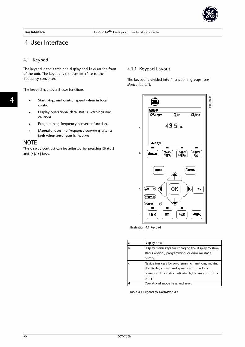
The keypad is divided into 4 functional groups (seeIllustration 4.1).
Illustration 4.1 Keypad
a Display area.
b Display menu keys for changing the display to showstatus options, programming, or error messagehistory.
c Navigation keys for programming functions, movingthe display cursor, and speed control in localoperation. The status indicator lights are also in thisgroup.
d Operational mode keys and reset.
Table 4.1 Legend to Illustration 4.1
User Interface AF-600 FPTM Design and Installation Guide
30 DET-768b
44
4.1.2 Setting Keypad Display Values
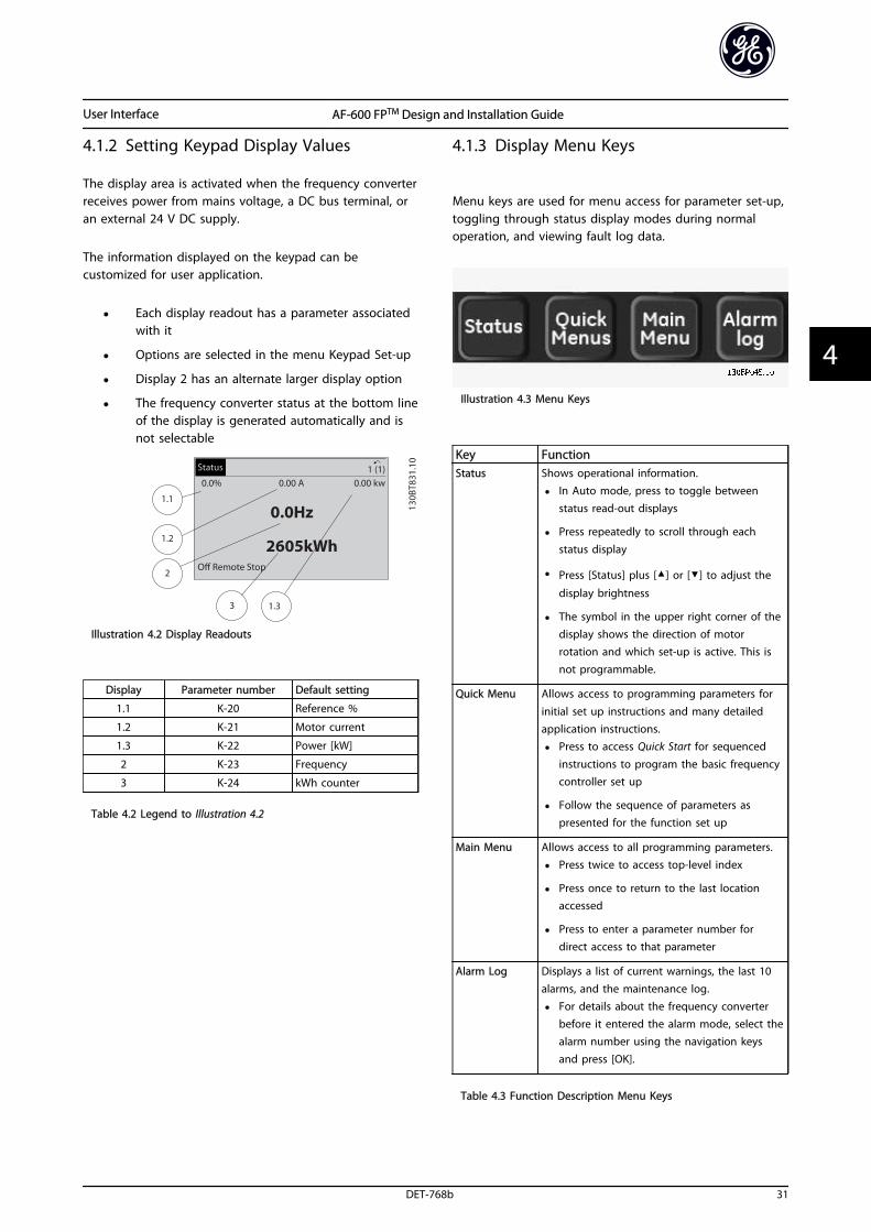
The display area is activated when the frequency converterreceives power from mains voltage, a DC bus terminal, oran external 24 V DC supply.
The information displayed on the keypad can becustomized for user application.
• Each display readout has a parameter associatedwith it
• Options are selected in the menu Keypad Set-up
• Display 2 has an alternate larger display option
• The frequency converter status at the bottom lineof the display is generated automatically and isnot selectable
Illustration 4.2 Display Readouts
Display Parameter number Default setting
1.1 K-20 Reference %
1.2 K-21 Motor current
1.3 K-22 Power [kW]
2 K-23 Frequency
3 K-24 kWh counter
Table 4.2 Legend to Illustration 4.2
4.1.3 Display Menu Keys
Menu keys are used for menu access for parameter set-up,toggling through status display modes during normaloperation, and viewing fault log data.
Illustration 4.3 Menu Keys
Key FunctionStatus Shows operational information.
• In Auto mode, press to toggle betweenstatus read-out displays
• Press repeatedly to scroll through each
status display
• Press [Status] plus [] or [] to adjust the
display brightness
• The symbol in the upper right corner of thedisplay shows the direction of motorrotation and which set-up is active. This isnot programmable.
Quick Menu Allows access to programming parameters for
initial set up instructions and many detailedapplication instructions.
• Press to access Quick Start for sequenced
instructions to program the basic frequencycontroller set up
• Follow the sequence of parameters aspresented for the function set up
Main Menu Allows access to all programming parameters.
• Press twice to access top-level index
• Press once to return to the last locationaccessed
• Press to enter a parameter number fordirect access to that parameter
Alarm Log Displays a list of current warnings, the last 10alarms, and the maintenance log.
• For details about the frequency converterbefore it entered the alarm mode, select thealarm number using the navigation keysand press [OK].
Table 4.3 Function Description Menu Keys
User Interface AF-600 FPTM Design and Installation Guide
DET-768b 31
4 4
4.1.4 Navigation Keys
Navigation keys are used for programming functions andmoving the display cursor. The navigation keys alsoprovide speed control in local (hand) operation. There arealso 3 frequency converter status indicator lights in thisarea.
Illustration 4.4 Navigation Keys
Key Function
Back Reverts to the previous step or list in the menustructure.
Cancel Cancels the last change or command as long as
the display mode has not changed.
Info Press for a definition of the function beingdisplayed.
NavigationKeys
Use the 4 navigation keys to move between itemsin the menu.
OK Use to access parameter groups or to enable achoice.
Table 4.4 Navigation Keys Functions
Light Indicator Function
Green ON The ON light activates when thefrequency converter receivespower from mains voltage, a DCbus terminal, or an external 24 Vsupply.
Yellow WARN When warning conditions are met,the yellow WARN light comes onand text appears in the displayarea identifying the problem.
Red ALARM A fault condition causes the red
alarm light to flash and an alarmtext is displayed.
Table 4.5 Indicator Lights Functions
4.1.5 Operation Keys
Operation keys are found at the bottom of the keypad.
Illustration 4.5 Operation Keys
Key Function
Hand Starts the frequency converter in local control.
• Use the navigation keys to control frequencyconverter speed
• An external stop signal by control input or
serial communication overrides the local hand
Off Stops the motor but does not remove power tothe frequency converter.
Auto Puts the system in remote operational mode.
• Responds to an external start command bycontrol terminals or serial communication
• Speed reference is from an external source
Reset Resets the frequency converter manually after afault has been cleared.
Table 4.6 Operation Keys Functions
4.2 Back Up and Copying ParameterSettings
Programming data is stored internally in the frequencyconverter.
• The data can be uploaded into the keypadmemory as a storage back up
• Once stored in the keypad, the data can bedownloaded back into the frequency converter
• Data can also be downloaded into otherfrequency converters by connecting the keypadinto those units and downloading the storedsettings. (This is a quick way to program multipleunits with the same settings).
• Initialisation of the frequency converter to restorefactory default settings does not change datastored in the keypad memory
User Interface AF-600 FPTM Design and Installation Guide
32 DET-768b
44
WARNINGUNINTENDED START!When the frequency converter is connected to AC mains,the motor may start at any time. The frequency converter,motor, and any driven equipment must be in operationalreadiness. Failure to be in operational readiness when thefrequency converter is connected to AC mains could resultin death, serious injury, or equipment or property damage.
4.2.1 Uploading Data to the Keypad
1. Press [Off] to stop the motor before uploading ordownloading data.
2. Go to K-50 Keypad Copy.
3. Press [OK].
4. Select All to keypad.
5. Press [OK]. A progress bar shows the uploadingprocess.
6. Press [Hand] or [Auto] to return to normaloperation.
4.2.2 Downloading Data from the Keypad
1. Press [Off] to stop the motor before uploading ordownloading data.
2. Go to K-50 Keypad Copy.
3. Press [OK].
4. Select All from keypad.
5. Press [OK]. A progress bar shows thedownloading process.
6. Press [Hand] or [Auto] to return to normaloperation.
4.3 Restoring Default Settings
CAUTIONInitialisation restores the unit to factory default settings.Any programming, motor data, localization, andmonitoring records will be lost. Uploading data to thekeypad provides a backup before initialisation.
Restoring the frequency converter parameter settings backto default values is done by initialisation of the frequencyconverter. Initialisation can be carried out throughH-03 Restore Factory Settings or manually.
• Initialisation using H-03 Restore Factory Settingsdoes not change frequency converter data suchas operating hours, serial communication
selections, personal menu settings, fault log,alarm log, and other monitoring functions
• Using H-03 Restore Factory Settings is generallyrecommended
• Manual initialisation erases all motor,programming, localization, and monitoring dataand restores factory default settings
4.3.1 Recommended Initialisation
1. Press [Main Menu] twice to access parameters.
2. Scroll to H-03 Restore Factory Settings.
3. Press [OK].
4. Scroll to [2] Restore Factory Settings.
5. Press [OK].
6. Remove power to the unit and wait for thedisplay to turn off.
7. Apply power to the unit.
Default parameter settings are restored during start up.This may take slightly longer than normal.
8. Alarm 80 is displayed.
9. Press [Reset] to return to operation mode.
4.3.2 Manual Initialisation
1. Remove power to the unit and wait for thedisplay to turn off.
2. Press and hold [Status], [Main Menu], and [OK] atthe same time and apply power to the unit.
Factory default parameter settings are restored during startup. This may take slightly longer than normal.
Manual initialisation does not reset the following frequencyconverter information
• ID-00 Operating hours
• ID-03 Power Up's
• ID-04 Over Temp's
• ID-05 Over Volt's
User Interface AF-600 FPTM Design and Installation Guide
DET-768b 33
4 4
5 About Programming
5.1 Introduction
The frequency converter is programmed for its applicationfunctions using parameters. Parameters are accessed bypressing either [Quick Menu] or [Main Menu] on thekeypad. (See 4 User Interface for details on using thekeypad function keys.) Parameters may also be accessedthrough a PC using the DCT-10.
The quick menu is intended for initial start up and detailedinstructions for common frequency converter applications .Step-by-step instructions are provided. These instructionsenable the user to walk through the parameters used forprogramming applications in their proper sequence. Dataentered in a parameter can change the options available inthe parameters following that entry. The quick menupresents easy guidelines for getting most systems up andrunning.
The main menu accesses all parameters and allows foradvanced frequency converter applications.
5.2 Programming Example
Here is an example for programming the frequencyconverter for a common application in open loop usingthe quick menu.
• This procedure programs the frequency converterto receive a 0-10 V DC analog control signal oninput terminal 53
• The frequency converter will respond byproviding 20 to 50 Hz output to the motorproportional to the input signal (0-10 V DC =20to 50 Hz)
Select the following parameters using the navigation keysto scroll to the titles and press [OK] after each action.
1. F-01 Frequency Setting 1
Illustration 5.1 References F-01 Frequency Setting 1
2. F-52 Minimum Reference. Set minimum internalfrequency converter reference to 0 Hz. (This setsthe minimum frequency converter speed at 0 Hz.)
Illustration 5.2 Analog Reference F-52 Minimum Reference
3. F-53 Maximum Reference. Set maximum internalfrequency converter reference to 50 Hz. (This setsthe maximum frequency converter speed at 60Hz. Note that 50 Hz is a regional variation.)
Illustration 5.3 Analog Reference F-53 Maximum Reference
About Programming AF-600 FPTM Design and Installation Guide
34 DET-768b
55
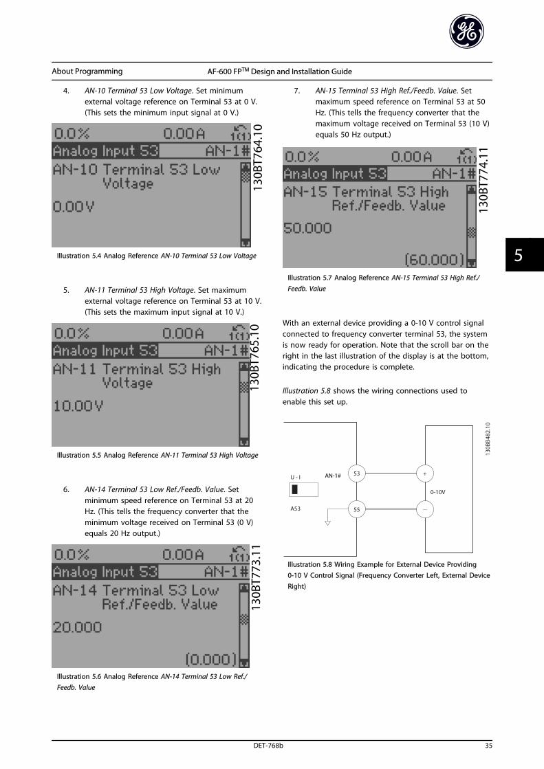
4. AN-10 Terminal 53 Low Voltage. Set minimumexternal voltage reference on Terminal 53 at 0 V.(This sets the minimum input signal at 0 V.)
Illustration 5.4 Analog Reference AN-10 Terminal 53 Low Voltage
5. AN-11 Terminal 53 High Voltage. Set maximumexternal voltage reference on Terminal 53 at 10 V.(This sets the maximum input signal at 10 V.)
Illustration 5.5 Analog Reference AN-11 Terminal 53 High Voltage
6. AN-14 Terminal 53 Low Ref./Feedb. Value. Setminimum speed reference on Terminal 53 at 20Hz. (This tells the frequency converter that theminimum voltage received on Terminal 53 (0 V)equals 20 Hz output.)
Illustration 5.6 Analog Reference AN-14 Terminal 53 Low Ref./Feedb. Value
7. AN-15 Terminal 53 High Ref./Feedb. Value. Setmaximum speed reference on Terminal 53 at 50Hz. (This tells the frequency converter that themaximum voltage received on Terminal 53 (10 V)equals 50 Hz output.)
Illustration 5.7 Analog Reference AN-15 Terminal 53 High Ref./Feedb. Value
With an external device providing a 0-10 V control signalconnected to frequency converter terminal 53, the systemis now ready for operation. Note that the scroll bar on theright in the last illustration of the display is at the bottom,indicating the procedure is complete.
Illustration 5.8 shows the wiring connections used toenable this set up.
Illustration 5.8 Wiring Example for External Device Providing0-10 V Control Signal (Frequency Converter Left, External Device
Right)
About Programming AF-600 FPTM Design and Installation Guide
DET-768b 35
5 5
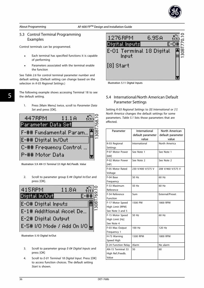
5.3 Control Terminal ProgrammingExamples
Control terminals can be programmed.
• Each terminal has specified functions it is capableof performing
• Parameters associated with the terminal enablethe function
See Table 2.6 for control terminal parameter number anddefault setting. (Default setting can change based on theselection in K-03 Regional Settings.)
The following example shows accessing Terminal 18 to seethe default setting.
1. Press [Main Menu] twice, scroll to Parameter DataSet and press [OK].
Illustration 5.9 AN-15 Terminal 53 High Ref./Feedb. Value
2. Scroll to parameter group E-## Digital In/Out andpress [OK].
Illustration 5.10 Digital In/Out
3. Scroll to parameter group E-0# Digital Inputs andpress [OK]
4. Scroll to E-01 Terminal 18 Digital Input. Press [OK]to access function choices. The default settingStart is shown.
Illustration 5.11 Digital Inputs
5.4 International/North American DefaultParameter Settings
Setting K-03 Regional Settings to [0] International or [1]North America changes the default settings for someparameters. Table 5.1 lists those parameters that areeffected.
Parameter Internationaldefault parameter
value
North Americandefault parameter
valueK-03 Regional
Settings
International North America
P-07 Motor Power
[kW]
See Note 1 See Note 1
P-02 Motor Power[HP]
See Note 2 See Note 2
F-05 Motor RatedVoltage
230 V/400 V/575 V 208 V/460 V/575 V
F-04 BaseFrequency
50 Hz 60 Hz
F-53 MaximumReference
50 Hz 60 Hz
F-54 Reference
Function
Sum External/Preset
F-17 Motor SpeedHigh Limit [RPM]See Note 3 and 5
1500 PM 1800 RPM
F-15 Motor SpeedHigh Limit [Hz]See Note 4
50 Hz 60 Hz
F-03 Max OutputFrequency 1
100 Hz 120 Hz
H-73 WarningSpeed High
1500 RPM 1800 RPM
E-24 Function Relay Alarm No alarm
AN-15 Terminal 53High Ref./Feedb.Value
50 60
About Programming AF-600 FPTM Design and Installation Guide
36 DET-768b
55
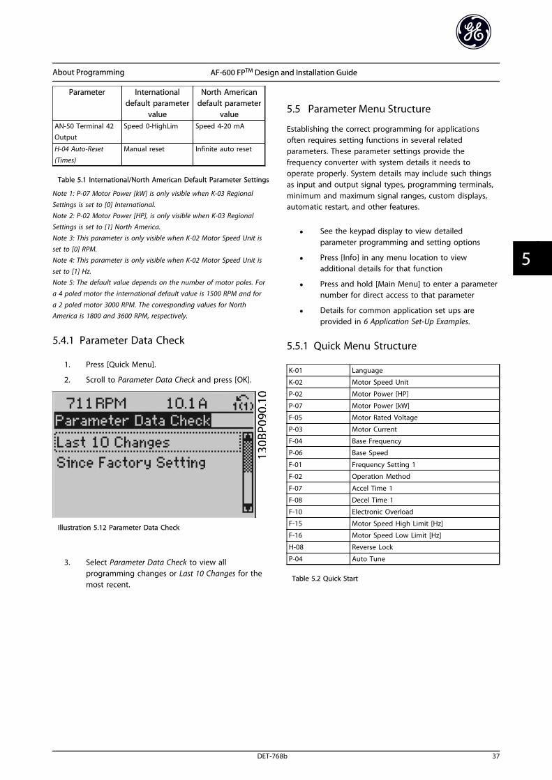
Parameter Internationaldefault parameter
value
North Americandefault parameter
valueAN-50 Terminal 42Output
Speed 0-HighLim Speed 4-20 mA
H-04 Auto-Reset
(Times)
Manual reset Infinite auto reset
Table 5.1 International/North American Default Parameter Settings
Note 1: P-07 Motor Power [kW] is only visible when K-03 Regional
Settings is set to [0] International.Note 2: P-02 Motor Power [HP], is only visible when K-03 RegionalSettings is set to [1] North America.
Note 3: This parameter is only visible when K-02 Motor Speed Unit isset to [0] RPM.Note 4: This parameter is only visible when K-02 Motor Speed Unit is
set to [1] Hz.Note 5: The default value depends on the number of motor poles. Fora 4 poled motor the international default value is 1500 RPM and for
a 2 poled motor 3000 RPM. The corresponding values for NorthAmerica is 1800 and 3600 RPM, respectively.
5.4.1 Parameter Data Check
1. Press [Quick Menu].
2. Scroll to Parameter Data Check and press [OK].
Illustration 5.12 Parameter Data Check
3. Select Parameter Data Check to view allprogramming changes or Last 10 Changes for themost recent.
5.5 Parameter Menu Structure
Establishing the correct programming for applicationsoften requires setting functions in several relatedparameters. These parameter settings provide thefrequency converter with system details it needs tooperate properly. System details may include such thingsas input and output signal types, programming terminals,minimum and maximum signal ranges, custom displays,automatic restart, and other features.
• See the keypad display to view detailedparameter programming and setting options
• Press [Info] in any menu location to viewadditional details for that function
• Press and hold [Main Menu] to enter a parameternumber for direct access to that parameter
• Details for common application set ups areprovided in 6 Application Set-Up Examples.
5.5.1 Quick Menu Structure
K-01 Language
K-02 Motor Speed Unit
P-02 Motor Power [HP]
P-07 Motor Power [kW]
F-05 Motor Rated Voltage
P-03 Motor Current
F-04 Base Frequency
P-06 Base Speed
F-01 Frequency Setting 1
F-02 Operation Method
F-07 Accel Time 1
F-08 Decel Time 1
F-10 Electronic Overload
F-15 Motor Speed High Limit [Hz]
F-16 Motor Speed Low Limit [Hz]
H-08 Reverse Lock
P-04 Auto Tune
Table 5.2 Quick Start
About Programming AF-600 FPTM Design and Installation Guide
DET-768b 37
5 5
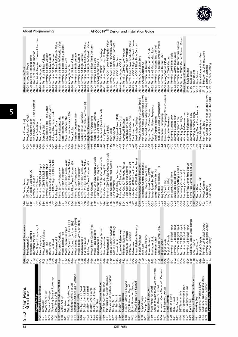
5.5.
2M
ain
Men
uSt
ruct
ure
Keyp
ad S
et-U
pK-
0#Ke
ypad
Bas
ic S
ettin
gsK-
01La
ngua
geK-
02M
otor
Spe
ed U
nit
K-03
Regi
onal
Set
tings
K-04
Ope
ratin
g S
tate
at
Pow
er-u
pK-
05Lo
cal M
ode
Uni
tK-
1#Ke
ypad
Set
-Up
Ope
ratio
nsK-
10A
ctiv
e Se
t-up
K-11
Edit
Set
-up
K-12
This
Set
-up
Lin
ked
to
K-13
Read
out:
Lin
ked
Set
-ups
K-14
Read
out:
Edi
t Se
t-up
s /
Chan
nel
K-2#
Keyp
ad D
ispl
ayK-
20D
ispl
ay L
ine
1.1
Smal
lK-
21D
ispl
ay L
ine
1.2
Smal
lK-
22D
ispl
ay L
ine
1.3
Smal
lK-
23D
ispl
ay L
ine
2 La
rge
K-24
Dis
play
Lin
e 3
Larg
eK-
25Q
uick
Sta
rtK-
3#Ke
ypad
Cus
tom
Rea
dout
K-30
Uni
t fo
r Cu
stom
Rea
dout
K-31
Min
Val
ue o
f Cu
stom
Rea
dout
K-32
Max
Val
ue o
f Cu
stom
Rea
dout
K-37
Dis
play
Tex
t 1
K-38
Dis
play
Tex
t 2
K-39
Dis
play
Tex
t 3
K-4#
Keyp
ad B
utto
nsK-
40[H
and]
But
ton
on
Key
pad
K-41
[Off]
But
ton
on
Key
pad
K-42
[Aut
o] B
utto
n o
n K
eypa
dK-
43[R
eset
] Bu
tton
on
Key
pad
K-5#
Copy
/Sav
eK-
50Ke
ypad
Cop
yK-
51Se
t-up
Cop
yK-
6#Pa
ssw
ord
Pro
tect
ion
K-60
Mai
n M
enu
Pas
swor
dK-
61A
cces
s to
Mai
n M
enu
w/o
Pas
swor
dK-
65Q
uick
Men
u P
assw
ord
K-66
Acc
ess
to Q
uick
Men
u w
/o P
assw
ord
K-67
Bus
Pass
wor
d A
cces
sK-
7#Cl
ock
Sett
ings
K-70
Dat
e an
d T
ime
K-71
Dat
e Fo
rmat
K-72
Tim
e Fo
rmat
K-74
DST
/Sum
mer
time
K-76
DST
/Sum
mer
time
Star
tK-
77D
ST/S
umm
ertim
e En
dK-
79Cl
ock
Faul
tK-
8#D
ays
and
Dat
e/Ti
me
Read
out
K-81
Wor
king
Day
sK-
82A
dditi
onal
Wor
king
Day
sK-
83A
dditi
onal
Non
-Wor
king
Day
sK-
89D
ate
and
Tim
e Re
adou
tPa
ram
eter
Dat
a Se
t
F-##
Fund
amen
tal P
aram
eter
sF-
0#Fu
ndam
enta
l 0F-
01Fr
eque
ncy
Sett
ing
1F-
02O
pera
tion
Met
hod
F-03
Max
Out
put
Freq
uenc
y 1
F-04
Base
Fre
quen
cyF-
05M
otor
Rat
ed V
olta
geF-
07A
ccel
Tim
e 1
F-08
Dec
el T
ime
1F-
09To
rque
Boo
stF-
1#Fu
ndam
enta
l 1F-
10El
ectr
onic
Ove
rload
F-11
Mot
or E
xter
nal F
anF-
12M
otor
The
rmis
tor
Inpu
tF-
15M
otor
Spe
ed H
igh
Lim
it [H
z]F-
16M
otor
Spe
ed L
ow L
imit
[Hz]
F-17
Mot
or S
peed
Hig
h L
imit
[RPM
]F-
18M
otor
Spe
ed L
ow L
imit
[RPM
]F-
2#Fu
ndam
enta
l 2F-
20PM
Sta
rt M
ode
F-24
Hol
ding
Tim
eF-
26M
otor
Noi
se (C
arrie
r Fr
eq)
F-27
Mot
or T
one
Rand
omF-
3#Fu
ndam
enta
l 3F-
37A
dv. S
witc
hing
Pat
tern
F-38
Ove
rmod
ulat
ion
F-4#
Fund
amen
tal 4
F-40
Torq
ue L
imite
r (D
rivin
g)F-
41To
rque
Lim
iter
(Bra
king
)F-
43Cu
rren
t Li
mit
F-5#
Exte
nded
Ref
eren
ces
F-52
Min
imum
Ref
eren
ceF-
53M
axim
um R
efer
ence
F-54
Refe
renc
e Fu
nctio
nF-
6#Re
fere
nces
F-64
Pres
et R
elat
ive
Refe
renc
eF-
9#D
igita
l Pot
.Met
erF-
90St
ep S
ize
F-91
Acc
el/D
ecel
Tim
eF-
92Po
wer
Res
tore
F-93
Max
imum
Lim
itF-
94M
inim
um L
imit
F-95
Acc
el/D
ecel
Ram
p D
elay
E-##
Dig
ital I
n/O
utE-
0#D
igita
l Inp
uts
E-00
Dig
ital I
/O M
ode
E-01
Term
inal
18
Dig
ital I
nput
E-02
Term
inal
19
Dig
ital I
nput
E-03
Term
inal
27
Dig
ital I
nput
E-04
Term
inal
29
Dig
ital I
nput
E-05
Term
inal
32
Dig
ital I
nput
E-06
Term
inal
33
Dig
ital I
nput
E-1#
Add
ition
al A
ccel
Dec
el R
amps
E-10
Acc
el T
ime
2E-
11D
ecel
Tim
e 2
E-2#
Dig
ital O
utpu
tsE-
20Te
rmin
al 2
7 D
igita
l Out
put
E-21
Term
inal
29
Dig
ital O
utpu
tE-
24Fu
nctio
n R
elay
E-26
On
Del
ay, R
elay
E-27
Off
Del
ay, R
elay
E-5#
I/O M
ode
/ A
dd O
n I/
OE-
51Te
rmin
al 2
7 M
ode
E-52
Term
inal
29
Mod
eE-
53Te
rmin
al X
30/2
Dig
ital I
nput
E-54
Term
inal
X30
/3 D
igita
l Inp
utE-
55Te
rmin
al X
30/4
Dig
ital I
nput
E-56
Term
X30
/6 D
igi O
ut (O
PCG
PIO
)E-
57Te
rm X
30/7
Dig
i Out
(OPC
GPI
O)
E-6#
Puls
e In
put
E-60
Term
. 29
Low
Fre
quen
cyE-
61Te
rm. 2
9 H
igh
Fre
quen
cyE-
62Te
rm. 2
9 Lo
w R
ef./F
eedb
. Val
ueE-
63Te
rm. 2
9 H
igh
Ref
./Fee
db. V
alue
E-64
Puls
e Fi
lter
Tim
e Co
nsta
nt #
29E-
65Te
rm. 3
3 Lo
w F
requ
ency
E-66
Term
. 33
Hig
h F
requ
ency
E-67
Term
. 33
Low
Ref
./Fee
db. V
alue
E-68
Term
. 33
Hig
h R
ef./F
eedb
. Val
ueE-
69Pu
lse
Filte
r Ti
me
Cons
tant
#33
E-7#
Puls
e O
utpu
tE-
70Te
rmin
al 2
7 Pu
lse
Out
put
Varia
ble
E-71
Puls
e O
utpu
t M
ax F
req
#27
E-72
Term
inal
29
Puls
e O
utpu
t Va
riabl
eE-
74Pu
lse
Out
put
Max
Fre
q #
29E-
75Te
rmin
al X
30/6
Pul
se O
utpu
t Va
riabl
eE-
76Pu
lse
Out
put
Max
Fre
q #
X30/
6E-
9#Bu
s Co
ntro
lled
E-90
Dig
ital &
Rel
ay B
us C
ontr
olE-
93Pu
lse
Out
#27
Bus
Con
trol
E-94
Puls
e O
ut #
27 T
imeo
ut P
rese
tE-
95Pu
lse
Out
#29
Bus
Con
trol
E-96
Puls
e O
ut #
29 T
imeo
ut P
rese
tE-
97Pu
lse
Out
#X3
0/6
Bus
Cont
rol
E-98
Puls
e O
ut #
X30/
6 Ti
meo
ut P
rese
tC-
##Fr
eque
ncy
Cont
rol F
unct
ions
C-0#
Freq
uenc
y Co
ntro
l Fun
ctio
nsC-
01Ju
mp
Fre
quen
cy F
rom
[Hz]
C-02
Jum
p S
peed
Fro
m [R
PM]
C-03
Jum
p S
peed
To
[RPM
]C-
04Ju
mp
Fre
quen
cy T
o [H
z]C-
05M
ulti-
step
Fre
quen
cy 1
- 8
C-2#
Jog
Set
upC-
20Jo
g S
peed
[Hz]
C-21
Jog
Spe
ed [R
PM]
C-22
Jog
Acc
el/D
ecel
Tim
eC-
23Q
uick
Sto
p D
ecel
Tim
eC-
3#Fr
eque
ncy
Sett
ing
2 a
nd 3
C-30
Freq
uenc
y Co
mm
and
2C-
34Fr
eque
ncy
Com
man
d 3
C-4#
Sem
i-Aut
o J
ump
Fre
q S
et-u
pC-
40Se
mi-A
uto
Jum
p F
req
Set
-up
P-##
Mot
or D
ata
P-0#
Mot
or D
ata
P-02
Mot
or P
ower
[HP]
P-03
Mot
or C
urre
ntP-
04A
uto
Tun
eP-
06Ba
se S
peed
P-07
Mot
or P
ower
[kW
]P-
08M
otor
Rot
atio
n C
heck
P-09
Slip
Com
pens
atio
nP-
10Sl
ip C
ompe
nsat
ion
Tim
e Co
nsta
ntP-
2#M
otor
Sel
ectio
nP-
20M
otor
Con
stru
ctio
nP-
24D
ampi
ng G
ain
P-25
Low
Spe
ed F
ilter
Tim
e Co
nst.
P-26
Hig
h S
peed
Filt
er T
ime
Cons
t.P-
27Vo
ltage
filte
r tim
e co
nst.
P-3#
Adv
. Mot
or D
ata
P-30
Stat
or R
esis
tanc
e (R
s)P-
31Ro
tor
Resi
stan
ce (R
r)P-
35M
ain
Rea
ctan
ce (X
h)P-
36Iro
n L
oss
Resi
stan
ce (R
fe)
P-39
Mot
or P
oles
P-46
Posi
tion
Det
ectio
n G
ain
P-6#
Lock
ed R
otor
P-62
Lock
ed R
otor
Pro
tect
ion
P-63
Lock
ed R
otor
Det
ectio
n T
ime
[s]
H-#
#H
igh
Per
f Pa
ram
eter
sH
-0#
Hig
h P
erf
Ope
ratio
nsH
-03
Rest
ore
Fact
ory
Sett
ings
H-0
4A
uto-
Rese
t (T
imes
)H
-05
Aut
o-Re
set
(Res
et In
terv
al)
H-0
6Fa
n O
pera
tion
H-0
8Re
vers
e Lo
ckH
-09
Star
t M
ode
H-3
#St
op S
peed
H-3
6Tr
ip S
peed
Low
[RPM
]H
-37
Trip
Spe
ed L
ow [H
z]H
-4#
Adv
ance
d S
ettin
gsH
-40
Conf
igur
atio
n M
ode
H-4
3To
rque
Cha
ract
eris
tics
H-4
8Cl
ockw
ise
Dire
ctio
nH
-5#
Load
Inde
p. S
ettin
gH
-50
Mot
or M
agne
tisat
ion
at
Zero
Spe
edH
-51
Min
Spe
ed N
orm
al M
agne
tisin
g [R
PM]
H-5
2M
in S
peed
Nor
mal
Mag
netis
ing
[Hz]
H-5
8Fl
ysta
rt T
est
Puls
es C
urre
ntH
-59
Flys
tart
Tes
t Pu
lses
Fre
quen
cyH
-6#
Load
Dep
en. S
ettin
gH
-61
Hig
h S
peed
Loa
d C
ompe
nsat
ion
H-6
4Re
sona
nce
Dam
peni
ngH
-65
Reso
nanc
e D
ampe
ning
Tim
e Co
nsta
ntH
-7#
Adj
usta
ble
War
ning
sH
-70
War
ning
Cur
rent
Low
H-7
1W
arni
ng C
urre
nt H
igh
H-7
2W
arni
ng S
peed
Low
H-7
3W
arni
ng S
peed
Hig
hH
-74
War
ning
Ref
eren
ce L
owH
-75
War
ning
Ref
eren
ce H
igh
H-7
6W
arni
ng F
eedb
ack
Low
H-7
7W
arni
ng F
eedb
ack
Hig
hH
-78
Mis
sing
Mot
or P
hase
Fun
ctio
nH
-8#
Stop
Adj
ustm
ents
H-8
0Fu
nctio
n a
t St
opH
-81
Min
Spe
ed fo
r Fu
nctio
n a
t St
op [R
PM]
H-8
2M
in S
peed
for
Func
tion
at
Stop
[Hz]
AN
-##
Ana
log
In/O
utA
N-0
#A
nalo
g I/
O M
ode
AN
-00
Live
Zer
o T
imeo
ut T
ime
AN
-01
Live
Zer
o T
imeo
ut F
unct
ion
AN
-02
Fire
Mod
e Li
ve Z
ero
Tim
eout
Fun
ctio
nA
N-1
#A
nalo
g In
put
53A
N-1
0Te
rmin
al 5
3 Lo
w V
olta
geA
N-1
1Te
rmin
al 5
3 H
igh
Vol
tage
AN
-12
Term
inal
53
Low
Cur
rent
AN
-13
Term
inal
53
Hig
h C
urre
ntA
N-1
4Te
rmin
al 5
3 Lo
w R
ef./F
eedb
. Val
ueA
N-1
5Te
rmin
al 5
3 H
igh
Ref
./Fee
db. V
alue
AN
-16
Term
inal
53
Filte
r Ti
me
Cons
tant
AN
-17
Term
inal
53
Live
Zer
oA
N-2
#A
nalo
g In
put
54A
N-2
0Te
rmin
al 5
4 Lo
w V
olta
geA
N-2
1Te
rmin
al 5
4 H
igh
Vol
tage
AN
-22
Term
inal
54
Low
Cur
rent
AN
-23
Term
inal
54
Hig
h C
urre
ntA
N-2
4Te
rmin
al 5
4 Lo
w R
ef./F
eedb
. Val
ueA
N-2
5Te
rmin
al 5
4 H
igh
Ref
./Fee
db. V
alue
AN
-26
Term
inal
54
Filte
r Ti
me
Cons
tant
AN
-27
Term
inal
54
Live
Zer
oA
N-3
#A
nalo
g In
put
X30/
11A
N-3
0Te
rmin
al X
30/1
1 Lo
w V
olta
geA
N-3
1Te
rmin
al X
30/1
1 H
igh
Vol
tage
AN
-34
Term
. X30
/11
Low
Ref
./Fee
db. V
alue
AN
-35
Term
. X30
/11
Hig
h R
ef./F
eedb
. Val
ueA
N-3
6Te
rm. X
30/1
1 Fi
lter
Tim
e Co
nsta
ntA
N-3
7Te
rm. X
30/1
1 Li
ve Z
ero
AN
-4#
Ana
log
Inpu
t X3
0/12
AN
-40
Term
inal
X30
/12
Low
Vol
tage
AN
-41
Term
inal
X30
/12
Hig
h V
olta
geA
N-4
4Te
rm. X
30/1
2 Lo
w R
ef./F
eedb
. Val
ueA
N-4
5Te
rm. X
30/1
2 H
igh
Ref
./Fee
db. V
alue
AN
-46
Term
. X30
/12
Filte
r Ti
me
Cons
tant
AN
-47
Term
. X30
/12
Live
Zer
oA
N-5
#A
nalo
g O
utpu
t 42
AN
-50
Term
inal
42
Out
put
AN
-51
Term
inal
42
Out
put
Min
Sca
leA
N-5
2Te
rmin
al 4
2 O
utpu
t M
ax S
cale
AN
-53
Term
inal
42
Out
put
Bus
Cont
rol
AN
-54
Term
inal
42
Out
put
Tim
eout
Pre
set
AN
-55
Term
inal
42
Out
put
Filte
rA
N-6
#A
nalo
g O
utpu
t X3
0/8
AN
-60
Term
inal
X30
/8 O
utpu
tA
N-6
1Te
rmin
al X
30/8
Min
. Sca
leA
N-6
2Te
rmin
al X
30/8
Max
. Sca
leA
N-6
3Te
rmin
al X
30/8
Out
put
Bus
Cont
rol
AN
-64
Term
inal
X30
/8 O
utpu
t Ti
meo
ut P
rese
tSP
-##
Spec
ial F
unct
ions
SP-0
#Fa
ult
Sett
ings
SP-0
0Fa
ult
Leve
lSP
-1#
Line
On/
Off
SP-1
0Li
ne fa
ilure
SP-1
1Li
ne V
olta
ge a
t In
put
Faul
tSP
-12
Func
tion
at
Line
Imba
lanc
eSP
-2#
Rese
t Fu
nctio
nsSP
-23
Type
code
Set
ting
About Programming AF-600 FPTM Design and Installation Guide
38 DET-768b
55
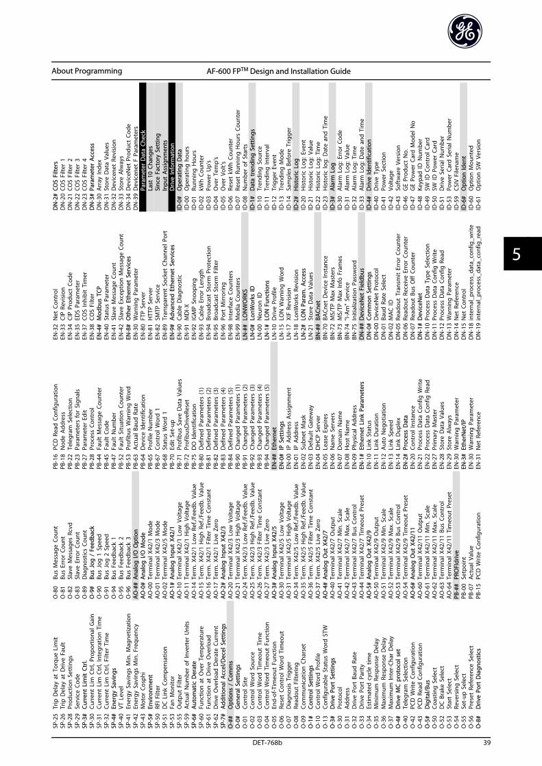
SP-2
5Tr
ip D
elay
at
Torq
ue L
imit
SP-2
6Tr
ip D
elay
at
Driv
e Fa
ult
SP-2
8Pr
oduc
tion
Set
tings
SP-2
9Se
rvic
e Co
deSP
-3#
Curr
ent
Lim
it C
trl.
SP-3
0Cu
rren
t Li
m C
trl,
Prop
ortio
nal G
ain
SP-3
1Cu
rren
t Li
m C
trl,
Inte
grat
ion
Tim
eSP
-32
Curr
ent
Lim
Ctr
l, Fi
lter
Tim
eSP
-4#
Ener
gy S
avin
gsSP
-40
VT L
evel
SP-4
1En
ergy
Sav
ings
Min
. Mag
netiz
atio
nSP
-42
Ener
gy S
avin
gs M
in. F
requ
ency
SP-4
3M
otor
Cos
phi
SP-5
#En
viro
nmen
tSP
-50
RFI F
ilter
SP-5
1D
C L
ink
Com
pens
atio
nSP
-53
Fan
Mon
itor
SP-5
5O
utpu
t Fi
lter
SP-5
9A
ctua
l Num
ber
of In
vert
er U
nits
SP-6
#A
utom
atic
Der
ate
SP-6
0Fu
nctio
n a
t O
ver
Tem
pera
ture
SP-6
1Fu
nctio
n a
t D
rive
Ove
rload
SP-6
2D
rive
Ove
rload
Der
ate
Curr
ent
SP-7
#A
dditi
onal
Acc
el/D
ecel
Set
tings
O-#
#O
ptio
ns /
Com
ms
O-0
#G
ener
al S
ettin
gsO
-01
Cont
rol S
iteO
-02
Cont
rol W
ord
Sou
rce
O-0
3Co
ntro
l Wor
d T
imeo
ut T
ime
O-0
4Co
ntro
l Wor
d T
imeo
ut F
unct
ion
O-0
5En
d-of
-Tim
eout
Fun
ctio
nO
-06
Rese
t Co
ntro
l Wor
d T
imeo
utO
-07
Dia
gnos
is T
rigge
rO
-08
Read
out
Filte
ring
O-0
9Co
mm
unic
atio
n C
hars
etO
-1#
Cont
rol S
ettin
gsO
-10
Cont
rol W
ord
Pro
file
O-1
3Co
nfig
urab
le S
tatu
s W
ord
STW
O-3
#D
rive
Port
Set
tings
O-3
0Pr
otoc
olO
-31
Add
ress
O-3
2D
rive
Port
Bau
d R
ate
O-3
3D
rive
Port
Par
ityO
-34
Estim
ated
cyc
le t
ime
O-3
5M
inim
um R
espo
nse
Del
ayO
-36
Max
imum
Res
pons
e D
elay
O-3
7M
axim
um In
ter-
Char
Del
ayO
-4#
Driv
e M
C p
roto
col s
etO
-40
Tele
gram
Sel
ectio
nO
-42
PCD
Writ
e Co
nfig
urat
ion
O-4
3PC
D R
ead
Con
figur
atio
nO
-5#
Dig
ital/B
usO
-50
Coas
ting
Sel
ect
O-5
2D
C B
rake
Sel
ect
O-5
3St
art
Sele
ctO
-54
Reve
rsin
g S
elec
tO
-55
Set-
up S
elec
tO
-56
Pres
et R
efer
ence
Sel
ect
O-8
#D
rive
Port
Dia
gnos
tics
O-8
0Bu
s M
essa
ge C
ount
O-8
1Bu
s Er
ror
Coun
tO
-82
Slav
e M
essa
ges
Rcvd
O-8
3Sl
ave
Erro
r Co
unt
O-8
9D
iagn
ostic
s Co
unt
O-9
#Bu
s Jo
g /
Fee
dbac
kO
-90
Bus
Jog
1 S
peed
O-9
1Bu
s Jo
g 2
Spe
edO
-94
Bus
Feed
back
1O
-95
Bus
Feed
back
2O
-96
Bus
Feed
back
3A
O-#
#A
nalo
g I/
O O
ptio
nA
O-0
#A
nalo
g I/
O M
ode
AO
-00
Term
inal
X42
/1 M
ode
AO
-01
Term
inal
X42
/3 M
ode
AO
-02
Term
inal
X42
/5 M
ode
AO
-1#
Ana
log
Inpu
t X4
2/1
AO
-10
Term
inal
X42
/1 L
ow V
olta
geA
O-1
1Te
rmin
al X
42/1
Hig
h V
olta
geA
O-1
4Te
rm. X
42/1
Low
Ref
./Fee
db. V
alue
AO
-15
Term
. X42
/1 H
igh
Ref
./Fee
db. V
alue
AO
-16
Term
. X42
/1 F
ilter
Tim
e Co
nsta
ntA
O-1
7Te
rm. X
42/1
Liv
e Ze
roA
O-2
#A
nalo
g In
put
X42/
3A
O-2
0Te
rmin
al X
42/3
Low
Vol
tage
AO
-21
Term
inal
X42
/3 H
igh
Vol
tage
AO
-24
Term
. X42
/3 L
ow R
ef./F
eedb
. Val
ueA
O-2
5Te
rm. X
42/3
Hig
h R
ef./F
eedb
. Val
ueA
O-2
6Te
rm. X
42/3
Filt
er T
ime
Cons
tant
AO
-27
Term
. X42
/3 L
ive
Zero
AO
-3#
Ana
log
Inpu
t X4
2/5
AO
-30
Term
inal
X42
/5 L
ow V
olta
geA
O-3
1Te
rmin
al X
42/5
Hig
h V
olta
geA
O-3
4Te
rm. X
42/5
Low
Ref
./Fee
db. V
alue
AO
-35
Term
. X42
/5 H
igh
Ref
./Fee
db. V
alue
AO
-36
Term
. X42
/5 F
ilter
Tim
e Co
nsta
ntA
O-3
7Te
rm. X
42/5
Liv
e Ze
roA
O-4
#A
nalo
g O
ut X
42/7
AO
-40
Term
inal
X42
/7 O
utpu
tA
O-4
1Te
rmin
al X
42/7
Min
. Sca
leA
O-4
2Te
rmin
al X
42/7
Max
. Sca
leA
O-4
3Te
rmin
al X
42/7
Bus
Con
trol
AO
-44
Term
inal
X42
/7 T
imeo
ut P
rese
tA
O-5
#A
nalo
g O
ut X
42/9
AO
-50
Term
inal
X42
/9 O
utpu
tA
O-5
1Te
rmin
al X
42/9
Min
. Sca
leA
O-5
2Te
rmin
al X
42/9
Max
. Sca
leA
O-5
3Te
rmin
al X
42/9
Bus
Con
trol
AO
-54
Term
inal
X42
/9 T
imeo
ut P
rese
tA
O-6
#A
nalo
g O
ut X
42/1
1A
O-6
0Te
rmin
al X
42/1
1 O
utpu
tA
O-6
1Te
rmin
al X
42/1
1 M
in. S
cale
AO
-62
Term
inal
X42
/11
Max
. Sca
leA
O-6
3Te
rmin
al X
42/1
1 Bu
s Co
ntro
lA
O-6
4Te
rmin
al X
42/1
1 Ti
meo
ut P
rese
tPB
-##
PRO
FIdr
ive
PB-0
0Se
tpoi
ntPB
-07
Act
ual V
alue
PB-1
5PC
D W
rite
Conf
igur
atio
n
PB-1
6PC
D R
ead
Con
figur
atio
nPB
-18
Nod
e A
ddre
ssPB
-22
Tele
gram
Sel
ectio
nPB
-23
Para
met
ers
for
Sign
als
PB-2
7Pa
ram
eter
Edi
tPB
-28
Proc
ess
Cont
rol
PB-4
4Fa
ult
Mes
sage
Cou
nter
PB-4
5Fa
ult
Code
PB-4
7Fa
ult
Num
ber
PB-5
2Fa
ult
Situ
atio
n C
ount
erPB
-53
Prof
ibus
War
ning
Wor
dPB
-63
Act
ual B
aud
Rat
ePB
-64
Dev
ice
Iden
tific
atio
nPB
-65
Prof
ile N
umbe
rPB
-67
Cont
rol W
ord
1PB
-68
Stat
us W
ord
1PB
-70
Edit
Set
-up
PB-7
1Pr
ofib
us S
ave
Dat
a Va
lues
PB-7
2Pr
ofib
usD
riveR
eset
PB-7
5D
O Id
entif
icat
ion
PB-8
0D
efin
ed P
aram
eter
s (1
)PB
-81
Def
ined
Par
amet
ers
(2)
PB-8
2D
efin
ed P
aram
eter
s (3
)PB
-83
Def
ined
Par
amet
ers
(4)
PB-8
4D
efin
ed P
aram
eter
s (5
)PB
-90
Chan
ged
Par
amet
ers
(1)
PB-9
1Ch
ange
d P
aram
eter
s (2
)PB
-92
Chan
ged
Par
amet
ers
(3)
PB-9
3Ch
ange
d P
aram
eter
s (4
)PB
-94
Chan
ged
Par
amet
ers
(5)
EN-#
#Et
hern
etEN
-0#
IP S
ettin
gsEN
-00
IP A
ddre
ss A
ssig
nmen
tEN
-01
IP A
ddre
ssEN
-02
Subn
et M
ask
EN-0
3D
efau
lt G
atew
ayEN
-04
DH
CP S
erve
rEN
-05
Leas
e Ex
pire
sEN
-06
Nam
e Se
rver
sEN
-07
Dom
ain
Nam
eEN
-08
Hos
t N
ame
EN-0
9Ph
ysic
al A
ddre
ssEN
-1#
Ethe
rnet
Lin
k Pa
ram
eter
sEN
-10
Link
Sta
tus
EN-1
1Li
nk D
urat
ion
EN-1
2A
uto
Neg
otia
tion
EN-1
3Li
nk S
peed
EN-1
4Li
nk D
uple
xEN
-2#
Proc
ess
Dat
aEN
-20
Cont
rol I
nsta
nce
EN-2
1Pr
oces
s D
ata
Conf
ig W
rite
EN-2
2Pr
oces
s D
ata
Conf
ig R
ead
EN-2
7Pr
imar
y M
aste
rEN
-28
Stor
e D
ata
Valu
esEN
-29
Stor
e A
lway
sEN
-30
War
ning
Par
amet
erEN
-3#
Ethe
rNet
/IPEN
-30
War
ning
Par
amet
erEN
-31
Net
Ref
eren
ce
EN-3
2N
et C
ontr
olEN
-33
CIP
Revi
sion
EN-3
4CI
P Pr
oduc
t Co
deEN
-35
EDS
Para
met
erEN
-37
COS
Inhi
bit
Tim
erEN
-38
COS
Filte
rEN
-4#
Mod
bus
TCP
EN-4
0St
atus
Par
amet
erEN
-41
Slav
e M
essa
ge C
ount
EN-4
2Sl
ave
Exce
ptio
n M
essa
ge C
ount
EN-8
#O
ther
Eth
erne
t Se
rvic
esEN
-30
War
ning
Par
amet
erEN
-80
FTP
Serv
erEN
-81
HTT
P Se
rver
EN-8
2SM
TP S
ervi
ceEN
-89
Tran
spar
ent
Sock
et C
hann
el P
ort
EN-9
#A
dvan
ced
Eth
erne
t Se
rvic
esEN
-90
Cabl
e D
iagn
ostic
EN-9
1M
DI-X
EN-9
2IG
MP
Snoo
ping
EN-9
3Ca
ble
Erro
r Le
ngth
EN-9
4Br
oadc
ast
Stor
m P
rote
ctio
nEN
-95
Broa
dcas
t St
orm
Filt
erEN
-96
Port
Mirr
orin
gEN
-98
Inte
rfac
e Co
unte
rsEN
-99
Med
ia C
ount
ers
LN-#
#LO
NW
ORK
SLN
-0#
LonW
orks
IDLN
-00
Neu
ron
IDLN
-1#
LON
Fun
ctio
nsLN
-10
Driv
e Pr
ofile
LN-1
5LO
N W
arni
ng W
ord
LN-1
7XI
F Re
visi
onLN
-18
LonW
orks
Rev
isio
nLN
-2#
LON
Par
am. A
cces
sLN
-21
Stor
e D
ata
Valu
esBN
-##
BACn
etBN
-70
BACn
et D
evic
e In
stan
ceBN
-72
MS/
TP M
ax M
aste
rsBN
-73
MS/
TP M
ax In
fo F
ram
esBN
-74
"I-A
m"
Serv
ice
BN-7
5In
itial
izat
ion
Pas
swor
dD
N-#
#D
evic
eNet
Fie
ldbu
sD
N-0
#Co
mm
on S
ettin
gsD
N-0
0D
evic
eNet
Pro
toco
lD
N-0
1Ba
ud R
ate
Sele
ctD
N-0
2M
AC
IDD
N-0
5Re
adou
t Tr
ansm
it E
rror
Cou
nter
DN
-06
Read
out
Rece
ive
Erro
r Co
unte
rD
N-0
7Re
adou
t Bu
s O
ff C
ount
erD
N-1
#D
evic
eNet
DN
-10
Proc
ess
Dat
a Ty
pe S
elec
tion
DN
-11
Proc
ess
Dat
a Co
nfig
Writ
eD
N-1
2Pr
oces
s D
ata
Conf
ig R
ead
DN
-13
War
ning
Par
amet
erD
N-1
4N
et R
efer
ence
DN
-15
Net
Con
trol
DN
-18
inte
rnal
_pro
cess
_dat
a_co
nfig
_writ
eD
N-1
9in
tern
al_p
roce
ss_d
ata_
conf
ig_r
ead
DN
-2#
COS
Filte
rsD
N-2
0CO
S Fi
lter
1D
N-2
1CO
S Fi
lter
2D
N-2
2CO
S Fi
lter
3D
N-2
3CO
S Fi
lter
4D
N-3
#Pa
ram
eter
Acc
ess
DN
-30
Arr
ay In
dex
DN
-31
Stor
e D
ata
Valu
esD
N-3
2D
evic
enet
Rev
isio
nD
N-3
3St
ore
Alw
ays
DN
-34
Dev
iceN
et P
rodu
ct C
ode
DN
-39
Dev
icen
et F
Par
amet
ers
Para
met
er D
ata
Chec
kLa
st 1
0 Ch
ange
sSi
nce
Fact
ory
Sett
ing
Inpu
t A
ssig
nmen
tsD
rive
Info
rmat
ion
ID-0
#O
pera
ting
Dat
aID
-00
Ope
ratin
g h
ours
ID-0
1Ru
nnin
g H
ours
ID-0
2kW
h C
ount
erID
-03
Pow
er U
p's
ID-0
4O
ver
Tem
p's
ID-0
5O
ver
Volt'
sID
-06
Rese
t kW
h C
ount
erID
-07
Rese
t Ru
nnin
g H
ours
Cou
nter
ID-0
8N
umbe
r of
Sta
rts
ID-1
#D
ata
tren
ding
Set
tings
ID-1
0Tr
endi
ng S
ourc
eID
-11
Tren
ding
Inte
rval
ID-1
2Tr
igge
r Ev
ent
ID-1
3Tr
endi
ng M
ode
ID-1
4Sa
mpl
es B
efor
e Tr
igge
rID
-2#
His
toric
Log
ID-2
0H
isto
ric L
og: E
vent
ID-2
1H
isto
ric L
og: V
alue
ID-2
2H
isto
ric L
og: T
ime
ID-2
3H
isto
ric lo
g: D
ate
and
Tim
eID
-3#
Ala
rm L
ogID
-30
Ala
rm L
og: E
rror
Cod
eID
-31
Ala
rm L
og: V
alue
ID-3
2A
larm
Log
: Tim
eID
-33
Ala
rm L
og: D
ate
and
Tim
eID
-4#
Driv
e Id
entif
icat
ion
ID-4
0D
rive
Type
ID-4
1Po
wer
Sec
tion
ID-4
2Vo
ltage
ID-4
3So
ftw
are
Vers
ion
ID-4
6G
E Pr
oduc
t N
o.ID
-47
GE
Pow
er C
ard
Mod
el N
oID
-48
Keyp
ad ID
Num
ber
ID-4
9SW
ID C
ontr
ol C
ard
ID-5
0SW
ID P
ower
Car
dID
-51
Driv
e Se
rial N
umbe
rID
-53
Pow
er C
ard
Ser
ial N
umbe
rID
-59
CSIV
File
nam
eID
-6#
Opt
ion
Iden
tID
-60
Opt
ion
Mou
nted
ID-6
1O
ptio
n S
W V
ersi
on
About Programming AF-600 FPTM Design and Installation Guide
DET-768b 39
5 5
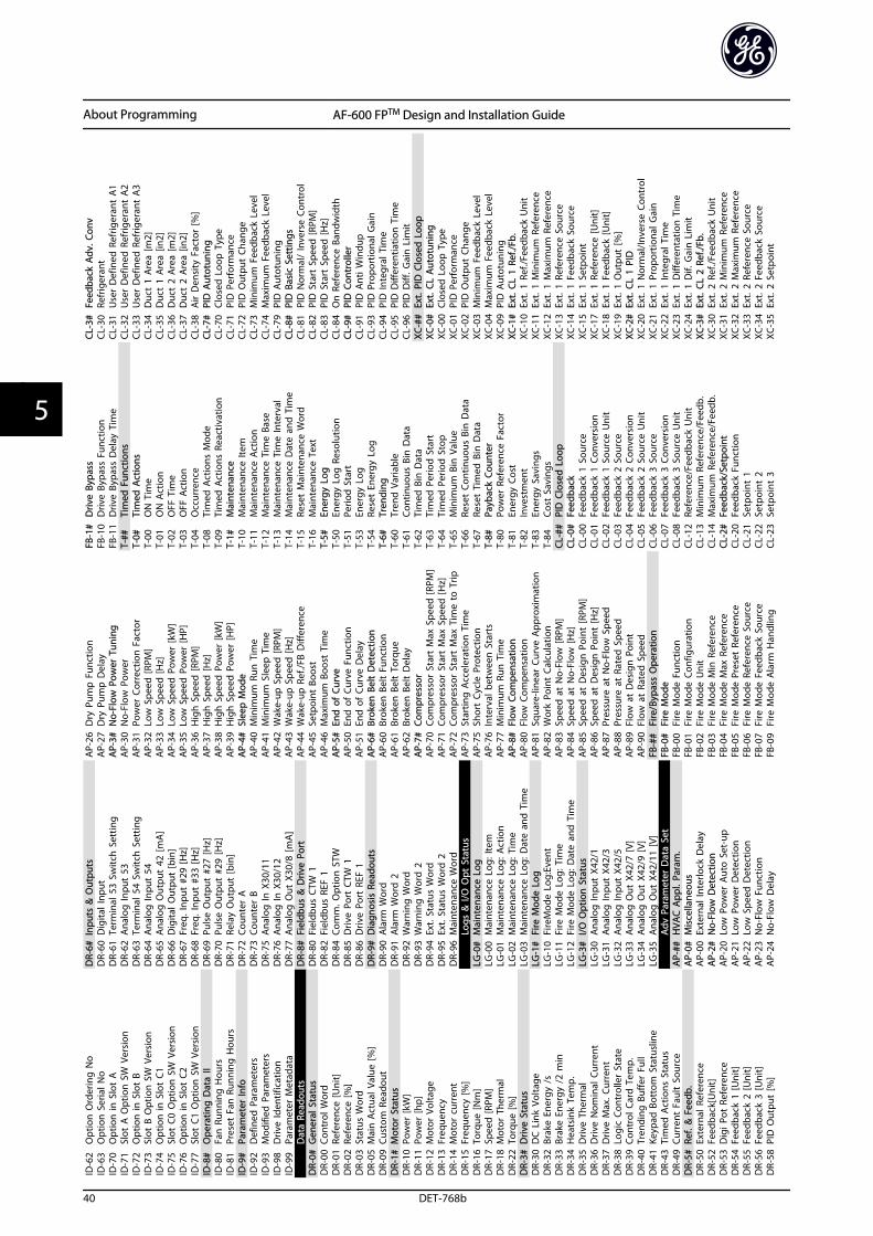
ID-6
2O
ptio
n O
rder
ing
No
ID-6
3O
ptio
n S
eria
l No
ID-7
0O
ptio
n in
Slo
t A
ID-7
1Sl
ot A
Opt
ion
SW
Ver
sion
ID-7
2O
ptio
n in
Slo
t B
ID-7
3Sl
ot B
Opt
ion
SW
Ver
sion
ID-7
4O
ptio
n in
Slo
t C1
ID-7
5Sl
ot C
0 O
ptio
n S
W V
ersi
onID
-76
Opt
ion
in S
lot
C2ID
-77
Slot
C1
Opt
ion
SW
Ver
sion
ID-8
#O
pera
ting
Dat
a II
ID-8
0Fa
n R
unni
ng H
ours
ID-8
1Pr
eset
Fan
Run
ning
Hou
rsID
-9#
Para
met
er In
foID
-92
Def
ined
Par
amet
ers
ID-9
3M
odifi
ed P
aram
eter
sID
-98
Driv
e Id
entif
icat
ion
ID-9
9Pa
ram
eter
Met
adat
aD
ata
Read
outs
DR-
0#G
ener
al S
tatu
sD
R-00
Cont
rol W
ord
DR-
01Re
fere
nce
[Uni
t]D
R-02
Refe
renc
e [%
]D
R-03
Stat
us W
ord
DR-
05M
ain
Act
ual V
alue
[%]
DR-
09Cu
stom
Rea
dout
DR-
1#M
otor
Sta
tus
DR-
10Po
wer
[kW
]D
R-11
Pow
er [h
p]D
R-12
Mot
or V
olta
geD
R-13
Freq
uenc
yD
R-14
Mot
or c
urre
ntD
R-15
Freq
uenc
y [%
]D
R-16
Torq
ue [N
m]
DR-
17Sp
eed
[RPM
]D
R-18
Mot
or T
herm
alD
R-22
Torq
ue [%
]D
R-3#
Driv
e St
atus
DR-
30D
C L
ink
Volta
geD
R-32
Brak
e En
ergy
/s
DR-
33Br
ake
Ener
gy /
2 m
inD
R-34
Hea
tsin
k Te
mp.
DR-
35D
rive
Ther
mal
DR-
36D
rive
Nom
inal
Cur
rent
DR-
37D
rive
Max
. Cur
rent
DR-
38Lo
gic
Cont
rolle
r St
ate
DR-
39Co
ntro
l Car
d T
emp.
DR-
40Tr
endi
ng B
uffe
r Fu
llD
R-41
Keyp
ad B
otto
m S
tatu
slin
eD
R-43
Tim
ed A
ctio
ns S
tatu
sD
R-49
Curr
ent
Faul
t So
urce
DR-
5#Re
f. &
Fee
db.
DR-
50Ex
tern
al R
efer
ence
DR-
52Fe
edba
ck[U
nit]
DR-
53D
igi P
ot R
efer
ence
DR-
54Fe
edba
ck 1
[Uni
t]D
R-55
Feed
back
2 [U
nit]
DR-
56Fe
edba
ck 3
[Uni
t]D
R-58
PID
Out
put
[%]
DR-
6#In
puts
& O
utpu
tsD
R-60
Dig
ital I
nput
DR-
61Te
rmin
al 5
3 Sw
itch
Set
ting
DR-
62A
nalo
g In
put
53D
R-63
Term
inal
54
Switc
h S
ettin
gD
R-64
Ana
log
Inpu
t 54
DR-
65A
nalo
g O
utpu
t 42
[mA
]D
R-66
Dig
ital O
utpu
t [b
in]
DR-
67Fr
eq. I
nput
#29
[Hz]
DR-
68Fr
eq. I
nput
#33
[Hz]
DR-
69Pu
lse
Out
put
#27
[Hz]
DR-
70Pu
lse
Out
put
#29
[Hz]
DR-
71Re
lay
Out
put
[bin
]D
R-72
Coun
ter
AD
R-73
Coun
ter
BD
R-75
Ana
log
In X
30/1
1D
R-76
Ana
log
In X
30/1
2D
R-77
Ana
log
Out
X30
/8 [m
A]
DR-
8#Fi
eldb
us &
Driv
e Po
rtD
R-80
Fiel
dbus
CTW
1D
R-82
Fiel
dbus
REF
1D
R-84
Com
m. O
ptio
n S
TWD
R-85
Driv
e Po
rt C
TW 1
DR-
86D
rive
Port
REF
1D
R-9#
Dia
gnos
is R
eado
uts
DR-
90A
larm
Wor
dD
R-91
Ala
rm W
ord
2D
R-92
War
ning
Wor
dD
R-93
War
ning
Wor
d 2
DR-
94Ex
t. S
tatu
s W
ord
DR-
95Ex
t. S
tatu
s W
ord
2D
R-96
Mai
nten
ance
Wor
dLo
gs &
I/O
Opt
Sta
tus
LG-0
#M
aint
enan
ce L
ogLG
-00
Mai
nten
ance
Log
: Ite
mLG
-01
Mai
nten
ance
Log
: Act
ion
LG-0
2M
aint
enan
ce L
og: T
ime
LG-0
3M
aint
enan
ce L
og: D
ate
and
Tim
eLG
-1#
Fire
Mod
e Lo
gLG
-10
Fire
Mod
e Lo
g:Ev
ent
LG-1
1Fi
re M
ode
Log:
Tim
eLG
-12
Fire
Mod
e Lo
g: D
ate
and
Tim
eLG
-3#
I/O O
ptio
n S
tatu
sLG
-30
Ana
log
Inpu
t X4
2/1
LG-3
1A
nalo
g In
put
X42/
3LG
-32
Ana
log
Inpu
t X4
2/5
LG-3
3A
nalo
g O
ut X
42/7
[V]
LG-3
4A
nalo
g O
ut X
42/9
[V]
LG-3
5A
nalo
g O
ut X
42/1
1 [V
]A
dv P
aram
eter
Dat
a Se
tA
P-##
HVA
C A
ppl.
Para
m.
AP-
0#M
isce
llane
ous
AP-
00Ex
tern
al In
terlo
ck D
elay
AP-
2#N
o-Fl
ow D
etec
tion
AP-
20Lo
w P
ower
Aut
o S
et-u
pA
P-21
Low
Pow
er D
etec
tion
AP-
22Lo
w S
peed
Det
ectio
nA
P-23
No-
Flow
Fun
ctio
nA
P-24
No-
Flow
Del
ay
AP-
26D
ry P
ump
Fun
ctio
nA
P-27
Dry
Pum
p D
elay
AP-
3#N
o-Fl
ow P
ower
Tun
ing
AP-
30N
o-Fl
ow P
ower
AP-
31Po
wer
Cor
rect
ion
Fac
tor
AP-
32Lo
w S
peed
[RPM
]A
P-33
Low
Spe
ed [H
z]A
P-34
Low
Spe
ed P
ower
[kW
]A
P-35
Low
Spe
ed P
ower
[HP]
AP-
36H
igh
Spe
ed [R
PM]
AP-
37H
igh
Spe
ed [H
z]A
P-38
Hig
h S
peed
Pow
er [k
W]
AP-
39H
igh
Spe
ed P
ower
[HP]
AP-
4#Sl
eep
Mod
eA
P-40
Min
imum
Run
Tim
eA
P-41
Min
imum
Sle
ep T
ime
AP-
42W
ake-
up S
peed
[RPM
]A
P-43
Wak
e-up
Spe
ed [H
z]A
P-44
Wak
e-up
Ref
./FB
Diff
eren
ceA
P-45
Setp
oint
Boo
stA
P-46
Max
imum
Boo
st T
ime
AP-
5#En
d o
f Cu
rve
AP-
50En
d o
f Cu
rve
Func
tion
AP-
51En
d o
f Cu
rve
Del
ayA
P-6#
Brok
en B
elt
Det
ectio
nA
P-60
Brok
en B
elt
Func
tion
AP-
61Br
oken
Bel
t To
rque
AP-
62Br
oken
Bel
t D
elay
AP-
7#Co
mpr
esso
rA
P-70
Com
pres
sor
Star
t M
ax S
peed
[RPM
]A
P-71
Com
pres
sor
Star
t M
ax S
peed
[Hz]
AP-
72Co
mpr
esso
r St
art
Max
Tim
e to
Trip
AP-
73St
artin
g A
ccel
erat
ion
Tim
eA
P-75
Shor
t Cy
cle
Prot
ectio
nA
P-76
Inte
rval
bet
wee
n S
tart
sA
P-77
Min
imum
Run
Tim
eA
P-8#
Flow
Com
pens
atio
nA
P-80
Flow
Com
pens
atio
nA
P-81
Squa
re-li
near
Cur
ve A
ppro
xim
atio
nA
P-82
Wor
k Po
int
Calc
ulat
ion
AP-
83Sp
eed
at
No-
Flow
[RPM
]A
P-84
Spee
d a
t N
o-Fl
ow [H
z]A
P-85
Spee
d a
t D
esig
n P
oint
[RPM
]A
P-86
Spee
d a
t D
esig
n P
oint
[Hz]
AP-
87Pr
essu
re a
t N
o-Fl
ow S
peed
AP-
88Pr
essu
re a
t Ra
ted
Spe
edA
P-89
Flow
at
Des
ign
Poi
ntA
P-90
Flow
at
Rate
d S
peed
FB-#
#Fi
re/B
ypas
s O
pera
tion
FB-0
#Fi
re M
ode
FB-0
0Fi
re M
ode
Func
tion
FB-0
1Fi
re M
ode
Conf
igur
atio
nFB
-02
Fire
Mod
e U
nit
FB-0
3Fi
re M
ode
Min
Ref
eren
ceFB
-04
Fire
Mod
e M
ax R
efer
ence
FB-0
5Fi
re M
ode
Pres
et R
efer
ence
FB-0
6Fi
re M
ode
Refe
renc
e So
urce
FB-0
7Fi
re M
ode
Feed
back
Sou
rce
FB-0
9Fi
re M
ode
Ala
rm H
andl
ing
FB-1
#D
rive
Bypa
ssFB
-10
Driv
e By
pass
Fun
ctio
nFB
-11
Driv
e By
pass
Del
ay T
ime
T-##
Tim
ed F
unct
ions
T-0#
Tim
ed A
ctio
nsT-
00O
N T
ime
T-01
ON
Act
ion
T-02
OFF
Tim
eT-
03O
FF A
ctio
nT-
04O
ccur
renc
eT-
08Ti
med
Act
ions
Mod
eT-
09Ti
med
Act
ions
Rea
ctiv
atio
nT-
1#M
aint
enan
ceT-
10M
aint
enan
ce It
emT-
11M
aint
enan
ce A
ctio
nT-
12M
aint
enan
ce T
ime
Base
T-13
Mai
nten
ance
Tim
e In
terv
alT-
14M
aint
enan
ce D
ate
and
Tim
eT-
15Re
set
Mai
nten
ance
Wor
dT-
16M
aint
enan
ce T
ext
T-5#
Ener
gy L
ogT-
50En
ergy
Log
Res
olut
ion
T-51
Perio
d S
tart
T-53
Ener
gy L
ogT-
54Re
set
Ener
gy L
ogT-
6#Tr
endi
ngT-
60Tr
end
Var
iabl
eT-
61Co
ntin
uous
Bin
Dat
aT-
62Ti
med
Bin
Dat
aT-
63Ti
med
Per
iod
Sta
rtT-
64Ti
med
Per
iod
Sto
pT-
65M
inim
um B
in V
alue
T-66
Rese
t Co
ntin
uous
Bin
Dat
aT-
67Re
set
Tim
ed B
in D
ata
T-8#
Payb
ack
Coun
ter
T-80
Pow
er R
efer
ence
Fac
tor
T-81
Ener
gy C
ost
T-82
Inve
stm
ent
T-83
Ener
gy S
avin
gsT-
84Co
st S
avin
gsCL
-##
PID
Clo
sed
Loo
pCL
-0#
Feed
back
CL-0
0Fe
edba
ck 1
Sou
rce
CL-0
1Fe
edba
ck 1
Con
vers
ion
CL-0
2Fe
edba
ck 1
Sou
rce
Uni
tCL
-03
Feed
back
2 S
ourc
eCL
-04
Feed
back
2 C
onve
rsio
nCL
-05
Feed
back
2 S
ourc
e U
nit
CL-0
6Fe
edba
ck 3
Sou
rce
CL-0
7Fe
edba
ck 3
Con
vers
ion
CL-0
8Fe
edba
ck 3
Sou
rce
Uni
tCL
-12
Refe
renc
e/Fe
edba
ck U
nit
CL-1
3M
inim
um R
efer
ence
/Fee
db.
CL-1
4M
axim
um R
efer
ence
/Fee
db.
CL-2
#Fe
edba
ck/S
etpo
int
CL-2
0Fe
edba
ck F
unct
ion
CL-2
1Se
tpoi
nt 1
CL-2
2Se
tpoi
nt 2
CL-2
3Se
tpoi
nt 3
CL-3
#Fe
edba
ck A
dv. C
onv
CL-3
0Re
frig
eran
tCL
-31
Use
r D
efin
ed R
efrig
eran
t A
1CL
-32
Use
r D
efin
ed R
efrig
eran
t A
2CL
-33
Use
r D
efin
ed R
efrig
eran
t A
3CL
-34
Duc
t 1
Are
a [m
2]CL
-35
Duc
t 1
Are
a [in
2]CL
-36
Duc
t 2
Are
a [m
2]CL
-37
Duc
t 2
Are
a [in
2]CL
-38
Air
Den
sity
Fac
tor
[%]
CL-7
#PI
D A
utot
unin
gCL
-70
Clos
ed L
oop
Typ
eCL
-71
PID
Per
form
ance
CL-7
2PI
D O
utpu
t Ch
ange
CL-7
3M
inim
um F
eedb
ack
Leve
lCL
-74
Max
imum
Fee
dbac
k Le
vel
CL-7
9PI
D A
utot
unin
gCL
-8#
PID
Bas
ic S
ettin
gsCL
-81
PID
Nor
mal
/ In
vers
e Co
ntro
lCL
-82
PID
Sta
rt S
peed
[RPM
]CL
-83
PID
Sta
rt S
peed
[Hz]
CL-8
4O
n R
efer
ence
Ban
dwid
thCL
-9#
PID
Con
trol
ler
CL-9
1PI
D A
nti W
indu
pCL
-93
PID
Pro
port
iona
l Gai
nCL
-94
PID
Inte
gral
Tim
eCL
-95
PID
Diff
eren
tiatio
n T
ime
CL-9
6PI
D D
iff. G
ain
Lim
itXC
-##
Ext.
PID
Clo
sed
Loo
pXC
-0#
Ext.
CL
Aut
otun
ing
XC-0
0Cl
osed
Loo
p T
ype
XC-0
1PI
D P
erfo
rman
ceXC
-02
PID
Out
put
Chan
geXC
-03
Min
imum
Fee
dbac
k Le
vel
XC-0
4M
axim
um F
eedb
ack
Leve
lXC
-09
PID
Aut
otun
ing
XC-1
#Ex
t. C
L 1
Ref./
Fb.
XC-1
0Ex
t. 1
Ref
./Fee
dbac
k U
nit
XC-1
1Ex
t. 1
Min
imum
Ref
eren
ceXC
-12
Ext.
1 M
axim
um R
efer
ence
XC-1
3Ex
t. 1
Ref
eren
ce S
ourc
eXC
-14
Ext.
1 F
eedb
ack
Sour
ceXC
-15
Ext.
1 S
etpo
int
XC-1
7Ex
t. 1
Ref
eren
ce [U
nit]
XC-1
8Ex
t. 1
Fee
dbac
k [U
nit]
XC-1
9Ex
t. 1
Out
put
[%]
XC-2
#Ex
t. C
L 1
PID
XC-2
0Ex
t. 1
Nor
mal
/Inve
rse
Cont
rol
XC-2
1Ex
t. 1
Pro
port
iona
l Gai
nXC
-22
Ext.
1 In
tegr
al T
ime
XC-2
3Ex
t. 1
Diff
eren
tatio
n T
ime
XC-2
4Ex
t. 1
Dif.
Gai
n L
imit
XC-3
#Ex
t. C
L 2
Ref./
Fb.
XC-3
0Ex
t. 2
Ref
./Fee
dbac
k U
nit
XC-3
1Ex
t. 2
Min
imum
Ref
eren
ceXC
-32
Ext.
2 M
axim
um R
efer
ence
XC-3
3Ex
t. 2
Ref
eren
ce S
ourc
eXC
-34
Ext.
2 F
eedb
ack
Sour
ceXC
-35
Ext.
2 S
etpo
int
About Programming AF-600 FPTM Design and Installation Guide
40 DET-768b
55
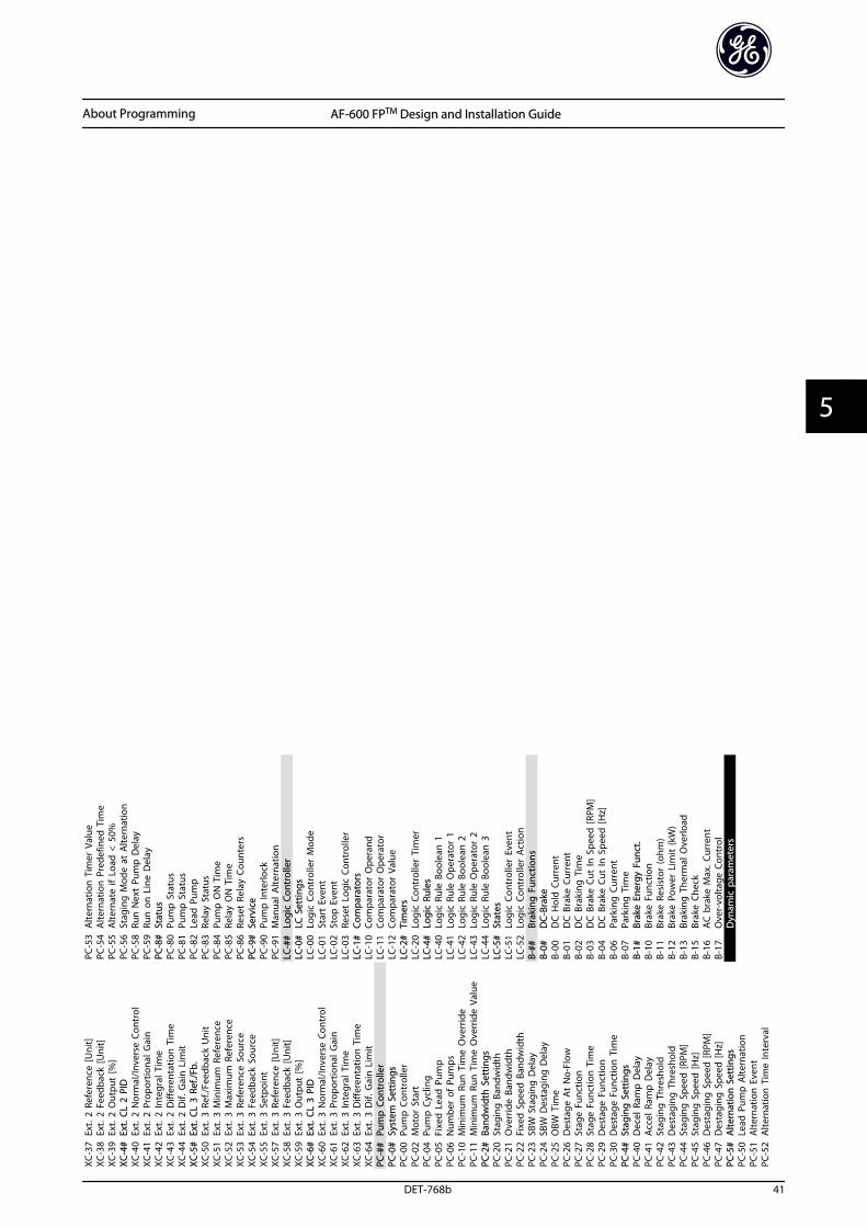
XC-3
7Ex
t. 2
Ref
eren
ce [U
nit]
XC-3
8Ex
t. 2
Fee
dbac
k [U
nit]
XC-3
9Ex
t. 2
Out
put
[%]
XC-4
#Ex
t. C
L 2
PID
XC-4
0Ex
t. 2
Nor
mal
/Inve
rse
Cont
rol
XC-4
1Ex
t. 2
Pro
port
iona
l Gai
nXC
-42
Ext.
2 In
tegr
al T
ime
XC-4
3Ex
t. 2
Diff
eren
tatio
n T
ime
XC-4
4Ex
t. 2
Dif.
Gai
n L
imit
XC-5
#Ex
t. C
L 3
Ref./
Fb.
XC-5
0Ex
t. 3
Ref
./Fee
dbac
k U
nit
XC-5
1Ex
t. 3
Min
imum
Ref
eren
ceXC
-52
Ext.
3 M
axim
um R
efer
ence
XC-5
3Ex
t. 3
Ref
eren
ce S
ourc
eXC
-54
Ext.
3 F
eedb
ack
Sour
ceXC
-55
Ext.
3 S
etpo
int
XC-5
7Ex
t. 3
Ref
eren
ce [U
nit]
XC-5
8Ex
t. 3
Fee
dbac
k [U
nit]
XC-5
9Ex
t. 3
Out
put
[%]
XC-6
#Ex
t. C
L 3
PID
XC-6
0Ex
t. 3
Nor
mal
/Inve
rse
Cont
rol
XC-6
1Ex
t. 3
Pro
port
iona
l Gai
nXC
-62
Ext.
3 In
tegr
al T
ime
XC-6
3Ex
t. 3
Diff
eren
tatio
n T
ime
XC-6
4Ex
t. 3
Dif.
Gai
n L
imit
PC-#
#Pu
mp
Con
trol
ler
PC-0
#Sy
stem
Set
tings
PC-0
0Pu
mp
Con
trol
ler
PC-0
2M
otor
Sta
rtPC
-04
Pum
p C
yclin
gPC
-05
Fixe
d L
ead
Pum
pPC
-06
Num
ber
of P
umps
PC-1
0M
inim
um R
un T
ime
Ove
rrid
ePC
-11
Min
imum
Run
Tim
e O
verr
ide
Valu
ePC
-2#
Band
wid
th S
ettin
gsPC
-20
Stag
ing
Ban
dwid
thPC
-21
Ove
rrid
e Ba
ndw
idth
PC-2
2Fi
xed
Spe
ed B
andw
idth
PC-2
3SB
W S
tagi
ng D
elay
PC-2
4SB
W D
esta
ging
Del
ayPC
-25
OBW
Tim
ePC
-26
Des
tage
At
No-
Flow
PC-2
7St
age
Func
tion
PC-2
8St
age
Func
tion
Tim
ePC
-29
Des
tage
Fun
ctio
nPC
-30
Des
tage
Fun
ctio
n T
ime
PC-4
#St
agin
g S
ettin
gsPC
-40
Dec
el R
amp
Del
ayPC
-41
Acc
el R
amp
Del
ayPC
-42
Stag
ing
Thr
esho
ldPC
-43
Des
tagi
ng T
hres
hold
PC-4
4St
agin
g S
peed
[RPM
]PC
-45
Stag
ing
Spe
ed [H
z]PC
-46
Des
tagi
ng S
peed
[RPM
]PC
-47
Des
tagi
ng S
peed
[Hz]
PC-5
#A
ltern
atio
n S
ettin
gsPC
-50
Lead
Pum
p A
ltern
atio
nPC
-51
Alte
rnat
ion
Eve
ntPC
-52
Alte
rnat
ion
Tim
e In
terv
al
PC-5
3A
ltern
atio
n T
imer
Val
uePC
-54
Alte
rnat
ion
Pre
defin
ed T
ime
PC-5
5A
ltern
ate
if L
oad
< 5
0%PC
-56
Stag
ing
Mod
e at
Alte
rnat
ion
PC-5
8Ru
n N
ext
Pum
p D
elay
PC-5
9Ru
n o
n L
ine
Del
ayPC
-8#
Stat
usPC
-80
Pum
p S
tatu
sPC
-81
Pum
p S
tatu
sPC
-82
Lead
Pum
pPC
-83
Rela
y St
atus
PC-8
4Pu
mp
ON
Tim
ePC
-85
Rela
y O
N T
ime
PC-8
6Re
set
Rela
y Co
unte
rsPC
-9#
Serv
ice
PC-9
0Pu
mp
Inte
rlock
PC-9
1M
anua
l Alte
rnat
ion
LC-#
#Lo
gic
Cont
rolle
rLC
-0#
LC S
ettin
gsLC
-00
Logi
c Co
ntro
ller
Mod
eLC
-01
Star
t Ev
ent
LC-0
2St
op E
vent
LC-0
3Re
set
Logi
c Co
ntro
ller
LC-1
#Co
mpa
rato
rsLC
-10
Com
para
tor
Ope
rand
LC-1
1Co
mpa
rato
r O
pera
tor
LC-1
2Co
mpa
rato
r Va
lue
LC-2
#Ti
mer
sLC
-20
Logi
c Co
ntro
ller
Tim
erLC
-4#
Logi
c Ru
les
LC-4
0Lo
gic
Rule
Boo
lean
1LC
-41
Logi
c Ru
le O
pera
tor
1LC
-42
Logi
c Ru
le B
oole
an 2
LC-4
3Lo
gic
Rule
Ope
rato
r 2
LC-4
4Lo
gic
Rule
Boo
lean
3LC
-5#
Stat
esLC
-51
Logi
c Co
ntro
ller
Even
tLC
-52
Logi
c Co
ntro
ller
Act
ion
B-##
Brak
ing
Fun
ctio
nsB-
0#D
C-Br
ake
B-00
DC
Hol
d C
urre
ntB-
01D
C B
rake
Cur
rent
B-02
DC
Bra
king
Tim
eB-
03D
C B
rake
Cut
In S
peed
[RPM
]B-
04D
C B
rake
Cut
In S
peed
[Hz]
B-06
Park
ing
Cur
rent
B-07
Park
ing
Tim
eB-
1#Br
ake
Ener
gy F
unct
.B-
10Br
ake
Func
tion
B-11
Brak
e Re
sist
or (o
hm)
B-12
Brak
e Po
wer
Lim
it (k
W)
B-13
Brak
ing
The
rmal
Ove
rload
B-15
Brak
e Ch
eck
B-16
AC
bra
ke M
ax. C
urre
ntB-
17O
ver-
volta
ge C
ontr
olD
ynam
ic p
aram
eter
s
About Programming AF-600 FPTM Design and Installation Guide
DET-768b 41
5 5
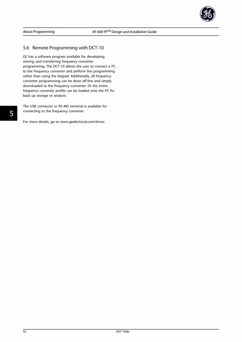
5.6 Remote Programming with DCT-10
GE has a software program available for developing,storing, and transferring frequency converterprogramming. The DCT-10 allows the user to connect a PCto the frequency converter and perform live programmingrather than using the keypad. Additionally, all frequencyconverter programming can be done off-line and simplydownloaded to the frequency converter. Or the entirefrequency converter profile can be loaded onto the PC forback up storage or analysis.
The USB connector or RS-485 terminal is available forconnecting to the frequency converter.
For more details, go to www.geelectrical.com/drives
About Programming AF-600 FPTM Design and Installation Guide
42 DET-768b
55
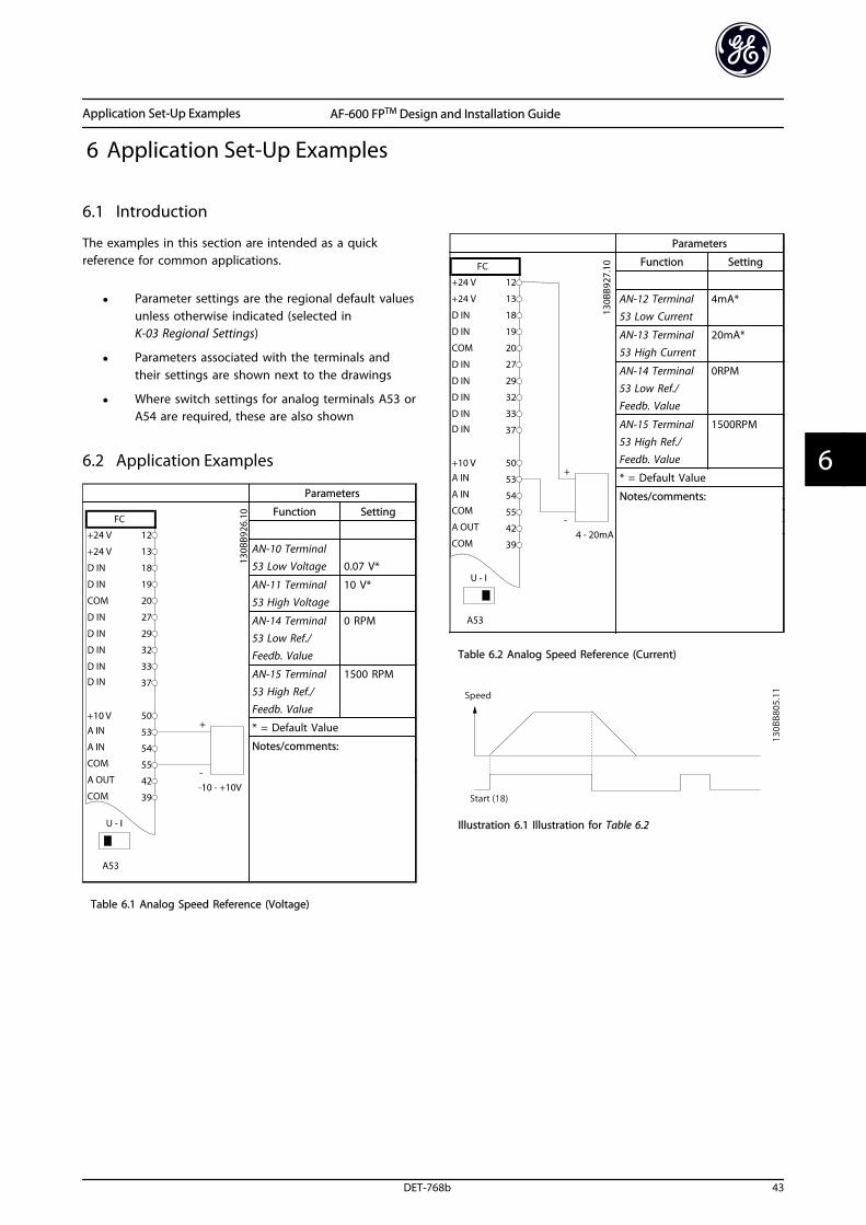
6 Application Set-Up Examples
6.1 Introduction
The examples in this section are intended as a quickreference for common applications.
• Parameter settings are the regional default valuesunless otherwise indicated (selected inK-03 Regional Settings)
• Parameters associated with the terminals andtheir settings are shown next to the drawings
• Where switch settings for analog terminals A53 orA54 are required, these are also shown
6.2 Application Examples
Parameters
Function Setting
AN-10 Terminal53 Low Voltage 0.07 V*
AN-11 Terminal53 High Voltage
10 V*
AN-14 Terminal53 Low Ref./Feedb. Value
0 RPM
AN-15 Terminal
53 High Ref./Feedb. Value
1500 RPM
* = Default Value
Notes/comments:
Table 6.1 Analog Speed Reference (Voltage)
Parameters
Function Setting
AN-12 Terminal53 Low Current
4mA*
AN-13 Terminal53 High Current
20mA*
AN-14 Terminal53 Low Ref./Feedb. Value
0RPM
AN-15 Terminal53 High Ref./Feedb. Value
1500RPM
* = Default Value
Notes/comments:
Table 6.2 Analog Speed Reference (Current)
Illustration 6.1 Illustration for Table 6.2
Application Set-Up Examples AF-600 FPTM Design and Installation Guide
DET-768b 43
6 6
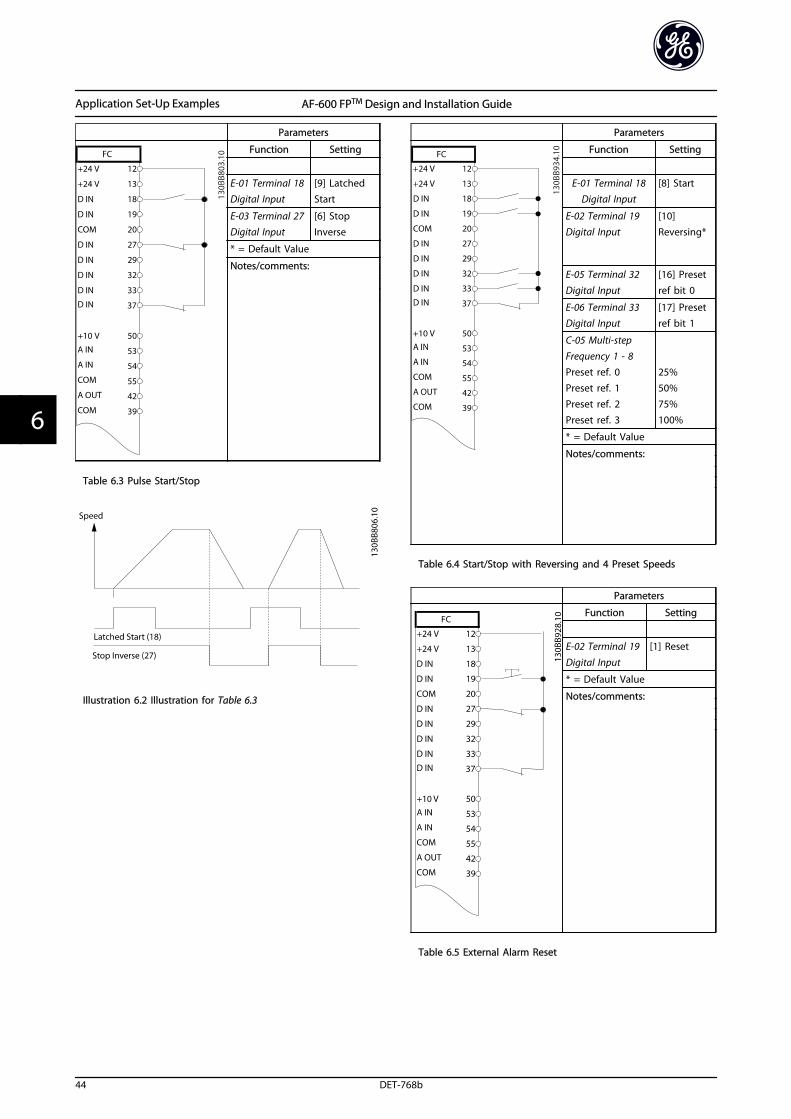
Parameters
Function Setting
E-01 Terminal 18Digital Input
[9] LatchedStart
E-03 Terminal 27Digital Input
[6] StopInverse
* = Default Value
Notes/comments:
Table 6.3 Pulse Start/Stop
Illustration 6.2 Illustration for Table 6.3
Parameters
Function Setting
E-01 Terminal 18Digital Input
[8] Start
E-02 Terminal 19Digital Input
[10]Reversing*
E-05 Terminal 32Digital Input
[16] Presetref bit 0
E-06 Terminal 33Digital Input
[17] Presetref bit 1
C-05 Multi-stepFrequency 1 - 8
Preset ref. 0Preset ref. 1Preset ref. 2Preset ref. 3
25%50%75%100%
* = Default Value
Notes/comments:
Table 6.4 Start/Stop with Reversing and 4 Preset Speeds
Parameters
Function Setting
E-02 Terminal 19
Digital Input
[1] Reset
* = Default Value
Notes/comments:
Table 6.5 External Alarm Reset
Application Set-Up Examples AF-600 FPTM Design and Installation Guide
44 DET-768b
66
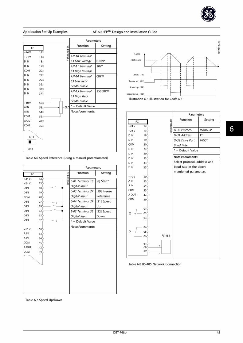
Parameters
Function Setting
AN-10 Terminal53 Low Voltage 0.07V*
AN-11 Terminal53 High Voltage
10V*
AN-14 Terminal53 Low Ref./Feedb. Value
0RPM
AN-15 Terminal53 High Ref./Feedb. Value
1500RPM
* = Default Value
Notes/comments:
Table 6.6 Speed Reference (using a manual potentiometer)
Parameters
Function Setting
E-01 Terminal 18
Digital Input
[8] Start*
E-03 Terminal 27Digital Input
[19] FreezeReference
E-04 Terminal 29Digital Input
[21] SpeedUp
E-05 Terminal 32Digital Input
[22] SpeedDown
* = Default Value
Notes/comments:
Table 6.7 Speed Up/Down
S t a r t ( 1 8 )
F r e e z e r e f ( 2 7 )
S p e e d u p ( 2 9 )
S p e e d d o w n ( 3 2 )
S p e e d
R e f e r e n c e
130B
B840
.10
Illustration 6.3 Illustration for Table 6.7
Parameters
Function Setting
O-30 Protocol Modbus*
O-31 Address 1*
O-32 Drive PortBaud Rate
9600*
* = Default Value
Notes/comments:Select protocol, address andbaud rate in the abovementioned parameters.
Table 6.8 RS-485 Network Connection
Application Set-Up Examples AF-600 FPTM Design and Installation Guide
DET-768b 45
6 6
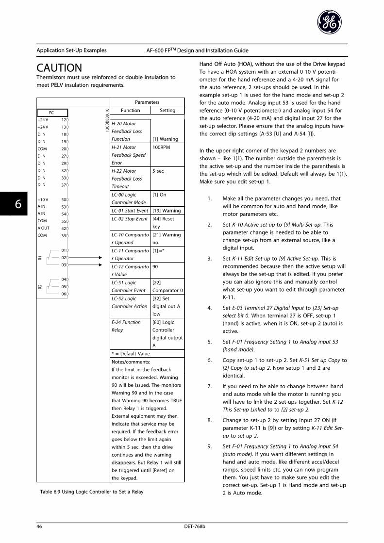
CAUTIONThermistors must use reinforced or double insulation tomeet PELV insulation requirements.
Parameters
Function Setting
H-20 Motor
Feedback LossFunction [1] Warning
H-21 MotorFeedback SpeedError
100RPM
H-22 MotorFeedback LossTimeout
5 sec
LC-00 LogicController Mode
[1] On
LC-01 Start Event [19] Warning
LC-02 Stop Event [44] Reset
key
LC-10 Comparator Operand
[21] Warningno.
LC-11 Comparator Operator
[1] ≈*
LC-12 Comparator Value
90
LC-51 LogicController Event
[22]Comparator 0
LC-52 Logic
Controller Action
[32] Set
digital out Alow
E-24 Function
Relay
[80] Logic
Controllerdigital outputA
* = Default Value
Notes/comments:If the limit in the feedbackmonitor is exceeded, Warning90 will be issued. The monitorsWarning 90 and in the casethat Warning 90 becomes TRUEthen Relay 1 is triggered.External equipment may thenindicate that service may berequired. If the feedback errorgoes below the limit againwithin 5 sec. then the drivecontinues and the warningdisappears. But Relay 1 will stillbe triggered until [Reset] onthe keypad.
Table 6.9 Using Logic Controller to Set a Relay
Hand Off Auto (HOA), without the use of the Drive keypadTo have a HOA system with an external 0-10 V potenti-ometer for the hand reference and a 4-20 mA signal forthe auto reference, 2 set-ups should be used. In thisexample set-up 1 is used for the hand mode and set-up 2for the auto mode. Analog input 53 is used for the handreference (0-10 V potentiometer) and analog input 54 forthe auto reference (4-20 mA) and digital input 27 for theset-up selector. Please ensure that the analog inputs havethe correct dip settings (A-53 [U] and A-54 [I]).
In the upper right corner of the keypad 2 numbers areshown – like 1(1). The number outside the parenthesis isthe active set-up and the number inside the parenthesis isthe set-up which will be edited. Default will always be 1(1).Make sure you edit set-up 1.
1. Make all the parameter changes you need, thatwill be common for auto and hand mode, likemotor parameters etc.
2. Set K-10 Active set-up to [9] Multi Set-up. Thisparameter change is needed to be able tochange set-up from an external source, like adigital input.
3. Set K-11 Edit Set-up to [9] Active Set-up. This isrecommended because then the active setup willalways be the set-up that is edited. If you preferyou can also ignore this and manually controlwhat set-up you want to edit through parameterK-11.
4. Set E-03 Terminal 27 Digital Input to [23] Set-upselect bit 0. When terminal 27 is OFF, set-up 1(hand) is active, when it is ON, set-up 2 (auto) isactive.
5. Set F-01 Frequency Setting 1 to Analog input 53(hand mode).
6. Copy set-up 1 to set-up 2. Set K-51 Set up Copy to[2] Copy to set-up 2. Now setup 1 and 2 areidentical.
7. If you need to be able to change between handand auto mode while the motor is running youwill have to link the 2 set-ups together. Set K-12This Set-up Linked to to [2] set-up 2.
8. Change to set-up 2 by setting input 27 ON (ifparameter K-11 is [9]) or by setting K-11 Edit Set-up to set-up 2.
9. Set F-01 Frequency Setting 1 to Analog input 54(auto mode). If you want different settings inhand and auto mode, like different accel/decelramps, speed limits etc. you can now programthem. You just have to make sure you edit thecorrect set-up. Set-up 1 is Hand mode and set-up2 is Auto mode.
Application Set-Up Examples AF-600 FPTM Design and Installation Guide
46 DET-768b
66
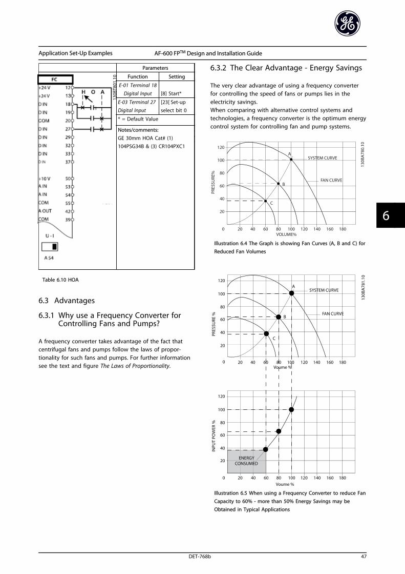
Parameters
Function Setting
E-01 Terminal 18
Digital Input [8] Start*
E-03 Terminal 27Digital Input
[23[ Set-upselect bit 0
* = Default Value
Notes/comments:GE 30mm HOA Cat# (1)104PSG34B & (3) CR104PXC1
Table 6.10 HOA
6.3 Advantages
6.3.1 Why use a Frequency Converter forControlling Fans and Pumps?
A frequency converter takes advantage of the fact thatcentrifugal fans and pumps follow the laws of propor-tionality for such fans and pumps. For further informationsee the text and figure The Laws of Proportionality.
6.3.2 The Clear Advantage - Energy Savings
The very clear advantage of using a frequency converterfor controlling the speed of fans or pumps lies in theelectricity savings.When comparing with alternative control systems andtechnologies, a frequency converter is the optimum energycontrol system for controlling fan and pump systems.
Illustration 6.4 The Graph is showing Fan Curves (A, B and C) forReduced Fan Volumes
Illustration 6.5 When using a Frequency Converter to reduce FanCapacity to 60% - more than 50% Energy Savings may beObtained in Typical Applications
Application Set-Up Examples AF-600 FPTM Design and Installation Guide
DET-768b 47
6 6
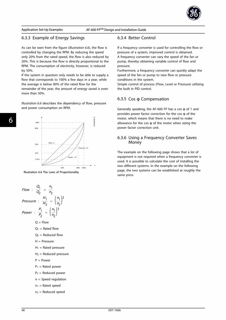
6.3.3 Example of Energy Savings
As can be seen from the figure (Illustration 6.6), the flow iscontrolled by changing the RPM. By reducing the speedonly 20% from the rated speed, the flow is also reduced by20%. This is because the flow is directly proportional to theRPM. The consumption of electricity, however, is reducedby 50%.If the system in question only needs to be able to supply aflow that corresponds to 100% a few days in a year, whilethe average is below 80% of the rated flow for theremainder of the year, the amount of energy saved is evenmore than 50%.
Illustration 6.6 describes the dependency of flow, pressureand power consumption on RPM.
Illustration 6.6 The Laws of Proportionality
Flow :Q1Q2
= n1n2
Pressure :H1H2
= ( n1n2 )2
Power :P1P2
= ( n1n2 )3
Q = Flow
Q1 = Rated flow
Q2 = Reduced flow
H = Pressure
H1 = Rated pressure
H2 = Reduced pressure
P = Power
P1 = Rated power
P2 = Reduced power
n = Speed regulation
n1 = Rated speed
n2 = Reduced speed
6.3.4 Better Control
If a frequency converter is used for controlling the flow orpressure of a system, improved control is obtained.A frequency converter can vary the speed of the fan orpump, thereby obtaining variable control of flow andpressure.Furthermore, a frequency converter can quickly adapt thespeed of the fan or pump to new flow or pressureconditions in the system.Simple control of process (Flow, Level or Pressure) utilizingthe built in PID control.
6.3.5 Cos φ Compensation
Generally speaking, the AF-600 FP has a cos φ of 1 andprovides power factor correction for the cos φ of themotor, which means that there is no need to makeallowance for the cos φ of the motor when sizing thepower factor correction unit.
6.3.6 Using a Frequency Converter SavesMoney
The example on the following page shows that a lot ofequipment is not required when a frequency converter isused. It is possible to calculate the cost of installing thetwo different systems. In the example on the followingpage, the two systems can be established at roughly thesame price.
Application Set-Up Examples AF-600 FPTM Design and Installation Guide
48 DET-768b
66
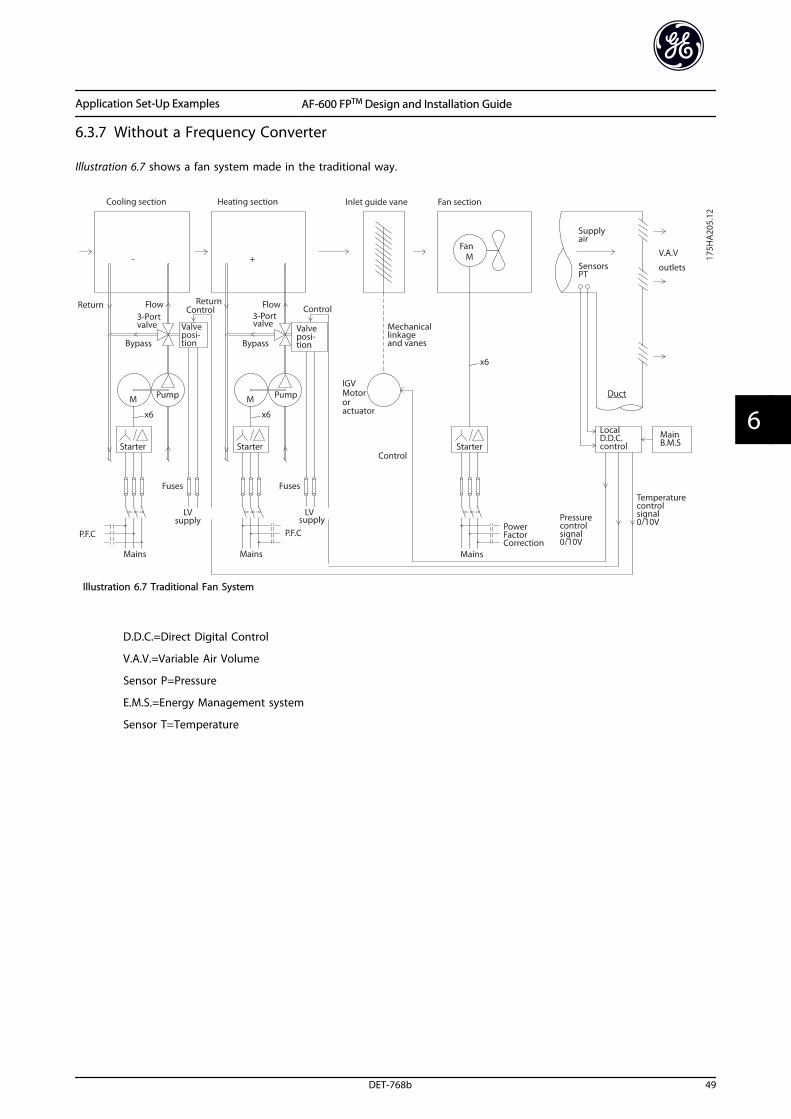
6.3.7 Without a Frequency Converter
Illustration 6.7 shows a fan system made in the traditional way.
Illustration 6.7 Traditional Fan System
D.D.C.=Direct Digital Control
V.A.V.=Variable Air Volume
Sensor P=Pressure
E.M.S.=Energy Management system
Sensor T=Temperature
Application Set-Up Examples AF-600 FPTM Design and Installation Guide
DET-768b 49
6 6
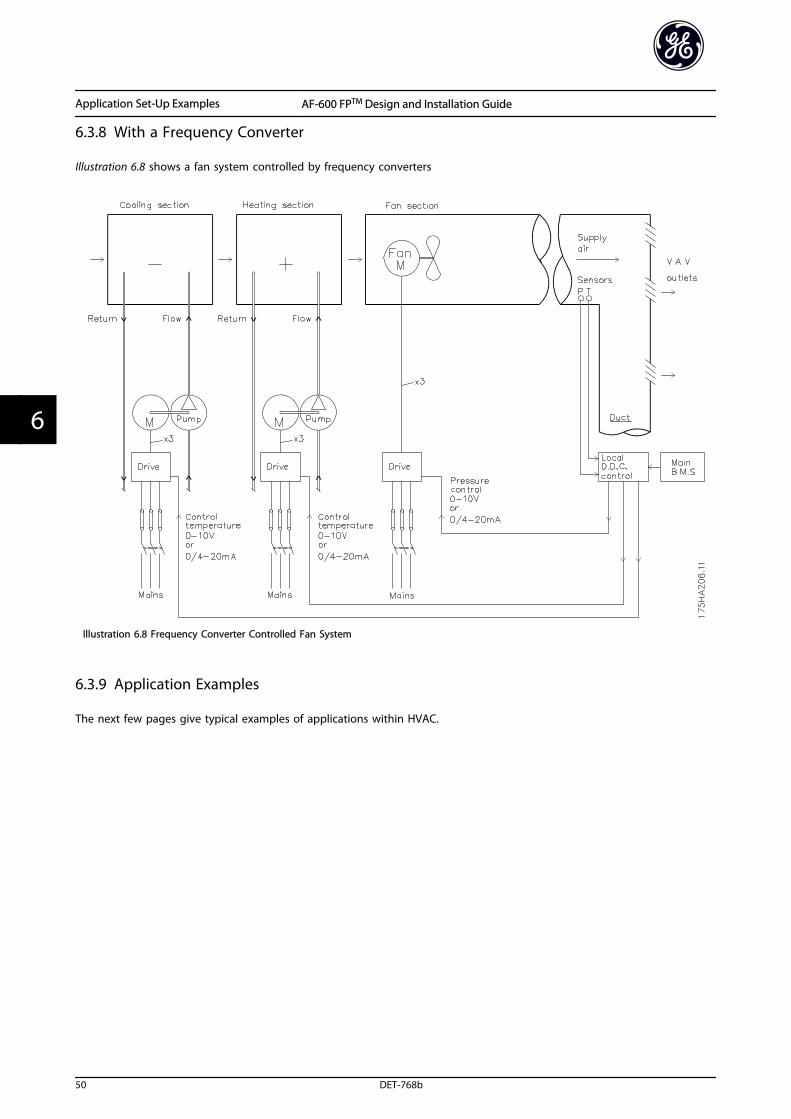
6.3.8 With a Frequency Converter
Illustration 6.8 shows a fan system controlled by frequency converters
Illustration 6.8 Frequency Converter Controlled Fan System
6.3.9 Application Examples
The next few pages give typical examples of applications within HVAC.
Application Set-Up Examples AF-600 FPTM Design and Installation Guide
50 DET-768b
66
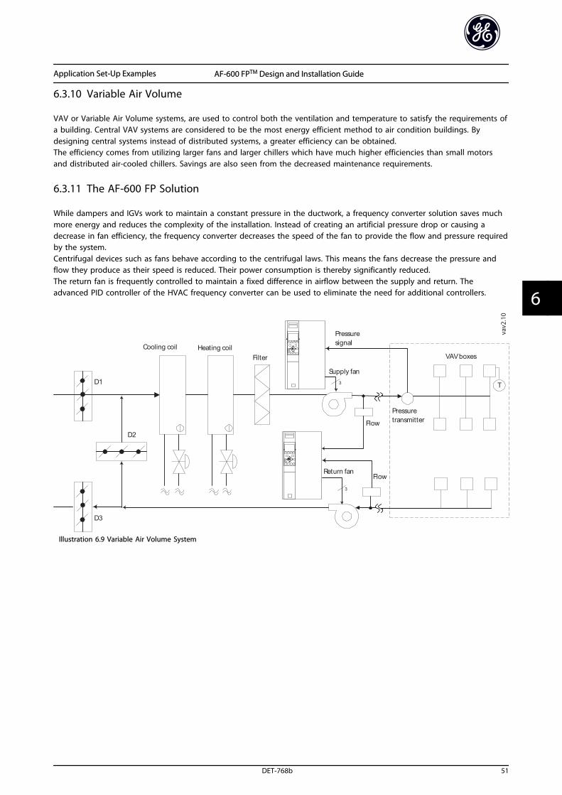
6.3.10 Variable Air Volume
VAV or Variable Air Volume systems, are used to control both the ventilation and temperature to satisfy the requirements ofa building. Central VAV systems are considered to be the most energy efficient method to air condition buildings. Bydesigning central systems instead of distributed systems, a greater efficiency can be obtained.The efficiency comes from utilizing larger fans and larger chillers which have much higher efficiencies than small motorsand distributed air-cooled chillers. Savings are also seen from the decreased maintenance requirements.
6.3.11 The AF-600 FP Solution
While dampers and IGVs work to maintain a constant pressure in the ductwork, a frequency converter solution saves muchmore energy and reduces the complexity of the installation. Instead of creating an artificial pressure drop or causing adecrease in fan efficiency, the frequency converter decreases the speed of the fan to provide the flow and pressure requiredby the system.Centrifugal devices such as fans behave according to the centrifugal laws. This means the fans decrease the pressure andflow they produce as their speed is reduced. Their power consumption is thereby significantly reduced.The return fan is frequently controlled to maintain a fixed difference in airflow between the supply and return. Theadvanced PID controller of the HVAC frequency converter can be used to eliminate the need for additional controllers.
Pressuresignal
VAV boxes
Flow
Flow
Cooling coil Heating coil
D1
D2
D3
Filter
Pressuretransmitter
Supply fan
Return fan
T
3
3
vav2.10
Illustration 6.9 Variable Air Volume System
Application Set-Up Examples AF-600 FPTM Design and Installation Guide
DET-768b 51
6 6
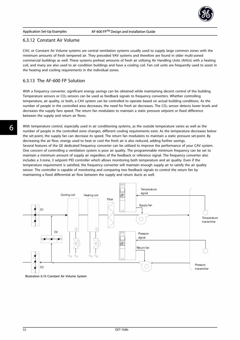
6.3.12 Constant Air Volume
CAV, or Constant Air Volume systems are central ventilation systems usually used to supply large common zones with theminimum amounts of fresh tempered air. They preceded VAV systems and therefore are found in older multi-zonedcommercial buildings as well. These systems preheat amounts of fresh air utilizing Air Handling Units (AHUs) with a heatingcoil, and many are also used to air condition buildings and have a cooling coil. Fan coil units are frequently used to assist inthe heating and cooling requirements in the individual zones.
6.3.13 The AF-600 FP Solution
With a frequency converter, significant energy savings can be obtained while maintaining decent control of the building.Temperature sensors or CO2 sensors can be used as feedback signals to frequency converters. Whether controllingtemperature, air quality, or both, a CAV system can be controlled to operate based on actual building conditions. As thenumber of people in the controlled area decreases, the need for fresh air decreases. The CO2 sensor detects lower levels anddecreases the supply fans speed. The return fan modulates to maintain a static pressure setpoint or fixed differencebetween the supply and return air flows.
With temperature control, especially used in air conditioning systems, as the outside temperature varies as well as thenumber of people in the controlled zone changes, different cooling requirements exist. As the temperature decreases belowthe set-point, the supply fan can decrease its speed. The return fan modulates to maintain a static pressure set-point. Bydecreasing the air flow, energy used to heat or cool the fresh air is also reduced, adding further savings.Several features of the GE dedicated frequency converter can be utilized to improve the performance of your CAV system.One concern of controlling a ventilation system is poor air quality. The programmable minimum frequency can be set tomaintain a minimum amount of supply air regardless of the feedback or reference signal. The frequency converter alsoincludes a 3-zone, 3 setpoint PID controller which allows monitoring both temperature and air quality. Even if thetemperature requirement is satisfied, the frequency converter will maintain enough supply air to satisfy the air qualitysensor. The controller is capable of monitoring and comparing two feedback signals to control the return fan bymaintaining a fixed differential air flow between the supply and return ducts as well.
Pressuresignal
Cooling coil Heating coil
D1
D2
D3
Filter
Pressuretransmitter
Supply fan
Return fan
Temperaturesignal
Temperaturetransmitter
Illustration 6.10 Constant Air Volume System
Application Set-Up Examples AF-600 FPTM Design and Installation Guide
52 DET-768b
66
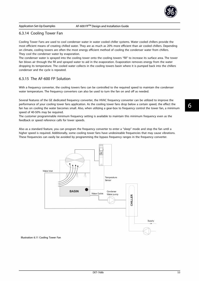
6.3.14 Cooling Tower Fan
Cooling Tower Fans are used to cool condenser water in water cooled chiller systems. Water cooled chillers provide themost efficient means of creating chilled water. They are as much as 20% more efficient than air cooled chillers. Dependingon climate, cooling towers are often the most energy efficient method of cooling the condenser water from chillers.They cool the condenser water by evaporation.The condenser water is sprayed into the cooling tower onto the cooling towers “fill” to increase its surface area. The towerfan blows air through the fill and sprayed water to aid in the evaporation. Evaporation removes energy from the waterdropping its temperature. The cooled water collects in the cooling towers basin where it is pumped back into the chillerscondenser and the cycle is repeated.
6.3.15 The AF-600 FP Solution
With a frequency converter, the cooling towers fans can be controlled to the required speed to maintain the condenserwater temperature. The frequency converters can also be used to turn the fan on and off as needed.
Several features of the GE dedicated frequency converter, the HVAC frequency converter can be utilized to improve theperformance of your cooling tower fans application. As the cooling tower fans drop below a certain speed, the effect thefan has on cooling the water becomes small. Also, when utilizing a gear-box to frequency control the tower fan, a minimumspeed of 40-50% may be required.The customer programmable minimum frequency setting is available to maintain this minimum frequency even as thefeedback or speed reference calls for lower speeds.
Also as a standard feature, you can program the frequency converter to enter a “sleep” mode and stop the fan until ahigher speed is required. Additionally, some cooling tower fans have undesireable frequencies that may cause vibrations.These frequencies can easily be avoided by programming the bypass frequency ranges in the frequency converter.
Illustration 6.11 Cooling Tower Fan
Application Set-Up Examples AF-600 FPTM Design and Installation Guide
DET-768b 53
6 6
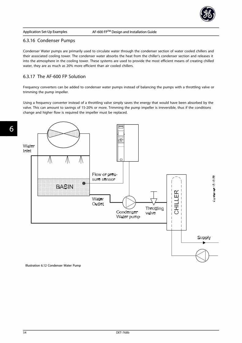
6.3.16 Condenser Pumps
Condenser Water pumps are primarily used to circulate water through the condenser section of water cooled chillers andtheir associated cooling tower. The condenser water absorbs the heat from the chiller's condenser section and releases itinto the atmosphere in the cooling tower. These systems are used to provide the most efficient means of creating chilledwater, they are as much as 20% more efficient than air cooled chillers.
6.3.17 The AF-600 FP Solution
Frequency converters can be added to condenser water pumps instead of balancing the pumps with a throttling valve ortrimming the pump impeller.
Using a frequency converter instead of a throttling valve simply saves the energy that would have been absorbed by thevalve. This can amount to savings of 15-20% or more. Trimming the pump impeller is irreversible, thus if the conditionschange and higher flow is required the impeller must be replaced.
Illustration 6.12 Condenser Water Pump
Application Set-Up Examples AF-600 FPTM Design and Installation Guide
54 DET-768b
66
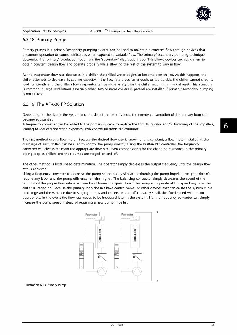
6.3.18 Primary Pumps
Primary pumps in a primary/secondary pumping system can be used to maintain a constant flow through devices thatencounter operation or control difficulties when exposed to variable flow. The primary/ secondary pumping techniquedecouples the “primary” production loop from the “secondary” distribution loop. This allows devices such as chillers toobtain constant design flow and operate properly while allowing the rest of the system to vary in flow.
As the evaporator flow rate decreases in a chiller, the chilled water begins to become over-chilled. As this happens, thechiller attempts to decrease its cooling capacity. If the flow rate drops far enough, or too quickly, the chiller cannot shed itsload sufficiently and the chiller’s low evaporator temperature safety trips the chiller requiring a manual reset. This situationis common in large installations especially when two or more chillers in parallel are installed if primary/ secondary pumpingis not utilized.
6.3.19 The AF-600 FP Solution
Depending on the size of the system and the size of the primary loop, the energy consumption of the primary loop canbecome substantial.A frequency converter can be added to the primary system, to replace the throttling valve and/or trimming of the impellers,leading to reduced operating expenses. Two control methods are common:
The first method uses a flow meter. Because the desired flow rate is known and is constant, a flow meter installed at thedischarge of each chiller, can be used to control the pump directly. Using the built-in PID controller, the frequencyconverter will always maintain the appropriate flow rate, even compensating for the changing resistance in the primarypiping loop as chillers and their pumps are staged on and off.
The other method is local speed determination. The operator simply decreases the output frequency until the design flowrate is achieved.Using a frequency converter to decrease the pump speed is very similar to trimming the pump impeller, except it doesn’trequire any labor and the pump efficiency remains higher. The balancing contractor simply decreases the speed of thepump until the proper flow rate is achieved and leaves the speed fixed. The pump will operate at this speed any time thechiller is staged on. Because the primary loop doesn’t have control valves or other devices that can cause the system curveto change and the variance due to staging pumps and chillers on and off is usually small, this fixed speed will remainappropriate. In the event the flow rate needs to be increased later in the systems life, the frequency converter can simplyincrease the pump speed instead of requiring a new pump impeller.
Illustration 6.13 Primary Pump
Application Set-Up Examples AF-600 FPTM Design and Installation Guide
DET-768b 55
6 6
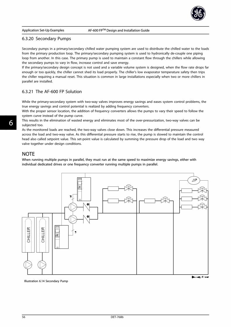
6.3.20 Secondary Pumps
Secondary pumps in a primary/secondary chilled water pumping system are used to distribute the chilled water to the loadsfrom the primary production loop. The primary/secondary pumping system is used to hydronically de-couple one pipingloop from another. In this case. The primary pump is used to maintain a constant flow through the chillers while allowingthe secondary pumps to vary in flow, increase control and save energy.If the primary/secondary design concept is not used and a variable volume system is designed, when the flow rate drops farenough or too quickly, the chiller cannot shed its load properly. The chiller’s low evaporator temperature safety then tripsthe chiller requiring a manual reset. This situation is common in large installations especially when two or more chillers inparallel are installed.
6.3.21 The AF-600 FP Solution
While the primary-secondary system with two-way valves improves energy savings and eases system control problems, thetrue energy savings and control potential is realized by adding frequency converters.With the proper sensor location, the addition of frequency converters allows the pumps to vary their speed to follow thesystem curve instead of the pump curve.This results in the elimination of wasted energy and eliminates most of the over-pressurization, two-way valves can besubjected too.As the monitored loads are reached, the two-way valves close down. This increases the differential pressure measuredacross the load and two-way valve. As this differential pressure starts to rise, the pump is slowed to maintain the controlhead also called setpoint value. This set-point value is calculated by summing the pressure drop of the load and two wayvalve together under design conditions.
NOTEWhen running multiple pumps in parallel, they must run at the same speed to maximize energy savings, either withindividual dedicated drives or one frequency converter running multiple pumps in parallel.
Illustration 6.14 Secondary Pump
Application Set-Up Examples AF-600 FPTM Design and Installation Guide
56 DET-768b
66
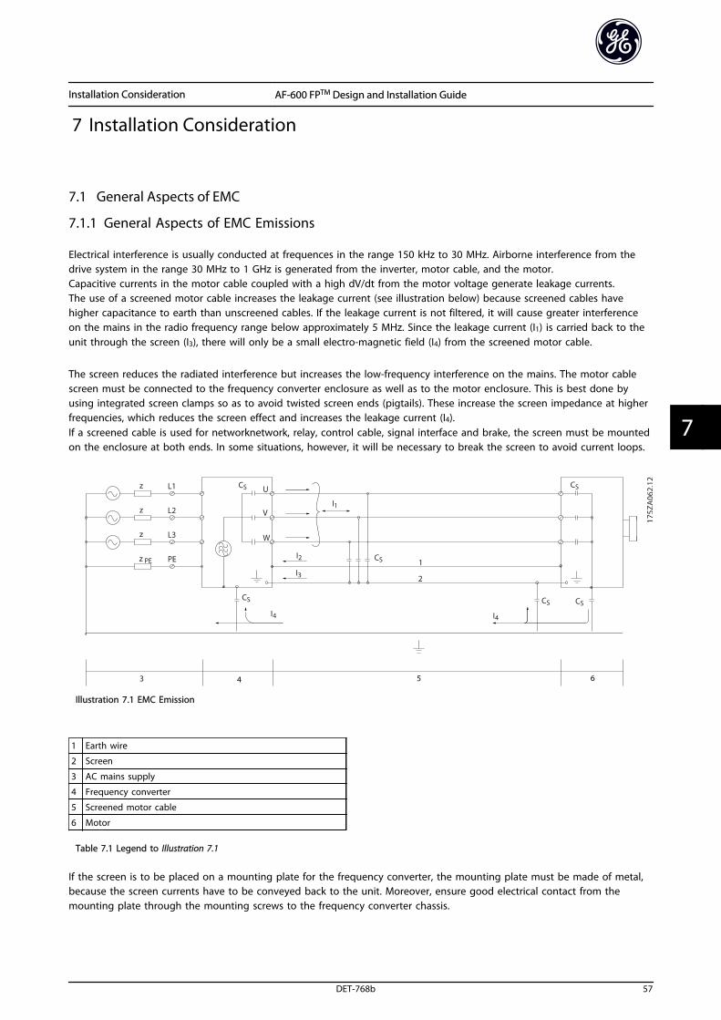
7 Installation Consideration
7.1 General Aspects of EMC
7.1.1 General Aspects of EMC Emissions
Electrical interference is usually conducted at frequences in the range 150 kHz to 30 MHz. Airborne interference from thedrive system in the range 30 MHz to 1 GHz is generated from the inverter, motor cable, and the motor.Capacitive currents in the motor cable coupled with a high dV/dt from the motor voltage generate leakage currents.The use of a screened motor cable increases the leakage current (see illustration below) because screened cables havehigher capacitance to earth than unscreened cables. If the leakage current is not filtered, it will cause greater interferenceon the mains in the radio frequency range below approximately 5 MHz. Since the leakage current (I1) is carried back to theunit through the screen (I3), there will only be a small electro-magnetic field (I4) from the screened motor cable.
The screen reduces the radiated interference but increases the low-frequency interference on the mains. The motor cablescreen must be connected to the frequency converter enclosure as well as to the motor enclosure. This is best done byusing integrated screen clamps so as to avoid twisted screen ends (pigtails). These increase the screen impedance at higherfrequencies, which reduces the screen effect and increases the leakage current (I4).If a screened cable is used for networknetwork, relay, control cable, signal interface and brake, the screen must be mountedon the enclosure at both ends. In some situations, however, it will be necessary to break the screen to avoid current loops.
Illustration 7.1 EMC Emission
1 Earth wire
2 Screen
3 AC mains supply
4 Frequency converter
5 Screened motor cable
6 Motor
Table 7.1 Legend to Illustration 7.1
If the screen is to be placed on a mounting plate for the frequency converter, the mounting plate must be made of metal,because the screen currents have to be conveyed back to the unit. Moreover, ensure good electrical contact from themounting plate through the mounting screws to the frequency converter chassis.
Installation Consideration AF-600 FPTM Design and Installation Guide
DET-768b 57
7 7
When unscreened cables are used, some emission requirements are not complied with, although the immunityrequirements are observed.
In order to reduce the interference level from the entire system (unit + installation), make motor and brake cables as shortas possible. Avoid placing cables with a sensitive signal level alongside motor and brake cables. Radio interference higherthan 50 MHz (airborne) is especially generated by the control electronics.
7.1.2 Emission Requirements
According to the EMC product standard for adjustable speed frequency converters EN/IEC61800-3:2004 the EMCrequirements depend on the intended use of the frequency converter. Four categories are defined in the EMC productstandard. The definitions of the four categories together with the requirements for mains supply voltage conductedemissions are given in Table 7.2:
Category DefinitionConducted emission requirementaccording to the limits given in
EN55011
C1 Frequency converters installed in the first environment (home and office) with asupply voltage less than 1000 V.
Class B
C2 Frequency converters installed in the first environment (home and office) with a
supply voltage less than 1000 V, which are neither plug-in nor movable and areintended to be installed and commissioned by a professional.
Class A Group 1
C3 Frequency converters installed in the second environment (industrial) with a supplyvoltage lower than 1000 V.
Class A Group 2
C4 Frequency converters installed in the second environment with a supply voltageequal to or above 1000 V or rated current equal to or above 400 A or intended foruse in complex systems.
No limit line.An EMC plan should be made.
Table 7.2 Categories
When the generic emission standards are used the frequency converters are required to comply with the limits in Table 7.3:
Environment Generic standardConducted emission requirement
according to the limits given in EN55011
First environment
(home and office)
EN/IEC61000-6-3 Emission standard for residential, commercial and
light industrial environments.
Class B
Second environment(industrial environment)
EN/IEC61000-6-4 Emission standard for industrial environments. Class A Group 1
Table 7.3 Limits
Installation Consideration AF-600 FPTM Design and Installation Guide
58 DET-768b
77
7.1.3 EMC Test Results (Emission)
The following test results have been obtained using a system with a frequency converter (with options if relevant), ascreened control cable, a control box with potentiometer, as well as a motor and motor screened cable.
RFI filter type Conducted emission
Maximum shielded cable length
Radiated emission
Industrial environment Housing, tradesand lightindustries
Industrialenvironment
Housing, trades and lightindustries
Standard EN 55011Class A2
EN 55011Class A1
EN 55011Class B
EN 55011Class A1
EN 55011Class B
Class A1/B RFI Filter installed
0.75-45 kW 200-240 V 150 m 150 m 50 m Yes No
0.75-90 kW 380-480 V 150 m 150 m 50 m Yes No
Class A2 RFI Filter installed
0.75-3.7 kW 200-240 V 5 m No No No No
5.5-37 kW 200-240 V 25 m No No No No
0.75-7.5 kW 380-480 V 5 m No No No No
11-75 kW 380-480 V 25 m No No No No
90-800 kW 380-480 V 150 m No No No No
90-1200 kW 525-690 V 150 m No No No No
No RFI Filter installed
0.75-75 kW 525-600 V - - - - -
Table 7.4 EMC Test Results (Emission)
7.2 Immunity Requirements
The immunity requirements for frequency converters depend on the environment where they are installed. Therequirements for the industrial environment are higher than the requirements for the home and office environment. All GEfrequency converters comply with the requirements for the industrial environment and consequently comply also with thelower requirements for home and office environment with a large safety margin.
In order to document immunity against electrical interference from electrical phenomena, the following immunity tests havebeen made on a system consisting of a frequency converter (with options if relevant), a screened control cable and acontrol box with potentiometer, motor cable and motor.The tests were performed in accordance with the following basic standards:
• EN 61000-4-2 (IEC 61000-4-2): Electrostatic discharges (ESD): Simulation of electrostatic discharges from humanbeings.
• EN 61000-4-3 (IEC 61000-4-3): Incoming electromagnetic field radiation, amplitude modulated simulation of theeffects of radar and radio communication equipment as well as mobile communications equipment.
• EN 61000-4-4 (IEC 61000-4-4): Burst transients: Simulation of interference brought about by switching a contactor,relay or similar devices.
• EN 61000-4-5 (IEC 61000-4-5): Surge transients: Simulation of transients brought about e.g. by lightning that strikesnear installations.
• EN 61000-4-6 (IEC 61000-4-6): RF Common mode: Simulation of the effect from radio-transmission equipmentjoined by connection cables.
See Table 7.5.
Installation Consideration AF-600 FPTM Design and Installation Guide
DET-768b 59
7 7
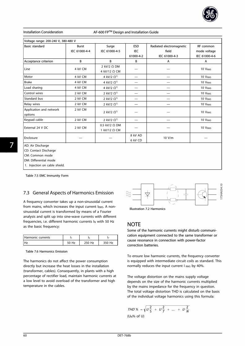
Voltage range: 200-240 V, 380-480 V
Basic standard BurstIEC 61000-4-4
SurgeIEC 61000-4-5
ESDIEC
61000-4-2
Radiated electromagneticfield
IEC 61000-4-3
RF commonmode voltageIEC 61000-4-6
Acceptance criterion B B B A A
Line 4 kV CM2 kV/2 Ω DM4 kV/12 Ω CM
— — 10 VRMS
Motor 4 kV CM 4 kV/2 Ω1) — — 10 VRMS
Brake 4 kV CM 4 kV/2 Ω1) — — 10 VRMS
Load sharing 4 kV CM 4 kV/2 Ω1) — — 10 VRMS
Control wires 2 kV CM 2 kV/2 Ω1) — — 10 VRMS
Standard bus 2 kV CM 2 kV/2 Ω1) — — 10 VRMS
Relay wires 2 kV CM 2 kV/2 Ω1) — — 10 VRMS
Application and network
options
2 kV CM2 kV/2 Ω1) — — 10 VRMS
Keypad cable 2 kV CM 2 kV/2 Ω1) — — 10 VRMS
External 24 V DC 2 kV CM0.5 kV/2 Ω DM
1 kV/12 Ω CM— — 10 VRMS
Enclosure — —8 kV AD6 kV CD
10 V/m —
AD: Air DischargeCD: Contact DischargeCM: Common modeDM: Differential mode1. Injection on cable shield.
Table 7.5 EMC Immunity Form
7.3 General Aspects of Harmonics Emission
A frequency converter takes up a non-sinusoidal currentfrom mains, which increases the input current IRMS. A non-sinusoidal current is transformed by means of a Fourieranalysis and split up into sine-wave currents with differentfrequencies, i.e. different harmonic currents IN with 50 Hzas the basic frequency:
Harmonic currents I1 I5 I7
Hz 50 Hz 250 Hz 350 Hz
Table 7.6 Harmonics Emission
The harmonics do not affect the power consumptiondirectly but increase the heat losses in the installation(transformer, cables). Consequently, in plants with a highpercentage of rectifier load, maintain harmonic currents ata low level to avoid overload of the transformer and hightemperature in the cables.
Illustration 7.2 Harmonics
NOTESome of the harmonic currents might disturb communi-cation equipment connected to the same transformer orcause resonance in connection with power-factorcorrection batteries.
To ensure low harmonic currents, the frequency converteris equipped with intermediate circuit coils as standard. Thisnormally reduces the input current I RMS by 40%.
The voltage distortion on the mains supply voltagedepends on the size of the harmonic currents multipliedby the mains impedance for the frequency in question.The total voltage distortion THD is calculated on the basisof the individual voltage harmonics using this formula:
THD % = U 25 + U 2
7 + ... + U 2N
(UN% of U)
Installation Consideration AF-600 FPTM Design and Installation Guide
60 DET-768b
77
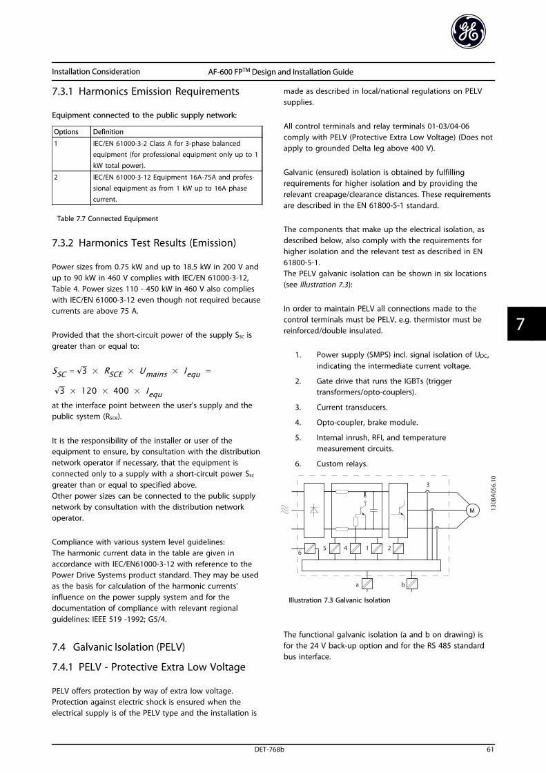
7.3.1 Harmonics Emission Requirements
Equipment connected to the public supply network:
Options Definition
1 IEC/EN 61000-3-2 Class A for 3-phase balancedequipment (for professional equipment only up to 1kW total power).
2 IEC/EN 61000-3-12 Equipment 16A-75A and profes-sional equipment as from 1 kW up to 16A phasecurrent.
Table 7.7 Connected Equipment
7.3.2 Harmonics Test Results (Emission)
Power sizes from 0.75 kW and up to 18.5 kW in 200 V andup to 90 kW in 460 V complies with IEC/EN 61000-3-12,Table 4. Power sizes 110 - 450 kW in 460 V also complieswith IEC/EN 61000-3-12 even though not required becausecurrents are above 75 A.
Provided that the short-circuit power of the supply Ssc isgreater than or equal to:
SSC = 3 × RSCE × Umains × Iequ =
3 × 120 × 400 × Iequat the interface point between the user’s supply and thepublic system (Rsce).
It is the responsibility of the installer or user of theequipment to ensure, by consultation with the distributionnetwork operator if necessary, that the equipment isconnected only to a supply with a short-circuit power Ssc
greater than or equal to specified above.Other power sizes can be connected to the public supplynetwork by consultation with the distribution networkoperator.
Compliance with various system level guidelines:The harmonic current data in the table are given inaccordance with IEC/EN61000-3-12 with reference to thePower Drive Systems product standard. They may be usedas the basis for calculation of the harmonic currents'influence on the power supply system and for thedocumentation of compliance with relevant regionalguidelines: IEEE 519 -1992; G5/4.
7.4 Galvanic Isolation (PELV)
7.4.1 PELV - Protective Extra Low Voltage
PELV offers protection by way of extra low voltage.Protection against electric shock is ensured when theelectrical supply is of the PELV type and the installation is
made as described in local/national regulations on PELVsupplies.
All control terminals and relay terminals 01-03/04-06comply with PELV (Protective Extra Low Voltage) (Does notapply to grounded Delta leg above 400 V).
Galvanic (ensured) isolation is obtained by fulfillingrequirements for higher isolation and by providing therelevant creapage/clearance distances. These requirementsare described in the EN 61800-5-1 standard.
The components that make up the electrical isolation, asdescribed below, also comply with the requirements forhigher isolation and the relevant test as described in EN61800-5-1.The PELV galvanic isolation can be shown in six locations(see Illustration 7.3):
In order to maintain PELV all connections made to thecontrol terminals must be PELV, e.g. thermistor must bereinforced/double insulated.
1. Power supply (SMPS) incl. signal isolation of UDC,indicating the intermediate current voltage.
2. Gate drive that runs the IGBTs (triggertransformers/opto-couplers).
3. Current transducers.
4. Opto-coupler, brake module.
5. Internal inrush, RFI, and temperaturemeasurement circuits.
6. Custom relays.
Illustration 7.3 Galvanic Isolation
The functional galvanic isolation (a and b on drawing) isfor the 24 V back-up option and for the RS 485 standardbus interface.
Installation Consideration AF-600 FPTM Design and Installation Guide
DET-768b 61
7 7
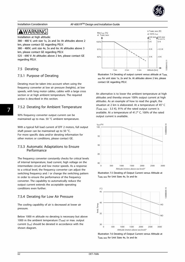
WARNINGInstallation at high altitude:380 - 480 V, unit size 1x, 2x and 3x: At altitudes above 2km, please contact GE regarding PELV.380 - 480V, unit size 4x, 5x and 6x: At altitudes above 3km, please contact GE regarding PELV.525 - 690 V: At altitudes above 2 km, please contact GEregarding PELV.
7.5 Derating
7.5.1 Purpose of Derating
Derating must be taken into account when using thefrequency converter at low air pressure (heights), at lowspeeds, with long motor cables, cables with a large crosssection or at high ambient temperature. The requiredaction is described in this section.
7.5.2 Derating for Ambient Temperature
90% frequency converter output current can bemaintained up to max. 50 °C ambient temperature.
With a typical full load current of EFF 2 motors, full outputshaft power can be maintained up to 50 °C.For more specific data and/or derating information forother motors or conditions, please contact GE.
7.5.3 Automatic Adaptations to EnsurePerformance
The frequency converter constantly checks for critical levelsof internal temperature, load current, high voltage on theintermediate circuit and low motor speeds. As a responseto a critical level, the frequency converter can adjust theswitching frequency and / or change the switching patternin order to ensure the performance of the frequencyconverter. The capability to automatically reduce theoutput current extends the acceptable operatingconditions even further.
7.5.4 Derating for Low Air Pressure
The cooling capability of air is decreased at lower airpressure.
Below 1000 m altitude no derating is necessary but above1000 m the ambient temperature (TAMB) or max. outputcurrent (Iout) should be derated in accordance with theshown diagram.
Illustration 7.4 Derating of output current versus altitude at TAMB,
MAX for unit sizes 1x, 2x and 3x. At altitudes above 2 km, please
contact GE regarding PELV.
An alternative is to lower the ambient temperature at highaltitudes and thereby ensure 100% output current at highaltitudes. As an example of how to read the graph, thesituation at 2 km is elaborated. At a temperature of 45° C(TAMB, MAX - 3.3 K), 91% of the rated output current isavailable. At a temperature of 41.7° C, 100% of the ratedoutput current is available.
Illustration 7.5 Derating of Output Current versus Altitude at
TAMB, MAX for Unit Sizes 4x, 5x and 6x
Illustration 7.6 Derating of Output Current versus Altitude atTAMB, MAX for Unit Sizes 4x, 5x and 6x
Installation Consideration AF-600 FPTM Design and Installation Guide
62 DET-768b
77
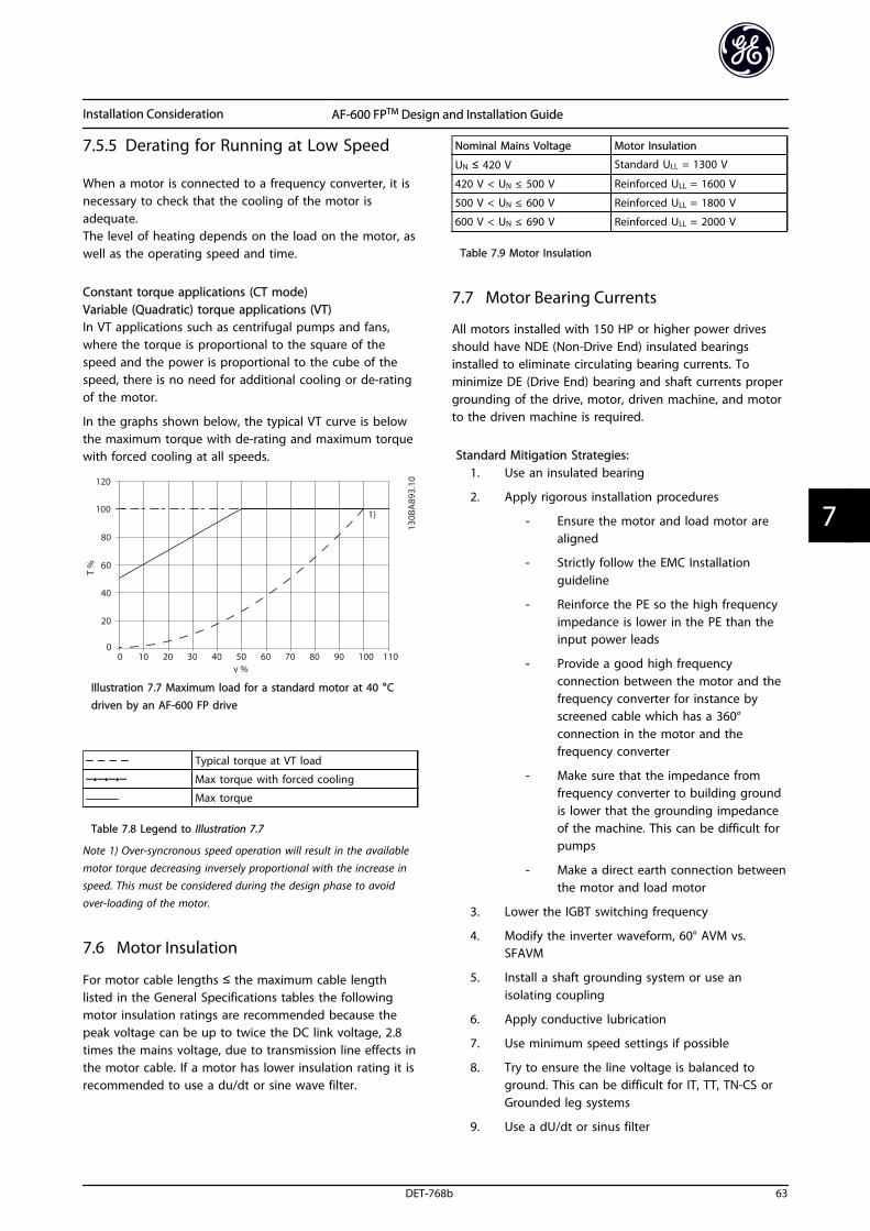
7.5.5 Derating for Running at Low Speed
When a motor is connected to a frequency converter, it isnecessary to check that the cooling of the motor isadequate.The level of heating depends on the load on the motor, aswell as the operating speed and time.
Constant torque applications (CT mode)Variable (Quadratic) torque applications (VT)In VT applications such as centrifugal pumps and fans,where the torque is proportional to the square of thespeed and the power is proportional to the cube of thespeed, there is no need for additional cooling or de-ratingof the motor.
In the graphs shown below, the typical VT curve is belowthe maximum torque with de-rating and maximum torquewith forced cooling at all speeds.
Illustration 7.7 Maximum load for a standard motor at 40 °C
driven by an AF-600 FP drive
Typical torque at VT load
••• Max torque with forced cooling
‒‒‒‒‒ Max torque
Table 7.8 Legend to Illustration 7.7
Note 1) Over-syncronous speed operation will result in the availablemotor torque decreasing inversely proportional with the increase inspeed. This must be considered during the design phase to avoidover-loading of the motor.
7.6 Motor Insulation
For motor cable lengths ≤ the maximum cable lengthlisted in the General Specifications tables the followingmotor insulation ratings are recommended because thepeak voltage can be up to twice the DC link voltage, 2.8times the mains voltage, due to transmission line effects inthe motor cable. If a motor has lower insulation rating it isrecommended to use a du/dt or sine wave filter.
Nominal Mains Voltage Motor Insulation
UN ≤ 420 V Standard ULL = 1300 V
420 V < UN ≤ 500 V Reinforced ULL = 1600 V
500 V < UN ≤ 600 V Reinforced ULL = 1800 V
600 V < UN ≤ 690 V Reinforced ULL = 2000 V
Table 7.9 Motor Insulation
7.7 Motor Bearing Currents
All motors installed with 150 HP or higher power drivesshould have NDE (Non-Drive End) insulated bearingsinstalled to eliminate circulating bearing currents. Tominimize DE (Drive End) bearing and shaft currents propergrounding of the drive, motor, driven machine, and motorto the driven machine is required.
Standard Mitigation Strategies:1. Use an insulated bearing
2. Apply rigorous installation procedures
- Ensure the motor and load motor arealigned
- Strictly follow the EMC Installationguideline
- Reinforce the PE so the high frequencyimpedance is lower in the PE than theinput power leads
- Provide a good high frequencyconnection between the motor and thefrequency converter for instance byscreened cable which has a 360°connection in the motor and thefrequency converter
- Make sure that the impedance fromfrequency converter to building groundis lower that the grounding impedanceof the machine. This can be difficult forpumps
- Make a direct earth connection betweenthe motor and load motor
3. Lower the IGBT switching frequency
4. Modify the inverter waveform, 60° AVM vs.SFAVM
5. Install a shaft grounding system or use anisolating coupling
6. Apply conductive lubrication
7. Use minimum speed settings if possible
8. Try to ensure the line voltage is balanced toground. This can be difficult for IT, TT, TN-CS orGrounded leg systems
9. Use a dU/dt or sinus filter
Installation Consideration AF-600 FPTM Design and Installation Guide
DET-768b 63
7 7
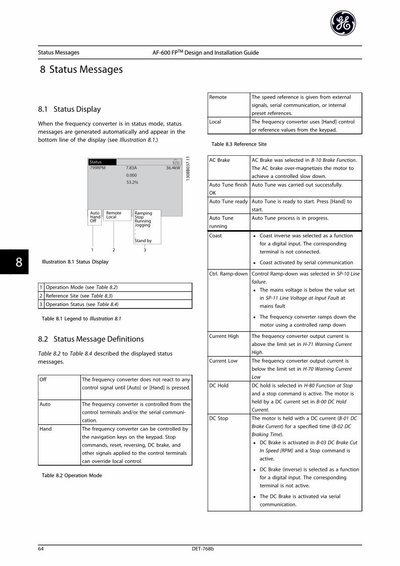
8 Status Messages
8.1 Status Display
When the frequency converter is in status mode, statusmessages are generated automatically and appear in thebottom line of the display (see Illustration 8.1.)
Illustration 8.1 Status Display
1 Operation Mode (see Table 8.2)
2 Reference Site (see Table 8.3)
3 Operation Status (see Table 8.4)
Table 8.1 Legend to Illustration 8.1
8.2 Status Message Definitions
Table 8.2 to Table 8.4 described the displayed statusmessages.
Off The frequency converter does not react to anycontrol signal until [Auto] or [Hand] is pressed.
Auto The frequency converter is controlled from thecontrol terminals and/or the serial communi-cation.
Hand The frequency converter can be controlled by
the navigation keys on the keypad. Stopcommands, reset, reversing, DC brake, andother signals applied to the control terminals
can override local control.
Table 8.2 Operation Mode
Remote The speed reference is given from externalsignals, serial communication, or internalpreset references.
Local The frequency converter uses [Hand] controlor reference values from the keypad.
Table 8.3 Reference Site
AC Brake AC Brake was selected in B-10 Brake Function.The AC brake over-magnetizes the motor toachieve a controlled slow down.
Auto Tune finishOK
Auto Tune was carried out successfully.
Auto Tune ready Auto Tune is ready to start. Press [Hand] tostart.
Auto Tune
running
Auto Tune process is in progress.
Coast • Coast inverse was selected as a functionfor a digital input. The correspondingterminal is not connected.
• Coast activated by serial communication
Ctrl. Ramp-down Control Ramp-down was selected in SP-10 Linefailure.
• The mains voltage is below the value setin SP-11 Line Voltage at Input Fault atmains fault
• The frequency converter ramps down themotor using a controlled ramp down
Current High The frequency converter output current is
above the limit set in H-71 Warning CurrentHigh.
Current Low The frequency converter output current is
below the limit set in H-70 Warning CurrentLow
DC Hold DC hold is selected in H-80 Function at Stopand a stop command is active. The motor isheld by a DC current set in B-00 DC Hold
Current.
DC Stop The motor is held with a DC current (B-01 DCBrake Current) for a specified time (B-02 DCBraking Time).
• DC Brake is activated in B-03 DC Brake CutIn Speed [RPM] and a Stop command is
active.
• DC Brake (inverse) is selected as a functionfor a digital input. The correspondingterminal is not active.
• The DC Brake is activated via serialcommunication.
Status Messages AF-600 FPTM Design and Installation Guide
64 DET-768b
88
Feedback high The sum of all active feedbacks is above the
feedback limit set in H-77 Warning FeedbackHigh.
Feedback low The sum of all active feedbacks is below thefeedback limit set in H-76 Warning FeedbackLow.
Freeze output The remote reference is active, which holdsthe present speed.
• Freeze output was selected as a functionfor a digital input. The correspondingterminal is active. Speed control is onlypossible via the terminal functions SpeedUp and Speed Down.
• Hold ramp is activated via serial communi-cation.
Freeze output
request
A freeze output command has been given,
but the motor will remain stopped until a runpermissive signal is received.
Freeze ref. Freeze Reference was chosen as a function fora digital input. The corresponding terminal isactive. The frequency converter saves theactual reference. Changing the reference isnow only possible via terminal functionsSpeed Up and Speed Down.
Jog request A jog command has been given, but themotor remains stopped until a run permissivesignal is received via a digital input.
Jogging The motor is running as programmed inC-21 Jog Speed [RPM].
• Jog was selected as function for a digitalinput. The corresponding terminal (e.g.Terminal 29) is active.
• The Jog function is activated via the serialcommunication.
• The Jog function was selected as areaction for a monitoring function (e.g. Nosignal). The monitoring function is active.
OVC control Overvoltage control was activated in
B-17 Over-voltage Control, [2] Enabled. Theconnected motor is supplying the frequencyconverter with generative energy. Theovervoltage control adjusts the V/Hz ratio torun the motor in controlled mode and toprevent the frequency converter from tripping.
PowerUnit Off (Only frequency converters with an external
24 V power supply installed).Mains supply to the frequency converter isremoved, but the control card is supplied by
the external 24 V.
Protection md Protection mode is active. The unit has
detected a critical status (an overcurrent orovervoltage).
• To avoid tripping, switching frequency is
reduced to 4 kHz.
• If possible, protection mode ends afterapproximately 10 s
• Protection mode can be restricted inSP-26 Trip Delay at Drive Fault
QStop The motor is decelerating using C-23 QuickStop Decel Time.
• Quick stop inverse was chosen as a functionfor a digital input. The correspondingterminal is not active.
• The quick stop function was activated viaserial communication.
Ramping The motor is accelerating/decelerating using
the active Ramp Up/Down. The reference, alimit value or a standstill is not yet reached.
Ref. high The sum of all active references is above thereference limit set in H-75 Warning ReferenceHigh.
Ref. low The sum of all active references is below thereference limit set in H-74 Warning ReferenceLow.
Run on ref. The frequency converter is running in thereference range. The feedback value matchesthe setpoint value.
Run request A start command has been given, but themotor is stopped until a run permissive signalis received via digital input.
Running The motor is driven by the frequencyconverter.
Sleep Mode The energy saving function is enabled. This
means that at present the motor has stopped,but that it will restart automatically whenrequired.
Speed high Motor speed is above the value set in
H-73 Warning Speed High.
Speed low Motor speed is below the value set inH-72 Warning Speed Low.
Standby In Auto mode, the frequency converter willstart the motor with a start signal from adigital input or serial communication.
Start delay In F-24 Holding Time, a delay starting time wasset. A start command is activated and themotor will start after the start delay timeexpires.
Status Messages AF-600 FPTM Design and Installation Guide
DET-768b 65
8 8
Start fwd/rev Start forward and start reverse were selected
as functions for two different digital inputs.The motor will start in forward or reversedepending on which corresponding terminal
is activated.
Stop The frequency converter has received a stopcommand from the keypad, digital input orserial communication.
Trip An alarm occurred and the motor is stopped.Once the cause of the alarm is cleared, thefrequency converter can be reset manually bypressing [Reset] or remotely by controlterminals or serial communication.
Trip lock An alarm occurred and the motor is stopped.Once the cause of the alarm is cleared, powermust be cycled to the frequency converter.The frequency converter can then be resetmanually by pressing [Reset] or remotely bycontrol terminals or serial communication.
Table 8.4 Operation Status
NOTEIn auto/remote mode, the frequency converter requiresexternal commands to execute functions.
Status Messages AF-600 FPTM Design and Installation Guide
66 DET-768b
88
9 RS-485 Installation and Set-up
9.1 Installation and Set-up
9.1 Network Configuration
9.1.1 Frequency Converter with ModbusRTU
To enable Modbus RTU on the frequency converter, set thefollowing parameters
Parameter Setting
O-30 Protocol Modbus RTU
O-31 Address 1-247
O-32 Drive Port Baud Rate 2400-115200
O-33 Drive Port Parity Even parity, 1 stop bit (default)
Table 9.1
9.1.2 How to Access Parameters
9.1.2.1 Parameter Handling
The PNU (Parameter Number) is translated from theregister address contained in the Modbus read or writemessage. The parameter number is translated to Modbusas (10 x parameter number) DECIMAL.
All parameters are named with one or two letters, a "-" anda number for example, F-07. To access parameters, useTable 9.2 because letters cannot be addressed.Example: F-07=7, E-01=101, DR-53=1253.
Letter NumberF 0
E 1
C 2
P 3
H 4
K 5
AN 6
B 7
O 8
PB 9
SP 10
XC 11
DR 12
LG 13
CL 14
ID 15
AP 16
Letter NumberT 17
FB 18
PC 19
AO 20
BP 21
DN 22
PI 23
LC 24
EC 25
RS 26
BN 27
LN 28
EN 29
CB 30
CA 31
CD 32
Table 9.2
9.1.2.2 Storage of Data
The Coil 65 decimal determines whether data written tothe frequency converter are stored in EEPROM and RAM(coil 65=1) or only in RAM (coil 65=0).
9.1.2.3 IND
The array index is set in Holding Register 9 and used whenaccessing array parameters.
9.1.2.4 Text Blocks
Parameters stored as text strings are accessed in the sameway as the other parameters. The maximum text block sizeis 20 characters. If a read request for a parameter is formore characters than the parameter stores, the response istruncated. If the read request for a parameter is for fewercharacters than the parameter stores, the response is spacefilled.
9.1.2.5 Conversion Factor
The different attributes for each parameter can be seen inthe section on factory settings. Since a parameter valuecan only be transferred as a whole number, a conversionfactor must be used to transfer decimals.
RS-485 Installation and Set... AF-600 FPTM Design and Installation Guide
DET-768b 67
9 9
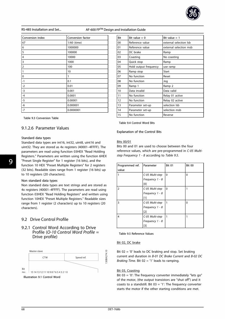
Conversion index Conversion factor
67 1/60 (time)
6 1000000
5 100000
4 10000
3 1000
2 100
1 10
0 1
-1 0.1
-2 0.01
-3 0.001
-4 0.0001
-5 0.00001
-6 0.000001
-7 0.0000001
Table 9.3 Conversion Table
9.1.2.6 Parameter Values
Standard data typesStandard data types are int16, int32, uint8, uint16 anduint32. They are stored as 4x registers (40001–4FFFF). Theparameters are read using function 03HEX "Read HoldingRegisters." Parameters are written using the function 6HEX"Preset Single Register" for 1 register (16 bits), and thefunction 10 HEX "Preset Multiple Registers" for 2 registers(32 bits). Readable sizes range from 1 register (16 bits) upto 10 registers (20 characters).
Non standard data typesNon standard data types are text strings and are stored as4x registers (40001–4FFFF). The parameters are read usingfunction 03HEX "Read Holding Registers" and written usingfunction 10HEX "Preset Multiple Registers." Readable sizesrange from 1 register (2 characters) up to 10 registers (20characters).
9.2 Drive Control Profile
9.2.1 Control Word According to DriveProfile (O-10 Control Word Profile =Drive profile)
Illustration 9.1 Control Word
Bit Bit value = 0 Bit value = 1
00 Reference value external selection lsb
01 Reference value external selection msb
02 DC brake Ramp
03 Coasting No coasting
04 Quick stop Ramp
05 Hold output frequency use ramp
06 Ramp stop Start
07 No function Reset
08 No function Jog
09 Ramp 1 Ramp 2
10 Data invalid Data valid
11 No function Relay 01 active
12 No function Relay 02 active
13 Parameter set-up selection lsb
14 Parameter set-up selection msb
15 No function Reverse
Table 9.4 Control Word Bits
Explanation of the Control Bits
Bits 00/01Bits 00 and 01 are used to choose between the fourreference values, which are pre-programmed in C-05 Multi-step Frequency 1 - 8 according to Table 9.5.
Programmed ref.
value
Parameter Bit 01 Bit 00
1 C-05 Multi-step
Frequency 1 - 8[0]
0 0
2 C-05 Multi-stepFrequency 1 - 8[1]
0 1
3 C-05 Multi-stepFrequency 1 - 8[2]
1 0
4 C-05 Multi-stepFrequency 1 - 8[3]
1 1
Table 9.5 Reference Values
Bit 02, DC brake
Bit 02 = ’0’ leads to DC braking and stop. Set brakingcurrent and duration in B-01 DC Brake Current and B-02 DCBraking Time. Bit 02 = ’1’ leads to ramping.
Bit 03, Coasting Bit 03 = ’0’: The frequency converter immediately "lets go"of the motor, (the output transistors are "shut off") and itcoasts to a standstill. Bit 03 = ’1’: The frequency converterstarts the motor if the other starting conditions are met.
RS-485 Installation and Set... AF-600 FPTM Design and Installation Guide
68 DET-768b
99
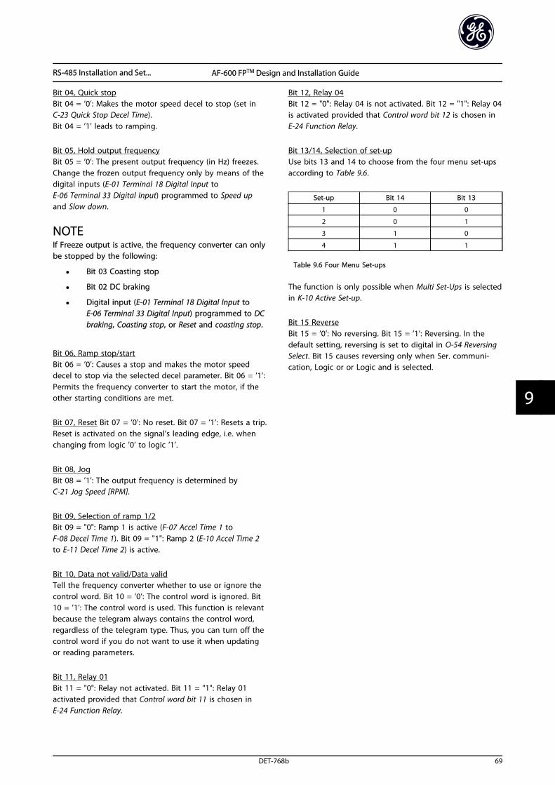
Bit 04, Quick stopBit 04 = ’0’: Makes the motor speed decel to stop (set inC-23 Quick Stop Decel Time).Bit 04 = ’1’ leads to ramping.
Bit 05, Hold output frequency Bit 05 = ’0’: The present output frequency (in Hz) freezes.Change the frozen output frequency only by means of thedigital inputs (E-01 Terminal 18 Digital Input toE-06 Terminal 33 Digital Input) programmed to Speed upand Slow down.
NOTEIf Freeze output is active, the frequency converter can onlybe stopped by the following:
• Bit 03 Coasting stop
• Bit 02 DC braking
• Digital input (E-01 Terminal 18 Digital Input toE-06 Terminal 33 Digital Input) programmed to DCbraking, Coasting stop, or Reset and coasting stop.
Bit 06, Ramp stop/startBit 06 = ’0’: Causes a stop and makes the motor speeddecel to stop via the selected decel parameter. Bit 06 = ’1’:Permits the frequency converter to start the motor, if theother starting conditions are met.
Bit 07, Reset Bit 07 = ’0’: No reset. Bit 07 = ’1’: Resets a trip.Reset is activated on the signal’s leading edge, i.e. whenchanging from logic ’0’ to logic ’1’.
Bit 08, Jog Bit 08 = ’1’: The output frequency is determined byC-21 Jog Speed [RPM].
Bit 09, Selection of ramp 1/2Bit 09 = "0": Ramp 1 is active (F-07 Accel Time 1 toF-08 Decel Time 1). Bit 09 = "1": Ramp 2 (E-10 Accel Time 2to E-11 Decel Time 2) is active.
Bit 10, Data not valid/Data validTell the frequency converter whether to use or ignore thecontrol word. Bit 10 = ’0’: The control word is ignored. Bit10 = ’1’: The control word is used. This function is relevantbecause the telegram always contains the control word,regardless of the telegram type. Thus, you can turn off thecontrol word if you do not want to use it when updatingor reading parameters.
Bit 11, Relay 01Bit 11 = "0": Relay not activated. Bit 11 = "1": Relay 01activated provided that Control word bit 11 is chosen inE-24 Function Relay.
Bit 12, Relay 04Bit 12 = "0": Relay 04 is not activated. Bit 12 = "1": Relay 04is activated provided that Control word bit 12 is chosen inE-24 Function Relay.
Bit 13/14, Selection of set-upUse bits 13 and 14 to choose from the four menu set-upsaccording to Table 9.6.
Set-up Bit 14 Bit 13
1 0 0
2 0 1
3 1 0
4 1 1
Table 9.6 Four Menu Set-ups
The function is only possible when Multi Set-Ups is selectedin K-10 Active Set-up.
Bit 15 ReverseBit 15 = ’0’: No reversing. Bit 15 = ’1’: Reversing. In thedefault setting, reversing is set to digital in O-54 ReversingSelect. Bit 15 causes reversing only when Ser. communi-cation, Logic or or Logic and is selected.
RS-485 Installation and Set... AF-600 FPTM Design and Installation Guide
DET-768b 69
9 9
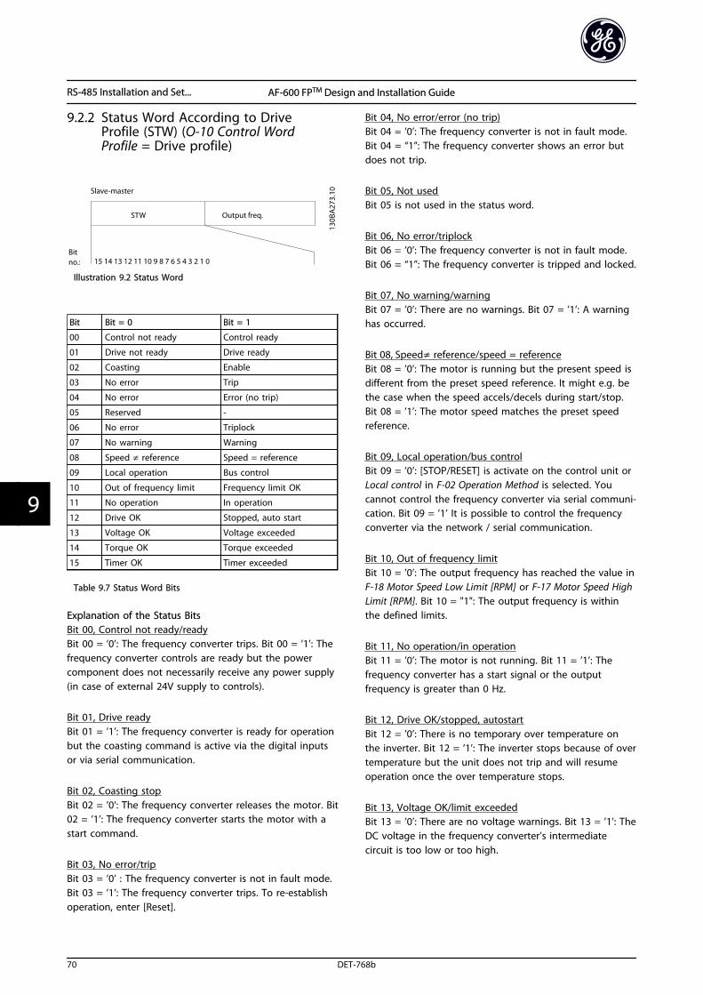
9.2.2 Status Word According to DriveProfile (STW) (O-10 Control WordProfile = Drive profile)
Illustration 9.2 Status Word
Bit Bit = 0 Bit = 1
00 Control not ready Control ready
01 Drive not ready Drive ready
02 Coasting Enable
03 No error Trip
04 No error Error (no trip)
05 Reserved -
06 No error Triplock
07 No warning Warning
08 Speed ≠ reference Speed = reference
09 Local operation Bus control
10 Out of frequency limit Frequency limit OK
11 No operation In operation
12 Drive OK Stopped, auto start
13 Voltage OK Voltage exceeded
14 Torque OK Torque exceeded
15 Timer OK Timer exceeded
Table 9.7 Status Word Bits
Explanation of the Status BitsBit 00, Control not ready/readyBit 00 = ’0’: The frequency converter trips. Bit 00 = ’1’: Thefrequency converter controls are ready but the powercomponent does not necessarily receive any power supply(in case of external 24V supply to controls).
Bit 01, Drive readyBit 01 = ’1’: The frequency converter is ready for operationbut the coasting command is active via the digital inputsor via serial communication.
Bit 02, Coasting stopBit 02 = ’0’: The frequency converter releases the motor. Bit02 = ’1’: The frequency converter starts the motor with astart command.
Bit 03, No error/tripBit 03 = ’0’ : The frequency converter is not in fault mode.Bit 03 = ’1’: The frequency converter trips. To re-establishoperation, enter [Reset].
Bit 04, No error/error (no trip)Bit 04 = ’0’: The frequency converter is not in fault mode.Bit 04 = “1”: The frequency converter shows an error butdoes not trip.
Bit 05, Not usedBit 05 is not used in the status word.
Bit 06, No error/triplockBit 06 = ’0’: The frequency converter is not in fault mode.Bit 06 = “1”: The frequency converter is tripped and locked.
Bit 07, No warning/warningBit 07 = ’0’: There are no warnings. Bit 07 = ’1’: A warninghas occurred.
Bit 08, Speed≠ reference/speed = referenceBit 08 = ’0’: The motor is running but the present speed isdifferent from the preset speed reference. It might e.g. bethe case when the speed accels/decels during start/stop.Bit 08 = ’1’: The motor speed matches the preset speedreference.
Bit 09, Local operation/bus controlBit 09 = ’0’: [STOP/RESET] is activate on the control unit orLocal control in F-02 Operation Method is selected. Youcannot control the frequency converter via serial communi-cation. Bit 09 = ’1’ It is possible to control the frequencyconverter via the network / serial communication.
Bit 10, Out of frequency limitBit 10 = ’0’: The output frequency has reached the value inF-18 Motor Speed Low Limit [RPM] or F-17 Motor Speed HighLimit [RPM]. Bit 10 = "1": The output frequency is withinthe defined limits.
Bit 11, No operation/in operationBit 11 = ’0’: The motor is not running. Bit 11 = ’1’: Thefrequency converter has a start signal or the outputfrequency is greater than 0 Hz.
Bit 12, Drive OK/stopped, autostartBit 12 = ’0’: There is no temporary over temperature onthe inverter. Bit 12 = ’1’: The inverter stops because of overtemperature but the unit does not trip and will resumeoperation once the over temperature stops.
Bit 13, Voltage OK/limit exceededBit 13 = ’0’: There are no voltage warnings. Bit 13 = ’1’: TheDC voltage in the frequency converter’s intermediatecircuit is too low or too high.
RS-485 Installation and Set... AF-600 FPTM Design and Installation Guide
70 DET-768b
99
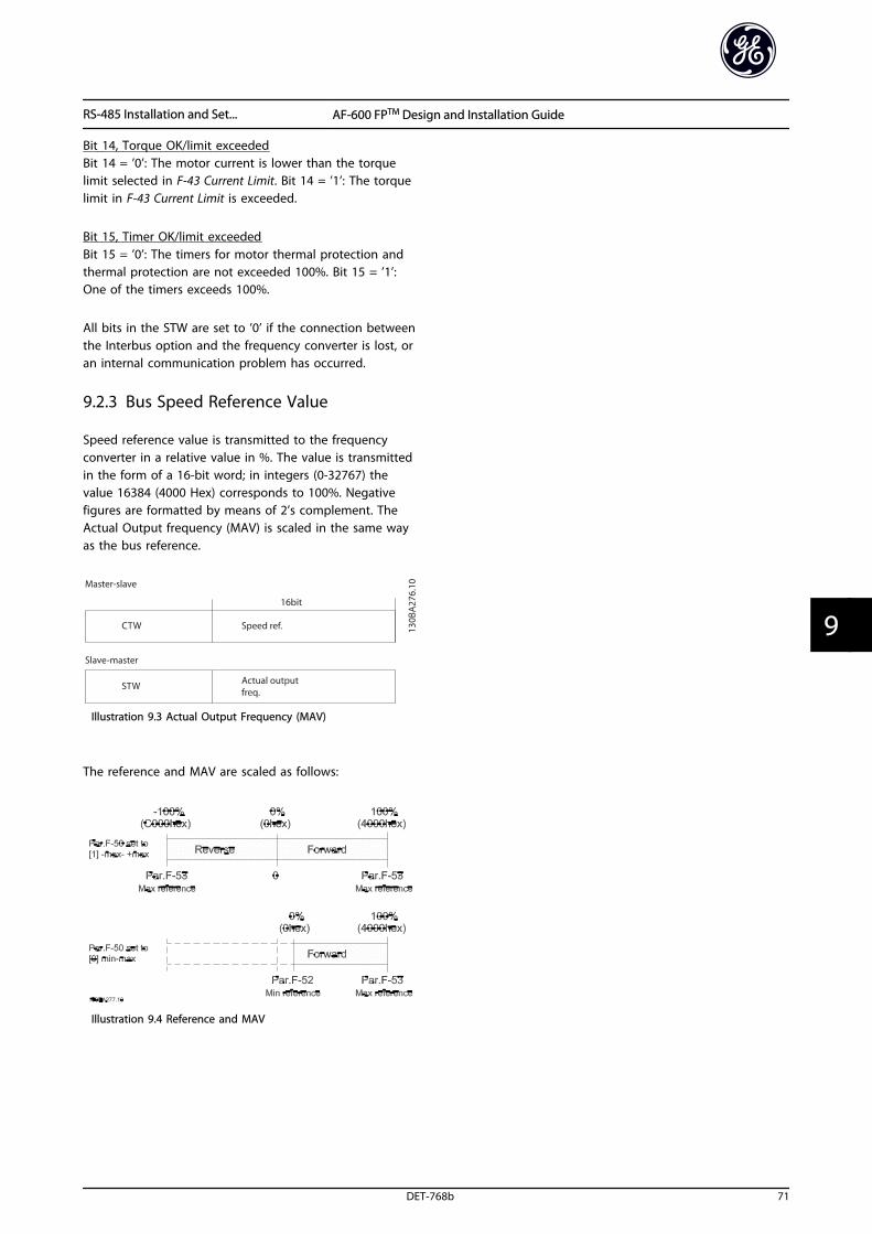
Bit 14, Torque OK/limit exceededBit 14 = ’0’: The motor current is lower than the torquelimit selected in F-43 Current Limit. Bit 14 = ’1’: The torquelimit in F-43 Current Limit is exceeded.
Bit 15, Timer OK/limit exceededBit 15 = ’0’: The timers for motor thermal protection andthermal protection are not exceeded 100%. Bit 15 = ’1’:One of the timers exceeds 100%.
All bits in the STW are set to ’0’ if the connection betweenthe Interbus option and the frequency converter is lost, oran internal communication problem has occurred.
9.2.3 Bus Speed Reference Value
Speed reference value is transmitted to the frequencyconverter in a relative value in %. The value is transmittedin the form of a 16-bit word; in integers (0-32767) thevalue 16384 (4000 Hex) corresponds to 100%. Negativefigures are formatted by means of 2’s complement. TheActual Output frequency (MAV) is scaled in the same wayas the bus reference.
Illustration 9.3 Actual Output Frequency (MAV)
The reference and MAV are scaled as follows:
Illustration 9.4 Reference and MAV
RS-485 Installation and Set... AF-600 FPTM Design and Installation Guide
DET-768b 71
9 9
10 Warnings and Alarms
10.1 System Monitoring
The frequency converter monitors the condition of itsinput power, output, and motor factors as well as othersystem performance indicators. A warning or alarm maynot necessarily indicate a problem internal to thefrequency converter itself. In many cases, it indicates failureconditions from input voltage, motor load or temperature,external signals, or other areas monitored by the frequencyconverter’s internal logic. Be sure to investigate those areasexterior to the frequency converter as indicated in thealarm or warning.
10.2 Warning and Alarm Types
WarningsA warning is issued when an alarm condition is impendingor when an abnormal operating condition is present andmay result in the frequency converter issuing an alarm. Awarning clears by itself when the abnormal condition isremoved.
AlarmsTripAn alarm is issued when the frequency converter istripped, that is, the frequency converter suspendsoperation to prevent frequency converter or systemdamage. The motor will coast to a stop. The frequencyconverter logic will continue to operate and monitor thefrequency converter status. After the fault condition isremedied, the frequency converter can be reset. It willthen be ready to start operation again.
A trip can be reset in any of 4 ways
• Press [Reset] on the keypad
• Digital reset input command
• Serial communication reset input command
• Auto reset
An alarm that causes the frequency converter to trip-lockrequires that input power is cycled. The motor will coast toa stop. The frequency converter logic will continue tooperate and monitor the frequency converter status.Remove input power to the frequency converter andcorrect the cause of the fault, then restore power. Thisaction puts the frequency converter into a trip condition asdescribed above and may be reset in any of those 4 ways.
10.3 Warning and Alarm Displays
Illustration 10.1 Warning Display
An alarm or trip-lock alarm will flash on display along withthe alarm number.
Illustration 10.2 Alarm Display
In addition to the text and alarm code on the frequencyconverter keypad, there are three status indicator lights.
Illustration 10.3 Status Indicator Lights
Warnings and Alarms AF-600 FPTM Design and Installation Guide
72 DET-768b
100
Warning LED Alarm LED
Warning On Off
Alarm Off On (Flashing)
Trip-Lock On On (Flashing)
Table 10.1 Status Indicator Lights Explanations
10.3.1 Warnings/Alarm Messages
A warning or an alarm is signalled by the relevant LED onthe front of the frequency converter and indicated by acode on the display.
A warning remains active until its cause is no longerpresent. Under certain circumstances, operation of themotor may still be continued. Warning messages may becritical, but are not necessarily so.
In the event of an alarm, the frequency converter trips.Reset the alarm to resume operation once the cause hasbeen rectified.
Three ways to reset:
• Press [Reset].
• Via a digital input with the “Reset” function.
• Via serial communication/optional network.
NOTEAfter a manual reset pressing [Reset], press [Auto ] torestart the motor.
If an alarm cannot be reset, the reason may be that itscause has not been rectified, or the alarm is trip-locked(see also Table 10.2).
Alarms that are trip-locked offer additional protection,meaning that the mains supply must be switched offbefore the alarm can be reset. After being switched backon, the frequency converter is no longer blocked and canbe reset as described above once the cause has beenrectified.
Alarms that are not trip-locked can also be reset using theautomatic reset function in H-04 Auto-Reset (Times)(Warning: automatic wake-up is possible!)
If a warning or alarm is marked against a code inTable 10.2, this means that either a warning occurs beforean alarm, or else that it is possible to specify whether awarning or an alarm should be displayed for a given fault.
This is possible, for instance, in F-10 Electronic Overload.After an alarm or trip, the motor carries on coasting, andthe alarm and warning flash. Once the problem has beenrectified, only the alarm continues flashing until thefrequency converter is reset.
NOTENo missing motor phase detection (numbers 30-32) and nostall detection is active when P-20 Motor Construction is setto [1] PM non salient SPM.
No. Description Warning Alarm/Trip Alarm/Trip Lock ParameterReference
1 10 Volts low X
2 Live zero error (X) (X) AN-01 Live ZeroTimeout Function
3 No motor (X) H-80 Function at Stop
4 Mains phase loss (X) (X) (X) SP-12 Function at LineImbalance
5 DC link voltage high X
6 DC link voltage low X
7 DC over-voltage X X
8 DC under voltage X X
9 Inverter overloaded X X
10 Motor Electronic OL over temperature (X) (X) F-10 ElectronicOverload
11 Motor thermistor over temperature (X) (X) F-10 ElectronicOverload
12 Torque limit X X
13 Over Current X X X
14 Earth Fault X X
15 Hardware mismatch X X
16 Short Circuit X X
Warnings and Alarms AF-600 FPTM Design and Installation Guide
DET-768b 73
10 10
No. Description Warning Alarm/Trip Alarm/Trip Lock ParameterReference
17 Control word time-out (X) (X) O-04 Control WordTimeout Function
20 Temp. Input Error
21 Param Error
23 Internal Fans X
24 External Fans X
25 Brake resistor short-circuited X
26 Brake resistor power limit (X) (X) B-13 Braking Thermal
Overload
27 Brake chopper short-circuited X X
28 Brake check (X) (X) B-15 Brake Check
29 Heatsink temp X X X
30 Motor phase U missing (X) (X) (X) H-78 Missing MotorPhase Function
31 Motor phase V missing (X) (X) (X) H-78 Missing Motor
Phase Function
32 Motor phase W missing (X) (X) (X) H-78 Missing Motor
Phase Function
33 Inrush Fault X X
34 Network communication fault X X
35 Option Fault
36 Mains failure X X
37 Phase imbalance X
38 Internal Fault X X
39 Heatsink sensor X X
40 Overload of Digital Output Terminal 27 (X) E-00 Digital I/O Mode,E-51 Terminal 27 Mode
41 Overload of Digital Output Terminal 29 (X) E-00 Digital I/O Mode,E-52 Terminal 29 Mode
42 Ovrld X30/6-7 (X)
43 Ext. Supply (option)
45 Earth Fault 2 X X
46 Pwr. card supply X X
47 24 V supply low X X X
48 1.8 V supply low X X
49 Speed limit X H-36 Trip Speed Low
[RPM]
50 Auto Tune calibration failed X
51 Auto Tune check Unom and Inom X
52 Auto Tune low Inom X
53 Auto Tune motor too big X
54 Auto Tune motor too small X
55 Auto Tune parameter out of range X
56 Auto Tune interrupted by user X
57 Auto Tune time-out X
58 Auto Tune internal fault X X
59 Current limit X
61 Feedback Error (X) (X) H-20 Motor Feedback
Loss Function
62 Output Frequency at Maximum Limit X
64 Voltage Limit X
65 Control Board Over-temperature X X X
Warnings and Alarms AF-600 FPTM Design and Installation Guide
74 DET-768b
100

No. Description Warning Alarm/Trip Alarm/Trip Lock ParameterReference
66 Heat sink Temperature Low X
67 Option Module Configuration has Changed X
69 Pwr. Card Temp X X
70 Illegal Drive configuration X
75 Illegal Profile Sel. X
76 Power Unit Setup X
77 Reduced power mode X SP-59 Actual Number of
Inverter Units
78 Tracking Error (X) (X) H-24 Tracking Error
Function
79 Illegal PS config X X
80 Drive Restored to Factory Settings X
81 CSIV corrupt X
82 CSIV parameter error X
83 Illegal Option Combination X
88 Option Detection X
91 Analog input 54 wrong settings X S202
246 Pwr.card supply
250 New spare parts X
251 New Type Code X X
Table 10.2 Alarm/Warning Code List
(X) Dependent on parameter
1) Cannot be Auto reset via H-04 Auto-Reset (Times)
A trip is the action following an alarm. The trip coasts themotor and is reset by pressing [Reset] or by a digital input(parameter group E-1# [1]). The origin event that causedan alarm cannot damage the frequency converter or causedangerous conditions. A trip lock is an action when analarm occurs, which could damage the frequency converter
or connected parts. A trip lock situation can only be resetby a power cycling.
Warning yellow
Alarm flashing red
Trip locked yellow and red
Table 10.3 LED Indication
Bit Hex Dec Alarm Word Alarm Word 2 Warning Word WarningWord 2
ExtendedStatus Word
Alarm Word Extended Status Word
0 00000001 1 Brake Check (A28) ServiceTrip,
Read/Write
Brake Check (W28) reserved Ramping
1 00000002 2 Pwr. Card Temp(A69)
ServiceTrip,(reserved)
Pwr. Card Temp (W69) reserved Auto Tune Running
2 00000004 4 Earth Fault (A14) ServiceTrip,Typecode/Sparepart
Earth Fault (W14) reserved Start CW/CCW
3 00000008 8 Ctrl.Card Temp(A65)
ServiceTrip,(reserved)
Ctrl.Card Temp (W65) reserved Slow Down
4 00000010 16 Ctrl. Word TO(A17)
ServiceTrip,(reserved)
Ctrl. Word TO (W17) Catch Up
5 00000020 32 Over Current
(A13)
reserved Over Current (W13) reserved Feedback High
6 00000040 64 Torque Limit
(A12)
reserved Torque Limit (W12) reserved Feedback Low
7 00000080 128 Motor Th Over(A11)
reserved Motor Th Over (W11) reserved Output CurrentHigh
Warnings and Alarms AF-600 FPTM Design and Installation Guide
DET-768b 75
10 10
Bit Hex Dec Alarm Word Alarm Word 2 Warning Word WarningWord 2
ExtendedStatus Word
8 00000100 256 Motor ElectronicOL Over (A10)
reserved Motor Electronic OLOver (W10)
reserved Output Current Low
9 00000200 512 Drive Overld. (A9) reserved Drive Overld (W9) reserved Output Freq High
10 00000400 1024 DC under Volt(A8)
reserved DC under Volt (W8) Output Freq Low
11 00000800 2048 DC over Volt (A7) reserved DC over Volt (W7) Brake Check OK
12 00001000 4096 Short Circuit(A16)
reserved DC Voltage Low (W6) reserved Braking Max
13 00002000 8192 Inrush Fault (A33) reserved DC Voltage High (W5) Braking
14 00004000 16384 Mains ph. Loss
(A4)
reserved Mains ph. Loss (W4) Out of Speed Range
15 00008000 32768 Auto Tune Not
OK
reserved No Motor (W3) OVC Active
16 00010000 65536 Live Zero Error(A2)
reserved Live Zero Error (W2) AC Brake
17 00020000 131072 Internal Fault(A38)
KTY error 10V Low (W1) KTY Warn Password Timelock
18 00040000 262144 Brake Overload(A26)
Fans error Brake Overload (W26) Fans Warn Password Protection
19 00080000 524288 U phase Loss(A30)
reserved Brake Resistor (W25) reserved
20 00100000 1048576 V phase Loss
(A31)
reserved Brake IGBT (W27) reserved
21 00200000 2097152 W phase Loss(A32)
reserved Speed Limit (W49) reserved
22 00400000 4194304 Network Fault(A34)
reserved Network Fault (W34) reserved Unused
23 00800000 8388608 24 V Supply Low(A47)
reserved 24V Supply Low (W47) reserved Unused
24 01000000 16777216 Mains Failure(A36)
reserved Mains Failure (W36) reserved Unused
25 02000000 33554432 1.8V Supply Low
(A48)
reserved Current Limit (W59) reserved Unused
26 04000000 67108864 Brake Resistor
(A25)
reserved Low Temp (W66) reserved Unused
27 08000000 134217728 Brake IGBT (A27) reserved Voltage Limit (W64) reserved Unused
28 10000000 268435456 Option Change(A67)
reserved Encoder loss (W90) reserved Unused
29 20000000 536870912 Drive Restored tofactorysettings(A80)
Feedback Fault(A61, A90)
Feedback Fault (W61,W90)
Unused
30 40000000 1073741824 Safe Stop (A68) Safe Stop (A71) Safe Stop (W68) Safe Stop
(W71)
Unused
31 80000000 2147483648 Mech. brake low
(A63)
Dangerous
Failure (A72)
Extended Status Word Unused
Table 10.4 Description of Alarm Word, Warning Word and Extended Status Word
The alarm words, warning words and extended status words can be read out via serial bus or optional network fordiagnostics. See also DR-94 Ext. Status Word.
Warnings and Alarms AF-600 FPTM Design and Installation Guide
76 DET-768b
100
10.4 Warning and Alarm Definitions
The warning/alarm information below defines eachwarning/alarm condition, provides the probable cause forthe condition, and details a remedy or troubleshootingprocedure.
WARNING 1, 10 Volts lowThe control card voltage is below 10 V from terminal 50.Remove some of the load from terminal 50, as the 10 Vsupply is overloaded. Max. 15 mA or minimum 590 Ω.
A short circuit in a connected potentiometer or improperwiring of the potentiometer can cause this condition.
TroubleshootingRemove the wiring from terminal 50. If thewarning clears, the problem is with the wiring. Ifthe warning does not clear, replace the controlcard.
WARNING/ALARM 2, Live zero errorThis warning or alarm only appears if programmed inAN-01 Live Zero Timeout Function. The signal on one of theanalog inputs is less than 50% of the minimum valueprogrammed for that input. Broken wiring or faulty devicesending the signal can cause this condition.
TroubleshootingCheck connections on all the analog inputterminals. Control card terminals 53 and 54 forsignals, terminal 55 common. OPCGPIO terminals11 and 12 for signals, terminal 10 common.OPCAIO terminals 1, 3, 5 for signals, terminals 2,4, 6 common).
Check that the frequency converter programmingand switch settings match the analog signal type.
Perform Input Terminal Signal Test.
WARNING/ALARM 4, Mains phase lossA phase is missing on the supply side, or the mainsvoltage imbalance is too high. This message also appearsfor a fault in the input rectifier on the frequency converter.Options are programmed at SP-12 Function at LineImbalance.
TroubleshootingCheck the supply voltage and supply currents tothe frequency converter.
WARNING 5, DC link voltage highThe intermediate circuit voltage (DC) is higher than thehigh-voltage warning limit. The limit is dependent on thefrequency converter voltage rating. The unit is still active.
WARNING 6, DC link voltage lowThe intermediate circuit voltage (DC) is lower than the low-voltage warning limit. The limit is dependent on thefrequency converter voltage rating. The unit is still active.
WARNING/ALARM 7, DC overvoltageIf the intermediate circuit voltage exceeds the limit, thefrequency converter trips after a time.
TroubleshootingExtend the ramp time
Change the ramp type
Activate the functions in B-10 Brake Function
Increase SP-26 Trip Delay at Drive Fault
If the alarm/warning occurs during a power sag,use kinetic back-up (SP-10 Line failure)
WARNING/ALARM 8, DC under voltageIf the intermediate circuit voltage (DC link) drops belowthe under voltage limit, the frequency converter checks if a24 V DC back-up supply is connected. If no 24 V DC back-up supply is connected, the frequency converter trips aftera fixed time delay. The time delay varies with unit size.
TroubleshootingCheck that the supply voltage matches thefrequency converter voltage.
Perform input voltage test.
Perform soft charge circuit test.
WARNING/ALARM 9, Inverter overloadThe frequency converter is about to cut out because of anoverload (too high current for too long). The counter forelectronic, thermal inverter protection issues a warning at98% and trips at 100%, while giving an alarm. Thefrequency converter cannot be reset until the counter isbelow 90%. The fault is that the frequency converter has run withmore than 100% overload for too long.
TroubleshootingCompare the output current shown on thekeypad with the frequency converter ratedcurrent.
Compare the output current shown on thekeypad with measured motor current.
Display the Thermal Drive Load on the keypadand monitor the value. When running above thefrequency converter continuous current rating,the counter increases. When running below thefrequency converter continuous current rating,the counter decreases.
Warnings and Alarms AF-600 FPTM Design and Installation Guide
DET-768b 77
10 10
WARNING/ALARM 10, Motor overload temperatureAccording to the electronic thermal protection, the motoris too hot. Select whether the frequency converter issues awarning or an alarm when the counter reaches 100% inF-10 Electronic Overload. The fault occurs when the motorruns with more than 100% overload for too long.
TroubleshootingCheck for motor overheating.
Check if the motor is mechanically overloaded
Check that the motor current set in P-03 MotorCurrent is correct.
Ensure that Motor data in parameters P-02, P-03,P-06, P-07, F-04 and F-05 are set correctly.
If an external fan is in use, check in F-11 MotorExternal Fan that it is selected.
Running Auto tune in P-04 Auto Tune tunes thefrequency converter to the motor moreaccurately and reduces thermal loading.
WARNING/ALARM 11, Motor thermistor over tempCheck whether the thermistor is disconnected. Selectwhether the frequency converter issues a warning or analarm in F-10 Electronic Overload.
TroubleshootingCheck for motor overheating.
Check if the motor is mechanically overloaded.
When using terminal 53 or 54, check that thethermistor is connected correctly between eitherterminal 53 or 54 (analog voltage input) andterminal 50 (+10 V supply). Also check that theterminal switch for 53 or 54 is set for voltage.Check F-12 Motor Thermistor Input selects terminal53 or 54.
When using digital inputs 18 or 19, check thatthe thermistor is connected correctly betweeneither terminal 18 or 19 (digital input PNP only)and terminal 50. Check F-12 Motor ThermistorInput selects terminal 18 or 19.
WARNING/ALARM 12, Torque limitThe torque has exceeded the value in F-40 Torque Limiter(Driving) or the value in F-41 Torque Limiter (Braking).SP-25 Trip Delay at Torque Limit can change this warningfrom a warning-only condition to a warning followed byan alarm.
TroubleshootingIf the motor torque limit is exceeded duringramp, extend the ramp time.
If the generator torque limit is exceeded duringramp, extend the ramp time.
If torque limit occurs while running, possiblyincrease the torque limit. Make sure that thesystem can operate safely at a higher torque.
Check the application for excessive current drawon the motor.
WARNING/ALARM 13, Over currentThe inverter peak current limit (approximately 200% of therated current) is exceeded. The warning lasts about 1.5 s,then the frequency converter trips and issues an alarm.Shock loading or quick acceleration with high inertia loadscan cause this fault . It can also appear after kinetic back-up, if the acceleration during ramp up is quick. If extendedmechanical brake control is selected, trip can be resetexternally.
TroubleshootingRemove power and check if the motor shaft canbe turned.
Check that the motor size matches the frequencyconverter.
Check parameters P-02, P-03, P-06, P-07, F-04 andF-05 for correct motor data.
ALARM 14, Earth (ground) faultThere is current from the output phases to earth, either inthe cable between the frequency converter and the motoror in the motor itself.
TroubleshootingRemove power to the frequency converter andrepair the earth fault.
Check for earth faults in the motor by measuringthe resistance to ground of the motor leads andthe motor with a megohmmeter.
ALARM 15, Hardware mismatchA fitted option is not operational with the present controlboard hardware or software.
Record the value of the following parameters and contactyour GE supplier:
ID-40 Drive Type
ID-41 Power Section
ID-42 Voltage
ID-43 Software Version
ID-45 Actual Typecode String
ID-49 SW ID Control Card
ID-50 SW ID Power Card
ID-60 Option Mounted
ID-61 Option SW Version (for each option slot)
ALARM 16, Short circuitThere is short-circuiting in the motor or motor wiring.
Remove power to the frequency converter and repair theshort circuit.
Warnings and Alarms AF-600 FPTM Design and Installation Guide
78 DET-768b
100
WARNING/ALARM 17, Control word timeoutThere is no communication to the frequency converter.The warning is only active when O-04 Control WordTimeout Function is NOT set to [0] Off.If O-04 Control Word Timeout Function is set to [5] Stop andTrip, a warning appears and the frequency converter rampsdown until it stops then displays an alarm.
TroubleshootingCheck connections on the serial communicationcable.
Increase O-03 Control Word Timeout Time
Check the operation of the communicationequipment.
Verify a proper installation based on EMCrequirements.
ALARM 18, Start failedThe speed has not been able to exceed AP-70 CompressorStart Max Speed [RPM] during start within the allowed time.(set in AP-72 Compressor Start Max Time to Trip). This maybe caused by a blocked motor.
WARNING 23, Internal fan faultThe fan warning function is an extra protective functionthat checks if the fan is running/mounted. The fan warningcan be disabled in SP-53 Fan Monitor ([0] Disabled).
TroubleshootingCheck for proper fan operation.
Cycle power to the frequency converter andcheck that the fan operates briefly at start-up.
Check the sensors on the heatsink and controlcard.
WARNING 24, External fan faultThe fan warning function is an extra protective functionthat checks if the fan is running/mounted. The fan warningcan be disabled in SP-53 Fan Monitor ([0] Disabled).
TroubleshootingCheck for proper fan operation.
Cycle power to the frequency converter andcheck that the fan operates briefly at start-up.
Check the sensors on the heatsink and controlcard.
WARNING 25, Brake resistor short circuitThe brake resistor is monitored during operation. If a shortcircuit occurs, the brake function is disabled and thewarning appears. The frequency converter is stilloperational but without the brake function. Remove powerto the frequency converter and replace the brake resistor(see B-15 Brake Check).
WARNING/ALARM 26, Brake resistor power limitThe power transmitted to the brake resistor is calculated asa mean value over the last 120 seconds of run time. Thecalculation is based on the intermediate circuit voltage andthe brake resistance value set in B-16 AC brake Max.
Current. The warning is active when the dissipated brakingis higher than 90% of the brake resistance power. If [2] Tripis selected in B-13 Braking Thermal Overload, the frequencyconverter trips when the dissipated braking power reaches100%.
WARNING/ALARM 27, Brake chopper faultThe brake transistor is monitored during operation and if ashort circuit occurs, the brake function is disabled and awarning is issued. The frequency converter is stilloperational but, since the brake transistor has short-circuited, substantial power is transmitted to the brakeresistor, even if it is inactive.Remove power to the frequency converter and remove thebrake resistor.
High power drives: This alarm/warning could also occursshould the brake resistor overheat. Terminals 104 to 106 ofFK102 are available as brake resistor temperature switch onthe power card of high power drives. Unless used as aninput, a jumper must be placed between terminals 104and 106 of FK102.
WARNING/ALARM 28, Brake check failedThe brake resistor is not connected or not working.Check B-15 Brake Check.
ALARM 29, Heatsink tempThe maximum temperature of the heatsink has beenexceeded. The temperature fault will not reset until thetemperature falls below a defined heatsink temperature.The trip and reset points are different based on thefrequency converter power size.
TroubleshootingCheck for the following conditions.
Ambient temperature too high.
Motor cable too long.
Incorrect airflow clearance above and below thefrequency converter.
Blocked airflow around the frequency converter.
Damaged heatsink fan.
Dirty heatsink.
ALARM 30, Motor phase U missingMotor phase U between the frequency converter and themotor is missing.
Remove power from the frequency converter and checkmotor phase U.
ALARM 31, Motor phase V missingMotor phase V between the frequency converter and themotor is missing.
Remove power from the frequency converter and checkmotor phase V.
ALARM 32, Motor phase W missingMotor phase W between the frequency converter and themotor is missing.
Warnings and Alarms AF-600 FPTM Design and Installation Guide
DET-768b 79
10 10
Remove power from the frequency converter and checkmotor phase W.
ALARM 33, Inrush faultToo many power-ups have occurred within a short timeperiod. Let the unit cool to operating temperature.
WARNING/ALARM 34, Fieldbus communication faultThe network on the communication option card is notworking.
WARNING/ALARM 36, Mains failureThis warning/alarm is only active if the supply voltage tothe frequency converter is lost and SP-10 Line failure is NOTset to [0] No Function. Check the fuses to the frequencyconverter and mains supply to the unit.
ALARM 38, Internal faultWhen an internal fault occurs, a code number defined inTable 10.5 is displayed.
TroubleshootingCycle power
Check that the option is properly installed
Check for loose or missing wiring
It may be necessary to contact your GE supplier or servicedepartment. Note the code number for further trouble-shooting directions.
No. Text0 Serial port cannot be restore. Contact your GE
supplier or GE Service Department.
256-258 Power EEPROM data is defective or too old.Replace power card.
512-519 Internal fault. Contact your GE supplier or GE
Service Department.
783 Parameter value outside of min/max limits
1024-1284 Internal fault. Contact your GE supplier or the GEService Department.
1299 Option SW in slot A is too old
1300 Option SW in slot B is too old
1315 Option SW in slot A is not supported (not allowed)
1316 Option SW in slot B is not supported (not allowed)
1379-2819 Internal fault. Contact your GE supplier or GEService Department.
2561 Replace control card
2820 Keypad stack overflow
2821 Serial port overflow
2822 USB port overflow
3072-5122 Parameter value is outside its limits
5123 Option in slot A: Hardware incompatible withcontrol board hardware
5124 Option in slot B: Hardware incompatible withcontrol board hardware
5376-6231 Internal fault. Contact your GE supplier or GEService Department.
Table 10.5 Internal Fault Codes
ALARM 39, Heatsink sensorNo feedback from the heatsink temperature sensor.
The signal from the IGBT thermal sensor is not available onthe power card. The problem could be on the power card,on the gate drive card, or the ribbon cable between thepower card and gate drive card.
WARNING 40, Overload of digital output terminal 27Check the load connected to terminal 27 or remove short-circuit connection. Check E-00 Digital I/O Mode andE-51 Terminal 27 Mode.
WARNING 41, Overload of digital output terminal 29Check the load connected to terminal 29 or remove short-circuit connection. Check E-00 Digital I/O Mode andE-52 Terminal 29 Mode.
WARNING 42, Overload of digital output on X30/6 oroverload of digital output on X30/7For X30/6, check the load connected to X30/6 or removethe short-circuit connection. Check E-56 Term X30/6 DigiOut (OPCGPIO).
For X30/7, check the load connected to X30/7 or removethe short-circuit connection. Check E-57 Term X30/7 DigiOut (OPCGPIO).
ALARM 45, Earth fault 2Earth (ground) fault on start-up.
TroubleshootingCheck for proper earthing (grounding) and looseconnections.
Check for proper wire size.
Check motor cables for short-circuits or leakagecurrents.
ALARM 46, Power card supplyThe supply on the power card is out of range.
There are three power supplies generated by the switchmode power supply (SMPS) on the power card: 24 V, 5 V,±18 V. When powered with three phase mains voltage, allthree supplies are monitored.
TroubleshootingCheck for a defective power card.
Check for a defective control card.
Check for a defective option card.
If a 24 V DC power supply is used, verify propersupply power.
WARNING 47, 24 V supply lowThe 24 V DC is measured on the control card. The external24 V DC back-up power supply may be overloaded,otherwise contact the GE supplier.
WARNING 48, 1.8 V supply lowThe 1.8 V DC supply used on the control card is outside ofallowable limits. The power supply is measured on thecontrol card. Check for a defective control card. If anoption card is present, check for an overvoltage condition.
Warnings and Alarms AF-600 FPTM Design and Installation Guide
80 DET-768b
100
WARNING 49, Speed limitWhen the speed is not within the specified range in F-18and F-17, the frequency converter shows a warning. Whenthe speed is below the specified limit in H-36 Trip SpeedLow [RPM] (except when starting or stopping), thefrequency converter trips.
ALARM 50, Auto tune calibration failedContact your GE supplier or GE Service Department.
ALARM 51, Auto tune check Unom and Inom
The settings for motor voltage, motor current and motorpower are wrong. Check the settings in parameters P-02,P-03, P-06, P-07, F-04 and F-05.
ALARM 52, Auto tune low Inom
The motor current is too low. Check the settings.
ALARM 53, Auto tune motor too bigThe motor is too big for the Auto tune to operate.
ALARM 54, Auto tune motor too smallThe motor is too small for the Auto tune to operate.
ALARM 55, Auto tune parameter out of rangeThe parameter values of the motor are outside of theacceptable range. Auto tune cannot run.
ALARM 56, Auto tune interrupted by userThe user has interrupted the Auto tune.
ALARM 57, Auto tune internal faultTry to restart Auto tune again. Repeated restarts can overheat the motor.
ALARM 58, Internal faultContact your GE supplier.
WARNING 59, Current limitThe current is higher than the value in F-43 Current Limit.Ensure that Motor data in parameters P-02, P-03, P-06,P-07, F-04 and F-05 are set correctly. Possibly increase thecurrent limit. Be sure that the system can operate safely ata higher limit.
WARNING 60, External interlockA digital input signal is indicating a fault condition externalto the frequency converter. An external interlock hascommanded the frequency converter to trip. Clear theexternal fault condition. To resume normal operation,apply 24 V DC to the terminal programmed for externalinterlock. Reset the frequency converter.
WARNING 62, Output frequency at maximum limitThe output frequency has reached the value set inF-03 Max Output Frequency 1. Check the application todetermine the cause. Possibly increase the outputfrequency limit. Be sure the system can operate safely at ahigher output frequency. The warning will clear when theoutput drops below the maximum limit.
WARNING/ALARM 65, Control card over temperatureThe cut-out temperature of the control card is 80 °C.
Troubleshooting
• Check that the ambient operating temperature iswithin limits
• Check for clogged filters
• Check fan operation
• Check the control card
WARNING 66, Heatsink temperature lowThe frequency converter is too cold to operate. Thiswarning is based on the temperature sensor in the IGBTmodule.Increase the ambient temperature of the unit. Also, atrickle amount of current can be supplied to the frequencyconverter whenever the motor is stopped by settingB-00 DC Hold Current at 5% and H-80 Function at Stop
ALARM 67, Option module configuration has changedOne or more options have either been added or removedsince the last power-down. Check that the configurationchange is intentional and reset the unit.
ALARM 69, Power card temperatureThe temperature sensor on the power card is either toohot or too cold.
TroubleshootingCheck that the ambient operating temperature iswithin limits.
Check for clogged filters.
Check fan operation.
Check the power card.
ALARM 70, Illegal drive configurationThe control card and power card are incompatible. Tocheck compatibility, contact your supplier with the modelnumber of the unit from the nameplate and the partnumbers of the cards.
ALARM 80, Drive initialised to default valueParameter settings are restored to factory settings after amanual reset. To clear the alarm, reset the unit.
ALARM 92, No flowA no-flow condition has been detected in the system.AP-23 No-Flow Function is set for alarm. Troubleshoot thesystem and reset the frequency converter after the faulthas been cleared.
ALARM 93, Dry pumpA no-flow condition in the system with the frequencyconverter operating at high speed may indicate a drypump. AP-26 Dry Pump Function is set for alarm.Troubleshoot the system and reset the frequency converterafter the fault has been cleared.
ALARM 94, End of curveFeedback is lower than the set point. This may indicateleakage in the system. AP-50 End of Curve Function is setfor alarm. Troubleshoot the system and reset the frequencyconverter after the fault has been cleared.
Warnings and Alarms AF-600 FPTM Design and Installation Guide
DET-768b 81
10 10
ALARM 95, Broken beltTorque is below the torque level set for no load, indicatinga broken belt. AP-60 Broken Belt Function is set for alarm.Troubleshoot the system and reset the frequency converterafter the fault has been cleared.
ALARM 96, Start delayedMotor start has been delayed due to short-cycleprotection. AP-76 Interval between Starts is enabled.Troubleshoot the system and reset the frequency converterafter the fault has been cleared.
WARNING 97, Stop delayedStopping the motor has been delayed due to short cycleprotection. AP-76 Interval between Starts is enabled.Troubleshoot the system and reset the frequency converterafter the fault has been cleared.
WARNING 98, Clock faultTime is not set or the RTC clock has failed. Reset the clockin K-70 Date and Time.
WARNING 200, Fire modeThis warning indicates the frequency converter is operatingin fire mode. The warning clears when fire mode isremoved. See the fire mode data in the alarm log.
WARNING 201, Fire mode was activeThis indicates the frequency converter had entered firemode. Cycle power to the unit to remove the warning. Seethe fire mode data in the alarm log.
WARNING 202, Fire mode limits exceededWhile operating in fire mode one or more alarm conditionshave been ignored which would normally trip the unit.Operating in this condition voids unit warranty. Cyclepower to the unit to remove the warning. See the firemode data in the alarm log.
WARNING 203, Missing motorWith a frequency converter operating multi-motors, anunder-load condition was detected. This could indicate amissing motor. Inspect the system for proper operation.
WARNING 204, Locked rotorWith a frequency converter operating multi-motors, anoverload condition was detected. This could indicate alocked rotor. Inspect the motor for proper operation.
WARNING 250, New spare partA component in the frequency converter has beenreplaced. Reset the frequency converter for normaloperation.
WARNING 251, New typecodeThe power card or other components have been replacedand the typecode changed. Reset to remove the warningand resume normal operation.
Warnings and Alarms AF-600 FPTM Design and Installation Guide
82 DET-768b
100
11 Basic Troubleshooting
11.1 Start Up and Operation
Symptom Possible cause Test Solution
Display dark/No function
Missing input power See Table 3.1 Check the input power source
Missing or open fuses or circuitbreaker tripped
See open fuses and tripped circuitbreaker in this table for possiblecauses
Follow the recommendationsprovided
No power to the keypad Check the keypad cable for properconnection or damage
Replace the faulty keypad orconnection cable
Shortcut on control voltage
(terminal 12 or 50) or at controlterminals
Check the 24 V control voltage
supply for terminals 12/13 to 20-39or 10 V supply for terminals 50 to55
Wire the terminals properly
Wrong contrast setting Press [Status] + []/[] to adjust
the contrast
Display (keypad) is defective Test using a different keypad Replace the faulty keypad or
connection cable
Internal voltage supply fault orSMPS is defective
Contact supplier
Intermittent display
Overloaded power supply (SMPS)due to improper control wiring ora fault within the frequencyconverter
To rule out a problem in thecontrol wiring, disconnect allcontrol wiring by removing theterminal blocks.
If the display stays lit, then theproblem is in the control wiring.Check the wiring for shorts orincorrect connections. If the displaycontinues to cut out, follow theprocedure for display dark.
Motor not running
Service switch open or missingmotor connection
Check if the motor is connectedand the connection is notinterrupted (by a service switch orother device).
Connect the motor and check theservice switch
No mains power with 24 V DCoption card
If the display is functioning but nooutput, check that mains power isapplied to the frequency converter.
Apply mains power to run the unit
keypad Stop Check if [Off] has been pressed Press [Auto] or [Hand] (depending
on operation mode) to run themotor
Missing start signal (Standby) Check E-01 Terminal 18 Digital Inputfor correct setting for terminal 18(use default setting)
Apply a valid start signal to startthe motor
Motor coast signal active(Coasting)
Check if a coast inv command isprogrammed for the terminal inparameter group E-0# DigitalInputs.
Apply 24 V on terminal or programthis terminal to No operation
Wrong reference signal source Check reference signal: Local,remote or bus reference? Presetreference active? Terminalconnection correct? Scaling ofterminals correct? Reference signalavailable?
Program correct settings. CheckF-02 Operation Method. Set presetreference active in parameterC-05 Multi-step Frequency 1 - 8.Check for correct wiring. Checkscaling of terminals. Checkreference signal.
Basic Troubleshooting AF-600 FPTM Design and Installation Guide
DET-768b 83
11 11
Symptom Possible cause Test Solution
Motor running in wrongdirection
Motor rotation limit Check that H-08 Reverse Lock isprogrammed correctly.
Program correct settings
Active reversing signal Check if a reversing command is
programmed for the terminal inparameter group E-0# Digitalinputs..
Deactivate reversing signal
Wrong motor phase connection
Motor is not reaching
maximum speed
Frequency limits set wrong Check output limits in F-17 Motor
Speed High Limit [RPM], F-15 MotorSpeed High Limit [Hz] and F-03 Max
Output Frequency 1.
Program correct limits
Reference input signal not scaled
correctly
Check reference input signal
scaling in AN-## Reference limits inparameter group F-5#.
Program correct settings
Motor speed unstable
Possible incorrect parametersettings
Check the settings of all motorparameters, including all motorcompensation settings. For closedloop operation, check PID settings.
Check settings in parameter groupAN-##. For closed loop operation,check settings in parameter groupCL-0#.
Motor runs rough
Possible over-magnetization Check for incorrect motor settingsin all motor parameters
Check motor settings in parametergroups P-0# Motor Data, P-3# AdvMotor Data, and H-5# Load Indep.Setting.
Motor will not brakePossible incorrect settings in thebrake parameters. Possible tooshort ramp down times
Check brake parameters. Checkramp time settings
Check parameter group B-0# DCBrake and F-5# Extended Reference.
Open power fuses or circuitbreaker trip
Phase to phase short Motor or panel has a short phaseto phase. Check motor and panelphase for shorts
Eliminate any shorts detected
Motor overload Motor is overloaded for theapplication
Perform startup test and verifymotor current is within specifi-cations. If motor current isexceeding nameplate full loadcurrent, motor may run only withreduced load. Review the specifi-cations for the application.
Loose connections Perform pre-startup check for loose
connections
Tighten loose connections
Mains current imbalancegreater than 3%
Problem with mains power (See
Alarm 4 Mains phase lossdescription)
Rotate input power leads into the
frequency converter one position: Ato B, B to C, C to A.
If imbalanced leg follows the wire,
it is a power problem. Check mainspower supply.
Problem with the frequencyconverter
Rotate input power leads into thefrequency converter one position: Ato B, B to C, C to A.
If imbalance leg stays on sameinput terminal, it is a problem withthe unit. Contact the supplier.
Motor current imbalancegreater than 3%
Problem with motor or motorwiring
Rotate output motor leads oneposition: U to V, V to W, W to U.
If imbalanced leg follows the wire,the problem is in the motor ormotor wiring. Check motor andmotor wiring.
Problem with the frequencyconverters
Rotate output motor leads oneposition: U to V, V to W, W to U.
If imbalance leg stays on sameoutput terminal, it is a problemwith the unit. Contact the supplier.
Basic Troubleshooting AF-600 FPTM Design and Installation Guide
84 DET-768b
111
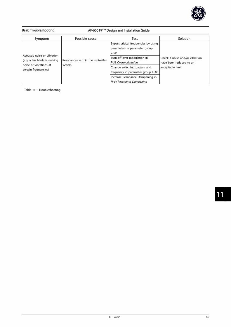
Symptom Possible cause Test Solution
Acoustic noise or vibration(e.g. a fan blade is making
noise or vibrations atcertain frequencies)
Resonances, e.g. in the motor/fan
system
Bypass critical frequencies by usingparameters in parameter group C-0#
Check if noise and/or vibrationhave been reduced to anacceptable limit
Turn off over-modulation in
F-38 Overmodulation
Change switching pattern and
frequency in parameter group F-3#
Increase Resonance Dampening inH-64 Resonance Dampening
Table 11.1 Troubleshooting
Basic Troubleshooting AF-600 FPTM Design and Installation Guide
DET-768b 85
11 11

12 Terminal and Applicable Wire
12.1 Cables
Pow
er [k
W/H
P]En
clos
ure
Mai
nsM
otor
Load
sha
reBr
ake
Eart
h*
200-
240V
380-
480V
525-
600V
525-
690V
Tigh
teni
ngto
rque
[Nm
/in-
lbs]
Wire
siz
e[m
m2
(AW
G)]
Tigh
teni
ngto
rque
[Nm
/in-lb
s]
Wire
siz
e[m
m2 (A
WG
)]
Tigh
teni
ng
torq
ue[N
m/in
-lb
s]
Wire
siz
e[m
m2 (A
WG
)]
Tigh
teni
ng
torq
ue[N
m/in
-lb
s]
Wire
siz
e[m
m2
(AW
G)]
Tigh
teni
ngto
rque
[Nm
/in-
lbs]
0.75
-2.2
kW1-
3HP
0.75
-3.7
kW1-
5HP
IP20
1.8
/ 16
4 (1
0)
1.8
/ 16
4 (1
0)1.
8 /
164
(10)
1.8
/ 16
4 (1
0)
3 /
27
3.7k
W 5
HP
5.5-
7.5k
W7.
5-10
HP
0.75
-7.5
kW1-
10H
P
IP20
0.75
-3.7
kW1-
5HP
0.75
-7.5
kW1-
10H
P0.
75-7
.5kW
1-10
HP
IP
55 o
rIP
665.
5-11
kW7.
5-15
HP
11-1
8.5k
W15
-25H
P11
-18.
5kW
15-2
5HP
IP
2016
(6)
16 (6
)16
(6)
16 (6
)5.
5-11
kW7.
5-15
HP
11-1
8.5k
W15
-25H
P11
-18.
5kW
15-2
5HP
IP
55 o
rIP
661.
5 /
141.
5 /
14
15-1
8.5k
W20
-25H
P22
-37k
W30
-50H
P22
-37k
W30
-50H
P
IP20
4.5
/ 40
35 (2
)4.
5 /
4035
(2)
4.5
/ 40
35 (2
)4.
5 /
4035
(2)
15kW
20H
P22
-30k
W30
-40H
P22
-30k
W30
-40H
P11
-30k
W15
-40H
PIP
55 o
rIP
663.
7 /
333.
7 /
33
22-3
0kW
30-4
0HP
45-5
5kW
60-7
5HP
45-5
5kW
60-7
5HP
IP
2010
/ 8
950
(1)
10 /
89
50 (1
)10
/ 8
950
(1)
10 /
89
50 (1
)
18.5
-30k
W25
-40H
P37
-55k
W50
-75H
P37
-55k
W50
-75H
P
IP55
or
IP66
90 (3
/0)
90 (3
/0)
90 (3
/0)
90 (3
/0)
37-4
5kW
50-6
0HP
75-9
0kW
100-
125H
P75
-90k
W10
0-12
5HP
IP
2014
/ 1
24
150
(300
mcm
)14
/ 1
24
150
(300
mcm
)14
/ 1
2495
(4/0
)14
/ 1
2495
(4/0
)
37-4
5kW
50-6
0HP
75-9
0kW
100-
125H
P75
-90k
W10
0-12
5HP
37-9
0kW
50-1
25H
PIP
55 o
rIP
6612
0 (4
/0)
120
(4/0
)12
0 (4
/0)
120
(4/0
)
11
0-16
0kW
150-
250H
P
110-
160k
W15
0-25
0HP
all
19 /
168
2x95
(2x3
/0)
19 /
168
2x95
(2x3
/0)
19 /
168
2x95
(2x3
/0)
8.5
/ 75
2x95
(2x3
/0)
8.5
/ 75
20
0-31
5kW
300-
450H
P
200-
400k
W30
0-55
0HP
all
2x18
5(2
x350
mcm
)2x
185
(2x3
50m
cm)
2x18
5(2
x350
mcm
)2x
185
(2x3
50m
cm)
19 /
168
35
5-45
0kW
500-
600H
P
450-
630k
W60
0-90
0HP
all
4x24
0(4
x500
mcm
)4x
240
(4x5
00m
cm)
19 /
168
4x24
0(4
x500
mcm
)
50
0-71
0kW
650-
1000
HP
71
0-90
0kW
1000
-125
0HP
all
8x24
0(8
x500
mcm
)
8x15
0(8
x300
mcm
)4x
120
(4x2
50m
cm)
4x18
5(4
x350
mcm
)
80
0-10
00kW
1200
-135
0HP
1000
-140
0kW
1350
-190
0HP
all
12x1
50(1
2x30
0mcm
)6x
185
(6x3
50m
cm)
* M
axim
um c
able
siz
e ac
cord
ing
to
nat
iona
l cod
e
Tabl
e 12
.1 C
able
s
Terminal and Applicable Wir... AF-600 FPTM Design and Installation Guide
86 DET-768b
122
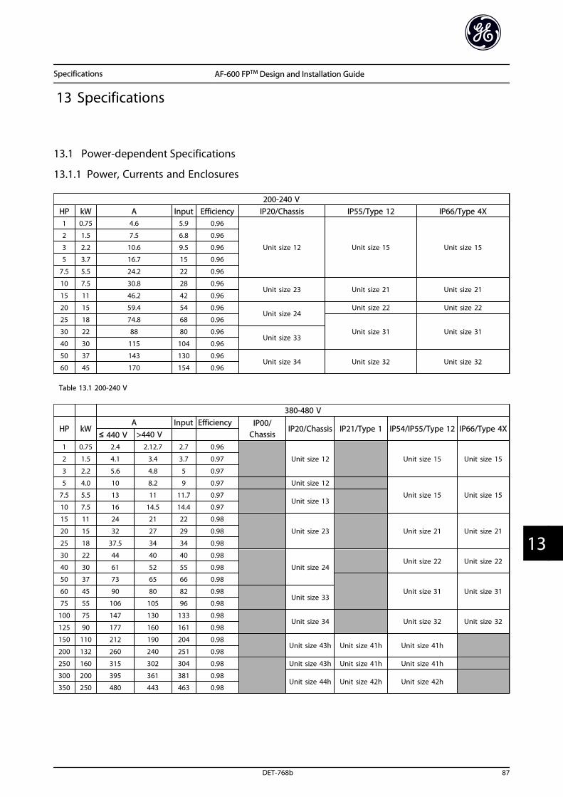
13 Specifications
13.1 Power-dependent Specifications
13.1.1 Power, Currents and Enclosures
200-240 VHP kW A Input Efficiency IP20/Chassis IP55/Type 12 IP66/Type 4X1 0.75 4.6 5.9 0.96
Unit size 12 Unit size 15 Unit size 15
2 1.5 7.5 6.8 0.96
3 2.2 10.6 9.5 0.96
5 3.7 16.7 15 0.96
7.5 5.5 24.2 22 0.96
10 7.5 30.8 28 0.96Unit size 23 Unit size 21 Unit size 21
15 11 46.2 42 0.96
20 15 59.4 54 0.96Unit size 24
Unit size 22 Unit size 22
25 18 74.8 68 0.96
Unit size 31 Unit size 3130 22 88 80 0.96Unit size 33
40 30 115 104 0.96
50 37 143 130 0.96Unit size 34 Unit size 32 Unit size 32
60 45 170 154 0.96
Table 13.1 200-240 V
380-480 V
HP kWA Input Efficiency IP00/
ChassisIP20/Chassis IP21/Type 1 IP54/IP55/Type 12 IP66/Type 4X
≤ 440 V >440 V 1 0.75 2.4 2.12.7 2.7 0.96
Unit size 12 Unit size 15 Unit size 152 1.5 4.1 3.4 3.7 0.97
3 2.2 5.6 4.8 5 0.97
5 4.0 10 8.2 9 0.97 Unit size 12
Unit size 15 Unit size 157.5 5.5 13 11 11.7 0.97Unit size 13
10 7.5 16 14.5 14.4 0.97
15 11 24 21 22 0.98
Unit size 23 Unit size 21 Unit size 2120 15 32 27 29 0.98
25 18 37.5 34 34 0.98
30 22 44 40 40 0.98
Unit size 24Unit size 22 Unit size 22
40 30 61 52 55 0.98
50 37 73 65 66 0.98
Unit size 31 Unit size 3160 45 90 80 82 0.98Unit size 33
75 55 106 105 96 0.98
100 75 147 130 133 0.98Unit size 34 Unit size 32 Unit size 32
125 90 177 160 161 0.98
150 110 212 190 204 0.98Unit size 43h Unit size 41h Unit size 41h
200 132 260 240 251 0.98
250 160 315 302 304 0.98 Unit size 43h Unit size 41h Unit size 41h
300 200 395 361 381 0.98Unit size 44h Unit size 42h Unit size 42h
350 250 480 443 463 0.98
Specifications AF-600 FPTM Design and Installation Guide
DET-768b 87
13 13
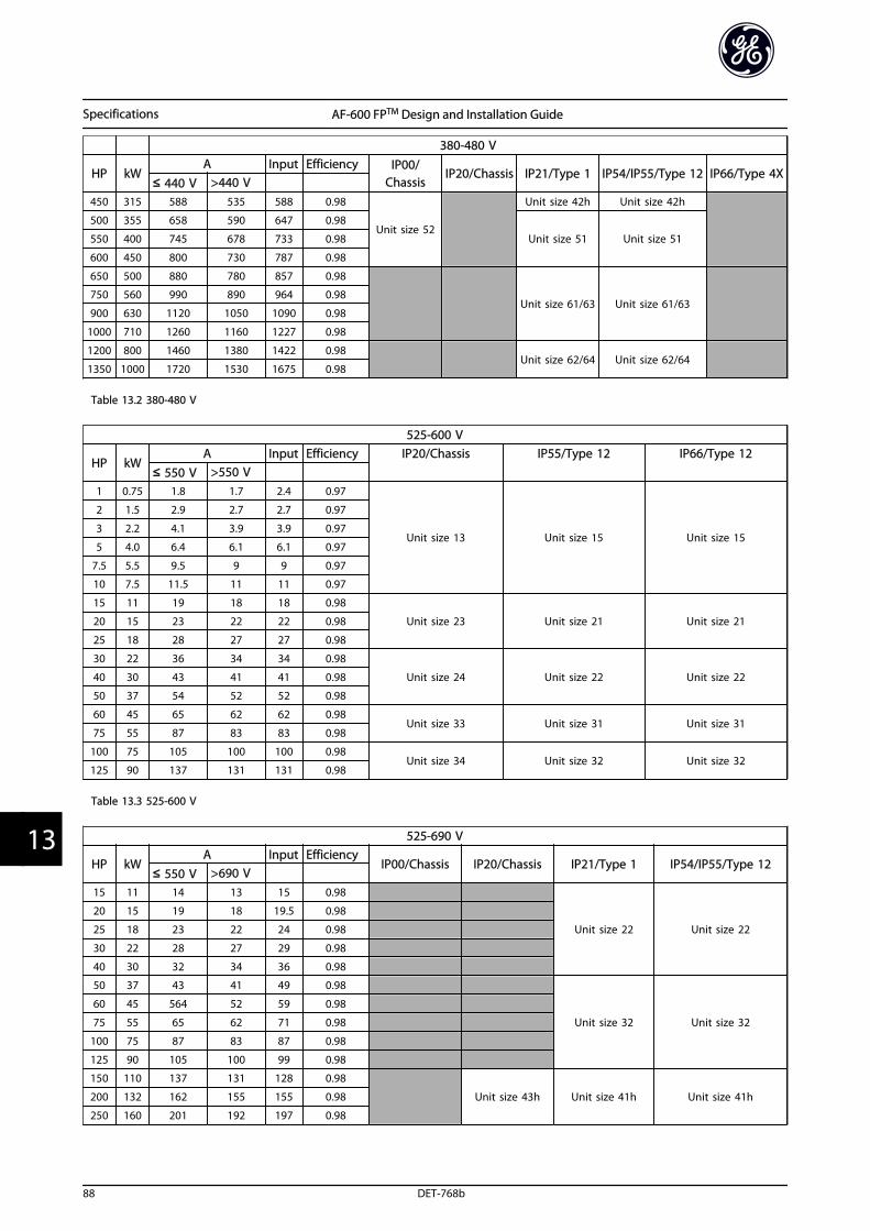
380-480 V
HP kWA Input Efficiency IP00/
ChassisIP20/Chassis IP21/Type 1 IP54/IP55/Type 12 IP66/Type 4X
≤ 440 V >440 V 450 315 588 535 588 0.98
Unit size 52
Unit size 42h Unit size 42h
500 355 658 590 647 0.98
Unit size 51 Unit size 51550 400 745 678 733 0.98
600 450 800 730 787 0.98
650 500 880 780 857 0.98
Unit size 61/63 Unit size 61/63750 560 990 890 964 0.98
900 630 1120 1050 1090 0.98
1000 710 1260 1160 1227 0.98
1200 800 1460 1380 1422 0.98Unit size 62/64 Unit size 62/64
1350 1000 1720 1530 1675 0.98
Table 13.2 380-480 V
525-600 V
HP kWA Input Efficiency IP20/Chassis IP55/Type 12 IP66/Type 12
≤ 550 V >550 V 1 0.75 1.8 1.7 2.4 0.97
Unit size 13 Unit size 15 Unit size 15
2 1.5 2.9 2.7 2.7 0.97
3 2.2 4.1 3.9 3.9 0.97
5 4.0 6.4 6.1 6.1 0.97
7.5 5.5 9.5 9 9 0.97
10 7.5 11.5 11 11 0.97
15 11 19 18 18 0.98
Unit size 23 Unit size 21 Unit size 2120 15 23 22 22 0.98
25 18 28 27 27 0.98
30 22 36 34 34 0.98
Unit size 24 Unit size 22 Unit size 2240 30 43 41 41 0.98
50 37 54 52 52 0.98
60 45 65 62 62 0.98Unit size 33 Unit size 31 Unit size 31
75 55 87 83 83 0.98
100 75 105 100 100 0.98Unit size 34 Unit size 32 Unit size 32
125 90 137 131 131 0.98
Table 13.3 525-600 V
525-690 V
HP kWA Input Efficiency
IP00/Chassis IP20/Chassis IP21/Type 1 IP54/IP55/Type 12≤ 550 V >690 V
15 11 14 13 15 0.98
Unit size 22 Unit size 22
20 15 19 18 19.5 0.98
25 18 23 22 24 0.98
30 22 28 27 29 0.98
40 30 32 34 36 0.98
50 37 43 41 49 0.98
Unit size 32 Unit size 32
60 45 564 52 59 0.98
75 55 65 62 71 0.98
100 75 87 83 87 0.98
125 90 105 100 99 0.98
150 110 137 131 128 0.98
Unit size 43h Unit size 41h Unit size 41h200 132 162 155 155 0.98
250 160 201 192 197 0.98
Specifications AF-600 FPTM Design and Installation Guide
88 DET-768b
133
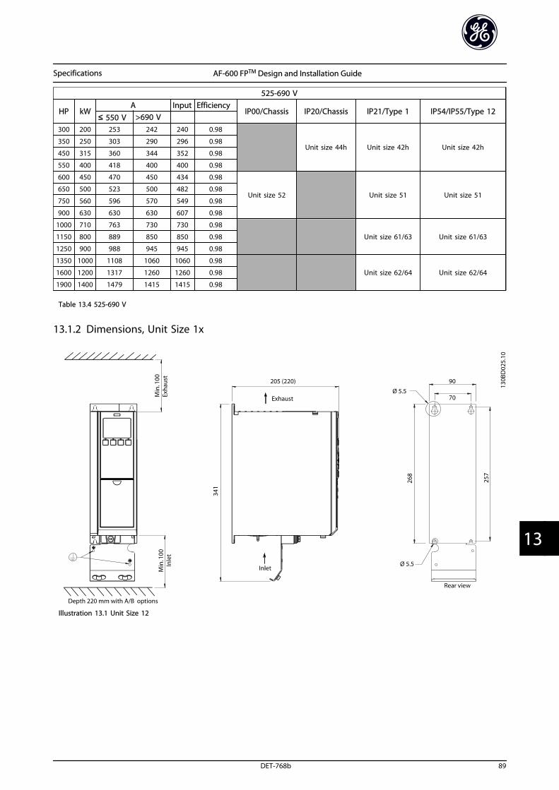
525-690 V
HP kWA Input Efficiency
IP00/Chassis IP20/Chassis IP21/Type 1 IP54/IP55/Type 12≤ 550 V >690 V
300 200 253 242 240 0.98
Unit size 44h Unit size 42h Unit size 42h350 250 303 290 296 0.98
450 315 360 344 352 0.98
550 400 418 400 400 0.98
600 450 470 450 434 0.98
Unit size 52 Unit size 51 Unit size 51650 500 523 500 482 0.98
750 560 596 570 549 0.98
900 630 630 630 607 0.98
1000 710 763 730 730 0.98
Unit size 61/63 Unit size 61/631150 800 889 850 850 0.98
1250 900 988 945 945 0.98
1350 1000 1108 1060 1060 0.98
Unit size 62/64 Unit size 62/641600 1200 1317 1260 1260 0.98
1900 1400 1479 1415 1415 0.98
Table 13.4 525-690 V
13.1.2 Dimensions, Unit Size 1x
Illustration 13.1 Unit Size 12
Specifications AF-600 FPTM Design and Installation Guide
DET-768b 89
13 13
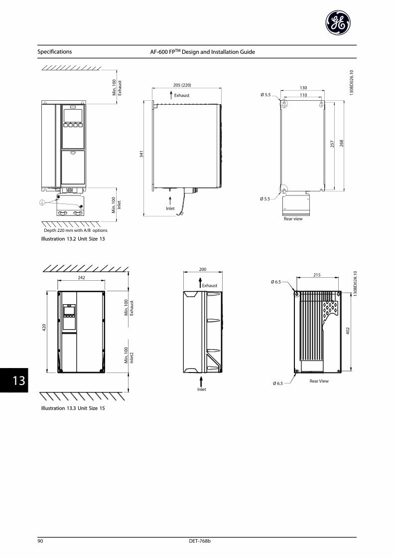
Illustration 13.2 Unit Size 13
Illustration 13.3 Unit Size 15
Specifications AF-600 FPTM Design and Installation Guide
90 DET-768b
133
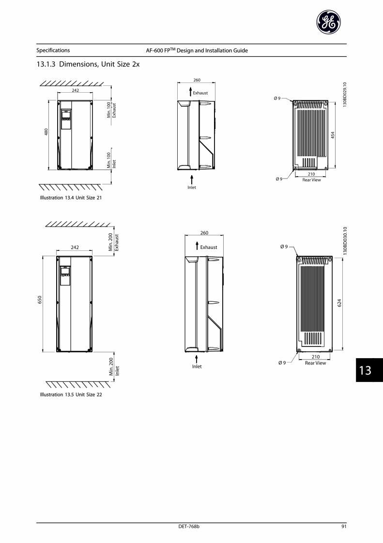
13.1.3 Dimensions, Unit Size 2x
Illustration 13.4 Unit Size 21
Illustration 13.5 Unit Size 22
Specifications AF-600 FPTM Design and Installation Guide
DET-768b 91
13 13
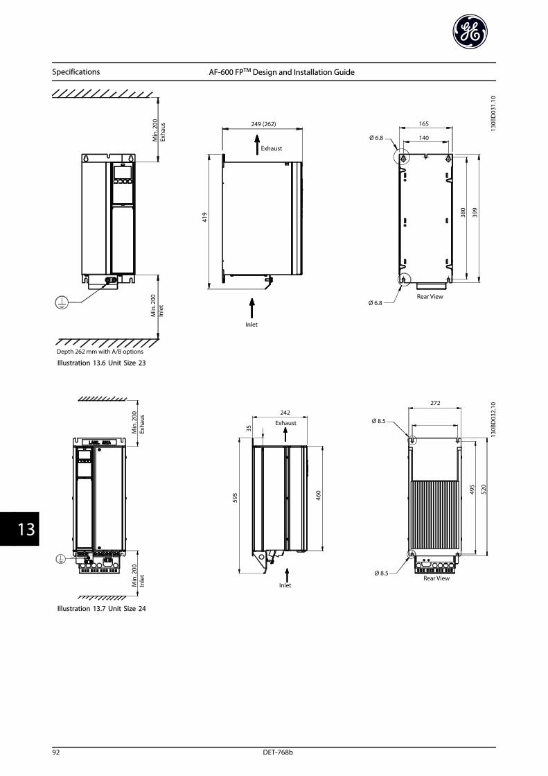
Illustration 13.6 Unit Size 23
Illustration 13.7 Unit Size 24
Specifications AF-600 FPTM Design and Installation Guide
92 DET-768b
133

13.1.4 Dimensions, Unit Size 3x
Illustration 13.8 Unit Size 31
Illustration 13.9 Unit Size 32
Specifications AF-600 FPTM Design and Installation Guide
DET-768b 93
13 13
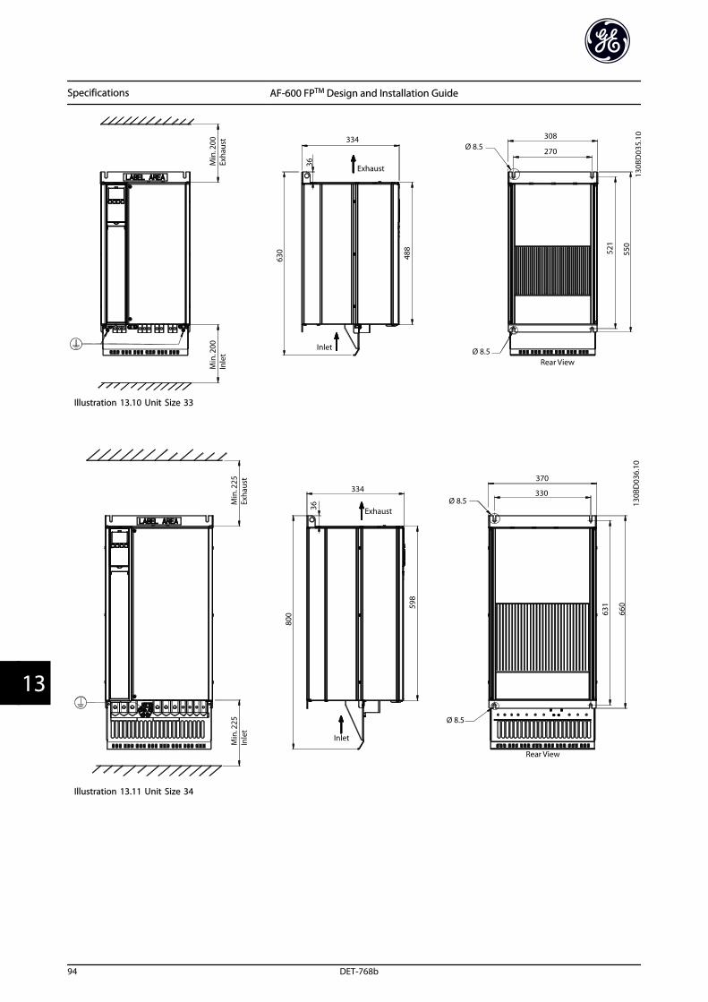
Illustration 13.10 Unit Size 33
Illustration 13.11 Unit Size 34
Specifications AF-600 FPTM Design and Installation Guide
94 DET-768b
133
13.1.5 Dimensions, Unit Size 4xh
Illustration 13.12 Unit Size 41h
Illustration 13.13 Unit Size 42h
Specifications AF-600 FPTM Design and Installation Guide
DET-768b 95
13 13
Illustration 13.14 Unit Size 43h
Illustration 13.15 Unit Size 44h
Specifications AF-600 FPTM Design and Installation Guide
96 DET-768b
133
13.1.6 Dimensions, Unit Size 5x
Illustration 13.16 Unit Size 51 (Floor Mount)
Illustration 13.17 Unit Size 52 (Cabinet Mount)
Specifications AF-600 FPTM Design and Installation Guide
DET-768b 97
13 13
13.1.7 Dimensions, Unit Size 6x
Illustration 13.18 Unit Size 61 (Floor Mount)
Min
. 200
(7.9
)A
ir Sp
ace
Out
let
607(23.9)
1804(71.0) IP 21/NEMA 1
2100 m3/hr(1236 CFM)
2280(89.8)
2205(86.8)
1497(58.9)
3941 m3/hr(2320 CFM)
IP 54/NEMA 121575 m3/hr(927 CFM)
130B
D08
2.10
Illustration 13.19 Unit Size 62 (Floor Mount)
Specifications AF-600 FPTM Design and Installation Guide
98 DET-768b
133
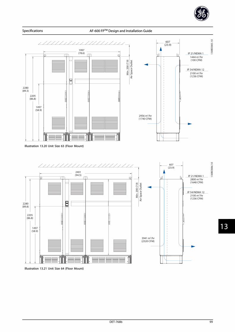
Min
. 200
(7.9
)A
ir Sp
ace
Out
let
607(23.9)
1997(78.6) IP 21/NEMA 1
1444 m3/hr(100 CFM)
2280(89.3)
2205(86.8)
1497(58.9)
2956 m3/hr(1740 CFM)
IP 54/NEMA 122100 m3/hr(1236 CFM)
130B
D08
3.10
Illustration 13.20 Unit Size 63 (Floor Mount)
Min
. 200
(7.9
)A
ir Sp
ace
Out
let
607(23.9)
2401(94.5) IP 21/NEMA 1
2800 m3/hr(1648 CFM)
2280(89.8)
2205(86.8)
1497(58.9)
3941 m3/hr(2320 CFM)
IP 54/NEMA 122100 m3/hr(1236 CFM)
130B
D08
4.10
Illustration 13.21 Unit Size 64 (Floor Mount)
Specifications AF-600 FPTM Design and Installation Guide
DET-768b 99
13 13
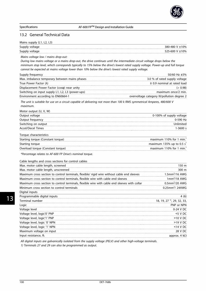
13.2 General Technical Data
Mains supply (L1, L2, L3)Supply voltage 380-480 V ±10%Supply voltage 525-600 V ±10%
Mains voltage low / mains drop-out:During low mains voltage or a mains drop-out, the drive continues until the intermediate circuit voltage drops below theminimum stop level, which corresponds typically to 15% below the drive's lowest rated supply voltage. Power-up and full torquecannot be expected at mains voltage lower than 10% below the drive's lowest rated supply voltage.
Supply frequency 50/60 Hz ±5%Max. imbalance temporary between mains phases 3.0 % of rated supply voltageTrue Power Factor (λ) ≥ 0.9 nominal at rated loadDisplacement Power Factor (cosφ) near unity (> 0.98)Switching on input supply L1, L2, L3 (power-ups) maximum once/2 min.Environment according to EN60664-1 overvoltage category III/pollution degree 2
The unit is suitable for use on a circuit capable of delivering not more than 100 k RMS symmetrical Amperes, 480/600 Vmaximum.
Motor output (U, V, W) Output voltage 0-100% of supply voltageOutput frequency 0-590 HzSwitching on output UnlimitedAccel/Decel Times 1-3600 s
Torque characteristicsStarting torque (Constant torque) maximum 110% for 1 min.*
Starting torque maximum 135% up to 0.5 s*
Overload torque (Constant torque) maximum 110% for 1 min.*
*Percentage relates to AF-600 FP Drive's nominal torque.
Cable lengths and cross sections for control cablesMax. motor cable length, screened 150 mMax. motor cable length, unscreened 300 mMaximum cross section to control terminals, flexible/ rigid wire without cable end sleeves 1.5mm2/16 AWGMaximum cross section to control terminals, flexible wire with cable end sleeves 1mm2/18 AWGMaximum cross section to control terminals, flexible wire with cable end sleeves with collar 0.5mm2/20 AWGMinimum cross section to control terminals 0.25mm2/ 24AWGDigital inputsProgrammable digital inputs 4 (6)Terminal number 18, 19, 27 1), 29, 32, 33,Logic PNP or NPNVoltage level 0-24 V DCVoltage level, logic'0' PNP <5 V DCVoltage level, logic'1' PNP >10 V DCVoltage level, logic '0' NPN >19 V DCVoltage level, logic '1' NPN <14 V DCMaximum voltage on input 28 V DCInput resistance, Ri approx. 4 kΩ
All digital inputs are galvanically isolated from the supply voltage (PELV) and other high-voltage terminals.1) Terminals 27 and 29 can also be programmed as output.
Specifications AF-600 FPTM Design and Installation Guide
100 DET-768b
133
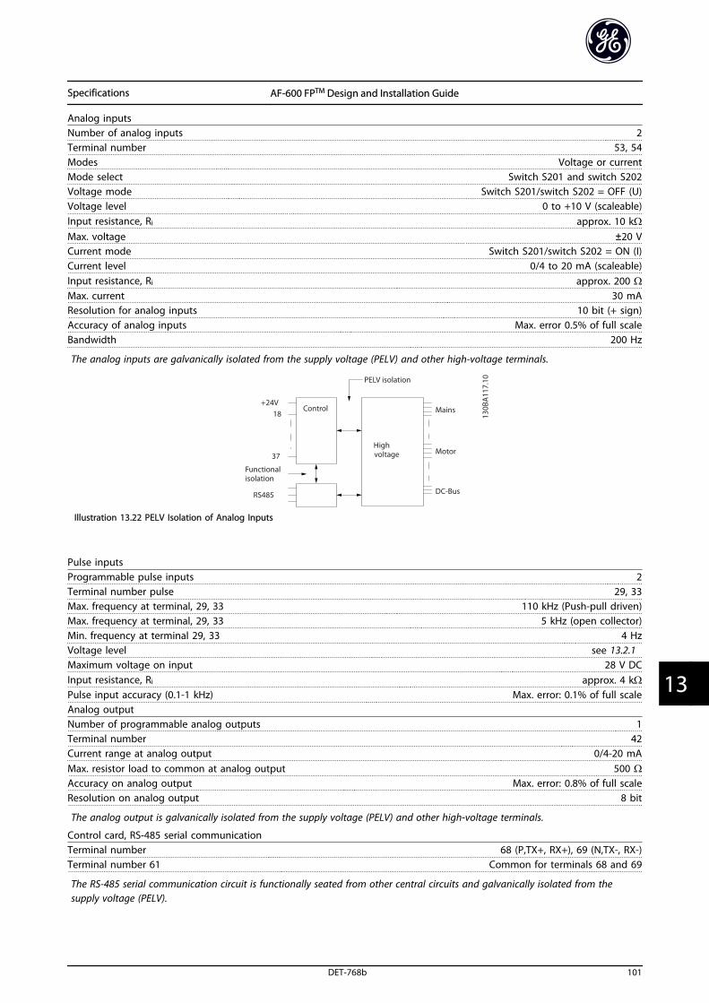
Analog inputsNumber of analog inputs 2Terminal number 53, 54Modes Voltage or currentMode select Switch S201 and switch S202Voltage mode Switch S201/switch S202 = OFF (U)Voltage level 0 to +10 V (scaleable)Input resistance, Ri approx. 10 kΩMax. voltage ±20 VCurrent mode Switch S201/switch S202 = ON (I)Current level 0/4 to 20 mA (scaleable)Input resistance, Ri approx. 200 ΩMax. current 30 mAResolution for analog inputs 10 bit (+ sign)Accuracy of analog inputs Max. error 0.5% of full scaleBandwidth 200 Hz
The analog inputs are galvanically isolated from the supply voltage (PELV) and other high-voltage terminals.
Illustration 13.22 PELV Isolation of Analog Inputs
Pulse inputsProgrammable pulse inputs 2Terminal number pulse 29, 33Max. frequency at terminal, 29, 33 110 kHz (Push-pull driven)Max. frequency at terminal, 29, 33 5 kHz (open collector)Min. frequency at terminal 29, 33 4 HzVoltage level see 13.2.1 Maximum voltage on input 28 V DCInput resistance, Ri approx. 4 kΩPulse input accuracy (0.1-1 kHz) Max. error: 0.1% of full scaleAnalog outputNumber of programmable analog outputs 1Terminal number 42Current range at analog output 0/4-20 mAMax. resistor load to common at analog output 500 ΩAccuracy on analog output Max. error: 0.8% of full scaleResolution on analog output 8 bit
The analog output is galvanically isolated from the supply voltage (PELV) and other high-voltage terminals.
Control card, RS-485 serial communicationTerminal number 68 (P,TX+, RX+), 69 (N,TX-, RX-)Terminal number 61 Common for terminals 68 and 69
The RS-485 serial communication circuit is functionally seated from other central circuits and galvanically isolated from thesupply voltage (PELV).
Specifications AF-600 FPTM Design and Installation Guide
DET-768b 101
13 13
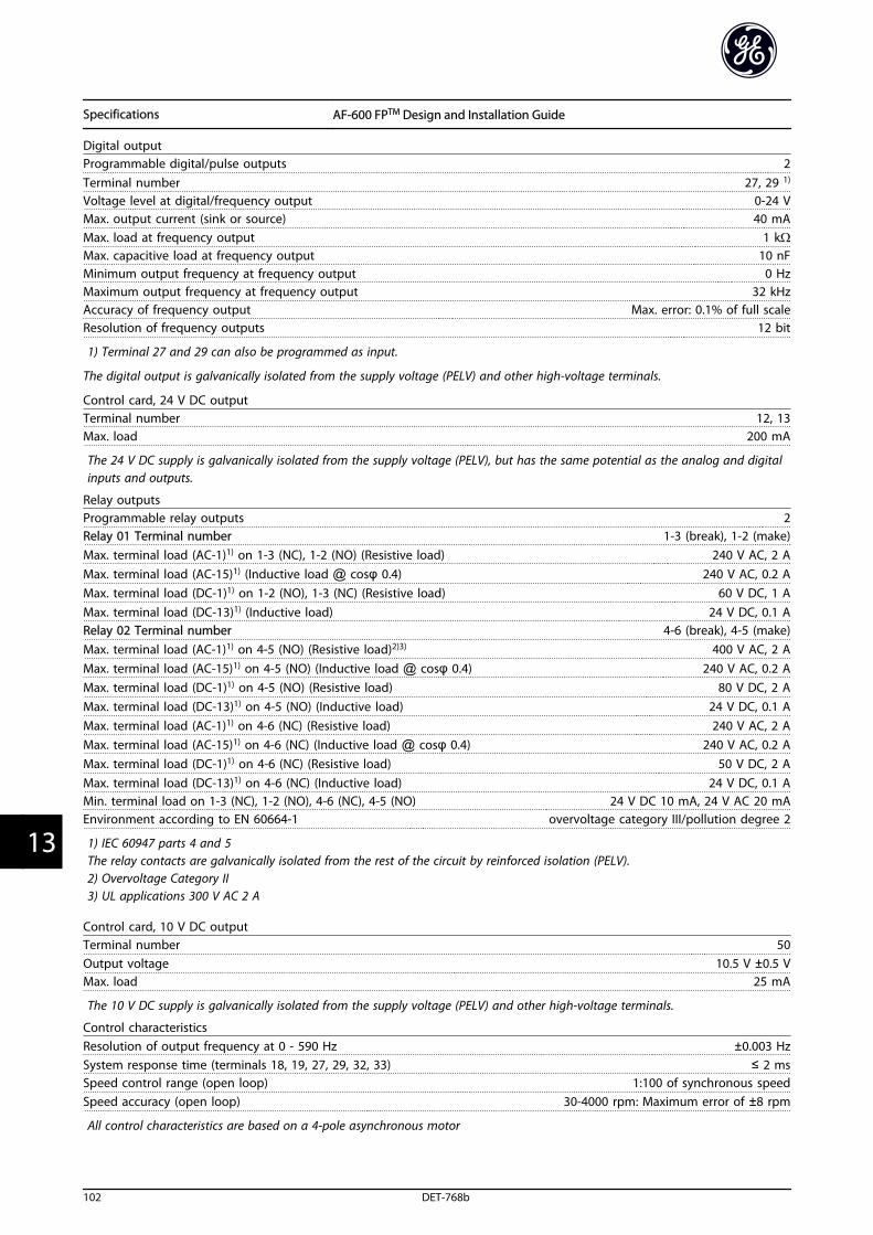
Digital outputProgrammable digital/pulse outputs 2Terminal number 27, 29 1)
Voltage level at digital/frequency output 0-24 VMax. output current (sink or source) 40 mAMax. load at frequency output 1 kΩMax. capacitive load at frequency output 10 nFMinimum output frequency at frequency output 0 HzMaximum output frequency at frequency output 32 kHzAccuracy of frequency output Max. error: 0.1% of full scaleResolution of frequency outputs 12 bit
1) Terminal 27 and 29 can also be programmed as input.
The digital output is galvanically isolated from the supply voltage (PELV) and other high-voltage terminals.
Control card, 24 V DC outputTerminal number 12, 13Max. load 200 mA
The 24 V DC supply is galvanically isolated from the supply voltage (PELV), but has the same potential as the analog and digitalinputs and outputs.
Relay outputsProgrammable relay outputs 2Relay 01 Terminal number 1-3 (break), 1-2 (make)Max. terminal load (AC-1)1) on 1-3 (NC), 1-2 (NO) (Resistive load) 240 V AC, 2 AMax. terminal load (AC-15)1) (Inductive load @ cosφ 0.4) 240 V AC, 0.2 AMax. terminal load (DC-1)1) on 1-2 (NO), 1-3 (NC) (Resistive load) 60 V DC, 1 AMax. terminal load (DC-13)1) (Inductive load) 24 V DC, 0.1 ARelay 02 Terminal number 4-6 (break), 4-5 (make)Max. terminal load (AC-1)1) on 4-5 (NO) (Resistive load)2)3) 400 V AC, 2 AMax. terminal load (AC-15)1) on 4-5 (NO) (Inductive load @ cosφ 0.4) 240 V AC, 0.2 AMax. terminal load (DC-1)1) on 4-5 (NO) (Resistive load) 80 V DC, 2 AMax. terminal load (DC-13)1) on 4-5 (NO) (Inductive load) 24 V DC, 0.1 AMax. terminal load (AC-1)1) on 4-6 (NC) (Resistive load) 240 V AC, 2 AMax. terminal load (AC-15)1) on 4-6 (NC) (Inductive load @ cosφ 0.4) 240 V AC, 0.2 AMax. terminal load (DC-1)1) on 4-6 (NC) (Resistive load) 50 V DC, 2 AMax. terminal load (DC-13)1) on 4-6 (NC) (Inductive load) 24 V DC, 0.1 AMin. terminal load on 1-3 (NC), 1-2 (NO), 4-6 (NC), 4-5 (NO) 24 V DC 10 mA, 24 V AC 20 mAEnvironment according to EN 60664-1 overvoltage category III/pollution degree 2
1) IEC 60947 parts 4 and 5The relay contacts are galvanically isolated from the rest of the circuit by reinforced isolation (PELV).2) Overvoltage Category II3) UL applications 300 V AC 2 A
Control card, 10 V DC outputTerminal number 50Output voltage 10.5 V ±0.5 VMax. load 25 mA
The 10 V DC supply is galvanically isolated from the supply voltage (PELV) and other high-voltage terminals.
Control characteristicsResolution of output frequency at 0 - 590 Hz ±0.003 HzSystem response time (terminals 18, 19, 27, 29, 32, 33) ≤ 2 msSpeed control range (open loop) 1:100 of synchronous speedSpeed accuracy (open loop) 30-4000 rpm: Maximum error of ±8 rpm
All control characteristics are based on a 4-pole asynchronous motor
Specifications AF-600 FPTM Design and Installation Guide
102 DET-768b
133
SurroundingsEnclosure, frame size 4X and 5X IP00, IP21, IP54Enclosure, frame size 6X IP21, IP54Vibration test 0.7 gRelative humidity 5% - 95%(IEC 721-3-3; Class 3K3 (non-condensing) during operationAggressive environment (IEC 60068-2-43) H2S test class kDTest method according to IEC 60068-2-43 H2S (10 days)- with derating max. 55 °C1)
- with full output power, typical EFF2 motors max. 50 °C1)
- at full continuous drive output current max. 45 °C1)
1) For more information on derating see the AF-600 FP, section on Special Conditions.
Minimum ambient temperature during full-scale operation 0 °CMinimum ambient temperature at reduced performance -10 °CTemperature during storage/transport -25 to +65/70 °CMaximum altitude above sea level without derating 1000 mMaximum altitude above sea level with derating 3000 m
Derating for high altitude, see section on special conditions in the Design Guide
EMC standards, Emission EN 61800-3, EN 61000-6-3/4, EN 55011, IEC 61800-3
EMC standards, ImmunityEN 61800-3, EN 61000-6-1/2,
EN 61000-4-2, EN 61000-4-3, EN 61000-4-4, EN 61000-4-5, EN 61000-4-6
See section on special conditions in the Design Guide!
Control card performanceScan interval 5 ms
Control card, USB serial communicationUSB standard 1.1 (Full speed)USB plug USB type B “device” plug
CAUTIONConnection to PC is carried out via a standard host/device USB cable.The USB connection is galvanically isolated from the supply voltage (PELV) and other high-voltage terminals.The USB connection is not galvanically isolated from protection earth. Use only isolated laptop/PC as connection to the USBconnector on the frequency converter or an isolated USB cable/converter.
Protection and Features
• Electronic thermal motor protection against overload.
• Temperature monitoring of the heatsink ensures that the frequency converter trips if the temperature reaches apredefined level. An overload temperature cannot be reset until the temperature of the heatsink is below thevalues stated in the tables on the following pages (Guideline - these temperatures may vary for different powersizes, Unit Sizes, enclosure ratings etc.).
• The frequency converter is protected against short-circuits on motor terminals U, V, W.
• If a mains phase is missing, the frequency converter trips or issues a warning (depending on the load).
• Monitoring of the intermediate circuit voltage ensures that the frequency converter trips if the intermediate circuitvoltage is too low or too high.
• The frequency converter is protected against earth faults on motor terminals U, V, W.
Specifications AF-600 FPTM Design and Installation Guide
DET-768b 103
13 13
13.3 Fuse Specifications
13.3.1 Fuses
It is recommended to use fuses and/or circuit breakers onthe supply side as protection in case of component break-down inside the frequency converter (first fault).
NOTEThis is mandatory in order to ensure compliance with IEC60364 for CE or NEC 2009 for UL.
WARNINGPersonnel and property must be protected against theconsequence of component break-down internally in thefrequency converter.
Branch Circuit Protection In order to protect the installation against electrical andfire hazard, all branch circuits in an installation, switchgear, machines etc., must be protected against short-circuitand over-current according to national/internationalregulations.
NOTEThe recommendations given do not cover Branch circuitprotection for UL.
Short-circuit protectionGE recommends using the fuses/Circuit Breakersmentioned below to protect service personnel andproperty in case of component break-down in thefrequency converter.
Over current protection:The frequency converter provides overload protection tolimit threats to human life, property damage and to avoidfire hazard due to overheating of the cables in the instal-lation. The frequency converter is equipped with aninternal over current protection (F-43 Current Limit) thatcan be used for upstream overload protection (UL-applications excluded). Moreover, fuses or Circuit Breakerscan be used to provide the over current protection in theinstallation. Over current protection must always be carriedout according to national regulations.
WARNINGIn case of malfunction, not following the recommendationmay result in personnel risk and damage to the frequencyconverter and other equipment.
The following tables list the recommended rated current.Recommended fuses are of the type gG for small tomedium power sizes. For larger powers, aR fuses arerecommended. Circuit breakers must be used providedthey meet the national/international regulations and theylimit the energy into the frequency converter to an equalor lower level than the compliant circuit breakers.If fuses/Circuit Breakers according to recommendations arechosen, possible damages on the frequency converter willmainly be limited to damages inside the unit.
13.3.2 Recommendations
WARNINGIn case of malfunction, not following the recommendationmay result in personnel risk and damage to the frequencyconverter and other equipment.
The following tables list the recommended rated current.Recommended fuses are of the type gG for small tomedium power sizes. For larger powers, aR fuses arerecommended. Circuit breakers must be used providedthey meet the national/international regulations and theylimit the energy into the frequency converter to an equalor lower level than the compliant circuit breakers.
If fuses/Circuit Breakers according to recommendations arechosen, possible damages on the frequency converter willmainly be limited to damages inside the unit.
13.3.3 CE Compliance
Fuses or Circuit Breakers are mandatory to comply with IEC60364. GE recommend using a selection of the following.
The fuses below are suitable for use on a circuit capable ofdelivering 100,000 Arms (symmetrical), 240 V, 480 V, 500 V,600 V, or 690 V depending on the frequency convertervoltage rating. With the proper fusing the frequencyconverter short circuit current rating (SCCR) is 100,000Arms.
Specifications AF-600 FPTM Design and Installation Guide
104 DET-768b
133
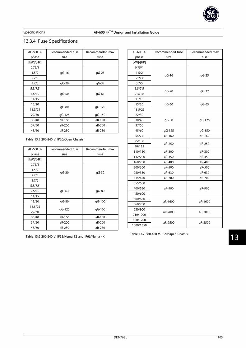
13.3.4 Fuse Specifications
AF-600 3-phase
Recommended fusesize
Recommended maxfuse
[kW]/[HP]
0.75/1
gG-16 gG-251.5/2
2.2/3
3.7/5 gG-20 gG-32
5.5/7.5
gG-50 gG-637.5/10
11/15
15/20gG-80 gG-125
18.5/25
22/30 gG-125 gG-150
30/40 aR-160 aR-160
37/50 aR-200 aR-200
45/60 aR-250 aR-250
Table 13.5 200-240 V, IP20/Open Chassis
AF-600 3-
phase
Recommended fuse
size
Recommended max
fuse
[kW]/[HP]
0.75/1
gG-20 gG-321.5/2
2.2/3
3.7/5
5.5/7.5
gG-63 gG-807.5/10
11/15
15/20 gG-80 gG-100
18.5/25gG-125 gG-160
22/30
30/40 aR-160 aR-160
37/50 aR-200 aR-200
45/60 aR-250 aR-250
Table 13.6 200-240 V, IP55/Nema 12 and IP66/Nema 4X
AF-600 3-phase
Recommended fusesize
Recommended maxfuse
[kW]/[HP]
0.75/1
gG-16 gG-251.5/2
2.2/3
3.7/5
5.5/7.5gG-20 gG-32
7.5/10
11/15
gG-50 gG-6315/20
18.5/25
22/30
gG-80 gG-12530/40
37/50
45/60 gG-125 gG-150
55/75 aR-160 aR-160
75/100aR-250 aR-250
90/125
110/150 aR-300 aR-300
132/200 aR-350 aR-350
160/250 aR-400 aR-400
200/300 aR-500 aR-500
250/350 aR-630 aR-630
315/450 aR-700 aR-700
355/500
aR-900 aR-900400/550
450/600
500/650aR-1600 aR-1600
560/750
630/900aR-2000 aR-2000
710/1000
800/1200aR-2500 aR-2500
1000/1350
Table 13.7 380-480 V, IP20/Open Chassis
Specifications AF-600 FPTM Design and Installation Guide
DET-768b 105
13 13
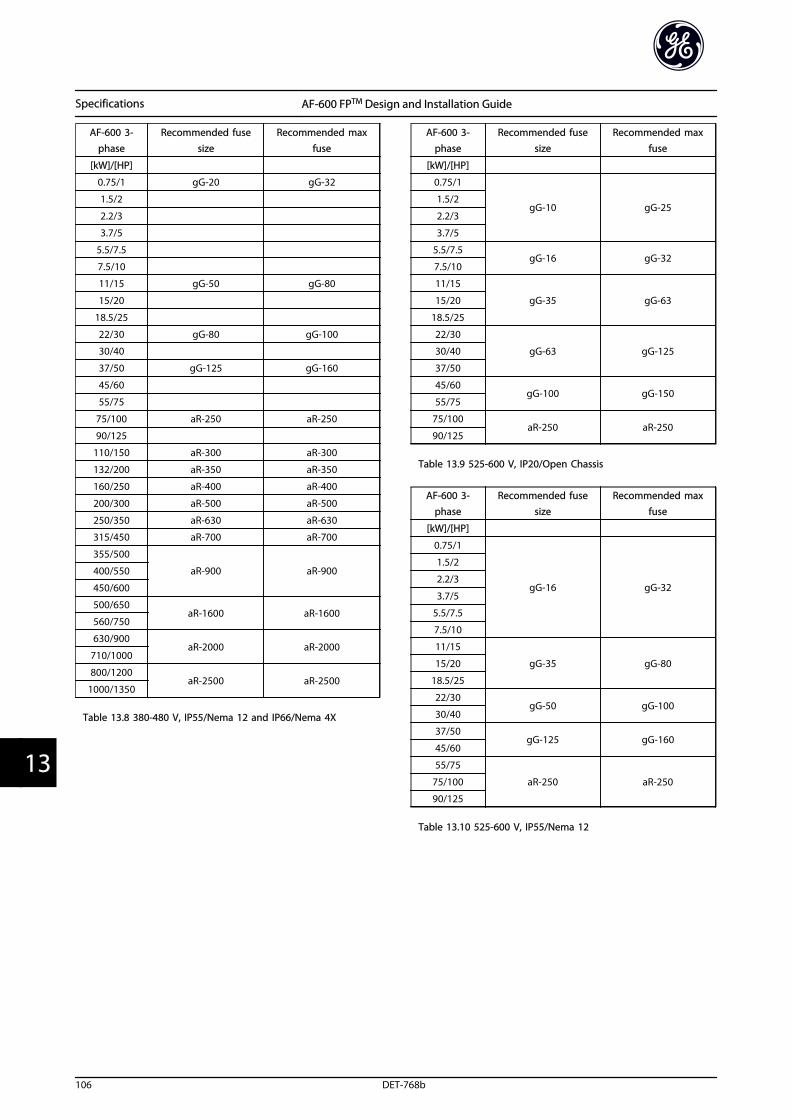
AF-600 3-phase
Recommended fusesize
Recommended maxfuse
[kW]/[HP]
0.75/1 gG-20 gG-32
1.5/2
2.2/3
3.7/5
5.5/7.5
7.5/10
11/15 gG-50 gG-80
15/20
18.5/25
22/30 gG-80 gG-100
30/40
37/50 gG-125 gG-160
45/60
55/75
75/100 aR-250 aR-250
90/125
110/150 aR-300 aR-300
132/200 aR-350 aR-350
160/250 aR-400 aR-400
200/300 aR-500 aR-500
250/350 aR-630 aR-630
315/450 aR-700 aR-700
355/500
aR-900 aR-900400/550
450/600
500/650aR-1600 aR-1600
560/750
630/900aR-2000 aR-2000
710/1000
800/1200aR-2500 aR-2500
1000/1350
Table 13.8 380-480 V, IP55/Nema 12 and IP66/Nema 4X
AF-600 3-phase
Recommended fusesize
Recommended maxfuse
[kW]/[HP]
0.75/1
gG-10 gG-251.5/2
2.2/3
3.7/5
5.5/7.5gG-16 gG-32
7.5/10
11/15
gG-35 gG-6315/20
18.5/25
22/30
gG-63 gG-12530/40
37/50
45/60gG-100 gG-150
55/75
75/100aR-250 aR-250
90/125
Table 13.9 525-600 V, IP20/Open Chassis
AF-600 3-phase
Recommended fusesize
Recommended maxfuse
[kW]/[HP]
0.75/1
gG-16 gG-32
1.5/2
2.2/3
3.7/5
5.5/7.5
7.5/10
11/15
gG-35 gG-8015/20
18.5/25
22/30gG-50 gG-100
30/40
37/50gG-125 gG-160
45/60
55/75
aR-250 aR-25075/100
90/125
Table 13.10 525-600 V, IP55/Nema 12
Specifications AF-600 FPTM Design and Installation Guide
106 DET-768b
133
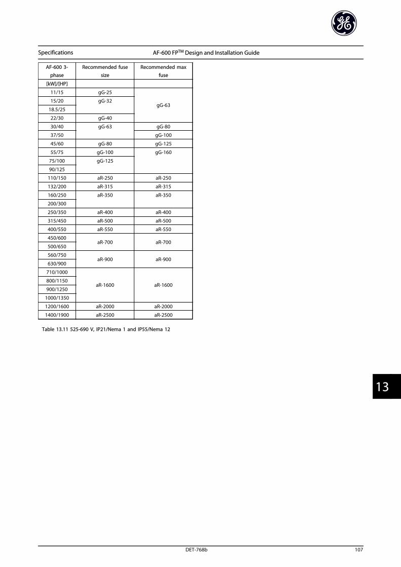
AF-600 3-phase
Recommended fusesize
Recommended maxfuse
[kW]/[HP]
11/15 gG-25
gG-6315/20 gG-32
18.5/25
22/30 gG-40
30/40 gG-63 gG-80
37/50 gG-100
45/60 gG-80 gG-125
55/75 gG-100 gG-160
75/100 gG-125
90/125
110/150 aR-250 aR-250
132/200 aR-315 aR-315
160/250 aR-350 aR-350
200/300
250/350 aR-400 aR-400
315/450 aR-500 aR-500
400/550 aR-550 aR-550
450/600aR-700 aR-700
500/650
560/750aR-900 aR-900
630/900
710/1000
aR-1600 aR-1600800/1150
900/1250
1000/1350
1200/1600 aR-2000 aR-2000
1400/1900 aR-2500 aR-2500
Table 13.11 525-690 V, IP21/Nema 1 and IP55/Nema 12
Specifications AF-600 FPTM Design and Installation Guide
DET-768b 107
13 13
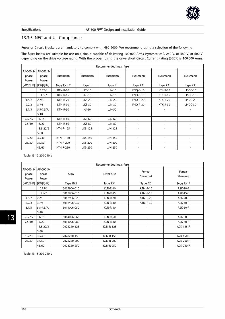
13.3.5 NEC and UL Compliance
Fuses or Circuit Breakers are mandatory to comply with NEC 2009. We recommend using a selection of the following
The fuses below are suitable for use on a circuit capable of delivering 100,000 Arms (symmetrical), 240 V, or 480 V, or 600 Vdepending on the drive voltage rating. With the proper fusing the drive Short Circuit Current Rating (SCCR) is 100,000 Arms.
Recommended max. fuse
AF-600 1-phasePower
AF-600 3-phasePower
Bussmann Bussmann Bussmann Bussmann Bussmann Bussmann
[kW]/[HP] [kW]/[HP] Type RK1 1) Type J Type T Type CC Type CC Type CC
0.75/1 KTN-R-10 JKS-10 JJN-10 FNQ-R-10 KTK-R-10 LP-CC-10
1.5/2 KTN-R-15 JKS-15 JJN-15 FNQ-R-15 KTK-R-15 LP-CC-15
1.5/2 2.2/3 KTN-R-20 JKS-20 JJN-20 FNQ-R-20 KTK-R-20 LP-CC-20
2.2/3 3.7/5 KTN-R-30 JKS-30 JJN-30 FNQ-R-30 KTK-R-30 LP-CC-30
3.7/5 5.5-7.5/7.5-10
KTN-R-50 KS-50 JJN-50 - - -
5.5/7.5 11/15 KTN-R-60 JKS-60 JJN-60 - - -
7.5/10 15/20 KTN-R-80 JKS-80 JJN-80 - - -
18.5-22/25-30
KTN-R-125 JKS-125 JJN-125 - - -
15/20 30/40 KTN-R-150 JKS-150 JJN-150 - - -
23/30 37/50 KTN-R-200 JKS-200 JJN-200 - - -
45/60 KTN-R-250 JKS-250 JJN-250 - - -
Table 13.12 200-240 V
Recommended max. fuse
AF-600 1-phasePower
AF-600 3-phasePower
SIBA Littel fuseFerraz-
ShawmutFerraz-
Shawmut
[kW]/[HP] [kW]/[HP] Type RK1 Type RK1 Type CC Type RK13)
0.75/1 5017906-010 KLN-R-10 ATM-R-10 A2K-10-R
1.5/2 5017906-016 KLN-R-15 ATM-R-15 A2K-15-R
1.5/2 2.2/3 5017906-020 KLN-R-20 ATM-R-20 A2K-20-R
2.2/3 3.7/5 5012406-032 KLN-R-30 ATM-R-30 A2K-30-R
3.7/5 5.5-7.5/7.5-10
5014006-050 KLN-R-50 - A2K-50-R
5.5/7.5 11/15 5014006-063 KLN-R-60 - A2K-60-R
7.5/10 15/20 5014006-080 KLN-R-80 - A2K-80-R
18.5-22/25-30
2028220-125 KLN-R-125 - A2K-125-R
15/20 30/40 2028220-150 KLN-R-150 - A2K-150-R
23/30 37/50 2028220-200 KLN-R-200 - A2K-200-R
45/60 2028220-250 KLN-R-250 - A2K-250-R
Table 13.13 200-240 V
Specifications AF-600 FPTM Design and Installation Guide
108 DET-768b
133
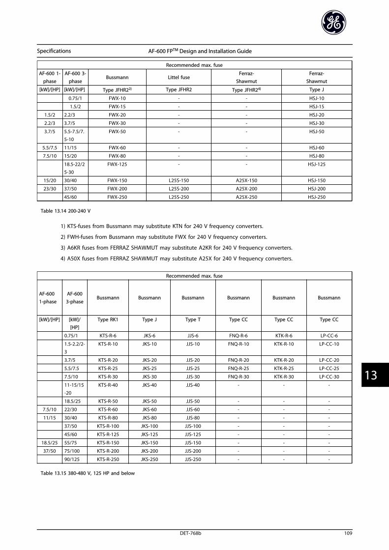
Recommended max. fuse
AF-600 1-phase
AF-600 3-phase
Bussmann Littel fuseFerraz-
ShawmutFerraz-
Shawmut
[kW]/[HP] [kW]/[HP] Type JFHR22) Type JFHR2 Type JFHR24) Type J
0.75/1 FWX-10 - - HSJ-10
1.5/2 FWX-15 - - HSJ-15
1.5/2 2.2/3 FWX-20 - - HSJ-20
2.2/3 3.7/5 FWX-30 - - HSJ-30
3.7/5 5.5-7.5/7.5-10
FWX-50 - - HSJ-50
5.5/7.5 11/15 FWX-60 - - HSJ-60
7.5/10 15/20 FWX-80 - - HSJ-80
18.5-22/2
5-30
FWX-125 - - HSJ-125
15/20 30/40 FWX-150 L25S-150 A25X-150 HSJ-150
23/30 37/50 FWX-200 L25S-200 A25X-200 HSJ-200
45/60 FWX-250 L25S-250 A25X-250 HSJ-250
Table 13.14 200-240 V
1) KTS-fuses from Bussmann may substitute KTN for 240 V frequency converters.
2) FWH-fuses from Bussmann may substitute FWX for 240 V frequency converters.
3) A6KR fuses from FERRAZ SHAWMUT may substitute A2KR for 240 V frequency converters.
4) A50X fuses from FERRAZ SHAWMUT may substitute A25X for 240 V frequency converters.
Recommended max. fuse
AF-6001-phase
AF-6003-phase
Bussmann Bussmann Bussmann Bussmann Bussmann Bussmann
[kW]/[HP] [kW]/[HP]
Type RK1 Type J Type T Type CC Type CC Type CC
0.75/1 KTS-R-6 JKS-6 JJS-6 FNQ-R-6 KTK-R-6 LP-CC-6
1.5-2.2/2-3
KTS-R-10 JKS-10 JJS-10 FNQ-R-10 KTK-R-10 LP-CC-10
3.7/5 KTS-R-20 JKS-20 JJS-20 FNQ-R-20 KTK-R-20 LP-CC-20
5.5/7.5 KTS-R-25 JKS-25 JJS-25 FNQ-R-25 KTK-R-25 LP-CC-25
7.5/10 KTS-R-30 JKS-30 JJS-30 FNQ-R-30 KTK-R-30 LP-CC-30
11-15/15-20
KTS-R-40 JKS-40 JJS-40 - - -
18.5/25 KTS-R-50 JKS-50 JJS-50 - - -
7.5/10 22/30 KTS-R-60 JKS-60 JJS-60 - - -
11/15 30/40 KTS-R-80 JKS-80 JJS-80 - - -
37/50 KTS-R-100 JKS-100 JJS-100 - - -
45/60 KTS-R-125 JKS-125 JJS-125 - - -
18.5/25 55/75 KTS-R-150 JKS-150 JJS-150 - - -
37/50 75/100 KTS-R-200 JKS-200 JJS-200 - - -
90/125 KTS-R-250 JKS-250 JJS-250 - - -
Table 13.15 380-480 V, 125 HP and below
Specifications AF-600 FPTM Design and Installation Guide
DET-768b 109
13 13
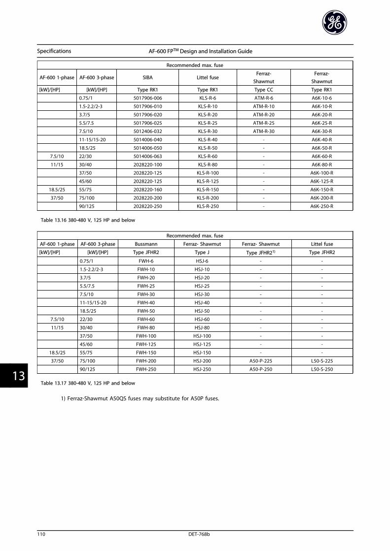
Recommended max. fuse
AF-600 1-phase AF-600 3-phase SIBA Littel fuseFerraz-
ShawmutFerraz-
Shawmut
[kW]/[HP] [kW]/[HP] Type RK1 Type RK1 Type CC Type RK1
0.75/1 5017906-006 KLS-R-6 ATM-R-6 A6K-10-6
1.5-2.2/2-3 5017906-010 KLS-R-10 ATM-R-10 A6K-10-R
3.7/5 5017906-020 KLS-R-20 ATM-R-20 A6K-20-R
5.5/7.5 5017906-025 KLS-R-25 ATM-R-25 A6K-25-R
7.5/10 5012406-032 KLS-R-30 ATM-R-30 A6K-30-R
11-15/15-20 5014006-040 KLS-R-40 - A6K-40-R
18.5/25 5014006-050 KLS-R-50 - A6K-50-R
7.5/10 22/30 5014006-063 KLS-R-60 - A6K-60-R
11/15 30/40 2028220-100 KLS-R-80 - A6K-80-R
37/50 2028220-125 KLS-R-100 - A6K-100-R
45/60 2028220-125 KLS-R-125 - A6K-125-R
18.5/25 55/75 2028220-160 KLS-R-150 - A6K-150-R
37/50 75/100 2028220-200 KLS-R-200 - A6K-200-R
90/125 2028220-250 KLS-R-250 - A6K-250-R
Table 13.16 380-480 V, 125 HP and below
Recommended max. fuse
AF-600 1-phase AF-600 3-phase Bussmann Ferraz- Shawmut Ferraz- Shawmut Littel fuse
[kW]/[HP] [kW]/[HP] Type JFHR2 Type J Type JFHR21) Type JFHR2
0.75/1 FWH-6 HSJ-6 - -
1.5-2.2/2-3 FWH-10 HSJ-10 - -
3.7/5 FWH-20 HSJ-20 - -
5.5/7.5 FWH-25 HSJ-25 - -
7.5/10 FWH-30 HSJ-30 - -
11-15/15-20 FWH-40 HSJ-40 - -
18.5/25 FWH-50 HSJ-50 - -
7.5/10 22/30 FWH-60 HSJ-60 - -
11/15 30/40 FWH-80 HSJ-80 - -
37/50 FWH-100 HSJ-100 - -
45/60 FWH-125 HSJ-125 - -
18.5/25 55/75 FWH-150 HSJ-150 - -
37/50 75/100 FWH-200 HSJ-200 A50-P-225 L50-S-225
90/125 FWH-250 HSJ-250 A50-P-250 L50-S-250
Table 13.17 380-480 V, 125 HP and below
1) Ferraz-Shawmut A50QS fuses may substitute for A50P fuses.
Specifications AF-600 FPTM Design and Installation Guide
110 DET-768b
133
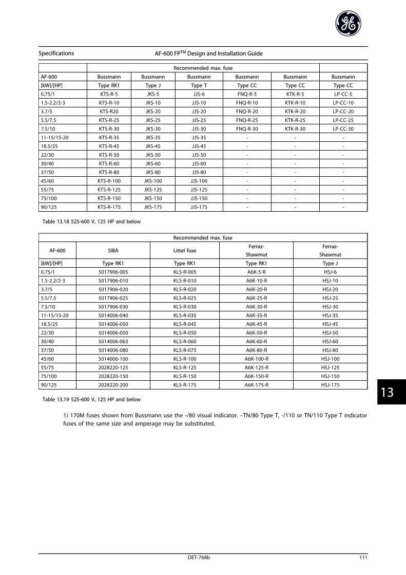
Recommended max. fuse
AF-600 Bussmann Bussmann Bussmann Bussmann Bussmann Bussmann
[kW]/[HP] Type RK1 Type J Type T Type CC Type CC Type CC
0.75/1 KTS-R-5 JKS-5 JJS-6 FNQ-R-5 KTK-R-5 LP-CC-5
1.5-2.2/2-3 KTS-R-10 JKS-10 JJS-10 FNQ-R-10 KTK-R-10 LP-CC-10
3.7/5 KTS-R20 JKS-20 JJS-20 FNQ-R-20 KTK-R-20 LP-CC-20
5.5/7.5 KTS-R-25 JKS-25 JJS-25 FNQ-R-25 KTK-R-25 LP-CC-25
7.5/10 KTS-R-30 JKS-30 JJS-30 FNQ-R-30 KTK-R-30 LP-CC-30
11-15/15-20 KTS-R-35 JKS-35 JJS-35 - - -
18.5/25 KTS-R-45 JKS-45 JJS-45 - - -
22/30 KTS-R-50 JKS-50 JJS-50 - - -
30/40 KTS-R-60 JKS-60 JJS-60 - - -
37/50 KTS-R-80 JKS-80 JJS-80 - - -
45/60 KTS-R-100 JKS-100 JJS-100 - - -
55/75 KTS-R-125 JKS-125 JJS-125 - - -
75/100 KTS-R-150 JKS-150 JJS-150 - - -
90/125 KTS-R-175 JKS-175 JJS-175 - - -
Table 13.18 525-600 V, 125 HP and below
Recommended max. fuse
AF-600 SIBA Littel fuseFerraz-
ShawmutFerraz-
Shawmut
[kW]/[HP] Type RK1 Type RK1 Type RK1 Type J
0.75/1 5017906-005 KLS-R-005 A6K-5-R HSJ-6
1.5-2.2/2-3 5017906-010 KLS-R-010 A6K-10-R HSJ-10
3.7/5 5017906-020 KLS-R-020 A6K-20-R HSJ-20
5.5/7.5 5017906-025 KLS-R-025 A6K-25-R HSJ-25
7.5/10 5017906-030 KLS-R-030 A6K-30-R HSJ-30
11-15/15-20 5014006-040 KLS-R-035 A6K-35-R HSJ-35
18.5/25 5014006-050 KLS-R-045 A6K-45-R HSJ-45
22/30 5014006-050 KLS-R-050 A6K-50-R HSJ-50
30/40 5014006-063 KLS-R-060 A6K-60-R HSJ-60
37/50 5014006-080 KLS-R-075 A6K-80-R HSJ-80
45/60 5014006-100 KLS-R-100 A6K-100-R HSJ-100
55/75 2028220-125 KLS-R-125 A6K-125-R HSJ-125
75/100 2028220-150 KLS-R-150 A6K-150-R HSJ-150
90/125 2028220-200 KLS-R-175 A6K-175-R HSJ-175
Table 13.19 525-600 V, 125 HP and below
1) 170M fuses shown from Bussmann use the -/80 visual indicator. –TN/80 Type T, -/110 or TN/110 Type T indicatorfuses of the same size and amperage may be substituted.
Specifications AF-600 FPTM Design and Installation Guide
DET-768b 111
13 13
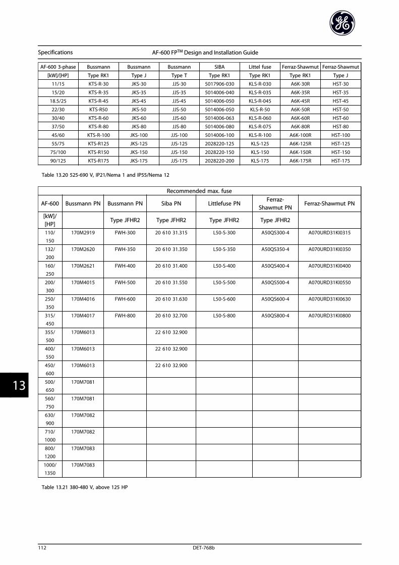
AF-600 3-phase Bussmann Bussmann Bussmann SIBA Littel fuse Ferraz-Shawmut Ferraz-Shawmut
[kW]/[HP] Type RK1 Type J Type T Type RK1 Type RK1 Type RK1 Type J
11/15 KTS-R-30 JKS-30 JJS-30 5017906-030 KLS-R-030 A6K-30R HST-30
15/20 KTS-R-35 JKS-35 JJS-35 5014006-040 KLS-R-035 A6K-35R HST-35
18.5/25 KTS-R-45 JKS-45 JJS-45 5014006-050 KLS-R-045 A6K-45R HST-45
22/30 KTS-R50 JKS-50 JJS-50 5014006-050 KLS-R-50 A6K-50R HST-50
30/40 KTS-R-60 JKS-60 JJS-60 5014006-063 KLS-R-060 A6K-60R HST-60
37/50 KTS-R-80 JKS-80 JJS-80 5014006-080 KLS-R-075 A6K-80R HST-80
45/60 KTS-R-100 JKS-100 JJS-100 5014006-100 KLS-R-100 A6K-100R HST-100
55/75 KTS-R125 JKS-125 JJS-125 2028220-125 KLS-125 A6K-125R HST-125
75/100 KTS-R150 JKS-150 JJS-150 2028220-150 KLS-150 A6K-150R HST-150
90/125 KTS-R175 JKS-175 JJS-175 2028220-200 KLS-175 A6K-175R HST-175
Table 13.20 525-690 V, IP21/Nema 1 and IP55/Nema 12
Recommended max. fuse
AF-600 Bussmann PN Bussmann PN Siba PN Littlefuse PNFerraz-
Shawmut PNFerraz-Shawmut PN
[kW]/[HP]
Type JFHR2 Type JFHR2 Type JFHR2 Type JFHR2
110/
150
170M2919 FWH-300 20 610 31.315 L50-S-300 A50QS300-4 A070URD31KI0315
132/200
170M2620 FWH-350 20 610 31.350 L50-S-350 A50QS350-4 A070URD31KI0350
160/250
170M2621 FWH-400 20 610 31.400 L50-S-400 A50QS400-4 A070URD31KI0400
200/300
170M4015 FWH-500 20 610 31.550 L50-S-500 A50QS500-4 A070URD31KI0550
250/
350
170M4016 FWH-600 20 610 31.630 L50-S-600 A50QS600-4 A070URD31KI0630
315/
450
170M4017 FWH-800 20 610 32.700 L50-S-800 A50QS800-4 A070URD31KI0800
355/500
170M6013 22 610 32.900
400/550
170M6013 22 610 32.900
450/600
170M6013 22 610 32.900
500/650
170M7081
560/
750
170M7081
630/900
170M7082
710/1000
170M7082
800/1200
170M7083
1000/1350
170M7083
Table 13.21 380-480 V, above 125 HP
Specifications AF-600 FPTM Design and Installation Guide
112 DET-768b
133
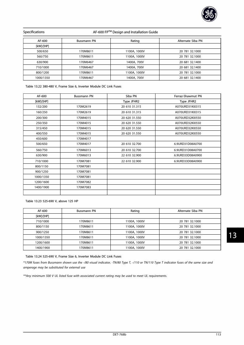
AF-600 Bussmann PN Rating Alternate Siba PN
[kW]/[HP]
500/650 170M8611 1100A, 1000V 20 781 32.1000
560/750 170M8611 1100A, 1000V 20 781 32.1000
630/900 170M6467 1400A, 700V 20 681 32.1400
710/1000 170M6467 1400A, 700V 20 681 32.1400
800/1200 170M8611 1100A, 1000V 20 781 32.1000
1000/1350 170M6467 1400A, 700V 20 681 32.1400
Table 13.22 380-480 V, Frame Size 6, Inverter Module DC Link Fuses
AF-600 Bussmann PN Siba PN Ferraz-Shawmut PN
[kW]/[HP] Type JFHR2 Type JFHR2
132/200 170M2619 20 610 31.315 A070URD31KI0315
160/250 170M2619 20 610 31.315 A070URD31KI0315
200/300 170M4015 20 620 31.550 A070URD32KI0550
250/350 170M4015 20 620 31.550 A070URD32KI0550
315/450 170M4015 20 620 31.550 A070URD32KI0550
400/550 170M4015 20 620 31.550 A070URD32KI0550
450/600 170M4017
500/650 170M4017 20 610 32.700 6.9URD31D08A0700
560/750 170M6013 20 610 32.700 6.9URD31D08A0700
630/900 170M6013 22 610 32.900 6.9URD33D08A0900
710/1000 170M7081 22 610 32.900 6.9URD33D08A0900
800/1150 170M7081
900/1250 170M7081
1000/1350 170M7081
1200/1600 170M7082
1400/1900 170M7083
Table 13.23 525-690 V, above 125 HP
AF-600 Bussmann PN Rating Alternate Siba PN
[kW]/[HP]
710/1000 170M8611 1100A, 1000V 20 781 32.1000
800/1150 170M8611 1100A, 1000V 20 781 32.1000
900/1250 170M8611 1100A, 1000V 20 781 32.1000
1000/1350 170M8611 1100A, 1000V 20 781 32.1000
1200/1600 170M8611 1100A, 1000V 20 781 32.1000
1400/1900 170M8611 1100A, 1000V 20 781 32.1000
Table 13.24 525-690 V, Frame Size 6, Inverter Module DC Link Fuses
*170M fuses from Bussmann shown use the -/80 visual indicator, -TN/80 Type T, -/110 or TN/110 Type T indicator fuses of the same size andamperage may be substituted for external use
**Any minimum 500 V UL listed fuse with associated current rating may be used to meet UL requirements.
Specifications AF-600 FPTM Design and Installation Guide
DET-768b 113
13 13
Index
AA53............................................................................................................. 23
A54............................................................................................................. 23
ACInput.............................................................................................. 11, 19Mains...................................................................................... 11, 16, 19Waveform........................................................................................... 11
Accel Time............................................................................................... 28
Acoustic Noise....................................................................................... 15
Airflow...................................................................................................... 14
AlarmLog......................................................................................................... 31Messages............................................................................................. 73
Alarms....................................................................................................... 72
AnalogInput..................................................................................................... 77Inputs.......................................................................................... 21, 101Output........................................................................................ 21, 101Signal.................................................................................................... 77
Approvals.................................................................................................... i
AutoAuto........................................................................................ 32, 64, 65Mode..................................................................................................... 31Tune........................................................................................ 28, 81, 64
Automatic Adaptations To Ensure Performance...................... 62
Auto-reset............................................................................................... 30
BBack
Cooling................................................................................................ 14Plate...................................................................................................... 15
Balancing Contractor.......................................................................... 55
Better Control........................................................................................ 48
Braking..................................................................................................... 79
Branch Circuit Protection................................................................ 104
Bypass Frequency Ranges................................................................. 53
CCAV System............................................................................................. 52
Central VAV Systems........................................................................... 51
Circuit Breakers...................................................................................... 26
ClearanceClearance............................................................................................ 13Requirements.................................................................................... 12
Closed Loop............................................................................................ 23
CO2 Sensor.............................................................................................. 52
Coasting............................................................................................ 70, 68
Communication Option..................................................................... 80
Condenser Pumps................................................................................ 54
Conducted Emission........................................................................... 59
Conduit.............................................................................................. 17, 25
ConstantAir Volume.......................................................................................... 52Torque Applications (CT Mode).................................................. 63
ControlCables................................................................................................... 23Card....................................................................................................... 77Card Performance......................................................................... 103Card, 10 V DC Output................................................................... 102Card, 24 V DC Output................................................................... 102Card, RS-485 Serial Communication....................................... 101Card, USB Serial Communication............................................. 103Characteristics................................................................................ 102Potential.............................................................................................. 56Signal...................................................................................... 34, 35, 64System.................................................................................................. 11Terminals.......................................................... 16, 64, 66, 32, 36, 22Wire....................................................................................................... 22Wiring..................................................................................... 17, 22, 25WordFC Profile.................................................................................. 68
CoolingCooling.................................................................................. 12, 63, 14Clearance............................................................................................ 25Tower Fan........................................................................................... 53
Copying Parameter Settings............................................................ 32
Cos Φ Compensation.......................................................................... 48
CurrentLimit...................................................................................................... 28Rating............................................................................................ 12, 77
DDampers................................................................................................... 51
DCBrake..................................................................................................... 68Current.......................................................................................... 11, 64Link........................................................................................................ 77
Decel Time.............................................................................................. 28
DeratingDerating............................................................................................... 12For Ambient Temperature............................................................ 62For Low Air Pressure....................................................................... 62For Running At Low Speed........................................................... 63
Differential Pressure............................................................................ 56
DigitalInput.............................................................................................. 65, 78Inputs................................................................................... 21, 66, 100Output............................................................................................... 102
DisconnectSwitch................................................................................................... 27Switches.............................................................................................. 25
Downloading Data From The Keypad.......................................... 33
Drive Profile............................................................................................ 68
Duct Cooling.......................................................................................... 14
Index AF-600 FPTM Design and Installation Guide
114 DET-768b
EEarth
Connections....................................................................................... 25Wire....................................................................................................... 25
EarthingEarthing............................................................................................... 25(Grounding)........................................................................................ 26
Electrical Noise...................................................................................... 18
EMCEMC....................................................................................................... 25Test Results......................................................................................... 59
Emission Requirements...................................................................... 58
Energy Savings...................................................................................... 48
Evaporator Flow Rate.......................................................................... 55
ExternalCommands.................................................................................. 11, 66Controllers.......................................................................................... 11Voltage................................................................................................. 35
FFan System Controlled By Frequency Converters.................... 50
Fault Log.................................................................................................. 31
Feedback..................................................................... 23, 25, 80, 65, 81
Floating Delta........................................................................................ 19
Flow Meter.............................................................................................. 55
FrequencyConverter............................................................................................ 21Converter Block Diagram.............................................................. 11
Full Load Current........................................................................... 12, 25
Functional Testing......................................................................... 11, 28
Fuses.................................................................................. 25, 80, 83, 104
Fusing................................................................................................ 17, 25
GGeneral
Aspects Of EMC Emissions............................................................ 57Aspects Of Harmonics Emission................................................. 60
Gland/Conduit Entry........................................................................... 20
GroundConnections....................................................................................... 25Loops.................................................................................................... 23Wire......................................................................................... 17, 18, 25
Grounded Delta.................................................................................... 19
GroundingGrounding..................................................................... 17, 18, 19, 25Using Shielded Cable...................................................................... 18
HHand
Hand....................................................................................... 28, 32, 64On.......................................................................................................... 28
HarmonicsHarmonics........................................................................................... 11Emission Requirements................................................................. 61Test Results (Emission)................................................................... 61
Hold Output Frequency..................................................................... 69
IIEC 61800-3............................................................................................. 19
IGVs............................................................................................................ 51
Immunity Requirements.................................................................... 59
Induced Voltage.................................................................................... 17
InitialisationManual Initialisation.................................................... 33
InputCurrent................................................................................................. 19Power................................................................. 17, 25, 72, 83, 11, 19Signal.................................................................................................... 35Signals.................................................................................................. 23Terminal.............................................................................................. 77Terminals........................................................................ 16, 19, 23, 25Voltage.......................................................................................... 27, 72
Installation............................................................ 11, 12, 15, 22, 25, 27
Intermediate Circuit............................................................................. 15
Isolated Mains........................................................................................ 19
JJog.............................................................................................................. 69
KKnock-outs.............................................................................................. 19
LLaws Of Proportionality...................................................................... 48
Leakage Current.................................................................................... 25
Lifting........................................................................................................ 14
LocalControl................................................................................... 30, 64, 32Mode..................................................................................................... 28Operation............................................................................................ 30Speed Determination..................................................................... 55Start....................................................................................................... 28
Local-control Test................................................................................. 28
Low Evaporator Temperature.......................................................... 55
MMain Menu....................................................................................... 34, 31
MainsMains.................................................................................................... 17Supply (L1, L2, L3).......................................................................... 100Voltage................................................................................... 31, 64, 32
MenuKeys................................................................................................ 30, 31Structure.............................................................................................. 32
Index AF-600 FPTM Design and Installation Guide
DET-768b 115
MotorCables.............................................................................. 12, 17, 18, 28Current............................................................................ 11, 28, 81, 31Data......................................................................................... 28, 78, 81Frequency........................................................................................... 31Output............................................................................................... 100Power.............................................................................. 16, 17, 81, 31Protection.................................................................................. 17, 103Rotation........................................................................................ 28, 31Speeds.................................................................................................. 27Status.................................................................................................... 11Thermal Protection.......................................................................... 71Wiring..................................................................................... 17, 18, 25
Mounting.......................................................................................... 15, 25
MultipleFrequency Converters............................................................. 17, 18Motors.................................................................................................. 25Pumps.................................................................................................. 56
NNavigation Keys................................................................ 34, 64, 30, 32
Noise Isolation................................................................................ 17, 25
OOpen Loop....................................................................................... 23, 34
Operation Keys...................................................................................... 32
Optional Equipment..................................................................... 27, 11
OutputCurrent.......................................................................................... 64, 77Performance (U, V, W).................................................................. 100Signal.................................................................................................... 37Terminals...................................................................................... 16, 25
Overcurrent............................................................................................ 65
Overload Protection..................................................................... 12, 17
Overvoltage..................................................................................... 28, 65
PParameter
Settings................................................................................................ 32Values................................................................................................... 68
PELVPELV............................................................................................... 20, 46- Protective Extra Low Voltage.................................................... 61
Phase Loss............................................................................................... 77
PowerConnections....................................................................................... 17Factor...................................................................................... 11, 18, 25Factor Correction............................................................................. 48
Pre-start.................................................................................................... 25
Primary Pumps...................................................................................... 55
Programmable Minimum Frequency Setting............................ 53
ProgrammingProgramming................................... 11, 28, 37, 42, 77, 30, 31, 32Example............................................................................................... 34
ProtectionProtection........................................................................................... 61And Features................................................................................... 103
Public Supply Network....................................................................... 61
Pulse Inputs.......................................................................................... 101
Pump Impeller....................................................................................... 54
QQuick Menu............................................................................... 31, 34, 31
RRadiated Emission................................................................................ 59
Ramp-up Time....................................................................................... 28
RCD............................................................................................................ 18
Reference............................................................................ 43, 64, 65, 31
Relay Outputs............................................................................... 21, 102
RemoteCommands......................................................................................... 11Programming.................................................................................... 42Reference............................................................................................ 65
Removal Of Knockouts For Extra Cables...................................... 20
Reset................................................................ 30, 66, 72, 77, 81, 32, 33
Restoring Default Settings................................................................ 33
Return Fan............................................................................................... 51
RFI Filter................................................................................................... 19
RMS Current............................................................................................ 11
RS-485....................................................................................................... 24
RunCommand........................................................................................... 29Permissive........................................................................................... 65
SSafety Inspection.................................................................................. 25
Secondary Pumps................................................................................. 56
Serial Communication....... 11, 16, 21, 22, 64, 65, 66, 32, 72, 103
Setpoint.................................................................................................... 65
Set-up................................................................................................ 29, 31
ShieldedCable....................................................................................... 12, 17, 25Wire....................................................................................................... 17
Short Circuit............................................................................................ 78
Sleep Mode............................................................................................. 65
Specifications......................................................................................... 11
Speed Reference....................................................... 23, 29, 35, 64, 43
Start Up............................................................................... 11, 34, 33, 83
StatusMode..................................................................................................... 64Word..................................................................................................... 70
Stop Command..................................................................................... 65
Index AF-600 FPTM Design and Installation Guide
116 DET-768b
Supply Voltage................................................................. 20, 21, 25, 80
Surroundings....................................................................................... 103
Switching Frequency.......................................................................... 65
Symbols....................................................................................................... i
SystemFeedback............................................................................................. 11Monitoring.......................................................................................... 72Start Up................................................................................................ 29
TTemperature Limits............................................................................. 25
Terminal53............................................................................................. 23, 34, 3554........................................................................................................... 23Programming.................................................................................... 23Programming Examples................................................................ 36
The Clear Advantage - Energy Savings......................................... 47
ThermistorThermistor................................................................................... 20, 46Control Wiring................................................................................... 20
Throttling Valve..................................................................................... 54
TorqueCharacteristics................................................................................ 100Limit...................................................................................................... 28
Transient Protection............................................................................ 11
TripTrip........................................................................................................ 72Function.............................................................................................. 17Lock....................................................................................................... 72
Troubleshooting................................................................................... 11
UUploading Data To The Keypad...................................................... 33
VVariable
(Quadratic) Torque Applications (VT)....................................... 63Air Volume.......................................................................................... 51Control Of Flow And Pressure..................................................... 48
VAV............................................................................................................ 51
Vibrations................................................................................................ 53
VoltageImbalance........................................................................................... 77Level................................................................................................... 100
WWarning
And Alarm Definitions.................................................................... 77And Alarm Displays......................................................................... 72And Alarm Types.............................................................................. 72
Warnings.................................................................................................. 73
Index AF-600 FPTM Design and Installation Guide
DET-768b 117

AF-600 FPTM
Fan & Pump Drive Design and Installation Guide
The instructions do not purport to cover all details or variations in equipment nor to provide for every possible contingency to be met in connection with installation, operation or maintenance. Should further information be desired or should particular problems arise which are not covered sufficiently for the purchaser’s purposes, the matter should be referred to the GE company.
AF-600 FP is a trademark of the General Electric Company.
GE41 Woodford AvenuePlainville, CT 06062
www.geelectrical.com/drives
130R0412 *MG14F302*
DET-768b
GE