Advanced User Guide - Affinity - Nidec Netherlands
240
Advanced User Guide Affinity Building Automation HVAC/R drive Part Number: 0474-0011-03 Issue: 3
-
Upload
khangminh22 -
Category
Documents
-
view
3 -
download
0
Transcript of Advanced User Guide - Affinity - Nidec Netherlands

Advanced User Guide
Affinity
Building Automation HVAC/R drive
Part Number: 0474-0011-03Issue: 3

Original InstructionsFor the purposes of compliance with the EU Machinery Directive 2006/42/EC, the English version of this manual is the Original Instructions. Manuals
in other languages are Translations of the Original Instructions.
DocumentationManuals are available to download from the following locations: http://www.drive-setup.com/ctdownloads
The information contained in this manual is believed to be correct at the time of printing and does not form part of any contract. The manufacturer reserves the right to change the specification of the product and its performance, and the contents of the manual, without notice.
Warranty and LiabilityIn no event and under no circumstances shall the manufacturer be liable for damages and failures due to misuse, abuse, improper installation, or abnormal conditions of temperature, dust, or corrosion, or failures due to operation outside the published ratings. The manufacturer is not liable for consequential and incidental damages. Contact the supplier of the drive for full details of the warranty terms.
Environmental policyControl Techniques Ltd operates an Environmental Management System (EMS) that conforms to the International Standard ISO 14001.
Further information on our Environmental Policy can be found at: http://www.drive-setup.com/environment
Restriction of Hazardous Substances (RoHS)The products covered by this manual comply with European and International regulations on the Restriction of Hazardous Substances including EU directive 2011/65/EU and the Chinese Administrative Measures for Restriction of Hazardous Substances in Electrical and Electronic Products.
Disposal and Recycling (WEEE)
REACH legislationEC Regulation 1907/2006 on the Registration, Evaluation, Authorisation and restriction of Chemicals (REACH) requires the supplier of an article to inform the recipient if it contains more than a specified proportion of any substance which is considered by the European Chemicals Agency (ECHA) to be a Substance of Very High Concern (SVHC) and is therefore listed by them as a candidate for compulsory authorisation.
Further information on our compliance with REACH can be found at: http://www.drive-setup.com/reach
Registered Office
Nidec Control Techniques Ltd
The Gro
Newtown
Powys
SY16 3BE
UK
Registered in England and Wales. Company Reg. No. 01236886.
Copyright
The contents of this publication are believed to be correct at the time of printing. In the interests of a commitment to a policy of continuous development and improvement, the manufacturer reserves the right to change the specification of the product or its performance, or the contents of the guide, without notice.
All rights reserved. No parts of this guide may be reproduced or transmitted in any form or by any means, electrical or mechanical including photocopying, recording or by an information storage or retrieval system, without permission in writing from the publisher.
Copyright © April 2018 Nidec Control Techniques Ltd
When electronic products reach the end of their useful life, they must not be disposed of along with domestic waste but should be recycled by a specialist recycler of electronic equipment. Control Techniques products are designed to be easily dismantled into their major component parts for efficient recycling. The majority of materials used in the product are suitable for recycling.
Product packaging is of good quality and can be re-used. Large products are packed in wooden crates. Smaller products are packaged in strong cardboard cartons which have a high recycled fibre content. Cartons can be re-used and recycled. Polythene, used in protective film and bags for wrapping the product, can be recycled. When preparing to recycle or dispose of any product or packaging, please observe local legislation and best practice.

Contents
1 Parameter structure.......................................................................................................51.1 Menu 0 ...................................................................................................................................................51.2 Advanced menus ...................................................................................................................................81.3 Solutions Modules .................................................................................................................................81.4 Drive and Building Automation Network (BAN) Interface software version ...........................................8
2 Keypad and display .......................................................................................................92.1 Understanding the display .....................................................................................................................92.2 Keypad operation ..................................................................................................................................92.3 Status mode ........................................................................................................................................102.4 Parameter view mode ..........................................................................................................................102.5 Edit mode ............................................................................................................................................102.6 Parameter access level and security ...................................................................................................122.7 Alarm and trip display ..........................................................................................................................132.8 Keypad control mode ...........................................................................................................................132.9 Drive reset ...........................................................................................................................................132.10 Second motor parameters ...................................................................................................................13
3 Parameter x.00 .............................................................................................................143.1 Parameter x.00 reset ...........................................................................................................................143.2 Saving parameters in drive EEPROM .................................................................................................143.3 Loading defaults ..................................................................................................................................153.4 SMARTCARD transfers .......................................................................................................................153.5 Display non-default values or destination parameters .........................................................................15
4 Typical parameter description format .......................................................................164.1 Parameter ranges and variable maximums: ........................................................................................174.2 Sources and destinations ....................................................................................................................204.3 Update rates ........................................................................................................................................20
5 Advanced parameter descriptions.............................................................................225.1 Overview ..............................................................................................................................................225.2 Feature look-up table ...........................................................................................................................235.3 Menu 1: Frequency/speed reference ...................................................................................................265.4 Menu 2: Ramps ...................................................................................................................................405.5 Menu 3: Speed feedback and speed control .......................................................................................495.6 Menu 4: Torque and current control ....................................................................................................605.7 Menu 5: Motor control ..........................................................................................................................775.8 Menu 6: Sequencer and clock .............................................................................................................955.9 Menu 7: Analog I/O ............................................................................................................................1115.10 Menu 8: Digital I/O .............................................................................................................................1225.11 Menu 9: Programmable logic, motorized pot and binary sum ...........................................................1305.12 Menu 10: Status and trips ..................................................................................................................1405.13 Menu 11: General drive set-up ..........................................................................................................1595.14 Menu 12: Threshold detectors, variable selectors and brake control function ...................................1725.15 Menu 13: Not used ............................................................................................................................1845.16 Menu 14: Advanced process PID ......................................................................................................1865.17 Menus 15 and 16: Solutions Module slots .........................................................................................2005.18 Menu 17: Building Automation Interface ............................................................................................2015.19 Menu 18: Application menu 1 ............................................................................................................2075.20 Menu 19: Application menu 2 ............................................................................................................2085.21 Menu 20: Application menu 3 ............................................................................................................2095.22 Menu 21: Second motor parameters .................................................................................................2105.23 Menu 22: Additional menu 0 set-up ...................................................................................................2175.24 32 bit parameters ...............................................................................................................................218
6 PC communications protocol...................................................................................2196.1 ANSI communications protocol ..........................................................................................................219
Affinity Advanced User Guide 3Issue Number: 3

6.2 CT Modbus RTU specification .......................................................................................................... 221
7 Building Automation Network ................................................................................. 2267.1 Introduction ....................................................................................................................................... 2267.2 BACnet ............................................................................................................................................. 2267.3 Metasys N2 ....................................................................................................................................... 230
8 Performance .............................................................................................................. 2348.1 Digital speed reference ..................................................................................................................... 2348.2 Analog reference .............................................................................................................................. 2348.3 Analog outputs .................................................................................................................................. 2348.4 Digital inputs and outputs ................................................................................................................. 2348.5 Current feedback .............................................................................................................................. 2358.6 Bandwidth ......................................................................................................................................... 235
9 Rotor Flux Control (RFC) mode............................................................................... 2369.1 Introduction ....................................................................................................................................... 2369.2 Setting up the RFC mode ................................................................................................................. 2369.3 Further Tuning .................................................................................................................................. 236
4 Affinity Advanced User Guide Issue Number: 3

Parameter structure
Keypad and display
Parameter x.00Parameter
description formatAdvanced parameter
descriptionsPC comms
protocolBuilding automation
networkPerformance RFC mode
1 Parameter structureThe drive parameter structure consists of menus and parameters.
The drive initially powers up so that only menu 0 can be viewed. The up and down arrow buttons are used to navigate between parameters and once level 2 access (L2) has been enabled in Pr 0.49, and the left and right buttons are used to navigate between menus. For further information, see section 2.6 Parameter access level and security on page 12.
Figure 1-1 Parameter navigation
* can only be used to move between menus if L2 access has been enabled (Pr 0.49).
The menus and parameters roll over in both directions; i.e. if the last parameter is displayed, a further press will cause the display to rollover and show the first parameter.
When changing between menus the drive remembers which parameter was last viewed in a particular menu and thus displays that parameter.
Figure 1-2 Menu structure
1.1 Menu 0Menu 0 has up to 19 fixed parameters and 40 programmable parameters that are defined in menu 11 and menu 22. Menu 0 parameters are copies of advanced menu parameters, and although these parameters are accessible via drive serial comms, they are not accessible to any Solutions Modules. All menu 0 read/write parameters are saved on exiting the edit mode. Table 1-1 gives the default structure for each drive type setting. Where alternative parameters are selected with motor map 2 from menu 21 these are shown below the motor map 1 parameters.
Figure 1-3 Menu 0 cloning‘
* *
Menu 0
....XX.00....
0.500.490.480.470.46
0.010.020.030.040.05
Movesbetweenparameters
Menu 41 Menu 1 Menu 2Menu 20
Moves between Menus
41.5041.4941.4841.4741.46
41.0141.0241.0341.0441.05
1.011.021.031.041.05
1.501.491.481.471.46
41.51
Menu 0
0.040.050.06
Menu 2
2.21
Menu 1
1.14
Menu 4
4.07
50
150
0
150
5
Affinity Advanced User Guide 5Issue Number: 3

Parameter structure
Keypad and display
Parameter x.00Parameter
description formatAdvanced parameter
descriptionsPC comms
protocolBuilding automation
networkPerformance RFC mode
Menu 0 is used to bring together various commonly used parameters for basic easy set up of the drive. All the parameters in menu 0 appear in other menus in the drive (denoted by {…}).
Menus 11 and 22 can be used to change most of the parameters in menu 0. Menu 0 can also contain up to 59 parameters by setting up menu 22.
Table 1-1 Menu 0 parameters
ParameterRange() Default()
OL RFC OL RFC
0.00 xx.00 {x.00} 0 to 32,767 0
0.01 Minimum reference clamp {1.07} ±3,000.0Hz±SPEED_LIMIT_
MAX Hz/rpm0.0
0.02 Maximum reference clamp {1.06} 0 to 3,000.0HzSPEED_LIMIT_
MAX Hz/rpmEUR> 50.0USA> 60.0
EUR> 1,500.0USA> 1800.0
0.03 Acceleration rate {2.11}0.0 to 3,200.0
s/100Hz 0.000 to 3,200.000
s/1,000rpmEUR> 40.0USA> 33.3
EUR> 13.333USA> 11.111
0.04 Deceleration rate {2.21}0.0 to 3,200.0
s/100Hz0.000 to 3,200.000
s/1,000rpmEUR> 40.0USA> 33.3
EUR> 13.333USA> 11.111
0.05 Reference select {1.14} A1.A2 (0), A1.Pr (1), A2.Pr (2), Pr (3), PAd (4), Prc (5) A1.A2 (0)
0.06 Current limit {4.07} 0 to CURRENT_LIMIT_MAX % 110
0.07
OL> Voltage mode select {5.14}Ur_S (0),
Ur (1), Fd (2), Ur_Auto (3), Ur_I (4), SrE (5)
Fd (2)
RFC> Speed controller P gain {3.10} 0.0000 to 6.5535
1/rad s-1 0.0300
0.08OL> Voltage boost {5.15}
0.0 to 25.0% of motor rated voltage
Size 1 to 3: 3.0Size 4 & 5: 2.0Size 6: 1.0
RFC> Speed controller I gain {3.11} 0.00 to 655.35 1/rad 0.10
0.09 OL> Dynamic V/F {5.13} OFF (0) or On (1) OFF (0)
RFC> Speed controller D gain {3.12}0.00000 to 0.65535 (s)
0.00000
0.10 OL> Estimated motor speed {5.04} ±180,000 rpm
RFC> Motor speed {3.02} ±SPEED_MAX rpm
0.11 Drive output frequency {5.01} ±SPEED_FREQ_MAX Hz ±1250 Hz
0.12 Total motor current {4.01} 0 to DRIVE_CURRENT_MAX A
0.13 Percentage load {4.20} ±USER_CURRENT_MAX %
0.14 Ramp mode select {2.04}FASt (0)Std (1)
Std.hV (2)
FASt (0)Std (1)
Std (1)
0.15 Sleep/wake threshold {6.53} ±SPEED_FREQ_MAX Hz/rpm 0.0
0.16 Sleep/wake delay time {6.54} 0.0 to 250.0 s 10.0
0.17 RFC> Current demand filter 1 {4.12} 0.0 to 25.0 ms 0.00.18 Spin start boost {5.40} 0.0 to 10.0 1.0
0.19 Analog input 2 mode {7.11}0-20 (0), 20-0 (1), 4-20tr (2), 20-4tr (3),
4-20 (4), 20-4 (5), VOLt (6)4-20 (4)
0.20 Analog input 2 destination {7.14} Pr 0.00 to Pr 50.99 Pr 1.37
0.21 Analog input 3 mode {7.15}0-20 (0), 20-0 (1), 4-20tr (2), 20-4tr (3), 4-20 (4), 20-4 (5), VOLt (6), th.SC (7),
th (8), th.diSp (9)VOLt (6)
0.22 Date {6.16} 0 to 311299
0.23 Time {6.17} 0.00 to 23.59
0.24 Date/Time selector {6.19} 0 to 5 3
0.25 Date format {6.20} Std (0), Std.ds (1), US (2), US.ds (3) EUR> Std (0), USA> US (2)
0.26 Low load detection level {4.27} 0.0 to 100.0 % 0.0
0.27Low load detection speed / frequency threshold
{4.28} 0.0 to +SPEED_FREQ_MAX Hz/rpm 0.0
0.28 Trip on abnormal load detection {4.29} OFF (0) or On (1) OFF (0)
0.29 SMARTCARD parameter data {11.36} 0 to 999 0
0.30 Parameter cloning {11.42} nonE (0), rEAd (1), Prog (2), AutO (3), boot (4) nonE (0)
0.31 Drive rated voltage {11.33} 200 (0), 400 (1), 575 (2), 690 (3) V
0.32 Drive current scaling {11.32} 0.00 to 9999.99A
0.33 Catch a spinning motor {6.09} 0 to 3 0 to 1 0 1
0.34 User security code {11.30} 0 to 999 0
0.35 PC comms mode {11.24} AnSI (0), rtU (1), Lcd (2) rtU (1)
0.36 PC comms baud rate {11.25}
300 (0), 600 (1), 1200 (2), 2400 (3), 4800 (4), 9600 (5), 19200 (6), 38400 (7),
57600 (8) Modbus RTU only, 115200 (9) Modbus RTU only
19200 (6)
0.37 PC comms address {11.23} 0 to 247 1
0.38 Hold zero speed / Motor pre-heat enable {6.08} OFF (0) or On (1) OFF (0)
0.39 Motor pre-heat current magnitude {6.52} 0 to 100 % 0
0.40 Autotune {5.12} 0 to 2 0 to 4 0
0.41 Maximum switching frequency {5.18} 3 (0), 4 (1), 6 (2), 8 (3), 12 (4), 16 (5) kHz 3 (0)
6 Affinity Advanced User Guide Issue Number: 3

Parameter structure
Keypad and display
Parameter x.00Parameter
description formatAdvanced parameter
descriptionsPC comms
protocolBuilding automation
networkPerformance RFC mode
0.42 No. of motor poles {5.11} 0 to 60 (Auto to 120 pole) 0 (Auto)
0.43 Motor rated power factor {5.10} 0.000 to 1.000 0.850
0.44 Motor rated voltage {5.09} 0 to AC_VOLTAGE_SET_MAX V
200V drive: 230400V drive: EUR> 400, USA> 460
575V drive: 575690V drive: 690
0.45 Motor rated full load speed (rpm) {5.08} 0 to 180,000 rpm0.00 to
40,000.00 rpmEUR> 1,500USA> 1,800
EUR> 1,450.00USA> 1,770.00
0.46 Motor rated current {5.07} 0 to RATED_CURRENT_MAX A Drive rated current [11.32]
0.47 Rated frequency {5.06} 0 to 3,000.0 Hz 0 to 1,250.0 HzEUR> 50.0USA> 60.0
0.48 Operating mode selector {11.31} OPEn LP (1), RFC (2), OPEn LP (1) RFC (2)
0.49 Security status {11.44} L1 (0), L2 (1), Loc (2)
0.50 Software version {11.29} 1.00 to 99.99
0.51 Positive logic select {8.29} OFF (0) or On (1) On (1)
0.52 Timer 1 start date {9.35} 0 to 311299 0
0.53 Timer 1 start time {9.36} 0.00 to 23.59 0.00
0.54 Timer 1 stop date {9.37} 0 to 311299 0
0.55 Timer 1 stop time {9.38} 0.00 to 23.59 0.00
0.56 Timer 1 repeat function {9.39} 0 to 6 0
0.57 Timer 1 enable {9.40} OFF (0) or On (1) OFF (0)
0.58 Timer 1 destination {9.43} Pr 0.00 to Pr 50.99 Pr 0.00
* Modes 1 and 2 are not user saved, Modes 0, 3 and 4 are user saved
ParameterRange() Default()
OL RFC OL RFC
Coding Attribute
OL Open loop
rfc RFC
{X.XX} Cloned / copied advanced parameter
RW Read/write: can be written by the user
RO Read only: can only be read by the user
Bit 1 bit parameter: ‘On’ or ‘OFF’ on the display
Bi Bipolar parameter
Uni Unipolar parameter
Txt Text: the parameter uses text strings instead of numbers.
FIFiltered: some parameters which can have rapidly changing values are filtered when displayed on the drive keypad for easy viewing.
DEDestination: This parameter selects the destination of an input or logic function.
RA
Rating dependent: this parameter is likely to have different values and ranges with drives of different voltage and current ratings. Parameters with this attribute will not be transferred to the destination drive by SMARTCARDs when the rating of the destination drive is different from the source drive and the file is a parameter file. However, the value will be transferred if only the current rating is different and the file is a differences from default type file.
NCNot cloned / copied: not transferred to or from SMARTCARDs during cloning.
PT Protected: cannot be used as a destination.
USUser save: parameter saved in drive EEPROM when the user initiates a parameter save.
PS
Power-down save: parameter automatically saved in drive EEPROM when the under volts (UV) trip occurs. Power-down save parameters are also saved in drive EEPROM when the user initiates a parameter save.
Affinity Advanced User Guide 7Issue Number: 3

Parameter structure
Keypad and display
Parameter x.00Parameter
description formatAdvanced parameter
descriptionsPC comms
protocolBuilding automation
networkPerformance RFC mode
1.2 Advanced menusThe advanced menus consist of groups or parameters appropriate to a specific function or feature of the drive. These are accessible via the keypad, drive serial comms and Solutions Modules. Advanced menu parameters can only be saved by setting Pr x.00 to 1000 and applying a reset (except parameters shown as power-down saved which are saved automatically at power-down). The advanced menus are accessible when the user selects L2 in Pr 11.44 (Pr 0.49 in menu 0). This can be done even if security is programmed. Pr 11.44 can be saved in EEPROM so that either Menu 0 only, or Menu 0 and the advanced menus are accessible at power-up.
1.3 Solutions ModulesAny Solutions Module type is recognized with all drive types in any slots. The relevant template is used to define menu 15 for the module type installed in slot 1 and menu 16 for slot 2.
1.4 Drive and Building Automation Network (BAN) Interface software versionThis product is supplied with the latest version of software. If this product is to be used in a new or existing system with other drives, there may be some differences between their software and the software in this product. These differences may cause this product to function differently. This may also apply to drives returned from a Control Techniques Service Centre.
The software version of the drive can be checked by looking at Pr 11.29 (or Pr 0.50) and Pr 11.34. The software version takes the form of xx.yy.zz, where Pr 11.29 displays xx.yy and Pr 11.34 displays zz, i.e. for software version 01.01.00, Pr 11.29 would display 1.01 and Pr 11.34 would display 0.
The software version of the Building Automation Network (BAN) Interface can be checked by looking at Pr 17.02 and Pr 17.51. The software version takes the form of xx.yy.zz, where Pr 17.02 displays xx.yy and Pr 17.51 displays zz.
If there is any doubt, contact a Control Techniques Drive Centre.
Menu Function
1 Speed reference selection, limits and filters
2 Ramps
3 Speed sensing thresholds
4 Current control
5 Motor control
6 Sequencer and clock
7 Analog I/O
8 Digital I/O
9 Programmable logic and motorised pot
10 Drive status and trip information
11 Miscellaneous
12Programmable threshold, variable selector and brake control function
13 Not used
14 Advanced process PID
15 Slot 1 Solutions Module menu
16 Slot 2 Solutions Module menu
17 Building Automation Network
18 User application menu 1 (saved in drive EEPROM)
19 User application menu 2 (saved in drive EEPROM)
20 User application menu 3 (not saved in drive EEPROM)
21 Second motor map
22 Additional menu 0 set-up
8 Affinity Advanced User Guide Issue Number: 3

Parameter structure
Keypad and display
Parameter x.00Parameter
description formatAdvanced parameter
descriptionsPC comms
protocolBuilding automation
networkPerformance RFC mode
2 Keypad and display
2.1 Understanding the display2.1.1 BA-Keypad (LCD)The display consists of three lines of text.
The top line shows the drive status or the current menu and parameter number being viewed on the left, and the parameter value or the specific trip type on the right.
The lower two lines show the parameter name or the help text.
Figure 2-1 BA-Keypad
The red stop button is also used to reset the drive.
2.2 Keypad operation2.2.1 Control buttonsThe keypad consists of: 1. Joypad - used to navigate the parameter structure and change parameter values.2. Mode button - used to change between the display modes – parameter view, parameter edit, status.3. Three control buttons - used to select Hand / Off / Auto modes4. Help button - displays text briefly describing the selected parameter.
The Help button toggles between other display modes and parameter help mode. The up and down functions on the joypad scroll the help text to allow the whole string to be viewed. The right and left functions on the joypad have no function when help text is being viewed.
The drive parameters are accessed as shown in Figure 2-2.
Figure 2-2 Display modes
Mode (black) button
JoypadFwd / Rev (blue) button
Stop/reset (red) button
Start (green) button
Control buttonsHelp button
NOTE
Use * keys
to select parameter for editing
To enter Edit Mode, press key
StatusMode
(Display notflashing)
ParameterMode(Parameter numberon upperline flashing)
Edit Mode(Flashing character on upper line to be edited)
Change parameter values using keys.
When returningto ParameterMode use the
keys to selectanother parameterto change, ifrequired
To exit Edit Mode, press key
To enter Parameter Mode, press key or
*TemporaryParameterMode(Parameter numberon upper line flashing)
Timeout** Timeout**
To return toStatus Mode,press key
r d y 0 rpm
E s t i m a t e d m o t o rR P M
0. 1 0 0 rpm
E s t i m a t e d m o t o rR P M
0. 0 0 0F r e q u e c ynR e f e r e c en s
0. 0 0 0F r e q u e c ynR e f e r e c en s
0. 0 0 0F r e q u e c ynR e f e r e c en s
Timeout**
RO parameter
R/W parameter
Affinity Advanced User Guide 9Issue Number: 3

Parameter structure
Keypad and display
Parameter x.00Parameter
description formatAdvanced parameter
descriptionsPC comms
protocolBuilding automation
networkPerformance RFC mode
2.3 Status modeIn status mode, the first row displays a four letter mnemonic on the left indicating the status of the drive together with the parameter last viewed or edited on the right.
2.4 Parameter view modeIn this mode the first row shows the menu.parameter number on the left and the parameter value on the right. The second row gives a parameter value range of -9,999,999 to 9,999,999 with or without decimal points. (32 bit parameters can have values outside this range if written by an application module. If the value is outside this range “-------“is shown and the parameter value cannot be changed from the keypad.) The Up and Down keys are used to select the parameter and the Left and Right keys are used to select the menu. In this mode the Up and Down keys are used to select the parameter within the selected menu. Holding the Up key will cause the parameter number to increment until the top of the menu is reached. A single Up key action when the last parameter in a menu is being displayed will cause the parameter number to roll over to Pr x.00. Similarly holding the Down key will cause the parameter number to decrement until Pr x.00 is reached and a single Down key action will cause the parameter number to roll under to the top of the menu. Pressing the Up and Down keys simultaneously will select Pr x.00 in the currently selected menu.
The Left and Right keys are used to select the required menu (provided the security has been unlocked to allow access to menus other than 0). Holding the Right key will cause the menu number to increment until the Menu 41 is reached. A single Right key action when Menu 41 is being displayed will cause the menu number to roll over to 0. Similarly holding the Left key will cause the menu number to decrement to 0 and a single key action will cause the menu number to roll under to Menu 41. Pressing the Left and Right keys simultaneously will select Menu 0.
The drive remembers the parameter last accessed in each menu such that when a new menu is entered the last parameter viewed in that menu will re-appear.
2.5 Edit modeUp and Down keys are used to increase and decrease parameter values respectively. If the maximum value of a parameter is greater than 9 and it is not represented by strings, then the Left and Right keys can be used to select a digit to adjust. The number of digits which can be independently selected for adjustment depends on the maximum value of the parameter. Pressing the Right key when the least significant digit is selected will cause the most significant digit to be selected, and vice-versa if the Left key is pressed when the most significant digit is selected. When a digit value is not being changed by the Up or Down keys the selected digit flashes to indicate which one is currently selected. For string type parameters the whole string flashes when adjustment is not occurring because there is no digit selection.
During adjustment of a parameter value with the Up or Down keys the display does not flash, providing the parameter value is in range, such that the user can see the value being edited without interruption. Adjustment of a numerical value can be done in one of two ways; firstly by using the Up and Down keys only, the selected digit remaining the least significant digit; and secondly by selecting each digit in turn and adjusting them to the required value. Holding the Up or Down key in the first method will cause the parameters value to change more rapidly the longer the key is held, until such time that the parameters maximum or minimum is reached. However when using the second method, an increasing rate of change does not take place when adjusting any other digit other than the least significant digit since a digit can only have one of 10 different values.
Holding the Up or Down will cause an auto repeat and roll over to more significant digits but the rate of change is unaltered. If the maximum or minimum is exceeded when adjusting any other digit than the least significant one, the maximum value will flash on the display to warn the user that the maximum or minimum has been reached.
If the user releases the Up or Down key before the flashing stops the last in range value will re-appear on the display. If the Up or Down key is held the display will stop flashing after 3 seconds and the maximum value will be written to the parameter.
Parameters can be set to 0 by pressing the Up and Down keys simultaneously.
The BA-Keypad contains two menus, menu 40 and menu 41. The parameters in these menus are listed Table 2-1 on page 11.
StateUpper
row
Inhibited: enable input is inactive inh
Ready: enable closed, but inverter not active rdy
Stopped: inverter active, but holding zero speed/frequency stop
Mains loss: decelerating to zero in mains loss ride-through or stop modes
acuu
Decelerating: speed/frequency is ramping to zero after a stop
dec
dc injection: dc injection stop is active dc
Tripped: drive is tripped trip
Drive is running with Hand / Off / Auto disabled run
Drive is running in Auto mode auto
Drive is running in Hand mode hand
Drive is stopped off
10 Affinity Advanced User Guide Issue Number: 3
Parameter structure
Keypad and display
Parameter x.00Parameter
description formatAdvanced parameter
descriptionsPC comms
protocolBuilding automation
networkPerformance RFC mode
Table 2-1 Menu 40 parameter descriptions
Table 2-2 Menu 41 parameter descriptions
For more information about the BA Keypad, see the SM-Keypad Plus User Guide.
Parameter Range() Default() Type
40.00 Parameter 0 0 to 32767 0 RW Uni
40.01 Language selectionEnglish (0), Custom (1), French (2), German (3), Spanish (4), Italian (5)
English (0) RW Txt US
40.02 Software version 999999 RO Uni PT
40.03 Save to flash Idle (0), Save (1), Restore (2),
Default (3)Idle (0) RW Txt
40.04 LCD contrast 0 to 31 16 RW Uni US
40.05Drive and attribute database upload was bypassed
Updated (0), Bypass (1) RO Txt PT
40.06 Browsing favourites control Normal (0), Filter (1) Normal (0) RW Txt40.07 Keypad security code 0 to 999 0 RW Uni US
40.08 Communication channel selectionDisable (0), Slot1 (1), Slot2 (2), Slot3 (3), Slave (4), Direct (5)
Disable (0) RW Txt US
40.09 Hardware key code 0 to 999 0 RW Uni US40.10 Drive node ID (Address) 0 to 255 1 RW Uni US40.11 Flash ROM memory size 4Mbit (0), 8Mbit (1) RO Txt PT US40.19 String database version number 0 to 999999 RO Uni PT40.20 Screen saver strings and enable None (0), Default (1), User (2) Default (1) RW Txt US40.21 Screen saver interval 0 to 600 120 RW Uni US40.22 Turbo browse time interval 0 to 200ms 50ms RW Uni US
Parameter Range() Default() Type
41.00 Parameter 0 0 to 32767 0 RW Uni41.01
to 41.50
Browsing filter source F01 to F50 Pr 0.00 to Pr 391.51 0 RW Uni
41.51 Browsing favourites control Normal (0), Filter (1) Normal (0) RW Txt
RW Read / Write RO Read only Uni Unipolar Bi Bi-polar
Bit Bit parameter Txt Text string FI Filtered DE Destination
NC Not cloned / copied RA Rating dependent PT Protected US User save
PS Power down save
Affinity Advanced User Guide 11Issue Number: 3

Parameter structure
Keypad and display
Parameter x.00Parameter
description formatAdvanced parameter
descriptionsPC comms
protocolBuilding automation
networkPerformance RFC mode
2.6 Parameter access level and securityThe parameter access level determines whether the user has access to menu 0 only or to all the advanced menus (menus 1 to 22) in addition to menu 0.
The User Security determines whether the access to the user is read only or read write.
Both the User Security and Parameter Access Level can operate
independently of each other as shown in the table below:
RW = Read / write access RO = Read only access
The default settings of the drive are Parameter Access Level L1 and user Security Open, i.e. read / write access to Menu 0 with the advanced menus not visible.
2.6.1 Access LevelThe access level is set in Pr 0.49 and allows or prevents access to the advanced menu parameters.
2.6.2 Changing the Access LevelThe Access Level is determined by the setting of Pr 0.49 as follows:
The Access Level can be changed through the keypad even if the User Security has been set.
2.6.3 User SecurityThe User Security, when set, prevents write access to any of the parameters (other than Pr. 0.49 Access Level) in any menu.
Setting User Security
Enter a value between 1 and 999 in Pr 0.34 and press the button; the security code has now been set to this value. In order to activate the security, the Access level must be set to Loc in Pr 0.49. When the drive is reset, the security code will have been activated and the drive returns to Access Level L1. The value of Pr 0.34 will return to 0 in order to hide the security code. At this point, the only parameter that can be changed by the user is the Access Level Pr 0.49.
Unlocking User SecuritySelect a read write parameter to be edited and press the button, the upper display will now show CodE. Use the arrow buttons to set the
security code and press the button.
With the correct security code entered, the display will revert to the parameter selected in edit mode.
If an incorrect security code is entered the display will revert to parameter view mode.
To lock the User Security again, set Pr 0.49 to Loc and press the reset button.
Disabling User Security.Unlock the previously set security code as detailed above. Set Pr 0.34 to
0 and press the button. The User Security has now been disabled, and will not have to be unlocked each time the drive is powered up to allow read / write access to the parameters.
Parameter Access Level
User SecurityMenu 0 status
Advanced menus status
L1 Open RW Not visible
L1 Closed RO Not visible
L2 Open RW RW
L2 Closed RO RO
String Value Effect
L1 0 Access to menu 0 only
L2 1 Access to all menus (menu 0 to menu 22)
Pr 0.00Pr 0.01Pr 0.02Pr 0.03
Pr 0.49Pr 0.50
Pr 1.00Pr 1.01Pr 1.02Pr 1.03
Pr 1.49Pr 1.50
Pr 22.00Pr 22.01Pr 22.02Pr 22.03
Pr 22.28Pr 22.29
............
............
............
............
............
............
............
............
L2 access selected - All parameters visible
Pr 0.00Pr 0.01Pr 0.02Pr 0.03
Pr 0.49Pr 0.50
Pr 1.00Pr 1.01Pr 1.02Pr 1.03
Pr 1.49Pr 1.50
Pr 19.00Pr 19.01Pr 19.02Pr 19.03
Pr 19.49Pr 19.50
Pr 20.00Pr 20.01Pr 20.02Pr 20.03
Pr 20.49Pr 20.50
............
............
............
............
............
............
............
............
L1 access selected - Menu 0 only visible
Pr 21.00Pr 21.01Pr 21.02Pr 21.03
Pr 21.30Pr 21.31
Pr 0.00Pr 0.01Pr 0.02Pr 0.03
Pr 0.50
Pr 1.00Pr 1.01Pr 1.02Pr 1.03
Pr 1.49Pr 1.50
............
............
............
............
............
............
............
............
Pr 0.00Pr 0.01Pr 0.02Pr 0.03
Pr 0.49Pr 0.50
Pr 1.00Pr 1.01Pr 1.02Pr 1.03
Pr 1.49Pr 1.50
Pr 22.00Pr 22.01Pr 22.02Pr 22.03
Pr 22.28Pr 22.29
............
............
............
............
............
............
............
............
User security open - All parameters: Read / Write access
User security closed0.49 11.44
- All parameters: Read Only access (except Pr and Pr )
Pr 22.00Pr 22.01Pr 22.02Pr 22.03
Pr 22.28Pr 22.29
Pr 0.49
Pr 21.00Pr 21.01Pr 21.02Pr 21.03
Pr 21.30Pr 21.31
Pr 21.00Pr 21.01Pr 21.02Pr 21.03
Pr 21.30Pr 21.31
12 Affinity Advanced User Guide Issue Number: 3

Parameter structure
Keypad and display
Parameter x.00Parameter
description formatAdvanced parameter
descriptionsPC comms
protocolBuilding automation
networkPerformance RFC mode
2.7 Alarm and trip displayAn alarm can flash alternately with the data displayed on the second row when one of the following conditions occur. If action is not taken to eliminate the alarm, except "Auto tune", "Lt" and "PLC", the drive may eventually trip. Alarms flash once every 640ms except "PLC" which flashes once every 10s. Alarms are not displayed when a parameter is being edited.
When a trip occurs the drive switches to status mode and "trip" is shown on the top left and the trip string flashes on the top right. If the trip is a power module trip and the drive is a multi-module drive, the number of the power module that initiated the trip flashes alternately with the trip string. The read only parameters listed below are frozen with any trip except UV trip until the trip is cleared. For a list of the possible trip strings see Pr 10.20. Pressing any of the parameter keys changes the mode to the parameter view mode. If the trip is HF01 to HF16 then no key action
is recognized.
2.8 Keypad control modeThe drive can be controlled from the keypad if Pr 1.14 is set to 4. The Stop and Run keys automatically become active (the Reverse key may be optionally enabled with Pr 6.13). The frequency/speed reference is defined by Pr 1.17. This is a read only parameter that can only be adjusted in status mode by pressing the Up or Down keys. If keypad control mode is selected, then pressing the Up or Down keys in status mode will cause the drive to automatically display the keypad reference and adjust it in the relevant direction. This can be done whether the drive is disabled or running. If the Up or Down keys are held the rate of change of keypad reference increases with time. The units used for to display the keypad reference for different modes are given below.
2.9 Drive resetA drive reset is required to: reset the drive from a trip (except some “Hfxx” trips which cannot be reset); and other functions as defined in Section 3. A reset can be performed in four ways:
1. Stop key: If the drive has been set up such that the stop key is not operable, then the key has a drive reset function only. When the stop function of the stop key is enabled, a reset is initiated while the drive is running by holding the Run key and then pressing the Stop key. When the drive is not running the Stop key will always reset the drive.
2. The drive resets after a 0 to 1 transition of the Drive Reset parameter (Pr 10.33). A digital input can be programmed to change this parameter.
3. Serial comms, fieldbus or applications Solutions Module: Drive reset is triggered by a value of 100 being written to the User trip parameter (Pr 10.38).
If the drive trips EEF (internal EEPROM error) then it is not possible to reset the drive using the normal reset methods described above. 1233 or 1244 must be entered into Pr x.00 before the drive can be reset. Default parameters are loaded after an EEF trip, and therefore the parameters must be re-programmed as required and saved in EEPROM.
If the drive is reset after a trip from any source other than the Stop key, the drive restarts immediately, if:
1. A non-latching sequencer is used with the enable active and one of run forward, run reverse or run active
2. A latching sequencer is used if the enable and not stop are active and one of run forward, run reverse or run is active.
If the drive is reset with the Stop key, the drive does not restart until a not active to active edge occurs on run forward, run reverse or run.
2.10 Second motor parametersAn alternative set of motor parameters are held in menu 21 which can be selected by Pr 11.45. When the alternative parameter set is being used by the drive the ‘mot 2 is displayed on the bottom left.
Alarm string Alarm condition
br.rSBraking resistor (Pr 10.39 > 75.0% and the braking IGBT is active)
OVLdMotor overload (Pr 4.20 > 75% and the drive output current > Pr 5.07)
hot Heatsink or control board alarms are active
Auto tune Auto tune in progress
LtIndicates that a limit switch is active and that it is causing the motor to be stopped (i.e. forward limit switch with forward reference etc.)
PLC On-board PLC program is running
Parameter Description
1.01 Frequency reference/Speed reference
1.02 Frequency reference/Speed reference
1.03 Pre-ramp reference
2.01 Post-ramp reference
3.01 Final speed reference
3.02 Speed feedback
3.03 Speed error
3.04 Speed controller output
4.01 Current magnitude
4.02 Active current
4.17 Magnetising current
5.01 Output frequency
5.02 Output voltage
5.03 Power
5.05 DC bus voltage
7.01 Analog input 1
7.02 Analog input 2
7.03 Analog input 3
Mode Unit
Open loop Hz
rfc rpm
Affinity Advanced User Guide 13Issue Number: 3
Parameter structure
Keypad and display
Parameter x.00Parameter
description formatAdvanced parameter
descriptionsPC comms
protocolBuilding automation
networkPerformance RFC mode
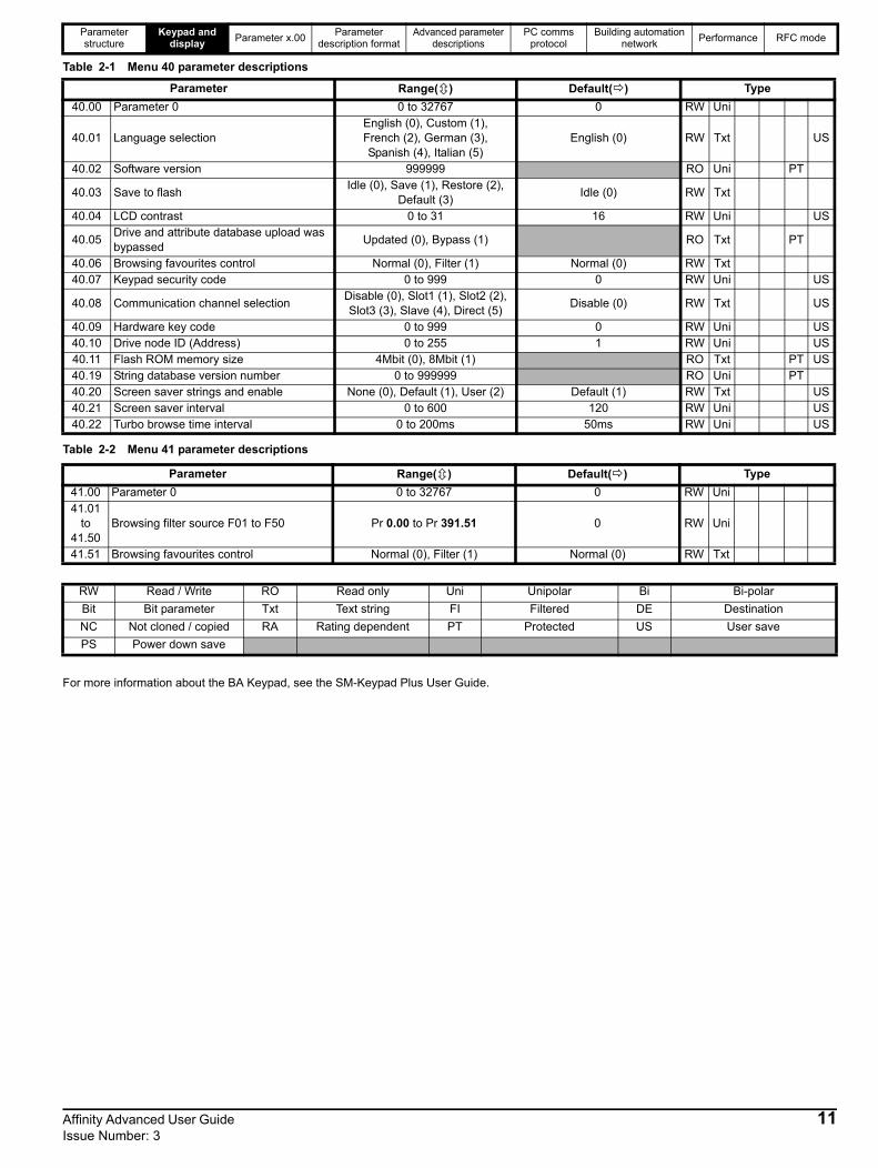
3 Parameter x.00Parameter x.00 is available in all menus and has the following functions.
*These functions do not require a drive reset to become active. All other functions require a drive reset.
3.1 Parameter x.00 resetWhen an action is started by setting Pr x.00 to one of the above values and initiating a drive reset this parameter is cleared when the action is completed successfully. If the action is not started, e.g. because the drive is enabled and an attempt is made to load defaults, etc., Pr x.00 is not cleared and no trip is produced.
If the action is started and then fails for some reason, a trip is always produced and Pr x.00 is not cleared. It should be noted that parameter saves etc. can also be initiated with the cloning parameter (Pr 11.42). If actions that can be initiated by either parameter are started and then completed successfully, Pr x.00 and Pr 11.42 are cleared if they have a value less than 3.
It should be noted that there could be some conflict between the actions of Pr x.00 and Pr 11.42 (Parameter cloning) when the drive is reset. If Pr 11.42 has a value of 1 or 2 and a valid action is required from the value of Pr x.00, then only the action required by Pr x.00 is performed. Pr x.00 and Pr 11.42 are then reset to zero. If Pr 11.42 has a value of 3 or 4 it will operate correctly causing parameters to be saved to the SMARTCARD each time a parameter save is performed.
3.2 Saving parameters in drive EEPROMDrive parameters are saved to the drive EEPROM by setting Pr x.00 to 1000 or 1001 and initiating a drive reset. In addition to user saved parameters, power down save parameters are also saved by these actions and/or by changing the drive mode, but not by any other actions that result in parameters being saved to drive EEPROM (i.e. loading defaults). Power down save parameters are not saved at power down unless the drive is supplied from a normal line power supply, thereby giving the user the option of saving these parameters when required.
When the parameter save is complete, Pr x.00 is reset to zero by the drive. Care should be taken when saving parameters because this action can take between 400ms and several seconds depending on how many changes are stored in the EEPROM. If the drive is powered down during a parameter save it is possible that data may be lost. When the drive is operating from a normal line power supply then it will stay active for a short time after the power is removed, however, if the drive is being powered from a 24V control supply, or it is being operated from a low voltage battery supply, the drive will power down very quickly after the supply is removed. The drive provides two features to reduce the risk of data loss when the drive is powered down:-
1. If Pr x.00 is set to 1000 a parameter save is only initiated on drive reset if the drive is supplied from a normal line power supply (Pr 10.16 = 0 and Pr 6.44 = 0). 1001 must be used to initiate a save if the drive is not supplied from a normal line power supply.
2. Two banks of arrays are provided in EEPROM to store the data. When a parameter save is initiated the data is stored in a new bank and only when the data store is complete does the new bank become active. If the power is removed before the parameter save is complete, a SAVE.Er trip (user save parameter save error) or PSAVE.Er trip (power down save parameter save error) will be produced when the drive is powered up again, indicating that the drive has reverted to the data that was saved prior to the last parameter save.
The second feature will significantly reduce the possibility of completely invalidating all saved data, which would result in an EEF trip on the next power-up. However the following points should be noted:
1. If the power is removed during a parameter save the current data that is being saved to the EEPROM that is different from the last data saved in the EEPROM will be lost and a SAVE.Er or PSAVE.Er trip will occur on power-up.
2. This feature does not apply when user save parameters are saved automatically by adjusting the values in menu 0 with an LED keypad. However, the time taken to save parameters in this way is very short, and is unlikely to cause data loss if the power is removed after the parameter has been changed. It should be noted that any parameter changes made in this way are included in the currently active bank in the EEPROM, so that if the power is removed during a subsequent save initiated via Pr x.00 that results in an SAVE.Er trip, the changes made via menu 0 will be retained and not lost.
3. User save parameters are saved to drive EEPROM after a transfer of data from an electronic nameplate in an encoder.
4. User save parameters are saved to drive EEPROM after a transfer of data from a SMARTCARD.
5. This feature is not provided for data saved to a SMARTCARD, and so it is possible to corrupt the data files on a SMARTCARD if the power is removed when data is being transferred to the card.
6. User save parameters are saved to drive EEPROM after defaults are loaded.
7. When the drive mode is changed all data in the EEPROM is deleted and then restored with the defaults for the new mode. If the power is removed during a change of drive mode, an EEF trip is likely to occur on the next power-up. After a change of drive mode the power down save parameters are also saved.
Value Action
1000Save parameters when under voltage is not active (Pr 10.16 = 0) and 48V supply is not active (Pr 6.44 = 0).
1001 Save parameters under all conditions
1070 Reset all Solutions Modules
1233 Load standard defaults
1244 Load US defaults
1253 Change drive mode with standard defaults
1254 Change drive mode with US defaults
1255Change drive mode with standard defaults (excluding menus 15 to 20)
1256Change drive mode with US defaults (excluding menus 15 to 20)
2001
Transfer drive parameter to a card and create a bootable difference from default SMARTCARD block with data block number 1 and clear Pr 11.42. If data block 1 exists it is over written.
3yyyTransfer drive EEPROM data to a SMARTCARD block number yyy
4yyyTransfer drive data as difference from defaults to SMARTCARD block number yyy
5yyyTransfer drive ladder program to SMARTCARD block number yyy
6yyy Transfer SMARTCARD data block yyy to the drive
7yyy Erase SMARTCARD data block yyy
8yyy Compare drive parameters with block yyy
9555 Clear SMARTCARD warning suppression flag
9666 Set SMARTCARD warning suppression flag
9777 Clear SMARTCARD read-only flag
9888 Set SMARTCARD read-only flag
9999 Erase SMARTCARD
*12000 Display non-default values only
*12001 Display destination parameters only
14 Affinity Advanced User Guide Issue Number: 3

Parameter structure
Keypad and display
Parameter x.00Parameter
description formatAdvanced parameter
descriptionsPC comms
protocolBuilding automation
networkPerformance RFC mode
8. As these parameters are not saved if the power is removed unless the drive is supplied with a normal line power supply, this ensures that the power down save parameters are always stored correctly for the new drive mode. The first time parameters are saved after the change of drive mode, however the save will take slightly longer than a normal parameter save.
9. When an Solutions Modules is changed for a different type in a slot, or a module is inserted when one was not present previously or a module is removed the EEPROM is forced to re-initialise itself on the next parameter saves. On the first parameter save one bank is cleared and then written to, and on the next parameter save the other bank is cleared and re-written. Each of these parameter saves takes slightly longer than a normal parameter save.
3.3 Loading defaultsWhen defaults are loaded the user save parameters are automatically saved to the drive EEPROM in all modes. Standard defaults are loaded by setting 1233 in Pr x.00 performing a drive reset.
The following differences from standard defaults are available when different values are set in Pr x.00.
US Default Differences (Pr x.00 = 1244 and perform a drive reset)
3.4 SMARTCARD transfersDrive parameters, set-up macros and internal ladder programs can be transferred to/from SMARTCARDs. See Pr 11.36 to Pr 11.40.
3.5 Display non-default values or destination parameters
If a value of 12000 is written to Pr x.00, then only parameters that are different from the last defaults loaded and Pr x.00 are displayed. If a value of 12001 is written to Pr x.00, then only destination parameters are displayed. This function is provided to aid locating destination clashes if a dESt trip occurs.
Pr Description Default ModesVoltage rating
1.06Max reference clamp
60.0Hz Open-loop All
1.06Max reference clamp
1800rpm RFC All
2.08 Standard ramp volts 775V Open-loop, RFC 400V
5.06 Rated frequency 60.0Hz Open-loop All
5.08 Rated load rpm 1800rpm Open-loop All
5.08 Rated load rpm 1770rpm RFC All
5.09 Rated voltage 460V Open-loop, RFC 400V
6.20 Date format US (2) Open-loop, RFC All
21.01M2 Max reference clamp
60.0Hz Open-loop All
21.01M2 Max reference clamp
1800rpm RFC All
21.06M2 Rated frequency
60.0Hz Open-loop All
21.09 M2 Rated voltage 460V Open-loop, RFC 400V
Affinity Advanced User Guide 15Issue Number: 3

Parameter structure
Keypad and display
Parameter x.00Parameter
description formatAdvanced parameter
descriptionsPC comms
protocolBuilding automation
networkPerformance RFC mode
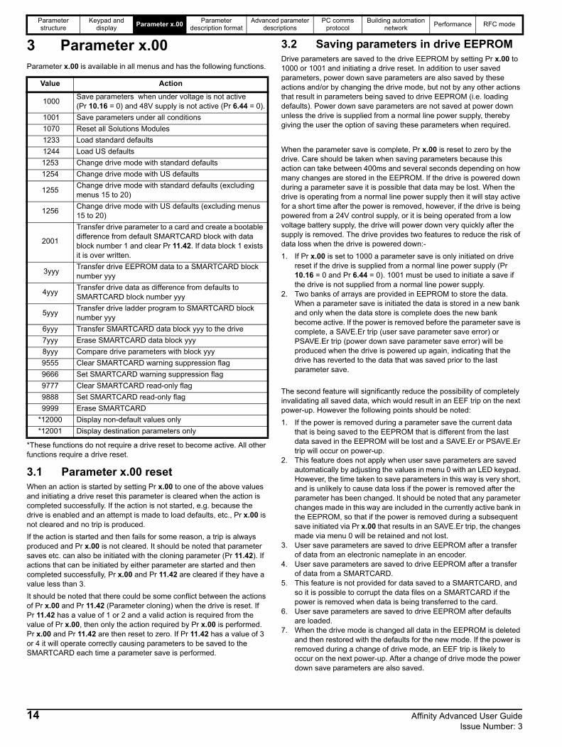
4 Typical parameter description formatIn the sections which follow, typical parameter descriptions are given for each advanced parameter set. Each parameter has its own detailed information block as shown here.
The first row gives the menu parameter number and name. The other rows describe the following information:-
Drive modesThe drive modes are the modes in which this parameter is accessible. If the parameter is not present, the parameter is skipped when accessing it via the keypad.
The following types of parameter are possible:
Open-loop - The control strategy is V/F mode with fixed boost or open-loop vector control.
RFC - The control strategy is rotor flux oriented vector control with closed-loop current operation for induction motors without position feedback.
Coding
This guide will show all bit parameters (with the Bit coding), as having a parameter range of "0 to 1", and a default value of either "0" or "1". This reflects the value seen through serial communications. The bit parameters will be displayed on the BA-Keypad as being "OFF" or "On" ("OFF"= 0, "On" = 1).
The coding defines the attributes of the parameter as follows:
5.11 Number of motor poles
Drive modes Open-loop, RFC
CodingBit SP FI DE Txt VM DP ND RA NC NV PT US RW BU PS
1 1 1 1
Range Open-loop, RFC 0 to 60 (Auto to 120 POLE)
Default Open-loop, RFC0 (Auto)3 (6 POLE)
Second motor parameter
Open-loop, RFC Pr 21.11
Update rate Background read
NOTE
Coding Attribute
Bit 1 bit parameter
SP Spare: not used
FIFiltered: some parameters which can have rapidly changing values are filtered when displayed on the drive keypad for easy viewing.
DE Destination: indicates that this parameter can be a destination parameter.
Txt Text: the parameter uses text strings instead of numbers.
VM Variable maximum: the maximum of this parameter can vary.
DP Decimal place: indicates the number of decimal places used by this parameter.
NDNo default: when defaults are loaded (except when the drive is manufactured or on EEPROM failure) this parameter is not modified.
RA
Rating dependent: this parameter is likely to have different values and ranges with drives of different voltage and current ratings. Parameters with this attribute will not be transferred to the destination drive by SMARTCARDs when the rating of the destination drive is different from the source drive and the file is a parameter file. However, the value will be transferred if only the current rating is different and the file is a differences from default type file.
NC Not cloned / copied: not transferred to or from SMARTCARDs during cloning / copying.
NV Not visible: not visible on the keypad.
PT Protected: cannot be used as a destination.
US User save: saved in drive EEPROM when the user initiates a parameter save.
RW Read/write: can be written by the user.
BUBit default one/unsigned: Bit parameters with this flag set to one have a default of one (all other bit parameters have a default of zero. Non-bit parameters are unipolar if this flag is one.
PSPower-down save: parameter automatically saved in drive EEPROM when the under volts (UV) trip occurs. Power-down save parameters are also saved in drive EEPROM when the user initiates a parameter save.
16 Affinity Advanced User Guide Issue Number: 3

Parameter structure
Keypad and display
Parameter x.00Parameter
description formatAdvanced parameter
descriptionsPC comms
protocolBuilding automation
networkPerformance RFC mode
4.1 Parameter ranges and variable maximums:The two values provided define the minimum and maximum values for the given parameter. In some cases the parameter range is variable and dependant on either:-
• other parameters,• the drive rating,• drive mode• or a combination of the above.The values given in Table 4-1 are the variable maximums used in the drive.
Table 4-1 Definition of parameter ranges & variable maximums
Maximum Definition
SPEED_FREQ_MAX[Open-loop 3000.0Hz,RFC 40000.0rpm]
Maximum speed (RFC mode) reference or frequency (open-loop mode) referenceIf Pr 1.08 = 0: SPEED_FREQ_MAX = Pr 1.06If Pr 1.08 = 1: SPEED_FREQ_MAX is Pr 1.06 or – Pr 1.07 whichever is the largest(If the second motor map is selected Pr 21.01 is used instead of Pr 1.06 and Pr 21.02 instead of Pr 1.07)
SPEED_LIMIT_MAX[40000.0rpm]
Maximum applied to speed reference limitsIn RFC mode SPEED_LIMIT_MAX = 40,000rpm.
SPEED_MAX[40000.0rpm]
Maximum speedThis maximum is used for some speed related parameters in menu 3. To allow headroom for overshoot etc. the maximum speed is twice the maximum speed reference.SPEED_MAX = 2 x SPEED_FREQ_MAX
RATED_CURRENT_MAX[9999.99A]
Maximum motor rated currentRATED_CURRENT_MAX = 1.36 x KC.
The motor rated current can be increased above KC up to a level not exceeding 1.36 x KC). (Maximum motor
rated current is the maximum normal duty current rating.) The actual level varies from one drive size to another, refer to Table 4-2.
DRIVE_CURRENT_MAX[9999.99A]
Maximum drive current The maximum drive current is the current at the over current trip level and is given by: DRIVE_CURRENT_MAX = KC / 0.45
AC_VOLTAGE_SET_MAX[690V]
Maximum output voltage set-pointDefines the maximum motor voltage that can be selected. 200V drives: 240V, 400V drives: 480V575V drives: 575V, 690V drives: 690V
AC_VOLTAGE_MAX[930V]
Maximum AC output voltageThis maximum has been chosen to allow for maximum AC voltage that can be produced by the drive including quasi-square wave operation as follows:AC_VOLTAGE_MAX = 0.78 x dc _VOLTAGE_MAX200V drives: 325V, 400V drives: 650V, 575V drives: 780V, 690V drives: 930V
dc _VOLTAGE_SET_MAX[1150V]
Maximum dc voltage set-point200V rating drive: 0 to 400V, 400V rating drive: 0 to 800V575V rating drive: 0 to 955V, 690V rating drive: 0 to 1150V
dc _VOLTAGE_MAX[1190V]
Maximum DC bus voltageThe maximum measurable DC bus voltage.200V drives: 415V, 400V drives: 830V, 575V drives: 990V, 690V drives: 1190V
Affinity Advanced User Guide 17Issue Number: 3

Parameter structure
Keypad and display
Parameter x.00Parameter
description formatAdvanced parameter
descriptionsPC comms
protocolBuilding automation
networkPerformance RFC mode
MOTOR1_CURRENT_LIMIT_MAX[1000.0%]
Maximum current limit settings for motor map 1This maximum current limit setting is the maximum applied to the current limit parameters in motor map 1.
Open Loop
Where:The Maximum current is either 1.1 x drive rating or 1.5 x KC if the motor rated current set in Pr 5.07 is more than
the drive current scaling given by Pr 11.32.
Motor rated current is given by Pr 5.07
PF is motor rated power factor given by Pr 5.10
RFC
Where:The Maximum current is either 1.1 x drive rating or 1.75 x KC if the motor rated current set in Pr 5.07 is more than
or equal to the drive current scaling given by Pr 11.32.
Motor rated current is given by Pr 5.07
1 = cos-1(PF) - 2. This is measured by the drive during an autotune. See Menu 4 in the Advanced User
Guide for more information regarding 2.
PF is motor rated power factor given by Pr 5.10
MOTOR2_CURRENT_LIMIT_MAX[1000.0%]
Maximum current limit settings for motor map 2This maximum current limit setting is the maximum applied to the current limit parameters in motor map 2.The formulae for MOTOR2_CURRENT_LIMIT_MAX are the same for MOTOR1_CURRENT_LIMIT_MAX except that Pr 5.07 is replaced with Pr 21.07 and Pr 5.10 is replaced with Pr 21.10.
TORQUE_PROD_CURRENT_MAX[1000.0%]
Maximum torque producing currentThis is used as a maximum for torque and torque producing current parameters. It is MOTOR1_CURRENT_LIMIT_MAX or MOTOR2_CURRENT_LIMIT_MAX depending on which motor map is currently active.
USER_CURRENT_MAX[1000.0%]
Current parameter limit selected by the userThe user can select a maximum for Pr 4.08 (torque reference) and Pr 4.20 (percentage load) to give suitable scaling for analog I/O with Pr 4.24. This maximum is subject to a limit of MOTOR1_CURRENT_LIMIT_MAX. or MOTOR2_CURRENT_LIMIT_MAX depending on which motor map is currently active.USER_CURRENT_MAX = Pr 4.24
POWER_MAX[9999.99kW]
Maximum power in kWThe maximum power has been chosen to allow for the maximum power that can be output by the drive with maximum AC output voltage, maximum controlled current and unity power factor. Therefore:
POWER_MAX = 3 x AC_VOLTAGE_MAX x DRIVE_CURRENT_MAX
The values given in square brackets indicate the absolute maximum value allowed for the variable maximum.
Maximum Definition
Maximum current limit
Maximum current ] 2
+ PF2 - 1 ] x 100%= Motor rated current
PF
Maximum current limit
Maximum current ] 2+ cos(1)2 - 1] x 100%= Motor rated current
cos(1)
18 Affinity Advanced User Guide Issue Number: 3

Parameter structure
Keypad and display
Parameter x.00Parameter
description formatAdvanced parameter
descriptionsPC comms
protocolBuilding automation
networkPerformance RFC mode
Table 4-2 Maximum motor rated current (sizes 1 to 6)
4.1.1 DefaultThe default values given are the standard drive defaults which are loaded after a drive reset with 1233 in Pr x.00.
4.1.2 Second motor parameterSome parameters have an equivalent second motor value that can be used as an alternative when the second motor is selected with Pr 11.45. Menu 21 contains all the second motor parameters. In this menu the parameter specifications include the location of the normal motor parameter which is being duplicated.
4.1.3 Update rateDefines the rate at which the parameter data is written by the drive (write) or read and acted upon by the drive (read). Where background update rate is specified, the update time depends on the drive processor load. Generally the update time is between 2ms and 30ms, however, the update time is significantly extended when loading defaults, changing drive mode, transferring data to/from a SMARTCARD, or transferring blocks of parameters or large CMP data blocks to/from the drive (not a Solutions Module) via the drive serial comms port.
Model KcMaximum normal duty
current rating
A
BA1201 4.3 5.2
BA1202 5.8 6.8
BA1203 7.5 9.6
BA1204 10.6 11
BA2201 12.6 15.5
BA2202 17.0 22.0
BA2203 25.0 28.0
BA3201 31.0 42.0
BA3202 42.0 54.0
BA4201 56.0 68.0
BA4202 68.0 80.0
BA4203 80.0 104.0
BA1401 2.1 2.8
BA1402 3.0 3.8
BA1403 4.2 5.0
BA1404 5.8 6.9
BA1405 7.6 8.8
BA1406 9.5 11.0
BA2401 13.0 15.3
BA2402 16.5 21.0
BA2403 23.0 29.0
BA3401 32.0 35.0
BA3402 40.0 43.0
BA3403 46.0 56.0
BA4401 60.0 68.0
BA4402 74.0 83.0
BA4403 96.0 104.0
BA5401 124.0 138.0
BA5402 156.0 168.0
BA6401 154.2 202.0
BA6402 180.0 236.0
BA3501 4.1 5.4
BA3502 5.4 6.1
BA3503 6.1 8.4
BA3504 9.5 11.0
BA3505 12.0 16.0
BA3506 18.0 22.0
BA3507 22.0 27.0
BA4601 19.0 22.0
BA4602 22.0 27.0
BA4603 27.0 36.0
BA4604 36.0 43.0
BA4605 43.0 52.0
BA4606 52.0 62.0
BA5601 63.0 84.0
BA5602 85.0 99.0
BA6601 85.7 125.0
BA6602 107.1 144.0
BAMD12X1 133.7 192
BAMD12X2 164.5 248
BAMD12X3 214.2 312
BAMD12X4 248.5 350
BAMA14X1 154.2 202
BAMA14X2 180.0 236
BAMD14X1 154.2 202
BAMD14X2 180.0 246
BAMD14X3 205.7 290
BAMD14X4 248.5 330
BAMA16X1 85.7 125
BAMA16X2 107.1 144
BAMD16X1 85.7 125
BAMD16X2 107.1 144
BAMD16X3 123.4 168
BAMD16X4 144.0 192
Model KcMaximum normal duty
current rating
A
Affinity Advanced User Guide 19Issue Number: 3

Parameter structure
Keypad and display
Parameter x.00Parameter
description formatAdvanced parameter
descriptionsPC comms
protocolBuilding automation
networkPerformance RFC mode
4.2 Sources and destinations4.2.1 SourcesSome functions have source pointer parameters, i.e. drive outputs, PID controller etc. The source pointer parameter range is Pr 0.00 to Pr 21.51. The source pointer is set up to point to a parameter which supplies the information to control the source, and this is referred to as the source data parameter. For example, Pr 7.19 is the source pointer parameter for analog output 1. If Pr 7.19 is set to a value of 18.11, then Pr 18.11 is the source data parameter, and as the value of Pr 18.11 is modified the analog output level is changed.
1. If the parameter number in the source pointer parameter does not exist the input is taken as zero.
2. If the source is not a bit type source (i.e. not a digital output etc.) then the source level is defined by (source data value x 100%) / source data parameter maximum. Generally the result is rounded down to the nearest unit, but other rounding effects may occur depending on the internal scaling of the particular source function.
3. If the source is a bit, i.e. a digital output, and the source data parameter is a bit parameter then the input to the source function follows the value of the source data parameter.
4. If the source is a bit, i.e. a digital output, and the source data parameter is not a bit parameter the source input is zero if the source data value is less than source data parameter maximum / 2 rounded down to the nearest unit. The source input is one if the source data value is greater than or equal to source data parameter maximum / 2 rounded down to the nearest unit. For example if the source pointer parameter is set to 18.11, which has a maximum of 32767, the source input is zero if the source data value is less than 16383 and one if it is greater than this.
4.2.2 DestinationsSome functions have destination pointer parameters, i.e. drive inputs, etc. The destination pointer parameter range is P 0.00 to Pr 21.51. The destination pointer parameter is set up to point to a parameter, which receives information from the function referred to as the destination parameter.
1. If the parameter number in the destination pointer parameter does not exist then the output value has no effect.
2. If the destination parameter is protected then the output value has no effect.
3. If the function output is a bit value (i.e. a digital input) the destination parameter value does not operate in the same way as a source described above, but is always either 0 or 1 depending on the state of the function output whether the destination parameter is a bit parameter or not.
4. If the function output is not a bit value (i.e. analog input) and the destination parameter is not a bit parameter, the destination value is given by (function output x destination parameter maximum) / 100%. Generally the result is rounded down to the nearest unit, but other rounding effects may occur depending on the internal scaling of the particular source function (rounded down to nearest unit). Pr 1.36 and Pr 1.37 are a special case. The scaling shown in the description of parameter Pr 1.08 is used when any non-bit type quantity is routed to these parameters.
5. If the function output is not a bit value and the destination parameter is a bit value, the destination value is 0 if the function output is less than 50% of its maximum value, otherwise it is 1.
6. If more than one destination selector is routed to the same destination, the value of the destination parameter is undefined. The drive checks for this condition where the destinations are defined in any menu except menus 15 to 17. If a conflict occurs a dESt trip occurs that cannot be reset until the conflict is resolved.
4.2.3 Sources and destinations1. Bit and non-bit parameters may be connected to each other as
sources or destinations. The scaling is as described previously.2. All new source and destination routing only changes to new set-up
locations when the drive is reset. When a destination pointer parameter within the drive or a dumb Solutions Modules (SM-I/O plus) is changed the old destination is written to zero, unless the destination change is the result of loading defaults or transferring parameters from a SMARTCARD. When defaults are loaded the old destination is set to its default value. When parameters are loaded from a SMARTCARD the old destination retains its old value unless a SMARTCARD value is written to it.
4.3 Update ratesUpdate rates are given for every parameter in the header table as shown below.
Some parameters have an increased update in special circumstances.
3.03 Speed error
Drive modes RFC
CodingBit SP FI DE Txt VM DP ND RA NC NV PT US
RW
BU PS
1 1 1 1 1 1
Range RFC ±SPEED_MAX rpm
Update rate 4ms write
20 Affinity Advanced User Guide Issue Number: 3

Parameter structure
Keypad and display
Parameter x.00Parameter
description formatAdvanced parameter
descriptionsPC comms
protocolBuilding automation
networkPerformance RFC mode
4.3.1 Speed reference update rateThe normal update rate for the speed references (via menu 1) is 4ms, however it is possible to reduce the sample time to 250s by selecting the reference from particular sources. The fast update rate is only possible provided the conditions given below are met. (Note: high speed updating is not provided for frequency references - i.e. Open-loop mode.)
Analog input references (not including I/O expansion Solutions Module)1. The reference must be derived via Pr 1.36 or Pr 1.37.2. The analog inputs must be in voltage mode with zero offset.3. Bipolar mode must be used or unipolar mode with the minimum speed (Pr 1.07) set to zero.4. No skip bands are enabled, i.e. Pr 1.29, Pr 1.31 and Pr 1.33 must be zero.5. The jog and velocity feed-forward references must not be enabled.
4.3.2 Hard speed reference update rateThe normal update rate for the hard speed reference is 4ms, however it is possible to reduce the sample time to 250s by selecting the reference from particular sources. The fast update rate is only possible provided the conditions given below are met.
Analog inputs (not including I/O expansion Solutions Module)The analog inputs must be in voltage mode with zero offset
Limitations are the same as for the references via menu 1 described above.
4.3.3 Torque reference update rateThe normal update rate for the torque reference (Pr 4.08) is 4ms, however it is possible to reduce the sample time to 250s by selecting the reference from particular sources, but only in RFC mode. The fast update rate is only possible provided the conditions given below are met.
Analog inputs 2 or 3 on the driveThe analog inputs must be in voltage mode with zero offset.
Affinity Advanced User Guide 21Issue Number: 3

Parameter structure
Keypad and display
Parameter x.00Parameter
description formatAdvanced parameter
descriptionsPC comms
protocolBuilding automation
networkPerformance RFC mode
5 Advanced parameter descriptions5.1 OverviewTable 5-1 Menu description
Table 5-2 gives a full key of the coding which appears in the following parameter tables.
Table 5-2 Key to parameter coding
Menu number
Description
0Commonly used basic set up parameters for quick / easy programming
1 Frequency / speed reference
2 Ramps
3 Speed feedback and speed control
4 Torque and current control
5 Motor control
6 Sequencer and clock
7 Analog I/O
8 Digital I/O
9 Programmable logic, motorized pot and binary sum
10 Status and trips
11 General drive set-up
12 Threshold detectors and variable selectors
13 Not used
14 Advanced process PID
15, 16 Solutions Module slots
17 Building Automation Network
18 Application menu 1
19 Application menu 2
20 Application menu 3
21 Second motor parameters
22 Additional Menu 0 set-up
Coding Attribute
RW Read/write: can be written by the user
RO Read only: can only be read by the user
Bit 1 bit parameter. ‘On’ or ‘OFF’ on the display
Bi Bipolar parameter
Uni Unipolar parameter
Txt Text: the parameter uses text strings instead of numbers.
FIFiltered: some parameters which can have rapidly changing values are filtered when displayed on the drive keypad for easy viewing.
DEDestination: This parameter selects the destination of an input or logic function.
RA
Rating dependent: this parameter is likely to have different values and ranges with drives of different voltage and current ratings. Parameters with this attribute will not be transferred to the destination drive by SMARTCARDs, when the rating of the destination drive is different from the source drive and the file is a parameter file. However, the value will be transferred if only the current rating is different and the file is different to the default file type.
NCNot cloned / copied: not transferred to or from SMARTCARDs during cloning / copying.
PT Protected: cannot be used as a destination.
USUser save: parameter saved in drive EEPROM when the user initiates a parameter save.
PSPower-down save: parameter automatically saved in drive EEPROM when the under volts (UV) trip occurs or when the user initiates a parameter save.
22 Affinity Advanced User Guide Issue Number: 3

Parameter structure
Keypad and display
Parameter x.00Parameter
description formatAdvanced parameter
descriptionsPC comms
protocolBuilding automation
networkPerformance RFC mode
5.2 Feature look-up table
Feature Parameter number (Pr)
Acceleration rates 2.10 2.11 to 2.19 2.32 2.33 2.34 2.02Analog speed reference 1 1.36 7.10 7.01 7.07 7.08 7.09 7.25 7.26 7.30Analog speed reference 2 1.37 7.14 1.41 7.02 7.11 7.12 7.13 7.28 7.31Analog I/O Menu 7Analog input 1 7.01 7.07 7.08 7.09 7.10 7.25 7.26 7.30Analog input 2 7.02 7.11 7.12 7.13 7.14 7.28 7.31Analog input 3 7.03 7.15 7.16 7.17 7.18 7.29 7.32Analog output 1 7.19 7.20 7.21 7.33Analog output 2 7.22 7.23 7.24Application menu Menu 18 Menu 19 Menu 20At speed indicator bit 3.06 3.07 3.09 10.06 10.05 10.07Auto reset 10.34 10.35 10.36 10.01Autotune 5.12 5.17 5.23 5.24 5.25 5.10 5.29 5.30Binary sum 9.29 9.30 9.31 9.32 9.33 9.34Bipolar speed 1.10Brake control 12.40 to 12.48Braking 10.11 10.10 10.30 10.31 6.01 2.04 2.02 10.12 10.39 10.40Building Automation Network Menu 17Catch a spinning motor 6.09Cloning 11.42 11.36 to 11.40Coast to stop 6.01Comms 11.23 to 11.26Cost - per kWh electricity 6.24 6.25 6.26 6.27 6.28Current controller 4.13 4.14Current feedback 4.01 4.02 4.17 4.04 4.12 4.20 4.23 4.24 4.26 10.08 10.09 10.17Current limits 4.05 4.06 4.07 4.18 4.15 4.19 4.16 5.07 5.10 10.08 10.09 10.17DC bus voltage 5.05 2.08dc injection braking 6.06 6.07 6.01Deceleration rates 2.20 2.21 to 2.29 2.04 2.35 to 2.37 2.02 2.08 6.01 10.30 10.31 10.39Defaults 11.43 11.46Digital I/O Menu 8Digital I/O read word 8.20Digital I/O T24 8.01 8.11 8.21 8.31Digital I/O T25 8.02 8.12 8.22 8.32Digital I/O T26 8.03 8.13 8.23 8.33Digital input T27 8.04 8.14 8.24Digital input T28 8.05 8.15 8.25 8.39Digital input T29 8.06 8.16 8.26 8.39Digital output T22 8.08 8.18 8.28Direction 10.13 6.30 6.31 1.03 10.14 2.01 3.02 8.03 8.04 10.40Display timeout 11.41Drive active 10.02 10.40Drive current scaling 5.07 11.32Drive derivative 11.28Drive OK 10.01 8.27 8.07 8.17 10.36 10.40Dynamic performance 5.26Dynamic V/F 5.13Enable 6.15 8.09 8.10External trip 10.32 8.10 8.07Fan speed 6.45Fast disable 6.29Filter change 6.21 6.22Fire mode 1.53 1.54Frequency reference selection 1.14 1.15Hard speed reference 3.22 3.23High stability space vector modulation
5.19
I/O sequencer 6.04 6.30 6.31 6.32 6.33 6.34 6.42 6.43 6.41Inertia compensation 2.38 5.12 4.22 3.18Jog reference 1.05 2.19 2.29Keypad operating mode 1.52Keypad reference 1.17 1.14 1.43 1.51 6.12 6.13Kt 5.32
Affinity Advanced User Guide 23Issue Number: 3

Parameter structure
Keypad and display
Parameter x.00Parameter
description formatAdvanced parameter
descriptionsPC comms
protocolBuilding automation
networkPerformance RFC mode
Limit switches 6.35 6.36Line power supply loss 6.03 10.15 10.16 5.05Logic function 1 9.01 9.04 9.05 9.06 9.07 9.08 9.09 9.10Logic function 2 9.02 9.14 9.15 9.16 9.17 9.18 9.19 9.20Low load detection 4.20 4.27 4.28 4.20 10.6Low voltage supply 6.44 6.46Maximum speed 1.06Menu 0 set up 11.01 to 11.22 Menu 22Minimum speed 1.07 10.04Modules - number of 11.35Motor map 5.06 5.07 5.08 5.09 5.10 5.11Motor map 2 Menu 21 11.45Motor pre-heat 6.08 6.52Motorized potentiometer 9.21 9.22 9.23 9.24 9.25 9.26 9.27 9.28Offset speed reference 1.04 1.38 1.09Onboard PLC 11.47 to 11.51Open collector digital outputs 8.30Open loop vector mode 5.14 5.17 5.23Operating mode 0.48 11.31Output 5.01 5.02 5.03 5.04Overspeed threshold 3.08PID controller Menu 14Positive logic 8.29Power up parameter 11.22 11.21Precision reference 1.18 1.19 1.20 1.44Preset speeds 1.15 1.21 to 1.28 1.16 1.14 1.42 1.45 to 1.48 1.50Programmable logic Menu 9Quasi square operation 5.20Ramp (accel / decel) mode 2.04 2.08 6.01 2.02 2.03 10.30 10.31 10.39Real time clock 6.16 6.17 6.18 6.19 6.20Regenerating 10.10 10.11 10.30 10.31 6.01 2.04 2.02 10.12 10.39 10.40Relay output 8.07 8.17 8.27Reset 10.33 8.02 8.22 10.34 10.35 10.36 10.01RFC mode 3.24 3.42 4.12 5.40S ramp 2.06 2.07Sample rates 5.18Security code 11.30 11.44Serial comms 11.23 to 11.26Skip speeds 1.29 1.30 1.31 1.32 1.33 1.34 1.35Sleep mode 6.53 6.54Slip compensation 5.27 5.08SMARTCARD 11.36 to 11.40 11.42Software version 11.29 11.34Speed controller 3.10 to 3.17 3.19 3.20 3.21Speed feedback 3.02 3.03 3.04Speed reference selection 1.14 1.15 1.49 1.50 1.01Status word 10.40Supply 6.44 5.05 6.46Switching frequency 5.18 5.35 7.34 7.35Thermal protection - drive 5.18 5.35 7.04 7.05 7.06 7.32 7.35 10.18Thermal protection - motor 4.15 5.07 4.19 4.16 4.25 7.15Thermistor input 7.15 7.03Threshold detector 1 12.01 12.03 to 12.07Threshold detector 2 12.02 12.23 to 12.27Time - filter change 6.21 6.22Time - powered up log 6.16 6.17 6.19 6.20Time - run log 6.16 6.17 6.19 6.20Timer functions 9.35 to 9.53Torque 4.03 4.26 5.32Torque mode 4.08 4.11 4.09 4.10Trip detection 10.37 10.38 10.20 to 10.29Trip log 10.20 to 10.29 10.41 to 10.60 6.28 6.49Under voltage 5.05 10.16 10.15V/F mode 5.15 5.14Variable selector 1 12.08 to 12.15
Feature Parameter number (Pr)
24 Affinity Advanced User Guide Issue Number: 3

Parameter structure
Keypad and display
Parameter x.00Parameter
description formatAdvanced parameter
descriptionsPC comms
protocolBuilding automation
networkPerformance RFC mode
Variable selector 2 12.28 to 12.35Voltage controller 5.31Voltage mode 5.14 5.17 5.23 5.15Voltage rating 11.33 5.09 5.05Voltage supply 6.44 6.46 5.05Warning 10.19 10.12 10.17 10.18 10.40Zero speed indicator bit 3.05 10.03
Feature Parameter number (Pr)
Affinity Advanced User Guide 25Issue Number: 3

Menu 1Parameter structure
Keypad and display
Parameter x.00
Parameter description format
Advanced parameter descriptions
PC comms protocol
Building automation network
Performance RFC mode
5.3 Menu 1: Frequency/speed referenceMenu 1 controls the main reference selection. When the drive operates in open-loop mode a frequency reference is produced, and when the drive operates in RFC mode a speed reference is produced.
Figure 5-1 Menu 1 logic diagram
*Refer to Pr 1.14 on page 31.
Preset reference*selector
Preset reference scan time
KeypadReference
Precision reference
Precision-reference update disable
Analog reference 1
Analog
reference 2
Analog reference 2 select
Preset reference select bits 1 ~ 3
Preset reference
Scan-timer reset
Analog input 1
Analog input 2
Memory
Menu 7
1.37
1.41
1.16
1.48
1.15
1.17
1.20
1.18
Precision reference trim
1.19
Preset reference select
Keypad reference select
Precision reference select
LOCAL/REMOTE
Menu 8
Level of referenceselected
Reference offset
Reference offset mode select
Reference*selector
Reference selected
indicator1.49
1.14
1.09
1.04
Reference percentage trim
1.38 1.01
Analog reference
Preset reference
Keypad reference
Precision reference
+
+
0.XX
0.XX
Key
Read-write (RW) parameter
Read-only (RO) parameter
Inputterminals
Outputterminals
The parameters are all shown in their default settings
1.51Power-up keypadcontrol modereference
1.20Preset reference selected indicator
Preset references 1 to 8
1.21 ~ 1.28
Scan timer
1.47 1.46 1.451.44
1.43
1.42
Pr set to greater than 1
1.501.50
Pr 1.491122345
Pr 1.501
>11
>1xxx
Reference being used
1.50
1.50
Analog reference 1Preset reference defined by Pr Analog reference 2Preset reference defined by Pr
Keypad referencePrecision reference
Preset reference defined by Pr 1.50
1.36
Set to 4 whenHand/Off selected
Set to value in Pr on transitionfrom Auto to Hand
1.03
Sleep modeactive
26 Affinity Advanced User Guide Issue Number: 3

Parameter structure
Keypad and display
Parameter x.00
Parameter description format
Advanced parameter descriptions
PC comms protocol
Building automation network
Performance RFC mode Menu 1
Bipolar reference select
1.10
Pre-filter reference
Pre-ramp reference
Maximum freq./speed "clamp"
Minimum freq./speed "clamp" (Maximum reverse freq./speed)
Negative minimum speed select
Reference enabled indicator
Reverse selected indicator
Skip freq./ speed 1
Reference in skip freq./speed band indicator
1.12
x(-1)
1.08
[1.06]
[1.07]
[1.07]
[1.06]
[1.06]
[1.06]
[1.06]
[1.07]
1.06
1.07
1.11
Sequencer (Menu 6)
1.021.03
Menu 2
Skip freq./ speed 2
Skip freq./ speed 3
Skip freq./speed band 1
Skip freq./speed band 2
Skip freq./speed band 3
1.29
1.30
1.31
1.32
1.33
1.34
1.35
Menu 8
RUN FORWARD
1.53
Fire modereference
FIRE MODEACTIVE
1.54
Fire modeactivate
Affinity Advanced User Guide 27Issue Number: 3
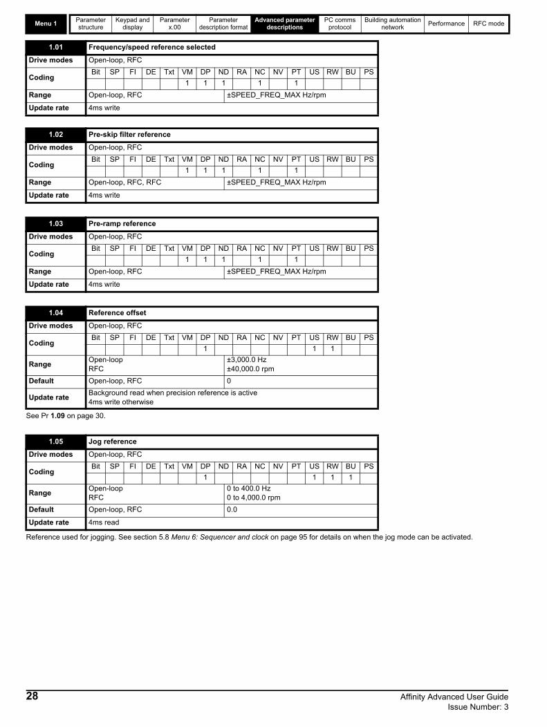
Menu 1Parameter structure
Keypad and display
Parameter x.00
Parameter description format
Advanced parameter descriptions
PC comms protocol
Building automation network
Performance RFC mode
See Pr 1.09 on page 30.
Reference used for jogging. See section 5.8 Menu 6: Sequencer and clock on page 95 for details on when the jog mode can be activated.
1.01 Frequency/speed reference selected
Drive modes Open-loop, RFC
CodingBit SP FI DE Txt VM DP ND RA NC NV PT US RW BU PS
1 1 1 1 1
Range Open-loop, RFC ±SPEED_FREQ_MAX Hz/rpm
Update rate 4ms write
1.02 Pre-skip filter reference
Drive modes Open-loop, RFC
CodingBit SP FI DE Txt VM DP ND RA NC NV PT US RW BU PS
1 1 1 1 1
Range Open-loop, RFC, RFC ±SPEED_FREQ_MAX Hz/rpm
Update rate 4ms write
1.03 Pre-ramp reference
Drive modes Open-loop, RFC
CodingBit SP FI DE Txt VM DP ND RA NC NV PT US RW BU PS
1 1 1 1 1
Range Open-loop, RFC ±SPEED_FREQ_MAX Hz/rpm
Update rate 4ms write
1.04 Reference offset
Drive modes Open-loop, RFC
CodingBit SP FI DE Txt VM DP ND RA NC NV PT US RW BU PS
1 1 1
RangeOpen-loopRFC
±3,000.0 Hz±40,000.0 rpm
Default Open-loop, RFC 0
Update rateBackground read when precision reference is active4ms write otherwise
1.05 Jog reference
Drive modes Open-loop, RFC
CodingBit SP FI DE Txt VM DP ND RA NC NV PT US RW BU PS
1 1 1 1
RangeOpen-loop RFC
0 to 400.0 Hz0 to 4,000.0 rpm
Default Open-loop, RFC 0.0
Update rate 4ms read
28 Affinity Advanced User Guide Issue Number: 3

Parameter structure
Keypad and display
Parameter x.00
Parameter description format
Advanced parameter descriptions
PC comms protocol
Building automation network
Performance RFC mode Menu 1
See below.
*The range shown for Pr 1.07 shows the range used for scaling purposes (i.e. for routing to an analog output etc.). Further range restrictions are applied as given below.
The same limits are applied to Pr 21.02, but based on the value of Pr 21.01.
(If the second motor map is selected Pr 21.01 is used instead of Pr 1.06 and Pr 21.02 instead of Pr 1.07)
The effects of the reference clamps (Pr 1.06 and 1.07), the negative minimum clamp enable (Pr 1.08) and the bipolar reference enable parameters are defined below.
The variable maximum limit for reference parameters, SPEED_FREQ_MAX, is defined as:
If Pr 1.08 = 0: SPEED_FREQ_MAX = Pr 1.06 If Pr 1.08=1: SPEED_FREQ_MAX is Pr 1.06 or -Pr 1.07 whichever is the largest
(If the second motor map is selected Pr 21.01 is used instead of Pr 1.06 and Pr 21.02 instead of Pr 1.07)
1.06 Maximum reference clamp
Drive modes Open-loop, RFC
Coding
Bit SP FI DE Txt VM DP ND RA NC NV PT US RW BU PS
1 1 1 1
RFC: VM = 1
RangeOpen-loopRFC
0 to 3,000.0 Hz±SPEED_LIMIT_MAX rpm
DefaultOpen-loopRFC
EUR: 50.0, USA: 60.0EUR: 1,500.0, USA: 1,800.0
Second motor parameter
Open-loop, RFC Pr 21.01
Update rate Background read
1.07 Minimum reference clamp
Drive modes Open-loop, RFC
Coding
Bit SP FI DE Txt VM DP ND RA NC NV PT US RW BU PS
1 1 1 1
RFC: VM = 1
RangeOpen-loopRFC
±3,000.0 Hz* ±SPEED_LIMIT_MAX rpm*
Default Open-loop, RFC 0.0
Second motor parameter
Open-loop, RFC Pr 21.02
Update rate Background read
Pr 1.08(Neg min ref enable)
Pr 1.10(Bipolar mode enable)
Open-loop RFC
0 0 0 to Pr 1.06 0 to Pr 1.06
0 1 0 0
1 0 -3,000 to 0Hz* -SPEED_LIMIT_MAX to 0 rpm
1 1 -3,000 to 0Hz* -SPEED_LIMIT_MAX to 0 rpm
1.08 Negative minimum reference clamp enable
Drive modes Open-loop, RFC
CodingBit SP FI DE Txt VM DP ND RA NC NV PT US RW BU PS
1 1 1
Default Open-loop, RFC 0
Update rate Background read
Affinity Advanced User Guide 29Issue Number: 3

Menu 1Parameter structure
Keypad and display
Parameter x.00
Parameter description format
Advanced parameter descriptions
PC comms protocol
Building automation network
Performance RFC mode
Analog input scalingThe following diagrams show the scaling applied when analog inputs are used to define the reference and are routed via Pr 1.36 or Pr 1.37.
Reference limitsWith reference to the block diagram for Menu 1 (Figure 5-1 on page 26) the following table shows the limits applied to the reference by various blocks in the reference system. It should be noted that the minimum limit in the main reference limits block changes when either the jog reference or velocity feedforward references are active. When one of these is active: if Pr 1.08 = 0 the minimum = -Pr 1.06 [-Pr 21.01 for motor map2], if Pr 1.08 = 1 the minimum = -Pr 1.07 [-Pr 21.02 for motor map 2].
When this parameter is 0 the reference is given by
Pr 1.01 = selected reference x (100 + Pr 1.38) / 100
and when this parameter is 1 the reference is given by
Pr 1.01 = selected reference + Pr 1.04
Minimum Maximum
Keypad control reference (Pr 1.17)Unipolar mode: Pr 1.07, or 0 if Pr 1.07 < 0
Bipolar mode: -SPEED_FREQ_MAXSPEED_FREQ_MAX
Bipolar/unipolar selector Unipolar mode: Pr 1.07, or 0 if Pr 1.07 < 0
Bipolar mode: no limit appliedNo maximum limit applied
Main reference limitsNeg minimum ref disabled: -Pr 1.06Neg minimum ref enabled: Pr 1.07
Pr 1.06
1.09 Reference offset select
Drive modes Open-loop, RFC
CodingBit SP FI DE Txt VM DP ND RA NC NV PT US RW BU PS
1 1 1
Default Open-loop, RFC 0
Update rateBackground read when precision reference is active4ms read otherwise
Pr 1.07
Pr =0 (1.10 unipolar mode)Pr =0 (1.08 neg min ref disabled)
-100% 100%
SPEED_FREQ_MAX
SPEED_FREQ_MAX
-100% 100%
-SPEED_FREQ_MAX
SPEED_FREQ_MAX
-100% 100%
-SPEED_FREQ_MAX
Pr =1 (bipolar mode)1.10Pr =0 (1.08 neg min ref disabled)
-100% 100%
SPEED_FREQ_MAX
Pr =0 (1.10 unipolar mode)Pr =1 (1.08 neg min ref enabled)
Pr =1 (bipolar mode)1.10Pr =1 (1.08 neg min ref enabled)
30 Affinity Advanced User Guide Issue Number: 3

Parameter structure
Keypad and display
Parameter x.00
Parameter description format
Advanced parameter descriptions
PC comms protocol
Building automation network
Performance RFC mode Menu 1
See Pr 1.08 on page 29.
These parameters are controlled by the drive sequencer as defined in Menu 6. They select the appropriate reference as commanded by the drive logic. Pr 1.11 will be active if a run command is given, the drive is enabled and the drive is healthy/ok. This parameter can be used as an interlock in an Onboard PLC program to show that the drive is able to respond to a speed or torque demand.
Pr 1.14 defines how the value of Pr 1.49 is derived as follows:
*Pr 1.41 to Pr 1.44 can be controlled by digital inputs to force the value of Pr 1.49:
all bits equal to zero gives 1,
Pr 1.41 = 1 then Pr 1.49 = 2 Pr 1.42 = 1 then Pr 1.49 = 3Pr 1.43 = 1 then Pr 1.49 = 4Pr 1.44 = 1 then Pr 1.49 = 5
The bit parameters with lower numbers have priority over those with higher numbers.
1.10 Bipolar reference enable
Drive modes Open-loop, RFC
CodingBit SP FI DE Txt VM DP ND RA NC NV PT US RW BU PS
1 1 1
Default Open-loop, RFC 0
Update rate 4ms read
1.11 Reference enabled indicator
1.12 Reverse selected indicator
1.13 Jog selected indicator
Drive modes Open-loop, RFC
CodingBit SP FI DE Txt VM DP ND RA NC NV PT US RW BU PS
1 1 1
Update rate 4ms read
1.14 Reference selector
Drive modes Open-loop, RFC
CodingBit SP FI DE Txt VM DP ND RA NC NV PT US RW BU PS
1 1 1 1
Range Open-loop, RFC 0 to 5
Default Open-loop, RFC 0 (A1.A2)
Second motor parameter
Open-loop, RFC Pr 21.03
Update rate 4ms read
Value of Pr 1.14 Display String Pr 1.49
0 A1.A2 (Analog ref 1. Analog ref 2) *Selected by terminal input
1 A1.Pr (Analog ref 1. Preset speeds) 1
2 A2.Pr (Analog ref 2. Preset speeds) 2
3 Pr (Preset speeds) 3
4 Pad (Keypad reference) 4
5 Prc (Precision reference) 5
Affinity Advanced User Guide 31Issue Number: 3

Menu 1Parameter structure
Keypad and display
Parameter x.00
Parameter description format
Advanced parameter descriptions
PC comms protocol
Building automation network
Performance RFC mode
Pr 1.49 and Pr 1.50 then define the reference as follows:
** x = any value
Keypad referenceIf Keypad reference is selected, the drive sequencer is controlled directly by the keypad keys and the keypad reference parameter (Pr 1.17) is selected. The sequencing bits, Pr 6.30 to Pr 6.34, have no effect and jog is disabled.
Pr 1.15 defines how the value of Pr 1.50 is derived as follows:
*Pr 1.45 to Pr 1.47 can be controlled by digital inputs to define the value of Pr 1.50 as follows:
**The presets are selected automatically in turn. Pr 1.16 defines the time between each change.
Pr 1.49 and Pr 1.50 then define the reference as follows:
Pr 1.49 Pr 1.50 Reference
1 1 Analog reference 1 (Pr 1.36)1 >1 Preset defined by Pr 1.50 (Pr 1.21 to Pr 1.28)2 1 Analog reference 2 (Pr 1.37)2 >1 Preset defined by Pr 1.50 (Pr 1.21 to Pr 1.28)3 x** Preset defined by Pr 1.50 (Pr 1.21 to Pr 1.28)4 x** Keypad reference (Pr 1.17)5 x** Precision reference (Pr 1.18 and Pr 1.19)
1.15 Preset selector
Drive modes Open-loop, RFC
CodingBit SP FI DE Txt VM DP ND RA NC NV PT US RW BU PS
1 1 1
Range Open-loop, RFC 0 to 9
Default Open-loop, RFC 0
Update rate 4ms read
Value of Pr 1.15 Pr 1.50
0 Selected by terminal input*
1 1
2 2
3 3
4 4
5 5
6 6
7 7
8 8
9 Selected by timer**
Pr 1.47 Pr 1.46 Pr 1.45 Pr 1.50
0 0 0 1
0 0 1 2
0 1 0 3
0 1 1 4
1 0 0 5
1 0 1 6
1 1 0 7
1 1 1 8
Pr 1.49 Pr 1.50 Reference
1 1 Analog reference 1 (Pr 1.36)
1 >1 Preset defined by Pr 1.50 (Pr 1.21 to Pr 1.28)
2 1 Analog reference 2 (Pr 1.37)
2 >1 Preset defined by Pr 1.50 (Pr 1.21 to Pr 1.28)
3 x Preset defined by Pr 1.50 (Pr 1.21 to Pr 1.28)
4 x Keypad reference (Pr 1.17)
5 x Precision reference (Pr 1.18 and Pr 1.19)
32 Affinity Advanced User Guide Issue Number: 3

Parameter structure
Keypad and display
Parameter x.00
Parameter description format
Advanced parameter descriptions
PC comms protocol
Building automation network
Performance RFC mode Menu 1
This parameter defines the time between preset reference changes when Pr 1.15 is set to 9. If Pr 1.48 is set to 1, then the preset counter and timer are reset and preset 1 will be selected.
The drive can be controlled from the keypad if Pr 1.14 is set to 4.The frequency/speed reference is defined by Pr 1.17. This is a read only parameter that can only be adjusted in status mode by pressing the Up or Down keys. If keypad control mode is selected, then pressing the Up or Down keys in status mode will cause the drive to automatically display the keypad reference and adjust it in the relevant direction. This can be done whether the drive is disabled or running. If the Up or Down keys are held down, the rate of change of keypad reference increases with time. The units used for displaying the keypad reference for different modes are given below.
See also Pr 1.51 on page 36 (Power-up keypad control mode reference).
See below.
Open loopThe frequency reference resolution is restricted to 0.1Hz from normal parameters, however the resolution can be improved by using the precision reference. Pr 1.18 defines the coarse part of reference (either positive or negative) with a resolution of 0.1Hz and Pr 1.19 defines the fine part of the reference (always positive) with a resolution of 0.001Hz. The final reference is given by Pr 1.18 + Pr 1.19. Therefore Pr 1.19 increases positive references away from zero, and decreases negative references towards zero.
RFCAs with open-loop a higher resolution speed reference can be programmed by selecting these parameters. In this case the speed will have a resolution of 0.001 rpm.
1.16 Preset reference selector timer
Drive modes Open-loop, RFC
CodingBit SP FI DE Txt VM DP ND RA NC NV PT US RW BU PS
1 1 1 1
Range Open-loop, RFC 0 to 400.0 s
Default Open-loop, RFC 10.0
Update rate Background read
1.17 Keypad control mode reference
Drive modes Open-loop, RFC
CodingBit SP FI DE Txt VM DP ND RA NC NV PT US RW BU PS
1 1 1 1 1
Range Open-loop, RFC ±SPEED_FREQ_MAX Hz/rpm
Default Open-loop, RFC 0.0
Update rate 4ms read
Mode Unit
Open loop Hz
RFC rpm
1.18 Precision reference coarse
Drive modes Open-loop, RFC
CodingBit SP FI DE Txt VM DP ND RA NC NV PT US RW BU PS
1 1 1 1
Range Open-loop, RFC ±SPEED_FREQ_MAX Hz/rpm
Default Open-loop, RFC 0.0
Update rate Background read
1.19 Precision reference fine
Drive modes Open-loop, RFC
CodingBit SP FI DE Txt VM DP ND RA NC NV PT US RW BU PS
3 1 1 1
RangeOpen-loop RFC
0.000 to 0.099 Hz0.000 to 0.099 rpm
Default Open-loop, RFC 0.000
Update rate Background read
Affinity Advanced User Guide 33Issue Number: 3
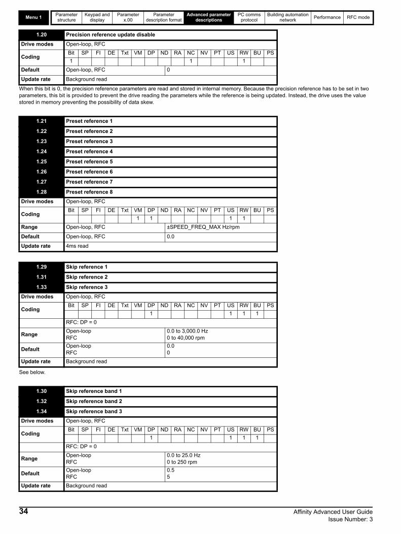
Menu 1Parameter structure
Keypad and display
Parameter x.00
Parameter description format
Advanced parameter descriptions
PC comms protocol
Building automation network
Performance RFC mode
When this bit is 0, the precision reference parameters are read and stored in internal memory. Because the precision reference has to be set in two parameters, this bit is provided to prevent the drive reading the parameters while the reference is being updated. Instead, the drive uses the value stored in memory preventing the possibility of data skew.
See below.
1.20 Precision reference update disable
Drive modes Open-loop, RFC
CodingBit SP FI DE Txt VM DP ND RA NC NV PT US RW BU PS
1 1 1
Default Open-loop, RFC 0
Update rate Background read
1.21 Preset reference 1
1.22 Preset reference 2
1.23 Preset reference 3
1.24 Preset reference 4
1.25 Preset reference 5
1.26 Preset reference 6
1.27 Preset reference 7
1.28 Preset reference 8
Drive modes Open-loop, RFC
CodingBit SP FI DE Txt VM DP ND RA NC NV PT US RW BU PS
1 1 1 1
Range Open-loop, RFC ±SPEED_FREQ_MAX Hz/rpm
Default Open-loop, RFC 0.0
Update rate 4ms read
1.29 Skip reference 1
1.31 Skip reference 2
1.33 Skip reference 3
Drive modes Open-loop, RFC
CodingBit SP FI DE Txt VM DP ND RA NC NV PT US RW BU PS
1 1 1 1
RFC: DP = 0
RangeOpen-loop RFC
0.0 to 3,000.0 Hz0 to 40,000 rpm
DefaultOpen-loop RFC
0.00
Update rate Background read
1.30 Skip reference band 1
1.32 Skip reference band 2
1.34 Skip reference band 3
Drive modes Open-loop, RFC
CodingBit SP FI DE Txt VM DP ND RA NC NV PT US RW BU PS
1 1 1 1
RFC: DP = 0
RangeOpen-loop RFC
0.0 to 25.0 Hz0 to 250 rpm
DefaultOpen-loop RFC
0.55
Update rate Background read
34 Affinity Advanced User Guide Issue Number: 3

Parameter structure
Keypad and display
Parameter x.00
Parameter description format
Advanced parameter descriptions
PC comms protocol
Building automation network
Performance RFC mode Menu 1
Three skip references are available to prevent continuous operation at a speed which would cause mechanical resonance. When a skip reference parameter is set to 0 that filter is disabled. The skip reference band parameters define the frequency or speed range either side of the programmed skip reference over which references are rejected. The actual reject band is therefore twice that programmed in these parameters, with the skip reference parameters defining the centre of the band. When the selected reference is within a band, the lower limit of the band is passed through to the ramps such that reference is always less than demanded.
This parameter indicates that the selected reference is within one of the skip reference zones such that the motor speed is not as demanded.
Although most parameters can be controlled from analog inputs, these two parameters are a special case in that if an analog input is directed to one of these parameters, the scan rate of that analog input is increased to 250s as long as:
1. The reference must be derived via Pr 1.36 or Pr 1.372. The analog inputs must be in voltage mode with zero offset3. Bipolar mode must be used or unipolar mode with the minimum speed (Pr 1.07) set to zero4. No skip bands are enabled, i.e. Pr 1.29, Pr 1.31 and Pr 1.33 must be zero.5. The jog and velocity feed-forward references must not be enabled.
These are special parameters when a non-bit type quantity uses these parameters as a destination (not just from analog inputs). The scaling and limiting applied is as described with Pr 1.08 on page 29.
See Pr 1.09 on page 30.
1.35 Reference in rejection zone
Drive modes Open-loop, RFC
CodingBit SP FI DE Txt VM DP ND RA NC NV PT US RW BU PS
1 1 1 1
Update rate 4ms write
1.36 Analog reference 1
1.37 Analog reference 2
Drive modes Open-loop, RFC
CodingBit SP FI DE Txt VM DP ND RA NC NV PT US RW BU PS
1 1 1 1
Range Open-loop, RFC ±SPEED_FREQ_MAX Hz/rpm
Default Open-loop, RFC 0
Update rate 4ms write
1.38 Percentage trim
Drive modes Open-loop, RFC
CodingBit SP FI DE Txt VM DP ND RA NC NV PT US RW BU PS
2 1 1
Range Open-loop, RFC ±100.00 %
Default Open-loop, RFC 0.00
Update rate 4ms read
1.41 Analog reference 2 select
1.42 Preset reference select
1.43 Keypad reference select
1.44 Precision reference select
1.45 Preset reference 1 select
1.46 Preset reference 2 select
1.47 Preset reference 3 select
Drive modes Open-loop, RFC
CodingBit SP FI DE Txt VM DP ND RA NC NV PT US RW BU PS
1 1 1
Default Open-loop, RFC 0
Update rate 4ms read
Affinity Advanced User Guide 35Issue Number: 3

Menu 1Parameter structure
Keypad and display
Parameter x.00
Parameter description format
Advanced parameter descriptions
PC comms protocol
Building automation network
Performance RFC mode
Pr 1.41 to Pr 1.44 control Pr 1.49. The priority order is Pr 1.44 (highest), Pr 1.43, Pr 1.42, Pr 1.41 (lowest). If more than one parameter is active, the highest priority takes precedence.
Pr 1.41 = 1 forces Pr 1.49 = 2 (see table in Pr 1.14 on page 31 and Pr 1.15 on page 32)Pr 1.42 = 1 forces Pr 1.49 = 3 (always selects preset references)Pr 1.43 = 1 forces Pr 1.49 = 4 (always selects keypad control mode)Pr 1.44 = 1 forces Pr 1.49 = 5 (always selects precision reference)
Pr 1.45 to Pr 1.47 control Pr 1.50.
Pr 1.45 controls Pr 1.50 bit 0*Pr 1.46 controls Pr 1.50 bit 1*Pr 1.47 controls Pr 1.50 bit 2*
*See the description with Pr 1.14 and Pr 1.15 on page 32 for more information.
When this flag is set, the preset timer for auto preset timer mode (Pr 01.15 = 9) is reset and preset 1 is selected. This can be used to start a new sequence of reference selection by a programmable input terminal or function. When this bit is zero the preset selection will follow the timer even when the drive is disabled.
Indicates the reference currently selected.
Indicates the preset reference currently being selected.
Selects the value of the keypad control mode (Pr 1.17) at power-up as follows:
0 rESEt zero
1 LASt last value used before power-down
2 PrS1 Preset 1, Pr 1.21, before power-down
1.48 Reference timer reset flag
Drive modes Open-loop, RFC
CodingBit SP FI DE Txt VM DP ND RA NC NV PT US RW BU PS
1 1 1
Default Open-loop, RFC 0
Update rate Background read
1.49 Reference selected indicator
Drive modes Open-loop, RFC
CodingBit SP FI DE Txt VM DP ND RA NC NV PT US RW BU PS
1 1 1 1
Range Open-loop, RFC 1 to 5
Update rate 4ms write
1.50 Preset reference selected indicator
Drive modes Open-loop, RFC
CodingBit SP FI DE Txt VM DP ND RA NC NV PT US RW BU PS
1 1 1 1
Range Open-loop, RFC 1 to 8
Update rate 4ms write
1.51 Power-up keypad control mode reference
Drive modes Open-loop, RFC
CodingBit SP FI DE Txt VM DP ND RA NC NV PT US RW BU PS
1 1 1 1
Range Open-loop, RFC 0 to 2
Default Open-loop, RFC 0
Update rate N/A
36 Affinity Advanced User Guide Issue Number: 3

Parameter structure
Keypad and display
Parameter x.00
Parameter description format
Advanced parameter descriptions
PC comms protocol
Building automation network
Performance RFC mode Menu 1
5.3.1 Hand / Off / Auto
Hand / Off / Auto functions are enabled if Pr 1.52 is set to a non-zero value, otherwise the keypad buttons are allocated as follows:
• Blue - Forward/Reverse
• Green - Run
• Red - Reset
When Hand / Off / Auto functions are enabled (Pr 1.52 set to either 1, 2 or 3), then the keypad buttons will be allocated as follows:
• Blue - Auto
• Green - Hand
• Red - Off/Reset
The value in Pr 1.52 selects Hand/Off/Auto mode on power-up as shown in Table 5-3.
Table 5-3 Hand/Off/Auto mode
Table 5-4 Power-up modes if Pr 1.52 = 3
Auto In Auto mode, the reference for the motor speed/frequency will be selected by the value set in Pr 0.05.
Hand The speed/frequency reference Pr 0.05 is automatically set to keypad reference. The motor speed is determined by the value in the keypad control mode reference Pr 1.17, which can be adjusted by pressing the Up/Down arrows on the keypad.
When Hand is selected from Auto, Pr 1.17 will be set to the value of the Pre-ramp reference (Pr 1.03) on mode transition, so the current motor speed is maintained.
If Hand mode is selected from Off mode, the motor will ramp up to the speed determined by the value in Pr 1.17.
Off In Off mode, the motor will be stopped. The speed/frequency reference (Pr 0.05) is automatically set to keypad reference, allowing the value in the keypad control mode reference (Pr 1.17) to be modified by pressing the Up/Down arrow keys. If Hand mode is then subsequently selected, the motor will ramp up to the speed determined by the value in Pr 1.17.
1.52 Enable hand/off/auto keypad operating mode
Drive modes Open-loop, RFC
CodingBit SP FI DE Txt VM DP ND RA NC NV PT US RW BU PS
1 1 1
Range Open-loop, RFC 0 to 3
Default Open-loop, RFC 1
Update rate Background read
Pr 1.52 Power up
0 Hand/Off/Auto disabled
1 Auto Mode
2 Off Mode
3 See table Table 5-4
Power-down Power-up
Hand Off
Off Off
Auto Auto
1.53 Fire mode reference
Drive modes Open-loop, RFC
CodingBit SP FI DE Txt VM DP ND RA NC NV PT US RW BU PS
1 1 1 1 1
Range Open-loop, RFC-SPEED_FREQ_MAX to +SPEED_FREQ_MAX Hz/rpm
DefaultOpen-loopRFC
0.0Hz0.0rpm
Update rate Background read
Affinity Advanced User Guide 37Issue Number: 3

Menu 1Parameter structure
Keypad and display
Parameter x.00
Parameter description format
Advanced parameter descriptions
PC comms protocol
Building automation network
Performance RFC mode
Emergency ventilation or fire mode allows for the purging of air from a structure during a fire. It is enabled if Pr 1.53 is set to a non zero value and activated when Pr 1.54 is set to one. When activated, the pre-ramp reference (Pr 1.03) is set to the value of Pr 1.53 and the normal drive controls are overridden as follows:
1. Drive enable is only controlled by the Enable input (Pr 6.15). The control word (Pr 6.43) cannot be used to disable the drive.2. The internal run command is forced to be active. The normal drive sequencing bits (Pr 6.30 to Pr 6.34) and the control word have no effect.3. The limit switch functions (Pr 6.35 and Pr 6.36) have no effect and will not stop the motor.4. The hard speed reference is forced to zero. The hard speed reference should not be used when fire mode is likely to be activated as this will
cause an abrupt change of speed. 5. The hand/off/auto function is disabled. If this system is in the hand state when fire mode is activated it will be forced to the off state, in order that
the hand state is not active when fire mode is de-activated. 6. Keypad mode is disabled. 7. All latching mode states are reset.
If the fire mode activate parameter is subsequently set to zero the drive returns to normal operation. The fire mode activate parameter does not have the RW attribute set, and so it must be controlled from a digital input. This prevents fire mode from being enabled via the keypad, serial comms or a correctly functioning Solutions Modules.
If the drive is in the tripped state when fire mode is activated, the trip is reset and thereafter only the trips listed in the table below can be initiated while fire mode is active.
Most of the trips included in the table are initiated in hardware and cannot be prevented in fire mode. These can be reset using the auto-reset function. The number of reset attempts can be set to a value from 1 to 5, or set to infinite attempts - see Pr 10.34, Number of auto-reset attempts on page 155 for details.
SLx.HF trips are allowed because these provide a watchdog function for most Solutions Modules and cannot be reset. HF17 to HF32 are hardware related faults that will prevent the drive from operating and cannot be reset. EEF, SAVE.Er and PSAVe.Er indicate that the parameter data taken from EEPROM is incorrect at power-up, and so the drive cannot run.
1.54 Fire mode activate
Drive modes Open-loop, RFC
CodingBit SP FI DE Txt VM DP ND RA NC NV PT US RW BU PS
1 1
Default Open-loop, RFC 0
Update rate Background read
Trip number
String Cause of trip
2 OU DC bus over-voltage
3 OI.AC AC instantaneous over-current
4 OI.br Braking resistor instantaneous over current
5 PS Drive power supply fault
8 PS.10V 10V user power supply overload
9 PS.24V 24V internal power supply overload
21 O.ht1 Power device over temperature based on thermal model
31 EEF EEProm failure
36 SAVE.Er User parameter save error
37 PSAVE.Er Power down save parameter error
103 OIbr.P Power module braking IGBT over current
104 OIAC.P Power module over current detected from the module output currents
105 Oht2.P Power module heatsink over temperature
106 OU.P Power module DC bus over-voltage
107 Ph.P Power module phase loss detection
108 PS.P Power module power supply fail
109 OIdc.P Power module over current detected from on state voltage monitoring
110 Unid.P Power module unidentified trip
200 SL1.HF Slot 1 Solutions Module failure
205 SL2.HF Slot 2 Solutions Module failure
210 SL3.HF Slot 3 Solutions Module failure
217 to 232 HF17 to HF32 Hardware faults
It is possible for the drive to become damaged when operating in fire mode because some of the drive thermal protection trips are disabled.
CAUTION
38 Affinity Advanced User Guide Issue Number: 3

Parameter structure
Keypad and display
Parameter x.00
Parameter description format
Advanced parameter descriptions
PC comms protocol
Building automation network
Performance RFC mode Menu 2
Affinity Advanced User Guide 39Issue Number: 3

Menu 2Parameter structure
Keypad and display
Parameter x.00
Parameter description format
Advanced parameter descriptions
PC comms protocol
Building automation network
Performance RFC mode
5.4 Menu 2: RampsThe pre-ramp frequency or speed reference passes through the ramp block controlled by menu 2 before being used by the drive to produce the basic output frequency (Open-loop modes), or as an input to the speed controller (RFC mode). The ramp block includes: linear ramps, an S ramp function for ramped acceleration and deceleration, deceleration ramp control to prevent rises in the DC bus voltage within the drive that would cause an over-voltage trip if no braking resistor is installed.Figure 5-2 Menu 2 logic diagram
0 0 0
0 0 1
0 1 0
0 1 1
1 0 0
1 0 1
1 1 0
1 1 1
Acceleration rate select bits
2.11 Acceleration rate 1
2.12 Acceleration rate 2
2.13 Acceleration rate 3
2.14 Acceleration rate 4
2.15 Acceleration rate 5
2.16 Acceleration rate 6
2.17 Acceleration rate 7
2.18 Acceleration rate 8
Acceleration rates 1 ~ 8
1.50
3
4
1
2
7
5
6
Preset referenceselected indicator
2.19Jog acceleration rate
1.13Jog selectedindicator
1.03Pre-ramp speedreference
2.03 Ramp hold
2.04 Ramp modeselect*
N
t
N
t
Acceleration
Reverse accel. rate
Forward accel. rate
Ramp control
2.10
Accelerationrate selector
2.34 2.322.33 2.32
0.XX
0.XX
Key
Read-write (RW) parameter
Read-only (RO) parameter
Inputterminals
Outputterminals
The parameters are all shown at their default settings
8
40 Affinity Advanced User Guide Issue Number: 3

Parameter structure
Keypad and display
Parameter x.00
Parameter description format
Advanced parameter descriptions
PC comms protocol
Building automation network
Performance RFC mode Menu 2
* For more information refer to Pr 2.04 on page 42.
** For more information refer to Pr 2.06 on page 43.
2.06 S-Ramp enable**
2.07 S-Ramp acceleration limit
2.08 Standard ramp voltage*
Ramp control
N
t
N
t
Deceleration
Forward Decel. rate
Reverse Decel. rate
+
_
2.01
Post-rampreference
2.02Ramp (RFC only)
enable
Current controlMenu 4(Open-loop only)
Deceleration rate select bits
2.21 Deceleration rate 1
2.22 Deceleration rate 2
2.23 Deceleration rate 3
2.24 Deceleration rate 4
2.25 Deceleration rate 5
2.26 Deceleration rate 6
2.27 Deceleration rate 7
2.28 Deceleration rate 8
Deceleration rates 1 ~ 8
3
4
1
2
7
8
5
6
2.37
1.50Preset referenceselected indicator
2.29 Jog deceleration rate
1.13 Jog selectedindicator
2.38
Inertia compensationtorque
(RFC only)
d/dt
2.20
Decelerationrate selector
2.36 2.35
Ramps always enabled in Open-loop
Affinity Advanced User Guide 41Issue Number: 3
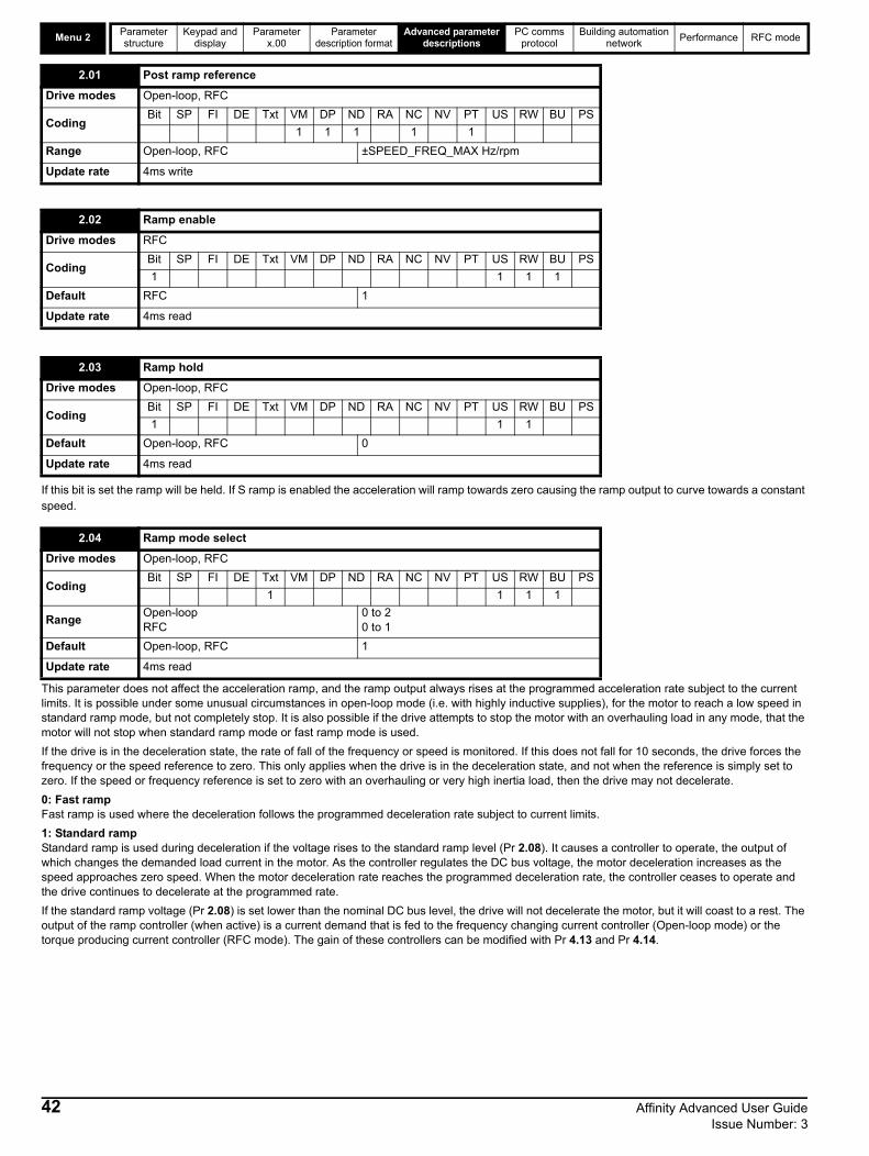
Menu 2Parameter structure
Keypad and display
Parameter x.00
Parameter description format
Advanced parameter descriptions
PC comms protocol
Building automation network
Performance RFC mode
If this bit is set the ramp will be held. If S ramp is enabled the acceleration will ramp towards zero causing the ramp output to curve towards a constant speed.
This parameter does not affect the acceleration ramp, and the ramp output always rises at the programmed acceleration rate subject to the current limits. It is possible under some unusual circumstances in open-loop mode (i.e. with highly inductive supplies), for the motor to reach a low speed in standard ramp mode, but not completely stop. It is also possible if the drive attempts to stop the motor with an overhauling load in any mode, that the motor will not stop when standard ramp mode or fast ramp mode is used.
If the drive is in the deceleration state, the rate of fall of the frequency or speed is monitored. If this does not fall for 10 seconds, the drive forces the frequency or the speed reference to zero. This only applies when the drive is in the deceleration state, and not when the reference is simply set to zero. If the speed or frequency reference is set to zero with an overhauling or very high inertia load, then the drive may not decelerate.
0: Fast rampFast ramp is used where the deceleration follows the programmed deceleration rate subject to current limits.
1: Standard rampStandard ramp is used during deceleration if the voltage rises to the standard ramp level (Pr 2.08). It causes a controller to operate, the output of which changes the demanded load current in the motor. As the controller regulates the DC bus voltage, the motor deceleration increases as the speed approaches zero speed. When the motor deceleration rate reaches the programmed deceleration rate, the controller ceases to operate and the drive continues to decelerate at the programmed rate.
If the standard ramp voltage (Pr 2.08) is set lower than the nominal DC bus level, the drive will not decelerate the motor, but it will coast to a rest. The output of the ramp controller (when active) is a current demand that is fed to the frequency changing current controller (Open-loop mode) or the torque producing current controller (RFC mode). The gain of these controllers can be modified with Pr 4.13 and Pr 4.14.
2.01 Post ramp reference
Drive modes Open-loop, RFC
CodingBit SP FI DE Txt VM DP ND RA NC NV PT US RW BU PS
1 1 1 1 1
Range Open-loop, RFC ±SPEED_FREQ_MAX Hz/rpm
Update rate 4ms write
2.02 Ramp enable
Drive modes RFC
CodingBit SP FI DE Txt VM DP ND RA NC NV PT US RW BU PS
1 1 1 1
Default RFC 1
Update rate 4ms read
2.03 Ramp hold
Drive modes Open-loop, RFC
CodingBit SP FI DE Txt VM DP ND RA NC NV PT US RW BU PS
1 1 1
Default Open-loop, RFC 0
Update rate 4ms read
2.04 Ramp mode select
Drive modes Open-loop, RFC
CodingBit SP FI DE Txt VM DP ND RA NC NV PT US RW BU PS
1 1 1 1
RangeOpen-loop RFC
0 to 20 to 1
Default Open-loop, RFC 1
Update rate 4ms read
42 Affinity Advanced User Guide Issue Number: 3

Parameter structure
Keypad and display
Parameter x.00
Parameter description format
Advanced parameter descriptions
PC comms protocol
Building automation network
Performance RFC mode Menu 2
2: Standard ramp with motor voltage boostThis mode is the same as normal standard ramp mode except that the motor voltage is boosted by 20%. This increases the losses in the motor giving faster deceleration.
Setting this parameter enables the S ramp function. S ramp is disabled during deceleration when the standard ramp voltage controller is active. When the motor is accelerated again after decelerating in standard ramp mode, the acceleration ramp used by the S ramp function is reset to zero.
This parameter defines the maximum rate of change of acceleration/deceleration. If the S ramp is disabled (Pr 2.06 = 0) a linear ramp is used and the time in seconds taken for the ramp output to change by frequency (f*) or speed (w*) is given by:
Frequency (Open-loop mode)TRamp = f* x A / 100
where A is the selected ramp rate in s / 100Hz
Speed (RFC)TRamp = w* x A / 100
Where A is the selected ramp rate in s / 1000rpm
If the S ramp is enabled (Pr 2.06 = 1) then the ramp time is extended as shown in the diagram below.
2.06 S ramp enable
Drive modes Open-loop, RFC
CodingBit SP FI DE Txt VM DP ND RA NC NV PT US RW BU PS
1 1 1
Default Open-loop, RFC 0
Update rate 4ms read
2.07 S ramp acceleration limit
Drive modes Open-loop, RFC
Coding
Bit SP FI DE Txt VM DP ND RA NC NV PT US RW BU PS
1 1 1 1
RFC: DP = 3
RangeOpen-loopRFC
0.0 to 300.0 s2/100Hz
0.000 to 100.000 s2/1,000rpm
DefaultOpen-loopRFC
3.11.500
Update rate Background read
DC Bus voltage
Motor Speed
Programmeddecelerationrate
t
Controlleroperational
Affinity Advanced User Guide 43Issue Number: 3

Menu 2Parameter structure
Keypad and display
Parameter x.00
Parameter description format
Advanced parameter descriptions
PC comms protocol
Building automation network
Performance RFC mode
The time taken in seconds for the ramp output to change by frequency (f*) or speed (w*) is given below. Two cases are given because the total ramp time must be calculated with a different equation depending on whether the acceleration is able to reach the selected ramp rate (A) or not. If the required change is small the selected ramp rate is not reached and the ramp does not include the central linear ramp region. If the required change is larger, the ramp does include the central linear region as shown in the diagram above.
Frequency (Open-loop mode)
f*linear = 100 x J / A2
where:
A is the selected ramp rate in s / 100Hz
J is parameter Pr 2.07, the S ramp acceleration limit in s2 / 100Hz
If the required change is less than f*linear then TRamp1 should be used, but if the speed change is greater or equal to f*linear TRamp2 should be used.
TRamp1 = 2 (f* x J / 100)
TRamp2 = (f* x A / 100) + (J / A)
Speed (RFC)w*linear = 1000 x J / A2
where:
A is the selected ramp rate in s / 1000rpm
J is Pr 2.07, the S ramp acceleration limit in s2 / 1000rpm
If the required change is less than w*linear then TRamp1 should be used, but if the speed change is greater or equal to w*linear TRamp1 should be
used.
TRamp1 = 2 (w* x J / 1000)
TRamp2 = (w* x A / 1000) + (J / A)
The default values for the ramp rate and S ramp acceleration limit have been chosen such that for the default maximum speed the curved parts of the S ramp are 25% of the original ramp if S ramp is enabled. Therefore the ramp time is increased by a factor of 1.5.
This voltage is used as the control level for standard ramp mode. If this parameter is set too low, the machine will coast to a rest, and if it is set too high and no braking resistor is used, the drive may indicate an OU trip. The minimum level should be greater than the voltage produced on the DC bus by the highest supply voltage. Normally the DC bus voltage will be approximately the rms supply line voltage x 2.
2.08 Standard ramp voltage
Drive modes Open-loop, RFC
CodingBit SP FI DE Txt VM DP ND RA NC NV PT US RW BU PS
1 1 1 1 1
Range Open-loop, RFC 0 to dc _VOLTAGE_SET_MAX V
Default Open-loop, RFC
200V rating drive: 375400V rating drive: EUR: 750 / USA: 775575V rating drive: 895690V rating drive: 1,075
Update rate Background read
t
AccelerationActual Speed
Programmedramp rate
T T
T/2 T/2 T/2T/2
S rampaccelerationramp
Demanded Speed
44 Affinity Advanced User Guide Issue Number: 3

Parameter structure
Keypad and display
Parameter x.00
Parameter description format
Advanced parameter descriptions
PC comms protocol
Building automation network
Performance RFC mode Menu 2
Deceleration failure detection is provided to force the drive to change from the decelerating state to the appropriate stop state if the motor frequency or speed is held at a constant level for 10s or more when the standard ramp voltage controller is active. When the drive is connected to a highly inductive supply, it is possible for the d.c. link voltage to rise as the motor frequency/speed falls. This rise in d.c. link voltage causes the standard ramp d.c. link voltage controller to prevent any further deceleration.
In some applications with very high inertia, the motor frequency/speed must fall very slowly or else the power fed into the d.c. link will cause an over-voltage trip. In these applications it may be necessary to disable the deceleration failure detection system by setting this parameter to 1.
The acceleration rate is selected as follows.
0 Ramp rate selection by terminal input1 - 8 Ramp rate defined by parameter number, i.e. 1 = Pr 2.11, 2 = Pr 2.12, etc.9 Ramp rate selection by Pr 1.50
When Pr 2.10 is set to 0, the acceleration ramp rate selected depends on the state of bit Pr 2.32 to Pr 2.34. These bits are for control by digital inputs such that ramp rates can be selected by external control. The ramp rate selected depends on the binary code generated by these bits as follows:
When Pr 2.10 is set to 9, the appropriate acceleration rate is automatically selected depending on the value of Pr 1.50, and so an acceleration rate can be programmed to operate with each reference. Since the new ramp rate is selected with the new reference, the acceleration applies towards the selected preset if the motor needs to accelerate to reach the preset.
2.09 Deceleration failure detection
Drive modes Open-loop, RFC
CodingBit SP FI DE Txt VM DP ND RA NC NV PT US RW BU PS
1 1 1
Default Open-loop, RFC OFF (0)
Update rate Background read
2.10 Acceleration rate selector
Drive modes Open-loop, RFC
CodingBit SP FI DE Txt VM DP ND RA NC NV PT US RW BU PS
1 1 1
Range Open-loop, RFC 0 to 9
Default Open-loop, RFC 0
Update rate 4ms read
Pr 2.34 Pr 2.33 Pr 2.32 Ramp defined by
0 0 0 Pr 2.11
0 0 1 Pr 2.12
0 1 0 Pr 2.13
0 1 1 Pr 2.14
1 0 0 Pr 2.15
1 0 1 Pr 2.16
1 1 0 Pr 2.17
1 1 1 Pr 2.18
Affinity Advanced User Guide 45Issue Number: 3

Menu 2Parameter structure
Keypad and display
Parameter x.00
Parameter description format
Advanced parameter descriptions
PC comms protocol
Building automation network
Performance RFC mode
RFCIf an acceleration rate is selected where the parameter is set to 0.000, the acceleration ramp is disabled and the reference changes instantly to its new value during acceleration.
Open-loopIf either an acceleration or deceleration rate is selected where the parameter is set to 0.0 in open-loop mode, the ramps are disabled for both acceleration and deceleration. This disables the voltage controller, used for standard ramp and mains loss ride through, and the frequency based current limits.
The jog acceleration rate is only used when accelerating towards the jog reference and when changing the jog reference.
The acceleration rate is selected as follows:
0 Ramp rate selection by terminal input1 - 8 Ramp rate defined by parameter number, i.e. 1 = Pr 2.21, 2 = Pr 2.22, etc.9 Ramp rate selection by Pr 1.50
2.11 Acceleration rate 1
2.12 Acceleration rate 2
2.13 Acceleration rate 3
2.14 Acceleration rate 4
2.15 Acceleration rate 5
2.16 Acceleration rate 6
2.17 Acceleration rate 7
2.18 Acceleration rate 8
Drive modes Open-loop, RFC
Coding
Bit SP FI DE Txt VM DP ND RA NC NV PT US RW BU PS
1 1 1 1
RFC: DP = 3
RangeOpen-loopRFC
0.0 to 3,200.0 s/100Hz0.000 to 3,200.000 s/1000rpm
DefaultOpen-loopRFC
EUR> 40.0, USA> 33.0EUR> 13.333, USA> 11.111
Second motor parameter
Open-loop, RFC Pr 21.04 for Pr 2.11 only
Update rate 4ms read
2.19 Jog acceleration rate
Drive modes Open-loop, RFC
Coding
Bit SP FI DE Txt VM DP ND RA NC NV PT US RW BU PS
1 1 1 1
RFCL: DP = 3
RangeOpen-loopRFC
0.0 to 3200.0 s/100Hz0.000 to 3200.000 s/1000rpm
DefaultOpen-loopRFC
0.20.000
Update rate Background read
2.20 Deceleration rate selector
Drive modes Open-loop, RFC
CodingBit SP FI DE Txt VM DP ND RA NC NV PT US RW BU PS
1 1 1
Range Open-loop, RFC 0 to 9
Default Open-loop, RFC 0
Update rate 4ms read
46 Affinity Advanced User Guide Issue Number: 3

Parameter structure
Keypad and display
Parameter x.00
Parameter description format
Advanced parameter descriptions
PC comms protocol
Building automation network
Performance RFC mode Menu 2
When Pr 2.20 is set to 0, the deceleration ramp rate selected depends on the state of bit Pr 2.35 to Pr 2.37. These bits are for control by digital inputs such that ramp rates can be selected by an external control. The ramp rate selected depends on the binary code generated by these bits as follows:
When Pr 2.20 is set to 9, the appropriate deceleration rate is automatically selected depending on the value of Pr 1.50, and so a deceleration rate can be programmed to operate with each reference. Since the new ramp rate is selected with the new reference, the deceleration applies towards the selected preset if the motor needs to decelerate to reach the preset.
RFCIf a deceleration rate is selected where the parameter is set to 0.000, the deceleration ramp is disabled and the reference changes instantly to its new value during deceleration.
Open-loopIf either an acceleration or deceleration rate is selected where the parameter is set to 0.0 in open-loop mode, the ramps are disabled for both acceleration and deceleration. This disables the voltage controller used for standard ramp and mains loss ride through, and the frequency based current limits.
The jog deceleration rate is only used when the drive is changing speed (when the jog reference has changed, or to stop from the jog reference. It is not used to go from the jog to the run state. This prevents the fast ramps normally used with jog from being used when changing between running and jogging.
02.37 02.36 02.35 Ramp defined by
0 0 0 Pr 2.21
0 0 1 Pr 2.22
0 1 0 Pr 2.23
0 1 1 Pr 2.24
1 0 0 Pr 2.25
1 0 1 Pr 2.26
1 1 0 Pr 2.27
1 1 1 Pr 2.28
2.21 Deceleration rate 1
2.22 Deceleration rate 2
2.23 Deceleration rate 3
2.24 Deceleration rate 4
2.25 Deceleration rate 5
2.26 Deceleration rate 6
2.27 Deceleration rate 7
2.28 Deceleration rate 8
Drive modes Open-loop, RFC
Coding
Bit SP FI DE Txt VM DP ND RA NC NV PT US RW BU PS
1 1 1 1
RFC: DP = 3
RangeOpen-loopRFC
0.0 to 3,200.0 s/100Hz0.000 to 3,200.000 s/1000rpm
DefaultOpen-loopRFC
EUR> 40.0, USA> 33.0EUR> 13.333, USA> 11.111
Second motor parameter
Open-loop, RFC Pr 21.05 for Pr 2.21 only
Update rate 4ms read
2.29 Jog deceleration rate
Drive modes Open-loop, RFC
Coding
Bit SP FI DE Txt VM DP ND RA NC NV PT US RW BU PS
1 1 1 1
RFC: DP = 3
RangeOpen-loopRFC
0.0 to 3,200.0 s/100Hz0.000 to 3,200.000 s/1000rpm
DefaultOpen-loopRFC
0.20.000
Update rate Background read
Affinity Advanced User Guide 47Issue Number: 3

Menu 2Parameter structure
Keypad and display
Parameter x.00
Parameter description format
Advanced parameter descriptions
PC comms protocol
Building automation network
Performance RFC mode
These bits are provided for control by logic input terminals for external ramp selection (see Pr 2.10 and Pr 2.20).
The motor and load inertia (Pr 3.18), motor torque per amp (Pr 5.32) and the rate of change of the ramp output (Pr 2.01), are used to produce a torque feed forward value that should accelerate or decelerate the load at the required rate. This value can be used as a feed forward term that is added to the speed controller output if Pr 4.22 is set to one. Pr 2.38 shows the torque value as a percentage of rated active current.
2.32 Acceleration select bit 0
2.33 Acceleration select bit 1
2.34 Acceleration select bit 2
2.35 Deceleration select bit 0
2.36 Deceleration select bit 1
2.37 Deceleration select bit 2
Drive modes Open-loop, RFC
CodingBit SP FI DE Txt VM DP ND RA NC NV PT US RW BU PS
1 1 1
Update rate 4ms read
2.38 Inertia compensation torque
Drive modes RFC
CodingBit SP FI DE Txt VM DP ND RA NC NV PT US RW BU PS
1 1 1 1
Range RFC ±1,000.0 %
Update rate 4ms write
48 Affinity Advanced User Guide Issue Number: 3

Parameter structure
Keypad and display
Parameter x.00
Parameter description format
Advanced parameter descriptions
PC comms protocol
Building automation network
Performance RFC mode Menu 3
Affinity Advanced User Guide 49Issue Number: 3
5.5 Menu 3: Speed feedback and speed controlMenu 3 relates to different functions depending on the drive mode selected as shown in the table below. The menus for some drive modes are significantly different, and therefore the complete menu is covered in different sections.
Frequency/Speed accuracy and resolutionDigital reference resolution
When a preset frequency/speed is used the reference resolution is 0.1Hz or 0.1rpm. Improved resolution can be obtained by using the precision reference (0.001Hz or 0.001rpm).
Analog reference resolution
In Open-loop modes the frequency reference controlled by an analog input has a maximum resolution of 12 bits plus sign, but this is reduced if the window time constant/filter period for this input controller by Pr 7.26, is reduced below the default value of 4.0ms. The resolution of the frequency reference from analog inputs 2 or 3 is 10 bits plus sign.
In RFC mode the resolution from analog input 1 is better than 16 bits plus sign provided the speed reference is routed via Pr 1.36, Pr 1.37 or Pr 3.22 in high speed update mode. The resolution from analog inputs 2 or 3 is 10 bits plus sign.
Accuracy
The absolute frequency and speed accuracy depends on the accuracy of the crystal used with the drive microprocessor. The accuracy of the crystal is 100ppm, and so the absolute frequency/speed accuracy is 100ppm (0.01%) of the reference, when a preset speed is used. If an analog input is used the absolute accuracy is further limited by the absolute accuracy and non-linearity of the analog input.
Drive mode section Menu 3 functions
Open-loop Frequency slaving “Zero speed” and “at speed” detectors
RFCSpeed feedback, speed controller “Zero speed”, “at speed” and overspeed detectors

Menu 3Open-loop
Parameter structure
Keypad and display
Parameter x.00
Parameter description format
Advanced parameter descriptions
PC comms protocol
Building automation network
Performance RFC mode
Parameter descriptions: Open-loopFigure 5-3 Menu 3 Open-loop logic diagram
If the post ramp reference (Pr 2.01) is at or below the level defined by this parameter in either direction, the Zero speed flag (Pr 10.03) is 1, otherwise the flag is 0.
3.05 Zero speed threshold
Drive modes Open-loop, RFC
CodingBit SP FI DE Txt VM DP ND RA NC NV PT US RW BU PS
1 1 1 1
Range Open-loop 0.0 to 20.0 Hz
Default Open-loop 1.0
Update rate Background read
3.06 At speed lower limit
Drive modes Open-loop, RFC
CodingBit SP FI DE Txt VM DP ND RA NC NV PT US RW BU PS
1 1 1 1
Range Open-loop 0.0 to 3,000.0 Hz
Default Open-loop 1.0
Update rate Background read
2.01
Post rampreference
+
_
3.0510.03
At zero speedindicator
Zero speedthreshold
+
_
1.07 10.04
At or below min.speed indicator
Minimumspeed
+
_Overspeed trip(O.SPd)1.06
Max.frequency
+
_
3.0610.05
Below at-speedwindow indicator
At speedlower limit
+
_3.07
10.07
Above at-speedwindow indicatorAt speed
upper limit
+
_
10.06
At speedindicator
+20%
5.01
Motorfrequency
+
+
SlipcompensationMenu 5
0.XX
0.XX
Key
Read-write (RW)parameter
Read-only (RO)parameter
Inputterminals
Outputterminals
XX
XX
Menu 2
0
1
1.10
Bipolar referenceselect
NOR
The parameters are all shown at their default settings
1.03
Pre rampreference
3.09
Absolute at-speeddetect mode
0
1
+0.5Hz
50 Affinity Advanced User Guide Issue Number: 3

Parameter structure
Keypad and display
Parameter x.00
Parameter description format
Advanced parameter descriptions
PC comms protocol
Building automation network
Performance RFC modeMenu 3
Open-loop
"At speed" flag (Pr 10.06) is set if the post-ramp reference (Pr 2.01) is on the boundaries or within the at speed window. Flags Pr 10.07 and Pr 10.05 are set if the reference is above or below the window respectively.
If Pr 3.09 = 0 reference window mode is used and the "at speed" condition is true if
(|Pr 1.03| - Pr 3.06) |Pr 2.01| (|Pr 1.03| + Pr 3.07)
(If the lower limit is less than zero then zero is used as the lower limit.)
If Pr 3.09 = 1 absolute window mode is used and the "at speed" condition is true if
Pr 3.06 |Pr 2.01| Pr 3.07
The speed detector system also includes an overspeed trip in open-loop mode. The level cannot be set by the user, but the drive produces an overspeed trip if the final frequency (Pr 5.01) exceeds 1.2 x SPEED_FREQ_MAX.
3.07 At speed upper limit
Drive modes Open-loop, RFC
CodingBit SP FI DE Txt VM DP ND RA NC NV PT US RW BU PS
1 1 1 1
Range Open-loop 0.0 to 3,000.0 Hz
Default Open-loop 1.0
Update rate Background read
3.09 Absolute “at speed” select
Drive modes Open-loop, RFC
CodingBit SP FI DE Txt VM DP ND RA NC NV PT US RW BU PS
1 1 1
Default Open-loop 0
Update rate Background read
Affinity Advanced User Guide 51Issue Number: 3

Menu 3RFC
Parameter structure
Keypad and display
Parameter x.00
Parameter description format
Advanced parameter descriptions
PC comms protocol
Building automation network
Performance RFC mode
Parameter descriptions: RFCFigure 5-4 Menu 3 RFC logic diagram
+
_
3.03
Speed error
+
_
+
_
Speed loop gains
3.04
Speed controlleroutput
Menu 4
+
_Overspeed trip(O.SPd)1.06
Max reference clamp
+
_
3.0610.05
Below at-speed window indicatorAt speed
lower limit
+
_3.0710.07
Above at-speed window indicator
At speedupper limit
10.06
At speedindicator
NOR
+
_
3.0510.03
At zero speed indicator
Zero speedthreshold
+
_
1.07 10.04
At or below min. speed indicatorMinimum
speed
1.10
Bipolar referenceselect
+5min-1
+20%
1.03
Pre rampreference
3.09
Absolute at-speed detect mode
Speed controller differential feedback gains
0.XX
0.XX
Key
Read-write (RW) parameter
Read-only (RO) parameter
Inputterminals
Outputterminals
The parameters are all shown at their default settings
3.08
Overspeed threshold
3.08 >0
Speed controllergain select
3.10
3.11 (Ki1)
(Kp1)
3.13
3.14 (Ki2)
(Kp2)
3.16
(Kd1) (Kd2)
3.153.12
3.02
Speed feedback
2.01Post-rampreference
+
+
3.23
1.11
Hard speed reference selector
Reference enabledindicator
3.01
Final speed reference
3.22Hard speed reference
RFC sensorless speed feedback
calculator3.42
Drive encoder filter
52 Affinity Advanced User Guide Issue Number: 3

Parameter structure
Keypad and display
Parameter x.00
Parameter description format
Advanced parameter descriptions
PC comms protocol
Building automation network
Performance RFC modeMenu 3
RFC
This is the final speed demand at the input to the speed regulator formed by the sum of the ramp output and the hard speed reference (if the hard speed reference is enabled). If the drive is disabled this parameter will show 0.0.
The speed feedback is derived from the sensorless feedback calculation.
The speed error is the difference between the final speed demand and the speed feedback in rpm. This does not include the effect of the D term in the speed controller feedback branch.
The output of the speed regulator is a torque demand given as a percentage of rated motor torque. This is then modified to account for changes in motor flux if field weakening is active, and then used as the torque producing current reference.
If the speed feedback (Pr 3.02) is at or below the level defined by this parameter in either direction the Zero speed flag (Pr 10.03) is 1, otherwise the flag is 0.
3.01 Final speed reference
Drive modes RFC
CodingBit SP FI DE Txt VM DP ND RA NC NV PT US RW BU PS
1 1 1 1 1 1
Range RFC ±SPEED_MAX rpm
Update rate 4ms write
3.02 Speed Feedback
Drive modes RFC
CodingBit SP FI DE Txt VM DP ND RA NC NV PT US RW BU PS
1 1 1 1 1 1
Range RFC ±SPEED_MAX rpm
Update rate 4ms write
3.03 Speed error
Drive modes RFC
CodingBit SP FI DE Txt VM DP ND RA NC NV PT US RW BU PS
1 1 1 1 1 1
Range RFC ±SPEED_MAX rpm
Update rate 4ms write
3.04 Speed controller output
Drive modes RFC
CodingBit SP FI DE Txt VM DP ND RA NC NV PT US RW BU PS
1 1 1 1 1 1
Range RFC ±TORQUE_PROD_CURRENT_MAX %
Update rate 4ms write
3.05 Zero speed threshold
Drive modes Open-loop, RFC
CodingBit SP FI DE Txt VM DP ND RA NC NV PT US RW BU PS
1 1 1
Range RFC 0 to 200 rpm
Default RFC 5
Update rate Background read
3.06 At speed lower limit
Drive modes Open-loop, RFC
CodingBit SP FI DE Txt VM DP ND RA NC NV PT US RW BU PS
1 1 1
Range RFC 0 to 40,000 rpm
Default RFC 50
Update rate Background read
Affinity Advanced User Guide 53Issue Number: 3

Menu 3RFC
Parameter structure
Keypad and display
Parameter x.00
Parameter description format
Advanced parameter descriptions
PC comms protocol
Building automation network
Performance RFC mode
"At speed" flag (Pr 10.06) is set if the speed feedback (Pr 3.02) is on the boundaries or within the at speed window. Flags Pr 10.07 and Pr 10.05 are set if the reference is above or below the window respectively.
If Pr 3.09 = 0 reference window mode is used and the "at speed" condition is true if
(|Pr 1.03| - Pr 3.06) |Pr 3.02| (|Pr 1.03| + Pr 3.07)
(If the lower limit is less than zero then zero is used as the lower limit.)
If Pr 3.09 = 1 absolute window mode is used and the "at speed" condition is true if
Pr 3.06 |Pr 3.02| Pr 3.07
If the speed feedback (Pr 3.02) exceeds this level in either direction an overspeed trip is produced. If this parameter is set to zero the overspeed threshold is automatically set to 1.2 x SPEED_FREQ_MAX.
See Pr 3.06 and Pr 3.07 on page 54.
3.07 At speed upper limit
Drive modes Open-loop, RFC
CodingBit SP FI DE Txt VM DP ND RA NC NV PT US RW BU PS
1 1 1
Range RFC 0 to 40,000 rpm
Default RFC 50
Update rate Background read
3.08 Overspeed threshold
Drive modes RFC
CodingBit SP FI DE Txt VM DP ND RA NC NV PT US RW BU PS
1 1 1
Range RFC 0 to 40,0000 rpm
Default RFC 0
Update rate Background read
3.09 Absolute “at speed” detect
Drive modes Open-loop, RFC
CodingBit SP FI DE Txt VM DP ND RA NC NV PT US RW BU PS
1 1 1
Default RFC 0
Update rate Background read
3.10 Speed controller proportional gain (Kp1)
3.13 Speed controller proportional gain (Kp2)
Drive modes RFC
CodingBit SP FI DE Txt VM DP ND RA NC NV PT US RW BU PS
4 1 1 1
Range RFC 0.0000 to 6.5335 (1/ rad s-1)
Default RFC 0.0300
Second motor parameter
RFC Pr 21.17
Update rate Background read
54 Affinity Advanced User Guide Issue Number: 3

Parameter structure
Keypad and display
Parameter x.00
Parameter description format
Advanced parameter descriptions
PC comms protocol
Building automation network
Performance RFC modeMenu 3
RFC
The following diagram shows a generalized representation of the speed controller. The controller includes proportional (Kp) and integral (Ki) feed-forward terms, and a differential (Kd) feedback term. The drive holds two sets of these gains, and either set may be selected for use by the speed controller with Pr 3.16. If Pr 3.16 = 0, gains Kp1, Ki1 and Kd1 are used, if Pr 3.16 = 1, gains Kp2, Ki2 and Kd2 are used. Pr 3.16 may be changed when the drive is enabled or disabled.
Proportional gain (Kp)If Kp has a value and Ki is set to zero the controller will only have a proportional term, and there must be a speed error to produce a torque reference. Therefore as the motor load increases there will be a difference between the reference and actual speeds. This effect, called regulation, depends on the level of the proportional gain, the higher the gain the smaller the speed error for a given load.
3.11 Speed controller integral gain (Ki1)
3.14 Speed controller integral gain (Ki2)
Drive modes RFC
CodingBit SP FI DE Txt VM DP ND RA NC NV PT US RW BU PS
2 1 1 1
Range RFC 0.00 to 653.35 s/rad s-1
Default RFC 0.10
Second motor parameter
RFC Pr 21.18
Update rate Background read
3.12 Speed controller differential feedback gain (Kd1)
3.15 Speed controller differential feedback gain (Kd2)
Drive modes RFC
CodingBit SP FI DE Txt VM DP ND RA NC NV PT US RW BU PS
5 1 1 1
Range RFC 0.00000 to 0.65335 s-1/rad s-1
Default RFC 0.00000
Second motor parameter
RFC Pr 21.19
Update rate Background read
3.16 Speed controller gain select
Drive modes RFC
CodingBit SP FI DE Txt VM DP ND RA NC NV PT US RW BU PS
1 1 1
Default RFC 0
Update rate 4ms read
Kp
Ki
Kd
Speedreference (wr*)
Speedfeedback (wr)
Torquereference (Te*)
-
+
+
+
+
+
Affinity Advanced User Guide 55Issue Number: 3

Menu 3RFC
Parameter structure
Keypad and display
Parameter x.00
Parameter description format
Advanced parameter descriptions
PC comms protocol
Building automation network
Performance RFC mode
Integral gain (Ki)The integral gain is provided to prevent speed regulation. The error is accumulated over a period of time, and used to produce the necessary torque demand without any speed error. Increasing the integral gain reduces the time taken for the speed to reach the correct level, and increases the stiffness of the system, i.e. it reduces the positional displacement produced by applying a load torque to the motor. Unfortunately, increasing the integral gain also reduces the system damping giving overshoot after a transient.
For a given integral gain, the damping can be improved by increasing the proportional gain. A compromise must be reached where the system response, stiffness and damping are all adequate for the application. The integral term is implemented in the form of (Ki x error), and so the integral gain can be changed when the controller is active without causing large torque demand transients.
Differential gain (Kd)The differential gain is provided in the feedback of the speed controller to give additional damping. The differential term is implemented in a way that does not introduce excessive noise normally associated with this type of function. Increasing the differential term reduces the overshoot produced by under-damping however, for most applications the proportional and integral gains alone are sufficient. It should be noted that the differential term is limited internally so that it is ineffective if speed in rpm x Kd x Ki is greater than 170.
To analyze the performance of the speed controller it may be represented as an s-domain model as shown below.
Where:
Kc is the conversion between the speed controller output and the torque producing current. A value of unity at the output of the speed controller gives a torque producing current equal to Kc. The drive automatically compensates the torque producing current for flux variations in field weakening, and so Kc can be assumed to have a constant value even in field weakening. See menu 4 for the value of Kc each drive size).
Kt is the torque constant of the motor (i.e. torque in Nm per amp of torque producing current). This value is normally available for a servo motor from the manufacturer, however for induction motors the value must be calculated from:-
Kt = Motor rated torque / Motor rated torque producing current
= Motor rated torque / (Motor rated current2 - No load current2)
L(s) is the transfer function of the load.
The s-domain system above may be used to determine the performance of systems with a relatively low bandwidth. However, the real drive system also includes non-ideal delays due to the torque controller response, speed measurement and control delays. These delays, which can be approximated with a simple unity gain transport delay (Tdelay) as shown below, should be taken into account for more accurate results.
The speed controller gains used in previous Unidrive products were in internal drive units. Conversion between the previous internal units and the SI units used in this product are given in the table below.
Gain Conversion from previous internal units to new SI units
Kp Kp_old / 17103
Ki Ki_old / 94.41
Kd Kd_old / 46376
Kp
Ki 1/s
Kc Kt L(s)+
_
+
+
w*(s)rads-1
w(s)
Speed controller
Ki.Kd
_
rads-1
Kp+Ki/s
Ki.Kd
Kc.Kt L(s)+
_
+
_
w*(s) w(s)
Tdelay
56 Affinity Advanced User Guide Issue Number: 3

Parameter structure
Keypad and display
Parameter x.00
Parameter description format
Advanced parameter descriptions
PC comms protocol
Building automation network
Performance RFC modeMenu 3
RFC
The user may enter the required speed controller gains into Pr 3.10 to Pr 3.15. However, if the load is predominantly a constant inertia and constant torque, the drive can calculate the required Kp and Ki gains, provided a value of motor plus load inertia (Pr 3.18) and the motor torque per amp (Pr 5.32) are set-up correctly. The gain values are calculated to give a required compliance angle or bandwidth. The calculated values for Kp and Ki are written to Pr 3.10 and Pr 3.11 once per second when one of these set-up methods is selected (i.e. Pr 3.17 = 1 or 2). The values are calculated from a linear model assuming a pure inertia load, not including unwanted delays in the speed and current controllers. The Kd gain is not affected. If Pr 3.17 is set to 3 automatic gain set up is not active, but Kp is boosted by a factor of 16.
0: user set-up
With the default value the user should enter the required speed controller gains.
1: Bandwidth set-up
If bandwidth based set-up is required, the following parameters must be set correctly: Pr 3.20 = required bandwidth, Pr 3.21 = required damping factor, Pr 3.18 = motor + load inertia (it is possible to measure the load inertia as part of the auto-tuning process, see Pr 5.12 on page 84), Pr 5.32 = motor torque per amp.
Ki = J / (Kc x Kt) x (2 x Bandwidth / Kbw)2 = Pr 3.18 / (Kc x Pr 5.32) x (2 x Pr 3.20 / Kbw)2
Where: Kbw = [ (22 + 1) +((22 + 1)2 + 1) ]
Kp = 2 [(Ki x J) / (Kc x Kt)] = 2 [(Pr 3.11 x Pr 3.18) / (Kc x Pr 5.32)]
2: Compliance angle set-up
If compliance angle based set-up is required the following parameters must be set correctly: Pr 3.19 = required compliance angle, Pr 3.21 = required damping factor, Pr 3.18 = motor + load inertia (it is possible to measure the load inertia as part of the auto-tuning process, see Pr 5.12 on page 84), Pr 5.32 = motor torque per amp.
Ki = 1 / Compliance angle (rad s-1)Kp = 2 [(Ki x J) / (Kc x Kt)] = 2 [(Pr 3.11 x Pr 3.18) / (Kc x Pr 5.32)]
3: Kp gain times 16If this parameter is set to 3, the Kp gain (from whichever source) is multiplied by 16. This is intended to boost the range of Kp for applications with very high inertia. It should be noted that if high values of Kp are used, it is likely that the speed controller output will need to be filtered (see Pr 4.12), or the speed feedback will need to be filtered (see Pr 3.42). If the feedback is not filtered, it is possible the output of the speed controller will be a square wave which changes between the current limits causing the integral term saturation system to malfunction.
The motor and load inertia represents the total inertia driven by the motor. This is used to set the speed controller gains (see Pr 3.13 on page 54) and to provide torque feed-forwards during acceleration when required. (see Pr 4.11 on page 69) (It is possible to measure the inertia as part of the auto-tune process, see Pr 5.12 on page 84.
The compliance angle is the required angular displacement when the drive delivers a torque producing current equivalent to the current scaling (Kc) with no field weakening.
3.17 Speed controller set-up method
Drive modes RFC
CodingBit SP FI DE Txt VM DP ND RA NC NV PT US RW BU PS
1 1 1
Range RFC 0 to 3
Default RFC 0
Update rate Background (1s) read
3.18 Motor and load inertia
Drive modes RFC
CodingBit SP FI DE Txt VM DP ND RA NC NV PT US RW BU PS
5 1 1 1
Range RFC 0.00000 to 90.00000 kg m2
Default RFC 0.00000
Update rate Background (1s) read
3.19 Compliance angle
Drive modes RFC
CodingBit SP FI DE Txt VM DP ND RA NC NV PT US RW BU PS
1 1 1 1
Range RFC 0.0 to 359.9 °mechanical
Default RFC 4.0
Update rate Background (1s) read
Affinity Advanced User Guide 57Issue Number: 3

Menu 3RFC
Parameter structure
Keypad and display
Parameter x.00
Parameter description format
Advanced parameter descriptions
PC comms protocol
Building automation network
Performance RFC mode
The bandwidth is defined as the theoretical 3dB point on the closed-loop gain characteristic of the speed controller as a second order system. At this point the phase shift is approximately 60°. This parameter is used to define the bandwidth used for setting up the speed loop gain parameters automatically when Pr 3.17 = 1.
This is the damping factor related to the response of the system to a torque transient, and so if the damping factor is unity the response to a load torque transient is critically damped. The step response of the speed controller gives approximately 10% overshoot with unity damping factor. This parameter is used to define the damping factor used for setting up the speed loop gain parameters automatically when Pr 3.17 = 1 or 2.
The hard speed reference is a reference value which does not pass through the ramp system (Menu 2). It is added to the normal post ramp speed reference. Its value may be written from the keypad, via serial comms or from an analog input. The hard speed reference is selected when Pr 3.23 = 1.
Pr 3.24 can only be set to 3 (RFC mode) - Closed loop vector without position feedback with no maximum limit.
A filter with a 4ms time constant/filter is automatically included in the speed feedback, as this is required for this system to operate correctly. Particularly when operating above rated speed it may be necessary to include further filtering (Pr 4.12 set to a value between 1.0 and 5.0ms) to achieve stable operation.
3.20 Bandwidth
Drive modes RFC
CodingBit SP FI DE Txt VM DP ND RA NC NV PT US RW BU PS
1 1 1
Range RFC 0 to 255 Hz
Default RFC 10 Hz
Update rate Background (1s) read
3.21 Damping factor
Drive modes RFC
CodingBit SP FI DE Txt VM DP ND RA NC NV PT US RW BU PS
1 1 1 1
Range RFC 0.0 to 10.0
Default RFC 1.0
Update rate Background (1s) read
3.22 Hard speed reference
Drive modes RFC
CodingBit SP FI DE Txt VM DP ND RA NC NV PT US RW BU PS
1 1 1 1 1
Range RFC ±SPEED_FREQ_MAX rpm
Default RFC 0.0
Update rate 4ms read
3.23 Hard speed reference selector
Drive modes RFC
CodingBit SP FI DE Txt VM DP ND RA NC NV PT US RW BU PS
1 1 1
Default RFC 1
Update rate 4ms read
3.24 Closed-loop vector mode
Drive modes RFC
CodingBit SP FI DE Txt VM DP ND RA NC NV PT US RW BU PS
1 1 1
Range RFC 3
Default RFC 3
Update rate Background read
58 Affinity Advanced User Guide Issue Number: 3

Parameter structure
Keypad and display
Parameter x.00
Parameter description format
Advanced parameter descriptions
PC comms protocol
Building automation network
Performance RFC modeMenu 3
RFC
0 = 0ms, 1 = 1ms, 2 = 2ms, 3 = 4ms, 4 = 8ms, 5 = 16ms
A sliding window filter may be applied to the feedback taken from the drive encoder. This is particularly useful in applications where the drive encoder is used to give speed feedback for the speed controller, and where the load includes a high inertia and hence the speed controller gains are very high. Under these conditions without a filter on the feedback, it is possible for the speed loop output to change constantly from one current limit to the other and lock the integral term of the speed controller.
This parameter also defines a filter on the output of the speed estimator which is used as the speed feedback. A filter with a 4ms time constant/filter is always present on the output of the speed estimator, but this filter may be extended as follows: 0 = 4ms, 1 = 8ms, 2 = 16ms, 3 = 32ms, 4 = 64ms, 5 = 128ms. The output of the speed estimator can include some ripple, which increases as the drive passes into field weakening, and the filter can be used to remove this ripple. This is particularly useful when using standard ramp or spinning start with a low friction high inertia load, and can prevent over voltage trips when the drive has no braking resistor.
3.42 Drive encoder filter
Drive modes RFC
CodingBit SP FI DE Txt VM DP ND RA NC NV PT US RW BU PS
1 1 1
Range RFC 0 to 5 (0 to16 ms)
Default RFC 0
Update rate Background read
Affinity Advanced User Guide 59Issue Number: 3

Menu 4Parameter structure
Keypad and display
Parameter x.00
Parameter description format
Advanced parameter descriptions
PC comms protocol
Building automation network
Performance RFC mode
5.6 Menu 4: Torque and current controlThe scaling of the current feedback is based on the rating of the drive as follows:
Current scaling (Kc) is 1 per unit current and is related to the scaling of the drive current feedback. For most drive sizes, Kc is the same as the drive current scaling defined by Pr 11.32. The drive current scaling is the maximum value of rated motor current (defined by Pr 5.07 or Pr 21.07) that can be set for operation with the force vented motor protection characteristic - Pr 4.25 = 0 (see Pr 4.16 for more details). If the Kc and drive current scaling are the same, then the drive uses 1.75 x Drive current scaling for the open-loop peak limit and the maximum standard operating current for closed-loop modes. This is the limit up to which the drive can control current normally. The current range above this is allowed for current controller overshoot and for additional current feedback pulses associated with long cable operation. For some drive sizes the drive current scaling is larger than Kc, therefore the potential overload is reduced below 1.75 x Kc.
The motor rated current (defined by Pr 5.07 or Pr 21.07), may be increased above the drive current scaling up to the maximum Normal Duty rated current. When the motor rated current is above the drive current scaling, the drive always provides a motor protection scheme that is intended for variable torque applications (see Pr 4.16 on page 72 for more details). The maximum rated current is the maximum rated current allowed for Normal Duty operation.
Table below gives the current scaling (Kc), Drive current scaling and Maximum normal duty rated current for all drive sizes and voltage ratings.
Table 5-5 Current ratings
Level x Rated drive current
Over-current trip 1/0.45 = 2.22
Open-loop peak limit 1.75
RFC 1.75
Open-loop maximum standard operating current 1.5
Current scaling (Kc) 1.0
Maximum Normal Duty current rating 1.36*
Maximum motor rated current 1.36*
200V 400V 575V 690V
ModelCurrent scaling
(Kc)
Drive current scaling
MaxNormal
Duty rated
current
ModelCurrent scaling
(Kc)
Drive current scaling
MaxNormal
Duty rated
current
ModelCurrent scaling
(Kc)
Drive current scaling
MaxNormal
Duty rated
current
ModelCurrent scaling
(Kc)
Drive current scaling
MaxNormal
Duty rated
current
BA1201 4.3 4.3 5.2 BA1401 2.1 2.1 2.8 BA3501 4.1 4.1 5.4 BA4601 18 18 22
BA1202 5.8 5.8 6.8 BA1402 3.0 3.0 3.8 BA3502 5.4 5.4 6.1 BA4602 22 22 27
BA1203 7.5 7.5 9.6 BA1403 4.2 4.2 5.0 BA3503 6.1 6.1 8.4 BA4603 27 27 36
BA1204 10.6 10.6 11 BA1404 5.8 5.8 6.9 BA3504 9.5 9.5 11 BA4604 36 36 43
BA2201 12.6 12.6 15.5 BA1405 7.6 7.6 8.8 BA3505 12 12 16 BA4605 43 43 52
BA2202 17 17 22 BA1406 9.5 9.5 11 BA3506 18 18 22 BA4606 52 52 62
BA2203 25 25 28 BA2401 13 13 15.3 BA3507 22 22 27 BA5601 62 62 84
BA3201 31 31 42 BA2402 16.5 16.5 21 BA5602 84 84 99
BA3202 42 42 54 BA2403 23 25 29 BA6601 85.7 100 125
BA4201 56 56 68 BA3401 32 32 35 BA6602 107.1 125 144
BA4202 68 68 80 BA3402 40 40 43 BAMA16X1 85.7 100 125
BA4203 80 80 104 BA3403 46 46 56 BAMA16X1 107.1 125 144
BA5201 105 105 130 BA4401 60 60 68 BAMD16X1 85.7 100 125
BA5202 130 130 154 BA4402 74 74 83 BAMD16X1 107.1 125 144
BAMD12X1 133.7 156 192 BA4403 96 96 104 BAMD16X1 123.4 144 168
BAMD12X2 164.5 192 248 BA5401 124 124 138 BAMD16X1 144.0 168 192
BAMD12X3 214.2 250 312 BA5402 156 156 168
BAMD12X4 248.5 290 350 BA6401 154.2 180 205
BA6402 180 210 236
BAMA14X1 154.2 180 202
BAMA14X2 180.0 210 236
BAMD14X1 154.2 180 202
BAMD14X2 180.0 210 246
BAMD14X3 205.7 246 290
BAMD14X4 248.5 290 330
60 Affinity Advanced User Guide Issue Number: 3

Parameter structure
Keypad and display
Parameter x.00
Parameter description format
Advanced parameter descriptions
PC comms protocol
Building automation network
Performance RFC mode Menu 4
BAMAxxxx and BAMDxxxx drive modules can be connected in parallel provided all power modules have the same voltage and current rating to make a larger drive. The currents are then defined as follows:
Current scaling (Kc)Kc is the sum of Kc for all the modules.
Maximum drive current scalingMaximum drive current scaling = 0.95 x Sum of maximum drive current scaling for all the modules.
Maximum rated currentMaximum rated current = 0.95 x Sum of maximum normal duty rated current for all the modules.
5.6.1 Open-loopIn this mode the drive operates in the stator flux reference frame under steady state conditions. The absolute maximum controlled motor current is defined by the peak limit system as 1.75 x Kc. However, the drive does not normally operate at this level, but uses the peak limit system as protection against over-current trips. Under normal operation the motor current is limited to 1.50 x Kc, allowing a safety margin between the maximum normal operating current and the peak limit level. Therefore a motor with the same current rating as the drive can produce at least 150% torque when the drive operates in current limit.
DRIVE_CURRENT_MAX is full scale current feedback, i.e. Kc / 0.45.
The relationship between the voltage and current for open-loop operation is shown in the following vector diagram.
Definitions:vs = motor terminal voltage vector
is = motor current vector
isy = y axis component of current
isx = x axis component of current
v* = no load y axis voltage reference
MOTOR1_CURRENT_LIMIT_MAX is used as the maximum for some parameters such as the user current limits. This is defined in the vector diagram as follows (with a maximum of 1000%):
Where
Motor rated current is given by Pr 5.07PF is motor rated power factor given by Pr 5.10(MOTOR2_CURRENT_LIMIT_MAX is calculated from the motor map 2 parameters) The Maximum current is either (1.5 x Kc) when the rated current set by Pr 5.07 (or Pr 21.07 if motor map 2 is selected) is less than or equal to the Drive currentscaling, otherwise it is (1.1 x Maximum motor rated current).
For example, with a motor of the same rating as the drive and a power factor of 0.85, the maximum current limit is 113.6%.
The above calculation is based on the assumption that the flux producing current (Pr 4.17) in the stator flux reference frame does not vary with the load, and remains at the level for rated load. This is not the case, and the flux producing current will vary as the load is increased. Therefore the maximum current limit may not be reached before the drive reduces the current limit to prevent the peak limit from becoming active.
v*
Stator flux(in steady state)
Open-loopmode
cos (PF)-1
R is sx
R is sy
isy
MOTOR1_CURRENT_LIMIT_MAX
Maximum currentMotor rated current-------------------------------------------------------
2PF 2 1–+
PF-------------------------------------------------------------------------------------------------------- 100%=
Affinity Advanced User Guide 61Issue Number: 3

Menu 4Parameter structure
Keypad and display
Parameter x.00
Parameter description format
Advanced parameter descriptions
PC comms protocol
Building automation network
Performance RFC mode
The rated active and rated magnetising currents are calculated from the power factor (Pr 5.10) and motor rated current (Pr 5.07) as:
rated active current = power factor x motor rated current
rated magnetising current = (1 - power factor2) x motor rated current
In this mode of operation the drive only requires the motor rated current and the power factor at rated load to set up the maximum current limits, scale the current limits correctly and calculate the rated active and magnetizing currents. The user may enter the nameplate values in Pr 5.07 and Pr 5.10 respectively, and the drive will operate satisfactorily. Alternatively the drive can perform an auto-tune test on the motor to measure the power factor at rated load by measuring Rs (stationary test), Ls (stationary test), and Ls (rotating test). See Pr 5.12 on page 84 for details.
5.6.2 RFCIn this mode the drive operates in the Rotor Flux Reference frame. The maximum normal operating current is controlled by the current limits.
DRIVE_CURRENT_MAX is full scale current feedback, i.e. Kc / 0.45.
The relationship between the voltage and current for RFC operation is shown in the following vector diagram.
Definitions:vs = motor terminal voltage vector
is = motor current vector
isy = y axis component of current
isx = x axis component of current
MOTOR1_CURRENT_LIMIT_MAX is used as the maximum for some parameters such as the user current limits. The magnetizing current (isx) remains constant except in field weakening where it is reduced to control the motor voltage. The maximum current limit is defined as follows (with a maximum of 1000%):
Where:
Motor rated current is given by Pr 5.07
1 = cos-1(PF) - 2
PF is motor rated power factor given by Pr 5.10(MOTOR2_CURRENT_LIMIT_MAX is calculated from the motor map 2 parameters) The Maximum current is either (1.75 x Kc) when the rated current set by Pr 5.07 (or Pr 21.07 if motor map 2 is selected) is less than or equal to the drive current scaling, otherwise it is (1.1 x Maximum rated current).
1 can be derived directly by the drive auto-tune. However, if the auto-tune is not carried out 1 is derived from 2 and the power factor. It should be
noted that the drive autotune would make the total y axis voltage under rated load conditions equal to the rated voltage (VR), therefore 2 is given by
the following equation.
Rotor flux
RFC mode
cos (PF)-1
R is sx
isy
1
2
isx
R is sy
W L imr s sy
W L i(steady state)
mr s sx
vs
is
MOTOR1_CURRENT_LIMIT_MAX
Maximum currentMotor rated current-------------------------------------------------------
2cos(1
21–+
cos 1 ---------------------------------------------------------------------------------------------------------------- 100%=
2 -tan1 RsIsxR 2fRLsIsyR–
VR-----------------------------------------------------------=
62 Affinity Advanced User Guide Issue Number: 3

Parameter structure
Keypad and display
Parameter x.00
Parameter description format
Advanced parameter descriptions
PC comms protocol
Building automation network
Performance RFC mode Menu 4
Where:
Rs is the motor stator resistance (Pr 5.17)
fR is the rated frequency (Pr 5.06)
Ls is the transient inductance (H) (Pr 5.24 / 1000)
VR is the rated voltage (Pr 5.09)
IsxR and IsyR are the currents in the x and y axes of the Rotor Flux Reference frame under rated load
IsxR and IsyR are derived as IsxR = Pr 5.07 x (1 - Pr 5.102) and IsyR = Pr 5.07 x Pr 5.10 for the purposes of calculating 2. This calculation gives a
result that is reasonably accurate for most purposes.
rated active current = cos(1) x motor rated current
rated magnetising current = (1 - cos(1)2) x motor rated current
In this mode of operation the drive requires the following parameters to set the maximum current limits, scale the current limits correctly and calculate the rated active and magnetising currents.
Parameters Current limit accuracy
Motor rated current, power factor at rated load(Rs and Ls are zero) Moderate accuracy
Motor rated current, power factor at rated load,measured values of Rs and Ls
Good accuracy
Motor rated current, power factor at rated load,measured values of Rs, Ls and Ls
Exact current limits based on all measured values
Affinity Advanced User Guide 63Issue Number: 3

Menu 4Parameter structure
Keypad and display
Parameter x.00
Parameter description format
Advanced parameter descriptions
PC comms protocol
Building automation network
Performance RFC mode
5.6.3 Parameter descriptionsParameter descriptions: Open-loopFigure 5-5 Menu 4 Open-loop logic diagram
4.08
4.10
4.09
10.0910.08
4.15 4.164.18
11.32
5.07
4.05 Motoring
Regenerating
Current limits
Symmetrical
Drive ratedcontinuous
current
Motor rated current
Over-ridingcurrent limit
4.03
Torquedemand
Torque referenceoffset
Torque reference*
Torque reference
offsetenable
+
Motor thermaltime constant
Motor protectionmode
At 100%load
indicator
Current limitactive
indicator
Activecurrent Current
magnitude
Magnetisingcurrent
4.02 - Active current (Amp)
4.20 - Percentage torque current
4.024.20
4.17
4.01
10.174.19
Motoroverload
accumulator
Motor currentoverload alarm
indicator
10.39
Braking energyoverloadindicator
4.04
Percentagecurrentdemand
Torque tocurrent
conversion
5.06
Motorfrequency
5.01
Motorrated
frequency
5.01Motor map2.01
Post rampreference
Motorfrequency
2.01
Torque modeselector*
4.11
4.13
4.14
P gain
I gain
Current loop
10.09
Currentlimit
active
2.01
Pre rampreference
1.03
Menu 2 rampcontroller
+
0.XX
0.XX
Key
Read-write (RW) parameter
Read-only (RO) parameter
Inputterminals
Outputterminals
+
_
The parameters are all shown at their default settings
4.25
Low speedprotection mode
Overload detection
+
+
+
_
64 Affinity Advanced User Guide Issue Number: 3

Parameter structure
Keypad and display
Parameter x.00
Parameter description format
Advanced parameter descriptions
PC comms protocol
Building automation network
Performance RFC mode Menu 4
Parameter descriptions: RFCFigure 5-6 Menu 4 RFC Logic diagram
4.04
Currentdemand
Filter
+
_
3.04+
3.01
3.02
4.08
4.09
10.0910.08
4.15 4.16
4.13
4.14
Current loopP gain
Current loopI gain
Current controller
4.18
11.32
5.07
4.05 Motoring
Regenerating
Current limits
Symmetrical
Drive ratedcontinuous
current
Motor rated current
Speedfeedback
Finalspeeddemand
_
Over-ridingcurrent limit
Speed loop output
Torque referenceoffset
Torque reference
+
Motor thermaltime constant
Motor protectionmode
At 100%load
indicator
Current limitactive
indicator
5.07 5.10
Motorratedpowerfactor
Motorrated
current
Activecurrent(Amp)
Currentmagnitude
Magnetisingcurrent
4.02
4.17
4.01
10.174.19
Motoroverload
accumulator
Motor currentoverload alarm
indicator
10.39
Braking energyoverloadindicator
Torque modeselector*
4.11
4.10
Torque reference
offsetenable
+
4.03
Torquedemand
0.XX
0.XX
Key
Read-write (RW) parameter
Read-only (RO) parameter
Inputterminals
Outputterminals
The parameters are all shown at their default settings
4.23
Current demandfilter 1
4.12
Current demandfilter 2
3.16
Speedcontroller
gainselect
4.24
4.25
Low speed protection mode
Overload detection
User current max scaling
RFC sensorlessspeed feedback
calculator
+
4.22
2.38
Inertia compensation
enable
+
Inertia compensation
torque
1
Affinity Advanced User Guide 65Issue Number: 3

Menu 4Parameter structure
Keypad and display
Parameter x.00
Parameter description format
Advanced parameter descriptions
PC comms protocol
Building automation network
Performance RFC mode
This parameter is the rms current from each output phase of the drive. The phase currents consist of an active component and a reactive component. The three phase currents can be combined to form a resultant current vector as shown below:
The resultant current magnitude is displayed by this parameter. The active current is the torque producing current for a motor drive. The reactive current is the magnetizing or flux producing current for a motor drive.
Open-loop and RFC The active current is the torque producing current in a motor drive.
The active current is aligned with the y axis of the reference frame. In open-loop mode, the x axis of the reference frame is aligned with the stator flux vector. In RFC mode the x axis of the reference frame is aligned with the rotor flux vector. The motor torque is proportional to the torque producing current when field weakening is not active. Once field weakening is active, the torque producing current is boosted to compensate for the reduction in motor flux.
Open-loopThe torque demand is the sum of the torque reference (Pr 4.08) and the torque offset (Pr 4.09), if enabled. The units of the torque demand are % of rated torque. 100% rated torque is defined as the torque produced by 100% rated active current.
RFC The torque demand can be derived from the speed controller and/or the torque reference and offset. The units of the torque demand are % of rated torque. 100% rated torque is defined as the torque produced by 100% rated active current.
4.01 Current magnitude
Drive modes Open-loop, RFC
CodingBit SP FI DE Txt VM DP ND RA NC NV PT US RW BU PS
1 1 2 1 1 1 1
Range Open-loop, RFC 0 to DRIVE_CURRENT_MAX A
Update rate 4ms write
4.02 Active current
Drive modes Open-loop, RFC
CodingBit SP FI DE Txt VM DP ND RA NC NV PT US RW BU PS
1 1 2 1 1 1
Range Open-loop, RFC ±DRIVE_CURRENT_MAX A
Update rate 4ms write
Direction of active current Direction of rotation Torque direction
+ + Forward (accelerating)
- + Reverse (decelerating)
+ - Forward (decelerating)
- - Reverse (accelerating)
4.03 Torque demand
Drive modes Open-loop, RFC
CodingBit SP FI DE Txt VM DP ND RA NC NV PT US RW BU PS
1 1 1 1 1 1
Range Open-loop, RFC ±TORQUE_PROD_CURRENT_MAX %
Update rate 4ms write
Pr 4.02
Resultantoutput currentPr 4.01
Pr 4.17
y
x
66 Affinity Advanced User Guide Issue Number: 3

Parameter structure
Keypad and display
Parameter x.00
Parameter description format
Advanced parameter descriptions
PC comms protocol
Building automation network
Performance RFC mode Menu 4
Open-loopThe current demand is derived from the torque demand. Provided the motor is not field weakened, the torque and current demands are the same. In field weakening the current demand is increased with reduced flux:
Pr 4.04 = Pr 4.03 x frequency / rated frequency
The current demand is subject to the current limits.
RFCThe current demand is derived from the torque demand. Provided the motor is not field weakened, the torque and current demands are the same. In the field weakening range the current demand is increased with reduced flux unless Pr 5.28 = 1. The level of flux is derived from the motor model within the drive controllers.
Pr 4.04 = Pr 4.03 x flux / rated flux
* These are the maximum default values. If the variable maximum of this parameter (MOTOR1_CURRENT_LIMIT_MAX) gives a lower value with the default value of Motor rated current (Pr 5.07) the default of this parameter is at the lower value.
4.04 Current demand
Drive modes Open-loop, RFC
CodingBit SP FI DE Txt VM DP ND RA NC NV PT US RW BU PS
1 1 1 1 1 1
Range Open-loop, RFC ±TORQUE_PROD_CURRENT_MAX %
Update rate 4ms write
4.05 Motoring current limit
Drive modes Open-loop, RFC
CodingBit SP FI DE Txt VM DP ND RA NC NV PT US RW BU PS
1 1 1 1 1 1
Range Open-loop, RFC 0 to MOTOR1_CURRENT_LIMIT_MAX %
Default Open-loop, RFC 110.0*
Second motor parameter
Open-loop, RFC Pr 21.27
Update rate Background read
4.06 Regen current limit
Drive modes Open-loop, RFC
CodingBit SP FI DE Txt VM DP ND RA NC NV PT US RW BU PS
1 1 1 1 1 1
Range Open-loop, RFC 0 to MOTOR1_CURRENT_LIMIT_MAX %
Default Open-loop, RFC 110.0*
Second motor parameter
Open-loop, RFC Pr 21.28
Update rate Background read
4.07 Symmetrical current limit
Drive modes Open-loop, RFC
CodingBit SP FI DE Txt VM DP ND RA NC NV PT US RW BU PS
1 1 1 1 1 1
Range Open-loop, RFC 0 to MOTOR1_CURRENT_LIMIT_MAX %
Default Open-loop, RFC 110.0*
Second motor parameter
Open-loop, RFC Pr 21.29
Update rate Background read
Affinity Advanced User Guide 67Issue Number: 3

Menu 4Parameter structure
Keypad and display
Parameter x.00
Parameter description format
Advanced parameter descriptions
PC comms protocol
Building automation network
Performance RFC mode
Open-loop
The motoring current limit applies in either direction of rotation when the machine is producing motoring torque. Similarly the regen current limit applies in either direction when the machine is producing regenerating torque. The symmetrical current limit can override either motoring or regenerating current limit if it is set at a lower value than either limit.
The current limits are compared with the active current, and if the current exceeds a limit the error value passes through the PI controller to give a frequency component which is used to modify the ramp output. The direction of the modification is always to reduce the frequency to zero if the active current is over the motoring limit, or to increase the frequency towards the maximum if the current is over the regenerating limit. Even when the current limit is active the ramp still operates, therefore the proportional and integral gains (Pr 4.13 and Pr 4.14) must be high enough to counter the effects of the ramp. See Pr 4.13 and Pr 4.14 on page 70 for gain setting.
RFCThe motoring current limit applies in either direction of rotation when the machine is producing motoring torque. Similarly the regen current limit applies in either direction when the machine is producing regenerating torque. The symmetrical current limit can override either motoring or regenerating current limit if it is set at a lower value than either limit.
The torque offset is added to the torque reference when Pr 4.10 is 1. The torque offset is updated every 4ms when connected to an analog input, and so Pr 4.08 should be used for fast updating if required.
4.08 Torque reference
Drive modes Open-loop, RFC
CodingBit SP FI DE Txt VM DP ND RA NC NV PT US RW BU PS
1 2 1 1
Range Open-loop, RFC ±USER_CURRENT_MAX %
Default Open-loop, RFC 0.00
Update rate 4ms read
4.09 Torque offset
Drive modes Open-loop, RFC
CodingBit SP FI DE Txt VM DP ND RA NC NV PT US RW BU PS
1 1 1 1
Range Open-loop, RFC ±USER_CURRENT_MAX %
Default Open-loop, RFC 0.0
Update rate 4ms read
4.10 Torque offset select
Drive modes Open-loop, RFC
CodingBit SP FI DE Txt VM DP ND RA NC NV PT US RW BU PS
1 1 1
Default Open-loop, RFC 0
Update rate 4ms read
Kp Pr 4.13Ki Pr 4.14
Current limitactive 1 0
currentlimit
Post rampreference
Ramp
Activecurrent
-
+
68 Affinity Advanced User Guide Issue Number: 3

Parameter structure
Keypad and display
Parameter x.00
Parameter description format
Advanced parameter descriptions
PC comms protocol
Building automation network
Performance RFC mode Menu 4
Open loop If this parameter is 0 normal frequency control is used. If this parameter is set to 1, the current demand is connected to the current PI controller giving closed loop torque/current demand as shown below. The current error is passed through proportional and integral terms to give a frequency reference which is limited to the range ±SPEED_FREQ_MAX .
RFCWhen this parameter is set to 1, the ramps are not active while the drive is in the run state. When the drive is taken out of the run state but not disabled, the appropriate stopping mode is used. It is recommended that coast stopping or stopping without ramps is used. However if ramp stop mode is used, the ramp output is pre-loaded with the actual speed at the changeover point to avoid unwanted jumps in the speed reference.
0: Speed control mode The torque demand is equal to the speed loop output.
1: Torque controlThe torque demand is given by the sum of the torque reference and the torque offset if enabled. The speed is not limited in any way, however the drive will trip at the overspeed threshold if runaway occurs.
This filter introduces a lag in the speed loop, and therefore the speed loop gains may need to be reduced to maintain stability as the filter time constant is increased. Alternative time constants/filters can be selected depending on the value of the speed controller gain selector (Pr 3.16). If Pr 3.16 = 0 Pr 4.12 is used, if Pr 3.16 = 1 Pr 4.23 is used.
4.11 Torque mode selector
Drive modes Open-loop, RFC
CodingBit SP FI DE Txt VM DP ND RA NC NV PT US RW BU PS
1 1 1
Range Open-loop, RFC 0 to 1
Default Open-loop, RFC 0
Update rate 4ms read
4.12 Current demand filter 1
Drive modes RFC
CodingBit SP FI DE Txt VM DP ND RA NC NV PT US RW BU PS
1 1 1 1
Range RFC 0.0 to 25.0 ms
Default RFC 0.0
Update rate Background read
4.13 Current controller Kp gain
Drive modes Open-loop, RFC
CodingBit SP FI DE Txt VM DP ND RA NC NV PT US RW BU PS
1 1 1
Range Open-loop, RFC 0 to 30,000
DefaultDrive voltage rating:Open-loop,RFC
200V 400V 575V 690V 20 20 20 20 75 150 180 215
Second motor parameter
RFC Pr 21.22
Update rate Background read
P Pr 4.13I Pr 4.14
Currentdemand
Activecurrent
Frequencyreference+
-
Affinity Advanced User Guide 69Issue Number: 3

Menu 4Parameter structure
Keypad and display
Parameter x.00
Parameter description format
Advanced parameter descriptions
PC comms protocol
Building automation network
Performance RFC mode
Open-loopThese parameters control the proportional and integral gains of the current controller used in the open loop drive. As already mentioned, the current controller either provides current limits or closed loop torque control by modifying the drive output frequency. The control loop is also used in its torque mode during mains loss, or when the controlled mode standard ramp is active and the drive is decelerating to regulate the flow of current into the drive. Although the default settings have been chosen to give suitable gains for less demanding applications, it may be necessary for the user to adjust the performance of the controller. The following is a guide to setting the gains for different applications.
Current limit operationThe current limits will normally operate with an integral term only, particularly below the point at which field weakening begins. The proportional term is inherent in the loop. The integral term must be increased sufficiently to counter the effect of the ramp which is still active even in current limit.
For example, if the drive is operating at constant frequency and is overloaded, the current limit system will try to reduce the output frequency to reduce the load. At the same time the ramp will try to increase the frequency to the demand level. If the integral gain is increased too far, the first signs of instability will occur when operating around the point where field weakening begins. These oscillations can be reduced by increasing the proportional gain.
A system has been included to prevent regulation because of the opposite actions of the ramps and the current limit. This can reduce the actual level that the current limit becomes active by 12.5%. This still allows the current to increase up to the current limit set by the user. However the current limit flag (Pr 10.09) could become active up to 12.5% below the current limit depending on the ramp rate used.
Torque controlAgain the controller will normally operate with an integral term only, particularly below the point where field weakening begins. The first signs of instability will appear around base speed, and can be reduced by increasing the proportional gain. The controller can be less stable in torque control mode rather than when it is used for current limiting. This is because load helps to stabilise the controller, and under torque control the drive may operate with light load. Under current limit the drive is often under heavy load unless the current limits are set at a low level.
Mains loss and controlled standard rampThe DC bus voltage controller becomes active if mains loss detection is enabled and the drive supply is lost, or controlled standard ramp is being used and the machine is regenerating. The DC bus controller attempts to hold the DC bus voltage at a fixed level by controlling the flow of current from the drive inverter into its DC bus capacitors. The output of the DC bus controller is a current demand which is fed into the current PI controller as shown in the following diagram.
Although it is not usually necessary, the DC bus voltage controller can be adjusted with Pr 5.31. However it may often be necessary to adjust the current controller gains to obtain the required performance. If the gains are not suitable, it is best to set up the drive in torque control first. Set the gains to a value that does not cause instability around the point at which field weakening occurs.
It should now be possible to revert back to open loop speed control in standard ramp mode. To test the controller, the supply should be removed while the motor is running. It is likely that the gains can be increased further if required, because the DC bus voltage controller has a stabilizing effect provided that the drive is not required to operate in torque control mode.
4.14 Current controller Ki gain
Drive modes Open-loop, RFC
CodingBit SP FI DE Txt VM DP ND RA NC NV PT US RW BU PS
1 1 1
Range Open-loop, RFC 0 to 30,000
DefaultDrive voltage rating:Open-loop,RFC
200V 400V 575V 690V 40 40 40 401,000 2,000 2,400 3,000
Second motor parameter
RFC Pr 21.23
Update rate Background read
DC Busvoltagecontroller
P Pr 4.13I Pr 4.14
Frequencyreference
Active current
DC Buscapacitor
Currentdemand
70 Affinity Advanced User Guide Issue Number: 3
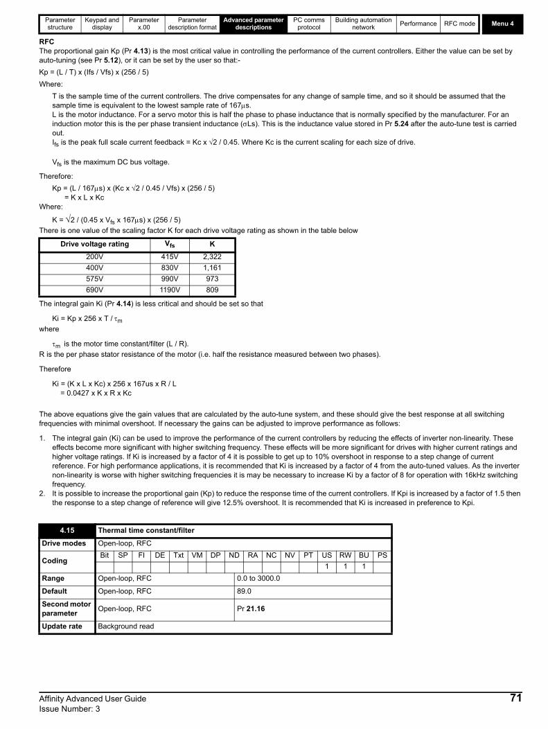
Parameter structure
Keypad and display
Parameter x.00
Parameter description format
Advanced parameter descriptions
PC comms protocol
Building automation network
Performance RFC mode Menu 4
RFCThe proportional gain Kp (Pr 4.13) is the most critical value in controlling the performance of the current controllers. Either the value can be set by auto-tuning (see Pr 5.12), or it can be set by the user so that:-
Kp = (L / T) x (Ifs / Vfs) x (256 / 5)
Where:
T is the sample time of the current controllers. The drive compensates for any change of sample time, and so it should be assumed that the sample time is equivalent to the lowest sample rate of 167s.L is the motor inductance. For a servo motor this is half the phase to phase inductance that is normally specified by the manufacturer. For an induction motor this is the per phase transient inductance (Ls). This is the inductance value stored in Pr 5.24 after the auto-tune test is carried out. Ifs is the peak full scale current feedback = Kc x 2 / 0.45. Where Kc is the current scaling for each size of drive.
Vfs is the maximum DC bus voltage.
Therefore:
Kp = (L / 167s) x (Kc x 2 / 0.45 / Vfs) x (256 / 5) = K x L x Kc
Where:
K = 2 / (0.45 x Vfs x 167s) x (256 / 5)
There is one value of the scaling factor K for each drive voltage rating as shown in the table below
The integral gain Ki (Pr 4.14) is less critical and should be set so that
Ki = Kp x 256 x T / m
where
m is the motor time constant/filter (L / R).
R is the per phase stator resistance of the motor (i.e. half the resistance measured between two phases).
Therefore
Ki = (K x L x Kc) x 256 x 167us x R / L = 0.0427 x K x R x Kc
The above equations give the gain values that are calculated by the auto-tune system, and these should give the best response at all switching frequencies with minimal overshoot. If necessary the gains can be adjusted to improve performance as follows:
1. The integral gain (Ki) can be used to improve the performance of the current controllers by reducing the effects of inverter non-linearity. These effects become more significant with higher switching frequency. These effects will be more significant for drives with higher current ratings and higher voltage ratings. If Ki is increased by a factor of 4 it is possible to get up to 10% overshoot in response to a step change of current reference. For high performance applications, it is recommended that Ki is increased by a factor of 4 from the auto-tuned values. As the inverter non-linearity is worse with higher switching frequencies it is may be necessary to increase Ki by a factor of 8 for operation with 16kHz switching frequency.
2. It is possible to increase the proportional gain (Kp) to reduce the response time of the current controllers. If Kpi is increased by a factor of 1.5 then the response to a step change of reference will give 12.5% overshoot. It is recommended that Ki is increased in preference to Kpi.
Drive voltage rating Vfs K
200V 415V 2,322
400V 830V 1,161
575V 990V 973
690V 1190V 809
4.15 Thermal time constant/filter
Drive modes Open-loop, RFC
CodingBit SP FI DE Txt VM DP ND RA NC NV PT US RW BU PS
1 1 1
Range Open-loop, RFC 0.0 to 3000.0
Default Open-loop, RFC 89.0
Second motor parameter
Open-loop, RFC Pr 21.16
Update rate Background read
Affinity Advanced User Guide 71Issue Number: 3

Menu 4Parameter structure
Keypad and display
Parameter x.00
Parameter description format
Advanced parameter descriptions
PC comms protocol
Building automation network
Performance RFC mode
The motor is modelled thermally in a way that is equivalent to the electrical circuit shown as follows.
The temperature of the motor as a percentage of maximum temperature, with a constant current magnitude of I, constant value of K and constant value of motor rated current (set by Pr 5.07 or Pr 21.07) after time t is given by
Temp = [I2 / (K x Motor rated current)2] (1 - e-t/) x 100%
This assumes that the maximum allowed motor temperature is produced by K x Motor rated current and that is the thermal time constant/filter of the point in the motor that reaches its maximum allowed temperature first. is defined by Pr 4.15. The estimated motor temperature is given by Pr 4.19 as a percentage of maximum temperature. If Pr 4.15 has a value between 0.0 and 1.0 the thermal time constant/filter is taken as 1.0.
If the rated current (defined by Pr 5.07 or Pr 21.07 depending on which motor is selected) is less or equal to the drive current scaling then Pr 4.25 can be used to select 2 alternative protection characteristics (see diagram below). If Pr 4.25 is 0 the characteristic is for a motor which can operate at rated current over the whole speed range. Induction motors with this type of characteristic normally have forced cooling. If Pr 4.25 is 1 the characteristic is intended for motors where the cooling effect of motor fan reduces with reduced motor speed below half of rated speed. The maximum value for K is 1.05, so that above the knee of the characteristics the motor can operate continuously up to 105% current.
The maximum value for K is 1.01, so that above the knee of the characteristics the motor can operate continuously up to 101% current.
4.16 Thermal protection mode
Drive modes Open-loop, RFC
CodingBit SP FI DE Txt VM DP ND RA NC NV PT US RW BU PS
1 1 1 1
Range Open-loop, RFC 0 to 1
Default Open-loop, RFC 0
Update rate Background read
I /(K*Motor Rated Current)2 2
TempC R
Motor totalcurrent (Pr 4.01)as a percentage
of motor ratedcurrent
Motor speed as a percentage of base speed
100%
Max. permissiblecontinuouscurrent
100%
I t protection operates in this region2
70%
50%15%
Open loop: Proportion of rated frequency Pr 5.06.
RFC: Proportion of rated speed Pr 5.08.
Rated current (Pr 5.07 or Pr 21.07) drive current rating.
72 Affinity Advanced User Guide Issue Number: 3

Parameter structure
Keypad and display
Parameter x.00
Parameter description format
Advanced parameter descriptions
PC comms protocol
Building automation network
Performance RFC mode Menu 4
When the estimated temperature reaches 100% the drive takes some action depending on the setting of Pr 4.16. If Pr 4.16 is 0, the drive trips when the threshold is reached. If Pr 4.16 is 1, the current limit is reduced to (K - 0.05) x 100% when the temperature is 100%. The current limit is set back to the user defined level when the temperature falls below 95%.
The time for some action to be taken by the drive from cold with constant motor current is given by:
Ttrip = -(Pr 4.15) x ln(1 - (K x Pr 5.07 / Pr 4.01)2)
Alternatively the thermal time constant/filter can be calculated from the trip time with a given current from:
Pr 4.15 = -Ttrip / ln(1 - (K / Overload)2)
For example, if the drive should trip after supplying 150% overload for 60 seconds with K = 1.05 then
Pr 4.15 = -60 / ln(1 - (1.05 / 1.50)2) = 89
The thermal model temperature accumulator is reset to zero at power-up and accumulates the temperature of the motor while the drive remains powered-up. Each time Pr 11.45 is changed to select a new motor, or the rated current defined by Pr 5.07 or Pr 21.07 (depending on the motor selected) is altered, the accumulator is reset to zero.
The drive reactive current is shown in this parameter for all modes.
The current limit applied at any time depends on whether the drive is motoring or regenerating and also on the level of the symmetrical current limit. Pr 4.18 gives the limit level that applies at any instant.
4.17 Reactive current
Drive modes Open-loop, RFC
CodingBit SP FI DE Txt VM DP ND RA NC NV PT US RW BU PS
1 1 2 1 1 1
Range Open-loop, RFC ±DRIVE_CURRENT_MAX A
Update rate 4ms write
4.18 Overriding current limit
Drive modes Open-loop, RFC
CodingBit SP FI DE Txt VM DP ND RA NC NV PT US RW BU PS
1 1 1 1 1 1
Range Open-loop, RFC 0 to TORQUE_PROD_CURRENT_MAX %
Update rate Background write
Motor totalcurrent (Pr 4.01)as a percentage
of motor ratedcurrent
Motor speed as a percentage of base speed
100%
Max. permissiblecontinuouscurrent
100%
I t protection operates in this region2
70%
50%15%
Pr = 0Pr = 1
4.254.25
Open loop: Proportion of rated frequency Pr 5.06.
RFC: Proportion of rated speed Pr 5.08.
Rated current (Pr 5.07 or Pr 21.07) drive current rating.
Affinity Advanced User Guide 73Issue Number: 3

Menu 4Parameter structure
Keypad and display
Parameter x.00
Parameter description format
Advanced parameter descriptions
PC comms protocol
Building automation network
Performance RFC mode
See Pr 4.16 on page 72.
Open-loop, RFCThis parameter displays the actual torque producing current (Pr 4.02) as a percentage of rated active current. Positive values indicate motoring and negative values indicate regenerating.
If this parameter is set to 1, the drive calculates a torque reference from the motor and load inertia (Pr 3.18), and the rate of change of speed reference. The torque reference is added to the speed controller output to provide inertia compensation. This can be used in speed or torque control applications to produce the torque required to accelerate or decelerate the load inertia.
The current demand filter time constant/filter is defined by this parameter if the speed gain select (Pr 3.16) is 1.
* These are the maximum default values. If the variable maximum of this parameter (TORQUE_PROD_CURRENT_MAX which is defined by MOTOR1_CURRENT_LIMIT_MAX or MOTOR2_CURRENT_LIMIT_MAX depending on which motor map is active) gives a lower value with the default value of Motor rated current (Pr 5.07 or Pr 21.07) default of this parameter is at the lower value.
The maximum for Pr 4.08 and Pr 4.20 is defined by this parameter
4.19 Overload accumulator
Drive modes Open-loop, RFC
CodingBit SP FI DE Txt VM DP ND RA NC NV PT US RW BU PS
1 1 1 1 1
Range Open-loop, RFC 0 to 100.0 %
Update rate Background write
4.20 Percentage load
Drive modes Open-loop, RFC
CodingBit SP FI DE Txt VM DP ND RA NC NV PT US RW BU PS
1 1 1 1 1 1
Range Open-loop, RFC ±USER_CURRENT_MAX %
Update rate Background write
4.22 Inertia compensation enable
Drive modes RFC
CodingBit SP FI DE Txt VM DP ND RA NC NV PT US RW BU PS
1 1 1
Default RFC 0
Update rate Background read
4.23 Current demand filter 2
Drive modes RFC
CodingBit SP FI DE Txt VM DP ND RA NC NV PT US RW BU PS
1 1 1 1
Range RFC 0.0 to 25.0 ms
Default RFC 0.0
Update rate Background read
4.24 User current maximum scaling
Drive modes Open-loop, RFC
CodingBit SP FI DE Txt VM DP ND RA NC NV PT US RW BU PS
1 1 1 1 1 1
Range Open-loop, RFC 0.0 to TORQUE_PROD_CURRENT_MAX %
DefaultOpen-loopRFC
165.0*175.0*
Update rate Background read
74 Affinity Advanced User Guide Issue Number: 3

Parameter structure
Keypad and display
Parameter x.00
Parameter description format
Advanced parameter descriptions
PC comms protocol
Building automation network
Performance RFC mode Menu 4
See Pr 4.16 on page 72.
Pr 4.25 is always set to 1
Pr 4.26 shows the torque producing current (Pr 4.02) as a percentage of the active torque producing current, but with an additional adjustment above base speed so that this parameter shows percentage torque. Below base speed Pr 4.26 is equal to Pr 4.20. Above base speed the percentage torque producing current (shown in Pr 4.20) is adjusted as follows:
Pr 4.26 = Pr 4.20 x rated frequency / frequency
4.25 Low speed thermal protection mode
Drive modes Open-loop, RFC
CodingBit SP FI DE Txt VM DP ND RA NC NV PT US RW BU PS
1 1 1
Default Open-loop, RFC 1
Update rate Background read
4.26 Percentage torque
Drive modes Open-loop
CodingBit SP FI DE Txt VM DP ND RA NC NV PT US RW BU PS
1 1 1 1 1 1
Default Open-loop ±USER_CURRENT_MAX %
Update rate Background read
4.27 Low load detection level
Drive modes Open-loop, RFC
CodingBit SP FI DE Txt VM DP ND RA NC NV PT US RW BU PS
1 1 1 1
Range Open-loop, RFC 0.0 to 100.0%
Default Open-loop, RFC 0.0
Update rate Background read
4.28 Low load detection speed / frequency threshold
Drive modes Open-loop, RFC
CodingBit SP FI DE Txt VM DP ND RA NC NV PT US RW BU PS
1 1 1 1 1 1
Range Open-loop, RFC 0.0 to SPEED_FREQ_MAX Hz/rpm
Default Open-loop, RFC 0.0
Update rate Background read
4.29 Trip on abnormal load detection
Drive modes Open-loop, RFC
CodingBit SP FI DE Txt VM DP ND RA NC NV PT US RW BU PS
1 1
Default Open-loop, RFC 0
Update rate Background read
NOTE
Affinity Advanced User Guide 75Issue Number: 3

Menu 4Parameter structure
Keypad and display
Parameter x.00
Parameter description format
Advanced parameter descriptions
PC comms protocol
Building automation network
Performance RFC mode
The low load detection function is provided so that loss of load can be detected and the necessary action taken. The low load detection function is disabled if Pr 4.27 is set to zero.
In order that the detector can be used with typical fan and pump load characteristics (i.e. where the load is relatively light at low motor speed), the detector is only active when the output frequency or speed is above the level defined by Pr 4.28. The motor must also be at the required speed (i.e. not accelerating or decelerating), so Pr 10.06 (At Speed) must be 1 for the low load detector to be active.
Once the detector is active, the low load condition is detected when Pr 4.20 (percentage load) falls below Pr 4.27, so the condition for detecting low load is given by:
(Pr 10.06 = 1) AND (|Output frequency or speed| > Pr 4.28) AND (Pr 4.20 < Pr 4.27)
If Pr 4.29 is zero when low load is detected, then a "Load" warning message is displayed on the keypad. If Pr 4.29 is 1 then a drive trip is initiated.The diagram below shows a typical fan load and operating areas (shaded), where the low load detection is active.
0
20
40
60
80
100
120
-100 -50 0 50 100
Motor speed (% Rated)
Ty
pic
al
load
(%R
ate
d)
04.28-04.28
04.27
76 Affinity Advanced User Guide Issue Number: 3

Parameter structure
Keypad and display
Parameter x.00
Parameter description format
Advanced parameter descriptions
PC comms protocol
Building automation network
Performance RFC mode Menu 5
5.7 Menu 5: Motor controlOpen loopFigure 5-7 Menu 5 Open-loop logic diagram
2.01
Post rampreference
+
+
5.10
5.11
Motor ratedpower factor
Motor numberof poles
5.02
Motorvoltage
5.03Total motorpower (kW) Ö 3 x V x I
Volt
L1 L2 L3
5.05
DC Busvoltage
5.09Motor ratedvoltage
5.07
5.08
Motor ratedcurrent
Motor ratedfull load RPM
5.06Motor ratedfrequency
5.23 Voltage offset
5.17Statorresistance
5.15 Voltage boost
5.13Dynamic V/fselect
Transientinductance
4.024.20
4.17
4.01
Motorcurrentmagnitude
Motor magnetisingcurrent
Motor activecurrent
Percentageactive current
Motormap
5.12
Autotune
5.24
5.14Voltagemode
5.01Motorfrequency
5.04Estimatedmotor speed
10
Slipcompensation
0.XX
0.XX
Key
Read-write (RW)parameter
Read-only (RO)parameter
Inputterminals
Outputterminals
XX
XX
Slipcompensationenable
5.27
The parameters are all shown at their default settings
5.18
5.19
PWMswitchingfrequency
High stabilityspace vectormodulation
Hertz
5.20
5.35
Quasi squarewave enable
Disable autoswitchingfrequencychange
5.31Voltagecontrollergain
Affinity Advanced User Guide 77Issue Number: 3
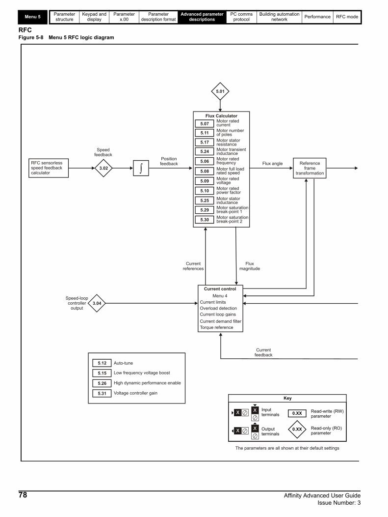
Menu 5Parameter structure
Keypad and display
Parameter x.00
Parameter description format
Advanced parameter descriptions
PC comms protocol
Building automation network
Performance RFC mode
RFCFigure 5-8 Menu 5 RFC logic diagram
3.04
5.06 Motor rated frequency
5.08 Motor full loadrated speed
5.09 Motor rated voltage
5.10 Motor rated power factor
5.25 Motor stator inductance
5.29 Motor saturation break-point 1
5.30 Motor saturation break-point 2
5.07Motor rated current
5.11 Motor number of poles
5.17 Motor stator resistance
5.24 Motor transient inductance
Flux Calculator
Current limits
Current control
Overload detectionCurrent loop gains
Torque referenceCurrent demand filter
Menu 4
Referenceframe
transformation3.02
Speedfeedback
Speed-loopcontroller
output
Positionfeedback
Fluxmagnitude
Currentreferences
Currentfeedback
5.01
Flux angle
5.12
5.15
5.26
5.31
Auto-tune
Low frequency voltage boost
High dynamic performance enable
Voltage controller gain
0.XX
0.XX
Key
Read-write (RW) parameter
Read-only (RO) parameter
Inputterminals
Outputterminals
The parameters are all shown at their default settings
RFC sensorlessspeed feedbackcalculator
78 Affinity Advanced User Guide Issue Number: 3

Parameter structure
Keypad and display
Parameter x.00
Parameter description format
Advanced parameter descriptions
PC comms protocol
Building automation network
Performance RFC mode Menu 5
4.02
4.17
4.01
5.09 Motor rated voltage
5.21 Field gainreduction
Flux Controller
5.18Maximum switchingfrequency
Modulator
5.03Power calculation (V x 1)
5.02Outputvoltage
Outputpower
5.05
Voltage reference
U
V
W
DC busvoltage
Motorcurrentmagnitude
Motor magnetising current
Motor activecurrent
5.35Disable auto switching frequencychange
Affinity Advanced User Guide 79Issue Number: 3

Menu 5Parameter structure
Keypad and display
Parameter x.00
Parameter description format
Advanced parameter descriptions
PC comms protocol
Building automation network
Performance RFC mode
Open-loopAlthough the range for scaling purposes is ±SPEED_FREQ_MAX, the actual parameter value can be increased beyond this range by slip compensation. This parameter gives the output frequency of the drive, i.e. the sum of the post ramp reference and the slip compensation.
RFCIn these modes the output frequency is not controlled directly, and so the output frequency displayed in this parameter is calculated by measuring the frequency of the controller reference frame.
This is the modulus of the rms line to line voltage at the inverter output at the drive output frequency.
Open-loop and RFC modeThe output power is the dot product of the output voltage and current vectors. Positive power indicates power flowing from the drive to the motor (motoring), and negative power indicates power flowing from the motor to the drive (regen).
The motor rpm is calculated from the post ramp reference (Pr 2.01) for normal operation, or the slave frequency demand (Pr 3.01) if frequency slaving is being used. The speed of rotation is calculated as follows:
rpm = 60 x frequency / no. of pole pairs
If frequency slaving is being used there will be an error due to the slip frequency. However, in normal operation the result will be reasonably accurate provided that the slip compensation has been set up correctly in the rated full load rpm parameter (Pr 5.08).
Voltage across the internal DC bus of the drive.
5.01 Output frequency
Drive modes Open-loop, RFC
Coding
Bit SP FI DE Txt VM DP ND RA NC NV PT US RW BU PS
1 1 1 1 1 1
RFC: VM = 0
RangeOpen-loopRFC
±SPEED_FREQ_MAX Hz ±1250.0 Hz
Update rate 250s write
5.02 Output voltage
Drive modes Open-loop, RFC
CodingBit SP FI DE Txt VM DP ND RA NC NV PT US RW BU PS
1 1 1 1 1
Range Open-loop, RFC 0 to AC_VOLTAGE_MAX V
Update rate Background write
5.03 Output power
Drive modes Open-loop, RFC
CodingBit SP FI DE Txt VM DP ND RA NC NV PT US RW BU PS
1 1 2 1 1 1
Range Open-loop, RFC ±POWER_MAX kW
Update rate Background write
5.04 Motor rpm
Drive modes Open-loop
CodingBit SP FI DE Txt VM DP ND RA NC NV PT US RW BU PS
1 1 1 1
Range Open-loop ±180,000 rpm
Update rate Background write
5.05 DC bus voltage
Drive modes Open-loop, RFC
CodingBit SP FI DE Txt VM DP ND RA NC NV PT US RW BU PS
1 1 1 1 1 1
Range Open-loop, RFC 0 to +dc _VOLTAGE_MAX V
Update rate Background write
80 Affinity Advanced User Guide Issue Number: 3

Parameter structure
Keypad and display
Parameter x.00
Parameter description format
Advanced parameter descriptions
PC comms protocol
Building automation network
Performance RFC mode Menu 5
Open loopThe motor rated frequency and the motor rated voltage (Pr 5.09) are used to define the voltage to frequency characteristic applied to the motor (see Pr 5.09 on page 82). The motor rated frequency is also used in conjunction with the motor full load rpm to calculate the rated slip for slip compensation (see Pr 5.08 on page 82).
RFCThe motor rated frequency is used in conjunction with the motor full load rpm to calculate the rated slip of the machine for the vector control algorithm
(see Pr 5.08 on page 82). The test frequency used for the rotating auto-tune test is 2/3 x Pr 5.06.
The rated current should be set at the motor nameplate value for rated current. The value of this parameter is used as follows:
5.06 Rated frequency
Drive modes Open-loop, RFC
CodingBit SP FI DE Txt VM DP ND RA NC NV PT US RW BU PS
1 1 1 1
RangeOpen-loopRFC
0 to 3000.0 Hz0 to 1250.0 Hz
Default Open-loop, RFC EUR: 50.0 Hz, USA: 60.0 Hz
Second motor parameter
Open-loop, RFC Pr 21.06
Update rate Background read
5.07 Motor rated current
Drive modes Open-loop, RFC
CodingBit SP FI DE Txt VM DP ND RA NC NV PT US RW BU PS
1 2 1 1 1 1
Range Open-loop, RFC 0 to RATED_CURRENT_MAX A
Default Open-loop, RFCDrive current scaling (i.e. the value of Pr 11.32)
Second motor parameter
Open-loop, RFC Pr 21.07
Update rate Background read
Open-loop
Current limitsMotor thermal protectionVector mode voltage controlSlip compensationDynamic V to F control
RFCCurrent limitsMotor thermal protectionVector control algorithm
Affinity Advanced User Guide 81Issue Number: 3

Menu 5Parameter structure
Keypad and display
Parameter x.00
Parameter description format
Advanced parameter descriptions
PC comms protocol
Building automation network
Performance RFC mode
Open loopThe rated load rpm is used with the motor rated frequency and number of poles to calculate the rated slip of induction machines in Hz.
rated slip (Hz) = rated motor frequency - (no. of pole pairs x motor full load rpm / 60) = Pr 5.06 - ((Pr 5.11 / 2) x Pr 5.08 / 60)
If Pr 5.08 is set to 0 or to synchronous speed slip, compensation is disabled. If slip compensation is required, this parameter should be set to the nameplate value, which should give the correct rpm for a hot machine. Sometimes it will be necessary to adjust this value when the drive is commissioned, because the nameplate value may be inaccurate. Slip compensation will operate correctly both below base speed and within the field weakening region. Slip compensation is normally used to correct for the motor speed to prevent speed droop as load is applied. The rated load rpm can be set higher than synchronous speed to deliberately introduce speed droop. This can be useful to aid load sharing with mechanically coupled motors.
RFCRated load rpm is used with motor rated frequency to determine the full load slip of the motor which is used by the vector control algorithm. Incorrect setting of this parameter has the following effects:
• Reduced efficiency of motor operation
• Reduction of maximum torque available from the motor
• Reduced transient performance
• Inaccurate control of absolute torque in torque control modes
The nameplate value is normally the value for a hot machine, however, some adjustment may be required when the drive is commissioned if the nameplate value is inaccurate.
Open loopThe rated voltage is used in conjunction with the motor rated frequency (Pr 5.06) to define the voltage to frequency characteristic applied to the motor. The following operating methods selected by Pr 5.14 are used to define the drive frequency to voltage characteristic.
Open-loop vector mode: Ur_S, Ur or Ur_IA linear characteristic is used from 0Hz to rated frequency, and then a constant voltage above rated frequency. When the drive operates between rated frequency/50 and rated frequency/4, full vector based stator resistance (Rs) compensation is applied.
However there is a delay of 0.5s when the drive is enabled during which only partial vector based compensation is applied to allow the machine flux to build up. When the drive operates between rated frequency/4 and rated frequency/2 the Rs compensation is gradually reduced to zero as the frequency increases. For the vector modes to operate correctly the stator resistance (Pr 5.17), motor rated power factor (Pr 5.10) and voltage offset (Pr 5.23) are all required to be set up accurately.
5.08 Rated load rpm / Rated speed
Drive modes Open-loop, RFC
Coding
Bit SP FI DE Txt VM DP ND RA NC NV PT US RW BU PS
1 1 1
RFC DP=2
RangeOpen-loop, RFC
0 to 180,000 rpm0.00 to 40,000.00 rpm
DefaultOpen-loop,RFC
EUR: 1,500, USA: 1,800EUR: 1450.00, USA: 1,770.00
Second motor parameter
Open-loop, RFC Pr 21.08
Update rate Background read
5.09 Rated voltage
Drive modes Open-loop, RFC
CodingBit SP FI DE Txt VM DP ND RA NC NV PT US RW BU PS
1 1 1 1 1
Range Open-loop, RFC 0 to AC_VOLTAGE_SET_MAX V
Default Open-loop, RFC
200V rating drive: 230V400V rating drive: EUR: 400V, USA: 480V600V rating drive: 575V 690V rating drive: 690V
Second motor parameter
Open-loop, RFC Pr 21.09
Update rate Level 4 read
82 Affinity Advanced User Guide Issue Number: 3

Parameter structure
Keypad and display
Parameter x.00
Parameter description format
Advanced parameter descriptions
PC comms protocol
Building automation network
Performance RFC mode Menu 5
Fixed boost mode: FdA linear characteristic is used from 0Hz to rated frequency, and then constant voltage above rated frequency. Low frequency voltage boost as defined by Pr 5.15 is applied as shown below.
Square law mode: SrEA square law characteristic is used from 0Hz to rated frequency, and then constant voltage above rated frequency. Low frequency voltage boost raises the start point of the square law characteristic as shown below.
RFCThe rated voltage is used by the field controller to limit the voltage applied to the motor. Normally this is set to the nameplate value.
In order that current control can be maintained, it is necessary for the drive to leave some 'headroom' between the machine terminal voltage and the maximum available drive output voltage. The drive allows over-modulation of the PWM inverter, which can produce a fundamental voltage that is higher than the drive input voltage, but would cause substantial odd harmonic distortion if used in steady state operation.
Accordingly the drive uses a headroom limit which allows the inverter to give a steady state output voltage equivalent to the input voltage minus voltage drops inside the drive. This gives enough headroom for the current controllers to operate satisfactorily. However, for good transient performance at high speed the rated voltage should be set below 95% of the minimum supply voltage to the drive.
The rated voltage is also used in conjunction with the motor rated frequency (Pr 5.06) during the rotating auto-tune test (see Pr 5.12 on page 84), and in the calculations required for automatic optimization of the rated motor slip. It is important therefore, that the correct rated voltage for the motor is used.
In some applications it may be necessary to restrict the voltage applied to the motor to a level lower than the nameplate rated voltage of the motor. In this case the rated frequency (Pr 5.06) must be adjusted to maintain the ratio of rated voltage and frequency given on the motor nameplate. The rated frequency will then be different to the nameplate value, and so the rated speed must be changed from the nameplate value to give the correct rated slip.
Voltage boost Pr 5.15
Outputvoltage
Pr 5.09
Pr / 25.09
Pr / 25.06 Pr 5.06 Outputfrequency
Output voltage characteristic
Pr 5.09
Pr 5.15
Pr 5.06
Pr + [(freq/Pr ) x (Pr - Pr )]5.15 5.06 5.09 5.152
Affinity Advanced User Guide 83Issue Number: 3

Menu 5Parameter structure
Keypad and display
Parameter x.00
Parameter description format
Advanced parameter descriptions
PC comms protocol
Building automation network
Performance RFC mode
Open loopThe power factor is the true power factor of the motor i.e. the angle between the motor voltage and current. The power factor is used in conjunction with the motor rated current (Pr 5.07), to calculate the rated active current and magnetizing current of the motor. The rated active current is used extensively to control the drive, and the magnetizing current is used in vector mode Rs compensation. It is important that this parameter is set up correctly.
RFCThe power factor is the true power factor of the motor, i.e. the angle between the motor voltage and current. If the stator inductance is set to zero (Pr 5.25), then the power factor is used in conjunction with the motor rated current and other motor parameters, to calculate the rated active and magnetizing currents which are used in the vector control algorithm. If the stator inductance has a non-zero value, this parameter is not used by the drive, but is continuously written with a calculated value of power factor.
Open-loopThis parameter is used in the calculation of motor speed and in applying the correct slip compensation. When auto is selected the number of motor poles is automatically calculated from the rated frequency (Pr 5.06) and the rated load rpm (Pr 5.08). The number of poles = 120 * rated frequency / rpm rounded to the nearest even number.
RFCThis parameter must be set correctly for the vector control algorithms to operate correctly. When auto is selected the number of motor poles is automatically calculated from the rated frequency (Pr 5.06) and the rated load rpm (Pr 5.08). The number of poles = 120 * rated frequency / rpm rounded to the nearest even number.
If this parameter is set to a non-zero value, the drive is enabled and a run command is applied in either direction. The drive performs an auto-tune test for the drive modes listed below. All tests that rotate the motor are carried out in the forward direction if Pr 1.12 = 0 or the reverse direction if Pr 1.12 = 1.
For example, if the test is initiated by applying run reverse (Pr 6.32 = 1), the test is performed in the reverse direction. It should be noted however that the motor may jump in either direction by up to half an electrical revolution at the start of the phasing test, and then move in the required direction for the remainder of the test. The test will not start unless the drive is disabled before the test is initiated by applying the enable or run, i.e. it will not start if the drive is in the stop state.
In RFC mode it is not possible to go into the stop state if Pr 5.12 has a non-zero value. (If Pr 5.12 is set to 4 in RFC mode then no test is carried out, but the current loop gains are re-calculated. For these actions the drive does not need to be enabled.)
5.10 Rated power factor
Drive modes Open-loop, RFC
CodingBit SP FI DE Txt VM DP ND RA NC NV PT US RW BU PS
3 1 1 1 1
Range Open-loop, RFC 0.000 to 1.000
Default Open-loop, RFC 0.850
Second motor parameter
Open-loop, RFC Pr 21.10
Update rate Background read
5.11 Number of motor poles
Drive modes Open-loop, RFC
CodingBit SP FI DE Txt VM DP ND RA NC NV PT US RW BU PS
1 1 1 1
Range Open-loop, RFC 0 to 60 (Auto to 120 POLE)
Default Open-loop, RFC 0 (Auto)
Second motor parameter
Open-loop, RFC Pr 21.11
Update rate Background read
5.12 Autotune
Drive modes Open-loop, RFC
CodingBit SP FI DE Txt VM DP ND RA NC NV PT US RW BU PS
1 1 1
RangeOpen-loop, RFC
0 to 20 to 4
Default Open-loop, RFC 0
Update rate Background read
84 Affinity Advanced User Guide Issue Number: 3

Parameter structure
Keypad and display
Parameter x.00
Parameter description format
Advanced parameter descriptions
PC comms protocol
Building automation network
Performance RFC mode Menu 5
It is important that the motor is at standstill before the auto-tune test is performed if the correct results are to be obtained. The parameters modified by the auto-tune tests are defined below when the second motor parameters are not selected (i.e. Pr 11.45 = 0).
If the second motor is selected for the duration of the tests (i.e. Pr 11.45 = 1), the second motor parameters in menu 21 are modified instead, and not the parameters described below. When the test has successfully completed, the drive is disabled and will enter the inhibit state.
The motor can only be restarted if the enable is removed either from the enable input if Pr 6.15 is set to zero, or by using control word (Pr 6.42). As the tests progresses, the calculated parameters are saved to EEPROM as indicated. If for any reason the test fails and the drive trips, no further parameters are calculated or stored in EEPROM. (If the drive is in Auto or Boot cloning modes (Pr 11.42 = 3 or 4) the parameters are also saved to the SMARTCARD where it is indicated that parameters are saved to EEPROM.)
Open-loopIn this mode the following parameters are used in the vector control algorithm.
All the above parameters can be set by the user. The auto-tune test can be used to overwrite the user or default settings as described below. Accurate values of stator resistance and voltage offset are required even for moderate performance in vector mode (an accurate value of power factor is less critical).
1: Stationary test• A stationary test is performed to measure the stator resistance (Pr 5.17) and voltage offset (Pr 5.23). The power factor (Pr 5.10) is not affected.
• Pr 5.17 and Pr 5.23 are saved to EEPROM.
2: Rotating test• The stationary test is performed and the parameters saved to EEPROM as described above.
• A stationary test is performed to measure the transient inductance (Pr 5.24). The transient inductance is not used directly by the drive, but is an intermediate value in determining the power factor after the rotating test.
• Pr 5.24 is saved to EEPROM.
• A rotating test is performed in which the motor is accelerated with the currently selected ramps to 2/3 of rated speed and held at this speed for
several seconds. Once the test is complete the power factor (Pr 5.10) is updated and the motor coasts to a stop. The motor should be unloaded for this test to produce correct results.
• Pr 5.10 is saved to EEPROM.
RFCIn this mode the following parameters are used in the vector control algorithm.
All the above parameters can be set by the user. The motor set-up is constantly recalculated in the background task, therefore modifying these parameters even after auto-tune will affect the performance of the drive. The auto-tune test can be used to overwrite the user or default settings as described below. It should be noted that the current loop gains (Pr 4.13 and 4.14) are not updated as part of any test if either the stator resistance or the transient inductance for the active motor map are zero.
Parameter Basic algorithm Slip compensation
Rated frequency Pr 5.06 Rated current Pr 5.07 Rated load rpm Pr 5.08 Rated voltage Pr 5.09 Power factor Pr 5.10 No. of poles Pr 5.11 Stator resistance (Rs) Pr 5.17
Transient inductance (Ls) Pr 5.24
Parameter If Ls is zero If Ls is not zero Required for good performance
Required for excellent performance
Rated frequency Pr 5.06
Rated current Pr 5.07
Rated load rpm Pr 5.08
Rated Voltage Pr 5.09
Power factor Pr 5.10
No. of poles Pr 5.11
Stator resistance (Rs) Pr 5.17
Transient inductance (Ls) Pr 5.24
Stator inductance (Ls) Pr 5.25
Motor saturation breakpoint 1 Pr 5.29
Motor saturation breakpoint 2 Pr 5.30
Affinity Advanced User Guide 85Issue Number: 3
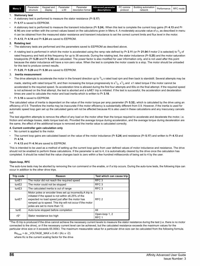
Menu 5Parameter structure
Keypad and display
Parameter x.00
Parameter description format
Advanced parameter descriptions
PC comms protocol
Building automation network
Performance RFC mode
1. Stationary test• A stationary test is performed to measure the stator resistance (Pr 5.17)
• Pr 5.17 is saved to EEPROM.
• A stationary test is performed to measure the transient inductance (Pr 5.24). When this test is complete the current loop gains (Pr 4.13 and Pr 4.14) are over-written with the correct values based on the calculations given in Menu 4. A moderately accurate value of 1 as described in menu
4 can be obtained from the measured stator resistance and transient inductance to set the correct current limits and flux level in the motor.
• Pr 4.13, Pr 4.14 and Pr 5.24 are saved to EEPROM.
2. Rotating test• The stationary tests are performed and the parameters saved to EEPROM as described above.
• A rotating test is performed in which the motor is accelerated using the ramp rate defined by Pr 2.11 (or Pr 21.04 if motor 2 is selected) to 2/3 of
rated frequency and held at this frequency for up to 36 seconds. During the rotating test, the stator inductance (Pr 5.25) and the motor saturation breakpoints (Pr 5.29 and Pr 5.30) are calculated. The power factor is also modified for user information only, and is not used after this point because the stator inductance will have a non-zero value. When the test is complete the motor coasts to a stop. The motor should be unloaded for this test to produce correct results.
• Pr 5.25, Pr 5.29 and Pr 5.30 are saved to EEPROM.
3. Inertia measurement
• The drive attempts to accelerate the motor in the forward direction up to 3/4 x rated load rpm and then back to standstill. Several attempts may be
made, starting with rated torque/16, and then increasing the torque progressively to x1/4, x1/2 and x1 rated torque if the motor cannot be
accelerated to the required speed. 5s acceleration time is allowed during the first four attempts and 60s on the final attempt. If the required speed is not achieved on the final attempt, the test is aborted and a tuNE1 trip is initiated. If the test is successful, the acceleration and deceleration times are used to calculate the motor and load inertia which is written to Pr 3.18.
• Pr 3.18 is saved to EEPROM.
The calculated value of inertia is dependant on the value of the motor torque per amp parameter (Pr 5.32), which is calculated by the drive using an efficiency of 0.9. Therefore the inertia may be inaccurate if the motor efficiency is substantially different from 0.9. However, if the inertia is used for automatic speed loop gain set up the calculated gains will not be affected because Kt is also used in these calculations and any inaccuracy cancels out.
The test algorithm attempts to remove the effect of any load on the motor other than the torque required to accelerate and decelerate the motor, i.e. friction and windage losses, static torque load etc. Provided the average torque during acceleration, and the average torque during deceleration are the same, the effect of the additional torque is removed and the inertia value is calculated correctly.
4. Current controller gain calculation only• No current is applied to the motor.
• The current loop gains are calculated based on the value of the motor inductance (Pr 5.24) and resistance (Pr 5.17) and written to Pr 4.13 and Pr 4.14.
• Pr 4.13 and Pr 4.14 are saved to EEPROM.
This is intended to be used as a method of setting up the current loop gains from user defined values of motor inductance and resistance. The drive should not be enabled to perform these calculations. If the parameter is set to 4, it is automatically cleared by the drive once the calculation has completed. It should be noted that the value changes back to zero within a few hundred milliseconds of being set to 4 by the user.
Open-loop, RFC
The auto-tune tests may be aborted by removing the run command or the enable, or if a trip occurs. During the auto-tune tests, the following trips can occur in addition to the other drive trips.
*The rS trip is produced if the drive cannot achieve the necessary current levels to measure the stator resistance during the test (i.e. there is no motor connected to the drive), or if the necessary current level can be achieved, but the calculated resistance exceeds the maximum values for the particular drive size or it exceeds 65.000. The maximum measurable value for a particular drive size can be calculated from the following formula.
Rsmax = dc _VOLTAGE_MAX x 0.45 / (Kc x 2)
where Kc is the current scaling factor for the drive
Trip code Reason Test which can cause trip
tunE1 The motor did not reach the required speed RFC 3
tunE2 The motor could not be stopped RFC 3
tunE3 The calculated inertia is out of range RFC 3
tunE7
Motor poles or encoder lines set up incorrectly.A trip is initiated if the speed is not within ±6.25% of the expected no load speed just after the motor has ramped up to speed. This trip will not occur if the motor poles are set to more than 12.
RFC 2
tunE Auto-tune stopped before completion All
rS* Stator resistance too highOpen-loop 1, 2RFC 1
86 Affinity Advanced User Guide Issue Number: 3

Parameter structure
Keypad and display
Parameter x.00
Parameter description format
Advanced parameter descriptions
PC comms protocol
Building automation network
Performance RFC mode Menu 5
Open-loopSetting this bit enables dynamic V to f mode which is intended for applications where power loss should be kept to a minimum under low load conditions. The rated frequency used to derive the voltage to frequency characteristic of the drive is varied with load:
if |active current| < 0.7 x rated active currentmotor rated frequency = Pr 5.06 x (2 - (active current / (0.7 x rated active current)))
else if |active current| 0.7 x rated active currentmotor rated frequency = Pr 5.06
Although the rated frequency varies, the value shown as Pr 5.06 does not vary from that set by the user.
0: Ur_S, Stator resistance and voltage offset measured at each startThe stator resistance (Pr 5.17) and the voltage offset (Pr 5.23) are measured, and the parameters over-written each time the drive is started. This test can only be done with a stationary machine where the flux has decayed to zero. Therefore this mode should only be used if the machine is guaranteed to be stationary each time the drive is enabled. To prevent the test from being done before the flux has decayed, there is a period of 1 second after the drive has been in the ready state during which the test is not done if the drive is re-started. In this case, previously measured values are used. The new values of stator resistance and voltage offset are not automatically saved to EEPROM or the SMARTCARD.
1: Ur, No measurementsThe stator resistance and voltage offset are not measured. The user can enter the motor and cabling resistance into the stator resistance parameter. However this will not include resistance effects within the drive inverter. Therefore if this mode is to be used, it is best to use the auto-tuning stationary test initially to measure the stator resistance.
2: Fd, Fixed boost mode.Neither the stator resistance nor the voltage offset are used, instead a fixed characteristic with boost applied as defined by Pr 5.15 is used.
3: Ur_Auto, Stator resistance and voltage offset measured at first drive enableThe stator resistance and voltage offset are measured once, the first time the drive is enabled. After the test has been completed successfully the mode is changed to Ur mode. The stator resistance and voltage offset are written to the parameters for the currently selected motor map and these parameters along with this parameter are saved in the EEPROM (and the SMARTCARD if Pr 11.42 = 3 or 4).
4: Ur_I, Stator resistance and voltage offset measured at each power-upThe stator resistance and voltage offset are measured when the drive is first enabled, and at each subsequent power-up. The new values of stator resistance and voltage offset are not automatically saved to EEPROM or the SMARTCARD.
5: SrE, Square law characteristicNeither the stator resistance nor the voltage offset are used, instead a fixed square law characteristic with boost applied as defined by Pr 5.15 is used.
5.13 Dynamic V to F / flux optimise select
Drive modes Open-loop, RFC
CodingBit SP FI DE Txt VM DP ND RA NC NV PT US RW BU PS
1 1 1
Default Open-loop 0
Update rate Background read
5.14 Voltage mode select
Drive modes Open-loop
CodingBit SP FI DE Txt VM DP ND RA NC NV PT US RW BU PS
1 1 1 1
Range Open-loop 0 to 5
Default Open-loop 2
Update rate Background read
Affinity Advanced User Guide 87Issue Number: 3

Menu 5Parameter structure
Keypad and display
Parameter x.00
Parameter description format
Advanced parameter descriptions
PC comms protocol
Building automation network
Performance RFC mode
Voltage boost is used in fixed boost mode and square law mode for Open-loop mode, and also during the rotating auto-tune test in RFC mode. In open-loop mode, the default is dependant on the frame size as given in the table below.
Pr 5.17 shows the stator resistance of the motor. The units vary with the drive size to ensure that the full range of likely resistances can be represented with suitable resolution. The table below shows the units. Therefore 1.000 in the parameter represents the resistance shown in the units column.
5.15 Low frequency voltage boost
Drive modes Open-loop, RFC
CodingBit SP FI DE Txt VM DP ND RA NC NV PT US RW BU PS
1 1 1 1
Range Open-loop, RFC 0.0 to 25.0 % of motor rated voltage
Default Open-loop, RFC See below
Update rate Background read
Drive sizes Default
BA1xxx, BA2xxx, BA3xxx 3.0%
BA4xxx, BA5xxx 2.0%
BA6xxx, BAMxxxx 1.0%
5.17 Stator resistance
Drive modes Open-loop, RFC
CodingBit SP FI DE Txt VM DP ND RA NC NV PT US RW BU PS
3 1 1 1 1
Range Open-loop, RFC 0.0 to 65.000
Default Open-loop, RFC 0.00
Second motor parameter
Open-loop, RFC Pr 21.12
Update rate Background read
Drive size Units
BA1xxx to BA5xxx 1 Ohm
BA6xxx, BAMxxxx 0.01 Ohms
88 Affinity Advanced User Guide Issue Number: 3

Parameter structure
Keypad and display
Parameter x.00
Parameter description format
Advanced parameter descriptions
PC comms protocol
Building automation network
Performance RFC mode Menu 5
*The maximum switching frequency available is limited for some drive sizes as shown inTable 5-6 below.
Table 5-6 maximum switching frequency
This parameter defines the required switching frequency. The drive may automatically reduce the actual switching frequency (without changing this parameter) if the power stage becomes too hot. The switching frequency can reduce from 12kHz to 6kHz to 3kHz, or 16kHz to 8kHz to 4kHz. An estimate of the IGBT junction temperature is made, based on the heatsink temperature and an instantaneous temperature drop using the drive output current and switching frequency.
The estimated IGBT junction temperature is displayed in Pr 7.34. If the temperature exceeds 135°C, the switching frequency is reduced (if this is possible i.e >4kHz) and this mode is enabled (see Pr 5.35 on page 94).
Reducing the switching frequency reduces the drive losses and the junction temperature displayed in Pr 7.34 also reduces. If the load condition persists the junction temperature may continue to rise. If the temperature exceeds 145°C and the switching frequency cannot be reduced, the drive will initiate an O.ht1 trip. Every 20ms the drive will attempt to restore the switching frequency if the higher switching frequency will not take the IGBT temperature above 135°C.
The following table gives the sampling rate for different sections of the control system for different switching frequencies.
5.18 Maximum switching frequency
Drive modes Open-loop, RFC
CodingBit SP FI DE Txt VM DP ND RA NC NV PT US RW BU PS
1 1 1 1 1
Range Open-loop, RFC 0 to 5 (3, 4, 6, 8, 12, 16 kHz)*
Default Open-loop, RFC 0 (3 kHz)
Update rate Background read
200V kHz 400V kHz 575V kHz 690V kHz
BA1201 16 BA1401 16 BA3501 8 BA4601 8
BA1202 16 BA1402 16 BA3502 8 BA4602 8
BA1203 16 BA1403 16 BA3503 8 BA4603 8
BA1204 16 BA1404 16 BA3504 8 BA4604 8
BA2201 16 BA1405 16 BA3505 8 BA4605 8
BA2202 16 BA1406 16 BA3506 8 BA4606 8
BA2203 16 BA2401 16 BA3507 8 BA5601 8
BA3201 12 BA2402 16 BA5602 8
BA3202 12 BA2403 16 BA6601 6
BA4201 8 BA3401 16 BA6602 6
BA4202 8 BA3402 16 BAMA16X1 6
BA4203 8 BA3403 12 BAMA16X2 6
BA5201 8 BA4401 8 BAMD16X1 6
BA5202 8 BA4402 8 BAMD16X2 6
BAMD12X1 6 BA4403 8 BAMD16X3 6
BAMD12X2 6 BA5401 8 BAMD16X4 6
BAMD12X3 6 BA5402 8
BAMD12X4 6 BA6401 6
BA6402 6
BAMA14X1 6
BAMA14X2 6
BAMD14X1 6
BAMD14X2 6
BAMD14X3 6
BAMD14X4 6
3, 6, 12kHz 4, 8, 16kHz Open-loop RFC
Level 13 = 167s6 = 83s
12 = 83s125s Peak limit Current controllers
Level 2 250s 250sCurrent limit and
rampsSpeed controller
and ramps
Level 3 1ms 1ms Voltage controller
Level 4 4ms 4ms Time critical user interface
Background N/A N/A Non-time critical user interface
Affinity Advanced User Guide 89Issue Number: 3

Menu 5Parameter structure
Keypad and display
Parameter x.00
Parameter description format
Advanced parameter descriptions
PC comms protocol
Building automation network
Performance RFC mode
Normally the drive will use space vector modulation to produce the IGBT control signals. High stability space vector modulation offers three advantages in an open loop drive, but the acoustic noise produced by the motor may increase slightly.• It is possible for instability to occur around motor rated frequency/2 on light load. The drive uses dead-time compensation to reduce this effect,
however it is still possible that some machines will be unstable. To prevent this, high stability space vector modulation should be enabled by setting this parameter.
• As the output voltage approaches the maximum available from the drive pulse deletion occurs. This can cause unstable operation with a lightly or fully loaded machine. High stability space vector modulation will reduce this effect.
• High stability space vector modulation also gives a small reduction in drive heat loss.
Open loopThe maximum modulation level of the drive is normally limited to unity, giving an output voltage equivalent to the drive input voltage minus voltage drops within the drive. If the motor rated voltage is set at the same level as the supply voltage, some pulse deletion will occur as the drive output voltage approaches the rated voltage level.
If Pr 5.20 is set to 1, the modulator will allow over modulation so that as the output frequency increases beyond the rated frequency, the voltage continues to increase above the rated voltage. The modulation depth will increase beyond unity first producing trapezoidal and then quasi-square waveforms. This can be used for example to obtain high output frequencies with a low switching frequency which would not be possible with space vector modulation limited to unity modulation depth.
The disadvantage is that the machine current will be distorted as the modulation depth increases above unity, and will contain a significant amount of low order odd harmonics of the fundamental output frequency.
As the rated voltage parameter is increased for a given DC bus voltage, the modulation depth is also increased. Therefore if the rated voltage is set to a level higher than the supply voltage the point at which pulse dropping, over-modulation and quasi-square operation each begin, may occur at a frequencies below the rated frequency.
A suitable field controller gain is automatically set by the drive from the motor parameters. However by setting this parameter to 1, it is possible to reduce this gain by a factor of 2 if instability problems occur above base speed.
Due to various effects in the drive inverter, a voltage offset must be produced before any current flows. To obtain good performance at low frequencies where the machine terminal voltage is small, this offset must be taken into account. The value shown in Pr 5.23 is this offset given in line to line rms volts. It is not possible for the user to measure this voltage easily, and so the automatic measurement procedure should be used (see Pr5.14 on page 87).
5.19 High stability space vector modulation
Drive modes Open-loop
CodingBit SP FI DE Txt VM DP ND RA NC NV PT US RW BU PS
1 1 1
Default Open-loop, 0
Update rate Background read
5.20 Quasi-square enable
Drive modes Open-loop
CodingBit SP FI DE Txt VM DP ND RA NC NV PT US RW BU PS
1 1 1
Default Open-loop 0
Update rate Background read
5.21 Field gain reduction
Drive modes RFC
CodingBit SP FI DE Txt VM DP ND RA NC NV PT US RW BU PS
1 1 1
Default RFC 0
Update rate Background read
5.23 Voltage offset
Drive modes Open-loop
CodingBit SP FI DE Txt VM DP ND RA NC NV PT US RW BU PS
1 1 1 1 1
Range Open-loop 0.0 to 25.0 V
Default Open-loop 0.0
Second motor parameter
Open-loop Pr 21.13
Update rate Background read
90 Affinity Advanced User Guide Issue Number: 3

Parameter structure
Keypad and display
Parameter x.00
Parameter description format
Advanced parameter descriptions
PC comms protocol
Building automation network
Performance RFC mode Menu 5
Open-loop, RFCWith reference to the diagram below, the transient inductance is defined as
Ls = L1 + (L2.Lm / (L2 + Lm))
Based on the parameters normally used for the motor equivalent circuit for transient analysis, i.e. Ls = L1 + Lm, Lr = L2 + Lm, the transient inductance
is given by
Ls = Ls - (Lm2 / Lr)
The transient inductance is used as an intermediate variable to calculate the power factor in open-loop mode. It is used in the vector algorithm, for cross-coupling compensation and to set the current controller gains in RFC mode.
This parameter holds the stator inductance of the motor with rated flux. If the motor flux is reduced, the value of stator inductance used by the vector control algorithm is modified using the motor saturation breakpoints (Pr 5.29 and Pr 5.30). Stator inductance (Ls) = L1 + Lm from the steady state
equivalent circuit. It should be noted that if this parameter is changed from a non-zero value to zero, the power factor (Pr 5.10) is automatically set to 0.850. The same applies to the motor map 2 stator inductance (Pr 21.24) and motor map 2 power factor (Pr 21.10).
When this bit is set, the drive provides a cross-coupling feed forward voltage as produced by the transient inductance, and a frequency based voltage feed forward term. These voltages improve the transient performance of the current controllers
5.24 Transient inductance (Ls)
Drive modes Open-loop, RFC
Coding Bit SP FI DE Txt VM DP ND RA NC NV PT US RW BU PS
3 1 1 1 1
Range Open-loop, RFC 0.000 to 500.000 mH
Default Open-loop, RFC 0.000
Second motor parameter
Open-loop, RFC Pr 21.14
Update rate Background read
5.25 Stator inductance (Ls)
Drive modes RFC
CodingBit SP FI DE Txt VM DP ND RA NC NV PT US RW BU PS
2 1 1 1 1
Range RFC 0.00 to 5000.00 mH
Default RFC 0.00
Second motor parameter
RFC Pr 21.24
Update rate Background read
5.26 High dynamic performance enable
Drive modes RFC
CodingBit SP FI DE Txt VM DP ND RA NC NV PT US RW BU PS
1 1 1
Default RFC 0
Update rate Background read
R1 jwL1 jwL2
R2/sjwLm
Steady state per phase equivalent circuitof an induction motor
Affinity Advanced User Guide 91Issue Number: 3

Menu 5Parameter structure
Keypad and display
Parameter x.00
Parameter description format
Advanced parameter descriptions
PC comms protocol
Building automation network
Performance RFC mode
The level of slip compensation is set by the rated frequency and rated speed parameters. Slip compensation is only enabled when this parameter is set to 1 Pr 5.08 is set to a value other than zero or synchronous speed.
When the flux in the motor is reduced below its rated level, the level of torque producing current required for a given amount of shaft torque is higher than the rated level. In speed control the compensation prevents gain reduction at higher speeds. In torque control the compensation maintains the torque at the correct level for a given torque demand. In some applications using speed control, it may be desirable to have a reduction of gain as the motor flux is reduced to maintain stability. If this is required Pr 5.28 should be set to 1. It should be noted that although field weakening is possible in servo mode, gain compensation is not applied in this mode.
5.27 Enable slip compensation
Drive modes Open-loop
CodingBit SP FI DE Txt VM DP ND RA NC NV PT US RW BU PS
1 1 1 1
Default Open-loop 1
Update rate Background read
5.28 Field weakening compensation disable
Drive modes RFC
CodingBit SP FI DE Txt VM DP ND RA NC NV PT US RW BU PS
1 1 1
Default RFC 0
Update rate Background read
5.29 Motor saturation breakpoint 1
Drive modes RFC
CodingBit SP FI DE Txt VM DP ND RA NC NV PT US RW BU PS
1 1 1
Range RFC 0 to 100 % of rated flux
Default RFC 50
Second motor parameter
RFC Pr 21.25
Update rate Background read
92 Affinity Advanced User Guide Issue Number: 3

Parameter structure
Keypad and display
Parameter x.00
Parameter description format
Advanced parameter descriptions
PC comms protocol
Building automation network
Performance RFC mode Menu 5
The rated level of flux in most induction motors causes saturation. Therefore the flux against flux producing current characteristic is non-linear. The effects of saturation are to cause a step increase in torque when operating in torque mode, as the speed increases into the field weakening region. The drive can include the effects of saturation by representing the flux producing current to flux characteristic as a series of three lines as shown below:
If Pr 5.29 and Pr 5.30 have their default values of 50 and 75, the characteristic becomes one line and there will be a linear relationship between the drive estimate of flux and the flux producing current. If Pr 5.29 and Pr 5.30 are increased above 50 and 75 the drive estimate of flux can include the effect of saturation. It is unlikely that information will be available to set up these parameters, and so the values are determined during the rotating auto-tune test.
This parameter controls the gain of the voltage controller used for mains loss and standard ramp control. If the parameter is set to 1, the gain used is suitable for applications where the drive is used alone. Higher values are intended for applications where the DC bus of each drive is connected in parallel, and the drive is used as a master for mains loss control. This is intended for use in applications where each drive is locked together using open-loop frequency slaving. (If motors are locked together using digital-locking using a master for mains loss control, it is unlikely that the system will be stable during mains loss unless the power rating of the master is much higher than the combined rating of the slaves. This is due to the lag created by the master motor inertia.)
This parameter shows the motor torque per amp of active (torque producing) current used to calculate the speed controller gains when the automatic set-up methods are active (i.e. Pr 3.17 = 1 or 2).
5.30 Motor saturation breakpoint 2
Drive modes RFC
CodingBit SP FI DE Txt VM DP ND RA NC NV PT US RW BU PS
1 1 1
Range RFC 0 to 100 % of rated flux
Default RFC 75
Second motor parameter
RFC Pr 21.26
Update rate Background read
5.31 Voltage controller gain
Drive modes Open-loop, RFC
CodingBit SP FI DE Txt VM DP ND RA NC NV PT US RW BU PS
1 1 1
Range Open-loop, RFC 0 to 30
Default Open-loop, RFC 1
Update rate Background read
5.32 Motor torque per amp (Kt)
Drive modes RFC
Coding Bit SP FI DE TE VM DP ND RA NC NV PT US RW BU PS
RFC 2 1 1
Range RFC 0.00 to 500.00 NmA-1
Update rate Background (1s) read
i_mag (%)
flux (%)
50 75 100
100%Pr 5.30
Pr 5.29
Affinity Advanced User Guide 93Issue Number: 3
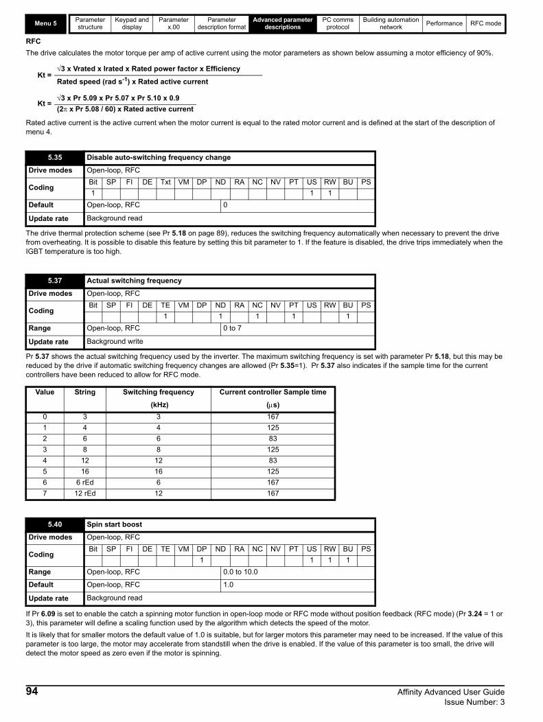
Menu 5Parameter structure
Keypad and display
Parameter x.00
Parameter description format
Advanced parameter descriptions
PC comms protocol
Building automation network
Performance RFC mode
RFC
The drive calculates the motor torque per amp of active current using the motor parameters as shown below assuming a motor efficiency of 90%.
Rated active current is the active current when the motor current is equal to the rated motor current and is defined at the start of the description of menu 4.
The drive thermal protection scheme (see Pr 5.18 on page 89), reduces the switching frequency automatically when necessary to prevent the drive from overheating. It is possible to disable this feature by setting this bit parameter to 1. If the feature is disabled, the drive trips immediately when the IGBT temperature is too high.
Pr 5.37 shows the actual switching frequency used by the inverter. The maximum switching frequency is set with parameter Pr 5.18, but this may be reduced by the drive if automatic switching frequency changes are allowed (Pr 5.35=1). Pr 5.37 also indicates if the sample time for the current controllers have been reduced to allow for RFC mode.
If Pr 6.09 is set to enable the catch a spinning motor function in open-loop mode or RFC mode without position feedback (RFC mode) (Pr 3.24 = 1 or 3), this parameter will define a scaling function used by the algorithm which detects the speed of the motor.
It is likely that for smaller motors the default value of 1.0 is suitable, but for larger motors this parameter may need to be increased. If the value of this parameter is too large, the motor may accelerate from standstill when the drive is enabled. If the value of this parameter is too small, the drive will detect the motor speed as zero even if the motor is spinning.
Kt =3 x Vrated x Irated x Rated power factor x Efficiency
Rated speed (rad s-1) x Rated active current
Kt =3 x Pr 5.09 x Pr 5.07 x Pr 5.10 x 0.9
(2 x Pr 5.08 / 60) x Rated active current
5.35 Disable auto-switching frequency change
Drive modes Open-loop, RFC
CodingBit SP FI DE Txt VM DP ND RA NC NV PT US RW BU PS
1 1 1
Default Open-loop, RFC 0
Update rate Background read
5.37 Actual switching frequency
Drive modes Open-loop, RFC
CodingBit SP FI DE TE VM DP ND RA NC NV PT US RW BU PS
1 1 1 1 1
Range Open-loop, RFC 0 to 7
Update rate Background write
Value String Switching frequency Current controller Sample time
(kHz) (s)
0 3 3 167
1 4 4 125
2 6 6 83
3 8 8 125
4 12 12 83
5 16 16 125
6 6 rEd 6 167
7 12 rEd 12 167
5.40 Spin start boost
Drive modes Open-loop, RFC
CodingBit SP FI DE TE VM DP ND RA NC NV PT US RW BU PS
1 1 1 1
Range Open-loop, RFC 0.0 to 10.0
Default Open-loop, RFC 1.0
Update rate Background read
94 Affinity Advanced User Guide Issue Number: 3

Parameter structure
Keypad and display
Parameter x.00
Parameter description format
Advanced parameter descriptions
PC comms protocol
Building automation network
Performance RFC mode Menu 6
5.8 Menu 6: Sequencer and clockFigure 5-9 Menu 6 logic diagram
6.12
Keypad STOP
1.11 Reference enabled indicator
1.12 Reverse selected indicator
1.13 Jog selected indicator
RUN
STOP/ RESET
FWD/REV
RESET
1.49
Reference selected indicator
Logic 1
Open loop only
6.06 Injection braking level*
6.07 Injection braking time*
6.17 Power consumption meter reset
6.21 Time interval betweenfilter changes
6.22 Filter change required/done
6.27Electricity costper kWh
Clock control
Time before filterchange due
6.28 Running cost
6.23
Power meter
Inverter enable
RFC only Menu 2
Menu 3Ramp
Hard speed reference
enable
enable
5.03Total motorpower
0.XX
0.XX
Key
Read-write (RW) parameter
Read-only (RO) parameter
Inputterminals
Outputterminals
The parameters are all shown at their default settings
Pr = 41.49
0 1
Sequencer
6.01
6.03
6.08
6.09
6.40
Stop mode*selector
Line power supply loss mode**Hold zero speed/Motor pre-heat
*****enableCatch a spinning motor***
Enable sequencerlatching
5.05DC bus voltage
Low voltage supplyDrive power supply monitor 6.44 Active supply
6.18
6.17 Time
Day ofweek
6.16 Date 6.19 Date/timeselector
012345
Power up timeSlot 1 RTCSlot 2 RTCInternal RTCRun timeSet time
6.256.26
Pr = 01.52
6.15
6.30
6.31
6.32
6.33
6.42
6.34
6.37
6.43
Jog reverse
Run
Forward / Reverse
Run reverse
Jog forward
Run forward
Drive enable
Control word
Control word enable
6.35
6.36Limit switch 2
Limit switch 1
6.29Hardwareenable
Menu 8
6.04
Stop / Start***select
T25 digital I/O 2
T26 digital I/O 3
T27 digital input 4
6.39Not stop
Fire modeactive
0
1
1
0
0
0
0
0
0
0
0
0
Affinity Advanced User Guide 95Issue Number: 3

Menu 6Parameter structure
Keypad and display
Parameter x.00
Parameter description format
Advanced parameter descriptions
PC comms protocol
Building automation network
Performance RFC mode
Open-loopStopping is in two distinct phases: decelerating to stop, and stopped.
Once modes 3 or 4 have begun, the drive must go through the ready state before being restarted either by stopping, tripping or being disabled.If this parameter is set to 5 (Disable stopping mode), the disable stopping mode is used when the run command is removed, and will allow the drive to be started immediately by reapplying the run command. However, if the drive is disabled by removing the drive enable (i.e. via the secure disable input or the drive enable (Pr 6.15), then the drive cannot be re-enabled for 1s.
RFC
Only one stopping phase exists, and the ready state is entered as soon as the single stopping action is complete. It should be noted that the stop condition is detected when the speed feedback is below the zero speed threshold (Pr 3.05) for at least 16ms. If the speed is not stable, it is possible that the stop condition may not be detected. In this case the system should be made more stable or alternatively the zero speed threshold should be raised.
If coast stop is selected, the inverter is inhibited immediately when the run command is removed. If however hold zero speed is also selected (Pr 6.08 = 1), then the inverter will be re-enabled to hold zero speed. The result is that the inverter is disabled for one sample and then enabled to ramp the motor to a stop. If coast stop is required Pr 6.08 should be set to zero to disable hold zero speed.
If stop with ramp is selected, the relevant ramp rate is used to stop the motor even if Pr 2.02 is set to zero to disable ramps.
The motor can be stopped with position orientation after stopping. This mode is selected with the position controller mode (Pr 13.10). When this mode is selected Pr 6.01 has no effect.
6.01 Stop mode
Drive modes Open-loop, RFC
CodingBit SP FI DE TE VM DP ND RA NC NV PT US RW BU PS
1 1 1 1
RangeOpen-loop RFC
0 to 50 to 2
DefaultOpen-loop, RFC
11
Update rate Background read
Stopping Mode Phase 1 Phase 2 Comments
0: Coast Inverter disabledDrive cannot be re-enabled for 1s
Delay in phase 2 allows rotor flux to decay.
1: RampRamp down to zero frequency
Wait for 1s with inverter enabled
2: Ramp followed by dc injection
Ramp down to zero frequency
Inject dc at level specified by Pr 6.06 for time defined by Pr 6.07
3: dc injection with zero speed detection
Low frequency current injection with detection of low speed before next phase.
Inject dc at level specified by Pr 6.06 for time defined by Pr 6.07
The drive automatically senses low speed and therefore it adjusts the injection time to suit the application. If the injection current level is too small, the drive will not sense low speed (normally a minimum of 50-60% is required).
4: Timed dc injection braking stop
Inject dc at level specified by Pr 6.06 for time specified by Pr 6.07.
No phase 2.
5:Disable Inverter disabled No phase 2.Allows the drive to be immediately disabled and then re-enabled again immediately if required.
Stopping Mode Action
0: Coast Inhibits the inverter
1: Ramp Stop with ramp
2: No ramp Stop with no ramp
96 Affinity Advanced User Guide Issue Number: 3

Parameter structure
Keypad and display
Parameter x.00
Parameter description format
Advanced parameter descriptions
PC comms protocol
Building automation network
Performance RFC mode Menu 6
0: disThere is no line power loss detection and the drive operates normally only as long as the DC bus voltage remains within specification (i.e. >Vuu). Once the voltage falls below Vuu a UU trip occurs. This will reset itself if the voltage rises again above VuuRestart as shown in Table 5-7 Voltages and voltage ratings on page 97.
1: Stop
Open-loopThe action taken by the drive is the same as for ride through mode except the ramp-down rate is at least as fast as the deceleration ramp setting, and the drive will continue to decelerate and stop even if the line power is re-applied. If normal or timed injection braking is selected, the drive will use ramp mode to stop on loss of line power. If ramp stop followed by injection braking is selected, the drive will ramp to a stop and then attempt to apply dc injection. If the line supply is reapplied the drive restarts after it reaches the ready state provided the necessary controls are still active to initiate a start.
RFCThe speed reference is set to zero and the ramps are disabled allowing the drive to decelerate the motor to a stop under current limit. If the line power is re-applied while the motor is stopping, any run signal is ignored until the motor has stopped. If the current limit value is set at a very low level, the drive may enter a UU trip before the motor has stopped. If the line power is reapplied the drive restarts after it reaches the ready state provided the necessary controls are still active to initiate a start.
2: ride.thThe drive detects line power loss when the DC bus voltage falls below Vml1. The drive then enters a mode where a closed-loop controller attempts to
hold the DC bus level at Vml2. This causes the motor to decelerate at a rate that increases as the speed falls. If the line power is re-applied, it will
force the DC bus voltage above the detection threshold Vml3 and the drive will continue to operate normally. The output of the line power loss
controller is a current demand that is fed into the current control system, and therefore the gain parameters Pr 4.13 and Pr 4.14 must be set up for optimum control. See Pr 4.13 and Pr 4.14 on page 70 for set-up details.
Table 5-7 Voltages and voltage ratings
* Vml1 is defined by Pr 6.48. The values given in the table are the default values.
This parameter is provided to allow the user to select several predefined digital input routing macros to control the sequencer. When a value between 0 and 3 is selected the drive processor continuously updates the destination parameters for digital I/O T25, T26 and T27, and the enable sequencer latching bit (Pr 6.40). When a value of 4 is selected the destination parameters for these digital I/O and Pr 6.40 can be modified by the user. (Note any changes made to the destination parameters only become active after a drive reset.)
* Pr 6.29 can be used as a fast disable parameter. See Pr 6.29 on page 103 for more information.
6.03 Line power loss mode
Drive modes Open-loop, RFC
CodingBit SP FI DE TE VM DP ND RA NC NV PT US RW BU PS
1 1 1 1
Range Open-loop, RFC 0 to 2
Default Open-loop, RFC 0
Update rate Background read
Voltage level 200V drive 400V drive 575V drive 690V drive
Vuu 175 350 500 500
Vml1 205* 410* 540* 540*
Vml2 Vml1 - 10V Vml1 - 20V Vml1 - 25V Vml1 - 25V
Vml3 Vml1 + 10 Vml1 + 15 Vml1 + 50 Vml1 + 50
Vuu Restart 215 425 590 590
6.04 Start/stop logic select
Drive modes Open-loop, RFC
CodingBit SP FI DE TE VM DP ND RA NC NV PT US RW BU PS
1 1 1
Range Open-loop, RFC 0 to 4
Default Open-loop, RFC 4
Update rate Background read
Pr 6.04 T25 (Pr 8.22) T26 (Pr 8.23) T27 (Pr 8.24) Pr 6.40
0 Pr 6.29* Pr 6.30 Run Forward Pr 6.32 Run Reverse 0 (non latching)
1 Pr 6.39 Not stop Pr 6.30 Run Forward Pr 6.32 Run Reverse 1 (latching)
2 Pr 6.29* Pr 6.34 Run Pr 6.33 Fwd /Rev 0 (non latching)
3 Pr 6.39 Not stop Pr 6.34 Run Pr 6.33 Fwd/Rev 1 (latching)
4 User prog User prog User prog User prog
Affinity Advanced User Guide 97Issue Number: 3

Menu 6Parameter structure
Keypad and display
Parameter x.00
Parameter description format
Advanced parameter descriptions
PC comms protocol
Building automation network
Performance RFC mode
Defines the current level used during dc injection braking as a percentage of motor rated current as defined by Pr 5.07.
Defines the time of injection braking during phase 1 with stopping modes 3 and 4 (see Pr 6.01 on page 96) for injection braking stop.
Pre-heat mode is enabled if Pr 6.08 is set to a 1 and Pr 6.52 is set to a value greater than zero. When the run command is removed and the motor has reached standstill, the drive applies a percentage (determined by the value in Pr 6.52) of the motor rated current. When pre-heat is active, then the keypad displays the status "Heat".
Hold zero speed is enabled if Pr 6.08 is set to a one and Pr 6.52 is set to zero. When the run command is removed and the motor has reached standstill, the drive continues to apply the magnetizing current. The level of magnetizing current cannot be modified. When hold zero speed is active, then the keypad displays the status "StoP".
The drive cannot be switched between hold zero speed and pre-heat mode if any one of these modes is active. The drive should either be disabled or running in order to change the mode.
Open-loopWhen the drive is enabled with this parameter at zero, the output frequency starts at zero and ramps to the required reference. When the drive is enabled with this parameter at a non-zero value, the drive performs a start-up test to determine the motor speed and then sets the initial output frequency to the synchronous frequency of the motor.
The test is not carried out and the motor frequency starts at zero:-
• if the run command is given when the drive is in the stop state.• OR when the drive is first enabled after power-up with Ur_I voltage mode.• OR when the run command is given with Ur_S voltage mode.
6.06 Injection braking level
Drive modes Open-loop
CodingBit SP FI DE TE VM DP ND RA NC NV PT US RW BU PS
1 1 1 1 1
Range Open-loop 0 to 150.0 %
Default Open-loop 100.0 %
Update rate Background read
6.07 Injection braking time
Drive modes Open-loop
CodingBit SP FI DE TE VM DP ND RA NC NV PT US RW BU PS
1 1 1 1
Range Open-loop 0.0 to 25.0 s
Default Open-loop 1.0
Update rate Background read
6.08 Hold zero speed / Motor pre-heat enable
Drive modes Open-loop, RFC
CodingBit SP FI DE TE VM DP ND RA NC NV PT US RW BU PS
1 1 1
Default Open-loop, RFC 0
Update rate Background read
The value in Pr 6.52 should not be set too high because it could damage the motor or cause the motor thermal protection to operate and trip the drive.
6.09 Catch a spinning motor
Drive modes Open-loop, RFC
CodingBit SP FI DE TE VM DP ND RA NC NV PT US RW BU PS
1 1 1
RangeOpen-loopRFC
31
DefaultOpen-loopRFC
01
Update rate Background read
CAUTION
98 Affinity Advanced User Guide Issue Number: 3

Parameter structure
Keypad and display
Parameter x.00
Parameter description format
Advanced parameter descriptions
PC comms protocol
Building automation network
Performance RFC mode Menu 6
Using the default parameters, the length of the test is approximately 200ms. However if the motor has a short rotor time constant/filter (usually found in smaller motors) the time may be shorter. The drive will set the test time automatically if the motor parameters including the rated load rpm, are set up correctly for the motor.
For the test to operate correctly, it is important that the stator resistance (Pr 5.17, Pr 21.12) is set up correctly. This applies even if fixed boost (Fd) or square law (SrE) voltage mode is being used. The test uses the rated magnetizing current of the motor during the test, therefore the rated current (Pr 5.07, Pr 21.07 and Pr 5.10, Pr 21.10) and power factor should be set to values close to those of the motor, although these parameters are not as critical as the stator resistance. For larger motors, it may be necessary to increase Pr 5.40 (spin start boost) from its default value of 1.0 for the drive to successfully detect the motor speed.
It should be noted that a stationary lightly loaded motor with low inertia may move slightly during the test. The direction of the movement is undefined. Restrictions may be placed on the direction of this movement and on the frequencies detected by the drive as follows:
RFCWhen the drive is enabled with this bit at zero, the post ramp reference (Pr 2.01) starts at zero and ramps to the required reference. When the drive is enabled with this parameter at one, the post ramp reference is set to the motor speed. When RFC mode is used feedback and catch a spinning motor is not required, this parameter should be set to zero as this avoids unwanted movement of the motor shaft when zero speed is required. When RFC mode is used with larger motors, it may be necessary to increase Pr 5.40 (spin start boost) from its default value of 1.0 for the drive to successfully detect the motor speed.
This parameter permanently enables the Stop key on the drive such that the drive will always stop when the Stop key is pressed. If keypad mode is selected this has no effect because the Stop key is automatically enabled.
The sequencer logic has been designed so that pressing the Stop key (whether the Stop key is enabled or not), does not make the drive change from a stopped to a running condition. As the Stop key is also used to reset trips, this means that if the Stop key is pressed when the drive is tripped, the trip will be reset but the drive does not start. (This does not apply to the UU trip which cannot be reset by the user, but is automatically reset when the DC bus voltage is high enough).
Preventing the drive from starting when the stop key is pressed is implemented as follows:-
Sequencer latching not enabled (Pr 6.40=0)
If the Stop key is pressed when the Stop key is enabled (Pr 6.12=1), or when the drive is tripped the sequencer run is removed, and so the drive stops or remains stopped respectively. The sequencer run can only then be reapplied after at least one of the following conditions occurs:-
1. Run forward, Run reverse and Run sequencing bits all zero2. OR the drive is disabled via Pr 6.15 or Pr 6.293. OR Run forward and Run reverse are both active and have been for 60ms. 4. OR The drive is in the UU state.
The drive can then be restarted by activating the necessary bits to give a normal start.
Sequencer latching enabled (Pr 6.40=1)
If the Stop key is pressed when the stop key is enabled (Pr 6.12=1) or when the drive is tripped the sequencer run is removed, and so the drive stops or remains stopped respectively. The sequencer run can only then be reapplied after at least one of the following conditions occurs.
1. Run forward, Run reverse and Run sequencing bits all zero after the latches2. OR Not stop sequencing bit is zero3. OR the drive is disabled via Pr 6.15 or Pr 6.294. OR Run forward and Run reverse are both active and have been for 60ms.5. OR The drive is in the UU state.
The drive can then be restarted by activating the necessary bits to give a normal start. Note that Run forward and Run reverse together will reset the stop key condition, but the latches associated with Run forward and Run reverse must then be reset before the drive can be restarted. It should be noted that holding the Run key and pressing the Stop key to reset the drive without stopping does not apply unless keypad reference mode is selected.
Pr 6.09 Function
0 Disabled
1 Detect all frequencies
2 Detect positive frequencies only
3 Detect negative frequencies only
6.12 Enable stop key
Drive modes Open-loop, RFC
CodingBit SP FI DE TE VM DP ND RA NC NV PT US RW BU PS
1 1 1
Default Open-loop, RFC 0
Update rate Background read
Affinity Advanced User Guide 99Issue Number: 3

Menu 6Parameter structure
Keypad and display
Parameter x.00
Parameter description format
Advanced parameter descriptions
PC comms protocol
Building automation network
Performance RFC mode
Setting this parameter to 0 will disable the drive. It must be at 1 for the drive to run.
6.15 Drive enable
Drive modes Open-loop, RFC
CodingBit SP FI DE TE VM DP ND RA NC NV PT US RW BU PS
1 1 1 1
Default Open-loop, RFC 1
Update rate 4ms read
6.16 Date
Drive modes Open-loop, RFC
CodingBit SP FI DE TE VM DP ND RA NC NV PT US RW BU PS
1 1 1 1 1
Default Open-loop, RFC 0 to 311299
Update rate Background read/write
6.17 Time
Drive modes Open-loop, RFC
CodingBit SP FI DE TE VM DP ND RA NC NV PT US RW BU PS
2 1 1 1 1 1
Default Open-loop, RFC 0.0 to 23.59
Update rate Background read/write
6.18 Day of week
Drive modes Open-loop, RFC
CodingBit SP FI DE TE VM DP ND RA NC NV PT US RW BU PS
1 1 1 1
Default Open-loop, RFC 0 to 6
Update rate Background write
6.19 Date / Time selector
Drive modes Open-loop, RFC
CodingBit SP FI DE TE VM DP ND RA NC NV PT US RW BU PS
1 1 1
Range Open-loop, RFC 0 to 5
Default Open-loop, RFC 3
Update rate Background read
100 Affinity Advanced User Guide Issue Number: 3
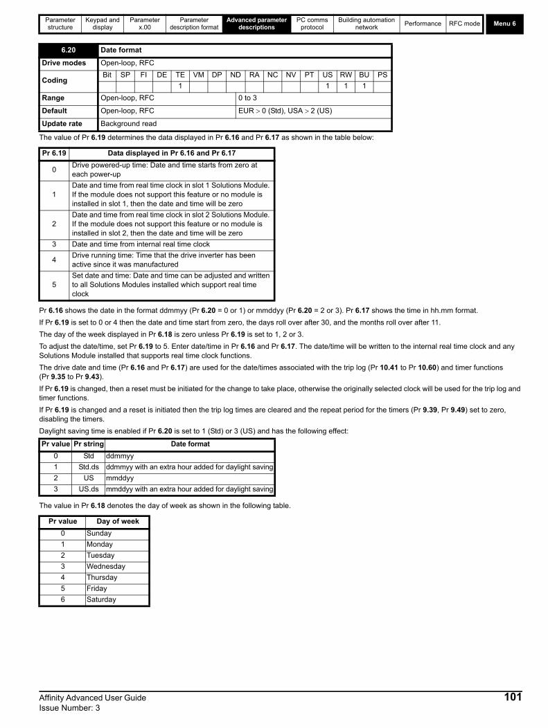
Parameter structure
Keypad and display
Parameter x.00
Parameter description format
Advanced parameter descriptions
PC comms protocol
Building automation network
Performance RFC mode Menu 6
The value of Pr 6.19 determines the data displayed in Pr 6.16 and Pr 6.17 as shown in the table below:
Pr 6.16 shows the date in the format ddmmyy (Pr 6.20 = 0 or 1) or mmddyy (Pr 6.20 = 2 or 3). Pr 6.17 shows the time in hh.mm format.
If Pr 6.19 is set to 0 or 4 then the date and time start from zero, the days roll over after 30, and the months roll over after 11.
The day of the week displayed in Pr 6.18 is zero unless Pr 6.19 is set to 1, 2 or 3.
To adjust the date/time, set Pr 6.19 to 5. Enter date/time in Pr 6.16 and Pr 6.17. The date/time will be written to the internal real time clock and any Solutions Module installed that supports real time clock functions.
The drive date and time (Pr 6.16 and Pr 6.17) are used for the date/times associated with the trip log (Pr 10.41 to Pr 10.60) and timer functions (Pr 9.35 to Pr 9.43).
If Pr 6.19 is changed, then a reset must be initiated for the change to take place, otherwise the originally selected clock will be used for the trip log and timer functions.
If Pr 6.19 is changed and a reset is initiated then the trip log times are cleared and the repeat period for the timers (Pr 9.39, Pr 9.49) set to zero, disabling the timers.
Daylight saving time is enabled if Pr 6.20 is set to 1 (Std) or 3 (US) and has the following effect:
The value in Pr 6.18 denotes the day of week as shown in the following table.
6.20 Date format
Drive modes Open-loop, RFC
CodingBit SP FI DE TE VM DP ND RA NC NV PT US RW BU PS
1 1 1 1
Range Open-loop, RFC 0 to 3
Default Open-loop, RFC EUR 0 (Std), USA 2 (US)
Update rate Background read
Pr 6.19 Data displayed in Pr 6.16 and Pr 6.17
0Drive powered-up time: Date and time starts from zero at each power-up
1Date and time from real time clock in slot 1 Solutions Module. If the module does not support this feature or no module is installed in slot 1, then the date and time will be zero
2Date and time from real time clock in slot 2 Solutions Module. If the module does not support this feature or no module is installed in slot 2, then the date and time will be zero
3 Date and time from internal real time clock
4Drive running time: Time that the drive inverter has been active since it was manufactured
5Set date and time: Date and time can be adjusted and written to all Solutions Modules installed which support real time clock
Pr value Pr string Date format
0 Std ddmmyy
1 Std.ds ddmmyy with an extra hour added for daylight saving
2 US mmddyy
3 US.ds mmddyy with an extra hour added for daylight saving
Pr value Day of week
0 Sunday
1 Monday
2 Tuesday
3 Wednesday
4 Thursday
5 Friday
6 Saturday
Affinity Advanced User Guide 101Issue Number: 3
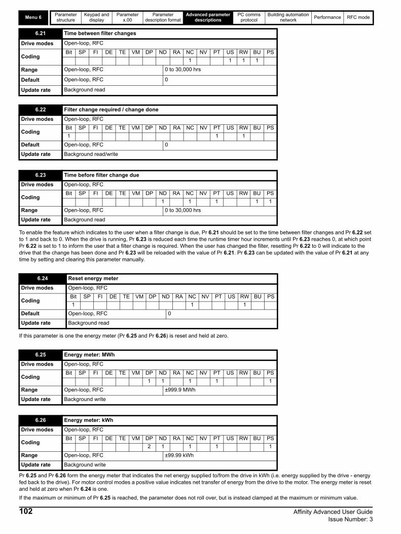
Menu 6Parameter structure
Keypad and display
Parameter x.00
Parameter description format
Advanced parameter descriptions
PC comms protocol
Building automation network
Performance RFC mode
To enable the feature which indicates to the user when a filter change is due, Pr 6.21 should be set to the time between filter changes and Pr 6.22 set to 1 and back to 0. When the drive is running, Pr 6.23 is reduced each time the runtime timer hour increments until Pr 6.23 reaches 0, at which point Pr 6.22 is set to 1 to inform the user that a filter change is required. When the user has changed the filter, resetting Pr 6.22 to 0 will indicate to the drive that the change has been done and Pr 6.23 will be reloaded with the value of Pr 6.21. Pr 6.23 can be updated with the value of Pr 6.21 at any time by setting and clearing this parameter manually.
If this parameter is one the energy meter (Pr 6.25 and Pr 6.26) is reset and held at zero.
Pr 6.25 and Pr 6.26 form the energy meter that indicates the net energy supplied to/from the drive in kWh (i.e. energy supplied by the drive - energy fed back to the drive). For motor control modes a positive value indicates net transfer of energy from the drive to the motor. The energy meter is reset and held at zero when Pr 6.24 is one.
If the maximum or minimum of Pr 6.25 is reached, the parameter does not roll over, but is instead clamped at the maximum or minimum value.
6.21 Time between filter changes
Drive modes Open-loop, RFC
CodingBit SP FI DE TE VM DP ND RA NC NV PT US RW BU PS
1 1 1 1
Range Open-loop, RFC 0 to 30,000 hrs
Default Open-loop, RFC 0
Update rate Background read
6.22 Filter change required / change done
Drive modes Open-loop, RFC
CodingBit SP FI DE TE VM DP ND RA NC NV PT US RW BU PS
1 1 1
Default Open-loop, RFC 0
Update rate Background read/write
6.23 Time before filter change due
Drive modes Open-loop, RFC
CodingBit SP FI DE TE VM DP ND RA NC NV PT US RW BU PS
1 1 1 1 1
Range Open-loop, RFC 0 to 30,000 hrs
Update rate Background read
6.24 Reset energy meter
Drive modes Open-loop, RFC
CodingBit SP FI DE TE VM DP ND RA NC NV PT US RW BU PS
1 1 1
Default Open-loop, RFC 0
Update rate Background read
6.25 Energy meter: MWh
Drive modes Open-loop, RFC
CodingBit SP FI DE TE VM DP ND RA NC NV PT US RW BU PS
1 1 1 1 1
Range Open-loop, RFC ±999.9 MWh
Update rate Background write
6.26 Energy meter: kWh
Drive modes Open-loop, RFC
CodingBit SP FI DE TE VM DP ND RA NC NV PT US RW BU PS
2 1 1 1 1
Range Open-loop, RFC ±99.99 kWh
Update rate Background write
102 Affinity Advanced User Guide Issue Number: 3

Parameter structure
Keypad and display
Parameter x.00
Parameter description format
Advanced parameter descriptions
PC comms protocol
Building automation network
Performance RFC mode Menu 6
When this parameter is set up correctly for the local currency, Pr 6.28 will give an instantaneous read out of running cost.
Instantaneous read out of the cost/hour of running the drive. This requires Pr 6.27 to be set up correctly.
This bit shows whether the drive is in the enable state or not.Generally this will reflect the state of the enable input and shows the same value as Pr 8.09. However, the disabled state can be forced by other functions within the drive. Pr 8.09 will always follow the enable input state but the Pr 6.29 will be held at zero, indicating that the drive is forced into the disable state by the following:1. A digital input is routed to this parameter as described below to provide a fast disable and the input forces this parameter to zero.2. Any of the following trips are active: OI.AC, PS.10V, PS.24V, OI.Br, OV.
If the destination of one of the drive digital I/O (Pr 8.21 to Pr 8.26) is set to Pr 6.29 and the I/O is set as an input, the state of the input does not affect the value of this parameter as it is protected, however it does provide a fast disable function. The drive enable input to the drive (T31) disables the drive in hardware by removing the gate drive signals from the inverter IGBT's and also disables the drive via the software system.
When the drive is disabled by de-activating the drive enable input there can be a delay of up to 20ms. However, if a digital I/O is set up to provide the fast disable function it is possible to disable the drive within 600us of de-activating the input. To do this the enable signal should be connected to both the drive enable (T31) and to the digital I/O selected for the fast disable function. The state of the digital I/O including the effect of its associated invert parameter is ANDed with the drive enable to enable the drive.
6.27 Electricity cost per kWh
Drive modes Open-loop, RFC
CodingBit SP FI DE TE VM DP ND RA NC NV PT US RW BU PS
1 1 1 1
Range Open-loop, RFC 0.0 to 600.0 currency units per kWh
Default Open-loop, RFC 0
Update rate Background read
6.28 Running cost
Drive modes Open-loop, RFC
CodingBit SP FI DE TE VM DP ND RA NC NV PT US RW BU PS
1 1 1 1
Range Open-loop, RFC ±32,000
Update rate Background write
6.29 Hardware enable
Drive modes Open-loop, RFC
CodingBit SP FI DE TE VM DP ND RA NC NV PT US RW BU PS
1 1 1
Update rate 4ms write
6.30 Sequencing bit: Run forward
Drive modes Open-loop, RFC
CodingBit SP FI DE TE VM DP ND RA NC NV PT US RW BU PS
1 1 1
Default Open-loop, RFC 0
Update rate 4ms read
6.31 Sequencing bit: Jog
Drive modes Open-loop, RFC
CodingBit SP FI DE TE VM DP ND RA NC NV PT US RW BU PS
1 1 1
Default Open-loop, RFC 0
Update rate 4ms read
Affinity Advanced User Guide 103Issue Number: 3
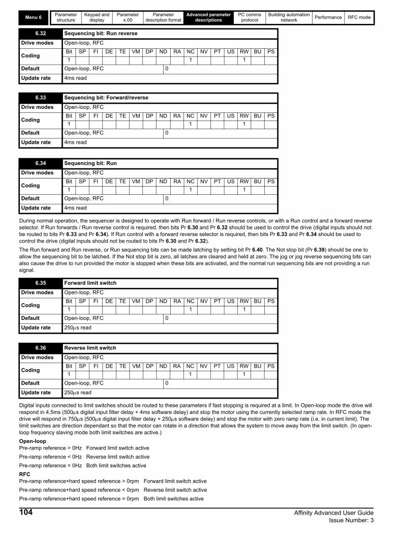
Menu 6Parameter structure
Keypad and display
Parameter x.00
Parameter description format
Advanced parameter descriptions
PC comms protocol
Building automation network
Performance RFC mode
During normal operation, the sequencer is designed to operate with Run forward / Run reverse controls, or with a Run control and a forward reverse selector. If Run forwards / Run reverse control is required, then bits Pr 6.30 and Pr 6.32 should be used to control the drive (digital inputs should not be routed to bits Pr 6.33 and Pr 6.34). If Run control with a forward reverse selector is required, then bits Pr 6.33 and Pr 6.34 should be used to control the drive (digital inputs should not be routed to bits Pr 6.30 and Pr 6.32).
The Run forward and Run reverse, or Run sequencing bits can be made latching by setting bit Pr 6.40. The Not stop bit (Pr 6.39) should be one to allow the sequencing bit to be latched. If the Not stop bit is zero, all latches are cleared and held at zero. The jog or jog reverse sequencing bits can also cause the drive to run provided the motor is stopped when these bits are activated, and the normal run sequencing bits are not providing a run signal.
Digital inputs connected to limit switches should be routed to these parameters if fast stopping is required at a limit. In Open-loop mode the drive will respond in 4.5ms (500s digital input filter delay + 4ms software delay) and stop the motor using the currently selected ramp rate. In RFC mode the drive will respond in 750s (500s digital input filter delay + 250s software delay) and stop the motor with zero ramp rate (i.e. in current limit). The limit switches are direction dependant so that the motor can rotate in a direction that allows the system to move away from the limit switch. (In open-loop frequency slaving mode both limit switches are active.)
Open-loopPre-ramp reference > 0Hz Forward limit switch active
Pre-ramp reference < 0Hz Reverse limit switch active
Pre-ramp reference = 0Hz Both limit switches active
RFCPre-ramp reference+hard speed reference > 0rpm Forward limit switch active
Pre-ramp reference+hard speed reference < 0rpm Reverse limit switch active
Pre-ramp reference+hard speed reference = 0rpm Both limit switches active
6.32 Sequencing bit: Run reverse
Drive modes Open-loop, RFC
CodingBit SP FI DE TE VM DP ND RA NC NV PT US RW BU PS
1 1 1
Default Open-loop, RFC 0
Update rate 4ms read
6.33 Sequencing bit: Forward/reverse
Drive modes Open-loop, RFC
CodingBit SP FI DE TE VM DP ND RA NC NV PT US RW BU PS
1 1 1
Default Open-loop, RFC 0
Update rate 4ms read
6.34 Sequencing bit: Run
Drive modes Open-loop, RFC
CodingBit SP FI DE TE VM DP ND RA NC NV PT US RW BU PS
1 1 1
Default Open-loop, RFC 0
Update rate 4ms read
6.35 Forward limit switch
Drive modes Open-loop, RFC
CodingBit SP FI DE TE VM DP ND RA NC NV PT US RW BU PS
1 1 1
Default Open-loop, RFC 0
Update rate 250s read
6.36 Reverse limit switch
Drive modes Open-loop, RFC
CodingBit SP FI DE TE VM DP ND RA NC NV PT US RW BU PS
1 1 1
Default Open-loop, RFC 0
Update rate 250s read
104 Affinity Advanced User Guide Issue Number: 3

Parameter structure
Keypad and display
Parameter x.00
Parameter description format
Advanced parameter descriptions
PC comms protocol
Building automation network
Performance RFC mode Menu 6
The drive event flags indicate certain actions have occurred within the drive as described below.
Defaults loaded (Bit 0)The drive sets bit 0 when defaults have been loaded and the associated parameter save has been completed. The drive does not reset this flag except at power-up.
Drive mode changed (Bit 1)The drive sets bit 1 when the drive mode has changed and the associated parameter save has been completed. The drive does not reset this flag except at power-up. This flag is intended to be used in a similar way as bit 0.
6.37 Sequencing bit: Jog reverse
Drive modes Open-loop, RFC
CodingBit SP FI DE TE VM DP ND RA NC NV PT US RW BU PS
1 1 1
Default Open-loop, RFC 0
Update rate 4ms read
6.39 Sequencing bit: Not stop
Drive modes Open-loop, RFC
CodingBit SP FI DE TE VM DP ND RA NC NV PT US RW BU PS
1 1 1
Default Open-loop, RFC 0
Update rate 4ms read
6.40 Enable sequencer latching
Drive modes Open-loop, RFC
CodingBit SP FI DE TE VM DP ND RA NC NV PT US RW BU PS
1 1 1
Default Open-loop, RFC 0
Update rate 4ms read
6.41 Drive event flags
Drive modes Open-loop, RFC
CodingBit SP FI DE TE VM DP ND RA NC NV PT US RW BU PS
1 1 1
Range Open-loop, RFC 0 to 65535
Default Open-loop, RFC 0
Update rate Background write
6.42 Control word
Drive modes Open-loop, RFC
CodingBit SP FI DE TE VM DP ND RA NC NV PT US RW BU PS
1 1 1
Range Open-loop, RFC 0 to 32,767
Default Open-loop, RFC 0
Update rate Bits 0 –7: 4ms read, Bits 8-15: Background read
Affinity Advanced User Guide 105Issue Number: 3

Menu 6Parameter structure
Keypad and display
Parameter x.00
Parameter description format
Advanced parameter descriptions
PC comms protocol
Building automation network
Performance RFC mode
Pr 6.42 and Pr 6.43 provide a method of controlling the sequencer inputs and other functions directly from a single control word. If Pr 6.43 = 0 the control word has no effect, if Pr 6.43 = 1 the control word is enabled. Each bit of the control word corresponds to a sequencing bit or function as shown below.
Bits 0-7 and bit 9: sequencing controlWhen the control word is enabled (Pr 6.43 = 1), and the Auto/manual bit (bit7) are both one, bits 0 to 6 and bit 9 of the control word become active. The equivalent parameters are not modified by these bits, but become inactive when the equivalent bits in the control word are active. When the bits are active they replace the functions of the equivalent parameters. For example, if Pr 6.43 = 1 and bit 7 of Pr 6.42 = 1 the drive enable is no longer controlled by Pr 6.15, but by bit 0 of the control word. If either Pr 6.43 = 0, or bit 7 of Pr 6.42 = 0, the drive enable is controlled by Pr 6.15.
Bit 8: Analog/preset referenceWhen the control word is enabled (Pr 6.43) bit 8 of the control word becomes active. (Bit 7 of the control word has no effect on this function.) The state of bit 8 is written to Pr 1.42. With default drive settings this selects analog reference 1 (bit8 = 0) or preset reference 1 (bit8 = 1). If any other drive parameters are routed to Pr 1.42 the value of Pr 1.42 is undefined.
Bit12: Trip driveWhen the control word is enabled (Pr 6.43) bit 12 of the control word becomes active. (Bit 7 of the control word has no effect on this function.) When bit 12 is set to one a CL.bit trip is initiated. The trip cannot be cleared until the bit is set to zero
Bit 13: Reset driveWhen the control word is enabled (Pr 6.43) bit 13 of the control word becomes active. (Bit 7 of the control word has no effect on this function.) When bit 13 is changed from 0 to 1 the drive is reset. This bit does not modify the equivalent parameter (Pr 10.33).
Bit 14: Keypad watchdogWhen the control word is enabled (Pr 6.43) bit 14 of the control word becomes active. (Bit 7 of the control word has no effect on this function.) A watchdog is provided for an external keypad or other device where a break in the communication link must be detected. The watchdog system can be enabled and/or serviced if bit 14 of the control word is changed from zero to one with the control word enabled. Once the watchdog is enabled it must be serviced at least once every second or an "SCL" trip occurs. The watchdog is disabled when an "SCL" trip occurs, and so it must be re-enabled when the trip is reset. It should be noted that when data is transferred from a SMARTCARD to the drive there may be a delay of up to 1.5s for the comms to respond. Once the comms starts to respond again normally the watchdog will not time-out for a further 2s even if it is not serviced. This period is allowed for the system connected to the comms port to recover if required and to begin servicing the watchdog again.
6.43 Control word enable
Drive modes Open-loop, RFC
CodingBit SP FI DE TE VM DP ND RA NC NV PT US RW BU PS
1 1 1
Default Open-loop, RFC 0
Update rate Related to bits 0-7: 4ms read, related to bits 8-15: Background read
Bit Function Equivalent parameter
0 Drive enable Pr 6.15
1 Run forward Pr 6.30
2 Jog Pr 6.31
3 Run reverse Pr 6.32
4 Forward/reverse Pr 6.33
5 Run Pr 6.34
6 Not stop Pr 6.39
7 Auto/manual
8 Analog/Preset reference Pr 1.42
9 Jog reverse Pr 6.37
10 Reserved
11 Reserved
12 Trip drive
13 Reset drive Pr 10.33
14 Keypad watchdog
106 Affinity Advanced User Guide Issue Number: 3
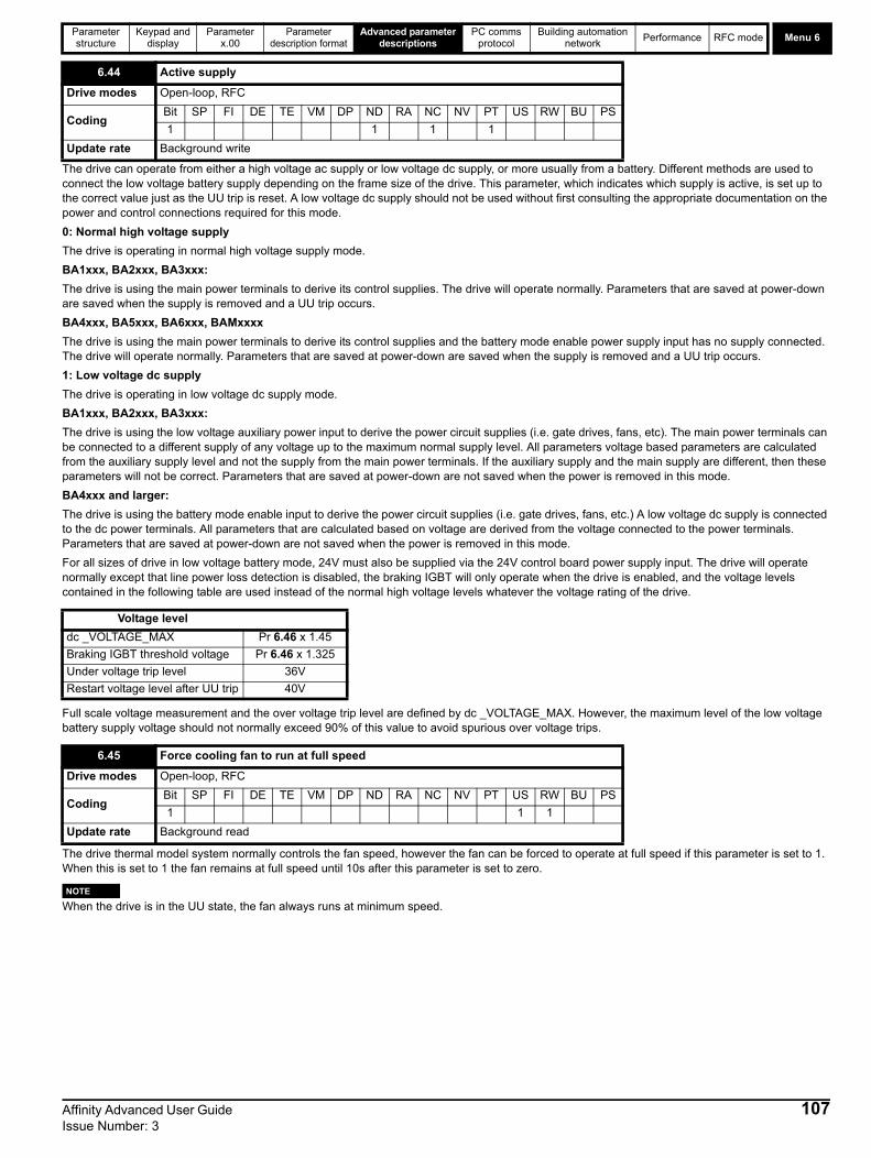
Parameter structure
Keypad and display
Parameter x.00
Parameter description format
Advanced parameter descriptions
PC comms protocol
Building automation network
Performance RFC mode Menu 6
The drive can operate from either a high voltage ac supply or low voltage dc supply, or more usually from a battery. Different methods are used to connect the low voltage battery supply depending on the frame size of the drive. This parameter, which indicates which supply is active, is set up to the correct value just as the UU trip is reset. A low voltage dc supply should not be used without first consulting the appropriate documentation on the power and control connections required for this mode.
0: Normal high voltage supply
The drive is operating in normal high voltage supply mode.
BA1xxx, BA2xxx, BA3xxx:
The drive is using the main power terminals to derive its control supplies. The drive will operate normally. Parameters that are saved at power-down are saved when the supply is removed and a UU trip occurs.
BA4xxx, BA5xxx, BA6xxx, BAMxxxx
The drive is using the main power terminals to derive its control supplies and the battery mode enable power supply input has no supply connected. The drive will operate normally. Parameters that are saved at power-down are saved when the supply is removed and a UU trip occurs.
1: Low voltage dc supply
The drive is operating in low voltage dc supply mode.
BA1xxx, BA2xxx, BA3xxx:
The drive is using the low voltage auxiliary power input to derive the power circuit supplies (i.e. gate drives, fans, etc). The main power terminals can be connected to a different supply of any voltage up to the maximum normal supply level. All parameters voltage based parameters are calculated from the auxiliary supply level and not the supply from the main power terminals. If the auxiliary supply and the main supply are different, then these parameters will not be correct. Parameters that are saved at power-down are not saved when the power is removed in this mode.
BA4xxx and larger:
The drive is using the battery mode enable input to derive the power circuit supplies (i.e. gate drives, fans, etc.) A low voltage dc supply is connected to the dc power terminals. All parameters that are calculated based on voltage are derived from the voltage connected to the power terminals. Parameters that are saved at power-down are not saved when the power is removed in this mode.
For all sizes of drive in low voltage battery mode, 24V must also be supplied via the 24V control board power supply input. The drive will operate normally except that line power loss detection is disabled, the braking IGBT will only operate when the drive is enabled, and the voltage levels contained in the following table are used instead of the normal high voltage levels whatever the voltage rating of the drive.
Full scale voltage measurement and the over voltage trip level are defined by dc _VOLTAGE_MAX. However, the maximum level of the low voltage battery supply voltage should not normally exceed 90% of this value to avoid spurious over voltage trips.
The drive thermal model system normally controls the fan speed, however the fan can be forced to operate at full speed if this parameter is set to 1. When this is set to 1 the fan remains at full speed until 10s after this parameter is set to zero.
When the drive is in the UU state, the fan always runs at minimum speed.
6.44 Active supply
Drive modes Open-loop, RFC
CodingBit SP FI DE TE VM DP ND RA NC NV PT US RW BU PS
1 1 1 1
Update rate Background write
Voltage level
dc _VOLTAGE_MAX Pr 6.46 x 1.45
Braking IGBT threshold voltage Pr 6.46 x 1.325
Under voltage trip level 36V
Restart voltage level after UU trip 40V
6.45 Force cooling fan to run at full speed
Drive modes Open-loop, RFC
CodingBit SP FI DE TE VM DP ND RA NC NV PT US RW BU PS
1 1 1
Update rate Background read
NOTE
Affinity Advanced User Guide 107Issue Number: 3

Menu 6Parameter structure
Keypad and display
Parameter x.00
Parameter description format
Advanced parameter descriptions
PC comms protocol
Building automation network
Performance RFC mode
This parameter defines the nominal supply voltage when operating in low voltage mode. The parameter is used to define the braking IGBT switching threshold and the over voltage trip level for low voltage battery mode (see Pr 6.44).
BA1xxx, BA2xxx and BA3xxxDrives in these sizes ranges have a diode rectifier input stage with no direct monitoring system. Line power loss and phase loss detection is derived from the DC bus voltage. This parameter has no effect.
BA4xxx, BA5xxx and BA6xxxDrives in these sizes ranges have an active rectifier input stage that is used to control DC bus charging. Line power loss and phase loss detection is derived from the DC bus voltage. The only status information taken from the input rectifier stage is an over temperature indication which gives an Oht4 trip if active. This parameter has no effect on this feature. When the control system is leaving the line power loss ride through condition (ACUU) it is important that no load is applied to the input rectifier until it is fully active. This feature can be disabled by setting this parameter to one.
BAMxxxx Drives in this size range have an active rectifier input stage that is used to control DC bus charging. Line power and phase loss detection is derived from the DC bus voltage, but additional monitoring is provided by the input rectifier controller as follows:
1. An over temperature indication from a single module or any module operating in parallel causes an Oht4.P trip if it is present for more than 0.5s. This feature is not affected by this parameter.
2. A phase loss indication from a single module or any module operating in parallel causes a PH.P trip if it is present for more than 0.5s. If this parameter is set to one, the drive is operating in regen mode or the drive is operating from a low voltage supply this feature is disabled.
3. A line power loss indication from any, but not all modules operating in parallel, causes a PH.P trip if this condition is present for more than 0.5s. If this parameter is set to one, the drive is operating in regen mode or the drive is operating from a low voltage supply this feature is disabled.
When the control system is leaving the line power loss ride through condition (ACUU) it is important that no load is applied to the input rectifier until it is fully active. This feature can be disabled by setting this parameter to one.
The active rectifier status signals are monitored in one of the following ways:
1. When BAMAxxx drives are connected in parallel, the status of the individual rectifiers is monitored through the parallel module control interface system.
2. When BAMDxxx drives are connected in parallel, the status of the individual rectifiers is combined and is monitored when the combined status signals are connected to power module one.
3. When an external rectifier is used, these monitoring features are provided via digital I/O terminals using the rectifier monitoring feature of the variable selector blocks (see menu 12).
The line power loss detection level can be adjusted using this parameter. If the value is reduced below the default value the default value is used by the drive. If the level is set too high so that line power loss detection becomes active under normal operating conditions the motor will coast to a stop.
6.46 Nominal low voltage dc supply
Drive modes Open-loop, RFC
CodingBit SP FI DE TE VM DP ND RA NC NV PT US RW BU PS
1 1 1 1
Range
48 to 48 for BA1xxx drives48 to 72 for BA2xxx and BA3xxx drives48 to 72 for all other 200V drives48 to 96 for all other 400V and 690V drives
Default Open-loop, RFC 48
Update rate Background read
6.47 Disable line power/phase loss detection from input rectifier
Drive modes Open-loop, RFC
CodingBit SP FI DE TE VM DP ND RA NC NV PT US RW BU PS
1 1 1
Default Open-loop, RFC 0
Update rate Background read
6.48 Line power loss ride through detection level
Drive modes Open-loop, RFC
CodingBit SP FI DE TE VM DP ND RA NC NV PT US RW BU PS
1 1 1 1 1
Range Open-loop, RFC 0 to dc _VOLTAGE_SET_MAX V
Default Open-loop, RFC
200V rated drive 205400V rated drive 410575V rated drive 540690V rated drive 540
Update rate Background read
108 Affinity Advanced User Guide Issue Number: 3

Parameter structure
Keypad and display
Parameter x.00
Parameter description format
Advanced parameter descriptions
PC comms protocol
Building automation network
Performance RFC mode Menu 6
The drive retains a log in Pr 10.20 to Pr 10.29 of the last 10 trips that have occurred. The state of Pr 6.49 determines whether date and time or module number, associated with the trip, is stored (see Table 5-8).
Table 5-8 Trip log definition
Trip 1 is the most recent trip or the current trip if the drive is in a trip condition, and trip 10 is the oldest trip.
The date and time for Pr 10.41 to 10.59 are taken from the values in Pr 6.16 and Pr 6.17.
The value in Pr 6.19 determines if power-up time, drive running time or real time clock is logged.
If any parameter between Pr 10.20 and Pr 10.29 inclusive is read by serial communications, then the trip number in Table 5-13 Trip indications on page 143 is the value transmitted.
When power modules are connected in parallel, various trips can be initiated from the power modules themselves. To aid identification of the source of the trip the module number of the source can be stored in the module number and trip time log (Pr 10.42 to Pr 10.60). If the drive is a single module drive (BA1xxx to BA6xxx), the module number that is stored is normally zero. However, a BAMAxxxx or BAMDxxxx drive is installed with the interface circuits normally intended for parallel operation, so if a BAMAxxxx or BAMDxxxx drive is used as a single module then a module number of 1 is stored.
If Pr 6.49 is zero the module number is stored in the module number and trip time log. If this parameter is one, either the powered-up clock or run time clock is stored in the module number and trip time log as defined by Pr 6.28. It should be noted that changing this parameter clears the trip, and module number and trip time logs.
The drive comms system 128 bytes buffer used with ANSI or Modbus rtu protocols via the 485 connector can be controlled by an Solutions Module under certain circumstances. This parameter shows which node has control of the buffer (0 (drv) = drive, 1 (Slot1) = Solutions Modules in slot 1, etc. If an Solutions Modules has control of the buffer the drive will use an alternative buffer for 485 comms and the following restrictions will apply:
1. Comms messages via the 485 port are limited to a maximum of 32 bytes2. The 6 pin keypad port will operate correctly with an LED keypad, but it will no longer operate with an LCD keypad3. Modbus messages using the CMP protocol can only route messages to nodes within the drive. It will not be possible for these to be routed further,
i.e. via CT Net on an SM Applications module.
6.49 Enable date / time in trip log
Drive modes Open-loop, RFC
CodingBit SP FI DE TE VM DP ND RA NC NV PT US RW BU PS
1 1 1
Default Open-loop, RFC 1
Update rate Background read
Trip number
Trip codePr 6.49 = 1 Pr 6.49 = 0
Date Time Module number
Trip 1 10.20 10.41 10.42 10.42Trip 2 10.21 10.43 10.44 10.44Trip 3 10.22 10.45 10.46 10.46Trip 4 10.23 10.47 10.48 10.48Trip 5 10.24 10.49 10.50 10.50Trip 6 10.25 10.51 10.52 10.52Trip 7 10.26 10.53 10.54 10.54Trip 8 10.27 10.55 10.56 10.56Trip 9 10.28 10.57 10.58 10.58Trip 10 10.29 10.59 10.60 10.60
6.50 Drive comms state
Drive modes Open-loop, RFC
CodingBit SP FI DE TE VM DP ND RA NC NV PT US RW BU PS
1 1 1 1 1
Default Open-loop,RFC 0 to 2
Update rate Background write
Affinity Advanced User Guide 109Issue Number: 3
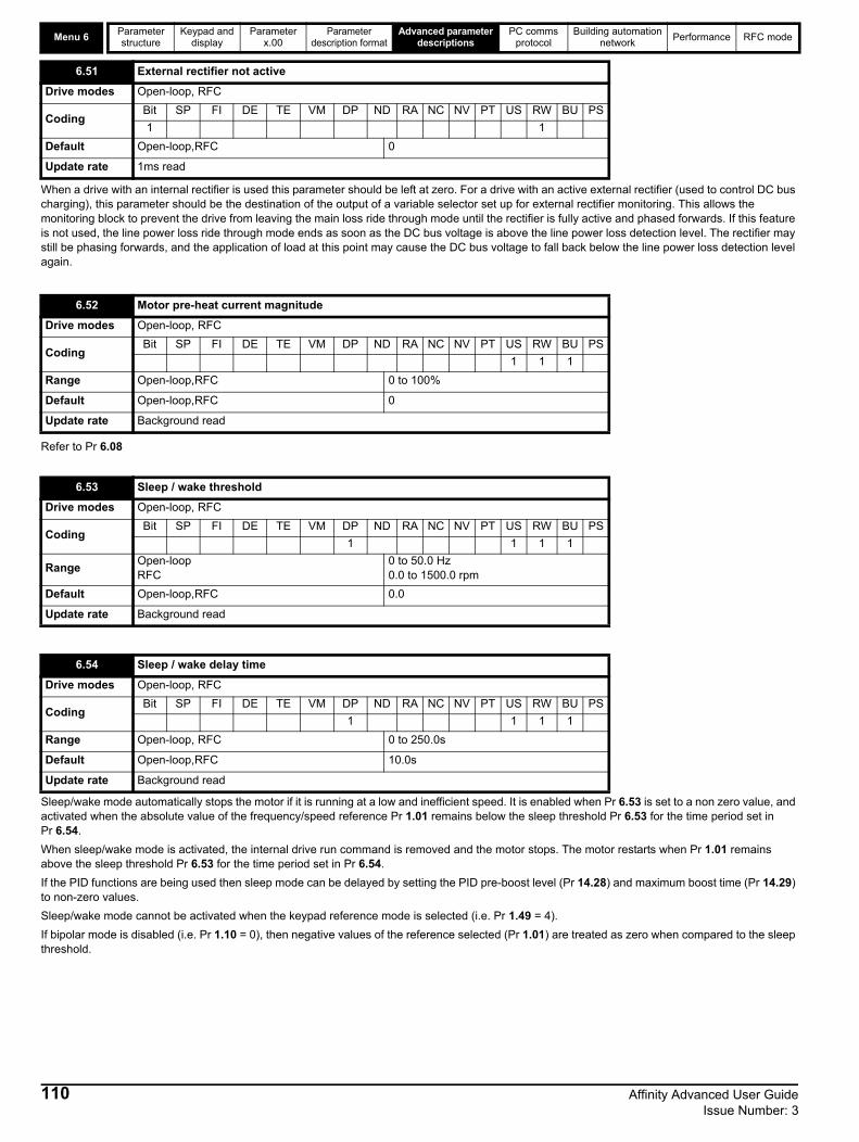
Menu 6Parameter structure
Keypad and display
Parameter x.00
Parameter description format
Advanced parameter descriptions
PC comms protocol
Building automation network
Performance RFC mode
When a drive with an internal rectifier is used this parameter should be left at zero. For a drive with an active external rectifier (used to control DC bus charging), this parameter should be the destination of the output of a variable selector set up for external rectifier monitoring. This allows the monitoring block to prevent the drive from leaving the main loss ride through mode until the rectifier is fully active and phased forwards. If this feature is not used, the line power loss ride through mode ends as soon as the DC bus voltage is above the line power loss detection level. The rectifier may still be phasing forwards, and the application of load at this point may cause the DC bus voltage to fall back below the line power loss detection level again.
Refer to Pr 6.08
Sleep/wake mode automatically stops the motor if it is running at a low and inefficient speed. It is enabled when Pr 6.53 is set to a non zero value, and activated when the absolute value of the frequency/speed reference Pr 1.01 remains below the sleep threshold Pr 6.53 for the time period set in Pr 6.54.
When sleep/wake mode is activated, the internal drive run command is removed and the motor stops. The motor restarts when Pr 1.01 remains above the sleep threshold Pr 6.53 for the time period set in Pr 6.54.
If the PID functions are being used then sleep mode can be delayed by setting the PID pre-boost level (Pr 14.28) and maximum boost time (Pr 14.29) to non-zero values.
Sleep/wake mode cannot be activated when the keypad reference mode is selected (i.e. Pr 1.49 = 4).
If bipolar mode is disabled (i.e. Pr 1.10 = 0), then negative values of the reference selected (Pr 1.01) are treated as zero when compared to the sleep threshold.
6.51 External rectifier not active
Drive modes Open-loop, RFC
CodingBit SP FI DE TE VM DP ND RA NC NV PT US RW BU PS
1 1
Default Open-loop,RFC 0
Update rate 1ms read
6.52 Motor pre-heat current magnitude
Drive modes Open-loop, RFC
CodingBit SP FI DE TE VM DP ND RA NC NV PT US RW BU PS
1 1 1
Range Open-loop,RFC 0 to 100%
Default Open-loop,RFC 0
Update rate Background read
6.53 Sleep / wake threshold
Drive modes Open-loop, RFC
CodingBit SP FI DE TE VM DP ND RA NC NV PT US RW BU PS
1 1 1 1
RangeOpen-loopRFC
0 to 50.0 Hz0.0 to 1500.0 rpm
Default Open-loop,RFC 0.0
Update rate Background read
6.54 Sleep / wake delay time
Drive modes Open-loop, RFC
CodingBit SP FI DE TE VM DP ND RA NC NV PT US RW BU PS
1 1 1 1
Range Open-loop, RFC 0 to 250.0s
Default Open-loop,RFC 10.0s
Update rate Background read
110 Affinity Advanced User Guide Issue Number: 3
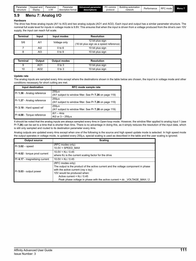
Parameter structure
Keypad and display
Parameter x.00
Parameter description format
Advanced parameter descriptions
PC comms protocol
Building automation network
Performance RFC mode Menu 7
5.9 Menu 7: Analog I/OHardwareThe drive has three analog inputs (AI1 to AI3) and two analog outputs (AO1 and AO2). Each input and output has a similar parameter structure. The nominal full scale level for inputs in voltage mode is 9.8V. This ensures that when the input is driven from a voltage produced from the drive's own 10V supply, the input can reach full scale.
Update rateThe analog inputs are sampled every 4ms except where the destinations shown in the table below are chosen, the input is in voltage mode and other conditions necessary for short cutting are met.
It should be noted that the analog inputs are always sampled every 4ms in Open-loop mode. However, the window filter applied to analog input 1 (see Pr 7.26) can be set to a time that is shorter than 4ms. There is no advantage in doing this, as it simply reduces the resolution of the input data, which is still only sampled and routed to its destination parameter every 4ms.
Analog outputs are updated every 4ms except when one of the following is the source and high speed update mode is selected. In high speed mode the output operates in voltage mode, is updated every 250s, special scaling is used as described in the table and the user scaling is ignored.
Terminal Input Input modes Resolution
5/6 AI1 Voltage only12 bit plus sign
(16 bit plus sign as a speed reference)
7 AI2 0 to 6 10 bit plus sign
8 AI3 0 to 9 10 bit plus sign
Terminal Output Output modes Resolution
9 AO1 0 to 3 10 bit plus sign
10 AO2 0 to 3 10 bit plus sign
Input destination RFC mode sample rate
Pr 1.36 - Analog reference250s(AI1 subject to window filter. See Pr 7.26 on page 119)
Pr 1.37 - Analog reference250s(AI1 subject to window filter. See Pr 7.26 on page 119)
Pr 3.19 - Hard speed ref250s(AI1 subject to window filter. See Pr 7.26 on page 119)
Pr 4.08 - Torque referenceAI1 – 4msAI2 or 3 – 250s
Output source Scaling
Pr 3.02 – speed(RFC modes only)10.0V = SPEED_MAX
Pr 4.02 - torque prod current10.0V = Kc / 0.45where Kc is the current scaling factor for the drive
Pr 4.17 - magnetising current 10.0V = Kc / 0.45
Pr 5.03 - output power
(RFC modes only)The output is the product of the active current and the voltage component in phase with the active current (vsy x isy).10V would be produced when:
Active current = Kc / 0.45Peak phase voltage in phase with the active current = dc _VOLTAGE_MAX / 2
Affinity Advanced User Guide 111Issue Number: 3

Menu 7Parameter structure
Keypad and display
Parameter x.00
Parameter description format
Advanced parameter descriptions
PC comms protocol
Building automation network
Performance RFC mode
Figure 5-10 Menu 7 logic diagram
Analog input 2
A/D 7.11
Analog input 2mode selector
7.12
Analoginput 2scaling
??.??
Any unprotected variable parameter
??.??
7.14
7.25
Calibrateanalog input 1full scale
7.26
V/f sample time
7.07
Analog input1 offset trim
7.08
Analoginput 1scaling
??.??
Any unprotected variable parameter
??.??
7.10
Analog input 1destinationparameter
V/f
x(-1)
Analog input 1
Analog input 3
A/D 7.15
Analog input 3mode selector
7.16
Analoginput 3scaling
??.??
Any unprotected variable parameter
??.??
7.18
??.??
Any variable parameter
??.??
7.19
Analog output 1source parameter
7.20
Analog output 1 scaling
7.21
Analog output 1 mode selector
Analog output 1
??.??
Any variable parameter
??.??
7.22
Analog output 2source parameter
7.23
Analog output 2 scaling
7.24
Analog output 2 mode selector
7.09 Analog input 1 invert
x(-1)
7.01
Analoginput 1
7.02
Analoginput 2
x(-1)
7.17 Analoginput 3 invert
7.13 Analoginput 2 invert
Analog output 2
1.36
Analogref. 1
1.37
Analogref. 2
5.01
Motorfrequency
3.02
Speedfeedback
4.02
Motoractivecurrent
OL>
RFC>
0.XX
0.XX
Key
Read-write (RW) parameter
Read-only (RO) parameter
Inputterminals
Outputterminals
The parameters are all shown at their default settings
++
++
7.30
Analog input1 offset
7.28
Analog input 2current loop loss
++
7.31
++
7.31
Analog input2 offset
++
7.31
++
7.32
Analog input3 offset7.29
Analog input 3current loop loss
7.33
Analogoutput 1 control
Analog input 2destinationparameter
Analog input 3destinationparameter
7.03
Analoginput 3
112 Affinity Advanced User Guide Issue Number: 3

Parameter structure
Keypad and display
Parameter x.00
Parameter description format
Advanced parameter descriptions
PC comms protocol
Building automation network
Performance RFC mode Menu 7
This input operates in voltage mode only where -9.8V and +9.8V at the input correspond with -100.0% and 100.0% respectively in this parameter.
These inputs can operate in different modes defined by Pr 7.11 and Pr 7.15.
In current modes (modes 0 to 5) the minimum and maximum current values given in mA correspond with 0.0% and 100.0% respectively in Pr 7.02 and Pr 7.03. Therefore in modes 2 and 4, the parameter is at 0.0% when the input current is less than 4mA, and in modes 3 and 5 the parameter is at 100.0% when the input current is less than 4mA.
In voltage mode (mode 6) -9.8V and +9.8V at the input correspond with -100.0% and 100.0% respectively in Pr 7.02 and Pr 7.03.
When analog input 3 is in thermistor mode (modes 7 to 9), the display indicates the resistance of the thermistor as a percentage of 10k
For drive sizes BA1xxx to BA5xxx two temperatures are available from the power circuit. These are displayed in Pr 7.04 and Pr 7.05. For drive size BA6xxx and BAMxxxx, three temperatures are available from the power circuit. These are displayed in Pr 7.04, Pr 7.05 and Pr 7.36. If BAMxxxx drives consist of more than one parallel power module, the temperatures displayed are the highest value from any of the parallel modules.
If the temperature displayed in Pr 7.04, Pr 7.05 or Pr 7.36 exceeds the trip threshold for the parameter, the drive does not have parallel power modules and is not a single power module that uses the parallel power module hardware, an Oht2 trip is initiated. This trip can only be reset if the parameter that has caused the trip falls below the trip reset level. If the temperature exceeds the alarm level a "hot" alarm is displayed. If the temperature for any of these monitoring points is outside the range -20C to 150C, it is assumed that the monitoring thermistor has failed and a hardware fault trip is initiated (Pr 7.04 - HF27, Pr 7.05 and Pr 7.36 - HF28).
7.01 T5/6 analog input 1 level
Drive modes Open-loop, RFC
CodingBit SP FI DE Txt VM DP ND RA NC NV PT US RW BU PS
2 1 1 1
Range Open-loop, RFC ±100.00 %
Update rate 4ms write
7.02 T7 analog input 2 level
7.03 T8 analog input 3 level
Drive modes Open-loop, RFC
CodingBit SP FI DE Txt VM DP ND RA NC NV PT US RW BU PS
1 1 1 1
Range Open-loop, RFC ±100.0 %
Update rate 4ms write
7.04 Power circuit temperature 1
Drive modes Open-loop, RFC
CodingBit SP FI DE Txt VM DP ND RA NC NV PT US RW BU PS
1 1 1
Range Open-loop, RFC -128 to 127oC
Update rate Background write
7.05 Power circuit temperature 2
Drive modes Open-loop, RFC
CodingBit SP FI DE Txt VM DP ND RA NC NV PT US RW BU PS
1 1 1
Range Open-loop, RFC -128 to 127oC
Update rate Background write
7.06 Control board temperature
Drive modes Open-loop, RFC
CodingBit SP FI DE Txt VM DP ND RA NC NV PT US RW BU PS
1 1 1
Range Open-loop, RFC -128 to 127oC
Update rate Background write
Affinity Advanced User Guide 113Issue Number: 3

Menu 7Parameter structure
Keypad and display
Parameter x.00
Parameter description format
Advanced parameter descriptions
PC comms protocol
Building automation network
Performance RFC mode
Table 5-9 Power stage temperature 1 (Pr 7.04) in C
Additional monitoring is used with drives size BA6xxx and BAMxxxx to detect failure of the power stage cooling fan. If this fan fails, the monitoring point used to derive power stage temperature 1 that is nearest the fan, will raise the temperature above it s normal level, but not above the trip temperature for the power stage. This is detected and can initiate an Oht2 trip. The trip thresholds are shown below.
Table 5-10 Power stack temperature 2 (Pr 7.05) in C
Table 5-11 Power stack temperature 3 (Pr 7.36) in °C
The control board temperature is also monitored and displayed in Pr 7.06. If the temperature displayed exceeds 92C, an O.Ctl trip is initiated. This trip can only be reset if the temperature falls below 87C . If the temperature exceeds 85C, a "hot" alarm is displayed. If the temperature is outside the range from -20C to +150C, it is assumed that the monitoring thermistor has failed and an HF29 hardware fault trip is initiated.
Drive cooling fanThe drive cooling fan is controlled by the temperature from monitoring points and other actions as follows:
1. If Pr 6.45 = 1 the fan is at full speed for at least 10s.2. If a Solutions Module indicates that it is overheating, the fan will run at full speed for at least 10s.3. For drive sizes BA1xxx to BA2xxx the fan is at full speed if the drive is enabled and the highest power circuit temperature (Pr 7.04 or Pr 7.05) or
the temperature calculated for the case of the IGBT package exceed the threshold for the drive. The fan is at its low speed if this temperature falls 5C below the threshold, or the drive is disabled and the temperature is below the alarm level for Pr 7.04 and Pr 7.05.
4. For drive sizes BA3xxx to BA6xxxx, the fan speed is controlled above its minimum level if the drive is enabled, and the highest power circuit temperature (Pr 7.04, Pr 7.05 or Pr 7.36) or the temperature calculated for the case of the IGBT package exceed the lower threshold for the drive. The maximum fan speed is reached when the highest of these temperatures exceeds the upper threshold. The fan is at its minimum speed if the
drive is disabled and the temperature is below the alarm level for Pr 7.04, Pr 7.05 and Pr 7.36.The thresholds are given in the table below in C :
Drive size Trip temperature Trip reset temperature Alarm temperature
BA0xxx 77 72 75
BA1xxx 110 105 100
BA2xxx 115 110 100
BA3xxx 120 115 100
BA4xxx 72 67 68
BA5xxx 72 67 68
BA6xxx 92 87 85
BAMAxxxx 92 87 85
BAMDxxxx 96 91 88
Drive size Trip temperature
BA6xxx 67
BAMAxxxx 67
BAMDxxxx 71
Drive size Trip temperature Trip reset temperature Alarm temperature
BA0xxx 83 78 80
BA1xxx 92 87 85
BA2xxx 100 95 95
BA3xxx 98 93 94
BA4xxx 78 73 72
BA5xxx 78 73 72
BA6xxx 78 73 72
BAMAxxxx 78 73 72
BAMDxxxx 78 73 72
Drive size Trip temperature Trip reset temperature Alarm temperature
BA0xxx 105 100 100
BA1xxx N/A N/A N/A
BA2xxx N/A N/A N/A
BA3xxx N/A N/A N/A
BA4xxx N/A N/A N/A
BA5xxx N/A N/A N/A
BA6xxx 85 80 80
BAMAxxxx 85 80 80
BAMDxxxx 125 100 120
114 Affinity Advanced User Guide Issue Number: 3
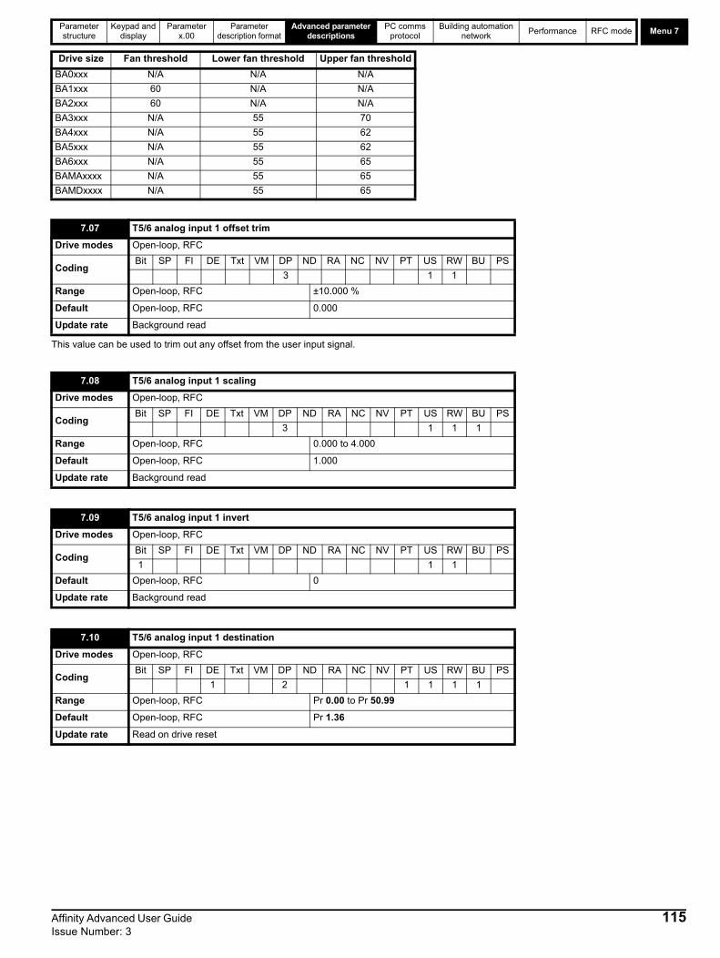
Parameter structure
Keypad and display
Parameter x.00
Parameter description format
Advanced parameter descriptions
PC comms protocol
Building automation network
Performance RFC mode Menu 7
This value can be used to trim out any offset from the user input signal.
Drive size Fan threshold Lower fan threshold Upper fan threshold
BA0xxx N/A N/A N/A
BA1xxx 60 N/A N/A
BA2xxx 60 N/A N/A
BA3xxx N/A 55 70
BA4xxx N/A 55 62
BA5xxx N/A 55 62
BA6xxx N/A 55 65
BAMAxxxx N/A 55 65
BAMDxxxx N/A 55 65
7.07 T5/6 analog input 1 offset trim
Drive modes Open-loop, RFC
CodingBit SP FI DE Txt VM DP ND RA NC NV PT US RW BU PS
3 1 1
Range Open-loop, RFC ±10.000 %
Default Open-loop, RFC 0.000
Update rate Background read
7.08 T5/6 analog input 1 scaling
Drive modes Open-loop, RFC
CodingBit SP FI DE Txt VM DP ND RA NC NV PT US RW BU PS
3 1 1 1
Range Open-loop, RFC 0.000 to 4.000
Default Open-loop, RFC 1.000
Update rate Background read
7.09 T5/6 analog input 1 invert
Drive modes Open-loop, RFC
CodingBit SP FI DE Txt VM DP ND RA NC NV PT US RW BU PS
1 1 1
Default Open-loop, RFC 0
Update rate Background read
7.10 T5/6 analog input 1 destination
Drive modes Open-loop, RFC
CodingBit SP FI DE Txt VM DP ND RA NC NV PT US RW BU PS
1 2 1 1 1 1
Range Open-loop, RFC Pr 0.00 to Pr 50.99
Default Open-loop, RFC Pr 1.36
Update rate Read on drive reset
Affinity Advanced User Guide 115Issue Number: 3
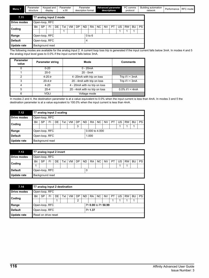
Menu 7Parameter structure
Keypad and display
Parameter x.00
Parameter description format
Advanced parameter descriptions
PC comms protocol
Building automation network
Performance RFC mode
The following modes are available for the analog input 2. A current loop loss trip is generated if the input current falls below 3mA. In modes 4 and 5 the analog input level goes to 0.0% if the input current falls below 3mA.
In modes 2 and 4, the destination parameter is at a value equivalent to 0.0% when the input current is less than 4mA. In modes 3 and 5 the destination parameter is at a value equivalent to 100.0% when the input current is less than 4mA.
7.11 T7 analog input 2 mode
Drive modes Open-loop, RFC
CodingBit SP FI DE Txt VM DP ND RA NC NV PT US RW BU PS
1 1 1 1
Range Open-loop, RFC 0 to 6
Default Open-loop, RFC 4
Update rate Background read
Parameter value
Parameter string Mode Comments
0 0-20 0 - 20mA
1 20-0 20 - 0mA
2 4-20.tr 4 -20mA with trip on loss Trip if I < 3mA
3 20-4.tr 20 - 4mA with trip on loss Trip if I < 3mA
4 4-20 4 - 20mA with no trip on loss
5 20-4 20 - 4mA with no trip on loss 0.0% if I < 4mA
6 VOLt Voltage mode
7.12 T7 analog input 2 scaling
Drive modes Open-loop, RFC
CodingBit SP FI DE Txt VM DP ND RA NC NV PT US RW BU PS
3 1 1 1
Range Open-loop, RFC 0.000 to 4.000
Default Open-loop, RFC 1.000
Update rate Background read
7.13 T7 analog input 2 invert
Drive modes Open-loop, RFC
CodingBit SP FI DE Txt VM DP ND RA NC NV PT US RW BU PS
1 1 1
Default Open-loop, RFC 0
Update rate Background read
7.14 T7 analog input 2 destination
Drive modes Open-loop, RFC
CodingBit SP FI DE Txt VM DP ND RA NC NV PT US RW BU PS
1 2 1 1 1 1
Range Open-loop, RFC Pr 0.00 to Pr 50.99
Default Open-loop, RFC Pr 1.37
Update rate Read on drive reset
116 Affinity Advanced User Guide Issue Number: 3
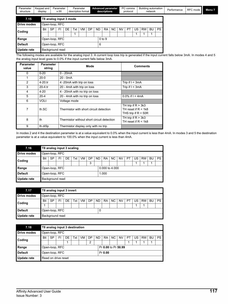
Parameter structure
Keypad and display
Parameter x.00
Parameter description format
Advanced parameter descriptions
PC comms protocol
Building automation network
Performance RFC mode Menu 7
The following modes are available for the analog input 3. A current loop loss trip is generated if the input current falls below 3mA. In modes 4 and 5 the analog input level goes to 0.0% if the input current falls below 3mA.
In modes 2 and 4 the destination parameter is at a value equivalent to 0.0% when the input current is less than 4mA. In modes 3 and 5 the destination parameter is at a value equivalent to 100.0% when the input current is less than 4mA.
7.15 T8 analog input 3 mode
Drive modes Open-loop, RFC
CodingBit SP FI DE Txt VM DP ND RA NC NV PT US RW BU PS
1 1 1 1
Range Open-loop, RFC 0 to 9
Default Open-loop, RFC 6
Update rate Background read
Parameter value
Parameter string
Mode Comments
0 0-20 0 - 20mA
1 20-0 20 - 0mA
2 4-20.tr 4 -20mA with trip on loss Trip if I < 3mA
3 20-4.tr 20 - 4mA with trip on loss Trip if I < 3mA
4 4-20 4 - 20mA with no trip on loss
5 20-4 20 - 4mA with no trip on loss 0.0% if I < 4mA
6 VOLt Voltage mode
7 th.SC Thermistor with short circuit detectionTH trip if R > 3k3TH reset if R < 1k8THS trip if R < 50R
8 th Thermistor without short circuit detectionTH trip if R > 3k3TH reset if R < 1k8
9 th.diSp Thermistor display only with no trip
7.16 T8 analog input 3 scaling
Drive modes Open-loop, RFC
CodingBit SP FI DE Txt VM DP ND RA NC NV PT US RW BU PS
3 1 1 1
Range Open-loop, RFC 0.000 to 4.000
Default Open-loop, RFC 1.000
Update rate Background read
7.17 T8 analog input 3 invert
Drive modes Open-loop, RFC
CodingBit SP FI DE Txt VM DP ND RA NC NV PT US RW BU PS
1 1 1
Default Open-loop, RFC 0
Update rate Background read
7.18 T8 analog input 3 destination
Drive modes Open-loop, RFC
CodingBit SP FI DE Txt VM DP ND RA NC NV PT US RW BU PS
1 2 1 1 1 1
Range Open-loop, RFC Pr 0.00 to Pr 50.99
Default Open-loop, RFC Pr 0.00
Update rate Read on drive reset
Affinity Advanced User Guide 117Issue Number: 3

Menu 7Parameter structure
Keypad and display
Parameter x.00
Parameter description format
Advanced parameter descriptions
PC comms protocol
Building automation network
Performance RFC mode
The following modes are available for the analog outputs.
In voltage mode the output range is -10V to 10V. If the scaling parameter is 1.000 then -10V and +10V are produced when the source parameter is at -maximum and maximum respectively. Different scaling can be applied with Pr 7.23. If the result of the scaling produces an output of more than +/-100% the output is clamped within the 10V range.
In current modes with a scaling parameter of 1.000, the minimum and maximum current is produced when the source parameter is at 0 and maximum respectively. Therefore in 4 - 20mA mode the output is 4mA when the source parameter is zero. Different scaling can be applied with Pr 7.23. If the result of the scaling produces an output of more than 100% the output is clamped at 20mA.
If high speed update mode is selected and the source for the output is one of the parameters designated for high speed analog output operation (see start of this section), the output is updated at a higher rate with special scaling. If the parameter selected is not designated for this mode, the output is updated at the normal rate. If speed feedback or power is selected for high speed mode for both analog output 1 and analog output 2, the setting is ignored for analog output 2. If the high speed mode is selected the output is always a voltage signal.
7.19 T9 analog output 1 source
Drive modes Open-loop, RFC
CodingBit SP FI DE Txt VM DP ND RA NC NV PT US RW BU PS
2 1 1 1 1
Range Open-loop, RFC Pr 0.00 to Pr 50.99
DefaultOpen-loopRFC
Pr 5.01Pr 3.02
Update rate Background read
7.20 T9 analog output 1 scaling
Drive modes Open-loop, RFC
CodingBit SP FI DE Txt VM DP ND RA NC NV PT US RW BU PS
3 1 1 1
Range Open-loop, RFC 0.000 to 4.000
Default Open-loop, RFC 1.000
Update rate Background read
7.21 T9 analog output 1 mode
Drive modes Open-loop, RFC
CodingBit SP FI DE Txt VM DP ND RA NC NV PT US RW BU PS
1 1 1 1
Range Open-loop, RFC 0 to 3
Default Open-loop, RFC 0
Update rate Background read
Parameter value Parameter string Mode
0 VOLt Voltage mode
1 0-20 0 - 20mA
2 4-20 4 - 20mA
3 H.Spd High speed up date mode
7.22 T10 analog output 2 source
Drive modes Open-loop, RFC
CodingBit SP FI DE Txt VM DP ND RA NC NV PT US RW BU PS
2 1 1 1 1
Range Open-loop, RFC Pr 0.00 to Pr 50.99
Default Open-loop, RFC Pr 4.02
Update rate Read on drive reset
118 Affinity Advanced User Guide Issue Number: 3

Parameter structure
Keypad and display
Parameter x.00
Parameter description format
Advanced parameter descriptions
PC comms protocol
Building automation network
Performance RFC mode Menu 7
The following modes are available for the analog outputs.
In voltage mode the output range is -10V to +10V. If the scaling parameter is 1.000 then -10V and +10V are produced when the source parameter is at -maximum and maximum respectively. Different scaling can be applied with Pr 7.23. If the result of the scaling produces an output of more than +/-100% the output is clamped within the 10V range.
In current modes with a scaling parameter of 1.000, the minimum and maximum current are produced when the source parameter is at 0 and maximum respectively. Therefore in 4 - 20mA mode the output is 4mA when the source parameter is zero. Different scaling can be applied with Pr 7.23. If the result of the scaling produces an output of more than 100% the output is clamped at 20mA.
If high speed update mode is selected, and the source for the output is one of the parameters designated for high speed analog output operation (see start of this section), the output is updated at a higher rate with special scaling. If the parameter selected is not designated for this mode, the output is updated at the normal rate. If speed feedback or power is selected for high speed mode for both analog output 1 and analog output 2, the setting is ignored for analog output 2. If the high speed mode is selected the output is always a voltage signal.
Setting this bit will cause the drive to re-calibrate the full scale level of analog input 1 provided the input voltage is below +1.5V or above +2.5V. This parameter is cleared by the software automatically when the calibration is complete. If the input voltage is above +2.5V the input voltage itself is used for calibration, and so after calibration this level will be full scale for the input. If the input voltage is below +1.5V the internal reference is used for calibration, and so the full scale will be nominally 9.8V after calibration. The calibration level is automatically stored on power-down. It should be noted that the Analog input 1 offset trim is included in the input voltage when the input voltage itself is used for calibration, but this trim is not included when the internal reference is used for calibration.
Analog input 1 is filtered using a window filter to remove quantisation noise and adjust the resolution of this input. The length of the window can be adjusted with this parameter. The shortest possible window is 250s. It should be noted that if this input is not used as a speed reference (Pr 1.36, Pr 1.37) or as a hard speed reference (Pr 3.22) the sample time affects the resolution. The nominal resolution is given by Pr 7.26 x 500 x 10, therefore the default setting gives approximately 11 bit resolution.
7.23 T10 analog output 2 scaling
Drive modes Open-loop, RFC
CodingBit SP FI DE Txt VM DP ND RA NC NV PT US RW BU PS
3 1 1 1
Range Open-loop, RFC 0.000 to 4.000
Default Open-loop, RFC 1.000
Update rate Background read
7.24 T10 analog output 2 mode
Drive modes Open-loop, RFC
CodingBit SP FI DE Txt VM DP ND RA NC NV PT US RW BU PS
1 1 1 1
Range Open-loop, RFC 0 to 3
Default Open-loop, RFC 0
Update rate Background read
Parameter value Parameter string Mode
0 VOLt Voltage mode
1 0-20 0 - 20mA
2 4-20 4 - 20mA
3 H.Spd High speed update mode
7.25 Calibrate T5/6 analog input 1 full scale
Drive modes Open-loop, RFC
CodingBit SP FI DE Txt VM DP ND RA NC NV PT US RW BU PS
1 1 1
Default Open-loop, RFC 0
Update rate Background read
7.26 T5/6 analog input 1 sample time
Drive modes Open-loop, RFC
CodingBit SP FI DE Txt VM DP ND RA NC NV PT US RW BU PS
1 1 1 1
Range Open-loop, RFC 0 to 8.0 ms
Default Open-loop, RFC 4.0
Update rate Background read
Affinity Advanced User Guide 119Issue Number: 3

Menu 7Parameter structure
Keypad and display
Parameter x.00
Parameter description format
Advanced parameter descriptions
PC comms protocol
Building automation network
Performance RFC mode
If an analog input is used with 4-20mA or 20-4mA current loop modes the respective bit (Pr 7.28 - analog input 2 and Pr 7.29 -analog input 3) is set to one if the current falls below 3mA. If the current is above 3mA with these modes or another mode is selected the respective bit is set to zero.
An offset can be added to each analog input with a range from -100% to 100%. If the sum of the input and the offset exceeds ±100% the results is limited to ±100%.
This offers a simple control of Pr 7.19 to change the source for the analog output for use from Menu 0. When this parameter is set to 0 or 1 the drive constantly writes Pr 5.01 or Pr 4.02 to Pr 7.19 respectively.
The IGBT junction temperature is displayed in this parameter is the sum of the power circuit 1 temperature (Pr 7.04) and a thermal model of the drive power stage. The resulting temperature is displayed in this parameter. The calculated IGBT junction temperature is used to modify the drive switching frequency to reduce losses if the devices become too hot (see Pr 5.18 on page 89).
7.28 T7 analog input 2 current loop loss
7.29 T8 analog input 3 current loop loss
Drive modes Open-loop, RFC
CodingBit SP FI DE Txt VM DP ND RA NC NV PT US RW BU PS
1 1 1 1
Update rate Background write
7.30 T5/6 analog input 1 offset
Drive modes Open-loop, RFC
CodingBit SP FI DE Txt VM DP ND RA NC NV PT US RW BU PS
2 1 1
Range Open-loop, RFC ±100.00 %
Default Open-loop, RFC 0.00
Update rate Background read
7.31 T7 analog input 2 offset
7.32 T8 analog input 3 offset
Drive modes Open-loop, RFC
CodingBit SP FI DE Txt VM DP ND RA NC NV PT US RW BU PS
1 1 1
Range Open-loop, RFC ±100.0 %
Default Open-loop, RFC 0.0
Update rate Background read
7.33 T9 analog output 1 control
Drive modes Open-loop, RFC
CodingBit SP FI DE Txt VM DP ND RA NC NV PT US RW BU PS
1 1 1 1
Range Open-loop, RFC 0 to 2
Default Open-loop, RFC 2
Update rate Background read
Parameter value Parameter string Action0 Fr Write Pr 7.19 = Pr 5.011 Ld Write Pr 7.19 = Pr 4.022 AdV No action
7.34 IGBT junction temperature
Drive modes Open-loop, RFC
CodingBit SP FI DE Txt VM DP ND RA NC NV PT US RW BU PS
1 1 1
Range Open-loop, RFC ±200 °C
Update rate Background write
120 Affinity Advanced User Guide Issue Number: 3

Parameter structure
Keypad and display
Parameter x.00
Parameter description format
Advanced parameter descriptions
PC comms protocol
Building automation network
Performance RFC mode Menu 7
In addition to monitoring the IGBT junction temperatures the drive includes a thermal protection system to protect the other components within the drive. This includes the effects of drive output current and DC bus ripple. The estimated temperature is displayed as a percentage of the trip level in this parameter. If the parameter value reaches 100% an Oht3 trip is initiated.
An additional thermal monitoring point is provided in BA6xxx and BAMxxxx drives. The temperature is displayed in this parameter in degrees C. See Pr 7.04 to Pr 7.06 for more details.
If this temperature exceeds 135°C, the switching frequency is reduced provided that this feature has not been reached. The switching frequency can be reduced from 12kHz to 6kHz to 3kHz, or from 16kHz to 8kHz to 4kHz. If at any time the calculated IGBT junction temperature exceeds 145°C the drive initiates an Ohtl.trip. Once the switching frequency has been reduced the drive will attempt to restore the switching frequency every 20ms if the higher switching frequency will not take the IGBT temperature above 135°C.
7.35 Drive thermal protection accumulator
Drive modes Open-loop, RFC
CodingBit SP FI DE Txt VM DP ND RA NC NV PT US RW BU PS
1 1 1 1 1
Range Open-loop, RFC 0 to 100 %
Update rate Background write
7.36 Power circuit temperature 3
Drive modes Open-loop, RFC
CodingBit SP FI DE Txt VM DP ND RA NC NV PT US RW BU PS
1 1 1
Range Open-loop, RFC -128 to 127 °C
Update rate Background write
Affinity Advanced User Guide 121Issue Number: 3

Menu 8Parameter structure
Keypad and display
Parameter x.00
Parameter description format
Advanced parameter descriptions
PC comms protocol
Building automation network
Performance RFC mode
5.10 Menu 8: Digital I/OThe drive has eight digital I/O terminals (T22, T24 to T29 and the relay) plus an enable input.
Each input has the same parameter structure. The digital inputs are sampled every 4ms except when inputs are routed to the limit switches Pr 6.35 and Pr 6.36 when the sample time is reduced to 250s.
The digital input hardware (excluding the drive enable input) introduces a further 100s delay. The secure disable input hardware gives a typical delay of 8ms (maximum 20ms). The digital outputs are updated every 4ms. Any changes to the source/destination parameters only become effect after drive reset is activated.
I/O Sample rate Function
T24 to T26 4ms Digital input or output
T27 to T29 4ms Digital input
Relay Background
T22 Background 24V output
122 Affinity Advanced User Guide Issue Number: 3

Parameter structure
Keypad and display
Parameter x.00
Parameter description format
Advanced parameter descriptions
PC comms protocol
Building automation network
Performance RFC mode Menu 8
Affinity Advanced User Guide 123Issue Number: 3

Menu 8Parameter structure
Keypad and display
Parameter x.00
Parameter description format
Advanced parameter descriptions
PC comms protocol
Building automation network
Performance RFC mode
Figure 5-11 Menu 8 logic diagram
T25 digital I/O 2
8.32
??.??
Any unprotected bit parameter
??.??
??.??
??.??
Any bit parameter
8.22
x(-1)
x(-1)
8.12
8.02
T26 digital I/O 3
8.33
??.??
Any unprotected bit parameter
??.??
??.??
Any bit parameter
??.??
8.23
x(-1)
x(-1)
8.13
8.03
8.29
Open collector output
8.30
8.29
Open collector output
8.30
10.33
Drive reset
6.30
Run forward
I/O polarityselect
I/O polarityselect
T24 digital I/O 1
T24 digital I/O 1 state
8.31
T24 outputselect
??.??
??.??
Any unprotected bit parameter
??.??
??.??
Any bit parameter8.21T24 digital
I/O 1 source/destination
x(-1)
x(-1)
8.11 T24 digital I/O 1 invert
8.01
8.29
I/O polarityselect
Open collector output
8.30
10.02
Driveactive
T25 digital I/O 2 state T25 output
select
T25 digital I/O 2 source/destination
T25 digital I/O 2 invert
T26 digital I/O 3 state T26 output
select
T26 digital I/O 3 source/destination
T26 digital I/O 3 invert
6.04Start/stoplogic select
6.04Start/stoplogic select
124 Affinity Advanced User Guide Issue Number: 3

Parameter structure
Keypad and display
Parameter x.00
Parameter description format
Advanced parameter descriptions
PC comms protocol
Building automation network
Performance RFC mode Menu 8
T29 digital input 6
??.??
Any unprotected bit parameter
??.??
8.26
T29 digital input 6
destination
x(-1)
8.16
T29 digitalinput 6 invert T29 digital
input 6 state
8.06
8.29
0.00I.O polarityselect
8.27
Relaysource
Relay source invert
Any bitparameter
x(-1)
Relay state
DriveHealthy
0.XX
0.XX
Key
Read-write (RW) parameter
Read-only (RO) parameter
Inputterminals
Outputterminals
This logic diagram applies only when allparameters are at their default settings
8.25
T28 digital input 5
destination
??.??
Any unprotected bit parameter
??.??x(-1)
8.15
T28 digitalinput 5 invert T28 digital
input 5 state
8.05
8.291.41
Analog input 1 / input 2 select
I.O polarityselect
T28 digital input 5
8.10
Drive enable mode select
Drive enable
10.32
External trip
Drive enable
Drive enable indicator 8.09
x(-1)
T22 24V output
Anyunprotectedbitparameter
??.??
8.28
T22 24V output source
x(-1)
8.18
T22 24V outputsource invertT22 24V
output state 8.08
0.00
??.??
T27 digital input 4
??.??
Any unprotected bit parameter
??.??
8.24
T27 digital input 4destination
x(-1)
8.14
T27 digitalinput 4 invert T27 digital
input 4 state
8.04
8.29
I.O polarityselect
1.54
Fire modeactivate
Stop/startlogic select
6.04
1.14
8.39 T28 & T29 digitalinput auto-selectiondisable*Reference
selector*
Affinity Advanced User Guide 125Issue Number: 3

Menu 8Parameter structure
Keypad and display
Parameter x.00
Parameter description format
Advanced parameter descriptions
PC comms protocol
Building automation network
Performance RFC mode
Open-loop, RFCTable 5-12
OFF (0) = Terminal inactive
On (1) = Terminal active
Affinity has a dedicated hardware enable/input which always controls Pr 6.29. If the enable is inactive, the IGBT firing signals are turned off without software intervention. As default (Pr 8.10 = 0) the drive is in the inhibit mode when the enable is inactive. Setting this parameter to one causes the enable to behave as an Et trip input. When the input becomes inactive an Et trip is initiated. This does not affect Pr 10.32 (Et trip parameter), therefore an Et trip can be initiated in this mode either by making the enable inactive or setting Pr 10.32 to one.
Terminal + typeI/O state Invert Source / destination Output select
Pr Pr Default Pr Default Pr Default
T24 input / output 1 Pr 8.01 Pr 8.11 0 Pr 8.21 Pr 10.02 - Drive active Pr 8.31 1
T25 input / output 2 Pr 8.02 Pr 8.12 0 Pr 8.22 Pr 10.33 - Drive reset Pr 8.32 0
T26 input / output 3 Pr 8.03 Pr 8.13 0 Pr 8.23 Pr 6.30 - Run forward Pr 8.33 0
T27 input 4 Pr 8.04 Pr 8.14 0 Pr 8.24 Pr 1.54 - Fire mode activate
T28 input 5 Pr 8.05 Pr 8.15 0 Pr 8.25 Pr 1.41 – Local/remote
T29 input 6 Pr 8.06 Pr 8.16 0 Pr 8.26 Pr 0.00
T41 / 42 Relay Pr 8.07 Pr 8.17 0 Pr 8.27 Pr 10.01 – Drive ok
T22 24V output Pr 8.08 Pr 8.18 1 Pr 8.28 Pr 0.00
T31 Drive enable Pr 8.09
8.01 T24 digital I/O 1 state
8.02 T25 digital I/O 2 state
8.03 T26 digital I/O 3 state
8.04 T27 digital input 4 state
8.05 T28 digital input 5 state
8.06 T29 digital input 6 state
8.07 Relay status
8.08 T22 24V output state
8.09 Drive enable indicator
Drive modes Open-loop, RFC
CodingBit SP FI DE Txt VM DP ND RA NC NV PT US RW BU PS
1 1 1 1
Default Open-loop, RFC See table
Update rate 4ms write
8.10 Drive enable mode select
Drive modes Open-loop, RFC
Coding Bit SP FI DE Txt VM DP ND RA NC NV PT US RW BU PS
1 1 1
Default Open-loop, RFC OFF (0)
Update rate Background read
126 Affinity Advanced User Guide Issue Number: 3

Parameter structure
Keypad and display
Parameter x.00
Parameter description format
Advanced parameter descriptions
PC comms protocol
Building automation network
Performance RFC mode Menu 8
OFF (0) = Non-invertedOn (1) = Inverted
This word is used to determine the status of the digital I/O by reading one parameter. The bits in this word reflect the state of Pr 8.01 to Pr 8.09.
8.11 T24 digital I/O 1 invert
8.12 T25 digital I/O 2 invert
8.13 T26 digital I/O 3 invert
8.14 T27 digital input 4 invert
8.15 T28 digital input 5 invert
8.16 T29 digital input 6 invert
8.17 Relay source invert
8.18 T22 24V output source invert
Drive modes Open-loop, RFC
CodingBit SP FI DE Txt VM DP ND RA NC NV PT US RW BU PS
1 1 1
Default Open-loop, RFC Pr 8.11 to Pr 8.17 = OFF (0), Pr 8.18 = On (1)
Update rate 4ms read
8.20 Digital I/O read word
Drive modes Open-loop, RFC
CodingBit SP FI DE Txt VM DP ND RA NC NV PT US RW BU PS
1 1 1 1
Range Open-loop, RFC 0 to 511
Update rate Background write
Bit Digital I/O
0 T24 input / output 1
1 T25 input / output 2
2 T26 input / output 3
3 T27 input 4
4 T28 input 5
5 T29 input 6
6 Relay
7 T22 24V output
8 Drive enable
8.21 T24 digital I/O 1 source/destination
8.22 T25 digital I/O 2 source/destination
8.23 T26 digital I/O 3 source/destination
8.24 T27 digital input 4 destination
8.25 T28 digital input 5 destination
8.26 T29 digital input 6 destination
Drive modes Open-loop, RFC
CodingBit SP FI DE Txt VM DP ND RA NC NV PT US RW BU PS
1 2 1 1 1 1
Default Open-loop, RFC See Table 5-12 on page 126
Range Open-loop, RFC Pr 0.00 to Pr 50.99
Update rate Read on drive reset
Affinity Advanced User Guide 127Issue Number: 3

Menu 8Parameter structure
Keypad and display
Parameter x.00
Parameter description format
Advanced parameter descriptions
PC comms protocol
Building automation network
Performance RFC mode
This parameter changes the logic polarity for digital inputs and digital outputs, but not the enable input, the relay output or the 24V output.
When this parameter is zero digital outputs are in push-pull mode. When this parameter is one either the high-side drive (negative logic polarity) or the low-side driver (positive logic polarity) is disabled. This allows outputs to be connected in a wire-ORed configuration.
OFF (0) = Terminal is an inputOn (1) = Terminal is an output
8.27 Relay source
8.28 T22 24V output source
Drive modes Open-loop, RFC
CodingBit SP FI DE Txt VM DP ND RA NC NV PT US RW BU PS
2 1 1 1 1
Default Open-loop, RFC See Table 5-12 on page 126
Range Open-loop, RFC Pr 0.00 to Pr 50.99
Update rate Read on drive reset
8.29 Positive logic select
Drive modes Open-loop, RFC
CodingBit SP FI DE Txt VM DP ND RA NC NV PT US RW BU PS
1 1 1 1 1
Default Open-loop, RFC On (1)
Update rate Background read
Pr 8.29 = 0(negative logic)
Pr 8.29 = 1(positive logic)
Inputs <5V = 1>15V = 0
<5V = 0>15V = 1
Non-relay Outputs On (1) = <5VOFF (0) = >15V
OFF (0) = <5VOn (1) = >15V
Relay outputs OFF (0) = openOn (1) = closed
OFF (0) = openOn (1) = closed
24V output (T22) OFF (0) = 0VOn (1) = 24V
OFF (0) = 0VOn (1) = 24V
8.30 Open collector output
Drive modes Open-loop, RFC
CodingBit SP FI DE Txt VM DP ND RA NC NV PT US RW BU PS
1 1 1
Default Open-loop, RFC OFF (0)
Update rate Background read
8.31 T24 digital I/O 1 output select
8.32 T25 digital I/O 2 output select
8.33 T26 digital I/O 3 output select
Drive modes Open-loop, RFC
CodingBit SP FI DE Txt VM DP ND RA NC NV PT US RW BU PS
1 1 1
Default Open-loop, RFCPr 8.31 = On (1), Pr 8.32 and Pr 8.33 = OFF (0)
Update rate Background read
128 Affinity Advanced User Guide Issue Number: 3

Parameter structure
Keypad and display
Parameter x.00
Parameter description format
Advanced parameter descriptions
PC comms protocol
Building automation network
Performance RFC mode Menu 8
When this parameter is 0, Pr 8.25 and Pr 8.26 are set up automatically according to the setting of the reference select Pr 1.14. Setting this parameter to 1 disables this function.
8.39 T28 & T29 digital input auto-selection disable
Drive modes Open-loop, RFC
CodingBit SP FI DE Txt VM DP ND RA NC NV PT US RW BU PS
1 1 1
Default Open-loop, RFC On (1)
Update rate Background read
Reference select Pr 1.14 Pr 8.25 set to: Pr 8.26 set to:
0, A1.A2 Reference selection by terminal input Pr 1.41 - Analog ref 2 select Pr 0.00
1, A1.PrAnalog reference 1 or presets selected by terminal input
Pr 1.45 - preset select bit 0 Pr 1.46 - preset select bit 1
2, A2.PrAnalog reference 2 or presets selected by terminal input
Pr 1.45 - preset select bit 0 Pr 1.46 - preset select bit 1
3, PrPreset reference selected by terminal input
Pr 1.45 - preset select bit 0 Pr 1.46 - preset select bit 1
4, Pad Keypad reference selected Pr 1.41 - Analog ref 2 select Pr 6.31 - jog
5, Prc Precision reference selected Pr 1.41 - Analog ref 2 select Pr 6.31 - jog
Affinity Advanced User Guide 129Issue Number: 3

Menu 9Parameter structure
Keypad and display
Parameter x.00
Parameter description format
Advanced parameter descriptions
PC comms protocol
Building automation network
Performance RFC mode
5.11 Menu 9: Programmable logic, motorized pot and binary sumFigure 5-12 Menu 9 logic diagram
??.??
Any unprotected bit parameter
??.??
9.10
Function-1 destination parameter
??.??
Any bit parameter
??.?? x(-1)
9.04 Function-1 input-1 source parameter
9.05Function-1 input-1 invert
??.??
Any bit parameter
??.?? x(-1)
9.06 Function-1 input-2 source parameter
9.07Function-1 input-2 invert
9.08
Function-1 output invert
9.09
Function-1 delay
x(-1)
Function-1 output indicator
9.01
??.??
Any unprotected bit parameter
??.??
9.20
Function-2 destination parameter
??.??
Any bit parameter
??.?? x(-1)
9.14 Function-2 input-1 source parameter
9.15Function-2 input-1 invert
??.??
Any bit parameter
??.?? x(-1)
9.16 Function-2 input-2 source parameter
9.17Function-2 input-2 invert
9.18
Function-2 output invert
9.19
Function-2 delay
x(-1)
Function-2 output indicator
9.02
0.XX
0.XX
Key
Read-write (RW) parameter
Read-only (RO) parameter
Inputterminals
Outputterminals
The parameters are all shown at their default settings
130 Affinity Advanced User Guide Issue Number: 3

Parameter structure
Keypad and display
Parameter x.00
Parameter description format
Advanced parameter descriptions
PC comms protocol
Building automation network
Performance RFC mode Menu 9
9.30
Binary-sumlogic twos
9.29
Binary-sumlogic ones (LSB)
9.31
Binary-sumlogic fours (MSB)
9.32
Binary-sumlogic output
value
??.??
Anyunprotectedbitparameter
??.??
9.33
Binary-sumlogic destinationparameter
S
9.24
Motorised pot.output scale
9.25
Motorised pot.destinationparameter
9.23
Motorisedpot. rate
??.??
Anyunprotectedvariableparameter
??.??
9.27
Motorised pot.down
9.26
Motorised pot.up
M
9.03
Motorised pot.output indicator
9.22
Motorisedpot. bipolarselect
9.219.28
Motorised pot.reset to zero
Motorised pot.mode
+
+
9.34
Binary-sumoffset
Affinity Advanced User Guide 131Issue Number: 3

Menu 9Parameter structure
Keypad and display
Parameter x.00
Parameter description format
Advanced parameter descriptions
PC comms protocol
Building automation network
Performance RFC mode
Figure 5-13 Menu 9 logic diagram: Timers
Menu 9 contains 2 logic block functions (which can be used to produce any type of 2 input logic gate, with or without a delay), a motorized pot function, a binary sum block and two timers. One menu 9 or one menu 12 function is executed every 4ms. Therefore the sample time of these functions is 4ms x number of menu 9 and 12 functions active. The logic functions are active if one or both the sources are routed to a valid parameter. The other functions are active if the output destination is routed to a valid unprotected parameter.
Indicates the level of the motorized pot prior to scaling. If Pr 9.21 is set to 0 or 2 this parameter is set to 0 at power-up, otherwise it retains its value at the last power-down.
9.01 Logic function 1 output
9.02 Logic function 2 output
Drive modes Open-loop, RFC
CodingBit SP FI DE Txt VM DP ND RA NC NV PT US RW BU PS
1 1 1 1
Update rate 4ms x number of menu 9 or 12 functions active write
9.03 Motorized pot output
Drive modes Open-loop, RFC
CodingBit SP FI DE Txt VM DP ND RA NC NV PT US RW BU PS
2 1 1 1 1
Range Open-loop, RFC ±100.00 %
Update rate 4ms x number of menu 9 or 12 functions active write
??.??
Any unprotected bit parameter
??.??
9.43
9.41
x(-1)
9.42
0.XX
0.XX
Key
Read-write (RW) parameter
Read-only (RO) parameter
Inputterminals
Outputterminals
The parameters are all shown at their default settings
9.40
9.35 Timer 1 start date
9.36 Timer 1 start time
9.37 Timer 1 stop date
9.38 Timer 1 stop time
9.39 Timer 1 repeat function
Timer 1enable
Timer 1invert
Timer 1output Timer 1
destination
??.??
Any unprotected bit parameter
??.??
9.53
9.51
x(-1)
9.52
9.50
9.45 Timer 2 start date
9.46 Timer 2 start time
9.47 Timer 2 stop date
9.48 Timer 2 stop time
9.49 Timer 2 repeat function
Timer 2enable
Timer 2invert
Timer 2output Timer 2
destination
Timer disabled if set to a non valid destination
Timer disabled if set to a non valid destination
132 Affinity Advanced User Guide Issue Number: 3
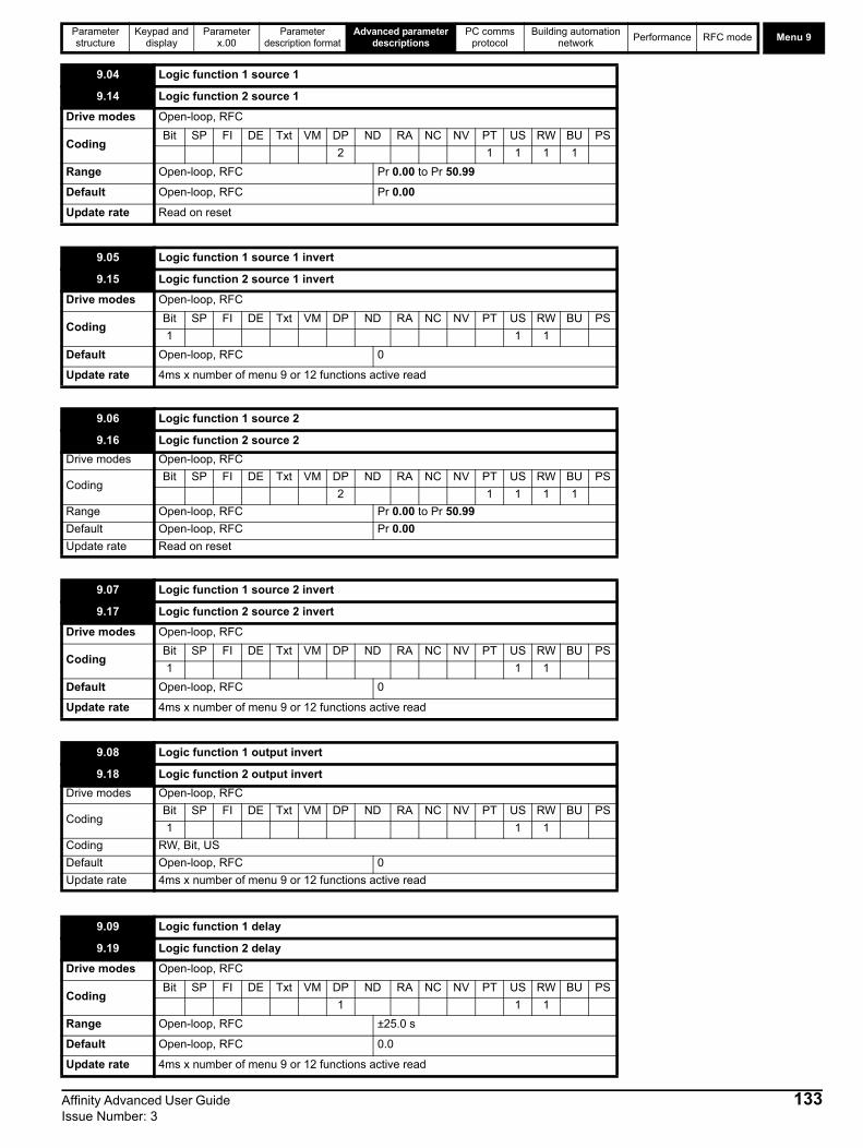
Parameter structure
Keypad and display
Parameter x.00
Parameter description format
Advanced parameter descriptions
PC comms protocol
Building automation network
Performance RFC mode Menu 9
9.04 Logic function 1 source 1
9.14 Logic function 2 source 1
Drive modes Open-loop, RFC
CodingBit SP FI DE Txt VM DP ND RA NC NV PT US RW BU PS
2 1 1 1 1
Range Open-loop, RFC Pr 0.00 to Pr 50.99
Default Open-loop, RFC Pr 0.00
Update rate Read on reset
9.05 Logic function 1 source 1 invert
9.15 Logic function 2 source 1 invert
Drive modes Open-loop, RFC
CodingBit SP FI DE Txt VM DP ND RA NC NV PT US RW BU PS
1 1 1
Default Open-loop, RFC 0
Update rate 4ms x number of menu 9 or 12 functions active read
9.06 Logic function 1 source 2
9.16 Logic function 2 source 2
Drive modes Open-loop, RFC
CodingBit SP FI DE Txt VM DP ND RA NC NV PT US RW BU PS
2 1 1 1 1
Range Open-loop, RFC Pr 0.00 to Pr 50.99
Default Open-loop, RFC Pr 0.00
Update rate Read on reset
9.07 Logic function 1 source 2 invert
9.17 Logic function 2 source 2 invert
Drive modes Open-loop, RFC
CodingBit SP FI DE Txt VM DP ND RA NC NV PT US RW BU PS
1 1 1
Default Open-loop, RFC 0
Update rate 4ms x number of menu 9 or 12 functions active read
9.08 Logic function 1 output invert
9.18 Logic function 2 output invert
Drive modes Open-loop, RFC
CodingBit SP FI DE Txt VM DP ND RA NC NV PT US RW BU PS
1 1 1
Coding RW, Bit, US
Default Open-loop, RFC 0
Update rate 4ms x number of menu 9 or 12 functions active read
9.09 Logic function 1 delay
9.19 Logic function 2 delay
Drive modes Open-loop, RFC
CodingBit SP FI DE Txt VM DP ND RA NC NV PT US RW BU PS
1 1 1
Range Open-loop, RFC ±25.0 s
Default Open-loop, RFC 0.0
Update rate 4ms x number of menu 9 or 12 functions active read
Affinity Advanced User Guide 133Issue Number: 3

Menu 9Parameter structure
Keypad and display
Parameter x.00
Parameter description format
Advanced parameter descriptions
PC comms protocol
Building automation network
Performance RFC mode
If the delay parameter is positive, the delay ensures that the output does not become active until an active condition has been present at the input for the delay time as shown below.
If the delay parameter is negative, the delay holds the output active for the delay period after the active condition has been removed as shown below. Therefore an active input that lasts for 4ms or more will produce an output that lasts at least as long as the delay time.
The motorized pot modes are given in the following table.
When this bit is set to 0 the motorized pot output is limited to positive values only (i.e. 0 to 100.0%). Setting it to 1 allows negative outputs (i.e. ±100.0%).
9.10 Logic function 1 destination
9.20 Logic function 2 destination
Drive modes Open-loop, RFC
CodingBit SP FI DE Txt VM DP ND RA NC NV PT US RW BU PS
1 2 1 1 1 1
Range Open-loop, RFC Pr 0.00 to Pr 50.99
Default Open-loop, RFC Pr 0.00
Update rate Read on reset
9.21 Motorized pot mode
Drive modes Open-loop, RFC
CodingBit SP FI DE Txt VM DP ND RA NC NV PT US RW BU PS
1 1 1
Range Open-loop, RFC 0 to 3
Default Open-loop, RFC 2
Update rate Background read
Pr 9.21 Mode Comments
0 Zero at power-upReset to zero at each power-up.Up, down and reset are active at all times.
1 Last value at power-upSet to value at power-down when drive powered-up.Up, down and reset are active at all times.
2Zero at power-up and only change when drive running
Reset to zero at each power-up.Up and down are only active when the drive is running (i.e. inverter active). Reset is active at all times.
3Last value at power-up and only change when drive running
Set to value at power-down when drive powered-up.Up and down are only active when the drive is running (i.e. inverter active). Reset is active at all times.
9.22 Motorized pot bipolar select
Drive modes Open-loop, RFC
CodingBit SP FI DE Txt VM DP ND RA NC NV PT US RW BU PS
1 1 1
Default Open-loop, RFC 0
Update rate 4ms x number of menu 9 or 12 functions active read
Delay
Input
Output
Delay
Input
Output
134 Affinity Advanced User Guide Issue Number: 3

Parameter structure
Keypad and display
Parameter x.00
Parameter description format
Advanced parameter descriptions
PC comms protocol
Building automation network
Performance RFC mode Menu 9
This parameter defines the time taken for the motorized pot function to ramp from 0 to 100.0%. Twice this time will be taken to adjust the output from -100.0 % to +100.0 %.
This parameter can be used to restrict the output of the motorized pot to operate over a reduced range so that it can be used as a trim, for example.
These three bits control the motorized pot. The up and down inputs increase and decrease the output at the programmed rate respectively. If both up and down are active together the up function dominates and the output increases. If the reset input is one, the motorized pot output is reset and held at 0.0%.
9.23 Motorized pot rate
Drive modes Open-loop, RFC
CodingBit SP FI DE Txt VM DP ND RA NC NV PT US RW BU PS
1 1 1
Range Open-loop, RFC 0 to 250 s
Default Open-loop, RFC 20
Update rate Background read
9.24 Motorized pot scale factor
Drive modes Open-loop, RFC
CodingBit SP FI DE Txt VM DP ND RA NC NV PT US RW BU PS
3 1 1 1
Range Open-loop, RFC 0.000 to 4.000
Default Open-loop, RFC 1.000
Update rate 4ms x number of menu 9 or 12 functions active read
9.25 Motorized pot destination
Drive modes Open-loop, RFC
CodingBit SP FI DE Txt VM DP ND RA NC NV PT US RW BU PS
1 2 1 1 1 1
Range Open-loop, RFC Pr 0.00 to Pr 50.99
Default Open-loop, RFC Pr 0.00
Update rate Read on reset
9.26 Motorized pot up
Drive modes Open-loop, RFC
CodingBit SP FI DE Txt VM DP ND RA NC NV PT US RW BU PS
1 1 1
Default Open-loop, RFC 0
Update rate 4ms x number of menu 9 or 12 functions active read
9.27 Motorized pot down
Drive modes Open-loop, RFC
CodingBit SP FI DE Txt VM DP ND RA NC NV PT US RW BU PS
1 1 1
Default Open-loop, RFC 0
Update rate 4ms x number of menu 9 or 12 functions active read
9.28 Motorized pot reset
Drive modes Open-loop, RFC
CodingBit SP FI DE Txt VM DP ND RA NC NV PT US RW BU PS
1 1 1
Default Open-loop, RFC 0
Update rate 4ms x number of menu 9 or 12 functions active read
Affinity Advanced User Guide 135Issue Number: 3

Menu 9Parameter structure
Keypad and display
Parameter x.00
Parameter description format
Advanced parameter descriptions
PC comms protocol
Building automation network
Performance RFC mode
The binary sum output is given by:
Offset + ones input + (2 x twos input) + (4 x fours input)
The value written to the destination parameter is defined as follows:
If destination parameter maximum (7 + Offset):Destination parameter = Binary sum output
If destination parameter maximum > (7 + Offset):Destination parameter = Destination parameter maximum x Binary sum output / (7 + Offset)
9.29 Binary sum ones input
Drive modes Open-loop, RFC
CodingBit SP FI DE Txt VM DP ND RA NC NV PT US RW BU PS
1 1 1
Default Open-loop, RFC 0
Update rate 4ms x number of menu 9 or 12 functions active read
9.30 Binary sum twos input
Drive modes Open-loop, RFC
CodingBit SP FI DE Txt VM DP ND RA NC NV PT US RW BU PS
1 1 1
Default Open-loop, RFC 0
Update rate 4ms x number of menu 9 or 12 functions active read
9.31 Binary sum fours input
Drive modes Open-loop, RFC
CodingBit SP FI DE Txt VM DP ND RA NC NV PT US RW BU PS
1 1 1
Default Open-loop, RFC 0
Update rate 4ms x number of menu 9 or 12 functions active read
9.32 Binary sum output
Drive modes Open-loop, RFC
CodingBit SP FI DE Txt VM DP ND RA NC NV PT US RW BU PS
1 1 1 1
Range Open-loop, RFC 0 to 255
Default Open-loop, RFC 0
Update rate 4ms x number of menu 9 or 12 functions active write
9.33 Binary sum destination
Drive modes Open-loop, RFC
CodingBit SP FI DE Txt VM DP ND RA NC NV PT US RW BU PS
1 2 1 1 1 1
Range Open-loop, RFC Pr 0.00 to Pr 50.99
Default Open-loop, RFC Pr 0.00
Update rate Read on reset
9.34 Binary sum offset
Drive modes Open-loop, RFC
CodingBit SP FI DE Txt VM DP ND RA NC NV PT US RW BU PS
1 2 1 1 1 1
Range Open-loop, RFC 0 to 248
Default Open-loop, RFC 0
Update rate 4ms x number of menu 9 or 12 functions active write
136 Affinity Advanced User Guide Issue Number: 3

Parameter structure
Keypad and display
Parameter x.00
Parameter description format
Advanced parameter descriptions
PC comms protocol
Building automation network
Performance RFC mode Menu 9
The state of the timer output (Pr 9.42,Pr 9.52) is on between the start and stop date/time events.
9.35 Timer 1 start date
9.45 Timer 2 start date
Drive modes Open-loop, RFC
CodingBit SP FI DE Txt VM DP ND RA NC NV PT US RW BU PS
1 1 1 1
Range Open-loop, RFC 0 to 311299
Default Open-loop, RFC 0
Update rate Background read
9.36 Timer 1 start time
9.46 Timer 2 start time
Drive modes Open-loop, RFC
CodingBit SP FI DE Txt VM DP ND RA NC NV PT US RW BU PS
2 1 1 1 1
Range Open-loop, RFC 0.00 to 23.59
Default Open-loop, RFC 0.00
Update rate Background read
9.37 Timer 1 stop date
9.47 Timer 2 stop date
Drive modes Open-loop, RFC
CodingBit SP FI DE Txt VM DP ND RA NC NV PT US RW BU PS
2 1 1 1 1
Range Open-loop, RFC 0 to 311299
Default Open-loop, RFC 0
Update rate Background read
9.38 Timer 1 stop time
9.48 Timer 2 stop time
Drive modes Open-loop, RFC
CodingBit SP FI DE Txt VM DP ND RA NC NV PT US RW BU PS
2 1 1 1 1
Range Open-loop, RFC 0.00 to 23.59
Default Open-loop, RFC 0.00
Update rate Background read
9.39 Timer 1 repeat function
9.49 Timer 2 repeat function
Drive modes Open-loop, RFC
CodingBit SP FI DE Txt VM DP ND RA NC NV PT US RW BU PS
1 1 1 1
Range Open-loop, RFC 0 to 6
Default Open-loop, RFC 0
Update rate Background read
Affinity Advanced User Guide 137Issue Number: 3
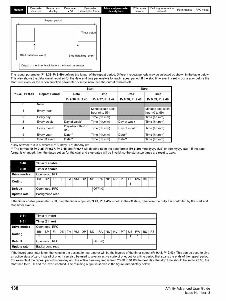
Menu 9Parameter structure
Keypad and display
Parameter x.00
Parameter description format
Advanced parameter descriptions
PC comms protocol
Building automation network
Performance RFC mode
The repeat parameter (Pr 9.39, Pr 9.49) defines the length of the repeat period. Different repeat periods may be selected as shown in the table below. This also shows the data format required for the date and time parameters for each repeat period. If the stop time event is set to occur at or before the start time event or the repeat function parameter is set to zero then the output remains off.
* Day of week = 0 to 6, where 0 = Sunday, 1 = Monday etc.** The format for Pr 9.35, Pr 9.37, Pr 9.45 and Pr 9.47 will depend upon the date format (Pr 6.20) mmddyyyy (US) or ddmmyyyy (Std). If the date format is changed, then the dates set up for the start and stop dates will be invalid, so the start/stop times are reset to zero.
If the timer enable parameter is off, then the timer output (Pr 9.42, Pr 9.43) is held in the off state, otherwise the output is controlled by the start and stop timer events.
If the invert parameter is on, the value in the destination parameter will be the inverse of the timer output (Pr 9.42, Pr 9.43). This can be used to give an active state of zero instead of one. It can also be used to give an active state of one, but for a time period that spans the ends of the repeat period. For example if the repeat period is one day and the active time required is from 23.00 to 01.00 the next day, the stop time should be set to 23.00, the start time to 01.00 and the invert enabled. The resulting output is shown in the figure immediately below.
Pr 9.39, Pr 9.49 Repeat Period
Start Stop
Date Time Date Time
Pr 9.36, Pr 9.46 Pr 9.37, Pr 9.47 Pr 9.38, Pr 9.48 Pr 9.39, Pr 9.49
0 None
1 Every hourMinutes past each hour (0 to 59)
Minutes past each hour (0 to 59)
2 Every day Time (hh.mm) Time (hh.mm)
3 Every week Day of week* Time (hh.mm) Day of week Time (hh.mm)
4 Every monthDay of month (0 to 31)
Time (hh.mm) Day of month Time (hh.mm)
5 Every year Date** Time (hh.mm) Date** Time (hh.mm)
6 One off event Date** Time (hh.mm) Date** Time (hh.mm)
9.40 Timer 1 enable
9.50 Timer 2 enable
Drive modes Open-loop, RFC
CodingBit SP FI DE Txt VM DP ND RA NC NV PT US RW BU PS
1 1 1
Default Open-loop, RFC OFF (0)
Update rate Background read
9.41 Timer 1 invert
9.51 Timer 2 invert
Drive modes Open-loop, RFC
CodingBit SP FI DE Txt VM DP ND RA NC NV PT US RW BU PS
1 1 1
Default Open-loop, RFC OFF (0)
Update rate Background read
Stop date/time event Start date/time event
Timer output
Repeat period
Output of the timer block before the invert parameter
138 Affinity Advanced User Guide Issue Number: 3

Parameter structure
Keypad and display
Parameter x.00
Parameter description format
Advanced parameter descriptions
PC comms protocol
Building automation network
Performance RFC mode Menu 9
It the enable parameter is set to 1 then the destination parameter will be 1 if the timer is disabled.
This parameter indicates the state of the timer output (Pr 9.42, Pr 9.43) prior to the invert function.
This parameter defines the address for the timer output destination. If this is not set to a valid destination parameter then the timer output will be zero.
9.42 Timer 1 output
9.52 Timer 2 output
Drive modes Open-loop, RFC
CodingBit SP FI DE Txt VM DP ND RA NC NV PT US RW BU PS
1 1
Default Open-loop, RFC OFF (0)
Update rate Background read
9.43 Timer 1 destination
9.53 Timer 2 destination
Drive modes Open-loop, RFC
CodingBit SP FI DE Txt VM DP ND RA NC NV PT US RW BU PS
1 2 1 1 1 1
Default Open-loop, RFC OFF (0)
Update rate Background read
01.00 23.00
Active period spanning the ends of repeat period
NOTE
Affinity Advanced User Guide 139Issue Number: 3
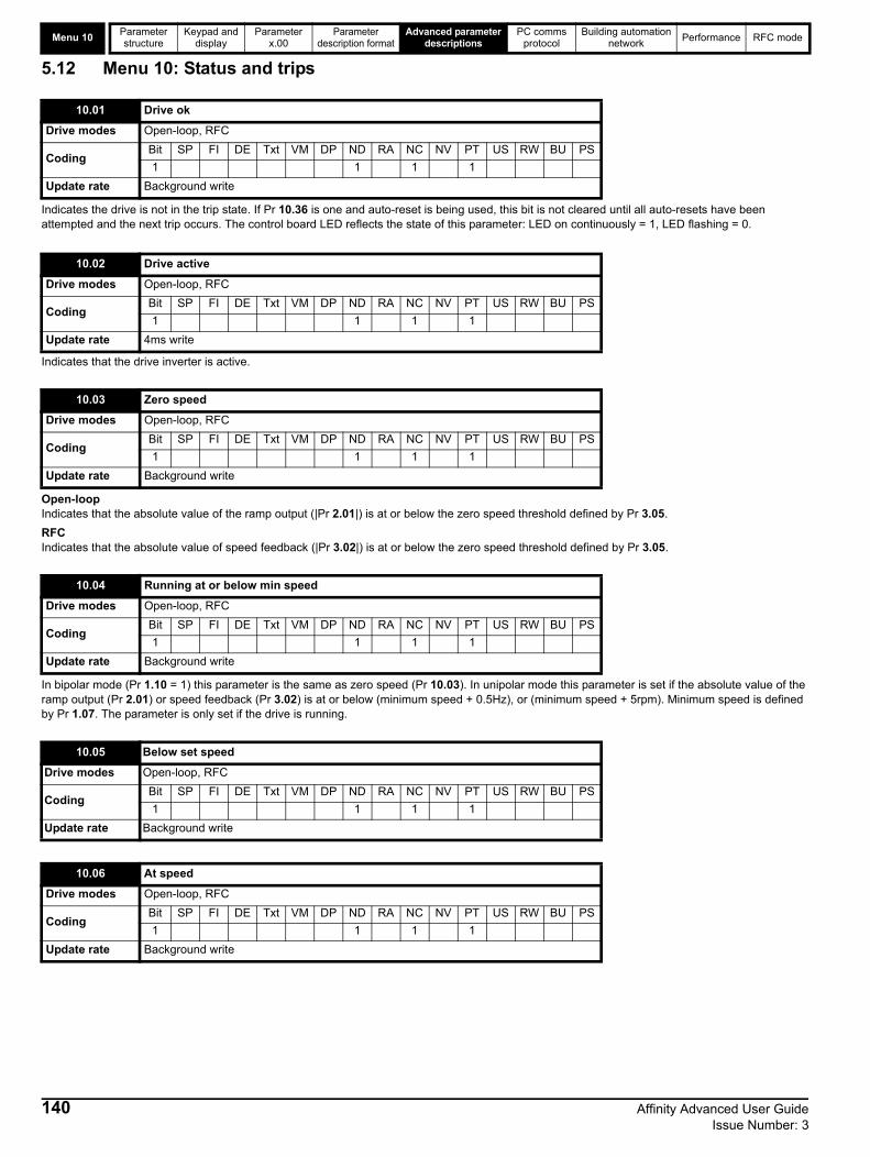
Menu 10Parameter structure
Keypad and display
Parameter x.00
Parameter description format
Advanced parameter descriptions
PC comms protocol
Building automation network
Performance RFC mode
5.12 Menu 10: Status and trips
Indicates the drive is not in the trip state. If Pr 10.36 is one and auto-reset is being used, this bit is not cleared until all auto-resets have been attempted and the next trip occurs. The control board LED reflects the state of this parameter: LED on continuously = 1, LED flashing = 0.
Indicates that the drive inverter is active.
Open-loopIndicates that the absolute value of the ramp output (|Pr 2.01|) is at or below the zero speed threshold defined by Pr 3.05.
RFCIndicates that the absolute value of speed feedback (|Pr 3.02|) is at or below the zero speed threshold defined by Pr 3.05.
In bipolar mode (Pr 1.10 = 1) this parameter is the same as zero speed (Pr 10.03). In unipolar mode this parameter is set if the absolute value of the ramp output (Pr 2.01) or speed feedback (Pr 3.02) is at or below (minimum speed + 0.5Hz), or (minimum speed + 5rpm). Minimum speed is defined by Pr 1.07. The parameter is only set if the drive is running.
10.01 Drive ok
Drive modes Open-loop, RFC
CodingBit SP FI DE Txt VM DP ND RA NC NV PT US RW BU PS
1 1 1 1
Update rate Background write
10.02 Drive active
Drive modes Open-loop, RFC
CodingBit SP FI DE Txt VM DP ND RA NC NV PT US RW BU PS
1 1 1 1
Update rate 4ms write
10.03 Zero speed
Drive modes Open-loop, RFC
CodingBit SP FI DE Txt VM DP ND RA NC NV PT US RW BU PS
1 1 1 1
Update rate Background write
10.04 Running at or below min speed
Drive modes Open-loop, RFC
CodingBit SP FI DE Txt VM DP ND RA NC NV PT US RW BU PS
1 1 1 1
Update rate Background write
10.05 Below set speed
Drive modes Open-loop, RFC
CodingBit SP FI DE Txt VM DP ND RA NC NV PT US RW BU PS
1 1 1 1
Update rate Background write
10.06 At speed
Drive modes Open-loop, RFC
CodingBit SP FI DE Txt VM DP ND RA NC NV PT US RW BU PS
1 1 1 1
Update rate Background write
140 Affinity Advanced User Guide Issue Number: 3

Parameter structure
Keypad and display
Parameter x.00
Parameter description format
Advanced parameter descriptions
PC comms protocol
Building automation network
Performance RFC mode Menu 10
These flags are set by the speed detector in menu 3.See Pr 3.06, Pr 3.07 on page 54 and Pr 3.09 on page 54.
Indicates that the modulus of the active current is greater or equal to the rated active current as defined in menu 4.
Indicates that the current limits are active.
Indicates that power is being transferred from the motor to the drive.
Indicates that the Braking IGBT is active. If the IGBT becomes active this parameter is held on for at least 0.5s so that it can be seen on the display.
This parameter is set when the braking IGBT is active and the braking energy accumulator is greater than 75%. This parameter is held on for at least 0.5s so that it can be seen on the display.
This parameter is one if the pre-ramp reference (Pr 1.03) is negative, and zero if the pre-ramp reference is zero or positive.
10.07 Above set speed
Drive modes Open-loop, RFC
CodingBit SP FI DE Txt VM DP ND RA NC NV PT US RW BU PS
1 1 1 1
Update rate Background write
10.08 Load reached
Drive modes Open-loop, RFC
CodingBit SP FI DE Txt VM DP ND RA NC NV PT US RW BU PS
1 1 1 1
Update rate Background write
10.09 Drive output is at current limit
Drive modes Open-loop, RFC
CodingBit SP FI DE Txt VM DP ND RA NC NV PT US RW BU PS
1 1 1 1
Update rate 4ms write
10.10 Regenerating
Drive modes Open-loop, RFC
CodingBit SP FI DE Txt VM DP ND RA NC NV PT US RW BU PS
1 1 1 1
Update rate 4ms write
10.11 Braking IGBT active
Drive modes Open-loop, RFC
CodingBit SP FI DE Txt VM DP ND RA NC NV PT US RW BU PS
1 1 1 1
Update rate 4ms write
10.12 Braking resistor alarm
Drive modes Open-loop, RFC
CodingBit SP FI DE Txt VM DP ND RA NC NV PT US RW BU PS
1 1 1 1
Update rate Background write
10.13 Direction commanded
Drive modes Open-loop, RFC
CodingBit SP FI DE Txt VM DP ND RA NC NV PT US RW BU PS
1 1 1 1
Update rate Background write
Affinity Advanced User Guide 141Issue Number: 3

Menu 10Parameter structure
Keypad and display
Parameter x.00
Parameter description format
Advanced parameter descriptions
PC comms protocol
Building automation network
Performance RFC mode
Open-loopThis parameter is one if the post-ramp reference (Pr 2.01) is negative, or zero if the post-ramp reference is zero or positive.
RFCThis parameter is one if the speed feedback (Pr 3.02) is negative, or zero if the speed feedback is zero or positive.
Indicates that the drive has detected line power loss from the level of the DC bus voltage. This parameter can only become active if line power loss ride through or line power loss stop modes are selected (see Pr 6.03 on page 97).
This parameter indicates that the under voltage condition is active. Normally this condition exists when the UU trip is also active. However, when the drive first powers up it remains in the under voltage state (i.e. this parameter is active) until the DC bus voltage exceeds the under voltage restart level (see Pr 6.03 on page 97). As the UU trip voltage level is lower than the under voltage restart level this parameter is active, but a UU trip is not active at power up until the DC bus voltage exceeds the under voltage restart level.
This parameter is set if the drive output current is larger than 105% of rated current (Pr 5.07) and the overload accumulator is greater than 75% to warn that if the motor current is not reduced the drive will trip on an Ixt overload. (If the rated current (Pr 5.07) is set to a level above the maximum drive current scaling (Pr 11.32) the overload alarm is given when the current is higher than 101% of rated current.)
Indicates that any of the heat sink temperatures (Pr 7.04 or Pr 7.05) or the control board temperature (Pr 7.06) are above their alarm level.
Indicates that one of the drive alarms is active, i.e. Pr 10.19 = Pr 10.12 OR Pr 10.17 OR Pr 10.18 or Pr 10.61.
10.14 Direction running
Drive modes Open-loop, RFC
CodingBit SP FI DE Txt VM DP ND RA NC NV PT US RW BU PS
1 1 1 1
Update rate Background write
10.15 Line power loss
Drive modes Open-loop, RFC
CodingBit SP FI DE Txt VM DP ND RA NC NV PT US RW BU PS
1 1 1 1
Update rate 4ms write
10.16 Under voltage active
Drive modes Open-loop, RFC
CodingBit SP FI DE Txt VM DP ND RA NC NV PT US RW BU PS
1 1 1 1
Update rate Background write
10.17 Overload alarm
Drive modes Open-loop, RFC
CodingBit SP FI DE Txt VM DP ND RA NC NV PT US RW BU PS
1 1 1 1
Update rate Background write
10.18 Drive over temperature alarm
Drive modes Open-loop, RFC
CodingBit SP FI DE Txt VM DP ND RA NC NV PT US RW BU PS
1 1 1 1
Update rate Background write
10.19 Drive warning
Drive modes Open-loop, RFC
CodingBit SP FI DE Txt VM DP ND RA NC NV PT US RW BU PS
1 1 1 1
Update rate Background write
142 Affinity Advanced User Guide Issue Number: 3

Parameter structure
Keypad and display
Parameter x.00
Parameter description format
Advanced parameter descriptions
PC comms protocol
Building automation network
Performance RFC mode Menu 10
Contains the last 10 drive trips. Pr 10.20 is the most recent trip and Pr 10.29 the oldest. When a new trip occurs all the parameters move down one, the current trip is put in Pr 10.20 and the oldest trip is lost off the bottom of the log (descriptions of the trips are given in Table 5-13 below). A time stamp can be stored for each trip (see Pr 10.41 to Pr 10.60). All trips are stored, including HF trips numbered from 17 to 32. (HF trips with numbers from 1 to 16 are not stored in the trip log.) UU trips are not stored unless the drive is running when the trip occurs. Any trip can be initiated by the actions described or by writing the relevant trip number to Pr 10.38. If any trips shown as user trips are initiated the trip string is "txxx", where xxx is the trip number.
For drives BA4xxx and larger some trips are detected and initiated by the power module hardware (trips 101 -109). These are indicated by ".P" at the end of the trip string. If the drive is a multi-module drive the number of the module that has caused the trip can be stored (see Pr 10.41 to Pr 10.60).
Table 5-13 Trip indications
10.20 Trip 0
10.21 Trip 1
10.22 Trip 2
10.23 Trip 3
10.24 Trip 4
10.25 Trip 5
10.26 Trip 6
10.27 Trip 7
10.28 Trip 8
10.29 Trip 9
Drive modes Open-loop, RFC
CodingBit SP FI DE Txt VM DP ND RA NC NV PT US RW BU PS
1 1 1 1 1 1
Range Open-loop, RFC 0 to 232
Update rate Background write
Trip Diagnosis
C.Acc SMARTCARD trip: SMARTCARD Read / Write fail
185Check SMARTCARD is installed / located correctlyEnsure SMARTCARD is not writing data to data location 500 to 999Replace SMARTCARD
C.bootSMARTCARD trip: The menu 0 parameter modification cannot be saved to the SMARTCARD because the necessary file has not been created on the SMARTCARD
177
A write to a menu 0 parameter has been initiated via the keypad with Pr 11.42 set to auto(3) or boot(4), but the necessary file on the SMARTCARD has not bee createdEnsure that Pr 11.42 is correctly set and reset the drive to create the necessary file on the SMARTCARDRe-attempt the parameter write to the menu 0 parameter
C.bUSY SMARTCARD trip: SMARTCARD can not perform the required function as it is being accessed by a Solutions Module
178 Wait for the Solutions Module to finish accessing the SMARTCARD and then re-attempt the required function
C.Chg SMARTCARD trip: Data location already contains data
179Erase data in data locationWrite data to an alternative data location
C.cPr SMARTCARD trip: The values stored in the drive and the values in the data block on the SMARTCARD are different
188 Press the red reset button
C.dAt SMARTCARD trip: Data location specified does not contain any data
183 Ensure data block number is correct
C.Err SMARTCARD trip: SMARTCARD data is corrupted
182Ensure the card is located correctlyErase data and retryReplace SMARTCARD
C.Full SMARTCARD trip: SMARTCARD full
184 Delete a data block or use different SMARTCARD
cL2 Analog input 2 current loss (current mode)
28 Check analog input 2 (terminal 7) current signal is present (4-20mA, 20-4mA)
Affinity Advanced User Guide 143Issue Number: 3

Menu 10Parameter structure
Keypad and display
Parameter x.00
Parameter description format
Advanced parameter descriptions
PC comms protocol
Building automation network
Performance RFC mode
cL3 Analog input 3 current loss (current mode)
29 Check analog input 3 (terminal 8) current signal is present (4-20mA, 20-4mA)
CL.bit Trip initiated from the control word (Pr 6.42)
35 Disable the control word by setting Pr 6.43 to 0 or check setting of Pr 6.42
ConF.P The number of power modules installed no longer matches the value stored in Pr 11.35
111
Ensure that all power modules are correctly connected
Ensure that all power modules have powered up correctly
Ensure that the value in Pr 11.35 matches the number of power modules connected
C.OPtn SMARTCARD trip: Solutions Modules installed are different between source drive and destination drive
180
Ensure correct Solutions Modules are installed Ensure Solutions Modules are in the same Solutions Module slot
Press the red reset button
C.Prod SMARTCARD trip: The data blocks on the SMARTCARD are not compatible with this product
175 Erase all data on the SMARTCARD by setting Pr xx.00 to 9999 and pressing the red reset buttonReplace SMARTCARD
C.rdo SMARTCARD trip: SMARTCARD has the Read Only bit set
181Enter 9777 in Pr xx.00 to allow SMARTCARD Read / Write access Ensure the drive is not writing to data locations 500 to 999 on the card
C.rtg SMARTCARD trip: The voltage and/or current rating of the source and destination drives are different
186
Drive rating dependent parameters (parameters with the RA coding) are likely to have different values and ranges with drives of different voltage and current ratings. Parameters with this attribute will not be transferred to the destination drive by SMARTCARDs when the rating of the destination drive is different from the source drive and the file is a parameter file. Drive rating dependent parameters will only be transferred if the current rating is different and the file is a 4yyy type (differences from default) file.
Press the red reset buttonDrive rating parameters are:
The above parameters will be set to their default values.
C.TyP SMARTCARD trip: SMARTCARD parameter set not compatible with drive
187Press the reset buttonEnsure destination drive type is the same as the source parameter file drive type
dESt Two or more parameters are writing to the same destination parameter
199 Set Pr xx.00 = 12001 check all visible parameters in the menus for duplication
EEFEEPROM data corrupted - Drive mode becomes open loop and serial comms will timeout with remote keypad on the drive RS485 comms port.
31 This trip can only be cleared by loading default parameters and saving parameters
Trip Diagnosis
Parameter Function
2.08 Standard ramp voltage
4.05/6/7, 21.27/8/9 Current limits
4.24 User current maximum scaling
5.07, 21.07 Motor rated current
5.09, 21.09 Motor rated voltage
5.10, 21.10 Rated power factor
5.17, 21.12 Stator resistance
5.18 Switching frequency
5.23, 21.13 Voltage offset
5.24, 21.14 Transient inductance
5.25, 21.24 Stator inductance
6.06 dc injection braking current
6.48 Line power supply loss ride through detection level
144 Affinity Advanced User Guide Issue Number: 3

Parameter structure
Keypad and display
Parameter x.00
Parameter description format
Advanced parameter descriptions
PC comms protocol
Building automation network
Performance RFC mode Menu 10
Et External trip
6
Check terminal 31 signalCheck value of Pr 10.32Enter 12001 in Pr xx.00 and check for parameter controlling Pr 10.32Ensure Pr 10.32 or Pr 10.38 (=6) are not being controlled by serial comms
HF01 Data processing error: CPU address error
Hardware fault - return drive to supplier
HF02 Data processing error: DMAC address error
Hardware fault - return drive to supplier
HF03 Data processing error: Illegal instruction
Hardware fault - return drive to supplier
HF04 Data processing error: Illegal slot instruction
Hardware fault - return drive to supplier
HF05 Data processing error: Undefined exception
Hardware fault - return drive to supplier
HF06 Data processing error: Reserved exception
Hardware fault - return drive to supplier
HF07 Data processing error: Watchdog failure
Hardware fault - return drive to supplier
HF08 Data processing error: Level 4 crash
Hardware fault - return drive to supplier
HF09 Data processing error: Heap overflow
Hardware fault - return drive to supplier
HF10 Data processing error: Router error
Hardware fault - return drive to supplier
HF11 Data processing error: Access to EEPROM failed
Hardware fault - return drive to supplier
HF12 Data processing error: Main program stack overflow
Hardware fault - return drive to supplier
HF13 Data processing error: Software incompatible with hardware
Hardware or software fault - return drive to supplier
HF17 Multi-module system thermistor short circuit or open circuit
217 Hardware fault - return drive to supplier
HF18 Multi-module system interconnect cable error
218 Hardware fault - return drive to supplier
HF19 Temperature feedback multiplexing failure
219 Hardware fault - return drive to supplier
HF20 Power stage recognition: serial code error
220 Hardware fault - return drive to supplier
HF21 Power stage recognition: unrecognized frame size
221 Hardware fault - return drive to supplier
HF22 Power stage recognition: multi module frame size mismatch
222 Hardware fault - return drive to supplier
HF23 Power stage recognition: multi module voltage rating mismatch
223 Hardware fault - return drive to supplier
HF24 Power stage recognition: unrecognised drive size
224 Hardware fault - return drive to supplier
Trip Diagnosis
Affinity Advanced User Guide 145Issue Number: 3

Menu 10Parameter structure
Keypad and display
Parameter x.00
Parameter description format
Advanced parameter descriptions
PC comms protocol
Building automation network
Performance RFC mode
HF25 Current feedback offset error
225 Hardware fault - return drive to supplier
HF26 Soft start relay failed to close, soft start monitor failed or braking IGBT short circuit at power up
226 Hardware fault - return drive to supplier
HF27 Power stage thermistor 1 fault
227 Hardware fault - return drive to supplier
HF28 Power stage thermistor 2 fault, or internal fan fault (size 3)
228 Hardware fault - return drive to supplier
HF29 Control board thermistor fault
229 Hardware fault - return drive to supplier
HF30 dc CT wire break trip from power module
230 Hardware fault - return drive to supplier
HF31 Internal capacitor bank fan failure (size 4 and larger) or a module has not powered up in a multi-module parallel drive
231Check the AC or dc power supply to all modules in a multi-module parallel driveIf the AC or dc power supply is present, or if this is a single drive, then there is a hardware fault - return drive to the supplier
HF32 Power stage - Identification and trip information serial code error
232 Hardware fault - return drive to the supplier
It.AC Output current overload timed out (I2t) - accumulator value can be seen in Pr 4.19
20Ensure the load is not jammed / stickingCheck the load on the motor has not changed Ensure rated speed parameter is correct (RFC)
It.br Braking resistor overload timed out (I2t) – accumulator value can be seen in Pr 10.39
19
Ensure the values entered in Pr 10.30 and Pr 10.31 are correctIncrease the power rating of the braking resistor and change Pr 10.30 and Pr 10.31 If an external thermal protection device is being used and the braking resistor software overload is not required, set Pr 10.30 or Pr 10.31 to 0 to disable the trip
LOAD Low load detected
38 Check mechanical motor coupling
O.CtL Drive control board over temperature
23
Check enclosure / drive fans are still functioning correctlyCheck enclosure ventilation paths Check enclosure door filtersCheck ambient temperatureReduce drive switching frequency
O.ht1 Power device over temperature based on thermal model
21
Reduce drive switching frequencyReduce duty cycleDecrease acceleration / deceleration ratesReduce motor load
O.ht2 Heatsink over temperature
22
Check enclosure / drive fans are still functioning correctlyCheck enclosure ventilation paths Check enclosure door filtersIncrease ventilationDecrease acceleration / deceleration ratesReduce drive switching frequencyReduce duty cycleReduce motor load
Trip Diagnosis
146 Affinity Advanced User Guide Issue Number: 3
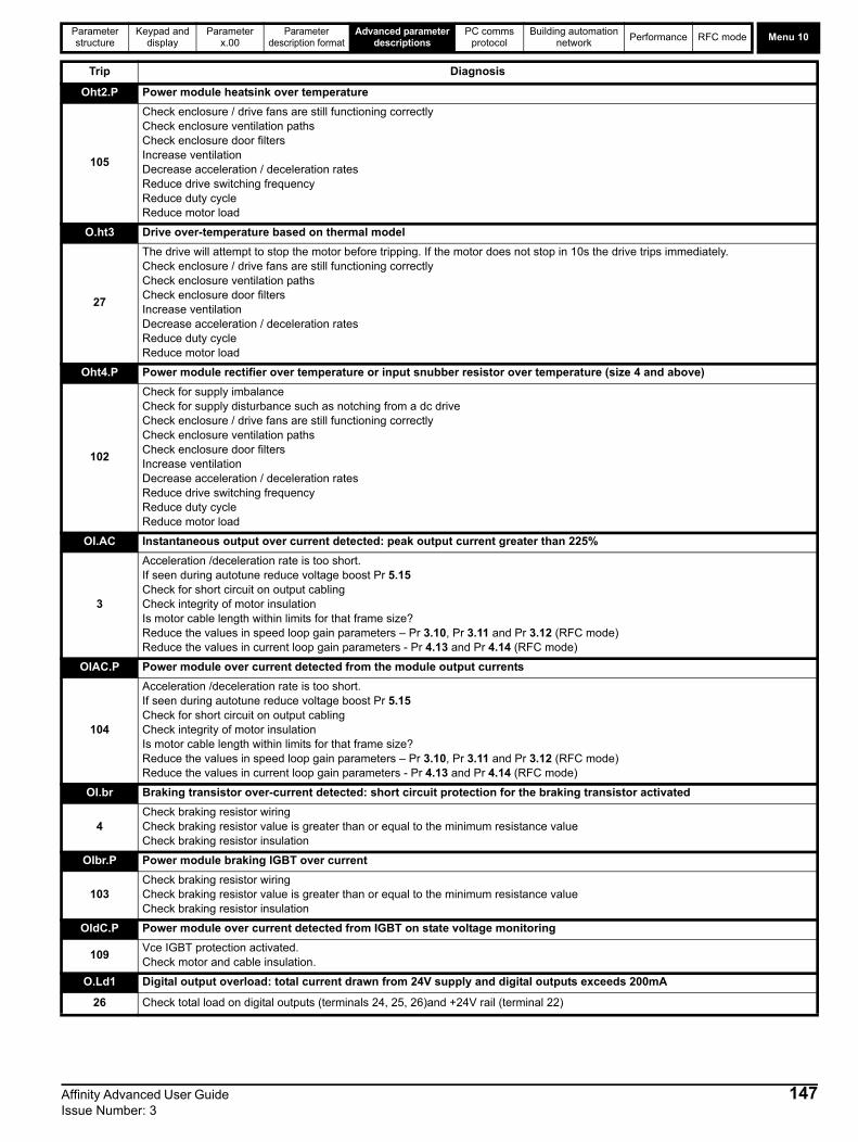
Parameter structure
Keypad and display
Parameter x.00
Parameter description format
Advanced parameter descriptions
PC comms protocol
Building automation network
Performance RFC mode Menu 10
Oht2.P Power module heatsink over temperature
105
Check enclosure / drive fans are still functioning correctlyCheck enclosure ventilation paths Check enclosure door filtersIncrease ventilationDecrease acceleration / deceleration ratesReduce drive switching frequencyReduce duty cycleReduce motor load
O.ht3 Drive over-temperature based on thermal model
27
The drive will attempt to stop the motor before tripping. If the motor does not stop in 10s the drive trips immediately.Check enclosure / drive fans are still functioning correctlyCheck enclosure ventilation paths Check enclosure door filtersIncrease ventilationDecrease acceleration / deceleration ratesReduce duty cycleReduce motor load
Oht4.P Power module rectifier over temperature or input snubber resistor over temperature (size 4 and above)
102
Check for supply imbalanceCheck for supply disturbance such as notching from a dc driveCheck enclosure / drive fans are still functioning correctlyCheck enclosure ventilation paths Check enclosure door filtersIncrease ventilationDecrease acceleration / deceleration ratesReduce drive switching frequencyReduce duty cycleReduce motor load
OI.AC Instantaneous output over current detected: peak output current greater than 225%
3
Acceleration /deceleration rate is too short.If seen during autotune reduce voltage boost Pr 5.15 Check for short circuit on output cablingCheck integrity of motor insulationIs motor cable length within limits for that frame size?Reduce the values in speed loop gain parameters – Pr 3.10, Pr 3.11 and Pr 3.12 (RFC mode) Reduce the values in current loop gain parameters - Pr 4.13 and Pr 4.14 (RFC mode)
OIAC.P Power module over current detected from the module output currents
104
Acceleration /deceleration rate is too short.If seen during autotune reduce voltage boost Pr 5.15 Check for short circuit on output cablingCheck integrity of motor insulationIs motor cable length within limits for that frame size?Reduce the values in speed loop gain parameters – Pr 3.10, Pr 3.11 and Pr 3.12 (RFC mode)Reduce the values in current loop gain parameters - Pr 4.13 and Pr 4.14 (RFC mode)
OI.br Braking transistor over-current detected: short circuit protection for the braking transistor activated
4Check braking resistor wiringCheck braking resistor value is greater than or equal to the minimum resistance valueCheck braking resistor insulation
OIbr.P Power module braking IGBT over current
103Check braking resistor wiringCheck braking resistor value is greater than or equal to the minimum resistance valueCheck braking resistor insulation
OIdC.P Power module over current detected from IGBT on state voltage monitoring
109Vce IGBT protection activated.Check motor and cable insulation.
O.Ld1 Digital output overload: total current drawn from 24V supply and digital outputs exceeds 200mA
26 Check total load on digital outputs (terminals 24, 25, 26)and +24V rail (terminal 22)
Trip Diagnosis
Affinity Advanced User Guide 147Issue Number: 3

Menu 10Parameter structure
Keypad and display
Parameter x.00
Parameter description format
Advanced parameter descriptions
PC comms protocol
Building automation network
Performance RFC mode
O.SPd Motor speed has exceeded the over speed threshold
7Increase the over speed trip threshold in Pr 3.08 (RFC mode)Speed has exceeded 1.2 x Pr 1.06 or Pr 1.07 (open loop mode)Reduce the speed loop P gain (Pr 3.10) to reduce the speed overshoot (RFC mode)
OV DC bus voltage has exceeded the peak level or the maximum continuous level for 15 seconds
2
Increase deceleration ramp (Pr 0.04)Decrease braking resistor value (staying above the minimum value) Check nominal AC supply level Check for supply disturbances which could cause the DC bus to rise – voltage overshoot after supply recovery from a notch induced by dc drivesCheck motor insulationDrive voltage rating Peak voltage Maximum continuous voltage level (15s) 200 415 410 400 830 815 575 990 970 690 1190 1175If the drive is operating in low voltage dc mode the overvoltage trip level is 1.45 x Pr 6.46.
OV.P Power module DC bus voltage has exceeded the peak level or the maximum continuous level for 15 seconds
106
Increase deceleration ramp (Pr 0.04)Decrease braking resistor value (staying above the minimum value) Check nominal AC supply level Check for supply disturbances which could cause the DC bus to rise – voltage overshoot after supply recovery from a notch induced by dc drivesCheck motor insulationDrive voltage rating Peak voltage Maximum continuous voltage level (15s) 200 415 410 400 830 815 575 990 970 690 1190 1175If the drive is operating in low voltage dc mode the overvoltage trip level is 1.45 x Pr 6.46.
PAd Keypad has been removed when the drive is receiving the speed reference from the keypad
34Install keypad and resetChange speed reference selector to select speed reference from another source
PH AC voltage input phase loss or large supply imbalance detected
32
Ensure all three phases are present and balancedCheck input voltage levels are correct (at full load)
NLoad level must be between 50 and 100% for the drive to trip under phase loss conditions. The drive will attempt to stop the motor before this trip is initiated.
PH.P Power module phase loss detection
107Ensure all three phases are present and balancedCheck input voltage levels are correct (at full load)
PS Internal power supply fault
5Remove any Solutions Modules and reset Hardware fault - return drive to supplier
PS.10V 10V user power supply current greater than 10mA
8Check wiring to terminal 4Reduce load on terminal 4
PS.24V 24V internal power supply overload
9
The total user load of the drive and Solutions Modules has exceeded the internal 24V power supply limit.The user load consists of the drive’s digital outputs and the SM-I/O Plus digital outputs.• Reduce load and reset• Provide an external 24V >50W power supply • Remove any Solutions Modules and reset
PS.P Power module power supply fail
108Remove any Solutions Modules and reset Hardware fault - return drive to supplier
Trip Diagnosis
NOTE
148 Affinity Advanced User Guide Issue Number: 3

Parameter structure
Keypad and display
Parameter x.00
Parameter description format
Advanced parameter descriptions
PC comms protocol
Building automation network
Performance RFC mode Menu 10
PSAVE.Er Power down save parameters in the EEPROM are corrupt
37
Indicates that the power was removed when power down save parameters were being saved.The drive will revert back to the power down parameter set that was last saved successfully.Perform a user save (Pr xx.00 to 1000 or 1001 and reset the drive) or power down the drive normally to ensure this trip does or occur the next time the drive is powered up.
rS Failure to measure resistance during autotune or when starting in open loop vector mode 0 or 3
33 Check motor power connection continuity
SAVE.Er User save parameters in the EEPROM are corrupt
36
Indicates that the power was removed when user parameters were being saved.The drive will revert back to the user parameter set that was last saved successfully.Perform a user save (Pr xx.00 to 1000 or 1001 and reset the drive) to ensure this trip does or occur the next time the drive is powered up.
SCL Drive RS485 serial comms loss to remote keypad
30
Reinstall the cable between the drive and keypadCheck cable for damageReplace cableReplace keypad
SLX.dF Solutions Module slot X trip: Solutions Module type installed in slot X changed
204,209 Save parameters and reset
SL3.dF Building automation interface slot trip
214 Module typed changed
SLX.Er Solutions Module slot X trip: Solutions Module in slot X has detected a fault
202,207 Check value in Pr 15/16.50. See the Diagnostics section in the relevant Solutions Module User Guide for more information.
SL3.Er Building automation interface: Module has detected a fault
212
Check value in Pr 17.50. The following table lists the possible error codes.
SLX.HF Solutions Module slot X trip: Solutions Module X hardware fault
200,205Ensure Solutions Module is installed correctlyReturn Solutions Module to supplier
SL3.HF Building automation interface: Module hardware fault
210Ensure Solutions Module is installed correctlyReturn Solutions Module to supplier
SLX.nF Solutions Module slot X trip: Solutions Module has been removed
203,208Ensure Solutions Module is installed correctlyReinstall Solutions ModuleSave parameters and reset drive
SL3.nF Building automation interface: Module has been removed
213Ensure Solutions Module is installed correctlyReinstall Solutions ModuleSave parameters and reset drive
SL.rtd Solutions Module trip: Drive mode has changed and Solutions Module parameter routing is now incorrect
215Press reset.If the trip persists, contact the supplier of the drive.
SLX.tO Solutions Module slot X trip: Solutions Module watchdog timeout
201,206Press reset.If the trip persists, contact the supplier of the drive.
Trip Diagnosis
Error code Trip Description
0 No trip
10 Module operating system error
20 Real time clock error
30 IP54 cooling fan power supply fault
40 Drive to Solutions Modules interface error
50 Building Automation Network error
74 Building Automation Network PCB over-temperature
Affinity Advanced User Guide 149Issue Number: 3

Menu 10Parameter structure
Keypad and display
Parameter x.00
Parameter description format
Advanced parameter descriptions
PC comms protocol
Building automation network
Performance RFC mode
SL3.tO Building automation interface: Module watchdog timeout
211Press reset.If the trip persists, contact the supplier of the drive.
t040 to t089 User defined trip
40 to 89 Onboard PLC program must be interrogated to find the cause of this trip
t099 User defined trip
99 Onboard PLC program must be interrogated to find the cause of this trip
t101 User defined trip
101 Onboard PLC program must be interrogated to find the cause of this trip
t112 to t160 User defined trip
112 to 160 Onboard PLC program must be interrogated to find the cause of this trip
t168 to t174 User defined trip
168 to 174 Onboard PLC program must be interrogated to find the cause of this trip
t216 User defined trip
216 Onboard PLC program must be interrogated to find the cause of this trip
th Motor thermistor trip
24Check motor temperatureCheck thermistor continuitySet Pr 7.15 = VOLt and reset the drive to disable this function
thS Motor thermistor short circuit
25Check motor thermistor wiringReplace motor / motor thermistorSet Pr 7.15 = VOLt and reset the drive to disable this function
tunE* Autotune stopped before completion
18The drive has tripped out during the autotuneThe red stop key has been pressed during the autotuneThe Enable signal (terminal 31) was active during the autotune procedure
tunE1* Required speed could not be reached during the inertia test (see Pr 5.12)
11 Ensure the motor is free to turn i.e. brake was released
tunE2* Motor could not be stopped during the inertia test (see Pr 5.12)
12 Check motor cable wiring is correct
tunE3* Measured inertia out of range (see Pr 5.12)
13 Check motor cable wiring is correct
tunE7* Motor number of poles set incorrectly
17Check lines per revolution for feedback deviceCheck the number of poles in Pr 5.11 is set correctly
Unid.P Power module unidentified trip
110Check all interconnecting cables between power modulesEnsure cables are routed away from electrical noise sources
UP ACC Onboard PLC program: cannot access Onboard PLC program file on drive
98Disable drive - write access is not allowed when the drive is enabledAnother source is already accessing Onboard PLC program - retry once other action is complete
UP div0 Onboard PLC program attempted divide by zero
90 Check program
UP OFL Onboard PLC program variables and function block calls using more than the allowed RAM space (stack overflow)
95 Check program
UP ovr Onboard PLC program attempted out of range parameter write
94 Check program
UP PAr Onboard PLC program attempted access to a non-existent parameter
91 Check program
Trip Diagnosis
150 Affinity Advanced User Guide Issue Number: 3

Parameter structure
Keypad and display
Parameter x.00
Parameter description format
Advanced parameter descriptions
PC comms protocol
Building automation network
Performance RFC mode Menu 10
*If a tunE through tunE3 trip occurs, then after the drive is reset the drive cannot be made to run unless it is disabled via the Enable input (terminal 31), drive enable parameter (Pr 6.15) or the control word (Pr 6.42 and Pr 6.43).
Table 5-14 Serial communications look-up table
UP ro Onboard PLC program attempted write to a read-only parameter
92 Check program
UP So Onboard PLC program attempted read of a write-only parameter
93 Check program
UP udF Onboard PLC program un-defined trip
97 Check program
UP uSEr Onboard PLC program requested a trip
96 Check program
UV DC bus under voltage threshold reached
1
Check AC supply voltage levelDrive voltage rating (Vac) Under voltage threshold (Vdc) UV reset voltage (Vdc)
200 175 215V 400 330 425V 575 & 690 435 590V
No. Trip No. Trip No. Trip
1 UV 40 to 89 t040 to t089 182 C.Err
2 OV 90 UP div0 183 C.dAt
3 OI.AC 91 UP PAr 184 C.FULL
4 OI.br 92 UP ro 185 C.Acc
5 PS 93 UP So 186 C.rtg
6 Et 94 UP ovr 187 C.TyP
7 O.SPd 95 UP OFL 188 C.cPr
8 PS.10V 96 UP uSEr 189 Reserved
9 PS.24V 97 UP udF 190 Reserved
10 Reserved 98 UP ACC 191 Reserved
11 tunE1 99 t099 192 Reserved
12 tunE2 100 193 Reserved
13 tunE3 101 t101 194 Reserved
14 Reserved 102 Oht4.P 195 Reserved
15 Reserved 103 OIbr.P 196 Reserved
16 Reserved 104 OIAC.P 197 Reserved
17 tuneE7 105 Oht2.P 198 Reserved
18 tuneE 106 OV.P 199 DESt
19 It.br 107 PH.P 200 SL1.HF
20 It.AC 108 PS.P 201 SL1.tO
21 O.ht1 109 OIdC.P 202 SL1.Er
22 O.ht2 110 Unid.P 203 SL1.nF
23 O.CtL 111 ConF.P 204 SL1.dF
24 th 112 to 160 t112 to t160 205 SL2.HF
25 thS 161 Reserved 206 SL2.tO
26 O.Ld1 162 Reserved 207 SL2.Er
27 O.ht3 163 Reserved 208 SL2.nF
28 cL2 164 Reserved 209 SL2.dF
29 cL3 165 Reserved 210 SL3.HF
30 SCL 166 Reserved 211 SL3.tO
31 EEF 167 Reserved 212 SL3.Er
32 PH 168 to 174 t168 to t174 213 SL3.nF
33 rS 175 C.Prod 214 SL3.dF
34 PAd 176 Reserved 215 SL.rtd
35 CL.bit 177 C.boot 216 t216
36 SAVE.Er 178 C.bUSY 217 HF17
37 PSAVE.Er 179 C.Chg 218 HF18
38 LOAD 180 C.OPtn 219 HF19
39 Reserved 181 C.RdO 220 to 232 HF20 to HF32
Trip Diagnosis
Affinity Advanced User Guide 151Issue Number: 3
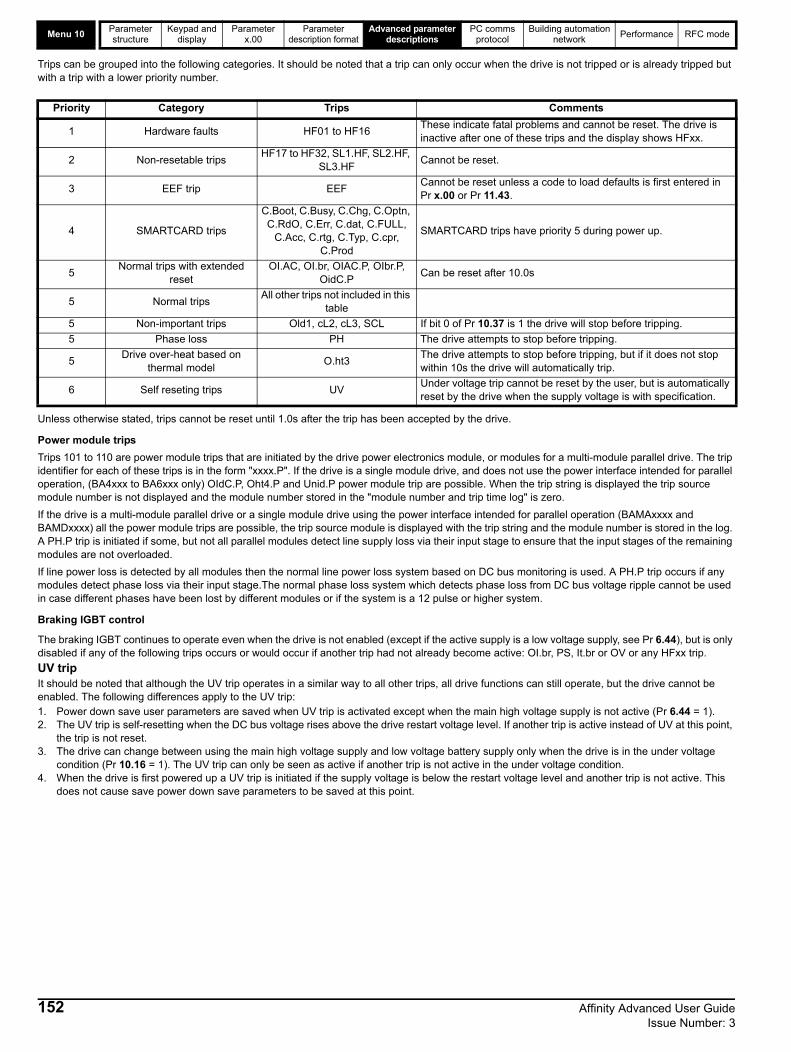
Menu 10Parameter structure
Keypad and display
Parameter x.00
Parameter description format
Advanced parameter descriptions
PC comms protocol
Building automation network
Performance RFC mode
Trips can be grouped into the following categories. It should be noted that a trip can only occur when the drive is not tripped or is already tripped but with a trip with a lower priority number.
Unless otherwise stated, trips cannot be reset until 1.0s after the trip has been accepted by the drive.
Power module trips
Trips 101 to 110 are power module trips that are initiated by the drive power electronics module, or modules for a multi-module parallel drive. The trip identifier for each of these trips is in the form "xxxx.P". If the drive is a single module drive, and does not use the power interface intended for parallel operation, (BA4xxx to BA6xxx only) OIdC.P, Oht4.P and Unid.P power module trip are possible. When the trip string is displayed the trip source module number is not displayed and the module number stored in the "module number and trip time log" is zero.
If the drive is a multi-module parallel drive or a single module drive using the power interface intended for parallel operation (BAMAxxxx and BAMDxxxx) all the power module trips are possible, the trip source module is displayed with the trip string and the module number is stored in the log. A PH.P trip is initiated if some, but not all parallel modules detect line supply loss via their input stage to ensure that the input stages of the remaining modules are not overloaded.
If line power loss is detected by all modules then the normal line power loss system based on DC bus monitoring is used. A PH.P trip occurs if any modules detect phase loss via their input stage.The normal phase loss system which detects phase loss from DC bus voltage ripple cannot be used in case different phases have been lost by different modules or if the system is a 12 pulse or higher system.
Braking IGBT control
The braking IGBT continues to operate even when the drive is not enabled (except if the active supply is a low voltage supply, see Pr 6.44), but is only disabled if any of the following trips occurs or would occur if another trip had not already become active: OI.br, PS, It.br or OV or any HFxx trip.
UV tripIt should be noted that although the UV trip operates in a similar way to all other trips, all drive functions can still operate, but the drive cannot be enabled. The following differences apply to the UV trip: 1. Power down save user parameters are saved when UV trip is activated except when the main high voltage supply is not active (Pr 6.44 = 1).2. The UV trip is self-resetting when the DC bus voltage rises above the drive restart voltage level. If another trip is active instead of UV at this point,
the trip is not reset.3. The drive can change between using the main high voltage supply and low voltage battery supply only when the drive is in the under voltage
condition (Pr 10.16 = 1). The UV trip can only be seen as active if another trip is not active in the under voltage condition.4. When the drive is first powered up a UV trip is initiated if the supply voltage is below the restart voltage level and another trip is not active. This
does not cause save power down save parameters to be saved at this point.
Priority Category Trips Comments
1 Hardware faults HF01 to HF16These indicate fatal problems and cannot be reset. The drive is inactive after one of these trips and the display shows HFxx.
2 Non-resetable tripsHF17 to HF32, SL1.HF, SL2.HF,
SL3.HFCannot be reset.
3 EEF trip EEFCannot be reset unless a code to load defaults is first entered in Pr x.00 or Pr 11.43.
4 SMARTCARD trips
C.Boot, C.Busy, C.Chg, C.Optn, C.RdO, C.Err, C.dat, C.FULL,
C.Acc, C.rtg, C.Typ, C.cpr, C.Prod
SMARTCARD trips have priority 5 during power up.
5Normal trips with extended
resetOI.AC, OI.br, OIAC.P, OIbr.P,
OidC.PCan be reset after 10.0s
5 Normal tripsAll other trips not included in this
table
5 Non-important trips Old1, cL2, cL3, SCL If bit 0 of Pr 10.37 is 1 the drive will stop before tripping.
5 Phase loss PH The drive attempts to stop before tripping.
5Drive over-heat based on
thermal modelO.ht3
The drive attempts to stop before tripping, but if it does not stop within 10s the drive will automatically trip.
6 Self reseting trips UVUnder voltage trip cannot be reset by the user, but is automatically reset by the drive when the supply voltage is with specification.
152 Affinity Advanced User Guide Issue Number: 3

Parameter structure
Keypad and display
Parameter x.00
Parameter description format
Advanced parameter descriptions
PC comms protocol
Building automation network
Performance RFC mode Menu 10
Table 5-15 Hardware fault trips
For BA1xxx and BA2xxx drives the default value is a suitable value for standard braking resistors that can be mounted within the drive heatsink as given in the table below. For larger drives the default is 0.00.
This parameter defines the time period that the braking resistor installed can stand full braking volts without damage. The setting of this parameter is used in determining the braking overload time.
HF fault code
Reason for trip
01 CPU address error
02 DMAC address error
03 Illegal instruction
04 Illegal slot instruction
05 Undefined exception
06 Reserved exception
07 Watchdog failure
08 Level 4 crash
09 Heap overflow
10 Router error
11Access to the EEPROM failed or incorrect EEPROMs installed.
12 Main program stack overflow
13The drive firmware is not compatible with the drive hardware
14-16 Not used
17 Reserved
18 Reserved
19 Power circuit temperature feedback multiplexor failure
20 Power circuit - identification code error
21 Power circuit - unrecognized frame size
22 Reserved
23 Reserved
24 Power circuit - unrecognized drive size
25 Current feedback offset error
26Soft start relay failed to close, or soft start monitor failed, or braking IGBT short circuit at power-up
27 Power circuit thermistor 1 fault
28Power circuit thermistor 2 or 3 fault / Internal fan fault for some drive sizes.
29 Control board thermistor fault
30 dc CT wired break trip from power module
31 Internal capacitor fan failure from power module
32Power stage - a module has not powered up in a multi-module parallel drive
10.30 Full power braking time
Drive modes Open-loop, RFC
CodingBit SP FI DE Txt VM DP ND RA NC NV PT US RW BU PS
2 1 1 1
Range Open-loop, RFC 0.00 to 400.00 s
Default Open-loop, RFC See below
Update rate Background read
Drive voltage rating Size 1 and 2
200V 0.09s
400V 0.02s
575V and 690V N/A
Affinity Advanced User Guide 153Issue Number: 3

Menu 10Parameter structure
Keypad and display
Parameter x.00
Parameter description format
Advanced parameter descriptions
PC comms protocol
Building automation network
Performance RFC mode
This parameter defines the time between periods when the braking IGBT is on for the full power braking time so that the average power in the resistor does not exceed the rating of the resistor. If Pr 10.30 is set to 0 then no braking resistor protection is implemented.
The braking resistor temperature is modelled by the drive as shown below. The temperature rises in proportion to the power flowing into the resistor and falls in proportion to the difference between the resistor temperature and ambient. Under the conditions shown the resistor is heating up just to 100% of its rated temperature during each braking period.
Assuming that the full power braking time is much shorter than the full power braking period i.e. Pr 10.30 Pr 10.31 / 10(which is normally the case) the values for Pr 10.30 and Pr 10.31 can be calculated as follows:
Power flowing into the resistor when the braking IGBT is on, Pon = Full braking volts2 / R
Where: Full braking volts is defined in the table and R is the resistance of the braking resistor.
Full power braking time (Pr 10.30), Ton = E / Pon
Where: E is the total energy that can be absorbed by the resistor when its initial temperature is ambient temperature.
Therefore full power braking time (Pr 10.30), Ton = E x R / Full braking volts2
If the average power rating of the resistor is not to be exceeded in the cycle shown in the diagram above.
The average power in the resistor is given by, Pav = Pon x Ton / Tp
Where: Tp is the full power braking period
Pon = E / Ton
Therefore Pav = E / Tp
Therefore full power braking period (Pr 10.31), Tp = E / Pav
The resistance of the braking resistor R, the total energy E and the average power Pav can normally be obtained for the resistor and used to calculate
Pr 10.30 and Pr 10.31.
Drive voltage rating Full braking volts
200V 390V
400V 780V
575V 930V
690V 1120V
10.31 Full power braking period
Drive modes Open-loop, RFC
CodingBit SP FI DE Txt VM DP ND RA NC NV PT US RW BU PS
1 1 1 1
Range Open-loop, RFC 0.0 to 1500.0 s
Default Open-loop, RFCBA1xxx and BA2xxx: 3.3sLarger drive sizes: 0.0s
Update rate Background read
0
100
%
tPr 10.30 Pr 10.31
Overload accumulator Pr 10.39
154 Affinity Advanced User Guide Issue Number: 3
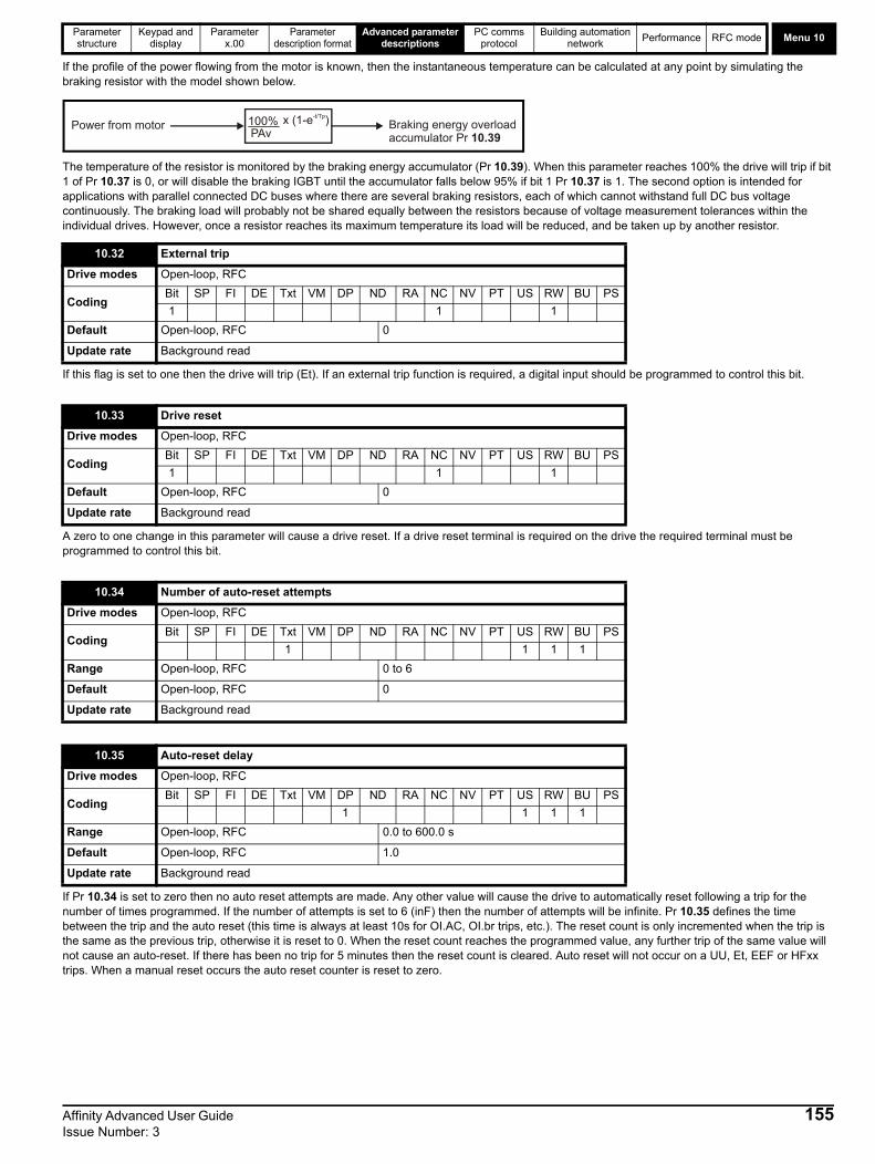
Parameter structure
Keypad and display
Parameter x.00
Parameter description format
Advanced parameter descriptions
PC comms protocol
Building automation network
Performance RFC mode Menu 10
If the profile of the power flowing from the motor is known, then the instantaneous temperature can be calculated at any point by simulating the braking resistor with the model shown below.
The temperature of the resistor is monitored by the braking energy accumulator (Pr 10.39). When this parameter reaches 100% the drive will trip if bit 1 of Pr 10.37 is 0, or will disable the braking IGBT until the accumulator falls below 95% if bit 1 Pr 10.37 is 1. The second option is intended for applications with parallel connected DC buses where there are several braking resistors, each of which cannot withstand full DC bus voltage continuously. The braking load will probably not be shared equally between the resistors because of voltage measurement tolerances within the individual drives. However, once a resistor reaches its maximum temperature its load will be reduced, and be taken up by another resistor.
If this flag is set to one then the drive will trip (Et). If an external trip function is required, a digital input should be programmed to control this bit.
A zero to one change in this parameter will cause a drive reset. If a drive reset terminal is required on the drive the required terminal must be programmed to control this bit.
If Pr 10.34 is set to zero then no auto reset attempts are made. Any other value will cause the drive to automatically reset following a trip for the number of times programmed. If the number of attempts is set to 6 (inF) then the number of attempts will be infinite. Pr 10.35 defines the time between the trip and the auto reset (this time is always at least 10s for OI.AC, OI.br trips, etc.). The reset count is only incremented when the trip is the same as the previous trip, otherwise it is reset to 0. When the reset count reaches the programmed value, any further trip of the same value will not cause an auto-reset. If there has been no trip for 5 minutes then the reset count is cleared. Auto reset will not occur on a UU, Et, EEF or HFxx trips. When a manual reset occurs the auto reset counter is reset to zero.
10.32 External trip
Drive modes Open-loop, RFC
CodingBit SP FI DE Txt VM DP ND RA NC NV PT US RW BU PS
1 1 1
Default Open-loop, RFC 0
Update rate Background read
10.33 Drive reset
Drive modes Open-loop, RFC
CodingBit SP FI DE Txt VM DP ND RA NC NV PT US RW BU PS
1 1 1
Default Open-loop, RFC 0
Update rate Background read
10.34 Number of auto-reset attempts
Drive modes Open-loop, RFC
CodingBit SP FI DE Txt VM DP ND RA NC NV PT US RW BU PS
1 1 1 1
Range Open-loop, RFC 0 to 6
Default Open-loop, RFC 0
Update rate Background read
10.35 Auto-reset delay
Drive modes Open-loop, RFC
CodingBit SP FI DE Txt VM DP ND RA NC NV PT US RW BU PS
1 1 1 1
Range Open-loop, RFC 0.0 to 600.0 s
Default Open-loop, RFC 1.0
Update rate Background read
100%PAv
x (1-e )-t/Tp
Power from motor Braking energy overloadaccumulator Pr 10.39
Affinity Advanced User Guide 155Issue Number: 3
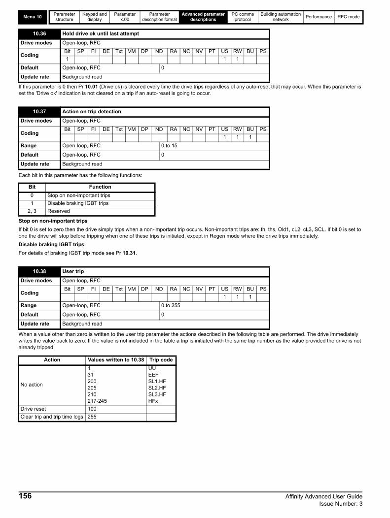
Menu 10Parameter structure
Keypad and display
Parameter x.00
Parameter description format
Advanced parameter descriptions
PC comms protocol
Building automation network
Performance RFC mode
If this parameter is 0 then Pr 10.01 (Drive ok) is cleared every time the drive trips regardless of any auto-reset that may occur. When this parameter is set the 'Drive ok' indication is not cleared on a trip if an auto-reset is going to occur.
Each bit in this parameter has the following functions:
Stop on non-important trips
If bit 0 is set to zero then the drive simply trips when a non-important trip occurs. Non-important trips are: th, ths, Old1, cL2, cL3, SCL. If bit 0 is set to one the drive will stop before tripping when one of these trips is initiated, except in Regen mode where the drive trips immediately.
Disable braking IGBT trips
For details of braking IGBT trip mode see Pr 10.31.
When a value other than zero is written to the user trip parameter the actions described in the following table are performed. The drive immediately writes the value back to zero. If the value is not included in the table a trip is initiated with the same trip number as the value provided the drive is not already tripped.
10.36 Hold drive ok until last attempt
Drive modes Open-loop, RFC
CodingBit SP FI DE Txt VM DP ND RA NC NV PT US RW BU PS
1 1 1
Default Open-loop, RFC 0
Update rate Background read
10.37 Action on trip detection
Drive modes Open-loop, RFC
CodingBit SP FI DE Txt VM DP ND RA NC NV PT US RW BU PS
1 1 1
Range Open-loop, RFC 0 to 15
Default Open-loop, RFC 0
Update rate Background read
Bit Function
0 Stop on non-important trips
1 Disable braking IGBT trips
2, 3 Reserved
10.38 User trip
Drive modes Open-loop, RFC
CodingBit SP FI DE Txt VM DP ND RA NC NV PT US RW BU PS
1 1 1
Range Open-loop, RFC 0 to 255
Default Open-loop, RFC 0
Update rate Background read
Action Values written to 10.38 Trip code
No action
131200205210217-245
UUEEFSL1.HFSL2.HFSL3.HFHFx
Drive reset 100
Clear trip and trip time logs 255
156 Affinity Advanced User Guide Issue Number: 3

Parameter structure
Keypad and display
Parameter x.00
Parameter description format
Advanced parameter descriptions
PC comms protocol
Building automation network
Performance RFC mode Menu 10
This parameter gives an indication of braking resistor temperature based on a simple thermal model, see Pr 10.30 and Pr 10.31 on page 154. Zero indicates the resistor is close to ambient and 100% is the maximum temperature (trip level). A br.rS warning is given if this parameter is above 75% and the braking IGBT active.
The bits in this parameter correspond to the status bits in menu 10 as follows.
* See Pr 6.19 for details of date format
10.39 Braking energy overload accumulator
Drive modes Open-loop, RFC
CodingBit SP FI DE Txt VM DP ND RA NC NV PT US RW BU PS
1 1 1 1 1
Range Open-loop, RFC 0.0 to 100.0 %
Update rate Background read
10.40 Status word
Drive modes Open-loop, RFC
CodingBit SP FI DE Txt VM DP ND RA NC NV PT US RW BU PS
1 1 1 1
Range Open-loop, RFC 0 to 32,767
Update rate Background write
15 14 13 12 11 10 9 8
Not used Pr 10.15 Pr 10.14 Pr 10.13 Pr 10.12 Pr 10.11 Pr 10.10 Pr 10.09
7 6 5 4 3 2 1 0
Pr 10.08 Pr 10.07 Pr 10.06 Pr 10.05 Pr 10.04 Pr 10.03 Pr 10.02 Pr 10.01
10.41 Trip 0 date
10.43 Trip 1 date
10.45 Trip 2 date
10.47 Trip 3 date
10.49 Trip 4 date
10.51 Trip 5 date
10.53 Trip 6 date
10.55 Trip 7 date
10.57 Trip 8 date
10.59 Trip 9 date
Drive modes Open-loop, RFC
CodingBit SP FI DE Txt VM DP ND RA NC NV PT US RW BU PS
2 1 1 1 1 1
Range Open-loop, RFC 0 to 31.12 Days. Month*
Update rate Background read
Affinity Advanced User Guide 157Issue Number: 3

Menu 10Parameter structure
Keypad and display
Parameter x.00
Parameter description format
Advanced parameter descriptions
PC comms protocol
Building automation network
Performance RFC mode
If Pr 6.49 = 1, then Pr 10.41 to Pr 10.60 are used to store the date and time associated with trip x in the trip log (Pr 10.2x). The data stored depends upon the setting of Pr 6.20 as follows:
If Pr 6.49 = 0, then Pr 10.41 to Pr 10.60 are used to store the module number if the trip has been initiated by the power module hardware (trip numbers 101 to 110, HF30 and HF31). The trip number is stored in the "Trip x time or power module number" parameter and the "Trip x date parameter" is set to zero. If the drive has only one power module, and this module is not using the power interface intended for parallel operation, then Pr 10.41 to Pr 10.60 are always zero. If the drive has more than one parallel power module, or is a single module drive using the power interface intended for parallel operation (BAMDxxxx / BAMAxxxx), then module values stored can be used to identify the power module that initiated the trip.
Pr 10.41 to Pr 10.60 are cleared if any of the following occurs:
• Pr 6.49 =1, Pr 6.19 is changed and the drive reset • Pr 6.49 =1 and date format (Pr 6.20) is changed• Pr 6.49 is changed
This parameter is one when the low load condition is detected. (See Pr 4.27 to Pr 4.29).
10.42 Trip 0 time or power module number
10.44 Trip 1 time or power module number
10.46 Trip 2 time or power module number
10.48 Trip 3 time or power module number
10.50 Trip 4 time or power module number
10.52 Trip 5 time or power module number
10.54 Trip 6 time or power module number
10.56 Trip 7 time or power module number
10.58 Trip 8 time or power module number
10.60 Trip 9 time or power module number
Drive modes Open-loop, RFC
CodingBit SP FI DE Txt VM DP ND RA NC NV PT US RW BU PS
2 1 1 1 1 1
Range Open-loop, RFC 0.00 to 23.59 hours.minutes
Update rate Background read
Pr 6.20 Trip x date Trip x time
0 0 Drive powered up time
1 Date (RTC Option slot 1) Time (RTC Option slot 1)
2 Date (RTC Option slot 2) Time (RTC Option slot 2)
3 Date (Onboard RTC) Time (Onboard RTC)
4 0 Drive running time
10.61 Low load detected alarm
Drive modes Open-loop, RFC
CodingBit SP FI DE Txt VM DP ND RA NC NV PT US RW BU PS
1 1 1
Range Open-loop, RFC 0
Update rate Background write
158 Affinity Advanced User Guide Issue Number: 3

Parameter structure
Keypad and display
Parameter x.00
Parameter description format
Advanced parameter descriptions
PC comms protocol
Building automation network
Performance RFC mode Menu 11
5.13 Menu 11: General drive set-up
These parameters define the parameters that reside in the programmable area in menu 0.
Table 5-16 Default settings:
11.01 Parameter 0.11 set-up
11.02 Parameter 0.12 set-up
11.03 Parameter 0.13 set-up
11.04 Parameter 0.14 set-up
11.05 Parameter 0.15 set-up
11.06 Parameter 0.16 set-up
11.07 Parameter 0.17 set-up
11.08 Parameter 0.18 set-up
11.09 Parameter 0.19 set-up
11.10 Parameter 0.20 set-up
11.11 Parameter 0.21 set-up
11.12 Parameter 0.22 set-up
11.13 Parameter 0.23 set-up
11.14 Parameter 0.24 set-up
11.15 Parameter 0.25 set-up
11.16 Parameter 0.26 set-up
11.17 Parameter 0.27 set-up
11.18 Parameter 0.28 set-up
11.19 Parameter 0.29 set-up
11.20 Parameter 0.30 set-up
Drive modes Open-loop, RFC
CodingBit SP FI DE Txt VM DP ND RA NC NV PT US RW BU PS
2 1 1 1 1
Range Open-loop, RFC Pr 1.00 to Pr 50.99
Default Open-loop, RFC See Table 5-16
Update rate Background read
Parameter Menu 0 Open-loop RFC
Pr 11.01 Pr 0.11 Pr 5.01 Pr 5.01
Pr 11.02 Pr 0.12 Pr 4.01 Pr 4.01
Pr 11.03 Pr 0.13 Pr 4.20 Pr 4.20
Pr 11.04 Pr 0.14 Pr 2.04 Pr 2.04
Pr 11.05 Pr 0.15 Pr 6.53 Pr 6.53
Pr 11.06 Pr 0.16 Pr 6.54 Pr 6.54
Pr 11.07 Pr 0.17 Pr 0.00 Pr 4.12
Pr 11.08 Pr 0.18 Pr 5.40 Pr 5.40
Pr 11.09 Pr 0.19 Pr 7.11 Pr 7.11
Pr 11.10 Pr 0.20 Pr 7.14 Pr 7.14
Pr 11.11 Pr 0.21 Pr 7.15 Pr 7.15
Pr 11.12 Pr 0.22 Pr 6.16 Pr 6.16
Pr 11.13 Pr 0.23 Pr 6.17 Pr 6.17
Pr 11.14 Pr 0.24 Pr 6.19 Pr 6.19
Pr 11.15 Pr 0.25 Pr 6.20 Pr 6.20
Pr 11.16 Pr 0.26 Pr 4.27 Pr 4.27
Pr 11.17 Pr 0.27 Pr 4.28 Pr 4.28
Pr 11.18 Pr 0.28 Pr 4.29 Pr 4.29
Pr 11.19 Pr 0.29 Pr 11.36 Pr 11.36
Pr 11.20 Pr 0.30 Pr 11.42 Pr 11.42
Affinity Advanced User Guide 159Issue Number: 3
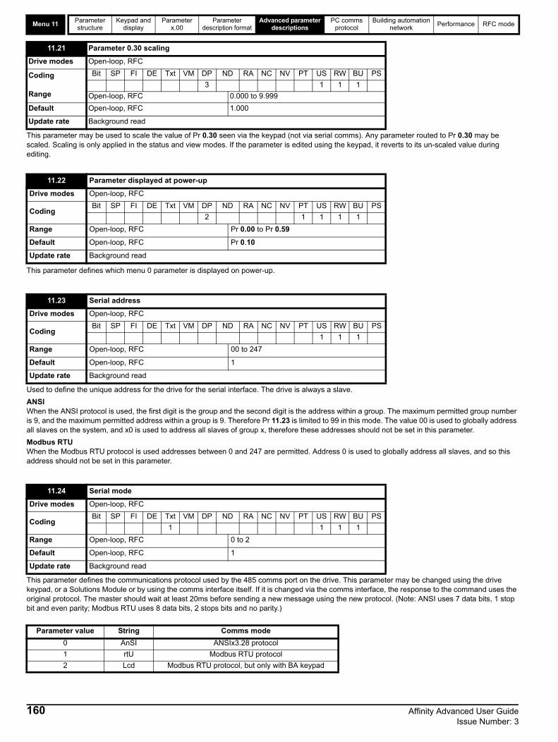
Menu 11Parameter structure
Keypad and display
Parameter x.00
Parameter description format
Advanced parameter descriptions
PC comms protocol
Building automation network
Performance RFC mode
This parameter may be used to scale the value of Pr 0.30 seen via the keypad (not via serial comms). Any parameter routed to Pr 0.30 may be scaled. Scaling is only applied in the status and view modes. If the parameter is edited using the keypad, it reverts to its un-scaled value during editing.
This parameter defines which menu 0 parameter is displayed on power-up.
Used to define the unique address for the drive for the serial interface. The drive is always a slave.
ANSIWhen the ANSI protocol is used, the first digit is the group and the second digit is the address within a group. The maximum permitted group number is 9, and the maximum permitted address within a group is 9. Therefore Pr 11.23 is limited to 99 in this mode. The value 00 is used to globally address all slaves on the system, and x0 is used to address all slaves of group x, therefore these addresses should not be set in this parameter.
Modbus RTU When the Modbus RTU protocol is used addresses between 0 and 247 are permitted. Address 0 is used to globally address all slaves, and so this address should not be set in this parameter.
This parameter defines the communications protocol used by the 485 comms port on the drive. This parameter may be changed using the drive keypad, or a Solutions Module or by using the comms interface itself. If it is changed via the comms interface, the response to the command uses the original protocol. The master should wait at least 20ms before sending a new message using the new protocol. (Note: ANSI uses 7 data bits, 1 stop bit and even parity; Modbus RTU uses 8 data bits, 2 stops bits and no parity.)
11.21 Parameter 0.30 scaling
Drive modes Open-loop, RFC
Coding
Range
Bit SP FI DE Txt VM DP ND RA NC NV PT US RW BU PS
3 1 1 1
Open-loop, RFC 0.000 to 9.999
Default Open-loop, RFC 1.000
Update rate Background read
11.22 Parameter displayed at power-up
Drive modes Open-loop, RFC
CodingBit SP FI DE Txt VM DP ND RA NC NV PT US RW BU PS
2 1 1 1 1
Range Open-loop, RFC Pr 0.00 to Pr 0.59
Default Open-loop, RFC Pr 0.10
Update rate Background read
11.23 Serial address
Drive modes Open-loop, RFC
CodingBit SP FI DE Txt VM DP ND RA NC NV PT US RW BU PS
1 1 1
Range Open-loop, RFC 00 to 247
Default Open-loop, RFC 1
Update rate Background read
11.24 Serial mode
Drive modes Open-loop, RFC
CodingBit SP FI DE Txt VM DP ND RA NC NV PT US RW BU PS
1 1 1 1
Range Open-loop, RFC 0 to 2
Default Open-loop, RFC 1
Update rate Background read
Parameter value String Comms mode
0 AnSI ANSIx3.28 protocol
1 rtU Modbus RTU protocol
2 Lcd Modbus RTU protocol, but only with BA keypad
160 Affinity Advanced User Guide Issue Number: 3

Parameter structure
Keypad and display
Parameter x.00
Parameter description format
Advanced parameter descriptions
PC comms protocol
Building automation network
Performance RFC mode Menu 11
ANSIx3.28 protocolFull details of the CT implementation of ANSIx3.28 are given in Chapter 6 PC communications protocol on page 219.
Modbus RTU protocolFull details of the CT implementation of Modbus RTU are given in Chapter 6 PC communications protocol on page 219.
The protocol provides the following facilities:
• Drive parameter access with basic Modbus RTU• The protocol supports access to 32 bit floating point parameters
The following product specific limitations apply:
• Maximum slave response time when accessing the drive is 100ms.• Maximum number of 16 bit registers which can be written to or read from the drive itself is limited to 16. • Maximum number of 16 bit registers which can be written to or read from a Solutions Module or by using a Solutions Module - see Solutions
Module User Guide.• The communications buffer can hold a maximum of 128bytes.
Modbus RTU protocol, but with BA Keypad only
This setting is used for disabling comms access when the BA Keypad is used as a hardware key. See the SM-Keypad Plus User Guide for more information.
Used in all comms modes to define the baud rate.
*Modbus RTU only
This parameter can be changed via the drive keypad, a Solutions Module or by using the comms interface itself. If it is changed via the comms interface, the response to the command uses the original baud rate. The master should wait at least 20ms before sending a new message using the new baud rate.
There will always be a finite delay between the end of a message from the host (master), and the time at which the host is ready to receive the response from the drive (slave). The drive does not respond until at least 1ms after the message has been received from the host, allowing 1ms for the host to change from transmit to receive mode. This initial delay can be extended using Pr 11.26 if required for both ANSI and Modbus RTU protocols.
11.25 Baud rate
Drive modes Open-loop, RFC
CodingBit SP FI DE Txt VM DP ND RA NC NV PT US RW BU PS
1 1 1 1
Range Open-loop, RFC 0 to 9
Default Open-loop, RFC 6
Update rate Background read
Parameter value String/baud rate
0 300
1 600
2 1200
3 2400
4 4800
5 9600
6 19200
7 38400
8* 57600
9* 115200
11.26 Minimum comms transmit delay
Drive modes Open-loop, RFC
CodingBit SP FI DE Txt VM DP ND RA NC NV PT US RW BU PS
1 1 1
Range Open-loop, RFC 0 to 250 ms
Default Open-loop,RFC 2
Update rate Background read
Affinity Advanced User Guide 161Issue Number: 3

Menu 11Parameter structure
Keypad and display
Parameter x.00
Parameter description format
Advanced parameter descriptions
PC comms protocol
Building automation network
Performance RFC mode
Note that the drive holds its own transmitters active for up to 1ms after it has transmitted data before switching to the receive mode. The host should not send any data during this time.
Modbus RTU uses a silent period detection system to detect the end of a message. This silent period is either the length of time for 3.5 characters at the present baud rate, or the length of time set in Pr 11.26, whichever is the longest.
If this parameter is zero, the drive is a standard product. If this parameter is non-zero, then the product is a derivative product. Derivatives can have different defaults from the standard product and restrictions on the values allowed for some parameters.
The drive software version consists of three numbers xx.yy.zz. Pr 11.29 displays xx.yy and zz is displayed in Pr 11.34. Where xx specifies a change that affects hardware compatibility, yy specifies a change that affects product documentation, and zz specifies a change that does not affect the product documentation.
If any number other than 0 is programmed into this parameter, user security is applied so that no parameters except Pr 11.44 can be adjusted with the keypad. When this parameter is read using a keypad and security is locked, it appears as zero. The security code can be modified using serial comms etc. By setting this parameter to the required value, setting Pr 11.44 to 2 and initiating a reset by setting Pr 10.38 to 100. However security can only be cleared via the keypad.
Pr 11.26 Action
0The transmit buffers are turned on and data transmission begins immediately after the initial delay (1ms)
1The transmit buffers are turned on after the initial delay (1ms) and data transmission begins after 1ms.
2 or moreThe transmit buffers are turned on after the initial delay (1ms) a delay of at least the time specified in Pr 11.26 and data transmission begins 1ms later.
11.28 Drive derivative
Drive modes Open-loop, RFC
CodingBit SP FI DE Txt VM DP ND RA NC NV PT US RW BU PS
1 1 1 1
Range Open-loop, RFC 0 to 16
Update rate Write at power-up
11.29 Software version
Drive modes Open-loop, RFC
CodingBit SP FI DE Txt VM DP ND RA NC NV PT US RW BU PS
2 1 1 1 1
Range Open-loop, RFC 1.00 to 99.99
Update rate Write at power-up
11.30 User security code
Drive modes Open-loop, RFC
CodingBit SP FI DE Txt VM DP ND RA NC NV PT US RW BU PS
1 1 1 1 1 1
Range Open-loop, RFC 0 to 999
Default Open-loop, RFC 0
Update rate Background read
162 Affinity Advanced User Guide Issue Number: 3
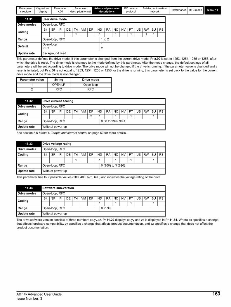
Parameter structure
Keypad and display
Parameter x.00
Parameter description format
Advanced parameter descriptions
PC comms protocol
Building automation network
Performance RFC mode Menu 11
This parameter defines the drive mode. If this parameter is changed from the current drive mode, Pr x.00 is set to 1253, 1254, 1255 or 1256, after which the drive is reset. The drive mode is changed to the mode defined by this parameter. After the mode change, the default settings of all parameters will be set according to drive mode. The drive mode will not be changed if the drive is running. If the parameter value is changed and a reset is initiated, but Pr x.00 is not equal to 1253, 1254, 1255 or 1256, or the drive is running, this parameter is set back to the value for the current drive mode and the drive mode is not changed.
See section 5.6 Menu 4: Torque and current control on page 60 for more details.
This parameter has four possible values (200, 400, 575, 690) and indicates the voltage rating of the drive.
The drive software version consists of three numbers xx.yy.zz. Pr 11.29 displays xx.yy and zz is displayed in Pr 11.34. Where xx specifies a change that affects hardware compatibility, yy specifies a change that affects product documentation, and zz specifies a change that does not affect the product documentation.
11.31 User drive mode
Drive modes Open-loop, RFC
CodingBit SP FI DE Txt VM DP ND RA NC NV PT US RW BU PS
1 1 1 1 1 1
Range Open-loop, RFC 1 to 2
DefaultOpen-loopRFC
12
Update rate Background read
Parameter value String Drive mode
1 OPEn LP Open-loop
2 RFC RFC
11.32 Drive current scaling
Drive modes Open-loop, RFC
CodingBit SP FI DE Txt VM DP ND RA NC NV PT US RW BU PS
2 1 1 1 1
Range Open-loop, RFC 0.00 to 9999.99 A
Update rate Write at power-up
11.33 Drive voltage rating
Drive modes Open-loop, RFC
Coding Bit SP FI DE Txt VM DP ND RA NC NV PT US RW BU PS
1 1 1 1 1
Range Open-loop, RFC 0 (200) to 3 (690)
Update rate Write at power-up
11.34 Software sub-version
Drive modes Open-loop, RFC
CodingBit SP FI DE Txt VM DP ND RA NC NV PT US RW BU PS
1 1 1 1
Range Open-loop, RFC 0 to 99
Update rate Write at power-up
Affinity Advanced User Guide 163Issue Number: 3
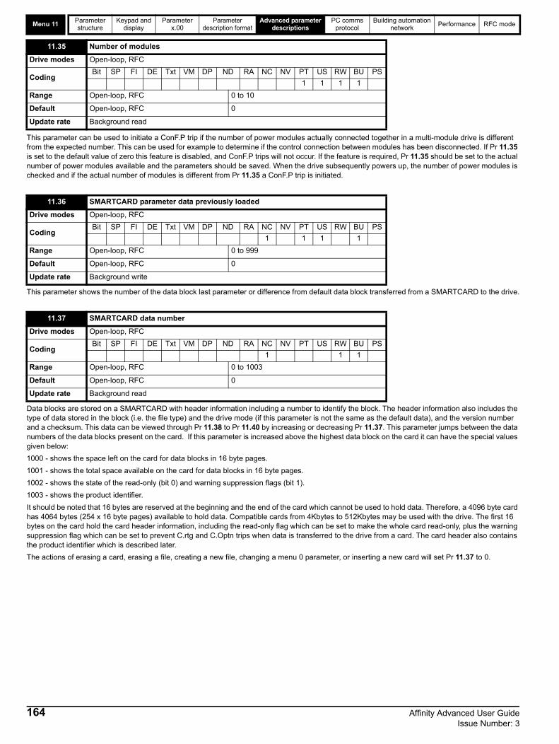
Menu 11Parameter structure
Keypad and display
Parameter x.00
Parameter description format
Advanced parameter descriptions
PC comms protocol
Building automation network
Performance RFC mode
This parameter can be used to initiate a ConF.P trip if the number of power modules actually connected together in a multi-module drive is different from the expected number. This can be used for example to determine if the control connection between modules has been disconnected. If Pr 11.35 is set to the default value of zero this feature is disabled, and ConF.P trips will not occur. If the feature is required, Pr 11.35 should be set to the actual number of power modules available and the parameters should be saved. When the drive subsequently powers up, the number of power modules is checked and if the actual number of modules is different from Pr 11.35 a ConF.P trip is initiated.
This parameter shows the number of the data block last parameter or difference from default data block transferred from a SMARTCARD to the drive.
Data blocks are stored on a SMARTCARD with header information including a number to identify the block. The header information also includes the type of data stored in the block (i.e. the file type) and the drive mode (if this parameter is not the same as the default data), and the version number and a checksum. This data can be viewed through Pr 11.38 to Pr 11.40 by increasing or decreasing Pr 11.37. This parameter jumps between the data numbers of the data blocks present on the card. If this parameter is increased above the highest data block on the card it can have the special values given below:
1000 - shows the space left on the card for data blocks in 16 byte pages.
1001 - shows the total space available on the card for data blocks in 16 byte pages.
1002 - shows the state of the read-only (bit 0) and warning suppression flags (bit 1).
1003 - shows the product identifier.
It should be noted that 16 bytes are reserved at the beginning and the end of the card which cannot be used to hold data. Therefore, a 4096 byte card has 4064 bytes (254 x 16 byte pages) available to hold data. Compatible cards from 4Kbytes to 512Kbytes may be used with the drive. The first 16 bytes on the card hold the card header information, including the read-only flag which can be set to make the whole card read-only, plus the warning suppression flag which can be set to prevent C.rtg and C.Optn trips when data is transferred to the drive from a card. The card header also contains the product identifier which is described later.
The actions of erasing a card, erasing a file, creating a new file, changing a menu 0 parameter, or inserting a new card will set Pr 11.37 to 0.
11.35 Number of modules
Drive modes Open-loop, RFC
CodingBit SP FI DE Txt VM DP ND RA NC NV PT US RW BU PS
1 1 1 1
Range Open-loop, RFC 0 to 10
Default Open-loop, RFC 0
Update rate Background read
11.36 SMARTCARD parameter data previously loaded
Drive modes Open-loop, RFC
CodingBit SP FI DE Txt VM DP ND RA NC NV PT US RW BU PS
1 1 1 1
Range Open-loop, RFC 0 to 999
Default Open-loop, RFC 0
Update rate Background write
11.37 SMARTCARD data number
Drive modes Open-loop, RFC
CodingBit SP FI DE Txt VM DP ND RA NC NV PT US RW BU PS
1 1 1
Range Open-loop, RFC 0 to 1003
Default Open-loop, RFC 0
Update rate Background read
164 Affinity Advanced User Guide Issue Number: 3

Parameter structure
Keypad and display
Parameter x.00
Parameter description format
Advanced parameter descriptions
PC comms protocol
Building automation network
Performance RFC mode Menu 11
Various SMARTCARD actions can be initiated via Pr x.00 or the cloning (Pr 11.42) and resetting of the drive as given in the table below:
The data and the format of the data, is different depending on the method used to store it on a SMARTCARD. The different formats are described below. In addition to data transfers, a compare function is also provided.
If 8yyy is entered in Pr x.00 and the drive is reset, data block yyy on the SMARTCARD is compared with the data in the drive. If the compare is successful, Pr x.00 is set to 0. If the compare fails, a trip is initiated and parameter x.00 is not cleared. This function can be used with all data block types except the option type (18).
Parameter file type data block
This type of data block is created when 3xxx in Pr x.00, the cloning parameter (Pr 11.42) or auto/boot mode is used to initiate the transfer. The data block (referred to as a parameter file), contains the complete data from all user save (US) parameters, except those with the NC coding bit set. Parameter RAM is used as the source for this information. Power-down save (PS) are not saved to the SMARTCARD. When the data is transferred back to a drive, it is transferred to the drive RAM and then to the drive EEPROM. A parameter save is not required to retain the data after power-down. Before the data is taken from the card, defaults are loaded in the destination drive using the same default code as was last used in the source drive.
Difference from defaults type data block
This type of data block is created when 4xxx in Pr x.00 is used to initiate the transfer. This data block format (referred to a difference from defaults file), is different depending on the software version.
The data held in the data block has changed between different software versions as follows:
Parameters with the following attributes: NC=0 (clonable) and US=1 (user save), and menu 20 parameters except Pr 20.00 if they are different from their default value. If a parameter is a user save (US), but has no default (ND) it is saved on the card whatever its value.
It is possible to transfer parameters between drives with each of the software version dependant formats, however, the data block compare function does not work with data produced by the different formats.
The data density is not as high as a parameter file type data block, but in most cases the number of differences from default is small and the data blocks are therefore smaller. This method can be used for example for creating drive macros. Parameter RAM is used as the source of this information.
When the data is transferred back to a drive, using 6yyy in Pr x.00, it is transferred to the drive RAM and then to the drive EEPROM. A parameter save is not required to retain the data after power-down.
Onboard Application Lite user program data blocks
This type of data block is created when 5xxx in Pr x.00 is used to initiate the transfer. The Onboard Application Lite user program from a drive, may be transferred to/from internal flash memory, or from/to a SMARTCARD. If the user program is transferred from a drive with no program loaded, the block is still created on the card but contains no data. If this is then transferred to a drive, the drive will then have no user program.
When transferring data between drives the following should be noted:
Parameter transfer failure
When parameter or default difference data is transferred to the drive, the parameters are automatically saved to drive EEPROM. If the transfer from the card fails for any reason, the drive generates the appropriate trip. If the failure occurs after the transfer has begun, it is possible that some, but not all the parameters will have been updated with the card data. However if the transfer fails, the parameters are not saved to drive EEPROM, therefore only the RAM values will be incorrect. If the drive is powered down and then powered up again, the original drive parameters will be restored.
Read-only function
Data blocks with numbers from 1 to 499 can be created or erased by the user. Data block with numbers 500 and above are read-only and cannot be created or erased by the user. The whole card may also be protected from writing or erasing by setting the read-only flag. If the card or a data block on the card is read-only, then the operation to erase the whole card is disabled.
Code Action
x.00 = 2001Transfer drive parameters as difference from defaults to a bootable SMARTCARD block with block number 1. (This will clear data block 1 on the card if it already exists.)
x.00 = 3yyy Transfer drive parameters to a SMARTCARD block number yyy as a parameter file
x.00 = 4yyyTransfer drive data to a SMARTCARD block number yyy as difference from defaults file
x.00 = 5yyy Transfer drive user program to SMARTCARD block number yyy
x.00 = 6yyy Transfer SMARTCARD data block yyy to the drive
x.00 = 7yyy Erase SMARTCARD data block yyy
x.00 = 8yyy Compare drive parameters with block yyy
x.00 = 9555 Clear SMARTCARD warning suppression flag
x.00 = 9666 Set SMARTCARD warning suppression flag
x.00 = 9777 Clear SMARTCARD read-only flag
x.00 = 9888 Set SMARTCARD read-only flag
x.00 = 9999 Erase SMARTCARD
Pr 11.42 = Read Transfer SMARTCARD data block 1 to the drive provided it is a parameter file
Pr 11.42 = Prog Transfer drive parameters to a SMARTCARD block number one as a parameter file
Pr 11.42 = AutoPr 11.42 = boot
Transfer drive parameters to a SMARTCARD block with data block number 1 as a parameter file provided Pr 11.42 has been changed since power-up.
Affinity Advanced User Guide 165Issue Number: 3

Menu 11Parameter structure
Keypad and display
Parameter x.00
Parameter description format
Advanced parameter descriptions
PC comms protocol
Building automation network
Performance RFC mode
Changing the drive mode
If the destination drive has a different drive mode to the parameters on the card, the drive mode will be changed by the action of transferring parameters from the card to the drive. The only exception is that the mode cannot be changed to a mode that is not allowed for the particular derivative of the drive, e.g. Regen mode is not allowed with the Unidrive ES derivative. If an attempt is made to change to a disallowed mode, the drive produces a C.Typ trip.
Different voltage ratings
If the voltage rating of the source and destination drive are different, then the parameters are transferred with the exception of rating dependent parameters (RA attribute set, see table below), which are left at their default values. In this case a C.rtg trip is displayed as a warning that this has happened. It is possible to suppress this warning trip for any data transfer to the drive, including a boot transfer at power-up by setting the warning suppression flag for the whole card.
Different Solutions Modules installed
If the categories of the Solutions Modules installed to the source drive are different to the destination drive, the parameters are transferred with the exception of the parameters in the menus of the modules that are different. These parameters are left at their default values. In this case a C.Optn trip is given as a warning. It is possible to suppress this warning trip for any data transfer to the drive, including a boot transfer at power-up by setting the warning suppression flag for the whole card.
Different current rating with a parameter file type data block
If the current ratings of the source and destination drive are different and the parameters stored as a parameter file (not differences from default), then rating dependant parameters are set to their defaults and a C.rtg trip is produced as described above where the voltage ratings are different. It is possible to suppress this warning trip for any data transfer to the drive, including a boot transfer at power-up by setting the warning suppression flag for the whole card.
Different current rating with difference from defaults type data block
If the current ratings of the source and destination drives are different, but the parameters are stored as a difference from defaults file, the rating dependant parameters are transferred from the card to the drive and the appropriate maximums are applied. The C.rtg is still produced unless it is suppressed. To ensure that the performance of the destination drive is similar to that of the source drive, the speed controller gains and current controller gains are scaled as shown in the table below. Note that the gain scaling is only applied when the data block number is less than 500.
Effects of variable maximums if ratings or options are different
It should be noted that if ratings of the source and destination drives are different, or if the Solutions Modules installed to the source and destination drives are different, it is possible that some parameters with variable maximums may be limited, and may not have the same values as on the card. For example, the user current maximum scaling (Pr 4.24) is rating dependent and could be set to its default value when it is transferred between drives of different ratings, but this could also affect the torque reference (Pr 4.08) as this uses Pr 4.24 as its maximum.
Unexpected rating changes
Some drive ratings may change between software versions. These changes will cause a C.rtg trip when parameters are transferred between drives of different software versions where the rating has changed.
Parameter number Function
Pr 2.08 Standard ramp voltage
Pr 4.05 - Pr 4.07, Pr 21.27- Pr 21.29 Current limits
Pr 4.24 User current maximum scaling
Pr 5.07, Pr 21.07 Motor rated current
Pr 5.09, Pr 21.09 Motor rated voltage
Pr 5.10, Pr 21.10 Rated power factor
Pr 5.17, Pr 21.12 Stator resistance
Pr 5.18 Switching frequency
Pr 5.23, Pr 21.13 Voltage offset
Pr 5.24, Pr 21.14 Transient inductance
Pr 5.25, Pr 21.24 Stator inductance
Pr 6.06 dc injection braking current
Pr 6.48 Mains loss ride through detection level
Drive modes Gains Scaling applied
RFC Speed controller gains x Source Pr 11.32 / Destination Pr 11.32
RFC Current controller gains x Destination Pr 11.32 / Source Pr 11.32
166 Affinity Advanced User Guide Issue Number: 3

Parameter structure
Keypad and display
Parameter x.00
Parameter description format
Advanced parameter descriptions
PC comms protocol
Building automation network
Performance RFC mode Menu 11
Product identifier
When a SMARTCARD is used with any of the following software versions, it must have the correct product identifier in the card header to give full functionality with the drive. The product identifier is written to the card when the whole card is erased. If the software version is earlier than those given above, the product identifier is set to 255 otherwise the following values are used:
If the identifier does not match the drive product and the card contains data blocks, a C.Prod trip is produced. Also if the following functions are initiated, a C.Acc trip is produced and the card or drive data is not affected: erase file, transfer data block from card to drive, or transfer data block from drive to card. It is still possible to use Pr 11.37 to browse information about the whole card (i.e. Pr 11.37 = 1000 to 1003), but it is not possible to see the data block information (i.e. Pr 11.37 < 1000). It is also possible to change the card header information (i.e. read-only flag and warning suppression flag). This feature allows the read-only flag to be cleared so that a card can be erased for use with the product that performs the card erase.
If the card does not contain any data blocks (i.e. an erased card), and the identifier does not match that of the drive, then the drive will automatically change the identifier on the card to match when it is first inserted.
Gives the type/mode of the data block selected with Pr 11.37 as shown in the following table.
Gives the version number of the data block. This is intended to be used when data blocks are used as drive macros. If a version number is to be stored with a data block this parameter should be set to the required version number before the data is transferred. Each time Pr 11.37 is changed by the user, the drive adds the version number of the currently viewed data block to this parameter.
Product Product Identifier
Unidrive SP (standard) 255
Commander GP20 1
Digitax ST 2
Affinity 3
11.38 SMARTCARD data type/mode
Drive modes Open-loop, RFC
CodingBit SP FI DE Txt VM DP ND RA NC NV PT US RW BU PS
1 1 1 1 1
Range Open-loop, RFC 0 to 18
Update rate Background write
Pr 11.38 String Type/mode Data stored
0 FrEE Value when Pr 11.37 = 0, 1000 to 1003
1 Reserved
2 3OpEn.LP Open-loop mode parameters Data from EEPROM3 3rfc RFC mode parameters
4 to 5 Reserved
6 to 8 3Un Unused
9 Reserved
10 4OpEn.LP Open-loop mode parameters Defaults last loaded and differences11 4rfc RFC mode parameters
12 to 13 Reserved
14 to 16 4Un Unused
17 LAddEr Onboard PLC program
18 Option A Solutions Module file
19 Reserved
11.39 SMARTCARD data version
Drive modes Open-loop, RFC
CodingBit SP FI DE Txt VM DP ND RA NC NV PT US RW BU PS
1 1 1
Range Open-loop, RFC 0 to 9,999
Default Open-loop, RFC 0
Update rate Background read/write
Affinity Advanced User Guide 167Issue Number: 3

Menu 11Parameter structure
Keypad and display
Parameter x.00
Parameter description format
Advanced parameter descriptions
PC comms protocol
Building automation network
Performance RFC mode
Gives the checksum of the data block space left on the card, the total space on the card for the card flags see Pr 11.37 for details.
Sets the timeout for the drive display to revert to status mode from edit mode following no key presses. Although this parameter can be set to less than 2s, the minimum timeout is 2s.
* Modes 1 and 2 are not US (i.e. not saved when drive parameters are saved), mode 3 and 4 are US.
Therefore this parameter can only be saved to EEPROM if it has a value of 0, 3 or 4.
Reading (1)Setting Pr 11.42 to 1 and resetting the drive, will transfer the data from the card into the drive parameter and then the drive EEPROM, provided data block 1 exists and is a parameter file for the current drive mode. All SMARTCARD trips apply. When the action is complete this parameter is automatically reset to zero.
Programming (2)Setting Pr 11.42 to 2 and resetting the drive, will save the parameters to a card, i.e. equivalent to writing 3001 to Pr x.00. If the data block already exists it is automatically over-written. When the action is complete this parameter is automatically reset to zero.
Auto (3)Changing Pr 11.42 to 3 and resetting the drive, will save the complete parameter set from the drive parameters to the card, i.e. equivalent to writing 3001 to Pr x.00. If the data block already exists it is automatically overwritten. If the card is removed when Pr 11.42 is set to 3, Pr 11.42 will be set to 0. The action of setting Pr 11.42 to 0 when a card is removed forces the user to change Pr 11.42 back to 3 if auto mode is still required. The user will need to set Pr 11.42 to 3 and reset the drive to write the complete parameter set to the new card.
When a parameter in menu zero is changed via the keypad and a card is installed, the parameter is saved to both the drive EEPROM and the card. Only the new value of the modified parameter is written to the EEPROM and the card. If Pr 11.42 was not cleared automatically when a card was removed, then when a new card is inserted which contains data block 1, the modified parameter would be written to the existing data block 1 on the new card and the rest of the parameters in this data block may not be the same as those in the drive.
When Pr 11.42 is equal to 3 and the parameters in the drive are saved, the card is also updated, therefore the card becomes a copy of the drive parameters. At power up, if Pr 11.42 is set to 3, the drive will save the complete parameter set to the card. This is done to ensure that if a card is inserted while the drive is powered down, the new card will have the correct data after the drive is powered up again.
Boot (4)When Pr 11.42 is set 4, the drive operates in the same way as with Pr 11.42 set to 3 and automatically creates a copy of it parameters on a SMARTCARD. Pr 11.42 has the NC (not clonable) attribute, and so it does not have a value stored on a SMARTCARD in the normal way. However, when data is transferred to a card from the source drive, the value of this parameter is held in the header of parameter or difference from default file type data blocks so that the destination drive can detect when boot transfer is required on power-up (i.e. the source drive had this parameter set to 4). If a card is present at power up, and it has Pr 11.42 stored as 4 in the header of a parameter file or difference from default file as data block 1 then the following actions are taken.
1. The parameters from data block 1 are transferred to the drive and then saved in drive EEPROM.2. If data block 2 exists and is type 17 the user program from this data block is transferred to the drive.3. Parameter Pr 11.42 is set to zero after the data transfer is complete.
11.40 SMARTCARD data checksum
Drive modes Open-loop, RFC
CodingBit SP FI DE Txt VM DP ND RA NC NV PT US RW BU PS
1 1 1 1
Range Open-loop, RFC 0 to 65,335
Update rate Background write
11.41 Status mode time-out
Drive modes Open-loop, RFC
CodingBit SP FI DE Txt VM DP ND RA NC NV PT US RW BU PS
1 1 1
Range Open-loop, RFC 0 to 250 s
Default Open-loop, RFC 240
Update rate Background read
11.42 Parameter cloning
Drive modes Open-loop, RFC
CodingBit SP FI DE Txt VM DP ND RA NC NV PT US RW BU PS
1 1 * 1 1
Range Open-loop, RFC 0 to 4
Default Open-loop, RFC 0
Update rate Background read
168 Affinity Advanced User Guide Issue Number: 3

Parameter structure
Keypad and display
Parameter x.00
Parameter description format
Advanced parameter descriptions
PC comms protocol
Building automation network
Performance RFC mode Menu 11
It is possible to create a difference from default bootable file by setting parameter Pr x.00 to 2001 and resetting the drive. This type of file causes the drive to behave in the same way at power-up as a file created with boot mode set up with Pr 11.42. The difference from default file has the added advantage of including menu 20 parameters. A bootable difference from default file can only be created in one operation and parameters cannot be added as they are saved via menu zero.
When the drive is powered up it detects which Solutions Modules are installed before loading parameters from a SMARTCARD which has been set up for boot mode. If a new Solutions Module has been installed since the last time the drive was powered up, the drive produces a SLx.dF trip and then proceeds to transfer the parameters from the SMARTCARD. If the parameter data in the card includes the parameters for the newly installed Solutions Module, then these are also transferred to the drive. Once the transfer is complete, the drive parameters are automatically saved to the drive EEPROM. The SLx.dF trip can be reset either by resting the drive or power recycling. Because the parameters are transferred to the drive after detecting the Solutions Modules, it is possible to fit the required Solutions Modules to a drive (corresponding to the modules installed when the SMARTCARD data was stored) and transfer the parameters to the drive including those for the Solutions Modules.
Setting this parameter to a non-zero value and resetting the drive loads defaults as follows. This parameter is automatically reset to zero when the action is complete.
This parameter controls access via the drive LED keypad as follows:
The LED keypad can adjust this parameter even when user security is set.
When this bit is set to 1, the motor 2 parameters in menu 21 become active instead of the equivalent parameters in other menus. Changes will only be implemented when the drive is disabled. When the motor 2 parameters are active, the decimal point that is second from the right on the 1st row of the display is lit. If this parameter is one when an auto-tune is carried out (Pr 5.12 = 1), the results of the auto-tune are written to the equivalent second motor parameters instead of the normal parameters. Each time this parameter is changed the accumulator for motor thermal protection is reset to zero.
11.43 Load defaults
Drive modes Open-loop, RFC
CodingBit SP FI DE Txt VM DP ND RA NC NV PT US RW BU PS
1 1 1 1
Range Open-loop, RFC 0 to 2
Default Open-loop, RFC 0
Update rate Background read
Parameter value Equivalent Pr x.00 value Defaults loaded
1 (Eur) 1233 Normal defaults
2 (USA) 1244 US defaults
11.44 Security status
Drive modes Open-loop, RFC
CodingBit SP FI DE Txt VM DP ND RA NC NV PT US RW BU PS
1 1 1 1 1 1
Range Open-loop, RFC 0 to 2
Update rate Background read
Value String Action
0 L1 Only menu 0 can be accessed
1 L2 All menus can be accessed
2 LocLock user security when drive is reset.
(This parameter is set to L1 after reset.)
11.45 Motor 2 parameters select
Drive modes Open-loop, RFC
CodingBit SP FI DE Txt VM DP ND RA NC NV PT US RW BU PS
1 1 1
Default Open-loop, RFC 0
Update rate Background read
Affinity Advanced User Guide 169Issue Number: 3

Menu 11Parameter structure
Keypad and display
Parameter x.00
Parameter description format
Advanced parameter descriptions
PC comms protocol
Building automation network
Performance RFC mode
Displays the number of the last set of defaults loaded, i.e. 1233, 1244, etc.
This parameter is used to start and stop the drive Onboard PLC program.
The Drive Onboard Application Lite Ladder Program Status parameter indicates to the user the actual state of the drive Onboard Application Lite Ladder Program. (Not installed / running / stopped / tripped).
The Drive Onboard Application Lite Ladder Programming Events parameter, holds the number of times an Onboard Application Lite Ladder program download has taken place, and is set to 0 by default on dispatch from the factory. If the Drive Onboard Application Lite Ladder Programming Events is greater than the maximum value which may be represented by this parameter the value will be clipped to the maximum value. This parameter is not altered when defaults are loaded.
11.46 Defaults previously loaded
Drive modes Open-loop, RFC
CodingBit SP FI DE Txt VM DP ND RA NC NV PT US RW BU PS
1 1 1
Range Open-loop, RFC 0 to 2,000
Default Open-loop, RFC Number of defaults loaded, i.e. 1,233 etc.
Update rate Background write
11.47 Drive Onboard Application Lite Ladder Program Enable
Drive modes Open-loop, RFC
CodingBit SP FI DE Txt VM DP ND RA NC NV PT US RW BU PS
1 1 1
Range Open-loop, RFC 0 to 2
Default Open-loop, RFC 2
Update rate Background read
Value Description
0 Halt the Drive Onboard Application Lite ladder Program.
1Run the Drive Onboard Application Lite ladder Program (if installed). Any out-of-range parameter writes attempted will be clipped to the maximum / minimum values valid for that parameter before being written.
2Run the drive Onboard Application Lite ladder Program (if installed). Any out-of-range parameter writes attempted will cause a drive trip.
11.48 Drive Onboard PLC program status
Drive modes Open-loop, RFC
CodingBit SP FI DE Txt VM DP ND RA NC NV PT US RW BU PS
1 1 1
Range Open-loop, RFC -128 to +127
Update rate Background write
Value Description
-nOnboard Application Lite Ladder Program caused a drive trip due to an error condition while running rung n. Note that the rung number is shown on the display as a negative number.
0 Onboard Application Lite Ladder Program is not installed.
1 Onboard Application Lite Ladder Program is installed but stopped.
2 Onboard Application Lite Ladder Program is installed and running.
11.49 Drive Onboard application lite ladder programming events
Drive modes Open-loop, RFC
CodingBit SP FI DE Txt VM DP ND RA NC NV PT US RW BU PS
1 1 1 1 1
Range Open-loop, RFC 0 to 65,535
Update rate Background write
170 Affinity Advanced User Guide Issue Number: 3
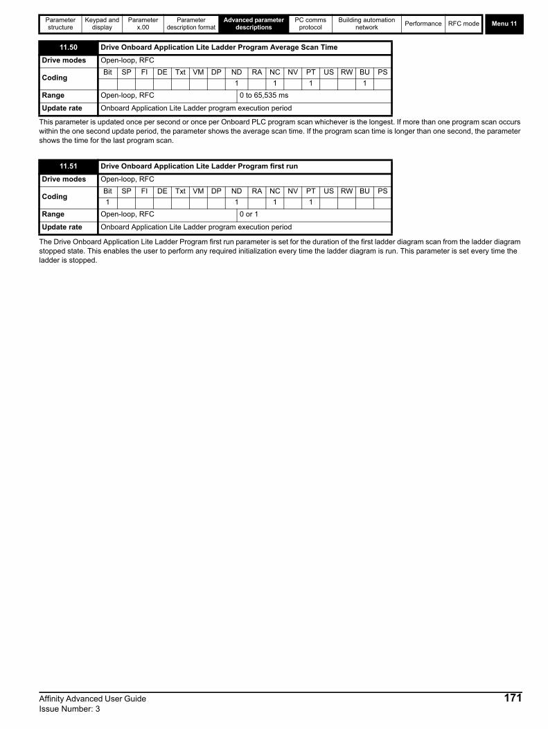
Parameter structure
Keypad and display
Parameter x.00
Parameter description format
Advanced parameter descriptions
PC comms protocol
Building automation network
Performance RFC mode Menu 11
This parameter is updated once per second or once per Onboard PLC program scan whichever is the longest. If more than one program scan occurs within the one second update period, the parameter shows the average scan time. If the program scan time is longer than one second, the parameter shows the time for the last program scan.
The Drive Onboard Application Lite Ladder Program first run parameter is set for the duration of the first ladder diagram scan from the ladder diagram stopped state. This enables the user to perform any required initialization every time the ladder diagram is run. This parameter is set every time the ladder is stopped.
11.50 Drive Onboard Application Lite Ladder Program Average Scan Time
Drive modes Open-loop, RFC
CodingBit SP FI DE Txt VM DP ND RA NC NV PT US RW BU PS
1 1 1 1
Range Open-loop, RFC 0 to 65,535 ms
Update rate Onboard Application Lite Ladder program execution period
11.51 Drive Onboard Application Lite Ladder Program first run
Drive modes Open-loop, RFC
CodingBit SP FI DE Txt VM DP ND RA NC NV PT US RW BU PS
1 1 1 1
Range Open-loop, RFC 0 or 1
Update rate Onboard Application Lite Ladder program execution period
Affinity Advanced User Guide 171Issue Number: 3

Menu 12Parameter structure
Keypad and display
Parameter x.00
Parameter description format
Advanced parameter descriptions
PC comms protocol
Building automation network
Performance RFC mode
5.14 Menu 12: Threshold detectors, variable selectors and brake control functionMenu 12 includes two threshold detectors which produce logic signals depending on the level of a variable value with respect to a threshold, and two variable selectors which allow two input parameters to be selected or combined to produce a variable output. One menu 9 or one menu 12 function is executed every 4ms. Therefore the sample time of these functions is 4ms x number of menu 9 and 12 functions active. A function is active if one or more sources are routed to a valid parameter.
Figure 5-14 Menu 12 logic diagram
??.??
Any variable parameter
??.??
12.03
Threshold Detector 1
input source
12.04
Threshold Detector 1
threshold level
Threshold Detector 1
Threshold Detector 1
x(-1)
12.06
ThresholdDetector 1
output invert
12.01
Threshold Detector 1
output indicator
12.05
Threshold Detector 1 hysteresis
??.??
Any unprotected
bit parameter
??.??
12.07
ThresholdDetector
outputdestinationparameter
1
??.??
Any variable parameter
??.??
12.23
Threshold Detector 2
input source
12.24
Threshold Detector 2
threshold level
Threshold Detector 2
Threshold Detector 2
x(-1)
12.26
ThresholdDetector 2
output invert
12.02
Threshold Detector 2
output indicator
12.25
Threshold Detector 2 hysteresis
??.??
??.??
12.27
ThresholdDetector
outputdestinationparameter
2
All parameters are shown at their default setting
0.XX
0.XX
Key
Read-write (RW) parameter
Read-only (RO) parameter
Inputterminals
Outputterminals
HysteresisThreshold
level
Thresholdoutput
t
t
Any unprotected
bit parameter
172 Affinity Advanced User Guide Issue Number: 3
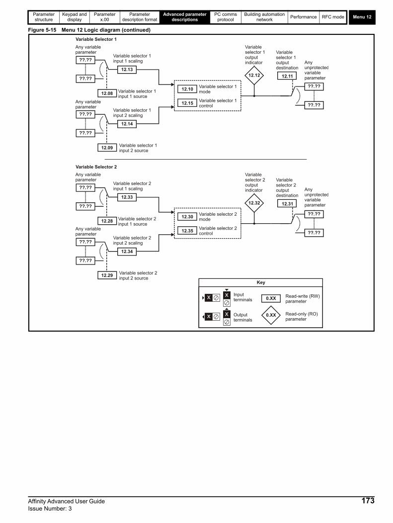
Parameter structure
Keypad and display
Parameter x.00
Parameter description format
Advanced parameter descriptions
PC comms protocol
Building automation network
Performance RFC mode Menu 12
Figure 5-15 Menu 12 Logic diagram (continued)
12.32
??.??
??.??
12.31
Variable Selector 2
Variable selector 2mode
Variable selector 2control
12.30
12.35
??.??
??.??
12.28
12.33
Variable selector 2input 1 source
Variable selector 2input 1 scaling
??.??
??.??
12.29
12.34
Variable selector 2input 2 source
Variable selector 2input 2 scaling
Variable selector 2output indicator
Variable selector 2output destination
12.12
??.??
??.??
12.11
Variable Selector 1
Variable selector 1mode
Variable selector 1control
12.10
12.15
??.??
Any variableparameter
??.??
12.08
12.13
Variable selector 1input 1 source
Variable selector 1input 1 scaling
??.??
??.??
12.09
12.14
Variable selector 1input 2 source
Variable selector 1input 2 scaling
Variable selector 1output indicator
Variable selector 1output destination
Any variableparameter
Any variableparameter
Any variableparameter
Any unprotectedvariableparameter
Any unprotectedvariableparameter
0.XX
0.XX
Key
Read-write (RW) parameter
Read-only (RO) parameter
Inputterminals
Outputterminals
Affinity Advanced User Guide 173Issue Number: 3
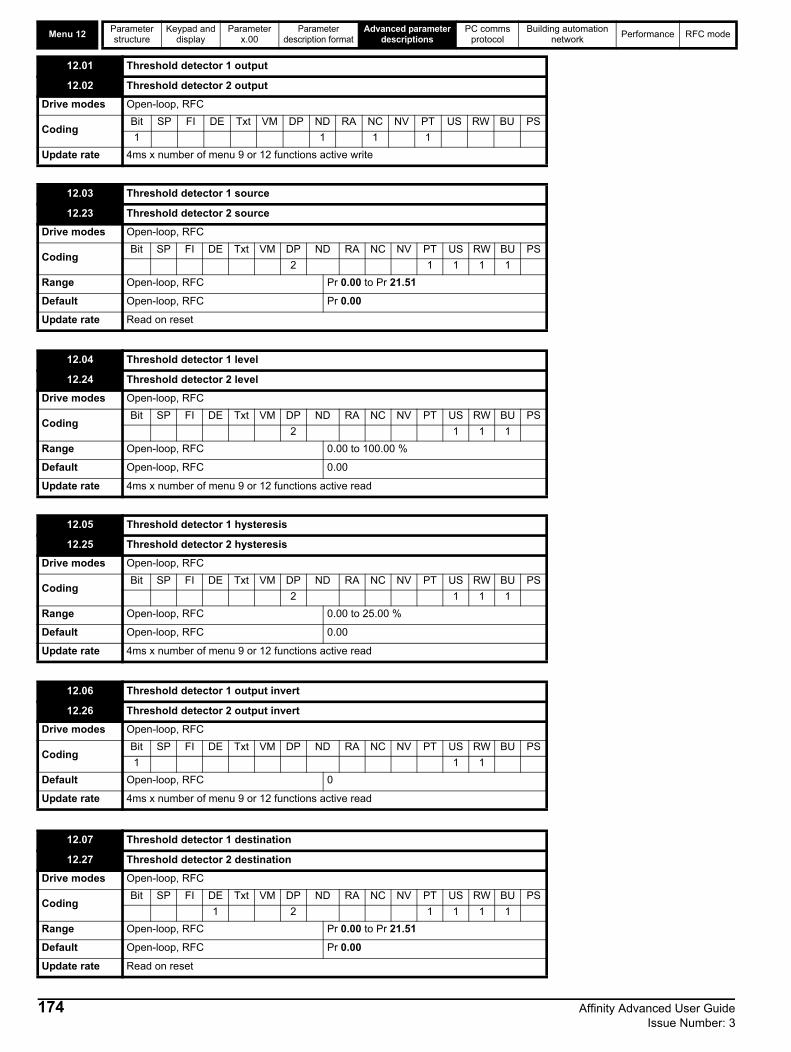
Menu 12Parameter structure
Keypad and display
Parameter x.00
Parameter description format
Advanced parameter descriptions
PC comms protocol
Building automation network
Performance RFC mode
12.01 Threshold detector 1 output
12.02 Threshold detector 2 output
Drive modes Open-loop, RFC
CodingBit SP FI DE Txt VM DP ND RA NC NV PT US RW BU PS
1 1 1 1
Update rate 4ms x number of menu 9 or 12 functions active write
12.03 Threshold detector 1 source
12.23 Threshold detector 2 source
Drive modes Open-loop, RFC
CodingBit SP FI DE Txt VM DP ND RA NC NV PT US RW BU PS
2 1 1 1 1
Range Open-loop, RFC Pr 0.00 to Pr 21.51
Default Open-loop, RFC Pr 0.00
Update rate Read on reset
12.04 Threshold detector 1 level
12.24 Threshold detector 2 level
Drive modes Open-loop, RFC
CodingBit SP FI DE Txt VM DP ND RA NC NV PT US RW BU PS
2 1 1 1
Range Open-loop, RFC 0.00 to 100.00 %
Default Open-loop, RFC 0.00
Update rate 4ms x number of menu 9 or 12 functions active read
12.05 Threshold detector 1 hysteresis
12.25 Threshold detector 2 hysteresis
Drive modes Open-loop, RFC
CodingBit SP FI DE Txt VM DP ND RA NC NV PT US RW BU PS
2 1 1 1
Range Open-loop, RFC 0.00 to 25.00 %
Default Open-loop, RFC 0.00
Update rate 4ms x number of menu 9 or 12 functions active read
12.06 Threshold detector 1 output invert
12.26 Threshold detector 2 output invert
Drive modes Open-loop, RFC
CodingBit SP FI DE Txt VM DP ND RA NC NV PT US RW BU PS
1 1 1
Default Open-loop, RFC 0
Update rate 4ms x number of menu 9 or 12 functions active read
12.07 Threshold detector 1 destination
12.27 Threshold detector 2 destination
Drive modes Open-loop, RFC
CodingBit SP FI DE Txt VM DP ND RA NC NV PT US RW BU PS
1 2 1 1 1 1
Range Open-loop, RFC Pr 0.00 to Pr 21.51
Default Open-loop, RFC Pr 0.00
Update rate Read on reset
174 Affinity Advanced User Guide Issue Number: 3

Parameter structure
Keypad and display
Parameter x.00
Parameter description format
Advanced parameter descriptions
PC comms protocol
Building automation network
Performance RFC mode Menu 12
The threshold detector compares the modulus of the source input value (defined by Pr 12.03, Pr 12.23), converted to a percentage of its maximum value, with the threshold level (Pr 12.04, Pr 12.24). If the value is greater or equal to the threshold plus half the hysteresis band (Pr 12.05, Pr 12.25) the output becomes active, or if the value is less than the threshold minus half the hysteresis band the output becomes inactive. The output may be inverted if required by setting the invert flag (Pr 12.06, Pr 12.26). The result is routed to the destination (defined by Pr 12.07, Pr 12.27).
12.08 Variable selector 1 source 1
12.28 Variable selector 2 source 1
Drive modes Open-loop, RFC
CodingBit SP FI DE Txt VM DP ND RA NC NV PT US RW BU PS
2 1 1 1 1
Range Open-loop, RFC Pr 0.00 to Pr 21.51
Default Open-loop, RFC Pr 0.00
Update rate Read on reset
12.09 Variable selector 1 source 2
12.29 Variable selector 2 source 2
Drive modes Open-loop, RFC
CodingBit SP FI DE Txt VM DP ND RA NC NV PT US RW BU PS
2 1 1 1 1
Range Open-loop, RFC Pr 0.00 to Pr 21.51
Default Open-loop, RFC Pr 0.00
Update rate Read on reset
12.10 Variable selector 1 mode
12.30 Variable selector 2 mode
Drive modes Open-loop, RFC
CodingBit SP FI DE Txt VM DP ND RA NC NV PT US RW BU PS
1 1 1
Range Open-loop, RFC 0 to 11
Default Open-loop, RFC 0
Update rate 4ms x number of menu 9 or 12 functions active read
12.11 Variable selector 1 destination
12.31 Variable selector 2 destination
Drive modes Open-loop, RFC
CodingBit SP FI DE Txt VM DP ND RA NC NV PT US RW BU PS
1 2 1 1 1 1
Range Open-loop, RFC Pr 0.00 to Pr 21.51
Default Open-loop, RFC Pr 0.00
Update rate Read on reset
12.12 Variable selector 1 output
12.32 Variable selector 2 output
Drive modes Open-loop, RFC
CodingBit SP FI DE Txt VM DP ND RA NC NV PT US RW BU PS
2 1 1 1
Range Open-loop, RFC ±100.00 %
Update rate 4ms x number of menu 9 or 12 functions active write
Affinity Advanced User Guide 175Issue Number: 3

Menu 12Parameter structure
Keypad and display
Parameter x.00
Parameter description format
Advanced parameter descriptions
PC comms protocol
Building automation network
Performance RFC mode
The variable selectors allow two source values (defined by Pr 12.08, Pr 12.28 and Pr 12.09, Pr 12.29) to be combined as defined by the mode (Pr 12.10, Pr 12.30) to produce an output (Pr 12.12, Pr 12.32) which can be routed to the destination parameter (defined by Pr 12.11, Pr 12.31). The actions of the variable selector are defined by the mode parameter as given below. If the mode parameter is changed or the variable selector is disabled because neither source is routed to a valid parameter, all internal state variables (i.e. time constant/filter accumulator, etc.) within the selector are reset.
12.13 Variable selector 1 source 1 scaling
12.33 Variable selector 2 source 1 scaling
Drive modes Open-loop, RFC
CodingBit SP FI DE Txt VM DP ND RA NC NV PT US RW BU PS
3 1 1
Range Open-loop, RFC ±4.000
Default Open-loop, RFC 1.000
Update rate 4ms x number of menu 9 or 12 functions active read
12.14 Variable selector 1 source 2 scaling
12.34 Variable selector 2 source 2 scaling
Drive modes Open-loop, RFC
CodingBit SP FI DE Txt VM DP ND RA NC NV PT US RW BU PS
3 1 1
Range Open-loop, RFC ±4.000
Default Open-loop, RFC 1.000
Update rate 4ms x number of menu 9 or 12 functions active read
12.15 Variable selector 1 control
12.35 Variable selector 2 control
Drive modes Open-loop, RFC
CodingBit SP FI DE Txt VM DP ND RA NC NV PT US RW BU PS
2 1 1 1
Range Open-loop, RFC 0.00 to 100.00
Default Open-loop, RFC 0.00
Update rate Background
Mode value Action Result
0 Select input 1 output = input1
1 Select input 2 output = input2
2 Add output = input1 + input2
3 Subtract output = input1 - input 2
4 Multiply output = (input1 x input2) / 100.0
5 Divide output = (input1 x 100.0) / input2
6 Time constant/filter output = input1 / ((control param)s + 1)
7 Linear rampoutput = input1 via a ramp with a ramp time of (control param) seconds from 0 to 100%
8 Modulus output = | input1 |
9 Powerscontrol = 0.02: output = input12 / 100.0
control = 0.03: output = input13 / 100.02
control has any other value: output = input1
10 Reserved
11 External rectifier monitor See section 5.14.1 below
176 Affinity Advanced User Guide Issue Number: 3

Parameter structure
Keypad and display
Parameter x.00
Parameter description format
Advanced parameter descriptions
PC comms protocol
Building automation network
Performance RFC mode Menu 12
5.14.1 External Rectifier (BAMC/U) MonitorThis mode is intended to monitor an external rectifier system (BAMC/U) to provide over temperature monitoring, phase loss detection and mains loss detection. The variable selector inputs should be routed to digital inputs on the drive or a Solutions Module, which are connected to the (BAMC/U) rectifier status outputs. The external rectifier monitor produces a number of actions depending on the state of the inputs as given in the table below.
The healthy/OK state becomes active immediately both inputs are high, but the other states only become active when the required inputs have been active for at least 0.5s. The high state is defined as a value greater than, or equal to half the source maximum, and the low state is defined as a value less than half the source maximum (with the scaling parameters set to 1.000). If digital inputs are used as the sources, and the scaling parameters are 1.000, high is therefore defined as 1, and low is defined as 0. The variable selector output gives 0% if the rectifier is healthy/OK otherwise it gives 100%.
The output should be routed to Pr 6.51 (rectifier not active), in order that the drive is not allowed to leave the main loss condition if the rectifier is not fully phased forwards.
For more information about Oht4.P and PH.P trips, refer to the Affinity Modular Drive User Guide.
5.14.2 Brake control functionThe brake control function can be used to control an electro-mechanical brake via the drive digital I/O. A brake control function is provided for open-loop operation of induction motors (Open-loop mode) and an alternative brake control function is provided for closed-loop operation of induction motors (RFC mode). The parameters that are common to both brake control functions (Pr 12.40 and Pr 12.41) are described below. The other parameters used by each of the brake control functions are then described in the section for the appropriate function.
This parameter should be used as a source for a digital output to control an electro-mechanical brake. This parameter is one to release the brake and zero to apply the brake. Digital I/O can be automatically configured to use this parameter as a source (see Pr 12.41).
Input 1 Input 2 State Trip Output
(Pr 12.08, Pr 12.28) (Pr 12.09, Pr 12.29) (Pr 12.09, Pr 12.29)
High High healthy/OK None 0%
High Low Over temperature Oht4.P trip 100%
Low High Phase Loss PH.P trip 100%
Low Low Mains Loss None 100%
12.40 Brake release
Drive modes Open-loop, RFC
CodingBit SP FI DE Txt VM DP ND RA NC NV PT US RW BU PS
1 1 1 1
Update rate Background read
Affinity Advanced User Guide 177Issue Number: 3

Menu 12Parameter structure
Keypad and display
Parameter x.00
Parameter description format
Advanced parameter descriptions
PC comms protocol
Building automation network
Performance RFC mode
0 = dis The brake controller is disabled and no other drive parameters are affected by the brake controller. When this parameter is changed from a non-zero value to zero the following parameters are set to zero: Pr 2.03 (all modes), Pr 6.08 (RFC mode), Pr 13.04 and Pr 13.10 (RFC mode if Pr 12.49 = 1).
1 = rel The brake controller is enabled with I/O set up to control the brake via the relay output T41/42. Drive ok is re-routed to digital I/O 2 (T25).
2 = d IO The brake controller is enabled with I/O set up to control the brake via digital I/O 2 (T25).
3 = User The brake controller is enabled, but no parameters are set to select the brake output.
The following tables show the automatic parameter changes that occur to set up digital I/O2 (T25) and the relay output (T41/42) after drive reset when Pr 12.41 has been changed. The changes are done in two stages: the first stage restores the I/O used as defined by the initial setting of Pr 12.41, and the second stage sets up the I/O as defined by the new setting of Pr 12.41.
Stage 1: Restore I/O
Stage 2: Set-up I/O
The brake control functions are provided to allow well co-ordinated operation of an external brake with the drive. While both hardware and software are designed to high standards of quality and robustness, they are not intended for use as safety functions, i.e. where a fault or failure would result in a risk of injury. In any application where the incorrect operation of the brake release mechanism could result in injury, independent protection devices of proven integrity must also be incorporated.
12.41 Brake controller enable
Drive modes Open-loop, RFC
Coding Bit SP FI DE Txt VM DP ND RA NC NV PT US RW BU PS
1 1 1 1
Range Open-loop, RFC 0 to 3
Default Open-loop, RFC 0
Update rate Read on drive reset
Initial settingin Pr 12.41
Pr 8.12 (Invert)Pr 8.22 (Source /
destination)Pr 8.32 (Input/
output)Pr 8.17 (Invert) Pr 8.27 (Source)
0 No action
1 0 Pr 10.33 0 0 Pr 10.01
2 0 Pr 10.33 0 No action
3 No action
New settingin Pr 12.41
Pr 8.12 (Invert)Pr 8.22 (Source /
destination)Pr 8.32 (Input/
output)Pr 8.17 (Invert) Pr 8.27 (Source)
0 No action
1 0 Pr 10.01 1 0 Pr 12.40
2 0 Pr 12.40 1 No action
3 No action
WARNING
178 Affinity Advanced User Guide Issue Number: 3

Parameter structure
Keypad and display
Parameter x.00
Parameter description format
Advanced parameter descriptions
PC comms protocol
Building automation network
Performance RFC mode Menu 12
Open-loop Figure 5-16 Open-loop brake function
The brake control functions are provided to allow well co-ordinated operation of an external brake with the drive. While both hardware and software are designed to high standards of quality and robustness, they are not intended for use as safety functions, i.e. where a fault or failure would result in a risk of injury. In any application where the incorrect operation of the brake release mechanism could result in injury, independent protection devices of proven integrity must also be incorporated.
The control terminal relay can be selected as an output to release a brake. If a drive is set up in this manner and a drive replacement takes place, prior to programming the drive on initial power up, the brake may be released.When drive terminals are programmed to non default settings the result of incorrect or delayed programming must be considered. The use of a SMARTCARD in boot mode or an SM-Applications module can ensure drive parameters are immediately programmed to avoid this situation.
WARNING
WARNING
4.01
Currentmagnitude
Upper currentthreshold
Lower currentthreshold
12.42
12.43
+
_
5.01
Outputfrequency
Brake releasefrequency
Brake applyfrequency
12.44
12.45
+
_
+
_
1.11
Referenceon
LAT
10.02
Driveactive
Post-brakereleasedelay
12.47
Pre-brakereleasedelay
12.46
12.40
Brakerelease
Ramphold
2.03
Brakecontroller
enable12.41
0.XX
0.XX
Key
Read-write (RW)parameter
Read-only (RO)parameter
Inputterminals
Outputterminals
XX
XX
i o
r
LAT
input
reset
output
If the reset input is 1, the output is 0.If the reset input is 0, the outputlatches at 1 if the input is 1.
i
r
o
2
3
8.12
8.17
8.22
8.27
8.32
T25 digitalI/O 2 invert
Relay sourceinvert
T25 digital I/O 2source / destination
Relay source
T25 digital I/O 12output select
Affinity Advanced User Guide 179Issue Number: 3

Menu 12Parameter structure
Keypad and display
Parameter x.00
Parameter description format
Advanced parameter descriptions
PC comms protocol
Building automation network
Performance RFC mode
Figure 5-17 Open-loop brake sequence
The current magnitude is compared to an upper and lower threshold by a comparator with hysteresis to establish torque present and drive output open detection functions respectively. The upper and lower threshold currents are given as a percentage of motor current defined by Pr 5.07 (or Pr 21.07 if motor map 2 is selected). The upper threshold should be set to the current level which indicates that there is magnetizing current and sufficient torque producing current in the motor to deliver the required amount of torque when the brake is released.
The output of the comparator remains active after this level has been reached, unless the current subsequently falls below the lower threshold which should be set to the required level to detect the condition where the motor has been disconnected from the drive. If the lower threshold is set greater or equal to the upper threshold, the upper threshold applies a hysteresis band of zero. If Pr 12.42 and Pr 12.43 are both set to zero, then the output of the comparator is always one.
12.42 Upper current threshold
Drive modes Open-loop
Coding Bit SP FI DE Txt VM DP ND RA NC NV PT US RW BU PS
1 1 1
Range Open-loop 0 to 200 %
Default Open-loop 50
Update rate Background read
12.43 Lower current threshold
Drive modes Open-loop
Coding Bit SP FI DE Txt VM DP ND RA NC NV PT US RW BU PS
1 1 1
Range Open-loop 0 to 200 %
Default Open-loop 10
Update rate Background read
1 2 3 4 65
Pr Output frequency5.01
Pr Reference on1.11
Pr Brake release12.40
Pr Ramp hold2.03
Pr Drive active10.02
Pr Current magnitude4.01
1. Wait for upper current threshold and brake release frequency2. Pre-brake release delay3. Post-brake release delay4. Wait for brake apply frequency5. Wait for zero frequency6. 1s delay as phase 2 of stopping sequence (Pr =1,2 or 3)6.01
Pr Brake release frequency12.44 Pr Brake apply frequency12.45
Pr 12.46 Pr 12.47
Pr Upper current threshold12.42
180 Affinity Advanced User Guide Issue Number: 3

Parameter structure
Keypad and display
Parameter x.00
Parameter description format
Advanced parameter descriptions
PC comms protocol
Building automation network
Performance RFC mode Menu 12
The frequency comparator can be used to detect when the motor frequency has reached a level where the motor can produce the required amount of torque to ensure that the motor rotates in the demanded direction when the brake is released. This parameter should be set to a level slightly above the motor slip frequency which is likely to occur under the highest expected load that is applied to the motor when the brake is released.
The brake apply frequency threshold is used to ensure that the brake is applied before the motor frequency reaches zero, and to prevent the motor rotating in the reverse direction due to an overhauling load, for example during the brake apply time. If the frequency falls below this threshold, but the motor is not required to stop (i.e. reversing direction without stopping), provided the Reference on parameter (Pr 1.11) remains at one, the brake is not applied. This prevents the brake from activating and de-activating as the motor passes through zero speed.
The pre-brake release delay is used to allow time for the motor torque to reach the required level before the brake is released. This time should allow for the motor flux to reach a significant proportion of the rated level (2 or 3 times the rotor time constant/filter of the motor), and the time for slip compensation to become fully active (at least 0.5s). During the Pre-brake delay period the frequency reference is held constant (Pr 2.03 = 1).
The post-brake release delay is used to allow for the brake release time. During this period the frequency reference is held constant (Pr 2.03 = 1), so that there is no sudden increase in motor speed when the brake actually releases.
12.44 Brake release frequency
Drive modes Open-loop
Coding Bit SP FI DE Txt VM DP ND RA NC NV PT US RW BU PS
1 1 1 1
Range Open-loop 0.0 to 20.0 Hz
Default Open-loop 1.0
Update rate Background read
12.45 Brake apply frequency
Drive modes Open-loop
Coding Bit SP FI DE Txt VM DP ND RA NC NV PT US RW BU PS
1 1 1 1
Range Open-loop 0.0 to 20.0 Hz
Default Open-loop 2.0
Update rate Background read
12.46 Pre-brake release delay
Drive modes Open-loop
Coding Bit SP FI DE Txt VM DP ND RA NC NV PT US RW BU PS
1 1 1 1
Range Open-loop 0.0 to 25.0 s
Default Open-loop 1.0
Update rate Background read
12.47 Post-brake release delay
Drive modes Open-loop
Coding Bit SP FI DE Txt VM DP ND RA NC NV PT US RW BU PS
1 1 1 1
Range Open-loop 0.0 to 25.0 s
Default Open-loop 1.0
Update rate Background read
Affinity Advanced User Guide 181Issue Number: 3

Menu 12Parameter structure
Keypad and display
Parameter x.00
Parameter description format
Advanced parameter descriptions
PC comms protocol
Building automation network
Performance RFC mode
RFCFigure 5-18 RFC brake function
Figure 5-19 RFC brake sequence
4.01
Current magnitude
Lower currentthreshold
12.43
+
_
Speedfeedback
Brake applyspeed
12.45
+
_
Post-brake release delay
0.XX
0.XX
Key
Read-write (RW) parameter
Read-only (RO) parameter
Inputterminals
Outputterminals
LAT
input
reset
output
If the reset input is 1, the output is 0.If the reset input is 0, the output latches at 1 if the input is 1.
i
r
o
+
_
Motor flux
7/8 x Rated flux
1.11
Referenceon
LAT
i o
r
OR
Brake applyspeed delay 12.46
10.02
Drive active
12.47
12.40Brakerelease
2.03
6.08 Hold zerospeed
Ramphold
Brakecontroller
enable12.41
8.12
8.17
8.22
8.27
8.32
T25 digitalI/O 2 invertRelay sourceinvertT25 digital I/O 2source / destination
Relay source
T25 digital I/O 2 output select
12.48 Brake applydelay
10.02
Drive active
1
Driveencoder
filterRFC sensorlessspeedfeedback
3.023.42
1 2 3 54
Pr Speed feedback3.02
Pr Reference on1.11
Pr Brake release12.40
Pr Ramp hold2.03Pr Position control mode13.10
Pr Drive active10.02
Pr Current magnitude4.01
1. Wait for motor fluxed (RFC only)2. Post-brake release delay3. Wait for speed threshold4. Wait for brake apply speed delay5. Brake apply delay
Pr Hold zero speed6.08
Pr Brake apply speed12.45
Pr 12.47 Pr 12.46 Pr 12.48
182 Affinity Advanced User Guide Issue Number: 3

Parameter structure
Keypad and display
Parameter x.00
Parameter description format
Advanced parameter descriptions
PC comms protocol
Building automation network
Performance RFC mode Menu 12
If the current magnitude falls below the lower current threshold the brake is applied immediately. The lower threshold should be set to the required level to detect the condition where the motor has been disconnected from the drive. If this parameter is set to zero, the loss of current will not cause the brake to be applied. However, the flux detection and current threshold latch will be reset when the drive is disabled.
When stopping, the drive reference can be removed (i.e. Pr 1.11 = 0), but the brake will remain energized (open) until the motor has remained at a speed below the brake apply speed for the delay defined by Pr 12.46. The delay prevents rapid activation and de-activation of the brake when fine control of a motor is required close to zero speed.
See Pr 12.45.
The post-brake release time is used to allow for the brake release time. From the time that the drive is enabled and then during this period the speed reference is held constant at zero, so that there is no sudden increase in motor speed when the brake actually releases.
The brake apply delay is used to allow for the brake application time. During this period the Hold zero speed parameter (Pr 6.08) is one, and so the drive is enabled with zero speed reference. This ensures that the motor remains stationary while the brake is being applied.
12.43 Low current threshold
Drive modes Open-loop, RFC
Coding Bit SP FI DE Txt VM DP ND RA NC NV PT US RW BU PS
1 1 1
Range Open-loop, RFC 0 to 200 %
Default Open-loop, RFC 10
Update rate Background read
12.45 Brake apply speed
Drive modes RFC
Coding Bit SP FI DE Txt VM DP ND RA NC NV PT US RW BU PS
1 1 1
Range RFC 0 to 200 rpm
Default RFC 5
Update rate Background read
12.46 Brake apply speed delay
Drive modes RFC
Coding Bit SP FI DE Txt VM DP ND RA NC NV PT US RW BU PS
1 1 1 1
Range RFC 0.0 to 25.0 s
Default RFC 1.0
Update rate Background read
12.47 Post-brake release delay
Drive modes RFC
Coding Bit SP FI DE Txt VM DP ND RA NC NV PT US RW BU PS
1 1 1 1
Range RFC 0.0 to 25.0 s
Default RFC 1.0
Update rate Background read
12.48 Brake-apply delay
Drive modes RFC
Coding Bit SP FI DE Txt VM DP ND RA NC NV PT US RW BU PS
1 1 1
Range RFC 0.0 to 25.0 s
Default RFC 1.0
Update rate Background read
Affinity Advanced User Guide 183Issue Number: 3

Menu 13Parameter structure
Keypad and display
Parameter x.00
Parameter description format
Advanced parameter descriptions
PC comms protocol
Building automation network
Performance RFC mode
184 Affinity Advanced User Guide Issue Number: 3
5.15 Menu 13: Not usedMenu 13 is not used by the Affinity drive but Pr 13.00 is available and provides Pr x.00 functions (See Chapter 3)

Parameter structure
Keypad and display
Parameter x.00
Parameter description format
Advanced parameter descriptions
PC comms protocol
Building automation network
Performance RFC mode Menu 14
Affinity Advanced User Guide 185Issue Number: 3

Menu 14Parameter structure
Keypad and display
Parameter x.00
Parameter description format
Advanced parameter descriptions
PC comms protocol
Building automation network
Performance RFC mode
5.16 Menu 14: Advanced process PIDThis menu contains two PID controllers. The PID controllers may be used independently or combined for complex applications. The sample rate of the PID controller is 4ms. Figure 5-20 Menu 14 logic diagram - single setpoint, single feedback
??.??
??.??
14.03Any variableparameter
PID 1 referencesource parameter
14.2014.07
+
_
14.22
PID 1reference
x(-1)
PID 1 reference
slew-rate limit
PID 1 error
14.05PID 1
referencesource invert
??.??
??.??
14.19
14.02
Any variableparameter
Main referencesource parameter
PID Main reference
??.??
??.??
14.09
14.08
&Any bitparameter
PID 1enable
Optional PID 1 enable source parameter 1
Source not used
Logic 1
??.??
??.??
14.27
Any bitparameter
Optional PID 1 enable source parameter 2
Source not used
Logic 1
++
14.25
PID 1 digitalreference
PID 1 referencescaling
+
14.28
PID 1 pre-sleepboost level
Logic 0
14.30
PID 1 pre-sleep boostlevel enable
??.??
??.??
14.33Any variableparameter
PID 2 referencesource parameter
14.5014.37
+
_
14.52
PID 2reference
x(-1)
PID 2 reference
slew-rate limit
PID 2 error
14.35
PID 2 referencesource invert
++
14.55
PID 2 digitalreference
PID 2 referencescaling
14.53
??.??
??.??
14.34Any variableparameter
PID 2 feedbacksource parameter
14.51
PID 2feedback
x(-1)
14.36
PID 2 feedbacksource invert
++
14.56
PID 2 digitalfeedbck
PID 2 feedbackscaling
14.54
??.??
??.??
14.04Any variableparameter
PID 1 feedbacksource parameter
++
14.26
PID 1 digitalfeedbck
PID 1 feedbackscaling
14.24
CombinedPID squareroot enable
14.23
PID controller 1
PID controller 2
14.21
PID 1feedback
x(-1)
14.06
PID 1 feedbacksource invert
Mode PID1 Feedback0 PID1 FB1 PID2 FB
14.59
PID modeselector
14.61
PID 2 squareroot enable
14.60
PID 1 squareroot enable
14.62
PID output 1feedback scaling
14.58
186 Affinity Advanced User Guide Issue Number: 3

Parameter structure
Keypad and display
Parameter x.00
Parameter description format
Advanced parameter descriptions
PC comms protocol
Building automation network
Performance RFC mode Menu 14
*The PID controller is only enabled if Pr 14.16 is set to a non Pr xx.00 and unprotected destination parameter.
14.10
14.11
14.12
14.17
14.13
14.14
14.18
14.01 14.15+
+
14.16
??.??
??.??
Any unprotectedvariable parameter
PID 1 derivativegain
PID 1 integralgain
PID 1 proportionalgain
PID 1 hold integrator enable
PID 1 outputhigh limit
PID 1 outputlow limit
PID 1 symmetricallimits enable
PID 1 controlleroutput PID 1 output
scale factor
PID 1 outputdestinationparameter*
0.XX
0.XX
Key
Read-write (RW) parameter
Read-only (RO) parameter
Inputterminals
Outputterminals
The parameters are all shown at their default settings
14.40
14.41
14.42
14.38
14.43
14.44
14.48
14.31 14.45
14.46
??.??
??.??
Any unprotectedvariable parameter
PID 2 derivativegain
PID 2 integralgain
PID 2 proportionalgain
PID 2 enable
PID 2 outputhigh limit
PID 2 outputlow limit
PID 2 symmetricallimits enable
PID 2 controlleroutput PID 2 output
scale factor
PID 2 outputdestinationparameter*
14.47
PID 2 hold integratorenable
Affinity Advanced User Guide 187Issue Number: 3

Menu 14Parameter structure
Keypad and display
Parameter x.00
Parameter description format
Advanced parameter descriptions
PC comms protocol
Building automation network
Performance RFC mode
Figure 5-21 Menu 14 Logic diagram - single setpoint, dual feedback
??.??
??.??
14.03Any variableparameter
PID 1 referencesource parameter
14.2014.07
+
_
14.22
PID 1reference
x(-1)
PID 1 reference
slew-rate limit
PID 1 error
14.05PID 1
referencesource invert
??.??
??.??
14.19
14.02
Any variableparameter
Main referencesource parameter
PID Main reference
??.??
??.??
14.09
14.08
&Any bitparameter
PID 1enable
Optional PID 1 enable source parameter 1
Source not used
Logic 1
??.??
??.??
14.27
Any bitparameter
Optional PID 1 enable source parameter 2
Source not used
Logic 1
++
14.25
PID 1 digitalreference
PID 1 reference
scaling
+
14.28
PID 1 pre-sleepboost level
Logic 0
14.30
PID 1 pre-sleep boostlevel enable
??.??
??.??
14.33Any variableparameter
PID 2 referencesource parameter
14.5014.37
+
_
14.52
PID 2reference
x(-1)
PID 2 reference
slew-rate limit
PID 2 error
14.35
PID 2 referencesource invert
++
14.55
PID 2 digitalreference
PID 2 reference
scaling
14.53
??.??
??.??
14.34Any variableparameter
PID 2 feedbacksource parameter
14.51
PID 2feedback
x(-1)
14.36
PID 2 feedbacksource invert
++
14.56
PID 2 digitalfeedbck
PID 2 feedbackscaling
14.54
??.??
??.??
14.04Any variableparameter
PID 1 feedbacksource parameter
++
14.26
PID 1 digitalfeedbck
PID 1 feedbackscaling
14.24
CombinedPID squareroot enable
14.23
PID controller 1
PID controller 2
14.21
PID 1feedback
x(-1)
14.06
PID 1 feedbacksource invert
14.59
PID modeselector
14.61
PID 2 squareroot enable
14.60
PID 1 squareroot enable
14.62
PID output 1feedback scaling
14.58
Mode PID1 Feedback
2 PID1 FB + PID2 FB3 MIN (PID1 FB, PIB2 FB)4 MAX (PID1 FB, PIB2 FB)5 AVG (PID1 FB, PID2 FB2
188 Affinity Advanced User Guide Issue Number: 3

Parameter structure
Keypad and display
Parameter x.00
Parameter description format
Advanced parameter descriptions
PC comms protocol
Building automation network
Performance RFC mode Menu 14
14.10
14.11
14.12
14.17
14.13
14.14
14.18
14.01 14.15+
+
14.16
??.??
??.??
Any unprotectedvariable parameter
PID 1 derivativegain
PID 1 integralgain
PID 1 proportionalgain
PID 1 hold integrator enable
PID 1 outputhigh limit
PID 1 outputlow limit
PID 1 symmetricallimits enable
PID 1 controlleroutput PID 1 output
scale factor
PID 1 outputdestinationparameter
0.XX
0.XX
Key
Read-write (RW) parameter
Read-only (RO) parameter
Inputterminals
Outputterminals
The parameters are all shown at their default settings
14.40
14.41
14.42
14.38
14.43
14.44
14.48
14.31 14.45
14.46
??.??
??.??
Any unprotectedvariable parameter
PID 2 derivativegain
PID 2 integralgain
PID 2 proportionalgain
PID 2 enable
PID 2 outputhigh limit
PID 2 outputlow limit
PID 2 symmetricallimits enable
PID 2 controlleroutput PID 2 output
scale factor
PID 2 outputdestinationparameter
14.47
PID 2 hold integratorenable
Affinity Advanced User Guide 189Issue Number: 3

Menu 14Parameter structure
Keypad and display
Parameter x.00
Parameter description format
Advanced parameter descriptions
PC comms protocol
Building automation network
Performance RFC mode
Figure 5-22 Menu 14 Logic diagram - dual setpoint, dual feedback
??.??
??.??
14.03Any variableparameter
PID 1 referencesource parameter
14.2014.07
+
_
14.22
PID 1reference
x(-1)
PID 1 reference
slew-rate limit
PID 1 error
14.05PID 1
referencesource invert
??.??
??.??
14.19
14.02
Any variableparameter
Main referencesource parameter
PID Main reference
??.??
??.??
14.09
14.08
&Any bitparameter
PID 1enable
Optional PID 1 enable source parameter 1
Source not used
Logic 1
??.??
??.??
14.27
Any bitparameter
Optional PID 1 enable source parameter 2
Source not used
Logic 1
++
14.25
PID 1 digitalreference
+
PID 1 reference
scaling
14.23
14.28
PID 1 pre-sleepboost level
Logic 0
14.30
PID 1 pre-sleep boostlevel enable
??.??
??.??
14.33Any variableparameter
PID 2 referencesource parameter
14.5014.37
+
_14.52
PID 2reference
x(-1)
PID 2 reference
slew-rate limit
PID 2 error
14.35
PID 2 referencesource invert
++
14.55
PID 2 digitalreference
PID 2 reference
scaling
14.53
??.??
??.??
14.04Any variableparameter
PID 1 feedbacksource parameter
PID 1feedback
x(-1)
14.06
PID 1 feedbacksource invert
++
14.26
PID 1 digitalfeedbck
PID 1 feedbackscaling
??.??
??.??
14.34Any variableparameter
PID 2 feedbacksource parameter
++
14.56
PID 2 digitalfeedbck
PID 2 feedbackscaling
14.54
PID output1 feedbackscaling
14.21
CombinedPID squareroot enable
14.62
14.58
14.61
14.51
PID 2feedback
x(-1)
14.36
PID 2 feedbacksource invert
14.60
PID 1 squareroot enable
14.24
190 Affinity Advanced User Guide Issue Number: 3
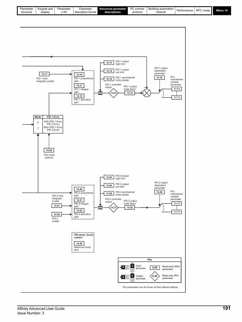
Parameter structure
Keypad and display
Parameter x.00
Parameter description format
Advanced parameter descriptions
PC comms protocol
Building automation network
Performance RFC mode Menu 14
14.10
14.11
14.12
14.17
14.13
14.14
14.18
14.01 14.15+
+
14.16
??.??
??.??
Any unprotectedvariable parameter
PID 1 derivativegain
PID 1 integralgain
PID 1 proportionalgain
PID 1 hold integrator enable
PID 1 outputhigh limit
PID 1 outputlow limit
PID 1 symmetricallimits enable
PID 1 controlleroutput PID 1 output
scale factor
PID 1 outputdestinationparameter
0.XX
0.XX
Key
Read-write (RW)parameter
Read-only (RO)parameter
Inputterminals
Outputterminals
The parameters are all shown at their default settings
Mode PID 1 Error
6 MIN (PID 1 Error,PID 2 Error)
7 MAX (PID 1 Error,PID 2 Error)
14.59
PID modeselector
14.40
14.41
14.42
14.38
14.43
14.44
14.48
14.31 14.45
14.46
??.??
??.??
Any unprotectedvariable parameter
PID 2 derivativegain
PID 2 integralgain
PID 2 proportionalgain
PID 2 enable
PID 2 outputhigh limit
PID 2 outputlow limit
PID 2 symmetricallimits enable
PID 2 controlleroutput PID 2 output
scale factor
PID 2 outputdestinationparameter
14.47
PID 2 hold integratorenable
14.29
Maximum boosttime
PID sleep / boostsystem
Affinity Advanced User Guide 191Issue Number: 3

Menu 14Parameter structure
Keypad and display
Parameter x.00
Parameter description format
Advanced parameter descriptions
PC comms protocol
Building automation network
Performance RFC mode
The PID output is derived from the following algorithm:
Output = Error x [Kp + Ki/s + Kds/(0.064s + 1)] where:
• Error (Pr 14.22, Pr 14.52) = Reference (Pr 14.20, Pr 14.50) - Feedback (Pr 14.21, Pr 14.51)• Kp = proportional gain (Pr 14.10, Pr 14.40)• Ki = integral gain (Pr 14.11, Pr 14.41)• Kd = differential gain (Pr 14.12, Pr 14.42)Therefore with an error of 100% and Kp=1.000, the output produced by the proportional term is 100%. With an error of 100% and Ki=1.000, the output produced by the integral term will increase linearly by 100% every second. With an error that is increasing by 100% per second and Kd=1.000, the output produced by the differential term will be 100%. A filter with a 64ms time constant is applied to the differential term to reduce noise.
The output Pr 14.01 (Pr 14.31) is limited by the values in Pr 14.13 (Pr 14.43) upper limit and Pr 14.14 (Pr 14.44) lower limit. Scaling can be applied before this value is sent to the location defined by destination parameter Pr 14.16 (Pr 14.46) by setting Pr 14.15 (Pr 14.45) to a value other than one.
The PID reference Pr 14.20 (Pr 14.50) is the sum of the digital reference Pr 14.25 (Pr 14.55) and the value from the location defined by the source parameter Pr 14.03 (Pr 14.33). Before the reference is applied to the controller algorithm, it can be scaled by setting Pr 14.23 (Pr 14.53) to a value other than one and/or inverted by setting Pr 14.05 (Pr 14.35) =1.
The feedback Pr 14.21 (Pr 14.51) is the sum of the digital feedback Pr 14.26 (Pr 14.56) and the value from the location defined by the source parameter Pr 14.04 (Pr 14.34). Before the reference is applied to the controller algorithm, it can be scaled by setting Pr 14.24 (Pr 14.54) to a value other than one and/or inverted by setting Pr 14.06 (Pr 14.36) =1.
14.01 PID 1 Output
14.31 PID 2 Output
Drive modes Open-loop, RFC
CodingBit SP FI DE Txt VM DP ND RA NC NV PT US RW BU PS
2 1 1 1
Range Open-loop, RFC -100.00 to 100.00%
Update rate 4ms read
14.02 PID main reference source parameter
Drive modes Open-loop, RFC
CodingBit SP FI DE Txt VM DP ND RA NC NV PT US RW BU PS
2 1 1 1 1
Range Open-loop, RFC Pr 0.00 to Pr 50.99
Default Open-loop, RFC Pr 0.00
Update rate Read on reset
14.03 PID 1 reference source parameter
14.33 PID 2 reference source parameter
Drive modes Open-loop, RFC
CodingBit SP FI DE Txt VM DP ND RA NC NV PT US RW BU PS
2 1 1 1 1
Range Open-loop, RFC Pr 0.00 to Pr 50.99
Default Open-loop, RFC Pr 0.00
Update rate Read on reset
14.04 PID 1 feedback source parameter
14.34 PID 2 feedback source parameter
Drive modes Open-loop, RFC
CodingBit SP FI DE Txt VM DP ND RA NC NV PT US RW BU PS
2 1 1 1 1
Range Open-loop, RFC Pr 0.00 to Pr 50.99
Default Open-loop, RFC Pr 0.00
Update rate Read on reset
192 Affinity Advanced User Guide Issue Number: 3

Parameter structure
Keypad and display
Parameter x.00
Parameter description format
Advanced parameter descriptions
PC comms protocol
Building automation network
Performance RFC mode Menu 14
This parameter defines the time taken for the reference input to ramp from 0 to 100.0% following a 0 to 100% step change in input.
PID 1 is enabled when Pr 14.08 =1 both the parameter sources defined by Pr 14.09 and Pr 14.27 to have a value of one (the source value for Pr 14.09 or Pr 14.27 appears as one if the parameter is set to 0.0). By default Pr 14.09 is set to 10.01 (drive ok) so that PID 1 controller is disabled if the drive is tripped. When the PID controller is disabled, the output is zero and all the internal state variables (i.e. integrator accumulator etc.) are held at zero.
To enable the PID controller, the drive must be ok (Pr 10.01 = 1) and the PID enable (Pr 14.08) must be one. If the option enable source (Pr 14.09) is 00.00 or routed to a non-existent parameter the PID controller is still enabled provided Pr 10.01 = 1 and Pr 14.08 = 1. If the optional enable source (Pr14.09) is routed to an existing parameter the source parameter must be one before the PID controller can be enabled. If the PID controller is disabled the output is zero and the integrator is set to zero.
14.05 PID 1 reference invert
14.35 PID 2 reference invert
Drive modes Open-loop, RFC
CodingBit SP FI DE Txt VM DP ND RA NC NV PT US RW BU PS
1 1 1
Default Open-loop, RFC 0
Update rate 4ms read
14.06 PID 1 feedback invert
14.36 PID 2 feedback invert
Drive modes Open-loop, RFC
CodingBit SP FI DE Txt VM DP ND RA NC NV PT US RW BU PS
1 1 1
Default Open-loop, RFC 0
Update rate 4ms read
14.07 PID 1 reference slew-rate limit
14.37 PID 2 reference slew-rate limit
Drive modes Open-loop, RFC
CodingBit SP FI DE Txt VM DP ND RA NC NV PT US RW BU PS
1 1 1 1
Range Open-loop, RFC 0.00 to 3200.0s
Default Open-loop, RFC 0.0
Update rate Background read
14.08 PID 1 enable
Drive modes Open-loop, RFC
CodingBit SP FI DE Txt VM DP ND RA NC NV PT US RW BU PS
1 1 1
Default Open-loop, RFC 0
Update rate 4ms read
14.09 PID 1 optional enable source parameter 1
Drive modes Open-loop, RFC
CodingBit SP FI DE Txt VM DP ND RA NC NV PT US RW BU PS
2 1 1 1 1
Range Open-loop, RFC Pr 0.00 to Pr 50.99
Default Open-loop, RFC Pr 10.01
Update rate Read on reset
Affinity Advanced User Guide 193Issue Number: 3

Menu 14Parameter structure
Keypad and display
Parameter x.00
Parameter description format
Advanced parameter descriptions
PC comms protocol
Building automation network
Performance RFC mode
If Pr 14.18 (Pr 14.48) is zero, the upper limit Pr 14.13 (Pr 14.43) defines the maximum positive output for the PID Controller and the lower limit defines the minimum positive or maximum negative output. If symmetrical limits are selected, i.e. Pr 14.18 (Pr 14.48) =1, then the upper limit defines the maximum positive or negative magnitude for the PID output. When any of the limits is active, then the integrator accumulator is held.
14.10 PID 1 proportional gain
14.40 PID 2 proportional gain
Drive modes Open-loop, RFC
CodingBit SP FI DE Txt VM DP ND RA NC NV PT US RW BU PS
3 1 1 1
Range Open-loop, RFC 0.000 to 4.000
Default Open-loop, RFC 1.000
Update rate Background read
14.11 PID 1 integral gain
14.41 PID 2 integral gain
Drive modes Open-loop, RFC
CodingBit SP FI DE Txt VM DP ND RA NC NV PT US RW BU PS
3 1 1 1
Range Open-loop, RFC 0.000 to 4.000
Default Open-loop, RFC 0.500
Update rate Background read
14.12 PID 1 differential gain
14.42 PID 2 differential gain
Drive modes Open-loop, RFC
CodingBit SP FI DE Txt VM DP ND RA NC NV PT US RW BU PS
3 1 1 1
Range Open-loop, RFC 0.000 to 4.000
Default Open-loop, RFC 0.000
Update rate Background read
14.13 PID 1 output upper limit
14.43 PID 2 output upper limit
Drive modes Open-loop, RFC
CodingBit SP FI DE Txt VM DP ND RA NC NV PT US RW BU PS
2 1 1 1
Range Open-loop, RFC 0.00 to 100.00 %
Default Open-loop, RFC 100.00%
Update rate Background read
14.14 PID 1 output lower limit
14.44 PID 2 output lower limit
Drive modes Open-loop, RFC
CodingBit SP FI DE Txt VM DP ND RA NC NV PT US RW BU PS
2 1 1
Range Open-loop, RFC ±100.00 %
Default Open-loop, RFC -100.00
Update rate Background read
194 Affinity Advanced User Guide Issue Number: 3
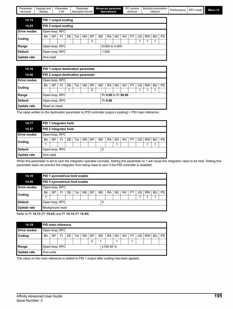
Parameter structure
Keypad and display
Parameter x.00
Parameter description format
Advanced parameter descriptions
PC comms protocol
Building automation network
Performance RFC mode Menu 14
The value written to the destination parameter is (PID controller output x scaling) + PID main reference.
When this parameter is set to zero the integrator operates normally. Setting this parameter to 1 will cause the integrator value to be held. Setting this parameter does not prevent the integrator from being reset to zero if the PID controller is disabled.
Refer to Pr 14.13 (Pr 14.43) and Pr 14.14 (Pr 14.44).
The value on the main reference is added to PID 1 output after scaling has been applied.
14.15 PID 1 output scaling
14.45 PID 2 output scaling
Drive modes Open-loop, RFC
CodingBit SP FI DE Txt VM DP ND RA NC NV PT US RW BU PS
3 1 1 1
Range Open-loop, RFC 0.000 to 4.000
Default Open-loop, RFC 1.000
Update rate 4ms read
14.16 PID 1 output destination parameter
14.46 PID 2 output destination parameter
Drive modes Open-loop, RFC
CodingBit SP FI DE Txt VM DP ND RA NC NV PT US RW BU PS
1 2 1 1 1
Range Open-loop, RFC Pr 0.00 to Pr 50.99
Default Open-loop, RFC Pr 0.00
Update rate Read on reset
14.17 PID 1 integrator hold
14.47 PID 2 integrator hold
Drive modes Open-loop, RFC
CodingBit SP FI DE Txt VM DP ND RA NC NV PT US RW BU PS
1 1 1 1
Default Open-loop, RFC 0
Update rate 4ms read
14.18 PID 1 symmetrical limit enable
14.48 PID 2 symmetrical limit enable
Drive modes Open-loop, RFC
CodingBit SP FI DE Txt VM DP ND RA NC NV PT US RW BU PS
1 1 1 1
Default Open-loop, RFC 0
Update rate Background read
14.19 PID main reference
Drive modes Open-loop, RFC
Coding Bit SP FI DE Txt VM DP ND RA NC NV PT US RW BU PS
2 1 1 1
Range Open-loop, RFC ±100.00 %
Update rate 4ms write
Affinity Advanced User Guide 195Issue Number: 3

Menu 14Parameter structure
Keypad and display
Parameter x.00
Parameter description format
Advanced parameter descriptions
PC comms protocol
Building automation network
Performance RFC mode
14.20 PID 1 reference
14.50 PID 2 reference
Drive modes Open-loop, RFC
Coding Bit SP FI DE Txt VM DP ND RA NC NV PT US RW BU PS
2 1 1 1
Range Open-loop, RFC ±100.00 %
Update rate 4ms write
14.21 PID 1 feedback
14.51 PID 2 feedback
Drive modes Open-loop, RFC
Coding Bit SP FI DE Txt VM DP ND RA NC NV PT US RW BU PS
2 1 1 1
Range Open-loop, RFC ±100.00 %
Update rate 4ms write
14.22 PID 1 error
14.52 PID 2 error
Drive modes Open-loop, RFC
Coding Bit SP FI DE Txt VM DP ND RA NC NV PT US RW BU PS
2 1 1 1
Range Open-loop, RFC ±100.00 %
Update rate 4ms write
14.23 PID 1 reference scaling
14.53 PID 2 reference scaling
Drive modes Open-loop, RFC
Coding Bit SP FI DE Txt VM DP ND RA NC NV PT US RW BU PS
3 1 1 1
Range Open-loop, RFC 0.000 to 4.000
Default Open-loop, RFC 1.000
Update rate 4ms read
14.24 PID 1 feedback scaling
14.54 PID 2 feedback scaling
Drive modes Open-loop, RFC
Coding Bit SP FI DE Txt VM DP ND RA NC NV PT US RW BU PS
3 1 1 1
Range Open-loop, RFC 0.000 to 4.000
Default Open-loop, RFC 1.000
Update rate 4ms read
196 Affinity Advanced User Guide Issue Number: 3

Parameter structure
Keypad and display
Parameter x.00
Parameter description format
Advanced parameter descriptions
PC comms protocol
Building automation network
Performance RFC mode Menu 14
See Pr 14.08.
14.25 PID 1 feedback reference
14.55 PID 2 feedback reference
Drive modes Open-loop, RFC
Coding Bit SP FI DE Txt VM DP ND RA NC NV PT US RW BU PS
2 1 1
Range Open-loop, RFC ±100.00 %
Default Open-loop, RFC 0.00%
Update rate 4ms read
14.26 PID 1 digital feedback
14.56 PID 2 digital feedback
Drive modes Open-loop, RFC
Coding Bit SP FI DE Txt VM DP ND RA NC NV PT US RW BU PS
2 1 1
Range Open-loop, RFC ±100.00 %
Default Open-loop, RFC 0.00%
Update rate 4ms read
14.27 PID 1 optional enable source parameter 2
Drive modes Open-loop, RFC
Coding Bit SP FI DE Txt VM DP ND RA NC NV PT US RW BU PS
2 1 1 1 1
Range Open-loop, RFC Pr 0.00 to Pr 50.99
Default Open-loop, RFC Pr 0.00
Update rate 4ms write
14.28 PID 1 pre-sleep boost level
Drive modes Open-loop, RFC
Coding Bit SP FI DE Txt VM DP ND RA NC NV PT US RW BU PS
2 1 1 1
Range Open-loop, RFC ±100.00 %
Default Open-loop, RFC 0.00%
Update rate Background read
14.29 Maximum boost time
Drive modes Open-loop, RFC
Coding Bit SP FI DE Txt VM DP ND RA NC NV PT US RW BU PS
1 1 1 1
Range Open-loop, RFC 0.0 to 250.0s
Default Open-loop, RFC 0.0s
Update rate Background read
Affinity Advanced User Guide 197Issue Number: 3

Menu 14Parameter structure
Keypad and display
Parameter x.00
Parameter description format
Advanced parameter descriptions
PC comms protocol
Building automation network
Performance RFC mode
If PID is used to control the motor output via Menu 1 and sleep mode is enabled, the drive will automatically stop the motor when the output drops below the sleep/wake threshold. The feedback may then fall causing the output and hence the feedback to rise again. Setting Pr 14.28 and Pr 14.29 to non zero values results in the value in Pr 14.28 being added to the PID reference for a length of time defined in Pr 14.29 when the drive attempts to enter sleep mode. This will reduce the frequency of the transitions into sleep mode. Pr 14.30 indicates when the boost system is enabled.
If Pr 14.58 is set a value greater than zero, then the following algorithm is applied to PID 1 feedback.
• Square root function output = Sign(Feedback) x 100.00% x 14.58 x v(|Feedback| / 100.00%) where Sign(Feedback) is 1 if the feedback is positive or -1 is the feedback is negative.
If Pr 14.58 is set to 0.000 then this feature is disabled and the feedback remains unchanged.
Normal mode (Pr 14.59 is between 0 and 5)
The two PID controllers operate independently. The feedback for PID2 is always from the PID2 feedback input. The feedback for PID1 is as given in the following table.
14.30 PID 1 pre-sleep boost level enable
Drive modes Open-loop, RFC
Coding Bit SP FI DE Txt VM DP ND RA NC NV PT US RW BU PS
1 1 1 1
Default Open-loop, RFC 0
Update rate 4ms read
14.38 PID 2 enable
Drive modes Open-loop, RFC
Coding Bit SP FI DE Txt VM DP ND RA NC NV PT US RW BU PS
1 1 1
Range Open-loop, RFC 0 to 2
Default Open-loop, RFC 0
Update rate 4ms read
Parameter Value PID Enable state
0 PID 2 disabled; output is zero and integrator reset to zero
1 PID 2 enabled
2 PID 2 enable state follows PID 1 enable state
14.58 PID 1 Feedback output scaling
Drive modes Open-loop, RFC
Coding Bit SP FI DE Txt VM DP ND RA NC NV PT US RW BU PS
3 1 1 1
Range Open-loop, RFC 0.000 to 4.000
Default Open-loop, RFC 1.000
Update rate 4ms read
14.59 PID mode selector
Drive modes Open-loop, RFC
Coding Bit SP FI DE Txt VM DP ND RA NC NV PT US RW BU PS
1 1 1
Range Open-loop, RFC 0 to 7
Default Open-loop, RFC 0
Update rate Background read
198 Affinity Advanced User Guide Issue Number: 3

Parameter structure
Keypad and display
Parameter x.00
Parameter description format
Advanced parameter descriptions
PC comms protocol
Building automation network
Performance RFC mode Menu 14
Dual Zone Mode (Pr 14.59 is 6 or 7)
When PID mode 6 or 7 is selected the controller operates in a dual zone mode. In this mode, the reference and feedback quantities from each PID controller are used to calculate two controller errors. These two errors are then checked and the zone with the larger or smaller absolute value of error (depending upon mode selected) is used as the error signal to the PID1 controller.
Pr 14.59 Final PID1 feedback
0 PID1 feedback
1 PID2 feedback
2 PID1 feedback + PID2 feedback
3 Lowest of PID1 feedback and PID2 feedback
4 Highest of PID1 feedback and PID2 feedback
5 (PID1 feedback + PID2 feedback) / 2
Pr 14.59 Final PID1 feedback PID1 Error
6 PID1 feedback Lowest of |PID1 Error| or |PID2 Error|
7 PID1 feedback Highest of |PID1 Error| or |PID2 Error|
14.60 PID 1 Square root enable
Drive modes Open-loop, RFC
Coding Bit SP FI DE Txt VM DP ND RA NC NV PT US RW BU PS
1 1 1
Range Open-loop, RFC OFF (0) or On (1)
Default Open-loop, RFC
Update rate Background read
14.61 PID 2 Square root enable
Drive modes Open-loop, RFC
Coding Bit SP FI DE Txt VM DP ND RA NC NV PT US RW BU PS
1 1 1
Range Open-loop, RFC OFF (0) or On (1)
Default Open-loop, RFC OFF (0)
Update rate Background read
14.62 Combined square root enable
Drive modes Open-loop, RFC
Coding Bit SP FI DE Txt VM DP ND RA NC NV PT US RW BU PS
1 1 1
Range Open-loop, RFC OFF (0) or On (1)
Default Open-loop, RFC OFF (0)
Update rate Background read
Affinity Advanced User Guide 199Issue Number: 3
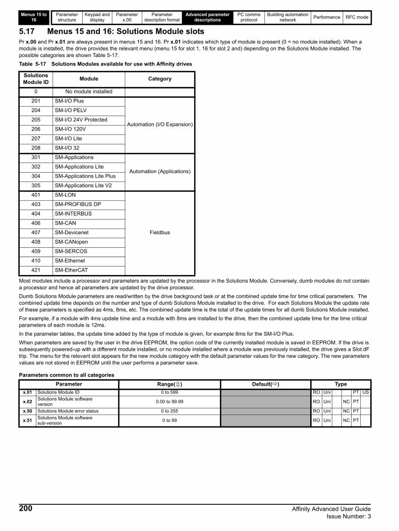
Menus 15 to 16
Parameter structure
Keypad and display
Parameter x.00
Parameter description format
Advanced parameter descriptions
PC comms protocol
Building automation network
Performance RFC mode
200 Affinity Advanced User Guide Issue Number: 3
5.17 Menus 15 and 16: Solutions Module slotsPr x.00 and Pr x.01 are always present in menus 15 and 16. Pr x.01 indicates which type of module is present (0 = no module installed). When a module is installed, the drive provides the relevant menu (menu 15 for slot 1, 16 for slot 2 and) depending on the Solutions Module installed. The possible categories are shown Table 5-17.
Table 5-17 Solutions Modules available for use with Affinity drives
Most modules include a processor and parameters are updated by the processor in the Solutions Module. Conversely, dumb modules do not contain a processor and hence all parameters are updated by the drive processor.
Dumb Solutions Module parameters are read/written by the drive background task or at the combined update time for time critical parameters. The combined update time depends on the number and type of dumb Solutions Module installed to the drive. For each Solutions Module the update rate of these parameters is specified as 4ms, 8ms, etc. The combined update time is the total of the update times for all dumb Solutions Module installed.
For example, if a module with 4ms update time and a module with 8ms are installed to the drive, then the combined update time for the time critical parameters of each module is 12ms.
In the parameter tables, the update time added by the type of module is given, for example 8ms for the SM-I/O Plus.
When parameters are saved by the user in the drive EEPROM, the option code of the currently installed module is saved in EEPROM. If the drive is subsequently powered-up with a different module installed, or no module installed where a module was previously installed, the drive gives a Slot.dF trip. The menu for the relevant slot appears for the new module category with the default parameter values for the new category. The new parameters values are not stored in EEPROM until the user performs a parameter save.
Parameters common to all categories
Solutions Module ID
Module Category
0 No module installed
201 SM-I/O Plus
Automation (I/O Expansion)
204 SM-I/O PELV
205 SM-I/O 24V Protected
206 SM-I/O 120V
207 SM-I/O Lite
208 SM-I/O 32
301 SM-Applications
Automation (Applications)302 SM-Applications Lite
304 SM-Applications Lite Plus
305 SM-Applications Lite V2
401 SM-LON
Fieldbus
403 SM-PROFIBUS DP
404 SM-INTERBUS
406 SM-CAN
407 SM-Devicenet
408 SM-CANopen
409 SM-SERCOS
410 SM-Ethernet
421 SM-EtherCAT
Parameter Range() Default() Type
x.01 Solutions Module ID 0 to 599 RO Uni PT US
x.02Solutions Module software version
0.00 to 99.99 RO Uni NC PT
x.50 Solutions Module error status 0 to 255 RO Uni NC PT
x.51Solutions Module software sub-version
0 to 99 RO Uni NC PT

Parameter structure
Keypad and display
Parameter x.00
Parameter description format
Advanced parameter descriptions
PC comms protocol
Building automation network
Performance RFC mode Menu 17
5.18 Menu 17: Building Automation Interface
The ID code for the Building Automation Interface is 402.
Pr 17.02 and Pr 17.51 display the firmware version in the form xx.yy.zz where xx.yy is Pr 17.02 and zz is Pr 17.51.
If a MAC address is selected that is greater than, or less than those allowed by the currently selected protocol, then the actual address used will be the maximum valid address value.
This selects the baud rate used for network communication.
17.01 ID number
Drive modes Open-loop, RFC
CodingBit SP FI DE Txt VM DP ND RA NC NV PT US RW BU PS
2 1 1 1
Range Open-loop, RFC
Default Open-loop, RFC 402
Update rate 4ms write
17.02 Software version
Drive modes Open-loop, RFC
Coding Bit SP FI DE Txt VM DP ND RA NC NV PT US RW BU PS
2 1 1 1 1
Range Open-loop, RFC 0 to 99.99
Update rate N/A
17.03 MAC / Node address
Drive modes Open-loop, RFC
CodingBit SP FI DE Txt VM DP ND RA NC NV PT US RW BU PS
1 1 1
Range Open-loop, RFC 0 to 65535
Default Open-loop, RFC 1
Update rate Read on reset
ProtocolAllowable MAC Address Values
Minimum Maximum
Modbus RTU 1 247
BACnet ( see note 1) 0 127
MetaSys N2 1 255
17.04 Baud rate
Drive modes Open-loop, RFC
CodingBit SP FI DE Txt VM DP ND RA NC NV PT US RW BU PS
1 1 1
Range Open-loop, RFC 0 to 127
Default Open-loop, RFC 0
Update rate N/A
Affinity Advanced User Guide 201Issue Number: 3

Menu 17Parameter structure
Keypad and display
Parameter x.00
Parameter description format
Advanced parameter descriptions
PC comms protocol
Building automation network
Performance RFC mode
The default value for each protocol is as follows: -
This selects the protocol used for the Building Automation Network as follows:
If a value greater than 3 is entered for Pr 17.05 then the Building Automation Network is disabled.
This parameter displays the number of valid messages that have been received using the currently selected building automation protocol. If the communications settings are configured correctly then this counter will count each time a message is received, therefore if the value remains constant then there is likely to be an error in either the configuration or the wiring to the communications port.
The received message counter is reset to in the following circumstances: -
1. When another message is received after 9999 prior valid messages have been received.2. Upon power up.
17.04 Value Baud rate (bps)
0 Protocol default value (see table below)
1 1200
2 2400
3 4800
4 9600
5 19200
6 38400
7 57600
8 76800
>8 Protocol default value (see table below)
Protocol Default baud rate (bps)
Modbus RTU 19200
BACnet 9600
MetaSys N2 9600
17.05 Building Automation Network protocol
Drive modes Open-loop, RFC
CodingBit SP FI DE Txt VM DP ND RA NC NV PT US RW BU PS
1 1 1
Range Open-loop, RFC 0 to 65535
Default Open-loop, RFC 0
Update rate Read on reset
Pr 17.05 Protocol Reference section
0 Disabled
1 Modbus RTU 6.2
2 BACnet 7.2
3 MetaSys N2 IOopen 7.3
17.06 Received message counter
Drive modes Open-loop, RFC
CodingBit SP FI DE Txt VM DP ND RA NC NV PT US RW BU PS
1 1 1
Range Open-loop, RFC 0 to 9999
Default Open-loop, RFC 0
Update rate Background write
17.07 MS/TP maximum master MAC address
Drive modes Open-loop, RFC
CodingBit SP FI DE Txt VM DP ND RA NC NV PT US RW BU PS
1 1 1
Range Open-loop, RFC 0 to 3000
Default Open-loop, RFC 127
Update rate Read on reset
202 Affinity Advanced User Guide Issue Number: 3

Parameter structure
Keypad and display
Parameter x.00
Parameter description format
Advanced parameter descriptions
PC comms protocol
Building automation network
Performance RFC mode Menu 17
BACnet use only
This is highest address that the drive will use when looking for the next master on the network with which token passing can be achieved.If a value greater than 127 is entered then the value used will be 127.
If this parameter is zero, then the MAC/Node address selected in parameter Pr 17.03 will be used as the object identifier for the BACnet device, otherwise the device object identifier will be the value specified here.If the node address is also set to zero then the Device Object Identifier value will be set to 1.
This is the period of time in seconds that the drive will wait to see a valid communications frame on the building automation network before taking the action specified in Pr 17.13.
If the value specified is less than or equal to five, then the timeout period will be adjusted to be 5 seconds. Care must be taken to ensure that this parameter is not set to a time less than the minimum time period between frames on the network.
The move to fixed speed option will only operate if the drive is configured to use preset speed 1 as the reference at the time communications are lost.
Every time there is a transition from the communications healthy state to the communications lost state, the reference value set in preset speed 8, will be transferred to preset speed 1, causing the drive to run at the speed defined in preset speed 8.
The drive will continue to run at this speed until such time as the user manually changes preset speed 1 via the keypad, or communications resume and a new speed reference is provided via the building automation network.
17.10 Device object identifier
Drive modes Open-loop, RFC
CodingBit SP FI DE Txt VM DP ND RA NC NV PT US RW BU PS
1 1
Range Open-loop, RFC 32768 to -32767
Default Open-loop, RFC 0
Update rate Read on reset
17.12 Communications lost detection timeout
Drive modes Open-loop, RFC
CodingBit SP FI DE Txt VM DP ND RA NC NV PT US RW BU PS
1 1
Range Open-loop, RFC 32768 to -32767
Default Open-loop, RFC 0
Update rate Read on reset
17.13 Communications loss action
Drive modes Open-loop, RFC
CodingBit SP FI DE Txt VM DP ND RA NC NV PT US RW BU PS
1 1
Range Open-loop, RFC 32768 to -32767
Default Open-loop, RFC 0
Update rate Read on reset
Pr 17.13 Action Comment
0 Do nothing The drive will continue as it was before communications was lost
1 Trip the drive The drive will trip when communications is lost
2 Move to a fixed speed Preset speed 8 is used to define this speed, see below
183 Reserved Do not select this value.
Affinity Advanced User Guide 203Issue Number: 3

Menu 17Parameter structure
Keypad and display
Parameter x.00
Parameter description format
Advanced parameter descriptions
PC comms protocol
Building automation network
Performance RFC mode
If an error is detected in the message header or body, then this count is incremented by one and the message disposed of. This parameter should remain constant when the connection to the Building Automation Network is operating correctly.
The CRC error count is reset to zero under the following circumstances:-
1. When another CRC error is detected after 32767 prior errors.2. Upon power up.3. After the last successfully received message.4. After building automation protocol is changed.
This selects the data transmission format used for the selected protocol.
The default value when Pr 17.38 is set to 0 OR >4 is as follows:-
17.35 CRC errors
Drive modes Open-loop, RFC
CodingBit SP FI DE Txt VM DP ND RA NC NV PT US RW BU PS
1 1 1
Range Open-loop, RFC 0 to +231-1
Update rate Background write
17.38 Data format
Drive modes Open-loop, RFC
CodingBit SP FI DE Txt VM DP ND RA NC NV PT US RW BU PS
1 1 1 1
Range Open-loop, RFC 0 to 255
Default Open-loop, RFC 0
Update rate Background read
17.38Description
Start Bits Data Bits Parity Stop Bits
0 Protocol default value
1 1 8 None 1
2 1 8 None 2
3 1 8 Even 1
4 1 8 Odd 1
>4 Protocol default value
ProtocolDescription
Start bits Data bits Parity Stop bits
Modbus RTU 1 8 None 2
BACnet 1 8 None 1
MetaSys N2 1 8 None 1
204 Affinity Advanced User Guide Issue Number: 3

Parameter structure
Keypad and display
Parameter x.00
Parameter description format
Advanced parameter descriptions
PC comms protocol
Building automation network
Performance RFC mode Menu 17
Modbus RTU Only
There will always be a finite delay between the end of a message from the host (master), and the time at which the host is ready to receive the response from the drive (slave). The drive does not respond until at least 1ms after the message has been received from the host, allowing 1ms for the host to change from transmit to receive mode. This initial delay can be extended using Pr 17.39 if required.
The real-time clock backup battery is checked upon power up and after a drive reset to determine if it should be changed. The conditions requiring battery replacement are when all power has been lost to the real-time clock while the drive was un-powered or that the battery voltage has fallen below 2.5Vdc.
If this parameter is 1 then the real-time clock backup battery should be replaced at the earliest opportunity.If the battery is low, the real-time clock will continue to operate as long as the drive remains powered. If the time-synchronization features of are also being used then the user may never notice nor care that the battery has failed.
This parameter has a value of 1 when the building automation network communications are healthy and zero when the communications lost detection determines that an error has occurred; this is determined differently for BACnet and MetaSys as follows: -
BACnet
The network is monitored for the presence of an active token; should this token disappear for the time specified in parameter Pr 17.12 the drive will take the action configured in parameter Pr 17.13.
MetaSys
The network is monitored for any message. Receipt of a valid message (regardless of intended destination) will be seen as communications being healthy. If no valid message is received within time specified in Pr 17.12 the drive will take the action configured in parameter Pr 17.13. It is important to ensure that a message is placed onto the network within the configured time-out period to prevent spurious drive operation
17.39 Response turn-around time
Drive modes Open-loop, RFC
CodingBit SP FI DE Txt VM DP ND RA NC NV PT US RW BU PS
1 1 1 1
Range Open-loop, RFC 0 to 255ms
Default Open-loop, RFC 5ms
Update rate Read on reset
Pr 17.39 Action
0The transmitters are turned on and data transmission begins immediately after the initial delay (1ms).
1The transmitters are turned on after the initial delay (1ms) and data transmission begins 1ms later.
2 or moreThe transmitters are turned on after a delay of at least the time specified in Pr 17.39 and data transmission begins 1ms later.
184 Reserved. Do not select this value.
17.44 Real-time clock battery low
Drive modes Open-loop, RFC
CodingBit SP FI DE Txt VM DP ND RA NC NV PT US RW BU PS
1 1 1 1
Range Open-loop, RFC 0 to 255
Update rate Read on reset
17.45 Communications OK flag
Drive modes Open-loop, RFC
CodingBit SP FI DE Txt VM DP ND RA NC NV PT US RW BU PS
1 1 1
Range Open-loop, RFC 0 to 255
Update rate Read on reset
Affinity Advanced User Guide 205Issue Number: 3
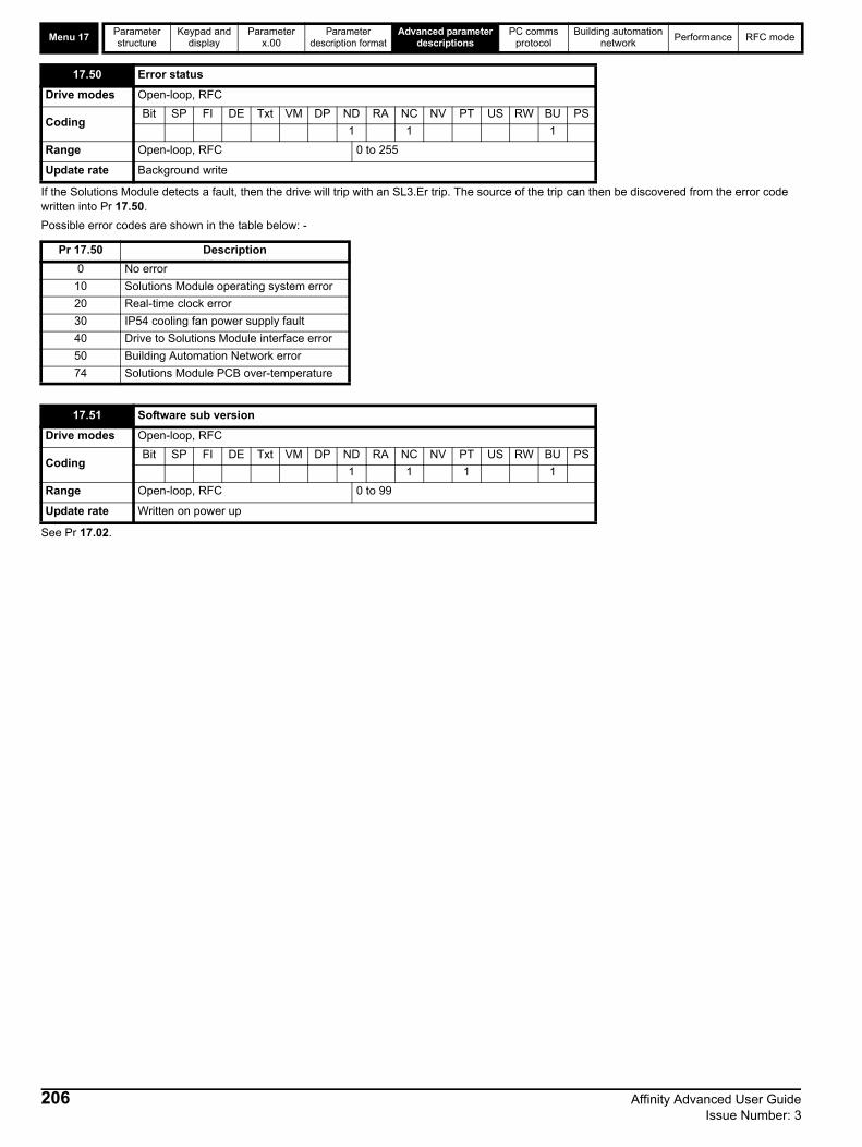
Menu 17Parameter structure
Keypad and display
Parameter x.00
Parameter description format
Advanced parameter descriptions
PC comms protocol
Building automation network
Performance RFC mode
If the Solutions Module detects a fault, then the drive will trip with an SL3.Er trip. The source of the trip can then be discovered from the error code written into Pr 17.50.
Possible error codes are shown in the table below: -
See Pr 17.02.
17.50 Error status
Drive modes Open-loop, RFC
CodingBit SP FI DE Txt VM DP ND RA NC NV PT US RW BU PS
1 1 1
Range Open-loop, RFC 0 to 255
Update rate Background write
Pr 17.50 Description
0 No error
10 Solutions Module operating system error
20 Real-time clock error
30 IP54 cooling fan power supply fault
40 Drive to Solutions Module interface error
50 Building Automation Network error
74 Solutions Module PCB over-temperature
17.51 Software sub version
Drive modes Open-loop, RFC
CodingBit SP FI DE Txt VM DP ND RA NC NV PT US RW BU PS
1 1 1 1
Range Open-loop, RFC 0 to 99
Update rate Written on power up
206 Affinity Advanced User Guide Issue Number: 3

Parameter structure
Keypad and display
Parameter x.00
Parameter description format
Advanced parameter descriptions
PC comms protocol
Building automation network
Performance RFC mode Menu 18
Affinity Advanced User Guide 207Issue Number: 3
5.19 Menu 18: Application menu 1Menu 18 contains parameters that do not affect the operation of the drive. These general purpose parameters are intended for use with fieldbus and application Solutions Modules. The read write parameters in this menu can be saved in the drive.
18.01 Application menu 1 power-down saved integer
Drive modes Open-loop, RFC
CodingBit SP FI DE Txt VM DP ND RA NC NV PT US RW BU PS
1 1 1
Range Open-loop, RFC -32,768 to 32,767
Default Open-loop, RFC 0
Update rate N/A
18.02 to 18.10 Application menu 1 read-only integer
Drive modes Open-loop, RFC
Coding Bit SP FI DE Txt VM DP ND RA NC NV PT US RW BU PS
1
Range Open-loop, RFC -32,768 to 32,767
Default Open-loop, RFC 0
Update rate N/A
18.11 to 18.30 Application menu 1 read-write integer
Drive modes Open-loop, RFC
CodingBit SP FI DE Txt VM DP ND RA NC NV PT US RW BU PS
1 1
Range Open-loop, RFC -32,768 to 32,767
Default Open-loop, RFC 0
Update rate N/A
18.31 to 18.50 Application menu 1 read-write bit
Drive modes Open-loop, RFC
CodingBit SP FI DE Txt VM DP ND RA NC NV PT US RW BU PS
1 1 1
Default Open-loop, RFC 0
Update rate N/A

Menu 19Parameter structure
Keypad and display
Parameter x.00
Parameter description format
Advanced parameter descriptions
PC comms protocol
Building automation network
Performance RFC mode
208 Affinity Advanced User Guide Issue Number: 3
5.20 Menu 19: Application menu 2Menu 19 contains parameters that do not affect the operation of the drive. These general purpose parameters are intended for use with fieldbus and application Solutions Modules. The read write parameters in this menu can be saved in the drive.
19.01 Application menu 2 power-down saved integer
Drive modes Open-loop, RFC
CodingBit SP FI DE Txt VM DP ND RA NC NV PT US RW BU PS
1 1 1
Range Open-loop, RFC -32,768 to 32,767
Default Open-loop, RFC 0
Update rate N/A
19.02 to 19.10 Application menu 2 read-only integer
Drive modes Open-loop, RFC
CodingBit SP FI DE Txt VM DP ND RA NC NV PT US RW BU PS
1
Range Open-loop, RFC -32,768 to 32,767
Default Open-loop, RFC 0
Update rate N/A
19.11 to 19.30 Application menu 2 read-write integer
Drive modes Open-loop, RFC
CodingBit SP FI DE Txt VM DP ND RA NC NV PT US RW BU PS
1 1
Range Open-loop, RFC -32,768 to 32,767
Default Open-loop, RFC 0
Update rate N/A
19.31 to 19.50 Application menu 2 read-write bit
Drive modes Open-loop, RFC
CodingBit SP FI DE Txt VM DP ND RA NC NV PT US RW BU PS
1 1 1
Default Open-loop, RFC 0
Update rate N/A

Parameter structure
Keypad and display
Parameter x.00
Parameter description format
Advanced parameter descriptions
PC comms protocol
Building automation network
Performance RFC mode Menu 20
Affinity Advanced User Guide 209Issue Number: 3
5.21 Menu 20: Application menu 3Menu 20 contains parameters that do not affect the operation of the drive. These general purpose parameters are intended for use with fieldbus and application Solutions Modules. The read write parameters in this menu cannot be saved in the drive.
*Menu 20 parameters are non-clonable and cannot be saved in a full parameter type data block but these parameters can be saved in a difference from defaults type data block if they are not at their default value.
20.01 to 20.20 Application menu 3 read-write integer
Drive modes Open-loop, RFC
CodingBit SP FI DE Txt VM DP ND RA NC NV PT US RW BU PS
1* 1
Range Open-loop, RFC -32,768 to 32,767
Default Open-loop, RFC 0
Update rate N/A
20.21 to 20.40 Application menu 3 read-write long integer
Drive modes Open-loop, RFC
CodingBit SP FI DE Txt VM DP ND RA NC NV PT US RW BU PS
1* 1
Range Open-loop, RFC -231 to 231-1
Default Open-loop, RFC 0
Update rate N/A

Menu 21Parameter structure
Keypad and display
Parameter x.00
Parameter description format
Advanced parameter descriptions
PC comms protocol
Building automation network
Performance RFC mode
5.22 Menu 21: Second motor parametersThe following parameters are used instead of the normal motor set-up parameters when Pr 11.45 = 1.When the alternative parameter set is being used by the drive ‘mot 2’ is displayed in the bottom left hand side of the display.For more information about a particular parameter, see the equivalent normal motor map 1 parameter.
* The range shown for Pr 1.07 shows the range used for scaling purposes (i.e. for routing to an analog output etc.). Further range restrictions are applied as given below.
Pr 21.03 defines how the value of Pr 1.49 is derived as follows:
21.01 Maximum reference clamp
Drive modes Open-loop, RFC
Coding
Bit SP FI DE Txt VM DP ND RA NC NV PT US RW BU PS
1 1 1 1
RFC = VM
RangeOpen-loopRFC
0 to 3,000.0HzSPEED_LIMIT_MAX rpm
DefaultOpen-loopRFC
EUR: 50.0, USA: 60.0EUR: 1,500.0, USA: 1,800.0
Normal parameter
Open-loop, RFC Pr 1.06
Update rate Background read
21.02 Minimum reference clamp
Drive modes Open-loop, RFC
Coding
Bit SP FI DE Txt VM DP ND RA NC NV PT US RW BU PS
1 1 1 1
RFC = VM
RangeOpen-loopRFC
±3,000.0 Hz *±SPEED_LIMIT_MAX rpm
Default Open-loop, RFC 0.0
Normal parameter
Open-loop, RFC Pr 1.07
Update rate Background read
01.08 01.10 Open-loop RFC
(Neg min ref enable) (Bipolar mode enable)
0 0 0 to 01.06 0 to 21.01
0 1 0 0
1 0 -3000 to 0Hz* -SPEED_LIMIT_MAX to 0 rpm
1 1 -3000 to 0Hz* -SPEED_LIMIT_MAX to 0 rpm
21.03 Reference selector
Drive modes Open-loop, RFC
CodingBit SP FI DE Txt VM DP ND RA NC NV PT US RW BU PS
1 1 1 1
Range Open-loop, RFC 0 to 5
Default Open-loop, RFC 0 (A1.A2)
Normal parameter
Open-loop, RFC Pr 1.14
Update rate 4ms read
210 Affinity Advanced User Guide Issue Number: 3

Parameter structure
Keypad and display
Parameter x.00
Parameter description format
Advanced parameter descriptions
PC comms protocol
Building automation network
Performance RFC mode Menu 21
*The bit Pr 1.41 to Pr 1.44 can be controlled to force the value of Pr 1.49:
all bits equal to zero gives 1,
Pr 1.41 = 1 then Pr 1.49 = 2 Pr 1.42 = 1 then Pr 1.49 = 3Pr 1.43 = 1 then Pr 1.49 = 4Pr 1.44 = 1 then Pr 1.49 = 5
The bit parameters with lower numbers have priority over those with higher numbers.
Pr 1.49 and Pr 1.50 then define the reference as follows:
Keypad referenceIf Keypad reference is selected the drive sequencer is controlled directly by the keypad keys and the keypad reference parameter (Pr 1.17) is selected. The sequencing bits Pr 6.30 to Pr 6.34, have no effect, and jog is disabled.
Reference selected by timerThe presets are selected automatically in turn. Pr 1.16 defines the time between each change.
Value of Pr 21.03 Display String Pr 1.49
0 A1.A2 *Selected by terminal input
1 A1.Pr 1
2 A2.Pr 2
3 Pr 3
4 Pad 4
5 Prc 5
Pr 1.49 Pr 1.50 Reference
1 1 Analog reference 1
1 >1 Preset defined by Pr 1.50
2 1 Analog reference 2
2 >1 Preset defined by Pr 1.50
3 x Preset defined by Pr 1.50
4 x Keypad reference
5 x Precision reference
21.04 Acceleration rate
Drive modes Open-loop, RFC
Coding
Bit SP FI DE Txt VM DP ND RA NC NV PT US RW BU PS
1 1 1 1
RFC DP = 3
RangeOpen-loopRFC
0.0 to 3200.0 s/100Hz0.000 to 3200.000 s/1000rpm
DefaultOpen-loopRFC
EUR: 40.0, USA: 33.3EUR: 13.333, USA: 11.111
Normal parameter
Open-loop, RFC Pr 2.11
Update rate Background read
21.05 Deceleration rate
Drive modes Open-loop, RFC
Coding
Bit SP FI DE Txt VM DP ND RA NC NV PT US RW BU PS
1 1 1 1
RFC DP = 3
RangeOpen-loopRFC
0.0 to 3200.0 s/100Hz0.000 to 3200.000 s/1000rpm
DefaultOpen-loopRFC
EUR: 40.0, USA: 33.3EUR: 13.333, USA: 11.111
Normal parameter
Open-loop, RFC Pr 2.21
Update rate Background read
Affinity Advanced User Guide 211Issue Number: 3

Menu 21Parameter structure
Keypad and display
Parameter x.00
Parameter description format
Advanced parameter descriptions
PC comms protocol
Building automation network
Performance RFC mode
21.06 Rated frequency
Drive modes Open-loop, RFC
CodingBit SP FI DE Txt VM DP ND RA NC NV PT US RW BU PS
1 1 1 1
RangeOpen-loopRFC
0 to 3000.0 Hz0 to 1250.0 Hz
Default Open-loop, RFC EUR: 50.0, USA: 60.0
Normal parameter
Open-loop, RFC Pr 5.06
Update rate Background read
21.07 Rated current
Drive modes Open-loop, RFC
CodingBit SP FI DE Txt VM DP ND RA NC NV PT US RW BU PS
1 2 1 1 1 1
Range Open-loop, RFC 0 to RATED_CURRENT_MAX A
Default Open-loop, RFC RATED_CURRENT_MAX (Pr 11.32)
Normal parameter
Open-loop, RFC Pr 5.07
Update rate Background read
21.08 Rated load rpm
Drive modes Open-loop, RFC
Coding
Bit SP FI DE Txt VM DP ND RA NC NV PT US RW BU PS
1 1 1
RFC DP=2
RangeOpen-loop, RFC
0 to 180,000 rpm0.00 to 40,000.00 rpm
DefaultOpen-loop,RFC
15001450.00
Normal parameter
Open-loop, RFC Pr 5.08
Update rate Background read
21.09 Rated voltage
Drive modes Open-loop, RFC
CodingBit SP FI DE Txt VM DP ND RA NC NV PT US RW BU PS
1 1 1 1 1
Range Open-loop, RFC 0 to AC_VOLTAGE_SET_MAX V
Default Open-loop, RFC
200V rating drive: 230V400V rating drive: EUR: 400V, USA: 460V575V rating drive: 575V 690V rating drive: 690V
Normal parameter
Open-loop, RFC Pr 5.09
Update rate Level 4 read
212 Affinity Advanced User Guide Issue Number: 3

Parameter structure
Keypad and display
Parameter x.00
Parameter description format
Advanced parameter descriptions
PC comms protocol
Building automation network
Performance RFC mode Menu 21
Pr 21.12 shows the stator resistance of the motor. The units vary with the drive size to ensure that the full range of likely resistances can be represented with suitable resolution. The table below shows the units. Therefore 1.000 in the parameter represents the resistance shown in the units column.
21.10 Rated power factor
Drive modes Open-loop, RFC
CodingBit SP FI DE Txt VM DP ND RA NC NV PT US RW BU PS
3 1 1 1 1
Range Open-loop, RFC 0.000 to 1.000
Default Open-loop, RFC 0.850
Normal parameter
Open-loop, RFC Pr 5.10
Update rate Background read
21.11 Number of motor poles
Drive modes Open-loop, RFC
CodingBit SP FI DE Txt VM DP ND RA NC NV PT US RW BU PS
1 1 1 1
Range Open-loop, RFC 0 to 60 (Auto to 120 POLE)
Default Open-loop, RFC 0 (Auto)
Normal parameter
Open-loop, RFC Pr 5.11
Update rate Background read
21.12 Stator resistance
Drive modes Open-loop, RFC
CodingBit SP FI DE Txt VM DP ND RA NC NV PT US RW BU PS
3 1 1 1 1
Range Open-loop, RFC 0.000 to 65.000
Default Open-loop, RFC 0.000
Normal parameter
Open-loop, RFC Pr 5.17
Update rate Background read
Drive size Units
BA1xxx to BA5xxx 1 Ohm
BA6xxx, BAMxxxx 0.01 Ohms
21.13 Voltage offset
Drive modes Open-loop
CodingBit SP FI DE Txt VM DP ND RA NC NV PT US RW BU PS
1 1 1 1 1
Range Open-loop 0.0 to 25.0 V
Default Open-loop 0.0
Normal parameter
Open-loop Pr 5.23
Update rate Background read
Affinity Advanced User Guide 213Issue Number: 3

Menu 21Parameter structure
Keypad and display
Parameter x.00
Parameter description format
Advanced parameter descriptions
PC comms protocol
Building automation network
Performance RFC mode
Pr 21.15 does not have an equivalent normal motor parameter, but is displayed when motor 2 is active.
21.14 Transient inductance (Ls)
Drive modes Open-loop, RFC
CodingBit SP FI DE Txt VM DP ND RA NC NV PT US RW BU PS
3 1 1 1 1
Range Open-loop, RFC 0.000 to 500.000 mH
Default Open-loop, RFC 0.000
Normal parameter
Open-loop, RFC Pr 5.24
Update rate Background read
21.15 Motor 2 active
Drive modes Open-loop, RFC
CodingBit SP FI DE Txt VM DP ND RA NC NV PT US RW BU PS
1 1 1 1
Normal motor parameter
Open-loop, RFC Pr 21.15
Update rate Background write
21.16 Thermal time constant/filter
Drive modes Open-loop, RFC
CodingBit SP FI DE Txt VM DP ND RA NC NV PT US RW BU PS
1 1 1 1
Range Open-loop, RFC 0.0 to 3000.0
Default Open-loop, RFC 89.0
Normal motor parameter
Open-loop, RFC Pr 4.15
Update rate Background read
21.17 Speed controller Kp gain
Drive modes RFC
CodingBit SP FI DE Txt VM DP ND RA NC NV PT US RW BU PS
4 1 1 1
Range RFC 0.00 to 6.5335 (1/rad s-1)
Default RFC 0.0300
Normal motor parameter
RFC Pr 3.10
Update rate Background read
21.18 Speed controller Ki gain
Drive modes RFC
CodingBit SP FI DE Txt VM DP ND RA NC NV PT US RW BU PS
2 1 1 1
Range RFC 0.00 to 653.35 s/rad s-1
Default RFC 0.10
Normal motor parameter
RFC Pr 3.11
Update rate Background read
214 Affinity Advanced User Guide Issue Number: 3

Parameter structure
Keypad and display
Parameter x.00
Parameter description format
Advanced parameter descriptions
PC comms protocol
Building automation network
Performance RFC mode Menu 21
When the second motor is selected the gains defined in Pr 21.17 to Pr 21.19 are used directly by the speed controller. The speed controller set-up method defined by Pr 3.13 is ignored.
21.19 Speed controller Kd gain
Drive modes RFC
CodingBit SP FI DE Txt VM DP ND RA NC NV PT US RW BU PS
5 1 1 1
Range RFC 0.00000 to 0.65335 s-1 / rad s-1
Default RFC 0.00000
Normal motor parameter
RFC Pr 3.12
Update rate Background read
21.22 Current controller Kp gain
Drive modes Open-loop, RFC
CodingBit SP FI DE Txt VM DP ND RA NC NV PT US RW BU PS
1 1 1
Range Open-loop, RFC 0 to 30,000
DefaultDrive voltage rating:Open-loop,RFC
200V 400V 575V 690V 20 20 20 20 75 150 180 215 45 90 110
Normal parameter
Open-loop, RFC Pr 4.13
Update rate Background read
21.23 Current controller Ki gain
Drive modes Open-loop, RFC
CodingBit SP FI DE Txt VM DP ND RA NC NV PT US RW BU PS
1 1 1
Range Open-loop, RFC 0 to 30,000
DefaultDrive voltage rating:Open-loop,RFC
200V 400V 575V 690V 40 40 40 401,000 2,000 2,400 3,000
Normal parameter
Open-loop, RFC Pr 4.14
Update rate Background read
21.24 Stator inductance (Ls)
Drive modes RFC
CodingBit SP FI DE Txt VM DP ND RA NC NV PT US RW BU PS
2 1 1 1 1
Range RFC 0.00 to 5,000.00 mH
Default RFC 0.00
Normal parameter
RFC Pr 5.25
Update rate Background read
Affinity Advanced User Guide 215Issue Number: 3

Menu 21Parameter structure
Keypad and display
Parameter x.00
Parameter description format
Advanced parameter descriptions
PC comms protocol
Building automation network
Performance RFC mode
*These are the maximum default values. If the variable maximum of this parameter (MOTOR2_CURRENT_LIMIT_MAX) gives a lower value with the
default value of Motor rated current (Pr 21.07) the default of this parameter is at the lower value.
21.25 Motor saturation breakpoint 1
Drive modes RFC
CodingBit SP FI DE Txt VM DP ND RA NC NV PT US RW BU PS
1 1 1
Range RFC 0 to 100% of rated flux
Default RFC 50
Normal parameter
RFC Pr 5.29
Update rate Background read
21.26 Motor saturation breakpoint 2
Drive modes RFC
CodingBit SP FI DE Txt VM DP ND RA NC NV PT US RW BU PS
1 1 1
Range RFC 0 to 100% of rated flux
Default RFC 75
Normal parameter
RFC Pr 5.30
Update rate Background read
21.27 Motoring current limit
Drive modes Open-loop, RFC
CodingBit SP FI DE Txt VM DP ND RA NC NV PT US RW BU PS
1 1 1 1 1 1
Range Open-loop, RFC 0 to MOTOR2_CURRENT_LIMIT_MAX %
Default Open-loop, RFC 110.0*
Normal parameter
Open-loop, RFC Pr 4.05
Update rate Background read
21.28 Regen current limit
Drive modes Open-loop, RFC
CodingBit SP FI DE Txt VM DP ND RA NC NV PT US RW BU PS
1 1 1 1 1 1
Range Open-loop, RFC 0 to MOTOR2_CURRENT_LIMIT_MAX %
Default Open-loop, RFC 110.0*
Normal parameter
Open-loop, RFC Pr 4.06
Update rate Background read
21.29 Symmetrical current limit
Drive modes Open-loop, RFC
CodingBit SP FI DE Txt VM DP ND RA NC NV PT US RW BU PS
1 1 1 1 1 1
Range Open-loop, RFC 0 to MOTOR2_CURRENT_LIMIT_MAX %
Default Open-loop, RFC 110.0*
Normal parameter
Open-loop, RFC Pr 4.07
Update rate Background read
216 Affinity Advanced User Guide Issue Number: 3

Parameter structure
Keypad and display
Parameter x.00
Parameter description format
Advanced parameter descriptions
PC comms protocol
Building automation network
Performance RFC mode Menu 22
Affinity Advanced User Guide 217Issue Number: 3
5.23 Menu 22: Additional menu 0 set-upMenu 22 contains parameters that are used to set up the source parameters for menu 0 in addition to those that are set up from within Menu 11.
These parameters define the parameters that reside in the programmable area in menu 0.
Table 5-18 Menu 22 default settings
It should be noted that if the parameter values saved in the drive EEPROM or on a SMARTCARD are all zero for menu 22, the drive will automatically load defaults for this menu when the drive is powered up, or the parameters are transferred from the SMARTCARD. This ensures that defaults are used for this menu if the saved parameters are from a software version which did not include this menu.
22.01 to 22.0722.10 to 22.11
22.1822.20 to 22.29
Parameter 00.xy set-up
Drive modes Open-loop, RFC
CodingBit SP FI DE Txt VM DP ND RA NC NV PT US RW BU PS
2 1 1 1 1
Range Open-loop, RFC Pr 1.00 to Pr 21.51
Default Open-loop, RFC See Table 5-18
Update rate Background read
ParameterMenu 0
parameterOpen-loop RFC
Pr 22.01 Pr 031 Pr 11.33
Pr 22.02 Pr 0.32 Pr 11.32
Pr 22.03 Pr 0.33 Pr 6.09
Pr 22.04 Pr 0.34 Pr 11.30
Pr 22.05 Pr 0.35 Pr 11.24
Pr 22.06 Pr 0.36 Pr 11.25
Pr 22.07 Pr 0.37 Pr 11.23
Pr 22.10 Pr 0.40 Pr 5.12
Pr 22.11 Pr 0.41 Pr 5.18
Pr 22.18 Pr 0.48 Pr 11.31
Pr 22.20 Pr 0.50 Pr 11.29
Pr 22.21 Pr 0.51 Pr 8.29
Pr 22.22 Pr 0.52 Pr 9.35
Pr 22.23 Pr 0.53 Pr 9.36
Pr 22.24 Pr 0.54 Pr 9.37
Pr 22.25 Pr 0.55 Pr 9.38
Pr 22.26 Pr 0.56 Pr 9.39
Pr 22.27 Pr 0.57 Pr 9.40
Pr 22.28 Pr 0.58 Pr 9.43
Pr 22.29 Pr 0.59 Pr 0.00

32 bit parameters
Parameter structure
Keypad and display
Parameter x.00
Parameter description format
Advanced parameter descriptions
PC comms protocol
Building automation network
Performance RFC mode
218 Affinity Advanced User Guide Issue Number: 3
5.24 32 bit parametersAll parameters in the drive are 1 bit, 16 bit or 32 bit. This section identifies all the 32 bit parameters in the drive and Solutions Modules.
5.24.1 Drive parametersThe table below contains all the 32 bit parameters present in the drive for all four modes of operation (open loop, RFC).
Table 5-19 32 bit drive parameters
Some of the parameters listed above are only 32 bit parameters in certain modes. Below is a table listing these parameters and the modes in which they are 32 bit parameters.
5.24.2 Solutions Module parametersSome Solutions Modules contain 32 bit parameters. Below is a table listing these parameters and the modules in which they are 32 bit parameters.
Table 5-20 32 bit Solutions Module parameters
Menu 32-bit parameters
Menu 1
Pr 1.01 Pr 1.02 Pr 1.03 Pr 1.04 Pr 1.06 Pr 1.07 Pr 1.17 Pr 1.18
Pr 1.21 Pr 1.22 Pr 1.23 Pr 1.24 Pr 1.25 Pr 1.26 Pr 1.27 Pr 1.28
Pr 1.36 Pr 1.37 Pr 1.39
Menu 2
Pr 2.01 Pr 2.07 Pr 2.11 Pr 2.12 Pr 2.13 Pr 2.14 Pr 2.15 Pr 2.16
Pr 2.17 Pr 2.18 Pr 2.19 Pr 2.21 Pr 2.22 Pr 2.23 Pr 2.24 Pr 2.25
Pr 2.26 Pr 2.27 Pr 2.28 Pr 2.29
Menu 3 Pr 3.01 Pr 3.02 Pr 3.03 Pr 3.10 Pr 3.18 Pr 3.22
Menu 4 Pr 4.01 Pr 4.02 Pr 4.08 Pr 4.17
Menu 5 Pr 5.01 Pr 5.03 Pr 5.04 Pr 5.07 Pr 5.08 Pr 5.24 Pr 5.25
Menu 11 Pr 11.32
Menu 20 Pr 20.21 Pr 20.22 Pr 20.23 Pr 20.24 Pr 20.25 Pr 20.26 Pr 20.27 Pr 20.28
Menu 21
Pr 20.29 Pr 20.30 Pr 20.31 Pr 20.32 Pr 20.33 Pr 20.34 Pr 20.35 Pr 20.36
Pr 20.37 Pr 20.38 Pr 20.39 Pr 20.40
Pr 21.01 Pr 21.02 Pr 21.04 Pr 21.05 Pr 21.07 Pr 21.08 Pr 21.14 Pr 21.24
Parameter Modes in which the parameter is 32 bit
Pr 3.01 RFC
Pr 3.03 RFC
Pr 3.18 RFC
Pr 4.08 Open Loop, RFC
Parameter Solutions modules in which the parameter is 32 bit
Pr x.35 All Fieldbus modules

Parameter structure
Keypad and display
Parameter x.00Parameter
description formatAdvanced parameter
descriptionsPC comms
protocolBuilding automation
networkPerformance RFC mode
6 PC communications protocol
6.1 ANSI communications protocol
6.1.1 IntroductionAffinity supports an ANSIx3.28 type comms protocol as supported by previous Control Techniques products with some modification to allow access to 32 bit parameters. This chapter describes the implementation of the protocol for Affinity.
6.1.2 Physical layer and UART
6.1.3 Reading a parameterThe command to read a parameter is:
If the message is correct and the parameter exists the response is:
The length of the data field varies depending on the number of significant digits required to represent the value of the parameter. The maximum length is 12 digits, including the sign and decimal point if present. The data field always starts with a sign, either a minus sign for negative numbers or a plus sign for zero and positive numbers. The field may contain a decimal point, but this will not be before all the numbers in the field or after all the numbers in the field. The following examples demonstrate some possible data fields.
If the parameter to be read does not exist the End of transmission character (Ctl D) is returned.
The checksum is derived by exclusive ORing the message byte together excluding the STX and the checksum, i.e. Checksum = M1 ^ M2 ^ P1^ P2 ^ D1 ^ D2 ^ ...... Dn ^ ETX. The checksum is an unsigned 8 bit value and if the checksum is less than 32 then 32 is added to the calculated checksum.
6.1.4 Writing to a parameterThe command to write to a parameter is:
The following rules apply to the data field:
1. The maximum length is 12 characters.2. The field may contain leading spaces, but not after any other
character.3. A sign character is optional. No sign indicates positive.4. A decimal point is optional. This can appear at any point in the data
field, but not before the sign or before 10 numbers (i.e. the value written should not have more than 9 decimal places). If the decimal point is not in the same position as used by the parameter, some accuracy may be lost or extra decimal places added (i.e. if +1.2345 is written to a parameter with one decimal place the result is +1.2, if +1.2 is written to a parameter with three decimal places the result is +1.200). It should be noted that parameters can only have 0, 1, 2, 3, 4, 5, or 6 decimal places.
5. The data field can contain up to 10 numbers, but the value even
ignoring decimal points must not exceed the range –231 to 231-1.
If the parameter is written successfully, an Acknowledge character (Ctl F) is returned. If the parameter does not exist, the value written exceeds the allowed parameter range or the data field rules are not obeyed an Not acknowledge character (Ctl U) is returned.
The checksum is derived by exclusive ORing the message byte together excluding the STX and the checksum, i.e. Checksum = M1 ^ M2 ^ P1^ P2 ^ D1 ^ D2 ^ ...... Dn ^ ETX. The checksum is an unsigned 8 bit value and if the checksum is less than 32 then 32 is added to the calculated checksum.
Attribute Description
Physical layer 2 wire EIA485
Bit streamStandard UART asynchronous symbols with Non Return to Zero (NRZ)
Symbol
Each symbol consists of:1 start bit7 data bits (ASCII)1 parity bit (even parity)1 stop bit
Baud rates 300, 600, 1200, 2400, 4800, 9600, 19200, 38400
EOT End of transmission (Ctl D)
A1 Drive address: 1st digit
A1 Drive address: 1st digit
A2 Drive address: 2nd digit
A2 Drive address: 2nd digit
M1 Menu number: 1st digit
M2 Menu number: 2nd digit
P1 Parameter number: 1st digit
P2 Parameter number: 2nd digit
ENQ Enquiry (Ctl E)
STX Start of text (Ctl B)
M1 Menu number: 1st digit
M2 Menu number: 2nd digit
P1 Parameter number: 1st digit
P2 Parameter number: 2nd digit
D1 Data: 1st digit
D2 Data: 2nd digit
-
-
Dn Data: nth digit
ETX End of text (Ctl C)
Checksum
Value Data field
0 +0 (parameter with no decimal places)
0 +0.00 (parameter with 2 decimal places)
1.2 +1.2
-345.78 -345.78
123456 +123456
EOT End of transmission (Ctl D)
A1 Drive address: 1st digit
A1 Drive address: 1st digit
A2 Drive address: 2nd digit
A2 Drive address: 2nd digit
STX Start of text (Ctl B)
M1 Menu number: 1st digit
M2 Menu number: 2nd digit
P1 Parameter number: 1st digit
P2 Parameter number: 2nd digit
D1 Data: 1st digit
D2 Data: 2nd digit
-
-
Dn Data: nth digit
ETX End of text (Ctl C)
Checksum
Affinity Advanced User Guide 219Issue Number: 3

Parameter structure
Keypad and display
Parameter x.00Parameter
description formatAdvanced parameter
descriptionsPC comms
protocolBuilding automation
networkPerformance RFC mode
6.1.5 Drive addressThe drive only acts on received messages which contain a drive address if the whole drive address or drive group address, matches the whole address or the group address in the message, or if the address in the message is 0 (i.e. a global message). Global or group addressing allows data to be written to more than one drive with one command. The drive does not give a response to a global or group write message. Although it is possible to perform a global or group read, this would result in messages crashing if more than one drive responds to the command.
6.1.6 Short commandsThe following short commands can be used:
This is the same as requesting the value of the last parameter to be read or written to. The response is the same as for a normal read.
This is the same as requesting the value of the parameter after the last parameter to be read or written to. The response is the same as for a normal read.
This is the same as requesting the value of the parameter before the last parameter to be read or written to. The response is the same as for a normal read.
Writes to the specified parameter at the same drive address as used by the last read or write.
All the short commands will only read from the drive or write to the drive if a valid address has already been sent to the drive in a previous command. The address is registered as being valid once a read or write command has been completed provide the address was valid for the drive even if the parameter does not exist. The valid address is cancelled if a message is received for a non-valid address or one of the following occurs:
1. The command is aborted because a non-numerical value is received in the drive address, menu or parameter numbers.
2. The command is aborted because the two digits for the drive address first digit, drive address second digit, menu number or parameter number are not the same as each other.
3. EOT is received.4. A character other than NAK, ACK, BS or STX is sent as a short
command.5. A character other than ENQ is sent at the end of a read command.
6.1.7 Summary of control characters
Drive address
Message address
Command Action
7.8 7.8 Read Read
7.8 7.8 Write Write
7.8 7.0 Read Read
7.8 7.0 Write Write with no response
7.8 0.0 Read Read
7.8 0.0 Write Write with no response
NAK Not acknowledge (Ctl U)
ACK Acknowledge (Ctl F)
BS Back space (Ctl H)
STX Start of text (Ctl B)
M1 Menu number: 1st digit
M2 Menu number: 2nd digit
P1 Parameter number: 1st digit
P2 Parameter number: 2nd digit
D1 Data: 1st digit
D2 Data: 2nd digit
-
-
Dn Data: nth digit
ETX End of text (Ctl C)
Checksum
ASCII code Ctl code
STX Start of text 02 B
ETX End of text 03 C
EOT End of transmission 04 D
ENQ Enquiry 05 E
ACK Acknowledge 06 F
BS Back space 08 H
NAK Not acknowledge 15 U
220 Affinity Advanced User Guide Issue Number: 3

Parameter structure
Keypad and display
Parameter x.00Parameter
description formatAdvanced parameter
descriptionsPC comms
protocolBuilding automation
networkPerformance RFC mode
6.2 CT Modbus RTU specificationThis section describes the adaptation of the MODBUS RTU protocol offered on Control Techniques' products. The portable software class which implements this protocol is also defined.
MODBUS RTU is a master slave system with half-duplex message exchange. The Control Techniques (CT) implementation supports the core function codes to read and write registers. A scheme to map between MODBUS registers and CT parameters is defined. The CT implementation also defines a 32bit extension to the standard 16bit register data format.
6.2.1 MODBUS RTUPhysical layer
*The drive will accept a packet with 1 or 2 stop bits, but will always transit 2 stop bits
RTU framingThe frame has the following basic format
The frame is terminated with a minimum silent period of 3.5 character times (for example, at 19200 baud the minimum silent period is 2ms). Nodes use the terminating silence period to detect the end of frame and begin frame processing. All frames must therefore be transmitted as a continuous stream without any gaps greater or equal to the silence period. If an erroneous gap is inserted, then receiving nodes may start frame processing early, in which case the CRC will fail and the frame will be discarded.
MODBUS RTU is a master slave system. All master requests, except broadcast requests, will lead to a response from an individual slave. The slave will respond (i.e. start transmitting the response) within the quoted maximum slave response time (this time is quoted in the data sheet for all Control Techniques products). The minimum slave response time is also quoted, but will never be less that the minimum silent period defined by 3.5 character times.
If the master request was a broadcast request, then the master may transmit a new request once the maximum slave response time has expired.
The master must implement a message time-out to handle transmission errors. This time-out period must be set to the maximum slave response time plus transmission time for the response.
6.2.2 Slave addressThe first byte of the frame is the slave node address. Valid slave node addresses are 1 through 247 decimal. In the master request this byte indicates the target slave node; in the slave response this byte indicates the address of the slave sending the response.
Global addressingAddress zero addresses all slave nodes on the network. Slave nodes suppress the response messages for broadcast requests.
Attribute Description
Normal physical layer for multi-drop operation EIA485 2 wire
Bit stream Standard UART asynchronous symbols with Non Return to Zero (NRZ)
Symbol
Each symbol consists of:-1 start bit8 data bits (transmitted least significant bit first)2 stop bits*
Baud rates 300, 600, 1200, 2400, 4800, 9600, 19200, 38400, 57600, 115200
Message data
SLAVEADDRESS
16bit CRCmessage dataFUNCTION
CODESilent
interval
Master request
Time
frame detectSlave frameprocessing
Slave response
Slave response time
Master request
New master requestcan start here
minimum silenceperiod
minimum silenceperiod
Affinity Advanced User Guide 221Issue Number: 3

Parameter structure
Keypad and display
Parameter x.00Parameter
description formatAdvanced parameter
descriptionsPC comms
protocolBuilding automation
networkPerformance RFC mode
6.2.3 MODBUS registersThe MODBUS register address range is 16bit (65536 registers) which at the protocol level is represented by indexes 0 through 65535.
PLC registersModicon PLCs typically define 4 register 'files' each containing 65536 registers. Traditionally, the registers are referenced 1 through 65536 rather than 0 through 65535. The register address is therefore decremented on the master device before passing to the protocol.
The register file type code is NOT transmitted by MODBUS, and all register files can be considered to map onto a single register address space. However, specific function codes are defined in MODBUS to support access to the "coil" registers.
All standard CT drive parameters are mapped to register file '4' and the coil function codes are not required.
CT parameter mappingAll CT products are parameterized using the #menu.param notation. Indexes 'menu' and 'param' are in the range 0 through 99. The #menu.param is mapped into the MODBUS register space as menu*100 + param.
To correctly map the parameters at the application layer, the slave device increments the received register address. The consequence of this behavior is that #0.0 cannot be accessed.
Data typesThe MODBUS protocol specification defines registers as 16bit signed integers. All CT devices support this data size.
Refer to the section 6.2.7 Extended data types on page 223 for detail on accessing 32bit register data.
6.2.4 Data consistencyAll CT devices support a minimum data consistency of one parameter (16bit or 32bit data). Some devices support consistency for a complete multiple register transaction.
6.2.5 Data encodingMODBUS RTU uses a 'big-endian' representation for addresses and data items (except the CRC, which is 'little-endian'). This means that when a numerical quantity larger than a single byte is transmitted, the MOST significant byte is sent first. So for example
16 - bits 0x1234 would be 0x12 0x3432 - bits 0x12345678 would be 0x12 0x340x560x78
6.2.6 Function codesThe function code determines the context and format of the message data. Bit 7 of the function code is used in the slave response to indicate an exception.
The following function codes are supported:
FC03 Read multipleRead a contiguous array of registers. The slave imposes an upper limit on the number of registers, which can be read. If this is exceeded the slave will issue an exception code 2.
Table 6-1 Master request
Table 6-2 Slave response
FC06 Write single registerWrites a value to a single 16bit register. The normal response is an echo of the request returned after the register contents have been written. The register address can correspond to a 32bit parameter, but only 16 bits of data can be sent.
Table 6-3 Master request
Table 6-4 Slave response
File type Description
1 Read only bits ("coil")
2 Read / write bits ("coil")
3 Read only 16bit register
4 Read / write 16bit register
CT parameter
MODBUS PLC register
Register address(protocol level)
Comments
#X.Y 40000 + X x 100 + Y X x 100 + Y - 1#0.0 cannot be accessed
Examples:
#1.02 40102 101
#1.00 40100 99
#0.01 40001 0
#20.00 42000 1999
Code Description
3 Read multiple 16bit registers
6 Write single register
16 Write multiple 16bit registers
23 Read and write multiple 16bit registers
Byte Description
0Slave destination node address 1 through 247, 0 is global
1 Function code 0x03
2 Start register address MSB
3 Start register address LSB
4 Number of 16bit registers MSB
5 Number of 16bit registers LSB
6 CRC LSB
7 CRC MSB
Byte Description
0 Slave source node address
1 Function code 0x03
2 Length of register data in read block (in bytes)
3 Register data 0 MSB
4 Register data 0 LSB
3+byte count CRC LSB
4+byte count CRC MSB
Byte Description
0 Slave node address 1 through 247, 0 is global
1 Function code 0x06
2 Register address MSB
3 Register address LSB
4 Register data MSB
5 Register data LSB
6 CRC LSB
7 CRC MSB
Byte Description
0 Slave source node address
1 Function code 0x06
2 Register address MSB
3 Register address LSB
4 Register data MSB
5 Register data LSB
6 CRC LSB
7 CRC MSB
222 Affinity Advanced User Guide Issue Number: 3

Parameter structure
Keypad and display
Parameter x.00Parameter
description formatAdvanced parameter
descriptionsPC comms
protocolBuilding automation
networkPerformance RFC mode
FC16 Write multipleWrites a contiguous array of registers. The slave imposes an upper limit on the number of registers which can be written. If this is exceeded, the slave will discard the request and the master will time-out.
Table 6-5 Master request
Table 6-6 Slave response
FC23 Read/Write multipleWrites and reads two contiguous arrays of registers. The slave imposes an upper limit on the number of registers which can be written. If this is exceeded the slave will discard the request and the master will time-out.
Table 6-7 Master request
Table 6-8 Slave response
6.2.7 Extended data typesStandard MODBUS registers are 16bit and the standard mapping maps a single #X.Y parameter to a single MODBUS register. To support 32bit data types (integer and float), the MODBUS multiple read and write services are used to transfer a contiguous array of 16bit registers.
Slave devices typically contain a mixed set of 16bit and 32bit registers. To permit the master to select the desired 16bit or 32bit access, the top two bits of the register address are used to indicate the selected data type.
The selection is applied for the whole block access.
The 2bit type field selects the data type according to the table below:
If a 32bit data type is selected, then the slave uses two consecutive 16bit MODBUS registers (in 'big endian'). The master must also set the correct 'number of 16bit registers'.
Example: read #20.21 through #20.24 as 32bit parameters using FC03 from node 8:
Table 6-9 Master request
Byte Description
0Slave node address 1 through 247,0 is global
1 Function code 0x10
2 Start register address MSB
3 Start register address LSB
4 Number of 16bit registers MSB
5 Number of 16bit registers LSB
6 Length of register data to write (in bytes)
7 Register data 0 MSB
8 Register data 0 LSB
7+byte count CRC LSB
8+byte count CRC MSB
Byte Description
0 Slave source node address
1 Function code 0x10
2 Start register address MSB
3 Start register address LSB
4 Number of 16bit registers written MSB
5 Number of 16bit registers written LSB
6 CRC LSB
7 CRC MSB
Byte Description
0Slave node address 1 through 2470 is global
1 Function code 0x17
2 Start register address to read MSB
3 Start register address to read LSB
4 Number of 16bit registers to read MSB
5 Number of 16bit registers to read LSB
6 Start register address to write MSB
7 Start register address to write LSB
8 Number of 16bit registers to write MSB
9 Number of 16bit registers to write LSB
10 Length of register data to write (in bytes)
11 Register data 0 MSB
12 Register data 0 LSB
11+byte count CRC LSB
12+byte count
CRC MSB
Byte Description
0 Slave source node address
1 Function code 0x17
2 Length of register data in read block (in bytes)
3 Register data 0 MSB
4 Register data 0 LSB
3+byte count CRC LSB
4+byte count CRC MSB
Type fieldbits 15-14
Selected data type
Comments
00 INT16 backward compatible
01 INT32
10 Float32IEEE754 standardNot supported on all slaves
11 Reserved
Byte Value Description
0 0x08 Slave destination node address
1 0x03 FC03 multiple read
2 0x47 Start register address #20.21(16384 + 2021 - 1) = 18404 = 0x47E43 0xE4
4 0x00 Number of 16bit registers to read#20.21 through #20.24 is 4x32bit registers = 8x16bit registers5 0x08
6 CRC LSB
7CRC MSB
NOTE
bit 15TYP1
bits 0 - 13
Type select Parameter addressX x 100+Y-1
bit 14TYP0
Affinity Advanced User Guide 223Issue Number: 3

Parameter structure
Keypad and display
Parameter x.00Parameter
description formatAdvanced parameter
descriptionsPC comms
protocolBuilding automation
networkPerformance RFC mode
Table 6-10 Slave response
Reads when actual parameter type is different from selectedThe slave will send the least significant word of a 32 bit parameter if that parameter is read as part of a 16 bit access.
The slave will sign/extend the least significant word if a 16 bit parameter is accessed as a 32 bit parameter. The number of 16 bit registers must be even during a 32 bit access.
Example: If #1.28 is a 32 bit parameter with a value of 0x12345678, #1.29 is a signed 16 bit parameter with a value of 0xABCD, and #1.30 is a signed 16 bit parameter with a value of 0x0123.
*For 32 bit access, bit 14 is set
Writes when actual parameter type is different from selectedThe slave will permit the writing of a 32 bit value to a 16 bit parameter, provided the 32 bit value is within the normal range of the 16 bit parameter.
The slave will permit the writing of a 16 bit value to a 32 bit parameter. The slave will sign extend the written value, therefore, the effective range of this type of write will be ±32767.
Examples, if #1.28 has a range of ±100000, and #1.29 has a range of ±10000.
6.2.8 ExceptionsThe slave will respond with an exception response if an error is detected in the master request. If a message is corrupted and the frame is not received or if the CRC fails, then the slave will not issue an exception.
In this case the master device will time-out. If a write multiple (FC16 or FC23) request exceeds the slave maximum buffer size then the slave will discard the message. No exception will be transmitted in this case and the master will time-out.
Exception message formatThe slave exception message has the following format.
Exception codesThe following exception codes are supported.
Parameter over range during block write FC16The slave processes the write block in the order the data is received. If a write fails due to an out of range value then the write block is terminated. However, the slave does not raise an exception response, rather the error condition is signalled to the master by the number of successful writes field in the response.
Parameter over range during block read/write FC23There will be no indication that there has been a value out of range during a FC23 access.
Byte Value Description
0 0x08 Slave destination node address
1 0x03 FC03 multiple read
2 0x10Length of data (bytes) = 4x32bit registers = 16bytes
3-6 #20.21 data
7-10 #20.22 data
11-14 #20.23 data
15-18 #20.24 data
19 CRC LSB
20 CRC MSB
ReadStart
register address
Number of 16bit
registersResponse Comments
#1.28 127 1 0x5678
Standard 16 bit access to a 32bit register will return low 16bit word of truncated data
#1.28 16511* 2 0x12345678 Full 32bit access
#1.28 16511* 1 Exception 2Number of words must be even for 32bit access
#1.29 128 1 0xABCD
Standard 16 bit access to a 32bit register will return low 16bit word of data
#1.29 16512* 2 0xFFFFABCD32bit access to a 16bit register will return 32bit sign extended data
#1.30 16513* 2 0x0000012332bit access to a 16bit register will return 32bit sign extended data
#1.28 -
#1.29127 2
0x5678, 0xABCD
Standard 16 bit access to a 32bit register will return low 16bit word of truncated data
#1.28 -
#1.29 16511* 4
0x12345678, 0xFFFFABCD
Full 32bit access
WriteStart
register address
Number of 16bit
registersData Comments
#1.28 127 1 0x1234Standard 16 bit write to a 32bit register. Value written = 0x00001234
#1.28 127 1 0xABCDStandard 16 bit write to a 32bit register. Value written = 0xFFFFABCD
#1.28 16511 2 0x00001234Value written = 0x00001234
#1.29 128 1 0x0123 Value written = 0x0123
#1.29 16512 2 0x00000123Value written = 0x00000123
Byte Description
0 Slave source node address
1 Original function code with bit7 set
2 Exception code
3 CRC LSB
4 CRC MSB
Code Description
1 Function code not supported
2Register address out of range, or request to read too many registers
224 Affinity Advanced User Guide Issue Number: 3

Parameter structure
Keypad and display
Parameter x.00Parameter
description formatAdvanced parameter
descriptionsPC comms
protocolBuilding automation
networkPerformance RFC mode
6.2.9 CRCThe CRC is a 16bit cyclic redundancy check using the standard CRC-16 polynomial x16 + x15 + x2 + 1. The 16bit CRC is appended to the message and transmitted LSB first.
The CRC is calculated on ALL the bytes in the frame.
6.2.10 Device compatibility parametersAll devices have the following compatibility parameters defined:
Parameter Description
Device ID Unique device identification code.
Minimum slave response time
The minimum delay between the end of a message from the master and the time at which the master is ready to receive a response from the slave.
Maximum slave response time
When global addressing, the master must wait for this time before issuing a new message. In a network of devices, the slowest time must be used.
Maximum baud rate
32bit float data type supported
If this data type is not supported then an over range error will be raised if this data type is used.
Maximum buffer size Determines the maximum block size.
Affinity Advanced User Guide 225Issue Number: 3

Parameter structure
Keypad and display
Parameter x.00
Parameter description format
Advanced parameter descriptions
PC comms protocol
Building automation network
Performance RFC mode
7 Building Automation Network
7.1 Introduction The Affinity Building Automation Network (BAN) Interface supports the following communication protocols:
• Modbus RTU (see section 6.2)• BACnet• Metasys N2
7.2 BACnetThe tables in the following sections describe the BACnet objects that are available on the drive. The device object is also produced when queried by a master on the network.
The number of objects available is variable depending upon which Solutions Modules are installed. Object identifiers are allocated in the following order:
1. Drive2. Module in slot 13. Module in slot 2
The Present Value property of each of the objects can be accessed in the manner indicated in the right-hand column of each of the object tables. The three access types are as follows:
The supported properties for each of the supported object types are
given in the table below:
*The polarity property is read-only for all objects that support it, and can only be changed via the invert parameter associated with the input/output represented by the object.
Analog input objects
Analog output objectsTo control an analog output via BACnet the source parameter for the output must be set to a read/write parameter on menu 18. (Pr 18.11 to Pr 18.30 are acceptable).
Code Type Description
RO Read onlyThe present value of these objects can only be read
RW Read/write
The present value property of these objects can be both read from and written to.Writes from different BACnet devices will overwrite each other
C Commanded
The present value property of these objects can be both read from and written to. Writes are accompanied by a priority level in the range 1 to 16, the underlying drive parameter is set to the value written at the highest priority level
Object PropertyBinaryinput
Binaryoutput
Binaryvalue
Analoginput
Analogoutput
Analogvalue
Object_Identifer
Object_Name
Object_Type
Present_Value
Status_Flags
Event_State
Reliability
Out_Of_Service
Units x x x
Priority_Array x x
Relinquish_Default
x x
Polarity* x x x x
Object ID (AIn)
Object name DescriptionPresent value access mode
1 Drive analog input 1Analog input 1 on drive (Pr 7.01)
RO
2 Drive analog input 2Analog input 2 on drive (Pr 7.02)
RO
3 Drive analog input 3Analog input 3 on drive (Pr 7.03)
RO
4Module x analog input 1
The first available analog input on a Solutions Module.
RO
nModule x analog input n
The nth available analog input on a Solutions Module
RO
Object ID
(AOn)Object name Description
Present value access mode
1 Drive analog output 1Analog output 1 on drive
C
2 Drive analog output 2Analog output 2 on drive
C
3Module x analog output 1
The first available analog output on a Solutions Module
C
nModule x analog output 1
The first available analog output on a Solutions Module
C
226 Affinity Advanced User Guide Issue Number: 3

Parameter structure
Keypad and display
Parameter x.00
Parameter description format
Advanced parameter descriptions
PC comms protocol
Building automation network
Performance RFC mode
The following list describes the Device Object properties supported on the BAN interface with Affinity.
Table 7-1 Device Object properties
Analog value objects
Binary input objects
Device Object Property
APDU-timeout
Application software version
Database revision
Firmware revision
Local date
Local time
Max-APDU-length-accepted
Model name
Number of APDU retries
Object identifier
Object-list
Object-name
Object-type
Protocol object types supported
Protocol-version
Segmentation-supported
System-status
Vendor-identifier
Vendor-name
Object ID(AVn)
Object name DescriptionPresent value access mode
1Drive parameter
The drive parameter to read/write
RW
2Parameter value
The new value for the parameter, or the value read from the parameter
RW
3Parameter read/write
Whether the parameter should be read or written (1 = write, 2 = read)
RW
4Speed reference
The required output frequency/speed reference (Pr 1.21)
C
5Maximum speed reference
The maximum reference clamp value (Pr 1.06)
RW
6Output current
Motor output current magnitude (Pr 4.01)
RO
7 Output torqueMotor output torque (Pr 4.20) as a percentage of full load
RO
8Output frequency
Drive output frequency (Pr 5.01)
RO
9 Output speed Motor speed (Pr 5.04) RO
10 Output power Drive output power (Pr 5.03) RO
11Drive status word
Drive status word (Pr 10.40) RO
12User trip parameter
User trip (Pr 10.38) RW
13 Last trip Last drive trip (Pr 10.20) RO
14Filter change (dt)
Time between filter changes (Pr 6.21)
RW
15Time to next filter change
Time before filter change due (Pr 6.23)
RO
16Energy meter (MWH)
Energy meter (MWh) (Pr 6.25)
RO
17Energy meter (KWH)
Energy meter (kWh) (Pr 6.26)
RO
18PID 1 digital reference
Digital reference for PID 1 (Pr 14.25)
C
19PID 1 digital feedback
Digital feedback for PID 1 (Pr 14.26)
C
20PID 1 reference
Sum of all reference inputs to PID 1 (Pr 14.20)
RO
21PID 1 feedback
Sum of all feedback inputs to PID 1 (Pr 14.21)
RO
22 PID 1 outputThe output from PID 1 (Pr 14.01)
RO
23PID 2 digital reference
Digital reference for PID 2 (Pr 14.55)
C
24PID 2 digital feedback
Digital feedback for PID 2 (Pr 14.56)
C
25PID 2 reference
Sum of all reference inputs to PID 2 (Pr 14.50)
RO
26PID 2 feedback
Sum of all feedback inputs to PID 2 (Pr 14.51)
RO
27 PID 2 outputThe output from PID 2 (Pr 14.31)
RO
Object ID (BIn)
Object name Description
Present value
access mode
1 Drive digital input 1Digital input 1 on drive (bi-dir Pr 8.01)
RO
2 Drive digital input 2Digital input 2 on drive (bi-dir Pr 8.02)
RO
3 Drive digital input 3Digital input 3 on drive (bi-dir Pr 8.03)
RO
Drive digital input 4Digital input 4 on drive(bi-dir Pr 8.04)
RO
5 Drive digital input 5Digital input 5 on drive(bi-dir Pr 8.05)
RO
6 Drive digital input 6Digital input 6 on drive(bi-dir Pr 8.06)
RO
7 Drive digital input 7Drive enable input(Pr 8.09)
RO
8Module x digital input 1
The first available digital input on a Solutions Module
RO
nModule x digital input n
The nth available digital input on a Solutions Module
RO
Affinity Advanced User Guide 227Issue Number: 3

Parameter structure
Keypad and display
Parameter x.00
Parameter description format
Advanced parameter descriptions
PC comms protocol
Building automation network
Performance RFC mode
Binary output objectsTo control a binary output via BACnet the source parameter for the output must be set to a read/write bit parameter on menu 18. (Pr 18.31 to Pr 18.50 are acceptable).
Binary value objects
Object ID (BOn)
Object name Description
Present value
access mode
1 Drive digital output 1Digital output 1 on drive (bi-dir Pr 8.01)
C
2 Drive digital output 2Digital output 2 on drive (bi-dir Pr 8.02)
C
3 Drive digital output 3Digital output 3 on drive (bi-dir Pr 8.03)
C
Drive digital output 4 24V Output (Pr 8.08) C
5Drive digital output 5 (R)
Drive relay (Pr 8.07) C
6Module x digital output 1
The first available digital output on a Solutions Module
C
nModule x digital output n
The nth available digital output on a Solutions Module
C
Object ID (BVn)
Object name Description
Present value
access mode
1Reset energy meter
Reset drive energy meter (Pr 6.24)
RW
2Filter change required
Filter change required/done (Pr 6.22)
RW
3 Drive run forward Run forward (Pr 6.30) C
4 Drive OKDrive OK indication (Pr 10.01)
RO
5 Drive warningDrive warning/alarm state (Pr 10.19)
RO
6 Drive reset Drive reset (Pr 10.33) RW
228 Affinity Advanced User Guide Issue Number: 3

Parameter structure
Keypad and display
Parameter x.00
Parameter description format
Advanced parameter descriptions
PC comms protocol
Building automation network
Performance RFC mode
Table 7-2 BACnet protocol implementation conformance statement
Date 7th March 2011
Vendor Name Control Techniques
Product Name Affinity Variable Speed Drive
Product Model Number Affinity (All models)
Applications Software Version
n/a Firmware Revision V01.03.08BACnet Protocol Revision
4
BACnet Standardized Device Profile
(Annex L)
BACnet Operator Workstation (B_OWS)
BACnet Building Controller (B-BC)
BACnet Advanced Application Controller (B-AAC)
BACnet Application Specific Controller (B-ASC)
BACnet Smart Sensor (B-SS)
BACnet Smart Actuator (B-SA)
Supported BACnet Interoperability Building Blocks(Annex K)
DS-RP-B, DS-WP-B, DM-DDB-B, DM-DCC-B, DM-RD-B,
DM-TS-B, DM-DOB-B
Segmentation CapabilityAble to transmit segmented messages Window Size _____
Able to receive segmented messages Window Size _____
Standard Object Types Supported See BACnet Objects section
Data Link Layer Options
BACnet IP, (Annex J)
BACnet IP, (Annex J), Foreign Device
ISO 8802-3, Ethernet (Clause 7)
ANSI/ATA 878.1, 2.5Mb. ARCNET (Clause 8)
ANSI/ATA 878.1, EIA-485 ARCNET (Clause 8)
MS/TP master (Clause 9), baud rates :
1200, 2400, 4800, 9600, 19200, 38400, 57600, 76800
MS/TP slave (Clause 9), baud rates :
1200, 2400, 4800, 9600, 19200, 38400, 57600, 76800
Point-To-Point, EIA 232 (Clause 10)
Point-To-Point, modem (Clause 10)
LonTalk, (Clause 11)
Other
Device Address Binding Supported Yes No
Networking Options
Router, Clause 6
Annex H, BACnet Tunnelling Router over IP
BACnet/IP Broadcast Management Device (BBMD)
BBMD supports registration by Foreign Devices Yes
No
Character Sets Supported
Indicating support for multiple character sets does not imply that they can all be supported simultaneously
ANSI X3.4 IBM™/Microsoft™ DBCS ISO 8859-1
ISO 10646 (UCS-2) ISO 10646 (UCS-4) JIS C 6226
Affinity Advanced User Guide 229Issue Number: 3

Parameter structure
Keypad and display
Parameter x.00
Parameter description format
Advanced parameter descriptions
PC comms protocol
Building automation network
Performance RFC mode
7.3 Metasys N27.3.1 IntroductionThe sections below detail the Metasys N2 regions, points, commands, alarms and warnings supported by the Affinity drive.
The supported region types are listed in the table below.
Within each region, there may be up to 256 points that can be accessed over the network. The points available in the drive are detailed in the sections below.
The "Protocol level point list" should be used for the direct communications by client software, and the "Controller level point list" should be used for the controllers such as the "Johnson Controls N2 master Controller", "SlotServer's Metasys N2 module", etc.
7.3.2 Analog InputsAnalog input points are numeric parameters (real) that are read-only. An analog input cannot be written to but can be overridden.
The drive only supports integer parameters with an implied decimal point. Any such parameter returned by a Metasys query will be in IEEE floating point (not the internal representation in the drive).
*Only available if I/O Solutions Modules are fitted on the drive. The number of available I/O’s will vary depending on the type of I/O Solutions Modules installed.
Region Name Description
1 Analog Inputs Drive numeric parameters that are read-only
2 Binary Inputs Drive bit parameters that are read-only
3 Analog Outputs Drive numeric parameters that are read-write
4 Binary Outputs Drive bit parameters that are read-write and read-only
5 Internal Float Values Used for non cyclic access
6 Internal Integer Values Not supported
7 Internal Byte Values Not supported
Protocol levelpoint list
Controller levelpoint list
Description Parameter Access
0 1 Motor output current magnitude Pr 4.01 RO
1 2 Motor output torque % full load Pr 4.20 RO
2 3 Drive output frequency Pr 5.01 RO
3 4 Motor Speed Pr 5.04 RO
4 5 Drive output power Pr 5.03 RO
5 6 Drive status word Pr 10.40 RO
6 7 Last drive trip Pr 10.20 RO
7 8 Time to next filter change Pr 6.23 RO
8 9 Energy meter (MWh) Pr 6.25 RO
9 10 Energy meter (kWh) Pr 6.26 RO
10 11 Sum of all reference inputs to PID 1 Pr 14.20 RO
11 12 Sum of all feedback inputs to PID 1 Pr 14.21 RO
13 13 The output from PID 1 Pr 14.01 RO
13 14 Sum of all reference inputs to PID 2 Pr 14.50 RO
14 15 Sum of all feedback inputs to PID 2 Pr 14.51 RO
15 16 The output from PID 2 Pr 14.31 RO
16 17 Analogue input 1 on drive Pr 7.01 RO
17 18 Analogue input 2 on drive Pr 7.02 RO
18 19 Analogue input 3 on drive Pr 7.03 RO
19* 20 Analogue input 4 on I/O Plus – slot 1 Pr 15.40 RO
20* 21 Analogue input 5 on I/O Plus – slot 1 Pr 15.44 RO
21* 22 Analogue input 4 on I/O Plus – slot 2 Pr 16.40 RO
22* 23 Analogue input 5 on I/O Plus – slot 2 Pr 16.44 RO
NOTE
230 Affinity Advanced User Guide Issue Number: 3
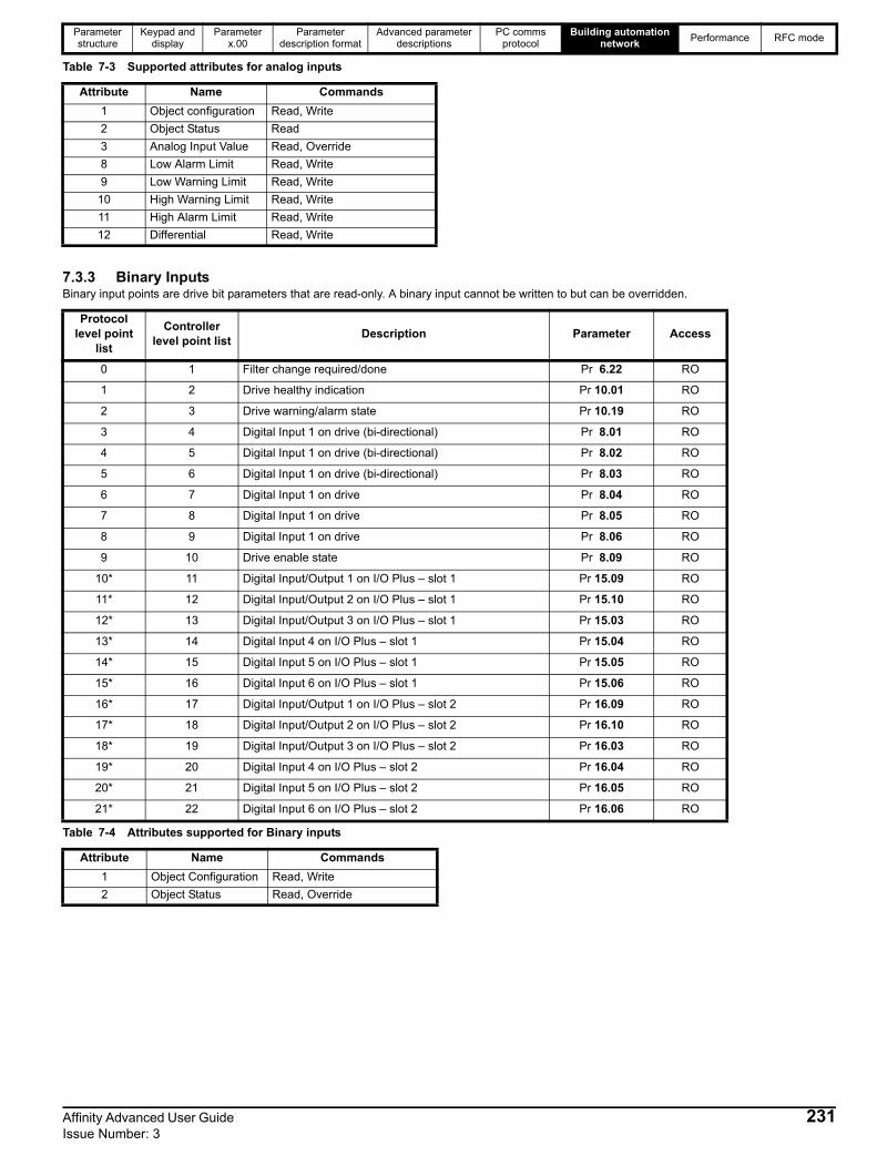
Parameter structure
Keypad and display
Parameter x.00
Parameter description format
Advanced parameter descriptions
PC comms protocol
Building automation network
Performance RFC mode
Table 7-3 Supported attributes for analog inputs
7.3.3 Binary InputsBinary input points are drive bit parameters that are read-only. A binary input cannot be written to but can be overridden.
Table 7-4 Attributes supported for Binary inputs
Attribute Name Commands
1 Object configuration Read, Write
2 Object Status Read
3 Analog Input Value Read, Override
8 Low Alarm Limit Read, Write
9 Low Warning Limit Read, Write
10 High Warning Limit Read, Write
11 High Alarm Limit Read, Write
12 Differential Read, Write
Protocol level point
list
Controller level point list
Description Parameter Access
0 1 Filter change required/done Pr 6.22 RO
1 2 Drive healthy indication Pr 10.01 RO
2 3 Drive warning/alarm state Pr 10.19 RO
3 4 Digital Input 1 on drive (bi-directional) Pr 8.01 RO
4 5 Digital Input 1 on drive (bi-directional) Pr 8.02 RO
5 6 Digital Input 1 on drive (bi-directional) Pr 8.03 RO
6 7 Digital Input 1 on drive Pr 8.04 RO
7 8 Digital Input 1 on drive Pr 8.05 RO
8 9 Digital Input 1 on drive Pr 8.06 RO
9 10 Drive enable state Pr 8.09 RO
10* 11 Digital Input/Output 1 on I/O Plus – slot 1 Pr 15.09 RO
11* 12 Digital Input/Output 2 on I/O Plus – slot 1 Pr 15.10 RO
12* 13 Digital Input/Output 3 on I/O Plus – slot 1 Pr 15.03 RO
13* 14 Digital Input 4 on I/O Plus – slot 1 Pr 15.04 RO
14* 15 Digital Input 5 on I/O Plus – slot 1 Pr 15.05 RO
15* 16 Digital Input 6 on I/O Plus – slot 1 Pr 15.06 RO
16* 17 Digital Input/Output 1 on I/O Plus – slot 2 Pr 16.09 RO
17* 18 Digital Input/Output 2 on I/O Plus – slot 2 Pr 16.10 RO
18* 19 Digital Input/Output 3 on I/O Plus – slot 2 Pr 16.03 RO
19* 20 Digital Input 4 on I/O Plus – slot 2 Pr 16.04 RO
20* 21 Digital Input 5 on I/O Plus – slot 2 Pr 16.05 RO
21* 22 Digital Input 6 on I/O Plus – slot 2 Pr 16.06 RO
Attribute Name Commands
1 Object Configuration Read, Write
2 Object Status Read, Override
Affinity Advanced User Guide 231Issue Number: 3

Parameter structure
Keypad and display
Parameter x.00
Parameter description format
Advanced parameter descriptions
PC comms protocol
Building automation network
Performance RFC mode
7.3.4 Analog outputs
The drive only supports integer parameters with an implied decimal point. Any such parameter returned by a Metasys query will be in IEEE floating point (not the internal representation in the drive).
*Only available if I/O Solutions Modules are fitted on the drive. The number of available I/Os will vary depending on the type of I/O Solutions Modules.
Table 7-5 Attributes supported for Analog Outputs
7.3.5 Binary OutputsBinary output points are drive bit parameters that have read/write access. The output is updated by using a Metasys write command. Reading a binary output will return its current state.
*Only available if I/O Solutions Modules are fitted on the drive. The number of available I/Os will vary depending on the type of I/O Solutions Modules.
Protocol level point list
Controller level point list
Description Parameter Access
0 1 Preset Speed Reference 1 Pr 1.21 RW
1 2 Maximum reference clamp Pr 1.06 RW
2 3 User trip Pr 10.38 RW
3 4 Time between Filter Changes Pr 6.21 RW
4 5 PID 1 Digital Pr 14.25 RW
5 6 PID 1 Digital Pr 14.26 RW
6 7 PID 1 Digital Pr 14.55 RW
7 8 PID 1 Digital Pr 14.56 RW
8 9 Analogue Output 1 on Drive Pr 7.19 RW
9 10 Analogue Output 2 on Drive Pr 7.22 RW
10* 11 Analogue output 3 on I/O Plus – slot 1 Pr 15.48 RW
11* 12 Analogue output 3 on I/O Plus – slot 2 Pr 16.48 RW
Attribute Name Commands
1 Object Configuration Read, Write
2 Object Status Read
3 Current Value Read, Override
Protocol level point list
Controller level point list
Description Parameter Access
0 1 Sequencing Bit – Run Forward Pr 6.30 RW
1 2 Drive Reset Pr 10.38 W
2 3 Reset energy meter Pr 6.24 RW
3 4 Digital Input 1 on drive (bi-directional) Pr 8.01 RO
4 5 Digital Input 2 on drive (bi-directional) Pr 8.02 RO
5 6 Digital Input 3 on drive (bi-directional) Pr 8.03 RO
6 7 24 Volt Output State Pr 8.08 RO
7 8 Relay State Indicator Pr 8.07 RO
8* 9 Digital Input/Output 1 on I/O Plus – slot 1 Pr 15.21 RO
9* 10 Digital Input/Output 1 on I/O Plus – slot 1 Pr 15.22 RO
10* 11 Digital Input/Output 1 on I/O Plus – slot 1 Pr 15.23 RO
11* 12 Relay 1 on I/O Plus – slot 1 Pr 15.27 RO
12* 13 Relay 2 on I/O Plus – slot 1 Pr 15.28 RO
13* 14 Digital Input/Output 1 on I/O Plus – slot 2 Pr 16.21 RO
14* 15 Digital Input/Output 1 on I/O Plus – slot 2 Pr 16.22 RO
15* 16 Digital Input/Output 1 on I/O Plus – slot 2 Pr 16.23 RO
16* 17 Relay 1 on I/O Plus – slot 2 Pr 16.27 RO
17* 18 Relay 1 on I/O Plus – slot 2 Pr 16.28 RO
NOTE
232 Affinity Advanced User Guide Issue Number: 3

Parameter structure
Keypad and display
Parameter x.00
Parameter description format
Advanced parameter descriptions
PC comms protocol
Building automation network
Performance RFC mode
Table 7-6 Attributes supported for Binary Outputs
7.3.6 Internal Float ValuesInternal float values are read/write internal parameters used to implement a generic parameter access method allowing access to any drive parameter.
Table 7-7 Attributes supported for Internal Float Values
7.3.7 Metasys N2 commandsThe Metasys commands supported by Affinity are listed in the table below.
7.3.8 Change of state
Affinity supports the COS (change of state) feature for all supported points (except internal float values). The drive constantly queries the points and any that have changed from the stored current value will be flagged in the status byte as having changed state.
Table 7-8 lists the conditions which cause a change of state to be detected.
Table 7-8 Change of state
When the polling command appears, the flagged point will be returned in the status reply message. Transmission of the status reply will clear the change of state indication.
Attribute Name Commands
1 Object Configuration Read, Write
2 Object Status Read, Override
Point Description Access
0Parameter (specified as a float e.g. 1.25 = Pr 1.25)
RW
1 Value (specified as a float value) RW
2
Read/Write command code0 = Idle1 = Write2 = Read
RW
Attribute Name Commands
1 Object Status Read
2 Current Value Read, Override
Metasys commands
Synch time command
Poll without ack message
Read analog input command
Read binary input command
Read analog output command
Read binary output command
Read internal parameter command
Write analog input command
Write binary input command
Write analog output command
Write binary output command
Write internal parameter command
Override analog input command
Override binary input command
Override analog output command
Override binary output command
Override internal parameter command
Override release request
Identify device type command
Point type Region COS Detection Conditions
Analog Inputs 1
Current value transitions into one of four alarm/warning regions (high alarm, high warning, low warning, low alarm) or current value transitions back to normal
Binary Inputs 2 Current bit changes logic state.
Analog Outputs
3 Current value changes by .001%
Binary Outputs 4 Current bit changes logic state.
Internal Float Values
5 Not applicable
Affinity Advanced User Guide 233Issue Number: 3

Parameter structure
Keypad and display
Parameter x.00Parameter
description formatAdvanced parameter
descriptionsPC comms
protocolBuilding automation
networkPerformance RFC mode
8 Performance
8.1 Digital speed reference
Table 8-1 Accuracy and resolution
*0.01% of the reference
8.2 Analog referenceTable 8-2 Update rates
* Analog input 1 is subject to a window filter as defined in Pr 7.26.
Table 8-3 Resolution
*16 bit plus sign as a speed reference, resolution = Pr 7.26 x 500 x 103 .
8.3 Analog outputsTable 8-4 Analog outputs
*When sourced from Pr 4.02, Pr 4.17 in any mode and Pr 3.02, Pr 5.03 in RFC mode.
8.4 Digital inputs and outputsTable 8-5 Response times
*software only
Open loop RFC
Preset Precision Preset Precision
Accuracy 0.01%* 0.01%* 0.01%* 0.01%*
Resolution 0.1Hz 0.001Hz 0.1rpm 0.001rpm
Open Loop RFC
Pr 1.36 / Pr 1.37
Pr 4.08 Pr 3.19 OtherPr 1.36 / Pr 1.37
Pr 4.08 Pr 3.22 Other
All kHz Analog input 1 4ms 4ms 4ms 4ms 250s* 4ms* 250s* 4ms*
Analog input 2 / 3 4ms 4ms 4ms 4ms 250s 250s 250s 4ms
Open loop RFC
Analog input 1 16 bits plus sign* 16 bits plus sign*
Analog input 2 / 3 10 bit plus sign 10 bit plus sign
Resolution (voltage mode) 10 bit plus sign
Resolution (current mode) 10bit
Update rate 4ms
Update rate (high speed update - voltage mode only)*
250s
Switching frequency
Terminals
Open loop RFC
Pr 6.35 / Pr 6.36(Limit switches)
OtherPr 6.35 / Pr 6.36(Limit switches)
Other
All 24-26 as input 4ms 4ms 250s 4ms
All 24-26 as output 4ms 4ms 4ms 4ms
All 27-29 4ms 4ms 250s 4ms
All 31 (enable) 4ms* 4ms*
All 31 (disable) <100us <100s
All Relay output closing 4ms* 4ms* 4ms* 4ms*
All Relay output opening 4ms* 4ms* 4ms* 4ms*
234 Affinity Advanced User Guide Issue Number: 3

Parameter structure
Keypad and display
Parameter x.00Parameter
description formatAdvanced parameter
descriptionsPC comms
protocolBuilding automation
networkPerformance RFC mode
8.5 Current feedbackAccuracy: 5% worst case, 2% typicalResolution: 10 bit plus sign Full scale resolution is equivalent to 222% drive rated current (OI.AC trip level)
8.6 BandwidthThe following bandwidth values are for 12kHz PWM switching frequency:
8.6.1 Speed loopThe speed loop bandwidth is 160Hz
8.6.2 Current loopThe current loop bandwidth is 1100Hz for the 3dB point, and 400Hz for the 45point.
1. The gain characteristic and associated 3dB point is most useful where drive is used in an application where the current controller is not included within an outer control loop.
2. The phase characteristic and associated 45 point is most useful where the current controller is used within an outer control loop such as a speed controller. The phase delay of the current controller has a limiting effect on the response of the outer loop.
Affinity Advanced User Guide 235Issue Number: 3

Parameter structure
Keypad and display
Parameter x.00Parameter
description formatAdvanced parameter
descriptionsPC comms
protocolBuilding automation
networkPerformance RFC mode
236 Affinity Advanced User Guide Issue Number: 3
9 Rotor Flux Control (RFC) mode
9.1 IntroductionRotor Flux Control (RFC) mode, is a sub mode of closed loop vector mode on the drive. Instead of using a position feedback device, the drive uses a position estimator to determine the position of the flux in the motor. The drive uses motor currents, motor voltages and key motor parameters in a robust model of the motor to estimate flux position, flux magnitude and motor speed. The control system is exactly the same as the system used with closed loop vector with position feedback, except that in RFC mode the feedback is derived from a position estimator instead of an actual feedback device. The position estimator gives an effective resolution of 16384 lines per revolution.
RFC mode can eliminate instability when operating a large motor on light load and at low frequencies, for example in large fan applications.
9.2 Setting up the RFC modeThis section describes how to set up the drive to run in RFC mode.
It is recommended that the lowest possible switching frequency is used, preferably 3kHz. This is because as the switching frequency is increased, the effect of the IGBT switching dead times is greater, which reduces stability. This is more of an issue on larger drives, where the IGBT dead times are longer.
To set up the Affinity in RFC mode follow the instructions below.
9.3 Further TuningThe position estimator used in RFC mode, has a filter with a time constant/filter of 4ms which will reduce the possible bandwidth of the speed controller compared with the bandwidth possible when position feedback is used.
This means that the speed loop integral gain will need to be lower than the value normally used when a feedback device used.
With Unidrive SP software version V01.10.00 onwards, the default of the speed loop I gain has been decreased from 1.00 to 0.10 and the P gain increased from 0.0100 to 0.0300 to enable the RFC mode to work at optimum levels with the default parameter settings. The speed loop gains should be modified to obtain the best possible performance for the application, but it is unlikely that the integral gain can be increased much above 0.50.
A filter with a 4ms time constant/filter is always present on the output of the speed estimator. This filter may be extended by setting Pr 3.42 as follows:
0 = 4ms1 = 8ms2 = 16ms3 = 32ms4 = 64ms5 = 128ms
The output of the speed estimator can include some ripple, which increases as the drive passes into field weakening and the filter can be used to remove this ripple. This is particularly useful when using standard ramp or spinning start with a low friction high inertia load, and can prevent over voltage trips when the drive has no braking resistor. When operating above rated speed it may be necessary to include further filtering of the current demand (Pr 4.12 set to a value between 1.0 and 5.0ms) to achieve stable operation.
Action Detail
1 Set the drive into RFC modeSet Pr xx.00 to 1253 (EUR defaults) or 1254 (US defaults), set Pr 11.31 (or Pr 0.48) to CL VECt, and perform a drive reset.
2Enter the motor nameplate values
Ensure all the following motor map parameters are entered into the drive using the motor nameplate.• Motor rated frequency in Pr 5.06• Motor rated current in Pr 5.07• Motor rated speed in Pr 5.08• Motor rated voltage in Pr 5.09
3Select or deselect catch a spinning motor mode
If catch a spinning motor mode is not required then set Pr 6.09 to 0.If catch a spinning motor mode is required then leave Pr 6.09 at the default of 1, but depending on the size of the motor the value in Pr 5.40 may need to be adjusted. Pr 5.40 defines a scaling function used by the algorithm that detects the speed of the motor. The default value of Pr 5.40 is 1 which is suitable for small motors (<4kW). For larger motors the value in Pr 5.40 will need to be increased. Approximate values of Pr 5.40 for different motor sizes are as follows, 2 for 11kW, 3 for 55kW and 5 for 150kW.If the value of Pr 5.40 is too large the motor may accelerate from standstill when the drive is enabled. If the value of this parameter is too small the drive will detect the motor speed as zero even if the motor is spinning.
4 AutotuneIt is highly recommended that a rotating autotune is performed (Pr 5.12 set to 2). If a rotating autotune is not possible then a static autotune must be performed (Pr 5.12 set to 1) and the nameplate value of power factor entered into Pr 5.10

Index
Numerics3 ..............................................................................................514 -20mA ........................................................................ 116, 117
AAcceleration ..............................................................................6Acceleration rate selector ........................................................45Access Level ...........................................................................12Accuracy .................................................................................49Active current ..........................................................................66Advanced menus ......................................................................8Advanced parameter descriptions ...........................................22Alarm .......................................................................................13Analog I/O .............................................................................111Analog input 1 destination .....................................................115Analog input 1 level ...............................................................113Analog input 2 destination .....................................................116Analog input 2 level ...............................................................113Analog input 2 mode .............................................................116Analog input 3 destination .....................................................117Analog input 3 level ...............................................................113Analog input 3 mode .............................................................117Analog input objects ..............................................................226Analog output 1 mode ...........................................................118Analog output 1 source .........................................................118Analog output 2 mode ...........................................................119Analog output 2 source .........................................................118Analog output objects ............................................................226Analog reference 1 ..................................................................35Analog reference resolution ....................................................49Analog value objects .............................................................227ANSI communications protocol .............................................219Application menu 1 ....................................................... 201, 207Application menu 2 ................................................................208Application menu 3 ................................................................209At speed ................................................................................140At speed lower limit .................................................................50At speed upper limit ................................................................51Auto-reset attempts ...............................................................155Auto-tune .................................................................................84
BBandwidth ...............................................................................58Bandwidth set-up ....................................................................57Baud rate ...............................................................................161Binary input objects ...............................................................227Binary output objects .............................................................227Binary sum ............................................................................136Binary value objects ..............................................................228Bipolar reference enable .........................................................31Brake control function ...........................................................172Braking IGBT active ..............................................................141Braking resistor alarm ...........................................................141Braking time ..........................................................................153Building ........................................................................ 201, 226Building Automation Network ................................................226
CCatch a spinning motor ........................................................... 98Closed .................................................................................... 58Coding .................................................................................... 16Compliance angle ................................................................... 57Compliance angle set-up ........................................................ 57Control word ......................................................................... 105Current control ........................................................................ 60Current controller Ki gain ........................................................ 70Current controller Kp gain ....................................................... 69Current limit ............................................................................ 67Current limit operation ............................................................ 70
DDamping factor ....................................................................... 58DC bus voltage ................................................................. 17, 80Deceleration ............................................................................. 6Deceleration rate selector ....................................................... 46Destinations ............................................................................ 20Differential feedback gain ....................................................... 55Digital I/O 1 output select ..................................................... 128Digital I/O 1 source/destination ............................................. 127Digital I/O 2 output select ..................................................... 128Digital I/O 2 source/destination ............................................. 127Digital I/O 3 output select ..................................................... 128Digital I/O 3 source/destination ............................................. 127Digital I/O read word ............................................................. 127Digital input ........................................................................... 122Digital input 4 destination ..................................................... 127Digital input 5 destination ..................................................... 127Digital input 6 destination ..................................................... 127Digital input auto-selection disable ....................................... 129Digital output ......................................................................... 122Digital reference resolution ..................................................... 49Direction commanded ........................................................... 141Direction running .................................................................. 142Display ...................................................................................... 9Display - special functions ...................................................... 13Drive active ........................................................................... 140Drive enable ......................................................................... 126Drive mode ........................................................................... 163Drive ok ................................................................................ 140Drive reset ...................................................................... 13, 155Drive warning ........................................................................ 142Dynamic V to F ....................................................................... 87
EEdit mode ............................................................................... 10Energy meter ........................................................................ 102External trip .......................................................................... 155
FFd ........................................................................................... 87Field gain reduction ................................................................ 90Field weakening compensation disable .................................. 92Fire mode ............................................................................... 37Fixed boost ....................................................................... 83, 87Flux optimise select ................................................................ 87Frequency/speed reference .................................................... 26
Affinity Advanced User Guide 237Issue Number: 3
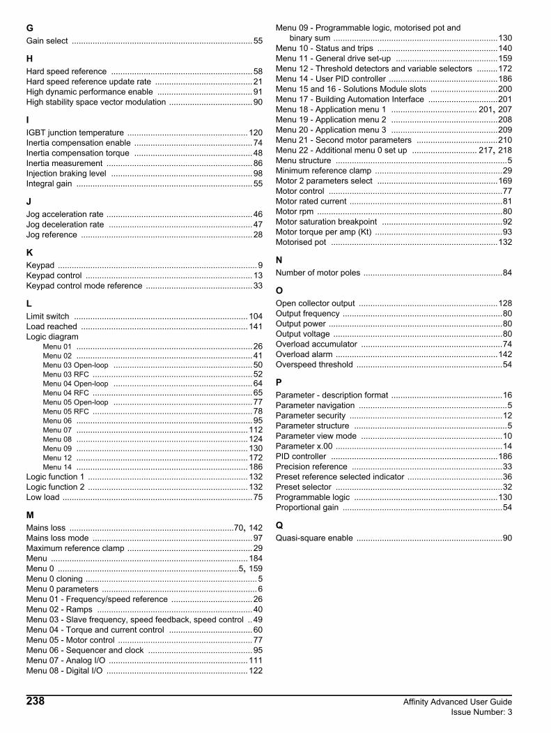
GGain select .............................................................................. 55
HHard speed reference ............................................................. 58Hard speed reference update rate .......................................... 21High dynamic performance enable ......................................... 91High stability space vector modulation .................................... 90
IIGBT junction temperature ....................................................120Inertia compensation enable ................................................... 74Inertia compensation torque ................................................... 48Inertia measurement ............................................................... 86Injection braking level ............................................................. 98Integral gain ............................................................................ 55
JJog acceleration rate ............................................................... 46Jog deceleration rate .............................................................. 47Jog reference .......................................................................... 28
KKeypad ......................................................................................9Keypad control ........................................................................ 13Keypad control mode reference .............................................. 33
LLimit switch ...........................................................................104Load reached ........................................................................141Logic diagram
Menu 01 ............................................................................26Menu 02 ............................................................................41Menu 03 Open-loop ............................................................50Menu 03 RFC .....................................................................52Menu 04 Open-loop ............................................................64Menu 04 RFC .....................................................................65Menu 05 Open-loop ............................................................77Menu 05 RFC .....................................................................78Menu 06 ............................................................................95Menu 07 ..........................................................................112Menu 08 ..........................................................................124Menu 09 ..........................................................................130Menu 12 ..........................................................................172Menu 14 ..........................................................................186
Logic function 1 .....................................................................132Logic function 2 .....................................................................132Low load .................................................................................. 75
MMains loss .......................................................................70, 142Mains loss mode ..................................................................... 97Maximum reference clamp ...................................................... 29Menu .....................................................................................184Menu 0 ..............................................................................5, 159Menu 0 cloning .......................................................................... 5Menu 0 parameters ...................................................................6Menu 01 - Frequency/speed reference ................................... 26Menu 02 - Ramps ................................................................... 40Menu 03 - Slave frequency, speed feedback, speed control .. 49Menu 04 - Torque and current control .................................... 60Menu 05 - Motor control .......................................................... 77Menu 06 - Sequencer and clock ............................................. 95Menu 07 - Analog I/O ............................................................111Menu 08 - Digital I/O .............................................................122
Menu 09 - Programmable logic, motorised pot and binary sum .......................................................................130Menu 10 - Status and trips ....................................................140Menu 11 - General drive set-up ............................................159Menu 12 - Threshold detectors and variable selectors .........172Menu 14 - User PID controller ...............................................186Menu 15 and 16 - Solutions Module slots .............................200Menu 17 - Building Automation Interface ..............................201Menu 18 - Application menu 1 ..................................... 201, 207Menu 19 - Application menu 2 ..............................................208Menu 20 - Application menu 3 ..............................................209Menu 21 - Second motor parameters ...................................210Menu 22 - Additional menu 0 set up ............................ 217, 218Menu structure ..........................................................................5Minimum reference clamp .......................................................29Motor 2 parameters select ....................................................169Motor control ...........................................................................77Motor rated current ..................................................................81Motor rpm ................................................................................80Motor saturation breakpoint ....................................................92Motor torque per amp (Kt) .......................................................93Motorised pot ........................................................................132
NNumber of motor poles ............................................................84
OOpen collector output ............................................................128Output frequency .....................................................................80Output power ...........................................................................80Output voltage .........................................................................80Overload accumulator .............................................................74Overload alarm ......................................................................142Overspeed threshold ...............................................................54
PParameter - description format ................................................16Parameter navigation ................................................................5Parameter security ..................................................................12Parameter structure ..................................................................5Parameter view mode .............................................................10Parameter x.00 ........................................................................14PID controller ........................................................................186Precision reference .................................................................33Preset reference selected indicator .........................................36Preset selector ........................................................................32Programmable logic ..............................................................130Proportional gain .....................................................................54
QQuasi-square enable ...............................................................90
238 Affinity Advanced User Guide Issue Number: 3

RRamp enable ...........................................................................42Ramp mode select ..................................................................42Ramps .....................................................................................40Ranges ....................................................................................17Rated frequency ......................................................................81Rated load rpm ........................................................................82Rated power factor ..................................................................84Rated speed ............................................................................82Rated voltage ..........................................................................82Reactive current ......................................................................73Real time clock ......................................................................100Reference offset ......................................................................28Reference selected indicator ...................................................36Reference selector ..................................................................31Regenerating .........................................................................141Relay source .........................................................................128Resolution ...............................................................................49RFC mode .............................................................................236Rotating test ..................................................................... 85, 86Running cost .........................................................................103
SS ramp .....................................................................................43Second motor parameters .............................................. 13, 210Security ...................................................................................12Security code ........................................................................162Security status .......................................................................169Sequencer ...............................................................................95Sequencing bit ......................................................................103Serial communications look-up table .....................................151Serial communications protocol ............................................219Serial mode ...........................................................................160Skip reference 1 ......................................................................34Sleep/wake mode ..................................................................110Slip compensation enable .......................................................92SMARTCARD ........................................................................164Software sub-version ............................................................163Software version ...................................................................162Solutions Module slots ..........................................................200Sources ...................................................................................20Speed controller ......................................................................57Speed error .............................................................................53Speed feedback ......................................................................53Square law mode ....................................................................83Stationary test .................................................................. 85, 86Stator inductance ....................................................................91Stator resistance .....................................................................87Status mode ............................................................................10Status word ...........................................................................157Stop mode ...............................................................................96Switching frequency - maximum .............................................89
TThermal protection mode ........................................................ 72Thermal time constant ............................................................ 71Thermistor ............................................................................ 117Threshold detector 1 ............................................................. 174Threshold detector 2 ............................................................. 174Threshold detectors .............................................................. 172Timers ................................................................................... 137Torque control ........................................................................ 69Torque demand ...................................................................... 66Torque mode selector ............................................................. 69Torque offset .......................................................................... 68Torque reference .................................................................... 68Transient inductance .............................................................. 91
UUnder voltage active ............................................................. 142Update rate ............................................................................. 19Ur ............................................................................................ 87Ur_Auto .................................................................................. 87Ur_I ......................................................................................... 87Ur_S ....................................................................................... 87US defaults ............................................................................. 15User Security .......................................................................... 12
VVariable maximums ................................................................ 17Variable selector 1 ................................................................ 175Variable selector 2 ................................................................ 175Variable selectors ................................................................. 172Voltage boost .......................................................................... 88Voltage controller .................................................................... 93Voltage mode select ............................................................... 87Voltage offset .......................................................................... 87Voltage rating ....................................................................... 163
ZZero speed ........................................................................... 140Zero speed threshold .............................................................. 50
Affinity Advanced User Guide 239Issue Number: 3

0474-0011-03