

Advanced Modulation Techniques for Telemetry - Quasonix
222
Advanced Modulation Techniques for Telemetry A Short Course at the International Telemetering Conference Las Vegas, NV • October 23, 2017 Terry Hill, Quasonix
-
Upload
khangminh22 -
Category
Documents
-
view
1 -
download
0
Transcript of Advanced Modulation Techniques for Telemetry - Quasonix

Advanced Modulation Techniques for Telemetry
A Short Course at the
International Telemetering Conference
Las Vegas, NV • October 23, 2017
Terry Hill, Quasonix

2017 International Telemetering ConferenceTerry Hill - [email protected]
Course Outline
Performance Metrics
Continuous Phase Modulation (CPM) Tier 0
Tier I
Tier II
Demodulation Synchronization
Channel Impairments Adjacent Channel Interference
Lunch
Multipath Propagation
Impairment Mitigation Techniques Diversity Combining
Adaptive Equalization
Best Source Selection
Space-Time Coding
Forward Error Correction (FEC)
Using All the Tools Together
Performance Comparison & Summary

2017 International Telemetering ConferenceTerry Hill - [email protected]
Performance Metrics
Information Fidelity Additive White Gaussian Noise (AWGN) channels
Bit Error Probability (BEP) or Bit Error Rate (BER)
Bursty (dropout) channels Cumulative error count
Link Availability
Bandwidth Efficiency Power spectral density
Fractional Out-of-band Power
Channel spacing with adjacent channel interference (ACI)
Bandwidth-Power plane

2017 International Telemetering ConferenceTerry Hill - [email protected]
Cumulative Error Countsin Bursty Channels
Bit Error Accumulation HistoryARTM flight 78, frequency diversity, 5 m antenna, high altitude corridor, easterly, 20k ft. altitude
0.0E+00
5.0E+06
1.0E+07
1.5E+07
2.0E+07
2.5E+07
0 500 1000 1500 2000 2500
Elapsed Time - Seconds
Bit
Err
ors
ERR ND
ERR DBS
Figure from Robert Jefferis, Tybrin, Edwards AFB. Reprinted by permission of the author.

2017 International Telemetering ConferenceTerry Hill - [email protected]
Performance Metrics
Link Availability (LA) – % of the time that the instantaneous BER over 1 sec blocks is less than 10-5.
Video Availability (VA) - % of time video is available (picture on time/ total time x 100)
These two metrics are not the same. Video system sensitivity and its response to bit errors can have significant impact on VA performance.

2017 International Telemetering ConferenceTerry Hill - [email protected]
Which Bandwidth?
Fixed level -60 dBc is common
-25 dBm is “standard” in IRIG-106
Fractional out-of-band power 99%, 99.9%, 99.99% are all used
Minimum frequency separation Accounts for receive-side effects
Receiver IF filtering
Demodulator interference tolerance
Relative levels of interfering signals
Depends on application

2017 International Telemetering ConferenceTerry Hill - [email protected]
Power Spectral Density (PSD)

2017 International Telemetering ConferenceTerry Hill - [email protected]
Fractional Out-of-band Power
5 Mbps

2017 International Telemetering ConferenceTerry Hill - [email protected]
Bandwidth-Power Plane Simultaneous representation of
Bandwidth Efficiency (Bandwidth normalized to Bit Rate)
Power Efficiency (Eb/No required to achieve 10-5 BEP)
Eb/No (dB) Required for 10-5 BEP
% B
an
dw
idth
in B
it R
ate
s
Sp
ectr
al
Eff
icie
nc
y
Detection Efficiency
same BW,worse BEP
Same BW,better BEP
Sa
me
BE
P,
bett
er
BW
sa
me
BE
P,
wo
rse
BW
worse BW,worse BEP
worse BW,better BEP
better BW,worse BEP
better BW,better BEP

Continuous Phase Modulation

2017 International Telemetering ConferenceTerry Hill - [email protected]
The Modulation Universe
Analog, Digital
Amplitude modulation
Quadrature amplitude modulation
Angle modulations Frequency modulation
Phase modulation
2017 International Telemetering ConferenceTerry Hill - [email protected]
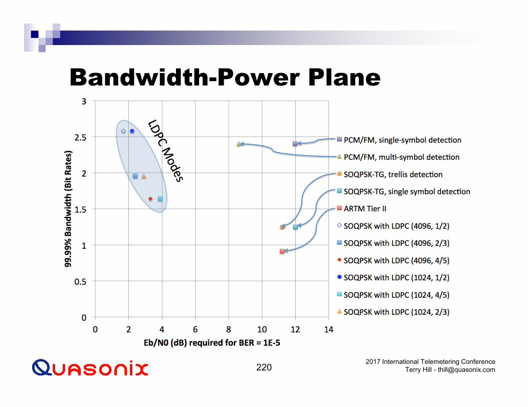
Angle Modulations
Includes both frequency modulation and phase modulation
Some have an amplitude modulation component BPSK
QPSK
Offset QPSK
Some are constant envelope Binary FM
FSK, MSK, premod filtered MSK, GMSK
M-ary FSK
SOQPSK
Multi-h continuous phase modulation
No amplitude variation
Saturated power amplifiers are ideal for constant envelope waveforms

2017 International Telemetering ConferenceTerry Hill - [email protected]
Saturated Power Amplifiers
DC-to-RF conversion efficiency is important Minimizes cooling requirements
Maximizes battery life
Maximizing efficiency demands nonlinear operation
Non-linear operation creates AM-AM and AM-PM conversion:

2017 International Telemetering ConferenceTerry Hill - [email protected]
Constant Envelope Modulations
Before ARTM (Tier 0) PCM/FM
“Legacy” waveform for telemetry
Advanced Range Telemetry (ARTM) Program ARTM Tier 1
Proprietary Feher-patented FQPSK FQPSK-B, Revision A1
FQPSK-JR
SOQPSK-TG Equivalent in performance to FQPSK
Non-proprietary
ARTM Tier 2 Multi-h CPM (M=4, L=3RC, h1 = 4/16, h2 = 5/16)
PCM/FM, SOQPSK and Multi-h CPM are all continuous phase modulations (CPM)

2017 International Telemetering ConferenceTerry Hill - [email protected]
CPM Notation and Parameters
Where ai represents an M-ary symbol sequence ai derived from input bits di
h is the modulation index
g(t) is the frequency pulse shape in the interval 0 < t < LT L = 1 is “full response” signaling
L > 1 yields “partial response”
CPM is a modulation with memory due to the constraint of continuous phase. Further memory is introduced with L > 1.
-¥< t <+¥
]),(2cos[/2)( oo ttfTEts fafp ++=
ò å¥-
+¥
-¥=
-=t
ii diTght ttapaf )(2),(

2017 International Telemetering ConferenceTerry Hill - [email protected]
Key Parameters of CPM
M – Order of Modulation (2-ary, 4-ary, etc.)
g(t) - Frequency Pulse (Rectangular, Raised Cosine, etc.)
L – Length of Frequency Pulse
h – Modulation Index
Increase Spectral Efficiency by Increasing M
Reducing h
Increasing L
Choosing Smoother Frequency Pulse Shape
In general, increasing spectral efficiency decreases detection efficiency

2017 International Telemetering ConferenceTerry Hill - [email protected]
CPM Characteristics
Continuous Phase
Constant envelope
Signals are described by their phase trajectories Phase tree representation is complete
PSD and BER can be “traded” by Varying h, modulation index
Changing g(t), the frequency pulse shape
Phase trellis decoder is optimum for any variant of CPM

2017 International Telemetering ConferenceTerry Hill - [email protected]
Phase Tree Representation
-2
-1.5
-1
-0.5
0
0.5
1
1.5
2
0 1 2 3 4 5 6 7Time in bits
Phase in C
ycle
s
-2
-1.5
-1
-0.5
0
0.5
1
1.5
2
0 1 2 3 4 5 6 7Time in bits
Phase in C
ycle
s
-2
-1.5
-1
-0.5
0
0.5
1
1.5
2
0 1 2 3 4 5 6 7Time in bits
Phase in C
ycle
s
-2
-1.5
-1
-0.5
0
0.5
1
1.5
2
0 1 2 3 4 5 6 7Time in bits
Phase in C
ycle
s
-2
-1.5
-1
-0.5
0
0.5
1
1.5
2
0 1 2 3 4 5 6 7Time in bits
Phase in C
ycle
s
-2
-1.5
-1
-0.5
0
0.5
1
1.5
2
0 1 2 3 4 5 6 7Time in bits
Phase in C
ycle
s

2017 International Telemetering ConferenceTerry Hill - [email protected]
M=2, h=1/2, 1REC (MSK)
- 2
-1.5
- 1
-0.5
0
0 . 5
1
1 . 5
2
0 1 2 3 4
CPM Phase Tree
Multip
le o
f π
Time in Symbols
RECShaping
1/2h
2M
1L
-120
-100
-80
-60
-40
-20
- 2 -1.5 - 1 -0.5 0 0.5 1 1.5 2
PS
D i
n d
Bc/H
z
CPM PSD
Frequency (Bit Rates)
PSD vertical axis is dBc per FFT bin1 FFT bin = 1/64 * symbol rate

2017 International Telemetering ConferenceTerry Hill - [email protected]
M=4, h=1/4, 1REC
- 3
- 2
- 1
0
1
2
3
0 1 2 3 4
CPM Phase Tree
Multip
le o
f π
Time in Symbols
RECShaping
1/4h
4M
1L
-120
-100
-80
-60
-40
-20
- 2 -1.5 - 1 -0.5 0 0.5 1 1.5 2
PS
D i
n d
Bc/H
z
CPM PSD
Frequency (Bit Rates)
PSD vertical axis is dBc per FFT bin1 FFT bin = 1/64 * symbol rate

2017 International Telemetering ConferenceTerry Hill - [email protected]
M=4, h=1/4, 1RC
-120
-100
-80
-60
-40
-20
- 2 -1.5 - 1 -0.5 0 0.5 1 1.5 2
PS
D i
n d
Bc/
Hz
CPM PSD
Frequency (Bit Rates)
- 3
- 2
- 1
0
1
2
3
0 1 2 3 4
CPM Phase Tree
Multip
le o
f π
Time in Symbols
R CShaping
1/4h
4M
1L
PSD vertical axis is dBc per FFT bin1 FFT bin = 1/64 * symbol rate

2017 International Telemetering ConferenceTerry Hill - [email protected]
M=4, h=1/4, 2RC
-120
-100
-80
-60
-40
-20
- 2 -1.5 - 1 -0.5 0 0.5 1 1.5 2
PS
D i
n d
Bc/H
z
CPM PSD
Frequency (Bit Rates)
- 3
- 2
- 1
0
1
2
3
0 1 2 3 4
CPM Phase Tree
Multip
le o
f π
Time in Symbols
R CShaping
1/4h
4M
2L
PSD vertical axis is dBc per FFT bin1 FFT bin = 1/64 * symbol rate
2017 International Telemetering ConferenceTerry Hill - [email protected]
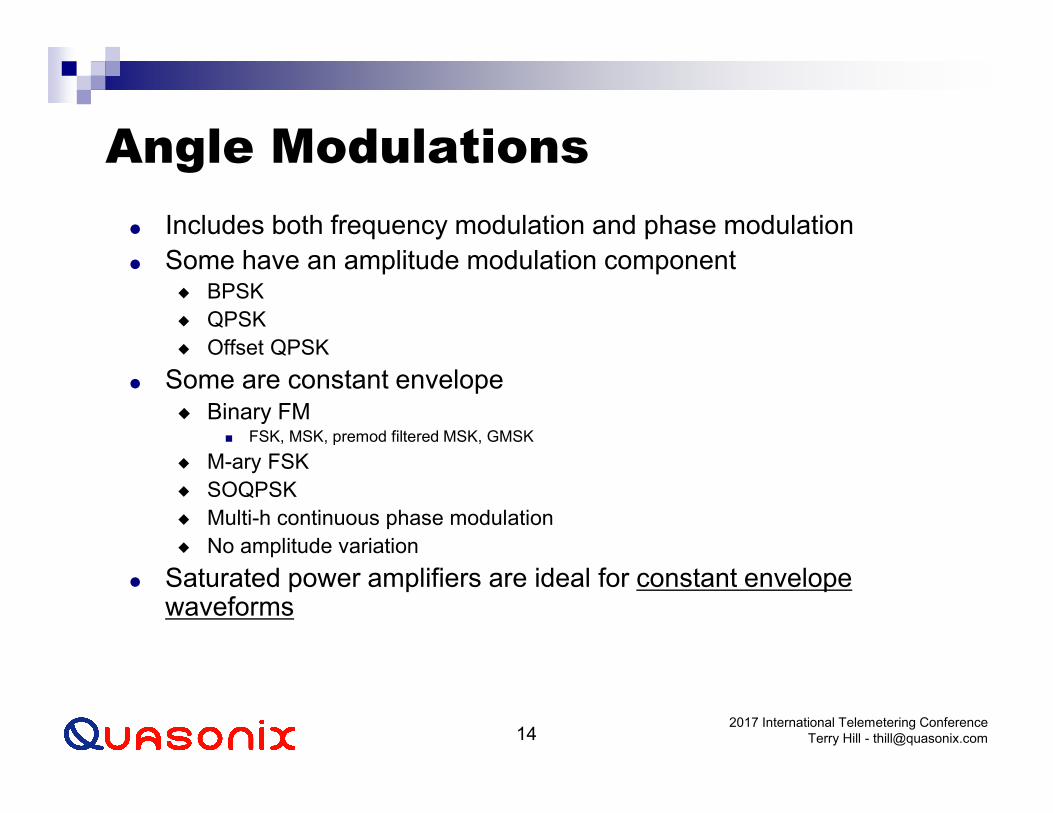
M=4, h=1/4, 3RC
-120
-100
-80
-60
-40
-20
- 2 -1.5 - 1 -0.5 0 0.5 1 1.5 2
PS
D i
n d
Bc/H
z
CPM PSD
Frequency (Bit Rates)
- 2
- 1
0
1
2
3
0 1 2 3 4
CPM Phase Tree
Multip
le o
f π
Time in Symbols
R CShaping
1/4h
4M
3L
PSD vertical axis is dBc per FFT bin1 FFT bin = 1/64 * symbol rate

2017 International Telemetering ConferenceTerry Hill - [email protected]
Multi-h CPM
Cyclically rotates through multiple “sets” of FSK tones
Increases minimum distance in trellis Improves BER performance
Widely proposed for high-performance nonlinear channels MIL-STD-188-181B

2017 International Telemetering ConferenceTerry Hill - [email protected]
M=2, h1=1/4, h2=1/2, 1REC
-1.5
- 1
-0.5
0
0 . 5
1
1 . 5
0 1 2 3 4
CPM Phase Tree
Multip
le o
f π
Time in Symbols
RECShaping
1/4, 1/2h
2M
1L
-120
-100
-80
-60
-40
-20
- 2 -1.5 - 1 -0.5 0 0.5 1 1.5 2
PS
D i
n d
Bc/H
z
CPM PSD
Frequency (Bit Rates)
PSD vertical axis is dBc per FFT bin1 FFT bin = 1/64 * symbol rate

2017 International Telemetering ConferenceTerry Hill - [email protected]
M=4, h1=4/16, h2=5/16, 3RC
- 2
- 1
0
1
2
3
4
0 1 2 3 4
CPM Phase Tree
Multip
le o
f π
Time in Symbols
R CShaping
4/16, 5/16h
4M
3L
-120
-100
-80
-60
-40
-20
- 2 -1.5 - 1 -0.5 0 0.5 1 1.5 2
PS
D i
n d
Bc/
Hz
CPM PSD
Frequency (Bit Rates)
PSD vertical axis is dBc per FFT bin1 FFT bin = 1/64 * symbol rate
ARTM Tier II Waveform

2017 International Telemetering ConferenceTerry Hill - [email protected]
CPM Summary
To reduce bandwidth of a CPM signal, the phase transitions must be smoothed by: Requiring phase to have more continuous derivatives
Spreading the phase change over more intervals (i.e., L > 1)
Reducing h
The shape of g(t) determines the smoothness of the information-carrying phase
An endless variety of CPM schemes can be obtained by choosing different g(t) pulse shapes and varying the parameters h and M.

ARTM Tier 0(PCM/FM)(CPFSK)
The way things were

2017 International Telemetering ConferenceTerry Hill - [email protected]
PCM/FM (Tier 0)
LPFFM
ModulatorbipolarNRZ-L
ò¥-
=t
d dmft llpf )(2)(frequency is the time-derivative of the phasesince the phase is proportional to the integral of m(t), the frequency is proportional to m(t).
)(tm)(tx
( ))(2cos)( 0 ttfAtx fp +=
time-varying phase
Figure from " Quadrature Modulation for Aeronautical Telemetry”, by Michael Rice, BYU and Robert Jefferis, Tybrin Corp, ITC 2001. Reprinted by permission of the authors.

2017 International Telemetering ConferenceTerry Hill - [email protected]
Tier 0 in CPM Notation
M = 2 (binary)
ai = 2di - 1 di = {0, 1}, ai = {-1, +1}
h = 0.7
g(t) is the normalized impulse response of a high order Bessel filter with 3 dB bandwidth = 0.7 * bit rate
Normalized such that the integral over all time = 1/2
-¥< t <+¥
]),(2cos[/2)( oo ttfTEts fafp ++=
ò å¥-
+¥
-¥=
-=t
ii diTght ttapaf )(2),(

2017 International Telemetering ConferenceTerry Hill - [email protected]
PCM/FM as a Phase Modulation

2017 International Telemetering ConferenceTerry Hill - [email protected]
Power Spectral Density (PSD)

2017 International Telemetering ConferenceTerry Hill - [email protected]
Fractional Out-of-band Power
5 Mbps

2017 International Telemetering ConferenceTerry Hill - [email protected]
PCM/FM Summary
Legacy waveform Equipment is ubiquitous
Constant envelope
Several practical implementations
99.9% bandwidth: 2.03 times bit rate
M ai h g(t)2 {-1, +1} 0.7 Normalized impulse response of a high order
Bessel filter with 3 dB bandwidth = 0.7 * bit rate

ARTM Tier I(SOQPSK-TG)
The way things are

2017 International Telemetering ConferenceTerry Hill - [email protected]
Tier I Overview
Shaped OQPSK (SOQPSK) Constant envelope modulation(s) introduced by Hill (ITC 2000)
Defined by 4 parameters ( r, B, T1, T2 )
Compatible with existing efficient non-linear class C power amplifier
Non-proprietary waveform
Comparable in performance and interoperable with FQPSK
FQPSK Patented by K. Feher
Defined by I and Q components
Non-constant envelope
Details are proprietary, contact Digcom

2017 International Telemetering ConferenceTerry Hill - [email protected]
SOQPSK in CPM Notation
M = 3 (ternary)
ai = {-1, 0, +1}
ai = 2di - 1
ai = {-1, +1}, di = {0, 1}
h = 0.5
g(t) = windowed impulse response of spectral raised cosine
Normalized such that the integral over all time = 1/2
-¥< t <+¥
]),(2cos[/2)( oo ttfTEts fafp ++=
ò å¥-
+¥
-¥=
-=t
ii diTght ttapaf )(2),(
a i = -1( )i+1 ai-1(ai - ai-2)
2,

2017 International Telemetering ConferenceTerry Hill - [email protected]
Definition of SOQPSK Pulse
g(t) = n(t) * w(t), where
n(t) =Acos(pr Bt T)
1- 4(r Bt T )2*
sin(p Bt T )
(p Bt T )
w(t) =
1, for t T < T1
1
2+
1
2cos
p ( t T -T1)
T2
, for T1 < t T < T1 + T2
0, for t T > T1 + T2
ì
í
ï ï
î
ï ï
ü
ý
ï ï
þ
ï ï

2017 International Telemetering ConferenceTerry Hill - [email protected]
Frequency Pulse Shape, g(t)

2017 International Telemetering ConferenceTerry Hill - [email protected]
SOQPSK Variants
99.9
9%
Bandw
idth

2017 International Telemetering ConferenceTerry Hill - [email protected]
Optimal SOQPSK Variants
99.9
9%
Bandw
idth

2017 International Telemetering ConferenceTerry Hill - [email protected]
SOQPSK-TG
Jump to file://localhost/Users/TerryHill/Documents/Quasonix/TIMTER/SOQPSK Modulator10.xls

2017 International Telemetering ConferenceTerry Hill - [email protected]
SOQPSK-TG Phase Tree
-2
-1.5
-1
-0.5
0
0.5
1
1.5
2
0 1 2 3 4 5 6 7 8Time in bits
Phase in C
ycle
s
-2
-1.5
-1
-0.5
0
0.5
1
1.5
2
0 1 2 3 4 5 6 7 8Time in bits
Phase in C
ycle
s
-2
-1.5
-1
-0.5
0
0.5
1
1.5
2
0 1 2 3 4 5 6 7 8Time in bits
Phase in C
ycle
s
-2
-1.5
-1
-0.5
0
0.5
1
1.5
2
0 1 2 3 4 5 6 7 8Time in bits
Phase in C
ycle
s
-2
-1.5
-1
-0.5
0
0.5
1
1.5
2
0 1 2 3 4 5 6 7 8Time in bits
Phase in C
ycle
s
-2
-1.5
-1
-0.5
0
0.5
1
1.5
2
0 1 2 3 4 5 6 7 8Time in bits
Phase in C
ycle
s
-2
-1.5
-1
-0.5
0
0.5
1
1.5
2
0 1 2 3 4 5 6 7 8Time in bits
Phase in C
ycle
s
-2
-1.5
-1
-0.5
0
0.5
1
1.5
2
0 1 2 3 4 5 6 7 8Time in bits
Phase in C
ycle
s

2017 International Telemetering ConferenceTerry Hill - [email protected]
SOQPSK-TG Eye Patterns
Single-symbol detection is sub-optimal, but practical

2017 International Telemetering ConferenceTerry Hill - [email protected]
SOQPSK Constellations
Wait! I thought SOQPSK was constant envelope…

2017 International Telemetering ConferenceTerry Hill - [email protected]
Fractional Out-of-band Power
5 MbpsOften-cited factor of two

2017 International Telemetering ConferenceTerry Hill - [email protected]
Shaped Offset QPSK Summary
Constant envelope, CPM waveform
Adjustable shaping factor for BW and detection efficiency trade-off
Improved spectral containment over OQPSK
Compatible with standard OQPSK receivers and demodulators
Adopted as an ARTM Tier I waveform
99.9% bandwidth: 0.98 times bit rate
Interoperable with FQPSK
M ai h g(t)3 {-1, 0, +1} 0.50 Normalized windowed impulse response of a
spectral raised cosine

ARTM Tier II(ARTM CPM)(Multi-h CPM)
The way things can be

2017 International Telemetering ConferenceTerry Hill - [email protected]
Tier II Overview
Multi-h CPM characteristics Easy to trade off bandwidth and detection efficiency.
Constant envelope is ideal for high efficiency non-linear power amplifiers.
Detection efficiency is enhanced by periodically varying the modulation index (h).
Extends the point at which competing paths remerge thereby increasing the minimum distance and decreasing the probability of symbol error.
Nearly 2.5x improvement over PCM/FM in spectral efficiency with similar detection efficiency.

2017 International Telemetering ConferenceTerry Hill - [email protected]
ARTM Tier II in CPM Notation
M = 4 (quaternary)
ai = 2 [2d1i + d0i] - 3 ai = {-3, -1, +1, +3}
di = {0, 1}
h = {4/16, 5/16}, alternating
g(t) = raised cosine, 3 symbols (6 bits) in duration
Normalized such that the integral over all time = 1/2
-¥< t <+¥
]),(2cos[/2)( oo ttfTEts fafp ++=
ò å¥-
+¥
-¥=
-=t
ii diTght ttapaf )(2),(

2017 International Telemetering ConferenceTerry Hill - [email protected]
Frequency Pulse & Phase Tree
0 0.5 1 1.5 2 2.5 30
0.1
0.2
0.3
0.4
0.5
0.6
0.7
0.8
0.9
1
TIME (SYMBOLS)
NO
RM
AL
IZE
D F
RE
QU
EN
CY
/PH
AS
E
LENGTH 3 RC FREQUENCY PULSE AND CORRESPONDING PHASE PULSE

2017 International Telemetering ConferenceTerry Hill - [email protected]
Fractional Out-of-band Power
5 Mbps

2017 International Telemetering ConferenceTerry Hill - [email protected]
Tier II Multi-h CPM Summary
Similar detection efficiency to PCM/FM.
Constant envelope waveform is ideal for efficient non-linear PA’s.
Enhanced performance gained by increasing demodulator complexity.
99.9% bandwidth: 0.75 times bit rate
M ai h g(t)4 {-3, -1, +1, +3} {4/16, 5/16} Normalized raised cosine, 3 symbols
(6 bits) long

2017 International Telemetering ConferenceTerry Hill - [email protected]
Side by Side SummaryTier M ai h g(t) 99.9%
BW0 2 {-1, +1} 0.7 Normalized impulse response of a high order
Bessel filter with 3 dB bandwidth = 0.7 * bit rate2.03
I 3 {-1, 0, +1} 0.5 Normalized windowed impulse response of a spectral raised cosine, 8 bits long
0.98
II 4 {-3, -1, +1, +3} {4/16, 5/16} Normalized raised cosine, 3 symbols (6 bits) long 0.75

Demodulation

2017 International Telemetering ConferenceTerry Hill - [email protected]
Demodulation
As the shop manual says, “Installation is reverse of removal.”
Demodulation is intrinsically more difficult Unknown carrier frequency
Unknown carrier phase
Unknown clock frequency and phase
Signal corruption Noise
Interference
Multipath
Doppler shift
Multiple techniques can be applied

2017 International Telemetering ConferenceTerry Hill - [email protected]
Tier 0 Legacy (nearly exclusive in 20th century)
Simple to build
Robust to signal defects and channel impairments
~3.5 to 5 dB short of theoretical limit
Tier I Requires optimization for SOQPSK
Weakly synchronized
Requires high SNR for acquisition
~1.0 to 1.5 dB short of theoretical limit
Tier II No practical single-symbol detectors
Single-Symbol Demodulation

2017 International Telemetering ConferenceTerry Hill - [email protected]
Tier 0 Single-Symbol Detection
Differentiate the phase to get frequency Limiter-discriminator
Phase locked loop
Digital processing
If the frequency in this symbol > 0, data = 1
If the frequency in this symbol < 0, data = 0
]),(2cos[/2)( oo ttfTEts fafp ++=
ò å¥-
+¥
-¥=
-=t
ii diTght ttapaf )(2),(

2017 International Telemetering ConferenceTerry Hill - [email protected]
SOQPSK-TG Eye Patterns
Single-symbol detection ignores memory inherent in waveform
Can be detected by conventional (non-shaped) offset QPSK demod
I&D detector endures additional loss due to waveform mismatch

2017 International Telemetering ConferenceTerry Hill - [email protected]
Waveform Comparison
PCM/FM (1x) SOQPSK (2x) Multi-h CPM (2.5x)
0 20 40 60 80 100 120 140 160 180 200-1
-0.8
-0.6
-0.4
-0.2
0
0.2
0.4
0.6
0.8
1
0 20 40 60 80 100 120 140 160 180 200-0.04
-0.03
-0.02
-0.01
0
0.01
0.02
0.03
0.04Eye Diagram of PCM/FM
0 20 40 60 80 100 120 140 160 180 200-1
-0.8
-0.6
-0.4
-0.2
0
0.2
0.4
0.6
0.8
1

2017 International Telemetering ConferenceTerry Hill - [email protected]
Tier 0 Invented in 1974, introduced in 2001
Osborne & Luntz, “Coherent and Noncoherent Detection of CPFSK”, IEEE T-COM, August 1974
Requires significant signal processing power
Signal defects and channel impairments require attention DSP techniques can be applied to solve these issues
Operates within 0.2 dB of theoretical limit
Tier I Strong, rapid synchronization
Operates within 0.2 dB of theoretical limit
Tier II Mandatory for practical implementation
Trellis Demodulation Overview

2017 International Telemetering ConferenceTerry Hill - [email protected]
Tier 0 Phase Tree
-4
-3
-2
-1
0
1
2
3
4
0 1 2 3 4 5 6 7Time in bits
Phase in C
ycle
s
h = 0.7
A multi-symbol detector finds the data sequencethat best fits the observed phase trajectory

2017 International Telemetering ConferenceTerry Hill - [email protected]
Why Does It Matter?
-2.1
-1.75
-1.4
-1.05
-0.7
-0.35
0
0.35
0.7
1.05
1.4
1.75
2.1
0 1 2 3 4 5 6 7Time in bits
Phase in C
ycle
s
If this bit is different, the phase trajectory is forever shifted…
Therefore, later bits can help make decisions about earlier bits.Noise-corrupted
trajectory
Single-symbol detector decides “zero”
Multi-symbol detector decides “one” –
correcting the error

2017 International Telemetering ConferenceTerry Hill - [email protected]
Multi-Symbol Detector Example
Phase1
11
10
00
000001010
100101110111
011
Correlators
ChooseLargest
Magnitude
MiddleBit
Multi-SymbolDetector Span
Brute force approach –yields performance gain,
but leads to extreme hardware complexity

2017 International Telemetering ConferenceTerry Hill - [email protected]
Generic Trellis Demodulator
Brains over brawn – Efficient computation yields the same
performance as the brute force approach, with far less hardware

2017 International Telemetering ConferenceTerry Hill - [email protected]
Tier 0 BER Performance
1.E-07
1.E-06
1.E-05
1.E-04
1.E-03
1.E-02
1.E-01
2 3 4 5 6 7 8 9 10 11 12 13 14Eb/N0 (dB)
BER
Conventional Single-Symbol (1990's)
First Generation Multi-Symbol (2001)
Second Generation Multi-Symbol (2004)
MLSE (Theoretical Limit)

2017 International Telemetering ConferenceTerry Hill - [email protected]
Legacy PCM/FM Transmitters
-4
-3
-2
-1
0
1
2
3
4
0 1 2 3 4 5 6 7Time in bits
Phase in C
ycle
s
h = 0.6
-4
-3
-2
-1
0
1
2
3
4
0 1 2 3 4 5 6 7Time in bits
Phase in C
ycle
s
h = 0.7h = 0.8
-4
-3
-2
-1
0
1
2
3
4
0 1 2 3 4 5 6 7Time in bits
Phase in C
ycle
s

2017 International Telemetering ConferenceTerry Hill - [email protected]
Effect of TX Deviation Error
8
9
10
11
12
13
0.60 0.65 0.70 0.75 0.80
Modulation Index, h
Eb/N
0 (
dB)
for
BER =
1.0
e-5
Conventional Single-Symbol (1990's)
First Generation Multi-Symbol (2001)
Second Generation Multi-Symbol (2004)
MLSE (Theoretical Limit)

2017 International Telemetering ConferenceTerry Hill - [email protected]
What About Phase Noise?
-2.1
-1.75
-1.4
-1.05
-0.7
-0.35
0
0.35
0.7
1.05
1.4
1.75
2.1
0 1 2 3 4 5 6 7Time in bits
Phase i
n C
ycle
s
-2.1
-1.75
-1.4
-1.05
-0.7
-0.35
0
0.35
0.7
1.05
1.4
1.75
2.1
0 1 2 3 4 5 6 7Time in bits
Phase i
n C
ycle
s
-2.1
-1.75
-1.4
-1.05
-0.7
-0.35
0
0.35
0.7
1.05
1.4
1.75
2.1
0 1 2 3 4 5 6 7
Time in bits
Phase i
n C
ycle
s
-2.1
-1.75
-1.4
-1.05
-0.7
-0.35
0
0.35
0.7
1.05
1.4
1.75
2.1
0 1 2 3 4 5 6 7
Time in bits
Phase i
n C
ycle
s
No phase noise:The entire trellis is helpful
Minimal phase noise:Several bits of the trellis are helpful
Significant phase noise:A few bits of the trellis are helpful
Severe phase noise:Not a candidate for trellis demodulation

2017 International Telemetering ConferenceTerry Hill - [email protected]
Phase Noise
Trellis demodulation is based on the assumption that the signal is following a predictable path through the trellis.
If this is not true (due to high phase noise), then a trellis demodulator may not provide the expected performance gain
Most often an issue at low bit rates
Some trellis demods handle this case by modifying the trellis calculations.

2017 International Telemetering ConferenceTerry Hill - [email protected]
SOQPSK Detection
Can be detected by conventional (non-shaped) offset QPSK demod
Non-matched filtering loss of about 2 dB
Butterworth lowpass filter is reasonable approximation to matched filter
Trellis detection is optimum, but more complex

2017 International Telemetering ConferenceTerry Hill - [email protected]
SOQPSK-TG Phase Tree
-2
-1.5
-1
-0.5
0
0.5
1
1.5
2
0 1 2 3 4 5 6 7 8Time in bits
Phase in C
ycle
s
-2
-1.5
-1
-0.5
0
0.5
1
1.5
2
0 1 2 3 4 5 6 7 8Time in bits
Phase in C
ycle
s
-2
-1.5
-1
-0.5
0
0.5
1
1.5
2
0 1 2 3 4 5 6 7 8Time in bits
Phase in C
ycle
s
-2
-1.5
-1
-0.5
0
0.5
1
1.5
2
0 1 2 3 4 5 6 7 8Time in bits
Phase in C
ycle
s
-2
-1.5
-1
-0.5
0
0.5
1
1.5
2
0 1 2 3 4 5 6 7 8Time in bits
Phase in C
ycle
s
-2
-1.5
-1
-0.5
0
0.5
1
1.5
2
0 1 2 3 4 5 6 7 8Time in bits
Phase in C
ycle
s
-2
-1.5
-1
-0.5
0
0.5
1
1.5
2
0 1 2 3 4 5 6 7 8Time in bits
Phase in C
ycle
s
-2
-1.5
-1
-0.5
0
0.5
1
1.5
2
0 1 2 3 4 5 6 7 8Time in bits
Phase in C
ycle
s

2017 International Telemetering ConferenceTerry Hill - [email protected]
SOQPSK Detection Efficiency
SOQPSK-TG

2017 International Telemetering ConferenceTerry Hill - [email protected]
Multi-h CPM Detection
Modulator intentionally creates severe inter-symbol interference 3-symbol RC premod filter
Symbol-by-symbol detection is essentially useless
Trellis detection is required

Synchronization

2017 International Telemetering ConferenceTerry Hill - [email protected]
Telemetry Channels are Bursty
Bit Error Accumulation HistoryARTM flight 78, frequency diversity, 5 m antenna, high altitude corridor, easterly, 20k ft. altitude
0.0E+00
5.0E+06
1.0E+07
1.5E+07
2.0E+07
2.5E+07
0 500 1000 1500 2000 2500
Elapsed Time - Seconds
Bit
Err
ors
ERR ND
ERR DBS
Figure from Robert Jefferis, Tybrin, Edwards AFB. Reprinted by permission of the author.
In a typical flight test, the vast majority of bit errors occur at dropouts

2017 International Telemetering ConferenceTerry Hill - [email protected]
Synchronization Test
IRIG 118-12, Procedure 7.4 (Flat Fade Recovery Test)
Transmit randomized ones pattern
Measure time at which output becomes “all (or mostly) ones”
IRIG Randomizer
Modulator Add Noise
Noise
Switch
Demodwith
DerandomizerTimer
OnesDetector
All ones
Controller
Start
Stop

2017 International Telemetering ConferenceTerry Hill - [email protected]
Synchronization Parameters
Modulation technique Tier 0 uses more bandwidth – easier to synchronize to
Tier I is spectrally compact, making it slippery – synchronization is more difficult Trellis demodulation helps achieve sync
Tier II is even more compact – synchronization takes longer
Bit rate Fixed-duration tasks amount to more bits at high bit rates
Signal to noise ratio Sync times will be longer at low SNR
Synchronization threshold SNR at which the demodulator can acquire sync
Sync loss threshold SNR at which a synchronized demodulator will drop sync

2017 International Telemetering ConferenceTerry Hill - [email protected]
Tier 0 Synchronization, BER = 1e-5

2017 International Telemetering ConferenceTerry Hill - [email protected]
SOQPSK Synchronization, No Noise

2017 International Telemetering ConferenceTerry Hill - [email protected]
SOQPSK Synchronization, 6 dB
10 Mbps, 6 dB Eb/N0
0
200
400
600
800
1000
1200
1400
1600
1800
0
10
0
20
0
30
0
40
0
50
0
60
0
70
0
80
0
90
0
10
00
Synchronization Time (Bits)
Fre
qu
en
cy
0%
20%
40%
60%
80%
100%
120%
Frequency
Cumulative %

2017 International Telemetering ConferenceTerry Hill - [email protected]
SOQPSK Synchronization, 3 dB
10 Mbps, 3 dB Eb/N0
0
200
400
600
800
1000
1200
1400
1600
1800
0
10
0
20
0
30
0
40
0
50
0
60
0
70
0
80
0
90
0
10
00
Synchronization Time (Bits)
Fre
qu
en
cy
0%
20%
40%
60%
80%
100%
120%
Frequency
Cumulative %

2017 International Telemetering ConferenceTerry Hill - [email protected]
SOQPSK Synchronization, 1 dB
10 Mbps, 1 dB Eb/N0
0
200
400
600
800
1000
1200
1400
1600
1800
0
10
0
20
0
30
0
40
0
50
0
60
0
70
0
80
0
90
0
10
00
Synchronization Time (Bits)
Fre
qu
en
cy
0%
20%
40%
60%
80%
100%
120%
Frequency
Cumulative %

2017 International Telemetering ConferenceTerry Hill - [email protected]
SOQPSK Synchronization, -1 dB
10 Mbps, -1 dB Eb/N0
0
200
400
600
800
1000
1200
1400
1600
1800
0
10
0
20
0
30
0
40
0
50
0
60
0
70
0
80
0
90
0
10
00
Synchronization Time (Bits)
Fre
qu
en
cy
0%
20%
40%
60%
80%
100%
120%
Frequency
Cumulative %

2017 International Telemetering ConferenceTerry Hill - [email protected]
Synchronization Summary
The aeronautical telemetry channel is plagued with dropouts
Rapid synchronization, and synchronization at low SNR, is the best means of minimizing the impact of these dropouts
IRIG 118 defines test procedures for measuring sync time and sync thresholds
Pay attention to synchronization performance!

Adjacent Channel Interference

2017 International Telemetering ConferenceTerry Hill - [email protected]
PSD is Half the Story
Overall spectral efficiency is determined by spacing between channels
Receiver selectivity affects channel spacing
A valid comparison must account for both transmitted spectrum and “tolerable” receiver filtering
Not all modulations are equally “tolerant” of IF filtering and interference
Multi-channel testing accounts for these factors

2017 International Telemetering ConferenceTerry Hill - [email protected]
9 Mbps Multi-h CPM, Multichannel

2017 International Telemetering ConferenceTerry Hill - [email protected]
BER as a Function of F
Fro
m G
ene L
aw
, “R
ecom
mended M
inim
um
Tele
metr
y F
requency
Spacin
g W
ith C
PF
SK
, C
PM
, S
OQ
PS
K, and F
QP
SK
Sig
nals
”, I
TC
2003

2017 International Telemetering ConferenceTerry Hill - [email protected]
Degradation as a Function of F
Fro
m G
ene L
aw
, “R
ecom
mended M
inim
um
Tele
metr
y F
requency
Spacin
g W
ith C
PF
SK
, C
PM
, S
OQ
PS
K, and F
QP
SK
Sig
nals
”, I
TC
2003

2017 International Telemetering ConferenceTerry Hill - [email protected]
I/C=20 dB
ACI Summary
Fro
m G
ene L
aw
, “R
ecom
mended M
inim
um
Tele
metr
y F
requency
Spacin
g W
ith C
PF
SK
, C
PM
, S
OQ
PS
K, and F
QP
SK
Sig
nals
”, I
TC
2003

2017 International Telemetering ConferenceTerry Hill - [email protected]
Frequency Separation Rule
where:• ΔF0 = the minimum center frequency separation in MHz• Rs = bit rate of desired signal in Mb/s• Ri = bit rate of interfering signal in Mb/s
ΔF0 = as*Rs + ai*Ri
Modulation Type as ai Rs = Ri
NRZ PCM/FM 1
for receivers with RLC final
Intermediate Frequency (IF)
filters
1.2 2.2
0.7
for receivers with Surface
Acoustic Wave (SAW) or digital
IF filters
1.2 1.9
0.5with multi-symbol detectors (or
equivalent devices)1.2 1.7
FQPSK-B, FQPSK-JR, SOQPSK-TG 0.45 0.65 1.1
ARTM CPM 0.35 0.5 0.85
The NRZ PCM/FM signals are assumed to be premodulation filtered with a multi-pole filter with 3 dB point of 0.7 times the bit rate and the peak deviation is assumed to be approximately 0.35 times the bit rate.
The receiver IF filter is assumed to be no wider than 1.5 times the bit rate and provides at least 6 dB of attenuation of the interfering signal.
The interfering signal is assumed to be no more than 20 dB stronger than the desired signal.
The receiver is assumed to be operating in linear mode; no significant intermodulation products or spurious responses are present.

Let’s Eat Students!
Let’s Eat, Students!
Commas Save Lives
See you back here at _______ PM

Multipath Propagation

2017 International Telemetering ConferenceTerry Hill - [email protected]
Multipath Propagation
The picture can't be displayed.
Dry lake bed = smooth reflecting surface
Narrow beam receive antennaAirborne transmitter Line-of-sight communications link
Irregular terrain
Low elevation angle
Figure from Dr.Michael Rice, BYU Telemetry Laboratory, Provo, Utah. Reprinted by permission of the author.

2017 International Telemetering ConferenceTerry Hill - [email protected]
Multipath Experiments
127-PNsource
LPFBPSKmod
linearPA
bipolar NRZ @10 Mbits/sec
aircraft fuselage
hemisphericallyomni-directionalantenna
tracking antenna
widebandtelemetryreceiver
70 MHz IFhigh speed
digital oscilloscope
BPSKdemod
BERanalyzer
triggercircuit
AGCA/D
PC
GPS
sampling trigger
L-Band 1500 MHzS-Band 2200 MHz
Figure from Dr.Michael Rice, BYU Telemetry Laboratory, Provo, Utah. Reprinted by permission of the author.

2017 International Telemetering ConferenceTerry Hill - [email protected]
Edwards AFB Flight Paths
Figure from Dr.Michael Rice, BYU Telemetry Laboratory, Provo, Utah. Reprinted by permission of the author.

2017 International Telemetering ConferenceTerry Hill - [email protected]
Signal Processing
-8 -6 -4 -2 0 2 4 6 81
2
3
4
5
6
7
8
9
10
Frequency (MHz), relative to carrier
S x(e
jW
) (d
B)
-8 -6 -4 -2 0 2 4 6 80
2
4
6
8
10
12
14
Sy(e
j W)
(dB
)
Frequency (MHz), relative to carrier
-35
-30
-25
-20
-15
-10
-5
0
5
10
-8 -6 -4 -2 0 2 4 6 8
Frequency (MHz), relative to carrier
|H(e
jW)|
2(d
B)
Power spectral density of transmitted signal
Power spectral density of received signal
Estimate of channel transfer function
Figure from Dr.Michael Rice, BYU Telemetry Laboratory, Provo, Utah. Reprinted by permission of the author.

2017 International Telemetering ConferenceTerry Hill - [email protected]
Modeling Procedure
( ) ( )( )w
ww
S
RH = power spectral density of received signal
power spectral density of transmitted signal
Figure from Dr.Michael Rice, BYU Telemetry Laboratory, Provo, Utah. Reprinted by permission of the author.

2017 International Telemetering ConferenceTerry Hill - [email protected]
Measurement and Modeling
Figure from Dr.Michael Rice, BYU Telemetry Laboratory, Provo, Utah. Reprinted by permission of the author.

2017 International Telemetering ConferenceTerry Hill - [email protected]
Multipath on the Tarmac
Nearly static, frequency selective, long delays

2017 International Telemetering ConferenceTerry Hill - [email protected]
Multipath in Flight
Dynamic, frequency selective and flat fading, various delays

2017 International Telemetering ConferenceTerry Hill - [email protected]
Received Signal Strength HistoryARTM flight 78, Cords Road, westerly
1
1.5
2
2.5
3
3.5
4
0 100 200 300 400 500 600 700 800
Elapsed Time - Seconds
RS
S -
Vo
lts
(1
0 d
B/V
olt
)
AGC1
AGC4
Multipath During Flight
Frequency Diversity
Figure from Robert Jefferis, Tybrin, Edwards AFB. Reprinted by permission of the author.

2017 International Telemetering ConferenceTerry Hill - [email protected]
Received Signal Strength HistoryARTM flight 78, Cords Road, westerly
0
0.5
1
1.5
2
2.5
3
3.5
100 120 140 160 180 200 220 240 260 280 300
Elapsed Time - Seconds
RS
S -
Vo
lts
(1
0 d
B/V
olt
)
AGC1
AGC4
Figure from Robert Jefferis, Tybrin, Edwards AFB. Reprinted by permission of the author.
Classic Two-Ray Multipath

2017 International Telemetering ConferenceTerry Hill - [email protected]
Multipath Summary
If your test article operates near the ground, you are quite likely experiencing multipath.
If so, there will be intervals during which no useful data is recovered.
Loss of bit count integrity is likely Encrypted links will lose crypto sync
What to do?
Stay tuned for the “Mitigation” discussion

DSP Techniques for Telemetry

2017 International Telemetering ConferenceTerry Hill - [email protected]
DSP Techniques for Telemetry
Maximal ratio combining – optimal against AWGN Polarization diversity
Frequency diversity
Receive-side processing, no transmitter impact
Adaptive equalization Powerful tool against multipath
Receive-side processing, no transmitter impact
Best source selection Combats all forms of signal impairment
Receive-side processing, no transmitter impact
Space-time coding (STC) Mitigates “built-in” multipath from dual TX antennas
Requires dual transmitters
Forward error correction Spending bandwidth to buy link margin
Requires encoder implemented in transmitter

2017 International Telemetering ConferenceTerry Hill - [email protected]
Maximal Ratio Combining
Many telemetry systems utilize diversity reception Frequency separation using two transmitter
Orthogonal polarizations using cross-polarized antenna feeds
Combining two (or more) copies of the same signal Diversity combining
Creates a third signal to be demodulated
BER performance of third signal is better than either of the individual signals
Special case – the leading use of diversity Linearly polarized transmit antenna on test article – could be at any orientation
Left-hand and right-hand circularly polarized receive antennas
Each receive antenna loses half the transmit power
Diversity combiner puts it all back together, eliminating the polarization loss
Frequency diversity works the same way, but uses twice the bandwidth

2017 International Telemetering ConferenceTerry Hill - [email protected]
Maximal Ratio Combining
Weight each signal in proportion to its SNR and add
Yields optimum SNR on combined channel in AWGN SNRcombined = SNRa + SNRb

2017 International Telemetering ConferenceTerry Hill - [email protected]
Maximal Ratio Combining
Jump to file://localhost/Users/TerryHill/Documents/Quasonix/ITC 2015/Diversity Combiner.avi

2017 International Telemetering ConferenceTerry Hill - [email protected]
BER Results - Fading Signals

2017 International Telemetering ConferenceTerry Hill - [email protected]
Measured Combiner BER - Tier 0
PCMFM
Ch 0 Eb/N0 = Ch 1 Eb/N0
1.E-07
1.E-06
1.E-05
1.E-04
1.E-03
1.E-02
1.E-01
0 5 10 15
Eb/N0 (dB)
BE
R
Ch 0
Ch 1
Ch 2 (90º)
Theory
PCMFM
Ch 0 Eb/N0 = 6
1.E-07
1.E-06
1.E-05
1.E-04
1.E-03
1.E-02
1.E-01
-2 0 2 4 6 8 10 12 14
Ch 1 Eb/N0 (dB)
BE
R
Ch 0
Ch 1
Ch 2 (90º)
Theory

2017 International Telemetering ConferenceTerry Hill - [email protected]
Measured Combiner BER - Tier I
SOQPSK
Ch 0 Eb/N0 = Ch 1 Eb/N0
1.E-07
1.E-06
1.E-05
1.E-04
1.E-03
1.E-02
1.E-01
0 5 10 15
Eb/N0 (dB)
BE
R
Ch 0
Ch 1
Ch 2 (90º)
Theory
SOQPSK
Ch 0 Eb/N0 = 6
1.E-07
1.E-06
1.E-05
1.E-04
1.E-03
1.E-02
1.E-01
-2 0 2 4 6 8 10 12 14
Ch 1 Eb/N0 (dB)
BE
R
Ch 0
Ch 1
Ch 2 (90º)
Theory

2017 International Telemetering ConferenceTerry Hill - [email protected]
Measured Combiner BER - Tier II
MHCPM
Ch 0 Eb/N0 = Ch 1 Eb/N0
1.E-07
1.E-06
1.E-05
1.E-04
1.E-03
1.E-02
1.E-01
0 5 10 15
Eb/N0 (dB)
BE
R
Ch 0
Ch 1
Ch 2 (90º)
Theory
MHCPM
Ch 0 Eb/N0 = 9
1.E-07
1.E-06
1.E-05
1.E-04
1.E-03
1.E-02
1.E-01
-2 0 2 4 6 8 10 12 14
Ch 1 Eb/N0 (dB)
BE
R
Ch 0
Ch 1
Ch 2 (90º)
Theory

2017 International Telemetering ConferenceTerry Hill - [email protected]
Combiner Summary
Receive-side processing No transmitter impact
Phase aligns the signals
Forms weighted sum of two inputs
SNR of the weighted sum is at least as high as the better signal
May be as much as 3 dB higher (equal input case)
Conventional combiner design assumes signals are time-aligned Performance falls off rapidly with increasing time skew
Combiner will probably fail altogether at ± ½ bit time skew
Some combiners do both phase alignment and time alignment Supports operation with spatially separated antennas
If you have access to two copies of the signal, use them!
Adaptive Equalization

2017 International Telemetering ConferenceTerry Hill - [email protected]
Multipath is Ugly
Equalization can turn
this into… this.
Actual multipath from aircraft on the tarmac at Edwards AFB

2017 International Telemetering ConferenceTerry Hill - [email protected]
Adaptive Equalization
Consider the multipath channel to be a filter Varies over time
Consider building a filter which “undoes” the filtering imposed by the channel Let it keep track of the the channel and continuously adapt itself
to the channel
Presto! You have an adaptive equalizer Can repair damage done by multipath
Works with a single receiver
Requires no bandwidth expansion
Requires no changes to the transmitter

2017 International Telemetering ConferenceTerry Hill - [email protected]
Equalizer Techniques
J.G. Proakis, Digital Communications. 1989 2nd Edition

2017 International Telemetering ConferenceTerry Hill - [email protected]
Generic Adaptive Equalizer
EqualizerDecisionDevice
EqualizerAdjustment
ErrorCalculation
TrainingSequence
SymbolStatistics
Training Mode Blind Mode
Decision-Directed Mode
Transmitted Signal
Received Signal Recovered
Data
EqualizedSignal
Error
Tap Weights
RFChannel

2017 International Telemetering ConferenceTerry Hill - [email protected]
Equalizer AdaptationClick here

2017 International Telemetering ConferenceTerry Hill - [email protected]
Adaptive Equalizer Summary
Adaptive equalizer can “undo” multipath distortion
Requires no changes at the transmit end If available, a training sequence can be helpful
Effectiveness of equalizer depends on the severity of the multipath
Well-designed equalizers monitor their own performance, and disengage when they are doing badly. This must be done without losing bit count integrity
If you have multipath, use an equalizer!

Best Source Selection

2017 International Telemetering ConferenceTerry Hill - [email protected]
Combining Multiple Sources
Receive and demodulate the same signal at multiple receive sites
Funnel all the demodulated data to one central location
Time align the multiple data streams
Build a better output stream from the multiple input streams

2017 International Telemetering ConferenceTerry Hill - [email protected]
Selection Algorithms
Majority vote Reasonably effective with three or more sources
Reduces to guesswork with only two sources
Sub-optimal for any number of sources
PCM frame header accuracy Uses only a small fraction of the bits to make an estimate
Poor resolution (BER is typically measured as Num_errors÷ 32)
Useless with encrypted data
Log-likelihood ratio Uses all the bits
Works with encrypted data
Max-likelihood (optimal) combining scheme Rice, Michael and Perrins, Erik. "Maximum Likelihood Detection From Multiple Bit Sources", Proceedings of the International Telemetering Conference,
Las Vegas, NV, USA, 2015.

2017 International Telemetering ConferenceTerry Hill - [email protected]
Why Measure Data Quality?
Telemetry links suffer from a wide range of impairments Noise
Interference
Multipath
Shadowing
Loss of antenna track
We need a way to asses the impact of allthese impairments
We need to compute pn Quickly
Accurately
Rice, Michael and Perrins, Erik. "Maximum Likelihood Detection From Multiple Bit Sources", Proceedings of the International
Telemetering Conference, Las Vegas, NV, USA, 2015.

2017 International Telemetering ConferenceTerry Hill - [email protected]
Terminology
BER (Bit Error Rate) Measured as (number of errors / number of bits)
Assumes you know the data in advance
Measuring very low BER requires a long time
Converges to BEP if test runs long enough, and channel is static
BEP (Bit Error Probability) Calculated likelihood that a bit is in error
Even very low BEP can be determined from only a few bits
DQM (Data Quality Metric) Derived directly from BEP
Expressed as a 16-bit integer
DQE (Data Quality Encapsulation) Process of “bundling” DQM words and payload data
Includes a sync word to aid BSS time alignment

2017 International Telemetering ConferenceTerry Hill - [email protected]
Data Quality Encapsulation
Payload data is bundled with its DQM, to give Best Source Selectors a valid basis for “best”
Interoperability among vendors requires standards DQM calibration against multiple signal impairments
DQE packet structure
Quasonix has developed and shared an open DQM/DQE format Published at ITC 2015
License-free, royalty-free
Proposed for adoption as an RCC standard
Includes test procedures to evaluate DQM accuracy

2017 International Telemetering ConferenceTerry Hill - [email protected]
How to Assess Data Quality
Measured BER is not practical Requires known data in the stream – not possible with encryption
Takes a long time to measure low BERs
Bit error probability (BEP), however… Does not require any known data
Can be determined quickly and accurately from demodulator statistics
Is an unbiased quality metric, regardless of channel impairments
When calibrated per a standardized procedure, DQM based on BEP allows DQE from multiple vendors to interoperate
Each vendor can use their own algorithm for developing BEP
DQM is calculated directly from BEP Use of Likelihood Ratio leads to maximum likelihood BSS algorithms
Converted to 16-bit integer on log scale

2017 International Telemetering ConferenceTerry Hill - [email protected]
Definition of DQM
Start with BEP, derived within demod
Likelihood Ratio (LR) = (1 - BEP) / BEP
DQM = min (round (log10 (LR) / 12 * (2^16)), 2^16 -1) 16-bit unsigned integer, ranges from 0 to 65,535
Easily reversed: LR = 10^(-12 * DQM / 2^16)
BEP = 1 / (1 + LR)
Define “Q” as the “User’s DQM” Q = 12 * DQM / 65535
Represents the exponent of 10 in the BEP
Examples: Q = 3 BEP = 1e-3
Q = 7 BEP = 1e-7
Arbitrarily cap Q at “a perfect 10”.
BEP LR DQM Q
0.5 1.00 0 0.00
1E-01 1.11111E-01 5211 0.95
1E-02 1.01010E-02 10899 2.00
1E-03 1.00100E-03 16382 3.00
1E-04 1.00010E-04 21845 4.00
1E-05 1.00001E-05 27307 5.00
1E-06 1.00000E-06 32768 6.00
1E-07 1.00000E-07 38229 7.00
1E-08 1.00000E-08 43691 8.00
1E-09 1.00000E-09 49152 9.00
1E-10 1.00000E-10 54613 10.00
1E-11 1.00000E-11 60075 10.00
1E-12 1.00000E-12 65535 10.00

2017 International Telemetering ConferenceTerry Hill - [email protected]
DQE Format
Header 16-bit sync pattern (0xFAC4)
MSB first: 1111101011000100
8-bit reserved word, potentially for packet header version number (currently 0)
8-bit reserved word, potentially for source ID tag (currently 0)
16-bit DQM
Payload data User selectable length, (128 ≤ N ≤ 16,536)
Defaults to 4096
16-bitSync
Pattern
8-b
itW
ord 16-bit
DQM N bits of payload data (128 ≤ N ≤ 16,536)8-b
itW
ord

2017 International Telemetering ConferenceTerry Hill - [email protected]
DQM Parameter Trades
Choice of N impacts both DQM update rate and network efficiency

2017 International Telemetering ConferenceTerry Hill - [email protected]
Calibration of DQM
Calibrate DQM under various channel impairments: AWGN – static level
AWGN – dynamic level (step response)
Dropouts
In-band and adjacent channel interference
Phase noise
Timing jitter
Static multipath
Test procedures are being developed to evaluate accuracy of DQM Targeted for inclusion in IRIG 118

2017 International Telemetering ConferenceTerry Hill - [email protected]
DQM Calibration Fixture
Synthesize “impaired” RF signal
Recover the “corrupted” data (with clock)
Extract the frame sync word, including DQM
Measure BER of payload data
Compare DQM (converted to BEP) to measured BER Recorded and stored on a packet-by-packet basis

2017 International Telemetering ConferenceTerry Hill - [email protected]
DQM Calibration in AWGN
Required as a baseline for all other tests

2017 International Telemetering ConferenceTerry Hill - [email protected]
DQM Step Response
Assesses timeliness of DQM values
UUT stays synchronized during test
One block at each step is a blend of the two states

2017 International Telemetering ConferenceTerry Hill - [email protected]
DQM Fade Recovery
Includes UUT synchronization time

2017 International Telemetering ConferenceTerry Hill - [email protected]
DQM Interference Test
Interference is not AWGN, but it causes bit errors

2017 International Telemetering ConferenceTerry Hill - [email protected]
DQM in Multipath
Test run at high signal level – essentially no noise

2017 International Telemetering ConferenceTerry Hill - [email protected]
Does it work?
Four “poor” channels for input to BSS
One nearly error-free output from BSS10-11
10-10
10-9
10-8
10-7
10-6
10-5
10-4
10-3
10-2
10-1Inve
rte
d B
ER
axi
s (u
p is
go
od
)

2017 International Telemetering ConferenceTerry Hill - [email protected]
BSS Summary
Correlating (time-aligning) source selectors deliver output data that is better than any single input stream
Combats all forms of signal impairment Noise
Multipath
Interference
Shadowing
Loss of antenna track
Diversity can be in any form Polarization
Frequency
Spatial
DQE / DQM equip the BSS to make optimal decisions

Space-Time Coding

2017 International Telemetering ConferenceTerry Hill - [email protected]
Polarizationreceive diversity
Space-Time Coding
Air vehicle maneuveringmasks Tx antenna andcauses polarization mismatch
Ground bouncecreates multipathinterference
Spatial transmit diversity
Ronald C. Crummett, Michael A. Jensen, Michael D. Rice
Department of Electrical and Computer Engineering
Brigham Young University

2017 International Telemetering ConferenceTerry Hill - [email protected]
Difficulties with TX Diversity
30
210
60
240
90
270
120
300
150
330
180 0
Antenna 2
Antenna 1
Spatially Separated Antennas CreateInterference Pattern

2017 International Telemetering ConferenceTerry Hill - [email protected]
MIMO Communications
MIMO: Multiple-Input Multiple-OutputExploit multiple communication modes
HSpace-TimeEncoder
DataSpace-Time
Decoder
Data
Potential Benefits:
• Diversity (robust communications)
• Increased data throughput

2017 International Telemetering ConferenceTerry Hill - [email protected]
Alamouti Space-Time Coding
A B C D E F G H I J K L ...
space-timeencoder
A -B* C -D* E -F* G -H* I -J* K -L* ...
B A* D C* F E* H G* J I* L K* ...
traditional
1st block 2nd block
• 2 transmit antennas + 1 receive antenna version
• 2 transmit antennas + 2 receive antennas version
• Calderbank showed that the Alamouti schemes are special cases of more general “orthogonal designs”

2017 International Telemetering ConferenceTerry Hill - [email protected]
Traditional Transmission
Each symbol is simultaneously sent from both antennas
Received signal energy
With the noise energy as No, the received SNR is
r =1
2h1 + h2( )s + h
Power equally divided between
antennas
ET = E1
2h1 + h2( )s[ ]
*h1 + h2( )s
ì í î
ü ý þ
=1
2h1 + h2
2E s2{ } =
1
2h1 + h2
2Es
SNRT =1
2h1 + h2
2 Es
No

2017 International Telemetering ConferenceTerry Hill - [email protected]
Alamouti Space-Time Coding
Signal energy over one symbol time:
Received noise energy:
Signal-to-Noise Ratio:
EA ,1 = E1
2h1
2+ h2
2( )é
ë ê ù
û ú
2
s1*s1
ì í î
ü ý þ
=1
2h1
2+ h2
2( )é
ë ê ù
û ú
2
Es
NA ,1 = E1
2h1
*h1 + h2h2*( )
*h1
*h1 + h2h2*( )
ì í î
ü ý þ
=1
2h1
2E h1
2{ } +1
2h2
2E h2
2{ } =1
2h1
2+ h2
2( )No
SNRA =1
2h1
2+ h2
2( ) Es
No

2017 International Telemetering ConferenceTerry Hill - [email protected]
Symbol Error Rate - QPSK
P E( ) = 2QEs
No
æ
è ç
ö
ø ÷
If the aircraft is rotated 360 in the horizontal plane
SER for QPSK in AWGN
Using two transmit antennas (traditional signaling)
P E |q,f( ) = 2QEs
No
h1 q,f( ) + h2 q,f( )2
2
æ
è
ç ç
ö
ø
÷÷
P E |q( ) =1
2p2Q
Es
No
h1 q,f( ) + h2 q,f( )2
2
æ
è
ç ç
ö
ø
÷ ÷
df0
2p
ò

2017 International Telemetering ConferenceTerry Hill - [email protected]
Symbol Error Rate - QPSK
For Alamouti signaling
P E |q( ) =1
2p2Q
Es
No
h1 q,f( )2
+ h2 q,f( )2
2
æ
è
ç ç
ö
ø
÷ ÷ df
0
2p
òOnly magnitudes oftransfer functionsused in sum
Traditional signaling
P E |q( ) =1
2p2Q
Es
No
h1 q,f( ) + h2 q,f( )2
2
æ
è
ç ç
ö
ø
÷ ÷ df
0
2p
òAddition of transferfunctions leads toreduction in effectiveSNR

2017 International Telemetering ConferenceTerry Hill - [email protected]
Consider BPSK Signaling and Assume s1 = s2 = 1Time Slot 1:
Gain Pattern:
Time Slot 2:Gain Pattern:
Alamouti Scheme
úû
ùêë
é= ff cos
2cos2)( 2
1
kdGt
úû
ùêë
é= ff cos
2sin2)( 2
2
kdGt
30
210
60
240
90
270
120
300
150
330
180 0
30
210
60
240
90
270
120
300
150
330
180 0
Antenna Pattern Interpretation

2017 International Telemetering ConferenceTerry Hill - [email protected]
Symbol Error Rate
Similar expressions have been derived for:
• Polarization diversity at receiver (Maximal Ratio combining)
• One multipath (ground) bounce
• BPSK and 16-QAM signal constellations
for both Traditional Signaling and Alamouti Signaling

2017 International Telemetering ConferenceTerry Hill - [email protected]
SER SimulationsAntenna Separation: 20’ Horizontal, 8’ VerticalAntenna Patterns: Isotropic
Simple AWGN
Channel

2017 International Telemetering ConferenceTerry Hill - [email protected]
SER Simulations
Results Identical to Single Receive Antenna System
Circular
Polarization Diversity
Reception

10 W
10 W
Flight Tests: Airborne Configuration
169
STCTransmitter
SOQPSKTransmitter
L-bandisolator
+
+÷
Channel MicrowaveL320I
3 dB
3 dB
PasternakPE 7016-3
Narda 4322-2
upper antenna
lower antenna
10 W5 W
5 W
5 W
5 W
SOQPSKTransmitter
GPS/AHRShouse keeping link antenna (separate lower antenna)
Quasonix QSX-VLT-110-105-20-6A
Quasonix
Channel MicrowaveL320I
L-bandisolator
Channel MicrowaveL320I
L-bandisolator
Channel MicrowaveL320I
L-bandisolator
Channel MicrowaveL320I
Narda 4322-2Narda 4322-2
L-bandisolator
Channel MicrowaveL120I
PasternakPE 7016-3

170
C-12 Beechcraft: Airborne Platform

Antenna Locations
171

Flight Tests: Idealized Gain Patterns
172
STC FrequencyReference Link
Frequency

spectrum display
Flight Tests: Ground Station Configuration
173
LNA
Bldg 4795: “Antenna 5”EMT Model 150
5-m parabolic reflector
RHCP
multi-coupler
MU-Dell2MDP1425
T/M Receiver
1496.5 MHz
L-3/MicrodyneRCB 2000
Antenna Tracking
TCS ACU-M1
Housekeeping data logging and display
A20 dBatten
1:4split
MU-Dell2MDA1424D-06
MU-Dell2MDA1424D-06
unity gain input-to-each-output
PC
AGC
AM
Data
Clock
to antennaservo motors
reference link1514.5 MHz
STC link1485.5 MHz
SpectrumAnalyzer
to DVD

Clk
IF
70 MHz
Test Flights: Ground Station Configuration
174
Receiver1514.5 MHz
M/A Com SMR 5550i
Tier 1Demod.
RF NetworksModel 2120
BERT
Fireberd 6000A
Data
Receiver1485.5 MHz
Microdyne 700 MR
AGC
AM
Data Acquisition
Wideband SystemsDRS 3300 (5 Msamples/s)
Clk
IF
70 MHz
Receiver1485.5 MHz
M/A Com SMR 5550i
BYUPrototype
STC Demod.BERT
Fireberd 6000A
Data
to PC data logging
Receiver1514.5 MHz
Microdyne 700 MR
AGC
AM
to PC data logging
Laptop PCfrom
splitter
National InstrumentsDAQ (20 samples/s)
Data Acquisition
AGC
AGC

Test Flights: Ground Station Configuration
175

Test Flights: Ground Station Configuration
176

STC Video Clip
177
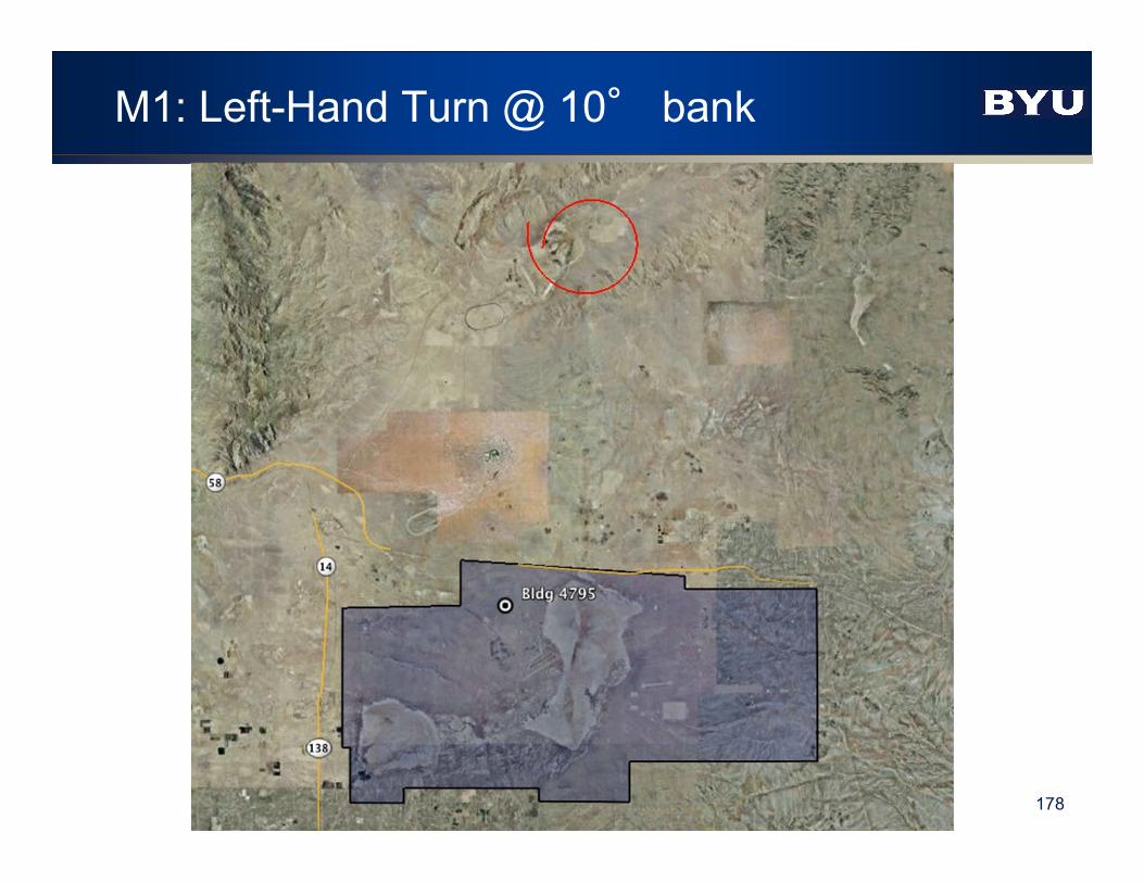
M1: Left-Hand Turn @ 10° bank
178

M1: Test Results
179

M2: Right-Hand Turn @ 10° bank
180

M2: Test Results
181

M3: Left-Hand Turn @ 30° bank
182

M3: Test Results
183

M4: Right-Hand Turn @ 30° bank
184

M4: Test Results
185

M3 to C2 Transition
186

M3 to C2 Transition Test Results
187
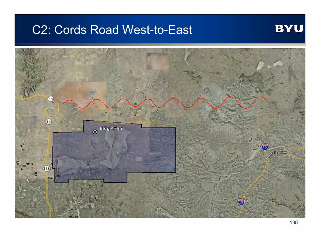
C2: Cords Road West-to-East
188

C2: Test Results
189

D2: Cords Road East-to-West
190

D2: Test Results
191

2017 International Telemetering ConferenceTerry Hill - [email protected]
STC Summary
Dual-Antenna Diversity Scheme Removes interference created by multiple transmit
antennas SNR equivalent to single antenna transmission
Multi-antenna scheme alleviates masking during maneuvering
Can be used with diversity reception
Realtime hardware flight tested at Edwards AFB and showed substantial performance benefit

Forward Error Correction

2017 International Telemetering ConferenceTerry Hill - [email protected]
Forward Error Correction
Basic premise Insert redundant bits into transmitted stream
Use known relationships between bits to correct errors
Countless schemes have been developed Convolutional code / Viterbi decoder
Block codes BCH
Reed-Solomon
Concatenated codes RS / Viterbi
Turbo product codes (TPC)
Low Density Parity Check (LDPC)

2017 International Telemetering ConferenceTerry Hill - [email protected]
LDPC Codes - History
LDPC: Low Density Parity Check
Linear block codes Some are systematic
Developed by Robert G. Gallager at M.I.T. in 1960 Published by the M.I.T Press as a monograph in 1963
No practical implementations at that time
Re-discovered by David J.C. MacKay in 1996 Began displacing turbo codes in the late 1990s
Recent history 2003: LDPC code selected for the new DVB-S2 standard for the satellite digital TV
2006: LDPC code selected for 10GBase-T Ethernet (10 Gbps over twisted-pair cables)
2007: LDPC codes published by CCSDS as an “Orange Book”
2008: LDPC code selected for the ITU-T G.hn standard
2009: LDPC codes adopted for Wi-Fi 802.11 High Throughput (HT) PHY specification
2012: LDPC code selected for integrated Network Enhanced Telemetry (iNET)

2017 International Telemetering ConferenceTerry Hill - [email protected]
LDPC AR4JA Codes
AR4JA: Accumulate-Repeat-4-Jagged-Accumulate
Published by CCSDS as an “Orange Book” Low Density Parity Check Codes For Use in Near-Earth and Deep Space Applications
Defines a family of systematic LDPC codes
Defines attached sync markers (ASM) Specified in section 6 of CCSDS Recommended Standard CCSDS 131.0-B-1
Present work based on the (6144, 4096) code

2017 International Telemetering ConferenceTerry Hill - [email protected]
Packet Assembly
Input 4096 data bits Randomize prior to encoding, if necessary
Compute and append 2048 parity bits
Prepend 256-bit attached sync marker (ASM) Yields a 6400-bit packet
Each and every code word carries the ASM: A, A, Ā, A A = FCB88938D8D76A4F
Ā = 034776C7272895B0
Synchronization requires at most one code word
A A Ā A 4096 Data Bits 2048 Parity bits

2017 International Telemetering ConferenceTerry Hill - [email protected]
Fractional Out-of-Band Power

2017 International Telemetering ConferenceTerry Hill - [email protected]
Decoder
Demodulate SOQPSK with soft decisions Implemented 8-bit decisions
Iterative decoders work best with high resolution soft decisions
Estimate Eb/N0 for soft decision scaling
Correlate for ASM with hard decisions Resolves the 4-ary phase ambiguity in SOQPSK
Virtually certain sync at Eb/N0 = 0 dB
Initialize decoder
Execute decode iterations until next code word Coding gain varies with bit rate

2017 International Telemetering ConferenceTerry Hill - [email protected]
Conclusions
Rate 2/3 LDPC code yields ≈9 dB coding gain relative to uncoded SOQPSK ±0.5 dB, depending on data rate
256-bit ASM provides reliable, fast synchronization at Eb/N0 < 0 dB
Synchronization is consistently achieved in < 4096 data bits
Bandwidth expansion of 25/16 Still 22% less bandwidth than legacy PCM/FM
SOQPSK with LDPC offers a reasonable trade of spectral efficiency for a significant gain in detection efficiency
5 other LDPC codes offer similar trade of bandwidth for BER performance

How Well Does It All Work Together?
Yuma Proving Grounds, AZ
Feb 8-11, 2016

2017 International Telemetering ConferenceTerry Hill - [email protected]
Recipe for Delivering Every Bit
Space Time Coding (STC) Eliminates aircraft pattern nulls
Low Density Parity Check (LDPC) coding Improves margin, stops “dribbling errors”
Adaptive Equalization (for non-STC signals) Mitigates multipath
Spatial diversity with correlating source selection Eliminate coverage-based dropouts
Requires DQE/DQM for optimal operation
TMoIP makes delivery easy

2017 International Telemetering ConferenceTerry Hill - [email protected]
Multiple Receiving Sites
Best Source Selector used 6 inputs: Ch1, Ch2 from each source, but not the combiner
outputs (not enough channels).

2017 International Telemetering ConferenceTerry Hill - [email protected]
Dual Transmitter – S band – 10 W each output
Installed in UH-1 (Huey) helicopter with top and bottom blade antennas

2017 International Telemetering ConferenceTerry Hill - [email protected]
YPG Test Sites
Site CM4
Site 2
Site 4
Site 4 to Site CM4 = 14.25 mi
Laguna Airfield

2017 International Telemetering ConferenceTerry Hill - [email protected]
Analysis using Data Logs
Ch1, Ch2DQE
Ch1, Ch2DQE
Ch1, Ch2DQE
Site 4
‘Best’
F1
Ch1 Ch2
F2Site 2
F1
Ch1 Ch2
F2CM4
F1
Ch1 Ch2
F2
F1Top
Antenna
F2BottomAntenna
Transmit F1-Top, F2-Bottom
3 Receive Sites
6 Clock & Data streams provided to A-CSS with Data Quality Encapsulation (DQE)
DQE = Receiver inserts periodic estimate of instantaneous BEP
Items of interest Top vs Bottom Antenna
Individual Site Performance
Source Selector Performance
Receiver Analyzer
BERT Log
Receiver Analyzer Log(BER of A-CSS output)
A-CSS Log(BEP of each time-
aligned source)
Data Log onEach Receiver
(BEP, BER, RSSI,...)

2017 International Telemetering ConferenceTerry Hill - [email protected]
Flight 1 – PCM/FM 5 MbpsLink Availability Summary (PN23 BER)

2017 International Telemetering ConferenceTerry Hill - [email protected]
Flight 2 – SOQPSK 5 MbpsLink Availability Summary (PN23 BER)

2017 International Telemetering ConferenceTerry Hill - [email protected]
Flight 3 – SOQPSK 20 MbpsLink Availability Summary (PN23 BER)

2017 International Telemetering ConferenceTerry Hill - [email protected]
Flight 4 – STC/LDPC 5 MbpsLink Availability Summary (PN23 BER)

2017 International Telemetering ConferenceTerry Hill - [email protected]
The elusive zero-error link…..
STC/LDPC from 3 sites at 5 MBPS
1st pass PN23 -- 34 minutes of helicopter flight across YPG…
Error-free!
2nd pass video with no freeze ups or blackouts!

Performance Comparison and Summary

2017 International Telemetering ConferenceTerry Hill - [email protected]
Acknowledgements
Mark Geoghegan, Quasonix
Dr. Michael Rice, Brigham Young University
Bob Jefferis, Tybrin, Edwards AFB
Kip Temple, ARTM, Edwards AFB
Gene Law, NAWCWD, Pt. Mugu
Vickie Reynolds, White Sands Missile Range