ADMECO LUX LED SL Manual
30
ADMECO LUX LED SL Manual EN Please read the operating and installation instructions carefully before using the surgical light. This prevents accidents and allows for optimal use of the surgical light. 12/2016
-
Upload
khangminh22 -
Category
Documents
-
view
0 -
download
0
Transcript of ADMECO LUX LED SL Manual

ADMECO LUX LED SLManual
EN
Please read the operating and installation instructions carefully before using the surgical light. This prevents accidents and allows for optimal use of the
surgical light.
12/2016

2
1 Used symbols 3
2 Description of the surgical light 4
3 Instructions for installing the surgical light to the „Multi“ ceiling system 5 3.1 Example:Arrangementandattachmentto„Multi“system 5 3.2 Installingtheceilinganchorring 6 3.3 Installingtheceilingflangeandstandtube 6 3.4 Installingtheadapterwithboom-andspringarm 6 3.5 Installingthelightheadonthespringarm 7 3.6 Removingthespringarm 8 3.7 Checkingtheoperatingvoltage 8 3.8 Connectionsonthepowersupplyunit 9
4 Operating instructions 10 4.1 Operatingconditions 10 4.2 Positioningbeforestartinganoperation 10 4.3 Sterilisablehandle 10 4.4 OverviewController 11 4.5 Switchingonandoff 11 4.6 Adjustingthebrightness 11 4.7 Endoscopiclight 11 4.8 Changethecolortemperatur 12 4.9 Centeringthelightbeam 12 4.10 Repositioningduringtheoperation 12 4.11 Movingthearms 12
5 Light care and disinfection 13
6 Maintenance 14 6.1 Maintenanceofthesurgicallight 14 6.2 ReplacingtheLEDmodule 14 5.3 Adjustingthebracketbrake 15 5.4 Adjustingthespringarmbreak 16
7 Safety 17
8 Troubleshooting 18 8.1 Electricalcauses 18 8.2 Mechanicalcauses 18
9 Miscellaneos 19 9.1 Serialnumberandtypeplate 19 9.2 GeneralinformationontheLEDmodules 19 9.3 Storageandtransportation 19 9.4 Disposalandenvironmentalprotection 19
10 Technical data 20 10.1 Dimmer 20 10.2 APSpowersupplyunit 20 10.3 Lightdata 22 10.4 ElectromagneticCompability 22 10.5 Electricalscheme 23 10.6 Dimensions 2511 Spare parts 26 11.1 Projector 26 11.2 Lighthead 27 11.3 Ceilingsystem„Multi“ 28 11.4 Wallbearing 29

3
1 Used symbols
Warning:Indicatesapotentionalhazard.Ifnotavoided,thiscancauseadeathor seriousinjury.
Electricshock:warnsofanelectricshockwhichmayresultinsevereorevenfatal injury.
Damagetosurface:warnsoftheriskofdamagetothesurfacethroughtheuseof incorrectagentsordisinfectants.
Disposal:indicates,thatthisdeviceisnotallowedtobedisposedindomestic waste.
CE-Conformitymark:confirmsconformityofthedevicetotheguidelinesofthe EuropeanMedicalDeviceDirective(MDD).
Payattentiontotheoperatinginstructions:Itindicatesthattheoperatorshaveto consulttheoperatinginstructions.
4
2 Description of the surgical light
TheADMECOLUXsurgicallightisanairstream-optimisedlightingsystemforuseinoperatingtheatres,and isbasedon individualhigh-performanceprojectors.LEDsareused in theseprojectors.Thanks tothisconcept,ADMECOLUXsurgicallightscanbecombinedinarangeofsizesforalltypesofoperationaccordingtomodulardesignprinciples.
Originallydevelopedspeciallyforuseunderlaminarsupply-airsystemsinoperatingtheatres,thesystemisnowhighlyvaluedbysurgeonsworldwidethankstoitsexcellentlightingpropertiesandexceptionallyeasyhandling.Despitethecompactprojectordesign,extremelyhighlightyieldscanbeachieved.Thesurgicallightiseasytooperateandfocusthankstothesterilisablehandle.
The ADMECO LUX surgical light has an extremely low air-resistant surface. As a result, the build-upof upward-moving airstreams and aerodynamic stagnation points underneath the surgical light areminimised.Surgicallightsarepositionedintheoperatingtheatresothatthesterilisablehandlecannotcomeintocontactwiththeheadofthesurgeonatanytime.ThismeansthatADMECOLUXlightscanbeusedatgreaterdistancestothesurgicalsitecomparedtolightswheresterilemanipulationisnotpossible.
PracticalexperiencehasshownthatADMECOLUXsurgicallightsareusedapproximately1.2to1.4metresawayfromthewoundarea.Theprojectoropticsaredesignedsothatalightbeamdiameterof22cmisachievedatadistanceof1.2metres.
Intendeduse
Thesurgicallightisusedinthevicinityofpatientsforthelocallightingofsurgicalsitesonthebodyandgeneratestheappropriateilluminationintensity.Itisintendedforuseinoperatingtheatresandasanaidinpatienttreatmentanddiagnosis.
Thesurgical lightsareintendedforuseunderambientconditionsaccordingtoDINEN60601,section10.2.1inmedicalrooms,whichareequippedaccordingtotheguidelinessetoutinVDE0100,part710.The surgical lights are installed by the manufacturer or an authorised representative of ADMECO AG.Circuitdiagramsandnationalregulationsmustbeobservedduringinstallationandmaintenance.
Thesurgicallightsmustbeoperatedbytrainedspecialistpersonnel,andnotbypatients.Theoperatormustreadtheoperatingmanualandensurethatthedeviceisworkingproperlybeforeusingthesurgicallight.
Thesurgicallightisintendedforcontinuoususeunderthefollowingconditions:temperature:0…40°Chumidity:10…75%airpressure:500…1060hPa

5
3 Instructions for installing the surgical light to the “Multi” ceiling system
3.1 Example: Arrangement and attachment to “Multi” system
Ceilinganchorring
Ceilingflange
Standtube
“Multi”adapter

6
3.2 Installing the ceiling anchor ring
Duetothestrictsafetyrequirementsinsidetheoperatingtheatre,theequipotentialbondingbetweentheceiling/buildingreinforcements(orthesteelbuildingstructure)andthesurgicallightmustbeisola-tedcorrectly.Forthisreason,thesurgicallightisinsulatedwhensuspended.
Aceilingwithhighstaticloadresistanceisrequiredwhensuspendingfromtheceiling.Theceilinganchorringmustbeattachedtotheceilingwiththeanchorplugsaccordingtotheinstallationinstructionsfromtheplugmanufacturer(UPAT,HILTIetc.),togetherwiththewashersandnuts.Thepull-outstrengthofeachanchorscrew(plug)mustbetestedtoaloadof12.5KN.
3.3 Installing the ceiling flange and stand tube
Theceilingflangeandstandtubearedeliveredasacomplete,pre-assembledunittogetherwiththeconnectionterminals.
Installing the ceiling flange:Unscrewthetopnutontheboltoftheceilinganchorring.Inserttheinsulationsleeveandwasherintotheflangehole.Inserttheceilingflangeintotheboltoftheceilinganchorring,alignitperpendicularlyatadistanceofapprox.40mmusingthewashersandnuts,thenfastenintoplace.
3.4 Installing the adapter with boom and spring arm
Theadapterispre-assembledwiththeboomsandspringarmsondelivery.Beforeinstallingtheadapter,thecylindricalsurfacewherethestandtubeisinsertedmustbecoatedwithgraphiticgrease.
Theplugpairisthenjoinedtogether.Ensurethattheplugforthemainlightandtheplugforthesatellitelightsarebothassignedcorrectly.Inserttheadapterintothestandtubeandfastenitwiththesixgrubscrews.Aligntheadaptersothatthelongconnectingportforthemainlightpointstowardstheheadofthepatient(anaesthetic)andtheshortconnectingport(satellite)pointstowardsthefeet,andareflushwiththeaxisoftheoperatingtable.Tightenallofthegrubscrews.Differentadapterarrangementsarepossibleaccordingtocustomerdemands.

7
3.5 Installing the light head on the spring arm
1+2 removecontroller/cover3+4 removethesecurity-ringandplate5+6 pullouttheprotectioncoverandundcarefullypluginlighthead7+8 mountthesecurityplateandcover;adjusttheforceofthebreakwiththescrew9+10connectthecontrollerandmountthecovers
2.
3. 4.
5. 6.
1.
7.8.
9. 10.
8
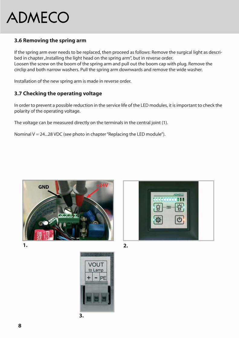
3.6 Removing the spring arm
Ifthespringarmeverneedstobereplaced,thenproceedasfollows:Removethesurgicallightasdescri-bedinchapter„Installingthelightheadonthespringarm“,butinreverseorder.Loosenthescrewontheboomofthespringarmandpullouttheboomcapwithplug.Removethecirclipandbothnarrowwashers.Pullthespringarmdownwardsandremovethewidewasher.
Installationofthenewspringarmismadeinreverseorder.
3.7 Checking the operating voltage
InordertopreventapossiblereductionintheservicelifeoftheLEDmodules,itisimportanttocheckthepolarityoftheoperatingvoltage.
Thevoltagecanbemeasureddirectlyontheterminalsinthecentraljoint(1).
NominalV=24...28VDC(seephotoinchapter“ReplacingtheLEDmodule”).
1. 2.
3.

9
3.8 Connections on the power supply unit
Thewiringdiagramforconnectingtheinputcanbefoundinchapter9.
Terminal X1: INPUT
Ifthemainpowersupplyisnotused,then“AUX”isautomaticallyactive.
Terminal X2: AUX
Thein-house24Vemergencypowersupplysystemcanbeconnectedtotheemergencypowerinput.IfthereisnoinputvoltagepresentontheINPUT,thenthepowersupplyunitswitchesautomaticallytoAUX.The dc-voltage has to be connected in the way it is indicated!
Terminal X5:
VOUT-surgicallightoutput
Voltage 24Vdc
Power max.110W
diameterwiring <10m 2.5mm2
10-20m 4mm2
20-30m 6mm2 !!!>connectiondiameter!!!-4mm2
30-50m 10mm2 !!!>connectiondiameter!!!-4mm2
Thelightoutputisconnectedwiththeterminalsonthestandlegofthesurgicallight.
INPUT - Main power supply
Voltage 100...240Vac
Power max.115W
Frequency 50/60Hz
Terminalcross-section 4mm2
AUXIN - 24V Input / Emergency power supply
Voltage 24Vac/dc
Power max.115W
Terminalcross-section 4mm2
Leuchtenkopflight headtête de lampe
GND
24VDC
PE
GND
24VDC
PE
GND
24VDC
PE
Gezeichnet
Geprüft
Gesehen
Ersatz für
Anzahl Blatt Blatt-Nr.
Än
deru
nge
n
Än
deru
nge
n
A3F
ür
die
ses
Dokum
ent
behalten
wir
uns
alle
Rechte
vor.
/We
rese
rve
all
rig
hts
incon
nection
with
this
docu
me
nt.
Maßstab
ADMECO AGMedizintechnikHochdorf / Schweiz
Änderungen im Sinne des technischen Fortschrittes vorbehalten
..OP-Leuchte
StS 27.11.14
Installation bauseitsinstallation on the part of building siteinstallation effectuée par des tiers
Installation Admeco
A)StS, 27.11.14B)
40-70-0022_A
Auf Polarität achten !!!Pay attention to the wire polarity!!!Attention à la polarité!!!
- die aufgeführten Bauteile sind Bestandteil der Admeco Lieferung- the shown parts are components of the Admeco delivery- les composants mentionnés font partie intégrante de la livraison Admeco
AdmecoDimmerARC 24V
GND
Elektroschema LED WIP II APS
Pro Dimmer eine geschirmte Leitung nutzen! 0.5mm2Use 1 shielded cable per dimmer! 0.5mm2
D)
2.5 mm2<10m
Leitungsquerschnitt Netzteil - OP-Leuchtediameter of wiring Power supply - OT-Light
10m-20m20m-30m30m-50m
4 mm26 mm210 mm2
!! > Anschlussquerschnitt X5 (4mm2) !!!! > connection diameter X5 (4mm2) !!
E)F)G)H)
Stativsuspension tubetube à bride
Federarmspring armbras à ressort
Auslegerboom armPotence
Vin (+24V) sw, black, noir
GND bl, blue, bleu
GN
D+V
inD
+D
-
X5
X1 X2 X3 X4
1 2 3
PE
LIN
E
NE
UT
RA
L
PE AU
XIN
AU
XIN
Bato
k
Ala
rm
+24V
0.5A
GN
D
Dim
-
CC
T+
Dim
+
IO-C
OM
1 2 3 21 321 7 8 9 10 11 12 1 2 3 4 5 6
+-
+ -
DP
S
D+
D-
WIP II Admeco Power Supply
Aux
on
LTon
Lich
tE/A
CC
T-
3 4
24V ac/dc 10A+/-10%
Bat+
Bat-
230V
DimmerControllerFSZ
GND
24V
C)
Leuchtenkopflight headtête de lampe
GND
24VDC
PE
GND
24VDC
PE
GND
24VDC
PE
Gezeichnet
Geprüft
Gesehen
Ersatz für
Anzahl Blatt Blatt-Nr.
Änd
erun
gen
Änd
erun
gen
A3F
ür
die
ses
Doku
ment
behalte
nw
iruns
alle
Rech
tevo
r./W
ere
se
rve
all
rig
hts
incon
nection
with
this
docu
me
nt.
Maßstab
ADMECO AGMedizintechnikHochdorf / Schweiz
Änderungen im Sinne des technischen Fortschrittes vorbehalten
..OP-Leuchte
StS 27.11.14
Installation bauseitsinstallation on the part of building siteinstallation effectuée par des tiers
Installation Admeco
A)StS, 27.11.14B)
40-70-0022_A
Auf Polarität achten !!!Pay attention to the wire polarity!!!Attention à la polarité!!!
- die aufgeführten Bauteile sind Bestandteil der Admeco Lieferung- the shown parts are components of the Admeco delivery- les composants mentionnés font partie intégrante de la livraison Admeco
AdmecoDimmerARC 24V
GND
Elektroschema LED WIP II APS
Pro Dimmer eine geschirmte Leitung nutzen! 0.5mm2Use 1 shielded cable per dimmer! 0.5mm2
D)
2.5 mm2<10m
Leitungsquerschnitt Netzteil - OP-Leuchtediameter of wiring Power supply - OT-Light
10m-20m20m-30m30m-50m
4 mm26 mm210 mm2
!! > Anschlussquerschnitt X5 (4mm2) !!!! > connection diameter X5 (4mm2) !!
E)F)G)H)
Stativsuspension tubetube à bride
Federarmspring armbras à ressort
Auslegerboom armPotence
Vin (+24V) sw, black, noir
GND bl, blue, bleu
GND
+Vin
D+ D-
X5
X1 X2 X3 X4
1 2 3
PE
LIN
E
NEU
TRAL
PE AU
XIN
AU
XIN
Bato
k
Alar
m
+24V
0.5A
GND
Dim
-
CCT+
Dim
+
IO-C
OM
1 2 3 21 321 7 8 9 10 11 12 1 2 3 4 5 6
+-
+ -
DP
S
D+
D-
WIP II Admeco Power Supply
Auxo
n
LTon
Lich
tE/A
CCT-
3 4
24V ac/dc 10A+/-10%
Bat
+
Bat
-
230V
DimmerControllerFSZ
GND
24V
C)

10
4 Operating instructions
4.1 Operating conditions
Seealsochapter1Thesurgicallightisintendedforcontinuoususeunderthefollowingconditions:
temperature:0…40°Chumidity:10…75%airpressure:500…1060hPa
4.2 Positioning before starting an operation
Werecommendthatthesurgicallightispositionedbythestaffbeforehandsothatanyadjustmentsdu-ringtheoperationareavoidedasfaraspossible.Thesurgeonthenonlyhastomakefineadjustmentsonthesterilisablehandleduringtheoperation,whichcanbemadeveryeasilythankstothesimplehandlingofthesurgicallight.
4.3 Sterilisable handle
Thesterilisablehandleisinsertedandlockedintoplaceasshown,withthegroovepointingtowardsthereleaseleveronthesurgicallight.Toremovethehandle,pushthereleaseleveronthesurgicallightupwardsandpulloutthehandle.Thesterilisablehandleisdeliverednon-sterile.
Spindleextension:
InstallationofthespindleextensionensuresoptimalhandlingoftheADMECOsterilisablehandle.Whenrequired,thecapcanberemovedandtheextensionscrewedon.Thecappreventsscratchestothesterilisablehandles.

11
4.4 Overview Controller
wall controller spring arm controller
4.5 Switching on and off
switching on: *pushthebuttonOn/Standby switching off: *pushthebuttonOn/Standbyfor>1sec.
4.6 Adjusting the brightness
reducing the brightness: *pushthebutton„darker“ theLed-beamindicatestheposition
increasing the brightness: *pushthebutton„brighter“ theLed-beamindicatestheposition
4.7 Endoscopic light
wall controller: *switchingon:pushthebuttons„brighter“and„darker“ atthesametimefor2sec. *switchingoff:pushthebuttons„brighter“and„darker atthesametimeagainfor2sec. theLED-beamwillchangehisindication
spring arm controller: *switchingon:pushthebutton„Endo“for2sec. *switchingoff:pushthebutton„Endo“for2sec.

12
4.8 Change the color temperatur
4.8.1 Wall controller
change the color temperatur *pushthebutton„colortemp“ TheLEDbeamwillchangehisindication. *pushthebutton„darker“toreducethecolor temperatur(warmerlight) *pushthebutton„brighter“toincreasethe colortemperatur(colderlight) *leavethecolortemperaturemodebypushing thebutton„colortemp“.Themodewill automaticallystopafter10sec.
4.8.2 Spring arm controller
change the color temperatur *pushthebutton„lower“fordecreasingthe colortemperatur(warmerlight)
*pushthebutton„higher“forincreasingthe colortemperature(colderlight)
4.9 Centering the light beam
Itisrecommendedtoposition(centre)thesurgicallightonthewoundareabeforetheincisionusingthesterilisablehandle.Thisismadebyrotatingthehandle,whichadjuststhepitchangleoftheprojectors.Itisthenpossibletoeitherconcentratethelightbeamsontopofoneanother(minimumfieldsize)ortoin-creasethelightspotsothatthebeamisopenedsufficientlyenoughsothatnovisibledarkpointsappearinthecentreofthelitarea(maximumfieldsize).Anadjustmentofthesurgicallightduringtheoperationisunnecessary,unlessthedistancebetweenthewoundareaandthesurgicallightchangessignificantly.
4.10 Repositioning during the operation
Thecompactdesignandeasymovementofthesurgicallightsmeanthatangleadjustmentscanbemadewithoutanyproblemsduringoperations.Thismeansthatobstructionofthesurgicallightislargelyprevented,dependingonthepositionofthesurgeon.
4.11 Moving the arms
Therotaryresistancebetweentheboomandtheadapterisgreaterthanthatbetweentheboomandspringarm.Thisthenmakesitpossibletorotatethespringarmwithouttheboomfollowing.
13
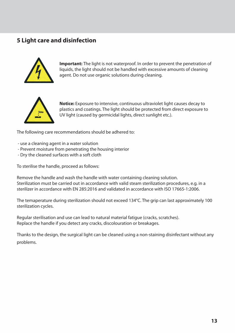
5 Light care and disinfection
Important: Thelightisnotwaterproof.Inordertopreventthepenetrationof liquids,thelightshouldnotbehandledwithexcessiveamountsofcleaning agent.Donotuseorganicsolutionsduringcleaning.
Notice: Exposuretointensive,continuousultravioletlightcausesdecayto plasticsandcoatings.Thelightshouldbeprotectedfromdirectexposureto UVlight(causedbygermicidallights,directsunlightetc.).
Thefollowingcarerecommendationsshouldbeadheredto:-useacleaningagentinawatersolution-Preventmoisturefrompenetratingthehousinginterior-Drythecleanedsurfaceswithasoftcloth
Tosterilisethehandle,proceedasfollows:
Removethehandleandwashthehandlewithwatercontainingcleaningsolution.Sterilizationmustbecarriedoutinaccordancewithvalidsteamsterilizationprocedures,e.g.inasterilizerinaccordancewithEN285:2016andvalidatedinaccordancewithISO17665-1:2006.
Thetemaperatureduringsterilizationshouldnotexceed134°C.Thegripcanlastapproximately100sterilizationcycles.
Regularsterilisationandusecanleadtonaturalmaterialfatigue(cracks,scratches).Replacethehandleifyoudetectanycracks,discolourationorbreakages.
Thankstothedesign,thesurgicallightcanbecleanedusinganon-stainingdisinfectantwithoutany
problems.
14
6 Maintenance
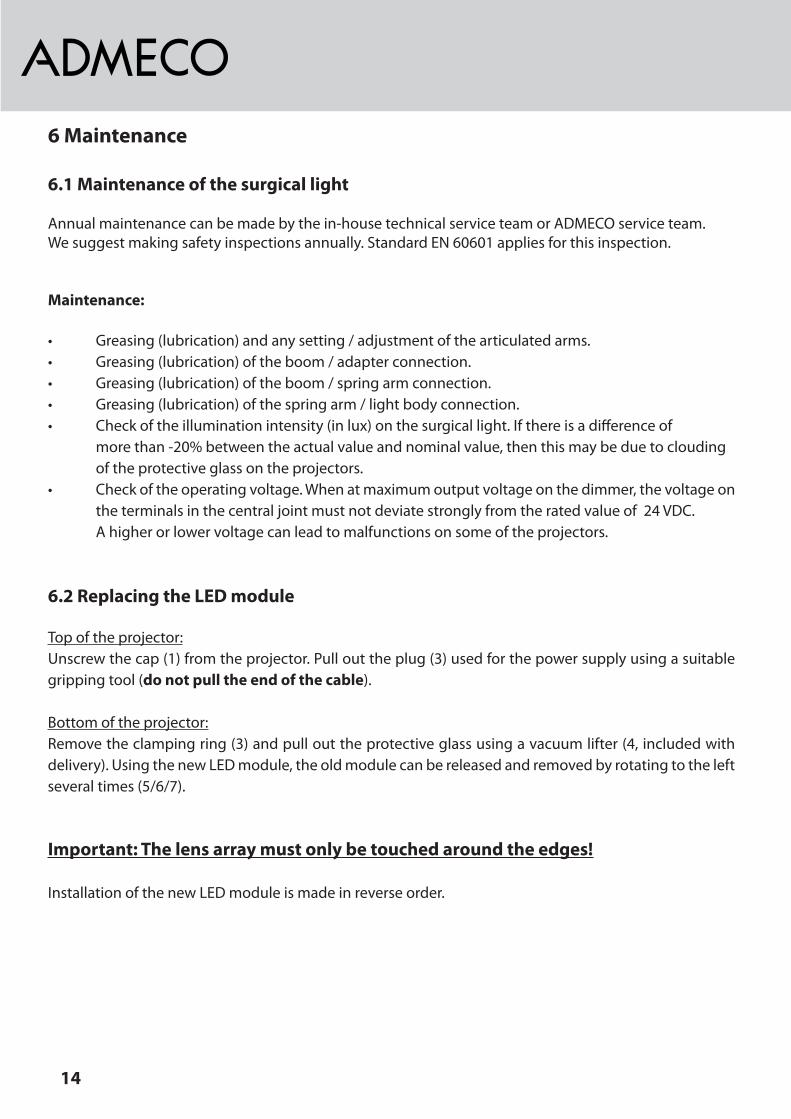
6.1 Maintenance of the surgical light
Annualmaintenancecanbemadebythein-housetechnicalserviceteamorADMECOserviceteam.Wesuggestmakingsafetyinspectionsannually.StandardEN60601appliesforthisinspection.
Maintenance:
• Greasing(lubrication)andanysetting/adjustmentofthearticulatedarms.• Greasing(lubrication)oftheboom/adapterconnection.• Greasing(lubrication)oftheboom/springarmconnection.• Greasing(lubrication)ofthespringarm/lightbodyconnection.• Checkoftheilluminationintensity(inlux)onthesurgicallight.Ifthereisadifferenceof morethan-20%betweentheactualvalueandnominalvalue,thenthismaybeduetoclouding oftheprotectiveglassontheprojectors.• Checkoftheoperatingvoltage.Whenatmaximumoutputvoltageonthedimmer,thevoltageon theterminalsinthecentraljointmustnotdeviatestronglyfromtheratedvalueof24VDC. Ahigherorlowervoltagecanleadtomalfunctionsonsomeoftheprojectors.
6.2 Replacing the LED module
Topoftheprojector:Unscrewthecap(1)fromtheprojector.Pullouttheplug(3)usedforthepowersupplyusingasuitablegrippingtool(do not pull the end of the cable).
Bottomoftheprojector:Removetheclampingring(3)andpullouttheprotectiveglassusingavacuumlifter(4,includedwithdelivery).UsingthenewLEDmodule,theoldmodulecanbereleasedandremovedbyrotatingtotheleftseveraltimes(5/6/7).
Important: The lens array must only be touched around the edges!
InstallationofthenewLEDmoduleismadeinreverseorder.

15
6.3 Adjusting the bracket brake
Adjustmentofthebracketbrakeisnecessarywhenrotationofthelightaroundthecentreofgravityonthebracketbecomestooeasyortoodifficult.
Procedure:Removethecoverlidandadjustthescrew.
1. 2. 3.
4. 5. 6.
8.7.
16
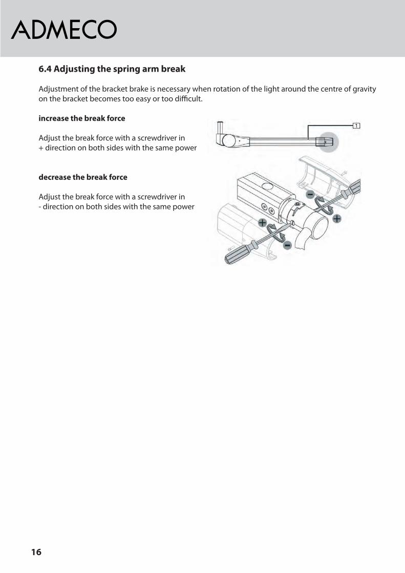
6.4 Adjusting the spring arm break
Adjustmentofthebracketbrakeisnecessarywhenrotationofthelightaroundthecentreofgravityonthebracketbecomestooeasyortoodifficult.
increase the break force
Adjustthebreakforcewithascrewdriverin+directiononbothsideswiththesamepower
decrease the break force
Adjustthebreakforcewithascrewdriverin-directiononbothsideswiththesamepower

17
7 Safety
Thefollowingsafetyinstructionsshouldbereadandappliedcarefullyinorder toensuresafeinstallationandhandling.
TheelectricalsystemmustcorrespondtoDINVDE0100andlocalregulations.Thismeansthatnoadditi-onalmeasuresarerequiredrelatingtothesafetyoftheADMECOLUXsurgicallight.
Important:Inordertoavoidtheriskofelectricshocks,thisdevicemustonlybeconnectedtoapowersupplynetworkwithprotectiveconductors.
TheADMECOsurgicallightisnotsuitableforuseinexplosiveatmospheres.
IfasingleLEDmodulefails,thentheADMECOLUXsurgicallightcanstillbeused.
Lightintensityinwattsperm2Thestandardstatesthatamaximumvalueof1000wattsperm2shouldnotbeexceededinordertopre-ventburnstothepatient.ThisvalueisexceededwhenmorethantenLEDprojectorsonanADMECOLUXLEDcombinationareusedtoilluminatethewoundarea.Aworkingdistanceof1metreisusedasabasis.Whenthisworkingdistanceisreduced(e.g.80cm),thenthelightintensityincreasesby1.56times!Anincreaseinworkingdistanceto1.2metresleadstoa30%reductioninlightintensity.Asabsorbedradiationistransformedintoheat,thiscanresultinburns.
LEDsareextremelyconcentratedlightsources.Avoidlookingdirectlyintothelight.
ADMECO accepts no liability for the safety characteristics as a result of misuse, insufficient care or maintenance. All repairs or modifications must be made exclusively with original ADMECO parts. Modification of the device is not permitted.
Thelighthasbeendesignedforaservicelifeof25years.

18
8 Troubleshooting
Malfunctionsonthesurgicallightmaybeduetothefollowingcauses:
8.1 Electrical causes
a) Defectivepowersupplyunit b) Defectivedimmercontrolc) Operatingvoltagetoohighortoolow
8.2 Mechanical causes
a) The spring arm is unstable, meaningthe surgicallightdoesnotremainatthesetheight.
• Surgical light rises:Thescrewislocatedbehindthelittlecover.Turntheallenwrenchtorightasitisshowninthepicture.
• Surgical light sinks: Turntheallenwrenchtoleftasitisshown
inthepicture.
b) The surgical light can be moved too far or not far enough upwards. Theheightstop onthesurgicallightcanbeadjustedbyremoving thecovers.
• Adjustingtheheightstopupwards: Nutmustbeturnedhigher(+,downwards)• Adjustingtheheightstopdownwards: Nutmustbeturnedlower(-,upwards)

19
9 Miscellaneous
9.1 Serial number and type plate
Note: Always give the serial number and the location of the surgical light in the building when contacting our customer service team.
Meaning of the serial number:
LED14000001 -> 00 01 0000 Year Generation Sequential number
9.2 General information on the LED modules
LEDs have a very long service life (50,000 hours). However, with increased usage the illumination in-tensity isreducedwhenunderthesameloads(approximately75%brightnessafter50,000hours).Anassessmentmustthenbemadeastowhetherfurtheruseispossible,basedonameasurementoftheilluminationintensityandsubjectiveevaluation.
9.3 Storage and transportation
Thefollowingstorageconditionsapplyforperiodsofupto15weeks: -Temperature:-25to+70°C -Rel.humidity:10to75% -Airpressure:500to1060hPa
Storageismadeinclosedorcoveredroomsonly.Afterthis,thevaluesspecifiedfortheoperatingcondi-tionsintheinstructionsapply.
9.4 Disposal and environmental protection
Thelightisreturnedtothemanufacturerfordisposal.Aspecialrecycling companycanalsobeappointedfordisposal.Anydefectiveorwornparts detectedduringmaintenancemustbedisposedofcorrectly.
Theserialnumberandtypeplateareloca-tedonthecoverofthesurgicallight.

20
10 Technical data
10.1 Dimmer
ThisdimmerisespeciallysuitedforcontrollingtheADMECOAPSpowersupplyunits.Installation:SeewiringdiagramFunction:Seechapter3
Technical data
Type: ControllerARC
Itemno.: 40.20.0558
Voltage: max.24VDC
Connections: Screwclamp1,5mm2
Dimensions:Installationdepth:
88x88x49mm35mm forSEVundDINdevicesockets
Protectionclass: IP20 Dryinstallation
Ambienttemperature: 0°Cbis45°C
TheADP-1310ismainlyusedasacontrollerfortheAPSpowersupplyunit:•Sendscontrolcommands(buttons)totheAPS.•RegularlyqueriesthecurrentbrightnessvalueintheAPS.•DisplaysthecurrentbrightnessvalueontheLEDbar.
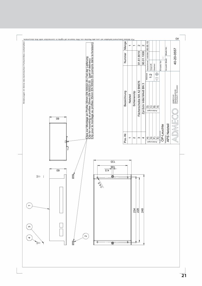
10.2 APS power supply unit
Nenndaten
ItemNo.: 40.20.0557
Type: APS
Power: max.125VA
Frequency: 50/60Hz
Primaryvoltage: 100...240VAC50/60Hz
Secondaryvoltage: 24VDC,max.5A
incl.iemperaturswitch: 120°C
Connections: clamps(seescheme)
Protectionclass: IP20dryinstallation
Ambienttemperature: 0°C....40°C
primaryfuse: 230VAC 3A
secondaryfuse: 24VDC 5A
21
60
60
13
4 2
234
2
28
248
4.5 106
133
4.
5
Clip
s zu
r Mon
tage
an
Pro
file
35m
m E
N 5
0022
-35
(Tei
l der
Lie
feru
ngC
lip fo
r mou
ntin
g at
pro
files
35m
m E
N 5
0022
-35
(pa
rt of
del
iver
y)C
lip p
our l
e m
onta
ge a
u pr
ofile
s 35
mm
EN
500
22-3
5 (c
ompr
is d
ans
la li
vrai
son)
Pos
.-Nr.
Bez
eich
nung
Num
mer
Men
ge
1N
etzt
eil
12
Sch
iene
nclip
1
3Fä
cher
sche
ibe
M4
A2
BN
676
91.6
1.90
192
4Zy
l-Sch
r In6
kt M
4x8
BN
390
.01.
1008
2
1:2
40-2
0-05
57
AP
S N
etzt
eil
OP
-Leu
chte
05.0
5.15
CAD/
StS
Hochdorf
/ S
chw
eiz
Mediz
inte
chnik
ADM
ECO
AG
Maß
stab
/We reserve all rights in connection with this document. Für dieses Dokument behalten wir uns alle Rechte vor.A3
Änderungen
Änderungen
Bla
tt-N
r.A
nzahl B
latt
Ers
atz
fü
r
Ges
ehen
Geprü
ft
Geze
ichnet
..
H) G) F) E)
D) C) B) A)
Än
de
run
ge
n im
Sin
ne
de
s t
ech
nis
ch
en
Fo
rtsch
ritt
es v
orb
eh
alte
n
Pro
jekt
/ K
ompo
nent
e
Bez
eich
nung
22
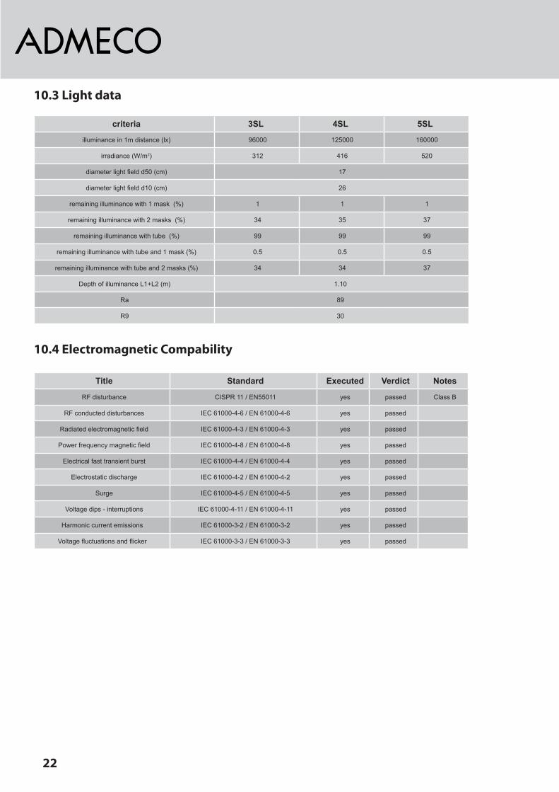
10.3 Light data
criteria 3SL 4SL 5SL
illuminance in 1m distance (lx) 96000 125000 160000
irradiance (W/m2) 312 416 520
diameter light field d50 (cm) 17
diameter light field d10 (cm) 26
remaining illuminance with 1 mask (%) 1 1 1
remaining illuminance with 2 masks (%) 34 35 37
remaining illuminance with tube (%) 99 99 99
remaining illuminance with tube and 1 mask (%) 0.5 0.5 0.5
remaining illuminance with tube and 2 masks (%) 34 34 37
Depth of illuminance L1+L2 (m) 1.10
Ra 89
R9 30
10.4 Electromagnetic Compability
Title Standard Executed Verdict Notes
RF disturbance CISPR 11 / EN55011 yes passed Class B
RF conducted disturbances IEC 61000-4-6 / EN 61000-4-6 yes passed
Radiated electromagnetic field IEC 61000-4-3 / EN 61000-4-3 yes passed
Power frequency magnetic field IEC 61000-4-8 / EN 61000-4-8 yes passed
Electrical fast transient burst IEC 61000-4-4 / EN 61000-4-4 yes passed
Electrostatic discharge IEC 61000-4-2 / EN 61000-4-2 yes passed
Surge IEC 61000-4-5 / EN 61000-4-5 yes passed
Voltage dips - interruptions IEC 61000-4-11 / EN 61000-4-11 yes passed
Harmonic current emissions IEC 61000-3-2 / EN 61000-3-2 yes passed
Voltage fluctuations and flicker IEC 61000-3-3 / EN 61000-3-3 yes passed

23
10.5 Elektrical scheme
Le
uch
ten
ko
pf
light
head
tête
de
lam
pe
GND
24V
DC
PE
GND
24V
DC
PE
GND
24V
DC
PE
Gez
eich
net
Geprü
ft
Ges
ehen
Ers
atz
für
AnzahlB
latt
Bla
tt-N
r.
Änderungen
Änderungen
A3FürdiesesDokumentbehaltenwirunsalleRechtevor./Wereserveallrightsinconnectionwiththisdocument.
Maß
stab
ADM
ECO
AGM
ed
izin
tech
nik
Hoch
dorf
/S
chw
eiz
Änderu
ngen
imS
inne
des
tech
nis
chen
Fort
schrittes
vorb
ehalte
n
..O
P-L
euch
te
StS
27.1
1.14
Insta
llatio
nb
au
se
its
insta
llation
on
the
part
of
build
ing
site
insta
lla
tio
ne
ffe
ctu
ée
pa
rd
es
tie
rs
Inst
alla
tion
Adm
eco
A)S
tS,2
7.11
.14
B)S
tS,1
3.02
.15
40-7
0-00
22_E
AufP
olar
itäta
chte
n!!!
Pay
atte
ntio
nto
the
wire
pola
rity!
!!At
tent
ion
àla
pola
rité!
!!-d
ieau
fgef
ührte
nBa
utei
lesi
ndBe
stan
dtei
lder
Adm
eco
Lief
erun
g-t
hesh
own
parts
are
com
pone
nts
ofth
eAd
mec
ode
liver
y-l
esco
mpo
sant
sm
entio
nnés
font
parti
ein
tégr
ante
dela
livra
ison
Adm
eco
Adm
eco
Dim
mer
ARC
24V
GN
D
Elek
trosc
hem
aLE
DSL
-APS
Pro
Dim
mer
eine
gesc
hirm
teLe
itung
nutz
en!
0.5m
m2
Use
1w
eld
cabl
epe
rdim
mer
!0.
5mm
2
D)S
tS,2
2.04
.15
2.5
mm
2<1
0m
Le
itu
ng
sq
ue
rsch
nitt
Ne
tzte
il-
OP
-Le
uch
tedia
mete
rof
wirin
gP
ow
er
supply
-O
T-L
ight
10m
-20m
20m
-30m
30m
-50m
4m
m2
6m
m2
10m
m2
!!>
Ansc
hluss
quer
schn
ittX5
(4m
m2)
!!!!
>co
nnec
tion
diam
eter
X5(4
mm
2)!!
E)S
tS,2
5.11
.15
F)
G)
H)
Stat
ivsu
spen
sion
tube
tube
àbr
ide
Fede
rarm
sprin
gar
mbr
asà
ress
ort
Ausle
ger
boom
arm
Pote
nce
Vin
(+24
V)sw
,blac
k,no
ir
GND
bl,blu
e,ble
u
GND+VinD+D-
X51
23 PE
LINE
NEUTRAL
PE
AUXIN
AUXIN
Batok
Alarm
+24V0.5A
GND
Dim-
CCT+
Dim+
COM
+-
+
-
DPS
D+
D-
AP20
0-02
Adm
eco
Powe
rSup
ply
Auxon
LTon
on/off
CCT-
230
V98
W0.
52A
Dimm
erCo
ntro
ller
FSZ
GND
24V
24V
dcm
ax.2
00m
AC
)StS
,23.
03.1
524
Vac
/dc
+/-1
0%5A
Bat+
Bat-
ACIn
put
Vout
AUX
BAT
DAL
IC
ontro
lI/O

24
Dec
kenb
oard
Cei
ling
boar
dad
apte
rcon
nexi
on
HD
-VVD
-AA-
xxx
PEY-di
f-w
hite
Y-di
f+bl
ack
Leuc
hten
kopf
und
Kam
era
light
head
and
cam
era
tête
dela
mpe
etca
mér
a
Stat
ivsu
spen
sion
tube
tube
àbr
ide
Ausl
eger
boom
arm
Pote
nce
Fede
rarm
sprin
gar
mbr
asà
ress
ort
AufP
olar
itäta
chte
n!!!
Pay
atte
ntio
nto
the
wire
pola
rity!
!!At
tent
ion
àla
pola
rité!
!!
Ge
zeic
hne
t
Geprü
ft
Ges
ehen
Ers
atz
für
AnzahlB
latt
Bla
tt-N
r.
Änderungen
Änderungen
A3FürdiesesDokumentbehaltenwirunsalleRechtevor./Wereserveallrightsinconnectionwiththisdocument.
Maß
stab
ADM
ECO
AGM
ed
izin
tech
nik
Hoch
dorf
/S
chw
eiz
Änderu
ngen
imS
inne
des
technis
chen
Fort
schrittes
vorb
ehalten
..
Elek
trosc
hem
eSL
-APS
+CO
P-Le
ucht
e
40-7
0-00
23_C
StS
27.1
1.14
1234
PE
+24V
GN
D
PEY-di
f-
Y-di
f+
Adap
ter
PEY-di
f-
Y-di
f+
GND
+24V
PEY-di
f-
Y-di
f+
GN
D
+24V
5 4 3 2 15 4 3 2 1
5 4 3 2 1
5 4 3 2 1
Cam
Volt
1bl
ack
2bl
ack
PE3w
hite
4bl
ack
PEPE 4bl
ack
3w
hite
PE 2bl
ack
1bl
ack
fem
ale
back
side
male
back
side
1bl
ack
2bl
ack
PE1
blac
kPE
2bl
ack
PEPE
brow
nw
hite
male
back
side
fem
ale
back
side
whi
tebr
own
RJ4
5
Steu
erge
rät
HD
-VVD
-ST-
xxx
Con
trolle
r
zum
Mon
itor
tom
onito
r
Bind
er-K
abel
stec
ker(
rund
,8-P
ol)
Bind
erPl
ug(ro
und,
8-po
l)(B
inde
rArt-
No:
09-0
571-
92-0
8)
12
3
45
54
3
2 1
Schl
eifk
onta
ktsl
idin
gco
ntac
t
Stec
ker
Plug
Kupp
lung
Sock
et
Inst
alla
tion
Adm
eco
15
69
whi
te
blac
k
Verb
indu
ngsk
abel
2mBi
nder
Plug
-Rj4
5Li
efer
ung
/del
iver
yAd
mec
o
Patc
hkab
elm
in.K
at5
max
.40m
Patc
hw
irem
in.C
at5
max
.40m
baus
eits
/bui
ldin
gsi
te
Net
zwer
kdos
e/n
etw
ork
sock
etba
usei
ts/b
uild
ing
site In
stal
latio
nba
usei
tsco
nnec
tion
onbu
ildin
gsi
te
C)S
tS,2
5.11
.15
B)St
S,25
.03.
15A)
StS,
27.1
1.14
D)
G)
E)H)
Kaltg
erät
eans
chlu
ss11
0...2
40V
Lief
erun
gAd
mec
oL=
1,5m
appl
ianc
eco
uple
r110
...24
0VAd
mec
ode
liver
yL=
1,5m
F)
Adm
eco
Dim
mer
24V
GN
D
2.5
mm
2<1
0m
Le
itu
ng
sq
ue
rsch
nitt
Ne
tzte
il-
OP
-Le
uch
tedia
mete
rof
wirin
gP
ow
er
supply
-O
T-L
ight
10m
-20m
20m
-30m
30m
-50m
4m
m2
6m
m2
10m
m2
!!>
Ansc
hluss
quer
schn
ittX5
(4m
m2)
!!!!
>co
nnec
tion
diam
eter
X5(4
mm
2)!!
Pro
Dim
mer
eine
gesc
hirm
teLe
itung
nutze
n!0.
5mm
2Us
e1
shiel
ded
cable
perd
imm
er!
0.5m
m2
Veui
llez
inst
alle
run
câbl
ebl
indé
parv
aria
teur
!0.
5mm
2
GND+VinD+D-
Vin
(+24
V)sw
,blac
k,no
ir
GND
bl,blu
e,ble
u
D1D2
D2brD1gr0Vsw24VrtC
amer
aSo
cket
X51
23 PE
LINE
NEUTRAL
PE
AUXIN
AUXIN
Batok
Alarm
+24V0.5A
GND
Dim-
CCT+
Dim+
COM
+-
+
-
DPS
D+
D-
AP20
0-02
Adm
eco
Powe
rSup
ply
Auxon
LTon
on/off
CCT-
110-
230V
24V
dcm
ax.2
00m
A
24V
ac/d
c+/
-10%
10A
Bat+
Bat-
ACIn
put
Vout
AUX
BAT
DAL
IC
ontro
lI/O

25
10.6 Dimensions
Höhe Rohdecke-Unterkonstruktion / concrete ceiling - underconstruction
Höhe Zwischendecke / hight false ceiling ......
UK Stativrohr / bottom edge suspension tube 2444
min. ca. 1653
2831
min. ca. 1882
2538
X= ...... 90
50° 45°
30° 45°
tiefster Punkt / lower fix 2040
min. ca. 1240
360°
360°
265°
265°
331°
360°
330°
330°
Kop
fsei
teH
eads
ide
Fuss
seite
Foot
side
Läng
e S
tativ
rohr
= X
= R
aum
höhe
(Roh
deck
e) -
(244
4+90
)
=....
......
Legt
h su
ppor
t tub
e= X
= ro
om h
ight
(con
cret
e ce
iling
) - (2
444+
90) =
......
...
R75
0
331°
R1689
R939 - B
eweg
ungs
radi
en d
er u
nter
en L
euch
tena
usle
ger
- mov
emen
t rad
ius
of th
e lo
wer
ext
ensi
on a
rms
- Bew
egun
gsra
dien
der
obe
ren
Aus
lege
r für
AC
2000
- mov
emen
t rad
ius
of t
he u
pper
ext
ensi
on a
rms
for A
C20
00
ca.
1786
R93
5 2
65°
R75
0
R16
85
330
°
32
0
27
0
6x
16
6x 60°
100
M12
Dec
kenf
lans
ch (M
1:1
0)
Änderu
ngen im
Sin
ne d
es technis
chen F
ort
schrittes v
orb
ehalten
A)St
S, 2
2.06
.07
B)St
S, 3
0.08
.10
C)St
S, 01
.12.10
D)St
S, 07
.12.11
E)St
S, 1
8.09
.13
F)St
S, 2
1.11
.13
G)St
S, 24
.07.14
H)
..
Ge
zeic
hn
et
Geprü
ft
Ges
ehen
Ers
atz
fü
r
An
za
hl B
latt
Bla
tt-N
r.
Änderungen
Änderungen
A2Für dieses Dokument behalten wir uns alle Rechte vor./We reserve all rights in connection with this document.
Maß
stab
CAD/
StS03
.02.
071:
20
ADM
ECO
AG
Mediz
inte
chnik
Hochdorf
/ S
chw
eiz
Proj
ekt /
Kom
pone
nte
Beze
ichn
ung
40-7
0-00
02_G
Bere
chnu
ngsb
latt
für O
P-La
mpe
nsta
tivP
roje
kt:

26
11 Spare parts
11.1 Projector
Projector 1) Projector, assembled 40.20.0477 3) LED module 40.20.0394 4) Protective glass, assembled 40.21.0187 5) Clamping ring, punched 40.20.0020 6) Projector cap, assembled 40.21.0232
7) Sleeve 40.20.0005
In order to prevent incorrect deliveries,please specify the serial number of thesurgical light.
27
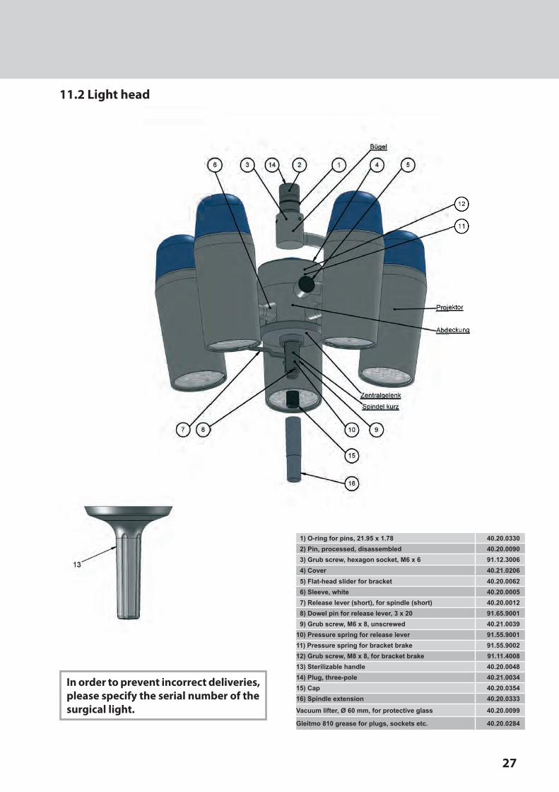
11.2 Light head
In order to prevent incorrect deliveries,please specify the serial number of thesurgical light.
1) O-ring for pins, 21.95 x 1.78 40.20.03302) Pin, processed, disassembled 40.20.00903) Grub screw, hexagon socket, M6 x 6 91.12.30064) Cover 40.21.02065) Flat-head slider for bracket 40.20.00626) Sleeve, white 40.20.00057) Release lever (short), for spindle (short) 40.20.00128) Dowel pin for release lever, 3 x 20 91.65.90019) Grub screw, M6 x 8, unscrewed 40.21.0039
10) Pressure spring for release lever 91.55.900111) Pressure spring for bracket brake 91.55.900212) Grub screw, M8 x 8, for bracket brake 91.11.400813) Sterilizable handle 40.20.004814) Plug, three-pole 40.21.003415) Cap 40.20.035416) Spindle extension 40.20.0333
Vacuum lifter, Ø 60 mm, for protective glass 40.20.0099
Gleitmo 810 grease for plugs, sockets etc. 40.20.0284

28
11.3 Ceiling system „Multi“
5
34
1
2
21
5
1
3
2
14
12
19
9
2
1
3
522
135
26 (6x)
24
2325 (6x)
2
2916/17/
15
6
28
27
18
32
26
26
33
30
1011
137 8
32
32
26
33
33
31
360 96
200
34
Hochdorf / SchweizMedizintechnikADMECO AG
1:115.04.10CAD/StS
40-20-0428_A
BaldachinOP-Leuchte
Maßstab
/We
re
se
rve
all r
igh
ts in
co
nn
ectio
n w
ith
th
is d
ocu
me
nt.
Für
die
ses D
okum
ent behalten w
ir u
ns a
lle R
echte
vor.
A4
Änderu
ngen
Änderu
ngen
Blatt-Nr.Anzahl Blatt
Ersatz für
Gesehen
Geprüft
Gezeichnet
..
H)G)F)E)
D)C)B)A)StS, 05.07.12
Änderungen im Sinne des technischen Fortschrittes vorbehalten
Projekt / Komponente
Bezeichnung
1) Casing on boom, grey/white 40.20.04032) Washer, Ø 48/32 x 0.5 40.20.02243) Rondelle circlips ø39/32 x 0.5 40.20.02254) Washer with external tab, Ø 39/32 x 1 40.20.02265) V-circlip, d = 32 94.61.90056) Cover for angle adjustment, grey/white 40.20.02277) Cover for spring adjustment, grey/white 40.21.01678) Raised countersunk head screw, M4 x 8 90.90.90199) Sliding flange, grey/white 40.20.0229
10) Oval-head screw with Phillips head, M4 x 10 90.90.901711) Lock washer, M4 91.61.900112) Deflection leaf spring, white 40.20.023013) Nose segment 40.20.023114) Round plate, Ø 35 mm, matt silver 40.20.008915) Stand tube, Ø 95/80 mm, grey/white 40.21.004816) “Multi 2” adapter, assembled, grey/white 40.21.022117) “Multi 3” adapter, assembled, grey/white 40.21.021418) “Multi 4” adapter, assembled, grey/white 40.21.021519) Spring arm, 4.5 – 7.5 kg, grey/white 40.20.0396
21) Boom, 2000 V, grey/white, L=750 m, NL 40.20.046422) Boom, 2000 S, grey/white, L=750 m, NL 40.20.039723) Ceiling flange, Ø 320 mm, six-hole, grey/white 40.20.004324) Ceiling anchor ring, Ø 330 mm, assembled, M12, g/w 40.21.009525) Hexagon screws, M8 x 20 90.10.402026) Grub screws, M8 x 12, with base 91.13.401227) Plug 40.20.011828) Socket 40.20.011729) Cap, white 40.20.006730) Socket, three-pole 40.21.016131) Socket, three-pole 40.90.002932) Plug, three-pole 40.90.001533) Holder, W 40.20.042534) Baldachin 40.20.0428Power Supply Unit, APS 40.20.0557Dimmer APS 40.20.0558Gleitmo 810 grease for plugs, sockets etc. 40.20.0284

11.4 Wall bearing
5
1
3
2119
22
2
20
5
1
3
2
17
14
15 912
131110
5
1
3
2119
22
2
20
18
4
5
1
3
2
14
15 912
137 8 11106
67 8
26 26
26 26 33
32
32 32
23 25
24
17) Boom, 2000 S, grey/white, L=750 m, NL 40.20.039718) Boom, 2000 V, grey/white, L=750 m, NL 40.20.046419) Wall bearing, assembled, grey/white 40.21.008920) Wall bearing cover, grey/white 40.20.011421) Wall bearing panel, grey/white 40.20.011522) Cap for wall bearing cover, grey/white 40.20.011623) Socket, three-pole 40.90.000424) Socket, three-pole 40.90.002925) Plug, three-pole 40.90.001526) Holder, W 40.20.0425Power supply unit, EL 40.20.0519
Gleitmo 810 grease for plugs, sockets etc. 40.20.0284
1) Casing on boom, grey/white 40.20.04032) Washer, Ø 48/32 x 0.5 40.20.02243) Rondelle circlips ø39/32 x 0.5 40.20.02254) Washer with external tab, Ø 39/32 x 1 40.20.02265) V-circlip, d = 32 94.61.90056) Cover for angle adjustment, grey/white 40.20.02277) Cover for spring adjustment, grey/white 40.21.01678) Raised countersunk head screw, M4 x 8 90.90.90199) Sliding flange, grey/white 40.20.0229
10) Oval-head screw with Phillips head, M4 x 10 90.90.901711) Lock washer, M4 91.61.900112) Deflection leaf spring, white 40.20.023013) Nose segment 40.20.023114) Round plate, Ø 35 mm, matt silver 40.20.008915) Spring arm, 4.5 – 7.5 kg, grey/white 40.20.0396
30
ADMECO AGTurbistrasse17CH-6281HochdorfSchweiz
phone 0041419147030fax 0041419106119email [email protected]
web www.admeco.ch