Catálogo General - LUX IMPORT
187
1
-
Upload
khangminh22 -
Category
Documents
-
view
1 -
download
0
Transcript of Catálogo General - LUX IMPORT

1


General CatalogueCatálogo General
2016

“This catalogue replaces the previous ones. Data into this catalogue are subject to change without prior notice for the purpose of improvement or discontinued products. We kindly request you to ask
placing an order.
website”.
www.elt.es “El presente catálogo anula y sustituye los anteriores. Los datos de este catálogo están sujeto a cambios sin previo aviso por cuestiones de mejora o de descatalogación de producto. Les rogamos se aseguren de utilizar la documentación más actualizada y revisar sus contenidos en el momento de realizar pedidos.En nuestra página Web puede encontrar una versiónactualizada de nuestros productos”
www.elt.es

GENERAL INDEXÍNDICE GENERAL
eBLUE enabled devicesDispositivos con tecnología eBLUE 7
GENERAL INFORMATIONAdditional information for all rangesINFORMACIÓN GENERALInformación complementaria de todas las gamas 159
GuaranteeGarantía
169
PackagingEmpaquetado
171
Sales networkRed comercial
177
Product indexÍndice de producto
181
Control gears and LED modules/stripsEquipos de alimentación y modulos/tiras LED 19
AccessoriesAccesorios 119


5www.elt.es
Introducción
ELT – Especialidades Luminotécnicas S.A.U. is a
Spanish company placed in Zaragoza which offers design,
manufacturing and commercialization of power supplies and
wireless solutions for lighting management within lighting
professional industry and street lighting.
Strongly focused on internationalization, ELT offers
technical solutions to more than a hundred countries, owning
a commercial office in Czech Republic and logistic facilities in
Lyon, where ELT FRANCE and ELT ITALY subsidiaries are
attended from.
A�er more than 40-year experience in lighting industry,
ELT keeps on investing in innovation and development in
order to offer efficient solutions providing maximum comfort in
lighting environments.
As a consequence, R&D facilities have been enlarged and a
new development division has been founded: Smart Systems.
These novelties allow ELT to keep on creating its own added
value and securing its competitiveness.
Its portfolio, very well-known and recognized in Africa,
America, Europe and Middle East Asia consists of the following
product ranges:
~ Wireless solutions for indoor and outdoor lighting control.
~ LED constant current drivers and modules.
~ LED constant voltage drivers and strips.
~ Electronic and conventional ballasts for fluorescent and HID
lamps (HPS, MH and MV).
~ Electronic and conventional transformers for halogen
lamps.
Purposing to improve customer service, and following other
editions policy, 2016 General Catalogue has been divided in
two volumes: one for eBLUE and LED technology and other for
FLUO, HID and HALO.
The LED catalogue brings together all up-to-now available
ELT solutions and includes the following novelties:
~ eBLUE Technology. DLCM-E-BT Drivers. Bluetooth
dimmable drivers for constant current LED modules.
~ eLED Modules. Street Lighting ranges and new models for
indoor lighting applications.
~ iLC Drivers. Programmable drivers for constant current LED
modules up to 75W, IP20 for Street Lighting applications.
~ DLCM Drivers. DALI dimmable drivers for constant current
LED modules, including a selector for fixing up to 5 different
currents.
~ DLC Driver. 1…10V dimmable driver for constant current
LED modules up to 400W, IP67.
~ Accesories. ITP and ODP protection equipment, also new
ranges of controllers and aluminium profiles for constant
voltage applications.
For further information about product development and
novelties see the following URL:
http://www.elt.es/novedades/i-novedades.html.
The following charts for information search are included in
this catalogue:
~ Most suitable drivers for eLED LINE modules (Page 77).
~ Product packaging belonging to each product in catalogue
(Page 171).
~ Alphabetical order product index (Page 181).
ELT - Especialidades Luminotécnicas S.A.U. es una
empresa española con sede en Zaragoza que ofrece diseño,
fabricación y comercialización de equipos de alimentación y
soluciones inalámbricas para la gestión de la iluminación en el
sector profesional de la iluminación y el alumbrado.
Con un marcado enfoque a la internacionalización, ELT
ofrece soluciones a más de 100 países, contando con una
oficina comercial en República Checa y un almacén logístico en
Lyon, desde donde se atiende a las filiales ELT FRANCE y ELT ITALIA.
Tras más de 40 años de experiencia en el sector, ELT
sigue realizando una fuerte apuesta por la innovación y el
desarrollo para ofrecer soluciones eficientes que proporcionen
el máximo confort en materia de iluminación.
Fruto de lo anterior, se han ampliado las instalaciones
dedicadas a I+D y se ha creado una nueva división de desarrollo:
Sistemas Inteligentes. Todo esto permite a ELT seguir
creando valor añadido propio y afianzar su competitividad.
Su porfolio, muy reconocido en África, América, Europa y
Oriente Medio, está formado por las siguientes familias:
~ Soluciones inalámbricas para el control de la iluminación
interior y exterior.
~ Fuentes de alimentación y módulos LED de corriente cons-
tante.
~ Fuentes de alimentación y tiras LED de tensión constante.
~ Balastos electrónicos y reactancias electromagnéticas para
lámparas fluorescentes y de alta intensidad de descarga
(VSAP, HM y VM).
~ Transformadores electrónicos y electromagnéticos para
lámparas halógenas.
Con el objetivo de mejorar el servicio a los clientes, y al igual
que en ediciones anteriores, el catálogo general 2016 se en-
cuentra dividido en dos tomos: uno para tecnología eBLUE y
LED y otro para FLUO, HID y HALO.
Este catálogo LED reúne todas las soluciones de ELT
disponibles hasta la fecha e incluye las siguientes novedades:
~ Tecnología eBLUE. Drivers DLCM-E-BT. Equipos Bluetooth
regulables para módulos LED de corriente constante.
~ Módulos eLED. Gama para alumbrado público y nuevos
modelos para aplicaciones de iluminación interior.
~ Drivers iLC. Equipos programables de alimentación de
corriente constante para módulos LED hasta 75W IP20 para
aplicaciones de alumbrado público.
~ Drivers DLCM. Equipos regulables DALI de corriente
constante para módulos LED. Incorpora selector para fijar
hasta 5 corrientes diferentes.
~ Driver DLC. Equipo regulable 1… 10V de alimentación de
corriente constante para módulos LED hasta 400W. IP67.
~ Accesorios. Equipos de protección ITP y ODP para equipos
de alumbrado público y una nueva gama de controladores
y perfiles de aluminio para aplicaciones de iluminación con
equipos de alimentación de tensión constante.
Para obtener más información sobre desarrollos de producto
y novedades consultar la siguiente URL:
http://www.elt.es/novedades/novedades.html.
Este catálogo incorpora las siguientes tablas para facilitar la
búsqueda de información:
~ Fuentes de alimentación más adecuadas para los módulos
de la gama eLED LINE (Pág. 77).
~ Embalaje correspondiente a cada artículo del catálogo (Pág.
171).
~ Índice de artículos por orden alfabético (Pág. 181).
Introduction


8 www.elt.es
eBLUE INDEXÍNDICE eBLUE
eBLUE ENABLED DEVICES DISPOSITIVOS CON TECNOLOGÍA eBLUE
Bluetooth smart wireless control device for lightingcontrol gears Dispositivo inteligente de control inalámbrico Bluetooth para fuentes auxiliares de iluminación ........................ 9
Bluetooth smart wireless trailing edge dimmerRegulador trailing edge inteligente de control inalámbrico Bluetooth .................................... 10
Bluetooth dimmable constant current control gears for LED modules up to 50W. IP20Equipos Bluetooth regulables de alimentación de corriente constante para módulos de LED hasta 50W. IP20 ........................................................ 11
Bluetooth dimmable constant current control gears for LED modules up to 50W. Protection class II and independent use. IP20Equipos Bluetooth regulables de alimentación de corriente constante para módulos de LED hasta 50W. Clase II y uso independiente. IP20 ............................ 12
eBLUE TECHNICAL INFORMATION INFORMACIÓN TÉCNICA SOBRE eBLUE..13
9www.elt.es
eBLUE 0-10V/DALI220-240V
50Hz
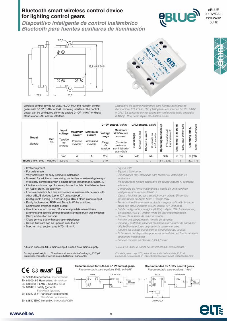
Bluetooth smart wireless control device for lighting control gears Dispositivo inteligente de control inalámbrico Bluetooth para fuentes auxiliares de iluminación
EN 55015 Interferences / InterferenciasEN 61000-3-2 Harmonics / ArmónicosEN 61000-3-3 EMC Emission / CEMEN 61347-1 Safety (general)
Seguridad (general)EN 61347-2-11 Particular requirements
Requisitos particularesEN 61547 EMC Immunity / Inmunidad CEM
N
N
L
L
NN
LL
0-10V / DALI
CONTROL GEAReBLUE
LEDMODULES
N
N
L
L
NN
LL
1-10V
CONTROL GEAReBLUE
LEDMODULES
EXTERNAL RELAY
~ IP20 equipment.~ For built-in use.~ Very small size for easy luminaire installation.~ No need for additional new wiring, controllers or external gateways.~ Wirelessly controllable with a smart device (smartphone, tablet...).~ Intuitive and visual app for smartphones / tablets. Available for free
on Apple Store / Google Play.~ Forms automatically a fast and secure wireless mesh network with
other eBLUE devices (up to 127 units/network).
~ Easily implemented RGB and Tunable White solutions.~ Controllable switched mains output.~ Use timers to turn on and off scene at predetermined times.~ Dimming and scenes control through standard on/off wall switches
(SwS) and motion sensors.~ Cloud service that enhances user experience.
~ Max. terminal section area 0,75-1,5 mm2.
* Just in case eBLUE’s mains output is used as a mains supply.
Packaging and weight p. 171 and www.elt.es/productos/packaging_ELT.pdfInstructions manual on www.elt.es/productos/inst_manual.html
~ Equipo IP20.~ Equipo a incorporar.~ Dimensiones muy reducidas para facilitar su instalación en
luminarias.~ No se necesita ningún dispositivo de enlace externo ni cableado
adicional.~ Controlable de forma inalámbrica a través de un dispositivo
inteligente (smartphone, tablet...).~ Visual e intuitiva app para smartphones / tablets. Disponible
gratuitamente en Apple Store / Google Play.~ Forma automáticamente una rápida y segura red inalámbrica de
malla con otras unidades eBLUE (hasta 127 unid./red).
~ Soluciones RGB y Tunable White de fácil implementación.~ Control de la salida de red conmutable.~ Permite una programación horaria de escenas.~ Dimado y control de escenas mediante interruptores de pared on/
off (SwS) y detectores de presencia convencionales.~ Servicio en la nube que mejora la experiencia del usuario.
de manera inalámbrica.2.
*Sólo si se utiliza la salida de red del eBLUE directamente.
Embalaje y peso pág. 171 y www.elt.es/productos/embalaje_ELT.pdfManual de instrucciones en www.elt.es/productos/manual_instrucciones.html
Model
Modelo
Ref. No.
Input voltage
Tensión de
entrada
Maximum power*
Potencia máxima*
Maximum current
Intensidad máxima
0-10V output / salida DALI output / salida
Op
erat
ing
fre
qu
enci
es
Fre
cuen
cias
de
func
iona
mie
nto
Max
. tem
p. a
t tc
po
int
Tem
p. m
áx. e
nvol
vent
e
Op
erat
ing
tem
p.
Tem
p. fu
ncio
nam
ient
o
Voltage range
Rango de
tensión
Maximum sink/source
current
Corriente máxima
suministrada/ absorbida
Bu
s vo
ltag
e
Ten
sión
de
bus
Sh
orc
ut
curr
ent
Cor
rient
e en
co
rtoc
ircui
toVac W A Vdc mA Vdc mA GHz tc (°C) ta (°C)
eBLUE 0-10V / DALI 9953070 220-240 100 1,2 0-10 7 12 7 2,4… 2,483 70 -20… +70
Ø 3,5
35,822,3
42,4 49,5 56,5
Wireless control device for LED, FLUO, HID and halogen control gears with 0-10V, 1-10V or DALI dimming interface. The control
stand-alone DALI control interface.
Dispositivo de control inalámbrico para fuentes auxiliares de
Recommended for DALI or 0-10V control gearsRecomendado para equipos DALI o 0-10V
Recommended for 1-10V control gearsRecomendado para equipos 1-10V
10 www.elt.es
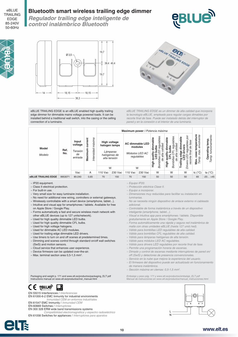
Bluetooth smart wireless trailing edge dimmerRegulador trailing edge inteligente de control inalámbrico Bluetooth
eBLUETRAILING
EDGE85-240V50-60Hz
L N N
NL
~ IP20 equipment.~ Class II electrical protection.~ For built-in use.~ Very small size for easy luminaire installation.~ No need for additional new wiring, controllers or external gateways.~ Wirelessly controllable with a smart device (smartphone, tablet...).~ Intuitive and visual app for smartphones / tablets. Available for free
on Apple Store / Google Play.~ Forms automatically a fast and secure wireless mesh network with
other eBLUE devices (up to 127 units/network).~ Used for high quality dimmable LED bulbs.~ Used for high quality dimmable CFL bulbs.~ Used for high voltage halogens.~ Used for dimmable AC LED modules.~ Used for trailing edge dimmable LED drivers.~ Use timers to turn on and off scenes at predetermined times.~ Dimming and scenes control through standard on/off wall switches
(SwS) and motion sensors.~ Cloud service that enhances user experience.
~ Max. terminal section area 0,5-1,5 mm2.
Packaging and weight p. 171 and www.elt.es/productos/packaging_ELT.pdfInstructions manual on www.elt.es/productos/inst_manual.html
~ Equipo IP20.~ Protección eléctrica Clase II.~ Equipo a incorporar.~ Dimensiones muy reducidas para facilitar su instalación en
luminarias.~ No se necesita ningún dispositivo de enlace externo ni cableado
adicional.~ Controlable de forma inalámbrica a través de un dispositivo
inteligente (smartphone, tablet...).~ Visual e intuitiva app para smartphones / tablets. Disponible
gratuitamente en Apple Store / Google Play.~ Forma automáticamente una rápida y segura red inalámbrica de
malla con otras unidades eBLUE (hasta 127 unid./red).~ Válido para bombillas LED regulables de alta calidad.~ Válido para bombillas CFL regulables de alta calidad.~ Válido para lámparas halógenas de alta tensión.~ Válido para módulos LED AC regulables.
~ Permite una programación horaria de escenas.~ Dimado y control de escenas mediante interruptores de pared on/
off (SwS) y detectores de presencia convencionales.~ Servicio en la nube que mejora la experiencia del usuario.
de manera inalámbrica.2.
Embalaje y peso pág. 171 y www.elt.es/productos/embalaje_ELT.pdfManual de instrucciones en www.elt.es/productos/manual_instrucciones.html
Model
Modelo
Ref. No.
Input voltage
Tensión de
entrada
Max
imu
m c
urr
ent
Inte
nsid
ad m
áxim
a
Maximum power I Potencia máxima
Max
. cas
e te
mp
erat
ure
Tem
p. m
áx. e
nvol
vent
e
Op
erat
ing
tem
p.
Tem
p. fu
ncio
nam
ient
o
High voltage halogen lamps
Lámparas halógenas de alta tensión
AC dimmable LED modules
Módulos LED AC regulables
Hig
h q
ual
ity
dim
mab
le
LE
D b
ulb
s B
ombi
llas
LED
reg
ulab
les
de
alta
cal
idad
Hig
h q
ual
ity
dim
mab
le
CF
L b
ulb
sB
ombi
llas
CF
L re
gula
bles
de
alta
cal
idad
Tra
ilin
g e
dg
e d
imm
able
L
ED
dri
vers
Driv
ers
LED
reg
ulab
les
por
W W
Vac A 110 Vac 230 Vac 110 Vac 230 Vac W W W tc (°C) ta (°C)
eBLUE TRAILING EDGE 9953071 85-240 0,65 70 150 70 150 50 50 50 65 -20… +45
Ø 3,5
18,15 18,15
36,3
14
19,7
19,7
39,4 40,4
eBLUE TRAILING EDGE is an eBLUE enabled high quality trailing edge dimmer for dimmable mains voltage powered loads. It can be installed behind a traditional wall switch, into the casing or the celling connection of a luminaire.
eBLUE TRAILING EDGE es un dimmer de alta calidad que incorpora la tecnología eBLUE, empleado para regular cargas dimables por
pared y en la conexión o el interior de una luminaria.
EN 55015 Interferences / InterferenciasEN 61000-6-2 EMC Inmunity for industrial environments
Inmunidad CEM en entornos industrialesEN 61547 EMC Immunity / Inmunidad CEMEN-60669 Switches / InterruptoresEN 300 328 ERM wide band transmissions systems
Compatibilidad electromagnética y espectro radioeléctrico EN 61058 Switches for appliances / Interruptores para aparatos

11www.elt.es
DLCM-E-BT220-240V50-60Hz
~ IP20 equipment. ~ Driver for built-in use. Class I. ~ Maximum length of secondary wires: 2 m.~ 5 output selectable currents through dip-switch. ~ No need for additional new wiring, controllers or external gateways.~ Wirelessly controllable with a smart device (smartphone, tablet…).
App available for free on Apple Store / Google Play.~ Forms automatically a fast and secure wireless mesh network with
other eBLUE devices (up to 127 units/network).~ Dimming and scenes control through standard on/off wall switches
(SwS) and motion sensors.~ Cloud service that enhances user experience.
~ Regulation range 3...100%.~ PWM output dimming.~ Output ripple current <5%.~ Low stand-by power consumption <0,8W. ~ Low Total Harmonic Distortion (THD) at maximum power: <10%. ~ High power factor. ~ Dynamic thermal protection. ~ Protection against short circuit, overload and no load operation.~ Permitted input voltage AC/DC: 198-264V.
2. ~ Nominal lifetime at max. ta allowed: 50.000h (with a failure rate
max. 0,2% per 1000h).
(1) Except 9918391
Packaging and weight p. 171 and www.elt.es/productos/packaging_ELT.pdfInstructions manual on www.elt.es/productos/inst_manual.html
~ Equipo IP20. ~ Equipo a incorporar. Clase I.~ Longitud máxima de los cables del secundario: 2 m.~ 5 corrientes de salida seleccionables con microswitch.~ No se necesita ningún dispositivo de enlace externo ni cableado
adicional.~ Controlable de forma inalámbrica a través de un dispositivo
inteligente (smartphone, tablet…). App gratuita disponible en Apple Store/Google Play.
~ Forma automáticamente una rápida y segura red inalámbrica de malla con otras unidades eBLUE (hasta 127 unid./red).
~ Dimado y control de escenas mediante interruptores de pared on/off (SwS) y detectores de presencia convencionales.
~ Servicio en la nube que mejora la experiencia de usuario.
de manera inalámbrica.~ Rango de regulación de 3… 100%.~ Regulación a la salida por PWM.~ Rizado de corriente de salida <5%.
~ Bajo factor de distorsión armónica (THD) a máxima carga: <10%. ~ Alto factor de potencia. ~ Protección térmica dinámica. ~ Protección contra cortocircuito, sobrecarga y circuito abierto.
2.
~ Vida útil a máxima ta permitida: 50.000h (tasa de fallo max. 0,2% por 1000h).
Embalaje y peso pág. 171 y www.elt.es/productos/embalaje_ELT.pdfManual de instrucciones en www.elt.es/productos/manual_instrucciones.html
Bluetooth dimmable constant current control gears for LED modules up to 50W. IP20Equipos Bluetooth regulables de alimentación de corriente constante para módulos de LED hasta 50W. IP20
EN-61347-2-13 Safety / SeguridadEN-62384 Perfomance / FuncionamientoEN-61000-3-2 Harmonics / ArmónicosEN-61000-3-3 EMC Emission / CEMEN-55015 Interferences / InterferenciasEN-61547 EMC Immunity / Inmunidad CEM
Model
ModeloRef. No.
Output currents
Corrientes de salida
Output voltage range
Rango de tensión de
salida
Power factor
Factor de potencia
Sys
tem
Ren
dim
ient
o de
l sis
tem
a
Op
erat
ing
fr
equ
enci
es
Fre
cuen
cias
de
func
iona
mie
nto
Max
.tem
p.
at t
c p
oin
t
Tem
p.m
áx.
envo
lven
te
Op
erat
ing
te
mp
.
Tem
p.
func
iona
mie
nto
mA Vdc (%) GHz tc (°C) ta (°C)
DLCM 50/250…350-E-BT 9918391 250 275 300 325 350 75… 143 0,98 89 2,4… 2,483 75 -20...+50
DLCM 50/400…500-E-BT 9918392 400 425 450 475 500 57… 100 0,97 88 2,4… 2,483 75 -20...+50
DLCM 50/600…700-E-BT 9918393 600 625 650 675 700 40… 72 0,97 87 2,4… 2,483 80 -20...+45
63
29,5
69
108
Ø 4,2
92,5
1001 1
DLCM ...-E-BT
1ONED 3
24
NL
LEDMODULESPWM Output Dimming OR %ORC < 5
For other currents consult our commercial department / Para otras corrientes consultar con el departamento comercial

12 www.elt.es
DLCM-E- C2-BT
220-240V50-60Hz
~ IP20 equipment for independent use. Class II control gear.~ Maximum length of secondary wires: 5 m.~ 5 output selectable currents through dip-switch. ~ No need for additional new wiring, controllers or external gateways.~ Wirelessly controllable with a smart device (smartphone, tablet…).
App available for free on Apple Store / Google Play.~ Forms automatically a fast and secure wireless mesh network with
other eBLUE devices (up to 127 units/network).~ Dimming and scenes control through standard on/off wall switches
(SwS) and motion sensors.~ Cloud service that enhances user experience.
~ Regulation range 3...100%.~ PWM output dimming.~ Output ripple current <5%.~ Low stand-by power consumption <0,8W. ~ Low Total Harmonic Distortion (THD) at maximum power: <10%. ~ High power factor. ~ Dynamic thermal protection. ~ Protection against short circuit, overload and no load operation.~ Permitted input voltage AC/DC: 198-264V.
2. ~ Nominal lifetime at max. ta allowed: 50.000h (with a failure rate
max. 0,2% per 1000h).
(1) Except 9918401
Packaging and weight p. 171 and www.elt.es/productos/packaging_ELT.pdfInstructions manual on www.elt.es/productos/inst_manual.html
~ Equipo para uso independiente IP20. Equipo Clase II.~ Longitud máxima de los cables del secundario: 5 m.~ 5 corrientes de salida seleccionables con microswitch.~ No se necesita ningún dispositivo de enlace externo ni cableado
adicional.~ Controlable de forma inalámbrica a través de un dispositivo
inteligente (smartphone, tablet…). App gratuita disponible en Apple Store/Google Play.
~ Forma automáticamente una rápida y segura red inalámbrica de malla con otras unidades eBLUE (hasta 127 unid./red).
~ Dimado y control de escenas mediante interruptores de pared on/off (SwS) y detectores de presencia convencionales.
~ Servicio en la nube que mejora la experiencia de usuario.
de manera inalámbrica.~ Rango de regulación de 3… 100%.~ Regulación a la salida por PWM.~ Rizado de corriente de salida <5%.
~ Bajo factor de distorsión armónica (THD) a máxima carga: <10%. ~ Alto factor de potencia. ~ Protección térmica dinámica. ~ Protección contra cortocircuito, sobrecarga y circuito abierto.
2.
~ Vida útil a máxima ta permitida: 50.000h (tasa de fallo max. 0,2% por 1000h).
Embalaje y peso pág. 171 y www.elt.es/productos/embalaje_ELT.pdfManual de instrucciones en www.elt.es/productos/manual_instrucciones.html
Bluetooth dimmable constant current control gears for LED modules up to 50W. Protection class II and independent use. IP20Equipos Bluetooth regulables de alimentación de corriente constante para módulos de LED hasta 50W. Clase II y uso independiente. IP20
EN-61347-2-13 Safety / SeguridadEN-62384 Perfomance / FuncionamientoEN-61000-3-2 Harmonics / ArmónicosEN-61000-3-3 EMC Emission / CEMEN-55015 Interferences / InterferenciasEN-61547 EMC Immunity / Inmunidad CEM
Model
ModeloRef. No.
Output currents
Corrientes de salida
Output voltage range
Rango de tensión de
salida
Power factor
Factor de potencia
Sys
tem
Ren
dim
ient
o de
l sis
tem
a
Op
erat
ing
fr
equ
enci
es
Fre
cuen
cias
de
func
iona
mie
nto
Max
.tem
p.
at t
c p
oin
t
Tem
p.m
áx.
envo
lven
te
Op
erat
ing
te
mp
.
Tem
p.
func
iona
mie
nto
mA Vdc (%) GHz tc (°C) ta (°C)
DLCM 50/250…350-E-C2-BT 9918401 250 275 300 325 350 75… 143 0,98 89 2,4… 2,483 75 -20...+50
DLCM 50/400…500-E-C2-BT 9918402 400 425 450 475 500 57… 100 0,97 88 2,4… 2,483 75 -20...+50
DLCM 50/600…700-E-C2-BT 9918403 600 625 650 675 700 40… 72 0,97 87 2,4… 2,483 80 -20...+45
Ø 4
32
70,2
170,5
153,5
160,5 24,5
PWM Output Dimming OR %ORC < 5
1001 1
DLCM ...-E-C2-BT
1ONED 3
24
NL
LEDMODULES
For other currents consult our commercial department / Para otras corrientes consultar con el departamento comercial
13www.elt.es
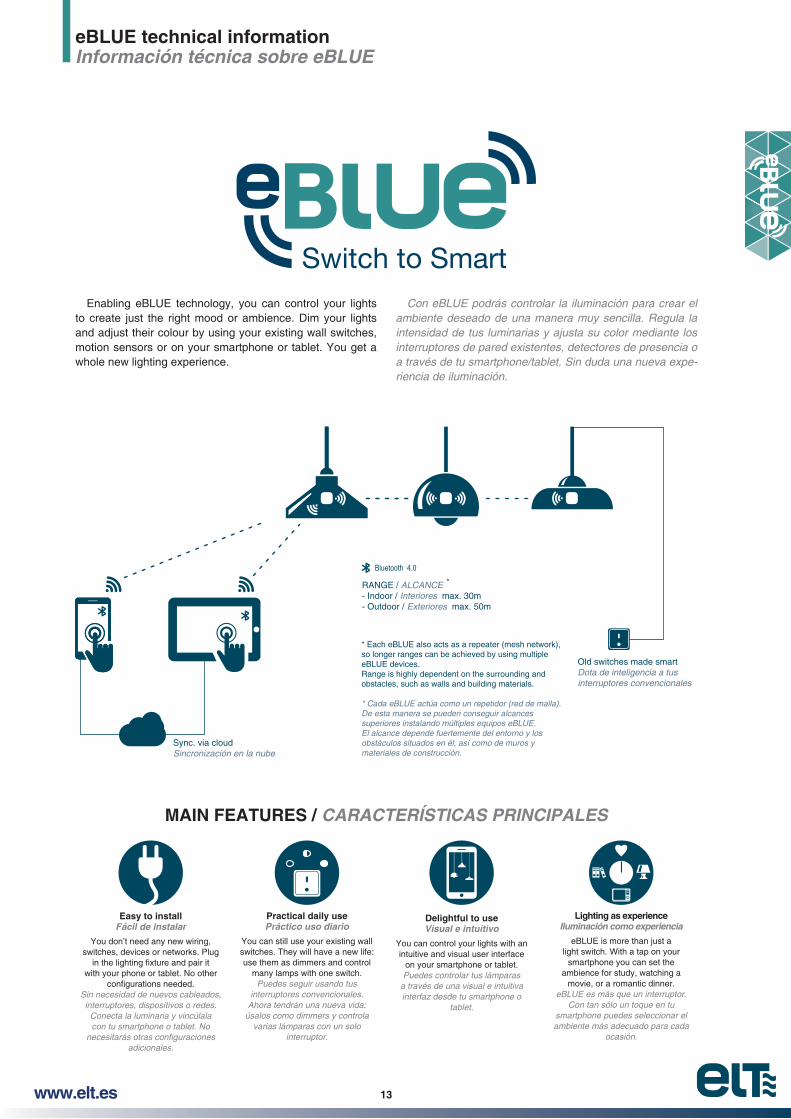
Bluetooth 4.0
Sync. via cloudSincronización en la nube
Old switches made smartDota de inteligencia a tusinterruptores convencionales
RANGE / ALCANCE - Indoor / Interiores max. 30m- Outdoor / Exteriores max. 50m
*
* Each eBLUE also acts as a repeater (mesh network), so longer ranges can be achieved by using multiple eBLUE devices.Range is highly dependent on the surrounding andobstacles, such as walls and building materials.
* Cada eBLUE actúa como un repetidor (red de malla). De esta manera se pueden conseguir alcances superiores instalando múltiples equipos eBLUE.El alcance depende fuertemente del entorno y los obstáculos situados en él, así como de muros y materiales de construcción.
Switch to SmartEnabling eBLUE technology, you can control your lights
to create just the right mood or ambience. Dim your lights and adjust their colour by using your existing wall switches, motion sensors or on your smartphone or tablet. You get a whole new lighting experience.
Con eBLUE podrás controlar la iluminación para crear el ambiente deseado de una manera muy sencilla. Regula la intensidad de tus luminarias y ajusta su color mediante los interruptores de pared existentes, detectores de presencia o a través de tu smartphone/tablet. Sin duda una nueva experiencia de iluminación.
MAIN FEATURES / CARACTERÍSTICAS PRINCIPALES
Practical daily use Práctico uso diario
You can still use your existing wall switches. They will have a new life: use them as dimmers and control
many lamps with one switch. Puedes seguir usando tus
interruptores convencionales. Ahora tendrán una nueva vida:
úsalos como dimmers y controla varias lámparas con un solo
interruptor.
Easy to install Fácil de instalar
You don’t need any new wiring, switches, devices or networks. Plug
with your phone or tablet. No other
Sin necesidad de nuevos cableados, interruptores, dispositivos o redes.
Conecta la luminaria y vincúlala con tu smartphone o tablet. No
adicionales.
Lighting as experience Iluminación como experiencia
eBLUE is more than just a light switch. With a tap on your
smartphone you can set the ambience for study, watching a
movie, or a romantic dinner.eBLUE es más que un interruptor.
Con tan sólo un toque en tu smartphone puedes seleccionar el ambiente más adecuado para cada
ocasión.
Delightful to use Visual e intuitivo
You can control your lights with an intuitive and visual user interface
on your smartphone or tablet.Puedes controlar tus lámparas
a través de una visual e intuitiva interfaz desde tu smartphone o
tablet.
eBLUE technical informationInformación técnica sobre eBLUE

14 www.elt.es
DOWNLOAD THE FREE APP
Search `Casambi´ or just scan below QR code:
Compatible devices
iPhone 4S or later.iPad 3 or later.iPod Touch 5 th gen or later.Android 4.4 KitKat or later devices produced after 2013 with full BT 4.0 support.
USER INTERFACE
eBLUE is the easiest and most natural way to control your lights:
With the app you can control all eBLUE enabled lighting
With one tap you are ready to control all your lights.
DESCARGA LA APP GRATUITA
Busca `Casambi´ o simplemente escanea el siguiente código QR:
Dispositivos compatibles:
iPhone 4S o posteriores.iPad 3 o posteriores. iPod Touch 5ª generación o posteriores.Android 4.4 KitKat o dispositivos fabricados después del
INTERFAZ DE USUARIO
eBLUE es la forma más sencilla y natural de controlar tus lámparas:
A través de la app podrás controlar todas las luminarias habilitadas con la tecnología eBLUE. La puesta en marcha se realiza de forma fácil e intuitiva. Simplemente con una pulsación estarás preparado para controlar toda tu iluminación.

15www.elt.es
Controlling all your lamps from one view:
one view. It is possible to control your lights individually or as a group. For example you can create a group of your kitchen,
tap. Or you can dim the living room lights to pleasant light level for a movie.
Control your lights from a photo:
The Gallery in app is the most natural way of controlling your lights. Take a picture of your room(s) and place the lamp
Controla todas tus lámparas a través de la misma interfaz:
Con la app podrás controlar todas tus lámparas desde la misma pantalla. Es posible controlarlas individualmente o por grupos. Por ejemplo, puedes crear un grupo con las lám
ellas con una única pulsación. También puedes regular las
ver una película.
Controla tus lámparas desde una fotografía:
La Galería en la app es la forma más natural de controlar tu iluminación. Toma una fotografía de tu(s) estancia(s) y coloca los controles de lámpara sobre ellas en la fotografía. Ahora puedes controlar tus lámparas visualmente desde la propia fotografía.

16 www.elt.es
Create scenes for different lighting situations:
You can create different scenes for different occasions.
promotions and save the settings in a scene. Now you can change the lighting with one tap for different occasions for example a party or a meeting with a customer.
Share your network and allow other devices to control your lights:
eBLUE has four different levels for sharing and access control. You can decide if your network is open to everyone or if other users need a password to access your network. If you have several users and devices using the same network, all changes made with one device will be automatically up-dated to the other devices with cloud service.
Crea escenas para distintas situaciones:
Puedes crear varias escenas para diferentes ocasiones. Establece la iluminación adecuada para una cena, entornos
ración en una escena. Ahora puedes cambiar la iluminación con una única pulsación para adecuarla a diferentes situa
Comparte tu red y permite a otros dispositivos controlar tus lámparas:
eBLUE tiene cuatro niveles diferentes para compartir y controlar el acceso a tu red. Puedes decidir si tu red se encuentra abierta a todo el mundo o si se necesita una contraseña para acceder a ella. En caso de que varios usuarios/dispositivos estén utilizando la misma red, todos los cambios realizados por uno de ellos se actualizarán automáticamente en los demás dispositivos a través del servidor en la nube.

17www.elt.es
ADITTIONAL FEATURES
~ Cloud service that enhances user experience.
~
~ Support for scene animations.
~ Support for Apple Watch.
~ Support for remote gateway.
~ Support for iBeacon.
~ Support for timmers allowing switching scenes ON or OFF based on date, weekdays, hour/minute or sunrise/sunset event switching.
DIMMING WITHOUT APP
1.- Turn lights on from wall switch.
2.-(max. 1sec.). The light level starts to increase gradua-lly.
3.-level is saved automatically.
4.- -sity reaches its maximum level.
CUSTOMIZE YOUR PRODUCT
CARACTERÍSTICAS ADICIONALES
~ Servicio en la nube que mejora la experiencia de usuario.
funcionamiento de manera inalámbrica.
~ Soporte para animaciones de escenas.
~ Soporte para Apple Watch.
~ Soporte para acceso remoto (gateway).
~ Soporte para iBeacon.
~ Soporte para programación horaria de escenas en función de una fecha concreta, días de la semana, una hora determinada o en base al amanecer/atardecer.
REGULACIÓN SIN LA APP
1.- Enciende las lámparas desde el interruptor.
2.-terruptor (máx. 1 seg.). El nivel de luz empezará a aumentar gradualmente.
3.-nivel de luz deseado. El nivel seleccionado se quedará guardado automáticamente.
4.- Si el segundo apagado y encendido rápido no se ha realizado en 15 seg., la intensidad de la luz alcanzará su nivel máximo.
PERSONALIZA TU PRODUCTO
eBLUE de acuerdo a los mismos.
1 2 3 4
t
18 www.elt.es
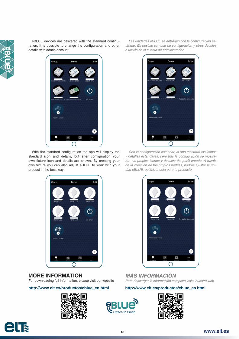
http://www.elt.es/productos/eblue_en.html
Switch to Smart
http://www.elt.es/productos/eblue_es.html
-
details with admin account.
product in the best way.
MORE INFORMATION For downloading full information, please visit our website
a través de la cuenta de administrador.
dad eBLUE, optimizándola para tu producto.
MÁS INFORMACIÓN Para descargar la información completa visita nuestra web

www.elt.es20
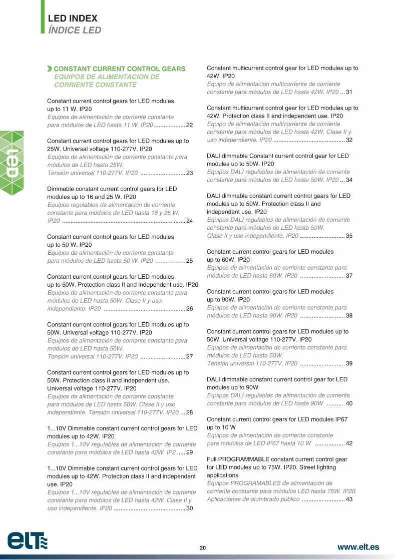
LED INDEXÍNDICE LED
CONSTANT CURRENT CONTROL GEARS EQUIPOS DE ALIMENTACION DE CORRIENTE CONSTANTE
Constant current control gears for LED modulesup to 11 W. IP20Equipos de alimentación de corriente constantepara módulos de LED hasta 11 W. IP20 ................... 22
Constant current control gears for LED modules up to 25W. Universal voltage 110-277V. IP20Equipos de alimentación de corriente constante para módulos de LED hasta 25W.
........................... 23
Dimmable constant current control gears for LED modules up to 16 and 25 W. IP20Equipos regulables de alimentación de corriente
IP20 .......................................................................... 24
Constant current control gears for LED modulesup to 50 W. IP20Equipos de alimentación de corriente constantepara módulos de LED hasta 50 W. IP20 .................. 25
Constant current control gears for LED modulesup to 50W. Protection class II and independent use. IP20Equipos de alimentación de corriente constante paramódulos de LED hasta 50W. Clase II y usoindependiente. IP20 ................................................. 26
Constant current control gears for LED modules up to 50W. Universal voltage 110-277V. IP20Equipos de alimentación de corriente constante para módulos de LED hasta 50W.
........................... 27
Constant current control gears for LED modules up to 50W. Protection class II and independent use. Universal voltage 110-277V. IP20 Equipos de alimentación de corriente constante para módulos de LED hasta 50W. Clase II y uso
... 28
1...10V Dimmable constant current control gears for LED modules up to 42W. IP20Equipos 1...10V regulables de alimentación de corriente
..... 29
1...10V Dimmable constant current control gears for LED modules up to 42W. Protection class II and independent use. IP20Equipos 1...10V regulables de alimentación de corriente
uso independiente. IP20 ........................................... 30
Constant multicurrent control gear for LED modules up to 42W. IP20Equipo de alimentación multicorriente de corriente
... 31
Constant multicurrent control gear for LED modules up to 42W. Protection class II and independent use. IP20Equipo de alimentación multicorriente de corriente
uso independiente. IP20 ........................................... 32
DALI dimmable Constant current control gear for LED modules up to 50W. IP20Equipos DALI regulables de alimentación de corrienteconstante para módulos de LED hasta 50W. IP20 ... 34
DALI dimmable constant current control gears for LED modules up to 50W. Protection class II and independent use. IP20Equipos DALI regulables de alimentación de corriente constante para módulos de LED hasta 50W. Clase II y uso independiente. IP20 ........................... 35
Constant current control gears for LED modulesup to 60W. IP20Equipos de alimentación de corriente constante para
........................... 37
Constant current control gears for LED modulesup to 90W. IP20Equipos de alimentación de corriente constante paramódulos de LED hasta 90W. IP20 ........................... 38
Constant current control gears for LED modules up to 50W. Universal voltage 110-277V. IP20Equipos de alimentación de corriente constante para módulos de LED hasta 50W.
........................... 39
DALI dimmable constant current control gear for LED modules up to 90WEquipos DALI regulables de alimentación de corrienteconstante para módulos de LED hasta 90W ........... 40
Constant current control gears for LED modules IP67up to 10 WEquipos de alimentación de corriente constante
.................. 42
Full PROGRAMMABLE constant current control gear for LED modules up to 75W. IP20. Street lighting applicationsEquipos PROGRAMABLES de alimentación de corriente constante para módulos LED hasta 75W. IP20. Aplicaciones de alumbrado público .......................... 43
www.elt.es 21
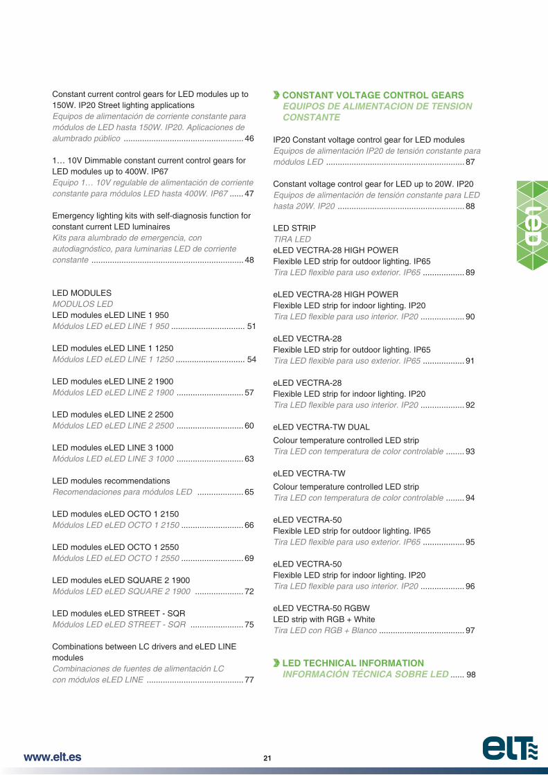
Constant current control gears for LED modules up to 150W. IP20 Street lighting applicationsEquipos de alimentación de corriente constante para módulos de LED hasta 150W. IP20. Aplicaciones de alumbrado público .................................................... 46
1… 10V Dimmable constant current control gears for LED modules up to 400W. IP67Equipo 1… 10V regulable de alimentación de corriente
...... 47
Emergency lighting kits with self-diagnosis function for constant current LED luminairesKits para alumbrado de emergencia, con autodiagnóstico, para luminarias LED de corriente constante .................................................................. 48
LED MODULESMODULOS LEDLED modules eLED LINE 1 950Módulos LED eLED LINE 1 950 ................................ 51
LED modules eLED LINE 1 1250Módulos LED eLED LINE 1 1250 .............................. 54
LED modules eLED LINE 2 1900Módulos LED eLED LINE 2 1900 ............................. 57
LED modules eLED LINE 2 2500Módulos LED eLED LINE 2 2500 ............................. 60
LED modules eLED LINE 3 1000Módulos LED eLED LINE 3 1000 ............................. 63
LED modules recommendationsRecomendaciones para módulos LED .................... 65
LED modules eLED OCTO 1 2150Módulos LED eLED OCTO 1 2150 ........................... 66
LED modules eLED OCTO 1 2550Módulos LED eLED OCTO 1 2550 ........................... 69
LED modules eLED SQUARE 2 1900Módulos LED eLED SQUARE 2 1900 ..................... 72
LED modules eLED STREET - SQR ....................... 75
Combinations between LC drivers and eLED LINEmodulesCombinaciones de fuentes de alimentación LCcon módulos eLED LINE .......................................... 77
CONSTANT VOLTAGE CONTROL GEARS EQUIPOS DE ALIMENTACION DE TENSION CONSTANTE
IP20 Constant voltage control gear for LED modulesEquipos de alimentación IP20 de tensión constante paramódulos LED ............................................................ 87
Constant voltage control gear for LED up to 20W. IP20Equipos de alimentación de tensión constante para LED hasta 20W. IP20 ....................................................... 88
LED STRIPTIRA LEDeLED VECTRA-28 HIGH POWERFlexible LED strip for outdoor lighting. IP65
.................. 89
eLED VECTRA-28 HIGH POWERFlexible LED strip for indoor lighting. IP20
................... 90
eLED VECTRA-28Flexible LED strip for outdoor lighting. IP65
.................. 91
eLED VECTRA-28Flexible LED strip for indoor lighting. IP20
................... 92
eLED VECTRA-TW DUAL
Colour temperature controlled LED stripTira LED con temperatura de color controlable ........ 93
eLED VECTRA-TW
Colour temperature controlled LED stripTira LED con temperatura de color controlable ........ 94
eLED VECTRA-50Flexible LED strip for outdoor lighting. IP65
.................. 95
eLED VECTRA-50Flexible LED strip for indoor lighting. IP20
................... 96
eLED VECTRA-50 RGBWLED strip with RGB + WhiteTira LED con RGB + Blanco ..................................... 97
LED TECHNICAL INFORMATION INFORMACIÓN TÉCNICA SOBRE LED ...... 98

www.elt.es22
Constant current control gears for LED modules up to 11W. IP20Equipos de alimentación de corriente constante para módulos de LED hasta 11W. IP20
LC-B DLC-B220-240V
DC/AC 50-60Hz
EN-61347-2-13 Safety / SeguridadEN-62384 Perfomance / FuncionamientoEN-61000-3-2 Harmonics / ArmónicosEN-61000-3-3 EMC Emission / CEMEN-55015 Interferences / InterferenciasEN-61547 EMC Immunity / Inmunidad CEM
Dimmer
LC-B DLC-B
14
37 80
66
21
~ IP20 equipment.~ Class II electrical protection.~ Indoor use.~ Equipped with terminal cover and wire clamps system.~ Maximum length of secondary wires: 5 m.~ Suitable for installation on wooden surfaces.~ High power factor.~ Overload protection.~ Short circuit protection.~ Protection against no load operation.~ Withstands 2 hours at 350V (AC). ~ Permitted input voltage AC/DC: 198-264V.~ Allowed dimmers for DLC models:
Trailing-edge and leading-edge dimming.Dimming 5% - 100%.
~ Nominal lifetime at max. ta allowed: 50.000h (with a failure rate max.0,2% per 1000h).
Packaging and weight p. 171 and www.elt.es/productos/packaging_ELT.pdf
Instructions manual on www.elt.es/productos/inst_manual.htmlRecommended dimmers list on: http://www.elt.es/productos/pdf/703000000.pdf
~ Equipos IP20.~ Protección eléctrica Clase II. ~ Uso interior.
~ Longitud máxima de los cables del secundario: 5 m.~ Aptos para montaje sobre madera.~ Alto factor de potencia.~ Protección contra sobrecarga.~ Protección contra cortocircuitos.~ Protección en circuito abierto.~ Soporta 2 horas a 350V (AC).
~ Tipo de regulador que admite los modelos DLC:
~ Vida útil a máxima ta permitida: 50.000h (tasa de fallo max. 0,2% por 1000h).
Embalaje y peso pág. 171 y www.elt.es/productos/embalaje_ELT.pdfSelección de producto pág. 77 y www.elt.es/productos/buscador_producto.htmlManual de instrucciones en www.elt.es/productos/manual_instrucciones.htmlLista de reguladores recomendados en: http://www.elt.es/productos/pdf/703000000.pdf
Model
Modelo
Ref. No.
Output power range
Rango de potencia en módulo
Output current
Corriente de salida
Output voltage range
Rango de tensión de salida
Power factor
Factor de potencia
System
Rendimiento del sistema
Max.temp. at tc point
Temp.máx. envolvente
Operating temp.
Temp. funcionamiento
Ap
pro
vals
Hom
olog
acio
nes
W mA Vdc (%) tc (°C) ta (°C)
LC 110/350-B 9918021 3... 10 350 9... 31 0,97 80 75 -25... +50
LC 110/500-B 9918022 4... 10,5 500 9... 21 0,97 80 80 -25... +50
LC 110/700-B 9918023 4... 10 700 6... 16 0,98 80 75 -25... +50
STANDARD CONTROL GEARS / EQUIPOS ESTANDAR
01
01
01
LC
DLC 108/200-B 9918035 4... 8 200 20... 39 0,94 80 80 -25... +50
DLC 111/300-B 9918036 7... 11 300 25... 38 0,96 80 85 -25... +50
DLC 110/350-B 9918031 3... 10 350 9... 31 0,97 80 85 -25... +50
DLC 110/500-B 9918032 4... 10,5 500 9... 21 0,97 80 85 -25... +50
DLC 110/700-B 9918033 4... 10 700 6... 16 0,98 80 80 -25... +50
DIMMABLE CONTROL GEARS / EQUIPOS REGULABLES
01
01
01
01
01
For other currents consult our commercial department / Para otras corrientes consultar con el departamento comercial
01

www.elt.es 23
Constant current control gears for LED modules up to 25W. Universal voltage 110-277V. IP20Equipos de alimentación de corriente constante para módulos de LED hasta 25W. Tensión universal 110-277V. IP20
LC-A-UN110-277V
DC/AC 50-60Hz
LEDMODULES
EN-61347-2-13 Safety / SeguridadEN-62384 Perfomance / FuncionamientoEN-61000-3-2 Harmonics / ArmónicosEN-61000-3-3 EMC Emission / CEMEN-55015 Interferences / InterferenciasEN-61547 EMC Immunity / Inmunidad CEM
~ IP20 equipment.~ Class II electrical protection. ~ Indoor use. ~ Equipped with terminal cover and cable clamps. ~ Clamping screws on primary and secondary circuits for cables with
diameter: 3 mm to 8 mm. ~ Max. terminal section area 2,5 mm². (secondary circuit). ~ Maximum length of secondary wires: 5 m. ~ Suitable for installation on wooden surfaces. ~ High power factor. ~ Thermal protection. ~ Overload protection.~ Short circuit protection~ Protection against no load operation. ~ Permitted input voltage AC/DC: 99-305V.~ Nominal lifetime at max. ta allowed: 50.000h (with a failure rate
max.0,2% per 1000h).
Packaging and weight p. 171 and www.elt.es/productos/packaging_ELT.pdf
Instructions manual on www.elt.es/productos/inst_manual.html
~ Equipos IP20.~ Protección eléctrica Clase II. ~ Uso interiores.
~ Cierra cables primario y secundario para conductores entre 3 y
~ Sección máxima en clemas del secundario: 2,5 mm². ~ Longitud máxima de los cables del secundario: 5 m. ~ Aptos para montaje sobre madera. ~ Alto factor de potencia. ~ Protección térmica. ~ Protección contra sobrecarga. ~ Protección contra cortocircuitos. ~ Protección en circuito abierto.
~ Vida útil a máxima ta permitida: 50.000h (tasa de fallo max. 0,2% por 1000h).
Embalaje y peso pág. 171 y www.elt.es/productos/embalaje_ELT.pdfSelección de producto pág. 77 y www.elt.es/productos/buscador_producto.htmlManual de instrucciones en www.elt.es/productos/manual_instrucciones.html
Model
Modelo
Ref. No.
Output power range
Rango de potencia en
módulo
Output current
Corriente de salida
Output voltage range
Rango de tensión de salida
Power factor
Factor de potencia
System
Rendimiento del sistema
Max.temp. at tc point
Temp.máx. envolvente
Operating temp.
Temp. funcionamiento
W mA Vdc (%) tc (°C) ta (°C)110V 230V
LC 125/350-A-UN 9918261 8... 25 350 23... 72 0,99 0,94 >85 80 -20...+50
LC 125/500-A-UN 9918262 8... 25 500 16... 50 0,99 0,94 >85 75 -20...+50
LC 125/700-A-UN 9918263 8,5… 25 700 12... 36 0,99 0,94 >85 80 -20...+50
38
29
3,6
131122
For other currents consult our commercial department / Para otras corrientes consultar con el departamento comercial

www.elt.es24
Dimmable constant current control gears for LED modules up to 16 and 25 W. IP20Equipos regulables de alimentación de corriente constante para módulos de LED hasta 16 y 25 W. IP20
DLC-A220-240V50-60Hz
EN-61347-2-13 Safety / SeguridadEN-62384 Perfomance / FuncionamientoEN-61000-3-2 Harmonics / ArmónicosEN-61000-3-3 EMC Emission / CEMEN-55015 Interferences / InterferenciasEN-61547 EMC Immunity / Inmunidad CEM
Dimmer
DLC-A
~ IP20 equipment.~ Class II electrical protection. ~ Indoor use. ~ Equipped with terminal cover and cable clamps. ~ Clamping screws on primary and secondary circuits for wires with
diameter: 3 mm to 8 mm. ~ Max. terminal section area 2,5 mm². (secondary circuit). ~ Maximum length of secondary wires: 5 m. ~ Suitable for installation on wooden surfaces. ~ High power factor. ~ Overload protection.~ Short circuit protection~ Protection against no load operation. ~ Permitted input voltage AC/DC: 198-264V.~ Allowed dimmers for DLC models:
Trailing-edge and leading-edge dimming.Dimming 5% - 100%.
~ Nominal lifetime at max. ta allowed: 50.000h (with a failure rate max.0,2% per 1000h).
Packaging and weight p. 171 and www.elt.es/productos/packaging_ELT.pdf
Instructions manual on www.elt.es/productos/inst_manual.htmlRecommended dimmers list on: http://www.elt.es/productos/pdf/703000000.pdf
~ Equipos IP20.~ Protección eléctrica Clase II. ~ Uso interiores.
~ Cierra cables primario y secundario para conductores entre 3 y
~ Sección máxima en clemas del secundario: 2,5 mm². ~ Longitud máxima de los cables del secundario: 5 m. ~ Aptos para montaje sobre madera. ~ Alto factor de potencia. ~ Protección contra sobrecarga. ~ Protección contra cortocircuitos. ~ Protección en circuito abierto.
~ Tipo de regulador que admite los modelos DLC:
~ Vida útil a máxima ta permitida: 50.000h (tasa de fallo max. 0,2% por 1000h).
Embalaje y peso pág. 171 y www.elt.es/productos/embalaje_ELT.pdfSelección de producto pág. 77 y www.elt.es/productos/buscador_producto.htmlManual de instrucciones en www.elt.es/productos/manual_instrucciones.htmlLista de reguladores recomendados en: http://www.elt.es/productos/pdf/703000000.pdf
Model
Modelo
Ref. No.
Output power range
Rango de potencia en módulo
Output current
Corriente de salida
Output voltage range
Rango de tensión de salida
Power factor
Factor de potencia
System
Rendimiento del sistema
Max.temp. at tc point
Temp.máx. envolvente
Operating temp.
Temp. funcionamiento
Ap
pro
vals
Hom
olog
acio
nes
W mA Vdc (%) tc (°C) ta (°C)
DLC 116/350-A 9918232 10… 16 350 29… 46 0,85 85 75 -25… +50
DLC 116/500-A 9918233 10… 16 500 20... 32 0,85 85 85 -25… +50
DLC 116/700-A 9918236 10… 16 700 14... 23 0,85 85 75 -25… +50
DLC 125/350-A 9918252 16… 25 350 45… 72 0,93 85 75 -25… +50
DLC 125/500-A 9918253 16… 25 500 32… 50 0,94 85 85 -25… +50
DLC 125/700-A 9918256 16… 25 700 23... 37 0,91 85 80 -25… +50
01
01
01
01
01
01
38
29
3,6
131122
LC
For other currents consult our commercial department / Para otras corrientes consultar con el departamento comercial
01

www.elt.es 25
Constant current control gears for LED modules up to 50W. IP20Equipos de alimentación de corriente constante para módulos de LED hasta 50W. IP20
LC-E220-240V
DC/AC 50-60Hz
N L
63
29,5
69
108
Ø 4,2
92,5
EN-61347-2-13 Safety / SeguridadEN-62384 Perfomance / FuncionamientoEN-61000-3-2 Harmonics / ArmónicosEN-61000-3-3 EMC Emission / CEMEN-55015 Interferences / InterferenciasEN-61547 EMC Immunity / Inmunidad CEM
~ IP20 equipment.~ Driver for built-in use. Class I.~ Maximum length of secondary wires: 2 m.~ High power factor.~ Thermal protection.~ Overload protection.~ Short circuit protection.~ Protection against no load operation.~ Withstands 2 hours at 350V (AC).~ Permitted input voltage AC/DC 198-264V.
Conductor size 0,5-1,5 mm2.~ Drivers connection in series.~ Nominal lifetime at max. ta allowed: 50.000h (with a failure rate
max. 0,2% per 1000h).~ Output ripple current <4%.~ THD <10%.
(1) Except LC 148/1050-E.
Packaging and weight p. 171 and www.elt.es/productos/packaging_ELT.pdf
Instructions manual on www.elt.es/productos/inst_manual.html
~ Equipos IP20.~ Equipo a incorporar. Clase I~ Longitud máxima de los cables del secundario: 2 m.~ Alto factor de potencia.~ Protección térmica.~ Protección contra sobrecarga~ Protección contra cortocircuitos.~ Protección en circuito abierto.~ Soporta 2 horas a 350V (AC).
2..
~ Conexión de equipos en serie.~ Vida útil a máxima ta permitida: 50.000h (tasa de fallo max. 0,2%
por 1000h).
~ THD <10%.
Embalaje y peso pág. 171 y www.elt.es/productos/embalaje_ELT.pdf Selección de producto pág. 77 y www.elt.es/productos/buscador_producto.htmlManual de instrucciones en www.elt.es/productos/manual_instrucciones.html
Model
Modelo
Ref. No.
Output power range
Rango de potencia en
módulo
Output current
Corriente de salida
Output voltage range
Rango de tensión de salida
Power factor
Factor de potencia
System
Rendimiento del sistema
Max.temp. at tc point
Temp.máx. envolvente
Operating temp.
Temp. funcionamiento
Ap
pro
vals
Hom
olog
acio
nes
W mA Vdc (%) tc (°C) ta (°C)
LC 150/700-E 9918173 24… 50 700 34… 72 0,98 89 75 -20… +50
LC 148/1050-E 9918174 23... 48 1050 22… 46 0,98 87 75 -20… +50
01
01
STANDARD CONTROL GEARS / EQUIPOS ESTANDAR
1001 1ORC < 4%
For other currents consult our commercial department / Para otras corrientes consultar con el departamento comercial
01
www.elt.es26
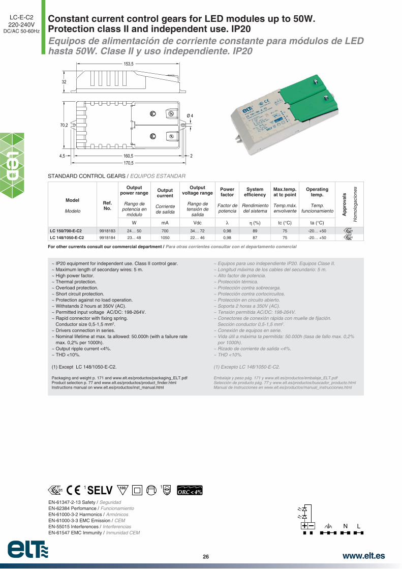
Constant current control gears for LED modules up to 50W.Protection class II and independent use. IP20Equipos de alimentación de corriente constante para módulos de LED hasta 50W. Clase II y uso independiente. IP20
LC-E-C2220-240V
DC/AC 50-60Hz
EN-61347-2-13 Safety / SeguridadEN-62384 Perfomance / FuncionamientoEN-61000-3-2 Harmonics / ArmónicosEN-61000-3-3 EMC Emission / CEMEN-55015 Interferences / InterferenciasEN-61547 EMC Immunity / Inmunidad CEM
Ø 4
32
70,2
170,5
153,5
160,5 24,5
N L
~ IP20 equipment for independent use. Class II control gear.~ Maximum length of secondary wires: 5 m.~ High power factor.~ Thermal protection.~ Overload protection.~ Short circuit protection.~ Protection against no load operation.~ Withstands 2 hours at 350V (AC).~ Permitted input voltage AC/DC: 198-264V.
Conductor size 0,5-1,5 mm2.~ Drivers connection in series.~ Nominal lifetime at max. ta allowed: 50.000h (with a failure rate
max. 0,2% per 1000h).~ Output ripple current <4%.~ THD <10%.
(1) Except LC 148/1050-E-C2.
Packaging and weight p. 171 and www.elt.es/productos/packaging_ELT.pdf
Instructions manual on www.elt.es/productos/inst_manual.html
~ Equipos para uso independiente IP20. Equipos Clase II.~ Longitud máxima de los cables del secundario: 5 m.~ Alto factor de potencia.~ Protección térmica.~ Protección contra sobrecarga.~ Protección contra cortocircuitos.~ Protección en circuito abierto.~ Soporta 2 horas a 350V (AC).
2..
~ Conexión de equipos en serie.~ Vida útil a máxima ta permitida: 50.000h (tasa de fallo max. 0,2%
por 1000h).
~ THD <10%.
Embalaje y peso pág. 171 y www.elt.es/productos/embalaje_ELT.pdfSelección de producto pág. 77 y www.elt.es/productos/buscador_producto.htmlManual de instrucciones en www.elt.es/productos/manual_instrucciones.html
Model
Modelo
Ref. No.
Output power range
Rango de potencia en
módulo
Output current
Corriente de salida
Output voltage range
Rango de tensión de
salida
Power factor
Factor de potencia
System
Rendimiento del sistema
Max.temp. at tc point
Temp.máx. envolvente
Operating temp.
Temp. funcionamiento
Ap
pro
vals
Hom
olog
acio
nes
W mA Vdc (%) tc (°C) ta (°C)
LC 150/700-E-C2 9918183 24… 50 700 34… 72 0,98 89 75 -20… +50
LC 148/1050-E-C2 9918184 23... 48 1050 22… 46 0,98 87 75 -20… +50
01
01
STANDARD CONTROL GEARS / EQUIPOS ESTANDAR
100ORC < 4%
11
For other currents consult our commercial department / Para otras corrientes consultar con el departamento comercial
01
www.elt.es 27
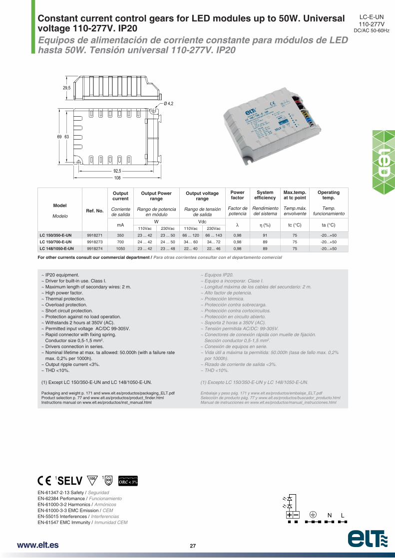
Constant current control gears for LED modules up to 50W. Universal voltage 110-277V. IP20 Equipos de alimentación de corriente constante para módulos de LED hasta 50W. Tensión universal 110-277V. IP20
LC-E-UN110-277V
DC/AC 50-60Hz
N L
63
29,5
69
108
Ø 4,2
92,5
EN-61347-2-13 Safety / SeguridadEN-62384 Perfomance / FuncionamientoEN-61000-3-2 Harmonics / ArmónicosEN-61000-3-3 EMC Emission / CEMEN-55015 Interferences / InterferenciasEN-61547 EMC Immunity / Inmunidad CEM
~ IP20 equipment.~ Driver for built-in use. Class I.~ Maximum length of secondary wires: 2 m.~ High power factor.~ Thermal protection.~ Overload protection.~ Short circuit protection.~ Protection against no load operation.~ Withstands 2 hours at 350V (AC).~ Permitted input voltage AC/DC 99-305V.
Conductor size 0,5-1,5 mm2.~ Drivers connection in series.~ Nominal lifetime at max. ta allowed: 50.000h (with a failure rate
max. 0,2% per 1000h).~ Output ripple current <3%.~ THD <10%.
(1) Except LC 150/350-E-UN and LC 148/1050-E-UN.
Packaging and weight p. 171 and www.elt.es/productos/packaging_ELT.pdf
Instructions manual on www.elt.es/productos/inst_manual.html
~ Equipos IP20.~ Equipo a incorporar. Clase I.~ Longitud máxima de los cables del secundario: 2 m.~ Alto factor de potencia.~ Protección térmica.~ Protección contra sobrecarga.~ Protección contra cortocircuitos.~ Protección en circuito abierto.~ Soporta 2 horas a 350V (AC).
2..
~ Conexión de equipos en serie.~ Vida útil a máxima ta permitida: 50.000h (tasa de fallo max. 0,2%
por 1000h).~ Rizado de corriente de salida <3%.~ THD <10%.
Embalaje y peso pág. 171 y www.elt.es/productos/embalaje_ELT.pdf Selección de producto pág. 77 y www.elt.es/productos/buscador_producto.htmlManual de instrucciones en www.elt.es/productos/manual_instrucciones.html
Model
ModeloRef. No.
Output current
Corriente de salida
Output Powerrange
Rango de potencia en módulo
Output voltage range
Rango de tensión de salida
Power factor
Factor de potencia
System
Rendimiento del sistema
Max.temp. at tc point
Temp.máx. envolvente
Operating temp.
Temp. funcionamiento
mAW Vdc
(%) tc (°C) ta (°C)110Vac 230Vac 110Vac 230Vac
LC 150/350-E-UN 9918271 350 23 ... 42 23 ... 50 66 ... 120 66 ... 143 0,98 91 75 -20...+50
LC 150/700-E-UN 9918273 700 24 ... 42 24 ... 50 34… 60 34... 72 0,98 89 75 -20...+50
LC 148/1050-E-UN 9918274 1050 23 ... 42 23 ... 48 22... 40 22... 46 0,98 89 75 -20...+50
1001 1ORC < 3%
For other currents consult our commercial department / Para otras corrientes consultar con el departamento comercial
www.elt.es28
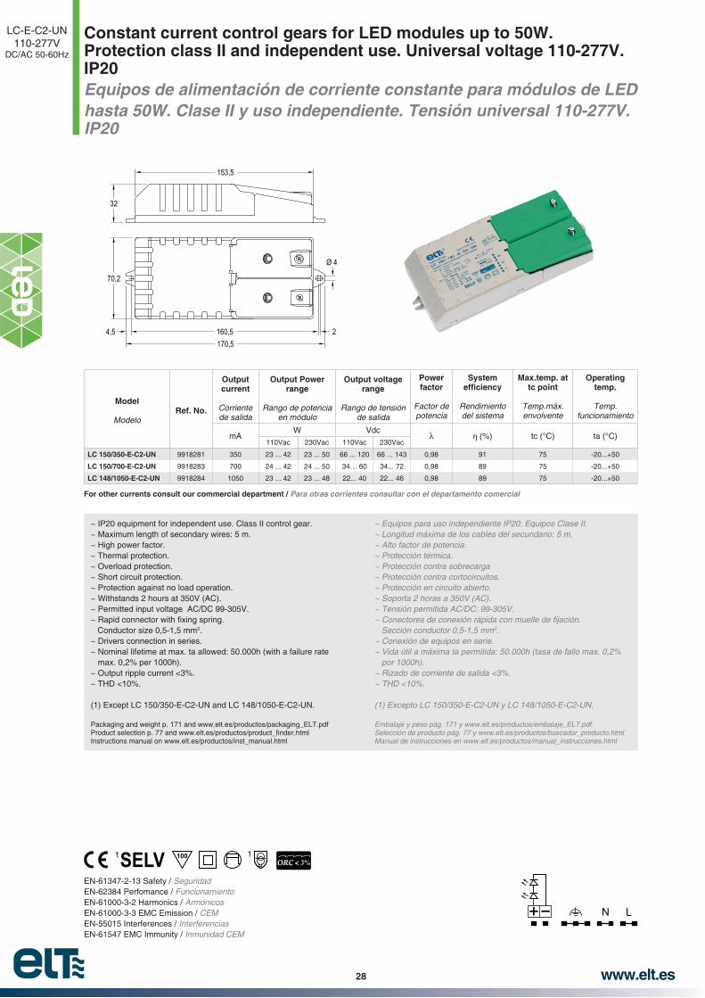
Constant current control gears for LED modules up to 50W. Protection class II and independent use. Universal voltage 110-277V. IP20 Equipos de alimentación de corriente constante para módulos de LEDhasta 50W. Clase II y uso independiente. Tensión universal 110-277V. IP20
LC-E-C2-UN110-277V
DC/AC 50-60Hz
EN-61347-2-13 Safety / SeguridadEN-62384 Perfomance / FuncionamientoEN-61000-3-2 Harmonics / ArmónicosEN-61000-3-3 EMC Emission / CEMEN-55015 Interferences / InterferenciasEN-61547 EMC Immunity / Inmunidad CEM
~ IP20 equipment for independent use. Class II control gear.~ Maximum length of secondary wires: 5 m.~ High power factor.~ Thermal protection.~ Overload protection.~ Short circuit protection.~ Protection against no load operation.~ Withstands 2 hours at 350V (AC).~ Permitted input voltage AC/DC 99-305V.
Conductor size 0,5-1,5 mm2.~ Drivers connection in series.~ Nominal lifetime at max. ta allowed: 50.000h (with a failure rate
max. 0,2% per 1000h).~ Output ripple current <3%.~ THD <10%.
(1) Except LC 150/350-E-C2-UN and LC 148/1050-E-C2-UN.
Packaging and weight p. 171 and www.elt.es/productos/packaging_ELT.pdf
Instructions manual on www.elt.es/productos/inst_manual.html
~ Equipos para uso independiente IP20. Equipos Clase II.~ Longitud máxima de los cables del secundario: 5 m.~ Alto factor de potencia.~ Protección térmica.~ Protección contra sobrecarga~ Protección contra cortocircuitos.~ Protección en circuito abierto.~ Soporta 2 horas a 350V (AC).
2..
~ Conexión de equipos en serie.~ Vida útil a máxima ta permitida: 50.000h (tasa de fallo max. 0,2%
por 1000h).~ Rizado de corriente de salida <3%.~ THD <10%.
Embalaje y peso pág. 171 y www.elt.es/productos/embalaje_ELT.pdf Selección de producto pág. 77 y www.elt.es/productos/buscador_producto.htmlManual de instrucciones en www.elt.es/productos/manual_instrucciones.html
Model
ModeloRef. No.
Output current
Corriente de salida
Output Powerrange
Rango de potencia en módulo
Output voltage range
Rango de tensión de salida
Power factor
Factor de potencia
System
Rendimiento del sistema
Max.temp. at tc point
Temp.máx. envolvente
Operating temp.
Temp. funcionamiento
mAW Vdc
(%) tc (°C) ta (°C)110Vac 230Vac 110Vac 230Vac
LC 150/350-E-C2-UN 9918281 350 23 ... 42 23 ... 50 66 ... 120 66 ... 143 0,98 91 75 -20...+50
LC 150/700-E-C2-UN 9918283 700 24 ... 42 24 ... 50 34… 60 34... 72 0,98 89 75 -20...+50
LC 148/1050-E-C2-UN 9918284 1050 23 ... 42 23 ... 48 22... 40 22... 46 0,98 89 75 -20...+50
Ø 4
32
70,2
170,5
153,5
160,5 24,5
N L
100 11ORC < 3%
For other currents consult our commercial department / Para otras corrientes consultar con el departamento comercial

www.elt.es 29
1...10V Dimmable constant current control gears for LED modules up to 42W. IP20Equipos 1...10V regulables de alimentación de corriente constante para módulos de LED hasta 42W. IP20
DLC-E1...10V
220-240VDC/AC 50-60Hz
N1...10V
L
63
29,5
69
108
Ø 4,2
92,5
EN-61347-2-13 Safety / SeguridadEN-62384 Perfomance / FuncionamientoEN-61000-3-2 Harmonics / ArmónicosEN-61000-3-3 EMC Emission / CEMEN-55015 Interferences / InterferenciasEN-61547 EMC Immunity / Inmunidad CEM
~ IP20 equipment. ~ Current regulation control through 1…10V signal.~ Regulation range: 10…100%.~ Driver for built-in use. Class I. ~ Maximum length of secondary wires: 2 m. ~ High power factor. ~ Thermal protection. ~ Overload protection. ~ Short circuit protection. ~ Protection against no load operation. ~ Withstands 2 hours at 350V (AC). ~ Permitted input voltage AC/DC 198-264V.
Conductor size 0,5-1,5 mm2.
~ Drivers connection in series. ~ Nominal lifetime at max. ta allowed: 50.000h (with a failure rate
max. 0,2% per 1000h). ~ Output ripple current <3%.~ THD <10%. ~ Available upon request with protection against surge pulses: 4kV
between phases.
(1) Except DLC 142/1050-E-1…10V
Packaging and weight p. 171 and www.elt.es/productos/packaging_ELT.pdfInstructions manual on www.elt.es/productos/inst_manual.html
~ Equipos IP20. ~ Control de regulación de corriente mediante señal 1…10V.~ Rango de regulación: 10…100%.~ Equipo a incorporar. Clase I.~ Longitud máxima de los cables del secundario: 2 m. ~ Alto factor de potencia. ~ Protección térmica. ~ Protección contra sobrecarga.~ Protección contra cortocircuitos. ~ Protección en circuito abierto. ~ Soporta 2 horas a 350V (AC).
2.
~ Conexión de equipos en serie. ~ Vida útil a máxima ta permitida: 50.000h (tasa de fallo max. 0,2%
por 1000h). ~ Rizado de corriente de salida <3%. ~ THD <10%. ~ Disponible bajo demanda con protección contra impulsos de
Embalaje y peso pág. 171 y www.elt.es/productos/embalaje_ELT.pdfManual de instrucciones en www.elt.es/productos/manual_instrucciones.html
Model
Modelo
Ref. No.
Output power range
Rango de potencia en
módulo
Output current
Corriente de salida
Output voltage range
Rango de tensión de salida
Power factor
Factor de potencia
System
Rendimiento del sistema
Max.temp. at tc point
Temp.máx. envolvente
Operating temp.
Temp. funcionamiento
Ap
pro
vals
Hom
olog
acio
nes
W mA Vdc (%) tc (°C) ta (°C)
DLC 142/700-E-1…10V 9918333 24…42 700 35…60 0,95 88 75 -20… +50
DLC 142/1050-E-1…10V 9918334 31…42 1050 29,5…40 0,97 88 75 -20… +50
01
01
100ORC < 3%
1 1
For other currents consult our commercial department / Para otras corrientes consultar con el departamento comercial
01

www.elt.es30
1...10V Dimmable constant current control gears for LED modules up to 42W. Protection class II and independent use. IP20Equipos 1...10V regulables de alimentación de corriente constante para módulos de LED hasta 42W. Clase II y uso independiente. IP20
DLC-E-C21...10V
220-240VDC/AC 50-60Hz
EN-61347-2-13 Safety / SeguridadEN-62384 Perfomance / FuncionamientoEN-61000-3-2 Harmonics / ArmónicosEN-61000-3-3 EMC Emission / CEMEN-55015 Interferences / InterferenciasEN-61547 EMC Immunity / Inmunidad CEM
Ø 4
32
70,2
170,5
153,5
160,5 24,5
N1...10V
L
Model
Modelo
Ref. No.
Output power range
Rango de potencia en
módulo
Output current
Corriente de salida
Output voltage range
Rango de tensión de salida
Power factor
Factor de potencia
System
Rendimiento del sistema
Max.temp. at tc point
Temp.máx. envolvente
Operating temp.
Temp. funcionamiento
Ap
pro
vals
Hom
olog
acio
nes
W mA Vdc (%) tc (°C) ta (°C)
DLC 142/700-E-C2-1…10V 9918343 24…42 700 35…60 0,95 88 75 -20… +50
DLC 142/1050-E-C2-1…10V 9918344 31…42 1050 29,5…40 0,97 88 75 -20… +50
01
01
~ IP20 equipment for independent use. Class II control gear.~ Current regulation control through 1…10V signal.~ Regulation range: 10…100%.~ Maximum length of secondary wires: 5 m.~ High power factor.~ Thermal protection.~ Overload protection.~ Short circuit protection.~ Protection against no load operation.~ Withstands 2 hours at 350V (AC).~ Permitted input voltage AC/DC: 198-264V.
Conductor size 0,5-1,5 mm2.~ Drivers connection in series.~ Nominal lifetime at max. ta allowed: 50.000h (with a failure rate
max. 0,2% per 1000h).~ Output ripple current <3%.~ THD <10%.~ Available upon request with protection against surge pulses: 4kV
between phases.
(1) Except DLC 142/1050-E-C2-1…10V
Packaging and weight p. 171 and www.elt.es/productos/packaging_ELT.pdfInstructions manual on www.elt.es/productos/inst_manual.html
~ Equipos para uso independiente IP20. Equipos Clase II.~ Control de regulación de corriente mediante señal 1…10V.~ Rango de regulación: 10…100%.~ Longitud máxima de los cables del secundario: 5 m.~ Alto factor de potencia.~ Protección térmica.~ Protección contra sobrecarga.~ Protección contra cortocircuitos.~ Protección en circuito abierto.~ Soporta 2 horas a 350V (AC).
2..
~ Conexión de equipos en serie.~ Vida útil a máxima ta permitida: 50.000h (tasa de fallo max. 0,2%
por 1000h).~ Rizado de corriente de salida <3%.~ THD <10%.~ Disponible bajo demanda con protección contra impulsos de
Embalaje y peso pág. 171 y www.elt.es/productos/embalaje_ELT.pdfManual de instrucciones en www.elt.es/productos/manual_instrucciones.html
100ORC < 3%
11
For other currents consult our commercial department / Para otras corrientes consultar con el departamento comercial
01

www.elt.es 31
Constant multicurrent control gear for LED modules up to 42W. IP20Equipo de alimentación multicorriente de corriente constante para módulos de LED hasta 42W. IP20
LCM-E220-240V
DC/AC 50-60Hz
N L13 24
63
29,5
69
108
Ø 4,2
92,5
EN-61347-2-13 Safety / SeguridadEN-62384 Perfomance / FuncionamientoEN-61000-3-2 Harmonics / ArmónicosEN-61000-3-3 EMC Emission / CEMEN-55015 Interferences / InterferenciasEN-61547 EMC Immunity / Inmunidad CEM
~ 16 output selectable currents through dip-switch. ~ IP20 equipment.~ Driver for built-in use. Class I.~ Maximum length of secondary wires: 2 m.~ High power factor.~ Thermal protection.~ Overload protection.~ Short circuit protection.~ Protection against no load operation.~ Withstands 2 hours at 350V (AC).~ Permitted input voltage AC/DC 198-264V.
Conductor size 0,5-1,5 mm2.~ Drivers connection in series.~ Nominal lifetime at max. ta allowed: 50.000h (with a failure rate
max. 0,2% per 1000h).~ Output ripple current <2%.~ Low THD.~ Available upon request with protection against surge pulses: 4kV
between phases.
* See more combinations on page 33
Packaging and weight p. 171 and www.elt.es/productos/packaging_ELT.pdfInstructions manual on www.elt.es/productos/inst_manual.html
~ Equipos IP20.~ Equipo a incorporar. Clase I~ Longitud máxima de los cables del secundario: 2 m.~ Alto factor de potencia.~ Protección térmica.~ Protección contra sobrecarga~ Protección contra cortocircuitos.~ Protección en circuito abierto.~ Soporta 2 horas a 350V (AC).
2..
~ Conexión de equipos en serie.~ Vida útil a máxima ta permitida: 50.000h (tasa de fallo max. 0,2%
por 1000h).~ Rizado de corriente de salida <2%.~ Bajo THD.~ Disponible bajo demanda con protección contra impulsos de
* Ver más combinaciones en la página 33
Embalaje y peso pág. 171 y www.elt.es/productos/embalaje_ELT.pdfManual de instrucciones en www.elt.es/productos/manual_instrucciones.html
Model
Modelo
Ref. No.
Output power range
Rango de potencia en
módulo
Output current
Corriente de salida
Output voltage range
Rango de tensión de
salida
Power factor
Factor de potencia
System
Rendimiento del sistema
Max
.tem
p. a
t tc
po
int
Tem
p.m
áx. e
nvol
vent
e
Op
erat
ing
tem
p.
Tem
p. fu
ncio
nam
ient
o
* Switch position
* Posición del interruptor
Ap
pro
vals
Hom
olog
acio
nes
W mA Vdc (%) tc (°C) ta (°C) 1 2 3 4
LCM 42/350…1050-E 9918311
15,5… 25 350 44… 72 0,92 87
75
-20… +50 0 0 0 0
16,5… 34 500 33… 68 0,94 87 -20… +50 1 0 0 0
21… 42 700 30… 60 0,95 88 -20… +50 1 1 0 0
27,3… 38 1050 26… 36 0,96 88 -20… +45 1 1 1 0
STANDARD CONTROL GEARS / EQUIPOS ESTANDAR
100ORC < 2%
01
01

www.elt.es32
Constant multicurrent control gear for LED modules up to 42W.Protection class II and independent use. IP20Equipo de alimentación multicorriente de corriente constante para módulos de LED hasta 42W. Clase II y uso independiente. IP20
LCM-E-C2220-240V
DC/AC 50-60Hz
EN-61347-2-13 Safety / SeguridadEN-62384 Perfomance / FuncionamientoEN-61000-3-2 Harmonics / ArmónicosEN-61000-3-3 EMC Emission / CEMEN-55015 Interferences / InterferenciasEN-61547 EMC Immunity / Inmunidad CEM
Ø 4
32
70,2
170,5
153,5
160,5 24,5
100ORC < 2%
~ 16 output selectable currents through dip-switch.~ IP20 equipment for independent use. Class II control gear.~ Maximum length of secondary wires: 5 m.~ High power factor.~ Thermal protection.~ Overload protection.~ Short circuit protection.~ Protection against no load operation.~ Withstands 2 hours at 350V (AC).~ Permitted input voltage AC/DC: 198-264V.
Conductor size 0,5-1,5 mm2.~ Drivers connection in series.~ Nominal lifetime at max. ta allowed: 50.000h (with a failure rate
max. 0,2% per 1000h).~ Output ripple current <2%.~ THD <10%.~ Available upon request with protection against surge pulses: 4kV
between phases.
* See more combinations on page 33
Packaging and weight p. 171 and www.elt.es/productos/packaging_ELT.pdfInstructions manual on www.elt.es/productos/inst_manual.html
~ Equipos para uso independiente IP20. Equipos Clase II.~ Longitud máxima de los cables del secundario: 5 m.~ Alto factor de potencia.~ Protección térmica.~ Protección contra sobrecarga.~ Protección contra cortocircuitos.~ Protección en circuito abierto.~ Soporta 2 horas a 350V (AC).
2..
~ Conexión de equipos en serie.~ Vida útil a máxima ta permitida: 50.000h (tasa de fallo max. 0,2%
por 1000h).~ Rizado de corriente de salida <2%.~ THD <10%.~ Disponible bajo demanda con protección contra impulsos de
* Ver más combinaciones en la pagina 33
Embalaje y peso pág. 171 y www.elt.es/productos/embalaje_ELT.pdfManual de instrucciones en www.elt.es/productos/manual_instrucciones.html
STANDARD CONTROL GEARS / EQUIPOS ESTANDAR
N L13 24
Model
Modelo
Ref. No.
Output power range
Rango de potencia en
módulo
Output current
Corriente de salida
Output voltage range
Rango de tensión de
salida
Power factor
Factor de potencia
System
Rendimiento del sistema
Max
.tem
p. a
t tc
po
int
Tem
p.m
áx. e
nvol
vent
e
Op
erat
ing
tem
p.
Tem
p. fu
ncio
nam
ient
o
* Switch position
* Posición del interruptor
Ap
pro
vals
Hom
olog
acio
nes
W mA Vdc (%) tc (°C) ta (°C) 1 2 3 4
LCM 42/350…1050-E-C2 9918321
15,5… 25 350 44… 72 0,92 87
75
-20… +50 0 0 0 0
16,5… 34 500 33… 68 0,94 87 -20… +50 1 0 0 0
21… 42 700 30… 60 0,95 88 -20… +50 1 1 0 0
27,3… 38 1050 26… 36 0,96 88 -20… +45 1 1 1 0
01
01

www.elt.es 33
Constant multicurrent control gear for LED modules up to 42W. IP20Equipo de alimentación multicorriente de corriente constante para módulos de LED hasta 42W. IP20
LCM-ELCM-E-C2220-240V
DC/AC 50-60Hz
Switch position
Posición del interruptorIout Vout Wout
Operating temp.
Temp. funcionamiento
1 2 3 4 (mA) (V) (W) ta (°C)
0 0 0 0 350 44…72 15,5…25 -20… +50
0 0 0 1 400 36…70 14…28 -20… +50
1 0 0 0 500 33…68 16,5…34 -20… +50
1 0 0 1 550 33…66 18…36 -20… +50
0 1 0 0 580 33…66 19…38 -20… +50
0 1 0 1 630 32…64 20…40 -20… +50
1 1 0 0 700 30…60 21…42 -20… +50
0 0 1 0 750 30…54 22,5…41 -20… +50
1 1 0 1 755 30…54 22,5…41 -20… +50
0 0 1 1 800 29…50 23…40 -20… +45
1 0 1 0 870 28…44 24…39 -20… +45
1 0 1 1 920 28…42 25,5…39 -20… +45
0 1 1 0 950 28…40 26,5…38 -20… +45
0 1 1 1 1000 27…39 27…39 -20… +45
1 1 1 0 1050 26…36 27,5…38 -20… +45
1 1 1 1 1100 26…30 28,5…33 -20… +45
1 32 4
ON OFF
CURRENTS COMBINATION CHARTTABLA DE COMBINACION DE CORRIENTES
LCM DRIVER OPERATION AREAÁREA DE OPERACIÓN DEL DRIVER LCM
350 400 500 550 580 630 700 750 755 800 870 920 950 1000 1050 110005
101520253035404550556065707580
Current (mA) / Corriente (mA)
Volta
ge (V
) / V
olta
je (V
)
The coloured space is the operation area. If the operating point is within that range, the driver can be used.
se encuentra dentro del área coloreada, el driver será apto para su utilización.
www.elt.es34
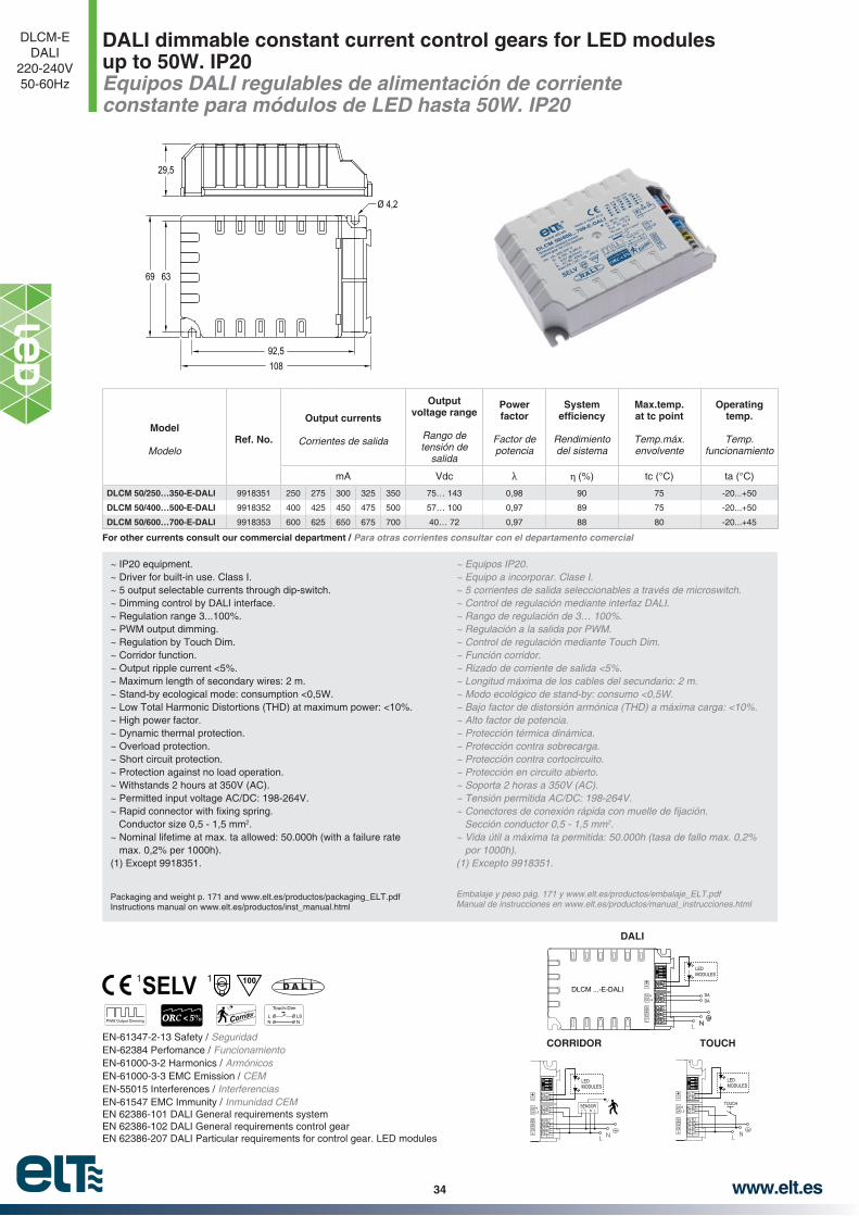
DALI dimmable constant current control gears for LED modules up to 50W. IP20Equipos DALI regulables de alimentación de corriente constante para módulos de LED hasta 50W. IP20
DLCM-EDALI
220-240V50-60Hz
EN-61347-2-13 Safety / SeguridadEN-62384 Perfomance / FuncionamientoEN-61000-3-2 Harmonics / ArmónicosEN-61000-3-3 EMC Emission / CEMEN-55015 Interferences / InterferenciasEN-61547 EMC Immunity / Inmunidad CEMEN 62386-101 DALI General requirements systemEN 62386-102 DALI General requirements control gearEN 62386-207 DALI Particular requirements for control gear. LED modules
~ IP20 equipment.~ Driver for built-in use. Class I.~ 5 output selectable currents through dip-switch.~ Dimming control by DALI interface.~ Regulation range 3...100%.~ PWM output dimming.~ Regulation by Touch Dim.~ Corridor function.~ Output ripple current <5%.~ Maximum length of secondary wires: 2 m.~ Stand-by ecological mode: consumption <0,5W.~ Low Total Harmonic Distortions (THD) at maximum power: <10%.~ High power factor.~ Dynamic thermal protection.~ Overload protection.~ Short circuit protection.~ Protection against no load operation.~ Withstands 2 hours at 350V (AC).~ Permitted input voltage AC/DC: 198-264V.
Conductor size 0,5 - 1,5 mm2.~ Nominal lifetime at max. ta allowed: 50.000h (with a failure rate
max. 0,2% per 1000h).(1) Except 9918351.
Packaging and weight p. 171 and www.elt.es/productos/packaging_ELT.pdfInstructions manual on www.elt.es/productos/inst_manual.html
~ Equipos IP20.~ Equipo a incorporar. Clase I.~ 5 corrientes de salida seleccionables a través de microswitch.~ Control de regulación mediante interfaz DALI.~ Rango de regulación de 3… 100%.~ Regulación a la salida por PWM.~ Control de regulación mediante Touch Dim.~ Función corridor.~ Rizado de corriente de salida <5%.~ Longitud máxima de los cables del secundario: 2 m.
~ Bajo factor de distorsión armónica (THD) a máxima carga: <10%.~ Alto factor de potencia.~ Protección térmica dinámica.~ Protección contra sobrecarga.~ Protección contra cortocircuito.~ Protección en circuito abierto.~ Soporta 2 horas a 350V (AC).
2.~ Vida útil a máxima ta permitida: 50.000h (tasa de fallo max. 0,2%
por 1000h).
Embalaje y peso pág. 171 y www.elt.es/productos/embalaje_ELT.pdfManual de instrucciones en www.elt.es/productos/manual_instrucciones.html
Model
ModeloRef. No.
Output currents
Corrientes de salida
Output voltage range
Rango de tensión de
salida
Power factor
Factor de potencia
System
Rendimiento del sistema
Max.temp. at tc point
Temp.máx. envolvente
Operating temp.
Temp. funcionamiento
mA Vdc (%) tc (°C) ta (°C)
DLCM 50/250…350-E-DALI 9918351 250 275 300 325 350 75… 143 0,98 90 75 -20...+50
DLCM 50/400…500-E-DALI 9918352 400 425 450 475 500 57… 100 0,97 89 75 -20...+50
DLCM 50/600…700-E-DALI 9918353 600 625 650 675 700 40… 72 0,97 88 80 -20...+45
63
29,5
69
108
Ø 4,2
92,5
TOUCH
1ONED 3
24
NL
DALSN
DA
LEDMODULES
TOUCH
N LSENSOR
1ONED 3
24
NL
DALSN
DA
LEDMODULES
CORRIDOR
DADA
DLCM ...-E-DALI
1ONED 3
24
NL
DALSN
DA
LEDMODULES
DALI
PWM Output Dimming OR %ORC < 5Touch-Dim
LN
LSN
A L ID1001 1
For other currents consult our commercial department / Para otras corrientes consultar con el departamento comercial

www.elt.es 35
DALI dimmable constant current control gears for LED modules up to 50W. Protection class II and independent use. IP20Equipos DALI regulables de alimentación de corriente constante para módulos de LED hasta 50W. Clase II y uso independiente. IP20
DLCM-E-C2-DALI220-240V50-60Hz
EN-61347-2-13 Safety / SeguridadEN-62384 Perfomance / FuncionamientoEN-61000-3-2 Harmonics / ArmónicosEN-61000-3-3 EMC Emission / CEMEN-55015 Interferences / InterferenciasEN-61547 EMC Immunity / Inmunidad CEMEN 62386-101 DALI General requirements systemEN 62386-102 DALI General requirements control gearEN 62386-207 DALI Particular requirements for control gear. LED modules
~ IP20 equipment for independent use. Class II control gear.~ 5 output selectable currents through dip-switch.~ Dimming control by DALI interface.~ Regulation range 3...100%.~ PWM output dimming.~ Regulation by Touch Dim.~ Corridor function.~ Output ripple current <5%.~ Maximum length of secondary wires: 5 m.~ Stand-by ecological mode: consumption <0,5W.~ Low Total Harmonic Distortions (THD) at maximum power: <10%.~ High power factor.~ Dynamic thermal protection.~ Overload protection.~ Short circuit protection.~ Protection against no load operation.~ Withstands 2 hours at 350V (AC).~ Permitted input voltage AC/DC: 198-264V.
Conductor size 0,5 - 1,5 mm2.~ Nominal lifetime at max. ta allowed: 50.000h ( with a failure rate
max. 0,2% per 1000h).
(1) Except 9918361.
Packaging and weight p. 171 and www.elt.es/productos/packaging_ELT.pdfInstructions manual on www.elt.es/productos/inst_manual.html
~ Equipo para uso independiente IP20. Equipo Clase II.~ 5 corrientes de salida seleccionables a través de microswitch.~ Control de regulación mediante interfaz DALI.~ Rango de regulación de 3… 100%.~ Regulación a la salida por PWM.~ Control de regulación mediante Touch Dim.~ Función corridor.~ Rizado de corriente de salida <5%.~ Longitud máxima de los cables del secundario: 5 m.
~ Bajo factor de distorsión armónica (THD) a máxima carga: <10%.~ Alto factor de potencia.~ Protección térmica dinámica.~ Protección contra sobrecarga.~ Protección contra cortocircuito.~ Protección en circuito abierto.~ Soporta 2 horas a 350V (AC).
2.~ Vida útil a máxima ta permitida: 50.000h (tasa de fallo max. 0,2%
por 1000h).
Embalaje y peso pág. 171 y www.elt.es/productos/embalaje_ELT.pdfManual de instrucciones en www.elt.es/productos/manual_instrucciones.html
Model
Modelo
Ref. No.
Output currents
Corrientes de salida
Output voltage range
Rango de tensión de
salida
Power factor
Factor de potencia
System
Rendimiento del sistema
Max.temp. at tc point
Temp.máx. envolvente
Operating temp.
Temp. funcionamiento
mA Vdc (%) tc (°C) ta (°C)
DLCM 50/250…350-E-C2-DALI 9918361 250 275 300 325 350 75… 143 0,98 90 75 -20...+50
DLCM 50/400…500-E-C2-DALI 9918362 400 425 450 475 500 57… 100 0,97 89 75 -20...+50
DLCM 50/600…700-E-C2-DALI 9918363 600 625 650 675 700 40… 72 0,97 88 80 -20...+45
Ø 4
32
70,2
170,5
153,5
160,5 24,5
PWM Output Dimming OR %ORC < 5Touch-Dim
LN
LSN
A L ID1001 1
TOUCH
1ONED 3
24
NL
DALSN
DA
LEDMODULES
TOUCH
N LSENSOR
1ONED 3
24
NL
DALSN
DA
LEDMODULES
CORRIDOR
DADA
DLCM ...-E-C2-DALI
1ONED 3
24
NL
DALSN
DA
LEDMODULES
DALI
For other currents consult our commercial department / Para otras corrientes consultar con el departamento comercial

www.elt.es36
DALI control gear: characteristics and technical informationEquipo DALI: Características e información técnica
~ Interfaz DALI: Los terminales del control DALI están protegidos frente a sobretensiones. Sin polaridad.
~ TOUCH DIM: Regulación manual con pulsador estándar (NA: Normalmente abierto).
~ Función corridor: sistema para controlar el nivel de luz con un sensor de movimiento convencional conectado en los bornes DALI. Cuando el sensor detecta presencia, el nivel de luz aumenta al 100%, en caso contrario, el equipo mantiene un 10% de nivel de luz.
Protección térmica inteligente de forma que el equipo
tura interna.~ Si la temperatura en Tc alcanza Tcmáx
+ 5°C, se reduce la potencia un 25%.
~ Si la temperatura en Tc baja a Tcmáx
potencia se ha reducido en un 25%, el equipo vuelve a funcionamiento normal.
~ Si la temperatura en Tc aumenta hasta Tcmáx +10°C una
vez se ha reducido la potencia un 25%, el equipo pasa a
baja a Tcmáx
ento normal.
~ DALI interface: protected DALI control input against overvoltage. Polarity free.
~ Touch DIM: by using standard commercial normally
open switches.
~ Corridor function: Dimming system that controls light level when a presence is detected by a conventional mains on/off sensor connected in DALI input. When the sensor detects a presence, light level increases up to 100%, otherwise the control gear keeps on providing 10% light level.
Effective thermal management protection reducing lumi-
~ If Tc temperature exceeds Tcmax + 5°C, power is reduced by 25%.
~ If temperature decreases to Tcmax - 5°C once power has been reduced by 25%, gear returns to normal operation.
~ If Tc temperature increases to Tcmax + 10°C once power has been reduced by 25%, gear switches to stand-by mode.
~ When gear is on stand-by and Tc temperature decreases to Tcmax - 5°C, gear reboots in normal operation mode.
25% power re nReducción de un 25% de la potencia
Stand-by (OFF)
NONO
NO
YES/SI
YES/SI
YES/SIYES/SI
Funcionamiento normal
Tc > Tc max.+5°NO
nEncendido
Tc > Tc max.+10°
Tc < Tc max.-5° Tc < Tc max.-5°
%LuminousFlux
1009080706050403020100
0,0 0,5 2,0
Time (sec)1,0 1,5 2,5 3,0 3,5 4,0
TOUCH
%LuminousFlux
1009080706050403020100
0 50 100 150 200 250
Digital Light Value
DALI
TOUCH DALI
10%
OFF60 seg. 32 seg.
100%
Light levelNivel de flujo
luminoso
L1
L1
N
N
T
Pushbutton
DLCM ...-DALI
NL
DA / LSDA / N
DLCM ...-DALI
NL
DA / LSDA / N
DLCM ...-DALI
NL
DA / LSDA / N
DALIcontroller
L
L1
L1
L2
L2
L3
L3
N
N
N
PEDA
DA
DA
DA
DLCM ...-DALI
NL
DA / LSDA / N
DLCM ...-DALI
NL
DA / LSDA / N
DLCM ...-DALI
NL
DA / LSDA / N

www.elt.es 37
Constant current control gears for LED modules up to 60W. IP20Equipos de alimentación de corriente constante para módulos de LED hasta 60W. IP20
LC-C220-240V
DC/AC 50-60Hz
230220 5
4,25
5
28
40
NL
+- LED
MODULESEN-61347-2-13 Safety / SeguridadEN-61000-3-2 Harmonics / ArmónicosEN-61000-3-3 EMC Emission / CEMEN-55015 Interferences / InterferenciasEN-61547 EMC Immunity / Inmunidad CEM
~ IP20 equipment.~ Driver for built-in use. Class I.~ Maximum length of secondary wires: 2 m.~ High power factor.~ Overload protection.~ Protection against no load operation.~ Withstands 2 hours at 350V (AC).~ Permitted input voltage AC: 198-264V; DC:150-270V.
Conductor size 0,5 - 1,5 mm2.~ Nominal lifetime at max. ta allowed: 50.000h (with a failure rate
max.0,2% per 1000h).
Packaging and weight p. 171 and www.elt.es/productos/packaging_ELT.pdf
Instructions manual on www.elt.es/productos/inst_manual.html
~ Equipos IP20.~ Equipo a incorporar. Clase I.~ Longitud máxima de los cables del secundario: 2 m.~ Alto factor de potencia.~ Protección contra sobrecarga~ Protección en circuito abierto.~ Soporta 2 horas a 350V (AC).
2..
~ Vida útil a máxima ta permitida: 50.000h (tasa de fallo max. 0,2% por 1000h).
Embalaje y peso pág. 171 y www.elt.es/productos/embalaje_ELT.pdfSelección de producto pág. 77 y www.elt.es/productos/buscador_producto.htmlManual de instrucciones en www.elt.es/productos/manual_instrucciones.html
Model
Modelo
Ref. No.
Output power range
Rango de potencia en
módulo
Output current
Corriente de salida
Output voltage range
Rango de tensión de
salida
Power factor
Factor de potencia
System
Rendimiento del sistema
Max.temp. at tc point
Temp.máx. envolvente
Operating temp.
Temp. funcionamiento
W mA Vdc (%) tc (°C) ta (°C)
LC 142/700-C 9918044 24... 42 700 34... 60 0,99 87 75 -25... +50
LC 160/700-C 9918040 24... 60 700 34... 86 0,99 87 75 -25... +50
For other currents consult our commercial department / Para otras corrientes consultar con el departamento comercial

www.elt.es38
Constant current control gears for LED modules up to 90W. IP20Equipos de alimentación de corriente constante para módulos de LED hasta 90W. IP20
LC-D220-240V
DC/AC 50-60Hz
EN-61347-2-13 Safety / SeguridadEN-62384 Perfomance / FuncionamientoEN-61000-3-2 Harmonics / ArmónicosEN-61000-3-3 EMC Emission / CEMEN-55015 Interferences / InterferenciasEN-61547 EMC Immunity / Inmunidad CEM
360350
348
5
7
5
5
21
30
4,25
4,510
~ IP20 equipment.~ Driver for built-in use. Class I.~ Maximum length of secondary wires: 2 m.~ High power factor.~ Overload protection.~ Short circuit protection.~ Protection against no load operation.~ Withstands 2 hours at 350V (AC).~ Permitted input voltage AC/DC: 198-264V.
Conductor size 0,5-1,5 mm2.~ Nominal lifetime at max. ta allowed: 50.000h (with a failure rate
max. 0,2% per 1000h).~ Output ripple current <2%.~ THD <10%.
(1) Except: LC 150/350-D and LC 190/700-D.
Packaging and weight p. 171 and www.elt.es/productos/packaging_ELT.pdf
Instructions manual on www.elt.es/productos/inst_manual.html
~ Equipos IP20.~ Equipo a incorporar. Clase I.~ Longitud máxima de los cables del secundario: 2 m.~ Alto factor de potencia.~ Protección contra sobrecarga.~ Protección contra cortocircuitos.~ Protección en circuito abierto.~ Soporta 2 horas a 350V (AC).
2..
~ Vida útil a máxima ta permitida: 50.000h (tasa de fallo max. 0,2% por 1000h).
~ Rizado de corriente de salida <2%.~ THD <10%.
(1) Excepto:
Embalaje y peso pág. 171 y www.elt.es/productos/embalaje_ELT.pdfSelección de producto pág. 77 y www.elt.es/productos/buscador_producto.htmlManual de instrucciones en www.elt.es/productos/manual_instrucciones.html
Model
Modelo
Ref. No.
Output power range
Rango de potencia en
módulo
Output current
Corriente de salida
Output voltage range
Rango de tensión de
salida
Power factor
Factor de potencia
System
Rendimiento del sistema
Max.temp. at tc point
Temp.máx. envolvente
Operating temp.
Temp. funcionamiento
Approvals
Homologaciones
W mA Vdc (%) tc (°C) ta (°C)
LC 150/350-D 9918103 23… 50 350 66… 143 0,98 90 75 -20… +55
LC 150/500-D 9918105 23… 50 500 46… 100 0,98 90 75 -20… +55
LC 150/700-D 9918107 24… 50 700 34… 72 0,98 89 75 -20… +55
LC 190/700-D 9918117 40… 90 700 58… 129 0,98 91 75 -20… +50
01
01
01
01
11
For other currents consult our commercial department / Para otras corrientes consultar con el departamento comercial
ORC < 2%01

www.elt.es 39
Constant current control gears for LED modules up to 50W. Universal voltage 110-277V. IP20 Equipos de alimentación de corriente constante para módulos de LED hasta 50W. Tensión universal 110-277V. IP20
LC-D-UN110-277V
DC/AC 50-60Hz
EN-61347-2-13 Safety / SeguridadEN-62384 Perfomance / FuncionamientoEN-61000-3-2 Harmonics / ArmónicosEN-61000-3-3 EMC Emission / CEMEN-55015 Interferences / InterferenciasEN-61547 EMC Immunity / Inmunidad CEM
360350
348
5
7
5
5
21
30
4,25
4,510
~ IP20 equipment.~ Driver for built-in use. Class I.~ Maximum length of secondary wires: 2 m.~ High power factor.~ Overload protection.~ Short circuit protection.~ Protection against no load operation.~ Withstands 2 hours at 350V (AC).~ Permitted input voltage AC/DC: 99-305V.
Conductor size 0,5-1,5 mm2.~ Nominal lifetime at max. ta allowed: 50.000h (with a failure rate
max. 0,2% per 1000h).~ Output ripple current <3%.~ THD <10%.
(1) Except: LC 150/350-D-UN.
Packaging and weight p. 171 and www.elt.es/productos/packaging_ELT.pdf
Instructions manual on www.elt.es/productos/inst_manual.html
~ Equipos IP20.~ Equipo a incorporar. Clase I.~ Longitud máxima de los cables del secundario: 2 m.~ Alto factor de potencia.~ Protección contra sobrecarga.~ Protección contra cortocircuitos.~ Protección en circuito abierto.~ Soporta 2 horas a 350V (AC).
2..
~ Vida útil a máxima ta permitida: 50.000h (tasa de fallo max. 0,2% por 1000h).
~ Rizado de corriente de salida <3%.~ THD <10%.
(1) Excepto:
Embalaje y peso pág. 171 y www.elt.es/productos/embalaje_ELT.pdfSelección de producto pág. 77 y www.elt.es/productos/buscador_producto.htmlManual de instrucciones en www.elt.es/productos/manual_instrucciones.html
Model
ModeloRef. No.
Output power range
Rango de potencia en
módulo
Output current
Corriente de salida
Output voltage range
Rango de tensión de
salida
Power factor
Factor de potencia
System
Rendimiento del sistema
Max.temp. at tc point
Temp.máx. envolvente
Operating temp.
Temp. funcionamiento
W mA Vdc (%) tc (°C) ta (°C)
LC 150/350-D-UN 9918123 23... 50 350 66... 143 0,98 90 75 -20… +55
LC 150/500-D-UN 9918125 23... 50 500 46... 100 0,98 90 75 -20… +55
LC 150/700-D-UN 9918127 24... 50 700 34... 72 0,98 89 75 -20… +55
11
For other currents consult our commercial department / Para otras corrientes consultar con el departamento comercial
ORC < 3%
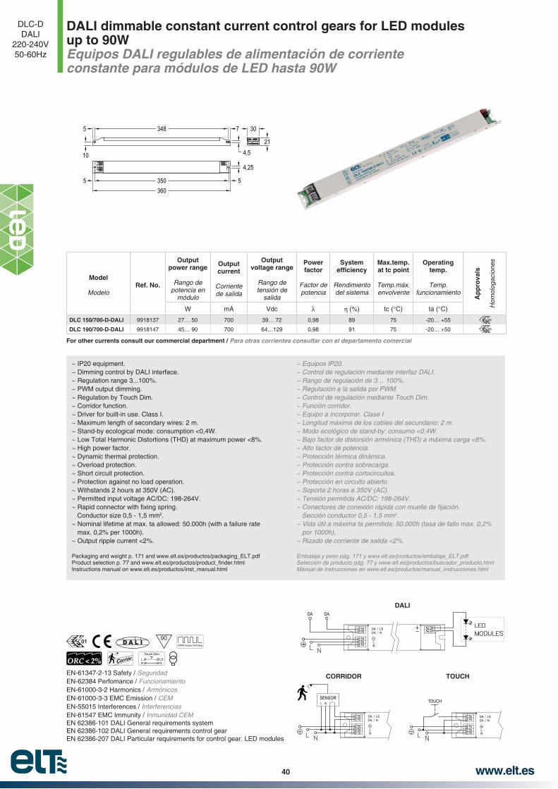
www.elt.es40
DALI dimmable constant current control gears for LED modules up to 90WEquipos DALI regulables de alimentación de corriente constante para módulos de LED hasta 90W
DLC-DDALI
220-240V50-60Hz
EN-61347-2-13 Safety / SeguridadEN-62384 Perfomance / FuncionamientoEN-61000-3-2 Harmonics / ArmónicosEN-61000-3-3 EMC Emission / CEMEN-55015 Interferences / InterferenciasEN-61547 EMC Immunity / Inmunidad CEMEN 62386-101 DALI General requirements systemEN 62386-102 DALI General requirements control gearEN 62386-207 DALI Particular requirements for control gear. LED modules
~ IP20 equipment.~ Dimming control by DALI interface.~ Regulation range 3...100%.~ PWM output dimming.~ Regulation by Touch Dim.~ Corridor function.~ Driver for built-in use. Class I.~ Maximum length of secondary wires: 2 m.~ Stand-by ecological mode: consumption <0,4W.~ Low Total Harmonic Distortions (THD) at maximum power <8%.~ High power factor.~ Dynamic thermal protection.~ Overload protection.~ Short circuit protection.~ Protection against no load operation.~ Withstands 2 hours at 350V (AC).~ Permitted input voltage AC/DC: 198-264V.
Conductor size 0,5 - 1,5 mm2.~ Nominal lifetime at max. ta allowed: 50.000h (with a failure rate
max. 0,2% per 1000h).~ Output ripple current <2%.
Packaging and weight p. 171 and www.elt.es/productos/packaging_ELT.pdf
Instructions manual on www.elt.es/productos/inst_manual.html
~ Equipos IP20.~ Control de regulación mediante interfaz DALI.~ Rango de regulación de 3… 100%.~ Regulación a la salida por PWM.~ Control de regulación mediante Touch Dim.~ Función corridor.~ Equipo a incorporar. Clase I~ Longitud máxima de los cables del secundario: 2 m.
~ Alto factor de potencia.~ Protección térmica dinámica.~ Protección contra sobrecarga.~ Protección contra cortocircuitos.~ Protección en circuito abierto.~ Soporta 2 horas a 350V (AC).
2.~ Vida útil a máxima ta permitida: 50.000h (tasa de fallo max. 0,2%
por 1000h).~ Rizado de corriente de salida <2%.
Embalaje y peso pág. 171 y www.elt.es/productos/embalaje_ELT.pdfSelección de producto pág. 77 y www.elt.es/productos/buscador_producto.htmlManual de instrucciones en www.elt.es/productos/manual_instrucciones.html
Model
ModeloRef. No.
Output power range
Rango de potencia en
módulo
Output current
Corriente de salida
Output voltage range
Rango de tensión de
salida
Power factor
Factor de potencia
System
Rendimiento del sistema
Max.temp. at tc point
Temp.máx. envolvente
Operating temp.
Temp. funcionamiento
Ap
pro
vals
Hom
olog
acio
nes
W mA Vdc (%) tc (°C) ta (°C)
DLC 150/700-D-DALI 9918137 27… 50 700 39… 72 0,98 89 75 -20… +55
DLC 190/700-D-DALI 9918147 45… 90 700 64…129 0,98 91 75 -20… +50
01
01
360350
348
5
7
5
5
21
30
4,25
4,510
NL
DA / LSDA / N
TOUCH
TOUCH
NL
DA / LSDA / N
NLSENSOR
CORRIDOR
DADA
NL
DA / LSDA / N
DALI
A L ID90
PWM Output Dimming
ORC < 2%Touch-Dim
LN
LSN
For other currents consult our commercial department / Para otras corrientes consultar con el departamento comercial
01

www.elt.es 41
DALI control gear: characteristics and technical informationEquipo DALI: Características e información técnica
~ Interfaz DALI: Los terminales del control DALI están protegidos frente a sobretensiones. Sin polaridad.
~ TOUCH DIM: Regulación manual con pulsador estándar (NA: Normalmente abierto).
~ Función corridor: sistema para controlar el nivel de luz con un sensor de movimiento convencional conectado en los bornes DALI. Cuando el sensor detecta presencia, el nivel de luz aumenta al 100%, en caso contrario, el equipo mantiene un 10% de nivel de luz.
Protección térmica inteligente de forma que el equipo
tura interna.
potencia un 25%.~ Si la temperatura en Tc baja a 70°C una vez la potencia
se ha reducido en un 25%, el equipo vuelve a funcionamiento normal.
ha reducido la potencia un 25%, el equipo pasa a modo
Tc baja a 70°C, el equipo reenciende en funcionamiento normal.
~ DALI interface: protected DALI control input against overvoltage. Polarity free.
~ Touch DIM: by using standard commercial normally
open switches.
~ Corridor function: Dimming system that controls light level when a presence is detected by a conventional mains on/off sensor connected in DALI input. When the sensor detects a presence, light level increases up to 100%, otherwise the control gear keeps on providing 10% light level.
Effective thermal management protection reducing lumi-
~ If Tc temperature exceeds 80º C, power is reduced by 25%.
~ If temperature decreases to Tc 70° C once power has been reduced by 25%, gear returns to normal operation.
~ If Tc temperature increases to 85° C once power has been reduced by 25%, gear switches to stand-by mode.
~ When gear is on stand-by and Tc temperature decreases to 70° C, gear reboots in normal operation mode.
25% power re nReducción de un 25% de la potencia
Tc >85°C? Stand-by (OFF)
Tc <70°C? Tc <70°C?NO
NONO
YES/SI
YES/SI
YES/SIYES/SI
Funcionamiento normal
Tc >80°C?NO
nEncendido
%LuminousFlux
1009080706050403020100
0,0 0,5 2,0
Time (sec)1,0 1,5 2,5 3,0 3,5 4,0
TOUCH
%LuminousFlux
1009080706050403020100
0 50 100 150 200 250
Digital Light Value
DALI
L1
L1
N
N
LS
Pushbutton
LEDMODULES
LEDMODULES
LEDMODULES
DLC ...-DALINL
DA / LSDA / N
DLC ...-DALINL
DA / LSDA / N
DLC ...-DALINL
DA / LSDA / N
TOUCH
DALIcontroller
L
L1
L1
L2
L2
L3
L3
N
N
N
PE DA
DA
DA
DA
DLC ...-DALI
DLC ...-DALI
N
N
L
L
DA / LS
DA / LS
DA / N
DA / N
DLC ...-DALINL
DA / LSDA / N LED
MODULES
LEDMODULES
LEDMODULES
DALI
10%
OFF60 seg. 32 seg.
100%
Light levelNivel de flujo
luminoso
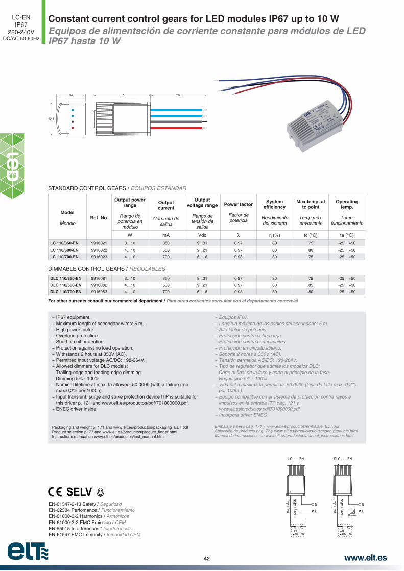
www.elt.es42
Constant current control gears for LED modules IP67 up to 10 W Equipos de alimentación de corriente constante para módulos de LED IP67 hasta 10 W
LC-ENIP67
220-240VDC/AC 50-60Hz
40,5
34 67 200
EN-61347-2-13 Safety / SeguridadEN-62384 Perfomance / FuncionamientoEN-61000-3-2 Harmonics / ArmónicosEN-61000-3-3 EMC Emission / CEMEN-55015 Interferences / InterferenciasEN-61547 EMC Immunity / Inmunidad CEM
~ IP67 equipment.~ Maximum length of secondary wires: 5 m.~ High power factor.~ Overload protection.~ Short circuit protection.~ Protection against no load operation.~ Withstands 2 hours at 350V (AC).~ Permitted input voltage AC/DC: 198-264V.~ Allowed dimmers for DLC models:
Trailing-edge and leading-edge dimming.Dimming 5% - 100%.
~ Nominal lifetime at max. ta allowed: 50.000h (with a failure rate max.0,2% per 1000h).
~ Input transient, surge and strike protection device ITP is suitable for this driver p. 121 and www.elt.es/productos/pdf/701000000.pdf.
~ ENEC driver inside.
Packaging and weight p. 171 and www.elt.es/productos/packaging_ELT.pdf
Instructions manual on www.elt.es/productos/inst_manual.html
~ Longitud máxima de los cables del secundario: 5 m.~ Alto factor de potencia.~ Protección contra sobrecarga.~ Protección contra cortocircuitos.~ Protección en circuito abierto.~ Soporta 2 horas a 350V (AC).
~ Tipo de regulador que admite los modelos DLC:
~ Vida útil a máxima ta permitida: 50.000h (tasa de fallo max. 0,2% por 1000h).
~ Equipo compatible con el sistema de protección contra rayos e impulsos en la entrada ITP pág. 121 y www.elt.es\productos pdf\701000000.pdf.
~ Incorpora driver ENEC.
Embalaje y peso pág. 171 y www.elt.es/productos/embalaje_ELT.pdfSelección de producto pág. 77 y www.elt.es/productos/buscador_producto.htmlManual de instrucciones en www.elt.es/productos/manual_instrucciones.html
Model
ModeloRef. No.
Output power range
Rango de potencia en
módulo
Output current
Corriente de salida
Output voltage range
Rango de tensión de
salida
Power factor
Factor de potencia
System
Rendimiento del sistema
Max.temp. at tc point
Temp.máx. envolvente
Operating temp.
Temp. funcionamiento
W mA Vdc (%) tc (°C) ta (°C)
LC 110/350-EN 9916021 3…10 350 9...31 0,97 80 75 -25 .. +50
LC 110/500-EN 9916022 4…10 500 9...21 0,97 80 80 -25 .. +50
LC 110/700-EN 9916023 4…10 700 6...16 0,98 80 75 -25 .. +50
STANDARD CONTROL GEARS / EQUIPOS ESTANDAR
DLC 110/350-EN 9916081 3…10 350 9...31 0,97 80 75 -25 .. +50
DLC 110/500-EN 9916082 4…10 500 9...21 0,97 80 85 -25 .. +50
DLC 110/700-EN 9916083 4…10 700 6...16 0,98 80 80 -25 .. +50
DIMMABLE CONTROL GEARS / REGULABLES
DLC 1...-EN
Rojo/Red
Negro/Black
Dimmer
N
L
LC 1...-EN
Rojo/Red
Negro/Black
N
L
For other currents consult our commercial department / Para otras corrientes consultar con el departamento comercial

www.elt.es 43
Full PROGRAMMABLE constant current control gear for LED modules up to 75W. IP20. Street lighting applicationsEquipos PROGRAMABLES de alimentación de corriente constante para módulos LED hasta 75W. IP20. Aplicaciones de alumbrado público
iLC-XR180-277V
AC 50-60Hz
140,5
129,1
10,8
50
129,1
EN-61347-2-13 Safety / SeguridadEN-62384 Perfomance / FuncionamientoEN-61000-3-2 Harmonics / ArmónicosEN-55015 Interferences / InterferenciasEN-61547 EMC Immunity / Inmunidad CEM
~ Full Programmable electrical parameters and functionalities.~ Interfaces: DALI, 0-10V, 1-10, actiDIM, actiDIM + parking, Mains
Switch and Line Switch.~ Compatible version with STELARIA™ Remote Wireless Street
Lighting CMS available.~ Output constant current allowed: 70 … 1400mA.~ Maximum output power: 75W.~ ORC (Output Ripple Current) <5%.~ Permitted input voltage AC: 162 … 305V.~ Low Total Harmonic Distortion (THD @230Vac, 75W) <8%.~ Dimming range: 10 … 100% (minimum output current = 70mA).~ Protection against short circuit, overload and no load operation.~ Control gear thermal protection.~ External LED module thermal protection connector.~ Input transient and surge protection (ITP) integrated. Protection
10kV/3kA L-N and LN-PE (max=8kA).~ Nominal lifetime at max. ta allowed: 100.000h**.~ Built-in-use control gear, protection index IP20.~ Electronic circuit fully protected against humidity.
~ Low Stand-by power consumption: < 0,5W.
* At nominal output power (75W@700mA). Higher ambient temperature is allowed if tcmax is not reached.
max (with a maximum failure rate of 10%). See tc data table.
Packaging and weight p. 171 and www.elt.es/productos/packaging_ELT.pdfInstructions manual on www.elt.es/productos/inst_manual.html
~ Parámetros eléctricos y funcionalidades programables.
Switch y Line Switch.~ Versión disponible compatible con sistema de gestión remota de
alumbrado STELARIA™.
~ Máxima potencia en la salida: 75W.~ ORC (Output Ripple Current) <5%.
~ Rango de regulación: 10 … 100% (corriente de salida mínima = 70mA).
~ Protección contra cortocircuito, sobrecarga y en circuito abierto.~ Protección térmica en el equipo electrónico.~ Conexión para protección térmica del módulo LED.~ Protección contra sobretensiones de red y rayo integrada (ITP).
~ Vida útil a máxima ta permitida: 100.000h**.~ Equipos a incorporar, índice de protección IP20.~ Circuito electrónico protegido contra la humedad.~ Elevada calidad de la luz sin parpadeos.
* A potencia nominal de salida (75W@700mA). Una mayor temperatura ambiente está permitida si no se alcanza tcmax.
max (con una tasa de fallo máx. del 10%). Ver datos de la tabla tc.
Embalaje y peso pág. 171 y www.elt.es/productos/embalaje_ELT.pdfManual de instrucciones en www.elt.es/productos/manual_instrucciones.html
Model
ModeloRef. No.
Output power range
Rango de potencia en módulo
Output current
Corriente de salida
Output voltage range
Rango de tensión de salida
Power factor
Factor de potencia
System
Rendimiento del sistema
Max.temp. at tc point
Temp.máx. envolvente
Operating temp.
Temp. funcionamiento
W mA Vdc (%) tcmax (°C) ta (°C)*
iLC PRO 75/200...1400-XR 9916151
7,4…37,8 350 21…108
0,98
>89
80 -40… +55
10,5…54 500 21…108 >90
14,7…75 700 21…108 >90
22…75 1050 21…72 >91
25,2…70 1200 21…58 >90
29,4…70 1400 21…50 >88
10OR %ORC < 5
100A L ID
N
DADA
NTCNTC
LED
L
DA
LEDMODULES
TM

www.elt.es44
0
10
20
30
40
50
60
70
80
90
100
110
120
0 50 100 150 200 250 300 350 400 450 500 550 600 650 700 750 800 850 900 950 1000 1050 1100 1150 1200 1250 1300 1350 1400 1450
Vout
[V]
Iout [mA]*
* Minimum dimmed current is 10% of the maximum programed current / La corriente mínima de dimado es el 10% de la corriente máxima programada.
OPERATING AREA 100%
OPERATING AREA / AREA DE OPERACION
COMPATIBLE ACCESSORIES / ACCESORIOS COMPATIBLES
iLC PRO 75/200...1400-XR control gear is compatible with the following accessories:
~ iProgrammer: 3512003.
~ iSOFT: The software programming is available to download in www.elt.es/productos/i-productos.html~ iSoft: el software de programación está disponible para descargar en www.elt.es/productos/productos.html
Full PROGRAMMABLE constant current control gear for LED modules up to 75W. IP20. Street lighting applicationsEquipos PROGRAMABLES de alimentación de corriente constante para módulos LED hasta 75W. IP20. Aplicaciones de alumbrado público
iLC-XR180-277V
AC 50-60Hz

www.elt.es 45
Full PROGRAMMABLE constant current control gear for LED modules up to 75W. IP20. Street lighting applicationsEquipos PROGRAMABLES de alimentación de corriente constante para módulos LED hasta 75W. IP20. Aplicaciones de alumbrado público
iLC-XR180-277V
AC 50-60Hz
QUICK START GUIDE / GUÍA RÁPIDA DE INICIO
DOWNLOADDESCARGA
PROGRAMMINGPROGRAMACIÓN
START-UPPUESTA EN MARCHA
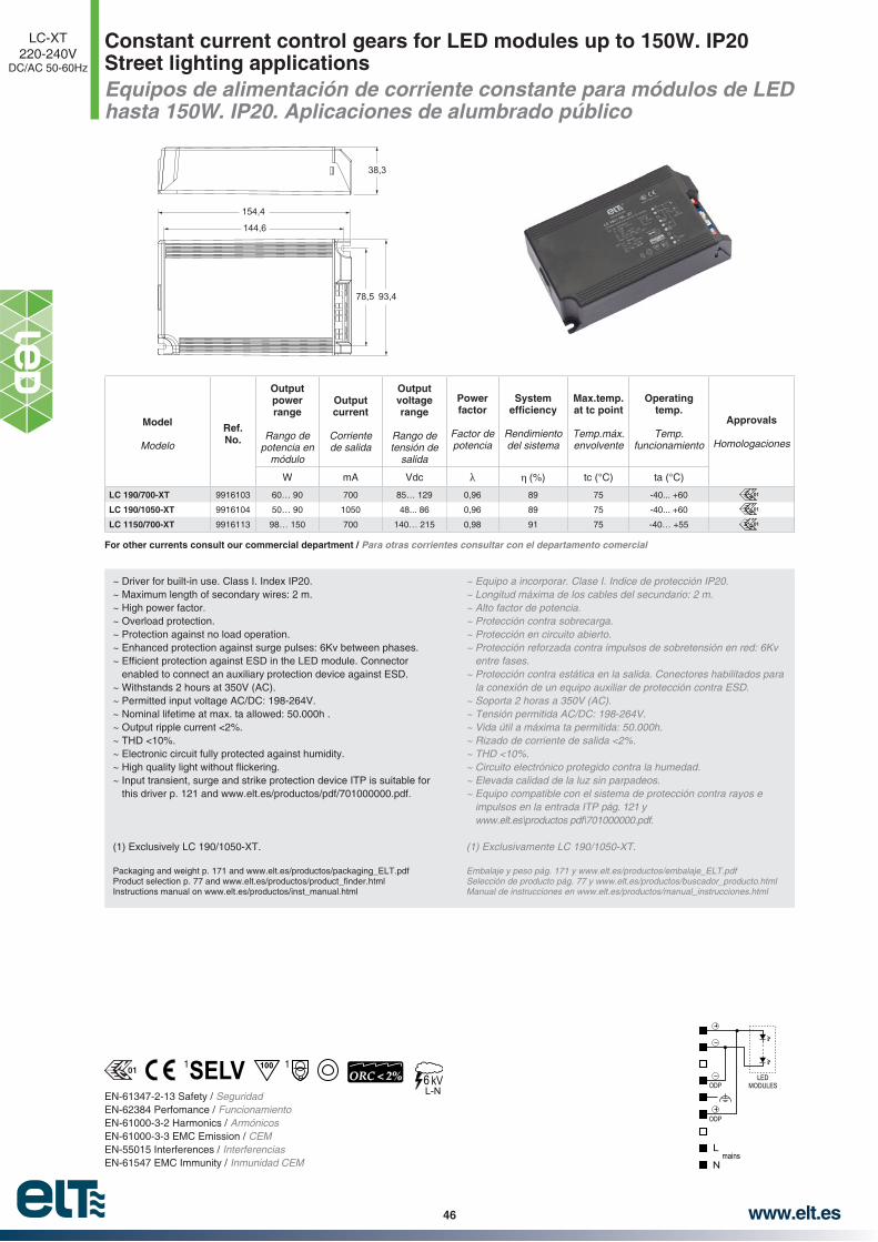
www.elt.es46
Constant current control gears for LED modules up to 150W. IP20 Street lighting applicationsEquipos de alimentación de corriente constante para módulos de LED hasta 150W. IP20. Aplicaciones de alumbrado público
LC-XT220-240V
DC/AC 50-60Hz
EN-61347-2-13 Safety / SeguridadEN-62384 Perfomance / FuncionamientoEN-61000-3-2 Harmonics / ArmónicosEN-61000-3-3 EMC Emission / CEMEN-55015 Interferences / InterferenciasEN-61547 EMC Immunity / Inmunidad CEM
~ Driver for built-in use. Class I. Index IP20.~ Maximum length of secondary wires: 2 m.~ High power factor.~ Overload protection.~ Protection against no load operation.~ Enhanced protection against surge pulses: 6Kv between phases.
enabled to connect an auxiliary protection device against ESD.~ Withstands 2 hours at 350V (AC).~ Permitted input voltage AC/DC: 198-264V.~ Nominal lifetime at max. ta allowed: 50.000h .~ Output ripple current <2%.~ THD <10%.~ Electronic circuit fully protected against humidity.
~ Input transient, surge and strike protection device ITP is suitable for this driver p. 121 and www.elt.es/productos/pdf/701000000.pdf.
(1) Exclusively LC 190/1050-XT.
Packaging and weight p. 171 and www.elt.es/productos/packaging_ELT.pdf
Instructions manual on www.elt.es/productos/inst_manual.html
~ Equipo a incorporar. Clase I. Indice de protección IP20.~ Longitud máxima de los cables del secundario: 2 m.~ Alto factor de potencia.~ Protección contra sobrecarga.~ Protección en circuito abierto.
entre fases.~ Protección contra estática en la salida. Conectores habilitados para
la conexión de un equipo auxiliar de protección contra ESD.~ Soporta 2 horas a 350V (AC).
~ Vida útil a máxima ta permitida: 50.000h.~ Rizado de corriente de salida <2%.~ THD <10%.~ Circuito electrónico protegido contra la humedad.~ Elevada calidad de la luz sin parpadeos.~ Equipo compatible con el sistema de protección contra rayos e
impulsos en la entrada ITP pág. 121 y www.elt.es\productos pdf\701000000.pdf.
Embalaje y peso pág. 171 y www.elt.es/productos/embalaje_ELT.pdfSelección de producto pág. 77 y www.elt.es/productos/buscador_producto.htmlManual de instrucciones en www.elt.es/productos/manual_instrucciones.html
Model
Modelo
Ref. No.
Output power range
Rango de potencia en
módulo
Output current
Corriente de salida
Output voltage range
Rango de tensión de
salida
Power factor
Factor de potencia
System
Rendimiento del sistema
Max.temp. at tc point
Temp.máx. envolvente
Operating temp.
Temp. funcionamiento
Approvals
Homologaciones
W mA Vdc (%) tc (°C) ta (°C)
LC 190/700-XT 9916103 60… 90 700 85… 129 0,96 89 75 -40... +60
LC 190/1050-XT 9916104 50… 90 1050 48... 86 0,96 89 75 -40... +60
LC 1150/700-XT 9916113 98… 150 700 140… 215 0,98 91 75 -40… +55
01
L
N
LEDMODULESODP
ODP
mains
38,3
78,5 93,4
144,6
154,4
01
01
6L-N
1001 1
For other currents consult our commercial department / Para otras corrientes consultar con el departamento comercial
ORC < 2%01
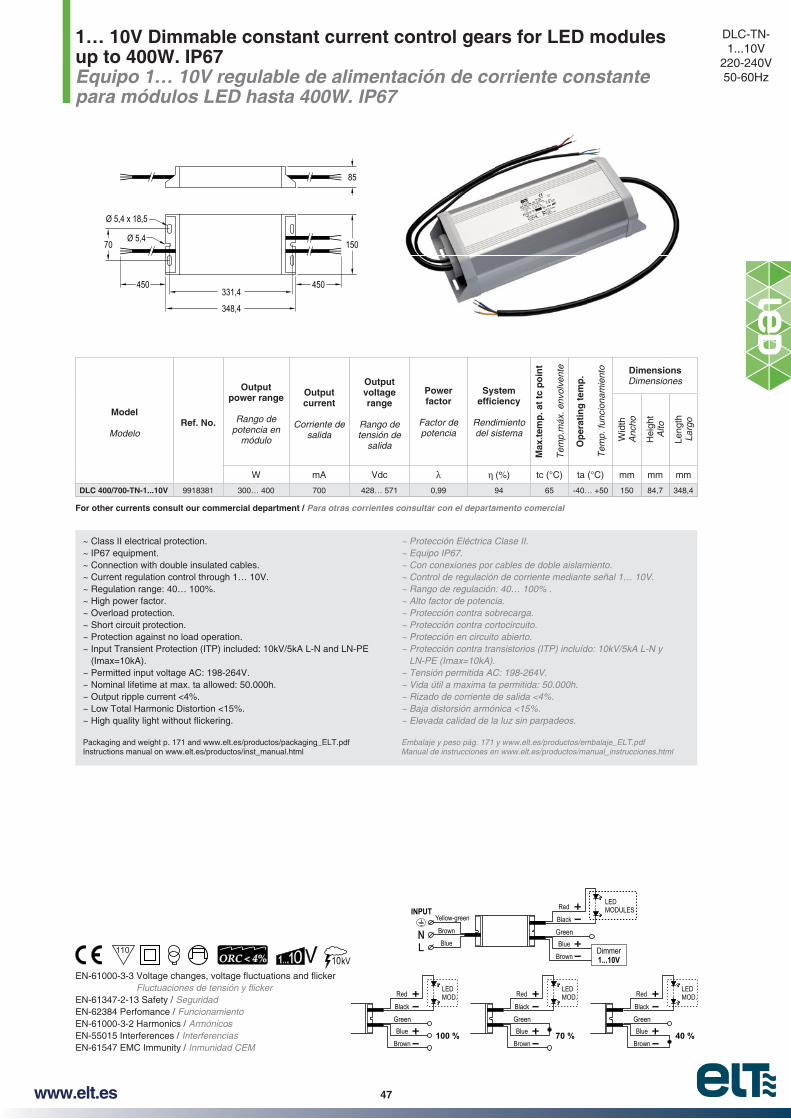
www.elt.es 47
1… 10V Dimmable constant current control gears for LED modules up to 400W. IP67Equipo 1… 10V regulable de alimentación de corriente constante para módulos LED hasta 400W. IP67
DLC-TN- 1...10V
220-240V50-60Hz
~ Class II electrical protection.~ IP67 equipment.~ Connection with double insulated cables.~ Current regulation control through 1… 10V.~ Regulation range: 40… 100%.~ High power factor.~ Overload protection.~ Short circuit protection.~ Protection against no load operation.~ Input Transient Protection (ITP) included: 10kV/5kA L-N and LN-PE
(Imax=10kA).~ Permitted input voltage AC: 198-264V.~ Nominal lifetime at max. ta allowed: 50.000h.~ Output ripple current <4%.~ Low Total Harmonic Distortion <15%.
Packaging and weight p. 171 and www.elt.es/productos/packaging_ELT.pdfInstructions manual on www.elt.es/productos/inst_manual.html
~ Protección Eléctrica Clase II.~ Equipo IP67.~ Con conexiones por cables de doble aislamiento.~ Control de regulación de corriente mediante señal 1… 10V.~ Rango de regulación: 40… 100% .~ Alto factor de potencia.~ Protección contra sobrecarga.~ Protección contra cortocircuito.~ Protección en circuito abierto.~ Protección contra transistorios (ITP) incluído: 10kV/5kA L-N y
LN-PE (Imax=10kA).~ Tensión permitida AC: 198-264V.~ Vida útil a maxima ta permitida: 50.000h.~ Rizado de corriente de salida <4%.~ Baja distorsión armónica <15%.~ Elevada calidad de la luz sin parpadeos.
Embalaje y peso pág. 171 y www.elt.es/productos/embalaje_ELT.pdfManual de instrucciones en www.elt.es/productos/manual_instrucciones.html
Model
ModeloRef. No.
Output power range
Rango de potencia en
módulo
Output current
Corriente de salida
Output voltage range
Rango de tensión de
salida
Power factor
Factor de potencia
System
Rendimiento del sistema
Max
.tem
p. a
t tc
po
int
Tem
p.m
áx. e
nvol
vent
e
Op
erat
ing
tem
p.
Tem
p. fu
ncio
nam
ient
o Dimensions Dimensiones
Wid
thA
ncho
Hei
ght
Alto
Leng
thLa
rgo
W mA Vdc (%) tc (°C) ta (°C) mm mm mm
DLC 400/700-TN-1...10V 9918381 300… 400 700 428… 571 0,99 94 65 -40… +50 150 84,7 348,4
15070
331,4450 450
348,4
85
Ø 5,4 x 18,5
Ø 5,4
10ORC < 4%
EN-61347-2-13 Safety / SeguridadEN-62384 Perfomance / FuncionamientoEN-61000-3-2 Harmonics / ArmónicosEN-55015 Interferences / InterferenciasEN-61547 EMC Immunity / Inmunidad CEM
110
Red
BlueGreen
Brown100 %
Black
LEDMOD. Red
BlueGreen
Brown40 %
Black
LEDMOD.Red
BlueGreen
Brown70 %
Black
LEDMOD.
Blue
Yellow-green
BrownNL
INPUT Red
BlueGreen
BrownDimmer1...10V
Black
LEDMODULES
For other currents consult our commercial department / Para otras corrientes consultar con el departamento comercial

www.elt.es48
Ø 4,5210
450
205,5
31,5
21,5
16,8
173 250
Ø 23 4,8V 1,8 Ah NiCd 1 h.
250240
Ø 33 4,8V 4,5 Ah NiCd 3 h.
Emergency lighting kits with self-diagnosis function for constant current LED luminairesKits para alumbrado de emergencia, con autodiagnóstico, para luminarias LED de corriente constante
emerLED230V
50-60Hz
EN 60598-2-22 Luminaires emergency lighting / Luminarias alumbrado emergencia EN 61347-1 Safety (general) / Seguridad (general)EN 61347-2-7 Safety (particular emergency) / Seguridad (particular para emergencias)
~ The emerLED has to be used in combination with a constant current control gear for LED modules in LED luminaires.
~ Electrical protection: Class I.~ Protection rating: IP 20.~ Automatic test according EN 62034.~ Valid for DIN 0108 / EN 50172 installations.~ Suitable for cables 0,5-1,5 mm2 section stripping 8 mm.~ The battery holders must be ordered separately.
~ The maximum operating current in the LED module has to be lower than 2,5A.
to disconnect the mains. So the LED module is completely isolated from the driver; ensuring its correct re-ignition when it returns to normal operating mode.
~ Batteries are supplied discharged. For a functional test a 10 minutes charge period should be enough. To obtain full performance it has to be connected to the mains at least 48 hours.
~ These emerLED modules include an automatic self-diagnostic at regular intervals. Every 8 days the correct performance of the module, the light and the battery is tested. Every 12 weeks the capacity of the batteries is tested simulating a mains failure and making a performance test. That is the reason why there’s only need for a visual and periodical inspection LED display and the installation.
~ Permitted input voltage AC: 207-253V.
~ Los emerLED tienen que ser empleados en combinación con un equipo de alimentación de corriente constante para módulos LED en las luminarias.
~ Protección eléctrica: Clase I.~ Grado de protección: IP 20.
2
~ Los soportes para la batería deben solicitarse separadamente.~ Unidad de iluminación de emergencia polivalente. Válida para
~ La corriente máxima de funcionamiento del módulo LED deberá ser inferior a 2,5A.
~ En el caso de un fallo de red, los equipos de emergencia emerLED están provistos de un quinto polo para la desconexión de su alimentación, de forma que el módulo LED se aisla completamente
modo normal de funcionamiento.~ Las baterías se entregan descargadas. Para una prueba funcional
Para obtener un rendimiento total deberá estar conectada a la red
funcionamiento del equipo, la luz y la batería. Cada 12 semanas la capacidad de las baterías se mide mediante la simulación de un fallo de alimentación, además de la prueba de funcionamiento. De esta forma sólo es necesaria una inspección visual periódica del estado del indicador LED y de la instalación.
KIT (Emergency unit + battery / Unidad de emergencia + bateria)
ModelModelo
Ref. No.
Operating voltages under
normal conditions Tensión de
funcionamiento en condiciones normales
LED module not connected or
defectiveMódulo LED
no conectado o defectuoso
Battery included
Batería incluída
Nominal Perfomance
Funcionamiento nominal
Operating temp.Temp.
funcionamiento Set
wei
gh
Pes
o co
njun
to
Ap
pro
vals
H
omol
ogac
ione
s
h ta (°C) Kg.emerLED 12-50V 3W 1h 9953061 min. 12V / max. 50V max. 60V 4,8V 1,8 Ah NiCd 1 +5... +50 0,343
emerLED 12-50V 3W 3h 9953062 min. 12V / max. 50V max. 60V 4,8V 4,5 Ah NiCd 3 +5... +50 0,660
emerLED 30-220V 3W 1h 9953063 min. 30V / max. 220V max. 250V 4,8V 1,8 Ah NiCd 1 +5... +50 0,343
emerLED 30-220V 3W 3h 9953064 min. 30V / max. 220V max. 250V 4,8V 4,5 Ah NiCd 3 +5... +50 0,661
ModelModelo
Battery codeCódigo batería
Nominal PerfomanceFuncionamiento nominal
Battery weightPeso batería Holder code
Código soporte
Holder weightPeso soporte
h Kg. Kg.
4,8V 1,8 Ah NiCd 9513041 1 0,200 9331700 0,004
4,8V 4,5 Ah NiCd 9513051 3 0,500 9331701 0,011
BATTERIES AND HOLDERS / BATERÍA Y SOPORTE BATERÍA
01

www.elt.es 49
emerLED: characteristics and technical informationCaracterísticas del emerLED e información técnica
emerLED230V
50-60Hz
emerLED - LED MODULES COMBINATIONS
COMBINACIONES emerLED - MÓDULOS LED
eLED Model
Modelo eLED
Nº eLED connected in series
Nº eLED conectados en serie
1 2 3 4 5 8 10
eLED LINE 1 950 emerLED 12-50V emerLED 12-50VemerLED 12-50VemerLED 30-220V
emerLED 12-50VemerLED 30-220V
emerLED 30-220V emerLED 30-220V
eLED LINE 1 1250 emerLED 12-50VemerLED 12-50V
emerLED 30-220VemerLED 30-220V emerLED 30-220V emerLED 30-220V emerLED 30-220V
eLED LINE 2 1900 emerLED 12-50VemerLED 12-50V
emerLED 30-220VemerLED 30-220V emerLED 30-220V emerLED 30-220V emerLED 30-220V emerLED 30-220V
eLED LINE 2 2500 emerLED 12-50V emerLED 30-220V emerLED 30-220V emerLED 30-220V emerLED 30-220V emerLED 30-220V
eLED OCTO 1 2150emerLED 12-50V
emerLED 30-220VemerLED 12-50V
emerLED 30-220VemerLED 30-220V emerLED 30-220V emerLED 30-220V emerLED 30-220V
eLED OCTO 1 2550emerLED 12-50V
emerLED 30-220VemerLED 30-220V emerLED 30-220V emerLED 30-220V emerLED 30-220V
eLED SQUARE 2 1900 emerLED 12-50VemerLED 12-50V
emerLED 30-220VemerLED 30-220V emerLED 30-220V emerLED 30-220V emerLED 30-220V emerLED 30-220V
emerLED VALIDS FOR THE FOLLOWING COMBINATIONS OF eLED MODULESemerLED VÁLIDOS PARA LAS SIGUIENTES COMBINACIONES DE MÓDULOS eLED
The ideal emerLED will be the one whose output voltage range includes all operating voltage range of the LED load.
El emerLED idóneo será aquel cuyo rango de tension de funcionamiento incluya todo el rango de tensión de operación de la carga.
LED indicator colour Status Situation Color del
indicador LED Estado Situación
Green OnBattery charged
Correct functioningVerde Encendido
Batería cargadaFuncionamiento correcto
White Off > 10 mnMains failure
Mains below 160VBattery discharged
Defective emergency unitBlanco Apagado > 10mn
Fallo de red
Bateria descargadaEmergencia defectuosa
RedIntermittent
Defective LED module Rojo Parpadeo intermitente Fallo del modulo LED
Red Permanently Defective battery Rojo Parpadeo continuo Fallo en la bateria
LED
LED
LED
LED
Packaging and weight p. 171 and www.elt.es/productos/packaging_ELT.pdfInstructions manual on www.elt.es/productos/inst_manual.html
Embalaje y peso pág. 171 y www.elt.es/productos/embalaje_ELT.pdfManual de instrucciones en www.elt.es/productos/manual_instrucciones.html
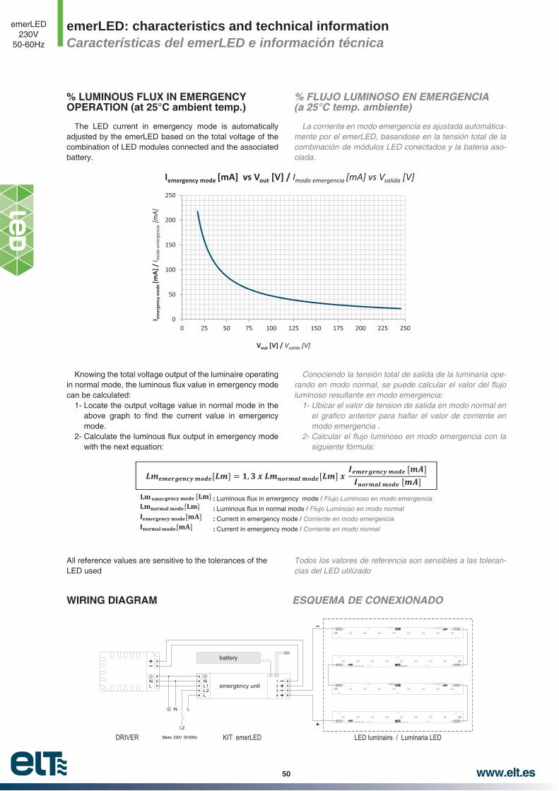
www.elt.es50
emerLED: characteristics and technical informationCaracterísticas del emerLED e información técnica
emerLED230V
50-60Hz
% FLUJO LUMINOSO EN EMERGENCIA (a 25°C temp. ambiente)
La corriente en modo emergencia es ajustada automáticamente por el emerLED, basandose en la tensión total de la combinación de módulos LED conectados y la bateria asociada.
Conociendo la tensión total de salida de la luminaria ope
luminoso resultante en modo emergencia:
modo emergencia .
siguiente fórmula:
Todos los valores de referencia son sensibles a las tolerancias del LED utilizado
% LUMINOUS FLUX IN EMERGENCY OPERATION (at 25°C ambient temp.)
The LED current in emergency mode is automatically adjusted by the emerLED based on the total voltage of the combination of LED modules connected and the associated battery.
Knowing the total voltage output of the luminaire operating
can be calculated:1- Locate the output voltage value in normal mode in the
mode.
with the next equation:
All reference values are sensitive to the tolerances of the LED used
0
50
100
150
200
250
0 25 50 75 100 125 150 175 200 225 250
I emer
genc
y m
ode
[mA]
/ I m
odo
emer
genc
ia [m
A]
Vout [V] / Vsalida [V]
Iemergency mode [mA] vs Vout [V] / Imodo emergencia [mA] vs Vsalida [V]
: Luminous flux in emergency mode / Flujo Luminoso en modo emergencia : Luminous flux in normal mode / Flujo Luminoso en modo normal : Current in emergency mode / Corriente en modo emergencia
: Current in emergency mode / Corriente en modo normal
N
L2
Mains 230V 50-60Hz
L
KIT emerLEDDRIVER LED luminaire / Luminaria LED
RR
RR
RR
RR
battery
NL emergency unit
N 1234
L1L2L
WIRING DIAGRAM ESQUEMA DE CONEXIONADO

www.elt.es 51
LED modules eLED LINE 1 950Módulos LED eLED LINE 1 950
eLED LINE280x24mm
950
Ø 4
1,66,1
2,8
24
18,4
15 1562,5 62,5 62,5 62,5280
1562,5
Model
Modelo
Ref. No.
Typical power in module
Potencia típica en módulo
Maximum current
Intensidad máxima
Typical voltage range
Rango de tensión típica
Colour temp.
Temp. de color
Typical
at amb. temp. 25 °C
Flujo luminoso típico a temp. amb. 25 °C
CR
I
Max
.tem
p. a
t tc
po
int
Tem
p. m
áx. e
n tc
Op
erat
ing
tem
p.
Tem
p. fu
ncio
nam
ient
o
Max
. Tem
p. I
n t
he
jun
ctio
n
Tem
p. M
áx. E
n la
uni
ón
Un
its
per
bo
x
Uni
dade
s po
r ca
ja
W mA V *K *lm lm / W tc (°C) ta (°C) Tj (°C)
eLED LINE 1 950 830 9950502 6,4 700 8,7…9,6 3.000 875 137 >80 75 -40…+55 110 120
eLED LINE 1 950 840 9950501 6,4 700 8,7…9,6 4.000 950 148 >80 75 -40…+55 110 120
Tolerancia de Flujo Luminoso de ±10% y de Temperatura de Color ±7% asegurando una desviación típica de un ±3% por módulo eLED
For other colour temperatures consult our comercial department / Para otras temperaturas de color consultar con el departamento comercial
~ Beam angle 120°.~ Colour tolerance: 3 MacAdam’s ellipses - 3SDCM.~ Excellent thermal performance, it doesn’t require further dissipation~ Dimmable.~ Indifferent installation position.~ Anti-reverse polarity protection.~ Designed upon ZHAGA requirements book 7 cat. LLE-L28W2.~ Push wire connection.~ The connector allows connection and disconnection.~ Wire gauge: 0,2... 0,75 mm2.~ Stripping length: 6...7 mm.
this time period.
~ Diffusers available. See accessories section.
~ Made in Spain.~ 5 years warranty in combination with an appropriate ELT driver.
Packaging and weight p. 171 and www.elt.es/productos/packaging_ELT.pdf
~ Angulo de visión 120°.
~ Bajo calentamiento del módulo, no requiere ningún tipo de disipación extra.
~ Regulable.~ Posición de la operación indiferente.~ Protección contra inversión de polaridad.
~ Conexión mediante conector rápido.~ Conector que permite conexión y desconexión.~ Sección conductor: 0,2... 0,75 mm2.
de este periodo.
~ Difusores disponibles. Ver apartado de accesorios.
~ Fabricado en España.~ Garantía de 5 años en combinación con driver ELT apropiado.
Embalaje y peso pág. 171 y www.elt.es/productos/embalaje_ELT.pdfSelección de producto pág. 77 y www.elt.es/productos/buscador_producto.html
EN 62031 Safety / SeguridadEN 62471 Photo-biological / Fotobiológica
~ LED Module appropriate for operation in constant current.
~ Low voltage of the module, allowing applications up to more than 4.000lm with a voltage under 50V.
~ Low heating of the module due to the independent operation of the LED in low current.
~ Built-in luminaires.
~ Módulo de LED apropiado para funcionamiento en corriente constante.
~ Baja tensión del módulo lo que permite aplicaciones de hasta más
~ Bajo calentamiento del módulo debido al funcionamiento independiente del LED a baja corriente.
~ Instalación en luminaria.

www.elt.es52
ELECCIÓN DEL BIN DEL LED
Cada eLED LINE se fabrica con LED previamente acordado y seleccionado en nuestro proceso logístico, en cuanto a Brillo, Color y Tensión, de esta forma la uniformidad y calidad de la luz está garantizada.
Brillo:
Tensión: Tolerancia en cada LED máxima de 0,1V.Color: La posible variación de color de los LED es imper
ceptible al ojo humano, dando como resultado 3 elipses de MacAdam: 3SDCM.
LED BIN SELECTION
Each eLED LINE is made with approved LED and selected previously during our logistic process, considering bright-ness, colour and voltage, obtaining guaranteed uniformity and light quality.
Brightness:
Voltage: Tolerance in each LED of maximum 0,1V.Colour: The possible variation of LED colour is im-
perceptible to the human eye, and as a result gives 3 MacAdam’s ellipses: 3SDCM.
Current
Intensidad
Colour Temperature
Temperatura de Color
at amb. temp. 25 °C
Flujo luminoso típico a temp. amb. 25 °C
mA *K *lm
700
3.000 875
4.000 950
5.700 975
500
3.000 625
4.000 680
5.700 700
350
3.000 455
4.000 495
5.700 505
LUMINOUS FLUX DATA DATOS DEL FLUJO LUMINOSO
CURVAS DE DISTRIBUCIÓN DE INTENSIDAD LUMÍNICA (Cd/Klm) @700mA
Esta curva de distribución de intensidad lumínica es el resultado de los datos obtenidos de un único modulo eLED LINE sin ningún tipo de óptica.
LUMINOUS INTENSITY DISTRIBUTION CURVES (Cd/Klm) @700mA
This luminous intensity distribution curve is the result of the information obtained with an unique eLED LINE module without any type of optics.
Tolerancia de Flujo Luminoso de ±10% y de Temperatura de Color ±7% asegurando una desviación típica de un ±3% por módulo eLED
Typical Lum
inous Flux (lm
) / Flujo Lum
inoso Típico (lm
)
Current (mA) / Corriente (mA)
3.000K
4.000K
5.000K

www.elt.es 53
COMBINATION EXAMPLES eLED LINE AND ELT DRIVER @700mA
EJEMPLOS DE COMBINACIONES eLED LINE Y DRIVER ELT @700mA
RR RR
RRRR RR RR RR
RR
RR RR RR RR
RR
RR
RR
RR
RR RR
RR
RR
RR RR
RR
RR
DRIVERNL
R
DRIVERNL
R
1
1
3
5
5
7
2 3 4
4 x 2 eLED
2 x 4 eLED
Driver8 x 950 =8 x 9,2 =8 x 6,4 =
LC 160/700-C7.600 Lm
73,6 Vout51,2 W
2
4
6 7 8
6
8
DRIVERNL
R
1 2 3 4 5
4 x 280 = 1.120 mm
2 x 280 = 560 mm
1 x 5 eLED
Driver5 x 280 =5 x 950 =5 x 9,2 =5 x 6,4 =
LC 142/700-C1.400 mm4.750 Lm46 Vout32 W
{
{
{
DRIVER1 2
1 x 2 eLED
Driver2 x 280 =2 x 950 =2 x 9,2 =2 x 6,4 =
LC 116/700-A560 mm1.900 Lm
18,4 Vout12,8 W
Made
inSp
ain(EU
)
R
SEC
+-
~~
PRI {
DRIVER1
1 x 1 eLED
Driver LC 110/700-B280 mm950 Lm9,2 Vout6,4 W
{SEC+-
PRI~~
R
Selección de producto pág. 77 y www.elt.es/productos/buscador_producto.html
Información de instalación y de seguridad
pias, libres de polvo, aceite, silicona u otra suciedad.
Los productos eLED LINE son sensibles a esfuerzos mecánicos, evite aplicar tensiones mecánicas, esfuerzos de
mecánico.
Tome los módulos eLED LINE por los bordes del circuito impreso, nunca sobre la cara top donde se sitúan los componentes LED.
Manipule los productos eLED LINE en zonas protegidas contra la electricidad estática. (ESD Electric Static Discharge).
Se recomienda dejar una separación entre módulos consecutivos para favorecer las dilataciones.
Assembly and Safety Information
The eLED LINE must be applied to dry and clean surfaces that are free from dust, oil, silicone or other soiling.
eLED LINE products are sensitive to mechanical efforts, avoid applying mechanical tensions, bending stresses, mill-ings, pressure, or any other form of mechanical stress on them.
eLED LINE modules should be taken by the edges of the printed circuit board, never by the top side where the LED components are.
Handle eLED LINE products in protected zones against static electricity. (ESD Electric Static Discharge).
A gap between consecutive modules is recommended to facilitate the thermal expansion.
0,5 mm
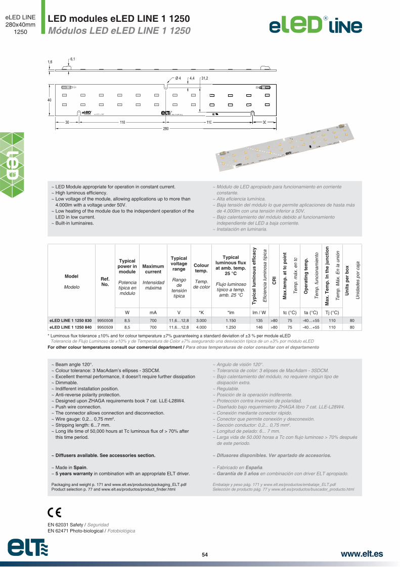
www.elt.es54
LED modules eLED LINE 1 1250Módulos LED eLED LINE 1 1250
eLED LINE280x40mm
1250
Model
Modelo
Ref. No.
Typical power in module
Potencia típica en módulo
Maximum current
Intensidad máxima
Typical voltage range
Rango de
tensión típica
Colour temp.
Temp. de color
Typical
at amb. temp. 25 °C
Flujo luminoso típico a temp. amb. 25 °C
CR
I
Max
.tem
p. a
t tc
po
int
Tem
p. m
áx. e
n tc
Op
erat
ing
tem
p.
Tem
p. fu
ncio
nam
ient
o
Max
. Tem
p. I
n t
he
jun
ctio
n
Tem
p. M
áx. E
n la
uni
ón
Un
its
per
bo
x
Uni
dade
s po
r ca
ja
W mA V *K *lm lm / W tc (°C) ta (°C) Tj (°C)
eLED LINE 1 1250 830 9950508 8,5 700 11,6…12,8 3.000 1.150 135 >80 75 -40…+55 110 80
eLED LINE 1 1250 840 9950509 8,5 700 11,6…12,8 4.000 1.250 146 >80 75 -40…+55 110 80
Tolerancia de Flujo Luminoso de ±10% y de Temperatura de Color ±7% asegurando una desviación típica de un ±3% por módulo eLED
For other colour temperatures consult our comercial department / Para otras temperaturas de color consultar con el departamento
~ Beam angle 120°.~ Colour tolerance: 3 MacAdam’s ellipses - 3SDCM.~ Excellent thermal performance, it doesn’t require further dissipation~ Dimmable.~ Indifferent installation position.~ Anti-reverse polarity protection.~ Designed upon ZHAGA requirements book 7 cat. LLE-L28W4.~ Push wire connection.~ The connector allows connection and disconnection.~ Wire gauge: 0,2... 0,75 mm2.~ Stripping length: 6...7 mm.
this time period.
~ Diffusers available. See accessories section.
~ Made in Spain.~ 5 years warranty in combination with an appropriate ELT driver.
Packaging and weight p. 171 and www.elt.es/productos/packaging_ELT.pdf
~ Angulo de visión 120°.
~ Bajo calentamiento del módulo, no requiere ningún tipo de disipación extra.
~ Regulable.~ Posición de la operación indiferente.~ Protección contra inversión de polaridad.
~ Conexión mediante conector rápido.~ Conector que permite conexión y desconexión.~ Sección conductor: 0,2... 0,75 mm2.
de este periodo.
~ Difusores disponibles. Ver apartado de accesorios.
~ Fabricado en España.~ Garantía de 5 años en combinación con driver ELT apropiado.
Embalaje y peso pág. 171 y www.elt.es/productos/embalaje_ELT.pdfSelección de producto pág. 77 y www.elt.es/productos/buscador_producto.html
EN 62031 Safety / SeguridadEN 62471 Photo-biological / Fotobiológica
~ LED Module appropriate for operation in constant current.
~ Low voltage of the module, allowing applications up to more than 4.000lm with a voltage under 50V.
~ Low heating of the module due to the independent operation of the LED in low current.
~ Built-in luminaires.
~ Módulo de LED apropiado para funcionamiento en corriente constante.
~ Baja tensión del módulo lo que permite aplicaciones de hasta más
~ Bajo calentamiento del módulo debido al funcionamiento independiente del LED a baja corriente.
~ Instalación en luminaria.
Ø 4
1,66,1
4,4
40
31,2
30 30110 110280
30110
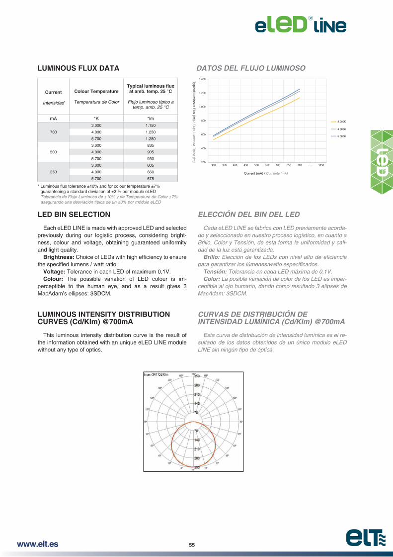
www.elt.es 55
Current
Intensidad
Colour Temperature
Temperatura de Color
at amb. temp. 25 °C
Flujo luminoso típico a temp. amb. 25 °C
mA *K *lm
700
3.000 1.150
4.000 1.250
5.700 1.280
500
3.000 835
4.000 905
5.700 930
350
3.000 605
4.000 660
5.700 675
LUMINOUS FLUX DATA DATOS DEL FLUJO LUMINOSO
ELECCIÓN DEL BIN DEL LED
Cada eLED LINE se fabrica con LED previamente acordado y seleccionado en nuestro proceso logístico, en cuanto a Brillo, Color y Tensión, de esta forma la uniformidad y calidad de la luz está garantizada.
Brillo:
Tensión: Tolerancia en cada LED máxima de 0,1V.Color: La posible variación de color de los LED es imper
ceptible al ojo humano, dando como resultado 3 elipses de MacAdam: 3SDCM.
LED BIN SELECTION
Each eLED LINE is made with approved LED and selected previously during our logistic process, considering bright-ness, colour and voltage, obtaining guaranteed uniformity and light quality.
Brightness:
Voltage: Tolerance in each LED of maximum 0,1V.Colour: The possible variation of LED colour is im-
perceptible to the human eye, and as a result gives 3 MacAdam’s ellipses: 3SDCM.
CURVAS DE DISTRIBUCIÓN DE INTENSIDAD LUMÍNICA (Cd/Klm) @700mA
Esta curva de distribución de intensidad lumínica es el resultado de los datos obtenidos de un único modulo eLED LINE sin ningún tipo de óptica.
LUMINOUS INTENSITY DISTRIBUTION CURVES (Cd/Klm) @700mA
This luminous intensity distribution curve is the result of the information obtained with an unique eLED LINE module without any type of optics.
Tolerancia de Flujo Luminoso de ±10% y de Temperatura de Color ±7% asegurando una desviación típica de un ±3% por módulo eLED
Typical Lum
inous Flux (lm
) / Flujo Lum
inoso Típico (lm
)
Current (mA) / Corriente (mA)
3.000K
4.000K
5.000K

www.elt.es56
COMBINATION EXAMPLES eLED LINE AND ELT DRIVER @700mA
EJEMPLOS DE COMBINACIONES eLED LINE Y DRIVER ELT @700mA
Selección de producto pág. 77 y www.elt.es/productos/buscador_producto.html
Información de instalación y de seguridad
pias, libres de polvo, aceite, silicona u otra suciedad.
Los productos eLED LINE son sensibles a esfuerzos mecánicos, evite aplicar tensiones mecánicas, esfuerzos de
mecánico.
Tome los módulos eLED LINE por los bordes del circuito impreso, nunca sobre la cara top donde se sitúan los componentes LED.
Manipule los productos eLED LINE en zonas protegidas contra la electricidad estática. (ESD Electric Static Discharge).
Se recomienda dejar una separación entre módulos consecutivos para favorecer las dilataciones.
Assembly and Safety Information
The eLED LINE must be applied to dry and clean surfaces that are free from dust, oil, silicone or other soiling.
eLED LINE products are sensitive to mechanical efforts, avoid applying mechanical tensions, bending stresses, mill-ings, pressure, or any other form of mechanical stress on them.
eLED LINE modules should be taken by the edges of the printed circuit board, never by the top side where the LED components are.
Handle eLED LINE products in protected zones against static electricity. (ESD Electric Static Discharge).
A gap between consecutive modules is recommended to facilitate the thermal expansion.
RR
RR
RR
RR
RR
RR
RR
RR
RR
RR
RR RR RR RR
RR RR
RR RR
RR RR RR RR
RR RR
1
1
3
5
5
7
2 3 4
4 x 2 eLED
2 x 4 eLED
Driver8 x 1.250 =8 x 12,2 =8 x 8,5 =
LC 190/700-D10.000 Lm
97,6 Vout68,3 W
2
4
6 7 8
6
8
DRIVERNL
R
1 2 3 4 5
4 x 280 = 1.120 mm
2 x 280 = 560 mm
1 x 5 eLED
Driver5 x 280 =5 x 1.250 =5 x 12,2 =5 x 8,5 =
LC 160/700-C1.400 mm
6.250 Lm61 Vout
42,7 W
{
{
{
DRIVER
1 2
1 x 2 eLED
Driver2 x 280 =2 x 1.250 =2 x 12,2 =2 x 8,5 =
LC 125/700-A560 mm
2.500 Lm24,4 Vout
17,1 W
Made
inSp
ain(E
U)R
S EC
+-
~~
PRI {
DRIVER
1
1 x 1 eLED
Driver LC 110/700-B280 mm1.250 Lm12,2 Vout8,5 W
{SEC+-
PRI~~
R
DRIVERNL
R
DRIVERNL
R
0,5 mm

www.elt.es 57
LED modules eLED LINE 2 1900Módulos LED eLED LINE 2 1900
eLED LINE560x24mm
1900
Model
Modelo
Ref. No.
Typical power in module
Potencia típica en módulo
Maximum current
Intensidad máxima
Typical voltage range
Rango de tensión típica
Colour temp.
Temp. de color
Typical
at amb. temp. 25 °C
Flujo luminoso típico a temp. amb. 25 °C
CR
I
Max
.tem
p. a
t tc
po
int
Tem
p. m
áx. e
n tc
Op
erat
ing
tem
p.
Tem
p. fu
ncio
nam
ient
o
Max
. Tem
p. I
n t
he
jun
ctio
n
Tem
p. m
áx. e
n la
uni
ón
Un
its
per
bo
x
Uni
dade
s po
r ca
ja
W mA V *K *lm lm / W tc (°C) ta (°C) Tj (°C)
eLED LINE 2 1900 830 9950531 12,8 700 17,4…19,2 3.000 1.750 137 >80 75 -40…+55 110 60
eLED LINE 2 1900 840 9950532 12,8 700 17,4…19,2 4.000 1.900 148 >80 75 -40…+55 110 60
Tolerancia de Flujo Luminoso de ±10% y de Temperatura de Color ±7% asegurando una desviación típica de un ±3% por módulo eLED
For other colour temperatures consult our comercial department / Para otras temperaturas de color consultar con el departamento comercial.
~ Beam angle 120°.~ Colour tolerance: 3 MacAdam’s ellipses - 3SDCM.~ Excellent thermal performance, it doesn’t require further dissipation~ Dimmable.~ Indifferent installation position.~ Anti-reverse polarity protection.~ Designed upon ZHAGA requirements book 7 cat. LLE-L56W2.~ Push wire connection.~ The connector allows connection and disconnection.~ Wire gauge: 0,2... 0,75 mm2.~ Stripping length: 6...7 mm.
this time period.
~ Diffusers available. See accessories section.
~ Made in Spain.~ 5 years warranty in combination with an appropriate ELT driver.
Packaging and weight p. 171 and www.elt.es/productos/packaging_ELT.pdf
~ Angulo de visión 120°.
~ Bajo calentamiento del módulo, no requiere ningún tipo de disipación extra.
~ Regulable.~ Posición de la operación indiferente.~ Protección contra inversión de polaridad.
~ Conexión mediante conector rápido.~ Conector que permite conexión y desconexión.~ Sección conductor: 0,2... 0,75 mm2.
de este periodo.
~ Difusores disponibles. Ver apartado de accesorios.
~ Fabricado en España.~ Garantía de 5 años en combinación con driver ELT apropiado.
Embalaje y peso pág. 171 y www.elt.es/productos/embalaje_ELT.pdfSelección de producto pág. 77 y www.elt.es/productos/buscador_producto.html
EN 62031 Safety / SeguridadEN 62471 Photo-biological / Fotobiológica
~ LED Module appropriate for operation in constant current.
~ Low heating of the module due to the independent operation of the LED in low current.
~ Built-in luminaires.
~ Módulo de LED apropiado para funcionamiento en corriente constante.
~ Bajo calentamiento del módulo debido al funcionamiento independiente del LED a baja corriente.
~ Instalación en luminaria.
RR
Ø 4,7
1,6 6,1
2,8
24
18,4
15 15125 125 125 12530560

www.elt.es58
ELECCIÓN DEL BIN DEL LED
Cada eLED LINE se fabrica con LED previamente acordado y seleccionado en nuestro proceso logístico, en cuanto a Brillo, Color y Tensión, de esta forma la uniformidad y calidad de la luz está garantizada.
Brillo:
Tensión: Tolerancia en cada LED máxima de 0,1V.Color: La posible variación de color de los LED es imper
ceptible al ojo humano, dando como resultado 3 elipses de MacAdam: 3SDCM.
LED BIN SELECTION
Each eLED LINE is made with approved LED and selected previously during our logistic process, considering bright-ness, colour and voltage, obtaining guaranteed uniformity and light quality.
Brightness:
Voltage: Tolerance in each LED of maximum 0,1V.Colour: The possible variation of LED colour is im-
perceptible to the human eye, and as a result gives 3 MacAdam’s ellipses: 3SDCM.
Current
Intensidad
Colour Temperature
Temperatura de Color
at amb. temp. 25 °C
Flujo luminoso típico a temp. amb. 25 °C
mA *K *lm
700
3.000 1.750
4.000 1.900
5.700 1.950
500
3.000 1.250
4.000 1.360
5.700 1.390
350
3.000 915
4.000 990
5.700 1.015
LUMINOUS FLUX DATA DATOS DEL FLUJO LUMINOSO
CURVAS DE DISTRIBUCIÓN DE INTENSIDAD LUMÍNICA (Cd/Klm) @700mA
Esta curva de distribución de intensidad lumínica es el resultado de los datos obtenidos de un único modulo eLED LINE sin ningún tipo de óptica.
LUMINOUS INTENSITY DISTRIBUTION CURVES (Cd/Klm) @700mA
This luminous intensity distribution curve is the result of the information obtained with an unique eLED LINE module without any type of optics.
Tolerancia de Flujo Luminoso de ±10% y de Temperatura de Color ±7% asegurando una desviación típica de un ±3% por módulo eLED
Typical Lum
inous Flux (lm
) / Flujo Lum
inoso Típico (lm
)
Current (mA) / Corriente (mA)
3.000K
4.000K
5.000K

www.elt.es 59
COMBINATION EXAMPLES eLED LINE AND ELT DRIVER @700mA
EJEMPLOS DE COMBINACIONES eLED LINE Y DRIVER ELT @700mA
RR
4
DRIVERNL
R
DRIVERNL
R
1
1
2
3
3
2
4 x 1 eLED
2 x 2 eLED
Driver4
LC 160/700-Cx 1.900 =
4 x 18,3 =4 x 12,8 =
7.600 Lm73,2 Vout51,2 W
4
2 x 560 = 1.120 mm
1 x 560 = 560 mm {
{
{
1 x 1 eLED
Driver LC 116/700-A560 mm1.900 Lm18,3 Vout12,8 W
DRIVER1
Made
inSp
ain(E
U)R
SEC
+-
~~
PRI
DRIVERNL
R
1 21 x 2 eLED
Driver2 x 560 =2 x 1.900 =2 x 18,3 =2 x 12,8 =
LC 142/700-C1.120 mm
3.800 Lm36,6 Vout25,6 W
{RR RR
RR
RR
RR
RR
R RR R R R
RR
RR
RR RR
RR
Información de instalación y de seguridad
pias, libres de polvo, aceite, silicona u otra suciedad.
Los productos eLED LINE son sensibles a esfuerzos mecánicos, evite aplicar tensiones mecánicas, esfuerzos de
mecánico.
Tome los módulos eLED LINE por los bordes del circuito impreso, nunca sobre la cara top donde se sitúan los componentes LED.
Manipule los productos eLED LINE en zonas protegidas contra la electricidad estática. (ESD Electric Static Discharge).
Se recomienda dejar una separación entre módulos consecutivos para favorecer las dilataciones.
Assembly and Safety Information
The eLED LINE must be applied to dry and clean surfaces that are free from dust, oil, silicone or other soiling.
eLED LINE products are sensitive to mechanical efforts, avoid applying mechanical tensions, bending stresses, mill-ings, pressure, or any other form of mechanical stress on them.
eLED LINE modules should be taken by the edges of the printed circuit board, never by the top side where the LED components are.
Handle eLED LINE products in protected zones against static electricity. (ESD Electric Static Discharge).
A gap between consecutive modules is recommended to facilitate the thermal expansion.
0,5 mm
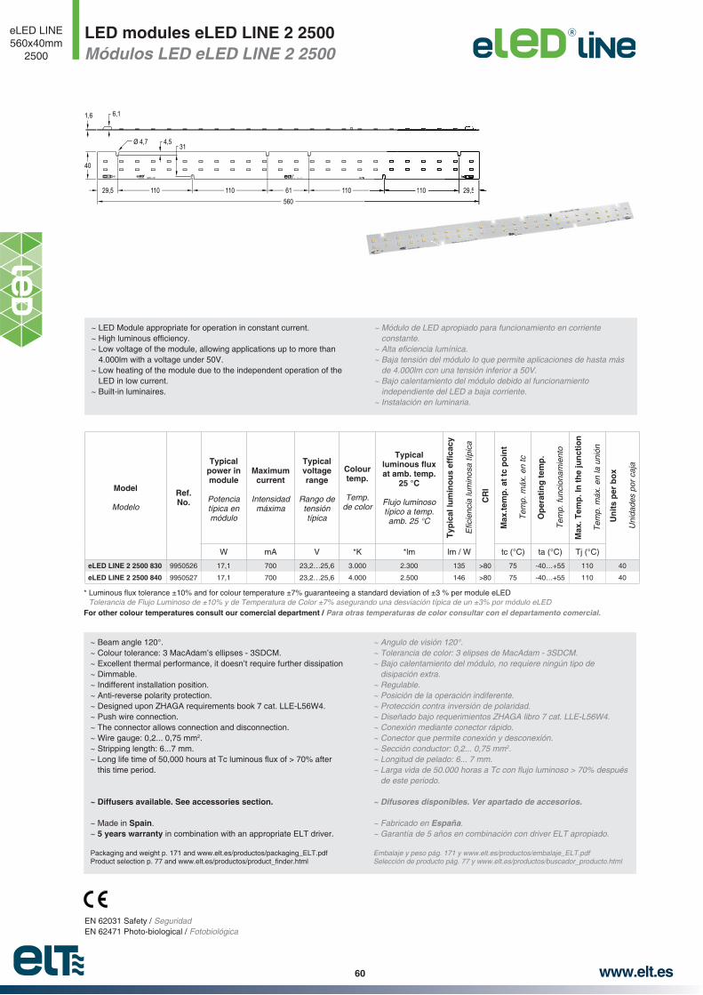
www.elt.es60
LED modules eLED LINE 2 2500Módulos LED eLED LINE 2 2500
eLED LINE560x40mm
2500
Ø 4,7
1,6 6,1
4,5
40
31
29,5 110 110 61560
110 110 29,5110 29,5
Model
Modelo
Ref. No.
Typical power in module
Potencia típica en módulo
Maximum current
Intensidad máxima
Typical voltage range
Rango de tensión típica
Colour temp.
Temp. de color
Typical
at amb. temp. 25 °C
Flujo luminoso típico a temp. amb. 25 °C
CR
I
Max
.tem
p. a
t tc
po
int
Tem
p. m
áx. e
n tc
Op
erat
ing
tem
p.
Tem
p. fu
ncio
nam
ient
o
Max
. Tem
p. I
n t
he
jun
ctio
n
Tem
p. m
áx. e
n la
uni
ón
Un
its
per
bo
x
Uni
dade
s po
r ca
ja
W mA V *K *lm lm / W tc (°C) ta (°C) Tj (°C)
eLED LINE 2 2500 830 9950526 17,1 700 23,2…25,6 3.000 2.300 135 >80 75 -40…+55 110 40
eLED LINE 2 2500 840 9950527 17,1 700 23,2…25,6 4.000 2.500 146 >80 75 -40…+55 110 40
Tolerancia de Flujo Luminoso de ±10% y de Temperatura de Color ±7% asegurando una desviación típica de un ±3% por módulo eLED
For other colour temperatures consult our comercial department / Para otras temperaturas de color consultar con el departamento comercial.
~ Beam angle 120°.~ Colour tolerance: 3 MacAdam’s ellipses - 3SDCM.~ Excellent thermal performance, it doesn’t require further dissipation~ Dimmable.~ Indifferent installation position.~ Anti-reverse polarity protection. ~ Designed upon ZHAGA requirements book 7 cat. LLE-L56W4.~ Push wire connection.~ The connector allows connection and disconnection.~ Wire gauge: 0,2... 0,75 mm2.~ Stripping length: 6...7 mm.
this time period.
~ Diffusers available. See accessories section.
~ Made in Spain.~ 5 years warranty in combination with an appropriate ELT driver.
Packaging and weight p. 171 and www.elt.es/productos/packaging_ELT.pdf
~ Angulo de visión 120°.
~ Bajo calentamiento del módulo, no requiere ningún tipo de disipación extra.
~ Regulable.~ Posición de la operación indiferente.~ Protección contra inversión de polaridad.
~ Conexión mediante conector rápido.~ Conector que permite conexión y desconexión.~ Sección conductor: 0,2... 0,75 mm2.
de este periodo.
~ Difusores disponibles. Ver apartado de accesorios.
~ Fabricado en España.~ Garantía de 5 años en combinación con driver ELT apropiado.
Embalaje y peso pág. 171 y www.elt.es/productos/embalaje_ELT.pdfSelección de producto pág. 77 y www.elt.es/productos/buscador_producto.html
EN 62031 Safety / SeguridadEN 62471 Photo-biological / Fotobiológica
~ LED Module appropriate for operation in constant current.
~ Low voltage of the module, allowing applications up to more than 4.000lm with a voltage under 50V.
~ Low heating of the module due to the independent operation of the LED in low current.
~ Built-in luminaires.
~ Módulo de LED apropiado para funcionamiento en corriente constante.
~ Baja tensión del módulo lo que permite aplicaciones de hasta más
~ Bajo calentamiento del módulo debido al funcionamiento independiente del LED a baja corriente.
~ Instalación en luminaria.

www.elt.es 61
ELECCIÓN DEL BIN DEL LED
Cada eLED LINE se fabrica con LED previamente acordado y seleccionado en nuestro proceso logístico, en cuanto a Brillo, Color y Tensión, de esta forma la uniformidad y calidad de la luz está garantizada.
Brillo:
Tensión: Tolerancia en cada LED máxima de 0,1V.Color: La posible variación de color de los LED es imper
ceptible al ojo humano, dando como resultado 3 elipses de MacAdam: 3SDCM.
LED BIN SELECTION
Each eLED LINE is made with approved LED and selected previously during our logistic process, considering bright-ness, colour and voltage, obtaining guaranteed uniformity and light quality.
Brightness:
Voltage: Tolerance in each LED of maximum 0,1V.Colour: The possible variation of LED colour is im-
perceptible to the human eye, and as a result gives 3 MacAdam’s ellipses: 3SDCM.
Current
Intensidad
Colour Temperature
Temperatura de Color
at amb. temp. 25 °C
Flujo luminoso típico a temp. amb. 25 °C
mA *K *lm
700
3.000 2.300
4.000 2.500
5.700 2.565
500
3.000 1.670
4.000 1.815
5.700 1.860
350
3.000 1.215
4.000 1.318
5.700 1.350
LUMINOUS FLUX DATA DATOS DEL FLUJO LUMINOSO
CURVAS DE DISTRIBUCIÓN DE INTENSIDAD LUMÍNICA (Cd/Klm) @700mA
Esta curva de distribución de intensidad lumínica es el resultado de los datos obtenidos de un único modulo eLED LINE sin ningún tipo de óptica.
LUMINOUS INTENSITY DISTRIBUTION CURVES (Cd/Klm) @700mA
This luminous intensity distribution curve is the result of the information obtained with an unique eLED LINE module without any type of optics.
Tolerancia de Flujo Luminoso de ±10% y de Temperatura de Color ±7% asegurando una desviación típica de un ±3% por módulo eLED
Typical Lum
inous Flux (lm
) / Flujo Lum
inoso Típico (lm
)
Current (mA) / Corriente (mA)
3.000K
4.000K
5.000K

www.elt.es62
COMBINATION EXAMPLES eLED LINE AND ELT DRIVER @700mA
EJEMPLOS DE COMBINACIONES eLED LINE Y DRIVER ELT @700mA
DRIVERNL
R
1
1
2
3
3
4
2
4 x 1 eLED
2 x 2 eLED
Driver4
LC 190/700-Dx 2.500 =
4 x 24,4 =4 x 17,1 =
10.000 Lm97,6 Vout68,4 W
4
2 x 560 = 1.120 mm
1 x 560 = 560 mm
1 x 2 eLED
Driver2 x 560 =2 x 2.500 =2 x 24,4 =2 x 17,1 =
LC 142/700-C1.120 mm
5.000 Lm48,4 Vout34,2 W
{
{
{
{1 2
1 x 1 eLED
Driver LC 125/700-A560 mm2.500 Lm24,4 Vout17,1 W
DRIVER1
Made
inSp
ain(E
U)R
SEC
+-
~~
PRI
DRIVERNL
Made in Spain (EU)
R
DRIVERNL
Made in Spain (EU)
R
R R
R R
R R
R R
RR
RR
RR
RR
R R
R R
R R
Información de instalación y de seguridad
pias, libres de polvo, aceite, silicona u otra suciedad.
Los productos eLED LINE son sensibles a esfuerzos mecánicos, evite aplicar tensiones mecánicas, esfuerzos de
mecánico.
Tome los módulos eLED LINE por los bordes del circuito impreso, nunca sobre la cara top donde se sitúan los componentes LED.
Manipule los productos eLED LINE en zonas protegidas contra la electricidad estática. (ESD Electric Static Discharge).
Se recomienda dejar una separación entre módulos consecutivos para favorecer las dilataciones.
Assembly and Safety Information
The eLED LINE must be applied to dry and clean surfaces that are free from dust, oil, silicone or other soiling.
eLED LINE products are sensitive to mechanical efforts, avoid applying mechanical tensions, bending stresses, mill-ings, pressure, or any other form of mechanical stress on them.
eLED LINE modules should be taken by the edges of the printed circuit board, never by the top side where the LED components are.
Handle eLED LINE products in protected zones against static electricity. (ESD Electric Static Discharge).
A gap between consecutive modules is recommended to facilitate the thermal expansion.
0,5 mm
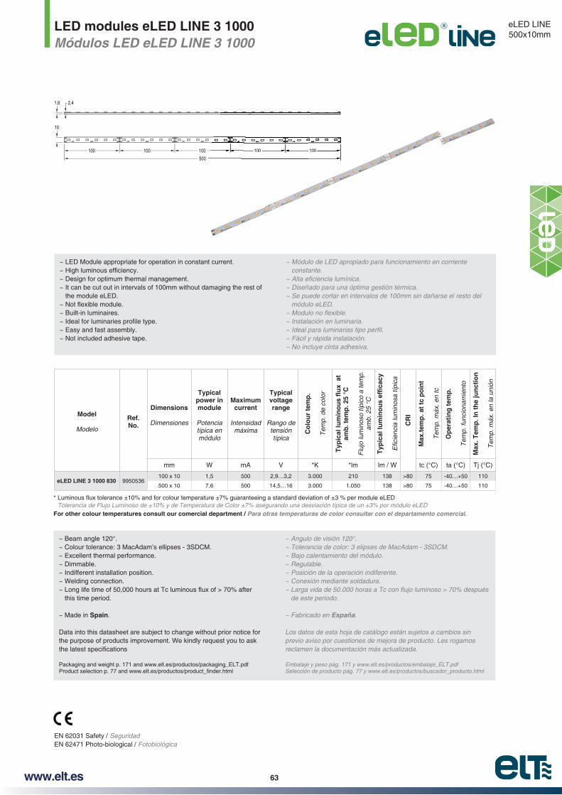
www.elt.es 63
LED modules eLED LINE 3 1000Módulos LED eLED LINE 3 1000
eLED LINE500x10mm
1,6 2,4
10
100 100 100 100 100500
100 100
Model
Modelo
Ref. No.
Dimensions
Dimensiones
Typical power in module
Potencia típica en módulo
Maximum current
Intensidad máxima
Typical voltage range
Rango de tensión típica
Co
lou
r te
mp
.
Tem
p. d
e co
lor
amb
. tem
p. 2
5 °C
Flu
jo lu
min
oso
típic
o a
tem
p.
amb.
25
°C
CR
I
Max
.tem
p. a
t tc
po
int
Tem
p. m
áx. e
n tc
Op
erat
ing
tem
p.
Tem
p. fu
ncio
nam
ient
o
Max
. Tem
p. I
n t
he
jun
ctio
n
Tem
p. m
áx. e
n la
uni
ón
mm W mA V *K *lm lm / W tc (°C) ta (°C) Tj (°C)
eLED LINE 3 1000 830 9950536100 x 10 1,5 500 2,9…3,2 3.000 210 138 >80 75 -40…+50 110
500 x 10 7,6 500 14,5…16 3.000 1.050 138 >80 75 -40…+50 110
Tolerancia de Flujo Luminoso de ±10% y de Temperatura de Color ±7% asegurando una desviación típica de un ±3% por módulo eLED
For other colour temperatures consult our comercial department / Para otras temperaturas de color consultar con el departamento comercial.
~ Beam angle 120°.~ Colour tolerance: 3 MacAdam’s ellipses - 3SDCM.~ Excellent thermal performance.~ Dimmable.~ Indifferent installation position.~ Welding connection.
this time period.
~ Made in Spain.
Data into this datasheet are subject to change without prior notice forthe purpose of products improvement. We kindly request you to ask
Packaging and weight p. 171 and www.elt.es/productos/packaging_ELT.pdf
~ Angulo de visión 120°.
~ Bajo calentamiento del módulo.~ Regulable.~ Posición de la operación indiferente.~ Conexión mediante soldadura.
de este periodo.
~ Fabricado en España.
Los datos de esta hoja de catálogo están sujetos a cambios sin previo aviso por cuestiones de mejora de producto. Les rogamos reclamen la documentación más actualizada.
Embalaje y peso pág. 171 y www.elt.es/productos/embalaje_ELT.pdfSelección de producto pág. 77 y www.elt.es/productos/buscador_producto.html
EN 62031 Safety / SeguridadEN 62471 Photo-biological / Fotobiológica
~ LED Module appropriate for operation in constant current.
~ Design for optimum thermal management.~ It can be cut out in intervals of 100mm without damaging the rest of
the module eLED.
~ Built-in luminaires.
~ Easy and fast assembly.~ Not included adhesive tape.
~ Módulo de LED apropiado para funcionamiento en corriente constante.
~ Diseñado para una óptima gestión térmica.~ Se puede cortar en intervalos de 100mm sin dañarse el resto del
módulo eLED.
~ Instalación en luminaria.
~ Fácil y rápida instalación.~ No incluye cinta adhesiva.
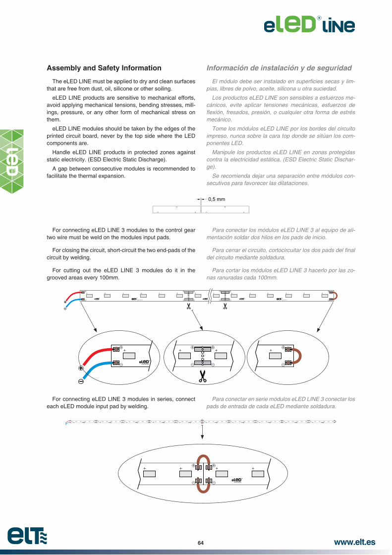
www.elt.es64
Información de instalación y de seguridad
pias, libres de polvo, aceite, silicona u otra suciedad.
Los productos eLED LINE son sensibles a esfuerzos mecánicos, evite aplicar tensiones mecánicas, esfuerzos de
mecánico.
Tome los módulos eLED LINE por los bordes del circuito impreso, nunca sobre la cara top donde se sitúan los componentes LED.
Manipule los productos eLED LINE en zonas protegidas contra la electricidad estática. (ESD Electric Static Discharge).
Se recomienda dejar una separación entre módulos consecutivos para favorecer las dilataciones.
Assembly and Safety Information
The eLED LINE must be applied to dry and clean surfaces that are free from dust, oil, silicone or other soiling.
eLED LINE products are sensitive to mechanical efforts, avoid applying mechanical tensions, bending stresses, mill-ings, pressure, or any other form of mechanical stress on them.
eLED LINE modules should be taken by the edges of the printed circuit board, never by the top side where the LED components are.
Handle eLED LINE products in protected zones against static electricity. (ESD Electric Static Discharge).
A gap between consecutive modules is recommended to facilitate the thermal expansion.
Para conectar en serie módulos eLED LINE 3 conectar los pads de entrada de cada eLED mediante soldadura.
For connecting eLED LINE 3 modules in series, connect each eLED module input pad by welding.
0,5 mm
Para conectar los módulos eLED LINE 3 al equipo de alimentación soldar dos hilos en los pads de inicio.
del circuito mediante soldadura.
Para cortar los módulos eLED LINE 3 hacerlo por las zonas ranuradas cada 100mm.
For connecting eLED LINE 3 modules to the control gear two wire must be weld on the modules input pads.
For closing the circuit, short-circuit the two end-pads of the circuit by welding.
For cutting out the eLED LINE 3 modules do it in the grooved areas every 100mm.

www.elt.es 65
RECOMENDACIONES
CINTA ADHESIVA
mediante cinta adhesiva, recomendamos la utilización de la cinta 3M™ VHB™ Tape RP25 (F).
Las cintas VHB™ se han sometido a gran número de envejecimientos acelerados en cámara climática, incluyendo exposiciones a altas y bajas temperaturas, humedad y radiación ultravioleta, manteniendo muy aceptablemente las propiedades de adhesión.
Ejemplo de ensayo: 92% de su adhesión después de un envejecimiento a 70°C durante 5 años.
RECOMENDACIONES DE USO:
alcohol isopropílico y agua.
La aplicación de la cinta debe realizarse en condiciones
mienda la aplicación a temperaturas inferiores a 10°C.
Almacenar en su embalaje original, en lugar seco y a tem
conservan sus propiedades durante un periodo mínimo de 1
que ver con el protector siliconado. Una vez aplicado el producto, 3M garantiza una vida superior a 10 años.
rendimiento del producto debe ser testado por el usuario para conocer su aptitud para el propósito deseado.
RECOMMENDATIONS
ADHESIVE TAPE-
hesive tape, we recommend the utilization of the tape 3M™ VHB ™ tape RP25 (F).
The VHB™ tapes have been subjected to accelerated aging tests in a climatic chamber, including high and low temperature exposures, humidity and UV radiation, keeping well their adhesion properties.
Example of test: 92% of adhesion after an aging test at 70°C during 5 years.
RECOMMENDATIONS FOR USE:
For maximum bond strength the surfaces should be thor-oughly cleaned with a 50:50 mixture of isopropyl alcohol and water.
Application must be accomplished when temperature is between 21°C and 38°C. Initial tape application to surfaces at temperatures below 10°C is not recommended.
Must be stored in original cartons in a dry place and the temperature must be controlled between 15-25°C. In these conditions its properties keep on for a minimum period of 1 year. It doesn’t mean that the tape will degenerate; it is related to his silicone protector. Once the product is applied, 3M guarantees a lifetime superior to 10 years.
Given the surfaces variety of application, the use and per-formance of the product must be tested by the user in order to know his aptitude for the intended purpose.
Model
Modelo
Dimensions
Dimensiones
Thickness
Espesor
eLED LINE 1 950 278x15 mm 0,6mm
eLED LINE 1 1250 278x25 mm 0,6mm
eLED LINE 2 1900 558x15 mm 0,6mm
eLED LINE 2 2500 558x25 mm 0,6mm
eLED LINE 3 1000 500x10 mm 0,6mm

www.elt.es66
LED modules eLED OCTO 1 2150Módulos LED eLED OCTO 1 2150
eLED OCTO
Ø165mm2150
R
R
152,44 8
38
24
Ø 1253 x 120º
Ø 162
Ø 4
62 1,6
6,158
50
Ø 10,5
Model
Modelo
Ref. No.
Typical power in module
Potencia típica en módulo
Maximum current
Intensidad máxima
Typical voltage range
Rango de tensión típica
Co
lou
r te
mp
.
Tem
p. d
e co
lor
amb
. tem
p. 2
5 °C
Flu
jo lu
min
oso
típic
o a
tem
p.
amb.
25
°C
CR
I
Max
.tem
p. a
t tc
po
int
Tem
p. m
áx. e
n tc
Op
erat
ing
tem
p.
Tem
p. fu
ncio
nam
ient
o
Max
. Tem
p. I
n t
he
jun
ctio
n
Tem
p. m
áx. e
n la
uni
ón
Un
its
per
bo
x
Uni
dade
s po
r ca
ja
W mA V *K *lm lm / W tc (°C) ta (°C) Tj (°C)
eLED OCTO 1 2150 830 9950551 15 700 20,3…22,4 3.000 2.000 134 >80 75 -40…+55 110 30
eLED OCTO 1 2150 840 9950552 15 700 20,3…22,4 4.000 2.150 143 >80 75 -40…+55 110 30
Tolerancia de Flujo Luminoso de ±10% y de Temperatura de Color ±7% asegurando una desviación típica de un ±3% por módulo eLED
For other colour temperatures consult our comercial department / Para otras temperaturas de color consultar con el departamento comercial.
~ Beam angle 120°.~ Colour tolerance: 3 MacAdam’s ellipses - 3SDCM.~ Excellent thermal performance, it doesn’t require further dissipation~ Dimmable.~ Indifferent installation position.~ Anti-reverse polarity protection. ~ Push wire connection.~ The connector allows connection and disconnection.~ Wire gauge: 0,2... 0,75 mm2.~ Stripping length: 6...7 mm.
this time period.
~ Diffusers available. See accessories section.
~ Made in Spain.~ 5 years warranty in combination with an appropriate ELT driver.
Packaging and weight p. 171 and www.elt.es/productos/packaging_ELT.pdf
~ Angulo de visión 120°.
~ Bajo calentamiento del módulo, no requiere ningún tipo de disipación extra.
~ Regulable.~ Posición de la operación indiferente.~ Protección contra inversión de polaridad.~ Conexión mediante conector rápido.~ Conector que permite conexión y desconexión.~ Sección conductor: 0,2... 0,75 mm2.
de este periodo.
~ Difusores disponibles. Ver apartado de accesorios.
~ Fabricado en España.~ Garantía de 5 años en combinación con driver ELT apropiado.
Embalaje y peso pág. 171 y www.elt.es/productos/embalaje_ELT.pdfSelección de producto pág. 77 y www.elt.es/productos/buscador_producto.html
EN 62031 Safety / SeguridadEN 62471 Photo-biological / Fotobiológica
~ LED Module appropriate for operation in constant current.
~ Low heating of the module due to the independent operation of the LED in low current.
~ Built-in luminaires.
~ Módulo de LED apropiado para funcionamiento en corriente constante.
~ Bajo calentamiento del módulo debido al funcionamiento independiente del LED a baja corriente.
~ Instalación en luminaria.

www.elt.es 67
ELECCIÓN DEL BIN DEL LED
Cada eLED OCTO se fabrica con LED previamente acordado y seleccionado en nuestro proceso logístico, en cuanto a Brillo, Color y Tensión, de esta forma la uniformidad y calidad de la luz está garantizada.
Brillo:
Tensión: Tolerancia en cada LED máxima de 0,1V.Color: La posible variación de color de los LED es imper
ceptible al ojo humano, dando como resultado 3 elipses de MacAdam: 3SDCM.
LED BIN SELECTION
Each eLED OCTO is made with approved LED and select-ed previously during our logistic process, considering bright-ness, colour and voltage, obtaining guaranteed uniformity and light quality.
Brightness:
Voltage: Tolerance in each LED of maximum 0,1V.Colour: The possible variation of LED colour is im-
perceptible to the human eye, and as a result gives 3 MacAdam’s ellipses: 3SDCM.
LUMINOUS FLUX DATA DATOS DEL FLUJO LUMINOSO
CURVAS DE DISTRIBUCIÓN DE INTENSIDAD LUMÍNICA (Cd/Klm) @700mA
Esta curva de distribución de intensidad lumínica es el resultado de los datos obtenidos de un único modulo eLED OCTO sin ningún tipo de óptica.
LUMINOUS INTENSITY DISTRIBUTION CURVES (Cd/Klm) @700mA
This luminous intensity distribution curve is the result of the information obtained with an unique eLED OCTO module without any type of optics.
Current
Intensidad
Colour Temperature
Temperatura de Color
at amb. temp. 25 °C
Flujo luminoso típico a temp. amb. 25 °C
mA *K *lm
700
3.000 2.000
4.000 2.150
5.700 2.200
500
3.000 1.465
4.000 1.585
5.700 1.625
350
3.000 1.065
4.000 1.155
5.700 1.180
Tolerancia de Flujo Luminoso de ±10% y de Temperatura de Color ±7% asegurando una desviación típica de un ±3% por módulo eLED
Typical Lum
inous Flux (lm
) / Flujo Lum
inoso Típico (lm
)
Current (mA) / Corriente (mA)
3.000K
4.000K
5.000K
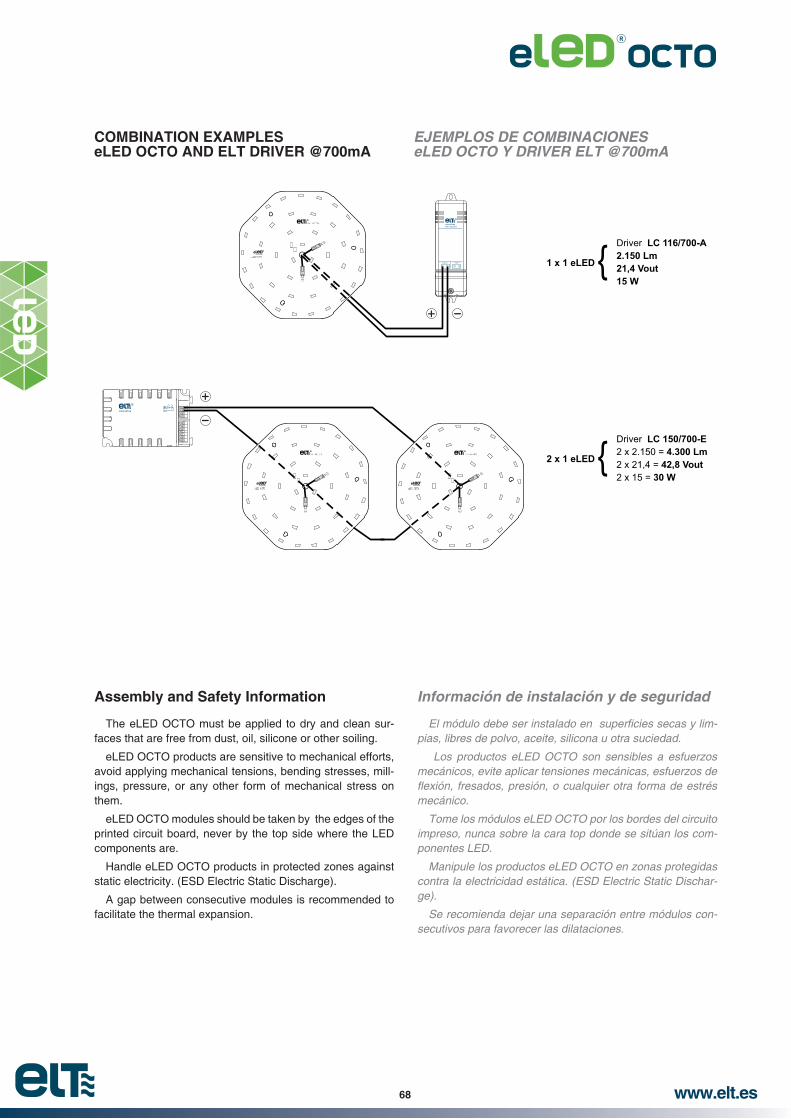
www.elt.es68
COMBINATION EXAMPLES eLED OCTO AND ELT DRIVER @700mA
EJEMPLOS DE COMBINACIONES eLED OCTO Y DRIVER ELT @700mA
Made in Spain (EU)
R
SEC+ - ~ ~PRI
R
2 x 1 eLED
Driver2 x 2.150 =2 x 21,4 =2 x 15 =
LC 150/700-E4.300 Lm
42,8 Vout30 W
{
1 x 1 eLED
Driver LC 116/700-A2.150 Lm21,4 Vout15 W
{
R
R
R
R
R
R
Información de instalación y de seguridad
pias, libres de polvo, aceite, silicona u otra suciedad.
Los productos eLED OCTO son sensibles a esfuerzos mecánicos, evite aplicar tensiones mecánicas, esfuerzos de
mecánico.
Tome los módulos eLED OCTO por los bordes del circuito impreso, nunca sobre la cara top donde se sitúan los componentes LED.
Manipule los productos eLED OCTO en zonas protegidas contra la electricidad estática. (ESD Electric Static Discharge).
Se recomienda dejar una separación entre módulos consecutivos para favorecer las dilataciones.
Assembly and Safety Information
The eLED OCTO must be applied to dry and clean sur-faces that are free from dust, oil, silicone or other soiling.
eLED OCTO products are sensitive to mechanical efforts, avoid applying mechanical tensions, bending stresses, mill-ings, pressure, or any other form of mechanical stress on them.
eLED OCTO modules should be taken by the edges of the printed circuit board, never by the top side where the LED components are.
Handle eLED OCTO products in protected zones against static electricity. (ESD Electric Static Discharge).
A gap between consecutive modules is recommended to facilitate the thermal expansion.

www.elt.es 69
LED modules eLED OCTO 1 2550Módulos LED eLED OCTO 1 2550
eLED OCTO
Ø165mm2550
152,44 8
38
24
Ø 1253 x 120º
Ø 162
Ø 4
62 1,6
6,158
50
Ø 10,5
R
R
Model
Modelo
Ref. No.
Typical power in module
Potencia típica en módulo
Maximum current
Intensidad máxima
Typical voltage range
Rango de tensión típica
Co
lou
r te
mp
.
Tem
p. d
e co
lor
amb
. tem
p. 2
5 °C
Flu
jo lu
min
oso
típic
o a
tem
p.
amb.
25
°C
CR
I
Max
.tem
p. a
t tc
po
int
Tem
p. m
áx. e
n tc
Op
erat
ing
tem
p.
Tem
p. fu
ncio
nam
ient
o
Max
. Tem
p. I
n t
he
jun
ctio
n
Tem
p. m
áx. e
n la
uni
ón
Un
its
per
bo
x
Uni
dade
s po
r ca
ja
W mA V *K *lm lm / W tc (°C) ta (°C) Tj (°C)
eLED OCTO 1 2550 830 9950556 19,5 700 26,1…28,8 3.000 2.350 121 >80 75 -40…+55 110 30
eLED OCTO 1 2550 840 9950557 19,5 700 26,1…28,8 4.000 2.550 131 >80 75 -40…+55 110 30
Tolerancia de Flujo Luminoso de ±10% y de Temperatura de Color ±7% asegurando una desviación típica de un ±3% por módulo eLED
For other colour temperatures consult our comercial department / Para otras temperaturas de color consultar con el departamento comercial.
~ Beam angle 120°.~ Colour tolerance: 3 MacAdam’s ellipses - 3SDCM.~ Excellent thermal performance, it doesn’t require further dissipation~ Dimmable.~ Indifferent installation position.~ Anti-reverse polarity protection. ~ Push wire connection.~ The connector allows connection and disconnection.~ Wire gauge: 0,2... 0,75 mm2.~ Stripping length: 6...7 mm.
this time period.
~ Diffusers available. See accessories section.
~ Made in Spain.~ 5 years warranty in combination with an appropriate ELT driver.
Packaging and weight p. 171 and www.elt.es/productos/packaging_ELT.pdf
~ Angulo de visión 120°.
~ Bajo calentamiento del módulo, no requiere ningún tipo de disipación extra.
~ Regulable.~ Posición de la operación indiferente.~ Protección contra inversión de polaridad.~ Conexión mediante conector rápido.~ Conector que permite conexión y desconexión.~ Sección conductor: 0,2... 0,75 mm2.
de este periodo.
~ Difusores disponibles. Ver apartado de accesorios.
~ Fabricado en España.~ Garantía de 5 años en combinación con driver ELT apropiado.
Embalaje y peso pág. 171 y www.elt.es/productos/embalaje_ELT.pdfSelección de producto pág. 77 y www.elt.es/productos/buscador_producto.html
EN 62031 Safety / SeguridadEN 62471 Photo-biological / Fotobiológica
~ LED Module appropriate for operation in constant current.
~ Low heating of the module due to the independent operation of the LED in low current.
~ Built-in luminaires.
~ Módulo de LED apropiado para funcionamiento en corriente constante.
~ Bajo calentamiento del módulo debido al funcionamiento independiente del LED a baja corriente.
~ Instalación en luminaria.
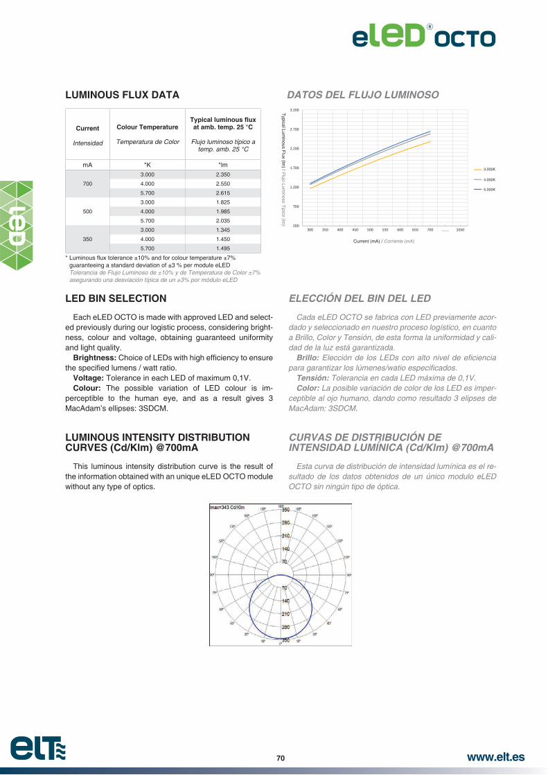
www.elt.es70
ELECCIÓN DEL BIN DEL LED
Cada eLED OCTO se fabrica con LED previamente acordado y seleccionado en nuestro proceso logístico, en cuanto a Brillo, Color y Tensión, de esta forma la uniformidad y calidad de la luz está garantizada.
Brillo:
Tensión: Tolerancia en cada LED máxima de 0,1V.Color: La posible variación de color de los LED es imper
ceptible al ojo humano, dando como resultado 3 elipses de MacAdam: 3SDCM.
LED BIN SELECTION
Each eLED OCTO is made with approved LED and select-ed previously during our logistic process, considering bright-ness, colour and voltage, obtaining guaranteed uniformity and light quality.
Brightness:
Voltage: Tolerance in each LED of maximum 0,1V.Colour: The possible variation of LED colour is im-
perceptible to the human eye, and as a result gives 3 MacAdam’s ellipses: 3SDCM.
LUMINOUS FLUX DATA DATOS DEL FLUJO LUMINOSO
CURVAS DE DISTRIBUCIÓN DE INTENSIDAD LUMÍNICA (Cd/Klm) @700mA
Esta curva de distribución de intensidad lumínica es el resultado de los datos obtenidos de un único modulo eLED OCTO sin ningún tipo de óptica.
LUMINOUS INTENSITY DISTRIBUTION CURVES (Cd/Klm) @700mA
This luminous intensity distribution curve is the result of the information obtained with an unique eLED OCTO module without any type of optics.
Current
Intensidad
Colour Temperature
Temperatura de Color
at amb. temp. 25 °C
Flujo luminoso típico a temp. amb. 25 °C
mA *K *lm
700
3.000 2.350
4.000 2.550
5.700 2.615
500
3.000 1.825
4.000 1.985
5.700 2.035
350
3.000 1.345
4.000 1.450
5.700 1.495
Tolerancia de Flujo Luminoso de ±10% y de Temperatura de Color ±7% asegurando una desviación típica de un ±3% por módulo eLED
Typical Lum
inous Flux (lm
) / Flujo Lum
inoso Típico (lm
)
Current (mA) / Corriente (mA)
3.000K
4.000K
5.000K

www.elt.es 71
COMBINATION EXAMPLESS eLED OCTO AND ELT DRIVER @700mA
EJEMPLOS DE COMBINACIONES eLED OCTO Y DRIVER ELT @700mA
MadeinSpain (EU)
R
SEC+ - ~ ~PRI
R
2 x 1 eLED
Driver2 x 2.550 =2 x 27,9 =2 x 19,5 =
LC 150/700-E5.100 Lm
55,8 Vout39 W
{
1 x 1 eLED
Driver LC 125/700-A2.550 Lm27,9 Vout19,5 W
{R
R
R
R
R
R
Información de instalación y de seguridad
pias, libres de polvo, aceite, silicona u otra suciedad.
Los productos eLED OCTO son sensibles a esfuerzos mecánicos, evite aplicar tensiones mecánicas, esfuerzos de
mecánico.
Tome los módulos eLED OCTO por los bordes del circuito impreso, nunca sobre la cara top donde se sitúan los componentes LED.
Manipule los productos eLED OCTO en zonas protegidas contra la electricidad estática. (ESD Electric Static Discharge).
Se recomienda dejar una separación entre módulos consecutivos para favorecer las dilataciones.
Assembly and Safety Information
The eLED OCTO must be applied to dry and clean sur-faces that are free from dust, oil, silicone or other soiling.
eLED OCTO products are sensitive to mechanical efforts, avoid applying mechanical tensions, bending stresses, mill-ings, pressure, or any other form of mechanical stress on them.
eLED OCTO modules should be taken by the edges of the printed circuit board, never by the top side where the LED components are.
Handle eLED OCTO products in protected zones against static electricity. (ESD Electric Static Discharge).
A gap between consecutive modules is recommended to facilitate the thermal expansion.

www.elt.es72
LED modules eLED SQUARE 2 1900Módulos LED eLED SQUARE 2 1900
eLED SQUARE250mm1900
R R
1,6
6,1
Ø 4,7
250 166,7
205,6250
Model
Modelo
Ref. No.
Typical power in module
Potencia típica en módulo
Maximum current
Intensidad máxima
Typical voltage range
Rango de tensión típica
Co
lou
r te
mp
.
Tem
p. d
e co
lor
amb
. tem
p. 2
5 °C
Flu
jo lu
min
oso
típic
o a
tem
p.
amb.
25
°C
CR
I
Max
.tem
p. a
t tc
po
int
Tem
p. m
áx. e
n tc
Op
erat
ing
tem
p.
Tem
p. fu
ncio
nam
ient
o
Max
. Tem
p. I
n t
he
jun
ctio
n
Tem
p. m
áx. e
n la
uni
ón
Un
its
per
bo
x
Uni
dade
s po
r ca
ja
W mA V *K *lm lm / W tc (°C) ta (°C) Tj (°C)
eLED SQUARE 2 1900 830 9950541 12,3 700 16,2…18 3.000 1.750 143 >80 75 -40…+55 110 30
eLED SQUARE 2 1900 840 9950542 12,3 700 16,2…18 4.000 1.900 155 >80 75 -40…+55 110 30
Tolerancia de Flujo Luminoso de ±10% y de Temperatura de Color ±7% asegurando una desviación típica de un ±3% por módulo eLED
For other colour temperatures consult our comercial department / Para otras temperaturas de color consultar con el departamento comercial.
~ Beam angle 120°.~ Colour tolerance: 3 MacAdam’s ellipses - 3SDCM.~ Excellent thermal performance, it doesn’t require further dissipation~ Dimmable.~ Indifferent installation position.~ Anti-reverse polarity protection. ~ Push wire connection.~ The connector allows connection and disconnection.~ Wire gauge: 0,2... 0,75 mm2.~ Stripping length: 6...7 mm.
this time period.
~ Diffusers available. See accessories section.
~ Made in Spain.~ 5 years warranty in combination with an appropriate ELT driver.
Packaging and weight p. 171 and www.elt.es/productos/packaging_ELT.pdf
~ Angulo de visión 120°.
~ Bajo calentamiento del módulo, no requiere ningún tipo de disipación extra.
~ Regulable.~ Posición de la operación indiferente.~ Protección contra inversión de polaridad.~ Conexión mediante conector rápido.~ Conector que permite conexión y desconexión.~ Sección conductor: 0,2... 0,75 mm2.
de este periodo.
~ Difusores disponibles. Ver apartado de accesorios.
~ Fabricado en España.~ Garantía de 5 años en combinación con driver ELT apropiado.
Embalaje y peso pág. 171 y www.elt.es/productos/embalaje_ELT.pdfSelección de producto pág. 77 y www.elt.es/productos/buscador_producto.html
EN 62031 Safety / SeguridadEN 62471 Photo-biological / Fotobiológica
~ LED Module appropriate for operation in constant current.
~ Low heating of the module due to the independent operation of the LED in low current.
~ Built-in luminaires.
~ Módulo de LED apropiado para funcionamiento en corriente constante.
~ Bajo calentamiento del módulo debido al funcionamiento independiente del LED a baja corriente.
~ Instalación en luminaria.
OPERATING MODE AT 500mA / MODO DE FUNCIONAMIENTO A 500mA
eLED SQUARE 2 1900 830 9950541 8,6 500 16,2…18 3.000 1.385 162 >80 75 -40…+55 110 30
eLED SQUARE 2 1900 840 9950542 8,6 500 16,2…18 4.000 1.500 175 >80 75 -40…+55 110 30

www.elt.es 73
ELECCIÓN DEL BIN DEL LED
Cada eLED SQUARE se fabrica con LED previamente acordado y seleccionado en nuestro proceso logístico, en cuanto a Brillo, Color y Tensión, de esta forma la uniformidad y calidad de la luz está garantizada.
Brillo:
Tensión: Tolerancia en cada LED máxima de 0,1V.Color: La posible variación de color de los LED es imper
ceptible al ojo humano, dando como resultado 3 elipses de MacAdam: 3SDCM.
LED BIN SELECTION
Each eLED SQUARE is made with approved LED and selected previously during our logistic process, considering brightness, colour and voltage, obtaining guaranteed uni-formity and light quality.
Brightness:
Voltage: Tolerance in each LED of maximum 0,1V.Colour: The possible variation of LED colour is im-
perceptible to the human eye, and as a result gives 3 MacAdam’s ellipses: 3SDCM.
Current
Intensidad
Colour Temperature
Temperatura de Color
at amb. temp. 25 °C
Flujo luminoso típico a temp. amb. 25 °C
mA *K *lm
700
3.000 1.750
4.000 1.900
5.700 1.950
500
3.000 1.315
4.000 1.425
5.700 1.465
LUMINOUS FLUX DATA DATOS DEL FLUJO LUMINOSO
CURVAS DE DISTRIBUCIÓN DE INTENSIDAD LUMÍNICA (Cd/Klm) @700mA
Esta curva de distribución de intensidad lumínica es el resultado de los datos obtenidos de un único modulo eLED SQUARE sin ningún tipo de óptica.
LUMINOUS INTENSITY DISTRIBUTION CURVES (Cd/Klm) @700mA
This luminous intensity distribution curve is the result of the information obtained with an unique eLED SQUARE module without any type of optics.
Tolerancia de Flujo Luminoso de ±10% y de Temperatura de Color ±7% asegurando una desviación típica de un ±3% por módulo eLED
Typical Lum
inous Flux (lm
) / Flujo Lum
inoso Típico (lm
)
Current (mA) / Corriente (mA)
3.000K
4.000K
5.000K

www.elt.es74
COMBINATION EXAMPLES eLED SQUARE AND ELT DRIVER @700mA
EJEMPLOS DE COMBINACIONES eLED SQUARE Y DRIVER ELT @700mA
DRIVERNL
R
2 x 1 eLED
Driver2
LC 125/700-Ax 1.900 =
2 x 17,50 =2 x 12,25 =
3.800 Lm35 Vout24,50 W
{
{1 x 1 eLED
Driver LC 116/700-A1.900 Lm17,50 Vout12,25 W
DRIVER
M ade
inSp
ain(E
U)R
SEC
+-
~~
PRI
DRIVER
Made
inSp
ain(E
U)R
SEC
+-
~~
PRI
R R
R R R R
RRRR
R R R R
4 x 1 eLED
Driver4
LC 160/700-Cx 1.900 =
4 x 17,50 =4 x 12,25 =
7.600 Lm70 Vout49 W
{
Información de instalación y de seguridad
pias, libres de polvo, aceite, silicona u otra suciedad.
Los productos eLED SQUARE son sensibles a esfuerzos mecánicos, evite aplicar tensiones mecánicas, esfuerzos de
mecánico.
Tome los módulos eLED SQUARE por los bordes del circuito impreso, nunca sobre la cara top donde se sitúan los componentes LED.
Manipule los productos eLED SQUARE en zonas protegidas contra la electricidad estática. (ESD Electric Static Discharge).
Se recomienda dejar una separación entre módulos consecutivos para favorecer las dilataciones.
Assembly and Safety Information
The eLED SQUARE must be applied to dry and clean sur-faces that are free from dust, oil, silicone or other soiling.
eLED SQUARE products are sensitive to mechanical ef-forts, avoid applying mechanical tensions, bending stresses, millings, pressure, or any other form of mechanical stress on them.
eLED SQUARE modules should be taken by the edges of the printed circuit board, never by the top side where the LED components are.
Handle eLED SQUARE products in protected zones against static electricity. (ESD Electric Static Discharge).
A gap between consecutive modules is recommended to facilitate the thermal expansion.
0,5 mm
* Typical values as a result of the module combinations / Valores típicos resultantes de la combinación de los módulos
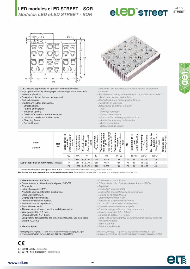
www.elt.es 75
LED modules eLED STREET – SQRMódulos LED eLED STREET - SQR
eLED STREET
Model
Modelo
Ref. No.
Typ
ical
po
wer
in
mo
du
leP
oten
cia
típic
a en
m
ódul
o
Typ
ical
cu
rren
tC
orrie
nte
típic
a
Typ
ical
vo
ltag
e ra
ng
eR
ango
de
tens
ión
típic
a
Co
lou
r te
mp
.T
emp.
de
colo
r
Typ
ical
lum
ino
us
25 °
CF
lujo
lum
inos
o típ
ico
a te
mp.
am
b. 2
5 °C
Typ
ical
lum
ino
us
típic
a
CR
I
Max
.tem
p. a
t tc
p
oin
tT
emp.
máx
. en
tc
Op
erat
ing
tem
p.
Tem
p.
func
iona
mie
nto
Max
. Tem
p. i
n t
he
jun
ctio
nT
emp.
Máx
. en
la
unió
n
Un
its
per
bo
xU
nida
des
por
caja
*W mA V K *lm lm / W tc (°C) ta (°C) Tj (°C)
eLED STREET-SQR 24 AVN-V 4000K 9950592
34 500 64,8…74,4 4.000 5.450 160 >70 95 -40…+60 150 1
47 700 64,8…74,4 4.000 7.050 150 >70 95 -40…+60 150 1
73 1.050 64,8…74,4 4.000 10.050 138 >70 95 -40…+50 150 1
Tolerancia de los datos eléctricos y luminicos: ±10%.For further currents consult our commercial department / Para otras corrientes consultar con el departamento comercial
~ Maximum current 1.400mA.~ Colour tolerance: 3 MacAdam’s ellipses - 3SDCM.~ Dimmable.~ Index of protection: IP20.~ Available others photometric distributions.~ Optic Material PMMA.~ Degree of protection: IP20.~ Indifferent installation position.~ Anti-reverse polarity protection.~ Push wire connection.~ The connector allows connection and disconnection.~ Wire gauge: 0,5... 1,5 mm2.~ Stripping length: 7... 10 mm.~ Long lifetime for guarantee the lumen maintenance. See next table.~ Weight: 1,225 Kg.
~ Made in Spain.
Packaging and weight p. 171 and www.elt.es/productos/packaging_ELT.pdfInstructions manual on www.elt.es/productos/inst_manual.html
~ Regulable.~ Grado de Protección: IP20.~ Disponibles otras distribuciones fotométricas.~ Material de la óptica PMMA.~ Grado de protección: IP20.~ Posición de la operación indiferente.~ Protección contra inversión de polaridad.~ Conexión mediante conector rápido.~ Conector que permite conexión y desconexión.~ Sección conductor: 0,5... 1,5 mm2.~ Longitud de pelado: 7... 10 mm.
Ver siguiente tabla.~ Peso: 1,225 Kg.~ Fabricado en España.
Embalaje y peso pág. 171 y www.elt.es/productos/embalaje_ELT.pdfManual de instrucciones en www.elt.es/productos/manual_instrucciones.html
EN 62031 Safety / SeguridadEN 62471 Photo-biological / Fotobiológica
~ LED Module appropriate for operation in constant current.
various applications.~ Design for optimum thermal management~ Built-in luminaires.~ Outdoor and indoor applications:
~ Street Lighting. ~ Parking and Garage. ~ Industrial Lighting. ~ Outdoor Ornamental and Architectural. ~ Urban and residential environments. ~ Shopping Areas. ~ General Indoor.
~ Módulo de LED apropiado para funcionamiento en corriente constante.
válidas para diversas aplicaciones.~ Diseñado para una óptima gestión térmica.~ Instalación en luminaria.~ Aplicaciones de exterior e Interior:
~ Vial.
~ Iluminación industrial. ~ Entornos Decorativos y arquitectonicos. ~ Ambientes urbanos y residenciales. ~ Areas comerciales. ~ Aplicaciones de interior.
Ø 3,6Ø 9
52 60 524,54,5173
15,686,5
60
6
60
108
136

www.elt.es76
CURVAS DE DISTRIBUCIÓN DE INTENSIDAD LUMÍNICA (Cd/Klm)
LUMINOUS INTENSITY DISTRIBUTION CURVES (Cd/Klm)
Información de instalación y de seguridad
pias, libres de polvo, aceite, silicona u otra suciedad.
Los productos eLED son sensibles a esfuerzos mecáni
fresados, presión, o cualquier otra forma de estrés mecánico.
Tome los módulos eLED STREET por los bordes del disipador, nunca sobre la cara top donde se sitúan las ópticas.
Manipule los productos eLED STREET en zonas protegidas contra la electricidad estática. (ESD Electric Static Discharge).
Assembly and Safety Information
The eLED STREET must be applied to dry and clean sur-faces that are free from dust, oil, silicone or other soiling.
eLED products are sensitive to mechanical efforts, avoid applying mechanical tensions, bending stresses, millings, pressure, or any other form of mechanical stress on them.
eLED STREET modules should be taken by the edges of the heat sink, never by the top side where the optics are.
Handle eLED STREET products in protected zones against static electricity. (ESD Electric Static Discharge).
TIEMPO DE VIDA, MANTENIMIENTO DE FLUJO LUMINOSO Y PORCETANJE DE FALLO
L:declarado en relación con los iniciales.
B: Describe el porcentaje de eLED STREET que están por debajo del valor de L.
LIFE-TIME, LUMEN MAINTENANCE AND FAILURE RATE
L: Percentage of lumens there are at the declared time in relation to the initial lumens.
B: Describes the percentage eLED STREET are below the value of L.
Current
Intensidad
Temp. tc point
Temp. en tc L70B10 L70B50 L80B10 L80B50
mA °C
500
75 > 80.000 > 200.000 > 55.000 > 150.000
85 > 60.000 > 180.000 > 40.000 > 115.000
95 > 45.000 > 140.000 > 30.000 > 85.000
700
75 > 75.000 > 215.000 > 50.000 > 135.000
85 > 55.000 > 165.000 > 35.000 > 100.000
95 > 40.000 >125.000 > 25.000 > 75.000
1050
75 > 60.000 > 170.000 > 40.000 > 110.000
85 > 45.000 > 135.000 > 30.000 > 80.000
95 > 35.000 > 100.000 > 20.000 > 65.000
eLED STREET-SQR 24 AVN-V

www.elt.es 77
Combinations between LC drivers and eLED LINE modules Combinaciones de fuentes de alimentación LC con módulos eLED LINE
Las siguientes tablas muestran las posibles combinacio
piados ELT en funcionamiento de corriente constante.
En ellas se puede encontrar la solución más adecuada
NOTAS:
centes a instalar.
lados considerando que se ha utilizado un balasto electrónico ELT.
Para encontrar la solución más óptima para su aplicación, hay que seguir los siguientes pasos o pautas:
En ocasiones aparecerán más de una opción. La elección más adecuada dependerá de si se desea mantener la mis
con lo cual aumentará la luminosidad o por el contrario se decide por disminuir la potencia y por lo tanto mantener el
En ambos casos la solución con eLED LINE siempre será
Los módulos se deben conectar siempre en serie.
En la elección del driver de la tabla, “x2” representa la necesidad de dos circuitos independientes con un driver para cada uno de ellos en lugar de uno único con todos los eLED LINE en serie.
según los lúmenes o potencia que desea para su aplicación.
* Le invitamos a visitar nuestra página web para obtener los mismos datos con módulos de 3.000K y 5.700K:
www.elt.es/productos/buscador_producto.html
*Si no encuentra la aplicación que desea o si su aplicación es para una luminaria especial, por favor póngase en contacto con el departamento comercial.
The following tables show the possible combinations of 4000K eLED LINE modules with the most appropriate con-stant current ELT control gears.
suitable solution for the most common luminaires that use
NOTES:
the basis of using an ELT electronic ballast.
for your application:
Sometimes more than one option will be suggested. The most suitable one will depend on whether or not you want to
lamps, thus increasing the light level or, on the contrary, you choose to decrease the power and therefore maintain the
In both cases, the eLED LINE solution will always be more
Modules must always be connected in series.
When choosing the driver from the table, “x2” means that two independent circuits are needed with a driver for each one of them, instead of a single one with all the eLED LINEs in series.
There are rows in blank at the bottom of the table that you -
men or power you want for your application.
* We recommend that you visit our website to get the same data with 3.000K and 5.700K modules:
-plication is for a special luminaire, please contact our com-mercial department.
Driver + eLED LINE 1 - 3.000K http://www.elt.es/productos/combinaciones/com_eLED_1_3000K.pdf
Driver + eLED LINE 1 - 4.000K. http://www.elt.es/productos/combinaciones/com_eLED_1_4000K.pdf
Driver + eLED LINE 1 - 5.700K. http://www.elt.es/productos/combinaciones/com_eLED_1_5700K.pdf
Driver + eLED LINE 2 - 3.000K. http://www.elt.es/productos/combinaciones/com_eLED_2_3000K.pdf
Driver + eLED LINE 2 - 4.000K. http://www.elt.es/productos/combinaciones/com_eLED_2_4000K.pdf
Driver + eLED LINE 2 - 5.700K. http://www.elt.es/productos/combinaciones/com_eLED_2_5700K.pdf
Driver + eLED OCTO 1 - 3.000K - 4.000K - 5.700K. http://www.elt.es/productos/combinaciones/com_eLED_OCTO_1.pdf
Driver + eLED SQUARE 2 - 3.000K. http://www.elt.es/productos/combinaciones/com_eLED_Square_2_3000K.pdf
Driver + eLED SQUARE 2 - 4.000K. http://www.elt.es/productos/combinaciones/com_eLED_Square_2_4000K.pdf
Driver + eLED SQUARE 2 - 5.700K. http://www.elt.es/productos/combinaciones/com_eLED_Square_2_5700K.pdf

www.elt.es78
T8
Fit
tin
gs
/ Lu
min
aria
LE
D m
od
ule
sel
ecti
on
at
4.00
0K /
Dri
ver
sele
ctio
n /
Ele
cció
n de
l driv
erLamp
Lámpara
Tipo de Luminaria
Length
Longitud
Power output with electronic ballast
Potencia real con balasto electrónico
°CFlujo luminoso típico a temp. amb. 25 °C
Mo
del
Mod
elo
280
mm
80 C
RI
4.00
0 K
Maximum current
Corriente máxima
Nº eLED in series
Nº eLED en serie
Typical power in module
Potencia típica en módulo
°CFlujo luminoso típico a temp. amb. 25 °C
LC 110/500-B - 9918022 (*)
LC 125/500-A-UN - 9918262
LC 125/700-A-UN - 9918263
DLC 116/500-A - 9918233
DLC 116/700-A - 9918236
DLC 125/500-A - 9918253
DLC 125/700-A - 9918256
LC 142/700-C - 9918044
LC 160/700-C - 9918040
LC 150/500-E - 9918172 (**)
LC 150/700-E - 9918173 (**)
LC 150/500-E-UN- 9918272 (**)
LC 150/700-E-UN - 9918273 (**)
DLC 142/500-E-1..10V - 9918332 (**)
DLC 142/700-E-1..10V - 9918333 (**)
LCM 142/350...1050-E - 9918311 (**)
DLCM 50/400...500-E-DALI - 9918352 (**)
DLCM 50/600...700-E-DALI - 9918353 (**)
LC 150/500-D - 9918105 (***)
LC 150/700-D - 9918107 (***)
LC 190/700-D - 9918117
DLC 150/700-D-DALI - 9918137
DLC 190/700-D-DALI – 9918147
mm
Wlm
lm /W
mA
udW
lmlm
/ W
x2 =
Tw
o se
para
te c
ircui
ts /
Dos
circ
uito
s in
depe
ndie
ntes
18W
1 x
1859
016
1.35
084
eLE
D L
INE
1 9
50 8
40 -
995
0501
500
2
9,2
1.36
014
8
700
12,8
1.90
014
8
eLE
D L
INE
1 1
250
840
- 99
5050
950
012
,21.
810
148
700
17,1
2.50
014
6
2 x
182
x 59
032
2.70
084
eLE
D L
INE
1 9
50 8
40 -
995
0501
500
4
18,4
2.72
014
8
700
25,6
3.80
014
8x2
x2
eLE
D L
INE
1 1
250
840
- 99
5050
950
024
,43.
620
148
700
34,2
5.00
014
6
4 x
184
x 59
064
5.40
084
eLE
D L
INE
1 9
50 8
40 -
995
0501
500
8
36,8
5.44
014
8x2
x2
700
51,2
7.60
014
8x2
x2x2
eLE
D L
INE
1 1
250
840
- 99
5050
950
048
,87.
240
148
x2x2
700
68,3
10.0
0014
6x2
x2x2
x2x2
30W
1 x
3089
024
2.40
010
0
eLE
D L
INE
1 9
50 8
40 -
995
0501
700
3
19,2
2.85
014
8
eLE
D L
INE
1 1
250
840
- 99
5050
950
018
,32.
715
148
700
25,6
3.75
014
6
36W
1 x
361.
200
323.
250
102
eLE
D L
INE
1 9
50 8
40 -
995
0501
700
4
25,6
3.80
014
8x2
x2
eLE
D L
INE
1 1
250
840
- 99
5050
950
024
,43.
620
148
700
34,2
5.00
014
6
2 x
362
x 1.
200
646.
500
105
eLE
D L
INE
1 9
50 8
40 -
995
0501
700
8
51,2
7.60
014
8x2
x2x2
eLE
D L
INE
1 1
250
840
- 99
5050
950
048
,87.
240
148
x2x2
700
68,3
10.0
0014
6x2
x2x2
x2x2
4 x
364
x 1.
200
128
13.0
0010
5
eLE
D L
INE
1 9
50 8
40 -
995
0501
700
16
102,
415
.200
148
x2x2
x2
eLE
D L
INE
1 1
250
840
- 99
5050
950
097
,614
.480
148
x2x2
700
136,
620
.000
146
x2x2
58W
1 x
581.
500
505.
200
104
eLE
D L
INE
1 9
50 8
40 -
995
0501
700
5
324.
750
148
eLE
D L
INE
1 1
250
840
- 99
5050
950
030
,54.
525
148
700
42,7
6.25
014
6
2 x
582
x 1.
500
100
10.4
0010
4
eLE
D L
INE
1 9
50 8
40 -
995
0501
700
10
649.
500
148
x2x2
x2x2
x2
eLE
D L
INE
1 1
250
840
- 99
5050
950
061
9.05
014
8x2
x2x2
x2
700
85,4
12.5
0014
6x2
x2
(*)
Ava
ilabl
e in
dim
mab
le v
ersi
on a
nd IP
67 /
(**)
Ava
ilabl
e in
Cla
ss II
and
inde
pend
ent u
se. I
P20
/ D
ispo
nibl
e en
Cla
se II
y u
so in
depe
ndie
nte.
IP20
(***
) A
vaila
ble
in u
nive
rsal
vol
tage
110
-277
V /
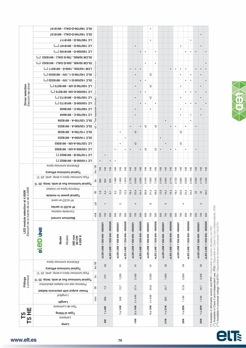
www.elt.es 79
T5
T5
HE
Fit
tin
gs
Lum
inar
iaL
ED
mo
du
le s
elec
tio
n a
t 4.
000K
Dri
ver
sele
ctio
nE
lecc
ión
del d
river
Lamp
Lámpara
Tipo de Luminaria
Length
Longitud
Power output with electronic ballast
Potencia real con balasto electrónico
°C
Flujo luminoso típico a temp. amb. 25 °C
Mo
del
Mod
elo
280
mm
80 C
RI
4.00
0 K
Maximum current
Corriente máxima
Nº eLED in series
Nº eLED en serie
Typical power in module
Potencia típica en módulo
°C
Flujo luminoso típico a temp. amb. 25 °C
LC 110/500-B - 9918022 (*)
LC 110/700-B - 9918023 (*)
LC 125/500-A-UN - 9918262
LC 125/700-A-UN - 9918263
DLC 116/500-A - 9918233
DLC 116/700-A - 9918236
DLC 125/500-A - 9918253
DLC 125/700-A - 9918256
LC 142/700-C - 9918044
LC 160/700-C - 9918040
LC 150/500-E - 9918172 (**)
LC 150/700-E - 9918173 (**)
LC 150/500-E-UN- 9918272 (**)
LC 150/700-E-UN - 9918273 (**)
DLC 142/500-E-1..10V - 9918332 (**)
DLC 142/700-E-1..10V - 9918333 (**)
LCM 142/350...1050-E - 9918311 (**)
DLCM 50/400...500-E-DALI - 9918352 (**)
DLCM 50/600...700-E-DALI - 9918353 (**)
LC 150/500-D - 9918105 (***)
LC 150/700-D - 9918107 (***)
LC 190/700-D - 9918117
DLC 150/700-D-DALI - 9918137
DLC 190/700-D-DALI - 9918147
mm
Wlm
lm /W
mA
udW
lmlm
/ W
x2 =
Tw
o se
para
te c
ircui
ts /
Dos
circ
uito
s in
depe
ndie
ntes
8W1
x 8W
289
7,5
470
63eL
ED
LIN
E 1
950
840
- 9
9505
0150
0
1
4,6
680
148
700
6,4
950
148
eLE
D L
INE
1 1
250
840
- 99
5050
950
06,
190
514
8
14W
1 x
14W
549
13,7
1.20
091
eLE
D L
INE
1 9
50 8
40 -
995
0501
500
2
9,2
1.36
014
8
700
12,8
1.90
014
8
eLE
D L
INE
1 1
250
840
- 99
5050
950
012
,21.
810
148
2 x
14W
2 x
549
27,4
2.40
091
eLE
D L
INE
1 9
50 8
40 -
995
0501
500
4
18,4
2.72
014
8
700
25,6
3.80
014
8x2
x2
eLE
D L
INE
1 1
250
840
- 99
5050
950
024
,43.
620
148
4 x
14W
4 x
549
54,8
5.00
091
eLE
D L
INE
1 9
50 8
40 -
995
0501
500
8
36,8
5.44
014
8x2
x2
700
51,2
7.60
014
8x2
x2x2
eLE
D L
INE
1 1
250
840
- 99
5050
950
048
,87.
240
148
x2x2
21W
1 x
21W
850
20,7
1.90
092
eLE
D L
INE
1 9
50 8
40 -
995
0501
500
3
13,8
2.04
014
8
700
19,2
2.85
014
8
eLE
D L
INE
1 1
250
840
- 99
5050
950
018
,32.
715
148
28W
1 x
28W
1.14
927
,82.
600
94
eLE
D L
INE
1 9
50 8
40 -
995
0501
500
4
18,4
2.72
014
8
700
25,6
3.80
014
8x2
x2
eLE
D L
INE
1 1
250
840
- 99
5050
950
024
,43.
620
148
700
34,2
5.00
014
6
35W
1 x
35W
1.44
934
,73.
300
95eL
ED
LIN
E 1
950
840
- 9
9505
0150
0
5
233.
400
148
700
324.
750
148
eLE
D L
INE
1 1
250
840
- 99
5050
950
030
,54.
525
148
(*)
Ava
ilabl
e in
dim
mab
le v
ersi
on a
nd IP
67 /
(**)
Ava
ilabl
e in
Cla
ss II
and
inde
pend
ent u
se. I
P20
/ D
ispo
nibl
e en
Cla
se II
y u
so in
depe
ndie
nte.
IP20
(***
) A
vaila
ble
in u
nive
rsal
vol
tage
110
-277
V /
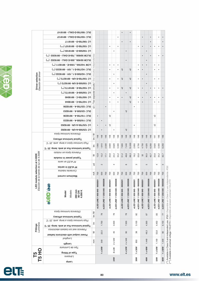
www.elt.es80
T5
T5
HO
Fit
tin
gs
Lum
inar
iaL
ED
mo
du
le s
elec
tio
n a
t 4.
000K
Dri
ver
sele
ctio
nE
lecc
ión
del d
river
Lamp
Lámpara
Tipo de Luminaria
Length
Longitud
Power output with electronic ballast
Potencia real con balasto electrónico
°C
Flujo luminoso típico a temp. amb. 25 °C
M
od
el
Mod
elo
280
mm
80 C
RI
4.00
0 K
Maximum current
Corriente máxima
Nº eLED in series
Nº eLED en serie
Typical power in module
Potencia típica en módulo
°C
Flujo luminoso típico a temp. amb. 25 °C
LC 125/500-A-UN - 9918262
LC 125/700-A-UN - 9918263
DLC 116/500-A - 9918233
DLC 116/700-A - 9918236
DLC 125/500-A - 9918253
DLC 125/700-A - 9918256
LC 142/700-C - 9918044
LC 160/700-C - 9918040
LC 150/500-E - 9918172 (**)
LC 150/700-E - 9918173 (**)
LC 150/500-E-UN- 9918272 (**)
LC 150/700-E-UN - 9918273 (**)
DLC 142/500-E-1..10V - 9918332 (**)
DLC 142/700-E-1..10V - 9918333 (**)
LCM 142/350...1050-E - 9918311 (**)
DLCM 50/400...500-E-DALI - 9918352 (**)
DLCM 50/600...700-E-DALI - 9918353 (**)
LC 150/500-D - 9918105 (***)
LC 150/700-D - 9918107 (***)
LC 190/700-D - 9918117
DLC 150/700-D-DALI - 9918137
DLC 190/700-D-DALI - 9918147
mm
Wlm
lm /W
mA
udW
lmlm
/ W
x2 =
Tw
o se
para
te c
ircui
ts /
Dos
circ
uito
s in
depe
ndie
ntes
24W
1 x
24W
549
22,5
1.75
078
eLE
D L
INE
1 9
50 8
40 -
995
0501
700
2
12,8
1.90
014
8
eLE
D L
INE
1 1
250
840
- 99
5050
950
012
,21.
810
148
700
17,1
2.50
014
6
2 x
242
x 54
945
3.50
078
eLE
D L
INE
1 9
50 8
40 -
995
0501
700
4
25,6
3.80
014
8x2
x2
eLE
D L
INE
1 1
250
840
- 99
5050
950
024
,43.
620
148
700
34,2
5.00
014
6
4 x
24W
4 x
549
907.
000
78
eLE
D L
INE
1 9
50 8
40 -
995
0501
700
8
51,2
7.60
014
8x2
x2x2
eLE
D L
INE
1 1
250
840
- 99
5050
950
048
,87.
240
148
x2x2
700
68,3
10.0
0014
6x2
x2x2
x2x2
39W
1 x
39W
850
383.
100
82eL
ED
LIN
E 1
950
840
- 9
9505
0170
03
19,2
2.85
014
8
eLE
D L
INE
1 1
250
840
- 99
5050
970
025
,63.
750
146
49W
1 x
49W
1.44
949
,34.
300
87
eLE
D L
INE
1 9
50 8
40 -
995
0501
700
5
324.
750
148
eLE
D L
INE
1 1
250
840
- 99
5050
950
030
,54.
525
148
700
42,7
6.25
014
6
54W
1 x
54W
1.14
953
,84.
450
83eL
ED
LIN
E 1
950
840
- 9
9505
0170
04
25,6
3.62
014
1x2
x2
eLE
D L
INE
1 1
250
840
- 99
5050
970
034
,25.
000
146
80W
1 x
80W
1.44
980
6.15
077
eLE
D L
INE
1 1
250
840
- 99
5050
970
05
42,7
6.25
014
6
(**)
Ava
ilabl
e in
Cla
ss II
and
inde
pend
ent u
se. I
P20
/ D
ispo
nibl
e en
Cla
se II
y u
so in
depe
ndie
nte.
IP20
(***
) A
vaila
ble
in u
nive
rsal
vol
tage
110
-277
V /

www.elt.es 81
T8
Fit
tin
gs
Lum
inar
iaL
ED
mo
du
le s
elec
tio
n a
t 4.
000K
Dri
ver
sele
ctio
nE
lecc
ión
del d
river
Lamp
Lámpara
Tipo de Luminaria
Length
Longitud
Power output with electronic ballast
Potencia real con balasto electrónico
°C
Flujo luminoso típico a temp. amb. 25 °C
Mo
del
Mod
elo
560
mm
80 C
RI
4.00
0 K
Maximum current
Corriente máxima
Nº eLED in series
Nº eLED en serie
Typical p5
°C
Flujo luminoso típico a temp. amb. 25 °C
LC 125/500-A-UN - 9918262
LC 125/700-A-UN - 9918263
DLC 116/500-A - 9918233
DLC 116/700-A - 9918236
DLC 125/500-A - 9918253
DLC 125/700-A - 9918256
LC 142/700-C - 9918044
LC 160/700-C - 9918040
LC 150/500-E - 9918172 (**)
LC 150/700-E - 9918173 (**)
LC 150/500-E-UN- 9918272 (**)
LC 150/700-E-UN - 9918273 (**)
DLC 142/500-E-1..10V - 9918332 (**)
DLC 142/700-E-1..10V - 9918333 (**)
LCM 142/350...1050-E - 9918311 (**)
DLCM 50/400...500-E-DALI - 9918352 (**)
DLCM 50/600...700-E-DALI - 9918353 (**)
LC 150/500-D - 9918105 (***)
LC 150/700-D - 9918107 (***)
LC 190/700-D - 9918117
DLC 150/700-D-DALI - 9918137
DLC 190/700-D-DALI - 9918147
mm
Wlm
lm /W
mA
udW
lmlm
/ W
x2 =
Tw
o se
para
te c
ircui
ts /
Dos
circ
uito
s in
depe
ndie
ntes
18W
1 x
1859
016
1.35
084
eLE
D L
INE
2 1
900
840
- 99
5053
270
01
12,8
1.90
014
8
eLE
D L
INE
2 2
500
840
- 99
5052
750
012
,21.
815
149
2 x
182
x 59
032
2.70
084
eLE
D L
INE
2 1
900
840
- 99
5053
270
02
25,6
3.80
014
8
eLE
D L
INE
2 2
500
840
- 99
5052
750
024
,43.
630
149
4 x
184
x 59
064
5.40
084
eLE
D L
INE
2 1
900
840
- 99
5053
270
04
51,2
7.60
014
8
eLE
D L
INE
2 2
500
840
- 99
5052
750
048
,87.
260
149
x2x2
30W
1 x
3089
024
2.40
010
0
eLE
D L
INE
1 9
50 8
40 -
995
0501
700
119
,22.
850
148
eLE
D L
INE
2 1
900
840
- 99
5053
21
eLE
D L
INE
1 1
250
840
- 99
5050
950
01
18,3
2.72
014
9eL
ED
LIN
E 2
250
0 84
0 -
9950
527
1
36W
1 x
361.
200
323.
250
102
eLE
D L
INE
2 1
900
840
- 99
5053
270
02
25,6
3.80
014
8
eLE
D L
INE
2 2
500
840
- 99
5052
750
024
,43.
630
149
2 x
362
x 1.
200
646.
500
105
eLE
D L
INE
2 1
900
840
- 99
5053
270
04
51,2
7.60
014
8
eLE
D L
INE
2 2
500
840
- 99
5052
750
048
,87.
260
149
x2x2
4 x
364
x 1.
200
128
13.0
0010
5eL
ED
LIN
E 2
190
0 84
0 -
9950
532
700
810
2,5
15.2
0014
8x2
x2x2
eLE
D L
INE
2 2
500
840
- 99
5052
750
097
,614
.520
149
x2x2
58W
1 x
581.
500
505.
200
104
eLE
D L
INE
1 1
250
840
- 99
5050
9 70
01
42,7
6.25
014
6eL
ED
LIN
E 2
250
0 84
0 -
9950
527
2
2 x
582
x 1.
500
100
10.4
0010
4eL
ED
LIN
E 1
125
0 84
0 -
9950
509
700
285
,412
.500
146
x2x2
x2eL
ED
LIN
E 2
250
0 84
0 -
9950
527
4
++ + +
(**)
Ava
ilabl
e in
Cla
ss II
and
inde
pend
ent u
se. I
P20
/ D
ispo
nibl
e en
Cla
se II
y u
so in
depe
ndie
nte.
IP20
(***
) A
vaila
ble
in u
nive
rsal
vol
tage
110
-277
V /
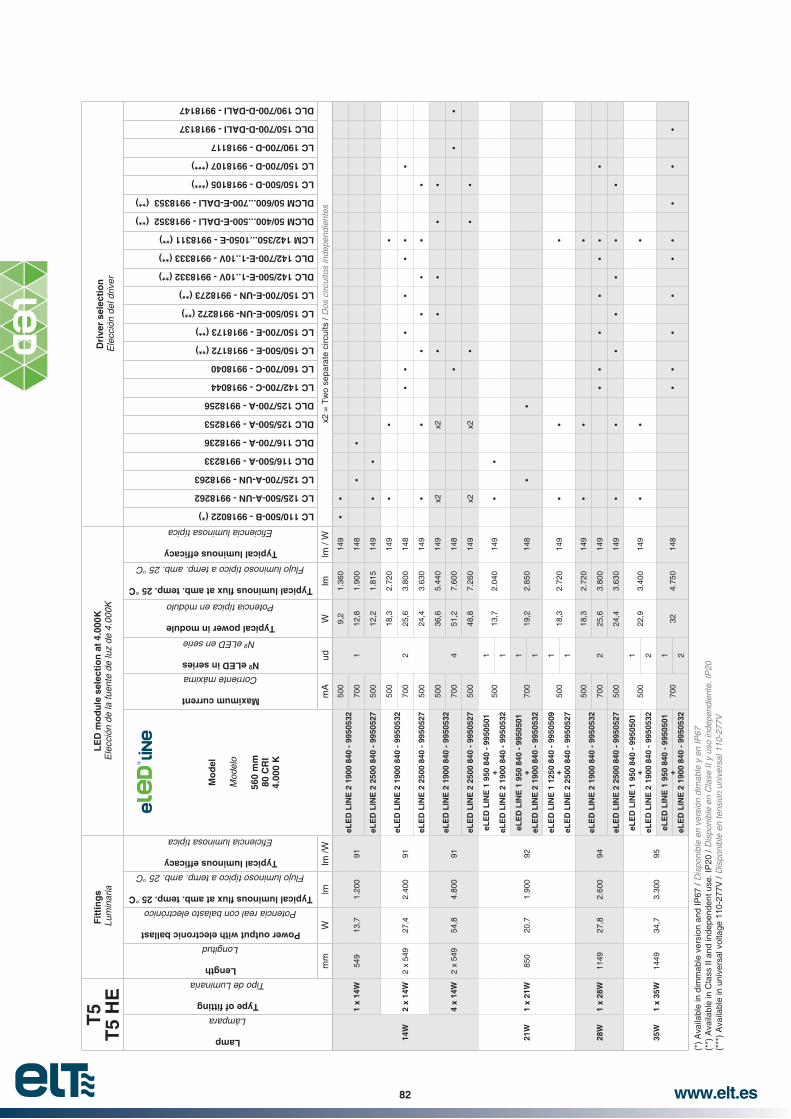
www.elt.es82
T5
T
5 H
EF
itti
ng
s L
umin
aria
LE
D m
od
ule
sel
ecti
on
at
4.00
0KD
rive
r se
lect
ion
Ele
cció
n de
l driv
er
Lamp
Lámpara
Tipo de Luminaria
Length
Longitud
Power output with electronic ballast
Potencia real con balasto electrónico
°C
Flujo luminoso típico a temp. amb. 25 °C
Mo
del
Mod
elo
560
mm
80 C
RI
4.00
0 K
Maximum current
Corriente máxima
Nº eLED in series
Nº eLED en serie
Typical power in module
Potencia típica en módulo
°C
Flujo luminoso típico a temp. amb. 25 °C
LC 110/500-B - 9918022 (*)
LC 125/500-A-UN - 9918262
LC 125/700-A-UN - 9918263
DLC 116/500-A - 9918233
DLC 116/700-A - 9918236
DLC 125/500-A - 9918253
DLC 125/700-A - 9918256
LC 142/700-C - 9918044
LC 160/700-C - 9918040
LC 150/500-E - 9918172 (**)
LC 150/700-E - 9918173 (**)
LC 150/500-E-UN- 9918272 (**)
LC 150/700-E-UN - 9918273 (**)
DLC 142/500-E-1..10V - 9918332 (**)
DLC 142/700-E-1..10V - 9918333 (**)
LCM 142/350...1050-E - 9918311 (**)
DLCM 50/400...500-E-DALI - 9918352 (**)
DLCM 50/600...700-E-DALI - 9918353 (**)
LC 150/500-D - 9918105 (***)
LC 150/700-D - 9918107 (***)
LC 190/700-D - 9918117
DLC 150/700-D-DALI - 9918137
DLC 190/700-D-DALI - 9918147
mm
Wlm
lm /W
mA
udW
lmlm
/ W
x2 =
Tw
o se
para
te c
ircui
ts /
Dos
circ
uito
s in
depe
ndie
ntes
14W
1 x
14W
549
13,7
1.20
091
eLE
D L
INE
2 1
900
840
- 99
5053
250
0
1
9,2
1.36
014
9
700
12,8
1.90
014
8
eLE
D L
INE
2 2
500
840
- 99
5052
750
012
,21.
815
149
2 x
14W
2 x
549
27,4
2.40
091
eLE
D L
INE
2 1
900
840
- 99
5053
250
0
2
18,3
2.72
014
9
700
25,6
3.80
014
8
eLE
D L
INE
2 2
500
840
- 99
5052
750
024
,43.
630
149
4 x
14W
2 x
549
54,8
4.80
091
eLE
D L
INE
2 1
900
840
- 99
5053
250
0
4
36,6
5.44
014
9x2
x2
700
51,2
7.60
014
8
eLE
D L
INE
2 2
500
840
- 99
5052
750
048
,87.
260
149
x2x2
21W
1 x
21W
850
20,7
1.90
092
eLE
D L
INE
1 9
50 8
40 -
995
0501
500
113
,72.
040
149
eLE
D L
INE
2 1
900
840
- 99
5053
21
eLE
D L
INE
1 9
50 8
40 -
995
0501
700
119
,22.
850
148
eLE
D L
INE
2 1
900
840
- 99
5053
21
eLE
D L
INE
1 1
250
840
- 99
5050
950
01
18,3
2.72
014
9eL
ED
LIN
E 2
250
0 84
0 -
9950
527
1
28W
1 x
28W
1149
27,8
2.60
094
eLE
D L
INE
2 1
900
840
- 99
5053
250
0
2
18,3
2.72
014
9
700
25,6
3.80
014
9
eLE
D L
INE
2 2
500
840
- 99
5052
750
024
,43.
630
149
35W
1 x
35W
1449
34,7
3.30
095
eLE
D L
INE
1 9
50 8
40 -
995
0501
50
01
22,9
3.40
014
9eL
ED
LIN
E 2
190
0 84
0 -
9950
532
2
eLE
D L
INE
1 9
50 8
40 -
995
0501
700
132
4.75
014
8eL
ED
LIN
E 2
190
0 84
0 -
9950
532
2
+ + + + +
(*)
Ava
ilabl
e in
dim
mab
le v
ersi
on a
nd IP
67 /
(**)
Ava
ilabl
e in
Cla
ss II
and
inde
pend
ent u
se. I
P20
/ D
ispo
nibl
e en
Cla
se II
y u
so in
depe
ndie
nte.
IP20
(***
) A
vaila
ble
in u
nive
rsal
vol
tage
110
-277
V /

www.elt.es 83
T5
T
5 H
OF
itti
ng
s L
umin
aria
LE
D m
od
ule
sel
ecti
on
at
4.00
0KD
rive
r se
lect
ion
Ele
cció
n de
l driv
er
Lamp
Lámpara
Tipo de Luminaria
Length
Longitud
Power output with electronic ballast
Potencia real con balasto electrónico
°C
Flujo luminoso típico a temp. amb. 25 °C
Mo
del
Mod
elo
560
mm
80 C
RI
4.00
0 K
Maximum current
Corriente máxima
Nº eLED in series
Nº eLED en serie
Typical power in module
Potencia típica en módulo
°C
Flujo luminoso típico a temp. amb. 25 °C
LC 125/500-A-UN - 9918262
LC 125/700-A-UN - 9918263
DLC 116/500-A - 9918233
DLC 116/700-A - 9918236
DLC 125/500-A - 9918253
DLC 125/700-A - 9918256
LC 142/700-C - 9918044
LC 160/700-C - 9918040
LC 150/500-E - 9918172 (**)
LC 150/700-E - 9918173 (**)
LC 150/500-E-UN- 9918272 (**)
LC 150/700-E-UN - 9918273 (**)
DLC 142/500-E-1..10V - 9918332 (**)
DLC 142/700-E-1..10V - 9918333 (**)
LCM 142/350...1050-E - 9918311 (**)
DLCM 50/400...500-E-DALI - 9918352 (**)
DLCM 50/600...700-E-DALI - 9918353 (**)
LC 150/500-D - 9918105 (***)
LC 150/700-D - 9918107 (***)
LC 190/700-D - 9918117
DLC 150/700-D-DALI - 9918137
DLC 190/700-D-DALI - 9918147
mm
Wlm
lm /W
mA
udW
lmlm
/ W
x2 =
Tw
o se
para
te c
ircui
ts /
Dos
circ
uito
s in
depe
ndie
ntes
24W
1 x
24W
549
22,5
1.75
078
eLE
D L
INE
2 1
900
840
- 99
5053
270
0
1
12,8
1.90
014
8
eLE
D L
INE
2 2
500
840
- 99
5052
750
012
,21.
815
149
700
17,1
2.50
014
6
2 x
242
x 54
945
3.50
078
eLE
D L
INE
2 1
900
840
- 99
5053
270
0
2
25,6
3.80
014
8
eLE
D L
INE
2 2
500
840
- 99
5052
750
024
,43.
630
149
700
34,2
5.00
014
6x2
x2
4 x
24W
4 x
549
907.
000
78
eLE
D L
INE
2 1
900
840
- 99
5053
270
0
4
51,2
7.60
014
8
eLE
D L
INE
2 2
500
840
- 99
5052
750
048
,87.
260
149
x2x2
700
68,3
10.0
0014
6x2
x2x2
x2x2
x2
39W
1 x
39W
850
383.
100
82eL
ED
LIN
E 1
125
0 84
0 -
9950
509
700
125
,63.
750
146
eLE
D L
INE
2 2
500
840
- 99
5052
71
49W
1 x
49W
1.44
949
,34.
300
87
eLE
D L
INE
1 9
00 8
40 -
995
0501
700
132
4.75
014
8eL
ED
LIN
E 2
190
0 84
0 -
9950
532
2
eLE
D L
INE
1 1
250
840
- 99
5050
950
01
30,5
4.53
514
9eL
ED
LIN
E 2
250
0 84
0 -
9950
527
2
eLE
D L
INE
1 1
250
840
- 99
5050
970
01
42,7
6.25
014
6eL
ED
LIN
E 2
250
0 84
0 -
9950
527
2
54W
1 x
54W
1.14
953
,84.
450
83eL
ED
LIN
E 2
250
0 84
0 -
9950
527
700
234
,25.
000
146
x2x2
80W
1 x
80W
1.44
980
6.15
077
eLE
D L
INE
1 1
250
840
- 99
5050
970
01
42,7
6.25
014
6eL
ED
LIN
E 2
250
0 84
0 -
9950
527
2++++ +
(**)
Ava
ilabl
e in
Cla
ss II
and
inde
pend
ent u
se. I
P20
/ D
ispo
nibl
e en
Cla
se II
y u
so in
depe
ndie
nte.
IP20
(***
) A
vaila
ble
in u
nive
rsal
vol
tage
110
-277
V /

www.elt.es84
TC
-D /
TC
-DE
/ T
C-T
/ T
C-T
E F
itti
ng
s /
Lum
inar
iaL
ED
mo
du
le s
elec
tio
n /
Ele
cció
n de
la fu
ente
de
luz
Dri
ver
sele
ctio
n /E
lecc
ión
del d
river
Lam
p
Lám
para
Typ
e o
f
Tip
o de
Lu
min
aria
Po
wer
ou
tpu
t W
ith
ele
ctro
nic
b
alla
st
Pot
enci
a re
al
con
bala
sto
elec
trón
ico
Typ
ical
amb
. tem
p. 2
5 °C
Flu
jo
lum
inos
o típ
ico
a te
mp.
am
b.
25 °
C
Typ
ical
lu
min
ou
s
lum
inos
a típ
ica
Mo
del
Mod
elo
165
mm
80
CR
I
Max
imu
m
curr
ent
Cor
rient
e m
áxim
a
Nº
eLE
D
in s
erie
s
en s
erie
Typ
ical
p
ow
er in
m
od
ule
Pot
enci
a típ
ica
en
mód
ulo
Typ
ical
at a
mb
. tem
p.
25 °
C
Flu
jo
lum
inos
o típ
ico
a te
mp.
am
b. 2
5 °C
Typ
ical
lu
min
ou
s lu
min
osa
típic
a
LC 125/500-A-UN - 9918262
LC 125/700-A-UN - 9918263
DLC 116/500-A - 9918233
DLC 116/700-A - 9918236
DLC 125/700-A - 9918256
Wlm
lm /W
mA
udW
lmlm
/ W
LE
D m
od
ule
sel
ecti
on
at
4.00
0K /
13W
1 x
13W
12,5
900
72eL
ED
OC
TO
1 2
150
840
- 99
5055
250
0
1
10,7
1.58
514
8
2 x
13W
251.
800
72eL
ED
OC
TO
1 2
150
840
- 99
5055
270
014
,92.
150
143
eLE
D O
CT
O 1
255
0 84
0 -
9950
557
500
13,5
1.98
514
8
18W
1 x
18W
16,5
1.20
073
eLE
D O
CT
O 1
215
0 84
0 -
9950
552
500
110
,71.
585
148
2 x
18W
332.
400
73eL
ED
OC
TO
1 2
550
840
- 99
5055
770
019
,52.
550
131
26W
1 x
26W
241.
800
75eL
ED
OC
TO
1 2
150
840
- 99
5055
270
01
14,9
2.15
014
3
eLE
D O
CT
O 1
255
0 84
0 -
9950
557
500
13,5
1.98
514
8
32W
1 x
32W
322.
400
75eL
ED
OC
TO
1 2
550
840
- 99
5055
770
01
19,5
2.55
013
1

www.elt.es 85
T8
Fit
tin
gs
Lum
inar
iaL
ED
mo
du
le s
elec
tio
n a
t 4.
000K
Dri
ver
sele
ctio
nE
lecc
ión
del d
river
Lamp
Lámpara
Tipo de Luminaria
Length
Longitud
Power output with electronic ballast
Potencia real con balasto electrónico
°C
Flujo luminoso típico a temp. amb. 25 °C
Mo
del
Mod
elo
250
x 25
0 m
m
80 C
RI
4.00
0 K
Maximum current
Corriente máxima
Nº eLED in series
Nº eLED en serie
Typical power in module
Potencia típica en módulo
°C
Flujo luminoso típico a temp. amb. 25 °C
LC 110/500-B - 9918022 (*)
LC 125/500-A-UN - 9918262
LC 125/700-A-UN - 9918263
DLC 116/700-A - 9918236
DLC 125/500-A - 9918253
DLC 125/700-A - 9918256
LC 142/700-C - 9918044
LC 160/700-C - 9918040
LC 150/500-E - 9918172 (**)
LC 150/700-E - 9918173 (**)
LC 150/500-E-UN- 9918272 (**)
LC 150/700-E-UN - 9918273 (**)
DLC 142/500-E-1..10V - 9918332 (**)
DLC 142/700-E-1..10V - 9918333 (**)
LCM 42/350...1050-E - 9918311 (**)
DLCM 50/400...500-E-DALI - 9918352 (**)
DLCM 50/600...700-E-DALI - 9918353 (**)
LC 150/500-D - 9918105 (***)
LC 150/700-D - 9918107 (***)
LC 190/700-D - 9918117
DLC 150/700-D-DALI - 9918137
DLC 190/700-D-DALI - 9918147
mm
Wlm
lm /W
mA
udW
lmlm
/ W
x2 =
Tw
o se
para
te c
ircui
ts /
Dos
circ
uito
s in
depe
ndie
ntes
18W
1 x
18W
590
161.
350
84eL
ED
SQ
UA
RE
2 1
900
840
- 99
5054
250
01
8,6
1.50
017
5
700
12,3
1.90
015
5
2 x
18W
2 x
590
322.
700
84eL
ED
SQ
UA
RE
2 1
900
840
- 99
5054
250
02
17,1
3.00
017
5
700
24,5
3.80
015
5
4 x
18W
4 x
590
645.
400
84eL
ED
SQ
UA
RE
2 1
900
840
- 99
5054
250
04
34,2
6.00
017
5x2
x2
700
49,0
7.60
015
5x2
x2
(*)
Ava
ilabl
e in
dim
mab
le v
ersi
on a
nd IP
67 /
(**)
Ava
ilabl
e in
Cla
ss II
and
inde
pend
ent u
se. I
P20
/ D
ispo
nibl
e en
Cla
se II
y u
so in
depe
ndie
nte.
IP20
(***
) A
vaila
ble
in u
nive
rsal
vol
tage
110
-277
V /

www.elt.es86
T5
T
5 H
EF
itti
ng
s L
umin
aria
LE
D m
od
ule
sel
ecti
on
at
4.00
0KD
rive
r se
lect
ion
Ele
cció
n de
l driv
erLamp
Lámpara
Tipo de Luminaria
Length
Longitud
Power output with electronic ballast
Potencia real con balasto electrónico
°C
Flujo luminoso típico a temp. amb. 25 °C
Mo
del
Mod
elo
250
x 25
0 m
m
80 C
RI
4.00
0 K
Maximum current
Corriente máxima
Nº eLED in series
Nº eLED en serie
Typical power in module
Potencia típica en módulo
°C
Flujo luminoso típico a temp. amb. 25 °C
LC 110/500-B - 9918022 (*)
LC 125/500-A-UN - 9918262
LC 125/700-A-UN - 9918263
DLC 116/700-A - 9918236
DLC 125/500-A - 9918253
DLC 125/700-A - 9918256
LC 142/700-C - 9918044
LC 160/700-C - 9918040
LC 150/500-E - 9918172 (**)
LC 150/700-E - 9918173 (**)
LC 150/500-E-UN- 9918272 (**)
LC 150/700-E-UN - 9918273 (**)
DLC 142/500-E-1..10V - 9918332 (**)
DLC 142/700-E-1..10V - 9918333 (**)
LCM 42/350...1050-E - 9918311 (**)
DLCM 50/400...500-E-DALI - 9918352 (**)
DLCM 50/600...700-E-DALI - 9918353 (**)
LC 150/500-D - 9918105 (***)
LC 150/700-D - 9918107 (***)
LC 190/700-D - 9918117
DLC 150/700-D-DALI - 9918137
DLC 190/700-D-DALI - 9918147
mm
Wlm
lm /W
mA
udW
lmlm
/ W
x2 =
Tw
o se
para
te c
ircui
ts /
Dos
circ
uito
s in
depe
ndie
ntes
14W
1 x
14W
549
13,7
1.20
091
eLE
D S
QU
AR
E 2
190
0 84
0 -
9950
542
500
18,
61.
500
175
700
12,3
1.90
015
5
2 x
14W
2 x
549
27,4
2.40
091
eLE
D S
QU
AR
E 2
190
0 84
0 -
9950
542
500
217
,13.
000
175
700
24,5
3.80
015
5
4 x
14W
4 x
549
54,8
4.80
091
eLE
D S
QU
AR
E 2
190
0 84
0 -
9950
542
500
434
,26.
000
175
x2x2
700
49,0
7.60
015
5x2
x2
T5
T
5 H
OF
itti
ng
s L
umin
aria
LE
D m
od
ule
sel
ecti
on
at
4.00
0KD
rive
r se
lect
ion
Ele
cció
n de
l driv
er
Lamp
Lámpara
Tipo de Luminaria
Length
Longitud
Power output with electronic ballast
Potencia real con balasto electrónico
°C
Flujo luminoso típico a temp. amb. 25 °C
Mo
del
Mod
elo
250
x 25
0 m
m
80 C
RI
4.00
0 K
Maximum current
Corriente máxima
Nº eLED in series
Nº eLED en serie
Typical power in module
Potencia típica en módulo
°C
Flujo luminoso típico a temp. amb. 25 °C
LC 110/500-B - 9918022 (*)
LC 125/500-A-UN - 9918262
LC 125/700-A-UN - 9918263
DLC 116/700-A - 9918236
DLC 125/500-A - 9918253
DLC 125/700-A - 9918256
LC 142/700-C - 9918044
LC 160/700-C - 9918040
LC 150/500-E - 9918172 (**)
LC 150/700-E - 9918173 (**)
LC 150/500-E-UN- 9918272 (**)
LC 150/700-E-UN - 9918273 (**)
DLC 142/500-E-1..10V - 9918332 (**)
DLC 142/700-E-1..10V - 9918333 (**)
LCM 42/350...1050-E - 9918311 (**)
DLCM 50/400...500-E-DALI - 9918352 (**)
DLCM 50/600...700-E-DALI - 9918353 (**)
LC 150/500-D - 9918105 (***)
LC 150/700-D - 9918107 (***)
LC 190/700-D - 9918117
DLC 150/700-D-DALI - 9918137
DLC 190/700-D-DALI - 9918147
mm
Wlm
lm /W
mA
udW
lmlm
/ W
x2 =
Tw
o se
para
te c
ircui
ts /
Dos
circ
uito
s in
depe
ndie
ntes
24W
1 x
24W
549
22,5
1.75
078
eLE
D S
QU
AR
E 2
190
0 84
0 -
9950
542
700
112
,31.
900
155
2 x
24W
2 x
549
453.
500
78eL
ED
SQ
UA
RE
2 1
900
840
- 99
5054
270
02
24,5
3.80
015
5
4 x
24W
4 x
549
907.
000
78eL
ED
SQ
UA
RE
2 1
900
840
- 99
5054
270
04
49,0
7.60
015
5x2
x2
(*)
Ava
ilabl
e in
dim
mab
le v
ersi
on a
nd IP
67 /
(**)
Ava
ilabl
e in
Cla
ss II
and
inde
pend
ent u
se. I
P20
/ D
ispo
nibl
e en
Cla
se II
y u
so in
depe
ndie
nte.
IP20
(***
) A
vaila
ble
in u
nive
rsal
vol
tage
110
-277
V /
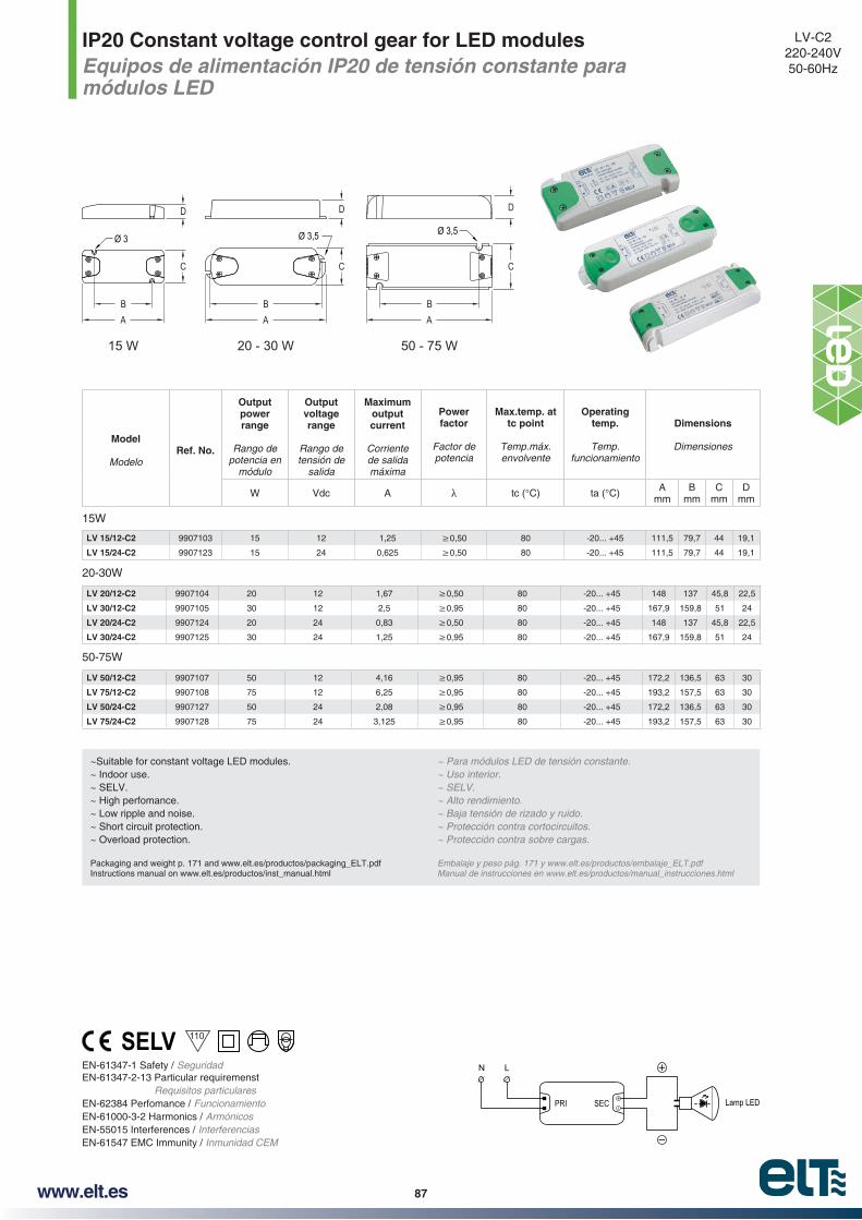
www.elt.es 87
IP20 Constant voltage control gear for LED modulesEquipos de alimentación IP20 de tensión constante para módulos LED
LV-C2220-240V50-60Hz
EN-61347-1 Safety / SeguridadEN-61347-2-13 Particular requiremenst
Requisitos particularesEN-62384 Perfomance / FuncionamientoEN-61000-3-2 Harmonics / ArmónicosEN-55015 Interferences / InterferenciasEN-61547 EMC Immunity / Inmunidad CEM
Ø 3 Ø 3,5 Ø 3,5
AB
AB
AB
C
D D D
C C
15 W 20 - 30 W 50 - 75 W
Lamp LED
LN
PRI SEC
~Suitable for constant voltage LED modules.~ Indoor use. ~ SELV. ~ High perfomance.~ Low ripple and noise.~ Short circuit protection.~ Overload protection.
Packaging and weight p. 171 and www.elt.es/productos/packaging_ELT.pdfInstructions manual on www.elt.es/productos/inst_manual.html
~ Para módulos LED de tensión constante.~ Uso interior. ~ SELV. ~ Alto rendimiento. ~ Baja tensión de rizado y ruido. ~ Protección contra cortocircuitos.~ Protección contra sobre cargas.
Embalaje y peso pág. 171 y www.elt.es/productos/embalaje_ELT.pdfManual de instrucciones en www.elt.es/productos/manual_instrucciones.html
15W
LV 15/12-C2 9907103 15 12 1,25 80 -20... +45 111,5 79,7 44 19,1
LV 15/24-C2 9907123 15 24 0,625 80 -20... +45 111,5 79,7 44 19,1
Model
ModeloRef. No.
Output power range
Rango de potencia en
módulo
Output voltage range
Rango de tensión de
salida
Maximum output current
Corriente de salida máxima
Power factor
Factor de potencia
Max.temp. at tc point
Temp.máx. envolvente
Operating temp.
Temp. funcionamiento
Dimensions
Dimensiones
W Vdc A tc (°C) ta (°C) Amm
Bmm
Cmm
Dmm
20-30W
LV 20/12-C2 9907104 20 12 1,67 80 -20... +45 148 137 45,8 22,5
LV 30/12-C2 9907105 30 12 2,5 80 -20... +45 167,9 159,8 51 24
LV 20/24-C2 9907124 20 24 0,83 80 -20... +45 148 137 45,8 22,5
LV 30/24-C2 9907125 30 24 1,25 80 -20... +45 167,9 159,8 51 24
LV 50/12-C2 9907107 50 12 4,16 80 -20... +45 172,2 136,5 63 30
LV 75/12-C2 9907108 75 12 6,25 80 -20... +45 193,2 157,5 63 30
LV 50/24-C2 9907127 50 24 2,08 80 -20... +45 172,2 136,5 63 30
LV 75/24-C2 9907128 75 24 3,125 80 -20... +45 193,2 157,5 63 30
50-75W
110

88 www.elt.es
Constant voltage control gear for LED up to 150W. IP20Equipos de alimentación de tensión constante para LED hasta 150W. IP20
EN 61347-2-13 Safety / Seguridad EN 61000-3-2 Harmonics / ArmónicosEN 61547 EMC Inmunity / Inmunidad EMCEN 55015-3-2 Interferences / InterferenciasEN 61000-3-3 EMC Inmunity / Inmunidad EMCEN 62384 Perfomance / Funcionamiento
LV-C2AC 50-60Hz
~ IP20 equipment.~ Class II electrical protection.~ Equipped with terminal coves and cable lamps.~ Cable lock with screws.~ Overload protection.~ Short circuit protection.~ Protection against no load operation.~ Low ripple and noise.~ Nominal lifetime at max. ta allowed: 30.000 h.
Packaging and weight p. 171 and www.elt.es/productos/packaging_ELT.pdfInstructions manual on www.elt.es/productos/inst_manual.html
~ Equipos IP20.~ Protección eléctrica Clase II.
~ Protección contra sobrecarga.~ Protección contra cortocircuitos.~ Protección en circuito abierto.~ Baja tensión de rizado y ruido.~ Vida útil a máxima ta permitida: 30.000 h.
Embalaje y peso pág. 171 y www.elt.es/productos/embalaje_ELT.pdfManual de instrucciones en www.elt.es/productos/manual_instrucciones.html
Model
ModeloRef. No.
Nominal input
voltage
Tensión nominal de
entrada
Permitted output power
range
Rango de potencia de
salida permitido
Output voltage DC
Tensión de salida DC
Output current DC
Corriente de salida
DC
Power factor
Factor de potencia
Max
.tem
p. a
t tc
po
int
Tem
p.m
áx. e
nvol
vent
e
Op
erat
ing
tem
p.
Tem
p. fu
ncio
nam
ient
o
Dimensions
Dimensiones
Un
its
per
bo
x
Uni
dade
s po
r ca
ja
Vac W* Vdc A tc (°C) ta (°C) Amm
Bmm
Cmm
LV 100/12-C2 9907109 100-240V 40...100 12 8,33 0,95 80 -20...+45 180 65 32 20
LV 100/24-C2 9907129 100-240V 40...100 24 4,16 0,95 80 -20...+45 180 65 32 20
LV 130/12-C2 9907110 220-240V 70...130 12 10,83 0,90 80 -20...+45 180 65 31 40
LV 150/24-C2 9907130 220-240V 65...150 24 6,25 0,90 80 -20...+45 180 65 31 40
A
BC
LN
PRI SEC+
-LED
* Range covered by the EC Declaration of Product Conformity Rango cubierto por la Declaración de Conformidad CE del Producto
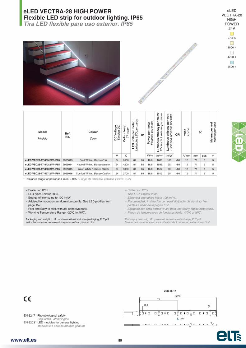
89www.elt.es
eLED VECTRA-28 HIGH POWERFlexible LED strip for outdoor lighting. IP65
EN 62471 Photobiological safety Seguridad Fotobiológica
EN 62031 LED modules for general lighting Módulos led para alumbrado general
~ Protection IP65.~ LED type: Epistar 2835.
page 152.~ Fast and Easy to stick with 3M adhesive back.~ Working Temperature Range: -20ºC to 40ºC.
Packaging and weight p. 171 and www.elt.es/productos/packaging_ELT.pdfInstructions manual on www.elt.es/productos/inst_manual.html
~ Equipado con cinta adhesiva 3M para una fácil y rápida instalación.
Embalaje y peso pág. 171 y www.elt.es/productos/embalaje_ELT.pdfManual de instrucciones en www.elt.es/productos/manual_instrucciones.html
Rango de tolerancia potencia y lm/m: ±10%
500071
11,8
-24V
412
VEC-28-17
Model
Modelo
Ref. No.
Colour
Color DC
Vo
ltag
eT
ensi
ón D
C
Co
lou
r te
mp
.T
ª. c
olor
LE
D u
nit
s p
er m
eter
Uni
dade
s LE
D p
or m
etro
IP
Po
wer
per
met
erP
oten
cia
por
met
ro
CRI Wid
eA
ncho
Met
ers
per
ree
lM
etro
s po
r ro
llo
V K W/m lm/m* lm/W A/mm mm pcs. m
eLED VEC28-17-865-24V-IP65 9955013 Cold White / Blanco Frío 24 6500 84 65 16,8 1680 100 >80 12 71 6 5
eLED VEC28-17-842-24V-IP65 9955014 Neutral White / Blanco Neutro 24 4200 84 65 16,8 1596 95 >80 12 71 6 5
eLED VEC28-17-830-24V-IP65 9955015 Warm White / Blanco Cálido 24 3000 84 65 16,8 1512 90 >80 12 71 6 5
eLED VEC28-17-827-24V-IP65 9955016 Comfort White / Blanco Confort 24 2700 84 65 16,8 1512 90 >80 12 71 6 5
eLEDVECTRA-28
HIGH POWER
24V
3000 K
2700 K
4200 K
6500 K
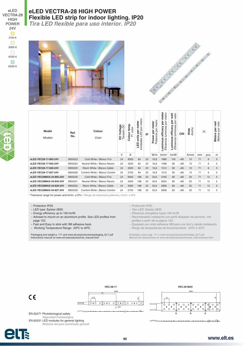
90 www.elt.es
eLED VECTRA-28 HIGH POWERFlexible LED strip for indoor lighting. IP20
EN 62471 Photobiological safety Seguridad Fotobiológica
EN 62031 LED modules for general lighting Módulos led para alumbrado general
~ Protection IP20.~ LED type: Epistar 2835.
page 152.~ Fast and Easy to stick with 3M adhesive back.~ Working Temperature Range: -20ºC to 40ºC.
Packaging and weight p. 171 and www.elt.es/productos/packaging_ELT.pdfInstructions manual on www.elt.es/productos/inst_manual.html
~ Protección IP20.
~ Equipado con cinta adhesiva 3M para una fácil y rápida instalación.
Embalaje y peso pág. 171 y www.elt.es/productos/embalaje_ELT.pdfManual de instrucciones en www.elt.es/productos/manual_instrucciones.html
Rango de tolerancia potencia y lm/m: ±10%
5000
12 202
VEC-28 MAX
500070
11,8
-24V
210
VEC-28-17
Model
Modelo
Ref. No.
Colour
Color DC
Vo
ltag
eT
ensi
ón D
C
Co
lou
r te
mp
.T
ª. c
olor
LE
D u
nit
s p
er m
eter
Uni
dade
s LE
D p
or m
etro
IP
Po
wer
per
met
erP
oten
cia
por
met
ro
CRI Wid
eA
ncho
Met
ers
per
ree
lM
etro
s po
r ro
llo
V K W/m lm/m* lm/W A/mm mm pcs. m
eLED VEC28-17-865-24V 9955023 Cold White / Blanco Frío 24 6500 84 20 16,8 1680 100 >80 10 71 6 5
eLED VEC28-17-842-24V 9955024 Neutral White / Blanco Neutro 24 4200 84 20 16,8 1596 95 >80 10 71 6 5
eLED VEC28-17-830-24V 9955025 Warm White / Blanco Cálido 24 3000 84 20 16,8 1512 90 >80 10 71 6 5
eLED VEC28-17-827-24V 9955026 Comfort White / Blanco Confort 24 2700 84 20 16,8 1512 90 >80 10 71 6 5
eLED VEC28MAX-34-865-24V 9955030 Cold White / Blanco Frío 24 6500 168 20 33,6 3192 95 >80 20 71 12 5
eLED VEC28MAX-34-842-24V 9955031 Neutral White / Blanco Neutro 24 4200 168 20 33,6 3024 90 >80 20 71 12 5
eLED VEC28MAX-34-830-24V 9955032 Warm White / Blanco Cálido 24 3000 168 20 33,6 2856 85 >80 20 71 12 5
eLED VEC28MAX-34-827-24V 9955033 Comfort White / Blanco Confort 24 2700 168 20 33,6 2856 85 >80 20 71 12 5
eLEDVECTRA-28
HIGH POWER
24V
3000 K
2700 K
4200 K
6500 K
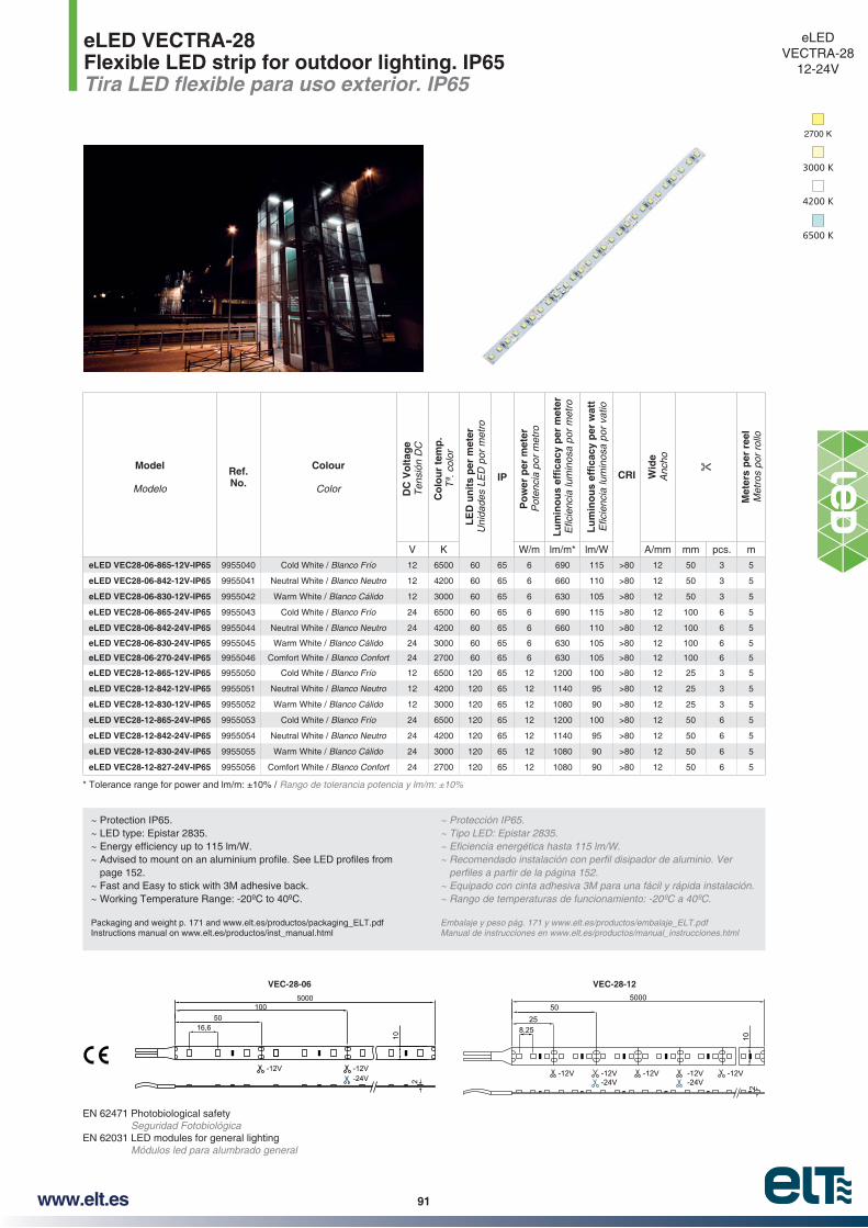
91www.elt.es
eLED VECTRA-28Flexible LED strip for outdoor lighting. IP65
EN 62471 Photobiological safety Seguridad Fotobiológica
EN 62031 LED modules for general lighting Módulos led para alumbrado general
~ Protection IP65.~ LED type: Epistar 2835.
page 152.~ Fast and Easy to stick with 3M adhesive back.~ Working Temperature Range: -20ºC to 40ºC.
Packaging and weight p. 171 and www.elt.es/productos/packaging_ELT.pdfInstructions manual on www.elt.es/productos/inst_manual.html
~ Equipado con cinta adhesiva 3M para una fácil y rápida instalación.
Embalaje y peso pág. 171 y www.elt.es/productos/embalaje_ELT.pdfManual de instrucciones en www.elt.es/productos/manual_instrucciones.html
-12V-24V
5000100
5016,6
10
2
-12V
VEC-28-06
-12V-24V
500050
258,25
-12V-24V
102
-12V -12V-12V
VEC-28-12
Rango de tolerancia potencia y lm/m: ±10%
Model
Modelo
Ref. No.
Colour
Color DC
Vo
ltag
eT
ensi
ón D
C
Co
lou
r te
mp
.T
ª. c
olor
LE
D u
nit
s p
er m
eter
Uni
dade
s LE
D p
or m
etro
IP
Po
wer
per
met
erP
oten
cia
por
met
ro
CRI Wid
eA
ncho
Met
ers
per
ree
lM
etro
s po
r ro
llo
V K W/m lm/m* lm/W A/mm mm pcs. m
eLED VEC28-06-865-12V-IP65 9955040 Cold White / Blanco Frío 12 6500 60 65 6 690 115 >80 12 50 3 5
eLED VEC28-06-842-12V-IP65 9955041 Neutral White / Blanco Neutro 12 4200 60 65 6 660 110 >80 12 50 3 5
eLED VEC28-06-830-12V-IP65 9955042 Warm White / Blanco Cálido 12 3000 60 65 6 630 105 >80 12 50 3 5
eLED VEC28-06-865-24V-IP65 9955043 Cold White / Blanco Frío 24 6500 60 65 6 690 115 >80 12 100 6 5
eLED VEC28-06-842-24V-IP65 9955044 Neutral White / Blanco Neutro 24 4200 60 65 6 660 110 >80 12 100 6 5
eLED VEC28-06-830-24V-IP65 9955045 Warm White / Blanco Cálido 24 3000 60 65 6 630 105 >80 12 100 6 5
eLED VEC28-06-270-24V-IP65 9955046 Comfort White / Blanco Confort 24 2700 60 65 6 630 105 >80 12 100 6 5
eLED VEC28-12-865-12V-IP65 9955050 Cold White / Blanco Frío 12 6500 120 65 12 1200 100 >80 12 25 3 5
eLED VEC28-12-842-12V-IP65 9955051 Neutral White / Blanco Neutro 12 4200 120 65 12 1140 95 >80 12 25 3 5
eLED VEC28-12-830-12V-IP65 9955052 Warm White / Blanco Cálido 12 3000 120 65 12 1080 90 >80 12 25 3 5
eLED VEC28-12-865-24V-IP65 9955053 Cold White / Blanco Frío 24 6500 120 65 12 1200 100 >80 12 50 6 5
eLED VEC28-12-842-24V-IP65 9955054 Neutral White / Blanco Neutro 24 4200 120 65 12 1140 95 >80 12 50 6 5
eLED VEC28-12-830-24V-IP65 9955055 Warm White / Blanco Cálido 24 3000 120 65 12 1080 90 >80 12 50 6 5
eLED VEC28-12-827-24V-IP65 9955056 Comfort White / Blanco Confort 24 2700 120 65 12 1080 90 >80 12 50 6 5
eLEDVECTRA-28
12-24V
3000 K
2700 K
4200 K
6500 K

92 www.elt.es
eLED VECTRA-28Flexible LED strip for indoor lighting. IP20
EN 62471 Photobiological safety Seguridad Fotobiológica
EN 62031 LED modules for general lighting Módulos led para alumbrado general
~ Protection IP20.~ LED type: Epistar 2835.
page 152.~ Fast and Easy to stick with 3M adhesive back.~ Working Temperature Range: -20ºC to 40ºC.
Packaging and weight p. 171 and www.elt.es/productos/packaging_ELT.pdfInstructions manual on www.elt.es/productos/inst_manual.html
~ Protección IP20.
~ Equipado con cinta adhesiva 3M para una fácil y rápida instalación.
Embalaje y peso pág. 171 y www.elt.es/productos/embalaje_ELT.pdfManual de instrucciones en www.elt.es/productos/manual_instrucciones.html
Rango de tolerancia potencia y lm/m: ±10%
eLEDVECTRA-28
12-24V
Model
Modelo
Ref. No.
Colour
Color DC
Vo
ltag
eT
ensi
ón D
C
Co
lou
r te
mp
.T
ª. c
olor
LE
D u
nit
s p
er m
eter
Uni
dade
s LE
D p
or m
etro
IP
Po
wer
per
met
erP
oten
cia
por
met
ro
CRI Wid
eA
ncho
Met
ers
per
ree
lM
etro
s po
r ro
llo
V K W/m lm/m* lm/W A/mm mm pcs. m
eLED VEC28-06-865-12V 9955060 Cold White / Blanco Frío 12 6500 60 20 6 690 115 >80 10 50 3 5
eLED VEC28-06-842-12V 9955061 Neutral White / Blanco Neutro 12 4200 60 20 6 660 110 >80 10 50 3 5
eLED VEC28-06-830-12V 9955062 Warm White / Blanco Cálido 12 3000 60 20 6 630 105 >80 10 50 3 5
eLED VEC28-06-865-24V 9955063 Cold White / Blanco Frío 24 6500 60 20 6 690 115 >80 10 100 6 5
eLED VEC28-06-842-24V 9955064 Neutral White / Blanco Neutro 24 4200 60 20 6 660 110 >80 10 100 6 5
eLED VEC28-06-830-24V 9955065 Warm White / Blanco Cálido 24 3000 60 20 6 630 105 >80 10 100 6 5
eLED VEC28-06-827-24V 9955066 Comfort White / Blanco Confort 24 2700 60 20 6 630 105 >80 10 100 6 5
eLED VEC28-12-865-12V 9955070 Cold White / Blanco Frío 12 6500 120 20 12 1200 100 >80 10 25 3 5
eLED VEC28-12-842-12V 9955071 Neutral White / Blanco Neutro 12 4200 120 20 12 1140 95 >80 10 25 3 5
eLED VEC28-12-830-12V 9955072 Warm White / Blanco Cálido 12 3000 120 20 12 1080 90 >80 10 25 3 5
eLED VEC28-12-865-24V 9955073 Cold White / Blanco Frío 24 6500 120 20 12 1200 100 >80 10 50 6 5
eLED VEC28-12-842-24V 9955074 Neutral White / Blanco Neutro 24 4200 120 20 12 1140 95 >80 10 50 6 5
eLED VEC28-12-830-24V 9955075 Warm White / Blanco Cálido 24 3000 120 20 12 1080 90 >80 10 50 6 5
eLED VEC28-12-827-24V 9955076 Comfort White / Blanco Confort 24 2700 120 20 12 1080 90 >80 10 50 6 5
-12V-24V
5000100
5016,6
10
2
-12V
VEC28-06
-12V-24V
500050
258,25
-12V-24V
102
-12V -12V-12V
VEC28-12
3000 K
2700 K
4200 K
6500 K
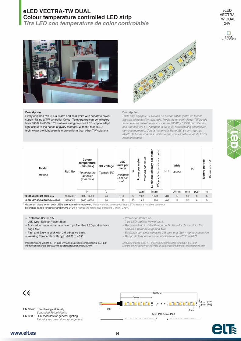
93www.elt.es
eLED VECTRA-TW DUALColour temperature controlled LED stripTira LED con temperatura de color controlable
EN 62471 Photobiological safety Seguridad Fotobiológica
EN 62031 LED modules for general lighting Módulos led para alumbrado general
~ Protection IP20/IP65. ~ LED type: Epistar Power 3528.
page 152.~ Fast and Easy to stick with 3M adhesive back.~ Working Temperature Range: -20ºC to 40ºC.
Packaging and weight p. 171 and www.elt.es/productos/packaging_ELT.pdfInstructions manual on www.elt.es/productos/inst_manual.html
~ Equipado con cinta adhesiva 3M para una fácil y rápida instalación.
Embalaje y peso pág. 171 y www.elt.es/productos/embalaje_ELT.pdfManual de instrucciones en www.elt.es/productos/manual_instrucciones.html
* Maximum value when both LEDs are at maximum power / Valor máximo cuando los dos LEDs están a máxima potencia. Rango de tolerancia potencia y lm/m: ±10%
eLED VECTRATW DUAL
24V
200
5000mm
50mm
8mm
10mm IP20 12mm IP65
2mm IP20 / 4mm IP65
6500K to / a 3000K
Model
ModeloRef. No.
Colour temperature (min-max)
Temperatura de color
DC Voltage
Tensión DC
LED units per
meter
Unidades LED por
metro
IP
Po
wer
per
met
er
Pot
enci
a po
r m
etro
CRI
Wide
Ancho
Met
ers
per
ree
l
Met
ros
por
rollo
K V W/m lm/m* A/mm mm pcs. m
eLED VEC35-20-TWD-24V 9955001 3000 - 6500 24 120 20 19,2 1320 >80 10 50 6 5
eLED VEC35-20-TWD-24V-IP65 9955002 3000 - 6500 24 120 65 19,2 1320 >80 12 50 6 5
DescriptionEvery chip has two LEDs, warm and cold white with separate power supply. Using a TW controller Colour Temperature can be adjusted from 3000k to 6500K. This allows using only one LED strip to adapt light colour to the needs of every moment. With the MonoLED technology the light beam is more uniform than other TW solutions.
Descripción Cada chip equipa 2 LEDs uno en blanco cálido y otro en blanco frío con alimentación separada. Mediante un controlador TW puede
con una sóla tira LED adaptar la luz a las necesidades decorativas de cada momento. Con la tecnología MonoLED se consigue un efecto de luz mucho más uniforme que con las soluciones de LEDs independientes.
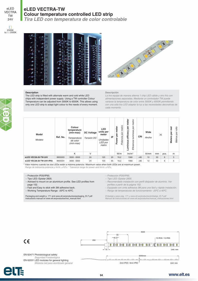
94 www.elt.es
eLED VECTRA-TWColour temperature controlled LED stripTira LED con temperatura de color controlable
~ Protección IP20/IP65.~ Tipo LED: Epistar 2835.
page 152.~ Fast and Easy to stick with 3M adhesive back.~ Working Temperature Range: -20ºC to 40ºC.
Packaging and weight p. 171 and www.elt.es/productos/packaging_ELT.pdfInstructions manual on www.elt.es/productos/inst_manual.html
~ Equipado con cinta adhesiva 3M para una fácil y rápida instalación.
Embalaje y peso pág. 171 y www.elt.es/productos/embalaje_ELT.pdfManual de instrucciones en www.elt.es/productos/manual_instrucciones.html
* Valor máximo cuando los dos LEDs están a máxima potencia / Maximum value when both LEDs are at maximum power. Rango de tolerancia potencia y lm/m: ±10% / Tolerance range for power and lm/m: ±10%.
eLEDVECTRA
TW24V
6500K to / a 3000K
EN 62471 Photobiological safety Seguridad Fotobiológica
EN 62031 LED modules for general lighting Módulos led para alumbrado general
500050
20010 IP20 / 12 IP65
5000mm
Unit: mm
2mm IP20 / 4mm IP65 Unit: mm
8,3
10
Model
ModeloRef. No.
Colour temperature (min-max)
Temperatura de color
DC Voltage
Tensión DC
LED units per
meter
Unidades LED por
metro
IP
Po
wer
per
met
er
Pot
enci
a po
r m
etro
CRI
Wide
Ancho
Met
ers
per
ree
l
Met
ros
por
rollo
K V W/m lm/m* A/mm mm pcs. m
eLED VEC28-20-TW-24V 9955003 3000 - 6500 24 120 20 19,2 1560 >80 10 50 6 5
eLED VEC28-20-TW-24V-IP65 9955004 3000 - 6500 24 120 65 19,2 1560 >80 12 50 6 5
Description
chips with independent power supply. Using a TW controller Colour Temperature can be adjusted from 3000K to 6500K. This allows using only one LED strip to adapt light colour to the needs of every moment.
Descripción La tira equipa de manera alterna 1 chip LED cálido y otro frío con alimentaciones separadas. Mediante un controlador TW puede
con una sóla tira LED adaptar la luz a las necesidades decorativas de cada momento.

95www.elt.es
eLED VECTRA-50Flexible LED strip for outdoor lighting. IP65
EN 62471 Photobiological safety Seguridad Fotobiológica
EN 62031 LED modules for general lighting Módulos led para alumbrado general
~ Protection IP65.~ LED type: Epistar 5050.
page 152.~ Fast and Easy to stick with 3M adhesive back.~ Working Temperature Range: -20ºC to 40ºC.
Packaging and weight p. 171 and www.elt.es/productos/packaging_ELT.pdfInstructions manual on www.elt.es/productos/inst_manual.html
~ Tipo LED: Epistar 5050.
~ Equipado con cinta adhesiva 3M para una fácil y rápida instalación.
Embalaje y peso pág. 171 y www.elt.es/productos/embalaje_ELT.pdfManual de instrucciones en www.elt.es/productos/manual_instrucciones.html
Rango de tolerancia potencia y lm/m: ±10%
-12V-24V
5000100
5016,6
12
-12V
4
VEC50-14
5000200
10033
-12V-24V
12
-12V
4
VEC50-07
Green / Verde
Red / Rojo
Blue / Azul
Yellow / Amarillo
RGB
eLEDVECTRA-50
24V
Model
ModeloRef. No.
Colour
Color DC
Vo
ltag
eT
ensi
ón D
C
Tem
p. C
olo
r w
ave
len
gth
Tem
p. c
olor
long
. ond
a
LE
D u
nit
s p
er m
eter
Uni
dade
s LE
D p
or m
etro
IP
Po
wer
per
met
erP
oten
cia
por
met
ro
met
er
met
ro
Wid
e
Anc
ho
24V
Met
ers
per
ree
lM
etro
s po
r ro
llo
V W/m lm/m* lm/W A/mm mm pcs. m
eLED VEC50-07-RE-24V-IP65 9955080 Red / Rojo 24 620-630 30 65 7,2 210 29,2 12 166 5 5
eLED VEC50-07-GR-24V-IP65 9955081 Green / Verde 24 520-525 30 65 7,2 405 56,3 12 166 5 5
eLED VEC50-07-BL-24V-IP65 9955082 Blue / Azul 24 465-470 30 65 7,2 192 26,7 12 166 5 5
eLED VEC50-07-YE-24V-IP65 9955083 Yellow / Amarillo 24 588-593 30 65 7,2 204 28,3 12 166 5 5
eLED VEC50-14-RGB-24V-IP65 9955085 RGB 24 RGB 60 65 14,4 540 37,5 12 100 6 5
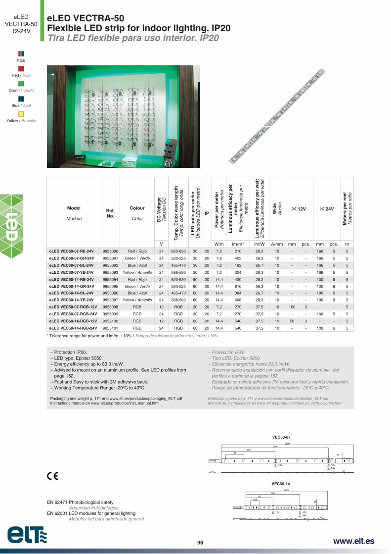
96 www.elt.es
eLED VECTRA-50Flexible LED strip for indoor lighting. IP20
EN 62471 Photobiological safety Seguridad Fotobiológica
EN 62031 LED modules for general lighting Módulos led para alumbrado general
Green / Verde
Red / Rojo
Blue / Azul
Yellow / Amarillo
RGB
eLEDVECTRA-50
12-24V
~ Protection IP20.~ LED type: Epistar 5050.
page 152.~ Fast and Easy to stick with 3M adhesive back.~ Working Temperature Range: -20ºC to 40ºC.
Packaging and weight p. 171 and www.elt.es/productos/packaging_ELT.pdfInstructions manual on www.elt.es/productos/inst_manual.html
~ Protección IP20.~ Tipo LED: Epistar 5050.
~ Equipado con cinta adhesiva 3M para una fácil y rápida instalación.
Embalaje y peso pág. 171 y www.elt.es/productos/embalaje_ELT.pdfManual de instrucciones en www.elt.es/productos/manual_instrucciones.html
Rango de tolerancia potencia y lm/m: ±10%
-12V-24V
5000100
5016,6
10
2
-12V
VEC50-14
5000200
10033
-12V-24V
10
-12V
2
VEC50-07
Model
Modelo
Ref. No.
Colour
Color DC
Vo
ltag
eT
ensi
ón D
C
Tem
p. C
olo
r w
ave
len
gth
Tem
p. c
olor
long
. ond
a
LE
D u
nit
s p
er m
eter
Uni
dade
s LE
D p
or m
etro
IPP
ow
er p
er m
eter
Pot
enci
a po
r m
etro
met
er
met
ro
Wid
eA
ncho
12V 24V
Met
ers
per
ree
lM
etro
s po
r ro
llo
V W/m lm/m* lm/W A/mm mm pcs. mm pcs. m
eLED VEC50-07-RE-24V 9955090 Red / Rojo 24 620-630 30 20 7,2 210 29,2 10 - - 166 5 5
eLED VEC50-07-GR-24V 9955091 Green / Verde 24 520-525 30 20 7,2 405 56,3 10 - - 166 5 5
eLED VEC50-07-BL-24V 9955092 Blue / Azul 24 465-470 30 20 7,2 192 26,7 10 - - 166 5 5
eLED VEC50-07-YE-24V 9955093 Yellow / Amarillo 24 588-593 30 20 7,2 204 28,3 10 - - 166 5 5
eLED VEC50-14-RE-24V 9955094 Red / Rojo 24 620-630 60 20 14,4 420 29,2 10 - - 100 6 5
eLED VEC50-14-GR-24V 9955095 Green / Verde 24 520-525 60 20 14,4 810 56,3 10 - - 100 6 5
eLED VEC50-14-BL-24V 9955096 Blue / Azul 24 465-470 60 20 14,4 384 26,7 10 - - 100 6 5
eLED VEC50-14-YE-24V 9955097 Yellow / Amarillo 24 588-593 60 20 14,4 408 28,3 10 - - 100 6 5
eLED VEC50-07-RGB-12V 9955098 RGB 12 RGB 30 20 7,2 270 37,5 10 100 3 - - 5
eLED VEC50-07-RGB-24V 9955099 RGB 24 RGB 30 20 7,2 270 37,5 10 - - 166 5 5
eLED VEC50-14-RGB-12V 9955100 RGB 12 RGB 60 20 14,4 540 37,5 10 50 3 - - 5
eLED VEC50-14-RGB-24V 9955101 RGB 24 RGB 60 20 14,4 540 37,5 10 - - 100 6 5
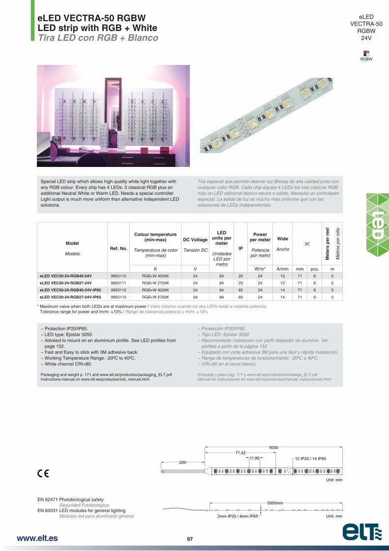
97www.elt.es
eLED VECTRA-50 RGBWLED strip with RGB + WhiteTira LED con RGB + Blanco
EN 62471 Photobiological safety Seguridad Fotobiológica
EN 62031 LED modules for general lighting Módulos led para alumbrado general
~ Protection IP20/IP65. ~ LED type: Epistar 5050.
page 152.~ Fast and Easy to stick with 3M adhesive back.~ Working Temperature Range: -20ºC to 40ºC.~ White channel CRI>80.
Packaging and weight p. 171 and www.elt.es/productos/packaging_ELT.pdfInstructions manual on www.elt.es/productos/inst_manual.html
~ Tipo LED: Epistar 5050.
~ Equipado con cinta adhesiva 3M para una fácil y rápida instalación.
Embalaje y peso pág. 171 y www.elt.es/productos/embalaje_ELT.pdfManual de instrucciones en www.elt.es/productos/manual_instrucciones.html
* Maximum value when both LEDs are at maximum power / Valor máximo cuando los dos LEDs están a máxima potencia. Rango de tolerancia potencia y lm/m: ±10%
500071,42
20012 IP20 / 14 IP6511,90
5000mm
Unit: mm
2mm IP20 / 4mm IP65 Unit: mm
eLEDVECTRA-50
RGBW24V
RGBW
Model
ModeloRef. No.
Colour temperature (min-max)
Temperatura de color
DC Voltage
Tensión DC
LED units per
meter
Unidades LED por
metro
IP
Power per meter
Potencia por metro
Wide
Ancho
Met
ers
per
ree
l
Met
ros
por
rollo
K V W/m* A/mm mm pcs. m
eLED VEC50-24-RGB40-24V 9955110 RGB+W 4000K 24 84 20 24 12 71 6 5
eLED VEC50-24-RGB27-24V 9955111 RGB+W 2700K 24 84 20 24 12 71 6 5
eLED VEC50-24-RGB40-24V-IP65 9955112 RGB+W 4000K 24 84 65 24 14 71 6 5
eLED VEC50-24-RGB27-24V-IP65 9955113 RGB+W 2700K 24 84 65 24 14 71 6 5
Special LED strip which allows high quality white light together with any RGB colour. Every chip has 4 LEDs: 3 classical RGB plus an additional Neutral White or Warm LED. Needs a special controller. Light output is much more uniform than alternative independent LED solutions.
Tira especial que permite obtener luz Blanca de alta calidad junto con
más un LED adicional blanco neutro o cálido. Necesita un controlador especial. La salida de luz es mucho más uniforme que con las soluciones de LEDs independientes.

98 www.elt.es
1.- INTRODUCTION
2.- GENERAL COMMENTS2.1.- What is an LED? How does it work?
2.2.- Principle behind LED operation
2.3.- LED lighting advantages
3.- BASIC LED AND LED MODULES CONCEPTS3.1.- Correlated Color Temperature - CCT
3.2.- Color Rendering Index - CRI
3.4.- Luminous intensity – Candela (cd)
3.5.- Iluminance – Lux (lm/m2)
3.7.- Luminous distribution curve
4.- LED MODULES4.1.- Selecting an LED – Binning
4.2.- MacAdam ellipses - SDCM
4.3.- Electrical circuit
4.4.- Heat management
4.5.- Zhaga Consortium
5.- CONTROL GEARS5.1.- Constant voltage control
5.2.- Constant current control
5.3.- Constant current control gear
5.3.1.- Single-stage converters
5.3.2.- Multi-stage converters
5.3.3.- Basic control gear protections
5.4.- Lighting regulation and control systems
5.4.1.- Regulation methods.
5.4.2.- Control system components.
6.- SELECTING LED TECHNOLOGY
LED technology indexÍndice tecnología LED
MÓDULOS LED
2)
alimentación

99www.elt.es
LED technology is rapidly developing and is going to bring about changes to the lighting sector. There are already LED applications in a host of devices, mobile
etc. However, it must be borne in mind that each type of lighting has to meet certain requirements and LED tech-nology must be designed to make the most of all its ad-vantages.
1.- INTRODUCTION
LED technology is already used in decorative and public areas and is going to be implemented in all systems, both indoors and outdoors.
ELT’s 35+ years of experience in the lighting sector provi-de you with a complete catalogue containing LED technology that includes the latest developments in LED modules and control gears. We want your new ideas to become a reality, to which end we wish to make all our expertise and technical advice available to you. This document is intended a basical knowledge to enable you to make the right choice when it comes to your lighting systems.
2.- GENERAL COMMENTS
2.1.- What is an LED? How does it work?
The abbreviation LED stands for “light-emitting diode”. An LED is a semiconductor device made up of two terminals, an anode (A) and a catho-de (K), which emits light in the visible spectrum when directly polarised (Vanode>Vcathode). This light increases as the current passing through increases.
are: direct voltage (Vd) and maximum direct cu-rrent (Id_max).
-ment or surrounding inert gas and no encasing glass cap-sule.
Moreover, it has no operating cut-off point, but rather it gra-dually weakens in the course of its service life, reducing its lighting capacity in accordance with two factors:
~ The quality of the semiconductor.
~ The heat dissipation of the system made up of the LED, the printed circuit design and the luminaire into which it
~ Ambient operating temperature.
~ The LED polarising point in voltage and current.
~ The control gear.
~ Length of use.
2.2.- Principle behind LED operation
The LED diode is a single-direction, semiconductor device, thus it must always be connected with higher voltage at the anode than at the cathode.
La tecnología LED está evolucionado a gran velocidad y va suponer un cambio en el sector de la iluminación. Hoy en día ya existen aplicaciones LED, en multitud de dispositivos, móviles, televisores, semáforos, paneles informativos, señalizaciones… Hay que tener en cuenta que cada tipo de iluminación necesita cumplir con requisitos particulares y la tecnología LED debe ser diseñada para obtener todas sus ventajas.
1.- INTRODUCCIÓN
La tecnología LED ya está presente en la iluminación decorativa y espacios públicos y se va a ir implantando en todas los sistemas tanto de tipo interior como de exterior.
ELT con más de 35 años de experiencia en el sector de la iluminación pone a su alcance un catálogo completo con tecnología LED que incluyen desarrollos en fuentes de alimentación y módulos LED. Queremos que sus nuevas ideas puedan convertirse en realidad para lo cual ponemos a su
presente documento pretende ser una base de conocimiento para una buena elección en los sistemas de iluminación.
2.- GENERALIDADES
2.1.- ¿Qué es un LED? ¿Cómo funciona?
Las siglas de LED corresponden a “Diodo Emisor de Luz”, y provienen del acrónimo inglés
Un LED es un dispositivo semiconductor formado por dos terminales, ánodo (A) y cátodo (K), el cual emite luz en el espectro visible cuando está polarizado en directa (Vánodo>Vcátodo). Está luminosidad aumenta conforme aumenta la corriente que lo atraviesa.
tensión directa (Vd) y corriente directa máxima (Id_max).
Básicamente, un diodo LED es una lámpara en estado só
capsula de vidrio recubriéndolo.
Además, no tiene un punto de cese de funcionamiento, sino que su degradación es gradual a lo largo de su vida, reduciendo su capacidad lumínica en función de los factores:
~ La calidad del semiconductor.
~ La disipación térmica del sistema compuesto por el LED, el diseño del circuito impreso y la luminaria donde se instale.
~ La temperatura ambiente de funcionamiento.
~ El punto de polarización del LED en tensión e intensidad
~ El equipo de alimentación.
~ El tiempo de uso.
2.2.- Principio de funcionamiento del LED
El diodo LED es un dispositivo semiconductor y unidireccional, por lo que siempre deberá ser conectado con mayor tensión en el ánodo que en el cátodo.
AnodeÁnodo
CathodeCátodo
+ -
LED diode symbolSímbolo de un diodo LED
LED technical informationInformación técnica sobre LED

100 www.elt.es
Typically, a lighting LED diode has a voltage drop of 3 volts, therefore, by applying this voltage between its anode and cathode, a direct current is produced that will make the diode light up.
If we try to connect the LED diode in reverse, with a higher voltage value at the cathode than at the anode, no current would be produced and thus it would not light up. Moreover, care must be taken with this type of connection, given that they are diodes that are generally not designed to withstand high reverse voltages.
2.3.- LED lighting advantages
LED technology has several advantages over conventio-nal lighting systems, such as:
~ Long service life that substantially reduces maintenan-ce and replacement costs. It is estimated that at about
initial level.
generated per watts used.
~ Greater response speed given that it lights up instantly
~ Clearer and brighter light. The LED chromatic scale is purer, thus the light is more natural for the human eye.
~ Uni-directional light: The light can be better focused on
the area you want to light up, which means less con-sumption.
~ Wide colour spectrum. LED technology affords us the choice of a more extensive variety of colours.
~ Environmentally-friendly. LED devices do not contain either mercury or other toxic elements and do not produ-ce either infrared or ultraviolet radiation.
~ Size. Their small dimensions enable the design of more compact applications.
3.- BASIC LED AND LED MODULE CONCEPTS
In addition to their electrical characteristics, LEDs possess
3.1.- Correlated Color Temperature - CCT
perceived by the human eye in the presence of light; it is warm when amber predominates, and cool when blue.
CCT is obtained from comparing the colour within the light spectrum of a light source with the light of a black body, i.e. an “ideal radiator” heated to a particular temperature.
Típicamente, un diodo LED dedicado a la iluminación tiene una caída de tensión de unos 3 voltios, por tanto, aplicando esa tensión entre su ánodo y su cátodo, se producirá una corriente en sentido directo que hará que el diodo se ilumine.
Si tratásemos de conectar el diodo LED al revés, con más tensión en cátodo que en ánodo, no se establecería corriente, y éste no luciría. Además, hay que tener cuidado con este tipo de conexión, ya que son diodos que generalmente no están pensados para soportar elevadas tensiones en inversa.
2.3.- Ventajas de la iluminación LED
La tecnología LED ofrece varias ventajas frente a los sistemas de iluminación convencionales, como por ejemplo:
~ Larga vida útil que reduce notablemente los costes de mantenimiento y reemplazo. Se considera que cerca de
inicial.
luz por cada vatio consumido.
~ Mayor rapidez de respuesta debido a que su encendido es instantáneo y sin ningún tipo de parpadeos ni periodos de arranque.
~ Luz más nítida y brillante. La escala cromática de los LEDs es más pura por lo que esta luz es más natural para el ojo humano.
~ Luz unidireccional: La luz puede ser dirigida a la zona que se desee iluminar con un mayor aprovechamiento, lo que se traduce en un menor consumo.
~ Amplio espectro cromático. La tecnología LED nos brinda la posibilidad de elegir entre una amplia variedad de colores.
~ Ecológicos. Los dispositivos LED no contienen mercurio ni otros elementos tóxicos, no producen irradiaciones de infrarrojos o ultravioletas.
~ Tamaño. Sus reducidas dimensiones permiten el desarrollo de aplicaciones más compactas.
3.- CONCEPTOS FUNDAMENTALES DEL LED Y MÓDULOS LED
Los LEDs, además de las características eléctricas, po
hay que conocer:
3.1.- Temperatura de Color Correlacionada - CCT
ción que percibe el ojo humano ante una luz, siendo cálida si predomina el ámbar o fría si es el azul.
La CCT se obtiene de la comparación del color dentro del espectro luminoso de una fuente de luz con el de la luz de un cuerpo negro, es decir un “radiante teórico perfecto” calentándolo a una temperatura determinada.

101www.elt.es
A simple way to understand this is to imagine the range of colours a piece of metal would pass through when heated; it would go from red to blue, by way of amber, yellow and white.
Colour temperature is measured in degrees Kelvin (K):
~ Amber: from 1.200K to 2.400K.~ Very Warm White: from 2,400K to 2.900K.~ Warm White: from 2.900K to 3.900K. ~ Neutral White or Daylight: from 3.900K to 5.500K.~ Cold White: from 5.500K to 7.000K.~ Very Cold White: from 7.000K to 9.000K.
3.2.- Color Rendering Index - CRI
The colour rendering index (CRI - or Ra) measures the ability of a light source to reproduce the colours of an object faithfully in comparison with an ideal or natural light source.
It is measured as indicated by the International Commis-sion on Illumination (CIE) 13.3 – Method of measuring and specifying colour rendering properties of light sources. This method is applied on a scale of 0 to 100:
-tions.
light radiation to which the human eye is sensitive.
It is measured as the amount of light emitted by a light source in all directions. Its symbol and SI unit of measurement is the lumen (lm).
3.4.- Luminous intensity – Candela (cd)
SI unit, the candela (cd). The candela, also referred to as luminous inten-
in a particular direction given by the solid angle that contains it.
Un ejemplo sencillo para comprenderlo es imaginarse la gama de colores por la cual pasaría un metal al calentarlo, los cuales irían desde el rojo al azul, pasando por el ámbar, amarillo y el blanco.
La temperatura de color se mide en Grados Kelvin (K):
~ Blanco Cálido: de 2.900K a 3.900K.~ Blanco Neutro o Luz Día: de 3.900K a 5.500K.~ Blanco Frio: de 5.500K a 7.000K.~ Blanco Muy Frio: de 7.000K a 9.000K.
3.2.- Índice de Reproducción Cromática - CRI
ring Index o Ra) mide la capacidad que tiene una fuente lu
comparación con una fuente de luz natural o real.
de las fuentes luminosas. Este método se aplica sobre una escala del 0 a 100:
de Indoor.
3.3.- Flujo luminoso - Lumen (lm)
de radiación luminosa a la que el ojo humano es sensible.
Se mide como la cantidad de luz emitida por una fuente de luz en todas las direcciones. Su símbolo y su unidad de medición en el Sistema de Internacional es el lumen (lm).
3.4.- Intensidad luminosa – Candela (cd)
básica del Sistema Internacional, la candela (cd).
La candela, o también llamada intensidad lumino
en una dirección dada por el ángulo sólido que lo contiene.
2.700K Very Warm Muy Cálido
3.000K Warm Cálido
4.000K Neutral Neutro
5.700K Frio Cold
8.500K Very Cold Muy Frio
1.500K Amber Ámbar

102 www.elt.es
3.5.- Iluminance – Lux (lm/m2)
magnitude: illuminance. The unit by which the latter is measured is the lux (lm/m2), which represents the
of the light on a given surface.
amount of light emitted (lm) to the power consumed (W). It is measured, therefore, in lm/W.
3.7.- Luminous distribution curve
The luminous distribution curve is obtained by taking light intensity measurements at different angles around a light source. It is normally represented by polar coordinates.
The distance from any point on the curve to the centre indi-cates the light intensity of the source in that direction.
Generally speaking these curves indicate the maximum light intensity value in candelas for every 1,000lm.
ELT provides luminous distribution curves for its LED mod-
result of the application will depend on system requirements.
3.5.- Iluminancia – Lux (lm/m2)
magnitud, la iluminancia. La unidad de esta última es el lux (lm/m2
ción entre la cantidad de luz emitida (lm) y la potencia consumida (W). Se mide por tanto en lm/W.
3.7.- Curva de distribución luminosa
La curva de distribución luminosa es el resultado de tomar medidas de intensidad luminosa en diversos ángulos alrededor de una fuente lumínica, y se representada normalmente en coordenadas polares.
La distancia de cualquier punto de la curva al centro, indica la intensidad luminosa de la fuente en esa dirección.
Generalmente, estas curvas indican el valor máximo de intensidad luminosa representado en candelas por cada 1.000lm.
ELT proporciona las curvas de distribución lumínica de los módulos LED como información para el usuario o fabricante
de los requisitos del sistema.
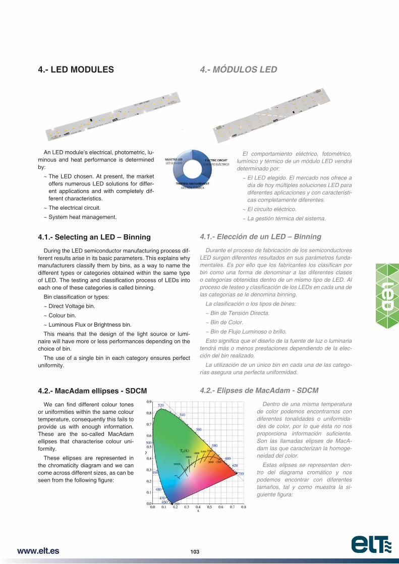
103www.elt.es
4.- LED MODULES
An LED module’s electrical, photometric, lu-minous and heat performance is determined by:
~ The LED chosen. At present, the market offers numerous LED solutions for differ-ent applications and with completely dif-ferent characteristics.
~ The electrical circuit.
~ System heat management.
4.1.- Selecting an LED – Binning
During the LED semiconductor manufacturing process dif-ferent results arise in its basic parameters. This explains why manufacturers classify them by bins, as a way to name the different types or categories obtained within the same type
each one of these categories is called binning.
~ Direct Voltage bin.
~ Colour bin.
~ Luminous Flux or Brightness bin.
This means that the design of the light source or lumi-naire will have more or less performances depending on the choice of bin.
The use of a single bin in each category ensures perfect uniformity.
4.2.- MacAdam ellipses - SDCM
or uniformities within the same colour temperature, consequently this fails to provide us with enough information. These are the so-called MacAdam ellipses that characterise colour uni-formity.
These ellipses are represented in the chromaticity diagram and we can come across different sizes, as can be
4.- MÓDULOS LED
El comportamiento eléctrico, fotométrico, lumínico y térmico de un módulo LED vendrá determinado por:
~ El LED elegido. El mercado nos ofrece a día de hoy múltiples soluciones LED para diferentes aplicaciones y con características completamente diferentes.
~ El circuito eléctrico.
~ La gestión térmica del sistema.
4.1.- Elección de un LED – Binning
Durante el proceso de fabricación de los semiconductores LED surgen diferentes resultados en sus parámetros funda
bin como una forma de denominar a las diferentes clases o categorías obtenidas dentro de un mismo tipo de LED. Al
las categorías se le denomina binning.
~ Bin de Tensión Directa.
~ Bin de Color.
~ Bin de Flujo Luminoso o brillo.
tendrá más o menos prestaciones dependiendo de la elección del bin realizado.
La utilización de un único bin en cada una de las categorías asegura una perfecta uniformidad.
4.2.- Elipses de MacAdam - SDCM
Dentro de una misma temperatura de color podemos encontrarnos con diferentes tonalidades o uniformidades de color, por lo que ésta no nos
Son las llamadas elipses de MacAdam las que caracterizan la homogeneidad del color.
Estas elipses se representan dentro del diagrama cromático y nos podemos encontrar con diferentes tamaños, tal y como muestra la si
4.- LED MODULES

104 www.elt.es
The measurement scale for these ellipses is determined by the standard deviation of the colour matching (SDCM – Standard Deviation of Color Matching).
Module colour uniformity is measured by tracing different ellipses around the quadrant of the chosen colour tempera-ture. The SCDM number is determined by the ellipse that contains all the colour bin values used in the module.
Therefore, the smaller the ellipse the less colour deviation obtained. Generally speaking, it can be said that the human
~ 1 SDCM: There are no colour differences.
~ 2 – 4 SDCM: There is hardly any visible difference.
~ 5 or more SDCM: Colour is easily perceived.
4.3.- Electrical circuit
When it comes to designing an LED module, the baseline
electrical in nature: voltage and current and photometric fea-tures: Lumens. The outcome and resulting quality will be de-termined both by LED distribution within the module, as well as by their electrical connection.
In Constant Current-powered LED modules, the internal electrical connection is based on interlinking LEDs serially forming a branch. The connecting of several branches in par-allel goes to make up the LED module.
La escala de medición de estas elipses viene determinada por la desviación estándar de combinación de colores
La forma de medida de la uniformidad de color del módulo se realiza trazando las diferentes elipses entorno al cuadrante de la temperatura de color elegida. El número de SCDM vendrá determinado por aquella elipse que contenga todos los valores de bines de color empleados en el módulo.
De modo que cuanto menor es el tamaño de la elipse menor desviación de color se obtendrá. De una forma general se puede decir que el ojo humano responde a la siguiente
~ 1 SDCM: No existen diferencias de color.
~ 5 o más SDCM: Es fácilmente perceptible.
4.3.- Circuito eléctrico
requisitos de partida. Estos normalmente suelen ser eléctricos: tensión y corriente, y fotométricos: Lúmenes. Los resultados y calidad resultante vendrán determinados tanto por la distribución de los LEDs dentro del módulo como por su conexión eléctrica interna.
En los módulos LED alimentados en Corriente Constante el conexionado eléctrico interno está basado en la concatenación de LEDs en serie formando una rama, la conexión en
4500K
4000K 3500K1 - 7 SDCM or steps MacAdam Ellipses1 - 7 SDCM o pasos de Elipses de MacAdam
1 SDCMor STEP
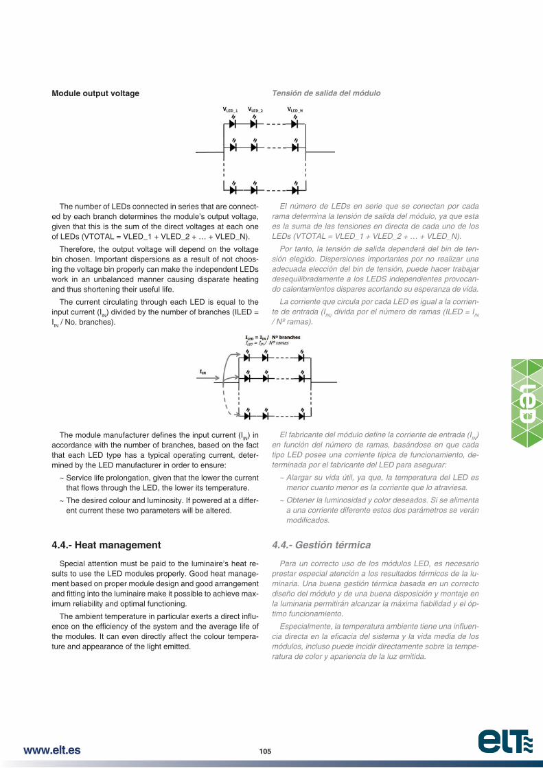
105www.elt.es
Module output voltage
The number of LEDs connected in series that are connect-ed by each branch determines the module’s output voltage, given that this is the sum of the direct voltages at each one of LEDs (VTOTAL = VLED_1 + VLED_2 + … + VLED_N).
Therefore, the output voltage will depend on the voltage bin chosen. Important dispersions as a result of not choos-ing the voltage bin properly can make the independent LEDs work in an unbalanced manner causing disparate heating and thus shortening their useful life.
The current circulating through each LED is equal to the input current (IIN) divided by the number of branches (ILED = IIN / No. branches).
IN) in accordance with the number of branches, based on the fact that each LED type has a typical operating current, deter-mined by the LED manufacturer in order to ensure:
~ Service life prolongation, given that the lower the current
~ The desired colour and luminosity. If powered at a differ-ent current these two parameters will be altered.
4.4.- Heat management
Special attention must be paid to the luminaire’s heat re-sults to use the LED modules properly. Good heat manage-ment based on proper module design and good arrangement
-imum reliability and optimal functioning.
-
the modules. It can even directly affect the colour tempera-ture and appearance of the light emitted.
Tensión de salida del módulo
El número de LEDs en serie que se conectan por cada rama determina la tensión de salida del módulo, ya que esta es la suma de las tensiones en directa de cada uno de los LEDs (VTOTAL = VLED_1 + VLED_2 + … + VLED_N).
Por tanto, la tensión de salida dependerá del bin de tensión elegido. Dispersiones importantes por no realizar una adecuada elección del bin de tensión, puede hacer trabajar desequilibradamente a los LEDS independientes provocando calentamientos dispares acortando su esperanza de vida.
La corriente que circula por cada LED es igual a la corriente de entrada (IIN) divida por el número de ramas (ILED = IIN
/ Nº ramas).
IN) en función del número de ramas, basándose en que cada tipo LED posee una corriente típica de funcionamiento, determinada por el fabricante del LED para asegurar:
~ Alargar su vida útil, ya que, la temperatura del LED es menor cuanto menor es la corriente que lo atraviesa.
~ Obtener la luminosidad y color deseados. Si se alimenta a una corriente diferente estos dos parámetros se verán
4.4.- Gestión térmica
Para un correcto uso de los módulos LED, es necesario prestar especial atención a los resultados térmicos de la luminaria. Una buena gestión térmica basada en un correcto diseño del módulo y de una buena disposición y montaje en
timo funcionamiento.
módulos, incluso puede incidir directamente sobre la temperatura de color y apariencia de la luz emitida.

106 www.elt.es
La temperatura de los módulos depende básicamente de:
~ La temperatura de funcionamiento del propio diodo LED, Tj ó temperatura de la unión. Esta será más alta a medida que la intensidad eléctrica que lo atraviesa se acerque al valor máximo permitido por el módulo.
~ La temperatura ambiente Ta que rodea al módulo
~ La disipación térmica entre el módulo y la luminaria o apoyo dentro de ella.
Para facilitar al usuario la interpretación y correcta apli
módulo para que de una forma rápida, se pueda evaluar el resultado térmico del sistema.
Recomendamos medir la temperatura en el punto Tc del módulo y que esta no sea superada, de lo contrario su esperanza de vida se verá mermada de forma exponencial. Valores por debajo de este punto aumenta considerablemente la vida de los LEDs.
4.5.- Zhaga Consortium
Los LEDs son una tecnología prácticamente nueva que no tiene casi ningún tipo de limitaciones en cuanto a tamaño, forma, rendimiento y tipo de interconexión.
de ocasionar confusión en el mercado y una falta de interoperabilidad entre fabricantes de productos LED.
Por ello, varias empresas del sector de la iluminación de todo el mundo (incluyendo ELT) han formado un consorcio llamado ZHAGA, el cual proporciona plataformas estables de diseño para los módulos LED con el objetivo de garantizar una intercambiabilidad de emisores de luz LED.
The temperature of the modules basically depends on:
~ The operating temperature of the LED diode itself, Tj or the junction temperature. This will be higher depending
the maximum value admitted by the module.
~ The ambient temperature, Ta, that surrounds the mod-ule.
~ The heat dissipation between the module and the lumi-naire or support inside it.
To facilitate correct user interpretation and application,
order to enable a quick evaluation of the system’s heat result.
We recommend that you measure the temperature at the module’s Tc point and make sure that this is not exceeded, otherwise its useful life will be reduced exponentially. Values below this point considerably increase the service life of the LEDs.
4.5.- Zhaga Consortium
LED is a practically new technology that knows no limits in terms of size, shape, performance and type of
-ibility and creativity; Nevertheless, given there are no agreed
a lack of interoperability between LED manufacturers’ prod-ucts.
As a result, several lighting sector companies around the world ( ELT included) have set up a consortium called ZHA-GA, which provides stable design platforms for LED modules with a view to ensuring the interchangeability of LED light emitters.

107www.elt.es
5.- CONTROL GEARS
After we establish the direct current through an LED diode, we must take care to avoid exceeding the limits set by the LED diode manufacturer. In other words, we will have to limit
-fering damage. The question is, how can we limit the current through our chain or strip of LED diodes? The solution lies in a piece of equipment commonly referred to as a control gear or driver, which is designed for ‘constant voltage’ or ‘constant current’ applications.
5.1.- Constant voltage control
In this method, the LED diodes control gear sup-plies a constant and unchanging output voltage, re-gardless of the connected load.
If we connect a chain of LED diodes and estab-
no element to limit the current, could cause dam-ages in our equipments. For avoiding this, a resistor is placed on each branch or chain of diodes con-nected in serie. Accordingly, on having a constant voltage in the resistor, a constant current will be established through it, therefore, though the LED diodes.
LED diodes are conducting 100% of the time. Given that
caused by heat dissipation, thus creating a system that is
should be.
You must also bear in mind that if you are using electronic or electromagnetic transformers to provide a constant volt-age, the LED diodes will conduct 50% of the time and, what is more, in the case of high frequency electronic transform-ers, we will get important current variations on the LED di-odes, which may cause unwanted heating.
5.2.- Constant current control
In this control method, our driver will supply a constant current through the LED module, thus en-suring uniform luminosity in all of them. The output voltage will be established by the number of LED diodes connected.
in this method, so we avoid unnecessary losses. Thus, our system becomes much .
The LED diodes will be conducting 100% of the
thus producing the same luminosity in each one. Accordingly, the ‘Constant current control’ method represents the best lighting solution.
5.- FUENTES DE ALIMENTACIÓN
Una vez que establecemos una corriente directa a través de un diodo LED, debemos ser cuidadosos en no superar los límites establecidos por el fabricante de diodos LED. En otras palabras, tendremos que limitar esa corriente para que
de control denominado comúnmente fuente de alimentación o driver, diseñado para aplicaciones de ‘tensión constante’ o ‘corriente constante’.
5.1.- Control por tensión constante
En este método, la fuente de alimentación de los diodos LED, suministra una salida de tensión constante e invariable, independientemente de la carga conectada.
Si conectásemos una cadena de diodos LED, y se estableciese corriente a través de ellos, no habría ningún elemento que limitase la corriente, llegando a poder producir daños en nuestro equipo. Para ello, se introduce una resistencia en cada rama o cadena de diodos en serie. De esta manera, al tener una tensión constante en bornes
a través de la resistencia y, por tanto, a través de los diodos LED.
Los diodos LED están conduciendo el 100% del tiempo, eso sí, al circular una corriente por las resistencias, se producirán pérdidas por disipación en forma de calor, dando como
tecnología tan prometedora como es la iluminación LED.
También hay que tener en cuenta que si se usan transformadores electrónicos o electromagnéticos para proporcionar una tensión constante, los diodos LED conducirán el 50% del tiempo y, además, en el caso de los transformadores electrónicos de alta frecuencia, tendremos unas variaciones de corriente importantes en los diodos LED, pudiendo dar como resultado calentamientos indeseados.
5.2.- Control por corriente constante
En este método de control, nuestro ‘driver’ sumi
del módulo LED, haciendo que la luminosidad en todos ellos sea la misma. La tensión en la salida
tados.
En este método no es necesaria la instalación
evitamos pérdidas innecesarias. Así, nuestro sistema se convierte en uno mucho .
Los diodos LED estarán conduciendo el 100%
rriente, produciendo la misma luminosidad en todos ellos. De esta manera, el método de ‘Control en corriente constante’ se convierte en la solución óptima para la iluminación.
CVTensión ConstanteConstant Voltage
v-
CCCorriente ConstanteConstant Current
v
-
+ -

108 www.elt.es
5.3.- Fuente de alimentación de corriente constante
Una fuente de alimentación o driver es un dispositivo que permite la conversión de energía desde la red a la forma
La energía que se entrega a la carga siempre es menor que la demandada a la red, debido a las pérdidas que se originan en cualquier dispositivo de este tipo y que se convierten en calor. Conseguir que esa pérdida de energía sea la menor posible es la meta de cualquier fabricante de fuentes de alimentación, es decir, acercarse lo más posible a un 100% de
En el caso de una fuente de alimentación para LEDs, normalmente se convierte la energía alterna de la red (AC) en energía continua en la salida (DC), y hablamos de conver
intermedias que van transformando la energía a los requerimientos que necesitamos en cada momento.
Una fuente de alimentación puede estar diseñada con una o varias etapas intermedias. El número de éstas determinará
en la salida, factor de potencia etc…
5.3.1.- Convertidores de una etapa o Single-Stage (adecuados para potencias bajas).
Este tipo de fuentes de alimentación utilizan una etapa conversora de energía. Un ejemplo sería un equipo basa
ciclo, la bobina se carga de energía, y en el otro ciclo, la bobina se descarga en el secundario, entregando energía a la carga y recargando los condensadores de la salida y que mantienen la corriente y tensión constantes.
Filtro salidaMódulos LEDLED modules
RedMains
Output filterDC DC
Filtro
EMI
Filter
Rectificador
Aislamiento
Rectifier
Isolation
5.3.- Constant current control gear
A control gear or driver is a device that enables the conver-sion of mains energy to the form required by the load in the
load is always less than that demanded from the mains ow-ing to the losses produced in any device of this type, which are converted into heat. Ensuring that this power loss is as little as possible is the aim of any control gears manufacturer,
In the case of a control gear for LEDs, normally the mains alternating current (AC) is converted into direct current (DC), thus we are talking of AC/DC converters. In addition to an
several intermediate stages that gradually transform the power to meet our requirements at any moment in time.
A control gear can be designed with one or several stages. The number of the stages will determine the features of the
5.3.1.- Single-Stage converters (suitable for low power levels).
This type of control gears uses a power stage converter. Equipment based on Flyback technology with two coupled windings would be an example. In one cycle the winding is charged with power, and in the other one the winding dis-charges in the secondary, delivering power to the load and recharging the output capacitors, thus maintaining constant voltage and current.

109www.elt.es
El acoplamiento entre estas dos bobinas es clave para determinar el tipo de aislamiento de la fuente de alimentación:
~ AISLADA: Cuando hay una separación galvánica y eléctrica entre los circuitos de primario o entrada de red y secundario o salida a la carga.
~ De uso INDEPENDIENTE: Cuando además del aislamiento, hay una doble protección entre las personas y cualquier parte activa accesible del equipo.
~ CLASE II: Cuando además hay una doble protección entre primario y secundario y desde estos al exterior.
~ SELV: en caso de cumplir los anteriores requisitos, así como otros referidos a los valores de tensión en la salida y su rizado.
cantidad de energía entregada a la carga es dependiente de la cantidad de energía en la entrada (tensión de alimentación). Estos equipos suelen tener un rizado mayor, aunque si éste no supera el 30% se considera que el comportamiento es bueno.
El rizado puede ser compensado por los condensadores electrolíticos que actúan como componentes que almacenan energía, por este motivo, si conectamos un módulo LED a una fuente de alimentación previamente conectada a la red, estos condensadores permanecerán cargados generando en el momento de la conexión del módulo intensidades de pico elevadas que pueden dañar los LED, este hecho es de vital importancia y se aconseja que se revisen las conexiones en los módulos LEDs para evitar falsos contactos.
Debido a que la etapa va adecuándose y siguiendo a los valores de red de entrada, el factor de potencia de este tipo de equipos suele ser bueno >0.9, y el THD o factor de dis
Ciclo de cargaCharge cycle OUTPUT
VDS
FLYBACK
INPUT OUTPUTOUTPUT
RMS
max
min
RMS
max - min% ripple = x 100
Módulo LEDLED module
PK
The coupling between these two windings is essential to determining the type of power source isolation:
~ ISOLATED: When there is galvanic and electrical sepa-ration between the primary circuits or mains input and secondary or load output.
~ INDEPENDENT use: When, in addition to the isolation, there is double protection between the person and any accessible live part of the equipment.
~ CLASS II: When, moreover, there is double protection between primary and secondary and between these and the exterior.
~ Safety Extra Low Voltage (SELV): in the event of com-plying with the aforementioned requirements, as well as others concerning voltage values at the output and its ripple.
In a Flyback stage without prior regulating stages, the amount of power delivered to the load depends on the amount of input power (power voltage). This equipment nor-mally has a bigger ripple, though if this does not exceed 30%, behaviour is considered to be good.
The ripple can be compensated for by the electrolytic ca-pacitors acting as components that store energy. This is why if we connect an LED module to a control gear previously connected to the mains, these capacitors will remain loaded, generating, upon connection of the module, high peak inten-sities which can damage the LEDs. This fact is of vital impor-tance, thus you are advised to check the connections at the LED modules to avoid bad contacts.
Owing to the fact that the stage gradually adapts itself, and in accordance with the mains input values, the power factor of this type of equipment is normally good >0.9 and the total
-back lies between 85 and 90%.
VDS
Ciclo de descargaDischarge cycle OUTPUT

110 www.elt.es
5.3.2.- Convertidores de varias etapas intermedias (adecuados para potencias altas y muy altas).
Este tipo de fuentes utilizan varias etapas para ir adecuando la energía a las características más convenientes, para lograr altas prestaciones y un buen rendimiento. Lo usual es disponer de una primera etapa de corrección activa del factor de potencia, generando además un bus de tensión
de potencia es altísimo >0.95, el THD puede controlarse y
una energía constante independientemente de la tensión de alimentación.
rias al conmutar en el mismo momento en el que la bobina
superiores al 90%.
5.3.3.- Protecciones básicas de una fuente de alimentación
Una fuente de alimentación debe ser capaz de enfrentarse a situaciones anormales de funcionamiento sin que ello suponga daño al equipo. Algunas de ellas son:
Situation / Situación Action / Actuación
Short circuit at output terminals
Cortocircuito en los bornes de salida
Disabling of the system or the capacity to regulate in the event of failure. Whatever the case, equipment connected against short circuit connections must be capable of withstanding this situation for prolonged periods and of operating properly after the reason causing the fault situation has been remedied.
Inhabilitación del sistema o bien capacidad para regular en caso de fallo. En todo caso, un equipo protegido contra conexión en cortocircuito debe ser capaz de soportar prolongadamente esta situación y de funcionar correctamente una vez haya desaparecido la condición de fallo.
Open circuit at output terminals
Circuito abierto en los bornes de salida
Disabling of the system and capacity to reset after the fault situation has been remedied.
Inhabilitación del sistema y capacidad de rearme una vez haya desaparecido la condición de fallo.
Power source high temperatu-res. Tc higher than indicated
Temperaturas altas en la fuente de alimentación. Tc superior al indicado
Disconnecting of one of the mains phases or disabling of the system until a suitable temperature is restored for equipment operation. There
Desconexión de una de las fases de alimentación o inhabilitación del sistema hasta que se recupere una condición de temperatura adecua
para favorecer un menor calentamiento.
High temperatures in the LED module
Temperaturas altas en el módulo de LED
Una NTC externa colocada en el módulo de LED puede ofrecer a la fuente de alimentación conocimiento de la temperatura alcanzada en los LEDs, y de esta manera, actuar si llega a ser peligrosa, regulando el nivel de intensidad a través de los LEDS o incluso inhabilitando el sistema.
Sudden input voltage variations
Variaciones bruscas de tensión en la entrada
those generated on the mains by lightning.
eventos de tensión peligrosos como pueden ser los generados sobre una red eléctrica por los rayos.
Filtro salidaRed
MainsOutput filter
FLYBACK
Filtro
EMI
Filter
RectificadorPFC
Boost400V
Aislamiento
Rectifier
Isolation
FLYBACK
PérdidasLosses
FLYBACK QR
VDS
5.3.2.- Intermediary stage converters (suitable for high and very high power levels).
These types of control gears use several stages to gradu-ally adapt the power to the most suitable characteristics
factor, in addition to generating a continuous voltage bus that supplies the Flyback. In this way, the power factor is ex-tremely high >0.95, the THD can be controlled and made as low as possible, the Flyback delivers a constant power at the output, regardless of the supply voltage
In this type of control gears a semi-resonant stage is nor-mally used, as the Flyback is quasi-resonant, with a view to
-mal Flyback, but avoids unnecessary losses by switching at
-cies of over 90% can be achieved.
5.3.3.-Basic control gear protection
A control gear must be capable of withstanding abnormal operating situations without damaging the equipment. Some of these are:

111www.elt.es
5.4.- Lighting regulation and control systems
Lighting regulation and control systems are a key issue for a modern society’s lighting.
Under the premise of smart light use, these systems offer a lighting that adapts to the needs of each installation and situ-ation, creating suitable ambiences for all times and providing both a high degree of comfort as well as considerable cost savings.
The energy saving made possible by these lighting regula-tion and control systems, in addition to the economic sav-ing, has an extremely positive effect on the environment, given that less power consumption means both a reduction of CO2 emissions as well as a sustainable use of the natural resources and power sources, thus contributing to environ-ment conservation.
5.4.1.- Regulation methods.
Leading & trailing edge dimming
This type of regulation is accomplished without any need for an additional control wire. It involves connecting a regulator in series between one of the mains wire and the equipment.
The regulator cuts part of the mains voltage sinusoidal waveform to a greater or lesser extent in order to regulate
Depending on how the mains voltage cut is made, it is pos-sible to distinguish between two types of regulation:
Leading-edge dimming:
Regulation by means of cut-off in the wave on its rising side, from the beginning (phase cut-off at ignition). This is habitually used in halogen lamps sup plied through electromagnetic transformers
Trailing-edge dimming:
Regulation by means of cut-off in the wave on its descending side, from the end cutting back wards (phase cut-off at switch off). This is the most suit-able for halogen lamps supplied through electronic transformers .
There are regulators and equipment that support both types of regulation, and others that support only one type.
In the marking of these systems with phase cutting regula-tion you can see indications of what type of cut is involved:
5.4.- Sistemas de regulación y control del alumbrado
Hablar de sistemas de regulación y control del alumbrado es hablar del alumbrado de una sociedad moderna.
Bajo la premisa de un uso inteligente de la luz, estos sistemas ofrecen un alumbrado que se adapta a las necesidades de cada instalación y situación, creando ambientes adecuados para cada momento y proporcionando tanto un alto grado de confort como un elevado ahorro de energía.
El ahorro de energía que proporcionan los sistemas de regulación y control del alumbrado, además del ahorro económico, tiene un efecto muy positivo desde el punto de vista ecológico, ya que el menor consumo de energía supone tanto la reducción de emisiones de CO2 como un uso sostenible de los recursos naturales y las fuentes de energía, preservando de esta forma el medioambiente.
5.4.1.- Métodos de regulación
(leading & trailingedge dimming)
Este tipo de regulación se realiza sin necesidad de una línea de control adicional, conectando un regulador en serie entre la línea de alimentación y el equipo.
El regulador recorta parte de la onda sinusoidal de la tensión de red en mayor o menor medida para obtener una re
Dependiendo como se realiza el recorte de la tensión de red se puede distinguir entre dos tipos de regulación:
Regulación al inicio de fase (Leading-edge dimming):
Regulación mediante recorte de la onda de red
fase en el encendido). Es el empleado habitualmente en lámparas halógenas alimentadas a través de transformado res electromagnéticos.
Regulación mediante recorte de la onda de red
hacia atrás (corte de fase en el apagado). Es más adecuado para lámparas halógenas alimentadas a través de transformadores electrónicos.
Existen diversos reguladores y equipos que soportan ambos tipos de regulación, y otros que solo soportan uno de ellos.
En el marcaje de estos sistemas con regulación por recorte de fase, se pueden observar indicaciones que informan del tipo de recorte:
DriverL
N
+
-
Trailing-edge dimming or cut-off(recorte por final de fase)
Leading-edge dimming or cut-on(recorte por inicio de fase)
Leading & Trailing-edge dimmingLC
Leading-edge dimmingRegulación con regulador de corte al inicio de fase
L
Trailing-edge dimmingC

112 www.elt.es
entre alrededor del 1 y el 100%, mediante una señal analógica que llega a los equipos a través de una línea de control adicional de dos hilos. Estos hilos de control poseen una polaridad positiva y negativa respectivamente que hay que respetar a la hora de realizar el cableado.
La señal analógica tiene un valor de tensión continua entre 1V y 10V, obteniéndose el nivel mínimo de luz con 1V o cortocircuitando la entrada de control del equipo, y el máximo nivel de luz con 10V o dejando la entrada de control en circuito abierto.
Mediante la línea de control solo se puede realizar la regu
que puede tener lugar en cualquier punto de la regulación, se realiza mediante un interruptor colocado en la línea de alimentación del equipo. Ambas líneas, la de control y la de alimentación, se encuentran separadas eléctricamente entre sí.
La curva de regulación que representa la relación entre la
prácticamente lineal en el rango de 3V a 10V.
Para obtener una respuesta adaptada a la respuesta del ojo humano, se pueden usar potenciómetros de control logarítmicos.
potencia de control es generada por éstos. A través de los bornes de control del equipo, se suministra una corriente al controlador que debe estar comprendida entre 10uA y 2mA. La máxima corriente por la línea de control se obtiene con la tensión de 1V y la mínima corriente con 10V.
Este sistema de regulación es unidireccional, es decir la
hacia el equipo de iluminación, no generando el equipo nin
miento via software de los equipos, teniendo que realizarse la creación de grupos de forma cableada. Este sistema se
La longitud del cableado de la línea de control está limitada por la caída de tensión que se produce a lo largo de la misma, por tanto la máxima distancia está limitada por el nú
la corriente por la línea y la sección del cable usado.
100
2 3 4 5 6 7 8 9 10
20
40
60
80
100
1-10V regulation
from around 1% to 100% by means of an analogue signal to the equipment over an additional, two-wire additional control line. These control wires have positive and negative polari-ties respectively and must be borne in mind when wiring up the system.
The analogue signal has a direct voltage value of 1V to 10V. Minimum light is obtained 1V or by short circuiting the equipment’s input control, while maximum light level is ob-tained 10V or by leaving the input control circuit open.
The line control only enables regulation of the luminous
switch on the equipment’s power line. Both lines, the control and power one, are electrically separated from each other.
The regulation curve that represents the relationship be--
practically lineal relationship in the range of 3V to 10V.
To get a response adapted to that of the human eye it is possible to use logarithmically controlled potentiometers.
Power control is generated by these in lighting equipment with 1-10V regulation. A current is supplied to the controller by means of equipment control terminals. The controller cur-rent must be from 10uA to 2mA. The maximum control line current is obtained with a voltage of 1V and the minimum with a voltage of 10V.
This regulation system is unidirectional, i.e. the information -
ment. The latter generates no type of feedback to control. It does not allow for addressing by means of equipment soft-ware. Groups have to be created by wiring. This system can be integrated into building control systems.
The length of the control line wiring is limited by the voltage drop that occurs along it, therefore, the maximum distance is limited by the number of control gears connected to be controlled. The latter establish the current per line and the cable diameter used.

113www.elt.es
Regulación mediante pulsador touch control
Touch Control es un sistema mediante el cual se consigue
nómica, que utiliza la tensión de red como señal de control, aplicándola, a través de un pulsador estándar normalmente abierto, en una línea de control, sin necesidad de controla
El sistema Touch Control permite realizar las funciones básicas de un sistema de regulación mediante el accionamiento de un pulsador libre de potencia. Dependiendo de la duración de la pulsación tiene lugar el encendido/apagado o la regulación de la luz. El encendido/apagado del alumbrado
entre el nivel máximo y el mínimo alternativamente.
Es un interfaz de regulación unidireccional, es decir la in
software de los equipos, teniendo que realizarse la creación de grupos de forma cableada. Este sistema no se puede in
La longitud del cableado y el número de equipos que se pueden conectar son, teóricamente, ilimitados, pero en la práctica a mayores distancias, superiores a 25 metros, y mayor número de equipos conectados puede aparecer un asincronismo en el encendido y dimado simultaneo de diferentes puntos de luz.
Debido a sus características, el uso de este método de
ñas salas de conferencias o habitaciones, rellanos y áreas reducidas en general.
Regulación dali
dresable Lighting Interface, DALI es un interfaz de comunicación digital y direccionable para sistemas de iluminación.
Este sistema es un estándar internacional, de acuerdo a la
biabilidad entre equipos de diferentes fabricantes, los cuales están marcados con el siguiente logo:
A L ID
Regulation by means of touch control pushbutton
Touch Control is a system that enables the simple and eco-
as a control signal, applying it by means of a normally open, standard pushbutton on a control line, without any need for
The Touch Control system enables you to carry out the ba-sic functions of a regulation system by means of power-free pushbutton. Depending on how long the button is pressed it is possible to switch the light on or off or regulate it. Switching the light on or off is done by short, sharp pressing or “click”. If the button is pressed for a longer time it is possible to regu-
levels alternately.
one direction. The equipment does not generate any type of feedback. It does not allow for addressing by means of equipment software. Groups have to be created by wiring. This system cannot be integrated into building control sys-tems.
The length of the wiring and the number of equipment that can be connected up are unlimited in theory, but in practice at longer distances of over 25 metres, and with a bigger num-ber of pieces of equipment connected, asynchronism may occur during switching on and dimming at different points of light simultaneously.
Owing to its characteristics, the use of this regulation
rooms or bedrooms, landings and small spaces in general.
DALI Regulation
As revealed by the meaning of this acronym, Digital Ad-dresableLightingInterface, DALI is a digital and addressable communication interface for lighting systems.
This is an international standard system in accordance with IEC 62386, which ensures compatibility and interchangeabil-ity between different manufacturers’ equipment marked with the following logo:
L1
L1
N
N
LS
Pushbutton
LEDMODULES
LEDMODULES
LEDMODULES
DLC ...-DALINL
DA / LSDA / N
DLC ...-DALINL
DA / LSDA / N
DLC ...-DALINL
DA / LSDA / N
TOUCH
DALIcontroller
L
L1
L1
L2
L2
L3
L3
N
N
N
PE DA
DA
DA
DA
DLC ...-DALI
DLC ...-DALI
N
N
L
L
DA / LS
DA / LS
DA / N
DA / N
DLC ...-DALINL
DA / LSDA / N LED
MODULES
LEDMODULES
LEDMODULES
DALI

114 www.elt.es
Es un interfaz de regulación bidireccional con una estruc
controlador, que opera como maestro, hacia los equipos de iluminación que operan únicamente como esclavos, ejecutando los comandos o respondiendo a las solicitudes de información recibidas.
La comunicación mediante las señales digitales se realiza a través de un bus o línea de control de dos hilos. Estos hilos de control pueden poseer polaridad positiva y negativa, aunque la mayoría de equipos están diseñados libres de polaridad para que la conexión sea indiferente.
No se necesitan cables especiales apantallados, pudiendo realizarse el cableado conjunto de la línea de alimentación y del bus DALI con una misma manguera estándar de 5 hilos.
A diferencia de otros sistemas de regulación, la creación de grupos no se tiene que realizar de forma cableada, por lo que todos los equipos se conectan en paralelo al bus sin tener en cuenta la agrupación de los mismos, únicamente evitando una topología en bucle o anillo cerrado.
No se necesitan relés mecánicos para el encendido y apagado del alumbrado ya que se realiza mediante comandos vía la línea de control. Tampoco se necesitan resistencias de terminación del bus.
Por tanto el interfaz DALI ofrece una simplicidad de ca
talación del alumbrado.
Neutral conductor
DALI (DA)
Protective earth
Phase
DALI (DA)
e.g. NYM 5x...
max 300m
DALIoperating device
DALIoperating device
DALIoperating device
DALIoperating device
DALIoperating device
DALIoperating device
DALIcontroller
DALIoperating device
DALIoperating device
DALIoperating device
It is a bi-directional regulation interface with a master-slave
operates as the master, to the control gears that only operate as slaves, with the latter carrying out the orders or respond-ing to the information requests received.
Digital signals are transmitted over a bus or two-wire con-trol wire. These control wires can be negatively and positively polarised, though the majority control gears are designed po-larity free to make connection indifferent.
No especially shielded cables are needed. It is possible to wire the power line and DALI bus together with a standard
Unlike other regulation systems, there is no need to create wiring groups, thus all the pieces of equipment are connect-ed in parallel to the bus, without bearing in mind the grouping of these, simply avoiding a closed ring or loop topology.
Mechanical relays are not required to switch the lighting on or off, given that this is done by means of orders sent along the control line. Neither are bus termination resistors required.
Consequently, the DALI interfaces offers wiring simplicity
lighting installation.
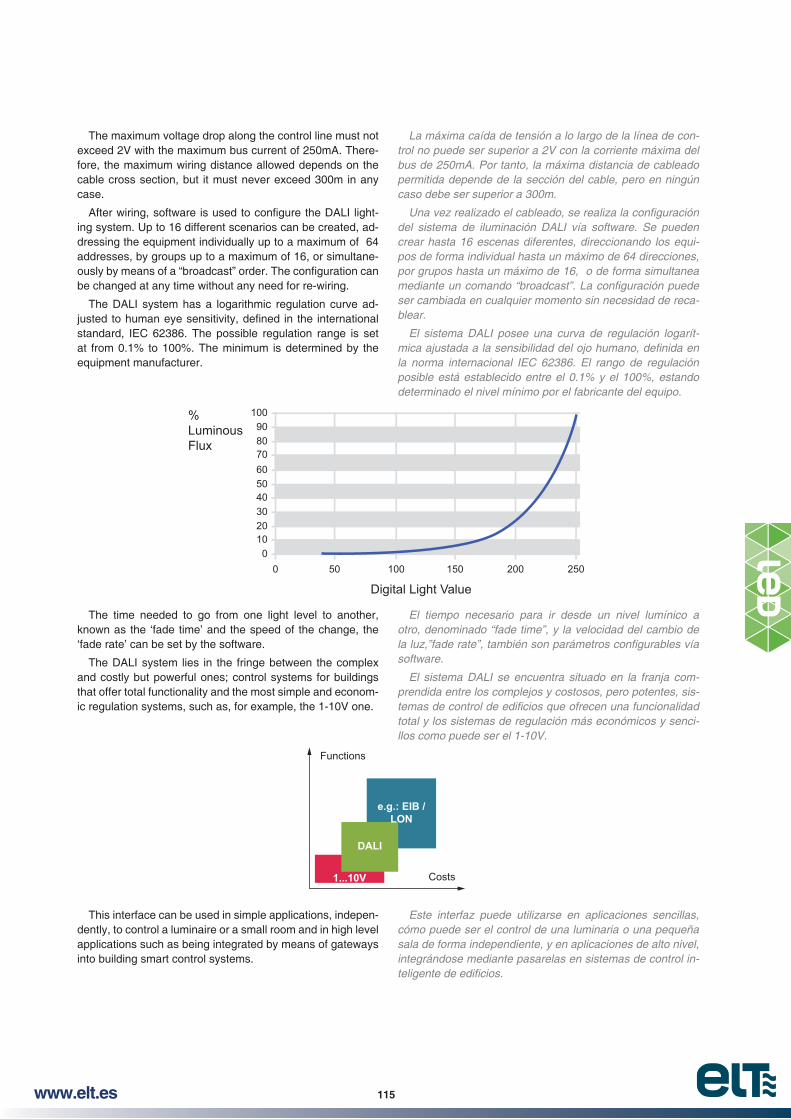
115www.elt.es
La máxima caída de tensión a lo largo de la línea de control no puede ser superior a 2V con la corriente máxima del bus de 250mA. Por tanto, la máxima distancia de cableado permitida depende de la sección del cable, pero en ningún caso debe ser superior a 300m.
del sistema de iluminación DALI vía software. Se pueden
ser cambiada en cualquier momento sin necesidad de recablear.
El sistema DALI posee una curva de regulación logarít
posible está establecido entre el 0.1% y el 100%, estando determinado el nivel mínimo por el fabricante del equipo.
El tiempo necesario para ir desde un nivel lumínico a otro, denominado “fade time”, y la velocidad del cambio de
software.
El sistema DALI se encuentra situado en la franja comprendida entre los complejos y costosos, pero potentes, sis
total y los sistemas de regulación más económicos y senci
Este interfaz puede utilizarse en aplicaciones sencillas, cómo puede ser el control de una luminaria o una pequeña sala de forma independiente, y en aplicaciones de alto nivel, integrándose mediante pasarelas en sistemas de control in
%LuminousFlux
1009080706050403020100
0 50 100 150 200 250
Digital Light Value
Functions
Costs1...10V
DALI
e.g.: EIB /LON
The maximum voltage drop along the control line must not exceed 2V with the maximum bus current of 250mA. There-fore, the maximum wiring distance allowed depends on the cable cross section, but it must never exceed 300m in any case.
-ing system. Up to 16 different scenarios can be created, ad-dressing the equipment individually up to a maximum of 64 addresses, by groups up to a maximum of 16, or simultane-
be changed at any time without any need for re-wiring.
The DALI system has a logarithmic regulation curve ad-
standard, IEC 62386. The possible regulation range is set at from 0.1% to 100%. The minimum is determined by the equipment manufacturer.
The time needed to go from one light level to another, known as the ‘fade time’ and the speed of the change, the ‘fade rate’ can be set by the software.
The DALI system lies in the fringe between the complex and costly but powerful ones; control systems for buildings that offer total functionality and the most simple and econom-ic regulation systems, such as, for example, the 1-10V one.
This interface can be used in simple applications, indepen-dently, to control a luminaire or a small room and in high level applications such as being integrated by means of gateways into building smart control systems.

116 www.elt.es
5.4.2.-Componentes del sistema de control.
Además de la fuente de luz que se pretende controlar, los sistemas de gestión del alumbrado están compuestos por otros componentes adicionales. Entre estos componentes se encuentran los equipos, accionamientos o elementos de mando, sensores, controladores, adaptadores, repetidores,
y de monitorización.
Equipos:
Los equipos de iluminación, drivers para módulos LED,
transformadores para lámparas halógenas, son los componentes encargados de hacer funcionar las fuentes de luz de forma correcta. Éstos, para poder integrarse en un sistema de gestión de alumbrado, deben ser regulables por el método de control elegido.
Accionamientos o elementos de mando:
Son los componentes mediante los que el usuario interacciona con el sistema de gestión del alumbrado, permitiendo encender, apagar o regular la luz voluntariamente de forma manual y directa. En este grupo se encuentran los pulsadores, los mandos rotativos y paneles de control.
Los sensores o detectores:
Son dispositivos capaces de detectar magnitudes físicas o químicas y transformarlas en señales que pueden ser procesadas. En los sistemas de gestión de alumbrado destacan los detectores de presencia y las fotocélulas, mediante los cuales el encendido, apagado o regulación de la luz se realiza de forma automática dependiendo de la presencia de personas y el nivel de luz natural en la estancia.
Unidades de control o controladores:
Son los componentes encargados de recibir toda la información procedente del resto de componentes del sistema, procesarla y generar los comandos de control para distribuirlos de forma inteligente.
Repetidores:
las señales débiles, por lo que, en los sistemas de gestión de alumbrado, se deben utilizar cuando se necesitan mayores distancias de cableado o mayor número de equipos conectados de lo permitido.
Adaptadores, convertidores y pasarelas:
Estos componentes son necesarios cuando se quieren conectar entre sí componentes que no utilizan el mismo protocolo de comunicación. Su misión es convertir una señal en otra para permitir la comunicación entre diferentes dispositivos. Existen desde simples adaptadores que convierten una señal eléctrica para comunicar unos pocos componentes, hasta pasarelas que permiten comunicar entre sí sistemas con protocolos y arquitecturas diferentes a todos los niveles de comunicación.
Para los sistemas de gestión del alumbrado más avanzados, son necesarias herramientas software que permitan el direccionamiento, la programación, la parametrización y la monitorización de los mismos.
5.4.2.- Control system components.
Apart from the light source to be controlled, lighting man-agement systems are made up of other additional compo-nents. Among these you have control gears, switches and command wire equipments, sensors, controllers, adaptors,
-toring tools.
Control gears:
Lighting control gears, drivers for LED modules, ballasts -
gen lamps are the components commissioned with making the light sources work properly. They must be adjustable by the control method chosen to enable their integration into a lighting management system.
Switches or control elements:
These are components by means of which the user inter-acts with the lighting management system, making it possible to switch the light on and off and regulate it directly by hand. This group consists of pushbuttons, knobs and control pan-els.
Sensors and detectors:
These are devices capable of detecting physical and chemical magnitudes and transforming them into signals that can be processed. In lighting management systems, pres-ence detectors and photocells are particularly important as they serve to switch on and off and regulate the lighting au-tomatically, depending on the presence of persons and the natural level of light in the space to be illuminated.
Control units and controllers:
These components serve to receive all the information from the rest of the system’s components, process it and generate the control orders to be distributed intelligently.
Repeaters:
These are components that amplify the level or power of weak signals, thus, in lighting management systems, they must be used when longer wiring distances are required, or a greater number of equipment needs to be connected than is allowed in principle.
Adapters, converters and gateways:
These components are needed when you have to connect components that do not use the same communication pro-tocol. They serve to convert a signal into another in order to enable communication between the different devices. They range from simple adapters that convert an electrical signal to communicate between a few components to gateways that enable communication between systems with different proto-cols and architectures at all levels of communication.
More advanced lighting management systems need soft-ware tools to enable their addressing, programming, param-eterising and monitoring.

117www.elt.es
Una solución para cada aplicación
Las instalaciones de gestión del alumbrado tendrán una menor o mayor complejidad dependiendo de la solución es
do, el número y tipo de componentes, la interconexión entre
Existen una gran variedad de posibilidades, desde las soluciones más sencillas compuestas por luminarias individuales, dotadas de equipos regulables y fotocélulas conectados directamente entre ellos, que regulan la luz independientemente del resto del alumbrado, hasta los sistemas de gestión del alumbrado más avanzados, integrados en el control
tes salas y en diferentes plantas con múltiples usos, pudiendo crear diferentes ambientes adaptados a cada situación y reportar información de su estado en cada momento.
6.- ELECCIÓN TECNOLOGÍA LED
A solution for every application
Lighting management systems can be more or less com-plex depending on the solution chosen for each one; the con-trol method chosen, the number and type of components, the interconnection between them and their integration with buildings’ control systems.
There are a wide range of possibilities ranging from the
with adjustable equipment and photocells connected directly between them, which regulate the light separately from the rest of the lighting, to more advanced lighting management systems, integrated into the smart control of buildings, which can control luminaires in different rooms and on different
different atmospheres adapted to each situation and to report information on their status at all times.
6.- SELECTING LED TECHNOLOGY
Steps to be taken
Pasos a seguir
Comments
Observaciones
1.- Decide on the application
IndoorOutdoorDegrees of environmental protection
IndoorOutdoorGrados de protección ambiental
2.- Decide on the most suitable LED module. Lumens, dimensions, CV or CC technology, photometry, etc.
Lúmenes, dimensiones, tecnología CV ó CC, fotometría…
3.- Decide on a CV or CC control gear
CV: Output voltage of 12Vcc or 24Vcc Installed power
CC: Output current, there are numerous versions ranging from 0.2A to 2.5A. Module or LED module system voltage must be between the minimum and maximum of the power supply
La potencia instaladaCC: Intensidad de salida, existen multitud de versiones, desde 0,2A hasta 2,5A.
La tensión del módulo o sistema de módulos LEDs debe estar comprendida entre la mínima y máxima de la fuente de alimentación
4.- Choose the regulation technology
~ Control gears~ Switches or control elements~ Sensors and detectors:~ Control units and controllers~ Repeaters:~ Adapters, converters and gateways
~ Equipos~ Accionamientos o elementos de mando~ Los sensores o detectores~ Unidades de control o controladores~ Repetidores~ Adaptadores, convertidores y pasarelas


120 www.elt.es
ACCESSORIES INDEXÍNDICE ACCESORIOS
ITP - Input transient and surges protection
sobretensiones de red y rayos ............................... 121
Protection against electrostatic discharge in the LED moduleEquipos para protección contra descargas
electrostáticas en el módulo led ............................. 122
Diffusers for 24mm - wide eLED LINE modulesDifusores para módulos eLED LINE
...................................................... 123
Diffusers for 600x600 luminaires ........................ 124
eDIM - Universal pushbutton dimmers ........ 125
Programming interface for eSMART control gearsInterfaz de programación para equipos de control eSMART ..................................................... 126
DIM-A01Constant voltage LED power repeater, 1 channel
tensión constante para LED, 1 canal ...................... 127
MULTI-A01Constant voltage LED power repeater, 1 channel
tensión constante para LED, 1 canal ...................... 128
MICRO DIM
aluminio .................................................................. 129
PRO SYSTEMLED Controllers and RF remote control systemSistema de mandos a distancia y controladores LED .................................................. 130
TOUCH SYSTEMWall-mounted touch LED controllerControlador LED táctil de pared ............................. 136
PUSH SYSTEMGeneral features: LED Controller for standard push switch and/or remote controlCaracteristicas generales: Controlador LED para pulsadores standard y/o mando a distancia ........... 140
DAL-MULTI-C01 DALI Decoders, 4 DALI addresses
............. 148
DAL-MULTI-C02DALI Decoders, 1 DALI address, 4 channels
................................................................ 149
DMX-MULTI-C01DMX512 Decoders
....................................... 150
DMX-MULTI-C02DMX512 Decoders
....................................... 151
............................................... 152

121www.elt.es
29
31
5568
9
M8
L
POWER SUPPLYL N
N
ITPL N
Input transient and surges protectionEquipos auxiliares de protección contra sobretensiones de red y rayos
ITP100-277V50-60Hz
~ Suitable for Class I and Class II luminaires.~ Device suitable for HID, FLUO and LED outdoor applications.~ Low Stand-by power consumption 0,05W MAX.~ Type 3 Protection equipment considering IEC 61643-11/2007. ~ Withstands strikes@1kA (common/differential) (90/90)**.~ Withstands strikes@3kA (common/differential) (40/50)**.~ Withstands strikes@5kA (common/differential) (20/15)**.~ 50/60 Hz frequencies allowed.
** Surges every 50 seconds.
Packaging and weight p. 171 and www.elt.es/productos/packaging_ELT.pdfMore detailed information is available on www.elt.es\productos\pdf\702000000_i.pdf
~ Apto para montajes en luminarias de tipo Clase I o Clase II.~ Apto para aplicaciones HID, FLUO y LED de exterior.~ Pérdidas reducidas 0,05W máximo.
** Pulsos cada 50 segundos.
Embalaje y peso pág. 171 y www.elt.es/productos/embalaje_ELT.pdfMás información detallada en www.elt.es\productos\pdf\702000000_e.pdf
Model
ModeloRef. No.
Input Voltage
Rango de tensión de
entrada
Open Circuit Voltage
Tensión de circuito abierto
Nominal Surge Current
Corriente nominal de transitorio
Maximum Surge Current
Corriente máxima de transitorio
Protection Level L-N
@3kA
Nivel de
Protection Level LN-PE
@3kA
Nivel de
Units per box
Unidades por caja
V V kA kA kV kVITP 277V-8KA 3512001 100-277V 10kV 3 8 1,6 2,5 30
Before reaching the breakdown voltage of the luminaire system referred to ground, ITP device produces a discharge through self-protection system that carries the energy that could be dangerous to ground.
Antes de llegar a la tensión de ruptura del sistema de la luminaria con respecto a tierra, los equipos ITP producen una descarga a través del propio sistema de protección que traslada la energía que pudiese ser peligrosa de una manera segura a tierra.
EN 61643-11: 2012 Low-voltage surge protective devices. Surge protective devices connected to low-voltage power systems Dispositivos de protección contra sobretensiones transitorias de baja tensión
EN 60598-1: 2015 Luminaires / Luminarias

122 www.elt.es
29
31
5568
9
M8
L N
CONTROLGEAR ODP
Protection against electrostatic discharge in the LED moduleEquipos para protección contra descargas electrostáticas en el módulo led
ODP0...430Vdc
~ Suitable for Class I and Class II luminaires.~ Device suitable just for LED applications.~ Nule stand-by power consumption.~ Withstands 5kV Isolation. ~ Suitable for LED Drivers that don’t produce current ripple.
Packaging and weight p. 171 and www.elt.es/productos/packaging_ELT.pdfMore detailed information is available on www.elt.es\productos\pdf\702000000_i.pdf
~ Apto para montajes en luminarias de tipo Clase I o Clase II.~ Apto para aplicaciones solo de tipo LED.
~ Apto para alimentadores LED que no produzcan rizado en la corriente.
Embalaje y peso pág. 171 y www.elt.es/productos/embalaje_ELT.pdfMás información detallada en www.elt.es\productos\pdf\702000000_e.pdf
Model
ModeloRef. No.
Output power range compatible
Rango de potencia en módulo compatible
Output voltage withstand
Tensión de salida a soportar
Input current
Corriente de entrada
Max.temp. at point
Temp.máx. envolvente
Operating temp.
Temp. Funcionamiento
Units per box
Unidades por caja
W Vdc A tc (°C) ta (°C)ODP LED 5KV 3512002 1…150 0…430 0 90 85 30
When a high electrostatic charge storage exists between the LED module and the luminaire, the ODP protection circuit gets rid off that charge safely through Earth, avoiding that discharge to go across the LED, producing permanent damages in the load.
Cuando se produce una acumulación excesiva de carga electrostática entre el módulo LED y la luminaria, el circuito de protección ODP LED evacúa esa carga de manera segura a tierra, evitando que la descarga se realice a través de los LED y produzca daños irreparables en la carga.

123www.elt.es
Diffusers for 24mm - wide eLED LINE modulesDifusores para módulos eLED LINE de ancho 24mm
eDIF LINE 24mm
~ Diffusers for 24mm - wide eLED LINE modules.~ High Luminous Transmission.
~ Fast snap on mounting with M4 insulation ring. (Ref. No. 9710107 DIN-125 M4 x ø4,30 x ø9 x 0,80 6.6PA).
Packaging and weight p. 171 and www.elt.es/productos/packaging_ELT.pdf
~ Elevada Transmisión Lumínica.~ Tolerancia Longitud eDIF: ±1%.
ø ø
Embalaje y peso pág. 171 y www.elt.es/productos/embalaje_ELT.pdf
Model
ModeloRef. No.
Lenght
LongitudOpacity
Opacidad
Units por box
Unidades por cajaLmm %
eDIF 1-595-TRANSPARENT 9953001 595 Transparent / Transparente 93 30
eDIF 1-595-FROSTED 9953002 595 Semitransparent / Semitransparente 88 30
eDIF 1-595-OPAL 9953003 595 Opal / Difuso 81 30
1,4 0,1±
32,6 0,5±
24,2 0,3± L
17,5 0,5±
Fijación del difusor mediante arandela de plastico M4( Ref. 9710107 )DIN-125 M 4 x 4,30 x 9 x 0,80 6.6PAø ø
Diffuser fixing with M4 insulation ring
eDIF 1-1200-TRANSPARENT 9953004 1.200 Transparent / Transparente 93 30
eDIF 1-1200-FROSTED 9953005 1.200 Semitransparent / Semitransparente 88 30
eDIF 1-1200-OPAL 9953006 1.200 Opal / Difuso 81 30

124 www.elt.es
Diffusers for 600x600 luminairesDifusores para luminarias 600x600
eDIF 600x600
~ Diffusers for 600x600 luminaires.~ High Luminous Transmission (According to ISO 13468-1:
Plastics. Determination of the total luminous transmittance of transparent materials).
~ High impact resistance.~ U.V. resistant.~ Weatherproof.
Packaging and weight p. 171 and www.elt.es/productos/packaging_ELT.pdf
Plásticos. Determinación de la transmitancia luminosa total de materiales transparentes).
~ Alta resistencia a los impactos.~ Resistente a los U.V.~ Resistente a la intemperie.
Embalaje y peso pág. 171 y www.elt.es/productos/embalaje_ELT.pdf
Model
ModeloRef. No.
Dimensions
DimensionesOpacity
Opacidad
Units por box
Unidades por cajaAmm
Emm %
eDIF SQUARE-562-FROSTED 9953021 562 2 Semitransparent / Semitransparente 68 15
eDIF SQUARE-562-OPAL 9953022 562 3 Opal / Difuso 54 15
A E
A
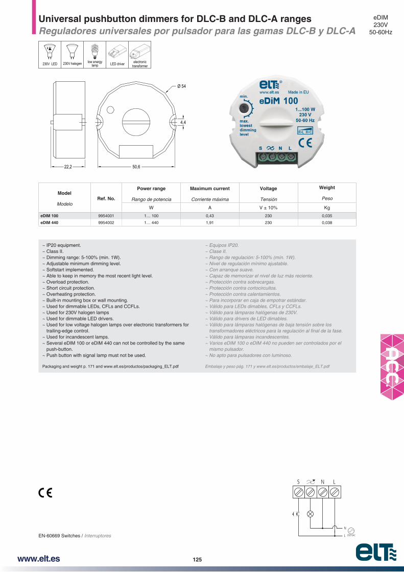
125www.elt.es
Universal pushbutton dimmers for DLC-B and DLC-A rangesReguladores universales por pulsador para las gamas DLC-B y DLC-A
eDIM230V
50-60Hz
EN-60669 Switches / Interruptores 230 VAC
N
L
LNS
~ IP20 equipment. ~ Class II.~ Dimming range: 5-100% (min. 1W).~ Adjustable minimum dimming level. ~ Softstart implemented.~ Able to keep in memory the most recent light level. ~ Overload protection.~ Short circuit protection.~ Overheating protection. ~ Built-in mounting box or wall mounting.~ Used for dimmable LEDs, CFLs and CCFLs. ~ Used for 230V halogen lamps~ Used for dimmable LED drivers.~ Used for low voltage halogen lamps over electronic transformers for
trailing-edge control. ~ Used for incandescent lamps. ~ Several eDIM 100 or eDIM 440 can not be controlled by the same
push-button. ~ Push button with signal lamp must not be used.
Packaging and weight p. 171 and www.elt.es/productos/packaging_ELT.pdf
~ Equipos IP20.~ Clase II.
~ Nivel de regulación mínimo ajustable.~ Con arranque suave.~ Capaz de memorizar el nivel de luz más reciente.~ Protección contra sobrecargas.~ Protección contra cortocircuitos.~ Protección contra calentamientos. ~ Para incorporar en caja de empotrar estándar. ~ Válido para LEDs dimables, CFLs y CCFLs.~ Válido para lámparas halógenas de 230V.~ Válido para drivers de LED dimables.~ Válido para lámparas halógenas de baja tensión sobre los
~ Válido para lámparas incandescentes.
mismo pulsador. ~ No apto para pulsadores con luminoso.
Embalaje y peso pág. 171 y www.elt.es/productos/embalaje_ELT.pdf
Model
ModeloRef. No.
Power range
Rango de potencia
Maximum current
Corriente máxima
Voltage
Tensión
Weight
Peso
W A Kg
eDIM 100 9954001 1… 100 0,43 230 0,035
eDIM 440 9954002 1… 440 1,91 230 0,038
Ø 54
50,622,2
4,4
230V LED LED driver electronictransformer
low energylamp230V halogen

126 www.elt.es
64,927
119,3
Programming interface for eSMART control gearsInterfaz de programación para equipos de control eSMART
iProgrammer
~ Mini USB 2.0 Input (Type AB) up to 4 control gear.~ External power supply (6V DC, 1A DC) up to 64 control gears. EIAJ-2
connector.~ DALI output protected against shortcircuit events (in case of a
sustained shortcircuit, internal DALI power supply is disconnected).~ 5 LEDs indicators:
~ Overload. ~ External DALI power supply. ~ Communication. ~ Internal DALI power supply. ~ Power ON.
~ Working ambient temperature: 0…+50ºC.~ Easy to program and update.~Type of protection: IP20.
Packaging and weight p. 171 and www.elt.es/productos/packaging_ELT.pdf
~ Salida DALI protegida contra eventos de cortocircuito. (En caso de un cortocircuito mantenido, la fuente interna DALI se desconecta).
~ 5 LEDs indicadores: ~ Sobrecarga. ~ Fuente de alimentación DALI externa. ~ Comunicación. ~ Fuente de alimentación DALI interna. ~ Encendido .
~ Temperatura ambiente de trabajo: 0…+50ºC.~ Facilidad de programación y actualización.~ Tipo de protección: IP20.
Embalaje y peso pág. 171 y www.elt.es/productos/embalaje_ELT.pdf
Model Modelo Ref. No. Units per box
Unidades por cajaiProgrammer 3512003 1
USB 2.0
DA (+)DA (-)
External power supply Alimentación eléctrica externa(Optional for more than 4 control gears Opcional para más de 4 equipos)
EIAJ-2 connector (for>4 control gears)
Conector EIAJ-2 (para > 4 equipos de control)
Overload
External DALI power supply
Communication
Internal DALI power supply
Power ON
Program
Programming interfacefor eSMART control gears
USB 2.0 Power 6V / 1A DC( for >4 control gears )
Made in Spain (EU)
R
iProgrammer
DA ( ) DA ( )
iLC
R
Made in Spain (EU)
PROVIDED ACCESSORIES / ACCESORIOS SUMINISTRADOS
USB CABLE CABLE USB
EXTERNAL POWER SUPPLY (6V DC, 1A DC)

127www.elt.es
DIM-A01Constant voltage LED power repeater, 1 channel
~ Constant voltage LED power reapter with 1 channel.~ Repeates PWM dimming signal.~ Suitable for single colour LED strips.
Packaging and weight p. 171 and www.elt.es/productos/packaging_ELT.pdfInstructions manual on www.elt.es/productos/inst_manual.html
constante para tiras LED de 1 canal.~ Repite señales de regulación PWM.~ Válido para tiras LED monocolor.
Embalaje y peso pág. 171 y www.elt.es/productos/embalaje_ELT.pdfManual de instrucciones en www.elt.es/productos/manual_instrucciones.html
Model
ModeloRef. No.
Input / Output Voltage
Tensiones de entrada y salida
Max Output current
Intensidad máxima de salida
Max Output Power
Potencia máxima de salida
LED strip type
Tipo tira LED
Vdc 12V 24V
DIM-A01 9955950 12-24 24A 288 W 576 W DIM
150
54
DIM-A0112-24V DC
DIM
LED DRIVER R
12
34
GN
D
DALI Master
INP
UT
12-24VD
CS
IGN
AL
INP
UT
OU
TP
UT
IND
I CA
TOR
RE
PLA
CA
BL E
FU
SE
POWER REPEATERDIM-A01
L
Single Color LED Strip
N
DAL-MULTI-C02
-
+
LED DRIVER R
L
N

128 www.elt.es
MULTI-A01Constant voltage LED power repeater, 4 channel
~ Constant voltage LED power reapter with 4 channel.~ Repeates PWM dimming signal.~ Fast connexion terminal blocks.
Packaging and weight p. 171 and www.elt.es/productos/packaging_ELT.pdfInstructions manual on www.elt.es/productos/inst_manual.html
~ Repite señales de regulación PWM.~ Conectores de conexión rápida.
Embalaje y peso pág. 171 y www.elt.es/productos/embalaje_ELT.pdfManual de instrucciones en www.elt.es/productos/manual_instrucciones.html
Model
ModeloRef. No.
Input / Output Voltage
Tensiones de entrada y salida
Max Output current
Intensidad máxima de salida
Max Output Power
Potencia máxima de salida
LED strip type
Tipo tira LED
Vdc 12V 24V 36V
MULTI-A01 9955951 12-24-36 4ch x 5A 240 W (4x60)
480 W (4x120)
720 W (4x180) DIM, TW, RGB, RGBW
156.0
166.0 23.0
53.4
LED DRIVER R
R
G
B
W
LED
LED CONTROLLERDAL-MULTI-C01
Learning Key
L
N
MasterSlave
1
2
3
4
LED
OU
TP
UT
MULTI-A01POWER REPEATERS
IGN
AL IN
PU
T
1
2
3
4
MULTI-A0112-36V DC
DIM
RGB
TW
RGBW

129www.elt.es
MICRO DIM
~ Ultra small size dimmer. Designed to be inserted into a LED
~ Available for DIM.
~ SUP, SUP MIDI, SUP MAX, SUP IP. ~ EMP, EMP MIDI. ~ RIN, RIN MIDI, RIN MAX, RIN 45. ~ G53, G53 MINI, G53 EMP.
Packaging and weight p. 171 and www.elt.es/productos/packaging_ELT.pdfInstructions manual on www.elt.es/productos/inst_manual.html
~ Dimmer de tamaño muy reducido para poder ser insertado en un
~ Disponible para DIM.
~ EMP, EMP MIDI.
~ G53, G53 MINI, G53 EMP.
Embalaje y peso pág. 171 y www.elt.es/productos/embalaje_ELT.pdfManual de instrucciones en www.elt.es/productos/manual_instrucciones.html
Model
ModeloRef. No.
Operation Voltage
Tensión de Trabajo
Control signal
Tipo de regulación
Max Output current
Intensidad máxima de salida
Max Output Power
Potencia máxima de salida
LED strip type
Tipo tira LED
Control made by
Control a través deW
V A 12V 24V
MIC-DIM-T01 9955900 12-24 PWM 1CH X 3A 36 72 Monocolor (1CH -DIM)Press in cover
Presión en difusor
PWM
MICRO DIM12-24V DC
DIM
-
V+
V-12-24VDC input
LED DRIVER R
LN
Product size Dimensiones
Operation diagram Esquema de funcionamiento
Short press: ON/OFFLong press: dimmingPulsación corta: ON/OFFPulsación larga: regulación

130 www.elt.es
PRO-DIM-R01 PRO-TW-R01 PRO-RGB-W-R01
ON / OFFEncendido /
Apagado
BrightnessIntensidad de luz2 custom scenes
Memoria de 2 escenas
Selection of the zones where apply the control. I.e. Pressing 1 & 3, next commands made with the remote will apply on zones 1 & 3.
Selección de la zona o zonas en las que aplicar el control. Ejemplo, si se pulsa 1 y 3, las órdenes que se hagan con el mando se
aplicarán a las zonas 1 y 3.
Brightness dialDial de selección de intensidad de luz
Colour Temperature selection dialDial de selección de temperatura de color
Encendido / ApagadoON / OFFColour selection dial
Dial de selección de color
R, G, B Independent Controls (ON/OFF, dim)Control individual de los canales R,G,B(ON / OFF, regulación)
W independent control (ON/OFF, Dim)Control independiente de Blanco
2 custom scenesMemoria de 2 escenas
BrightnessRegulación intensidadde luz
Dynamic Mode (ON/OFF, Speed)Modo dinamico(ON / OFF, velocidad)
LED Strip / Tira LED
RPRO-DIMTW-C01LED DRIVER R
Each remote can control up to 4 different zones.Each zone can have one or several controllers that will work synchronously.
Cada zona puede tener uno o varios controladores que trabajarán de forma sincronizada.
LED Strip / Tira LED
RPRO-RGB-W-C01LED DRIVER R
Each remote can control one or several controllers. All the controllers will work synchronously.Cada mando puede controlar uno o varios controladores.Todos los controladores trabajarán de forma sincronizada.
PRO-DIMTW-C01 PRO-RGB-W-C01
PRO SYSTEMGeneral features: LED Controllers and RF remote control systemCaracteristicas generales: Sistema de mandos a distancia y controladores LED
Input / Output Voltage
Tensiones de entrada y salida
Control signal
Tipo de regulación
Transmitting frequence
Frecuencia de transmisión
Compatible with
Compatible con
Control made by
Control a través deV
12-24 PWM434 Mhz 868 Mhz
DIM, TW, RGB, RGBWRF Remote
Mando a distancia RF
Functions / Funciones DIM, TW
RGB, RGBW
PRO SYSTEM
12-24V DC
DIM
RGB
TW
RGBW
PWMRFPUSH
Type of stripTipo de tira
ChannelsCanales
WiresCables
ControllerControlador
RemoteMando a distancia
OutputSalidas
Single colour Strip / Tira Monocolor 1 2 PRO-DIM-TW-C01 PRO-DIM-R01 3 x 5 A
LED Strip TW(*) and TWD / Tira LED TW (*) y TWD 2 3 PRO-DIM-TW-C01 PRO-TW-R01 2 x 5 A
RGB LED Strip / Tira LED RGB 3 4 PRO-RGB-W-C01 PRO-RGB-W-R01 3 x 5 A
RGBW LED Strip / Tira LED RGBW 4 5 PRO-RGB-W-C01 PRO-RGB-W-R01 4 x 5A
Model selection chart / Tabla de selección de modelos
* TW (Tuneable White) LED strip / TW (Blanco Dinámico) Tira LED

131www.elt.es
Single colour Strip / Tira Monocolor SINGLE COLOUR LED STRIP (1CH) (Max. 5A)TIRA LED MONOCOLOR (1CH) (Max. 5A)
Max. 5A, 60W 12V, 120W 24V
Max. 5A, 60W 12V, 120W 24V
Max. 5A, 60W 12V, 120W 24V
Optional wiring if more than 5A output neededConexión opcional si se necesita más de 5A de salida
V+
WW
CW
230V
LED DRIVER R
LED DRIVER R
RPRO-DIMTW-C01
Learning Key
V+
V-
V+
V-
V-
V-
-
-
-
230V
TW Strip / Tira TW LED STRIP TUNEABLE WHITE TW (2CH) (Max 5A)2 CH LED STRIP (Max. 5A)Tira LED Blanco Dinámico TW (2CH) (Max 5A)
Max. 2x5A, 120W 12V, 240W 24VPRO-DIMTW-C01
Learning Key
V+
V-WC
R
PRO SYSTEMDIM-TW LED Controller from the Pro SystemControlador LED DIM-TW del sistema PRO
~ PRO-DIMTW-C01 can control single colour (1CH) or Tuneable White (2CH) LED Strips from a RF remote control.
~ The controller could be linked with up to 8 remotes. Each remote can control 4 controllers independently.
Packaging and weight p. 171 and www.elt.es/productos/packaging_ELT.pdfInstructions manual on www.elt.es/productos/inst_manual.html
un tira LED monocolor o de Blanco Dinámico (TW) desde un mano a distancia.
controladores diferentes de manera autónoma.
Embalaje y peso pág. 171 y www.elt.es/productos/embalaje_ELT.pdfManual de instrucciones en www.elt.es/productos/manual_instrucciones.html
Model
ModeloRef. No.
Input / Output Voltage
Tensiones de entrada y salida
Control signal
Tipo de regulación
Max Output current
Intensidad máxima de salida
Max Output Power
Potencia máxima de salida
LED strip type
Tipo tira LED
Control made by
Control a través de
V A 12V 24V
PRO-DIMTW-C01 9955912 12-24 PWM3 x 5A DIM 2x 5A TW
60W CH 120 W CHMONOC/DIM (1CH)
TW (2CH)
RF Remote control
Mando a distancia RF
145
4718
PRO-DIMTW C01
12-24V DC
DIM
TW
PWMRF

132 www.elt.es
230V
RGBW LED STRIP (4CH)TIRA RGBW (4CH)
Learning Key
V+
V-
RG
BW
V+
R-
G-
B-
W-
230V
RGB LED STRIP (3CH)TIRA LED RGB (3CH)
Learning Key
V+
V-
RGB
V+
R-
G-
B-
LED DRIVER R
RPRO-RGB-W-C01
LED DRIVER R
RPRO-RGB-W-C01
PRO SYSTEMRGB-W-C01 LED Controller from the Pro SystemControlador LED RGB-W-C01 del sistema PRO
~ PRO-RGB-W-C01 can control RGB (3CH) or RGB+White (4CH) LED Strips from a RF remote control.
~ The controller could be linked with up to 8 remotes.
Packaging and weight p. 171 and www.elt.es/productos/packaging_ELT.pdfInstructions manual on www.elt.es/productos/inst_manual.html
a distancia.
distancia a la vez.
Embalaje y peso pág. 171 y www.elt.es/productos/embalaje_ELT.pdfManual de instrucciones en www.elt.es/productos/manual_instrucciones.html
Model
ModeloRef. No.
Input / Output Voltage
Tensiones de entrada y salida
Control signal
Tipo de regulación
Max Output current
Intensidad máxima de salida
Max Output Power
Potencia máxima de salida
LED strip type
Tipo tira LED
Control made by
Control a través de
V A 12V 24V
PRO-RGB-W-C01 9955913 12-24 PWM3 x 5A RGB
4 x 5A RGBW60W CH 120 W CH
RGB (3CH)RGBW (4CH)
RF Remote control
Mando a distancia RF
14547
18
PRO-RGB-W C01
12-24V DC
RGB
RGBW
PWMRF

133www.elt.es
PRO SYSTEMDIM remote control for the Pro SystemMando a distancia DIM del sistema Pro
~ Remote control for the controller PRO-DIMTW-C01.~ Can control up to 4 independent zones.~ Each zone can be with one or more PRO-DIMTW-C01 Controllers.~ Includes 2 scenes saving buttons.
Packaging and weight p. 171 and www.elt.es/productos/packaging_ELT.pdfInstructions manual on www.elt.es/productos/inst_manual.html
~ Cada zona puede ser de uno o más controladores
~ Dispone de dos memorias para escenarios.
Embalaje y peso pág. 171 y www.elt.es/productos/embalaje_ELT.pdfManual de instrucciones en www.elt.es/productos/manual_instrucciones.html
Model
ModeloRef. No.
Powered by
Alimentación
Operation frequency
Frecuencia de Operación
Max Output current
Intensidad máxima de salida
LED strip type
Tipo tira LED
Independent control zones
Zonas de control independientes
Max Range indoor (without walls)
Alcance máximo interior
(sin paredes) A
PRO-DIM-R01 99559113xAAA/LR03 1,5V batteries
434 MHz / 869 MHz3 x 5A DIM 2x 5A TW
MONOC/DIM (1CH)TW (2CH)
4 20 m
17.6
120.
0
47.9
PRO-DIM R01
DIM
PWMRFPUSH
1 2
3 4
S1 S2
Off / Apagado
Indicator / Indicador
Brightness up / Subir el nivel de luz
4 zones / 4 zonas
Brightness down / Bajar el nivel de luz
Each zone can save 2 colors/scenesCada zona puede guardar dos escenas
Brightness wheel Control del nivel de luz
On / Encendido
Operation / Funcionamiento

134 www.elt.es
PRO SYSTEMTW remote control for the Pro SystemMando a distancia TW del sistema Pro
~ Remote control with colour temperature change for the controller PRO-DIMTW-C01.
~ Can control up to 4 independent zones.~ Each zone can be with one or more PRO-DIMTW-C01 Controllers.~ Includes 2 scenes saving buttons.
Packaging and weight p. 171 and www.elt.es/productos/packaging_ELT.pdfInstructions manual on www.elt.es/productos/inst_manual.html
~ Mando a distancia con control de la temperatura de color para el
~ Cada zona puede ser de uno o más controladores
~ Dispone de dos memorias para escenarios.
Embalaje y peso pág. 171 y www.elt.es/productos/embalaje_ELT.pdfManual de instrucciones en www.elt.es/productos/manual_instrucciones.html
Model
ModeloRef. No.
Powered by
Alimentación
Operation frequency
Frecuencia de Operación
LED strip type
Tipo tira LED
Independent control zones
Zonas de control independientes
Max Range indoor (without walls)
Alcance máximo interior (sin paredes)
PRO-TW-R01 99559103xAAA/LR03 1,5V batteries
434 MHz / 869 MHz TW (2CH) 4 20 m
17.6
120.
0
47.9
PWMRFPUSH
Off / Apagado
Indicator / Indicador
Brightness up / Subir el nivel de luz
4 zones / 4 zonas
Brightness down / Bajar el nivel de luz
Each zone can save 2 colors/scenesCada zona puede guardar dos escenas
TW Colour WheelDial de selección de la temperatura de color
On / Encendido
1 2
3 4
S1 S2
PRO-TW R01
TW
Operation / Funcionamiento

135www.elt.es
PRO SYSTEMRGB & RGBW remote control for the Pro SystemMando a distancia RGB y RGBW del sistema Pro
~ Remote control for the controller PRO-RGB-W-C01.~ Each zone can be with one or more PRO-RGB-W-C01 Controllers~ Includes 2 scenes saving buttons.
Packaging and weight p. 171 and www.elt.es/productos/packaging_ELT.pdfInstructions manual on www.elt.es/productos/inst_manual.html
~ Dispone de dos memorias para escenarios.
Embalaje y peso pág. 171 y www.elt.es/productos/embalaje_ELT.pdfManual de instrucciones en www.elt.es/productos/manual_instrucciones.html
Model
ModeloRef. No.
Powered by
Alimentación
Operation frequency
Frecuencia de Operación
LED strip type
Tipo tira LED
Max Range indoor (without walls)
Alcance máximo interior (sin paredes)
PRO-RGB-W-R01 99559093xAAA/LR03 1,5V batteries
434 MHz / 869 MHz RGB, RGB-W (3CH / 4CH)) 20 m
17.6
120.
0
47.9
PWMRFPUSH
Off / Apagado
Indicator / Indicador
R G
B W
S2S1
Change Red Channel Selección y Ajuste de canal Rojo
Change Blue ChannelSelección y Ajuste de canal Azul
Save color/sceneGuardar escena
Brightness / Nivel de luz
For Warm white, Natural white,Cool white changing.(Through the three RGB color mixing)Selección de blanco cálido, neutro y frío a partir de mezcla RGB
Colour wheelDial de selección de color
Change Green Channel Selección y Ajuste de canal Verde
Change White ChannelSelección y Ajuste de canal Blanco
Save color/sceneGuardar escena
Play&pause button. There is 10 build-in modes. Short press it will play, short press again, it will pause. Long press it will speed up/down.Botón de cambio de color dinámico.
Operation / Funcionamiento
PRO-RGB-W R01
RGB
RGBW

136 www.elt.es
Type of strip
Tipo de tira
Channels
Canales
Wires
Cables
Controller
Controlador
Single colour Strip / Tira Monocolor 1 2 STO-DIM-CT01
LED Strip TW(*) and TWD / Tira LED TW (*) y TWD 2 3 STO-TW-CT01
RGB LED Strip / Tira LED RGB 3 4 STO-RGB-W-CT01
RGBW LED Strip / Tira LED RGBW 4 5 STO-RGB-W-CT01
Model selection chart / Tabla de selección de modelos
TOUCH SYSTEMGeneral features: Wall-mounted touch LED controllerCaracteristicas generales: Controlador LED táctil de pared
HOW DOES IT WORK?~ TOUCH SYSTEM can control LED strips from a wall-mounted touch
sensor.~ It’s compatible with the for kinds of LED strips: single colour (1CH
or DIM), Tuneable White (2CH or TW), RGB (3CH) and RGB+White (RGBW/4CH).
~ Able to be used with universal square or round mounting boxes.~ Every device can control one or several LED strips and all will work
synchronously. If two or more zones with independent control are needed, an extra controller must be used for each zone.
¿QUÉ HACE?~ El sistema Touch System permite controlar la iluminación de tiras
LED desde un panel táctil empotrable.~ Está disponible para los cuatro tipos de tira LED más habituales:
monocolor (1CH o DIM), Blanco Dinámico (2CH o TW), RGB (3CH)
~ Compatible con cajas de empotrar universales cuadradas y redondas.
~ Cada equipo puede controlar una o varias tiras LED y todas funcionarán de manera sincronizada. Si se quiere hacer dos o más zonas con funcionamiento diferente habrá que usar un controlador para cada zona adicional.
Input / Output Voltage
Tensiones de entrada y salida
Control signal
Tipo de regulación
Max Output current
Intensidad máxima de salida
Max. output power
Potencia máxima de salidaCompatible with
Compatible con
Control made by
Control a través de
W
V A 12V 24V
12-24 PWM 4x5 240 480 DIM, TW, RGB, RGBWTouch panel
Panel táctil
TOUCH SYSTEM
12-24V DC
DIM
RGB
TW
RGBW
LED StripTira LEDLED Driver
Fuente de Alimentación LED
Controller / Controlador
LED
DR
IVER
R
L N
STO-DIM-CT01
STO-TW-CT01
STO-RGB-W-CT01
PWM* TW (Tuneable White) LED strip / TW (Blanco Dinámico) Tira LED

137www.elt.es
TOUCH SYSTEMWall-mounted touch LED controllerControlador LED táctil de pared
~ STO-DIM-CT01 can control single colour LED strips from a wall-mounted touch sensor.
~ Able to be used with universal square or round mounting boxes.~ Every device can control one or several LED strips and all will work
synchronously. If two or more zones with independent control are needed, an extra controller must be used for each zone.
Packaging and weight p. 171 and www.elt.es/productos/packaging_ELT.pdfInstructions manual on www.elt.es/productos/inst_manual.html
un tira LED monocolor desde un panel táctil empotrable.~ Compatible con cajas de empotrar universales cuadradas y
redondas.~ Cada equipo puede controlar una o varias tiras LED y todas
funcionarán de manera sincronizada. Si se quiere hacer dos o más zonas con funcionamiento diferente habrá que usar un controlador para cada zona adicional.
Embalaje y peso pág. 171 y www.elt.es/productos/embalaje_ELT.pdfManual de instrucciones en www.elt.es/productos/manual_instrucciones.html
Model
ModeloRef. No.
Input / Output Voltage
Tensiones de entrada y salida
Control signal
Tipo de regulación
Max Output current
Intensidad máxima de salida
Max Output Power
Potencia máxima de salida
LED strip type
Tipo tira LED
Control made by
Control a través deW
V A 12V 24V
STO-DIM-CT01 9955914 12-24 PWM 4x5 240 480MONOC.
DIM (1CH)
Touch Panel
Panel Táctil
29,1
86,0
86,0
PWM
STO-DIMCT01
12-24V DC
DIM
INPUT
Single colour LED StripTira LED Monocolor
OUTPUT
LED
DR
IVER
R
L N
4 scenes:25%, 50%, 75% and 100% brightness
25%, 50%, 75% y 100% de luz
Brightness dialDial de selección de intensidad de luz
ON / OFFEncendido / Apagado
Functions Funciones
Connection diagram Esquema de conexión

138 www.elt.es
TOUCH SYSTEMWall-mounted touch LED controllerControlador LED táctil de pared
~ STO-TW-CT01 can control TW (Tuneable White) LED strips from a wall-mounted touch sensor.
~ Able to be used with universal square or round mounting boxes.~ Every device can control one or several LED strips and all will work
synchronously. If two or more zones with independent control are needed, an extra controller must be used for each zone.
Packaging and weight p. 171 and www.elt.es/productos/packaging_ELT.pdfInstructions manual on www.elt.es/productos/inst_manual.html
tira LED TW (Blanco Dinámico) desde un panel táctil empotrable.~ Compatible con cajas de empotrar universales cuadradas y
redondas.~ Cada equipo puede controlar una o varias tiras LED y todas
funcionarán de manera sincronizada. Si se quiere hacer dos o más zonas con funcionamiento diferente habrá que usar un controlador para cada zona adicional.
Embalaje y peso pág. 171 y www.elt.es/productos/embalaje_ELT.pdfManual de instrucciones en www.elt.es/productos/manual_instrucciones.html
Model
ModeloRef. No.
Input / Output Voltage
Tensiones de entrada y salida
Control signal
Tipo de regulación
Max Output current
Intensidad máxima de salida
Max Output Power
Potencia máxima de salida
LED strip type
Tipo tira LED
Control made by
Control a través deW
V A 12V 24V
STO-TW-CT01 9955915 12-24 PWM 4x5 240 480 TW (2CH)Touch Panel
Panel Táctil
29,1
86,0
86,0
PWM
INPUT
OUTPUT
TW StripTira TW
LED
DR
IVER
R
L N
4 custom scenes:Long press to save scebe, short press for recall.
Presión larga para memorizar, presión corta para cambiar a valores memorizados
Colour Temperature selection dialDial de selección de temperatura de color
ON / OFFEncendido / Apagado
Functions Funciones
Connection diagram Esquema de conexión
STO-TWCT01
12-24V DC
TW
BrightnessIntensidad de luz
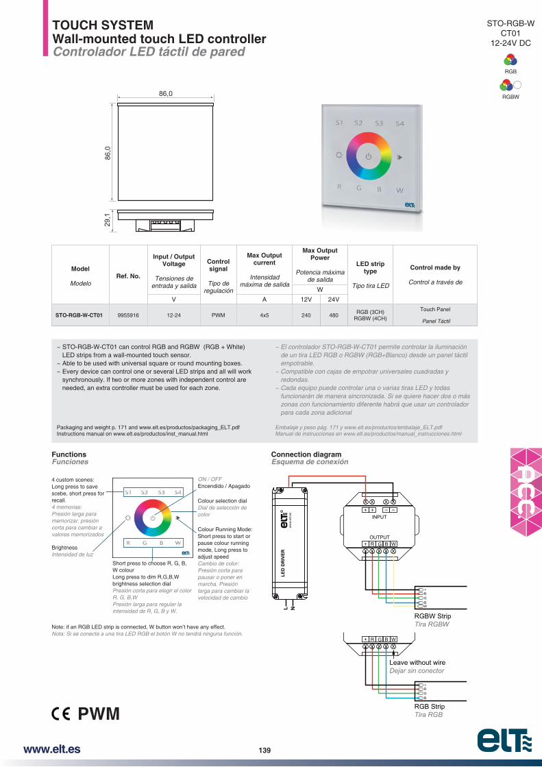
139www.elt.es
4 custom scenes:Long press to save scebe, short press for recall.
Presión larga para memorizar, presión corta para cambiar a valores memorizados
Colour selection dialDial de selección de color
BrightnessIntensidad de luz
ON / OFFEncendido / Apagado
Short press to choose R, G, B, W colourLong press to dim R,G,B,W brightness selection dialPresión corta para elegir el color R, G, B,WPresión larga para regular la intensidad de R, G, B y W.
Colour Running Mode: Short press to start or pause colour running mode, Long press to adjust speedCambio de color: Presión corta para pausar o poner en marcha. Presión larga para cambiar la velocidad de cambio
Note: if an RGB LED strip is connected, W button won’t have any effect.Nota: Si se conecta a una tira LED RGB el botón W no tendrá ninguna función.
STO-RGB-WCT01
12-24V DC
RGB
RGBW
TOUCH SYSTEMWall-mounted touch LED controllerControlador LED táctil de pared
~ STO-RGB-W-CT01 can control RGB and RGBW (RGB + White) LED strips from a wall-mounted touch sensor.
~ Able to be used with universal square or round mounting boxes.~ Every device can control one or several LED strips and all will work
synchronously. If two or more zones with independent control are needed, an extra controller must be used for each zone.
Packaging and weight p. 171 and www.elt.es/productos/packaging_ELT.pdfInstructions manual on www.elt.es/productos/inst_manual.html
de un tira LED RGB o RGBW (RGB+Blanco) desde un panel táctil empotrable.
~ Compatible con cajas de empotrar universales cuadradas y redondas.
~ Cada equipo puede controlar una o varias tiras LED y todas funcionarán de manera sincronizada. Si se quiere hacer dos o más zonas con funcionamiento diferente habrá que usar un controlador para cada zona adicional
Embalaje y peso pág. 171 y www.elt.es/productos/embalaje_ELT.pdfManual de instrucciones en www.elt.es/productos/manual_instrucciones.html
Model
ModeloRef. No.
Input / Output Voltage
Tensiones de entrada y salida
Control signal
Tipo de regulación
Max Output current
Intensidad máxima de salida
Max Output Power
Potencia máxima de salida
LED strip type
Tipo tira LED
Control made by
Control a través deW
V A 12V 24V
STO-RGB-W-CT01 9955916 12-24 PWM 4x5 240 480RGB (3CH)
RGBW (4CH)
Touch Panel
Panel Táctil
29,1
86,0
86,0
INPUT
OUTPUT
RGBW StripTira RGBW
RGB StripTira RGB
Leave without wireDejar sin conector
LED
DR
IVER
R
L N
Functions Funciones
Connection diagram Esquema de conexión
PWM

140 www.elt.es
Signal 0-10V; 1-10VSeñal 0-10V; 1-10V
0-10V1-10V
LED StripTira LED
SPU-DIM-C02
LED DRIVER R
R
LED StripTira LED
SPU-DIM-C01SPU-TW-C01SPU-RGB-C01SPU-DIM-C02
PUSHPUSHShort press: ON/OFFLong press: dimmingPulsación corta: ON/OFFPulsación larga: regulación
LED DRIVER R
R
LED StripTira LED
PUSHPUSH
SPU-DIM-C01SPU-TW-C01SPU-RGB-C01
LED DRIVER R
R
LED StripTira LED
SPU-DIM-C01SPU-TW-C01SPU-RGB-C01
LED DRIVER R
R
SPU-DIM-R02 SPU-DIM-R03 SPU-MULTI-R01
SPU-DIM-R01
SPU-DIM-R02 SPU-DIM-R03 SPU-RGB-R01 SPU-DIM-R01
SPU-DIM-C01 SPU-DIM-C02
SPU-RGB-C01 SPU-TW-C01
PUSH SYSTEMGeneral features: LED Controller for standard push switch and/or remote controlCaracteristicas generales: Controlador LED para pulsadores standard y/o mando a distancia
HOW DOES IT WORK?PUSH SYSTEM can control LEDs with push switches of the same family than the rest of the installation.It can work in four different ways:
¿QUÉ HACE?El sistema PUSH SYSTEM permite controlar LEDs con pulsadores de la misma familia que el resto de la instalación.Puede ser controlado de cuatro maneras diferentes:
Input / Output Voltage
Tensiones de entrada y salida
Control signal
Tipo de regulación
Max Output current
Intensidad máxima de salida
Compatible with
Compatible con
Control made by
Control a través deV A
12-36 PWM1x84x5
DIM, TW, RGB, RGBWPush switch / RF Switch / 0-10V / 1-10V
1- With one or more standar push switches Con uno o varios pulsadores estándar
2- With RF Switches Con Mecanismos RF
3- Push Switches + RF Switches Pulsadores + Mecanismos RF
4- 0-10V; 1-10V
PUSH SYSTEM12V DC
DIM
RGB
TW
RGBW
PWMRFPUSH
Type of stripTipo de tira
ChannelsCanales
WiresCables
ControllerControlador
ControlControl
OutputSalidas
Single colour Strip / Tira Monocolor 1 2 SPU-DIM-C01 / SPU-DIM-C02 PUSH + RF / PUSH + 0-10/1-10V 1 x 8A / 1 x 8A
LED Strip TW(*) and TWD / Tira LED TW (*) y TWD 2 3 SPU-TW-C01 PUSH + RF 4 x 5A
RGB LED Strip / Tira LED RGB 3 4 SPU-RGB-C01 PUSH + RF 3 x 5A
RGBW LED Strip / Tira LED RGBW 4 5 SPU-DIM-C01 +
SPU-RGB-C01PUSH + RFPUSH + RF
1 x 8A3 x 5A
Model selection chart / Tabla de selección de modelos
* TW (Tuneable White) LED strip / TW (Blanco Dinámico) Tira LED

141www.elt.es
PUSH SYSTEMLED Controller for standard push switch and/or remote controlControlador LED para pulsadores standard y/o mando a distancia
~ STO-DIM-C01 can control single colour LED strips from a standard push switch from any manufacturer. LED strips can be controlled keeping the same kind of switches as the rest of the installation.
~ It can also be controlled with the SPU RF Switches. These switches are wireless, work with a 3-year-life battery and are very easy to install: just screw or stick in any surface.
~ Controller can be managed by several push switches (see wiring diagram) and up to 8 SPU RF switches at the same time.
Packaging and weight p. 171 and www.elt.es/productos/packaging_ELT.pdfInstructions manual on www.elt.es/productos/inst_manual.html
un tira LED monocolor desde un pulsador estándar de cualquier fabricante. Pueden controlarse las tiras LED manteniendo la misma familia de mecanismos que en el resto de la instalación.
~ También puede controlarse con los mecanismos SPU RF. Son mecanismos sin cables de instalación muy sencilla, pegar o atornillar y que funcionan con pila de 3 años de duración. Permite
~ El controlador puede ser gobernado por varios pulsadores (ver
Puede funcionar con los dos sistemas de control de manera simultánea (pulsador conectado por cable y mecanismos RF) o sólo con uno de ellos.
Embalaje y peso pág. 171 y www.elt.es/productos/embalaje_ELT.pdfManual de instrucciones en www.elt.es/productos/manual_instrucciones.html
Model
ModeloRef. No.
Input / Output Voltage
Tensiones de entrada y salida
Control signal
Tipo de regulación
Max output current
Intensidad máxima de salida
Max output power
Potencia máxima de salida
LED strip type
Tipo tira LED
Control made by
Control a través deW
V A 12V 24V 36V
SPU-DIM-C01 9955901 12-36 0,96 9000 96 192 288MONOC.
DIM (1CH)
Standad push switch and/or RF Switch
Pulsador estándar y/o mecanismo RF
37.0
85.0
95.020
.0
PWM
SPU-DIMC01
12V DC
DIM
RFPUSH
PUSH
Short press: ON/OFFLong press: DimmingPulsación corta: ON/OFFPulsación larga: Regulación
Short Press: ON. Long Press: Dim UpPulsación Corta: Encendido. Pulsación Larga, Regulación: incremento del nivel de luz
Short Press: OFF. Long Press: Dim DownPulsación Corta: Apagado. Pulsación Larga, Regulación: disminución del nivel de luz
Short press: ON/OFF.Rotation: DimPulsación Corta: ON/OFF.Rotación: Regulación
Valid for two independent controllersValido para dos controladores independientes
Single colour LED StripTira LED Monocolor
PUSH PUSH
SPU-DIM-C01
LED DRIVER R
R
Single colour LED StripTira LED Monocolor
PUSH PUSH
SPU-DIM-C01
LED DRIVER R
R
Single colour LED StripTira LED Monocolor
SPU-DIM-C01
LED DRIVER R
R
SPU-DIM-R02 SPU-DIM-R03 SPU-MULTI-R01 SPU-DIM-R01
1- With one or more standar push switches Con uno o varios pulsadores estándar
2- With RF Switches Con Mecanismos RF
3- Push Switches + RF Switches Pulsadores + Mecanismos RF
4- Functions Funcionamiento

142 www.elt.es
PUSH SYSTEMLED Controller for standard push switch 0-10V / 1-10VControlador LED para pulsadores standard 0-10V /1-10V
~ SPU-DIM-C02 can control single colour LED strips from a standard push switch or from a 0-10V or 1-10V from any manufacturer.
~ The controller can be connected to one or more push switches (check wiring diagram) or with 0-10V or 1-10V signals.
Packaging and weight p. 171 and www.elt.es/productos/packaging_ELT.pdfInstructions manual on www.elt.es/productos/inst_manual.html
un tira LED monocolor desde un pulsador estándar, o cualquier
~ El controlador puede ser gobernado por uno o varios pulsadores
Embalaje y peso pág. 171 y www.elt.es/productos/embalaje_ELT.pdfManual de instrucciones en www.elt.es/productos/manual_instrucciones.html
37.0
85.0
95.0
20.0
1- With one or more standar push switches Con uno o varios pulsadores estándar
2- With 0-10V or 1-10V signal Con señal 0-10V ó 1-10V
SPU-DIMC02
12V DC
DIM
Single colour LED StripTira LED Monocolor
PUSH PUSH
SPU-DIM-C02
LED DRIVER R
R
Single colour LED StripTira LED Monocolor
SPU-DIM-C02
Signal 0-10V; 1-10VSeñal 0-10V; 1-10V
0-10V1-10V
LED DRIVER R
R
PWMRFPUSH
Model
ModeloRef. No.
Input / Output Voltage
Tensiones de entrada y salida
Control signal
Tipo de regulación
Max output current
Intensidad máxima de salida
Max output power
Potencia máxima de salida
LED strip type
Tipo tira LED
Control made by
Control a través deW
V A 12V 24V 36V
SPU-DIM-C02 9955903 12-36 PWM 1x8 96 192 288MONOC.
DIM (1CH)
Standad push switch or 0-10V or 1-10V

143www.elt.es
PUSH
Short press: ON/OFF.Long press: Dim / Colour temperature change.Double short press: Long press function change.Dim→Colour change→Dim.Pulsación corta: ON/OFF.Pulsación larga: Regulación / Cambio de temperatura de color.Doble pulsación corta: Cambio de función de pulsación larga. Regulación→Cambio color→Regula.
Short press: ON/OFF.Long press: Dim / Colour temperature change.Double short press: Rotation function change.Long press: White light 100% brightness.Pulsación corta: ON/OFF.Pulsación larga: Regulación / Cambio de temperatura de color.Doble pulsación corta: Cambio de función de la rotación.Pulsación larga: Color blanco 100% de luz.
PUSH PUSH
TW LED StripTira LED TW
SPU-TW-C01
LED DRIVER R
R
PUSH PUSH
TW LED StripTira LED TW
SPU-TW-C01
LED DRIVER R
R
TW LED StripTira LED TW
SPU-TW-C01
LED DRIVER R
R
SPU-MULTI-R01
SPU-MULTI-R01
PUSH SYSTEMLED Controller for standard push switch and/or remote controlControlador LED para pulsadores standard y/o mando a distancia
~ SPU-TW-C01 can control TW (Tuneable White) LED strips from a standard push switch from any manufacturer, keeping the same kind of switches than for the rest of the installation.
~ Also could be used our RF SPU switches, wireless switches with a very quick and easy installation: just screw or glue to a surface. Work with a 3-year-life battery.
~ Controller can be managed with one or many push switches (see wiring diagram) and up to 8 RF switches at the same time. Can work both controls systems (standard switches or RF switches) simuntaneously or only with one of them.
Packaging and weight p. 171 and www.elt.es/productos/packaging_ELT.pdfInstructions manual on www.elt.es/productos/inst_manual.html
un tira LED TW (Blanco Dinámico) desde un pulsador estándar de cualquier fabricante, manteniendo la misma familia de mecanismos que en el resto de la instalación.
~ También puede controlarse con los mecanismos RF SPU. Son mecanismos sin cables de instalación muy sencilla, pegar o atornillar y que funcionan con pila de 3 años de duración.
~ El controlador puede ser gobernado por uno o varios pulsadores
Puede funcionar con los dos sistemas de control de manera simultánea (pulsador conectado por cable y mecanismos RF) o sólo con uno de ellos.
Embalaje y peso pág. 171 y www.elt.es/productos/embalaje_ELT.pdfManual de instrucciones en www.elt.es/productos/manual_instrucciones.html
18.6
170.4
45.5
178.9
SPU-TWC01
12V DC
TW
PWMRFPUSH
1- With one or more standar push switches Con uno o varios pulsadores estándar
2- With RF Switches Con Mecanismos RF
3- Push Switches + RF Switches Pulsadores + Mecanismos RF
4- Functions Funcionamiento
Model
ModeloRef. No.
Input / Output Voltage
Tensiones de entrada y salida
Control signal
Tipo de regulación
Max output current
Intensidad máxima de salida
Max output power
Potencia máxima de salida
LED strip type
Tipo tira LED
Control made by
Control a través deW
V A 12V 24V 36V
SPU-TW-C01 9955904 12-36 PWM 4x5 240 480 720TW
(2CH)
Standad push switch and/or RF Switch
Pulsador estándar y/o mecanismo RF
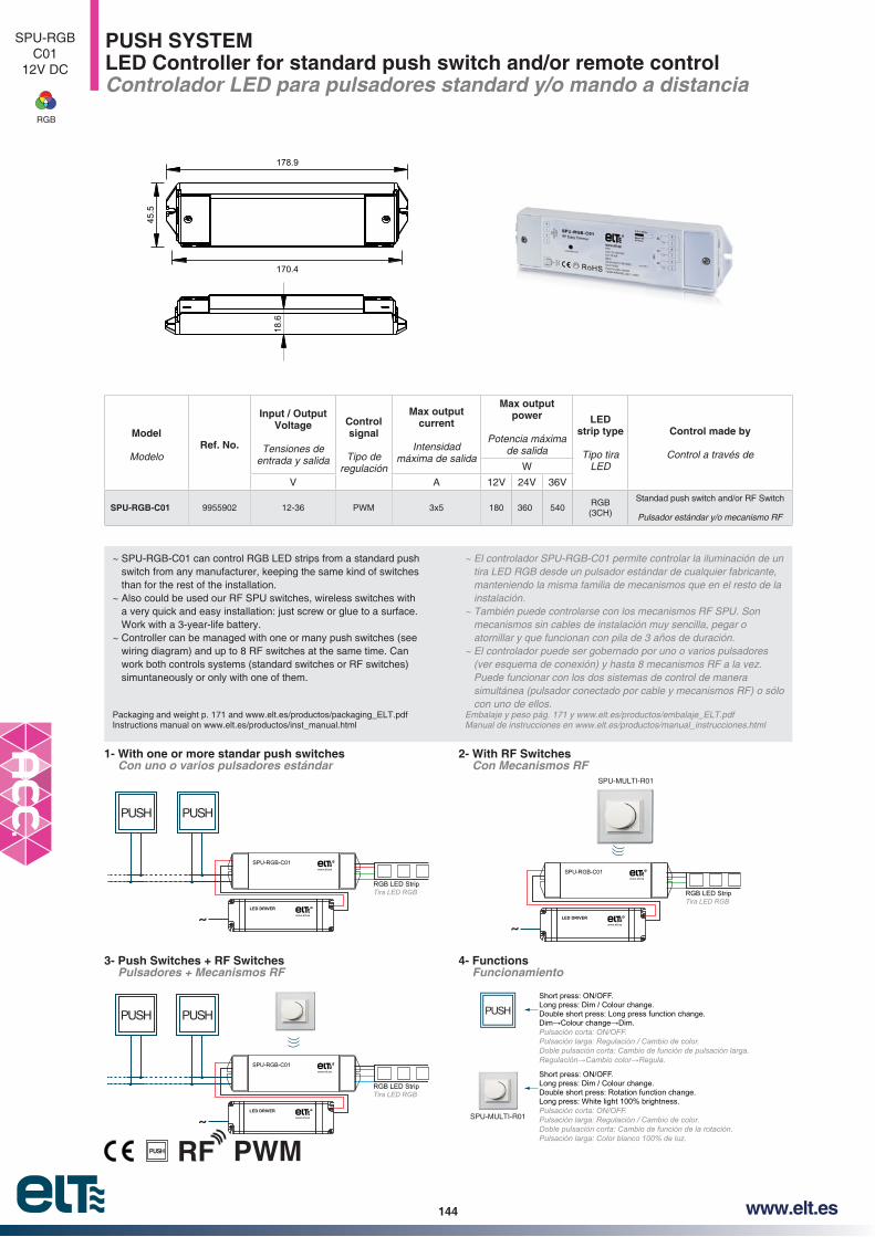
144 www.elt.es
PUSH SYSTEMLED Controller for standard push switch and/or remote controlControlador LED para pulsadores standard y/o mando a distancia
~ SPU-RGB-C01 can control RGB LED strips from a standard push switch from any manufacturer, keeping the same kind of switches than for the rest of the installation.
~ Also could be used our RF SPU switches, wireless switches with a very quick and easy installation: just screw or glue to a surface. Work with a 3-year-life battery.
~ Controller can be managed with one or many push switches (see wiring diagram) and up to 8 RF switches at the same time. Can work both controls systems (standard switches or RF switches) simuntaneously or only with one of them.
Packaging and weight p. 171 and www.elt.es/productos/packaging_ELT.pdfInstructions manual on www.elt.es/productos/inst_manual.html
tira LED RGB desde un pulsador estándar de cualquier fabricante, manteniendo la misma familia de mecanismos que en el resto de la instalación.
~ También puede controlarse con los mecanismos RF SPU. Son mecanismos sin cables de instalación muy sencilla, pegar o atornillar y que funcionan con pila de 3 años de duración.
~ El controlador puede ser gobernado por uno o varios pulsadores
Puede funcionar con los dos sistemas de control de manera simultánea (pulsador conectado por cable y mecanismos RF) o sólo con uno de ellos.
Embalaje y peso pág. 171 y www.elt.es/productos/embalaje_ELT.pdfManual de instrucciones en www.elt.es/productos/manual_instrucciones.html
18.6
170.4
45.5
178.9
PWMRFPUSH
1- With one or more standar push switches Con uno o varios pulsadores estándar
2- With RF Switches Con Mecanismos RF
3- Push Switches + RF Switches Pulsadores + Mecanismos RF
4- Functions Funcionamiento
PUSH
Short press: ON/OFF.Long press: Dim / Colour change.Double short press: Long press function change.Dim→Colour change→Dim.Pulsación corta: ON/OFF.Pulsación larga: Regulación / Cambio de color.Doble pulsación corta: Cambio de función de pulsación larga. Regulación→Cambio color→Regula.
Short press: ON/OFF.Long press: Dim / Colour change.Double short press: Rotation function change.Long press: White light 100% brightness.Pulsación corta: ON/OFF.Pulsación larga: Regulación / Cambio de color.Doble pulsación corta: Cambio de función de la rotación.Pulsación larga: Color blanco 100% de luz.
RGB LED StripTira LED RGB
PUSH PUSH
SPU-RGB-C01
LED DRIVER R
R
RGB LED StripTira LED RGB
PUSH PUSH
SPU-RGB-C01
LED DRIVER R
R
RGB LED StripTira LED RGB
SPU-RGB-C01
LED DRIVER R
R
SPU-MULTI-R01
SPU-RGBC01
12V DC
RGB
SPU-MULTI-R01
Model
ModeloRef. No.
Input / Output Voltage
Tensiones de entrada y salida
Control signal
Tipo de regulación
Max output current
Intensidad máxima de salida
Max output power
Potencia máxima de salida
LED strip type
Tipo tira LED
Control made by
Control a través deW
V A 12V 24V 36V
SPU-RGB-C01 9955902 12-36 PWM 3x5 180 360 540RGB (3CH)
Standad push switch and/or RF Switch
Pulsador estándar y/o mecanismo RF

145www.elt.es
PUSH SYSTEMRF SwitchMecanismo RF
~ Small and versatile RF switch which allows to swicth ON/OFF and dim a single colour LED strip.
on metalic surfaces.~ Its small size allows to take it in a pocket as a remote control.~ It´s powered with a long life CR2025 battery.~ Range in open indoor spaces: 30 meters.
Packaging and weight p. 171 and www.elt.es/productos/packaging_ELT.pdfInstructions manual on www.elt.es/productos/inst_manual.html
~ Mecanismo RF pequeño y versátil que permite encender, apagar y regular una instalación de tira LED monocolor.
~ Su reducido tamaño permite que pueda ser llevado en un bolsillo como mando a distancia.
~ Está alimentado por una pila de tipo CR2025 de larga duración.~ Alcance en interiores diáfanos: 30 metros.
Embalaje y peso pág. 171 y www.elt.es/productos/embalaje_ELT.pdfManual de instrucciones en www.elt.es/productos/manual_instrucciones.html
Model
ModeloRef. No.
Operation voltage
Tensiones de trabajo
RF Frequency
Frecuencia RF
Batery
Pila
Fixing
Fijación
LED strip type
Tipo tira LED
Compatible with
Compatible con
V Mhz
SPU-DIM-R01 9955905 3 434/868 CR2025Screw / Magnet
Tornillos / ImanDIM (1CH) SPU-DIM-C01
Ø35
.0
∅38.5 12.2
1.5Switch / Mecanismo
Frame / Marco15
38.5
14
PWM
SPU-DIMR01
3V DC
DIM
RFPUSH
1- Functions Funcionamiento
2- Fixing Fijación
3- Controller compatible with Controlador compatible
4- Match to controller Asociación controlador
Short press learning keyPulsación corta en boton “Learning Key”
Short pressPulsación corta
A-
B- Less than 3 secEn menos de 3 seg
C- LEDs blinked→Mach succesful!LEDs parpadean→¡Asociación correcta!
SPU-DIM-C01 R
A - Screws (included) Tornillos (incluidos)
B -With magnet Con imán
Magnet / Imán
Short press: ON/OFFLong press: dimmingPulsación corta: ON/OFFPulsación larga: regulación
SPU-DIM-C01

146 www.elt.es
PUSH SYSTEMRF SwitchMecanismo RF
swicth ON/OFF and dim a single colour LED strip. Available for one zone control (R02) or two (R03).
adhesive included).~ One controller could be managed by 8 different switches, making
the system ideal for multiway switching.~ It’s powered with a long life CR2430 battery.~ Range in open indoor spaces: 30 meters.
Packaging and weight p. 171 and www.elt.es/productos/packaging_ELT.pdfInstructions manual on www.elt.es/productos/inst_manual.html
~ Mecanismo RF con acabado en cristal templado de alta resistencia. Permite encender, apagar y regular una instalación de tira LED monocolor. Está disponible para controlar una zona (R02) o dos (R03).
y adhesivo incluidos).
mecanismos por lo que es un sustituto ideal a los mecanismos conmutados.
~ Alcance en interiores diáfanos: 30 metros.
Embalaje y peso pág. 171 y www.elt.es/productos/embalaje_ELT.pdfManual de instrucciones en www.elt.es/productos/manual_instrucciones.html
Model
ModeloRef. No.
Operation voltage
Tensiones de trabajo
RF Frequency
Frecuencia RF
Batery
Pila
Fixing
Fijación
LED strip type
Tipo tira LED
Compatible with
Compatible con
V Mhz
SPU-DIM-R02 9955906 3 434/868 CR2430Screw / Adhesive
Tornillos / AdhesivoDIM (1CH) SPU-DIM-C01
SPU-DIM-R03 9955907 3 434/868 CR2430Screw / Adhesive
Tornillos / AdhesivoDIM (1CH) SPU-DIM-C01
86.0
86.0
13.8
0
SPU-DIMR02 / R03
3V DC
DIM
SPU-DIM-C01
SPU-DIM-R02
SPU-DIM-R03
Short Press: ON. Long Press: Dim UpPulsación Corta: Encendido. Pulsación Larga, Regulación: incremento del nivel de luz
Short Press: OFF. Long Press: Dim DownPulsación Corta: Apagado. Pulsación Larga, Regulación: disminución del nivel de luz
Valid for two independent controllersValido para dos controladores independientes
Short pressPulsación corta
A-
B- Less than 3 secEn menos de 3 seg
C- LEDs blinked→Mach succesful!LEDs parpadean→¡Asociación correcta!
Short press learning keyPulsación corta en boton “Learning Key”
SPU-DIM-C01 R
PWMRFPUSH
1- Functions Funcionamiento
2- Fixing Fijación
3- Controller compatible with Controlador compatible
4- Match to controller Asociación controlador
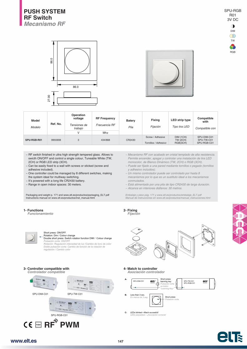
147www.elt.es
Short press learning keyPulsación corta en boton “Learning Key”
Short pressPulsación corta
A-
B- Less than 3 sec.En menos de 3 seg
C- LEDs blinked→Mach succesful!LEDs parpadean→¡Asociación correcta!
SPU-TW-C01SPU-RGB-C01
SPU-DIM-C01 R R
SPU-DIM-C01
SPU-RGB-C01
Short press: ON/OFF.Rotation: Dim / Colour changeDouble short press: Switch rotation function DIM / Colour changePulsación corta: ON/OFF.Rotación: Regulación intensidad de luz / Cambio de tono de colorDoble pulsación corta: Cambio de función de la rotación de regulación / Cambio color
SPU-TW-C01
PUSH SYSTEMRF SwitchMecanismo RF
swicth ON/OFF and control a single colour, Tuneable White (TW, 2CH) or RGB LED strip (3CH).
adhesive included).~ One controller could be managed by 8 different switches, making
the system ideal for multiway switching.~ It’s powered with a long life CR2430 battery.~ Range in open indoor spaces: 30 meters.
Packaging and weight p. 171 and www.elt.es/productos/packaging_ELT.pdfInstructions manual on www.elt.es/productos/inst_manual.html
~ Mecanismo RF con acabado en cristal templado de alta resistencia. Permite encender, apagar y controlar una instalación de tira LED monocolor, de Blanco Dinámico (TW, 2CH) o RGB (3CH).
y adhesivo incluidos).
mecanismos por lo que es un sustituto ideal a los mecanismos conmutados.
~ Alcance en interiores diáfanos: 30 metros.
Embalaje y peso pág. 171 y www.elt.es/productos/embalaje_ELT.pdfManual de instrucciones en www.elt.es/productos/manual_instrucciones.html
Model
ModeloRef. No.
Operation voltage
Tensiones de trabajo
RF Frequency
Frecuencia RF
Batery
Pila
Fixing
Fijación
LED strip type
Tipo tira LED
Compatible with
Compatible con
V Mhz
SPU-RGB-R01 9955908 3 434/868 CR2430Screw / Adhesive
Tornillos / Adhesivo
DIM (1CH)TW (2CH)RGB(3CH)
SPU-DIM-C01SPU-TW-C01
SPU-RGB-C01
86.0
86.0
27.0
0
PWMRFPUSH
1- Functions Funcionamiento
2- Fixing Fijación
3- Controller compatible with Controlador compatible
4- Match to controller Asociación controlador
SPU-RGBR01
3V DC
DIM
RGB
TW

148 www.elt.es
DAL-MULTI-C01DALI Decoders, 4 DALI addresses
~ Controls LED strips of any kind: single colour, TW, RGB & RGBW from a DALI system.
~ Includes screen and buttons to see and assign easily the DALI address and select the LED strip type.
~ The same model can work with the 4 types of LED strip:~ 1 Channel - For single colour LED strips. Each channel has a
current output of 5A. ~ 2 Channels - TW (Tuneable White) LED strips. Two terminals for
cold white and another two for warm white. 5A per channel.~ 3 Channels - RGB LED strips . 1 terminal for each channel: R, G,
B 5A per channel.~ 4 Channels - RGBW LED strips. 1 terminal for each channel: R,
G, B 5A per channel.~ 0-100% dimming range via logarithmic curve.
Packaging and weight p. 171 and www.elt.es/productos/packaging_ELT.pdfInstructions manual on www.elt.es/productos/inst_manual.html
~ Control de cualquier tipo de tira LED: monocolor, TW, RGB y RGBW desde un sistema de control DALI.
~ Incluye pantalla y botones para ver y asignar fácilmente la dirección DALI y seleccionar tipo de tira conectada.
~ 1 Canaluna capacidad de 5A.
~ 2 Canales para blanco frío y otros dos para cálido. 5A por canal.
~ 3 CanalesB 5A por canal.
~ 4 CanalesB, W 5A por canal.
Embalaje y peso pág. 171 y www.elt.es/productos/embalaje_ELT.pdfManual de instrucciones en www.elt.es/productos/manual_instrucciones.html
Model
ModeloRef. No.
Input / Output Voltage
Tensiones de entrada y salida
Control signal
Tipo de regulación
Max Output current
Intensidad máxima de salida
Max Output Power
Potencia máxima de salida
LED strip type
Tipo tira LED
Control made by
Control a través de
Vdc 12V 24V 36V
DAL-MULTI-C01 9955917 12-24-36 PWM 4ch x 5A 240 W (4x60)
480 W (4x120)
720 W (4x180)
DIM, TW, RGB, RGBW DALI
18.6
170.4
45.5
178.9
DAL-MULTIC01
12-36V DC
DIM
RGB
TW
RGBW
DALI Master
12
34
GN
D
DAL-MULTI-C01
RGB or single color LED strip
12
34
GN
D
DAL-MULTI-C01DALI Master
LED DRIVER R
LN
LED DRIVER R
LN
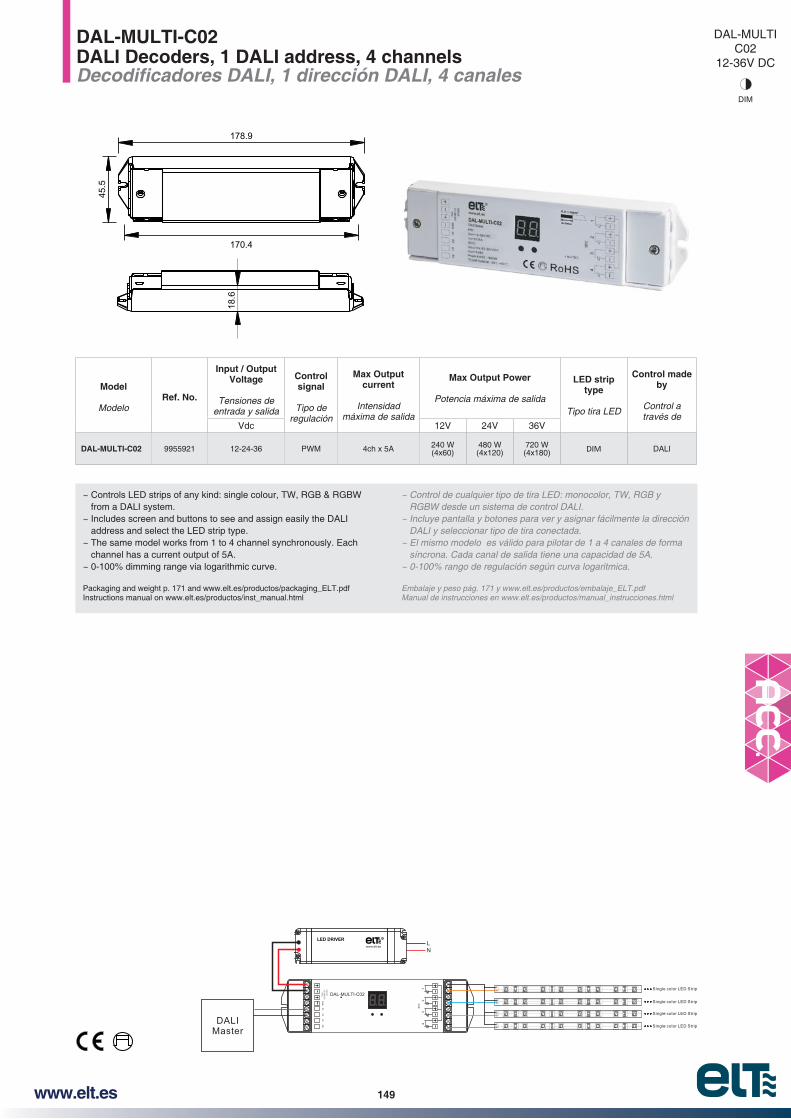
149www.elt.es
DAL-MULTI-C02DALI Decoders, 1 DALI address, 4 channels
~ Controls LED strips of any kind: single colour, TW, RGB & RGBW from a DALI system.
~ Includes screen and buttons to see and assign easily the DALI address and select the LED strip type.
~ The same model works from 1 to 4 channel synchronously. Each channel has a current output of 5A.
~ 0-100% dimming range via logarithmic curve.
Packaging and weight p. 171 and www.elt.es/productos/packaging_ELT.pdfInstructions manual on www.elt.es/productos/inst_manual.html
~ Control de cualquier tipo de tira LED: monocolor, TW, RGB y RGBW desde un sistema de control DALI.
~ Incluye pantalla y botones para ver y asignar fácilmente la dirección DALI y seleccionar tipo de tira conectada.
síncrona. Cada canal de salida tiene una capacidad de 5A.
Embalaje y peso pág. 171 y www.elt.es/productos/embalaje_ELT.pdfManual de instrucciones en www.elt.es/productos/manual_instrucciones.html
Model
ModeloRef. No.
Input / Output Voltage
Tensiones de entrada y salida
Control signal
Tipo de regulación
Max Output current
Intensidad máxima de salida
Max Output Power
Potencia máxima de salida
LED strip type
Tipo tira LED
Control made by
Control a través de
Vdc 12V 24V 36V
DAL-MULTI-C02 9955921 12-24-36 PWM 4ch x 5A 240 W (4x60)
480 W (4x120)
720 W (4x180) DIM DALI
18.6
170.4
45.5
178.9
DAL-MULTIC02
12-36V DC
DIM
12
34
GN
D
DALI Master
Single color LED Strip
Single color LED Strip
Single color LED Strip
Single color LED Strip
LED DRIVER R
LN
DAL-MULTI-C02

150 www.elt.es
DMX-MULTIC01
12-24V DC
RGBW
DMX-MULTI-C01DMX512 Decoders
~ 4 Output Channels: RGB 3CH x 4A + W 1CH x 12A.~ Includes screen and buttons to assign easily the DMX address.~ Three different in/out DMX ports type:
~ XLR-3R Port (Includes connectors IN/OUT). ~ RJ45. ~ Terminal block.
~ Supports master or slave mode.~ Available functions in master mode:
~ 8 Colour change sequences. ~ 8 Fixed colours. ~ 0-100% Dimming of each R G B W channel which allows the
selection of any colour.
Packaging and weight p. 171 and www.elt.es/productos/packaging_ELT.pdfInstructions manual on www.elt.es/productos/inst_manual.html
~ Incluye pantalla y botones para ver y asignar fácilmente la dirección
~ Bloque de conexiones para cable estándar.
~ Funciona en modo maestro o modo esclavo.~ Funciones disponibles en modo maestro con:
seleccionar cualquier color.
Embalaje y peso pág. 171 y www.elt.es/productos/embalaje_ELT.pdfManual de instrucciones en www.elt.es/productos/manual_instrucciones.html
Model
ModeloRef. No.
Input / Output Voltage
Tensiones de entrada y salida
Control signal
Tipo de regulación
Max Output current
Intensidad máxima de salida
Max Output Power
Potencia máxima de salidaLED strip
type
Tipo tira LED
Control made by
Control a través deW
V A 12V 24V
DMX-MULTI-C01 9955919 12-24 PWMRGB 3CH x 4A W 1CH x 12A
RGB 3CH x 48W W 1CH x 144W
RGB 3CH x 96W W 1CH x 288W RGBW DMX
PWM
RGBW Strip / Tira RGBW
XLR-3RDMX MASTER
DMX IN/OUTRJ45DMX MASTER
DMX BusDMX MASTERGND - +
LED DRIVER R
LN
65 mm
130 mm
157 mm
157 mm 157 mm
65 m
m40
mm
40 m
m
40 m
m
DMX adress/ program selection screen and buttons
XLR-3R IN/OUT Ports
Terminal Blocks DMX IN/OUTRJ45 DMX IN/OUT
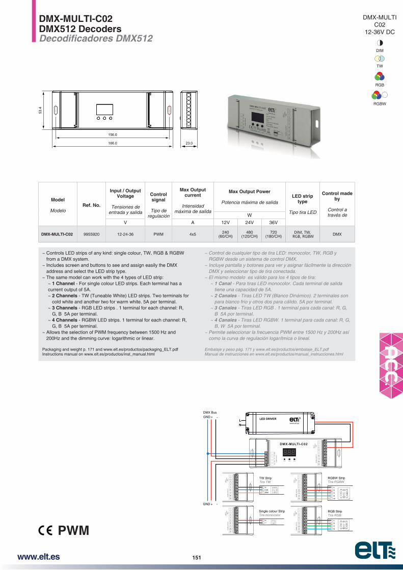
151www.elt.es
DMX-MULTI-C02DMX512 Decoders
~ Controls LED strips of any kind: single colour, TW, RGB & RGBW from a DMX system.
~ Includes screen and buttons to see and assign easily the DMX address and select the LED strip type.
~ The same model can work with the 4 types of LED strip:~ 1 Channel - For single colour LED strips. Each terminal has a current output of 5A. ~ 2 Channels - TW (Tuneable White) LED strips. Two terminals for
cold white and another two for warm white. 5A per terminal.~ 3 Channels - RGB LED strips . 1 terminal for each channel: R,
G, B 5A per terminal.~ 4 Channels - RGBW LED strips. 1 terminal for each channel: R,
G, B 5A per terminal.~ Allows the selection of PWM frequency between 1500 Hz and
200Hz and the dimming curve: logarithmic or linear.
Packaging and weight p. 171 and www.elt.es/productos/packaging_ELT.pdfInstructions manual on www.elt.es/productos/inst_manual.html
~ Control de cualquier tipo de tira LED: monocolor, TW, RGB y
~ Incluye pantalla y botones para ver y asignar fácilmente la dirección
~ 1 Canaltiene una capacidad de 5A.
~ 2 Canales para blanco frío y otros dos para cálido. 5A por terminal.
~ 3 CanalesB 5A por terminal.
~ 4 CanalesB, W 5A por terminal.
~ Permite seleccionar la frecuencia PWM entre 1500 Hz y 200Hz así como la curva de regulación logarítmica o lineal.
Embalaje y peso pág. 171 y www.elt.es/productos/embalaje_ELT.pdfManual de instrucciones en www.elt.es/productos/manual_instrucciones.html
Model
ModeloRef. No.
Input / Output Voltage
Tensiones de entrada y salida
Control signal
Tipo de regulación
Max Output current
Intensidad máxima de salida
Max Output Power
Potencia máxima de salidaLED strip
type
Tipo tira LED
Control made by
Control a través deW
V A 12V 24V 36V
DMX-MULTI-C02 9955920 12-24-36 PWM 4x5 240 (60/CH)
480 (120/CH)
720 (180/CH)
DIM, TW, RGB, RGBW DMX
PWM
DMX-MULTIC02
12-36V DC
DIM
RGB
TW
RGBW
156.0
166.0 23.0
53.4
DMX BusGND + -
GND + -
R
G
B
W
SIG
NA
L I NP
UT
SIG
NA
L O
UT
PU
T
DMX-MULTI-C02
RGBW StripTira RGBW
R
G
B
W
SIG
NA
L O
UT
PU
T
RGB StripTira RGB
R
G
B
W
SIG
NA
L O
UT
PU
T
CW+
Single colour StripTira monocolor
TW StripTira TW
R
G
B
W
SIG
NA
L O
UT
PU
T
WW
-+
R
G
B
W
SIG
NA
L O
UT
PU
T
W
LED DRIVER R
LN

152 www.elt.es
9
14,4
24
SUP MIDI For LED strips up toPara tiras LED hasta 14 mm
InstallationInstalación
Surface
ModelModelo Ref. No. Length
Longitud
eDEC SD-20 9955201 2 m
EndingsTapas
Ref. No.2 pcs / 2 uds.
Colour Color
eDEC TA-SD 9955206 Grey / Gris
See accessories on page 157Ver accesorios en pág. 157
AnodizedAnodizado
* Black Anodized Negro Anodizado
* Pintado Blanco White Painted
* On request / Bajo pedido
SUP
AnodizedAnodizado
* Black Anodized Negro Anodizado
* Pintado Blanco White Painted
* On request / Bajo pedido
SUP MAX
AnodizedAnodizado
* Black Anodized Negro Anodizado
* Pintado Blanco White Painted
* On request / Bajo pedido
SUP MINI
AnodizedAnodizado
* Black Anodized Negro Anodizado
* Pintado Blanco White Painted
* On request / Bajo pedido
SUP 2
AnodizedAnodizado
* Black Anodized Negro Anodizado
* Pintado Blanco White Painted
* On request / Bajo pedido
For LED strips up toPara tiras LED hasta 10 mm
InstallationInstalación
Surface
ModelModelo Ref. No. Length
Longitud
eDEC SU-20 9955222 2 m
EndingsTapas
Ref. No.2 pcs / 2 uds.
Colour Color
eDEC TA-SU 9955227 Grey / Gris
See accessories on page 157Ver accesorios en pág. 157
For LED strips up toPara tiras LED hasta
1 x 29mm2 x 14mm3 x 8mm
InstallationInstalación
Surface
ModelModelo Ref. No. Length
Longitud
eDEC SX-20 9955249 2 m
EndingsTapas
Ref. No.2 pcs / 2 uds.
Colour Color
eDEC TA-SX 9955254 Grey / Gris
See accessories on page 157Ver accesorios en pág. 157
For LED strips up toPara tiras LED hasta 10 mm
InstallationInstalación
Surface
ModelModelo Ref. No. Length
Longitud
eDEC SM-20 9955267 2 m
EndingsTapas
Ref. No.2 pcs / 2 uds.
Colour Color
eDEC TA-SM 9955272 Grey / Gris
See accessories on page 157Ver accesorios en pág. 157
For LED strips up toPara tiras LED hasta 10 mm
InstallationInstalación
Surface
ModelModelo Ref. No. Length
Longitud
eDEC S2-20 9955285 2 m
EndingsTapas
Ref. No.2 pcs / 2 uds.
Colour Color
eDEC TA-S2 9955290 Grey / Gris
See accessories on page 157Ver accesorios en pág. 157
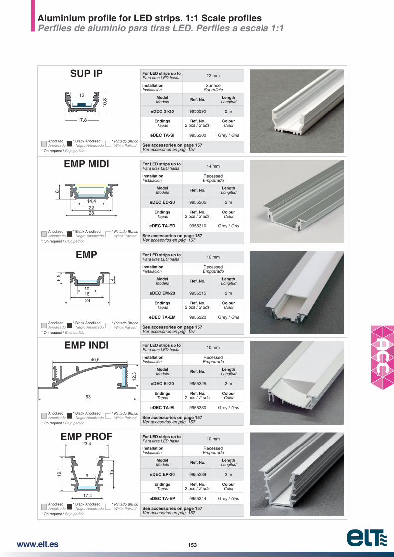
153www.elt.es
17,8
10,8
12
SUP IP
AnodizedAnodizado
* Black Anodized Negro Anodizado
* Pintado Blanco White Painted
* On request / Bajo pedido
8
2822
14,4
EMP MIDI
AnodizedAnodizado
* Black Anodized Negro Anodizado
* Pintado Blanco White Painted
* On request / Bajo pedido
EMP
AnodizedAnodizado
* Black Anodized Negro Anodizado
* Pintado Blanco White Painted
* On request / Bajo pedido
EMP INDI
AnodizedAnodizado
* Black Anodized Negro Anodizado
* Pintado Blanco White Painted
* On request / Bajo pedido
EMP PROF
AnodizedAnodizado
* Black Anodized Negro Anodizado
* Pintado Blanco White Painted
* On request / Bajo pedido
For LED strips up toPara tiras LED hasta 12 mm
InstallationInstalación
Surface
ModelModelo Ref. No. Length
Longitud
eDEC SI-20 9955295 2 m
EndingsTapas
Ref. No.2 pcs / 2 uds.
Colour Color
eDEC TA-SI 9955300 Grey / Gris
See accessories on page 157Ver accesorios en pág. 157
For LED strips up toPara tiras LED hasta 14 mm
InstallationInstalación
RecessedEmpotrado
ModelModelo Ref. No. Length
Longitud
eDEC ED-20 9955305 2 m
EndingsTapas
Ref. No.2 pcs / 2 uds.
Colour Color
eDEC TA-ED 9955310 Grey / Gris
See accessories on page 157Ver accesorios en pág. 157
For LED strips up toPara tiras LED hasta 10 mm
InstallationInstalación
RecessedEmpotrado
ModelModelo Ref. No. Length
Longitud
eDEC EM-20 9955315 2 m
EndingsTapas
Ref. No.2 pcs / 2 uds.
Colour Color
eDEC TA-EM 9955320 Grey / Gris
See accessories on page 157Ver accesorios en pág. 157
For LED strips up toPara tiras LED hasta 10 mm
InstallationInstalación
RecessedEmpotrado
ModelModelo Ref. No. Length
Longitud
eDEC EI-20 9955325 2 m
EndingsTapas
Ref. No.2 pcs / 2 uds.
Colour Color
eDEC TA-EI 9955330 Grey / Gris
See accessories on page 157Ver accesorios en pág. 157
For LED strips up toPara tiras LED hasta 10 mm
InstallationInstalación
RecessedEmpotrado
ModelModelo Ref. No. Length
Longitud
eDEC EP-20 9955339 2 m
EndingsTapas
Ref. No.2 pcs / 2 uds.
Colour Color
eDEC TA-EP 9955344 Grey / Gris
See accessories on page 157Ver accesorios en pág. 157
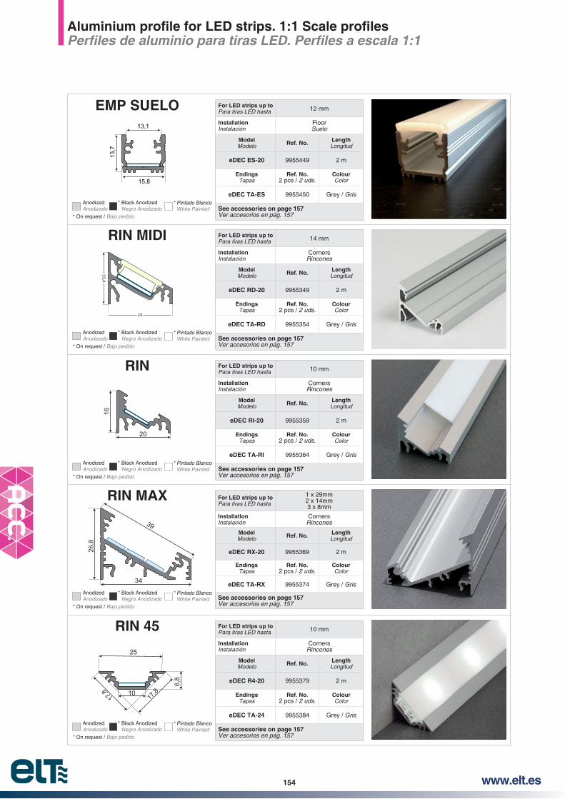
154 www.elt.es
13,1
15,8
13,7
EMP SUELO
AnodizedAnodizado
* Black Anodized Negro Anodizado
* Pintado Blanco White Painted
* On request / Bajo pedido
RIN MIDI
AnodizedAnodizado
* Black Anodized Negro Anodizado
* Pintado Blanco White Painted
* On request / Bajo pedido
RIN
AnodizedAnodizado
* Black Anodized Negro Anodizado
* Pintado Blanco White Painted
* On request / Bajo pedido
RIN MAX
AnodizedAnodizado
* Black Anodized Negro Anodizado
* Pintado Blanco White Painted
* On request / Bajo pedido
RIN 45
AnodizedAnodizado
* Black Anodized Negro Anodizado
* Pintado Blanco White Painted
* On request / Bajo pedido
For LED strips up toPara tiras LED hasta 12 mm
InstallationInstalación
FloorSuelo
ModelModelo Ref. No. Length
Longitud
eDEC ES-20 9955449 2 m
EndingsTapas
Ref. No.2 pcs / 2 uds.
Colour Color
eDEC TA-ES 9955450 Grey / Gris
See accessories on page 157Ver accesorios en pág. 157
For LED strips up toPara tiras LED hasta 14 mm
InstallationInstalación
CornersRincones
ModelModelo Ref. No. Length
Longitud
eDEC RD-20 9955349 2 m
EndingsTapas
Ref. No.2 pcs / 2 uds.
Colour Color
eDEC TA-RD 9955354 Grey / Gris
See accessories on page 157Ver accesorios en pág. 157
For LED strips up toPara tiras LED hasta 10 mm
InstallationInstalación
CornersRincones
ModelModelo Ref. No. Length
Longitud
eDEC RI-20 9955359 2 m
EndingsTapas
Ref. No.2 pcs / 2 uds.
Colour Color
eDEC TA-RI 9955364 Grey / Gris
See accessories on page 157Ver accesorios en pág. 157
For LED strips up toPara tiras LED hasta
1 x 29mm2 x 14mm3 x 8mm
InstallationInstalación
CornersRincones
ModelModelo Ref. No. Length
Longitud
eDEC RX-20 9955369 2 m
EndingsTapas
Ref. No.2 pcs / 2 uds.
Colour Color
eDEC TA-RX 9955374 Grey / Gris
See accessories on page 157Ver accesorios en pág. 157
For LED strips up toPara tiras LED hasta 10 mm
InstallationInstalación
CornersRincones
ModelModelo Ref. No. Length
Longitud
eDEC R4-20 9955379 2 m
EndingsTapas
Ref. No.2 pcs / 2 uds.
Colour Color
eDEC TA-24 9955384 Grey / Gris
See accessories on page 157Ver accesorios en pág. 157

155www.elt.es
FIJ For LED strips up toPara tiras LED hasta 12 mm
InstallationInstalación
installation. With different covers and accesories
See accessories on page 157.
accesorios de montaje. Ver accesorios en pág. 157
ModelModelo Ref. No. Length
Longitud
eDEC FI-20 9955389 2 mAnodizedAnodizado
20,6
40,6
19,9
SUP STEP
AnodizedAnodizado
* Black Anodized Negro Anodizado
* On request / Bajo pedido
CIL MINI For LED strips up toPara tiras LED hasta 10 mm
InstallationInstalación
With optional holdersCon soportes opcionales
installation. With different covers and accesories
See accessories on page 157.
accesorios de montaje. Ver accesorios en pág. 157
ModelModelo Ref. No. Length
Longitud
eDEC CM-20 9955405 2 mAnodizedAnodizado
29,5
28
CIL For LED strips up toPara tiras LED hasta 20 mm
InstallationInstalación
Hanger railBarra de armario
installation. With different covers and accesories
See accessories on page 157.
accesorios de montaje. Ver accesorios en pág. 157
ModelModelo Ref. No. Length
Longitud
eDEC CI-20 9955427 2 mAnodizedAnodizado
* Pintado Blanco White Painted
For LED strips up toPara tiras LED hasta 10 mm
InstallationInstalación
StepsEscaleras
ModelModelo Ref. No. Length
Longitud
eDEC SS-20 9955391 2 m
EndingsTapas
Ref. No.2 pcs / 2 uds.
Colour Color
eDEC TA-SS 9955394 Grey / Gris
See accessories on page 157Ver accesorios en pág. 157

156 www.elt.es
53
53
30
40
eDEC DA-G53-20Optional Opcional
G53
77
53
36
29
G53 EMP
53
28
40eDEC DA-G53-20Optional Opcional
G53 MINI
For LED strips up to / Para tiras LED hasta 40 mm
Installation / Instalación Surface /
Model / Modelo Ref. No. Length / Longitud
eDEC G53-20 9955431 2 m
Endings / Tapas Ref. No.2 pcs / 2 uds. Colour / Color
eDEC TA G53 9955438 Grey / Gris
See accessories on page 157 / Ver accesorios en pág. 157
For LED strips up to / Para tiras LED hasta 20 mm
Installation / Instalación Surface /
Model / Modelo Ref. No. Length / Longitud
eDEC G53E-20 9955442 2 m
Endings / Tapas Ref. No.2 pcs / 2 uds. Colour / Color
eDEC TA G53E 9955443 Grey / Gris
See accessories on page 157 / Ver accesorios en pág. 157
For LED strips up to / Para tiras LED hasta 20 mm
Installation / Instalación Surface /
Model / Modelo Ref. No. Length / Longitud
eDEC G53M-20 9955446 2 m
Endings / Tapas Ref. No.2 pcs / 2 uds. Colour / Color
eDEC TA G53M 9955447 Grey / Gris
See accessories on page 157 / Ver accesorios en pág. 157
AnodizedAnodizado* Black Anodized
Negro Anodizado * Pintado Blanco
White Painted* On request / Bajo pedido
AnodizedAnodizado* Black Anodized
Negro Anodizado * Pintado Blanco
White Painted* On request / Bajo pedido
AnodizedAnodizado* Black Anodized
Negro Anodizado * Pintado Blanco
White Painted* On request / Bajo pedido
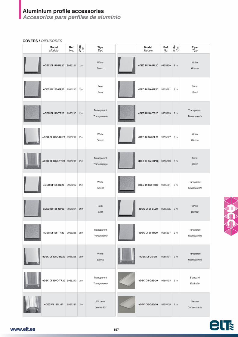
157www.elt.es
ModelModelo
Ref. No. U
nit
sU
ds. Tipe
TipoModelModelo
Ref. No. U
nit
sU
ds. Tipe
Tipo
eDEC DI 175-BL20 9955211 2 mWhite
BlancoeDEC DI SX-BL20 9955259 2 m
White
Blanco
eDEC DI 175-OP20 9955213 2 mSemi
SemieDEC DI SX-OP20 9955261 2 m
Semi
Semi
eDEC DI 175-TR20 9955215 2 mTransparent
TransparenteeDEC DI SX-TR20 9955263 2 m
Transparent
Transparente
eDEC DI 175C-BL20 9955217 2 mWhite
BlancoeDEC DI SM-BL20 9955277 2 m
White
Blanco
eDEC DI 175C-TR20 9955219 2 mTransparent
TransparenteeDEC DI SM-OP20 9955279 2 m
Semi
Semi
eDEC DI 135-BL20 9955232 2 mWhite
BlancoeDEC DI SM-TR20 9955281 2 m
Transparent
Transparente
eDEC DI 135-OP20 9955234 2 mSemi
SemieDEC DI EI-BL20 9955335 2 m
White
Blanco
eDEC DI 135-TR20 9955236 2 mTransparent
TransparenteeDEC DI EI-TR20 9955337 2 m
Transparent
Transparente
eDEC DI 135C-BL20 9955238 2 mWhite
BlancoeDEC DI-CM-20 9955407 2 m
Transparent
Transparente
eDEC DI 135C-TR20 9955240 2 mTransparent
TransparenteeDEC DS-G53-20 9955433 2 m
Standard
Estándar
eDEC DI 135L-20 9955242 2 m60º Lens
eDEC DE-G53-20 9955435 2 mNarrow
Concentrante
COVERS / DIFUSORES

158 www.elt.es
ModelModelo
Ref. No. U
nit
sU
ds. Characteristics
CaracterísticasModelModelo
Ref. No. U
nit
sU
ds. Characteristics
Características
eDEC PM-175 F 9955220 2
Clic-mounting for surface or recessed installation. Easy uninstall. Screws including. Recommended 2-4 pcs/m.Fijación mediante clic en
empotrada. Fácil desinstalación. Tornillos incluidos.
eDEC PM-135 M 9955247 1Mounting plate with springsPlaca de montaje con muelles
eDEC PM-135 9955244 2
Clic-mounting for surface or recessed installation. Screws including. Recommended 2-4 pcs/m.Fijación mediante clic en
empotrada. Tornillos incluidos.
eDEC PM-SX F 9955265 2
Clic-mounting for surface or recessed installation. Screws including. Recommended 2-4 pcs/m.Fijación mediante clic en
empotrada. Tornillos incluidos.
eDEC PM-135 F 9955245 2
Clic-mounting for surface or recessed installation. Easy uninstall. Screws including. Recommended 2-4 pcs/m.Fijación mediante clic en
empotrada. Fácil desinstalación. Tornillos incluidos.
eDEC PM-SM F 9955283 2
Clic-mounting for surface or recessed installation. Screws including. Recommended 2-4 pcs/m.Fijación mediante clic en
empotrada. Tornillos incluidos.
MOUNTING PLATES / PLACA DE MONTAJE
ModelModelo
Ref. No. U
nit
sU
ds. Characteristics
Características
eDEC PU-135 9955246 2
Clic-mounting for surface or recessed installation. Screws including. Strengthen with PM-135 or PM-135 F.Placa para montar y unir dos
empotrada. Tornillos incluidos.
135 F.
UNION PLATES / PLACA DE UNIÓN
ModelModelo
Ref. No. U
nit
sU
ds. Characteristics
CaracterísticasModelModelo
Ref. No. U
nit
sU
ds. Characteristics
Características
eDEC AD-SS 20 9955401 2 mOnly for installing position 1Sólo para la posición de instalación 1
eDEC AD-SS 20 N 9955403 2 mOnly for installing position 1Sólo para la posición de instalación 1
ANTISKID / ANTIDESLIZANTE
ModelModelo
Ref. No. U
nit
sU
ds. Characteristics
CaracterísticasModelModelo
Ref. No. U
nit
sU
ds. Characteristics
Características
eDEC CS-G53 15 9955439 1Suspension wire length: 1500 mmLongitud cable suspensión: 1500 mm
eDEC CS-G53 30 9955440 1Suspension wire length: 3000 mmLongitud cable suspensión: 3000 mm
SUSPENSION WIRE / CABLE DE SUSPENSIÓN
ModelModelo
Ref. No. U
nit
sU
ds. Tipe
TipoModelModelo
Ref. No. U
nit
sU
ds. Tipe
Tipo
eDEC CU-SS20 9955397 2 mAnodized
AnodizadoeDEC CU-SS20 N 9955399 2 m
Black anodizedNegro Anodizado
AUXILIARY COVER / CUBIERTA AUXILIAR
ModelModelo
Ref. No. U
nit
sU
ds. Tipe
Tipo
eDEC DA-G53-20 9955437 2 mAnodized cover
Cubierta aluminio
ANODIZE COVER / CUBIERTA DE ALUMINIO


160 www.elt.es160 www.elt.es
GENERAL INFORMATION INDEXíNDICE INFORMACIÓN GENERAL
Drivers approvals ..................................... 161
Marks and indications Marcas e indicaciones ............................................ 161
Quality ManagementGestión de calidad .................................................. 165
MarkingEl Marcado ............................................................. 167
Manufacturing standardsNormas de fabricación ............................................ 168
ELT product warrantyGarantia para productos ELT ................................. 169
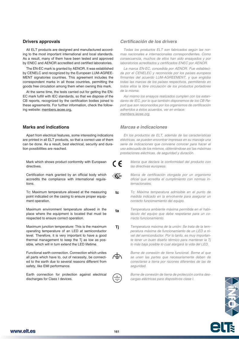
161www.elt.eswww.elt.es 161
Todas los productos ELT son fabricados según las normas nacionales e internacionales correspondientes. Como consecuencia, muchos de ellos han sido ensayados y por
da por el CENELEC y reconocida por los países europeos
todas las marcas de los países respectivos, permitiendo en todos ellos la libre circulación de los productos portadores de la misma.
Así mismo los ensayos realizados cumplen con los estandares de IEC, por lo que también disponemos de los CB Re
adheridos a éstos acuerdos, ver en enlace: members.iecee.org.
Marcas e indicaciones
En los productos de ELT, además de las características eléctricas, se pueden encontrar impresas en su marcaje una serie de indicaciones que conviene conocer para hacer el uso adecuado de los mismos, obteniéndose así las máximas prestaciones eléctricas, de seguridad y duración.
Marca que declara la conformidad del producto con las directivas europeas.
ternacionales.
Tc: Máxima temperatura admisible en el punto de medida indicado en la envolvente para asegurar un correcto funcionamiento del equipo.
Temperatura ambiente máxima permitida en el habitáculo del equipo que debe respetarse para un correcto funcionamiento.
Temperatura máxima de la unión: Se trata de la temperatura máxima de funcionamiento de un LED a nivel del semiconductor. Por lo tanto, es muy importante tener un buen diseño térmico para mantener la Tj lo más baja posible lo cual alargará la vida del LED.
Borne de conexión de tierra funcional. Borne al que se unen las partes que necesariamente deben de conectarse a tierra por razones diferentes de las de seguridad.
Borne de conexión de tierra de protección contra descargas eléctricas para dispositivos clase I.
Drivers approvals
All ELT products are designed and manufactured accord-ing to the most important international and local standards. As a result, many of them have been tested and approved
The EN-EC mark is granted by AENOR. It was established by CENELC and recognized by the European LUM-AGREE-MENT signatories countries. This agreement includes the correspondent marks in all those countries, permitting the goods free circulation among them when owning this mark.
At the same time, the tests carried out for getting the EN-
these agreements. For further information, check the follow-ing website: members.iecee.org.
Marks and indications
Apart from electrical features, some interesting indications are printed in all ELT products, so that a correct use of them can be done. As a result, best electrical, security and dura-tion possibilities are reached.
Mark which shows product conformity with European directives.
accredits the compliance with international regula-tions.
Tc: Maximum temperature allowed at the measuring point indicated on the casing to ensure proper equip-ment operation.
Maximum environment temperature allowed in the place where the equipment is located that must be respected to ensure correct operation.
Maximum junction temperature: This is the maximum operating temperature of an LED at semiconductor level. Therefore, it is very important to have a good thermal management to keep the Tj as low as pos-sible, which will in turn extend the LED lifetime.
Functional earth connection. Connection which unites all parts which have to, out of necessity, be connect-ed to the earth due to several reasons different from safety, like EMI performance.
Earth connection for protection against electrical discharges for Class I devices.
ta
tc
Tj
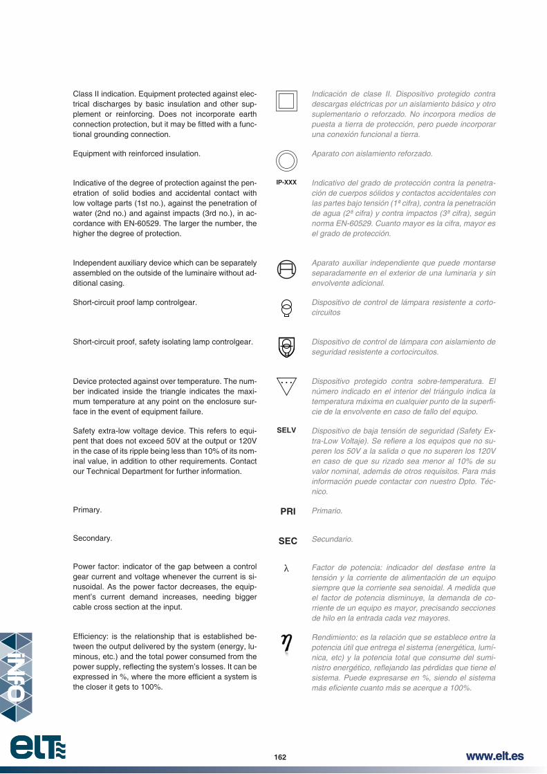
162 www.elt.es162 www.elt.es
Indicación de clase II. Dispositivo protegido contra descargas eléctricas por un aislamiento básico y otro suplementario o reforzado. No incorpora medios de puesta a tierra de protección, pero puede incorporar una conexión funcional a tierra.
Aparato con aislamiento reforzado.
Indicativo del grado de protección contra la penetración de cuerpos sólidos y contactos accidentales con las partes bajo tensión (1ª cifra), contra la penetración de agua (2ª cifra) y contra impactos (3ª cifra), según
el grado de protección.
Aparato auxiliar independiente que puede montarse separadamente en el exterior de una luminaria y sin envolvente adicional.
Dispositivo de control de lámpara resistente a cortocircuitos
Dispositivo de control de lámpara con aislamiento de seguridad resistente a cortocircuitos.
número indicado en el interior del triángulo indica la
cie de la envolvente en caso de fallo del equipo.
Dispositivo de baja tensión de seguridad (Safety Ex
peren los 50V a la salida o que no superen los 120V en caso de que su rizado sea menor al 10% de su valor nominal, además de otros requisitos. Para más información puede contactar con nuestro Dpto. Técnico.
Primario.
Secundario.
Factor de potencia: indicador del desfase entre la tensión y la corriente de alimentación de un equipo siempre que la corriente sea senoidal. A medida que el factor de potencia disminuye, la demanda de corriente de un equipo es mayor, precisando secciones de hilo en la entrada cada vez mayores.
Rendimiento: es la relación que se establece entre la potencia útil que entrega el sistema (energética, lumínica, etc) y la potencia total que consume del sumi
sistema. Puede expresarse en %, siendo el sistema
Class II indication. Equipment protected against elec-trical discharges by basic insulation and other sup-plement or reinforcing. Does not incorporate earth
-tional grounding connection.
Equipment with reinforced insulation.
Indicative of the degree of protection against the pen-etration of solid bodies and accidental contact with low voltage parts (1st no.), against the penetration of water (2nd no.) and against impacts (3rd no.), in ac-cordance with EN-60529. The larger the number, the higher the degree of protection.
Independent auxiliary device which can be separately assembled on the outside of the luminaire without ad-ditional casing.
Short-circuit proof lamp controlgear.
Short-circuit proof, safety isolating lamp controlgear.
Device protected against over temperature. The num-ber indicated inside the triangle indicates the maxi-mum temperature at any point on the enclosure sur-face in the event of equipment failure.
Safety extra-low voltage device. This refers to equi-pent that does not exceed 50V at the output or 120V in the case of its ripple being less than 10% of its nom-inal value, in addition to other requirements. Contact our Technical Department for further information.
Primary.
Secondary.
Power factor: indicator of the gap between a control gear current and voltage whenever the current is si-nusoidal. As the power factor decreases, the equip-ment’s current demand increases, needing bigger cable cross section at the input.
-tween the output delivered by the system (energy, lu-minous, etc.) and the total power consumed from the
the closer it gets to 100%.
IP-XXX
SELV
PRI
SEC

163www.elt.eswww.elt.es 163
LC
El THD o factor de distorsión armónica es un indi
pre a armónicos de corriente. Viene indicado en %, siendo mejor cuanto más reducido sea el valor.
de fase.
Dispositivo capaz de regular cargas capacitivas e inductivas además de las resistivas.
Rizado de corriente de salida.
Equipo que incorpora protección contra rayos y so
Equipo que incorpora protección contra rayos y so
Equipo que incorpora protección contra rayos y so
Marca indicativa de conformidad de los equipos con la
regulación digital direccionable DALI (Digital Addressable Lighting Interface).
Dimado a la salida por PWM.
Función corridor: sistema para controlar el nivel de luz con un sensor de movimiento convencional conectado en los bornes DALI.
minoso, entre el 10 y el 100% aproximadamente, mediante una señal analógica que llega a los equipos a través de una línea de control adicional de dos hilos, siendo 1V o cortocircuito entre líneas el nivel mínimo y 10V o circuito abierto el máximo nivel de luz. Para su control, también es posible usar potenciómetros de control logarítmicos, ya que la potencia de control es generada desde el equipo.
minoso, entre el 10 y el 100% aproximadamente, mediante una señal analógica que llega a los equipos a través de una línea de control adicional de dos hilos, siendo 0V o cortocircuito entre líneas el nivel mínimo y 10V o circuito abierto el máximo nivel de luz. Para su control, también es posible usar potenciómetros de control logarítmicos, ya que la potencia de control es generada desde el equipo.
The THD or total harmonic distortion factor is an in-dicator of how important harmonics are in our control gear, always referring to drivers and always to current harmonics. It is indicated by %, the lower the value the better.
Regulation with a cutting device at the beginning or the end of the phase.
Device capable of regulating capacitive and inductive loads, as well as resistive power.
Output ripple current.
Input transient, surge and strike protection device be-tween line and neutral up to 4kV.
Input transient, surge and strike protection device be-tween line and neutral up to 6kV.
Input transient, surge and strike protection device be-tween line and neutral up to 10kV and between line-neutral and earth up to 10kV.
Mark indicating equipments conformity with the Eu-ropean technical standard IEC 62386 concerning the Digital Addressable Lighting System (DALI).
PWM Output Dimming.
Corridor function: Dimming system that controls light level when a presence is detected by a conventional mains on/off sensor connected in DALI input.
1-10V: System that enables regulation of the lumi-
analogue signal to the equipment over a two-wire ad-ditional control line. Minimum light is obtained with 1V or by short-circuiting the equipment’s input control, while maximum light level is obtained by applying 10V or by leaving the input control in open circuit. Power control is also achieved by means of logarithmic po-tentiometers, since power control is generated by the lighting equipment.
0-10V: System that enables regulation of the lumi-
analogue signal to the equipment over a two-wire ad-ditional control line. Minimum light is obtained with 0V or by short-circuiting the equipment’s input control, while maximum light level is obtained by applying 10V or by leaving the input control in open circuit. Power control is also achieved by means of logarithmic po-tentiometers, since power control is generated by the lighting equipment.
ORC
4L-N
6L-N
A L ID
PWM Output Dimming
THD
10

164 www.elt.es164 www.elt.es
que utiliza la tensión de red como señal de control, aplicada a través de un pulsador estándar normalmente abierto, en una línea de control, sin necesidad
Los equipos electrónicos equipados con tecnología eSMART ofrecen la posibilidad de programar diferentes modos de operación para adaptar las luminarias al entorno donde van a ser instaladas. De esta forma, se consigue optimizar el rendimiento de cada uno de los puntos de luz para conseguir unas características de funcionamiento mejores así como un ahorro en consumo energético.
Tecnología inteligente de control Bluetooth para aplicaciones de iluminación. Con eBLUE podrás controlar la iluminación para crear el ambiente adecuado a cada situación. Regula la intensidad de tus luminarias y ajusta su color mediante los interruptores de pared existentes, detectores de presencia o a través de tu smartphone/tablet.
Control inteligente (SwS): Función que posibilita el uso de interruptores convencionales como dimmers o para controlar escenas.
TOUCH-DIM: System that enables regulation of the -
plied by means of a normally open, standard push-
controllers.
Electronic equipment including eSMART technology offer different operation mode possibilities to be pro-
-ronment in the best way. This ensures that each light spot performance is easily optimized in order to get better functioning characteristics as well as an extra energy saving.
Bluetooth smart control for lighting applications. Ena-bling eBLUE technology, you can control your lights to create just the right mood or ambience. Dim your lights and adjust their colour by using your existing wall switches, motion sensors or on your smartphone/tablet.
Smart Wall Switching (SwS): Feature that enables existing wall switches as dimmers or scenes controls.
Touch-DimLN
LSN

165www.elt.eswww.elt.es 165
Gestión de calidad
ELT desde su fundación, ha contemplado los principios básicos de la Gestión de Sistemas de Calidad. Por tal motivo, el desarrollo de principios de actuación basados en normas de referencia ha sido y es en la actualidad, un requisito interno enfocado a aumentar valor en nuestros procesos.
2005 Evaluación de la gestión de la empresa de acuerdo con el modelo EFQM.
Desde el punto de vista del aseguramiento de la conformidad de los productos, ELT tiene implantado un sistema de control de los productos de compra, procesos de fabricación
Todas la materias primas sufren un proceso de homologación interno, basado en normas internacionales y muy especialmente, en criterios propios acumulados en años de experiencia. Los ensayos son exhaustivos y deben superar pruebas de campo. Posteriormente, todos los envíos se someten a control de recepción, para garantizar su adecuación a los requisitos homologados.
La inspección del proceso de fabricación es continua. La tecnología de fabricación nos permite establecer de forma automática y al 100% de los productos fabricados, diferentes
miden y registran los parámetros eléctricos fundamentales, que aseguran su correcto funcionamiento. Periódicamente, se ensayan muestras en laboratorio para asegurar su idoneidad, además de realizar las correspondientes pruebas de duración del producto.
Gestión Medioambiental
La protección del Medio Ambiente es un objetivo prioritario para ELT y por esta razón se ha implantado en la factoría un Sistema de Gestión Medioambiental de acuerdo con la
te pasa a ser, junto con la Innovación y la Calidad un objetivo básico.
ELT como empresa integrante dentro del sector de fabricación de equipos auxiliares para iluminación, y por tanto, como organización socialmente responsable, se compromete con la protección y prevención de la contaminación del Medio Ambiente, estableciendo como objetivos:
~ El cumplimento con los requisitos legales.~ La reducción de residuos.~ La reducción de emisiones y ruido.~ Reciclaje y reutilización de materiales~ La optimización de los recursos energéticos.
Esto es posible gracias a la asignación de recursos que nos encaminen hacia la mejora continua, mejoras en el diseño de los productos, desarrollando procesos, y adquiriendo materiales y servicios que superen a los de generación anterior y establecimiento de programas de colaboración y selección de proveedores etc…
Quality Management
Since its foundation, ELT has contemplated the basic prin-cipals of Quality Management Systems. For this reason, the development of principles of action based on reference reg-ulations has been and currently is, an internal requirement focused on increasing the value of our processes.
-lation UNE-EN-ISO-9002:1994
-lation UNE-EN-ISO-9001:1994
-lation UNE-EN-ISO-14000:1996
-lation UNE-EN-ISO-9001:2000
2005 Company management evaluation in accord-ance with the EFQM model.
From the point of view of ensuring product conformity, ELT has an implanted system which controls the purchased prod-
All raw materials go through an approval process based on international regulations and, particularly, on our own cri-teria, built up as a result of years of experience. After this process, all dispatches go through reception control to guar-antee they meet approval requirements.
The inspection of the manufacturing process is continu-ous. The manufacturing technology allows us to establish, automatically and in 100% of the products, different stages of
electrical parameters are measured and recorded thus en-suring their correct operation. Samples from the laboratory are periodically tested to ensure their suitability, as well as to carry out the corresponding tests on the length of the life of the product.
Environmental management
Protecting the environment is one of ELT’s most important objectives and for this reason an Environmental Manage-ment System in accordance with regulation UNE-EN-ISO 14001 has been implanted in the factory. In this way, the environment, together with innovation and quality, has be-come a basic objective.
As a company integrated in the Auxiliary Devices for Light-ing sector, and as a result, as a socially responsible organi-sation, ELT commits itself to the protection of the environ-ment and the prevention of contamination, and has estab-lished the following objectives:
~ The compliance with legal requirements.~ The reduction of waste.~ The reduction of emissions and noise.~ The recycling and reuse of materials.~ Optimising energy resources.
This is possible thanks to the assignment of resources which steers us towards continuous improvement, improve-ment in product design, process development, the acquisi-tion of materials and services which exceed those of the previous generation, and the establishment of collaboration projects and supplier selection etc…

166 www.elt.es166 www.elt.es

167www.elt.eswww.elt.es 167
El Marcado
Para poder utilizar los aparatos eléctricos y electrónicos en la Comunidad Europea, es obligatorio que sean portado
y representa el cumplimiento de las siguientes Directivas Comunitarias a las que están sujetos los productos para iluminación.
Material eléctrico Baja Tensión. Directiva
2009/125/CE Diseño ecológico de productos relacionados con la energía. Directiva de 21 de octubre de 2009.
nadas sustancias peligrosas en aparatos eléctricos y electrónicos (RoHS). Directi
ción, siendo el propio fabricante, bajo su responsabilidad, el que realiza la declaracion de conformidad al respecto.
Todos los productos de ELT poseen el marcado CE, estando disponibles las correspondientes declaraciones de conformidad, por lo que las luminarias que los incorporen cumplirán con los requisitos legales.
Las Directivas WEEE y RoHS
La protección del medio ambiente ha llegado a ser importante en todos los ámbitos de la vida. El rápido aumento de los residuos de aparatos eléctricos y electrónicos, y las sustancias peligrosas que los mismos contienen, han causado preocupación. Para solucionar el problema, el Parlamento Europeo y la Comision Europea han aprobado dos directivas: WEEE y RoHS.
sobre residuos de aparatos eléctricos y electrónicos, tiene como objetivo reducir los residuos de aparatos eléctricos y electrónicos y promover la reutilización, el reciclado y otras
de tales residuos. A la vez se pretende optimizar la capacidad de las empresas que intervengan en el tratamiento de los residuos.
sobre restricciones a la utilización de determinadas sustancias peligrosas en aparatos eléctricos y electrónicos, indica que el plomo, mercurio, cadmio, cromo hexavalente, y otras sustancias se deben eliminar de aparatos eléctricos y electrónicos.
Marking
All electric and electronic appliances to be used within the European Community must bear the CE mark, which stands for “European Compliance” and denotes that they meet the following EU Directives applicable to lighting products:
2004/108/CE Electromagnetic compatibility. Directive of 15 December 2004.
2006/95/CE Electrical equipment designed for low voltage (LV) use: Directive of 12 Decem-ber 2006.
2009/125/CE Eco-design requirements for energy-related products: Directive of 21 October 2009.
2011/65/UE Restriction of the use of certain hazard-ous substances in electrical and elec-tronic equipment (RoHS): Directive of 8 June 2011.
The CE mark is not awarded by any certifying body but rather represents a declaration made by the actual manufac-turer under its own liability as to the compliance of its prod-ucts.
All ELT products bear the CE mark and the correspond-ing declarations of conformity thereto are available upon re-quest; in consequence, luminaires bearing the CE mark are equally guaranteed to comply with all legal requirements.
The WEEE and RoHS Directives
Environmental protection has become an important issue in all walks of life. The rapid increase in the generation of waste electrical and electronic equipment, and of the hazard-ous substances contained in it, is of growing concern. With a view to solving the issue, two directives have so far been approved by the European Parliament and European Com-mission, namely the WEEE and RoHS.
Directive 2012/19/EU of 4 July 2012 on waste electri-cal and electronic equipment (WEEE) aims to reduce the amount of WEEE and to encourage its re-use, recycling and other means of recovery that provide an overall reduction in the amount of end waste. Likewise, it also strives to optimise the capabilities of waste management enterprises.
Directive 2011/65/EU of 8 June 2011 on the restriction of the use of certain hazardous substances in electrical and electronic equipment (RoHS) requires that lead, mercury, cadmium, hexavalent chrome, and a number of other sub-stances be eliminated from electrical and electronic equip-ment.
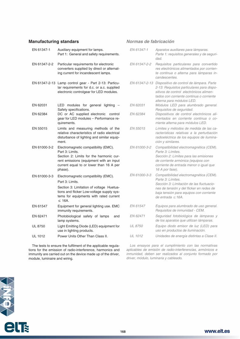
168 www.elt.es168 www.elt.es
Normas de fabricación
Parte 1: requisitos generales y de seguridad.
res electrónicos alimentados por corriente continua o alterna para lámparas incandescentes.
sitivos de control electrónicos alimentados con corriente continua o corriente alterna para módulos LED.
Requisitos de seguridad.
mentados en corriente continua o corriente alterna para módulos LED.
EN 55015 Límites y métodos de medida de las características relativas a la perturbación radioeléctrica de los equipos de iluminación y similares.
Parte 3: Límites. Sección 2: Límites para las emisiones de corriente armónica (equipos con corriente de entrada menor o igual que
Parte 3: Límites.
baja tensión para equipos con corriente
de los aparatos que utilizan lámparas.
uso en productos de iluminación.
UL 1012 Unidades de energía distintas a Clase II.
Los ensayos para el cumplimiento con las normativas
inmunidad, deben ser realizados al conjunto formado por driver, módulo, luminaria y cableado.
Manufacturing standars
EN 61347-1 Auxiliary equipment for lamps. Part 1: General and safety requirements.
EN 61347-2-2 Particular requirements for electronic converters supplied by direct or alternat-
ing current for incandescent lamps.
EN 61347-2-13 Lamp control gear - Part 2-13: Particu-lar requirements for d.c. or a.c. supplied electronic controlgear for LED modules.
EN 62031 LED modules for general lighting –
EN 62384 DC or AC supplied electronic control gear for LED modules – Performance re-quirements.
EN 55015 Limits and measuring methods of the relative characteristics of radio electrical disturbance of lighting and similar equip-ment.
EN 61000-3-2 Electromagnetic compatibility (EMC). Part 3: Limits. Section 2: Limits for the harmonic cur-
rent emissions (equipment with an input current equal to or lower than 16 A per phase).
EN 61000-3-3 Electromagnetic compatibility (EMC).
Part 3: Limits.
Section 3: Limitation of voltage Huetua--
tems for equipments with rated current
EN 61547 Equipment for general lighting use. EMC immunity requirements.
EN 62471 Photobiological safety of lamps and lamp systems.
UL 8750 Light Emitting Diode (LED) equipment for use in lighting products.
UL 1012 Power Units Other Than Class II.
-tions for the emission of radio-interference, harmonics and immunity are carried out on the device made up of the driver, module, luminaire and wiring.

169www.elt.eswww.elt.es 169
ELT product warrantyGarantía para productos ELT
Siguiendo con la política de mejora de producto y de servicio, ELT decidió ampliar a partir del 1 de enero de 2014 la garantía estándar de sus productos a cinco (5) años bajo las condiciones que se detallan más adelante.
Los componentes auxiliares para iluminación de ELT se diseñan conforme a las normas CEI (Comisión Electrotécnica Internacional) vigentes y son fabricados bajo los más exigentes criterios de calidad, basados, entre otras, en las
gurar una gran durabilidad y garantía en todos los productos de nuestra fabricación.
ilícitos.
Garantía de 5 años: La garantía de 5 años se concederá a todos los productos
con marca ELT que se encuentren en la siguiente descripción de producto:
~ Drivers para módulos LED con esperanza de vida superior a 50.000horas. Modelos LC y DLC.
~ Módulos LED siempre que se encuentren conectados con fuentes de alimentación de marca ELT. Modelos eLED.
Garantía de 3 años: La garantía de 3 años se concederá a todos los productos
con marca ELT que se encuentren en la siguiente descripción de producto:
~ Drivers para módulos LED con esperanza de vida superior a 50.000 horas. Modelos LV hasta 75W.
~ Kits de emergencia y sus baterías.
~ Cualquier producto suministrado con marca diferente a ELT.
Garantía de 2 años: La garantía de 2 años se concederá a todos los productos
que se encuentren en la siguiente descripción de producto:~ Drivers para módulos LED. Modelos LV de 100W, 130W
y 150W. ~ Drivers con una esperanza de vida inferior a 50.000 horas.~ Tiras LED.~ Resto de productos no mencionados anteriormente.
Condiciones de garantía:~ El tiempo de la garantía comienza a partir de la fecha de
fabricación, de la que da fe el número de lote marcado en el producto.
~ La garantía cubre la reposición del producto y costos de mano de obra de reposición, no siendo responsable de otros costos indirectos que se pudieran dar. (Documentación: “Application and maintenance recommendation for the use of electronic ballasts in view of the directive
http://www.lightingeurope.org)~ ELT se reserva el derecho de solicitar la devolución del
producto afectado a sus instalaciones de Zaragoza (España) para la comprobación y posterior validación del derecho de garantía.
~ La garantía cubre exclusivamente defectos en los materiales o fallos de fabricación en los componentes fabricados y suministrados por ELT.
Following its product and service improvement policy, ELT decided to extend its product warranty up to 5 years un-der the following terms and conditions, from 1 January 2014 onwards.
ELT auxiliary lighting components are designed in accor-dance with current International Electrotechnical Commis-sion (IEC) standards and are manufactured considering the most demanding quality criteria, based, among other things, on ISO-9001 and ISO-14001 management standards. This enables the company to ensure the great durability and warranty of all our products.
The use of our products is not forseen for illicit purposes.
Five-year warranty: All ELT branded products that fall under the following pro-
~ LED drivers or modules with an over 50,000-hour lifetime. LC and DLC models.
~ LED modules as long as they are connected to ELT branded power supplies. eLED models.
Three-year warranty: All ELT branded products that fall under the following pro-
duct description will be subject to a three-year warranty:~ LED drivers or modules with an over 50,000-hour
lifetime. LV models up to 75W.~ Emergency kits and their batteries.~ IP67 protection products (LC, LV, etc.).~ Whatever product supplied with any other brand diffe-
rent from ELT.
Two-year warranty: All ELT branded products that fall under the following pro-
duct description will be subject to a two-year warranty:~ LED drivers. LV models 100W, 130W and 150W.~ Under 50,000-hour lifetime drivers. ~ LED strips.~ Any other products different from mentioned above.
Warranty conditions:~ The manufacturing date sets up the warranty period
product.~ The warranty covers the product replacement and
replacement labour costs. Any other indirect costs that may apply are not covered. (Documentation: “Applica-tion and maintenance recommendation for the use of electronic ballasts in view of the directive 99/44/EC” Celma – Lighting Europe -
http://www.lightingeurope.org)~ ELT reserves the right to request the return of the faulty
product back to its facilities at Zaragoza (Spain) to check
~ The warranty solely covers material defects or manufac-turing faults in components which have been manufac-tured and supplied by ELT.

170 www.elt.es170 www.elt.es
Warranty application is conditioned by ELT to the following requisites compliance:
~ Lighting system operation in accordance with the appli-cable IEC international standards and the particular
available on www.elt.es/productos/inst_manual.html
~ Correct product use, handling and storage so that the absence of damage by third parties is ensured.
Warranty claims where ELT is not responsible for the de-fects or faults are not included in this warranty, and speci-
in any of the following circumstances:
~ Mishandling, abuse or any other type of fault in which the customer or some third party is responsible, especially in the event in which the use and installation conditions
-tions can be found in our catalogue, product sheets and informative technical documentation.
~ Anomalous operating conditions.
and vandalism, or similar situations.~ Faults in any accessory or other component (even when
they are made or supplied by ELT) which is not part of the components covered by this warranty.
~ An attempt to change or maintenance a component carried out by any person other than an authorised ins-taller.
~ Components having its batch number damaged, chan-ged or erased.
Legal warranty rights which apply to our products remain changeless because of this warranty and remain indepen-dently valid.
claims is reserved and it commits to manage every single claim in a full, trustworthy and honest way.
ELT right to modify these terms and conditions is reserved for future warranties without prior notice.
ELT condiciona la aplicación de la garantía al cumplimiento de los siguientes apartados:
~ Funcionamiento del sistema de iluminación de acuerdo
caciones particulares dadas por ELT. Existen manual de instrucciones disponibles en
www.elt.es/productos/manual_instrucciones.html
~ Correcto uso, manipulación y almacenaje del producto de forma que se garantice la ausencia de daños por terceros.
Quedan excluidas las reclamaciones de garantía en las que ELT no es responsable de los defectos o fallos y, en concreto, en cualquiera de los siguientes casos:
~ Manipulación incorrecta, uso abusivo o cualquier tipo de fallo atribuible al cliente o tercera parte, especialmente en caso de no cumplimiento de las condiciones de in
catálogos, hojas de producto y documentación técnica divulgativa.
~ Condiciones anómalas de funcionamiento.~ Fuerza Mayor, como por ejemplo: fuego, inundaciones,
actos de guerra, de violencia o vandálicos o situaciones similares.
~ Fallos de cualquier accesorio u otros componentes (incluso caso que fueran fabricados o suministrados por ELT) que no sean parte de los componentes cubiertos por esta garantía.
~ Intento de cambio o mantenimiento del componente por cualquier persona que no sea instalador autorizado.
~ Que el componente tenga su número de lote dañado, cambiado o borrado.
Los derechos de garantía legales que sean de aplicación a nuestros productos no varían con motivo de esta garantía y continúan siendo válidos de forma independiente.
cualquier reclamación de garantía y se compromete a ges
cualquier reclamación.
y términos para futuras garantías, sin previo aviso.


172 www.elt.es172 www.elt.es
Ref. No.Model
Modelo
Net unit weight
Peso neto unitario
Units per box
Unidades por caja
Units per pallet
Unidades por palet
Pallet dimension
Dimensiones del palet
Units per pallet
Unidades por palet
Pallet dimension
Dimensiones del palet
3512001 ITP 277-8KA 0,047 30 3150 750x1000
3512002 ODP LED 5KV 0,039 30 3150 750 x 1000
3512003 iLC programmer 0,115 1 - -
9513041 4,8 V 1,8 Ah NiCd 0,200 1 - -
9513051 4,8 V 4,5 Ah NiCd 0,500 1 - -
9907103 LV 15/12-C2 15W 12V 0,071 24 2880 800x1000
9907104 LV 20/12-C2 20W 12V 0,102 17 2040 800x1000
9907105 LV 30/12-C2 30W 12V 0,178 24 1344 750x1000
9907107 LV 50/12-C2 50W 12V 0,295 8 960 800x1000
9907108 LV 75/12-C2 75W 12V 0,345 10 560 750x1000
9907109 LV 100/12-C2 100W 12V 4,250 20 - -
9907110 LV 130/12-C2 130W 12V 4,150 20 - -
9907123 LV 15/24-B 15W 24V 0,071 24 2880 800x1000
9907124 LV 20/24-C2 20W 24V 0,102 17 2040 800x1000
9907125 LV 30/24-C2 30W 24V 0,176 24 1344 750x1000
9907127 LV 50/24-C2 50W 24V 0,296 8 960 800x1000
9907128 LV 75/24-C2 75W 24V 0,345 10 560 750x1000
9907129 LV 100/24-C2 100W 24V 4,350 20 - -
9907130 LV 150/24-C2 150W 24V 4,150 20 - -
9916021 LC 110/350-EN IP67 1x10W 220-240V 0,130 30 3150 750x1000
9916022 LC 110/500-EN IP67 1x10W 220-240V 0,131 30 3150 750x1000
9916023 LC 110/700-EN IP67 1x10W 220-240V 0,132 30 3150 750x1000
9916081 DLC 110/350-EN IP67 1x10W 220-240V 0,133 30 3150 750x1000
9916082 DLC 110/500-EN IP67 1x10W 220-240V 0,145 30 3150 750x1000
9916083 DLC 110/700-EN IP67 1x10W 220-240V 0,131 30 3150 750x1000
9916103 LC 190/700-XT 1x40-90W 220-240V 0,848 8 560 750x1000
9916104 LC 190/1050-XT 1x40-90W 220-240V 0,845 8 560 750x1000
9916113 LC 1150/700-XT 1x80-150W 220-240V 0,884 8 560 750x1000
9916151 iLC PRO 75/200...1400-XR 75W 700-14 0,429 8 960 750 x 1000
9918021 LC 110/350-B 1x10W 220-240V 0,049 48 3150 750x1000
9918022 LC 110/500-B 1x10W 220-240V 0,049 48 3150 750x1000
9918023 LC 110/700-B 1x10W 220-240V 0,049 48 3150 750x1000
9918031 DLC 110/350-B 1x10W 220-240V 0,050 48 3150 750x1000
9918032 DLC 110/500-B 1x10W 220-240V 0,050 48 3150 750x1000
9918033 DLC 110/700-B 1x10W 220-240V 0,050 48 3150 750x1000
9918035 DLC 108/200-B 1x8W 220-240V 0,052 48 3150 750x1000
9918036 DLC 111/300-B 1x11W 220-240V 0,050 48 3150 750x1000
9918040 LC 160/700-C 1x35..60W 220-240V 0,239 24 1512 750x1000 1680 800 x 1200
9918044 LC 142/700-C 1x24..42W 220-240V 0,239 24 1512 750x1000 1680 800 x 1200
9918103 LC 150/350-D 1x50W 220-240V 0,240 16 1456 750x1000 2016 800 x 1200
9918105 LC 150/500-D 1x50W 220-240V 0,239 16 1456 750x1000 2016 800 x 1200
9918107 LC 150/700-D 1x50W 220-240V 0,230 16 1456 750x1000 2016 800 x 1200
9918117 LC 190/700-D 1x90W 220-240V 0,269 16 1456 750x1000 2016 800 x 1200
9918123 LC 150/350-D-UN 1x50W 110-277V 0,259 16 1456 750x1000 2016 800 x 1200
9918125 LC 150/500-D-UN 1x50W 110-277V 0,250 16 1456 750x1000 2016 800 x 1200
9918127 LC 150/700-D-UN 1x50W 110-277V 0,254 16 1456 750x1000 2016 800 x 1200
9918137 DLC 150/700-D-DALI 1x50W 220-240V 0,269 16 1456 750x1000
9918147 DLC 190/700-D-DALI 1x90W 220-240V 0,297 16 1456 750x1000
9918173 LC 150/700-E 1x21...50W 220-240V 0,131 30 1680 750x1000
9918174 LC 148/1050-E 1x21...50W 220-240V 0,130 30 1680 750x1000
9918183 LC 150/700-E-C2 1x21...50W 220-240V 0,162 20 1000 750x1000
9918184 LC 148/1050-E-C2 1x21..50W 220-240V 0,164 20 1000 750x1000
9918232 DLC 116/350-A 1x16W 220-240V 0,102 25/150 3000 800x1000
9918233 DLC 116/500-A 1x16W 220-240V 0,099 25/150 3000 800x1000
9918236 DLC 116/700-A 1x16W 220-240V 0,100 25/150 3000 800x1000
9918252 DLC 125/350-A 1x25W 220-240V 0,101 25/150 3000 800x1000
9918253 DLC 125/500-A 1x25W 220-240V 0,102 25/150 3000 800x1000
9918256 DLC 125/700-A 1x25W 220-240V 0,102 25/150 3000 800x1000
9918261 LC 125/350-A-UN 1x25W 110-277V 0,100 25/150 3000 800x1000
9918262 LC 125/500-A-UN 1x25W 110-277V 0,102 25/150 3000 800x1000
9918263 LC 125/700-A-UN 1x25W 110-277V 0,104 25/150 3000 800x1000
9918271 LC 150/350-E-UN 1x23..50W 110-277V 0,145 30 1680 750 x 1000
9918273 LC 150/700-E-UN 1x24..50W 110-277V 0,142 30 1680 750x1000
9918274 LC 148/1050-E-UN 1x23..48W 110-277V 0,144 30 1680 750x1000
Packaging, unit net weight and pallet conditioning of ELT productsEmbalaje, peso unitario neto y acondicionamiento por palet de productos ELT

173www.elt.eswww.elt.es 173
Packaging, unit net weight and pallet conditioning of ELT productsEmbalaje, peso unitario neto y acondicionamiento por palet de productos ELT
Ref. No.Model
Modelo
Net unit weight
Peso neto unitario
Units per box
Unidades por caja
Units per pallet
Unidades por palet
Pallet dimension
Dimensiones del palet
Units per pallet
Unidades por palet
Pallet dimension
Dimensiones del palet
9918281 LC 150/350-E-C2-UN 23..50W 110-277V 0,164 20 1000 750 x 1000
9918283 LC 150/700-E-C2-UN 24..50W 110-277V 0,164 20 1000 750x1000
9918284 LC 148/1050-E-C2-UN 23..48W 110-277 0,164 20 1000 750x1000
9918311 LCM 42/350...1050-E max. 42W 0,141 30 1680 750x1000
9918321 LCM 42/350...1050-E-C2 max. 42W 0,178 20 1000 750x1000
9918333 DLC 142/700-E-1...10V 0,133 30 1680 750x1000
9918334 DLC 142/1050-E-1...10V 0,134 30 1680 750x1000
9918343 DLC 142/700-E-C2-1...10V 0,170 20 1000 750x1000
9918344 DLC 142/1050-E-C2-1...10V 0,171 20 1000 750x1000
9918351 DLCM 50/250...350-E-DALI 220-240V 0,152 30 1680 750 x 1000
9918352 DLCM 50/400...500-E-DALI 220-240V 0,150 30 1680 750 x 1000
9918353 DLCM 50/600...700-E-DALI 220-240V 0,149 30 1680 750 x 1000
9918361 DLCM 50/250...350-E-C2-DALI 0,185 20 1000 750 x 1000
9918362 DLCM 50/400...500-E-C2-DALI 0,183 20 1000 750 x 1000
9918363 DLCM 50/600...700-E-C2-DALI 0,183 20 1000 750 x 1000
9918381 DLC 400/700-TN-1...10V 400W220-240V 2,500 2 70 750 x 1000
9918391 DLCM 50/250...350-E-BT 50W 220-240V 0,143 30 1680 750 x 1000
9918392 DLCM 50/400...500-E-BT 50W 220-240V 0,143 30 1680 750 x 1000
9918393 DLCM 50/600...700-E-BT 50W 220-240V 0,143 30 1680 750 x 1000
9918401 DLCM 50/250...350-E-C2-BT 220-240V 0,182 20 1000 750 x 1000
9918402 DLCM 50/400...500-E-C2-BT 220-240V 0,182 20 1000 750 x 1000
9918403 DLCM 50/600...700-E-C2-BT 220-240V 0,182 20 1000 750 x 1000
9950501 eLED LINE 1 950 840 0,023 120 2520 750x1000
9950502 eLED LINE 1 950 830 0,023 120 2520 750x1000
9950508 eLED LINE 1 1250 830 0,034 80 1680 750x1000
9950509 eLED LINE 1 1250 840 0,034 80 1680 750x1000
9950526 eLED LINE 2 2500 830 0,077 40 840 750x1000
9950527 eLED LINE 2 2500 840 0,077 40 840 750x1000
9950531 eLED LINE 2 1900 830 0,047 60 1260 750x1000
9950532 eLED LINE 2 1900 840 0,047 60 1260 750x1000
9950536 eLED LINE 3 1000 830 0,013 200 4200 750 x 1000
9950541 eLED SQUARE 2 1900 830 0,165 30 450 750x1000
9950542 eLED SQUARE 2 1900 840 0,165 30 450 750x1000
9950551 eLED OCTO 1 2150 830 0,064 30 720 750x1000
9950552 eLED OCTO 1 2150 840 0,064 30 720 750x1000
9950556 eLED OCTO 1 2550 830 0,064 30 720 750x1000
9950557 eLED OCTO 1 2550 840 0,064 30 720 750x1000
9950592 eLED STREET-SQR 24 AVN-V 4000K 1,205 1 - -
9953001 eDIF 1-595-TRANSPARENT 0,050 28 - -
9953002 eDIF 1-595-FROSTED 0,050 28 - -
9953003 eDIF 1-595-OPAL 0,050 28 - -
9953004 eDIF 1-1200-TRANSPARENT 0,100 28 - -
9953005 eDIF 1-1200-FROSTED 0,100 28 - -
9953006 eDIF 1-1200-OPAL 0,100 28 - -
9953021 eDIF SQUARE-562-FROSTED 0,745 15 - -
9953022 eDIF SQUARE-562-OPAL 1,045 15 - -
9953061 emerLED 12-50V 3W 1h 0,343 25 - -
9953062 emerLED 12-50V 3W 3h 0,660 25 - -
9953063 emerLED 30-220V 3W 1h 0,343 25 - -
9953064 emerLED 30-220V 3W 3h 0,661 25 - -
9953070 eBLUE 0-10V/DALI BLUETOOTH 0,048 1 / 30 3150 750 x 1000
9953071 eBLUE TRAILING EDGE 0,016 1 / 30 3150 750 x 1000
9954001 eDIM 100 1...100W 230V 50-60Hz 0,045 30 3600 800x1000
9954002 eDIM 440 1...440W 230V 50-60Hz 0,045 30 3600 800x1000
9955001 eLED VEC35-20-CCTD-24V 0,130 - - -
9955002 eLED VEC35-20-CCTD-24V-IP65 0,285 15 - -
9955003 eLED VEC28-20-CCT-24V 0,140 25 - -
9955004 eLED VEC28-20-CCT-24V-IP65 0,280 15 - -
9955013 eLED VEC28-17-865-24V-IP65 0,305 10 - -
9955014 eLED VEC28-17-842-24V-IP65 0,305 10 - -
9955015 eLED VEC28-17-830-24V-IP65 0,305 10 - -
9955016 eLED VEC28-17-827-24V-IP65 0,305 - - -
9955023 eLED VEC28-17-865-24V 0,125 25 - -
9955024 eLED VEC28-17-842-24V 0,125 25 - -
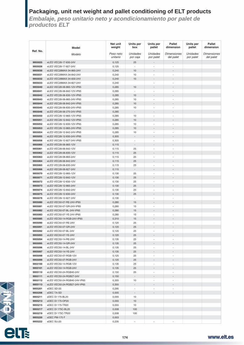
174 www.elt.es174 www.elt.es
Ref. No.Model
Modelo
Net unit weight
Peso neto unitario
Units per box
Unidades por caja
Units per pallet
Unidades por palet
Pallet dimension
Dimensiones del palet
Units per pallet
Unidades por palet
Pallet dimension
Dimensiones del palet
9955025 eLED VEC28-17-830-24V 0,125 25 - -
9955026 eLED VEC28-17-827-24V 0,125 - - -
9955030 eLED VEC28MAX-34-865-24V 0,240 10 - -
9955031 eLED VEC28MAX-34-842-24V 0,240 10 - -
9955032 eLED VEC28MAX-34-830-24V 0,240 10 - -
9955033 eLED VEC28MAX-34-827-24V 0,240 - -
9955040 eLED VEC28-06-865-12V-IP65 0,285 10 - -
9955041 eLED VEC28-06-842-12V-IP65 0,285 - - -
9955042 eLED VEC28-06-830-12V-IP65 0,285 10 - -
9955043 eLED VEC28-06-865-24V-IP65 0,285 10 - -
9955044 eLED VEC28-06-842-24V-IP65 0,285 10 - -
9955045 eLED VEC28-06-830-24V-IP65 0,285 10 - -
9955046 eLED VEC28-06-270-24V-IP65 0,285 - - -
9955050 eLED VEC28-12-865-12V-IP65 0,285 10 - -
9955051 eLED VEC28-12-842-12V-IP65 0,285 10 - -
9955052 eLED VEC28-12-830-12V-IP65 0,285 10 - -
9955053 eLED VEC28-12-865-24V-IP65 0,285 10 - -
9955054 eLED VEC28-12-842-24V-IP65 0,285 10 - -
9955055 eLED VEC28-12-830-24V-IP65 0,305 - - -
9955056 eLED VEC28-12-827-24V-IP65 0,305 - - -
9955060 eLED VEC28-06-865-12V 0,115 - - -
9955061 eLED VEC28-06-842-12V 0,115 25 - -
9955062 eLED VEC28-06-830-12V 0,115 25 - -
9955063 eLED VEC28-06-865-24V 0,115 25 - -
9955064 eLED VEC28-06-842-24V 0,115 25 - -
9955065 eLED VEC28-06-830-24V 0,115 25 - -
9955066 eLED VEC28-06-827-24V 0,115 - - -
9955070 eLED VEC28-12-865-12V 0,130 25 - -
9955071 eLED VEC28-12-842-12V 0,130 25 - -
9955072 eLED VEC28-12-830-12V 0,130 25 - -
9955073 eLED VEC28-12-865-24V 0,130 25 - -
9955074 eLED VEC28-12-842-24V 0,130 25 - -
9955075 eLED VEC28-12-830-24V 0,130 25 - -
9955076 eLED VEC28-12-827-24V 0,130 - - -
9955080 eLED VEC50-07-RE-24V-IP65 0,280 15 - -
9955081 eLED VEC50-07-GR-24V-IP65 0,280 15 - -
9955082 eLED VEC50-07-BL-24V-IP65 0,280 15 - -
9955083 eLED VEC50-07-YE-24V-IP65 0,280 15 - -
9955085 eLED VEC50-14-RGB-24V-IP65 0,310 15 - -
9955090 eLED VEC50-07-RE-24V 0,120 25 - -
9955091 eLED VEC50-07-GR-24V 0,120 25 - -
9955092 eLED VEC50-07-BL-24V 0,120 25 - -
9955093 eLED VEC50-07-YE-24V 0,120 25 - -
9955094 eLED VEC50-14-RE-24V 0,135 25 - -
9955095 eLED VEC50-14-GR-24V 0,135 25 - -
9955096 eLED VEC50-14-BL-24V 0,135 25 - -
9955097 eLED VEC50-14-YE-24V 0,135 25 - -
9955098 eLED VEC50-07-RGB-12V 0,125 25 - -
9955099 eLED VEC50-07-RGB-24V 0,120 25 - -
9955100 eLED VEC50-14-RGB-12V 0,135 25 - -
9955101 eLED VEC50-14-RGB-24V 0,135 25 - -
9955110 eLED VEC50-24-RGB40-24V 0,150 25 - -
9955111 eLED VEC50-24-RGB27-24V 0,150 - - -
9955112 eLED VEC50-24-RGB40-24V-IP65 0,355 10 - -
9955113 eLED VEC50-24-RGB27-24V-IP65 0,355 - - -
9955201 eDEC SD-20 0,295 - - -
9955206 eDEC TA-SD 0,005 - - -
9955211 eDEC DI 175-BL20 0,055 10
9955213 eDEC DI 175-OP20 0,055 10
9955215 eDEC DI 175-TR20 0,055 10
9955217 eDEC DI 175C-BL20 0,008 100
9955219 eDEC DI 175C-TR20 0,008 100
9955220 eDEC PM-175 F 0,003
9955222 eDEC SU-20 0,235 - - -
Packaging, unit net weight and pallet conditioning of ELT productsEmbalaje, peso unitario neto y acondicionamiento por palet de productos ELT

175www.elt.eswww.elt.es 175
Ref. No.Model
Modelo
Net unit weight
Peso neto unitario
Units per box
Unidades por caja
Units per pallet
Unidades por palet
Pallet dimension
Dimensiones del palet
Units per pallet
Unidades por palet
Pallet dimension
Dimensiones del palet
9955227 eDEC TA-SU 0,003 - - -
9955232 eDEC DI 135-BL20 0,004 10
9955234 eDEC DI 135-OP20 0,004 10
9955236 eDEC DI 135-TR20 0,004 10
9955238 eDEC DI 135C-BL20 0,004 100
9955240 eDEC DI 135C-TR20 0,004 100
9955242 eDEC DI 135L-20 0,011 100
9955244 eDEC PM-135 0,004
9955245 eDEC PM-135 F 0,003
9955246 eDEC PU-135 0,004
9955247 eDEC PM-135 M 0,003
9955249 eDEC SX-20 0,435 - - -
9955254 eDEC TA-SX 0,002 - - -
9955259 eDEC DI SX-BL20 0,008 10
9955261 eDEC DI SX-OP20 0,008 10
9955263 eDEC DI SX-TR20 0,008 10
9955265 eDEC PM-SX F 0,006
9955267 eDEC SM-20 0,135 - - -
9955272 eDEC TA-SM 0,003 - - -
9955277 eDEC DI SM-BL20 0,002 10
9955279 eDEC DI SM-OP20 0,002 10
9955281 eDEC DI SM-TR20 0,002 10
9955283 eDEC PM-SM F 0,002
9955285 eDEC S2-20 0,540 - - -
9955290 eDEC TA-S2 0,003 - - -
9955295 eDEC SI-20 0,235 - - -
9955300 eDEC TA-SI 0,003 - - -
9955305 eDEC ED-20 0,270 - - -
9955310 eDEC TA-ED 0,005 - - -
9955315 eDEC EM-20 0,210 - - -
9955320 eDEC TA-EM 0,003 - - -
9955325 eDEC EI-20 0,565 - - -
9955330 eDEC TA-EI 0,020 - - -
9955335 eDEC DI EI-BL20 0,100 10
9955337 eDEC DI EI-TR20 0,100 10
9955339 eDEC EP-20 0,410 - - -
9955344 eDEC TA-EP 0,005 - - -
9955450 eDEC-TA-ES 0,315
9955349 eDEC RD-20 0,410 - - -
9955354 eDEC TA-RD 0,005 - - -
9955359 eDEC RI-20 0,375 - - -
9955364 eDEC TA-RI 0,003 - - -
9955369 eDEC RX-20 0,640 - - -
9955374 eDEC TA-RX 0,006 - - -
9955379 eDEC R4-20 0,210 - - -
9955384 eDEC TA-24 0,004 - - -
9955389 eDEC FI-20 0,115 - - -
9955391 eDEC SS-20 1,045
9955394 eDEC TA-SS 0,003 - - -
9955397 eDEC CU-SS20 0,230
9955399 eDEC CU-SS20 N 0,230
9955401 eDEC AD-SS 20 0,004
9955403 eDEC AD-SS 20 N 0,004
9955405 eDEC CM-20 0,215 - - -
9955407 eDEC DI-CM-20 0,004 100
9955427 eDEC CI-20 0,875 - - -
9955431 eDEC G53-20 2,105 - - -
9955433 eDEC DS-G53-20 0,200 10
9955435 eDEC DE-G53-20 0,200 10
9955437 eDEC DA-G53-20 0,410
9955438 eDEC TA G53 0,006 - - -
9955439 eDEC CS-G53 15 0,275
9955440 eDEC CS-G53 30 0,325
9955442 eDEC G53E-20 0,020 - - -
Packaging, unit net weight and pallet conditioning of ELT productsEmbalaje, peso unitario neto y acondicionamiento por palet de productos ELT

176 www.elt.es176 www.elt.es
Ref. No.Model
Modelo
Net unit weight
Peso neto unitario
Units per box
Unidades por caja
Units per pallet
Unidades por palet
Pallet dimension
Dimensiones del palet
Units per pallet
Unidades por palet
Pallet dimension
Dimensiones del palet
9955443 eDEC TA G53E 0,003 - - -
9955446 eDEC G53M-20 0,006 - - -
9955447 eDEC TA G53M 0,005 - - -
9955900 MIC-DIM-T01 0,075 - - -
9955901 SPU-DIM-C01 0,065 100 - -
9955902 SPU-RGB-C01 0,130 - - -
9955903 SPU-DIM-C02 0,065 - - -
9955904 SPU-CCT-C01 0,065 - - -
9955905 SPU-DIM-R01 0,030 - - -
9955906 SPU-DIM-R02 0,200 36 - -
9955907 SPU-DIM-R03 0,200 36 - -
9955908 SPU-RGB-R01 0,200 36 - -
9955909 PRO-RGB-W-R01 0,065 100 - -
9955910 PRO-CCT-R01 0,065 100 - -
9955911 PRO-DIM-R01 0,065 100 - -
9955912 PRO-DIMCCT-C01 0,090 100 - -
9955913 PRO-RGB-W-C01 0,090 100 - -
9955914 STO-DIM-CT01 0,200 36 - -
9955915 STO-TW-CT01 0,200 36 - -
9955916 STO-RGB-W-CT01 0,200 36 - -
9955919 DMX-MULTI-C01 0,450 - - -
9955917 DAL-MULTI-C01 0,130 - - -
9955920 DMX-MULTI-C02 0,140 - - -
9955921 DAL-MULTI-C02 0,130 - - -
9955950 DIM-A01 0,260 - - -
9955951 MULTI-A01 - - - -
9955449 eDEC ES-20 0,335
Data into this catalogue are subject to change without prior notice for the purpose of improvement or discontinued products. We kindly
the moment of placing an order.
Los datos de este catálogo están sujeto a cambios sin previo aviso por cuestiones de mejora o de descatalogación de producto. Les rogamos se aseguren de utilizar la documentación más actualizada y revisar sus contenidos en el momento de realizar pedidos.
Packaging, unit net weight and pallet conditioning of ELT productsEmbalaje, peso unitario neto y acondicionamiento por palet de productos ELT


178 www.elt.es178 www.elt.es
Commercial NetworkRed comercial
For other areas, please, contact our Zaragoza headquarters
SPAINELT - ESPECIALIDADES LUMINOTÉCNICAS, S.A.U.Pol. Ind. MalpicaC/E nº 1150016 ZARAGOZATel. +34 976 573 660 Fax +34 976 574 960e-mail: [email protected]
HEADQUARTERSCENTRAL
FRANCEELT FRANCE, S.A.S.UMme. Roxane PiallouxMme. Sandra Diet43 rue d’Aubigny69003 Lyon – FranceTel. +33 4 82 53 70 70Fax. +33 4 82 53 37 51email. [email protected]
ITALYELT ITALIA, S.R.L. Sede Legale: Via Carlo Porta 321013 Gallarate (VA) - Italyemail : [email protected]: +33 4 82 53 37 51 Area Sales Manager:Sig. Donatello SchiavonCellulare: +39 328 074 12 90email: [email protected]
Area Sales Manager:Sig. Massimo UgolaCellulare: +39 334 655 38 14email: [email protected]
EASTERN EUROPE AND CIS COUNTRIES
Area Sales Manager: VICTORIA SYCHEVSKADecin - Czech RepublicTel. +420 725 937 825Email: [email protected]
BRANCH OFFICESFILIALES

179www.elt.eswww.elt.es 179
ALICANTEDª JOSEFINA CANET GARCÍAFco. Montero Pérez, 17, 03009 ALICANTETel. 965 243 143 / Fax 965 656 861e-mail: [email protected]
BALEARESLIGHT BALEAR, S.L.D. Carlos CorbachoD’Asival, 15 - Nave 2, Pol. Ind. Can Valero07011 PALMA DE MALLORCATel. 971 761 656 / Fax 971 761 167e-mail: [email protected]
GUIPÚZCOA - VIZCAYAD. JOSÉ Mª BENAVENTE GARASA20009 SAN SEBASTIÁNTel. 943 217 095 / Fax 943 310 417e-mail: [email protected]
ANDALUCÍAZona: Cádiz, Córdoba, Huelva y SevillaRUEDA REPRESENTACIONES TECNOLÓGICAS, S.L.
41927 MAIRENA DEL ALJARAFE (SEVILLA)Tel. 955 601 000 / Fax 955 087 478e-mail: [email protected]
Zona: Almería, Granada y MálagaE.J.D., S.A.Cuevas Bajas, 2929004 MÁLAGATel. 952 230 415 / Fax 952 230 416e-mail: [email protected]
Zona: JaénINSEL ENERGY, S.L.D. José Ballesta RamosPol. Los Olivares, Huelma, 9-1023009 JAÉNTel. 953 280 677 / Fax 953 280 537e-mail: [email protected]
CANARIASGONZÁLEZ ESCUDERO, S.A.L.D. Pedro González Escudero38004 SANTA CRUZ DE TENERIFETel. 922 311 638 / Fax 922 311 638e-mail: [email protected]
LA RIOJA - NAVARRAD. JAIME RICKETTS URBANMóvil: 619 145 979e-mail: [email protected]
50016 ZARAGOZATel. 902 519 666 / Fax 902 519 777
CASTILLA - LA MANCHAPROCAIN-MAN, S.L.Ánimas, 1713300 VALDEPEÑASTel. 926 320 826 / Fax 926 322 716e-mail: [email protected]
MADRIDD. ALFREDO MARTÍN VICENTE28100 ALCOBENDASTel. 610 529 086 / Fax 91 662 11 11e-mail: [email protected]
CASTILLA Y LEÓND. PABLO RODRÍGUEZ GABILONDO47001 VALLADOLIDMóvil: 627 576 876Tel. 983 307 159 / Fax 983 308 436e-mail: [email protected]
VALENCIA - CASTELLÓN MURCIA
LOYMARD. Javier López - D. Juan MartínezIsla Cabrera, 6, 46026 VALENCIATel. 963 332 440 / Fax 963 332 527e-mail: [email protected]
ARAGÓND. JAIME RICKETTS URBANMóvil: 619 145 979e-mail: [email protected]
50016 ZARAGOZATel. 902 519 666 / Fax 902 519 777
CATALUÑAD. MARIO RUIZ DONAIREÁvila, 6908005 BARCELONATel. 933 004 450 / Fax 934 854 442e-mail: [email protected]
ASTURIAS - CANTABRIAD. JOSÉ ÁNGEL CUERVO GARCÍA33011 OVIEDOTel. 985 119 272 / Fax 985 119 272e-mail: [email protected]
GALICIAMAFER GALICIA S.L.D. Iago Carrera.36280, Vigo, PONTEVEDRAMov. 687 721 368 / Fax. 986 366 699e-mail: [email protected]
SPAIN BRANCHES DELEGACIONES ESPAÑA


182 www.elt.es182 www.elt.es
Ref. No.
Model
ModeloPag.
9513041 4,8 V 1,8 Ah NiCd 48
9513051 4,8 V 4,5 Ah NiCd 48
9955917 DAL-MULTI-C01 148
9955921 DAL-MULTI-C02 149
9955950 DIM-A01 127
9918035 DLC 108/200-B 22
9918031 DLC 110/350-B 22
9916081 DLC 110/350-EN 42
9918032 DLC 110/500-B 22
9916082 DLC 110/500-EN 42
9918033 DLC 110/700-B 22
9916083 DLC 110/700-EN 42
9918036 DLC 111/300-B 22
9918232 DLC 116/350-A 24
9918233 DLC 116/500-A 24
9918236 DLC 116/700-A 24
9918252 DLC 125/350-A 24
9918253 DLC 125/500-A 24
9918256 DLC 125/700-A 24
9918334 DLC 142/1050-E-1…10V 29
9918344 DLC 142/1050-E-C2-1…10V 30
9918333 DLC 142/700-E-1…10V 29
9918343 DLC 142/700-E-C2-1…10V 30
9918137 DLC 150/700-D-DALI 40
9918147 DLC 190/700-D-DALI 40
9918381 DLC 400/700-TN-1..10V 47
9918391 DLCM 50/250…350-E-BT 11
9918401 DLCM 50/250…350-E-C2-BT 12
9918361 DLCM 50/250…350-E-C2-DALI 35
9918351 DLCM 50/250…350-E-DALI 34
9918392 DLCM 50/400…500-E-BT 11
9918402 DLCM 50/400…500-E-C2-BT 12
9918362 DLCM 50/400…500-E-C2-DALI 35
9918352 DLCM 50/400…500-E-DALI 34
9918393 DLCM 50/600…700-E-BT 11
9918403 DLCM 50/600…700-E-C2-BT 12
9918363 DLCM 50/600…700-E-C2-DALI 35
9918353 DLCM 50/600…700-E-DALI 34
9955919 DMX-MULTI-C01 150
9955920 DMX-MULTI-C02 151
9953070 eBLUE 0-10V / DALI 9
9953071 eBLUE TRAILING EDGE 10
9955401 eDEC AD-SS 20 158
9955403 eDEC AD-SS 20 N 158
9955427 eDEC CI-20 155
9955405 eDEC CM-20 155
9955439 eDEC CS-G53 15 158
9955440 eDEC CS-G53 30 158
9955397 eDEC CU-SS20 158
Ref. No.
Model
ModeloPag.
9955399 eDEC CU-SS20 N 158
9955437 eDEC DA-G53-20 158
9955435 eDEC DE-G53-20 157
9955232 eDEC DI 135-BL20 157
9955238 eDEC DI 135C-BL20 157
9955240 eDEC DI 135C-TR20 157
9955242 eDEC DI 135L-20 157
9955234 eDEC DI 135-OP20 157
9955236 eDEC DI 135-TR20 157
9955211 eDEC DI 175-BL20 157
9955217 eDEC DI 175C-BL20 157
9955219 eDEC DI 175C-TR20 157
9955213 eDEC DI 175-OP20 157
9955215 eDEC DI 175-TR20 157
9955335 eDEC DI EI-BL20 157
9955337 eDEC DI EI-TR20 157
9955277 eDEC DI SM-BL20 157
9955279 eDEC DI SM-OP20 157
9955281 eDEC DI SM-TR20 157
9955259 eDEC DI SX-BL20 157
9955261 eDEC DI SX-OP20 157
9955263 eDEC DI SX-TR20 157
9955407 eDEC DI-CM-20 157
9955433 eDEC DS-G53-20 157
9955305 eDEC ED-20 153
9955325 eDEC EI-20 153
9955315 eDEC EM-20 153
9955339 eDEC EP-20 153
9955449 eDEC ES-20 154
9955389 eDEC FI-20 155
9955431 eDEC G53-20 156
9955442 eDEC G53E-20 156
9955446 eDEC G53M-20 156
9955244 eDEC PM-135 158
9955245 eDEC PM-135 F 158
9955247 eDEC PM-135 M 158
9955220 eDEC PM-175 F 158
9955283 eDEC PM-SM F 158
9955265 eDEC PM-SX F 158
9955246 eDEC PU-135 158
9955379 eDEC R4-20 154
9955349 eDEC RD-20 154
9955359 eDEC RI-20 154
9955369 eDEC RX-20 154
9955285 eDEC S2-20 152
9955201 eDEC SD-20 152
9955295 eDEC SI-20 153
9955267 eDEC SM-20 152
9955391 eDEC SS-20 155
9955222 eDEC SU-20 152
9955249 eDEC SX-20 152
9955438 eDEC TA G53 156
9955443 eDEC TA G53E 156
Ref. No.
Model
ModeloPag.
9955447 eDEC TA G53M 156
9955384 eDEC TA-24 154
9955310 eDEC TA-ED 153
9955330 eDEC TA-EI 153
9955320 eDEC TA-EM 153
9955450 eDEC TA-ES 154
9955344 eDEC TA-EP 153
9955354 eDEC TA-RD 154
9955364 eDEC TA-RI 154
9955374 eDEC TA-RX 154
9955290 eDEC TA-S2 152
9955206 eDEC TA-SD 152
9955300 eDEC TA-SI 153
9955272 eDEC TA-SM 152
9955394 eDEC TA-SS 155
9955227 eDEC TA-SU 152
9955254 eDEC TA-SX 152
9953005 eDIF 1-1200-FROSTED 123
9953006 eDIF 1-1200-OPAL 123
9953004 eDIF 1-1200-TRANSPA-RENT 123
9953002 eDIF 1-595-FROSTED 123
9953003 eDIF 1-595-OPAL 123
9953001 eDIF 1-595-TRANSPA-RENT 123
9953021 eDIF SQUARE-562-FROS-TED 124
9953022 eDIF SQUARE-562-OPAL 124
9954001 eDIM 100 125
9954002 eDIM 440 125
9950508 eLED LINE 1 1250 830 54
9950509 eLED LINE 1 1250 840 54
9950502 eLED LINE 1 950 830 51
9950501 eLED LINE 1 950 840 51
9950531 eLED LINE 2 1900 830 57
9950532 eLED LINE 2 1900 840 57
9950526 eLED LINE 2 2500 830 60
9950527 eLED LINE 2 2500 840 60
9950536 eLED LINE 3 1000 830 63
9950551 eLED OCTO 1 2150 830 66
9950552 eLED OCTO 1 2150 840 66
9950556 eLED OCTO 1 2550 830 69
9950557 eLED OCTO 1 2550 840 69
9950541 eLED SQUARE 2 1900 830 72
9950542 eLED SQUARE 2 1900 840 72
9950592 eLED STREET-SQR 24 AVN-V 4000K 75
9955046 eLED VEC28-06-270-24V-IP65 91
9955066 eLED VEC28-06-827-24V 92
9955062 eLED VEC28-06-830-12V 92
9955042 eLED VEC28-06-830-12V-IP65 91
9955065 eLED VEC28-06-830-24V 92
9955045 eLED VEC28-06-830-24V-IP65 91
Index of product nameÍndice de producto

183www.elt.eswww.elt.es 183
Ref. No.
Model
ModeloPag.
9955061 eLED VEC28-06-842-12V 92
9955041 eLED VEC28-06-842-12V-IP65 91
9955064 eLED VEC28-06-842-24V 92
9955044 eLED VEC28-06-842-24V-IP65 91
9955060 eLED VEC28-06-865-12V 92
9955040 eLED VEC28-06-865-12V-IP65 91
9955063 eLED VEC28-06-865-24V 92
9955043 eLED VEC28-06-865-24V-IP65 91
9955076 eLED VEC28-12-827-24V 92
9955056 eLED VEC28-12-827-24V-IP65 91
9955072 eLED VEC28-12-830-12V 92
9955052 eLED VEC28-12-830-12V-IP65 91
9955075 eLED VEC28-12-830-24V 92
9955055 eLED VEC28-12-830-24V-IP65 91
9955071 eLED VEC28-12-842-12V 92
9955051 eLED VEC28-12-842-12V-IP65 91
9955074 eLED VEC28-12-842-24V 92
9955054 eLED VEC28-12-842-24V-IP65 91
9955070 eLED VEC28-12-865-12V 92
9955050 eLED VEC28-12-865-12V-IP65 91
9955073 eLED VEC28-12-865-24V 92
9955053 eLED VEC28-12-865-24V-IP65 91
9955026 eLED VEC28-17-827-24V 90
9955016 eLED VEC28-17-827-24V-IP65 89
9955025 eLED VEC28-17-830-24V 90
9955015 eLED VEC28-17-830-24V-IP65 89
9955024 eLED VEC28-17-842-24V 90
9955014 eLED VEC28-17-842-24V-IP65 89
9955023 eLED VEC28-17-865-24V 90
9955013 eLED VEC28-17-865-24V-IP65 89
9955003 eLED VEC28-20-TW-24V 94
9955004 eLED VEC28-20-TW-24V-IP65 94
9955033 eLED VEC28MAX-34-827-24V 90
9955032 eLED VEC28MAX-34-830-24V 90
9955031 eLED VEC28MAX-34-842-24V 90
9955030 eLED VEC28MAX-34-865-24V 90
9955001 eLED VEC35-20-TWD-24V 93
9955002 eLED VEC35-20-TWD-24V-IP65 93
9955092 eLED VEC50-07-BL-24V 96
9955082 eLED VEC50-07-BL-24V-IP65 95
9955091 eLED VEC50-07-GR-24V 96
Ref. No.
Model
ModeloPag.
9955081 eLED VEC50-07-GR-24V-IP65 95
9955090 eLED VEC50-07-RE-24V 96
9955080 eLED VEC50-07-RE-24V-IP65 95
9955098 eLED VEC50-07-RGB-12V 96
9955099 eLED VEC50-07-RGB-24V 96
9955093 eLED VEC50-07-YE-24V 96
9955083 eLED VEC50-07-YE-24V-IP65 95
9955096 eLED VEC50-14-BL-24V 96
9955095 eLED VEC50-14-GR-24V 96
9955094 eLED VEC50-14-RE-24V 96
9955100 eLED VEC50-14-RGB-12V 96
9955101 eLED VEC50-14-RGB-24V 96
9955085 eLED VEC50-14-RGB-24V-IP65 95
9955097 eLED VEC50-14-YE-24V 96
9955111 eLED VEC50-24-RGB27-24V 97
9955113 eLED VEC50-24-RGB27-24V-IP65 97
9955110 eLED VEC50-24-RGB40-24V 97
9955112 eLED VEC50-24-RGB40-24V-IP65 97
9953061 emerLED 12-50V 3W 1h 48
9953062 emerLED 12-50V 3W 3h 48
9953063 emerLED 30-220V 3W 1h 48
9953064 emerLED 30-220V 3W 3h 48
9916151 iLC PRO 75/200...1400-XR 43
3512003 iProgrammer 126
3512001 ITP 277-8KA 121
9918021 LC 110/350-B 22
9916021 LC 110/350-EN 42
9918022 LC 110/500-B 22
9916022 LC 110/500-EN 42
9918023 LC 110/700-B 22
9916023 LC 110/700-EN 42
9916113 LC 1150/700-XT 46
9918261 LC 125/350-A-UN 23
9918262 LC 125/500-A-UN 23
9918263 LC 125/700-A-UN 23
9918044 LC 142/700-C 37
9918174 LC 148/1050-E 25
9918184 LC 148/1050-E-C2 26
9918284 LC 148/1050-E-C2-UN 28
9918274 LC 148/1050-E-UN 27
9918103 LC 150/350-D 38
9918123 LC 150/350-D-UN 39
9918281 LC 150/350-E-C2-UN 28
9918271 LC 150/350-E-UN 27
9918105 LC 150/500-D 38
9918125 LC 150/500-D-UN 39
9918107 LC 150/700-D 38
9918127 LC 150/700-D-UN 39
9918173 LC 150/700-E 25
Ref. No.
Model
ModeloPag.
9918183 LC 150/700-E-C2 26
9918283 LC 150/700-E-C2-UN 28
9918273 LC 150/700-E-UN 27
9918040 LC 160/700-C 37
9916104 LC 190/1050-XT 46
9918117 LC 190/700-D 38
9916103 LC 190/700-XT 46
9918311 LCM 42/350…1050-E 31
9918321 LCM 42/350…1050-E-C2 32
9907109 LV 100/12-C2 88
9907129 LV 100/24-C2 88
9907103 LV 15/12-C2 87
9907123 LV 15/24-C2 87
9907110 LV 150/12-C2 88
9907130 LV 150/24-C2 88
9907104 LV 20/12-C2 87
9907124 LV 20/24-C2 87
9907105 LV 30/12-C2 87
9907125 LV 30/24-C2 87
9907107 LV 50/12-C2 87
9907127 LV 50/24-C2 87
9907108 LV 75/12-C2 87
9907128 LV 75/24-C2 87
9955900 MIC-DIM-T01 129
9955951 MULTI-A01 128
3512002 ODP LED 5KV 122
9955910 PRO-TW-R01 134
9955912 PRO-DIMTW-C01 131
9955911 PRO-DIM-R01 133
9955913 PRO-RGB-W-C01 132
9955909 PRO-RGB-W-R01 135
9955904 SPU-TW-C01 143
9955901 SPU-DIM-C01 141
9955903 SPU-DIM-C02 142
9955905 SPU-DIM-R01 145
9955906 SPU-DIM-R02 146
9955907 SPU-DIM-R03 146
9955902 SPU-RGB-C01 144
9955908 SPU-RGB-R01 147
9955915 STO-TW-CT01 138
9955914 STO-DIM-CT01 137
9955916 STO-RGB-W-CT01 139

Edita:La Abuela Creativa S.C.Diseño y coordinación editorial:Raúl Marcos Giménez RobresMaquetación: Sonia Gonzalvo Giraldoswww.laabuelacreativa.com