
Activation control extension of a design method of fluid ...
22
Vol.:(0123456789) Bulletin of Earthquake Engineering (2020) 18:4017–4038 https://doi.org/10.1007/s10518-020-00849-5 1 3 ORIGINAL RESEARCH Activation control extension of a design method of fluid viscous dissipative bracing systems Gloria Terenzi 1 · Iacopo Costoli 2 · Stefano Sorace 2 Received: 23 February 2020 / Accepted: 16 April 2020 / Published online: 27 April 2020 © Springer Nature B.V. 2020 Abstract Remarkable damage to non-structural elements and sometimes to structural members was surveyed in buildings retrofitted with dissipative bracing (DB) technologies recently hit by moderate-to-medium amplitude earthquakes. Damage is a consequence of the delayed con- tribution of protective systems to the seismic response of the buildings, caused by too high activation forces of dissipaters. In view of this, a sizing procedure for DB systems incor- porating fluid viscous (FV) spring-dampers is implemented in this study. The procedure provides a simplified version of a recently proposed energy-based design criterion, and an extension of it by including a pre-evaluation of the activation force of the FV devices with respect to the normative Serviceability Design Earthquake (SDE)-related seismic demand. The sizing procedure is applied to the retrofit design of a demonstrative case study, repre- sented by a school built in Italy in the early 1980s. Noticeable seismic vulnerabilities of the above-ground steel structure of the building are assessed in current conditions, high- lighting local unsafety conditions of the profiles constituting the reticular steel columns starting from the SDE. A retrofit intervention consisting in the installation of a DB system equipped with FV spring-dampers is presented for the steel structure, designed by apply- ing the proposed sizing method. The final verification time-history analyses confirm the activation of the FV devices at the SDE, and the attainment of the targeted elastic structural response up to the Maximum Considered Earthquake normative level. Keywords Design procedures · Dissipative bracing systems · Fluid viscous dampers · Damper activation force · Non-structural damage · Steel structures * Gloria Terenzi gloria.terenzi@unifi.it 1 Department of Civil and Environmental Engineering, University of Florence, Via S. Marta 3, 50139 Florence, Italy 2 Polytechnic Department of Engineering and Architecture, University of Udine, Via delle Scienze 206, 33100 Udine, Italy
-
Upload
khangminh22 -
Category
Documents
-
view
0 -
download
0
Transcript of Activation control extension of a design method of fluid ...
Vol.:(0123456789)
Bulletin of Earthquake Engineering (2020) 18:4017–4038https://doi.org/10.1007/s10518-020-00849-5
1 3
ORIGINAL RESEARCH
Activation control extension of a design method of fluid viscous dissipative bracing systems
Gloria Terenzi1 · Iacopo Costoli2 · Stefano Sorace2
Received: 23 February 2020 / Accepted: 16 April 2020 / Published online: 27 April 2020 © Springer Nature B.V. 2020
AbstractRemarkable damage to non-structural elements and sometimes to structural members was surveyed in buildings retrofitted with dissipative bracing (DB) technologies recently hit by moderate-to-medium amplitude earthquakes. Damage is a consequence of the delayed con-tribution of protective systems to the seismic response of the buildings, caused by too high activation forces of dissipaters. In view of this, a sizing procedure for DB systems incor-porating fluid viscous (FV) spring-dampers is implemented in this study. The procedure provides a simplified version of a recently proposed energy-based design criterion, and an extension of it by including a pre-evaluation of the activation force of the FV devices with respect to the normative Serviceability Design Earthquake (SDE)-related seismic demand. The sizing procedure is applied to the retrofit design of a demonstrative case study, repre-sented by a school built in Italy in the early 1980s. Noticeable seismic vulnerabilities of the above-ground steel structure of the building are assessed in current conditions, high-lighting local unsafety conditions of the profiles constituting the reticular steel columns starting from the SDE. A retrofit intervention consisting in the installation of a DB system equipped with FV spring-dampers is presented for the steel structure, designed by apply-ing the proposed sizing method. The final verification time-history analyses confirm the activation of the FV devices at the SDE, and the attainment of the targeted elastic structural response up to the Maximum Considered Earthquake normative level.
Keywords Design procedures · Dissipative bracing systems · Fluid viscous dampers · Damper activation force · Non-structural damage · Steel structures
* Gloria Terenzi [email protected]
1 Department of Civil and Environmental Engineering, University of Florence, Via S. Marta 3, 50139 Florence, Italy
2 Polytechnic Department of Engineering and Architecture, University of Udine, Via delle Scienze 206, 33100 Udine, Italy
4018 Bulletin of Earthquake Engineering (2020) 18:4017–4038
1 3
1 Introduction
In the last decades, dissipative bracing (DB) systems have been growingly adopted as seismic retrofit strategy for frame structures. Consequently, a certain number of DB-protected structures was hit by the seismic events recently occurred in several earth-quake-prone countries, and they generally showed a satisfactory response. Nonethe-less, remarkable damages to infills, partitions and other non-structural elements, as well as non negligible damages to structural members, were surveyed in some cases (Di Ludovico et al. 2018; Iacovino et al. 2019), due to a too high activation force of the dampers.
This highlights the need for design procedures ensuring a proper performance of dissipaters not only with respect to the highest normative levels of seismic action (i.e. Basic Design Earthquake—BDE, and Maximum Considered Earthquake—MCE), but also to the lowest levels (i.e. Frequent Design Earthquake—FDE, and Serviceability Design Earthquake—SDE). Indeed, the design methods of DB technologies currently offered in the literature are generally aimed at attaining prefixed performance objec-tives at the BDE and/or the MCE (De Domenico et al. 2019). Checks on the SDE (and, sometimes, the FDE) are included in the final verification phase to assess the retrofitted building performance against the requirements of the reference Technical Standards, but they are not part of the sizing process.
In view of this, a sizing procedure based on a conventional elastic analysis of the structure in current conditions is implemented in this study. The procedure reformulates in simplified version an energy-based design criterion for fluid viscous (FV) spring-dampers recently proposed by the first author (Terenzi 2018), essentially focused on the BDE-induced response, and extends it by including a pre-evaluation of the activation force of the FV devices with respect to the SDE-related seismic demand.
The sizing method is demonstratively applied to the retrofit design of a school built in Italy in the early 1980s. The structural skeleton is constituted by reinforced concrete (R/C) perimeter and internal walls, plus internal R/C frames, on the basement storey, and reticular steel beams and columns on the ground and first storey. A detailed seismic assessment analysis carried out in current conditions highlights that the above-ground steel structure is affected by remarkable seismic vulnerabilities, with local unsafety con-ditions of the profiles constituting the steel columns, starting from the SDE level of seismic action, and diffused unsafety conditions, from the BDE level.
Based on the seismic performance evaluated in current state, a retrofit intervention consisting in the installation of sets of dissipative braces incorporating FV spring-damp-ers is presented for the steel skeleton, designed by applying the proposed sizing method.
The design procedure steps, the characteristics of the case study structure, the results of the assessment analysis in its original conditions, the application of the procedure to the DB system design, and the performance achieved in retrofitted conditions are dis-cussed in the following Sections.
4019Bulletin of Earthquake Engineering (2020) 18:4017–4038
1 3
2 Sizing procedure for FV spring‑dampers incorporated in DB systems
2.1 Conceptual approach
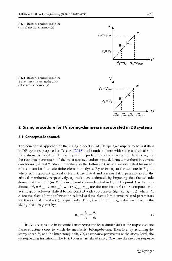
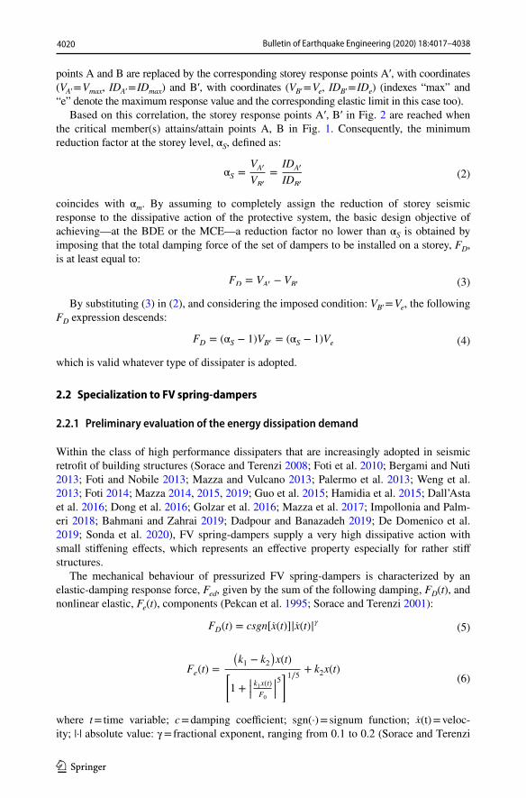
The conceptual approach of the sizing procedure of FV spring-dampers to be installed in DB systems proposed in Terenzi (2018), reformulated here with some analytical sim-plifications, is based on the assumption of prefixed minimum reduction factors, αm, of the response parameters of the most stressed and/or most deformed members in current conditions (named “critical” members in the following), which are evaluated by means of a conventional elastic finite element analysis. By referring to the scheme in Fig. 1, where d, s represent general deformation-related and stress-related parameters for the critical member(s), respectively, αm ratios are estimated by imposing that the seismic demand at the BDE (or MCE) in current state—denoted in Fig. 1 by point A with coor-dinates (dA = dmax, sA = smax), where dmax, smax are the maximum d and s computed val-ues, respectively—is shifted below point B with coordinates (dB = de, sB = se), where de, se are the elastic limit deformation-related and the elastic limit stress-related parameters for the critical member(s), respectively. Thus, the minimum αm value assumed in the sizing phase is given by:
The A → B transition in the critical member(s) implies a similar shift in the response of the frame structure storey to which the member(s) belongs/belong. Therefore, by assuming the storey shear, V, and the inter-storey drift, ID, as response parameters at the storey level, the corresponding transition in the V–ID plan is visualized in Fig. 2, where the member response
(1)αm =sA
sB=
dA
dB
Fig. 1 Response reduction for the critical structural member(s)
A
B
dB=de dA=dmaxd
s
sB=se
sA=smax
Fig. 2 Response reduction for the frame storey including the criti-cal structural member(s) A’
B’
IDB’=IDe IDA’=IDmaxID
V
VB’=Ve
VA’=Vmax
4020 Bulletin of Earthquake Engineering (2020) 18:4017–4038
1 3
points A and B are replaced by the corresponding storey response points A′, with coordinates (VA′ = Vmax, IDA′ = IDmax) and B′, with coordinates (VB′ = Ve, IDB′ = IDe) (indexes “max” and “e” denote the maximum response value and the corresponding elastic limit in this case too).
Based on this correlation, the storey response points A′, B′ in Fig. 2 are reached when the critical member(s) attains/attain points A, B in Fig. 1. Consequently, the minimum reduction factor at the storey level, αS, defined as:
coincides with αm. By assuming to completely assign the reduction of storey seismic response to the dissipative action of the protective system, the basic design objective of achieving—at the BDE or the MCE—a reduction factor no lower than αS is obtained by imposing that the total damping force of the set of dampers to be installed on a storey, FD, is at least equal to:
By substituting (3) in (2), and considering the imposed condition: VB′ = Ve, the following FD expression descends:
which is valid whatever type of dissipater is adopted.
2.2 Specialization to FV spring‑dampers
2.2.1 Preliminary evaluation of the energy dissipation demand
Within the class of high performance dissipaters that are increasingly adopted in seismic retrofit of building structures (Sorace and Terenzi 2008; Foti et al. 2010; Bergami and Nuti 2013; Foti and Nobile 2013; Mazza and Vulcano 2013; Palermo et al. 2013; Weng et al. 2013; Foti 2014; Mazza 2014, 2015, 2019; Guo et al. 2015; Hamidia et al. 2015; Dall’Asta et al. 2016; Dong et al. 2016; Golzar et al. 2016; Mazza et al. 2017; Impollonia and Palm-eri 2018; Bahmani and Zahrai 2019; Dadpour and Banazadeh 2019; De Domenico et al. 2019; Sonda et al. 2020), FV spring-dampers supply a very high dissipative action with small stiffening effects, which represents an effective property especially for rather stiff structures.
The mechanical behaviour of pressurized FV spring-dampers is characterized by an elastic-damping response force, Fed, given by the sum of the following damping, FD(t), and nonlinear elastic, Fe(t), components (Pekcan et al. 1995; Sorace and Terenzi 2001):
where t = time variable; c = damping coefficient; sgn(·) = signum function; x(t) = veloc-ity; |·| absolute value: γ = fractional exponent, ranging from 0.1 to 0.2 (Sorace and Terenzi
(2)αS =VA�
VB�
=IDA�
IDB�
(3)FD = VA� − VB�
(4)FD = (αS − 1)VB� = (αS − 1)Ve
(5)FD(t) = csgn[x(t)]|x(t)|𝛾
(6)Fe(t) =
(k1 − k2
)x(t)
[1 +
|||k1x(t)
F0
|||5]1∕5 + k2x(t)
4021Bulletin of Earthquake Engineering (2020) 18:4017–4038
1 3
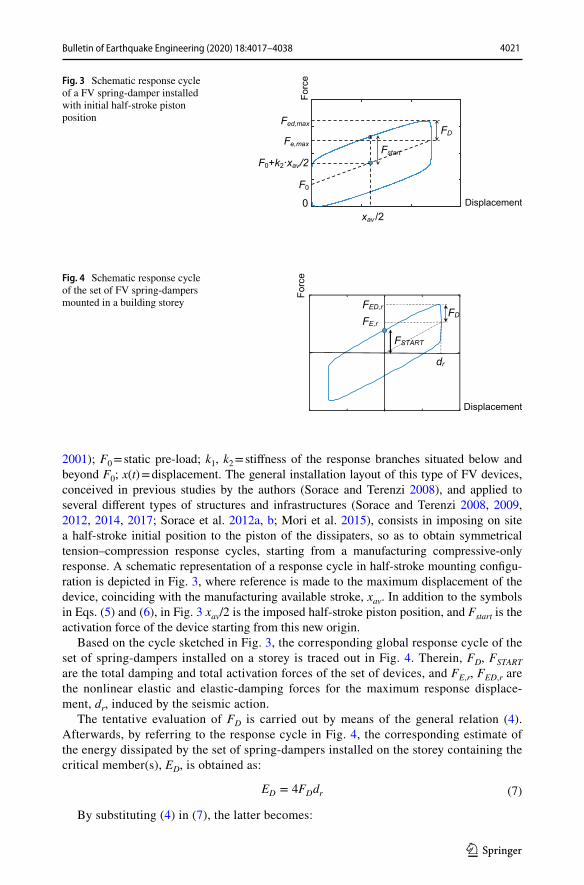
2001); F0 = static pre-load; k1, k2 = stiffness of the response branches situated below and beyond F0; x(t) = displacement. The general installation layout of this type of FV devices, conceived in previous studies by the authors (Sorace and Terenzi 2008), and applied to several different types of structures and infrastructures (Sorace and Terenzi 2008, 2009, 2012, 2014, 2017; Sorace et al. 2012a, b; Mori et al. 2015), consists in imposing on site a half-stroke initial position to the piston of the dissipaters, so as to obtain symmetrical tension–compression response cycles, starting from a manufacturing compressive-only response. A schematic representation of a response cycle in half-stroke mounting configu-ration is depicted in Fig. 3, where reference is made to the maximum displacement of the device, coinciding with the manufacturing available stroke, xav. In addition to the symbols in Eqs. (5) and (6), in Fig. 3 xav/2 is the imposed half-stroke piston position, and Fstart is the activation force of the device starting from this new origin.
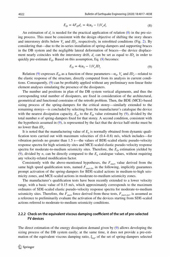
Based on the cycle sketched in Fig. 3, the corresponding global response cycle of the set of spring-dampers installed on a storey is traced out in Fig. 4. Therein, FD, FSTART are the total damping and total activation forces of the set of devices, and FE,r, FED,r are the nonlinear elastic and elastic-damping forces for the maximum response displace-ment, dr, induced by the seismic action.
The tentative evaluation of FD is carried out by means of the general relation (4). Afterwards, by referring to the response cycle in Fig. 4, the corresponding estimate of the energy dissipated by the set of spring-dampers installed on the storey containing the critical member(s), ED, is obtained as:
By substituting (4) in (7), the latter becomes:
(7)ED = 4FDdr
Fig. 3 Schematic response cycle of a FV spring-damper installed with initial half-stroke piston position
0
20
40
60Fed,max
Fe,max Fstart
Forc
e
F0+k2·xav/2
FD
Displacementxav /2
F0
0
Fig. 4 Schematic response cycle of the set of FV spring-dampers mounted in a building storey FED,r
FE,r
dr
FD
FSTART
Displacement
Forc
e
4022 Bulletin of Earthquake Engineering (2020) 18:4017–4038
1 3
An estimation of dr is needed for the practical application of relation (8) in the pre-siz-ing process. This must be consistent with the design objective of shifting the story shears and interstorey drifts below Ve and IDe, respectively, in retrofitted conditions (Fig. 2). By considering that—due to the in-series installation of spring-dampers and supporting braces in the DB system and the negligible lateral deformation of braces—the device displace-ment nearly coincides with the interstorey drift, dr can be set as equal to IDe in order to quickly pre-estimate ED. Based on this assumption, Eq. (8) becomes:
Relation (9) expresses ED as a function of three parameters—αS, Ve and IDe—related to the elastic response of the structure, directly computed from its analysis in current condi-tions. Consequently, (9) can be profitably applied without any preliminary non-linear finite element analyses simulating the presence of the dissipaters.
The number and positions in plan of the DB system vertical alignments, and thus the corresponding total number of dissipaters, are fixed in consideration of the architectural, geometrical and functional constrains of the retrofit problem. Then, the BDE (MCE)-based sizing process of the spring-dampers for the critical storey—similarly extended to the remaining storeys—is concluded by selecting from the manufacturer’s catalogue the device with the nearest dissipation capacity, En, to the ED value estimated by (9), divided by the total number n of spring-dampers fixed for that storey. A second condition, consistent with the hypothesis assumed in (9), is represented by the fact that the device half-stroke must be no lower than IDe.
It is noted that the manufacturing value of En is normally obtained from dynamic quali-fication tests carried out with maximum velocities of (0.4–0.8) m/s, which includes—for vibration periods no greater than 1.5 s—the values of BDE-scaled elastic pseudo-velocity response spectra for high seismicity sites and MCE-scaled elastic pseudo-velocity response spectra for moderate-to-medium seismicity sites. Therefore, the ED estimation yielded by (9), divided by n, can be directly compared to the En catalogue values, without requiring any velocity-related modification factor.
Consistently with the above-mentioned hypotheses, the Fstart value derived from the same high speed qualification tests, named Fstart,hv in the following, implicitly guarantees prompt activation of the spring-dampers for BDE-scaled actions in medium-to-high seis-micity zones, and MCE-scaled actions in moderate-to-medium seismicity zones.
The manufacturer’s qualification tests have been recently extended to a lower velocity range, with a basic value of 0.15 m/s, which approximately corresponds to the maximum ordinates of SDE-scaled elastic pseudo-velocity response spectra for moderate-to-medium seismicity sites. Therefore, the Fstart force derived from these tests, Fstart,mv, is assumed as a reference to preliminarily evaluate the activation of the devices starting from SDE-scaled actions referred to moderate-to-medium seismicity conditions.
2.2.2 Check on the equivalent viscous damping coefficient of the set of pre‑selected FV devices
The direct estimation of the energy dissipation demand given by (9) allows developing the sizing process of the DB system easily; at the same time, it does not provide a pre-esti-mation of the equivalent viscous damping ratio, ξeq, of the set of spring-dampers selected
(8)ED = 4FDdr = 4(αS − 1)Vedr
(9)ED = 4(αS − 1)VeIDe
4023Bulletin of Earthquake Engineering (2020) 18:4017–4038
1 3
to meet this demand. Consequently, for structures characterized by a high plastic demand in current conditions to be replaced by a correspondingly high ED value in the DB sys-tem design, overdamped retrofit solutions (i.e. with ξeq significantly greater than 0.3) could result from the sizing procedure, if a proper check on the supplemental damping supplied by the FV dissipaters is not carried out. This should be avoided because, as is known, over-damping can cause a significant mutation of the modal properties of the original structure, sometimes unfavourable in terms of seismic performance. Therefore, a preliminary evalua-tion of ξeq is useful at this stage.
The ξeq estimation is obtained starting from the general expression:
where by referring to the response cycle in Fig. 4, Ee is equal to
and FED,r to
Based on the same hypotheses formulated in the previous step of the procedure, FE,r can be set as equal to Ve, from which it follows:
By substituting (4) in (13), the latter becomes:
and thus (11) turns into:
By introducing (4) and (15) in (10), the following expression of ξeq is finally obtained:
which provides the searched estimation of ξeq. This relation allows to directly compute the equivalent viscous damping ratio demanded to obtain the targeted elastic response, as a function of the αs response reduction factor only.
2.3 Estimation of the activation force of FV spring‑dampers
As observed in the Introduction, the new step of the design procedure consists in prelimi-narily evaluating the activation force of the devices at the SDE. This allows preventing possible non-structural—and even structural—damages caused by a delayed contribution of the protective system to the building response, for a seismic action with similar intensity
(10)ξeq =ED
4�Ee
(11)Ee = FED,r
dr
2
(12)FED,r = FE,r + FD
(13)FED,r = Ve + FD
(14)FED,r =FD
�S − 1+ FD =
�S
�S − 1FD
(15)Ee =�S
�S − 1FD
dr
2
(16)ξeq =2
�⋅
�S − 1
�S
4024 Bulletin of Earthquake Engineering (2020) 18:4017–4038
1 3
to the SDE-scaled one. Indeed, as noted in Sect. 2.2.1, the basic Fstart,hv catalogue value identified by the highest velocity qualification tests of the dampers is a reference for the analyses at the BDE (or MCE). At the same time, the activation force at the SDE, named Fstart,SDE, can be checked against the Fstart,mv value derived from the moderate velocity qualification tests, introduced by the manufacturer to complete the dynamic characteriza-tion of the dampers over a larger input velocity range.
As the ratio of Fstart at a given normative earthquake level, La, to Fstart at another level, Lb, is equal to the corresponding ratio in terms of FD, based on Eq. (5) it is also equal to the ratio in terms of |x|𝛾 , and thus of relevant maximum values, ||xmax||
𝛾 . Named rF,a-b the Fstart ratio for levels La and Lb:
from the observations above it follows that:
The rF,a-b expression (18) yields the searched conversion factor on Fstart when passing from Lb to La, provided that a quantitative relation between xa,max and xb,max is tentatively fixed. To this aim, the hypothesis of maximum device displacements nearly coincident with the maximum inter-storey drifts can be extended to the maximum device and inter-storey velocities too. Consequently, for first-mode dominated frame structures, xa,max
xb,max can be
approximated by the ratio: SV ,a(T1)SV ,b(T1)
, where SV ,a(T1) , SV ,b
(T1) are the La-scaled and Lb-scaled
pseudo-velocity spectra for the site where the structure is situated, and T1 is its first vibra-tion period. Hence, relation (18) can be quantified as follows:
By assuming SDE = La and BDE = Lb, the corresponding ratio rF,SDE−BDE =[SV ,SDE(T1)SV ,BDE(T1)
]�
can be estimated by considering that the ratio of the SV ,SDE(T1) to the SV ,BDE(T1) pseudo-
velocity response spectra drawn from the pseudo-acceleration response spectra of the Ital-ian Standards (MIT 2018), in a wide T1 range of technical interest (i.e. from about 0.3 s to about 3 s), is included in the range (0.25, 0.5). At the same time, for SDE = La and MCE = Lb, and for the same T1 range, the ratio SV ,SDE(T1)
SV ,MCE(T1) is included in the range (0.2, 0.4).
The lower-end values of the two pseudo-velocity ratio ranges correspond to high seismicity zones, whereas the upper-end values to moderate-to-medium seismicity zones. By substi-tuting these values in (19), along with the mean value of the above-mentioned (0.1, 0.2) range of the γ exponent in Eq. (5), i.e. γ = 0.15, the following rF,SDE-BDE, rF,SDE-MCE ranges are obtained: (0.250.15, 0.50.15) = (0.81–0.9)—rF,SDE-BDE; (0.20.15–0.40.15) = (0.79–0.87)—rF,SDE-MCE. According to the observation above, for practical applications the lower-end values of these ranges, i.e. rF,SDE-BDE = 0.81 and rF,SDE-MCE = 0.79, can be tentatively assumed if the structure is located in a high seismicity zone; the upper-end values, i.e. rF,SDE-BDE = 0.87 and rF,SDE-MCE = 0.9, for a moderate seismicity zone; and the mean values of the two ranges, i.e. rF,SDE-BDE = 0.855, rF,SDE-MCE = 0.83, for a medium seismicity zone.
(17)rF,a−b =Fstart,a
Fstart,b
(18)rF,a−b =||xa,max||
𝛾
||xb,max||𝛾 =
|||||
xa,max
xb,max
|||||
𝛾
(19)rF,a−b =|||||
SV ,a(T1)
SV ,b(T1)|||||
�
4025Bulletin of Earthquake Engineering (2020) 18:4017–4038
1 3
These values can be finally adopted as reduction factors on Fstart,BDE or Fstart,MCE to obtain the Fstart,SDE values: Fstart,SDE= rF,SDE-BDEFstart,BDE; Fstart,SDE = rF,SDE-MCE· Fstart,MCE.
In order to quickly estimate Fstart,BDE or Fstart,MCE in the sizing process, they can be put as equal to Fstart,mv for buildings situated in high seismicity zones—Fstart,BDE—and mod-erate-to-medium seismicity zones—Fstart,MCE. Different values of the reduction factors for different regional or national territories, calculated with the same criteria, can be similarly adopted by referring to relevant pseudo-velocity normative response spectra.
3 Case study building
The case study structure is a school with a (31 × 38.7) m2 sized rectangular plan built in Florence in the early 1980s. The average floor area is about 1070 m2 and the total volume is 10,950 m3. The storey heights are equal to 3.3 m (basement storey) and 3.75 m (remain-ing storeys). The first floor is accessed through two internal flights of stairs, one connected with the ground floor only, and the other one with all the storeys. In addition, three external staircases connect the basement with the main entrance floor. A structural joint separates the building from a more recent elevator compartment made of a 250 mm-thick R/C box section. The roof is flat.
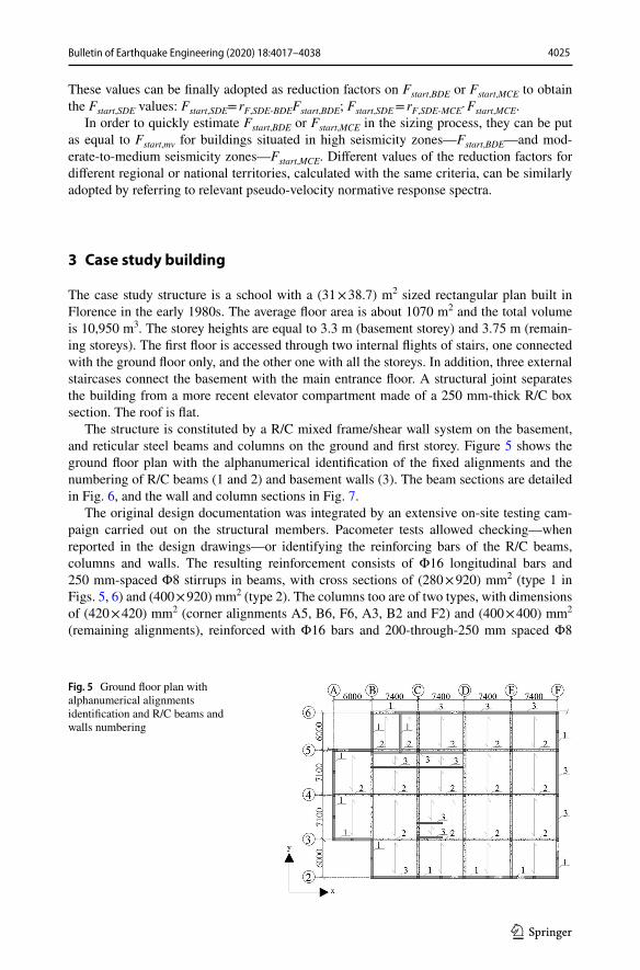
The structure is constituted by a R/C mixed frame/shear wall system on the basement, and reticular steel beams and columns on the ground and first storey. Figure 5 shows the ground floor plan with the alphanumerical identification of the fixed alignments and the numbering of R/C beams (1 and 2) and basement walls (3). The beam sections are detailed in Fig. 6, and the wall and column sections in Fig. 7.
The original design documentation was integrated by an extensive on-site testing cam-paign carried out on the structural members. Pacometer tests allowed checking—when reported in the design drawings—or identifying the reinforcing bars of the R/C beams, columns and walls. The resulting reinforcement consists of Φ16 longitudinal bars and 250 mm-spaced Φ8 stirrups in beams, with cross sections of (280 × 920) mm2 (type 1 in Figs. 5, 6) and (400 × 920) mm2 (type 2). The columns too are of two types, with dimensions of (420 × 420) mm2 (corner alignments A5, B6, F6, A3, B2 and F2) and (400 × 400) mm2 (remaining alignments), reinforced with Φ16 bars and 200-through-250 mm spaced Φ8
Fig. 5 Ground floor plan with alphanumerical alignments identification and R/C beams and walls numbering
4026 Bulletin of Earthquake Engineering (2020) 18:4017–4038
1 3
stirrups (Fig. 7). The floors are in reinforced concrete too, of “Predalles” type on the ground and first floor, and made of prefabricated joists and clay bricks, on the roof.
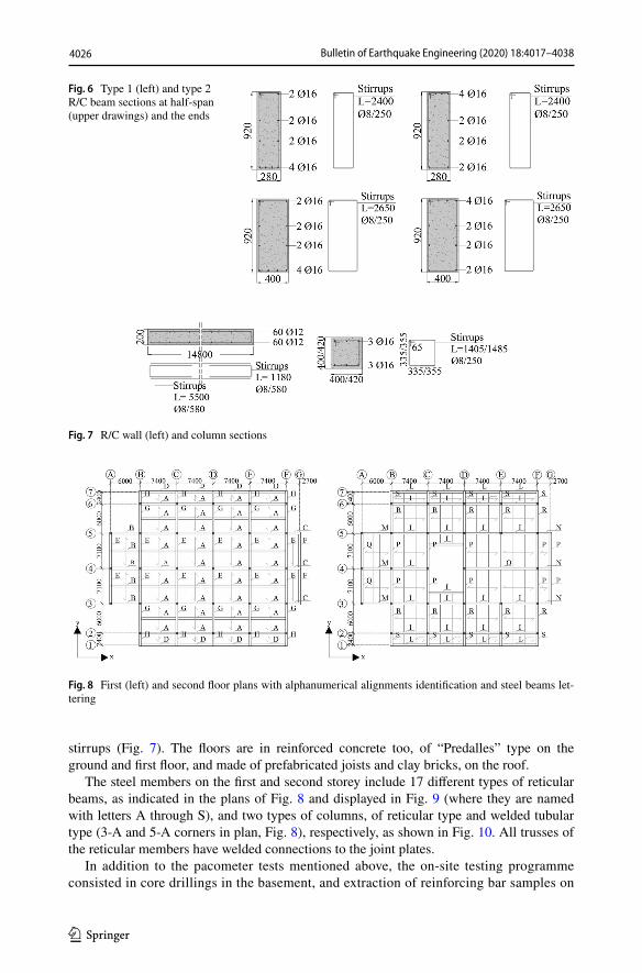
The steel members on the first and second storey include 17 different types of reticular beams, as indicated in the plans of Fig. 8 and displayed in Fig. 9 (where they are named with letters A through S), and two types of columns, of reticular type and welded tubular type (3-A and 5-A corners in plan, Fig. 8), respectively, as shown in Fig. 10. All trusses of the reticular members have welded connections to the joint plates.
In addition to the pacometer tests mentioned above, the on-site testing programme consisted in core drillings in the basement, and extraction of reinforcing bar samples on
Fig. 6 Type 1 (left) and type 2 R/C beam sections at half-span (upper drawings) and the ends
Fig. 7 R/C wall (left) and column sections
Fig. 8 First (left) and second floor plans with alphanumerical alignments identification and steel beams let-tering

4027Bulletin of Earthquake Engineering (2020) 18:4017–4038
1 3
the ground and first storey, for the R/C members; extraction of samples and magneto-scopic tests for the steel elements, and microdurometer and electric resistance tests for the steel joint welds.
The following mechanical properties resulted from the laboratory tests on the extracted samples: mean cubic compressive strength of concrete, fcm,c, equal to 24 MPa; yield stress, fy,r, and tensile strength, ft,r, of the reinforcing steel bars equal to 324 MPa
Fig. 9 Ground and first storey reticular steel beams
4028 Bulletin of Earthquake Engineering (2020) 18:4017–4038
1 3
and 462 MPa, respectively; yield stress, fy,s, equal to 260 MPa and 301 MPa, for steel beam and steel column profiles, respectively.
Consistently with the prescriptions of the Italian Technical Standards (MIT 2018) and relevant Instructions (MIT 2019), the tests allowed achieving the highest knowledge level of structural materials and members for the aims of the assessment analysis, named LC3. Consistently, value 1 was assumed for the “confidence factor”, FC, i.e. the additional knowledge level-related safety coefficient to be introduced in stress state and displacement-related checks.
4 Assessment analysis in current conditions
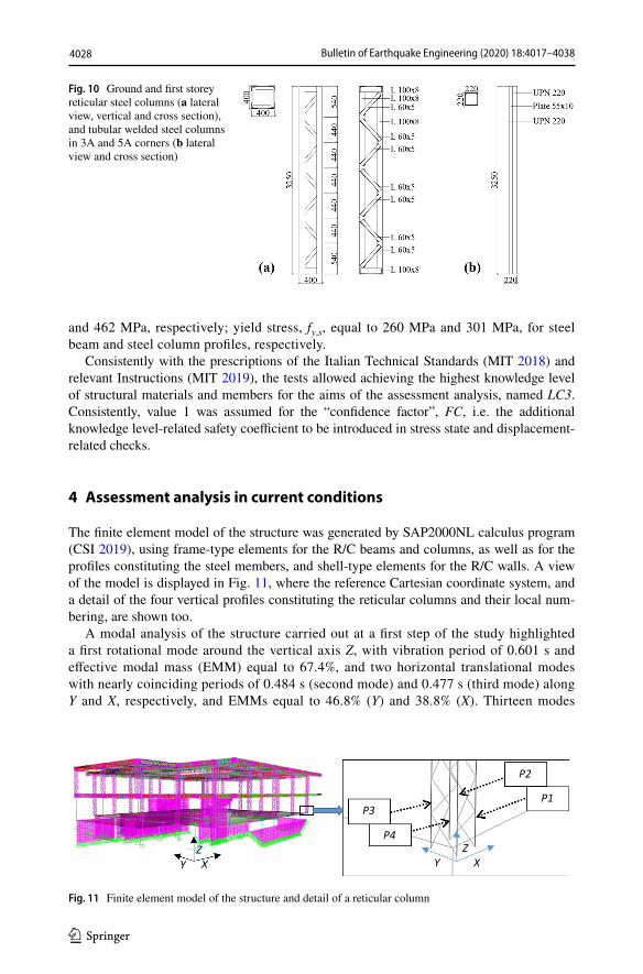
The finite element model of the structure was generated by SAP2000NL calculus program (CSI 2019), using frame-type elements for the R/C beams and columns, as well as for the profiles constituting the steel members, and shell-type elements for the R/C walls. A view of the model is displayed in Fig. 11, where the reference Cartesian coordinate system, and a detail of the four vertical profiles constituting the reticular columns and their local num-bering, are shown too.
A modal analysis of the structure carried out at a first step of the study highlighted a first rotational mode around the vertical axis Z, with vibration period of 0.601 s and effective modal mass (EMM) equal to 67.4%, and two horizontal translational modes with nearly coinciding periods of 0.484 s (second mode) and 0.477 s (third mode) along Y and X, respectively, and EMMs equal to 46.8% (Y) and 38.8% (X). Thirteen modes
Fig. 10 Ground and first storey reticular steel columns (a lateral view, vertical and cross section), and tubular welded steel columns in 3A and 5A corners (b lateral view and cross section)
P1
P2
P3
P4
YZXY X
Z
Fig. 11 Finite element model of the structure and detail of a reticular column
4029Bulletin of Earthquake Engineering (2020) 18:4017–4038
1 3
are needed to activate summed modal masses greater than 85% along both directions in plan, and around Z.
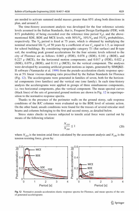
The time-history assessment analysis was developed for the four reference seismic levels assumed in the Italian Standards, that is, Frequent Design Earthquake (FDE, with 81% probability of being exceeded over the reference time period VR), and the above-mentioned SDE, BDE and MCE levels, with 50%/VR, 10%/VR and 5%/VR probabilities, respectively. The VR period is fixed at 75 years, which is obtained by multiplying the nominal structural life VN of 50 years by a coefficient of use Cu equal to 1.5, as imposed for school buildings. By considering topographic category T1 (flat surface) and B-type soil, the resulting peak ground accelerations for the four seismic levels referred to the city of Florence are as follows: 0.065 g (FDE), 0.078 g (SDE), 0.181 g (BDE), and 0.227 g (MCE), for the horizontal motion components; and 0.017 g (FDE), 0.022 g (SDE), 0.079 g (BDE), and 0.111 g (MCE), for the vertical component. The analyses were developed by assuming artificial ground motions as inputs, generated by SIMQKE-II software (Vanmarcke et al. 1999) from the pseudo-acceleration elastic response spec-tra at 5% linear viscous damping ratio prescribed by the Italian Standards for Florence (Fig. 12). The accelerograms were generated in families of seven, both for the horizon-tal components (two families) and the vertical one (one family). In each time-history analysis the accelerograms were applied in groups of three simultaneous components, i.e. two horizontal components, plus the vertical component. The mean spectral curves (black lines) of the sets of generated ground motions are shown in Fig. 12 in superimpo-sition to the normative response spectra.
Thanks to the presence of the perimeter walls on the ground storey, safe response conditions of the R/C columns were evaluated up to the BDE level of seismic action. On the other hand, unsafe conditions were found for the trusses of several reticular steel beams and columns belonging to the first and second storey, as detailed below.
Stress states checks in trusses subjected to tensile axial force were carried out by means of the following relation:
where Nt,Ed is the tension axial force calculated by the assessment analysis and Nt,Rd is the tension resisting force, given by:
(20)Nt,Ed
Nt,Rd
≤ 1
Fig. 12 Normative pseudo-acceleration elastic response spectra for Florence, and mean spectra of the sets of generated accelerograms
4030 Bulletin of Earthquake Engineering (2020) 18:4017–4038
1 3
with A = area of the steel profile, and FC = 1, consistently with the attainment of the LC3 knowledge level for structural materials and members, as commented in Sect. 3.
The corresponding relation for trusses subjected to compressive axial force is:
where Nb,Ed is the calculated compression axial force and Nb,Rd is the compression resisting force, defined as:
with
Ncr = Eulerian critical axial load; and α = imperfection coefficient, equal to 0.34 for L-type profiles and 0.49 for compact sections composed of welded plates with “thick welds”.
The results of the analysis showed that on the ground storey Nt,Rd and Nb,Rd limits are exceeded up to 16% at the BDE and 24% at the MCE in the diagonal profiles of beams, and 22% at the BDE and 29% at the MCE in the diagonal profiles of columns. At the same time, Nb,Rd is exceeded up to 67% at the BDE and 91% at the MCE in the vertical profiles of col-umns. In the latter, Nb,Rd is exceeded by 23% even at the SDE. Based on these data, the maxi-mum unsafety factors in current conditions in the structural members belonging to the ground storey, ruG, corresponding to the exceedance values of Nb,Rd, are equal to ruG,BDE = 1.67, at the BDE, and ruG,MCE = 1.91, at the MCE. The corresponding values for the first storey are about 25% lower, giving rise to the following maximum unsafety factors for its members, ru1: ru1,BDE = 1.25, ru1,MCE = 1.43.
The response in terms of maximum inter-storey drift ratio (i.e. maximum inter-storey drift normalized to the storey height), IDr,max, highlights values of 0.39% for the ground storey and 0.2% for the first storey at the SDE, 0.9% (ground) and 0.46% (first) at the BDE, and 1.13% (ground) and 0.58% (first) at the MCE. These value are referred to Y; averagely 2% lower values are found in X, due to the similar lateral stiffness of the structure in the two directions.
(21)Nt,Rd =Afy,s
FC
(22)Nb,Ed
Nb,Rd
≤ 1
(23)Nb,Rd = �Afy,s
FC
(24)𝜒 =1
� +√�2 − ��2
≤ 1
(25)� = 0.5[1 + 𝛼
(�� − 0.2
)+ ��2
]
(26)�� =
√Afyk
Ncr

4031Bulletin of Earthquake Engineering (2020) 18:4017–4038
1 3
5 Retrofit hypothesis
5.1 Application of the sizing procedure of FV spring‑dampers
The retrofit design target is represented by the attainment of an elastic response of the structure up to the MCE. Based on this assumption and the results of the assessment analysis in current conditions, the minimum response reduction factors αS = αm to be assumed in the sizing process of the FV spring-dampers on the ground and first storey are: αSG = αmG = ruG,MCE = 1.91 (ground); αS1 = αm1 = ru1,MCE = 1.43 (first).
By referring to these factors, the estimation of the minimum energy dissipation capacity to be assigned to the DB system in X and Y directions is carried out by means of relation (9). The Ve and IDe values to be introduced in relevant calculation for the two storeys, as derived from the finite element analysis in current conditions, are as follows (indexes “G” and “1” denote ground and first storey again): VeG = 4435 kN, IDeG = 14.6 mm; Ve1 = 2086 kN, IDe1 = 17.2 mm. It can be observed that a value higher than 2 for the ratio of VeG to Ve1, as well as the IDeG value lower than IDe1, are due to the presence on the ground storey of the two R/C walls emerging from the basement, which are not continued on the first storey. By applying (9), the resulting ED values are: EDG = 236 kJ; ED1 = 62 kJ.
The check on ξeq, carried out by (16), yields the following values: ξeqG = 0.3; ξeq1 = 0.19, assessing feasible equivalent viscous damping levels for the retrofit intervention on both storeys.
Al. X1
Al. X2
Al. X3
Al. X4
Al. Y1
Al. Y2 Al. Y4
Al. Y3
X
Y
Al. X5 Al. X7Al. Y5 Al. Y7
Al. Y6 Al. Y8
X
Y Al. X6 Al. X8
Fig. 13 Positions of the DB system alignments in plan
FV damperFV damper
Fig. 14 Installation details of the dissipative bracing system

4032 Bulletin of Earthquake Engineering (2020) 18:4017–4038
1 3
The installation design hypothesis adopted for the DB system consists, both for the ground and first storey, in incorporating it in four perimeter alignments parallel to X, highlighted in red and named Al. X1 through Al. X8 in the building plans of Fig. 13, and four plus four alignments parallel to Y, highlighted in green in the same plans (Al. Y1 through Al. Y8).
As illustrated by the drawing in Fig. 14, consistently with the general layout of the dissipative bracing system conceived in previous studies of the authors (Sorace and Ter-enzi 2008), the FV devices are mounted in pairs at the tip of the supporting diagonal trusses. The latter have inverted V-shaped layout, and are connected to the lower ends of the reticular columns belonging to the bays where the dissipative braces are installed. These columns, as well as the overlying reticular beams, are strengthened by rectangular steel plates welded to the constituting corner profiles (columns) and horizontal profiles (beams) in the connection zones with the braces, so as to safely absorb the additional stress states induced by the seismic interaction with them. A view of the finite element model including the seismic protection system is shown in Fig. 15.
The installation of the protective system on the first storey too reduces the energy dis-sipation demand on the ground storey.Therefore, the minimum energy dissipation capac-ity required for the latter is recalculated in this case, where a complete incorporation of the dissipaters is assumed along the height of the structure, by subtracting ED1 from EDG. Thus, the following final sizing value is obtained: EDG,fin = EDG − ED1 = 174 kJ. By dividing the EDG,fin and ED1 values by the number of devices, equal to 8 on the ground storey and 8 on the first storey both in X and Y, the minimum energy dissipation capac-ity of each device, EDd, results as follows: EDdG = 21.8 kJ; EDd1 = 7.8 kJ, for each axis. The spring-damper type with the nearest nominal energy dissipation capacity, En, to EDdG (named A-type) has the following mechanical properties, as drawn from the manu-facturer’s catalogue (Jarret 2019): En = 24 kJ; stroke smax = ± 50 mm; damping coeffi-cient c = 38 Kn (s/mm)γ; γ = 0.15; F0 = 60 kN; and k2 = 1.55 kN/mm. At the same time, the spring-damper with the nearest En capacity to EDd1 (named B-type), has the follow-ing characteristics: En = 7.8 kJ; stroke smax = ± 30 mm; damping coefficient c = 9.9 kN(s/mm)γ; γ = 0.15; F0 = 18 kN; and k2 = 1.74 kN/mm.
By preliminarily selecting these two types of devices, the first check on their prop-erties concerns relevant strokes, which are considerably greater than the correspond-ing IDe values (smax = ± 50 mm vs. IDeG = 14.6 mm—A-type; smax = ± 30 mm vs. IDe1 = 17.2 mm—B-type).
Fig. 15 Finite element model of the structure incorporating the dissipative bracing system
4033Bulletin of Earthquake Engineering (2020) 18:4017–4038
1 3
The pre-estimation of the activation force of the devices, carried out by the criterion presented in Sect. 2.3, is referred to the high speed qualification test adopted by the manu-facturer for A-type and B-type spring-dampers, carried out at a velocity of 0.5 m/s for both devices. Consistently with the observations in Sect. 2.3, as the building is located in a mod-erate-to-medium seismicity zone, Fstart,MCE can approximately be put as equal to Fstart,hv, and rF,SDE-MCE to 0.83. Based on the manufacturer’s Fstart,hv values of 65 kN and 22 kN for A-type and B-type devices, respectively, the following Fstart,SDE= rF,SDE-MCE · Fstart,MCE estimates are obtained: Fstart,SDE=0.83 · 65 =54 kN (A-type), Fstart,SDE = 0.83 · 22 =18 kN (B-type).
The additional moderate-speed tests performed at 0.15 m/s show Fstart,mv values of 55 kN (A-type) and 19 kN (B-type), nearly coinciding with the tentatively evaluated Fstart,SDE values. Hence, both types of devices should be activated starting from the SDE level of seismic action, as requested in this retrofit design, and they are consequently con-firmed as final choice of the sizing process.
5.2 Verification analyses
A new modal analysis, carried out with the finite element model including the DB system, shows little differences in the three first vibration periods and associated EMMs as com-pared to current conditions. Indeed, period and EMM pass to 0.567 s and 71.2% for the first rotational mode around Z, with differences of 5.7% and 5.6%, respectively; to 0.469 s
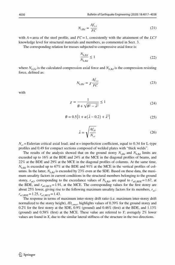
Fig. 16 Axial force time-history of the most stressed ground storey column in retrofitted con-ditions obtained from the most demanding MCE-scaled group of input accelerograms
Fig. 17 Maximum inter-storey drift profiles in current and retrofitted conditions at the MCE along X and Y

4034 Bulletin of Earthquake Engineering (2020) 18:4017–4038
1 3
Fig. 18 Response cycles of the pairs of spring-dampers installed in Al. X3, Al. X7, Al Y3 and Al. Y7 align-ments in plan obtained from the most demanding SDE, BDE and MCE-scaled groups of input accelero-grams
Fig. 19 Energy time-histories obtained from the most demand-ing MCE-scaled group of input accelerograms

4035Bulletin of Earthquake Engineering (2020) 18:4017–4038
1 3
and 44.8% for the first translational mode along Y (differences of 3.1% and 4.3%); and to 0.463 s and 39.9% for the first translational mode along X (differences of 2.9% and 2.8%). As observed in Sect. 2.2.1, this is due to the in-series connection of the spring-dampers to the supporting steel braces and the low stiffness of the former, which causes a little increase of the lateral stiffness of the structure.
The results of the time-history verification analyses are synthesized in Figs. 16, 17, 18 and 19, all referred to the response induced by the most demanding of the seven groups of input ground motions for each earthquake level. The axial force history in retrofitted con-ditions of the most stressed ground storey column at the MCE, plotted in Fig. 16, shows a peak value reduced by a factor equal to 2.08, as compared to the maximum axial force in current conditions. This reduction factor, slightly greater than the minimum αSG value of 1.91 assumed in the sizing process of the FV spring-dampers, assesses the attainment of the targeted elastic structural response up to the MCE, with no excessive redundancy margins. This is visually highlighted in the graph of Fig. 16 by the position of the dotted segment representing the Nb,Rd value for the considered column.
The maximum inter-storey drift ratio profiles displayed in Fig. 17 for both directions in plan highlight peak values reduced to 0.58% on the ground storey and 0.36% on the first storey for Y axis, i.e. slightly greater than the 0.5% Immediate Occupancy perfor-mance level-related limit (ground) and the 0.33% Operational performance level-related limit (first) established by Italian Standards in the presence of infills interacting with the structural skeleton. The peak values in X, equal to 0.49% (ground storey) and 0.31% (first storey) are below the 0.5% and 0.33% limits above, respectively.
The total reaction force–displacement [(FD(t) + Fe(t)] − x(t) response cycles of the pairs of FV devices situated in the Al. X3 (ground storey) and Al. X7 (first storey) alignments along X, and Al. Y3 (ground storey) and Al. Y7 (first storey) alignments along Y, are plot-ted in Fig. 18. The activation forces deduced from the cycles at the SDE are equal to 52 kN for A-type and 17 kN for B-type spring-dampers, respectively, i.e. very similar to the Fstart,SDE values computed in Sect. 5.1. This highlights a satisfactory prediction capacity of the criterion proposed for the tentative estimation of this parameter, which is also a conse-quence of the good correlation between the activation forces surveyed at the MCE—equal to 63 kN (A-type) and 20 kN (B-type)—and the Fstart,hv values of the devices experimen-tally identified by the manufacturer. This is confirmed by the response velocities starting from which the spring-dampers result to be activated in the MCE-scaled time-history anal-yses, equal to about 0.41 m/s, i.e. near to the high speed qualification test velocity value of 0.5 m/s.
The activation of the spring-dampers at the SDE allows reaching an elastic structural response at this level too, as witnessed by a reduction of the axial force in the most stressed ground storey column below Nb,Rd (exceeded by 23% in current conditions, as noted in Sect. 4). Early activation is also observed for the FV devices installed on the first storey, which produces the above-mentioned peak drift ratio of 0.36%, close to the OP-related nor-mative limitation.
The total energy (i.e. computed for the entire structure) time-histories plotted in Fig. 19 assess that the ED energy dissipated by the FV devices at the MCE is equal to about 82% of the input energy Ei, with the remaining 18% given by the modal damping energy Em. This value is consistent with the results of previous studies by the authors dedicated to the application of the DB system to the seismic retrofit of several types of building structures, where ED always proved to range from about 75% to about 90% of Ei. The contributions to the ED/Ei percent ratio of 82% of the sets of devices installed on the two storeys are as fol-lows: 63.2% (ground) and 18.8% (first).
4036 Bulletin of Earthquake Engineering (2020) 18:4017–4038
1 3
6 Conclusions
A recently proposed energy-based sizing procedure for FV spring-dampers incorporated in dissipative bracing systems was reassessed in this study, and extended by including a pre-evaluation of the activation force of the devices with respect to the SDE-related seismic demand. This pre-evaluation is aimed at preventing a delayed contribution of the protective system to the building response, which can cause significant non-struc-tural and structural damages, starting from earthquake levels with similar intensity to the SDE–scaled one.
This new step of the sizing process was prompted by the addition of moderate veloc-ity qualification tests of FV spring-dampers to the standard high velocity tests usually carried out, aimed at completing their dynamic characterization and qualification by the manufacturer. Indeed, by comparing the estimated Fstart,SDE values to the Fstart,mv forces obtained from the moderate speed tests, the device types selected in terms of energy dis-sipation capacity can be preliminarily checked also in terms of possible activation at the normative serviceability earthquake level.
The school building examined as representative case study of structures designed with earlier Technical Standards highlights that, also when the seismic performance assessed in current conditions is not very poor, the response of the most stressed mem-bers can be greater than relevant elastic limits even at the SDE. This was observed for the first storey reticular steel columns, where the compression resisting axial force is exceeded by 23% for the SDE-scaled input action. On the other hand, the inter-storey drifts—which often represent the most unfavourable response parameter at the SDE—are below 0.4% in this case, as a consequence of the rather high lateral stiffness of the structural system.
The activation of the spring-dampers at the SDE is confirmed by the results of the time-history verification analyses, which show activation forces deduced from the response cycles of the spring-dampers very similar to the Fstart,SDE values computed by means of the proposed rF,SDE-MCE conversion factor expression.
The application of the sizing procedure leads to the attainment of the targeted elas-tic structural response up to the MCE, with a well-proportioned redundancy margin, as assessed by a reduction factor equal to 2.08 on the maximum axial force in current conditions, as compared to a corresponding maximum unsafety factor of 1.91. At the same time, feasible values of the equivalent viscous damping ratio are estimated for the supplemental action of the DB system, equal to 0.3 for the ground storey and 0.19 for the first storey. The ED energy dissipated by the spring-dampers at the MCE is equal to about 82% of the Ei input energy, consistently with the results of previous applications of the DB system to the seismic retrofit of several different types of structures and infra-structures, where ED proved to range from about 75% to about 90% of Ei.
The installation of the protective system on both storeys helps reach a high perfor-mance improvement also in terms of drifts at the MCE, with peak values slightly greater than the 0.5% Immediate Occupancy performance level-related limit (ground storey) and the 0.33% Operational level-related limit (first storey) established by Italian Stand-ards in the presence of infills interacting with the structural skeleton.
Acknowledgements The study reported in this paper was financed by the Italian Department of Civil Pro-tection within the ReLUIS-DPC Project 2019–2021—Work Package 15: Normative Contributions for Seis-mic Isolation and Dissipation—Protocol No. 60–05/02/2019—Grant No. 1100004434, 10.13039/50.
4037Bulletin of Earthquake Engineering (2020) 18:4017–4038
1 3
References
Bahmani M, Zahrai SM (2019) Application of a comprehensive seismic retrofit procedure for steel buildings using nonlinear viscous dampers. Int J Civ Eng 17:1261–1279
Bergami AV, Nuti C (2013) A design procedure of dissipative braces for seismic upgrading structures. Earthq Struct 4:85–108
CSI (2019) SAP2000NL. Theoretical and users’ manual. Release 20.03. Computers & Structures Inc., Berkeley
Dadpour O, Banazadeh M (2019) Probabilistic seismic response models for risk assessment and design of steel moment frames with linear viscous dampers. Earthq Spectra 55:267–288
Dall’Asta A, Tubaldi E, Ragni L (2016) Influence of the nonlinear behavior of viscous dampers on the seis-mic demand hazard of building frames. Earthq Eng Struct Dyn 45:149–169
De Domenico D, Ricciardi G, Takewaki I (2019) Design strategies of viscous dampers for seismic protec-tion of building structures: a review. Soil Dyn Earthq Eng 118:144–165
Di Ludovico M, Digrisolo A, Moroni C, Graziotti F, Manfredi V, Prota A, Dolce M, Manfredi G (2018) Remarks on damage and response of school buildings after the Central Italy earthquake sequence. Bull Earthq Eng 17:5679–5700
Dong B, Ricles JM, Sause R (2016) Seismic performance of steel MRF building with nonlinear viscous dampers. Front Struct Ci Eng 10:254–271
Foti D (2014) Response of frames seismically protected with passive systems in near-field areas. Int J Struct Eng 5:326–345
Foti D, Nobile R (2013) Optimal design of a new hysteretic dissipater. In: Lagaros ND, Plevris V, Mitro-poulos CC (eds) Design optimization of active and passive structural control systems, chapter 12. IGC Global USA Ed., Hershey, pp 274–299. ISBN 978-1-4666-2030-8 (ebook), ISBN 978-1-4666-2031-5
Foti D, Diaferio M, Nobile R (2010) Optimal design of a new seismic passive protection device made in aluminium and steel. Struct Eng Mech 35(1):119–122
Golzar FG, Rodgers GW, Chase JG (2016) Design and experimental validation of a re-centring viscous dis-sipater. Structures 13:193–200
Guo T, Xu J, Xu W, Di Z (2015) Seismic upgrade of existing buildings with fluid viscous dampers: design methodologies and case study. ASCE J Perform Constr Facil 29:04014175
Hamidia M, Filiatrault A, Aref AJ (2015) A Seismic collapse capacity-based evaluation and design of frame buildings with viscous dampers using pushover analysis. ASCE J Struct Eng 141:04014153
Iacovino C, Ditommaso R, Ponzo FC, Limongelli MP (2019) Preliminary analysis of the dynamic behav-ior of two strategic buildings subjected to the 2016 Central Italy earthquake. In: Zingoni A (ed) Advances in engineering materials, structures and systems: innovation, mechanics and application. Taylor&Francis Group, London, pp 2011–2016. ISBN 978-1-138-38696-9
Impollonia N, Palmeri A (2018) Seismic performance of buildings retrofitted with nonlinear viscous damp-ers and adjacent reaction towers. Earthq Eng Struct Dyn 47:1329–1351
Jarret SL (2019) Shock-control technologies. http://www.intro ini.info. Accessed 2 Jan 2020.Mazza F (2014) Displacement-based seismic design of hysteretic damped braces for retrofitting in-plan
irregular r.c. framed structures. Soil Dyn Earthq Eng 66:231–240Mazza F (2015) Comparative study of the seismic response of RC framed buildings retrofitted using modern
techniques. Earthq Struct 9:29–48Mazza F (2019) A simplified retrofitting method based on seismic damage of a SDOF system equivalent to a
damped braced building. Eng Struct 200:109712Mazza F, Vulcano A (2013) Nonlinear seismic analysis to evaluate the effectiveness of damped braces
designed for retrofitting r.c. framed structures. Int J Mech 7(3):251–261Mazza F, Fiore M, Mazza M (2017) Dynamic response of steel framed structures fire-retrofitted with vis-
coelastic-damped braces. Int J Civ Eng 15:1187–1201MIT—Ministry of Infrastructure and Transport (2018) Update of Technical Standards for constructions;
Ministerial Decree, 17 January 2018. Ordinary supplement to G.U. no. 42-2018, Rome, Italy (in Italian)
MIT—Ministry of Infrastructure and Transport (2019) Instructions for the application of the update of Technical Standards for constructions; Circular no. 7, 21 January 2019. Ordinary supplement to G.U. no. 35-2019, Rome, Italy (in Italian)
Mori C, Sorace S, Terenzi G (2015) Seismic assessment and retrofit of two heritage R/C elevated water stor-age tanks. Soil Dyn Earthq Eng 77:123–136
Palermo M, Muscio M, Silvestri S, Landi L, Trombetti T (2013) On the dimensioning of viscous dampers for the mitigation of the earthquake-induced effects in moment-resisting frame structures. Bull Earthq Eng 11:2429–2446
4038 Bulletin of Earthquake Engineering (2020) 18:4017–4038
1 3
Pekcan G, Mander JB, Chen SS (1995) The seismic response of a 1:3 scale model R.C. structure with elas-tomeric spring dampers. Earthq Spectra 11:249–267
Sonda D, Pollini A, Cossu M (2020) Seismic retrofit of an industrial building using damping devices. Struct Eng Int 30(1):56–93
Sorace S, Terenzi G (2001) Non-linear dynamic modelling and design procedure of FV spring-dampers for base isolation. Eng Struct 23(12):1556–1567
Sorace S, Terenzi G (2008) Seismic protection of frame structures by fluid viscous damped braces. ASCE J Struct Eng 134(1):45–55
Sorace S, Terenzi G (2009) Fluid viscous damped-based seismic retrofit strategies of steel structures: gen-eral concepts and design applications. Adv Steel Constr 5(3):322–339
Sorace S, Terenzi G (2012) Dissipative bracing-based seismic retrofit of R/C school buildings. Open Constr Build Technol J 6:334–345
Sorace S, Terenzi G (2014) Motion control-based seismic retrofit solutions for a R/C school building designed with earlier Technical Standards. Bull Earthq Eng 12(6):2723–2744
Sorace S, Terenzi G (2017) Existing prefab R/C industrial buildings: seismic assessment and supplemental damping-based retrofit. Soil Dyn Earthq Eng 94:193–203
Sorace S, Terenzi G, Bertino G (2012a) Viscous dissipative, ductility-based and elastic bracing design solu-tions for an indoor sports steel building. Adv Steel Constr 8(3):295–316
Sorace S, Terenzi G, Fadi F (2012b) Shaking table and numerical seismic performance evaluation of a fluid viscous-dissipative bracing system. Earthq Spectra 28(4):1619–1642
Terenzi G (2018) Energy-based design criterion of dissipative bracing systems for seismic retrofit of framed structures. Applied Sciences 8:268
Vanmarcke EH, Fenton GA, Heredia-Zavoni E (1999) SIMQKE-II—conditioned earthquake ground motion simulator: user’s manual, version 2.1. Princeton University, Princeton
Weng DG, Zhang C, Lu XL, Zeng S, Zhang SM (2013) A simplified design procedure for seismic retrofit of earthquake-damaged RC frames with viscous dampers. Struct Eng Mech 44:611–631
Publisher’s Note Springer Nature remains neutral with regard to jurisdictional claims in published maps and institutional affiliations.