ACO Grease and light liquid separators for below ground ...
17
Separators ACO Grease and light liquid separators for below ground installation The new rotomoulded tank system
-
Upload
khangminh22 -
Category
Documents
-
view
1 -
download
0
Transcript of ACO Grease and light liquid separators for below ground ...
S e p a r a t o r s
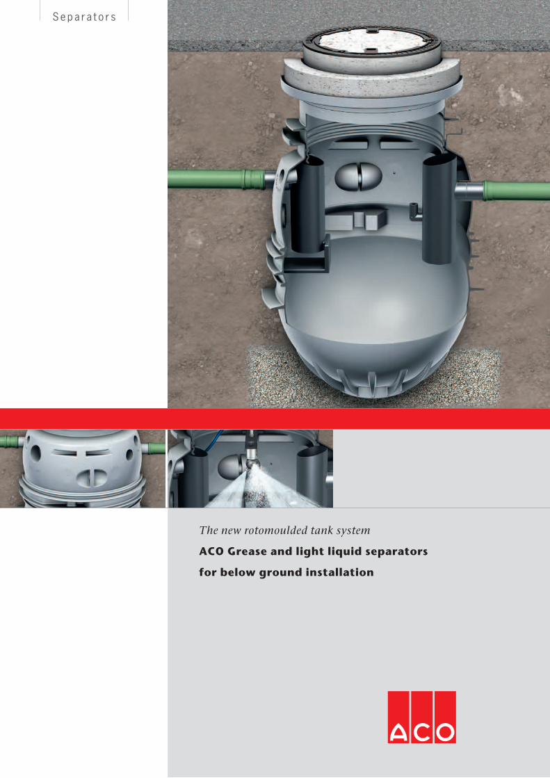
ACO Grease and light liquid separators
for below ground installation
The new rotomoulded tank system
2
Separators
Quality standards and tests
All ACO Grease separators are manufac-
tured in accordance with EN 1825, all
ACO Light liquid separators are manufac-
tured in accordance with EN 858. All the
separators in the range are hydraulically
tested and have General Building Supervi-
sory Authority Authorisation and/or the
new application authorisation from DIBT
Berlin.
Commercial operations generating
wastewater must implement appropriate
measures, by using suitable pre-treat-
ment installations like separators, to
ensure that solids and liquids which can
give off toxic and unpleasant vapours and
odours are prevented from damaging
construction materials and drainage facil-
ities, harming operations, and are held
back so that they do not enter sewage
pipes.
ACO Grease and light liquid separators
for below ground installation
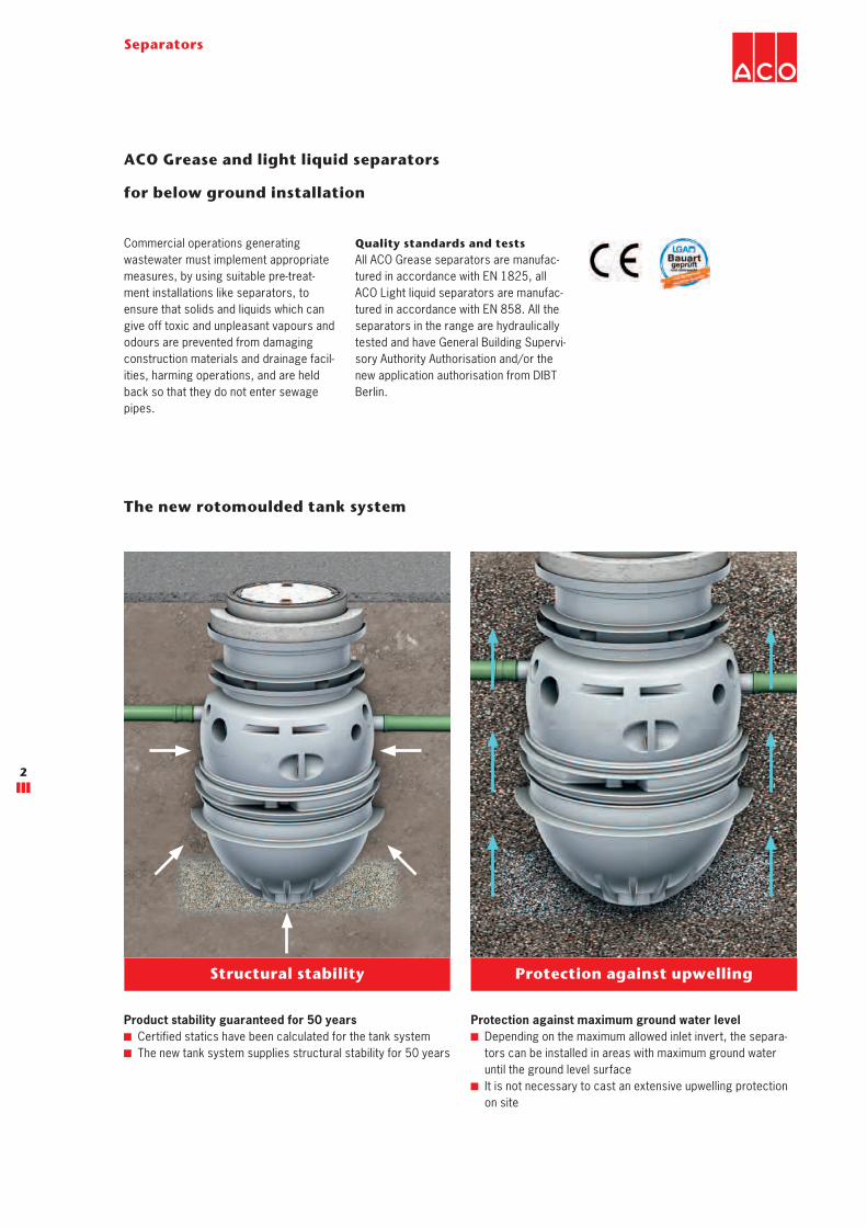
The new rotomoulded tank system
Structural stability
Product stability guaranteed for 50 years
Certified statics have been calculated for the tank system
The new tank system supplies structural stability for 50 years
Protection against upwelling
Protection against maximum ground water level
Depending on the maximum allowed inlet invert, the separa-
tors can be installed in areas with maximum ground water
until the ground level surface
It is not necessary to cast an extensive upwelling protection
on site

3
Separators
Contents
Available for load class A, B or D
Flexible application
Load class A: walkable – courtyards, open space
Load class B: drivable for cars – driveways, parking areas
Load class D: drivable for lorries – petrol stations, service
entrances
Grease separators
Lipumax P-B disposal and cleaning via cover 8
Lipumax P-Ddisposal via direct suction connection, cleaning via cover
10
Lipumax P-DMdisposal via direct suction connection, cleaning via high-pressure cleaning
12
Lipumax P-DA disposal via direct suction connection, automated cleaning via high-pressure, cleaning with remote control
14
Accessories 16
Light liquid separators
Oleopator P Light liquid separator Class I 18
Oleopass PLight liquid separator Class I with bypass
20
Sludge trap
Pitumax PSeparation of sediments according to dimensioning of light liquid separators
22
Accessories 24
4
Separators
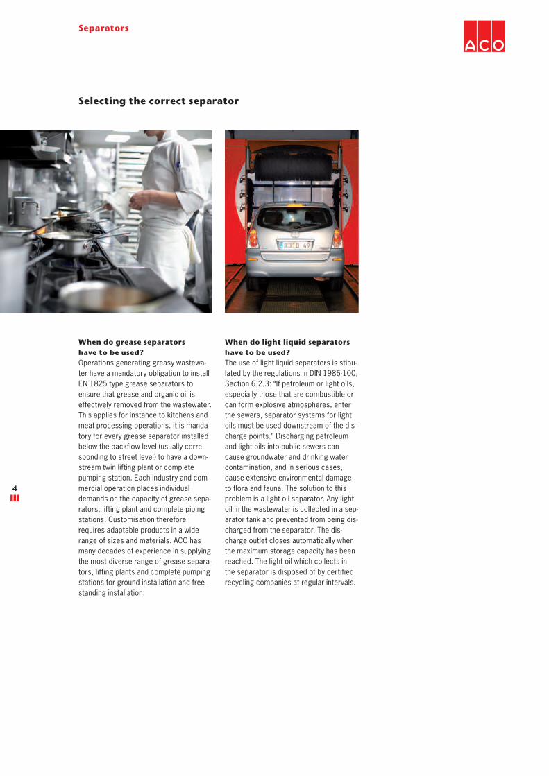
When do grease separators
have to be used?
Operations generating greasy wastewa-
ter have a mandatory obligation to install
EN 1825 type grease separators to
ensure that grease and organic oil is
effectively removed from the wastewater.
This applies for instance to kitchens and
meat-processing operations. It is manda-
tory for every grease separator installed
below the backflow level (usually corre-
sponding to street level) to have a down-
stream twin lifting plant or complete
pumping station. Each industry and com-
mercial operation places individual
demands on the capacity of grease sepa-
rators, lifting plant and complete piping
stations. Customisation therefore
requires adaptable products in a wide
range of sizes and materials. ACO has
many decades of experience in supplying
the most diverse range of grease separa-
tors, lifting plants and complete pumping
stations for ground installation and free-
standing installation.
Selecting the correct separator
When do light liquid separators
have to be used?
The use of light liquid separators is stipu-
lated by the regulations in DIN 1986-100,
Section 6.2.3: “If petroleum or light oils,
especially those that are combustible or
can form explosive atmospheres, enter
the sewers, separator systems for light
oils must be used downstream of the dis-
charge points.” Discharging petroleum
and light oils into public sewers can
cause groundwater and drinking water
contamination, and in serious cases,
cause extensive environmental damage
to flora and fauna. The solution to this
problem is a light oil separator. Any light
oil in the wastewater is collected in a sep-
arator tank and prevented from being dis-
charged from the separator. The dis-
charge outlet closes automatically when
the maximum storage capacity has been
reached. The light oil which collects in
the separator is disposed of by certified
recycling companies at regular intervals.
5
Separators
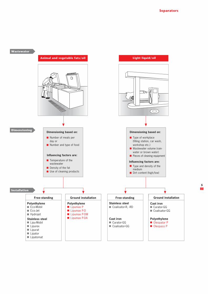
Free-standing
Polyethylene
Eco-Mobil
Eco-Jet
Hydrojet
Stainless steel
Lipu-Mobil
Lipurex
Lipurat
Lipator
Lipatomat
Ground installation
Polyethylene
Ground installation
Free-standing
Stainless steel
Coalisator-R, -RD
Cast iron
Curator-GG
Coalisator-GG
Animal and vegetable fats/oil
Installation
Light liquid/oil
Dimensioning based on:
Type of workplace
(filling station, car wash,
workshop etc.)
Wastewater volume (rain-
water or brown water)
Pieces of cleaning equipment
Influencing factors are:
Type and density of the medium
Dirt content (high/low)
Dimensioning based on:
Number of meals per
day or
Number and type of food
Temperature of the
Influencing factors are:
wastewater
Density of the fat
Use of cleaning products
Dimensioning
Wastewater
Cast iron
Curator-GG
Coalisator-GG
Oleopator P
Oleopass P
Lipumax P
Lipumax P-D
Lipumax P-DM
Lipumax P-DA Polyethylene
7
Separators
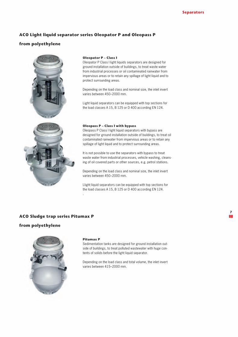
ACO Light liquid separator series Oleopator P and Oleopass P
from polyethylene
Oleopator P – Class I
Oleopator P Class I light liquids separators are designed for
ground installation outside of buildings, to treat waste water
from industrial processes or oil contaminated rainwater from
impervious areas or to retain any spillage of light liquid and to
protect surrounding areas.
Depending on the load class and nominal size, the inlet invert
varies between 450–2000 mm.
Light liquid separators can be equipped with top sections for
the load classes A 15, B 125 or D 400 according EN 124.
Oleopass P – Class I with bypass
Oleopass P Class I light liquid separators with bypass are
designed for ground installation outside of buildings, to treat oil
contaminated rainwater from impervious areas or to retain any
spillage of light liquid and to protect surrounding areas.
It is not possible to use the separators with bypass to treat
waste water from industrial processes, vehicle washing, cleans-
ing of oil covered parts or other sources, e.g. petrol stations.
Depending on the load class and nominal size, the inlet invert
varies between 450–2000 mm.
Llight liquid separators can be equipped with top sections for
the load classes A 15, B 125 or D 400 according EN 124.
.
ACO Sludge trap series Pitumax P
from polyethylene
Pitumax P
Sedimentation tanks are designed for ground installation out-
side of buildings, to treat polluted wastewater with huge con-
tents of solids before the light liquid separator.
Depending on the load class and total volume, the inlet invert
varies between 415–2000 mm.
18
Separators
Nominal
size
Nominal
width
Volume sludge trap
Volume oil storage
Total capacity D H H1 H2 Weight
Article No.
[l] [l] [l] [mm] [mm] [mm] [mm] [kg]
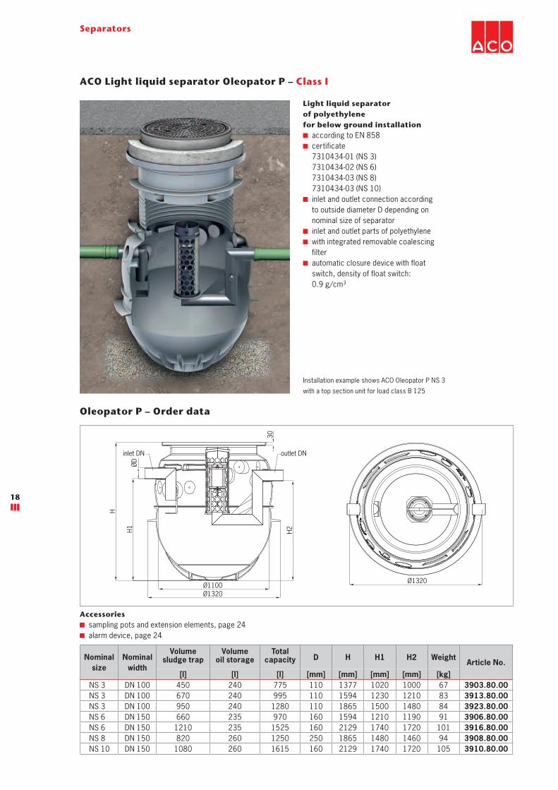
NS 3 DN 100 450 240 775 110 1377 1020 1000 67 3903.80.00
NS 3 DN 100 670 240 995 110 1594 1230 1210 83 3913.80.00
NS 3 DN 100 950 240 1280 110 1865 1500 1480 84 3923.80.00
NS 6 DN 150 660 235 970 160 1594 1210 1190 91 3906.80.00
NS 6 DN 150 1210 235 1525 160 2129 1740 1720 101 3916.80.00
NS 8 DN 150 820 260 1250 250 1865 1480 1460 94 3908.80.00
NS 10 DN 150 1080 260 1615 160 2129 1740 1720 105 3910.80.00
ACO Light liquid separator Oleopator P – Class I
Light liquid separator
of polyethylene
for below ground installation
according to EN 858
certificate
7310434-01 (NS 3)
7310434-02 (NS 6)
7310434-03 (NS 8)
7310434-03 (NS 10)
inlet and outlet connection according
to outside diameter D depending on
nominal size of separator
inlet and outlet parts of polyethylene
with integrated removable coalescing
filter
automatic closure device with float
switch, density of float switch:
0.9 g/cm3
Installation example shows ACO Oleopator P NS 3
with a top section unit for load class B 125
Oleopator P – Order data
Accessories
sampling pots and extension elements, page 24
alarm device, page 24
30
H1
H2
Ø1320
Ø1100
H
ØD
Ø1320
inlet DN outlet DN
19
Separators
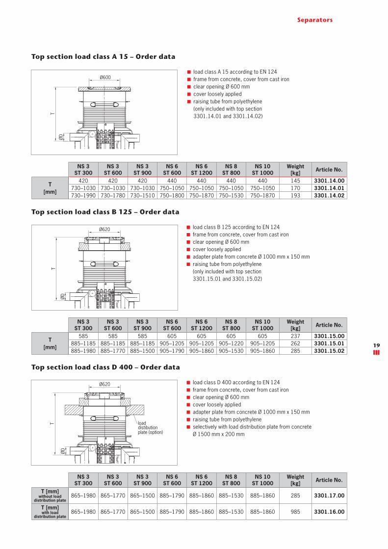
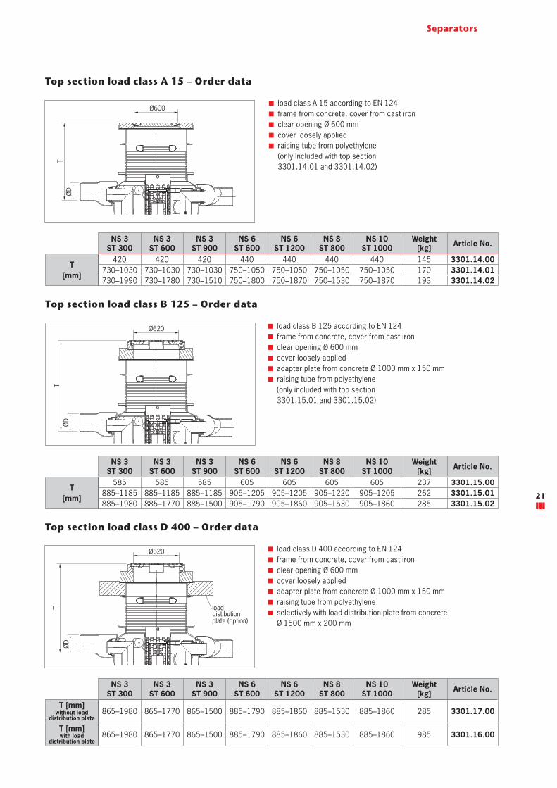
Top section load class D 400 – Order data
load class D 400 according to EN 124
frame from concrete, cover from cast iron
clear opening Ø 600 mm
cover loosely applied
adapter plate from concrete Ø 1000 mm x 150 mm
raising tube from polyethylene
selectively with load distribution plate from concrete
Ø 1500 mm x 200 mm
Top section load class A 15 – Order data
load class A 15 according to EN 124
frame from concrete, cover from cast iron
clear opening Ø 600 mm
cover loosely applied
raising tube from polyethylene
(only included with top section
3301.14.01 and 3301.14.02)
NS 3
ST 300
NS 3
ST 600
NS 3
ST 900
NS 6
ST 600
NS 6
ST 1200
NS 8
ST 800
NS 10
ST 1000
Weight
[kg]Article No.
T [mm] without load
distribution plate865–1980 865–1770 865–1500 885–1790 885–1860 885–1530 885–1860 285 3301.17.00
T [mm] with load
distribution plate865–1980 865–1770 865–1500 885–1790 885–1860 885–1530 885–1860 985 3301.16.00
Top section load class B 125 – Order data
load class B 125 according to EN 124
frame from concrete, cover from cast iron
clear opening Ø 600 mm
cover loosely applied
adapter plate from concrete Ø 1000 mm x 150 mm
raising tube from polyethylene
(only included with top section
3301.15.01 and 3301.15.02)
NS 3
ST 300
NS 3
ST 600
NS 3
ST 900
NS 6
ST 600
NS 6
ST 1200
NS 8
ST 800
NS 10
ST 1000
Weight
[kg]Article No.
T
[mm]
585 585 585 605 605 605 605 237 3301.15.00
885–1185 885–1185 885–1185 905–1205 905–1205 905–1220 905–1205 262 3301.15.01
885–1980 885–1770 885–1500 905–1790 905–1860 905–1530 905–1860 285 3301.15.02
NS 3
ST 300
NS 3
ST 600
NS 3
ST 900
NS 6
ST 600
NS 6
ST 1200
NS 8
ST 800
NS 10
ST 1000
Weight
[kg]Article No.
T
[mm]
420 420 420 440 440 440 440 145 3301.14.00
730–1030 730–1030 730–1030 750–1050 750–1050 750–1050 750–1050 170 3301.14.01
730–1990 730–1780 730–1510 750–1800 750–1870 750–1530 750–1870 193 3301.14.02
Ø600
T
ØD
T
Ø620
ØD
ØD
Ø620
T loaddistibutionplate (option)
20
Separators
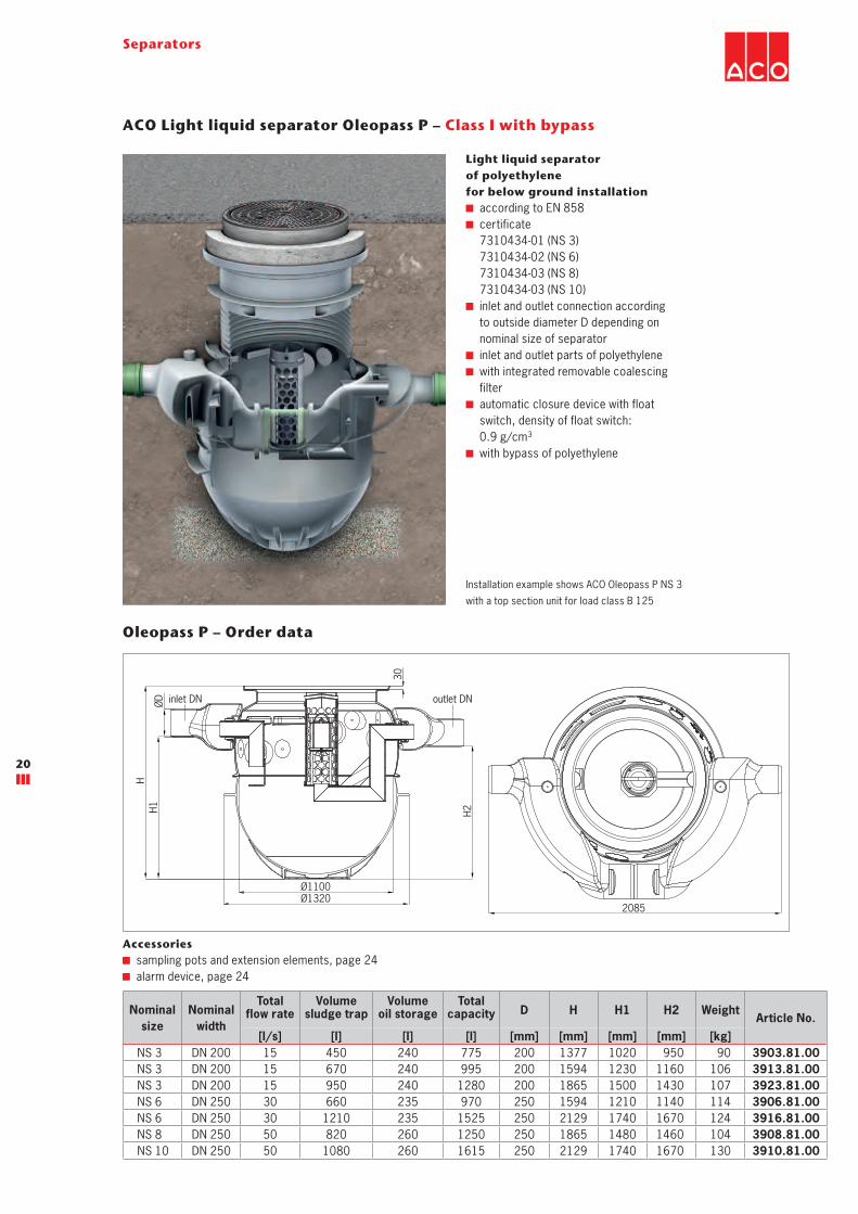
ACO Light liquid separator Oleopass P – Class I with bypass
Light liquid separator
of polyethylene
for below ground installation
according to EN 858
certificate
7310434-01 (NS 3)
7310434-02 (NS 6)
7310434-03 (NS 8)
7310434-03 (NS 10)
inlet and outlet connection according
to outside diameter D depending on
nominal size of separator
inlet and outlet parts of polyethylene
with integrated removable coalescing
filter
automatic closure device with float
switch, density of float switch:
0.9 g/cm3
with bypass of polyethylene
Nominal
size
Nominal
width
Total flow rate
Volume sludge trap
Volume oil storage
Total capacity D H H1 H2 Weight
Article No.
[l/s] [l] [l] [l] [mm] [mm] [mm] [mm] [kg]
NS 3 DN 200 15 450 240 775 200 1377 1020 950 90 3903.81.00
NS 3 DN 200 15 670 240 995 200 1594 1230 1160 106 3913.81.00
NS 3 DN 200 15 950 240 1280 200 1865 1500 1430 107 3923.81.00
NS 6 DN 250 30 660 235 970 250 1594 1210 1140 114 3906.81.00
NS 6 DN 250 30 1210 235 1525 250 2129 1740 1670 124 3916.81.00
NS 8 DN 250 50 820 260 1250 250 1865 1480 1460 104 3908.81.00
NS 10 DN 250 50 1080 260 1615 250 2129 1740 1670 130 3910.81.00
Installation example shows ACO Oleopass P NS 3
with a top section unit for load class B 125
Oleopass P – Order data
Accessories
sampling pots and extension elements, page 24
alarm device, page 24
H
H1
H2
ØD
30
Ø1320
Ø1100
2085
inlet DN outlet DN
21
Separators
Top section load class D 400 – Order data
load class D 400 according to EN 124
frame from concrete, cover from cast iron
clear opening Ø 600 mm
cover loosely applied
adapter plate from concrete Ø 1000 mm x 150 mm
raising tube from polyethylene
selectively with load distribution plate from concrete
Ø 1500 mm x 200 mm
Top section load class A 15 – Order data
Top section load class B 125 – Order data
load class A 15 according to EN 124
frame from concrete, cover from cast iron
clear opening Ø 600 mm
cover loosely applied
raising tube from polyethylene
(only included with top section
3301.14.01 and 3301.14.02)
load class B 125 according to EN 124
frame from concrete, cover from cast iron
clear opening Ø 600 mm
cover loosely applied
adapter plate from concrete Ø 1000 mm x 150 mm
raising tube from polyethylene
(only included with top section
3301.15.01 and 3301.15.02)
Ø600
T
ØD
T
Ø620
ØD
Ø620
T
ØD
loaddistibutionplate (option)
NS 3
ST 300
NS 3
ST 600
NS 3
ST 900
NS 6
ST 600
NS 6
ST 1200
NS 8
ST 800
NS 10
ST 1000
Weight
[kg]Article No.
T [mm] without load
distribution plate865–1980 865–1770 865–1500 885–1790 885–1860 885–1530 885–1860 285 3301.17.00
T [mm] with load
distribution plate865–1980 865–1770 865–1500 885–1790 885–1860 885–1530 885–1860 985 3301.16.00
NS 3
ST 300
NS 3
ST 600
NS 3
ST 900
NS 6
ST 600
NS 6
ST 1200
NS 8
ST 800
NS 10
ST 1000
Weight
[kg]Article No.
T
[mm]
585 585 585 605 605 605 605 237 3301.15.00
885–1185 885–1185 885–1185 905–1205 905–1205 905–1220 905–1205 262 3301.15.01
885–1980 885–1770 885–1500 905–1790 905–1860 905–1530 905–1860 285 3301.15.02
NS 3
ST 300
NS 3
ST 600
NS 3
ST 900
NS 6
ST 600
NS 6
ST 1200
NS 8
ST 800
NS 10
ST 1000
Weight
[kg]Article No.
T
[mm]
420 420 420 440 440 440 440 145 3301.14.00
730–1030 730–1030 730–1030 750–1050 750–1050 750–1050 750–1050 170 3301.14.01
730–1990 730–1780 730–1510 750–1800 750–1870 750–1530 750–1870 193 3301.14.02
22
Separators
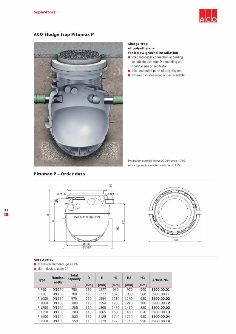
ACO Sludge trap Pitumax P
Sludge trap
of polyethylene
for below ground installation
inlet and outlet connection according
to outside diameter D depending on
nominal size of separator
inlet and outlet parts of polyethylene
different volumes/capacities available
TypeNominal
width
Total capacity D H H1 H2 H3
Article No.
[l] [mm] [mm] [mm] [mm] [mm]
P 750 DN 150 750 160 1377 990 970 540 3900.00.01
P 750 DN 100 780 110 1377 1020 1000 560 3900.00.11
P 1000 DN 150 975 160 1594 1210 1190 680 3900.00.02
P 1000 DN 100 1000 110 1594 1230 1210 700 3900.00.12
P 1250 DN 150 1255 160 1865 1480 1460 830 3900.00.03
P 1250 DN 100 1280 110 1865 1500 1480 850 3900.00.13
P 1500 DN 150 1530 160 2129 1740 1720 930 3900.00.04
P 1500 DN 100 1550 110 2129 1770 1750 950 3900.00.14
Installation example shows ACO Pitumax P 750
with a top section unit for load class B 125
Pitumax P – Order data
Accessories
extension elements, page 24
alarm device, page 24
inlet DN outlet DN
maximum sludge level
30
H
H1
ØD
H2
Ø1100Ø1320
1390
H3
23
Separators
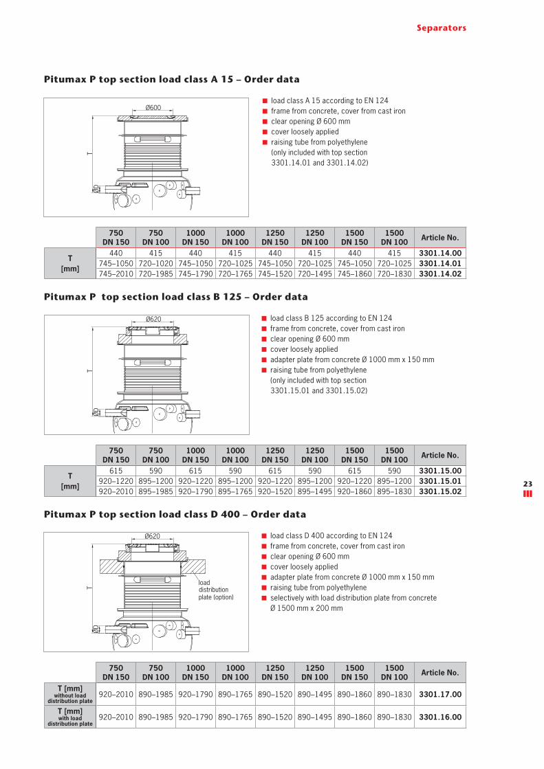
Pitumax P top section load class D 400 – Order data
load class D 400 according to EN 124
frame from concrete, cover from cast iron
clear opening Ø 600 mm
cover loosely applied
adapter plate from concrete Ø 1000 mm x 150 mm
raising tube from polyethylene
selectively with load distribution plate from concrete
Ø 1500 mm x 200 mm
Pitumax P top section load class A 15 – Order data
Pitumax P top section load class B 125 – Order data
load class A 15 according to EN 124
frame from concrete, cover from cast iron
clear opening Ø 600 mm
cover loosely applied
raising tube from polyethylene
(only included with top section
3301.14.01 and 3301.14.02)
load class B 125 according to EN 124
frame from concrete, cover from cast iron
clear opening Ø 600 mm
cover loosely applied
adapter plate from concrete Ø 1000 mm x 150 mm
raising tube from polyethylene
(only included with top section
3301.15.01 and 3301.15.02)
750
DN 150
750
DN 100
1000
DN 150
1000
DN 100
1250
DN 150
1250
DN 100
1500
DN 150
1500
DN 100Article No.
T
[mm]
615 590 615 590 615 590 615 590 3301.15.00
920–1220 895–1200 920–1220 895–1200 920–1220 895–1200 920–1220 895–1200 3301.15.01
920–2010 895–1985 920–1790 895–1765 920–1520 895–1495 920–1860 895–1830 3301.15.02
750
DN 150
750
DN 100
1000
DN 150
1000
DN 100
1250
DN 150
1250
DN 100
1500
DN 150
1500
DN 100Article No.
T
[mm]
440 415 440 415 440 415 440 415 3301.14.00
745–1050 720–1020 745–1050 720–1025 745–1050 720–1025 745–1050 720–1025 3301.14.01
745–2010 720–1985 745–1790 720–1765 745–1520 720–1495 745–1860 720–1830 3301.14.02
750
DN 150
750
DN 100
1000
DN 150
1000
DN 100
1250
DN 150
1250
DN 100
1500
DN 150
1500
DN 100Article No.
T [mm] without load
distribution plate920–2010 890–1985 920–1790 890–1765 890–1520 890–1495 890–1860 890–1830 3301.17.00
T [mm] with load
distribution plate920–2010 890–1985 920–1790 890–1765 890–1520 890–1495 890–1860 890–1830 3301.16.00
TØD
Ø600
TØD
Ø620
TØ
D
Ø620
loaddistributionplate (option)
24
Separators
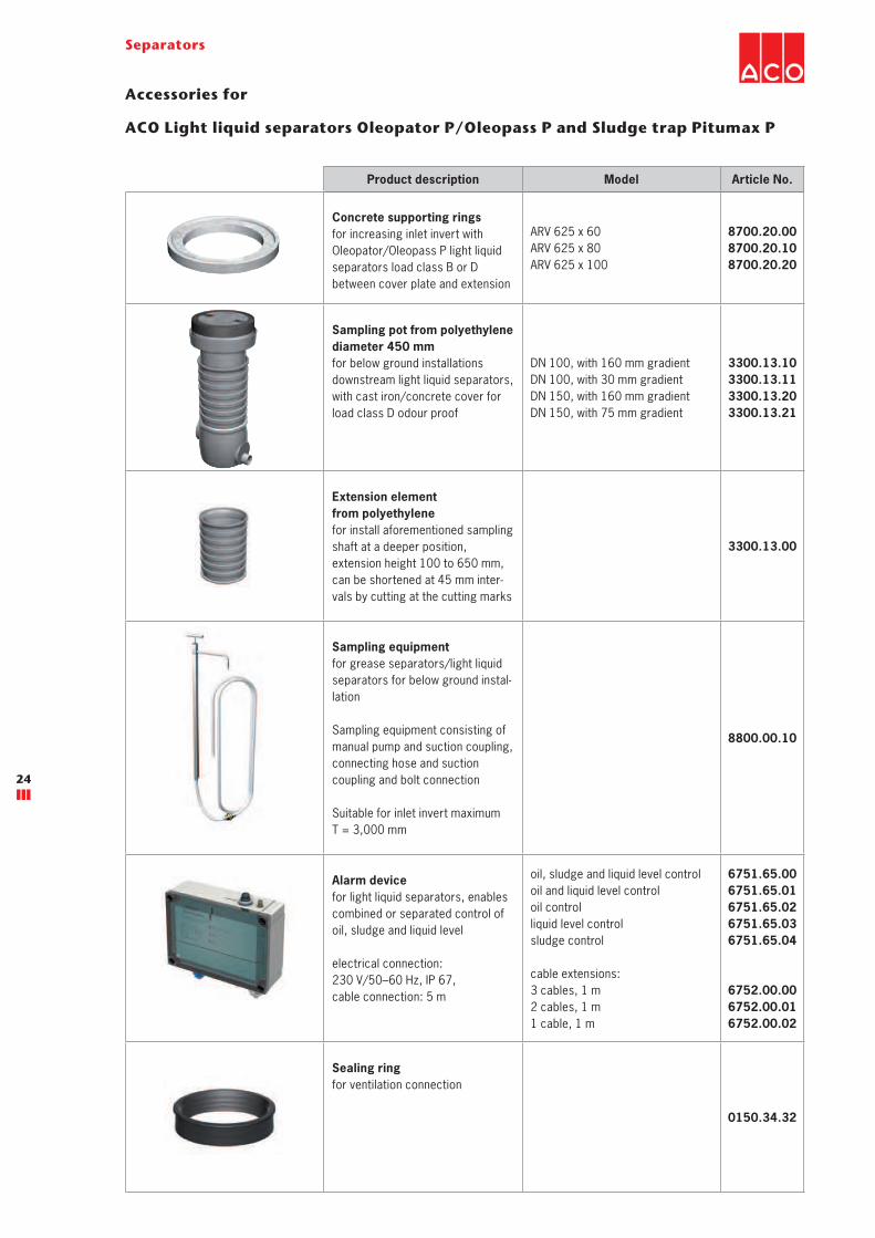
Product description Model Article No.
Concrete supporting rings
for increasing inlet invert with
Oleopator/Oleopass P light liquid
separators load class B or D
between cover plate and extension
ARV 625 x 60
ARV 625 x 80
ARV 625 x 100
8700.20.00
8700.20.10
8700.20.20
Sampling pot from polyethylene
diameter 450 mm
for below ground installations
downstream light liquid separators,
with cast iron/concrete cover for
load class D odour proof
DN 100, with 160 mm gradient
DN 100, with 30 mm gradient
DN 150, with 160 mm gradient
DN 150, with 75 mm gradient
3300.13.10
3300.13.11
3300.13.20
3300.13.21
Extension element
from polyethylene
for install aforementioned sampling
shaft at a deeper position,
extension height 100 to 650 mm,
can be shortened at 45 mm inter-
vals by cutting at the cutting marks
3300.13.00
Sampling equipment
for grease separators/light liquid
separators for below ground instal-
lation
Sampling equipment consisting of
manual pump and suction coupling,
connecting hose and suction
coupling and bolt connection
Suitable for inlet invert maximum
T = 3,000 mm
8800.00.10
Alarm device
for light liquid separators, enables
combined or separated control of
oil, sludge and liquid level
electrical connection:
230 V/50–60 Hz, IP 67,
cable connection: 5 m
oil, sludge and liquid level control
oil and liquid level control
oil control
liquid level control
sludge control
cable extensions:
3 cables, 1 m
2 cables, 1 m
1 cable, 1 m
6751.65.00
6751.65.01
6751.65.02
6751.65.03
6751.65.04
6752.00.00
6752.00.01
6752.00.02
Sealing ring
for ventilation connection
0150.34.32
Accessories for
ACO Light liquid separators Oleopator P/Oleopass P and Sludge trap Pitumax P
25
Separators
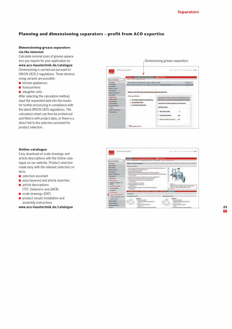
Planning and dimensioning separators – profit from ACO expertise
Dimensioning grease separators
via the internet
Calculate nominal sizes of grease separa-
tors you require for your application on
www.aco-haustechnik.de/catalogue
Dimensioning is carried out pursuant to
DIN EN 1825-2 regulations. Three dimensi-
oning variants are possible:
kitchen appliances
food portions
slaughter units
After selecting the calculation method,
input the requested data into the masks
for further processing in compliance with
the latest DIN EN 1825 regulations. The
calculation sheet can then be printed out
and filled in with project data, or there is a
direct link to the selection assistant for
product selection.
Online catalogue
Easy download of scale drawings and
article descriptions with the Online cata-
logue on our website. Product selection
made easy with the relevant selection cri-
teria.
selection assistant
easy keyword and article searches
article descriptions
(TXT, Datanorm and GAEB)
scale drawings (DXF)
product visuals Installation and
assembly instructions
www.aco-haustechnik.de/catalogue
Dimensioning grease separators
26
Separators
Notes

27
Separators
Notes