accd design standards - index to divisions in this document
1024
-
Upload
khangminh22 -
Category
Documents
-
view
1 -
download
0
Transcript of accd design standards - index to divisions in this document


ACCD DESIGN STANDARDS
ACCD Design and Construction Standards © July 2005 Index - 1
INDEX TO DIVISIONS IN THIS DOCUMENT
BOOK 1 - ARCHITECTURAL
General Requirements Subgroup Division 01 General Requirements July 2005
General Requirements Subgroup Division 02 Existing Conditions , July 2005 Division 03 Concrete, July 2005 Division 04 Masonry, July 2005 Division 05 Metals , July 2005 Division 06 Wood, Plastics and Composites, July 2005 Division 07 Thermal and Moisture Protection, July 2005 Division 08 Openings, July 2005 Division 09 Finishes, July 2005 Division 10 Specialties, July 2005 Division 11 Equipment (not included) Division 12 Furnishings (not included) Division 13 Special Construction, (not included) Division 14 Conveying Equipment, July 2005 Division 15 Reserved by CSI Division 16 Reserved by CSI Division 17 Reserved by CSI Division 18 Reserved by CSI
BOOK 2- MECHANICAL AND PLUMBING
Facility Services Subgroup Division 20 Reserved by CSI Division 21 Fire Suppression, December 2004 Division 22 Plumbing, December 2004 Division 23 Heating, Ventilating, and Air Conditioning, December 2004 Division 24 Reserved by CSI)
ACCD DESIGN STANDARDS
ACCD Design and Construction Standards © July 2005 Index - 2
BOOK 3- ELECTRICAL AND INFRASTRUCTURE
Facility Services Subgroup (Cont’d) Division 25 Integrated Automation (not included) Division 26 Electrical, December 2004 Division 27 Communications , July 2005 Division 28 Electronic Safety and Security, December 2004 Division 29 Reserved by CSI Division 30 Reserved by CSI
Site and Infrastructure Subgroup Division 31 Earthwork, December 2004 Division 32 Exterior Improvements , December 2004 Division 33 Utilities, December 2004 Division 34 Transportation (not included) Division 35 Waterway and Marine Construction (not included) Division 36 Reserved by CSI Division 37 Reserved by CSI Division 38 Reserved by CSI Division 39 Reserved by CSI
Looking to the future , these design standards have been prepared using the 2005 CSI numbering format, which will become the industry standard for design and construction. While relating to the present, each heading also includes (in parenthesis) the familiar division and section numbers.

DIVISION 0 – INTRODUCTION AND PROFESSIONAL REQUIREMENTS
00 00 00 Introduction
Consultants Requirements
Consultant Responsibilities
ACCD Requirements
Project Manager Requirements
Project Phases (general description)
Submittal Requirements
Codes
TAS / ADA
00 00 01 Project Definition
00 00 02 Architectural Requirements
00 00 03 Structural Engineering Requirements
00 00 04 Mechanical and Plumbing Requirements
00 00 05 Electrical Engineering Requirements
00 00 06 Civil Engineering Requirements
00 00 07 Landscape Architectural Requirements

Design and Construction Standards Introduction
ACCD Design and Construction Standards © July 2005 00 00 00- 1
Design standards, which include both Educational Standards and Design and Construction Standards, have been created as the foundation for the design of all Alamo Community College District (ACCD) facilities. Education Standards describe space requirements for each educational space and include typical room layouts. Design and Construction Standards are the basis for the design, construction, operation, renovation, modification, and general care of the facilities at ACCD. These two documents should be used in conjunction with each other in developing designs and modifications to ACCD facilities. The Design and Construction Standards are described below, the Education Standards are presented in a separate document. The intent of the Design and Construction Standards is to be a guide for all of those who will be using them, as they represent the preferred methods, materials, and systems. It is, however, the responsibility of the design professional to use these standards as a basis for creative solutions that meet the objectives of each ACCD project. If there are any reasons to deviate from these standards, a written request will be submitted for approval by the ACCD Facilities Department. The standards have been developed for all typical ACCD requirements. However, ACCD will have specific projects that are not addressed in these standards and these special requirements should be discussed during the Project Definition phase. The design professional is responsible for developing documentation and specifications for all products to be used, including products not listed in the standards. Consultant Requirements
Owner / Consultant Agreement The design professional hired by ACCD shall have a contract in place with ACCD and a clear Scope of Work that has been reviewed as part of a work-session with ACCD prior to commencing work. Sub-Consultants The design professional hired by ACCD shall provide a list of proposed sub-consultants to ACCD, who reserves the right to reject any person or firm which ACCD may deem to not be qualified or competent to render the services required. Consultants may include: § Architect § Mechanical, Electrical, Plumbing § Structural § Civil § Landscape Architect § Roofing Consultant

Design and Construction Standards Introduction
ACCD Design and Construction Standards © July 2005 00 00 00- 2
§ Acoustical Consultant § Lighting Consultant § Other
Sub-Consultant Agreements Sub-Consultant agreements shall match the consultant agreements. The design professional contracted with ACCD shall provide copies of the sub-consultant agreements to ACCD when requested. Consultant Responsibilities
§ The Educational Standards and the Design and Construction Standards are intended to establish standards, policies, and practices and are to be used as the basis for decisions on design, construction documents and specifications. They should be used as a guide only and are not intended to cover every situation or to restrict innovative design. Where good design dictates a deviation from the design standards, the design professional should submit a written Request for Variation (RFV) to ACCD’s project manager for approval by the ACCD Facility Department.
§ The standards are intended to provide the consultant with a
basis for making product selections, establishing project standards, performing calculations for MEP systems and completing designs of all systems. These guidelines are not intended, in any case, to take precedence over any code requirements, more stringent criteria based upon “good design and engineering practice,” or other known requirements. The design professional shall notify ACCD of any deviation or exceptions that are desired or required by submitting a Request for Variation (RFV) to ACCD’s project manager for approval by the ACCD Facility Department..
§ ACCD’s project manager and the ACCD Facility Department
will review any Requests for Variation (RFV) and, if it is agreed that a variation or deviation is in order, a written deviation will be granted. No deviation from the design standards will be allowed without written approval. The purpose of these design standards is to provide uniformity of design based on ACCD’s standards and policy.
§ Design professionals contracted for specific projects have
legal responsibility for design and document preparation. When specifications are required, they shall be written by the design professional for each specific project. These

Design and Construction Standards Introduction
ACCD Design and Construction Standards © July 2005 00 00 00- 3
Design and Construction Standards are not specifications, and may not be reproduced as such.
§ Existing or as-built drawings of renovated buildings or other
areas cannot be assumed to be 100% accurate; therefore, the design professional is required to visit the site, conduct a site survey, inspect existing conditions and record observations.
ACCD Requirements
Project Team ACCD will furnish the manager of the design team with a list of team members, including all user group team members. The list will establish approval and authority levels to be observed by all team members. Budget and Schedule ACCD will furnish the manager of the design team with the initial budget and schedule to be used as a basis for the project budget and schedule. Land Survey ACCD will furnish the land survey of the site. In order to assist ACCD in providing the most comprehensive information from the registered professional land surveyor (RPLS) in the State of Texas, ACCD will provide a standard requirement for land surveying and request that design professionals recommend and/or modify the requirements based on the scope of work. Geotechnical ACCD will furnish geotechnical consultant services when ACCD agrees that such services are necessary. In order to assist ACCD in providing the most constructive information from the geotechnical consultant, ACCD will provide a standard requirement for geotechnical services and request that design professionals recommend and/or modify the requirements based on the scope of work. Hazardous Materials ACCD will furnish a copy of a hazardous materials survey (when a survey has been performed on an existing building and/or site) to the manager of the design team, and will be responsible for the abatement of the site and/or building as required for new construction and/or renovations. Hazardous materials surveys shall be distributed during Project Definition phase. Hazardous materials include organic growth within existing structures. Any suspicious materials, organic or other materials,

Design and Construction Standards Introduction
ACCD Design and Construction Standards © July 2005 00 00 00- 4
found by the design professional during site investigation; shall be brought to the attention of ACCD’s project manager. Design Management Responsibilities
Project Kick-Off Meeting It is important for the success of the project for the team to have good communication. To begin this communication effort and promote team collaboration, a Project Kick-Off meeting should be scheduled to include the manager of the design team, ACCD’s project manager, and all other key design and ACCD team members. A thorough discussion of each of the following topics is critical to making sure the team is “off on the right foot.” The key topics for this meeting should include: § Project process § Project phases (project definition, schematic design, design
development, construction documents, bidding, and construction)
§ Project schedule, § Meeting schedule § Documentation requirements § Management Report requirements
Management Report The manager of the design team will be responsible for providing a written monthly progress report to ACCD’s project manager during the design phase of the project. The report will discuss accomplishments, schedule updates, outstanding issues, and work scheduled for the next month. Schedule The manager of the design team will be responsible for maintaining the schedule and providing periodic updates to ACCD’s project manager during the design phase of the project. A schedule for the project shall be developed to include: § Project Definition
o Workshops o Programming o Conceptual Design
§ ACCD Review and Approval § Schematic Design § Cost Estimating § ACCD Review and Approval § Design Development § Cost Estimating § ACCD Review and Approval § Construction Documentation – 65%

Design and Construction Standards Introduction
ACCD Design and Construction Standards © July 2005 00 00 00- 5
§ ACCD Review and Approval § Construction Documentation – 98% § ACCD Review and Approval § Construction Documentation – 100% § Solicitation for Construction Contracting § Estimated Construction Mobilization § Estimated Construction Period § Substantial Completion § ACCD Review and Approval § Warranty Completion
Project Directory The manager of the design team will be responsible for developing a project directory listing all team members and sub-consultant groups, including all team member names, companies, phone numbers, fax numbers, and e-mail addresses. The directory shall be distributed to the team and ACCD’s project manager. Project Phases
The design team will use the following standard phases for the development of design and documentation for the project. A brief description of each phase is listed below. A more detailed description is included in Sections 00 00 02 – 00 00 03 of these Design and Construction Standards listed by each professional discipline. Project Definition In order to establish a project scope that can be delivered within the constraints of cost, schedule, and quality requirements; ACCD requires a Project Definition phase, during which the project team will work together to establish values, goals, strategies, and detailed requirements. This phase is explained in more detail in Section 00 00 01 of the Design and Construction Standards. The basic components include: § Workshop / Big Picture Concepts § Program § Develop Building Systems § Develop Cost Model § Conceptual Design § Process Definition
Schematic Design Upon approval of the Program, Cost Model, and Conceptua l Design, the design team will proceed into Schematic Design. During this phase, it is the design team’s objective to work out all major design concepts and define all major decisions.

Design and Construction Standards Introduction
ACCD Design and Construction Standards © July 2005 00 00 00- 6
To complete this phase the design professionals will develop drawings and/or brief narratives as required to convey concept. Code analyses shall be started and a cost estimate developed. Documentation shall be submitted to ACCD for review, comments and approval. Design Development The design team shall proceed to Design Development upon receipt of Schematic Design comments and approval. During Design Development all design decisions should be finalized, and documented in drawings and outline specifications. Code analysis shall be finalized and a revised cost estimate developed. Design Development documents shall be submitted to ACCD for review, comments and approval. Construction Documentation The design team shall proceed with Construction Documents upon receipt of Design Development comments and approval. Construction Documents shall reflect all previous design decisions developed during Design Development. During this phase, details should be finalized and drawings completely integrated between all disciplines. The Construction Documents are to be issued in three submittals, a 65% submittal, a 98% submittal (which are 100% complete documents for the design professionals, lacking only final comments from ACCD), and a 100% submittal with comments from the previous submittal integrated in the documentation. Solicitation for Construction Contracting Solicitation for Construction Contracting is typically the responsibility of ACCD’s acquisitions department. The design professionals will be asked to respond to bidding questions as needed; and will shall also assist in evaluating, grading and ranking proposals as directed by the project manager. Fee for this service will typically be included in the lump sum pre-negotiated fee structure. Construction Administration During Construction Administration the design team will be responsible for submittals, construction review, and project team meetings as determined in the scope of work. Fee for this service will typically be included in the lump sum pre-negotiated fee structure. It is anticipated that the manager of the design team will attend bi-weekly meetings, and visit the site at weekly at a minimum. Each design professional shall participate in meetings, visit the site at

Design and Construction Standards Introduction
ACCD Design and Construction Standards © July 2005 00 00 00- 7
appropriate intervals to observe the progress of the work and shall process submittals etc. as appropriate to the scope of work. Substantial Completion The design professionals will be responsible for walking the project and developing a Punch List, at the time of substantial completion as agreed to by the contractor and ACCD’s project manager. Warranty Period The design professionals will typically not have any responsibilities during this time. If however, there are issues that arise regarding product failure, ACCD and/or the contactor may request additional services for review and professional opinions from the design professional. Submittal Requirements
ACCD has minimum submittal/review requirements as listed below. The manager of the design team shall indicate the dates on the schedule. Submittals include:
Program Review Conceptual Plan / Cost Model Review Schematic Design Review Design Development Review Construction Document 65% Review Construction Document 98% Review
More specific submittal requirements for each design discipline are written in Sections 00 00 02 – 00 00 07 of these standards. The copies of each submittal shall be submitted through ACCD’s project manager. The submittal/reviews listed shall be scheduled to allow a 5 – 10 day review period, based on the submittal and complexity of the project. Intermediate reviews are encouraged as needed for intermediate feedback from ACCD when the scope of the project has been changed, an earlier review is needed to finalize scope prior to proceeding, or if the previous submittal was not accepted by ACCD in whole or part. It is important for both ACCD and the design team to work closely through the process and review items as needed, in order to help expedite the construction document and construction period, without conflicts.

Design and Construction Standards Introduction
ACCD Design and Construction Standards © July 2005 00 00 00- 8
Codes and Standards
The design professional shall prepare a written codes and standards analysis for each project for review by ACCD. ACCD encourages reviews with local code officials to discuss code analysis and interpretations on projects, especially projects that have complicated code issues and/or where interpretation is necessary. The manager of the design team shall arrange the review to allow an ACCD representative to attend. The following is a list of codes that should be followed, using the currently adopted versions. Codes, including all adopted versions and amendments, shall be followed by the governing jurisdiction. Where duplication of requirements occurs between codes, the more stringent requirements shall be followed. Architectural Design § International Building Code § National Fire Protection Association National Fire Codes,
with emphasis on NFPA 101 Life Safety Codes, including all referenced standards.
§ NFPA 45, Standard on Fire Protection for Laboratories using Chemicals.
§ Americans with Disabilities Act (ADA) § Texas Department of Licensing and Regulation, Elimination
of Architectural Barriers , Texas Accessibility Standards (TAS)
Structural Design § Uniform Building Code § International Build Code § ACI, 318, Building Code Requirements for Reinforced
Concrete § AISC, Specification for the Design, Fabrication and Erection
of Structural Steel § Refer to Division 3 and 5 of these standards for more detail
on code requirements. Mechanical Design § International Building Code § International Mechanical Code § International Plumbing Code § National Fire Protection Association National Fire Codes
with emphasis on NFPA 101, 90A, 54, etc). § Refer to Division 22 and 23 of these standards for more
detail on code requirements.

Design and Construction Standards Introduction
ACCD Design and Construction Standards © July 2005 00 00 00- 9
Electrical Design § National Electrical Code § National Electrical Safety Code § National Fire Protection Association § City of San Antonio Electrical Codes and Ordinances § Terms and Conditions of the Electrical Utility § Refer to Division 26 of these standards for more detail on
code requirements. Civil Design § Uniform Building Code § International Building Code § City of San Antonio Unified Development Code § City of San Antonio Standard Specification for Public Work
Construction as Amended § City of San Antonio Handbook for Flatwork Construction § Texas Manual on Uniform Traffic Control Devices § Americans with Disabilities Act (ADA) § Texas Department of Licensing and Regulation, Elimination
of Architectural Barriers Act, Texas Accessibility Standards (TAS)
Landscape Design § City of San Antonio Tree Preservation Ordinance § City of San Antonio Landscape Ordinance § Americans with Disabilities Act (ADA) § Texas Department of Licensing and Regulation, Elimination
of Architectural Barriers Act, Texas Accessibility Standards (TAS)
§ Refer to Division 32 of these standards for more detail on code requirements.
Americans with Disabilities Act and Texas Accessibility Standards
Americans with Disabilities Act (ADA) and the Texas Accessibility Standards (TAS) as applied by the Texas Department of Licensing and Regulation, shall be followed when designing the project for ACCD. The design professional shall work to integrate accessibility into the overall design concept; it should not be an afterthought. Renovation projects must bring the renovated area and access to that area up to compliance. If the renovation is more than 50% of the building, the entire building should be brought up to compliance. § The building(s) site(s) will need to be carefully planned so
that the grades provide accessibility to the entrance, sidewalks and parking areas.
§ Ramps should be integrated into the entrance design, if necessary. Wheelchair lifts are not encouraged.

Design and Construction Standards Introduction
ACCD Design and Construction Standards © July 2005 00 00 00- 10
§ Parking areas are to be marked with signs and accessible routes shall meet gradient requirements and be free of obstructions.
§ Sidewalks and use of curb ramps need to be carefully planned in the site work design.
§ All entrances shall be barrier free. Doors shall have electronically equipped automatic door openers as requested by ACCD.
The manager of the design team is required by TAS to submit drawings for review by a licensed reviewer within 5 business days of the drawings being signed and sealed and submitted for permit for any project with a construction of more than $50,000. § Note this fee will be reimbursed by ACCD to the
professional submitting the drawings. § The submitter should submit the fee for the drawing review
and the one year inspection at the same time. This helps to ensure that ACCD will have their inspections done in a timely manner. It is also helpful to have the same reviewer do the inspection as well.
§ Additional fee may be required if drawings need to be resubmitted based on previous comments.
It is the responsibility of the design professional to design the building and/or site to meet ADA and TAS requirements. Information regarding specif ic ADA and TAS requirements can be found on their websites. § TAS the website is: http://www.license.state.tx.us/ab/ab.htm § ADA website is: http://www.usdoj.gov/crt/ada/adahom1.htm

Design and Construction Standards Project Definition
ACCD Design and Construction Standards © July 2005 00 00 01- 1
General
After award of the contract by ACCD the design team will begin Project Definition, which is the process of understanding and documenting ACCD’s requirements for the project: the values, goals, strategies, and detailed requirements—for both process and product—and then establishing the scope that can be delivered within the constraints of cost, schedule, and quality. ACCD has established Educational Standards and Design and Construction Standards that will be a guide for the design professional to help through the decision making process. These standards should be thoroughly reviewed when design concepts, layouts, and product selections are developed as these standards are required by ACCD in the implementation of the design. During Project Defin ition, early discovery of ACCD’s values sets ideas that will guide design thought. Designs that respond to specific programmatic needs and express the values of the institution are the natural result of this process. Values, reflected by programmatic content, standards and procedures, established by the stakeholders, become a filter for future decisions. Those help the team meet the design objectives and minimize costly changes as the project progresses. The design team should also be conscious of design decisions with regard to sustainable design. Although ACCD does not require LEED (Leadership in Energy and Environmental Design) certification, ACCD requires implementing design that is environmentally friendly. Workshop / Big Picture Concepts To perform the Project Definition task with ACCD, the design team will utilize a workshop format that will provide an opportunity for collaboration and buy-in for all parties. The Big Picture concepts to be discussed as part of the workshop are the values, goals, and strategies for the project, and the overall process. The workshop should include: ACCD Facilities Department ACCD User Group Architect / Designer Structural Engineer (as needed)
MEP Engineer (as needed) Civil Engineer (as needed) Landscape Architect (as needed) Other Consultants (as needed)

Design and Construction Standards Project Definition
ACCD Design and Construction Standards © July 2005 00 00 01- 2
Site and Building Analysis It is critical to perform a full site and building analysis early in the project. Discovering site and building issues early will help in the decision making process during the project definition phase, and eliminate rework of documentation based on poor uninformed decisions. The analysis should include: Site Analysis
• Researching existing site conditions. • Determining if the site has been surveyed or platted. If not
the owner is responsible for obtaining these services. • Identifying easements. • Identifying existing utilities and underground utility
locations. • Identifying existing fire hydrants and determining fire
hydrant requirements. • Identifying existing drainage and any drainage issues. • Researching existing soils / geology. The geotechnical
report is the responsibility of the owner. • Determining if there is any cultural restrictions
(archaeological or wildlife sites). Obtain any documentation from ACCD.
• Identifying parking requirements. • Researching traffic impact. Determine if a traffic analysis is
required, and obtain through ACCD. Building Analysis
• Researching existing building conditions including structural systems, mechanical systems, electrical systems, and architectural components.
• Obtain all existing building documentation from ACCD, including all original and any renovation construction documents and CADD files if available.
• Obtain any special assessments from ACCD that have been performed on existing buildings such as structural, acoustical etc.
• Identifying hazardous materials. Obtain reports from owner, and notify owner of any suspicious materials, including organic growth, if a report is not available.
• Determining if there is any Historic restrictions. Obtain any documentation from ACCD.
• Determining if there are any view corridor issues. • Verifying zoning requirements/restrictions, including
building uses, height limits. • Researching code requirements for building type.

Design and Construction Standards Project Definition
ACCD Design and Construction Standards © July 2005 00 00 01- 3
Develop and/or Finalize Program. In many cases ACCD will already have a program developed for the project.
• If a program has not been developed, the design team shall set up meetings with all departments within the user group to define requirements. Note all spaces, people, equipment requirements, and special requirements for each space. Use the educational standards as your guide for the space requirements.
• If a program has already been developed, the program shall be reviewed by the team. Meetings should be organized to confirm and/or update the program requirements as needed. In many cases more detailed programming will be required to include all equipment, furniture, layout, and special requirements for each space.
Develop Building Systems • A spectrum of building systems should be developed and
priced. The design team will need to describe the life cycles and define the performance differences for each of the different systems.
• The design team should develop an understanding of the cost/benefit criteria (ACCD’s definition of “value”) to help guide an analysis and to define the quality.
• The analysis should be reviewed with ACCD for a final direction based on value.
• The decision logic and the approval mechanisms to be documented.
Develop Cost Model • A cost model will be developed that will maintain a current
working estimate of total project cost that will provide ACCD and the design team with immediate feedback on design decisions.
• The effect of related decisions should be defined.
Conceptual Design • A design that illustrates the overall concept will be
developed by the design professionals. For a building or renovation, this will include plans indicating site concepts, buildings, spaces, and key elevations. Narratives should be written describing the structural system, MEP systems, and civil, landscape, and architectural concepts.

Design and Construction Standards Project Definition
ACCD Design and Construction Standards © July 2005 00 00 01- 4
• Through a work session with ACCD, the user groups, and the design team, concepts and alternatives should be discussed; including how comments may be worked into design.
Process Definition The process for the overall project shall be defined as described:
• Define Process of Project Definition, including work sessions and meeting requirements, and who is required at each work session.
• Define with ACCD who the decision makers are for the project. If there are several, define those and who has ultimate authority.
• Establish decision and approval processes for all phases from Project Definition through Construction Documentation.
• Establish decision and approval process for Construction Change Orders.
• Define workshop requirements and who is needed at each workshop.
• Define project schedule. Update throughout the process. Schedule to include:
o Project Definition Workshops o Programming o Conceptual Design o ACCD Review and Approval o Schematic Design o Cost Estimating o ACCD Review and Approval o Design Development o Cost Estimating o ACCD Review and Approval o Construction Documentation – 65% o ACCD Review and Approval o Construction Documentation – 98% o ACCD Review and Approval o Construction Documentation – 100% o Solicitation for Construction Contracting o Estimated Construction Mobilization o Substantial Completion o Warranty Period

Design and Construction Standards Architectural Requirements
ACCD Design and Construction Standards © July 2005 00 00 02- 1
This section of the Design and Construction Standards outlines specific requirements for the Architect. Sections for the other major disciplines, Structural, Mechanical, Electrical, Civil, and Landscape are outlined in similar format in the subsequent sections of this guide. General
The Architect / design professional shall participate in all work sessions, reviews, and presentations; and work in conjunction with all other design professionals to provide integrated documentation. ACCD will participate in the project during Project Definition through Substantial Completion and will approve work performed by design professionals at the scheduled periods. Design Scope
The architectural design shall consist of, but not be limited to the following: § Siting (designed in coordination with Civil Engineer and
Landscape Architect) § Site design including features such as plazas, courtyards, etc
(designed in coordination with Landscape Architect) § Building design and interior design concepts § Layout of all interior spaces § Door and window schedule, partition types, elevations,
building sections, and wall sections. § Building material and finish selections § Lighting design (designed in coordination with Electrical
Engineer) Submittal Requirements
The following are general requirements for submittals.
§ The Educational Standards and Design and Construction Standards are to be used as a basis for the design. The Architect is responsible for writing the specifications for the specific project. The Design and Construction Standards are not specifications, and may not be reproduced as such.
§ The Architect shall work in conjunction with the other design professionals in developing the design and documentation to assure that all documents are coordinated.

Design and Construction Standards Architectural Requirements
ACCD Design and Construction Standards © July 2005 00 00 02- 2
§ The Architect shall submit drawings, and specifications for review by ACCD at designated intervals. Intermediate reviews may be required if the scope of the project has been changed, if an earlier review is needed to finalize scope prior to proceeding, or if the previous submittal was not accepted by ACCD in whole or in part.
§ Any submittal comments received from ACCD, that the Architect can not incorporate based on professional practice or due to project constraints, shall be responded to in writing to ACCD’s project manager as early as practical but prior to the next submittal.
§ All architectural drawings and specifications shall bear the responsible Architect’s name and registration number, address, telephone and fax numbers. It is not necessary to seal documents at all stages of the design. All items submitted shall be in compliance with the Texas Board of Architectural Examiners (TBAE) regarding signatures and use of the architectural seal.
§ The Architect shall use ACCD’s standard title block and set up drawings as agreed with the manager of the design team.
§ The ACCD project number shall be included in the title block, specifications and other contract documents.
Project Definition
The Project Definition Phase includes several components. The Architect will work in coordination with the other design professionals and be involved in the Project Definition phase as indicated below. Workshop § The Architect should lead discussions on values, goals, and
strategies; and be involved in all discussion regarding site and building concepts.
Site and Building Analysis § The Architect shall research all relevant site and building
issues, in coordination with the other design professionals, as outlined in the Project Definition section of these standards (00 00 01-2).
Program § The Architect will be responsible for developing or refining
the program and meet with all user groups to define needs. The Architect will obtain input from other consultants as needed.

Design and Construction Standards Architectural Requirements
ACCD Design and Construction Standards © July 2005 00 00 02- 3
§ The manager of the design team will submit the program for review and approval by ACCD.
Building Systems Developed § The Architect will develop concepts of the building and
building systems in conjunction with the MEP and Structural Engineers. Differences in performance of the options shall be identified.
§ The design team will review concepts with ACCD for approval.
Conceptual Design § The Architect will be responsible for developing building,
renovation, and site conceptual designs.
§ The site design shall include building siting, major circulation, and specia l features (developed in conjunction with the Landscape Architect and the Civil Engineer).
§ Building design and/or renovations shall illustrate the building concept showing all major spaces and circulation (developed in conjunction with MEP and Structural Engineers).
§ A brief narrative shall be written describing the scope and character of the building and site. Special features and the initial concept of finish materials shall be described.
Cost Estimate § If required as part of scope of work, the Architect will
prepare a cost estimate of architectural work. This cost estimate shall describe the work and clearly define inclusions and exclusions.
Schematic Design
Based on approval of the Project Definition components, the Schematic Design submittal shall be developed in coordination with the other design professionals and include the following: Drawings / Specifications § Refinement of site plan at scale to illustrate building, parking
lot layout, site features, adjacent structures, and access to site. (including scale, graphic scale, and north arrow)
§ Relationship of all proposed work to existing site and/or building features illustrated.
§ Demolition plan indicating extent of demolition (if needed).
§ Building layout showing all spaces required.

Design and Construction Standards Architectural Requirements
ACCD Design and Construction Standards © July 2005 00 00 02- 4
§ Reflected ceiling plans indicating lighting and special ceiling features.
§ Roof plan
§ Building elevations, basic building sections, and wall sections shall be illustrated.
§ Major interior features shall be illustrated through enlarged plans and elevations,
§ Outline specifications for each category of proposed work. Other § Finish materials developed and presented. Options on finish
materials may be needed by the user groups.
§ Gross square footage and area calculations.
§ Code analysis, indicating building cla ssifications, occupancy, interpretations, and special requirements.
§ Rendering or model if needed and authorized based on scope of work.
Cost Estimate § If required as part of scope of work, the Architect will
prepare a cost estimate of architectural work. This cost estimate shall describe work and clearly define inclusions, and exclusions.
Design Development
The Design Development submittal shall incorporate review comments from both ACCD and ACCD’s project manager. The submittal shall be developed in coordination with the other design professionals and include the following: Drawings / Specifications § Refinement of site plan(s) illustrating all building and site
features, worked in conjunction with Landscape and Civil Engineer (including scale, graphic scale, and north arrow).
§ Refinement of demolition plan indicating extent of demolition (if needed).
§ Refinement of building floor plans indicating overall dimensions, room titles and numbers, door swings, furniture layouts, equipment layout, and fire-rated walls.
§ Refinement of reflected ceiling plans indicating lighting and special ceiling features.

Design and Construction Standards Architectural Requirements
ACCD Design and Construction Standards © July 2005 00 00 02- 5
§ Refinement of roof plans indicating overall dimensions and slopes.
§ Exterior elevations indicating all openings, dimensions, special features, etc.
§ Building and wall sections.
§ Interior or exterior features illustrated in enlarged plans, elevations, and details as needed to convey design.
§ Door schedule, finish schedule, and partition types to be developed.
§ Specifications written to match the scope of work.
§ Accessible routes shall be identified that meet ADA requirements.
Other § Finish material selections finalized.
§ Cut sheets illustrating proposed systems, materials and equipment.
§ Gross square footage and area calculations.
§ Code analysis finalized, indicating building classifications, occupancy, interpretations, and special requirements.
§ Rendering or model if needed and authorized based on scope of work.
Cost Estimate § If included in the scope of work, the Architect will prepare a
cost estimate of architectural work. This cost estimate shall describe work and clearly define inclusions, and exclusions.
Construction Documents
The Construction Document submittal shall incorporate review comments from both ACCD and ACCD’s project manager. The submittal shall be developed in coordination with the other design professionals, and submitted by the manager of the design team at three stages: a 65% submittal, a 98% submittal, and a 100% submittal. The submittal shall include the following: Drawings / Specifications § Drawings and Specifications shall be completed to the
appropriate level. The 98% submittal shall be 100% complete documents for the design professionals, lacking only final comments from ACCD. The 100% submittal will incorporate comments form the previous submittal into the documentation.

Design and Construction Standards Architectural Requirements
ACCD Design and Construction Standards © July 2005 00 00 02- 6
§ Drawing symbols, equipment schedules, and abbreviations shall be clearly indicated.
§ Alternates, if any, shall be clearly written in documentation.
§ Upon completion of the final submittal, the documents (drawings and specifications) shall include a dated and signed seal of the State of Texas licensed Architect, including date of expiration of current license.
§ Drawings shall be submitted by the manager of the design team to the appropriate jurisdiction for building permit as agreed to with ACCD’s project manager.
§ Drawings shall also be submitted to the Texas Accessibility Reviewer within 5 days of when documents are signed.
Other § Rendering or model, if needed, and authorized based on
scope of work.
Cost Estimate § If required as part of the scope of work, the Architect will
prepare a cost estimate of architectural work. This cost estimate shall describe work and clearly define inclusions, and exclusions.
Solicitation for Construction Contracting
The Architect shall respond to bidding questions as needed and as directed by the manager of the design team. The Architect will also assist in evaluating, grading, and ranking proposals with regard to the architectural components of the bid, as directed by ACCD’s project manager. Construction Administration
The Architect shall participate in meetings, visit the site at appropriate intervals to observe the progress of the work, and respond to requests as appropriate to the scope of work and in coordination with the manager of the design team. Responsibilities will include: § Process submittals as directed by the manager of the design
team.
§ Respond to Requests for Information (RFI’s and write Proposal Requests (PR), and Architectural Supplemental Instructions (ASI) as directed by the manager of the design team.

Design and Construction Standards Architectural Requirements
ACCD Design and Construction Standards © July 2005 00 00 02- 7
§ Evaluate contractor’s change proposals as directed by the manager of the design team and make recommendations.
§ Attend project meetings and visit the project site as determined by ACCD’s project manager and the manager of the design team.
Substantial Completion
The Architect shall develop a punch list for the architectural components of the project at the time of substantial completion as agreed to by ACCD’s project manager and the contractor. Punch list to be submitted to the manager of the design team, who will in turn submit to ACCD’s project manager and the contractor. Warranty Period
The Architect will typically not have any responsibilities during this time. If however, there are issues that arise regarding product failure, ACCD and/or the contractor may request additional services for review and professional opinions from the Architect. Project Notebook
A Project Notebook shall be kept for each project and be available for review by ACCD, the manager of the design team, and/or the ACCD project manager. Project Notebooks will include all information pertinent to the design of the project. It shall include but may not be limited to the following dividers and information:
§ Design criteria § Meeting notes § Correspondence (letters, transmittals, etc.) § Code reviews § Cost estimates § Material and product selection cut sheets. § Specification information
Miscellaneous

Design and Construction Standards Structural Engineering Requirements
ACCD Design and Construction Standards © July 2005 00 00 03- 1
This section of the Design and Construction Standards outlines specific requirements for the Structural Engineer. Sections for the other major disciplines, Architectural, Mechanical, Electrical, Civil, and Landscape are outlined in similar format in previous and subsequent sections of this guide. General
The Structural Engineer / design professional shall participate in all work sessions, reviews, and presentations; and work in conjunction with all other design professionals to provide integrated documentation. ACCD will participate in the project during Project Definition through Substantial Completion and will approve work performed by design professionals at scheduled periods. Design Scope
The structural design shall consist of, but not be limited to the following: § Structural engineered drawings for the building structural
system and site requirements.
o Future loads – structures built for ACCD must be designed to accept future loads large enough to permit wide flexibility in their functions. Refer to load requirements described in the standards.
o Load reductions – ACCD structures are subject to increased loads and high sustained live loads. Loads are often applied to large areas of usable floor space (thereby making liberal live load reduction factors undesirable).
o Deflection – live loads and deflection limitations must be assumed to accommodate these conditions of design. Care must be exercised in control of immediate and long-time deflections to prevent immediate and future damage to non-structural elements attached to the structure.
§ Structural integrity – The structural system selected shall be
adequately described and detailed such that all parts of the facility are incorporated and connected with the structure to allow the facility to function as a unit under extreme service conditions.

Design and Construction Standards Structural Engineering Requirements
ACCD Design and Construction Standards © July 2005 00 00 03- 2
Submittal Requirements
The following are general requirements for submittals: § The Design and Construction Standards are to be used as a
basis for the design. The Structural Engineer is responsible for writing the specifications for the specific project. These standards are not specifications, and may not be reproduced as such.
§ The Structural Engineer shall work in conjunction with the other design professionals in developing the design and documentation to assure that all documents are coordinated.
§ The Structural Engineer shall submit drawings, specifications, and calculations for review to ACCD at designated intervals. Intermediate reviews may be required if the scope of the project has been changed, if an earlier review is needed to finalize scope prior to proceeding, or if the previous submittal was not accepted by ACCD in whole or in part.
§ Any submittal comments received from ACCD, that the Structural Engineer can not incorporate based on professional practice or due to project constraints, shall be responded to in writing to ACCD’s project manager as early as practical but prior to the next submittal.
§ All structural engineering drawings and specifications shall bear the responsible Structural Engineer’s name and registration number, address, telephone and fax numbers. It is not necessary to seal documents at all stages of the design. Refer to the Texas Engineering Practice Act. All items submitted shall be in compliance with the Texas Engineering Practice Act, rule 138.138(8) regarding signatures and engineering seals.
§ The Structural Engineer shall use ACCD’s standard title block and set up drawings as agreed to with the manager of the design team.
§ The ACCD project number shall be included in the title block, specifications and other contract documents.
Project Definition
The Project Definition Phase includes several components. The Structural Engineer will work in coordination with the other design professionals and be involved in the Project Definition phase as indicated below.

Design and Construction Standards Structural Engineering Requirements
ACCD Design and Construction Standards © July 2005 00 00 03- 3
Workshop § The Structural Engineer to be included in any discussions
regarding building structural systems. Site / Building Analysis § The Structural Engineer shall research all relevant site and
building issues, in coordination with the other design professionals, as outlined in the Project Definition section of these standards (00 00 01-2).
Program § The Structural Engineer will give input to the Program as
needed. The manager of the design team will submit the program for review and approval by ACCD.
Building Systems Developed § The Structural Engineer will develop structural concepts of
the building and building systems in conjunction with the Architect and MEP Engineers. Differences in performance of the options shall be identified.
§ The design team will review concepts with ACCD for approval.
Conceptual Design § The Structural Engineer will be responsible for the building
structural conceptual design, including drawings that illustrate structural systems (developed in conjunction with the Architect).
§ A brief narrative of the scope of work shall be written describing the foundation and framing systems.
Cost Estimate § If required as part of scope of work, the Structural Engineer
will prepare a cost estimate of structural work. This cost estimate shall describe the work and clearly define inclusions and exclusions.
Schematic Design
Based on approval of the Project Definition components, the Schematic Design submittal shall be developed in coordination with the other design professionals and include the following: Drawings / Specifications § Structural drawings indicating foundation design and
structural framing system.
§ Outline specifications for each category of proposed work.

Design and Construction Standards Structural Engineering Requirements
ACCD Design and Construction Standards © July 2005 00 00 03- 4
Other § Narrative of the structural systems: reinforced concrete,
structural steel, combination frame, floor system, and stress distribution. The Structural Engineer shall also indicate the method of analysis and design: pre-cast or cast-in-place concrete, bolted or field-welded structural steel, etc.
§ Calculations developed for proposed use.
Cost Estimate § If required as part of scope of work, the Structural Engineer
will prepare a cost estimate of structural work. This cost estimate shall describe the work and clearly define inclusions and exclusions.
Design Development
The Design Development submittal shall incorporate review comments from both ACCD and the ACCD’s project manager. The submittal shall be developed in coordination with the other design professionals and will include the following: Drawings / Specifications § Foundation plan indicating dimensions.
§ Floor plans indicating column spacing dimensions, column sizes, beam sizes, and floor framing.
§ Building sections showing floor elevations.
§ Typical sectional details.
§ Structural design for special features.
§ Specifications written to match the scope of work.
Other § Calculations for live loads of floor, roof, wind, impact,
vibration and other special requirements.
Cost Estimate § If included in the scope of work, the Structural Engineer will
prepare a cost estimate of structural work. This cost estimate shall describe work and clearly define inclusions, and exclusions.
Construction Documents
The Construction Document submittal shall incorporate review comments from both ACCD and ACCD’s project manager. The submittal shall be developed in coordination with the other design professionals, and submitted by the manager of the design team at

Design and Construction Standards Structural Engineering Requirements
ACCD Design and Construction Standards © July 2005 00 00 03- 5
three stages: a 65% submittal, a 98% submittal, and a 100% submittal. The submittal shall include the following: Drawings / Specifications § Drawings and Specifications shall be completed to the
appropriate level. The 98% submittal shall be 100% complete documents for the design professionals, lacking only final comments from ACCD. The 100% submittal will incorporate comments form the previous submittal into the documentation.
§ Drawing symbols, equipment schedules, and abbreviations shall be clearly indicated.
§ Alternates, if any, shall be clearly written in documentation.
§ Upon completion of the final submittal, the documents (drawings and specifications) shall include a dated and signed seal of the State of Texas licensed Structural Engineer, including date of expiration of current license.
§ Drawings shall be submitted by the manager of the design team to the appropriate jurisdiction for building permit as agreed to with ACCD’s project manager.
Cost Estimate § If required as part of the scope of work, the Structural
Engineer will prepare a cost estimate of structural work. This cost estimate shall describe work and clearly define inclusions, and exclusions.
Solicitation for Construction Contracting
The Structural Engineer shall respond to bidding questions as needed and as directed by the manager of the design team. The Structural Engineer will also assist in evaluating, grading, and ranking proposals with regard to the structural components of the bid, as directed by the ACCD project manager.
Construction Administration
The Structural Engineer shall participate in meetings, visit the site at appropriate intervals to observe the progress of the work, and respond to requests as appropriate to the scope of work and in coordination with the manager of the design team. Responsibilities will include: § Processing submittals as directed by the manager of the
design team.

Design and Construction Standards Structural Engineering Requirements
ACCD Design and Construction Standards © July 2005 00 00 03- 6
§ Respond to Requests for Information (RFI) and write Proposal Requests (PR), and Architectural Supplemental Instructions (ASI) as directed by the manager of the design team.
§ Evaluate contractor’s change proposals as directed by the manager of the design team and make recommendations.
§ Attend project meetings and visit the project site as determined by ACCD’s project manager and the manager of the design team
Substantial Completion
The Structural Engineer shall develop a punch list for the structural components of the project at the time of substantial completion as agreed to by ACCD’s project manager and the contractor. Punch list to be submitted to the manager of the design team, who will in turn submit to ACCD’s project manager and the contractor. Warranty Period
The Structural Engineer will typically not have any responsibilities during this time. If however, there are issues that arise regarding product failure, ACCD and/or the contractor may request additional services for review and professional opinions from the Structural Engineer. Project Notebook
A Project Notebook shall be kept for each project and be available for review by ACCD, the manager of the design team, and/or the ACCD project manager. Project Notebooks will include all information pertinent to the design of the project. It shall include but may not be limited to the following dividers and information:
§ Design criteria § Meeting notes § Correspondence (letters, transmittals, etc.) § Code reviews § Structural system analysis § Load calculations § Specification information § Cost estimates § Miscellaneous

Design and Construction Standards Mechanical and Plumbing Engineering Requirements
ACCD Design and Construction Standards © July 2005 00 00 04- 1
This section of the Design and Construction Standards outlines specific requirements for the Mechanical and Plumbing Engineer. Sections for the other major disciplines, Architectural Structural, Electrical, Civil, and Landscape are outlined in similar format in previous and subsequent sections of this guide. General
The Mechanical Engineer / design professional shall participate in all work sessions, reviews, and presentations; and work in conjunction with all other design professionals to provide integrated documentation. ACCD will participate in the project during Project Definition through Substantial Completion and will approve work performed by design professionals at scheduled periods. Design Scope
The mechanical and plumbing design shall consist of, but not be limited to the following:
§ Review, recognition, and utilization of desirable existing mechanical systems.
§ Design of mechanical and plumbing systems for building and site. Criteria for a particular mechanical system will vary somewhat from building to building and campus to campus, which may change certain parameters of the initial design considerations.
o Calculations used to determine loads shall be made available.
o Systems shall comply with applicable ANSI Standards.
o It shall not be assume that ACCD will provide or connect any piece of equipment, apparatuses, etc. or otherwise perform any services without specific prior agreement.
§ Mechanical and plumbing systems shall be designed based on general criteria and standards written in Section 22 and 23 of these Design and Construction Standards.
§ Interface mechanical system to existing energy system.
§ Coordinate mechanical and plumbing systems with public utilities and ACCD.

Design and Construction Standards Mechanical and Plumbing Engineering Requirements
ACCD Design and Construction Standards © July 2005 00 00 04- 2
Submittal Requirements
The following are general requirements for submittals: § The Educational Standards and Design and Construction
Standards are to be used as a basis for the design. The Mechanical Engineer is responsible for writing the specifications for the specific project. The Design and Construction Standards are not specifications, and may not be reproduced as such.
§ The Mechanical Engineer shall work in conjunction with the other design professionals in developing the design and documentation to assure that all documents are coordinated.
§ The Mechanical Engineer shall submit drawings, specifications, and calculations for review to ACCD at designated intervals. Intermediate reviews may be required if the scope of the project has been changed, if an earlier review is needed to finalize scope prior to proceeding, or if the previous submittal was unaccepted by ACCD in whole or in part.
§ Any submittal comments received from ACCD, that the Mechanical Engineer can not incorporate based on professional practice or due to project constraints, shall be responded to in writing to ACCD’s project manager as early as practical but prior to the next submittal.
§ All mechanical and plumbing drawings and specifications shall bear the responsible Mechanical Engineer’s name and registration number, address, telephone and fax numbers. It is not necessary to seal documents at all stages of the design. Refer to the Texas Engineering Practice Act. All items submitted shall be in compliance with the Texas Engineering Practice Act, rule 138.138(8) regarding signatures and engineering seals.
§ The Mechanical Engineer shall use ACCD’s standard title block and set up drawings as agreed with the manager of the design team.
§ The ACCD project number shall be included in the title block, specifications and other contract documents.
§ Flow diagrams shall be drawn for each piping system including but not limited to steam, heating water, chilled water, hot and cold water, distilled water, fire standpipe, oxygen, compressed air, condensing water, gas, vacuum, and refrigerant systems. Mains and major branches shall show quantities of flow with size. All valve sizes shall be indicated.

Design and Construction Standards Mechanical and Plumbing Engineering Requirements
ACCD Design and Construction Standards © July 2005 00 00 04- 3
§ Architectural room names and numbers shall be used on all plans and diagrams to indicate locations.
§ Where piping systems are to be installed underfloor, these shall be shown on an underfloor plan and not on the plan prepared for the space above. Floor plans for mechanical systems shall be drawn to show pipes, ducts, etc. on the floor in which they are installed.
§ Fume hoods, kitchen hoods, cage washers as applicable, and all other specialized mechanical or electrical equipment shall be included in the mechanical or electrical sections.
§ All construction details, equipment schedules and legends shall be shown on the drawings and shall not be incorporated in the specifications.
§ All equipment and material specifications shall be bound in the specifications and shall not be shown on the drawings.
§ Performance data schedules for all equipment shall be shown in schedules on the drawings.
§ A Project Notebook shall be kept for each project by the Mechanical Engineer. Details of the notebook requirements are listed at the end of this section.
Project Definition
The Project Definition Phase includes several components. The Mechanical Engineer will work in coordination with the other design professionals and be involved in the Project Definition phase as indicated below. Workshop § The Mechanical Engineer should be included in any
discussions regarding building systems.
Site / Building Analysis § The Mechanical Engineer shall research all relevant site and
building issues, in coordination with the other design professionals, as outlined in the Project Definition section of these standards (00 00 01-2).
Program § The Mechanical Engineer will give input to the Program as
needed. The manager of the design team will submit the program for review and approval by ACCD.

Design and Construction Standards Mechanical and Plumbing Engineering Requirements
ACCD Design and Construction Standards © July 2005 00 00 04- 4
Building Systems Developed § The Mechanical Engineer will develop concepts of the
building systems in conjunction with the Architect. Differences in performance of the options shall be identified.
§ The design team will review concepts with ACCD for approval.
Conceptual Design § The Mechanical Engineer will be responsible fore
developing plans showing single line diagrams of major mechanical and plumbing systems.
§ A brief written narrative shall be written describing the scope of work for the mechanical and plumbing systems.
Cost Estimate § If required as part of scope of work, the Mechanical
Engineer will prepare a cost estimate of mechanical and plumbing work. This cost estimate shall describe the work and clearly define inclusions and exclusions.
Schematic Design
Based on approval of the Project Definition components, the Schematic Design submittal shall be developed in coordination with the other design professionals and include the following: Drawings / Specifications § Site Plan(s) at a scale consistent with architectural site plan
showing location of existing utilities and site requirements (including scale, graphic scale, and north arrow).
§ Floor plans indicating mechanical rooms, equipment layout and single line duct and pipe routes.
§ Plumbing fixtures and equipment (this may be shown on architectural floor plan).
§ Preliminary equipment schedules indicating proposed flow rates, capacities, selections, and the building schedule filled out completely.
§ Outline specifications for each category of proposed work. Other § Narrative describing proposed system, controls, gross design
loads, supply and return air system, principal piping materials, and fire protection.
§ Initial selection of all major mechanical and plumbing equipment. Provide cut sheets of equipment.

Design and Construction Standards Mechanical and Plumbing Engineering Requirements
ACCD Design and Construction Standards © July 2005 00 00 04- 5
§ Life Cycle Costs developed, if requested by the owner.
§ Initial code analysis including plumbing fixtures quantity requirements by code.
Cost Estimate § If required as part of scope of work, the Mechanical
Engineer will prepare cost estimate of mechanical and plumbing work. This cost estimate shall describe the work and clearly define inclusions and exclusions.
Design Development
The Design Development submittal shall incorporate review comments from both ACCD and ACCD’s project manager. The submittal shall be developed in coordination with the other design professionals and include the following: Drawings / Specifications § Refinement of site plan(s) at scale consistent with the
architectural site plan showing existing and proposed utilities, (underground and overhead with sizes, valves, boxes, cleanouts, access ways, and manholes indicated), fire protection Siamese and hydrant locations.
§ Refinement of HVAC plans indicating: o HVAC equipment (air handlers, pumps, compressors,
etc. shown to scale with clearances indicated including coil pull space for A/C units).
o Medium pressure ductwork shown in double line format, placement of single/dual terminal units, and thermostats. Show major taps, splits, and duct sizes.
o Low pressure ductwork shown in single line format, not sized. Diffusers, grilles, and returns shown but not sized.
o Above ceiling space detail, cross-section and/or other appropriate drawing method to convey requirements for specific services such as special laboratory services, conduit, piping, ductwork, fire protection piping etc.
o Equipment schedules
§ Refinement of plumbing plans indicating: o Plumbing fixtures, floor and roof drains, special
devices.
o Soil, waste and vent piping and main supply taps and piping sized.

Design and Construction Standards Mechanical and Plumbing Engineering Requirements
ACCD Design and Construction Standards © July 2005 00 00 04- 6
o Typical riser diagrams.
o Special plumbing system requirements such as vacuum, compressed air de-ionized water, medical or laboratory gases.
o Equipment and plumbing schedules.
§ Fire protection plans indicating: o Location of incoming supply, valves, fire pump, etc.
o Piping routes, sprinkler head locations in architecturally sensitive areas only, and fire department connections.
o Sizes of risers and trunks.
§ Specifications written to match the scope of work.
Other § Narrative and special environmental requirements such as
equipment, space pressurization, processes, animals, odors, sterility, etc.
§ Code analysis finalized including plumbing fixtures quantity requirements by code.
§ Design loads for HVAC and plumbing.
Cost Estimate § If required as part of scope of work, the Mechanical
Engineer will prepare a cost estimate of mechanical and plumbing work. This cost estimate shall describe the work and clearly define inclusions and exclusions.
Construction Documents
The Construction Document submittal shall incorporate review comments from both ACCD and ACCD’s project manager. The submittal shall be developed in coordination with the other design professionals, and submitted by the manager of the design team at three stages: a 65% submittal, a 98% submittal, and a 100% submittal. The submittal shall include the following: Drawings / Specifications § Drawings and Specifications shall be completed to the
appropriate level. The 98% submittal shall be 100% complete documents for the design professionals, lacking only final comments from ACCD. The 100% submittal will incorporate comments form the previous submittal into the documentation.

Design and Construction Standards Mechanical and Plumbing Engineering Requirements
ACCD Design and Construction Standards © July 2005 00 00 04- 7
§ Drawing symbols, equipment schedules, and abbreviations shall be clearly indicated.
§ Alternates, if any, shall be clearly written in documentation.
§ Upon completion of the final submittal, the documents (drawings and specifications) shall include a dated and signed seal of the State of Texas licensed Mechanical Engineer, including date of expiration of current license.
§ Drawings shall be submitted by the manager of the design team to the appropriate jurisdiction for building permit as agreed to with ACCD’s project manager.
Cost Estimate § If required as part of scope of work, the Mechanical
Engineer will prepare a cost estimate of mechanical and plumbing work. This cost estimate shall describe the work and clearly define inclusions and exclusions.
Solicitation for Construction Contracting
The Mechanical Engineer shall respond to bidding questions as needed and as directed by the manager of the design team. The Mechanical Engineer will also assist in evaluating, grading, and ranking proposals with regard to the architectural components of the bid, as directed by ACCD’s project manager. Construction Administration
The Mechanical Engineer shall participate in meetings, visit the site at appropriate intervals to observe the progress of the work, and respond to requests as appropriate to the scope of work and in coordination with the manager of the design team. Responsibilities will include: § Process submittals as directed by the manager of the design
team.
§ Respond to Requests for Information (RFI’s and write Proposal Requests (PR), and Architectural Supplemental Instructions (ASI) as directed by the manager of the design team.
§ Evaluate contractor’s change proposals as directed by the manager of the design team and make recommendations.
§ Attend project meetings and visit the project site as determined by ACCD’s project manager and the manager of the design team.

Design and Construction Standards Mechanical and Plumbing Engineering Requirements
ACCD Design and Construction Standards © July 2005 00 00 04- 8
Substantial Completion
The Mechanical Engineer shall develop a punch list for the mechanical and plumbing components of the project at the time of substantial completion and as agreed to by ACCD’s project manager and the contractor. Punch list to be submitted to the manager of the design team, who will in turn submit to ACCD’s project manager and the contractor. Warranty Period
The Mechanical Engineer will typically not have any responsibilities during this time. If however, there are issues that arise regarding product failure, ACCD and/or the contractor may request additional services for review and professional opinions from the Mechanical Engineer. Project Notebook
A Project Notebook shall be kept on each project and be available for review by ACCD, the manager of the design team, and/or the ACCD project manager. Project Notebooks will include all information pertinent to the design of the project. It shall include but may not be limited to the following dividers and information:
§ Design criteria § Meeting notes § Correspondence (letters, transmittals, etc.) § Code reviews § Energy compliance report § Utility information § Design calculations (as applicable) for:
o A/C loads o Duct system pressure drop o Hydronic system pressure drop
§ Product selection cut sheets § Specification information § Cost estimates § Miscellaneous

Design and Construction Standards Electrical Engineering Requirements
ACCD Design and Construction Standards © July 2005 00 00 05- 1
This section of the Design and Construction Standards outlines specific requirements for the Electrical Engineer. Sections for the other major disciplines, Architectural, Structural, Mechanical, Civil, and Landscape are outlined in similar format in previous and subsequent sections of this guide.
General
The Electrical Engineer / design professional shall participate in all work sessions, reviews, presentations and work in conjunction with all other design professionals to provide integrated documentation. ACCD will participate in the project during Project Definition through Substantial Completion and will approve work performed by the design professionals at scheduled periods. Design Scope
The electrical design shall consist of, but not be limited to the following: § Review, recognition, and utilization of desirable existing
electrical systems.
§ Design concepts of the electrical systems and lighting for building and site.
o Calculations developed.
o Systems shall comply with applicable ANSI Standards.
o It shall not be assume that ACCD will provide or connect any piece of equipment, apparatuses, etc.; or otherwise perform any services without specific prior agreement.
§ Energy analysis to be developed.
o All calculations to be kept in notebook as described at the end of this section.
§ Electrical system to be designed based on general criteria and standards written in Section 26 and 27 of this Design and Construction Standards.
§ Interface mechanical system to existing energy system.
§ Coordinate mechanical and plumbing systems with public utilities and ACCD.

Design and Construction Standards Electrical Engineering Requirements
ACCD Design and Construction Standards © July 2005 00 00 05- 2
Submittal Requirements
The following are general requirements for submittals:
§ The Educational Standards and Design and Construction Standards are to be used as a basis for the design. The Electrical Engineer is responsible for writing the specifications for the specific project. The Design and Construction Standards are not specifications, and may not be reproduced as such.
§ The Electrical Engineer shall work in conjunction with the other design professionals in the developing the design and documentation to assure that all documents are coordinated.
§ The Electrical Engineer shall submit drawings, specifications, and calculations for review by ACCD at designated intervals. Intermediate reviews may be required if the scope of the project has been changed, if an earlier review is needed to finalize scope prior to proceeding, or if the previous submittal was unaccepted by ACCD in whole or in part.
§ Any submittal comments received from ACCD, that the Electrical Engineer can not incorporate based on professional practice or due to project constraints, shall be responded to in writing to ACCD’s project manager as early as practical but prior to the next submittal.
§ All Electrical drawings and specifications shall bear the responsible Electrical Engineer’s name and registration number, address, telephone and fax numbers. It is not necessary to seal documents at all stages of the design. Refer to the Texas Engineering Practice Act. All items submitted shall be in compliance with the Texas Engineering Practice Act, rule 138.138(8) regarding signatures and engineering seals.
§ The Electrical Engineer shall use ACCD’s standard title block and set up drawings as agreed with the manager of the design team.
§ The ACCD project number shall be included in the title block, specifications and other contract documents.
§ Lighting, Power, and Special Systems Plans. These plans should follow each other by area. For example:
o First floor lighting, followed by first floor power, followed by first floor special systems, followed by second floor lighting, followed by second floor power, followed by second floor special systems. Or

Design and Construction Standards Electrical Engineering Requirements
ACCD Design and Construction Standards © July 2005 00 00 05- 3
o East half of building lighting, followed by east half of building power, followed by east half of building special systems, followed by west half of building lighting, followed by west half of building power, followed by west half of building special systems.
o Electrical one-line and riser diagrams
o Panel board schedules
o Schedules and details
o Riser diagrams of all special systems
§ Delineation: o To permit cost effective printing, distribution,
handling, and storage of the Contract Documents, all work shall be accomplished in a manner that will allow the drawings to be reduced to a legible one-half size.
o Circuitry between lighting fixtures, electrical outlets, etc. shall be indicated using straight lines. "Homeruns", short connections between devices, etc. may be shown with the use of curved lines. Circuit designations for other than standard #12 branch circuits and #10 "homeruns" in 3/4" conduit shall include conduit size and quantity and size of conductors.
§ Symbols Schedule o The Design Engineer shall use standard symbols and
abbreviations and insure that there is uniformity between new and existing projects. It shall also indicate the different line types used to define circuits installed underground, overhead, etc. and all abbreviations. The symbols and abbreviations sheet shall be issued as a separate drawing with each project and shall be a part of the Contract Documents.
o Special systems symbols will be included in a project where the associated symbols are not part of the standard symbols schedule. The new symbols shall be added to the standard symbols schedule or a supplementary symbols schedule shall be created. Where possible, supplementary schedules shall be located on the same sheet as their associated system. Where supplementary schedules are used they shall be referenced on the standard symbols schedule.

Design and Construction Standards Electrical Engineering Requirements
ACCD Design and Construction Standards © July 2005 00 00 05- 4
o A formal schedule for use by the Design Engineer shall be issued by the Coordinating Engineer with the final design guidelines.
§ Sheet Congestion o To prevent congested drawings, all electrical,
lighting, and power shall be shown on separate floor plans.
o Special systems such as security, fire alarm, etc. shall not be shown on a lighting or power floor plan, but shall be grouped together on a separate floor plan.
o Projects that are drawn at larger scales, i.e., 1/4" = 1'-0" or projects which have minimal information shown may be combined on a common floor plan. Such deviations shall be approved by the manager of the design team.
§ Equipment Layout - The Design Engineer shall show the physical size and location of all electrical equipment to scale to insure that adequate space is provided and the location is coordinated with all other equipment, etc.
§ Circuit Identification o When circuiting electrical items, the Design Engineer
shall show each individual circuit as a separate homerun in lieu of grouping multiple circuits into common raceways. When circuit ing the plans, the Engineer shall arrange the circuits physically in a logical manner so as to permit the Contractor to easily group circuits into multi-circuit homeruns. The Contractor will be allowed to group a maximum of three circuits per conduit without the Engineer's permission, but must obtain permission from the manager of the design team in order to group more.
o In rooms with multiple switching, the switching shall be indicated using letter subscripts (a, b, c,...) adjacent to each switch and the associated light fixtures. In rooms with one switch, a switch leg shall be shown from the switch to a light fixture. Crosshatching to show the number of conductors is not necessary.
o Conductor quantities and conduit sizes must be indicated for each circuit homerun where it exceeds two #10 conductors and a #10 ground in a 3/4" conduit.
o Conductor sizes must be indicated for each circuit homerun other than #10 conductors.

Design and Construction Standards Electrical Engineering Requirements
ACCD Design and Construction Standards © July 2005 00 00 05- 5
o Care must be taken when circuiting to facilitate the balancing of phases of a panel. Loads should be fairly equal or if that is not possible, the phase assignment of the loads should be such that subsequent groups of loads will offset the imbalance. Refer to Section 26 00 05, Panelboard Schedules.
§ A Project Notebook shall be kept for each project by the Electrical Engineer. Details of notebook requirements are listed below.
Project Definition
The Project Definition Phase includes several components. The Electrical Engineer will work in coordination with the other design professionals and be involved in the Project Definition phase as indicated below. Workshop § The Electrical Engineer should be included in any
discussions regarding building systems. Site / Building Analysis § The Electrical Engineer shall research all relevant site and
building issues, in coordination with the other design professionals, as outlined in the Project Definition section of these standards (00 00 01-2).
Program § The Electrical Engineer will give input to the Program as
needed. The manager of the design team will submit the program for review and approval by ACCD.
Building Systems Developed § The Electrical Engineer will develop concepts of the
building systems in conjunction with the Architect. Differences in performance of the options shall be identified.
§ The design team will review concepts with ACCD for approval.
Conceptual Design § The Electrical Engineer will be responsible for conceptual
design of the electrical system and lighting design. Lighting concepts to be worked in conjunction with Architect. Drawings shall be developed showing preliminary lighting and power layouts.
§ A brief narrative shall be written describing the scope of work for the electrical systems including switch gear/

Design and Construction Standards Electrical Engineering Requirements
ACCD Design and Construction Standards © July 2005 00 00 05- 6
voltages, gross design loads , fire detection systems, and lighting. The narrative shall include proposed major systems and alternate system considered.
Cost Estimate § If required as part of scope of work, the Electrical Engineer
will prepare a cost estimate of electrical work. This cost estimate shall describe the work and clearly define inclusions and exclusions.
Schematic Design
Based on approval of the Project Definition components, the Schematic Design submittal shall be developed in coordination with the other design professionals and include the following:
Drawings / Specifications § Site Plan(s) at scale consistent with Architectural Site Plan
showing electrical service location and characteristics, sub-stations, vaults etc. (including scale, graphic scale, and north arrow)
§ Demolition plans if required indicating existing system and lighting, and include fixtures to be removed.
§ Floor plans indicating electrical rooms, equipment layout, lighting layout, panel locations, electrical rooms, telephone and data rooms.
o Equipment space allocations, including transformer rooms, switchboard rooms, panelboards, and other electrical distribution equipment. Space allocations must also include the space required for special systems, such as telephone, fire alarms, clocks, bells, emergency systems, television systems, etc. The Design Engineer must also take into consideration equipment access space, maintenance space, and code required working space clearances when making space allocations. All electrical equipment and space allocations should be shown on the Schematic Design Drawings.
o Typical lighting in all areas indicated on plans.
§ Rough, one-line or riser diagram.
§ Typical capacities and sizes shown where available.
§ Preliminary equipment and lighting schedules.
§ Outline specifications for each category of proposed work.

Design and Construction Standards Electrical Engineering Requirements
ACCD Design and Construction Standards © July 2005 00 00 05- 7
Other § Initial selection of all major electrical equipment and
lighting.
§ Schematic design of load analysis
§ Life Cycle Costs shall be developed if requested by the owner.
§ Statement of probable cost for electrical systems.
§ Code analysis. All existing code deficiencies shall be indicated. A method of correction shall be recommended and an estimate of the cost of that recommendation shall be included.
Cost Estimate § If required as part of scope of work, the Electrical Engineer
will prepare a cost estimate of electrical work. This cost estimate shall describe the work and clearly define inclusions and exclusions.
Design Development
The Design Development submittal shall incorporate review comments from both ACCD and the ACCD project manager. The submittal shall be developed in coordination with the other design professionals and include the following: Drawings / Specifications § Refinement of site plan and floor plans(s) at a scale
consistent with architectural site plan showing electrical service location and characteristics, sub-stations, vaults etc. (including scale, graphic scale, and north arrow).
§ Refinement of demolition plans, if required, indicating existing system and lighting. All lighting and electrical systems being kept or removed shall be indicated.
§ Refinement of floor plans indicating electrical rooms, equipment layout, lighting layout, panel locations, electrical rooms, telephone and data rooms.
§ Refinement of lighting, panel, and equipment schedules.
§ Schedule of all rooms with maintained foot candle levels.
§ Specifications written to match the scope of work.

Design and Construction Standards Electrical Engineering Requirements
ACCD Design and Construction Standards © July 2005 00 00 05- 8
Cost Estimate § If required as part of scope of work, the Electrical Engineer
will prepare a cost estimate of electrical work. This cost estimate shall describe the work and clearly define inclusions and exclusions.
Construction Documents
The Construction Document submittal shall incorporate review comments from both ACCD and ACCD’s project manager. The submittal shall be developed in coordination with the other design professionals, and submitted by the manager of the design team at three stages: a 65% submittal, a 98% submittal, and a 100% submittal. The submittal shall include the following: Drawings / Specifications § Drawings and Specifications shall be completed to the
appropriate level. The 98% submittal shall be 100% complete documents for the design professionals, lacking only final comments from ACCD. The 100% submittal will incorporate comments form the previous submittal into the documentation.
§ Drawing symbols, equipment schedules, and abbreviations shall be clearly indicated.
§ Alternates, if any, shall be clearly written in documentation.
§ Upon completion of the final submittal, the documents (drawings and specifications) shall include a dated and signed seal of the State of Texas licensed Electrical Engineer, including date of expiration of current license.
§ Drawings shall be submitted by the manager of the design team to the appropriate jurisdiction for building permit as agreed to with ACCD’s project manager.
Other § Energy analysis shall be documented.
Cost Estimate § If required as part of scope of work, the Electrical Engineer
will prepare a cost estimate of electrical work. This cost estimate shall describe the work and clearly define inclusions and exclusions.

Design and Construction Standards Electrical Engineering Requirements
ACCD Design and Construction Standards © July 2005 00 00 05- 9
Solicitation for Construction Contracting
The Electrical Engineer shall respond to bidding questions as needed and as directed by the manager of the design team. The Electrical Engineer will also assist in evaluating, grading, and ranking proposals with regard to the architectural components of the bid, as directed by ACCD’s project manager. Construction Administration
The Electrical Engineer shall participate in meetings, visit the site at appropriate intervals to observe the progress of the work, and respond to requests as appropriate to the scope of work and in coordination with the manager of the design team. Responsibilities will include: § Process submittals as directed by the manager of the design
team.
§ Respond to Requests for Information (RFI’s and write Proposal Requests (PR), and Architectural Supplemental Instructions (ASI) as directed by the manager of the design team.
§ Evaluate contractor’s change proposals as directed by the manager of the design team and make recommendations.
§ Attend project meetings and visit the project site as determined by ACCD’s project manager and the manager of the design team.
Substantial Completion
The Electrical Engineer shall develop a punch list for the electrical components of the project at the time of substantial completion and as agreed to by ACCD’s project manager and the contractor. Punch list to be submitted to the manager of the design team, who will in turn submit to ACCD’s project manager and the contractor. Warranty Period
The Electrical Engineer will typically not have any responsibilities during this time. If however, there are issues that arise regarding product failure, ACCD and/or the contractor may request additional services for review and professional opinions from the Electrical Engineer.

Design and Construction Standards Electrical Engineering Requirements
ACCD Design and Construction Standards © July 2005 00 00 05- 10
Project Notebook
A Project Notebook shall be kept foreach project and be available for review by ACCD, the manager of the design team, and/or the ACCD project manager. Project Notebooks will include all information pertinent to the design of the project. It shall include the following dividers and information: § Design criteria § Meeting notes § Correspondence (letters, transmittals, etc.) § Utility information (power, telephone, communications, etc.) § Mechanical and plumbing equipment information and cut
sheets § Lighting (calculations, cutsheets, schedules, etc.) § Power (load calculations, panelboard schedules, feeder
calculations, risers, fault current calculations, and voltage drop calculations)
§ Specification information § Special systems (details, codes, and design information for
special systems) § Cost estimates § Miscellaneous\

Design and Construction Standards Civil Engineering Requirements
ACCD Design and Construction Standards © July 2005 00 00 06- 1
This section of the Design and Construction Standards outlines specific requirements for the Civil Engineer. Sections for the other major disciplines, Architectural, Structural, Mechanical, Electrical, and Landscape are outlined in similar format in previous and subsequent sections of this guide. General
The Civil Engineer / design professional shall participate in all work sessions, reviews, presentations and work in conjunction with all other design professionals to provide integrated documentation. ACCD will participate in the project during Project Definition through Substantial Completion and will approve work performed by design professionals at scheduled periods. Design Scope
The civil engineering design shall consist of, but not be limited to the following: § Demolition, protection, salvaging, recycling, and disposal of
existing site components.
§ Review, recognition, and utilization of desirable existing features such as water, tree groupings, geological formations (in coordination with the Landscape Architect).
§ Layout and design of streets, bridges, parking lots, parking structures, sidewalks, and pavements (designed in coordination with the Landscape Architect).
§ Site utilities.
§ Outdoor lighting if applicable and within assigned scope of services (designed in coordination with Landscape Architect).
§ Drainage and site grading if applicable and within assigned scope of services (designed in coordination with Landscape Architect).
§ Special outdoor features such as ramps, walls, fences, shelters, and/or other engineered elements if applicable and within assigned scope of services (designed in coordination with Landscape Architect).

Design and Construction Standards Civil Engineering Requirements
ACCD Design and Construction Standards © July 2005 00 00 06- 2
Submittal Requirements
The following are general requirements for submittals: § The Design and Construction Standards are to be used as a
basis for the design. The Civil Engineer is responsible for writing the specifications for the specific project. These standards are not specifications, and may not be reproduced as such.
§ The Civil Engineer shall work in conjunction with the other design professionals in developing the design and documentation to assure that all documents are coordinated.
§ The Civil Engineer shall submit plans, specifications, and calculations for review by ACCD at designated intervals. Intermedia te reviews may be required if the scope of the project has been changed, if an earlier review is needed to finalize scope prior to proceeding, or if the previous submittal was unaccepted by ACCD in whole or in part.
§ Any submittal comments received from ACCD, that the Civil Engineer can not incorporate based on professional practice or due to project constraints, shall be responded to in writing to ACCD’s project manager as early as practical but prior to the next submittal.
§ All Civil Engineering drawings and specifications shall bear the responsible Civil Engineer’s name and registration number, address, telephone and fax numbers. It is not necessary to seal documents at all stages of the design. Refer to the Texas Engineering Practice Act. All items submitted shall be in compliance with the Texas Engineering Practice Act, rule 138.138(8) regarding signatures and engineering seals.
§ The Civil Engineer consultant shall use ACCD’s standard title block and set up drawings as agreed with the manager of the design team.
§ The ACCD project number shall be included in the title block, specifications and other contract documents.
Project Definition
The Project Definition Phase includes several components. The Civil Engineer will work in coordination with the other design professionals and be involved in the Project Definition phase as indicated below.

Design and Construction Standards Civil Engineering Requirements
ACCD Design and Construction Standards © July 2005 00 00 06- 3
Workshop § The Civil Engineer should be included in any discussions
regarding site issues and building siting.
Site Analysis § The Civil Engineer shall research all relevant site and issues,
in coordination with the other design professionals, as outlined in the Project Definition section of these standards (00 00 01-2).
Program § The Civil Engineer will give input to the Program as needed.
The manager of the design team will submit the program for review and approval by ACCD.
Conceptual Design § The Civil Engineer will be responsible for site conceptual
design, including a site plan to convey site design concepts illustrating all major civil engineering elements.
§ A brief narrative shall be written of the scope of work describing storm drainage, utilities, and hardscape design elements.
Cost Estimate § If required as part of scope of work, the Civil Engineer will
prepare a cost estimate of civil work. This cost estimate shall describe the work and clearly define inclusions and exclusions.
Cost Estimate § If required as part of scope of work, the Civil Engineer will
prepare a cost estimate of civil work. This cost estimate shall describe the work and clearly define inclusions and exclusions.
Schematic Design
Based on approval of the Project Definition Components, the Schematic Design submittal shall be developed in coordination with the other design professionals and include the following:
Drawings / Specifications § Site plan(s) at scale consistent to convey design concept
(including scale, graphic scale, and north arrow)
§ Site utilities illustrated and identified.
§ Major civil engineering elements illustrated to convey site design concept.

Design and Construction Standards Civil Engineering Requirements
ACCD Design and Construction Standards © July 2005 00 00 06- 4
§ Vehicular and pedestrian circulation layout illustrated.
§ Relationship of all proposed work to existing site survey illustrated.
§ Outline specifications for each category of proposed work. Cost Estimate § If required as part of scope of work, the Civil Engineer will
prepare a cost estimate of civil work. This cost estimate shall describe the work and clearly define inclusions and exclusions.
Design Development
The Design Development submittal shall incorporate review comments from both ACCD and the ACCD project manager. The submittal shall be developed in coordination with the other design professionals and include the following: Drawings / Specificatations § Refinement of site drawing(s) at a scale consistent with
Architectural Site Plan, including scale, graphic scale, and north arrow.
§ Site plan illustrating complete scope of engineered features.
§ Site plan illustrating complete scope of outdoor lighting if within consultant’s scope of work.
§ Hardscape materials within scope of civil work identified.
§ Temporary storm water runoff and containment to meet applicable standards illustrated.
§ Specifications written to match the scope of work.
Cost Estimate § If required as part of scope of work, the Electrical Engineer
will prepare a cost estimate of civil work. This cost estimate shall describe the work and clearly define inclusions and exclusions.
Construction Documents
The Construction Document submittal shall incorporate review comments from both ACCD and ACCD’s project manager. The submittal shall be developed in coordination with the other design professionals, and submitted by the manager of the design team at three stages: a 65% submittal, a 98% submittal, and a 100% submittal. The submittal shall include the following:

Design and Construction Standards Civil Engineering Requirements
ACCD Design and Construction Standards © July 2005 00 00 06- 5
Drawings and Specifications § Drawings and Specifications shall be completed to the
appropriate level. The 98% submittal should be 100% complete documents for the design professionals, lacking only final comments from ACCD. The 100% submittal will incorporate comments form the previous submittal into the documentation.
§ Drawing symbols, equipment schedules, and abbreviations shall be clearly indicated.
§ Alternates, if any, shall be clearly written in documentation.
§ Upon completion of the final submittal, the documents (drawings and specifications) should include a dated and signed seal of the State of Texas licensed Civil Engineer, including date of expiration of current license.
Cost Estimate § If required as part of scope of work, the Civil Engineer will
prepare a cost estimate of civil work. This cost estimate shall describe the work and clearly define inclusions and exclusions.
Solicitation for Construction Contracting
The Civil Engineer shall respond to bidding questions as needed and as directed by the manager of the design team. The Civil Engineer will also assist in evaluating, grading, and ranking proposals with regard to the architectural components of the bid, as directed by ACCD’s project manager. Construction Administration
The Civil Engineer shall participate in meetings, visit the site at appropriate intervals to observe the progress of the work, and respond to requests as appropriate to the scope of work and in coordination with the manager of the design team. Responsibilities will include: § Process submittals as directed by the manager of the design
team.
§ Respond to Requests for Information (RFI’s and write Proposal Requests (PR), and Architectural Supplemental Instructions (ASI) as directed by the manager of the design team.
§ Evaluate contractor’s change proposals as directed by the manager of the design team and make recommendations.

Design and Construction Standards Civil Engineering Requirements
ACCD Design and Construction Standards © July 2005 00 00 06- 6
§ Attend project meetings and visit the project site as determined by ACCD’s project manager and the manager of the design team.
Substantial Completion
The Civil Engineer shall develop a punch list for the civil components of the project at the time of substantial completion and as agreed to by ACCD’s project manager and the contractor. Punch list to be submitted to the manager of the design team, who will in turn submit to ACCD’s project manager and the contractor. Warranty Period
The Civil Engineer will typically not have any responsibilities during this time. If however, there are issues that arise regarding product failure, ACCD and/or the contractor may request additional services for review and professional opinions from the Civil Engineer.
Project Notebook
A Project Notebook shall be kept for each project and be available for review by ACCD, the manager of the design team, and/or the ACCD project manager. Project Notebooks will include all information pertinent to the design of the project. It shall include but may not be limited to the following dividers and information:
§ Design criteria § Meeting notes § Correspondence (letters, transmittals, etc.) § Code reviews § Calculations for drainage, storm water, sanitary waste,
etc. § Cut sheets for product selections § Specification information § Cost estimates § Miscellaneous

Design and Construction Standards Landscape Architectural Requirements
ACCD Design and Construction Standards © July 2005 00 00 07- 1
This section of the Design and Construction Standards outlines specific requirements for the Landscape Architect. Sections for the other major disciplines, Architectural, Structural, Mechanical, Electrical, and Civil are outlined in similar format in previous sections of this guide. General
The Landscape Architect / design professional shall participate in all work sessions, reviews, presentations and work in conjunction with all other design professionals to provide integrated documentation. ACCD will participate in the project during Project Definition through Substantial Completion and will approve work performed by the design professionals at scheduled periods. Design Scope
The Landscape Architectural Design shall consist of, but not be limited to the following: § Grading and drainage (designed in coordination with Civil
Engineer)
§ Review, recognition, and utilization of desirable existing features such as water, tree groupings, geological formations.
§ Special outdoor amenities such as courtyards, sculpture, plazas, and fountains.
§ Exterior lighting and landscape illumination.
§ Site improvements such as outdoor furnishings and signage.
§ Irrigation system design.
§ Plant material selection and locations.
§ Pedestrian and vehicular circulation including walks, roads, parking, ramps, bike compounds, service lanes, etc. (designed in coordination with Civil Engineer).
§ Siting of building(s) (in coordination with Architect and Civil Engineer).
§ Requirements of the City of San Antonio’s Tree Preservation and Landscape Ordinances incorporated into the landscape design (for those campuses that fall within the jurisdiction of the City of San Antonio).

Design and Construction Standards Landscape Architectural Requirements
ACCD Design and Construction Standards © July 2005 00 00 07- 2
Submittal Requirements
The following are general requirements for submittals: § The Design and Construction Standards are to be used as a
basis for the design. The Landscape Architect is responsible for writing the specifications for the specific project. These standards are not specifications, and may not be reproduced as such.
§ The Landscape Architect shall work in conjunction with the other design professionals in developing design and documentation to assure that all documents are coordinated.
§ The Landscape Architect shall submit plans, specifications, and calculations for review by ACCD at the designated intervals. Intermediate reviews may be required if the scope of the project has been changed, if an earlier review is needed to finalize scope prior to proceeding, or if the previous submittal was unaccepted by ACCD in whole or in part.
§ Any submittal comments received from ACCD, that the Landscape Architect can not incorporate based on professional practice or due to project constraints, shall be responded to in writing to ACCD’s project manager as early as practical but prior to the next submittal.
§ The landscape irrigation drawings shall bear the seal of a current Texas-licensed landscape irrigator.
§ All Landscape Architectural drawings and specifications shall bear the responsible Landscape Architect’s name and registration number, address, telephone and fax numbers. It is not necessary to seal documents at all stages of the design. Refer to the rules of the TBAE. All items submitted shall be in compliance with the Texas Board of Architectural Examiners (TBAE) regarding signatures and seals
§ The Landscape Architect shall use ACCD’s standard title block and set up drawings as agreed with the manager of the design team.
§ The ACCD project number shall be included in the title block, specifications and other contract documents.
Project Definition
The Project Definition Phase includes several components. The Landscape Architect will work in coordination with the other design professionals and be involved in the Project Definition phase as indicated below.

Design and Construction Standards Landscape Architectural Requirements
ACCD Design and Construction Standards © July 2005 00 00 07- 3
Workshop § The Landscape Architect should be included in any
discussions regarding site issues and building siting. Site Analysis § The Landscape Architect shall research all relevant site and
building issues, in coordination with the other design professionals, as outlined in the Project Definition section of these standards (00 00 01-2).
Program § The Landscape Architect will give input to the Program as
needed. The manager of the design team will submit the program for review and approval by ACCD.
Conceptual Design § The Landscape Architect will be responsible for site design,
including a site plan to convey site design concepts illustrating all major site elements. This should include parking areas, major circulation, special features, and landscape concepts.
§ A brief narrative shall be written of the scope and character of the landscape development, both hardscape and softscape, including proposed special features.
Cost Estimate § If required as part of scope of work, the Landscape Architect
will prepare a cost estimate of landscape and irrigation work. This cost estimate shall describe the work and clearly define inclusions and exclusions.
Schematic Design
Based on approval of the Program and Conceptual Design, the Schematic Design submittal shall be developed in coordination with the other design professionals and include the following: Drawings / Specifications § Site Plan(s) at a scale sufficient to illustrate concepts
(including scale, graphic scale, and north arrow)
§ Relationships of all proposed work to existing site features.
§ Site concept including trees, walls, fences, planting areas, and special site features to convey overall site design.
§ Indication of areas to receive landscape irrigation with water source located.
§ Vehicular and pedestrian circulation layout illustrated.

Design and Construction Standards Landscape Architectural Requirements
ACCD Design and Construction Standards © July 2005 00 00 07- 4
§ Site improvements including furnishings and signage indicated.
§ Outline specifications for each category of proposed work. Cost Estimate § If required as part of scope of work, the Landscape Architect
will prepare a cost estimate of landscape and irrigation work. This cost estimate shall describe the work and clearly define inclusions and exclusions.
Design Development
The Design Development submittal shall incorporate review comments from both ACCD and ACCD’s project manager. The submittal shall be developed in coordination with the other design professionals and include the following: Drawings / Specifications § Refinement of site plan(s) at scale selected to convey the
design (including scale, graphic scale, and north arrow).
§ Site plan illustrating complete scope of all landscape architectural elements including hardscape elements, site lighting, and hardscape materials.
§ Grading plan indicating existing and proposed grades.
§ Plant materials identified and illustrated on a site plan.
§ Generally develop the irrigation plan to illustrate provision of coverage, and types of components (sprays on risers, pop-up sprays, rotary, drip systems, etc.)
§ Specifications written to match the scope of work.
Cost Estimate § If required as part of scope of work, the Landscape Architect
will prepare a cost estimate of landscape and irrigation work. This cost estimate shall describe the work and clearly define inclusions and exclusions.
Construction Documents
The Construction Document submittal shall incorporate review comments from both ACCD and ACCD’s project manager. The submittal shall be developed in coordination with the other design professionals, and submitted by the manager of the design team at three stages: a 65% submittal, a 98% submittal, and a 100% submittal. The submittal shall include the following:

Design and Construction Standards Landscape Architectural Requirements
ACCD Design and Construction Standards © July 2005 00 00 07- 5
Drawings / Specifications § Drawings and Specifications shall be completed to the
appropriate level. The 98% submittal should be 100% complete documents for the design professionals, lacking only final comments from ACCD. The 100% submittal will incorporate comments form the previous submittal into the documentation.
§ Drawing symbols, equipment schedules, and abbreviations shall be clearly indicated.
§ Alternates, if any, shall be clearly written in documentation.
§ Upon completion of the final submittal, the documents (drawings and specifications) should include a dated and signed seal of the State of Texas-licensed Landscape Architect. Landscape irrigation drawings and specifications shall include the dated and signed seal of the State of Texas-licensed Landscape Irrigator.
§ The Landscape Architect shall prepare the Tree Preservation Plan and Tree Affidavit form, required as part of the building permit process.
Cost Estimate § If required as part of scope of work, the Landscape Architect
will prepare a cost estimate of landscape and irrigation work. This cost estimate shall describe the work and clearly define inclusions and exclusions.
Solicitation for Construction Contracting
The Landscape Architect shall respond to bidding questions as needed and as directed by the manager of the design team. The Landscape Architect will also assist in evaluating, grading, and ranking proposals with regard to the architectural components of the bid, as directed by ACCD’s project manager. Construction Administration
The Landscape Architect shall participate in meetings, visit the site at appropriate intervals to observe the progress of the work, and respond to requests as appropriate to the scope of work and in coordination with the manager of the design team. Responsibilities will include: § Process submittals as directed by the manager of the design
team.

Design and Construction Standards Landscape Architectural Requirements
ACCD Design and Construction Standards © July 2005 00 00 07- 6
§ Respond to Requests for Information (RFI’s and write Proposal Requests (PR), and Architectural Supplemental Instructions (ASI) as directed by the manager of the design team.
§ Evaluate contractor’s change proposals as directed by the manager of the design team and make recommendations.
§ Attend project meetings and visit the project site as determined by ACCD’s project manager and the manager of the design team.
Substantial Completion
The Landscape Architect shall develop a punch list for the landscape components of the project at the time of substantial completion and as agreed to by ACCD’s project manager and the contractor. Punch list to be submitted to the manager of the design team, who will in turn submit to ACCD’s project manager and the contractor. Warranty Period
The Landscape Architect will typically not have any responsibilities during this time. If however, there are issues that arise regarding product failure, ACCD and/or the contractor may request additional services for review and professional opinions from the Landscape Architect. Project Notebook
A Project Notebook shall be kept for each project and be available for review by ACCD, the manager of the design team, and/or the ACCD project manager. Project Notebooks will include all information pertinent to the design of the project. It shall include but may not be limited to the following dividers and information:
§ Design criteria § Meeting notes § Correspondence (letters, transmittals, etc.) § Code review § Site evaluation of existing trees and other plant materials § Cut sheets of products and plant materials § Specification information § Cost estimates § Tree Preservation Plan and Tree Affidavit form § Miscellaneous

DIVISION 1 – GENERAL REQUIREMENTS 01 00 00 General
01 10 00 Summary
01 20 00 Price and Payment Procedures
01 30 00 Administrative Requirements
01 40 00 Quality Requirements
01 50 00 Temporary Facilities and Controls
01 60 00 Produce Requirements
01 70 00 Execution and Closeout Requirements

Division 01 00 00 General Requirements
ACCD Design and Construction Standards © July 2005 01 00 00 - 1
General
This standard provides general guidance for the development of appropriate sections of Division 1 of the specifications and contract documents. It is recognized that the ACCD Design and Construction Standards will apply to all campuses with varying Division 1 requirements depending on the nature of the work and campus specific requirements. All sections in this division are briefly covered with the intent of alerting the design professional of conditions that may be present on any one or all campuses. Section 01 10 00 Summary
Section 01 11 00 Summary of Work The design professionals shall provide a complete summarized description of the work including the following topics, as applicable. § 01 11 13 An accurate description of the work covered by the
contract documents.
§ 01 11 16 An accurate description of any portion of the work to be provided by ACCD.
§ 01 11 19 An accurate description of the work to be provided by owner-purchased contracts.
Section 01 12 00 Multiple Contract Summary The design professionals shall provide a complete description of the work provided under multiple contracts, as applicable. § 01 12 13 An accurate summary of the work provided under
each contract.
§ 01 12 16 An accurate description of the Work Sequence relating to each contract, as applicable.
§ 01 12 19 An accurate description of contract interface among the multiple contractors.
Section 01 14 00 Work Restrictions The design professionals shall provide a complete description of restrictions to the work including the following. § 01 14 13 An accurate description of access to the site, that
interfaces with a pictorial description on the contract drawings.

Division 01 00 00 General Requirements
ACCD Design and Construction Standards © July 2005 01 00 00 - 2
§ 01 14 16 A complete description of coordination requirements with occupants including coordination with campus/building occupants, ACCD’s project manager and campus leadership, as applicable.
A description of ACCD’s use of site should be included where occupancy and/or use of site coincides with construction.
§ 01 14 19 An accurate description of the intended use of the site coordinated with a pictorial description on the contract drawings.
Section 01 18 00 Project Utility Sources The design professional shall determine and clearly identify the providers of all utilities affecting the work on the site including but not limited to: § Public service provider(s) for electric, water and gas. § Campus utility/data system § Telephone company provider § Television/cable provider § Security systems provider § Campus energy management provider
Section 01 20 00 Price and Payment Procedures
Section 01 21 00 Allowances The design professional shall avoid the use of cash allowances unless specifically approved by ACCD’s Director of Construction. § Budget allowances for contingency, testing and inspection
shall be ACCD’s responsibility and included in the project budget.
§ Design professionals shall coordinate with ACCD’s project manager to determine the municipal development fees, pro-rata assessments, and other development costs not normally provided by the contractor as a part of the construction process.
§ Rain and mud days and resulting requests for contract time extension shall be clearly established in the contract documents using the TXDOT standard methodology.
Resources such as FEMA and the Corps of Engineers Reports may be utilized as back-up information.
The contractor shall be required to identify rain and/or mud days as they occur on a monthly basis. Each delay requested shall be identified by date and its impact on the work and

Division 01 00 00 General Requirements
ACCD Design and Construction Standards © July 2005 01 00 00 - 3
presented to ACCD’s project manager for consideration at the time of submittal of the application for payment. Under no circumstances will extensions of time due to weather be a subject for reimbursement of cost.
Section 01 22 00 Unit Prices The design professional shall establish the unit prices applicable for each project and provide in the contract documents a listing of each item. The contract documents shall establish a base amount with spaces for the unit cost of adding additional units and a space for deducting units in a plus and minus format per item. § Where the possibility of concrete pier casings exist, the
design professional shall provide all piers with casings as a part of the base contract with unit price deducts per foot and per each when casings are shorter or not used. Refer to section 31 63 29.
§ Payment for unit price changes shall be computed on the aggregate of adds and deducts per item.
Section 01 23 00 Alternates The design professional shall judiciously use alternates as a method of budget control as well as to establish the value of certain design elements for final consideration by ACCD. In establishing elements, the design professional shall use care to adequately define the scope of the alternate within the scope of the contract and bidding documents. Give clear consideration to the impact on the contract documents if the alternate is not selected. Develop alternates using the following steps: § Work included in alternates shall be clearly identified in
drawings and specifications by alternate numbers.
§ The cost of each alternate is the net addition to the contract sum to incorporate the alternate into the scope of work.
§ All alternates will be Add alternates (Avoid deductive alternates).
§ Alternates quoted on bid forms to be reviewed and accepted or rejected at ACCD’s option.
§ Accepted alternates should be identified in the owner-contractor agreement.
§ Coordinate related work and clearly indicate modification of surrounding work required to integrate each alternate.

Division 01 00 00 General Requirements
ACCD Design and Construction Standards © July 2005 01 00 00 - 4
Section 01 24 00 Value Analysis Value analysis or value engineering is the design professional’s “review and audit” of the design effort to provide ACCD the best solution to the program requirements in the most cost-effective manner (the most bang for the buck). The most effective use of value engineering occurs during the early concept and design phases of the project. Value engineering as a correction for budget busting should be avoided by performing good planning, cost estimating and budget adherence. The value engineering process should include the design professional and his consultants, ACCD’s project team and any other party that could provide relevant information. Section 01 25 00 Substitution Procedures The design professional shall clearly and fairly define the procedure and timeline for substitutions to the specified materials, systems and installation. If alternative suppliers and/or products are properly listed in the contract documents for each section, the design professional and ACCD has greater control over substitutions and the contractor has other alternatives to submit on his bid. Substitutions after award of the contract should not be allowed unless the contractor presents compelling reasons that are accepted by the design professional and ACCD. Price should not be used as a compelling reason. Section 01 26 00 Contract Modification Procedures The design professional shall use effort within his professional standard of care to provide documents that are complete, clear and concise thus avoiding modifications to the contract. Where modifications to the contract are required to provide for scope changes, omissions to the contract documents and unforeseen conditions, the procedure clearly established in the following manner: § Changes initiated by the design professional and/or ACCD
shall start with an ASI or RFP issued to the contractor advising a potential change to the scope of work.
§ The contractor shall respond within 5- 10 business days, or as agreed to with the project manager, with a proposed cost of the work. The cost shall be supported with sufficient detail documents allowing ACCD and the design professionals to make an informed decision.

Division 01 00 00 General Requirements
ACCD Design and Construction Standards © July 2005 01 00 00 - 5
§ Conditions requiring changes initiated by the contractor shall be directed to the design professional for consideration and response using an RFI. The design professional will respond within 5-10 business days, or as agreed to with the project manager, by issuing a response or an RFP to establish a cost for the change, if appropriate.
§ The process will culminate in the issuance of a change order following consideration of the RFP response and approval of by ACCD.
§ Change orders of $50,000 and greater will require action by the Board of Trustees of ACCD.
§ Minor changes in the work, field orders, and change directives may be effected pending approval by the Director of Construction.
§ A Construction Change Directive is a method of requiring the contractor to proceed with work prior to the final agreement of both parties, where there is a disagreement in the contract amount and/or contract time.
This method should be used judiciously where work is required and needs to proceed without impacting the overall project schedule or the work of others. This is sometimes necessary when there is a disagreement on the proposed amount, start time or an extension to the contract time. If agreement is reached, the Construction Change Directive is converted to a change order. If an agreement is not reached, the contractor retains his rights to appeal for remedies as established in the contract.
Section 01 29 00 Payment Procedures The design professional shall provide instructions in the contract documents that clearly outline payment procedures to be followed by both ACCD and the contractor. The following are key steps in the process: § A Notice to Proceed (NP) issued following the receipt of a
signed agreement, required insurance policy information and the required payment and performance bonds.
§ Submittal and acceptance of a detailed Schedule of Values.
§ Submittal and acceptance of a Master Project Schedule .
§ Monthly reviews of as-built drawings kept at the contractor’s job site office.

Division 01 00 00 General Requirements
ACCD Design and Construction Standards © July 2005 01 00 00 - 6
Following receipt of the above items, each pay request shall be provided to the design professional on the twenty-fifth of the month in draft form and a scheduled review of the project progress with ACCD’s project manager, the manager of the design team, and the contractor. § Applications for payment will include the approved payment
request incorporating any changes agreed upon as a part of the project review.
§ Adjustments to the project schedule shall be provided with the application for payment. Adjustments made to the project schedule due to rain or mud days must be documented and submitted for the current application period.
Section 01 30 00 Administrative Requirements
Section 01 31 00 Project Management and Coordination ACCD assumes the role of Program Manager on all work, both large and small, that is under design and construction on the various campuses. All projects will have a project/construction manager assigned to the project who manages the design and construction thus relating to the design professional as well as to the contractor(s). On projects where a consultant project/construction manager is not engaged, the district assumes the roles of both program and project manager and interfaces directly with design professionals and contractors. Regardless of who is performing the role of the project/construction manager, that position is referred to throughout this Design and Construction Standards guide as ACCD’s project manager. Section 01 31 13 Project Coordination Project coordination will be the initial responsibility of ACCD’s Construction Department, who will assign the project manger. It is the design professional’s role to understand and participate with ACCD’s project manager in the overall coordination of the project as a resource to ACCD. Section 01 31 16 Multiple Project Coordination Project coordination will be the initial responsibility of ACCD’s Construction Department and ACCD’s program manager working in coordination with the individual project managers. It is the design professional’s role to understand and participate with ACCD’s project manager in the overall coordination of the project as a resource to ACCD.

Division 01 00 00 General Requirements
ACCD Design and Construction Standards © July 2005 01 00 00 - 7
Section 01 31 19 Project Meetings ACCD’s project manager is responsible for conducting project meetings. The design professional shall participate in project meetings as a resource and provide technical input, interpretation of the drawings as may be required, and approvals or rejections of elements of the work within the scope of his authority. Project meetings are as follow: § 01 31 19.13 Preconstruction Meetings; where the roles of
the participants are clearly established and the logistics of the construction process are discussed.
§ 01 31 19.16 Site mobilization Meetings; will resolve such
issues as: location of contractor facilities, storage areas, site use and access etc.
§ 01 31 19.23 Progress Meetings; will be regularly
scheduled on bi-monthly intervals and will be attended by the contractor’s project manager, job superintendent, major sub-contractors and suppliers (as required), ACCD’s project manager, and manager of the design team, and other design professionals as required. These meetings, chaired by ACCD’s project manager, will follow an agenda including the following: 1. Review minutes of previous meetings. 2. Review progress of construction. 3. Field observations, questions and decisions. 4. Identification of unforeseen conditions which impede
planned progress. 5. Review of submittals schedule and status of submittals. 6. Review of off-site fabrication and delivery schedules. 7. Maintenance of progress schedule. 8. Corrective measures to regain projected schedules. 9. Planned progress during succeeding work period. 10. Coordination of projected progress.. 11. Maintenance of quality and work standards. 12. Effect of proposed changes on progress schedule and
coordination. 13. Updates to record drawings. 14. Other business relating to the project.
§ 01 31 19.33 Pre -installation Meetings; will be held at various stages during the project and required for each major trade before commencing that phase of work. The design professional shall provide a list of those work units where a pre-installation meeting is required and review the terms required for the performance of the work. Example: roofing

Division 01 00 00 General Requirements
ACCD Design and Construction Standards © July 2005 01 00 00 - 8
conference prior to installation of roof insulation, flashing and roofing.
Section 01 31 23 Project Web Site On larger capital projects, ACCD’s program manager and/or project manager will establish a project web site and the design professional will be asked to participate in providing information, drawings etc. to the web site as appropriate. Section 01 32 00 Construction Progress Documentation It is the design professional’s responsibility to review schedules, submittals, construction progress reports and provide written Site Observation Reports with photographs as appropriate and noting findings at each visit to the site. Progress documentation should be furnished to ACCD’s project manager with copies to the contractor. Frequency of site vis its and reports should occur no less than weekly and more frequently if needed to fulfill the terms of the contract. Section 01 33 00 Submittal Procedures These items are important elements of the quality control process that allows the professional to develop a level of quality both in product materials and performance of the contractor, installers and suppliers. Section 01 33 13 Certificates Design professionals shall include in the contract documents a clear definition of certificates required from manufacturers, installers, technicians and others as may be applicable. These requirements shall occur in the quality control section of each part of the specifications. Section 01 33 16 Design Data Design professionals shall specify design data requirements of each product as required to provide assurance that the product meets the design performance intent of the specifications. Section 01 33 19 Field Test Reporting: Design professionals shall require field test reports on each element of the work where adherence to quality and design standards can only determined by field testing the installed product such as: concrete, asphalt, compacted earth and sub-grade materials etc.
• Geophysical and material testing shall be accomplished by the same technical source that prepared the initial design requirements.

Division 01 00 00 General Requirements
ACCD Design and Construction Standards © July 2005 01 00 00 - 9
Section 01 33 23 Shop Drawings, Product Data, Samples Design professionals shall specify in each section of the specifications the requirement for materials to be submitted for review and comment by the design team and ACCD.
• Shop drawings of items of work with sufficient detail for both the design team and the installers to clearly understand the level of quality required. These shall be specified by quantity and size to meet the project requirements.
• It is the responsibility of the contractor to thoroughly review and check shop drawings prior to submitting to the design professional and this should be emphasized in the contract documents.
• Design professionals shall require product data on materials being submitted for installation.
• The design professional shall require samples for selected materials for design team and ACCD approval. This requirement is a quality control feature specifically relevant to the following.
o Color and texture of materials, e.g. brick, marble and other building materials
o System samples such as window wall systems and connections, lay-in ceiling systems.
o Specific equipment such as hardware, accessories etc.
Submittals shall be made in a quantity sufficient to satisfy the project needs. The design professional shall keep a submittal register showing submittals required for all items on the project and the status of each. The register shall record the following: § Specification section and item § Date received § Action taken § Date released
Submittals that fail to meet minimum standards shall be corrected, re-submitted and logged in the same manner. Section 01 33 26 Source Quality Control Reporting In order to maintain the quality control process, the design professional shall require that the contractor provide literature, reports etc. of building products directly from the manufacturer to ensure that the product being submitted meets the specification requirements.

Division 01 00 00 General Requirements
ACCD Design and Construction Standards © July 2005 01 00 00 - 10
Section 01 35 00 Special Procedures The design professional shall discuss any special procedures required for a project as part of the project definition phase (refer to 00 00 01 of the Design and Construction guide lines), and work with the manager of the design team and the project manager in finalizing the all procedures. Special project procedures can include the following: Section 01 35 13 Special Project Procedures
§ 01 35 13.19 Special Project Procedures for Healthcare Facilities
§ 01 35 13.43 Special Project Procedures for Contaminated Sites
Section 01 35 23 Owner Safety Requirements
Section 01 35 29 Health, Safety, and Emergency Response Procedures
Section 01 35 43 Environmental Procedures
Section 01 35 53 Security Procedures
Section 01 35 91 Historic Treatment Procedures Section 00 40 00 Quality Requirements
Section 01 41 00 Regulatory Requirements Design professionals shall provide a complete listing of regulatory agencies that will have jurisdiction over the projects. The following items should be included, as applicable to alert the contractor to the responsibilities of the design and construction team. § Federal requirements such as EPA storm water control,
hazardous material regulations OSHA standards, ADA and Texas Accessibility Standards
§ Municipal regulation analysis such as zoning classification, landscape ordinance compliance and
§ Historic Review Committee requirements. The design professionals shall participate with ACCD’s representatives to provide all pertinent data and attend required site visits and meetings of the committee in an effort gain design approval as may be required.
Section 01 41 13 Codes The design professional shall provide design and construction documents within the parameters of the existing codes affecting the project. Documents shall be noted as to the code requirements. Include a listing of applicable codes used. Examples are current editions of:

Division 01 00 00 General Requirements
ACCD Design and Construction Standards © July 2005 01 00 00 - 11
§ Applicable building codes with effective dates. § Design codes such as structural, mechanical, plumbing,
electrical, NFPA, life safety, health code and other relevant codes.
Codes and Standards to be used are listed in the Design and Construction Standards Introduction 00 00 00.
Design professionals shall provide a code summary on the general information sheet of the drawings and include the following: § Building description with gross square feet, number of
stories, and fire-sprinkled inclusion. § Type of construction defining building area and allowed
building height. § Occupancy classification providing group, new construction,
renovation, as applicable. § Occupancy separation providing a rating separation, as
applicable. § Fire protection systems establishing fire sprinkler and alarm
inclusion. § Structural fire rating providing rating by hours and UL
design assembly. § Wall construction providing rating by hours and UL design
assembly. § Roof construction providing rating by hours and UL design
assembly. § Column construction providing rating by hours and UL
design assembly. Design professionals shall provide an analysis of occupancy loads on the drawing, indicating location, use, area, square feet per person and number of persons Section 01 41 16 Laws Design professionals shall provide services strictly recognizing the professional licensing requirements and laws of the land; and require adherence to those laws by the contractor, subcontractors, sub-subcontractors and material suppliers. Section 01 41 19 Rules Design professionals shall be thoroughly familiar with the rules, regulations and procurement policies adopted by ACCD and include these requirements in Division 0 of the project specifications. Section 01 41.23 Fees Design professionals shall provide a complete listing of all fees required as part of the design and construction process: § Fees that are the responsibility of ACCD such as
assessments and related developer costs.

Division 01 00 00 General Requirements
ACCD Design and Construction Standards © July 2005 01 00 00 - 12
§ Fees that are the responsibility of the contractor such as all building permit-associated fees.
§ Fees that are the responsibility of the contractor’s subcontractors such as trade permit fees.
§ Fees that are the responsibility of the design professional such as ADA review fees or municipal review fees, as applicable.
Section 01 41 26 Permits The design professional shall, in consultation with ACCD’s program manager and/or project manager, determine the arty responsible for submitting construction documents and monitoring the review process pursuant to receiving a building permit. Regardless of the submitting party, the design professional is responsible for the preparation and submittal of responses to review comments generated by regulatory authorities and any document adjustments required.
Section 01 42 00 References Section 01 42 13 Abbreviations and Acronyms Abbreviations and acronyms shall be defined in the drawing legends and shall be consistent with those generally used in the profession. In addition, these abbreviations and acronyms shall be consistent in their use throughout the contract documents.
Section 01 42 16 Definitions Definitions generally will occur as a part of the General Conditions of the Contract for Construction and ACCD Supplementary Conditions. If the design professional needs to extend definitions into technical sections to adequately describer the product or the system, those definitions should be included in the technical specifications. Section 01 42 19 Reference Standards Reference standards shall be provided in every section of the technical specifications as appropriate. The design professional shall use every effort to provide current and appropriate references relating to the section of work involved. Section 01 43 00 Quality Assurance The first step in providing quality assurance is the design professional’s requirement for the qualifications of the contractor, his subcontractors, material suppliers and installers. Each section of the specifications shall list those qualification requirements appropriate

Division 01 00 00 General Requirements
ACCD Design and Construction Standards © July 2005 01 00 00 - 13
to the work of the section, including the number of years of satisfactory service or experience. A list of those requirements are: § 01 43 13 Manufacturer Qualifications § 01 43 16 Supplier Qualifications § 01 43 19 Fabricator Qualifications § 01 43 23 Installer Qualifications § 01 43 26 Testing and inspecting Agency Qualifications § 01 43 29 Code-Required Special Inspector qualifications § 01 43 33 Manufacturer’s Field Services § 01 43 36 Field Samples § 01 43 39 Mockups
Section 01 45 00 Quality Control The design professional shall establish quality control procedures appropriate for the project in each section, as appropriate, of the technical specifications. This process will define the specific procedures required. Levels of quality control are as follows: Section 01 45 13 Source Quality Control Procedures These quality control procedures are required at the manufacturing or production location. Section 01 45 16 Field Quality Control Procedures involve the quality control process with members of the manufacturer and the contractor. § 01 45 16.10 Design Professional Quality Control; shall
establish quality control requirements of the manufacturer or his designated, trained representatives to assure installation quality. Special conditions such as roofing, waterproofing and finishes are examples.
§ 01 45 16.13 Contractor Quality Control; shall be
provided by the general contractor. The design professional shall require that the general contractor provide a written quality-control plan to be reviewed by the manager of the design team and ACCD’s project manager. This shall include a contractor representative whose exclusive job is quality control with an on-going schedule of quality control meetings with project personnel.
Section 01 45 23 Testing and Inspecting Services Testing and inspecting services shall be provided by the testing laboratory selected by ACCD. The design professional, working with ACCD’s project manager, shall establish that work for testing and inspection services.

Division 01 00 00 General Requirements
ACCD Design and Construction Standards © July 2005 01 00 00 - 14
Section 01 45 26 Plant Inspection Procedures The design professional shall establish that level of work requiring plant inspection procedures as appropriate to the project. An example is the construction of millwork, casework and special equipment. Section 01 45 29 Testing Laboratory Services Testing laboratory services shall be provided by a testing laboratory selected by ACCD for those services required under Section 01 45 23. Section 01 45 33 Code -Required Special Inspection and Procedures These inspections and procedures are those required by municipal, state or federal regulations and shall be referred to in the specifications by reference to code or specific inclusion. ADA, electrical, plumbing and mechanical as well as structural inspections are examples. Section 00 50 00 Temporary Facilities and Controls
Section 01 51 00 Temporary Utilities Temporary utilities are the responsibility of the contractor. The design professional shall establish with ACCD’s project manger any services that may be made available to the construction project and the terms of use, if any. The following list represents services generally required on all projects. § 01 51 13 Temporary Electricity § 01 51 16 Temporary Fire Protection § 01 51 19 Temporary Fuel Oil § 01 51 23 Temporary Heating, Cooling, and Ventilating § 01 51 26 Temporary Lighting § 01 51 29 Temporary Natural-Gas § 01 51 33 Temporary Telecommunications § 01 51 36 Temporary Water
Section 01 52 13 Construction Facilities The design professional shall identify in the contract documents, the requirements for field offices, staging area and on-site storage. The field office shall contain first aid facilities. The field office shall provide sufficient space for the contractor’s administration of the project as well as a conference/meeting facility to accommodate a 20 person project meeting.

Division 01 00 00 General Requirements
ACCD Design and Construction Standards © July 2005 01 00 00 - 15
The contractor shall be directed to provide sanitary facilities to serve the project construction personnel. These shall exclude existing toilet rooms in all projects, particularly those where renovation is involved. Section 01 55 00 Vehicular Access and Parking In concert with ACCD’s project manager, the design professional shall provide a general description outlining the following temporary facilities required for the project: The following vehicular access and parking items shall be coordinated with the Alamo Community College Department of Public Safety. Section 01 55 13 Temporary Access Roads Temporary Access Roads may be required to service the site without impacting student and faculty vehicular and pedestrian flow. Section 01 55 16 Haul Routes The contract drawings shall establish haul routes when required to avoid unnecessary congestion and as a safety measure with respect to student and faculty campus usage. Section 01 55 19 Temporary Parking Areas Parking is at a premium at each established campus and following the district’s mandate that students come first, construction parking will generally not be provided. The contractor, therefore, should be directed to provide other means of construction project parking. Where temporary parking is required to accommodate student and faculty vehicles while new facilities are being provided; these locations shall be clearly designated as a part of the scope of work. Section 01 55 23 Temporary Roads The design professional shall determine if temporary access roads are required to avoid construction and new improvements. Section 01 55 26 Traffic Control The design professional shall require that the contractor provide temporary traffic control personnel, signage and barriers as required by contract conditions. Section 01 56 00 Temporary Barriers and Enclosures The dust and noise of the construction process is in direct conflict with education and learning. The design professional should be aware of this and instruct the contractor, as a part of the contract

Division 01 00 00 General Requirements
ACCD Design and Construction Standards © July 2005 01 00 00 - 16
documents, to provide the following temporary barriers and enclosures: § 01 56 13 Temporary Air Barriers § 01 56 16 Temporary Dust Barriers § 01 56 19 Temporary Noise Barriers § 01 56 23 Temporary Barricades § 01 56 26 Temporary Fencing § 01 56 29 Temporary Protective Walkways § 01 56 39 Temporary Tree and Plant Protection
Temporary tree and plant protection shall be strictly observed and maintained as a part of the requirements of the regulatory authorities landscape and tree ordinances. Section 01 57 00 Temporary Controls Temporary control of various elements of the site during the construction process is covered in the civil and landscape sections of these standards. The design professional shall verify that each of the following controls are in place: § 01 57 13 Erosion and Sediment § 01 57 16 Temporary Pest Control § 01 57 19 Temporary Environmental Control § 01 57 23 Temporary Storm Water Pollution Control
Section 01 58 00 Project Identification The design professional shall require the contractor to provide temporary project signage as appropriate for the scope of work. Signage shall be presented and approved by ACCD’s project manager and shall include temporary interior signage required for direction, information, and safety. Project signs for general project information and participants to be provided by the contractor shall be designed by the design professional and both the design and location shall be approved by ACCD’s project manager. The design professional shall restrict trade signs and advertisements and all signage shall be appropriate for an educational facility. Section 01 60 00 Product Requirements
Section 01 64 00 Owner Supplied Products: Owner supplied products may consist of furniture, office equipment, telecommunication systems, specialized equipment such as theatre, studios, laboratories and athletic equipment not included in the scope of the contractor’s work.

Division 01 00 00 General Requirements
ACCD Design and Construction Standards © July 2005 01 00 00 - 17
Design professionals shall provide in the contract documents the comment that the appropriate vendors will cooperate with ACCD’s forces to allow for delivery and installation of the products. ACCD to provide appropriate notice of the delivery and installation schedule to the contractor. Section 00 70 00 Execution and Closeout Requirements
In developing this section of the contract documents, the design professional shall use care in providing an accurate description of the contractor’s duties to understand the scope of work, to examine the site and existing facilities and to define the execution of the contract to meet the program requirements. The following areas, therefore, shall be included: Section 01 71 00 Examination and Preparation The design professional shall require the contractor to make a careful examination of the facilities, provide a mobilization plan and accept the conditions present on the site. The contractor’s surveyor shall be a registered land surveyor in the State of Texas and provide to the architect as required his license number and list of client references. The contractor shall provide field engineering which includes construction layout and construction surveying as often as required to construct the facilities in an accurate manner. The design professional shall include the requirement that it is the contractor’s responsibility to protect adjacent construction as well as the work in progress at all times. Section 01 73 00 Execution The design professional shall prepare a section in the specifications describing the execution requirement applying to all phases of the work to be performed by the contractor. The following items are generally included as a part of the execution requirements § Pre-installation meetings as described in Par 4, Section 01 31
19.33
§ Cutting and Patching: Specifications shall require the contractor to execute, when required, cutting and patching to complete the work, to remove and replace defective or non-conforming work, to remove samples of installed work for testing when requested, to provide openings for penetration

Division 01 00 00 General Requirements
ACCD Design and Construction Standards © July 2005 01 00 00 - 18
of mechanical and electrical work, to execute patching to complement adjacent work, and to fit products together to integrate with other work.
§ Bracing and Anchoring shall be the responsibility of the contractor in such a manner as to provide a structurally sound and safe condition for the execution of the work.
Section 01 74 00 Cleaning and Waste Management The design professional shall require that contractor keep the site clean and free of waste materials, debris, and rubbish with particular attention to the items listed below: § Remove debris and rubbish from pipe chases, crawl spaces,
closed or remote spaces prior to enclosing the space.
§ Contractor shall broom and vacuum clean interior areas prior to start of surface finishing and maintain the cleaning process to eliminate dust.
§ The contractor shall collect and remove waste materials, trash and rubbish from the site periodically, no less than weekly, and properly dispose of all material off-site using contractor provided dumpsters/containers. Waste materials shall not be disposed of through use of ACCD dumpsters/containers, burning or burying on site.
§ The contractor shall execute final cleaning prior to final project assessment. This process includes thorough cleaning of interior surfaces including glass, walls and floors and leaving all work in a sanitary condition.
§ Final cleaning includes replacement of filters for operating equipment, removal of any debris from roof, gutters, downspouts and drainage systems, sweep paved areas and rake-clean landscape surfaces.
Section 01 75 00 Starting and Adjusting The design professional shall require that the contractor follow manufacturer’s directions in the start-up of various equipment and systems. The contractor shall be required to provide a written report indicating that each system has been properly installed and that it is functioning. If required by the specifications and/or manufacturer’s recommendations, the manufacturer’s representation shall be present during the start-up process. All mechanical systems shall be tested and balanced as indicated by the specifications and/or manufacturer’s recommendations.

Division 01 00 00 General Requirements
ACCD Design and Construction Standards © July 2005 01 00 00 - 19
Section 01 78 00 Closeout Submittals The design professional shall provide, in the contract documents, a complete list of all required close-out submittals. The design professional shall require, review and approve close-out submittals to be provided in an organized manner using three-ring notebooks and organized by CSI sections. Include the following items in close-out submittals: § List of corrected deficiencies (punch list) with sign off
acceptance and date for each item on the list. § Maintenance contracts such as elevators and other special
equipment. § Operation and maintenance data including preventive
maintenance instructions. § Final site survey. § Bonds, warranties and extended warranties as required by
the specifications. § Project record documents, accurately prepared and presented
in a legible and reproducible manner. § Spare parts and “attic stock” § Sustainable design close-out documentation, where
applicable § Testing and balancing reports § List of all contractors, subcontractors and materials,
including contact name and telephone/fax numbers. § Releases of liens from contractor, subcontractors and
material suppliers, as applicable Section 01 79 00 Demonstration and Training The design professional shall provide in the contract documents, a complete list of all required demonstration and training procedures. The contractor shall be required to provide the following: § Instruction on the operation of all mechanical and electrical
equipment. § Instruction and demonstration for the operation of all
landscape irrigation equipment. § Instruction and demonstration for the care and upkeep of all
planting and hardscape materials. § Instruction and demonstration of fire suppression/sprinkler
systems. § Instruction and demonstration of any special equipment such
as theatrical, laboratory, audiovisual and telecommunication equipment.
The design professional shall require the contractor to provide in his close out documents a sign-in roster with legible signatures of each attendee, the date and time and description of the training event. An

Division 01 00 00 General Requirements
ACCD Design and Construction Standards © July 2005 01 00 00 - 20
effective method for some training programs is a video record of the training session.

DIVISION 2 – EXISTING CONDITIONS 02 20 00 Assessments
02 30 00 Subsurface Investigations
02 40 00 Demolition and Structure Moving
02 50 00 Site Remediation
02 60 00 Contaminated Site Material Removal
02 70 00 Water Remediation
02 80 00 Facility Remediation

Division 02 00 00 (01000 - 02000) Existing Conditions
ACCD Design and Construction Standards © July 2005 02 00 00 - 1
General
This standard provides general guidance concerning the identification and assessment of existing conditions within campus sites as well as existing buildings, building systems and infrastructure, where applicable. These Alamo Community College Design and Construction Standards apply to all campuses, each with varying site conditions , infrastructure systems and building conditions. This section addresses the essential documents, reports and findings that the designer will need to provide (or notify ACCD to provide) for timely decisions through the design phases of project development. Quality Control Additional costs encountered during project construction phases may be avoided or minimized if adequate information is obtained during the programming, project definition, budgeting and design processes. This allows value engineering options to be considered and decisions reached initially rather than late in the program where construction and budgets will be adversely affected. Section 02 20 00 Assessments (01000)
ACCD has developed a facility assessment document (current January 2005) and the information contained in this system is available to appropriate design professionals through the ACCD Facilities Department. It is the design professional’s responsibility (as established in their contract for services) to obtain from ACCD all necessary documents needed for the development of the project, which includes:
• Site surveys of the campus or other appropriate areas being developed.
• Boundary survey markers to anchor the location of the project.
• Measured drawings as required where renovation projects are being addressed.
• Movement, vibration, and acoustical assessments, as may be required under specific conditions.
• Traffic assessments as required by code authority. • Accessibility assessments • Natural environment assessment • Trans-boundary and global environmental aspects • Applicable soil analyses
Division 02 00 00 (01000 - 02000) Existing Conditions
ACCD Design and Construction Standards © July 2005 02 00 00 - 2
• Building materials on existing projects • Waterproofing and roofing investigations as may be
appropriate. • Hazardous material assessments such as asbestos, lead, PVC
and biological as well as shall be considered. • Masonry testing. • Historical data
Section 02 30 00 Subsurface Investigations (01000) It is the design professional’s responsibility (as established in their contract for services) to obtain from ACCD the following:
• Geotechnical investigations including subsurface drilling and sampling and material testing.
• Verify that the laboratory providing geotechnical investigations will also provide materials testing.
Section 02 40 00 Demolition and Structure Moving
• Define selective site demolition to provide removal of pavement, utility lines railroad tracks and other site appurtenances.
• Define demolition of structures following safety and code compliance requirements.
• Provide careful instructions and obtain required permits for historic building and site demolition, including removal and salvage of historic materials.
• Where moving a structure is involved, determine code requirements, special permits and precautions required.
Section 02 50 00 Site Remediation (02000) In cases where new properties are acquired or existing buildings are substantially renovated or demolished, attention will be directed to considerations as follows: Contamination
• Physical decontamination. • Chemical decontamination. • Thermal decontamination. • Biological decontamination.
Soil Stabilization:
• Site containment as may be required • Sinkhole remediation including deep sand pits, caves etc.

Division 02 00 00 (01000 - 02000) Existing Conditions
ACCD Design and Construction Standards © July 2005 02 00 00 - 3
Section 02 60 00 Contaminated Site Material Removal (02000)
In cases where contaminated materials are found, the design professional shall alert ACCD and provide recommendations for engaging properly licensed technical personnel for removal and disposal of contaminated soils and hazardous waste, underground storage tank removal and landfill storage. Section 02 70 00 Water Remediation (02000)
In cases where contaminated ground water may be present from chemical, biological, or electrolysis contamination, the design professional shall alert ACCD and provide recommendations for engaging properly licensed technical personnel. Section 02 80 00 Facility Remediation (02000)
In cases where contaminated materials are found, the design professional shall alert ACCD and provide recommendations for engaging properly licensed technical personnel for removal and disposal of contaminated materials such as asbestos, lead, mold and polycholoorinatedbiphenyl. This section addresses all forms of assessment remediation; however, the most important duty of the design professional in treating existing conditions is to use a standard of care sufficient to determine the forensics of the project to permit a thorough explanation of conditions and solutions to the bidding community required as part of the project. Where forensic demolition and repair is required in order to establish the project scope of the work, the design professional shall contact and receive permission from ACCD to provide these technical services as a part of the facility investigation.

DIVISION 3 – CONCRETE 03 00 00 Concrete General Information

Division 03 00 00 (03000) Concrete
ACCD Design and Construction Standards © July 2005 03 00 00 - 1
Part 1 General
Reference Standards ACI 211.1 – Standard Practice for Selecting Proportions for Normal, Heavyweight and Mass Concrete; American Concrete Institute International. ACI 301 – Specifications for Structural Concrete for Buildings; American Concrete Institute International. ACI 302.1R – Guide for Concrete Floor and Slab Construction; American Concrete Institute International. ACI 304R – Guide for Measuring, Mixing, Transporting, and Placing Concrete; American Concrete Institute International. ACI 305R – Hot Weather Concreting; American Concrete Institute International. ACI 306R – Cold Weather Concreting; American Concrete Institute International. ACI 308 – Standard Practice for Curing Concrete; American Concrete Institute International. ACI 318 – Building Code Requirements for Reinforced Concrete and Commentary; American Concrete Institute International. ASTM A 615/A 615M – Standard Specification for Deformed and Plain Billet-Steel Bars for Concrete Reinforcement; 2001b. ASTM C 33 – Standard Specification for Concrete Aggregates. ASTM C 39/C 39M – Standard Test Method for compressive Strength of Cylindrical Concrete Specimens. ASTM C 94/C 94M – Standard Specification for Ready-Mixed Concrete. ASTM C 143/C 143M – Standard Test Method for Slump of Hydraulic – Cement Concrete. ASTM C 150 – Standard Specification for Portland Cement. ASTM C 173/C 173M – Standard Test Method for Air Content of Freshly Mixed Concrete by Volumetric Method. ASTM C 309 – Standard Specification for Liquid Membrane – Forming Compounds for Curing Concrete. ASTM C 618 – Standard Specification for Coal Fly Ash and Raw or Calcined Natural Pozzolan for Use as a Mineral Admixture in Concrete. ASTM C 1059 – Standard Specification for Latex Agents for Bonding Fresh to Hardened Concrete. ASTM C 1107 – Standard Specification for Packaged Dry, Hydraulic-Cement Grout (Nonshrink). ACI SP-66 – ACI Detailing Manual; American Concrete Institute International. ASTM A 82 – Standard Specification for Steel Wire, Plain, for

Division 03 00 00 (03000) Concrete
ACCD Design and Construction Standards © July 2005 03 00 00 - 2
Concrete Reinforcement. ASTM A 615/A 615M – Standard Specification for Deformed and Plain Billet-Steel Bars for Concrete Reinforcement. ASTM A 884/A 884M – Standard Specification for Epoxy-Coated Steel Wire and Welded Wire Fabric for Reinforcement. CRSI (DA4) – Manual of Standard Practice; Concrete Reinforcing Steel Institute TXDOT – Texas Department of Transportation. Quality Control New Construction § In addition to good concrete design practices, the following
are specific design criteria: Concrete strength shall as required, be not less than 3,000 psi at 28 days.
§ Provide for differential movement and provide waterstops. Where the bottom of the structure is below the water table or exposed to ground water.
§ Provide a waterproofed sleeve and/or curb at all floor slab penetrations.
§ Provide all slabs on grade with a below slab gravel capillary break and a foundation ground water collection and drainage system. Provide expansion or contraction joints at periodic intervals and at all changes in concrete section to offset member restraint. All shall be continuous through the breath and depth of the member. Provide at all exposed slab on grade and other thin wall sections at 30 feet or less, minimum.
§ Provide keyways at all construction joints and provide continuous waterstops at all joints exposed to weather or ground water.
§ Beams and girders shall be uniform in size and spacing.
§ Column cross section shall be constant for two stories, minimum. Change column cross section with an inside face setback.
§ Dimensions of columns and beam sides shall be in multiplies of 2 inches.
§ Slope the top of all exposed concrete surfaces and provide cast-in drips at cantilevered leading edges.
§ Clear span requirements may require pre or post tensioning of long span members especially to continuous members. Special design attention shall be given to the long term effects of member shortening and creep cambering. Where continuity is established at the supports, weld the top only to

Division 03 00 00 (03000) Concrete
ACCD Design and Construction Standards © July 2005 03 00 00 - 3
avoid compromising the member’s gravity load=carrying capacity or design the bearing support members for full longitudinal load ductility.
Renovations In addition to the above, consideration shall be taken to interface with existing structure. Basis of Design (Floors) This section applies to the design and installation of suspended concrete floors. Design Criteria New laboratory, classrooms and office buildings § Design all floors in accordance to the following to support a
live load of 100 PSF; o New laboratory – 100 PSF o Classroom – 100 PSF o Office buildings – 100 PSF o Shop area – 250 PSF o Library – 125 PSF o Special loading – as required
§ Do not reduce the live load in the design of the floor beams and floor girders.
§ Design the columns and footings to carry the 100 PSF floor live load, reduced in accordance with the governing building code. Do not include the equipment load in the design of columns and footings.
§ Identify when floating slab are required for acoustical isolation and review options with Project Manager.
§ Floors, General: The owner supports the use of floor flatness and levelness “F-numbers” as described in ASTM E 1155-87 and ACI 117. Flatness and levelness specified in terms of “1/8 - inch in 10 feet” or similar descriptions are difficult to enforce. Job-site quality control will be provided by a testing firm engaged and paid for by the Owner, unless otherwise determined by the Project Coordinator.
Floor Flatness and Levelness
A. Flatness and levelness tolerances for floors shall conform to the requirements set forth in ACI 117, “Standard Tolerances for Concrete Construction and

Division 03 00 00 (03000) Concrete
ACCD Design and Construction Standards © July 2005 03 00 00 - 4
Materials”, particularly section 4.5.6 and 4.5.7. Either of the following specifications is acceptable.
1. Face Floor Profile Numbers (F-Numbers): CONVENTIONAL, BULL-FLOATED; Flatness Ff = 15 Level Fl = 13 CONVENTIONAL STRAIGHTEDGED; Flatness Ff = 20 Level Fl = 15 FLAT; Flatness Ff = 30 Level Fl = 20 VERY FLAT; Flatness Ff = 50 Level Fl = 30
2. 10-ft. Straightedge Method: CONVENTIONAL, BULL-FLOATED; ½ in. CONVENTIONAL, STRAIGHTEDGED; 5/16 in. FLAT; 3/16 in. VERY FLAT; 1/8 in.
B. Unless noted otherwise, slab surfaces shall conform to the following criteria:
1. Offices, classrooms, corridors, etc:
FLAT.
2. Warehouses, storerooms, equipment rooms: STRAIGHTEDGED.
3. Sidewalks, plazas, pavement: BULL-FLOATED.
Vibration § Some buildings on campus contain research
instrumentation that is extremely sensitive to vibration. Stiff floors with high resonance frequencies vibrate less than more flexible floors with low resonance frequencies. Short-span floors vibrate less than long-span floors. The structural engineer shall select a framing scheme as well as the size and spacing of columns to keep the floor vibrations within the criteria established in the Technical Programming Phase.
New Garage Structures Limit the shrinkage to 0.00030 inches per inch (including all admixtures) in the concrete in garage floors and beams.

Division 03 00 00 (03000) Concrete
ACCD Design and Construction Standards © July 2005 03 00 00 - 5
All structures § Provide minimum concrete cover over reinforcing steel as
follows: Slabs: Top bars in garage structures………….…2 inches Top bars in all other structures--------------1 inch Bottom bars: # 11 bar and smaller…………………..1 inch # 14 and # 18 bar………………..1 ½ inches
Post Tensioned Slabs § Use of port-tensioned slabs is disallowed because of
inflexibility of the structure for remodeling. The tendons are difficult to locate in the field for future remodeling and penetrations are restricted. Post-tensioned slabs are acceptable for parking garages. All other proposed uses shall be discussed with Project Manager and Engineering Services.
§ Grout all post-tensioned concrete tendons.
§ Post tensioning may be considered for parking structures.
Basis of Design (Slab on Grade) This section applies to the design and installation of concrete slabs on grade in buildings.
Design Criteria § Provide joints in all concrete slabs on grade. § Locate construction joints under partitions or on column
lines. § Provide contraction joints on all column lines at 20’-0”
maximum spacing each way in between. § Show on the plan the location of construction and
contraction joints.
Floor Flatness and Levelness A. Flatness and levelness tolerances for floors shall conform to
the requirements set forth in ACI 117, “Standard Tolerances for Concrete Construction and Materials”, particularly section 4.5.6 and 4.5.7. Either of the following specifications is acceptable.

Division 03 00 00 (03000) Concrete
ACCD Design and Construction Standards © July 2005 03 00 00 - 6
1. Face Floor Profile Numbers (F-Numbers):
CONVENTIONAL, BULL-FLOATED; Flatness Ff =
15 Level Fl = 13 CONVENTIONAL STRAIGHTEDGED; Flatness Ff = 20 Level Fl = 15 FLAT; Flatness Ff = 30 Level Fl = 20 VERY FLAT; Flatness Ff = 50 Level Fl = 30
2. 10-ft. Straightedge Method:
CONVENTIONAL, BULL-FLOATED; ½ in. CONVENTIONAL, STRAIGHTEDGED; 5/16 in. FLAT; 3/16 in. VERY FLAT; 1/8 in.
B. Unless noted otherwise, slab surfaces shall conform to the
following criteria:
1. Offices, classrooms, corridors, etc: FLAT.
2. Warehouses, storerooms, equipment rooms: STRAIGHTEDGED.
3. Sidewalks, plazas, pavement:
BULL-FLOATED.
Basis of Design (Roofs) This section applies to the design and installation of roofs.
Design Criteria Slope the structural roof system to accomplish the roof slopes shown in the drawings, where possible. Minimum slope of ¼ inch per foot.
Roof Flatness and Levelness
A. Flatness and levelness tolerances for floors shall conform to the requirements set forth in ACI 117, “Standard Tolerances for Concrete Construction and Materials”, particularly section 4.5.6 and 4.5.7. Either of the following specifications is acceptable.
1. Face Floor Profile Numbers (F-Numbers):
CONVENTIONAL, BULL-FLOATED; Flatness Ff =
15 Level Fl = 13

Division 03 00 00 (03000) Concrete
ACCD Design and Construction Standards © July 2005 03 00 00 - 7
CONVENTIONAL STRAIGHTEDGED; Flatness Ff = 20 Level Fl = 15 FLAT; Flatness Ff = 30 Level Fl = 20 VERY FLAT; Flatness Ff = 50 Level Fl = 30
2. 10-ft. Straightedge Method: CONVENTIONAL, BULL-FLOATED; ½ in. CONVENTIONAL, STRAIGHTEDGED; 5/16 in. FLAT; 3/16 in. VERY FLAT; 1/8 in.
B. Unless noted otherwise, slab surfaces shall conform to the following criteria:
1. Offices, classrooms, corridors, etc: FLAT.
2. Warehouses, storerooms, equipment rooms: STRAIGHTEDGED.
3. Sidewalks, plazas, pavement: BULL-FLOATED.
Part 2 Products
Materials § Concrete retainer blocks; no polystyrene or plastic retainer
blocks. § Cement: ASTM Designation C-150, Type III § Aggregates: Clean and natural crushed Steilacoom gravels
complying with ASTM Designation C-33. Maximum size: not to exceed 1/5 of the minimum concrete section or ¾ of the clear distance between reinforcing bars.
§ Reinforcing: Deformed bars shall be ASTM 615; welded wire fabric shall be ASTM 185.
§ Water: Potable quality, free from oils, acids and injurious amounts of organics or salts.
§ Concrete Admixtures 1) All admixtures shall be justifiably cost effective and
result oriented. 2) Admixtures either accelerating or retarding set times
without water reduction are unacceptable.

Division 03 00 00 (03000) Concrete
ACCD Design and Construction Standards © July 2005 03 00 00 - 8
3) Water reducing admixtures can be used to increase slump and workability without increasing mix water.
4) The use of super plasticizers shall be considered to temporarily increase mix fluidity whenever strength dictated low water/cement ratios interfere with successful placement and consolidation. Applications include pumped concrete placement and in thin section construction where shrinkage must be minimized.
5) Specify air entrainment admixtures for all slabs exposed to weather. Use with high-early strength type III concrete is unacceptable. Reduce mix water by approximately one gallon per sack of cement.
6) Fly ash is acceptable in mix quantities maximum of 20% of the weight of the concrete.
§ Sealers: The purpose of sealers is to protect exterior concrete from damage by water and to protect the window glazing from chemical leeching of the concrete.
§ Sand: Conform to the requirements of ASTM C 33.
§ Reinforcing Steel: Conform to the requirements of ASTM A 615, Grade 60.
Part 3 Execution
§ Cure concrete slabs using liquid membrane-forming curing
compound. § Do not use curing compounds on surfaces that are to receive
additional concrete, paint or tile, or other surface, unless it has been demonstrated that the membrane-curing compound can serve as a base for the later application.
§ If the curing compound hinders positive bond, remove it (by sandblasting, etc.) after a 7-day curing period, or cure the concrete using water curing or by sealing with moisture retaining cover.
§ Maintain the temperature of the concrete at 50 degrees F or above for at least 7 days.
§ 90Ε max concrete. § 40Ε and rising § Forms shall be removed at such time and manner to
guarantee the safety of the structure. Primary supports for elevated slabs shall not be removed before 28 days in the case if regular concrete usage. Other mix ingredients may

Division 03 00 00 (03000) Concrete
ACCD Design and Construction Standards © July 2005 03 00 00 - 9
affect this time and any primary shoring removal shall be verified by break strength tests of at least two job cured cylinders. Equivalent strength of fly ash (pozzalamic) Concrete may require up to 58 days to cure properly.
§ Number of sampling core from specifications.

DIVISION 4 – MASONRY 04 22 00 Concrete Unit Masonry

Section 04 22 00 (04340) Concrete Unit Masonry
ACCD Design and Construction Standards © July 2005 04 22 00 - 1
Part 1 General
Reference Standards Masonry Association ACI 530 - Building Code Requirements for Masonry Structures. ACI 530.1 - Specifications For Masonry Structures. ASTM A82 - Cold-Drawn Steel Wire for Concrete Reinforcement. ASTM A123 - Zinc (Hot-Dipped Galvanized) Coatings on Iron and Steel Products. ASTM A167 - Stainless and Heat-Resisting Chromium-Nickel Steel Plate. ASTM A525 - Steel Sheet, Zinc Coated, (Galvanized) by the Hot-Dip Process. ASTM A580 - Stainless and Heat-Resisting Steel Wire. ASTM A615 - Deformed and Plain Billet Steel Bars for Concrete Reinforcement. ASTM B370 - Copper Sheet and Strip for Building Construction. ASTM C55 - Concrete Building Brick. ASTM C90 - Load-Bearing Concrete Masonry Units. ASTM C216 - Facing Brick (Solid Masonry Units Made From Clay or Shale). ASTM C652 - Hollow Brick (Hollow Masonry Units Made From Clay or Shale). IMIAC - International Masonry Industry All-Weather Council: Recommended Practices and Guide Specification for Cold Weather Masonry Construction. IMIAC - International Masonry Industry All-Weather Council: Recommended Practices and Guide Specification for Hot Weather Masonry Construction. UL - Fire Resistance Directory. Quality Control New Construction
• Coordinate type of masonry, i.e., drainage wall or barrier wall, with building structural system.
• Consider vapor drive and air movement in design of exterior walls.
• Consider material movement and deferential movements due to forces of temperature, wind, water and earthquake.
• Consider potential damage to brick when used below grade. • Consider construction quality control when selecting
masonry systems.

Section 04 22 00 (04340) Concrete Unit Masonry
ACCD Design and Construction Standards © July 2005 04 22 00 - 2
• Maximum 30’ for control.
Renovations Evaluation of existing masonry structures shall be in accordance with the International Existing Building Code. Testing will be required. Construction Submittals The following minimum submittals are required from the Contractor: § Samples for appearance and conformance to specifications § Technical data § Wall elevations for placement of supporting steel, flashing,
wall ties. Survey of wall plumbness. Show relationships between materials and openings.
§ Details showing fabrication of built-up elements, i.e., flashing and ledgers
§ Work plan, foul-weather procedures Quality Assurance The following general quality assurance measures apply: § Full-time inspection of all masonry work by independent
forces, when required. § Mock-up is required for large projects; shall not be part of
the work; may be used to train installers. Work must be approved prior to working on the building. Use same sequencing as proposed for the building.
Part 2 Products
Materials Concrete Masonry Units Hollow Load Bearing Block Units (CMU): ASTM C90, Type 1 – Moisture Controlled; normal weight. Solid Load-Bearing Block Units (CMU): ASTM C90, Type I – Moisture Controlled; normal weight. Size and Shape: Refer to plan for block sizes. Provide special units for 90 degree corners, bond beams, lintels, coved base, and bullnosed corners.
Consideration shall be made to using local material for LEED credits.

Section 04 22 00 (04340) Concrete Unit Masonry
ACCD Design and Construction Standards © July 2005 04 22 00 - 3
Reinforcement and Anchorage Single Wythe Joint Reinforcement: Truss or Ladder type; steel wire, hot dip galvanized to ASTM A641 after fabrication, cold drawn steel wire conforming to ASTM A82, stainless steel conforming to ASTM A580 Type 304, 3/16 inch side rods with cross ties. Reinforcing Steel: specified in Section 03 00 00. Mortar and Grout Mortar and Grout: Type S. Accessories Preformed Control Joints: Rubber, Neoprene, Polyvinyl chloride material. Provide with corner and tee accessories, heat or cement fused joints. Joint Filler: Closed cell polyvinyl chloride, polyethylene, polyurethane rubber; oversized 50 percent to joint width, self expanding. Part 3 Execution
Tolerances § Continuously cover top of wall to prevent saturation of wall. § Maximum Variation From Unit to Adjacent Unit: 1/32 inch. § Maximum Variation from Plane of Wall: ¼ inch in 10 ft and
½ inch in 20 ft or more. § Maximum Variation from Plumb: ¼ inch per story non-
cumulative; ½ inch in two stories or more. § Maximum Variation from Level Coursing: 1/8 inch in 3 ft
and ¼ inch in 10 ft; ½ inch in 30 ft. § Maximum Variation of Joint Thickness: 1/8 inch in 3 ft.
Cleaning
1. Clean work 2. Remove excess mortar and mortar smears as work
progresses. 3. Replace defective mortar. Match adjacent work. 4. Clean soiled surfaces with cleaning solution. 5. Use non-metallic tools in cleaning operations.

Section 04 22 00 (04340) Concrete Unit Masonry
ACCD Design and Construction Standards © July 2005 04 22 00 - 4
Protection of Finished Work 1. Protect finished work. 2. Without damaging completed work, provide protective
boards at exposed external corners which may be damaged by construction activities.

DIVISION 5 – METALS 05 00 00 Metals

Division 05 00 00 (05000) Metals
ACCD Design and Construction Standards © July 2005 05 00 00 - 1
Part 1 General
Reference Standards AISC – ASD Manual of Steel Construction or LRFD Maunaul of Steel on Cunstruction; American Institute of Steel Construction, Inc. AISC S303 – Code of Standard Practice for Steel Buildings and Bridges; American Institute of Steel construction, Inc. AISC S348 – Specification for Structural Joints Using ASTM A325 or A490 Bolts. ASTM A 36/A 36M – Standard Specification for Carbon Structural Steel. ASTM A 53/A 53M – Standard Specification for Pipe, Steel, Black and Hot-Dipped, Zinc-Coated, Welded and Seamless. ASTM A 108 – Standard Specification for Steel Bars, Carbon, Cold Finished, Standard Quality. ASTM A 153/A 153M – Standard Specification for Zinc Coating (Hot-Dip) on Iron and Steel hardware. ASTM A 307 – Standard Specification for Carbon Steel Bolts and Studs, 60,000 PSI Tensile Strength. ASTM A 325 – Standard Specification for Structural Bolts, Steel, Heat Treated, 120/105 ksi Minimum Tensile Strength. ASTM A 325M – Standard Specification for High-Strength Bolts for Structural S Steel Joints (Metric). ASTM A 490 – Standard Specification for Structural Bolts, Alloy Steel, Heat-Treated, 150 ksi Minimum Tensile Strength. ASTM A 490M – Standard Specification for High-Strength Steel Bolts for Structural Steel Joints (Metric). ASTM A 501 – Standard Specification for Hot-Formed Welded and Seamless Carbon Steel Structural Tubing. ASTM A 514/A 514M – Standard Specification for High-Yield Strength, Quenched and Tempered Alloy Steel Plate, Suitable for Welding. ASTM A 563 – Standard Specification for Carbon and Alloy Steel Nuts. ASTM A 563M – Standard Specification for Carbon and Alloy Steel Nuts (Metric). ASTM A 570/A 570M – Standard Specification for Structural Steel, Sheet and Strip, Carbon, Hot-Rolled. ASTM A 1008/A 1008M – Standard Specification for Steel, Sheet, Cold-Rolled, Carbon, Structural, High-Strength Low-Alloy and High-Strength Low-Alloy with Improved Formability. ASTM A 1011/A 1011M – Standard Specification for Steel, Sheet and Strip, Hot-Rolled, Carbon, Structural, High-Strength Low-Alloy and High-Strength Low-Alloy with Improved Formability. ASTM C 1107 – Standard Specification for Packaged Dry, Hydraulic-Cement Grout (Nonshrink).

Division 05 00 00 (05000) Metals
ACCD Design and Construction Standards © July 2005 05 00 00 - 2
ASTM E 94 – Standard Guide for Radiographic Examination. ASTM E 142 – Standard Method for Controlling Quality of Radiographic Testing. ASTM E 164 – Standard Practice for Ultrasonic Contact Examination of Weldments. ASTM F 436 – Standard Specification for Hardened Steel Washers. AWS A2.4 – Standard Symbols for Welding, Brazing, and Nondestructive Examination; American Welding Society. AWS D1.1 – Structural Welding Code –Steel; American Welding Society. SJI (SPEC) – Catalog of Standard Specifications and Load Tables for Steel Joists and Joist Girders; Steel Joist Institute. SJI Technical Digest No. 9 – Handling and Erection of Steel Joists and Joist Girders; Steel Joist Institute. SSPC – Paint 20 – Zinc-Rich Primers (Type I, “Inorganic,” and Type II, “Organic”); Society for Protective Coatings. SSPC – Paint 25.1 – Zinc Oxide, Alkyd, Linseed Oil Primer for Use Over hand Cleaned Steel; Society for Protective Coatings. SSPC-SP2 – Hand Tool Cleaning; Society for Protective Coatings. UL (FRD) – Fire Resistance Directory; Underwriters Laboratories Inc.; current edition. Quality Control New Construction
§ Structural steel strength shall not be less than 36 ksi. § Provide expansion joints at periodic intervals. § Beams and girders shall be uniform size and spacing. § Column cross section shall be consent for two stories
minimum. § Structural Steel Lintels and shelf Angles – Lintels and shelf
angles provided for support of masonry veneers exposed to weather must comply with the following requirements: Units must be hot-dip galvanized after fabrication.
§ Units are not required to, but may be, stainless steel. § Leg thickness must be sized for structural loads, but not
less than 3/8-inch thick. § Metal Roof Deck – all metal roof deck must be hot-dip
galvanized (ASTM A 525 G60 coating.) Renovations In addition to the above, consideration shall be taken to interface with existing structure.

Division 05 00 00 (05000) Metals
ACCD Design and Construction Standards © July 2005 05 00 00 - 3
CODES AND STANDARDS In addition to complying with all pertinent codes and regulations, structural steel shall comply with the following:
§ Unless noted otherwise, shall meet the requirements of the “Manual of Steel Construction, Specification for the Design, Fabrication and Erection of Structural Steel for Buildings” as amended to date and the “Code of Standard Practice” latest edition as adopted by the American Institute of Steel Construction.
§ “Code for Welding in Building Construction” of the American Welding Society.
§ “Specifications for Architecturally Exposed Structural Steel” of the American Institute of Steel Construction.
BASIS OF DESIGN (FLOORS) This section applies to the design and installation of elevated steel floors. Design Criteria New laboratory, classrooms and office buildings § Design all floors in accordance to the following to support a
live load of 100 PSF. § New laboratory – 100 PSF § Classroom – 100 PSF § Office buildings – 100 PSF
§ Design the columns and footings to carry the 100 PSF floor live load, reduced in accordance with the governing building code. Do not include the equipment load in the design of columns and footings.
Floor Flatness and Levelness
A. Flatness and levelness tolerances for floors shall
conform to the requirements set forth in ACI 117, “Standard Tolerances for Concrete Construction and Materials”, particularly section 4.5.6 and 4.5.7. Either of the following specifications is acceptable.
1. Face Floor Profile Numbers (F-Numbers): CONVENTIONAL, BULL-FLOATED; Flatness Ff = 15 Level Fl = 13

Division 05 00 00 (05000) Metals
ACCD Design and Construction Standards © July 2005 05 00 00 - 4
CONVENTIONAL STRAIGHTEDGED; Flatness Ff = 20 Level Fl = 15 FLAT; Flatness Ff = 30 Level Fl = 20 VERY FLAT; Flatness Ff = 50 Level Fl = 30
2. 10-ft. Straightedge Method:
CONVENTIONAL, BULL-FLOATED; ½ in. CONVENTIONAL, STRAIGHTEDGED; 5/16 in. FLAT; 3/16 in. VERY FLAT; 1/8 in.
B. Unless noted otherwise, slab surfaces shall conform to the following criteria:
1. Offices, classrooms, corridors, etc: FLAT.
2. Warehouses, storerooms, equipment rooms:
STRAIGHTEDGED.
3. Sidewalks, plazas, pavement: BULL-FLOATED.
Vibration Some buildings on campus contain research instrumentation that is extremely sensitive to vibration. Stiff floors with high resonance frequencies vibrate less than more flexible floor with low resonance frequencies. Short-span floors vibrate less than long-span floors. The structural engineer shall select a framing scheme as well as the size and spacing of columns to keep the floor vibrations within the criteria established in the Technical Programming Phase.
Basis of Design (Roofs) This section applies to the design and installation of roofs. Design Criteria § Slope the structural roof system to accomplish the roof
slopes shown in the drawings. Minimum slope of ¼ inch per foot.
§ Specify the tolerance for roof surfaces to be within 1/8 inch in 10 feet, and the top of steel elevation at each column to be within 1/8 inch of the elevation shown in the drawings.

Division 05 00 00 (05000) Metals
ACCD Design and Construction Standards © July 2005 05 00 00 - 5
Qualifications of Suppliers and Personnel The steel fabricator shall have not less than five years continuous experience in the fabrication of structural steel and shall have AISC certification. If no certification is in place, fabricator shall engage in a special inspection process. The steel erector shall have not less than five years continuous experience in the erection of structural steel.
Part 2 Products
Acceptable Manufacturers Wheeling Corrugating Company or Vulcraft Division of Nucor. Substitutions: Items of same function and performance are acceptable if product data is submitted and approved. Materials Structural Steel and Plates Steel shapes and plates shall meet at a minimum requirements of ASTM A-36, Fy =36 KSI. Rectangular Tubing Rectangular tubing shall meet the requirements of ASTM A-500, Grade B, Fy =46 KSI. Circular Steel Pipe Steel pipe shall meet the requirements of ASTM A-501 or ASTM A-53, Type E or S, Grade B. Bolts and Nuts § High strength bolts: Use high strength bearing type bolts
conforming to ASTM A-325 for all bolted connections unless otherwise indicated on the Drawings.
§ Make bolt holes 1/16 inch larger than nominal bolt diameter. § All bolts shall have threads excluded from the shear plane.
Headed Concrete Anchors ASTM A496, Installation AWS 01.1. Joists Steel used in manufacture of joists shall meet the requirements of the applicable Steel Joist Institute specifications. Paint All steel joists and accessories shall receive one shop coat of paint meeting the requirements of the Steel Joist Institute Specifications.
Considerations shall be made to using local materials for LEED’s credits.

Division 05 00 00 (05000) Metals
ACCD Design and Construction Standards © July 2005 05 00 00 - 6
Where joists are exposed to view, the shop coat shall be Zinc Chromate or Red Oxide. Steel to be fireproofed shall be left bare or primed in accordance with fireproofing manufacturer. Part 3 Execution
Preparation Fabricate all structural steel in strict accordance with approved Shop Drawings and the referenced standards. Protection / Cleaning Shop Cleaning and Priming
§ Shop paint all structural steel one coat of primers, with the exception of:
o Steel to be encased in concrete. o Surfaces to be field welded with full penetration
groove welds or fillet welds. o Surfaces at welds smaller than (b) may be
prepared by abrasive paint removal in the field. Touch-up with same paint as used for original shop primer coat.
o Steel to be fireproofed shall be left bare or primed in accordance with fireproofing manufacturer.

DIVISION 6 – WOOD, PLASTICS, AND COMPOSITES 06 10 00 Rough Carpentry
06 40 23 Interior Architectural Woodwork
06 61 16 Solid Surface Fabrication

Section 06 10 00 (06100) Rough Carpentry
ACCD Design and Construction Standards © July 2005 06 10 00 - 1
Part 1 General
Quality Control Typically, ACCD does not use wood framing. Owner approval is needed. Insect control All older campus buildings should be thoroughly checked for termite and specifications should address treatment measures required if termites are found during renovation. New building should have slab treated for termites. All lumber used in ACCD buildings to be fire treated/retardant. Part 2 Products
Materials § Contractor is required to provide UL label for fire retardant
material § Contractor is required to provide certification for
preservative treated material. § Wood blocking is required for plumbing partitions, pencil
sharpener, door stops, cabinets, chair rail and hand rails. § Drywall installation shall not proceed until blocking has
passed inspection Part 3 Execution
Preparation Specifications shall address environmental concerns Protection / Cleaning Specifications shall address environmental concerns
LEED Credit Opportunities: MR Credit 5 Specifying products that are manufactured, extracted, harvested, or recovered regional, within 500 miles, will contribute to this credit. MR Credit 6.0 Using rapidly renewable materials can contribute to this credit. MR Credit 7.0 Using 50% of wood based materials certified in accordance with the Forest Stewardship Council Guidelines will contribute to this credit.

Section 06 40 23 (06402)Interior Architectural Woodwork
ACCD Design and Construction Standards © July 200506 40 23 - 1
Part 1 General
Reference StandardsThis standard provides general guidance concerning the specific preferences of Alamo Community College for fine shop fabricated woodwork, requiring expert craftsmanship and joinery.
Alamo Community College recognizes that project conditions and requirements vary, thus precluding the absolute adherence to the items identified herein in all cases. However, unless there is adequate written justification, it is expected that these guidelines will govern the design and specifications for ACCD projects.
Refer to AWI “Custom” grade.
Quality ControlTypes of wood in specific areasIn remodeling work, match existing. For new construction where there is no existing to match, use AWI “Custom” grade as the guideline.
Cabinet and Shelving Material SelectionFor cabinet carcass material selection and typical storage shelving fixed or adjustable, in no instance shall particleboard be used. Refer to AWI “custom” grade for preferred guidelines.
Grain MatchingBook matched for any wall paneling and also where stained wood is used on door faces.
Visible ConnectionsRefer to AWI “Custom” grade guidelines.
MaterialsTypes of wood and finish to be specified.Northwest Vista – Oak and Maple finishSt. Phillips College – Birch and OakSouthwest Campus – Birch and OakSan Antonio College – Birch and Oak
Color of Paint/StainThe preferred finish is light in lieu of dark. Match existing for renovations.
Plastic Laminate

Section 06 40 23 (06402)Interior Architectural Woodwork
ACCD Design and Construction Standards © July 200506 40 23 - 2
Refer to AWI “Custom” grade guidelines. Installation shall be only on horizontal surfaces and countertop splashes. Plastic laminate shall not be utilized for facings on cabinet doors and drawers without prior approval. Plastic laminate countertops to have a bullnose edge. Substrate material for countertops to be ¾” plywood or M.D.F. board. Installation where any off gassing will occur is not allowable in certain controlled environment. Contact the ACCD project representative for confirmation of these areas and for chemical resistant laminate requirements and locations
Plywood ShelvingRefer to AWI “Custom” grade guidelines. Shelving to be ¾” with a typical 3’-0” span. In areas other than janitorial, finish shall be a clear coating rather than solid color paint or plastic laminate.Coating shall be polyurethane or lacquer type. Painted coatings may be utilized on shelving in janitorial areas.
Wood Chair RailsRefer to AWI “Custom” grade guidelines. Chair rails to be stained wood. Refer to educational standards for locations required.
Cabinet HardwareReview all cabinet hardware proposals with ACCD whether exposed or hidden installation.
• Hinges to be rated for heavy duty use, self closing with magnetic holds.
• Pulls to meet ADA requirements.• Drawer Glides to be KV.
Pre-finished Woodwork/In-field FinishProvide pre-finished woodwork in any instance where this can be accompolished. Where in-field finish must be performed, coordinate environmental concerns, ventilation requirements, shutdowns, etc. with ACCD.
Delivery of Woodwork to ProjectAny area where woodwork is to be installed must have beensatisfactorily conditioned for temperature and humidity control prior to introduction woodwork into the space.
Part 2 ProductsNot used.
Part 3 Execution
Not Used.
LEED Credit Opportunities:
MR Credit 5Specifying products that are manufactured, extracted, harvested, or recovered regional, within 500 miles, will contribute to this credit.
MR Credit 6.0Using rapidly renewable materials can contribute to this credit.
MR Credit 7.0Using 50% of wood based materials certified in accordance with the Forest Stewardship Council Guidelines will contribute to this credit.

Section 06 61 16 (06650) Solid Surface Fabrication
ACCD Design and Construction Standards © July 2005 06 61 16 - 1
Part 1 General
Reference Standards ANSI Z124.3 – 1995 ASTM D 256 – 2000 ASTM D 570 - 1998 ASTM E 84 – 2000a
Quality Control Solid Surfaces to be used on all toilet room countertops. Solid Surface materials can be used as one option for toilet partitions. Accepted products are listed below. All other polymer products such as Marbelite are not acceptable. Warranty Ten year warranty from date of substantial completion against defects in materials excluding damges caused by physical or chemical abuse or excessive heat. Part 2 Products
Manufacturers § Corian by Dupont § Gibralter by WilsonArt § Surell by Formica § Avonite § Pionite Solid surfacing
Materials § Solid Polymer fabrications. Homogeneous filled acrylic
meeting ANSI Z124.3 and Z124.6, Type Six, and FS WW-P-541E/GEN. Material to be cast, filled, acrylic; not coated, laminated or of composite construction.
Part 3 Execution
Locations Faculty toilet room countertops Toilet room toilet partitions.

Section 06 61 16 (06650) Solid Surface Fabrication
ACCD Design and Construction Standards © July 2005 06 61 16 - 2
Countertops as needed for durability. Installation Fabrication and installation shall be by certified or approved by manufacturer. Protection / Cleaning As per manufacturer’s recommendations.

DIVISION 7 – THERMAL AND MOISTURE PROTECTION 07 11 00 Dampproofing
07 13 00 Sheet Waterproofing
07 14 13 Fluid Applied Waterproofing
07 15 00 Sheet Metal Waterproofing
07 18 00 Traffic Coatings
07 19 00 Water Repellents
07 21 00 Thermal Insulation
07 22 00 Roof & Deck Insulation
07 26 00 Vapor Retarders
07 32 13 Clay Roof Tile
07 41 13 Metal Roof Panels
07 51 00 Built-up Bituminous Roofing
07 52 16 Modified Bituminous Membrane Roofing
07 84 00 Through Penetration Fire Stop Systems
07 90 00 Joint Protection

Section 07 11 00 (07110) Dampproofing
ACCD Design and Construction Standards © July 2005 07 11 00 - 1
Part 1 General
This standard provides general guidance concerning the use of materials to provide resistance to moisture penetration through foundation walls and similar surfaces subject to high humidity, dampness, and direct contact with water. This section does not apply to conditions of hydrostatic pressures.
It is recognized that the Alamo Community College Design and Construction Standards will apply to all campuses, each with varying site conditions.
Reference Standards ASTM D41, Standard Specification for Asphalt Primer used in
Dampproofing and Waterproofing, current edition.
ASTM D1227, Standard Specification for Emulsified Asphalt used as a Protective Coating for Roofing, current edition.
NRCA ML104, the NCRA Roofing and Waterproofing; National Roofing Contractors Association, current edition.
Quality Control
§ Perform work in accordance with NCRA Roofing and Waterproofing Manual Installer.
§ Qualifications; Company specializing in performing the work will demonstrate a successful five-year experience record.
§ Installation shall follow manufacturer’s product recommendations.
Warranty Minimum 1 year.
Part 2 Products
Manufacturers § W.R. Meadows, Inc. § Karnak Chemical Corp. § Henry Company § Other manufacturers providing products approved as equal.
Materials § Bituminous Dampproofing (07 11 13) § Cementitious Dampproofing (07 11 16)

Section 07 11 00 (07110) Dampproofing
ACCD Design and Construction Standards © July 2005 07 11 00 - 2
§ Sheet Dampproofing (07 11 19) Part 3 Execution
Typical Location § Exterior walls § Foundations
Installation Any dampproofiing shall be compatible with substrate or primer on which it is adhered.
Verify compatibility of flashing material and adhesive with Dampproofing materials.
Preparation Prepare substrate prior to installation in accordance with manufacturer’s directions.
Protection / Cleaning As needed.

Section 07 13 00 (07100) Sheet Waterproofing
ACCD Design and Construction Standards © July 2005 07 13 00 - 1
Part 1 General
This standard provides general guidance concerning the use of sheet waterproofing materials to provide resistance to moisture penetration through vertical and horizontal surfaces subject to high humidity, dampness, and direct contact with water. This section does not apply to conditions of hydrostatic pressures. It is recognized that the Alamo Community College Design and Construction Standards will apply to all campuses, each with varying site and building conditions. Reference Standards ASTM D41, Standard Specification for Asphalt Primer used in
Dampproofing and Waterproofing, current edition.
ASTM D1227, Standard Specification for Emulsified Asphalt used as a Protective Coating for Roofing, current edition.
NRCA ML104, The NRCA Roofing and Waterproofing; National Roofing Contractors Association, current edition.
Quality Control § Perform work in accordance with NRCA Roofing and
Waterproofing Manual Installer. § Qualifications; Company specializing in performing the
work will demonstrate a successful five-year experience record.
§ Installation shall follow manufacturer’s product recommendations.
Warranty Five-year warranty
Part 2 Products
Manufacturers § W. R. Grace & Co. § W.R. Meadows, Inc. § Karnak Chemical Corp.
Materials § Bituminous Sheet Waterproofing (07 13 13) § Self-Adhering Sheet Waterproofing (07 13 26) § Modified Bituminous Sheet Waterproofing (07 13 52) § Elastomeric Sheet Waterproofing (07 13 53) § Thermoplastic Sheet Waterproofing (07 13 54)

Section 07 13 00 (07100) Sheet Waterproofing
ACCD Design and Construction Standards © July 2005 07 13 00 - 2
Finishes As needed. Part 3 Execution
Typical Location Vertical and horizontal surfaces/subsurfaces Installation Sheet waterproofing shall be compatible with substrate or primer on which it is adhered.
Verify compatibility of flashing material and adhesive with waterproofing materials.
Preparation Prepare substrate prior to installation in accordance with manufacturer’s directions. Protection / Cleaning Protect work during construction. For below grade work use protection board and replace any board that is damaged during construction prior to backfill placement.
Other precautions shall be taken as needed.

Section 07 14 13 (07142) Fluid Applied Waterproofing
ACCD Design and Construction Standards © July 2005 07 14 13 - 1
Part 1 General
This standard provides general guidance concerning the use of fluid waterproofing materials to provide resistance to moisture penetration through vertical and horizontal surfaces subject to high humidity, dampness, and direct contact with water. This section does not apply to conditions of hydrostatic pressures.
It is recognized that the Alamo Community College Design and Construction Standards will apply to all campuses, each with varying site and building conditions.
Reference Standards AASHTO M288, Geotextile Specification for Highway Applications ASTM C578, Specification for Rigid Cellular Polystyrene
Thermal Insulation ASTM D41, Specification for Asphalt Primer Used in Roofing, ASTM D412, Test Methods for Vulcanized rubber and
Thermoplastic Rubbers and Thermoplastic Elastomers – Tension
ASTM D624, Test Method for Tear Strength of Conventional Vulcanized rubber and Thermoplastic Elastomers
ASTM D1621, Test Method for compressive Properties of rigid Cellular Plastics
ASTM D2137, Test Methods for rubber Property – Brittleness Point of Flexible Polymer and Coated Fabrics
ASTM D4258, Practice for Surface Cleaning Concrete for Coating
ASTM D4259, Practice for Abrading Concrete ASTM D4263, Test Method for Indicating Moisture in Concrete
by the Plastic Sheet Method ASTMD4397, Specification for Polyethylene Sheeting for
Construction, Industrial Agricultural Applications. ASTM D4716, Test Method for Determining the (In-Plane) Flow
Rate per Unit Width and Hydraulic Transmissivity of a Geosynthetic Using a Constant Head
NRCA “The NRCA Roofing and Waterproofing Manual”
Quality Control § Perform work in accordance with NCRA Roofing and
Waterproofing Manual Installer. § Qualifications; Company specializing in performing the work
will demonstrate a successful five-year experience record. § Installation shall follow manufacturer’s product
recommendations.
Section 07 14 13 (07142) Fluid Applied Waterproofing
ACCD Design and Construction Standards © July 2005 07 14 13 - 2
§ Qualification of Manufacturer: Minimum 10-year experience manufacturing waterproofing products similar to those required and shall certify that products proposed for use meet or exceed specified requirements and are suitable for the use intended.
Warranty Five-year warranty
Part 2 Products
Manufacturers § American Hydrotech, Inc. § Barrett Company § Carlisle Corporation § T.C. Miradri § Monsey Bakor § Tremco § Other manufacturers providing products approved as equal.
Materials § Hot Fluid Applied Rubberized Asphalt Membrane § Auxiliary Materials: Primer, Flashing Sheet, Sealants,
Reinforcing Fabric, Separator Sheet and Protection Board
Part 3 Execution
Typical Location Prepared horizontal surfaces Installation Hot Liquid Applied waterproofing shall be compatible with substrate or primer on which it is adhered.
Verify compatibility of flashing material and adhesive with waterproofing materials.
Verify acceptable moisture content of substrate.
Cure waterproofing in accordance with manufacturer’s recommendations.
Protect membrane from damage during application, curing and construction periods.

Section 07 14 13 (07142) Fluid Applied Waterproofing
ACCD Design and Construction Standards © July 2005 07 14 13 - 3
Preparation Prepare substrate prior to installation in accordance with manufacturer’s directions. Protection / Cleaning Protect work during construction.
Other precautions shall be taken as needed.

Section 07 15 00 (07620) Sheet Metal Waterproofing
ACCD Design and Construction Standards © July 2005 07 15 00 - 1
Part 1 General
This standard provides general guidance concerning the use of flashing materials and trim in connection with roofing systems.
It is recognized that the Alamo Community College Design and Construction Standards will apply to all campuses, each with varying roof, wall and other flashing conditions
Reference Standards AAMA 611, 2603, 2604 Voluntary Specifications for Anodized and
Organic Products and Coatings: 1998 and 2002. ASTM A 653/A 653M
Standard Specification for Steel Sheet, Zinc-Coated (Galvanized) or Zinc-Iron Alloy-Coated (Galvannealed by the Hot-Dip Process.
ASTM A 792/A 792M Standard Specification for Steel Sheet, 55% Aluminum-Zinc Alloy-Coated by the Hot Dip Process, latest issue
ASTM B 209, Standard Specification for Aluminum and Aluminum-Alloy Sheet and Plate 2002a
ASTM B 209M Standard Specification for Aluminum and Aluminum-Ally sheet and Plate (Metric 2002a).
ASTM D 4479 Standard Speciation for Asphalt Roof Coatings – Asbestos Free
ASTM D 4586 Standard Speciation for Asphalt Roof Cement – Asbestos Free
SMACNA (ASMM) Architectural Sheet Metal Manual; Sheet Metal and Air Conditioning Contractors’ National Association 2003
Quality Control Perform work in accordance SMACNA architectural sheet metal manual; sheet metal and standard details with special attention to overlaps and sealants.
Warranty One-year contractor’s warranty, unless part of a roofing assembly in which case, the roofing assembly warranty governs.
Part 2 Products
Manufacturers Manufacturer determined by product compatibility with roofing system.

Section 07 15 00 (07620) Sheet Metal Waterproofing
ACCD Design and Construction Standards © July 2005 07 15 00 - 2
Materials Sheet metal flashings will include the use of mill-finish aluminum, anodized aluminum, galvanized steel and other products compatible with adjacent roofing, window wall or other building systems.
Finishes Colors as approved
Part 3 Execution
Typical Location Horizontal surfaces, decks and roadways.
Installation Substrates should be examined with installer present. Test for moisture vapor transmissions and moisture content.
Preparation § Clean and prepare substrates to produce a dust-free dry
surface, mask adjoining surfaces, deck drains and other substrates.
§ Mechanically abrade concrete surfaces. § Remove all grease, oil, paint, ridges, curing compounds,
laitance and other loose materials. § Prepare other vertical, horizontal terminations and
penetrations.
Protection / Cleaning § Permit adequate drying/curing time. § Protect coatings during construction period.

Section 07 18 00 (07180) Traffic Coatings
ACCD Design and Construction Standards © July 2005 07 18 00 - 1
Part 1 General
This standard provides general guidance concerning the use of materials to provide traffic coatings for pedestrian and vehicular traffic.
It is recognized that the Alamo Community College Design and Construction Standards will apply to all campuses, each with varying site conditions.
Reference Standards ASTM C957, Traffic Coatings
(07 18 13 pedestrian, 07 18 16 vehicular traffic) ASTM C1127, Preparation of Substrates and Penetrations ASTM D4263, Vapor Transmission ASTM D4259, Preparation of Concrete Substrates ASTM D4258, Cleaning and Removal of Loose Particulates TX DOT Pavement Marking Handbook TX DOT Manual of Uniform Traffic Control Devices
Quality Control Installation shall be by manufacturer’s authorized representative who is trained and approved for installation. Mock-ups are required prior to installation to demonstrate surface preparation, joint and crack treatment, thickness, color, and standard of workmanship.
Warranty Five-year warranty from date of substantial completion.
Part 2 Products
Manufacturers § Carlisle Coatings and Waterproofing, Inc. § Dex-O-Tex/Crossfield Products Corp. § Tremco Inc. § Neoguard, Division of Jones Blair
Materials § Traffic coatings complying with ASTM C957. § Primer, epoxy or urethane recommended for substrate and
conditions, as indicated. § Base coat, aromatic liquid urethane elastomer. § Intermediate coat, single or multi component aromatic liquid
urethane elastomer.

Section 07 18 00 (07180) Traffic Coatings
ACCD Design and Construction Standards © July 2005 07 18 00 - 2
§ Top coat, single or multi component aromatic liquid urethane elastomer.
§ Aggregate, uniformly graded Washed silica carbide sand. § Joint sealants as required.
Finishes Colors as approved from the TXDOT Manual of Uniform Traffic Control Devices.
Part 3 Execution
Typical Location Horizontal surfaces, decks and roadways.
Installation Substrates should be examined with installer present. Test for moisture vapor transmissions and moisture content.
Preparation § Clean and prepare substrates to produce a dust-free dry
surface, mask adjoining surfaces, deck drains and other substrates.
§ Mechanically abrade concrete surfaces. § Remove all grease, oil, paint, ridges, curing compounds,
laitance and other loose materials. § Prepare other vertical, horizontal terminations and
penetrations.
Protection / Cleaning § Permit adequate drying/curing time. § Protect coatings during construction period.

Section 07 19 00 (07190) Water Repellents
ACCD Design and Construction Standards © July 2005 07 19 00 - 1
Part 1 General
This standard provides general guidance concerning the use of water repellents for above-grade surfaces of concrete, stone, masonry and stucco.
It is recognized that the Alamo Community College Design and Construction Standards will apply to all campuses, each with varying site conditions.
Reference Standards • Absorption
Brick, ASTM C67 Stone, ASTM C97 Concrete Unit Masonry, ASTM C140 Hardened Concrete ASTM C642
• Water Vapor Transmission ASTM E96
• Permeability ASTM D1653
• Water Penetration/Leakage through Masonry ASTM E514
• Durability ASTM G154
• Chloride Ion Intrusion in Concrete NCHRP Report 244, Series II Test
Quality Control • Installer and Workers trained by manufacturer. • Pre-installation conference is required. • Manufacturer’s qualifications: 10 years in manufacturing
products. • Provide mock-up of each product required by specification.
Warranty Five-year warranty against failure of material and workmanship is required.
Part 2 Products
Manufacturers/Materials Silane Penetrating Water Repellent Cle ar (07 19 16) § Chemprobe Technologies, Inc./ Deck A Pell § Sonneborn Building Products, a division of ChemRex/
White Roc 10 WB § Advanced Chemical Technologies, Inc./ ATS-22, ATS-100 § Tamms Industries, Inc./Baracade Silane 40, Baracade Silane
40 IPA

Section 07 19 00 (07190) Water Repellents
ACCD Design and Construction Standards © July 2005 07 19 00 - 2
Siloxane Penetrating Water Repellent Clear (07 19 23) § Chemical Product Industries, Inc./CP-500W § Chemprobe Coating Systems, LP/Prime A Pell H20 § Euclid Chemical Company/WeatherGuard § Wacker Chemical Corporation/29A, 290, 1001A, 2001,
SMK 1311, as applicable
Materials § The Preferred products will be low VOC; aqueous based
with no noxious odors or volatile solvents. § Products shall be non-yellowing. § Products should be resistant to oils, acids, solvents, alcohols,
and salts. § Products containing fillers, sterates or paraffins are
unacceptable.
Finishes Preferred finish is clear.
Part 3 Execution
Typical Location Sealing of horizontal and vertical exterior surfaces such as brick, stone and concrete .
Installation Examine all surfaces prior to applying repellent in the presence of manufacturer’s representative and the approved installer.
Apply repellents in accordance with Manufacturer’s printed instructions.
Apply evenly until specified coverage has been achieved.
Preparation § Clean and prepare substrates to produce a dust-free dry
surface, mask adjoining surfaces, deck drains and other substrates.
§ Remove all grease, oil, paint, ridges, curing compounds, laitance and other loose materials.
§ Prepare other vertical, horizontal terminations and penetrations.
Protection / Cleaning § Permit adequate drying/curing time. § Protect coatings during construction period.

Section 07 21 00 (07210) Thermal Insulation
ACCD Design and Construction Standards © July 2005 07 21 00 - 1
Part 1 General
This standard provides general guidance concerning the use of thermal insulating products.
It is recognized that the Alamo Community College Design and Construction Standards will apply to all campuses, each with varying uses for thermal insulation depending on building types and local conditions.
Reference Standards ASTM E84, Surface Burning Characteristics
ASTM E119 Fire resistance Ratings
ASTM E136 Combustion Characteristics
Board Insulation ASTM C578, Type I Molded-Polystyrene Board Insulation
ASTM C4263, Type VI Fabric-Faced Extruded Polystyrene Drainage Panels
ASTM C1289, Type I Foil-Faced, Polyisocyanurate Board Insulation
Blanket Insulation ASTM C665, Standard for Mineral-Fiber Blanket Thermal
Insulation
ASTM C665, Type I Glass-Fiber Blanket Thermal Insulation.
ASTM C665, Type III Faced, Slag-Wool-Fiber/Rock-Wool-Fiber Blanket Insulation
Loose Insulation ASTM C739 Cellulosic-Fiber Loose Fill Insulation
ASTM C764 Glass-Fiber Loose Fill Insulation
ASTMC549 Perlite Type, Water Repellent Granular Loose-Fill Insulation
Performance Minimum standard for roof insulating systems shall be R30 for roof, and for walls the standard shall be R19.
Quality Control • No paper-faced product is allowed.

Section 07 21 00 (07210) Thermal Insulation
ACCD Design and Construction Standards © July 2005 07 21 00 - 2
• Adherence to substrate in accordance with manufacturer’s directions.
• Qualified installing subcontractor.
Warranty One-year warranty
Part 2 Products
Manufacturers Board Insulation § Dow Chemical § Owens Corning § Certain Teed Corporation § DiversiFoam products
Blanket Insulation § Certain Teed Corporation § Guardian Fiberglass, Inc. § Johns Manville § Fibrex Insulations § Owens Corning
Loose Insulation § Member Producers of Perlite, Institute § World Minerals, Inc. § Redco II § THERM-O-ROCK WEST, Inc.
Materials Board Insulation § Fitted insulation boards § Extruded polystyrene Drainage panels § Molded polystyrene board insulation § Foil-faced polyisocyanurate board insulation § Glass-fiber board insulation § Glass-mat-Faced, glass fiber board insulation § Slag-Wool-Fiber board insulation
Blanket Insulation § Glass fiber blanket insulation § Slag-Wool-Fiber rock wool insulation
Loose Insulation § Cellulosic fiber § Glass fiber § Perlite
LEED Credit Opportunities: EA Prerequisite 2 and Credit 1 Thermal protection can contribute towards the energy efficiency for the base building and systems.

Section 07 21 00 (07210) Thermal Insulation
ACCD Design and Construction Standards © July 2005 07 21 00 - 3
Part 3 Execution
Typical Location Ceilings, walls, underfloor, cavity walls and perimeter beams.
Installation § Install each type of insulation using certified, trained factory-
approved subcontractors and personnel. § All boards and blankets shall fit tightly at each edge with
proper stapling of flanges, as appropriate. § All boards shall be adhered to substrate with factory-
recommending adhesives and anchors. § Place loose-fill insulation level in cavities without excessive
compaction.
Preparation § Stuff glass fiber loose-fill insulation into miscellaneous
voids and cavity spaces.
Protection / Cleaning § Keep all insulation products dry and protected from
construction damage. § Refill voids formed due to construction penetrations.

Section 07 22 00 (07180) Roof and Deck Insulation
ACCD Design and Construction Standards © July 2005 07 22 00 - 1
Part 1 General
This standard provides general guidance for the use of materials to be applied to the roofing system and exterior decks over occupied spaces.
It is recognized that the Alamo Community College Design and Construction Standards will apply to all campuses, each with varying roofing and deck conditions.
Reference Standards ASTM C208, Cellulosic Fiber Insulating Board ASTM C209, Test Methods for Cellulosic Fiber Insulating
Board ASTM C518, Steady-State Heat Flux Measurements and
Thermal Transmission Properties ASTM C726 Mineral Fiber Insulation Board ASTM C728 Perlite Thermal Insulation Board ASTM D481, Asphaltic Primer Used in Roofing and Waterproofing ASTM D312 Asphalt Used in Roofing ASTM D2822 Asphalt Roofing Cement ASTM E108 Fire Test of Roof Coverings ASTM C-1289 Polyisocyanurate Board Insulation ASTM C-1289-95 Perlite Polyisocyanurate Composite Board, Type II NRCA “The NRCA Roofing and Waterproofing
Manual”
Quality Control § Perform work in accordance with NRCA Roofing and
Waterproofing Manua l Installer. § Qualifications; Company specializing in performing the work
will demonstrate a successful five-year experience record. § Installation shall follow manufacturer’s product
recommendations. § Tapered insulation shall be designed and furnished by a
company experienced in both design and installation of tapered insulation.
§ System shall conform to I90 Factory Mutual Classification § Avoid roof insulation that absorbs water.
Warranty Roof and deck insulation shall be a part of a two-year contractor warranty as well as a 20 year manufacturer’s No Dollar Limit material and labor warranty.

Section 07 22 00 (07180) Roof and Deck Insulation
ACCD Design and Construction Standards © July 2005 07 22 00 - 2
Part 2 Products
Manufacturers § Honeywell § Apache Products Company § Atlas Roofing Corporation § Celotex Corporation § Atlas Roofing Manufacturing § Georgia Pacific § Owens Corning § R-Max, Inc.
Materials § Polyisocyanurate foam board with R30 value ASTM C518. § Perlite board, ASTM C728. § Factory Tapered Perlite board, ASTM 728. § Product installation acceptable to Roofing Manufacturer.
Part 3 Execution
Typical Location Horizontal surfaces, roofs and decks.
Installation • Substrates should be examined with installer present. Test
for moisture vapor transmissions and moisture content. • Installation in accordance with manufacturer’s instructions.
Preparation § Clean and prepare substrates to produce a dust-free dry
surface. § Remove all grease, oil, paint, ridges, curing compounds,
laitance and other loose materials. § Prepare other horizontal terminations and penetrations.
Protection / Cleaning § Protect insulation during roof and deck construction period.
LEED Credit Opportunities: EA Prerequisite 2 and Credit 1 Thermal protection can contribute towards the energy efficiency for the base building and systems.

Section 07 26 00 (07260) Vapor Retarders
ACCD Design and Construction Standards © July 2005 07 26 00 - 1
Part 1 General
This standard provides general guidance concerning the use of materials to be applied under concrete slab construction.
It is recognized that the Alamo Community College Design and Construction Standards will apply to all campuses, each with varying construction conditions requiring vapor retardants.
Reference Standards ASTM E1643-04, Standard Practice for installation of Water Vapor
Retarders used in with Earth under Concrete Slabs. ASTM E1745, Standard Specification for installation of Water
Vapor Retarders used in contact with Earth under Concrete Slabs
ASTM D1709, Standard Test Methods for Puncture Resistance ASTM E154, Standard Test Method for Water Vapor Retarders
used in Contact with Earth under Concrete Slabs, on Walls, or as Ground Cover.
Quality Control • Manufacturer’s qualification: a minimum of three years
documented experience in specialization in manufacturing products specified in this section.
• Installer qualification: company specializing in installation of the work with a minimum of five years experience.
Warranty One-year contractor’s warranty
Part 2 Products
Manufacturers § W R Meadows, Inc., Hampshire, IL § Raven Industries, Sioux Falls, SD
Materials § Extruded 15-mil polyolefin membrane. § Material manufactured with ISO certified virgin resins. § High density polyethylene tape with pressure-sensitive
adhesive.

Section 07 26 00 (07260) Vapor Retarders
ACCD Design and Construction Standards © July 2005 07 26 00 - 2
Part 3 Execution
Typical Location Horizontal surfaces below concrete and where ground cover is used.
Installation § Installed with pressure-sensitive adhesive tape, minimum lap
4 inches. § Repair any tears or punctures prior to placement of concrete.
Preparation § Prepare ground condition to be free of rocks and other
material that may puncture vapor retarder. Protection / Cleaning § Protect vapor retarder during placement of reinforcing and
concrete.

Section 07 32 13 (07320) Clay Roof Tiles
ACCD Design and Construction Standards © July 2005 07 32 13 - 1
Part 1 General
This standard provides general guidance concerning the use of Clay Roof Tile roofing systems.
It is recognized that the Alamo Community College Design and Construction Standards will apply to all campuses, each with varying roof conditions. The use of tile roof systems applies to specific projects at Palo Alto and San Antonio College campuses.
The use of tile roofing systems for new buildings is discouraged unless these structures are a part of an existing cluster where the design intent would be compromised with a change in roofing systems. These exceptions will require approval of the ACCD Program Manager.
Reference Standards ASTM C 1167 Molded or Extruded-clay Roof Tile Units. ASTMD 4586 Type II Asphalt Roofing Cement ASTM C 1311 Butyl Sealant ASTM C 920 Elastomeric Sealant ASTM D 312 Type IV Roofing Asphalt ASTM C 270 Type M Natural Color Mortar ASTM F 1667 Roofing Nails ASTM D 226 Type II Roof Felt Underlayment ASTM D 2626 Asphalt Saturated Roof Underlayment ASTM C 249 Type I Roll Roofing Underlayment ASTM D 1970 Self-Adhering 55 mil Granular Faced Roofing
Underlayment ASTM D 1970 Self-Adhering 40 mil Polyetheline Faced Roof
Underlayment Division 7 “Sheet Metal Flashing and Trim” ASTM B 749 Type L51121 Vent Pipe Flashing SMACNA (ASMM)
Architectural Sheet Metal Manual; Sheet Metal and Air Conditioning Contractors’ National Association 2003
RTI/WSRCA “Concrete and Clay Roof Tile Roof Design Criteria Installation Manual for Moderate Climate Regions”
NRCA “The NRCA Roofing and Waterproofing Manual”
Quality Control Perform work in accordance SMACNA architectural sheet metal manual; sheet metal and standard details.

Section 07 32 13 (07320) Clay Roof Tiles
ACCD Design and Construction Standards © July 2005 07 32 13 - 2
Warranty • One-year contractor’s warranty .unless part of a roofing
assembly in which case, the roofing assembly warranty governs.
• Fifty (50) year materials warranty for clay tile.
Part 2 Products
Manufacturers Manufacturer determined by product compatibility with roofing system.
1. Altusa/Interclay, Corp.; 2. Ameri-Clay Roof Tile;. 3. Claymex Brick & Tile Co.;. 4. Deleo Clay Tile;. 5. D'Hanis Brick & Tile Company;. 6. Gladding, McBean, Div. of Pacific Coast Building
Products, Inc. 7. International Roofing Products, Inc. 8. Ludowici Roof Tile, Inc.; 9. MCA Tile 10. US Tile Co. 11. Zion Tile Corp
Materials Sheet metal flashings will include the use of mill-finish aluminum, copper, anodized aluminum, galvanized steel and other products compatible with adjacent roofing, window wall or other building systems. Finishes
• Colors as approved • Use care to match color and style of existing systems
Part 3 Execution
Typical Location Roofs, canopies, copings and special details.

Section 07 32 13 (07320) Clay Roof Tiles
ACCD Design and Construction Standards © July 2005 07 32 13 - 3
Installation Substrates should be examined with installer present. Test for moisture vapor transmissions and moisture content. Conduct Pre-Installation Conference
1. Underlayments
• Install underlayments in accordance with manufacturers recommendations in parallel courses running perpendicular with slope of roof.
• Stagger end laps minimum of 72” with laps a minimum of 6”.
• Lap edges a minimum of 3”.
• Terminate roof felt underlayment a minimum of 6” against chimneys, side walls, curbs and other projections.
• Follow NRCA details for all underlayment, valley and other flashings, nailing and self adhering when used.
2. Wood Nailers and Battens
• Pressure treated wood nailers at ridges hips and rakes.
• Beveled wood cant at eaves.
• Wood batten strips installed horizontal at spacing required by tile manufacturer.
• Follow NRCA details for installation of batten strips.
3. Tile Installation
• Maintain uniform exposure and coursing of tiles throughout roof.
• Install nailing and wire tying in accordance with manufacturers written instructions.
• Follow NRCA details for installation of batten strips.
Protection / Cleaning • Clean and prepare substrates to produce a dust-free dry
surface, mask adjoining surfaces, deck drains and other.
• Remove and replace broken tile units.
• Remove and replace broken tile units and debris from site.
• Clean and protect tile roofing installation during construction.

Section 07 41 13 (07413) Metal Roof Panels
ACCD Design and Construction Standards © July 2005 07 41 13 - 1
Part 1 General
This standard provides general guidance concerning the use of metal roofing panels on campus buildings.
It is recognized that the Alamo Community College Design and Construction Standards will apply to all campuses, each with varying roof conditions. Metal roofs have been used throughout the District predominantly at Northwest Vista and Palo Alto Colleges.
Design architects shall establish the roofing criteria on each campus before development of the project design(s).
Reference Standards American Iron & Steel Institute (AISI)
Design of Coldformed Steel Structural Members ASTM A 641/A 641M
Zinc Coated (Galvanized Carbon Steel Wire, latest edition.
ASTM A 653/A 653M Steel Sheet, Zinc-Coated (Galvanized) or Zinc-Iron Alloy-Coated (Galvannealed) by the Hot-Dip Process, latest edition.
ASTM A 924/A 924M General Requirements for Steel sheet, metallic -Coated by the Hot Dip Process, latest edition.
ASTM C 645 Standard Specification for Nonstructural Steel Framing members, latest edition.
ASTM C 745 Standard Test Method for Heat Flux Through Evacuated Insulations Using a Guarded Flat Plate Boiloff Calorimeter, latest edition
ASTM C 920 Elastomeric Joint Sealants, latest edition
ASTM E 283 Standard Test Method for Determining the Rate of Air Leakage Through Exterior Windows, Curtain Walls, and Doors under Specified Pressure Differences Across the Specimen, latest edition
ASTM E 331 Standard Test Method for Water Penetration of Exterior Windows, Skylights, Doors, and Curtain Walls by Uniform Static Air Pressure Difference, latest edition
ASTM E 1592 Standard Test Method for Structural Performance of sheet Metal Roof and Siding Systems by Uniform Static Air Pressure Difference, latest edition.
SMACNA Architectural Sheet Metal Manual
Layers (top to bottom) Architectural metal locked seal
Anchor clip Slip sheet
Membrane ¾” Plywood 6” Insulation
Building structure

Section 07 41 13 (07413) Metal Roof Panels
ACCD Design and Construction Standards © July 2005 07 41 13 - 2
UL Fire Resistance Directory – Underwriters Laboratories Inc., latest edition
UL580 Tests for Uplift Resistance of Roof Assemblies; Underwriters Laboratories, latest edition
Quality Control Mock-ups are required prior to installation to demonstrate method of connection to substrate and the finish of the standing seam. Provide the following, as applicable:
• Roof Panel / Lock Seal • Overhang Condition • Ridge vent • Soffit
Installation shall be by manufacturer’s authorized representative who is trained and approved for installation.
• Manufacturer’s Qualifications: Company specializing in manufacturing products specified in this section with not less than ten years of documented experience.
• Installer Qualifications: Company specializing in performing the work of this section with minimum five years of experience.
• Installation of roof system under direct supervision of a Professional Structural Engineer experienced in design of this work and licensed in Texas as required by system manufacturer.
• Metal roofing systems shall be pitched at 3:12 or greater in accordance with NRCA standards. No metal roof systems less than 3:12 pitch will be permitted.
Warranty Contractor’s two-year water-tightness warranty. Manufacturer’s twenty-year water tightness warranty No Dollar Limit.
Part 2 Products
Manufacturers § AEP-Span § Architectural building Components § ATAS International, Inc. § Berridge Manufacturing Company § MCBI; Division of NCI Building Systems
LEED Credit Opportunities: SS Credit 7.2 Use of ENERGY STAR roof compliant high reflectance and high emissivity roofing for a minimum of 75% of the roof surface.

Section 07 41 13 (07413) Metal Roof Panels
ACCD Design and Construction Standards © July 2005 07 41 13 - 3
Materials § Glass-Mat Gypsum Sheathing Board: ASTM C 1177/C
1177M, Type X, 5/8-inch (16-mm) thick. § Substrate-Board Fasteners: Factory-coated steel fasteners
and metal or plastic plates complying with corrosion-resistance provisions in FMG 4470.
§ Base coat, aromatic liquid urethane elastomer. § Intermediate coat, single or multi component aromatic liquid
urethane elastomer. § Top coat, single or multi component aromatic liquid
urethane elastomer. § Metallic coated sheet steel, 0.024 inch thick minimum in coil
form with Kynar 500 fluoropolymer metal coating or aluminum-zinc alloy coated.
§ Specifications for standing-seam metal roofs shall require a double-lock system with fasteners and accessories as required. Formed roof panel seams shall be 1-inch minimum in height with a 12 ¾-inch on-center seam spacing.
§ Continuous ridge vent system in lieu of roof top ventilators Finishes Kynar or “Galvalume” finishes with color selection approved by owner to meet campus standards.
Part 3 Execution
Typical Location Roofs and awnings
Installation § Examine roof deck to ensure proper attachment to framing. § Inspect roof deck to verify that it is clean and smooth, free of
moisture, depressions, waves or projections and properly sloped to valleys or eaves.
§ Panels should be site-formed with manufacturer’s portable roll former, continuous lengths from eave to ridge or factory formed (40-foot maximum).
Preparation § Clean and prepare substrates to produce a dust-free dry
surface, mask adjoining surfaces, deck drains and other substrates.
§ Prepare other vertical, horizontal terminations and penetrations.
§ Assure proper connection of substrate to deck framing and completion of self-adhering sheet underlayment.

Section 07 41 13 (07413) Metal Roof Panels
ACCD Design and Construction Standards © July 2005 07 41 13 - 4
§ Install flashings and other sheet metal devices, and roof penetrations.
Protection / Cleaning § Protect roof materials during construction period. § Protect finished roof installation from damage during
installation of adjacent work.

Section 07 51 00 (07511, 07512) Built-up Bituminous Roofing
ACCD Design and Construction Standards © July 2005 07 51 00 - 1
Part 1 General
This standard provides general guidance concerning the use of built-up roofing (BUR) systems.
It is recognized that the Alamo Community College Design and Construction Standards for these systems will apply only to St. Philip’s College (both campuses), Palo Alto College, and any other individual locations where asphalt bituminous roofing or coal tar pitch roofing occurs.
It is the intent that these standards apply to the repair of and additions to existing bituminous roofing systems. No additional installations of new facilities will allow the use of these systems.
Reference Standards ASTM D1079 See this reference for the definition of roofing
terms used in this section. NRCA Roofing and Waterproofing Manual
Quality Control • Installation shall be in accordance with NRCA Roofing and
Waterproofing Manual Installer. • Qualifications; Company performing the work will
demonstrate a successful ten-year experience record. • Systems shall conform to Factory Mutual I-90 specification. • On roofs supporting roof equipment, install protective roof
walkways, acceptable to roof manufacturer but no less than 48” wide, to and around roof equipment from any point of access. Pads shall adhere to roofing membrane.
Warranty Roofing system shall be part of a two-year contractor as well as a twenty-year manufacturer’s No Dollar Limit material and labor warranty.
Part 2 Products
Manufacturers § Hickman W P Systems, Inc. (asphalt and coal tar) § Honeywell Commercial Roofing Systems (asphalt and coal tar) § Barrett Company (asphalt) § Certain Teed Corporation (asphalt) § Coppers Industries (coal tar)
Layers (top to bottom) Gravel ballast
3 Plies asphalt impregnated felt 30# Felt base sheet
¼” Dens deck 3” Insulation
Structural deck
Detail applies to BUR-Asphalt and Coal Tar Pitch

Section 07 51 00 (07511, 07512) Built-up Bituminous Roofing
ACCD Design and Construction Standards © July 2005 07 51 00 - 2
Materials § Base sheets, ply sheets, flashings in accordance with
manufacturer’s recommendations. § Use primer and bitumen materials consistent with adjacent
roofing.
Finishes Aggregate surfacing shall be water-worn gravel or crushed stone, free of sharp edges and consistent with adjacent surfaces.
Part 3 Execution
Typical Location Roofs
Installation Substrates should be examined with installer and factory representative present. Test for moisture vapor transmissions and moisture content.
Preparation § Clean and prepare substrates to produce a dust-free dry
surface. § Prepare other vertical, horizontal terminations and
penetrations.
Protection / Cleaning § Protect existing roofing surface during construction period. § Install only the number of roofing plies that can be
completed in a day. § Protect substrate insulation from water and damage during
application of roofing.

Section 07 52 16 (07511) Modified Bituminous Membrane Roofing
ACCD Design and Construction Standards © July 2005 07 52 16 - 1
Part 1 General
This standard provides general guidance concerning the use of modified bituminous membrane roofing systems. The ACCD standard is a two-layered modified bitumen system.
It is recognized that the Alamo Community College Design and Construction Standards for this system will apply only to all campuses where low-sloped modified bitumen new construction is permitted.
Reference Standards ASTM D41 Standard Specification for Asphalt Primer Used in
Roofing, Dampproofing, and Waterproofing, latest ASTM D312 Standard Specification for Asphalt Used in
Roofing, latest edition ASTM D451 Test Method for Sieve Analysis of Granular
Mineral Surfacing for Asphalt Roofing Products ASTM D4586 Standard Specification for Asphalt Roof Cement,
Asbestos-free, latest edition ASTM D4897 Standard Specification for Asphalt-Coated Glass-
Fiber Venting Base Sheet Used in Roofing, latest edition
FM DS 1-28 Design Wind Loads; factory Mutual Research Corporation, latest edition
NRCA ML104 The NRCA Roofing and Waterproofing Manual; National Roofing Contractors association; latest edition.
Quality Control • Installation shall be in accordance with NRCA Roofing and
Waterproofing Manual Installer. • Qualifications; Company performing the work will
demonstrate a successful ten-year experience record and be approved by the manufacturer for the installation of their system.
• Systems shall conform Factory Mutual I-90 specification.
Warranty Roofing system shall be part of a two-year contractor as well as a twenty-year manufacturer’s No Dollar Limit material and labor warranty.
Part 2 Products
Manufacturers § Johns Manville § Honeywell Commercial Roofing Systems (asphalt and coal tar)
Layers (top to bottom) Granulated cap sheet
2 Plies modified bitumen 30# Base sheet
¼” Dens deck 3” Insulation
Structural deck
Detail applies to two-ply modified bitumen.

Section 07 52 16 (07511) Modified Bituminous Membrane Roofing
ACCD Design and Construction Standards © July 2005 07 52 16 - 2
§ Garland Company § Siplast Company § Tamco Roofing Products, Inc.
Materials § Asphalt primer, V.O.C. compliant. § Asphalt roofing mastic, V.O.C. compliant § Asphalt: ASTM Specification D312, Type IV. § Fiberglass felt § Modified bitumen sheet membrane: SBS/SIS/ES § Flashing membrane: fiberglass reinforced SBS
Finishes Second ply shall be a factory-installed granular finished with approved color.
Part 3 Execution
Typical Location Roofs
Installation § Substrates should be examined with installer and factory
representative present. § Contractor’s roofing conference prior to installation is
mandatory. § Test for moisture vapor transmissions and moisture content. § On roofs supporting roof equipment, install protective roof
walkways, acceptable to roof manufacturer but no less than 48” wide, to and around roof equipment from any point of access. Pads shall adhere to roofing membrane.
Preparation § Clean and prepare substrates to produce a dust-free dry
surface. § Prepare other vertical, horizontal terminations and
penetrations.
Protection / Cleaning § Protect existing roofing surface during construction period. § Install only the number of roofing plies that can be
completed in a day. § Protect substrate insulation from water and damage during
application of roofing.

Section 07 84 00 (07841) Through –Penetration Firestop Systems
ACCD Design and Construction Standards © July 2005 07 84 00 - 1
Part 1 General
This standard provides general guidance concerning the use of Through-Penetration Firestop systems in the design of educational facilities requiring firestop as a part of the rated building system protection.
Reference Standards ASTM E 814 Standard Test Method for Fire Tests of Through-
Penetration Fire Stops. Quality Control
• Installation shall be in accordance with ASTM Fire Tests Report.
• Qualifications; Company performing the work will demonstrate a successful five-year experience record in the installation of firestopping systems.
Warranty One year-year contractor’s Warranty.
Part 2 Products
Materials and Manufactures § Elastomeric Silicone Firestopping. A/D Fire Protection
Systems, 3M Fire Protection Products, Specified Technologies,Inc., Hilti, Inc.
§ Foam Firestopping 3M Fire Protection Products, Specified Technologies,Inc.
§ Fibered Compound Firestopping. A/D Fire Protection Systems, USG Corporation
§ Fiber Packing Material A/D Fire Protection Systems, USG Corporation
§ Firestop Devices 3M Fire Protection Products, Specified Technologies,Inc., Grace Construction Products
§ Intumescent Putty 3M Fire Protection Products, Specified Technologies,Inc., Grace Construction Products
§ Firestop Pillows Specified Technologies,Inc., Grace Construction Products, Nelson Firestop Products
§ Fire Brick Hilti, Inc. § Primers, Sleeves, Forms and Accessories (type required for
tested assembly design)

Section 07 84 00 (07841) Through –Penetration Firestop Systems
ACCD Design and Construction Standards © July 2005 07 84 00 - 2
Part 3 Execution
Typical Location All areas subject to area separation, changes in protection requirements and code interpretations
Installation § Install materials in compliance with fire test report
completely closing openings. § Installation shall be in compliance with manufacturer’s
recommendations.
Preparation § Clean and prepare substrates to produce a dust-free dry
surface free from grease, oil or loose materials. § Remove incompatible materials which may affect bond. § Install backing materials to arrest liquid material leakage.
Protection / Cleaning § Protect existing roofing surface during construction period.

Section 07 90 00 (07900) Joint Protection
ACCD Design and Construction Standards © July 2005 07 90 00 - 1
Part 1 General
This standard provides general guidance concerning the use of sealants, joint backing and pre-compressed sealers.
Reference Standards ASTM C 834 Standard Specification for Latex Sealants. ASTM.C 919 Standard Practice for Use of Sealants in Acoustical
Applications. ASTM.C 920 Standard Specification for Elastomeric Joint
Sealants ASTM.C 1193 Standard Guide for Use of Joint Sealants ASTM.C 1667 Standard Specification for Flexible Cellular
Materials—Vinyl Chloride Polymers and Copolymers
Quality Control
• Maintain copy of each reference document covering installation requirements on site.
• Manufacturer qualifications: Company specializing in manufacturing the products
specified in this section for a three year period of documented experience.
• Applicator Qualifications: Company specializing in performing the work specified in
this section for a five year period of documented experience.
Warranty One year-year contractor’s Warranty.
Part 2 Products
Materials Sealants § GPX General Purpose Exterior Sealant ASTM C 920,
Grade NS Class 25, Uses M,G and A-Single component § Type XEJFM Exterior Expansion Joint Sealer Pre-
compressed foam sealer, urethane with water repellant. § Type LAP Exterior Metal Lap Joint Sealant Butyl or
polyisobutylene, non drying ,non skinning, non curing. § Type GPI. General Purpose Interior Sealant Acrylic
Emulsion Latex, ASTM C.834, Type OP ,Grade NF Single component paintable
§ Type BTT Bathtub/Tile Sealant White silicone ASTM C 920 Uses I, M and A Single component

Section 07 90 00 (07900) Joint Protection
ACCD Design and Construction Standards © July 2005 07 90 00 - 2
§ Type ACU Acoustical Sealant Butyl or Acrylic Sealant ASTM C 920, Grade NS, Class 12-1/2.Uses M and A
§ Type IFJT Interior Floor Joint Sealant Polyurethane,self leveling , ASTM C 920, Grade P,Class 25 Uses T,M and A Single component
§ Type PAV Concrete Paving Joint Sealant Polyurethane,self leveling , ASTM C 920, Grade P,Class 25 Uses T,I, M and A Single component
§ Accessories Primer, Non staining type Joint Backing Round foam rod compatible with sealant Bond Breaker Pressure sensitive tape recommended by manufacturer
Part 3 Execution
Typical Location Variable areas from expansion control to finishes.
Installation § Installation shall be in compliance with manufacturer’s
recommendations. § Perform installation in accordance with ASTM C 1193. § Perform acoustical sealant in accordance with ASTM C 919. § Joint width to depth to meet manufacturer recommendations
for product. § Install bond breaker where joint backing is not used. § Install within approved temperature ranges. § Pre-compressed Foam sealant should not be stretched and
joints avoided except at ends, corners and intersections. Install with face 1/8 to ‘1/4 inch below adjoining surfaces.
Preparation § Clean and prepare substrates to produce a dust-free dry
surface free from grease, oil or loose materials. § Remove incompatible materials which may affect bond.
Protection / Cleaning § Protect sealants until cured. § Protect sealants during construction period. § Clean adjacent soiled surfaces.

DIVISION 8 – OPENINGS 08 06 10 Door Schedule
08 11 13 Hollow Metal Doors and Frames
08 11 16 Aluminum Doors and Frames
08 14 16 Flush Wood Doors
08 31 00 Access Doors and Panels
08 40 00 Entrances and Storefronts
08 42 29 Automatic Entrances
08 71 00 Door Hardware
08 80 00 Glazing

Section 08 06 10 Door Schedule
ACCD Design and Construction Standards © July 2005 08 06 10 - 1
Name of Project
DOOR SCHEDULE DOOR FRAMES DETAILS HWD FIRE REMARKS
DR. NO. NOM. OPNG SET RATE.Wdth. Ht. Thick. Type Mat. Fin. Type Mat. Fin. Head Jamb Sill
100 PR. 3'-0" 7'-0" 1 3/4" CC AL/GL - AA HM 15/A10.2 15A/10.2 1101 3'-0" 7'-0" 1 3/4" CC AL/GL - AA HM 15/A10.2 15/A10.2 1102 3'-0" 7'-0" 1 3/4" A S.C. LAM- A HM PT 20/A10.1 20/A10.1 3103 PR. 3'-0" 7'-0" 1 3/4" A HM PT- B HM PT 13/A10.2 14/A10.2 4104 3'-0" 7'-0" 1 3/4" A S.C. LAM- A HM PT 20/A10.1 20/A10.1 2105 3'-0" 7'-0" 1 3/4" A S.C. LAM- A HM PT 20/A10.1 20/A10.1 2106 PR. 3'-0" 7'-0" 1 3/4" CC AL/GL - AA HM 20/A10.1 20/A10.1 6107 PR. 3'-0" 7'-0" 1 3/4" AA HM PT- AA HM PT 21/A10.1 21/A10.1 5
LEGEND:WD: WOOD DOOR;
NAT: NATURAL FINISH HM: HOLLOW METAL DOOR / FRAMEAL: CLEAR ANODIZED ALUMINUMGL: TEMPERED GLASS
NOTE:1. Write typical notes in this location, and write corresponing number in the Remarks column.2. SEE SPECIFICATIONS FOR HARDWARE SET REQUIREMENTS3. PROVIDE ALUMINUM THRESHOLDS AT ALL EXTERIOR DOORS AS SCHEDULED
Part 1 General
Door numbering to correspond with room numbers. The following is an example format of a door schedule.
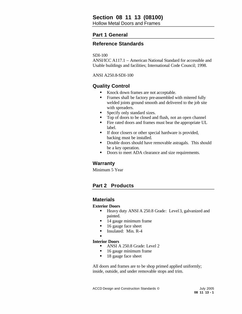
Section 08 11 13 (08100) Hollow Metal Doors and Frames
ACCD Design and Construction Standards © July 2005 08 11 13 - 1
Part 1 General
Reference Standards SDI-100 ANSI/ICC A117.1 – American National Standard for accessible and Usable buildings and facilities; International Code Council; 1998. ANSI A250.8-SDI-100 Quality Control § Knock down frames are not acceptable. § Frames shall be factory pre-assembled with mitered fully
welded joints ground smooth and delivered to the job site with spreaders.
§ Specify only standard sizes. § Top of doors to be closed and flush, not an open channel § Fire rated doors and frames must bear the appropriate UL
label. § If door closers or other special hardware is provided,
backing must be installed. § Double doors should have removable astragals. This should
be a key operation. § Doors to meet ADA clearance and size requirements.
Warranty Minimum 5 Year Part 2 Products
Materials Exterior Doors § Heavy duty ANSI A 250.8 Grade: Level 3, galvanized and
painted. § 14 gauge minimum frame § 16 gauge face sheet § Insulated: Min. R-4 §
Interior Doors § ANSI A 250.8 Grade: Level 2 § 16 gauge minimum frame § 18 gauge face sheet
All doors and frames are to be shop primed applied uniformly; inside, outside, and under removable stops and trim.

Section 08 11 13 (08100) Hollow Metal Doors and Frames
ACCD Design and Construction Standards © July 2005 08 11 13 - 2
All frames in masonry walls shall be grouted full with Portland cement grout. Part 3 Execution
Typical Location Hollow Metal Doors and Frames § All support spaces such as mechanical, electrical,
maintenance rooms. In interior, use only as required by code. § If double doors are used, a key operated removable mullion
is required. Hollow Metal Frames § Used at all doors throughout interior.

Section 08 11 16 (08250) Aluminum Doors and Frames
ACCD Design and Construction Standards © July 2005 08 11 16 - 1
Part 1 General
Reference Standards ASTM E283, E330, and E331 Quality Control New Construction § In new construction projects, finish to be clear anodized
aluminum. § Ensure that door can handle the heavy traffic that is to be
expected in a main entrance. § If door closers or other special hardware is provided,
backing must be installed. § Doors to meet ADA clearance and size requirements.
Renovations In renovation projects, finish to match existing finish, unless renovation will completely remove all storefront systems. Warranty Provide a notarized warranty to the owner that the Aluminum Entrance and Glass suppliers and the respective Manufacturers of each product, that all parts of work in this Section, including insulating glass units shall be free from defects in materials, workmanship and installation for a period of 5 years from the date of Substantial completion. Part 2 Products
Materials § Factory pre-finish is required. § Window units to be fixed non operable. § Thermal break is to be provided at exterior locations. § The doors should have heavy duty continuous hinges. § Ensure that door is specified to handle the heavy traffic that
is anticipated through the main entrances. § Automatic door hardware is to be located at all main
entrances. Part 3 Execution
Typical Location Aluminum Door and Frames systems are typically used as the entrance to a building.

Section 08 14 16 (08211) Flush Wood Doors
ACCD Design and Construction Standards © July 2005 08 14 16 - 1
Part 1 General
Reference Standards National Wood Window and Door Association Standards AWI/AWMAC Architectural Quality Standards Illustrated, Section 1300 Quality Control § Hollow Core Doors are not acceptable. § Specify only standard sizes. § All wood doors shall be mortised from templates furnished
by the hardware supplier and coordinated with the hollow metal supplier.
§ AWI Custom Grade § Doors to meet ADA clearance and size requirements.
Warranty Minimum 5 Year Part 2 Products
Materials § All wood doors to be solid core, 5 ply, guaranteed against
manufacturing defects for the life of the building. § Finish to be painted Birch or stained wood veneer. § Use structural composite lumber. § All edges of wood doors are to be sealed. § The species of wood used for the stiles should match the
door. § Light panels required at classrooms and offices. Refer to
Educational Standards. § Door stile should match veneer species.
Part 3 Execution
Typical Location § Interior only
Installation Doors should not be installed prior to building having dry conditioned air.
LEED Credit Opportunities: MR Credit 5.1, 5.2 Using materials harvested and manufactured within a 500 mile radius from the project site can assist with this credit . MR Credit 6 Using rapidly renewable materials can assist with this credit. MR Credit 7 Using a minimum of 50 percent of wood based materials and product incorporated into the project that is certified with the Forest Stewardship Council Guidelines can contribute with this credit. EQ Credit 4 Using low emitting VOC materials including: adhesives, sealants, paints, coatings can contribute to this credit.

Section 08 31 00 (08305) Access Doors and Panels
ACCD Design and Construction Standards © July 2005 08 31 00 - 1
Part 1 General
Quality Control § Trades should be coordinated to locate items needing access
in grouped locations to minimize the number of access doors.
§ Sizes are to be coordinated with MEP documents § Access doors in public areas are to be locked. § Access doors to crawl spaces are to be locked. § Access doors in toilet rooms to be stainless steel. § Access to crawl space should include a ladder.
Part 2 Products
Finishes The access panels should compliment the adjacent finishes of walls or ceilings. Part 3 Execution
Typical Location § All maintenance points where immediate access is required. § In wall, for plumbing valves and fittings. § In ceiling – above ceiling cut off valves, dampers, filter
units, j-boxes, meters. Installation Minimum sizes: Coordinate with MEP and with specific job requirements. Plumbing valves, reset buttons, controls manometers: 10”x10” in wall Plumbing fittings at toilets, mechanical filter banks, access hatches, areas requiring work access for unit replacement: 24”x24” in wall Above ceiling cut off valves, duct dampers, fire or smoke dampers, meters, registers: 12”x12” in ceiling HVAC filter units, remote duct dampers, remote fire dampers, remote electrical J-boxes, access hatches 24”x24” in ceiling

Section 08 41 00 Entrances and Storefronts
ACCD Design and Construction Standards © July 2005 08 41 00 - 1
Part 1 General
Reference Standards ASTM Standards E283, E330, E331 and ASCE 7 Quality Control § Submittals/ Shop drawings should be provided. § Sizes are to be coordinated with MEP documents § Doors to meet ADA clearance and size requirements.
Warranty 5 years from the date of Substantial Completion. Part 2 Products
Materials § Factory pre-finish insulating glass thermal break fixed non
operable. § Stainless steel fasteners. § At Northwest Vista, Samuels Glass doors to be provided.
Part 3 Execution
Typical Location § Used based on design criteria.

Section 08 42 29 Automatic Entrances
ACCD Design and Construction Standards © July 2005 08 42 29 - 1
Part 1 General
Reference Standards Underwriters Laboratories (UL) UL325 American national Standards Institute (ANSI) ANSI A156.10 National Fire Protection Associate (NFPA 101 Life Safety Code section 5-2.1.9 Quality Control § All major entrances to the building should have an ADA
accessible automatic entrance. § Ensure that a door stop is in place to avoid damage to door
system. § Ensure appropriate anchoring details § Mounting height above door.
Part 2 Products
Materials § Actuator type: Wireless manually operated – push plate. § Stanley Magic Force Hardware § Visual Sensor
Part 3 Execution
Typical Location § All major building entries and accessible routes §
Coordination § Electrical § Glazing

Section 08 71 00 Door Hardware
ACCD Design and Construction Standards © July 2005 08 71 00 - 1
Part 1 General
Reference Standards NFPA 101 Life Safety Code NFPA-80 Standard for Fire Doors and Windows ADA, the Americans with Disabilities Act- Title III TAS – Texas Accessibility Standards ANSI-A 117.1 – American National Standards Institute UL – Underwriter’s Laboratories Builder’s Hardware Manufacturer’s Association (BHMA) DHI – Door and Hardware Institute Quality Control § Hardware to be fitted prior to door finishing and then
removed. After finishing is completed, final installation of hardware to be made.
§ No names, designs or labels will be permitted on the following items: face of cylinders, turnpieces or operating trim of locksets or latchsets, push bars, pull handles, plates, case covers of surface applied closing devices and underside of door holder arms.
§ Hardware at Labeled Openings: UL label § All hardware products of each type used within a single
building shall be by one manufacturer. § All hardware shall be BHMA Grade 1. § Card readers to be electrical with back-up.
Warranty Warranty to be free of defects in material and workmanship and will perform the services for which it was intended for a period of 1 year, door closers for 10 years after substantial completion. Part 2 Products
Finishes § 612 – Dull Bronze § 613 – Oil Rubbed Bronze § 626 – Dull Chrome § 630 – Stainless Steel
Materials The following products are the standards. Standards listed should be verified by ACCD prior to finalizing specifications. § Levers and Trim § Locks and Latches

Section 08 71 00 Door Hardware
ACCD Design and Construction Standards © July 2005 08 71 00 - 2
Anti-friction deadlocking latch bolts Locksets, latchsets and deadlocks to be furnished complete with trim, armor fronts and 6 pin cylinders. Minimum ¾” throw on lock sets for pairs of doors. Schlage Lock Co. – Plymoth knob design with “E” type keyway. Product Numbers used by ACCD: Schlage ND10S RHO 626 Passage Set Schlage ND40S RHO 626 Privacy Set Schlage ND92RD RHO 626 O-bitted Vandlgard Entrance Lock Schlage ND94RD RHO 626 O-bitted Vandlgard Classroom Lock Schlage ND96RD RHO 626 O-bitted Vandlgard Storeroom Lock
Electronic Lock product numbers used by ACCD: Locknetics – PRO993LFS 06 with 26-091 CYL 626 for Von Duprin 99 Series Locknetics – PRO5196 626 06 26-091 CYL Lockset combination push button lock. Locknetics – PRO5596 626 06 26 091 CYL Mortise Lockset Combination push button lock Locknetics – CM993 MGK ATK 626 06 26 091 CYL Trim for 99 series Locknetics – CM 196 MGK ATK 626 06 26 091 CYL Lockset Locknetics – CM5596 MGK ATK 626 06 26-091 CYL Lockset § Cylinders, Cores and Keying
Heavy Duty 2 ¾” backsets with minimum 1/2” throw latch bolts typical and ¾” anti friction latch bolts at fire doors and pairs of doors. 2 ¼” x 1 1/8” beveled front 6 pin cyclinders for lock functions together with guard latch added to bolt. Box strikes with curved lips of suffiecient length to protect frames.

Section 08 71 00 Door Hardware
ACCD Design and Construction Standards © July 2005 08 71 00 - 3
All cylinders and keys will be properly tagged to indicate their intended location and to enable owner to establish their key control system. Keying: Locks for mechanical, electrical, telephone, elevator equipment and grounds irrigation shall be keyed alike.
§ Door Closers Heavy duty, surface mounted, full rack and pinion liquid (hydraulic) type with cast iron cylinders, capable of controlling door through 180 degrees of swing. Closers to have adjustable spring power to allow for closer sizing. No closers to be installed on the outside of any exterior door or on the corridor side of any room door. Blocking is to be provided for all door closers. Product used by ACCD: LCN 4041 RW-PA Al/Brz finish regular door closer. LCN 4041 RW-PA Del action Al/Brz finish ADA door closer.
§ Hinges and Pivots Five Knuckle, heavy duty, ball bearing, button tip, full mortise template type hinges. Exterior door hinges will be of steel with non removable pins. Interior door hinges will be of stainless steel. Pins: all interior hinges are to have non-rising pins. Sizes: Doors 3’-0” wide or less: 4 ½” x 4 ½” (1 ½ pr. hinges) Doors over 3’-0” wide: 4 ½”x4 ½” (2pr. Hinges) Quantity of Hinges per door as follows: Door up to 60” in height 1 pr (2 ea.) Door up to 90” in height 1 ½ pr (3ea)
Doors over 90” in height 1 additional hinge for every 30”
§ Exit Devises UL listed for life safety – UL Label “fire exit hardware”
§ Removable Mullions Von Duprin Key Removable Mullion – KR 4954 SP28/SP313 26-091 with mortise Cyl-housing and core.

Section 08 71 00 Door Hardware
ACCD Design and Construction Standards © July 2005 08 71 00 - 4
§ Flushbolts
Face mounted Dustproof strikes Minimum length 12” for all rods
§ Door Silencers Provide for all interior doors – 3 for single doors, 4 for pairs
§ Stops, Overhead Controls Wall stops are preferred over floor stops. Place door stops to allow for maximum door swing, but do not prevent a hazard or obstruction. Set anchors at least one inch into the concrete. Floor stops are to be set as to not allow a trip hazard. Wall stops are to be mounted with internal blocking.
§ Kickplates 10” high by width of door less 2”. Required on corridor side of doors. Match the finish of the lockset.
§ Push/Pull Plates § Thresholds, Gasketing and Door Bottoms
Provide thresholds and complete gasketing at all exterior doors. Provide smoke seals at all interior fire rated doors.
§ Electricfied Hardware, power Supplies, System Diagrams
§ Automatic Door Opener
Mechanical push button door openers are to be located at all building entries. This item must have a keyed building system override. Product Number:

Section 08 71 00 Door Hardware
ACCD Design and Construction Standards © July 2005 08 71 00 - 5
Stanley Magic Force for 36” opening with 2 each wireless remote buttons.
Part 3 Execution
Card readers to be located at all entry doors to all buildings. Card readers to be located at all classroom doors, and computer labs.

Section 08 80 00 Glazing
ACCD Design and Construction Standards © July 2005 08 80 00 - 1
Part 1 General
Reference Standards ASTM E 773, E 774 class CBA Quality Control § Glass with a film coating is not acceptable
Warranty Minimum 5 Year Part 2 Products
Materials Clear Glass Low E Glass Insulating Glass Tinted Glass Safety glazing – Tempered or laminated
Must be specified where required by codes, or when dictated by design judgment based on the intended application. § Exterior glazing to be clear low E insulated glass. § No reflective glass is to be used. § (VERIFY WITH ACCD EXTERIOR GLAZING
COLOR, SOME CAMPUSES HAVE STANDARDS) § Manufacturers stamp is to be provided on all glass required
by code to be heat tempered, heat strengthened or safety. § Northwest Vista College uses a smokey grey color glass. § Interior glazing to be a minimum of ¼” tempere d.
(VERIFY WITH ACCD) Part 3 Execution
Coordinate with Mechanical Engineer to evaluate heating and cooling loads for exterior glass.
LEED Credit Opportunities: EA Credit 1 Optimize Energy Performance by using Low E glass to reduce the demand on regulated energy systems. MR Credit 4.1 Recycled content: 5% (post consumer + ½ post-industrial) Many glass manufacturers meet this criteria. MR Credit 4.2 Recycled content: 10% (post consumer + ½ post-industrial) Many glass manufacturers meet this criteria. MR Credit 5.1 Regional Materials: 20% manufactured regionally Some glass manufacturers meet this criteria. MR Credit 5.2 Regional Materials: 50% manufactured regionally Some glass manufacturers meet this criteria. EQ Credit 8.1 Daylight and Views in 75% of spaces. EQ Credit 8.2 Daylight and Views in 90% of spaces.

DIVISION 9 – FINISHES 09 00 00 Finish Schedule
09 21 00 Plaster and Gypsum Board Assemblies
09 30 00 Tiling
09 51 00 Acoustical Ceilings
09 65 13 Resilient Base and Accessories
09 65 16 Resilient Sheet Flooring
09 65 19 Resilient Tile Flooring
09 66 00 Terrazzo Flooring
09 68 00 Carpeting
09 90 00 Painting

Section 09 00 00 Finish Schedule
ACCD Design and Construction Standards © July 2005 09 00 00 - 1
Part 1 General
The finish schedule below indicates the standard finish to be used for each space. Refer to the Educational Standards for additional finish requirements. Finishes are to be selected by the designer based on the Design and Construction Standards, Educational Standards, ACCD campus specific finishes, and programmatic requirements. Any deviations from the standards should be reviewed with ACCD and/or the project manager.
Space Floor Finish Base Wall Finish Clg. Finish Notes
Building Lobbies
Major Corridors
Terrazzo (preferred)
Tile / Stained Concrete (optional)
Ceramic Tile
(Terrazzo base only on buildings where change is very unlikely such as an auditorium)
Split Face CMU, Glazed CMU, Tile,
Gypsum Board and/or Acoustical Ceiling Tile
Materials chosen should be durable low maintenance materials
Minor Corridors Carpet / VCT Rubber Paint Acoustical Ceiling Tile
Classrooms Carpet or VCT Rubber Paint Acoustical Ceiling Tile
Administrative Carpet Tile Rubber Base Paint Acoustical Ceil ing Tile
Toilet Rooms Ceramic Tile (12” x 12” preferred)
Ceramic tile coved tile base with pre-manufactured inside and outside corners.
Ceramic Tile 8’ high on all walls
Note: All walls to use a cement board substrate.
Gypsum Board Toilet Partitions – Solid Plastic or Solid Surface (ie: Corian)
Countertops – Granite or Solid Surface (ie:Corian)
Cafeterias Terrazzo (preferred)
Tile / Stained Concrete (optional)
Tile Ceramic Tile 8’ high Gypsum Board and/or Acoustical Ceiling Tile
(in food areas tile will need to be vinyl faced)
Servery to be stainless steel, granite, or solid surface with stainless steel tray slides bars.
Kitchens Quarry Tile Quarry tile coved base, using pre-manufactured inside and outside corners.
FRP Panels Gypsum Board or Acoustical Ceiling with vinyl face
Elevators Terrazzo or Ceramic Tile
Solid Surface Material or Stainless Steel
Elevator standard with down lights
Elevator Equipment / Electrical
Sealed Concrete Rubber Paint None / Acoustical Ceiling Tile
Mechanical Equipment
Concrete with painted finish
Concrete Base CMU Walls with painted finish
None

Section 09 21 00 Plaster and Gypsum Board Assemblies
ACCD Design and Construction Standards © July 2005 09 21 00 - 1
Part 1 General
Reference Standards UL rated assemblies manual ASTM C 840 – control joints Gypsum Association Publications: GA 214, GA 216, GA 238, GA 253, GA 600.
Quality Control § Ensure Firestopping by code § Finish: Standard finish to be “orange peel” § Plumb: All assemblies shall have a tolerance of 1/8” in 10’
maximum. § All outside corners and furring to be floated with metal trim.
Part 2 Products
Materials § Use 5/8” type X gypsum board at all walls. § Use only cement backer board or other substrates
recommended by the gypsum association for application behind tile.
Part 3 Execution
Typical Location § Partitions that extend to deck should include:
o As required to meet fire code o Between classrooms o Toilet rooms o Electrical rooms o Mechanical room
§ Mechanical Rooms to have double layers of gypsum board and sound attenuation blankets.
LEED Credit Opportunities: MR Credit 4 Materials with recycled content can contribute towards this credit.

Section 09 30 00 (09300) Tiling
ACCD Design and Construction Standards © July 2005 09 30 00 - 1
Part 1 General
Reference Standards ASTM C 1028 Static Coefficient of Friction. ANSI A118.10, ANSI A118.4 ANSI A 137.1 American National Standards Specifications for Ceramic Tile Tile Council of America – Handbook for Tile Installation Quality Control § Finish to be matte on floor to meet requirements of heavy
traffic. § Contractor to provide written cleaning and maintenance
instructions with pre-submittal completion close-out documentation.
Part 2 Products
Materials / Finishes Floor Tile § Commercial ceramic tile for heavy traffic. § Toilet Room tile to be 8” x 8” – 12” x 12”. § Lobbies and Corridors to be 12” x 12” – 24” x 24” § Matte finish with a heavy commercial rating. § Medium to dark grouts to be used. § Appropriate trims to be used as needed. § Tile used as an exterior surface must meet minimum
requirements for coefficient of friction. Wall Tile § Commercial ceramic tile. . § Toilet Room Tile to be 4” x 4” – 12” x 12”. § Lobbies and Corridors to be 12” x 12” – 24” x 24” § Matte or glazed finish acceptable. § Medium to dark grouts to be used. § Use appropriate trims as needed. § Coved base is required standard in toilet rooms and kitchens,
with pre-manufactured inside and outside corners. Other Materials Requirements Waterproofing Membrane – ANSI 118.10 Use fabric-reinforced, modified –bituminous-sheet product: Self adhering SBS-modified bituminous sheet with woven reinforced facing for adhering to latex-portland cement.

Section 09 30 00 (09300) Tiling
ACCD Design and Construction Standards © July 2005 09 30 00 - 2
Setting and Grouting Materials § Latex-Portland Cement Mortar – ANSI 118.4 § Epoxy Grout – ANSI A 118.8
Thresholds To be stone or solid surface material fabricated to transition between floor finishes. In toilet rooms, threshold to set above ceramic tile floor finish by ¼” with a 1:2 beveled edge transition. Must meet ADA and TAS requirements. Attic Stock Part 3 Execution
Typical Location Toilet Rooms § Main public toilet rooms to use tile:
o Throughout floor area o 8’ minimum height on all walls o Epoxy grout at all public toilets
Floor drains and waterproofing membrane at all toilets Lobbies and Corridors Tile is one of the accepted materials for use in the Lobbies and major corridors. § Tile on walls in lobbies and major corridors to be a
minimum height of 4’. Installation § As per manufacturer’s recommendations. § Use no more than 1/8” grout joints typical. § At glazed wall tile use 1/16” grout joints. § Tile in kitchen areas must be sealed as recommended by
manufacturer. Preparation / Protection / Cleaning § As per manufacturer’s recommendations.

Section 09 51 00 (09510) Acoustical Ceilings
ACCD Design and Construction Standards © July 2005 09 51 00 - 1
Part 1 General
Quality Control Standard products § Edge condition: Panels shall be no less than 6” where
adjacent to wall. Edge trim shall be “L” type. § Products shall not contain any asbestos materials. § Install per ASTM C 636. § Maximum deflection in suspension system 1:360 § Maximum variation from flat and level: 1/8” in10’. § Maximum variation from plumb in grid system: 2 degrees.
Specialty products § Use specialty tile where required for sanitation, clean rooms,
or other special functions. Warranty Ten year warranty on suspension system, and a one year warranty on acoustical ceiling tile. Part 2 Products
Manufacturer Armstrong Ultima #1911 or equal. Beveled Tegular Ceiling with 15/16” grid or equal. Materials 24” x 24” x 5/8” lay-in acoustical ceiling tile fine texture with impact and scratch resistance. Finishes White Part 3 Execution
Typical Location § Throughout majority of spaces. § Use specialty tile where required for sanitation, clean rooms,
or other special functions. Installation / Protection / Cleaning Per manufacturer’s recommendations.
LEED Credit Opportunities: MR Credit 4 Using materials with recycled content can assist with this credit.

Section 09 65 13 (09650) Resilient Base and Accessories
ACCD Design and Construction Standards © July 2005 09 65 13 - 1
Part 1 General
Quality Control Base § 4” coved rubber base to be used, vinyl base not acceptable.
Accessories § Rubber flooring can be used on pedestrian style stairwells.
Other stairwell i.e. exit stairs, shall be concrete. § Transition strips, stair nosings, and treads to be rubber, vinyl
is not acceptable. Warranty 5 year limited warranty. Part 2 Products
Materials Base § 4” coved rubber base required. § In large open areas, continuous base is preferred. § Corners to be pre-molded rubber (both inside and outside
corners) Accessories § Rubber stair nosings, and stair treads and risers. Use heavy
duty grade. § Rubber accessories and transition strips. Use heavy duty
grade. Part 3 Execution
Typical Location Base § Resilient base shall be used at all carpeted and resilient
flooring areas. Accessories § At flooring transitions as needed. § At stair as needed.
Installation / Protection / Cleaning § Base and accessories to be installed using heavy duty epoxy
adhesive. § Per manufacturer’s recommendations.
LEED Credit Opportunities: EQ Credit 4.1 Using low emitting VOC adhesives can contribute to this credit.

Section 09 65 16 (09650) Resilient Sheet Flooring
ACCD Design and Construction Standards © July 2005 09 65 16 - 1
Part 1 General
Reference Vinyl: ASTM F 1303 Type II with backing Warranty 5 year limited warranty Part 2 Products
Materials / Finish § Vinyl Sheet Goods § Linoleum
Part 3 Execution
Typical Location Vinyl Sheet Goods Laboratories, and clean-rooms. Linoleum Corridors, and specialty area’s. Installation / Protection / Cleaning § Seams to be heat welded. § Per manufacturer’s recommendations.
LEED Credit Opportunities: EQ Credit 4.1 Using low emitting VOC adhesives can contribute to this credit. MR Credit 6.0 Using rapidly renewable materials can contribute to this credit.

Section 09 65 19 (09650) Resilient Tile Flooring
ACCD Design and Construction Standards © July 2005 09 65 19 - 1
Part 1 General
Reference Standards Vinyl Tile – ASTM F 1066 Rubber Tile – ASTM F 1344 Quality Control Vinyl Tile Asbestos-containing materials shall not be used. Rubber Tile Warranty 5 year limited warranty. Part 2 Products
Materials / Finish Vinyl Tile Use of solid color tile is discouraged. Homogeneous – through pattern 0.125 inch thickness Rubber Tile Homogeneous – color and pattern throughout 0.125 inch thickness Part 3 Execution
Typical Location Vinyl Tile Use of solid color tile is discouraged. Rubber Tile May be used in athletic rooms, for non-slip ramps as one option per architect/designers selection, and in areas where there is a need to provide sound control. Installation / Protection / Cleaning Per manufacturer’s recommendations. Test for moisture emission rate and alkalinity per ASTM F 710 to within limits recommended by tile and adhesive manufacturer recommendations.
LEED Credit Opportunities: EQ Credit 4.1 Using low emitting VOC adhesives can contribute to this credit.

Section 09 66 00 (09401) Terrazzo Flooring
ACCD Design and Construction Standards © July 2005 09 66 00 - 1
Part 1 General
Quality Control Provide control joints as needed. Part 2 Products
Materials New Construction Use 3” thick cementit ious Terrazzo with sand cushion or ¼” – ½” thick thin-set Terrazzo withy flexible epoxy membrane containing no VOC’s or plasticizers. Renovations Use ¼” – ½” thick thin-set Terrazzo. Use flexible epoxy membrane containing no VOC’s or plasticizers. Finishes Patterns and colors to be designed and selected by architect/designer. Part 3 Execution
Typical Location Lobbies, stairwells, corridors, cafeterias. Installation / Protection / Cleaning Only qualified installers can be used for installation. Per manufacturer’s recommendations.
LEED Credit Opportunities: MR Credit 4 Using materials with recycled content can assist with this credit. MR Credit 5 Using local material with 500 miles can assist with this credit.

Section 09 68 00 Carpeting
ACCD Design and Construction Standards © July 2005 09 68 00 - 1
Part 1 General
Reference Standards CRI – Carpet and Rug Institute Quality Control § Maintenance – refer to manufacturers recommendations for
cleaning § Broadloom carpet is not preferred. Only special applications
with approval of ACCD facilities will be permitted. Warranty Minimum 1 Year Installation from date of substantial completion. 15 year carpet material from date of substantial completion. Part 2 Products
Materials § Carpet Tiles should be used throughout the district. § Static control: Static rating shall be under 2kV in computer
labs and under 3.5 kV elsewhere § Provide 5% over-stock , with a minimum of one box of tile. § Adhesives: water resistant, mildew resistant, nonstaining
type to suit products and subfloor conditions indicated, that complies with flammability requirements for installed carpet tile and that is recommended by carpet tile manufacturer.
§ Carpet should have antimicrobial treatment. § Critical Radiant Flux Classification: not less than .45 w/sq.
cm. Part 3 Execution
Typical Location § Offices, conference rooms.
Installation § Glue down, install every tile with releasable adhesive. § Cut and fit carpet tile to butt tightly to vertical surfaces,
permanent fixtures, and built-in furniture including cabinets, pipes, outlets edgings, thresholds, and nosings.
§ Bind or seal cut edges as recommended by carpet tile manufacturer.
LEED Credit opportunities: MR Credit 1 Maintaining materials of an existing building can assist with this credit. MR Credit 2 Recycling or salvaging materia ls during renovations can assist with this credit. MR Credit 4 Using materials with recycled content can assist with this credit. MR Credit 3 Use of salvaged or refurbished materials can assist with this credit. EQ Credit 3.2 Contractor can conduct a two-week building flush-out or conduct a baseline indoor air quality testing procedure which can qualify for the Indoor Environmental Quality credit 3.2 EQ Credit 4.1, 4.3 Using low emitting VOC adhesives and carpet can contribute to this credit.

Section 09 68 00 Carpeting
ACCD Design and Construction Standards © July 2005 09 68 00 - 2
§ Extend carpet tile into toe spaces, door reveals, closets, open-bottomed obstructions, removable flanges, alcoves, and similar openings.

Section 09 90 00 (09900) Painting
ACCD Design and Construction Standards © July 2005 09 90 00 - 1
Part 1 General
Reference Standards § ASTM D 16 – Standard Terminology for Paint, Related
Coatings, Meterials, and Applications. § ASTM D 4442 – Standard Test Methods for Direct Moisture
Content Measurement of Wood and Wood-Base Materials; 1992 (Reapproved 2003)
§ ASHRAE Sted 62 – Ventilation for Acceptable indoor Air Quality; 2001
§ ASHRAE Sted 129 – Measuring Air-Change Effectiveness; 1997 (reaffirmed 2002)
§ SMACNA (OCC) – IAQ Guideline for Occupied Buildings Under Construction; 1995
Quality Control § In occupied buildings, low VOC is a requirement. This also
will assist with any LEED’s credits if needed. § Oil based paints are not accepted. § All similar coatings shall be from a single source.
Warranty One year. Part 2 Products
Manufacturers Use ‘first line” products from one of the following manufacturers. § Sherwin Williams § ICI Dulux
Materials Material Paint Schedule § Wood and metals to use Alkyd primer and paint. § Ferrous metals to use a metal primer. § Gypsum Board to use a Latex primer and paint. § Primers shall be type as recommended by manufacturer and
as approved by Architect. § Paints to be orange peel texture. § Follow manufacturer’s recommendations on materials for
primers and top coats. § Paint in toilet rooms to be Epoxy only.
LEED Credit opportunities: EQ Credit 4.2 Using low emitting VOC paints can contribute to this credit.

Section 09 90 00 (09900) Painting
ACCD Design and Construction Standards © July 2005 09 90 00 - 2
Interior Paint Schedule § Wall shall receive a primer with two (2)coats of semi-gloss
final coat paint. § Trim shall receive a primer with two (2)coats of gloss final
coat paint. § Ceilings shall receive a primer with two (2)coats of flat final
coat paint. Finishes Northwest Vista § SW 1101 China Doll § SW 1099 Knubby Wool § B55W102 C/M Vista Road
Per architect / designer. Part 3 Execution
Typical Location Throughout Installation / Protection / Cleaning § Apply paint before other absorbent materials are installed
such as carpet and acoustical ceiling tile. § Per manufacturer’s recommendations.
LEED Credit Opportunities: EQ Credit 3.2 Contractor can conduct a two-week building flush-out or conduct a baseline indoor air quality testing procedure which can qualify for the Indoor Environmental Quality credit 3.2

DIVISION 10 – SPECIALTIES 10 11 13 Chalkboards
10 11 16 Markerboards
10 11 23 Tackboards
10 14 00 Signage (Signage standards are located at end of Division 10)
10 21 13 Toilet Compartments
10 26 00 Wall and Door Protection
10 28 13 Toilet Accessories
10 44 13 Fire Extinguisher Cabinets
10 51 13 Metal Lockers
Signage Standards Section Pg. No. Sign Number
10 14 00 Graphic Standards
- 1 Introduction
- 2 Typography
- 4 Color Schemes
- 6 Mounting Conditions
- 7 Room Numbering
- 8 Interior Sign Schedule
- 9 Exterior Sign Schedule
10 14 01 Specifications
10 14 02 Interior Sign Types
Identification
- 1 Permanent Room or Space Function A1
- 2 Permanent room with Name Insert A2
- 3 Faculty / Staff Schedule Insert A3
- 4 Restroom / Locker Room A4
- 5 Stair A5
- 6 Stair Level A6
Directional and Information
- 7 Directional B1

- 8 Directional: Ceiling Hung B2
- 9 Building Directory B3
- 10 Building Plan Insert B4
- 11 Information B5
- 12 Freestanding Stanchion B6
Regulatory
- 13 Restricted Entry C1
- 14 Restricted Activity C2
- 15 Bracket-Hung C3
- 16 Emergency Exit C5
- 17 Fire Evacuation C6
10 14 03 Exterior Sign Types
Identification
- 1 Student Parking Lot User D1
- 2 Faculty/Staff Parking Lot User D2
- 3 Parking Lot D3
- 4 Visitor Parking D4
- 5 Reserved Parking D5-D7
- 8 Time Limit Visitor Parking D8
- 9 No Parking D9
- 10 No Parking This Block D10
- 11 Fire Lane D11
- 12 Motorcycle Parking D12
- 13 Freestanding Stanchion D13
- 14 Silk-screening on Doors D14
- 15 Metal Letters on Buildings D15
- 16 Building Plaques D16
Directional and Informational
- 17 Accessible Entry E1
- 18 Passenger Loading E2
- 19 Authorized Personnel Only E3
- 20 Loading and Unloading E4
- 21 Accessible Parking E5
- 22 Service Drive E6
- 23 Vehicle Directional E7

- 24 Wall-Mounted Directional E8
- 25 Pedestrian Map E9
Regulatory
- 26 Yield Sign F1
- 27 Stop Sign F2
- 28 Towing Sign F3
- 29 No Solicitation F4
- 30 Pedestrian Crossing F5
- 31 Speed Bump F6
- 32 Speed Limit F7
- 33 One Way F8
Texas Department of Transportation (selected standards)

Section 10 11 13 (10110) Chalkboards
ACCD Design and Construction Standards © July 2005 10 11 13 - 1
Part 1 General
Reference Standards ASTM E84 Standard test method for surface burning characteristics for building materials. ASTM B221 Standard for aluminum and aluminum-alloy extruded bars, rods, wires, profiles and tubes. Quality Control Warranty Under normal usage and maintenance, and when installed in accordance with manufacturer’s instructions and recommendations, the porcelain enamel steel marker boards will be guaranteed for the life of the building. Guarantee covers replacement of defective boards but does not include cost of removal or reinstallation. Part 2 Products
Products § 4’ x 4’ through 4’ x 16’ boards. Refer to Educational
Standards for size requirements for each room type. § All boards to include map rails with map hooks. § All boards to include full length marker tray § Chalkboards to be used only at Math and Science classrooms
and only with the approval from the department chairperson. Materials Porcelain enamel finish shall be fusion bonded to 24 gauge steel substrate at temperature necessary to reduce steel and porcelain stresses and achieve superior enamel bond and hardness. Trim and tray are to be satin anodized aluminum. § Face Plate: 24 gauge Vitracite chalkboard face sheet § Core Material: 7/16” MDF; 7/16” Duracore; or 3/8”
Duracore § Panel Backing: Moisture barrier back 0.005” aluminum foil
panel or 0.015” aluminum foil panel. Manufacturers Claridge Products or equal. Finishes White Board with satin anodized aluminum trim and tray.

Section 10 11 13 (10110) Chalkboards
ACCD Design and Construction Standards © July 2005 10 11 13 - 2
Part 3 Execution
Typical Location § Classrooms as needed based on educational standard
requirements. Installation § Install per manufacturer’s instructions. § Typical mounting height 37” from floor.
Preparation Cover and protect boards after installation and before occupancy. Protection / Cleaning Clean per manufacturer’s instructions.

Section 10 11 16 (10110) Markerboards
ACCD Design and Construction Standards © July 2005 10 11 16 - 1
Part 1 General
Reference Standards ASTM E84 Standard test method for surface burning characteristics for building materials. ASTM B221 Standard for aluminum and aluminum-alloy extruded bars, rods, wires, profiles and tubes. Quality Control Warranty Under normal usage and maintenance, and when installed in accordance with manufacturer’s instructions and recommendations, the porcelain enamel steel marker boards will be guaranteed for the life of the building. Guarantee covers replacement of defective boards but does not include cost of removal or reinstallation. Part 2 Products
Products § 4’ x 6’ through 4’ x 16’ boards. § All boards to include map rails with map hooks. § All boards to include full length marker tray
Materials Porcelain enamel finish shall be fusion bonded to 24 gauge steel substrate at temperature necessary to reduce steel and porcelain stresses and achieve superior enamel bond and hardness. Trim and tray are to be satin anodized aluminum. § Face Plate: 24 gauge LCS Markerboard § Core Material: 7/16” MDF; 7/16” Duracore; or 3/8”
Duracore § Panel Backing: Moisture barrier back 0.005” aluminum foil
panel or 0.015” aluminum foil panel. § Writing surface to be a low gloss surface of 65-75% of
reflectivity. Manufacturers Claridge Products or equal.

Section 10 11 16 (10110) Markerboards
ACCD Design and Construction Standards © July 2005 10 11 16 - 2
Finishes White Board with satin anodized aluminum trim and tray. Part 3 Execution
Typical Location § Classrooms as needed based on educational standard
requirements. § Conference rooms.
Installation § Install per manufacturer’s instructions. § Typical mounting height 37” from floor.
Preparation Cover and protect boards after installation and before occupancy. Protection / Cleaning Clean per manufacturer’s instructions.

Section 10 11 23 (10110) Tackboards
ACCD Design and Construction Standards © July 2005 10 11 23 - 1
Part 1 General
Reference Standards ASTM E84 Standard test method for surface burning characteristics for building materials. ASTM B221 Standard for aluminum and aluminum-alloy extruded bars, rods, wires, profiles and tubes. Warranty One year against defect in materials and workmanship. Warranty does not cover normal wear and tear, improper handling, misuse, or vandalism. Part 2 Products
Products 4’ x 4’ through 4’ x 16’ boards. Refer to educational standards for any specific size requirements. Materials
• Composed of ¼” thick self-healing, burlap backed cork laminated to a ¼” hardboard backing.
• Linoleum can be used as is alternate option for tack surface. Finishes Cork or Linoleum Part 3 Execution
Typical Location § Classrooms as needed based on educational standards and
requirements. § Corridors as needed.
Installation § Install per manufacturer’s instructions. § Typical mounting height 37” from floor.
Preparation Cover and protect boards after installation and before occupancy. Protection / Cleaning Clean per manufacturer’s instructions.

Section 10 21 13 (10155) Toilet Compartments
ACCD Design and Construction Standards © July 2005 10 21 13 - 1
Part 1 General
Quality Control § Plastic Laminate or painted metal partitions are not
acceptable. § Hardware and fittings must be heavy duty/institutional
grade. § Provide structural support as required if partitions are to be
ceiling mounted. Warranty 20 year warranty against breakage, delamination, and corrosion of solid plastic parts. Warranty does not include installation errors, improper usage, or vandalism. Part 2 Products
Manufacturers § For High Density Polypropylene or stainless steel partitions:
o Hadrian, Comtec Capitol Partitions or equal. § For Solid Surface/ Solid Color Reinforced Composite
Material partitions: o Bobrick, Corian, WilsonArt Gibralter, Wilson Art
Earthstone. Materials Partitions and Hardware to be Institutional Grade. Doors, panels, and pilasters to be one of the following: § High density polypropylene solid polymer. Floor mounted.
o Doors to be 1”, thick 55” high. o Pilasters to be 1” thick, 82” high. o Provide headrails for durability and stability, of
extruded aluminum construction with anti-grip design.
o Hardware and Fittings to be heavy duty extruded aluminum hinges that wrap both door and pilaster and to be full length continuous hinge system. Heavy duty brackets required.
§ Textured Stainless Steel. Floor or ceiling mounted. o Two sheets of panel flatness type 304 #4 brushed
finish rigidized stainless steel laminated under pressure to a “verticel” ½” honeycomb core.
o Doors to be 1” thick 55” high with cover sheets not less than 22 ga. (panels wider than 46” are 20 ga.)
o Pilasters to be 1 “ thick with cover sheets not less than 18 ga.

Section 10 21 13 (10155) Toilet Compartments
ACCD Design and Construction Standards © July 2005 10 21 13 - 2
o Hardware and Fittings to be chrome plated zinc die castings, standard. Doors shall be equipped with a gravity type hinge. Hinges shall be the wrap around type and adjustable.
o Provide structural support as required if ceiling mounting partitions.
§ Solid Surface Material / Solid Color Reinforced Composite Material. Floor mounted.
o Doors to be 3/4”, thick 55” high. o Pilasters to be 3/4” thick, 82” high. o Provide headrails for durability and stability, of
extruded aluminum construction with anti-grip design.
o Hardware and Fittings to be stainless steel. Hinges that wrap both door and pilaster. Heavy duty brackets required.
Accessories to include: § Coat hook, stainless steel. § Shelf
o Solid Surface built into wall o Stainless Steel fold-down with heavy duty hinge.
Finishes § To be selected from manufacturer’s standard finishes.
Medium to dark colors preferred. § For stainless steel partitions, finish to be textured.
Part 3 Execution
Typical Location All toilet rooms. Installation Install per manufacturer’s instructions. Protection / Cleaning Clean per manufacturer’s instructions.

Section 10 26 00 (10260) Wall and Door Protection
ACCD Design and Construction Standards © July 2005 10 26 00 - 1
Part 1 General
General Requirements There is no standard for wall and corner guards. Each project will dictate the type of guard and its location. ACCD prefers recessed corner guards when used. This will need to be planned and specified in construction documents. Part 2 Products
Materials Vinyl, plastic, wood, or stainless steel guards including corner guards and wall guards. At day care facilities finger guards are required. Part 3 Execution
Typical Location § Design team shall review locations for corner and wall
protection with ACCD. Note ACCD prefers recessed corner guards.
§ As a general rule protection of outside corners of gypsum board partitions in public corridors and lobbies needs corner protection to wainscot height. Spaces with moveable seating or carts should also consider wall protection at chair rail height at gypsum board partitions.

Section 10 28 13 (10810) Toilet Accessories
ACCD Design and Construction Standards © July 2005 10 28 13 - 1
Part 1 General
General Requirements ACCD has standard paper and supply products that they purchase. The specifications for these products shall be confirmed with ACCD prior to final documentation. ACCD also shall confirm if the contractor is to purchase those products or if ACCD will purchase those products directly through the vendor. Part 2 Products
Manufacturers Bobrick American Specialties Or equal Products The standards are as follows, equal products are acceptable : Paper Towel Dispenser & Waste Receptacle : American Specialties #046924 semi- recessed roll towel dispenser and waste receptacle. Dispenses rolls 8” or 9” wide preset lengths 2 ½” 4” or 5”. Receptacle is 14 gallons. Can be fully recessed (04692) or surface mounted (04692-9) Note semi-recessed or fully recessed is preferred. Paper Towel Dispenser: American Specialties #045224 semi-recessed roll towel dispenser. Dispenses rolls 8” or 9” wide preset lengths 2 ½” 4” or 5”. Receptacle is 14 gallons. Can be fully recessed (04523) or surface mounted (04523-9) Note semi-recessed or fully recessed is preferred. Napkin Disposal: American Specialties #0472 (partition mounted dual disposal) American Specialties #0473 (recessed mounted for side wall) American Specialties #0473-A (surface mounted for side wall) Toilet Paper Dispenser: Bobrick #B-2890 (holds 10” dia. / 3” dia. core roll) Bobrick #B-2892 (holds two 10” dia. / 3” dia. core roll) Napkin/Tampon Vendor: American Specialties #9468 (fully recessed) American Specialties #94684 (semi-recessed)

Section 10 28 13 (10810) Toilet Accessories
ACCD Design and Construction Standards © July 2005 10 28 13 - 2
Surface Mounted Soap Dispenser: Bobrick #B-5050 liquid dispenser, 50 oz. capacity, impact resistant polymer Grab Bars: Bobrick #5806 Series, 18 gauge, 1 ¼” diameter Framed Mirror: Bobrick #165 series, individual frames mirror with stainless steel frame. Mirror corners and back protected by shock-absorbing material. Baby Changing Station: Bobrick #2230 with pneumatic cylinder opening device. Station can be built in counter with sink and paper towel dispenser located near. Part 3 Execution
Typical Location All toilet rooms. Installation / Protection Per manufacturer’s recommendations , and to meet ADA requirements.
Section 10 44 13 (10522) Fire Extinguisher Cabinets
ACCD Design and Construction Standards © July 2005 10 44 13 - 1
Part 1 General
Reference Standards Reference Publications; NFPA 10, NFPA 10R, NFPA Fire Protection Handbook. Quality Control Type: Cabinets for fire extinguishers shall be recess mounted, or semi-recessed if walls do not allow fully recessed. In semi-recessed installation, cabinet shall only project 4” from wall. Fire extinguishers to be specified based on requirements of the project to meet code. Part 2 Products
Materials § Cabinet finish shall be brushed stainless steel. § Cabinet doors to be magnetic.
Part 3 Execution
Typical Location As required to meet code requirements.

Section 10 51 13 (10500) Metal Lockers
ACCD Design and Construction Standards © July 2005 10 28 13 - 1
Part 1 General
Quality Control Use painted metal lockers with solid fronts. All lockers to have vented fronts. Part 2 Products
Materials § For solid doors use standard corridor locks with double -pan,
honeycomb cored door. § Mild cold rolled sheet steel free from surface imperfections
and contaminants. § Continuous Hinge.
Finishes To be selected from manufacturer’s standard finishes. Part 3 Execution
Typical Location As required by program or educational standards such as athletics, art, etc. Installation Install per manufacturer’s instructions. Protection / Cleaning Clean per manufacturer’s instructions.

Outlined and illustrated on the pages to follow isa Graphic Standards Manual of interior andexterior signs that have been developed inresponse to Alamo Community CollegeDistrict’s (ACCD) desire to have a unified signsystem that will meet or exceed all applicablebuilding codes and federal regulations, and do soin an aesthetically pleasing manner. Thismanual is intended to be a district-wide designguideline for all campuses (present and future)and all other district properties. This wouldinclude: San Antonio College (SAC), Palo AltoCollege (PAC), St. Phillip’s College (SPC),Southwest Campus (SWC), and Northwest VistaCollege (NVC) as well as 811 W. Houston St.and 201 W. Sheridan St.
The Graphic Standards Manual is intended toassist sign manufacturers and, more specifically,campus facility directors by providing a checklistof standard signs that should be used as a basisto sign new campus buildings or existing campusbuildings that have been remodeled. Specificsign types with their dimensions, color schemes,mounting conditions and specifications areincluded in the manual, as well as a room num-bering system and typography.
All signs that are required to be accessible willcomply with the ADA Standards (Federal Regis-ter Vol. 56, No. 144, July 26, 1991) and theTexas Accessibility Standards (TAS) of theArchitectural Barriers Act, Article 9102, TexasCivil Statutes (effective April 1, 1994), and are inaccordance with the interpretation of the ADAguidelines developed by the Society for Environ-mental Graphic Design (SEGD) “White Paper,”dated June 1992.
Section 10 14 00 (10426)Graphic Standards - Introduction
ACCD Design and Construction Standards © July 200510 14 00 - 1

Text, arrow style and Braille shall be as follows:
ARRANGEMENT: Copy for interior signsshall be right-justified unless otherwise noted.Copy for exterior signs shall be center-justifiedunless otherwise noted.
SIZE: The size of all raised letters identifyingpermanent rooms and spaces shall be 5/8" high.All characters shall be upper case, unless signtype indicates lower case. Room numbers shallbe 1-1/2" high. Characters and numbers onexterior signs shall be sized according to theviewing distance.
BRAILLE: All Braille that identifies pictogramsand messages shall be placed directly below thecopy and right-justified.
ACCD Standards
NAMES: All rooms shall have either a genericor specific name as identified by the District.All District telecommunication rooms shall havea number only. The acceptable generic namesinclude the following:
CLASSROOM
LAB
LECTURE HALL
OFFICE
MECHANICAL
ELECTRICAL
HOUSEKEEPING
STORAGE
Section 10 14 00 (10426)Graphic Standards - Typography
ACCD Design and Construction Standards © July 200510 14 00 - 2

LETTERING: The typeface illustrated below isFUTURA medium. This typeface is the standardstyle to be used on all signs except metal letterson buildings, plaques or as noted otherwise.
A B C D E FG H I J K LM N O P QR S T U V WX Y Z a b c de f g h i j k lm n o p q r st u v w x y z1 2 3 4 5 67 8 9 0 , . /
ARROW STYLE: The arrow style used on allsigns shall be HELVETICA as shown below.
LETTERING: The typeface illustrated below isTIMES ROMAN normal. This typeface is thestandard style to be used for metal letters onbuilding exteriors and plaques or as noted other-wise.
A B C D E FG H I J K L MN O P Q R ST U V W X YZ a b c d e f gh i j k l m n op q r s t u v wx y z 1 2 3 4 56 7 8 9 0 , . /
Section 10 14 00 (10426)Graphic Standards - Typograpy
ACCD Design and Construction Standards © July 200510 14 00 - 3

Bennett Carriage House N/ASponsored Programs N/ALaw Enforcement Pantone Warm Gray 7CLaw Enforcement Annex N/A
ST. PHILIP’S COLLEGEFacilities Pantone 423CScience Building Pantone 423CWatson Fine Arts Center Pantone 423CPublic Safety Pantone 423CCentral Plant Pantone 423CHealth and FitnessCenter Devoe 2D37C “Denby”Continuing Education Pantone 690UApplied Science &Technology Pantone 690UG.J. Sutton LearningCenter Pantone 3435CNorris Technical Center Pantone 3435CCampus Center Pantone 423CE.L. Turbon StudentCenter Pantone 403CBowden Pantone 403C
NE LEARNING CENTERPantone Black 7C
PALO ALTO COLLEGEBusiness Building Pantone 5405CSocial Science Building Pantone 5405CLearning ResourcesCenter Pantone 5405CStudent LearningAssistance Center Pantone 5405CMath & ScienceBuilding Pantone 5405CApplied Sciences Pantone 5405CStudent Center Pantone 5405CAdministration Pantone 5405CFine Arts Pantone 5405CPerforming Arts Pantone 5405CCentral Plant Pantone 5405CFaculty Offices Pantone 5405CGeneral Education Pantone 5405CNatatorium/Gymnasium Pantone 16-5112Developmental Studies Pantone 5405CGeorge Ozuna Jr. LearningResources & AcademicComputing Center Pratt & Lambert 1284
ACCD Standards (Interior Signs)
The interior colors of each individual buildingshould be considered when determining thebackground color of the signs.
Raised WHITE characters shall be used with abackground color that blends with the interior.The selected color should be dark enough toprovide at least a 70% contrast with the whitecharacters.
The following color schemes are currently beingused at these District facilities:
SAN ANTONIO COLLEGEMotor Pool Pantone Warm Gray 7CPublic Safety Pantone Warm Gray 7CFacilities Pantone Black 3U2XKoehler House Pantone Warm Gray 7CKoehler Carriage House Pantone Warm Gray 7CFletcher AdministrationCenter Pantone Warm Gray 7CFrancis R. ScobiePlanetarium Pantone Warm Gray 7CNursing Education Pantone Warm Gray 7CRadio Television andFilm Hall Pantone Warm Gray 7CVisual Arts Center Pantone 432UHealth & PhysicalEducation Pantone Black 3U2XNail Technical Center Pantone 315UG.S. McCreless Hall Pantone 330UMcAllister Fine ArtsCenter Pantone 5487CLoftin Student Center Pantone 3308UGonzales Hall Pantone 342UChemistry & Geology Pantone 3U2XBusiness and IndustryCenter Pantone Black 7CTruett L. ChanceAcademic Center Pantone 3165U / 1807U -
color to match correspondingdoor frame
Child Development Pantone Black 7CMoody Learning Center Sherwin Williams
SW1006 "Silhoutte"Bennett Music Hall N/A
Section 10 14 00 (10426)Graphic Standards - Color Schemes
ACCD Design and Construction Standards © July 200510 14 00 - 4

SOUTHWEST CAMPUS3004 Pantone Warm Gray 7C3020 Pantone 431U
811 W. Houston St. Pantone Black 7C
201 W. Sheridan St.Building A,B, & C Pantone Black 7CPrint Shop Devoe 1D24C "Deleware'
The frame and post color for the above men-tioned signs will be as follows:
San Antonio College - match campus green(Martin-Senour “Levingston Kitchen Green”W84-1077)
St. Philip’s College - match campus gray-blue(Devoe 2D37C “Denby”)
Palo Alto College - pale gray (Pantone 428C)
Southwest Campus - pale gray (Pantone 428C)
811 W. Houston St. - match campus color(Pantone 175C)
201 W. Sheridan St. - match campus color(Pantone 175C)
Back panels of single faced signs shall be thesame color as the frame and post
ACCD Standards (Interior Signs cont.)
The following color schemes will be used at alldistrict facilities:
Sign types D2, D3 (Faculty & Visitor Lots), D4,D5, D8, D9, D10, D12, D13, E3, E4, E5, E6, F4,F7, and F8 shall be black graphics on a whitefield
Sign types D1 and D3 (Student Lots) shall beblue (Pantone 632C) graphics on a white field
Sign types D6, D7, E1, and E2 shall be blue(Pantone 2935C) graphics on a white field
Sign type D11 shall be red graphics on a whitefieldSign type D14 shall be white silkscreenedgraphics on glass
Sign type D15 shall be clear anodized castaluminum graphics
Sign type F1 and F2 shall be reflective graphicson field to match frame and post color
Refer to details for color schemes for sign typesD16, E7, E8, E9, F3, F5, and F6
ACCD Standards (Exterior Signs)
Section 10 14 00 (10426)Graphic Standards - Color Schemes
ACCD Design and Construction Standards © July 200510 14 00 - 5
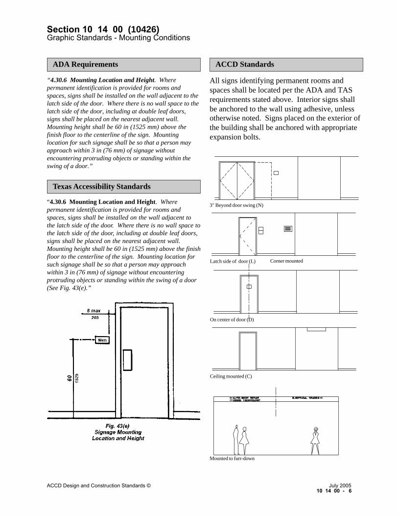
“4.30.6 Mounting Location and Height. Wherepermanent identification is provided for rooms andspaces, signs shall be installed on the wall adjacent to thelatch side of the door. Where there is no wall space to thelatch side of the door, including at double leaf doors,signs shall be placed on the nearest adjacent wall.Mounting height shall be 60 in (1525 mm) above thefinish floor to the centerline of the sign. Mountinglocation for such signage shall be so that a person mayapproach within 3 in (76 mm) of signage withoutencountering protruding objects or standing within theswing of a door.”
All signs identifying permanent rooms andspaces shall be located per the ADA and TASrequirements stated above. Interior signs shallbe anchored to the wall using adhesive, unlessotherwise noted. Signs placed on the exterior ofthe building shall be anchored with appropriateexpansion bolts.
ADA Requirements
Texas Accessibility Standards
“4.30.6 Mounting Location and Height. Wherepermanent identification is provided for rooms andspaces, signs shall be installed on the wall adjacent tothe latch side of the door. Where there is no wall space tothe latch side of the door, including at double leaf doors,signs shall be placed on the nearest adjacent wall.Mounting height shall be 60 in (1525 mm) above the finishfloor to the centerline of the sign. Mounting location forsuch signage shall be so that a person may approachwithin 3 in (76 mm) of signage without encounteringprotruding objects or standing within the swing of a door(See Fig. 43(e).”
ACCD Standards
3" Beyond door swing (N)
Latch side of door (L)
On center of door (D)
Ceiling mounted (C)
Corner mounted
Mounted to furr-down
Section 10 14 00 (10426)Graphic Standards - Mounting Conditions
ACCD Design and Construction Standards © July 200510 14 00 - 6

All rooms, including restrooms, mechanicalrooms, housekeeping, etc. shall be given a threedigit room number, beginning with 100 for thefirst floor, 200 for the second floor and so on.Basements will begin with the number “0" andnot the letter “B.”
The numbering sequence shall begin at the entryof “highest” use.
If possible, even numbers are located on the leftside of the corridor as you enter the main door,and odd numbers are located on the right.
Special use rooms, such as restrooms, mechani-cal rooms, housekeeping, etc. shall NOT beginwith a letter designation.
If additional rooms fall between two succeedingnumbers, such as an office inside of a depart-ment entry, then letter designations are given,such as 102A, 102B, etc.
Note: A deviation from this numbering systemwill occur in very large buildings such as Build-ing 3020 at Southwest Campus. Corridors shallbe assigned letter designations, and the roomnumber will follow. For example, room A101represents room 101 accessible from Corridor“A.” Another deviation may occur at very smallbuildings such as those at 201 W. Sheridan St.Rooms will be numbered in sequence beginningat the entry of “highest” use regardless of itslocation on the left or right of the corridor.
ACCD Standards
Section 10 14 00 (10426)Graphic Standards - Room Numbering
ACCD Design and Construction Standards © July 200510 14 00 - 7

BUILDING NAME:
MOUNTING LOCATION: Nearest mountable location, 3" beyond door swing ( N ), Ceiling ( C )Latch side of door ( L ), On center of door ( D ), Self - standing ( S ).
No.Room NameLOCATION
TYPESIGN
LOCATIONMOUNTING MESSAGE REMARKS
LEVEL:SIGN COLOR:
Section 10 14 00 (10426)Graphic Standards - Interior Sign Schedule
ACCD Design and Construction Standards © July 200510 14 00 - 8

CAMPUS:
No.TYPESIGN
CONDITIONINSTALLATION MESSAGE REMARKS
GRID SECTION:FRAME COLOR:
Section 10 14 00 (10426)Graphic Standards - Exterior Sign Schedule
ACCD Design and Construction Standards © July 200510 14 00 - 9

Section 10 14 01 (10426) Graphic Standards – Specifications
ACCD Design and Construction Standards © July 2005 10 14 01 - 1
The work includes fabrication and installation of interior and exterior signs. SUBMITTALS 1. Submit shop drawings indicating sign style,
sign construction and materials, mounting methods, lettering and locations, and overall dimensions of each type. For silk screened signs, submit full size, paper mock-up of sign illustrating letter sizing, spacing, sign layout and letter style.
2. Submit two samples of each proposed color selection for approval prior to fabrication.
3. Submit two full size samples of each type of sign illustrating construction, material, lettering style, colors specified and method of attachment. Accepted samples may be incorporated into the work.
4. Submit manufacturer’s installation instructions and cleaning instructions.
REGULATORY REQUIREMENTS 1. Design and fabricate signs to comply with
requirements of ADA and TAS. 2. Where the requirements of the two standards
are in conflict, the more stringent shall apply. DELIVERY, STORAGE AND HANDLING 1. Package signs to prevent damage from
marring, scratching, abrading or any other defacing of exposed surfaces.
2. If opaque packaging is used or if the text of the sign is obscured so that the sign cannot be easily identified while still wrapped, label signs on outside of packaging.
3. Provide small quantity of touch-up paint, in each color used, for future minor repairs. Submit to Owner’s Designated Representa-tive and obtain receipt signifying delivery.
CERTIFICATION 1. Certify that the Braille for each sign installed
is a true and accurate Grade 2 Braille transla -tion of the text in conformance with require-ments of ADA and TAS. If any errors are discovered, the Contractor shall pay all costs, including but not limited to new signs, re-certification and repair of wall and ceiling finishes damaged.
WARRANTY 1. Submit a written five (5) year warranty
endorsed by the manufacturer and the Contractor warranting signs against fastener and/or adhesive failure; coating failure including peeling, fading in excess of 5 NBS units and chalking; shrinking or peeling of appliqués on signs; or failures of any other type which render the signs unsightly and/or unreadable. Replace failed signs at no additional cost to the Owner. Deliberate destruction, intentional damage or defacing of signs are conditions excluded from warranty requirements.
MANUFACTURED PRODUCTS 1. Large Post and Panel Sign for sign types D1,
D2, F3, F4, and F5: Nominal 3-1/4" x 2-1/2" extruded aluminum frame and post with 0.090" aluminum sign face set in extruded panel frame with no exposed fasteners on sign faces. Sign panel(s) to be removable. Color, graphics and dimensions are as noted. Double-faced or single-faced with blank rear face, as noted. All exposed surfaces to be painted with custom color polyurethane. Provide five (5) year warranty on paint finish. Provide nominal 1/2" reveal between post and panel frame. Install with removable sleeve mount.
Products
General Requirements

Section 10 14 01 (10426) Graphic Standards – Specifications
ACCD Design and Construction Standards © July 2005 10 14 01 - 2
Andco Industries Corp. PP33 Sign series Charleston Industries, Inc. Series 325
standard ASI Sign Systems 2300 Series with 3" posts
or equal 2. Small Post and Panel Sign for sign type B6,
D4, D5, D6, D7, D8, D9, D10, D11, D12, D13, E1, E2, E3, E4, E5, E6, F6, F7, and F8: Nominal 2" x 2" extruded aluminum frame and post with 0.090" aluminum sign face set in extruded panel frame with no exposed fasteners on sign faces. Sign panel(s) to be removable. Color, graphics and dimensions are as noted. Single -faced with blank rear face unless otherwise noted. All exposed surfaces to be painted with custom color polyurethane. Provide five (5) year warranty on paint finish. Provide nominal 1/2" reveal between post and panel frame. Install with removable sleeve mount.
Andco Industries Corp. PP22 Sign series Charleston Industries, Inc. Series 225
standard ASI Sign Systems 2300 Series with 2" posts
or equal.
3. Small Post and Panel Sign for sign type F1 and F2 Steel post 10BWG tubing (2.875”outside diameter) with 0.08 inch thick aluminum alloy (Type A) meeting Texas Department of Transportation standards.
4. Directory for sign type B3: Model No. 435F Changeable Letter Directory Board manufactured by Claridge Products and Equipment, Inc. Provide white plastic Roman style letters and numerals as follows: (1) No. 385 - 3/4" size and (1) No. 386 - 1" size.
5. Extruded aluminum sign frame for sign type B4: EF2000 series manufactured by Andco Industries Corp.
6. Multi-Panel Signs for sign type E7: Nominal
2" x 2" or 2" x 3" extruded aluminum frame and post, sizes as indicated on drawings, with 0.090" thick aluminum size face set in extruded aluminum panel frame with no exposed fasteners on sign face. Sign panel(s) to be removable. Color, graphics and dimensions are as noted. Single -faced with blank rear face unless otherwise noted. All exposed faces to be painted with custom color polyurethane. Provide five (5) year warranty on paint finish. Provide nominal 1/2" reveal between post and panel frame. Install with removable sleeve mount.
Andco Industries Corp. PP33MPS Charleston Industries, Inc. Series 325
Changeable Word Bar ASI Sign Systems 2400S Series
7. Metal Letters for sign type D15: Cast aluminum, F-214 aluminum alloy, free of pits and gas holes. Hand dress letters for clean, sharp changes in plane. Deburr and mechanically texture all exposed surfaces to a uniform satin texture with striations in a uniform direction. Size and letter style as indicated, uniform thickness per letter size as follows: 4" high 1/4 - 1/2", 8" high 1/2 - 3/4", 12" high 1/2-1" and 16" high 1/2-1". Provide threaded bosses on rear of letters for projected mounting system. Provide clear (natural) anodized finish.
The Southwell Co. Architectural Letters OMC Industries, Inc. Cast Letters A.R.K. Ramos Architectural Signage
Systems Cast Letters
Products (cont.)

Section 10 14 01 (10426) Graphic Standards – Specifications
ACCD Design and Construction Standards © July 2005 10 14 01 - 3
8. Cast Plaques for sign type D16a-c:
a. Aluminum Plaques: AA356 alloy, cast in virgin ingots, free of pits, gas bubbles and other imperfections with sharp, hand-tooled characters of sizes and styles indicated. Clean entire plaque and paint background and edges with semi-gloss polyurethane paint. Buff letters, and border of plaque. The Southwell Co. Architectural Plaques
OMC Industries, Inc. Cast Plaques A.R.K. Ramos Architectural Signage
Systems Cast Letters Metal Arts Division of L&H
Manufacturing Co. Cast Metal Plaques
b. Copper Plaques: CDA 406 alloy, cast in
virgin ingots, free of pits, gas bubbles and other imperfections with sharp, hand-tooled characters of sizes and styles indicated. Clean entire plaque and paint background with semi-gloss polyurethane paint. Polish letters, border and beveled edge. Coat entire plaque with clear satin lacquer.
OMC Industries, Inc. Cast Plaques Metal Arts, Division of L&H Mfg. Co.
Cast Metal Plaques 9. Ceramic Plaques for sign type D16d: Molded
clay elements with unglazed backgrounds with glazed designs. Match construction and installation methods of existing units.
Beaumont Mood Lighting Inc., Attn: Cleo
McCall (210) 496-3591
10. Directory Case for sign type E9: Construct frame and door of extruded aluminum sections meeting ASTM B221. Fabricate case and door with neatly mitered and hairline joints. Weatherseal all joints and joint members with concealed fasteners and sealant compatible with members being jointed. Provide and install weathertight aluminum backpanel. Provide and install seamless, vinyl-coated cork back panels for interior of case. Glaze door with clear Lexan MR5 abrasion and UV-resistant sheet, 3/16" (0.1875") thick. Provide doors with weatherstripping, continuous non-corroding hinge and flat key tumbler lock. Finish all exposed surfaces, interior and exterior with custom color polyurethane paint. Provide five(5) warranty paint against peeling, crazing, chalking and fading in excess of 5 N.B.S. units. Internally light case with two 120V fluorescent light fixtures with cold weather electronic ballasts.
Claridge Products and Equipment, Inc. Series
548 Outdoor Changeable Letter Directory (no letters required)
MATERIALS 1. Tactile Signs: Photo-polymer process plastic
type at interior with lettering and Braille translations raised 1/32" from the background; total thickness required to comply with applicable regulations. Provide a minimum thickness at any point at completion of fabrication of not less than 0.0625"; laminate onto 0.10" thick acrylic backplate with permanent adhesive. For zinc or magnesium metal types, provide a minimum thickness of not less than 0.125". Signs installed at exterior or in interior humid environments must be zinc or magnesium type. Provide square edges and corners.
Products (cont.)

Section 10 14 01 (10426) Graphic Standards – Specifications
ACCD Design and Construction Standards © July 2005 10 14 01 - 4
2. Aluminum extrusions: ANSI/ASTM B221,
mill finish; free of dents, gouges, scratches and other surface distress visible after paint finishing.
3. Aluminum Plate: ANSI/ASTM B209, 6063 alloy, T5 temper, not less than 0.125" thick; mill finish; free of dents, gouges, scratches and other surface distress visible after paint finishing.
4. Fasteners: Aluminum, finished to match aluminum extrusions; tamper-resistant where exposed.
5. Attachment Devices: Tamper-resistant stainless steel screws with toggle bolts for hollow wall construction; tamper-resistant stainless steel screws with expansion shields for solid wall construction and tamper resistant stainless steel self-tapping screws into aluminum.
6. Adhesives: As recommended by manufacturers and Architect/Engineer accepted types for materials to be mated to substrate and service conditions.
7. Silk Screening Inks and Paints: Types recommended by sign installe r and compatible with substrate.
8. Clear Acrylic: Clear, cast acrylic; nominal 1/16" thickness.
9. Information Bar Clip: “Grip-A-Strip” with end caps, painted to match sign face.
10. Reflective Film: Series 580 Scotchlite reflective film manufactured by 3M, Inc.
11. Foam Tape: Double-coated open cell polyurethane rolled on release paper; No. 4016 manufactured by 3M, Inc.
12. Concrete: ASTM C94 ready mix concrete mixed from ASTM C150 Type 1 Portland Cement, ASTM C33 aggregates with 3/4" maximum size aggregates and clean, clear, potable water; with a 4 1/2" to 5" slump; developing 3000 psi compressive strength at 28 days.
LETTERING AND FINISHES 1. Lettering Size: Size as required to comply
with ADA and TAS or as indicated. 2. Lettering Style: Upper case Futura medium
unless otherwise noted. 3. Colors:
a. Lettering and Symbols: colors as noted. b. Backgrounds and Braille Characters:
custom color as selected. FABRICATION 1. Aluminum Framing:
a. Accurately fit and secure joints and corners. Make joints flush and hairline.
b. Arrange fasteners to be concealed from view.
c. Provide non-corrosive, adjustable, rubber casters/levelers on stanchions.
d. Paint all surfaces of framing as follows: 1. Prime with one coat; Tnemec series
66-1211 Epoxoline Primer, 3.0 to 5.0 mils dry film thickness (mdf).
2. Paint with one coat; Tnemec series 70 Endura-Shield, 2.0 mdf per coat.
e. Install end caps glued permanently in place except on replaceable panel signs.
2. Aluminum Plate Signs: a. Accurately cut plate to size. Dress edges
of plate to a smooth, square, straight edge.
b. Drill mounting holes for signs. Accurately place and regularly space holes.
c. Thoroughly clean all surfaces of plate in preparation for painting using SSPC SP-1 solvent cleaning specif ications. Remove all surface oil, grease, debris, oxidation and other forms of surface contamination.
d. Paint all surfaces of signs as follows: 1. Prime with one coat; Tnemec series
66-1211 Epoxoline Primer, 3.0 to 5.0 mils dry film thickness (mdf).
2. Paint with one coat; Tnemec series 70 Endura-Shield, 2.0 mdf per coat.
Products (cont.)

Section 10 14 01 (10426) Graphic Standards – Specifications
ACCD Design and Construction Standards © July 2005 10 14 01 - 5
e. Silk screen message on to sign with coating compatible with background paint.
f. Attach signs to supporting surface with screws and washers.
3. Plastic Signs: a. Fabricate signs of laminated-layered
construction with plastic spacers where required for insert slots. Cover insert slots with non-glare, clear acrylic set in recess for flush appearance.
b. Paint sign face, edges and background for insert slots using sign manufacturer’s recommended type of paint. Apply smooth, even coat of paint, free of dust, dirt, sand or other debris. In white color, paint faces of raised letters. Do not paint Braille to contrast with sign face. Finish all exposed surface with one coat of clear lacquer.
4. Zinc or Magnesium Metal Signs: a. Fabricate signs with routed slot where
required for inserts. Cover insert slots with non-glare, clear acrylic set in recess for flush appearance.
b. Paint sign face, edges and background for insert slots using sign manufacturer’s recommended type of paint. Apply smooth, even coat of paint, free of dust, dirt, sand or other debris. In white color, paint faces of raised letters. Do not paint Braille to contrast with sign face. Finish all exposed surfaces with one coat of clear lacquer.
5. Silk Screens: a. Produce silk screens through the
photographic process from accepted artwork submitted under the requirements for shop drawings.
EXAMINATION 1. Verify that surfaces are ready to receive
work. 2. Beginning of installation means installer
accepts existing surfaces. 3. The locating of utilities is the responsibility
of the Contractor. The Contractor should use extreme care when excavating for new footings. Where utility lines conflict with the proposed footing locations, coordinate new sign locations with the Owner’s Designated Representative. When unknown utilities are damaged during the course of the work, the Contractor should take immediate action to minimize damage and report damage to Owner. Where sprinkler irrigation lines or low voltage wiring conflicts with the proposed footing locations, relocate the sprinkler lines or wiring as required. The cost for relocations and repairs to irrigation lines and associated wiring should be included in the bid.
PREPARATION 1. Clean supporting surfaces prior to installation
of signs. Clean surfaces of dust, dirt, oil, grease or any other material which would preclude proper application of signs or which would detract from the finished appearance of signs after installation.
2. Sites are accessible to public at all times. The Contractor shall use extreme care to protect the public.
INSTALLATION 1. Install in accordance with manufacturer’s
instructions in numbers and in locations indicated on the drawings.
2. Locate in accordance with ADA and TAS. Verify locations for all signs with Architect/ Engineer.
Execution Products (cont.)

Section 10 14 01 (10426)Graphic Standards – Specifications
ACCD Design and Construction Standards © July 200510 14 01 - 6
3. Locate signs on wall surfaces, level. Mechanically attach signs to walls at exteriorand in high humidity environments. Wherewalls are solid, drill holes for toggle bolts,clean hole and fill with adhesive beforeinstalling toggle bolt. Remove misplacedadhesive.
4. Silk screen messages on glass as indicated.5. Install all interior signs (except humid
environment) using adhesive bead near perimeter. Mount sign using foam tape, being careful to maintain sign square and plumb on wall until adhesive sets. Install level and accurately centered on substrate. Provide a backup sign plate (opposite side) at each sign where mounted on glass. Each backup sign plate shall be the same size and color.
6. Surface mount Directory on the wall usingmanufacturer’s standard, concealed mountinghardware. Install level and secure to wallsubstrate.
7. Place free-standing signs where directed byArchitect/Engineer.
8. Install exterior post and panel signs withremovable sleeve mounts set in concretefooting. Footing to be sized by sign manufacturer. Set top of footing 2" above finish grade in planting areas and flush inhardscape areas. Slope top to drain.
9. Install exterior post and panel signs F1 and F2 based on Texas Department of Transportation standards.
10. Clean and polish signs. Clean substratessoiled during installation.
Execution
Wood fence attachment(fasten all four cornerswith screws)
Chain-link fence attachment(fasten all four corners with
stainless steel "pig-rings")
Loading dock - align sign withtop of railing / bolt sign postto concrete
Wall attachment(attach all four corners
with appropriate fasteners)

Aluminum bracket /screw attach to light pole
Bracket to be painted whiteto match sign
Sign type D3 / graphicson both sides / bolted
to bracket / level sign toaccommodate taper of pole
Bracket connection at squarelight pole
Bracket connection at roundlight pole
SAC Light Pole SAC Light Pole PAC, SWC, 811 W. Houston St.Light Pole
SPC Light Pole
15'-0" 15'-0" 15'-0"12'-0"
Section 10 14 01 (10426)Graphic Standards - Specifications
ACCD Design and Construction Standards © July 200510 14 01 - 7

Bollard Mount in Concrete or Asphalt Normal Mount in Concrete or Asphalt
Normal Mount in Soil Normal Mount in Pavers
Level Sloped
Concrete wash /Slope to drain
6" round pipebollard set 3'min. intoconcrete footing/Paint to matchframe
Post and Panel signwith removable sleevemount anchored inconcrete footing
1/2" controljoint with self-levelingpolyurethane sealanttypical
1/2" controljoint with self-levelingpolyurethane sealanttypical
Post and Panel signwith removable sleevemount anchored inconcrete footing
Post and Panel signwith removable sleevemount anchored inconcrete footing
Footing exposed onlow side / Use smoothSono tube form
Measure height ofsign from highestgrade point
Post and Panel signwith removable sleevemount anchored inconcrete footing
Footing covered bypavers to matchexisting / Sand bedover footing
Section 10 14 01 (10426)Graphic Standards - Specifications
ACCD Design and Construction Standards © July 200510 14 01 - 8

CLAASSROOMCLLASSSRROOOM
2011201
A1Permanent Room or Space Function
7"
Sign type A1 will be used to designate permanent rooms and spaces including, but not limited to: classrooms, offices,special use rooms and other spaces whose functions will not change.
GENERAL USAGE :
7"
1/4"1/2"
1/4"
1/4"
5/8"
5/8"
1/2"
1/2"
1/4"
1-1/2"
1/2"
Raised numbers
Braille
Third line, if required
Second line, if required
Raised letters
Braille
5/8"
1/2"
1/2"
Section 10 14 02 (10426)Interior Signage - Identification
ACCD Design and Construction Standards © July 200510 14 02 - 1

OFFICE
204204OFFICE
DR. GEORGE WRIGHT
A2Permanent Room with Name Insert
Sign type A2 will be used to designate permanent offices where assigned personnel will change and it is desirable todisplay their names. Names displayed will have no titles or associations before or after the name with the exception of"DR." The name strip can display up to three names if one office is shared by two or three faculty/staff members.
The information bar clip is intended to provide a method for hanging important messages. It can be used in conjunctionwith sign type A3 as well.
GENERAL USAGE :
7"
1-1/2"
7"
1/2"
1/2"
1/2"
3/4"
1/4"1/2"
5/8"
1/2"
1/4"1/2"
Raised numbers
Braille
Raised letters
White vinyl stickon letters or Kroytape over plasticinsert
Clear plastic"window"
Optional infor-mation bar clip
SECTION1/2"
Section 10 14 02 (10426)Interior Signage - Identification
ACCD Design and Construction Standards © July 200510 14 02 - 2

SCHEDULE
A3Faculty / Staff Schedule Insert
Sign type A3 will be used in conjunction with sign type A2 where it is desirable to display Faculty/Staff work scheduleswith their names. The insert will accommodate a standard 5" x 7" note card.
GENERAL USAGE :
7"
7"
5"
1/4"
3/4"
3/4"
1/4"
SECTION
Clear plastic"window"
Optionalinformationbar clip
Section 10 14 02 (10426)Interior Signage - Identification
ACCD Design and Construction Standards © July 200510 14 02 - 3

MEN'SLOCKERSLOCKERS
MEN'S
204204A4Restroom / Locker Room
GENERAL USAGE :Sign type A4 will be used to designate accessible restrooms and locker rooms.
6"
1/2"
6"
1/2"
1/4"1/2"
5/8"
1/4"
5/8"
1/4"
1-1/2"
1/2"
1/4"
1/2"1/4"
Raised numbers
Braille
1/16" x 1/16"reveal
Raised pictogram
a.
b.
c.
d.
e.
Raised letters
Braille
12"
1/2"
MEN'SRESTROOM
WOMEN'SRESTROOM
RESTROOM
MEN'SLOCKERS
WOMEN'SLOCKERS
Section 10 14 02 (10426)Interior Signage - Identification
ACCD Design and Construction Standards © July 200510 14 02 - 4

STAIRSSTAIRS
Raised pictogram
a.
b.
c.
d.
e.
1/16" x 1/16" reveal
Raised letters
Braille
A5Stair
GENERAL USAGE :
Sign type A5 will be used to designate stairs. This sign type will be mounted OUTSIDE the stairwell. Orient image onsign to match mounting location (left or right hand).
6"
1/2"
1/2"
5/8"
1/4"1/4"
6"
5/16"
8"
1/2"
Section 10 14 02 (10426)Interior Signage - Identification
ACCD Design and Construction Standards © July 200510 14 02 - 5

LEVEL
STAIR 22
A6Stair Level
Sign type A6 will be used to designate the stair level. This sign type will be located at strategic locations INSIDE thestairwell. This sign is required by code in buildings of four (4) or more stories.
GENERAL USAGE :
5" 12"
1"
1"
1-1/2"
1-1/2"
1"
1"
12"
Silkscreenedletters andnumbers onaluminum signpanel / Centerjustified
Section 10 14 02 (10426)Interior Signage - Identification
ACCD Design and Construction Standards © July 200510 14 02 - 6

RESTROOMSRESTROOMSGYM
AQUATICSGYM
AQUATICS
B1Directional
1/2" 3/4" 1/2"
3/8"
3/8"
3/4" 1-1/2"
1-1/2"
1-1/2"
VARIES
Blank panel
Raised letters andsymbols
1/16" x 1/16" reveal
Blank panel
Sign type B1 will be used to provide directional information and user orientation for room locations at strategic pointsin traffic patterns within buildings.
GENERAL USAGE :
12"
The exact height of this sign will be based on 1 1/2" increments, determined by the length and content of the messagedisplayed. Arrows will always be located along the right side of the sign.
NOTE:
OOOMSOOMS
Section 10 14 02 (10426)Interior Signage - Directional and Information
ACCD Design and Construction Standards © July 200510 14 02 - 7

AUDITORIUMAUDITORIUM
MM
B2Directional: Ceiling-Hung
Sign type B2 will be used to provide directional information and user orientation for room locations at strategic points incorridors within buildings. At gypsum board or plaster ceilings, provide removable sign face to anchor sign to ceilingframing from below. Minimum clearance from floor to bottom of sign will be 8'-0". Provide signs full width of corridorwhere appropriate. Where multiple signs are installed, use a consistent size for all signs. Arrows will always be locatedalong the right side of the sign.
GENERAL USAGE :
1/2"
3" 4"
1/2"
4"
4"
3"
Suspend from structure
Continuous wood block-ing, bolt to secure sign toceiling (do not overtighten)
1/4" painted woodspacer, full length
Weld nut to frame
3" precision cut plasticletters, adhere to sign
1/8" x 1/8" reveal
1/4" plastic signface,adhere to frame
1-1/2" aluminum channelframe at perimeter,painted
Precision cutplastic letters
1/8"x 1/8"reveal 4"
4"
4"
1"VARIES IN 6" INCREMENTS
1"
12"
Section 10 14 02 (10426)Interior Signage - Directional and Information
ACCD Design and Construction Standards © July 200510 14 02 - 8

GENERAL USAGE :
B3Building Directory
Surface mounteddirectory case
1" high whiteplastic letters
3/4" high whiteplastic letters
Black feltchangeableletter board
Sign type B3 will be used to provide directory information at a key entry point on the main floor in multi-story buildingsor at the main entry point to department offices.
24"
36"
ENGLISHENGLISHENGLISHENGLISHENGLISHDEPDEPDEPDEPDEPARTMENTARTMENTARTMENTARTMENTARTMENT
MARK COOKJANE SMITHROBERT JONES
431432433
Section 10 14 02 (10426)Interior Signage - Directional and Information
ACCD Design and Construction Standards © July 200510 14 02 - 9

B U I L D I N G N A M E
F L O O R L E V E L
1" high silkscreenedletters (bold)
1/16" x 1/16" reveal
Extruded aluminumsign frame to secureinsert - paint to matchsign
Clear plastic"window"
Building planon paper
Optional:1" high silkscreenedletters (bold)
B4Building Plan Insert
Sign type B4 will be used to provide directional information at key entry points in large buildings. The insert willaccommodate an 18" x 24" plan insert that is provided by others.
GENERAL USAGE :
3"
24"
3"
24"
Section 10 14 02 (10426)Interior Signage - Directional and Information
ACCD Design and Construction Standards © July 200510 14 02 - 10

DANGER
NO RUNNING
WETFLOOR
B5Information
24"
VARIES
Sign type B5 will be used to provide specific instructions about certain activities at the point of those activities. Thissign can be used in conjunction with sign type B6.
GENERAL USAGE :
The exact height of this sign will be based on 6" increments, determined by the length and content of the messagedisplayed.
NOTE:
Silkscreened letterson aluminum panel
Tamper-resistantscrews
Section 10 14 02 (10426)Graphic Standards - Directional and Information
ACCD Design and Construction Standards © July 200510 14 02 - 11

2"
B6Freestanding Stanchion
GENERAL USAGE :
Sign type B6 will be used to provide information at strategic points in traffic patterns within buildings. These units arelightweight, so their locations may be easily changed. Sign type B5 can be used in conjunction with this sign.
Optional "J" moldto hold posters
Cap exposed ends
Weld all jointsand grind smooth
2" x 2" x .125"extruded alum.tube frame
Non-corrosivelevelers
24"
12" 12" 2" 20" 2"
24"
2"2"
20"
2"
32"
60"
Section 10 14 02 (10426)Interior Signage - Directional and Information
ACCD Design and Construction Standards © July 200510 14 02 - 12

ONLYONLYPERSONNELPERSONNELAUTHORIZEDAUTHORIZED
C1Restricted Entry
Sign type C1 will be posted at the entrance to rooms that are accessible only by authorized personnel. It can be used inconjunction with sign type A1.
GENERAL USAGE :
1/2"
1/2"
2-1/2"
5/8"
1/4"
1/4"
1/4"5/8"
5/8"
1/2"
7"
1/2"
7"
Raised pictogram
Raised letters
Braille
1/2"
a.AUTHORIZEDPERSONNEL
ONLY
b.DO NOTENTER
Section 10 14 02 (10426)Interior Signage - Regulatory
ACCD Design and Construction Standards © July 200510 14 02 - 13

O R B E V E R A G E SN O F O O D
O R B E V E R A G E SN O F O O D
C2Restricted Activity
1/2"
1/2"
5/8"
1/4"
1/4"
5/8"
1/2"
7"
1/2"
7"
1/2"
Raised pictogram
a.
b.
c.
Raised letters
Braille
NO FOODOR BEVERAGES
NO PETS
Sign type C2 will be used to designate areas where certain activities are prohibited. Many variations of restricted activitysigns area available, with a few examples shown above.
GENERAL USAGE :
NO SMOKING
3-1/4"
1/2"
Section 10 14 02 (10426)Interior Signage - Regulatory
ACCD Design and Construction Standards © July 200510 14 02 - 14

Silkscreened pictogram
a.
b.
c.
d.
e.
C3Bracket-Hung
4"
1/2"
1/2"
3" 4"
Sign type C3 will be posted perpendicular to the line of travel at strategic locations to identify significant information oridentify rooms or information recessed in a vestibule. Many variations of bracket-hung signs are available, with a fewexamples shown above. Minimum clearance from floor to bottom of sign will be 80".
GENERAL USAGE :
f.
g.
Aluminum bracketwith tamper-resistantfasteners
Section 10 14 02 (10426)Interior Signage - Regulatory
ACCD Design and Construction Standards © July 200510 14 02 - 15

SOUND IF DOORIS OPENED
ALARM WILL
IS OPENEDSOUND IF DOOR
ALARM WILL
EXITEMERGENCYEMERGENCY
EXIT
C5Emergency Exit
1/2"
1/2"
5/8"
1/4"
1/4"
5/8"
1/2"
1/2"
7"
Silkscreenedletters
Braille
Silkscreenedletters
Braille
1/4"
1/4"
1/2"
5/8"
5/8"
Sign type C5 will be used to identify emergency exits and fire doors with alarms.
GENERAL USAGE :
7"1/4"
5/8"
1/2"
Section 10 14 02 (10426)Interior Signage - Regulatory
ACCD Design and Construction Standards © July 200510 14 02 - 16

DO NOT USE ELEVATORIn Fire Emergency
Use Stairs or Marked ExitsUse Stairs or Marked Exits
DO NOT USE ELEVATORIn Fire Emergency
YOU ARE HERE
EXIT
EXIT
EXIT
EXIT
EXIT
11
C6Fire Evacuation
GENERAL USAGE :
Sign type C6 will be conspicuously posted on each floor in the elevator lobby to advise occupants to use the stairsrather than the elevator in case of fire. This sign directs occupants to marked exits.
12"
1/2"
1-1/2"
1/2"1/2"
1/4"
1/4"
1/2"1/2"
8-1/2"
Raised letters
8-1/2" x 11" min.silkscreened floorevacuationdiagram
3/16" high min.
"YOU AREHERE" letters
3/16" high min.silkscreened"EXIT" identifi-cation
Raised number
Raised letters
12"
1/2"
Section 10 14 02 (10426)Interior Signage - Regulatory
ACCD Design and Construction Standards © July 200510 14 02 - 17

D1Student Parking Lot User
Non-illuminatedaluminum panel signwith painted graphics
ACCD logo
2" 2"
30"
26"
110"
30"
3"
9"
3"
9"
6"B Y P E R M I T O N L Y
STUDENTPARKING
��������� ����� ������������
30" x 30" Sign
large aluminum post and panelsign
aluminum cross brace
Removable sleeve mount
4"
3"
3"
3"
2-1/4"
1-1/4"
1-1/2"
Sign type D1 will be used to designate Student parking lots.
GENERAL USAGE :
Section 10 14 03 (10426)Exterior Signage - Identification
ACCD Design and Construction Standards © July 200510 14 03 - 1

D2Faculty / Staff Parking Lot User
Non-illuminatedaluminum panel signwith painted graphics
ACCD logo
2" 2"
30"
26"
110"
30"
3"
9"
3"
9"
6"B Y P E R M I T O N L Y
FACULTY/STAFF
��������� ����� ������������
30" x 30" Sign
Large aluminum post and panelsign
Aluminum cross brace
Removable sleeve mount
4"
3"
3"
3"
2-1/4"
1-1/4"
1-1/2"
Sign type D2 will be used to designate Faculty/Staff parking lots.
GENERAL USAGE :
Section 10 14 03 (10426)Exterior Signage - Identification
ACCD Design and Construction Standards © July 200510 14 03 - 2

D3Parking Lot
Sign type D3 will be used to designate parking lot numbers. These signs will be mounted on the light poles usingaluminum brackets the full height of the sign.
GENERAL USAGE :
Space foraluminumbracket
ACCD logo
Paintedaluminumsign
20"
LOT
415" 1-1/2"1-1/2"2"
1-1/2"
1-1/2"
15" 18"
1-1/2"
7-1/2"
Section 10 14 03 (10426)Exterior Signage - Identification
ACCD Design and Construction Standards © July 200510 14 03 - 3

D4
Non-illuminatedpainted aluminumpanel sign
84"
18"
2"
18" x 18" Sign
Sign type D4 will be used to identify visitor parking in designated areas. The sign can be used with or without thedirectional arrow.
GENERAL USAGE :
Small aluminum post and panelsign
Aluminum cross brace
Removable sleeve mount
4"
Visitor Parking
VISITORPARKING
2"2"
18"
14"
2"
1"
2"
5"
2"
1" 4"
Section 10 14 03 (10426)Exterior Signage - Identification
ACCD Design and Construction Standards © July 200510 14 03 - 4

Non-illuminatedpainted aluminumpanel sign
84"
18"
2"
18" x 18" Sign
Sign type D5 will be used to identify reserved parking spaces. The sign can be used with or without the directional arrow.
GENERAL USAGE :
Small aluminum post and panelsign
Aluminum cross brace
Removable sleeve mount
4"
Reserved Parking (President, etc.)
RESERVEDPARKING
1"
2"
8"
2"
D5
1"
2"
18"
Section 10 14 03 (10426)Exterior Signage - Identification
ACCD Design and Construction Standards © July 200510 14 03 - 5

Non-illuminatedpainted aluminumpanel sign with paintedgraphics
18"
2"
18" x 18" Sign
Sign type D6 will be used to identify "van accessible" parking spaces.
GENERAL USAGE :
Small aluminum post and panelsign
Aluminum cross brace
Removable sleeve mount
4"
Reserved Parking (Van Accessible)
RESERVEDPARKING
1"
2"
2"
D6
2"
1"
8"
VAN ACCESSIBLE 4"1"
Open between sign panels 2"
1-1/2"
1-1/2"
4" x 18" Signs
4"
18"
1"
VEHICLE PERMIT 1"
3/4"
1/2"
3/4"84"
$50-200 FINE WITHOUT
Section 10 14 03 (10426)Exterior Signage - Identification
ACCD Design and Construction Standards © July 200510 14 03 - 6

Non-illuminatedpainted aluminumpanel sign with paintedgraphics
84"
18"
2"
18" x 18" Sign
Sign type D7 will be used to identify "accessible" parking spaces.
GENERAL USAGE :
Small aluminum post and panelsign
Aluminum cross brace
Removable sleeve mount
4"
Reserved Parking (Accessible)
RESERVEDPARKING
1"
2"
2"
D7
2"
1"
8"
18"
4"
Open between sign panels 2"
4" x 18" Sign
$50-200 FINE WITHOUTVEHICLE PERMIT
1"
1"
Section 10 14 03 (10426)Exterior Signage - Identification
ACCD Design and Construction Standards © July 200510 14 03 - 7

D8
Non-illuminatedpainted aluminumpanel sign
84"
18"
1 1/2"
18" x 18" Sign
Sign type D8 will be used to identify time limited visitor parking in designated areas. The sign can be used with or withoutthe directional arrow.
GENERAL USAGE :
Small aluminum post and panelsign
Aluminum cross brace
Removable sleeve mount
4"
Time Limit Visitor Parking
TWOHOUR
2"2"
18"
14"
1 1/2"
1"
2"
2"
1" 3"
VISITORPARKING
1"
2"
1"
2"
1"
Section 10 14 03 (10426)Exterior Signage - Identification
ACCD Design and Construction Standards © July 200510 14 03 - 8

D9
Non-illuminatedpainted aluminumpanel sign
84"
18"
1 1/2"
18" x 18" Sign
Sign type D9 will be used to identify no parking areas. The sign can be used with or without the directional arrow and/or thetow-away zone message.
GENERAL USAGE :
Small aluminum post and panelsign
Aluminum cross brace
Removable sleeve mount
4"
No Parking
NOPARKING
2"2"
18"
14"
1 1/2"
1"
2"
2"
1" 3"
ANYTIMETOW-AWAY ZONE
1"
2"
1 1/4"
2"
3/4"
Section 10 14 03 (10426)Exterior Signage - Identification
ACCD Design and Construction Standards © July 200510 14 03 - 9

D10
Non-illuminatedpainted aluminumpanel sign
84"
18"
1 1/2"
18" x 18" Sign
Sign type D10 will be used to identify no parking areas in blocks. The sign can be used with or without the tow-away zonemessage.
GENERAL USAGE :
Small aluminum post and panelsign
Aluminum cross brace
Removable sleeve mount
4"
No Parking This Block
NO PARKING
18"
2"
1 1/4"
1 1/2"
2"
1 1/4"TOW-AWAY ZONE
1 1/4"
1 1/2"
1 1/2"
1 1/4"
3"
THIS SIDE
OF THISBLOCK
a. NO PARKINGTHIS SIDEOF THISBLOCK
b. NO PARKINGEITHER SIDE
OF THISBLOCK
Section 10 14 03 (10426)Exterior Signage - Identification
ACCD Design and Construction Standards © July 200510 14 03 - 10

D11
Non-illuminatedpainted aluminumpanel sign
84"
18"
18" x 18" Sign
Sign type D11 will be used to identify fire lane areas. The sign can be used with or without the directional arrow.
GENERAL USAGE :
Small aluminum post and panelsign
Aluminum cross brace
Removable sleeve mount
4"
Fire Lane
FIRELANE
2"2"
18"
14"
2"
2"
2"
2"
1"3"
NO PARKING
2"
1 1/2"
1 1/4"
1"
1 1/4"
AT ANY TIME
Section 10 14 03 (10426)Exterior Signage - Identification
ACCD Design and Construction Standards © July 200510 14 03 - 11

D12
Non-illuminatedpainted aluminumpanel sign
84"
18"
1 1/2"
18" x 18" Sign
Sign type D12 will be used to identify motorcycle parking areas.
GENERAL USAGE :
Small aluminum post and panelsign
Aluminum cross brace
Removable sleeve mount
4"
Motorcycle Parking
MOTORCYCLE
PARKING
18"
1 1/4"
1 1/2"
3"
3"
BY PERMIT ONLY
1 1/2"
6 1/4"
Section 10 14 03 (10426)Exterior Signage - Identification
ACCD Design and Construction Standards © July 200510 14 03 - 12

PARKING
RESERVED
2"
D13Freestanding Stanchion
GENERAL USAGE :
Sign type D13 will be used to provide temporary information at strategic exterior points. Typical message will be"RESERVED PARKING." 12" x 12" panels will be able to be inserted into channel frame for other messages. Theseunits are lightweight, so their locations may be easily changed.
Cap exposed ends
Weld all jointsand grind smooth
2" x 2" x .125"extruded alum.tube frameColor to matchcampus color
3/8" x 3/8" alum.channel at sidesand bottom
White front panelwith black textBack panel tomatch frame color
Alum. brace
Fill bottom tubeswith clean drysand to increaseweight
Non-corrosivelevelers
24"
12" 12" 2" 12" 2"
14"
4"
2"
12"
2"
28"
48"
Section 10 14 03 (10426)Exterior Signage - Identification
ACCD Design and Construction Standards © July 200510 14 03 - 13

D14
Sign type D14 will be used to identify entrances to buildings without other exterior identification signs. The first line willidentify the building. Following lines will identify the occupants.
GENERAL USAGE :
Silkscreening on Doors
ECOMMUNITY
CONFERENCE CENTER
PUBLIC RELATIONS
INTERNATIONALPROGRAMS 3/4"
3/8"3/4"
3/4"
3/4"
3/4"
3/4"
3/4"
3/8"
1 1/2"
4"
60"
4"
Text justified to latchside of door
Section 10 14 03 (10426)Exterior Signage - Identification
ACCD Design and Construction Standards © July 200510 14 03 - 14

D15
Sign type D15 will be used to identify campus buildings from a distance. Primary messages shall have 12" letters andlocated near the top of the builiding. Messages mounted at extreme heights shall have 16" letters. Secondary messagesshall have 8" letters and located near entrances. Messages on monument signs shall have 4" letters.
GENERAL USAGE :
Metal Letters on Buildings
VISUAL ARTSCENTER
LOFTINSTUDENTCENTER
G.S. McCRELESSHALL
12"
9"
12"
12"
9"
12"
12"
9"
12"
9"
12"
Center justify when not near a corner and in the center of a large wall space.
Left justify when near a corner to the left of the letters.
Right justify when near a corner to the right of the letters.
Cast aluminum clear anodizedletters, "Times Roman" font,1/2" projected mounting withaluminum spacer (typical)
Section 10 14 03 (10426)Exterior Signage - Identification
ACCD Design and Construction Standards © July 200510 14 03 - 15

D16
Sign type D16 will be used to identify campus buildings at building entrances. This sign type is used when sign type D15cannot be used.
GENERAL USAGE :
Building Plaques
Cast aluminumRaised 2 1/2" or 2" textPebble texture black backgroundClear coat lacquer finishBlind mounta. Southwest
Campus
b. St. Philip's College
c. San Antonio College
d. Palo Alto College
Cast aluminumRaised 2" text and logoPebble texture backgroundBackground color to match campus colorClear coat lacquer finishSingle line borderBlind mount
Cast brassRaised 2" or 1 1/2" textPebble texture black backgroundPolished brass with clear coat lacquer finishSingle line beveled edgeBlind mount
CeramicRaised 2" text, logo and borderUnglazed background and edgeRaised portions shall be glazedMatch existing plaques exactly in thickness, texture and color
CAMPUSCENTER
KOEHLER
HOUSE
FACULTYOFFICES
HOMEBUILDING
10 1/2"
12"
9"
24"
18"
18"
24"
5 3/4"
1 3/4"
10 1/2"
3/4" 3/4"
29"14 1/2"
12"
5 3/4" 5 3/4"1"1/2"1"1/2"
1/2"1"
8 3/4"
1"3/4"
Section 10 14 03 (10426)Exterior Signage - Identification
ACCD Design and Construction Standards © July 200510 14 03 - 16

Non-illuminatedpainted aluminumpanel sign with paintedgraphics
48"
Sign type E1 will be used to direct individuals to an accessible entry into a building.
GENERAL USAGE :
Small aluminum post and panelsign
Aluminum cross brace
Removable sleeve mount
4"
Accessible Entry E1
1"
6"
12"
12" x 12" Sign
a.
b.
c.
ACCESSIBLEENTRY
ACCESSIBLEENTRY
ACCESSIBLEENTRY
1 1/4"
3/4"
1 1/4"
1"
3/4"
ACCESSIBLEENTRY
1" 1"
12"
Section 10 14 03 (10426)Exterior Signage - Directional and Information
ACCD Design and Construction Standards © July 200510 14 03 - 17

Non-illuminatedpainted aluminumpanel sign with paintedgraphics
48"
Sign type E2 will be used to identify passenger loading at designated areas on campus.
GENERAL USAGE :
Small aluminum post and panelsign
Aluminum cross brace
Removable sleeve mount
4"
Passenger Loading E2
1"
6"
12"
12" x 12" Sign
1 1/4"
3/4"
1 1/4"
1"
3/4"
PASSENGERLOADING
1" 1"
12"
Section 10 14 03 (10426)Exterior Signage - Directional and Information
ACCD Design and Construction Standards © July 200510 14 03 - 18

Non-illuminatedpainted aluminumpanel sign with paintedgraphics
48"
Sign type E3 will be used to inform people of restricted areas, roads, paths, walkways, etc.
GENERAL USAGE :
Small aluminum post and panelsign
Aluminum cross brace
Removable sleeve mount
4"
Authorized Personnel Only E3
4"
1 1/2"
12"
12" x 12" Sign
1 1/2"
2 3/4"
1 1/2"
4"
2 3/4"
AUTHORIZED
ONLY
12"
PERSONNEL
Section 10 14 03 (10426)Exterior Signage - Directional and Information
ACCD Design and Construction Standards © July 200510 14 03 - 19

Non-illuminatedpainted aluminumpanel sign with paintedgraphics
48"
Sign type E4 will be used to identify loading and unloading zones.
GENERAL USAGE :
Small aluminum post and panelsign
Aluminum cross brace
Removable sleeve mount
4"
Loading and Unloading E4
2"
4"12"
12" x 12" Sign
1 1/2"
1"
1 1/2"
2"
1 1/2"
LOADINGAND
12"
UNLOADING
NO PARKINGAT ANY TIME
1"
1 1/4"
1"
1 1/4"
Section 10 14 03 (10426)Exterior Signage - Directional and Information
ACCD Design and Construction Standards © July 200510 14 03 - 20

ACCESSIBLEPARKING
ACCESSIBLEPARKING
ACCESSIBLEPARKING
Non-illuminatedpainted aluminumpanel sign with paintedgraphics
48"
Sign type E5 will be used to direct individuals to an accessible parking area when the area is not visually obvious.
GENERAL USAGE :
Small aluminum post and panelsign
Aluminum cross brace
Removable sleeve mount
4"
Accessible Parking E5
2"
3"
12"
12" x 12" Sign
a.
b.
c.
1 3/4"
1 3/4"
1 3/4"
2"
5 3/4"
ACCESSIBLE
PARKING
5" 5"
12"
8"
Section 10 14 03 (10426)Exterior Signage - Directional and Information
ACCD Design and Construction Standards © July 200510 14 03 - 21

Non-illuminatedpainted aluminumpanel sign with paintedgraphics
48"
Sign type E6 will be used to indicate service drives.
GENERAL USAGE :
Small aluminum post and panelsign
Aluminum cross brace
Removable sleeve mount
4"
Service Drive E6
5"
2"
12"
12" x 12" Sign
5"
2"
4"
SERVICE
DRIVE
12"
Section 10 14 03 (10426)Exterior Signage - Directional and Information
ACCD Design and Construction Standards © July 200510 14 03 - 22

Sign type E7 will be used to direct individuals in vehicles to key locations on a district campus. This sign may be single- ordouble-sided.
GENERAL USAGE :
Vehicle Directional E7
PALO ALTO COLLEGE
ADMINISTRATION
STUDENT CENTER
PERFORMING ARTS
CENTRAL PLANT
VISITOR PARKING
2" 2"
60"
56"
18"
60"
2"
5"
35"
3 1/2"
1 1/2"
2"
1 1/2"
Non-illuminatedpainted aluminumpanel sign withprinted graphics
Campus logo andcampus name incampus color onwhite panelBack panel onsingle sided sign tomatch post
Open
Silkscreened blacktext
Concrete footingengineered by signmanufacturerRemoveable sleevemount
Post color to matchcampus color
Section 10 14 03 (10426)Exterior Signage - Directional and Information
ACCD Design and Construction Standards © July 200510 14 03 - 23

Sign type E8 will be used to provide directional information and user orientation for key destinations at strategic points inexterior traffic patterns.
GENERAL USAGE :
Wall-Mounted Directional E8
CHANCELLOR'S OFFICE
PURCHASING
HUMAN RESOURCES
OFFICES
PRINTING
1/2"
Varies
18" 1/2" 1/2"
2"
2"
1/2"1"1/2"
2"
1"
Non-illuminatedpainted aluminumsign withsilkscreened lettersand arrows
Mount with exposedcountersunk fastners
Panel color to matchcampus color
Blank panel
Blank panel
1/16" x 1/16" reveal
The exact height of this sign will be based on 2" increments, determined by the length and content of the messagedisplayed. Arrows will always be located along the right side of the sign.
NOTE:
Section 10 14 03 (10426)Exterior Signage - Directional and Information
ACCD Design and Construction Standards © July 200510 14 03 - 24

Sign type E9 will be used to help individuals find their location and destination on a district campus with the use of a mapmounted inside the case.
GENERAL USAGE :
Pedestrian Map E9
30"
88"
12"
42" 44"
6"
26"
4"
2 3/8"
1 1/
2"
1/4"
1"
Silkscreen campus name and logo in campus color
Non-illuminated white painted aluminum panel
Large aluminum post and panel sign systemPaint to match campus color
30" wide by 42" high aluminum directory casewith aluminum locking door and fluorescent lightsDirectory case, back panel and trim to be paintedto match sign post color
2" silkscreen black letters / Times Roman Outline
Non-illuminated white painted aluminum panel
110V AC electrical service concealed inside ofsignCoordinate with sign manufacturer
Watertight "J" box mounted to postPaint to match post
Electrical in PVC conduit to be installed by ownerConnection to be completed by owner
Concrete footing to be engineered by sign manu-facturer
Aluminum sign system extrusionwith reveal
Fluorescent fixture
Weatherstripping at edge of door toprevent water infiltration
1/4" piano hinge
1/4" cork covered with vinylwallcovering on aluminum backingboard
Lock
1/8" aluminum sheet back panel flushwith caseSeal all joints and penetrations
1/8" thick clear Lexan to be clearwith no haze or yellowing character-istics
Map graphics by others
PALO ALTO COLLEGE
Section 10 14 03 (10426)Exterior Signage - Directional and Information
ACCD Design and Construction Standards © July 200510 14 03 - 25

F1Yield Sign
Sign type F1 will be used at locations where it is deemed appropriate for this type of traffic flow.
Section 10 14 03 (10426)Exterior Signage - Regulatory
ACCD Design and Construction Standards © July 200510 14 0 3 - 26
GE NE R A L USA GE :
48”
Sign shall meet Texas Department of
Transportation standards.
The alphabets and lateral spacing between
letters shall conform with the Texas
“Manual on Uniform Traffic Control Devices
for Streets and Highways”, latest edition,
and any approved changes thereto. Lateral
spacing of text shall provide a balanced
appearance. All materials shall conform to
Department Specifications.
Legend shall be applied by screening
process with transparent ink, cut-out
reflective sheeting applied to white
background or combination thereof.
Background shall be reflective sheeting
(Type C).

F2Stop Sign
GE NE R A L USA GE :Sign type F2 will be used at all exits from A CCD property and at major intersections within A CCD property.
Section 10 14 03 (10426)Exterior Signage - Regulatory
ACCD Design and Construction Standards © July 200510 1 4 30 - 27
48”
Sign shall meet Texas Department
of Transportation standards.
The alphabets and lateral spacing
between letters shall conform with
the Texas “Manual on Uniform
Traffic Control Devices for Streets
and Highways”, latest edition, and
any approved changes thereto.
Lateral spacing of text shall provide
a balanced appearance. All
materials shall conform to Depart-
ment Specifications.
Legend shall be applied by
screening process, cut-out white
reflective sheeting applied to
colored background or combina-
tion thereof. Background shall be
reflective sheeting (Type C).

F3Towing Sign
Non-illuminatedpainted aluminumpanel sign with paintedgraphics
30"
30"
5 1/2"
30" x 30" Sign
5"
10 1/2"
Sign type F3 will be used at all entrances to A CCD parking areas. T he wording of the sign shall match the type ofparking on the property ("a" for reserved parking lots, "b" for permit parking lots). T his sign should be located on theback of stop signs when the location meets state requirements for distance from the entry drive.
TO WIN G EN FO RCEDAT ALL TIMES
RESERVED PARK IN G O N LYIN DESIG N ATED AREAS
UN AUTH O RIZED V EH ICLES TO WEDAT O WN ER'S O R O PERATO R'S EXPEN SE
FO R TO WED V EH ICLES CALL:ACCD DPS 2 4 H O U R PH O N E
(210) 733- 2212V EH ICULO S SIN AUTO RIZACIÓ N SERÁN
TRASLADADO S CO N G RÚ A, Y EL CO STO SERÁPAG ADO PO R EL DU EÑ O DEL V EH ICU LO.
TO W I N G EN FO RCEDAT ALL TIMES
PERMIT PARK IN G O N LYIN DESIG N ATED AREAS
U N A U TH O RIZED V EH ICLES TO WEDAT O WN ER'S O R O PERATO R'S EX PEN SE
FO R TO W ED V EH I CLES CALL:A CCD DPS 2 4 H O U R PH O N E
(210) 733- 2212V EH ICU LO S SIN AU TO RIZACIÓ N SERÁN
TRASLADADO S CO N G RÚ A, Y EL CO STO SERÁPA G ADO PO R EL DU EÑ O DEL V EH ICU LO .
R ed graphics on awhite background
2" white letters on ared background
1" red letters on awhite background
White letters on a redbackground
1" red letters on awhite background
4 1/2"
5"
4"
Section 10 14 03 (10426)Exterior Signage - Regulatory
ACCD Design and Construction Standards © July 200510 14 03 - 28

F4No Solicitation
Non-illuminatedpainted aluminumpanel sign with paintedgraphics
2" black letters
1 1/2" black letters
30"
30"
GE NE R A L USA GE :Sign type F4 will be used at all entrances to A CCD administrative property.
N O SO LICITATIO NPERSO N S FO U N D TO B E
SO LICITIN G O N ACCD PRO PERTYWILL BE SUBJECTED TO ARREST
U N DER TEX AS P.C. 30.05 CRIMIN ALTRESPASS, A CLASS B
MISDEMEAN O R. A CLASS BMISDEMEAN O R IS PUN ISHABLE BY
A FIN E U P TO $1,500,CO N FIN EMEN T IN JAIL N OT TO
EXCEED 180 DAYS, O R B O TH.
Section 10 14 03 (10426)Exterior Signage - Regulatory
ACCD Design and Construction Standards © July 200510 14 02 - 29

F5Pedestrian Crossing
Non-illuminatedpainted aluminumpanel sign with paintedgraphics
30"
30"
1 1/4"
GE NE R A L USA GE :
1 1/4"
15"
Sign type F5 will be used at all pedestrian crossings on major roadways within A CCD property.
PED XIN G
Silkscreened blackgraphics and yellowfield on a whitebackground
4 7/8"
7 5/8"
3 1/2"
2"
8"
Section 10 14 03 (10426)Exterior Signage - Regulatory
ACCD Design and Construction Standards © July 200510 14 03 - 30

F6Speed Bump
Non-illuminatedpainted aluminumpanel sign with paintedgraphics
Silkscreened blackgraphics and yellowfield on a whitebackground
18"
15 1/2"
18"
1 1/4"
GE NE R A L USA GE :
1 1/4"
5"
11/
4"
11/
4"
Sign type F6 will be used to identify speed bumps within A CCD property.
SPEED
BUMP
5"
2"
2"
1 1/2"
Section 10 14 03 (10426)Exterior Signage - Regulatory
ACCD Design and Construction Standards © July 200510 14 03 - 31

F7Speed Limit
Non-illuminatedpainted aluminumpanel sign with paintedgraphics
Silkscreened blackgraphics on whitebackground
18"
18"
1"
GE NE R A L USA GE :
1"
1"
Sign type F7 will be used to regulate the speed of vehicles on roadways within A CCD property.
SPEED LIMIT
10O N
A CCDPROPERTY
1 1/2"
1 1/4"
3/4"
1"
6"
2"
1/2"
2"
Section 10 14 03 (10426)Exterior Signage - Regulatory
ACCD Design and Construction Standards © July 200510 14 03 - 32

F8One Way
Non-illuminatedpainted aluminumpanel sign with paintedgraphics
Silkscreened blackgraphics on whitebackground
18"
8"
84"
18"
2"
18" x 18" Sign
Small aluminum post and panelsign
Aluminum cross brace
Removable sleeve mount
4"
GENERAL USAGE:
2"
2 1/2"
5" 5"
Sign type F8 will be used to identify one way direction of travel on roadways within ACCD property.
ONE
WAY
2 1/2"
3 1/4"
2 3/4"
3"
a. ONE WAY
b. ONE WAY
c.
ONEWAY
DONOT
ENTER
Section 10 14 03 (10426)Exterior Signage - Regulatory
ACCD Design and Construction Standards © July 200510 14 03 - 33

DIVISION 14 - CONVEYING EQUIPMENT 14 00 00 Elevator Checklist
14 21 00 Electric Traction Elevators
14 24 13 Hydraulic Freight Elevator
14 24 23 Hydraulic Passenger Elevator
14 31 00 Escalator
14 42 00 Wheelchair Lift

Section 14 00 00 Elevator Checklist
ACCD Design and Construction Standards © July 2005 14 00 00 - 1
Part 1 General
Reference Standards This standard provides general guidance concerning the specific preferences of Alamo Community College for elevator and escalator basic requirements. Alamo Community College recognizes that project conditions and requirements vary, thus precluding the absolute adherence to the items identified herein in all cases. However, unless there is adequate written justification, it is expected that these guidelines will govern the design and specifications for ACCD projects. Part 2 Products
Alamo Community College does not have standard elevator manufacturers. Part 3 Execution
Elevator Checklist per ASME/ANSI A17.1
• One smoke detector is required in each elevator lobby. Wiring from the detector is run to the elevator machine room to the elevator controller. Smoke detectors shall not be self-resetting. Primary and alternate zones for smoke detectors are required to provide the code required elevator alternate landing feature. Rule 211.3. Sprinkler required in pit of hydraulic elevators.
• Metal pit ladder is to extend from the pit floor upward, not
less than 42” above the bottom landing floor level. One ladder per elevator is required. Rule 106.1
• Pit light and switch shall be accessible and 42” above the
bottom landing floor level. The pit convenience outlet shall be a GFI and mounted 48” above the pit floor. If sprinkled, NEMA 4 electrical apparatus required below four feet.
• Machine room to be vented, if necessary, to maintain
temperatures in the mid 80’s F. Rule 101.5b.
• Fused, padlockable mainline disconnect switch in machine room with feeder wires to elevator controller, all piped in accordance with N.F.P.A. and grounded. Disconnect switch must be in sight of the elevator machine and shall be the type that cannot be engaged with the door open. Rule 210.5. Shunt trip to be installed in disconnect or separate enclosure
Section 14 00 00 Elevator Checklist
ACCD Design and Construction Standards © July 2005 14 00 00 - 2
in the elevator machine room. A17.1 rule 102.2. If the elevator is a hydraulic type, the mainline disconnect shall have auxiliary contacts to remove power from the battery lowering unit.
• One (1) 120 volt, 20 amp, single phase power supply, fused
padlockable disconnect in machine room and run to the elevator controller for the car light supply, for each elevator.
• Provide an ADA compliant telephone or intercom in the
elevator cab that is hooked up to a 24-hour maintained location. Rule 211.1. Provide a phone in the elevator machine room for communication with the elevator car. The telephones will dial 9 through the campus PBX which will need a variance.
• Only elevator equipment is allowed in an elevator machine
room. A sprinkler head is required in the machine room. There shall be a heat detector mounted within 2 feet of the sprinkler head and there shall be a smoke detector in the machine room. When hoistway and/or machine room sprinklers are provided, then an automatic disconnect for elevator power (shunt trip) must be provided. Rule 102.2. When the hoistway is sprinkled, it shall have a head and smoke detector. If the hoistway is not sprinkled, there shall not be a smoke detector in the hoistway. For hydraulic elevators, sprinkler heads are required in the pit. If the sprinkler head is no more than two feet from the pit floor, no heat detector is required. All risers and returns shall be located outside of the hoistway and machine room. Branch lines in the hoistway shall supply sprinklers at no more than one floor level.
• Machine room doors shall be B labeled, self-closing, and
self-locking that can be opened from the machine room side without a key. Keys to unlock the machine room doors shall be readily accessible to authorized personnel, but not accessible to the general public. Rule 101.3d(4).
• All fire sprinkler risers shall be located outside elevator
hoistways. Rule 102.2
• Elevator hoistways shall be two (2) hour rated. Machine room (s) shall be rated for two (2) hour fire rating. There are exceptions to this rule, but it varies between areas. Rule 101.1a.

Section 14 00 00 Elevator Checklist
ACCD Design and Construction Standards © July 2005 14 00 00 - 3
• Pit shall be so designed and sized as to prevent the entry of ground water and remain dry. A sump pump is required and the sump pump recess must have a metal grate cover that is substantially flush with the pit floor. The sump pump is to have a separate circuit with a non-GFI simplex receptacle for the pump plug-in mounted 48” above bottom of the elevator shaft floor. Rule 102.2(5). The motor-rated switch for controlling the sump pump is to be mounted 42” (+6’-0”) above bottom landing floor level, adjacent to the light switch. Label switch “pump”. The pump discharge piping is to be routed to a location near the pump switch (42” above bottom landing floor level). A hose bib is to be placed on the piping at this point. Valves (gate and/or check) are not required in discharge pipe; only a union is to be installed at the pump for disassembly by maintenance. The local alarm panel shall be located above pump switch (where practical), shall have an alarm silence feature, and shall be powered from sump pump circuit at all times or other means. Switches and hose bib shall be located by ladder.
• All machine rooms must have permanent lighting. (10 foot
candles at floor). Rule 101.5.
• Hoistway walls shall be substantially flush on hoistway side. Any offsets over 2” shall be provided with a beveled angle of not less than 75 degrees. Rule 100.6.
• Pipes, conduits, or ducts conveying air, gases vapors, or
liquids which are not used in connection with the operation of the elevator are not permitted in the hoistway or machine rooms. Rule 102.2.
• Spaces containing machine, control equipment sheaves and
other machinery shall be enclosed with fire-resistive enclosure. Enclosures and access doors thereto shall have a fir-resistance rating at least equal to that required for the hoistway enclosure. Rule 101.1a.
• Grout space between floor and sill edge.
• Patch any holes in the hoistway wall and “clip” all screws or
other items projecting into elevator shaft.
• Refuge space between top of care and structure is to be 43” minimum. Rule 300.8g.
• Car number required in all cabs. (At least ½” in height).
Rule 211.9d.

Section 14 00 00 Elevator Checklist
ACCD Design and Construction Standards © July 2005 14 00 00 - 4
• Hall button wires to be in conduit. Rule 102.1.
• Ventilation of elevator shaft required for all elevators 4
floors or more. Rule 100.4.
• All hall button covers to have Appendix “H” pictograph with words: “In case of fire, elevators are out of service. Use exit”. UBC 3003.6.
• Verify with elevator consultant and structural engineer for
structural requirements.
• Verify with current code for fire rating of elevator shaft.
• Verify side clearance and determine if handrails are need on top of car.
• Hose Bibs are required in elevator pits.
Escalator Check List per ASME/ANSI A17.1
• Safety Zone: The entry and exit zones shall be kept clear of all obstacles. The width of the zones shall be not less than the width between the centerlines of the handrail plus 8” (203mm). The length of the zone, measured from the end of the newel, shall be no less than twice the distance between the centerline of the handrails. These dimensions are absolute minimums and every consideration should be given to traffic patterns. Rule 802.6d.
• The headroom shall be 7 ft. (2.13m) measured vertically
from the step noseline, landing plates, and landings. Rule 802.12.
• Rolling shutters, if used, shall be provided with a device that
shall be actuated as the shutters begin to close to cause the electric power to be removed from the escalator driving machine motor or brake. Rule 805.3g.
• The interior of the escalator truss shall have a GFI duplex
receptacle rated at not less than 15A, 120 V, accessibly located, provided under the access plates (Rule 806.3 at the top and bottom landing and in any machine areas located in the incline. Rule 806.1b.
• The lighting of escalator landing floor plates and all exposed
step treads shall be illuminated with a lighting intensity of not less than 5 footcandles (54lux). The illumination of

Section 14 00 00 Elevator Checklist
ACCD Design and Construction Standards © July 2005 14 00 00 - 5
these surfaceds shall be of uniform intensity and not contrast materially with that of the surrounding area. Rule 806.2.
• Reasonable access to the interior of the escalator shall be
provided for the inspection and maintenance. Rule 806.3.
• All electrical equipment and wiring shall conform to ANSI/NFPA 70.
ADA / TAS
• Elevators to meet all ADA and TAS requirements. Refer to ADA and TAS guidelines for elevator and clearance requirements.

Section 14 21 00 (14200) Electric Traction Elevator
ACCD Design and Construction Standards © July 2005 14 21 00 - 1
Part 1 General
Reference Standards This standard provides general guidance concerning the specific preferences of Alamo Community College for elevator basic requirements. Quality Control American Architectural Manufacturers Association (AAMA)
• AAMA 607.1 Voluntary Guide specification and Inspection Methods for Clear Anodic Finishes for Architectural Aluminum
American Society of Mechanical Engineers (ASME) • A17.1 Safety Code for Elevators • A17.2.2 Inspector’s Manual for Elevators
American Plywood Association (APA) American Society for Testing and Materials (ASTM) National Electrical Manufacturer’s Association (NEMA) National Fire Protection Association (NFPA)
• NFPA 70 National Electrical Code • NFPA 80 Fire Rated Doors and Windows
Americans with Disabilities Act MIL-L-1914: Lumber and Plywood, Fire Retardant Treatment AWS D1.1: Structural Welding Code AISC-Specifications for the Design, Fabrication, and Erection of Structural Steel for Buildings ANSI/IEEE 519: Electrical harmonic requirements Cab and clearances to meet ADA and TAS requirements. System Descr iption An Electric Elevator is a power elevator where the energy is applied by means of an electric driving machine. The machine includes the motor, brake, and the driving sheave or drum together with its connecting gearing. For buildings with up to 27 floors, a pre-engineered geared traction elevators are the most effective. These elevators are available in load capacities from 2,100 to 5,000 pounds and speeds from 200 to 500 feet-per-minute. A gearless elevator provide high speed service for any number of floors for capacities from 2500 to 4000 lbs. and speeds of 500 feet per minute and beyond.

Section 14 21 00 (14200) Electric Traction Elevator
ACCD Design and Construction Standards © July 2005 14 21 00 - 2
Specifications to include: • Type: Electric geared traction. (top mounted machine room
or offset mounted machine room.) • Control: Microprocessor based static type that is software
oriented. • Electrical Power: For elevator drive equipments: HP, 480
Volt, three-phase 60Hz. For lighting: 120 Volt, 60 Hz. • Drive System: Variable voltage variable frequency (VVVF) • Rated Net Capacity: lbs. • Rated Speed: ft/min. • Car Interior Dimensions • Cab Height • Cab Clear Ht. to suspended ceiling • Hoistway and Cab Entrance Frame opening size • Door Type/Operation: center opening, single slide; center
opening, two speed; single slide; single slide, two speed • No. of Stops: Number of stops; travel distance. • No. of Openings: Number; Number at front and number at
rear. Operation Select one of the following:
• Simplex Collective • Duplex Collective • Group microprocessor controlled demand allocation
Part 2 Products
Manufacturers Equivalent products by the following are acceptable.
• Thyssen Krupp • Kone • US Elevator Company /Tejas Elevators • United Technologies Otis Elevator Company • Schindler Elevator Corporation • Motion Control Engineering Inc. • Owner Approved Equal

Section 14 21 00 (14200) Electric Traction Elevator
ACCD Design and Construction Standards © July 2005 14 21 00 - 3
Materials Steel
• Shapes: ASTM A36 • Sheet: ASTM A446, galvanized, stretcher leveled,
Commercial Grade Stainless Steel: ASTM A167, Type 302 or 304 Aluminum: Anodizing Quality
• Extrusions: ASTM B221 • Sheet: ASTM B209, alloy 6063
Solid Surface: ISSFA-2 Paints
• Primer for Steel: Red Oxide (no lead). • Primer for Wood: Alkyd primer/sealer. • Enamel: Semigloss alkyd
Cab Design
• Flooring: Rubber flooring or aluminum checkered plate, ¼” thick. Architect to specify the “finish” floor. “Finish” floor materials to be rubber flooring, ceramic tile, slate, etc. VCT and carpet are not acceptable “finish” floor materials.
• Sides and rear walls: Solid Surface • Handrails: Stainless steel, cylindrical profile • Front and rear returns and transom: Stainless steel with No.
4 finish. • Ceiling: Translucent suspended specified distance under
ceiling. • Canopy: Baked enamel on steel specified distance under
canopy. • Ventilation: 2 speed blower mounted above ceiling, with
grille. • Lighting: Fluorescent with solid lens diffuser. • Provide wall hooks and removable protective mats for cab
walls. • Provide stainless steel license holders for display of required
certificates. Design the holder to used non-visible tamper-proof fastenings. Holder shall enclose an 8 ½” x 11” sign.

Section 14 21 00 (14200) Electric Traction Elevator
ACCD Design and Construction Standards © July 2005 14 21 00 - 4
Part 3 Execution
Installation Install in accordance with ASME A17.1, manufacturer’s instructions, and applicable codes. Coordinate with elevator consultants and structural engineer for structural requirements. Check code for fire rating of shaft.

Section 14 24 13 (14200) Hydraulic Freight Elevator
ACCD Design and Construction Standards © July 2005 14 24 13 - 1
Part 1 General
Reference Standards This standard provides general guidance concerning the specific preferences of Alamo Community College for elevator basic requirements. Quality Control American Architectural Manufacturers Association (AAMA)
• AAMA 607.1 Voluntary Guide specification and Inspection Methods for Clear Anodic Finishes for Architectural Aluminum
American Society of Mechanical Engineers (ASME) • A17.1 Safety Code for Elevators • A17.2.2 Inspector’s Manual for Elevators
American Society for Testing and Materials (ASTM) National Electrical Manufacturer’s Association (NEMA) National Fire Protection Association (NFPA)
• NFPA 70 National Electrical Code • NFPA 80 Fire Rated Doors and Windows
Americans with Disabilities Act MIL-L-1914: Lumber and Plywood, Fire Retardant Treatment AWS D1.1: Structural Welding Code AISC-Specifications for the Design, Fabrication, and Erection of Structural Steel for Buildings ANSI/IEEE 519: Electrical harmonic requirements Cab and clearances to meet ADA and TAS requirements. System Description Load Classifications Class A General freight loading. Where the load is distributed, the weight of any single piece is not more than ¼ the capacity of the elevator, and the load is handled on and off the car platform manually or by means of hand trucks. Class B Motor vehicle loading. The freight elevator is used solely to carry automobile trucks or passenger automobiles up to the rated capacity of the elevator.

Section 14 24 13 (14200) Hydraulic Freight Elevator
ACCD Design and Construction Standards © July 2005 14 24 13 - 2
Class C1 Industrial truck loading. A four wheeled vehicle may be used to load and unload the elevator. The combined weight of the vehicle and the load cannot exceed the rated capacity and may be rolled onto the platform as a single unit. Class C2 Industrial truck loading. During loading and unloading, max load on the platform may be up to 150% of the rated capacity. This enables you to use a forklift to load a car with freight weighing up to the rated capacity. Class C3 Other forms of industrial truck loading. During the loading and unloading process, the rated capacity must never be exceeded. Elevator Specifications to include:
• Control: Microprocessor based static type that is software oriented.
• Type: Hydraulic. • Operation: Single Automatic Push Button.This application
involves a bank of pushbuttons that are mounted in a car station. A time-delay prevents the car from being dispatched to another landing, and an “In Use” light will illuminate to show the elevator is being used.
• Electrical Power: For elevator drive equipments: HP, 480 Volt, three-phase 60Hz. For lighting: 120 Volt, 60 Hz.
• Rated Net Capacity: lbs. • Rated Speed: ft/min. • Loading Class: “A” or other • Car Interior Dimensions – width x height x depth • Landing entrances:
o Size o Type: vertical bi-parting, power operated o Construction: welded type o Material: steel prime and painted o Truckable sill on lower panel
• No. of Stops: Number of stops; travel distance. • No. of Openings: Number; Number at front and number at
rear. Operation
• Simplex Collective • Duplex Collective

Section 14 24 13 (14200) Hydraulic Freight Elevator
ACCD Design and Construction Standards © July 2005 14 24 13 - 3
Part 2 Products
Manufacturers Equivalent products by the following are acceptable.
• Thyssen Krupp • Kone • US Elevator Company /Tejas Elevators • United Technologies Otis Elevator Company • Schindler Elevator Corporation • Owner Approved Equal
Materials Steel
• Shapes: ASTM A36 • Sheet: ASTM A446, galvanized, stretcher leveled,
Commercial Grade Stainless Steel: ASTM A167, Type 302 or 304 Aluminum: Anodizing Quality
• Extrusions: ASTM B221 • Sheet: ASTM B209, alloy 6063
Plastic Laminate: NEMA LD-3, General Purpose Type Cab Design
• Flooring: Rubber flooring or non-skid steel plate platform. • Sides and rear walls: 14 Gauge steel panels that reach the
full car height. • Handrails: Stainless steel, cylindrical profile on rear wall. • Front and rear returns and transom: Stainless steel with No.
4 finish. • Ceiling: Highest possible ceiling height - 9’-0” minimum.
Translucent suspended specified distance under ceiling. • Canopy: Baked enamel on steel specified distance under
canopy. • Ventilation: 2 speed blower mounted above ceiling, with
grille. • Lighting: Fluorescent with solid lens diffuser. • Provide wall hooks and removable protective mats for cab
walls. • Provide stainless steel license holders for display of required
certificates. Design the holder to used non-visible tamper-proof fastenings. Holder shall enclose an 8 ½” x 11” sign.

Section 14 24 13 (14200) Hydraulic Freight Elevator
ACCD Design and Construction Standards © July 2005 14 24 13 - 4
Part 3 Execution
Installation Install in accordance with ASME A17.1, manufacturer’s instructions, and applicable codes. Coordinate with elevator consultants and structural engineer for structural requirements. Check code for fire rating of shaft.

Section 14 24 23 (14200) Hydraulic Passenger Elevator
ACCD Design and Construction Standards © July 2005 14 24 23 - 1
Part 1 General
Reference Standards This standard provides general guidance concerning the specific preferences of Alamo Community College for elevator basic requirements. Quality Control American Architectural Manufacturers Association (AAMA)
• AAMA 607.1 Voluntary Guide specification and Inspection Methods for Clear Anodic Finishes for Architectural Aluminum
American Society of Mechanical Engineers (ASME) • A17.1 Safety Code for Elevators • A17.2.2 Inspector’s Manual for Elevators
American Plywood Association (APA) American Society for Testing and Materials (ASTM) National Electrical Manufacturer’s Association (NEMA) National Fire Protection Association (NFPA)
• NFPA 70 National Electrical Code • NFPA 80 Fire Rated Doors and Windows
Americans with Disabilities Act MIL-L-1914: Lumber and Plywood, Fire Retardant Treatment AWS D1.1: Structural Welding Code AISC-Specifications for the Design, Fabrication, and Erection of Structural Steel for Buildings ANSI/IEEE 519: Electrical harmonic requirements Cab and clearances to meet ADA and TAS requirements. System Description The Hydraulic Elevator uses an oil hydraulic driving machine to raise and lower the elevator car and its load. A hydraulic pump unit is one in which the energy is applied by means of a liquid pressure in a cylinder equipped with a plunger or piston. The car is supported at the pit floor. Lower speeds and the piston length restrict the use of this system to approximately 55 feet. It generally requires the least initial installation expense, but more power is used during operation because the greater loads imposed on the driving machine. Specifications to include:
• Type: Hydraulic. Holed, holeless telescoping or holeless. • Control: Microprocessor based static type that is software
oriented. • Electrical Power: For elevator drive equipments: HP, 480
Volt, three-phase 60Hz. For lighting: 120 Volt, 60 Hz. • Rated Net Capacity: 2000-5000 lbs.

Section 14 24 23 (14200) Hydraulic Passenger Elevator
ACCD Design and Construction Standards © July 2005 14 24 23 - 2
• Rated Speed: 80-200 ft/min. • Car Interior Dimensions : varies with model • Cab Height: 8’- 0” • Door Height: 7’-0” • Cab Clear Ht. to suspended ceiling: highest possible • Hoistway and Cab Entrance Frame opening size : min. 36” • Door Type/Operation: single slide. • No. of Stops: Number of stops; travel distance. Typically
seven or less for Hydrolic. Holeless Hydrolic will have four or less.
• No. of Openings: Number; Number at front and number at rear. This depends on the building.
Operation
• Simplex Collective
Part 2 Products
Manufacturers Equivalent products by the following are acceptable.
• Thyssen Krupp • Kone • US Elevator Company /Tejas Elevators • United Technologies Otis Elevator Company • Schindler Elevator Corporation • Owner Approved Equal
Materials Steel
• Shapes: ASTM A36 • Sheet: ASTM A446, galvanized, stretcher leveled,
Commercial Grade Stainless Steel: ASTM A167, Type 302 or 304 Aluminum: Anodizing Quality
• Extrusions: ASTM B221 • Sheet: ASTM B209, alloy 6063
Solid Surface: ISSFA-2 Paints
• Primer for Steel: Red Oxide (no lead). • Primer for Wood: Alkyd primer/sealer. • Enamel: Semigloss alkyd

Section 14 24 23 (14200) Hydraulic Passenger Elevator
ACCD Design and Construction Standards © July 2005 14 24 23 - 3
Cab Design • Flooring: Rubber flooring or aluminum checkered plate, ¼”
thick. Architect to specify the “finish” floor. “Finish” floor materials to be rubber flooring, ceramic tile, slate, etc. VCT and carpet are not acceptable “finish” floor materials.
• Sides and rear walls: Solid Surface • Handrails: Stainless steel, cylindrical profile • Front and rear returns and transom: Stainless steel with No.
4 finish. • Ceiling: Translucent suspended specified distance under
ceiling. • Canopy: Baked enamel on steel specified distance under
canopy. • Ventilation: 2 speed blower mounted above ceiling, with
grille. • Lighting: Fluorescent with solid lens diffuser. Standard
light fixtures that are easily changed out. • Provide wall hooks and removable protective mats for cab
walls. • Provide stainless steel license holders for display of required
certificates. Design the holder to used non-visible tamper-proof fastenings. Holder shall enclose an 8 ½” x 11” sign.
Part 3 Execution
Installation Install in accordance with ASME A17.1, manufacturer’s instructions, and applicable codes. Coordinate with elevator consultants and structural engineer for structural requirements. Check code for fire rating of shaft.

Section 14 31 00 (14280) Escalators
ACCD Design and Construction Standards © July 2005 14 31 00 - 1
Part 1 General
Reference Standards This standard provides general guidance concerning the specific preferences of Alamo Community College escalator basic requirements. Quality Control American Architectural Manufacturers Association (AAMA)
• AAMA 607.1 Voluntary Guide specification and Inspection Methods for Clear Anodic Finishes for Architectural Aluminum
American Society of Mechanical Engineers (ASME) • A17.1 Safety Code for Elevators • A17.2.2 Inspector’s Manual for Elevators
American Plywood Association (APA) American Society for Testing and Materials (ASTM) National Electrical Manufacturer’s Association (NEMA) National Fire Protection Association (NFPA)
• NFPA 70 National Electrical Code • NFPA 80 Fire Rated Doors and Windows
Americans with Disabilities Act MIL-L-1914: Lumber and Plywood, Fire Retardant Treatment AWS D1.1: Structural Welding Code AISC-Specifications for the Design, Fabrication, and Erection of Structural Steel for Buildings ANSI/IEEE 519: Electrical harmonic requirements System Descript ion
• Quantity provided in pairs from floor to floor – one up and one down at each level.
• Escalator building number • Floors Served. • Speed: Escalator(s) shall ascend and descend at (select one
of the following): o 90 feet/minute (.48 M/sec) o 100 feet/minute (.51 M/sec)
• Vertical Rise. • Step Width (select one of the following):
o 24 inches (610 mm) o 32 inches (810 mm) o 40 inches (1016 mm)
• Electrical Power: Volts/three-phase 60Hz. Operation Select one of the following:

Section 14 31 00 (14280) Escalators
ACCD Design and Construction Standards © July 2005 14 31 00 - 2
• Simplex Collective • Duplex Collective • Group microprocessor controlled demand allocation
Part 2 Products
Manufacturers Equivalent products by the following are acceptable.
• Thyssen Krupp • Kone Inc • United Technologies Otis Elevator Company • Schindler Elevator Corporation • Owner Approved Equal
Materials Steel
• Shapes: ASTM A36, ANSI A17.1 • Sheet: ASTM A446, galvanized, stretcher leveled,
Commercial Grade Stainless Steel: ASTM A167, Type 302 or 304, No. 4 satin/brushed finish Aluminum: Anodizing Quality
• Extrusions: ASTM B221 • Sheet: ASTM B209, alloy 6063
Plywood: APA Structural I, Grade C-D, sanded. Plastic Laminate: NEMA LD-3, General Purpose Type Paints
• Primer for Steel: Red Oxide (no lead). • Primer for Wood: Alkyd primer/sealer. • Enamel: Semigloss alkyd
Escalator Components
• Ribbed moving treads with ribbed risers and comb step/impact plate thresholds – perimeter of treads shall be banded with painted yellow caution stripe on side, front, and back per ADAAG requirements
• Decks shall be stainless steel • Handrails shall be molded neoprene, steel mesh reinforced to
minimize stretch, black color • Balustrades and skirt panels shall be glass; narrow/slim
profile secured to decks

Section 14 31 00 (14280) Escalators
ACCD Design and Construction Standards © July 2005 14 31 00 - 3
Part 3 Execution
Installation Install in accordance with ASME A17.1, AWS D1.1, NFPA 70, AISC, manufacturer’s instructions, and applicable codes.

Section 14 42 00 (14420) Wheelchair Lift
ACCD Design and Construction Standards © July 2005 14 42 00 - 1
Part 1 General
Reference Standards This standard provides general guidance concerning the specific preferences of Alamo Community College for wheelchair lift basic requirements. Quality Control
• ANSI/ASME B20.1/ASME A17.1 Safety Standard For Conveyor and Related Equipment
• IEEE C1 – National Electrical Safety Code • State of Texas Accessibility Standards • ANSI 117.1 Accessibility Requirements • ANSI A18.1 – Wheelchair lifts
Wheelchair lifts should only be installed if a ramp can not be configured to meet accessibility requirements. Lift to meet ADA and TAS requirements. Part 2 Products
Manufacturers Equivalent products by the following are acceptable.
• American Stair Glide • Owner Approved Equal
System Description Rated Load: 450 lbs. Rated Speed: 20 fpm Suspension: Rack and pinion.
Part 3 Execution
Installation Install in accordance with ASME A17.1, ASME B20.1, AWS D1.1, IEEE C1, manufacturer’s instructions, and applicable codes.

DIVISION 21 – FIRE SUPPRESSION 21 01 10 Operation and Maintenance of Water-Based Fire-Suppression System
21 06 10 Schedules for Water-Based Fire-Suppression Systems
21 11 16 Facility Fire Hydrants
21 11 19 Fire-Department Connections
21 12 00 Fire-Suppression Standpipes
21 13 13 Wet-Pipe Sprinkler Systems
21 13 16 Dry-Pipe Sprinkler Systems
21 13 19 Preaction Sprinkler Systems
21 13 23 Combined Dry-Pipe and Preaction Sprinkler Systems
21 13 26 Deluge Fire-Suppression Spr inkler Systems
21 30 00 Fire Suppression Sprinkler System
21 31 13 Electric -Drive, Centrifugal Fire Pumps
21 31 16 Diesel-Drive, Centrifugal Fire Pumps
21 31 17 Natural Gas Drive, Centrifugal Fire Pumps

Section 21 01 10 (13975) Operation and Maintenance of Water-Based Fire-Suppression Systems
ACCD Design and Construction Standards © December 2004 21 01 10 - 1
Part 1 General Reference Standards Automatic Fire Sprinkler Systems: Perform work in
accordance with NFPA 13 1999 edition.
Quality Assurance Installation shall comply with all requirements of the Local
Code and the Authorities Having Jurisdiction.
Submittals Manufacturer's Installation Instruction: Indicate rough-in,
assembly, and general arrangement. Manufacturer’s Certificate: Certify that system has been
tested and meets or exceeds specified requirements and code requirements.
Hydraulic Calculations, Product Data, Shop Drawings: Bear stamp of approval of the local Fire Marshall and the Owner’s Fire Insurance Underwriter.
Equipment and Components: Bear UL and/or FM label or marking.
Provide certificate of compliance from Authority Having Jurisdiction indicating approval of field acceptance tests.
All electrical work shall comply with Division 260000.
Operation and maintenance data Submit under provisions of Section 230000. Operation Data: Include manufacturer's data. Maintenance Instructions: Include servicing requirements,
inspection data, replacement part numbers and availability, location and numbers of service agency, and test schedule.
Qualifications Installer: Company specializing and regularly engaged in the
design and installation of automatic fire sprinkler systems as specified in this Section with minimum three (3) years experience. Evidence to support the above requirements may be required and any proposed installer who cannot demonstrate suitable experience will be rejected.

Section 21 01 10 (13975) Operation and Maintenance of Water-Based Fire-Suppression Systems
ACCD Design and Construction Standards © December 2004 21 01 10 - 2
Regulatory requirements Conform to NFPA 14 Standard for Installation of Standpipe
and Hose Systems 1999 edition. Provide certificate of compliance from authority having
jurisdiction indicating approval of field acceptance tests.
Delivery, storage, and handling Deliver, store, protect, and handle products to site under
provisions of Section 230000. Store products in shipping containers and maintain in place
until installation. Provide temporary inlet and outlet caps. Maintain caps in place until installation.
Equipment, pre-painted piping and fittings and miscellaneous manufactured items such as valves, alarms and gauges shall be covered and protected during the execution of the work. Equipment and piping shall be protected from freezing. Labeling to remain in place.
Unloading, hauling, handling of materials, and cutting and patching required for installation shall also be the responsibility of the Contractor.
In the event of damage, immediately make repairs and replacements necessary at no expense to the Owner.
The Contractor shall take care to avoid marring the pre-painted surfaces of the piping systems to limit quantity of touch-up required.
Warranty One year from substantial completion date.
Part 2 Products Not applicable.
Part 3 Execution
Not applicable

Section 21 06 10 (13910) Schedules for Water-Based Fire-Suppression Systems
ACCD Design and Construction Standards © December 2004 21 06 10 - 1
Part 1 General
Reference Standards Automatic Fire Sprinkler Systems: Perform work in
accordance with NFPA 13 1999 edition.
Welding Materials and Procedures: Perform to ASME Code.
Valves: Bear UL and FM label or marking. All piping materials, fabrication, erection, flanging, welding,
tests, etc., shall be in accordance with ANSI and ASME B31.9, current edition.
ANSI A21.50 (AWWA C150) and ANSI A21.51 (AWWA C151) Cement mortar lined ductile iron, supplied in 16 feet laying lengths.
Steel Pipe: ANSI/ASTM A53, Welding Fittings: ANSI/ASTM A234 Seamless black steel Threaded Fittings: ANSI/ASTM B16. Flanges: ANSI B16.5, Companion Flanges: ANSI B16.1
Quality Assurance Installation shall comply with all requirements of the Local
Code and the Authorities Having Jurisdiction. All field welding and cutting operations shall strictly
conform to the requirements of NFPA 51B. Warranty One year from substantial completion date.
Part 2 Products
All materials and equipment used in the installation of the
sprinkler system shall be listed as approved by the Underwriters Laboratories, Inc., List of Inspected Fire Protection Equipment and Materials, or the Factory Mutual Testing Laboratories List of Approved Equipment, Fire Protection Devices and Devices Involving Fire Hazard, and shall be the latest design of the manufacturer. All piping, control valves, drain valves, fittings, etc. shall be as specified under this Section and related Sections, utilizing welded, flanged, threaded and grooved fittings only. Where valves are not specified by Figure No. they shall be of specified manufacture, UL listed and/or FM approved for service, and of same quality level as Figure Nos. specified.
Occupied areas shall include all those areas of the building

Section 21 06 10 (13910) Schedules for Water-Based Fire-Suppression Systems
ACCD Design and Construction Standards © December 2004 21 06 10 - 2
generally accessible to researchers, office staff, and students. Unoccupied areas shall include those areas of the building accessible only to building operating and maintenance personnel, e.g., storage rooms, janitor’s closets, etc.
Acceptable Manufacturers: Central. SimplexGrinnell Fire Protection Systems. GEM. Reliable Automatic Sprinkler Company. Star Sprinkler Corporation. Viking Corporation.
PIPING
Furnish and install in accordance with Section 21 13 13.
Valves
Furnish and install line control and trim and drain valves in
accordance with Section 21 13 13.
Sprinkler heads
Automatic sprinklers shall be FM approved and/or conform to the UL Fire Protection Equipment Directory for required application and shall be placed upright unless otherwise indicated, with the deflector parallel to the ceiling or slope of the roof. Clearances between deflectors and ceiling, roof decking, roof joists, and electric or heating equipment or other obstructions shall be in accordance with NFPA Standard 13.
The water distribution pattern shall be uniform, and shall have angles of discharge to provide coverage without excessive waste of water.
Water shall be discharged at, applied directly to and distributed equally over all surfaces and equipment to be protected.
Do not use on system pressures over 175 psi without specific high pressure listing.
Unless otherwise noted on the Drawings temperature rating of sprinklers shall be 165F, except in storage areas, compressed gas cylinder storage areas, loading docks, and standby generator rooms temperature rating shall be 286F. The temperature rating for sprinkler heads installed in elevator hoist ways and elevator machine rooms shall be approximately 25F higher than the temperature rating of the

Section 21 06 10 (13910) Schedules for Water-Based Fire-Suppression Systems
ACCD Design and Construction Standards © December 2004 21 06 10 - 3
heat detector furnished and installed in these areas by the Division 260000 Fire Alarm System Contractor. All sprinkler shall be color coded for temperature.
Orifice size shall be 1/2 inch for sprinklers in Light Hazard and Ordinary Hazard (Group 1) occupancies and 17/32 inch for sprinklers in Ordinary Hazard (Group 2) Occupancies.
Occupied Areas with Suspended Ceiling: Type: Standard pendant type with matching escutcheon plate. Head Finish: as selected. Escutcheon Plate Finish as selected. Cover Plate: Cover plate shall provide no less than 1/2 inch
adjustment; white finish. Fusible Link Glass bulb type temperature rated for specified
area hazard.
Unoccupied Areas with Suspended Ceiling: Type: Standard pendant type with matching screw-on escutcheon plate. Head Finish: as selected. Escutcheon Plate Finish as selected. Cover Plate: Cover plate shall provide no less than 1/2 inch adjustment; white finish. Fusible Link: glass bulb type temperature rated for specified area hazard.
Exposed Area Type: Type: Standard upright type with guard. Head Finish: as selected. Fusible Link: [Glass bulb type temperature rated for specific area hazard.
Sidewall Type: Type: Standard horizontal side wall type with matching scutcheon plate [and guard]. Head Finish: as selected. Escutcheon Plate Finish Fusible Link: Glass bulb type temperature rated for specific area hazard.
On/Off Type: Type: Flush, self-recycling type, capable of shutting off flow due to the removal of heat. Finish: Chrome plated. Escutcheon Plate Finish: Chrome plated. Fusible Link:

Section 21 06 10 (13910) Schedules for Water-Based Fire-Suppression Systems
ACCD Design and Construction Standards © December 2004 21 06 10 - 4
The sprinkler assembly shall have an initial dual actuation which consists of a thermally sensitive glass bulb (which acts to hold a seat in place) and a bimetallic disc (which actuates a piston assembly). The disc and piston assembly shall not incorporate “O” rings in the sealing design.
Dry Type: Type: Dry pendant or horizontal side wall type as indicated
on the Drawings, utilizing center strut in compression principle of construction to control valve mechanism at the inlet end. Valve shall seal pressurized water or air from the sprinkler tube until the sprinkler is activated.
Finish: Chrome plated. Escutcheon Plate Finish: Chrome plated. Fusible Link: Temperature rated for specific area hazard. Guards: Finish to match sprinkler head.
Fire hydrants U.L. listed and FM approved rated at 175 PSI working
pressure and tested at 300 PSI. Threads shall comply with local Fire Department requirements.
Detector check valve U.L. listed and FM approved; bronze or galvanized cast iron
body and suitable for 175 PSI working pressure and tested at 350 PSI.
Fire protection valve tamper switch UL rated and/or FM approved valve supervisory switch.
Part 3 Execution
Preparation Make all joints smooth and unobstructed inside. Ream all
cut pipe and tube ends to remove burrs. Bevel plain end ferrous pipe before welding. Remove all obstructions prior to fabrication.
Remove scale and foreign material, from inside and outside, before assembly. Before installing pipe that has been cut and threaded, the lengths of pipe shall be upended and tamped to remove all shavings.
Prepare piping connections to equipment with flanges or unions.
Before backfilling, all underground piping, fittings, joints, and valves shall be checked by the manufacturer’s

Section 21 06 10 (13910) Schedules for Water-Based Fire-Suppression Systems
ACCD Design and Construction Standards © December 2004 21 06 10 - 5
representative. Before welding, surfaces shall be thoroughly cleaned.
Installation Install piping in accordance with NFPA 13 1999 edition and
the automatic fire sprinkler systems. Route piping in orderly manner, plumb and parallel to
building structure. Install piping to conserve building space, and not interfere
with use of space and other work. Group piping whenever practical at common elevations. Install piping to allow for expansion and contraction without
stressing pipe, joints, or connected equipment. Slope piping and arrange systems to drain at low points. Provide sleeves. Seal pipe and sleeve penetrations to
achieve fire resistance equivalent to fire separation required. The grooved coupling/fitting manufacturer’s cut or roll
groove machine shall be used for all grooves in piping. . Install valves with stems upright or horizontal, not inverted. Provide drain valves at main shut-off valves and low points
of piping and apparatus. Provide reaction blocking or anchorage at all dead ends, tees,
crosses and bends in underground piping. Locate behind the fitting and symmetrical with the axis of
the resultant thrust. Minimum 1500 PSI; concrete. Place blocking so joints remain accessible.
Tests Flush and hydraulically test underground fire main in
accordance to NFPA 13, 14, 24 and Authorities Having Jurisdiction.

Section 21 11 16 (13975) Facility Fire Hydrant
ACCD Design and Construction Standards © December 2004 21 11 16- 1
Part 1 General Reference Standards Welding Materials and Procedures: Perform to ASME
Code. Valves: Bear UL and FM label or marking. All piping materials, fabrication, erection, flanging, welding,
tests, etc., shall be in accordance with ANSI and ASME B31.9, current edition.
ANSI A21.50 (AWWA C150) and ANSI A21.51 (AWWA C151) cement mortar lined ductile iron, supplied in 16 feet laying lengths.
Steel Pipe: ANSI/ASTM A53, Welding Fittings: ANSI/ASTM A234 Seamless black steel Threaded Fittings: ANSI/ASTM B16. Flanges: ANSI B16.5, Companion Flanges: ANSI B16.1
Quality Assurance Installation shall comply with all requirements of the Local
Code and the Authorities Having Jurisdiction. All field welding and cutting operations shall strictly
conform to the requirements of NFPA 51B.
Warranty One year from substantial completion date.
Part 2 Products Buried Fire Protection Piping Acceptable Manufacturers: Pipe and joints shall be as
manufactured in the United States by American Ductile Iron Pipe, Tyler Pipe and Foundry Company, U.S. Pipe and Foundry Company, Clow Corporation, or Engineer accepted equivalent.
Pipe Piping Four (4) Inches and Smaller: Class 51. Piping Six (6)
Inches and Larger: Class 50.

Section 21 11 16 (13975) Facility Fire Hydrant
ACCD Design and Construction Standards © December 2004 21 11 16- 2
Fittings Class 250 AWWA C110, cement mortar lined, ductile or
gray iron, standard thickness.
Joints Ductile Iron Pipe-to-Ductile Iron Pipe.
Valves Fire Protection System Trim and Drain Valves: Ball Valves: TFE seats, threaded ends, blowout-proof stem and lever handle, UL listed and/or FM Approved for trim and drain service and in compliance with MSS- SP-110, rated for 175 psi water working pressure or greater. Globe/Angle Valves: Rubber seat disc and threaded ends.
UL listed and/or FM approved for trim and drain service rated for 175 PSI water working pressure or greater.
Check Valves: To be rated 175 PSI or greater. Valves to have rubber seat discs and threaded ends.
Fire Hydrants U.L. listed and FM approved rated at 175 PSI working
pressure and tested at 300 PSI. Threads shall comply with local Fire Department requirements.
Detector Check Valve U.L. listed and FM approved; bronze or galvanized cast iron
body and suitable for 175 PSI working pressure and tested at 350 PSI.
Part 3 Execution Preparation Make all joints smooth and unobstructed inside. Ream all
cut pipe and tube ends to remove burrs. Bevel plain end ferrous pipe before welding. Remove all obstructions prior to fabrication.
Remove scale and foreign material, from inside and outside, before assembly. Before installing pipe that has been cut and threaded, the lengths of pipe shall be upended and tamped to remove all shavings.

Section 21 11 16 (13975) Facility Fire Hydrant
ACCD Design and Construction Standards © December 2004 21 11 16- 3
Prepare piping connections to equipment with flanges or unions.
Before backfilling, all underground piping, fittings, joints, and valves shall be checked by the manufacturer’s representative.
Before welding, surfaces shall be thoroughly cleaned.
Installation Route piping in orderly manner, plumb and parallel to
Building structure. Install piping to allow for expansion and contraction without stressing pipe, joints, or connected equipment. Slope piping and arrange systems to drain at low points. Provide sleeves. Seal pipe and sleeve penetrations to
achieve fire resistance equivalent to fire separation required. The grooved coupling/fitting manufacturer’s cut or roll
groove machine shall be used for all grooves in piping. . Install valves with stems upright or horizontal, not inverted. Provide drain valves at main shut-off valves and low points
of piping and apparatus. Provide reaction blocking or anchorage at all dead ends, tees, crosses and bends in underground piping. Locate behind the fitting and symmetrically with the axis of
the resultant thrust at a minimum 1500 PSI; concrete. Place blocking so joints remain accessible.
Tests Flush and hydraulically test underground fire main in
accordance to NFPA 13, 14, 24 and Authorities Having Jurisdiction.

Section 21 11 19 (13975) Fire Department Connection
ACCD Design and Construction Standards © December 2004 21 11 19 - 1
Part 1 General
Reference Standards Automatic Fire Sprinkler Systems: Perform work in
accordance with NFPA 13 1999 edition. Welding Materials and Procedures: Perform to ASME
Code. Valves: Bear UL and FM label or marking. All piping materials, fabrication, erection, flanging, welding,
tests, etc., shall be in accordance with ANSI and ASME B31.9, current edition.
ANSI A21.50 (AWWA C150) and ANSI A21.51 (AWWA C151) cement mortar lined ductile iron, supplied in 16 feet laying lengths.
Steel Pipe: ANSI/ASTM A53, Welding Fittings: ANSI/ASTM A234 Seamless black steel Threaded Fittings: ANSI/ASTM B16. Flanges: ANSI B16.5, Companion Flanges: ANSI B16.1
Quality Assurance Installation shall comply with all requirements of the Local
Code and the Authorities Having Jurisdiction. All field welding and cutting operations shall strictly
conform to the requirements of NFPA 51B. Warranty One year from substantial completion date. Part 2 Products
Fire Department Outlet Valve: 2-1/2 inch cast brass angle with chrome plated finish, red
hand wheel; female N.P.T. inlet and male hose thread outlet, UL listed and/or FM approved for use in Class 1 standpipe systems, and suitable for 300 PSIG working pressure, Potter-Roemer Valves shall be furnished with 2-1/2 inch by 1-1/2 inch reducer with threaded cap attached by a chain of same material and finish. Hose threads shall match local fire department standards.
Fire Department Inlet Connection: Type: Flush mounted wall type or a free standing type with
ductile iron pedestal. UL listed and/or FM approved for the working pressures in accordance NFPA 14 Potter-Roemer 5000 Series

Section 21 11 19 (13975) Fire Department Connection
ACCD Design and Construction Standards © December 2004 21 11 19 - 2
Inlets: 2-1/2 inch female inlets with clapper type check snoots with pin lug swivel, and cast brass pin lug plug attached with substantial chains of matching material and finish. Hose threads shall match local fire department standards.
Drain: ¾” inch automatic drip. Label: Label each fire department connection "Standpipe -
Fire Department Connection" cast on head of connection in accordance with NFPA 14 Section 4-3.5.2.
Buried fire protection piping Acceptable Manufacturers: Pipe and joints shall be as
manufactured in the United States by American Ductile Iron Pipe, Tyler Pipe and Foundry Company, U.S. Pipe and Foundry Company, Clow Corporation, or Engineer accepted equivalent.
Pipe: Piping Four (4) Inches and Smaller: Class 51. Piping Six (6) Inches and Larger: Class 50.
Fittings: Class 250 AWWA C110, cement mortar lined, ductile or
gray iron, standard thickness. Joints: Ductile Iron Pipe-to-Ductile Iron Pipe.
Above ground fire protection piping Pipe: ASTM A53 or ANSI/ASTM A135; black steel. Pipe Material: Acceptable Manufacturers: U.S. Steel, Wheatland, Laclede,
Sawhill Tubular, or LTV. Piping Four (4) Inches and Smaller: ASTM A 53, Grade B,
Type S (seamless) or Type E (ERW) or ASTM A 135 Grade B, Type E (ERW) black steel. Piping 1 inch through three (3) inches and smaller on wet systems, on the low pressure side of automatic pressure regulation control valves or where the full flow pressure is less than 100 PSIG on loop or branch piping may be Schedule 10 (A 135), Schedule 10 piping manufactured outside the United States will not be acceptable.
Piping 5 Inches and Larger: ASTM A 53 Grade B Type S (seamless), Type E (ERW), or API 5L, Grade B, Type S (seamless), or Type E (ERW) black steel.
3/4 Inches – Schedule 40. One (1) Inch through Three (3) Inches – Schedule 10. For 175 AND 30 PSIG working pressure systems in the high

Section 21 11 19 (13975) Fire Department Connection
ACCD Design and Construction Standards © December 2004 21 11 19 - 3
pressure side of all automatic pressure regulating control valves:
10 Inches and Smaller – Schedule 40. Joining Methods: Piping Two (2) Inches and Smaller: Screw threads shall be
in accordance with ANSI/ASME B1.20.1 standards. Piping 2-1/2 Inches and Larger: Butt welded joints
constructed in strict accordance with Chapter 5 of ANSI B31.1.0.
Fittings: Piping Two (2) Inches and Smaller: 175 PSIG working pressure systems: Class 150, ANSI
B16.3 screwed malleable iron. 300 PSIG working pressure systems: Class 300, ANSI
B16.3 screwed malleable iron. Piping 2-1/2 Inches and larger:
Unions, Flanges and Couplings:
Pipe Size 2 Inches and Smaller: ANSI B16.3 malleable iron
threaded unions, Class 150 for 175 PSIG working pressure, Class 300 for 300 PSIG working pressure.
Pipe Size 2-1/2 Inches and Larger: ANSI B16.5 PSIG forged steel slip-on or weld neck flanges with preformed gaskets. Class 150 for 175 PSIG working pressure. Class 300 for 300 PSIG working pressure.
Grooved Couplings and Fittings: At the Contractor’s option and subject to the approval by the
local Authorities Having Jurisdiction, grooved couplings and fittings may be used in lieu of welded or screwed joints specified here-in-before as follows:
For Loop and Branch Piping: Victaulic Style 77 UL listed, painted ductile iron couplings for cut groove on Schedule 40 and higher. Schedule 10 piping may be used with Victaulic roll groove only.
For Riser and Main Piping: Victaulic Style 07 “Zero Flex” couplings with cut groove may be used for up to and including 400 PSIG working pressure and Victaulic Style HP70 coupling with cut groove may be used for over 400 PSIG working pressure subject to the Special Requirements in Paragraph d) hereinafter. NOTE: Victaulic cut groove only.
For Fittings: Victaulic UL listed, painted ductile iron full flow fittings and Style 920 mechanical tees with cut groove for Schedule 30 and 40 pipe and roll groove for Schedule 10 pipe. All fittings shall be suitable for the design working pressures specified in the Section titled “Design Conditions”
Section 21 11 19 (13975) Fire Department Connection
ACCD Design and Construction Standards © December 2004 21 11 19 - 4
and may be used subject to the Special Requirements in paragraph d) hereinafter.
Victaulic gaskets shall be UL listed for the service and working pressure of the systems. Victaulic flanges, reducing couplings and outlet couplings shall not be allowed.
Valves Fire Protection System Trim and Drain Valves: Ball Valves: TFE seats, threaded ends, blowout-proof stem
and lever handle, UL listed and/or FM Approved for trim and drain service and in compliance with MSS-SP-110, rated for 175 psi water working pressure or greater. .
Globe/Angle Valves: Rubber seat disc and threaded ends. UL listed and/or FM approved for trim and drain service rated for 175 PSI water working pressure or greater.
Check Valves: To be rated 175 PSI or greater. Valves to have rubber seat discs and threaded ends.
Fire protection valve tamper switch UL rated and/or FM approved valve supervisory switch.
Part 3 Execution
Preparation Make all joints smooth and unobstructed inside. Ream all
cut pipe and tube ends to remove burrs. Bevel plain end ferrous pipe before welding. Remove all obstructions prior to fabrication.
Remove scale and foreign material, from inside and outside, before assembly. Before installing pipe that has been cut and threaded, the lengths of pipe shall be upended and tamped to remove all shavings.
Prepare piping connections to equipment with flanges or unions
Before backfilling, all underground piping, fittings, joints, and valves shall be checked by the manufacturer’s representative.
Before welding, surfaces shall be thoroughly cleaned. Installation Install piping in accordance with NFPA 13 1999 edition and
the automatic fire sprinkler systems. Route piping in orderly manner, plumb and parallel to
building structure. Install piping to conserve building space, and not interfere

Section 21 11 19 (13975) Fire Department Connection
ACCD Design and Construction Standards © December 2004 21 11 19 - 5
with use of space and other work. Group piping whenever practical at common elevations. Install piping to allow for expansion and contraction without
stressing pipe, joints, or connected equipment. Slope piping and arrange systems to drain at low points. Provide sleeves. Seal pipe and sleeve penetrations to
achieve fire resistance equivalent to fire separation required. The grooved coupling/fitting manufacturer’s cut or roll
groove machine shall be used for all grooves in piping. . Install valves with stems upright or horizontal, not inverted. Provide drain valves at main shut-off valves and low points
of piping and apparatus. Provide reaction blocking or anchorage at all dead ends, tees, crosses and bends in underground piping. Locate behind the fitting and symmetrical with the axis of
the resultant thrust. Minimum 1500 PSI; concrete. Place blocking so joints remain accessible.
Tests Flush and hydraulically test underground fire main in
accordance to NFPA 13, 14, 24 and Authorities Having Jurisdiction.

Section 21 12 00 (13975) Fire Suppression Standpipes
ACCD Design and Construction Standards © December 2004 21 12 00 - 1
Part 1 General Reference Standards Automatic Fire Sprinkler Systems: Perform work in
accordance with NFPA 13 1999 edition. Welding Materials and Procedures: Perform to ASME
Code. Valves: Bear UL and FM label or marking. All piping materials, fabrication, erection, flanging, welding,
tests, etc.,shall be in accordance with ANSI and ASME B31.9, current edition.
ANSI A21.50 (AWWA C150) and ANSI A21.51 (AWWA C151) cement
mortar lined ductile iron, supplied in 16 feet laying lengths. Steel Pipe: ANSI/ASTM A53, Welding Fittings: ANSI/ASTM A234 Seamless black steel Threaded Fittings: ANSI/ASTM B16. Flanges: ANSI B16.5, Companion Flanges: ANSI B16.1
Quality Assurance Installation shall comply with all requirements of the Local
Code and the Authorities Having Jurisdiction. All field welding and cutting operations shall strictly
conform to the requirements of NFPA 51B. The building shall be protected throughout by an approved
automatic sprinkler system and shall be provided with a Class 1 standpipe system in each fire exit stair. Fire department outlet valves shall be located throughout each floor using 100 foot hose and 30 foot water stream layout design criteria. System shall provide fire department hose coverage for entire building.
Hydraulic Calculations: System piping shall be hydraulically designed throughout all
areas in accordance with the rules and regulations of NFPA 14 to provide the required waterflow rate at a minimum residual pressure of 100 PSI at the outlet of the hydraulically most remote 2-1/2 inch fire department hose connection.
Coordinate installation with building fire alarm system furnished and installed by the Division 260000 Contractor.

Section 21 12 00 (13975) Fire Suppression Standpipes
ACCD Design and Construction Standards © December 2004 21 12 00 - 2
Warranty One year from substantial completion date.
Part 2 Products Fire Department Outlet Valve 2-1/2 inch cast brass angle with chrome plated finish, red
hand wheel; female N.P.T. inlet and male hose thread outlet, UL listed and/or FM approved for use in Class 1 standpipe systems, and suitable for 300 PSIG working pressure, Potter-Roemer No. 4065 or Engineer accepted equivalent.
Valves shall be furnished with 2-1/2 inch by 1-1/2 inch reducer with threaded cap attached by a chain of same material and finish. Hose threads shall match local fire department standards.
Roof Manifold Body: Two-way outlet, cast brass body with 4 inch female
N.P.T. inlet and male 2-1/2 inch N.P.T. threaded outlets, caps and chains. Potter-Roemer Model No. 5871 or approved equal. Outlet threads shall match local Fire Department standards.
Valve: Provide each outlet on body with fire department outlet valve.
Automatic Drain Device: Cast brass angle or straight connection, male N.P.T. both ends, ½ inch or 3/4-inch size as indicated on the Drawings; Potter-Roemer 5980 series or approved equal.
Buried Fire Protection Piping Acceptable Manufacturers: Pipe and joints shall be as
manufactured in the United States by American Ductile Iron Pipe, Tyler Pipe and Foundry Company, U.S. Pipe and Foundry Company, Clow Corporation, or Engineer accepted equivalent.
Pipe Piping Four (4) Inches and Smaller: Class 51. Piping Six (6) Inches and Larger: Class 50.

Section 21 12 00 (13975) Fire Suppression Standpipes
ACCD Design and Construction Standards © December 2004 21 12 00 - 3
Fittings Class 250 AWWA C110, cement mortar lined, ductile or
gray iron, standard thickness.
Joints Ductile Iron Pipe-to-Ductile Iron Pipe.
Above Ground Fire Protection Piping Pipe: ASTM A53 or ANSI/ASTM A135; black steel. Pipe Material: Acceptable Manufacturers: U.S. Steel, Wheatland, Laclede,
Sawhill Tubular, or LTV. Piping Four (4) Inches and Smaller: ASTM A 53, Grade B, Type S (seamless) or Type E (ERW) or ASTM A 135 Grade B, Type E (ERW) black steel. Piping 1 inch through three (3) inches and smaller on wet systems, on the low pressure side of automatic pressure regulation control valves or where the full flow pressure is less than 100 PSIG on loop or branch piping may be Schedule 10 (A 135), Schedule 10 piping manufactured outside the United States will not be acceptable. Piping 5 Inches and Larger: ASTM A 53 Grade B Type S (seamless), Type E (ERW), or API 5L, Grade B, Type S (seamless), or Type E (ERW) black steel. 3/4 Inches – Schedule 40. One (1) Inch through Three (3) Inches – Schedule 10. For 175 AND 30 PSIG working pressure systems in the high pressure side of all automatic pressure regulating control valves: 10 Inches and Smaller – Schedule 40. Joining Methods: Piping Two (2) Inches and Smaller: Screw threads shall be in accordance with ANSI/ASME B1.20.1 standards. Piping 2-1/2 Inches and Larger: Butt welded joints constructed in strict accordance with Chapter 5 of ANSI B31.1.0. Fittings: Piping Two (2) Inches and Smaller: 175 PSIG working pressure systems: Class 150, ANSI

Section 21 12 00 (13975) Fire Suppression Standpipes
ACCD Design and Construction Standards © December 2004 21 12 00 - 4
B16.3 screwed malleable iron. 300 PSIG working pressure systems: Class 300, ANSI B16.3 screwed malleable iron. Piping 2-1/2 Inches and larger:
Unions, Flanges and Couplings Pipe Size 2 Inches and Smaller: ANSI B16.3 malleable iron threaded unions, Class 150 for 175 PSIG working pressure, Class 300 for 300 PSIG working pressure. Pipe Size 2-1/2 Inches and Larger: ANSI B16.5 PSIG forged steel slip-on or weld neck flanges with preformed gaskets. Class 150 for 175 PSIG working pressure. Class 300 for 300 PSIG working pressure. Grooved Couplings and Fittings: At the Contractor’s option and subject to the approval by the local Authorities Having Jurisdiction, grooved couplings and fittings may be used in lieu of welded or screwed joints specified here-in-before as follows: For Loop and Branch Piping: Victaulic Style 77 UL listed, painted ductile iron couplings for cut groove on Schedule 40 and higher. Schedule 10 piping may be used with Victaulic
roll groove only. For Riser and Main Piping: Victaulic Style 07 “Zero Flex”
couplings with cut groove may be used for up to and including 400 PSIG working pressure and Victaulic Style HP70 coupling with cut groove may be used for over 400 PSIG working pressure subject to the Special Requirements in Paragraph d) hereinafter. NOTE: Victaulic cut groove only.
For Fittings: Victaulic UL listed, painted ductile iron full flow fittings and Style 920 mechanical tees with cut groove for Schedule 30 and 40 pipe and roll groove for Schedule 10 pipe. All fittings shall be suitable for the design working pressures specified in the Section titled “Design Conditions” and may be used subject to the Special Requirements in paragraph d) hereinafter.
Victaulic gaskets shall be UL listed for the service and working pressure of the systems. Victaulic flanges, reducing couplings and outlet couplings shall not be allowed.
Valves Fire Protection System Trim and Drain Valves:

Section 21 12 00 (13975) Fire Suppression Standpipes
ACCD Design and Construction Standards © December 2004 21 12 00 - 5
Ball Valves: TFE seats, threaded ends, blowout-proof stem and lever handle, UL listed and/or FM Approved for trim and drain service and in compliance with MSS-SP-110, rated for 175 psi water working pressure or greater. Globe/Angle Valves: Rubber seat disc and threaded ends.
UL listed and/or FM approved for trim and drain service rated for 175 PSI water working pressure or greater.
Check Valves: To be rated 175 PSI or greater. Valves to have rubber seat discs and threaded ends.
Fire Hydrants U.L. listed and FM approved rated at 175 PSI working
pressure and tested at 300 PSI. Threads shall comply with local Fire department requirements.
Fire Protection Valve Tamper Switch UL rated and/or FM approved valve supervisory switch.
Part 3 Execution Preparation Make all joints smooth and unobstructed inside. Ream all
cut pipe and tube ends to remove burrs. Bevel plain end ferrous pipe
before welding. Remove all obstructions prior to fabrication.
Remove scale and foreign material, from inside and outside, before assembly. Before installing pipe that has been cut and threaded, the lengths of pipe shall be upended and tamped to remove all shavings.
Prepare piping connections to equipment with flanges or unions.
Before backfilling, all underground piping, fittings, joints, and valves shall be checked by the manufacturer’s representative.
Before welding, surfaces shall be thoroughly cleaned.
Installation Install in accordance with manufacturer's instructions. Install in accordance with NFPA 14 1999 edition).

Section 21 12 00 (13975) Fire Suppression Standpipes
ACCD Design and Construction Standards © December 2004 21 12 00 - 6
Install inlet connections required for fire protection purposes at the points designated on the Drawings.
Installation Contractor shall not institute changes in direction or size without resubmitting revised hydraulic calculations.
Locate angle valve in cabinet at 60 inches above floor. Locate fire department connection below angle valve and not closer than 4 inches from side or bottom of cabinet.
Connect standpipe system independent to city mains. Where static pressure exceeds 100 psi at any hose station, provide pressure reducing valve to prevent pressure on hose exceeding 90 PSIG. Provide fire department outlet connection (roof manifold) on
roof. An indicating line control valve shall be installed in the lateral fire lines serving roof manifolds
Install piping in accordance with NFPA 14 1999 Route piping in orderly manner, plumb and parallel to
building structure. Install piping to conserve building space, and not interfere
with use of space and other work. Group piping whenever practical at common elevations. Install piping to allow for expansion and contraction without stressing pipe, joints, or connected equipment. Slope piping and arrange systems to drain at low points. Provide sleeves. Seal pipe and sleeve penetrations to
achieve fire resistance equivalent to fire separation required. The grooved coupling/fitting manufacturer’s cut or roll
groovemachine shall be used for all grooves in piping. . Install valves with stems upright or horizontal, not inverted. Provide drain valves at main shut-off valves and low points
of piping and apparatus. Provide reaction blocking or anchorage at all dead ends, tees,
crosses and bends in underground piping. Locate behind the fitting and symmetrical with the axis of
the resultant thrust. Minimum 1500 PSI; concrete. Place blocking so joints remain accessible.
Tests Flush and hydraulically test underground fire main in
accordance to NFPA 13, 14, 24 and Authorities Having Jurisdiction.

Section 21 13 13 (13925) Wet Pipe Sprinkler System
ACCD Design and Construction Standards © December 2004 21 13 13 - 1
Part 1 General
Reference Standards Automatic Fire Sprinkler Systems: Perform work in
accordance with NFPA 13 1999 edition. Welding Materials and Procedures: Perform to ASME
Code. Valves: Bear UL and FM label or marking. All piping materials, fabrication, erection, flanging, welding,
tests, etc., shall be in accordance with ANSI and ASME B31.9, current edition.
ANSI A21.50 (AWWA C150) and ANSI A21.51 (AWWA C151) Cement mortar lined ductile iron, supplied in 16 feet laying lengths.
Steel Pipe: ANSI/ASTM A53, Welding Fittings: ANSI/ASTM A234 Seamless black steel Threaded Fittings: ANSI/ASTM B16. Flanges: ANSI B16.5, Companion Flanges: ANSI B16.1
Quality Assurance Installation shall comply with all requirements of the Local
Code and the Authorities Having Jurisdiction. All field welding and cutting operations shall strictly
conform to the requirements of NFPA 51B. Warranty One year from substantial completion date.
Part 2 Products
Buried fire protection piping Acceptable Manufacturers: Pipe and joints shall be as
manufactured in the United States by American Ductile Iron Pipe, Tyler Pipe and Foundry Company, U.S. Pipe and Foundry Company, Clow Corporation, or Engineer accepted equivalent.
Pipe: Piping Four (4) Inches and Smaller: Class 51. Piping Six (6) Inches and Larger: Class 50.
Fittings: Class 250 AWWA C110, cement mortar lined, ductile or gray iron, standard thickness.

Section 21 13 13 (13925) Wet Pipe Sprinkler System
ACCD Design and Construction Standards © December 2004 21 13 13 - 2
Joints: Ductile Iron Pipe-to-Ductile Iron Pipe.
Above ground fire protection piping Pipe: ASTM A53 or ANSI/ASTM A135; black steel. Pipe Material: Acceptable Manufacturers: U.S. Steel, Wheatland, Laclede, Sawhill Tubular, or LTV. Piping Four (4) Inches and Smaller: ASTM A 53, Grade B,
Type S (seamless) or Type E (ERW) or ASTM A 135 Grade B, Type E (ERW) black steel. Piping 1 inch through three (3) inches and smaller on wet systems, on the low pressure side of automatic pressure regulation control valves or where the full flow pressure is less than 100 PSIG on loop or branch piping may be Schedule 10 (A 135), Schedule 10 piping manufactured outside the United States will not be acceptable.
Piping 5 Inches and Larger: ASTM A 53 Grade B Type S (seamless), Type E (ERW), or API 5L, Grade B, Type S (seamless), or Type E (ERW) black steel.
3/4 Inches – Schedule 40. One (1) Inch through Three (3) Inches – Schedule 10. For 175 AND 30 PSIG working pressure systems in the high
pressure side of all automatic pressure regulating control valves:
10 Inches and Smaller – Schedule 40. Joining Methods: Piping Two (2) Inches and Smaller: Screw threads shall be
in accordance with ANSI/ASME B1.20.1 standards. Piping 2-1/2 Inches and Larger: Butt welded joints
constructed in strict accordance with Chapter 5 of ANSI B31.1.0.
Fittings: Piping Two (2) Inches and Smaller: 175 PSIG working pressure systems: Class 150, ANSI
B16.3 screwed malleable iron. 300 PSIG working pressure systems: Class 300, ANSI
B16.3 screwed malleable iron. Piping 2-1/2 Inches and larger:
Unions, Flanges and Couplings: Pipe Size 2 Inches and Smaller: ANSI B16.3 malleable iron
threaded unions, Class 150 for 175 PSIG working pressure, Class 300 for 300 PSIG working pressure.
Pipe Size 2-1/2 Inches and Larger: ANSI B16.5 PSIG forged steel slip-on or weld neck flanges with preformed

Section 21 13 13 (13925) Wet Pipe Sprinkler System
ACCD Design and Construction Standards © December 2004 21 13 13 - 3
gaskets. Class 150 for 175 PSIG working pressure. Class 300 for 300 PSIG working pressure.
Grooved Couplings and Fittings: At the Contractor’s option and subject to the approval by the
local Authorities Having Jurisdiction, grooved couplings and fittings may be used in lieu of welded or screwed joints specified here-in-before as follows:
For Loop and Branch Piping: Victaulic Style 77 UL listed, painted ductile iron couplings for cut groove on Schedule 40 and higher. Schedule 10 piping may be used with Victaulic roll groove only.
For Riser and Main Piping: Victaulic Style 07 “Zero Flex” couplings with cut groove may be used for up to and including 400 PSIG working pressure and Victaulic Style HP70 coupling with cut groove may be used for over 400 PSIG working pressure subject to the Special Requirements in Paragraph d) hereinafter. NOTE: Victaulic cut groove only.
For Fittings: Victaulic UL listed, painted ductile iron full flow fittings and Style 920 mechanical tees with cut groove for Schedule 30 and 40 pipe and roll groove for Schedule 10 pipe. All fittings shall be suitable for the design working pressures specified in the Section titled “Design Conditions” and may be used subject to the Special Requirements in paragraph d) hereinafter.
Victaulic gaskets shall be UL listed for the service and working pressure of the systems. Victaulic flanges, reducing couplings and outlet couplings shall not be allowed.
Valves Fire Protection System Trim and Drain Valves:
Ball Valves: TFE seats, threaded ends, blowout-proof stem and lever handle, UL listed and/or FM Approved for trim and drain service and in compliance with MSS-SP-110, rated for 175 psi water working pressure or greater. . Globe/Angle Valves: Rubber seat disc and threaded ends.
UL listed and/or FM approved for trim and drain service rated for 175 PSI water working pressure or greater.
Check Valves: To be rated 175 PSI or greater. Valves to have rubber seat discs and threaded ends.
Fire hydrants U.L. listed and FM approved rated at 175 PSI working
pressure and tested at 300 PSI. Threads shall comply with local Fire Department requirements.
Detector check valve U.L. listed and FM approved; bronze or galvanized cast iron

Section 21 13 13 (13925) Wet Pipe Sprinkler System
ACCD Design and Construction Standards © December 2004 21 13 13 - 4
body and suitable for 175 PSI working pressure and tested at 350 PSI.
Fire protection valve tamper switch UL rated and/or FM approved valve supervisory switch.
Part 3 Execution
Preparation Make all joints smooth and unobstructed inside. Ream all
cut pipe and tube ends to remove burrs. Bevel plain end ferrous pipe before welding. Remove all obstructions prior to fabrication.
Remove scale and foreign material, from inside and outside, before assembly. Before installing pipe that has been cut and threaded, the lengths of pipe shall be upended and tamped to remove all shavings.
Prepare piping connections to equipment with flanges or unions.
Before backfilling, all underground piping, fittings, joints, and valves shall be checked by the manufacturer’s representative.
Before welding, surfaces shall be thoroughly cleaned. Installation Install piping in accordance with NFPA 13 1999 edition and
the automatic fire sprinkler systems. Route piping in orderly manner, plumb and parallel to
building structure. Install piping to conserve building space, and not interfere
with use of space and other work. Group piping whenever practical at common elevations. Install piping to allow for expansion and contraction without
stressing pipe, joints, or connected equipment. Slope piping and arrange systems to drain at low points. Provide sleeves. Seal pipe and sleeve penetrations to
achieve fire resistance equivalent to fire separation required. The grooved coupling/fitting manufacturer’s cut or roll
groove machine shall be used for all grooves in piping. . Install valves with stems upright or horizontal, not inverted. Provide drain valves at main shut-off valves and low points
of piping and apparatus. Provide reaction blocking or anchorage at all dead ends, tees,
crosses and bends in underground piping. Locate behind the fitting and symmetrical with the axis of
the resultant thrust. Minimum 1500 PSI; concrete. Place blocking so joints remain accessible

Section 21 13 13 (13925) Wet Pipe Sprinkler System
ACCD Design and Construction Standards © December 2004 21 13 13 - 5
Tests Flush and hydraulically test underground fire main in
accordance to NFPA 13, 14, 24 and Authorities Having Jurisdiction.

Section 21 13 16 (13925) Dry Pipe Sprinkler Systems
ACCD Design and Construction Standards © December 2004 21 13 16 - 1
Part 1 General Reference Standards Automatic Fire Sprinkler Systems: Perform work in
accordance with NFPA 13 1999 edition. Welding Materials and Procedures: Perform to ASME
Code. Valves: Bear UL and FM label or marking. All piping materials, fabrication, erection, flanging, welding,
tests, etc., shall be in accordance with ANSI and ASME B31.9, current edition.
ANSI A21.50 (AWWA C150) and ANSI A21.51 (AWWA C151) Cement mortar lined ductile iron, supplied in 16 feet laying lengths.
Steel Pipe: ANSI/ASTM A53, Welding Fittings: ANSI/ASTM A234 Seamless black steel Threaded Fittings: ANSI/ASTM B16. Flanges: ANSI B16.5, Companion Flanges: ANSI B16.1
Quality Assurance Installation shall comply with all requirements of the Local
Code and the Authorities Having Jurisdiction. All field welding and cutting operations shall strictly
conform to the requirements of NFPA 51B.
Warranty One year from substantial completion date.
Part 2 Products
Dry Pipe Sprinkler Alarm Valve: Check type valve with divided seat ring, rubber faced
clapper to automatically actuate hydraulically operated alarms, with accelerator, 0 to 300 psi gauges, test and drain valves, test and drain piping, and automatic air maintenance device.

Section 21 13 16 (13925) Dry Pipe Sprinkler Systems
ACCD Design and Construction Standards © December 2004 21 13 16 - 2
Maintenance Air Compressor Single stage, direct drive, electric motor driven, air
cooled, oil-less compressor with air pressure operated electric switch, motor, safety valves, check valve and controls suitable for mounting on the Fire Main.
Performance: 2.0 S PERCENT at 50 PSI continuous operating pressure. Safety relief valve set at 65 PSIG.
Motor 0.25 HP, 7.4 amp, 115 volt, single phase, 60 Hz.
Above Ground Fire Protection Piping Pipe: ASTM A53 or ANSI/ASTM A135; black steel. Acceptable Manufacturers: U.S. Steel, Wheatland, Laclede,
Sawhill Tubular, or LTV. Piping Four (4) Inches and Smaller: ASTM A 53, Grade B,
Type S (seamless) or Type E (ERW) or ASTM A 135 Grade B, Type E (ERW) black steel
Piping 5 Inches and Larger: ASTM A 53 Grade B Type S (seamless), Type E (ERW), or API 5L, Grade B, Type S (seamless), or Type E (ERW) black steel.
One (1) Inch through Three (3) Inches – Schedule 10. . Schedule 10 piping manufactured outside the United States will not be acceptable.
For 175 AND 30 PSIG working pressure systems in the high pressure side of all automatic pressure regulating control valves:
10 Inches and Smaller – Schedule 40. Joining Methods: Piping Two (2) Inches and Smaller: Screw threads shall be
in accordance with ANSI/ASME B1.20.1 standards. Piping 2-1/2 Inches and Larger: Butt welded joints
constructed in strict accordance with Chapter 5 of ANSI B31.1.0.
Fittings: Piping Two (2) Inches and Smaller: 175 PSIG working pressure systems: Class 150, ANSI
B16.3 screwed malleable iron. 300 PSIG working pressure systems: Class 300, ANSI
B16.3 screwed malleable iron. Piping 2-1/2 Inches and larger:

Section 21 13 16 (13925) Dry Pipe Sprinkler Systems
ACCD Design and Construction Standards © December 2004 21 13 16 - 3
Unions, Flanges and Couplings Pipe Size 2 Inches and Smaller: ANSI B16.3 malleable iron
threaded unions, Class 150 for 175 PSIG working pressure, Class 300 for 300 PSIG working pressure.
Pipe Size 2-1/2 Inches and Larger: ANSI B16.5 PSIG forged steel slip-on or weld neck flanges with preformed gaskets. Class 150 for 175 PSIG working pressure. Class 300 for 300 PSIG working pressure.
Grooved Couplings and Fittings: At the Contractor’s option and subject to the approval by the
local Authorities Having Jurisdiction, grooved couplings and fittings may be used in lieu of welded or screwed joints specified here-in-before as follows:
For Loop and Branch Piping: Victaulic Style 77 UL listed, painted ductile iron couplings for cut groove on Schedule 40 and higher. Schedule 10 piping may be used with Victaulic roll groove only.
For Riser and Main Piping: Victaulic Style 07 “Zero Flex” couplings with cut groove may be used for up to and including 400 PSIG working pressure and Victaulic Style HP70 coupling with cut groove may be used for over 400 PSIG working pressure subject to the Special Requirements in Paragraph d) hereinafter. NOTE: Victaulic cut groove only.
For Fittings: Victaulic UL listed, painted ductile iron full flow fittings and Style 920 mechanical tees with cut groove for Schedule 30 and 40 pipe and roll groove for Schedule 10 pipe. All fittings shall be suitable for the design working pressures specified in the Section titled “Design Conditions” and may be used subject to the Special Requirements in paragraph d) hereinafter.
Victaulic gaskets shall be UL listed for the service and working pressure of the systems. Victaulic flanges, reducing couplings and outlet couplings shall not be allowed.
Valves Fire Protection System Trim and Drain Valves:
Ball Valves: TFE seats, threaded ends, blowout-proof stem and lever handle, UL listed and/or FM Approved for trim and drain service and in compliance with MSS-SP-110, rated for 175 psi water working pressure or greater.
Globe/Angle Valves: Rubber seat disc and threaded ends. UL listed and/or FM approved for trim and drain service rated for 175 PSI water working pressure or greater.
Check Valves: To be rated 175 PSI or greater. Valves to

Section 21 13 16 (13925) Dry Pipe Sprinkler Systems
ACCD Design and Construction Standards © December 2004 21 13 16 - 4
have rubber seat discs and threaded ends.
Fire Protection Valve Tamper Switch UL rated and/or FM approved valve supervisory switch.
Part 3 Execution Preparation Make all joints smooth and unobstructed inside. Ream all
cut pipe and tube ends to remove burrs. Bevel plain end ferrous pipe before welding. Remove all obstructions prior to fabrication.
Remove scale and foreign material, from inside and outside, before assembly. Before installing pipe that has been cut and threaded, the lengths of pipe shall be upended and tamped to remove all shavings.
Prepare piping connections to equipment with flanges or unions.
Before welding, surfaces shall be thoroughly cleaned.
Installation Install piping in accordance with NFPA 13 1999 edition Route piping in orderly manner, plumb and parallel to
building structure. Install piping to conserve building space, and not interfere
with use of space and other work. Group piping whenever practical at common elevations. Install piping to allow for expansion and contraction without
stressing pipe, joints, or connected equipment. Slope piping and arrange systems to drain at low points. Provide sleeves. Seal pipe and sleeve penetrations to
achieve fire resistance equivalent to fire separation required. The grooved coupling/fitting manufacturer’s cut or roll
groove machine shall be used for all grooves in piping. Install valves with stems upright or horizontal, not inverted.
Provide drain valves at main shut-off valves and low points of piping and apparatus.
Provide reaction blocking or anchorage at all dead ends, tees, crosses and bends in underground piping.
Locate behind the fitting and symmetrical with the axis of the resultant thrust.
Minimum 1500 PSI; concrete.

Section 21 13 16 (13925) Dry Pipe Sprinkler Systems
ACCD Design and Construction Standards © December 2004 21 13 16 - 5
Place blocking so joints remain accessible.
Tests Flush and hydraulically test underground fire main in
accordance to NFPA 13, 25 and Authorities Having Jurisdiction.

Section 21 13 19 (13925) Pre-action Sprinkler System
ACCD Design and Construction Standards © December 2004 23 13 19 - 1
Part 1 General Reference Standards Automatic Fire Sprinkler Systems: Perform work in
accordance with NFPA 13 1999 edition. Welding Materials and Procedures: Perform to ASME
Code. Valves: Bear UL and FM label or marking. All piping materials, fabrication, erection, flanging, welding,
tests, etc., shall be in accordance with ANSI and ASME B31.9, current edition.
ANSI A21.50 (AWWA C150) and ANSI A21.51 (AWWA C151) cement mortar lined ductile iron, supplied in 16 feet laying lengths.
Steel Pipe: ANSI/ASTM A53, Welding Fittings: ANSI/ASTM A234 Seamless black steel Threaded Fittings: ANSI/ASTM B16. Flanges: ANSI B16.5, Companion Flanges: ANSI B16.1
Quality Assurance Installation shall comply with all requirements of the Local
Code and the Authorities Having Jurisdiction. All field welding and cutting operations shall strictly
conform to the requirements of NFPA 51B.
Warranty One year from substantial completion date.
Part 2 Products Pre-action: Pre-action system shall be designed in such a manner that
the system shall not discharge unless the detection system has activated the deluge valve and a sprinkler head has fused.
Provide a complete automatic detection and activation system utilizing heat detectors and smoke detectors; electric manual control stations and supervision of the detection circuit.
Provide supervised air pressure control. Provide deluge control panel with visual and audible trouble

Section 21 13 19 (13925) Pre-action Sprinkler System
ACCD Design and Construction Standards © December 2004 23 13 19 - 2
alarm and electric deluge valve activation with visual annunciation.
Interface this system with the building control system building fire detection and alarm system.
Above Ground Fire Protection Piping Pipe: ASTM A53 or ANSI/ASTM A135; black steel. Pipe Material:Acceptable Manufacturers: U.S. Steel,
Wheatland, Laclede, Sawhill Tubular, or LTV. Piping Four (4) Inches and Smaller: ASTM A 53, Grade B,
Type S (seamless) or Type E (ERW) or ASTM A 135 Grade B, Type E (ERW) black steel. Piping 1 inch through three (3) inches and smaller on wet systems, on the low pressure side of automatic pressure regulation control valves or where the full flow pressure is less than 100 PSIG on loop or branch piping may be Schedule 10 (A 135), Schedule 10 piping manufactured outside the United States will not be acceptable.
Piping 5 Inches and Larger: ASTM A 53 Grade B Type S (seamless), Type E (ERW), or API 5L, Grade B, Type S (seamless), or Type E (ERW) black steel.
3/4 Inches – Schedule 40. One (1) Inch through Three (3) Inches – Schedule 10. For 175 AND 30 PSIG working pressure systems in the high
pressure side of all automatic pressure regulating control valves:
10 Inches and Smaller – Schedule 40. Joining Methods: Piping Two (2) Inches and Smaller: Screw threads shall be
in accordance with ANSI/ASME B1.20.1 standards. Piping 2-1/2 Inches and Larger: Butt welded joints
constructed in strict accordance with Chapter 5 of ANSI B31.1.0.
Fittings: Piping Two (2) Inches and Smaller: 175 PSIG working pressure systems: Class 150, ANSI
B16.3 screwed malleable iron. 300 PSIG working pressure systems: Class 300, ANSI
B16.3 screwed malleable iron. Piping 2-1/2 Inches and larger:

Section 21 13 19 (13925) Pre-action Sprinkler System
ACCD Design and Construction Standards © December 2004 23 13 19 - 3
Unions, Flanges and Couplings Pipe Size 2 Inches and Smaller: ANSI B16.3 malleable iron
threaded unions, Class 150 for 175 PSIG working pressure, Class 300 for 300 PSIG working pressure.
Pipe Size 2-1/2 Inches and Larger: ANSI B16.5 PSIG forged steel slip-on or weld neck flanges with preformed gaskets. Class 150 for 175 PSIG working pressure. Class 300 for 300 PSIG working pressure.
Grooved Couplings and Fittings: At the Contractor’s option and subject to the approval by the
local Authorities Having Jurisdiction, grooved couplings and fittings may be used in lieu of welded or screwed joints specified here-in-before as follows:
For Loop and Branch Piping: Victaulic Style 77 UL listed, painted ductile iron couplings for cut groove on Schedule 40 and higher. Schedule 10 piping may be used with Victaulic roll groove only.
For Riser and Main Piping: Victaulic Style 07 “Zero Flex” couplings with cut groove may be used for up to and including 400 PSIG working pressure and Victaulic Style HP70 coupling with cut groove may be used for over 400 PSIG working pressure subject to the Special Requirements in Paragraph d) hereinafter. NOTE: Victaulic cut groove only.
For Fittings: Victaulic UL listed, painted ductile iron full flow fittings and Style 920 mechanical tees with cut groove for Schedule 30 and 40 pipe and roll groove for Schedule 10 pipe. All fittings shall be suitable for the design working pressures specified in the Section titled “Design Conditions” and may be used subject to the Special Requirements in paragraph d) hereinafter.
Victaulic gaskets shall be UL listed for the service and working pressure of the systems. Victaulic flanges, reducing couplings and outlet couplings shall not be allowed.
Valves Fire Protection System Trim and Drain Valves:
Ball Valves: TFE seats, threaded ends, blowout-proof stem and lever handle, UL listed and/or FM Approved for trim and drain service and in compliance with MSS-SP-110, rated for 175 psi water working pressure or greater. .
Globe/Angle Valves: Rubber seat disc and threaded ends. UL listed and/or FM approved for trim and drain service rated for 175 PSI water working pressure or greater.
Check Valves: To be rated 175 PSI or greater. Valves to

Section 21 13 19 (13925) Pre-action Sprinkler System
ACCD Design and Construction Standards © December 2004 23 13 19 - 4
have rubber seat discs and threaded ends. .
Fire Protection Valve Tamper Switch UL rated and/or FM approved valve supervisory switch.
Part 3 Execution Preparation Make all joints smooth and unobstructed inside. Ream all
cut pipe and tube ends to remove burrs. Bevel plain end ferrous pipe before welding. Remove all obstructions prior to fabrication.
Remove scale and foreign material, from inside and outside, before assembly. Before installing pipe that has been cut and threaded, the lengths of pipe shall be upended and tamped to remove all shavings.
Prepare piping connections to equipment with flanges or unions.
Before backfilling, all underground piping, fittings, joints, and valves shall be checked by the manufacturer’s representative.
Before welding, surfaces shall be thoroughly cleaned.
Installation Install piping in accordance with NFPA 13 1999 edition and
the automatic fire sprinkler systems. Route piping in orderly manner, plumb and parallel to
Building structure. Install piping to conserve building space, and not interfere
with use of space and other work. Group piping whenever practical at common elevations. Install piping to allow for expansion and contraction without
stressing pipe, joints, or connected equipment. Slope piping and arrange systems to drain at low points. Provide sleeves. Seal pipe and sleeve penetrations to
achieve fire resistance equivalent to fire separation required. The grooved coupling/fitting manufacturer’s cut or roll
groove machine shall be used for all grooves in piping. Install valves with stems upright or horizontal, not inverted. Provide drain valves at main shut-off valves and low points

Section 21 13 19 (13925) Pre-action Sprinkler System
ACCD Design and Construction Standards © December 2004 23 13 19 - 5
of piping and apparatus. Provide reaction blocking or anchorage at all dead ends,
tees, crosses and bends in underground piping. Locate behind the fitting and symmetrical with the axis of
the resultant thrust. Minimum 1500 PSI; concrete. Place blocking so joints remain accessible.
Tests Flush and hydraulically test underground fire main in
accordance to NFPA 13, 25 and Authorities Having Jurisdiction.

Section 21 13 23 (13925) Combined Dry-Pipe and Preaction Sprinkler Systems
ACCD Design and Construction Standards © December 2004 21 13 23 - 1
Part 1 General
Reference Standards Automatic Fire Sprinkler Systems: Perform work in
accordance with NFPA 13 1999 edition. Welding Materials and Procedures: Perform to ASME
Code. Valves: Bear UL and FM label or marking. All piping materials, fabrication, erection, flanging, welding,
tests, etc., shall be in accordance with ANSI and ASME B31.9, current edition.
ANSI A21.50 (AWWA C150) and ANSI A21.51 (AWWA C151) cement mortar lined ductile iron, supplied in 16 feet laying lengths.
Steel Pipe: ANSI/ASTM A53, Welding Fittings: ANSI/ASTM A234 Seamless black steel Threaded Fittings: ANSI/ASTM B16. Flanges: ANSI B16.5, Companion Flanges: ANSI B16.1
Quality Assurance Installation shall comply with all requirements of the Local
Code and the Authorities Having Jurisdiction. All field welding and cutting operations shall strictly
conform to the requirements of NFPA 51B. Warranty One year from substantial completion date.
Part 2 Products
Check type valve with divided seat ring, rubber faced clapper to automatically actuate hydraulically operated alarms, with accelerator, 0 to 300 psi gauges, test and drain valves, test and drain piping, and automatic air maintenance device.
Maintenance Air compressor Single stage, direct drive, electric motor driven, air cooled,
oil-less compressor with air pressure operated electric switch, motor, safety valves, check valve and controls suitable for mounting on the Fire Main.
Performance: 2.0 S PERCENT at 50 PSI continuous operating pressure. Safety relief valve set at 65 PSIG.
Motor 0.25 HP, 7.4 amp, 115 volt, single phase, 60 Hz.

Section 21 13 23 (13925) Combined Dry-Pipe and Preaction Sprinkler Systems
ACCD Design and Construction Standards © December 2004 21 13 23 - 2
Pre-action: Pre-action system shall be designed in such a manner that
the system shall not discharge unless the detection system has activated the deluge valve and a sprinkler head has fused.
Provide a complete automatic detection and activation system utilizing heat detectors and smoke detectors; electric manual control stations and supervision of the detection circuit.
Provide supervised air pressure control. Provide deluge control panel with visual and audible trouble
alarm and electric deluge valve activation with visual annunciation.
Interface this system with the building control system building fire detection and alarm system.
Above ground fire protection piping
Pipe: ASTM A53 or ANSI/ASTM A135; black steel. Pipe Material:Acceptable Manufacturers: U.S. Steel,
Wheatland, Laclede, Sawhill Tubular, or LTV. Piping Four (4) Inches and Smaller: ASTM A 53, Grade B,
Type S (seamless) or Type E (ERW) or ASTM A 135 Grade B, Type E (ERW) black steel. Piping 1 inch through three (3) inches and smaller on wet systems, on the low pressure side of automatic pressure regulation control valves or where the full flow pressure is less than 100 PSIG on loop or branch piping may be Schedule 10 (A 135), Schedule 10 piping manufactured outside the United States will not be acceptable.
Piping 5 Inches and Larger: ASTM A 53 Grade B Type S (seamless), Type E (ERW), or API 5L, Grade B, Type S (seamless), or Type E (ERW) black steel.
3/4 Inches – Schedule 40. One (1) Inch through Three (3) Inches – Schedule 10. For 175 AND 30 PSIG working pressure systems in the high
pressure side of all automatic pressure regulating control valves:
10 Inches and Smaller – Schedule 40. Joining Methods: Piping Two (2) Inches and Smaller: Screw threads shall be
in accordance with ANSI/ASME B1.20.1 standards. Piping 2-1/2 Inches and Larger: Butt welded joints
constructed in strict accordance with Chapter 5 of ANSI B31.1.0.
Fittings: Piping Two (2) Inches and Smaller: 175 PSIG working pressure systems: Class 150, ANSI

Section 21 13 23 (13925) Combined Dry-Pipe and Preaction Sprinkler Systems
ACCD Design and Construction Standards © December 2004 21 13 23 - 3
B16.3 screwed malleable iron. 300 PSIG working pressure systems: Class 300, ANSI
B16.3 screwed malleable iron. Piping 2-1/2 Inches and larger shall be welded.
Unions, Flanges and Couplings: Pipe Size 2 Inches and Smaller: ANSI B16.3 malleable iron
threaded unions, Class 150 for 175 PSIG working pressure, Class 300 for 300 PSIG working pressure.
Pipe Size 2-1/2 Inches and Larger: ANSI B16.5 PSIG forged steel slip-on or weld neck flanges with preformed gaskets. Class 150 for 175 PSIG working pressure. Class 300 for 300 PSIG working pressure.
Grooved Couplings and Fittings: At the Contractor’s option and subject to the approval by the
local Authorities Having Jurisdiction, grooved couplings and fittings may be used in lieu of welded or screwed joints specified here-in-before as follows:
For Loop and Branch Piping: Victaulic Style 77 UL listed, painted ductile iron couplings
for cut groove on Schedule 40 and higher. Schedule 10 piping may be used with Victaulic roll groove only.
For Riser and Main Piping: Victaulic Style 07 “Zero Flex” couplings with cut groove
may be used for up to and including 400 PSIG working pressure and Victaulic Style HP70 coupling with cut groove may be used for over 400 PSIG working pressure subject to the Special Requirements in Paragraph d) hereinafter. NOTE: Victaulic cut groove only.
Fittings: Victaulic UL listed, painted ductile iron full flow fittings and
Style 920 mechanical tees with cut groove for Schedule 30 and 40 pipe and roll groove for Schedule 10 pipe. All fittings shall be suitable for the design working pressures specified in the Section titled “Design Conditions” and may be used subject to the Special Requirements in paragraph d) hereinafter.
Victaulic gaskets shall be UL listed for the service and working pressure of the systems. Victaulic flanges, reducing couplings and outlet couplings shall not be allowed.
Valves Fire Protection System Trim and Drain Valves:
Ball Valves: TFE seats, threaded ends, blowout-proof stem

Section 21 13 23 (13925) Combined Dry-Pipe and Preaction Sprinkler Systems
ACCD Design and Construction Standards © December 2004 21 13 23 - 4
and lever handle, UL listed and/or FM Approved for trim and drain service and in compliance with MSS-SP-110, rated for 175 psi water working pressure or greater. . Globe/Angle Valves: Rubber seat disc and threaded ends.
UL listed and/or FM approved for trim and drain service rated for 175 PSI water working pressure or greater.
Check Valves: To be rated 175 PSI or greater. Valves to have rubber seat discs and threaded ends. .
Fire protection valve tamper switch UL rated and/or FM approved valve supervisory switch.
Part 3 Execution
Preparation Make all joints smooth and unobstructed inside. Ream all
cut pipe and tube ends to remove burrs. Bevel plain end ferrous pipe before welding. Remove all obstructions prior to fabrication.
Remove scale and foreign material, from inside and outside, before assembly. Before installing pipe that has been cut and threaded, the lengths of pipe shall be upended and tamped to remove all shavings.
Prepare piping connections to equipment with flanges or unions.
Before backfilling, all underground piping, fittings, joints, and valves shall be checked by the manufacturer’s representative.
Before welding, surfaces shall be thoroughly cleaned. Installation Install piping in accordance with NFPA 13 1999 edition and
the automatic fire sprinkler systems. Route piping in orderly manner, plumb and parallel to
building structure. Install piping to conserve building space, and not interfere
with use of space and other work. Group piping whenever practical at common elevations. Install piping to allow for expansion and contraction without
tressing pipe, joints, or connected equipment. Slope piping and arrange systems to drain at low points. Provide sleeves. Seal pipe and sleeve penetrations to
achieve fire resistance equivalent to fire separation required. The grooved coupling/fitting manufacturer’s cut or roll
groove machine shall be used for all grooves in piping. .

Section 21 13 23 (13925) Combined Dry-Pipe and Preaction Sprinkler Systems
ACCD Design and Construction Standards © December 2004 21 13 23 - 5
Install valves with stems upright or horizontal, not inverted. Provide drain valves at main shut-off valves and low points
of piping and apparatus. Provide reaction blocking or anchorage at all dead ends, tees, crosses and bends in underground piping. Locate behind the fitting and symmetrical with the axis of
the resultant thrust. Minimum 1500 PSI; concrete. Place blocking so joints remain accessible.
Tests Flush and hydraulically test underground fire main in
accordance to NFPA 13, 25 and Authorities Having Jurisdiction.

Section 21 13 26 (13925) Deluge Fire Suppresssion Sprinkler System
ACCD Design and Construction Standards © December 2004 21 13 26 - 1
Part 1 General Reference Standards Automatic Fire Sprinkler Systems: Perform work in
accordance with NFPA 13 1999 edition. Welding Materials and Procedures: Perform to ASME
Code. Valves: Bear UL and FM label or marking. All piping materials, fabrication, erection, flanging, welding,
tests, etc., shall be in accordance with ANSI and ASME B31.9, current edition.
ANSI A21.50 (AWWA C150) and ANSI A21.51 (AWWA C151) cement mortar lined ductile iron, supplied in 16 feet laying lengths.
Steel Pipe: ANSI/ASTM A53, Welding Fittings: ANSI/ASTM A234 Seamless black steel Threaded Fittings: ANSI/ASTM B16. Flanges: ANSI B16.5, Companion Flanges: ANSI B16.1
Quality Assurance Installation shall comply with all requirements of the Local
Code and the Authorities Having Jurisdiction. All field welding and cutting operations shall strictly
conform to the requirements of NFPA 51B.
Warranty One year from substantial completion date.
Part 2 Products Flooding Deluge Valve Differential Diaphragm type valve with rubber faced bronze clapper, actuated electrically with [electrically] [and] [or] [hydraulically] operated alarms, with alarm testing trim. Provide a complete automatic detection and activation system utilizing heat detectors and smoke detectors; electric
manual control stations and supervision of the detection circuit.
Provide deluge control panel with visual and audible trouble alarm and electric deluge valve activation with

Section 21 13 26 (13925) Deluge Fire Suppresssion Sprinkler System
ACCD Design and Construction Standards © December 2004 21 13 26 - 2
visual annunciation. Interface this system with the building control system building fire detection and alarm system.
Above Ground Fire Protection Piping Pipe: ASTM A53 or ANSI/ASTM A135; black steel. Pipe Material:Acceptable Manufacturers: U.S. Steel,
Wheatland, Laclede, Sawhill Tubular, or LTV. Piping Four (4) Inches and Smaller: ASTM A 53, Grade B,
Type S (seamless) or Type E (ERW) or ASTM A 135 Grade B, Type E (ERW) black steel. Piping 1 inch through three (3) inches and smaller on wet systems, on the low pressure side of automatic pressure regulation control valves or where the full flow pressure is less than 100 PSIG on loop or branch piping may be Schedule 10 (A 135), Schedule 10 piping manufactured outside the United States will not be acceptable.
Piping 5 Inches and Larger: ASTM A 53 Grade B Type S (seamless), Type E (ERW), or API 5L, Grade B, Type S (seamless), or Type E (ERW) black steel.
3/4 Inches – Schedule 40. One (1) Inch through Three (3) Inches – Schedule 10. For 175 AND 30 PSIG working pressure systems in the high
pressure side of all automatic pressure regulating control valves:
10 Inches and Smaller – Schedule 40. Joining Methods: Piping Two (2) Inches and Smaller: Screw threads shall be
in accordance with ANSI/ASME B1.20.1 standards. Piping 2-1/2 Inches and Larger: Butt welded joints
constructed in strict accordance with Chapter 5 of ANSI B31.1.0.
Fittings: Piping Two (2) Inches and Smaller: 175 PSIG working pressure systems: Class 150, ANSI
B16.3 screwed malleable iron. 300 PSIG working pressure systems: Class 300, ANSI
B16.3 screwed malleable iron. Piping 2-1/2 Inches and larger:

Section 21 13 26 (13925) Deluge Fire Suppresssion Sprinkler System
ACCD Design and Construction Standards © December 2004 21 13 26 - 3
Unions, Flanges and Couplings Pipe Size 2 Inches and Smaller: ANSI B16.3 malleable iron threaded unions, Class 150 for 175 PSIG working pressure, Class 300 for 300 PSIG working pressure. Pipe Size 2-1/2 Inches and Larger: ANSI B16.5 PSIG
forged steel slip-on or weld neck flanges with preformed gaskets. Class 150 for 175 PSIG working pressure. Class 300 for 300 PSIG working pressure.
Grooved Couplings and Fittings At the Contractor’s option and subject to the approval by the
local Authorities Having Jurisdiction, grooved couplings and fittings may be used in lieu of welded or screwed joints specified here-in-before as follows:
Loop and Branch Piping Victaulic Style 77 UL listed, painted ductile iron couplings
for cut groove on Schedule 40 and higher. Schedule 10 piping may be used with Victaulic roll groove only.
Riser and Main Piping Victaulic Style 07 “Zero Flex” couplings with cut groove
may be used for up to and including 400 PSIG working pressure and Victaulic Style HP70 coupling with cut groove may be used for over 400 PSIG working pressure subject to the Special Requirements in Paragraph d) hereinafter. NOTE: Victaulic cut groove only.
Fittings Victaulic UL listed, painted ductile iron full flow fittings
and Style 920 mechanical tees with cut groove for Schedule 30 and 40 pipe and roll groove for Schedule 10 pipe
Victaulic gaskets shall be UL listed for the service and working pressure of the systems. Victaulic flanges, reducing couplings and outlet couplings shall not be allowed.
Valves Fire Protection System Trim and Drain Valves: Ball Valves: TFE seats, threaded ends, blowout-proof stem
and lever handle, UL listed and/or FM Approved for trim and drain service and in compliance with MSS-SP-110, rated for 175 psi water working pressure or greater. .

Section 21 13 26 (13925) Deluge Fire Suppresssion Sprinkler System
ACCD Design and Construction Standards © December 2004 21 13 26 - 4
Globe/Angle Valves: Rubber seat disc and threaded ends. UL listed and/or FM approved for trim and drain service rated for 175 PSI water working pressure or greater.
Check Valves: To be rated 175 PSI or greater. Valves to have rubber seat discs and threaded ends. .
Fire Protection Valve Tamper Switch UL rated and/or FM approved valve supervisory switch.
Part 3 Execution Preparation Make all joints smooth and unobstructed inside. Ream all
cut pipe and tube ends to remove burrs. Bevel plain end ferrous pipe before welding. Remove all obstructions prior to fabrication.
Remove scale and foreign material, from inside and outside, before assembly. Before installing pipe that has been cut and threaded, the lengths of pipe shall be upended and tamped to remove all shavings.
Prepare piping connections to equipment with flanges or unions.
Before backfilling, all underground piping, fittings, joints, and valves shall be checked by the manufacturer’s representative.
Before welding, surfaces shall be thoroughly cleaned.
Installation Install piping in accordance with NFPA 13 1999 edition and
the automatic fire sprinkler systems. Route piping in orderly manner, plumb and parallel to
building structure. Install piping to conserve building space, and not interfere
with use of space and other work. Group piping whenever practical at common elevations. Install piping to allow for expansion and contraction without
stressing pipe, joints, or connected equipment. Slope piping and arrange systems to drain at low points. Provide sleeves. Seal pipe and sleeve penetrations to
achieve fire resistance equivalent to fire separation required. The grooved coupling/fitting manufacturer’s cut or roll
groove machine shall be used for all grooves in piping. .

Section 21 13 26 (13925) Deluge Fire Suppresssion Sprinkler System
ACCD Design and Construction Standards © December 2004 21 13 26 - 5
Install valves with stems upright or horizontal, not inverted. Provide drain valves at main shut-off valves and low points
of piping and apparatus. Provide reaction blocking or anchorage at all dead ends, tees,
crosses and bends in underground piping. Locate behind the fitting and symmetrical with the axis of
the resultant thrust. Minimum 1500 PSI; concrete. Place blocking so joints remain accessible.
Tests Flush and hydraulically test underground fire main in
accordance to NFPA 13, 25 and Authorities Having Jurisdiction.

Section 21 30 00 (13925) Fire Suppression Sprinkler System
ACCD Design and Construction Standards © December 2004 21 30 00 - 1
Part 1 General Reference Standards Automatic Fire Sprinkler Systems: Perform work in
accordance with NFPA 13 1999 edition. Welding Materials and Procedures: Perform to ASME
Code. Valves: Bear UL and FM label or marking. All piping materials, fabrication, erection, flanging, welding,
tests, etc., shall be in accordance with ANSI and ASME B31.9, current edition.
ANSI A21.50 (AWWA C150) and ANSI A21.51 (AWWA C151) cement mortar lined ductile iron, supplied in 16 feet laying lengths.
Steel Pipe: ANSI/ASTM A53, Welding Fittings: ANSI/ASTM A234 Seamless black steel Threaded Fittings: ANSI/ASTM B16. Flanges: ANSI B16.5, Companion Flanges: ANSI B16.1
Quality Assurance Installation shall comply with all requirements of the Local
Code and the Authorities Having Jurisdiction. All field welding and cutting operations shall strictly
conform to the requirements of NFPA 51B.
Warranty One year from substantial completion date.
Part 2 Products Buried Fire Protection Piping Acceptable Manufacturers: Pipe and joints shall be as
manufactured in the United States by American Ductile Iron Pipe, Tyler Pipe and Foundry Company, U.S. Pipe and Foundry Company, Clow Corporation, or Engineer accepted equivalent.
Pipe Piping Four (4) Inches and Smaller: Class 51.

Section 21 30 00 (13925) Fire Suppression Sprinkler System
ACCD Design and Construction Standards © December 2004 21 30 00 - 2
Piping Six (6) Inches and Larger: Class 50.
Fittings Class 250 AWWA C110, cement mortar lined, ductile or
gray iron, standard thickness.
Joints Ductile Iron Pipe-to-Ductile Iron Pipe.
Above Ground Fire Protection Piping Pipe: ASTM A53 or ANSI/ASTM A135; black steel. Pipe Material: Acceptable Manufacturers: U.S. Steel, Wheatland, Laclede,
Sawhill Tubular, or LTV. Piping Four (4) Inches and Smaller: ASTM A 53, Grade B,
Type S (seamless) or Type E (ERW) or ASTM A 135 Grade B, Type E (ERW) black steel. Piping 1 inch through three (3) inches and smaller on wet systems, on the low pressure side of automatic pressure regulation control valves or where the full flow pressure is less than 100 PSIG on loop or branch piping may be Schedule 10 (A 135), Schedule 10 piping manufactured outside the United States will not be acceptable.
Piping 5 Inches and Larger: ASTM A 53 Grade B Type S (seamless), Type E (ERW), or API 5L, Grade B, Type S (seamless), or Type E (ERW) black steel.
3/4 Inches – Schedule 40. One (1) Inch through Three (3) Inches – Schedule 10. For 175 AND 30 PSIG working pressure systems in the high
pressure side of all automatic pressure regulating control valves:
10 Inches and Smaller – Schedule 40. Joining Methods: Piping Two (2) Inches and Smaller: Screw threads shall
be in accordance with ANSI/ASME B1.20.1 standards. Piping 2-1/2 Inches and Larger: Butt welded joints
constructed in strict accordance with Chapter 5 of ANSI B31.1.0.
Fittings: Piping Two (2) Inches and Smaller: 175 PSIG working pressure systems: Class 150, ANSI
B16.3 screwed malleable iron.

Section 21 30 00 (13925) Fire Suppression Sprinkler System
ACCD Design and Construction Standards © December 2004 21 30 00 - 3
300 PSIG working pressure systems: Class 300, ANSI B16.3 screwed malleable iron.
Piping 2-1/2 Inches and larger: Unions, Flanges and Couplings Pipe Size 2 Inches and Smaller: ANSI B16.3 malleable iron
threaded unions, Class 150 for 175 PSIG working pressure, Class 300 for 300 PSIG working pressure.
Pipe Size 2-1/2 Inches and Larger: ANSI B16.5 PSIG forged steel slip-on or weld neck flanges with preformed gaskets. Class 150 for 175 PSIG working pressure. Class 300 for 300 PSIG working pressure.
Grooved Couplings and Fittings: At the Contractor’s option and subject to the approval by the
local Authorities Having Jurisdiction, grooved couplings and fittings may be used in lieu of welded or screwed joints specified here-in-before as follows:
For Loop and Branch Piping: Victaulic Style 77 UL listed, painted ductile iron couplings for cut groove on Schedule 40 and higher. Schedule 10 piping may be used with Victaulic roll groove only.
For Riser and Main Piping: Victaulic Style 07 “Zero Flex” couplings with cut groove may be used for up to and including 400 PSIG working pressure and Victaulic Style HP70 coupling with cut groove may be used for over 400 PSIG working pressure subject to the Special Requirements in Paragraph d) hereinafter. NOTE: Victaulic cut groove only.
For Fittings: Victaulic UL listed, painted ductile iron full flow fittings and Style 920 mechanical tees with cut groove for Schedule 30 and 40 pipe and roll groove for Schedule 10 pipe. All fittings shall be suitable for the design working pressures specified in the Section titled “Design Conditions” and may be used subject to the Special Requirements in paragraph d) hereinafter.
Victaulic gaskets shall be UL listed for the service and working pressure of the systems. Victaulic flanges, reducing couplings and outlet couplings shall not be allowed.
Valves Fire Protection System Trim and Drain Valves: Ball Valves: TFE seats, threaded ends, blowout-proof
stem and lever handle, UL listed and/or FM Approved for trim and drain service and in compliance with MSS-SP-110, rated for 175 psi water working pressure or
Section 21 30 00 (13925) Fire Suppression Sprinkler System
ACCD Design and Construction Standards © December 2004 21 30 00 - 4
greater. Globe/Angle Valves: Rubber seat disc and threaded
ends. UL listed and/or FM approved for trim and drain service rated for 175 PSI water working pressure or greater.
Check Valves: To be rated 175 PSI or greater. Valves to have rubber seat discs and threaded ends.
Fire Hydrants U.L. listed and FM approved rated at 175 PSI working
pressure and tested at 300 PSI. Threads shall comply with local Fire Department requirements.
Detector Check Valve U.L. listed and FM approved; bronze or galvanized cast iron
body and suitable for 175 PSI working pressure and tested at 350 PSI.
Fire Protection Valve Tamper Switch UL rated and/o FM approved valve supervisory switch.
Part 3 Execution Preparation Make all joints smooth and unobstructed inside. Ream all
cut pipe and tube ends to remove burrs. Bevel plain end ferrous pipe before welding. Remove all obstructions prior to fabrication.
Remove scale and foreign material, from inside and outside, before assembly. Before installing pipe that has been cut and threaded, the lengths of pipe shall be upended and tamped to remove all shavings.
Prepare piping connections to equipment with flanges or unions.
Before backfilling, all underground piping, fittings, joints, and valves shall be checked by the manufacturer’s representative.
Before welding, surfaces shall be thoroughly cleaned.

Section 21 30 00 (13925) Fire Suppression Sprinkler System
ACCD Design and Construction Standards © December 2004 21 30 00 - 5
Installation Install piping in accordance with NFPA 13 1999 edition and
the automatic fire sprinkler systems. Route piping in orderly manner, plumb and parallel to
building structure. Install piping to conserve building space, and not
interfere with use of space and other work. Group piping whenever practical at common elevations. Install piping to allow for expansion and contraction without
stressing pipe, joints, or connected equipment. Slope piping and arrange systems to drain at low points. Provide sleeves. Seal pipe and sleeve penetrations to
achieve fire resistance equivalent to fire separation required. The grooved coupling/fitting manufacturer’s cut or roll
groove machine shall be used for all grooves in piping. Install valves with stems upright or horizontal, not
inverted. Provide drain valves at main shut-off valves and low points
of piping and apparatus. Provide reaction blocking or anchorage at all dead ends, tees,
crosses and bends in underground piping. Locate behind the fitting and symmetrical with the axis of
the resultant thrust. Minimum 1500 PSI; concrete. Place blocking so joints remain accessible.
Tests Flush and hydraulically test underground fire main in
accordance to NFPA 13, 14, 24 and Authorities Having Jurisdiction.

Section 21 31 13 (13920) Electric-Drive, Centrifugal Fire Pumps
ACCD Design and Construction Standards © December 2004 21 31 13 - 1
Part 1 General
Reference Standards Automatic Fire Sprinkler Systems: Perform work in
accordance with NFPA 13 1999 edition. Welding Materials and Procedures: Perform to ASME
Code. Valves: Bear UL and FM label or marking. All piping materials, fabrication, erection, flanging, welding,
tests, etc., shall be in accordance with ANSI and ASME B31.9, current edition.
ANSI A21.50 (AWWA C150) and ANSI A21.51 (AWWA C151) cement mortar lined ductile iron, supplied in 16 feet laying lengths.
Steel Pipe: ANSI/ASTM A53, Welding Fittings: ANSI/ASTM A234 Seamless black steel Threaded Fittings: ANSI/ASTM B16. Flanges: ANSI B16.5, Companion Flanges: ANSI B16.1 NFPA-20 - Installation of Centrifugal Fire Pump. NFPA-24 - Private Fire Service Mains and Their
Appurtenances. Recommendations of State Board of Insurance. Requirements of the Local Fire Department Authorities.
Quality Assurance Installation shall comply with all requirements of the Local
Code and the Authorities Having Jurisdiction. All field welding and cutting operations shall strictly
conform to the requirements of NFPA 51B. Warranty One year from substantial completion date.
Approval Alamo Community College District favors electric drive
pumps than gas driven pumps.
Part 2 Products
Acceptable Manufacturers Fire and Jockey Pumps: Fairbanks-Morse. Grundfos. Patterson.

Section 21 31 13 (13920) Electric-Drive, Centrifugal Fire Pumps
ACCD Design and Construction Standards © December 2004 21 31 13 - 2
Peerless.
Manifold, Valves and Fittings: Croker. Elkhart Brass Fire Protection. Anvil. Potter-Roemer.
Fire Pump Controller with Transfer Switch and Jockey Pump Controller: Firetrol, Inc. Master. Metron.
Electric fire pump (horizontal base) and accessories The fire pump shall be a horizontal base mounted, split case,
bronze fitted, single stage, double suction, centrifugal pump complete with coupling, coupling guard, and directly connected to the motor.
Electric fire pump controller The fire pump motor control shall be manufactured in the
United States of Canada and shall be UL listed in accordance with UL 218 “Standard for Fire Pump Controllers” and/or FM approved, for fire pump service.
Jockey pump Jockey pump shall be electrically operated, horizontal close-
coupled, centrifugal or vertical turbine type with 316 stainless steel shaft, bronze impeller, mechanical seals, cast iron suction and discharge chambers and open drip-proof motor as shown and scheduled on drawings.
Jockey pump controller The auxiliary jockey pump controller shall be factory
assembled, wired and tested and specifically designed for this type of service. This controller shall be UL listed and/or FM approved and shall be of the same manufacturer as the main fire pump controller.
Above ground fire protection piping Pipe: ASTM A53 or ANSI/ASTM A135; black steel. Pipe Material: Acceptable Manufacturers: U.S. Steel, Wheatland, Laclede,
Sawhill Tubular, or LTV. Piping Four (4) Inches and Smaller: ASTM A 53, Grade B,
Type S (seamless) or Type E (ERW) or ASTM A 135 Grade

Section 21 31 13 (13920) Electric-Drive, Centrifugal Fire Pumps
ACCD Design and Construction Standards © December 2004 21 31 13 - 3
B, Type E (ERW) black steel. Piping 1 inch through three (3) inches and smaller on wet systems, on the low pressure side of automatic pressure regulation control valves or where the full flow pressure is less than 100 PSIG on loop or branch piping may be Schedule 10 (A 135), Schedule 10 piping manufactured outside the United States will not be acceptable.
Piping 5 Inches and Larger: ASTM A 53 Grade B Type S (seamless), Type E (ERW), or API 5L, Grade B, Type S (seamless), or Type E (ERW) black steel.
3/4 Inches – Schedule 40. One (1) Inch through Three (3) Inches – Schedule 10. For 175 AND 30 PSIG working pressure systems in the high
pressure side of all automatic pressure regulating control valves:
10 Inches and Smaller – Schedule 40.
Joining Methods: Piping Two (2) Inches and Smaller: Screw threads shall be
in accordance with ANSI/ASME B1.20.1 standards. Piping 2-1/2 Inches and Larger: Butt welded joints
constructed in strict accordance with Chapter 5 of ANSI B31.1.0.
Fittings: Piping Two (2) Inches and Smaller: 175 PSIG working pressure systems: Class 150, ANSI
B16.3 screwed malleable iron. 300 PSIG working pressure systems: Class 300, ANSI
B16.3 screwed malleable iron. Piping 2-1/2 Inches and larger:
Unions, Flanges and Couplings: Pipe Size 2 Inches and Smaller: ANSI B16.3 malleable iron
threaded unions, Class 150 for 175 PSIG working pressure, Class 300 for 300 PSIG working ressure.
Pipe Size 2-1/2 Inches and Larger: ANSI B16.5 PSIG forged steel slip-on or weld neck flanges with preformed gaskets. Class 150 for 175 PSIG working pressure. Class 300 for 300 PSIG working pressure.
Grooved Couplings and Fittings: At the Contractor’s option and subject to the approval by the
local Authorities Having Jurisdiction, grooved couplings and fittings may be used in lieu of welded or screwed joints specified here-in-before as follows:
For Loop and Branch Piping: Victaulic Style 77 UL listed, painted ductile iron couplings for cut groove on Schedule 40

Section 21 31 13 (13920) Electric-Drive, Centrifugal Fire Pumps
ACCD Design and Construction Standards © December 2004 21 31 13 - 4
and higher. Schedule 10 piping may be used with Victaulic roll groove only.
For Riser and Main Piping: Victaulic Style 07 “Zero Flex” couplings with cut groove
may be used for up to and including 400 PSIG working pressure and Victaulic Style HP70 coupling with cut groove may be used for over 400 PSIG working pressure subject to the Special Requirements in Paragraph d) hereinafter. NOTE: Victaulic cut groove only.
For Fittings: Victaulic UL listed, painted ductile iron full flow fittings and Style 920 mechanical tees with cut groove for Schedule 30 and 40 pipe and roll groove for Schedule 10 pipe. All fittings shall be suitable for the design working pressures specified in the Section titled “Design Conditions” and may be used subject to the Special Requirements in paragraph d) hereinafter.
Victaulic gaskets shall be UL listed for the service and working pressure of the systems. Victaulic flanges, reducing couplings and outlet couplings shall not be allowed.
Valves Fire Protection System Trim and Drain Valves:
Ball Valves: TFE seats, threaded ends, blowout-proof stem and lever handle, UL listed and/or FM Approved for trim and drain service and in compliance with MSS-SP-110, rated for 175 psi water working pressure or greater. . Globe/Angle Valves: Rubber seat disc and threaded ends.
UL listed and/or FM approved for trim and drain service rated for 175 PSI water working pressure or greater.
Check valves: To be rated 175 PSI or greater. Valves to have rubber seat
discs and threaded ends.
Fire protection valve tamper switch UL rated and/or FM approved valve supervisory switch. Part 3 Execution
Preparation Make all joints smooth and unobstructed inside. Ream all
cut pipe and tube ends to remove burrs. Bevel plain end ferrous pipe before welding. Remove all obstructions prior to fabrication.
Remove scale and foreign material, from inside and outside, before assembly. Before installing pipe that has been cut and threaded, the lengths of pipe shall be upended and

Section 21 31 13 (13920) Electric-Drive, Centrifugal Fire Pumps
ACCD Design and Construction Standards © December 2004 21 31 13 - 5
tamped to remove all shavings. Prepare piping connections to equipment with flanges or
unions. Before backfilling, all underground piping, fittings, joints,
and valves shall be checked by the manufacturer’s representative.
Before welding, surfaces shall be thoroughly cleaned. Installation Install piping in accordance with NFPA 13 1999 edition and
the automatic fire sprinkler systems. Route piping in orderly manner, plumb and parallel to
building structure. Install piping to conserve building space, and not interfere
with use of space and other work. Group piping whenever practical at common elevations. Install piping to allow for expansion and contraction without
stressing pipe, joints, or connected equipment. Slope piping and arrange systems to drain at low points. Provide sleeves. Seal pipe and sleeve penetrations to
achieve fire resistance equivalent to fire separation required. The grooved coupling/fitting manufacturer’s cut or roll
groove machine shall be used for all grooves in piping. . Install valves with stems upright or horizontal, not inverted. Provide drain valves at main shut-off valves and low points
of piping and apparatus. Provide reaction blocking or anchorage at all dead ends, tees,
crosses and bends in underground piping. Locate behind the fitting and symmetrical with the axis of
the resultant thrust. Minimum 1500 PSI; concrete. Place blocking so joints remain accessible.
Tests Flush and hydraulically test underground fire main in
accordance to NFPA 13, 25 and Authorities Having Jurisdiction.

Section 21 31 16 (13925) Diesel-Drive, Centrifugal Fire Pumps
ACCD Design and Construction Standards © December 2004 21 31 16 - 1
Part 1 General Reference Standards Automatic Fire Sprinkler Systems: Perform work in
accordance with NFPA 13 1999 edition. Welding Materials and Procedures: Perform to ASME
Code. Valves: Bear UL and FM label or marking. All piping materials, fabrication, erection, flanging, welding,
tests, etc., shall be in accordance with ANSI and ASME B31.9, current edition.
ANSI A21.50 (AWWA C150) and ANSI A21.51 (AWWA C151) cement mortar lined ductile iron, supplied in 16 feet laying lengths.
Steel Pipe: ANSI/ASTM A53, Welding Fittings: ANSI/ASTM A234 Seamless black steel Threaded Fittings: ANSI/ASTM B16. Flanges: ANSI B16.5, Companion Flanges: ANSI B16.1 NFPA-20 - Installation of Centrifugal Fire Pump. NFPA-24 - Private Fire Service Mains and Their
Appurtenances. NFPA-37 - Installation and Use of Stationary Combustion
Engines and Gas Turbines. Recommendations of State Board of Insurance. Recommendations of Industrial Risk Industries. Requirements of the Local Fire Department Authorities.
Quality Assurance Installation shall comply with all requirements of the Local
Code and the Authorities Having Jurisdiction. All field welding and cutting operations shall strictly
conform to the requirements of NFPA 51B.
Warranty One year from substantial completion date.
Approval Use of Diesel-Drive fire pump is not allowed without
written permission from Alamo Community College District.

Section 21 31 16 (13925) Diesel-Drive, Centrifugal Fire Pumps
ACCD Design and Construction Standards © December 2004 21 31 16 - 2
Part 2 Products Acceptable Manufacturers Fire and Jockey Pumps Fairbanks-Morse. Grundfos. Patterson. Peerless.
Manifold, Valves and Fittings Croker. Elkhart Brass Fire Protection. Anvil. Potter-Roemer. Fire Pump Controller with Transfer Switch and Jockey Pump Controller Firetrol, Inc. Master. Metron.
Diesel Drive motor Fire Pump (Horizontal Base) and Accessories The fire pump shall be a horizontal base mounted, split case,
bronze fitted, single stage, double suction, centrifugal pump complete with coupling, coupling guard, and directly connected to the diesel motor.
Electric Fire Pump Controller The fire pump motor control shall be manufactured in the
United States of Canada and shall be UL listed in accordance with UL 218 “Standard for Fire Pump Controllers” and/or FM approved, for fire pump service.
Jockey Pump Jockey pump shall be electrically operated, horizontal close-
coupled, centrifugal or vertical turbine type with 316 stainless steel shaft, bronze impeller, mechanical seals, cast iron suction and discharge chambers and open drip-proof motor as shown and scheduled on drawings.

Section 21 31 16 (13925) Diesel-Drive, Centrifugal Fire Pumps
ACCD Design and Construction Standards © December 2004 21 31 16 - 3
Jockey Pump Controller The auxiliary jockey pump controller shall be factory
assembled, wired and tested and specifically designed for this type of service. This controller shall be UL listed and/or FM approved and shall be of the same manufacturer as the main fire pump controller.
Buried Fire Protection Piping Acceptable Manufacturers: Pipe and joints shall be as
manufactured in the United States by American Ductile Iron Pipe, Tyler Pipe and Foundry Company, U.S. Pipe and Foundry Company, Clow Corporation, or Engineer accepted equivalent.
Pipe Piping Four (4) Inches and Smaller: Class 51. Piping Six (6) Inches and Larger: Class 50.
Fittings Class 250 AWWA C110, cement mortar lined, ductile or
gray iron, standard thickness.
Joints Ductile Iron Pipe-to-Ductile Iron Pipe.
Above Ground Fire Protection Piping Pipe: ASTM A53 or ANSI/ASTM A135; black steel. Pipe Material: Acceptable Manufacturers: U.S. Steel, Wheatland, Laclede,
Sawhill Tubular, or LTV. Piping Four (4) Inches and Smaller: ASTM A 53, Grade B,
Type S (seamless) or Type E (ERW) or ASTM A 135 Grade B, Type E (ERW) black steel. Piping 1 inch through three (3) inches and smaller on wet systems, on the low pressure side of automatic pressure regulation control valves or where the full flow pressure is less than 100 PSIG on loop or branch piping may be Schedule 10 (A 135), Schedule 10 piping manufactured outside the United States will not be acceptable.
Piping 5 Inches and Larger: ASTM A 53 Grade B Type S (seamless), Type E (ERW), or API 5L, Grade B, Type S (seamless), or Type E (ERW) black steel.
3/4 Inches – Schedule 40. One (1) Inch through Three (3) Inches – Schedule 10.

Section 21 31 16 (13925) Diesel-Drive, Centrifugal Fire Pumps
ACCD Design and Construction Standards © December 2004 21 31 16 - 4
For 175 AND 30 PSIG working pressure systems in the high pressure side of all automatic pressure regulating control valves:
10 Inches and Smaller – Schedule 40. Joining Methods: Piping Two (2) Inches and Smaller: Screw threads shall be
in accordance with ANSI/ASME B1.20.1 standards. Piping 2-1/2 Inches and Larger: Butt welded joints
constructed in strict accordance with Chapter 5 of ANSI B31.1.0.
Fittings Piping Two (2) Inches and Smaller: 175 PSIG working pressure systems: Class 150, ANSI
B16.3 screwed malleable iron. 300 PSIG working pressure systems: Class 300, ANSI
B16.3 screwed malleable iron. Piping 2-1/2 Inches and Larger:
Unions, Flanges and Couplings Pipe Size 2 Inches and Smaller: ANSI B16.3 malleable iron
threaded unions, Class 150 for 175 PSIG working pressure, Class 300 for 300 PSIG working pressure.
Pipe Size 2-1/2 Inches and Larger: ANSI B16.5 PSIG forged steel slip-on or weld neck flanges with preformed gaskets. Class 150 for 175 PSIG working pressure. Class 300 for 300 PSIG working pressure.
Grooved Couplings and Fittings At the Contractor’s option and subject to the approval by the
local Authorities Having Jurisdiction, grooved couplings and fittings may be used in lieu of welded or screwed joints specified here-in-before as follows:
Loop and Branch Piping Victaulic Style 77 UL listed, painted ductile iron couplings
for cut groove on Schedule 40 and higher. Schedule 10 piping may be used with Victaulic roll groove only.
For Riser and Main Piping Victaulic Style 07 “Zero Flex” couplings with cut groove
may be used for up to and including 400 PSIG working pressure and Victaulic Style HP70 coupling with cut groove may be used for over 400 PSIG working pressure subject to

Section 21 31 16 (13925) Diesel-Drive, Centrifugal Fire Pumps
ACCD Design and Construction Standards © December 2004 21 31 16 - 5
the Special Requirements in Paragraph d) hereinafter. NOTE: Victaulic cut groove only.
Fittings Victaulic UL listed, painted ductile iron full flow fittings and
Style 920 mechanical tees with cut groove for Schedule 30 and 40 pipe and roll groove for Schedule 10 pipe. All fittings shall be suitable for the design working pressures specified in the Section titled “Design Conditions” and may be used subject to the Special Requirements in paragraph d) hereinafter.
Victaulic gaskets shall be UL listed for the service and working pressure of the systems. Victaulic flanges, reducing couplings and outlet couplings shall not be allowed.
Valves Fire Protection System Trim and Drain Valves: Ball Valves: TFE seats, threaded ends, blowout-proof stem
and lever handle, UL listed and/or FM Approved for trim and drain service and in compliance with MSS-SP-110, rated for 175 psi water working pressure or greater. . Globe/Angle Valves: Rubber seat disc and threaded ends.
UL listed and/or FM approved for trim and drain service rated for 175 PSI water working pressure or greater.
Check Valves To be rated 175 PSI or greater. Valves to have rubber seat
discs and threaded ends.
Fire Protection Valve Tamper Switch UL rated and/or FM approved valve supervisory switch.
Part 3 Execution Preparation Make all joints smooth and unobstructed inside. Ream all
cut pipe and tube ends to remove burrs. Bevel plain end ferrous pipe before welding. Remove all obstructions prior to fabrication.
Remove scale and foreign material, from inside and outside, before assembly. Before installing pipe that has been cut and threaded, the lengths of pipe shall be upended and tamped to remove all shavings.

Section 21 31 16 (13925) Diesel-Drive, Centrifugal Fire Pumps
ACCD Design and Construction Standards © December 2004 21 31 16 - 6
Prepare piping connections to equipment with flanges or unions.
Before backfilling, all underground piping, fittings, joints, and valves shall be checked by the manufacturer’s representative.
Before welding, surfaces shall be thoroughly cleaned.
Installation Install piping in accordance with NFPA 13 1999 edition and
the automatic fire sprinkler systems. Route piping in orderly manner, plumb and parallel to
building structure. Install piping to conserve building space, and not interfere
with use of space and other work. Group piping whenever practical at common elevations. Install piping to allow for expansion and contraction without
stressing pipe, joints, or connected equipment. Slope piping and arrange systems to drain at low points. Provide sleeves. Seal pipe and sleeve penetrations to
achieve fire resistance equivalent to fire separation required. The grooved coupling/fitting manufacturer’s cut or roll
groove machine shall be used for all grooves in piping. Install valves with stems upright or horizontal, not inverted. Provide drain valves at main shut-off valves and low points
of piping and apparatus. Provide reaction blocking or anchorage at all dead ends, tees,
crosses and bends in underground piping. Locate behind the fitting and symmetrical with the axis of
the resultant thrust. Minimum 1500 PSI; concrete. Place blocking so joints remain accessible.
Tests Flush and hydraulically test underground fire main in
accordance to NFPA 13, 14, 24 and Authorities Having Jurisdiction.

Section 21 31 17 (13920) Natural Gas Drive, Centrifugal Fire Pumps
ACCD Design and Construction Standards © December 2004 21 31 16 - 1
Part 1 General Reference Standards Perform work in accordance with NFPA 13 1999 edition. Welding Materials and Procedures: Perform to ASME
Code. Valves: Bear UL and FM label or marking. All piping materials, fabrication, erection, flanging, welding,
tests, etc., shall be in accordance with ANSI and ASME B31.9, current edition.
ANSI A21.50 (AWWA C150) and ANSI A21.51 (AWWA C151) cement mortar lined ductile iron, supplied in 16 feet laying lengths.
Steel Pipe: ANSI/ASTM A53, Welding Fittings: ANSI/ASTM A234 Seamless black steel Threaded Fittings: ANSI/ASTM B16. Flanges: ANSI B16.5, Companion Flanges: ANSI B16.1 NFPA-20 - Installation of Centrifugal Fire Pump. NFPA-24 - Private Fire Service Mains and Their
Appurtenances. NFPA-37 - Installation and Use of Stationary Combustion
Engines and Gas Turbines. Recommendations of State Board of Insurance. Recommendations of Industrial Risk Industries. Requirements of the Local Fire Department Authorities.
Quality Assurance Installation shall comply with all requirements of the Local
Code and the Authorities Having Jurisdiction. All field welding and cutting operations shall strictly
conform to the requirements of NFPA 51B.
Warranty One year from substantial completion date.
Approval See section “21 31 16”

Section 21 31 17 (13920) Natural Gas Drive, Centrifugal Fire Pumps
ACCD Design and Construction Standards © December 2004 21 31 16 - 2
Part 2 Products Acceptable Manufacturers Fire and Jockey Pumps Fairbanks-Morse. Grundfos. Patterson. Peerless.
Manifold, Valves and Fittings Croker. Elkhart Brass Fire Protection. Anvil. Potter-Roemer. Fire Pump Controller with Transfer Switch and Jockey Pump Controller Firetrol, Inc. Master. Metron.
Natural Gas Fire Pump (Horizontal Base) and Accessories The fire pump shall be a horizontal base mounted, split case,
bronze fitted, single stage, double suction, centrifugal pump complete with coupling, coupling guard, and directly connected to the natural gas motor.
Electric Fire Pump Controller The fire pump motor control shall be manufactured in the
United States of Canada and shall be UL listed in accordance with UL 218 “Standard for Fire Pump Controllers” and/or FM approved, for fire pump service.
Jockey Pump Jockey pump shall be electrically operated, horizontal close-
coupled, centrifugal or vertical turbine type with 316 stainless steel shaft, bronze impeller, mechanical seals, cast iron suction and discharge chambers and open drip-proof motor as shown and scheduled on drawings.

Section 21 31 17 (13920) Natural Gas Drive, Centrifugal Fire Pumps
ACCD Design and Construction Standards © December 2004 21 31 16 - 3
Jockey Pump Controller The auxiliary jockey pump controller shall be factory
assembled, wired and tested and specifically designed for this type of service. This controller shall be UL listed and/or FM approved and shall be of the same manufacturer as the main fire pump controller.
Buried Fire Protection Piping Acceptable Manufacturers: Pipe and joints shall be as
manufactured in the United States by American Ductile Iron Pipe, Tyler Pipe and Foundry Company, U.S. Pipe and Foundry Company, Clow Corporation, or Engineer accepted equivalent.
Pipe Piping Four (4) Inches and Smaller: Class 51. Piping Six (6) Inches and Larger: Class 50.
Fittings Class 250 AWWA C110, cement mortar lined, ductile or
gray iron, standard thickness.
Joints Ductile Iron Pipe-to-Ductile Iron Pipe.
Above Ground Fire Protection Piping Pipe: ASTM A53 or ANSI/ASTM A135; black steel. Pipe Material: Acceptable Manufacturers: U.S. Steel, Wheatland, Laclede,
Sawhill Tubular, or LTV. Piping Four (4) Inches and Smaller: ASTM A 53, Grade B,
Type S (seamless) or Type E (ERW) or ASTM A 135 Grade B, Type E (ERW) black steel. Piping 1 inch through three (3) inches and smaller on wet systems, on the low pressure side of automatic pressure regulation control valves or where the full flow pressure is less than 100 PSIG on loop or branch piping may be Schedule 10 (A 135), Schedule 10 piping manufactured outside the United States will not be acceptable.
Piping 5 Inches and Larger: ASTM A 53 Grade B Type S (seamless), Type E (ERW), or API 5L, Grade B, Type S (seamless), or Type E (ERW) black steel.
3/4 Inches – Schedule 40. One (1) Inch through Three (3) Inches – Schedule 10.

Section 21 31 17 (13920) Natural Gas Drive, Centrifugal Fire Pumps
ACCD Design and Construction Standards © December 2004 21 31 16 - 4
For 175 AND 30 PSIG working pressure systems in the high pressure side of all automatic pressure regulating control valves:
10 Inches and Smaller – Schedule 40. Joining Methods: Piping Two (2) Inches and Smaller: Screw threads shall be
in accordance with ANSI/ASME B1.20.1 standards. Piping 2-1/2 Inches and Larger: Butt welded joints
constructed in strict accordance with Chapter 5 of ANSI B31.1.0.
Fittings Piping Two (2) Inches and Smaller: 175 PSIG working pressure systems: Class 150, ANSI
B16.3 screwed malleable iron. 300 PSIG working pressure systems: Class 300, ANSI
B16.3 screwed malleable iron. Piping 2-1/2 Inches and Larger:
Unions, Flanges and Couplings Pipe Size 2 Inches and Smaller: ANSI B16.3 malleable iron
threaded unions, Class 150 for 175 PSIG working pressure, Class 300 for 300 PSIG working pressure.
Pipe Size 2-1/2 Inches and Larger: ANSI B16.5 PSIG forged steel slip-on or weld neck flanges with preformed gaskets. Class 150 for 175 PSIG working pressure. Class 300 for 300 PSIG working pressure.
Grooved Couplings and Fittings At the Contractor’s option and subject to the approval by the
local Authorities Having Jurisdiction, grooved couplings and fittings may be used in lieu of welded or screwed joints specified here-in-before as follows:
Loop and Branch Piping Victaulic Style 77 UL listed, painted ductile iron couplings
for cut groove on Schedule 40 and higher. Schedule 10 piping may be used with Victaulic roll groove only.
For Riser and Main Piping Victaulic Style 07 “Zero Flex” couplings with cut groove
may be used for up to and including 400 PSIG working pressure and Victaulic Style HP70 coupling with cut groove may be used for over 400 PSIG working pressure subject to

Section 21 31 17 (13920) Natural Gas Drive, Centrifugal Fire Pumps
ACCD Design and Construction Standards © December 2004 21 31 16 - 5
the Special Requirements in Paragraph d) hereinafter. NOTE: Victaulic cut groove only.
Fittings Victaulic UL listed, painted ductile iron full flow fittings and
Style 920 mechanical tees with cut groove for Schedule 30 and 40 pipe and roll groove for Schedule 10 pipe. All fittings shall be suitable for the design working pressures specified in the Section titled “Design Conditions” and may be used subject to the Special Requirements in paragraph d) hereinafter.
Victaulic gaskets shall be UL listed for the service and working pressure of the systems. Victaulic flanges, reducing couplings and outlet couplings shall not be allowed.
Valves Fire Protection System Trim and Drain Valves: Ball Valves: TFE seats, threaded ends, blowout-proof stem
and lever handle, UL listed and/or FM Approved for trim and drain service and in compliance with MSS-SP-110, rated for 175 psi water working pressure or greater. . Globe/Angle Valves: Rubber seat disc and threaded ends.
UL listed and/or FM approved for trim and drain service rated for 175 PSI water working pressure or greater.
Check Valves To be rated 175 PSI or greater. Valves to have rubber seat
discs and threaded ends.
Fire Protection Valve Tamper Switch UL rated and/or FM approved valve supervisory switch.
Part 3 Execution Preparation Make all joints smooth and unobstructed inside. Ream all
cut pipe and tube ends to remove burrs. Bevel plain end ferrous pipe before welding. Remove all obstructions prior to fabrication.
Remove scale and foreign material, from inside and outside, before assembly. Before installing pipe that has been cut and threaded, the lengths of pipe shall be upended and tamped to remove all shavings.

Section 21 31 17 (13920) Natural Gas Drive, Centrifugal Fire Pumps
ACCD Design and Construction Standards © December 2004 21 31 16 - 6
Prepare piping connections to equipment with flanges or unions.
Before backfilling, all underground piping, fittings, joints, and valves shall be checked by the manufacturer’s representative.
Before welding, surfaces shall be thoroughly cleaned.
Installation Install piping in accordance with NFPA 13 1999 edition and
the automatic fire sprinkler systems. Route piping in orderly manner, plumb and parallel to
building structure. Install piping to conserve building space, and not interfere
with use of space and other work. Group piping whenever practical at common elevations. Install piping to allow for expansion and contraction without
stressing pipe, joints, or connected equipment. Slope piping and arrange systems to drain at low points. Provide sleeves. Seal pipe and sleeve penetrations to
achieve fire resistance equivalent to fire separation required. The grooved coupling/fitting manufacturer’s cut or roll
groove machine shall be used for all grooves in piping. Install valves with stems upright or horizontal, not inverted. Provide drain valves at main shut-off valves and low points
of piping and apparatus. Provide reaction blocking or anchorage at all dead ends, tees,
crosses and bends in underground piping. Locate behind the fitting and symmetrical with the axis of
the resultant thrust. Minimum 1500 PSI; concrete. Place blocking so joints remain accessible.
Tests Flush and hydraulically test underground fire main in
accordance to NFPA 13, 14, 24 and Authorities Having Jurisdiction.

DIVISION 22 – PLUMBING
22 00 00 Plumbing
22 01 00 Operation and Maintenance of Plumbing
22 05 00 Common Work Results for Plumbing
22 05 13 Common Motor Requirements for Plumbing Equipment
22 05 16 Expansion Fittings and Loops for Plumbing Piping
22 05 19 Meters and Gages for Plumbing Piping
22 05 23 General-Duty Valves for Plumbing Piping
22 05 29 Hangers and Supports for Plumbing Piping and Equipment
22 05 33 Heat Tracing for Plumbing Piping
22 05 48 Vibration and Seismic Controls for Plumbing Piping and Equipment
22 05 53 Identification for Plumbing Piping and Equipment
22 05 73 Facility Drainage Manholes
22 05 76 Facility Drainage Piping Cleanouts
22 07 00 Plumbing Insulation
22 07 16 Plumbing Equipment Insulation
22 07 19 Plumbing Piping Insulation
22 10 00 Plumbing Piping and Pumps
22 11 00 Facility Water Distribution
22 11 13 Facility Water Distribution Piping
22 11 16 Domestic Water Piping
22 11 19 Domestic Water Piping Specialties
22 11 23 Domestic Water Pumps
22 11 23.13 Domestic -Water Packaged Booster Pumps
22 11 23.23 Close-Coupled, In-Line, Seal less Centrifugal Domestic -Water Pumps
22 11 23.26 Close-Coupled, Horizontally Mounted, In-Line Centrifugal Domestic -Water Pumps
22 11 23.29 Close-Coupled, Vertically Mounted, In-Line Centrifugal Domestic -Water Pumps
22 11 23.33 Separately Coupled, In-Line Centrifugal Domestic -Water Pumps
22 11 23.36 Separately Coupled, Horizontally Mounted, In-Line Centrifugal Domestic -Water Pumps
22 13 00 Facility Sanitary Sewerage
22 13 13 Facility Sanitary Sewers
22 13 16 Sanitary Waste and Vent Piping
22 13 19 Sanitary Waste Piping Specialties

22 13 19.13 Sanitary Drains
22 13 19.23 Fats, Oils, and Grease Disposal Systems
22 13 19.26 Grease Removal Devices
22 13 19.33 Backwater Valves
22 13 23 Sanitary Waste Interceptors
22 13 26 Sanitary Waste Separators
22 13 29 Sanitary Sewerage Pumps
22 13 29.13 Wet Pit-Mounted, Vertical Sewerage Pumps
22 13 29.16 Submersible Sewerage Pumps
22 13 29.33 Sewerage Pump Basins and Pits
22 14 00 Facility Storm Drainage
22 14 13 Facility Storm Drainage Piping
22 14 19 Sump Pump Discharge Piping
22 14 23 Storm Drainage Piping Specialties
22 14 23.33 Backwater Valves
22 14 26 Facility Storm Drains
22 14 26.13 Roof Drains
22 14 26.16 Facility Area Drains
22 14 29 Sump Pumps
22 14 29.13 Wet Pit-Mounted, Vertical Sump Pumps
22 14 29.16 Submersible Sump Pumps
22 14 29.19 Sump-Pump Basins and Pits
22 14 36 Packaged, Submersible, Drainage Pump Units
22 15 00 General Service Compressed-Air Systems
22 15 13 General Service Compressed-Air Piping
22 15 16 General Service Compressed-Air Valves
22 15 19 General Service Packaged Air Compressors and Receivers
22 30 00 Plumbing Equipment
22 31 16 Commercial Domestic Water Softeners
22 32 00 Domestic Water Filtration Equipment
22 32 19 Domestic -Water Off-Floor Cartridge Filters
22 33 00 Electric Domestic Water Heaters
22 33 13 Instantaneous Electric Domestic Water Heaters
22 33 36.13 Commercial Domestic Water Electric Booster Heaters
22 33 36.16 Commercial Storage Electric Domestic Water Heaters

22 34 00 Fuel-Fired Domestic Water Heaters
22 34 13 Instantaneous, Tank-less, Gas Domestic Water Heaters
22 34 36 Commercial Gas Domestic Water Heaters
22 34 36.13 Commercial, Atmospheric, Gas Domestic Water Heaters
22 34 36.16 Commercial, Power-Burner, Gas Domestic Water Heaters
22 34 36.19 Commercial, Power-Vent, Gas Domestic Water Heaters
22 34 36.23 Commercial, High-Efficiency, Gas Domestic Water Heaters
22 34 36.26 Commercial, Coil-Type, Finned-Tube, Gas Domestic Water Heaters
22 40 00 Plumbing Fixtures
22 42 00 Commercial Plumbing Fixtures
22 42 13 Commercial Water Closets and Urinals
22 42 16 Commercial Lavatories and Sinks
22 42 19 Commercial Bathtubs
22 42 23 Commercial Shower Receptors and Basins
22 42 26 Commercial Disposers
22 42 33 Wash Fountains
22 42 39 Commercial Faucets, Supplies and Trim
22 42 43 Flushometers
22 45 00 Emergency Plumbing Fixtures
22 45 13 Emergency Equipment
22 45 16 Eyewash Equipment
22 45 19 Self-Contained Eyewash Equipment
22 45 23 Personal Eyewash Equipment
22 45 26 Eye/Face Wash Equipment
22 47 00 Drinking Fountains
22 47 13 Drinking Fountains
22 50 00 Pool and Fountain Plumbing Systems
22 51 00 Swimming Pool Plumbing Systems
22 51 13 Swimming Pool Piping
22 51 16 Swimming Pool Pumps
22 51 19 Swimming Pool Water Treatment Equipment
22 51 23 Swimming Pool Equipment Controls
22 60 00 Gas and Vacuum Systems for Laboratory
22 61 00 Compressed-Air Systems for Laboratory
22 61 13.53 Laboratory Compressed Air Piping

22 61 19 Compressed-Air Equipment for Laboratory
22 61 19.53 Laboratory Compressed-Air Equipment
22 62 00 Vacuum Systems for Laboratory
22 62 13.53 Laboratory Vacuum Piping
22 62 19.53 Laboratory Vacuum Equipment
22 63 00 Gas Systems for Laboratory
22 63 13.53 Laboratory Gas Piping
22 63 19 Gas Storage Tanks for Laboratory
22 66 00 Chemical-Waste Systems for Laboratory
22 66 53 Laboratory Chemical-Waste and Vent Piping
22 66 83.13 Chemical-Waste Dilution Tanks
22 67 13.16 Reverse-Osmosis Water Piping
22 67 13.19 De-ionized-Water Piping
22 67 19.16 Reverse-Osmosis Water Equipment
22 67 19.19 De-ionized-Water Equipment

Section 22 01 00 (15061) Operation and Maintenance of Plumbing
ACCD Design and Construction Standards © December 2004 22 01 00 - 1
Part 1 General
Reference Standards Not applicable
Warranty
Refer to the operating manuals for warranty. Part 2 Products
Manufacturers Not applicable
Operating manuals
These manuals shall include all of the listed data bound into a permanent hard-back binder identified on the cover as "Operation and Maintenance Manual". Provide a title page listing the name and location of the Building, the Owner, the Architect, the Engineers, the General Contractor, and the Trade-Contractors installing equipment represented in the brochure.
Contents of the manual shall be grouped in sections according to the various sections of Division 23000, and shall be listed in a Table of Contents.
Part 3 Execution
Installation Not applicable

Section 22 05 13 (15065) Common Motor Requirements for Plumbing Equipment
ACCD Design and Construction Standards © December 2004 22 05 13 - 1
Part 1 General Reference Standards NFPA-70-1996, National Electrical Code. NEMA MG1-1993, Motors and Generators. NEMA MG10-1994, Energy Management Guide for
Selection and Use of Polyphase Motors. UL 674-1994, Electric Motors and Generators UL 1004-1994, Electric Motors.
Warranty The manufacture shall provide a 3 year warranty on standard
motors and 3 year warranty on premium motors from the date of substantial completion of the project.
Part 2 Products Manufacturers ABB. Baldor. General Electric. MAGNETEK Reliance. Square D. US. Electric Motors.
Equipment & Materials Controllers in motor Centers Controllers not located in motor control centers Variable Frequency Drives
Part 3 Execution
Typical Location As required per construction documents.
Installation Motors: Furnished and installed under Division 15,
connected under Division 16.

Section 22 05 16 (15122) Expansion Fittings and Loops for Plumbing Piping
ACCD Design and Construction Standards © December 2004 22 05 16 - 1
Part 1 General Reference Standards ASTM Standards
Warranty Provide one warranty from the date of the construction
completion of the project.
Part 2 Products Manufacturers Adsco. Advanced Thermal Systems. Flexicraft. Hyspan. Metraflex.
Equipment & Materials Externally pressurized, internally guided expansion
compensator with stainless steel bellows and liner and soldered ends.
Externally pressurized, internally guided expansion joint with stainless steel bellows and liner and flanged ends.
Steel packed guides, internal and external guides and provision for packing lubrication under pressure
Pipe Guides: Fabricated of carbon steel
Part 3 Execution Typical Location As pre construction documents.
Installation Install all expansion joints in accordance with manufacturer's
installation instructions. Verify that structures to which pipe is anchored have
sufficient strength to withstand anchor loads.

Section 22 05 19 (15128) Meters and Gages for Plumbing Piping
ACCD Design and Construction Standards © December 2004 22 05 19 - 1
Part 1 General Reference Standards ASTM and ANSI Standards
Warranty Provide one warranty from the date of the construction
completion of the project.
Part 2 Products Manufacturers Thermometers and Pressure Gauges: Ernst. Trerice. Weiss. Weksler.
Equipment & Materials Thermometers and Pressure Gauges: Manufacturer's product
data showing dimensions, materials and scale ranges. Domestic Hot Water 30 degrees F to 240 degrees F Provide 9 inch, aluminum case, brass stem, adjustable angle,
mercury red reading type thermometers Provide brass separable sockets of the correct length for the
pipe size in which they are installed, with extension necks when installed in insulated piping.
Brass industrial test wells, 3/4-inch N.P.T., with cap and chain.
Provide 4-1/2 inch dial, Bourdon type pressure gauges Case shall be cast aluminum with black finish. Domestic Hot Water 0 to 150 PSI Domestic Soft Water 0 to 100 PSI
Part 3 Execution Typical Location As per construction documents

Section 22 05 19 (15128) Meters and Gages for Plumbing Piping
ACCD Design and Construction Standards © December 2004 22 05 19 - 2
Installation Install in strict accordance with manufacturer's instructions. Install thermometers with scales upright and in a location
where they may be easily read. Provide gauge cocks or needle valves at all gauges suitable
for the pressures and service involved

Section 22 05 23 (15076) General-Duty Valves for Plumbing Piping
ACCD Design and Construction Standards © December 2004 22 05 23 - 1
Part 1 General Reference Standards Valves shall be manufactured in the United States
Warranty Valves shall be warranted, by the manufacturer, to be free of
defects in material and workmanship for a period of five (5) years.
Part 2 Products Manufacturers Gate and Globe Valves: Clow. Hammond. Kennedy. Milwaukee. Mueller. Nibco. Stockham.
Check Valves: Centerline. Clow. Hammond. Resistoflex. Mech-Line. Metraflex. Milwaukee Mission. Mueller. Nibco. Stockham. Victaulic.
Ball Valves: Apollo. Hammond. Jamesbury. Kennedy. Milwaukee.

Section 22 05 23 (15076) General-Duty Valves for Plumbing Piping
ACCD Design and Construction Standards © December 2004 22 05 23 - 2
Mueller. Nibco. Stockham. Watts.
Butterfly Valves: Centerline. Anvil. Hammond. Jamesbury. Mech-Line. Milwaukee. Nibco. Norris. Stockham. Victaulic.
Circuit Balancing Valves: Armstrong. Flow Set. Nexus. Nibco. Tour and Andersson.
Plug Valves: Armstrong. Anvil. Nordstrom. Stockham.
Equipment & Materials Provide threaded ends for valves 2-1/2 inches and smaller. Provide flanged or grooved ends for valves 3 inches and
larger. Provide cast or malleable iron hand wheels for gate, globe,
angle, and drain valves Gate Valves: Class 150, ASTM B-62 Ball Valves: Bronze two piece body, stainless steel ASTM
A-276 Butterfly Valves: Full threaded lug body, lever operated 6 inches and
smaller, gear operated 3 inches and larger, cast or ductile

Section 22 05 23 (15076) General-Duty Valves for Plumbing Piping
ACCD Design and Construction Standards © December 2004 22 05 23 - 3
iron body suitable for a maximum working pressure of 150 PSIG,
Grooved end, ductile iron body, for a maximum working pressure of 175 PSIG, type 416 stainless steel shafts,
Check Valves: Class 150, ASTM B-62 bronze body, Class 125, ASTM A-126 Class B cast iron body,
Circuit Balancing Valves: The circuit balancing valves shall be Globe Style
Part 3 Execution Installation Provide shut-off valves and check valves on discharge of
pumps Install gate All valves shall be located so that the bonnets
can be removed and globe valves with stems upright

Section 22 05 29 (15062) Hangers and Supports for Plumbing Piping and Equipment
ACCD Design and Construction Standards © December 2004 22 05 29 - 1
Part 1 General Reference Standards ANSI B31.1. Manufacturer's Standardization Society (MSS) Standard
Practice SP-69.
Warranty Provide a one year warranty after substantial completion of
the project.
Part 2 Products Manufacturers B-Line. I.T.T. Anvil. Michigan Hanger. PHD. Tolco. Unistrut.
Equipment & Materials Inserts and Rods. Pipe Hangers and Supports. Use inserts for suspending hangers from reinforced concrete
slabs and sides of reinforced concrete beams wherever practicable.
Where inserts are omitted, drill through concrete slab from below and provide rod with recessed square steel plate and nut above slab.
Part 3 Execution Installation Support horizontal soil pipe near each hub, with 5 feet
maximum spacing between hangers. Support horizontal piping and provide hangers and rods at
each change in direction. Support vertical piping at every other floor. Support vertical
soil pipe at each floor at hub.

Section 22 05 29 (15062) Hangers and Supports for Plumbing Piping and Equipment
ACCD Design and Construction Standards © December 2004 22 05 29 - 2
Preparation As required per manufactures recommendation.

Section 22 05 33 (15146) Heat Tracing for Plumbing Piping
ACCD Design and Construction Standards © December 2004 22 05 33 - 1
Part 1 General Reference Standards ANSI/IEEE 515-1989 and 515.1-1995. UL Listed system of heaters and components approved
specifically for pipe heat tracing.
Warranty Provide a one year warranty starting from the date the
project is substantially completed.
Part 2 Products Manufacturers Raychem. Thermon. Chromalox.
Equipment & Materials Factory Mutual Approved system of heaters and
components, listed specifically for maintaining domestic hot water temperatures at a selected temperature.
The heating cable shall be suitable for use on metallic and nonmetallic piping.
The self-regulating heater shall consist of two (2) 16 AWG nickel plated copper bus wires embedded in parallel in a self-regulating polymer core specially designed for this application that varies its heat output all along its length, allowing the heater to maintain the water in the selected temperature range (select:: 105 degrees F., 120 degrees F., 140 degrees F.).
Part 3 Execution Typical Location Install self-regulating heater and components on domestic
hot water supply piping mains and risers
Installation Install in strict accordance with manufacturer's instructions. Secure the heater to piping with a manufacturer’s

Section 22 05 33 (15146) Heat Tracing for Plumbing Piping
ACCD Design and Construction Standards © December 2004 22 05 33 - 2
recommendation polyester fiber type.
Preparation As recommended per manufactures instructions.
Protection / Cleaning As recommended per manufactures instructions.

Section 22 05 48 (15072) Vibration and Seismic Control for Plumbing Piping and Equipment
ACCD Design and Construction Standards © December 2004 22 05 48 - 1
Part 1 General Reference Standards ANSI S1.8 – Preferred Reference Quantities for Acoustical
Levels.
Warranty Manufacture shall provide a one warranty from the
completion of the project.
Part 2 Products Manufacturers Amber-Booth Company. Consolidated Kinetics. Kinetics Noise Control. Mason Industries. Vibration Eliminator Co., Inc. Vibration Mountings and Controls, Inc.
Equipment & Materials Equipment Bases: Restraints at base supported equipment shall include resilient
neoprene pads at all potential contact areas between isolated equipment and rigid restraining element.
Mass: Minimum of 1.5 times weight of isolated equipment. Snubbers: Furnish if required to prevent excessive motion
on starting or stopping. Snubbers shall not be engaged under steady running conditions.
The vibration isolation manufacturer shall perform calculations required to properly design all seismic and wind restraints.
Spring Hanger Flexible Connectors. Seismic Restraints. Wind Restraints. Seismic Loads: Seismic loads shall be in accordance with
manufactures recommendations. Heat Shields: Provide heat shields for elastomeric
components subject to high temperatures.

Section 22 05 48 (15072) Vibration and Seismic Control for Plumbing Piping and Equipment
ACCD Design and Construction Standards © December 2004 22 05 48 - 2
Equipment Connections: Isolate electrical, drain, and piping connections made to isolated equipment in accordance with ASHRAE recommendations.
Accessories: Include all necessary bolts, nuts, dowels, and anchoring devices as required to properly install isolators.
Concrete Inertia Bases:
Part 3 Execution Installation Install in accordance with manufacturer’s recommendations. Restraints shall not be installed until vibration isolators have
all been loaded and adjusted to achieve the specified static deflection and clearances.

Section 22 05 53 (15075) Identification for Plumbing Piping and Equipment
ACCD Design and Construction Standards © December 2004 22 05 53 - 1
Part 1 General Reference Standards ANSI A13.1 – Scheme for the Identification of Piping
Systems and ANSI Z53.1 for Scheme and color codes.
Warranty Provide a one warranty from the substantial completion of
the project.
Part 2 Products Manufacturers Brady. Metalcraft. Panduit. Seton.
Equipment & Materials Adhesive markers shall be made of minimum 0.005-inch
thick vinyl with a minimum tensile strength of 15 lb./inch. Stick-on type or plastic wrap-it markers are not acceptable. The style shall be bold and easy to read, similar to Sans
Serif gothic bold.
All plastic snap over type pipe identification shall be outdoor grade acrylic plastic.
Each pipe circuit is to be marked
Part 3 Execution Installation All identification shall be located so that the view is
unobstructed.
Apply markers around circumference of pipe where view is un-obstructed in open and service areas above ceiling.
Identify each valve in a manner that will permit free operation of the valve.
Apply pipe markers and arrow markers at intervals not exceeding 25 feet in both horizontal and vertical runs.

Section 22 05 53 (15075) Identification for Plumbing Piping and Equipment
ACCD Design and Construction Standards © December 2004 22 05 53 - 2
The adhesive marker shall be used on indoor applications only. Green – Sewer Lines. Blue – Water Lines. Orange – Natural Gas. Green – Plumbing valves.
Preparation Clean the pipe area when applying the adhesive pipe maker
onto the pipe.
Protection / Cleaning As required per manufacture recommendations.

Section 22 05 73 (15145) Facility Drainage Manholes
ACCD Design and Construction Standards © December 2004 22 05 73 - 1
Part 1 General Reference Standards ASTM C923 Standards ANSI / ASTM D-3753-99 “Standard Specifications for
Fiber-Reinforced Manholes”. These standards include and are not
limited to ASTM C478
Warranty Provide a one year warranty from the completed date of the
project and thereafter.
Part 2 Products Manufacturers Tru Contour Inc. APS Concrete Products Inc. River Valley Pre-cast Four Corners Pre-cast Inc. Inland Concrete Enterprises Warminster Fiberglass
Equipment & Materials Manholes are wet cast in precision steel forms
with integrally cast base sections. Manholes may be pre-cast concrete or cast in place.
Part 3 Execution Installation Connections shall be made to sewer manhole using resilient
connectors. Testing manholes shall meet the requirements of ASTM
C1227 prior to acceptance.

Section 22 05 73 (15145) Facility Drainage Manholes
ACCD Design and Construction Standards © December 2004 22 05 73 - 2
Preparation As required per manufacture recommendations
Protection / Cleaning As required per manufacture recommendations

Section 22 05 76 (15145) Facility Drainage Piping Cleanouts
ACCD Design and Construction Standards © December 2004 22 05 76 - 1
Part 1 General Reference Standards ASTM Standards materials
Warranty Provide one year warranty after substantial completion of the
project.
Part 2 Products Manufacturers Clean Outs: J. R. Smith. Josam. Wade. Zurn.
Equipment & Materials Provide caulked or threaded type extended to finished floor
or wall surface. Floor Clean Out Access Covers in Unfinished Areas Exterior clean outs shall be two way with slot type threaded
covers.
Part 3 Execution Installation Bring exterior clean outs up to grade. Provide concrete box
with cast iron cover over each exterior clean out. Install in strict accordance with manufacturer's instructions. Sleeves sized at least one inch larger than the outside
diameter of the pipe shall be installed at all penetrations of piping through concrete or steel.
Locate clean outs at each change of line direction of more than 45 degrees and at maximum 50 foot intervals within the building and 100 foot intervals outside the building. Clean outs shall be line size for mains up to 4 inches and shall be 4 inches for all larger mains.

Section 22 05 76 (15145) Facility Drainage Piping Cleanouts
ACCD Design and Construction Standards © December 2004 22 05 76 - 2
Preparation Lubricate clean out plugs with mixture of graphite and
linseed oil.
Protection / Cleaning Flush piping clean with water after installation. Following chlorination, thoroughly flush complete system
until replacement water is comparable in quality to water from the water supply system.

Section 22 07 16 (15084) Plumbing Equipment Insulation
ACCD Design and Construction Standards © December 2004 22 07 16 - 1
Part 1 General Reference Standards ASTM E-84, NFPA 255 and UL 73 not exceeding Flame
Spread of 25, Fuel Contributed of 50 and Smoke Developed of 50.
Insulation installed per Midwest Insulation Contractors’ Association (MICA) Commercial and Industrial Insulation Standards, 1983.
Warranty One year from substantial completion date.
Part 2 Products Manufacturers Insulation: Armstrong. CertainTeed. IMCOA (IMCOLOCK, IMCOSHIELD) Knauf. Owens-Corning. Pittsburg Corning. Schuller.
Adhesives, Sealants and Finishes: 3M. Childers. Foster. IMCOA-FUSE_SEAL SYSTEM Pittsburg Corning. Thermal Ceramics.
Equipment & Materials Roof Drain Bodies - fiberglass Domestic Hot Water Storage Tank. - fiberglass Expansion Tanks. - cellular foam

Section 22 07 16 (15084) Plumbing Equipment Insulation
ACCD Design and Construction Standards © December 2004 22 07 16 - 2
Part 3 Execution Installation Install all insulation and apply all sealants, in strict
accordance with manufacturer's printed installation procedures.
Repair separation of joints or cracking of insulation due to thermal movement or poor workmanship.
Apply insulation board of the same thickness as the adjoining pipe. Overlap the adjacent insulation by 4 inches minimum. Pack voids with glass fiber blanket. Apply vapor barrier adhesive to all butt joints. Fabricate in a minimum of sections to facilitate service and replacement. Finish with vapor barrier adhesive and 4 inch strips of facing material overlapping all joints two (2) inches minimum. Seal all joints with PVC adhesive and PVC tape.
Insulate bodies of roof drains and horizontal runs of pipe up to and including first vertical elbow. Insulation shall be attached to the surface to be insulated with specified adhesive over the entire surface. The butt joints shall be sealed with adhesive. The insulation shall be finished with two (2) coats of finish coating. Color to be the manufacturer’s standard.
Insulation finish shall be suitable for field painting.

Section 22 07 19 (15082) Plumbing Piping Insulation
ACCD Design and Construction Standards © December 2004 22 07 19 - 1
Part 1 General Reference Standards ASTM C547, C795, C1136 standards UL 181 Standards
Warranty Provide a one warranty from the construction completion of
the project.
Part 2 Products Manufacturers Insulation: Armstrong. CertainTeed. IMCOA (IMCOLOCK, IMCOSHIELD) Knauf. Owens-Corning. Pittsburg Corning. Schuller.
Adhesives, Sealants and Finishes: 3M. Childers. Foster. IMCOA-FUSE_SEAL SYSTEM Pittsburg Corning. Thermal Ceramics.
Equipment & Materials Materials
Domestic Cold and Hot Water. - fiberglass or polyolefin
Domestic Hot Water. - fiberglass or polyolefin
Domestic Hot Water Recirculation. - fiberglass or polyolefin
Roof Drain Bodies and Piping. - fiberglass

Section 22 07 19 (15082) Plumbing Piping Insulation
ACCD Design and Construction Standards © December 2004 22 07 19 - 2
Finishes Seal and finish in the same fashion as pipe insulation. Insulation finish shall be suitable for field painting.
Part 3 Execution Installation Apply pipe insulation as recommended by the manufacturer. Insulation shall be applied to piping with butt joints
staggered and all joints tightly butted. Fabricate covers of cellular glass of the same thickness as
the adjoining pipe. Apply insulation to pipe and seal longitudinal seam with
pressure sensitive Foster 85-60 water base adhesive lap.
Preparation Do not install covering before piping and equipment have
been tested and approved. Ensure surface is clean and dry prior to installation. Apply finishes with system at operating conditions.

Section 22 11 13 (15145) Facility Water Distribution Piping
ACCD Design and Construction Standards © December 2004 22 11 13 - 1
Part 1 General Reference Standards ANSI/ASTM A377, ANSI/AWWA C110, ANSI 21.11,
ANSI/AWWA C111/A21.11, ANSI/AWWA C153/A21.53 latest addition, ANSI/ASTM B16.1, ASTM F441-88 and ASTM D-2466.
Warranty One year from substantial completion date.
Part 2 Products Manufacturers Charlotte Pipe
Tyler
Harvel
Clow Corporation
Equipment & Materials Building Water Supply shall be Ductile Iron, Super-Lock
PVC- schedule 40.
Finishes Trenches shall be carefully backfilled with approved sand,
free from large earth clods, rocks, and/or foreign materials, lay in 6 inch layers, moistened thoroughly, and carefully rammed to an elevation of one foot above top of pipe. The remainder of the backfill to finish grade shall be placed in one foot layers soaked with water, and well tamped. Under roadways, backfill to bottom of road bed material with sand only. Where settlement occurs, trenches shall be re-opened to depth required for proper compaction, refilled, and compacted.

Section 22 11 13 (15145) Facility Water Distribution Piping
ACCD Design and Construction Standards © December 2004 22 11 13 - 2
Part 3 Execution Installation Provide the longest commercial standard length to minimize
the number of piping joints.
Accurately cut piping to field measurements to permit placement without forcing.
Install piping straight and parallel with adjacent walls.
Provide and install flanges at proper points to permit removal of pipe from equipment.
Provide clearance for access to valves.
Clamp pressure pipe at fittings with ¾-inch rods, anchor and support.
Test all piping prior to backfill.
Piping shall be laid straight, on a solid bed, eliminating sags in the pipe during backfill.

Section 22 11 16 (15145) Domestic Water Piping
ACCD Design and Construction Standards © December 2004 22 11 16 - 1
Part 1 General Reference Standards ASTM B88, ANSI B16.22.
Warranty One year from substantial completion date.
Part 2 Products Manufacturers Mueller Wolverine
Equipment & Materials Fixtures Type “L” Water heater and Boilers. Type “L” Trap Primers and supplies routed under floor Type “K”
Part 3 Execution Typical Location Above ceilings Equipment rooms.
Installation Follow manufacture’s printed installation procedures. Ream piping and tube ends. Remove burrs. Provide the longest available commercial standard lengths of
piping to minimize number of piping joints. Accurately cut piping to field measurements to permit
placement without forcing, except where requirements for cold springing are shown.
Install piping straight and parallel with adjacent walls. Provide non-conducting dielectric connections where
jointing dissimilar materials. Provide and install unions or flanges at points to permit
removal of pipe from equipment without injury to other parts of system.

Section 22 11 16 (15145) Domestic Water Piping
ACCD Design and Construction Standards © December 2004 22 11 16 - 2
Provide clearance for installation of insulation and for access to valves, air vents, drains and unions.
Testing Turn water on to water system or sections of system and
check joints for leakage. Repair leak found and re-test.

Section 22 11 19 (15146) Domestic Water Piping Specialties
ACCD Design and Construction Standards © December 2004 22 11 19 - 1
Part 1 General Warranty One year from substantial completion date.
Part 2 Products Manufacturers Vacuum Breakers: Cla-Val. Febco. Watts. Weksler.
Water Hammer Arrestors: J. R. Smith Josam. Wade. Zurn. Precision Plumbing Products
Back Flow Preventors: Beeco. Cla-Val. Conbraco. Hersey. Watts.
Thermometers and Pressure Gauges: Ernst. Trerice. Weiss. Weksler
Pressure Reducing Valves: Cla-Val. Watts. Armstrong
Trap Primers: Jay R. Smith. Josam. Precision Plumbing Products. MIFAB. Watts.

Section 22 11 19 (15146) Domestic Water Piping Specialties
ACCD Design and Construction Standards © December 2004 22 11 19 - 2
Relief Valves: Consolidated. Kunkel. Watts Regulator. Cla-Val Conbraco
Equipment & Materials Cold and Hot water supplies Hammer arrestors, Pressure reducing valve, Backflow preventors.
Water heaters Vacuum breakers, Thermometers and Pressure gauges, Relief valves.
Pumps Pressure gauges
Floor and hub drains, Floor sinks Trap primer
Finishes As needed.
Part 3 Execution Typical Location Above ceilings and walls in access boxes. Equipment rooms. Janitor’s closets
Installation Follow manufacture’s printed installation procedures. Install in water lines and at equipment per construction
documents.
Testing Turn water on to water system or sections of system and
check joints for leakage. Repair leak found and re-test.

Section 22 11 23.13 (15131) Domestic-Water Packaged Booster Pumps
ACCD Design and Construction Standards © December 2004 22 11 23.13 - 1
Part 1 General Reference Standards Motor- NEMA standards Controls-National Electrical Code and the complete
assembly shall have the UL listing mark for industrial control panels.
Pressure Tanks-ASME certified and stamped
Warranty Provide a one warranty from the construction
completion of the project.
Part 2 Products Manufacturers ITT Domestic. SyncroFlo.
Equipment & Materials Pumps end suction: Cast iron, bronze fitted construction,
equipped with mechanical shaft seal. Valve bodies - Cast iron with epoxy coated cover Disc guide - Brass or epoxy coated Disc retainers - Brass or epoxy coated Diaphragm washer - Brass or epoxy coated Hydro-pneumatic tank - Steel walls
Finishes The entire booster system shall be factory prefabricated on a
common structural steel stand with all interconnecting piping and wiring completed and operationally tested prior to shipment. Include isolation valves on the suction and discharge of each pump. Type L copper suction and discharge pipe manifolds, as well as copper tubing with shutoff cocks for gauges and pressure switches, will be furnished assembled. The suction and discharge headers, the drain tube, and the power connection at the control panel shall be the only field connection.
Factory shall certify in writing that the water pressure booster system and its component parts have undergone a complete electric and hydraulic test prior to shipment.

Section 22 11 23.13 (15131) Domestic-Water Packaged Booster Pumps
ACCD Design and Construction Standards © December 2004 22 11 23.13 - 2
Testing shall include a system operating flow test from zero to 100% design flow rate under the specified suction and net system pressure conditions. The certification shall include copies of the test data as recorded by X-Y plotter.
Each pump motor shall operate within the nameplate horsepower at any point on the pump capacity head curve.
Constant system pressure shall be maintained by a pilot operated, diaphragm type, combination pressure regulating and non-slam check valve on each pump discharge line.
Pre-charged hydro-pneumatic tank shall include an ASME relief valve, an air fill valve, an air pressure gauge, a drain valve, and a replaceable flexible membrane to separate air and water. The tank shall be bottom fed and capable of 100% draw down.
Part 3 Execution Installation Furnish steel power and control panels to house all control
components and include 115V control transformer with control power switch, indicating lights, manual alternator, audio-visual alarm system, and other necessary controls. Include for each pump a fused disconnect switch with external operating handle, a magnetic starter with 3-leg overload protection, a running light, and multiple position selector switch. Test factory internally pre-wired in accordance with the provisions of the National Electrical Code. Control wires shall be individually numbered and each component shall be labeled accordingly. Internal wiring shall be copper stranded, A.W.G. with a minimum insulation of 90 degrees C. Assembly shall have the UL listing mark for industrial control panels.
Provide a pressure switch, a flow switch, and a time delay relay to automatically control lead pump on-off operation. Controls shall operate in such a way as to prevent high flow rate shutdowns and lead pump short cycling while maximizing the amount of stored water available from the tank.
The lag pump shall be sequenced on and off by a factory set, direct sensing, vane type flow switch. The flow switch shall be field adjustable while in service and all wetted parts shall be stainless steel.
Each pump shall have anti-vibration pads, a temperature probe, and an electric purge valve. Include individual 4-1/2" ASA grade A pressure gauges for indicating pump, system, and suction pressure. Include pressure switches for

Section 22 11 23.13 (15131) Domestic-Water Packaged Booster Pumps
ACCD Design and Construction Standards © December 2004 22 11 23.13 - 3
abnormally low system and low suction pressure to activate the manual reset alarm systems. Pressure switches, as well as the system and suction pressure gauges, shall be control panel mounted.
Testing A factory trained representative shall be made available on
the job-site to check installation and start-up and instruct operating personnel.
The contractor shall notify the Engineer and Owner in writing three (3) weeks prior to testing and startup of the pumps.
Should there be leaks shut the system down, repair leaks and reschedule test and startup.

Section 22 11 23.23 (15131) Close-Coupled, In-Line, Seal less Centrifugal Domestic-Water Pumps
ACCD Design and Construction Standards © December 2004 22 11 23.23 - 1
Part 1 General Reference Standards National Sanitation Foundation (NSF). National Electrical Manufacturers' Association (NEMA). Underwriters Laboratory (UL). NFPA 70 and Energy Conservation Standards for New State
Office Buildings (State Energy Code). Mechanical Seals-BP-1D1
Warranty Provide a five (5) year warranty from the construction
completion of the project. Pump manufacturer period of one (1) year after the
issuance of a "Certificate of Substantial Completion" by the Owner or Owner's Representative.
Part 2 Products Manufacturers Grundfos. ITT Bell & Gossett. Ingersoll-Rand. Paco. Taco.
Equipment & Materials Circulator pumps - Bronze fitted Enclosed type impeller - Dynamically balanced brass Mechanical seal - Type 1 or 2 material per
specified service Finishes Include dimensioned drawings of pump assemblies,
indicating components and connections to other equipment and piping.
Indicate pump type, capacity, power requirements, and affected adjacent construction.
Pumps, casings, flanges, and seals shall be suitable for operation with the working pressures and temperatures

Section 22 11 23.23 (15131) Close-Coupled, In-Line, Seal less Centrifugal Domestic-Water Pumps
ACCD Design and Construction Standards © December 2004 22 11 23.23 - 2
indicated. Scheduled working pressure applies to the entire pump assembly.
Submit pump curves showing pump performance characteristics with pump and system operating point plotted. Include unit’s rated speed, head, capacity, efficiency, brake horsepower, NPSH curve when applicable, and other conditions required to establish the performance curve.
Provide electrical characteristics, connection requirements, and complete wiring diagrams.
Motor shall have a maximum speed of 1750 rpm. Pump capacities shall be as listed in the equipment schedules.
Provide manufacture’s name, model number and rating/capacity.
Part 3 Execution Installation
Install in accordance with manufacturer’s instructions and support requirements.
Perform Work in accordance with the latest Edition of the Uniform or applicable Plumbing Code.
Testing
Factory-approved service personnel shall be available for startup and initial startup testing of the pumping system on the day scheduled by the Contractor to ensure the system is in proper operating condition. The Contractor shall notify the Engineer and Owner in writing three (3) weeks prior to testing and startup of the pumps.
Should there be leaks shut the system down, repair leaks and reschedule test and startup.

Section 22 11 23.26 (15131) Close-Coupled, Horizontally Mounted, In-Line, Centrifugal Domestic-Water Pumps
ACCD Design and Construction Standards © December 2004 22 11 23.26 - 1
Part 1 General Reference Standards National Sanitation Foundation (NSF). National Electrical Manufacturers' Association (NEMA). Underwriters Laboratory (UL). NFPA 70 and Energy Conservation Standards for New State
Office Buildings (State Energy Code). Mechanical Seals-BP-1D1
Warranty Provide a five (5) year warranty from the construction
completion of the project. Pump manufacturer period of one (1) year after the
issuance of a "Certificate of Substantial Completion" by the Owner or Owner's Representative.
Part 2 Products Manufacturers Grundfos. ITT Bell & Gossett. Ingersoll-Rand. Paco. Taco.
Equipment & Materials Circulator pumps - Bronze fitted Enclosed type impeller - Dynamically balanced brass Mechanical seal - Type 1 or 2 material per specified service
Finishes Include dimensioned drawings of pump assemblies,
indicating components and connections to other equipment and piping.
Indicate pump type, capacity, power requirements, and affected adjacent construction.

Section 22 11 23.26 (15131) Close-Coupled, Horizontally Mounted, In-Line, Centrifugal Domestic-Water Pumps
ACCD Design and Construction Standards © December 2004 22 11 23.26 - 2
Pumps, casings, flanges, and seals shall be suitable for operation with the working pressures and temperatures indicated. Scheduled working pressure applies to the entire pump assembly.
Submit pump curves showing pump performance characteristics with pump and system operating point plotted. Include unit’s rated speed, head, capacity, efficiency, brake horsepower, NPSH curve when applicable, and other conditions required to establish the performance curve.
Provide electrical characteristics, connection requirements, and complete wiring diagrams.
Motor shall have a maximum speed of 1750 rpm. Pump capacities shall be as listed in the equipment schedules.
Provide manufacture’s name, model number and rating/capacity.
Part 3 Execution Installation Install in accordance with manufacturer’s instructions and
support requirements. Perform Work in accordance with the latest Edition of the
Uniform or applicable Plumbing Code.
Testing
Factory-approved service personnel shall be available for startup and initial startup testing of the pumping system on the day scheduled by the Contractor to ensure the system is in proper operating condition. The Contractor shall notify the Engineer and Owner in writing three (3) weeks prior to testing and startup of the pumps.
Should there be leaks shut the system down, repair leaks and reschedule test and startup.

Section 22 11 23.29 (15131) Close-Coupled, Vertically Mounted, In-Line, Centrifugal Domestic-Water Pumps
ACCD Design and Construction Standards © December 2004 22 11 23.29 - 1
Part 1 General Reference Standards National Sanitation Foundation (NSF). National Electrical Manufacturers' Association (NEMA). Underwriters Laboratory (UL). NFPA 70 and Energy Conservation Standards for New State
Office Buildings (State Energy Code). Mechanical Seals-BP-1D1
Warranty Provide a five (5) year warranty from the construction
completion of the project. Pump manufacturer period of one (1) year after the issuance
of a "Certificate of Substantial Completion" by the Owner or Owner's Representative.
Part 2 Products Manufacturers Grundfos. ITT Bell & Gossett. Ingersoll-Rand. Paco. Taco.
Equipment & Materials Circulator pumps - Bronze fitted Enclosed type impeller - Dynamically balanced brass Mechanical seal - Type 1 or 2 material per specified service
Finishes Include dimensioned drawings of pump assemblies,
indicating components and connections to other equipment and piping.
Indicate pump type, capacity, power requirements, and affected adjacent construction.
Pumps, casings, flanges, and seals shall be suitable for operation with the working pressures and temperatures

Section 22 11 23.29 (15131) Close-Coupled, Vertically Mounted, In-Line, Centrifugal Domestic-Water Pumps
ACCD Design and Construction Standards © December 2004 22 11 23.29 - 2
indicated. Scheduled working pressure applies to the entire pump assembly.
Submit pump curves showing pump performance characteristics with pump and system operating point plotted. Include unit’s rated speed, head, capacity, efficiency, brake horsepower, NPSH curve when applicable, and other conditions required to establish the performance curve.
Provide electrical characteristics, connection requirements, and complete wiring diagrams.
Motor shall have a maximum speed of 1750 rpm. Pump capacities shall be as listed in the equipment schedules.
Provide manufacture’s name, model number and rating/capacity.
Part 3 Execution Installation
Install in accordance with manufacturer’s instructions and support requirements.
Perform Work in accordance with the latest Edition of the Uniform or applicable Plumbing Code.
Testing
Factory-approved service personnel shall be available for startup and initial startup testing of the pumping system on the day scheduled by the Contractor to ensure the system is in proper operating condition. The Contractor shall notify the Engineer and Owner in writing three (3) weeks prior to testing and startup of the pumps.
Should there be leaks shut the system down, repair leaks and reschedule test and startup.

Section 22 11 23.33 (15131) Separately Coupled, In-Line Centrifugal Domestic-Water Pumps
ACCD Design and Construction Standards © December 2004 22 11 23.33 - 1
Part 1 General Reference Standards National Sanitation Foundation (NSF). National Electrical Manufacturers' Association (NEMA). Underwriters Laboratory (UL). NFPA 70 and Energy Conservation Standards for New State
Office Buildings (State Energy Code). Mechanical Seals-BP-1D1
Warranty Provide a five (5) year warranty from the construction
completion of the project. Pump manufacturer period of one (1) year after the issuance
of a "Certificate of Substantial Completion" by the Owner or Owner's Representative.
Part 2 Products Manufacturers Grundfos. ITT Bell & Gossett. Ingersoll-Rand. Paco. Taco.
Equipment & Materials Circulator pumps - Bronze fitted Enclosed type impeller - Dynamically balanced brass Mechanical seal - Type 1 or 2 material per specified service
Finishes Include dimensioned drawings of pump assemblies,
indicating components and connections to other equipment and piping.

Section 22 11 23.33 (15131) Separately Coupled, In-Line Centrifugal Domestic-Water Pumps
ACCD Design and Construction Standards © December 2004 22 11 23.33 - 2
Indicate pump type, capacity, power requirements, and affected adjacent construction.
Pumps, casings, flanges, and seals shall be suitable for operation with the working pressures and temperatures indicated. Scheduled working pressure applies to the entire pump assembly.
Submit pump curves showing pump performance characteristics with pump and system operating point plotted. Include unit’s rated speed, head, capacity, efficiency, brake horsepower, NPSH curve when applicable, and other conditions required to establish the performance curve.
Provide electrical characteristics, connection requirements, and complete wiring diagrams.
Motor shall have a maximum speed of 1750 rpm. Pump capacities shall be as listed in the equipment schedules.
Provide manufacture’s name, model number and rating/capacity.
Part 3 Execution Installation Install in accordance with manufacturer’s instructions
and support requirements. Perform Work in accordance with the latest Edition of the
Uniform or applicable Plumbing Code.
Testing
Factory-approved service personnel shall be available for startup and initial startup testing of the pumping system on the day scheduled by the Contractor to ensure the system is in proper operating condition. The Contractor shall notify the Engineer and Owner in writing three (3) weeks prior to testing and startup of the pumps.
Should there be leaks shut the system down, repair leaks and reschedule test and startup.

Section 22 11 23.36 (15131) Separately Coupled, Horizontally Mounted, In-Line Centrifugal Domestic-Water Pumps
ACCD Design and Construction Standards © December 2004 22 11 23.36 - 1
Part 1 General Reference Standards National Sanitation Foundation (NSF). National Electrical Manufacturers' Association (NEMA). Underwriters Laboratory (UL). NFPA 70 and Energy Conservation Standards for New State
Office Buildings (State Energy Code). Mechanical Seals-BP-1D1
Warranty Provide a five (5) year warranty from the construction
completion of the project. Pump manufacturer period of one (1) year after the issuance
of a "Certificate of Substantial Completion" by the Owner or Owner's Representative.
Part 2 Products Manufacturers Grundfos. ITT Bell & Gossett. Ingersoll-Rand. Paco. Taco.
Equipment & Materials Circulator pumps - Bronze fitted Enclosed type impeller - Dynamically balanced brass Mechanical seal - Type 1 or 2 material per specified
service
Finishes Include dimensioned drawings of pump assemblies,
indicating components and connections to other equipment and piping.

Section 22 11 23.36 (15131) Separately Coupled, Horizontally Mounted, In-Line Centrifugal Domestic-Water Pumps
ACCD Design and Construction Standards © December 2004 22 11 23.36 - 2
Indicate pump type, capacity, power requirements, and affected adjacent construction.
Pumps, casings, flanges, and seals shall be suitable for operation with the working pressures and temperatures indicated. Scheduled working pressure applies to the entire pump assembly.
Submit pump curves showing pump performance characteristics with pump and system operating point plotted. Include unit’s rated speed, head, capacity, efficiency, brake horsepower, NPSH curve when applicable, and other conditions required to establish the performance curve.
Provide electrical characteristics, connection requirements, and complete wiring diagrams.
Motor shall have a maximum speed of 1750 rpm. Pump capacities shall be as listed in the equipment schedules.
Provide manufacture’s name, model number and rating/capacity.
Part 3 Execution Installation Install in accordance with manufacturer’s instructions and
support requirements. Perform Work in accordance with the latest Edition of the
Uniform or applicable Plumbing Code.
Testing Factory-approved service personnel shall be available for
startup and initial startup testing of the pumping system on the day scheduled by the Contractor to ensure the system is in proper operating condition. The Contractor shall notify the Engineer and Owner in writing three (3) weeks prior to testing and startup of the pumps.
Should there be leaks shut the system down, repair leaks and reschedule test and startup.

Section 22 13 13 (15145) Facility Sanitary Sewers
ACCD Design and Construction Standards © December 2004 22 13 13 - 1
Part 1 General Reference Standards ASTM D-1785, ASTM D-3034, ASTM F-679
Warranty One year from substantial completion date.
Part 2 Products Manufacturers Charlotte Pipe Tyler Harvel Spears Clow Corporation
Equipment & Materials Sanitary Waste and Vent piping underground to five (5) feet
outside building shall be service weight cast iron.
Part 3 Execution Installation Slope soil and waste lines inside and outside building in
accordance with requirements of governing Plumbing Codes Drain vent lines back to waste lines. Bring exterior clean outs up to grade. Provide concrete box
with cast iron cover over each exterior clean out. Contractor may provide substantial mechanical support to
prevent the piping from movement and to maintain plumb. Contractor shall coordinate and ensure that a proper
connection of dissimilar materials between site drainage and building discharge is made.
Testing Notify the Engineer one (1) week prior to all testing. Test piping systems prior to the application of insulation.

Section 22 13 13 (15145) Facility Sanitary Sewers
ACCD Design and Construction Standards © December 2004 22 13 13 - 2
All testing shall be approved and accepted by the Engineer. Use higher pressure if required by Authorities Having
Jurisdiction.

Section 22 13 16 (15145) Sanitary Waste and Vent Piping
ACCD Design and Construction Standards © December 2004 22 13 16 - 1
Part 1 General Reference Standards ASTM D-1785, ASTM D-3034, ASTM F-679
Warranty One year from substantial completion date.
Part 2 Products Manufacturers Charlotte Pipe Tyler Harvel Spears Clow Corporation
Equipment & Materials Refer to individual sections for equipment and materials
design standards.
Part 3 Execution Installation Slope soil and waste lines inside and outside building in
accordance with requirements of governing Plumbing Codes, in flow direction shown on Drawings.
Establish grade lines with surveyor's level. Verify location of sewer taps before start of work and make necessary grade adjustments. Drain vent lines back to waste lines.
Locate clean outs at each change of line direction of more than 45 degrees and at maximum 50 foot intervals within the building and 100 foot intervals outside the building. Clean outs shall be line size for mains up to 4 inches and shall be 4 inches for all larger mains.
Lubricate clean out plugs with mixture of graphite and linseed oil. Prior to building turnover, remove clean out plugs, re-lubricate and reinstall using only enough force to ensure permanent leak proof joint.
Bring exterior clean outs up to grade. Provide concrete box with cast iron cover over each exterior clean out.

Section 22 13 16 (15145) Sanitary Waste and Vent Piping
ACCD Design and Construction Standards © December 2004 22 13 16 - 2
The first exposed joint of vertical vent or drainage piping extending above slab shall be joined by lead and oakum method. As an alternative to this requirement, the Contractor may provide substantial mechanical support to prevent the piping from movement and to maintain plumb.
Contractor shall coordinate and ensure that a proper connection of dissimilar materials between site drainage and building discharge is made.
Testing Notify the Engineer one (1) week prior to all testing. Test piping systems prior to the application of insulation. For piping installed in concealed space or buried, test piping
before system is concealed or backfilled. Test sanitary drainage system below grade by plugging lines
and filling system with water to a static head of 10 feet of water. Observe water level for 24-hour period. If level is lowered indicating leakage, repair leaks and test again until no leakage is detected.
All testing shall be approved and accepted by the Engineer. Use higher pressure if required by Authorities Having
Jurisdiction

Section 22 13 19.13 (15146) Sanitary Drains
ACCD Design and Construction Standards © December 2004 22 13 19.13 - 1
Part 1 General Reference Standards ASTM D-1785, ASTM D-3034, ASTM F-679
Warranty One year from substantial completion date.
Part 2 Products Manufacturers MIFAB Jay R. Smith Josam Wade Zurn
Equipment & Materials Floor drain with integral trap primer connection. Floor drains cast iron body with nickel strainer.
Part 3 Execution Installation Lubricate clean out plugs with mixture of graphite and
linseed oil. Prior to building turnover, remove clean out plugs, re-lubricate and reinstall using only enough force to ensure permanent leak proof joint.
Contractor shall coordinate and ensure that a proper connection of dissimilar materials between site drainage and building discharge is made.
Testing Notify the Engineer one (1) week prior to all testing.

Section 22 13 19.23 (15146) Fats, Oils, and Grease Disposal Systems
ACCD Design and Construction Standards © December 2004 22 13 19.23 - 1
Part 1 General Reference Standards ASME A112.14.3, IAPMO, ASTM C913, EPA and all other
governing state and local code requirements.
Warranty One year from substantial completion date.
Part 2 Products Manufacturers MIFAB Park Environmental Wade Zurn
Equipment & Materials Cast iron with an epoxy coated liner or fiber reinforced fiber
glass.
Part 3 Execution Installation Install as required by manufacturer unless installation
requirements are superseded by local codes. Prepare the excavation to the proper depth using dimensional
data and weights from approved submitted drawings.
Testing Notify the Engineer one (1) week prior to all testing.

Section 22 13 19.26 (15146) Grease Removal Devices
ACCD Design and Construction Standards © December 2004 22 13 19.26 - 1
Part 1 General Reference Standards ASME A112.14.4, IAPMO, ASTM C913, EPA and all other
governing state and local code requirements.
Warranty One year from substantial completion date.
Part 2 Products Manufacturers MIFAB Park Environmental Wade Zurn
Equipment & Materials A Cast iron body construction box with epoxy interior liner
and with a double compartment divider for grease separation.
Part 3 Execution Installation Install as required by manufacturer unless installation
requirements are superseded by local codes.
Testing Notify the Engineer one (1) week prior to all testing.

Section 22 13 19.33 (15146) Backwater Valves
ACCD Design and Construction Standards © December 2004 22 13 19.33 - 1
Part 1 General Reference Standards ASTM ANSI
Warranty One year from substantial completion date.
Part 2 Products Manufacturers J.R. Smith MIFAB Wade Zurn
Equipment & Materials The body of the valve is cast iron body lined with epoxy
corrosion resistance material.
Part 3 Execution Installation Install in strict accordance with manufacturer’s instructions.
Testing Notify the Engineer one (1) week prior to all testing

Section 22 13 19 (15146) Sanitary Waste Piping Specialties
ACCD Design and Construction Standards © December 2004 22 13 19 - 1
Part 1 General ASTM D-1785, ASTM D-3034, ASTM F-679
Warranty One year from substantial completion date.
Part 2 Products Manufacturers Charlotte Pipe Tyler Harvel Spears Clow Corporation
Equipment & Materials Refer to individual sections for equipment and materials
design standards.
Part 3 Execution Installation Slope soil and waste lines inside and outside building in
accordance with requirements of governing Plumbing Codes, in flow direction shown on Drawings.
Establish grade lines with surveyor's level. Verify location of sewer taps before start of work and make necessary grade adjustments. Drain vent lines back to waste lines.
Lubricate clean out plugs with mixture of graphite and linseed oil. Prior to building turnover, remove clean out plugs, re-lubricate and reinstall using only enough force to ensure permanent leak proof joint.
Bring exterior clean outs up to grade. Provide concrete box with cast iron cover over each exterior clean out.
Contractor shall coordinate and ensure that a proper connection of dissimilar materials between site drainage and building discharge is made.
Testing Notify the Engineer one (1) week prior to all testing.

Section 22 13 19 (15146) Sanitary Waste Piping Specialties
ACCD Design and Construction Standards © December 2004 22 13 19 - 2
Test piping systems prior to the application of insulation. For piping installed in concealed space or buried, test piping
before system is concealed or backfilled. Test sanitary drainage system below grade by plugging lines
and filling system with water to a static head of 10 feet of water. Observe water level for 24-hour period. If level is lowered indicating leakage, repair leaks and test again until no leakage is detected.
All testing shall be approved and accepted by the Engineer. Use higher pressure if required by Authorities Having
Jurisdiction

Section 22 13 23 (15146) Sanitary Waste Interceptors
ACCD Design and Construction Standards © December 2004 22 13 23 - 1
Part 1 General Reference Standards ASTM, ANSI
Warranty One year from substantial completion date.
Part 2 Products Manufacturers MIFAB Park Environmental Wade Zurn
Equipment & Materials A 750 gallon cast iron body construction box with epoxy
interior liner and with a double compartment divider for grease separation.
Part 3 Execution Installation Install as required by manufacturer unless installation
requirements are superseded by local codes.
Testing Notify the Engineer one (1) week prior to all testing

Section 22 13 26 (15146) Sanitary Waste Separators
ACCD Design and Construction Standards © December 2004 22 13 26 - 1
Part 1 General Reference Standards ASTM ANSI
Warranty One year from substantial completion date.
Part 2 Products Manufacturers MIFAB Park Environmental Wade Zurn
Equipment & Materials A Cast iron body construction box with epoxy interior liner
and with a double compartment divider for oil and dirt separation.
Part 3 Execution Installation Install as required by manufacturer unless installation
requirements are superseded by local codes.
Testing Notify the Engineer one (1) week prior to all testing

Section 22 13 29.13 (15131) Wet Pit-Mounted, Vertical Sewerage Pumps
ACCD Design and Construction Standards © December 2004 22 13 29.13 - 1
Part 1 General
Reference Standards ASTM A48-C30, ASTM A53, ANSI
Warranty
One year from substantial completion date.
Part 2 Products
Manufacturers Deming Pacific Peabody Barnes Weil
Equipment & Materials
Guard Rails- Stainless steel Bottom guide rail supports - Stainless steel Main cover - Steel Top guide rail supports - Steel Control panel - Steel Pump mounting plates -Stainless steel Discharge elbows - Stainless steel Hermetically sealed Class "F" insulated motor - Heavy ribbed cast iron shell Motor shell - Grained cast iron Pump volute - Grained cast iron Impeller - Grained cast iron Pump - Type 316 stainless steel Fastening hardware - Stainless steel. Lifting cable -Stainless steel
Part 3 Execution
Installation Install in strict accordance with manufacture’s instruction. Install quick removal type submersible pumps with quick
removal fittings. Pumps shall be capable of handling raw, unscreened sewage. Install pump impeller with two-vane, non-clog type accurately
machined to the proper diameter and dynamically balanced

Section 22 13 29.13 (15131) Wet Pit-Mounted, Vertical Sewerage Pumps
ACCD Design and Construction Standards © December 2004 22 13 29.13 - 2
prior to installation in pump.
Install "Y" guides, stainless steel lifting cable, and a removable discharge elbow with all necessary hardware. Install a moisture sensing probe and relay panel with light to
indicate entrance of water to the motor. Install pump and motor unit with red chromate primer and a finish coat of water resistant metallic enamel. Install separate steel base plate incorporating a stationary
discharge elbow with flexible connector for pump discharge line and bottom guide rail supports for proper alignment shall be furnished. System shall include guide rails terminating into guide rail supports at the main cover. No gasket shall be furnished between the mating faces of the pump elbow. No portion of the pump shall touch the floor of the basin. Install control panel dead front with blank gasketed weather
door and an internal dead front safety door. Panel shall contain a motor disconnect switch and a magnetic starter with 3-coil overload protection for each pump. An alternating relay, to alternate duty pump, shall be provided. Panel to have a "test-off-auto" selector switch and a pilot "run" light for each pump. Transformers for 115-control circuitry shall be provided for 440 volt or higher service. A terminal strip shall be included for connection of all necessary wires. Furnish an audible and visual alarm signal with provision for silencing the audible alarm. When the control panel is to be remotely mounted, a junction box mounted in the valve box chamber is to be furnished. The junction box will be provided with a terminal strip to accommodate all necessary power and control wiring and have suitable watertight sealing means for all cables. Junction box and cable entrance fittings to meet NEMA 6 waterproof requirements. Install mercury float type liquid level control for proper pump
and alarm operation. Four two-pole mercury switches, each sealed in a corrosion-resistant polypropylene float, shall be provided. Each switch to have a PVC coated, U.L. listed cable and to be attached to a corrosion-resistant bracket to a galvanized suspension rod. The switch bracket to be provided with a reinforcing sleeve to prevent sharp bending and damage to cable. Level controls and motor power cords shall terminate at a watertight junction box for final connections to the control panels. High water alarm panel shall consist of bell, transformer, red light and silencer.
On liquid level rise to the pump basin, the lowest level mercury switch will energize, the next level switch will energize, starting the duty pump. Duty pump will operate until the lowest level switch is de-energized. On next liquid level rise, the alternate pump will be
started and again will operate until the lowest level switch is de-energized.

Section 22 13 29.13 (15131) Wet Pit-Mounted, Vertical Sewerage Pumps
ACCD Design and Construction Standards © December 2004 22 13 29.13 - 3
Should liquid level continue to rise when one pump is operating, the standby (or third switch) will be energized, starting the idle or standby pump. Both pumps will continue to operate until the lowest level switch is de-energized. Should liquid level continue to rise after both pumps
are operating, the alarm (or fourth) switch will be energized operating the visual and audible alarms.
Testing
Supervision of the installation and initial startup and adjustment shall be provided by a field trained representative of the manufacturer.

Section 22 13 29.16 (15131) Submersible Sewerage Pumps
ACCD Design and Construction Standards © December 2004 22 13 29.16 - 1
Part 1 General
Reference Standards ASTM A48-C30, ANSI, NEMA 3R UL labeled, NEMA 6
Warranty One year from substantial completion date.
Part 2 Products
Manufacturers Deming Pacific Peabody Barnes Weil
Equipment & Materials
Guard Rails- Stainless steel Bottom guide rail supports - Stainless steel Main cover - Steel Top guide rail supports - Steel Control panel - Steel Pump mounting plates -Stainless steel Discharge elbows - Stainless steel Hermetically sealed Class "F" insulated motor - Heavy ribbed cast iron shell Motor shell - Grained cast iron Pump volute - Grained cast iron Impeller - Grained cast iron Pump - Type 316 stainless steel Fastening hardware - Stainless steel. Lifting cable -Stainless steel
Part 3 Execution
Installation Install in strict accordance with manufacture’s instruction. Install quick removal type submersible pumps with quick
removal fittings. Pumps shall be capable of handling raw, unscreened sewage. Install pump impeller with two-vane, non-clog type accurately
machined to the proper diameter and dynamically balanced prior to installation in pump. Install "Y" guides, stainless steel lifting cable, and a
removable discharge elbow with all necessary hardware. Install a moisture sensing probe and relay panel with light to
indicate entrance of water to the motor.

Section 22 13 29.16 (15131) Submersible Sewerage Pumps
ACCD Design and Construction Standards © December 2004 22 13 29.16 - 2
Install pump and motor unit with red chromate primer and a finish coat of water resistant metallic enamel. Install separate steel base plate incorporating a stationary
discharge elbow with flexible connector for pump discharge line and bottom guide rail supports for proper alignment shall be furnished. System shall include guide rails terminating into guide rail supports at the main cover. No gasket shall be furnished between the mating faces of the pump elbow. No portion of the pump shall touch the floor of the basin. Install control panel dead front with blank gasketed weather
door and an internal dead front safety door. Panel shall contain a motor disconnect switch and a magnetic starter with 3-coil overload protection for each pump. An alternating relay, to alternate duty pump, shall be provided. Panel to have a "test-off-auto" selector switch and a pilot "run" light for each pump. Transformers for 115-control circuitry shall be provided for 440 volt or higher service. A terminal strip shall be included for connection of all necessary wires. Furnish an audible and visual alarm signal with provision for silencing the audible alarm. When the control panel is to be remotely mounted, a junction box mounted in the valve box chamber is to be furnished. The junction box will be provided with a terminal strip to accommodate all necessary power and control wiring and have suitable watertight sealing means for all cables. Junction box and cable entrance fittings to meet NEMA 6 waterproof requirements. Install mercury float type liquid level control for proper pump
and alarm operation. Four two-pole mercury switches, each sealed in a corrosion-resistant polypropylene float, shall be provided. Each switch to have a PVC coated, U.L. listed cable and to be attached to a corrosion-resistant bracket to a galvanized suspension rod. The switch bracket to be provided with a reinforcing sleeve to prevent sharp bending and damage to cable. Level controls and motor power cords shall terminate at a watertight junction box for final connections to the control panels. High water alarm panel shall consist of bell, transformer, red light and silencer.
On liquid level rise to the pump basin, the lowest level mercury switch will energize, the next level switch will energize, starting the duty pump. Duty pump will operate until the lowest level switch is de-energized. On next liquid level rise, the alternate pump will be
started and again will operate until the lowest level switch is de-energized. Should liquid level continue to rise when one pump
is operating, the standby (or third switch) will be energized, starting the idle or standby pump. Both pumps will continue to operate until the lowest level switch is de-energized.

Section 22 13 29.16 (15131) Submersible Sewerage Pumps
ACCD Design and Construction Standards © December 2004 22 13 29.16 - 3
Should liquid level continue to rise after both pumps
are operating, the alarm (or fourth) switch will be energized operating the visual and audible alarms.
Testing
Supervision of the installation and initial startup and adjustment shall be provided by a field trained representative of the manufacturer.

Section 22 13 29.33 (15146) Sewerage Pump Basins and Pits
ACCD Design and Construction Standards © December 2004 22 13 29.33 - 1
Part 1 General
Reference Standards ASTM A48-C30, ANSI
Warranty One year from substantial completion date.
Part 2 Products
Manufacturers Deming Pacific Peabody Barnes Weil
Equipment & Materials The basins and pits shall cast in place concrete and lined
with epoxy liner. Part 3 Execution
Installation Install in strict accordance with manufacturer’s instructions. Sump Pump Basins: Install basins and connect to storm
drainage piping. Brace interior of basins according to manufacturer's written instructions to prevent distortion or collapse during concrete placement. Set basin cover and fasten to basin top flange. Install so top surface of cover is flush with finished floor.
Sump Pump Pits: Construct concrete pits and connect to
storm drainage piping. Set basin cover and fasten to top edge of concrete pit. Install so top surface of cover is flush with finished floor.
Testing Test piping system in accordance with manufacturer's
recommendations and local code requirements.

Section 22 13 29 (15131) Sanitary Sewerage Pumps
ACCD Design and Construction Standards © December 2004 22 13 29 - 1
Part 1 General
Reference Standards ASTM A48-C30, ANSI
Warranty 3 year from substantial completion date.
Part 2 Products
Manufacturers Deming Pacific Peabody Barnes Weil
Equipment & Materials Pumps shall be capable of handling raw, unscreened sewage.
Each pump shall be equipped with a hermetically sealed Class "F" insulated motor installed in a heavy ribbed cast iron shell. The motor shell, pump volute and impeller shall be made of close-grained cast iron (ASTM A48-C30).
Pump shaft shall be Type 316 stainless steel and all fastening hardware shall be stainless steel.
The pump impeller shall be two-vane, non-clog type accurately machined to the proper diameter and dynamically balanced prior to installation in pump.
The pump unit shall be furnished with a moisture sensing probe and relay panel with light to indicate entrance of water to the motor.
Pump and motor unit shall be coated with red chromate primer and a finish coat of water resistant metallic enamel.
The control panel furnished shall be UL listed NEMA 3R, Operation of System:
On liquid level rise to the pump basin, the lowest level mercury switch will energize, the next level switch will energize, starting the duty pump. Duty pump will operate until the lowest level switch is de-energized.
On next liquid level rise, the alternate pump will be started and again will operate until the lowest level switch is de-energized.
Should liquid level continue to rise when one pump is operating, the standby (or third switch) will be energized, starting the idle or standby pump. Both pumps will continue to operate until the lowest level switch is de-energized.
Should liquid level continue to rise after both pumps are operating, the alarm (or fourth) switch will be energized

Section 22 13 29 (15131) Sanitary Sewerage Pumps
ACCD Design and Construction Standards © December 2004 22 13 29 - 2
operating the visual and audible alarms.
Part 3 Execution
Installation Install in strict accordance with manufacturer’s instructions. Examine roughing-in of plumbing piping systems to
verify actual locations of piping connections before pump installation.
Packaged Drainage Pump Units: Install and make direct connections to storm drainage piping.
Testing Test piping system in accordance with manufacturer's
recommendations and local code requirements. Operate the pumping system for a period of 8 hours and
check for any leaks.

Section 22 14 12 (15145) Facility Storm Drainage Piping
ACCD Design and Construction Standards © December 2004 22 14 13 - 1
Part 1 General
Reference Standards ASTM D-1785, ASTM D-3034, ASTM F-679
Warranty One year from substantial completion date.
Part 2 Products
Manufacturers Charlotte Pipe Tyler Harvel Spears Clow Corporation
Equipment & Materials Storm Waste piping underground to five (5) feet outside
building shall be service weight cast iron. Part 3 Execution
Installation Slope storm waste lines inside and outside building in
accordance with requirements of governing Plumbing Codes Bring exterior clean outs up to grade. Provide concrete box
with cast iron cover over each exterior clean out. Contractor may provide substantial mechanical support to
prevent the piping from movement and to maintain plumb. Contractor shall coordinate and ensure that a proper
connection of dissimilar materials between site drainage and building discharge is made.
Testing Notify the Engineer one (1) week prior to all testing. Test piping systems prior to the application of insulation.

Section 22 14 19 (15145) Sump Pump Discharge Piping
ACCD Design and Construction Standards © December 2004 22 14 19 - 1
Part 1 General
ASTM D-1785, ASTM D-3034, ASTM F-679 Warranty One year from substantial completion date.
Part 2 Products
Manufacturers Charlotte Pipe Tyler Harvel Spears Clow Corporation
Equipment & Materials Storm Waste piping underground to five (5) feet outside
building shall be service weight cast iron. Part 3 Execution
Installation Slope storm waste lines inside and outside building in
accordance with requirements of governing Plumbing Codes Bring exterior clean outs up to grade. Provide concrete box
with cast iron cover over each exterior clean out. Contractor may provide substantial mechanical support to
prevent the piping from movement and to maintain plumb. Contractor shall coordinate and ensure that a proper
connection of dissimilar materials between site drainage and building discharge is made.
Testing Notify the Engineer one (1) week prior to all testing. Test piping systems prior to the application of insulation.

Section 22 14 23.33 (15146) Backwater Valves
ACCD Design and Construction Standards © December 2004 22 14 23.33 - 1
Part 1 General Reference Standards ASTM ANSI
Warranty One year from substantial completion date.
Part 2 Products Manufacturers J.R. Smith MIFAB Wade Zurn
Equipment & Materials The body of the valve is cast iron body lined with epoxy
corrosion resistance material.
Part 3 Execution Installation Install in strict accordance with manufacturer’s instructions.
Testing Notify the Engineer one (1) week prior to all testing

Section 22 14 23 (15146) Storm Drainage Piping Specialties
ACCD Design and Construction Standards © December 2004 22 14 23 - 1
Part 1 General ASTM D-1785, ASTM D-3034, ASTM F-679
Warranty One year from substantial completion date.
Part 2 Products Manufacturers Charlotte Pipe Tyler Harvel Spears Clow Corporation
Equipment & Materials Refer to individual sections for equipment and materials
design standards.
Part 3 Execution Installation Slope storm lines inside and outside building in accordance
with requirements of governing Plumbing Codes, in flow direction shown on Drawings.
Locate clean outs at each change of line direction of more than 45 degrees and at maximum 50 foot intervals within the building and 100 foot intervals outside the building. Clean outs shall be line size for mains up to 4 inches and shall be 4 inches for all larger mains.
Bring exterior clean outs up to grade. Provide concrete box with cast iron cover over each exterior clean out.
Contractor shall coordinate and ensure that a proper connection of dissimilar materials between site drainage and building discharge is made.
Testing Notify the Engineer one (1) week prior to all testing. Test piping systems prior to the application of insulation. For piping installed in concealed space or buried, test piping

Section 22 14 23 (15146) Storm Drainage Piping Specialties
ACCD Design and Construction Standards © December 2004 22 14 23 - 2
before system is concealed or backfilled. Test storm drainage system below grade by plugging lines
and filling system with water to a static head of 10 feet of water. Observe water level for 24-hour period. If level is lowered indicating leakage, repair leaks and test again until no leakage is detected.
All testing shall be approved and accepted by the Engineer. Use higher pressure if required by Authorities Having
Jurisdiction

Section 22 14 26.13 (15146) Roof Drains
ACCD Design and Construction Standards © December 2004 22 14 26.13 - 1
Part 1 General Reference Standards ASTM D-1785, ASTM D-3034, ASTM F-679
Warranty One year from substantial completion date.
Part 2 Products Manufacturers MIFAB Jay R. Smith Josam Wade Zurn
Equipment & Materials Roof drains cast iron body with polypropylene mushroom
dome strainer.
Part 3 Execution Installation Contractor shall coordinate and ensure that a proper
connection to storm piping.
Testing Notify the Engineer one (1) week prior to all testing.

Section 22 14 26.16 (15146) Facility Area Drains
ACCD Design and Construction Standards © December 2004 22 14 26.16 - 1
Part 1 General Reference Standards ASTM D-1785, ASTM D-3034, ASTM F-679
Warranty One year from substantial completion date.
Part 2 Products Manufacturers MIFAB Jay R. Smith Josam Wade Zurn
Equipment & Materials Storm drains cast iron body trench drain epoxy coated and
with a nickel alloy strainer.
Part 3 Execution Installation Contractor shall coordinate and ensure that a proper
connection to storm piping.
Testing Notify the Engineer one (1) week prior to all testing.

Section 22 14 26 (15146) Facility Storm Drains
ACCD Design and Construction Standards © December 2004 22 14 26 - 1
Part 1 General Reference Standards ASTM D-1785, ASTM D-3034, ASTM F-679
Warranty One year from substantial completion date.
Part 2 Products Manufacturers MIFAB Jay R. Smith Josam Wade Zurn
Equipment & Materials Storm drains cast iron body trench drain epoxy coated and
with a nickel alloy strainer.
Part 3 Execution Installation Contractor shall coordinate and ensure that a proper
connection to storm piping.
Testing Notify the Engineer one (1) week prior to all testing.

Section 22 14 29.13 (15131) Wet Pit-Mounted, Vertical Sump Pumps
ACCD Design and Construction Standards © December 2004 22 14 29.13 - 1
Part 1 General
Reference Standards ASTM A48-C30, ASTM A53, ANSI
Warranty
One year from substantial completion date.
Part 2 Products
Manufacturers Deming Pacific Peabody Barnes Weil
Equipment & Materials
Guard Rails- Stainless steel Bottom guide rail supports - Stainless steel Main cover - Steel Top guide rail supports - Steel Control panel - Steel Pump mounting plates -Stainless steel Discharge elbows - Stainless steel Hermetically sealed Class "F" insulated motor - Heavy ribbed cast iron shell Motor shell - Grained cast iron Pump volute - Grained cast iron Impeller - Grained cast iron Pump - Type 316 stainless steel Fastening hardware - Stainless steel. Lifting cable -Stainless steel
Part 3 Execution
Installation
Install in strict accordance with manufacture’s instruction. Install quick removal type submersible pumps with quick
removal fittings. Pumps shall be capable of handling raw, unscreened sewage. Install pump impeller with two-vane, non-clog type accurately machined to the proper diameter and dynamically balanced prior to installation in pump.

Section 22 14 29.13 (15131) Wet Pit-Mounted, Vertical Sump Pumps
ACCD Design and Construction Standards © December 2004 22 14 29.13 - 2
Install "Y" guides, stainless steel lifting cable, and a removable discharge elbow with all necessary hardware. Install a moisture sensing probe and relay panel with light to
indicate entrance of water to the motor. Install pump and motor unit with red chromate primer and a finish coat of water resistant metallic enamel. Install separate steel base plate incorporating a stationary
discharge elbow with flexible connector for pump discharge line and bottom guide rail supports for proper alignment shall be furnished. System shall include guide rails terminating into guide rail supports at the main cover. No gasket shall be furnished between the mating faces of the pump elbow. No portion of the pump shall touch the floor of the basin. Install control panel dead front with blank gasketed weather
door and an internal dead front safety door. Panel shall contain a motor disconnect switch and a magnetic starter with 3-coil overload protection for each pump. An alternating relay, to alternate duty pump, shall be provided. Panel to have a "test-off-auto" selector switch and a pilot "run" light for each pump. Transformers for 115-control circuitry shall be provided for 440 volt or higher service. A terminal strip shall be included for connection of all necessary wires. Furnish an audible and visual alarm signal with provision for silencing the audible alarm. When the control panel is to be remotely mounted, a junction box mounted in the valve box chamber is to be furnished. The junction box will be provided with a terminal strip to accommodate all necessary power and control wiring and have suitable watertight sealing means for all cables. Junction box and cable entrance fittings to meet NEMA 6 waterproof requirements.
Install mercury float type liquid level control for proper pump and alarm operation. Four two-pole mercury switches, each sealed in a corrosion-resistant polypropylene float, shall be provided. Each switch to have a PVC coated, U.L. listed cable and to be attached to a corrosion-resistant bracket to a galvanized suspension rod. The switch bracket to be provided with a reinforcing sleeve to prevent sharp bending and damage to cable. Level controls and motor power cords shall terminate at a watertight junction box for final connections to the control panels. High water alarm panel shall consist of bell, transformer, red light and silencer.
On liquid level rise to the pump basin, the lowest level mercury switch will energize, the next level switch will energize, starting the duty pump. Duty pump will operate until the lowest level switch is de-energized. On next liquid level rise, the alternate pump will be
started and again will operate until the lowest level switch is de-energized.

Section 22 14 29.13 (15131) Wet Pit-Mounted, Vertical Sump Pumps
ACCD Design and Construction Standards © December 2004 22 14 29.13 - 3
Should liquid level continue to rise when one pump is operating, the standby (or third switch) will be energized, starting the idle or standby pump. Both pumps will continue to operate until the lowest level switch is de-energized. Should liquid level continue to rise after both pumps
are operating, the alarm (or fourth) switch will be energized operating the visual and audible alarms.
Testing
Supervision of the installation and initial startup and adjustment shall be provided by a field trained representative of the manufacturer.

Section 22 14 29.16 (15131) Submersible Sump Pumps
ACCD Design and Construction Standards © December 2004 22 14 29.16 - 1
Part 1 General
ASTM A48-C30, ANSI Warranty 3 year from substantial completion date.
Part 2 Products
Manufacturers Deming Pacific Peabody Barnes Weil
Equipment & Materials Pumps shall be capable of handling raw, unscreened sewage.
Each pump shall be equipped with a hermetically sealed Class "F" insulated motor installed in a heavy ribbed cast iron shell. The motor shell, pump volute and impeller shall be made of close-grained cast iron (ASTM A48-C30).
Pump shaft shall be Type 316 stainless steel and all fastening hardware shall be stainless steel.
The pump impeller shall be two-vane, non-clog type accurately machined to the proper diameter and dynamically balanced prior to installation in pump.
The pump unit shall be furnished with a moisture sensing probe and relay panel with light to indicate entrance of water to the motor.
Pump and motor unit shall be coated with red chromate primer and a finish coat of water resistant metallic enamel.
The control panel furnished shall be UL listed NEMA 3R, Operation of System:
On liquid level rise to the pump basin, the lowest level mercury switch will energize, the next level switch will energize, starting the duty pump. Duty pump will operate until the lowest level switch is de-energized.
On next liquid level rise, the alternate pump will be started and again will operate until the lowest level switch is de-energized.
Should liquid level continue to rise when one pump is operating, the standby (or third switch) will be energized, starting the idle or standby pump. Both pumps will continue to operate until the lowest level switch is de-energized.
Should liquid level continue to rise after both pumps are operating, the alarm (or fourth) switch will be energized operating the visual and audible alarms.

Section 22 14 29.16 (15131) Submersible Sump Pumps
ACCD Design and Construction Standards © December 2004 22 14 29.16 - 2
Part 3 Execution
Installation Install in strict accordance with manufacturer’s instructions. Examine roughing-in of plumbing piping systems to verify
actual locations of piping connections before pump installation.
Drainage Pump Units: Install and make direct connections to storm drainage piping.
Testing Test piping system in accordance with manufacturer's
recommendations and local code requirements. Operate the pumping system for a period of 8 hours and
check for any leaks.

Section 22 14 29.19 (15146) Sump- Pump Basins and Pits
ACCD Design and Construction Standards © December 2004 22 13 29.33 - 1
Part 1 General
Reference Standards ASTM A48-C30, ANSI
Warranty One year from substantial completion date.
Part 2 Products
Manufacturers Deming Pacific Peabody Barnes Weil
Equipment & Materials The basins and pits shall cast in place concrete and lined
with epoxy liner. Part 3 Execution
Installation Install in strict accordance with manufacturer’s instructions. Sump Pump Basins: Install basins and connect to storm
drainage piping. Brace interior of basins according to manufacturer's written instructions to prevent distortion or collapse during concrete placement. Set basin cover and fasten to basin top flange. Install so top surface of cover is flush with finished floor.
Sump Pump Pits: Construct concrete pits and connect to
storm drainage piping. Set basin cover and fasten to top edge of concrete pit. Install so top surface of cover is flush with finished floor.
Testing Test piping system in accordance with manufacturer's
recommendations and local code requirements.

Section 22 14 29 (15131) Sump Pumps
ACCD Design and Construction Standards © December 2004 22 14 29 - 1
Part 1 General
ASTM A48-C30, ANSI Warranty 3 year from substantial completion date.
Part 2 Products
Manufacturers Deming Pacific Peabody Barnes Weil
Equipment & Materials Pumps shall be capable of handling raw, unscreened sewage.
Each pump shall be equipped with a hermetically sealed Class "F" insulated motor installed in a heavy ribbed cast iron shell. The motor shell, pump volute and impeller shall be made of close-grained cast iron (ASTM A48-C30).
Pump shaft shall be Type 316 stainless steel and all fastening hardware shall be stainless steel.
The pump impeller shall be two-vane, non-clog type accurately machined to the proper diameter and dynamically balanced prior to installation in pump.
The pump unit shall be furnished with a moisture sensing probe and relay panel with light to indicate entrance of water to the motor.
Pump and motor unit shall be coated with red chromate primer and a finish coat of water resistant metallic enamel.
The control panel furnished shall be UL listed NEMA 3R, Operation of System:
On liquid level rise to the pump basin, the lowest level mercury switch will energize, the next level switch will energize, starting the duty pump. Duty pump will operate until the lowest level switch is de-energized.
On next liquid level rise, the alternate pump will be started and again will operate until the lowest level switch is de-energized.
Should liquid level continue to rise when one pump is operating, the standby (or third switch) will be energized, starting the idle or standby pump. Both pumps will continue to operate until the lowest level switch is de-energized.
Should liquid level continue to rise after both pumps are operating, the alarm (or fourth) switch will be energized operating the visual and audible alarms.

Section 22 14 29 (15131) Sump Pumps
ACCD Design and Construction Standards © December 2004 22 14 29 - 2
Part 3 Execution
Installation Install in strict accordance with manufacturer’s instructions. Examine roughing-in of plumbing piping systems to
verify actual locations of piping connections before pump installation.
Drainage Pump Units: Install and make direct connections to storm drainage piping.
Testing Test piping system in accordance with manufacturer's
recommendations and local code requirements. Operate the pumping system for a period of 8 hours and
check for any leaks.

Section 22 14 36 (15131) Packaged, Submersible, Drainage Pump Units
ACCD Design and Construction Standards © December 2004 22 14 36 - 1
Part 1 General
ASTM A48-C30, ANSI Warranty 3 year from substantial completion date.
Part 2 Products
Manufacturers Deming Pacific Peabody Barnes Weil
Equipment & Materials Pumps shall be capable of handling raw, unscreened sewage.
Each pump shall be equipped with a hermetically sealed Class "F" insulated motor installed in a heavy ribbed cast iron shell. The motor shell, pump volute and impeller shall be made of close-grained cast iron (ASTM A48-C30).
Pump shaft shall be Type 316 stainless steel and all fastening hardware shall be stainless steel.
The pump impeller shall be two-vane, non-clog type accurately machined to the proper diameter and dynamically balanced prior to installation in pump.
The pump unit shall be furnished with a moisture sensing probe and relay panel with light to indicate entrance of water to the motor.
Pump and motor unit shall be coated with red chromate primer and a finish coat of water resistant metallic enamel.
The control panel furnished shall be UL listed NEMA 3R, Operation of System:
On liquid level rise to the pump basin, the lowest level mercury switch will energize, the next level switch will energize, starting the duty pump. Duty pump will operate until the lowest level switch is de-energized.
On next liquid level rise, the alternate pump will be started and again will operate until the lowest level switch is de-energized.
Should liquid level continue to rise when one pump is operating, the standby (or third switch) will be energized, starting the idle or standby pump. Both pumps will continue to operate until the lowest level switch is de-energized.
Should liquid level continue to rise after both pumps are operating, the alarm (or fourth) switch will be energized operating the visual and audible alarms.

Section 22 14 36 (15131) Packaged, Submersible, Drainage Pump Units
ACCD Design and Construction Standards © December 2004 22 14 36 - 2
Part 3 Execution
Installation Install in strict accordance with manufacturer’s instructions. Examine roughing-in of plumbing piping systems to
verify actual locations of piping connections before pump installation.
Packaged Drainage Pump Units: Install and make direct connections to storm drainage piping.
Testing Test piping system in accordance with manufacturer's
recommendations and local code requirements. Operate the pumping system for a period of 8 hours and
check for any leaks.

Section 22 15 13 (15212) General Service Compressed-Air Piping
ACCD Design and Construction Standards © December 2004 22 15 13 - 1
Part 1 General Reference Standards All pipes shall be ANSI/ASTM A53, seamless black steel
standard or extra strength. Threaded fittings shall be ANSI/ASTM B16.3 black
malleable iron. All threaded unions shall be ANSI/ASTM B16.3 Class 150
malleable iron, brass seat.
Warranty Provide a one year warranty on piping from the date of
substantial completion of construction.
Part 2 Products Manufacturers American Steel pipe Aladdin steel pipe Cal pipe manufacture Pacific Steel and supply Quality Pipe Products Inc
Equipment & Materials All piping shall be made manufactured in the United States.
Part 3 Execution Installation Install piping straight and parallel with adjacent walls. Air intake pipe shall be routed to outside the building
Testing All piping network shall be field tested for pressure and air
leakage as per ASME and ANSI standards.

Section 22 15 16 (15212) General Service Compressed-Air Valves
ACCD Design and Construction Standards © December 2004 22 15 16 - 1
Part 1 General
Reference Standards All pipes shall be ANSI/ASTM A53, seamless black steel
standard or extra strength. Threaded fittings shall be ANSI/ASTM B16.3 black
malleable iron. All threaded unions shall be ANSI/ASTM B16.3 Class 150
malleable iron, brass seat.
Warranty Provide a one year warranty on piping from the date of
substantial completion of construction.
Part 2 Products
Manufacturers Pneuaire Hagen Aquatronics Oscar Enterprises
Equipment & Materials All air valves shall be made manufactured in the United
States.
Part 3 Execution Installation Install piping straight and parallel with adjacent walls. Air intake pipe shall be routed to outside the building
Testing All piping network shall be field tested for pressure and air
leakage as per ASME and ANSI standards.

Section 22 15 19 (15212) General Service Packaged Air Compressors and Receivers
ACCD Design and Construction Standards © December 2004 22 15 19 - 1
Part 1 General Reference Standards ASME approved 200 psi working pressure tank. All packaged piping shall be ANSI/ASTM A53, seamless
black steel standard or extra strength. Threaded fittings shall be ANSI/ASTM B16.3 black
malleable iron. All threaded unions shall be ANSI/ASTM B16.3 Class 150
malleable iron, brass seat.
Warranty Provide a 5 year warranty on air compressors from the date
of substantial completion of construction.
Part 2 Products Manufacturers Champion Pneumatic Machinery Co. Gardner-Denver Machinery, Inc. Ingersol-Rand. Quincy. Saylor-Beall Mfg. Co.
Equipment & Materials Air compressor shall be a lubricated type reciprocating
design, single acting, two stage, air cooled unit with splash lubrication design and low oil level shutdown or non-lubricated.
Unit to have heavy duty dry type inlet filter and OSHA approved steel belt guard
Air compressor shall be furnished with air cooled, free standing type after-cooler
Part 3 Execution
Installation Install piping straight and parallel with adjacent walls.

Section 22 15 19 (15212) General Service Packaged Air Compressors and Receivers
ACCD Design and Construction Standards © December 2004 22 15 19 - 2
Air intake pipe shall be routed to outside the building
Testing Air compressor shall be tested per ASME and ANSI
Standards.

Section 22 31 16 (15430) Commercial Domestic Water Softeners
ACCD Design and Construction Standards © December 2004 22 31 16 - 1
Part 1 General Reference Standards Tank construction shall conform to the latest edition of
Section VIII for ASME CODE pressure vessels so stamped and certified.
Warranty Provide one warranty from the construction date of
completion.
Part 2 Products Manufacturers Acceptable manufacturers will include: Bruner. Cochran. Culligan. Hudson Permutit. U.S. Filter
Equipment & Materials Softener tanks shall be made of low carbon steel or
fiberglass. The ion exchange resin shall be virgin high capacity
sulfonated polystyrene type. The tank shall be heavy duty polyethylene with plastic
overflow adapter or fiberglass. The main operating valve on each softener shall be an
automatic multi-port type. The Contractor shall provide the initial salt for each softener
system.
Part 3 Execution Installation Contractor shall provide for the service of a competent
supervising agent from the water softener manufacturer/supplier to inspect the completed installation

Section 22 31 16 (15430) Commercial Domestic Water Softeners
ACCD Design and Construction Standards © December 2004 22 31 16 - 2
Testing A water test from the laboratory or agency performing the
analysis shall be furnished for each system.

Section 22 32 00 (15430) Domestic Water Filtration Equipment
ACCD Design and Construction Standards © December 2004 22 32 00 - 1
Part 1 General Reference Standards Materials from which pipe, fittings and valves are
manufactured shall have been tested and approved for conveying potable water by the National Sanitation Foundation (NSF).
All polypropylene pipe shall conform to the requirements of DIN 8077 and ASTM D 2837.
Pipe, valves and fittings shall be manufactured from a natural, unpigmented, virgin polyvinylidene fluoride (PVDF) homopolymer conforming to the standards of ASTM D-3222.
All socket fusion natural polypropylene or PVDF pipe and fittings shall be joined in accordance with ASTM D 2657.
Quality Assurance Polypropylene or PVDF piping installation shall only be
performed by factory trained and certified installers in accordance with the manufacturer’s written procedures.
Warranty Provide one warranty from the substantial construction date
of completion.
Part 2 Products Manufacturers Amtrol Inc. Aquion/Rainsoft. Bruner. Culligan. High Purity and Industrial. Marlo, Inc. Osmonics.
Equipment & Materials Activated carbon filters Sediment filter Reverse osmosis unit

Section 22 32 00 (15430) Domestic Water Filtration Equipment
ACCD Design and Construction Standards © December 2004 22 32 00 - 2
Vertical polyethylene, closed top atmospheric tank with 3,000 gallon storage capacity
Re-pressurization pumps - Pumps shall be heavy-duty stainless steel booster type.
Provide one (1) 254 nanometer ultraviolet sterlization unit constructed of Type 304 stainless steel.
Final filter shall be capable of particle removal down to 0.2 micron and constructed of polypropylene/fiberglass.
Primary control of de-ionized water unit shall be an on-off switch.
Part 3 Execution Installation Install equipment on concrete housekeeping pad. Install the reverse osmosis system equipment in accordance
with the manufacturer’s installation Install line size isolation and check valves on circulation
pump discharge. Install valve bypass around purification equipment. Install manual air vent valves at all high points of piping
system, including piping direction changes from horizontal to vertical drops (ells only).
Install take offs to outlets with shut off valve after take off. Slope take-off piping to outlets.
Testing After installation the Contractor shall flush the entire piping
system with purified water to the satisfaction of the Owner. All system filters shall be installed after piping system is flushed.

Section 22 32 19 (15430) Domestic Water Off-Floor Cartridge Filters
ACCD Design and Construction Standards © December 2004 22 32 19 - 1
Part 1 General
Reference Standards Materials from which pipe, fittings and valves are
manufactured shall have been tested and approved for conveying potable water by the National Sanitation Foundation (NSF).
The following swimming pools pipe, fittings and valves shall conform to ASTM D2466-78 and IAMPO SPS 1-84
Warranty Provide one warranty from the construction date of
completion.
Part 2 Products Manufacturers Acceptable manufacturers will include: Bruner. Cochran. Culligan. Hudson Permutit. U.S. Filter
Equipment & Materials The ion exchange resin shall be virgin high capacity
sulfonated polystyrene type.
Part 3 Execution Installation Contractor shall provide for the service of a competent
supervising agent manufacturer/supplier to inspect the completed installation
Testing A water test from the laboratory or agency performing the
analysis shall be furnished for each system.

Section 22 33 13 (15430) Instantaneous Electric Domestic Water Heaters
ACCD Design and Construction Standards © December 2004 22 33 13 - 1
Part 1 General Reference Standards Water heaters shall be inspected and bear the ASME Section
IV – Heating Boilers seal for 150 design pressure. Water heating equipment shall meet the minimum
performance requirements set forth in Table 11.1 of the State of Texas Energy Conservation Standards for New State Buildings.
Warranty Provide three (3) year warranty on water heaters from the
substantial construction date of completion.
Part 2 Products Manufacturers Electric Water Heaters: A.O. Smith. Bock. Bradford White. Lochinvar. PVI. Raypak. Rheem.
Equipment & Materials Water heater shall be UL listed. Heater shall have heater element and a baked enamel finish.
Part 3 Execution
Installation Connect to separately fused disconnect switch in accordance
with Division 26. Install in strict accordance with manufacturer's instructions. Allow water heater to obtain operating temperature and cycle
off.

Section 22 33 13 (15430) Instantaneous Electric Domestic Water Heaters
ACCD Design and Construction Standards © December 2004 22 33 13 - 2
Testing Run water from faucet until the heater cycles on to assure
proper operation. Operate heater for a minimum of 5 days and verify all
connections are leak free.

Section 22 33 36.13 (15430) Commercial Domestic Water Electric Booster Heaters
ACCD Design and Construction Standards © December 2004 22 33 36.13 - 1
Part 1 General Reference Standards Water heaters shall be inspected and bear the ASME Section
IV – Heating Boilers seal for 150 design pressure. Water heating equipment shall meet the minimum
performance requirements set forth in Table 11.1 of the State of Texas Energy Conservation Standards for New State Buildings.
Water heater shall be UL listed.
Warranty Provide three (3) year warranty on water heaters from the
construction date of completion.
Part 2 Products Manufacturers Electric Booster Water Heaters: Bradford White. Raypak. Rheem. Coates Hubbell Hatco
Equipment & Materials 120 volt control circuit transformer. High temperature limit manual reset. Stainless steel front cover. Stainless steel tank rated 125 psig or glass lined or porcelain
enamel lining steel tank.
Part 3 Execution
Installation Connect to separately fused disconnect switch in accordance
with Division 26. Install in strict accordance with manufacturer's instructions. Allow water heater to obtain operating temperature and cycle
off.

Section 22 33 36.13 (15430) Commercial Domestic Water Electric Booster Heaters
ACCD Design and Construction Standards © December 2004 22 33 36.13 - 2
Packaged with all electrical controls for immediate service
Testing Run water from faucet until the heater cycles on to assure
proper operation. Operate heater for a minimum of 5 days and verify all
connections are leak free.

Section 22 33 36.16 (15430) Commercial Storage Electric Domestic Water Heaters
ACCD Design and Construction Standards © December 2004 22 33 36.16 - 1
Part 1 General Reference Standards Water heaters shall be inspected and bear the ASME Section
IV – Heating Boilers seal for 150 design pressure. Water heating equipment shall meet the minimum
performance requirements set forth in Table 11.1 of the State of Texas Energy Conservation Standards for New State Buildings.
Warranty Provide three (3) year warranty on water heaters from the
construction date of completion.
Part 2 Products Manufacturers Electric Water Heaters: A.O. Smith. Bock. Bradford White. Lochinvar. PVI. Raypak. Rheem.
Equipment & Materials Water heater shall be UL listed. Heater shall have heater element and a baked enamel finish.
Part 3 Execution
Installation Connect to separately fused disconnect switch in accordance
with Division 26. Install in strict accordance with manufacturer's instructions. Allow water heater to obtain operating temperature and cycle
off.

Section 22 33 36.16 (15430) Commercial Storage Electric Domestic Water Heaters
ACCD Design and Construction Standards © December 2004 22 33 36.16 - 2
Testing Run water from faucet until the heater cycles on to assure
proper operation. Operate heater for a minimum of 5 days and verify all
connections are leak free.

Section 22 34 13 (15430) Instantaneous, Tank-less, Gas Domestic Water Heaters
ACCD Design and Construction Standards © December 2004 22 34 13 - 1
Part 1 General Reference Standards Gas-fired water heating equipment shall be design certified
and tested by American Gas Association Laboratories. Water heaters shall be inspected and bear the ASME Section
IV – Heating Boilers seal for 150 PSI working pressure and shall have the National Board (ASME) Registration.
National fuel gas code venting requirements based on category 1 and other local code.
The heater shall comply with ANSI standards and NFPA 54
Warranty Provide three (3) year warranty on water heaters.
Part 2 Products Manufacturers Gas Water Heaters: A.O. Smith. Bock. Bradford White. Lochinvar. PVI. Raypak. Rheem.
Equipment & Materials The Instantaneous water heater shall be certified by
American Gas Association (AGA). Rating above 2000 feet shall be reduced 4% per 1000 feet. UL listed forced draft flange mounted burner and fan
assembly suitable or AGA fan assisted combustion. Gas pressure regulator. Copper tube heating coils. Stainless steel gas burners.

Section 22 34 13 (15430) Instantaneous, Tank-less, Gas Domestic Water Heaters
ACCD Design and Construction Standards © December 2004 22 34 13 - 2
Part 3 Execution Installation The area of installation shall comply with national fire code
and the area must provide enough ventilation. Install in strict accordance with manufacturer's instructions.
Testing Allow water heater to obtain operating temperature and cycle
off. Run water from faucet until the heater cycles on to assure proper operation.
Operate heater for a minimum of 5 days and verify all connections are leak free.

Section 22 34 36.13 (15430) Commercial, Atmospheric, Gas Domestic Water Heaters
ACCD Design and Construction Standards © December 2004 22 34 36.13 - 1
Part 1 General Reference Standards Gas-fired water heating equipment shall be design certified
and tested by American Gas Association Laboratories. Water heaters shall be inspected and bear the ASME Section
IV – Heating Boilers seal for 150 PSI working pressure and shall have the National Board (ASME) Registration.
The venting requirements shall comply with National Fuel Gas code category 1 and other local codes.
The Low NOx 82% Efficiency water heater shall comply with ANSI Z21.10.3 standards and NFPA 54.
The water heater shall comply with paragraph 7.2.4.4 of ASHRAE 90.1-1999 standards.
An ASME rated temperature and pressure relief valve.
Warranty Provide three (3) year warranty on water heaters from the
substantial completion date of construction.
Part 2 Products Manufacturers Gas Water Heaters: A.O. Smith. Bock. Bradford White. Lochinvar. PVI. Raypak. Rheem. State. Teldyne Laars
Equipment & Materials Rating above 2000 feet shall be reduced 4% per 1000 feet. Provide a UL listed atmospheric mounted burner and vent
cap

Section 22 34 36.13 (15430) Commercial, Atmospheric, Gas Domestic Water Heaters
ACCD Design and Construction Standards © December 2004 22 34 36.13 - 2
Provide a gas pressure regulator in conformance with National Fuel Gas code and NFPA 54.
Thermostatic control and safety shut off shall be product of the same manufacture installed on the water heater.
Provide anode rod. The steel storage tank shall have a finish to be factory baked
enamel outer casing Provide approved draft hood, barometric dampers. Heaters over 100-gallon capacity shall have a 4-inch opening
for clean out. Stainless steel burner with Venturi tubes and orifices suitable
for natural gas. Integral draft diverter with fixed air openings. Provide spark ignition with intermittent pilot or hot surface
ignition system. Provide electronic flame safeguard controls Boiler shall be suitable for 4-stage firing. Interior surfaces of the tank shall be coated with high silica
content glass. Anode Rod: Large magnesium rod suspended in tank.
Part 3 Execution Installation The area of installation shall comply with national fire code
and the area must provide enough ventilation. Install in strict accordance with manufacturer's instructions. Regulator vents shall be full size run to outside the building.
Avoid traps and terminate away from doors, windows and air intakes.
When power from external source is required connect to 120 Volt, 1 Phase, 60 Hz, separately fused disconnect switch in accordance with Division 26000.
Testing Allow water heater to obtain operating temperature and cycle
off. Run water from faucet until the heater cycles on to assure proper operation.
Operate heater for a minimum of 5 days and verify all connections are leak free.

Section 22 34 36.16 (15430) Commercial, Power-Burner, Gas Domestic Water Heaters
ACCD Design and Construction Standards © October 2004 22 34 36.16 - 1
Part 1 General Reference Standards Gas-fired water heating equipment shall be design certified
and tested by American Gas Association Laboratories. Water heaters shall be inspected and bear the ASME Section
IV – Heating Boilers seal for 150 PSI working pressure and shall have the National Board (ASME) Registration.
National fuel gas code venting requirements based on category 1 and other local code.
The Low NOx 82% Efficiency water heater shall comply with ANSI Z21.10.3 standards and NFPA 54.
The water heater shall comply with paragraph 7.2.4.4 of ASHRAE 90.1-1999 standards.
An AMSE rated temperature and pressure relief valve.
Warranty Provide three (3) year warranty on water heaters from the
substantial completion date of construction.
Part 2 Products Manufacturers Gas Water Heaters: A.O. Smith. Bock. Bradford White. Lochinvar. PVI. Raypak. Rheem. State. Teldyne Laars
Equipment & Materials Rating above 2000 feet shall be reduced 4% per 1000 feet. UL listed combustion vent cap Gas pressure regulator. Thermostatic control and safety shut off shall be product of
the same manufacture installed on the water heater.

Section 22 34 36.16 (15430) Commercial, Power-Burner, Gas Domestic Water Heaters
ACCD Design and Construction Standards © October 2004 22 34 36.16 - 2
Provide anode rod. Storage tank shall have a finish to be factory baked enamel
outer casing Provide approved draft hood, fan assisted combustion
equipment. Heaters over 100-gallon capacity shall have a 4-inch opening
for clean out. Heaters over 100 gallons may have force draft burners or fan
assisted combustion. Stainless steel burner with Venturi tubes and orifices suitable
for natural gas. Integral draft diverter with fixed air openings. Provide spark ignition with intermittent pilot or hot surface
ignition system. Provide electronic flame safeguard controls. UL listed forced draft flange mounted burner and fan
assembly suitable or AGA fan assisted combustion to precisely control fuel natural gas air ratio.
Provide spark ignition with intermittent pilot or hot surface ignition system.
Boiler shall be suitable for 4-stage firing. Lining: Interior surfaces of the tank shall be coated with
high silica content glass. Anode Rod: Large magnesium rod suspended in tank. The burner shall have a leak-free, cast aluminum fan housing
for quiet operating, and shall be U.L. recognized.
Part 3 Execution Installation The area of installation shall comply with national fire code
and the area must provide enough ventilation. Install in strict accordance with manufacturer's instructions. Regulator vents shall be full size run to outside the building.
Avoid traps and terminate away from doors, windows and air intakes.
When power from external source is required connect to 120 Volt, 1 Phase, 60 Hz, separately fused disconnect switch in accordance with Division 26000.

Section 22 34 36.16 (15430) Commercial, Power-Burner, Gas Domestic Water Heaters
ACCD Design and Construction Standards © October 2004 22 34 36.16 - 3
Testing Allow water heater to obtain operating temperature and cycle
off. Run water from faucet until the heater cycles on to assure proper operation.
Operate heater for a minimum of 5 days and verify all connections are leak free.

Section 22 34 36.19 (15430) Commercial, Power-Vent, Gas Domestic Water Heaters
ACCD Design and Construction Standards © December 2004 22 34 36.19 - 1
Part 1 General Reference Standards Gas-fired water heating equipment shall be design certified
and tested by American Gas Association Laboratories. Water heaters shall be inspected and bear the ASME Section
IV – Heating Boilers seal for 150 PSI working pressure and shall have the National Board (ASME) Registration.
National fuel gas code based on power venting requirements and standards
The heater shall comply with ANSI standards, UL and NFPA 54.
An AMSE rated temperature and pressure relief valve.
Warranty Provide three (3) year warranty on water heaters from the
construction date of completion.
Part 2 Products Manufacturers Gas Water Heaters: A.O. Smith. Bock. Bradford White. Lochinvar. PVI. Raypak. Rheem. State. Teldyne Laars Tjernlund
Equipment & Materials The gas water heater shall be certified by American Gas
Association (AGA). Rating above 2000 feet shall be reduced 4% per 1000 feet. Proved AGA certified gas pressure regulator. Thermostatic control and safety shut off shall be product of
the same manufacture installed on the water heater. Provide anode rod.

Section 22 34 36.19 (15430) Commercial, Power-Vent, Gas Domestic Water Heaters
ACCD Design and Construction Standards © December 2004 22 34 36.19 - 2
Provide a finish to be factory baked enamel outer casing Provide approved UL listed fan assisted power vent draft
inducer to relieve the flue gases of combustion. Heaters over 100-gallon capacity shall have a 4-inch opening
for clean out. Heaters over 100 gallons may have fan assisted combustion
burner. Stainless steel burner with Venturi tubes and orifices suitable
for natural gas. Integral draft diverter with fixed air openings. Provide spark ignition with intermittent pilot or hot surface
ignition system. Provide electronic flame safeguard controls UL listed forced draft flange mounted burner and fan
assembly suitable or AGA fan assisted combustion to precisely control fuel natural gas / air ratio.
Barometric damper with variable air openings and counterweights.
Provide spark ignition with intermittent pilot or hot surface ignition system.
Provide electronic flame safeguard controls. Boiler shall be suitable for 4-stage firing. Lining: Interior surfaces of the tank shall be coated with
high silica content glass. Anode Rod: Large magnesium rod suspended in tank. The burner shall have a leak-free, cast aluminum fan housing
for quiet operating, and shall be U.L. recognized.
Part 3 Execution Installation The area of installation shall comply with national fire code
and the area must provide enough ventilation. Install in strict accordance with manufacturer's instructions. Regulator vents shall be full size run to outside the building.
Avoid traps and terminate away from doors, windows and air intakes.
When power from external source is required connect to 120 Volt, 1 Phase, 60 Hz, separately fused disconnect switch in accordance with Division 26000.

Section 22 34 36.19 (15430) Commercial, Power-Vent, Gas Domestic Water Heaters
ACCD Design and Construction Standards © December 2004 22 34 36.19 - 3
Testing Allow water heater to obtain operating temperature and cycle
off. Run water from faucet until the heater cycles on to assure proper operation.
Operate heater for a minimum of 5 days and verify all connections are leak free.

Section 22 34 36.23 (15430) Commercial, High-Efficiency, Gas Domestic Water Heaters
ACCD Design and Construction Standards © December 2004 22 34 36.23 - 1
Part 1 General Reference Standards Gas-fired water heating equipment shall be design certified
and tested by American Gas Association Laboratories. Water heaters shall be inspected and bear the ASME Section
IV – Heating Boilers seal for 150 PSI working pressure and shall have the National Board (ASME) Registration.
The venting requirements shall be base on National fuel gas code other pluming local codes.
The Low NOx 97% Efficiency water heater shall comply with ANSI Z21.10.3 standards and NFPA 54.
The water heater shall comply with paragraph 7.2.4.4 of ASHRAE 90.1-1999 standards.
An AMSE rated temperature and pressure relief valve.
Warranty Provide three (3) year warranty on water heaters from the
substantial completion date of construction.
Part 2 Products Manufacturers Gas Water Heaters: A.O. Smith. Bock. Bradford White. Lochinvar. PVI. Raypak. Rheem. State. Teldyne Laars
Equipment & Materials The gas water heater shall be certified by American Gas
Association (AGA). Rating above 2000 feet shall be reduced 4% per 1000 feet. UL listed atmospheric mounted burner and vent cap Stainless steel gas burners.

Section 22 34 36.23 (15430) Commercial, High-Efficiency, Gas Domestic Water Heaters
ACCD Design and Construction Standards © December 2004 22 34 36.23 - 2
Thermostatic control and safety shut off shall be product of the same manufacture installed on the water heater.
Provide anode rod. Finish to be factory baked enamel outer casing Provide approved draft hood, fan assisted combustion
equipment. Heaters over 100-gallon capacity shall have a 4-inch opening
for clean out. Heaters over 100 gallons may have force draft burners or fan
assisted combustion. Stainless steel burner with Venturi tubes and orifices suitable
for natural gas. Integral draft diverter with fixed air openings. Provide spark ignition with intermittent pilot or hot surface
ignition system. Provide electronic flame safeguard controls UL listed forced draft flange mounted burner and fan
assembly suitable or AGA fan assisted combustion to precisely control fuel natural gas/ air ratio.
Barometric damper with variable air openings and counterweights.
Provide spark ignition with intermittent pilot or hot surface ignition system.
Provide electronic flame safeguard controls. Boiler shall be suitable for 4-stage firing. Lining: Interior surfaces of the tank shall be coated with
high silica content glass. Anode Rod: Large magnesium rod suspended in tank. The burner shall have a leak-free, cast aluminum fan housing
for quiet operating, and shall be U.L. recognized.
Part 3 Execution Installation The area of installation shall comply with national fire code
and the area must provide enough ventilation. Install in strict accordance with manufacturer's instructions. Regulator vents shall be full size run to outside the building.
Avoid traps and terminate away from doors, windows and air intakes.

Section 22 34 36.23 (15430) Commercial, High-Efficiency, Gas Domestic Water Heaters
ACCD Design and Construction Standards © December 2004 22 34 36.23 - 3
When power from external source is required connect to 120 Volt, 1 Phase, 60 Hz, separately fused disconnect switch in accordance with Division 26000.
Testing Allow water heater to obtain operating temperature and cycle
off. Run water from faucet until the heater cycles on to assure proper operation.
Operate heater for a minimum of 5 days and verify all connections are leak free.

Section 22 34 36.26 (15430) Commercial, Coil-Type, Finned-Tube, Gas Domestic Water Heaters
ACCD Design and Construction Standards © December 2004 22 34 36.26 - 1
Part 1 General Reference Standards Gas-fired water heating equipment shall be design certified
and tested by American Gas Association Laboratories. Water heaters shall be inspected and bear the ASME Section
IV – Heating Boilers seal for 150 PSI working pressure and shall have the National Board (ASME) Registration.
National fuel gas code venting requirements based on category 1 and other local code.
The Low NOx 82% Efficiency water heater shall comply with ANSI Z21.10.3 standards and NFPA 54.
The water heater shall comply with paragraph 7.2.4.4 of ASHRAE 90.1-1999 standards.
An AMSE rated temperature and pressure relief valve.
Warranty Provide three (3) year warranty on water heaters from
substantial construction date of completion.
Part 2 Products Manufacturers Gas Water Heaters: A.O. Smith. Bock. Bradford White. Lochinvar. PVI. Raypak. Rheem. State. Teldyne Laars
Equipment & Materials The gas water heater shall be certified by American Gas
Association (AGA). Rating above 2000 feet shall be reduced 4% per 1000 feet. AGA certified gas pressure regulator. Copper tube heating coils.

Section 22 34 36.26 (15430) Commercial, Coil-Type, Finned-Tube, Gas Domestic Water Heaters
ACCD Design and Construction Standards © December 2004 22 34 36.26 - 2
Stainless steel gas burners. Thermostatic control and safety shut off shall be product of
the same manufacture installed on the water heater. Provide anode rod. Finish to be factory baked enamel outer casing Provide approved draft hood, fan assisted combustion
equipment. Heaters over 100-gallon capacity shall have a 4-inch opening
for clean out. Heaters over 100 gallons may have force draft burners or fan
assisted combustion. Stainless steel burner with Venturi tubes and orifices suitable
for natural gas. Integral draft diverter with fixed air openings. Provide spark ignition with intermittent pilot or hot surface
ignition system. Provide electronic flame safeguard controls UL listed forced draft flange mounted burner and fan
assembly suitable or AGA fan assisted combustion to precisely control fuel natural gas / air ratio.
Barometric damper with variable air openings and counterweights.
Provide spark ignition with intermittent pilot or hot surface ignition system.
Provide electronic flame safeguard controls. Boiler shall be suitable for 4-stage firing. Lining: Interior surfaces of the tank shall be coated with
high silica content glass. Anode Rod: Large magnesium rod suspended in tank. The burner shall have a leak-free, cast aluminum fan housing
for quiet operating, and shall be U.L. recognized.
Part 3 Execution Installation The area of installation shall comply with national fire code
and the area must provide enough ventilation. Install in strict accordance with manufacturer's instructions. Regulator vents shall be full size run to outside the building.
Avoid traps and terminate away from doors, windows and air intakes.

Section 22 34 36.26 (15430) Commercial, Coil-Type, Finned-Tube, Gas Domestic Water Heaters
ACCD Design and Construction Standards © December 2004 22 34 36.26 - 3
When power from external source is required connect to 120 Volt, 1 Phase, 60 Hz, separately fused disconnect switch in accordance with Division 26000.
Testing Allow water heater to obtain operating temperature and cycle
off. Run water from faucet until the heater cycles on to assure proper operation.
Operate heater for a minimum of 5 days and verify all connections are leak free.

Section 22 42 13 (15415) Commercial Water Closets and Urinals
ACCD Design and Construction Standards © December 2004 22 42 13 - 1
Part 1 General Reference Standards All plumbing fixtures and trim shall be manufactured in the
U.S.A. All water faucets and valve bodies shall be cast bronze. Plumbing fixtures shall be approved for use by the Water
Utilities Division of the Texas Natural Resource Conservation commission (TNRCC)
Texas Accessibility Standards (TAS) and NSF61
Warranty Provide one warranty from the construction date of
completion.
Part 2 Products Manufacturers Water Closets and Urinals: American Standard. Briggs. Crane. Eljer. Kohler. Toto.
Flush Valves: Delany. Sloan. Zurn.
Toilet Seats: Bemis. Beneke. Church. Centoco. Olsonite.
Carriers: Jay. R. Smith. Josam. Wade.

Section 22 42 13 (15415) Commercial Water Closets and Urinals
ACCD Design and Construction Standards © December 2004 22 42 13 - 2
Zurn
Equipment & Materials Plumbing fixtures mounting heights shall comply with ADA
guidelines and TAS requirements Wall hung water closets (vitreous china) Floor mounted water closets (vitreous china) Wall hung urinal (vitreous china)
Finishes As required per construction documents.
Part 3 Execution Installation Confirm location, size of fixtures and openings before
rough-in and installation. Secure floor outlet fixtures to floor Rough-in fixture piping connections in accordance with local
plumbing codes.
Preparation As per manufacture recommendations
Protection / Cleaning Protective coating liner shall not be removed until the
plumbing fixture has been completely installed.

Section 22 42 16 (15416) Commercial Lavatories and Sinks
ACCD Design and Construction Standards © December 2004 22 42 16 - 1
Part 1 General Reference Standards All plumbing fixtures and trim shall be manufactured in the
U.S.A. All water faucets and valve bodies shall be cast bronze. Plumbing fixtures shall be approved for use by the Water
Utilities Division of the Texas Natural Resource Conservation commission (TNRCC)
Texas Accessibility Standards (TAS) and NSF61
Warranty Provide one warranty from the construction date of
completion.
Part 2 Products Manufacturers Lavatories: American Standard. Briggs. Crane. Eljer. Kohler. Toto.
Stainless Steel Sinks: Elkay. Just. Aqua Glass Fiat/Crane. Lasco. Sloan. Zurn.
Carriers: Jay. R. Smith. Josam. Wade. Zurn.

Section 22 42 16 (15416) Commercial Lavatories and Sinks
ACCD Design and Construction Standards © December 2004 22 42 16 - 2
Faucets: American Standard. Bradley. Chicago. Delta. Eljer. Elkay. Just. Kohler. Royal Brass. Symmons. T&S Brass.
Faucet Supplies, Stops and Drain Fittings: American Standard. Chicago. Eljer. Elkay Just. Kohler. McGuire. Royal Brass. T&S Brass.
Thermostatic Mixing Valves: Armstrong. Leonard. Powers. Symmons..
Insulation: Pro Wrap. Truebro.
Equipment & Materials Plumbing fixtures mounting heights shall comply with ADA
guidelines and TAS requirements Wall hung mounted lavatory (vitreous china) Counter mounted lavatory (vitreous china) Under-counter mounted lavatory (vitreous china) Double Compartment stainless steel sink Stainless steel bas sink

Section 22 42 16 (15416) Commercial Lavatories and Sinks
ACCD Design and Construction Standards © December 2004 22 42 16 - 3
Finishes As required per construction documents.
Part 3 Execution Installation Confirm location, size of fixtures and openings before
rough-in and installation. Rough-in fixture piping connections in accordance with local
plumbing codes.
Preparation As per manufacture recommendations
Protection / Cleaning Protective coating liner shall not be removed until the
plumbing fixture has been completely installed.

Section 22 42 19 (15411) Commercial Bathtubs
ACCD Design and Construction Standards © December 2004 22 42 19 - 1
Part 1 General Reference Standards All plumbing fixtures and trim shall be manufactured in the
U.S.A. All water faucets and valve bodies shall be cast bronze. Plumbing fixtures shall be approved for use by the Water
Utilities Division of the Texas Natural Resource Conservation commission (TNRCC)
Texas Accessibility Standards (TAS) and NSF61
Warranty Provide one warranty from the construction date of
completion.
Part 2 Products Manufacturers Showers Valve Assemblies: Acorn Eng. Co. Bradley. Chicago. Leonard. Powers. Speakman. Symmons. T&S Brass.
Thermostatic Mixing Valves: Armstrong. Leonard. Powers. Symmons.
Equipment & Materials Plumbing fixtures mounting heights shall comply with ADA
guidelines and TAS requirements. 5’ to 6’ Cast iron Bathtub and no plastic polymer bathtub
allowed.

Section 22 42 19 (15411) Commercial Bathtubs
ACCD Design and Construction Standards © December 2004 22 42 19 - 2
Finishes As required per construction documents.
Part 3 Execution Installation Confirm location, size of fixtures and openings before
rough-in and installation. Secure floor outlet fixtures to floor Rough-in fixture piping connections in accordance with local
plumbing codes.
Preparation As per manufacture recommendations
Protection / Cleaning Protective coating liner shall not be removed until the
plumbing fixture has been completely installed.

Section 22 42 23 (15411) Commercial Shower Receptors and Basins
ACCD Design and Construction Standards © December 2004 22 42 23 - 1
Part 1 General Reference Standards All plumbing fixtures and trim shall be manufactured in the
U.S.A. All water faucets and valve bodies shall be cast bronze. Plumbing fixtures shall be approved for use by the Water
Utilities Division of the Texas Natural Resource Conservation commission (TNRCC)
Texas Accessibility Standards (TAS) and NSF61
Warranty Provide one warranty from the construction date of
completion.
Part 2 Products Manufacturers Showers Valve Assemblies: Acorn Eng. Co. Bradley. Chicago. Leonard. Powers. Speakman. Symmons. T&S Brass.
Shower Modules: Aquarius. Aqua Glass Fiat/Crane. Lasco.
Floor Drains: MIFAB. Jay. R. Smith. Josam. Wade. Zurn.

Section 22 42 23 (15411) Commercial Shower Receptors and Basins
ACCD Design and Construction Standards © December 2004 22 42 23 - 2
Thermostatic Mixing Valves: Armstrong. Leonard. Powers. Symmons.
Equipment & Materials Plumbing fixtures mounting heights shall comply with ADA
guidelines and TAS requirements Furnish and install a floor mounted fiberglass plastic
polymer shower module with basin.
Finishes As required per construction documents.
Part 3 Execution Installation Confirm location, size of fixtures and openings before
rough-in and installation. Secure shower module to the floor. Rough-in fixture piping connections in accordance with local
plumbing codes.
Preparation As per manufacture recommendations
Protection / Cleaning Protective coating liner shall not be removed until the
plumbing fixture has been completely installed.

Section 22 42 26 (15410) Commercial Disposers
ACCD Design and Construction Standards © December 2004 22 42 26 - 1
Part 1 General Reference Standards All garbage disposer and trim shall be manufactured in the
U.S.A. The commercial disposer shall be constructed of stainless
steel components and body.
Warranty Provide a 3 warranty from the construction date of
completion.
Part 2 Products Manufacturers. Stainless Steel Sinks garbage disposer In-sink-Arator Kenmore GE Franke Waste King
Equipment & Materials Plumbing fixtures mounting heights shall comply with ADA
guidelines and TAS requirements Stainless steel garbage disposer.
Finishes Stainless steel body.
Part 3 Execution Installation Confirm location, size of fixtures and openings before
rough-in and installation. Rough-in fixture piping connections in accordance with local
plumbing codes.

Section 22 42 26 (15410) Commercial Disposers
ACCD Design and Construction Standards © December 2004 22 42 26 - 2
Preparation As per manufacture recommendations
Protection / Cleaning Protective coating liner shall not be removed until the
plumbing fixture has been completely installed.

Section 22 42 33 (15410) Wash Fountains
ACCD Design and Construction Standards © December 2004 22 42 33 - 1
Part 1 General Reference Standards All plumbing fixtures and trim shall be manufactured in the
U.S.A. All water faucets and valve bodies shall be cast bronze. Plumbing fixtures shall be approved for use by the Water
Utilities Division of the Texas Natural Resource Conservation commission (TNRCC)
Texas Accessibility Standards (TAS) and NSF61
Warranty Provide one warranty from the construction date of
completion.
Part 2 Products Manufacturers Wash Fountains: Acron Bradley. Kohler.
Faucets: American Standard. Bradley. Chicago. Delta. Eljer. Elkay. Just. Kohler. Royal Brass. Symmons. T&S Brass.
Faucet Supplies, Stops and Drain Fittings: American Standard. Chicago. Eljer. Elkay

Section 22 42 33 (15410) Wash Fountains
ACCD Design and Construction Standards © December 2004 22 42 33 - 2
Just. Kohler. McGuire. Royal Brass. T&S Brass.
Insulation: Pro Wrap. Truebro.
Equipment & Materials Plumbing fixtures mounting heights shall comply with ADA
guidelines and TAS requirements Stainless steel wash fountain with mechanical lever foot
pedal or hands free sensor.
Finishes As required per construction documents.
Part 3 Execution Installation Confirm location, size of fixtures and openings before
rough-in and installation. Secure wash fountain to the floor. Rough-in fixture piping connections in accordance with local
plumbing codes.
Preparation As per manufacture recommendations
Protection / Cleaning Protective coating liner shall not be removed until the
plumbing fixture has been completely installed.

Section 22 42 39 (15410) Commercial Faucets, Supplies and Trim
ACCD Design and Construction Standards © December 2004 22 42 39 - 1
Part 1 General Reference Standards All plumbing fixtures and trim shall be manufactured in the
U.S.A. All water faucet valve bodies shall be cast bronze. Plumbing fixtures shall be approved for use by the Water
Utilities Division of the Texas Natural Resource Conservation commission (TNRCC)
Texas Accessibility Standards (TAS) and NSF61
Warranty Provide one warranty from the construction date of
completion.
Part 2 Products Manufacturers Faucets: American Standard. Bradley. Chicago. Delta. Eljer. Elkay. Just. Kohler. Royal Brass. Symmons. T&S Brass.
Faucet Supplies, Stops and Drain Fittings: American Standard. Chicago. Eljer. Elkay Just. Kohler. McGuire. Royal Brass.

Section 22 42 39 (15410) Commercial Faucets, Supplies and Trim
ACCD Design and Construction Standards © December 2004 22 42 39 - 2
T&S Brass.
Equipment & Materials Plumbing fixtures mounting heights shall comply with ADA
guidelines and TAS requirements Hose bibb (brass body) Wall Hydrants (brass body)
Finishes As required per construction documents.
Part 3 Execution Installation Confirm location, size of fixtures and openings before
rough-in and installation. Secure floor outlet fixtures to floor Rough-in fixture piping connections in accordance with local
plumbing codes.
Preparation As per manufacture recommendations
Protection / Cleaning Protective coating liner shall not be removed until the
plumbing fixture has been completely installed.

Section 22 42 43 (15410) Flushometers
ACCD Design and Construction Standards © December 2004 22 42 43 - 1
Part 1 General Reference Standards
All plumbing fixtures and trim shall be manufactured in the U.S.A.
All water faucets and valve bodies shall be cast bronze. Plumbing fixtures shall be approved for use by the Water
Utilities Division of the Texas Natural Resource Conservation commission (TNRCC)
Texas Accessibility Standards (TAS) and NSF61
Warranty Provide one warranty from the construction date of
completion.
Part 2 Products Manufacturers Flush Valves: Delany. Sloan. Zurn.
Equipment & Materials Plumbing fixtures mounting heights shall comply with ADA
guidelines and TAS requirements The flushometer valves shall be manual operated or
sensor driven. The flushometer valves shall be an exposed type not
concealed.
Finishes As required per construction documents.
Part 3 Execution Installation Confirm location, size of fixtures and openings before
rough-in and installation.

Section 22 42 43 (15410) Flushometers
ACCD Design and Construction Standards © December 2004 22 42 43 - 2
Rough-in fixture piping connections in accordance with local plumbing codes.
Preparation As per manufacture recommendations
Protection / Cleaning Protective coating liner shall not be removed until the
plumbing fixture has been completely installed.

Section 22 45 13 (15430) Emergency Equipment
ACCD Design and Construction Standards © December 2004 22 45 13 - 1
Part 1 General Reference Standards All plumbing fixtures and trim shall be manufactured in the
U.S.A. All water faucet valve bodies shall be cast bronze. Plumbing fixtures shall be approved for use by the Water
Utilities Division of the Texas Natural Resource Conservation commission (TNRCC)
Texas Accessibility Standards (TAS) and NSF61
Warranty Provide one warranty from the construction date of
completion.
Part 2 Products Manufacturers Emergency Equipment: Bradley. Flinn Scientific. Guardian. Haws.
Equipment & Materials Plumbing fixtures mounting heights shall comply with ADA
guidelines and TAS requirements Furnish and install an emergency eye/wash and shower
pedestal, counter mounted fixed or pull out body wash sprayer.
Finishes As required per construction documents.
Part 3 Execution Installation Confirm location, size of fixtures and openings before
rough-in and installation.

Section 22 45 13 (15430) Emergency Equipment
ACCD Design and Construction Standards © December 2004 22 45 13 - 2
Secure fixture to the floor, wall or sink counter. Rough-in fixture piping connections in accordance with local
plumbing codes.
Preparation As per manufacture recommendations
Protection / Cleaning Protective coating liner shall not be removed until the
plumbing fixture has been completely installed.

Section 22 45 16 (15430) Eyewash Equipment
ACCD Design and Construction Standards © December 2004 22 45 13 - 1
Part 1 General Reference Standards
All plumbing fixtures and trim shall be manufactured in the U.S.A.
All water faucet valve bodies shall be cast bronze. Plumbing fixtures shall be approved for use by the
Water Utilities Division of the Texas Natural Resource Conservation commission (TNRCC)
Texas Accessibility Standards (TAS) and NSF61
Warranty Provide one warranty from the construction date of
completion.
Part 2 Products Manufacturers Emergency Eyewash Equipment: Bradley. Flinn Scientific. Guardian. Haws.
Equipment & Materials Plumbing fixtures mounting heights shall comply with ADA
guidelines and TAS requirements Furnish and install an emergency eye/wash and shower
pedestal, counter mounted fixed or pull out body wash sprayer.
Finishes As required per construction documents.
Part 3 Execution Installation Confirm location, size of fixtures and openings before
rough-in and installation.

Section 22 45 16 (15430) Eyewash Equipment
ACCD Design and Construction Standards © December 2004 22 45 13 - 2
Secure fixture to the floor, wall or sink counter. Rough-in fixture piping connections in accordance with local
plumbing codes.
Preparation As per manufacture recommendations
Protection / Cleaning Protective coating liner shall not be removed until the
plumbing fixture has been completely installed.

Section 22 45 19 (15430) Self Contained Eyewash Equipment
ACCD Design and Construction Standards © December 2004 22 45 19 - 1
Part 1 General Reference Standards All plumbing fixtures and trim shall be manufactured in the
U.S.A. All water faucet valve bodies shall be cast bronze. Plumbing fixtures shall be approved for use by the Water
Utilities Division of the Texas Natural Resource Conservation commission (TNRCC)
Texas Accessibility Standards (TAS) and NSF61
Warranty Provide one warranty from the construction date of
completion.
Part 2 Products Manufacturers Emergency Self-Contained Eyewash equipment: Bradley. Flinn Scientific. Guardian. Haws.
Equipment & Materials Plumbing fixtures mounting heights shall comply with ADA
guidelines and TAS requirements Furnish and install an emergency eye/wash and shower
pedestal, counter mounted fixed or pull out body wash sprayer.
Finishes As required per construction documents.
Part 3 Execution Installation Confirm location, size of fixtures and openings before
rough-in and installation.

Section 22 45 19 (15430) Self Contained Eyewash Equipment
ACCD Design and Construction Standards © December 2004 22 45 19 - 2
Secure fixture to the floor, wall or sink counter. Rough-in fixture piping connections in accordance with local
plumbing codes.
Preparation As per manufacture recommendations
Protection / Cleaning Protective coating liner shall not be removed until the
plumbing fixture has been completely installed.

Section 22 45 23 (15430) Personal Eyewash Equipment
ACCD Design and Construction Standards © December 2004 22 45 23 - 1
Part 1 General Reference Standards All plumbing fixtures and trim shall be manufactured in the
U.S.A. All water faucets and valve bodies shall be cast bronze. Plumbing fixtures shall be approved for use by the Water
Utilities Division of the Texas Natural Resource Conservation commission (TNRCC)
Texas Accessibility Standards (TAS) and NSF61
Warranty Provide one warranty from the construction date of
completion.
Part 2 Products Manufacturers Emergency personal eyewash equipment: Bradley. Flinn Scientific. Guardian. Haws.
Equipment & Materials Plumbing fixtures mounting heights shall comply with ADA
guidelines and TAS requirements Furnish and install an emergency eye/wash and shower
pedestal, counter mounted fixed or pull out body wash sprayer.
Finishes As required per construction documents.
Part 3 Execution Installation Confirm location, size of fixtures and openings before
rough-in and installation.

Section 22 45 23 (15430) Personal Eyewash Equipment
ACCD Design and Construction Standards © December 2004 22 45 23 - 2
Secure fixture to the floor, wall or sink counter. Rough-in fixture piping connections in accordance with local
plumbing codes.
Preparation As per manufacture recommendations
Protection / Cleaning Protective coating liner shall not be removed until the
plumbing fixture has been completely installed.

Section 22 45 26 (15430) Eye/Face Wash Equipment
ACCD Design and Construction Standards © December 2004 22 45 26 - 1
Part 1 General Reference Standards All plumbing fixtures and trim shall be manufactured in the
U.S.A. All water faucet valve bodies shall be cast bronze. Plumbing fixtures shall be approved for use by the Water
Utilities Division of the Texas Natural Resource Conservation commission (TNRCC)
Texas Accessibility Standards (TAS) and NSF61
Warranty Provide one warranty from the construction date of
completion.
Part 2 Products Manufacturers Emergency Shower/Eyewash: Bradley. Flinn Scientific. Guardian. Haws.
Equipment & Materials Plumbing fixtures mounting heights shall comply with ADA
guidelines and TAS requirements Furnish and install an emergency eye/wash and shower
pedestal, counter mounted fixed or pull out body wash sprayer.
Finishes As required per construction documents.
Part 3 Execution Installation Confirm location, size of fixtures and openings before
rough-in and installation.

Section 22 45 26 (15430) Eye/Face Wash Equipment
ACCD Design and Construction Standards © December 2004 22 45 26 - 2
Secure fixture to the floor, wall or sink counter. Rough-in fixture piping connections in accordance with local
plumbing codes.
Preparation As per manufacture recommendations
Protection / Cleaning Protective coating liner shall not be removed until the
plumbing fixture has been completely installed.

Section 22 47 13 (15410) Drinking Fountains
ACCD Design and Construction Standards © December 2004 22 47 13 - 1
Part 1 General Reference Standards All plumbing fixtures and trim shall be manufactured in the
U.S.A. Plumbing fixtures shall be approved for use by the Water
Utilities Division of the Texas Natural Resource Conservation commission (TNRCC)
Texas Accessibility Standards (TAS) and NSF61
Warranty Provide one warranty from the construction date of
completion.
Part 2 Products Manufacturers Electric Drinking Fountains: Elkay. Filtrine. Halsey Taylor. Haws. Oasis. Sun-Roc.
Carriers: Jay. R. Smith. Josam. Wade. Zurn.
Equipment & Materials Plumbing fixtures mounting heights shall comply with ADA
guidelines and TAS requirements Hi/lo dual height drinking fountain (stainless steel
construction body
Finishes As required per construction documents.

Section 22 47 13 (15410) Drinking Fountains
ACCD Design and Construction Standards © December 2004 22 47 13 - 2
Part 3 Execution Installation Confirm location, size of fixtures and openings before
rough-in and installation. Rough-in fixture piping connections in accordance with local
plumbing codes.
Preparation As per manufacture recommendations
Protection / Cleaning Protective coating liner shall not be removed until the
plumbing fixture has been completely installed.

Section 22 51 13 (15495) Swimming Pool Piping
ACCD Design and Construction Standards © December 2004 22 51 00 - 1
Part 1 General The following swimming pools pipe, fittings and valves shall
conform to ASTM D2466-78 and IAMPO SPS 1-84 Schedule 40 in accordance to NSF-listed standards on
swimming pools. Uniform swimming pool code the latest edition.
Warranty Provide a one warranty from substantial completion date of
construction.
Part 2 Products Manufacturers Spears Charlotte Chemtrol
Equipment & Materials Skimmers Influent Pressure gauge Relief valve on top of each filter. Means to drain the filter tanks
Part 3 Execution Installation Mount the filter system on a house keeping pad. Connect the chemical injection system to the filter system.
Testing Test piping system in accordance with manufacturer's
recommendations and local code requirements. Operate the pumping system for a period of 8 hours and
check for any leaks. Test a bottled specimen for total removal of micron sized
dirt particles and bacteria to verify the quality of the water.

Section 22 51 16 (15495) Swimming Pool Pumps
ACCD Design and Construction Standards © December 2004 22 51 16 - 1
Part 1 General Reference Standards The following swimming pools pipe, fittings and valves shall
conform to ASTM D2466-78 and IAMPO SPS 1-84 NSF-listed standards on swimming pools Uniform swimming pool code the latest edition.
Warranty Provide a one warranty from substantial completion date of
construction.
Part 2 Products
Manufacturers Pentair Dynamo
Equipment & Materials Provide closed coupled in-line pumps and all required check
valves, isolation valves and fittings to make connections to schedule for PVC pipe.
Influent Pressure gauge Relief valve on top of each filter. Means to drain the filter tanks.
Part 3 Execution
Installation Mount the filter system on a house keeping pad. Connect the chemical injection system to the filter system.
Testing Test piping system in accordance with manufacturer's
recommendations and local code requirements. Operate the pumping system for a period of 8 hours and
check for any leaks.

Section 22 51 19 (15495) Swimming Pool Water Treatment Equipment
ACCD Design and Construction Standards © December 2004 22 51 19 - 1
Part 1 General Reference Standards The following swimming pools pipe, fittings and valves shall
conform to ASTM D2466-78 and IAMPO SPS 1-84 NSF-listed standards on swimming pools Uniform swimming pool code the latest edition.
Warranty Provide a one warranty from substantial completion date of
construction.
Part 2 Products Manufacturers Pentair Sta-rit Hayward American Products Purex Pac Fab Jacuzzi Compool IntelliTouch
Equipment & Materials The basic filter is the sand filter removing dirt particles
between 10 to 20 microns. Provide a diatomaceous filter removing 3 to 5 microns
particles. (Optional) Cartridge filter can remove 10 to 20 micron
particles Provide a control automation advance package pool
treatment system
Part 3 Execution Installation Mount the filter system on a house keeping pad.

Section 22 51 19 (15495) Swimming Pool Water Treatment Equipment
ACCD Design and Construction Standards © December 2004 22 51 19 - 2
Connect the chemical injection chlorine system to the Pool system as required per local codes.
Testing Test piping system in accordance with manufacturer's
recommendations and local code requirements. Operate the pumping system for a period of 8 hours and
check for any leaks. Test a bottled specimen for total remove of micron sized dirt
particles and bacteria to verify the quality of the water.

Section 22 51 23 (15495) Swimming Pool Equipment Controls
ACCD Design and Construction Standards © December 2004 22 51 23 - 1
Part 1 General The following swimming pools pipe, fittings and valves shall
conform to ASTM D2466-78 and IAMPO SPS 1-84 The swimming pool system shall comply to the Uniform
swimming pool code latest edition. Control wiring low voltage and relays shall be UL listed.
Warranty Provide a one warranty from substantial completion date of
construction.
Part 2 Products Manufacturers Compool Easytouch Sta-rite, Hayward, American Products, Purex, Pac Fab, Jacuzzi
Equipment & Materials Provide a control automation package advanced system to
control the swimming pool operational control schemes.
Part 3 Execution Installation Mount the control system on the wall in the main control
room and provide a lock and keyed enclosure.
Testing Test control system in accordance with manufacturer's
recommendations and local code requirements. Operate the pumping system for a period of 8 hours and
check for any malfunctions in the control system.

Section 22 61 13.53 (15212) Laboratory Compressed Air Piping
ACCD Design and Construction Standards © December 2004 22 61 13.53 - 1
Part 1 General Reference Standards ASME approved 200 psi working pressure All pipes shall be ANSI/ASTM A53, seamless black steel
standard or extra strength. Threaded fittings shall be ANSI/ASTM B16.3 black
malleable iron. All threaded unions shall be ANSI/ASTM B16.3 Class 150
malleable iron, brass seat. ASTM B88, ANSI B16.22.
Warranty Provide a one year warranty on piping from the date of
substantial completion of construction.
Part 2 Products Manufacturers Black steel Mueller Wolverine
Copper pipe type K Mueller Wolverine
Equipment & Materials
Part 3 Execution Installation Install piping straight and parallel with adjacent walls. Air intake pipe shall be routed to outside the building
Testing

Section 22 61 19.53 (15212) Laboratory Compressed-Air Equipment
ACCD Design and Construction Standards © December 2004 22 61 19.53 - 1
Part 1 General Reference Standards B40.1-85 - Gauges-Pressure Indicating Dial Type-Elastic
Element. NFPA 99 - Latest edition ASME Section VIII, 125 PSIG working pressure stamped
and certified. American Society of Mechanical Engineers (ASME): ASTM B88, ANSI B16.22.
Warranty Provide a 5 year warranty from the date of substantial
completion of construction.
Part 2 Products Manufacturers Hill-rom Beacon
Equipment & Materials Reciprocating type, capable of delivering a minimum
pressure of 125 PSIG, (Optional) Rolling profile (screw) rotary type, single stage,
capable of delivering a minimum pressure of 125 PSIG, (Optional) Liquid ring type with water re-circulation system,
capable of delivering a minimum pressure of 125 PSIG; Receiver Tank: Welded steel, galvanized, in compliance
with ASME Section VIII, 125 PSIG working pressure stamped and certified.
Provide filter of sufficient size to minimize back-pressure. Pressure Reducing Regulators Air Dryer: Duplexed, sized for 100% of design load, self-
contained, refrigerated type, with counter current heat exchanger, hermetically sealed refrigeration system, moisture separator with automatic drain, and all internal wiring and plumbing.
All components factory packaged (pre-wired and prepaid), on a steel base, or tank mounted. Provide discharge separator/silencer.

Section 22 61 19.53 (15212) Laboratory Compressed-Air Equipment
ACCD Design and Construction Standards © December 2004 22 61 19.53 - 2
Provide a motor and starter with the required controls for a fully operational vacuum system.
Part 3 Execution Installation Clean pipe valves and fittings as required by NFPA 99,
Latest edition. Do not bend tubing. Use fittings. Rigidly support valves and other equipment to prevent strain
on tube or joints. Spacing of Hangers: NFPA 99, Latest edition.
Testing After initial leakage testing is completed, allow piping to
remain pressurized with testing gas until testing agency performs final tests.
Blow down, and high and low pressure leakage tests as required by NFPA 99 – Latest edition, with documentation.

Section 22 61 19 (15212) Compressed-Air Equipment for Laboratory
ACCD Design and Construction Standards © December 2004 22 61 19 - 1
Part 1 General Reference Standards B40.1-85 - Gauges-Pressure Indicating Dial Type-Elastic
Element. NFPA 99 - Latest edition ASME Section VIII, 125 PSIG working pressure stamped
and certified. American Society of Mechanical Engineers (ASME): ASTM B88, ANSI B16.22.
Warranty Provide a 1 year warranty from the date of substantial
completion of construction.
Part 2 Products Manufacturers Hill-rom Beacon Chicago T&S
Equipment & Materials Pressure Reducing Regulators Provide needle point gas Cock with pressure not to exceed
90 psi Max. Provide ground key gas cock turret mounted for low pressure
systems.
Part 3 Execution Installation Clean pipe valves and fittings as required by NFPA 99,
Latest edition. Do not bend tubing. Use fittings. Rigidly support valves and other equipment to prevent strain
on tube or joints. Spacing of Hangers: NFPA 99, Latest edition.

Section 22 61 19 (15212) Compressed-Air Equipment for Laboratory
ACCD Design and Construction Standards © December 2004 22 61 19 - 2
Testing After initial leakage testing is completed, allow piping to
remain pressurized with testing gas until testing agency performs final tests.

Section 22 62 13.53 (15214) Laboratory Vacuum Piping
ACCD Design and Construction Standards © December 2004 22 62 13.53 - 1
Part 1 General Reference Standards B16.22-80 - Wrought Copper and Bronze Solder-Joint
Pressure Fittings. B40.1-85 - Gauges-Pressure Indicating Dial Type-Elastic
Element. NFPA 99 - Latest edition Copper Tubing: Type "K" or "L", ASTM B819, copper
tube, hard drawn temper, with wrought copper fittings conforming to ANSI B16.22 and brazed joints,
Comply with American Society of Mechanical Engineers (ASME)code standards
ASTM B88, ANSI B16.22.
Warranty Provide a one year warranty on piping from the date of
substantial completion of construction.
Part 2 Products Manufacturers Mueller Wolverine
Equipment & Materials The Copper pipe shall Type "K" or "L"
Part 3 Execution Installation Clean pipe valves and fittings as required by NFPA 99,
Latest edition. Do not bend tubing. Rigidly support pipe to prevent strain on or joints. Spacing of Hangers: NFPA 99, Latest edition.

Section 22 62 13.53 (15214) Laboratory Vacuum Piping
ACCD Design and Construction Standards © December 2004 22 62 13.53 - 2
Testing After initial leakage testing is completed, allow piping to
remain pressurized with testing gas until testing agency performs final tests.
Blow down, and high and low pressure leakage tests as required by NFPA 99 – Latest edition, with documentation.

Section 22 62 19.53 (15214) Laboratory Vacuum Equipment
ACCD Design and Construction Standards © December 2004 22 62 19.53 - 1
Part 1 General Reference Standards B40.1-85 - Gauges-Pressure Indicating Dial Type-Elastic
Element. NFPA 99 - Latest edition ASME Section VIII, 125 PSIG working pressure stamped
and certified. American Society of Mechanical Engineers (ASME): ASTM B88, ANSI B16.22.
Warranty Provide a 5 year warranty from the date of substantial
completion of construction.
Part 2 Products Manufacturers Hill-rom Beacon
Equipment & Materials Receiver Tank: Welded steel, galvanized, in compliance
with ASME Section VIII, 125 PSIG working pressure stamped and certified.
Pressure Reducing Regulators All components factory packaged (pre-wired and prepaid),
on a steel base, or tank mounted. Provide discharge separator/silencer.
Flooded oil rotary vane type, with filtered total oil re-circulation, capable of providing a maximum vacuum level of 28-inches Hg
(optional) Provide a liquid ring type, water re-circulation vacuum system, capable of providing a maximum vacuum level of 28-inches of Hg.
Provide a motor and starter with the required controls for a fully operational vacuum system.
Install pressure and vacuum switches

Section 22 62 19.53 (15214) Laboratory Vacuum Equipment
ACCD Design and Construction Standards © December 2004 22 62 19.53 - 2
Part 3 Execution Installation Clean pipe valves and fittings as required by NFPA 99,
Latest edition. Do not bend tubing. . Rigidly support valves and other equipment to prevent strain
on tube or joints. Spacing of Hangers: NFPA 99, Latest edition. Install the vacuum system on a housekeeping pad.
Testing After initial leakage testing is completed, allow piping to
remain pressurized with testing gas until testing agency performs final tests.
Blow down, and high and low pressure leakage tests as required by NFPA 99 – Latest edition, with documentation.

Section 22 63 13.53 (15214) Laboratory Gas Piping
ACCD Design and Construction Standards © December 2004 22 63 13.53 - 1
Part 1 General Reference Standards All pipes shall be ANSI/ASTM A53, seamless black steel
standard or extra strength. Threaded fittings shall be ANSI/ASTM B16.3 black
malleable iron. All threaded unions shall be ANSI/ASTM B16.3 Class 150
malleable iron, brass seat.
Warranty Provide a one year warranty on piping from the date of
substantial completion of construction.
Part 2 Products Manufacturers American Steel pipe Aladdin steel pipe Cal pipe manufacture Pacific Steel and supply Quality Pipe Products Inc
Equipment & Materials All piping shall be made manufactured in the United States.
Part 3 Execution Installation Install piping straight and parallel with adjacent walls.
Testing All piping network shall be field tested for pressure and gas
leakage as per ASME and ANSI standards.

Section 22 63 19 (15214) Gas Storage Tanks for Laboratory
ACCD Design and Construction Standards © December 2004 22 63 19 - 1
Part 1 General Reference Standards All pipes shall be ANSI/ASTM A53, seamless black steel
standard or extra strength. Threaded fittings shall be ANSI/ASTM B16.3 black
malleable iron. All threaded unions shall be ANSI/ASTM B16.3 Class 150
malleable iron, brass seat. ASME Section VIII, 125 PSIG working pressure stamped
and certified. American Society of Mechanical Engineers (ASME)
Warranty Provide a one year warranty on piping from the date of
substantial completion of construction.
Part 2 Products Manufacturers American Steel pipe Aladdin steel pipe Cal pipe manufacture Pacific Steel and supply Quality Pipe Products Inc
Equipment & Materials Welded steel in compliance with ASME Section VIII, 125
PSIG working pressure stamped and certified. Pressure Reducing Regulators All components factory packaged (pre-wired and prepaid),
on a steel base, or tank mounted. Storage gas tanks shall be manufactured in the United States.
Part 3 Execution
Installation Clean pipe valves and fittings as required by NFPA 99,
Latest edition. Do not bend tubing and use fittings.

Section 22 63 19 (15214) Gas Storage Tanks for Laboratory
ACCD Design and Construction Standards © December 2004 22 63 19 - 2
Rigidly support gas storage tanks in accordance to NFPA 99, Latest edition to prevent strain on the manifold piping system and valve.
Testing After initial leakage testing is completed, allow piping to
remain pressurized with testing gas until testing agency performs final tests.
Provide a pressure leakage tests as required by NFPA 99 – Latest edition, with documentation.

Section 22 66 53 (15146) Laboratory Chemical-Waste and Vent Piping
ACCD Design and Construction Standards © December 2004 22 66 53 - 1
Part 1 General Reference Standards All polypropylene piping shall conform to the requirements
of DIN 8077 and ASTM D 2837 for hydrostatic design basis. All borosilicate glass piping shall conform to the
requirements of ASTM standards.
Warranty Provide a 1 year warranty from substantial completion date
of construction.
Part 2 Products Manufacturers Orion. Knight-Ware Chemtrol Ryan Herco. Park Marlo Inc. Wendland Manufacture Wellmate Schott laboratory systems EnFeild Industries Town & country Plastics
.
Equipment & Materials Chemically-resistant plastic piping system can be used only
if approved by the local Authority having jurisdiction. All socket fusion natural polypropylene and fittings shall be joined in accordance with ASTM D 2657.
Chemically-resistant borosilicate glass piping system shall be used for acid waste drainage system.
Part 3 Execution Installation All fabrication and installation to be in accordance with
piping Manufacturer's Installation Manual.

Section 22 66 53 (15146) Laboratory Chemical-Waste and Vent Piping
ACCD Design and Construction Standards © December 2004 22 66 53 - 2
Testing Test piping system in accordance with manufacturer's
recommendations and local code requirements.

Section 22 66 83.13 (15430) Chemical-Waste Dilution Tanks
ACCD Design and Construction Standards © December 2004 22 66 83.13 - 1
Part 1 General Reference Standards All polypropylene tanks shall conform to the requirements of
DIN 8077 and ASTM D 2837 for hydrostatic design basis. Chemically resistance ceramic tank shall conform to the
ASTM and ANSI standards.
Warranty Provide a 1 year warranty from substantial completion date
of construction.
Part 2 Products Manufacturers Orion. Knight-Ware Chemtrol Ryan Herco. Park Marlo Inc. Wendland Manufacture Wellmate Schott laboratory systems EnFeild Industries Town & country Plastics
.
Equipment & Materials Chemically-resistant Polypropylene tank can be used only if
approved by the local Authority having jurisdiction. All socket fusion natural polypropylene and fittings shall be joined in accordance with ASTM D 2657.
The ceramic neutralization tank sump body should be fortified acid-proof chemical resistance stoneware vitrified in one piece.
Lime stones chips or marbles chips are used to neutralize the acids.
Neutralization charge supplied by basin manufacturer.

Section 22 66 83.13 (15430) Chemical-Waste Dilution Tanks
ACCD Design and Construction Standards © December 2004 22 66 83.13 - 2
Part 3 Execution Installation Sump shall be supplied and installed with neutralizing
charge. Provide and install manhole extension All fabrication and installation to be in accordance with
Manufacturer's Installation Manual and recommendations.
Testing The effluent discharge pH analysis shall be preformed and
the results shall satisfy the minimum requirements as approved by the local authorities having jurisdiction.

Section 22 67 13.16 (15146) Reverse-Osmosis Water Piping
ACCD Design and Construction Standards © December 2004 22 67 13.16 - 1
Part 1 General Reference Standards National Sanitation Foundation (NSF). Pipe and fittings for purified water service shall be
manufactured from, virgin, unpigmented polypropylene meeting the requirements of ASTM D 4101.
All polypropylene pipe shall conform to the requirements of DIN 8077 and ASTM D 2837.
Pipe and fittings shall be manufactured from a natural, unpigmented, virgin polyvinylidene fluoride (PVDF) homopolymer conforming to the standards of ASTM D-3222.
Warranty Provide a 1 year warranty from substantial completion
date of construction.
Part 2 Products Manufacturers Orion Spears. Chemtrol High Purity and Industrial. Environmental Products Model EPRO.
Equipment & Materials All socket fusion natural polypropylene or PVDF pipe and
fittings shall be joined in accordance with ASTM D 2657. Polypropylene pipe shall be SDR 11.
Part 3 Execution Installation Install the reverse osmosis piping in accordance with the
manufacturer’s installation. Polypropylene or PVDF piping installation shall only be
performed by factory trained and certified installers in accordance with the manufacturer’s written procedures.

Section 22 67 13.16 (15146) Reverse-Osmosis Water Piping
ACCD Design and Construction Standards © December 2004 22 67 13.16 - 2
Testing Test piping system in accordance with manufacturer's
recommendations and local code requirements. Operate the pumping system for a period of 8 hours and
check for any leaks. Test a bottled specimen for TDS, and run a PH analysis to
verify the quality of the water satisfies the FDA minimum requirements.
Piping shall be tested and approved for conveying potable water by the National Sanitation Foundation (NSF).

Section 22 67 13.19 (15146) Deionized-Water Piping
ACCD Design and Construction Standards © December 2004 22 67 13.19 - 1
Part 1 General Reference Standards Pipe valves and fittings for purified water service shall be
manufactured from, virgin, unpigmented polypropylene meeting the requirements of ASTM D 4101.
Polypropylene pipe shall be SDR 11. All polypropylene pipe shall conform to the requirements of DIN 8077 and ASTM D 2837 for hydrostatic design basis.
Pipe, valves and fittings shall be manufactured from a natural, unpigmented, virgin polyvinylidene fluoride (PVDF) homopolymer conforming to the standards of ASTM D-3222.
Warranty Provide a 1 year warranty from substantial completion
date of construction.
Part 2 Products Manufacturers Orion Spears. Chemtrol High Purity and Industrial. Environmental Products Model EPRO.
Equipment & Materials All socket fusion natural polypropylene or PVDF pipe and
fittings shall be joined in accordance with ASTM D 2657. Manual air vent valves at all high points of piping system
Part 3 Execution Installation Polypropylene or PVDF piping installation shall only be
performed by factory trained and certified installers in accordance with the manufacturer’s written procedures.
Materials from which pipe, fittings and valves are manufactured shall have been tested and approved for

Section 22 67 13.19 (15146) Deionized-Water Piping
ACCD Design and Construction Standards © December 2004 22 67 13.19 - 2
conveying potable water by the National Sanitation Foundation (NSF).
Testing Test piping system in accordance with manufacturer's
recommendations and local code requirements. Operate the pumping system for a period of 8 hours and
check for any leaks. Test a bottled specimen for TDS, and run a PH analysis to
verify the quality of the water satisfies the FDA minimum requirements.
Piping shall be tested and approved for conveying potable water by the National Sanitation Foundation (NSF).

Section 22 67 19.16 (15430) Reverse-Osmosis Water Equipment
ACCD Design and Construction Standards © December 2004 22 67 19.16 - 1
Part 1 General Reference Standards Valves shall be tested and approved for conveying potable
water by the National Sanitation Foundation (NSF). Pipe valves for purified water service shall be manufactured
from, virgin, unpigmented polypropylene meeting the requirements of ASTM D 4101.
Valves shall be manufactured from a natural, unpigmented, virgin polyvinylidene fluoride (PVDF) homopolymer conforming to the standards of ASTM D-3222.
Reverse-Osmosis tanks shall comply with ASME carbon steel tank with corrosive resistance liner or a reinforced fiberglass construction type of vessel with 100 psig working pressure.
Warranty Provide a 3 year warranty from substantial completion date
of construction.
Part 2 Products Manufacturers Amtrol Inc. Aquion/Rainsoft. Bruner. Culligan. High Purity and Industrial. Marlo, Inc. Osmonics. Webtrol EZ Series. Environmental Products Model EPRO.
Equipment & Materials Heavy-gauge carbon steel pressure vessels internally lined
with a chemically resistant vinylester coating. Reverse Osmosis (R.O.) unit shall be open frame design
manufactured from heavy gauge steel with protective texture finish.
Unit shall include 1 Hp, 260 Volt, 3 Phase pump with operating pressure of 190 psi, pressure gauge on inlet to membranes.
Vertical polyethylene, closed top atmospheric tank. Manual air vent valves at all high points of piping system.

Section 22 67 19.16 (15430) Reverse-Osmosis Water Equipment
ACCD Design and Construction Standards © December 2004 22 67 19.16 - 2
Provide 0.2-micron HEPA filter on tank vent. Reverse Osmosis (R.O.) unit shall be open frame design
manufactured from heavy gauge steel with protective texture finish or polyethylene.
The post-treatment systems shall be a water softener along with a carbon activation filter all connect in series.
Part 3 Execution Installation Install the reverse osmosis system equipment in accordance
with the manufacturer’s installation. Install equipment on concrete housekeeping pad. Install valve bypass around purification equipment. Install line size isolation and check valves on circulation
pump discharge.
Testing Test piping system in accordance with manufacturer's
recommendations and local code requirements. Operate the pumping system for a period of 8 hours and
check for any leaks. Test a bottled specimen for TDS, and run a PH analysis to
verify the quality of the water satisfies the FDA minimum requirements.
Equipment shall be tested and approved for conveying potable water by the National Sanitation Foundation (NSF).

Section 22 67 19.19 (15430) Deionized-Water Equipment
ACCD Design and Construction Standards © December 2004 22 67 19.19 - 1
Part 1 General Reference Standards National Sanitation Foundation (NSF). Valves for purified water service shall be manufactured
from, virgin, unpigmented polypropylene meeting the requirements of ASTM D 4101.
Valves shall be manufactured from a natural, unpigmented, virgin polyvinylidene fluoride (PVDF) homopolymer conforming to the standards of ASTM D-3222.
Deionization tanks shall comply with ASME construction type vessel with 100 psig working pressure.
Warranty Provide a 3 year warranty from substantial completion date
of construction.
Part 2 Products Manufacturers Amtrol Inc. Aquion/Rainsoft. Bruner. Culligan. High Purity and Industrial. Marlo, Inc. Osmonics. Webtrol EZ Series. Environmental Products Model EPRO.
Equipment & Materials Deionization tanks shall contain a mixed bed strong-acid
cation exchange resin in hydrogen-form. Re-pressurization pump system shall consist of two (2)
pumps, one (1) of which is a 100% standby unit. Pumps shall be heavy-duty stainless steel booster type.
Unit shall include 1 Hp, 260 Volt, 3 Phase pump with operating pressure of 190 psi, pressure gauge on inlet to membranes.
UV sterilization and sub-micron filter post-treatment systems.

Section 22 67 19.19 (15430) Deionized-Water Equipment
ACCD Design and Construction Standards © December 2004 22 67 19.19 - 2
A post-treatment system with ultrafiltration, submicron filtration, steam distillation or even ultraviolet irradiation to remove harmful bacteria and other microorganism.
Part 3 Execution Installation Install the deionization tanks and dual pump system
equipment in accordance with the manufacturer’s installation.
Install equipment on concrete housekeeping pad. Install line size isolation and check valves on circulation
pump discharge.
Testing Test piping system in accordance with manufacturer's
recommendations and local code requirements. Operate the pumping system for a period of 8 hours and
check for any leaks. Test a bottled specimen for TDS, and run a PH analysis to
verify the quality of the water satisfies the FDA minimum requirements.

DIVISION 23 – HEATING, VENTILATING, AND AIR-CONDITIONING (HVAC)
23 00 01 General Planning
23 00 02 Design Review Requirements
23 00 03 Design for Existing Buildings
23 00 04 Equipment Location and Installations
23 00 05 Air Conditioning Systems
23 00 06 Central Plant Design Guidelines
23 00 07 Design Criteria
23 00 08 Design Requirements for Energy Conservation
23 00 09 Air Distribution Systems
23 00 10 Exhaust Systems
23 00 11 Smoke and Fire Protection
23 00 12 Acoustical and Vibratio n Control
23 00 13 Equipment Scheduling Criteria
23 00 22 Equipment Schedules
23 00 24 Standard Symbols and Abbreviations
23 05 13 Common Motor Requirements for HVAC Equipment
23 05 16 Expansion Fittings and Loops for HVAC Piping
23 05 19 Meters and Gages for HVAC Piping
23 05 23 General-Duty Valves for HVAC Piping
23 05 29 Hangers and Supports for HVAC Piping and Equipment
23 05 33 Heat Tracing for HVAC Piping
23 05 48 Vibration and Seismic Controls for HVAC Piping and Equipment
23 05 53 Identification for HVAC Piping and Equipment
23 05 93 Testing, Adjusting, and Balancing for HVAC
23 07 13 Duct Insulation
23 07 16 HVAC Equipment Insulation
23 07 19 HVAC Piping Insulation
23 09 23 HVAC Control Systems
23 09 23.13 Diagnostic Systems for HAC Control Systems
23 09 23.23 Conductors and Cables for HVAC Control Systems
23 09 23.33 Software HVAC Control Systems
23 09 23.43 Control Sequences for HVAC Control Systems

23 09 23.63 Commissioning of HVAC Control Systems
23 21 13.13 Underground Hydronic Piping
23 21 13.23 Aboveground Hydronic Piping
23 21 23.13 In-Line Centrifugal Hydronic Pumps
23 21 23.16 Base-Mounted, Centrifugal Hydronic Pumps
23 21 23.23 Horizontal Split Case Double -Suction Centrifugal Hydronic Pumps
23 22 13 Steam and Condensate Heating Piping
23 22 23 Steam Condensate Pumps
23 23 00 Refrigerant Piping
23 23 13 Refrigerant Piping Valves
23 23 16 Refrigerant Piping Specialties
23 23 19 Refrigerant Safety Relie f Valve Discharge Piping
23 25 13 Water Treatment for Closed-Loop Hydronic Systems
23 25 16 Water Treatment for Open Hydronic Systems
23 31 00 HVAC Ducts and Casings
23 33 13.13 Volume-Control Dampers
23 33 13.16 Fire Dampers
23 33 13.19 Smoke-Control Dampers
23 33 13.23 Backdraft Dampers
23 33 19 Duct Silencers
23 33 33 Duct-Mounting Access Doors
23 33 43 Flexible Connectors
23 33 46 Flexible Ducts
23 33 53 Duct Liners
23 34 13 Axial HVAC Fans
23 34 16 Centrifugal HVAC Fans
23 34 19 In-Line Centrifugal HVAC Fans
23 34 23 HVAC Power Ventilators
23 34 33 Air Curtains
23 36 13 Series Flow Fan Powered Terminal Units
23 36 16 Variable-Air-Volume Units
23 37 00 Air Outlets and Inlets
23 37 13 Diffusers, Registers, and Gnlles
23 41 13 Panel Air Filters
23 41 23 Extended Surface Filters

23 41 33 High-Efficiency Particulate Filtration
23 52 13 Electric Steam Boilers
23 52 33 Water-Tube Boilers
23 52 39 Fire-Tube Boilers
23 53 16 Boiler Feedwater Equipment
23 57 16 Steam-to-Water Heat Exchangers
23 57 19.13 Plate-Type, Liquid-to-Liquid Heat Exchangers
23 57 19.16 Shell-Type, Liquid-to-Liquid Heat Exchangers
23 62 13 Packaged Air-Cooled Chillers
23 64 16 Centrifugal Water Chillers
23 64 23 Scroll Water Chillers
23 64 26 Rotary-Screw Water Chillers
23 65 13.13 Open-Circuit, Forced-Draft Cooling Towers
23 65 23 Field-Erected Cooling Towers
23 72 13 Heat-Wheel Air-to-Air Energy-Recovery Equipment
23 73 13 Modular Indoor Central Station Air handling Units
23 73 23 Custom Indoor Central-Station Air-Handling Units
23 73 33.13 Indoor Indirect Gas-Fired Heating and Ventilating Units
23 74 13 Packaged, Outdoor, Central-Station Air-Handling Units
23 74 16 Packaged Rooftop Air Conditioning Units
23 81 19 Self-Contained Air-Conditioners
23 81 23 Computer-Room Air-Conditioners
23 81 26 Split-System Air-Conditioners
23 82 16 Air Coils
23 82 19 Fan Coil Units
23 82 23 Unit Ventilators
23 82 39.23 Hot Water Unit Heaters
23 84 19 Indoor Pool and Dehumidification Units

Section 23 00 01 (15010) GENERAL PLANNING
ACCD Design and Construction Standards © December 2004 23 00 02- 1
Part 1 General Planning
The D.E. shall consider the following during his design to provide for access and ease of maintenance. The list is not intended to be comprehensive such that the engineer shall consider other items not listed below:
Design Conditions Design Outdoor Temperature
Summer 100º F Dry Bulb (1% ASHRAE) 78º F Wet Bulb
Winter 15º F (99% ASHRAE) Design Indoor Conditions
Cooling 73º F DB 50-60% RH
Heating 73º F DB Do not use machine rooms as return air plenums. The term
“Machine Room” refers to equipment rooms that have items of equipment other than those items directly related to the air handling equipment. No pumps, panel boxes, etc. can be installed in a plenum. The use of rooms as plenums, however, is encouraged provided that outside air and return air are directed to the plenum and volume control dampers are provided to control the quantity of each entering the plenum. Each component of an air handling system shall be spaced in the unit so that there is ample room on all sides for inspection and maintenance and man size hinged access doors shall be provided for ready access to these spaces. Mechanically ventilate machine rooms.
Combination machine rooms and janitor closets, or machine room/storage spaces, are not acceptable. Main switch gear shall be in a separate room and avoid liquid conveying pipes above the electrical gear. Access shall be provided to machine room spaces without going through assigned areas, such as janitor closet.
Coordinate with the architect the installation of walkways (“Carey Tread”) for roof-mounted machinery so that equipment may be serviced without traffic directly on roof. Roof-mounted equipment shall be accessible by a stair. Hatches without stairs or use of external ladders is not acceptable.
Equipment rooms shall be large enough to provide access to all equipment for maintenance and a means to remove and replace equipment. This includes allowance to pull coils, fan shaft, tubes, filters, etc.

Section 23 00 01 (15010) GENERAL PLANNING
ACCD Design and Construction Standards © December 2004 23 00 02- 2
Coordinate with the architect the installation of equipment room doors sized to accommodate all maintenance operations for equipment installed in room.
Provide nominal 4” high concrete housekeeping pads under all floor-mounted equipment.
The use of roll filters shall be used only as a pre-filter for high efficiency filters. Roll filters shall not be utilized unless specifically requested by ACCD or the Project Manager.
Provide at least one - 4” floor drain in each equipment room. Locate out of walking area, but not under equipment. Floors shall be sloped toward floor drains. Connect to sanitary sewer system.
If double duct air conditioning systems are employed, up to three spaces may be served by one (1) mixing box provided the spaces have similar heat losses and gains. High pressure duct work and low pressure duct work shall be drawn on the same floor plan for each floor.
All coils shall be ARI rated. Fins shall be no more than 9 per inch. Cooling coils shall have aluminum fins; and copper tubes. Maximum number of rows shall not exceed six. Cooling coils shall be sized for a maximum face velocity of 500 feet per minute.
All air handling equipment shall be installed so that bearings can be replaced without equipment demolition and be serviced through hinged access doors.
Electric motor speeds 1800 RPM and less are preferred for fans.
Fans shall be sized for quiet operation taking into consideration the system effects shown in AMCA Publication 210.
Equipment located above finished ceiling shall have adequate ceiling access panels or other means of access to equipment for maintenance and removal. Except for lift out ceiling installation all access panels shall be hinged. Equipment should not be located above ceilings when alternate locations are available.
Suspend air handlers from structure only if alternate mounting methods are not possible. Suspended air handlers must be provided with permanent platforms for maintenance. These platforms must be a minimum of 7’0” clear from floor below.
All storage spaces shall be ventilated and should preferably be served with building exhaust air or a treated air supply.
Restrooms shall have supply air and an exhaust system. Janitor’s closets shall have an exhaust system.

Section 23 00 01 (15010) GENERAL PLANNING
ACCD Design and Construction Standards © December 2004 23 00 02- 3
Rooms connected to an exhaust system shall be maintained at a negative pressure relative to adjacent spaces.
Communication rooms shall be air conditioned 24 hours a day, 7 days a week.
Elevator penthouses shall be air conditioned or ventilated consistent with the elevator manufacturer recommendations.
Electrical vaults and rooms shall be ventilated to maintain no higher than 85°F 24 hours a day, 7 days a week.
Parking garages shall be ventilated as required by code. All fume hood/exhaust systems shall comply with the
following: 18” sash height control with manual override/alarm such
that 100 fpm across open face is maintained at 18” sash height. Above this position an alarm bell (silenceable) and light (non-switchable) should activate to warn user that (s)he is no longer protected.
All hoods must undergo testing per ASHRAE standards and have a satisfactory radio-tracer gas study performed.
All exhaust duct systems shall be 316 stainless or FRP unless fumes exhausted are sufficiently non-corrosive to warrant change to lesser material (i.e. galvanize or 304 SS).
Any variable volume hood shall employ sash position sensor to control volume. Do not use hood/wall mounted velocity sensors.
Hood exhaust fans shall be roof mounted (at the end of the duct runs) and shall be as a minimum, vinyl or phenolic coated (heresite) on all parts.
Fume hood exhaust systems shall be interlocked with the (make-up) air supply to the space.
Exhausts from adjacent toilet rooms shall be separated to prevent sound transmission. Transformer vaults shall have separate ventilating fan or fans connected to emergency power supply. Vault shall be vented to outside in accordance with the National Electric Code.
Pressure piping, including gas piping should not be placed under slabs within buildings. Where such placement is unavoidable, the piping must be run in a sleeve such that leakage can be channeled off without pressurizing the underside of the slab.
No piping should be run in concrete floors. No piping should be buried beneath the lowest floor level with the exception of soil pipe. At every point where piping and ductwork penetrate a floor slab, except slabs on grade, a cast-in-place sleeve or other curbing at least 2” high shall be provided. All

Section 23 00 01 (15010) GENERAL PLANNING
ACCD Design and Construction Standards © December 2004 23 00 02- 4
chilled and hot water coils shall be provided with control valves. Two way valves shall be used for all but 10% of the coils located towards the ends of the mains which shall have 3-way valves. No wild coils will be permitted.
All condensate piping shall be designed to flow by gravity back to the condensate receiver (i.e. floor drain, sump pump, etc.).
The testing, adjusting and balancing (T.A.B) of the heating, ventilating and air conditioning systems will be performed by an independent technical firm or balancing agency. The T.A.B. firm or agency shall not be associated in any way with the Project Manager, Campus Coordinating Engineer, D.E., any equipment supplier, contractor or any manufacturer’s representative involved in the project. This balancing agency shall be experienced and specialized in the field of air and hydronic system balancing, possessing calibrated instruments, qualified engineers and skilled technicians to perform all required tests. The Owner will select and pay the balancing contractor.
No perforated grilles may be used for supply. Floor supply or return grilles are not to be used. Use of heat rejection lights are encouraged.
Fire dampers shall be installed in accordance with all codes and City of San Antonio requirements. Normally this means that. fire dampers should be installed in any rated wall and all floors; if a duct penetrates the roof over a public space (corridor, lobby, etc.) a fire damper should be installed. Exceptions should be verified with city building inspector. Corridors should not be used as return plenums for other spaces. (This means no door grills, transfer ducts from adjacent spaces to corridors, etc.) A smoke detecting sensor shall be installed in the return air plenum of each air handling unit serving more than one room and on the supply side as required by NFPA 90A, Chapter 4.
All ductwork shown on plans shall be indicated as air flow size with allowance already included for liner (if any). Ducts shall be shown in double lined, to scale, with fittings, dampers, splitters, outlets and offsets clearly illustrated. Include large scale details of duct fabrication where necessary to show construction methods.
Walls of equipment rooms when located on an occupied floor shall be sound proofed and return air passages shall utilize sound attenuation (lined metal ducts or pre-manufactured boxes) to meet the acoustical guidelines.
Provide isolation valves at all equipment to preclude the draining of the system during repair.
All room air supply devices shall require a tool to adjust.

Section 23 00 01 (15010) GENERAL PLANNING
ACCD Design and Construction Standards © December 2004 23 00 02- 5
Acoustically lined sheetmetal duct with mylar film on the air side shall be used within 20 feet of all air handling equipment. All other ductwork shall have external insulation.
Provide access doors upstream from all duct mounted coils and at all fire dampers. Where multizone systems are used, provide hot water coils in zone ducts and install a balancing damper in each zone duct.
Variable air volume systems shall provide a constant volume of outside air, irrespective of variations in the total supply air quantity.
Outside air shall be pre-tempered and dehumidified prior to mixing with building return air.
Project phasing shall be considered in the design process. All phasing requirements shall be indicated on the bid documents.
Air Distribution and Exhaust Drawings: Refer to previous paragraphs for additional information on these systems. Outdoor air intakes shall be located as far as practical, 24 feet in general but not less than 10 feet, from any exhaust outlet, flue stack, vacuum system, plumbing vent or any other noxious fume vent. The bottom of outdoor air intakes shall be located as high as practical but not less than three feet above ground level. Locate air intakes and exhausts so as to avoid recirculation.
Duct systems should be designed in accordance with the general rules outlined in the latest issue of the ASHRAE Guide and Data Books, SMACNA manuals or the Design Guide Section of the Associated Air Balance Council Manual.
For high velocity systems, initial main duct velocities shall not exceed 3000 FPM and a constant friction loss not greater than 0.7 in. water gage per 100 feet. Static pressure loss and regain shall be considered in calculating the duct losses for high velocity systems. Avoid using square elbows with turning vanes.
For low velocity ducts, maximum design velocity is 1500 FPM and a friction loss not greater than .10 in. of water gage per 100 feet, with a minimum duct area of 32 square inches except for short run-outs to registers.
For rectangular ducts,, indicate duct static pressure construction classification according to SMACNA on drawings. See SMACNA manuals for pressure-velocity classification of ducts.
Use of air flow measuring devices and air balancing devices is recommended, especially for, large, extensive systems. They may be necessary for maintaining minimum outdoor

Section 23 00 01 (15010) GENERAL PLANNING
ACCD Design and Construction Standards © December 2004 23 00 02- 6
air and for synchronizing RA fan (if needed) control on variable air volume systems.
Room registers shall be used only for minor balancing requiring a maximum pressure drop of approximately .05 inches of water gage unless VAV slots are used. Registers and/or diffusers shall not be located on main ducts or main branches, but on individual branch ducts with opposed blade balancing dampers in the branch. The use of extractors for this purpose is acceptable and encouraged.
Smoke detectors for air conditioning systems are specified in the Electrical Specifications but the locations at air handling units shall be shown on control, diagrams and floor plans. Coordinate diffuser location and blow direction with space detector locations (E drawings) to avoid false alarms caused by air discharge. Particular attention shall be given to achieve good mixing of outside air and return air to minimize stratification.
Avoid connection of multiple fans to a common plenum for outside air, return air or exhaust air. Provide independent ducts to each fan to avoid flow/pressure interference with other units.
The project engineer shall layout equipment rooms where little to no equipment is located on the floors. Support on pipe stands or hang from overhead expansion tank air separators, etc.
As indicated hereinafter, mechanical rooms are to be drawn @ 1/4” = l’-0”. The 1/4” drawings shall be completely accurate as to the equipment specified and/or allowed for. The D.E. shall draw the largest piece of equipment specified as acceptable thereby assuring his design will not be changed by the contractor.
Part 2 Products Not Applicable
Part 3 Execution Not Applicable

Section 23 00 02 (15010) Design Review Requirements
ACCD Design and Construction Standards © December 2004 23 00 03- 1
Part 1 General Design Phases The design engineer will be required to submit design
documents for each of the three design phases: Schematic Design Design Development Construction Documents.
Refer to the Division 01, General Guidelines section for the submittal requirements of each phase.
Design Notebook Requirements A design notebook will be kept on all projects and be
available for review by the Project Manager. Design notebooks will include all information pertinent to the design of the project. It shall include the following dividers and information: Design Criteria Meeting Notes Correspondence (Letters, Transmittals, etc.) Code Reviews Energy Compliance Report Utility Information Design Calculations (As Applicable) For: HVAC Loads Duct System Pressure Drop Hydronic System Pressure Drop Equipment Selections Building Air Balancing
Cost Estimates Miscellaneous
Part 2 Products Not Applicable.
Part 3 Execution Not Applicable.

Section 23 00 03 (15010) Design for Existing Buildings
ACCD Design and Construction Standards © December 2004 23 00 04 - 1
Part 1 General Surveys Site surveys of the existing buildings must be conducted to
determine space available for ducts and equipment. Low corridor ceilings and existing utilities may prevail in many areas. Early in the design stage, arrangements must be made with the Project Manager for access above ceiling, etc., to inspect conditions and to locate existing HVAC and other services.
Phasing Phasing of the construction work must be coordinated with
operation of the facility and be provided for in the design. The D.E. and Project Manager must develop construction phasing with the District.
Demolition Demolition Drawings of existing HVAC work must be
shown on the drawings. Location of new equipment and services must be coordinated with the Project Manager.
Existing ductwork, piping and equipment that will be obsolete as a result of a project should be removed as part of the project. Coordinate deposal and storage of demolition equipment and materials with the Project Manager to determine what equipment the Owner wishes to retain. Demolition drawings must note items to be removed or stored during the demolition phase. Demolition notes must coordinated in accordance with the General Conditions.
Control wiring and tubing shall be concealed. Use of wire mold is not acceptable. The project design engineer shall ascertain The building life expectancy of the building he is designing. If the building is being remodeled and is for temporary use only, compromises in the design guidelines should be considered to produce a cost effective solution to the design.
In the Moody Learning Center, and similar buildings the dual duct constant volume system may be reused, but shall be converted to a variable volume system, with proper attention to fan modulation. Outside air economizers shall also be incorporated if not existing.
Warranty Not Applicable.

Section 23 00 03 (15010) Design for Existing Buildings
ACCD Design and Construction Standards © December 2004 23 00 04 - 2
Part 2 Products Not Applicable.
Part 3 Execution Not Applicable.

Section 23 00 04 (15010) Equipment Locations and Installation
ACCD Design and Construction Standards © December 2004 23 00 08- 1
Part 1 General Equipment shall be located so as to be accessible for
installation, operation and repair. Mechanical spaces shall be of suitable size to permit inspection and maintenance, including the removal of coils, tubes, shafts, filters, etc. and to provide space for future equipment when required. The effect that equipment noise or vibration might have on areas adjacent to, or above, or below equipment shall be considered.
Adequate maintenance space should be provided for all equipment, control valves, dampers, etc. The D.E. should not rely on construction shop drawings to be assured of maintenance space.
Air handling units and similar equipment located outdoors, on roofs or at grade shall be housed in a mechanical building. Factory built rooftop (penthouse-type) air handling units will be acceptable, as a last resort. The Owner desires to have no roof mounted equipment. Request for exceptions to this pproach shall be requested and obtained from the Project Manager before proceeding.
Provide in the construction drawings all stairs, cat walks, platforms, steps over roof mounted piping and ducts, etc., that will be required for access, operation and maintenance. Access to roofs by portable ladder is not acceptable.
Cooling towers shall be located to avoid problems with noise, vibration, air recirculation or drift. An analysis of the proposed cooling tower relative to adjacent occupancies shall be made considering noise, fan horsepower and cost of alternative cooling tower selections. In general a 60 dBA at 120 feet requirement may be changed for particular projects (lower for critical locations which may also require attenuation, and higher for non-critical location). Also provide security and maintenance lights and receptacles for maintenance at the cooling tower.
Part 2 Products Not Applicable.
Part 3 Execution Not Applicable.

Section 23 00 05 (15010) Air Conditioning Systems
ACCD Design and Construction Standards © December 2004 23 00 09- 1
Part 1 General The selection of an air conditioning system shall be
from the following system types considering the space available for equipment and ducts. Energy conservation shall be a primary consideration. For existing facilities, phasing construction with building activities may also be a major factor in system selection.
Based on computer simulation and life cycle cost analysis and in an effort to standardize systems in the district, the following systems are strongly recommended:
New Construction: For classroom and administrative functions the project consulting engineer shall employ one of the following systems (in order of preference), space permitting:
Series Fan-powered variable air volume system with hot water reheat coils and variable frequency motor controllers.
Ceiling or floor mounted unit ventilators with outside air economizer capability on a 4-pipe system.
Existing Buildings: For classroom/minor administration functions the project consulting engineer shall employ same systems as on the new construction above, space permitting.
In the Moody Learning Center and similar buildings, the dual duct constant volume system may be reused if zoning permits, otherwise air systems shall be converted to a variable volume system. Outside air economizer shall be incorporated if not existing.
Perimeter spaces shall have heating provided. This requirement also pertains to spaces with roof and floors exposed to the elements.
All rooms shall have individual temperature control with the exception of rooms of similar function and load which may be grouped into one zone. No zone singe zone shall exceed three rooms. Laboratories, or other spaces, in which the supply air volume is based on special air requirements shall have individual temperature control.

Section 23 00 05 (15010) Air Conditioning Systems
ACCD Design and Construction Standards © December 2004 23 00 09- 2
Part 2 Products Not Applicable.
Part 3 Execution Not Applicable.

Section 23 00 06 (15010) Central Plant Design Guidelines
ACCD Design and Construction Standards © December 2004 23 00 10- 1
Part 1 General The following guidelines shall be followed when adding on
to or constructing a new central plant for the purposes of providing hot and chilled water to the campus facilities for heating and air conditioning. These parameters are intended to serve as standard for central plant design and to maintain common energy conservation practices. Should the D.E. deem it necessary to deviate from these guidelines a written request with explanation shall be forwarded to the Project Manager.
The plant shall generally contain primary and secondary chilled and hot water circuits. Primary chilled and hot water and condenser water pumps shall be dedicated to individual pieces of equipment, but where possible, provide piping and shut-off valves to switch pumps over to other pieces of equipment in the event of equipment and/or pump failure.
Secondary pumping arrangement shall be designed to suit campus requirements. Provide back-up pumping capacity wherever possible. Pumps shall be selected at high enough heads to pump through all buildings. The use of tertiary (or booster) pumps is discouraged.
New chillers shall be selected at the following conditions. Types of chillers and their specific requirements shall be as required in the guide specifications.
Evaporator Condenser . LWT 44°F LWT 95°F EWT 56°F EWT 85°F F.F. .0005 F.F. .001 PASSES 2 PASSES 2
Water Velocity - 10 FPS (MAX) KW/Tons (at full load) - 0.68 (MAX)
Boilers may be either steam or hot water. The use of steam boilers is acceptable, but where their use is deemed practical or necessary, provide hot water converters as required. Boilers shall be selected to provide minimum natural gas efficiency of 80%. Types of boilers and their specific requirements shall be as required in guide specifications.
Cooling towers shall be selected at the following conditions. Types of towers and their specific requirements shall be as required in the guide specifications.

Section 23 00 06 (15010) Central Plant Design Guidelines
ACCD Design and Construction Standards © December 2004 23 00 10- 2
GPM 3GPM/Ton LWT 85°F EWT 95°F WBT 78°F
Select cooling tower locations by carefully considering noise, drift, prevailing winds elevation relative to condenser water pumps and architectural aesthetics.
Cooling towers shall be provided with two speed fans and where possible shall be multi-celled. Multi-celled towers shall be fully divided including basin. Basin shall be concrete wherever feasible.
Chilled, hot and condenser water pumps shall be of the horizontal split case arrangement unless smaller sizes dictate the use of end suction pumps. Pumps shall comply with the guide specifications.
Provide adequately sized expansion tanks for hot and chilled water systems as required.
A condenser water treatment system shall be provided as detailed in the guide specifications and shown on the standard details.
Water treatment equipment shall be located over a pit filled with crushed limestone. Provide a suitable fiberglass grating of sufficient strength over top of pit. Provide an emergency shower and eyewash adjacent to treatment equipment.
Chilled and hot water shall be treated by dedicated combination filter feeder units.
All equipment shall be placed on concrete housekeeping pads or bases. Provisions shall be made for draining condensate from chilled water pump bases.
Chillers, boilers and pumps shall be located as required to provide adequate clearances for service, tube removal, compressor and/or motor removal, etc. Show tube removal space on drawings.
Pipe sizes shall be selected at a maximum velocity of 8 FPS or 4.0 feet water pressure drop per 100 feet of pipe; whichever limit occurs first.
Central plant shall be adequately ventilated as required by the code.
Provide a service sink and adequate floor drains throughout the plant as required by equipment arrangements and requirements.
Chillers and boilers shall not be located in the same room. Do not locate main switchgear or motor control centers in boiler rooms.

Section 23 00 06 (15010) Central Plant Design Guidelines
ACCD Design and Construction Standards © December 2004 23 00 10- 3
Chillers and Boilers shall be sized based on the following approach: Chillers Building Peak Load btuh Duplicated Occupancy btuh Pumps H.P. x 2545 + btuh Subtotal btuh Subtotal x .15 + btuh (Reserve Capacity) Required Plant Capacity btuh Boilers Building Peak Load btuh Building Peak Load x .20 ÷_________ btuh (warm up) Subtotal btuh Subtotal x .15 + btuh (Reserve Capacity) Required Plant Capacity btuh
Part 2 Products Not Applicable.
Part 3 Execution Not Applicable.

Section 23 00 07 (15010) Design Criteria
ACCD Design and Construction Standards © December 2004 23 00 12-1
Part 1 General Design Criteria includes design temperatures, ventilation
standards, internal load allowances and safety factors to be used as bases of design.
This section gives general design guidelines and criteria for producing all working drawings.
All work, design, materials, etc. must comply with the applicable codes and ordinances.
Economics, maintenance, code compliance, access, noise generation, ventilation, clearance, and enclosure ratings must be considered during design.
Part 2 Criteria Entering water temperatures to coils: Chilled Water 45 deg. F Hot Water 140 deg. F
Temperature differential across coils: Chilled Water 12 deg. F Hot Water 20 deg. F
Control valves: Chilled Water Coils 90% of the coils: 2-way valves
10% of the coils: 3-way valves Hot Water Coils 2-way valves for all coils except
for end of main coils which shall be 3 way valves.
A “Griswold” type flow control valve shall be installed where chilled and hot water supply piping enters the building.
Provide mercury glass thermometers, shut-off valves and annubar flow measuring stations at convenient accessible locations in the chilled and hot water supply mains, prior to any branch piping.
All chilled and hot water piping shall extend five feet underground from the building for connection to piping from the central plant. Use suitable pre-insulated underground piping and provide a flanged connection. The D.E. shall provide the location of desired pipe entrances to the Project Coordinating Engineer at earliest possible date to facilitate the design of the underground piping system from the central plant.

Section 23 00 07 (15010) Design Criteria
ACCD Design and Construction Standards © December 2004 23 00 12-2
Total water pressure drop for each building shall be transmitted to the Project Coordinating Engineer as early as possible. Calculations shall include all losses from piping, control valves, piping accessories, coils, etc. Total pressure drop should not exceed 50 feet H20.
The peak building load and required water flow rates for new and renovated buildings shall be transmitted to the Coordinating Engineer at the earliest possible date to facilitate the design of the central plant.
Temperatures: Outside Design Summer 100 deg.F DB - 78. deg. F WB Winter 20 deg.F Inside Design Classrooms, Libraries, Offices, Administrative:
Summer 74 deg. F DB - 50% RH Winter 74 deg. F DB
Kitchens: Summer 82 deg.F DB
Winter 70 deg.F Showers:
Summer 78 deg.F DB Winter 78 deg.F
Suspended Slab: Summer Differential 10 deg.F Winter Differential 25 deg.F
Common Partition/Wall: Summer Differential 15 deg.F Winter Differential 10 deg.F
Air Cooled Condenser Ambient Condition: 100 deg.F DB (grade) 105 deg.F DB (on roofs
or asphalted areas)
Ventilation: Classrooms – General 7 CFM/person Classrooms - Labs, etc. ASHRAE Standard 62-2001 recommendations Assembly Areas 5 CFM/person Cafeterias, Auditoriums) 5 CFM/person Offices 15 CFM/person Lounges 25 CFM/person

Section 23 00 07 (15010) Design Criteria
ACCD Design and Construction Standards © December 2004 23 00 12-3
Library 7 CFM/person Gymnasiums (Non A/C’d) 15 air chgs/hr Toilet Rooms/Janitor’s Closets 15 air changes/hr Animal Research Rooms (Exh) 15 air changes/hr
Miscellaneous Areas: Refer to ASHRAE Standard. 62-2001 recommendatons Fume Hoods 150 CFM per foot of width
(Assumes an 18” sash opening) Minimum ventilation rate shall not be less than 0.25
CFM/SF or 1 air change per hour up to 10’ ceilings for occupied areas. Care should be given to minimizing duplication of ventilation requirements for transient occupancies.
The following areas shall have 100% exhaust of supply air to outdoors: Animal Research Showers Dark Rooms Janitor Closets Kitchens Laboratory Areas Gas Storage Rooms Flammable Storage Rooms Toilet Rooms Other Areas As Required
Miscellaneous Internal Loads: The Project Engineer shall coordinate with the Project
Architect to determine cooling loads produced by soft drink machines, refrigerators, copying equipment, typewriters, cooking equipment, computers, gas outlets in labs, etc. The above sensible and latent loads shall be added to load calculations as required, taking into account any diversity that is inherent in the operation and/or use of the heat producing equipment. A load allowance of 3 mini-computers at 250 btuh each shall be made for each classroom.
Heat Transmission Coefficients and Miscellaneous Factors: ASHRAE Fundamentals Guide (Latest Edition)
Normal Peak Load: 3 PM solartime, July 30 deg. latitude unless occupancy
and/or conditions dictate otherwise. Unusual exposures shall be considered separately. Places of assembly shall

Section 23 00 07 (15010) Design Criteria
ACCD Design and Construction Standards © December 2004 23 00 12-4
also be evaluated at critical times and compared to the load at the time above. Safety Factors: Room Sensible Heat + 10% Room Latent Heat + 5% Total Heating Load + 20% (Warm-Up) NOTE: The above safety factors are not intended to cover any specific loads such as duct heat gains, air leakage, fan heat, plenum or fan room heat gains. These loads shall be calculated separately. The above safety factors are intended for design “margin of error” only.
Part 3 Execution Not applicable.

Section 23 00 08 (15010) Design Requirements for Energy Conservation
ACCD Design and Construction Standards © December 2004 23 00 13-1
Part 1 General The mechanical system design shall include energy
conservation methods which comply with the latest adopted publication of the International Energy Conservation Code (IECC).
Part 2 Design Criteria Systems The following criteria shall govern for the design of
mechanical systems for both new and existing buildings. All systems in each building shall be designed to have a
ventilation system that will provide a means to introduce 100% outside air into all parts of the building to make it possible to continue to use the building without mechanical cooling.
Incorporate into the design an economizer type control system using the outside air cycle described above to cool the building when the outside air temperature is at or below that needed to accomplish interior cooling. Under these conditions the use of chilled water shall be discontinued to conserve energy.
The number of air handling units in a building shall be as few as feasible to serve the building. Each system shall be provided with a return air fan, relief hood or relief fan to discharge or relieve air to the outside in direct ratio to the outside air being introduced into the system. The system shall be capable of exhausting or relieving up to 90% of the building return air when the system is on a controlled ventilation cycle, thereby pressurizing the building to approximately .05 inches.
Selection of mechanical equipment shall be based on their most efficient design characteristics.
The ratio of outside air to return air introduced into the system shall be •made controllable from a remote point to make it convenient for the occupant to reduce the amount of outside air entering the system when a smaller quantity will meet the needs of the occasion or internal conditions. Where significant variations can be programmed, the control of the dampers shall be signaled from the Central Control System to automatically make the adjustments.
The design of the cooling and heating systems shall incorporate means to hold the building conditions within tolerable limits on weekends, holidays and nights instead of at design conditions when the building is fully occupied.

Section 23 00 08 (15010) Design Requirements for Energy Conservation
ACCD Design and Construction Standards © December 2004 23 00 13-2
When initially planned, all new and remodeled building projects shall conform to ASHRAE Standards 90A-80 for construction materials and methods to minimize heat gain and heat losses. Where aesthetics will permit, solar shading should be increased beyond the recommendation of the standard. Glass areas with direct solar exposure should be minimized. Some operable window units should be included for emergency use if mechanical ventilation is curtailed under emergency conditions.
Energy Conservation Air conditioning systems shall be designed to operate below
55 degrees F outside temperature (adjustable) without mechanical refrigeration.
Air conditioning systems for areas such as administration, etc., that are regularly eight hour occupancies, shall be separate from air conditioning systems serving longer occupancies. In the unoccupied mode, these systems shall be operated intermittently only, if necessary, with as little outside air as feasible.
Constant volume systems shall be zoned separately for interior and exterior. If practical, the exterior shall be divided into the two most prominent exposures. Unless obviously impractical, each of these zones shall be on a separate air handling unit, or on a separate zone of a multi-zone unit.
Variable volume and fan powered variable volume reheat terminal units may be used, except in rooms where a constant air change rate or constant critical relative pressure is required. Volume reduction down to the design exhaust air quantity will be allowed. In rooms which contain intermittently operated hoods, or other exhausting equipment, the hood “on” switch shall de-activate the variable volume feature (switch to constant volume).
Perimeter heating, if installed in rooms having cooling.units, shall be controlled in sequence by a single room thermostat. Zone control alone for perimeter systems is not acceptable.
Schedule special energy efficient electric motors in accordance with guideline specifications.
Monitoring Energy usage shall be measured for every building over
10,000 square feet. Utilities to be measured include: Chilled Water Heating Hot Water Steam

Section 23 00 08 (15010) Design Requirements for Energy Conservation
ACCD Design and Construction Standards © December 2004 23 00 13-3
Part 3 Execution Not applicable.

Section 23 00 09 (15825) Air Distribution Systems
ACCD Design and Construction Standards © December 2004 23 00 14-1
Part 1 General Reference Standards ASHRAE Guide and Data Books AMCA 210 – System Effects AABC Manual NFPA 45, 90A, 90B, and 96 SMACNA Manuals
Part 2 Design Criteria Outdoor air intakes shall be located as far as practical, 24
feet in general but not less than 10 feet, from the, exhaust from any ventilating system, combustion equipment stack, vacuum system, plumbing vent, or from areas which may collect vehicular exhaust and other noxious fumes. The bottom of outdoor air intakes shall be located as high as practical but not less than three feet above ground level. Locate air intakes and exhausts so as to avoid recirculation.
Duct systems should be designed in accordance with the general rules outlined in the latest ASHRAE Guide and Data Books, SMACNA manuals or Design Guide Section of the Associated Air Balance Council Manual.
For high velocity systems, initial main duct velocities shall not exceed 2500 FPM and a constant friction loss not greater than 0.5 in. water gage per 100 feet. Static pressure loss and regain shall be considered in calculating the duct losses for high velocity systems. Avoid using square elbows with turning vanes. For low velocity ducts, maximum design velocity is 1500 FPM and a friction loss not greater than .10 in. of water gage per 100 feet, with a minimum duct area of 32 square inches except for short run-outs to registers.
For rectangular ducts,, indicate duct static pressure construction classification according to SMACNA on drawings. See SMACNA manuals for pressure-velocity classification of ducts.
Use of air flow measuring devices and air balancing devices is recommended, especially for large extensive systems. They may be necessary for maintaining minimum outdoor air and for synchronizing RA fan (if needed) control on variable air volume systems.
Room registers shall be used only for minor balancing requiring a maximum pressure drop of approximately .05 in. of water gage unless VAV slots are used. Registers and/or diffusers shall not be located on main ducts or main branches but on individual branch ducts with opposed blade balancing

Section 23 00 09 (15825) Air Distribution Systems
ACCD Design and Construction Standards © December 2004 23 00 14-2
dampers in the branch. The use of extractors for this purpose is acceptable and encouraged.
Smoke detectors for air conditioning systems are specified in the Electrical Specifications but the locations at air handling units shall be shown on control, diagrams and floor plans. Coordinate diffuser location and blow direction with space detector locations to avoid false alarms caused by air discharge.
Particular attention shall be given to achieve good mixing of outside air and return air to minimize stratification.
Avoid connection of multiple fans to a common plenum for outside air, return air or exhaust air. Provide independent ducts to each fan to avoid flow/pressure interference with other units.
The project engineer shall layout equipment rooms utilizing both floor space and overhead space for mounting equipment, accessories and piping. Support expansion tanks, air separators, etc. on pipe stands or hang from overhead.
As indicated hereinafter, mechanical rooms are to be drawn @ 1/4” = l’-0”. The 1/4” scale drawings shall accurately show the size and location of he specified equipment to verify adequate space for the installation and maintenance of the specified equipment. The Design Engineer shall draw the largest piece of equipment specified as acceptable thereby assuring his design will not be changed by the contractor.
Part 3 Execution Not applicable.

Section 23 00 10 (15810) Exhaust Systems
ACCD Design and Construction Standards © December 2004 23 00 15 - 1
Part 1 General Reference Standards ASHRAE Guide and Data Books AMCA 210 – System Effects AABC Manual NFPA 45, 90A, 90B, and 96 SMACNA Manuals
Part 2 Design Criteria Provide separate exhaust systems for mechanical rooms,
laboratories, laboratory fume hoods, radioisotope hoods, bacteriological safety cabinets, kitchen hoods and other areas which emit hazardous or noxious fumes. Other areas may be connected to a general building exhaust system including exhaust from toilet rooms, janitor rooms, break rooms and areas supplied with 100% outside air.
Air may be exhausted from the corridor through toilet rooms and janitor rooms in accordance with NFPA 101. Door grilles may be used if doors are not labeled. If labeled doors are involved, air shall be transferred through ducted grilles with fire dampers at the wall. Exhaust air shall not be drawn directly from a public corridor through any storage room.
Laboratory Exhaust Systems: Locate exhaust fans at the discharge end of the systems with exhaust air discharged above the roof so that it will not be drawn into any air intake or be blown into windows (NFPA-56C). Lab Exhaust fan shall include a high velocity discharge venture and wind band designed to induce ambient air up to 270% of the fan capacity to provide a high plume discharge above the roof. Fans shall be corrosion resistant.
Continuous operating laboratory hood exhaust fans shall be on emergency power, unless otherwise directed by the Project Manager, and shall not be stopped.
Provide an individual exhaust fan for each fume hood. When possible, fan shall be controlled by a hood mounted on/off switch. Interlock exhaust fan with constant volume auxiliary air supply device that provides hood makeup air. Auxiliary supply shall be filtered and heated to approximately room temperature when found to be economically viable. On/off switch shall also modify the air conditioned supply air to the room in the amount of hood
Section 23 00 10 (15810) Exhaust Systems
ACCD Design and Construction Standards © December 2004 23 00 15 - 2
make-up air from the room. Exhaust ductwork for fume hoods shall be continuous seam welded 316 stainless steel.
Exhaust ducts from glass washers and dishwashers shall have soldered or welded joints, and shall pitch to drain as specified. Exhaust duct shall be constructed of 316 stainless steel from inlet to discharge.
Provide exhaust for hydraulic elevator machine rooms to remove fumes.
Part 3 Execution Not applicable.

Section 23 00 11 (15820) Smoke and Fire Protection
ACCD Design and Construction Standards © December 2004 23 00 16 -1
Part 1 General Reference Standards AMCA 500 - Test Methods for Louvers, Dampers and
Shutters. AMCA 511 - Certified Ratings Program for Air Control
Devices. BOCA – Building Officials and Code Administrators. ICBO – International Conference of Building Officials. IBC – International Building Code NFPA 90A - Installation of Air Conditioning and Ventilating
Systems NFPA 92A - Smoke-Control Systems. NFPA 96 – Standard for Ventilation Control and Fire
Protection of Commercial Cooking Operations NFPA 101 – Life Safety Code. UL 555 - Standard for Safety; Fire Dampers. UL 555S - Standard for Safety; Leakage Rated Dampers for
Use in Smoke Control Systems.
Design Criteria Duct penetrations of fire walls, fire partitions, shafts
(into or out of), ceilings, floors and smoke partitions shall be protected as required by NFPA 90A, Chapter 3. Where the ceiling is part of the required fire resistant construction, protect ceiling penetrations as shown in the U.L. Fire Resistance Index.
Provide fire dampers in floor penetrations of wood framed attics.
Fire dampers are not required in the following locations: Outside air intake where there is no combustible
material within 100 feet. Intakes shall be protected by screens of corrosion resistant material not larger than one-half inch mesh (NFPA 9OA).
Exhaust ducts through exterior walls. Duct penetrations of roof, with or without penthouse. Kitchen hood exhaust ducts shall not pass thru fire walls
or fire partitions (NFPA-96). Ducts shall be furred with two hour construction. Coordinate furring with Project Architect.

Section 23 00 11 (15820) Smoke and Fire Protection
ACCD Design and Construction Standards © December 2004 23 00 16 -2
Louvers are not permitted in fire rated doors nor in doors which are required to resist the passage of smoke, thus there are no fire dampers on doors.
Automatic Shutdown Control: Automatic shutdown of air handling units shall be
independent of space smoke control functions and shall be in accordance with NFPA 90A, Paragraph 4-1, 4-3.1 and 4-3.2.
Smoke detectors are not required in exhaust systems. where there is danger of collapsing the RA duct under low flow conditions, such as fire or smoke dampers closing, provide inlet pressure limit control (inlet vanes, bypass of supply air, etc.) or, as a last resort, stop the fan. Also provide high discharge pressure limit for SA fan where the pressure sensor for a VAV system could be isolated by a closed damper.
Systems above 15,000 CFM: Smoke dampers in the return air duct and supply air duct(s) to isolate the air handling unit, including filters, shall be provided in accordance with NFPA 90A. Rather than a single main supply duct damper, multiple dampers in branch mains, before any outlet connections, may be used. The unit smoke dampers shall be interlocked with the unit supply air fan to close and isolate the unit when the fan stops, as required by NFPA 90A. To prevent excessive pressures it may be necessary to open these dampers prior to starting the fan.
Engineered Smoke Control Design: HVAC systems shall be designed as “engineered smoke
control systems” (ESCS), where feasible, as discussed in NFPA 90A, Appendix B. The objective is to contain the smoke in the smoke zone where it originated by holding negative pressure ((exhaust only) in the fire zone and positive pressure (supply air only) in all other zones. Smoke control is to be accomplished with the normal project equipment without special provisions for emergency power, high temperature or higher speed fan operation.
Pressurization can be accomplished by start/stop operation of fans where the HVAC systems coincide, on a one to one basis, with the architectural smoke compartment. Otherwise, two position control dampers in the ductdwork can be used to provide HVAC conformance with the smoke compartments as far as possible.
Section 23 00 11 (15820) Smoke and Fire Protection
ACCD Design and Construction Standards © December 2004 23 00 16 -3
Smoke control principles shall apply except where the nonconformance of HVAC zones with architectural smoke zones causes smoke control to be impractical or excessively complicated. This frequently happens in renovation or retrofit work.
Smoke control for a zone shall be as follows: Initiated automatically by a signal from the zone
sprinkler flow switch (using the auxiliary contact, ususally) where the sprinkler zone conforms to the smoke zone.
Manual start or stop, by an operator: Through the central control computer or other program. Fire alarm pull stations or area smoke detectors (at
barrier doors) shall not be used to activate smoke control action.
Modes of operation of HVAC systems for smoke control shall be: Provide exhaust in the fire/smoke zone, but no supply
air. Dampers in terminal units shall close. When applicable on recirculating systems , the return air
fan mode shall be 100% exhaust and 0 return. In smoke zones adjacent to, and above and below the
fire/smoke zone provide supply air but no exhaust air except for fume hood exhaust, or other critical exhaust. Supply air fan modes shall be 100% outside air. Variable volume controls shall be designed to provide 100% design supply air flow from the air handling unit and terminal units.
Supply air fans shall not be stopped by freezestat during smoke control operation. Chilled water circulation may be started to reduce the chance of freezing the chilled water coil.
Equipment that is off on “unoccupied” cycle, demand limiting or other program, shall start automatically when required for smoke control.
A schedule, by zones, of required action of fans and dampers is required on the contract drawings. The components and sequence of operation shall be included in the HVAC control drawings.
The contractor should be required to provide a report on tests of the ESCS. The tests should include measurements of pressure differentials across doors in the fire zone and across shaft doors as well as the operating conditions of each air handling device.

Section 23 00 11 (15820) Smoke and Fire Protection
ACCD Design and Construction Standards © December 2004 23 00 16 -4
Duct mounted smoke detectors are specified in the electrical specs and wired to the fire alarm control panel (FACP) thru a supervised circuit for alarm and annunciation. Detectors shall have an auxiliary contact for use by the mechanical contractor for HVAC control and interlock wiring.
Elevator hoistways serving three floors or more shall be vented in accordance with ANSI A17.1 - Elevator Safety Code. Provide two-position normally open dampers in hoistway vents. Vent dampers shall open when smoke is detected at the detector located at the tap of each elevator hoistway.
Part 2 Products Not applicable.
Part 3 Execution Not applicable.

Section 23 00 12 (15072 & 15822) Acoustical and Vibration Control
ACCD Design and Construction Standards © December 2004 23 00 17 -1
Part 1 General Reference Standards AMCA 300 - Test Code for Sound Rating. AMCA 301 - Methods for Calculating Fan Sound Ratings
from Laboratory Test Data. AMCA 302 - Application of Sound Loudness Ratings for
Non-Ducted Air Moving Devices. AMCA 303 - Application of Sound Power Level Ratings for
Ducted Air Moving Devices Recommended Typical dBA Calculation.
ASA 16 (ANSI S1.36) - Survey Methods for Determination of Sound Power Levels of Noise Sources.
ASA 49 (ANSI S12.1) - Preparation of Standard Procedures to Determine the Noise Emission from Sources.
ASHRAE Handbooks – Fundamental, Systems and Equipment, HVAC Applications. (Latest editions)
NEBB - Procedural Standards for Measuring Sound and Vibration
Design Criteria Analyze each space or room for the purpose of insuring
acoustical quality and vibration control. Room acoustics and control of mechanical noise and
vibration is a requirement of the Design Engineer standard professional service.
The Design Engineer is charged with achieving a good educational environment in his design product.
Room Criteria (RC) for occupied spaces are as follows: Room Type Rc(N) Executive and Private Offices 25-35 Conference Rooms 25-35 Lecture Rooms 25-30 Major Lecture Halls 25-30 Auditoriums 25-30 Corridors 35-40 Classrooms 25-30 Laboratories 35-45 Libraries 30-40
Part 2 Products Not applicable.

Section 23 00 12 (15072 & 15822) Acoustical and Vibration Control
ACCD Design and Construction Standards © December 2004 23 00 17 -2
Part 3 Execution Not applicable.

Section 23 00 13 (15010) Equipment Scheduling Criteria
ACCD Design and Construction Standards © December 2004 23 00 21 - 1
Part 1 General Standard schedules are included in the guidelines at half
scale with instructions to the Design Engineer to request by sheet number what photo ready details are required. A set of notes that are commonly used and/or occasionally forgotten for the various schedules are attached after the schedules.
The following set of equipment schedule guidelines are to be used, as applicable, in the design and installation of the HVAC systems. This set is not comprehensive, but is intended to provide some uniformity between projects. Any deviation from these schedules shall be brought to the attention of the Coordinating Engineer.
Equipment performance and capacity data shall correspond to that shown in the calculations, not a particular manufacturer’s catalog data, but the data shall be in the range of available manufactured products. Scheduled fan motor sizes, 1/2 hp and larger, for supply, return and exhaust fans shall be selected as follows to provide for increasing the fan rpm above design if necessary: Using design air quantity and static pressure adjusted as necessary for altitude, temperature, fan inlet restrictions, discharge conditions, AMCA 201 System Effect Factors select a fan from fan curves which will operate well within the stable range at a reasonable static efficiency. Note fan RPM. Add 10%, but not to exceed 3/4 inch of water, to design static pressure and using the same design CFM, check for satisfactory operation of the fan. Note fan brake HP required for nonoverloading at any point on fan curve. To the above brake HP, add 5% for drive losses. Select motor HP with normal service factor and no “allowable motor overload.” Show this motor HP on the equipment schedule with the design static pressure. Some miscellaneous items requiring schedules are air curtains, terminal boxes, venturis or orifices for main piping, and other water flow measuring devices.
Part 2 Products Not Applicable
Part 3 Execution Not Applicable

Section 23 00 22 (15010) Equipment Schedules
ACCD Design and Construction Standards © December 2004 23 00 22 - 1
Section # Equipment Description
23 00 22.01 Water Cooled Chiller Schedule 23 00 22.02 Air Cooled Chiller Schedule 23 00 22.03 Air Cooled Condensing Unit Schedule 23 00 22.04 Air Cooled Condensing Unit Schedule 23 00 22.06 Cooling Tower Schedule 23 00 22.10 Gas Fired Steam Boiler Schedule 23 00 22.12 Electric Steam Boiler Schedule 23 00 22.20 Roof Mounted Air Conditioning Unit Schedule 23 00 22.22 Computer Room Air Conditioning Unit Schedule 23 00 22.24 Water Source Heat Pump Schedule 23 00 22.26 Mini-Split Air Conditioning Unit Schedule 23 00 22.30 Air Handling Unit Schedule 23 00 22.36 Fan Coil Unit Schedule 23 00 22.38 Unit Ventilator Schedule 23 00 22.40 HVAC Pump Schedule 23 00 22.46 Steam Condensate Pump Schedule 23 00 22.50 Steam–to-Hot Water heat Exchanger Schedule 23 00 22.52 Deaerator Schedule 23 00 22.54 Expansion Tank Schedule 23 00 22.56 Steam Pressure Reducing Valve Schedule 23 00 22.58 Hydronic Valve Schedule 23 00 22.60 Fan Schedule 23 00 22.66 Gravity Vent Schedule 23 00 22.70 Electric Duct Heater Schedule 23 00 22.76 Electric Humidifier Schedule 23 00 22.80 Single Duct Terminal Unit Schedule 23 00 22.81 Series Fan Powered Terminal Unit Schedule 23 00 22.82 Series Fan Powered Terminal Unit with Hot Water
Coil Schedule 23 00 22.83 Series Fan Powered Terminal Unit with Electric
Heater Schedule 23 00 22.86 Lab Exhaust Valve Schedule 23 00 22.88 Air Flow Measuring Station Schedule 23 00 22.89 Duct Static Pressure Sensor Schedule 23 00 22.90 Air Device Schedule 23 00 22.92 Wall Louver Schedule

Section 23 00 22.01 (15010) Water Cooled Chiller Schedule
ACCD Design and Construction Standards © December 2004 23 00 22.01-1
Tag Type Refrigerant Ambient Temp (Deg F) Min. Tons Max. APLV Compressor Type No. Compressors Evaporator Data Total Cooling Capacity (MBH) EWT (Deg F) LWT (Deg F) Water Flow (GPM) Max. WPD (Ft. Hd) No. Passes Fouling Factor Condenser Data Total Heat Rejected (MBH) EWT (Deg F) LWT (Deg F) Water Flow (GPM) Max. WPD (Ft. Hd) No. Passes
Fouling Factor Electrical Data MCA (AMP) LRA (AMP) MCB (AMP) Volts/Ph/Hz Unit Physical Data Width (In.) Height (In.)
Length (In.) Operating Wt. (Lbs.) Manufacturer Model Notes

Section 23 00 22.02 (15010) Air Cooled Chiller Schedule
ACCD Design and Construction Standards © December 2004 23 00 22.02-1
Tag Type Refrigerant Ambient Temp (Deg F) Min. Tons Max. APLV Compressor Type No. Compressors Evaporator Data Total Cooling Capacity (MBH) EWT (Deg F) LWT (Deg F) Water Flow (GPM) Max. WPD (Ft. Hd) No. Passes Fouling Factor Condenser Data No. Fans Fan HP Electrical Data MCA (AMP) LRA (AMP) MCB (AMP) Volts/Ph/Hz Unit Physical Data Width (In.) Height (In.)
Length (In.) Operating Wt. (Lbs.) Manufacturer Model Notes

Section 23 00 22.03 (15010) Air Cooled Condensing Unit Schedule
ACCD Design and Construction Standards © December 2004 23 00 22.03-1
Tag Type Refrigerant Ambient Temp (Deg F) Min. Tons Min. EER Compressor Type No. Compressors Evaporator Data Total Cooling Capacity (MBH)
Min. Suction Temp (Deg F) Max. Cond Temp (Deg F) Outdoor Temp (Deg F)
Min. Operating Temp (Deg F) Condenser Data No. Fans Fan HP Electrical Data MCA (AMP) WSA (AMP) MCB (AMP) Volts/Ph/Hz Unit Physical Data Width (In.) Height (In.)
Length (In.) Operating Wt. (Lbs.) Manufacturer Model Notes

Section 23 00 22.04 (15010) Air Cooled Condenser Schedule
ACCD Design and Construction Standards © December 2004 23 00 22.04-1
Tag Type Refrigerant Ambient Temp (Deg F) Tons Max. APLV Compressor Type No. Compressors Evaporator Data Total Cooling Capacity (MBH)
Min. Suction Temp (Deg F) Max. Cond Temp (Deg F) Outdoor Temp (Deg F)
Min. Operating Temp (Deg F) Condenser Data Total Heat Rejected (MBH) Total Coil Area (SFT) Rows FPI No. Fans Fan HP Volts/Ph/Hz
Max. Cond Temp (Deg F) Outdoor Temp (Deg F)
Min. Operating Temp (Deg F) Electrical Data MCA (AMP) WSA (AMP) MCB (AMP) Volts/Ph/Hz Unit Physical Data Width (In.) Height (In.)
Length (In.) Operating Wt. (Lbs.) Manufacturer Model Notes

Section 23 00 22.06 (15010) Cooling Tower Schedule
ACCD Design and Construction Standards © December 2004 23 00 22.061
Tag Service Type Nominal Tons No. Cells Fan Data No. Fans Fan HP Fan Drive Volts/Ph/Hz Heater Data No. heaters KW Each Volts/Ph/Hz Performance
EWT (Deg F) LWT (Deg F) AMB WB ( Deg F) Water Flow (GPM) WPD (Ft. Hd)
Unit Physical Data Width (In.) Height (In.)
Length (In.) Operating Wt. (Lbs.)
Manufacturer Model Notes

Section 23 00 22.10 (15010) Gas Fired Steam Boiler Schedule
ACCD Design and Construction Standards © December 2004 23 00 22.10-1
Tag Service Location Type Operating.Pressure (PSI) Fuel Type Gross Output (BHP) Gas Input (MBH) Steam Output (Lbs/Hr) Heating Surface (Sf.Ft.) Safety Valve Cap (Lbs/Hr) Forced Draft Fan
HP Volts/Ph/Hz
Unit Physical Data Width (In.) Height (In.)
Length (In.) Operating Wt. (Lbs.) Manufacturer Model Notes

Section 23 00 22.12 (15010) Electric Steam Boiler Schedule
ACCD Design and Construction Standards © December 2004 23 00 22.12-1
Tag Service Location Type Operating Pressure (PSI) Gross Output (BHP) Steam Output (Lbs/Hr) Safety Valve Cap (Lbs/Hr) Electrical Data Power (KW) No. Steps Volts/Ph/Hz Unit Physical Data Width (In.) Height (In.)
Length (In.) Operating Wt. (Lbs.) Manufacturer Model Notes

Section 23 00 22.20 (15010) Roof Mounted Air Conditioning Unit Schedule
ACCD Design and Construction Standards © December 2004 23 00 22.20-1
Tag Location Service Air Flow Data Supply Air (CFM) Outside Air (CFM) Ext .S.P. (In. W.G.) Fan Data Fan Type Drive Type Fan Wheel Size (In.) Wheel Speed ( RPM) B.H.P. H.P. Discharge Noise Level (DB) 63 (Hz) 125 (Hz) 250 (Hz)
500 (Hz) 1000 (Hz) 2000 (Hz) 4000 (Hz)
8000 (Hz) dBA
Inlet Noise Level (DB) 63 (Hz) 125 (Hz) 250 (Hz)
500 (Hz) 1000 (Hz) 2000 (Hz) 4000 (Hz)
8000 (Hz) dBA

Section 23 00 22.20 (15010) Roof Mounted Air Conditioning Unit Schedule
ACCD Design and Construction Standards © December 2004 23 00 22.20-2
Cooling Coil Data Air Flow (CFM) Max. Face Vel (FPM)
Min. Rows Max. FPI Max. APD ( In.W.G.) EDB (Deg F) EWB (Deg F) LDB (Deg F) LWB (Deg F) Total Cooling Capacity (MBH) Sensible Heat Capacity (MBH) EWT (Deg F) LWT (Deg F) Water Flow (GPM) Max. WPD ( Ft.HD)
Heating Coil Data Air Flow (CFM) Max. Face Vel (FPM)
Min. Rows Max. FPI Max. APD ( In.W.G.) EDB (Deg F) LDB (Deg F) Total Heating Capacity (MBH) EWT (Deg F) LWT (Deg F) Water Flow (GPM) Max. WPD ( Ft.HD)
Filter Type/ Efficiency Unit Physical Data Width (In.) Height (In.)
Length (In.) Operating Wt. (Lbs.) Manufacturer Model Notes

Section 23 00 22.22 (15010) Computer Room Air Conditioning Unit Schedule
ACCD Design and Construction Standards © December 2004 23 00 22.22-1
Tag Location Service Refrigerant Type Compressor Type No. Compressors No. Circuits Air Flow Data Supply Air (CFM) Outside Air (CFM) Ext .S.P. (In. W.G.) Fan Data Fan Type Drive Type Fan Wheel Size (In.) Wheel Speed ( RPM) B.H.P. H.P. Evaporator Coil Data Air Flow (CFM) Max. Face Vel (FPM)
Min. Rows Max. FPI Max. APD ( In.W.G.) Total Cooling Capacity (MBH) Sensible Heat Capacity (MBH) EDB (Deg F) EWB (Deg F) LDB (Deg F) LWB (Deg F)
Heating Coil Data Air Flow (CFM)
Total Heating Capacity (MBH) EDB (Deg F) LDB (Deg F) Heating Capacity (KW)
No. Steps Volts/Ph/Hz

Section 23 00 22.22 (15010) Computer Room Air Conditioning Unit Schedule
ACCD Design and Construction Standards © December 2004 23 00 22.22-2
Unit Electrical Power MCA (Amps) MCB Size (Amps) WSA (Amps Volts/Ph/Hz Filter Type/ Efficiency Unit Physical Data Width (In.) Height (In.)
Length (In.) Operating Wt. (Lbs.) Manufacturer Model Notes

Section 23 00 22.24 (15010) Water Source Heat Pump Schedule
ACCD Design and Construction Standards © December 2004 23 00 22.24-1
Tag Location Service Refrigerant Type Compressor Type No. Compressors Min. EER Rating Air Flow Data Supply Air (CFM) Outside Air (CFM) Ext .S.P. (In. W.G.) Fan Data Fan Type Drive Type Fan Wheel Size (In.) Wheel Speed ( RPM) B.H.P. H.P. Discharge Noise Level (DB) 63 (Hz) 125 (Hz) 250 (Hz)
500 (Hz) 1000 (Hz) 2000 (Hz) 4000 (Hz)
8000 (Hz) dBA
Casing Noise Level (DB) 63 (Hz) 125 (Hz) 250 (Hz)
500 (Hz) 1000 (Hz) 2000 (Hz) 4000 (Hz)
8000 (Hz) dBA

Section 23 00 22.24 (15010) Water Source Heat Pump Schedule
ACCD Design and Construction Standards © December 2004 23 00 22.24-2
Cooling Data Total Cooling Capacity (MBH) Sensible Heat Capacity (MBH) EDB (Deg F) EWB (Deg F) LDB (Deg F) LWB (Deg F)
Heating Data Total Heating Capacity (MBH) Total Heat of Absorption (MBH) EAT (Deg F) LAT (Deg F)
Condenser Data EWT (Deg F) LWT (Deg F) Water Flow (GPM) Max. WPD (Ft.HD)
Filter Type/ Efficiency Unit Physical Data Width (In.) Height (In.)
Length (In.) Operating Wt. (Lbs.) Manufacturer Model Notes

Section 23 00 22.26 (15010) Air Cooled Mini-Split Air Conditioner Schedule
ACCD Design and Construction Standards © December 2004 23 00 22.26-1
Tag Area Served Refrigerant Type Min. EER Rating Indoor Unit
Cooling Capacaity Total (MBH) Sensible (MBH)
Fan Data Air Flow (CFM) Motor (Amps)
Volts/Ph/Hz Physical Size
Width (In.) Height (In.)
Length (In.) Operating Wt. (Lbs.) Model Number Outdoor Unit Electrical Data
Min Circuit Amps Max. Circuit Breaker Amps Volts/Ph/Hz
Physical Size Width (In.) Height (In.)
Length (In.) Operating Wt. (Lbs.) Model Number Manufacturer Notes

Section 23 00 22.30 (15010) Air Handling Unit Schedule
ACCD Design and Construction Standards © December 2004 23 00 22.30-1
Tag Location Service Air Flow Data Supply Air (CFM) Outside Air (CFM) Ext .S.P. (In. W.G.) Fan Data Fan Type Drive Type Fan Wheel Size (In.) Wheel Speed ( RPM) B.H.P. H.P. Discharge Noise Level (DB) 63 (Hz) 125 (Hz) 250 (Hz)
500 (Hz) 1000 (Hz) 2000 (Hz) 4000 (Hz)
8000 (Hz) dBA
Casing Noise Level (DB) 63 (Hz) 125 (Hz) 250 (Hz)
500 (Hz) 1000 (Hz) 2000 (Hz) 4000 (Hz)
8000 (Hz) dBA

Section 23 00 22.30 (15010) Air Handling Unit Schedule
ACCD Design and Construction Standards © December 2004 23 00 22.30-2
Cooling Coil Data Air Flow (CFM) Max. Face Vel (FPM)
Min. Rows Max. FPI Max. APD ( In.W.G.) EDB (Deg F) EWB (Deg F) LDB (Deg F) LWB (Deg F) Total Cooling Capacity (MBH) Sensible Heat Capacity (MBH) EWT (Deg F) LWT (Deg F) Water Flow (GPM) Max. WPD ( Ft.HD)
Heating Coil Data Air Flow (CFM) Max. Face Vel (FPM)
Min. Rows Max. FPI Max. APD ( In.W.G.) EDB (Deg F) LDB (Deg F) Total Heating Capacity (MBH) EWT (Deg F) LWT (Deg F) Water Flow (GPM) Max. WPD ( Ft.HD)
Filter Type/ Efficiency Unit Physical Data Width (In.) Height (In.)
Length (In.) Operating Wt. (Lbs.) Manufacturer Model Notes

Section 23 00 22.36 (15010) Fan Coil Unit Schedule
ACCD Design and Construction Standards © December 2004 23 00 22.36-1
Tag Location Service Air Flow Data Supply Air (CFM) Outside Air (CFM) Ext .S.P. (In. W.G.) Fan Data Fan Type Drive Type Fan Speed (RPM) H.P. Volts/Ph/Hz Sound Data Discharge Noise Level (DB) 63 (Hz) 125 (Hz) 250 (Hz)
500 (Hz) 1000 (Hz) 2000 (Hz) 4000 (Hz)
8000 (Hz) dBA
Casing Noise Level (DB) 63 (Hz) 125 (Hz) 250 (Hz)
500 (Hz) 1000 (Hz) 2000 (Hz) 4000 (Hz)
8000 (Hz) dBA

Section 23 00 22.36 (15010) Fan Coil Unit Schedule
ACCD Design and Construction Standards © December 2004 23 00 22.36-2
Cooling Coil Data Air Flow (CFM) Max. Face Vel (FPM)
Min. Rows Max. FPI Max. APD ( In.W.G.) EDB (Deg F) EWB (Deg F) LDB (Deg F) LWB (Deg F) Total Cooling Capacity (MBH) Sensible Heat Capacity (MBH) EWT (Deg F) LWT (Deg F) Water Flow (GPM) Max. WPD ( Ft.HD)
Heating Coil Data Air Flow (CFM) Max. Face Vel (FPM)
Min. Rows Max. FPI Max. APD ( In.W.G.) EDB (Deg F) LDB (Deg F) Total Heating Capacity (MBH) EWT (Deg F) LWT (Deg F) Water Flow (GPM) Max. WPD ( Ft.HD)
Filter Type/ Efficiency Unit Physical Data Width (In.) Height (In.)
Length (In.) Operating Wt. (Lbs.) Manufacturer Model Notes

Section 23 00 22.38 (15010) Unit Ventilator Schedule
ACCD Design and Construction Standards © December 2004 23 00 22.38-1
Tag Location Service Air Flow Data Supply Air (CFM) Outside Air (CFM) Ext .S.P. (In. W.G.) Fan Data Fan Type Drive Type Fan Speed (RPM) H.P. Volts/Ph/Hz Sound Data Discharge Noise Level (DB) 63 (Hz) 125 (Hz) 250 (Hz)
500 (Hz) 1000 (Hz) 2000 (Hz) 4000 (Hz)
8000 (Hz) dBA Cooling Coil Data Air Flow (CFM) Max. Face Vel (FPM)
Min. Rows Max. FPI Max. APD ( In.W.G.) EDB (Deg F) EWB (Deg F) LDB (Deg F) LWB (Deg F) Total Cooling Capacity (MBH) Sensible Heat Capacity (MBH) EWT (Deg F) LWT (Deg F) Water Flow (GPM) Max. WPD ( Ft.HD)

Section 23 00 22.38 (15010) Unit Ventilator Schedule
ACCD Design and Construction Standards © December 2004 23 00 22.38-2
Heating Coil Data Air Flow (CFM) Max. Face Vel (FPM)
Min. Rows Max. FPI Max. APD ( In.W.G.) EDB (Deg F) LDB (Deg F) Total Heating Capacity (MBH) EWT (Deg F) LWT (Deg F) Water Flow (GPM) Max. WPD ( Ft.HD)
Filter Type/ Efficiency Unit Physical Data Width (In.) Height (In.)
Length (In.) Operating Wt. (Lbs.) Manufacturer Model Notes

Section 23 00 22.40 (15010) HVAC Pump Schedule
ACCD Design and Construction Standards © December 2004 23 00 22.40-1
Tag Service Location Type Fluid Flow (GPM) Fluid Head (Ft.) NPSH (Ft.) Fluid Temp (Deg F) Impeller Size (In.) Min. Efficiency Motor Speed (RPM) Operating BHP Non-Overload BHP Motor HP Volt/Ph/Hz Unit Physical Data Width (In.) Height (In.)
Length (In.) Operating Wt. (Lbs.) Manufacturer Model Size Notes

Section 23 00 22.46 (15010) Steam Condensate Pump Schedule
ACCD Design and Construction Standards © December 2004 23 00 22.46-1
Tag Type Receiver Volume (GAL.) Number of Pumps Pump Data Flow (GPM)
Discharge Press. (PSIG) Pump Qty
Motor Data Motor HP Motor Speed (RPM) Volts/Ph/Hz
Approx. Operating Wt. (Lbs.) Manufacturer Model Notes

Section 23 00 22.50 (15010) Steam to Hot Water Heat Exchanger Schedule
ACCD Design and Construction Standards © December 2004 23 00 22.50-1
Tag Service Type Total Capacity (MBH) Shell Side
Physical Size Dia. (In.) Length (In.)
Fluid Steam Rate (Lbs/Hr) Steam Pressure (PSIG) Tube Side Number Passes
Surface Area (Sft) Physical Size
Dia. (In.) Length (In.)
Fluid Fluid flow ((GPM) Max. P.D. (Ft. W.G.) EWT (Deg F) LWT (Deg F) Operating Wt. (Lbs.) Manufacturer Model Size Notes

Section 23 00 22.52 (15010) Deaerator Schedule
ACCD Design and Construction Standards © December 2004 23 00 22.52-1
Tag System Location Type Rating (Lbs/Hr) Receiver Cap (Gal) Pressure at Control Valve (PSIG) Boiler Feed Pumps Qty Tag
Capacity (GPM) Pressure (PSIG) Motor HP Volts/Ph/Hz
Recycle Pumps Qty Tag Motor HP
Volts/Ph/Hz Unit Physical Data Width (In.) Height (In.)
Length (In.) Operating Wt. (Lbs.) Manufacturer Model Notes

Section 23 00 22.54 (15010) Expansion Tank Schedule
ACCD Design and Construction Standards © December 2004 23 00 22.54-1
Tag System Location System Volume (GPM) System Temperature Range Min. Temp (Deg F) Max. Temp (Deg F) Initial Pressure (PSIG) PRV Fill Pressure (PSIG) Tank Size (Gal) Acceptance Volume (Gal) Max. Operating Temperature Relief valve (PSIG) Tank (PSIG) Pipe Connection Size (In.) Cold Water Fill Size (In.) Unit Physical Data Diameter (In.)
Length (In.) Operating Wt. (Lbs.) Manufacturer Model Notes

Section 23 00 22.56 (15010) Steam Pressure Reducing Valve Schedule
ACCD Design and Construction Standards © December 2004 23 00 22.56-1
Tag System Location Steam Pressure Inlet (PSIG) Outlet (PSIG) Min. Cap (Lbs/Hr) Valve Size (In. Dia.) CV Bypass Valve Size (In. Dia.) CV Pipe Size (In. Dia.) Manufacturer Model Notes

Section 23 00 22.57 (15010) Expansion Joint Schedule
ACCD Design and Construction Standards © December 2004 23 00 22.57-1
Tag Type System Fluid Steam Pressure (PSIG) Water Temperature (Deg F) Size (In. Dia.) Axial Compression (In.) Manufacturer Model Notes

Section 23 00 22.58 (15010) Hydronic Valve Schedule
ACCD Design and Construction Standards © December 2004 23 00 22.58-1
Tag System Location Flow (GPM) Fluid temp (Deg F) Size (In. Dia.) CV Manufacturer Model Notes

Section 23 00 22.60 (15010) Fan Schedule
ACCD Design and Construction Standards © December 2004 23 00 22.60-1
Tag Service Location Type Fan Data
Air Flow Data (CFM) Ext .S.P. (In. W.G.)
Fan Type Drive Type Fan Wheel Size (In.) Wheel Speed ( RPM) B.H.P. HP
Volt/Ph/Hz Max. Noise Level (Sones) Unit Physical Data Width (In.) Height (In.)
Length (In.) Operating Wt. (Lbs.) Manufacturer Model Notes

Section 23 00 22.66 (15010) Gravity Vent Schedule
ACCD Design and Construction Standards © December 2004 23 00 22.66-1
Tag Service Location Type Air Flow (CFM) S.P. Loss (In. W.G.) Throat Size Width (In.)
Length (In.) Free Area (SFT) Unit Physical Data Width (In.) Height (In.)
Length (In.) Operating Wt. (Lbs.) Manufacturer Model Notes

Section 23 00 22.70 (15010) Electric Duct Heater Schedule
ACCD Design and Construction Standards © December 2004 23 00 22.70-1
Tag Service Location Type Air Flow (CFM) P.D. (In. W.G.) Duct Size Width (In.) Height (In.) Heating Data Cap (KW) EDB (Deg F)
LDB (Deg F) No. Steps Volts/Ph/Hz Manufacturer Model Notes

Section 23 00 22.72 (15010) Electric Unit Heater Schedule
ACCD Design and Construction Standards © December 2004 23 00 22.72-1
Tag Service Location Type Mounting Ht. (Ft) Fan Data
Air Flow (CFM) Motor HP Volts/Ph/Hz Heating Data Cap (KW) Stages EDB (Deg F)
LDB (Deg F) Electrical Data FLA (Amps) MCA (Amps) Volts/Ph/Hz Unit Physical Data Width (In.) Height (In.)
Length (In.) Operating Wt. (Lbs.) Model Notes

Section 23 00 22.76 (15010) Electric Humidifier Schedule
ACCD Design and Construction Standards © December 2004 23 00 22.76-1
Tag Service Type Air Flow (CFM) Capacity (Lbs/Hr) Water (GPH) Duct Size Width (In.) Height (In.) Cabinet Dimensions Width (In.) Height (In.) Length (In.) Electrical KW Amps Voltage Entering Air Condition Deg (F) Gr/Lb Operating Wt. (Lbs) Manufacturer Model Notes

Section 23 00 22.80 (15010) Single Duct Terminal Unit Schedule
ACCD Design and Construction Standards © December 2004 23 00 22.80-1
Tag Service Location Type Inlet Size (In. Dia.) Primary Air Flow Max. Flow (CFM) Min. Flow (CFM) Inlet Static (In. WG) Sound Data Discharge Noise Level (DB) 63 (Hz) 125 (Hz) 250 (Hz)
500 (Hz) 1000 (Hz) 2000 (Hz) 4000 (Hz)
8000 (Hz) dBA
Casing Noise Level (DB) 63 (Hz) 125 (Hz) 250 (Hz)
500 (Hz) 1000 (Hz) 2000 (Hz) 4000 (Hz)
8000 (Hz) dBA Unit Physical Data Width (In.) Height (In.)
Length (In.) Manufacturer Model Notes

Section 23 00 22.81 (15010) Series Fan Powered Terminal Unit Schedule
ACCD Design and Construction Standards © December 2004 23 00 22.81-1
Tag Service Location Type Unit Size Inlet Size Fan Data
Air Flow (CFM) Ext S.P. (In.) Motor Speed (RPM) Motor Size (HP) Volt/Ph/Hz
Inlet Size Primary Air Flow Max. Flow (CFM) Min. Flow (CFM) Inlet Static (In. WG) Sound Data Discharge Noise Level (DB) 63 (Hz) 125 (Hz) 250 (Hz)
500 (Hz) 1000 (Hz) 2000 (Hz) 4000 (Hz)
8000 (Hz) dBA
Casing Noise Level (DB) 63 (Hz) 125 (Hz) 250 (Hz)
500 (Hz) 1000 (Hz) 2000 (Hz) 4000 (Hz)
8000 (Hz) dBA

Section 23 00 22.81 (15010) Series Fan Powered Terminal Unit Schedule
ACCD Design and Construction Standards © December 2004 23 00 22.81-2
Unit Physical Data Width (In.) Height (In.)
Length (In.) Manufacturer Model Notes

Section 23 00 22.82 (15010) Series Fan Powered Terminal Unit With Hot Water Coil Schedule
ACCD Design and Construction Standards © December 2004 23 00 22.82-1
Tag Service Location Type Unit Size Inlet Size Fan Data
Air Flow (CFM) Ext S.P. (In.) Motor Speed (RPM) Motor Size (HP) Volt/Ph/Hz
Inlet Size Primary Air Flow Max. Flow (CFM) Min. Flow (CFM) Inlet Static (In. WG) Sound Data Discharge Noise Level (DB) 63 (Hz) 125 (Hz) 250 (Hz)
500 (Hz) 1000 (Hz) 2000 (Hz) 4000 (Hz)
8000 (Hz) dBA
Casing Noise Level (DB) 63 (Hz) 125 (Hz) 250 (Hz)
500 (Hz) 1000 (Hz) 2000 (Hz) 4000 (Hz)
8000 (Hz) dBA

Section 23 00 22.82 (15010) Series Fan Powered Terminal Unit With Hot Water Coil Schedule
ACCD Design and Construction Standards © December 2004 23 00 22.82-2
Heating Coil Data Air Flow (CFM) Min. Rows
Max. FPI EDB (Deg F) LDB (Deg F) Total Heating Capacity (MBH) EWT (Deg F) LWT (Deg F) Water Flow (GPM) Max. WPD (Ft.HD)
Unit Physical Data Width (In.) Height (In.)
Length (In.) Manufacturer Model Notes

Section 23 00 22.83 (15010) Series Fan Powered Terminal Unit With Electric Heating Coil Schedule
ACCD Design and Construction Standards © December 2004 23 00 22.82-1
Tag Service Location Type Unit Size Inlet Size Fan Data
Air Flow (CFM) Ext S.P. (In.) Motor Speed (RPM) Motor Size (HP) Volt/Ph/Hz
Inlet Size Primary Air Flow Max. Flow (CFM) Min. Flow (CFM) Inlet Static (In. WG) Sound Data Discharge Noise Level (DB) 63 (Hz) 125 (Hz) 250 (Hz)
500 (Hz) 1000 (Hz) 2000 (Hz) 4000 (Hz)
8000 (Hz) dBA
Casing Noise Level (DB) 63 (Hz) 125 (Hz) 250 (Hz)
500 (Hz) 1000 (Hz) 2000 (Hz) 4000 (Hz)
8000 (Hz) dBA

Section 23 00 22.83 (15010) Series Fan Powered Terminal Unit With Electric Heating Coil Schedule
ACCD Design and Construction Standards © December 2004 23 00 22.82-2
Electric Heater Data Air Flow (CFM) Cap (KW)
EDB (Deg F) LDB (Deg F) No. Steps Volts/Ph/Hz
Unit Physical Data Width (In.) Height (In.)
Length (In.) Manufacturer Model Notes
Section 23 00 22.86 (15010) Lab Exhaust Valve Schedule
ACCD Design and Construction Standards © December 2004 23 00 22.86-1
Tag Air System Location Unit Size (In. Dia.) Air Flow Max. Flow (CFM) Min. Flow (CFM) Pressure Loss (In. WG) Unit Physical Data Width (In.) Height (In.)
Length (In.) Manufacturer Model Notes

Section 23 00 22.88 (15010) Air Flow Measuring Station Schedule
ACCD Design and Construction Standards © December 2004 23 00 22.88-1
Tag Fan System Service Location Size Width (In.) Height (In.) Max. Air Flow (CFM) Min. Air Flow (CFM) Pressure Loss (In. W.G.) Material Manufacturer Model Notes

Section 23 00 22.89 (15010) Static Pressure Sensor Schedule
ACCD Design and Construction Standards © December 2004 23 00 22.89-1
Tag Fan System Duct Type Duct Location Duct Size
Width (In.) Height (In.)
Manufacturer Model Notes

Section 23 00 22.90 (15010) Air Device Schedule
ACCD Design and Construction Standards © December 2004 23 00 22.090-1
Tag Service Type Module Size Air Throw Pattern Material Color Manufacturer Model Notes

Section 23 00 22.92 (15010) Wall Louver Schedule
ACCD Design and Construction Standards © December 2004 23 00 22.092-1
Tag Service Type Module Size Width (In.) Height (In.) Free Area (Sf.Ft.) Max. APD (In. W.G.) Material Color Manufacturer Model Notes

Section 23 00 22 (15010) Schedules
ACCD Design and Construction Standards © December 2004 23 00 22-1
Part 1 General The following set of standard details are to be used as
applicable in the design and installation of the HVAC systems. This set is not comprehensive, but is intended to provide some uniformity between projects to assist the maintenance staff of ACCD. Any major deviation from these schedules shall be brought to the attention of the Coordinating Engineer.
Part 2 Products Not applicable.
Part 3 Execution Not applicable.

Section 23 00 24.01 (15010) HVAC Abbreviations
ACCD Design and Construction Standards © December 2004 23 00 24.01-1
Abbreviation Description ABV ABOVE AD ACCESS DOOR AFF ABOVE FINISHED FLOOR AV AIR VENT BF BELOW FLOOR BHP BRAKE HORSEPOWER BTU BRITISH THERMAL UNIT CFM CUBIC FEET PER MINUTE CI CAST IRON CLG CEILING CO CLEANOUT CONC CONCRETE CONNX CONNECTION CONT CONTINUATION CL CENTERLINE DB DRY BULB DEG DEGREES DN DOWN DWG DRAWING EAT ENTERING AIR TEMPERATURE EDB ENTERING DRY BULB EWB ENTERING WET BULB ELECT ELECTRICAL ELEV ELEVATION ENT ENTERING ESP EXTERNAL STATIC PRESSURE EXIST EXISTING FD FIRE DAMPER OR FLR. DRAIN F FAHRENHEIT FLR FLOOR. FT FEET GAL GALLON(S) GALV GALVANIZED GPM GALLONS PER MINUTE GTH GROSS TOTAL HEAT HB HOSE BIBB HD HEAD HP HORSEPOWER HTR HEATER H20 WATER HZ HERTZ INV INVERT IN INCHES JST JOIST LAT LEAVING AIR TERMPERATURE LDB LEAVING DRY BULB LWB LEAVING WET BULB MAX MAXINUM MECH MECHANICAL MIN MINIMUM

Section 23 00 24.01 (15010) HVAC Abbreviations
ACCD Design and Construction Standards © December 2004 23 00 24.01-2
Abbreviation Description MTD MOUNTED NC NORMALLY CLOSED NIC NOT IN CONTRACT NO NORMALLY OPEN NTS NOT TO SCALE OA OUTSIDE AIR OB OPPOSED BLADE OH OVERHEAD PD PRESSURE DROP PLBG PLUMBING PRESS PRESSURE PSI POUNDS PER SQUARE INCH, GUAGE PVC POLYVINYL CHLORIDE RA RETURN AIR RPM REVOLUTIONS PER MINUTE SD SPLITTER DAMPER/SMOKE DETECTOR SHT SHEET SP STATIC PRESSURE SPEC SPECIFICATION STL STEEL TEMP TEMPERATURE TSH TOTAL SENSIBLE HEAT TYP TYPICAL UG UNDERGROUND• UL UNDERWRITERS LABORATORIES V VENT/VALVE VCP VITRIFIED CLAY PIPE VTR VENT THRU ROOF WB WET BULB W/ WITH W/O WITHOUT

Section 23 00 24 (15010) Standard Symbols and Abbreviations
ACCD Design and Construction Standards © December 2004 23 00 24-1
Part 1 General A copy of the standard symbols and abbreviations, are
included in the guidelines. An electronic drawing file with mechanical symbols and abbreviations will be provided to the design engineer.
The guideline symbols and abbreviations sheet shall contain all of the standard symbols normally used for ACCD projects. The symbols not applicable for a specific project should be deleted from the drawing. The symbols and abbreviations sheet shall be issued as a separate drawing with each project and shall be a part of the Contract Documents.
A non-comprehensive list of abbreviations is shown in section 23 00 24.01.
Part 2 Products Not Applicable
Part 3 Execution Not applicable.

Section 23 05 13 (15065) Common Motor Requirements for HVAC Equipment
ACCD Design and Construction Standards © December 2004 23 05 13 - 1
Part 1 General Reference Standards NFPA-70-1996, National Electrical Code. NEMA MG1-1993, Motors and Generators. NEMA MG10-1994, Energy Management Guide for
Selection and Use of Polyphase Motors. UL 674-1994, Electric Motors and Generators for use in
Division 01 Hazardous (Classified) Locations. UL 1004-1994, Electric Motors
Warranty One year from substantial completion date.
Part 2 Products Manufacturers ABB. Baldor. General Electric. MAGNETEK. Reliance. Square D. Toshiba. US. Electric Motors.
Equipment & Materials
Motors Alternating current, fractional and integral horsepower
motors: NEMA Publication MG1 and MG2 shall apply. NEMA MG10 shall apply for energy management selection of polyphase motors. Motors controlled by a variable frequency drive shall meet the requirements of NEMA MG1, Part 31.40.4.2 .
Single phase voltage ratings: Motors connected to 120 volt systems: 115 volts. Motors connected to 208 volt systems: 200 volts. Motors connected to 240 volt systems: 230/460 volts,
dual connection. Three phase voltage ratings: Motors connected to 208 volt systems: 200 volts.

Section 23 05 13 (15065) Common Motor Requirements for HVAC Equipment
ACCD Design and Construction Standards © December 2004 23 05 13 - 2
Motors, less than 100 HP, connected to 240 volt or 480 volt systems: 230/460 volts, dual connection.
Motors, 100 HP or larger, connected to 240 volt systems: 230 volts.
Motors, 100 HP or larger, connected to 480 volt systems: 460 volts.
Number of phases : Motors, less than 3/4 HP: Single phase. Motors, 3/4 HP and larger: Three (3) phase.
Motors shall be equipped with pre-lubricated steel ball or roller bearings with a rated fatigue life of L-10 20,000 hours.
Bearings in motors controlled by variable frequency drives shall be guaranteed against premature bearing failure caused by discharge current.
Motor insulation shall be NEMA Design B for standard duty motors. Severe duty motors shall have Class F insulation. Temperature rise will be in accordance with NEMA limits for class of insulation, service factor, and enclosure specified. Unless otherwise noted, motors shall be rated for 40 degrees C ambient temperature. Motors scheduled for use with a variable frequency drive shall have spike resistant windings and shall be rated for inverter duty.
Motor enclosures shall be open drip-proof construction, except where exposed to weather where they shall be splash-proof with rodent screens. Where adverse vapors or dust conditions prevail, enclosures shall be totally-enclosed, or totally-enclosed fan-cooled. In explosive atmospheres, explosion-proof fan-cooled enclosures with non-spark fans shall be provided. Motor frames shall be of heavy-duty construction using steel, aluminum or cast iron. End brackets shall be of cast iron or aluminum construction. Aluminum must have steel inserts in bearing cavity. Severe duty motors shall be cast iron construction (frame, end brackets and terminal box) and have external hardware including fan and fan cover plated to prevent corrosion or be of corrosion resistant material. The air gap surfaces shall be coated with epoxy or zinc chromate to resist corrosion.
Polyphase motors shall be EPACT 1992 compliant squirrel cage design with NEMA Design B or NEMA Design E locked-rotor, break-down and pull-out torque as standard unless otherwise specified. For heavy inertia loads, provide motors having design torque characteristics. Motors shall have minimum service factor of 1.15.

Section 23 05 13 (15065) Common Motor Requirements for HVAC Equipment
ACCD Design and Construction Standards © December 2004 23 05 13 - 3
Energy Efficiency Motors will have a power factor rating at full load and rated
voltage of at least 90 percent. If a motor draws less than 1000 watts at full load, it is excluded from the 90 percent P.F. requirement.
The minimum full load efficiency (P.F. x Eff.) shall meet or exceed values below:
NOMINAL FULL-LOAD EFFICIENCY
OPEN MOTORS ENCLOSED MOTORS
MOTOR HORSE POWER
6 POLE
4 POLE
2 POLE
6 POLE
4 POLE
2 POLE
1 80.0 82.5 8.0 82.5 75.5
1.5 84.0 84.0 82.5 85.5 84.0 82.5
2 85.5 94.0 84.0 86.5 84.0 84.0
3 86.5 86.5 84.0 87.5 87.5 85.5
5 97.5 87.5 85.5 87.5 87.5 87.5
7.5 88.5 88.5 87.5 89.5 89.5 88.5
10 90.2 89.5 88.5 89.5 89.5 89.5
15 90.2 91.0 89.5 90.2 91.0 90.2
20 91.0 91.0 90.2 90.2 91.0 90.2
25 91.7 91.7 91.0 91.7 92.4 91.0
30 92.4 92.4 91.0 91.7 92.4 91.0
40 93.0 93.0 91.7 93.0 93.0 91.7
50 93.0 93.0 92.4 93.0 93.0 92.4
60 93.6 93.6 93.0 93.6 93.6 93.0
75 93.6 94.1 93.0 93.6 94.1 93.0
100 94.1 94.1 93.0 94.1 94.5 93.6
125 94.1 94.5 93.6 94.1 94.5 94.5
150 94.5 95.0 93.6 95.0 95.0 94.5
200 94.5 95.0 94.5 95.0 95.0 95.0
Part 3 Execution Installation Install loose motor on base. Install pulleys and belts. Adjust belt tension. Install necessary internal wiring.
LEED Credit Opportunities: Prerequisite EA-2: Minimum Energy Effeciency

Section 23 05 13 (15065) Common Motor Requirements for HVAC Equipment
ACCD Design and Construction Standards © December 2004 23 05 13 - 4
Adjust speed on driven device to obtain prescribed capacity. Check motor load electrically to determine the motor is not
overloaded when the driven device is operating at prescribed capacity.

Section 23 05 16 (15122) Expansion Fittings and Loops for HVAC Piping
ACCD Design and Construction Standards © December 2004 23 05 16 - 1
Part 1 General Reference Standards ANSI/ASTM A53 ANSI B16.1 ANSI B16.3 ANSI B16.5
Warranty One year from date of substantial completion.
Part 2 Products Manufacturers Adsco Advanced Thermal Systems Flexicraft Hyspan
Equipment & Materials Copper Piping Four (4) Inches and Less: Externally
pressurized, internally guided expansion compensator with stainless steel bellows and liner and soldered ends. Hyspan Model 8500.
Steel Piping 1-1/2 Inches and Larger: Externally pressurized, internally guided expansion joint with stainless steel bellows and liner and flanged ends. Hyspan Model 3500.
Steel Piping 1-1/2 Inches and Larger: Steel packed guides, internal and external guides and provision for packing lubrication under pressure ATS Model TP2.
Joints shall be suitable for the working pressure class of the piping system in which they are installed.
Pipe Guides: Fabricated of carbon steel painted for corrosion protection and suitable for the piping system material. Where used with copper tubing, spider shall be copper plated. Hyspan Model 9500

Section 23 05 16 (15122) Expansion Fittings and Loops for HVAC Piping
ACCD Design and Construction Standards © December 2004 23 05 16 - 2
Part 3 Execution Installation Examine piping layout and notify the Engineer of additional
anchors, expansion joints and pipe guides required to adequately protect the system.
Install all expansion joints in accordance with manufacturer's installation instructions as needed.

Section 23 05 19 (15128) Meters and Gages for HVAC Piping
ACCD Design and Construction Standards © December 2004 23 05 19 - 1
Part 1 General Reference Standards ANSI B40.1 Grade A
Warranty One year from date of substantial completion.
Part 2 Products Manufacturers
Thermometers & Air Pressure gages Ashcroft. Wika. Trerice. Weiss. Weksler Water Pressure gages Ashcroft. Wika. Trerice. Weiss. Weksler Steam Pressure gages Ernst. Orange Research. Trerice. Weiss. Weksler.
Equipment & Materials Thermometers
Solar powered digital thermometer with high impact ABS case, brass stem, adjustable angle, and glass passivated thermister sensor, 1% accuracy of reading or 1F, whichever is greater.
Temperature ranges shall be as follows: Chilled Water 0F to 120F
Hot Water 30F to 240F Condenser Water 0F to 160F

Section 23 05 19 (15128) Meters and Gages for HVAC Piping
ACCD Design and Construction Standards © December 2004 23 05 19 - 2
Steam 50F to 500F Pressure Gages
Bourdon type, pressure gauges with 4-1/2 inch dial, stainless steel case, brass socket, brass pressure snubbers and gauge cock.
Pressure ranges shall be as follows: Chilled Water 0 to 150 PSI & 0-347’, dual scale Hot Water 0 to 150 PSI & 0-347’, dual scale Condenser Water 0 to 100 PSI & 0-231’, dual scale Steam Up to 75 PSI 0 to 100 PSI Steam 75 to 125 PSI 0 to 300 PSI
Part 3 Execution Installation Provide brass separable sockets of the correct length for the
pipe size in which they are installed, with extension necks when installed in insulated piping.

Section 23 05 23 (15183) General-Duty Valves for HVAC Piping
ACCD Design and Construction Standards © December 2004 23 05 23 - 1
Part 1 General Reference Standards ASTM A-126 ASTM A-276 ASTM A-395 ASTM B-16 ASTM B-61 ASTM B-62 ASTM B-371 ASTM B-584 MSS-SP80
Warranty One year from date of substantial completion.
Part 2 Products Manufacturers
Gate and Globe Valves Clow Hammond Kennedy Milwaukee Mueller Nibco Stockham Check Valves Centerline Clow Hammond Resistoflex Mech-Line Metraflex Milwaukee Mission Mueller Nibco Stockham

Section 23 05 23 (15183) General-Duty Valves for HVAC Piping
ACCD Design and Construction Standards © December 2004 23 05 23 - 2
Victaulic Ball Valves Apollo Hammond Jamesbury Kennedy Milwaukee Mueller NibcoStockham Watts Butterfly Valves Centerline Grinnell Hammond Jamesbury Mech-Line Milwaukee Nibco Norris Stockham Victaulic Circuit Balancing Valves Armstrong Flow Set Nexus Nibco Tour and Anderson Plug Valves Armstrong Grinnell Nordstrom Stockham.
Valves
Gate Valves Type GA-A: Class 150, ASTM B-62 bronze body, solid
disc and union bonnet, rising stem of bronze ASTM B-62, copper silicon alloy ASTM B-371 alloy 694 or machined bronze alloy containing less than 15% zinc and listed in

Section 23 05 23 (15183) General-Duty Valves for HVAC Piping
ACCD Design and Construction Standards © December 2004 23 05 23 - 3
MSS-SP80, threaded ends, malleable iron hand wheels. Stockham B-120, Hammond IB-629, Nibco T-134.
Type GA-B: Class 200, ASTM B-62 bronze body, solid disc and union bonnet, stainless steel seat rings, solid disc or seat rings, rising stem of bronze ASTM B-61, copper silicon alloy ASTM B-371 alloy 694 or machined bronze alloy containing less than 15 percent zinc, threaded ends, malleable hand wheels. Stockham B-132, Hammond IB-651, Nibco T-174SS.
Type GA-C: Class 300, ASTM B-61 bronze body and union bonnet, rising stem of bronze ASTM B-61, copper silicon alloy ASTM B-371 alloy 694 or machined bronze alloy containing less than 15% zinc and listed in MSS-SP80, stainless steel solid disc or seat rings, threaded ends, malleable hand wheels. Stockham B-145, Hammond IB-654, Nibco T-174SS.
Type GA-D: Class 125, ASTM A-126 Class B cast iron body solid disc and bolted bonnet, brass ASTM B-16 or copper silicon alloy ASTM B-584 alloy 875 rising stem, outside screw and yoke, bronze mounted, flanged ends. Stockham G-623, Hammond IR-1140, Nibco F-617-0.
Type GA-E: ASTM A-126 Class B cast iron alloy body, solid disc and bolted bonnet, brass ASTM B-16 or copper silicon alloy ASTM B-584 alloy 875 rising stem, outside screw and yoke, Class 125 ANSI B16.1 flanged ends, UL listed and FM approved for 175 PSIG working pressure. Valve stem to be pre-grooved for use with supervisory switch. Stockham G-634, Nibco F-607-0TS, Kennedy C68, Mueller A2073-6, Clow F5733.
Type GA-F: Class 250, ASTM A-126 Class B cast iron body solid disc and bolted bonnet, brass ASTM B-16 or copper silicon alloy ASTM B-584 alloy 875 rising stem, outside screw and yoke, bronze mounted, flanged ends. Stockham F-667, Hammond IR-330, Nibco F-667-0.
Type GA-G: ASTM A-126 Class B, cast iron alloy body and bonnet, with resilient rubber encapsulated wedge and interior epoxy coating, brass ASTM B-16 or copper silicon alloy ASTM B-584 alloy 875 non-rising stem and bronze mounted Class 125 flanged or mechanical joint ends. UL listed and/or FM approved for 175 PSI working pressure. Upright indicator post shall be adjustable for bury depth required.
Flanged Valve
Nibco F609RW, Kennedy 4701, Mueller A2074-6, Stockham G-600, Clow F6130, or approved equal by a listed manufacturer.

Section 23 05 23 (15183) General-Duty Valves for HVAC Piping
ACCD Design and Construction Standards © December 2004 23 05 23 - 4
Underground M.J. Valve: Nibco M609-RW, Kennedy 4071, Mueller A2074-20, Stockham G-601, Clow F6140, or approved equal by a listed manufacturer.
Upright Post: Nibco NIP1-AJ, Kennedy 741-25, Mueller A20804, Stockham G-950, Clow F5760, or approved equal by a listed manufacturer.
Wall Post: Nibco N1P2-AJ, Kennedy 641-13, Mueller A20810, Stockham G-951, Clow F5761 or approved equal by a listed manufacturer.
Type GA-H: ASTM A-126 Class B, cast iron alloy body, solid wedge disk, bronze seats and bolted bonnet, brass ASTM B-16 alloy C38000 rising stem, bronze mounted, Class 250, ANSI B16.1 flanged ends, outside screw and yoke. UL listed and/or FM approved for 300 psig working pressure. Kennedy 3068, Nibco F-697-0, Stockham F670.
Type GA-I: ASTM B-62 bronze body, bronze trim, bronze wedge, screwed bonnet, copper silicon alloy ASTM B-371 alloy 694 rising stem, outside screw & yoke, threaded ends, UL listed and FM approved for 175 psi working pressure. Kennedy 66, Stockham B-133, Nibco T-104-O.
Globe or Angle Valves Type GL-A: Class 150 ASTM B-62 bronze body and union
bonnet, rising stem of bronze ASTM B-62, copper silicon alloy ASTM B-371 alloy 694 or machined bronze alloy with less than 15% zinc content and listed in MSS-SP80, replaceable Teflon disc, threaded ends. Stockham B-22, Hammond IB-413T, Nibco T-235Y straight pattern. Stockham B-222T, Hammond IB-454T, Nibco T-335Y angle pattern.
Type GL-B: Class 300, ASTM B-61 bronze body and union bonnet, rising stem of bronze ASTM B-61, copper silicon alloy ASTM B-371 alloy 694 or machined bronze alloy with less than 15% zinc content and listed in MSS-SP80, stainless steel plug and seat, threaded ends. Stockham B-74, Hammond IB-444, Nibco T-276 AP straight pattern.
Type GL-C: Class 125 ASTM A-126 Class B cast iron body and bolted bonnet, copper silicon alloy ASTM B-584 alloy 875 or brass ASTM B-16 rising stem, outside screw and yoke, renewable seat and disc, bronze mounted flanged ends. Stockham G-512, Hammond IR-116, Nibco F-718-B.
Type GL-D: Class 250, ASTM A-126 Class B cast iron body and bolted bonnet, copper silicon alloy ASTM B-584 alloy 875 or brass ASTM B-16 rising stem, renewable seat and disc, bronze mounted, flanged ends. Stockham F-532, Hammond IR-313, Nibco F-768 B.

Section 23 05 23 (15183) General-Duty Valves for HVAC Piping
ACCD Design and Construction Standards © December 2004 23 05 23 - 5
Check Valves Type CK-A: Class 150, ASTM B-62 bronze body, Teflon
disc, T-pattern, swing check design, threaded ends. Hammond IB-946, Nibco T-433.
Type CK-B: Class 200, ASTM B-61 bronze body, regrinding bronze disc, Y-pattern swing check design, threaded ends. Stockham B-345, Hammond IB-944, Nibco T-453-B.
Type CK-C: Class 300, ASTM B-61 bronze body, regrinding bronze disc, Y-pattern, swing check design, threaded ends. Stockham B-375, Hammond IB-949, Nibco T-473-B.
Type CK-D: Class 125, ASTM A-126 Class B cast iron body, bolted cap, bronze disc, bronze mounted, swing check design, flanged ends. Stockham G-931, Hammond IR-1124, Nibco F-918 B.
Type CK-E: Class 250, ASTM A-126 Class B cast iron body, bolted cap, bronze disc, bronze mounted, swing check design, flanged ends. Stockham F-947, Hammond IR-322, Nibco F-968 B.
Type CK-F: Class 125, ASTM A-126 Class B cast iron wafer style body, bronze disc, Type 316 stainless steel spring, bronze or Buna-N seat, non-slam design. Stockham WG-970, Hammond IR-9253, Nibco W-920-W, Victaulic Series 715.
Type CK-G: ASTM A-126 Class B cast iron body, bolted cap, bronze mounted, Buna-N disc, 175 psig water working pressure, swing check design, Class 125/250 flanged ends, UL listed and FM approved. Nibco F-908-W, Kennedy 126A, Mueller A2122-6, Clow F534&R.
Type CK-H: Grooved end, ductile iron body, UL listed and/or FM approved, rated for a maximum working pressure of 175 PSIG, aluminum bronze disc, nylon bushings, Type 316 stainless steel trim, Buna-N seat, non-slam design. Victaulic Series 714 or Mech-Line MCV, Nibco 4765.
Type CK-I: ASTM A-395 Ductile Iron, ANSI Class 150, flanged vertical poppet type, PTFE lined. Resistoflex Series.
Type CK-J: ASTM A126-B cast iron alloy body, Class 250/300 flanged ends, bronze trim, swing disc, renewable disc and seat, bolted bonnet and ball drip assembly, rated for 300 PSI water working pressure. Nibco F-968-B, Stockham F947 or approved equal by a listed manufacturer.

Section 23 05 23 (15183) General-Duty Valves for HVAC Piping
ACCD Design and Construction Standards © December 2004 23 05 23 - 6
Ball Valves Type BA-A: Bronze two piece body, stainless steel ASTM
A-276 Type 316 ball and stem, reinforced Teflon seat, 600 PSI WOG, threaded ends, full port design. Stockham S-216-BR1-R-T, Nibco T-585-70-66 Series, Hammond 8503, Apollo 77 Series.
Type BA-B: ASTM B-584 alloy 844 three piece body, silicon bronze ASTM B-371 alloy 694 stem, reinforced Teflon seat and packing, 300 PSIG water working pressure, threaded ends, with weatherproof actuator, indicator flag and tamper switch. UL listed and FM approved. Nibco K*-505W-8, Milwaukee BB-SC.
Butterfly Valves Type BF-A: Full threaded lug body, lever operated 6 inches
and smaller, gear operated 3 inches and larger, cast or ductile iron body suitable for a maximum working pressure of 150 PSIG, aluminum bronze disc, stainless steel stem, EPDM field replaceable seat, waterway must be clear of all bolts or pins, Hammond 6200, Grinnell 8000, Nibco LD-2000.
Type BF-B: Grooved end, ductile iron body, for a maximum working pressure of 175 PSIG, type 416 stainless steel shafts, EPDM encapsulated aluminum bronze disc, EPDM seat. Victaulic Series 703 and 704, Hammond 5000 and Mech-Line MBFV, Nibco GD-4765.
Type BF-C: Full threaded lug body, UL listed, and/or FM approved ductile iron body suitable for a maximum working pressure of 175 PSIG, stainless steel stem, EPDM seat, nickel plated ductile iron disc, weatherproof worm gear actuator with indicator flag, tamper switch and hand wheel. Nibco LD-3510-8, Grinnell LC82823FP, Stockham LG72UF.
Type BF-D: Grooved end, ductile iron body, U.L. listed and FM approved, suitable for a maximum working pressure of 175 PSIG, Type 416 stainless steel shafts, EPDM encapsulated aluminum bronze disc, EPDM seat, weatherproof worm gear actuator with indicator flag, tamper switch and hand wheel. Victaulic Series 708 or Mech-Line MBFV, Nibco GD-4765-8.
Type BF-E: Full lug body, UL listed and FM approved, ductile iron body, ASTM A-536, suitable for 250 PSIG water working pressure, stainless steel stem, Buna-N seat, nickel plated ductile iron disc, weatherproof worm gear actuator with indicator flag, tamper switch and hand wheel. Nibco LD-3510-8.
All butterfly valves shall be suitable for dead end service in both directions without a downstream flange. Manufacturer

Section 23 05 23 (15183) General-Duty Valves for HVAC Piping
ACCD Design and Construction Standards © December 2004 23 05 23 - 7
shall supply notarized letter of certification signed by an officer of the company, that valves meet these requirements. Letter must be supplied with valve submittals.
Circuit Balancing Valves Type CB-A: Armstrong CBV-T Balancing Valves with
provision for connecting a portable Differential (Ft. of Hd.) Pressure Meter. Each meter connection shall have positive shut-off valves. The circuit balancing valves shall be Globe Style and all metal parts of nonferrous, pressure die cast, non-porous Ametal Copper Alloy. Each valve shall be capable of installation in any direction without affecting flow measurement and shall provide four (4) functions: Precise flow measurement. Precision flow balancing. Positive shut-off with no drip seat and Teflon disc. Drain connection with protective cap. The valves shall have four (4) 360 degree adjustment turns of hand wheel for maximum vernier-type setting with "Hidden Memory" feature to program the valve with precision Tamper-Proof balancing setting. Each valve is to be shipped in a 4.5 R factor polyurethane container that doubles as insulation after valve is installed.
Type CB-B: Armstrong CBV-G circuit balancing valves with provision for connecting a portable Differential (Ft. of Hd.) Pressure Meter. Each meter connection shall have positive shut-off valves. The circuit balancing valves shall be Globe style design and provide three (3) functions: Precise flow measurement. Precision flow balancing. Positive shut-off with no drip seat and Teflon disc. The valves shall have eight, twelve or sixteen 360 degree adjustment turns of hand wheel for maximum vernier-type setting with "Hidden Memory" feature to program the valve with precision tamper-proof balancing setting.
Type CB-C: Nexus XB Orturi shall be combination metering/balance flow type of forged brass construction with: a modified venturi equipped with test plugs and an ID tag; a combination shut-off and memory stop device; a rating of: up to two (2) inches, 600 PSI WOG, 325 degrees; over two (2) inches, 250 PSI WOG, 250 degrees with 150 lb. flanged ends. An O-ring type, full port, union/reducing end; Blowout proof stem with dual seals (2 Viton o-ring, or 1 Viton o-ring primary seal and 1 Teflon secondary seal.

Section 23 05 23 (15183) General-Duty Valves for HVAC Piping
ACCD Design and Construction Standards © December 2004 23 05 23 - 8
Plug Valves Type PL-A: ASTM A-126 Class B cast iron body plug and
cover, 175 CWP, 350 PSIG test, threaded ends. Nordstrom Model 142.
Type PL-B: ASTM A-126 Class B cast iron body plug and cover, 175 CWP, 350 PSIG test, flanged ends. Nordstrom Model 143.
Automatic Flow Control Valves Valve shall consist of dynamic, accessible, flow limiting
device. Valve Housing: Housing shall be constructed of forged ASTM brass
rated at no less than 230 PSIG static pressure and 250 degrees F.
Valve housing shall be female threaded for the appropriate pipe size and shall be configured for accessibility.
Flow Regulator/Automatic Balancing Unit: Flow regulation cartridge assembly shall be precision
ground, all AISI type 300 Series stainless steel; shall be available in four (4) PSID control ranges; minimum range shall be capable of being activated by less than two (2) PSID; and shall be capable of controlling flow within 5 percent of rated flow.
Flow regulation unit shall be readily accessible, for change out and maintenance.
Dual pressure or pressure/temperature test valve for verifying accuracy of flow performance shall be provided for all valves.
Valve Connections Provide threaded ends for valves 2-1/2 inches and smaller. Provide flanged or grooved ends for valves 3 inches and
larger.
Valve Operators Provide cast or malleable iron hand wheels for gate, globe,
angle, and drain valves. Provide cast iron gear operators and hand wheels for
butterfly valves sizes eight (8) inches and larger. For smaller sizes provide lever handle, infinitely adjustable with lock nut and memory stop. Provide hot dipped galvanized extension stems, valve handles and gear actuators outdoors. Provide

Section 23 05 23 (15183) General-Duty Valves for HVAC Piping
ACCD Design and Construction Standards © December 2004 23 05 23 - 9
weatherproof galvanized cast iron gear operators for valves mounted outdoors.
Provide valves located more than seven (7) feet from floor in equipment room areas with chain operated sheaves. Extend chains to about five (5) feet above floor and hook to clips arranged to clear walking aisles; chains shall be painted “safety yellow”.
Provide extension stems for ball and butterfly valves installed in insulated piping to allow full range of actuator motion; distance from insulation to actuator shall be one to two inches.
Valve Accessories Analog pressure meter kit shall be provided as a single-hose
portable or double-hose portable kit; pressure gauge with a 4-1/2 inch dial shall have a range of –14.7 to 150 PSIG. Portable kits shall be available with end connections for either pressure only or pressure/temperature test valves and shall include carrying cases. All kits shall include flow rate chart for determining flow rate.
Identification tags shall be available for all valves. Tags shall be indelibly marked with flow rate, model number, and identification. Tags shall be three (3) inches by three (3) inches aluminum.
Part 3 Execution Typical Location Chilled water, hot water, condenser water and steam pipe
systems.
Installation Install gate and globe valves with stems upright within 15
degrees of vertical, not inverted. Butterfly valves shall be mounted with the stem horizontal whenever possible. Bottom half of butterfly disc shall close against direction of flow.
Provide shut-off valves and check valves on discharge of pumps.
Wherever access is required through walls or inaccessible ceilings to valves, or other concealed equipment specified under this Division, the Division 15 Subcontractor shall furnish and the Contractor shall install adequately sized

Section 23 05 23 (15183) General-Duty Valves for HVAC Piping
ACCD Design and Construction Standards © December 2004 23 05 23 - 10
access doors. Door shall be large enough to service valves and shall be installed flush with finished walls and ceilings.
Provide UL approved indicator posts for gate valves used in fire protection service where indicated on the Drawings.
Use UL and FM approved butterfly valves in fire protection systems for post indicator valves if approved.
All valves shall be located so that the bonnets can be removed.
Where valves are installed concealed in pipe chases or above inaccessible ceilings, provide access doors with concealed hinge and key operated locks. Door shall be large enough to service valves and shall be installed flush with finished walls and ceilings.
Install underground fire protection service valves in road box.
Install underground domestic water valves in pre-cast concrete valve box with a cast iron lid with "water" cast into lid.
All line control valves shall open in the same direction as the existing valves in the facility.
Ball valves located overhead shall be installed upside down for easy access. If located above ceiling, install within twelve (12) inches of ceiling grid.
Loose keys, one for each key operated valve, shall be furnished to the Owner prior to Project closeout.
Automatic flow control valves shall be installed where indicated on Drawings and/or wherever necessary for controlling the several sections of the domestic water system. Valves shall be provided on all inlet (and outlet where applicable) connections to all kinds of apparatuses, all risers and all groups of fixtures. Groups of fixtures shall be arranged to have their group valves in one (1) location. Valves shall be balanced to deliver the flow rates scheduled on the Drawings.

Section 23 05 29 (15100) Hangers and Supports for HVAC Piping and Equipment
ACCD Design and Construction Standards © December 2004 23 05 29 - 1
Part 1 General Reference Standards SMACNA
Warranty One year from date of substantial completion.
Part 2 Products Manufacturers B-Line I.T.T. Grinnell Michigan Hanger PHD Tolco Unistrut
Equipment & Materials Inserts and Rods Use inserts for suspending hangers from reinforced concrete
slabs and sides of reinforced concrete beams wherever practicable.
Use drilled expansion anchors in existing concrete structure. Where concrete slabs form finished ceiling, finish inserts,
flush with slab surface. Where inserts are omitted, drill through concrete slab from
below and provide rod with recessed square steel plate and nut above slab.
Provide tunnel support system to General Contractor for insertion into form work prior to concrete placement.
Provide electro-galvanized steel hanger rods, threaded both ends, threaded one end or continuous threaded.
Size inserts to suit threaded hanger rods. Pipe Hangers and Supports
Hangers Pipe sizes 1/2 inch to 1-1/2 inches: adjustable wrought
steel ring, Grinnell #69. Pipe sizes two (2) inches to four (4) inches; adjustable
wrought steel clevis, Grinnell #260. Pipe sizes six (6) inches and over: adjustable steel yoke.
Provide cast iron roll for all hot piping, Grinnell #181.

Section 23 05 29 (15100) Hangers and Supports for HVAC Piping and Equipment
ACCD Design and Construction Standards © December 2004 23 05 29 - 2
Glass Pipe: Adjustable wrought steel ring with internal padding.
Multiple or Trapeze Hangers: Steel channels with welded spacers and hanger rods, metal slide for pipe sizes six (6) inches and over. Provide cast iron roll and stand for Hot Pipe sizes six (6) inches and over.
Steel Beam Clamps: Grinnell #134. Obtain approval from Structural Engineer to suspend from bottom chord of bar joists. “C” type beam clamps are not acceptable.
Vertical Supports
Steel riser clamp, Grinnell #261. Glass Pipe: Riser clamp lined with 1/4" thick neoprene.
Wall Supports Pipe sizes to three (3) inches: cast iron hook, Grinnell
#67. Pipe sizes four (4) inches and over: Welded steel
bracket and wrought steel clamp, adjustable steel yoke and metal slide for pipe sizes 6 inches and over. Provide cast iron roll for pipe sizes six (6) inches and over.
Floor Supports Pipe sizes to four (4) inches: Cast iron adjustable pipe
saddle, lock-nut nipple, floor flange and concrete pier to steel support, Grinnell #264.
Hot pipe sizes six (6) inches and over: Adjustable cast iron roll and stand, steel screws and concrete pier or steel support, Grinnell #274.
Roof Pipestands Pipe sizes less than one (1) inch: All-weather, UV
resistant, plastic pipe saddle and base with 3/4-inch Schedule 40 PVC, UV resistant conduit as the vertical connection. PVC conduit length shall be field determined and cut to the proper height to maintain minimum pipe slope. Pipe shall be secured to saddle using UV/weather resistant black nylon cable tie. JMB Industries “Pipe Prop” or Engineer accepted equivalent.
Pipe size one (1) inch and larger: Stainless Steel adjustable height pipe stand with cadmium plated hardware and self-lubricating, heavy duty SBR rubber roller. Miro Model 24-R-AH for pipe with an outside diameter up to 4.5 inches. Miro Model 48-R-H with an outside diameter between five (5) to 8.5 inches. Expansion Anchors: Phillips Red Head, Hilti.
Additional Requirements

Section 23 05 29 (15100) Hangers and Supports for HVAC Piping and Equipment
ACCD Design and Construction Standards © December 2004 23 05 29 - 3
Design hangers to impede disengagement by movement of supported pipe.
Provide copper plated hangers and supports, or two layers of PVC tape, where hangers and supports are in direct contact with the copper pipe.
All Ferrous pipe hangers and supports shall be cadmium plated, except those located outdoors and in crawl spaces beneath the building shall be galvanized.
Duct Hangers and Supports Comply with SMACNA HVAC Duct Construction
Standards, Metal and Flexible, 2nd Edition, Chapter 4.
Part 3 Execution
Installation Install in accordance with manufacturers instructions.

Section 23 05 33 (15771) Heat Tracing for HVAC Piping
ACCD Design and Construction Standards © December 2004 23 05 33- 1
Part 1 General Reference Standards ISO 9001 Standard ANSI/IEEE 515 ANSI/IEEE 515.1 National Electrical Code
Warranty One year from date of substantial completion.
Part 2 Products Manufacturers Chromalox. Raychem. Thermon.
Equipment & Materials Freeze Protection Heat tracing system shall be designed to maintain the water
temperature within the piping to at least 40F, with an ambient temperature of 0F. .
Thermostat: The heating cable shall be controlled by a bimetallic pipe wall sensing thermostat preset at 40F, with a switch rating of 12/8 amps at 120/240 Vac or 25/25/22 amps at 120/240/277 Vac based on current loads for each circuit furnished by the heat trace system manufacturer and installed by the Contractor.
Part 3 Execution Typical Location All HVAC hydronic pipe systems located in
unconditioned spaces or exposed to ambient. Installation Install heater cable on fire protection, chilled water, heating
hot water, domestic cold water, and domestic hot water piping, valves and valve bonnets where indicated on the Drawings and elsewhere as required for freeze protection. Coordinate the installation with the Division 26 Electrical Contractor.

Section 23 05 48 (15072) Vibration and Seismic Controls for HVAC Piping and Equipment
ACCD Design and Construction Standards © December 2004 23 05 48 - 1
Part 1 General Reference Standards ASHRAE International Building Code
Warranty One year from date of substantial completion.
Part 2 Products Manufacturers Amber-Booth Company. Consolidated Kinetics. Kinetics Noise Control. Mason Industries. Vibration Eliminator Co., Inc. Vibration Mountings and Controls, Inc.
Equipment & Materials Vibration Isolators Provide vibration isolation devices for rotating or vibrating
piping and equipment of the types specified below and sized by vibration isolation equipment manufacturer to conform to details indicated on Drawings and listed in the Equipment Isolation Schedule at the end of this section.
Coatings and Finishes: All vibration isolators and bases furnished by the Contractor shall be designed and treated to resist corrosion.
Steel components shall be PVC coated or phosphated and painted with industrial grade enamel.
All nuts, bolts and washers shall be zinc: Electroplated or cad-plated. Structural bases shall be thoroughly cleaned of welding slag and primed with zinc-chromate or metal etching primer. A finish coat of industrial grade enamel shall be applied over the primer.
All isolators exposed to the weather shall have steel parts PVC coated hot-dip galvanized or zinc-electroplated plus coated with Neoprene or Bitumastic paint. Aluminum components for outdoor installation shall be etched and painted with industrial grade enamel.
Static Deflections: Provide vibration isolators with minimum

Section 23 05 48 (15072) Vibration and Seismic Controls for HVAC Piping and Equipment
ACCD Design and Construction Standards © December 2004 23 05 48 - 2
static deflection as specified in Equipment Isolation Schedule at the end of this section. In no case shall deflections be less than one inch. Unless noted otherwise elsewhere in this section all springs shall be capable of 30% over-travel before becoming solid.
All isolators supporting a given piece of equipment shall be selected for approximately equal spring deflection. Isolator types are scheduled to establish minimum
standards. At the Contractor’s option, labor-saving accessories can be an integral part of isolators supplied to provide initial lift of equipment to operating height, holding piping at fixed elevations during installation and initial system filling operations, and similar installation advantages. Accessories must not degrade the vibration-isolation system.
Select and locate isolators to ensure uniform deflection, regardless of equipment weight distribution.
Ensure that connections to equipment have deflection capabilities equal to or greater than equipment deflections.
Where height-saving brackets for side mounting of isolators are required, the height-saving brackets shall be designed to provide for a minimum operating clearance of 2 inches under the isolated structure, and designed so that the isolators can be installed and removed when the operating clearance is 2 inches or less. When used with spring isolators having a deflection of 2-1/2 inches or more, the height-saving brackets shall be of the pre-compression type to limit exposed bolt length between the top of the isolator and the underneath side of the bracket.
The use of nested springs or of multiple parallel springs within a single mount will not be permitted.
All isolators supporting a given piece of equipment shall limit the length of the exposed adjustment bolt between the top and base to a maximum range of 1 inch to 2 inches.
Ensure no metal-to-metal contact between fixed and floating parts.
Uplift Restraints: Isolators for equipment installed out-of-doors shall be designed to provide adequate restraint due to normal wind conditions and to withstand wind load of 55 PSF (pounds per square foot) applied to any exposed surface of the equipment without failure.
Lateral Motion: Control of excess lateral motion shall be incorporated in design of isolation system.
Seismic Loads: Seismic loads shall be in accordance with

Section 23 05 48 (15072) Vibration and Seismic Controls for HVAC Piping and Equipment
ACCD Design and Construction Standards © December 2004 23 05 48 - 3
the International Building Code. Heat Shields: Provide heat shields for elastomeric
components subject to high temperatures. Equipment Connections: Isolate electrical, drain, and
piping connections made to isolated equipment in accordance with ASHRAE recommendations.
Accessories: Include all necessary bolts, nuts, dowels, and anchoring devices as required to properly install isolators.
Floor Mounted Isolators: Type F-1 (Open Spring Isolators) Coatings: For Exterior and Humid Areas: Provide hot dipped
galvanized housings and neoprene coated springs. Code: Color code springs for load carrying capacity.
Springs: Steel with minimum horizontal stiffness equal to 100 percent vertical stiffness, with working deflection between 0.3 and 0.6 of maximum deflection. Minimum spring diameter shall be 0.8 of the compressed height of the spring under design load. Spring shall be rigidly attached to both the spring mounting base plate and compression plate for stability. For loads exceeding 6,000 pounds, weld springs to load plate assemblies.
Spring Mounts: Provide with combination leveling and equipment fastening bolt, minimum 0.25 inch thick neoprene sound pads, and zinc chromate plated hardware.
Sound Pads: Size for minimum deflection of 0.05 inch, meet requirements for neoprene pad isolators.
Base Plates: Size to limit sound pad loading to 100 PSI. Overload Capacity: Minimum 50 percent. Aluminum housed isolators may not be substituted for
open stable spring isolators. Acceptable Products: Amber/Booth Type SW.
Type F-2 (Restrained Spring Isolators): Same as Type F-1, except provide heavy mounting frame
and travel limit stops. Housings: Welded, steel enclosure consisting of top plate
and rigid lower housing which serves as a limit stop and blocking device during erection of equipment. Minimum clearance of ¼ inch shall be maintained around restraining bolts and between limit stops and spring during equipment operation.
Acceptable Products: Amber/Booth Type SW. Type F-3 (Closed Spring Isolators):

Section 23 05 48 (15072) Vibration and Seismic Controls for HVAC Piping and Equipment
ACCD Design and Construction Standards © December 2004 23 05 48 - 4
Coatings: For Exterior and Humid Areas: Provide hot dipped
galvanized housings and neoprene coated springs. Code: Color code springs for load carrying capacity. Type: Adjustable, closed spring mount with one (1) or
more coiled springs attached to top compression plate and base plate.
Springs: Steel with minimum horizontal stiffness equal to 100 percent vertical stiffness, with working deflection between 0.3 and 0.6 of maximum deflection.
Spring Mounts: Provide with leveling device, minimum 0.25 inch thick neoprene pads, and zinc chromate plated hardware.
Housings: Welded, steel enclosure consisting of top plate and rigid lower housing which serves as a limit stop and blocking device during erection of equipment. Minimum clearance of 1/4-inch shall be maintained around restraining bolts and between limit stops and spring during equipment operation.
Acceptable Products: Amber/Booth, Type CT. Type F-4 (Floor Mounted, Free Standing Open Spring):
Similar to Type F-1, except isolator shall have a steel semi-housing with built-in height saving bracket for recessing into a concrete inertia block for side access. Brackets for use with isolators having 2.5 inches deflection or greater shall be of the pre-compression type to limit exposed bolt length.
Acceptable Products: Amber/Booth Type PSW. Type F-5 (Neoprene Pad Isolators):
Neoprene waffled or ribbed pads meeting the following requirements: 40 to 50 durometer. Minimum 3/8 inch thick. Maximum loading 40 PSI. Height of ribs shall not exceed 0.7 times width.
Configuration: Single layer, 1/2-inch thick waffle pads bonded each side of 16 gauge galvanized steel separator plate. Maximum Deflection: 15 percent of pad thickness. Acceptable Products: Amber/Booth Type SP-NRC.
Hangers

Section 23 05 48 (15072) Vibration and Seismic Controls for HVAC Piping and Equipment
ACCD Design and Construction Standards © December 2004 23 05 48 - 5
Type H-1 (Spring Hanger): Coatings:
For Exterior and Humid Areas: Provide hot dipped galvanized housings and neoprene coated springs.
Code: Color code springs for load carrying capacity. Springs: Steel with minimum horizontal stiffness equal to
75 percent vertical stiffness, with working deflection between 0.3 and 0.6 of maximum deflection. Minimum spring diameter shall exceed deflected spring height.
Housings: Rigid steel box with neoprene impregnated fabric washer, steel washer, and spring retainers.
Misalignment: Capable of 15 degree hanger rod misalignment (in Central Mechanical Equipment rooms only).
Overload Capacity: Minimum 200 percent without visible deformation.
Provide angularity type hanger in Central Mechanical Equipment rooms.
Acceptable Products: Amber/Booth Type BS (for 1 inch deflection), Type BSW (for 2 inch deflection).
Type H-2 (Combination Spring/Elastomeric Hanger): Similar to Type H-1, except with neoprene insert designed
to prevent metal-to-metal contact between the hanger rod and the bottom of the hanger box. Elastomer mounting shall be designed for approximately ½ inch deflection.
Acceptable Products: Amber/Booth Type BSR. Type H-3 (Positioning Type Spring Hanger):
Same as Type H-1, except with addition of load transfer plate to hold equipment or piping at a fixed elevation during installation and to permit transferring the load to the spring after installation.
Acceptable Products: Amber/Booth Type PBS. Type H-4 (Positioning Type Combination Spring/Elastomer):
Same as Type H-1, except with neoprene insert designed to prevent metal-to-metal contact between the hanger rod and the bottom of the hanger box. Elastomer mounting shall be designed for approximately 1/2-inch deflection.
Acceptable Products: Amber/Booth Type PBSR.

Section 23 05 48 (15072) Vibration and Seismic Controls for HVAC Piping and Equipment
ACCD Design and Construction Standards © December 2004 23 05 48 - 6
Type H-5 (Elastomeric Hanger): Coatings:
For Exterior or Humid Areas: Provide hot dipped galvanized housings.
Code: Color code for load carrying capacities. Elastomer: Neoprene in shear designed for approximately
1/4-inch deflection and loaded so that deflection does not exceed 15 percent of free height of the elastomeric element.
Housings: Rigid steel box. Provide neoprene neck bushing where hanger passes through housing to prevent contact with rod.
Misalignment: Capable of 15 degree hanger rod arc misalignment.
Acceptable Products: Amber/Booth Type BRD-A. Equipment Bases
Type B-1 (Structural Steel Fan and Motor Bases): Design: Sufficiently rigid to prevent distortion,
misalignment, and undue stress on machine, and to transmit design loads to isolators and snubbers. Limit beam deflection on drive side to 0.05 inch due to starting torque.
Construction: Welded structural steel with gusseted brackets, supporting equipment and motor with motor slide rails, and holes drilled to accept motor and driven equipment.
Snubbers: Furnish if required to prevent excessive motion on starting or stopping. Snubbers shall not be engaged under steady running conditions.
Acceptable Products: Amber/Booth Type SFB. Type B-2 (Concrete Inertia Bases):
Mass: Minimum of 1.5 times weight of isolated equipment.
Construction: Structured steel channel perimeter frame, with gusseted height-saving brackets for side mounting of isolators and anchor bolts, reinforcing bars welded in place, concrete filled. Channels shall have minimum depth of 1/12th longest span, but not less than six (6) inches deep. Size base for minimum margin of four (4) inches around equipment base. Pump bases shall be sized to support suction elbow of end suction pumps and both suction and discharge elbow of horizontal split-case pumps. Bases shall be T-shaped where required to conserve space.

Section 23 05 48 (15072) Vibration and Seismic Controls for HVAC Piping and Equipment
ACCD Design and Construction Standards © December 2004 23 05 48 - 7
Connecting Point: Reinforced to connect isolators and snubbers to base.
Concrete: Reinforced 3,000 PSI concrete. Minimum Thickness of Concrete Pad or Inertia Base shall
be:
Motor H.P. Minimum Thickness (in.)
5-15 6 20-50 8 60-75 10 100-250 12 300-500 18
Acceptable Products: Amber/Booth Type CPF.
Type B-3 (Concrete Housekeeping Pad): See Specification Section 15140 – SUPPORTS AND ANCHORS for requirements.
Type B-4 (Structural Steel Base): Similar to Type B-1 with the following additional
requirements: Fan bases are to be supplied with NEMA standard
motor slide rails. The steel members shall have a minimum depth of 1/12th of the longest span, but not less than six (6) inches deep.
Junior beams and junior channels shall not be used. Cross members shall be provided where necessary to support the equipment or to prevent twisting of the main members.
Where height restrictions prevent the use of members having a depth of 1/12th of the longest span, beams of less depth may be used provided they have equal rigidity.
Acceptable Products: Amber/Booth Type WSB. Type B-5 (Rail Base):
Unit shall be isolated with continuous roof top isolation assembly consisting of a pair of extruded aluminum rails formed to fit prefabricated curb and equipment with a flexible air and weather seal continuously joining the two rails and incorporating open spring isolators sized for one (1) inch static deflection.
Aluminum rails shall be caulked to curb and furnished

Section 23 05 48 (15072) Vibration and Seismic Controls for HVAC Piping and Equipment
ACCD Design and Construction Standards © December 2004 23 05 48 - 8
with a neoprene sponge isolation pad on top. Flexible weather seals shall be 1/16th inch thick minimum
reinforced neoprene protected from sunlight and accidental puncture by an extruded aluminum shield and shall be capable of being replaced completely without disturbing the unit mounting.
Springs shall be stable with a Kx/Ky (horizontal to vertical spring rate) or 1.0 or greater and be properly sized to support the load at one (1) inch static deflection.
Isolation assembly shall have neoprene cushioned 100 MPH wind restraints which are not engaged in normal operation with sufficient capacity to resist wind load in any direction without distortion or damage to the isolated equipment.
To prevent leaks, rails shall be factory assembled (to the limits of freight carriers) and shipped as one-piece unit.
Acceptable Products: Amber/Booth Type RTIR with type SW open springs.
Thrust Resistors A set of two (2) or more spring thrust resisting assemblies,
each consisting of a coil spring, spring retainer, isolation washer, angle mounting brackets and neoprene tubing for isolating thrust resistor rod at fan discharge or suction.
Flexible Connections Type FC-1: Flexible connections of a stainless steel seamless
corrugated core with stainless steel braided cover. Use threaded or soldered ends for pipe sizes two (2) inches and less, Vibration Mountings and Controls Type MFP. Use flanged ends for pipe sizes three (3) inches and larger.
Type FC-2: Pump connectors for pipe sizes 12 inches and smaller shall be twin spherical type. Connectors for pipe sizes 14 inches and larger shall be single sphere type fabricated of multiple layers of molded, reinforced neoprene. The connector shall be suitable for operating pressures of 150 PSIG at 220 degrees F. and 26 inches HG vacuum. Connectors shall have flanged ends and over extension control rods, Vibration Mountings and Controls Series VM.
Wind and Seismic Restraints Restraints shall permit adjustment during installation to insure
sufficient clearance between vibration isolated element and rigid restraining device.
Restraining devices at all base supported vibration isolated equipment shall be separate units.

Section 23 05 48 (15072) Vibration and Seismic Controls for HVAC Piping and Equipment
ACCD Design and Construction Standards © December 2004 23 05 48 - 9
Restraints at base supported equipment shall include resilient neoprene pads at all potential contact areas between isolated equipment and rigid restraining element.
Restraints shall be capable of withstanding seismic forces in any direction in accordance with the local code and the 19__ Uniform , Standard Building Code.
Restraints shall be capable of withstanding wind forces in any direction in accordance with the local code and the 19__ Uniform, Standard Building Code and to withstand wind load of 55 PSF (pounds per square foot) applied to any exposed surface of the equipment without failure.
Restraints at all suspended piping, ductwork and equipment shall be arranged to achieve the required all-directional restraint and sized to resist the seismic forces as required. Shop drawings shall indicate proposed method for achieving vertical restraint for suspended items. Cables shall have sufficient slack to avoid short circuiting the vibration isolators.
Part 3 Execution Typical Location Rotating or Vibrating Piping and Equipment.
Installation Install in accordance with manufacturer’s instructions. Install spring hangers without binding. Adjust closed spring isolators so side stabilizers are clear under
normal operating conditions

Section 23 05 53 (15076) Identification for HVAC Piping and Equipment _
ACCD Design and Construction Standards © December 2004 23 05 53 - 1
Part 1 General Reference Standards ANSI A13.1 ANSI Z53.1
Warranty Minimum 1 Year.
Part 2 Products Manufacturers Brady. Metalcraft. Panduit. Seton.
Pipe Identification Each pipe circuit is to be marked by pipe marker. Stick-on
type or plastic wrap-it markers are not acceptable. Pipe markers shall be suitable for all temperatures anticipated in system down periods as well as operational times.
Adhesive markers shall be made of minimum 0.005-inch thick vinyl with a minimum tensile strength of 15 lb./inch. Adhesive shall be permanent cold temperature pressure sensitive acrylic. Surface preparation shall be as prescribed by the manufacturer. The adhesive marker shall be used on indoor applications only.
All plastic snap over type pipe identification shall be outdoor grade acrylic plastic. Strap on construction shall be used on pipe size (including insulation) six inches and over.
Paint for pipe identification shall be high-grade high gloss enamel in accordance with Section 09900.
Each marker shall indicate direction of flow with an arrow pointing away from the marker. When flow can be in each direction the marker shall have double-ended arrows.
The marker shall comply with ANSI A13.1 and ANSI Z53.1 for Scheme and color codes.

Section 23 05 53 (15076) Identification for HVAC Piping and Equipment _
ACCD Design and Construction Standards © December 2004 23 05 53 - 2
The table below may be used as a guide:
Classification
Color Field
Color of Letters for Legend
Materials Inherently Hazardous
Flammable or Explosive Yellow Black
Chemically Active or Toxic
Yellow Black
Extreme Temperature or pressures
Yellow Black
Radioactive Purple Yellow
Materials of Inherently Low Hazard Liquid or Liquid Admixture
Green White
Gas or Gaseous Admixture
Blue White
Fire Quenching Materials Water, AFF Foam, CO2, etc.
Red White
The size of letters and color field shall comply with the following table:
Outside Diameter Of Pipe Or Covering (in.)
Length of Color Field A (in.)
Size Of Letters B (in.)
¼ to 5/8 2 3/8
¾ to 1-1/4 8 ½
1-1/2 to 2 8 3/4

Section 23 05 53 (15076) Identification for HVAC Piping and Equipment _
ACCD Design and Construction Standards © December 2004 23 05 53 - 3
Outside Diameter Of Pipe Or Covering (in.)
Length of Color Field A (in.)
Size Of Letters B (in.)
2-1/2 to 6 12 1-1/4
8 to 10 24 2-1/2
Over 10 32 3-1/2
Letter style shall be bold and easy to read, similar to Sans Serif gothic bold.
Valve Identification Each valve tag shall be minimum 20 gauge polished brass
not less than 1-1/2 inches in diameter. Each tag shall identify service (1/4 inch stamped letters) and valve number (1/2 inch letters).
Tags shall be secured to the valve with approved meter seal, Brass "S" hook, Brass jack chain, or other approved methods.
Abbreviations for service shall be as follows with the system designation indicating the system served. (Note: color coded aluminum tags may be used for this purpose in lieu of brass tags).
Abbreviations for Service HPS High Pressure Steam HPC High Pressure Steam Condensate MPS Medium Pressure Steam MPC Medium Pressure Steam Condensate IPS Intermediate Pressure Steam IPC Intermediate Pressure Steam Condensate LPS Low Pressure Steam LPC Low Pressure Steam Condensate CRV Condensate Receiver Vent Line BPRV Back Pressure Relief Valve Vent Line BDV Blow Down Tank Vent BFW Boiler Feed Water EXS Exhaust Steam Line FP Fire Protection HWS Heating Water Supply HWR Heating Water Return

Section 23 05 53 (15076) Identification for HVAC Piping and Equipment _
ACCD Design and Construction Standards © December 2004 23 05 53 - 4
DCW Domestic Cold Water DHWS Domestic Hot Water Supply DHWR Domestic Hot Water Return CHS Chilled Water Supply CHR Chilled Water Return dWS Condenser Water Supply CWR Condenser Water Return RS Refrigerant Suction RL Refrigerant Liquid RHG Freon Hot Gas CA Compressed Air SW Soft Water GAS Natural Gas DIWS De-ionized Water Supply DIWR De-ionized Water Return LP Liquified Petroleum Gas NO Nitrous Oxide N2 Nitrogen O2 Oxygen MA Medical Air MV Medical Vacuum WAGD Waste Anesthetic Gas Disposal
Equipment Identification Equipment identification tags shall identify the function and
use of the equipment in language corresponding to the drawings and schedules.
Aluminum nameplates shall be with black enamel background with etched or engraved natural aluminum lettering not less than 3/8 inch high.
Engraved laminated plastic nameplates may be used on indoor equipment with 3/8 inch high lettering and contrasting letter color.
Stenciled high gloss painted lettering in accordance with Section 09900 may be used when applied neatly, with minimum 1-inch high lettering over a contrasting color painted background of suitable size for the lettering.
Ceiling Tacks Description: Steel with 3/4-inch diameter color-coded head. Color code as follows:

Section 23 05 53 (15076) Identification for HVAC Piping and Equipment _
ACCD Design and Construction Standards © December 2004 23 05 53 - 5
Yellow – HVAC equipment. Red – Fire dampers/smoke dampers. Green – Plumbing valves. Blue – Heating/cooling valves.
Underground Hazardous Tape Description: Bright colored continuously printed aluminum
foil polyethylene laminate tape (detectable), minimum 6 inches wide designed for direction burial.
Color code as follows: Green – Sewer Lines.
Blue – Water Lines. Orange – Natural Gas.
Continuously label tape “Caution “Pipe Type” Buried Below.”
Part 3 Execution Installation All identification shall be located so that the view is
unobstructed. Attachment of all identification tags or plate shall be
permanent, suitable for the location and located so as to not interfere with system operation or maintenance.

Section 23 05 93 (15950) Testing, Adjusting, and Balancing for HVAC _
ACCD Design and Construction Standards © December 2004 23 05 93 -1
Part 1 General Reference Standards AABC AMCA ASHRAE NEBB
Warranty The Test and Balance Agency shall include an extended
warranty of 90 days, after final acceptance of the project, during which time the Engineer at his discretion may request a recheck or resetting of any item listed in test report. The firm shall provide technicians to assist the Engineer in making any tests he may require during this period of time.
Part 2 Products Manufacturers Air Technologies, Inc. Engineered Air Balance. Energy Testing & Balance, Inc. Mechanical Performance, Inc. PHI Service Agency, Inc. Testing Specialties, Inc.
SUBMITTALS Submit qualifications and certification of personnel within
30 days after the award of the contract. Submit proposed testing and balancing procedures with
sample forms for each system for approval prior to testing. Specific procedures used in all tests shall be included in the
test report. Contractor shall identify all equipment by the identification code as shown on the drawings.
Submit a complete test report certified correct by an officer of the Testing, Adjusting and Balancing Agency. The report shall be bound and shall contain the following:
Title Page. Certificate verifying that the testing and balancing has
been done in accordance with the specifications and the results achieved are correct.
System diagrams.

Section 23 05 93 (15950) Testing, Adjusting, and Balancing for HVAC _
ACCD Design and Construction Standards © December 2004 23 05 93 -2
Recommended testing procedures. Test reports for systems and equipment on AABC or
NEBB standard forms. Instrument calibration reports. Control system verification report. Submit certification of Workmen's Compensation
Insurance.
Quality Assurance All testing and balancing shall be done by an independent
Test and Balance Agency that specializes in the testing and balancing of heating, ventilating and air conditioning systems. The firm shall not be affiliated with the contractor or equipment supplier.
The Test and Balance Firm shall be certified by AABC or NEBB to perform air, hydronics, sound and vibration measurements.
All work shall be done under the direct supervision of a Test and Balance Supervisor, who is certified by AABC or NEBB to perform air, hydronics, sound and vibration measurements. If requested, the test shall be conducted in the presence of the Engineer.
The environmental systems including all equipment, apparatus and distribution systems shall be tested, adjusted and balanced in accordance with the latest edition of the NEBB Procedural Standards for Testing, Adjusting and Balancing of Environmental Systems or the AABC National Standards except where superseded by these specifications.
Instruments used in all HVAC systems and equipment tests shall be as recommended by the AABC, AMCA, ASHRAE, NEBB, or as approved by the Engineer. Test instruments used shall be initially checked and periodically checked thereafter to verify their calibration accuracy. Verification of the calibration of each instrument required for a test is to be provided with each test report.
All test equipment shall be furnished by the Contractor and shall remain his property.
Part 3 Execution Examination The Contractor shall provide to the Test and Balance Agency
one (1) set of approved shop drawings on all equipment which will be tested and balanced.

Section 23 05 93 (15950) Testing, Adjusting, and Balancing for HVAC _
ACCD Design and Construction Standards © December 2004 23 05 93 -3
The Contractor shall provide all thermometer wells, gauge cocks and test ports required to perform the testing and balancing work.
The Test and Balance Supervisor shall review the HVAC design drawings and shop drawings prior to fabrication and installation of the HVAC systems to insure that all of the necessary balancing dampers, valves, test ports, etc. required to test and balance the systems are provided.
The Test and Balance Supervisor shall be kept informed during the construction of the project of major changes made to the HVAC system.
The Test and Balance Supervisor will make periodic inspections during construction to familiarize himself with the project and submit a written report to the Engineer of each visit.
Preparations Put all equipment into full operation and continue its
operation during each working day of testing and balancing. No test and balancing work shall start until all of the air handling equipment has new filters installed and coils and strainers have been cleaned.
Testing, Adjusting and Balancing Perform all work in accordance with approved testing and
balancing procedures published by AABC or NEBB that have been approved by the engineer.
Test, adjust and balance the following systems and all associated equipment. Supply Air. Return Air. Outside Air. Exhaust Air. Relief Air. Chilled Water. Hot Water. Condenser Water. Cooling Water. Steam. Domestic Hot Water Recirculation. Refrigeration System.

Section 23 05 93 (15950) Testing, Adjusting, and Balancing for HVAC _
ACCD Design and Construction Standards © December 2004 23 05 93 -4
Test, adjust and balance all air and hydronic systems and individual components to within -0% to +10% of the values shown on the drawings.
Perform pitot traverse measurements of all main and sub-main ducts.
Test, adjust and balance all fume hoods and exhaust hoods including face velocities.
Perform cooling tower performance testing in accordance with the standard C.T.I. Code ATC-105. Flow quantities shall be determined by calibrated orifice, venturi or pitot traverse measurements.
Combustion Testing After the boiler has been tested and adjusted by the
manufacturer's representative perform the following combustion testing in accordance with the standard AABC procedure: Gross input. Gross output. Net stack temperature. Oxygen content. Carbon dioxide content. Carbon monoxide content. Fuel to water efficiency.
Vibration Testing After all systems have been tested, adjusted and balanced to
meet specifications, perform vibration measurements of all rotating equipment in accordance with AABC procedures.
Vibration measurements shall be evaluated in accordance with Chapter 57 of the ASHRAE 1987 HVAC Systems and Application Handbook.
Vibration measurements shall be compared to the following acceptable criteria:
Maximum Allowable Vibration Peak to Peak
Equipment Displacement (MIL)
Pumps 1800 RPM 2 3600 RPM 1

Section 23 05 93 (15950) Testing, Adjusting, and Balancing for HVAC _
ACCD Design and Construction Standards © December 2004 23 05 93 -5
Maximum Allowable Vibration Peak to Peak
Equipment Displacement (MIL)
Compressors Centrifugal 1
Screw 1
Fans (Centrifugal and Axial) Under 600 RPM 4
600 RPM to 1000 RPM 3 1000 RPM to 2000 RPM 2
Over 2000 RPM 1
Vibration amplitude shall not exceed the values listed at the final balanced rotating speed of the machine. Predominant vibration at frequencies other than rotational speed is not acceptable.
The amplitude of axial vibration at the bearings shall not exceed radial vibration.
Test and report the vibration isolation system efficiency for all isolated equipment.
Sound Testing After the vibration measurements have been made, analyzed
and corrections made, perform sound measurements in the following rooms:
Acoustical data shall be reduced to Noise Criteria (NC) levels with and without the HVAC equipment operating and compared to the acceptable range of NC values for the type of space listed below:
Type of Area Noise Criteria Range Apartments 30 - 35 Churches 25 - 30 Classrooms 30 - 35 Conference Rooms 25 - 30 Corridors and Lobbies 35 - 40 Data Processing Rooms 40 - 45 Hospital Rooms 25 - 30

Section 23 05 93 (15950) Testing, Adjusting, and Balancing for HVAC _
ACCD Design and Construction Standards © December 2004 23 05 93 -6
Type of Area Noise Criteria Range Hospital Wards 30 - 35 Hotel Rooms 30 - 35 Libraries 30 - 35 Movie Theaters 30 - 35 Open Plan Offices 35 - 40 Operating Rooms 35 - 40 Private Offices 30 - 35 Residences 25 - 30

Section 23 07 13 (15086) Duct Insulation
ACCD Design and Construction Standards © October 2004 23 07 13 -1
Part 1 General Reference Standards ASTM E-84 NFPA 255 UL 73
Warranty One year from date of substantial completion.
Part 2 Products Manufacturers
Duct Insulation Armstrong. CertainTeed. IMCOA (IMCOLOCK, IMCOSHIELD) Knauf. Owens-Corning. Pittsburg Corning. Schuller. Adhesives 3M. Childers. Foster. IMCOA-FUSE_SEAL SYSTEM Pittsburg Corning. Thermal Ceramics.
Equipment & Materials
Fiberglass Blanket: 1.5 pcf density, 6.0 R Fiberglass Board: 6 pcf density, 0.23 K factor
Service Min.Thickness Supply Air Ducts 2 inches Return Air Ducts 2 inches Outside Air Ducts 2 inches Exhaust Air Ducts 2 inches

Section 23 07 13 (15086) Duct Insulation
ACCD Design and Construction Standards © October 2004 23 07 13 -2
Part 3 Execution Installation Install all insulation and apply all sealants and finishes in
accordance with manufacturer's installation procedures.

Section 23 07 16 (15084) HVAC Equipment Insulation
ACCD Design and Construction Standards © December 2004 23 07 16 -1
Part 1 General Reference Standards ASTM E-84 NFPA 255 UL 73
Warranty One year from date of substantial completion.
Part 2 Products Manufacturers
Duct Insulation Armstrong. CertainTeed. IMCOA (IMCOLOCK, IMCOSHIELD) Knauf. Owens-Corning. Pittsburg Corning. Schuller. Adhesives 3M. Childers. Foster. IMCOA-FUSE_SEAL SYSTEM Pittsburg Corning. Thermal Ceramics.
Insulation Materials Chilled Water Pumps Cellular glass or foam HW Expansion Tanks Cellular foam Hot Water Storage Tank Fiberglass Boiler Flue. Calcium silicate or perlite Emergency Generator Exh. Calcium silicate or perlite
Insulation Thickness
Chilled Water Pumps 1.5 inches Chilled Water Expansion Tanks 1.5 inches

Section 23 07 16 (15084) HVAC Equipment Insulation
ACCD Design and Construction Standards © December 2004 23 07 16 -2
Emergency Generator Exhaust 3 inches Boiler Flue 3 inches
Part 3 Execution Installation Apply sealants and Install insulation in accordance with
manufacturer's instructions.

Section 23 07 19 (15082) HVAC Piping Insulation
ACCD Design and Construction Standards © December 2004 23 07 19 - 1
Part 1 General Reference Standards ASTM E-84 NFPA 255 UL 73
Warranty One year from date of substantial completion.
Part 2 Products Manufacturers
Duct Insulation Armstrong. CertainTeed. IMCOA (IMCOLOCK, IMCOSHIELD) Knauf. Owens-Corning. Pittsburg Corning. Schuller. Adhesives 3M. Childers. Foster. IMCOA-FUSE_SEAL SYSTEM Pittsburg Corning. Thermal Ceramics.
Insulation Materials Refrigerant Suction. Cellular foam Domestic Cold Water. Fiberglass or polyolefin Chilled Water. Fiberglass or polyolefin Heating Hot Water. Fiberglass or polyolefin Condensate Drain. Cellular foam or polyolefin Steam. Fiberglass Steam Condensate. Fiberglass

Section 23 07 19 (15082) HVAC Piping Insulation
ACCD Design and Construction Standards © December 2004 23 07 19 - 2
Insulation Thickness Chilled Water & Condensate Pipes Size 1 inch or less 1.0 inch 1-1/4 to 3 1.5 inches 4 to 6 2.0 inches 8 to 12 2.5 inches Over 12 3.0 inches
Hot Water Pipes Size 1 inch or less 1.0 inch 1-1/4 to 3 1.5 inches 4 to 6 2.0 inches 8 to 12 2.0 inches Over 12 2.5 inches
Steam Pipes Size 1.0 inch 1 inch or less 2.0 inches 1-1/4 to 3 2.0 inches 4 to 6 2.0 inches 8 to 12 3.5 inches Over 12 3.5 inches
Part 3 Execution Installation Install all insulation and apply all sealants, IMCOA
USE_SEAL SYSTEM, and finishes in strict accordance with manufacturer's printed installation procedures.

Section 23 09 23.13 (15926 Diagnostic Systems for HAC Control Systems Automation
ACCD Design and Construction Standards © December 2004 23 09 13.13- 1
Part 1 General System shall automatically monitor and annunciate
controller failure, LAN interruptions and manual override to a fixed value.
Part 2 Products Not Applicable
Part 3 Execution Not Applicable

Section 23 09 23.23 (15926 Conductors and Cables for HVAC Control Systems
ACCD Design and Construction Standards © December 2004 253 09 23.23 - 1
Part 1 General Reference Standards Electrical Specification Sections ANSI and all National, State and Local Electrical Codes
Warranty One year.
Part 2 Products Products Insulated Wire Copper UL Listed for 200 degrees F. minimum
Fiber Optic Duplex 900mm tight buffer construction UL Listed OFNP/NEC 770 FDDI, ANSI X3T 9.5 PMD for 62.5/125 mm ST connectors
Communication Wiring Low voltage, Class 2 complying with Article 3.7 wiring.
Part 3 Execution Installation DDC/Control wiring Concealed in structure Concealed and accessible Plenum rated Low voltage Line voltage Fiber optic

Section 23 09 23.33 (15926) Software for HVAC Control Systems
ACCD Design and Construction Standards © December 2004 23 09 23.33 - 1
Warranty One year after final acceptance.
Part 2 Products Systems Operating System WEB Server or Work Station shall have an industry-
standard professional grade operating system. System Graphics Graphics for each piece of controlled equipment
including floor and zone devices. Points viewable and editable. Points alarmable using color of visual indicators. Format shall be industry standard. Web based
graphics shall be viewable on WWW WEB consortium browser.
Part 3 Execution Not Applicable.
LEED Credit Opportunities: Prerequisite EQ-6.2: Controllability of Systems Effeciency

Section 23 09 23.43 (15940) Control Sequences for HVAC Control Systems
ACCD Design and Construction Standards © December 2004 23 09 23.43 - 1
Part 1 General Control Sequences AHU Run Conditions Emergency Shutdown Freeze Protection High Static Shutdown Smoke Detection Optimal Start Supply and Return Fans Supply Air Duct Static Pressure Control Cold Deck Control Cold Deck Cooling Valve Heating Coil Heating Coil Valve Minimum Outside Air Ventilation (Air Flow Measuring
Stations) Economizer Control Filter D.P. Monitor Mixed Air Temperature Return Air Temperature and Humidity Provide alarms for all temperature, humidity, CO2, static
pressure D.P. and critical air flow sensors. VAV AHU (add following component to Constant Volume
AHU requirements). Variable Speed Drive
Multi-zone AHU (add following components): Hot Deck Control Hot Deck Valve Zone Damper Section
Terminal Units Run Conditions Set Point Adjust Unoccupied Override Flow Control Discharge Air Temperature Sensor Provide alarms on temperature and fan failure where
applicable. Terminal Units with Re-heat Coil Heating Coil

Section 23 09 23.43 (15940) Control Sequences for HVAC Control Systems
ACCD Design and Construction Standards © December 2004 23 09 23.43 - 2
Heating Coil Valve Pumps (Condenser, Chilled and Heating Water) Run Conditions Lead/Lag Operation Differential Pressure Control Variable Speed Drives Alarm Pump Failure and Pressure Conditions
Outside Air Conditions Outside Air Temperature Outside Air Humidity Outside Air Enthalpy High and Low Daily Temperatures Sensor Failure Alarms
Variable Frequency Drive Interface Motor Speed (RPM) Motor Frequency Motor Current Runtime Drive Status In Bypass Provide drive failure alarm.
Chilled Water System Run Conditions Refrigeration Leak Detection Chilled Water Pumps Condenser Water Pumps Chillers Chilled Water Supply Set Point Chiller Sequencing Chilled Water Supply and Return Temperatures Condenser Water Supply and Return Temperatures Chiller Interface Alarm Equipment Failure, Temperatures and Refrigerant
Leaks. Heating Systems Boilers Boiler Sequencing Boiler Safeties Boiler Circulation Pumps

Section 23 09 23.43 (15940) Control Sequences for HVAC Control Systems
ACCD Design and Construction Standards © December 2004 23 09 23.43 - 3
Boiler Bypass Valves System Supply and Return Temperatures Boiler Supply and Return Temperatures Alarm Equipment Failure, Status, Temperatures and
Low Water Exhaust Fans Run Conditions Fan Damper Alarm Equipment Failure, Status, H-O-A Status and
Damper Position Fan Coil Units Run Conditions Space Temperature Fan Cooling Coil Cooling Coil Valve Heating Coil Heating Coil Valve Discharge Air Alarm Unit Status and Temperatures
Make Up AHU Run Conditions Emergency Shutdown Freeze Protection Outside Air Damper Supply Fan Cooling Coil Cooling Coil Valve Heating Coil Heating Coil Valve Discharge Air Temperatures Filter Status Alarm Fan Failure, Freeze-stat and Temperatures
Unit Heater Run Conditions Space Temperature Fan Heating Coil Heating Coil Valve

Section 23 09 23.43 (15940) Control Sequences for HVAC Control Systems
ACCD Design and Construction Standards © December 2004 23 09 23.43 - 4
Alarm Temperature
Part 2 Products Not Applicable.
Part 3 Execution Not Applicable.

Section 23 09 23.63 (15926) Commissioning of HVAC Control Systems
ACCD Design and Construction Standards © December 2004 23 09 23.63 - 1
Part 1 General ASHRAE
Part 2 Products Documents and Test Equipment Contractor to provide and maintain commissioning
checklists and documents. Contractor to provide testing equipment as required.
Part 3 Execution Commissioning Pre-fuctional testing to be performed on all equipment and
systems. Functional Acceptance Testing to be performed to prove
compliance with specified sequences. Engineer and Owner to observe and review both pre-
functional tests and functional performance tests. Contractor to provide personnel and communication
equipment necessary to perform tests. Contractor to make necessary adjustments and repairs on
failed tests and reschedule tests as required. Final Acceptance of tests will be by Owner and Engineer.
LEED Credit Opportunities: Credit EA-5: Controls Commissioning

Section 22 09 23 (15926) HVAC Control Systems
ACCD Design and Construction Standards © December 2004 23 09 23 - 1
Part 1 General
NEC IBC – Sections 219, 907, 909 and Chapter 28 ASHRAE/ANSI 135-2001 (Bacnet) UL FCC
Warranty One year.
Part 2 Products Manufacturers Automated Logic Honeywell Johnson Control Siemens
Equipment & Materials Direct Digital Components Operator Interface Devices Controllers – Controller software Input and Output Devices – I/O Interface Auxiliary Control Devices Wiring Fiber Optic Devices
Part 3 Execution Installation Workmanship Quality Control Wiring Device Installation Valves, Dampers and Actuators Programming Testing and Commissioning
Related Specification Sections
LEED Credit Opportunities: Credit 6.2: Controllability of Systems

Section 22 09 23 (15926) HVAC Control Systems
ACCD Design and Construction Standards © December 2004 23 09 23 - 2
Architectural Security and Surveillance Lighting Controls Fire and Smoke Alarm Systems Basic Mechanical Methods and Materials Boilers Chillers HVAC Equipment Air Distribution Test and Balance Electrical Variable Frequency Drives Power Supplies

Section 23 21 13.13 (15182) Underground Hydronic Piping
ACCD Design and Construction Standards © December 2004 23 21 13.13 - 1
Part 1 General Reference Standards ASTM A-126 ASTM A-276 ASTM A-395 ASTM B-16 ASTM B-61 ASTM B-62 ASTM B-371 ASTM B-584 MSS-SP80
Warranty One year from date of substantial completion.
Part 2 Products Manufacturers Insul-Pipe Systems. Perma-Pipe. Thermacor Process, Inc.
Materials General: Provide a polyurethane pre-insulated underground
piping system with HDPE outer shell. The pre-insulated pipe shall be in unitized factory pre-fabricated sections. Pipe shall be listed for use with 44 degrees F. chilled water and 180 degrees F. heating hot water.
Core Pipe (4 inches and larger): The core pipe shall be Schedule 40, ASTM A53 ERW black steel rated for 150 psig minimum operating pressure. Pipe ends shall be beveled for welded fittings and connections.
Core Pipe (up to and including 3 inches): ASTM B88 seamless copper, hard drawn or annealed temper, Type K with wrought copper solder joint pressure fittings.
Insulation: The insulation shall be formed in place closed cell polyurethane foam providing intimate contact with both the core and casing pipe. It shall be 90-95% close cell with a 2.5 to 6 lb./cu. ft. density. Minimum thickness shall not be less than 1.2 inches for 4 inches and larger and 1 inch for 3 inches and smaller. Fittings and joints on straight runs shall be field insulated with pre-cut polyurethane half-sections of

Section 23 21 13.13 (15182) Underground Hydronic Piping
ACCD Design and Construction Standards © December 2004 23 21 13.13 - 2
the same thickness as the adjacent pipe, wired in place with all voids being eliminated. Provide perforated flexible heat shrink jacket over joints in the insulation after piping is installed in trench and tested.
Casing: The insulation shall be completely encased within a seamless high density polyethylene (HDPE) jacket with a minimum thickness of 125 mils for 3 inches and smaller core pipe and 150 mils for 4 inches and larger core pipe. Jacketing must comply with H-20 Highway loading specifications. Vapor barrier jacketing material for fittings and joints shall be of the same material and thickness as the pipe jacketing.
Joints and Fittings, 4 inches and larger: Fusion Welded fittings.
Joints and Fittings, up to and including 3 inches: Brazed joints in copper piping using Silphos.
End Seals: The end of each pipe casing joint shall be sealed to the core pipe with a preformed flexible polyethylene heat shrink end seal to protect the insulation. End seals shall be factory applied and bonded to the jacket and carrier pipe. End seals shall be field applied as per manufacturer's recommendations at pipe cuts. End seals/jacket combinations are to be certified by an independent testing laboratory to maintain a water-tight seal at twenty foot head pressure for forty-eight hour test period. End seal certification shall be submitted for approval.
Pipe Coating: For additional corrosion protection for the core pipe and fittings, a heavy coat of asphalt mastic shall be applied directly to the exposed portions of all steel pipe and fittings after specified leak testing has been performed and before field insulation kits are installed.
Part 3 Execution Installation Underground piping shall terminate in the building crawl
spaces or basement. The underground pipe shall be terminated with a 125# flat face companion flange for interconnection with Schedule 40 pipe. Provide isolation kit for flanges as shown on Drawings and specified herein.
Trenching and backfill shall be in accordance with Sections 02161 and 02770.
Install piping in accordance with the specifications, pipe manufacturer's published installation instructions and as shown on the Drawings.

Section 23 21 13.13 (15182) Underground Hydronic Piping
ACCD Design and Construction Standards © December 2004 23 21 13.13 - 3
Shop drawings shall be drawn to scale indicating the entire site plan with all underground piping thereon. Locations of all thrust blocks shall be indicated. Elevations of all piping shall be indicated. Details of all anchor plates, thrust blocks and bedding shall be drawn indicating size materials and arrangement. All shop drawings shall be submitted to the Engineering Department of the pipe manufacturer for their approval and shall bear their stamp of approval prior to Engineer's review. Excavation for and laying of pipe shall not be started until these shop drawings are approved.
Prior to fabrication, this Contractor shall review drawings of all disciplines including Architectural, Structural, Mechanical, Electrical, Plumbing, etc., visit the site and make on-site measurements to ascertain that no interference’s will be encountered upon installation. If there are any significant deviations from the Contract Drawings, produce "Interference Drawings." Before fabricating the piping and installing related equipment, this Contractor shall send a letter stating that no interferences exist in the proposed installation. The letter must be co-signed by the Mechanical Contractor and the General Contractor. By not submitting this letter, the Contractor certifies that he has performed the above requirements and no interferences will result in installation. There will be no additional compensation for minor deviations.
The entire installation shall be under the direction of, and subject to the approval of, an authorized representative of the piping manufacturer. The representative shall be thoroughly qualified, in knowledge and experience, in the proper installation methods for this type of piping system. This representative shall visit the site as frequently as is necessary to assure that the entire installation is being properly installed in accordance with the instructions of the manufacturer, the Contract Documents and the approved shop drawings. The representative shall submit a written report, through the Contractor to the Architect immediately after each visit reporting upon the progress of the work indicating compliance with the contract.
Testing Immediately after installation a partial backfill shall be made
in the middle of each unit leaving the joints exposed for inspection. After all thrust blocks are poured and cured, a hydrostatic test at 1.5 times the operating pressure shall be performed for a period of four (4) hours.

Section 23 21 13.13 (15182) Underground Hydronic Piping
ACCD Design and Construction Standards © December 2004 23 21 13.13 - 4
After hydrostatic test, a final backfill of selected earth shall be hand placed and hand tamped in 4-inch layers to 12 inches minimum over the top of the jacket. Remainder of the backfill shall be free of large boulders, rock over 6 inches in diameter or foreign matter. Use of tracked or wheeled vehicles for tamping is not allowed.

Section 23 21 13.23 (15182) Aboveground Hydronic Piping
ACCD Design and Construction Standards © December 2004 23 21 13.23 - 1
Part 1 General Reference Standards ASTM A-126 ASTM A-276 ASTM A-395 ASTM B-16 ASTM B-61 ASTM B-62 ASTM B-371 ASTM B-584 MSS-SP80
Quality Assurance Submit welder qualification and certification test records prior
to starting of work. Submit welding procedures for review prior to starting work.
Warranty One year from date of substantial completion.
Part 2 Products Equipment & Materials Above Ground Chilled Water, Hot Water, Condenser Water:
Schedule 40 black steel pipe plain end with 150 LB malleable iron threaded fittings or standard weight welding fittings or grooved steel pipe and grooved fittings.
Condensate Drain Piping: Schedule 40, galvanized steel pipe with 150 LB galvanized malleable iron fittings, or Type “L” copper tube with Type DWV copper fittings.
Part 3 Execution Installation Grade piping to facilitate drainage. Install piping with regard to expansion. Provide non-conducting dielectric connections where
jointing dissimilar materials.

Section 23 21 13.23 (15182) Aboveground Hydronic Piping
ACCD Design and Construction Standards © December 2004 23 21 13.23 - 2
Provide non-conducting dielectric separation at points of support where materials are dissimilar.
Welded pipe joints shall be 100% penetration bevel welded. Butt welds are not acceptable.
Testing Test piping systems prior to the application of insulation. Test pipe in concealed spaces prior to concealment. Provide hydrostatic pressure testing.

Section 23 21 23.13 (15188) In-Line Centrifugal Hydronic Pumps
ACCD Design and Construction Standards © December 2004
1 23 21 23.13 - 1
Part 1 General Reference Standards ANSI standards
ASTM A 108 carbon steel ASTM A48-76 Class 30 cast iron
ASTM A53 fabricated steel ASTM A536-84 grade 65-45-12 Ductile Iron
ASTM B584 bronze
ASTM A584 grade 416 stainless steel AWWA E-101
Warranty Provide a warranty on all materials and labor for a period of
one (1) year starting from the date of final acceptance.
Part 2 Products Manufacturers Aurora. Ingersoll-Rand. ITT Allis-Chalmers, ITT Bell & Gossett. Peerless. TACO. Weinman
Equipment & Materials Casing The casing will be ASTM A48 cast iron of the in-line
design. The casing shall have tapped and plugged holes for priming and draining. The impeller shall be easily removed without disturbing the casing or suction and discharge piping.
The pump casing shall be fitted with a case wear ring to minimize abrasive and corrosive wear to the casing.
Impeller The impeller shall be ASTM B584 bronze, enclosed type,
vacuum cast in one piece, keyed to the shaft and fastened with a washer, gasket and cap screw. It shall be finished smooth and cleaned of all burrs, trimmings and irregularities.

Section 23 21 23.13 (15188) In-Line Centrifugal Hydronic Pumps
ACCD Design and Construction Standards © December 2004
2 23 21 23.13 - 2
The impeller shall be hydro-statically and dynamically balanced.
Shaft The shaft shall be Type 316 stainless steel direct-coupled to
the power frame shaft. Seals Seals shall be mechanical type. All metal parts of the
mechanical seal shall be stainless steel with "Buna N" elastomers, Ni-Resist seals and carbon washers.
Part 3 Execution Installation Install pumps on 6-inch concrete housekeeping pads. Mount pump as specified in Section 15240. Furnish and install gauges and accessories indicated on the
Drawings.
Inspection Field verify all dimensions. If any deviations from the
Drawings are required by the Contractor, details of such deviations shall be submitted in writing for approval. Deviations shall not be made until written approval has been made.

Section 23 21 23.16 (15188) Base-Mounted, Centrifugal Hydronic Pumps
ACCD Design and Construction Standards © December 2004 23 21 23.16 - 1
Part 1 General Reference Standards ANSI standards
ASTM A 108 carbon steel ASTM A48-76 Class 30 cast iron
ASTM A53 fabricated steel ASTM A536-84 grade 65-45-12 Ductile Iron
ASTM B584 bronze
ASTM A584 grade 416 stainless steel AWWA E-101
Warranty Provide a warranty on all materials and labor for a period of
one (1) year starting from the date of final acceptance.
Part 2 Products Manufacturers Aurora. Ingersoll-Rand. ITT Allis-Chalmers, ITT Bell & Gossett. Peerless. TACO. Weinman
Equipment & Materials Casing The casing shall be ASTM A48 cast iron of the end suction
design with tangential discharge outlet. The casing shall have tapped and plugged holes for priming and draining. The casing bore shall be large enough to allow removal of the impeller without disturbing the casing or suction and discharge piping.
The pump case shall be fitted with a case wear ring to minimize abrasive and corrosive wear to the casing. The case wear ring shall be of the radial type, press fitted into the casing.
For suction piping diameters of 2-1/2 inches or greater and discharge piping diameters of two (2) inches or greater,

Section 23 21 23.16 (15188) Base-Mounted, Centrifugal Hydronic Pumps
ACCD Design and Construction Standards © December 2004 23 21 23.16 - 2
flange connections shall be ANSI 125# rated. Impeller The impeller shall be ASTM B584 bronze, enclosed type,
vacuum cast in one piece, keyed to the shaft and fastened with a washer, gasket and cap screw. It shall be finished smooth and cleaned of all burrs, trimmings and irregularities. The impeller shall be hydrostatically and dynamically balanced, and be of a diameter not greater than 85% of the cut-water diameter.
Shaft The shaft shall be Type 316 stainless steel direct-coupled to
the power frame shaft. The shaft shall be machined to provide an impeller keyway, and drilled and tapped to accept the impeller fastener. The outboard shaft extension shall be machined with a keyway to accept a coupling to the driving unit.
Shaft sleeves shall be Type 316 stainless steel and shall be sealed to the impeller hub by an O-ring, and shall be positively driven by a pin to the keyway. The use of adhesive compounds to fasten the sleeve to the shaft shall not be accepted.
Stuffing Box The stuffing box shall be integrally cast with a mounting
bracket, and shall provide an adequate area for internal re-circulation of the pumped fluid around the sealing medium.
Each stuffing box shall be furnished with John Crane Type 21 mechanical seals. All metal parts of the seal shall be stainless steel with “Buna-N” elastomers, Ni-Resist seals and carbon washers.
Provide one (1) set of replacement mechanical seals for each size of pump. After the pumps are in operation for ninety days, the Contractor shall check the seals and replace any that are defective. If the replacement seals are not used during the ninety-day operational period, they shall be delivered to the Owner.
Frame The power frame shall house regreaseable ball bearings
selected for a three year minimum life at maximum load. Lubrication fittings shall be provided in convenient location.
The pump unit shall be supported from beneath the mounting bracket and the power frame by mounting feet.
Pump and motor shall be mounted on a common drip lip type cast iron or fabricated structural steel base. The base shall have provisions for grouting, anchor bolts, and collection of all seal leakage. The base shall have machined

Section 23 21 23.16 (15188) Base-Mounted, Centrifugal Hydronic Pumps
ACCD Design and Construction Standards © December 2004 23 21 23.16 - 3
surfaces for the motor and pump mounting surfaces. Motor mounting shall permit horizontal adjustment. A threaded outlet of ¾ inch minimum size shall be provided at the pump end for field piping of drainage to drain. The base shall be of sufficient strength to prevent vibration, warping, or misalignment of the pump and motor when installed without grouting. Structural steel bases shall be fabricated with continuous welds. Spot welding is not acceptable. Bases shall be hot dipped galvanized after fabrication. The base shall be rigidly bolted to the vibration isolation base. After final alignment, pumps 25 horsepower and over shall have the pump and motor doweled to the base. In addition, the minimum requirements of the fabricated structural steel base shall be as follows: For pumps driven by motors 20 horsepower and smaller,
the steel base shall be fabricated of formed steel shapes adequately stiffened as required to prevent “oil-canning.”
For pumps driven by motors 25 horsepower and larger, the steel base shall be fabricated of structural shapes and formed steel section. The main structural member and formed steel sections shall have a depth of at least 1/12th the overall length of the base but not less than 4 inches. The base shall be filled with concrete or grout after installation on the isolation base.
Coupling A Woods “Sure-Flex” flexible coupling shall be provided to
connect the pump shaft to the motor shaft. The coupling shall be all metal type with a flexible rubber insert. The entire rotating coupling element shall be enclosed by a coupling guard. Coupling alignment and pump vibration shall be field-checked. See the Section entitled, “Testing, Balancing, and Adjusting” for alignment and vibration tests. Provide factory manufactured coupling guards, which comply with OSHA requirements.
Part 3 Execution Installation Install pumps on 6-inch concrete housekeeping pads. Mount pump as specified in Section 15240. Furnish and install gauges and accessories indicated on the
Drawings.

Section 23 21 23.16 (15188) Base-Mounted, Centrifugal Hydronic Pumps
ACCD Design and Construction Standards © December 2004 23 21 23.16 - 4
Inspection Field verify all dimensions. If any deviations from the
Drawings are required by the Contractor, details of such deviations shall be submitted in writing for approval. Deviations shall not be made until written approval has been made.
Alignment of the pump, motor and coupling shall be checked, and corrected if necessary, after installation and prior to energizing the pump motor.

Section 23 21 23.23 (15188) Horizontal Split Case Double-Suction Centrifugal Hydronic Pumps
ACCD Design and Construction Standards © December 2004 23 21 23.19 - 1
Part 1 General Reference Standards ANSI standards
ASTM A 108 carbon steel ASTM A48-76 Class 30 cast iron
ASTM A53 fabricated steel ASTM A536-84 grade 65-45-12 Ductile Iron
ASTM B584 bronze
ASTM A584 grade 416 stainless steel AWWA E-101
Warranty Provide a warranty on all materials and labor for a period of
one (1) year starting from the date of final acceptance.
Part 2 Products Manufacturers Aurora. Ingersoll-Rand. ITT Allis-Chalmers, ITT Bell & Gossett. Peerless. TACO. Weinman
Equipment & Materials Casing The casing shall be ASTM A48 cast iron of the horizontal
split case design. The casing shall have tapped and plugged holes for priming, vent and drain. Removal of the upper half of the casing must allow removal of the rotating element without disconnecting the suction or discharge piping.
Impeller The impeller shall be ASTM B62 bronze, enclosed type,
vacuum cast in one piece and keyed to the shaft. The impeller shall be hydraulically and dynamically balanced. The impeller supplied shall be of a diameter not greater than 85 percent of the casing cut water diameter.

Section 23 21 23.23 (15188) Horizontal Split Case Double-Suction Centrifugal Hydronic Pumps
ACCD Design and Construction Standards © December 2004 23 21 23.19 - 2
Shaft The pump shaft shall be Type 316 stainless steel, one (1)
piece, finished and polished on all sections. The shaft shall be of ample strength and rigidity. The maximum allowable deflection of the shaft shall be 0.002 inches at any point of operation on the pump curve.
Stuffing Box A stuffing box shall be provided on each side of the pump
casing, designed with sufficient area for incorporation of either packing rings or mechanical seals.
Each stuffing box shall be furnished with John Crane Type 21 mechanical seals. All metal parts of the seal shall be stainless steel with "Buna-N" elastomers, Ni-Resist seats and carbon washers. The stuffing boxes shall be fitted with rings of die-cut, non-asbestos, graphited Teflon fiber packing material. A two-piece gland shall be used to secure the packing and to allow access to the packing without disassembly of unit.
Provide one (1) set of replacement mechanical seals for each size of pump. After the pumps are in operation for ninety days, the Contractor shall check the seals and replace any that are defective. If the replacement seals are not used during the ninety day operational period, they shall be delivered to the Owner.
Bearings Bearings shall be regreaseable lubrication ball type,
designed for 250,000 hours average life. Each bearing shall be mounted in a machined housing that is moisture and dust proof. The housing shall have registered fits to assure alignment. Each housing shall be supplied with a grease fitting and a plugged relief port.
Provide oil-lubricated bearings with adjustable oiler to maintain proper oil level. Bearings shall be designed for 250,000 hours average life.
Coupling A Woods “Sure-Flex” flexible coupling shall be provided to
connect the pump shaft to the motor shaft. The coupling shall be all metal type with a flexible rubber insert. The entire rotating coupling element shall be enclosed by a coupling guard. Coupling alignment and pump vibration shall be field-checked. See the Section entitled "Testing, Balancing and Adjusting" for alignment and vibration tests. Provide factory manufactured coupling guards, which comply with OSHA requirements.

Section 23 21 23.23 (15188) Horizontal Split Case Double-Suction Centrifugal Hydronic Pumps
ACCD Design and Construction Standards © December 2004 23 21 23.19 - 3
Base Pump and motor shall be mounted on a common drip lip
type cast iron or fabricated structural steel base. The base shall have provisions for grouting, anchor bolts, and collection of all seal leakage. The base shall have machined surfaces for the motor and pump mounting surfaces. Motor mounting shall permit horizontal adjustment. A threaded outlet of 3/4-inch minimum size shall be provided at the pump end for field piping of drainage to drain. The base shall be of sufficient strength to prevent vibration, warping, or misalignment of the pump and motor when installed without grouting. The base shall be rigidly bolted to the vibration isolation base. After final alignment, all pumps, 25 horsepower and over, shall have the pump and motor doweled to the base. In addition, the minimum requirements of the fabricated structural steel base shall be as follows: For pumps driven by motors 20 horsepower and smaller,
the steel base shall be fabricated of formed steel shapes adequately stiffened as required to prevent "oil-canning."
For pumps driven by motors 25 horsepower and larger, the steel base shall be fabricated of structural shapes and formed steel section. The main structural member and formed steel sections shall have a depth of at least 1/12th the overall length of the base but not less than 4 inches. The base shall be filled with concrete or grout after installation on the isolation base.
Part 3 Execution Installation Install pumps on 6-inch concrete housekeeping pads. Mount pump as specified in Section 15240. Furnish and install gauges and accessories indicated on the
Drawings.
Inspection Field verify all dimensions. If any deviations from the
Drawings are required by the Contractor, details of such deviations shall be submitted in writing for approval. Deviations shall not be made until written approval has been
Alignment of the pump, motor and coupling shall be checked, and corrected if necessary, after installation and prior to energizing the pump motor.

Section 23 22 13 (15184) Steam and Condensate Heating Piping
ACCD Design and Construction Standards © December 2004 23 22 13 - 1
Part 1 General Reference Standards ASTM A-126 ASTM A-276 ASTM A-395 ASTM B-16 ASTM B-61 ASTM B-62 ASTM B-371 ASTM B-584 MSS-SP80
Warranty One year from date of substantial completion.
Part 2 Products Manufacturers Steam Traps Armstrong. Clark-Reliance. Hoffman. Sarco. Watson McDaniel.
Pressure Reducing Stations Fisher. Leslie. Spence. Watts.
Steam Relief Valves Conbraco. Crane. Kunkel. Keckly. Watson McDaniel.

Section 23 22 13 (15184) Steam and Condensate Heating Piping
ACCD Design and Construction Standards © December 2004 23 22 13 - 2
Pipe Materials Steam Up to 100 PSIG: Standard weight, black steel pipe
with 150 lb. screwed malleable iron fittings or standard weight welding fittings and 150 lb. steel flanges.
Steam 100 to 200 PSIG: Standard weight, black steel pipe with 300 lb. screwed malleable iron fittings or standard weight welding fittings and 300 lb. steel flanges.
Condensate Up to 200 PSIG: Extra strong weight, black steel pipe with 300 lb. screwed malleable iron fittings or extra strong weight welding fittings and 300 lb. steel flanges.
Valves Refer to Section 23 05 23. Thermostatic Steam Traps Balanced pressure, thermostatic type with semi-steel or cast
brass body, bolted top, and renewable stainless steel valve head and seat, stainless steel thermostatic element
Float and Thermostatic Steam Traps (0-15 PSI) Modulating type with semi-steel body and cover, suitable for
continuous operation. Stainless steel float, air vent, head, seat, and valve mechanism. Two inlet and two outlet connections.
Bucket Steam Traps (Up to 250 PSI) Inverted bucket type with stainless steel bucket, seat, head,
operating mechanism, strainer. Semi-steel body. Thermostatic Traps Thermodynamic type traps with hardened stainless steel disk
and stainless steel body suitable for 125 psig steam working pressure. Trap capacity shall be based on 50% of the supply line available pressure. Provide thermodynamic traps only for end of line traps and drip traps.
Pumping Trap Pump: Pressure powered pump suitable for 125 psi steam
working pressure with cast iron body and cover, stainless steel float, valve mechanism and linkage and bronze bodied inlet and outlet check valves.
Steam Trap Sizing Size to handle a minimum of twice the maximum condensate
load of the apparatus served, ¾ inch minimum size. Steam Air Vents Automatic, thermostatic balanced pressure type, with brass
or semi-steel bodies, and renewable stainless steel head and seat, bronze thermostatic bellows, liquid filled.

Section 23 22 13 (15184) Steam and Condensate Heating Piping
ACCD Design and Construction Standards © December 2004 23 22 13 - 3
Steam Pressure Reducing Stations Diaphragm operated pressure reducing valves with cast iron
or cast steel bodies, balanced design, stainless steel trim, renewable valve plugs and seats and pilot operator.
Safety Relief Valves 125 PSIG steam, 2 Inches and less: Brass bodies with
threaded connections, ASME rated 2-1/2 Inches to 4-1/2 Inches: ASME standard cast iron
safety valve, flanged inlet, threaded outlet. Flash Tank Closed type, 125 PSI welded steel with internal Type 316
stainless steel perforated tube condensate inlet.
Part 3 Execution Installation Grade piping to facilitate drainage. Install piping with regard to expansion. Provide non-conducting dielectric connections where
jointing dissimilar materials. Provide non-conducting dielectric separation at points of
support where materials are dissimilar.
Testing Test piping systems prior to the application of insulation. Test pipe in concealed spaces prior to concealment. Provide pressure testing.

Section 23 22 23 (15185) Steam Condensate Pumps
ACCD Design and Construction Standards © December 2004 23 22 23 - 1
Part 1 General Reference Standards UL Nema 2 ASTM
Warranty Minimum 1 Year.
Part 2 Products Manufacturers Armstrong. Burks. Chicago. Skidmore. ITT-Domestic. ITT-Hoffman. Sarco. Weil.
Equipment & Materials Factory assembled with cast iron receiver with inlet strainer,
duplex pumps, glass water level gauge with brass shut-off cocks and control panel.
Pump case and head shall be bronze or close grain cast iron with bronze impeller fitted with Type 316 stainless steel mechanical seals.
Part 3 Execution Installation Complete mechanical and electrical connections in
accordance with manufacturer's installation instructions.
Start-Up Carefully observe unit during supervised warm-up of the
steam system

Section 23 23 00 (15186) Refrigerant Piping
ACCD Design and Construction Standards © December 2004 23 23 13 - 1
Part 1 General Reference Standards ASTM – B1 ASTM – B3 ASTM – B280
Warranty One year from date of substantial completion.
Part 2 Products Refrigerant Piping Five Tons or larger: Type ACR copper tubing, hard temper
with wrought copper fittings. Less than five tons: Annealed Type ACR tubing may be
used. Brazed, phos-copper alloy or bronzed, silver alloy.
Part 3 Execution Installation Grade and trap piping as necessary to facilitate oil return. Charged system in accordance with manufacturer's
recommendations. Tested all joints with liquid soap and electronic leak detectors. If no leaks are found, system shall be evacuated to a deep vacuum using an approved auxiliary vacuum pump. The vacuum pump shall be operated until a reading of 250 microns is obtained with a wet bulb temperature less than 35 is obtained
Testing Test piping systems prior to the application of insulation. For piping installed in concealed spaces or buried, test
piping before system is concealed or back filled. Test all pipe with liquid soap and electronic leak detectors. Repair leaks retest as needed. Operate systems at normal operating pressure and
temperature for not less than five consecutive days

Section 23 23 13 (15186) Refrigerant Piping Valves
ACCD Design and Construction Standards © December 2004 23 23 13 - 1
Part 1 General Reference Standards ASTM – B1 ASTM – B3 ASTM – B280
Warranty One year from date of substantial completion.
Part 2 Products Manufacturers
Specialties Henry. Sporlan. Solenoid Valves Copper or brass body with flared or threaded ends,
replaceable coil assembly. Provide a manually operated stem to permit operation in case of coil failure.
Expansion Valves Angle type or straight through design suitable for the
refrigerant utilized in the system. Brass body, internal or external equalizer, and adjustable superheat setting, complete with capillary tube and remote sensing bulb.
Size expansion valves to avoid undersized at full load and excessively oversized at partial load.
Charging Valves General purpose type with brass body, flared or solder ends,
and removable valve core, quick coupling connection and refrigerant charging connections in liquid line between receiver shut-off valve and expansion valve.
Part 3 Execution Installation Locate expansion valve sensing bulb immediately after
evaporator outlet on suction line.

Section 23 23 16 (15186) Refrigerant Piping Specialties
ACCD Design and Construction Standards © December 2004 23 23 16 - 1
Part 1 General Reference Standards ASTM – B1 ASTM – B3 ASTM – B280
Warranty One year from date of substantial completion.
Part 2 Products Manufacturers
Specialties: Henry. Sporlan. Liquid Indicators Double port type with copper or brass body, and flared or
solder ends, removable seal caps. Strainers Angle type with brass shell and replaceable cartridge. Refrigerant Driers In-line or angle type with copper or brass shell, replaceable
desiccant drier material and three-valve bypass assembly. Filter-Driers Angle type, with brass shell and using combined straining
and drying material, replaceable desiccant material and three-valve bypass assembly.
Part 3 Execution Installation Grade and trap piping as necessary to facilitate oil return. Charged system in accordance with manufacturer's
recommendations. Tested all joints with liquid soap and electronic leak detectors. If no leaks are found, system shall be evacuated to a deep vacuum using an approved auxiliary vacuum pump. The vacuum pump shall be operated until a reading of 250 microns is obtained with a wet bulb temperature less than 35 is obtained

Section 23 23 16 (15186) Refrigerant Piping Specialties
ACCD Design and Construction Standards © December 2004 23 23 16 - 2
Refrigerant Driers Mount drier vertically in liquid line adjacent to receiver with
bypass assembly to permit isolation of drier for servicing. Filter Driers Install with bypass assembly to permit isolation for
servicing. Strainers
Provide shut-off valve on each side of strainer to facilitate maintenance.
Testing Test piping systems prior to the application of insulation. For piping installed in concealed spaces or buried, test
piping before system is concealed or back filled. Test all pipe with liquid soap and electronic leak detectors. Repair leaks retest as needed. Operate systems at normal operating pressure and
temperature for not less than five consecutive days

Section 23 23 19 (15186) Refrigerant Safety Relief Valve Discharge Piping
ACCD Design and Construction Standards © December 2004 23 23 19 - 1
Part 1 General Reference Standards ANSI B9.1
Warranty One year from date of chiller startup.
Part 2 Products Manufacturers Carrier McQuay Trane York
Equipment & Materials Relief devices shall be provided for the refrigerant side, in
accordance with ANSI B9.1 Safety Code and local codes. Relief devices shall consist of a frangible carbon bursting disc relief device located in the compressor suction line and a self closing refrigerant pressure relief located in the refrigerant relief vent pipe.
Part 3 Execution Installation Multiple relief devices for each chiller shall be brought to a
common vent connection for each chiller to safely discharge outdoors. Flexible connectors shall be installed at all points of connection of refrigerant reliefs to the chiller. There shall be one individual refrigerant relief pipe per chiller, sized to the requirements of applicable codes run to the outside of the building. Each refrigerant relief pipe must include a cleanable, vertical-leg dirt trap to catch vent-stack condensation.

Section 23 25 13 (15189) Water Treatment for Closed-Loop Hydronic Systems
ACCD Design and Construction Standards © December 2004 23 25 13 - 1
Part 1 General Reference Standards EPA FDA USDA UL
ASTM D 859-Tests for Silica in Water and Waste Water. ASTM D 1067-Tests for Acidity or Alkalinity of Water. ASTM D 1068-Tests for Iron in Water and Waste Water. ASTM D 1126-Tests for Hardness in Water. ASTM D 1128-Identification of Types of Microorganisms
and Microscopic Matter in Water and Waste Water. ASTM D 3370- Sampling Water.
Warranty One year from system start-up date.
Part 2 Products Manufacturers Betz Dearborn. Mogul. Nalco
Equipment Furnish complete, ready to operate factory assembled filter
feeder. Filter feeder housings shall be 30 inches tall by 8-5/8
inch diameter. Wall thickness shall be 0.0188 inch, with one (1) inch female inlet and outlet.
Each filter feeder shall have a 3-1/2 inch heavy-duty iron “Quick-Open” closure.
Each filter feeder shall have a Schedule 40 base plate which is inset 3/4-inch from the bottom of the side walls to prevent contact with wet or corrosive surfaces.
Each filter feeder shall be complete with 304 stainless steel basket with three (3) inch diameter by 23 inch length by five (5) micron polyester filter bag.
Operating pressure of 150 PSI, and operating temperature of 200 degrees F.

Section 23 25 13 (15189) Water Treatment for Closed-Loop Hydronic Systems
ACCD Design and Construction Standards © December 2004 23 25 13 - 2
Filter feeder housing shall be primed with one coat of red oxide primer. Finish coat to be oil base enamel.
Provide test kit and reagents for determining proper water conditions
Chemicals Provide water treatment products which contain inhibitors
that perform the following: Form a protective film to prevent corrosion and scale
formation; Scavenge oxygen and protect against scale; Remain stable throughout operating temperature range,
and; Are compatible with pump seals and other elements in
the system. The system cleaner shall be a liquid, alkaline compound
with emulsifying agents and detergents to remove grease and petroleum products.
The inhibitor shall be a boron-nitrate scale inhibitor compound..
Part 3 Execution Typical Systems Chilled water hydronic loop. Heating water hydronic loop.
Piping Systems Preparation After piping systems are erected and proven free of leaks,
administer chemicals required for preparation treatment and flushing. Apply chemicals for the time period and in the concentration recommended by the water treatment manufacturer for this portion of the work. Chemical supplier shall certify that all systems have been flushed and cleaned prior to installation of inhibitors.
Boiler Boil-Out Perform boiler boil-out using procedures and products as
recommended by boiler manufacturer.
Flushing
Section 23 25 13 (15189) Water Treatment for Closed-Loop Hydronic Systems
ACCD Design and Construction Standards © December 2004 23 25 13 - 3
Drain preparation and boil out products from systems. Flush with clean water until system tests prove systems are free of preparation and boil-out products and other contaminants prior to administering system water treatment as specified here-in-before.
Start-up During hydronic chilled and heating water systems start-up,
operate after charging with specified chemicals to maintain the required steady-state characteristics of chilled and heating hot water. Reports: Prepare certified test report for each required
water performance characteristic.
Testing Perform test procedures and submit a written report of test
conditions and results to the Engineer. If test results are unsatisfactory, repeat preparation treatment as necessary to achieve test results approved by the Owner's insurance carrier and the Engineer.
Training Train Owner's personnel in use and operation of the hydronic
chilled and hot water treating systems and or including preparation of chemical solution, if applicable, and charging of the chemical solution reservoir.

Section 23 25 16 (15189) Water Treatment for Open Hydronic Systems
ACCD Design and Construction Standards © December 2004 23 25 16 - 1
Part 1 General Reference Standards EPA FDA USDA UL ASTM D 859-Tests for Silica in Water and Waste Water. ASTM D 1067-Tests for Acidity or Alkalinity of Water. ASTM D 1068-Tests for Iron in Water and Waste Water. ASTM D 1126-Tests for Hardness in Water. ASTM D 1128-Identification of Types of Microorganisms
and Microscopic Matter in Water and Waste Water. ASTM D 3370- Sampling Water.
Quality Assurance The Contractor for work under this Section shall have: Research and development facilities. Regional laboratories capable of making water analyses. A service department and qualified technical service
representatives located within a reasonable distance of the project site.
Service representatives who are Registered Engineers or factory-certified technicians with not less than 5 years of water treatment experience with the water treatment system manufacturer
Warranty One year from date of substantial completion.
Part 2 Products Equipment & Materials Manufacturers Betz Dearborn. Hydro Systems, Inc. Mogul. Nalco

Section 23 25 16 (15189) Water Treatment for Open Hydronic Systems
ACCD Design and Construction Standards © December 2004 23 25 16 - 1
Equipment Furnish complete, ready to operate factory assembled filter
feeder. Filter feeder housings shall be 30 inches tall by 8-5/8
inch diameter. Wall thickness shall be 0.0188 inch, with one (1) inch female inlet and outlet.
Each filter feeder shall have a 3-1/2 inch heavy-duty iron “Quick-Open” closure.
Each filter feeder shall have a Schedule 40 base plate which is inset 3/4-inch from the bottom of the side walls to prevent contact with wet or corrosive surfaces.
Each filter feeder shall be complete with 304 stainless steel basket with three (3) inch diameter by 23 inch length by five (5) micron polyester filter bag.
Operating pressure of 150 PSI, and operating temperature of 200 degrees F.
Filter feeder housing shall be primed with one coat of red oxide primer. Finish coat to be oil base enamel.
Provide test kit and reagents for determining proper water conditions
Chemicals Provide water treatment products which contain inhibitors
that perform the following: Form a protective film to prevent corrosion and scale
formation; Scavenge oxygen and protect against scale; Remain stable throughout operating temperature range,
and; Are compatible with pump seals and other elements in
the system. The system cleaner shall be a liquid, alkaline compound
with emulsifying agents and detergents to remove grease and petroleum products.
The inhibitor shall be a boron-nitrate scale inhibitor compound.
Part 3 Execution Typical Systems Cooling Tower

Section 23 25 16 (15189) Water Treatment for Open Hydronic Systems
ACCD Design and Construction Standards © December 2004 23 25 16 - 1
Piping Systems Preparation After piping systems are erected and proven free of leaks,
administer chemicals required for preparation treatment and flushing. Apply chemicals for the time period and in the concentration recommended by the water treatment manufacturer for this portion of the work. Chemical supplier shall certify that all systems have been flushed and cleaned prior to installation of inhibitors.
Flushing Drain preparation and boil out products from systems. Flush
with clean water until system tests prove systems are free of preparation and boil-out products and other contaminants prior to administering system water treatment as specified here-in-before.
Start-up During hydronic chilled and heating water systems start-up,
operate after charging with specified chemicals to maintain the required steady-state characteristics of chilled and heating hot water. Reports: Prepare certified test report for each required
water performance characteristic.
Testing Perform test procedures and submit a written report of test
conditions and results to the Engineer. If test results are unsatisfactory, repeat preparation treatment as necessary to achieve test results approved by the Owner's insurance carrier and the Engineer.
Training Train Owner's personnel in use and operation of the hydronic
chilled and hot water treating systems and or including preparation of chemical solution, if applicable, and charging of the chemical solution reservoir.

Section 23 31 00 (15810) HVAC Ducts and Casings
ACCD Design and Construction Standards © December 2004 23 31 00 - 1
Part 1 General Reference Standards ASTM A 480 ASTM A 524 ASTM A 525 ASTM A 527 ASTM B 209 ASTM E-84 NFPA 45, 90A, 90B, and 96 SMACNA
Duct Pressure Classification Low pressure - Static pressure rating up to two (2) inches
W.G. (water gauge), positive or negative. Refer to SMACNA Manual Table 1-5, Tables 3-2A and B.
Medium pressure - Static pressure rating up to four (4) inches W.G. positive, or three (3) inches W.G. negative pressure. Refer to SMACNA Manual Table 1-7, Tables 3-2A and B.
High pressure - Static pressure rating up to 10 inches W.G. positive pressure, greater than three (3) inches W.G. negative pressure. Refer to SMACNA Manual Table 1-9, Tables 3-2A and B.
Warranty One year from date of substantial completion.
Part 2 Products Duct Materials Except for systems specified otherwise, construct ducts,
casings, and accessories of galvanized sheet steel. Galvanized sheet steel shall have minimum ASTM A 525, G60 coating.
Stainless steel shall be ASTM A 480 Type 302 or 304 Condition A (annealed), Finish 2B for concealed ducts or ducts located in mechanical rooms, Finish No. 4 for exposed ducts. .
Aluminum ducts shall be ASTM B 209, alloy 3003-H14. Sheet metal gauges and specifications shall be in accordance
with current SMACNA standards.

Section 23 31 00 (15810) HVAC Ducts and Casings
ACCD Design and Construction Standards © December 2004 23 31 00 - 2
Kitchen Hood Exhaust: Fabricate in accordance with SMACNA Duct Construction Standards - Metal in accordance with NFPA 96. Construct of 16 gauge carbon steel or 18 gauge stainless steel using continuous external welded joints.
Joint Sealing Sealant shall be water based, non-toxic, non-combustible and
flame resistant in wet or dry state, maximum 25 flame spread and 50 smoke developed compounded specifically for sealing ductwork. .
Tape shall be open weave glass fabric as recommended by the sealant manufacturer.
Flange gaskets shall be soft preformed mastic strip, minimum thickness 1/8 inch for ducts up to 48 inches wide and 3/16 inch thick.for ducts larger than 48 inches wide.
Approved joints such as the DUCTMATE SYSTEM or approved equal may be used. All corners shall be secured with bolts and intermediate flange clips shall be provided at 12 inches o.c. for joints on duct side of 24 inches or larger.
Double Wall Duct United McGill Acousti-K-27 Type P duct and fitting system
or approved equal. System shall consist of perforated galvanized steel inner
liner neoprene coated glass fiber acoustical insulation and spiral wound galvanized outer duct. Materials shall be inert, vermin and moisture proof, and odorless. A tightly woven fiberglass cloth equal to BGF Industries or JPS Style 7628 shall be installed between the acoustical blanket and perforated inner duct. Material shall comply with ASTM E-84, NFPA 90A-1993 and UL requirements, and shall have the following maximum fire classification values: Flame Spread 25. Fuel Contributed 20. Smoke Developed 0.
Insulation shall be adequate to prevent condensation on the outside of the outer duct under normal operating conditions. Panels shall be mounted using neoprene gaskets and rubber washered, cadmium plated screws.
Terminate ends of double wall system with factory made adapters at transition to different construction.
Fittings shall be factory made by the same manufacturer and shall be of the same construction as the straight duct.

Section 23 31 00 (15810) HVAC Ducts and Casings
ACCD Design and Construction Standards © December 2004 23 31 00 - 3
Lab Hood Fume Hood Exhaust Ducts Fume exhaust ducts serving laboratory fume hoods and
biological safety cabinets shall be fabricated of minimum 18 gauge welded Type 316L stainless steel. Longitudinal seams shall be fusion welded with no filler rod used. Traverse seams shall be continuously welded. All seams shall be ground/polished smooth.
Materials size, spacing, and construction of access doors, installation, identification, etc., shall comply with NFPA 91.
Ductwork shall be constructed and supported in accordance with the SMACNA Round Industrial Duct Construction Standards, current edition and the SMACNA Rectangular Industrial Duct Construction Standards, current edition with a Class 1 negative six (6) inch W.G. schedule.
Fittings: Elbows shall have a minimum centerline radius of 1-1/2
times the duct diameter whenever possible. Unless specifically detailed otherwise, use 45 degree
laterals and 45 degree elbows for branch takeoff connections.
Where 90 degree branches are indicated, provide shoe tap type tees.
Duct Joints: Companion Flange duct joints shall be used. The
minimum number of holes for flange connections is one (1) hole for each six (6) inches of duct circumference to the next higher even number. In no case shall flange connections have fewer than 6 holes. The minimum flange height for round ducts shall be as follows: Diameter to 11 Inches Diameter = 1-1/4 Inches. Diameter to 24 Inches Diameter = 1-1/2 Inches. Diameter to 48 Inches Diameter = 2 Inches. 49 inch diameter and up = 2-1/2 Inches.
Nuts and Bolts: Nuts and bolts shall be a minimum SAE grade 2 plated finish. Torque shall be as follows: 5/16 bolts = 8 foot pounds. 3/8 bolts = 5 foot pounds. 7/16 bolts = 24 foot pounds.
Companion Flange joint sealant shall be fully expanded 100 percent PTFE gasket material as manufactured by W. L. Gore & Associates or Engineer accepted equivalent. The minimum size for round ducts shall be as follows: 6 Inches Dia. to 11 Inches Dia. = 3/16 Inch.

Section 23 31 00 (15810) HVAC Ducts and Casings
ACCD Design and Construction Standards © December 2004 23 31 00 - 4
12 Inches Dia. to 24 Inches Dia. = 1/4 Inch. 25 Inches Dia. and larger = 3/8 Inch..
Provide duct drains (one (1) Inch NPT nipple with cap) and condensation traps at base of riser and trapped low points in horizontal runs of duct. Drain piping shall be clear PVC pipe, one (1) inch minimum diameter, with PVC ball valve and two (2) inch long tail piece. Horizontal duct shall be installed with a minimum slope to drain coupling of 1/4 inch per foot of run.
Wet Air Exhaust Ductwork Where indicated on the Drawings, exhaust ducts conveying
moist air shall be fabricated of minimum 18 gauge welded stainless steel or aluminum.
Turning vanes shall not be used in exhaust ducts of this type. Ductwork shall be constructed and supported in accordance
with the SMACNA HVAC Duct Construction Standards - Metal and Flexible, current edition.
Provide duct drains (one (1) NPT nipple with cap) and condensation traps at base of riser and low points in horizontal runs of duct. Horizontal duct shall be installed with a minimum slope to drain coupling of 1/4 inch per foot of run. Drain away from in-line fans.
Volatile Fume Exhaust Ductwork Sheet Metal and Metal Shapes shall be hot-dipped
galvanized steel sheet lock-forming grade conforming to ASTM A 524 and ASTM A 527, having a G90 zinc coating in conformance with ASTM A 90, unless heavier galvanized is specified.
Sealants shall be resistant to fumes of acetone, sodium hydroxide, and isopropyl alcohol, and n-Methylpyrrolidone.
Gaskets shall be EPR: Ethylene propylene rubber sheet, minimum 1/8 -inch thickness.
Part 3 Execution Installation Install ductwork in accordance with the latest SMACNA and
NFPA requirements.

Section 23 31 00 (15810) HVAC Ducts and Casings
ACCD Design and Construction Standards © December 2004 23 31 00 - 5
Duct Leakage Testing
Randomly test 10 percent of all duct systems for leakage in accordance with Section 4 of SMACNA HVAC Air Duct Leakage Test Manual, current edition. If leakage test results exceed SMACNA's allowable leakage rates, then entire duct systems shall be tested.
The duct system shall be tested in sections at a static pressure equal to or greater than the highest static pressure duct classification contained in the section. The sections tested shall represent a minimum of 10 percent of the entire system and shall include all duct pressure classes.
Leakage test pressure and allowable leakage (including exhaust ducts):
Medium pressure ducts: At test pressure of four (4) inch W.G. allowable leakage shall not exceed 0.04 CFM/square foot duct surface area.
Low pressure ducts: At test pressure of two (2) inch W.G., allowable leakage shall not exceed 0.08 CFM/square foot duct surface area.

Section 23 33 13.13 (15820) Volume Control Dampers
ACCD Design and Construction Standards © December 2004 23 33 13.13 - 1
Part 1 General Reference Standards ASTM A 480 ASTM A 524 ASTM A 525 ASTM A 527 ASTM B 209 ASTM E-84 NFPA 45, 90A, 90B, and 96 SMACNA
Manufacturers American Warming and Ventilating Greenheck. Louvers & Dampers, Inc.. Ruskin.
Warranty One year from date of substantial completion.
Part 2 Products Materials Provide parallel blade or opposed blade, multi-louver type as
detailed in SMACNA Manual, Figures 2-12 and 2-13. Provide end bearing for all dampers. Quadrant or other operator for externally insulated duct shall have stand-off mount so operation is clear of the insulation.
Regulators mounted on externally insulated ductwork shall have 16 gauge elevated platform at least 1/8 inch higher than the thickness of the insulation. Damper shaft shall have Ventlok No. 607 bearing mounted on ductwork within elevated platform. If duct is enclosed in a furring, or in an inaccessible ceiling the operating handle shall be extended and the regulator installed on the face of the wall or ceiling. Where regulators are exposed in finished areas of the building, they shall be flush type Ventlok No. 666. Areas with inaccessible ceiling construction shall be adjusted prior to ceiling installation. Concealed damper regulators shall not be installed in any area without the written permission of the Architect.

Section 23 33 13.13 (15820) Volume Control Dampers
ACCD Design and Construction Standards © December 2004 23 33 13.13 - 2
Part 3 Execution Installation Install ductwork in accordance with the latest SMACNA and
NFPA requirements. Provide necessary blank-off plates required to install
dampers that are smaller than duct size. Provide necessary transitions required to install dampers larger than duct size.
Assemble multiple section dampers with required interconnecting linkage and extend number of shafts through duct for external mounting of damper motors.
Provide necessary sheet metal baffle plates to eliminate stratification and provide air volumes specified. Locate baffles by experimentation, and affix and seal permanently in place, only after stratification problem has been eliminated.

Section 23 33 13.16 (15820) Fire Dampers
ACCD Design and Construction Standards © December 2004 23 33 13.16 - 1
Part 1 General Reference Standards AMCA 500 - Test Methods for Louvers, Dampers and
Shutters. AMCA 511 - Certified Ratings Program for Air Control
Devices. BOCA – Building Officials and Code Administrators. ICBO – International Conference of Building Officials. IBC – International Building Code NFPA 90A - Installation of Air Conditioning and Ventilating
Systems NFPA 92A - Smoke-Control Systems. NFPA 101 – Life Safety Code. UL 555 - Standard for Safety; Fire Dampers. UL 555S - Standard for Safety; Leakage Rated Dampers for
Use in Smoke Control Systems. SMACNA
Manufacturers Air Balance, Inc. American Warming and Ventilation Company. Greenheck. Nailor Industries, Inc. Prefco. Ruskin.
Warranty One year from date of substantial completion.
Part 2 Products General Fire dampers shall be of high free area without cap to
exclude blade stack from duct dimension. Fire dampers for duct penetrations less than seven inches in
height shall use single blade type fire damper with no greater than 3/8 inch perimeter obstruction for frame and blade.
All fire dampers shall be UL labeled under the UL 555 testing and classification standard.

Section 23 33 13.16 (15820) Fire Dampers
ACCD Design and Construction Standards © December 2004 23 33 13.16 - 2
All fire dampers shall have the ability to close under elevated temperature flow conditions of 450 degrees F, 6000 FPM and eight inches W.G.
Fire endurance ratings shall be as follows: 1-1/2 hour for walls/partitions rated less than three hours. Three hour for walls/partition rated 3 hours or more. Fusible links: UL 33. Dampers and sleeves: NFPA 90A.
Construction Type FD-A (3 hour rated fire dampers): Where ducts pass
through three hour or more rated fire walls/partitions or area separation walls, furnish and install fire dampers rated for three hours in accordance with UL Standard No. 555. Dampers shall be installed at the fire wall and shall be of the trap door, curtain or guillotine type.
Type FD-B (1-1/2 hour rated fire dampers): Either hinged swing, drop and lock single blade type, or multi-blade type with maximum six inch wide blades.
Vertical Airflow Dampers: Welded galvanized steel, minimum 22 gauge frame, stainless steel closure spring, and lightweight, heat retardant non-asbestos fabric blanket.
Multiple Blade Dampers: 16 gauge galvanized steel frame and blades, oil-impregnated bronze or stainless steel sleeve bearings and plated steel axles, 1/8 inch x 1/2 inch plated steel concealed linkage, stainless steel closure spring, blade stops, and lock.
Frames shall be low resistance type, flanged galvanized steel, rigidly braced and supported to withstand air velocities of 3,000 FPM.
Dampers shall be actuated by UL listed fusible link. Upon operation of the link, the dampers shall close automatically and remain tightly closed. Provide adjustable link straps for combination fire/balancing dampers. Links shall be capable of withstanding air velocities of 3,000 FPM.
Fire dampers shall be installed in sleeves in accordance with UL Standard No. 555 and in a manner acceptable to the Authority Having Jurisdiction (AHJ). Sleeves galvanized steel of at least 16 gauge for 1-1/2 hour rated dampers and at least 14 gauge for three (3) hour rated dampers. Sleeve shall be securely fastened to retaining angles furnished by the damper manufacturer framing the opening.
Hinged dampers shall be equipped with cadmium-coated or stainless steel spring catches.

Section 23 33 13.16 (15820) Fire Dampers
ACCD Design and Construction Standards © December 2004 23 33 13.16 - 3
Maximum pressure drop through open damper shall not exceed 0.05 inch water gauge at design air flow.
Part 3 Execution
Installation Install dampers in accordance with manufacturer's UL
approved installation instructions. Install dampers square and free from racking with blades
running horizontally. Dampers shall be accessible for inspection and servicing.

Section 23 33 13.19 (15820) Smoke Control Dampers
ACCD Design and Construction Standards © December 2004 23 33 13.19 - 1
Part 1 General Reference Standards AMCA 500 - Test Methods for Louvers, Dampers and
Shutters. AMCA 511 - Certified Ratings Program for Air Control
Devices. BOCA – Building Officials and Code Administrators. ICBO – International Conference of Building Officials. IBC – International Building Code NFPA 90A - Installation of Air Conditioning and Ventilating
Systems NFPA 92A - Smoke-Control Systems. NFPA 101 – Life Safety Code. UL 555 - Standard for Safety; Fire Dampers. UL 555S - Standard for Safety; Leakage Rated Dampers for
Use in Smoke Control Systems. SMACNA
Manufacturers Greenheck. Prefco. Ruskin.
Warranty One year from date of substantial completion.
Part 2 Products Construction Multiple blade dampers with 16 gauge galvanized steel
frame and blades, oil-impregnated bronze or stainless steel sleeve bearings and plated steel axles, stainless steel jamb seals, concealed linkage, stainless steel closure spring, blade stops, and lock, and 1/2 inch actuator shaft. Provide flexible stainless steel blade edge seals to provide constant sealing pressure.
The maximum air pressure drop through the damper shall not exceed 0.10 inch water gauge at the design air quantity. Note: This may require a larger damper than the connected duct size.

Section 23 33 13.19 (15820) Smoke Control Dampers
ACCD Design and Construction Standards © December 2004 23 33 13.19 - 2
The Contractor shall furnish and install sleeves manufactured by the approved damper manufacturer for each damper. The sleeves shall be constructed with square or rectangular to square, rectangular, round, or oval adapters as required. The entire assembly, following installation, shall be capable of withstanding six inch W.G. static pressure.
Damper actuators shall be provided as an integral component by the combination fire and smoke damper manufacturer and shall be factory installed and adjusted.
Actuators shall be UL labeled spring return electric type. Actuator shall position damper fully open to fully closed in
less than seventy-five seconds. Fail Safe Modes: Return Air: Power open/spring closed. Supply Air: Power closed/spring open. Elevator Hoistway Openings: Power closed/spring open.
Provide one damper actuator for each 16 square feet of operable damper face area.
Provide additional damper actuators to meet the damper leakage requirements for the installed damper assembly at the maximum close-off leakage requirements.
Provide mounting brackets suitable for extended shaft mounting an externally mounted damper actuator.
Provide factory sleeve and collar for each damper. Provide Damper Position Indicator Switch.. Furnish all relays, EP switches, wiring and piping necessary
to interconnect the damper to the Fire Alarm System. All smoke dampers shall be tested and labeled under UL
555S testing and classification standards: Maximum Leakage Rate: 8 CFM per square foot of overall
damper face area at four inch W.G. differential pressure and four CFM/square foot. at one inch W.G. The leakage rate of the field-installed damper shall not exceed the Class I UL rating.
Dampers shall meet all the requirements of smoke dampers per the latest edition of NFPA 90A and NFPA 92A.
Part 3 Execution
Installation Install dampers in accordance with manufacturer's UL
approved installation instructions.

Section 23 33 13.19 (15820) Smoke Control Dampers
ACCD Design and Construction Standards © December 2004 23 33 13.19 - 3
Install dampers square and free from racking with blades running horizontally.
Dampers shall be accessible for inspection and servicing.

Section 23 33 13.23 (15820) Backdraft Dampers
ACCD Design and Construction Standards © December 2004 23 33 13.23 - 1
Part 1 General Reference Standards AMCA 500 - Test Methods for Louvers, Dampers and
Shutters. ASTM A 480 ASTM A 524 ASTM A 525 ASTM A 527 ASTM B 209 ASTM E-84 IBC – International Building Code NFPA 45, 90A, 90B, and 96 SMACNA
Manufacturers American Warming and Ventilating Greenheck. Louvers & Dampers, Inc.. Ruskin.
Warranty One year from date of substantial completion.
Part 2 Products Construction Self-operating, multi-blade damper to open fully on 0.06
inch W.G. pressure difference and close by gravity. Aluminum, 16 gauge frame, 0.023 inch blades of flat or elliptical shape, with tie-bar to connect blades for parallel operation. Provide resilient gasket for air seal and quiet operation. Blade pivots shall be in nylon bushings. Provide adjustable counter-balance
Part 3 Execution
Installation Install dampers in accordance with manufacturer's
installation instructions.

Section 23 33 13.23 (15820) Backdraft Dampers
ACCD Design and Construction Standards © December 2004 23 33 13.23 - 2
Install dampers square and free from racking with blades running horizontally.

Section 23 33 19 (15820) Duct Silencers
ACCD Design and Construction Standards © December 2004 23 33 19 - 1
Part 1 General Reference Standards AMCA 300 - Test Code for Sound Rating. AMCA 301 - Methods for Calculating Fan Sound Ratings
from Laboratory Test Data. AMCA 302 - Application of Sound Loudness Ratings for
Non-Ducted Air Moving Devices. AMCA 303 - Application of Sound Power Level Ratings for
Ducted Air Moving Devices Recommended Typical dBA Calculation.
ANSI S1.13 - Methods for Measurement of Sound Pressure Levels.
ASA 16 (ANSI S1.36) - Survey Methods for Determination of Sound Power Levels of Noise Sources.
ASA 49 (ANSI S12.1) - Preparation of Standard Procedures to Determine the Noise Emission from Sources.
ASHRAE 68 - Method of Testing In-Duct Sound Power Measurement Procedure for Fans.
ASHRAE Handbook - Systems Volume, Chapter Titled "Sound and Vibration Control".
ASTM E90 - Method for Laboratory Measurement of Airborne Sound Transmission of Building Partitions.
ASTM E 477 - Method of Testing Duct Liner Materials and Prefabricated Silencers for Acoustical and Airflow Performance.
ASTM E596 - Method for Laboratory Measurement of the Noise Reduction of Sound Isolating Enclosures.
NEBB - Procedural Standards for Measuring Sound and Vibration
Warranty One year from date of substantial completion.
Part 2 Products Manufacturers Industrial Acoustics Co., Inc. (IAC). Rink Sound Control. Semco Transonic, Inc. (TSI). Vibro-Acoustics.

Section 23 33 19 (15820) Duct Silencers
ACCD Design and Construction Standards © December 2004 23 33 19 - 2
Equipment & Materials Casings
Outer Casing: Minimum 22 gage thick galvanized steel with mastic filled lock formed or continuously welded external seams designed to remain airtight and suitably stiffened to prevent deformation when tested at 10" water gage pressure differential.
Inner Casing and Splitters: Minimum 24 gage thick galvanized steel perforated to remove not more than 18% of the area.
Acoustical Absorptive Filler Non-combustible, inorganic glass fiber, mineral wool, or
spun felt. Material shall be vermin and moisture proof and shall impart no odor to the air.
Fire hazard ratings for the silencer acoustic fill shall be not more than the following when tested in accordance with ASTM E84, NFPA Standard 255, or UL No. 723:
Flame Spread Classification 25 Smoke Development Rating 50 Fuel Contribution 20
Performance Acoustical performance ratings shall be determined in a
duct-to-reverberation room test facility, which provides for airflow in both directions through the test silencer in accordance with ASTM Specification E 477-90 or later.
All test data shall be certified by the manufacturer.
Part 3 Execution Installation Install in accordance with manufacturer's instructions. Where sound attenuators are assembled in bank, encase with
sheet metal.

Section 23 33 33 (15820) Duct Mounted Access Doors
ACCD Design and Construction Standards © December 2004 23 33 33 - 1
Part 1 General Reference Standards ADC Guidelines 4.1 - 4.7. ADC FD 72-R1, Section 3.0, Sound Properties. ASTM E477. ASTM E96, Procedure A. SMACNA HVAC Duct Construction Standards NFPA 45, 90A, 90B, and 96 UL181 - Factory Made Air Ducts and Connectors. UL181B - Part 1, Pressure Sensitive Tapes. UL181B - Part 2, Mastics.
Warranty One year from date of substantial completion.
Part 2 Products Manufacturers Duro Dyne
Duct Mate
Flexmaster
Equipment & Materials Provide hinged access doors, sized and located for
maintenance work, upstream in the following locations: Hydronic coils, electric duct heaters and humidifier. Each fire damper , smoke damper, combination fire and
smoke damper, and automatic control damper. Each duct mounted smoke detector. Each change in direction, at required intervals and at
grease reservoirs of kitchen exhaust ducts for cleaning.
Part 3 Execution Installation Install in accordance with manufacturers instructions.

Section 23 33 43 (15810) Flexible Connectors
ACCD Design and Construction Standards © December 2004 23 33 43 - 1
Part 1 General
Reference Standards Air Diffusion Council - Flexible Duct Test Code FD 72-R1 NFPA 90A. SMACNA Manual UL 214
Warranty One year from date of substantial completion.
Part 2 Products
Manufacturers Ventfabrics DuroDyne
Equipment & Materials Provide flexible connectors where duct connections are
made to fans and air handling units, install a non-combustible flexible connection of 29 ounce neoprene coated fiber glass fabric approximately six (6) inches wide. For connections exposed to sun and weather provide Hypalon coating in lieu of neoprene. Burning characteristics shall conform to NFPA 90A. Refer to SMACNA Manual Chapter 2, Fig. 2-17.
Flexible connections to be Ventfabrics “Ventglas” for supply
and return ducts inside the building and “Ventlon” for all ducts exposed to the weather including outside air intake and wet exhaust ducts.
Part 3 Execution
Installation Install in accordance with manufacturers instructions.

Section 23 33 46 (15810) Flexible Ducts
ACCD Design and Construction Standards © December 2004 23 33 46 - 1
Part 1 General
Reference Standards Air Diffusion Council - Flexible Duct Test Code FD 72-R1 NFPA 90A. UL 181, Class I Air Duct
Warranty One year from date of substantial completion.
Part 2 Products
Manufacturers Flexmaster
Equipment & Materials General: Factory fabricated, comply with NFPA 90A.
Flexible ducts shall not penetrate any fire or smoke barrier. Provide only where permitted by local codes and licensing standards. Maximum length of flexible duct shall be six (6) feet.
Insulated Flexible Air Duct: Factory made including chlorinated polyethylene fabric mechanically locked to steel helix without the use of adhesives or chemicals. Duct insulation shall be mineral fiber with maximum C factor of .23 at 75 degrees F. mean temperature, encased with a reinforced metalized fire retardant vapor barrier outer jacket.
Flexible ducts shall be UL 181, Class I Air Duct. The internal working pressure rating shall be at least six (6)
inch W.G. positive and four (4) inch W.G. negative (up to 16 inch diameter) with a bursting pressure of at least 2-1/2 times the working pressure.
Acoustical performance, when tested by an independent laboratory in accordance with the Air Diffusion Council’s Flexible Air Duct Test Code FD 72-R1, Section 3.0, Sound Properties, shall be as follows:

Section 23 33 46 (15810) Flexible Ducts
ACCD Design and Construction Standards © December 2004 23 33 46 - 2
The insertion loss (dB) of a 10 foot length of straight duct when tested in accordance with ASTM E477, at a velocity of 2500 feet per minute, shall be at least:
OCTAVE BAND 2 3 4 5 6 7
Hz 125 250 500 1000 2000 4000
6 inch diameter 7 31 40 38 40 27
8 inch diameter 13 29 36 35 38 22
12 inch diameter 21 28 29 33 26 12
The radiated noise reduction (dB) of a 10 foot length of straight duct when tested in accordance with ASTM E477, at a velocity of 2500 feet per minute, shall be at least:
OCTAVE BAND 2 3 4 5 6 7
Hz 125 250 500 1000 2000 4000
6 inch diameter 5 8 7 8 11 15
8 inch diameter 10 7 7 8 10 13
12 inch diameter 9 6 6 5 9 13
The self-generated sound power levels (LW) dB re 10-12 Watt of a 10 foot length of straight duct for an empty sheet metal duct when tested in accordance with ASTM E477, at a velocity of 1000 feet per minute, shall not exceed:
OCTAVE BAND 2 3 4 5 6 7
Hz 125 250 500 1000 2000 4000
6 inch diameter 42 31 23 18 17 21
8 inch diameter 41 34 27 19 18 21
12 inch diameter 54 45 38 31 27 23
Flexible ducts shall be Flexmaster Model 8M or equal.
Part 3 Execution
Installation Install on accordance with manufacturers instructions.

Section 23 33 54 (15086) Duct Liners
ACCD Design and Construction Standards © December 2004 23 33 53 - 1
Part 1 General
Reference Standards
Warranty Minimum 1 Year.
Part 2 Products
Manufacturers
Equipment & Materials
Finishes As needed.
Part 3 Execution
Typical Location
Installation As needed.
Preparation As needed.
Protection / Cleaning As needed.

Section 23 34 13 (15834) Axial HVAC Fans
ACCD Design and Construction Standards © December 2004 23 34 13 - 1
Part 1 General Reference Standards AMCA Publication 211 AMCA Publication 311 AMCA Standard 301 UL
Quality Assurance Fans shall be tested and rated in accordance with AMCA
requirements for both sound and air flow performance. Fans shall bear AMCA rating seals for both sound and air flow
performance.
Submittals Submit product data including dimensional data, material
specifications, capacity data and installation procedures.
Warranty One year from date of substantial completion.
Part 2 Products Manufacturers Acme Cook Greenheck
Equipment & Materials
Provide belt or direct driven propeller fans that meet or exceed scheduled performance.
Fan housings shall be of heavy gauge spun aluminum construction, formed galvanized steel, or steel with an enamel finish.
Fan wheels shall be statically and dynamically balanced. Propeller blades shall be constructed of die formed steel with
reinforcing gussets welded to each blade and to the hub. The fan shall be keyed to solid carbon steel shaft and mounted
in self aligning pillow block ball bearings having a minimum average life of 200,000 hours.

Section 23 34 13 (15834) Axial HVAC Fans
ACCD Design and Construction Standards © December 2004 23 34 13 - 2
Motor pulleys shall be cast iron machined sheaves sized for a minimum of 150 percent of the driven horsepower
Part 3 Execution Installation Install in accordance with manufacturer's recommendations. Roof mounted fans shall be installed on roof curbs provided by
the fan manufacturer. Propeller wall fans shall be mounted in collars provided by the
fan manufacturer. Carefully coordinate exact collar dimensions.

Section 23 34 16 (15833) Centrifugal HVAC Fans
ACCD Design and Construction Standards © December 2004 23 34 16 - 1
Part 1 General Reference Standards AMCA Publication 211 AMCA Publication 311 AMCA Standard 301 UL
Quality Assurance Fans shall be tested and rated in accordance with AMCA
requirements for both sound and air flow performance. Fans shall bear AMCA rating seals for both sound and air
flow performance.
Warranty One year parts warranty from start-up date.
Part 2 Products Manufacturers Acme Cook Greenheck Twin City
Equipment & Materials Housing: The Housing and frame shall be constructed of aluminum or
steel with an enamel finish structurally reinforced to withstand the pressures involved and support the fan and motor.
Scroll shall be bolted in place and not welded and capable of being rotated in the field.
Provide flanged connections. Wheel: The fan wheel shall be of the centrifugal type either forward
curved, backward inclined or airfoil as scheduled on the drawings.
The fan wheel shall be aluminum, galvanized steel or steel.

Section 23 34 16 (15833) Centrifugal HVAC Fans
ACCD Design and Construction Standards © December 2004 23 34 16 - 2
The fan shall be keyed to solid carbon steel shaft and mounted in self aligning pillow block ball bearings having a minimum average life of 200,000 hours.
Drives Fan drive shall be at a minimum of 120 percent of motor
nameplate horsepower. Motor sheave shall be adjustable. Provide an additional set of sheaves on belt driven units, if
required to obtain the scheduled airflow.
Part 3 Execution Installation Install in accordance with manufacturer's recommendations. Provide flexible connections at inlet and outlet for all fans
except grease hood exhaust and wall or roof mounted propeller fans.

Section 23 34 19 (15833) In-Line Centrifugal Fans
ACCD Design and Construction Standards © December 2004 23 34 19 - 1
Part 1 General Reference Standards AMCA Publication 211 AMCA Publication 311 AMCA Standard 301 UL
Quality Assurance Fans shall be tested and rated in accordance with AMCA
requirements for both sound and air flow performance. Fans shall bear AMCA rating seals for both sound and air
flow performance.
Warranty One year from date of substantial completion.
Part 2 Products Manufacturers Acme Cook Greenheck
Equipment & Materials
Fans shall be direct driven or belt driven as scheduled. Casing shall be fabricated of heavy gauge spun aluminum
construction or formed galvanized steel and shall have a hinged panel to allow service of the fan and drive assembly without dismantling the fan. Fan housing shall be internally lined with one (1) inch thick neoprene coated fiberglass insulation. Steel housings shall be epoxy coated. Housing shall have collars for duct connections.
Fans wheels shall be backward inclined centrifugal type statically and dynamically balanced.
The fan shall be keyed to solid carbon steel shaft and mounted in self aligning pillow block ball bearings.
Motors shall be self-cooled with air from outside the duct system. Direct drive unit motors shall be located in a compartment separate from the exhaust air stream. Belt driven units shall have drives sized for 150 percent of the motor nameplate rating and adjustable sheaves. Fan

Section 23 34 19 (15833) In-Line Centrifugal Fans
ACCD Design and Construction Standards © December 2004 23 34 19 - 2
bearings shall be permanently lubricated pillow block ball bearings or cast iron lubricated bearings having a minimum average life of 200,000 hours.
Part 3 Execution Installation Install in accordance with manufacturer's recommendations. Roof mounted fans shall be installed on roof curbs provided
by the fan manufacturer.

Section 23 34 23 (15835) HVAC Power Ventilators
ACCD Design and Construction Standards © December 2004 23 34 23 - 1
Part 1 General Reference Standards AMCA Publication 211 AMCA Publication 311 AMCA Standard 301 UL 762.
Quality Assurance Fans shall be tested and rated in accordance with AMCA
requirements for both sound and air flow performance. Fans shall bear AMCA rating seals for both sound and air
flow performance.
Warranty One year from date of substantial completion.
Part 2 Products Manufacturers Acme Cook Greenheck
Equipment & Materials
Fans shall be belt or direct driven as scheduled. Direct drive units shall have speed controls mounted on the fan housing.
Ventilator housing shall be of heavy gauge spun aluminum construction and shall be weatherproof, incorporating an integral weather shield.
Fan wheels shall be statically and dynamically balanced and shall have a spun venturi inlet.
The fan shall be keyed to solid carbon steel shaft and mounted in self aligning pillow block ball bearings.
Motor and fan assembly shall be on neoprene vibration isolating mounts.
Motors shall be self-cooled with air from outside the duct system. Direct drive unit motors shall be located in a compartment separate from the exhaust air stream. Belt driven units shall have drives sized for 150% of the motor nameplate rating and adjustable sheaves. Fan bearings shall be permanently lubricated pillow block ball bearings or cast

Section 23 34 23 (15835) HVAC Power Ventilators
ACCD Design and Construction Standards © December 2004 23 34 23 - 2
iron lubricated bearings having a minimum average life of 200,000 hours.
Kitchen hood exhaust fans shall be upblast type and be UL 762 listed.
Part 3 Execution Installation Install in accordance with manufacturer's recommendations.

Section 23 34 33 (15831) Air Curtains
ACCD Design and Construction Standards © December 2004 23 34 33 - 1
Reference Standards AMCA UL
Quality Assurance Fans shall be tested and rated in accordance with AMCA
requirements for both sound and air flow performance. Fans shall bear AMCA rating seals for both sound and air
flow performance.
Warranty One year from date of substantial completion.
Part 2 Products Manufacturers Berner International Corp. Greenheck Leading Edge. Mars
Equipment & Materials
Cabinet: Galvanized steel or heavy gauge aluminum with baked enamel finish and equipped with an OSHA Approved inlet grille. Nozzle shall extend the full width of the unit and be equipped with aluminum straightening vanes.
Fan and Motor: Fan section to consist of aluminum vane axial fan or squirrel cage blower with TEAO motor. The unit shall be internally wired to a junction box on top and shall be operated by a door switch.
Heating Coil: The unit shall be equipped with an electric heater assembly consisting of a helical coil heater with fuse links, two automatic reset thermal overloads, magnetic contractor and a built-in selector switch for heater operation. The heater shall have a minimum of two heating stages.
Thermostat: A line voltage on/off wall mounted thermostat shall be furnished with each unit.

Section 23 34 33 (15831) Air Curtains
ACCD Design and Construction Standards © December 2004 23 34 33 - 2
Part 3 Execution Installation Install in accordance with manufacturer's recommendations.

Section 23 36 13 Series Flow Fan Powered Terminal Units
ACCD Design and Construction Standards © December 2004 23 36 13 - 1
Part 1 General
Reference Standards ARI 410 - Forced-Circulation Air-cooling and Air-heating
Coils. ARI 880 - Terminal Unit Test Code. ARI 885 - Procedure for Estimating Occupied Space Sound
Levels in the Application of Air Terminals and Air Outlets. ASTM 1071 - Specification for Thermal and Acoustical
Insulation (Mineral Fiber, Duct Lining Material). ASTM C 1136 - Specification for Flexible, Low Permeance
Vapor Retarders for Thermal Insulation NFPA 70 - National Electrical Code. NFPA 90A - Installation of Air Conditioning and Ventilation
Systems. UL 181 - Factory-Made Air Ducts and Connectors.
Performance Terminals shall be certified under ARI Standard 880 and
bear the ARI seal. Damper Leakage: Damper leakage at shutoff shall not
exceed 2% of terminal unit’s scheduled maximum inlet rated airflow at 3 inch W.G. rated inlet static pressure.
Casing Leakage: Casing leakage shall not exceed 2% of terminal unit’s maximum rated capacity at 0.5 inch W.G. inlet static pressure.
Acoustical Performance Sound attenuation of air stream noise and acoustical
treatment of device shall comply with the requirements specified below with 1 inch W.G. inlet pressure, 0.30 inch W.G. discharge pressure, and the specified design air volume scheduled on the Drawings. Radiated noise and self-generated noise readings shall be recorded at 0.5 inch W.G., 1.0 inch W.G., and 1.5 inches W.G. inlet static pressures.
No sound rating for any air terminal device shall exceed the following NC levels under the design operating conditions, the duct and diffuser layouts as shown on the Drawings, and assuming room losses no greater than 7 dB up to 180 square feet (sf), 8 dB up to 250 sf, or 10 dB for rooms greater than 250 sf.
Desired Noise Criteria
Space (NC) Administrative Areas 40 Auditoriums 30
Classrooms 30 Corridors and Public Areas 45

Section 23 36 13 Series Flow Fan Powered Terminal Units
ACCD Design and Construction Standards © December 2004 23 36 13 - 2
Executive Offices 30 Laboratories 40 Libraries 30 Offices 35
Warranty One year parts and labor warranty from date of substantial
completion. Part 2 Products
Manufacturers Enviro-Tec Krueger. Metal-Aire. Price. Tempmaster. Titus
Equipment & Materials
Primary Air Valve The primary air valve shall be of a design that shall vary
primary air supply in response to an electronic signal. Construction: Body, 22 gauge galvanized steel. 18 gauge
galvanized steel or aluminum damper blade securely riveted or bolted through a solid shaft , bronze oilite self-lubricating bearings. The dampers shall seat against gasketed stops or the dampers shall have gasketed edges. . Damper assembly shall be fully removable.
Valve assembly shall include internal mechanical stops for both full open and full closed positionsDampers shall be life cycle tested to at least 10,000 cycles.
The static pressure loss across the primary air valve at an equivalent 2,000 FPM inlet velocity through the primary air valve shall not exceed 0.20 inch water gauge.
Fan Assembly: Fan: Forward curved centrifugal type with dynamically
balanced wheel with a direct drive motor. The primary air supply system is designed to provide at least 0.5 inch W.G. static pressure at the inlet to the terminal device.
Motors shall be ECM type. Sound Attenuation: The attenuator shall be fabricated as a separate section and
field installed at the discharge of the terminal unit.

Section 23 36 13 Series Flow Fan Powered Terminal Units
ACCD Design and Construction Standards © December 2004 23 36 13 - 3
Controls: The Division 23 Mechanical Contractor shall input the
following setpoints for each fan powered terminal unit, based on information supplied by the Division 25 Automatic Temperature Controls Contractor: Maximum primary air velocity or CFM set point. Minimum primary air velocity or CFM set point. Cooling set point. Heating set point.
Part 3 Execution Installation Install as recommended by the manufacturer. Provide access panels where unit is installed above
concealed ceiling.

Section 23 36 16 (15840) Variable Air Volume Units
ACCD Design and Construction Standards © December 2004 23 36 16 - 1
Part 1 General
Reference Standards ARI 880 - Terminal Unit Test Code. ARI 885 - Procedure for Estimating Occupied Space Sound
Levels in the Application of Air Terminals and Air Outlets. ASTM 1071 - Specification for Thermal and Acoustical
Insulation (Mineral Fiber, Duct Lining Material). ASTM C 1136 - Specification for Flexible, Low Permeance
Vapor Retarders for Thermal Insulation NFPA 70 - National Electrical Code. NFPA 90A - Installation of Air Conditioning and Ventilation
Systems. UL 181 - Factory-Made Air Ducts and Connectors.
Performance Terminals shall be certified under ARI Standard 880 and
bear the ARI seal. Damper Leakage: Damper leakage at shutoff shall not
exceed 2% of terminal unit’s scheduled maximum inlet rated airflow at 3 inch W.G. rated inlet static pressure.
Casing Leakage: Casing leakage shall not exceed 2% of terminal unit’s maximum rated capacity at 0.5 inch W.G. inlet static pressure.
Acoustical Performance Sound attenuation of air stream noise and acoustical
treatment of device shall comply with the requirements specified below with 1 inch W.G. inlet pressure, 0.30 inch W.G. discharge pressure, and the specified design air volume scheduled on the Drawings. Radiated noise and self-generated noise readings shall be recorded at 0.5 inch W.G., 1.0 inch W.G., and 1.5 inches W.G. inlet static pressures.
No sound rating for any air terminal device shall exceed the following NC levels under the design operating conditions, the duct and diffuser layouts as shown on the Drawings, and assuming room losses no greater than 7 dB up to 180 square feet (sf), 8 dB up to 250 sf, or 10 dB for rooms greater than 250 sf.
Desired Noise Criteria Space (NC) Administrative Areas 40 Auditoriums 30
Classrooms 30 Corridors and Public Areas 45 Executive Offices 30 Laboratories 40 Libraries 30

Section 23 36 16 (15840) Variable Air Volume Units
ACCD Design and Construction Standards © December 2004 23 36 16 - 2
Offices 35 Warranty One year parts and labor warranty from date of substantial
completion. Part 2 Products
Manufacturers Enviro-Tec Krueger. Metal*Aire. Price. Tempmaster. Titus
Equipment & Materials
Primary Air Valve The primary air valve shall be of a design that shall vary
primary air supply in response to an electronic signal. Construction:
Body, 22 gauge galvanized steel Damper Blade, 18 gauge galvanized steel or
aluminum, riveted or bolted through a solid shaft , bronze oilite self-lubricating bearings.
The dampers shall seat against gasketed stops or the dampers shall have gasketed edges.
Damper assembly shall be fully removable. Valve assembly shall include internal mechanical stops for
both full open and full closed positions The static pressure loss across the primary air valve at an
equivalent 2,000 FPM inlet velocity through the primary air valve shall not exceed 0.20 inch water gauge.
Sound Attenuation: The attenuator shall be fabricated as a separate section and
field installed at the discharge of the terminal unit. Controls: The Division 23 Mechanical Contractor shall input the
following setpoints for each terminal unit, based on information supplied by the Division 25 Automatic Temperature Controls Contractor: Maximum air velocity or CFM set point. Minimum air velocity or CFM set point. Cooling set point. Heating set point.

Section 23 36 16 (15840) Variable Air Volume Units
ACCD Design and Construction Standards © December 2004 23 36 16 - 3
Part 3 Execution Installation Install as recommended by the manufacturer. Provide access panels where unit is installed above
concealed ceiling.

Section 23 37 00 (15850) Air Outlets and Inlets
ACCD Design and Construction Standards © December 2004 23 37 00 - 1
Part 1 General Reference Standards AMCA
Warranty One year from date of substantial completion.
Part 2 Products Manufacturers Acme Cook Greenheck
Equipment & Materials Louvered Penthouse
Extruded Aluminum Tiered Louver Ventilator: Welded aluminum construction with bird screen, removable top having mastic insulating interior coating
Dome Ventilator
Spun Aluminum Dome Ventilator: Aluminum construction with 1/2" x 1/2" galvanized birdscreen and removable top.
Weatherhood Hoods shall be constructed of heavy duty galvanized steel
with rolled interlocking seams for reinforcement. Provide an epoxy coating for corrosion protection.
Provide 1/2" x 1/2" galvanized birdscreen. Accessories Provide motorized damper on relief hoods. Provide eight (8) inch high galvanized steel curb with
internal insulation and damper shelf. Provide curb type to match roof type and roof pitch.
Finishes Provide finish specified by the architect.

Section 23 37 00 (15850) Air Outlets and Inlets
ACCD Design and Construction Standards © December 2004 23 37 00 - 2
Part 3 Execution Installation Mount on eight (8) inch high factory fabricated galvanized
steel curb with 1/4" x 2" sponge rubber pad at mounting surface and two (2) inch thick fiberglass insulation board.

Section 23 37 13 (15820) Diffusers, Registers and Grilles
ACCD Design and Construction Standards © December 2004 23 37 13 - 1
Part 1 General Reference Standards AMCA 500 - Test Method for Louvers, Dampers and Shutters. ARI 650 - Air Outlets and Inlets. ARI 890-94 - Rating of Air Diffusers and Air Diffuser
Aseemblies. ASHRAE 70 - Method of Testing for Rating the Airflow
SMACNA - HVAC Duct Construction Standard - Metal and Flexible, 2nd Edition, 1995.
NFPA 70 - National Electrical Code. NFPA 90A - Installation of Air Conditioning and Ventilating
Systems.
Warranty One year from date of substantial completion.
Part 2 Products Manufacturers Krueger. Metal Aire. Price. Titus
Equipment & Materials Ceiling Mounted Devices Square/Rectangular Type S1: Supply Diffusers: Type: Square face and round neck, fixed pattern,
multi-louvered diffuser to discharge air in 1,2,3 or 4-way horizontal pattern as required.
Finish: Aluminum with baked enamel off-white finish. Reference Manufacturer/Model: Titus Series TDC.
Type R1: Return Grilles Type: Extruded aluminum grille, 1/8” x 3/4” blades,
1/2” on center, 35 degree deflection. Finish: Aluminum with baked enamel off-white. . Reference Manufacturer/Model: Titus 355FL.
Type R2: Return Grilles Type: Square face, fixed pattern, multi-louvered.

Section 23 37 13 (15820) Diffusers, Registers and Grilles
ACCD Design and Construction Standards © December 2004 23 37 13 - 2
Finish: Aluminum with baked enamel off-white finish. Reference Manufacturer/Model: Titus Series TDC
Type E1: Exhaust Grilles Type: Aluminum, 1/2" x 1/2" x 1" egg crate face
without discharge pattern controller Finish: Factory baked enamel, off-white. Reference Manufacturer/Model: Titus Model 50F.
Type E2: Exhaust Grilles Type: Extruded aluminum grille, 1/8” x 3/4” blades,
1/2” on center, 35 degree deflection. Finish: Aluminum with baked enamel off-white. . Reference Manufacturer/Model: Titus 355FL.
Slot Diffusers: (For perimeter zones only) Type S2: Plenum Slot Supply Diffusers Type: Plenum slot diffuser, oval side inlet, designed
for installation in standard lay-in ceilings. Fabrication: Integral, 24 gage galvanized steel plenum
with end caps, externally insulated, substantially supported and reinforced.
Finish: Flat black baked enamel. Pattern Controller: Each slot shall be provided with a
two (2) element pattern controller, capable of 180° air pattern adjustment and air volume control for final balancing. All adjustments shall be accessible from the face of the diffuser. Pattern controllers shall have a center divider with two (2) independently adjustable pattern controllers in each slot.
Reference Manufacturers/Model: Titus Model TBD-80.
Type S3: Linear Supply Diffusers Type: An aerodynamically shaped steel deflector with
180 degree pattern control and 1 inch continuous slots. Length and number of slots shall be as indicated in schedule on the Drawing.
Frame: 1-1/8 inch margin flange border with concealed mounting. Mounting frame shall be suitable for installation in the ceiling type indicated on the Architectural Drawings.
Fabrication: Extruded aluminum frame with steel pattern controllers. Each and every blade edge, etc., of linear diffuser must be in perfect alignment and flush with adjacent ceiling material. Diffusers shall be provided with alignment strips for insertion in an extruded alignment slot on each blade.

Section 23 37 13 (15820) Diffusers, Registers and Grilles
ACCD Design and Construction Standards © December 2004 23 37 13 - 3
Finish: baked enamel with color as follows: Frame: off-white Pattern Controller: Black Plenum: Factory-built or Contractor fabricated internally lined
galvanized sheet metal plenum. Reference Manufacturer/Model: Titus Model ML-39.
Type R3: Linear Return Diffusers: Same as Type S-3 linear supply diffuser, except
without pattern controllers. Reference Manufacturer/Model: Titus Model MLR-39.
Wall Mounted Devices Type S4: Sidewall Registers Type: Streamlined and individually adjustable blades, ¾
inch minimum depth, ¾ inch maximum spacing with spring or other device to set blades, horizontal face, double deflection.
Frame: Surface mount, aluminum border, minimum thickness of 0.040 inch - 0.050 inch, and constructed for duct sizes according to schedule indicated on the Drawings.
Fabrication: Aluminum blades spaced ¾ inch apart and contoured to airfoil cross-section to meet published performance data.
Finish: Off-white, baked enamel. Reference Manufacturer/Model: Titus AeroBlade Series
Model 300FL. Type R4: Sidewall Return Grille Type: Aluminum return air grille, 1/8” x 3/4” blades, 1/2”
on center, 35 degree deflection. Frame: 1-1/4” wide, surface mount, aluminum border,
minimum thickness of 0.040 inch – 0.050 inch with concealed mounting and gasket.
Fabrication: Aluminum blades spaced 1/2” apart at 35 degree deflection, running parallel to the long dimension.
Finish: Aluminum with baked enamel off-white. Reference Manufacturer/Model: Titus 355FL.
Type E2: Sidewall Exhaust Register Same device as specified for Type R4.

Section 23 37 13 (15820) Diffusers, Registers and Grilles
ACCD Design and Construction Standards © December 2004 23 37 13 - 4
Part 3 Execution Installation
Install items in accordance with manufacturer's printed instructions.

Section 23 41 13 (15860) Panel Air Filters
ACCD Design and Construction Standards © October 2004 23 41 13 - 1
rt 1 General
Reference Standards UL Listed Class I ASHRAE Test Standard 52.2
Part 2 Products
Manufacturers American Air Filter. Cambridge. Continental. Farr. Tri-Dim. Viledon.
Construction Media: 2 inch deep panel, having non-woven cotton media,
pleated to provide a media surface 4.6 times as great as the filter face area.
Media Support Grid: Grid shall be welded wire on 1 inch centers with an open area of not less than 96%. Grid shall be bonded to the media to eliminate oscillation and pull away. .
Enclosing Frame: The frame shall be a rigid beverage board, with diagonal support members bonded to the air entering and air exiting side of each pleat.
Performance Filter media shall have an average efficiency of 25-30% and
an average arrestance of 90-92% in accordance with ASHRAE Test Standard 52.2.
Part 3 Execution
Installation Do not start up fan systems without temporary filters in
place. Where applicable, new filters are not to be put in place until time of final acceptance.
Provide adequate space in the filter housing to install differential pressure gage taps between each filter in a pre-and final filter assembly.
Install and level pressure gauge, outside air stream, for each bank of filters.

Section 23 41 23 (15860) Extended Surface Air Filters
ACCD Design and Construction Standards © October 2004 23 41 23 - 1
Part 1 General
Reference Standards UL Listed Class I ASHRAE Test Standard 52.2
Part 2 Products
Manufacturers American Air Filter. Cambridge. Continental. Farr.
Construction Media: High density, micro-fine, lofted glass fibers,
laminated to and strengthened by a non-woven synthetic backing, preformed into a totally rigid, deep pleated, disposable element. Media supported in the air stream by a welded wire grid bonded to its leaving air face and by contour stabilizers inserted between the pleats on both the entering air and leaving air faces. 100% of the media surface shall be presented to the air flow at all times, regardless of the percent turndown in the air delivery of variable air volume systems.
Frames: Rigid, light gauge, galvanized steel, continuously bonded internally to the filter pack. Protective diagonal support members on both the air entering and air leaving faces. Cell to be capable of withstanding a pressure drop as high as 10 inch W.G. without distortion.
Performance Efficiency: Average [40-45%] [60-65%] dust spot
efficiency (96%/97% arrestance), certified in accordance with ASHRAE Test Standard 52-2
Dust Holding Capacity: Not less than 200 grams of ASHRAE Test Dust per 1,000 cu. ft. per minute of rated capacity when operated at 500 feet/minute to a final resistance of 1.0 inch W.G.
Initial Resistance: 0.25 inch at 500 feet/minute.

Section 23 41 23 (15860) Extended Surface Air Filters
ACCD Design and Construction Standards © October 2004 23 41 23 - 1
Part 3 Execution
Installation Do not start up fan systems without temporary filters in
place. Where applicable, new filters are not to be put in place until time of final acceptance.
Provide adequate space in the filter housing to install differential pressure gage taps between each filter in a pre-and final filter assembly.
Install and level pressure gauge, outside air stream, for each bank of filters.

Section 23 52 13 (15519) Electric Steam Boilers
ACCD Design and Construction Standards © December 2004 23 52 13 - 1
Part 1 General Reference Standards ASME Boiler and Pressure Vessel Code NEC
UL
Quality Assurance The boiler shall be constructed in accordance with the
ASME Boiler and Pressure Vessel Code for steam boilers and shall bear the ASME stamp.
The boiler shall be a packaged unit with the burner, fuel train, relief valve, all necessary trim, and operational controls and safety devices factory assembled.
The boiler shall be tested, rated and listed by Underwriters' Laboratories and bear the UL label.
Warranty Five year parts and labor warranty from date of substantial
completion.
Part 2 Products Manufacturers Bryan
Fulton
Equipment & Materials Specify Boiler with following features: Full Size Structural Steel Base Heavy Duty Steel Boiler Vessel Housing Three Inch Fiberglass Insulation ASME Safety Valve(s) (2 on Models> 1100 KW) Pressure Gauge with Gauge Cock Feedwater Stop & Check Valves Full-Port Bottom Blowdown Valves Incoloy-Sheathed Elements Construction per NEC & UL, with UL Label Integral Electric Control Panel with Key-Locked Door(s)
Internal Branch Circuit Fusing

Section 23 52 13 (15519) Electric Steam Boilers
ACCD Design and Construction Standards © December 2004 23 52 13 - 2
Magnetic Contactors Rated 500,000 Cycles Main Supply Circuit Lugs 120 Volt Fused Control Transformer On/Off Switch with Pilot Light Preheat Switch (above 240 KW) with Pilot Light
Status Pilot Light for each Stage/Step Combination Float-Type Level Control / Low Water Cut-Off
with Blowdown Valve Water Level Sight Gauge with Blowdown Valve Manual Reset Probe-Type Low Water Cut-Off with Pilot
Light Surface Blowoff Provision Two Adjustable High Limit Cutouts: with Common Pilot
Light (1) Auto Reset (1) Manual Reset Pressure Control via: Staged On-Off Pressure Switches Proportional Progressive Sequence Step Control
Part 3 Execution Installation Boiler accessories, such as safety valves, water column and
controls may be shipped loose for field assembly. Mount and connect all loose accessory equipment on the boiler.
Furnish and install all miscellaneous piping, fittings, and shutoff valves required to complete the boiler installation in accordance the manufacturers’ instructions..
Insulate boiler piping as specified under Section 23 07 16. A representative of the manufacturer shall provide start-up
services.

Section 23 52 33 (15516) Water-Tube Boilers
ACCD Design and Construction Standards © December 2004 23 52 33 - 1
Part 1 General Reference Standards ASME Boiler and Pressure Vessel Code for heating boilers
UL IRI
Quality Assurance The boiler shall be constructed in accordance with the
ASME Boiler and Pressure Vessel Code for heating boilers and shall bear the ASME stamp.
The boiler shall be a packaged unit with the burner, fuel train, relief valve, all necessary trim, and operational controls and safety devices factory assembled.
The boiler shall be tested, rated and listed by Underwriters' Laboratories and bear the UL label.
Warranty Five year parts and labor warranty from date of substantial
completion.
Part 2 Products Manufacturers Ajax
Rite
Equipment & Materials Firebox Constructed of cast refractory or firebrick.
Water Section Minimum two (2) inch O.D. inclined copper tubes rolled and
flared into the tube sheets. Steel water head boxes and tube sheets, with piping
connections. Steel head plates with hand holes. Neoprene, full face, head gaskets.

Section 23 52 33 (15516) Water-Tube Boilers
ACCD Design and Construction Standards © December 2004 23 52 33 - 2
Casing Galvanized steel primed with zinc chromate and enamel
finished.
Powered Burners UL listed forced draft flange mounted burner and fan
assembly suitable for natural gas. Provide spark ignition with intermittent pilot.
Part 3 Execution
Installation Boiler accessories, such as safety valves, water column and
main gas train piping, may be shipped loose for field assembly to the boiler. Mount and connect all loose accessory equipment on the boiler.
Furnish and install all miscellaneous piping, fittings, and shutoff valves required to complete the boiler installation in accordance with the Drawings.
Install boiler flue stack and relief cap. Insulate boiler piping and stack as specified under Section 23 07 16. A representative of the manufacturer shall provide start-up
services.
Tests Input capacity. Net stack temperature. Oxygen content. Carbon dioxide content. Carbon monoxide content. Fuel to water efficiency.

Section 23 52 39 (15518) Fire-Tube Boilers
ACCD Design and Construction Standards © October 2004 23 52 39 - 1
Part 1 General
Reference Standards ASME Code for Power Boilers Factory Mutual
Warranty Five years from date of substantial completion. Part 2 Products
Manufacturers Bryan Burnham Industrial Cleaver Brooks Hurst
Equipment & Materials
Boiler Boiler shall be steel, multiple pass horizontal fire-tube type
designed, constructed and hydrostatically tested in accordance with the requirements of the ASME Boiler Code for the working pressure specified.
The boiler shall be provided with adequate handholes, drum vent, front and rear bottom blowdown, surface blowdown, water column, safety valves and other connections as required by code.
The baffle chamber separating the furnace and fire doors shall be completely lined with conventional firebrick or firetile refractory materials and insulated. The flue gas outlet shall terminate in a collar for connection to the stack.
The front and rear flue doors shall be approved gastight and insulated. They shall be readily removable to permit access to all fire surfaces from both front and rear without removal of burner or control equipment
Boiler Trim The following trim shall be provided on boilers specified for
steam service: Water Column: Safety Valves: Steam Pressure Gauges: . Stack Thermometer: Boiler Feed and Blow Down Piping:

Section 23 52 39 (15518) Fire-Tube Boilers
ACCD Design and Construction Standards © October 2004 23 52 39 - 1
Vent: Burner Equipment Furnish fully automatic fuel burning equipment to fire the
boiler with natural gas. Burner Type: Annular entry type for gas. Burner Operation: Full modulation range firing controls to
permit fully automatic operation at all intermediate points from 20% to 100% of rating.
Gas Pilot: Gas-electric ignition system. Forced Draft Blower: Direct connected motor driven blower
complete with ductwork to the burner Gas Burner Piping: Lubricated plug cock Gas pressure regulator Low gas pressure cut-out switch Firing rate control valve (characterized type) Motor-driven safety shutoff valve (2 required) Normally open solenoid vent valve Line size gas strainer High pressure cut-out switch Lubricated plug cock Combustion Programming and Safeguard Controls Provide a complete control system to provide for the automatic
regulation of boiler pressure, combustion programming and combustion safeguards.
Provide a master pressure controller with hand-auto switch and firing rate limiting potentiometer for periods of low steam consumption.
The sequence of burner operation shall be controlled by a programming relay providing proved pre-purge and post-purge cycles and with full protection against flame failure during both ignition and normal burner operating periods. Programmer shall be complete with DC voltmeter.
Operation of the programming relay shall be governed by the following safety interlocks:
Excess pressure cut-out (2 required - one recycling and one non-recycling);
Low water cut-out (2 required - one recycling and one non-recycling);
Forced draft fan failure (low air pressure); Low atomizing air pressure; Low gas pressure;

Section 23 52 39 (15518) Fire-Tube Boilers
ACCD Design and Construction Standards © October 2004 23 52 39 - 1
High gas pressure; Low oil pressure; Ignition failure; Main flame failure; Lead sulfide flame detector. Any of the above mentioned safety controls shall cause the
burner to shut down and it shall be necessary to reset the system manually before the burner can be restarted, except for one low water cut-out and one high steam pressure cut-out.
Annunciator Panel The boiler unit shall be provided with an annunciator panel to
provide visual and audible alarm when the boiler is in a safety shutdown mode.
Electrical Requirements Provide all components necessary for a complete electrical
system. Electrical components shall be installed in a boiler panel with
the exception of pressure switches, level controls, etc., which must be externally mounted. All selector switches, including the fuel selector switch, shall be installed in the panel.
The electrical system shall be pre-wired at the factory with all components wired to terminal strips in the panel enclosure.
The control voltage for all electrical control components shall be 115 volt, single phase, 60 hertz and shall be obtained from a control transformer provided in the panel. Where lower voltages are required for electronic subassemblies, they shall be obtained from transformers with isolated secondary windings.
Enclosures Control enclosures shall be non-ventilated NEMA 12 design
with hinged door and hand tool opened latches. Control Transformers Main control circuit transformers shall be a 230/460 volt
primary and an isolated 120 volt secondary with one side protected by a circuit breaker and the other side grounded. Transformers having a capacity of 25% in excess of the connected load shall be provided.
Operator Devices Push buttons, indicating lights and selector switch operators
shall be of the oiltight type, Cutler Hammer. Indicating lights shall be of the "push-to-test" transformer type for 120 volt primary power.
Motor Starters Each automatically controlled motor shall have a magnetic

Section 23 52 39 (15518) Fire-Tube Boilers
ACCD Design and Construction Standards © October 2004 23 52 39 - 1
starter suitable for full voltage, non-reversing, 600 volt service, with overload protection in each leg. Contactor coil shall be rated for 120 volts. Each starter shall be furnished with spare normally open or closed auxiliary contact.
Low Water Cut-Out By-Pass: Provide a momentary push button to electrically by-pass the
low water cut-out switches while the water column is being blown down. The push button must be located in close proximity to the blowdown valves so that blowdown can be accomplished by one person without tripping the boiler on low water level.
Factory Tests After the unit is completely fabricated and assembled, it shall
be given the following tests: Hydrostatic test in accordance with the requirements of the
A.S.M.E. Boiler Code. Test shall be witnessed and certified by a National Board Inspector.
All controls, circuits, etc., to be tested for continuity and functional capability.
If any oil or grease is used during fabrication so that the water side of the boiler could be contaminated, the boiler shall be "boiled out". Boil out procedure shall be repeated until all indication of contamination is removed.
Fire test shall consist of actual firing of unit with fuels specified and an operational check of all operating controls, safety valves, all limiting devices, etc. Test shall be documented and a full report given to the ARCHITECT.
Start-Up Service When the boiler has been completely installed, the Contractor
shall arrange for a factory trained specialist to put the boiler into service, which shall include assisting in a field hydrostatic test and the adjusting of the burner and control system.
Performance Tests After completion of the boiler installation and at a time to be
mutually agreed upon between the Contractor and the Architect, a performance test shall be conducted on the boiler and firing equipment to determine that the boiler is capable of continuous operation at the ratings specified, that the burners and controls will function as specified under all load conditions, and that manufacturer's guarantee of efficiency, steam quality, etc. have been met.
Standard short form tests in accordance with the latest revision of the A.S.M.E. Power Test Code shall be performed. The test shall consist of a run of approximately one hour at 20 percent of maximum continuous rating; a run of one hour at 50 percent

Section 23 52 39 (15518) Fire-Tube Boilers
ACCD Design and Construction Standards © October 2004 23 52 39 - 1
of maximum continuous rating; and a run of two hours at 100 percent of maximum continuous rating when firing each of the fuels specified.
During the boiler efficiency tests, the manufacturer's guarantees of efficiency when burning the specified fuels shall be clearly demonstrated. Certified copies of the test log shall be submitted to the Architect after completion of the tests.
Part 3 Execution Installation Boiler accessories, such as safety valves, water column and
main gas train piping, may be shipped loose for field assembly to the boiler. Mount and connect all loose accessory equipment on the boiler.
Furnish and install all miscellaneous piping, fittings, and shutoff valves required to complete the boiler installation in accordance with the drawings.
Install boiler flue stack and relief cap. Insulate boiler piping and stack.
Tests A representative of the manufacturer shall perform the
following tests: Input capacity. Net stack temperature. Oxygen content. Carbon dioxide content. Carbon monoxide content. Fuel to water efficiency.
Submit final test report to Engineer.

Section 23 53 16 (15189) Boiler Feedwater Equipment
ACCD Design and Construction Standards © October 2004 23 53 16 -1
Part 1 General Reference Standards ASME Boiler and Pressure Vessel Codes
Warranty Manufacturer shall warrant that the deaerator is capable of
continuously producing effluent of the specified quality for a period of 5 years when operated and maintained according to the manufacturer's instructions.
Part 2 Products Manufacturers Shipco Bryan Burnham
General Boiler Feedwater Ssystem shall include the following: Horizontal Spray Type Atmospheric De-aerator. Boiler Feed Pump and Control Panel. Continuous Blowdown Heat Recovery Unit.
The deaerator shall be a factory assembled type unit consisting of the components specified herein and all other appurtenances and accessories required for a completely functional system.
The design shall be such that heating and de-aeration can be accomplished without water hammer or vibration throughout the entire capacity range.
Operating Conditions Dissolved oxygen content shall not be greater than 0.005
milliliter per liter (ml/l) as determined by the Winkler Test, over the entire operating range from 10 percent to 100 percent of rated load regardless of the amount of oxygen initially in solution.
Titratable Carbon Dioxide shall be zero. Temperature of effluent shall be the same as the saturated
steam temperature inside the de-aerator. Steam Supply: De-aerator shall be continuously supplied
with steam at 50 pounds per square inch gauge (psig)

Section 23 53 16 (15189) Boiler Feedwater Equipment
ACCD Design and Construction Standards © October 2004 23 53 16 -2
through a control valve modulated by de-aerator steam pressure.
Make-up Water: Sodium Zeolite softened water shall be supplied to the de-aerator through a control valve modulated by the low water level controller in the de-aerator storage tank.
Return Condensate: Return condensate (less than 15 psig) shall be piped directly to the de-aerator.
High Pressure Condensate: High pressure condensate returns (15 psig or over) shall be piped directly into de-aerator. (Separate connection to low pressure condensate return.)
Overflow: Overflow from de-aerator storage tank shall occur automatically by means of a fixed overflow pipe with siphon break.
Alarms: Alarm shall sound when water reaches either high or low level switch positions. Low level switch will also cause boiler feed pumps to shutdown.
Construction The de-aerating feed water heater shall be of the
spray-scrubber type as specified in the Equipment Schedule with the de-aeration section installed inside of a horizontal cylindrical storage section.
Both sections shall be welded steel construction, designed and fabricated in accordance with ASME Boiler and Pressure Vessel Code for a minimum working pressure of 125 psig using corrosion allowance of 1/16 inch. Provide an ASME label and National Board number attached to the tank.
Materials of construction shall be as listed on ASME Boiler and Pressure Vessel Codes Section II, Part I. Ferrous materials, annealed and pickled shall be used for shell and heads. Nozzles 2 inches and larger shall be 150 pound forged steel with necks of ASTM A33 Gr. A or B, Type E, or S pipe. Nozzles 1-1/2 inches and smaller shall be 3,000 pounds forged steel, half couplings, screwed or thread-O-let.
If fabricated as separate units, the de-aerator and storage section shall be joined together by welding or bolting. Fabrication shall be such as to assure accurate alignment of these two parts. De-aerator Section: The design of this Section shall be such that heating
and de-aeration can be accomplished without water hammer or vibration throughout the entire capacity range.

Section 23 53 16 (15189) Boiler Feedwater Equipment
ACCD Design and Construction Standards © October 2004 23 53 16 -3
Internal parts such as sprays, trays, baffles, vent condenser, and piping shall be fabricated from 403 stainless steel.
Provide a hinged and bolted manhole for easy access into the de-aerator to inspect and maintain all internal parts.
Provide the following accessories on the de-aerator: Vacuum Breaker Pressure relief valve, set at 15 psig Pressure gauge Thermometer Vent condenser control valves Provide additional flanged or threaded nozzles on
the de-aerator for the following items. See Equipment Schedule for nozzle sizes not indicated.
Steam inlet Makeup water High pressure condensate inlet Low pressure condensate inlet 3/4 inch coupling with plug for remote thermometer 3/4 inch coupling for remote pressure gauge 3/4 inch coupling for steam valve control
Storage Section: Provide a 16 inch diameter hinged and bolted
manhole in one end of the tank. Provide the following accessories on the storage
section. Bottom drain valve 3/4 inch diameter sampling valve. Install below
normal water level. Thermometer Provide additional flanged or threaded nozzles on
the storage section for the following items. See Equipment Schedule for nozzle sizes not indicated.
Water column connections at top and bottom centerline of tank - 2-1/2 inch diameter flanges.
Water outlet. Overflow. Vent. 3/4 inch coupling with plug for remote thermometer.
Install below normal water level. 1 inch coupling for chemical feed. Install at low

Section 23 53 16 (15189) Boiler Feedwater Equipment
ACCD Design and Construction Standards © October 2004 23 53 16 -4
water cut-off level. Water Columns: Provide full height gauge glass
or glasses to show water level. Pneumatic water level controller for control of makeup water. Two level alarm switches for high and low water pump cutoff.
Arrangement: De-aerator to be supported on a steel fabricated frame with boiler feed pumps and heat exchangers below the de-aerator vessel.
Tank Saddles: Provide 2 fabricated structural steel saddles designed to support the entire flooded weight of the unit and appurtenances.
Appurtenances Pressure Gauges (for 15 psig or less): 4-1/2 inch diameter
face, case drilled and equipped with safety blowout disc, range 0-30 psig. Provide siphon loop, snubber and valve with each gage.
Thermometers: Red reading mercury type, 9 inch scale, 90 degree angle, range 80 to 270 degrees Fahrenheit. Provide stainless steel separable sockets.
Gauge Glass: Protected gauge glasses with separate ball-check shut-off and drain cocks.
Vacuum Breaker High and Low Level Alarm Switches: Alarm suitable for
115 volt, 60 hertz, and provided with vapor tight switch housing and cast iron float cage.
Control Valves: Pneumatically operated with pilot positioner, normally closed, flanged ends, linear cage.
Makeup valve shall be single-seated. Level Control: Pneumatic modulating control with pilot, 14
inch long cast iron float chamber with 2 inch 125 psi flanges top and bottom, main and control air pressure gauges. Reverse acting for makeup water control.
Part 3 Execution Installation Furnish and install all miscellaneous piping, fittings, and
shut-off valves required to complete the de-aerator installation in accordance with manufacturer’s instructions.
Insulate entire de-aerator as specified under Section 23 07 16, except insulation thickness shall be 3".

Section 23 57 16 (15710) Steam to Water Heat Exchangers
ACCD Design and Construction Standards © October 2004 23 57 16 - 1
Part 1 General Reference Standards ASME, Section VIII, Division 1.
Quality Assurance Provide certificate of compliance with ASME code for
pressure vessels as detailed in ASME Form No. P-1. Heat exchangers shall bear ASME stamp and a metal plate
engraved to show make, model number and capacity.
Warranty One year from date of substantial completion.
Part 2 Products Manufacturers Amtrol. Bell & Gossett. Dunham-Bush. Patterson Kelley. TACO. Trane.
Equipment & Materials Tubes: U-tube or straight tube as scheduled on the drawings,
with 3/4 inch O.D. minimum seamless copper tubes suitable for 125 psig working pressure with steel tube supports and steel or bronze tube sheets. Tube bundle shall be removable.
Heads: Cast iron or steel, removable, threaded or flanged for piping connections.
Steel shell, with threaded or flanged piping connections, necessary tappings, and prime coating.
Provide steel saddle and attaching U-bolts. Design for steam in shell and water in tubes.

Section 23 57 16 (15710) Steam to Water Heat Exchangers
ACCD Design and Construction Standards © October 2004 23 57 16 - 2
Part 3 Execution Installation Install to allow tube removal without disturbing installed
equipment or piping. Provide valved drain and condensate trap. Heat exchangers shall be graded for proper drainage to the
condensate drain opening. Allow for expansion of the exchanger shell.
Provide for temperature regulator sensor at water outlet. Provide thermometer, pressure gauge and vacuum breaker
tappings in water inlet and outlet.

Section 23 57 19.13 (15710) Plate Type, Liquid to Liquid Heat Exchangers
ACCD Design and Construction Standards © October 2004 23 57 19.13 - 1
Part 1 General Reference Standards ASME, Section VIII, Division 1.
Quality Assurance Provide certificate of compliance with ASME code for
pressure vessels as detailed in ASME Form No. P-1.
Heat exchangers shall bear ASME stamp and a metal plate engraved to show make, model number and capacity.
Warranty One year from date of substantial completion.
Part 2 Products Manufacturers Alfa-Laval.
Tranter.
Graham.
Equipment & Materials Design Pressure: Heat exchanger shall be designed,
fabricated and tested in accordance with the Requirements of Section VIII, Division 1 of the ASME code and shall be code stamped for 125 psig design pressure.
Plates: Type 304 stainless steel with minimum plate thickness of 0.6mm.
Gaskets: Nitril Rubber (NRB) or other material standard with manufacturer suitable for designed service
Connections: All inlet and outlet connections shall be studded ports or flanged pipe connections. Port connections shall be lined with a metal similar to plate material or an elastomer identical to the plate gasket material. Port velocity shall not exceed 18 feet per second.
Frame: Fixed and movable end frames shall each be of one-piece construction. Frame assembly shall have base coat of heavy-duty, two part epoxy primer and final coat of corrosion resistant polyurethane paint.
Plate Hanger: Type 304 stainless steel

Section 23 57 19.13 (15710) Plate Type, Liquid to Liquid Heat Exchangers
ACCD Design and Construction Standards © October 2004 23 57 19.13 - 2
Shroud: 18 gauge, type 304 stainless steel shroud.
Part 3 Execution Installation Install to allow plate removal without disturbing installed
equipment or piping.
Provide for temperature regulator sensor at water outlet.
Provide thermometer, pressure gauge and vacuum breaker tappings in water inlet and outlet.

Section 23 57 19.16 (15710) Shell Type, Liquid to Liquid Heat Exchangers
ACCD Design and Construction Standards © October 2004 23 57 19.16 - 1
Part 1 General Reference Standards ASME, Section VIII, Division 1.
Quality Assurance Provide certificate of compliance with ASME code for
pressure vessels as detailed in ASME Form No. P-1.
Heat exchangers shall bear ASME stamp and a metal plate engraved to show make, model number and capacity.
Warranty One year from date of substantial completion.
Part 2 Products Manufacturers Amtrol.
Bell & Gossett.
Dunham-Bush.
Patterson Kelley.
TACO.
Trane
Equipment & Materials Tubes: U-tube or straight tube as scheduled on the
drawings, with 3/4 inch O.D. minimum seamless copper tubes suitable for 125 psig working pressure with steel tube supports and steel or bronze tube sheets. Tube bundle shall be removable.
Heads: Cast iron or steel, removable, threaded or flanged for piping connections.
Steel shell, with threaded or flanged piping connections, necessary tappings, and prime coating.
Provide steel saddle and attaching U-bolts.
Design for steam in shell and water in tubes.

Section 23 57 19.16 (15710) Shell Type, Liquid to Liquid Heat Exchangers
ACCD Design and Construction Standards © October 2004 23 57 19.16 - 2
Part 3 Execution Installation Install to allow tube removal without disturbing
installed equipment or piping.
Provide for temperature regulator sensor at water outlet.
Provide thermometer, pressure gauge and vacuum breaker tappings in water inlet and outlet.

Section 23 62 13 (15622) Packaged Air Cooled Chillers
ACCD Design and Construction Standards © December 2004 23 62 13 - 1
Part 1 General Reference Standards
ARI Standard 550/590-98
ARI standard 370
Warranty Five years, parts and labor from date of substantial
completion.
Part 2 Products Manufacturers Carrier Trane York
Equipment & Materials The air-cooled packaged chiller shall have refrigerant
circuits completely independent of one another with one (1) compressor per circuit. Multiple compressors on a single circuit are not acceptable. Provide each refrigerant circuit with hot gas muffler, moisture indicating sight glass, filter drier, thermal expansion valve and charging valves.
Insulate suction line with close-fitting closed cell foam plastic vapor barrier insulation.
Quality Assurance Construction and ratings for rotary screw chillers shall be in
accordance with ARI Standard 550/590-98. Construction and ratings for positive displacement
compressor chillers shall be in accordance with ARI Standard 550/590-98.
Rotary Screw Compressors Compressors shall be direct drive, semi hermetic, rotary
screw type, including: muffler, temperature actuated ‘off-cycle’ heater, rain-tight terminal box, and precision machined cast iron housing.
Motors: Refrigerant suction gas cooled accessible hermetic compressor motor, full suction gas flow through 0.006" maximum mesh screen, with inherent internal thermal
LEED Credit Opportunities: Prerequisite EA-3.0: CFC Reduction in HVAC & Refrigeration Equipment

Section 23 62 13 (15622) Packaged Air Cooled Chillers
ACCD Design and Construction Standards © December 2004 23 62 13 - 2
overload protection and external current overload on all three phases.
Capacity Control: Compressors shall start at minimum load. Capacity control range from 100% to 10% of chiller full load. Provide Microprocessor control to command compressor capacity to balance compressor capacity with cooling load. When required to meet minimum load, hot gas bypass shall be factory installed and integrated into standard control system
Evaporator Provide a shell and tube evaporator with dual independent
refrigerant circuits on multiple compressor units and one circuit on single compressor units.
Fabricate evaporator shell of seamless or welded steel with removable cast iron or steel heads.
Construct evaporator using seamless copper or red brass tubes roller expanded or silver brazed into tube sheets.
Select evaporator with 0.0001 fouling factor on waterside.
Condenser House condenser components in galvanized steel casing with
weather resistant finish. Provide condenser coils constructed of seamless copper
tubes with aluminum fins mechanically bonded to the tubes. Provide dual independent refrigerant circuit on multiple
compressor units and one (1) refrigerant circuit on single compressor units.
Provide or louvers entering air side of the condenser coils to prevent mechanical damage.
Condenser Fans and Motors Provide direct drive or belt drive, vertical discharge,
propeller type condenser fans. Fan Motors: High efficiency, direct drive, 6 pole, 3 phase,
insulation class “F”, current protected, Totally Enclosed Air-Over (TEAO), rigid mounted, with double sealed, permanently lubricated, ball bearings.
Motor Starters Motor Starters: Motors starters shall be reduced inrush type
(Wye-Delta or Solid State) for minimum electrical inrush. Across the line type starters will not be acceptable.

Section 23 62 13 (15622) Packaged Air Cooled Chillers
ACCD Design and Construction Standards © December 2004 23 62 13 - 3
Electrical Characteristics Primary electrical power supply shall be connected at a
single location on unit. Each compressor shall be provided with starter, non-
recycling compressor overload, and starter relay. Starter panel shall include magnetic contactor and calibrated, ambient-compensated circuit breaker shall open all three (3) phases in the event of overload in any one (1) phase, single phasing or phase reversal and shall be manually resettable.
Part 3 Execution Installation Align chiller on spring isolated concrete foundations, sole
plates, and sub-bases. Level, grout, and bolt in place. Arrange piping for easy dismantling to permit tube cleaning. Furnish and install necessary auxiliary water piping for oil
cooling units and purge condensers.
Start-Up Supply initial charge of refrigerant and oil. Supply service of factory trained representative for a period
of two (2) days to supervise testing, dehydration, charging of machine, start-up, and instruction on operation and maintenance to Owner.
Startup and operation of the chillers to temporarily air condition the building during construction shall require that the warranty period be extended for at least one (1) year beyond the warranty period listed in Part 1 of this Specification section.

Section 23 64 16 (15623) Centrifugal Water Chillers
ACCD Design and Construction Standards © December 2004 23 64 16 - 1
Reference Standards ARI Standard 550/590-98
ARI Standard 575
ARI standard 370
ANSI B9.1
ASME Section VIII
Warranty Five years parts and labor warranty from date of
substantial completion.
Part 2 Products Manufacturers Carrier McQuay Trane York
Evaporators and Condensers Provide shell and tube type evaporators, condensers and
water boxes/heads designed in accordance with the requirements of the latest edition of the ASME code for unfired pressure vessels and bearing the ASME stamp. Use welded steel shells, and copper tubes with integral fins, rolled or silver brazed into tube sheets. Each tube shall be integral externally finned 3/4 inch nominal diameter seamless copper. Tube wall thickness shall be minimum 0.025 inch wall thickness at the finned section and 0.045 inch wall thickness at the smooth ends.
Provide welded steel marine type water boxes on both ends of condenser and evaporator.
Design refrigerant to water transfer surfaces with waterside fouling factors of 0.00025 chilled water and condenser water.
Insulation The evaporator, compressor suction piping and other low
temperature refrigerant piping shall be factory insulated with flexible closed-cell plastic type insulation.
Insulation shall be minimum 3/4 inch thick.
LEED Credit Opportunities: Prerequisite EA-3.0: CFC Reduction in HVAC & Refrigeration Equipment

Section 23 64 16 (15623) Centrifugal Water Chillers
ACCD Design and Construction Standards © December 2004 23 64 16 - 2
Refrigerants Chillers using either R-123 or R-134a are acceptable.
Control Center Each unit shall be furnished with a complete electronic
control center in a lockable enclosure, factory-mounted, piped and wired. Control system shall be interfaced to the DDC energy management/control system.
Part 3 Execution Installation Adjust chiller in alignment on concrete foundations. All gauge and control piping and wiring within the confines
of the machine base shall be complete. Connect piping between refrigerant transfer unit and chiller
if required. Route refrigerant relief discharge to the exterior of the
building. Provide additional insulation, if required, to prevent
condensation.
Start-Up Supply initial charge of refrigerant and oil. The water chilling unit manufacturer shall furnish the
services of a factory-trained specialist to supervise the unit assembly, pressure testing, leak testing, charging evacuation, the checkout of the interlock wiring, and the start-up of the units. The water chilling unit manufacturer shall certify in writing that this Work was supervised and approved. In addition, the factory-trained specialist shall also instruct the Owner's operating personnel in the operation and service of the units for a period of one week, based on a forty-hour week, excluding nights, weekends, and travel time to and from the Project. Schedule training with the Owner. Provide proper coordination with the contractor on startup of the cooling towers, condenser water pumps and chilled water pumps.

Section 23 64 16 (15623) Centrifugal Water Chillers
ACCD Design and Construction Standards © December 2004 23 64 16 - 3
Commissioning Provide services of a factory trained field representative to
perform all tasks for commissioning of the chillers.

Section 23 64 23 (15620) Scroll Water Chillers
ACCD Design and Construction Standards © October 2004 23 64 23 - 1
Part 1 General Reference Standards ARI standard 370
Warranty Five year parts and labor labor from date of substantial
completion.
Part 2 Products Manufacturers Carrier
Trane
York
Equipment & Materials General Each liquid chiller shall be completely factory assembled
including all interconnecting refrigerant piping and internal wiring of controls and motor starting equipment. Provide a single electrical point of connection.
The air-cooled chiller shall have refrigerant circuits completely independent of one another with one (1) compressor per circuit. Provide each refrigerant circuit with hot gas muffler, moisture indicating sight glass, filter drier, thermal expansion valve and charging valves.
Quality Assurance Construction and ratings for rotary screw chillers shall be in
accordance with ARI Standard 550/590-98.
Construction and ratings for positive displacement compressor chillers shall be in accordance with ARI Standard 550/590-98.
Rotary Screw Compressors Cooling towers shall be selCompressors: Shall be direct
drive, semi hermetic, scroll type, including: muffler, temperature actuated ‘off-cycle’ heater, rain-tight terminal box, and precision machined cast iron housing. Design
LEED Credit Opportunities: Prerequisite EA-3.0: CFC Reduction in HVAC & Refrigeration Equipment

Section 23 64 23 (15620) Scroll Water Chillers
ACCD Design and Construction Standards © October 2004 23 64 23 - 2
working pressure of entire compressor, suction to discharge, shall be 450 PSIG (31bar). Compressor shall be U.L. Recognized. design for axial and radial sealing.
Motors: Refrigerant suction gas cooled accessible hermetic compressor motor, full suction gas flow through 0.006" maximum mesh screen, with inherent internal thermal overload protection and external current overload on all three phases.
Capacity Control: Compressors shall start at minimum load. Capacity control range from 100% to 10% of chiller full load. Provide Microprocessor control to command compressor capacity to balance compressor capacity with cooling load.
Evaporator Provide a shell and tube evaporator with dual independent
refrigerant circuits on multiple compressor units and one circuit on single compressor units.
Fabricate evaporator shell of seamless or welded steel with removable cast iron or steel heads.
Construct evaporator using seamless copper or red brass tubes roller expanded or silver brazed into tube sheets.
Provide intermediate tube supports between tube sheets not over 3 feet apart.
Design water side for 150 psi working pressure and test at not less than 1.5 times maximum working pressures.
Design and test refrigerant side for 225 psig in accordance with the ASME Code. Provide evaporator having ASME stamp.
Provide heater cable beneath insulation for freeze protection 0 to -20 degrees F.
Select evaporator with 0.0001 fouling factor on waterside.
Condenser House condenser components in galvanized steel casing with
weather resistant finish.
Provide condenser coils constructed of seamless copper tubes with aluminum fins mechanically bonded to the tubes.
Provide dual independent refrigerant circuit on multiple compressor units and one refrigerant circuit on single compressor units.

Section 23 64 23 (15620) Scroll Water Chillers
ACCD Design and Construction Standards © October 2004 23 64 23 - 3
Provide integral sub-cooling circuit with liquid accumulators.
Design condenser for a maximum working pressure of 450 psig.
Provide or louvers entering air side of the condenser coils to prevent mechanical damage.
Condenser Fans and Motors Provide direct drive, vertical discharge, propeller type
condenser fans.
Fan Motors: High efficiency, direct drive, 6 pole, 3 phase, insulation class “F”, current protected, Totally Enclosed Air-Over (TEAO), rigid mounted, with double sealed, permanently lubricated, ball bearings.
Power/Control Panel: NEMA 3R (IP65), powder painted steel cabinets with
hinged, latched, and gasket sealed outer doors equipped with wind struts for safer servicing. Provide main power connection(s), compressor starters and fan motor contactors, current overloads, and factory wiring.
Panel shall include control display access door.
Single Point Power
Circuit breaker shall be provided at point of incoming single point connection to provide disconnecting means and be sized to provide the motor branch circuit protection, short circuit protection and ground fault protection for the motor branch-circuit conductors, the motor control apparatus and the motors. Circuit breaker shall be equipped with lockable operating handle that shall extend through power panel door so that power may be disconnected without opening any panel doors.
Control Transformer: Power panel shall be supplied with a factory mounted and wired control transformer that will supply all unit control voltage from the main unit power supply. Transformer shall utilize scheduled line voltage on the primary side and provide 115V/1Ø on secondary.
Motor Starters: Motors starters shall be reduced inrush type (Wye-Delta or Solid State) for minimum electrical inrush. Across the line type starters will not be acceptable.

Section 23 64 23 (15620) Scroll Water Chillers
ACCD Design and Construction Standards © October 2004 23 64 23 - 4
Power Factor Provide equipment with power factor correction capacitors
as required to maintain a power factor of 95% at all load conditions.
Exposed compressor and fan motor power wiring shall be routed through liquid tight conduit.
Provide on the chiller a fully enclosed, weatherproof factory wired, steel control panel(s) complete with lock. The unit shall be provided with an interface module to allow control and monitoring from Building Automation System.
Provide the following operating controls:
Main power circuit breaker or fused disconnect switch.
Control power transformer.
Control power fuse or circuit breaker.
Control power on-off device.
Automatic capacity controller.
Switches for automatic operation of the oil pump.
Switch and indicating light for each crankcase heater.
Manual switch to change compressor starting sequence.
Timer to prevent compressor rapid cycling.
Indicating lights for each compressor.
Gauges indicating compressor discharge pressure, evaporator pressure, condenser pressure and oil pressure.
Demand limiting switch.
Timed periodic pump down device.
Current and voltage meters for each phase of one (1) current and voltage meter with a phase selector switch.
Provide the following controls arranged so that any one control will shut down the machine and require manual reset. Flow switches in chilled and condenser water lines. Low water temperature switch. Refrigerant high pressure switch. Refrigerant low pressure switch. Compressor motor winding high temperature switch. Low oil pressure switch.

Section 23 64 23 (15620) Scroll Water Chillers
ACCD Design and Construction Standards © October 2004 23 64 23 - 5
Accessories Flow Switch: The Contractor shall furnish and install a
McDonnell-Miller No. FS7-4 flow switch with adjustable time delay in the chilled water supply piping leaving the evaporator. The location of the flow switch shall be subject to the approval of the water chilling unit manufacturer.
Low Ambient Controls: Provide low ambient controls down to 10 degrees F. outside ambient air temperature at minimum loading step.
Remote Alarm Contacts: Provide remote alarm contacts for each refrigerated circuit.
Control Power Transformer: Provide factory installed control power transformer with primary and secondary fusing. .
Sound Reduction Provide the following options as required to meet scheduled
sound performance data at all load points.
Ultra Quiet fans (Factory Mounted)
Compressor Sound Blankets (Factory Mounted)
Acoustical perimeter enclosures (Field Mounted)
Electrical Characteristics and Components Primary electrical power supply shall be connected at a
single location on unit.
The unit shall be suitable for operation on 480 volt, 3 phase, 60 hertz primary electrical power Coordinate requirements with the Division 26 Electrical Subcontractor.
Each compressor shall be provided with starter, non-recycling compressor overload, and starter relay. Starter panel shall include magnetic contactor and calibrated, ambient-compensated circuit breaker shall open all three phases in the event of overload in any one phase, single phasing or phase reversal and shall be manually resettable. In lieu of circuit breakers, current transformers (one per phase/compressor) may be used to provide compressor motor protection.

Section 23 64 23 (15620) Scroll Water Chillers
ACCD Design and Construction Standards © October 2004 23 64 23 - 6
Part 3 Execution Installation Align chiller on spring isolated concrete foundations, sole
plates, and sub-bases. Level, grout, and bolt in place.
Arrange piping for easy dismantling to permit tube cleaning.
Furnish and install necessary auxiliary water piping for oil cooling units and purge condensers.
Start-Up Supply initial charge of refrigerant and oil.
Supply service of factory trained representative for a period of two (2) days to supervise testing, dehydration, charging of machine, start-up, and instruction on operation and maintenance to Owner.
Submit startup report to Engineer.
Startup and operation of the chillers to temporarily air condition the building during construction shall require that the warranty period be extended for at least one (1) year beyond the warranty period listed in Part 1 of this Specification section.

Section 23 64 26 (15621) Rotary Screw Water Chillers
ACCD Design and Construction Standards © October 2004 23 64 26 - 1
Part 1 General Reference Standards ARI Standard 550/590-98 ARI standard 370
Warranty Five year parts and labor labor from date of substantial
completion.
Part 2 Products Manufacturers Carrier
Trane
York
Equipment & Materials General Each liquid chiller shall be completely factory assembled
including all interconnecting refrigerant piping and internal wiring of controls and motor starting equipment. Provide a single electrical point of connection.
The air-cooled chiller shall have refrigerant circuits completely independent of one another with one (1) compressor per circuit. Provide each refrigerant circuit with hot gas muffler, moisture indicating sight glass, filter drier, thermal expansion valve and charging valves.
Quality Assurance Construction and ratings for rotary screw chillers shall be
in accordance with ARI Standard 550/590-98.
Construction and ratings for positive displacement compressor chillers shall be in accordance with ARI Standard 550/590-98.
Rotary Screw Compressors Compressors: Shall be direct drive, semi hermetic, rotary
twin-screw type, including: muffler, temperature actuated
LEED Credit Opportunities: Prerequisite EA-3.0: CFC Reduction in HVAC & Refrigeration Equipment

Section 23 64 26 (15621) Rotary Screw Water Chillers
ACCD Design and Construction Standards © October 2004 23 64 26 - 2
‘off-cycle’ heater, rain-tight terminal box, and precision machined cast iron housing. Design working pressure of entire compressor, suction to discharge, shall be 450 PSIG (31bar). Compressor shall be U.L. Recognized. design for axial and radial sealing:
Motors: Refrigerant suction gas cooled accessible hermetic compressor motor, full suction gas flow through 0.006" maximum mesh screen, with inherent internal thermal overload protection and external current overload on all three phases.
Capacity Control: Compressors shall start at minimum load. Capacity control range from 100% to 10% of chiller full load. Provide Microprocessor control to command compressor capacity to balance compressor capacity with cooling load.
Evaporator Provide a shell and tube evaporator with dual independent
refrigerant circuits on multiple compressor units and one circuit on single compressor units.
Fabricate evaporator shell of seamless or welded steel with removable cast iron or steel heads.
Construct evaporator using seamless copper or red brass tubes roller expanded or silver brazed into tube sheets.
Provide intermediate tube supports between tube sheets not over 3 feet apart.
Design water side for 150 psi working pressure and test at not less than 1.5 times maximum working pressures.
Design and test refrigerant side for 225 psig in accordance with the ASME Code. Provide evaporator having ASME stamp.
Provide heater cable beneath insulation for freeze protection 0 to -20 degrees F.
Select evaporator with 0.0001 fouling factor on waterside.
Condenser Cooling towers shall be selHouse condenser components
in galvanized steel casing with weather resistant finish.

Section 23 64 26 (15621) Rotary Screw Water Chillers
ACCD Design and Construction Standards © October 2004 23 64 26 - 3
Provide condenser coils constructed of seamless copper tubes with aluminum fins mechanically bonded to the tubes.
Provide dual independent refrigerant circuit on multiple compressor units and one refrigerant circuit on single compressor units.
Provide integral sub-cooling circuit with liquid accumulators.
Design condenser for a maximum working pressure of 450 psig.
Provide or louvers entering air side of the condenser coils to prevent mechanical damage.
Condenser Fans and Motors Provide direct drive, vertical discharge, propeller type
condenser fans.
Fan Motors: High efficiency, direct drive, 6 pole, 3 phase, insulation class “F”, current protected, Totally Enclosed Air-Over (TEAO), rigid mounted, with double sealed, permanently lubricated, ball bearings.
Power/Control Panel NEMA 3R (IP65), powder painted steel cabinets with
hinged, latched, and gasket sealed outer doors equipped with wind struts for safer servicing. Provide main power connection(s), compressor starters and fan motor contactors, current overloads, and factory wiring.
Panel shall include control display access door.
Single Point Power
Circuit breaker shall be provided at point of incoming single point connection to provide disconnecting means and be sized to provide the motor branch circuit protection, short circuit protection and ground fault protection for the motor branch-circuit conductors, the motor control apparatus and the motors. Circuit breaker shall be equipped with lockable operating handle that shall extend through power panel door so that power may be disconnected without opening any panel doors.
Control Transformer: Power panel shall be supplied with a factory mounted and wired control transformer that will supply all unit control voltage from the main unit power

Section 23 64 26 (15621) Rotary Screw Water Chillers
ACCD Design and Construction Standards © October 2004 23 64 26 - 4
supply. Transformer shall utilize scheduled line voltage on the primary side and provide 115V/1Ø on secondary.
Motor Starters: Motors starters shall be reduced inrush type (Wye-Delta or Solid State) for minimum electrical inrush. Across the line type starters will not be acceptable.
Power Factor Cooling towers shall be selProvide equipment with power
factor correction capacitors as required to maintain a power factor of 95% at all load conditions.
Exposed compressor and fan motor power wiring shall be routed through liquid tight conduit.
Provide on the chiller a fully enclosed, weatherproof factory wired, steel control panel(s) complete with lock. The unit shall be provided with an interface module to allow control and monitoring from Building Automation System.
Provide the following operating controls:
Main power circuit breaker or fused disconnect switch.
Control power transformer.
Control power fuse or circuit breaker.
Control power on-off device.
Automatic capacity controller.
Switches for automatic operation of the oil pump.
Switch and indicating light for each crankcase heater.
Manual switch to change compressor starting sequence.
Timer to prevent compressor rapid cycling.
Indicating lights for each compressor.
Gauges indicating compressor discharge pressure, evaporator pressure, condenser pressure and oil pressure.
Demand limiting switch.
Timed periodic pump down device.
Current and voltage meters for each phase of one (1) current and voltage meter with a phase selector switch.

Section 23 64 26 (15621) Rotary Screw Water Chillers
ACCD Design and Construction Standards © October 2004 23 64 26 - 5
Provide the following controls arranged so that any one control will shut down the machine and require manual reset.
Flow switches in chilled and condenser water lines.
Low water temperature switch.
Refrigerant high pressure switch.
Refrigerant low pressure switch.
Compressor motor winding high temperature switch.
Low oil pressure switch.
Accessories Flow Switch: The Contractor shall furnish and install a
McDonnell-Miller No. FS7-4 flow switch with adjustable time delay in the chilled water supply piping leaving the evaporator. The location of the flow switch shall be subject to the approval of the water chilling unit manufacturer.
Low Ambient Controls: Provide low ambient controls down to 10 degrees F. outside ambient air temperature at minimum loading step.
Remote Alarm Contacts: Provide remote alarm contacts for each refrigerated circuit.
Control Power Transformer: Provide factory installed control power transformer with primary and secondary fusing. .
Sound Reduction
Provide the following options as required to meet scheduled sound performance data at all load points.
Ultra Quiet fans (Factory Mounted)
Compressor Sound Blankets (Factory Mounted)
Acoustical perimeter enclosures (Field Mounted)
Electrical Characteristics and Components Primary electrical power supply shall be connected at a
single location on unit.
The unit shall be suitable for operation on 480 volt, 3 phase, 60 hertz primary electrical power Coordinate requirements with the Division 26 Electrical Subcontractor.

Section 23 64 26 (15621) Rotary Screw Water Chillers
ACCD Design and Construction Standards © October 2004 23 64 26 - 6
Each compressor shall be provided with starter, non-recycling compressor overload, and starter relay. Starter panel shall include magnetic contactor and calibrated, ambient-compensated circuit breaker shall open all three phases in the event of overload in any one phase, single phasing or phase reversal and shall be manually resettable. In lieu of circuit breakers, current transformers (one per phase/compressor) may be used to provide compressor motor protection. .
Part 3 Execution Installation Align chiller on spring isolated concrete foundations, sole
plates, and sub-bases. Level, grout, and bolt in place. Arrange piping for easy dismantling to permit tube
cleaning. Furnish and install necessary auxiliary water piping for oil
cooling units and purge condensers.
Start-Up Supply initial charge of refrigerant and oil.
Supply service of factory trained representative for a period of two (2) days to supervise testing, dehydration, charging of machine, start-up, and instruction on operation and maintenance to Owner.
Submit startup report to Engineer.
Startup and operation of the chillers to temporarily air condition the building during construction shall require that the warranty period be extended for at least one (1) year beyond the warranty period listed in Part 1 of this Specification section.

Section 23 65 13.13 (15642) Open-Circuit Forced Draft Cooling Towers
ACCD Design and Construction Standards © December 2004 23 65 13.13 - 1
Part 1 General Reference Standards CTI Code ATC-105
Warranty Provide a five (5) year warranty against defects in parts,
except fan motor, from date of final acceptance of the project.
Part 2 Products Manufacturers Marley Cooling Tower Co. Evapco, Inc. Baltimore Air Coil.
Fans, Motors and Drives Fans shall be heavy duty axial propeller type. The fans shall
be constructed of aluminum alloy blades, installed in a closely fitted cowl with venturi air inlet.
Motors shall be totally enclosed fan cooled (TEFC) or totally enclosed air over (TEAO) with a minimum 1.15 service factor. The motor shall be specifically designed for cooling tower service.
Fans shall be gear or belt driven.
Water Distribution System The water distribution system shall be of the open gravity
type or have a spray header assembly. The water shall be distributed over the fill by nozzles.
Fill, Eliminator and Louvers Fill shall consist of wave formed or cross fluted PVC. Drift eliminators shall be constructed of PVC. Louvers shall be PVC treated to resist ultraviolet light.
Cold Water Basin Cold water collection basin floor sides shall be welded or
bolted hot –dipped galvanize.

Section 23 65 13.13 (15642) Open-Circuit Forced Draft Cooling Towers
ACCD Design and Construction Standards © December 2004 23 65 13.13 - 2

Section 23 65 13.13 (15642) Open-Circuit Forced Draft Cooling Towers
ACCD Design and Construction Standards © December 2004 23 65 13.13 - 3
Provide brass float operated makeup valve with easily adjustable floats.
Cooling tower cold water collection basin shall include electric basin heater, sized as shown on the schedule.
Part 3 Execution Installation Install tower on hot dipped galvanized after fabrication steel
beams as instructed by manufacturer or as shown on drawings.
Tower elevation must be sufficient to maintain adequate positive suction head on condenser pump.
Start-Up and Instruction Have manufacturer's representative inspect tower after
installation is complete and submit report prior to start-up, verifying installation is in accordance with specifications and manufacturer's recommendations.
Have manufacturer's representative supervise rigging, hoisting, and installation of the cooling tower.
Provide manufacturer's representative for one consecutive eight hour day working per tower for start-up of cooling tower and instruction of Owner's operating personnel.
Performance Tower shall be tested in accordance with CTI Code ATC-
105.

Section 23 65 23 (15641) Field Erected Cooling Towers
ACCD Design and Construction Standards © October 2004 23 65 23 - 1
Part 1 General Reference Standards CTI Code ATC-105
CTI Code ATC-106
CTI - STD-201
FSP-153
AMCA
Warranty One year parts and labor warranty from date of
substantial completion.
Part 2 Products Manufacturers Baltimore Air Coil.
Marley Cooling Tower Co.
Equipment & Materials Type: Suitable for outdoor use, section, crossflow draw-thru
type, complete with sump, fan, surface sections, drift eliminators, and motor.
Casing: Stainless steel and overlapping joints or hot dipped galvanized steel.
Fan: Multi-Blade, cast aluminum axial type with geared drive and drive shaft equipped with non-lubricated flexible coupling. Critical speed shall be at least 115% of maximum running speed.
Motor: Two speed totally enclosed air over type with special moisture protection, mounted on welded steel frame in fan deck.
Fan Cylinder: Shall be hot-dip galvanized or stainless steel unit designed for streamlined air entry and minimum tip loss for maximum efficiency.
Fan Guard: Shall be heavy gauge hot-dip galvanized or stainless steel wire unit over each fan cylinder.
Access: Large doors to air plenum, safety railings, and ladder from grade to fan deck.

Section 23 65 23 (15641) Field Erected Cooling Towers
ACCD Design and Construction Standards © October 2004 23 65 23 - 2
Distribution: Open basin gravity type with plastic diffusing type orifices. Provide basin covers.
Wetted Surface: Shall consist of wave formed self-extinguishing individually cleanable PVC sheets with a minimum thickness of 15 mils or stainless steel.
Control Option Cycle fan motor from aquastat with bulb in water basin.
Control by contractor. Cycle two speed fan motor from aquastat with bulb in
water basin. Control by control contractor. Control contractor to provide bypass valve and
electronic controls as shown on drawings for head pressure control. Provide opening with anti-splash device below water level from bypass line.
Drift Eliminators: Shall be PVC, stainless steel or hot-dip galvanized steel fabricated to limit drift loss to 0.2% of the total water circulated.
Collecting Basin: Shall be self-cleaning depressed center type with drain and cleanout connections.
Float Operated Makeup: Provide brass float operated makeup valve with easily adjustable float.
Suction Connection: Suction connection to pump[s] shall be located as shown on drawings and shall be provided with anti-vortexing device and large lift out hot-dip galvanized or stainless steel strainers.
Provide safety cage on ladder where fan deck is 20 feet (6.1 m) or more above tower base.
Corrosion Protection System: All metal parts of the cooling tower except fan, shaft and bearings shall be provided with an electrostatically sprayed thermosetting epoxy resin or a hybrid polymer finish that is fire-bonded to the hot-dip galvanized substrate by a thermally activated curing stage or stainless steel.
Part 3 Execution Installation Cooling towers shall be selInstall tower on steel beams as
instructed by manufacturer or as shown on drawings.
Tower elevation must be sufficient to maintain adequate positive suction head on condenser pump.

Section 23 65 23 (15641) Field Erected Cooling Towers
ACCD Design and Construction Standards © October 2004 23 65 23 - 3
Start-Up and Instruction Tower manufacturer's representative shall supervise rigging,
hoisting, and installation of the cooling tower.
Tower manufacturer's representative shall inspect tower after installation is complete and submit report prior to start-up, verifying installation is in accordance with specifications and manufacturer's recommendations
Tower manufacturer's representative shall provide start-up of cooling tower and instruction of Owner's operating personnel.

Section 23 72 13 (15762) Heat Wheel Air-to-Air Energy Recovery Equipment
ACCD Design and Construction Standards © December 2004 23 72 13 - 1
Part 1 General Reference Standards
AMCA 210 ARI 410 ARI 1060 ASHRAE 84-78P
Part 2 Products Manufacturers AnnexAir Greenheck Semco York
Equipment & Materials Casing Unit casings shall be 18 gauge galvanized steel. The interior
panels shall be solid, 20 gauge galvanized steel with a minimum of 2 inch thick, 3 pcf mineral wool insulation.
Fans Fans shall be air foil centrifugal plenum type. The blades
shall be securely welded airfoil type. Fan wheel bearings shall be heavy duty, grease lubricated, anti-friction ball or roller, self-aligning, pillow block type.
Energy Recovery Wheel The Enthalpy Recovery Wheel rotor media shall be made of
aluminum coated to prohibit corrosion The desiccant shall utilize a 3A molecular sieve certified by the manufacturer to have an internal pore diameter distribution which limits adsorption to materials not larger than the critical diameter of a water molecule (2.8 angstroms).
Purge The unit shall be provided with a factory set, field adjustable
purge sector designed to limit cross contamination to less than .04 percent of that of the exhaust air stream concentration when operated under appropriate conditions.
Rotor The rotor shall be supplied with labyrinth seals. The rotor
media shall be provided in segmented fashion to allow for field erection or replacement of one section at a time without
LEED Credit Opportunities: Credit EA-1: Optimize Energy Performance

Section 23 72 13 (15762) Heat Wheel Air-to-Air Energy Recovery Equipment
ACCD Design and Construction Standards © December 2004 23 72 13 - 2
requiring side access. The housing is made of galvanized steel.
Cooling Coil The unit shall be provided with chilled water coils. Coils
shall be round seamless 5/8 inch O.D. by .025 inch thick copper tubes with .006 inch rippled aluminum plate fins. Tubes shall be mechanically expanded into the fins. Headers on coils shall be seamless copper tubing. Cooling coils shall be mounted in an insulated pitched 304 stainless steel condensate pan.
Filters The unit shall be provided with 2” thick, pleated type pre-
filters equal to Farr type 30/30 Outdoor Air and Exhaust Air Damper Outdoor air and exhaust air dampers shall have galvanized
steel frames and blades, with blade and jamb seals for low leakage performance.
Control Panel The unit shall be provided with a temperature control panel
and a variable frequency drive (VFD). The VFD shall include all digital programming with a manual speed adjustment on the front of the VFD.
Electrical Unit shall be pre-wired for single point power connection.
Part 3 Execution Installation Replace sheaves as required for final balancing. Provide filters to protect units during construction. Replace
filters at time of final acceptance.

Section 23 73 13.13 (15858) Indoor Indirect Fired Heating and Ventilating Units
ACCD Design and Construction Standards © December 2004 23 73 13.13 - 1
Part 1 General Reference Standards AGA – American Gas Association AMCA 99 – Standard Handbook AMCA 210 – Laboratory Methods of Testing Fans for
Rating Purposes AMCA 300 – Test Code for Sound Rating Air Moving
Devices AMCA 301 – Method of Publishing Sound Ratings for Air
Moving Devices ANSI/AFBMA 9 – Load Ratings and Fatigue Life for Ball
Bearings ARI 410 – Forced-Circulation Air Cooling and Air
Heating Coils ARI 430 – Standard for Application of Central-Station Air
Handling Units ARI 260 - Sound Rating of Ducted Air Moving and
Conditioning Equipment NFPA 90A – Installation of Air Conditioning and
Ventilation Systems SMACNA – Low Pressure Duct Construction Standards ASHRAE 62 – Ventilation for Acceptable Indoor Air
Quality
Warranty One year parts warranty from date of substantial
completion.
Part 2 Products Manufacturers Carrier. Greenheck. McQuay. Modine. Reznor. Trane Weather Rite York.

Section 23 73 13.13 (15858) Indoor Indirect Fired Heating and Ventilating Units
ACCD Design and Construction Standards © December 2004 23 73 13.13 - 2
Equipment & Materials Casing Unit shall be minimum two inch, double wall construction,
18 gauge exterior and 20 gauge interior panels. Casing panels shall be fabricated of G-90 galvanized steel. The casing shall be designed and constructed to withstand the pressures required by the system, but not less than ±6 inches static pressure.
Panels shall be internally insulated with minimum 2"-1.5 lb. glass fiber insulation.
Unit shall have a full length structural steel base with cross members.s. The unit floor shall consist of a galvanized steel outer panel, 3 inches of glass fiber insulation and galvanized steel inner panel.
Drain pans shall be in compliance with the latest ASHRAE 62N IAQ requirements. Drain pans shall be full width and extend completely under the coil section. They shall be double broke and sloped to the drain side of the unit. Unit shall drain all water from the drain pan within five minutes after the unit has shutdown. Drain pans shall be sealed double wall steel construction with rigid glass fiber insulation and Type 316 stainless steel inner pan.
Access doors shall be hinged, double wall insulated type with gasket seals completely around the opening and camlock latches. Provide doors on the drive side of fan sections, in coil sections and in side access filter sections. Access doors shall be provided as close as possible in size to the height.
Fans Internally isolated units shall have the fan motor and drive
factory mounted on a structural steel base with 2-inch deflection springs, discharge flexible connector, and thrust restraint springs.
The fan segment shall be equipped with single or double width, single or double inlet centrifugal type wheels. All fans shall have Forward Curve, Backward Inclined or Airfoil blades.
All fans shall bear the AMCA Seal. Fan shafts shall be solid steel ground and polished. . Bearings shall be self-aligning, greasable, pillow block
ball or roller bearings with lubrication fittings extended to the drive side and located within the casing. Bearings shall have an average life of 200,000 hours at design conditions in accordance with ANSI B3.15.

Section 23 73 13.13 (15858) Indoor Indirect Fired Heating and Ventilating Units
ACCD Design and Construction Standards © December 2004 23 73 13.13 - 3
Drives shall be selected with a minimum belt horsepower capacity of 150% of the motor nameplate horsepower. .
Fan sheaves shall be fixed (non-adjustable) type with removable machined bushings.
Fan unloading for variable-air-volume control shall be accomplished through a factory mounted variable frequency drive The drive shall be supplied in a NEMA-1 enclosure for indoor units and NEMA-4 for outdoor units.
Fan Motors - Refer to Section 23 05 13 Furnace Section The heat exchanger and burner shall be made of
aluminized steel. Tubes shall be indirect fired. A drain pan made of aluminized steel shall be provided
with a means for connection of a condensate drain line. Controls The furnace shall be provided with gas controls rated for a
minimum inlet gas pressure of ½ psi. Controls shall be designed for use with natural gas having
a specific gravity of 0.60, a BTU/cu. feet rating of 1,000 BTU/cu. ft. at 700 feet elevation above mean sea level.
The gas controls shall include an overheat control, 25v automatic gas valve, low voltage control transformer with terminal board type connections, and a built-in manifold pressure regulator.
The gas controls shall be two-stage and shall operate as described in the sequence of operation listed on the Automatic Temperature Controls Diagram.
Air Filters - Refer to Sections 23 41 13 thru 23 41 33
Part 3 Execution Installation Mount units on concrete housekeeping pads with anchor
bolts and secure in place. Install ducts and piping to facilitate burner and filter
removal and allow access to all sections.

Section 23 73 13 (15720) Modular Indoor Central Station Air handling Units
ACCD Design and Construction Standards © December 2004 23 73 13 - 1
Part 1 General Reference Standards AMCA 99 – Standard Handbook AMCA 210 – Laboratory Methods of Testing Fans for
Rating Purposes AMCA 300 – Test Code for Sound Rating Air Moving
Devices AMCA 301 – Method of Publishing Sound Ratings for Air
Moving Devices ANSI/AFBMA 9 – Load Ratings and Fatigue Life for Ball
Bearings ARI 410 – Forced-Circulation Air Cooling and Air
Heating Coils ARI 430 – Standard for Application of Central-Station Air
Handling Units ARI 260 - Sound Rating of Ducted Air Moving and
Conditioning Equipment NFPA 90A – Installation of Air Conditioning and
Ventilation Systems SMACNA – Low Pressure Duct Construction Standards AMCA 611-95 – Methods of Testing Airflow
Measurement Stations for Rating ASHRAE 62 – Ventilation for Acceptable Indoor Air
Quality ASHRAE 90.1 – Energy Standard for Buildings Except
Low-Rise Residential Buildings
Warranty One year parts warranty from date of substantial
completion.
Part 2 Products Manufacturers Carrier McQuay Trane York

Section 23 73 13 (15720) Modular Indoor Central Station Air handling Units
ACCD Design and Construction Standards © December 2004 23 73 13 - 2
Equipment & Materials Casing Unit shall be minimum two inch, double wall construction,
18 gauge exterior and 20 gauge interior panels. Casing panels shall be fabricated of G-90 galvanized steel. The casing shall be designed and constructed to withstand the pressures required by the system, but not less than ±6 inches static pressure.
Panels shall be internally insulated with minimum 2"-1.5 lb. glass fiber insulation.
Unit shall have a full length structural steel base with cross members.s. The unit floor shall consist of a galvanized steel outer panel, 3 inches of glass fiber insulation and galvanized steel inner panel.
Drain pans shall be in compliance with the latest ASHRAE 62N IAQ requirements. Drain pans shall be full width and extend completely under the coil section. They shall be double broke and sloped to the drain side of the unit. Unit shall drain all water from the drain pan within five minutes after the unit has shutdown. Drain pans shall be sealed double wall steel construction with rigid glass fiber insulation and Type 316 stainless steel inner pan.
Access doors shall be hinged, double wall insulated type with gasket seals completely around the opening and camlock latches. Provide doors on the drive side of fan sections, in coil sections and in side access filter sections. Access doors shall be provided as close as possible in size to the height.
Fans Internally isolated units shall have the fan motor and drive
factory mounted on a structural steel base with 2-inch deflection springs, discharge flexible connector, and thrust restraint springs.
The fan segment shall be equipped with single or double width, single or double inlet centrifugal type wheels. All fans shall have Forward Curve, Backward Inclined or Airfoil blades.
All fans shall bear the AMCA Seal. Fan shafts shall be solid steel ground and polished. . Bearings shall be self-aligning, greasable, pillow block
ball or roller bearings with lubrication fittings extended to the drive side and located within the casing. Bearings shall have an average life of 200,000 hours at design conditions in accordance with ANSI B3.15.

Section 23 73 13 (15720) Modular Indoor Central Station Air handling Units
ACCD Design and Construction Standards © December 2004 23 73 13 - 3
Drives shall be selected with a minimum belt horsepower capacity of 150% of the motor nameplate horsepower. .
Fan sheaves shall be fixed (non-adjustable) type with removable machined bushings.
Fan unloading for variable-air-volume control shall be accomplished through a factory mounted variable frequency drive The drive shall be supplied in a NEMA-1 enclosure for indoor units and NEMA-4 for outdoor units.
Fan Motors - Refer to Section 23 05 13 Coils - Refer to Section 23 82 16 Air Filters - Refer to Sections 23 41 13 thru 23 41 33
Part 3 Execution Installation Mount units on concrete housekeeping pads with anchor
bolts and secure in place. Install ducts and piping to facilitate coil and filter removal
and allow access to all sections.

Section 23 73 23 (15720 Custom Indoor Central Station Air handling Units
ACCD Design and Construction Standards © December 2004 23 73 23 - 1
Part 1 General Reference Standards AMCA 99 – Standard Handbook AMCA 210 – Laboratory Methods of Testing Fans for
Rating Purposes AMCA 300 – Test Code for Sound Rating Air Moving
Devices AMCA 301 – Method of Publishing Sound Ratings for Air
Moving Devices ANSI/AFBMA 9 – Load Ratings and Fatigue Life for Ball
Bearings ARI 410 – Forced-Circulation Air Cooling and Air
Heating Coils ARI 430 – Standard for Application of Central-Station Air
Handling Units ARI 260 - Sound Rating of Ducted Air Moving and
Conditioning Equipment NFPA 90A – Installation of Air Conditioning and
Ventilation Systems SMACNA – Low Pressure Duct Construction Standards AMCA 611-95 – Methods of Testing Airflow
Measurement Stations for Rating ASHRAE 62 – Ventilation for Acceptable Indoor Air
Quality ASHRAE 90.1 – Energy Standard for Buildings Except
Low-Rise Residential Buildings
Warranty One year parts warranty from date of substantial
completion.
Part 2 Products Manufacturers Buffalo. Haakon Marcraft. Pace. Tempmaster. Temptrol

Section 23 73 23 (15720 Custom Indoor Central Station Air handling Units
ACCD Design and Construction Standards © December 2004 23 73 23 - 2
Equipment & Materials Casing The entire unit shall be supported on a welded structural
steel channel base around the perimeter of each major section with intermediate channels as required to support major components. The base shall be designed such that during lifting, loading and transportation no deflection resulting in permanent deformation of any portion of the equipment will occur.
The unit casing for all sections shall be minimum 4 inches thick, double wall design with minimum 16 gauge G-90 galvanized steel exterior skin, 4 inch thick, 1.5 LB/CU.FT., density neoprene coated fiberglass duct liner and minimum 20 gauge galvanized steel inner skin with 5/32 inch perforations on 3/16 inch staggered centers.
The casing shall be designed for structural rigidity and shall have a maximum deflection of 1/200th of span at unit operating pressure
The floor shall be double wall construction consisting of an 18 gauge galvanized sheet metal top sheet, 1/2 inch gypsum wall board layer, minimum 2 inch rigid glass fiber insulation board layer, 1/2 inch gypsum wall board layer and a 20 gauge galvanized sheet metal bottom sheet. The double floor shall have the edges trimmed with a perimeter channel welded to the structural base. The top sheet joints shall be continuously welded watertight. The insulation thickness shall be sufficient to prevent condensation beneath the unit, but not less than 2 inches.
All floor penetrations shall have structural framing, a 4-inch high sheet metal curb welded to the floor and removable walking grates.
Roof panels for outdoor units shall be constructed and insulated, as described for the 4-inch thick wall casing, except that the roof shall be constructed with a standing seam and a sheet metal "U" cap, which will be sealed for weatherproofing and sloped 1/4 inch per foot for drainage. The exterior roof surface shall overhang the wall casing by 2 inches.
Drain pans shall be in compliance with the latest ASHRAE 62N IAQ requirements. Drain pans shall be full width and extend completely under the coil section. They shall be double broke and sloped to the drain side of the unit. Unit shall drain all water from the drain pan within five minutes after the unit has shutdown. Drain pans shall be sealed double wall steel construction with rigid glass fiber insulation and Type 316 stainless steel inner pan.

Section 23 73 23 (15720 Custom Indoor Central Station Air handling Units
ACCD Design and Construction Standards © December 2004 23 73 23 - 3
Access doors shall be hinged, double wall insulated type with gasket seals completely around the opening and camlock latches. Provide doors on the drive side of fan sections, in coil sections and in side access filter sections. Access doors shall be provided as close as possible in size to the height.
Louvers shall be either fabricated by the air handling unit manufacturer or shall be supplied by a louver manufacturer. The blades and frame shall be formed of 16 gauge sheet metal, reinforced as required. Bird screen shall be attached to the inside of the louver and shall be 16 gauge galvanized wire with removable frame. The louver shall be designed to withstand a wind load of 20 pounds per square foot. The performance of the louver shall meet AMCA Standard 500 for airflow with no water penetration.
Fans Internally isolated units shall have the fan motor and drive
factory mounted on a structural steel base with 2-inch deflection springs, discharge flexible connector, and thrust restraint springs.
The fan segment shall be equipped with single or double width, single or double inlet centrifugal type wheels. All fans shall have Forward Curve, Backward Inclined or Airfoil blades.
All fans shall bear the AMCA Seal. Fan shafts shall be solid steel ground and polished. . Bearings shall be self-aligning, greasable, pillow block
ball or roller bearings with lubrication fittings extended to the drive side and located within the casing. Bearings shall have an average life of 200,000 hours at design conditions in accordance with ANSI B3.15.
Drives shall be selected with a minimum belt horsepower capacity of 150% of the motor nameplate horsepower. .
Fan sheaves shall be fixed (non-adjustable) type with removable machined bushings.
Fan unloading for variable-air-volume control shall be accomplished through a factory mounted variable frequency drive The drive shall be supplied in a NEMA-1 enclosure for indoor units and NEMA-4 for outdoor units.
Fan Motors - Refer to Section 23 05 13 Coils - Refer to Section 23 82 16 Air Filters - Refer to Sections 23 41 13 thru 23 41 33

Section 23 73 23 (15720 Custom Indoor Central Station Air handling Units
ACCD Design and Construction Standards © December 2004 23 73 23 - 4
Part 3 Execution Installation Mount units on concrete housekeeping pads with anchor
bolts and secure in place. Install ducts and piping to facilitate coil and filter removal
and allow access to all sections.

Section 23 74 13 (15720) Packaged Outdoor Central Station Air handling Units
ACCD Design and Construction Standards © December 2004 23 74 13 - 1
Part 1 General Reference Standards AMCA 99 – Standard Handbook AMCA 210 – Laboratory Methods of Testing Fans for
Rating Purposes AMCA 300 – Test Code for Sound Rating Air Moving
Devices AMCA 301 – Method of Publishing Sound Ratings for Air
Moving Devices ANSI/AFBMA 9 – Load Ratings and Fatigue Life for Ball
Bearings ARI 410 – Forced-Circulation Air Cooling and Air
Heating Coils ARI 430 – Standard for Application of Central-Station Air
Handling Units ARI 260 - Sound Rating of Ducted Air Moving and
Conditioning Equipment NFPA 90A – Installation of Air Conditioning and
Ventilation Systems SMACNA – Low Pressure Duct Construction Standards AMCA 611-95 – Methods of Testing Airflow
Measurement Stations for Rating ASHRAE 62 – Ventilation for Acceptable Indoor Air
Quality ASHRAE 90.1 – Energy Standard for Buildings Except
Low-Rise Residential Buildings
Warranty One year parts warranty from date of substantial
completion.
Part 2 Products Manufacturers Carrier McQuay Temtrol Trane York

Section 23 74 13 (15720) Packaged Outdoor Central Station Air handling Units
ACCD Design and Construction Standards © December 2004 23 74 13 - 2
Equipment & Materials Casing The entire unit shall be supported on a welded structural
steel channel base around the perimeter of each major section with intermediate channels as required to support major components. The base shall be designed such that during lifting, loading and transportation no deflection resulting in permanent deformation of any portion of the equipment will occur.
The unit casing for all sections shall be minimum 4 inches thick, double wall design with minimum 16 gauge G-90 galvanized steel exterior skin, 4 inch thick, 1.5 lb/Cuft. density neoprene coated fiberglass duct liner and minimum 20 gauge galvanized steel inner skin with 5/32 inch perforations on 3/16 inch staggered centers.
The casing shall be designed for structural rigidity and shall have a maximum deflection of 1/200th of span at unit operating pressure
The floor shall be double wall construction consisting of an 18 gauge galvanized sheet metal top sheet, 1/2 inch gypsum wall board layer, minimum 2 inch rigid glass fiber insulation board layer, 1/2 inch gypsum wall board layer and a 20 gauge galvanized sheet metal bottom sheet. The double floor shall have the edges trimmed with a perimeter channel welded to the structural base. The top sheet joints shall be continuously welded watertight. The insulation thickness shall be sufficient to prevent condensation beneath the unit, but not less than 2 inches.
All floor penetrations shall have structural framing, a 4” high sheet metal curb welded to the floor and removable walking grates.
Roof panels for outdoor units shall be constructed and insulated, as described for the 4” thick wall casing, except that the roof shall be constructed with a standing seam, weatherproof sealed and sloped 1/4 inch per foot for drainage. The exterior roof surface shall overhang the wall casing by 2 inches.
Drain pans shall be in compliance with the latest ASHRAE 62N IAQ requirements. Drain pans shall be full width and extend completely under the coil section. They shall be double broke and sloped to the drain side of the unit. Unit shall drain all water from the drain pan within five minutes after the unit has shutdown. Drain pans shall be sealed double wall steel construction with rigid glass fiber insulation and Type 316 stainless steel inner pan.
Access doors shall be hinged, double wall insulated type with gasket seals completely around the opening and

Section 23 74 13 (15720) Packaged Outdoor Central Station Air handling Units
ACCD Design and Construction Standards © December 2004 23 74 13 - 3
camlock latches. Provide doors on the drive side of fan sections, in coil sections and in side access filter sections. Access doors shall be provided as close as possible in size to the height.
Louvers shall be either fabricated by the air handling unit manufacturer or shall be supplied by a louver manufacturer. The blades and frame shall be formed of 16 gauge sheet metal, reinforced as required. Bird screen shall be attached to the inside of the louver and shall be 16 gauge galvanized wire with removable frame. The louver shall be designed to withstand a wind load of 20 pounds per square foot. The performance of the louver shall meet AMCA Standard 500 for airflow with no water penetration.
The exterior of the unit shall be completely cleaned and finished with acrylic polyurethane over epoxy chromate primer.
All duct and piping connections shall be contained within the roof curb and apparatus casing.
All rooftop air handling units shall have return air and discharge plenums. Down discharge fans are not acceptable. Provide walking grates over supply and return openings.
Rooftop air handling units shall be provided with an internal electric heater and thermostat. Thermostat shall cycle electric heater as required to protect coil and pipe
Fans Internally isolated units shall have the fan motor and drive
factory mounted on a structural steel base with 2-inch deflection springs, discharge flexible connector, and thrust restraint springs.
The fan segment shall be equipped with single or double width, single or double inlet centrifugal type wheels. All fans shall have Forward Curve, Backward Inclined or Airfoil blades.
All fans shall bear the AMCA Seal. Fan shafts shall be solid steel ground and polished. . Bearings shall be self-aligning, greasable, pillow block
ball or roller bearings with lubrication fittings extended to the drive side and located within the casing. Bearings shall have an average life of 200,000 hours at design conditions in accordance with ANSI B3.15.
Drives shall be selected with a minimum belt horsepower capacity of 150% of the motor nameplate horsepower. .

Section 23 74 13 (15720) Packaged Outdoor Central Station Air handling Units
ACCD Design and Construction Standards © December 2004 23 74 13 - 4
Fan sheaves shall be fixed (non-adjustable) type with removable machined bushings.
Fan unloading for variable-air-volume control shall be accomplished through a factory mounted variable frequency drive The drive shall be supplied in a NEMA-1 enclosure for indoor units and NEMA-4 for outdoor units.
Fan Motors - Refer to Section 23 05 13 Coils - Refer to Section 23 82 16 Air Filters - Refer to Sections 23 41 13 thru 23 41 33
Part 3 Execution Installation Leave roof deck intact except for required duct and piping
penetrations. Seal space around ducts and pipes with fire retardant
sealant. Fill inside of curb with lead impregnated sound absorbent
material. Mount unit to curb with gasket seal and securely fasten in
place.

Section 23 74 16 (15735) Packaged Outdoor Air Conditioning Units
ACCD Design and Construction Standards © December 2004 23 74 16 - 1
Part 1 General Reference Standards AMCA 99 – Standard Handbook AMCA 210 – Laboratory Methods of Testing Fans for
Aerodynamic Performance Rating AMCA 300 – Reverberant Room Method for Sound
Testing of Fans AMCA 301 – Methods for Calculating Fan Sound Ratings
from Laboratory Test Data ANSI/AFBMA 9 – Load Ratings and Fatigue Life for Ball
Bearings ANSI Z21.47 Standard ARI 410 – Forced-Circulation Air Cooling and Air
Heating Coils ARI 430 – Standard for Application of Central-Station Air
Handling Units ARI 260 - Sound Rating of Ducted Air Moving and
Conditioning Equipment Federal Test Method Standard No. 141 (Method 6061)
500-hour salt spray test. NFPA 90A – Installation of Air Conditioning and
Ventilation Systems ASHRAE 62 – Ventilation for Acceptable Indoor Air
Quality ASHRAE 90.1 – Energy Standard for Buildings Except
Low-Rise Residential Buildings
Warranty Provide five (5) year unconditional parts and labor
warranty on Compressor evaporator coil, condenser coil, heat exchangers and electric heating elements.
Warranty period shall begin on date of substantial completion.
Part 2 Products Manufacturers Carrier McQuay Temtrol Trane York

Section 23 74 16 (15735) Packaged Outdoor Air Conditioning Units
ACCD Design and Construction Standards © December 2004 23 74 16 - 2
Equipment & Materials Unit Type Units shall be self-contained, factory assembled and pre-
wired with single point electrical connection. Unit shall consist of cabinet and frame, supply fan, return fan, chilled water, hot water coils, condenser coils, economizer cycle dampers, controls and roof curb.
Units shall be suitable for roof or slab mounting outdoors. Casing Unit shall be double wall construction with 1"
encapsulated insulation fabricated of galvanized steel with a baked enamel finish. Frame shall be constructed from minimum 18 gauge galvanized steel structural members. Double wall removable panels and access doors shall be minimum 20 gauge. A condensate drain connection shall be provided.
Insulate fan section with [one, two] inch thick 3 lb./cu.ft. neoprene coated glass fiber insulation applied to internal surface with adhesive (100% coverage) and secure with weld pins, one for each two square foot of surface. Coat exposed edges of insulation with adhesive. Insulation and adhesive to meet NFPA 90A Standards. Insulation to be foil backed on air side or unit can be double wall construction with insulation between walls.
Cabinet panels shall be easily removable with quick fasteners, locking door handle type, or screw driver operated flush cam type.
Cabinet service access doors shall be hinged and permanently attached to unit.
Cabinet filter rack shall be designed for two filters in series. Unit shall have factory-installed filter access panel to provide filter access with tool-less removal.
Holes shall be provided in the base rails for rigging shackles to facilitate overhead rigging, and forklift slots shall be provided to facilitate maneuvering.
Unit shall have a factory-installed, sloped condensate drain pan made of a non-corrosive material, providing a minimum 3/4-in. connection with both vertical and horizontal drains and shall comply with ASHRAE Standard 62-89.
Unit shall have standard through the bottom power connection capability.
Fans Supply and return air fans shall be forward curved or air
foil centrifugal type. Bearings shall be of the sealed, permanently lubricated, ball bearing type. Fan and motor

Section 23 74 16 (15735) Packaged Outdoor Air Conditioning Units
ACCD Design and Construction Standards © December 2004 23 74 16 - 3
shall be internally isolated from the unit frame. Outdoor condenser fans shall be of the propeller type,
direct drive, with permanently lubricated bearings. Condenser fans shall discharge air vertically upward away from unit.
Coils Indoor evaporator and outdoor condenser coils shall be of
non-ferrous construction with aluminum plate fins mechanically bonded to seamless copper tubes with all joints brazed.
Tube sheet openings shall be belled to prevent tube wear. Evaporator coil shall be of the full-face active design. Provide condenser coil guard grille. Compressors Compressors shall be fully hermetic or semi-hermetic
scroll type with capacity modulation, positive lubrication and crank case heaters.
Compressors shall be capable of operation down to 20F. outdoor air temperature when unit is supplied without economizer.
Hermetic compressors shall be installed on rubber mounts. Semi-hermetic compressors shall be spring isolated.
Economizer Cycle Provide a fully modulating economizer cycle including
outside air, return air and barometric relief dampers capable of introducing up to 100% outside air.
The economizer cycle shall be controlled in sequence with the refrigeration cycle.
Refrigeration Components Feed System. Refrigerant strainer. Service gage connections on suction, discharge, and liquid
lines. Filter drier. Ability to route gage hoses through unit top cover.
Part 3 Execution Installation Leave roof deck intact except for required duct and piping
penetrations. Seal space around ducts and pipes with fire retardant
sealant. Fill inside of curb with lead impregnated sound absorbent
material. Mount unit to curb with gasket seal and securely fasten in
place.

Section 23 81 19 (15737) Self-Contained Air-Conditioners
ACCD Design and Construction Standards © October 2004 23 81 19 - 1
Part 1 General
Reference Standards ARI Standard 430 UL Warranty One year from date of substantial completion.
Part 2 Products
Manufacturers American Air Filter Carrier General Electric
Equipment & Materials Cabinet The chassis shall be slide-out type of heavy gauge
galvanized steel construction. The vent control shall be located on the unit's main control panel. Filters shall be washable foam type. Discharge grille shall be of one piece construction.
The wall case shall be constructed of not less than 18 gauge galvanized steel, welded and protected with a baked-on enamel finish.
The outdoor grille shall be architectural style constructed of extruded anodized aluminum or molded resin. Grille shall secure to the wall case from the inside.
Compressor Compressor shall be rotary type in a hermetically sealed
steel case mounted on rubber-in-shear or spring isolators. Evaporator and Condenser Coils Coils shall be fin and tube type constructed of copper or
aluminum. Motors Motors on direct drive units shall be permanent split
capacitor with oilers and inherent thermal protection with automatic reset. Motor shall be resiliently mounted with the fan directly connected on the motor shaft. All motors on exterior side of the weather barrier shall be of a totally enclosed design.

Section 23 81 19 (15737) Self-Contained Air-Conditioners
ACCD Design and Construction Standards © October 2004 23 81 19 - 1
Fans The indoor fan shall be a forward curved, centrifugal type
dynamically balanced and mounted on a solid steel fan shaft. Fan bearings shall be self-aligning, bronze sleeve type with oil cup.
The outdoor fan shall be direct drive, propeller type designed for horizontal air discharge. Fan blades shall be constructed of steel.
Condensate Removal Each unit shall have a condensate disposal system to remove
accumulated moisture from the base pan. The condensate shall be deposited in a fine mist on the condenser coil where it is evaporated into the outdoor air stream. The condensate disposal system shall meet the requirements of ARI Standard 310-76.
Electric Heating Coil Units shall be factory equipped with open wire type heaters
installed within the unit. Heaters shall meet all NEC requirements.
Controls Manual controls for heat, cool, fan and ventilation shall be
within easy reach on the front top of the unit. Indoor temperature shall be controlled by a line voltage
seasonal selector heat/cool thermostat, one stage cooling, one stage heating, range 60 degrees F. to 90 degrees F.
Electrical Connections Chassis shall be equipped with electrical connections
compatible with the unit's ampacity. The case, sub-base and electrical connection devices shall be U.L. listed and shall comply with NEC and local codes. Unit shall be furnished with fused disconnect switch.
Part 3 Execution
Installation Install units as shown on the drawings and in accordance
with the manufacturer's installation instructions.

Section 23 81 23 (15738) Computer-Room Air-Conditioners
ACCD Design and Construction Standards © October 2004 23 81 23 - 1
Part 1 General Warranty Five year parts and labor warranty from date of substantial
completion.
Part 2 Products Manufacturers Carrier. Data Aire. Liebert.
Equipment & Materials Packaged Indoor Unit Exterior panels shall be insulated with minimum 1", 1-1/2
lbs. density fiber insulation. All panels shall have captive 1/4 turn fasteners and shall be removable for service access.
Filter chamber shall be an integral part of system. Filters disposable pleated type with efficiency of 30% based on ASHRAE 52-76.
Fan shall be centrifugal type, double width, double inlet with forward curved wheel. The shaft shall be carbon solid steel with self aligning ball bearings with a minimum life span of L-10 200,000 hours. The fan motor shall be 1750 RPM and mounted on an adjustable slide base. The drive package shall be two-belt, variable speed, sized for 200% of the fan motor horsepower.
Humidifier shall be of infrared or steam generating type and shall accurately control space humidity at setpoint with maximum plus or minus 2-1/2% variance. Provide auto flush cycle or other means to protect the elements.
Electric reheat coils shall be low watt density, fin tubular construction, protected by thermal safety switches and shall be controlled in equal stages.
The compressor shall be semi-hermetic with a suction gas cooled motor, vibration isolators, thermal overloads, oil sight glass, manual reset high pressure switch, pump down low pressure switch, suction line strainer, reversible oil pumps for forced feed lubrication.
Each refrigeration circuit shall include hot gas mufflers, liquid line filter dryers, refrigerant sight glass with moisture indicator; adjustable, externally equalized expansion valves, and liquid line solenoid valves.

Section 23 81 23 (15738) Computer-Room Air-Conditioners
ACCD Design and Construction Standards © October 2004 23 81 23 - 2
The evaporator coil shall be an A-Frame design constructed of copper tubes and aluminum fins and shall have a maximum face velocity of 500 ft. per minute. A stainless steel condensate drain pan shall be provided.
Air Cooled Condenser The air cooled condenser shall be the low profile, multiple
direct drive propeller fan type. The condenser shall have two separate refrigeration circuits to balance the heat rejection of each compressor. The casing shall be constructed of aluminum and shall contain a copper tube, aluminum fin coil arranged for vertical discharge.
Winter control system shall be by Fan Speed Control. The variable speed motor shall operate from 0 to 230 volts, single phase, 10 to 1050 rpm and designed with ball bearings, permanent lubrication, internal overload protection, 40 deg. C rise at full speed, 65 deg. C rise at 10 rpm.
The control system shall be complete with transducers, thermostats and electrical control circuit, factory pre-packaged in the integral condenser control box. The fan speed control system shall provide positive start-up and operation in ambient temperature as low as 10 deg. F.
Part 3 Execution Installation
Mount indoor section on accessory floor stand or concrete house keeping pad as applicable..
Connect refrigerant, water and drain piping to offer least resistance to airflow.
Interconnect indoor and outdoor sections with refrigerant piping and electrical power and control wiring per manufacturer's recommendations.
Mount outdoor section on galvanized steel equipment rails. Locate water sensors under raised floor where directed.

Section 23 81 26 (15785) Split-System Air-Conditioners
ACCD Design and Construction Standards © December 2004 23 81 26 - 1
Part 1 General Reference Standards
Conform to requirements of UL and applicable codes. Test and rate cooling systems to ARI Standard 210. Test and rate sound of Outdoor Equipment to ARI-270.
Submittals Submit manufacturer's product data including:
Dimensional data.
Cross plot of condenser with its associated evaporator showing sensible and total capacities at scheduled conditions.
Electrical power and control wiring diagrams.
Electrical characteristics.
Installation instructions.
Piping connection location and sizes.
Maintenance and operating manuals.
Warranty Provide a warranty covering all parts and labor for one
year from date of start-up. Compressors shall have minimum warranty of five years from date of start-up Five year parts and labor from date of acceptance.
Part 2 Products Manufacturers Carrier
McQuay
Trane
York
Equipment Type
Provide self-contained, packaged, factory assembled and pre-wired units suitable for outdoor use consisting of cabinet, compressors, condensing coil and fans (condenser fans controlled by pressure switches), integral sub-cooling coil, fans, controls, liquid receiver and screens.

Section 23 81 26 (15785) Split-System Air-Conditioners
ACCD Design and Construction Standards © December 2004 23 81 26 - 2
The condensing unit and associated air handling unit shall be the product of one manufacturer and shall meet or exceed the capacity scheduled on the drawings. Ratings shall be in accordance with ARI 210/240 and ANSI/UL 207 and ANSI/UL 303. Testing shall be in accordance with ASHRAE Energy Efficiency Rating (EER) and Coefficient of Performance (COP) not less than prescribed by ANSI/ASHRAE 90A.
Materials Use corrosion resistant materials for parts in contact with
refrigerant.
Provide timer circuits to prevent rapid loading and unloading of compressor.
Cabinet: Galvanized steel with baked enamel finish and removable access doors or panels with quick fasteners.
Compressor: Compressor shall be hermetic reciprocating type with heat treated forged steel or cast iron shafts, aluminum alloy connecting rods, automotive type pistons, rings to prevent gas leakage, suction and discharge valves, and sealing surface immersed in oil
Mounting: Statically and dynamically balanced rotating parts, mounted on spring vibration isolators.
Lubrication System: Reversible, positive displacement oil pump with oil charging valve, oil level sight glass, oil filter, and magnetic plug or strainer.
Compressors shall be warranted for five years from date of Certification of Substantial Completion.
Condenser Seamless copper tubing with mechanically bolded aluminum
fins. Provide sub-cooling circuits.
Fan: Vertical discharge direct drive propeller fan resiliently mounted with fan guard on discharge, and ball bearings with grease fittings extended to outside of casing.
Motors: Permanently lubricated ball bearing motors with built-in current and overload protection, U.L. listed for outdoor use, complete with large rain guard shields.
Controls
Starters, disconnects and controls shall be mounted in a weatherproof panel with full opening access doors.

Section 23 81 26 (15785) Split-System Air-Conditioners
ACCD Design and Construction Standards © December 2004 23 81 26 - 3
Provide 24Volt transformer for controls as required. On unit, mount weatherproof steel control panel, NEMA
250, containing power and control wiring, factory wired with single point power connection.
For compressor, provide starter, non-recycling compressor overload, starter relay, and control power transformer or terminal for controls power. Provide manual reset current overload protection. For condenser fan, provide across-the-line starter with starter relay.
Provide the following safety controls arranged so that operating any one will shut down machine and require manual reset:
High discharge pressure switch (manual reset). Low suction pressure switch (automatic reset). Oil pressure switch (manual reset). Provide controls including hot gas bypass, if required, to
permit operation down to 0 degrees F. ambient temperature at minimum compressor load.
Evaporator Evaporator Section:
Fan for the evaporator shall be a direct driven double width/double inlet forward curved centrifugal fan statically and dynamically balanced, resiliently mounted. Provide manually adjustable speed controls mounted on the fan housing.
Evaporator Coil:
Direct expansion cooling coil of seamless copper expanded into aluminum fins.
Coil shall drain into an insulated drain pan.
Refrigeration circuit with externally equalized thermal expansion valve, filter-drier, and charging valves.
Refrigerant Circuit Provide unit with one refrigerant circuit factory supplied and
piped. Entire system shall conform to all state and federal quidelines for refrigerant characteristics.
Provide the following for each refrigerant circuit:
Filter dryer.
Liquid line sight glass and moisture indicator.

Section 23 81 26 (15785) Split-System Air-Conditioners
ACCD Design and Construction Standards © December 2004 23 81 26 - 4
Expansion valve for maximum operating pressure, per manufacturer.
Insulated suction line.
Suction and liquid line service valves.
Liquid line solenoid valve.
Charging valve.
Discharge line check valve.
Compressor discharge service valve.
Condenser pressure relief valve.
Part 3 Execution Installation Provide mechanical and electrical connections in accordance
with manufacturer's installation instructions.
Furnish charge of refrigerant and oil.
Start-Up and Testing Supply initial charge of refrigerant and oil for each
refrigeration system. Replace losses of oil or refrigerant prior to end of correction period.
Test entire refrigeration piping system for leaks and repair leaks.
Shut-down system if initial start-up and testing take place in winter and machines are to remain inoperative. Repeat start-up and testing operating at beginning of first cooling season.
Provide cooling season start-up and winter season shut-down for first year of operation.

Section 23 82 16 (15765) Air Coils
ACCD Design and Construction Standards © October 2004 23 82 16 - 1
Part 1 General Reference Standards ARI Standard 410
Warranty One year from date of substantial completion.
Part 2 Products Manufacturers Aerofin. Carrier. Heatcraft. McQuay. Trane. York.
Equipment & Materials Chilled water cooling coils and hot water or steam heating
coils shall be of the plate fin, extended surface type. Coil capacities, pressure drops and selection procedures shall be certified in accordance with ARI Standard 410.
A fouling factor of 0.00025 shall be applied when certifying coil capacities.
Water coils shall be designed for 200 psig working pressure and 200F.
All coils shall be provided with an air vent connection at the high point and drain connection at the low point extended through the unit casing.
Water velocity in the tubes shall not exceed eight feet per second and the water pressure drop through the coil shall not exceed 12 feet W.G. at design conditions. Water velocity in the tubes at design conditions shall not be less than two and seven tenths (2.7) feet per second for coils with “enhanced tubes” nor less than six feet per second for coils without “enhanced tubes.”
Coil frames shall not be part of the air handling unit structural frame. Coils shall be independently removable without affecting the structural integrity of the air handling unit. Provide 304L stainless steel stacking rack for stacked

Section 23 82 16 (15765) Air Coils
ACCD Design and Construction Standards © October 2004 23 82 16 - 2
coils. Stacked coils shall have stainless steel intermediate drain pans with copper downspouts extended to main drain pan.
Chilled Water Cooling Coils
Cooling coils shall be nonferrous, extended surface type with aluminum plate fins mechanically bonded to tubes without flow turbulators. Provide full fin collars for accurate spacing and maximum fin-tube contact unless noted otherwise
Chilled water cooling coil shall be six rows deep minimum, but shall be more rows if required to meet or exceed the specified design load for the sensible heat removal requirements as well as the total heat removable. Coils more than six rows deep shall be separated into two banks of coils with space in between for cleaning.
Tubes shall be ½” or 5/8” O.D. seamless copper tubes, arranged in counter flow pattern with respect to airflow unless noted otherwise. Minimum wall thickness shall be 0.035 inches for 5/8” O.D. tubes and 0.022 inches for ½” O.D. tubes. Minimum fin thickness shall be 0.01 inches.
Tubes shall be brazed into round seamless extra heavy Type K copper headers which shall be completely drainable with threaded plugs for drain and vent.
Coil casings shall be constructed from minimum 20 gauge Type 304L stainless steel casings with intermediate tube sheets 48 inches on center maximum. Construct casing channels to prevent air bypass around fins and water carryover into air stream.
Cooling coil air face velocities shall not exceed 500 fpm. Hot Water Heating Coils
Heating coils shall be nonferrous, extended surface type with aluminum plate fins mechanically bonded to tubes without flow turbulators. Provide full fin collars for accurate spacing and maximum fin-tube contact unless noted otherwise. Fin spacing shall be a maximum of 10 fins per inch
Tubes shall be 5/8” O.D. seamless copper tubes, arranged in counter flow pattern with respect to airflow unless noted otherwise. Minimum tube wall thickness shall be 0.035 inches. Minimum fin thickness shall be 0.01 inches.
Tubes shall be brazed into round seamless extra heavy Type K copper headers which shall be completely drainable with threaded plugs for drain and vent.
Coil casings shall be constructed from Type 304L stainless steel. Construct casing channels to prevent air bypass around fins and water carryover into air stream.

Section 23 82 16 (15765) Air Coils
ACCD Design and Construction Standards © October 2004 23 82 16 - 3
Heating coil air face velocities shall not exceed 700 fpm. Steam Heating Coils
Non-freeze steam distributing type, designed for 200 psig and 400F.
Minimum 5/8 inch O.D., .035” wall copper type and minimum one (1) inch copper outer tube with mechanically bonded plate or spiral aluminum fins.
Maximum 10 fins/inch. Direct Expansion Cooling Coils
Minimum 5/8 inch O.D. copper tubes with mechanically bonded plate or spiral aluminum fins. Coils shall have .035 inch tube bends.
Copper solder type connections.
Minimum of two (2) pressure type distributors.
Intertwined face splits/row split circuiting.
Dehydrated and charged with dry nitrogen.
Maximum 10 fins/inch.
Part 3 Execution Installation Install coils in accordance with manufacturer’s instructions.

Section 23 82 19 (15725) Fan Coil Units
ACCD Design and Construction Standards © October 2004 23 82 19 - 1
Part 1 General Reference Standards ARI Standard 440 ASTM C 1136 ASTM C 1071 NFPA 90A UL 181
Warranty One year from date of substantial completion.
Part 2 Products Manufacturers Carrier. Enviro-Tex. International Environmental. McQuay. Trane. York.
Equipment & Materials Cabinet shall be minimum 18 gauge, G-90 galvanized steel
with easily removed panels, 1” neoprene glass fiber internal insulation coated with bio-hazard inhibitor “Intercept”, or equal. Exposed units shall have integral air outlet and inlet grilles and shall be finished in baked enamel. Concealed units shall have return air plenum and duct collars.
Internal Lining shall be minimum ¾ inch thick, 4 lb./cu. ft., dual density, scrim stitched, reinforced foil faced glass fiber insulation. Thermal conductivity shall be 0.24 BTU/hr per S.F. per F./minimum 1 inch thick neoprene faced glass fiber internal insulation coated with bio-hazard inhibitor.
Coils shall be ½” O.D. copper tubes, aluminum fin. Primary drain pan shall be fabricated of G-90 galvanized
steel, insulated with closed cell insulation, sealed with mastic and pitched toward the drain connection.
Provide heating coil as shown on the equipment schedules. Refer to section 23 82 16.
Fans shall be centrifugal type with forward-curved, double-width wheels, direct or belt driven.

Section 23 82 19 (15725) Fan Coil Units
ACCD Design and Construction Standards © October 2004 23 82 19 - 2
Motors shall be permanent ECM type. Filters shall be disposable panel filter type as described in
Section 23 41 13.
Part 3 Execution Installation Provide each unit with shut-off valve on supply and
lockshield balancing valve on return piping. Provide each unit at high points with easily accessible
manual air vents. Secondary Condensate Drain Pans: For units suspended or mounted on platforms above
ceilings, provide sealed secondary drain pans. Drain pans shall be full width and shall extend under coil
and control valve. Drain pan outlets shall be piped through ceiling. Outlets
shall be located above sinks, lavatories or mechanical room floor drains.

Section 23 82 23 (15728) Unit Ventilators
ACCD Design and Construction Standards © October 2004 23 82 23 - 1
Part 1 General Reference Standards
ARI Standard 440
ASTM C 1136
ASTM C 1071
NFPA 90A
UL 181
Warranty One year from date of substantial completion.
Part 2 Products Manufacturers
Air Filter.
Trane.
Equipment & Materials Cabinet
Exterior cabinet panels shall be constructed of heavy-gauge steel. All sheet metal panels must be cleaned and phosphatized, then painted with an oven baked enamel finish.
Floor mounted units shall have an integral pipe tunnel for crossover of piping or electrical wiring in accordance with local and National Electric Codes (N.E.C.). The front surface shall consist of three separate, removable panels. Control compartment must be accessible without removing the entire front panel. Unit discharge grille shall be welded continuous bar type with round edged steel bars placed for a 10 degree vertical deflection. Unit top surface shall be supplied with a textured paint surface that resists scuffing and hides fingerprints.
Ceiling units shall be constructed with two hinged bottom panels for ease of maintenance. Access to filters, controls and piping shall be easily available through the two bottom panels.. The discharge opening of the unit shall be fitted with an adjustable 4-way deflection grille.
Fan and Motor

Section 23 82 23 (15728) Unit Ventilators
ACCD Design and Construction Standards © October 2004 23 82 23 - 2
The motor and fan assembly shall be low speed design to assure maximum quietness and efficiency. Fans shall be double inlet, forward curved centrifugal type and shall be modular design.
Fan shaft shall be 11/4” diameter hollow steel with 11/4” end bearing. Fan and motor assembly shall be direct drive type. Motor speed shall be controlled by factory mounted multi-tap transformer through high-low-off switch. Fan/coil arrangement shall be draw-through design for uniform coil face velocity and discharge air temperature.
Coils
Chilled water and hot water coils shall be copper tubes and mechanically bonded aluminum corrugated plate fins.
Coils shall be ARI certified for performance Filters
Filter shall be one-piece design located to provide filtration of the outdoor air/return air mixture to assure even dust loading and balanced airflow in lieu of separate filters for outdoor air and return.
Controls
The unit shall provide a microprocessor based control for each unit ventilator that must be adaptable to ACCD network system. Controls must be pre-engineered, preprogrammed and pretested for each unit and shall be factory installed before shipment. The microprocessor-based control shall monitor room conditions and automatically adjust unit operations to maintain these requirements. The control sequence shall be on the basis of ASHRAE II. The manufacturer shall provide the DDC controller in each unit ventilator
Louver
Provide a chevron-type wall louver with aluminum blades/ frame and ½ square mesh aluminum screen on the interior side of the louver. Provide with oven-baked powder paint finish.
Part 3 Execution Installation
Install in accordance with manufacturers instructions.
Provide each unit with shut-off valve on supply and balancing valve on return piping.

Section 23 82 39.23 Hot Water Unit Heaters
ACCD Design and Construction Standards © October 2004 23 82 39.23 - 1
Part 1 General Reference Standards ARI 410
CSA
NEC
UL
Warranty One year from date of substantial completion.
Part 2 Products Manufacturers McQuay.
Modine.
Reznor.
Trane.
Equipment & Materials Cabinet: Unit heater cabinet shall be constructed of
corrosion resistant aluminized or galvanized steel with a baked-on enamel finish. Unit shall have horizontal discharge louvers for horizontal units and a nemostat air deflector for vertical units.
Fan and Motor: Unit heaters shall have 120 volt open drip proof motors with internal thermal overload protection. Units shall have propeller fans with protective fan guards.
Hot Water Coils: The coil shall be of the extended surface type, utilizing aluminum fins and copper tubes with steel supply and return connections. The tubes are mechanically bonded to the fins.
Part 3 Execution Installation Install unit heaters as indicated on the drawings and in
accordance with the manufacturer's installation instructions.

Section 23 82 39.23 Hot Water Unit Heaters
ACCD Design and Construction Standards © October 2004 23 82 39.23 - 2
The contractor shall operate the unit heater after installation to determine that the unit heater and its controls are operating correctly.

Section 23 84 19 (15740) Indoor Pool and Dehumidification Units
ACCD Design and Construction Standards © October 2004 23 84 19 - 1
Part 1 General
Reference Standards ARI 410 ASHRAE 62 NEC UL
Warranty Five year parts and labor from date of substantial completion. Part 2 Products
Manufacturers Desert Aire Dumont Pool Pak
Equipment & Materials Cabinet: Galvanneal with powder epoxy coating. Coating shall meet the1000 hour salt spray test. Compressor: Scroll type. Evaporator coil: Copper tube – Aluminum Fin with Epoxy Coating. Reheat coil: Copper tube – Aluminum Fin with Epoxy Coating. Insulation: Closed cell foam. Condensate Drain: Stainless steel ASHRAE 62 compliant Controls: DDC BacNet Interface Part 3 Execution
Installation Install in accordance with manufacturers instruction.

DIVISION 26 – ELECTRICAL
26 00 01 General Design Criteria 26 00 02 Design for Existing Buildings 26 00 03 Normal Power Distribution System Requirements 26 00 04 Emergency Power Distribution System Requirements 26 00 05 Grounding 26 00 06 Lighting 26 00 07 General Power Requirements 26 00 08 Communication Raceway Systems 26 00 09 Electrical Design for Mechanical Equipment 26 00 10 Fire Alarm System 26 00 11 Security System 26 00 12 Public Address System 26 00 13 Lightning Protection 26 00 14 Underground Primary Distribution 26 00 15 Underground Communication Duct Banks 26 00 16 Pre Bid Electrical Equipment 26 05 13 Medium Voltage Cables 26 05 19 Low-Voltage Electrical Power Conductors and Cables 26 05 26 Grounding and Bonding for Electrical Systems 26 05 33 Raceway and Boxes for Electrical Systems 26 05 35.12 Multi-Outlet Assemblies 26 05 36 Cable Trays for Electrical Systems 26 05 43 Underground Ducts and Raceways for Electrical Systems 26 05 53 Identification for Electrical Systems 26 05 73 Overcurrent Protective Device Coordination Study 26 09 23 Lighting Control Devices 26 09 33 Central Dimming Controls 26 12 00 Medium-Voltage Transformers 26 13 00 Medium-Voltage Switchgear 26 22 00 Low-Voltage Transformers 26 24 13 Switchboards 26 24 16 Panelboards 26 24 19 Motor-Control Centers 26 25 01 Enclosed Bus Assemblies 26 27 26 Wiring Devices 26 28 00 Low-Voltage Circuit Protective Devices 26 29 13.13 Across-the-Line Motor Controllers 26 29 13.16 Reduced-Voltage Motor Controllers 26 29 23 Variable-Frequency Motor Controllers 26 32 13.13 Diesel-Engine-Driven Generator Sets 26 32 13.16 Gas-Engine-Driven Generator Sets 26 33 53 Static Uninterruptible Power Supply 26 36 13 Manual Transfer Switches

26 36 23 Automatic Transfer Switches 26 41 00 Facility Lightning Protection 26 43 00 Transient Voltage Suppression 26 51 00 Interior Lighting 26 56 00 Exterior Lighting

Section 26 00 01 General Design Criteria
ACCD Design and Construction Standards © December 2004 26 00 01 - 1
General Design Criteria Codes and Ordinances All design, materials, installation, fabrication, testing,
etc. shall comply with the applicable rules of the latest published National Electrical Code, the National Electrical Safety Code, the National Fire Codes (published by the National Fire Protection Association), the City Electrical Codes and Ordinances, and the terms and conditions of services of the Electrical Utility, as well as any other authorities that may have lawful jurisdiction pertaining to the work specified. Where duplication of requirements occurs between codes, the more stringent requirement will be followed. None of the terms or provisions of these Electrical Design Guidelines shall be construed as waiving any of the rules, regulations or requirements of these authorities.
General Requirements for All Electrical Equipment (Main service, panels, generators, transformers, etc.) Location The main distribution equipment shall be designed
to: Be located in a separate room as near as possible
to the entrance of the main service feeders into the building.
Minimize the length and cost of main feeder and secondary conductor lengths.
Minimize the number of new panels and transformers.
The space allowed for all electrical equipment should be able to accommodate the standard sizes of equipment of at least three different manufacturers.
The location, size, and weight of all electrical equipment shall be coordinated with the mechanical, architectural, and structural Drawings. This is required for all engine-generator sets and their controls, main switchboards, motor control centers, main panelboards rated above 600 amperes, switches and circuit breakers mounted separately from panelboards and rated above 600 amperes, automatic transfer switches, and dry type transformers.
The electrical system shall be designed in conjunction with mechanical equipment to allow the desired or required control of equipment. An example would be to feed all classroom units on a common control switching zone from a common panel.

Section 26 00 01 General Design Criteria
ACCD Design and Construction Standards © December 2004 26 00 01 - 2
Low voltage electrical distribution equipment shall be located as close as possible to the center of load to minimize voltage drop.
Access - All equipment shall be located so as to be accessible for installation, operation, and repair. Electrical spaces shall be of suitable size to permit inspection and maintenance and to provide space for future equipment when required. Adequate space shall be furnished for maintenance as indicated in clearances below.
Noise - The Design Engineer should take into consideration the effect that equipment noise or vibration might have on areas adjacent to, above, or below the equipment.
Ventilation - All rooms which contain heat producing electrical or electronic equipment shall be ventilated or air conditioned as required by equipment manufacturer. Maximum temperature should be 30 degrees C.
Clearance – The National Electrical Code (NEC) requires that space be dedicated for electrical equipment such as panelboards, switchboards, etc. Application rules for this code will be as follows: The working space required shall be maintained
about all electrical equipment. This space shall be dedicated from floor to structure.
Dedicated shall mean that no foreign material such as pipes, ducts, boxes, etc. shall be located in this space.
Any piping required for fire protection (sprinkler piping) shall not be considered as foreign and will be allowed. Good design would dictate that sprinkler piping or any pipe or duct conveying liquids not be located directly over electrical equipment.
Electrical equipment may be located in rooms with other items, such as mechanical equipment, as long as these items do not infringe upon the space dedicated for the electrical equipment or conflict with requirements of the Uniform Mechanical Code.
Enclosure Rating - NEMA Standard Publications covers the classification and description of enclosures for electrical equipment rated 1,000 volts or less. These standards are used by the electrical industry to provide guidelines for the manufacture and application of these enclosures. The standards shall be followed when designing or specifying electrical equipment rated 1,000 volts or less in non-hazardous or hazardous locations.

Section 26 00 01 General Design Criteria
ACCD Design and Construction Standards © December 2004 26 00 01 - 3
The NEMA enclosure type shall be specified by the Design Engineer and be as required by the environment. In general: NEMA 1 enclosures shall be used indoors in general
locations not subject to getting wet. NEMA 3R enclosures shall be specified and
indicated for outdoor locations and indoor damp locations where the equipment is not subject to driving rain or hose down.
NEMA 4X enclosures shall be provided indoors where subject to hose down or very wet conditions or corrosive conditions and outdoors where susceptible to driving rain.
Maintenance Considerations - It is essential to the present and future operation of all facilities that during the design stage proper consideration be given to maintenance. The Design Engineer shall consider the following items to provide for access and ease of maintenance. The list is not intended to be comprehensive and the Design Engineer shall consider other items not listed below. Switchgear shall be in separate rooms. Adequate space
shall be provided around and above switchgear for installation of conduit. Piping and ductwork are not allowed directly over switchgear or in the working space allocated for the switchgear.
Equipment room shall be large enough to provide access to all equipment and for removal and replacement of equipment.
Equipment room doors should be sized to accommodate all maintenance operations for equipment installed in a room, including removal and installation of the equipment.
Provide nominal 4" high concrete housekeeping pads under all floor mounted equipment. This applies also to all panelboards that extend from the floor.
Consideration should be made when selecting equipment in order to minimize the need for specialized services for maintenance and repair.
Proper space and accessibility shall be provided around all electrical equipment so as to allow maintenance without difficulty or excessive costs.
Adequate lighting, emergency lighting, and general power shall be provided around all electrical and mechanical equipment for maintenance. (See HVAC)
All lighting design shall consider lighting maintenance in its entirety. Such items as susceptibility to dirt

Section 26 00 01 General Design Criteria
ACCD Design and Construction Standards © December 2004 26 00 01 - 4
collection, ease of cleaning, ease of relamping, and durability should be considered when selecting fixtures.
Roof penetrations are not allowed without the Project Manager's permission.
Wiring and Conduit Callouts To maintain a standard method of identifying conduits
and the conductors within, the following protocol shall be utilized: Conduit size and quantity shall be shown first. The
conventional conduit trade size shall be indicated in inches.
Next, the quantity and size of conductors shall be shown.
And last, the ground conductor size will be given. Conductor sizes "0" through "0000" shall be
indicated as "1/0", "2/0", "3/0", and "4/0". Conductor sizes beginning with 250 shall have
"kCMIL" included as part of the callout, i.e., "250 kCMIL".
Example: 2" C. - 4 #2/0 and 1 #6 GND indicates a 2" conduit with 4 #2/0 conductors and 1 #6 ground.
Example: 2-3" C. Ea. W/4-250 kCMIL and 1 #2 GND indicates two parallel 3" conduits each with 4-250 kCMIL conductors and 1 #2 ground.
Future Provisions A minimum of 20% spare capacity for future load
expansion shall be furnished throughout the electrical system.
This spare capacity applies to spare ampacity in switchboards, panelboards, motor control centers, transformers, etc., as well as spare devices in panelboards and spaces in switchboards, motor control centers, etc. For switchboards and motor control centers, this can be met by providing floor space and provisions for future sections.
Where this spare capacity is difficult or very expensive due to existing services or conditions, the Design Engineer should inform the Project Manager and include his recommendations with cost estimates.
Furnish at least 25% spare or a minimum of one spare conduit at each electrical service entrance equal to the service entrance conduit(s) size. The spare conduit should be stubbed out of the building 5'-0" (past walkways where applicable) and capped off for future use. Spare conduits shall be stubbed out of buildings as

Section 26 00 01 General Design Criteria
ACCD Design and Construction Standards © December 2004 26 00 01 - 5
provision for future extension of power. Voltage Recommendations Contact the Project Manager for service transformer
locations and voltages available at all new facilities. Existing facilities shall utilize existing service voltage
with the following exception: 120/240 volt, 3 phase, 4 wire panels shall be used
only to retrofit existing installations having this voltage class. In this case, the panel shall be specifically manufactured and rated for the application (i.e., two separated sections shall be provided, one for 1 and 2 pole breakers and one for 3 pole breakers only). When practical, two separate panels should be provided as outlined above.
Where practical, buildings with 120/240 volt, 3 phase, 4 wire service should be converted to 120/208 volt, 3 phase, 4 wire.
Building/Utility System Interface - The Design Engineer shall indicate the electrical system interface between the building and the campus utility systems on the Construction Documents. Power - Service raceways and conductors shall be
extended from the building to the primary transformer and terminated.
Special Systems - Raceways for communications and special systems shall be extended to the communications manhole or 5' outside the building as designated by the Project Manager. Conductors shall be extended to the appropriate campus interface point for the central equipment, if required.
Coordination of Design The Design Engineer shall coordinate his design with all
other disciplines (architectural, civil, structural, mechanical, etc.) including: Coordinate all special types of equipment for correct
rough-in requirements. Coordinate all ceiling and wall furring to conceal
new conduit, etc. Patching and painting shall match existing adjacent
areas (floors, walls, ceiling, etc.) where removals, remodeling, or restoration occurs.
Coordinate construction of any new mechanical and electrical equipment rooms.
Coordinate the installation of proper sized doors for equipment removal.

Section 26 00 01 General Design Criteria
ACCD Design and Construction Standards © December 2004 26 00 01 - 6
When ceiling plenums are utilized for return air, coordinate that no non-plenum rated cables exist in the same space. Cables shall be installed in cable tray or conduit.
All raceways shall be concealed in finished areas, if feasible. Where raceway must be exposed, it shall be Wiremold or equal and be indicated on the plans. Exposed conduit in finished areas will not be allowed without the Project Manager's permission.
A light table check shall be performed to determine if any conflicts exist. This check will be used to verify the following: All mechanical equipment requiring electrical
service has been shown and provided power. Light fixture locations do not conflict with air
diffusers, sprinkler heads, ceiling grilles, speakers, etc. They should also match the reflected ceiling plan and grid. Ceiling grid type and fixture compatibility should be verified.
Clearances above fixtures, especially incandescent downlights, should be checked with the structure, ductwork, piping, etc.
Switchgear locations should be compared with structure to coordinate conduit entry and exit. Any piping in the room should not be routed over switchgear.
Panelboard locations should be checked for wall depth and fire rating. Installation of panels in rated walls should be coordinated with the authority having jurisdiction.
Receptacle Coverplates: Coverplates for power and switch outlets shall be stainless steel Type 430, unless otherwise Specified.

Section 26 00 02 Design for Existing Buildings
ACCD Design and Construction Standards © December 2004 26 00 02 - 1
Design for Existing Buildings Site Surveys and Documentation The Design Engineer shall visit the site and familiarize
himself with all existing conditions, systems, dimensions, details, etc. which will affect his project(s). They shall make themselves aware of the current function of existing buildings and any changes or intended new use of the building. New buildings will not require as much field verification as existing buildings which are being renovated or added to, but the site must still be surveyed. Each survey shall also include an investigation of existing facilities (infrastructure, other buildings, etc.) to be affected by the new construction. The Design Engineer should coordinate and schedule all site visits/surveys with the Project Manager.
The following items shall be considered during investigation of existing facilities which are scheduled for renovation. The Design Engineer shall recommend replacement or reconditioning of existing equipment where warranted and provide estimated costs where required. Age and condition of existing equipment. Maintenance cost and availability of parts for the
existing equipment. Economy of distributing power at the existing
system voltage. Short circuit withstand and interrupting ratings
(including bus bracing) for all existing equipment. Safety and correct application of existing systems. Reliability of existing electrical systems. Present loading of electrical equipment.
General Electrical Demolition Considerations: Following are some general electrical demolition items to be considered by the Design Engineer: Equipment not indicated or not indicated to be removed
should remain in service except: Equipment in walls and partitions being removed
should be removed. Facilities which interfere with the installation of
new partitions should be relocated as required to accommodate the new partitioning.
Outlets serving facilities or equipment being removed should be removed or abandoned.

Section 26 00 02 Design for Existing Buildings
ACCD Design and Construction Standards © December 2004 26 00 02 - 2
Where wiring serving facilities to remain passes through removed outlets, reuse outlet in place as a junction box or relocate wiring as required. Route all conduit and conductors concealed in building construction.
Where partition removal exposes facilities to remain or services to facilities which remain, relocate facilities or services as acceptable to the Owner's representative.
The Contractor shall relocate any and all outlet boxes, conduit, and conductors as required to clear openings cut through walls, floors, ceilings, and roofs for construction modifications, and for installation of equipment by other trades, route all conduit and conductors concealed where possible. All floor, wall, and structural penetrations in existing construction shall be drilled not closer than 12" from any column or 6" from soffit of beams or as approved by the Owner's representative.
Where conduit and conductors are indicated to be removed, conduit shall be removed to point of concealment and wiring removed entirely. Provide blank coverplates where required.
Reference the mechanical demolition plans for additional equipment being removed or abandoned.
Where the installation of new air conditioning equipment interferes with existing electrical outlets, the existing outlets should be relocated to be clear of new air conditioning equipment.
All salvage will remain the property of the Owner and shall be delivered by the Contractor to a location as directed. Any salvage not desired by the Owner shall become the property of the Contractor and shall be removed from the premises.

Section 26 00 03 Normal Power Distribution System Requirements
ACCD Design and Construction Standards © December 2004 26 00 03 - 1
Normal Power Distribution System Requirements Schematic Design Load Analysis Criteria A preliminary load analysis must be done during
Schematic Design. The Design Engineer will contact the Project
Manager for available voltage. Equipment space requirements will also be
determined based on the preliminary load analysis. Transformers, if required, can be located. Space and clearances for panels, switchboards, motor control centers, etc. can be allocated.
Preliminary load estimates will be made based on actual loads for the different electrical load groups or on the "volt-amperes per square foot method". The electrical load groups to be included in the preliminary load analysis are: Lighting - Lighting loads will be estimated using the
latest edition of the NEC and I.E.C.C. An I.E.C.C. Lighting Compliance Certificate shall be submitted with each project.
General Power - General purpose receptacle outlet loads may be estimated at between 1.0 and 2.0 volt-ampere per square foot depending on the project. The Design Engineer shall consider future use of personal computers in educational facilities.
Building Power Loads - Building power loads (ventilating systems, miscellaneous loads, air handling units, etc.) may be estimated between .5 and 1.5 volt-ampere per square foot depending on the project.
Air Conditioning - Air conditioning (A/C) loads depend on the type of building, locality, construction, orientation, internal heat gain, size, and type of equipment. The preliminary A/C electrical power load should be actual loads or should be estimated on a volt-ampere per square foot based on the type of building and system to be used.
Kitchens - Electrical cooking loads shall also be included and shall be coordinated with the kitchen consultant.
Special Loads - Special loads, such as elevators, main frame computers, etc. shall be included as applicable.
Future - Future loads shall also be considered and sufficient reserve capacity provided.

Section 26 00 03 Normal Power Distribution System Requirements
ACCD Design and Construction Standards © December 2004 26 00 03 - 2
Main Service Entrance Service Selection - Selection of service characteristics
shall be based on an economic analysis. Service Characteristics Secondary Services Sources - Secondary service voltage shall be
determined from the distribution transformers provided to service the individual project. Consult the Project Manager for voltage.
Three Phase Wye - Either 208Y/120-volt or 480Y/277-volt, three phase, 4-wire service shall be provided.
Service Equipment - Locate service entrance equipment as near as possible to the building service entrance point. Circuit breakers or fused disconnects shall be used as indicated under Overcurrent Protection.
The Design Engineer shall coordinate the service entrance equipment with the infrastructure design to avoid redundant protection and minimize cost.
Short Circuit Considerations - Devices must be able to clear any fault which may occur on the secondary systems without damage.
Service Equipment Rooms - Utilities shall be accessible and equipment rooms shall be sized to provide sufficient space for maintenance. If electrical equipment is located in an electrical-mechanical equipment room, adequate space for electrical equipment shall be reserved.
Service Grounding - See section on grounding. Service Feeders Number - The number and arrangement of
incoming feeders shall be based on requirements for maximum uninterrupted service, large motor inrush characteristics, and the reliability of the distribution system.
Capacities - Each service feeder shall be based on the sum of distribution feeder load requirements, future loads, and system demand factors. However, it shall not be less than the capacity calculated from the values based on the latest National Electrical Code. Neutrals of secondary services shall be full size, where required, to carry electrical discharge lighting,

Section 26 00 03 Normal Power Distribution System Requirements
ACCD Design and Construction Standards © December 2004 26 00 03 - 3
data processing, or similar equipment loads where harmonic currents are present.
Service Feeder Conduits Conduits for service feeders shall be run
underground from the point of connection of the pad mounted transformer to the exterior wall of the room or vault in which main service disconnecting equipment is located.
Secondary service conduits shall be steel or rigid PVC with concrete envelopes. A minimum of one spare conduit shall be provided for each underground service. Four inch minimum diameter service conduits shall be used, except 2" minimum will be allowed for services 100A or less.
Service Disconnecting Equipment Secondary Disconnecting Equipment - Service
disconnecting devices shall be molded case circuit breakers or fused-load break switches of the quick-break type.
Ratings - Continuous current ratings of service disconnecting devices shall be calculated on the same basis as the capacities of the feeders they serve.
Ground Fault Protection Application - Ground fault protection (GFP)
shall be applied as required by the National Electrical Code. To achieve selectivity and continuity of service, additional GFP may be required on feeder and branch circuits.
Selection - Economics shall be weighed against the cost of outages and potential cost of equipment damage to arrive at a practical system. Each system shall be analyzed individually. The following factors shall be considered in selecting GFP: Type of power distribution Reliability required Neutral circuit complexity Number of ground return paths Rating and application of protective devices Setting of protective devices

Section 26 00 03 Normal Power Distribution System Requirements
ACCD Design and Construction Standards © December 2004 26 00 03 - 4
Service Metering: A pulse type kilowatt hour demand metering is required at each building service with provision for connection to the EMCS system.
Main Switchboards and Motor Control Centers Switchboards and motor control centers shall include as
a minimum the same information as for panelboards. A one-line type format shall be used for switchboards in lieu of the standard panel format. A schedule may be used for motor control centers. In addition, the following shall also be provided when applicable: Short circuit bracing Phase, neutral, and ground bus current rating NEMA wiring type Individual starter information (e.g., NEMA size,
type, etc.) Special features Elevation of equipment with overall dimensions
General Requirements - A main low-voltage switchgear assembly shall be provided for each building that requires secondary service rated more than 600 amperes. Switchboard shall be enclosed, dead-front type. Secondary service disconnecting devices and metering equipment, where required, shall be included in main switchgear assemblies. Each switchgear assembly shall include a circuit breaker or fused switch for each outgoing feeder. Number of service disconnects shall be limited to six as per latest National Electrical Code. A voltmeter and ammeter with switches shall be provided. A KWH meter with demand register and pulse initiator for interface with the EMCS shall be provided.
Expansion - Each low-voltage switchgear assembly shall be designed with main bus spare ampacity and appropriate spaces or future sections for accommodation of future loads. Spare fuses shall be provided for switchboards equipped with fused switches. Where known loads are anticipated in the near future, space, spare units, or space for future section shall be provided. Switchgear assemblies shall be arranged so that additional sections may be installed.
Bus bracing shall be indicated on drawings and be greater than the calculated maximum available short circuit current.
Overcurrent Protection - Overcurrent protective devices shall be selected to provide continuity of service. Selection of overcurrent protective devices for low-

Section 26 00 03 Normal Power Distribution System Requirements
ACCD Design and Construction Standards © December 2004 26 00 03 - 5
voltage switchgear assemblies shall be made on the basis of load current, available fault current, and selective operation. The Owner prefers circuit breaker devices over fusible devices. Therefore, circuit breakers should be used wherever possible. Fuses may be used wherever it is required for available faults, to limit fault levels downstream, for proper coordination, for motor protection, where current limiting circuit breakers are not economically feasible, etc. Recommendations for the use of fusible devices shall be submitted to the Owner through the Project Manager for review and consideration. Low-voltage Insulated Case Power Circuit Breakers
- Insulated case power breakers in metal-enclosed switchgear may be used when trip rating is above 800 amperes.
Molded-case Circuit Breakers - Breakers with fixed mounting may be used in switchboard when trip ratings are not over 800 amperes and their interrupting capacities, with or without current-limiting devices, are adequate.
Fused Switches - Determine the rating of fuses and switches, based on voltage, current carrying capacity, and interrupting capacity. Take into consideration motor starting and other forms of inrush current.
Coordination - Fuses must be coordinated with all other circuit protective equipment in the system. Use current-time curves of all devices in the system, from the source to the fuse.
Motor Control - Motor control centers shall be provided in lieu of separately mounted motor starters where several motors are located in close proximity and it is economical to do so. The Mechanical Engineer will be responsible for
specifying proper types and sizes of motors and for indicating their locations on drawings. This information must be given to the Electrical Engineer who will be responsible for providing suitable motor starter type, size, and feeder sizes. He shall select line voltages and other current characteristics in cooperation with the Mechanical Engineer.
The mechanical specification shall clearly indicate type and duty of each motor; whether it shall be single speed, two speed, or variable speed; and whether the control shall be manual, thermostatic, or otherwise.

Section 26 00 03 Normal Power Distribution System Requirements
ACCD Design and Construction Standards © December 2004 26 00 03 - 6
Panelboard Schedules A typical three phase panel schedule shall indicate the
following: (Single phase panels shall be described on a similar schedule except with only two VA Load/phase columns) Panel designation Quantity of conductors Voltage NEMA enclosure rating Mounting Rating of panel mains Main circuit breaker size Main lug only rating Circuit use Circuit breaker size and pole quantity Circuit load in VA Load totals per phase Connected load totals per type Diversities Design KVA Design amperes Sub-totals Reserve/spare capacity Total Square footage served by panel Lighting volt-amperes allowed per square foot Notes Required integrated short circuit rating (ISCR)
Panelboard Designations - The following switchboard and panelboard designations shall be used where possible: Description Designation
Main Switchboard MSB Main Distribution Panelboard MDP Distribution Panelboard DP Panelboards: Single

Section 26 00 03 Normal Power Distribution System Requirements
ACCD Design and Construction Standards © December 2004 26 00 03 - 7
Multiple Panel Panels 120/208V Single Story or Building L,LA,LB,etc. 120/208V Multiple Stories or Buildings P1,P1A,L1, P2,P2A,L2. 277/480V Single Story or Building HA,HB,etc. 277/480V Multiple H1,H1A,H1B, Stories or Buildings H2,H2A,H2B, H3,H3A,H3B. Emergency Panelboards - Emergency panelboard designations shall be the same as for panelboards, only with an E in front (i.e., EP, EL, EP1, etc.) Quantity of conductors indicates the number of phases
and neutral, if any, that are associated with the panel. They shall be shown as 3 for 120/240V/10/ and 4 for 120/208V/30/ and 277/480V/30/ .
Voltage shall be displayed in its proper location and a neutral conductor indicated when applicable.
NEMA enclosure rating (i.e., 3R or 1) shall be stated. Mounting (surface or flush) shall be identified. Panel bussing ampacity shown in the space provided
shall comply with the standard ratings available from most manufacturers.
When required, a main circuit breaker size shall be indicated.
When a main circuit breaker is not required, the main lug rating shall be shown.
Indicate the required integrated short circuit rating. The circuit designation shall show the type of load being
served (i.e., L = Lighting, A = Air Conditioning, etc.) and the specific location of the load (i.e., L-CORR. 123, OFFICE 456, or R-CLASSROOM 789 or M-AHU-1). L-LIGHTING or R-RECEPTACLES will not be acceptable.
Device/poles shall indicate the circuit breaker ampacity rating and quantity of poles (i.e., 30A/3P).
Circuit load shall be shown in VA and any power factor must be introduced into the load prior to placing it in this column.
Three spaces have been provided at the bottom of the VA Load/Phase columns. The loads per phase shall be totaled and the sum entered in KVA in these spaces.

Section 26 00 03 Normal Power Distribution System Requirements
ACCD Design and Construction Standards © December 2004 26 00 03 - 8
The figures shall be compared and the phases balanced to within a nominal 10% of each other where practical to insure proper feeder and overcurrent protection sizing. Circuits may have to be reassigned to different phases to accomplish this task. The Design Engineer shall use good engineering judgment in balancing phases and sizing feeders and overcurrent protection.
The connected KVA shall be totaled on a per type basis at the bottom of the schedule. All loads indicated in the circuit use columns with a common prefix shall be totaled under the corresponding heading.
Load demand shall be identified and the figures entered in the diversity column.
The demand percentages shall be applied to the connected load totals and the design KVA shown in the appropriate location.
The design amperes shall be determined by dividing the design KVA by the panel voltage (line to line) and 1.732 if the panel is three phase.
The lighting volt-amperes per square foot as selected from the NEC shall also be entered in the remarks box. A comparison between the connected KVA lighting load the total of the lighting VA/square foot multiplied by the square footage served shall be made. The larger of the two figures shall then be entered in the lighting design KVA space.
All columns shall be sub-totaled and sums shown in these spaces.
The reserve/spare capacity shall be determined and entered.
The percentage shall be used to resolve the total ampacity and KVA load of the panel.
The square footage served by the panel shall be shown in the remarks box.
A space for notes has been provided and may be used to call attention to any information that may affect the panel.
General 1, 2 and 3 pole breakers shall be grouped for
simplicity. A minimum of 20% spare capacity (spares/or
spaces) shall be provided where practical. Spare capacity in bussing and feeder shall correspond to the number of spares or spaces.

Section 26 00 03 Normal Power Distribution System Requirements
ACCD Design and Construction Standards © December 2004 26 00 03 - 9
When more than 42 poles are required, separate panels should be provided.
Panelboard shall be hinged trim type. Conductor Sizing: The Design Engineer shall consider the
following when sizing feeder conductors. Generally use 60 degrees C. ampacities for wire sizes
No. 12 through 1 AWG and use 75 degrees C. ampacities for wire sizes No. 1/0 AWG and larger. The following exceptions are required in order to limit the conductor temperature at the terminations of the circuit breakers and switches to that allowed by Underwriters Laboratories: Use 60 degrees C. ampacities for circuit breakers
rated 125 amps or smaller. Use 60 degrees C. ampacities for switches rated 100
amperes and less. All feeder sizes shall be checked and sized for
acceptable voltage drop. The equipment grounding conductor also must be up-sized for voltage drop when the phase conductors are increased.
When sizing conductors for underground feeders, the National Electrical Code shall be used for conductor ampacities.
All conductor ampacities shall be derated for ambient conditions as follows. 330 degrees C. ambient shall be used for
underground feeder conductors. Use 40 degrees C. ambient temperatures in all non-
conditioned spaces. Use 40 degrees C. ambient temperatures for all
outdoor locations where the conductors are always shaded.
Where conductors are exposed to direct sunlight, an ambient temperature of 50 degrees C. shall be utilized.
Use 50 degrees C. ambient temperature for conductors located in all uninsulated attic spaces.
The neutral shall be considered a current carrying conductor and the feeder derated for more than three conductors in a conduit where applicable, if the majority of the load on the circuit is electrical discharge lighting or data processing equipment or dimmer equipment or other similar equipment producing harmonic currents.
Note that double derating is required by the National Electrical Code, so that whenever ambient temperature

Section 26 00 03 Normal Power Distribution System Requirements
ACCD Design and Construction Standards © December 2004 26 00 03 - 10
exceeds that given in the Tables and there are more than three current carrying conductors in a conduit, both derating factors must be applied.
Each Design Engineer will be responsible for performing feeder calculations and keeping documentation of these calculations in their design notebook.
Transformers Standard dry type transformers will be 480 volt Delta
primary and 120/208 volt wye secondary with copper core winding material and a 115 degree C. rise by resistance utilizing a UL component recognized 220 degree C. insulation system. With a hot spot allowance of 30 degrees C. in a 40 degree C. ambient, the 115 degree C. rise by resistance transformer would: Have a 185 degree C. ultimate winding temperature
under normal continuous load. Have a 25-year half-life insulation expectancy at full
load 24 hours per day compared to 2.3 years for 150 degree C. rise transformers.
Carry a 15% overload continuously before its ultimate winding temperature would reach 220 degrees C.
Sizing - All transformers should be sized for their maximum continuous load and not for their allowable overload.
The NEC gives requirements for overcurrent protection for transformers rated 600 volts or less such as the typical 480 volt Delta primary 120/208 volt secondary dry type transformer to be used on Alamo Community College District projects.
The NEC requires that every panelboard supplied through a transformer be furnished with overcurrent protection on the secondary of the transformer. This overcurrent protection on the secondary can be a fused disconnect, an enclosed circuit breaker, or a main circuit breaker in a panel. A main breaker in the panel meets the requirements for protection of the panel, but the transformer secondary conductors must also be protected in accordance with NEC, i.e., the transformer secondary conductors must be protected where they receive their supply unless they meet the requirements of the Tap Rule exceptions.

Section 26 00 03 Normal Power Distribution System Requirements
ACCD Design and Construction Standards © December 2004 26 00 03 - 11
The following information shall be indicated on Contract Documents when designing systems with 480 volt Delta primary and 120/208 volt wye secondary dry type transformers: Transformer KVA Transformer primary (480V, 30/ ) full load current
(FLA). Primary overcurrent protection size (based on closest
overcurrent device to 1.25 times FLA). Primary conductor to be used with the overcurrent
device. Transformer secondary (120/208V, 30/ ) full load
current. Secondary overcurrent protection size (based on
closest overcurrent device to 1.25 times FLA). Secondary conductor to be used with the overcurrent
device. One-Line and Riser Diagrams Power One-Line - A single consolidated power one-line
diagram shall be provided and shall include as a minimum the following: Transformer/substation, etc. Secondary cable or bus. Main and branch panels. Swtchboards and motor control centers. Large motors. Generators. Automatic transfer switches. Metering. Grounding. Protective/control devices. Feeders for above equipment with wire and conduit
size noted. Notes: Provide a separate grounding plan or diagram
where grounding/lightning protection system is extensive.
Description of major primary equipment (cable, transformers, switches, regulators, etc.) shall include complete electrical ratings on drawings for record purposes.

Section 26 00 03 Normal Power Distribution System Requirements
ACCD Design and Construction Standards © December 2004 26 00 03 - 12
Show the electrical (not physical) connections of equipment adequately so that fault calculations can be made.
Voltage Drop Voltage drop calculations should be made for all feeders
and long branch circuits. Voltage drop calculations should be made using IEEE 241.
The maximum demand load voltage drop shall be 5 percent.
It normally should be apportioned 1 percent to service entrance and service drop, 1 percent for panel feeder, and 3 percent for branch circuit wiring. These percentages can be varied so long as the 5 percent total is not exceeded.
Starting motor voltage drop calculations should be made for large motors. Calculations shall show each significant motor KVA inrush requirement in comparison with electric supply limitations, and resultant starting voltage drop at the associated switchgear assembly that serves lighting feeders. The voltage dip due to starting inrush should not exceed that stated in section on Mechanical Systems.
Fault Current The available short circuit current shall be calculated for
all projects having services over 150 KVA at 480 volts or 50 KVA at 208 volts. Short circuit calculations should be based on the maximum future anticipated service.
The calculations should assume an infinite bus on the primary of the service transformers.
For preliminary design, the service transformer impedance values listed for service transformers in the primary distribution section should be used. Final values shall be obtained from the campus infrastructure engineer during Construction Drawings (CD's) based on actual transformer impedances.
Motor contribution to fault current shall be included. All equipment and overcurrent devices shall have an
interrupting capacity as required by NEC based on the fault current calculations.
The integrated short circuit ratings of all electrical equipment shall be indicated on one-line diagrams and panelboard schedules.

Section 26 00 03 Normal Power Distribution System Requirements
ACCD Design and Construction Standards © December 2004 26 00 03 - 13
A fault current schedule shall be included with the one-line showing the available fault current at all major equipment.
Where fuses are chosen to furnish fault current limitation for downstream equipment, this shall be specifically noted on the Drawings and required nameplates. Fuse and breaker series combinations shall be selected in accordance with U.L. Recommended Component Directory - Circuit Breakers - Series Connected or comply with the downstream equipment manufacturer's recommendations.
Overcurrent Protection Coordination The Design Engineer shall coordinate the main feeder
and subfeeder protective device trip characteristics so that they will clear or trip before the upstream main and primary transformer overcurrent protective device.
The Design Engineer shall consider additional coordination for branch devices where continuity of service to building loads is critical.
For new buildings, select the devices which provide the best selectivity/coordination, thereby minimizing the areas of outages. Special device settings shall be indicated on the Drawings.
For existing systems, make recommendations which will improve system selectivity to the Project Manager. Include estimate of cost with recommendations.
Final Load Analysis The final load analysis represents the Design Engineer's
compilation of the project's electrical loads and demand factors. It shall be included as part of the Contract Documents on each project.
All panelboards, switchboards, motor control centers, etc. shall be totaled according to type of load.
Not all of the connected load will be used at the same time. Therefore, a "demand" factor may be applied to represent the actual maximum demand to connected load ratio. This ratio is expressed as a percentage of the connected load. The National Electrical Code (NEC) specifies the allowed lighting load feeder demand factors. The NEC also contains demand factors for non-dwelling receptacle load and shall be used by the Design Engineer as appropriate.
A step-by-step procedure for calculating the net overall demand load of a typical building would be: Total the connected load of each load group -
lighting, general utility, building power, air

Section 26 00 03 Normal Power Distribution System Requirements
ACCD Design and Construction Standards © December 2004 26 00 03 - 14
conditioning, production equipment, kitchen equipment, special loads, etc.
Multiply the connected load of each group by the appropriate demand factor to get the total present demand.
Add the estimated future load to the overall demand. Non Linear Loads Provide 200% Neutral Bus Bar sizing on Panelboards
serving Non Linear loads. Provide dedicated neutral for branch circuits. Utilize K-13 type Transformers with 200% Neutral
conductors to Panelboards. Provide as a Separate System from Normal General
Purpose power. Special consideration shall be given to buildings with
extreme harmonic generating loads (i.e., Computer Labs, Data Centers, etc.). A true harmonic suppression system shall be considered as an alternate design. The design engineer shall provide the owner with a statement of probable cost for this system including potential energy savings and payback time. Final decision shall be made by the owner.

Section 26 00 03 Normal Power Distribution System Requirements
ACCD Design and Construction Standards © December 2004 26 00 03 - 15

Section 26 00 04 Emergency Power Distribution System Requirements
ACCD Design and Construction Standards © December 2004 26 00 04 - 1
Emergency Power Distribution System Requirements Emergency power systems shall be provided as required by
the local building codes or good design practice. The Design Engineer will make recommendations for the most appropriate emergency system for each project during Schematic Design. Recommendations should include a cost estimate for the recommended system.
The emergency power systems shall be designed in accordance with Standard ANSI/IEEE STD 446-latest edition, entitled IEEE Recommended Practice for Emergency and Stand-by Power Systems for Industrial and Commercial Applications, NFPA 37, Standard for the Installation and Use of Stationary Combustion Engines and Gas Turbines, and NFPA 110, Standard for Emergency and Stand-by Power Systems.
New Buildings: An emergency generator shall be considered for all new buildings above seventy-five thousand square feet, unless a more beneficial solution can be derived.
Batteries shall not be used for emergency power. Existing Buildings Where emergency systems are required, an emergency
generator is the preferred source instead of battery packs. The Design Engineer shall study the feasibility of retrofitting a generator set and present his findings to the Owner through the Project Manager for review and consideration.
The Engineer shall evaluate the existing equipment and specify replacement or repairs as necessary.
The age of existing batteries shall be determined. Batteries at or near their rated useful life shall be replaced.
Existing emergency systems in renovated areas shall be upgraded to meet current code requirements.
Generator Set An engine generator shall be provided for all new
buildings where an emergency power source is required by code as follows: <250 kW – Diesel or Natural Gas >250 kW - Diesel
Careful consideration shall be given to proper ventilation, fuel system details, noise, exhaust location, and ease of maintenance.
Section 26 00 04 Emergency Power Distribution System Requirements
ACCD Design and Construction Standards © December 2004 26 00 04 - 2
Provision for remote monitoring by the building fire alarm system shall be made.
Individual Unit Battery Equipment Battery back-up shall be provided for small loads, such
as fire alarm control panels, emergency lighting, and exit signs where an emergency generator is not provided.
Fluorescent troffers shall contain battery packs with self diagnostics, charging indicator light to monitor charger and battery, and a battery low voltage annunciator
All battery operated emergency lighting units shall be Dual Lite Spectron II Series, having monthly self-diagnostic and self-discharging cycles, in addition to constantly monitoring the charger performance and the battery voltage. The Dual Lite Spectron II Series shall be utilized for all single or two headed emergency units, all fluorescent battery packs, and all battery operated emergency exits. Spectron II auxiliary communication modules shall be furnished in each building main telephone room as required to monitor the quantity of units used. A Spectron II portable communicator shall be bid as an additive alternate on each project. Alternate units shall be bid as deductive alternate bid items.
Connection Ahead of Service Disconnecting Means Connection ahead of the service disconnecting means is
not required where unit batteries are provided for exit signs and emergency lighting, or where stand-by generator is provided.
Location of Distribution Equipment - Emergency distribution equipment shall be separated from normal equipment to prevent simultaneous interruptions of both normal and emergency power.
Conduits and Circuitry Battery powered emergency fixtures and exit lights shall
be connected to the same normal unswitched power source that feeds the general lighting in the area. Circuits to battery powered emergency fixtures shall be unswitched unless special conditions dictate otherwise.
All emergency wiring shall be installed in separate raceways from normal system wiring. All emergency power system raceways and junction boxes shall be labeled.
Additional Design Considerations The emergency power systems shall supply critical
systems and equipment only. The following systems should be considered for

Section 26 00 04 Emergency Power Distribution System Requirements
ACCD Design and Construction Standards © December 2004 26 00 04 - 3
connection to an emergency power system: Exit and emergency lighting Elevators Refrigeration equipment (including laboratory
refrigerators) Smoke control equipment Fire alarm control panels Fire pumps Data processing equipment Communications equipment Signaling circuits Maintenance support requirements Other designated equipment

Section 26 00 05 Grounding
ACCD Design and Construction Standards © December 2004 26 00 05 - 1
Grounding All electrical receptacles, fixtures, equipment, conduit, and
support cabinets shall be grounded with a green insulated grounding conductor in accordance with the latest National Electrical Code.
All available grounding electrodes, including metal underground water pipe, metal building frames, concrete encased electrodes, and/or ground ring, shall be bonded together to form the grounding electrode system through Exothermic weld or Irreversible Compression type.
A made electrode consisting of two 3/4" diameter by 10' long copper clad ground rods located 10'-0" apart minimum shall be provided and bonded to the ground electrode system described above.
The Design Engineer shall provide a concrete encased electrode in the concrete foundation of all new buildings by providing a minimum of 20' of bare copper No. 2 AWG conductor in the foundation as described in the National Electrical Code or by bonding to reinforcing bar not less than 1/2" diameter and 20' long.
The ground electrode system and ground electrode conductors shall be clearly shown on the plans and details.
Green insulated ground wire equipment grounding conductors shall be provided in all circuits.
Equipment grounding conductors shall be sized and indicated on the Contract Documents by the Design Engineers.
Computer terminals and all other sensitive electronic equipment shall be kept separate from general-purpose loads.
All raceways enclosing ground electrode conductors and bonding jumpers shall be non-metallic unless required by code to be metal (as in plenums, for example).
Swimming Pools, Fountains, and Similar Installations - Grounding and bonding shall be clearly indicated on the Drawings and be designed in accordance with NEC Article 680.
Electronic Data Processing (EDP) Centers - Special consideration shall be made regarding grounding of EDP centers. Grounding shall meet NEC and the equipment manufacturer's recommendations.
The service entrance grounding at each building or structure shall be carefully coordinated with the Infrastructure Engineer on each campus. An equipment ground conductor shall not be provided with feeders from the padmount

Section 26 00 05 Grounding
ACCD Design and Construction Standards © December 2004 26 00 05 - 2
transformer to the building entrance equipment. Ground electrodes shall be provided at both the transformer and as described above at each building.

Section 26 00 06 Lighting
ACCD Design and Construction Standards © December 2004 26 00 06 - 1
Lighting Lighting Level Calculations
Footcandle Levels - Footcandle levels for interiors and exteriors of buildings shall be as recommended by the ACCD Educational Standards. All design footcandle levels shall be maintained values with all applicable light loss factors taken into consideration.
Outdoor Areas - General Parking and Pedestrian Area – Nominal
1 footcandle minimum and maintained with 4:1 average/minimum uniformity ratio.
Vehicle Use Area - 1 footcandle average and maintained with 3:1 average/minimum uniformity ratio.
Average Illuminance Calculations As a minimum, all interior spaces shall be
calculated using the "lumen method" (zonal cavity) as described in the IES Reference Volume Chapter 9, to determine the average footcandle level at a specific work plane in a given room or area.
If the Engineer chooses to use a computer program to perform point by point lighting calculations, the information that would have been provided by performing the “lumen method” (zonal cavity) calculation shall be required to be provided as a minimum.
Room Reflectance Values The Engineer should make every effort to
obtain room finishes (i.e., color, texture) from the Architect to establish the room reflectance values used in determining light fixture coefficients of utilization. The Engineer should recommend the following IES recommended reflectance’s to the Architect on his project:
Walls, including tack boards and large cabinets or cupboards mounted on the wall, should have nonspecular surface with from 40 to 60 percent reflectance.
The ceiling should be as nearly white as practicable and nonspecular, for this surface is most important in reflecting light downward toward tasks on desktops. Ideally, the ceiling should have a luminance

Section 26 00 06 Lighting
ACCD Design and Construction Standards © December 2004 26 00 06 - 2
greater than, or at least equal to, that of the side walls.
Floors should have a nonspecular reflectance as high as possible. Floor or floor coverings should be lower in luminance than the walls.
To prevent direct glare, windows must be either located outside the normal field of view or provided with means of control.
Unless sunlight is desired, it usually should be prevented from entering a space, since it can produce areas of excessively high luminance within the space itself.
If actual room reflectance information is not available at the time of calculation, the following shall be used as maximum reflectance values: Ceiling - 80% Walls - 50% Floor - 20%
Maintenance Factors - The maintenance factor used in the lumen method or point-by-point calculations shall be the product of all known light loss factors applicable to the specific room or area. These factors area as follows: Ballast Factor (where applicable) - This factor
will take into account the difference in lamp lumen output from the standard test ballast and that of the ballast used in each specific fixture application. This information should be obtained from lamp/ballast manufacturers published data.
Lamp Lumen Depreciation - This factor will take in account the lamps decreased lumen output through the life of the lamp. This factor should be derived from lamp manufacturers published data given for light output at 70% of the lamps rated life.
Luminaire Dirt Depreciation - This factor takes into account the accumulation of dirt on the light fixture and its impact on light output from the fixture.
General Factor - This factor will be the product of all the following factors as applicable to the room or area: Temperature Factor (High or Low

Section 26 00 06 Lighting
ACCD Design and Construction Standards © December 2004 26 00 06 - 3
Ambients) Lamp Position Factor (Applies to H.I.D.
lamps and ballasts only) Equipment Operation Factor (Applies to
H.I.D. lamps and ballasts only) Room Surface Dirt Depreciation Factor
Point-by-Point Calculations For calculations for large rooms (i.e.,
gymnasiums, cafetoriums) or in special fixture applications (i.e., indirect lighting) the point-by-point method of calculation is preferred and shall be used to insure that proper distribution of light in the room or area is provided.
Outdoor Calculations Open parking areas, intercampus roadways, and
building floodlighting calculations should be performed with the use of manufacturers "Isolux" diagrams or by point-by-point computer calculation programs. In either method of calculation, it is extremely important that the values obtained are maintained (including all applicable light loss factors), not initial amounts. The Design Engineer should include a print-out of the computer program or a blueline of the building/site plan with footcandle levels indicated on Isolux diagrams in the design notebook.
Include site and parking lot Point-by-Point calculations on Contract Documents. Tree shadowing shall be considered in design.
Lighting Fixtures To comply with the Alamo Community College
District's desire to use and maintain standard light fixtures throughout the many and varied portions of this project, a number of "Building Standard" light fixtures have been selected.
A three lamp parabolic fluorescent fixture has been selected as the new construction building standard fixture. It shall be equipped with a three (3) inch deep clear anodized louver. This fixture shall be used in classroom, office, and corridor applications. It shall be equipped with electronic ballasts with <10% THD. Three lamp ballasts shall be rated at 88 watts. Lamps shall be T8 rated at 32 watts.

Section 26 00 06 Lighting
ACCD Design and Construction Standards © December 2004 26 00 06 - 4
Downlights shall be open bottom type (not lensed) with specular clear alzak reflectors and utilize compact fluorescent (PL) lamps. Incandescent downlights shall only be used when dimming is essential or a specific lighting effect is desired. Downlights shall be used for accent purposes and to provide additional light when necessary.
Fluorescent strips shall be equipped with wire guards and electronic ballasts with standard lamps. Strips shall be used for cove lighting, mechanical rooms, etc.
Parking lot pole mounted luminaires and poles shall be coordinated with fixtures that are existing to remain. They shall be aesthetically selected to complement the campus and any existing lighting. Lamp shall be 400W metal halide lamps in a
rectangular cut-off type fixture with a NEMA distribution as required for the application. Finish shall be campus specific per ACCD Educational Standards. Coordinate lamp color characteristics with existing campus lighting.
Poles shall be 20'-0" or 30'-0" high, square or round, steel or aluminum, with color finish to match existing campus fixtures. Poles shall be furnished with anchor bolts, bolt templates and matching bolt covers.
Wall packs shall be furnished with a 250W metal halide lamp, aluminum housing, borosilicate lens and provided with campus specific finish as required by ACCD Educational Standards.
Pedestrian walkway lighting shall be pole mounted luminaires and poles as follows: Luminaire shall be an 18" round refractor globe
designed to control glare and direct the light to where it is needed.
Lamps shall be metal halide. Coordinate lamp color characteristics with existing campus lighting.
Poles shall be 10' to 14' tall round steel with factory applied dark bronze baked enamel finish.
Exit lights shall be furnished with a universal mounting canopy, stencil face with red letters and white finish housing. Fixtures shall be single face with removable arrow covers. They shall have internal battery back-up with testing ability. Directional Exit Signs shall be placed in every location where the direction of travel to reach the nearest exit is not apparent per NFPA 101.
Lensed troffers shall have prismatic pattern lenses with a

Section 26 00 06 Lighting
ACCD Design and Construction Standards © December 2004 26 00 06 - 5
minimum of 0.125" overall thickness. Existing Facilities Areas being remodeled shall be studied on an individual
basis. Budget constraints shall govern selection of light fixtures. The Design Engineer shall review existing conditions with a view towards reuse, refurbishing or replacing the existing lighting system. He shall examine each case and provide the Project Manager with recommendations and cost estimates for evaluation. Recommendations and cost estimating should be done on the basis of life cycle costing which takes into consideration first cost, operating cost, etc. This information shall be submitted during the Schematic Design (SD) part of each project. Existing lighting systems may be replaced in their entirety only if it is economically feasible. Where a small proportion of light fixtures must be replaced, fixtures to match the existing shall be used.
Prebids The Alamo Community College District may request
bids from various manufacturers for large lots of the building standard light fixtures. These bids would also include unit pricing to allow future purchases of the same type fixtures if an adjustment of the original quantity estimates is required. During the Schematic Design (SD) phase of the each project, the Design Engineers shall submit lighting layouts and/or estimates of the quantities of building standard fixtures they feel will be required. After quantity estimates are received, the Alamo Community College District may prebid or prepurchase and warehouse the fixtures for future dispersal to the Contractors.
Specifications One manufacturer will be listed for each fixture type on
the Construction Documents's light fixture schedule. At least two alternate fixture manufacturers should be
acceptable to the Engineer for each non-building standard scheduled fixture.
Special fixtures (decorative) or fixtures that only one manufacturer will satisfy the performance requirements of a room or area, shall be listed as a separate bid item apart from all other fixtures.
The light fixture schedule shall include the following information in each column: Type: Fixture designation adjacent to fixture symbol

Section 26 00 06 Lighting
ACCD Design and Construction Standards © December 2004 26 00 06 - 6
on floor plans. The letters 'I' and 'O' shall not be used. When schedules use more than 24 letters, double
letters shall be used (i.e., AA, AB, AC-AZ, BA, BB, BC-BZ, etc.).
Lamps: Indicate the quantity and type of lamps required
per fixture. The type of lamp shall be descriptive in that it will
state the following: Bulb Shape - A, B, BT, C, CA-9, CA-10, CM,
E, ER, F, FB, FC, FCM, FM, G, P, PAR, PS, R, S, STC, T, etc.
Bulb Size - Diameter in increments of 1/8". Wattage. Bulb Coating (or lack of) - CLEAR, IF (Inside
Frosted), CW (Cool White), WW (Warm White), DIFFUSE, PHOSPHOR COATED, etc.
Burning position where applicable. The third column shall indicate the mounting
location of the fixture. It shall state that the fixture is to be recessed, surface, ceiling, wall or pole mounted or any combination of mountings that apply. Mounting height or pole height shall also be stated in this column when applicable.
Voltage requirements of the fixture shall be shown in the fourth column.
The fifth column of this form shall contain a complete and detailed description of the fixture. The description shall include the manufacturer, the correct catalog number, the type of fixture, i.e., incandescent, fluorescent, quartz, low voltage, light track, HID, etc., any special finishes or features, and all characteristics that will be required in order to produce the lighting design intended, i.e., photometrics, beam angles, lens types with penetrated and unpenetrated depth indicated, maximum overall depth and size of fixture, spacing requirements, etc. In all, this column must thoroughly describe the
fixture that the lighting design was based upon. This will help the contractor to bid equals and the construction administrator to review fixtures submitted as equals to the fixture used for design.

Section 26 00 06 Lighting
ACCD Design and Construction Standards © December 2004 26 00 06 - 7
Copies of manufacturer's data sheets of selected fixtures shall be kept in the project file. All outstanding features shall be highlighted.
Lamp and Ballast Types – Electronic ballasts shall be specified for fluorescent fixtures. They shall be rated at not more than 88 watts per three 4'-0" lamp unit. Fluorescent lamps shall have lamp color Temperature of 4100 K rated at 32 watts. Other fluorescent ballasts and lamps shall be equivalent types. Ballasts shall have a 10% THD rating.
Fixture Installation and Mounting Details The Coordinating Engineer will provide typical details
for fixture installation and mounting where applicable. The Design Engineer shall provide any additional details
as required to clearly describe how to install or mount light fixtures used on the project.
Lighting Design Considerations Lighting Design shall be coordinated with Project
Architectural Reflected Ceiling Plans (RCP’s) and the ACCD Educational Standards.
The rooms/areas and lighting layouts are generic in nature and are furnished to establish typical light fixture orientation and spacing only. It is the responsibility of the Design Engineer to perform lighting calculations for each room and design the lighting to conform with the actual rooms and architectural configurations for his project.
Lighting Controls Incandescent lighting shall be used sparingly and shall
be placed on dimmers. Dimmers shall have a preset feature and will be set at 85% full output to increase the life of the lamps by approximately eight times. Caution should be exercised when performing lighting calculations to ensure compensation is made for the reduced light output.
Classrooms shall have I.E.C.C compliant multi-level lighting through switching alternate luminaries in a row or alternate rows of luminaries. The building standard fluorescent fixture is a three lamp lens unit with a single electronic ballast.
In corridors and common public areas, all normal lighting (not emergency or security) shall be controlled through a timeclock.
Use of three-way light switches should be minimized. In large rooms or areas with more than one lighting

Section 26 00 06 Lighting
ACCD Design and Construction Standards © December 2004 26 00 06 - 8
circuit, ganging of switches (single or three-way) should be avoided through use of relays or contactors.
Exterior building lighting fixtures shall be controlled by photocells only (Photocell On and Off). Photocells are not permitted to be roof mounted. Photocells used on north walls where aesthetics are important shall be flush mounted and in a location easily accessible for maintenance personnel.
Parking lot and area lighting fixture control shall be coordinated with the Project Manager. Control by Photocell through electrically-held lighting contactors. Provide lighting contactors with an override switch. Provide Photocell/On/Off control for all night security lighting.
Emergency and Security Lighting Emergency Lighting Emergency egress lighting shall be provided along
all paths of egress in the building. Emergency lighting shall be circuited to the
emergency electrical system if one has been provided or exists, i.e., a central battery system or an engine generator.
If an emergency electrical system is not available, selected fluorescent fixtures with battery pack units or self-contained emergency lighting units shall be specified to provide a minimum of one footcandle along all paths of egress.
Emergency and exit lighting shall be placed on "unswitched" circuits.
Refer to Section 26 00 06 for stand-by power requirements.
Security Lighting (Night Lighting) Security lighting in interior spaces shall be
comprised of selected fixtures connected to unswitched circuit wiring.
In most cases, the light fixtures used for emergency lighting can also serve as security lighting.
In areas that do not have fluorescent fixtures for emergency lighting, adequate fixtures shall be selected to be placed on unswitched circuit wiring.
Connect additional fixtures to unswitched circuit wiring in areas having high security requirements as instructed by the Owner.

Section 26 00 07 General Power Requirements
ACCD Design and Construction Standards © December 2004 26 00 07 - 1
General Power Requirements General power may be described as miscellaneous duplex
receptacles throughout the project that are not assigned to serve a specific device or piece of equipment. Special purpose outlets are receptacles other than 120 volt, NEMA 5-20 configuration outlets, such as twistlock or 208 volt receptacles.
Receptacle locations will vary according to the use of space. Classrooms for instance, should have as a minimum one
general power duplex receptacle centered on each wall. In multi-desk offices, a minimum of one quad-plex
receptacle shall be provided at each administrative desk location with at least one duplex receptacle on other walls.
In one-person offices, provide a quad-plex receptacle on the wall adjacent to the preferred desk location. Provide a minimum of two other duplex receptacles in the office.
Corridors should have receptacles or special purpose outlets located approximately 30'-0" on centers for cleaning equipment.
Receptacle densities should be adjusted to suit the application. Lab areas will require more outlets per square foot than gymnasiums.
Ground fault circuit interrupting receptacles shall be used in lieu of GFI circuit breakers. They shall be installed in all locations where the possibility of serious electrical shock may exist. Receptacles located adjacent to sinks, exterior outlets, toilet rooms, etc. are typical locations.
Receptacles with weatherproof covers shall be installed on all exteriors for use by maintenance personnel. They should be mounted a minimum of 2'-0" above finished grade. Maximum spacing shall be 100' for outlets at grade level.
Coordinate all receptacle locations with casework, chalkboards, etc.
Specification commercial grade, 20A, 125-volt, grounding type, duplex receptacles shall be specified.
Approximately six to eight general purpose duplex receptacles shall be connected to the same circuit. Care shall be taken not to connect outlets dedicated to specific equipment on a general use circuit.
Coverplates shall be stainless steel Type 430. Special purpose outlets shall be designated as shown on the
symbols schedule. The specific NEMA configuration shall be indicated and the use or equipment served shown adjacent to the outlet.

Section 26 00 07 General Power Requirements
ACCD Design and Construction Standards © December 2004 26 00 07 - 2
Indicate mounting heights of devices other than 15”A.F.F to center of receptacle.
Whenever dedicated circuits are required, the equipment served shall be identified next to the outlet location.
All computer outlets shall be circuited together and contain standard duplex type receptacles.
Electric drinking fountains shall be provided a duplex receptacle located behind the housing. A cord and cap shall be furnished and installed when required.
To prevent sound transmission between rooms, no outlets shall be installed "back-to-back".
On new construction when floor outlets are required, flush floor outlets are preferred over tombstone type. Tombstone type shall not be used without specific Alamo Community College District approval. On existing construction, core drilled, fire rated flush "poke-thru" type outlets shall be installed.
Use of power poles shall be minimized. Wiring devices shall be commercial specification grade. Surface mounted raceways such as Wiremold shall be
specified complete with all components. All installations shall have a ground conductor within the raceway and all outlets shall be grounded.

Section 26 00 08 Communication Raceway Systems
ACCD Design and Construction Standards © December 2004 26 00 08 - 1
Communication Raceway Systems Telephone One-Line Riser Diagram: This shall include as a minimum the following: Building stub out and/or connection to existing
system Backboards Outlets Conduit runs Cable
Conduit and cable may be shown as typical. Telephone Backboard - In general the following minimum
guidelines apply: Provide 20"W x 30"H backboard for up to six (6) single
line handsets. Provide 4' x 4' backboard for up to sixteen (16) six
button stations. Provide 4'W x 8'H backboard for up to thirty-two (32)
six button stations. Clearance - Provide 3' of clear space in front of backboard. Power - Provide a single dedicated 120V, 20A, circuit
feeding 2 duplex NEMA 5-20R receptacles mounted on the top right side of the backboard. (1 - duplex receptacle is adequate for a 4' x 4' backboard or smaller.) This circuit shall be an emergency circuit when an emergency generator or battery invertor system is provided.
Grounding - Provide #6 bare copper ground wire from backboard to building ground, and at backboard coil up minimum of 5' (i.e., enough to reach any location on backboard).
Conduit to Outlets - Provide 3/4" conduit minimum to each outlet. Consult the following chart when more than one outlet is fed through a single conduit.
Conduit Size Maximum Number of Outlets
3/4" 1 1" 2 1-1/4" 4 1-1/2" 5 2" 8
Service Entrance - Provide 4" conduit minimum for service

Section 26 00 08 Communication Raceway Systems
ACCD Design and Construction Standards © December 2004 26 00 08 - 2
entrance. This conduit may be one of the four 4" conduits mentioned in Section 26 00 18.
Conduit Risers and Sleeves Minimum size 4". Sleeves should be vertically aligned to permit pulling of
cables. Initial unused sleeves and conduits should be capped and
marked. Sleeves should be stubbed 2" above the finished floor. Sleeves should be located immediately adjacent to the
wall and to the left of the cable terminating space. They should never be designed to be located close to or in the center of the terminal board.
Supporting Facilities (Utility Interface) Supporting facilities shall include an empty conduit/duct
system installed underground from the main backboard to communication manhole.
Outlet Locations In individual offices, locate the telephone outlet directly
behind the preferred desk location. In multi-person offices, locate a telephone outlet
adjacent to every desk location. Coordinate location of other outlets as required with the
Project Architect. All outlets shall be installed vertically. Provide public access pay telephone outlets at lobbies,
corridors, lounges, etc. Install outlets at 36" above finished floor to comply with handicapped access requirements.
Wire and Cable Specification of wire and cable for this system will have
to be coordinated with the Project Manager and Alamo Community College District.

Section 26 00 09 Electrical Design for Mechanical Equipment
ACCD Design and Construction Standards © December 2004 26 00 09 - 1
Electrical Design for Mechanical Equipment
Motor Voltages: Motors 5 HP and larger shall be 480 volt, 3 phase.
Motors from 3/4 HP up to and including 3 HP shall be 208 volt, 3 phase. Motors 1/2 HP and smaller shall be 120 volt, single phase. 277 volt, single phase motors may be used for VAV boxes and other such equipment that is normally rated for 277 volts. The motor voltages, of course, shall be modified as dictated by the power distribution system voltage within the building, i.e. if 480 volts is not available, then the motor should be specified for the voltage that is available. Deviation from these voltages is also permissible where a manufacturer of the particular equipment does not provide motors in that particular voltage. Consideration to the availability of motors stocked normally in a particular voltage should be made in selecting the equipment voltages.
Starters: Starters, except for those starters supplied in motor
control centers, shall be supplied by the Mechanical Contractor and coordinated with the mechanical equipment. The Electrical Contractor will install and terminate the power conductors but control wire will not be in the Electrical Contractor's scope.
The Design Engineer shall show the physical size and location of the starters on the Electrical Drawings. The starter shall be shown to scale in order to insure that adequate space is provided. The location of starters will be coordinated with other equipment so that adequate space and accessibility is provided for maintenance.
Combination starters are permissible. They shall use magnetic-only circuit breakers. The operator handle shall not be mounted any higher than 6'-6" above the finished floor.
Starters shall be located within sight of the associated motor wherever practicable.\
Starters shall be mounted 6'-6" or lower where required for local control. If this is not practicable, then a local control station shall be provided.
Reduced voltage starters shall be provided for motors 50 HP and larger if motor starting causes unacceptable voltage dips. Voltage dips shall be analyzed in accordance with IEEE Std.241-1990, IEEE Recommended Practice for Electric Power Systems in Commercial Buildings.

Section 26 00 09 Electrical Design for Mechanical Equipment
ACCD Design and Construction Standards © December 2004 26 00 09 - 2
Enclosures shall be as required by the environment. Disconnect Requirements Enclosures for motor disconnect switches shall be as
required by the environment. Disconnect switches shall be provided for all motors in
accordance with the National Electrical Code. The physical location and size of all disconnect switches
shall be shown on the plans and drawn to scale in order to insure proper coordination with other equipment.
Fusible disconnect switches shall not be mounted higher than 6'-6" or above ceiling unless approved in writing by the Alamo Community College District.
Fusible disconnect switches shall be provided and indicated where they are required because of the short circuit withstand capability of the starters associated with it (i.e., where air conditioning and refrigeration equipment nameplate indicates maximum fuse size and does not indicate that circuit breakers may be used for branch circuit protection).
Where starters are located out of sight from the motor, then a nonfusible disconnect shall be required within sight and 50' of the motor.
Phase Failure Protection A phase failure protection relay shall be provided for all
motors rated 5 HP or larger. Provide a phase failure protection relay on motor control
center main feeder overcurrent devices or main circuit breakers in lieu of a relay on each starter.

Section 26 00 10 Fire Alarm System
ACCD Design and Construction Standards © December 2004 26 00 10 - 1
Fire Alarm System
Manual and automatic fire alarm systems are required for all education buildings.
New Fire Alarm systems shall be coordinated with existing Fire alarm Systems to insure compatibility.
Fire Alarm One-Line - This shall include as a minimum the following (if applicable): Power source Control panel Connection to existing fire alarm system Manual pull stations Pressure/flow switches Detectors Bells/alarms Wiring/conduit between components Connection to shut down air handling units Connection to remote annunciator panel Connection to smoke removal system Connection to door holders or electric releases Fire suppression system control panels Connection to the campus master fire alarm wiring loop
All duct-mounted smoke detectors shall be specified by Division 26. Detectors shall have an auxiliary contact to be used by the Mechanical Contractor for HVAC control and interlock wiring. Provide as required by NFPA 90A and International Mechanical Code.
All systems shall be manually and automatically operated. System Description New Fire Alarm and Detection Systems shall be fully-
addressable and microprocessor based. Initiating devices shall include, but not limited too,
smoke detectors, heat detectors, flow and tamper switches, manual pull stations and beam detectors. They shall be installed in accordance with NFPA 72.
Annunciator devices shall include, but not limited too, audio/visual devices, speaker-strobes, and horn-strobes. They shall be installed in accordance with NFPA 72 and TAS article 4.28.
Location of Building Fire Alarm Panels Each building fire alarm control panel shall be located
on the access floor of the building at the main entrance, lobby exit corridor, etc. The panel must be directly

Section 26 00 10 Fire Alarm System
ACCD Design and Construction Standards © December 2004 26 00 10 - 2
visible and accessible for the Fire Department's use. If because of aesthetical reasons or size, the fire alarm control panel cannot be installed at any of these locations, a remote annunciator panel should be installed instead. Fire alarm control panels installed in a separate room should be located on the access floor and in close proximity to the entrance or lobby and remote annunciator panel.
Provide power from an emergency power source when available.

Section 26 00 11 Security System
ACCD Design and Construction Standards © December 2004 26 00 11 - 1
Security System
Security system one-line shall include the following: Power source. Building control panel or multiplex fire alarm control
panel. Card readers. Contact devices. Emergency exit switches. Interface wiring required for connection to campus
master fire alarm panel. System Description The security system shall be supervised, remote
annunciated, low voltage with remote monitoring. This system will be installed for use during hours other than normal school hours as established by Alamo Community College District.
All building entry/exit doors shall have electric door holders. The door holders will be controlled through the building fire alarm system and campus master fire alarm control panel.
Each building main entry/exit door shall have a card reader for entry and exit. An emergency exit switch which deactivates the door holders and sounds an alarm shall be located next to each exit.
Location of card readers shall be established by Alamo Community College District.
Remote monitoring will be at the campus police station through the campus master fire alarm panel.
Drawing floor plans shall indicate locations of the following: Building control panel Card readers and emergency exit switches Door contacts and holders Power source
Specifications Building access control master panels are to be installed
at each campus as part of the Infrastructure Projects. Individual building projects will require interface to
campus master control panels and campus master fire alarm panel.
Specifications are to be edited to reflect specific requirements for each project.

Section 26 00 12 Public Address System
ACCD Design and Construction Standards © December 2004 26 00 12 - 1
Public Address System
The Alamo Community College District currently does not use a general public address system throughout its facilities. There may be requirements by users on specific projects for public address or intercommunication systems which cannot be handled by the local telephone system. Where public address or intercommunication systems are required for particular applications which cannot be handled by the local telephone system, the Design Engineer will evaluate the options available and make recommendations along with estimates of cost for review by the Project Manager and Owner at Schematic Design.
The Design Engineer should consider the following in design of any system. Intercommunication/Paging One-Line - Drawings should
include a one-line with the following: Power source Master station with associated equipment Speakers/outlets, etc. Microphone outlets Volume control outlets
Drawings should indicate locations of speakers, volume controls, microphone outlets, amplifiers, and master control panel.
System should have the capability for interface to the telephone system where applicable.
Minimum conduit size should be 3/4" for runs below 100' and 1" or larger for runs exceeding 100'.

Section 26 00 13 Lightning Protection
ACCD Design and Construction Standards © December 2004 26 00 13 - 1
Lightning Protection
The Engineer shall perform a "Risk Assessment" calculation to determine the potential for losses to a specific building due to lightning.
The calculation shall be performed in accordance with the most current edition of the NFPA National Fire Code, Chapter 780 "Lightning Protection Code" and Underwriters Laboratories Lightning Protection Code UL96-A . The basic equation for this calculation is as follows:
R = A + B + C + D + E
F
R = Risk Index A = Type of Structure B = Type of Construction C = Relative Location D = Topography E = Occupancy and Contents F = Lightning Frequency
A lightning protection should be furnished if the risk is
"moderate to severe" or "severe" and should be considered if "moderate".

Section 26 00 14 Underground Primary Distribution
ACCD Design and Construction Standards © December 2004 26 00 14 - 1
Underground Primary Distribution
Voltage The voltage utilized for St. Philip's, St. Philip's
Southwest Campus, and San Antonio College is 4160 volt grounded wye.
The primary distribution voltage for Palo Alto is 13.2 kV grounded wye.
The primary distribution voltage for Northwest Vista College is 35kV grounded wye.
The maximum voltage drop allowed on the primary distribution systems at all three campuses shall be limited to a maximum of three percent.
Transient Voltage Surge Protection: Surge protection shall be provided at the main primary distribution switchboard. Additional surge protection shall be considered at the end of distribution circuits if necessary to protect the transformers. Transient voltages due to current limiting fuse operation may also require surge protection on each distribution transformer primary and should be considered.
Overcurrent Protection Medium voltage current limiting power fuses shall be
used for protection of the primary distribution system unless the coordination study indicates that other fuses should be used for proper coordination.
For new primary distribution feeders the Design Engineer shall make an overcurrent protection coordination study and verify that fuses will clear any ground faults on the system. Where ground faults will not be cleared by fuses in an acceptable period of time, then ground fault relays shall be provided.
Fault locators shall be provided on loop systems in order to expedite the location of cable faults. Retrofitting of these to existing transformers should be considered.
Grounding A bare copper grounding conductor shall be installed in
each duct with each set of primary distribution feeder conductors. This ground conductor shall be sized to carry the ground fault current without damage until the overcurrent protection device clears the fault. Where fuses are used for overcurrent protection, the ground conductor shall be sized to carry the fault current for three times the fault clearing time of one fuse.
All splices and terminations shall be grounded. The neutral at each primary service entrance shall be
grounded.

Section 26 00 14 Underground Primary Distribution
ACCD Design and Construction Standards © December 2004 26 00 14 - 2
Each and every electrical manhole shall be provided with a ground rod.
Type of Distribution St. Philip's - The present distribution system is a primary
selective system with a single CPS service feeder. Palo Alto - The existing system at Palo Alto is a loop
system with a single CPS service. San Antonio College - This system is a simple radial
system with two buses and a bus tie. There is only one CPS transformer with one feeder.
St. Philip's Southwest Campus - The present distribution system is a radial system. It is part of the Kelly USA system.
Northwest Vista College – Radial type distribution system.
Spare Capacity - The Design Engineer shall evaluate the existing distribution system to insure that there is adequate spare capacity for the planned expansion. If the spare capacity is not adequate, the Engineer shall indicate what steps need to be taken to upgrade the system. If the system is upgraded, consideration shall be given for future expansion.
Instrumentation and Metering - The existing primary distribution switchgear instrumentation shall be evaluated at all campuses. An ammeter and voltmeter shall be provided for all new feeders (incoming and outgoing) where feasible.
Transformers All new transformers shall be pad mounted type with
deadfront construction where feasible. Mineral oil insulation shall be utilized in transformers.
Transformers shall be located a minimum of 20' away from combustible surfaces and from windows and exit doors in non-combustible walls. If this clearance cannot be maintained, then the Design Consulting Engineer shall consult with the Project Manager for alternatives.
All transformers shall be designed with 15-20 percent spare capacity over and above the known load including any future loads due to planned expansion. The transformer size shall be based upon the load calculation method described below.
The transformer rating shall be based upon 65 degrees C. temperature rise.
Transformer minimum impedance shall be based upon IEEE C57.12.26. The minimum percent impedance shall be 2.0 for transformers less than 225 KVA and less,

Section 26 00 14 Underground Primary Distribution
ACCD Design and Construction Standards © December 2004 26 00 14 - 3
4.5 for 300 and 500 KVA transformers, and shall be 5.75 for transformers 750 KVA and above.
All transformers shall be connected delta primary and wye secondary.
Fusing - Bay-o-Net or drywell currently limiting fuses are preferred where available and fuses shall be sized in accordance with the ANSI Damage Curves for Transformers.
Group operated load break type switches shall be provided. The ampere rating shall be suitable for use anywhere in the Alamo Community College District.
Universal bushing wells shall be provided for separable connectors. Use 200 amp load break connectors where cable size permits and 600 amp non-load break connectors for larger cables.
Transformer pad sizes shall be uniform in size to accommodate the largest transformer in the system, so that if a spare transformer is provided it can be accommodated by any pad within the system.
Secondary Voltage: Standard secondary voltages shall be 480Y/277 for transformers 225 KVA and larger and 208Y/120 for smaller transformers. The Design Engineer may deviate from this where the nature of the load indicates that another voltage is more economical. Any deviation shall be reviewed with the Project Manager before proceeding with design.
Secondary overcurrent protection shall be provided at each transformer.
A partial one-line diagram shall be provided on each transformer secondary compartment door. The primary circuits shall be shown to the next primary switches or transformers located in both directions from the subject transformer. Each secondary circuit shall be shown to each building or structure served.
The Transformer color shall be Standard Munsell No. 7GY3.29/1.5 Green
Medium Voltage Cable Cable ampacity shall be based upon the National
Electrical Code. The ampacity shall be calculated based upon a 30
degrees C. ambient. Splices may be made in a manhole. Separable insulated
connectors shall be utilized for terminating at transformers.
The primary circuit shall be installed with three

Section 26 00 14 Underground Primary Distribution
ACCD Design and Construction Standards © December 2004 26 00 14 - 4
conductors and a ground conductor per duct. Duct Banks All duct banks shall be installed with a minimum depth
of 24" to the top of the duct and 18" to the top of the concrete encasement.
A minimum of 25 percent spare ducts shall be provided over and above allowances for any future plans.
The minimum duct size shall be 4" diameter for both primary and secondary duct banks. 2" may be used for secondary services less than or equal to 100 amperes.
A minimum of 12" separation shall be maintained between electrical and communication ducts in the same duct bank.
Power circuits shall be located in the top and side ducts of a duct bank. Installation in the center or bottom ducts of the duct bank should be avoided.
Duct banks shall have no bends with a less than a 25' minimum radius, except where they rise up into equipment.
The duct bank shall consist of Type EB PVC-90 degrees C. rated conduit with concrete encasement.
All ducts shall slope toward manholes with a constant pitch of not less than 4" per 100'.
All duct banks shall be routed along and parallel with roads wherever possible, and routed to avoid the footprint of future buildings.
There will be no less than two ducts in each duct bank. The use of rebar in concrete duct banks shall be
considered based upon geotechnical reports. Manholes Manholes shall be sized as required for the number and
configuration of the cables therein. The minimum inside dimension shall be 6'-0" long by 6'-6" high by 4'-0" wide. Consideration shall be given to cable bending radiuses and sizes of splices when sizing manholes.
The maximum spacing for manholes shall be 600' for straight runs and 300' maximum spacing on curved sections.

Section 26 00 14 Underground Primary Distribution
ACCD Design and Construction Standards © December 2004 26 00 14 - 5
A minimum of 6'-0" of wall space will be required for racking of spliced cables.
Permanent ladders shall not be installed in manholes. Square manhole covers are not allowed. Manhole covers shall be 32" minimum in diameter with
a 30" clear opening. No handholes will be allowed in the primary distribution
system. No more than a total of 180 degrees of total bends shall
be permitted between manholes. Manhole locations shall be determined so as to limit the
cable pulling tension to acceptable levels. Fire Proofing - Medium voltage cables shall be fireproofed
in manholes and vaults. Load Calculation Method for Equipment Sizing Primary distribution circuits and equipment shall be
sized based upon diversity factors and demand factors as indicated in the Standard Handbook for Electrical Engineers by Fink and Beatty.
The building load shall be based upon unit loads determined on a volt-amp per square foot basis from IEEE Standard 241 IEEE Recommended Practice for Electric Power Systems in Commercial Buildings. Other bases for unit load calculations shall be reviewed with the Project Manager and may be acceptable if approved by them.
Design Standards and Documents The Design Engineer shall provide load calculations,
voltage drop calculations, short circuit calculations and protective device coordination studies for the primary distribution system. The Contract Drawings shall include one-line diagrams, site plans, details and profiles of the duct bank system.
All exterior electrical features shall be identified and sized on exterior plans.

Section 26 00 15 Underground Communication Duct Banks
ACCD Design and Construction Standards © December 2004 26 00 15 - 1
Underground Communication Duct Banks
St. Philip's Extensions of the existing main communications
ductbanks shall consist of four 4" conduits. Service extensions to new buildings shall consist of a
minimum of four 4" conduits. The Consulting Engineer shall provide more if required.
The minimum service size for conduits shall be 4". San Antonio College The existing communications systems are routed through
the existing utility tunnel. All new communications systems to new buildings shall utilize the existing tunnel as far as practicable.
Where a new main communications ductbank is required to serve two or more major buildings, provide a minimum of four 4" ducts extending from the existing utility tunnel.
Service extensions to new buildings shall consist of a minimum of four 4" conduits. The Design Engineer shall provide more if required.
Palo Alto The existing communications ductbank consists of two
4" and three 2" conduits looped from building to building. Where the communication ductbank system must be extended from the existing buildings, utilize the two 4" and three 2" conduits stubbed out from the existing buildings.
All new main communications ductbanks shall consist of four 4" conduits. Building services shall be tapped from this ductbank at strategically located manholes.
Service extensions to new buildings shall consist of a minimum of four 4" conduits. The Design Engineer shall provide more if required.
Northwest Vista College All new main communications ductbanks shall consist of
four 4" conduits. Building services shall be tapped from this ductbank at strategically located manholes.
Service extensions to new buildings shall consist of a minimum of four 4" conduits. The Design Engineer shall provide more if required.

Section 26 00 16 Pre Bid Electrical Equipment
ACCD Design and Construction Standards © December 2004 26 00 16 - 1
Pre Bid Electrical Equipment
Some electrical items may be prebid during the Design Development and Construction Document stages in order to: Take advantage of competitive pricing levels associated
with large quantity bidding. Standardize on common items.
Following is a list of some of the typical electrical equipment which may be pre-bid: Light fixtures Switchgear Fire alarm and detection system
Prebidding will be done based on the Schematic Design Drawings. Therefore, it is imperative that the Design Engineer produce Schematic Design Drawings with enough detail and accuracy for the Coordinating Engineer to arrive at meaningful quantities and capacities for prebidding.
Once the prebid items have been finalized, the Coordinating Engineer will furnish the Design Engineer with the necessary prebid information. Prebid electrical equipment will be included by the Design Engineer in his Contract Drawings, along with the cost to be included by the Contractor for each item.

Section 26 05 13 (16121) Medium Voltage Cables
ACCD Design and Construction Standards © December 2004 26 05 13 - 1
Reference Standards ASTM B-496, ICEA S-93-639/NEMA WC74 & S-97-682,
AEIC CS8 and UL 1072.
Warranty One year from substantial completion date.
Part 2 Products Manufacturer The Okonite Company Southwire Houston Wire & Cable Company General Cable
Cable 5kV and 15kV Shielded Power Cable Annealed, Uncoated, Stranded, Single Copper Conductor Type MV-90 for 5kV cables, Type MV-105 for 15kV cables 100% or 133% Insulation Level Ethylene-Propylene Rubber (EPR) Insulation Shielded Copper Tape PVC Jacket
Splices Cold Shrink Inline Splice Kit equal to 3M 5550 Series for
5kV Cables. Cold Shrink Inline Splice Kit equal to 3M 5513A, 5514A,
5515A and 5516A for 15kV Cables.
Terminations Silicone Rubber Termination Kit equal to 3M 7620-T and
7690-T Series for indoor applications. Silicone Rubber Termination Kit equal to 3M 7620-S, 7680-
S and 7690-S Series for outdoor applications.

Section 26 05 13 (16121) Medium Voltage Cables
ACCD Design and Construction Standards © December 2004 26 05 13 - 2
Part 3 Execution Installation Install medium voltage cables in underground duct banks
and manholes or in RMC/IMC if installed indoors. Splices and terminations shall be installed in accordance
with manufacturer’s recommendations. Ground shields of shielded cable at terminations and splices.
Testing Shall comply with the International Electrical Testing
Association, Inc. (NETA) and the Institute of Electrical and Electronics Engineers, Inc. (IEEE) acceptance testing specifications for medium voltage cable.

Section 26 05 19 (16123) Low Voltage Electrical Power Conductors and Cables
ACCD Design and Construction Standards © December 2004 26 05 19 - 1
Part 1 General ASTM B-3, B-8; UL 44, 62, 83, 758, 1063, VW-1; IEEE
383; Fed. Spec. CID A-A-55543; ICEA S-95-658; NEC 300, 310.
Warranty One year from substantial completion date.
Part 2 Products Manufacturer Southwire Houston Wire & Cable Company Essex General Cable
Cable 600V Insulation Class Insulation Types: XHHW, THHN/THWN. Temperature Rating: 75ºC, 90ºC. Soft bare annealed copper conductor. Shall be permanently marked every 2-feet to indicate
conductor size, voltage class, insulation type and temperature rating.
Shall be stranded conductor for all wire sizes.
Part 3 Execution Installation Install in approved raceway system. Handle and install to ensure that maximum tensile and
compressive strengths of conductor and insulation are not exceeded and that the conductors are not kinked or the insulation damaged.
Wire pulling lubricant: UL listed products recommended or specified by the wire and cable manufacturers with which the lubricant is utilized. The use of soap flakes, liquid detergents, or vegetable oils is unacceptable.
Install line and load side conductors of feeders and branch circuits in separate conduits, except that lighting switch legs may be installed in the same conduit with branching wiring.

Section 26 05 19 (16123) Low Voltage Electrical Power Conductors and Cables
ACCD Design and Construction Standards © December 2004 26 05 19 - 2
Do not install feeder and branch circuit conductors in the same conduit.
Insulation color coding shall be consistent with the City of San Antonio’s amendments to the NEC-Chapter 10.
Service entrance conductors shall be type XHHW. General building wiring shall be type THHN/THWN.
Testing Shall comply with the International Electrical Testing
Association, Inc. (NETA) and the Institute of Electrical and Electronics Engineers, Inc. (IEEE) acceptance testing specifications for low voltage cable.

Section 26 05 26 (16060) Grounding and Bonding for Electrical Systems
ACCD Design and Construction Standards © December 2004 26 05 26 - 1
Part 1 General Reference Standards IEEE 80, 81, 837 NEC 200, 250, 800, 810, 820 UL 467 ANSI/IEEE C2 ANSI/NEMA GR 1.
Warranty One year from substantial completion date.
Part 2 Products Manufacturer Connectors: Burndy Corp. O-Z/Gedney Buchanan Electrical Products Corp. Blackburn. Cadweld.
Ground Rods: Blackburn. Copperweld Corp. Erico
Material Ground rods: Copper-clad steel rods, minimum 5/8” in
diameter by 10-feet long.
Connections Provide irreversible compression or exothermic weld type
connections.
Part 3 Execution Installation Provide ground electrode system at the disconnecting means
of each service entrance at each building and at each

Section 26 05 26 (16060) Grounding and Bonding for Electrical Systems
ACCD Design and Construction Standards © December 2004 26 05 26 - 2
separately derived system. Install ground electrode system in accordance with NEC Article 250. Connect available and made ground electrodes specified herein to the system grounded conductor (neutral) by means of bonding jumper sized in accordance with NEC. Provide main bonding jumper, sized in accordance with NEC, between the system’s grounded conductor and the equipment ground bus within the service entrance equipment.
Provide equipment grounding conductor with each feeder and branch circuit.
Provide bonding jumper for raceways and enclosures.
Testing Perform ground resistances test of system grounds, including
separately derived systems, using the fall of potential method as recommended by IEEE 81.

Section 26 05 33 (16131 & 16138) Raceways and Boxes for Electrical Systems
ACCD Design and Construction Standards © December 2004 26 05 33 - 1
Part 1 General Reference Standards Raceways; ANSI C80.1, C80.3, ANSI/NEMA FB 1, NFPA 70, NECA,
NEMA TC 2 and 3, UL 1, 6, 360, 514B, 797, and 1242.
Boxes; NFPA 70, UL 50, 514A, 870 and 886.
Warranty One year from substantial completion date.
Part 2 Products Manufacturer (See below)
Raceways Rigid Metal Conduit (RMC), Intermediate Metal Conduit (IMC) and Electrical Metallic Tubing (EMT) Allied Tube & Conduit Wheatland Tube Company Western Tube & Conduit Corporation
Flexible Metal Conduit (FMC) and Liquid tight Flexible Metal Conduit (LFMC) American Flexible Conduit Anamet, Inc. Electri-Flex Company International Metal Hose Rigid Nonmetallic Conduit (RNC) Carlon Cantex
Boxes Appleton Electric Hubbell-Raco Thomas & Betts-Steel City

Section 26 05 33 (16131 & 16138) Raceways and Boxes for Electrical Systems
ACCD Design and Construction Standards © December 2004 26 05 33 - 2
Cooper Crouse-Hinds
Part 3 Execution Installation Install raceways in compliance with the requirements of
NEC and these specifications. Rigid Metal Conduit (RMC) and Intermediate Metal
Conduit (IMC): Provide in mechanical equipment rooms to a height
of 60" above finished floor, for service entrance conduits, feeder conduits, in damp or wet locations, in under-floor crawl spaces, where exposed to physical damage, and for conduits installed underground, except as herein otherwise allowed.
Electrical Metallic Tubing (EMT): May be installed: Concealed above grade. Where exposed 60" above finished floor in
mechanical rooms. Shall not be installed: For feeder conduits. Underground. In ground bearing concrete slabs. In hazardous, classified locations. In areas where subject to physical damage. In damp or wet locations. In under floor crawl spaces.
Rigid Nonmetallic Conduit: May be installed for underground branch circuit
and feeder conduits from a point 5'-0" outside the building line to the load served. Provide RMC elbows at transition from underground to above grade.
May be installed under building slab on grade [when encased in a 3" thick envelope of 2500 psi concrete]. Where passing through beams or footings, provide rigid metal conduit to extend 5'-0" either side thereof. Where passing below grade beams, install minimum of 12" below bottom of beam.
Shall not be installed concealed or exposed within the building.

Section 26 05 33 (16131 & 16138) Raceways and Boxes for Electrical Systems
ACCD Design and Construction Standards © December 2004 26 05 33 - 3
In sizes 2” and larger and supported at not less than 72" on center, may be installed within under floor crawl spaces provided that the crawl spaces are not utilized as air handling plenums or as a source of outside air supply for environmental HVAC systems or process air systems.
Below grade installation: Minimum trade size permitted for below grade installation, 1” diameter. Make joints watertight. Install couplings, connectors, and elbows using approved adhesive, driving joint tight and ensure permanent adhesive set prior to backfill or conductor installation conductors.
Flexible and Liquid Tight Metal Conduit: Provide from point of connection to rotating,
reciprocating and vibration producing equipment and machines, to the point of connection with the rigidly supported conduit wiring system. Minimum length; 24" or 12" per 1" of conduit diameter, whichever is greater.
May be installed in lengths to 72" maximum to connect recessed lighting fixtures installed in accessible ceilings to the branch circuit wiring system.
Provide liquid tight PVC jacket and terminate using UL listed liquid tight fittings where installed in damp and wet locations and in locations subject to airborne oil, grease, exhaust fumes, or similar contaminants.
May be installed in dry locations where conditions preclude the installation of rigid conduit systems, or to span expansion joints by connecting between pull boxes located either side of the joint. Provide in sufficient length to compensate for joint movement.
In sizes 1/2", 3/4" and 1". May be installed concealed in dry wall construction and above accessible ceilings, in lengths not exceeding 10 feet. It is the intent of this paragraph to permit flexible conduit to be utilized, in lieu of EMT, for the installation of branch circuit wiring from outlet box to outlet box.
Conduit Installation: Conceal conduit within walls, ceilings, plenums, and chases. Where installed exposed in other than mechanical and electrical rooms, obtain the approval by the Architect prior to installation. DO NOT INSTALL CONDUITS

Section 26 05 33 (16131 & 16138) Raceways and Boxes for Electrical Systems
ACCD Design and Construction Standards © December 2004 26 05 33 - 4
CONTAINING FEEDERS OR BRANCH CIRCUITS IN GROUND BEARING OR STRUCTURAL CONCRETE SLABS OR IN CONCRETE STRUCTURAL MEMBERS. EXCEPTION: LIGHTNING PROTECTION DOWN CONDUCTORS AND AS SPECIFICALLY NOTED HEREIN OR WITHIN THE CONSTRUCTION DRAWINGS. Minimum Acceptable Conduit trade size: 3/4"
diameter except that 1/2" C is acceptable for switch legs and for branch circuit taps to lay in type lighting fixtures.
Do not install in the horizontal above or below in parallel with steam, water, or waste piping. Maintain parallel runs a minimum of 6" from steam and hot water piping, and a minimum of 24" from boiler flues or exhaust stacks.
Install parallel with or at right angles to building lines, structural members, ceiling members, and walls where located above accessible ceilings or where visible after completion of project. In underfloor crawl spaces, routing may be direct reckoning.
Make changes of direction using field bends, factory elbows, UL listed conduits bodies, or appropriately sized junction or pull boxes. Make field-bends and offsets using proper conduit hickeys, hand benders, or mechanical benders.
Provide pull boxes to limit the number of equivalent 90-degree bends in any conduit run to three (3).
Install conduits passing through fire rated partitions, walls, and floors in a manner so as to maintain the specified and required fire rating. Seal openings and annular spaces of pipe sleeves with UL listed component materials. Acceptable manufacturers: 3M, General Electric and Dow. Provide, for conduits penetrating fire rated floor structures and serving pedestal or surface mounted power outlets, wiring devices, or communications outlets, UL listed assemblies as specified above.
Terminate threaded conduits in unthreaded openings of metallic and nonmetallic boxes and cabinets using two locknuts and nonmetallic insulating bushings or with one locknut and one insulated throat malleable iron or steel bushing.

Section 26 05 33 (16131 & 16138) Raceways and Boxes for Electrical Systems
ACCD Design and Construction Standards © December 2004 26 05 33 - 5
Zinc die cast metallic bushings are not acceptable.
Terminate unthreaded conduits of 1/2” and 3/4" in unthreaded openings of metallic and nonmetallic boxes and cabinets using conduit connector fittings. Provide insulated throat connector fittings for conduits 1" and larger. Provide insulated throat metal grounding bushings at termination point of metallic service entrance conduits.
Prevent concrete, plaster, dirt, trash, or other foreign materials from entering or lodging in conduit systems and equipment during construction.
Provide pull wire in empty conduit systems. Field Cutting and Threading: Cut conduit ends
square, thread using proper hand or power machines, ream and leave cut ends free of burrs and jagged edges. Paint threads with Thomas and Betts "KOPR-SHIELD" compound. Paint exposed threads with a cold galvanizing compound.
Conduit systems shall be complete and electrically continuous before conductors are installed.
Provide insulated bushings for conduits terminating or stubbing-out into plenums, chases, raised floors, and communications equipment rooms where wiring method changes from wiring in raceway to open wiring.
Spare Conduits: Provide a minimum of three (3) 3/4" conduits from each flush mounted panelboard to an accessible ceiling location.
Conduit Support: Provide, for each conduit type, supports at
intervals in accordance with NEC-1999, Articles 345 through 351. Support conduit by means of pipe straps, wall brackets, hangers, or trapeze assemblies. The load applied to fasteners, anchors and trapeze assemblies shall not exceed 25% of the maximum rated working load. For pipe strap installations on conduit sizes one inch and larger provide two hole type pipe straps. The use of perforated strap iron is unacceptable.
Fasten to wood surfaces using wood screws; to hollow masonry units using toggle bolts; to concrete and brick surfaces using lead inserts or

Section 26 05 33 (16131 & 16138) Raceways and Boxes for Electrical Systems
ACCD Design and Construction Standards © December 2004 26 05 33 - 6
expansion bolts; to metal, lumber, and steel work using machine screws or spring tension clamps. Use insert anchors in poured-in-place concrete construction. Threaded C-clamps may be used only on rigid conduit. Do not weld pipe straps or conduits to structural steel members.
Multiple conduits, installed in parallel may be supported by means of trapeze assemblies fabricated of minimum 3/8" diameter galvanized all-thread rods and galvanized channel, Unistrut P1000 or equal, assembled and supported by inserts, beam clamps, bolts, flat washers, lock washers, and hex nuts. Fasten conduits to the first, last, and alternate trapeze assemblies by means of two hole straps or u-bolt clamps. Load trapeze assemblies to not greater than 1/4 (25%) of the rated load capacity.
Do not support branch circuit conduit systems utilizing suspended ceiling supporting systems.
Support vertical risers by U-clamp hangers at each floor level and at intervals not exceeding 10'-0".
Support flexible metal conduit at intervals not exceeding 36" on center and within 12" of each termination in a junction or pull box, conduit fitting, or cabinet.
Sleeves and Inserts: Layout in advance of the construction of structural members, walls, floors, and roof decks and install in the proper sequence of work. Sleeves shall be as specified in Section 16010, "General Requirements for Electrical Work".
Coordination: Prior to rough-in, coordinate the work of this section with that of other divisions and sections to avoid conflicts of space utilization.
Underground Conduits: Excavation and Backfill: Excavate along straight lines to the width
and depth required for proper installation of conduits. Where excavated below the necessary elevation, backfill with sand and compact to the proper elevation.
Where rocks, materials with sharp edges, permanently moist, or unstable ground is encountered, excavate to a depth 4" below the specified elevation, and backfill with 4"

Section 26 05 33 (16131 & 16138) Raceways and Boxes for Electrical Systems
ACCD Design and Construction Standards © December 2004 26 05 33 - 7
of sand, free of particles that would be retained by a 1/4" sieve.
Dewater trenches before installing conduit. Backfill in not more than 6" lifts, compacted
to 95% of the density of adjacent soil, with soil materials free of rocks, debris, roots, wood, scrap materials, or vegetable matter.
Where necessary to remove sod, remove in large sections and carefully set aside and care for until replaced. Backfill the top 4" of trench with topsoil before replacing sod. Carefully replace sod and water thoroughly. If dead or severely damaged, replace with like material or seed as directed by the Architect.
Underground Conduits Without Concrete Encasement: Install to code required depth, but not
less than 24", below finished grade or as detailed in the drawings and at a minimum slope of 3" per 100' away from buildings.
Following backfill and prior to conductor installation, clean each conduit using a testing mandrel not less than 12" long with a diameter 1/4" less than the inside diameter of the conduit. Pull through the conduit followed by a brush having stiff bristles, until the conduit is clear of all particles of earth, sand, gravel and other contaminates.
Underground Conduits, Concrete Encased: Provide concrete encasement of
conduits extending below slab on grade, below paved areas, roadways, driveways and parking areas.
Concrete encasements shall be steel reinforced.
Extend concrete encasement to a minimum of five (5) feet beyond the edges of paved areas, driveways and roads. Conduits installed under existing paved areas, which are not to be disturbed, shall be rigid metal conduit (RMC) and jacked into place.
Provide base and intermediate spacers to allow a minimum of 3" of encasement

Section 26 05 33 (16131 & 16138) Raceways and Boxes for Electrical Systems
ACCD Design and Construction Standards © December 2004 26 05 33 - 8
on all sides and a minimum of 2" between parallel runs.
Following backfill and prior to conductor installation clean each conduit using a testing mandrel not less than 12" long with a diameter 1/4" less than the inside diameter of the conduit. Pull through the conduit followed by a brush having stiff bristles until the conduit is clear of all particles of earth, sand, gravel and other contaminants.
Concrete - Class B, 2500 psi, maximum aggregate size of 3/4", slump test of 3" to 4".
Provide O.Z./Gedney Type "CSBI" conduit sealing bushings where service entrance conduits enter service equipment.
Underground conduits shall be observed and accepted by the Owner's Representative before backfill or encasement. Notify the Owner’s representative a minimum of 48 hours before an observation is required.
Provide duct line marking tape 12" below finished grade over all underground power and communications service entrance conduits.
The minimum bend radius for underground service and feeder conduit shall be 36" except at vertical risers to equipment.
Wall Penetrations Below Grade: Where conduits enter an interior building space
through concrete construction from below finished grade, provide the following construction for each conduit: Poured-in-place water stop steel sleeve,
equal to Link Seal Model AWS@. Seal annular space between conduit and
sleeve using Link Seal Type LS Model C sealing assemblies, O.Z./Gedney series CSM sealing fittings or acceptable equivalent.
Terminate conduit in junction or pull box and provide sealing bushings, O.Z./Gedney series CSBI, at cable exit from conduit into box.
Install raceways in compliance with the requirements of NEC.

Section 26 05 33 (16131 & 16138) Raceways and Boxes for Electrical Systems
ACCD Design and Construction Standards © December 2004 26 05 33 - 9
Boxes, Outlets and Supports: Provide boxes in the raceway system where required for pulling conductors, making connections, and mounting devices and fixtures. Provide boxes of the volume required by NEC
for the number and size of conductors installed. The use of box extension rings to increase box volume for the purpose of increasing the quantity of conductors permitted by Article 370 is not acceptable.
Provide of minimum 2-1/8" deep except where shallower boxes are required due to structural conditions are approved. Provide accessories as required for the intended function at each box, including mounting hardware, hangers, extension rings, fixture studs and covers.
Provide cast metal hub type within damp and wet locations, where surface mounted outside. Within dry locations, provide boxes of zinc galvanized steel. Provide gaskets for cast metal boxes installed in wet locations and for boxes installed flush with the outside of exterior walls. Provide knockout closures or plugs in unused openings.
Boxes for other than lighting fixture outlets: Minimum 4" square by 2-1/8" deep.
In masonry, block and tile walls provide square cornered masonry boxes or standard boxes fitted with square cornered tile rings.
Boxes for surface mounted lighting fixtures - minimum 4" square or octagonal.
Boxes for ganged devices: 4" square for two devices and solid ganged boxes for more than two devices.
Boxes for switches and receptacle outlets: 4" square and fitted with plaster or tile device rings appropriate to the installed location, conditions and wall construction and the quantity and type of devices contained.
Thru-wall boxes and back-to-back installation are not acceptable. Provide minimum 6" horizontal or vertical separation of boxes installed on a non-rated common wall or partition. Provide 12” horizontal or vertical

Section 26 05 33 (16131 & 16138) Raceways and Boxes for Electrical Systems
ACCD Design and Construction Standards © December 2004 26 05 33 - 10
separation in fire-rated partitions. Provide minimum 24" separation in acoustical rated walls.
Supports: Support boxes and pendants for surface
mounted fixtures independent of suspended ceiling supports, or make adequate provisions for distributing the load over the ceiling supporting members using a minimum of two approved bar hangers or 1-1/2" lathers channels spanning the horizontal ceiling suspension members.
Fasten boxes and supports with wood screws to wood, with expansion bolts or metallic (lead) anchors on concrete and brick, with toggle bolts on hollow masonry units and gypsum board, and with machine screws on steel work. Plastic anchors are not acceptable.
In light weight metal stud construction, support boxes using Caddy Fasteners series “SGB” screw gun brackets, series “H” box mounting brackets or series “RBS” box mounting brackets.
Do not utilize outlet boxes to support fixtures or loads of 25 lbs. or greater, or for supporting ceiling fans. Support fixtures and loads greater than 25 lbs. and ceiling fans from building structure, independent of the associated outlet box, raceway and ceiling suspension system, except where the box is specifically designed for the application.
Support cast metal boxes by means of integral mounting lugs or by the raceway system in which installed. Drilling of cast boxes is not acceptable.
Locations of Outlets: Carefully layout the location and elevation
of each box and coordinating with architectural appurtenances, millwork, casework and furniture. Examine the architectural documents to ensure that outlet locations and elevations agree with provided

Section 26 05 33 (16131 & 16138) Raceways and Boxes for Electrical Systems
ACCD Design and Construction Standards © December 2004 26 05 33 - 11
details. Architectural details of box and outlet locations have precedent.
Install boxes in manner to ensure that the equipment or piping of other trades passing under, over, across, or in close proximity to will not cause the box to be inaccessible for use or maintenance.
Mounting Heights: Unless otherwise noted in the drawings, mounting heights for box mounted devices shall be as listed below.
OUTLET MOUNTING HEIGHT Wall Switches
48" (to top of box)
* Receptacles
15" (to bottom of box)
Toggle Switches
48" (to top of box)
Desk Telephone Outlets
15" (to bottom of box)
** Wall Telephone Outlets
48" (to top of box)
Disconnect Switches
66" (maximum)
Clock Outlets
90" (to top of box)
Fire Alarm Notification Appliances
80” (to bottom of box)
Fire Alarm Manual Pull Stations
48" (to top of box)
Alarm Bells
84" (to bottom of box)
Wall Speaker Outlets
90" (to top of box)
Push-button Stations
48" (to top of box)
Emergency Lighting Units
96" or 6" below ceiling
Wall Mounted Light Fixtures
78" or as specified
* A.C. - above counter tops (6" normally). Verify exact

Section 26 05 33 (16131 & 16138) Raceways and Boxes for Electrical Systems
ACCD Design and Construction Standards © December 2004 26 05 33 - 12
OUTLET MOUNTING HEIGHT
mounting heights required with architectural details. Mount in horizontal orientation.. ** Wall mounted public telephones, handicap accessible - 36"
Provide blank covers for boxes that are not covered
by device plates or lighting fixtures. In dry locations, provide 1/2" raised galvanized
device covers for surface mounted boxes. Install boxes so that device covers are plumb and
tight against the wall finish. Center wall bracket outlets on columns and above
doors where indicted at these locations. In noncombustible walls and ceilings, install
recessed boxes with front edge set back not more than 1/4" from the finished surface. In combustible construction, install with front edge flush with finished wall or ceiling surface.
In plaster, drywall, or plasterboard surfaces, gaps or open spaces at the edge of the box or fitting greater than 1/8" are not permitted.

Section 26 05 35.12 (16132) Multi-Outlet Assemblies
ACCD Design and Construction Standards © December 2004 26 05 35.12 - 1
Part 1 General Reference Standards NEC 388 UL 94V-0 TIA/EIA 569-A
Part 2 Products Manufacturer Wiremold (5400 Series) Or approved equal
Materials Shall be a surface-mounted, non-metallic, raceway system
used for branch circuit wiring and telecommunication wiring.
Raceway shall be a two-piece design with a base and snap-on covers.
Raceway shall have two wiring channels separated by one integral barrier. Each channel shall be large enough to accept standard power and communication devices without restricting capacity of the adjacent channel.
Raceway system shall be provided with device brackets and plates for mounting of receptacles and telecommunication devices.
Raceway system shall be provided with fitting and accessories for a complete and functional system.
Wiring devices shall be consistent with section 26 27 26.
Part 3 Execution Installation Install multi-outlet assembly in accordance with
manufacturer’s instructions.

Section 26 05 36 (16134) Cable Trays for Electrical Systems
ACCD Design and Construction Standards © December 2004 26 05 36 - 1
Part 1 General Reference Standards ASTM A123, A510, A569, A570, A653/653M, B633;
NEMA-VE 1, VE 2; NEC 392
Warranty One year from substantial completion date.
Part 2 Products Manufacturer GS Metals Cablofil, Inc. Mono-Systems, Inc. Wiremold
Material Welded wire mesh cable management system produced from
high mechanical strength steel wire, welded into a 2”x4” net, then formed into channels to carry cables.
Minimum wire diameter: 0.197-inches Maximum straight section lengths: 120-inches. Minimum tray width: 24-inches. Minimum tray loading depth: 4-inches. Epoxy powder coat finish complying with ASA 61 grey.
Part 3 Execution Installation Shall be used as a cable management system for
telecommunication and signal wiring only. Support cable tray not more than 8-feet on center and at each
bend and tee transition. Support, as recommended by the manufacturer for the
specified class, on trapeze/center style hangers with minimum 1/2” galvanized threaded rod hangers from preset concrete inserts or other approved support brackets as required to support the cable management system.
Connect sections of cable tray together with edges free from burrs and sharp projections.
Install a grounding strap between sections to insure electrical continuity.

Section 26 05 43 (16375) Underground Ducts and Raceways for Electrical Systems
ACCD Design and Construction Standards © December 2004 26 05 43 - 1
Part 1 General Reference Standards UL6, 514B, 651, 651A, 1242. NEC. NEMA. ANSI. ICEA. IEEE.
Warranty One year from substantial completion date.
Part 2 Products Manufacturer Raceways
Rigid Metal Conduit (RMC) and Intermediate Metal Conduit (IMC) Allied Tube & Conduit Wheatland Tube Company Western Tube & Conduit Corporation Rigid Nonmetallic Conduit (RNC) Carlon Cantex
Part 3 Execution Installation Concrete encased Ductbank shall be constructed of steel
reinforced, 2500 psi rated concrete with red dye as specified and detailed in the drawing.
Concrete encased Ductbank shall be buried with a minimum of 36 inches of cover from finished grade.
Conduits encased in ductbanks shall be PVC schedule-40 for straight runs. RMC or IMC shall be used for 90-degree bends, offsets, and for the first 10-feet section from manholes.
Tracer wire shall be installed at 24” below finished grade.

Section 26 05 43 (16375) Underground Ducts and Raceways for Electrical Systems
ACCD Design and Construction Standards © December 2004 26 05 43 - 2
Provide nonmetallic conduit spacers between each vertical and horizontal layer and row of conduits at no greater than 4 feet on center.
Number and size of ducts shall be indicated on drawings. Ducts shall be kept clean of concrete, dirt, or foreign
substances during construction. Cable pulling through ductbanks shall not exceed the
maximum pulling tension and side wall pressures recommended by the cable manufacture.

Section 26 05 53 (16075) Identification for Electrical Systems
ACCD Design and Construction Standards © December 2004 26 05 53 - 1
Part 1 General Reference Standards ANSI Standard A13.1 NFPA 70 NEMA
Warranty One year from substantial completion date.
Part 2 Products Manufacturer American Label Mark Calpico Cole-Flex Corp. Emed Co., Inc. George-Ingraham Corp. Kraftbilt. LEM Products, Inc. Markal Corp. National Band and Tag Co. Panduit Corp. Radar Engineers Div., EPIC Corp. Seton Name Plate Co. Standard Signs, Inc. W. H. Brady & Co. 3M Scotch Code.
General Provide nameplate identification for switchboards,
panelboards, transformers, control panels, starters, controllers, and other significant equipment. Designations shall match those indicated on drawings.
Provide manufacturer’s standard products of categories and types required for each application unless otherwise indicated. Where more than single type is specified for an application, selection is Installer’s option, but provide single selection for each application.
Adhesive Marking Labels for Raceway and Metal-Clad Cable: Pre-printed, flexible, self-adhesive labels with legend

Section 26 05 53 (16075) Identification for Electrical Systems
ACCD Design and Construction Standards © December 2004 26 05 53 - 2
indicating voltage and service (Emergency, Lighting, Power, Light, Power dc, Air Conditioning, Communications, Control, Fire).
Provide pre-tensioned bands, snap-around, colored plastic sleeves, colored adhesive marking tape, or a combination of the two for conduit requiring identification. Bands shall be not less than 2" wide, completely encircling conduit, and place adjacent bands of two color markings in contact, side by side. Bands shall be installed at changes in direction, at penetrations of walls and floors, and at 40-foot maximum intervals in straight runs.
Identify Junction, Pull, and Connection Boxes
Underground Electrical Line Identification
Install line marker for underground wiring, both direct buried and in raceway.
Provide wire/cable designation tape markers
Provide aluminum, wraparound, cable marker bands
Baked-Enamel warning and caution signs for interior use.
Metal-Backed, butyrate warning and caution signs for exterior use.
Cable-ties shall be fungus-inert, self-extinguishing, one-piece, and self-locking. Provide cable ties in specified colors when used for color-coding.
Part 3 Execution Lettering and Graphics: Coordinate names, abbreviations,
colors, and other designations used in electrical identification work with corresponding designations specified or indicated. Install numbers, lettering, and colors as approved in submittals and as required by code.
Install identification devices in accordance with manufacturer’s written instructions and requirements of NEC and applicable ANSI standards.
Sequence of Work: Where identification is to be applied to surfaces that require finish, install identification after completion of finish work.
Conduit Identification: Identify high-voltage feeder conduits (over 600V) by words “DANGER-HIGH VOLTAGE – VOLTS” in black letters 2" high, stenciled at 10 foot intervals over continuous painted orange background.
The following areas shall be identified:

Section 26 05 53 (16075) Identification for Electrical Systems
ACCD Design and Construction Standards © December 2004 26 05 53 - 3
On entire floor area directly above conduits running beneath and within 12" of a basement or ground floor that is in contact with earth or is framed above unexcavated space.
On wall surfaces directly external to conduits run concealed within wall.
On accessible surfaces of concrete envelope around conduits in vertical shafts, exposed at ceilings or concealed above suspended ceilings.
On entire exposed conduits surface. Apply identification to areas as follows:
Clean surface of dust, loose material, and oily films before painting.
Prime Surfaces: For galvanized metal, use single-component acrylic vehicle coating formulated for galvanized surfaces. For concrete masonry units, use heavy-duty, acrylic resin block filler. For concrete surfaces, use clear alkali-resistant alkyd binder-type sealer.
Apply one intermediate and one finish coat of orange silicone alkyd enamel.
Apply primer and finish materials in accordance with manufacturer’s instructions.
Identify Raceways of Certain Systems with Color Banding: Band exposed or accessible raceways of the following systems for identification. Bands shall be pre-tensioned, snap-around, colored plastic sleeves, colored adhesive marking tape, or a combination of the two. Make each color band 2" wide, completely encircling conduit, and place adjacent bands of two color markings in contact, side by side. Install bands at changes in direction, at penetrations of walls and floors, and at 40 foot maximum intervals in straight runs. Apply the following colors: Fire Alarm System: Red. Fire Suppression Supervisory and Control System:
Red and Yellow. Combined Fire Alarm and Watchmen’s Report
System: Red and Blue. Watchmen’s Report System: Blue. Security System: Blue and Yellow. Civil Defense System: Yellow. Clock System: Green. Mechanical and Electrical Supervisory System:
Green and Blue.

Section 26 05 53 (16075) Identification for Electrical Systems
ACCD Design and Construction Standards © December 2004 26 05 53 - 4
Telephone System: Green and Yellow. Identify Junction, Pull, and Connection Boxes: Code
required caution sign for boxes shall be pressure-sensitive, self-adhesive label indicating system voltage in black, preprinted on orange background. Install on outside of box cover. Also, label box covers with identity of contained circuits. Use pressure-sensitive plastic labels at exposed locations and similar labels or plasticized card stock tags at concealed boxes.
Underground Electrical Line Identification: During trench backfilling, for exterior underground power, signal, and communications lines, install continuous underground plastic line grade. Where multiple lines installed in a common trench or concrete envelope, do not exceed an overall width of 16"; install a single line marker.
Install line marker for underground wiring, both direct buried and in raceway.
Conductor Color Coding: Provide color coding for secondary service, feeder,
and branch circuit conductors throughout the project secondary electrical system as follows:
208/120 VOLTS
PHASE
480/277 VOLTS
Black
A
Purple
Red
B
Brown
Blue
C
Yellow
White
Neutral
Gray
Green
Ground
Green
Use conductors with color factory applied the entire length
of the conductors except as follows: The following field applied color coding methods
may be used in lieu of factory-coded wire for sizes larger than No. 10 AWG. Apply colored, pressure-sensitive plastic tape in half-lapped turns for a

Section 26 05 53 (16075) Identification for Electrical Systems
ACCD Design and Construction Standards © December 2004 26 05 53 - 5
distance of 6" from terminal points and in boxes where splices or taps are made. Apply the last two laps of tape with no tension to prevent possible unwinding. Use 1" wide tape in colors as specified. Do not obliterate cable identification markings by taping. Tape locations may be adjusted slightly to prevent such obliteration. Conductors #10 and smaller, color code by means of factory applied, color impregnated insulation. Conductors #8 and larger, color code by means of plastic coated self-sticking markers, colored nylon cable ties, or heat shrink type sleeves, or colored vinyl tape.
In lieu of pressure-sensitive tape, colored cable ties may be used for color identification. Apply three ties of specified color to each wire at each terminal or splice point starting 3" from the terminal and spaced 3" apart. Apply with a special tool or pliers, tighten for snug fit, and cut off excess length.
Power Circuit Identification: Securely fasten identifying metal tags or aluminum wraparound marker bands to cables, feeders, and power circuits in vaults, pullboxes, junction boxes, manholes, and switchboard rooms with 1/4" steel letter and number stamps with legend to correspond with designations on Drawings. If metal tags are provided, attach them with approximately 55-lb. test monofilament line or one-piece self-locking nylon cable ties.
Tag or label conductors as follows: Future Connections: Conductors indicated to be for
future connection or connection under another contract with identification indicating source and circuit numbers.
Multiple Circuits: Where multiple branch circuits or control wiring or communications/signal conductors are present in the same box or enclosure (except for three-circuit, four-wire homeruns), label each conductor or cable. Provide legend indicating source, voltage, circuit number, and phase for branch circuit wiring. Phase and voltage of branch circuit wiring may be indicated by means of coded color of conductor insulation. For control and communications/signal wiring, use color-coding or wire/cable marking tape at terminations and at intermediate location where conductors appear in wiring boxes, troughs, and control cabinets. Use consistent letter/number conductor designations throughout on wire/cable marking tapes.

Section 26 05 53 (16075) Identification for Electrical Systems
ACCD Design and Construction Standards © December 2004 26 05 53 - 6
Match identification markings with designations used in panelboard Shop Drawings, Contract Documents, and similar previously established identification schemes for the facility’s electrical installations.
Apply warning, caution, and instruction signs and stencils as follows: Install warning, caution, or instruction signs where
required by NEC, by ANSI, where indicated, or where reasonably required to assure safe operation and maintenance of electrical systems and of the items to which they connect. Locations shall include but not be limited to the following:
Electrical room doors. Electrical equipment rated over 600V. Opened doors and enclosures exposing
electrically energized parts. Install engraved, plastic-laminated instruction signs with
approved legend where instructions or explanations are needed for system or equipment operation. Install butyrate signs with metal backing for outdoor items.
Emergency Operation Signs: Install engraved laminate signs with white legend on red background with minimum 3/8" high lettering for emergency instructions on power transfer, load shedding, or other emergency operations.
Install equipment/system circuit/device identification as follows: Apply equipment identification labels of engraved
plastic laminate on each major unit of electrical equipment in building, including central or master unit of each electrical system. This includes communication/signal/alarm system, unless unit is specified with its own self-explanatory identification. Except as otherwise indicated, provide single line of text, with 1/2" high letter on 1-1/2" high label (2" high where two lines are required), white lettering in black field. Text shall match terminology and number of the Contract Documents and Shop Drawings. Apply labels for each unit of the following categories of electrical equipment:
Panelboards, electrical cabinets, and
enclosures. Access doors and panels for concealed
electrical items.

Section 26 05 53 (16075) Identification for Electrical Systems
ACCD Design and Construction Standards © December 2004 26 05 53 - 7
Electrical switchgear and switchboards. Motor control centers. Motor starters. Pushbutton stations. Power transfer equipment. Contactors. Remote controlled switches. Dimmers. Control devices. Transformers. Power generating units. Telephone switching equipment. Clock/program master equipment. Call system master station. TV/audio monitoring master station. Fire alarm master station or control
panel. Security monitoring master station or
control panel. Apply circuit/control/item designation labels of engraved
plastic laminate for disconnect switches, breakers, pushbuttons, pilot lights, motor control centers, and similar items for power distribution and control components above, except panelboards and alarm/signal components, where labeling is specified elsewhere. For panelboards, provide framed, typed circuit schedules with explicit description and identification of items controlled by each individual breaker.
Install labels at locations indicated and at locations for best convenience of viewing without interference with operation and maintenance of equipment.

Section 26 05 73 (16476) Overcurrent Protective Device Coordination Study
ACCD Design and Construction Standards © December 2004 26 05 73 - 1
Part 1 General Reference Standards ANSI C12.11-1987 (R2002), BSR/IEEE C37.06-200x,
ANSI C37.16-2000, C37.46-2000, & C37.50 IEEE C2, C37.2, C37.04, C37.13, C37.20.1, C37.90,
C57.13, & Std. 242 NEMA AB 1, FU 1, SG 2, SG 3, SG 4, & SG 5 NFPA 70 UL 198B, 198C, 198D, 198E, 198H, 489, & 845
Part 2 Products Coordination Study Coordinated Power System Protection: Analysis shall be
prepared to demonstrate that equipment selected and system constructed meet contract requirements for ratings, coordination, and protection. They shall include fault current analysis, and protective device coordination study. Studies shall be performed by licensed professional engineers with demonstrated experience in power system coordination in last three years.
Scope of Analysis: Fault current analysis and protective device coordination study shall begin at source bus and extend down to system buses where fault availability is 10,000 amperes (symmetrical) for building/facility 600 volt level distribution buses or panelboards.
Equipment Data: Time-current characteristics, features, and nameplate data for each existing protective device shall be determined and documented. Contractor shall coordinate with commercial power company for fault current availability at site. Installing electrical contractor shall provide feeder lengths, conduit types and other information as required.
Single Line Diagram: Single line diagram shall be prepared to show electrical system buses, devices, transformation points, and sources of fault current. Each bus, device or transformation point shall have unique identifier. Location of switches, breakers, and circuit interrupting devices shall be shown on diagram together with available fault data, and device interrupting rating.
Fault Current Analysis: Method: Fault current analysis shall be performed in
accordance with methods described in IEEE Std. 242, and IEEE Std 399.

Section 26 05 73 (16476) Overcurrent Protective Device Coordination Study
ACCD Design and Construction Standards © December 2004 26 05 73 - 2
Data: Actual data shall be utilized in fault calculations. Bus characteristics and transformer impedance shall be those installed. Data shall be documented in report.
Fault Current Availability: Balanced three-phase fault, bolted line-to-line fault, and line-to-ground fault current values shall be provided at each voltage transformation point and at each power distribution bus. Maximum values of fault current available at each location shall be shown in tabular form on diagram or in report.
Coordination Study: Study shall demonstrate that maximum possible degree of selectivity has been obtained between devices specified, consistent with protection of equipment and conductors from damage from overloads and fault conditions. Study shall include description of coordination of protective devices in this project. Written narrative shall be provided describing: which devices may operate in event of fault at each bus; logic used to arrive at device ratings and settings; situations where system coordination is not achievable due to device limitations (analysis of device curves which overlap); coordination between upstream and downstream devices; and relay settings. Recommendations to improve or enhance system reliability shall be provided. Composite coordination plots shall be provided on log-log graph paper.
Study Report: Report shall include narrative describing: analyses
performed; bases and methods used; desired methods of coordinated protection of power system.
Report shall document utility company data including system voltages, fault MVA, system X/R ratio, time-current characteristic curves, current transformer ratios, and relay device numbers and settings; and existing power system data including time-current characteristic curves and protective device ratings and settings.
Report shall contain fully coordinated composite time-current characteristics curves for each bus in system, as required to ensure coordinated power system protection between protective devices or equipment. Report shall include recommended ratings and settings of protective devices in tabulated form.
Report shall provide calculation performed for analyses, including computer analysis programs utilized. Name of software package, developer, and version number shall be provided.
Part 3 Execution In accordance with requirements of Part 2.

Section 26 09 23 (16530) Lighting Control Devices
ACCD Design and Construction Standards © December 2004 26 09 23 - 1
Part 1 General General Exterior Lighting Control shall be Photocell only.
Reference Standards ANSI C82.1, C82.2, C82.3, C78, & C62.41 UL57, 1570, 1571, 1572, 1574, 844, 924, 935, & 1029
Warranty One year from substantial completion date.
Part 2 Products Manufacturer Watt Stopper & Mytech (occupancy sensors) Tork (Time Clocks and Photocells)
Part 3 Execution Installation Each lighting system shall be controlled by one of the
following methods as shown for each system on the Drawings: A photocell acting as the pilot device shall be the type
that fails safe to the closed position. The photocell shall provide the ON function at dusk and
OFF functions during lighted hours. The pilot devices shall control the power circuit through
the contactor or relay as shown on the Drawings. Provide a disconnect switch to bypass photocell and
allow manual control of lighting. Mount and connect photocells as shown on the Drawings. Photocells shall have the following features: Quick response, cadmium-sulfide type. A 15 - 30 second, built-in time delay to prevent response
to momentary lightning flashes, car headlights, or cloud movements.
Energizes the system when the north sky light decreases to approximately 1.5 foot-candles and maintains the system energized until the north sky light increases to

Section 26 09 23 (16530) Lighting Control Devices
ACCD Design and Construction Standards © December 2004 26 09 23 - 2
approximately 3 to 5 foot-candles. Time clocks shall have the following features: A 24-hour astronomic dial Motor or digital driven A spring actuated or digital with battery backup, reserve
power mechanism for operating the timer during electrical power failures and that automatically winds the spring when electrical power is restored.
Control methods and device arrangement shall be shown on drawings.

Section 26 09 33 (16500) Central Dimming Controls
ACCD Design and Construction Standards © December 2004 26 09 33 - 1
Part 1 General Central Dimming Systems shall be considered for use in
Theaters, Auditoriums, Large Meeting Rooms or other special use areas.
Reference Standards UL Listed ANSI/IEEE - Std. C62.41
Warranty One year from substantial completion date.
Part 2 Products Manufacturer Leviton – Dimension 3200 or 4200 series Lutron – Grafik-eye 3000 or 4000 series ETC – Unison Controls
Part 3 Execution Installation Provide dimming systems and component equipment as
specified, scheduled, and detailed in the Drawings. Install systems in accordance with the direction and
recommendations of the manufacturer. Mounting shall be at wall switch height or as specified by
the Architect or Engineer.
Quality Control Test system prior to final acceptance and repair or replace
defective components and devices. Provide a minimum of six (6) hours, consisting of not more
than two (2) 3-hour periods, of Owner instruction in the operation and maintenance of the systems.

Section 26 12 00 (16271) Medium-Voltage Transformers
ACCD Design and Construction Standards © December 2004 26 12 00 - 1
Part 1 General Reference Standards Liquid-Filled: IEEE C57.12.00, C57.12.90, C57.13; ANSI
C37.47, C57.12.26, C57.12.28; ANSI/IEEE 386; ASTM Dry-Type: ANSI C37.121, C57.12.28, C57.12.50, C57.12.51, C57.12.55, C57.12.70; IEEE C57.12.01, C57.12.56, C57.12.58, C57.12.59, C57.12.80, C57.12.91,
Warranty One year from substantial completion date.
Part 2 Products Manufacturer Square D Culter-Hammer General Electric Siemens ABB
Liquid-filled Transformers Compartment type, self-cooled for mounting on a steel-
reinforced, concrete pad. Enclosure shall be suited for outdoor installation. Average temperature rise of the windings, measured by the
resistance method, shall be 65ºC. when the transformer is operated at rated kVA output in a 40ºC. ambient.
Coolant and insulating fluid shall be inhibited mineral oil. High and low voltage compartments shall be separated by a
steel barrier. Provide with drain plug and drain valve. Provide with two 2-1/2% full capacity above normal and two
2-1/2% below normal taps. Impedance shall be 5.75%, minimum. Basic impulse level of the primary winding shall be as
specified in ANSI C57.12.00 for comparable kV class. Transformer shall be of a sealed-tank construction capable of
withstanding a pressure of 7 psi without permanent distortion.
Provide transformer with lifting hooks, jacking pads and ground pad.
Coil windings shall be copper.

Section 26 12 00 (16271) Medium-Voltage Transformers
ACCD Design and Construction Standards © December 2004 26 12 00 - 2
High voltage terminations and equipment shall be dead-front construction and conform to ANSI C57.12.26.
Provide three lightning arrestors in the high voltage compartment, at rated kV distribution class, for surge protection.
Provide transformer with dial type thermometer, liquid-level gauge, pressure vacuum gauge and pressure relief valve.
Dry-Type Transformers Single-ended unit substation type, self-cooled. Enclosure shall be suited for indoor installation. Average temperature rise of the windings, measured by the
resistance method, shall be 150ºC. when the transformer is operated at rated kVA output in a 40ºC. maximum ambient.
Provide with two 2-1/2% full capacity above normal and two 2-1/2% below normal taps.
Impedance shall be 5.75%, minimum. Basic impulse level of the primary winding shall be as
specified in ANSI C57.12.00 for comparable kV class. Coils shall be manufactured utilizing Vacuum/Pressure
Impregnation (VPI) design. Coil windings shall be copper. Insulating materials shall be in accordance with IEEE
C57.12.01 for 220ºC. UL insulation system. Transformers rated over 500kVA shall have provisions for
the installation of a fan cooling system in the future. Provide transformer with jacking pads, ground pad,
provisions for rolling and ventilation grilles.
Part 3 Execution Installation Install transformer on a concrete, steel-reinforced, pad. Install transformer in accordance with manufacturer’s
instructions.
Testing The following factory tests shall be performed on each
transformer: Induced potential Applied potential

Section 26 12 00 (16271) Medium-Voltage Transformers
ACCD Design and Construction Standards © December 2004 26 12 00 - 3
Resistance measurement Ratio test Polarity and phase relationship test No load loss at rated voltage Exciting current at rated voltage Impedance and load loss Quality control impulse Mechanical leak test (liquid-filled only)
Shall comply with the International Electrical Testing Association, Inc. (NETA) and the Institute of Electrical and Electronics Engineers, Inc. (IEEE) acceptance testing specifications for medium voltage transformers.

Section 26 13 00 (16341) Medium-Voltage Switchgear
ACCD Design and Construction Standards © December 2004 26 13 00 - 1
Part 1 General Reference Standards ANSI/IEEE C37.20.3, C37.20.4, 24, 48, Z55.1 NEMA SG5
Warranty One year from substantial completion date.
Part 2 Products Manufacturer Square D Culter-Hammer General Electric Siemens
Medium Voltage Switchgear Shall be metal-enclosed switchgear with load interrupter
switches. Suitable for indoor or outdoor installation. Provide switchgear with lightning arrestors for outdoor
installations. Provide switchgear with mechanical interlocks to prevent the
opening of a load interrupter switch while the switch is in the closed position.
Incoming cable terminations shall be cable lugs. Provide switchgear with copper bussing. Buss ampacity shall be 600A, 1200A or 2000A, continuous. Provide each switchgear section with a viewing window to
enable visible inspection of switch blades and blown fuse indicators from outside of the enclosure.
Basic Impulse Level (BIL) shall be 60kV (5kV Class) or 95kV (15kV Class).
Maximum short circuit current rating shall be as determined by the short circuit analysis.
Load interrupter switch shall be rated at 600A or 1200A, continuous, and fixed-mounted on a NEMA class A-20, glass-reinforced, polyester standoff insulators.
Load interrupter switch shall be manually operated with quick-make/quick-break design.
Fuses shall be direct acting, “E” rated, and UL listed.

Section 26 13 00 (16341) Medium-Voltage Switchgear
ACCD Design and Construction Standards © December 2004 26 13 00 - 2
Fuses sizes shall be determined by the Design Enginer.
Part 3 Execution Installation Install switchgear on a concrete, steel-reinforced, pad. Install switchgear in accordance with manufacturer’s
instructions.
Testing Shall comply with the International Electrical Testing
Association, Inc. (NETA) and the Institute of Electrical and Electronics Engineers, Inc. (IEEE) acceptance testing specifications for medium voltage switchgear.

Section 26 22 00 (16272) Low-Voltage Transformers
ACCD Design and Construction Standards © December 2004 26 22 00 - 1
Part 1 General Reference Standards IEEE C57.12.01 & C57.12.94 NEMA ST20. UL 506, 1561, and 1562. ANSI NFPA 70
Warranty One year from substantial completion date.
Manufacturer Square D Culter-Hammer General Electric Siemens
Dry-Type Transformer Unless otherwise indicated or scheduled, three-phase
transformers shall be dry-type 480-volt delta primary and 208/120-volt wye secondary. Transformers 15 kVA and larger, provide a minimum of four (4) 2-1/2% full capacity primary taps. Exact voltages and taps to be as designated on the Drawings or the Transformer Schedule.
Insulation Systems: 2 kVA and below: 150 degree C insulation system based
upon 80 degree C maximum temperature rise above 40 degree C ambient.
3 to 15kVA: 185 degree C insulation based upon 115 degree C maximum temperature rise above 40 degree C ambient.
15 kVA and above: 220 degree insulation system based upon 115 degree C maximum temperature rise above 40 degree C ambient.
Insulation materials: flame retardant, not supporting combustion, as defined by ASTM Standard Test Method D635 and NEMA ST-20.
Core and Coil Assemblies: Core: Constructed of high grade, non-aging silicon
steel with high magnetic permeability, low

Section 26 22 00 (16272) Low-Voltage Transformers
ACCD Design and Construction Standards © December 2004 26 22 00 - 2
hysteresis and eddy current losses. Maximum magnetic flux densities shall be maintained substantially below the saturation point. Provide core volume sufficient to allow efficient operation a 10% above highest tap voltage. Clamp and compress core laminations together using structural steel angles.
Transformer Coils: Continuous wound copper conductor.
Units rated 15KVA and below: Encapsulate assembled core and coil in a resin and aggregate mixture, providing a moisture proof and shock resistant seal.
Units rated greater than 15KVA: Impregnate assembled core and coil using non-hydroscopic, thermo-setting varnish and heat cure to seal out moisture Secure the completed core and coil to the base using vibration absorbing mounts, without metal-to-metal contact between the core and coil and the enclosure.
Enclosures: Units rated above 15kVA: NEMA 2, ventilated and
drip proof, constructed of heavy gauge, cold rolled sheet steel. Transformers 75 kVA and smaller shall be designed so they can be either floor or wall mounted. Above 75 kVA, transformers shall be floor-mounted design.
Units rated 15kVA and below: NEMA 3R, totally enclosed, non-ventilated, constructed of heavy gauge, cold rolled sheet steel and suitable for wall mounting.
Finish: Degreased, cleaned, phosphatized, primed, and finished with a gray, weather-resistance enamel.
Maximum temperature of the top of the enclosure shall not exceed 35 degree C rise above a 40 degree C ambient.
Provide K-13 Type Transformers for non-linear loads.
Part 3 Execution Installation Install in accordance with the recommendations of ANSI
C57.12.94 and the requirements of NEC 70. Isolate line and load side terminations using a minimum of
24" flexible conduit.

Section 26 22 00 (16272) Low-Voltage Transformers
ACCD Design and Construction Standards © December 2004 26 22 00 - 3
Provide NEC clearance from adjacent surfaces. Provide a 3-1/2" housekeeping pad at each transformer. Provide vibration isolation at each point of contact with
building or supporting members using Korfund Corporation Type EU devices or equivalent.
Prior to energizing transformers 50kVA and above, perform insulation resistance and ratio tests as recommended by ANSI C57.12.94.

Section 26 24 13 (16442) Switchboards
ACCD Design and Construction Standards © December 2004 26 24 13 - 1
Part 1 General Reference Standards ANSI C57.13; NEMA AB 1, PB 2, PB 2.1, PB 2.2; UL 50,
98, 489, 891, 943.
Warranty One year from substantial completion date.
Part 2 Products Manufacturer Cutler-Hammer. General Electric Company. Siemens. Square D Company.
Switchboard Shall be service-entrance rated. Suitable for indoor or outdoor installation. Shall be deadfront, metal enclosed, self-supporting structure,
independent of wall supports. Bus shall be silver-plated copper and be of sufficient cross-
sectional area to meet UL 891 temperature rise requirements. Bussing shall travel the entire length of each vertical section. Neutral bus shall be of full capacity. Provide ground bus, sized per UL 891, extending the entire
length of the switchboard and secured to each vertical section of the structure.
Horizontal busses shall be non-tapering and have provisions for future extension.
Main and distribution overcurrent protective devices shall be molded case circuit breakers rated at 80%.
Provide electronic trip accessory for overcurrent protective devices rated at 1000-amps or greater. Circuit breaker trip system shall be microprocessor-based, true RMS sensing, stored energy type circuit breakers with rating plugs. Circuit breakers shall have field-adjustable LSIG trip settings.
Distribution circuit breakers shall be group-mounted up to 1200A.

Section 26 24 13 (16442) Switchboards
ACCD Design and Construction Standards © December 2004 26 24 13 - 2
Provided switchboard with a digital power meter to indicate the following basic values: Amps, Volts, kW, kVAR, Power Factor, kWh, kVARh, kVAh.
Provide switchboard with a transient voltage surge suppression unit (See section 26 43 00).
Part 3 Execution Installation Install switchboard on a concrete, steel-reinforced, pad. Install switchboard in accordance with manufacturer’s
instructions.

Section 26 24 16 (16443) Panelboards
ACCD Design and Construction Standards © December 2004 26 24 16 - 1
Part 1 General Reference Standards NEMA PB 1, PB 1.1, AB 1, KS 1; UL 50, 67, 98, 489 ASTM
Warranty
Part 2 Products Manufacturer Cutler-Hammer. General Electric Company. Siemens. Square D Company.
Panelboard Suitable for indoor or outdoor installation. Shall be flush-mounted or surface-mounted. Bus shall be copper, and bus current rating shall be
determined by heat-rise tests conducted in accordance with UL 67.
Provide one (1) continuous bus bar per phase the entire length of the panel.
Bus bars shall have sequentially phased branch circuit connectors for bolt-on circuit breakers only.
Provide a solidly bonded copper ground bus. Provide split solid neutral bus rated at full capacity. Main and branch overcurrent protective devices shall be
bolt-on, molded case circuit breakers. Provide each panel with hinged trim to allow access to
wiring compartments without trim removal. Unless a greater fault current rating is required, integrated
equipment ratings shall be not less than 10,000 amps symmetrical for 208V panels and 14,000 amps symmetrical for 480V panels.
Integrated equipment ratings shall not depend on series-rated circuit breakers upstream.

Section 26 24 16 (16443) Panelboards
ACCD Design and Construction Standards © December 2004 26 24 16 - 2
Part 3 Execution Installation Install panelboard in accordance with manufacturer’s
instructions.

Section 26 24 19 (16424) Motor Control Centers
ACCD Design and Construction Standards © December 2004 26 24 19 - 1
Part 1 General Reference Standards UL 845; NEMA ICS-2; ISO 9001
Warranty
Part 2 Products Manufacturer Cutler-Hammer. General Electric Company. Siemens. Square D Company. Allen Bradley
Motor Control Centers Buses and Connections: Three horizontal main bus bars shall be provided at the
top of each section and shall run continuously through the motor control center. Each section shall contain three vertical bus bars running the full working height of the section and connected to the horizontal bus.
Buses and electrical connections shall be rated 600 volts A.C., consist of hard drawn copper, and be mounted on insulated supports. The buses, insulators and their supports shall be designed and constructed to withstand the mechanical stresses and the electromagnetic forces imposed for the maximum short circuit current available. The main horizontal bus shall be rated at 600-amps minimum, and the vertical bus shall be rated at 300-amps minimum. The other current carrying devices shall have sufficient capacity to supply full rated power continuously to the various control units without overheating in an ambient temperature of 40ºC.
Vertical buses and plug-in clips shall be tinned or plated copper. Splicing connections in the buses and tap connections to the buses shall be drilled or punched before the contact surfaces are plated. Provisions shall be made in the design for the expansion and contraction of the current carrying conductors and the metal housing due to temperature changes.
Control Central Units, Plug-in Type:

Section 26 24 19 (16424) Motor Control Centers
ACCD Design and Construction Standards © December 2004 26 24 19 - 2
Control units shall be rated 600 volts A.C. and be installed in separate compartments.
Circuit breaker or switch operating handles shall be interlocked with the door so that the door cannot be opened with the device in the closed position except through a hidden release mechanism which shall be provided for use by authorized personnel. The operating handle shall be arranged for padlocking in the OFF position with up to three padlocks.
The starter units shall be equipped with three Class 20 manual reset thermal overload relays and heaters, control power transformer, and 120 volt operating coils, unless otherwise noted. One side of the secondary of the control transformer shall be grounded; the line side shall be fused. Transformers shall be sized for the operating coil burden plus 50 VA extra capacity.
Starters shall be furnished with one N.O. and two N.C. auxiliary contacts, in addition to the seal-in contact. Auxiliary contact wiring shall be brought out to terminal strips mounted within the unit compartment.
Overload relays shall have one N.O. and one N.C. contact.
Starters Size 4 and smaller shall connect to the vertical bus with silver plated stab-on connectors. These connectors shall be constructed so as to increase contact pressure under short circuit conditions.
Compartments shall have steel barriers top and bottom to provide isolation between units. Unit support brackets shall be provided in the structure to properly align the unit.
Compartments labeled SPARE shall be equipped with a control unit of the size and type indicated on attached Drawings, and those labeled SPACE shall be equipped to receive the largest unit which can be mounted in the allotted space.
Unless otherwise indicated, provide each starter with HAND-OFF-AUTO selector switch and red and green pilot lights. Provide other devices and accessories as scheduled on the Drawings or otherwise required.
Grounding Bus: The motor control center shall have a 300 ampere copper
ground bus running the full length of the motor control center.
One clamp type ground connector suitable for connection to #4/0 AWG stranded copper cable shall be provided at each end of the motor control center. Six

Section 26 24 19 (16424) Motor Control Centers
ACCD Design and Construction Standards © December 2004 26 24 19 - 3
clamp type ground terminals suitable for #12 AWG to #2 AWG stranded copper shall be provided in each section.
Neutral Bus: The motor control center shall have 300 ampere copper
neutral bus running the full length of the motor control center.
One clamp type connector shall be provided at each end of the motor control center suitable for connection to #4/0 strand copper cable
Part 3 Execution Installation Set in place, level, and connect all vertical sections at
shipping breaks as directed by the manufacturer. Center shall be installed on housekeeping pad as specified in
Section 16010. Prior to the connection of normal power, torque all factory
assembled bus connections and power and control wiring connections.
Coordinate and verify the correctness of control wiring interface with the work provided under other Divisions.
Repair or replace components damaged during transit or installation, including damages to the finish of the sheetmetal enclosure.
Motor control centers stored outdoors shall be securely covered for protection from weather and dirt and be set standing upright on shipping pallets. Self-contained space heaters or temporary electric heaters (150 watts per vertical section) shall be provided. Incandescent lamps may be used for temporary heating.
The minimum clearances from walls (for motor control centers not rear accessible) shall be 1/2" for dry and 6" for wet locations.
Anchor each vertical section to the supporting housekeeping pad using a minimum of four (4) 1/2" expansion anchors.
Testing Before energizing each motor control center, megger phase-
to-ground, phase-to-phase, and phase-to-neutral with all switches or circuit breakers opened. Minimum acceptable resistance shall be 1 Megohm.

Section 26 25 01 (16451) Feeder and Plug-In Busway
ACCD Design and Construction Standards © December 2004 26 25 01 - 1
Part 1 General Reference Standards NEMA BU 1 NFPA 70 UL 857
Warranty One year from substantial completion date.
Part 2 Products Manufacturer Cutler-Hammer. General Electric Company. Square D Company.
Enclosed Bus Assembly Feeder and plug-in busway shall consist of insulated
conductors totally enclosed in a nonventilated, fabricated, code gauge steel housing. Unless otherwise indicated, feeder duct having ventilated housing will not be acceptable. Busway shall be of the rating indicated on the drawings, and shall be complete with all necessary fittings, power take-offs, firestops, hanging devices, grounding bus, wall and floor flanges, and accessories. Components of the busway system shall be UL listed and labeled for mounting in horizontal or vertical position.
Joints shall be one-bolt. The bolt shall be torque indicating, fully insulated, and at ground potential. Access shall be required to only one side of the busway for tightening joint bolts. It shall be possible to remove any one length in a run without disturbing adjacent lengths. Bellville washers in combination with flat washer shall be provided at all bolted connections to ensure joint torque integrity. Contact surfaces at joints shall be silver plated.
The housing for indoor busway shall be fabricated of code gauge steel bonderized both inside and outside, and finished in gray baked-on enamel. The housing for outdoor busway shall be fabricated of code gauge galvanized steel and provided with drain holes fitted with rubber drain plugs. Splice joint channel covers shall be provided at each joint and outdoor duct shall be gasketed. A ground bus shall be provided within the busway enclosure with no steel parts between the phase and ground return paths. The ground bus

Section 26 25 01 (16451) Feeder and Plug-In Busway
ACCD Design and Construction Standards © December 2004 26 25 01 - 2
shall be as close as possible to the phase conductors for minimum reactance and shall be electrically connected to the housing at each joint.
Bus bars shall be 98% conductivity copper with a rectangular cross-section and rounded edges. The bus bars shall be insulated their entire length except at joints and contact surfaces with a UL approved 105ºC. PVC insulating material. The ground bus shall be tin-plated over its entire length except at contact surfaces where they shall be silver- plated.
The busway assembly shall be such that it will provide a compact low reactance, low impedance, low voltage drop bus system. The bus bar assembly shall withstand short circuit stresses in accordance with NEMA short circuit ratings for busways.
The busway shall be so designed and tested that at full rated load no part shall exceed 55ºC. above a maximum ambient temperature of 40ºC. in any position. The busway shall be able to withstand for one minute without breakdown the application of 2200 volts of 60 cycle alternating potential between conductors, and between conductors and enclosure.
Plug-in Openings: On plug-in type busway, a suitable support shall be provided at each plug-in opening to provide protection of the duct in the event of stresses due to a fault and to provide full isolation of the stabs of any plug-in device installed on the duct. When an internal ground bar is included in the busway, the plug-in support shall also provide for its positive engagement by the grounding stab of the plug-in device.
Plug-in Units: Provide plug-in units of the types and ratings indicated on the drawings. Plug-in units shall be mechanically interlocked with the busway housing to prevent their installation or removal while the switch is in the ON position. The enclosure shall make positive ground connection to the duct housing before the stabs make contact with the bus bars. A ground stab shall be provided to engage the busway internal ground bar. Units shall be equipped with a defeatable interlock to prevent the cover from being opened while the switch is in the ON position and to prevent accidental closing of the switch while cover is open. Provide with a means for padlocking the cover closed and the disconnect device in the OFF position. The operating handle and mechanism must remain in control of the disconnect device at all times permitting its easy operation from the floor by means of a hookstick or chain. Units shall be equipped with a means for direct positioning or hanging, so that the weight is born by the duct before the stabs make

Section 26 25 01 (16451) Feeder and Plug-In Busway
ACCD Design and Construction Standards © December 2004 26 25 01 - 3
contact with the bus bars. For safety reasons, no projections shall extend into the busway housing other than the plug-in stabs. Units shall be interchangeable without alteration or modification on all ratings of plug-in duct.
Part 3 Execution Installation Horizontal busway runs should be supported at least 10'-0"
on center or as otherwise directed by the manufacturer. Vertical busway runs should be supported at each floor level vertical penetration, and at least every 15'-0" with a hanger specifically designed for vertical suspension.
Provide one expansion section in every 90'-0" of horizontal run, and at each point where busway crosses a building expansion joint. Provide expansion joints in vertical runs as directed by the manufacturer.
Provide all accessories required for proper installation. Install joints in accessible locations. Torque busway joints at the time of installation to
manufacturer's recommendations and retorque after six (6) months.
Coordinate the position and spacing of plug-in units and cable tap boxes with panel assemblies.
Provide sway braces on plug-in duct supports to allow for the unbalanced weight of a ladder with a man against the busway.
Provide appropriate flanges on either side of fire walls and floors, and fill flanges with UL approved fire stop material as provided by 3M, Nelson, or as approved.
Coordinate the routing of busway with other trades. Make final field measurements prior to release for fabrication.

Section 26 27 26 (16140) Wiring Devices
ACCD Design and Construction Standards © December 2004 26 27 26 - 1
Part 1 General Reference Standards NEMA WD-1 NFPA 70 UL 20, & 498
Warranty One year from substantial completion date.
Part 2 Products Manufacturers Cooper Wiring Devices. Hubbell. Leviton. Pass & Seymour
Devices All devices shall have a 20-amp rating. Architect during design. For work in an existing building,
device color shall match that of existing devices to remain. Switches & Receptacles shall be Specification Grade. Wall
switches shall be “quiet” type. Coverplates, Dry Locations: Specification grade, .032 thick,
Type 430 stainless steel with a brushed satin finish. Coverplates, Damp and Wet Locations, Weatherproof , and
in NEMA 3R enclosures. GFCI receptacles shall be provided with automatic
disconnecting means from the power source in case critical components become damage and ground fault protection is lost within the device.
Part 3 Execution Installation Install coverplates with edges in continuous contact with
finished wall surfaces. Do not use oversized or sectional type coverplates.

Section 26 27 26 (16140) Wiring Devices
ACCD Design and Construction Standards © December 2004 26 27 26 - 2
Multiple devices of the same type located adjacent to each other shall be installed in multi-gang boxes and under a common coverplate.
Engrave coverplates of switches serving remote load, not located within sight, with a description of the load served.
Provide GFCI receptacles within 36” of a water source.

Section 26 28 00 (16475) Low-Voltage Circuit Protective Devices
ACCD Design and Construction Standards © December 2004 26 28 00 - 1
Part 1 General Reference Standards NEMA AB 1 UL 498, 943
Warranty One year from substantial completion date.
Manufacturers Fuses Bussman Gould-Shawmut Little Fuse
Circuit Breakers: Cutler Hammer General Electric Square D Siemens
Fuses Fuses, 600 volts and less, shall meet the following criteria: Be of same manufacturer. Fuses rated 1/10 to 600 amperes shall be current limiting
UL Class RK5 with time delay. Time delay should be at least 10 seconds at 500 percent of rated amperes.
Fuses rated 601 to 6000 amperes shall be UL Class L with time delay. Time for fuse to open shall be at least 4 seconds at 500 percent of rated amperes.
Motor circuit fuses rated 1/10 to 600 amperes should be sized at 125 percent of motor nameplate FLA or next standard size unless otherwise directed by equipment manufacturer.
Motor circuit fuses rated 601 to 6000 amperes shall be sized between 150 and 175 percent of motor nameplate FLA or next size larger.
Provide one spare set of three of each size and type of fuse rated at more than 600 amperes, and 10 percent of each size and type of fuse rated 600 amperes or less, but in no case less than one set of three of each size.
Provide a cabinet of adequate dimensions to store specified spare fuses. Cabinet shall be of panelboard

Section 26 28 00 (16475) Low-Voltage Circuit Protective Devices
ACCD Design and Construction Standards © December 2004 26 28 00 - 2
type construction, having separate labeled compartments for each fuse class and rating. Install cabinet where indicated on Drawings or as directed by Architect.
Fuses for Fluorescent Lamp Ballasts: Bussman Type GLR with Type HLR fuseholder.
Circuit Breakers Circuit breakers shall: Have inverse time tripping characteristics with fixed
thermal trip action. Have a permanent trip unit containing individual thermal
and magnetic trip elements in each pole. Have variable magnetic trip elements for frame sizes
larger than 100 amperes which are set by a single adjustment (to assure uniform tripping characteristics in each pole).
Be magnetic only where indicated. Each breaker shall be provided with a single magnetic adjustment which simultaneously sets the magnetic trip level of each individual pole.
Be calibrated for operation in a minimum ambient temperature of 40 degrees C.
Clearly indicate their current and voltage rating. Have interrupting capacity compatible with panelboard
or switchboard integrated equipment rating. Have a minimum AIC of 10,000A on 120/208V wye
systems, and 14,000A on 277/480V wye systems unless otherwise specified on drawings,
Be one, two, or three pole molded case circuit breakers as specified on Drawings.
Be common trip type for multi-pole breakers. Wires, pins, etc. between single pole breakers to form common trip will not be acceptable.
Not require more space than equivalent number of single pole breakers when indicated to be a multi-pole breaker.
Have over-center toggle type mechanisms, providing quick-make, quick-break action.
Be "bolted" type when group mounted. Have operating handle that visually indicates ON, OFF,
or TRIPPED condition. Have reverse connection capability and be suitable for
mounting and operating in position. Have removable lugs. Lugs shall be UL listed for
copper and aluminum conductor. Breakers shall be UL

Section 26 28 00 (16475) Low-Voltage Circuit Protective Devices
ACCD Design and Construction Standards © December 2004 26 28 00 - 3
listed for installation of mechanical type lugs. Accessories shall be UL listed field replaceable. Be suitable for switching lighting loads when used for
switching light circuits and shall be so marked (SWD).
Part 3 Execution Installation Provide overcurrent protection for wiring and equipment in
accordance with National Electrical Code. Label shall be placed inside each fused switch door. Label
should indicate fuse type, ampere rating, and interrupting rating, and should indicate that fuses should be replaced only with fuses of same class, ampacity, and interrupting rating.
Breakers must clear panel doors and be mounted on frame allowing outward and inward adjustment. Depth of panel shall also permit adjustment.
Each breaker shall be provided with a numerical designation strip.
Use of tandem "Multi", "Push-O-Matic", or "Quicklag" breakers will not be permitted.
Breakers shall have AIC ratings equal to or in excess of available short circuit current indicated for panelboard or switchboard in which they are installed.
Fuses shall NOT be shipped in fused switches. Devices shall be stored in a moisture-free area until installed. Provide spare fuses as required by Owner.

Section 26 29 13.13 (16423) Across-the-Line Motor Controllers
ACCD Design and Construction Standards © December 2004 26 29 13.13 - 1
Part 1 General Reference Standards NFPA 70-1999. UL-508 NEMA.ICS-2 NEMA.ICS-6 IEEE: Publication 519.
Warranty One year from substantial completion date.
Part 2 Products Manufacturers ABB Allen-Bradley Cutler-Hammer General Electric Company Magnetek Siemens Square D
Materials Starters - Magnetic Type Full Voltage Non-reversing and
Reversing: Built and rated in accordance with NEMA ICS-2
standards and UL-508 listed, and equipped with double-break silver alloy contacts that are replaceable in the field without requiring removal of the power wiring or the starter from the enclosure. Starter shall have straight through wiring. Size 00 starters are not acceptable. Half size starters will be permitted provided they comply with applicable NEMA and UL testing equivalent to integral size starters.
Coils: Molded construction and encapsulated through Size 6; replaceable in the field from the front without requiring removal the starter from the panel or enclosure.
Control coil voltage: 120 volts, 60HZ AC unless otherwise indicated. Provide control circuit transformer with fused overcurrent protection in each starter as required to transform line voltage to 120V control

Section 26 29 13.13 (16423) Across-the-Line Motor Controllers
ACCD Design and Construction Standards © December 2004 26 29 13.13 - 2
voltage. Over-load Relays: Provide each starter, Size 0 - 5 with
ambient compensated block type three pole overload relays with NEMA Class 10 tripping characteristics. Overload relay shall have test feature, normally open isolated alarm contact and shall be factory calibrated. Size 6 and larger starters, provide with solid state overload relays.
Phase Loss/Phase Reversal Protection: provide in each starter for motors rated 7.5 horsepower or greater. Install integral with and within the starter enclosure.
Auxiliary Interlocks (Contacts): Each starter shall be capable of accepting a minimum of four filed convertible, auxiliary interlocks of any arrangement, normally open or normally closed. Provide a minimum of one spare interlock in each starter.
Enclosures: Unless otherwise specified, provide the following enclosure types for the specified installed locations: Indoors: NEMA 1; Outdoors: NEMA 3R.
Auxiliary Devices: Provide the following devices, equal in construction and performance to Square D Class 9001 Type K Heavy Duty Oil Tight, with each starter, unless otherwise specified.
HAND-OFF-AUTO selector switch in starter enclosure cover for motors controlled led automatically by remote devices.
START-STOP push-button in the starter cover for motors not automatically controlled, unless indicated to be remotely mounted.
Pilot Lights, Each starter: Red (ON) and Green (OFF) indicating light installed in the door or cover.
Legend Plates for each device: Equal to Square D Class 9001 Type KN300.
Combination Starters - Full Voltage Non-reversing and Reversing: Shall consist of starters as, heavy duty fusible
disconnects as herein specified and Class R current limiting fuses, factory assembled and mounted within a common enclosure. The disconnect handle operator shall be clearly marked, providing positive indication of disconnect position (ON or OFF) and shall maintain positive control of the disconnect device with enclosure door opened or closed.
Short Circuit Withstand Rating: Sizes 1 through 6, fused at 600 amperes or less,

Section 26 29 13.13 (16423) Across-the-Line Motor Controllers
ACCD Design and Construction Standards © December 2004 26 29 13.13 - 3
Class L: Minimum 100,000 amperes RMS at 480V. Size 6, fused at 800 amperes, Class L: Minimum
100,000 amperes RMS at 480V.
Part 3 Execution Installation For manually controlled single phase motors, horsepower
and less, provide a horsepower rated manual motor starter switch having integral thermal overload protection. For motors 1/2 horsepower or less having integral overload protection, the thermal overload may be deleted.
Except where located in mechanical rooms, equipment rooms, plenum spaces, electric rooms, or other architecturally unfinished spaces, auxiliary devices such as pushbuttons, pilot lights, motor switches, and similar shall be flush mounted.
Control voltages shall be 120 volt AC maximum, or as otherwise indicated in the Drawings. For systems having greater than 120 volts AC to ground, provide each magnetic controller with individual control circuit transformer. Transformer shall be mounted within the controller enclosure.
In each phase of each controller, provide thermal overload elements selected in accordance with the manufacturer's recommendations and with NEC requirements.
Motor controllers and the power wiring to both line and load terminals shall be installed under this section. For equipment furnished under this or other sections provided with controller(s) and load terminals factory installed and prewired, the work of this section shall include inspection and verification that such terminal connections are properly installed and are properly torqued prior to the application of line voltage to the controller.

Section 26 29 13.16 (16423) Reduced-Voltage Motor Controllers
ACCD Design and Construction Standards © December 2004 26 29 13.16 - 1
Part 1 General Reference Standards NFPA 70-1999. UL-508. NEMA.ICS-2. NEMA.ICS-6. IEEE: Publication 519.
One year from substantial completion date.
Part 2 Products Manufacturers ABB Allen-Bradley Cutler-Hammer General Electric Company Magnetek Siemens Square D
Materials Reduced Voltage Starters: Reduced voltage starters shall be equipped with all
features outlined under "Starters - Magnetic Full Voltage". In addition, starters shall have a field adjustable transition timer on all types.
Autotransformer starters shall be closed transition type and shall have field adjustable voltage taps for 50, 65, and 80% of line voltage. Autotransformer starters shall be NEMA medium duty with internal thermal protectors. Provide incomplete sequence protection on all NEMA size 6-8 starters. Autotransformer starters will be permitted on all loads except where repeat starting exceeds the duty cycle on the transformer.
Wye Delta starters shall be closed transition type and shall be selected where duty cycle prohibits the use of autotransformer type, or where acceleration time exceeds 30 seconds. A separate three pole contactor shall be used to select transition resistors. Wye Delta starters

Section 26 29 13.16 (16423) Reduced-Voltage Motor Controllers
ACCD Design and Construction Standards © December 2004 26 29 13.16 - 2
shall include an incomplete sequencing relay to protect transition resistors.
Part Winding starters shall be permitted only on low starting torque loads, where acceleration time does not exceed 2 seconds, and only in cases where a two winding motor is an integral part of the load.
Use for all motors greater than 50 hp. Solid State Reduced Voltage Starters: All solid state reduced voltage starters shall be equipped
with solid state overload relays with selectable tripping classes.
All electronics shall be isolated from input noise and voltage spikes through passive network or MOV and shall have thermal protection for SCR’s.
Voltage ramp shall be adjustable in a minimum of two segments.
Starter shall be equipped with features which permit a motor impulse start, motor soft stop and shall be capable of a rotating motor restart.
Furnish an HP rated isolating contactor when a bypass is called for on drawings.
Starter electronics shall be equipped with an RS232 serial communications port.
Combination starters shall be fused disconnect type or magnetic only motor circuit protector as indicated on drawings.
Part 3 Execution Installation For manually controlled single phase motors, horsepower
and less, provide a horsepower rated manual motor starter switch having integral thermal overload protection. For motors 1/2 horsepower or less having integral overload protection, the thermal overload may be deleted.
Except where located in mechanical rooms, equipment rooms, plenum spaces, electric rooms, or other architecturally unfinished spaces, auxiliary devices such as pushbuttons, pilot lights, motor switches, and similar shall be flush mounted.
Control voltages shall be 120 volt AC maximum, or as otherwise indicated in the Drawings. For systems having greater than 120 volts AC to ground, provide each magnetic

Section 26 29 13.16 (16423) Reduced-Voltage Motor Controllers
ACCD Design and Construction Standards © December 2004 26 29 13.16 - 3
controller with individual control circuit transformer. Transformer shall be mounted within the controller enclosure.
In each phase of each controller, provide thermal overload elements selected in accordance with the manufacturer's recommendations and with NEC requirements.
Motor controllers and the power wiring to both line and load terminals shall be installed under this section. For equipment furnished under this or other sections provided with controller(s) and load terminals factory installed and prewired, the work of this section shall include inspection and verification that such terminal connections are properly installed and are properly torqued prior to the application of line voltage to the controller.

Section 26 29 23 (16425) Variable Frequency Motor Controllers
ACCD Design and Construction Standards © December 2004 26 29 23 - 1
Part 1 General Reference Standards National Electrical Code (NEC): NFPA 70-1999. Underwriters Laboratories: UL-508 Standards for Industrial
Control Equipment. National Electrical Manufacturers Association: NEMA.ICS-
2 Industrial Control Devices. National Electrical Manufacturers Association: NEMA.ICS-
6 Enclosure for Industrial Equipment. Institute of Electrical and Electronic Engineers : Publication
519.
Warranty One year from substantial completion date.
Part 2 Products Manufacturers ABB Benshaw Graham Magnetek Reliance Electric Siemens Toshiba Robicon
Materials Variable frequency motor drives shall consist of a UL listed
continuous duty inverter assembly designed to furnish stepless motor speed control to three phase induction motors. All standard components, options, and modifications shall be contained within a single controller enclosure. The controller shall be of a sine coded pulse width modulated (PWM) design. Unless noted otherwise, the input section "front end" shall consist of a non-switching six step full wave diode bridge designed to regulate the inverter’s source DC voltage to a constant value. Inverter output shall be generated through Insulated Gate Bipolar Transistors switched by microprocessor based drive logic. Distributor or packager modifications to the VFD will not be permitted.
The VFD shall be suitable for use on EPACT-92 compliant

Section 26 29 23 (16425) Variable Frequency Motor Controllers
ACCD Design and Construction Standards © December 2004 26 29 23 - 2
NEMA-B squirrel cage induction motors having a 1.15 service factor.
The VFD shall operate satisfactorily when connected to a bus supplying other solid state power conversion equipment and under the following input limits: Input Impedance 3% minimum Frequency 50 or 60 Hz 5% Voltage 10% without loss of output speed or
torque The VFD shall be suitable for operation in a -0 to 40 Deg.
C/90% RH (non condensing) environment at an altitude to 3300 feet without derating.
Maximum allowable total and individual harmonic current distortion limits for each odd harmonic shall not exceed those set forth by IEEE 519 for the point of common coupling. For purposes of complying with this specification, the point of common coupling will be at the utility connection. Displacement power factor shall be equal to or greater than 0.95 for all speeds and loads.
Functional/Operational features:
PWM Frequency 8kHz or greater, adjustable or
dynamically controlled.
V/Hz Ratio Settable Pattern or Linear with
Adjustable Trim.
Output Frequency To 120 Hz or 63 Hz with dynamic
carrier frequency.
Frequency Skipping Minimum of three resonant set
points or two with adjustable
frequency bands
Overload 115% for 60 seconds, variable
torque.
Start/Restart Automatic for coasting or
reversing motor, momentary
power loss or under/over voltage.
Accel/Decel Separately adjustable, 3 to 300
seconds minimum.
Braking 12% torque unless noted
otherwise.

Section 26 29 23 (16425) Variable Frequency Motor Controllers
ACCD Design and Construction Standards © December 2004 26 29 23 - 3
Pilot/Control Features:
H-O-A Switch Keypad selectable.
Digital Display Settable parameters, output
frequency, output current, faults,
limits.
Bypass Integral to unit with Overload
Protection in bypass mode, fully
isolable drive unit.
Remote PID setpoint, 0-10VDC, 4-20mA
optically isolated process follower
with bias and gain adjustment.
Capable of being shutdown
whether in drive or bypass mode
by external signal.
Protective Features:
VFD Trip Overvoltage, overcurrent, heatsink
thermal, motor overload.
Short Circuit Phase-phase, phase-ground at load.
Outputs Form C contacts on fault condition.
Stall Prevention Current Limited.
Integral Input Reactors (3%) (5%) Equivalent impedance.
Provide NEMA 1 enclosure unless noted otherwise.
Part 3 Execution Installation For manually controlled single phase motors, horsepower
and less, provide a horsepower rated manual motor starter switch having integral thermal overload protection. For motors 1/2 horsepower or less having integral overload protection, the thermal overload may be deleted.

Section 26 29 23 (16425) Variable Frequency Motor Controllers
ACCD Design and Construction Standards © December 2004 26 29 23 - 4
Except where located in mechanical rooms, equipment rooms, plenum spaces, electric rooms, or other architecturally unfinished spaces, auxiliary devices such as pushbuttons, pilot lights, motor switches, and similar shall be flush mounted.
Control voltages shall be 120 volt AC maximum, or as otherwise indicated in the Drawings. For systems having greater than 120 volts AC to ground, provide each magnetic controller with individual control circuit transformer. Transformer shall be mounted within the controller enclosure.
In each phase of each controller, provide thermal overload elements selected in accordance with the manufacturer's recommendations and with NEC requirements.
Motor controllers and the power wiring to both line and load terminals shall be installed under this section. For equipment furnished under this or other sections provided with controller(s) and load terminals factory installed and prewired, the work of this section shall include inspection and verification that such terminal connections are properly installed and are properly torqued prior to the application of line voltage to the controller.
Control leads from and to VFD’s shall be run in a conduit separate from power leads.

Section 26 32 13.13 (16231) Diesel-Engine-Driven Generator Sets
ACCD Design and Construction Standards © December 2004 26 32 13.13 - 1
Part 1 General Reference National Electrical Code (NEC). National Electrical Manufacturers Association (NEMA). National Fire Prevention Association (NFPA 90). National Fire Prevention Association (NFPA 110). Underwriters Laboratory (UL).
Warranty One year from substantial completion.
Part 2 Products Manufacturers Caterpillar. Generac Cummins. Onan.
Engine Generator Engine may be Type 2 diesel for Generators for all kW sizes. Provide with woodwork isochronous governor for non-linear
loads. Provide with dual containment fuel sub-base tank sized for
8-hours of operation at 75% loading. Provide with an SCR voltage regulated battery charger with
float, taper, and equalize charge settings. Provide with vibration isolators. Provide with remote annunciator panel. Provide with heavy-gauge, reinforced sheet steel housing
with ample air flow. Provide with water jacket heater. Provide with humidity control space heater. Alternator shall be selected based on the maximum starting
kVA (skVA) calculated.

Section 26 32 13.13 (16231) Diesel-Engine-Driven Generator Sets
ACCD Design and Construction Standards © December 2004 26 32 13.13 - 2
Part 3 Execution Testing Factory Prototype Model Tests: The power system
consisting of prime mover, generator, transfer switches, and all necessary controls must be tested as complete systems on representative engineering prototype models. The tests, being potentially damaging to the equipment tested, must not be performed on equipment sold, but on separate prototype models. A certificate certifying that this prototype testing has been accomplished shall be submitted along with submittal data for approval. These tests shall have included: Maximum power level (maximum KW). Maximum motor starting capacity (maximum KVA).
Measurement to be by light beam oscillograph coupled to prime mover in prototype test. Synchronous motor drive ratings will not be acceptable.
Structural soundness as per MGI-22.41. Torsigraph analysis per MIL-STD 705B, Method 504.2.
A torsional analysis shall be calculated using data from actual tests by the generator set manufacturer to verify freedom from torsional stresses within 10% of rated speed. Results shall be made available to Engineer for inspection upon request. Actual torsional fatigue test must be performed on the complete prototype generator set. Calculations based on engine and generator data separately are not acceptable.
Engine-alternator cooling air flow. Transient response and steady-state governing. Alternator temperature rise by imbedded thermocouples
and by resistance method per NEMA MGI-22.40. Harmonic analysis and voltage wave form deviation per
MIL-STD-705B, Method 601.4 with maximum TIF Factor as per MGI-22.43.
Three-phase short-circuit test per MGI-22.45. Overspeed capability as per MGI-22.46. Endurance testing at rated load and speed is required
without significant damage or failures of electrical or mechanical components occurring.
Factory Production Model Test: Before shipment of the equipment, the generator sets, transfer switches, and system components shall be tested as per MGI-22.40. The Engineer shall be notified in advance of these tests, and shall have the option of witnessing these tests. Certified copies of test results shall be forwarded to the Engineer for review, when requested.

Section 26 32 13.13 (16231) Diesel-Engine-Driven Generator Sets
ACCD Design and Construction Standards © December 2004 26 32 13.13 - 3
Single step load pickup per NFPA 99. Transient response and steady state governing. Alternator temperature rise by resistance method. Fuel consumption. (No load, 1/4, 1/2, 3/4 and full load).
Field Tests After Installation: The complete installation shall be initially started and
checked out for operational compliance by factory trained representative of the manufacturer of the generator set and the automatic transfer switch. The engine lubrication oil and antifreeze, as recommended by the manufacturer for operation under environmental conditions specified, shall be provided by the supplier of the generator set. If transfer switches and generator sets are furnished by different manufacturers, technical representatives of both transfer switch and generator set manufacturers shall be present during the field tests to verify operational compliance.
Upon completion of initial start-up and system checkout, the supplier of the generator set shall perform a field test, with the Engineer notified in advance and having the option of witnessing these tests, to demonstrate load carrying capability, stability, voltage, and frequency. The Contractor shall submit a copy of the test procedures and systems checkout lists for review prior to commencing tests.
The generator set shall be run for 2 hours continuously with all available building emergency load connected to its output. Records shall be maintained throughout this period to record water temperature, oil pressure, ambient air temperature, voltage, current, frequency, kilowatts, and power factor. The above data shall be recorded at 15 minute intervals throughout the test. There shall be a 10 minute unloaded run at the conclusion of the test to allow engine to cool before shutdown. Three copies of the field test data shall be furnished to the Engineer. The Contractor shall make all necessary hook-ups to accomplish field tests and shall furnish all fuel necessary for field tests and startup.
Simulated Power Failure Test: Generator set shall be made ready for automatic operation and started by means of the test transfer switch on the automatic transfer switch. Unit shall run for the duration of all time delays and then automatically shutdown.

Section 26 32 13.16 (16231) Gas-Engine-Driven Generator Sets
ACCD Design and Construction Standards © December 2004 26 32 13.16 - 1
Part 1 General Reference NEC NFPA 90 NFPA 110 UL
Warranty One Year Warranty for substantial completion.
Part 2 Products Manufacturers Caterpillar. Generac Cummins. Onan.
Engine Generator Engine may be Natural Gas for Generators sized at 250 kW
or less. Engine may not be Natural Gas for Generators sized greater than 250 kW.
Provide with woodwork isochronous governor for non-linear loads.
Provide with an SCR voltage regulated battery charger with float, taper, and equalize charge settings.
Provide with vibration isolators. Provide with remote annunciator panel. Provide with heavy-gauge, reinforced sheet steel housing
with ample air flow. Provide with water jacket heater. Provide with humidity control space heater. Alternator shall be selected based on the maximum starting
kVA (skVA) calculated.

Section 26 32 13.16 (16231) Gas-Engine-Driven Generator Sets
ACCD Design and Construction Standards © December 2004 26 32 13.16 - 2
Part 3 Execution Testing Factory Prototype Model Tests: The power system
consisting of prime mover, generator, transfer switches, and all necessary controls must be tested as complete systems on representative engineering prototype models. The tests, being potentially damaging to the equipment tested, must not be performed on equipment sold, but on separate prototype models. A certificate certifying that this prototype testing has been accomplished shall be submitted along with submittal data for approval. These tests shall have included: Maximum power level (maximum KW). Maximum motor starting capacity (maximum
KVA). Measurement to be by light beam oscillograph coupled to prime mover in prototype test. Synchronous motor drive ratings will not be acceptable.
Structural soundness as per MGI-22.41. Torsigraph analysis per MIL-STD 705B, Method
504.2. A torsional analysis shall be calculated using data from actual tests by the generator set manufacturer to verify freedom from torsional stresses within 10% of rated speed. Results shall be made available to Engineer for inspection upon request. Actual torsional fatigue test must be performed on the complete prototype generator set. Calculations based on engine and generator data separately are not acceptable.
Engine-alternator cooling air flow. Transient response and steady-state governing. Alternator temperature rise by imbedded
thermocouples and by resistance method per NEMA MGI-22.40.
Harmonic analysis and voltage wave form deviation per MIL-STD-705B, Method 601.4 with maximum TIF Factor as per MGI-22.43.
Three-phase short-circuit test per MGI-22.45. Overspeed capability as per MGI-22.46. Endurance testing at rated load and speed is
required without significant damage or failures of electrical or mechanical components occurring.

Section 26 32 13.16 (16231) Gas-Engine-Driven Generator Sets
ACCD Design and Construction Standards © December 2004 26 32 13.16 - 3
Factory Production Model Test: Before shipment of the equipment, the generator sets, transfer switches, and system components shall be tested as per MGI-22.40. The Engineer shall be notified in advance of these tests, and shall have the option of witnessing these tests. Certified copies of test results shall be forwarded to the Engineer for review, when requested. Single step load pickup per NFPA 99. Transient response and steady state governing. Alternator temperature rise by resistance
method. Fuel consumption. (No load, 1/4, 1/2, 3/4 and
full load). Field Tests After Installation: The complete installation shall be initially
started and checked out for operational compliance by factory trained representative of the manufacturer of the generator set and the automatic transfer switch. The engine lubrication oil and antifreeze, as recommended by the manufacturer for operation under environmental conditions specified, shall be provided by the supplier of the generator set. If transfer switches and generator sets are furnished by different manufacturers, technical representatives of both transfer switch and generator set manufacturers shall be present during the field tests to verify operational compliance.
Upon completion of initial start-up and system checkout, the supplier of the generator set shall perform a field test, with the Engineer notified in advance and having the option of witnessing these tests, to demonstrate load carrying capability, stability, voltage, and frequency. The Contractor shall submit a copy of the test procedures and systems checkout lists for review prior to commencing tests.
The generator set shall be run for 2 hours continuously with all available building emergency load connected to its output. Records shall be maintained throughout this

Section 26 32 13.16 (16231) Gas-Engine-Driven Generator Sets
ACCD Design and Construction Standards © December 2004 26 32 13.16 - 4
period to record water temperature, oil pressure, ambient air temperature, voltage, current, frequency, kilowatts, and power factor. The above data shall be recorded at 15 minute intervals throughout the test. There shall be a 10 minute unloaded run at the conclusion of the test to allow engine to cool before shutdown. Three copies of the field test data shall be furnished to the Engineer. The Contractor shall make all necessary hook-ups to accomplish field tests and shall furnish all fuel necessary for field tests and startup.
Simulated Power Failure Test: Generator set shall be made ready for automatic operation and started by means of the test transfer switch on the automatic transfer switch. Unit shall run for the duration of all time delays and then automatically shutdown.

Section 26 33 53 (16263) Static Uninterruptible Power Supply
ACCD Design and Construction Standards © December 2004 26 33 53 - 1
Part 1 General Reference Standards ANSI/NEMA 241, 250 IEEE 587, 944 NEMA PB2, PE1 UL 1012, 1778
Warranty One year from substantial completion date.
Part 2 Products Manufacturer Powerware - Eaton Liebert
UPS The UPS shall consist of the following major components: Power Processors including Rectifier/Charger and
Inverter UPS Battery Bank, including racks. Batteries shall be
sealed, maintenance free, and lead acid. Static Transfer Switch. System Metering Remote Monitor Panel Battery Disconnect Switch. Emergency power-off switch
Provide an external bypass with provisions to isolate and remove the whole UPS System.
UPS shall be designed to operate as an on-line reverse transfer system in the following modes: Normal Emergency Recharge Bypass Mode Maintenance Mode

Section 26 33 53 (16263) Static Uninterruptible Power Supply
ACCD Design and Construction Standards © December 2004 26 33 53 - 2
Part 3 Execution Installation The UPS shall operate in conjunction with the power
distribution system to provide on uninterrupted source of quality power for critical electronic equipment loads.
The UPS when specified as a three-phase unit, shall be a three phase system in one unit. Use of three single-phase units to comprise a three phase system is not acceptable.
Operation of the UPS shall be demonstrated to the Engineer to prove that under emergency conditions UPS will provide power to the designated load without interruptions of functions and loss of stored information.
Install UPS per manufacturer’s recommendations.

Section 26 36 13 (16413) Manual Transfer Switches
ACCD Design and Construction Standards © December 2004 26 36 13 - 1
Part 1 General Reference Standards NEC NEMA UL NFPA
Warranty One year from substantial completion date.
Part 2 Products Manufacturer ASCO Caterpillar Cummins Generac Onan Russelectric
Manual ATS One piece copper bus construction. Standard size width of 14-3/8”. UL listed for total system loads. True double throw design to prohibit connecting both
sources together. Pad locking provisions on operating handle.
Part 3 Execution Installation Install the transfer switch as shown on Drawings. Make
installation in accordance with manufacturer's instructions. Start-up and Inspection: On completion of the installation,
start-up shall be performed by a factory trained, authorized dealer service representative. Operation of each voltage, frequency, and timing device shall be checked for proper operation and initial setting.
Training: Provide the services of a factory authorized dealer representative to conduct a minimum of two (2) one-hour training sessions in the operation and maintenance of the installed transfer switching equipment. Training sessions shall be conducted at the installation site and shall be held at a time and place designated by the Architect.

Section 26 36 23 (16413) Automatic Transfer Switches
ACCD Design and Construction Standards © December 2004 26 36 23 - 1
Part 1 General Reference Standards UL 1008 IEEE 446 NEMA ICS10 ISO 9001 NFPA 110; NEC 700, 701, 702.
Warranty One year from substantial completion date.
Part 2 Products Manufacturer ASCO Caterpillar Cummins Generac Onan Russelectric
ATS Electrically operated and mechanically held. Electrical operator with a single-solenoid mechanism,
momentarily energized. Mechanically interlocked to ensure only one of two possible
positions, normal or emergency. Main contacts of silver composition. Provide fully-rated neutral transfer contacts where neutral
conductors must be switched. Provide a neutral terminal plate with fully-rated pressure
connectors where neutral conductors are solidly connected. Controller shall be microprocessor based with serial
communications capability. Shall have voltage and frequency sensing, adjustable relays. Shall have adjustable time delay features for override of
momentary normal source outages, transfer to emergency source, retransfer to normal source, and cooldown on shutdown of engine generator.
Provide with two (2) NO/NC auxiliary contacts.

Section 26 36 23 (16413) Automatic Transfer Switches
ACCD Design and Construction Standards © December 2004 26 36 23 - 2
Provide indicating lights to indicate when the ATS is connected to the normal source (green) and emergency source (red).
Provide indicating lights for both normal and emergency source availability.
Provide with engine exerciser and in-phase monitor.
Part 3 Execution Installation Install the transfer switch as shown on Drawings. Make
installation in accordance with manufacturer's instructions. Start-up and Inspection: On completion of the installation,
start-up shall be performed by a factory trained, authorized dealer service representative. Operation of each voltage, frequency, and timing device shall be checked for proper operation and initial setting.
Training: Provide the services of a factory authorized dealer representative to conduct a minimum of two (2) one-hour training sessions in the operation and maintenance of the installed transfer switching equipment. Training sessions shall be conducted at the installation site and shall be held at a time and place designated by the Architect.
Testing Shall comply with the International Electrical Testing
Association, Inc. (NETA) and the Institute of Electrical and Electronics Engineers, Inc. (IEEE) acceptance testing specifications for medium voltage cable.

Section 26 41 00 (16670) Facility Lightning Protection
ACCD Design and Construction Standards © December 2004 26 41 00 - 1
Part 1 General Reference Standards PI-175 - Lightning Protection Installation Standard LPI-176 - Lightning Protection System Material and
Components Standard LPI-177 - Inspection Guide for LPI Certified Systems. NFPA-780 - Lightning Protection Code - 1997. UL 96 - Lightning Protection Components UL 96A - Installation Requirements for Lightning Protection
Systems.
Warranty One year from substantial completion date.
Part 2 Products Manufacturer Heary Brothers. Robbins Lightning, Inc. Thompson. ECLE, Inc.
Lightning Protection Standard products of a manufacturer regularly engaged in
the production of lightning protection systems. Materials shall comply in weight, size, and composition for CLASS I (up to 75”-0”) or Class II (less than 75’-0”) installations, as applicable.
Except as indicated otherwise, system material shall be copper.
Do not install copper lightning protection materials on aluminum roof, siding or other aluminum surfaces. Do not install aluminum lightning protection materials on copper surfaces.
Aluminum materials may not be used except on roofs that utilize aluminum roofing components. On aluminum metal roofs or where aluminum parapet caps exist, the entire roof lightning protection equipment shall utilize aluminum components to insure compatibility. Down leads and grounding conductors are to utilize copper with the bimetal transition occurring at the through-roof penetration with an approved bimetal through-roof assembly.

Section 26 41 00 (16670) Facility Lightning Protection
ACCD Design and Construction Standards © December 2004 26 41 00 - 2
For copper cables, cable holders shall be solid copper. All other fittings shall be cast bronze.
Pressure plates of stamped or pressed metal parts, or fittings utilizing crimp type pressure devices are not acceptable. Bolts, screws, and related mounting hardware shall be stainless steel.
Conductors shall be in accordance with Table 3-1.1(a), NFPA 780. Main conductor cable shall be copper and weight 187 pounds per 1000 feet (57.4 kCMIL).
Ground Rod shall be Copper clad steel, 5/8" by 8'. Air Terminals shall be 3/8” diameter nickel-tipped solid
copper rod. Points shall be tapered. Blunt points at mid-roof areas are acceptable.
Part 3 Execution Installation
Install in accordance with NFPA 780, complying with UL 96A and LPI-175.
Conductors: Secure to building surfaces using mechanical
fasteners. Adhesive attachment is not acceptable. Protect adjacent construction elements and finishes from damage.
Conceal wherever possible. Conceal main down leads and roof risers within building walls or columns. Install downs in 1" PVC conduit in columns with upper ends terminating above top floor accessible ceiling. Make roof cable penetrations utilizing approved through-roof connectors. Terminate conduits approximately 6" above finished ground level, visible to permit inspection.
Bond metallic objects and building system components at roof levels and elsewhere on the structure to the system using listed fittings and full size conductor.
Bond metal bodies of inductance, located within 6' of a conductor or system component, with primary bond using secondary cable and fittings. Typical of these are: roof flashings, parapet coping caps, gravel guards, isolated metal building panels or siding, roof drains, down spouts, roof ventilators, exterior balcony handrails, and lower level sizeable miscellaneous metals.
Ground Connections To Earth: At each down, ground rod driven to a minimum depth of 12' or more as necessary to reach permanent moisture; and minimum of one concrete

Section 26 41 00 (16670) Facility Lightning Protection
ACCD Design and Construction Standards © December 2004 26 41 00 - 3
encased ground. Provide common ground connection between the lightning protection system and the electrical system grounding electrodes.
Certification
Installation of the system shall be certified as correct and in accordance with these Specifications. The Contractor shall furnish the Owner with the Certificates of LPI Code Compliance or UL Master Label "C" Certificate of compliance. The job will not be accepted without these certificates.

Section 26 43 00 (16485) Transient Voltage Suppression
ACCD Design and Construction Standards © December 2004 26 43 00 - 1
Part 1 General Reference Standards
ANSI/IEEE C62.41-1991, C62.45-1987, C62.11 and C62.33.
Federal Information Processing Standards Publication 94 (FIPS PUB 94).
Federal Specification (W-P-115b and W-C-375a,b). NEMA AB-1, PB-1, PB-1.1 and PB-1.2. NFPA 70 [NEC], 75 and 780). UL 50, 67, 489, 943, 1283 and 1449.
Warranty Provide a limited ten (10) year warranty from date of
shipment.
Part 2 Products Manufacturer Current Technology United Power Square D General Electric Cutler Hammer Siemens
Electrical Requirements Unit Operating Voltage: The nominal unit operating voltage
and configuration shall be as indicated on the drawings. Maximum Continuous Operating Voltage (MCOV): The
maximum continuous operating voltage (MCOV) of all suppression components utilized in the unit shall not be less than 125% of the facility's nominal operating voltage for 120 volt nominal systems and not less than 115% of the facility's nominal operating voltage for 220, 240, 277, 347, 480, 575 and 600 volt nominal systems.
Operating Frequency: The operating frequency range of the unit shall be 50 to 400 Hertz.
Overcurrent Protection: The unit shall be equipped with series overcurrent protection that carries a UL 489 listing as an overcurrent device. Suppression filter system overcurrent protection shall have the same KAIC rating as the entire panel.

Section 26 43 00 (16485) Transient Voltage Suppression
ACCD Design and Construction Standards © December 2004 26 43 00 - 2
Protection Modes: The unit's primary mode of protection shall be line-to-line (delta-configured systems) or line-to-neutral (wye-configured systems). The secondary modes of protection shall be line-to-ground and neutral-to-ground (wye-configured systems) or line-to-ground (delta-configured systems).
Maximum Single Impulse Surge Current Capacity: Based on ANSI/IEEE C62.41-1991's standard 8 x 20 microsecond current waveform, the maximum single impulse surge current capacity, in amps, of the unit shall be no less than as follows:
Performance Ratings: The unit's published performance
ratings shall be the UL 1449 Listed suppression ratings. The UL 1449 suppression rating shall be, for each mode of protection, as follows:
UL 1449 SUPPRESSION RATING
VOLTAGE CONFIGURATION L-N L-G N-G
277/480 Grounded Wye 800 800 800
120/208 Grounded Wye 400 400 400 High Frequency Extended Range Tracking Power Filter:
The unit shall include a UL 1283 high-frequency extended range power filter. The unit shall reduce fast rise-time, high frequency, error producing transients and electrical line noise to harmless levels thus eliminating disturbances which may lead to system upset. The filter shall provide minimum insertion loss as follows:
MODE OF PROTECTION
L-L
L-N
L-G N-G
Service Entrance and MCC
150,000 150,000 150,000 150,000
Distribution Panelboards
100,000 100,000 100,000 50,000
Branch Panelboards 80,000 80,000 80,000 50,000

Section 26 43 00 (16485) Transient Voltage Suppression
ACCD Design and Construction Standards © December 2004 26 43 00 - 3
Attenuation Frequency 100KHz 1MHz 10MHz 100MHz
Insert Loss (dB) 30 30 30 30 Unit Status Indicators: The unit shall include solid state,
long-life, externally mounted LED visual status indicator that indicate the on-line status of each phase of the unit.
Enclosure: Standard surface-mounted units shall be provided in a NEMA 1 type enclosure of 14 gauge steel, painted inside and out. Dimensions shall not be greater than 22" wide by 38" high by 12" deep. Weight of standard surface-mounted units shall not exceed 100 lbs. (max).
Part 3 Execution Installation The unit(s) shall be installed as close as practical to the
facility's wiring system in accordance with applicable national/local electrical codes and the manufacturers recommended installation instructions.
Connection shall be with the following size of copper conductor or larger and not be any longer than necessary, avoiding unnecessary bends: High exposure service entrance/MCC #2 AWG Medium exposure branch distribution panelboard #4
AWG. Lower exposure branch panelboard #8 AWG.
Testing Equipment manual: The manufacturer shall furnish an
equipment manual with installation, operation, and maintenance instructions for the specified unit.
UL 1449 suppression ratings: Documentation of unit’s UL 1449 suppression rating shall be included as required product data submittal information. Manufacturer shall make available upon request certified documentation of applicable location category testing in full compliance with ANSI/IEEE C62.41-1991 and ANSI/IEEE C62.45-1987 Guidelines.

Section 26 43 00 (16485) Transient Voltage Suppression
ACCD Design and Construction Standards © December 2004 26 43 00 - 4
Spare parts: A list of customer-replaceable spare parts shall be included in the unit's installation, operation and maintenance instructions. All spare parts shall be quickly and easily field-replaceable.

Section 26 51 00 (16510) Interior Lighting
ACCD Design and Construction Standards © December 2004 26 51 00 - 1
Part 1 General Reference Standards 2000 IECC with 2001 amendments. UL 57, 1570, 1571, 1572 & 1574, Lighting Fixtures. UL 844, Lighting Fixtures for Use in Hazardous Locations. UL 924, Emergency Lighting and Power Equipment. UL 935, Fluorescent Ballasts. UL 1029, HID Ballasts. IES.
Warranty One year from substantial completion date.
Part 2 Products
Lighting Fixture Manufacturer Firms regularly engaged in manufacture of exterior lighting
fixtures of types and ratings required, whose products have been in satisfactory use in similar service for not less than 5 years.
Comply with applicable portions of NEMA Standard Publications pertaining to general exterior, roadway and parking area lighting units.
Comply with applicable requirements of ANSI and ANSI/IES standards pertaining to exterior lighting fixtures and components.
Lighting fixtures shall be UL-listed and labeled.
Lighting Controls Lighting designer shall obtain direction from Owner during
programming of the project as to the Owner’s preference for use of occupancy sensors, timer, or EMCS-controlled lighting contactors meeting IECC requirements for each type of space.
Fluorescent Lighting Fixture Requirements Provide fluorescent lamp ballasts which comply with
Certified Ballast Manufacturers Association standards and carry the CBM label. Ballasts shall be electronic type with 10% total harmonic distortion (THD) unless other type is required for a specific application (e.g. cold weather).

Section 26 51 00 (16510) Interior Lighting
ACCD Design and Construction Standards © December 2004 26 51 00 - 2
Fluorescent lamp color shall be 4100° C with a CRI between 80 and 85. In order to assure uniformity of lamp color from fixture to fixture, fluorescent lamps shall be from the same manufacturer for a given project. Lamps shall be low mercury type.
Use parabolic louver or suspended direct/indirect lighting fixtures in typical classrooms, computer laboratories, offices, libraries, and corridors. Do not use lensed troffers in these or similar locations without permission.
Use of lensed lighting fixtures in chemistry laboratories, kitchens, and similar locations having significant amounts of air-borne contaminants.
Use 48” fluorescent lamps where ever possible. Do not use “U” lamps without permission.
Use “T8” lamps for typical fluorescent lighting needs. Do not use “T5” or other fluorescent lamps sizes without permission.
Incandescent Lighting Fixture Requirements Use primarily for decorative purposes, not as the main
lighting element in a space. Provide wall box dimmers for lighting flexibility and to
increase lamp life.
HID Lighting Fixture Requirements HID type lighting fixtures shall not be used for interior
lighting without permission. Preferred lamp type is metal halide. Do not use other HID
sources without permission.
Part 3 Execution In accordance with requirements of Part 2.

Section 26 56 00 (16520) Exterior Lighting
ACCD Design and Construction Standards © December 2004 26 56 00 - 1
Part 1 General Reference Standards ANSI C82.1, C82.2, C82.3, & C78 IEEE Publication 587 (ANSI C62.41) IES UL 57, 1570, 1571, 1572, 1574, 844, 924, 935, & 1029 2000 International Energy Conservation Code (IECC) with
2001 amendments.
Warranty One year from substantial completion date.
Part 2 Products Lighting Fixture Manufacturer Firms regularly engaged in manufacture of exterior lighting
fixtures of types and ratings required, whose products have been in satisfactory use in similar service for not less than 5 years.
Comply with applicable portions of NEMA Standard Publications pertaining to general exterior, roadway and parking area lighting units.
Comply with applicable requirements of ANSI and ANSI/IES standards pertaining to exterior lighting fixtures and components.
Lighting fixtures shall be UL-listed and labeled.
Lighting Controls Lighting designer shall obtain direction from Owner during
programming of the project as to the Owner’s preference for use of photocell, timer, or EMCS-controlled lighting contactor meeting IECC requirements for each type of space.
It may be desirable to turn off one group of exterior lights separately and at a later time from another group of exterior lights. Lighting designer shall obtain direction from Owner during programming of the project as to the Owner’s preference.
Other factors being equal, photocells shall face north. Other factors being equal, photocells shall be serviceable
from a standing position or a ladder not taller than 10 feet.

Section 26 56 00 (16520) Exterior Lighting
ACCD Design and Construction Standards © December 2004 26 56 00 - 2
Miscellaneous Where exterior lighting fixtures have adjustable mounting
assemblies or adjustable internal optics, specifications and/or drawing notes shall require night-time aiming / adjusting. Owner, Architect, and Engineer shall be advised far enough in advance of the date and time of the aiming to allow representatives to be present during aiming.
Adjustments to aiming shall be done as directed by Owner’s representative.
Care shall be taken in fixture selection and aiming to minimize unnecessary light trespass.
Fluorescent Lighting Fixture Requirements Lamps and ballast shall be suitable for cold weather
operation. Fluorescent lamp color shall be 4100° C with a CRI between
80 and 85. In order to assure uniformity of lamp color from fixture to fixture, fluorescent lamps shall be from the same manufacturer for a given project. Lamps shall be low mercury type.
Incandescent Lighting Fixture Requirements Do not use without permission.
HID Lighting Fixture Requirements Lighting of parking lots and other large expanses shall be by
use metal halide sources unless permission is received for other HID sources.
Ballasts shall be high power factor. Material, shape, height, and finish of poles and related heads
shall be Owner standards for each location of use in order to maintain a uniform appearance.
Part 3 Execution In accordance with requirements of Part 2.

DIVISION 27 – COMMUNICATIONS
27 00 00 General Introduction
27 00 01 Basic Design Considerations
27 00 02 Installation Verification
27 00 03 Definitions
27 05 28 Pathways for Communications Systems
27 05 28.29 Hangers and Supports for Communication Systems
27 05 28.33 Conduits and Backboxes for Communications Systems
27 05 28.36 Cable Trays for Communications Systems
27 05 28.39 Surface Raceways for Communications Systems
27 11 13 Communications Entrance Protection
27 11 16 Communications Cabinets, Rack, Frames & Enclosures
27 11 19 Communications Termination Block & Patch Panels
27 11 23 Communications Cable Management & Ladder Rack
27 11 26 Communications Rack Mounted Power Protection and Power Strips
27 13 00 Communications Backbone Cabling
27 13 13 Communications Copper Backbone Cabling
27 13 13.13 Communications Copper Cable Splicing and Terminations
27 13 23 Communications Optical Fiber Backbone Cabling
27 13 23.13 Communications Optical Fiber Splicing and Terminations
27 15 00 Communications Horizontal Cabling
27 15 00.16 Voice Communications Horizontal Cabling
27 15 00.19 Data Communications Horizontal Cabling
27 15 00.23 Audio-Video Communications Horizontal Cabling
27 15 23 Communications Optical Fiber Horizontal Cabling
27 15 43 Communications Faceplates and Connectors

DIVISION 28 – FIRE ALARM SYSTEMS 28 31 00 Fire Detection and Alarm Systems

Section 28 31 00 (13851 & 13852) Fire Detection and Alarm Systems
ACCD Design and Construction Standards © December 2004 28 31 00 - 1
Part 1 General Reference Standards NFPA – 20, 70, 72, & 90A City of San Antonio Codes and Ordinances. ANSI 17.1 Texas Accessibility Standards – Texas Civil Statues Article
9102. UL 864, 1971. International Building and Fire Codes.
Warranty One year from substantial completion date.
Part 2 Products Manufacturer Siemens. Notifier. Edwards.
Materials FIRE CONTROL PANEL Microprocessor based modular with solid-state
electronics, housed in sheet metal enclosure suitable for surface or flush wall mounting. UL 864 and 1076 listed and FM approved for supervision and control of Automatic and Deluge Sprinkler systems.
Main Control Board: Main Control Board Processor: 16-bit
microprocessor with non-volatile EPROM and Flash memory supporting custom, field-programmable configuration. Provide control of operating sequences, and supervising and monitoring of intelligent input and supervisory devices, device identity, detector sensitivity, network communications and operator commands.
Main Control Board Capacity, Monitor and Control: Utilizing Style 6 (Class A) or Style 4 (Class B) circuits, sixty intelligent input devices and sixty programmable device output relays. Expandable to 758 control points by the addition of plug in modules and supporting the operation of conventional Style D (Class A) and Style B (Class B) initiating circuits.

Section 28 31 00 (13851 & 13852) Fire Detection and Alarm Systems
ACCD Design and Construction Standards © December 2004 28 31 00 - 2
Main Control Board Capacity, Signaling: Two programmable and codeable, Style Y (Class B) or Style Z (Class A) circuits, each capable of operating 1.5 amp load of signal devices Quantity of signal circuits expandable using plug-in controllable signal modules.
Main Board shall incorporate a built-in, microprocessor controlled battery charger and transfer circuit, and provide supervision of incoming power supply and battery power status.
The Main Board shall be factory and field programmable and shall support field expansion using modular components, to accept and support the specified operations, features, functions and the available options herein specified.
Features and Functions, Field Programmable (via lap top computer): Automatic environmental compensation for
smoke detectors. History Logging, 800 events, with On-line and
Off-line reports. Multiple level password protection. Detector sensitivity read-out/print-out. Programmable, RS-485 network Input/Output
modules and drives. City Tie or Lease Line communications. One person Walk Test. Logic and Time based controlled output
functions. Holiday Scheduling. Controlled, selectable function bypass. Pre-alarm operation. Device Identification - 32 character custom
alphanumeric message. Peripheral Support: Bi-directional isolated RS-232
port for connection to printers, CRT’s, VDT’s and color graphics.
Network Support: RS-485 communications path to provide and support network inter-panel logic and communications in a peer to peer protocol, utilizing interface modules and repeaters.
Annunciator/Keypad: Integral with, mounted on hinged frame and visible
at the panel front and providing: 80-character backlit, scrolling, LCD
alphanumerical display, annunciating system status reports, user commands and Help Screen.

Section 28 31 00 (13851 & 13852) Fire Detection and Alarm Systems
ACCD Design and Construction Standards © December 2004 28 31 00 - 3
10-digit numeric keypad for input of user passwords, menu driven operations, programming and maintenance functions.
Function keys, user assignable for signal button access to selected systems commands
Switches to acknowledge fire alarms, supervisories and system trouble.
System status indicators LED lamp annunciators.
AUTOMATIC INITIATING DEVICES, INTELLIGENT,
ADDRESSABLE Each addressable automatic initiating device specified
shall incorporate integral microprocessor based circuiting providing the following functions and features; Bi-directional communications with the fire control
panel via field installed initiating circuit wiring, providing field-programmable, unique electronic addressing and electronic field-testing. Mechanical means of addressing is not acceptable.
Detection and device calibration, sensitivity, monitoring, supervision functions.
Accommodate device detection sensitivity adjustment by electronic signal from the fire control panel.
Interface (Supervisory) Devices, Addressable: Interface module incorporating microprocessor
components providing bi-directional communications with the fire control panel, programmable and addressable as specified for intelligent devices, and supervision of normally open or normally closed direct shorting devices.
Module may be single or dual input, provided with one SPDT relay, controllable from the fire control panel as a separate function.
The unit shall be equal in construction, characteristics, function and features to Cerberus/Pyrotronics Model TRI-B6, TRI-B6R and TRI-B6D.
Smoke Detector, Photoelectric, Spot Type, Addressable: Consisting of intelligent photoelectric plug-in
detector "head’ and a twist-lock mounting base. Device microprocessor components and detection chamber shall be incorporated within the detector head. The base shall include self-wiping plug-in contacts and two wire detection circuit screw terminals. Bases with integral auxiliary relay, audible device and locking mechanism shall be available and as installable options where specified.

Section 28 31 00 (13851 & 13852) Fire Detection and Alarm Systems
ACCD Design and Construction Standards © December 2004 28 31 00 - 4
Integral LED lamp annunciator that flashes in alarm condition.
Detection mechanism: Photoelectric smoke chamber utilizing a fixed array of light emitting diode, mirror and light sensing photodiode.
Detector sensitivity, when beyond acceptable limits for a predetermined duration, shall initiate a discrete trouble signal at the fire control panel.
Support operation of one remote alarm indicator, auxiliary relay or audible base.
Spacing Criteria: 30 foot maximum on center, 900 square feet area coverage as defined by NFPA 72.
The unit shall be equal in construction, characteristics, function and features to Cerberus/Pyrotronics Model ILP Series intelligent photoelectric detectors.
Smoke Detector, Ionization, Spot Type, Addressable: Consisting of intelligent ionization plug-in detector
"head’ and a twist-lock mounting base. Device microprocessor components and detection chamber shall be incorporated within the detector head. The base shall include self wiping plug-in contacts and two wire detection circuit screw terminals. Bases with integral auxiliary relay, audible device and locking mechanism shall be available and as installable options where specified.
Integral LED lmap annunciator that flashes in alarm condition.
Detection mechanism: self-compensating dual ionization chambers.
Detector sensitivity, when beyond acceptable limits for a predetermined duration, shall initiate a discrete trouble signal at the fire control panel.
Support operation of one remote alarm indicator, auxiliary relay or audible base.
Spacing Criteria: 30 foot maximum on center, 900 square feet area coverage as defined by NFPA 72.
Environment Criteria - Air Velocity and Altitude: Open areas: Air velocity to 300 ft/min and altitude
less than 3000 feet above sea level. Air velocity to 300 ft/min and altitude 3000 feet
to 8000 feet above sea level. Air plenums and Under raised floors: Air velocity to 1200 ft/min and less than 3000
feet above sea level. Air Velocity to 1200 ft/min and altitude 3000
feet to 8000 feet above sea level. The unit shall be equal in construction,
characteristics, function and features to

Section 28 31 00 (13851 & 13852) Fire Detection and Alarm Systems
ACCD Design and Construction Standards © December 2004 28 31 00 - 5
Cerberus/Pyrotronics Series ILI intelligent ionization smoke detectors.
Thermal Detector, Spot Type, Addressable: Consisting of intelligent Rate Compensation/Fixed
Temperature plug-in detector "head’ and a twist-lock mounting base. Device microprocessor components and detection chamber shall be incorporated within the detector head. The base shall include self wiping plug-in contacts and two wire detection circuit screw terminals. Bases with integral auxiliary relay, audible device and locking mechanism shall be available and as installable options where specified.
Integral LED lamp annunciator that flashes in alarm condition.
Detection mechanism: 135 degrees F rate compensation/fixed temperature thermal sensing device.
Support operation of one remote alarm indicator, auxiliary relay or audible base.
Spacing Criteria: 30 foot maximum on center, 900 square feet area coverage as defined by NFPA 72.
The unit shall be equal in construction, characteristics, function and features to Cerberus/Pyrotronics Series ID-60T intelligent thermal detectors.
Smoke Detector, Duct Mounted, Addressable: Consisting of a photoelectric smoke detector and
base as specified in paragraph 2.05B onization smoke detector and base as specified in paragraph 2.05C, a smoke detector housing and air duct sampling tubes.
Duct housing shall include detection air sampling chamber, with clear cover, suitable for installation and function of the detector and auxiliary relays, air sampling tubes and components to affect the specified sequence of operation; provisions for mounting air sampling tubes and for secure attachment directly to sheet metal duct work.
Air Velocity: suitable for installation in air stream of air velocities of 300 ft/min to 400 ft/min.
The unit shall be equal in construction, characteristics, function and features to Cerberus/Pyrotronics Model Series 3 Air Duct Housing ID-60T intelligent thermal.
PERIPHERAL DEVICES Control Relays: Electro-magnetic and of the voltage and number and
configuration of load switching poles required to

Section 28 31 00 (13851 & 13852) Fire Detection and Alarm Systems
ACCD Design and Construction Standards © December 2004 28 31 00 - 6
accommodate the intended functional operating sequence.
Enclosure: NEMA standard as required by the installed location.
Equal in construction, characteristics, function and features to Air Products & Controls, Series MR control relays.
Remote Alarm Lamps: LED lamp mounted in finished plate, suitable for
flush mounting in wall or ceiling. Equal in construction, characteristics, function and features to Cerberus/Pyrotronics Model RL-1 for ceiling mounting and RL-2 for wall mounting.
Water flow and Supervisory (Tamper) Switches: Furnished and installed under Division 15.
Door Holders - Electro-magnetic: Construction: Body and mounting plates of cast and
die formed aluminum components having smooth, polished finish.
Electro-magnet Mechanism: [24v] [120v] magnetic and armature of high-grade magnet steel, 25 lb. minimum holding force.
Provide mechanism configuration as required to accommodate the installed location and door type.
Equal in construction, characteristics, function and features to Cerberus/Pyrotronics Series SDH Fire Door Holders.
MANUAL INITIATING DEVICES Manual Pull Stations: Construction: Molded polycarbonate, matte red
finish and raised white letters, with pull down lever that locks open when operated and keyed manual reset to normal position. Suitable for surface or semi-recessed mounting.
Provided with integral, microprocessor based integrated circuit board, supporting field programming, electronic addressing, electronic field testing and verification and bi-directional communications, supervision and monitoring by the fire control panel. Mechanical means of addressing is not acceptable. Compatible with and installable on same initiating circuits with other initiating devices.
Operation: Double action. The unit shall be equal in construction,
characteristics, function and features to Cerberus/Pyrotronics Model MSI-20.
EVACUATION SIGNALING DEVICES - AUDIBLE AND VISUAL Audible Mini-Horns Electronic Signal Appliances: Audible Signal: Broadband, low directive,
minimum 90dBA at 10 feet (anechoic).

Section 28 31 00 (13851 & 13852) Fire Detection and Alarm Systems
ACCD Design and Construction Standards © December 2004 28 31 00 - 7
Flush or surface mounting, faceplate of flame retardant molded plastic.
Equal in construction, characteristics function and features to Cerberus /Pyrotronics Model HM-24.
Visual (Strobe) Appliances: Intensity: 15, 15/75, 30, 75 and 110 CD as
required at the installed location to affect compliance with applicable codes.
Provide synchronized operation in accordance with NFPA 72 as required by the installed location.
Clear strobe lens and [red] [white] faceplate constructed of high impact, flame retardant Lexan.
Equal in construction, characteristics, function, and features to Cerberus Pyrotronics Series STD, SGL, and SUR Notification Appliances.
Combination Audible/Visual (Strobe) Appliances: Consisting of audible and visual devices,
mounted to a common faceplate, as specified in paragraphs 2.07A and B.
Installation ALARM AND SUPERVISORY SEQUENCE OF
OPERATION The system operation subsequent to the actuation of a
manual or automatic initiating device, including automatic sprinkler system water flow sensing devices and automatic fire suppression and extinguishing systems, except as otherwise specified in this specification, shall be as follows: Evacuation Signal Appliances, Audible and Visual:
Activate a continuous automatic fire alarm evacuation signal throughout the premises. The system shall have the capability of selective zone signaling.
Each subsequent alarm initiation shall, if previously silenced, reactivate the alarm evacuation signal.
The actuation of an area, spot type smoke or heat detector, shall cause smoke and combination fire/smoke dampers in the zone of incidence to close, and cause the release doors normally held open by door control devices. Unless otherwise defined within the Contract Documents, each individual floor level is defined as a smoke zone.
The activation of a duct mounted smoke detector, in addition to causing activation of the evacuation signal, shall cause automatic shutdown of the air handling system with which it is associated, and the smoke and fire/smoke dampers installed within the

Section 28 31 00 (13851 & 13852) Fire Detection and Alarm Systems
ACCD Design and Construction Standards © December 2004 28 31 00 - 8
air distribution system served by the air handling system to close.
The activation of an elevator lobby, elevator machine room or elevator shaft area smoke detector, in addition to the operations listed above, shall cause each elevator car within the affected shaft, served by the affected lobby or machine room, to be recalled to the designated level. The recall signal shall originate at the fire control panel and shall be of characteristics compatible with the elevator control equipment, The signal circuit shall be configured and installed in accordance with the requirements of ANSI 17-1, Safety Code for Elevators and Escalators and in accordance with the requirements of the State of Texas licensing requirements for elevators.
The activation of a heat detector located within an elevator machine room or elevator shaft shall, in accordance with the requirements of ANSI 17.1, Rule 102-2 , cause the automatic disconnect of the main power supply to each of the elevators served by the machine room of incidence and within the common shaft. The control signal shall originate at the fire control panel. The signal circuit shall be configured and installed in accordance with the requirements of ANSI 17-1, Safety Code for Elevators and Escalators and in accordance with the requirements of the State of Texas licensing requirements for elevators. The evacuation alarm shall not be activated.
The following information shall be displayed and functions performed at the fire control panel and remote command center(s). The point of alarm initiation shall be displayed
on an 80 character LCD display located on the front face of the panel. The top line of characters shall display the point identifier (point address or zone) and the second line shall be identify the initiating device type.
A system LCD lamp annunciator and a pulse tone audible alarm shall be and remain activated until acknowledged at the panel. Once acknowledged, the lamp shall latch "on" and remain illuminated. Provide means to silence the audible alarm. Each subsequent alarm shall reactivate the lamp annunciator and the audible alarm. The panel shall remain in the "alarm" status until the initiating devices are restored to normal status.

Section 28 31 00 (13851 & 13852) Fire Detection and Alarm Systems
ACCD Design and Construction Standards © December 2004 28 31 00 - 9
At each remote command center, the information display and functions specified in paragraphs 1 and 2 above, shall occur simultaneous with that at the fire control panel.
The activation of a system smoke detector shall initiate an Alarm Verification procedure. Upon receipt of an initiation signal, the panel will automatically reset the activated detector and wait for a second alarm activation. If, within one (1) minute after reset, a second alarm is reported from the same or any other smoke detector, the system shall initiate alarm status. If a second alarm does not occur within the one-minute time period, the system shall resume normal status operation. The Alarm Verification shall operate only on smoke detector alarms. Other activated initiating devices shall be processed immediately. The alarm verification operation shall be selectable by individual point address or zone.
Supervisory Functions: The following supervisory functions shall be provided at the fire control panel. Automatic Sprinkler Systems and Standpipes.
The activation of a fire protection standpipe or wet pipe automatic sprinkler system valve supervisory (tamper) switch shall activate the system supervisory service audible signal and illuminate a separate and dedicated LED lamp annunciator at the control panel and remote command center]. Annunciation, visual and audible, shall be distinctively unique to fire protection supervision and shall indicate both normal and off-normal conditions as required by NFPA 72, Article 3-8.6. Provisions to acknowledge and silence the audible alarm are permitted. The lamp annunciator shall remain illuminated until the condition is restored to normal.
Dry Pipe Automatic Sprinkler Systems: The dedicated control system provided under Division 15 shall be supervised and annunciated at the fire control panel for normal and off-normal condition as required by NFPA 72, Article 3.8-6 for automatic sprinkler systems and standpipes.
Automatic Fire Suppression Systems Other Than Water Flow: The dedicated control system provided under Division 15 shall be supervised and annunciated at the fire control panel for normal and off-normal condition as required by

Section 28 31 00 (13851 & 13852) Fire Detection and Alarm Systems
ACCD Design and Construction Standards © December 2004 28 31 00 - 10
NFPA 72, Article 3.8-6 for automatic sprinkler systems and standpipes.
Fire Pumps: The dedicated control system provided under Division 15 shall be supervised and annunciated at the fire control panel for normal and off-normal condition as specified for automatic sprinkler systems and standpipes and in accordance with NFPA 20, Standard for the Installation of Centrifugal Fire Pumps. Supervision shall include status indicator of primary source power supply, secondary source power supply and pump running.
Part 3 Execution Installation
Furnish and install system equipment, components and materials in accordance with the Construction Documents, local codes and ordinances, the conditions of installer licensure, and the equipment manufacturer's recommendations.
Identify junction boxes, pull boxes and enclosures containing system wiring by painting the enclosure red and labeled "Fire Alarm". Maintain wiring color code consistent throughout the installation.
Install the Fire Control Panel and Remote annunciators at the locations identified in the drawings or as otherwise directed and acceptable to the local authority of jurisdiction.
Provide relays in quantity and characteristics as required to affect the control of building systems and components as required by the ALARM AND SUPERVISORY SEQUENCE OF OPERATION.
Provide component equipment and supervisory wiring and termination at devices provided under other Divisions as required to affect supervision of automatic sprinkler systems, fire pumps, fire supervision and extinguishing systems, and door release systems as required by the ALARM AND SUPERVISORY SEQUENCE OF OPERATION. Examine Division 15000 Specifications (mechanical and plumbing disciplines) and drawings and to identify the type, quantity and locations of devices required to be supervised. Configure supervisory circuits for automatic sprinkler system flow devices and valves in accordance with NFPA 72.
Provide component equipment, wiring and terminations as required to affect the sequence of operation of elevator cars and power supplies as required by ANSI

Section 28 31 00 (13851 & 13852) Fire Detection and Alarm Systems
ACCD Design and Construction Standards © December 2004 28 31 00 - 11
17.1. At each elevator shaft and machine room, provide a Thermal Detector within 12" horizontal distance of each sprinkler head. Multiple thermal detectors in a common space need not be individually addressable and may be grouped to an addressable interface device that identifies the space where installed.
Installation shall be supervised by and the system testing and certification shall be performed by the "Licensed Fire Alarm Installer" of record in accordance with the State of Texas "Fire Alarm Rules".
Unless otherwise specified herein, each automatic and manuel initiating device including sprinkler system flow devices, shall be individually addressable.
Testing Perform Acceptance Testing of the system with NFPA-
72. Testing shall be performed at a time acceptable to and in the presence of the Owner’s Representative and the local Authority of Jurisdiction. Following completion and acceptance of the testing, an Inspection and Testing Form, and a "Fire Alarm Installation Certificate" executed by a "Licensed Fire Alarm Installer" in accordance with the State of Texas "Fire Alarm Rules" , and Texas Insurance Code Article shall be submitted to the Owners Representative.
Training Provide training for Owner’s personnel in the operation,
maintenance, and testing of the system. Training shall be conducted at a time and place acceptable to the Owner and consist of a minimum two sessions, each of four hour durations.
Warranty A One Year Warranty shall be provided in writing and
encompass the completed fire alarm system wiring, equipment, full labor, repair, and parts replacement. Entire system shall be free from inherent mechanical and electrical defects for a period of one (1) year from the date of the completed and certified test or from the date of first beneficial use.
The "Licensed Installer" and Manufacturer shall make available to the owner a maintenance contract proposal to provide a minimum of two (2) inspections and tests per year in compliance with NFPA-72H guidelines.
Furnish and install system equipment, components and materials in accordance with the Construction Documents, local codes and ordinances, the conditions of installer licensure, and the equipment manufacturer's.

DIVISION 31 – EARTHWORK 31 00 00 Earthwork General Information
31 23 00 Excavation and Fill
31 63 29 Drilled Concrete Piers and Shafts

Section 31 00 00 (02000) Earthwork
ACCD Design and Construction Standards December 2004 31 00 00 - 1
Part 1 General Scope of Standards • This standard provides general guidance concerning the specific
preferences of Alamo Community College District for site grading. General Requirements Tree Affidavit/Permit Application Landscape Plan Tree Preservation Plan Floodplain Development Permit Stormwater Pollution Prevention Plan & Permit Edwards Aquifer Contributing/Transition Zone Plan & Permit Historic Review Archeological Review Endangered Species Review Texas Department of Licensing and Regulation, Elimination of Architectural Barriers Act (Texas Accessibility Standard) Americans with Disabilities Act Interlocal Agreement Review copies of any available geotechnical reports and obtain a geotechnical report for new projects. Part 2 Products Materials • Import fill shall meet ASTMD 2487 Soil Classification Groups
GW, GP, GM, SW, SP, and SM or a combination of these groups free of rock or gravel larger than 3 inches in any dimension, debris, waste, vegetation, and other deleterious matter.
• SW3P items shall conform to Texas Department of Transportation specifications.
• Conform to geotechnical report for allowable materials. Part 3 Execution • The finished floor elevation of the building should be raised
sufficiently to permit positive drainage away from the building and to avoid pocketing of water behind sidewalks or against foundation walls. The grade at 12’ to 15’ from the building shall be 1’ below the finished floor elevation. A 2% slope in sidewalks from all entrances is mandatory.
Section 31 00 00 (02000) Earthwork
ACCD Design and Construction Standards December 2004 31 00 00 - 2
• The nearest swale shall not be closer than 15’ to the building and its’ highest point shall be 1’ lower than the inside main floor of the building.
• Sprinkling systems shall not direct water towards the building. • All piping passing in or out of the building shall be designed to
allow for movement of the building. • Consideration should be given to protect sidewalks and asphalt
parking areas against the effects of heaving soil. Engineers should be sensitive and cautious in these areas and make recommendations which in their judgment would be in the best interest of the Owner.
• In severe conditions the following precautions are acceptable when recommended by the soils engineer.
-Sub-surface peripheral drainage systems to control underground water. Geotechnical Engineer should
assist in specifying subsurface drainage systems. -Concrete aprons adjacent to foundation walls. Appropriate details shall be used to prevent trapping water behind sidewalks or in planters adjacent to a building. Splash blocks or pipes should conduct water to a distance at least 6’ to 8’ from the building. A continuous slope away from the building shall be used. Area surface drains, trench drains or similar methods should be used to avoid ponding water any length of time. Avoid using sidewalks for drainageways. Provide existing and finish contours of entire site to include 10’ beyond property lines and to the centerline of adjacent roads. Provide spot elevations at sidewalks, building entrances, parking lot corners, and all exterior concrete slabs, including the storage building. Provide an underground drainage system for courtyard areas. Provide tops and invert elevations of storm drainage structures, such as catch basins and culverts, to which the property drains. Check slope on paving surfaces. Provide 2% minimum slope for asphalt surfaces and 1% minimum slope on concrete surfaces. Where these slopes cannot be maintained, coordination should occur with ACCD. The maximum slope should not exceed 5%. All accessible routes shall meet the current ADA/TAS requirements. Lawn area shall have a 2% minimum slope and a desirable maximum of 25%. Ditches and swales shall have a minimum slope of 0.5%.

Section 31 00 00 (02000) Earthwork
ACCD Design and Construction Standards December 2004 31 00 00 - 3
Survey Control • Types of Control Primary Control - Permanent in nature. It is to be used to disseminate Secondary Control for use by anyone who may need to submit or to use the data base. It is permanent in nature. Warrants recovery and replacement procedures to insure the integrity of the data. Secondary Control - Usually project specific. Not necessarily permanent in nature; it must be available and be maintained for the time length of the project. It must be derived from and closely tied to Primary Control. • The Consensus for the Datum source is: Vertical NAVD 1988 Horizontal NAD 1983 (State Plane Coordinates) (So. Central Zone) Unit US survey feet • Uses for the Control Control Aerial Topography Control Conventional Topography Effort (Field Survey Work) Control Construction Activity Provide a Common Datum Source for Design Efforts • Accuracy Requirements Horizontal and vertical accuracy should meet or exceed those described in the Manual of Practice for Land Surveying in Texas. This manual is comprised of Standards for Land Surveys and Specifications for Categories of Surveying. Data derived from the use of GPS equipment should comply to the Federal Geodetic Control Committee Standards for Condition C 1. These Standards are the industry accepted method for insuring data integrity for GPS derived data. Design the network for the more stringent use accuracy Requirements. Design the network only for the purpose of this project’s needs. The Control network should be designed site specific. The location, spacing and placement of the network should be selected based on long term development plans.

Section 31 00 00 (02000) Earthwork
ACCD Design and Construction Standards December 2004 31 00 00 - 4
• Available Control Networks CSA SAWS TxDOT SARA USC&G A surveyor should provide at least 2 secondary control points with both horizontal and vertical control for each project. These control points should be identified on all site plans. The surveyor shall provide a topographic survey, improvement, utility and tree survey for each project. The inverts of all sanitary sewers and storm sewers in the vicinity of the project shall also be located. A tree survey should be prepared in accordance with the City of San Antonio Tree Ordinance. The tree survey should include location, size and species. The tree survey should be field verified by the Landscape Architect. Steps to Approval and Compliance With Storm Water Requirements 1. Engineer to develop sediment and erosion controls for the site. 2. Engineer to develop storm water management measures including a Storm Water Pollution Prevention Plan (SWP3) and submit with plat application or building permit application. Make the SWP3 available to SAWS personnel during site inspections. 3. Contractor to file a Notice of Intent (NOI) or Construction Site Notice (CSN) with TCEQ, at least 48 hours prior to starting and approved construction activity and at least 48 hours prior to a new individual taking over as the site ‘operator’. Send copy of NOI to SAWS. 4. Contractor to install appropriate best management practices (BMPs) correctly and in a timely manner. 5. Contractor to perform inspections biweekly and after a 1/2” rain event. Contractor to maintain BMPs in good working order and keep the SWP3 plan current. 6. Contractor to file a Notice of Terminatin (NOT) and remove controls when the project meets the TPDES definition of “final stabilization” or is totally completed.

Section 31 00 00 (02000) Earthwork
ACCD Design and Construction Standards December 2004 31 00 00 - 5
Submittal Requirements for Storm Water Pollution Prevention Plan (SWP3) SITE INFORMATION 1. Existing soil conditions and runoff water quality 2. Location of existing waters on the construction site 3. Information on Endangered Species on the site 4. Name of the receiving waters 5. Latitude and Longitude coordinates SITE PLAN CONTENTS 1. Description of the construction activity. 2. Description of the intended sequence of events for major activities, which disturb soils. 3. Designate areas of construction. Specify areas that are not to be disturbed. 4. Specify entry and exits, location for equipment, storage, waste disposal areas, major structural and nonstructural controls, surface water flow direction, etc. 5. Include topography, slopes, drainage patterns, existing storm drains and discharge points. 6. Measure area, determine drainage patterns, and calculate runoff coefficient. EROSION & SEDIMENT CONTROL PLAN CONTENTS 1. Select erosion and sediment controls based on the most appropriate for the site. 2. Indicate the control measures you will use and mark their location on the site map. Contractor to make and date plan revisions as needed. 3. Contractor to prepare a biweekly inspection and maintenance plan (include comment and signature area). 4. Additional stabilization measures are required if an area sits idle for more than 14 days. Where construction activities will resume within 21 days, stabilization is not required until activities cease. 5. Contractor is to certify the plan. Signature of an authorized representative must review and certify that the information is true, and assume liability for the plan. 6. For sites with a common drainage location that serves an area of 10 or more disturbed acres at one time, a temporary sediment basin providing 3600 cubic feet of storage per acre drained is required, (or equivalent control measures until final stabilization is reached.) Plan Location A copy of the SWP3 plan must be kept on the construction site from the time the project starts until it reaches final stabilization. The plan must be available to the inspector.

Section 31 00 00 (02000) Earthwork
ACCD Design and Construction Standards December 2004 31 00 00 - 6
SUBMIT THE NOTICE OF INTENT (NOI) Following completion of the SWP3, contractor must submit their NOI or CSN at least 2 days prior to starting a project. Send the original to State of Texas by registered mail with return receipt at the address on the back of NOI form. Fax or mail a copy of the NOI to SAWS (the local MS4 operator). Construction/Implementation Contractor to implement erosion and sediment controls specified in the SWP3, insure proper installation of controls by performing and documenting regular inspections. The TPDES general permit requires inspection by a qualified inspector every 14 days or within 24 hours of a storm event (0.5 inches or more). Keep all controls in good operating condition until final stabilization. Record all inspections and keep with the SWP3. Correct any deficiencies in the SWP3 before the next inspection to avoid penalties. Minimize the off site vehicle tracking of sediment and the generation of dust. Update/Change the SWP3 The SWP3 must accurately reflect any day-to-day changes at the site. Contractor is to revise the plan to show any changes the contractor makes to correct measures that are not effectively controlling/minimizing pollutant discharges from the site. Notice of Termination (NOT) The NOT is submitted under two conditions: 1. After “final stabilization” and the facility no longer discharges storm water associated with construction activities; or 2. When there is a change of contractor. Environmental Protection Agency Region 6: www.epa.gov/earth/r6/6en/w/sw/home.html T.C.E.Q.: www.tceq.state.tx.us/publications/gi/145/ch11.html S.A.W.S.: www.saws.org (an interactive BMPs site is available under functions link - “TGM”) For information on BMP’s: www.txnpsbook.org/ SAWS CONTACTS Resource Compliance Division, Robert Martinez, Manager 704-1103 Construction Compliance Section, Phil Handley, Supervisor 704-7467 Storm Water Quality Specialists Central Bexar County Ed Griffin 704-1162 Albert Vargas 704-1159 Western Bexar County Johnny Avina 704-1166 Robert Morales 704-1163

Section 31 00 00 (02000) Earthwork
ACCD Design and Construction Standards December 2004 31 00 00 - 7
Eastern Bexar County Erik Hobson 704-1149 Kathy Prenzler 704-1165 Fax: (210) 704-7596 SAWS Mailing Address: P.O. Box 2449 San Antonio, TX 78298-2449 SAWS Physical Address: 1001 E. Market St. San Antonio, TX 78205

Section 31 23 00 (02221) Excavation and Fill
ACCD Design and Construction Standards © July 2005 31 23 00 - 1
Part 1 General
Reference Standards A. ASTM D2922 – Density of Soil and Soil Aggregates in
place by Nuclear Methods. B. ASTM D3017 – Moisture Content of Soil and Soil
Aggregates in place by Nuclear Methods. C. TXDOT – Texas Department of Transportation. Quality Control New Construction Foundation Design § Design in accordance with Geotechnical recommendations.
Soil Investigation Data § Soils report will be referenced in the contract documents and
available to bidders. It will not be bound as a part of the CD’s. This cost is part of the project overhead and will be included in the project budget.
Boring Log § Boring log will be used in the contract documents and
available to bidders. It will not be bound as a part of the CD’s. This cost is part of the project overhead and will be included in the project budget.
Renovations Foundation Design § Design in accordance with Geotechnical recommendations.
Consideration shall be made of existing foundations and potential interfaces.
Part 2 Products
Materials Select Structural Fill
§ Structural fill under building foundations shall be per Geotechnical recommendations.

Section 31 23 00 (02221) Excavation and Fill
ACCD Design and Construction Standards © July 2005 31 23 00 - 2
Part 3 Execution
Preparation Preparation and Layout • Preparation and layout shall be by a registered surveyor in
the State of Texas hired by the Contractor. • Establish extent of excavation by area and elevation;
designate and identify datum elevation. • Set required lines and levels. • Maintain bench marks, monuments and other reference
points. Reestablish if disturbed or destroyed at no cost the owner.
Protection • Protect bench marks, and existing neighboring buildings,
fences, roads, sidewalks paving and curbs against damage from vehicle and vehicular traffic.
• Protect excavations by shoring, bracing, sheet piling, or other methods, as required to prevent cave-ins or loosed from dirt falling excavations.
• Notify Project Manager of unexpected sub-surface condition discontinue work in the area until the Project Manager provides notification work in the area until Project Manger provides notification to resume work.

Section 31 63 29 (02362) Drilled Concrete Piers and Shafts
ACCD Design and Construction Standards © July 2005 31 63 29 - 1
Part 1 General
Reference Standards Codes and Standards In addition to complying with all pertinent codes and regulations, compy with ACI 201 “Specifications for Structural Concrete for Buildings”, “Texas Department of Transportation” ACI 318 “Building Code Requirements for the Reinforced Concrete”; whichever is more stringent. Construction tolerances shall conform to the provision of ACI 117 “Standard Tolerances for Concrete Construction and Materials”. Quality Control New Construction Foundation Design § Design in accordance with geotechnical recommendations.
Soil Investigation Data § Soils report will be referenced in the contract documents and
available to bidders. It will not be bound as a part of the CD’s. This cost is part of the project overhead and will be included in the project budget.
Boring Log § Boring log will be referenced in the contract documents and
available to bidders. It will not be bound as a part of the CD’s. This cost is part of the project overhead and will be included in the project budget.
Unit Price Schedules § Unit price schedules shall be included for overage and
underage. Payment will be applied on net differences of overage and underage.
Casing § If the possibility of casting exists, provide casing as base bid
item with deductive allowance in unit price schedule if not used.
Renovations Foundation Design • Design in accordance with Geotechnical recommendations.
Consideration shall be made of existing systems and potential interfaces.

Section 31 63 29 (02362) Drilled Concrete Piers and Shafts
ACCD Design and Construction Standards © July 2005 31 63 29 - 2
Part 2 Products
Materials Refer to section 03 00 00 concrete Part 3 Execution
Installation Take every precaution to reduce the hazard of open holes. Cover during non-working hours with ½” plywood, 36” square. Mound 6” of dirt over plywood. Keep unauthorized persons, especially minors, at a safe distance.
Footing Inspection The same Geotechnical Engineer who performed the project subsurface investigation shall perform the designated duties described herein. The Contractor shall be responsible for coordination of the drill pier inspections.
Protection § Protect bench marks, and existing neighboring buildings,
fences, roads, sidewalks paving and curbs against damage from vehicle and vehicular traffic.
§ Protect excavations by shoring, bracing, sheet piling, or other methods, as required to prevent cave-ins or loosed from dirt falling excavations.
§ Notify Project Manager of unexpected sub-surface condition discontinue work in the area until the Project Manager provides notification work in the area until Project Manger provides notification to resume work.

DIVISION 32 – EXTERIOR IMPROVEMENTS 32 00 00 Exterior Improvements
32 13 16 Concrete Paving
32 14 00 Unit Paving
32 30 00 Site Improvements
32 84 00 Irrigation
32 90 00 Planting
32 90 01 Tree Preservation

Section 32 00 00 (02800) Exterior Improvements
ACCD Design and Construction Standards December 2004 32 00 00 - 1
Part 1 General Scope of Standard • This standard provides general guidance concerning the specific
preferences of Alamo Community College District for Exterior Improvements for a project.
General Requirements • Consultant should review the status of the following items and
determine whether any of the following apply: Zoning Platting Traffic Impact Analysis Right of Way Permit Barricade Permit Curbs and Sidewalks Permit Sidewalk/Traffic Lane Closure Permit Sign Permit CSA Handbook for Flatwork Construction Quickclaiming existing ROW Tree Affidavit/Permit Application Landscape Plan Tree Preservation Plan Floodplain Development Permit Stormwater Pollution Prevention Plan & Permit
Edwards Aquifer Contributing/Transition Zone Plan & Permit
Historic Review Archeological Review Endangered Species Review Texas Department of Licensing and Regulation Architectural Barriers Permit Interlocal Agreement Site Plan • Show entire lot, not just as part of a lot or lease lines. Should the
lot be unusually large, a location detail may be used. • All easements, right-of-ways, and existing structures shall be
shown. • Show existing and proposed sidewalks, approaches and curbs
within the right-of-way and on the property. • Show existing and proposed parking layout, including access
aisles. Number of parking spaces shall conform to City of San Antonio criteria.
• Show location of the building within the site. Building setbacks shall conform to City of San Antonio criteria.

Section 32 00 00 (02800) Exterior Improvements
ACCD Design and Construction Standards December 2004 32 00 00 - 2
• Parking lot cannot drain over sidewalks; it must have sidewalk box drain.
• All striping/H/C parking and signs must be complete. H/C ramps must ramp into sidewalk, not into parking area.
• Any drains in City ROW or easements must meet City Specifications and be inspected by Public Works Inspectors.
• The design of a pavement section should be based on a geotechnical report.
The following restrictions apply with the construction of curbs, sidewalks, and driveways in City ROW: • Where new curb are installed, a pavement tie -in must be made to
the existing pavement. • When laying new curb, curb lines and grades require the City
Engineer’s approval. The Traffic and Engineering Division of the City’s Public Works Department can provide the engineering/surveying analysis (plan and profile sheets) needed to establish curb lines and grades. Coordinate the engineering/surveying services with the surveying section, allowing adequate time for delivery of services. To expedite the development, the owner may contract with a private consultant to furnish the required plan & profile sheets together with cut sheets for submittal review.
• Where existing, curbs and sidewalks must comply with TAS and/or ADA, otherwise the non-conforming curb and/or sidewalk are required to be reconstructed; the public works inspector to make the on-site determination.
• Engineer to meet with City ROW management department to review existing condition of sidewalks.
A building permit includes construction of sidewalks and driveways but does not include any utility construction in the right-of-way. A permit obtained from the Public Works Department Right-of-Way Management Division is required for all work proposed to be done within City Public right-of-way. Fences and Walls No fence or wall, or portion thereof, shall exceed one-hundered (100) horizontal feet in length unless one of the following architectural features visible from the paved surface of the street is provided as part of the fence: a column or pillar; or articulation of the surface plane wall by incorporating plane projections or recesses having a depth of at least one (1) foot and extending a horizontal distance not less than three (3) or more than twenty (20) feet. These provisions do not apply to a fence or wall constructed of brick, masonry, or iron fencing that is at least fifty percent (50%) open voids.

Section 32 00 00 (02800) Exterior Improvements
ACCD Design and Construction Standards December 2004 32 00 00 - 3
Part 2 Products • Concrete sidewalks, driveways, and riprap shall conform to
TxDOT Specifications and City of San Antonio Specifications. • Parking lots shall be asphalt on top of flexible base on top of
geofabic if necessary. Material shall conform to TxDOT Specifications.
• Concrete pavement shall be used for dumpsters, in front of dumpsters, bus stop locations, motor pools and docks.

Section 32 13 16 (02752) Landscape Concrete Paving
ACCD Design and Construction Standards © December 2004 32 13 16 - 1
Part 1 General
Reference Standards § American Concrete Institute (ACI) § Concrete Reinforcing Steel Institute (CSRI) § American Society of Testing and Materials (ASTM)
Quality Control § ACI “Recommended Practice for Measuring, Mixing, and
Placing Concrete”, current edition § ASTM C 94 for requirements for production facilities and
equipment § Refer to project’s geotechnical report for any
recommendations regarding pavement design. § Mock up samples of any special finish requirements in the
field for approval. General Requirements § Landscape concrete paving, as used here, means sidewalks,
plazas, or other finished site improvements. Other standards will address structural or hidden concrete applications.
§ Driveways, streets, loading docks or other such heavy-duty concrete pavements should be specified elsewhere.
§ Landscape concrete paving shall be 5 inches thick § Reinforce with #4 bars at 12” on center § Dowel into adjacent flatwork and building foundations § Cross slope on landscape concrete paving shall not exceed
2% (two percent). § Avoid using sidewalk surfaces as drainageways. § It is recommended that all pedestrian walkways have a
longitudinal slope not to exceed 1:20, or it would be considered to be a ramp. Any pavement over 1:20 longitudinal slope must have handrails and conform to Texas Accessibility Standards (TAS) and ADA requirements for ramp design.
Part 2 Products
Materials § Concrete and appurtenant materials shall conform to
applicable requirements of the City of San Antonio’s Standard Specifications for Public Works Construction or Texas Department of Transportation specification.
§ Exposed aggregate or “pebble -finish” concrete is not recommended for pedestrian walkways due to higher
LEED Credit Opportunities: SS Credit 7.2 Using landscape construction materials to reduce heat in islands can assist with this credit. MR Credit 5.1, 5.2 Specifying locally-manufactured products can assist with this credit.

Section 32 13 16 (02752) Landscape Concrete Paving
ACCD Design and Construction Standards © December 2004 32 13 16 - 2
potential for being slippery when wet, becoming a potential slip-and-fall hazard.
Part 3 Execution
Finishing § Landscape concrete paving should be finished by brooming
or sandblasting to yield a reliably non-skid surface for pedestrian safety.

Section 32 14 00 (02780) Unit Paving
ACCD Design and Construction Standards © December 2004 32 14 00 - 1
Part 1 General
Reference Standards § Interlocking Concrete Pavement Institute (ICPI) § American Society of Testing and Materials (ASTM)
Quality Control § Provide from one source to ensure consistency § Submit samples for color and shape, as necessary
General Requirements General § Design consultant should anticipate the use of unit paver
surfaces by maintenance, emergency, or mass transit vehicles, and provide an appropriate pavement design section design capable of accommodating vehicle weights and turning movements.
§ Vehicular traffic applications should be coordinated with a civil engineer for proper base course and/or structural substrate design.
Solid Concrete Paver Units § Concrete unit pavers are preferred in paving areas where
access to underground utilities might be expected. § Concrete unit pavers should always be installed on top of a
sand leveling bed. The sand leveling bed may be installed over a concrete pavement substrate, or a well-prepared and compacted base course. Sand leveling beds should never be installed over only compacted subgrade.
Open-cell Concrete Paver Units § Open-cell concrete paving units, finished with turf, are
discouraged from use due to difficulty in maintaining turf, especially in parking areas, where the paving unit is exposed to the surface.
§ An acceptable alternative application is to install the open-cell pavers on a compacted base course and fill cells with topsoil, then cover with minimum 4 inches of topsoil and install turf. This application is recommended only at fire lanes, where a wide paved surface may be visually unacceptable.
§ Open-cell concrete paving units cells may be finished with stabilized gravel in lieu of turf. This application may be exposed to the surface.
Edge Restraints § Metal or plastic edging products are not acceptable edge
restraints for campus use.
LEED Credit Opportunities: SS Credit 7.2 Using landscape construction materials to reduce heat islands can assist with this credit. MR Credit 5.1, 5.2 Specifying locally-manufactured products can assist with this credit.

Section 32 14 00 (02780) Unit Paving
ACCD Design and Construction Standards © December 2004 32 14 00 - 2
§ Concrete unit pavers should be retained at their edges by concrete curbs, building or wall foundations, or adjacent concrete paving.
§ An acceptable edge restraint is to mortar the perimeter concrete pavers to a concrete beam below grade, and infill with concrete pavers on a sand leveling bed. This may be used where a concrete curb edge restraint is visually unacceptable.
Brick Paver Units § Brick paver units are preferred in paving areas where a
higher degree of finished aesthetic appeal is desired. § Thin-section brick paver units should be installed only over a
rigid (concrete) substrate. § Thick brick paver units may be installed on a sand leveling
bed, over a properly-prepared base course. Attention must be paid to the edge restraint.
§ Thin brick paver units should always be mortared to the concrete substrate.
Part 2 Products
Concrete Paving Units Concrete Paver Units § ASTM C 936
Setting Bed Material § Sharp, washed natural sand complying with gradation
requirements of ASTM C 33 Joint Material § Sharp, washed natural sand complying with gradation
requirements of ASTM C 144 Color § Pigment shall conform to ASTM C 979. Use
manufacturer’s standard colors. Brick Paving Units Brick Paver Units § ASTM C 936
Mortar Setting Bed Material § Portland Cement, ASTM C 150, Type I or II § Hydrated Lime, ASTM C 207, Type S, or depending on
application § Aggregate, ASTM C 144 § Water, potable

Section 32 14 00 (02780) Unit Paving
ACCD Design and Construction Standards © December 2004 32 14 00 - 3
Part 3 Execution
Not Used

Section 32 30 00 (02800) Site Improvements
ACCD Design and Construction Standards © December 2004 32 30 00 - 1
Part 1 General
Project Requirement § Project must comply with the site furnishings requirements
of an approved campus-specific master plan (if any). § Specific products may be identified and required by campus
physical plant personnel. Reference Standards § Product manufacturer’s recommendations for installation
and maintenance Quality Control § Provide only products approved for use by campus physical
plant personnel. § Specify products specifically intended for outdoor
applications. Part 2 Products
Benches § Metal benches are preferred. Subject to specific selection,
all benches should be powder-finish coated metal, Hunter Green in color. Multiple manufacturers offer product lines meeting this general requirement, some of whom are: Columbia Cascade; Conceptual Site Furnishings; Landscape Forms; Victor Stanley.
Bike Racks § Painted or galvanized steel, “ribbon” racks, by various
manufacturers. Embed or anchor to a concrete surface. Trash Receptacles § Metal, powder-coat finish, Hunter Green in color.
Coordinate internal container type and size with campus maintenance personnel. Multiple manufacturers offer product lines meeting this general requirement, some of whom are: Columbia Cascade; Conceptual Site Furnishings; Landscape Forms; Victor Stanley.
Ash Urns § If and as required, select a unit that has a closed top to allow
butts to be inserted, but which is not open to the environment. If possible, select from same manufacturer as benches and trash receptacles, for continuity.
LEED Credit Opportunities: SS Credit 8.0 Careful selection of exterior site light fixtures can assist with this credit. MR Credit 5.1, 5.2 Specifying locally-manufactured products can assist with this credit.

Section 32 30 00 (02800) Site Improvements
ACCD Design and Construction Standards © December 2004 32 30 00 - 2
Signage § Refer to Division 10 “Signage” elsewhere in these standards.
Pole -Mounted Light Fixtures § Consider minimizing use of pole -mounted light fixtures,
capable of being damaged by campus maintenance activities. § Select from square vs, round and/or tapered poles as
standard. § Type of lamp should be coordinated with each campus for
visual uniformity in colors of lighting. § Multiple manufacturers offer product lines meeting this
general requirement, some of whom are: Architectural Area Lighting; Bega; Condaz; Gardco; Hubbell; Quality Lighting.
Indirect Landscape Lighting § It is recommended that pedestrian pathways and gathering
places be indirectly lit by using directional tree-mounted downlights. Among others, Greenlee is an acceptable manufacturer for these kinds of lights.
Emergency Telephone Kiosks § Design consultant should ask if there is a campus-specific
requirement for these. Often, there is, and a specific manufacturer is desired by the campus.
Part 3 Execution
Not Used

Section 32 84 00 (02810) Planting Irrigation
ACCD Design and Construction Standards © December 2004 32 84 00 - 1
Part 1 General
Project Requirements § Provide new design and equipment compatible with and to
complement existing campus infrastructure and satisfactory to the District Director of Construction.
§ Design consultant should interview campus physical plant director and maintenance personnel for irrigation system preferences and experiences.
§ Irrigation system shall be operated by an automatic controller, located inside new building in maintenance room.
§ Irrigation system and controller design shall include a rain sensor device.
§ Design system so that no water is directed onto building faces or across pedestrian walkways.
§ Irrigate only areas of new planting. § System design should emphasize efficient use of water,
including providing drip and bubbler in lieu of rotor and spray heads.
§ System design should include provision for Central Satellite Control of functioning of system.
§ Existing controllers should be upgraded as required to facilitate conversion to remote control. New controllers should be selected to include this feature.
§ For campuses in San Antonio’s jurisdiction, the preparation of irrigation plans shall conform to requirements by the City’s Department of Development Services governing project documentation. This includes, among other things, tabular display of performance and friction loss calculations, and signed affidavit indicating design conformance with City requirements.
Reference Standards § ASTM D 1785: PVC Plastic Pipe, Schedules 40, 80, and
120 § ASTM D 2241: PVC Pressure-rated Pipe (SDR Series) § ASTM D 2466: PVC Plastic Pipe Fittings, Schedule 40 § ASTM D 2564: Solvent Chemicals for PVC Pipe and
Fittings § City of San Antonio Uniform Development Code
Quality Control § Design of underground irrigation system shall be by current
Texas-licensed Landscape Irrigator. § Installation of system shall be by current Texas-licensed
Landscape Irrigation Installer, with documented 5 years of continuous experience of successful installations.
LEED Credit Opportunities: WE Credit 1.1, 1.2 Using high efficiency irrigation technology, or recaptured/recycled water, can assist with this credit

Section 32 84 00 (02810) Planting Irrigation
ACCD Design and Construction Standards © December 2004 32 84 00 - 2
§ District Director of Construction and/or campus physical plant director should review and approve design prior to the beginning of installation.
§ The design consultant should observe the installation of the system for compliance with design requirements and proper installation techniques.
§ Trenches should be observed for proper installation and bedding before being covered up.
§ Design consultant should specify an extended warranty on system components and function.
Submittals § Provide record drawings of actual installation to campus
Physical Plant Director. § Provide 3 (three) spares of each type of sprinkler head and
nozzle used on the project to the campus physical plant director.
Part 2 Products
Acceptable Manufacturers § Design consultant should coordinate selection of
manufacturer of system components with each campus. Each campus may emphasize one manufacturer over another. For example, the SAC campus utilizes Rain Bird components exclusively.
§ Rain Bird and Toro/Irritrol are acceptable manufacturers for the components of an automatically controlled, underground irrigation system. Intended substitutions should be submitted in writing by the design consultant for approval.
Part 3 Execution
Not Used

Section 32 90 00 (02900) Planting
ACCD Design and Construction Standards © December 2004 32 90 00 - 1
Part 1 General
Project Requirement § By reference, the City of San Antonio’s Landscape
Ordinance is made part of this Standard, for campuses that are within the City of San Antonio’s jurisdiction.
§ For campuses that are in San Antonio’s jurisdiction, a project must comply with the requirements of the City of San Antonio’s Landscape Ordinance. Design consultant should obtain a copy of the ordinance (it is available online) and be familiar with its requirements.
§ A landscape plan is required as part of the building permit process.
§ For campuses that are in San Antonio’s jurisdiction, the design consultant should coordinate with the City of San Antonio’s Development Services department to ascertain landscape plan requirements. It is recommended that the consultant review the landscape plan with the department prior to its formal submittal.
§ Depending on site and project design conditions, landscape plan will have to earn up to 70 points. Points are earned for successful compliance with requirements for parking lot shading, street yard planting, parking lot screening, etc. Mandatory compliance with streetscape tree planting may apply if a project site fronts a public right-of-way.
§ Project must comply with the recommendations of an approved campus-specific master plan (if any).
Project Design Requirements § Design consultant should interview campus-specific physical
plant and maintenance personnel for information regarding preferences, selection and application of landscape and plant materials. Specific products or sources may be identified and required by campus physical plant personnel. Plant material preferences should be considered seriously by the design consultant.
§ Plant material selections should be reviewed by campus-specific physical plant and maintenance personnel for compatibility with maintenance practices.
§ Plant material selection should focus on drought-tolerant species and avoid plants that have high maintenance requirements.
§ Selection of plant materials should be guided by xeriscape principles.
§ Provision of large, homogenous areas of turf should be carefully considered by the design consultant. Landscape budget and campus maintenance requirements will also affect the provision of large areas of turf. Where turf is
LEED Credit Opportunities: WE Credit 1.1, 1.2 Planting design utilizing high efficiency irrigation technology, or recaptured/recycled water, can assist with this credit. MR Credit 5.1, 5.2 Specifying locally-manufactured products can assist with this credit.

Section 32 90 00 (02900) Planting
ACCD Design and Construction Standards © December 2004 32 90 00 - 2
provided, consideration should be given to its irrigation requirements; select species that have a lower water demand. Sports or recreation fields will have their own specific design requirements.
§ All newly-planted areas will be required to be irrigated. § Attention should be paid to the design of landscape and
irrigation at faces of buildings so that maintenance activities will not damage building face or disrupt activities inside. Irrigation water should not contact the building face.
§ To avoid its potential for damaging landscape, it is encouraged that roof drainage be conducted via downspouts to underground connections to storm drains. Where this is not possible, design consultant should anticipate release of water from downspouts, scuppers, or sheet flow from roof and plan for minimizing its effects on landscape.
§ Visual and physical security should be considered when designing the landscape so that no hiding areas or blind spots are created.
§ Landscape design in parking lots should not create hiding places and should also anticipate mature size of plant materials in islands so that plants do not impinge onto parking spaces. Design consultant should coordinate selection and location of trees and shrubs with locations of parking lot lighting.
Reference Standards § City of San Antonio Landscape Ordinance, current version § American Standard for Nursery Stock, Standardized Plant
Names, current edition § Texas Association of Nurseryman, Grades & Standards § Association of Official Agriculture Chemists
Quality Control § Landscape contractor shall have been in active, continuous
business for 5 preceding years and have successfully completed at least 3 commissions of similar size and scope.
§ Do not make substitutions without approval of landscape architect.
§ Landscape architect should have the authority to reject unsatisfactory plant material.
§ Provide samples of topsoil and mulch. § Provide soil analysis of area of proposed planting work.
Project Warranty Requirements § Contractor shall maintain all plant material until substantial
completion. Any plant that dies or exhibits unsatisfactory growth, as determined by the design consultant, shall be

Section 32 90 00 (02900) Planting
ACCD Design and Construction Standards © December 2004 32 90 00 - 3
replaced prior to substantial completion at no additional cost to the project.
§ All plant material shall be alive and shall be good, viable specimens prior to substantial completion. Substantial completion is not an exercise to identify dead or unsatisfactory plant material.
§ Contractor shall warranty all plant material for one year from date of substantial completion, except for defects resulting from neglect by owner, vandalism, or other incidents beyond the contractor’s control.
§ At end of one-year warranty period, at the discretion of the owner, a follow-up inspection will be made. Any plant that is dead or exhibiting unsatisfactory growth, as determined by the design consultant, shall be replaced with plants of the same species, size, at no additional cost to the owner. This is only a one-time replacement.
Part 2 Products
General § The plant list contained in the appendix to the City of San
Antonio’s Landscape Ordinance may be consulted as a general guide to plant materials appropriate to this region.
§ Biodiversity is encouraged in the composition of a planting palette by the City of San Antonio’s Development Services department.
§ Certain plant materials may be emphasized from campus to campus, if required by an approved campus-specific master plan.
§ Plant materials shall be container-grown, unless B&B material is specifically specified.
§ For purposes of this Standard, the following plant materials, abstracted from the list, are recommended for general compliance with criteria of drought-tolerance, survivability, availability, and compatibility.
Landscape Materials Topsoil § Fertile, friable, surface soil complying with ASTM D 5268
Mulch § Shredded organic mulch. Garden-Ville, or approved
equivalent. Fertilizer § For planting soil mix, shall be per recommendation of soil
analysis

Section 32 90 00 (02900) Planting
ACCD Design and Construction Standards © December 2004 32 90 00 - 4
Appurtenant Materials § As required by campus physical plant
Plant Materials § The following list of recommended plant materials is
comprised of plants that are either native to or perform reliably in San Antonio. They are also commercially available. The list is not exhaustive. Other plants not listed here may be equally reliable or available, and the design consultant is encouraged to be creative in compiling a plant palette. Campus maintenance personnel should be consulted regarding any campus-specific requirements. Design consultants unfamiliar with plants on this list are encouraged to research their suitability for specific applications.
Trees § Bald Cypress (Taxodium distichum) § Bur Oak (Quercus macrocarpa) § Cedar Elm (Ulmus crassifolia) § Chinquapin Oak (Quercus muhlenbergii) § Desert Willow (Chilopsis linearis) § Live Oak (Quercus virginiana) § Mexican Buckeye (Ungnadia speciosa) § Monterrey Oak (Quercus macrophylla ) § Pecan (Carya illinoensis) § Persimmon, Texas (Diospyros texana) § Possum Haw (Ilex decidua) § Red Oak, Texas (Quercus texana) § Redbud, Texas (Cercis canadensis var. texana) § Sycamore, Mexican (Platanus mexicana) § Texas Mountain Laurel (Sophora secundiflora) § Texas Pistache (Pistacia texana) § Vitex (Vitex agnus-castus) § Yaupon Holly (Ilex vomitoria)
Shrubs § American Beautyberry (Callicarpa americana) § Butterfly Rose (Rosa chinensis ‘Mutabilis’) § Button Bush (Cephalanthus occidentalis) § Cenizo, Silvercloud (Leucophyllum candidum 'Silvercloud') § Cenizo, Greencloud (Leucophyllum frutescens ‘Green
Cloud’) § Coppertone Loquat (Eriobotrya x coppertone) § Dwarf Wax Myrtle (Myrica pusilla) § Grayleaf Cotoneaster (Cotoneaster glaucophylla) § Green Santolina (Santolina chamaecyparissus ‘virens’) § Indian Hawthorn ‘Springtime’ (Raphiolepis indica
‘Springtime’) § Jack Evans Hawthorn (Raphiolepis indica ‘Jack Evans’)
Cedar Elm
Dwarf Wax Myrtle

Section 32 90 00 (02900) Planting
ACCD Design and Construction Standards © December 2004 32 90 00 - 5
§ Lantana, New Gold (Lantana x ‘New Gold’) § Lantana, Ham and Eggs (Lantana camara) § Native and Antique Roses § Red Yucca (Hesperaloe parviflora) § Rosemary, Upright (Rosmarinus officinalis) § Roughleaf Dogwood (Cornus drummondii) § Sago Palm (Cycas revoluta) § Sandankwa Viburnum (Viburnum suspensum) § Softleaf Yucca (Yucca pendula ) § Southern Wax Myrtle (Myrica cerifera) § Twisted Leaf Yucca (Yucca rupicola)
Groundcovers § Coral Honeysuckle (Lonicera sempervirens) § Katie Ruellia (Ruellia brittoniana ‘Katie’) § Lantana, Purple (Lantana montevidensis) § Liriope (Liriope muscari) § Monkey Grass (Ophiopogon japonicus) § Rosemary, Prostrate (Rosmarinus officinalis ‘Prostratus’)
Perennials § Autumn Sage (Salvia greggii) § Blue Mist Flower (Eupatorium coelestinum) § Bulbs § Butteryfly Weed (Asclepias spp.) § Cigar Plant (Cuphea micropetala ) § Evergreen Daylily (Hemerocallis sp.) § Firebush (Hamelia patens) § Gayfeather (Liatrus spp.) § Heartleaf Hibiscus (Hibiscus martianus) § Indigo Spires (Salvia farinacea x longispicata ) § Mexican Bird of Paradise (Caesallpinia pulcherrima) § Mexican Bush Sage (Salvia leucantha) § Mealy Cup Sage (Salvia farinacea) § Mexican Oregano (Poliomentha longiflora) § Mexican Petunia (Ruellia sp.) § Pigeonberry (Rivina humilis) § Pink Evening Primrose (Oenothera speciosa) § Pink Skullcap (Scutellaria suffrutescens) § Rock Rose (Pavonia lasiopetala ) § Russian Sage (Perovskia atriplicifolia) § Shrimp Plant (Justicia spp.) § Texas Yellowbells (Tecoma stans var. angustata ) § Turk’s Cap (Malvaviscus drummondii)
Grasses, Turf § Bermuda Grass (Cynodon dactylon) § Buffalo Grass (Buchloe dactyloides) § Zoysia (Zoysia sp.)
Oranmental Grasses § Bamboo Muhly (Muhlenbergia dumosa) § Gulf Muhly (Muhlenbergia capillaris)
Katie Ruellia
Mexican Bush Sage

Section 32 90 00 (02900) Planting
ACCD Design and Construction Standards © December 2004 32 90 00 - 6
§ Maiden Grass (Miscanthus sinensis) § Mexican Feather Grass (Stipa tenuissima) § Miscanthus (Miscanthus sinensis) § Muhly Grass (Muhlenbergia lindheimeri) § Nolina (Nolina texana)
Palms § Dwarf Palmetto (Sabal minor) § European Fan Palm (Chamaerops humilis) § Texas Palmetto (Sabal texana) § Windmill Palm (Trachycarpus fortunei)
Part 3 Execution
General § Planting beds shall be a minimum 12 inches deep. § Turf should be installed over 4 inches of topsoil. § Preparation of subgrade should be by General Contractor
and turned over to the Landscape Contractor for application of topsoil or planting soil mix.
§ Mulch depth shall be 4 inches. § For trees 4 inch caliper and greater: tree pit diameter
minimum 4 feet greater than diameter of root ball; depth equal to depth of ball.
§ For trees 4 inch caliper and less: tree pit diameter minimum 2 feet greater than diameter of ball; depth equal to depth of ball.
§ Do not stake trees unless absolutely necessary. § Palm trees should be staked for at least one year after
planting.
Miscanthus

Section 32 90 01 (02900) Tree Protection
ACCD Design and Construction Standards © December 2004 32 90 01 - 1
Part 1 General
Project Requirement § By reference, the City of San Antonio’s Tree Preservation
Ordinance is made part of this Standard, for campuses that are within the City of San Antonio’s jurisdiction.
§ For campuses that are in San Antonio’s jurisdiction, a project must comply with the requirements of the City of San Antonio’s Tree Preservation Ordinance. Design consultant should obtain a copy of the ordinance (it is available online) and be familiar with its requirements.
§ Submittal of a tree preservation plan and tree affidavit form is required as part of the building permit process.
§ For campuses that are in San Antonio’s jurisdiction, the design consultant should coordinate with the City of San Antonio’s Development Services department with any questions about the application of the ordinance’s the tree preservation plan with the department prior to its formal If the design consultant is not familiar with the tree species inhabiting a project site, consulting with a registered arborist is recommended.
§ Design Consultant should be aware that trees existing on a project site are not evaluated and protected by the ordinance simply on the basis of size. Species is equally important and this provision protects smaller native trees that will never attain a large girth.
Special Project Recommendation § Because of the value that accrues to mature trees that may
exist on a project site, it is recommended that the campus consider digging and relocating trees that would otherwise be removed by construction.
§ The design consultant should be aware that, although the success rate for digging and relocating trees is high if done by qualified contractors, the ordinance nevertheless counts a dug and relocated tree as a ‘removed’ tree. This can have an impact on the calculation of percentage of caliper inches retained. It is recommended that the design consultant review with the City’s Development Services department any plans to dig and move trees. Generally, they will respond favorably to this option.
Project Design Requirements § Site survey for a project should include location, size, and
species of all trees on the site that qualify for the protections described in the ordinance. The design consultant should
LEED Credit Opportunities: SS Credit 5.1 Preservation of existing vegetation can assist with this credit.
Tree Relocation

Section 32 90 01 (02900) Tree Protection
ACCD Design and Construction Standards © December 2004 32 90 01 - 2
insist on a proper site survey before commencing tree preservation work.
§ The ordinance identifies trees requiring protection by size and by species. Trees scheduled for protection are classified as either ‘significant’ or ‘heritage’. Significant trees can be removed without penalty as long as at least 40% of their overall quantity (as measured by caliper inches) is retained. Heritage trees may not be removed. If they are removed, a 3:1 mitigation is required on the project site.
§ The quantification of trees to remain and trees to be removed is by caliper inches of trunk, not by actual numbers of trees.
§ The design consultant should be aware of the definitions of and distinctions between significant and heritage trees. For example, some small trees (e.g., mountain laurel) are classified as ‘heritage’ trees at a caliper inch size of 8 inches, while for large trees (e.g., live oak), the ‘heritage’ classification begins at 24 inches. Yet, both are protected equally under the ‘heritage’ category.
§ The tabulation and calculations required by the ordinance are detailed therein.
§ It is strongly recommended that the design consultant visit the project site to confirm the content and accuracy of the site survey. Discrepancies should be brought to the attention of the surveyor and corrected prior to completion of the Tree Preservation Plan.
§ The design consultant should be aware that an inspector will visit the site to confirm the content and accuracy of the tree protection plan. Conditions different than those represented on the tree protection plan are subject to penalties.
Reference Standards § City of San Antonio Tree Preservation Ordinance, current
version Quality Control § Professional arborist certified by the International Society of
Arboriculture § Tree Pruning must comply with the National Arborist
Association’s “Pruning Standards for Shade Trees” Part 2 Products
Not Used

Section 32 90 01 (02900) Tree Protection
ACCD Design and Construction Standards © December 2004 32 90 01 - 3
Part 3 Execution
General § Erect and maintain tree protection barricades at the specified
distance from the trunk. Do not allow construction work, storage of material, or parking inside the barricaded area for the duration of the project.

DIVISION 33 – UTILITIES 33 00 00 Utilities General Information

Section 33 00 00 (02500) Utilities
ACCD Design and Construction Standards December 2004 33 00 00 - 1
Part I General Scope of Standard • This standard provides general guidance concerning the specific
preferences of Alamo Community College District for utilities for a project.
General Utility Companies Gas and Electric Service City Public Service 353-3333 Sewer and Water Service San Antonio Water System 704-7297 Water Service Bexar Metropolitan Water 354-6561 Telephone Service Southwestern Bell Company 820-7539 Cable TV Service Time Warner Cable 352-4460 Utility Plan • Consultant will prepare a Site Utility Plan to provide private water
and sanitary sewer service to within 5 feet of the building. Gas, electric and telephone services will be indicated on the plan as provided by the MEP or electrical contractor. All utilities shall be placed underground. Easement descriptions for City Public Service gas and electric services will be prepared as required during the Construction Phase. All utility service locations will be as specified by the building construction plans. MEP engineer shall provide consultant the size and location required for sewer and water services out of each building. Architect and MEP engineer to provide any backflow prevention requirements to Civil Engineer.
Water Plan • Proposed water line design shall conform to TCEQ, SAWS rules
and regulations or Bexar Met rules and regulations and any other governing entity ordinances or codes.
• Show location of existing water mains. • Show proposed water mains and services. • Show service sizes. • Water mains shall be a minimum of 9 feet from any sanitary sewer
mains.

Section 33 00 00 (02500) Utilities
ACCD Design and Construction Standards December 2004 33 00 00 - 2
Backflow Prevention • Design should conform to SAWS Cross Connection Control and
Backflow Prevention Program manual. • Provide freeze protection. Fire Code Review Requirements • Fire hydrant location: No more than 300 feet along a direct line; or 500 feet along the route of travel. • Water flow. • Fire flow pressure test. • Use of building/space. • Fire Department access. Show ingress, egress and turnaround space when required by current Fire Code. The requirements are based on building distance to street, size, use, etc. Sewer Plan • Proposed sanitary sewer lines shall comply with TCEQ, SAWS
rules and regulations and any other governing entity ordinances or codes.
• Show location of existing sewer mains. • Show proposed sewer mains and services. • Show service sizes. • No life stations unless approved by ACCD. Drainage Plan • Design the building finished floor above the 100 year ultimate
floodplain elevation or 25 year floodplain elevations plus 0.5’ of freeboard, whichever is higher.
• Submit calculation for any storm sewer system. • Onsite lines shall be designed for a 25 year storm period. • Show location of existing storm sewer lines. • Show proposed storm sewer lines. Part 2 Products • Water - water materials shall conform to SAWS or Bexar Met
Specifications. • Sewer - sewer materials shall conform to SAWS Specifications or
SARA Specifications. • Drainage - drainage pipe shall be concrete or plastic and shall
conform to TxDOT Specifications or City of San Antonio Specifications.
• Inlets and manholes shall conform to TxDOT Specifications or City of San Antonio Specifications.

THE CONTENTS OF THIS DOCUMENT ARE NOT FOR REGULATORY APPROVAL, PERMITTING OR CONSTRUCTION.
PUBLISHED JULY 2005