ABBREVIATIONS USED IN THIS MANUAL
163
IN049-03 - INTRODUCTION TERMS IN-5 5 Author: Date: U140F AX (RM772U) ABBREVIATIONS USED IN THIS MANUAL Abbreviations Meaning A/X Automatic Transaxle ATF Automatic Transaxle Fluid B 1 2nd brake B 2 1st & reverse brake B 3 U/D brake C 1 Forward Clutch C 2 Direct Clutch C 3 Underdrive Clutch D Disc F Flange F 1 No.1 One-way Clutch F 2 No.2 One-way Clutch FIPG Formed in Place Gasket MP Multipurose O/D Overdrive P Plate SSM Special Service Materials SST Special Service Tools U/D Underdrive w/ with w/o without 1st First 2nd Second
-
Upload
khangminh22 -
Category
Documents
-
view
0 -
download
0
Transcript of ABBREVIATIONS USED IN THIS MANUAL

IN049-03
-INTRODUCTION TERMSIN-5
5Author�: Date�:
U140F AX (RM772U)
ABBREVIATIONS USED IN THIS MANUALAbbreviations Meaning
A/X Automatic Transaxle
ATF Automatic Transaxle Fluid
B1 2nd brake
B2 1st & reverse brake
B3 U/D brake
C1 Forward Clutch
C2 Direct Clutch
C3 Underdrive Clutch
D Disc
F Flange
F1 No.1 One-way Clutch
F2 No.2 One-way Clutch
FIPG Formed in Place Gasket
MP Multipurose
O/D Overdrive
P Plate
SSM Special Service Materials
SST Special Service Tools
U/D Underdrive
w/ with
w/o without
1st First
2nd Second

AX0BF-02
D09647
19.6 (200, 14)
No. 1 Case CoverOil Deflector
6.5 (66, 58 in.·lbf)
77.5 (791, 57)
x12
Washer
Bearing Outer Race LH
Tapered Roller Bearing LH
Ring Gear Tapered Roller Bearing RH
Center DifferentialControl Coupling
BearingRetainer RH
� O-Ring
� Oil Seal
x7
28 (286, 21)
No. 2 Intermediate Differential Side Gear
Snap Ring� Oil Seal
Center DifferentialLock Sleeve Rear Bearing
Outer RaceRear BearingInner Race
�349 (3,560, 257)*308 (3,142, 227)
25.5 (260, 19)
� Oil Seal
ExtensionHousing
Dust Deflector
49 (500, 36)
� Gasket
� Gasket
Transfer Case
49 (500, 36)
Bearing OuterRace RH
Washer
Bearing
Snap Ring
� Oil Seal
� Gasket
Driven Pinion
Front BearingInner Race
Front BearingInner Race
Washer
Spacer
N·m (kgf·cm, ft·lbf) : Specified torque� Non-reusable part* For use with SST
39.2 (400, 29)
19.6 (200, 14)�
x6
� O-Ring
� O-Ring
-AUTOMATIC TRANSAXLE TRANSFERAX-1 17
146Author�: Date�:
U140F AX (RM772U)
TRANSFERCOMPONENTS

AX0BC-03
D09655
� Oil Seal
Bearing Race
Differential RH Case
Tapered Roller Bearing
Center DifferentialSide Gear ThrustWasher No.1
Conical Washer
Center DifferentialSide Gear
Center Differential Pinion
95 (970, 70)
x16
Front DifferentialSide Gear ThrustWasher
Front DifferentialPinion Thrust Washer
Snap Ring
Front DifferentialPinion Shaft
� Oil Seal
Front DifferentialSide Gear ThrustWasher
Center DifferentialSide Gear ThrustWasher No. 2
Differential Ring Gear
Front DifferentialSide Gear
Conical Washer
N·m (kgf·cm, ft·lbf) : Specified torque� Non-reusable part
DifferentialLH Case
Tapered Roller Bearing
Bearing Race
Plate Washer
Front DifferentialPinion
Center DifferentialPinion Shaft Holder
Spacer
Snap Ring
Front DifferentialCase
Center DifferentialPinion Thrust Washer Center Differential
Pinion Shaft
Spacer
Front DifferentialPinion Shaft Holder
Front DifferentialPinion Shaft
Front DifferentialSide Gear
AX-102-AUTOMATIC TRANSAXLE DIFFERENTIAL CASE
131Author�: Date�:
U140F AX (RM772U)
DIFFERENTIAL CASECOMPONENTS

AX0B7-02
D03780
Upper Valve Body
Manual Valve
Plate
Shift SolenoidValve SL1
Shift SolenoidValve SLT
6.6 (67, 58 in.·lbf)
Shift SolenoidValve DSL
Shift Solenoid Valve S4
11 (110, 8)
Shift Solenoid Valve SL2
11 (110, 8)
N·m (kgf·cm, ft·lbf) : Specified torque
11 (110, 8)
X7
-AUTOMATIC TRANSAXLE VALVE BODYAX-87
116Author�: Date�:
U140F AX (RM772U)
VALVE BODYCOMPONENTS

D03781
Spring
Snap Ring
Plate
C2 AccumulatorValve Piston
B1 AccumulatorValve Piston
CheckBall
Gasket
Retainer
CheckBall
Cover
N·m (kgf·cm, ft·lbf) : Specified torque
11 (110, 8)11 (110, 8)
6.6 (67, 58 in.·lbf)
X7
X8
AX-88-AUTOMATIC TRANSAXLE VALVE BODY
117Author�: Date�:
U140F AX (RM772U)

AX0B0-04
D08122
Snap Ring
Plate
Disc
Snap Ring
Clutch Balancer
Piston Return Spring
U/D Clutch Piston
U/D Clutch Drum
Flange
� Non-reusable part
� O-ring
-AUTOMATIC TRANSAXLE UNDERDRIVE CLUTCHAX-81
110Author�: Date�:
U140F AX (RM772U)
UNDERDRIVE CLUTCHCOMPONENTS

AX0B4-01
D03683� Non-reusable part
CylindricalRoller BearingInner Race
DifferentialDrive Pinion
Parking Lock Gear
Tapered Roller Bearing FR
U/D PlanetaryRing Gear
Snap Ring
Counter Driven Gear
U/D Planetary Gear
Tapered Roller Bearing RR
� See page AX-79
AX-76-AUTOMATIC TRANSAXLE UNDERDRIVE PLANETARY GEAR
105Author�: Date�:
U140F AX (RM772U)
UNDERDRIVE PLANETARY GEARCOMPONENTS

AX0AW-01
D03842
Snap Ring
Piston Return Spring
2nd Brake Piston
2nd Brake Cylinder
� O-ring
� Non-reusable part
AX-72-AUTOMATIC TRANSAXLE SECOND BRAKE
101Author�: Date�:
U140F AX (RM772U)
SECOND BRAKECOMPONENTS

AX0AS-04
D09645
Forward Clutch Drum
Forward Clutch
Piston Return Spring
Snap Ring
Plate
Disc
Flange
Thrust Bearing
Thrust Bearing
Multiple Disc Clutch Hub
� Non-reusable part
� O-ring
Snap Ring
-AUTOMATIC TRANSAXLE FORWARD CLUTCHAX-65
94Author�: Date�:
U140F AX (RM772U)
FORWARD CLUTCHCOMPONENTS

AX0AO-04
D08097
Snap Ring
Flange
Plate
Disc
Clutch Balancer
Snap Ring
Piston Return Spring
Direct Clutch Piston
Direct Clutch Drum
-AUTOMATIC TRANSAXLE DIRECT CLUTCHAX-59
88Author�: Date�:
U140F AX (RM772U)
DIRECT CLUTCHCOMPONENTS

AX0AK-04
D09204
� O-ring
Oil Pump BodyOil Pump Drive Gear
Stator Shaft
x11
Oil Seal Ring
9.8 (100, 7 in.·lbf)
� Oil Seal
N·m (kgf·cm, ft·lbf) : Specified torque
� Non-reusable partApply petroleum jelly
Oil Pump Driven Gear
-AUTOMATIC TRANSAXLE OIL PUMPAX-55
84Author�: Date�:
U140F AX (RM772U)
OIL PUMPCOMPONENTS

AX0AH-03
D09944
Transfer Assembly
� Gasket
Intermediate Shaft
Counter Gear Speed Sensor
Input Turbine Speed Sensor
Transmission Wire
Union� O-Ring
Elbow
25 (254, 18)
x6
5.4 (55, 48 in.·lbf) 11.3 (115, 8)
11.3 (115, 8)
69 (700, 51)
7.4 (75, 65 in.·lbf)
27 (276, 20)47 (479, 35)
� Gasket
N·m (kgf·cm, ft·lbf) : Specified torque
� Non-reusable part
69 (700, 51)
� O-Ring
� O-Ring
-AUTOMATIC TRANSAXLE COMPONENT PARTSAX-3
32Author�: Date�:
U140F AX (RM772U)
COMPONENT PARTSCOMPONENTS
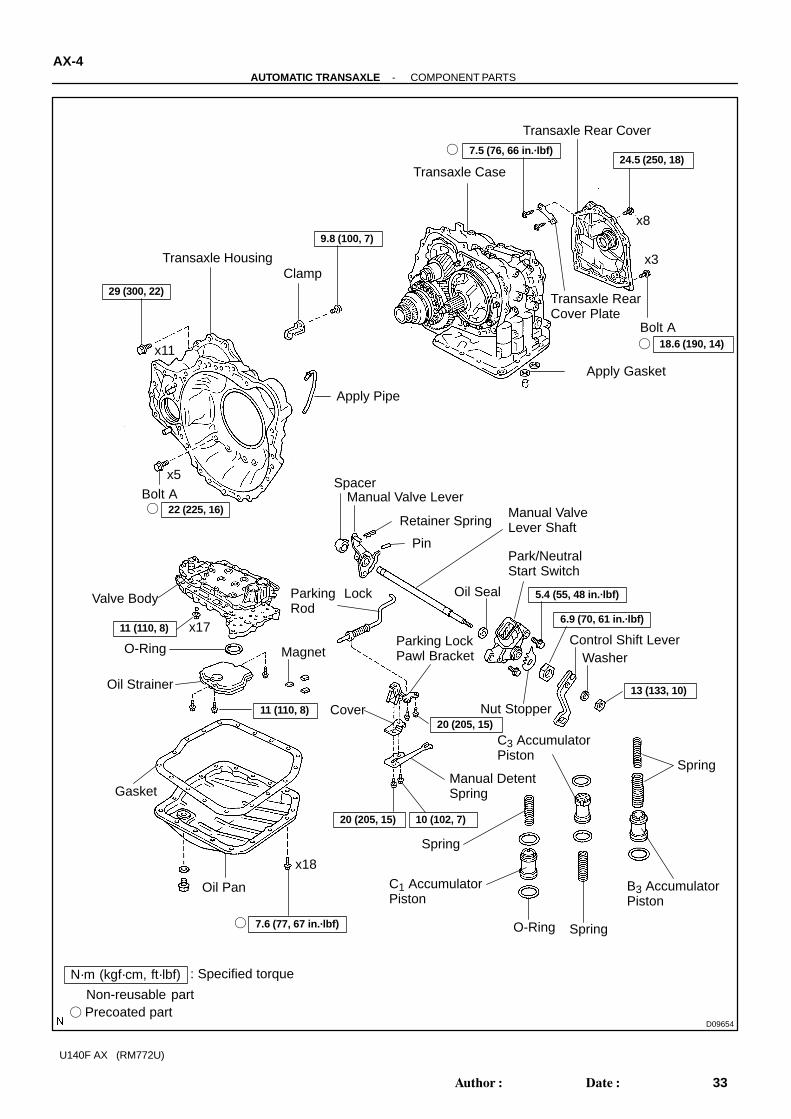
D09654
Transaxle HousingClamp
Transaxle Case
Apply Pipe
Manual Valve Lever
Retainer Spring
Transaxle Rear Cover
� Apply Gasket
Valve Body
Manual ValveLever Shaft
� Spacer
� Gasket
� O-Ring
� Oil Seal
x8
18.6 (190, 14)
11 (110, 8) x17
Oil Strainer
Magnet
Oil Pan
C3 AccumulatorPiston
Park/NeutralStart Switch
7.6 (77, 67 in.·lbf)
Spring
Spring
Spring
C1 AccumulatorPiston
N·m (kgf·cm, ft·lbf) : Specified torque
� Non-reusable part
x18
9.8 (100, 7)
Parking LockRod
Parking LockPawl Bracket
Manual DetentSpring
29 (300, 22)
�
11 (110, 8)
5.4 (55, 48 in.·lbf)
� Precoated part
x11
x5
6.9 (70, 61 in.·lbf)
Control Shift LeverWasher
Nut StopperCover20 (205, 15)
20 (205, 15) 10 (102, 7)
B3 AccumulatorPiston
� O-Ring
24.5 (250, 18)�
x3
Transaxle Rear Cover Plate
Bolt A�
7.5 (76, 66 in.·lbf)
Bolt A� 22 (225, 16)
13 (133, 10)
Pin
AX-4-AUTOMATIC TRANSAXLE COMPONENT PARTS
33Author�: Date�:
U140F AX (RM772U)

D09635
Oil Pump
Thrust Bearing
� Washer
Forward Clutch
Thrust Bearing
Multiple ClutchHub
Needle RollerBearing
Bearing Race
Bearing Outer Race
Snap Ring
Counter Drive Gear
Tapered RollerBearing
� Apply Gasket
Plate
Disc Snap Ring
FlangePlate
Disc
SnapRing
1st & ReverseBrake Piston
Piston ReturnSpring
� O-Ring
Bearing Outer Race
2nd Brake Assembly
Front PlanetaryGear
Needle RollerBearing
Thrust Bearing
Snap RingRear Planetary Gear
One-way ClutchOuter Sleeve
One-wayClutch No. 1
Thrust Bearing
Direct Clutch
Thrust Bearing
Oil Seal Ring
Transaxle Rear Cover
x7
N·m (kgf·cm, ft·lbf) : Specified torque
� Non-reusable part
Tapered RollerBearing
Washer No. 2
Bearing Race
280 (2,855, 207)
WasherNo. 1
Flange
22 (226, 16)
Rear PlanetarySun Gear
Front PlanetarySun Gear
Snap RingBrake Hub
Front planetaryRing Gear
One-wayClutch Inner Race
BearingRace
-AUTOMATIC TRANSAXLE COMPONENT PARTSAX-5
34Author�: Date�:
U140F AX (RM772U)

D09653
ThrustBearing
U/D PlanetaryGear Assembly
U/D ClutchAssembly
Thrust BearingSnap Ring
BearingRace
One-wayClutch No.2
Plate
Flange
Disc
Snap Ring
Piston Return SpringOil Seal Ring
U/D Brake Piston
� O-Ring
Needle RollerBearing
Parking LockPawl Shaft
Parking Lock Pawl
Spring
Parking Lock Pawl Clamp
Pawl Pin
Apply Pipe
Differential
5.4 (55, 48 in.·lbf)N·m (kgf·cm, ft·lbf) : Specified torque� Non-reusable part
BearingRace
� Apply Gasket
Clamp
9.8 (100, 7)
AX-6-AUTOMATIC TRANSAXLE COMPONENT PARTS
35Author�: Date�:
U140F AX (RM772U)

AX10E-01
D03083
D03084
D03085
D03086
D09648
AX-1 18-AUTOMATIC TRANSAXLE TRANSFER
147Author�: Date�:
U140F AX (RM772U)
DISASSEMBLY1. REMOVE GASKET
2. REMOVE NO. 2 INTERMEDIATE DIFFERENTIAL SIDEGEAR
3. REMOVE NO. 1 CASE COVER(a) Remove the 8 bolts.
(b) Using a brass bar and hammer, remove the No. 1 casecover.
NOTICE:Be careful not to damage the transfer case and No. 1 casecover.
(c) Remove a bolt and breather oil deflector from the No. 1case cover.
4. REMOVE PINRemove the 4 pins from the transfer case.5. REMOVE STUD BOLTRemove the 4 stud bolts from the transfer case.6. INSTALL TRANSFER ON OVERHAUL ATTACHMENT

D03089
D03090
SST
D03091
D03092
D03093
SST
-AUTOMATIC TRANSAXLE TRANSFERAX-1 19
148Author�: Date�:
U140F AX (RM772U)
7. REMOVE EXTENSION HOUSING(a) Using plastic hammer, remove the dust deflector from the
extension housing.
(b) Using SST, remove the oil seal from the extension hous-ing.SST 09308-00010
NOTICE:Be careful not to damage the extension housing.
(c) Remove the 4 bolts.
(d) Using a plastic hammer, remove the extension housing.
8. CHECK PRELOAD(a) Using SST and a torque wrench, measure the driven pin-
ion preload of the backlash between the driven pinion andring gear.SST 09326-2001 1Preload (at starting):0.9 - 1.3 N·m (9 - 13 kgf·cm, 7.8 - 11.5 in.·lbf)

D03094
D03095
D03096
SST
AX-120-AUTOMATIC TRANSAXLE TRANSFER
149Author�: Date�:
U140F AX (RM772U)
HINT:� Using a torque wrench with a fulcrum length of 160 mm
(6.3 in.).� This torque value is effective in case that SST is parallel
to a torque wrench.(b) Using SST and the torque wrench, measure the total pre-
load.SST 09326-2001 1Total preload (at starting):1.0 - 1.6 N·m (10 - 16 kgf·cm, 8.9 - 14.2 in.·lbf)
HINT:� Using a torque wrench with a fulcrum length of 160 mm
(6.3 in.).� This torque value is effective in case that SST is parallel
to a torque wrench.
9. CHECK RING GEAR BACKUsing a dial indicator, measure the ring gear backlash.
Backlash: 0.10 - 0.15 mm10. CHECK TOOTH CONTACT
(See page AX-126 )
11. REMOVE CENTER DIFFERENTIAL LOCK SLEEVE(a) Using a snap ring pliers, remove the shaft snap ring.
(b) Using SST, remove the center differential lock sleeve.SST 09308-00010
NOTICE:Be careful not to damage the center differential lock sleeve.

D03097
D03098SST
D03099SST
D03100
D09624
Transfer case
Bearing Retainer RH
-AUTOMATIC TRANSAXLE TRANSFERAX-121
150Author�: Date�:
U140F AX (RM772U)
(c) Using a screwdriver, remove the O-ring from the centerdifferential lock sleeve.
NOTICE:Be careful not to damage the center differential lock sleeve.
12. REMOVE OIL SEALUsing SST, remove the oil seal from the transfer case.
SST 09308-00010NOTICE:Be careful not to damage the transfer case.
13. REMOVE BEARING RETAINER RH(a) Using SST, remove the oil seal from the bearing retainer
RH.SST 09308-00010
NOTICE:Be careful not to damage the bearing retainer.
(b) Remove the 7 bolts.
(c) Using a screwdriver and hammer, make clearance by hit-ting between the bearing retainer RH and transfer case.
D09625
SST
D03101
O-ring
D03102
SST
D03103
D03104
AX-122-AUTOMATIC TRANSAXLE TRANSFER
151Author�: Date�:
U140F AX (RM772U)
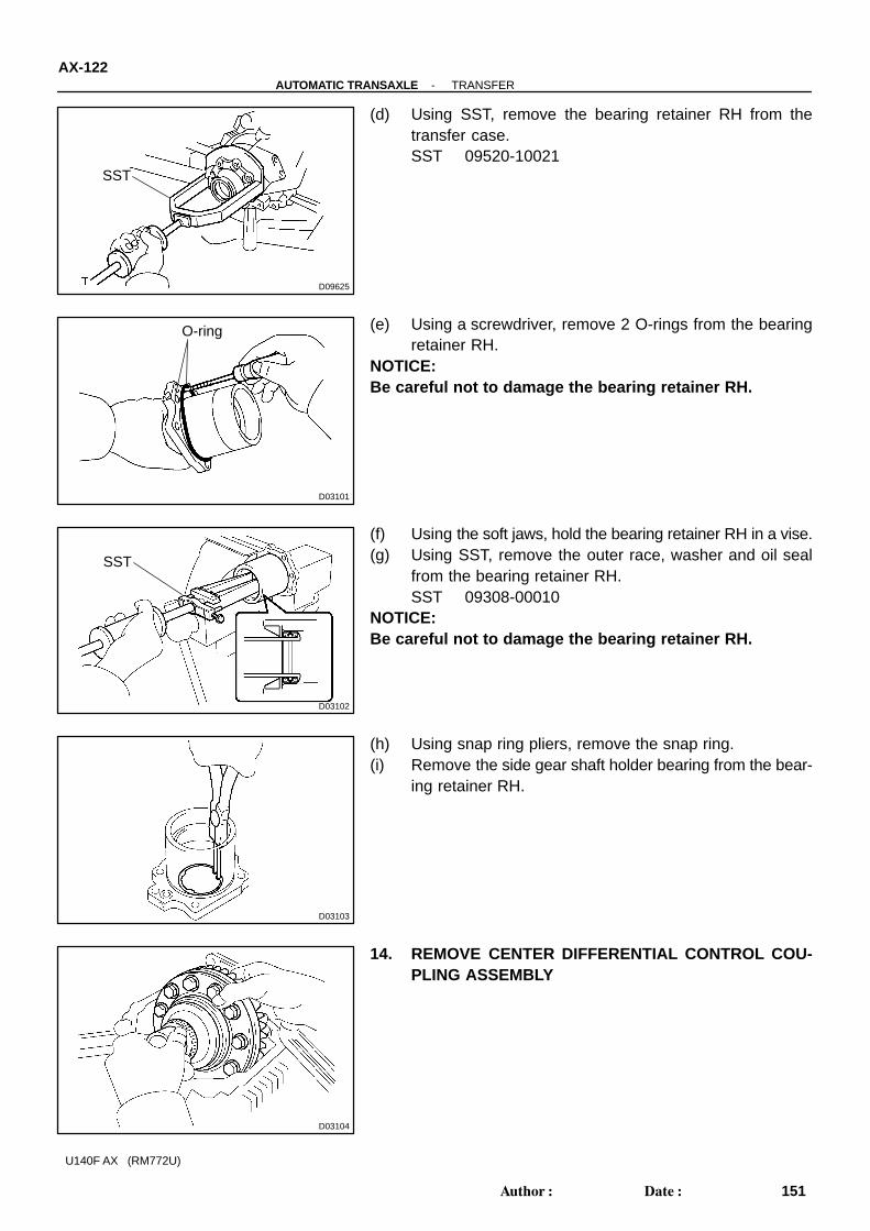
(d) Using SST, remove the bearing retainer RH from thetransfer case.SST 09520-10021
(e) Using a screwdriver, remove 2 O-rings from the bearingretainer RH.
NOTICE:Be careful not to damage the bearing retainer RH.
(f) Using the soft jaws, hold the bearing retainer RH in a vise.(g) Using SST, remove the outer race, washer and oil seal
from the bearing retainer RH.SST 09308-00010
NOTICE:Be careful not to damage the bearing retainer RH.
(h) Using snap ring pliers, remove the snap ring.(i) Remove the side gear shaft holder bearing from the bear-
ing retainer RH.
14. REMOVE CENTER DIFFERENTIAL CONTROL COU-PLING ASSEMBLY

D03106
LH
RH
SST
SST
SST
D03109
D03110
Matchmarks
D03111
-AUTOMATIC TRANSAXLE TRANSFERAX-123
152Author�: Date�:
U140F AX (RM772U)
15. REMOVE TAPERED ROLLER BEARING LH AND RHUsing SST, remove the tapered roller bearing inner race LH andRH.
SST 09950- 00020, 09950- 00030, 09950- 60010(09951-00360)
16. CHECK RING GEAR RUNOUTUsing a dial indicator, check the ring gear runout.
Maximum runout: 0.1 mm (0.004 in.)
17. REMOVE RING GEAR(a) Place matchmarks on both the ring gear and the center
differential control coupling.(b) Remove the 12 bolts.
(c) Using a plastic hammer, remove the ring gear.
D03112
D03113
SST
D03114
SST
D03115
D03116
SST
AX-124-AUTOMATIC TRANSAXLE TRANSFER
153Author�: Date�:
U140F AX (RM772U)
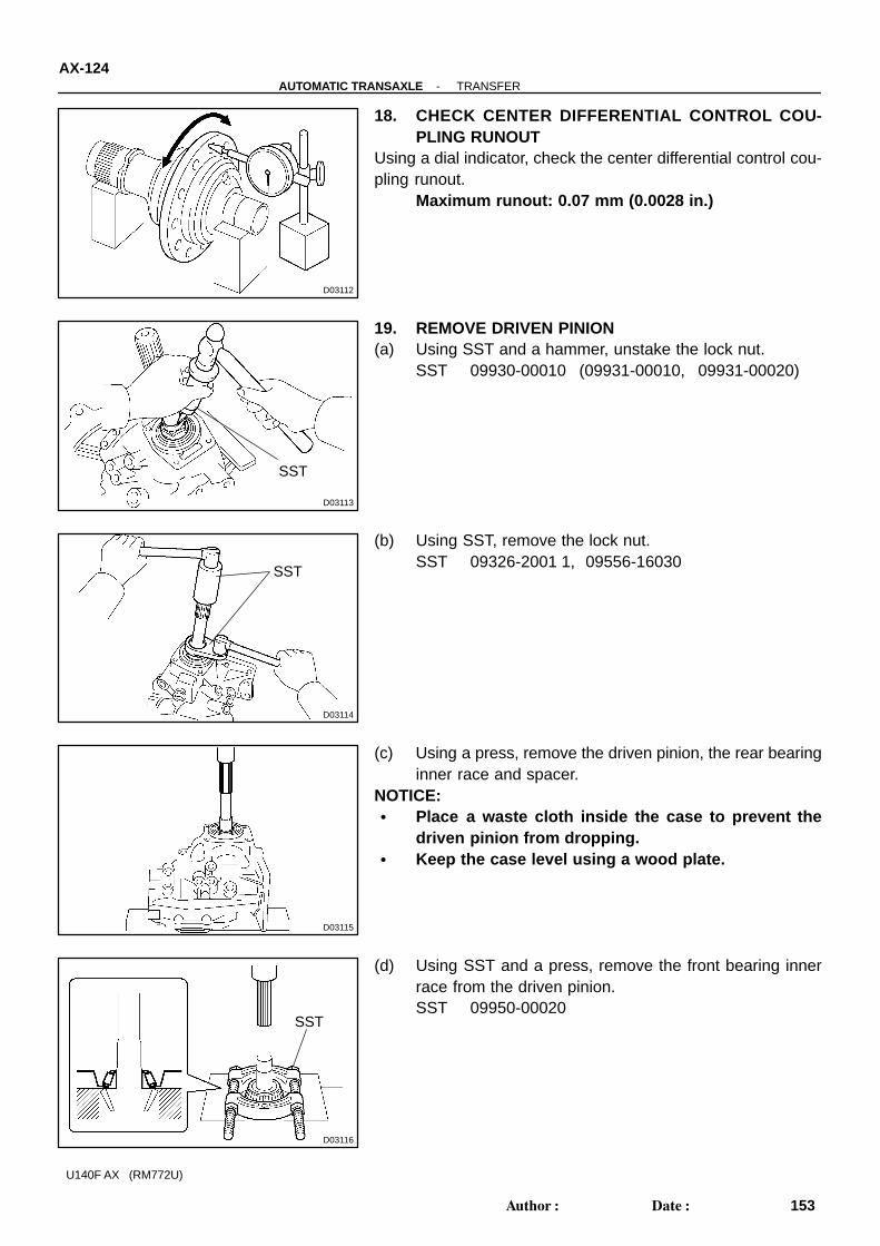
18. CHECK CENTER DIFFERENTIAL CONTROL COU-PLING RUNOUT
Using a dial indicator, check the center differential control cou-pling runout.
Maximum runout: 0.07 mm (0.0028 in.)
19. REMOVE DRIVEN PINION(a) Using SST and a hammer, unstake the lock nut.
SST 09930-00010 (09931-00010, 09931-00020)
(b) Using SST, remove the lock nut.SST 09326-2001 1, 09556-16030
(c) Using a press, remove the driven pinion, the rear bearinginner race and spacer.
NOTICE:� Place a waste cloth inside the case to prevent the
driven pinion from dropping.� Keep the case level using a wood plate.
(d) Using SST and a press, remove the front bearing innerrace from the driven pinion.SST 09950-00020

D03117
D03118
D03119
-AUTOMATIC TRANSAXLE TRANSFERAX-125
154Author�: Date�:
U140F AX (RM772U)
20. REMOVE BEARING OUTER RACE LHUsing a brass bar and a hammer, remove the outer race and thewasher.
21. REMOVE FRONT BEARING OUTER RACEUsing a brass bar and a hammer, remove outer race and wash-er.
22. REMOVE REAR BEARING OUTER RACEUsing a brass bar and a hammer, remove outer race.

AX10C-01
D09656
D09657
D09658
D09659
D09660
-AUTOMATIC TRANSAXLE DIFFERENTIAL CASEAX-103
132Author�: Date�:
U140F AX (RM772U)
DISASSEMBLY1. REMOVE DIFFERENTIAL RING GEAR(a) Place the matchmarks on the ring gear and the differential
case.
(b) Remove the 16 bolts.
(c) Using a plastic hammer, tap on the ring gear to remove itfrom the case.
2. REMOVE FRONT DIFFERENTIAL(a) Remove the differential LH case from the differential case
assembly.
(b) Remove the front differential case from the differential LHcase.

D09661
D09662
D09669
D09663
D09664
AX-104-AUTOMATIC TRANSAXLE DIFFERENTIAL CASE
133Author�: Date�:
U140F AX (RM772U)
(c) Remove the front differential side gear, front differentialside gear thrust washer, conical washer and center differ-ential side gear thrust washer No. 2 from the differentialLH case.
(d) Using a snap ring expander, remove the snap ring fromthe front differential case.
(e) Remove the spacer from the front differential case.
(f) Remove the 3 pinion shafts from the front differentialcase.
(g) Remove the 4 front differential pinions, 4 front differentialpinion thrust washers, front differential pinion shaft hold-er, front differential side gear and front differential sidegear thrust washer from the front differential case.

D03823
SSTSST
D09665
D09667
D09668
SST
-AUTOMATIC TRANSAXLE DIFFERENTIAL CASEAX-105
134Author�: Date�:
U140F AX (RM772U)
3. REMOVE LH BEARINGUsing SST, remove the tapered roller bearing.
SST 09950- 00020, 09950- 00030, 09950- 60010(09951-00060)
4. REMOVE CENTER DIFFERENTIAL(a) Using snap ring expander, remove the snap ring.(b) Slide down the spacer to remove the 4 center differential
pinion shafts.
(c) Remove the 4 center differential pinion shafts, 4 centerdifferential pinions, 4 center differential pinion thrustwashers, center differential pinion shaft holder, center dif-ferential side gear, conical washer and center differentialside gear thrust washer No. 1 from the differential RHcase.
(d) Remove the spacer.
5. REMOVE RH BEARINGUsing SST and a press, remove the tapered roller bearing.
SST 09950-00020, 09950-60010 (09951-00600)

D03722
SST
D03734
SST
D03736
SST
D03735
SST
AX-106-AUTOMATIC TRANSAXLE DIFFERENTIAL CASE
135Author�: Date�:
U140F AX (RM772U)
6. REMOVE TRANSAXLE HOUSING SIDE BEARINGOUTER RACE
Using SST, remove the outer race.SST 09308-00010
7. REMOVE TRANSAXLE HOUSING OIL SEALUsing SST, remove the oil seal from the transaxle housing.
SST 09649-17010, 09950-70010 (09951-07100)
8. REMOVE TRANSAXLE CASE SIDE BEARING OUTERRACE
Using SST, remove the outer race.SST 09308-00010
9. REMOVE TRANSAXLE CASE OIL SEALUsing SST, remove the oil seal from the transaxle case.
SST 09649-17010, (09950-70010 (09951-07100)

AX0B8-02
D03782
D03783
D03784
-AUTOMATIC TRANSAXLE VALVE BODYAX-89
118Author�: Date�:
U140F AX (RM772U)
DISASSEMBLYNOTICE:� Disassembling and reassembling s hould be con-
ducted on a clean vinyl sheet or mat, or aluminumtray.
� Make the valve slide through the valve hole by its ownweight. Do not forcibly pull out the valve using needlenose pliers. When having difficulty in removing it,slant and shake the valve body or use a magnet hand.
� Do not place the disassembled parts directly on metalwork bench or waste cloth.
� Do not use dropped parts.� Make sure that no burr is identified before assem-
bling.
1. CHECK PRIMARY REGULATOR VALVE POSITIONWrite down the relative position of the primary regulator valvesleeve, the plug and the pin.NOTICE:Because the line pressure is changed by the position of thepin and the groove in the sleeve end, make sure to checkthe position.
2. REMOVE SHIFT SOLENOID VALVE(a) Remove the 5 bolts and 5 shift solenoid valves.
3. REMOVE LOWER VALVE BODY(a) Remove the 8 bolts.

D03879
D03878
D04081
D03853
D03785
AX-90-AUTOMATIC TRANSAXLE VALVE BODY
119Author�: Date�:
U140F AX (RM772U)
(b) Remove the 7 bolts, cover and gasket.
(c) Remove the bolt, retainer and 2 check balls.
(d) Using snap ring pliers, remove the 2 snap rings.
(e) Remove 4 springs from the valve body.(f) Remove 2 pistons from the valve body.
(g) Remove the 7 bolts from lower valve body.

D03786
D03788
-AUTOMATIC TRANSAXLE VALVE BODYAX-91
120Author�: Date�:
U140F AX (RM772U)
(h) Remove lower valve body with plate from the upper valvebody.
NOTICE:Be careful that the check balls do not fall out.
(i) Turn over the lower valve body with plate.(j) Remove the plate from lower valve body.NOTICE:Be careful that the check balls do not fall out.

AX0B1-02
D08123
D03700
D03701
D08126
D03703
SST
AX-82-AUTOMATIC TRANSAXLE UNDERDRIVE CLUTCH
111Author�: Date�:
U140F AX (RM772U)
DISASSEMBLY1. CHECK PISTON STROKE OF U/D CLUTCH(a) Install the U/D clutch to the transaxle case.NOTICE:Be careful not to damage the oil seal rings.(b) Install the dial indicator, as shown in the illustration.
(c) Measure the U/D clutch piston stroke while applying andreleasing compressed air (392 kgf/cm2, 4.0 kPa, 57 psi).Piston stroke: 1.51 - 1.90 mm (0.0594 - 0.0748 in.)
If the piston stroke is non-standard inspect the discs, platesand flange.
2. REMOVE FLANGE, DISC AND PLATE(a) Using a screwdriver, remove the snap ring.
(b) Remove the flange, 3 discs and 3 plates from the U/Dclutch drum.
3. REMOVE PISTON RETURN SPRING(a) Place SST on the clutch balancer and compress the
spring with a press.SST 09350-32014 (09351-32070)
(b) Using a snap ring expander, remove the snap ring.NOTICE:� Stop the press when the spring sheet is lowered to the
place 1 - 2 mm (0.039 - 0.078 in.) from the snap ringgroove, preventing the spring sheet from deforming.
� Do not expand the snap ring excessively.

D03704
D03705
D04078
-AUTOMATIC TRANSAXLE UNDERDRIVE CLUTCHAX-83
112Author�: Date�:
U140F AX (RM772U)
(c) Remove the clutch balancer and piston return spring fromthe U/D clutch drum.
4. REMOVE U/D CLUTCH PISTON(a) Install the U/D clutch to the transfer case.NOTICE:Be careful not to damage the oil seal rings.(b) Holding the U/D clutch piston with your hand, apply com-
pressed air (392 kPa, 4.0 kgf/cm2, 57 psi) to the transaxlecase to remove the U/D clutch piston.
5. REMOVE O-RING

AX0B5-02
D03685
SST
SST
D03686
SST
D03687
D03688
SST
-AUTOMATIC TRANSAXLE UNDERDRIVE PLANETARY GEARAX-77
106Author�: Date�:
U140F AX (RM772U)
DISASSEMBLY1. MEASURE TURNING TORQUE OF U/D OUTPUT
SHAFTUsing SST and a small torque wrench, measure the turningtorque of the U/D output shaft.
SST 09387-00050, 09564-16020Turning torque at 60 rpm:0.79 - 5.77 N·m (8 - 59 kgf·cm, 7.0 - 51.1 in.·lbf)
HINT:Use a torque wrench with a fulcrum length of 160 mm (6.3 in.).
2. REMOVE CYLINDRICAL ROLLER BEARING INNERRACE
(a) Using SST, loosen the staked part of the nut.SST 09930-00010 (09931-00010, 09930-00020)
(b) Clamp the U/D planetary gear in soft jaw vise.NOTICE:Be careful not to damage the differential drive pinion.
(c) Using SST, remove lock nut.SST 09564-16020

D03689
SST SST
D03690
SST
D03691
SST
SST
D03826
D03827
AX-78-AUTOMATIC TRANSAXLE UNDERDRIVE PLANETARY GEAR
107Author�: Date�:
U140F AX (RM772U)
(d) Using SST, remove cylindrical roller bearing inner race.SST 09950-00020, 09950-00030, 09950-60010
(09951-00340)
3. REMOVE U/D PLANETARY GEAR(a) Using SST and a press, remove the differential drive pin-
ion, parking lock gear, counter driven gear with U/D plane-tary ring gear and tapered roller bearing FR.SST 09387-00050
(b) Clamp the U/D planetary gear in soft jaw vise.(c) Using SST, remove the tapered roller bearing RR from the
U/D planetary gear.SST 09950-00020, 09950-00030, 09950-60010
(09951-00320)
4. REMOVE U/D PLANETARY RING GEAR(a) Using snap ring pliers, remove snap ring.
(b) Remove the U/D planetary ring gear from the counterdriven gear.

AX0AX-01
D03796
SST
D03843
D03844
D03846
-AUTOMATIC TRANSAXLE SECOND BRAKEAX-73
102Author�: Date�:
U140F AX (RM772U)
DISASSEMBLY1. REMOVE PISTON RETURN SPRING(a) Place SST on the piston return spring and compress.
SST 09387-00060(b) Using a screwdriver, remove the snap ring.
(c) Remove the piston return spring.
2. REMOVE 2ND BRAKE PISTON(a) Hold the 2nd brake piston and apply compressed air (392
kPa, 4.0 kgf/cm2, 57 psi) to the 2nd brake cylinder to re-move the 2nd brake piston.
(b) Remove the 2 O-rings from the 2nd brake piston.

AX0AT-02
D09646
D03660
D03661
D03662
SST
AX-66-AUTOMATIC TRANSAXLE FORWARD CLUTCH
95Author�: Date�:
U140F AX (RM772U)
DISASSEMBLY1. CHECK PISTON STROKE OF FORWARD CLUTCH(a) Install the forward clutch on the oil pump.NOTICE:Be careful not to damage the oil seal ring of oil pump.(b) Using a dial indicator, measure the forward clutch piston
stroke while applying and releasing compressed air (392kPa, 4.0 kgf/cm2, 57 psi).Piston stroke: 1.41 - 1.75 mm (0.0555 - 0.0689 in.)
If the clearance is non-standard, inspect the discs, platesflange.HINT:As the opening is big, cover it with a shop rug as well as an com-pressed air th prevent the air from discharging.
2. REMOVE FLANGE, PLATE AND DISC(a) Using a screwdriver, remove the snap ring from the for-
ward clutch drum.
(b) Remove the flange, 4 discs and 4 plates.
3. REMOVE PISTON RETURN SPRING(a) Place SST on the spring retainer and compress the return
spring with a press.SST 09350-32014 (09351-32070)
(b) Using a snap ring expander, remove the snap ring.

D03663
D03664
D03666
-AUTOMATIC TRANSAXLE FORWARD CLUTCHAX-67
96Author�: Date�:
U140F AX (RM772U)
(c) Remove the piston return spring.
4. REMOVE FORWARD CLUTCH PISTON(a) Place the forward clutch drum onto the oil pump.(b) Holding the forward clutch piston with your hard, apply
compressed air (392 kPa, 4.0 kgf/cm2, 57 psi) to the oilpump to remove the forward clutch piston.
HINT:When the piston can not be removed as it is slanted, either blowthe air again with the protruding side pushed or remove the pis-ton using the needle nose plier with vinyl tape on the tip.
5. REMOVE O-RINGUsing a small screwdriver, remove the 2 O-rings.

AX0AP-02
D09210
D08099
D08100
AX-60-AUTOMATIC TRANSAXLE DIRECT CLUTCH
89Author�: Date�:
U140F AX (RM772U)
DISASSEMBLY1. CHECK PISTON STROKE OF DIRECT CLUTCH(a) Install the direct clutch and needle roller bearing on the
transaxle rear cover.(b) Using a dial indicator, measure the direct clutch piston
stroke while applying and releasing compressed air (392kPa, 4.0 kgf/cm2, 57 psi).Piston stroke:0.61 - 0.83 mm (0.0240 - 0.0327 in.)
If the stroke is non-standard, inspect the discs, plates andflange.
2. REMOVE SNAP RINGUsing a screwdriver, remove the snap ring from the direct clutchdrum.
3. REMOVE FLANGE, DISC AND PLATERemove the flange, 3 discs and 3 plates from the direct clutchdrum.

D03677
SST
D03678
D03679
-AUTOMATIC TRANSAXLE DIRECT CLUTCHAX-61
90Author�: Date�:
U140F AX (RM772U)
4. REMOVE PISTON RETURN SPRING(a) Place SST on the clutch balancer and compress the
springs with a press.SST 09387-00020
(b) Using a snap ring expander, remove the snap ring fromthe direct clutch drum.
NOTICE:� Stop the press when the spring sheet is lowered to the
place 1 - 2 mm (0.039 - 0.078 in.) from the snap ringgroove, preventing the spring sheet from the deform-ing.
� Do not expand the snap ring excessively.
(c) Remove the clutch balancer and piston return spring fromthe direct clutch drum.
5. REMOVE DIRECT CLUTCH PISTON(a) Install direct clutch on the transaxle rear cover.(b) Holding the direct clutch piston with your hand, apply
compressed air (392 kPa, 4.0 kgf·cm2, 57 psi) to thetransaxle rear cover to remove the direct clutch piston.

AX0AL-04
D09205
D03650
D03651
D09206
D03647
SST
AX-56-AUTOMATIC TRANSAXLE OIL PUMP
85Author�: Date�:
U140F AX (RM772U)
DISASSEMBLY1. CHECK PUMP DRIVE GEAR ROTATIONTurn the drive gear with 2 screwdrivers and make sure it rotatessmoothly.NOTICE:Be careful not to damage the oil seal lip.
2. REMOVE 2 OIL SEAL RINGS
3. REMOVE STATOR SHAFTUsing a torx socket T30, remove the 11 bolts and stator shaft.Keep the gears in assembling order.
4. REMOVE OIL PUMP DRIVE GEAR AND DRIVEN GEAR
5. REMOVE OIL SEAL(a) Mount oil pump in a soft jaw vise.(b) Using SST, remove oil seal from the oil pump body.
SST 09308-00010

AX10A-01
D03082
D03083
D09636
D03805
-AUTOMATIC TRANSAXLE COMPONENT PARTSAX-7
36Author�: Date�:
U140F AX (RM772U)
DISASSEMBLY1. REMOVE TRANSFER ASSEMBLY(a) Remove the 2 bolts and 6 nuts.(b) Using a plastic hummer, remove the transfer assembly
from the transaxle assembly.NOTICE:� Pull the transfer straight up and remove it from the
transaxle.� Pulling up the transfer case by inserting your fingers
into the holes on both sides may cause damage to theoil seal lip. Be careful not to damage it.
2. REMOVE GASKET AND INTERMEDIATE SHAFT
3. REMOVE PARK/NEUTRAL POSITION SWITCH(a) Remove the nut, washer and control shaft lever.(b) Using a screwdriver, unstake the nut stopper.(c) Remove the nut.(d) Remove the 2 bolts, and pull out the park/neutral position
switch.
4. REMOVE UNION AND ELBOW(a) Remove the union and elbow.(b) Remove the 2 O-rings form the union and elbow.

D03900
D03901
D03547
D09176
D09177
AX-8-AUTOMATIC TRANSAXLE COMPONENT PARTS
37Author�: Date�:
U140F AX (RM772U)
5. REMOVE SPEED SENSOR(a) Remove the 2 bolts and the 2 speed sensors from the
transaxle.(b) Remove the 2 O-rings from the sensors.
6. REMOVE TRANSAXLE CASE PLUG NO.1(a) Remove the transaxle case plug No. 1 from the transaxle
case.(b) Remove the O-ring from the transaxle case plug No. 1.
7. REMOVE SOLENOID WIRE RETAINING BOLTNOTICE:Remove the bolt only and do not remove the solenoid wire.
8. PLACE TRANSAXLE ON WOODEN BLOCKSNOTICE:Be careful not to damage the oil seal.
9. REMOVE OIL PAN AND GASKET(a) Remove the 18 bolts.(b) Remove the oil pan and gasket.

AT0103
D09637
D03636
D09179
D09180
-AUTOMATIC TRANSAXLE COMPONENT PARTSAX-9
38Author�: Date�:
U140F AX (RM772U)
10. EXAMINE PARTICLES IN PANRemove the magnets and use them to collect any steel chips.Examine the chips and particles in the pan and on the magnetto determine what type of wear has occurred in the transaxle:Steel (magnetic)..... bearing, gear and plate wearBrass (non-magnetic)..... bushing wear
11. REMOVE TRANSAXLE SOLENOID WIRE(a) Remove the 5 connectors from the shift solenoid valves.(b) Remove the bolt, the clamp and the ATF temperature
sensor.(c) Remove the transaxle solenoid wire from the transaxle
case.
(d) Remove the O-ring from the transaxle solenoid wire.
12. REMOVE OIL STRAINER(a) Remove the 3 bolts and oil strainer.
(b) Remove the O-ring from the oil strainer.

D03553
D09688
D03554
D03555
D03556
AX-10-AUTOMATIC TRANSAXLE COMPONENT PARTS
39Author�: Date�:
U140F AX (RM772U)
13. REMOVE VALVE BODY ASSEMBLYSupport the valve body assembly and remove the 17 bolts andthe valve body assembly.
14. REMOVE 3 APPLY GASKETS
15. REMOVE CHECK BALL BODYRemove the check ball body and spring.
16. REMOVE ACCUMULATOR SPRING AND PISTON(a) Remove the spring from the C3 accumulator piston.
(b) Apply compressed air (392 kPa, 4.0 kgf/cm2, 57 psi) to theoil hole and remove the C3 accumulator piston.
NOTICE:� Blowing off the air may cause the piston’s jump-out.
When removing the piston, hold it with your hand us-ing a waste cloth.
� Take care not to splash ATF when air-blowing.

D03902
D03557
D03903
D03558
D03904
-AUTOMATIC TRANSAXLE COMPONENT PARTSAX-1 1
40Author�: Date�:
U140F AX (RM772U)
(c) Remove the O-ring from the piston.
(d) Apply compressed air (392 kPa, 4.0 kgf/cm2, 57 psi) to theoil hole and remove the C1 accumulator piston and spring.
NOTICE:� Blowing off the air may cause the piston’s jump-out.
When removing the piston, hold it with your hand us-ing a waste cloth.
� Take care not to splash ATF when air-blowing.
(e) Remove the 2 O-rings from the piston.
(f) Apply compressed air (392 kPa, 4.0 kgf/cm2, 57 psi) to theoil hole and remove the B3 accumulator piston and 2springs.
NOTICE:� Blowing off the air may cause the piston’s jump-out.
When removing the piston, hold it with your hand us-ing a waste cloth.
� Take care not to splash ATF when air-blowing.
(g) Remove the O-ring from the piston.
D03559
D03560
D03561
D03563
D03564
AX-12-AUTOMATIC TRANSAXLE COMPONENT PARTS
41Author�: Date�:
U140F AX (RM772U)
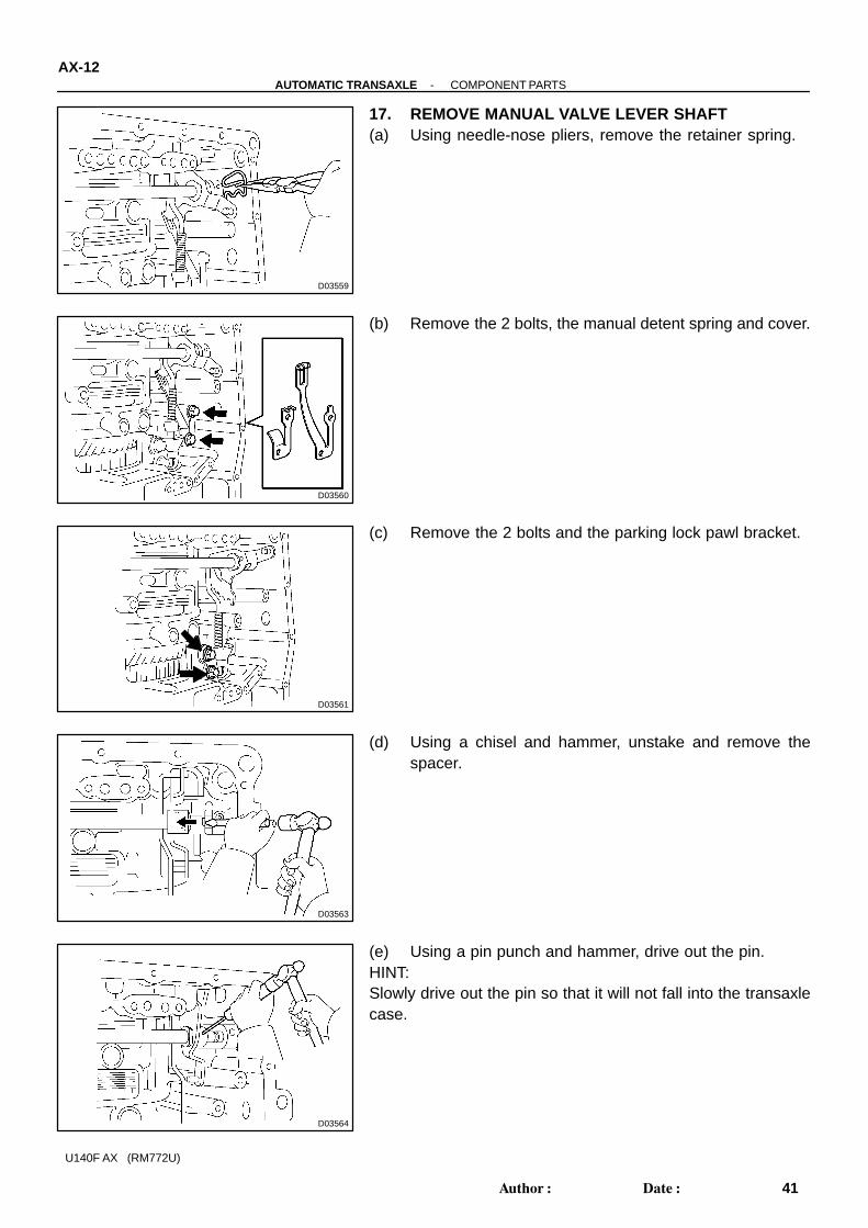
17. REMOVE MANUAL VALVE LEVER SHAFT(a) Using needle-nose pliers, remove the retainer spring.
(b) Remove the 2 bolts, the manual detent spring and cover.
(c) Remove the 2 bolts and the parking lock pawl bracket.
(d) Using a chisel and hammer, unstake and remove thespacer.
(e) Using a pin punch and hammer, drive out the pin.HINT:Slowly drive out the pin so that it will not fall into the transaxlecase.

D03565
D03905
D03566
D03567
D03568
-AUTOMATIC TRANSAXLE COMPONENT PARTSAX-13
42Author�: Date�:
U140F AX (RM772U)
(f) Remove the manual valve lever shaft and manual valvelever.
(g) Remove the parking lock rod from the manual valve levershaft.
(h) Using a screwdriver, remove the oil seal.18. PLACE TRANSAXLE CASEFix the transaxle case with the oil pump side facing up.
19. INSPECT INPUT SHAFT END PLAYUsing a dial indicator, measure the input shaft end play.
End play: 0.26 - 1.25 mm (0.0103 - 0.0492 in.)
20. REMOVE TRANSAXLE HOUSING(a) Remove the 16 bolts.(b) Tap on the circumference of the transaxle housing with a
plastic hammer to remove the transaxle housing from thetransaxle case.
NOTICE:Differential may be accidentally removed when the trans-axle housing is removed.

D03569
D03570
D03571
D03572
D03573
AX-14-AUTOMATIC TRANSAXLE COMPONENT PARTS
43Author�: Date�:
U140F AX (RM772U)
21. REMOVE OIL PUMP(a) Remove the 7 bolts and oil pump.
(b) Remove the O-ring from the oil pump.
22. REMOVE THRUST BEARING AND BEARING RACERemove thrust bearing and bearing race from the U/D planetarygear assembly.
23. REMOVE DIFFERENTIAL
24. REMOVE 2 APPLY GASKETS

D03574
D03906
D03575
D03576
D09652
-AUTOMATIC TRANSAXLE COMPONENT PARTSAX-15
44Author�: Date�:
U140F AX (RM772U)
25. REMOVE FORWARD CLUTCH(a) Remove the forward clutch from the transaxle case.
(b) Remove the thrust bearing from the forward clutch.
(c) Remove the thrust bearing, multiple clutch hub, needleroller bearing and bearing race from the transaxle case.
26. REMOVE U/D PLANETARY GEAR ASSEMBLY(a) Remove the bolt and parking pawl shaft clamp.
(b) Remove the parking lock pawl shaft.

D09689
D03579
D09690
D03580
D03581
AX-16-AUTOMATIC TRANSAXLE COMPONENT PARTS
45Author�: Date�:
U140F AX (RM772U)
(c) Push the parking lock pawl.HINT:Failure to do so will cause interference when the U/D planetarygear is removed.
(d) Remove the U/D planetary gear assembly from the trans-axle case.
NOTICE:Be careful that the U/D planetary gear assembly do not fallout.
(e) Remove the spring, pawl pin and parking lock pawl.
27. REMOVE U/D CLUTCH ASSEMBLYRemove the U/D clutch assembly, thrust bearing and bearingrace from the transaxle case.
28. REMOVE ONE-WAY CLUTCH NO. 2(a) Using a screwdriver, remove the snap ring.

D03627
D03907
D09197
D03610
SST
D09943
-AUTOMATIC TRANSAXLE COMPONENT PARTSAX-17
46Author�: Date�:
U140F AX (RM772U)
(b) Remove the one-way clutch No. 2 from the transaxlecase.
(c) Remove the outer race retainer from the one-way clutchNo. 2.
29. REMOVE U/D BRAKE(a) Using a screwdriver, remove the snap ring.(b) Remove the flange, 3 discs and 3 plates from the trans-
axle case.
(c) Using SST, a snap ring expander and a press, remove thesnap ring and piston return spring.SST 09387-00020
30. REMOVE TRANSAXLE REAR COVER(a) Remove the 11 bolts.(b) Tap on the circumference of the rear cover with a plastic
hammer to remove the transaxle rear cover from thetransaxle case.

D03584
D03801
SST
D03585
D03591
D03586
AX-18-AUTOMATIC TRANSAXLE COMPONENT PARTS
47Author�: Date�:
U140F AX (RM772U)
(c) Remove the 2 oil seal rings from the transaxle rear cover.(d) Remove the 2 screws and transaxle rear cover plate.
(e) Using SST, remove the needle-roller bearing.SST 09387-00040 (09387-01010, 09387-01030,
09387-01040)
31. REMOVE BRAKE APPLY PIPE(a) Remove a bolt, clamp and 2 brake apply pipes.
32. REMOVE TRANSAXLE CASE APPLY GASKETUsing a screwdriver, remove the 2 apply gaskets.
33. REMOVE DIRECT CLUTCH ASSEMBLY(a) Remove the thrust bearing and the direct clutch from the
transaxle case.

D03802
D03587
D03791
D03908
D03588
-AUTOMATIC TRANSAXLE COMPONENT PARTSAX-19
48Author�: Date�:
U140F AX (RM772U)
(b) Remove the bearing race from the direct clutch.
34. REMOVE REAR PLANETARY SUN GEAR ASSEMBLY(a) Remove the rear planetary sun gear assembly from the
transaxle case.
(b) Remove the thrust bearing from the rear planetary sungear.
(c) Remove the thrust washer No. 1 from the rear planetarysun gear.
35. REMOVE ONE-WAY CLUTCH NO.1(a) Remove the one-way clutch No. 1 and the thrust bearing
from the transaxle case.

D03909
D03589
D09940
D03616
D03592
AX-20-AUTOMATIC TRANSAXLE COMPONENT PARTS
49Author�: Date�:
U140F AX (RM772U)
(b) Remove the inner race from the one-way clutch No. 1.
36. REMOVE ONE-WAY CLUTCH OUTER SLEEVE
37. REMOVE 2ND BRAKE(a) Using a screwdriver, remove the snap ring.(b) Remove the flange, 3 discs and 3 plates from the trans-
axle case.
38. REMOVE REAR PLANETARY GEAR(a) Using a screwdriver, remove the snap ring.
(b) Remove the rear planetary gear from the transaxle case.

D03910
D03593
D03873
D03595
D03596
SST
-AUTOMATIC TRANSAXLE COMPONENT PARTSAX-21
50Author�: Date�:
U140F AX (RM772U)
(c) Remove the thrust washer No. 2 from the rear planetarygear.
(d) Remove the bearing race from the rear planetary gear.
39. REMOVE FRONT PLANETARY SUN GEAR(a) Remove the 2 thrust bearings, the bearing race and the
front planetary sun gear from the transaxle case.
40. REMOVE FRONT PLANETARY GEAR ASSEMBLYAND BRAKE HUB
(a) Using a chisel and a hammer, unstake the lock washer.NOTICE:Push down all claws of the washer. Otherwise SST can notbe fully pressed again the nut and can not loosen the nut.
(b) Using SST, remove the nut.SST 09387-00030, 09387-00080

D03597
SST
D03598
D03911
D03615
D09941
AX-22-AUTOMATIC TRANSAXLE COMPONENT PARTS
51Author�: Date�:
U140F AX (RM772U)
(c) Using SST and a press, remove the front planetary gearassembly from the counter drive gear.SST 09950-60010 (09951-00450)
41. REMOVE 2ND BRAKE A SSEMBLY AND FRONTPLANETARY RING GEAR
(a) Using a screwdriver, remove the snap ring and the brakehub with 2nd brake cylinder assembly.
(b) Remove the brake hub from the 2nd brake cylinder as-sembly.
42. REMOVE FRONT PLANETARY RING GEARUsing a screwdriver, remove the snap ring and front planetaryring gear from the brake hub.
43. REMOVE 1ST & REVERSE BRAKE(a) Remove the flange, 5 discs and 5 plates from the trans-
axle case.

D03600
SST
D03800
D03913
D03601
SST
D03602
-AUTOMATIC TRANSAXLE COMPONENT PARTSAX-23
52Author�: Date�:
U140F AX (RM772U)
(b) Using SST, a press and a snap ring expander, remove thesnap ring and the piston return spring.SST 09387-00070
NOTICE:� Stop the press when the spring sheet is lowered 1 -
2 mm (0.039 - 0.078 in.) from the snap ring groove,preventing the spring sheet from deforming.
� Do not expand the snap ring excessively.
(c) Apply compressed air (392 kPa, 4.0 kgf/cm2, 57 psi) to thetransaxle case to remove 1st & reverse brake piston.
NOTICE:� Blowing off the air may cause the piston jump-out.
When removing the piston, hold it with your hand us-ing a waste cloth.
� Take care not to splash ATF when air-blowing.
(d) Remove 2 O-rings from the 1st & reverse brake piston.
44. REMOVE COUNTER DRIVE GEAR(a) Using SST and a press, remove the counter drive gear
from the transaxle case.SST 09950-60010 (09951-00600), 09950-70010
(09951-07100)
(b) As shown in the illustration, tighten 2 bolts evenly andmake clearance of approx. 20.0 mm (0.797 in.) betweenthe counter drive gear and the inner race.

D03603
SST
D03798
D03604
D03799
D03794
AX-24-AUTOMATIC TRANSAXLE COMPONENT PARTS
53Author�: Date�:
U140F AX (RM772U)
(c) Using SST, remove the tapered roller bearing RH.SST 09950-00020, 09950-00030, 09950-60010
(09951-00600)
(d) Using a brass bar and a hammer, remove the 2 bearingouter races.
(e) Using a screwdriver, remove the snap ring from the trans-axle case.
45. REMOVE U/D BRAKE PISTON(a) Apply compressed air (392 kPa, 4.0 kgf/cm2, 57 psi) to the
transaxle case to remove the U/D brake piston.
(b) Remove the 2 O-rings from the U/D brake piston.

D03605
SST
D03914
D03606
SST
D03915
D03607
-AUTOMATIC TRANSAXLE COMPONENT PARTSAX-25
54Author�: Date�:
U140F AX (RM772U)
(c) Using SST, remove the needle-roller bearing from thetransaxle case.SST 09387-00040, (09387-01020, 09387-01030,
09387-01040)
(d) Remove the 2 oil seal rings from the transaxle case.
46. REMOVE U/D CYLINDRICAL ROLLER BEARING(a) Using SST, remove the cylindrical roller bearing from the
transaxle case.SST 09514-3501 1
(b) Remove the oil seal ring from the transaxle housing.
47. REMOVE APPLY PIPERemove the bolt, the clamp and the apply pipe from the trans-axle case.

SS0ZU-01
6N
8N
10N
11N
12N
B06432
Nut Type
Present Standard Hexagon Nut Cold Forging Nut Cutting Processed Nut
Class
4N
5N (4T)
6N
7N (5T)
8N
10N (7T)
11N
12N
Old Standard Hexagon Nut
No Mark (w/ Washer)
No Mark
*
No Mark (w/ Washer) No Mark
No Mark
*: Nut with 1 or more marks on one side surface of the nut.
-SERVICE SPECIFICATIONS STANDARD BOLTSS-3
21Author�: Date�:
U140F AX (RM772U)
HOW TO DETERMINE NUT STRENGTH
HINT:Use the nut with the same number of the nut strength classification or the greater than the bolt strength clas-sification number when tightening parts with a bolt and nut.Example: Bolt = 4T Nut = 4N or more

SS0ZS-01
4
5
6
7
8
9
10
11
B06431
Bolt Type
Hexagon Head Bolt
Normal Recess Bolt Deep Recess BoltStud Bolt Weld Bolt
Class
4T
5T
6T
7T
8T
9T
10T
11T
No Mark
w/ Washer
No Mark No Mark
w/ Washer
-SERVICE SPECIFICATIONS STANDARD BOLTSS-1
19Author�: Date�:
U140F AX (RM772U)
STANDARD BOLTHOW TO DETERMINE BOLT STRENGTH

IN047-01
D01280
Oil Pump Body
Oil Pump Drive Gear
Stator Shaft
Oil Seal Ring
Oil Pump Driven Gear
�
� Oil Seal
N·m (kgf·cm, ft·lbf)� Non-reusable part
: Specified torque
X13
10 (100, 7)
O-ring
-INTRODUCTION HOW TO USE THIS MANUALIN-1
1Author�: Date�:
U140F AX (RM772U)
HOW TO USE THIS MANUALGENERAL INFORMATION1. INDEXAn INDEX is provided on the first page of each section to guide you to the item to be repaired. To assist youin finding your way through the manual, the Section Title and major heading are given at the top of everypage.2. PREPARATIONPreparation lists the SST (Special Service Tools), recommended tools, equipment, lubricant and SSM (Spe-cial Service Materials) which should be prepared before beginning the operation and explains the purposeof each one.3. REPAIR PROCEDURESMost repair operations begin with an overview illustration. It identifies the components and shows how theparts fit together.Example:

Illustration:what to do and where
21. CHECK PISTON STROKE OF OVERDRIVE BRAKE
(a) Place SST and a dial indicator onto the overdrive brakepiston as shown in the illustration.
Task heading : what to do
SST 09350-30020 (09350-06120)
Set part No. Component part No.Detailed text : how to do task
(b) Measure the stroke applying and releasing the compressed
Piston stroke: 1.40 � 1.70 mm (0.0551 � 0.0669 in.)
Specification
air (392 - 785 kPa, 4 - 8 kgf.cm2 or 57 - 114 psi) asshown in the illustration.
IN-2-INTRODUCTION HOW TO USE THIS MANUAL
2Author�: Date�:
U140F AX (RM772U)
The procedures are presented in a step-by-step format:� The illustration shows what to do and where to do it.� The task heading tells what to do.� The detailed text tells how to perform the task and gives other information such as specifications
and warnings.Example:
This format provides the experienced technician with a FAST TRACK to the information needed. The uppercase task heading can be read at a glance when necessary, and the text below it provides detailed informa-tion. Important specifications and warnings always stand out in bold type.4. REFERENCESReferences have been kept to a minimum. However, when they are required you are given the page to referto.5. SPECIFICATIONSSpecifications are presented in bold type throughout the text where needed. You never have to leave theprocedure to look up your specifications. They are also found at the end of each section, for quick reference.6. CAUTIONS, NOTICES, HINTS:� CAUTIONS are presented in bold type, and indicate there is a possibility of injury to you or other
people.� NOTICES are also presented in bold type, and indicate the possibility of damage to the components
being repaired.� HINTS are separated from the text but do not appear in bold. They provide additional information to
help you perform the repair efficiently.7. SI UNITThe UNITS given in this manual are primarily expressed according to the SI UNIT (International System ofUnit), and alternately expressed in the metric system and in the English System.Example:
Torque: 30 N·m (310 kgf·cm, 22 ft·lbf)

AX0B2-04
D04077
D08129
D03824
AX-84-AUTOMATIC TRANSAXLE UNDERDRIVE CLUTCH
113Author�: Date�:
U140F AX (RM772U)
INSPECTION1. INSPECT DISC, PLATE AND FLANGECheck to see if the sliding surface of the disc, plate and flangeare worn or burnt. If necessary, replace them.HINT:� If the lining of the disc is peeling off or discolored, or even
if a part of the printed mark is defaced, replace all discs.� Before assembling new discs, soak them in ATF for at
least 15 minutes.
2. CHECK U/D CLUTCH DRUM BUSHINGUsing a dial indicator, measure the inside diameter of the U/Dclutch drum bushing.
Standard drum bushing: 37.06 - 37.08 mm (1.4591 - 1.4598 in.)Maximum drum bushing: 37.13 mm (1.4618 in.)
If the inside diameter is greater than the maximum, replace theU/D clutch drum.
3. CHECK U/D CLUTCH PISTON RETURN SPRINGUsing vernier calipers, measure the free length of the spring to-gether with spring seat.
Standard free length: 17.14 mm (0.6748 in.)

AX0AY-02
D03824
AX-74-AUTOMATIC TRANSAXLE SECOND BRAKE
103Author�: Date�:
U140F AX (RM772U)
INSPECTIONCHECK 2ND BRAKE PISTON RETURN SPRINGUsing vernier calipers, measure the free length of the spring to-gether with the spring seat.
Standard free length: 16.61 mm (0.6539 in.)

AX0AQ-01
D04079
D03830
AX-62-AUTOMATIC TRANSAXLE DIRECT CLUTCH
91Author�: Date�:
U140F AX (RM772U)
INSPECTION1. INSPECT DISC AND FLANGECheck to see if the sliding surface of the disc, plate and flangeare worn or burnt.If necessary, replace them.HINT:� If the lining of the disc is peeling off or discolored, or even
if a part of the printed mark is defaced, replace all discs.� Before assembling new discs, soak them in ATF for at
least 15 minutes.
2. CHECK DIRECT CLUTCH RETURN SPRINGUsing a vernier calipers, measure the free length of the springtogether with the spring seat.
Standard free length: 22.58 mm (0.8890 in.)

AX0AM-04
D09207
D09208
D09209
D03648
D03653
-AUTOMATIC TRANSAXLE OIL PUMPAX-57
86Author�: Date�:
U140F AX (RM772U)
INSPECTION1. CHECK BODY CLEARANCE OF DRIVEN GEARPush the driven gear to one side of the body. Using a feelergauge, measure the clearance.
Standard body clearance:0.10 - 0.17 mm (0.0039 - 0.0067 in.)Maximum body clearance: 0.17 mm (0.0067 in.)
If the body clearance is greater than the maximum, replace theoil pump body sub-assembly.
2. CHECK TIP CLEARANCE OF DRIVEN GEARMeasure the tip clearance between the driven gear teeth anddrive gear teeth.
Standard tip clearance:0.07 - 0.15 mm (0.0028 - 0.0059 in.)Maximum tip clearance: 0.15 mm (0.0059 in.)
If the tip clearance is greater than the maximum, replace the oilpump body sub assembly.
3. CHECK SIDE CLEARANCE OF BOTH GEARUsing a steel straight edge and feeler gauge, measure the sideclearance of both gears.
Standard side clearance:0.02 - 0.05 mm (0.0008 - 0.0020 in.)Maximum side clearance: 0.05 mm (0.0020 in.)
4. CHECK OIL PUMP BODY BUSHINGUsing a dial indicator, measure the inside diameter of the oilpump body bushing.
Standard inside diameter:38.12 - 38.13 mm (1.5008 - 1.5012 in.)Maximum inside diameter: 38.18 mm (1.5031 in.)
If the inside diameter is greater than the maximum, replace theoil pump body sub-assembly.
5. CHECK STATOR SHAFT BUSHINGUsing a dial indicator, measure the inside diameter of the statorshaft bushings.
Standard inside diameter:21.50 - 21.52 mm (0.8465 - 0.8472 in.)Maximum inside diameter: 21.57 (0.8492 in.)
If the inside diameter is greater than the maximum, replace thestator shaft.

AX0BB-04
D03835
Plug
Key
PrimaryRegulator Valve
C-2 Control Valve
Plunger
Sleeve
Plug
Pin
Key
Plug
B-2 Control Valve
Key
Plug
B-1 Control Valve
Key
3-4 Shift Valve
Manual Valve
Check Valve
AX-98-AUTOMATIC TRANSAXLE LOWER VALVE BODY
127Author�: Date�:
U140F AX (RM772U)
LOWER VALVE BODYLOCATION1. COMPONENTS

D03836
AB C D E
-AUTOMATIC TRANSAXLE LOWER VALVE BODYAX-99
128Author�: Date�:
U140F AX (RM772U)
2. SPRINGHINT:During re-assembly please refer to the spring specifications below to help you to discriminate between thedifferent springs:
Mark Name (Color)Free length / Outer diameter
mm (in.)Total number of coils
A 3-4 shift valve (None) 29.25 (1.1516) / 9.7 (0.382) 10.5
B B-1 control valve (Light Green) 48.55 (1.9114) / 9.8 (0.386) 13.43
C B-2 control valve (Pink) 57.05 (2.2461) / 9.8 (0.386) 15.34
D Primary regulator valve (Orange) 57.55 (2.2657) / 19.9 (0.783) 7.87
E C-2 control valve (Brown) 34.20 (1.3465) / 9.9 (0.390) 8.79

D03837
A B C D
AX-100-AUTOMATIC TRANSAXLE LOWER VALVE BODY
129Author�: Date�:
U140F AX (RM772U)
3. KEY
Mark RetainerHeight / Width / Thickness
mm (in.)
A 3-4 shift valve 25.5 (1.004) / - / 2.3 (0.091)
B B-1 control valve 14.5 (0.571) / 5.0 (0.197) / 3.2 (0.126)
C B-2 control valve 14.5 (0.571) / 5.0 (0.197) / 3.2 (0.126)
E C-2 control valve 14.5 (0.571) / 5.0 (0.197) / 3.2 (0.126)

D03838
-AUTOMATIC TRANSAXLE LOWER VALVE BODYAX-101
130Author�: Date�:
U140F AX (RM772U)
4. Check ball
Check ball mm (in.) 5.5 (0.217)

AX0BA-02
D03831
Pin
Sleeve
Plunger
Clutch ApplyControl Valve
Key
Plug
B-1 Lock Valve
KeyPlug
B-3 OrificeControl Valve
Plug
Solenoid Modulator Valve
Key
Plug
C-2 ExhaustValve
Key
Check ValveNo.3
Ball
Check ValveNo.2
Oil Strainer
Oil Strainer
Plug
Key
Key
Plug
Lock-up Relay Valve
SecondaryRegulatorValve
Key
Lock-up Control Valve
Valve Plunger
Key
Plug
C-2 Lock Valve
Key
Control Sleeve
AX-94-AUTOMATIC TRANSAXLE UPPER VALVE BODY
123Author�: Date�:
U140F AX (RM772U)
UPPER VALVE BODYLOCATION1. COMPONENTS

D03832
A B CD
E
F G H I
-AUTOMATIC TRANSAXLE UPPER VALVE BODYAX-95
124Author�: Date�:
U140F AX (RM772U)
2. SPRINGHINT:During reassembly please refer to the spring specifications below to help you to discriminate between thedifferent springs.
Mark Name (Color)Free length / Outer diameter
mm (in.)Total number of coils
A Lock-up relay valve (None) 29.27 (1.1524) / 9.7 (0.382) 10.50
B Lock-up control valve (None) 23.98 (0.9441) / 5.4 (0.213) 14.94
C Secondary regulator valve (Blue) 58.35 (2.2972) / 8.7 (0.343) 20.58
D C-2 lock valve (Yellow) 33.65 (1.3247) / 7.4 (0.291) 11.82
E Solenoid modulator valve (Red) 62.40 (2.4567) / 9.8 (0.386) 22.31
F B-3 orifice control valve (Gray) 62.65 (2.4665) / 7.8 (0.307) 19.60
G B-1 lock valve (White) 37.40 (1.4724) / 9.8 (0.386) 8.84
H Clutch apply control valve (Purple) 40.29 (1.5862) / 9.0 (0.354) 13.00
I C-2 exhaust check valve (Orange) 40.27 (1.5854) / 7.4 (0.291) 17.10

D03833
A B C D
F G H I
E
AX-96-AUTOMATIC TRANSAXLE UPPER VALVE BODY
125Author�: Date�:
U140F AX (RM772U)
3. KEY
Mark RetainerHeight / Width / Thickness
mm (in.)
A Lock-up relay valve 10.0 (0.394) / 5.0 (0.197) / 3.2 (0.126)
B Lock-up control valve 10.0 (0.394) / 5.0 (0.197) / 3.2 (0.126)
C Secondary regulator valve 8.0 (0.315) / 5.0 (0.197) / 3.2 (0.126)
D C-2 lock valve 10.0 (0.394) / 5.0 (0.197) / 3.2 (0.126)
E Solenoid modulator valve 8.0 (0.315) / 5.0 (0.197) / 3.2 (0.126)
F B-3 orifice control valve 18.5 (0.728) / - / 2.3 (0.091)
G B-1 lock valve 8.0 (0.315) / 5.0 (0.197) / 3.2 (0.126)
H C-2 exhaust check valve 8.0 (0.315) / 5.0 (0.197) / 3.2 (0.126)
I 3-way check valve 8.0 (0.315) / 5.0 (0.197) / 3.2 (0.126)

D03834
-AUTOMATIC TRANSAXLE UPPER VALVE BODYAX-97
126Author�: Date�:
U140F AX (RM772U)
4. CHECK BALL
Check ball mm (in.) 5.5 (0.217)

AX0AG-07
D09634
Direct Clutch (C2)
No. 1 One-way Clutch(F1)
U/D Brake (B3)
No. 2 One-wayClutch (F2)
U/D Clutch(C3)
2nd Brake (B1)1st & Reverse Brake(B2) Forward Clutch (C1)
Shift lever position
P
N
R
D
L
2
C3Gear position C1 C2 F2B1 B2 B3
Reverse
Parking
Neutral
1st
2nd
3rd
O/D
1st
2nd
�
1st
�
�
�
�
�
�
�
�
�
�
�
�
�
�
�
� �
�
�
�
�
�
�
�
�
�
� ... Operating
F1
�
�
�
�
�
�
-AUTOMATIC TRANSAXLE AUTOMATIC TRANSAXLE SYSTEMAX-1
30Author�: Date�:
U140F AX (RM772U)
AUTOMATIC TRANSAXLE SYSTEMOPERATION

D04090
C1
B2F1B1
C2C3
B3 F2
IN
OUT
AX-2-AUTOMATIC TRANSAXLE AUTOMATIC TRANSAXLE SYSTEM
31Author�: Date�:
U140F AX (RM772U)
FUNCTION OF COMPONENTS
Component Function
C1 Forward Clutch Connects input shaft and front planetary sun gear.
C2 Direct Clutch Connects input shaft and rear planetary sun gear.
C3 U/D Clutch Connects U/D sun gear and U/D planetary carrier.
B1 2nd BrakePrevents rear planetary sun gear from turning either clockwise
or counterclockwise.
B2 1st & Reverse BrakePrevents rear planetary carrier and front planetary ring gear
from turning either clockwise or counterclockwise.
B3 U/D BrakePrevents U/D sun gear from turning either clockwise or coun-
terclockwise.
F1 No.1 One-way Clutch Prevents rear planetary carrier from turning counterclockwise.
F2 No.2 One-way Clutch Prevents U/D planetary sun gear from turning clockwise.
Planetary Gears
These gears change the route through which driving force is
transmitted, in accordance with the operation of each clutch
and brake, in order to increase or reduce the input and output
speed.

AX10F-01
D03120
SST
D03121
SSTSST
SST
D03123
SST
D03124
SST
D03125
AX-126-AUTOMATIC TRANSAXLE TRANSFER
155Author�: Date�:
U140F AX (RM772U)
REASSEMBLY1. INSTALL REAR BEARING OUTER RACEUsing SST and a press, install the outer race.
SST 09950-60010 (09951-00620), 09950-70010(09951-07150)
2. INSTALL FRONT BEARING OUTER RACE(a) Install the washer to the transfer case.HINT:First install a washer of the same thickness as before.(b) Using SST, bolt and nut, install outer race to the transfer
case.SST 09950-60010 (09951-00610, 09951-00620),
09950-60020 (09951-00790, 09951-00810)
3. INSTALL BEARING OUTER RACE LH(a) Install the washer to the transfer case.HINT:First install a washer of the same thickness as before.(b) Using SST and a press, install outer race to the transfer
case.SST 09950- 60010 (09951- 00700), 09950- 70010
(09951-07200)
4. INSTALL DRIVEN PINION(a) Using SST and a press, install the front bearing inner race
to the driven pinion.SST 09316-6001 1 (09316-00041)
(b) Install the driven pinion to the transfer case.

D03126
D09833
SST
Fulcrum Length 380 mm
D03093
SST
-AUTOMATIC TRANSAXLE TRANSFERAX-127
156Author�: Date�:
U140F AX (RM772U)
(c) Install a new spacer and rear bearing inner race to thedriven pinion.
(d) Using SST, install the lock nut.SST 09326-2001 1, 09556-16030Torque: 308 N·m (3,142 kgf·cm, 227 ft·lbf) for use with SST349 N·m (3,560 kgf·cm, 257 ft·lbf)
HINT:� Using a torque wrench with a fulcrum length of 380 mm
(15.03 in.).� This torque value is effective in case the SST is parallel
to torque wrench.NOTICE:Do not tighten the nut until the final adjustment of the pre-load, tooth contact and backlash is completed.
5. CHECK DRIVEN PINION PRELOADUsing SST and torque wrench, measure the driven pinion pre-load.
SST 09326-2001 1Preload (at starting):New bearing:0.9 - 1.4 N·m (9 - 14 kgf·cm, 7.8 - 12.4 in.·lbf)Reused bearing:0.8 - 1.1 N·m (8 - 11 kgf·cm, 7.1 - 9.7 in.·lbf)
HINT:� Using a torque wrench with a fulcrum length of 160 mm
(6.3 in.).� This torque value is effective in case that SST is parallel
to torque wrench.� If the preload is not sufficient, adjust the driven pinion by
tightening the lock nut by 5° to 10° and measuring thepreload until the preload is with in the standard value.
� If the preload is more than the standard value, replace thespacer with a new one.

SA1143
Boiling Water
D03110
Matchmarks
D03128
LH
RH
SST
SST
SST
AX-128-AUTOMATIC TRANSAXLE TRANSFER
157Author�: Date�:
U140F AX (RM772U)
� If the tightening torque for a driven pinion nut is more thanthe standard value, and the preload is not sufficient, loos-en the lock nut, apply gear oil on the thread and bearingsurface and adjust it as described above. When the tight-ening torque is less than the standard value, replace thespacer with a new one
6. ASSEMBLE CENTER DIFFERENTIAL CONTROLCOUPLING
(a) Clean the contact surface of the ring gear and center dif-ferential control coupling.
(b) Heat the ring gear in water and boil for 10 minutes.(c) Carefully remove the ring gear from the water.
(d) After the moisture on the ring gear has completely evapo-rated, quickly install the ring gear to the center differentialcontrol coupling.
(e) Install the 12 bolts.Torque: 77.5 N·m (791 kgf·cm, 57 ft·lbf)
(f) Using SST and a press, install the center differential casetapered roller bearing inner race LH and RH.SST 09223-00010, 09506-35010, 09950-60010
(09951-00420)

D03104
D03130
SST
D05935
D05936
SST
-AUTOMATIC TRANSAXLE TRANSFERAX-129
158Author�: Date�:
U140F AX (RM772U)
7. INSTALL CENTER DIFFERENTIAL CONTROL COU-PLING
8. INSTALL CENTER DIFFERENTIAL CASE TAPEREDROLLER BEARING OUTER RACE RH
(a) Install the washer to the bearing retainer RH.HINT:First install a washer of the same thickness as before.(b) Using SST and a press, install the outer race to the bear-
ing retainer RH.SST 09550-60010 (09951-00620), 09950-70010
(09951-07150)
9. INSTALL BEARING RETAINER RH(a) Put the installation surface for the bearing retainer RH of
the transfer case upward.(b) Install the center differential control coupling onto the
transfer case and make the center meet each other.
(c) Insert the SST to the bearing retainer RH.SST 09387-00090
NOTICE:Insert SST straight in order not to damage the oil seal.

D05937
D05938
SST
D03094
AX-130-AUTOMATIC TRANSAXLE TRANSFER
159Author�: Date�:
U140F AX (RM772U)
(d) Install the bearing retainer RH with the SST to the transfercenter differential control coupling.
NOTICE:� Do not make the transfer case, bearing retainer RH
and SST interfere forcibly with the center differentialcontrol coupling.
� Pay attention for the damage and peeling off in the O-ring of the retainer.
HINT:When the bearing retainer cannot be inserted, hit it soft with theplastic hammer and insert it.
(e) After having inserted the bearing retainer to the transfercase, remove SST.
(f) Install 7 bolts.Torque: 28 N·m (286 kgf·cm, 115 ft·lbf)
10. INSPECT BACKLASHUsing a dial indicator, measure the backlash of the ring gear at3 positions at least.
Backlash: 0.10 - 0.15 mm (0.0039 - 0.0059 in.)HINT:The measure values should be used as reference when select-ing washer, so take a note of the values.If the backlash is not within the specification replace the washeron the ring gear side with one of a different thickness using thefollowing procedure.

D03131
Washer: Backlash adjust
D03132
Z16229
Proper Contact
Heel Contact Face Contact
Select an washer that will bring the driven pin-ion closer to the ring gear.
Toe Contact Flank Contact
Select an washer that will shift the drivenpinion away from the ring gear.
-AUTOMATIC TRANSAXLE TRANSFERAX-131
160Author�: Date�:
U140F AX (RM772U)
Washer thickness: mm (in.)
Mark0 Thickness Mark Thickness
AA 2.07 (0.0815) FB 2.55 (0.1004)
AB 2.10 (0.0827) FC 2.58 (0.1016)
AC 2.13 (0.0839) GA 2.61 (0.1028)
BA 2.16 (0.0850) GB 2.64 (0.1039)
BB 2.19 (0.0862) GC 2.67 (0.1051)
BC 2.22 (0.0874) HA 2.70 (0.1063)
CA 2.25 (0.0886) HB 2.73 (0.1075)
CB 2.28 (0.0898) HC 2.76 (0.1087)
CD 2.31 (0.0909) JA 2.79 (0.1098)
DA 2.34 (0.0921) JB 2.82 (0.1110)
DB 2.37 (0.0933) JC 2.85 (0.1122)
DC 2.40 (0.0945) KA 2.88 (0.1134)
EA 2.43 (0.0957) KB 2.91 (0.1146)
EB 2.46 (0.0969) KC 2.94 (0.1157)
EC 2.49 (0.0980) LA 2.97 (0.1169)
FA 2.52 (0.0992) LB 3.00 (0.1181)
11. INSPECT TOOTH CONTACT PATTERN(a) Coat 3 or 4 teeth at the 4 different positions on the ring
gear with red lead.(b) Rotate the ring gear, inspect the teeth pattern.

D03133Washer: Tooth contact adjust
D03093
SST
AX-132-AUTOMATIC TRANSAXLE TRANSFER
161Author�: Date�:
U140F AX (RM772U)
(c) If the teeth are not contacting properly, select the properwasher again.
Washer thickness: mm (in.)
Mark Thickness Mark Thickness
AA 1.20 (0.0472) HC 1.43 (0.0563)
AB 1.21 (0.0476) JA 1.44 (0.0567)
AC 1.22 (0.0480) JB 1.45 (0.0571)
BA 1.23 (0.0484) JC 1.46 (0.0575)
BB 1.24 (0.0488) KA 1.47 (0.0579)
BC 1.25 (0.0492) KB 1.48 (0.0583)
CA 1.26 (0.0496) KC 1.49 (0.0587)
CB 1.27 (0.0500) LA 1.50 (0.0591)
CC 1.28 (0.0504) LB 1.51 (0.0594)
DA 1.29 (0.0508) LC 1.52 (0.0598)
DB 1.30 (0.0512) MA 1.53 (0.0602)
DC 1.31 (0.0516) MB 1.54 (0.0606)
EA 1.32 (0.0520) MC 1.55 (0.0610)
EB 1.33 (0.0524) NA 1.56 (0.0614)
EC 1.34 (0.0528) NB 1.57 (0.0618)
FA 1.35 (0.0531) NC 1.58 (0.0622)
FB 1.36 (0.0535) PA 1.59 (0.0626)
FC 1.37 (0.0539) PB 1.60 (0.0630)
GA 1.38 (0.0543) PC 1.61 (0.0634)
GB 1.39 (0.0547) QA 1.62 (0.0638)
GC 1.40 (0.0551) QB 1.63 (0.0642)
HA 1.41 (0.0555) QC 1.64 (0.0646)
HB 1.42 (0.0559) RA 1.65 (0.0650)
12. ADJUST TOTAL PRELOADUsing SST and a torque wrench, measure the total preload.
SST 09326-2001 1Total preload:New bearing:Driven pinion preload + 0.2 - 0.4 N·m (2 - 4 kgf·cm,1.7 - 3.5 in.·lbf)Reused bearing:Driven pinion preload + 0.1 - 0.3 N·m (1 - 3 kgf·cm,0.9 - 2.7 in.·lbf)
HINT:Using a torque wrench with a fulcrum length of 160 mm (6.3 in.)
D03134
Washer: Preload adjust
D03100
D09624
Transfer case
Bearing Retainer RH
-AUTOMATIC TRANSAXLE TRANSFERAX-133
162Author�: Date�:
U140F AX (RM772U)
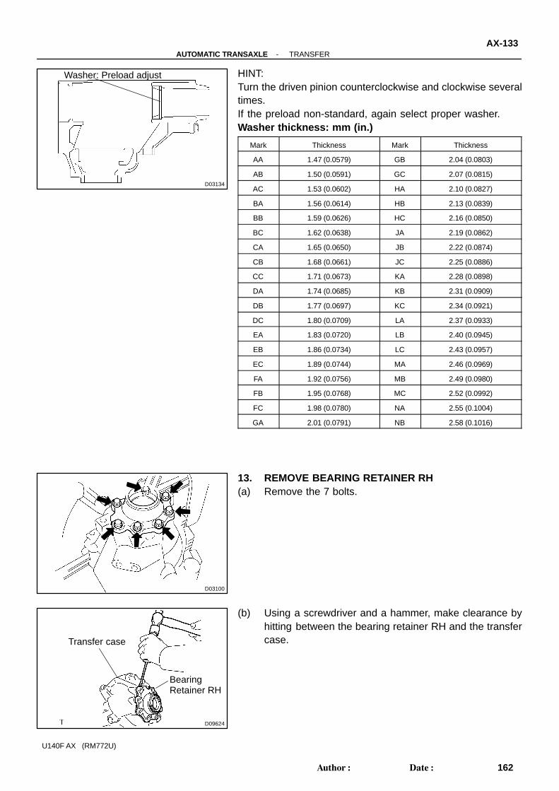
HINT:Turn the driven pinion counterclockwise and clockwise severaltimes.If the preload non-standard, again select proper washer.Washer thickness: mm (in.)
Mark Thickness Mark Thickness
AA 1.47 (0.0579) GB 2.04 (0.0803)
AB 1.50 (0.0591) GC 2.07 (0.0815)
AC 1.53 (0.0602) HA 2.10 (0.0827)
BA 1.56 (0.0614) HB 2.13 (0.0839)
BB 1.59 (0.0626) HC 2.16 (0.0850)
BC 1.62 (0.0638) JA 2.19 (0.0862)
CA 1.65 (0.0650) JB 2.22 (0.0874)
CB 1.68 (0.0661) JC 2.25 (0.0886)
CC 1.71 (0.0673) KA 2.28 (0.0898)
DA 1.74 (0.0685) KB 2.31 (0.0909)
DB 1.77 (0.0697) KC 2.34 (0.0921)
DC 1.80 (0.0709) LA 2.37 (0.0933)
EA 1.83 (0.0720) LB 2.40 (0.0945)
EB 1.86 (0.0734) LC 2.43 (0.0957)
EC 1.89 (0.0744) MA 2.46 (0.0969)
FA 1.92 (0.0756) MB 2.49 (0.0980)
FB 1.95 (0.0768) MC 2.52 (0.0992)
FC 1.98 (0.0780) NA 2.55 (0.1004)
GA 2.01 (0.0791) NB 2.58 (0.1016)
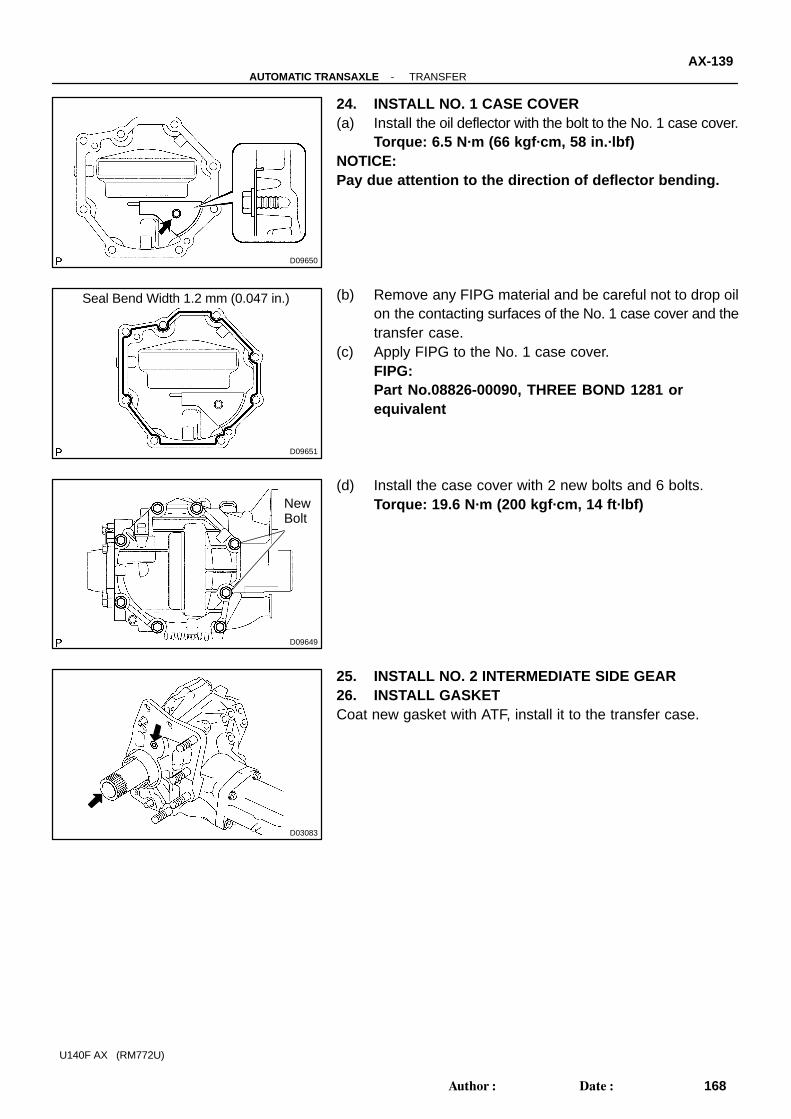
13. REMOVE BEARING RETAINER RH(a) Remove the 7 bolts.
(b) Using a screwdriver and a hammer, make clearance byhitting between the bearing retainer RH and the transfercase.

D09625
SST
D03136
SST
D03137
D03138
SST
SST
1.5 - 2.5 mm(0.059 - 0.098 in.)
D03139
SST
AX-134-AUTOMATIC TRANSAXLE TRANSFER
163Author�: Date�:
U140F AX (RM772U)
(c) Using SST, remove the bearing retainer RH from thetransfer case.SST 09520-10021
(d) Using SST, remove the outer race and washer from thebearing retainer RH.SST 09308-00010
14. ASSEMBLE BEARING RETAINER RH(a) Install the side gear shaft holder bearing to the bearing re-
tainer RH.(b) Using a snap ring pliers, install the snap ring.(c) Coat a new oil seal lip with MP grease.
(d) Using SST and a press, install the oil seal to the bearingretainer RH.SST 09950-60010 (09951-00370, 09951-00540,
09952-06010), 09950-70010 (09951-07150)(e) Install the washer.
(f) Using SST and a press, install the outer race to the bear-ing retainer RH.SST 09950- 60010 (09951- 00620), 09950- 70010
(09951-07150)

D03523
O-ring
D05935
D05936
SST
D05937
SST
-AUTOMATIC TRANSAXLE TRANSFERAX-135
164Author�: Date�:
U140F AX (RM772U)
(g) Coat 2 new O-rings with gear oil, the install them to thebearing retainer RH.
15. INSTALL BEARING RETAINER RH(a) Put the installation surface for the bearing retainer RH of
the transfer case upward.(b) Install the center differential control coupling onto the
transfer case and make the center meet each other.
(c) Insert the SST to the bearing retainer RH.SST 09387-00090
NOTICE:Insert SST straight in order not to damage the oil seal.
(d) Install the bearing retainer RH with the SST to the transfercenter differential control coupling.

D03524
Oil Seal
O-ring
D03525SST
0.7 - 1.3 mm
(0.028 - 0.071 in.)
D03526
SST
8.7 - 9.3 mm(0.343 - 0.366 in.)
D03527
AX-136-AUTOMATIC TRANSAXLE TRANSFER
165Author�: Date�:
U140F AX (RM772U)
NOTICE:� Do not make the transfer case, bearing retainer RH
and SST interfere forcibly with the center differentialcontrol coupling.
� Pay attention for the damage and peeling off in the O-ring of the retainer.
HINT:When the bearing retainer cannot be inserted, hit it soft with theplastic hammer and insert it.(e) After having inserted the bearing retainer to the transfer
case, remove SST.(f) Install 7 bolts.
Torque: 28 N·m (286 kgf·cm, 115 ft·lbf)16. PRECHECK TOTAL PRELOAD
(See Step 12)
17. INSTALL OIL SEAL(a) Coat a new oil seal lip with MP grease.(b) Using SST, install the oil seal to the bearing retainer RH.
SST 09223-4601 1
(c) Coat a new oil seal lip with MP grease.(d) Using SST, install the oil seal to the transfer case.
SST 09387-00010, 09950-70010 (09951-07150)
18. INSTALL CENTER DIFFERENTIAL LOCK SLEEVE(a) Coat new O-ring with gear oil, install it to the center differ-
ential lock sleeve.

D03528
SST
D03529
D03135
D03530SST
SST
1.1 - 1.9 mm(0.043- 0.075 in.)
D03531
SST
-AUTOMATIC TRANSAXLE TRANSFERAX-137
166Author�: Date�:
U140F AX (RM772U)
(b) Using SST, install the center differential lock sleeve to thetransfer case.SST 09950-60010 (09951-00600), 09950-70010
(09951-07150)
(c) Using snap ring pliers, install the snap ring.
19. STAKE LOCK NUTUsing a chisel and a hammer, stake the lock nut.
20. INSTALL EXTENSION HOUSING(a) Coat the oil seal lip with MP grease.(b) Using SST, install the oil seal to the extension housing.
SST 09950-60010 (09951-00380, 09951-00590,09952-06010) 09950-70010 (09951-07150)
(c) Using SST and a press, install the dust deflector to the ex-tension housing.SST 09950-60010 (09951-00640), 09950-70010
(09951-07150)

D03532
Seal Bend Width 1.2 mm (0.047 in.)
D03533
D03534
27 (1.06)
14 (0.55)
15 (0.59)
58 (2.28)
mm (in.) 2 (0.08)
D03535
6.5 - 7.5(0.256 - 0.295)
10.8 - 11.8(0.43 - 0.46)
mm (in.)
AX-138-AUTOMATIC TRANSAXLE TRANSFER
167Author�: Date�:
U140F AX (RM772U)
(d) Remove any FIPG material and be careful not to drop oilon the contacting surfaces of the extension housing andthe transfer case.
(e) Apply FIPG to the extension housing.FIPG:Part No.08826-00090, THREE BOND 1281 orequivalent
(f) Install the extension housing with the 4 bolts.Torque: 25.5 N·m (260 kgf·cm, 19 ft·lbf)
21. INSTALL STUD BOLTInstall the 4 stud bolts to the transfer case.
Torque: 39.2 N·m (400 kgf·cm, 29 ft·lbf)HINT:From the bottom side of the stud bolt shown in the illustrationit should be installed to the case.
22. INSTALL PINUsing a plastic hammer, install the 4 pins.23. REMOVE TRANSFER FROM OVERHAUL ATTACH-
MENT
D09650
D09651
Seal Bend Width 1.2 mm (0.047 in.)
D09649
NewBolt
D03083
-AUTOMATIC TRANSAXLE TRANSFERAX-139
168Author�: Date�:
U140F AX (RM772U)
24. INSTALL NO. 1 CASE COVER(a) Install the oil deflector with the bolt to the No. 1 case cover.
Torque: 6.5 N·m (66 kgf·cm, 58 in.·lbf)NOTICE:Pay due attention to the direction of deflector bending.
(b) Remove any FIPG material and be careful not to drop oilon the contacting surfaces of the No. 1 case cover and thetransfer case.
(c) Apply FIPG to the No. 1 case cover.FIPG:Part No.08826-00090, THREE BOND 1281 orequivalent
(d) Install the case cover with 2 new bolts and 6 bolts.Torque: 19.6 N·m (200 kgf·cm, 14 ft·lbf)
25. INSTALL NO. 2 INTERMEDIATE SIDE GEAR26. INSTALL GASKETCoat new gasket with ATF, install it to the transfer case.

AX10D-01
D03737
SST
D03738
SST
D09664
D09663
-AUTOMATIC TRANSAXLE DIFFERENTIAL CASEAX-107
136Author�: Date�:
U140F AX (RM772U)
REASSEMBLYHINT:Coat all of the sliding and rotating surfaces with ATF beforereassembly.
1. INSTALL TRANSAXLE HOUSING SIDE BEARINGOUTER RACE
Using SST and a hammer, install the bearing outer race.SST 09350- 32014 (09351- 32111), 09950- 70010
(09951-07150)
2. INSTALL TRANSAXLE CASE SIDE BEARING OUTERRACE
(a) Install the plate washer to the transaxle case.HINT:First select and install a plate washer of less thickness than be-fore.(b) Using SST and a hammer, install the bearing outer race.
SST 09223-15020, 09950-70010 (09951-07100)
3. INSTALL FRONT DIFFERENTIAL CASE(a) Coat the front differential side gear thrust washer, front
differential side gear, front differential pinion shaft holder,4 front differential pinion thrust washers, the 4 front differ-ential pinions with ATF, install them to the front differentialcase.
(b) Install the 3 pinion shafts to the front differential case.

D09670
D09671
D09672
AX-108-AUTOMATIC TRANSAXLE DIFFERENTIAL CASE
137Author�: Date�:
U140F AX (RM772U)
(c) Using a dial indicator, measure the backlash of one piniongear while holding the front differential side gear towardthe case.Standard backlash: 0.05 - 0.20 mm (0.002 - 0.008 in.)
NOTICE:Do not mount the surface of front differential case whichcontacts with bushing in a vise.If the backlash is not within the specified value, refer to the tablebelow and select a thrust washer which will ensure that thebacklash is within the specified value.Thrust washer thickness: mm (in.)
Mark Thickness mm (in.)
B 1.00 (0.0394)
C 1.05 (0.0413)
D 1.10 (0.0433)
E 1.15 (0.0453)
F 1.20 (0.0472)
G 1.25 (0.0492)
(d) Engage the front differential side gear to the above men-tioned front differential case.
(e) Install the differential case LH to the front differential caseand measure its center.
(f) After that, remove the differential case LH.
(g) Using a straight edge and feeler gauge, measure theclearance between the front differential case and the frontdifferential side gear.t= Thrust washer thicknessL= Clearancet= L- 0.16 - 0.27 mm (0.0063 - 0.0106 in.)
HINT:Refer to the table below and select a turust washer which willensure that the clearance is within the specification.Thrust washer thickness: mm (in.)
Mark Thickness Mark Thickness
A 0.95 (0.0373) F 1.20 (0.0472)
B 1.00 (0.0393) G 1.25 (0.0492)
C 1.05 (0.0413) H 1.30 (0.0512)
D 1.10 (0.0433) J 1.35 (0.0532)
E 1.15 (0.0453) K 1.40 (0.0552)
If the clearance is not within the specified value, parts may havebeen assembled incorrectly, so check and reassemble it.

D09669
Q06195
D09674
D09667
-AUTOMATIC TRANSAXLE DIFFERENTIAL CASEAX-109
138Author�: Date�:
U140F AX (RM772U)
(h) Install the spacer to the front differential case.
(i) Using a snap ring expander, install the snap ring, asshown.
HINT:Before installing the shaft snap ring, wrap vinyl tape around thecase to avoid damaging the case.
4. INSTALL DIFFERENTIAL RH CASE(a) Install the spacer to the differential RH case.(b) Slide down the spacer to install the 4 center differential
pinion shafts.
(c) Install the center differential side gear thrust washer No.1, conical washer, center differential side gear, center dif-ferential pinion shaft holder, 4 center differential pinions,4 center differential pinion thrust washers and 4 center dif-ferential pinion shafts to the differential RH case.
HINT:Ensure that the conical washers is installed correctly.

D09673
D09665
D09681
Thrust WasherThickness1.0 mm (0.039 in.)
Differential RH Case
AX-1 10-AUTOMATIC TRANSAXLE DIFFERENTIAL CASE
139Author�: Date�:
U140F AX (RM772U)
5. CHECK CENTER DIFFERENTIAL PINION GEARBACKLASH OF DIFFERENTIAL RH CASE SIDE
(a) Using a dial indicator, measure the backlash of one piniongear while holding the front differential side gear towardthe case.Standard backlash:0.05 - 0.20 mm (0.0020 - 0.0079 in.)
If the backlash is not within the specified value, refer to the tablebelow and select a thrust washer which satisfied the specifiedvalue.Thrust washer thickness: mm (in.)
Mark Thickness Mark Thickness
MA 0.80 (0.0315) MH 1.15 (0.0453)
MB 0.85 (0.0335) MJ 1.20 (0.0472)
MC 0.90 (0.0354) MK 1.25 (0.0492)
MD 0.95 (0.0374) ML 1.30 (0.0512)
ME 1.00 (0.0394) MM 1.35 (0.0531)
MF 1.05 (0.0413) MN 1.40 (0.0551)
MG 1.10 (0.0433)
(b) Slide up the spacer to the install the snap ring.(c) Using a snap ring expander, install the snap ring as
shown.
6. CHECK AND ADJUST CENTER DIFFERENTIAL SIDEGEAR THRUST CLEARANCE (FRONT DIFFERENTIALLH CASE SIDE)
(a) Temporarily install the front differential case assembly,front differential side gear, front differential side gearthrust washer, (temporarily install) a 1.0 mm (0.039 in.)thick center differential side gear thrust washer No. 2 andcenter differential side gear thrust washer No. 2 to the dif-ferential RH case.
HINT:� Engage the front differential side gear and pinion gear of
the differential RH case.� The temporarily installed a 1.0 mm (0.039 in.) thick center
differential side gear thrust washer No. 2 is used for refer-ence when checking backlash.

D09682
Plastigage
Plastigage
D09685Matchmarks
D09676
D09684
-AUTOMATIC TRANSAXLE DIFFERENTIAL CASEAX-1 11
140Author�: Date�:
U140F AX (RM772U)
(b) Clean the contact surface of the center differential sidegear thrust washer No. 2 and differential LH case.
(c) Apply plastigage on the center differential side gear thrustwasher No. 2, as shown.
HINT:Apply the plastigage on the center differential side gear thrustwasher No. 2 in the 4 positions directly above the pinion shaftsin the differential RH case’s position.
(d) Install the differential LH case downward.HINT:Align the matchmarks on the differential RH case and contactthe differential LH case.
(e) Temporarily install the differential RH case and service 4bolts to the differential LH case.Parts No: Service bolt: 90105-08100Torque: 33 N·m (337 kgf·cm, 24 ft·lbf)
(f) Remove the 4 bolts and differential LH case upward.
(g) Measure the plastigage at widest point.Standard clearance: 0.16 - 0.25 mm (0.006 - 0.010 in.)
Refer to the table below, select the thrust washer No. 2 whichwill ensure that the backlash is within the specification. Try toselect a washer of the same size.Thrust washer thickness: mm (in.)
Mark Thickness Mark Thickness
0 0.80 (0.0315) 7 1.15 (0.0453)
1 0.85 (0.0335) 8 1.20 (0.0472)
2 0.90 (0.0354) 9 1.25 (0.0492)
3 0.95 (0.0374) A 1.30 (0.0512)
4 1.00 (0.0394) B 1.35 (0.0531)
5 1.05 (0.0413) C 1.40 (0.0551)
6 1.10 (0.0433)
(h) Remove the differential LH case, center differential sidegear thrust washer No. 2 and (temporarily install) a 1.0mm (0.039 in.) thick center differential side gear thrustwasher No. 2.

D09683
D09685Matchmarks
D09676
D09686
SST
SST
AX-1 12-AUTOMATIC TRANSAXLE DIFFERENTIAL CASE
141Author�: Date�:
U140F AX (RM772U)
(i) Install the conical washer and center differential side gearthrust washer No. 2 (previously selected) from differentialcase.
HINT:Be careful not to mistake the direction of the conical washer.
(j) Install the differential LH case downward.HINT:Align the matchmarks on the differential RH case and contactthe differential LH case.
(k) Temporarily install the differential RH case and 4 servicebolts to the differential LH case.Parts No: Service bolt: 90105-08100Torque: 33 N·m (337 kgf·cm, 24 ft·lbf)
7. CHECK PRELOAD OF DIFFERENTIAL CASE(a) Using SST and a press, install the side bearing RR and
FR to the differential case.SST 09214- 76011, 09252- 10010, 09316- 20011,
09649-17010

D09677
D03755
A
B
C
A
C
C
C
D03756
D03757
SST
-AUTOMATIC TRANSAXLE DIFFERENTIAL CASEAX-1 13
142Author�: Date�:
U140F AX (RM772U)
(b) Install the differential to the T/F case.
(c) Remove any FIPG material and be careful not to drop oilon the contacting surfaces of the transaxle case and thetransaxle housing.
(d) Install the transaxle housing and 16 bolts to the transaxlecase.
HINT:Although the bolt A is a non-reusable seal bolt, in the case,clean the bolts and tighten them as well as the bolts B and C.
Torque: Bolt A: 22 N·m (226 kgf·cm, 16 ft·lbf) Bolt B and C: 29 N·m (300 kgf·cm, 22 ft·lbf)Bolt length:Bolt A: 50.0 mm (1.969 in.)Bolt B: 50.0 mm (1.969 in.)Bolt C: 42.0 mm (1.654 in.)
(e) Temporarily install the intermediate shaft.(f) Turn the intermediate shaft right and left 2 or 3 times to
allow the bearing settle.(g) Remove the intermediate shaft.
(h) Using SST and torque wrench, measure the turningtorque of the differential.SST 09564-3201 1Turning torque at 60 rpm: New bearing:0.20 - 0.69 N·m (2 - 7 kgf·cm, 1.8 - 6.1 in.·lbf)Used bearing:0.10 - 0.35 N·m (1 - 4 kgf·cm, 0.9 - 3.1 in.·lbf)

D03755
D09677
D03882
AX-1 14-AUTOMATIC TRANSAXLE DIFFERENTIAL CASE
143Author�: Date�:
U140F AX (RM772U)
HINT:If the preload is not within the specified value, refer to the tablebelow and select a thrust washer which preload is within thespecified value.Plate washer thickness: mm (in.)
Mark Thickness Mark Thickness
0 2.00 (0.0787) 9 2.45 (0.0965)
1 2.05 (0.0807) A 2.50 (0.0984)
2 2.10 (0.0827) B 2.55 (0.1004)
3 2.15 (0.0846) C 2.60 (0.1024)
4 2.20 (0.0866) D 2.65 (0.1043)
5 2.25 (0.0886) E 2.70 (0.1063)
6 2.30 (0.0906) F 2.75 (0.1083)
7 2.35 (0.0925) G 2.80 (0.1102)
8 2.40 (0.0945) H 2.85 (0.1122)
(i) Remove the 16 bolts and the transaxle housing.
(j) Remove the differential from the transaxle case.
8. INSTALL RING GEAR ON DIFFERENTIAL CASE(a) Clean the contact surfaces of the differential case and the
ring gear.(b) Heat the ring gear in boiling water.(c) Carefully remove the ring gear from the boiling water.

D09678
D09679
D09680
D04075
SST
D03809
Vinyl Tape
SST
-AUTOMATIC TRANSAXLE DIFFERENTIAL CASEAX-1 15
144Author�: Date�:
U140F AX (RM772U)
(d) Install the ring gear to the differential.
(e) Temporarily install the 8 bolts.
(f) Remove the 4 service bolts.(g) Temporarily install the 8 bolts.(h) Tighten the 16 bolts.
Torque: 95 N·m (970 kgf·cm, 70 ft·lbf)
9. INSTALL DIFFERENTIAL SIDE BEARING RETAINEROIL SEAL
(a) Using SST, install the new oil seal.SST 09608-10010, 09950-70010 (09951-07150)
(b) Coat a lip of oil seal with petroleum jelly.
10. INSTALL TRANSAXLE HOUSING OIL SEAL(a) Wind a vinyl tape around SST at the place 6.0 mm (0.236
in.) above from the bottom end until the thickness of thewound tape is about 5.0 mm (0.197 in.).SST 09950-60010 (09951-00730)
NOTICE:Clean SST to remove deposited oil, before winding a vinyltape.(b) Coat the lip of oil seal with petroleum jelly.
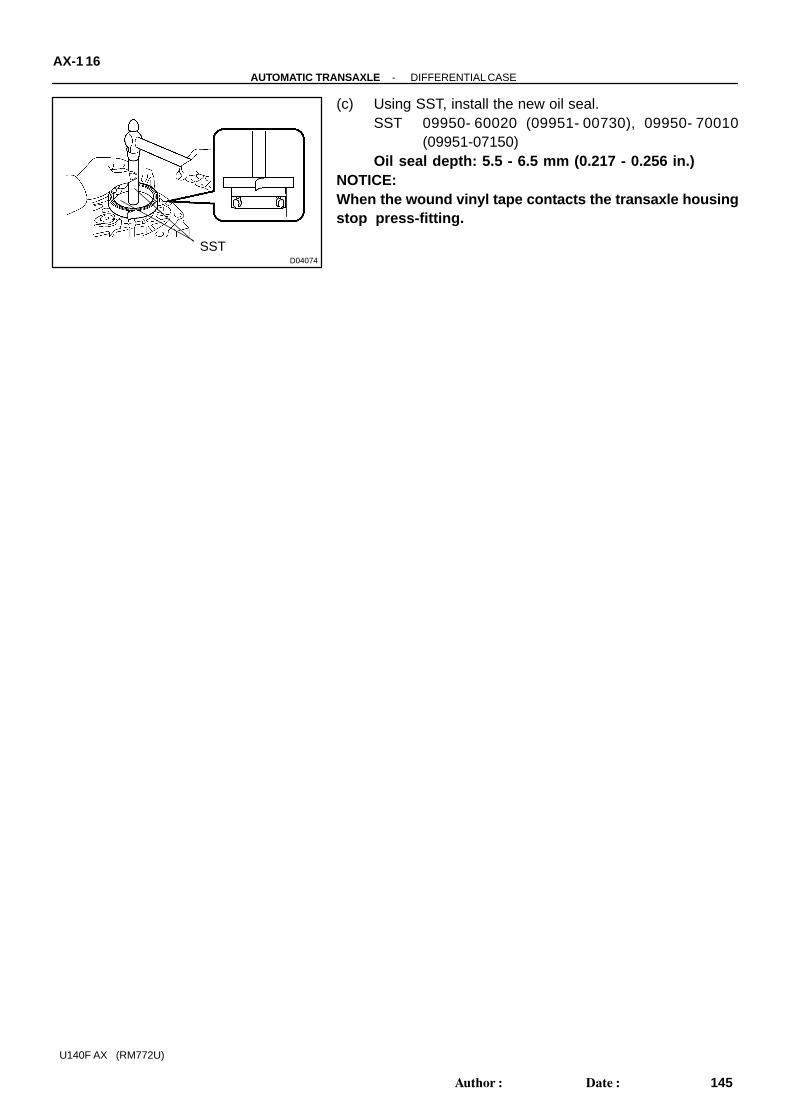
D04074
SST
AX-1 16-AUTOMATIC TRANSAXLE DIFFERENTIAL CASE
145Author�: Date�:
U140F AX (RM772U)
(c) Using SST, install the new oil seal.SST 09950- 60020 (09951- 00730), 09950- 70010
(09951-07150)Oil seal depth: 5.5 - 6.5 mm (0.217 - 0.256 in.)
NOTICE:When the wound vinyl tape contacts the transaxle housingstop press-fitting.

AX0B9-04
D03786
D03785
D03853
D04081
AX-92-AUTOMATIC TRANSAXLE VALVE BODY
121Author�: Date�:
U140F AX (RM772U)
REASSEMBLY1. ASSEMBLE VALVE BODY(a) Install the check balls to the upper and lower valve body.(b) Install the plate to the lower valve body.(c) Install the lower valve body with plate to the upper valve
body.
(d) Install the 7 bolts to the lower valve body.Torque: 11 N·m (110 kgf·cm, 8 ft·lbf)Bolt length: 41 mm (1.614 in.)
2. INSTALL ACCUMULATOR(a) Install the 2 accumulator valves to the valve body.(b) Install the 4 springs to the valve body.Spring length: mm (in.)
SpringFree length /
Outer diameter mm (in.)Color
C2 Inner: 47.58 (1.8732) /
11.2 (0.441)Brown
Outer: 47.61 (1.8744) /
12.0 (0.472)Brown
B1 Inner: 43.88 (1.7276) /
11.0 (0.433)Purple
Outer: 45.12 (1.7764) /
11.8 (0.465)White
(c) Using snap ring pliers, install the snap ring.
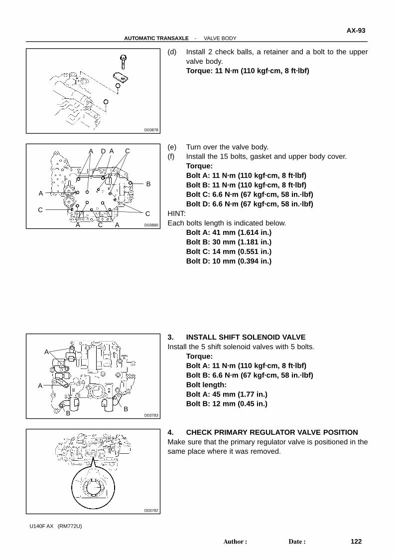
D03878
D03880
C
C
B
C
C
A
D
A A
A A
D03783
A
BB
A
D03782
-AUTOMATIC TRANSAXLE VALVE BODYAX-93
122Author�: Date�:
U140F AX (RM772U)
(d) Install 2 check balls, a retainer and a bolt to the uppervalve body.Torque: 11 N·m (110 kgf·cm, 8 ft·lbf)
(e) Turn over the valve body.(f) Install the 15 bolts, gasket and upper body cover.
Torque:Bolt A: 11 N·m (110 kgf·cm, 8 ft·lbf)Bolt B: 11 N·m (110 kgf·cm, 8 ft·lbf)Bolt C: 6.6 N·m (67 kgf·cm, 58 in.·lbf)Bolt D: 6.6 N·m (67 kgf·cm, 58 in.·lbf)
HINT:Each bolts length is indicated below.
Bolt A: 41 mm (1.614 in.)Bolt B: 30 mm (1.181 in.)Bolt C: 14 mm (0.551 in.)Bolt D: 10 mm (0.394 in.)
3. INSTALL SHIFT SOLENOID VALVEInstall the 5 shift solenoid valves with 5 bolts.
Torque:Bolt A: 11 N·m (110 kgf·cm, 8 ft·lbf)Bolt B: 6.6 N·m (67 kgf·cm, 58 in.·lbf)Bolt length:Bolt A: 45 mm (1.77 in.)Bolt B: 12 mm (0.45 in.)
4. CHECK PRIMARY REGULATOR VALVE POSITIONMake sure that the primary regulator valve is positioned in thesame place where it was removed.

AX0B3-04
D04078
D03860
D03704
D03703
SST
-AUTOMATIC TRANSAXLE UNDERDRIVE CLUTCHAX-85
114Author�: Date�:
U140F AX (RM772U)
REASSEMBLY1. INSTALL O-RINGCoat new O-ring with ATF, install it to the U/D clutch drum.
2. INSTALL U/D CLUTCH PISTONCoat the U/D clutch piston with ATF, install it to the U/D clutchpiston drum.NOTICE:Be careful not to damage the O-ring.
3. INSTALL PISTON RETURN SPRING(a) Install the piston return spring and clutch balancer to the
U/D clutch drum.NOTICE:Be careful not to damage the lip seal of clutch balancer.
(b) Place SST on the clutch balancer and compress the pis-ton return spring with a press.SST 09350-32014 (09351-32070)
(c) Using a snap ring expander, install the snap ring to U/Dclutch drum.
NOTICE:� Be sure the end gap of the snap ring is not aligned
with the clutch balancer claw.� Stop the press when the spring sheet is lowered to the
place 1 - 2 mm (0.039 - 0.078 in.) from the snap ringgroove, preventing the spring sheet from deforming.
� Do not expand the snap ring excessively.

D08130
Disc
Plate
D03701
D08123
D03700
AX-86-AUTOMATIC TRANSAXLE UNDERDRIVE CLUTCH
115Author�: Date�:
U140F AX (RM772U)
4. INSTALL PLATE, DISC AND FLANGE(a) Install the 3 plates, 3 discs and flange.
Install in order: P = Plate, D = Disc, F = FlangeP - D - P - D - P - D - F
(b) Using a screwdriver, install the snap ring.(c) Check that the end gap of snap ring is not aligned with one
of the cutouts.
5. CHECK PISTON STROKE OF U/D CLUTCH(a) Install the U/D clutch to the transaxle case.NOTICE:Be careful not to damage the oil seal rings.(b) Install the dial indicator, as shown in the illustration.
(c) Measure the U/D clutch piston stroke while applying andreleasing compressed air (392 kgf/cm2, 4.0 kPa, 57 psi).Piston stroke: 1.51 - 1.90 mm (0.0594 - 0.0748 in.)
If the piston stroke is less than the limit of piston stroke, partsmay have been assembled incorrectly, so check and reas-semble again.If the stroke is non-standard, select another flange.HINT:There are 3 flanges in different thickness.Flange Thickness: mm (in.)
No. Thickness No. Thickness
1 3.0 (0.118) 3 3.4 (0.134)
2 3.2 (0.126)

AX0B6-02
D03827
D03826
D03692
D03693
SST
D03694
-AUTOMATIC TRANSAXLE UNDERDRIVE PLANETARY GEARAX-79
108Author�: Date�:
U140F AX (RM772U)
REASSEMBLY1. INSTALL U/D PLANETARY RING GEAR(a) Install the U/D planetary ring gear to the counter driven
gear.
(b) Using snap ring pliers, install snap ring.
2. INSTALL U/D PLANETARY GEAR(a) Using a press, install the tapered roller bearing RR to the
U/D planetary gear.NOTICE:Press in the bearing until it becomes flat at the bottom.
(b) Install the counter driven gear with the U/D planetary ringgear.
(c) Using SST and a press, install the tapered roller bearingFR.SST 09214-7601 1
NOTICE:Press in the counter driven gear while rotating it.
(d) Using a press, install the parking lock gear.NOTICE:Press in the counter driven gear while rotating it.

D03695
D03696
D03688
SST
D03685
SST
SST
D03852
AX-80-AUTOMATIC TRANSAXLE UNDERDRIVE PLANETARY GEAR
109Author�: Date�:
U140F AX (RM772U)
(e) Using a press, install the differential drive pinion.NOTICE:Press in the counter driven gear while rotating it.HINT:When replacing the differential drive pinion, replace it togetherwith the U/D planetary gear.
(f) Using a press, install the cylindrical roller bearing innerrace.
NOTICE:Press in the counter driven gear while rotating it.
(g) Clamp the U/D planetary gear in soft jaw vise.NOTICE:Be careful not to damage the differential drive pinion.(h) Using SST, install a new lock nut.
Torque: 280 N·m (2,855 kgf·cm, 207 ft·lbf)SST 09564-16020
HINT:Use a torque wrench with a fulcrum length of 750 mm (29.53in.).
3. MEASURE TURNING TORQUE OF U/D OUTPUTSHAFT
Using SST and a small torque wrench, measure the turningtorque of U/D output shaft.
SST 09387-00050, 09564-16020Turning torque at 60 rpm:0.79 - 5.77 N·m (8 - 59 kgf·cm, 7.0 - 51.1 in.·lbf)
HINT:Use a torque wrench with a fulcrum length 160 mm (6.3 in.).
4. STAKE LOCK NUTUsing a pin punch and hammer, stake the lock nut.NOTICE:Also, make sure that there are no cracks on the nut.

AX0AZ-01
D03846
D03845
D03843
D03796
SST
-AUTOMATIC TRANSAXLE SECOND BRAKEAX-75
104Author�: Date�:
U140F AX (RM772U)
REASSEMBLY1. INSTALL 2ND BRAKE PISTON(a) Coat 2 new O-rings with ATF and install them in the 2nd
brake piston.
(b) Be careful not to damage the O-rings and press in the2nd brake piston into the 2nd brake cylinder with a yourhands.
2. INSTALL PISTON RETURN SPRING(a) Install the piston return spring.
(b) Place SST on the piston return spring, and compress thepiston return spring with a press.SST 09387-00060
(c) Using a screwdriver, install the snap ring.NOTICE:Be sure the end gap of the snap ring is not aligned with thepiston return spring claw.

AX0AV-02
D03669
D03670
D03663
D03662
SST
AX-70-AUTOMATIC TRANSAXLE FORWARD CLUTCH
99Author�: Date�:
U140F AX (RM772U)
REASSEMBLY1. INSTALL FORWARD CLUTCH PISTON(a) Coat 2 new O-rings with ATF, and install them to the for-
ward clutch piston.
(b) Install the forward clutch piston to the forward clutchdrum.
2. INSTALL PISTON RETURN SPRING(a) Place the return spring onto the piston.
(b) Place SST on the return spring, and compress the returnspring with a press.SST 09350-32014 (09351-32070)
(c) Install the snap ring with a snap ring expander. Be surethe end gap of the snap ring is not aligned with the springretainer claw.
NOTICE:� Stop the press when the spring sheet is lowered to the
place 1 - 2 mm (0.039 - 0.078 in.) from the snap ringgroove, preventing the spring sheet from the deform-ing.
� Do not expand the snap ring excessively.

D03661
D03660
D09646
D03672
-AUTOMATIC TRANSAXLE FORWARD CLUTCHAX-71
100Author�: Date�:
U140F AX (RM772U)
3. INSTALL PLATE, DISC AND FLANGEInstall the flange, 4 plates and 4 discs in order.
Install in order: P=Plate, D=Disc, F=FlangeP - D - P - D - P - D - P - D - F
4. INSTALL SNAP RING(a) Using a screwdriver, install the snap ring.(b) Check that the end gap of the snap ring is not aligned with
one of the cutouts.
5. CHECK PISTON STROKE OF FORWARD CLUTCH(a) Using a dial indicator, measure the forward clutch piston
stroke while applying and releasing compressed air (392kgf/cm2, 4.0 kPa, 57 psi).Piston stroke: 1.41 - 1.75 mm (0.0555 - 0.0689 in.)
If the piston stroke is less than the limit, parts may have beenassembled incorrectly, check and reassemble again.If the clearance is non-standard, select another flange.HINT:There are 5 different flanges in thickness.Flange thickness: mm (in.)
No. Thickness No. Thickness
1 3.00 (0.1181) 4 3.45 (0.1358)
2 3.15 (0.1240) 5 3.60 (0.1417)
3 3.30 (0.1299) - -
6. CHECK DISK ROTATECheck that the disc lightly rotates when rotating the forwardclutch assembly after inserting the multiple disc clutch into it.NOTICE:Do not place the forward clutch assembly in a vise.

AX0AR-02
D03680
D03678
D03677
SST
D08104
D
F
P
-AUTOMATIC TRANSAXLE DIRECT CLUTCHAX-63
92Author�: Date�:
U140F AX (RM772U)
REASSEMBLY1. INSTALL DIRECT CLUTCH PISTONCoat the direct clutch piston with ATF, install it to the directclutch drum.NOTICE:Be careful not to damage the lip seal of direct clutch piston.
2. INSTALL PISTON RETURN SPRING(a) Install the piston return spring and clutch balancer to the
direct clutch drum.NOTICE:Be careful not to damage the lip seal of direct clutch ba-lancer.
(b) Place SST, on the clutch balancer and compress the pis-ton return spring with a press.SST 09387-00020
(c) Using a snap ring expander, install the snap ring to the di-rect clutch drum.
NOTICE:� Be sure the end gap of the snap ring is not aligned
with the clutch balancer claw.� Stop the press when the spring sheet is lowered to the
place 1 - 2 mm (0.039 - 0.078 in.) from the snap ringgroove, preventing the spring sheet from the deform-ing.
� Do not expand the snap ring excessively.
3. INSTALL PLATE, DISC AND FLANGE(a) Install the 3 plates, 3 discs and flange.
Install in order: P=Plate, D=Disc, F=FlangeP - D - P - D - P - D - F

D03675
D09210
D03682
AX-64-AUTOMATIC TRANSAXLE DIRECT CLUTCH
93Author�: Date�:
U140F AX (RM772U)
(b) Using a screwdriver, install the snap ring.(c) Check that the end gap of the snap ring is not aligned with
one of the cutouts.
4. CHECK PISTON STROKE OF DIRECT CLUTCH(a) Install the direct clutch on the transaxle rear cover.(b) Using and a dial indicator, measure the direct clutch pis-
ton stroke while applying and releasing compressed air(392 kPa, 4.0 kgf/cm2, 57 psi).Piston stroke: 0.61 - 0.83 mm (0.0240 - 0.0327 in.)
If the piston stroke is less than the limit of piston stroke, partsmay have been assembled incorrectly, so check and reas-semble again.If the stroke is non-standard, select another flange.HINT:There are 6 flanges in different thickness.Flange Thickness: mm (in.)
No. Thickness No. Thickness
1 3.0 (0.118) 4 3.3 (0.130)
2 3.1 (0.122) 5 3.4 (0.134)
3 3.2 (0.126) 6 3.5 (0.138)
5. CHECK DISK ROTATECheck that the disc rotates when rotating the disk after insertingthe rear planetary sun gear.NOTICE:Do not place the rear planetary sun gear in a vise.

AX0AN-04
D03654
SST
D09206
D03651
D03655
D09205
AX-58-AUTOMATIC TRANSAXLE OIL PUMP
87Author�: Date�:
U140F AX (RM772U)
REASSEMBLY1. INSTALL OIL SEAL(a) Using SST and a hammer, install a new oil seal from oil
pump.SST 09350-32014 (09351-32140)
HINT:The seal end should be flat with the outer edge of the oil pump.(b) Coat the lip of oil seal with petroleum jelly.
2. INSTALL OIL PUMP DRIVE GEAR AND DRIVEN GEAR
3. INSTALL STATOR SHAFT(a) Align the stator shaft with each bolt hole.(b) Using a torx socket T30, install the 11 bolts.
Torque: 9.8 N·m (100 kgf·cm, 7 in.·lbf)
4. INSTALL 2 OIL SEAL RINGSNOTICE:Do not expand the ring ends excessively.
5. CHECK PUMP DRIVE GEAR ROTATIONTurn the drive gear with 2 screwdrivers and make sure it rotatessmoothly.NOTICE:Be careful not to damage the oil seal lip.

AX10B-01
AX-26-AUTOMATIC TRANSAXLE COMPONENT PARTS
55Author�: Date�:
U140F AX (RM772U)
REASSEMBLYNOTICE:� The automatic transaxle is composed of highly precision-finished parts, necessitating careful
inspection before reassembly because even a small nick could cause fluid leakage or affectthe performance. The instructions here are organized so that you work on only one componentgroup at a time. This will help avoid confusion from similar-looking parts of different sub-as-semblies being on your workbench at the same time. The component groups are inspected andrepaired from the converter housing side. As much as possible, complete the inspection, repairand reassembly before proceeding to the next component group. If a defect is found in a certaincomponent group during reassembly, inspect and repair this group immediately. If a compo-nent group cannot be assembled because parts are being ordered, be sure to keep all parts ofthe group in a separate container while proceeding with disassembly, inspection, repair andreassembly of other component groups.Recommended ATF: TYPE T-IV
� All disassembled parts should be washed clean and any fluid passages and holes should beblown through with compressed air.
� Dry all parts with compressed air-never use shop rags.� When using compressed air, always aim away from yourself to prevent accidentally spraying
ATF or kerosene on your face.� The recommended automatic transaxle fluid or kerosene should be used for cleaning.� After cleaning, the parts should be arranged in the correct order for efficient inspection, repairs,
and reassembly.� When disassembling a valve body, be sure to match each valve together with the correspond-
ing spring.� New discs for the brakes and clutches that are to be used for replacement must be soaked in
ATF for at least 15 minutes before reassembly.� All oil seal rings, clutch discs, clutch plates, rotating parts, and sliding surfaces should be
coated with ATF prior to reassembly.� All gaskets and rubber O-rings should be replaced.� Do not apply adhesive cements to gaskets and similar parts.� Make sure that the ends of a snap ring are not aligned with one of the cutouts and are installed
in the groove correctly.� If a worn bushing is to be replaced, the sub-assembly containing the bushing must also be re-
placed.� Check thrust bearings and races for wear or damage. Replace if necessary.� Use petroleum jelly to keep parts in place.� When working with FIPG material, you must observe the following.
Using a razor blade and a gasket scraper, remove all the old packing (FIPG) material from thegasket surface.Thoroughly clean all components to remove all the loose material.Clean both sealing surfaces with a non-residue solvent.Parts must be reassembled within 10 minutes of application. Otherwise, the packing (FIPG) ma-terial must be removed and reapplied.

D09942
A
B
C D
E
F G
H
I J
-AUTOMATIC TRANSAXLE COMPONENT PARTSAX-27
56Author�: Date�:
U140F AX (RM772U) Corrected 11/08/01 - MH
BEARING AND RACES INSTALLATION POSITION AND DIRECTION

AX-28-AUTOMATIC TRANSAXLE COMPONENT PARTS
57Author�: Date�:
U140F AX (RM772U)
MarkFront Race Diameter
Inside / Outside mm (in.)
Thrust Bearing Diameter
Inside / Outside mm (in.)
Rear Race Diameter
Inside / Outside mm (in.)
A - 57.2 (2.252) / 84.96 (3.3449) 56.4 (2.220) / 83.0 (3.268)
B - 37.73 (1.4854) / 58.0 (2.283) 29.9 (1.177) / 55.5 (2.185)
C - 33.85 (1.3327) / 52.2 (2.055) -
D - 23.5 (0.925) / 44.0 (1.732) -
E - 36.3 (1.429) / 52.2 (2.055) 34.5 (1.358) / 48.5 (1.909)
F - 34.6 (1.362) / 52.2 (2.055) -
G 40.3 (1.587) / 58.0 (2.283) 38.6 (1.520) / 60.0 (2.362) 38.6 (1.520) / 58.0 (2.283)
H - 53.6 (2.110) / 69.6 (2.740) -
I - 33.7 (1.327) / 48.2 (1.898) 30.3 (1.193) / 46.0 (1.811)
J - 53.6 (2.110) / 70.18 (2.763) or 69.6 (2.740) -

D03607
D03915
D03807
SST
D03806
D03914
-AUTOMATIC TRANSAXLE COMPONENT PARTSAX-29
58Author�: Date�:
U140F AX (RM772U) Corrected 11/08/01 - MH
1. INSTALL APPLY PIPEInstall the apply pipe, and clamp with the bolt to the transaxlecase.
Torque: 9.8 N·m (100 kgf·cm, 7 ft·lbf)NOTICE:Make sure to insert the pipe to the stopper.
2. INSTALL U/D CYLINDRICAL ROLLER BEARING(a) Install the oil seal ring to the transaxle housing.
(b) Using SST and a press, install the U/D cylindrical rollerbearing.SST 09950-60020, (09951-00810), 09950-70010,
(09951-07100)NOTICE:Do not apply excessive pressure to it.
3. CHECK U/D BRAKE PISTON RETURN SPRINGUsing vernier calipers, measure the free length of the spring to-gether with the spring seat.
Standard free length: 14.04 mm (0.5528 in.)
4. INSTALL U/D BRAKE(a) Install the 2 oil seal rings to the transaxle case.

D03809
SST
Vinyl Tape
D03810
SST
D03794
D03609
D03610
SST
AX-30-AUTOMATIC TRANSAXLE COMPONENT PARTS
59Author�: Date�:
U140F AX (RM772U)
(b) Wind a vinyl tape around SST at the place 4.0 mm (0.157in.) above from the bottom end until the thickness of thewound tape is about 5.0 mm (0.197 in.).SST 09550-60010 (09951-00320)
NOTICE:Clean SST to remove deposited oil, before winding a vinyltape.
(c) Using SST and a press, install the needle-roller bearingto the transaxle case.SST 09950-60010, (09951-00320), 09950-70010
(09951-07100)NOTICE:When the wound vinyl tape contacts the transaxle case,stop press-fitting.
(d) Coat 2 new O-rings with ATF, install them to the U/Dbrake piston.
(e) Install the U/D brake piston to the transaxle case.
(f) Using SST, a snap ring expander and a press, install thepiston return spring and snap ring to the transaxle case.SST 09387-00020
NOTICE:� Press-fit the bearing race RH until it contacts the
snap ring.� Do not apply excessive pressure to it.

D03604
D03611
SST
SST
Counter Drive Gear Side:
Front Planetary Gear Side:
D03613
SST
D03614
SST
-AUTOMATIC TRANSAXLE COMPONENT PARTSAX-31
60Author�: Date�:
U140F AX (RM772U) Corrected 11/08/01 - MH
5. INSTALL COUNTER DRIVE GEAR(a) Using a screwdriver, install the snap ring to the transaxle
case.
(b) Using SST and a press, install the 2 bearing outer racesto the transaxle case.SST 09950-60020 (09951-00890), 09950-70010
(09951-07150)NOTICE:� Press-fit the bearing race until it contacts the snap
ring.� Do not apply excessive pressure to it.
(c) Using SST and a press, install the tapered roller bearingto the counter drive gear.SST 09649-17010
NOTICE:� Press-fit the bearing inner race until it contacts the
counter drive gear.� Do not apply excessive pressure to it.
(d) Using SST and a press, install the counter drive gear andbearing to the transaxle case.SST 09950-60010 (09951-00890), 09950-70010
(09951-07150)NOTICE:Do not apply excessive pressure to it.

D03811
D03913
D03813
D03600
SST
D03615
AX-32-AUTOMATIC TRANSAXLE COMPONENT PARTS
61Author�: Date�:
U140F AX (RM772U)
6. CHECK 1ST & REVERSE BRAKE PISTON RETURNSPRING
Using vernier calipers, measure the free length of the spring to-gether with the spring seat.
Standard free length: 15.51 mm (0.6106 in.)
7. INSTALL 1ST & REVERSE BRAKE PISTON(a) Coat 2 new O-rings with ATF.(b) Install the 2 O-rings to the 1st & reverse brake piston.
(c) Coat a 1st & reverse brake piston with ATF, install the 1st& reverse brake piston to the transaxle case.
(d) Using SST, a press, and snap ring pliers, install the pistonreturn spring and snap ring to the transaxle case.SST 09387-00070
NOTICE:� Stop the press when the spring sheet is lowered to the
place 1 - 2 mm (0.039 - 0.078 in.) from the snap ringgroove, preventing the spring sheet from deforming.
� Do not expand the snap ring excessively.
8. INSTALL FRONT PLANETARY GEAR ASSEMBLY(a) Using a screwdriver, install the front planetary ring gear
and snap ring to the brake hub.

D03916
SST
Counter DriveGear
TransaxleCase
2nd Brake Hubw/ Front PlanetaryGear
D03917
D03596
SST
D03918
SST
-AUTOMATIC TRANSAXLE COMPONENT PARTSAX-33
62Author�: Date�:
U140F AX (RM772U) Corrected 11/08/01 - MH
(b) Install the front planetary gear to the brake hub.(c) Using SST, a press and press-fit the front planetary gear.
SST 09950-60010 (09951-00400)NOTICE:Do not apply excessive pressure to it.
(d) Install the washer, as shown in the illustration.
(e) Using SST, install the nut.SST 09387-00030, 09387-00080Torque: 280 N·m (2855 kgf·cm, 207 ft·lbf)
(f) Using SST and a torque wrench, measure the startingtorque of the bearing. When the measured value is notwithin the specified value, gradually tighten the nut untilit reaches the specified value.SST 09387-00080Starting torque:0.5 - 1.0 N·m (5.1 - 10.0 kgf·cm, 4.4 - 8.7 in.·lbf)

D03873
D03593
D03910
D03592
D03616
AX-34-AUTOMATIC TRANSAXLE COMPONENT PARTS
63Author�: Date�:
U140F AX (RM772U)
(g) Install the 2 bearings, 2 races and front planetary sungear to the front planetary gear.
Bearing and race diameter: mm (in.)
inside out side
Bearing 34.6 (1.362) 52.2 (2.055)
Race 40.3 (1.587) 58.0 (2.283)
Bearing 38.6 (1.520) 60.0 (2.362)
9. INSTALL REAR PLANETARY GEAR(a) Coat a bearing race with ATF, install it to the rear planetary
gear assembly.Bearing race diameter: mm (in.)
inside out side
Race 38.6 (1.520) 58.0 (2.283)
(b) Install the thrust washer No. 2.
(c) Install the rear planetary gear from the rear planetary ringgear.
(d) Using a screwdriver, install the snap ring.

D09189
D09190
D03618
A
D03815
-AUTOMATIC TRANSAXLE COMPONENT PARTSAX-35
64Author�: Date�:
U140F AX (RM772U) Corrected 11/08/01 - MH
10. INSPECT DISC AND FLANGE OF 1ST & REVERSEBRAKE
Check to see if the sliding surface of the disc, plate and flangeare worn or burnt. If necessary, replace them.HINT:� If the lining of the disc is peeling off or discolored, or even
if a part of the printed mark is defaced, replace all discs.� Before assembling new discs, soak them in ATF for at
least 15 minutes.
11. INSTALL 1ST & REVERSE BRAKE(a) Install the 5 plates and 5 discs.
(b) Using vernier calipers, measure the distance between thedisc surface and the contact surface of the 2nd brake cyl-inder and transaxle case.(Dimension A)
(c) Select an appropriate flange so that the piston stroke willmeet the specified value.Piston stroke: 1.02 - 1.21 mm (0.0402 - 0.0476 in.)
HINT:Piston stroke = Dimension A - Flange thicknessFlange thickness: mm (in.)
Mark Thickness Mark Thickness
1 1.8 (0.071) 5 2.2 (0.087)
2 1.9 (0.075) 6 2.3 (0.091)
3 2.0 (0.079) 7 2.4 (0.094)
4 2.1 (0.083) 8 2.5 (0.098)
(d) Install the flange.

D03619
D03589
D03909
D09638
Groove
Free
AX-36-AUTOMATIC TRANSAXLE COMPONENT PARTS
65Author�: Date�:
U140F AX (RM772U)
12. INSTALL 2ND BRAKE CYLINDER ASSEMBLY, ONE-WAY CLUTCH NO. 1 AND REAR PLANETARY SUNGEAR ASSEMBLY
(a) Install the 2nd brake cylinder assembly to the transaxlecase.
(b) Install the snap ring and measure the inside diameter.Inside diameter: More than 167 mm (6.57 in.)
NOTICE:� Because the taper snap ring has the positioning
direction, check it when installing.� When the diameter does not satisfy the specified val-
ue, replace the snap ring with new one.
(c) Install the one-way clutch outer sleeve to the 2nd brakecylinder assembly.
NOTICE:Check the positioning direction of the outer sleeve.
(d) Install the inner race to the one-way clutch.NOTICE:Check the direction of the inner race.
(e) Check the rotating direction of one-way clutch for the lockor free operation, as shown in illustration.

D03588
D03908
D03791
D03587
D04083
-AUTOMATIC TRANSAXLE COMPONENT PARTSAX-37
66Author�: Date�:
U140F AX (RM772U) Corrected 11/08/01 - MH
(f) Install the one-way clutch No. 1 and bearing to the one-way clutch outer race sleeve.
Bearing diameter: mm (in.)
Inside Outside
Bearing 53.6 (2.110) 69.6 (2.740)
NOTICE:Install the thrust bearing properly so that the black race willbe visible.
(g) Coat the thrust washer No. 1 with petroleum jelly install itonto the rear planetary sun gear.
(h) Coat the bearing with petroleum jelly and install it onto therear planetary sun gear.
Bearing diameter: mm (in.)
Inside Outside
Bearing 33.7 (1.327) 48.2 (1.898)
(i) Install the rear planetary sun gear assembly to the rearplanetary gear.
13. INSPECT DISC AND FLANGE OF 2ND BRAKECheck to see if the sliding surface of the disc, plate and flangeare worn or burnt. If necessary, replace them.HINT:� If the lining of the disc is peeling off or discolored, or even
if a part of the printed mark is defaced, replace all discs.� Before assembling new discs, soak them in ATF for at
least 15 minutes.

D09162
D09163
D03623
D03802
AX-38-AUTOMATIC TRANSAXLE COMPONENT PARTS
67Author�: Date�:
U140F AX (RM772U)
14. INSTALL 2ND BRAKE(a) Install the 3 discs and 3 plates to the transaxle case.(b) Temporarily install the snap ring.
(c) Using vernier calipers, measure the distance between thedisk surface and snap ring surface.
(d) Select an appropriate flange so that the piston stroke willmeet the specified value.Piston stroke: 0.62 - 0.91 mm (0.0244 - 0.0358 in.)
HINT:Piston stroke = Clearance - Flange thickness - Snap ring thick-ness 1.6 mm (0.063 in.).Flange thickness: mm (in.)
Mark Thickness Mark Thickness
1 3.0 (0.118) 5 3.4 (0.134)
2 3.1 (0.122) 6 3.5 (0.138)
3 3.2 (0.126) 7 3.6 (0.142)
4 3.3 (0.130) - -
(e) Temporarily remove the snap ring, attach the selectedflange and restore the snap ring.
NOTICE:Secure the snap ring so that its end gap is visible throughthe groove of the transaxle case.
15. INSTALL DIRECT CLUTCH ASSEMBLY(a) Install the bearing race to the direct clutch.Bearing race diameter: mm (in.)
Inside Outside
Bearing race 30.3 (1.193) 46.0 (1.811)

D03586
D03624
B
D03922
Dimension (1) Dimension (2)
D03591
-AUTOMATIC TRANSAXLE COMPONENT PARTSAX-39
68Author�: Date�:
U140F AX (RM772U) Corrected 11/08/01 - MH
(b) Install direct clutch assembly and thrust bearing to therear planetary sun gear assembly.
NOTICE:The disk in the direct clutch should completely mate withthe hub attached outside the rear planetary sun gear.Otherwise, the rear cover can not be installed.
(c) Clean the connected part of the transaxle case and rearcover.
(d) As shown in the illustration, place a straight edge on thedirect clutch drum and measure the distance between thetransaxle case and the straight edge using vernier cali-pers. (Dimension B)
(e) Measure the 2 places of the rear cover as shown in theillustration and calculate a dimension C using the follow-ing formula.
HINT:Dimension C = Dimension (1) - Dimension (2)(f) Calculate the end play value using the following formula.
Select a thrust bearing which satisfies the end play valueand install it.End play: 0.198 - 0.936 mm (0.00800 - 0.03685 in.)
NOTICE:Make sure that the black race side is facing the rear cover.HINT:End play = Dimension C - Dimension BBearing thickness and diameter: mm ( in.)
Thickness Inside Outside
3.55 (0.1397) 53.6 (2.110) 69.6 (2.740)
3.85 (0.1515) 53.6 (2.110) 70.18 (2.763)
16. INSTALL 2 NEW APPLY GASKETS

D03923
D03585
D09193
D03584
AX-40-AUTOMATIC TRANSAXLE COMPONENT PARTS
69Author�: Date�:
U140F AX (RM772U)
17. INSTALL APPLY PIPE(a) Install the clamp to the apply pipe.NOTICE:Make sure to install the clamp to the apply pipe beforeinstalling the apply pipe to the transaxle case. This pre-vents the apply pipe from being deformed or damaged.
(b) Install the 2 apply pipe and a bolt to the transaxle case.Torque: 5.4 N·m (55 kgf·cm, 48 in.·lbf)
NOTICE:Each pipe is securely inserted until it reaches the stopper.
18. INSTALL TRANSAXLE REAR COVER(a) Using SST and a press, install the bearing.
SST 09950-60010 (09951-00230, 09951-00350)Press fit depth: 12.05 - 12.75 mm (0.4744 - 0.5020 in.)
NOTICE:� Face the inscribed mark side of the bearing race up.� Repeat the press fit until the specified value is ob-
tained.(b) Apply liquid sealer to the 2 screws.
Sealant:Part No. 08833-00080, THREE BOND 1344, LOCTITE242 or equivalent.
(c) Install the transaxle rear cover plate with the 2 screws.Torque: 7.5 N·m (76 kgf·cm, 66 in.·lbf)
(d) Coat 2 oil seal rings with ATF, install them to the transaxlerear cover.

D09946
FIPG
D09943A
D09196
D09197
D08082
-AUTOMATIC TRANSAXLE COMPONENT PARTSAX-41
70Author�: Date�:
U140F AX (RM772U) Corrected 11/08/01 - MH
(e) Remove any packing material and be careful not to get oilon the contacting surfaces of the transaxle rear cover orthe transaxle case.
(f) Apply FIPG to the rear cover.FIPG:Part No. 08826-00090, THREE BOND 1281 or equiva-lent.
(g) Coat a needle roller bearing with ATF.
(h) Apply liquid sealer to the ”A” bolt threads.Sealant:Part No. 08833-00080, THREE BOND 1344, LOCTITE242 or equivalent.
(i) Install the 11 bolts.Torque:Bolt A: 18.6 N·m (190 kgf·cm, 14 ft·lbf)Other bolt: 24.5 N·m (250 kgf·cm, 18 ft·lbf)
19. INSPECT DISC AND FLANGE OF U/D BRAKECheck to see if the sliding surface of the disc, plate and flangeare worn or burnt. if necessary, replace them.HINT:� If the lining of the disc is peeling off or discolored, or even
if a part of the printed mark is defaced, replace all discs.� Before assembling new discs, soak them in ATF for at
least 15 minutes.
20. INSTALL U/D BRAKE(a) Install the 3 discs and 3 plates to the transaxle case.(b) Using a screwdriver, install the snap ring.
(c) Using a dial indicator, measure the U/D brake pistonstroke while applying and releasing compressed air (392kPa, 4.0 kgf/cm2, 57 psi).Piston stroke: 1.81 - 2.20 mm (0.0713 - 0.0866 in.)
HINT:Select an appropriate flange from the table below so that it willmeet the specified value.

D03907
D03925
Free
D03627
D03581
AX-42-AUTOMATIC TRANSAXLE COMPONENT PARTS
71Author�: Date�:
U140F AX (RM772U)
Flange thickness: mm (in.)
Mark Thickness Mark Thickness
1 3.0 (0.118) 3 3.4 (0.134)
2 3.2 (0.126) - -
(d) Temporarily remove the snap ring and attach the flange.Restore the snap ring.
21. INSTALL ONE-WAY CLUTCH NO. 2(a) Install the outer race retainer to the one-way clutch No.
2.
(b) Install the U/D clutch assembly to the one-way clutch.Rotate the U/D clutch assembly to check the rotatingdirection for the lock or free operation.
22. INSTALL ONE-WAY CLUTCH NO. 2(a) Install the one-way clutch No. 2 to the transaxle case.NOTICE:Make sure that the mark on the one-way clutch outer raceis visible.
(b) Using screwdriver, install the snap ring to the transaxlecase.
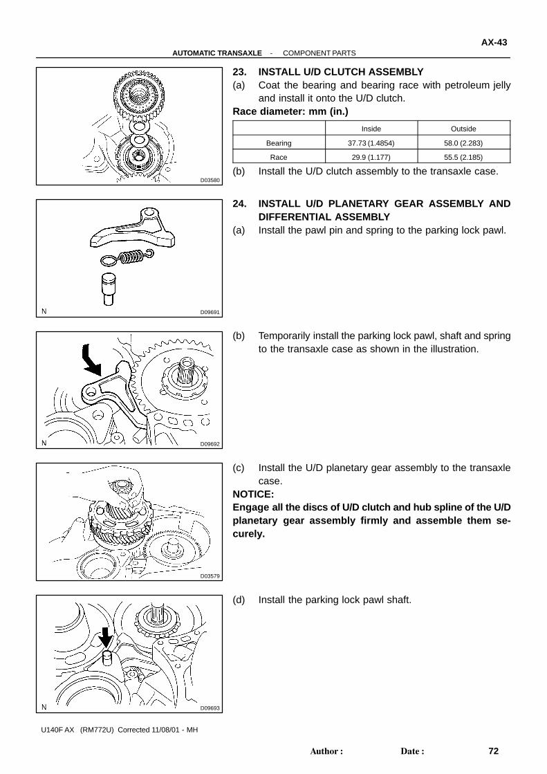
D03580
D09691
D09692
D03579
D09693
-AUTOMATIC TRANSAXLE COMPONENT PARTSAX-43
72Author�: Date�:
U140F AX (RM772U) Corrected 11/08/01 - MH
23. INSTALL U/D CLUTCH ASSEMBLY(a) Coat the bearing and bearing race with petroleum jelly
and install it onto the U/D clutch.Race diameter: mm (in.)
Inside Outside
Bearing 37.73 (1.4854) 58.0 (2.283)
Race 29.9 (1.177) 55.5 (2.185)
(b) Install the U/D clutch assembly to the transaxle case.
24. INSTALL U/D PLANETARY GEAR ASSEMBLY ANDDIFFERENTIAL ASSEMBLY
(a) Install the pawl pin and spring to the parking lock pawl.
(b) Temporarily install the parking lock pawl, shaft and springto the transaxle case as shown in the illustration.
(c) Install the U/D planetary gear assembly to the transaxlecase.
NOTICE:Engage all the discs of U/D clutch and hub spline of the U/Dplanetary gear assembly firmly and assemble them se-curely.
(d) Install the parking lock pawl shaft.

D03576
D03875
D
D09945
Dimension (1) Dimension (2)
D03928
D03628
AX-44-AUTOMATIC TRANSAXLE COMPONENT PARTS
73Author�: Date�:
U140F AX (RM772U)
(e) Install the pawl shaft with the bolt.Torque: 9.8 N·m (100 kgf·cm, 7 ft·lbf)
(f) Using a straight edge and vernier calipers as shown in theillustration, measure the gap between the top of the differ-ential drive pinion in the U/D planetary gear and contactsurface of the transaxle case and housing. (Dimension D)
NOTICE:Note down the dimension D as it is necessary for the fol-lowing process.
(g) As shown in the illustration, measure the 2 places of thetransaxle housing. Calculate the dimension E using theformula.
NOTICE:Note down the dimension E as it is necessary for the follow-ing process.HINT:Dimension E = Dimension (1) - Dimension (2)
25. INSTALL MULTIPLE DISC CLUTCH HUB(a) Install the bearing race to the transaxle while checking its
direction.Bearing race diameter: mm (in.)
Inside Outside
Bearing race 34.5 (1.358) 48.5 (1.909)
(b) Coat the thrust bearing and race with petroleum jelly andinstall them onto the multiple disc clutch hub.
Thrust bearing and race diameter: mm (in.)
Inside Outside
Bearing 36.3 (1.429) 52.2 (2.055)

D03929
D11358
Race ”B”
Race ”A”
Forward Clutch Side
D03574
D03573
D03572
-AUTOMATIC TRANSAXLE COMPONENT PARTSAX-45
74Author�: Date�:
U140F AX (RM772U) Corrected 11/08/01 - MH
(c) Install the bearing to the multiple clutch hub.Bearing diameter: mm (in.)
Inside Outside
Bearing 23.5 (0.925) 44.0 (1.732)
(d) Install the forward clutch hub to the transaxle case.
(e) Install the thrust bearing to the forward clutch.Bearing diameter: mm (in.)
Inside Outside
Bearing 33.85 (1.3327) 52.2 (2.055)
NOTICE:Install the thrust bearing properly so that the race “B” willbe visible.
(f) Install the forward clutch to the multiple clutch hub.NOTICE:Align the splines of all discs in the forward clutch withthose of multiple clutch hub to assemble them securely.
26. INSTALL 2 NEW APPLY GASKET
27. INSTALL DIFFERENTIAL ASSEMBLY

D03571
D03569
D03629
AX-46-AUTOMATIC TRANSAXLE COMPONENT PARTS
75Author�: Date�:
U140F AX (RM772U)
28. INSTALL TRANSAXLE HOUSING(a) Calculate the end play value using the following formula
and values of Dimension D and E that were measuredwhen installing cylindrical roller bearing and U/D plane-tary gear. Select an appropriate U/D planetary gear thrustbearing race No.2 which satisfies the specified end playvalue, and install it.End play: 0.498 - 0.993 mm (0.01961 - 0.03909 in.)
HINT:End play = Dimension E - Dimension D - thrust bearing thick-ness 3.28 mm (0.1291 in.) - U/D gear thrust bearing race No.2thicknessRace thickness: mm (in.)
E - D Thickness
Less than 7.64 (0.3008) 3.5 (0.138)
7.64 (0.3008) or more 3.8 (0.150)
Bearing and bearing race diameter: mm (in.)
Inside Outside
Bearing 57.2 (2.252) 84.96 (3.3449)
Bearing race 56.4 (2.220) 83.0 (3.268)
(b) Install the oil pump and 7 bolts to the transaxle caseTorque: 22 N·m (226 kgf·cm, 16 ft·lbf)
(c) Coat on O-ring of oil pump with ATF.

D03630Seal Bend Width 1.2 mm (0.047 in.)
D03568
C
A
A
B
B
C
CC
A
D03567
D03631
-AUTOMATIC TRANSAXLE COMPONENT PARTSAX-47
76Author�: Date�:
U140F AX (RM772U) Corrected 11/08/01 - MH
(d) Remove any packing material and be careful not to get oilon the contacting surfaces of the transaxle case or trans-axle housing.
(e) Apply FIPG to the transaxle case.FIPG:Part No. 08826-00090, THREE BOND 1281 or equiva-lent
(f) Install the transaxle housing and 16 bolts to the transaxlecase.Torque:Bolt A: 22 N·m (226 kgf·cm, 16 ft·lbf)Bolt B and C: 29 N·m (300 kgf·cm, 22 ft·lbf)
HINT:Apply seal packing or equivalent to the bolt A.
Seal packing:THREE BOND 2403 or equivalentBolt length:Bolt A: 50 mm (1.969 in.)Bolt B: 50 mm (1.969 in.)Bolt C: 42 mm (1.654 in.)
NOTICE:Because the bolt A is a seal bolt, apply the seal packing tonew bolts and tighten them within 10 minutes after applica-tion.
29. INSPECT INPUT SHAFT END PLAYUsing a dial indicator, measure the input shaft end play.
End play: 0.26 - 1.25 mm (0.0103 - 0.0492 in.)30. CHECK DIFFERENTIAL PRELOAD
(See page AX-107 )
31. PLACE TRANSAXLE HOUSING

D03632
D03905
D03565
D03564
D03930
AX-48-AUTOMATIC TRANSAXLE COMPONENT PARTS
77Author�: Date�:
U140F AX (RM772U)
32. INSTALL MANUAL VALVE LEVER SHAFT(a) Coat new oil seal with ATF.(b) Install the oil seal to the transaxle case.
(c) Install the parking lock rod to the manual valve lever.
(d) Install a new spacer and manual valve lever shaft to thetransaxle case.
(e) Using a pin punch and a hammer, drive in a new pin.
(f) Turn the spacer and the lever shaft to alight the small holefor locating the staking position in the spacer with thestaking position mark on the lever shaft.
(g) Using a pin punch, stake the spacer through the smallhole.
(h) Check that the spacer does not turn.

D03559
D03561
D03560
B
A
D03862
C1 C3 B3
-AUTOMATIC TRANSAXLE COMPONENT PARTSAX-49
78Author�: Date�:
U140F AX (RM772U) Corrected 11/08/01 - MH
(i) Using needle-nose pliers, install the return spring.
(j) Install the parking lock pawl bracket with the 2 bolts.Torque: 20 N·m (205 kgf·cm, 15 ft·lbf)Bolt length: 25 mm (0.984 in.)
(k) Install the manual detent spring with the 2 bolts.NOTICE:Make sure to install the manual detent spring and cover inthis order.
Torque:Bolt A: 20 N·m (205 kgf·cm, 15 ft·lbf)Bolt B: 10 N·m (102 kgf·cm, 7 ft·lbf)Bolt length:Bolt A: 27 mm (1.063 in.)Bolt B: 16 mm (0.630 in.)
33. INSTALL ACCUMULATOR PISTON AND SPRING(a) Coat new 4 O-rings with ATF and install them to the pis-
tons.(b) Coat the 4 springs and 3 accumulator pistons with ATF,
install them to the holes.Accumulator spring:
SpringFree length
Outer diameter mm (in.)Color
B3 Inner 60.24 (2.3716) /
15.9 (0.626)Green
Outer 72.61 (2.8587) /
16.7 (0.657)Blue
C390.49 (3.5626) /
19.2 (0.756)White
C181.53 (3.2098) /
18.5 (0.728)Pink

D03554
D03636
D03547
D09688
D03553
B
C
A
A
A
B
B �
CC�
AX-50-AUTOMATIC TRANSAXLE COMPONENT PARTS
79Author�: Date�:
U140F AX (RM772U)
34. INSTALL CHECK BALL BODY AND SPRING
35. INSTALL TRANSAXLE SOLENOID WIRE(a) Coat a new O-ring with ATF, install it to the transaxle sole-
noid wire.
(b) Install the solenoid wire retaining boltTorque: 5.4 N·m (55 kgf·cm, 48 in.·lbf)
36. INSTALL APPLY GASKET(a) Coat 3 apply gaskets with ATF and install them to the
transaxle case.
37. INSTALL VALVE BODY ASSEMBLY(a) Align the groove of the manual valve with the pin of lever.(b) Install the 17 bolts.
Torque: 11 N·m (110 kgf·cm, 8 ft·lbf)NOTICE:� Push the valve body against the accumulator piston
spring and the check ball body to install it.� Tighten those bolts marked by � in the illustration
first temporarily because they are positioning bolts.Each bolt length is indicated below.

D09180
D09179
D09637
D09223
-AUTOMATIC TRANSAXLE COMPONENT PARTSAX-51
80Author�: Date�:
U140F AX (RM772U) Corrected 11/08/01 - MH
HINT:Bolt length:Bolt A: 25 mm (0.984 in.)Bolt B: 41 mm (1.614 in.)Bolt C: 45 mm (1.771 in.)
38. INSTALL OIL STRAINER(a) Coat new O-ring with ATF, install it to the oil strainer.
(b) Install the oil strainer and 3 bolts to the valve body.Torque: 11 N·m (110 kgf·cm, 8 ft·lbf)
(c) Connect the 5 solenoid connectors.(d) Install the ATF temperature sensor, clamp and bolt.
Torque: 6.6 N·m (67 kgf·cm, 58 in.·lbf)
39. INSTALL OIL PAN(a) Install the 3 magnets in the oil pan.(b) Apply seal packing or equivalent to new 18 bolts.
Seal packing:THREE BOND 2430 or equivalent

D09176
D03900
D03805
Union
Elbow
D03901
D09639
AX-52-AUTOMATIC TRANSAXLE COMPONENT PARTS
81Author�: Date�:
U140F AX (RM772U)
(c) Install a new gasket, oil pan and 18 bolts to the transaxlecase.Torque: 7.6 N·m (77 kgf·cm, 67 in.·lbf)
NOTICE:Because the bolts should be seal bolts, apply seal packingto new bolts and tighten them within 10 minutes after ap-plication.
40. INSTALL SPEED SENSOR(a) Coat 2 new O-rings with ATF, install it to the 2 sensors.(b) Install the 2 sensors with the 2 bolts to the transaxle case.
Torque: 11.3 N·m (115 kgf·cm, 8 in.·lbf)
41. INSTALL UNION AND ELBOW(a) Coat 2 new O-rings with ATF, install them to the union and
elbow.(b) Install the union and elbow to the transaxle case.
Torque:Union: 25 Nm (254 kgf·cm, 18 ft·lbf)Elbow: 27 Nm (276 kgf·cm, 20 ft·lbf)
42. INSTALL TRANSAXLE CASE PLUG NO. 1(a) Coat a new O-ring with ATF, install it to the transaxle case
plug No.1.(b) Install the transaxle case plug No.1 to the transaxle case.
Torque: 7.4 N·m (75 kgf·cm, 65 in.·lbf)
43. INSTALL PARK/NEUTRAL POSITION SWITCH(a) Install the park/neutral position switch onto the manual
valve lever shaft and temporarily install the 2 adjustingbolts.
(b) Install a new nut stopper and nut.Torque: 6.9 N·m (70 kgf·cm, 61 in.·lbf)
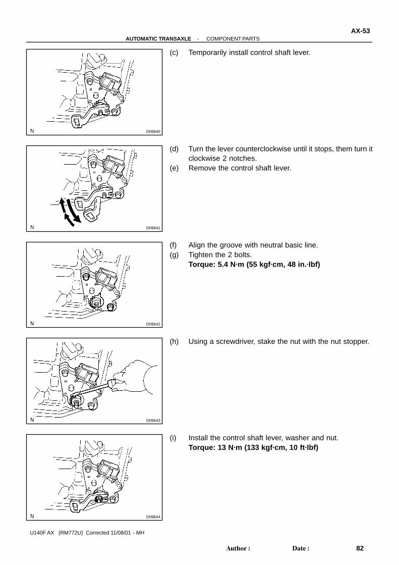
D09640
D09641
D09642
D09643
D09644
-AUTOMATIC TRANSAXLE COMPONENT PARTSAX-53
82Author�: Date�:
U140F AX (RM772U) Corrected 11/08/01 - MH
(c) Temporarily install control shaft lever.
(d) Turn the lever counterclockwise until it stops, them turn itclockwise 2 notches.
(e) Remove the control shaft lever.
(f) Align the groove with neutral basic line.(g) Tighten the 2 bolts.
Torque: 5.4 N·m (55 kgf·cm, 48 in.·lbf)
(h) Using a screwdriver, stake the nut with the nut stopper.
(i) Install the control shaft lever, washer and nut.Torque: 13 N·m (133 kgf·cm, 10 ft·lbf)

D03931Seal Bend Width 1.2 mm (0.047 in.)
FIPG
D03540
D03082
AX-54-AUTOMATIC TRANSAXLE COMPONENT PARTS
83Author�: Date�:
U140F AX (RM772U)
44. INSTALL TRANSFER ASSEMBLY(a) Remove any FIPG material and be careful not to get oil
on the contacting surfaces of the transaxle case or trans-fer assembly.
(b) Coat new gasket with petroleum jelly and install it to thetransfer assembly.
(c) As shown in the illustration, apply FIPG to the transfer as-sembly.FIPG: Part No. 08826-00090, THREE BOND 1281 or equiva-lent
NOTICE:Do not apply FIPG to the part where it is not specified.
(d) Install the intermediate shaft to the transfer assembly.
(e) Install the transfer assembly, 2 bolts and 6 nuts to thetransaxle case.Torque: 69 N·m (700 kgf·cm, 51 ft·lbf)
NOTICE:� Push the transfer straight up and install it to the trans-
axle.� Pull up the transfer case by inserting your fingers into
the hole on both sides may cause damage to the oilseal lip. Be careful not to damage it.
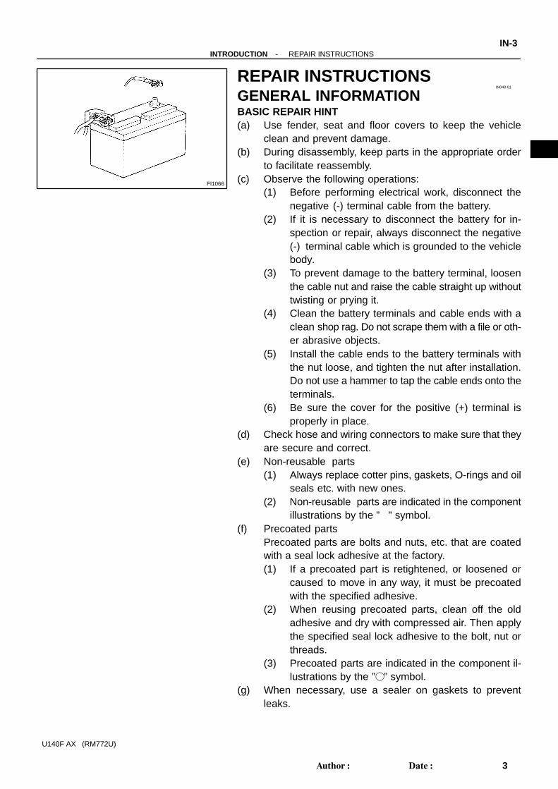
FI1066
IN048-01
-INTRODUCTION REPAIR INSTRUCTIONSIN-3
3Author�: Date�:
U140F AX (RM772U)
REPAIR INSTRUCTIONSGENERAL INFORMATIONBASIC REPAIR HINT(a) Use fender, seat and floor covers to keep the vehicle
clean and prevent damage.(b) During disassembly, keep parts in the appropriate order
to facilitate reassembly.(c) Observe the following operations:
(1) Before performing electrical work, disconnect thenegative (-) terminal cable from the battery.
(2) If it is necessary to disconnect the battery for in-spection or repair, always disconnect the negative(-) terminal cable which is grounded to the vehiclebody.
(3) To prevent damage to the battery terminal, loosenthe cable nut and raise the cable straight up withouttwisting or prying it.
(4) Clean the battery terminals and cable ends with aclean shop rag. Do not scrape them with a file or oth-er abrasive objects.
(5) Install the cable ends to the battery terminals withthe nut loose, and tighten the nut after installation.Do not use a hammer to tap the cable ends onto theterminals.
(6) Be sure the cover for the positive (+) terminal isproperly in place.
(d) Check hose and wiring connectors to make sure that theyare secure and correct.
(e) Non-reusable parts(1) Always replace cotter pins, gaskets, O-rings and oil
seals etc. with new ones.(2) Non-reusable parts are indicated in the component
illustrations by the ”�” symbol.(f) Precoated parts
Precoated parts are bolts and nuts, etc. that are coatedwith a seal lock adhesive at the factory.(1) If a precoated part is retightened, or loosened or
caused to move in any way, it must be precoatedwith the specified adhesive.
(2) When reusing precoated parts, clean off the oldadhesive and dry with compressed air. Then applythe specified seal lock adhesive to the bolt, nut orthreads.
(3) Precoated parts are indicated in the component il-lustrations by the ”�” symbol.
(g) When necessary, use a sealer on gaskets to preventleaks.

IN0252
WRONG CORRECT
IN-4-INTRODUCTION REPAIR INSTRUCTIONS
4Author�: Date�:
U140F AX (RM772U)
(h) Carefully observe all specifications for bolt tighteningtorques. Always use a torque wrench.
(i) Use of special service tools (SST) and special service ma-terials (SSM) may be required, depending on the natureof the repair. Be sure to use SST and SSM where speci-fied and follow the proper work procedure. A list of SSTand SSM can be found in the preparation of AT section.
(j) To pull apart electrical connectors, pull the connector it-self, not the wires.

SS0YR-02
SS-4-SERVICE SPECIFICATIONS AUTOMATIC TRANSAXLE
22Author�: Date�:
U140F AX (RM772U)
AUTOMATIC TRANSAXLESERVICE DATAOil pump
Body clearance STD
Max.
0.10 - 0.17 mm (0.0039 - 0.0067 in.)
0.17 mm (0.0067 in.)
Tip clearance STD
Max.
0.07 - 0.15 mm (0.0028 - 0.0059 in.)
0.15 mm (0.0059 in.)
Side clearance STD
Max.
0.02 - 0.05 mm (0.0008 - 0.0020 in.)
0.05 mm (0.0020 in.)
Pump body bushing inside diameter STD
Max.
38.12 - 38.13 mm (1.5008 - 1.5012 in.)
38.18 mm (1.5031 in.)
Stator shaft bushing inside diameter STD
Max.
21.50 - 21.52 mm (0.8465 - 0.8472 in.)
21.57 mm (0.8492 in.)
Direct clutch
Piston stroke 0.61 - 0.83 mm (0.0240 - 0.0327 in.)
Piston return spring free length 22.58 mm (0.8890 in.)
Flange thickness Mark
1
2
3
4
5
6
3.0 mm (0.118 in.)
3.1 mm (0.122 in.)
3.2 mm (0.126 in.)
3.3 mm (0.130 in.)
3.4 mm (0.134 in.)
3.5 mm (0.138 in.)
Froward clutch
Piston stroke 1.41 - 1.75 mm (0.0555 - 0.0689 in.)
Piston return spring free length 28.23 mm (1.1114 in.)
Multiple disc clutch hub bushing inside diameter STD
Max.
23.03 - 23.04 mm (0.9067 - 0.9071 in.)
23.09 mm (0.9091 in.)
Flange thickness Mark
1
2
3
4
5
3.00 mm (0.1181 in.)
3.15 mm (0.1240 in.)
3.30 mm (0.1299 in.)
3.45 mm (0.1358 in.)
3.60 mm (0.1417 in.)
2nd brake
Piston stroke 0.62 - 0.91 mm (0.0244 - 0.0358 in.)
Piston return spring free length 16.61 mm (0.6539 in.)
Flange thickness Mark
1
2
3
4
5
6
7
3.0 mm (0.118 in.)
3.1 mm (0.122 in.)
3.2 mm (0.126 in.)
3.3 mm (0.130 in.)
3.4 mm (0.134 in.)
3.5 mm (0.138 in.)
3.6 mm (0.142 in.)
Input shaft
End play 0.26 - 1.25 mm (0.0103 - 0.0492 in.)
U/D clutch
Piston stroke 1.51 - 1.90 mm (0.0594 - 0.0748 in.)

-SERVICE SPECIFICATIONS AUTOMATIC TRANSAXLESS-5
23Author�: Date�:
U140F AX (RM772U)
U/D clutch drum bushing inside diameter
STD
Max.
37.06 - 37.08 mm (1.4591 - 1.4598 in.)
37.13 mm (1.4618 in.)
Piston return spring free length 17.14 mm (0.6748 in.)
Flange thickness Mark
1
2
3
3.0 mm (0.118 in.)
3.2 mm (0.126 in.)
3.4 mm (0.134 in.)
U/D brake
Piston stroke 1.81 - 2.20 mm (0.0713 - 0.0866 in.)
Piston return spring free length 14.04 mm (0.5528 in.)
Flange thickness Mark
1
2
3
3.0 mm (0.118 in.)
3.2 mm (0.126 in.)
3.4 mm (0.134 in.)
1st & reverse brake
Piston stroke 1.02 - 1.21 mm (0.0402 - 0.0476 in.)
Piston return spring free length 15.51 mm (0.6106 in.)
Flange thickness Mark
1
2
3
4
5
6
7
8
1.8 mm (0.071 in.)
1.9 mm (0.075 in.)
2.0 mm (0.079 in.)
2.1 mm (0.083 in.)
2.2 mm (0.087 in.)
2.3 mm (0.091 in.)
2.4 mm (0.094 in.)
2.5 mm (0.098 in.)
Valve body spring
Spring (Color) Free length Coil outer diameter Total No. of coils
Upper valve body
Lock-up relay valve (None)29.27 mm
(1.1524 in.)9.7 mm (0.382 in.) 10.50
Lock -up control valve (None)23.98 mm
(0.9441 in.)5.4 mm (0.213 in.) 14.94
Secondary regulator valve (Blue)58.35 mm
(2.2972 in.)8.7 mm (0.343 in.) 20.58
C-2 lock valve (Yellow)33.65 mm
(1.3248 in.)7.4 mm (0.291 in.) 11.82
Solenoid modulator valve (Red)62.40 mm
(2.4567 in.)9.8 mm (0.386 in.) 22.31
B-3 orifice control valve (Gray)62.65 mm
(2.4665 in.)7.8 mm (0.307 in.) 19.60
B-1 lock valve (White)37.40 mm
(1.4724 in.)9.8 mm (0.386 in.) 8.84
Clutch apply control valve (Purple)40.25 mm
(1.5846 in.)9.0 mm (0.354 in.) 13.00
C-2 exhaust check valve (Orange)40.27 mm
(1.5854 in.)7.4 mm (0.291 in.) 17.10

SS-6-SERVICE SPECIFICATIONS AUTOMATIC TRANSAXLE
24Author�: Date�:
U140F AX (RM772U)
Lower valve body
3-4 shift valve (None)29.25 mm
(1.1516 in.)9.7 mm (0.382 in.) 10.5
B-1 control valve (Green)48.55 mm
(1.9114 in.)9.8 mm (0.386 in.) 13.43
B-2 control valve (Pink)57.05 mm
(2.2461 in.)9.8 mm (0.386 in.) 15.34
Primary regulator valve (Orange)57.55 mm
(2.2657 in.)19.9 mm (0.783 in.) 7.87
C-2 control valve (Brown)34.20 mm
(1.3465 in.)9.9 mm (0.390 in.) 8.79
Valve body key
Key Height Width Thickness
Upper valve body
Lock-up relay valve 10.0 mm (0.394 in.) 5.0 mm (0.197 in.) 3.2 mm (0.126 in.)
Lock-up control valve 10.0 mm (0.394 in.) 5.0 mm (0.197 in.) 3.2 mm (0.126 in.)
Secondary regulator valve 8.0 mm (0.315 in.) 5.0 mm (0.197 in.) 3.2 mm (0.126 in.)
C-2 lock valve 10.0 mm (0.394 in.) 5.0 mm (0.197 in.) 3.2 mm (0.126 in.)
Solenoid modulator valve 8.0 mm (0.315 in.) 5.0 mm (0.197 in.) 3.2 mm (0.126 in.)
B-3 orifice control valve 18.5 mm (0.728 in.) - 2.3 mm (0.091 in.)
B-1 lock valve 8.0 mm (0.315 in.) 5.0 mm (0.197 in.) 3.2 mm (0.126 in.)
C-2 exhaust check valve 8.0 mm (0.315 in.) 5.0 mm (0.197 in.) 3.2 mm (0.126 in.)
3-way check valve 8.0 mm (0.315 in.) 5.0 mm (0.197 in.) 3.2 mm (0.126 in.)
Lower valve body
3-4 shift valve 25.5 mm (1.004 in.) - 2.3 mm ( 0.091in.)
B-1 control valve 14.5 mm (0.571 in.) 5.0 mm (0.197 in.) 3.2 mm (0.126 in.)
B-2 control valve 14.5 mm (0.571 in.) 5.0 mm (0.197 in.) 3.2 mm (0.126 in.)
C-2 control valve 14.5 mm (0.571 in.) 5.0 mm (0.197 in.) 3.2 mm (0.126 in.)
Accumulator
Spring Free length/Outer diameter Color
B3 Inner 60.24 mm (2.3716 in.) / 15.9 mm (0.626 in.) GreenB3 Inner
Outer
60.24 mm (2.3716 in.) / 15.9 mm (0.626 in.)
72.61 mm (2.8587 in.) / 16.7 mm (0.626 in.)
Green
Blue
C3 90.49 mm (3.5626 in.) / 19.2 mm ( 0.756in.) White
C1 81.53 mm (3.2098 in.) / 18.5 mm (0.728 in.) Pink
C Inner 47 58 mm (1 8732 in ) / 11 2 mm (0 441 in ) BrownC2 Inner
O
47.58 mm (1.8732 in.) / 11.2 mm (0.441 in.)
47 61 (1 8744 i ) / 12 0 (0 472 i )
Brown
BOuter 47.61 mm (1.8744 in.) / 12.0 mm (0.472 in.) Brown
B1 Inner 43.88 mm (1.7276 in.) / 11.0 mm (0.433 in.) PurpleB1 Inner
Outer
43.88 mm (1.7276 in.) / 11.0 mm (0.433 in.)
45.12 mm (1.7764 in.) / 11.8 mm (0.465 in.)
Pur le
White
Transfer
Drive pinion preload (at starting) (For use with SST)
New bearing
Reused bearing
1.0 - 1.5 N·m (10 - 15 kgf·cm, 8.7 - 13.0 in.·lbf)
0.9 - 1.4 N·m (9 - 14 kgf·cm, 7.8 - 12.4 in.·lbf)
Drive pinion total preload (at starting) (For use with SST)
(Drive pinion preload plus)
New bearing
Reused bearing
0.2 - 0.4 N·m (2 - 4 kgf·cm, 1.7 - 3.5 in.·lbf)
0.1 - 0.3 N·m (1 - 3 kgf·cm, 0.9 - 2.6 in.·lbf)
Ring gear backlash 0.10 - 0.15 mm (0.0039 - 0.0059 in.)

-SERVICE SPECIFICATIONS AUTOMATIC TRANSAXLESS-7
25Author�: Date�:
U140F AX (RM772U)
Ring gear runout 0.1 mm (0.004 in.)
Center differential control coupling runout 0.07 mm (0.0028 in.)
Backlash adjust washer thickness Mark
AA
AB
AC
BA
BB
BC
CA
CB
CC
DA
DB
DC
EA
EB
EC
FA
FB
FC
GA
GB
GC
HA
HB
HC
JA
JB
JC
KA
KB
KC
LA
LB
2.07 mm (0.0815 in.)
2.10 mm (0.0827 in.)
2.13 mm (0.0839 in.)
2.16 mm (0.0850 in.)
2.19 mm (0.0862 in.)
2.22 mm (0.0874 in.)
2.25 mm (0.0886 in.)
2.28 mm (0.0898 in.)
2.31 mm (0.0909 in.)
2.34 mm (0.0921 in.)
2.37 mm (0.0933 in.)
2.40 mm (0.0945 in.)
2.43 mm (0.0957 in.)
2.46 mm (0.0969 in.)
2.49 mm (0.0980 in.)
2.52 mm (0.0992 in.)
2.55 mm (0.1004 in.)
2.58 mm (0.1016 in.)
2.61 mm (0.1028 in.)
2.64 mm (0.1039 in.)
2.67 mm (0.1051 in.)
2.70 mm (0.1063 in.)
2.73 mm (0.1075 in.)
2.76 mm (0.1087 in.)
2.79 mm (0.1098 in.)
2.82 mm (0.1110 in.)
2.85 mm (0.1122 in.)
2.88 mm (0.1134 in.)
2.91 mm (0.1146 in.)
2.94 mm (0.1157 in.)
2.97 mm (0.1169 in.)
3.00 mm (0.1181 in.)

SS-8-SERVICE SPECIFICATIONS AUTOMATIC TRANSAXLE
26Author�: Date�:
U140F AX (RM772U)
Tooth contact adjust washer thickness Mark
AA
AB
AC
BA
BB
BC
CA
CB
CC
DA
DB
DC
EA
EB
EC
FA
FB
FC
GA
GB
GC
HA
HB
HC
JA
JB
JC
KA
KB
KC
LA
LB
LC
MA
MB
MC
NA
NB
NC
PA
PB
PC
QA
QB
QC
RA
1.20 mm (0.0472 in.)
1.21 mm (0.0476 in.)
1.22 mm (0.0480 in.)
1.23 mm (0.0484 in.)
1.24 mm (0.0488 in.)
1.25 mm (0.0492 in.)
1.26 mm (0.0496 in.)
1.27 mm (0.0500 in.)
1.28 mm (0.0504 in.)
1.29 mm (0.0508 in.)
1.30 mm (0.0512 in.)
1.31 mm (0.0516 in.)
1.32 mm (0.0520 in.)
1.33 mm (0.0524 in.)
1.34 mm (0.0528 in.)
1.35 mm (0.0531 in.)
1.36 mm (0.0535 in.)
1.37 mm (0.0539 in.)
1.38 mm (0.0543 in.)
1.39 mm (0.0547 in.)
1.40 mm (0.0551 in.)
1.41 mm (0.0555 in.)
1.42 mm (0.0559 in.)
1.43 mm (0.0563 in.)
1.44 mm (0.0567 in.)
1.45 mm (0.0571 in.)
1.46 mm (0.0575 in.)
1.47 mm (0.0579 in.)
1.48 mm (0.0583 in.)
1.49 mm (0.0587 in.)
1.50 mm (0.0591 in.)
1.51 mm (0.0594 in.)
1.52 mm (0.0598 in.)
1.53 mm (0.0602 in.)
1.54 mm (0.0606 in.)
1.55 mm (0.0610 in.)
1.56 mm (0.0614 in.)
1.57 mm (0.0618 in.)
1.58 mm (0.0622 in.)
1.59 mm (0.0626 in.)
1.60 mm (0.0630 in.)
1.61 mm (0.0634 in.)
1.62 mm (0.0638 in.)
1.63 mm (0.0642 in.)
1.64 mm (0.0646 in.)
1.65 mm (0.0650 in.)

-SERVICE SPECIFICATIONS AUTOMATIC TRANSAXLESS-9
27Author�: Date�:
U140F AX (RM772U)
Preload adjust washer thickness Mark
AA
AB
AC
BA
BB
BC
CA
CB
CC
DA
DB
DC
EA
EB
EC
FA
FB
FC
GA
GB
GC
HA
HB
HC
JA
JB
JC
KA
KB
KC
LA
LB
LC
MA
MB
MC
NA
NB
1.47 mm (0.0579 in.)
1.50 mm (0.0591 in.)
1.53 mm (0.0602 in.)
1.56 mm (0.0614 in.)
1.59 mm (0.0626 in.)
1.62 mm (0.0638 in.)
1.65 mm (0.0650 in.)
1.68 mm (0.0661 in.)
1.71 mm (0.0673 in.)
1.74 mm (0.0685 in.)
1.77 mm (0.0697 in.)
1.80 mm (0.0709 in.)
1.83 mm (0.0720 in.)
1.86 mm (0.0732 in.)
1.89 mm (0.0744 in.)
1.92 mm (0.0756 in.)
1.95 mm (0.0768 in.)
1.98 mm (0.0780 in.)
2.01 mm (0.0791 in.)
2.04 mm (0.0803 in.)
2.07 mm (0.0815 in.)
2.10 mm (0.0827 in.)
2.13 mm (0.0839 in.)
2.16 mm (0.0850 in.)
2.19 mm (0.0862 in.)
2.22 mm (0.0874 in.)
2.25 mm (0.0886 in.)
2.28 mm (0.0898 in.)
2.31 mm (0.0909 in.)
2.34 mm (0.0921 in.)
2.37 mm (0.0933 in.)
2.40 mm (0.0945 in.)
2.43 mm (0.0957 in.)
2.46 mm (0.0969 in.)
2.49 mm (0.0980 in.)
2.52 mm (0.0992 in.)
2.55 mm (0.1004 in.)
2.58 mm (0.1016 in.)
Differential case
Front differential side gear backlash 0.05 - 0.20 mm (0.0020 - 0.0079 in.)
Front differential side gear thrust washer thickness Mark
A
B
C
D
E
F
G
H
J
K
0.95 mm (0.0374 in.)
1.00 mm (0.0394 in.)
1.05 mm (0.0413 in.)
1.10 mm (0.0433 in.)
1.15 mm (0.0453 in.)
1.20 mm (0.0472 in.)
1.25 mm (0.0492 in.)
1.30 mm (0.0511 in.)
1.35 mm (0.0531 in.)
1.40 mm (0.0551 in.)
Center differential side gear backlash 0.05 - 0.20 mm (0.0020 - 0.0079 in.)

SS-10-SERVICE SPECIFICATIONS AUTOMATIC TRANSAXLE
28Author�: Date�:
U140F AX (RM772U)
Center differential side gear thrust washer No.1 thickness Mark
MA
MB
MC
MD
ME
MF
MG
MH
MJ
MK
MM
MN
ML
0.80 mm (0.0315 in.)
0.85 mm (0.0335 in.)
0.90 mm (0.0354 in.)
0.95 mm (0.0374 in.)
1.00 mm (0.0394 in.)
1.05 mm (0.0413 in.)
1.10 mm (0.0433 in.)
1.15 mm (0.0453 in.)
1.20 mm (0.0472 in.)
1.25 mm (0.0492 in.)
1.30 mm (0.0512 in.)
1.35 mm (0.0531 in.)
1.40 mm (0.0551 in.)
Center differential side gear thrust clearance STD 0.16 - 0.25 mm (0.006 - 0.010 in.)
Center differential side gear thrust washer No.2 thickness Mark
0
1
2
3
4
5
6
7
8
9
A
B
C
0.80 mm (0.0315 in.)
0.85 mm (0.0335 in.)
0.90 mm (0.0354 in.)
0.95 mm (0.0374 in.)
1.00 mm (0.0394 in.)
1.05 mm (0.0413 in.)
1.10 mm (0.0433 in.)
1.15 mm (0.0453 in.)
1.20 mm (0.0472 in.)
1.25 mm (0.0492 in.)
1.30 mm (0.0512 in.)
1.35 mm (0.0531 in.)
1.40 mm (0.0551 in.)
Preload (turning torque at 60 rpm)
New bearing
Reused bearing
0.20 - 0.69 N·m (2 - 7 kgf·cm, 1.8 - 6.1 in.·lbf)
0.10 - 0.35 N·m (1 - 4 kgf·cm, 0.9 - 3.1 in.·lbf)
Plate washer thickness Mark
0
1
2
3
4
5
6
7
8
9
A
B
C
D
E
F
G
H
2.00 mm (0.0787 in.)
2.05 mm (0.0807 in.)
2.10 mm (0.0827 in.)
2.15 mm (0.0846 in.)
2.20 mm (0.0866 in.)
2.25 mm (0.0886 in.)
2.30 mm (0.0906 in.)
2.35 mm (0.0925 in.)
2.40 mm (0.0945 in.)
2.45 mm (0.0965 in.)
2.50 mm (0.0984 in.)
2.55 mm (0.1004 in.)
2.60 mm (0.1024 in.)
2.65 mm (0.1043 in.)
2.70 mm (0.1063 in.)
2.75 mm (0.1083 in.)
2.80 mm (0.1102 in.)
2.85 mm (0.1122 in.)

SS0ZT-01
SS-2-SERVICE SPECIFICATIONS STANDARD BOLT
20Author�: Date�:
U140F AX (RM772U)
SPECIFIED TORQUE FOR STANDARD BOLTSSpecified torque
ClassDiameter
mm
Pitch
mmHexagon head bolt Hexagon flange boltClass
mm mmN·m kgf·cm ft·lbf N·m kgf·cm ft·lbf
4T
6
8
10
12
14
16
1
1.25
1.25
1.25
1.5
1.5
5
12.5
26
47
74
115
55
130
260
480
760
1,150
48 in.·lbf
9
19
35
55
83
6
14
29
53
84
-
60
145
290
540
850
-
52 in.·lbf
10
21
39
61
-
5T
6
8
10
12
14
16
1
1.25
1.25
1.25
1.5
1.5
6.5
15.5
32
59
91
140
65
160
330
600
930
1,400
56 in.·lbf
12
24
43
67
101
7.5
17.5
36
65
100
-
75
175
360
670
1,050
-
65 in.·lbf
13
26
48
76
-
6T
6
8
10
12
14
16
1
1.25
1.25
1.25
1.5
1.5
8
19
39
71
110
170
80
195
400
730
1,100
1,750
69 in.·lbf
14
29
53
80
127
9
21
44
80
125
-
90
210
440
810
1,250
-
78 in.·lbf
15
32
59
90
-
7T
6
8
10
12
14
16
1
1.25
1.25
1.25
1.5
1.5
10.5
25
52
95
145
230
110
260
530
970
1,500
2,300
8
19
38
70
108
166
12
28
58
105
165
-
120
290
590
1,050
1,700
-
9
21
43
76
123
-
8T
8
10
12
1.25
1.25
1.25
29
61
110
300
620
1,100
22
45
80
33
68
120
330
690
1,250
24
50
90
9T
8
10
12
1.25
1.25
1.25
34
70
125
340
710
1,300
25
51
94
37
78
140
380
790
1,450
27
57
105
10T
8
10
12
1.25
1.25
1.25
38
78
140
390
800
1,450
28
58
105
42
88
155
430
890
1,600
31
64
116
11T
8
10
12
1.25
1.25
1.25
42
87
155
430
890
1,600
31
64
116
47
97
175
480
990
1,800
35
72
130

PP3BG-01
-PREPARATION AUTOMATIC TRANSAXLEPP-1
9Author�: Date�:
U140F AX (RM772U)
AUTOMATIC TRANSAXLESST (Special Service Tools)
09214-7601 1 Crankshaft Pulley Replacer
09223-00010 Cover & Seal Replacer
09223-15020 Oil Seal & Bearing Replacer
09223-4601 1 Crankshaft Front Oil Seal
Replacer
09308-00010 Oil Seal Puller
09316-2001 1 Transfer Bearing Replacer
09316-6001 1 Transmission & Transfer Bearing
Replacer
(09316-00041) Replacer ”C”
09326-2001 1 Output Shaft Bearing Lock Nut
Wrench
09350-32014 TOYOTA Automatic Transmission
Tool Set
(09351-32070) No.2 Piston Spring Compressor
(09351-32140) Oil Seal Replacer

PP-2-PREPARATION AUTOMATIC TRANSAXLE
10Author�: Date�:
U140F AX (RM772U)
(09351-321 11) Side Bearing Race Replacer
09387-00010 Transfer Oil Seal Replacer
09387-00020 Direct Clutch Wrench
09387-00030 Counter Drive Gear Holding Tool
09387-00040 Bearing Puller Assembly
(09387-01010) Claw No.1
(09387-01020) Claw No.2
(09387-01030) Pin
(09387-01040) Bearing Puller Body
09387-00050 Under Drive Gear Puller
09387-00060 Second Brake Wrench
09387-00070 First & Reverse Brake Wrench
09387-00080 Counter Drive Gear Nut Wrench

-PREPARATION AUTOMATIC TRANSAXLEPP-3
11Author�: Date�:
U140F AX (RM772U)
09387-00090 Senter Differential
Sentering Tool
09506-35010 Differential Drive Pinion Rear
Bearing Replacer
09514-3501 1 Rear Wheel Bearing Puller
09520-10021 Drive Shaft Remover & Replacer
09556-16030 Differential Drive Pinion
Holding Tool 28
09564-16020 Drive Pinion Lock Nut Wrench
09564-3201 1 Differential Preload Adaptor
09608-10010 Steering Knuckle Oil Seal
Replacer
09608-32010 Steering Knuckle Oil Seal
Replacer
09649-17010 Steering Knuckle Tool
09930-00010 Drive Shaft Nut Chisel
(09931-00010) Handle
(09931-00020) Nut Chisel

PP-4-PREPARATION AUTOMATIC TRANSAXLE
12Author�: Date�:
U140F AX (RM772U)
09950-00020 Bearing Remover
09950-00030 Bearing Remover Attachment
09950-60010 Replacer Set
(09951-00230) Replacer 23
(09951-00320) Replacer 32
(09951-00340) Replacer 34
(09951-00350) Replacer 35
(09951-00360) Replacer 36
(09951-00370) Replacer 37
(09951-00380) Replacer 38
(09951-00400) Replacer 40
(09951-00420) Replacer 42
(09951-00450) Replacer 45

-PREPARATION AUTOMATIC TRANSAXLEPP-5
13Author�: Date�:
U140F AX (RM772U)
(09951-00540) Replacer 54
(09951-00590) Replacer 59
(09951-00600) Replacer 60
(09951-00610) Replacer 61
(09951-00620) Replacer 62
(09951-00640) Replacer 64
(09952-06010) Adapter
09950-60020 Replacer Set No.2
(09951-00710) Replacer 71
(09951-00730) Replacer 73
(09951-00790) Replacer 79
(09951-00810) Replacer 81
(09951-00890) Replacer 89

PP-6-PREPARATION AUTOMATIC TRANSAXLE
14Author�: Date�:
U140F AX (RM772U)
09950-70010 Handle Set
(09951-07100) Handle 100
(09951-07150) Handle 150
(09951-07200) Handle 200

PP1T8-01
-PREPARATION AUTOMATIC TRANSAXLEPP-7
15Author�: Date�:
U140F AX (RM772U)
RECOMMENDED TOOLS09025-00010 Torque Wrench (30 kgf-cm)
09031-00030 Pin Punch .
09031-00040 Pin Punch .
09042-00010 Torx Socket T30 .
09905-00012 Snap Ring No.1 Expander .
09905-00013 Snap Ring Pliers .

PP1T9-02
PP-8-PREPARATION AUTOMATIC TRANSAXLE
16Author�: Date�:
U140F AX (RM772U)
EQUIPMENTDial indicator with magnetic base
Feeler gauge
Plastic hammer
Plastigage
Straight edge
Seal packing 2403, THREE BOND 2403 or equivalent
Seal packing 2430, THREE BOND 2430 or equivalent
Torque wrench
Vernier calipers

PP1TA-02
-PREPARATION AUTOMATIC TRANSAXLEPP-9
17Author�: Date�:
U140F AX (RM772U)
LUBRICANTItem Capacity Classification
Automatic transaxle fluid
Dry fill
Drain and refill
8.3 liters (8.8 US qts, 7.3 Imp. qts)
3.9 liters (4.1 US qts, 3.4 Imp. qts)
ATF TYPE T-IV
Transfer oil 0.9 liters (0.95 US qts, 0.71 Imp. qts)APL GL-5
SAE 90

PP3BH-01
PP-10-PREPARATION AUTOMATIC TRANSAXLE
18Author�: Date�:
U140F AX (RM772U)
SSM (Special Service Materials)08826-00090 Seal Packing 1281,
THREE BOND 1281 or equivalent
(FIPG)
08833-00080 Adhesive 1344
THREE BOND 1344
LOCTITE 242 or equivalent

SS0YS-02
-SERVICE SPECIFICATIONS AUTOMATIC TRANSAXLESS-1 1
29Author�: Date�:
U140F AX (RM772U)
TORQUE SPECIFICATIONPart tightened N·m kgf·cm ft·lbf
Apply pipe clamp x Transaxle housing 9.8 100 7
Apply pipe clamp x Transaxle case 5.4 55 48 in.·lbf
Transaxle rear cover x Transaxle case Bolt A
Other bolt
18.6
24.5
190
250
14
18
Parking pawl shaft clamp x Transaxle case 9.8 100 7
Oil pump x Transaxle case 22 226 16
Transaxle housing x Transaxle case Bolt A
Bolt B and C
22
29
225
300
16
22
Parking bracket x Transaxle case 20 205 15
Detent spring x Valve body assembly Bolt A
Bolt B
20
10
205
102
15
7
Valve body x Transaxle case 11 110 8
Oil strainer x Valve body 11 110 8
Transaxle solenoid wire x Transaxle case 5.4 55 48 in.·lbf
ATF temperature sensor clamp x Valve body 6.6 67 58 in.·lbf
Oil pan x Transaxle case 7.6 77 67 in.·lbf
Counter gear speed sensor x Transaxle case 11.3 115 8
Input turbin speed sensor x Transaxle case 11.3 115 8
Union 25 254 18
Elbow 27 276 20
Transaxle case plug No. 1 7.4 75 65 in.·lbf
Park/neutral start switch Bolt:
Nut:
5.4
6.9
55
70
48 in.·lbf
61 in.·lbf
Control shaft lever 13 133 10
Transfer x Transaxle 69 700 51
Counter drive gear lock nut 280 2855 207
Oil pump body x Stator Shaft 9.8 100 7
U/D output shaft lock nut 280 2,855 207
Valve body assembly x Shift solenoid valve Bolt A
Bolt B
11
6.6
110
67
8
58 in.·lbf
Retainer x Upper valve body 11 110 8
Upper valve body x Lower valve body 11 110 8
Upper valve body x Cover Bolt A
Bolt B
Bolt C
Bolt D
11
11
6.6
6.6
110
110
67
67
8
8
58 in.·lbf
58 in.·lbf
Differential ring gear x Differential case 95 970 70
Center differential control coupling x Ring gear 77.5 791 57
Bearing retainer RH x Transfer case 28 286 21
Drive pinion lock nut 295 (333) 3,010 (3,400) 218 (246)
Oil deflector x No.1 Case cover 6.5 66 58 in.·lbf
No.1 Case cover x Transfer case 19.6 200 14
Extension housing x Transfer case 25.5 260 19


![Index Abbreviations, 1.4.2.1.[A] Absorbent materials ...](https://static.fdokumen.com/doc/165x107/632130edaa6c954bc707258c/index-abbreviations-1421a-absorbent-materials-.jpg)