
Ovarlez J.P. - Presentation HDR English Final - jean-philippe ovarlez
Upload
khangminh22Category
view
3download
0
A Versatile HDR Video Production System
Michael D. Tocci1,2 Chris Kiser1,2,3 Nora Tocci1 Pradeep Sen2,3
1Contrast Optical Design & Engineering, Inc. 2University of New Mexico 3Advanced Graphics Lab
Figure 1: HDR image acquired with our proposed system. On the left we show the final image acquired with our camera and merged withthe proposed algorithm. The inset photos show the individual LDR images from the high, medium, and low-exposure sensors, respectively.
AbstractAlthough High Dynamic Range (HDR) imaging has been the sub-ject of significant research over the past fifteen years, the goal ofacquiring cinema-quality HDR images of fast-moving scenes us-ing available components has not yet been achieved. In this work,we present an optical architecture for HDR imaging that allows si-multaneous capture of high, medium, and low-exposure images onthree sensors at high fidelity with efficient use of the available light.We also present an HDR merging algorithm to complement this ar-chitecture, which avoids undesired artifacts when there is a large ex-posure difference between the images. We implemented a prototypehigh-definition HDR-video system and we present still frames fromthe acquired HDR video, tonemapped with various techniques.
CR Categories: I.4.1 [Image Processing and Computer Vision]:Digitization and Image capture—Radiometry
Keywords: HDR video, merging HDR images
Links: DL PDF
1 IntroductionThe extension of the dynamic range of digital images has been thesubject of significant research in both academia and industry. De-spite all this previous work, however, there are currently no readily-implemented solutions for capturing high-quality HDR video offast-moving scenes. In this paper, we describe an end-to-end sys-tem for capturing HDR video with high pixel fidelity, using a light-efficient optical architecture that fits into a single hand-held unit.
Our proposed system is simple, uses only off-the-shelf technology,and is flexible in terms of the sensors that are used. Specifically, ourHDR optical architecture: (1) captures optically-aligned, multiple-exposure images simultaneously that do not need image manipula-tion to account for motion, (2) extends the dynamic range of avail-able image sensors (by over 7 photographic stops in our currentprototype), (3) is inexpensive to implement, (4) utilizes a single,standard camera lens, and (5) efficiently uses the light from the lens.
To complement our system, we also propose a novel HDR image-merging algorithm that: (1) combines images separated by morethan 3 stops in exposure, (2) spatially blends pre-demosaiced pixeldata to reduce unwanted artifacts, (3) produces HDR images thatare radiometrically correct, and (4) uses the highest-fidelity (lowestquantized-noise) pixel data available. We demonstrate a workingprototype and present images and video acquired with this system.
2 Previous Work
2.1 HDR Acquisition systems
The process of capturing HDR images has been the focus of workby dozens of researchers and hundreds of artists and photographers.As a result, there are many published papers and patents describ-ing methods and systems for capturing HDR images. Because ofspace limits, we focus only on the principal technologies currentlyavailable for HDR video and refer interested readers to texts on thesubject (e.g., [Myszkowski et al. 2008]) for more information.
The simplest approach for HDR imaging involves taking a series ofimages with different exposure times (e.g., [Mann and Picard 1995;Debevec and Malik 1997]). Although this method works well forstatic scenes, it is not well-suited for video because of the differ-ent moments in time and exposure lengths for each photograph,which result in varying amounts of motion blur and other time-related effects. Nevertheless, researchers have extended this ap-proach to video, by capturing frames with alternating bright anddark exposures [Ginosar et al. 1992; Kang et al. 2003] or using arolling shutter with varying exposures [Unger and Gustavson 2007;Krymski 2008]. These approaches require image manipulation toregister the images, which also introduces artifacts.

Q
HE sensor
0.33 Q
prism
LE sensor
ME
sensor
0.33 Q
0.33 Q
0.0272 Q
0.0016 Q
0.33 Q
Figure 2: A traditional beamsplitting HDR optical system.Here a beamsplitting prism breaks up the light into three parts,one for each sensor fitted with different filters. Designs that useabsorptive filters like this one make inefficient use of light.
Other researchers have proposed new camera sensors for HDRimaging. Some approaches place an array of neutral-density filtersover the individual pixels of the sensor with varying amounts ofabsorption (e.g., [Nayar and Mitsunaga 2000]), which can requirecomplex demosaicing algorithms. These approaches are also waste-ful of light entering the camera. If the sensor has a filter pattern withfour differently-exposed pixels (one of the four fully exposed), thenonly 1
4pixels would receive the full exposure level from the scene.
Other proposed HDR sensors have a unique response to light, eitherby adapting their sensitivity (e.g., [Nayar and Branzoi 2003]), mea-suring the pixel saturation time (e.g., [Brajovic and Kanade 1996]),or having a logarithmic response to mimic the human eye(e.g., [Seger et al. 1999]). The primary problem with all of theseapproaches is that they require the production of a new type of cam-era sensor. Although commercial-scale production of these sensorsmay someday be realized, they are currently expensive to manufac-ture, rendering these methods unusable by most researchers today.Our proposed architecture, on the other hand, performs HDR imag-ing independent of the sensor used, which makes it realizable usingtoday’s technology and allows us to adopt better sensor technolo-gies (with low-light level response, faster framerates, wider spectralresponse, etc.), as they are developed in the future.
In approaches similar to our own, the light in the camera is splitwith a pyramid-shaped mirror or refracting prism and redirectedtoward a set of sensors fitted with absorptive filters to produce im-ages with different exposures (e.g., Harvey [1998], Aggarwal andAhuja [2001; 2004], and Wang et al. [2005]). The designs ofthese previous systems all suffer from parallax error, due to the factthat the image-forming beam is split into spatially-distinct subsec-tions; each individual sensor “looks” through the camera lens froma slightly different angle. As shown in recent work on handheldplenoptic cameras (e.g., [Ng et al. 2005]), this provides each of thesensors with slightly different information, which significantly af-fects the imaging of scenes close to the camera.
These previous spatial-beamsplitting methods are also wasteful oflight: the absorptive filters used to achieve the dynamic range al-low only a fraction of the incoming light to the sensors. If QWattsof radiative power enters the aperture of the camera, the three-waysystem shown in Fig. 2 (configured for the same dynamic range asours) allows only 0.3622Q Watts to the sensors, wasting almost 2
3of the available light. As Aggarwal and Ahuja [2004] point out, itis possible to vary the amount of light to each sensor by movingthe beamsplitting prism away from the optical axis instead of us-ing filters. This effectively changes the size and shape of the aper-ture stop for each sensor, exacerbating the problem of each sensorgetting different views of the scene. Furthermore, these shifted-optical-axis spatial-beamsplitting methods are not easily integratedwith standard camera lenses, and require either custom lens manu-facture or lens modification to work correctly.
Another option is to split the incoming light with beamsplittersprior to the lens. For example, McGuire et al. [2007] present
a design tool to create efficient beamsplitting trees with sepa-rate lenses for each sensor, and show examples of HDR imag-ing. This same concept was demonstrated by Soviet MontageProductions [Cole and Safai 2010], which can be implemented ona 3D filming rig with an intraocular distance of zero by using abeamsplitter to provide different light transmission to two identi-cal lenses, one for each sensor. The two lenses must be perfectlymatched, however, and zoom-, focus-, and iris-tracking can be diffi-cult to maintain between them. In addition, putting the beamsplitterin front of the camera lens places a limit on the field of view. Fi-nally, it is unclear how such as system could be developed into asingle, hand-held unit. Our system places the beamsplitter behind asingle camera lens, so it does not suffer from these limitations.
Finally, there are early prototype HDR systems in industry eventu-ally intended for commercial use, such as the SpheronVR HDRvcamera [SpheronVR 2011]. However, their method for achievingHDR capture has not been published. While all the systems wemention in this section are capable of producing HDR video, to dateno method for producing high-quality HDR video has been demon-strated that is robust and yet simple enough to be readily introducedto a wide commercial audience or implemented in a modern opticslaboratory. The goal of this work is to present such a system.
2.2 Algorithms for merging HDR images
A common method for merging multiple LDR images into a sin-gle composite HDR image is the one of Debevec and Malik [1997],which first solves for the camera response curve that translates pixelvalues to the log of scene irradiance and then blends irradiancesfrom the images together. During the merging process, the al-gorithm combines values from every exposure by weighting eachcontribution by a triangle filter that falls off as the pixel value ap-proaches cutoff or saturation and peaks in the middle. The idea isto give more weight to pixels in the “working range” of the cam-era, and less to the ones near the extrema of the camera’s operatingrange. As we describe in Sec. 4, however, this approach can sufferfrom undesirable artifacts when applied to widely-separated LDRimages due to the blending between exposures.
Following the work of Debevec and Malik, other researchers haveproposed different weighting functions for merging differently-exposed LDR images to reduce noise and improve the re-sult (e.g., [Mitsunaga and Nayar 1999; Robertson et al. 2003;Kao 2008; Granados et al. 2010]). These approaches typicallywork on each pixel of the final HDR image independently and useonly the information contained within the respective pixel in eachof the LDR images. Unlike these approaches, we propose to use ad-ditional information available in the neighborhood of a pixel to re-duce the noise in our final irradiance estimate. Finally, others havepresented algorithms for fusing the LDR images together withoutexplicitly creating an HDR image first (e.g., [Agarwala et al. 2004;Mertens et al. 2008]). These methods do not produce a true,radiometrically-correct HDR image, so the results cannot be incor-porated into an HDR production workflow.
3 Efficient Optical Architecture for HDR VideoOur optical architecture is based on beamsplitters located betweenthe camera lens and the sensors, which have been used in previousHDR camera designs as well as in 3-sensor color-splitting cam-eras [Kell and Sziklai 1951]1. Like these previous methods, ouroptical system uses a set of partially-reflecting surfaces to split thelight from a single photographic lens so that it is focused onto three
1The optical splitting prisms used in 3CCD cameras employ dichroicfilters to split the incoming light from a camera lens into red, green, andblue portions so that each color is imaged onto its own image sensor.

ME sensor
0.92 Q
LE sensor
HE
sensor
0.075 Q
0.0044 Q
beam splitter 2 (94/6)
beam splitter 1 (92/8)
Q
Figure 3: Illustration of our optical architecture. We also usebeamsplitters between the lens and sensors, but the key differenceis that we re-use the optical path to improve our light efficiency. Inthe end, 99.96% of light entering the aperture arrives at the sensors.Light efficiency is important in all imaging applications.
imaging sensors simultaneously. In our architecture, however, thelight is directed back through one of the beamsplitters a secondtime, and the three sub-images are not split into red, green, andblue but instead are optically identical except for their light levels.This design, shown in Fig. 3, allows us to capture HDR images us-ing most of the light entering the camera. We use the terms “high,”“medium,” and “low” exposure (HE, ME, LE, respectively) to referto the sensors based on the amount of light each one receives.
The optical splitting system in our current implementation usestwo uncoated, 2-micron thick plastic beamsplitters which rely onFresnel reflections at air/plastic interfaces so their actual transmit-tance/reflectance (T/R) values are a function of angle. In our ar-rangement, the first beamsplitter is at a 45◦ angle and has an ap-proximate T/R ratio of 92/8, which means that 92% of the light fromthe camera lens is transmitted through the first beamsplitter and fo-cused directly onto the high-exposure (HE) sensor2. This beam-splitter reflects 8% of the light from the lens upwards, as shownin Fig. 3, toward the second uncoated beamsplitter, which has thesame optical properties as the first but is positioned at a 90◦ angleto the light path and has an approximate T/R ratio of 94/6.
Of the 8% of the total light that is reflected upwards, 94% (or 7.52%of the total light) is transmitted through the second beamsplitter andfocused onto the medium-exposure (ME) sensor. The other 6% ofthis upward-reflected light (or 0.48% of the total light) is reflectedback down by the second beamsplitter toward the first one (whichis again at 45◦), through which 92% (or 0.44% of the total light) istransmitted and focused onto the low-exposure (LE) sensor. Withthis arrangement, the HE, ME and LE sensors capture images with92%, 7.52%, and 0.44% of the total light gathered by the cameralens, respectively. Therefore, the HE and ME exposures are sepa-rated by 12.2× (3.61 stops) and the ME and LE are separated by17.0× (4.09 stops), which means that this configuration is designedto extend the dynamic range of the sensor by 7.7 stops.
This beamsplitter arrangement makes our design light efficient: anegligible 0.04% of the total light gathered by the lens is wasted. Italso allows all three sensors to “see” the same scene, so all three im-ages are optically identical except for their light levels. Of course,the ME image has undergone an odd number of reflections and soit is flipped left-right compared to the other images, but this is fixedeasily in software. The three sensors are gen-locked to capture per-fectly synchronized video frames with identical exposure times.
2Since T/R is also dependent on the wavelength of the light, we calculateT/R values for the full visible spectrum and integrate over the R, G, and Bfilter spectra in the Bayer pattern to arrive at separate T/R values for eachcolor channel for use in our design and implementation. To simplify thediscussion in this paper, however, we simply state a single average value oftransmittance.
41 mm
5.45 mm
115 mmexit pupilof lens
HE sensorθ1
θ2
Figure 4: Scale drawing of optical path of first sensor. Since un-coated beamsplitters like ours can vary in transmittance as a func-tion of angle, we examine the exact geometrical configuration ofour system at f/2.8 to determine the range of transmittance valuesacross our sensor. In this case, θ1 = 46.4◦ and θ2 = 43.7◦, whichresult in transmittance values of 91.85% and 92.38%, respectively.
3.1 Analysis of Optical System
Because the exact transmission/reflection properties of our beam-splitters vary with angle, we examine how these might vary overthe area of the sensor by simulating the proposed optical architec-ture in ZEMAX [2011]. To calculate the range of transmittancevalues as a function of angle, we examine the largest angular varia-tion possible on the pellicle beamsplitter. Approaches that place thebeamsplitters outside the lens, such as the optical trees of McGuireet al. [2007], can have a large range of incident angles which resultsin significant variation in transmission over the field of view. Unlikethese approaches, our system’s internal beamsplitters receive lightin a much smaller range of field angles because of the geometricalconfiguration of the system, shown to scale in Fig. 4.
In our case, the top-left and bottom-right corner points on the sensorhave chief-ray angles at the pellicle of 46.4◦ and 43.7◦, a differenceof 2.7◦. At f/2.8, each of these two points receives a ±10◦ cone ofrays from the lens, shown in blue and red (these cones are constantin angle over the entire sensor). We calculate the transmittance ofthe beamsplitter by integrating over this cone of rays using a ZE-MAX simulation with 1 million random rays on a 2-micron thick,uncoated plastic pellicle beamsplitter, which yields a transmittanceof 91.85% for the top-left and 92.38% for the bottom-right points,a difference of about 0.5%, and close to the 92% value we used inour design calculations. Therefore variation in transmittance acrossthe sensor is not a major issue in our system.
Polarization of the incident light might affect the transmission prop-erties of the beamsplitter as well. Although our simulations wereall done with unpolarized light, it is possible to encounter linearlypolarized light in outdoor scenes (e.g., from glancing reflectionsoff water), which may change the exposure difference between sen-sors. However, in practice we did not see such polarization effectsin the scenes we captured. We note that all of these effects may bereduced or eliminated by using a thin-film coating on the beamsplit-ter. This thin-film coating could be designed to have more constanttransmission properties over the range of angles in the system or toreduce polarization effects. An examination of different beamsplit-ter coatings to address these factors is a topic for future work.
Advantages of the proposed optical splitting system are that itscost and complexity are relatively low, and it is compatible withstandard camera lenses. The compact light path allows integrationinto a single hand-held unit, something difficult to do with designsthat place the beamsplitters outside the lens [McGuire et al. 2007;Cole and Safai 2010]. The optical architecture is also flexible interms of the kind of sensor used. The use of low-cost sensors,for example, could allow the design to be integrated into consumerelectronics and bring HDR video to a wide audience.
sample HE input
sample LE input
merged results with Debevec and Malik’s algorithm
our proposed merging approach
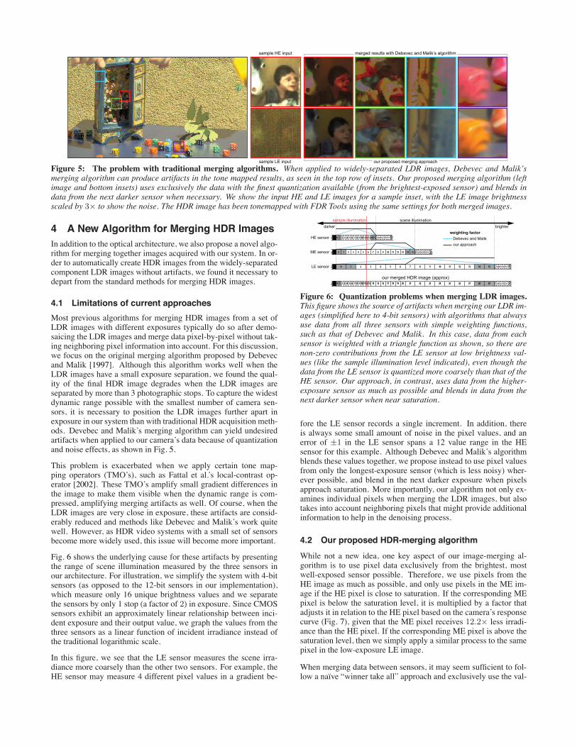
Figure 5: The problem with traditional merging algorithms. When applied to widely-separated LDR images, Debevec and Malik’smerging algorithm can produce artifacts in the tone mapped results, as seen in the top row of insets. Our proposed merging algorithm (leftimage and bottom insets) uses exclusively the data with the finest quantization available (from the brightest-exposed sensor) and blends indata from the next darker sensor when necessary. We show the input HE and LE images for a sample inset, with the LE image brightnessscaled by 3× to show the noise. The HDR image has been tonemapped with FDR Tools using the same settings for both merged images.
4 A New Algorithm for Merging HDR ImagesIn addition to the optical architecture, we also propose a novel algo-rithm for merging together images acquired with our system. In or-der to automatically create HDR images from the widely-separatedcomponent LDR images without artifacts, we found it necessary todepart from the standard methods for merging HDR images.
4.1 Limitations of current approaches
Most previous algorithms for merging HDR images from a set ofLDR images with different exposures typically do so after demo-saicing the LDR images and merge data pixel-by-pixel without tak-ing neighboring pixel information into account. For this discussion,we focus on the original merging algorithm proposed by Debevecand Malik [1997]. Although this algorithm works well when theLDR images have a small exposure separation, we found the qual-ity of the final HDR image degrades when the LDR images areseparated by more than 3 photographic stops. To capture the widestdynamic range possible with the smallest number of camera sen-sors, it is necessary to position the LDR images further apart inexposure in our system than with traditional HDR acquisition meth-ods. Devebec and Malik’s merging algorithm can yield undesiredartifacts when applied to our camera’s data because of quantizationand noise effects, as shown in Fig. 5.
This problem is exacerbated when we apply certain tone map-ping operators (TMO’s), such as Fattal et al.’s local-contrast op-erator [2002]. These TMO’s amplify small gradient differences inthe image to make them visible when the dynamic range is com-pressed, amplifying merging artifacts as well. Of course, when theLDR images are very close in exposure, these artifacts are consid-erably reduced and methods like Debevec and Malik’s work quitewell. However, as HDR video systems with a small set of sensorsbecome more widely used, this issue will become more important.
Fig. 6 shows the underlying cause for these artifacts by presentingthe range of scene illumination measured by the three sensors inour architecture. For illustration, we simplify the system with 4-bitsensors (as opposed to the 12-bit sensors in our implementation),which measure only 16 unique brightness values and we separatethe sensors by only 1 stop (a factor of 2) in exposure. Since CMOSsensors exhibit an approximately linear relationship between inci-dent exposure and their output value, we graph the values from thethree sensors as a linear function of incident irradiance instead ofthe traditional logarithmic scale.
In this figure, we see that the LE sensor measures the scene irra-diance more coarsely than the other two sensors. For example, theHE sensor may measure 4 different pixel values in a gradient be-
scene illuminationbrighterdarker
1514131211109876543210LE sensor saturation
29282726252423222120191817161514131211109876543210 saturation
1514131211109876543210ME sensor saturation
1514131211109876543210HE sensor saturation
weighting factorDebevec and Malikour approach
our merged HDR image (approx)
sample illumination
Figure 6: Quantization problems when merging LDR images.This figure shows the source of artifacts when merging our LDR im-ages (simplified here to 4-bit sensors) with algorithms that alwaysuse data from all three sensors with simple weighting functions,such as that of Debevec and Malik. In this case, data from eachsensor is weighted with a triangle function as shown, so there arenon-zero contributions from the LE sensor at low brightness val-ues (like the sample illumination level indicated), even though thedata from the LE sensor is quantized more coarsely than that of theHE sensor. Our approach, in contrast, uses data from the higher-exposure sensor as much as possible and blends in data from thenext darker sensor when near saturation.
fore the LE sensor records a single increment. In addition, thereis always some small amount of noise in the pixel values, and anerror of ±1 in the LE sensor spans a 12 value range in the HEsensor for this example. Although Debevec and Malik’s algorithmblends these values together, we propose instead to use pixel valuesfrom only the longest-exposure sensor (which is less noisy) wher-ever possible, and blend in the next darker exposure when pixelsapproach saturation. More importantly, our algorithm not only ex-amines individual pixels when merging the LDR images, but alsotakes into account neighboring pixels that might provide additionalinformation to help in the denoising process.
4.2 Our proposed HDR-merging algorithm
While not a new idea, one key aspect of our image-merging al-gorithm is to use pixel data exclusively from the brightest, mostwell-exposed sensor possible. Therefore, we use pixels from theHE image as much as possible, and only use pixels in the ME im-age if the HE pixel is close to saturation. If the corresponding MEpixel is below the saturation level, it is multiplied by a factor thatadjusts it in relation to the HE pixel based on the camera’s responsecurve (Fig. 7), given that the ME pixel receives 12.2× less irradi-ance than the HE pixel. If the corresponding ME pixel is above thesaturation level, then we simply apply a similar process to the samepixel in the low-exposure LE image.
When merging data between sensors, it may seem sufficient to fol-low a naıve “winner take all” approach and exclusively use the val-

ues from the HE sensor until they become saturated and then simplyswitch to the next sensor [JAI 2009]. We found that this does notwork well in practice because it results in banding artifacts wheretransitions occur. Instead, we propose to gracefully transition fromone sensor to the next by spatially blending pixel values betweenthe two sensors. To do this, our algorithm scans a region aroundthe pixel being evaluated. If any neighboring pixels in this regionare saturated, then the pixel under consideration may be subject topixel crosstalk or leakage, and the algorithm will estimate a valuefor the pixel based on its neighbors as described below.
Algorithm details – In our approach, HDR-merging is performedprior to demosaicing the individual Bayer color filter array images,because we found that demosaicing can corrupt colors in saturatedregions (also noted by Ajdin et al. [2008]). For example, a brightorange section of a scene might have red pixels that are saturatedwhile the green and blue pixels are not. If the image is demo-saiced before being merged into HDR, the demosaiced orange colorwill be computed from saturated red-pixel data and non-saturatedgreen/blue-pixel data. As a result, the hue of the orange section willbe incorrectly reproduced. The only way to avoid these artifacts isto perform HDR-merging prior to demosaicing.
Since the images are merged prior to the demosaicing step, our al-gorithm works with pixel values instead of irradiance. To producea radiometrically-correct HDR image, we must correctly match theirradiance levels of the HE, ME, and LE sensors using the appro-priate beamsplitter transmittance values for each pixel color, sincethese change slightly as a function of wavelength. Although we usedifferent values to match each of the color channels, for simplicitywe explain the process with average values. We consider convert-ing a pixel value through the camera response curve, where the re-sulting irradiance is adjusted by the exposure level ratio (averageof 12.2× for HE/ME), and this new irradiance value is convertedback through the camera response curve to a new pixel value. Fig. 7shows this 3-step process graphically.
This conversion process may next be done for all HE pixel values(from 1 through 4096), to arrive at a pixel-ratio curve, which givesthe scaling factor for converting each ME pixel’s value to the cor-responding pixel value on the HE sensor for the same irradiance(Fig. 8). In practice, separate pixel-ratio curves are calculated foreach color (R,G,B) in the Bayer pattern. When comparing pixel val-ues between HE and ME images (or between ME and LE images),we use the pixel-ratio curves as lookup tables (LUTs) to convertHE pixel values less than 4096 into ME pixel values, or vice versa.When the HE pixel values are saturated, we simply extend the pixel-ratio curve using the last value obtained there (approximately 8).
The camera response curve can be measured with the method ofDebevec and Malik [1997], by taking a set of bracketed exposuresand solving for a monotonically-increasing function that relates ex-posure to pixel value (to within a scale constant in the linear do-main). Fig. 7 shows the curve computed from the raw camera data,although a curve computed from a linear best-fit could also be used.In our case, we can factor out the exposure time (since it is constantfor all three images) and produce a curve that maps pixel value di-rectly to scene irradiance. If we call this function f(x), where xis our pixel value, then the three-step process described earlier canbe reversed to map ME pixel values to HE pixel values, written asgME→HE(x) = f−1(12.2f(x)). The function gME→HE(x) is used toblend pixel values between the ME and HE sensors, and a similarfunction gLE→HE(x) is used to blend between the LE and the HEsensors. Once the irradiance levels of the three images have beenmatched, we are ready to begin the merging process.
To explain our merging approach, we assume two registered LDRimages (one high-exposure image IHE and a second medium-
0
0.5
1
1.5
2
2.5
0 500 1000 1500 2000 2500 3000 3500 4000 4500
Irrad
ianc
e (E
)
Pixel Value
1
2
34
Figure 7: Camera response curve. This curve shows how thecamera converts scene irradiance into pixel values. To computewhat the ME pixel value should be for a given HE value, the HEpixel value (1) is first converted to a scene irradiance (2), which isnext divided by our HE/ME attenuation ratio of 12.2. This new ir-radiance value (3) is converted through the camera response curveinto the expected ME pixel value (4). Although this graph is ap-proximately linear, it is not perfectly so because it is computed fromthe raw data, without significant smoothing or applying a linear fit.
exposure image IME) that are to be merged into an HDR image IHDR.Our approach starts with the information in the high-exposure im-age IHE and then combines in data from the next darker-exposureimage IME, as needed. To reduce the transition artifacts describedearlier, our algorithm works on each pixel location (x, y) by look-ing at the information from the surrounding (2k + 1) × (2k + 1)pixel neighborhood, denoted as N(x, y). In our implementation,we used a 5× 5 pixel neighborhood (k = 2), and we define a pixelto be saturated if its value is greater than 90% of the maximumpixel value (4096, for our sensor). We now specify the algorithmfor each of the following 4 states for the pixel and its neighborhood:
Case 1: The pixel under consideration IHE(x, y) is not saturatedand NHE(x, y) has no saturated pixels, so the pixel value is usedas-is: IHDR(x, y) = IHE(x, y).
Case 2: IHE(x, y) is not saturated, but NHE(x, y) has 1 or moresaturated pixels. Although most HDR merging algorithms woulduse this pixel as-is, we find that this calls into question the actualvalue of our pixel due to proximity effects (e.g., leakage or pixelcross-talk on the sensor). We therefore blend between the pixelvalue at IHE(x, y) and the one at the next darker-exposure IME(x, y)depending on the amount of saturation present in the neighborhood.This is done in three steps:
1. Let U be the set of unsaturated pixels in neighborhoodNHE(x, y), where |U | is the number of unsaturated pixels.
2. Let |NHE(x, y)| be the number of pixels in neighborhoodNHE(x, y). An interpolation coefficient α can be computedas α = |U |/|NHE|, which represents the fraction of unsatu-rated pixels in the neighborhood.
3. The output pixel is then given by the blended value:IHDR(x, y) = αIHE(x, y)+(1−α)gME→HE(IME(x, y)),wherewe use the pixel-ratio LUT to map the ME value into the HErange. This blends the measurement at the higher exposureIHE(x, y) with IME(x, y) based on the number of saturatedpixels in the neighborhood NHE(x, y).
Case 3: IHE(x, y) is saturated but NHE(x, y) has 1 or more non-saturated pixels, which can be used to better estimate a value forIHE(x, y). We calculate the ratios of pixel values in the ME imagebetween the unsaturated pixels in the neighborhood and the centerpixel, and use this map of ME ratios to estimate the actual value ofthe saturated pixel under consideration. This is done in four steps:
1. As in Case 2, compute U , |U |, and the coefficient α

0
2
4
6
8
10
0 500 1000 1500 2000 2500 3000 3500 4000 4500
Ra�o
of H
E pi
xel v
alue
/ME p
ixel
valu
e
HE Pixel Value
Measured ra�o from imagesCalculated ra�o from camera calibra�on curve
Figure 8: Pixel ratio curve. The blue curve is obtained whenthe 3-step process (Fig. 7) is applied to all red pixel values in theHE image using the camera response curve, and the ratio betweenHE and ME pixel values is calculated. The red curve is measuredexperimentally by taking the ratio of a large set of red HE and MEpixels in actual images captured by our system. The two matchreasonably, validating our approach. This red curve is used by thealgorithm as a look-up table (LUT) of scale factors to convert redME pixel values to blend them smoothly with red HE pixel values.Similar curves were computed for the green and blue channels.
2. Compute a ratio map R of the ratios between the center pixeland each pixel of the neighborhood from the ME image:R(x, y)i = IME(x, y)/NME(x, y)i, for all pixels i in the MEneighborhood NME(x, y).
3. Now compute an estimated IHE(x, y) for the saturated pixelby scaling the unsaturated pixel values in the neighborhoodNHE with the ratios computed in step 2:IHE(x, y) = 1
|U|P
i∈U RiNHE(x, y)i.
4. Finally, blend estimated IHE(x, y) with IME(x, y) using anequation similar to that of Case 2, step 3:IHDR(x, y) = αIHE(x, y) + (1 − α)gME→HE(IME(x, y)).
Case 4: IHE(x, y) is saturated and all pixels in NHE(x, y) are sat-urated, so we do not have any valid information from the high-exposure image. In this case, we simply use the ME image and setIHDR(x, y) = IME(x, y).
This is our algorithm for combining data from two sensors. Whenthere are three LDR images, the process above is simply repeatedin a second iteration, substituting IHDR for IHE and ILE for IME. Inthis manner, we merge data from the higher exposures as we workour way toward the lowest exposure, and only use data from lowerexposures when the higher-exposure data is at or near saturation.We found that this algorithm reduces artifacts in the merged imageconsiderably, as shown in Fig. 5.
The output of our algorithm is an HDR image that can be de-mosaiced and converted from pixel values to irradiance using acamera response curve similar to that of Fig. 7 accounting for all3 color channels. The final HDR full-color image may then betonemapped with commercial software packages (e.g., FDRTools,HDR Expose, Photomatix, etc.), or as described in the literature(e.g., [Smith et al. 2006]).
5 System ImplementationWe implemented a prototype of our design using three SiliconImaging SI-1920HD high-end cinema CMOS sensors mounted in-side a custom camera body. Each 12-bit sensor was connected toa Dalsa/Coreco x64-CL iPro frame grabber in a PC. These sensorshave 1920 × 1080 pixels (5 microns square) with a standard Bayercolor filter array, and can measure a dynamic range of around 10stops (excluding noise). The sensors were aligned by aiming thecamera at small pinhole light sources, locking down the HE sensorand then adjusting setscrews to align the ME and LE sensors. Inour prototype, the final image registration was accurate to less than
ME sensor
LE sensor
HE sensor
beam splitter 2
beam splitter 1
ME sensor
LE sensor
HE sensor
beam splitter 2
beam splitter 1
Figure 9: Completed camera prototype. (left) The optical pathof our completed implementation. (right) The finished prototypeused to acquire the video images in this paper.
5 microns with a rotation error of less than 0.1◦. Note that, in gen-eral, the required registration accuracy is modulo the 2 × 2 pixelarray of the Bayer pattern, because while pixels of one color in asensor must match with the same color in another, a shift of anynumber of 2 × 2 Bayer patterns can be handled in software. Wediscuss how registration tolerances affect our results in Sec. 7.
The camera body has a Hasselblad lens mount to allow the use ofhigh-performance, interchangeable commercial lenses. For beam-splitters, our current prototype system employs uncoated pelliclebeamsplitters, such as the ones sold by Edmund Optics [part num-ber NT39-482]. Although pellicle beamsplitters are not ideal forcommercial products (they can be delicate and difficult to clean andmaintain), we used them because of their low cost and accessibil-ity. However, we found them to be robust for our application, aswe were able to use our system successfully in various locationsand environmental conditions. A picture of the completed cameraprototype, which cost less than US$15k in parts, is shown in Fig. 9.
We calculated the camera’s response curve as described by Devebecand Malik [1997] with a set of bracketed exposures from the HEsensor (Fig. 7). We also measured the ratio between the HE andMEpixel values experimentally for each color channel and observedthat it matched the curve predicted by our 3-step process (Fig. 8).This curve was implemented as a LUT to translate values from theME to the HE sensor range for merging, and a similar process wasused to obtain and implement the HE/LE ratio curve. The LE sensorvalues are also adjusted with a slight offset before being used in themerging algorithm to account for a small amount of stray light.
The workflow for processing the data coming from the camera isshown in Alg. 1. Most of the steps are self-explanatory and aretypical for HDR systems. The non-uniform correction (NUC) stepis applied to each image to correct for non-uniformities in the sen-sor. This is a 2-point correction, which involves taking a dark fieldimage for offset and a uniformly-lit diffuse scene for gain. TheHDR merging algorithm presented in Sec. 4 was implemented inMATLAB. The demosaicing step used the algorithm of Malvar etal. [2004], and we tonemapped the final HDR images using HDRprocessing tools such as HDR Expose and Photomatix.
6 ResultsOnce the system was built, we performed a radiometric calibrationtest to measure its dynamic range. To do this, we aimed the cameraat a stepped array of neutral density filters, in steps of 1 stop each,and focused down the sun’s light to an integrating sphere behindthe array to provide a uniform, bright light source. A single frameof image data was captured with all 3 sensors simultaneously at anexposure time of 1/30 second. Fig. 10 shows the result of this ex-periment. In our current prototype, we are able to clearly measure adynamic range of over 217 to 1, equivalent to over 17 photographicstops or over 100dB. More importantly, we demonstrate that ouroptical architecture can increase the dynamic range of these partic-
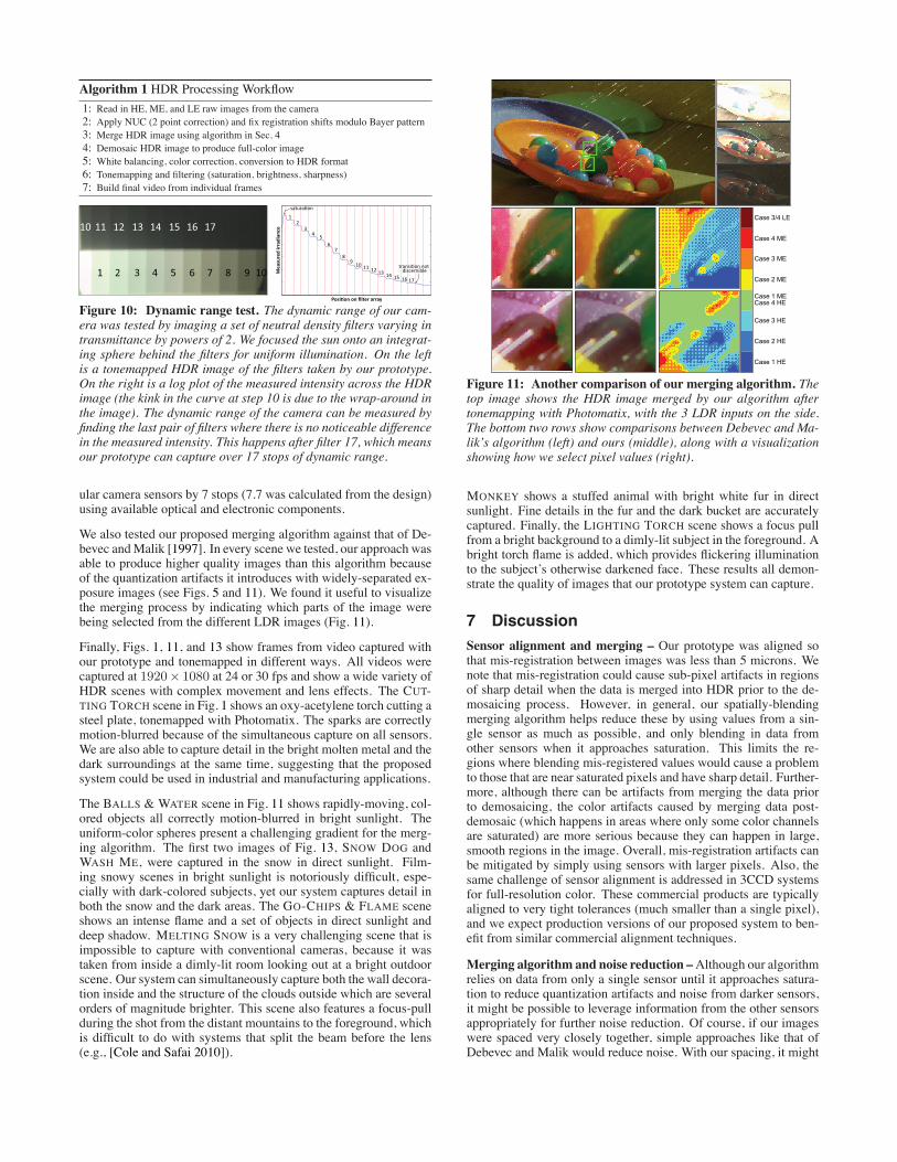
Algorithm 1 HDR Processing Workflow1: Read in HE, ME, and LE raw images from the camera2: Apply NUC (2 point correction) and fix registration shifts modulo Bayer pattern3: Merge HDR image using algorithm in Sec. 44: Demosaic HDR image to produce full-color image5: White balancing, color correction, conversion to HDR format6: Tonemapping and filtering (saturation, brightness, sharpness)7: Build final video from individual frames
transi�on not discernible
12
34 5
67
89 10 11 12 13 14 15 16 17
satura�on
Posi�on on filter array
Mea
sure
d irr
adia
nce
1 2 3 4 5 6 7 8 9 10
10 11 12 13 14 15 16 17
Figure 10: Dynamic range test. The dynamic range of our cam-era was tested by imaging a set of neutral density filters varying intransmittance by powers of 2. We focused the sun onto an integrat-ing sphere behind the filters for uniform illumination. On the leftis a tonemapped HDR image of the filters taken by our prototype.On the right is a log plot of the measured intensity across the HDRimage (the kink in the curve at step 10 is due to the wrap-around inthe image). The dynamic range of the camera can be measured byfinding the last pair of filters where there is no noticeable differencein the measured intensity. This happens after filter 17, which meansour prototype can capture over 17 stops of dynamic range.
ular camera sensors by 7 stops (7.7 was calculated from the design)using available optical and electronic components.
We also tested our proposed merging algorithm against that of De-bevec andMalik [1997]. In every scene we tested, our approach wasable to produce higher quality images than this algorithm becauseof the quantization artifacts it introduces with widely-separated ex-posure images (see Figs. 5 and 11). We found it useful to visualizethe merging process by indicating which parts of the image werebeing selected from the different LDR images (Fig. 11).
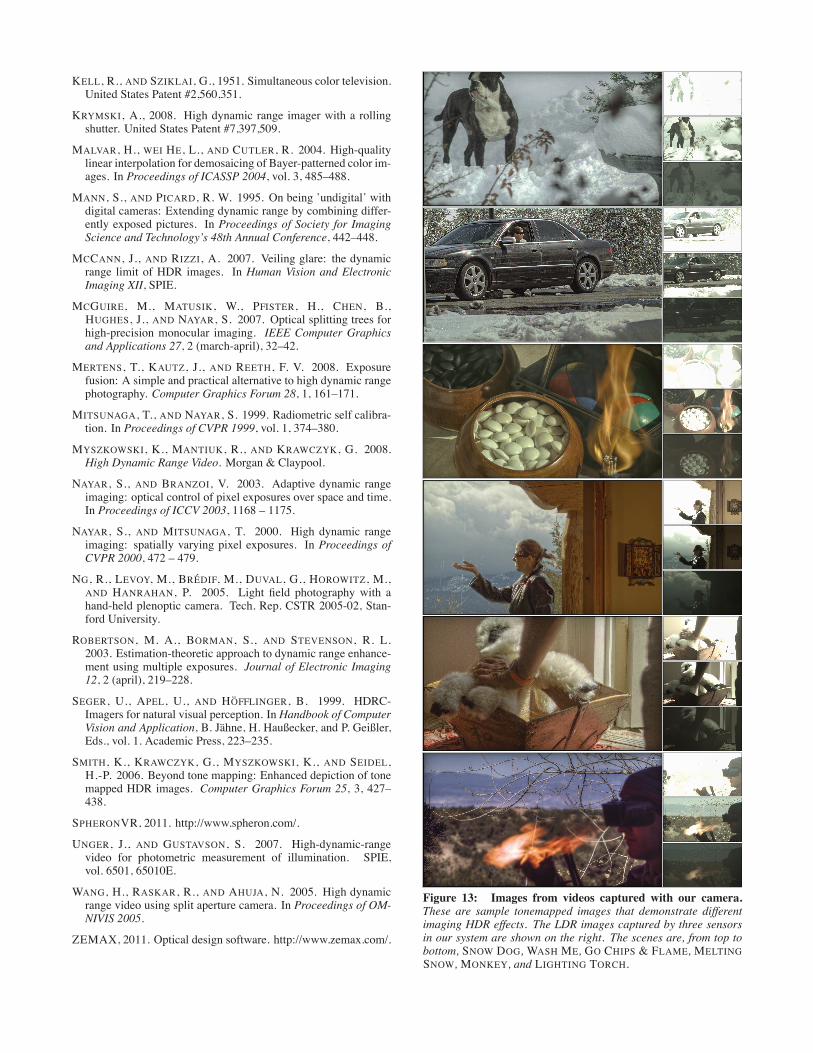
Finally, Figs. 1, 11, and 13 show frames from video captured withour prototype and tonemapped in different ways. All videos werecaptured at 1920× 1080 at 24 or 30 fps and show a wide variety ofHDR scenes with complex movement and lens effects. The CUT-TING TORCH scene in Fig. 1 shows an oxy-acetylene torch cutting asteel plate, tonemapped with Photomatix. The sparks are correctlymotion-blurred because of the simultaneous capture on all sensors.We are also able to capture detail in the bright molten metal and thedark surroundings at the same time, suggesting that the proposedsystem could be used in industrial and manufacturing applications.
The BALLS & WATER scene in Fig. 11 shows rapidly-moving, col-ored objects all correctly motion-blurred in bright sunlight. Theuniform-color spheres present a challenging gradient for the merg-ing algorithm. The first two images of Fig. 13, SNOW DOG andWASH ME, were captured in the snow in direct sunlight. Film-ing snowy scenes in bright sunlight is notoriously difficult, espe-cially with dark-colored subjects, yet our system captures detail inboth the snow and the dark areas. The GO-CHIPS & FLAME sceneshows an intense flame and a set of objects in direct sunlight anddeep shadow. MELTING SNOW is a very challenging scene that isimpossible to capture with conventional cameras, because it wastaken from inside a dimly-lit room looking out at a bright outdoorscene. Our system can simultaneously capture both the wall decora-tion inside and the structure of the clouds outside which are severalorders of magnitude brighter. This scene also features a focus-pullduring the shot from the distant mountains to the foreground, whichis difficult to do with systems that split the beam before the lens(e.g., [Cole and Safai 2010]).
Case 3/4 LE
Case 4 ME
Case 3 ME
Case 2 ME
Case 1 MECase 4 HE
Case 3 HE
Case 2 HE
Case 1 HE
Figure 11: Another comparison of our merging algorithm. Thetop image shows the HDR image merged by our algorithm aftertonemapping with Photomatix, with the 3 LDR inputs on the side.The bottom two rows show comparisons between Debevec and Ma-lik’s algorithm (left) and ours (middle), along with a visualizationshowing how we select pixel values (right).
MONKEY shows a stuffed animal with bright white fur in directsunlight. Fine details in the fur and the dark bucket are accuratelycaptured. Finally, the LIGHTING TORCH scene shows a focus pullfrom a bright background to a dimly-lit subject in the foreground. Abright torch flame is added, which provides flickering illuminationto the subject’s otherwise darkened face. These results all demon-strate the quality of images that our prototype system can capture.
7 DiscussionSensor alignment and merging – Our prototype was aligned sothat mis-registration between images was less than 5 microns. Wenote that mis-registration could cause sub-pixel artifacts in regionsof sharp detail when the data is merged into HDR prior to the de-mosaicing process. However, in general, our spatially-blendingmerging algorithm helps reduce these by using values from a sin-gle sensor as much as possible, and only blending in data fromother sensors when it approaches saturation. This limits the re-gions where blending mis-registered values would cause a problemto those that are near saturated pixels and have sharp detail. Further-more, although there can be artifacts from merging the data priorto demosaicing, the color artifacts caused by merging data post-demosaic (which happens in areas where only some color channelsare saturated) are more serious because they can happen in large,smooth regions in the image. Overall, mis-registration artifacts canbe mitigated by simply using sensors with larger pixels. Also, thesame challenge of sensor alignment is addressed in 3CCD systemsfor full-resolution color. These commercial products are typicallyaligned to very tight tolerances (much smaller than a single pixel),and we expect production versions of our proposed system to ben-efit from similar commercial alignment techniques.
Merging algorithm and noise reduction –Although our algorithmrelies on data from only a single sensor until it approaches satura-tion to reduce quantization artifacts and noise from darker sensors,it might be possible to leverage information from the other sensorsappropriately for further noise reduction. Of course, if our imageswere spaced very closely together, simple approaches like that ofDebevec and Malik would reduce noise. With our spacing, it might

sensor 1
sensor 2
sensor 5
sensor 3
sensor 4
main lens
Figure 12: Extension of our optical architecture. Our opticalarchitecture can be extended to more sensors for a better imagequality or higher dynamic range. Here we show a design for asystem with 5 sensors, where we essentially replace the HE and MEsensors with two other beamsplitters and a pair of sensors for each.The design was simulated with ZEMAX [2011].
be possible to combine our spatial-blending approach (which looksat a neighborhood of pixels, not just the pixel being merged) withmerging algorithms that weigh other images based on their noisecontent (e.g., [Granados et al. 2010; Hasinoff et al. 2010]) to pro-duce better results. This is an interesting subject for future work.
Flexible design – We present a simple blueprint for an HDRvideo imaging system using off-the-shelf components that can pro-duce high-quality HDR video footage. The use of commercially-available sensors makes it easy to change them to extend the ca-pabilities of the camera. Furthermore, the number of sensors canbe extended with minor modifications to the optical path. Fig. 12shows an optical design configured with 5 sensors, which would al-low the camera to have an even higher dynamic range, or to producehigher quality images at the same dynamic range.
Toward better, low-cost consumer cameras – Although a systemlike ours could be used in high-end imaging applications such asfeature film production, it could also impact the consumer cameramarket. First, the proposed architecture might enable high-quality,low-cost imaging because it allows three cheap sensors with limiteddynamic range to capture images with dynamic range comparableto that of a single, high-end sensor. Second, HDR imaging wouldarguably benefit consumers more than professional cinematogra-phers because the typical consumer does not have the lighting rigsor training needed to achieve HDR effects with LDR systems.
Limitations – Any HDR system (including the human eye) is ul-timately limited in its ability to capture wide dynamic range byveiling glare in the optics [McCann and Rizzi 2007]. Our designis compatible with higher-performance lenses, which may help re-duce veiling glare. Our optical architecture also provides the high-exposure sensor with only 92% of the light of the scene, which com-pares favorably with the 33% provided by previous internal beam-splitting systems, but is less light than would be captured with asingle sensor and lens in a traditional camera.
Future work – In terms of the optical system, a study of thin-film coatings on the beamsplitters to reduce angle- or polarization-dependent effects (as discussed in Sec. 3.1) could be explored. Theoptical system would also benefit from improvements in the sensoralignment. In terms of the proposed merging algorithm, studies ofnoise optimization during the image merging process, in conjunc-tion with our spatial-blending method, would make an interestingsubject for future work. Finally, it would be useful to develop soft-ware packages for HDR cinematography for use with systems likethe one proposed. These would give directors of photography thesame kinds of tools in post-process that they are used to having attheir disposal when lighting the set.
8 ConclusionIn conclusion, we have presented an optical architecture for high-dynamic range video that makes efficient use of the incoming lightand produces cinema-quality images. We also proposed a novelHDR merging algorithm that minimizes quantization artifacts fromthe LDR data by using the highest-exposure data until saturation be-fore spatially-blending in darker-exposure data. To test our design,we built a working prototype of the system and showed images fromvideo acquired with the system.
Acknowledgment – We thank the anonymous reviewers for theirhelpful comments that improved the final version of the paper.
ReferencesAGARWALA, A., DONTCHEVA, M., AGRAWALA, M., DRUCKER,S., COLBURN, A., CURLESS, B., SALESIN, D., AND COHEN,M. 2004. Interactive digital photomontage. ACM Trans. Graph.23 (August), 294–302.
AGGARWAL, M., AND AHUJA, N. 2001. Split aperture imagingfor high dynamic range. In Proceedings of ICCV 2001, 10 – 17.
AGGARWAL, M., AND AHUJA, N. 2004. Split aperture imagingfor high dynamic range. International Journal of Computer Vi-sion 58, 7–17.
AJDIN, B., HULLIN, M., FUCHS, C., SEIDEL, H.-P., ANDLENSCH, H. 2008. Demosaicing by smoothing along 1D fea-tures. In Proceedings of CVPR 2008, 1–8.
BRAJOVIC, V., AND KANADE, T. 1996. A sorting image sen-sor: an example of massively parallel intensity-to-time process-ing for low-latency computational sensors. In Proceedings ofICRA, 1996, vol. 2, 1638–1643.
COLE, A., AND SAFAI, M., 2010. Soviet Montage Productions.http://www.sovietmontage.com/.
DEBEVEC, P. E., AND MALIK, J. 1997. Recovering high dynamicrange radiance maps from photographs. In Proceedings of ACMSIGGRAPH 1997, 369–378.
FATTAL, R., LISCHINSKI, D., AND WERMAN, M. 2002. Gradientdomain high dynamic range compression. ACM Trans. Graph.21 (July), 249–256.
GINOSAR, R., HILSENRATH, O., AND ZEEVI, Y., 1992. Widedynamic range camera. United States Patent #5,144,442.
GRANADOS, M., AJDIN, B., WAND, M., THEOBALT, C., SEI-DEL, H.-P., AND LENSCH, H. 2010. Optimal HDR reconstruc-tion with linear digital cameras. In Proceedings of CVPR 2010.
HARVEY, R., 1998. Optical beam splitter and electronic high speedcamera incorporating such a beam splitter. United States Patent#5,734,507.
HASINOFF, S. W., DURAND, F., AND FREEMAN, W. T. 2010.Noise-optimal capture for high dynamic range photography. InProceedings of CVPR 2010.
JAI. 2009. Using image fusion to capture high-dynamic range(HDR) scenes. Tech. Rep. TN-0903. JAI, Inc., Japan.
KANG, S. B., UYTTENDAELE, M., WINDER, S., AND SZELISKI,R. 2003. High dynamic range video. In Proceedings of ACMSIGGRAPH 2003, ACM, 319–325.
KAO, W.-C. 2008. High dynamic range imaging by fusing mul-tiple raw images and tone reproduction. IEEE Transactions onConsumer Electronics 54, 1 (Feb.), 10 – 15.
KELL, R., AND SZIKLAI, G., 1951. Simultaneous color television.United States Patent #2,560,351.
KRYMSKI, A., 2008. High dynamic range imager with a rollingshutter. United States Patent #7,397,509.
MALVAR, H., WEI HE, L., AND CUTLER, R. 2004. High-qualitylinear interpolation for demosaicing of Bayer-patterned color im-ages. In Proceedings of ICASSP 2004, vol. 3, 485–488.
MANN, S., AND PICARD, R. W. 1995. On being ’undigital’ withdigital cameras: Extending dynamic range by combining differ-ently exposed pictures. In Proceedings of Society for ImagingScience and Technology’s 48th Annual Conference, 442–448.
MCCANN, J., AND RIZZI, A. 2007. Veiling glare: the dynamicrange limit of HDR images. In Human Vision and ElectronicImaging XII, SPIE.
MCGUIRE, M., MATUSIK, W., PFISTER, H., CHEN, B.,HUGHES, J., AND NAYAR, S. 2007. Optical splitting trees forhigh-precision monocular imaging. IEEE Computer Graphicsand Applications 27, 2 (march-april), 32–42.
MERTENS, T., KAUTZ, J., AND REETH, F. V. 2008. Exposurefusion: A simple and practical alternative to high dynamic rangephotography. Computer Graphics Forum 28, 1, 161–171.
MITSUNAGA, T., AND NAYAR, S. 1999. Radiometric self calibra-tion. In Proceedings of CVPR 1999, vol. 1, 374–380.
MYSZKOWSKI, K., MANTIUK, R., AND KRAWCZYK, G. 2008.High Dynamic Range Video. Morgan & Claypool.
NAYAR, S., AND BRANZOI, V. 2003. Adaptive dynamic rangeimaging: optical control of pixel exposures over space and time.In Proceedings of ICCV 2003, 1168 – 1175.
NAYAR, S., AND MITSUNAGA, T. 2000. High dynamic rangeimaging: spatially varying pixel exposures. In Proceedings ofCVPR 2000, 472 – 479.
NG, R., LEVOY, M., BREDIF, M., DUVAL, G., HOROWITZ, M.,AND HANRAHAN, P. 2005. Light field photography with ahand-held plenoptic camera. Tech. Rep. CSTR 2005-02, Stan-ford University.
ROBERTSON, M. A., BORMAN, S., AND STEVENSON, R. L.2003. Estimation-theoretic approach to dynamic range enhance-ment using multiple exposures. Journal of Electronic Imaging12, 2 (april), 219–228.
SEGER, U., APEL, U., AND HOFFLINGER, B. 1999. HDRC-Imagers for natural visual perception. In Handbook of ComputerVision and Application, B. Jahne, H. Haußecker, and P. Geißler,Eds., vol. 1. Academic Press, 223–235.
SMITH, K., KRAWCZYK, G., MYSZKOWSKI, K., AND SEIDEL,H.-P. 2006. Beyond tone mapping: Enhanced depiction of tonemapped HDR images. Computer Graphics Forum 25, 3, 427–438.
SPHERONVR, 2011. http://www.spheron.com/.
UNGER, J., AND GUSTAVSON, S. 2007. High-dynamic-rangevideo for photometric measurement of illumination. SPIE,vol. 6501, 65010E.
WANG, H., RASKAR, R., AND AHUJA, N. 2005. High dynamicrange video using split aperture camera. In Proceedings of OM-NIVIS 2005.
ZEMAX, 2011. Optical design software. http://www.zemax.com/.
Figure 13: Images from videos captured with our camera.These are sample tonemapped images that demonstrate differentimaging HDR effects. The LDR images captured by three sensorsin our system are shown on the right. The scenes are, from top tobottom, SNOW DOG,WASH ME, GO CHIPS & FLAME, MELTINGSNOW, MONKEY, and LIGHTING TORCH.
Copyright © 2022 FDOKUMEN