A Universal Approach to Data Center Network Design - UTNS
10
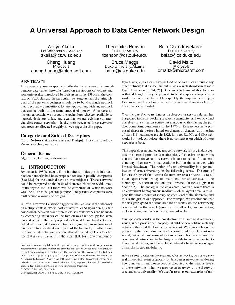
A Universal Approach to Data Center Network Design Aditya Akella U of Wisconsin - Madison [email protected] Theophilus Benson Duke University [email protected] Bala Chandrasekaran Duke University [email protected] Cheng Huang Microsoft [email protected] Bruce Maggs Duke University/Akamai [email protected] David Maltz Microsoft [email protected] ABSTRACT This paper proposes an approach to the design of large-scale general- purpose data center networks based on the notions of volume and area universality introduced by Leiserson in the 1980’s in the con- text of VLSI design. In particular, we suggest that the principle goal of the network designer should be to build a single network that is provably competitive, for any application, with any network that can be built for the same amount of money. After describ- ing our approach, we survey the technology choices available to network designers today, and examine several existing commer- cial data center networks. In the most recent of these networks resources are allocated roughly as we suggest in this paper. Categories and Subject Descriptors C.2.1 [Network Architecture and Design]: Network topology, Packet-switching networks General Terms Algorithms, Design, Performance 1. INTRODUCTION By the early 1980s dozens, if not hundreds, of designs of intercon- nection networks had been proposed for use in parallel computers. (See [22] for the seminal text on this subject.) These networks could be compared on the basis of diameter, bisection width, max- imum degree, etc., but there was no consensus on which network was “best” or most general purpose, and parallel computers were built around a variety of designs. In 1985, however, Leiserson suggested that, at least in the “network on a chip” context, where cost equates to VLSI layout area, a fair comparison between two different classes of networks can be made by comparing instances of the two classes that occupy the same amount of area. He then proposed a class of hierarchical networks called fat-trees that allows a network designer to choose how much bandwidth to allocate at each level of the hierarchy. Furthermore, he demonstrated that one specific allocation strategy leads to a fat- tree that is area universal in the sense that, for a given amount of Permission to make digital or hard copies of all or part of this work for personal or classroom use is granted without fee provided that copies are not made or distributed for profit or commercial advantage and that copies bear this notice and the full cita- tion on the first page. Copyrights for components of this work owned by others than ACM must be honored. Abstracting with credit is permitted. To copy otherwise, or re- publish, to post on servers or to redistribute to lists, requires prior specific permission and/or a fee. Request permissions from [email protected]. ICDCN ’15 Jan. 4-7, Goa, India Copyright 2015 ACM 978-1-4503-3063-3/14/11 ...$15.00. layout area, n, an area-universal fat-tree of area n can emulate any other network that can be laid out in area n with slowdown at most logarithmic in n [5, 24, 25]. One interpretation of this theorem is that although it may be possible to build a special-purpose net- work to solve a specific problem quickly, the improvement in per- formance over that achievable by an area-universal network built at the same cost is limited. Over the past few years, interest in data center network design has burgeoned in the networking research community, and we now find ourselves in a situation somewhat analgous to that facing the par- allel computing community in the 1980’s. Researchers have pro- posed disparate designs based on cliques of cliques [20], meshes of stars [19], expander graphs [32], fat-trees [2, 30], and Clos net- works [14, 16]. As before, there is no consensus on which of these networks is best. This paper does not advocate a specific network for use in data cen- ters, but instead promotes a methodology for designing networks that are “cost universal”. A network is cost universal if it can em- ulate any other network that could be built at the same cost with limited slowdown. The notion of cost universalilty is a general- ization of area universality in the following sense. The crux of Leiserson’s proof that certain fat-trees are area universal is to al- lot an equal amount of layout area to the links at each level of the hierarchy. (A short tutorial on area-universal fat-trees is given in Section 2). The analog in the data center context, where there is no convenient homogeneous medium such as layout area, is to ex- pend the same amount of money on each level of the hierarchy, and this is the gist of our approach. For example, we recommend that the designer spend the same amount of money on the networking connectivity within a rack (summed over all racks), on connecting racks in a row, and on connecting rows of racks. Our approach results in the constuction of hierarchical networks, which, when provisioned properly, should be competitive with any networks that could be built at the same cost. We do not rule out the possibility that a non-hierarchical network could also be cost uni- versal, but we do not know of any such examples. In any case, the commercial networking technology available today is well suited to hierarchical design, and hierarchical networks have the advantages of simplicity and modularity. After a short tutorial on fat-trees and Clos networks, we survey sev- eral influential recent proposals for data center networks, analyzing how bandwidth, and hence cost, is allocated to the various levels of these networks. Then we provide an overview of the theory of area and cost universality. We use fat-trees as our examples of uni-
-
Upload
khangminh22 -
Category
Documents
-
view
1 -
download
0
Transcript of A Universal Approach to Data Center Network Design - UTNS
A Universal Approach to Data Center Network Design
Aditya AkellaU of Wisconsin - [email protected]
Theophilus BensonDuke University
Bala ChandrasekaranDuke University
[email protected] Huang
Bruce MaggsDuke University/[email protected]
David MaltzMicrosoft
ABSTRACTThis paper proposes an approach to the design of large-scale general-purpose data center networks based on the notions of volume andarea universality introduced by Leiserson in the 1980’s in the con-text of VLSI design. In particular, we suggest that the principlegoal of the network designer should be to build a single networkthat is provably competitive, for any application, with any networkthat can be built for the same amount of money. After describ-ing our approach, we survey the technology choices available tonetwork designers today, and examine several existing commer-cial data center networks. In the most recent of these networksresources are allocated roughly as we suggest in this paper.
Categories and Subject DescriptorsC.2.1 [Network Architecture and Design]: Network topology,Packet-switching networks
General TermsAlgorithms, Design, Performance
1. INTRODUCTIONBy the early 1980s dozens, if not hundreds, of designs of intercon-nection networks had been proposed for use in parallel computers.(See [22] for the seminal text on this subject.) These networkscould be compared on the basis of diameter, bisection width, max-imum degree, etc., but there was no consensus on which networkwas “best” or most general purpose, and parallel computers werebuilt around a variety of designs.
In 1985, however, Leiserson suggested that, at least in the “networkon a chip” context, where cost equates to VLSI layout area, a faircomparison between two different classes of networks can be madeby comparing instances of the two classes that occupy the sameamount of area. He then proposed a class of hierarchical networkscalled fat-trees that allows a network designer to choose how muchbandwidth to allocate at each level of the hierarchy. Furthermore,he demonstrated that one specific allocation strategy leads to a fat-tree that is area universal in the sense that, for a given amount of
Permission to make digital or hard copies of all or part of this work for personal orclassroom use is granted without fee provided that copies are not made or distributedfor profit or commercial advantage and that copies bear this notice and the full cita-tion on the first page. Copyrights for components of this work owned by others thanACM must be honored. Abstracting with credit is permitted. To copy otherwise, or re-publish, to post on servers or to redistribute to lists, requires prior specific permissionand/or a fee. Request permissions from [email protected] ’15 Jan. 4-7, Goa, IndiaCopyright 2015 ACM 978-1-4503-3063-3/14/11 ...$15.00.
layout area, n, an area-universal fat-tree of area n can emulate anyother network that can be laid out in area n with slowdown at mostlogarithmic in n [5, 24, 25]. One interpretation of this theoremis that although it may be possible to build a special-purpose net-work to solve a specific problem quickly, the improvement in per-formance over that achievable by an area-universal network built atthe same cost is limited.
Over the past few years, interest in data center network design hasburgeoned in the networking research community, and we now findourselves in a situation somewhat analgous to that facing the par-allel computing community in the 1980’s. Researchers have pro-posed disparate designs based on cliques of cliques [20], meshesof stars [19], expander graphs [32], fat-trees [2, 30], and Clos net-works [14, 16]. As before, there is no consensus on which of thesenetworks is best.
This paper does not advocate a specific network for use in data cen-ters, but instead promotes a methodology for designing networksthat are “cost universal”. A network is cost universal if it can em-ulate any other network that could be built at the same cost withlimited slowdown. The notion of cost universalilty is a general-ization of area universality in the following sense. The crux ofLeiserson’s proof that certain fat-trees are area universal is to al-lot an equal amount of layout area to the links at each level of thehierarchy. (A short tutorial on area-universal fat-trees is given inSection 2). The analog in the data center context, where there isno convenient homogeneous medium such as layout area, is to ex-pend the same amount of money on each level of the hierarchy, andthis is the gist of our approach. For example, we recommend thatthe designer spend the same amount of money on the networkingconnectivity within a rack (summed over all racks), on connectingracks in a row, and on connecting rows of racks.
Our approach results in the constuction of hierarchical networks,which, when provisioned properly, should be competitive with anynetworks that could be built at the same cost. We do not rule out thepossibility that a non-hierarchical network could also be cost uni-versal, but we do not know of any such examples. In any case, thecommercial networking technology available today is well suited tohierarchical design, and hierarchical networks have the advantagesof simplicity and modularity.
After a short tutorial on fat-trees and Clos networks, we survey sev-eral influential recent proposals for data center networks, analyzinghow bandwidth, and hence cost, is allocated to the various levelsof these networks. Then we provide an overview of the theory ofarea and cost universality. We use fat-trees as our examples of uni-

node
channel
leaves
Figure 1: The coarse structure of a fat-tree could, for example, be acomplete 4-ary tree.
processors
switch
link
Figure 2: One possible fine structure, called a butterfly fat-tree,where the coarse structure is a complete 4-ary tree. In this exam-ple, the capacities of the channels have been to chosen to make thenetwork area universal.
versal networks, but other hierarchical networks might suffice. Thefat-trees, however, are proportioned very differently than those de-scribed in recent papers on data center network design, where thecost of the top level of the hierarchy dominates the costs of the otherlevels. We then examine several modern data center networks, andobserve that, whether consciously or not, the designers roughly fol-lowed our recommendation of spending the same amount of moneyon each level of the hierarchy.
2. NETWORK STRUCTURESThis section begins with a brief primer on fat-tree networks. It alsoexamines the relationships between fat-trees and other networkssuch as folded Clos networks, and explains how expanders can beincorporated into fat-trees.
Fat-trees were introduced by Leiserson [25] in 1985. A fat-tree hasa coarse structure and a fine structure. The coarse structure is arooted tree, consisting of nodes and bidirectional channels betweenparents and children. The degrees of the nodes can be chosen bythe fat-tree designer. An example coarse structure for a fat-tree, acomplete 4-ary tree, is shown in Figure 1.
The fine structure provides the details necessary to implement thefat-tree. For each leaf in the coarse structure there is a processor,server, or other device in the fine structure. For each internal nodein the coarse structure, there is a corresponding set of switches inthe fine structure. The number of switches per node, and the num-ber of ports per switch, are chosen by the designer. For each chan-nel in the coarse structure, there is a corresponding set of links con-necting ports on switches at the parent to ports on switches at thechild. How these ports are connected is again up to the designer.The capacity (bandwidth) allocated to each channel is determinedby the number of links, which in turn depends on the number ofswitches and ports at the parent and child nodes. Leiserson’s orig-inal paper [25] contemplated links between switches at the same
Figure 3: A VLSI layout of an area-universal fat-tree.
Figure 4: A full 4-ary butterfly fat-tree.
node, but in practice such links have not been used. One possiblefine structure for a complete 4-ary fat-tree is shown in Figure 2.
2.1 Butterfly fat-treesIn [18], Greenberg and Leiserson introduced a fine structure sim-pler than those in [25], which Greenberg calls a butterfly fat-tree inhis thesis [17]. Today the term fat-tree almost always refers to abutterfly fat-tree. Figure 2 depicts a butterfly fat-tree whose chan-nel capacities (doubling every level in a 4-ary fat-tree) have beenchosen so that the network is area universal.
In a butterfly fat-tree, every link connects a port on a switch at aparent node to a port on a switch at a child node (i.e., there are nolinks between switches at the same tree node). Furthermore, thereis at most one link between any two switches, and each switch at aparent node is connected to exactly one switch at each of the chil-dren. A butterfly fat-tree is not actually a tree (it contains cycles!),but its coarse structure is a tree.
Figure 3 shows a VLSI layout of the fine structure shown in Fig-ure 2. This way laying out a tree is called an H-tree layout [29]. Inthe figure, the square leaf nodes denote processors, while the ovalsdenote switches. Note that although the number of links at the root(8) is only the square root of the number of processors (64), theselinks occupy a significant fraction of the layout area.
In general, switches with any number of children or parents can beused to construct a butterfly fat-tree. Typically only a single type ofswitch is used, but, for example, an area-universal binary fat-treecould be constructed in which each switch has two links to childswitches, but on alternating levels, each switch either has a singlelink to a parent switch, or two links to parent switches. In general,
the number of parents per switch can be varied from level to levelin order to control the rate at which bandwidth is allocated amongthe levels. At the top level of a fat-tree, the number of switches canbe reduced because there are no parent switches to connect to. Inparticular, ports that would otherwise be used to connect to parentswitches can instead be used to provide additional connections tochildren. It would be unusual to use a switch with more parentsthan children, because the children would not be able to send orreceive enough traffic to saturate the connections to the parents. Ina fat-tree built out of commodity Ethernet switches or routers, eachswitch would typically have a large number of children and parents.
The special case in which every switch in a butterfly fat-tree hasas many parents as children, shown in Figure 4, is called a full fat-tree [11, 12]. Full fat-trees are not area or volume universal, andwould likely be prohibitively expensive to build on a large scale dueto their large bisection bandwidths. In particular, in a full fat-treewith N leaves, the amount of layout area required for the differentlevels of the tree vary greatly. For example, the wires at the rootrequire Θ(N2) area, whereas the wires at the leaves require onlyΘ(N) area. Confusingly, some authors depict fat-trees as full fat-trees without pointing out that the full fat-tree is a special case,and many experimental network simulations are carried out on fullfat-trees without justifying the choice of this special case.
A defining feature of the butterfly fat-tree is the algorithm for find-ing a path from one leaf to another. The path first proceeds upwardsin the tree, following parent links. Upon reaching a switch at thelowest common ancestor of the two leaves (in the coarse structureof the tree), the path then proceeds down child links to the destina-tion leaf. On the upward part of the path, any parent switch can bechosen. A common strategy for load balancing is to select a parentat random, which is precisely the technique suggested by Valiantand Brebner [34] (and somewhat unfairly known as "Valiant loadbalancing" today). On the way down from the lowest common an-cestor, there is a unique path to the destination leaf.
2.2 Redundant downard paths in fat-treesOne defininition of an expander is an N -node graph with the prop-erty that any set of k ≤ αN nodes is connected to at least βk othernodes, for some fixed constants 0 < α < 1 and β > 0. An N ×Nbipartite graph is an expander if any set of k ≤ αN nodes on theleft side is connected to a set of at least βk nodes on the right side,for β > 1. With nonzero probability, a bipartite graph in whicheach node on the left has at least three neighbors, and those neigh-bors are chosen at random, is an expander. Explicit constructionsare also known.
Unless α and β are very small, an expander will have high bisectionbandwidth. Hence, building a large-scale network that exhibits aglobal expansion property is challenging. Adding to the challenge,a randomly-wired expander also exhibits an irregular wiring pat-tern. The use of expanders as components within structured net-works, however, has proven useful in theory. For example, theAKS sorting network [1], which can sort any set of N keys usingO(logN) levels of comparators, incorporates expanders, as doesthe N -input multibutterfly [33] network, which has a determinis-tic routing algorithm that can route any permutation of N packetsin O(logN) steps, and is highly resilient to faults [23]. The non-blocking multi-Beneš network [3], which is based on the multibut-terfly can establish a set of circuits among N inputs and N outputsin any permutation using O(N logN) crosspoints.
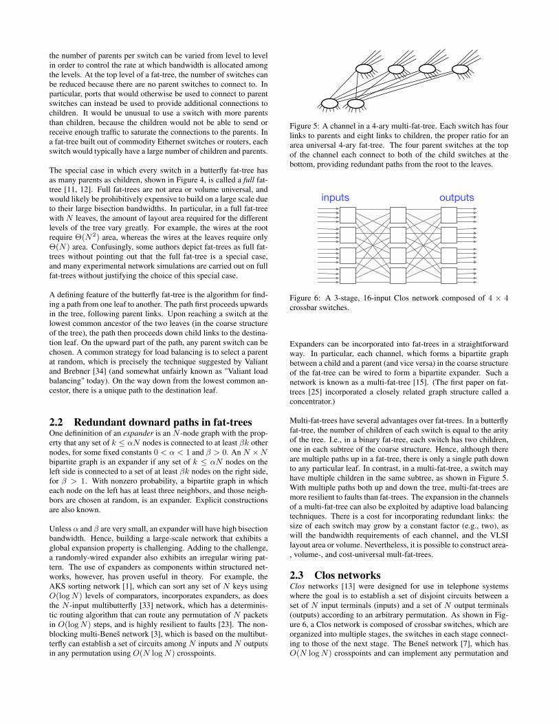
Figure 5: A channel in a 4-ary multi-fat-tree. Each switch has fourlinks to parents and eight links to children, the proper ratio for anarea universal 4-ary fat-tree. The four parent switches at the topof the channel each connect to both of the child switches at thebottom, providing redundant paths from the root to the leaves.
inputs outputs
Figure 6: A 3-stage, 16-input Clos network composed of 4 × 4crossbar switches.
Expanders can be incorporated into fat-trees in a straightforwardway. In particular, each channel, which forms a bipartite graphbetween a child and a parent (and vice versa) in the coarse structureof the fat-tree can be wired to form a bipartite expander. Such anetwork is known as a multi-fat-tree [15]. (The first paper on fat-trees [25] incorporated a closely related graph structure called aconcentrator.)
Multi-fat-trees have several advantages over fat-trees. In a butterflyfat-tree, the number of children of each switch is equal to the arityof the tree. I.e., in a binary fat-tree, each switch has two children,one in each subtree of the coarse structure. Hence, although thereare multiple paths up in a fat-tree, there is only a single path downto any particular leaf. In contrast, in a multi-fat-tree, a switch mayhave multiple children in the same subtree, as shown in Figure 5.With multiple paths both up and down the tree, multi-fat-trees aremore resilient to faults than fat-trees. The expansion in the channelsof a multi-fat-tree can also be exploited by adaptive load balancingtechniques. There is a cost for incorporating redundant links: thesize of each switch may grow by a constant factor (e.g., two), aswill the bandwidth requirements of each channel, and the VLSIlayout area or volume. Nevertheless, it is possible to construct area-, volume-, and cost-universal mult-fat-trees.
2.3 Clos networksClos networks [13] were designed for use in telephone systemswhere the goal is to establish a set of disjoint circuits between aset of N input terminals (inputs) and a set of N output terminals(outputs) according to an arbitrary permutation. As shown in Fig-ure 6, a Clos network is composed of crossbar switches, which areorganized into multiple stages, the switches in each stage connect-ing to those of the next stage. The Beneš network [7], which hasO(N logN) crosspoints and can implement any permutation and
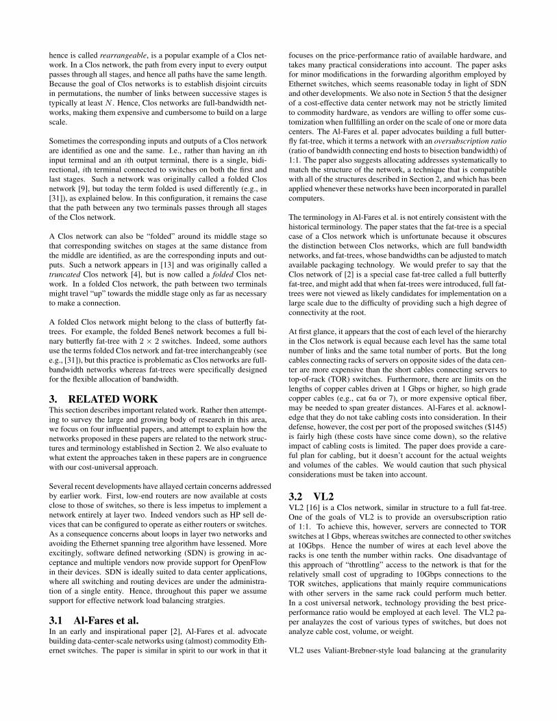
hence is called rearrangeable, is a popular example of a Clos net-work. In a Clos network, the path from every input to every outputpasses through all stages, and hence all paths have the same length.Because the goal of Clos networks is to establish disjoint circuitsin permutations, the number of links between successive stages istypically at least N . Hence, Clos networks are full-bandwidth net-works, making them expensive and cumbersome to build on a largescale.
Sometimes the corresponding inputs and outputs of a Clos networkare identified as one and the same. I.e., rather than having an ithinput terminal and an ith output terminal, there is a single, bidi-rectional, ith terminal connected to switches on both the first andlast stages. Such a network was originally called a folded Closnetwork [9], but today the term folded is used differently (e.g., in[31]), as explained below. In this configuration, it remains the casethat the path between any two terminals passes through all stagesof the Clos network.
A Clos network can also be “folded” around its middle stage sothat corresponding switches on stages at the same distance fromthe middle are identified, as are the corresponding inputs and out-puts. Such a network appears in [13] and was originally called atruncated Clos network [4], but is now called a folded Clos net-work. In a folded Clos network, the path between two terminalsmight travel “up” towards the middle stage only as far as necessaryto make a connection.
A folded Clos network might belong to the class of butterfly fat-trees. For example, the folded Beneš network becomes a full bi-nary butterfly fat-tree with 2 × 2 switches. Indeed, some authorsuse the terms folded Clos network and fat-tree interchangeably (seee.g., [31]), but this practice is problematic as Clos networks are full-bandwidth networks whereas fat-trees were specifically designedfor the flexible allocation of bandwidth.
3. RELATED WORKThis section describes important related work. Rather then attempt-ing to survey the large and growing body of research in this area,we focus on four influential papers, and attempt to explain how thenetworks proposed in these papers are related to the network struc-tures and terminology established in Section 2. We also evaluate towhat extent the approaches taken in these papers are in congruencewith our cost-universal approach.
Several recent developments have allayed certain concerns addressedby earlier work. First, low-end routers are now available at costsclose to those of switches, so there is less impetus to implement anetwork entirely at layer two. Indeed vendors such as HP sell de-vices that can be configured to operate as either routers or switches.As a consequence concerns about loops in layer two networks andavoiding the Ethernet spanning tree algorithm have lessened. Moreexcitingly, software defined networking (SDN) is growing in ac-ceptance and multiple vendors now provide support for OpenFlowin their devices. SDN is ideally suited to data center applications,where all switching and routing devices are under the administra-tion of a single entity. Hence, throughout this paper we assumesupport for effective network load balancing stratgies.
3.1 Al-Fares et al.In an early and inspirational paper [2], Al-Fares et al. advocatebuilding data-center-scale networks using (almost) commodity Eth-ernet switches. The paper is similar in spirit to our work in that it
focuses on the price-performance ratio of available hardware, andtakes many practical considerations into account. The paper asksfor minor modifications in the forwarding algorithm employed byEthernet switches, which seems reasonable today in light of SDNand other developments. We also note in Section 5 that the designerof a cost-effective data center network may not be strictly limitedto commodity hardware, as vendors are willing to offer some cus-tomization when fullfilling an order on the scale of one or more datacenters. The Al-Fares et al. paper advocates building a full butter-fly fat-tree, which it terms a network with an oversubscription ratio(ratio of bandwidth connecting end hosts to bisection bandwidth) of1:1. The paper also suggests allocating addresses systematically tomatch the structure of the network, a technique that is compatiblewith all of the structures described in Section 2, and which has beenapplied whenever these networks have been incorporated in parallelcomputers.
The terminology in Al-Fares et al. is not entirely consistent with thehistorical terminology. The paper states that the fat-tree is a specialcase of a Clos network which is unfortunate because it obscuresthe distinction between Clos networks, which are full bandwidthnetworks, and fat-trees, whose bandwidths can be adjusted to matchavailable packaging technology. We would prefer to say that theClos network of [2] is a special case fat-tree called a full butterflyfat-tree, and might add that when fat-trees were introduced, full fat-trees were not viewed as likely candidates for implementation on alarge scale due to the difficulty of providing such a high degree ofconnectivity at the root.
At first glance, it appears that the cost of each level of the hierarchyin the Clos network is equal because each level has the same totalnumber of links and the same total number of ports. But the longcables connecting racks of servers on opposite sides of the data cen-ter are more expensive than the short cables connecting servers totop-of-rack (TOR) switches. Furthermore, there are limits on thelengths of copper cables driven at 1 Gbps or higher, so high gradecopper cables (e.g., cat 6a or 7), or more expensive optical fiber,may be needed to span greater distances. Al-Fares et al. acknowl-edge that they do not take cabling costs into consideration. In theirdefense, however, the cost per port of the proposed switches ($145)is fairly high (these costs have since come down), so the relativeimpact of cabling costs is limited. The paper does provide a care-ful plan for cabling, but it doesn’t account for the actual weightsand volumes of the cables. We would caution that such physicalconsiderations must be taken into account.
3.2 VL2VL2 [16] is a Clos network, similar in structure to a full fat-tree.One of the goals of VL2 is to provide an oversubscription ratioof 1:1. To achieve this, however, servers are connected to TORswitches at 1 Gbps, whereas switches are connected to other switchesat 10Gbps. Hence the number of wires at each level above theracks is one tenth the number within racks. One disadvantage ofthis approach of “throttling” access to the network is that for therelatively small cost of upgrading to 10Gbps connections to theTOR switches, applications that mainly require communicationswith other servers in the same rack could perform much better.In a cost universal network, technology providing the best price-performance ratio would be employed at each level. The VL2 pa-per analayzes the cost of various types of switches, but does notanalyze cable cost, volume, or weight.
VL2 uses Valiant-Brebner-style load balancing at the granularity
of flows, with paths from servers behind different TOR switchestraveling all the way to the root. Note, though, that there is provablylittle load-balancing advantage gained from sending all packets tothe root whether they need to travel that far up in the tree or not.
The VL2 prototype consists of 80 servers in four racks, with theTOR switches connected to three 24-port “aggregation” switches.The aggregation switches are in turn connected to three 24-port“intermediate” switches. (Not all ports are used in the prototype.)
3.3 DCellThe paper by Guo et al. [20] introduces a network called DCell.The stated goals of the DCell design are fault-tolerance and scala-bility. Fault-tolerance is achieved through redundant paths betweensource-destination pairs. DCell also aims to provide high bisectionbandwidth. The authors argue that tree-based networks contain sin-gle points of failure and cannot provide a high degree of connectiv-ity. The multi-fat-trees described in Section 2.2, however, providemultiple paths between pairs of endpoints, and as we have seen inSection 2, the amount of bisection bandwidth provided by a fat-treecan be chosen by the network designer.
DCell is constructed as follows. At the lowest level of the hierar-chy, the N servers in DCell0 are connected to a single switch. Ingeneral, suppose that a DCelli contains ti servers. Then a DCelli+1
is built from ti + 1 instances of DCelli. In each of the DCelli in-stances, each of the ti servers has a link to a server in a differentinstance. Hence, each DCelli instance is connected by one link toevery other DCelli instance. For this reason, we might call DCell aclique of cliques. DCell is hierarchical in the sense that if any twoservers belong to the same DCelli, there is a path between themthat is contained entirely with that DCelli. On the other hand, theremay be redundant paths between the servers that are not entirelycontained in the DCelli.
A major difference between the fat-trees described in Section 2 andDCell is that the DCell network structure is inflexible. The totalnumber of servers and the topology of DCell is determined entirelyby two parameters: the number of servers in a DCell0, n, and thenumber of levels in the hierarchy. For example, in a DCell2, thenumber of servers is given by the ugly formula t2 = ((N + 1)N +1)(N +1)N . The designer cannot adjust the structure to match theavailable packaging and wiring technologies.
Apart from the use of switches in DCell0, all other connections aremade directly between servers. This type of network is called a di-rect network in the literature. Clos networks and fat-trees, on theother hand, are indirect networks. In a direct network, switchingand routing are implemented at the servers themselves. One advan-tage to this approach is that it allows for flexible routing algorithms,and may be used to avoid the pitfalls of cycles in layer-2 networks.Without augmenting the servers with specialized hardware, how-ever, performance is likely to suffer. With specialized hardware,the price-performance ratio (today) is unlikely to be competitivewith an indirect network.
The DCell paper does not contain any analysis of the lengths orweights or costs of the cabling, although it acknowledges that thedesign uses more and longer cables than competing designs.
The authors implemented a 20-server testbed, but did not face thecabling challenges that would arise were the network to be im-plemented at the scale of a data center with tens of thousands of
servers.
The DCell paper states that in a fat-tree the aggregate bandwidth isthe same at all levels. As we have discussed, this is true only of fullfat-trees.
3.4 BCubeThe BCube [19] is another network in which servers participate inthe routing. Its topology could be called a “mesh of stars,” i.e., avariant of the mesh of trees network [22], in which each tree con-sists of a root (a switch) connected directly to leaves (servers).
To the best of our knowledge, the exact oversubscription ratio of theBCube is not known. Calculating the bisection width of the meshof stars, i.e., the number of links that must be cut to separate theN leaves into two equal-sized groups, is somewhat complicated.A BCubek is formed by connecting d BCubek−1 networks usingdk degree-d roots. Hence the bisection width is at most dk+1/2.There are N = dk+1 leaves, so the bisection width is at most N/2.The standard technique for proving a lower bound on the bisectionwidth of a network is to find an efficient and symmetric embed-ding of the complete graph KN in the network. This techniqueprovides a lower bound of N/4 for the BCube. Thus, the BCube isa full-bandwidth network in the sense that the bisection bandwidthis proportional to the number of servers in the network. For thosecurious about whether the true bisection width is closer to N/2 orN/4: the simple bisection described above is not optimal. Instead,it is more efficient to cut out a (1/2)1/(k+1)d×. . .×(1/2)1/(k+1)d
submesh leading to a bisection width of (k+ 1)((1/2)(k/(k+1))−(1/2))dk+1, which approaches ((ln 2)/2)dk+1, about .35N , as kgrows large. We don’t know if this bound is tight.
Wiring volume is estimated in [19], but only for a 2048-serverBCube. Weight and cable length are not estimated. The paper ex-plains that an Ethernet cable has diameter 0.54cm, that the numberof level-2 cables along a column of racks is 256, and that the num-ber of level-3 cables is 512 (for a total of 768). These cables need176cm2, which is less than (20cm)2. The available height is 42cm,so there is enough room for the cables. Note however, the exponen-tional growth in the number of cables needed at level 2 versus level3. Adding another dimension would require routing another 1024cables along the top of the racks, so from a packaging perspective,this design is not scaling well.
4. UNIVERSALITYThis section reviews the theory of area-univeral networks and thendescribes the approach that we take in constructing cost-universaldata center networks.
The main result in Leiserson’s paper is a construction of a fat-tree network that can be laid out with VLSI area n and that canemulate any other network that can be laid out with area n withonly O(log3 n) slowdown. Such a fat-tree is called area univer-sal, and there is an analogous volume universal fat-tree for three-dimensional VLSI layouts. Greenberg’s thesis also shows how toreduce the slowdown of the emulation to O(log2 n). The emula-tion results described thus far assume the bit model of computationin which a wire in a circuit can transmit a single bit of informationin one time step. In the word model, in which a wire can transmitanO(logn)-bit address in a single step, Leighton, Maggs, Ranade,and Rao [24] showed how to reduce the slowdown to O(logn).Bay and Bilardi then reduced the slowdown to O(logn) in the bit
√n
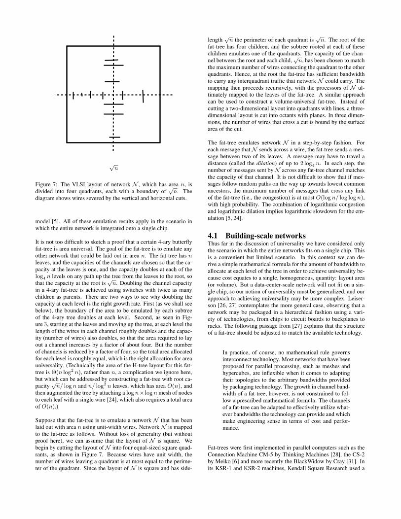
Figure 7: The VLSI layout of network N , which has area n, isdivided into four quadrants, each with a boundary of
√n. The
diagram shows wires severed by the vertical and horizontal cuts.
model [5]. All of these emulation results apply in the scenario inwhich the entire network is integrated onto a single chip.
It is not too difficult to sketch a proof that a certain 4-ary butterflyfat-tree is area universal. The goal of the fat-tree is to emulate anyother network that could be laid out in area n. The fat-tree has nleaves, and the capacities of the channels are chosen so that the ca-pacity at the leaves is one, and the capacity doubles at each of thelog4 n levels on any path up the tree from the leaves to the root, sothat the capacity at the root is
√n. Doubling the channel capacity
in a 4-ary fat-tree is achieved using switches with twice as manychildren as parents. There are two ways to see why doubling thecapacity at each level is the right growth rate. First (as we shall seebelow), the boundary of the area to be emulated by each subtreeof the 4-ary tree doubles at each level. Second, as seen in Fig-ure 3, starting at the leaves and moving up the tree, at each level thelength of the wires in each channel roughly doubles and the capac-ity (number of wires) also doubles, so that the area required to layout a channel increases by a factor of about four. But the numberof channels is reduced by a factor of four, so the total area allocatedfor each level is roughly equal, which is the right allocation for areauniversality. (Technically the area of the H-tree layout for this fat-tree is Θ(n log2 n), rather than n, a complication we ignore here,but which can be addressed by constructing a fat-tree with root ca-pacity
√n/ logn and n/ log2 n leaves, which has area O(n), and
then augmented the tree by attaching a logn× lognmesh of nodesto each leaf with a single wire [24], which also requires a total areaof O(n).)
Suppose that the fat-tree is to emulate a network N that has beenlaid out with area n using unit-width wires. NetworkN is mappedto the fat-tree as follows. Without loss of generality (but withoutproof here), we can assume that the layout of N is square. Webegin by cutting the layout ofN into four equal-sized square quad-rants, as shown in Figure 7. Because wires have unit width, thenumber of wires leaving a quadrant is at most equal to the perime-ter of the quadrant. Since the layout of N is square and has side-
length√n the perimeter of each quadrant is
√n. The root of the
fat-tree has four children, and the subtree rooted at each of thesechildren emulates one of the quadrants. The capacity of the chan-nel between the root and each child,
√n, has been chosen to match
the maximum number of wires connecting the quadrant to the otherquadrants. Hence, at the root the fat-tree has sufficient bandwidthto carry any interquadrant traffic that network N could carry. Themapping then proceeds recursively, with the processors of N ul-timately mapped to the leaves of the fat-tree. A similar approachcan be used to construct a volume-universal fat-tree. Instead ofcutting a two-dimensional layout into quadrants with lines, a three-dimensional layout is cut into octants with planes. In three dimen-sions, the number of wires that cross a cut is bound by the surfacearea of the cut.
The fat-tree emulates network N in a step-by-step fashion. Foreach message that N sends across a wire, the fat-tree sends a mes-sage between two of its leaves. A message may have to travel adistance (called the dilation) of up to 2 log4 n. In each step, thenumber of messages sent byN across any fat-tree channel matchesthe capacity of that channel. It is not difficult to show that if mes-sages follow random paths on the way up towards lowest commonancestors, the maximum number of messages that cross any linkof the fat-tree (i.e., the congestion) is at most O(logn/ log log n),with high probability. The combination of logarithmic congestionand logarithmic dilation implies logarithmic slowdown for the em-ulation [5, 24].
4.1 Building-scale networksThus far in the discussion of universality we have considered onlythe scenario in which the entire networks fits on a single chip. Thisis a convenient but limited scenario. In this context we can de-rive a simple mathematical formula for the amount of bandwidth toallocate at each level of the tree in order to achieve universality be-cause cost equates to a single, homogeneous, quantity: layout area(or volume). But a data-center-scale network will not fit on a sin-gle chip, so our notion of universality must be generalized, and ourapproach to achieving universality may be more complex. Leiser-son [26, 27] contemplates the more general case, observing that anetwork may be packaged in a hierarchical fashion using a vari-ety of technologies, from chips to circuit boards to backplanes toracks. The following passage from [27] explains that the structureof a fat-tree should be adjusted to match the available technology.
In practice, of course, no mathematical rule governsinterconnect technology. Most networks that have beenproposed for parallel processing, such as meshes andhypercubes, are inflexible when it comes to adaptingtheir topologies to the arbitrary bandwidths providedby packaging technology. The growth in channel band-width of a fat-tree, however, is not constrained to fol-low a prescribed mathematical formula. The channelsof a fat-tree can be adapted to effectivelty utilize what-ever bandwidths the technology can provide and whichmake engineering sense in terms of cost and perfor-mance.
Fat-trees were first implemented in parallel computers such as theConnection Machine CM-5 by Thinking Machines [28], the CS-2by Meiko [6] and more recently the BlackWidow by Cray [31]. Inits KSR-1 and KSR-2 machines, Kendall Square Research used a
hierarchy of rings, which has at times been called a fat-tree (see,e.g., [10]).
The coarse structure of the CM-5 was a complete 4-ary tree, con-structed using two types of switches. Every switch had four chil-dren, but the number of parents could be either two or four. Think-ing Machines exploited the flexible structure of fat-trees to matchengineering constraints, as explained in the following passage from [28].The passage uses the term “router chip” synonymously with theterm “switch” in this paper.
Based on technology, packaging, and cost considera-tions, the CM-5 bandwidths are as follows. Each pro-cessor has 2 connections to the data network, corre-sponding to a raw bandwidth of 40 megabytes/secondin and out of each processing node. In the first two lev-els, each router chip uses only 2 parent connections tothe next higher level, yielding an aggregate bandwidthof 160 megabytes/second out of a subtree with 16 pro-cessing nodes. All router chips higher than the secondlevel use all 4 parent connections, which, for example,yields an aggregate bandwidth of 10 gigabytes/second,in each direction, from one half of a 2K-node systemto the other.
4.2 Provisioning cost-universal networksThe proof that a data-center-scale fat-tree is cost universal cannotstrictly follow the proof that a certain fat-tree is area or volumeuniversal. While it is amusing to contemplate cutting a data cen-ter building into octants and allocating as many cables to the rootchannels of the fat-tree as can possibly cross the surface area of thecorresponding cut, the analogy with the VLSI model doesn’t en-tirely hold up. The biggest difference is that in the VLSI model thecost of a wire, i.e., the area or volume that it occupies, is exactlyequal to the length of the wire. Furthermore, the area or volumedevoted to a wire often dominates that devoted to the circuitry thatdrives the wire. In a data center, different cabling technologies, e.g.,copper versus optical fiber, impose different limits on the lengthsof cables, and vary in transmission speed, cost, weight, and vol-ume. While weight and volume are proportional to length, cost canbe better modeled as the sum of a fixed-cost term and a term pro-portional to length [21]. The fixed cost, which includes the costof ports and line cards, is higher for optical cables than for electri-cal cables, but the cost per meter is lower. The operational cost ofwiring the cables, which depends on the complexity of the networkdesign, may also be significant. In Section 5, we discuss currentcabling and switch port costs.
On the other hand, whereas VLSI layout technology offers a net-work designer the freedom to create arbitrary structures within thearea bounds of a chip, there are many practical constraints that limitthe options of a data center network designer, including, most im-portantly, the technologies available at low cost at the time of thedesign. At the endpoints of the network, the best price-performanceratio is achieved by installing commodity servers, or in any caseservers composed of commodity processors on commodity moth-erboards. In a denser installation, server blades might be pluggedinto a blackplane, which could implement a high-speed networkthat connects the blades and also interfaces with the rest of the net-work. Servers are typically housed in racks, and the best price-performance ratio approach to connecting the servers within a rackis often achieved by using a switch or router. Racks are organized
in rows (for ventilation and wiring purposes), and the same sorts ofswitches and routers can be used to connect the racks within a row,or to connect different rows.
The cost-universal approach to data center design leverages the factthat a data center network designer makes investments in only asmall number of connectivity categories. For any network thatis implemented in practice, the designer must decide how muchmoney to spend connecting processors or servers within racks, howmuch to spend connecting racks within a row, and finally, howmuch to spend connecting the rows. To build a cost-universal net-work, the designer allocates roughly the same amount of money toeach of these categories, heeding physical constraints such as limitson the weight of cables that can be carried from one row to another.When physical constraints prevent the designer from spending anequal amount on all levels (due to weight, volume, or wiring com-plexity), the designer’s goal is then to spend as close as possible toan equal amount.
For the purposes of our approach, the differences in the intercon-nection patterns of fat-trees, multi-fat-trees, folded Clos networks,etc., are not especially significant. What is required is that the cho-sen class of networks can be configured in a hierarchical fashionwith a small number of levels in the hierarchy. A second require-ment is that it must be possible to allocate bandwidth at each levelof the hierarchy as a function of the costs and engineering con-straints of the networking technology, e.g. maximum wiring lengthand wiring volume, that is most appropriate for implementing thatlevel. Finally, the path in the network from one leaf to anothershould travel no higher than their least common ancestor, and thenetwork and its routing algorithm must provide an effective loadbalancing mechansim so that any bandwidth allocated at a particu-lar level can be fully utilized.
We are now in a position to argue that a network such as a fat-treein which an equal amount has been invested symmetrically in eachlevel of the hierarchy (e.g., within the racks, between the racks,between the rows) is cost universal. As in the proof that certain fat-trees are area universal, we describe an emulation. Suppose thatthe cost-universal network is to emulate a networkN that has beenimplemented at the same cost. We assume that N is a roughlysymmetric network, i.e., there is no rack that is much better con-nected internally than any other rack, there is no row that is muchbetter connected internally than any other row, and each row hasroughly the same amount of connectivity to the rest of the network.This assumption is limiting, but virtually all proposed data centernetworks are symmetric. Consider an application A that is exe-cuting on N , and now imagine instead that the same applicationA is executed on the cost-universal network. How much slowerwill it run? Suppose that the performance of A is limited by anetwork bandwidth bottleneck in some category, e.g., the links be-tween racks in a row are saturated. (If instead, the performanceof A is limited by the latency of N , then it should not be muchmore limited by the latency of the cost-universal network, which isa shallow hierarchical network.) The cost-universal network has alevel in its hierarchy for each category of connectivity in N , andcan use all of its bandwidth efficiently. Because there are only asmall number of levels in the hierarchy (e.g., four), even if the de-signer of N invested everything in this single bottleneck category,the designer of the cost-universal network has made at least onefourth of the same investment in the corresponding level of the hi-erarchy. We assume that this one-fourth investment will provideapplication A with at least one fourth the bandwidth, and hence at
most a factor of four slowdown. (In practice, it is not strictly truethat the optimal price/performance ratio is constant for all levelsof investment. The price/performance ratio might change at inflec-tion points where different technologies requiring different mini-mum investments are employed. If a small increase in investmentwould allow the designer to switch to a technology with a betterprice/performance ratio, it might make sense to invest a little more.)While a factor of four (in this example) certainly matters in prac-tice, this worst-case slowdown would apply only if the designerknew the application in advance of building the network, and theapplication had a communication pattern that exclusively exercisedone category of connectivity. The fact that such an upper bound ap-plies to all application running on all possible networks that couldbe built at the same cost is an indication that the cost-universal net-work is a sound general-purpose design.
Of course if the application or applications to be executed in a datacenter are all known in advance, it may make sense to design acustom network with the aim of optimizing these applications. Inthis case, a cost-universal network can serve as a design startingpoint, and the capacities of the channels at different levels of thehiearchy can be adjusted to match the demands of the applications.
Another important cost to consider when designing a network is thecost of developing the software for the applications that will run onthe network. Blelloch et al. [8] argue that achieving good perfor-mance on networks with low bisection bandwidth requires carefullyengineering algorithms that are specialized to the network architec-ture, which is an expensive and time-consuming process. Hence, alarger investment in the wiring of the upper levels of the hierarchymay be offset by savings in software development costs. This ar-gument does not contradict the universality argument presented inthis paper. Instead, it suggests that in determining the total budgetfor building a network, the impact on future software developmentcosts should be taken into consideration.
5. PRACTICAL ISSUESThe art of designing a realizable and cost-effective data center net-work requires a careful blending of theory and practical concerns.Previous sections have reviewed some of the applicable theory, andwe now turn to some of the important of the practical issues.
As previously pointed out, the overall network serves as one large“switch” made of ASICs (switching elements) connected togetherby a variety of motherboard traces, backplanes, or cables (links)and knit together by software (the control plane) [26]. Due to spaceconstraints, we examine the ASICs, backplanes, and cable, leavingthe software for future work. We examine several large data centersbuilt by a major online services company, analyzing the spent ateach of the layers.
5.1 Trends in ASIC Design“Commodity” switching has been revolutionized by single-chip switchASICs with astonishing performance. Each switch ASIC genera-tion is usually opened by a new fabrication node, just like CPUs.This sets how many transistors the switch designer has to work withon a cost effective die-area of silicon.
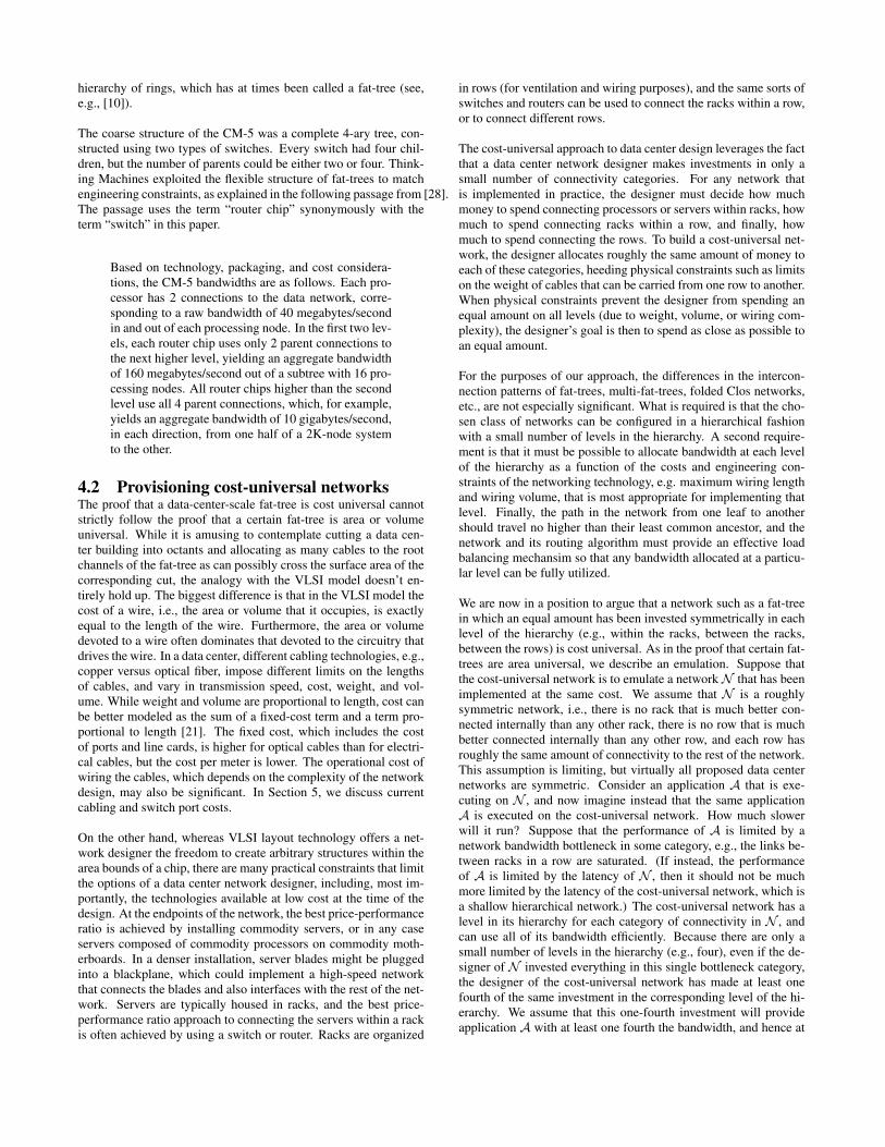
The trend is to spend these transistors on more links, faster links,and integrating more elements of a physical switch onto the chip(e.g., the SERDES). As a result, designers have spent fewer transis-tors on buffer space or forwarding features. This trend is illustratedby Table 1 that shows how the number of ports, port speeds, total
Year Ports Throughput Total µs ofBuffer Buffer
2007 24 x 1Gbps, 4 x 10 Gbps 64Gbps 2MB 2502009 48 1Gbps, 4 10Gbps 88Gbps 4MB 3632009 24 10Gbps 240 Gbps 4MB 1332011 64 10Gbps 640 Gbps 9MB 1122013 32 40Gbps or 128 10Gbps 1.2Tbps 9MB 56
Table 1: Timeline of ASIC port counts, speeds, buffer size, and howmany microseconds of buffer are available per port if each port isoutputting at maximum utilization.
buffer, and buffer per port have changed over multiple generationsof switch ASICs.
Continuing the similarities with CPUs, since the die area of eachgeneration of switch ASIC is roughly the same, the per-unit man-ufacturing cost of each generation is also roughly the same. Likewith CPUs, prices vary greatly depending on a buyer’s volume andmarket relationship, but are probably in the range of $500 - $1,500each.
5.2 ASIC Interconnection StrategiesConsider the challenge faced by a designer wishing to create a net-work that can interconnect 2,048 ports of 10Gbps Ethernet withno oversubscription, and the designer has a switch ASIC with 64ports of 10Gbps available as the basic building block. The designercould create a two layer Clos network of switches, each switch hav-ing 64x10Gbps ports and the two layers of switches connected byfiber links. This would consume 64 switches in one layer and 32switches in the other for a total of 96 switches and 2,048 cablesinside the Clos. Alternatively, the designer could first assemble aset of ASICs into a 128x10Gbps switch, creating a Clos networkamong the ASICs using traces on a PCB motherboard, and thenbuild a network using these 128x10Gbps switches.
The challenge faced by commodity network device vendors is toassemble a collection of switch ASICs into a switch that they cansell profitably to a large market. Since the complexity is higher andthe market smaller for a multi-chip switch, the per-port cost of sucha multi-chip switch is usually higher than the costs for a networkdevice housing a single switch ASIC. This can be counter-intuitive,given that the cost of traces between multiple switch ASICs on amotherboard are much cheaper than wires in the backplane of amulti-motherboard switch, which are much cheaper than the cost offiber or copper connection between two physical separate networkdevices.
To give some feel for the costs: motherboard traces are so cheapas to be essentially free. The cost of a switch chassis containinga roughly 4Tbps backplane is on the order of $50K, or $125 per10Gbps. The cost of a 10Gbps fiber cable, with optical modules oneach side, is roughly $200. A copper-based Direct Attach Copper(DAC) 10Gbps cable, which can used up for distances up to about5m, costs about $50-$100 (one problem with DAC cables is theirvolume, which is significantly larger per cable than fiber).
This means that today, any network that can be built using singleASIC switches within about 5m of each other connected by coppercables is the cheapest way to build such a network. Above that size,the use of multi-ASIC switches starts to become cost effective.
Active Optical Cables (AOCs) are changing the game, however. At
a cost around $125, AOCs provide 10 or even 40Gbps over 3mto 20m of fiber. They achieve this feat by hermetically sealingthe fiber to the optical modules, which enables them to use non-standard lasers or even LEDs. The major drawback is a deploymentissue — the cables have to be pulled or otherwise installed with theoptical modules attached.
Planning for the cabling between switches is a first order concernin any network design, but especially in designs like those we de-scribe. Physically running the cables needed to realize these de-signs is quite possible, but does require carefully computing theweight and volume of all the cable paths so that properly sized hor-izontal and vertical cables trays can be installed. Failure to planahead has led fibers to overflow and spill out of cable managers, re-sulting in such a mess that the network layout had to be redesignedand recabled.
Similarly, the cost of cables and cabling needs to be accounted forin the design process. For example, consider building a networkusing three layers of single ASIC switches or two layers of multi-ASIC switches (each switch then having a higher radix than a sin-gle ASIC switch). The network with three layers of single ASICswitches will use fewer ASICs than a similarly sized network withmulti-ASIC switches. However, the three-layer network uses twiceas many physical cables, and is much harder to construct.
5.3 CostsWhile we have some data on the costs of data center components,we do not have enough information to fully flesh out the designof a cost-universal network. However, we were able to obtain,from a large on-line services provider, the relative capital expenseson each tier (top-of-rack, aggregation switch, spine switch) of twogenerations of production networks. Interestingly, the data suggeststhat, in practice, network designers are now roughly following our“equal cost per tier of the hierarchy” suggestion. The cost of thecables to connect two layers is included with the cost of the layerabove (e.g., server to ToR cables are included in the cost of theToR layer, and ToR to Aggregation cables are included in the costof the Aggregation layer). In a network over 4 years old with arelatively high oversubscription ratio, the ratio of the cost of thenetwork layers was 6:2:1 ($6 spent on top-of-rack switches and $2on aggregation switches for every dollar spent on spine switches).For newer networks with lower oversubscription ratios, we foundthe ratio to be close to 2:2:1. As predicted by the model, the factordriving the equalization of cost is the increased expense for cablesin the networks with less oversubscription.
6. CONCLUSIONAs we enter an era of ubiquitous cloud computing and online ser-vices, investment in data centers is going to be enormous. It is in-cumbent on the networking community, therefore, to develop prin-cipled methods for designing data center networks. In this vein, wehave suggested a rule for allocating resources to the tiers of hierar-chical networks: roughly equal investment at each tier. Our focus ison network bandwidth and the cost, volume, and wiring complexityof the network. There are numerous other important considerations,however. For example, the network designer must also address thecooling, energy consumption, latency, fault tolerance, and manage-ment of the network. At the moment we do not see any reasonswhy addressing these issues will conflict with our cost-universalapproach. Further confirmation, however, will require a completeand holistic design of a cost-universal network.
7. REFERENCES[1] M. Ajtai, J. Komlós, and E. Szemerédi. Sorting in c logn parallel
steps. Combinatorica, 3:1–19, 1983.[2] M. Al-Fares, A. Loukissas, and A. Vahdat. A scalable, commodity
data center network architecture. In Proceedngs of SIGCOMM 2008.[3] S. Arora, F. T. Leighton, and B. M. Maggs. On-line algorithms for
path selection in a non-blocking network. SIAM Journal onComputing, 25(3):600–625, June 1996.
[4] L. A. Bassalygo, I. I Grushko, and V. I. Neiman. The structures ofone-sided connecting networks. In Proceedings of the 6thInternational Teletraffic Congress, pages 245/1–245/9, September1970.
[5] P. Bay and G. Bilardi. An area-universal circuit. In Proceedings ofthe 1993 Symposium on Research on Integrated Systems.
[6] J. Beecroft, M. Homewood, and M. McLaren. Meiko CS-2interconnect Elan-Elite design. Parallel Computing,(10–11):1627–1638, November 1994.
[7] V. E. Beneš. Mathematical Theory of Connecting Networks andTelephone Traffic. Academic Press, New York, 1965.
[8] G. E. Blelloch, B. M. Maggs, and G. L. Miller. The hidden cost oflow bandwidth communication. In U. Vishkin, editor, Developing aComputer Science Agenda for High-Performance Computing, pages22–25. ACM Press, 1994.
[9] T. L. Bowers. Blocking in 3-stage “folded” switching arrays. IEEETransactions on Communication Technology, 13(1):14–37, March1965.
[10] E. L. Boyd and E. S. Davidson. Communication in the ksr1 mpp:Performance evaluation using synthetic workload experiments. InProceedings of the 8th ACM International Conference onSupercomputing, pages 166–176, July 1994.
[11] T. Callahan and S. C. Goldstein. NIFDY: A low overhead, highthroughput network interface. In Proceedings of ISCA 1995.
[12] D. Chiou, B. S. Ang, R. Greiner, Arvind, M. J. Beckerle, James E.Hicks, and G. A. Boughton. StarT-NG: Delivering seamless parallelcomputing. In Proceedings of EURO-PAR ’95.
[13] C. Clos. A study of non-blocking switching networks. Bell SystemTechnical Journal, 32:406–424, 1953.
[14] A. Curtis, S. Keshav, and A. Lopez-Ortiz. LEGUP: Usingheterogeneity to reduce the cost of data center network upgrades. InProceedings of CoNEXT 2010.
[15] A. V. Goldberg, B. M. Maggs, and S. A. Plotkin. A parallel algorithmfor reconfiguring a multibutterfly network with faulty switches. IEEETransactions on Computers, 43(3):321–326, March 1994.
[16] A. Greenberg, N. Jain, S. Kandula, C. Kim, P. Lahiri, D. A. Maltz,P. Patel, and S. Sengupta. VL2: A scalable and flexible data centernetwork. In Proceedings of SIGCOMM 2009.
[17] R. I. Greenberg. Efficient Interconnection Schemes for VLSI andParallel Computation. PhD thesis, Department of ElectricalEngineering and Computer Science, Massachusetts Institute ofTechnology, Cambridge, MA, August 1989.
[18] R. I. Greenberg and C. E. Leiserson. Randomized routing onfat-trees. In Silvio Micali, editor, Randomness andComputation.Volume 5 of Advances in Computing Research, pages345–374. JAI Press, Greenwich, CT, 1989.
[19] C. Guo, G. Lu, D. Li, H. Wu, X. Zhang, Y. Shi, C. Tian, Y. Zhang,and S. Lu. Bcube: A high performance, server-centric networkarchitecture for modular data centers. In Proceedings of SIGCOMM2009.
[20] C. Guo, H. Wu, K. Tan, L. Shi, Y. Zhang, and S. Lu. DCell: Ascalable and fault-tolerant network structure for data centers. InProceedings of SIGCOMM 2008.
[21] John Kim, Wiliam J. Dally, Steve Scott, and Dennis Abts.Technology-driven, highly-scalable dragonfly topology. InProceedings of ISCA 2008.
[22] F. T. Leighton. Introduction to Parallel Algorithms andArchitectures: Arrays • Trees • Hypercubes. Morgan Kaufmann, SanMateo, CA, 1992.
[23] F. T. Leighton and B. M. Maggs. Fast algorithms for routing aroundfaults in multibutterflies and randomly-wired splitter networks. IEEETransactions on Computers, 41(5):578–587, May 1992.
[24] F. T. Leighton, B. M. Maggs, A. G. Ranade, and S. B. Rao.
Randomized routing and sorting on fixed-connection networks.Journal of Algorithms, 17(1):157–205, July 1994.
[25] C. E. Leiserson. Fat-trees: universal networks for hardware-efficientsupercomputing. IEEE Transactions on Computers,C–34(10):892–901, October 1985.
[26] C. E. Leiserson. VLSI theory and parallel supercomputing. InAdvanced Research in VLSI 1989: Proceedings of the DecennialCaltech Conference on VLSI, March 1989.
[27] C. E. Leiserson. VLSI theory and parallel supercomputing. TechnicalMemo MIT/LCS/TM-402, MIT Laboratory for Computer Science,Cambridge, MA, May 1989.
[28] C. E. Leiserson, Z. S. Abuhamdeh, D. C. Douglas, C. R. Feynman,M. N. Ganmukhi, J. V. Jill, W. D. Hillis, B. C. Kuszmaul, M. A. St.Pierre, D. S. Wells, M. C. Wong-Chan, S.-W. Yang, and R. Zak. Thenetwork architecture of the connection machine CM-5. Journal ofParallel and Distributed Computing, 33(2):145–158, March 1996.
[29] Carver A. Mead and Martin Rem. Cost and performance of VLSIcomputing structures. Technical report, California Institute ofTechnology, Pasadena, CA, April 1978.
[30] R. N. Mysore, A. Pamboris, N. Farrington, N. Huang, P. Miri,S. Radhakrishnan, V. Subramanya, and A. Vahdat. Portland: Ascalable fault-tolerant layer 2 data center network fabric. InProceedings of SIGCOMM 2009.
[31] S. Scott, D. Abts, J. Kim, and W. J. Dally. The BlackWidowhigh-radix Clos network. In Proceedings of ISCA 2006.
[32] A. Singla, C.-Y. Hong, L. Popa, and P. B. Godfrey. Jellyfish:Networking data centers randomly. In Proceedings of NSDI 2012.
[33] E. Upfal. An O(logN) deterministic packet routing scheme. Journalof the ACM, 39(1):55–70, January 1992.
[34] L. G. Valiant and G. J. Brebner. Universal schemes for parallelcommunication. In Conference Proceedings of the Thirteenth AnnualACM Symposium on Theory of Computing, May 1981.