A turbo coded multiple description system for multiple antennas
26
A Turbo Coded Multiple Description System for Multiple Antennas Israfil Bahceci and Yucel Altunbasak Tolga M. Duman Multimedia Computing and Communications Laboratory Telecommunications Research Center School of Electrical and Computer Engineering Department of Electrical Engineering Georgia Institute of Technology Arizona State University Atlanta, GA, 30318 Tempe, AZ, 85287 {bahceci,yucel}@ece.gatech.edu [email protected] Abstract We propose a joint source-channel coding scheme for wireless communication systems with mul- tiple transmit and receive antennas. The source coder is realized by a multiple description encoder that generates multiple bit streams of the same source. Each description is then separately turbo coded and transmitted using multiple antennas. For the receiver, we describe a suitable iterative joint source-channel decoding technique that exploits the correlations between the descriptions. Finally, we present several examples that illustrate the performance of the proposed system and compare it with other approaches. Keywords: Joint source-channel coding, wireless communications, multiple antennas, turbo coded modulation, iterative decoding.
Transcript of A turbo coded multiple description system for multiple antennas

A Turbo Coded Multiple Description System for MultipleAntennas
Israfil Bahceci and Yucel Altunbasak Tolga M. DumanMultimedia Computing and Communications Laboratory Telecommunications Research Center
School of Electrical and Computer Engineering Department of Electrical EngineeringGeorgia Institute of Technology Arizona State University
Atlanta, GA, 30318 Tempe, AZ, 85287{bahceci,yucel}@ece.gatech.edu [email protected]
Abstract
We propose a joint source-channel coding scheme for wireless communication systems with mul-
tiple transmit and receive antennas. The source coder is realized by a multiple description encoder
that generates multiple bit streams of the same source. Each description is then separately turbo
coded and transmitted using multiple antennas. For the receiver, we describe a suitable iterative joint
source-channel decoding technique that exploits the correlations between the descriptions. Finally,
we present several examples that illustrate the performance of the proposed system and compare it
with other approaches.
Keywords: Joint source-channel coding, wireless communications, multiple antennas, turbo coded
modulation, iterative decoding.

1 Introduction
The traditional design of a communication system makes use of the Shannon’s source-channel separation
theorem [1]. That is, source and channel coders are designed separately. However, for (practical) mul-
timedia communications over wireless channels, the assumptions held in the separation theorem (e.g.,
infinite delay and complexity) are not directly applicable, which implies that the joint design of channel
and source coding may achieve a better performance. Therefore, joint source-channel codecs have taken
considerable attention and various methods have already been developed [2–6].
A particular source coding method, known as multiple description coding (MDC), can be viewed as a
joint source – channel coding technique. MDC generates multiple bitstreams, also called descriptions, of
a source so that various quality levels of reconstruction can be obtained from any subset of the descrip-
tions. The descriptions are transmitted over independent channels with the hope that upon the reception
of all or some of the descriptions, a superior or an acceptable quality reconstruction is possible. This
can be accomplished by introducing a certain amount of correlation between the individual descriptions.
In an ideal transform coding, the aim is to represent the signal as efficiently as possible by removing all
the redundancy. However, in this case, it is difficult to estimate the parts that are lost from those that
remain. Introducing redundancy among the transform domain coefficients can provide robustness against
such losses. There are various methods of implementing MDC. A practical approach, known as multiple
description scalar quantization (MDSQ), is to use a pair of scalar quantizers that generates two indices
(descriptions) of a source sample [7]. The quantization levels and index assignment are designed such
that if only one index is received, the quantizer functions as a coarse quantizer, but if both indices are
received, it functions as a fine quantizer. Another MDC scheme uses correlating transforms: Multiple
Description Transform Coding (MDTC) [8, 9, 10]. In [8], a rotation matrix was applied to create pair-
wise correlation between the uncorrelated variables obtained using the Karhunuen-Loeve transform. This
method is studied in a generalized framework in [9] and [11]. Other techniques of multiple description
coding uses the lapped orthogonal transform framework [12] and projections onto convex sets framework
[13].
The MDC has been extensively studied for “on-off” channels, such as the Internet, assuming that there
exists multiple independent channels that either provide error-free transmission or experience total failure.
2

However, this assumption is not suited to wireless channels. Such impairments as fading and multipath
propagation cannot simply be abstracted as “on-off" type channel. Yang and Vaishampayan [14] showed
that the performance of an MDSQ-based system dominates that of a channel-code based system for delay-
constrained slow-fading channels. Another attempt on the use of multiple description coding for wireless
systems is made in [15, 16]. In [15], the authors propose the transmission of multiple descriptions over
a wireless link using multiple transmit and receive antennas. A recent interesting approach makes use of
the dependencies in descriptions [17]; in this work, Sirinavasan considers the transmission of multiple
descriptions over a noisy channel model, and proposes an iterative decoding algorithm based on turbo
coding concepts, which exploits the correlation between the descriptions.
Noting that MDC requires multiple independent paths, we naturally consider multiple antenna systems
where we can obtain multiple independently fading channels. Deploying multiple antennas has long been
known to be an effective technique to provide spatial diversity for combating the destructive effects of
multipath fading. It has also recently been shown that using multiple antennas can enhance the capacity
of the wireless channels dramatically [18, 19]. To exploit this capacity, various coded modulation tech-
niques, which are known as space-time codes, have been proposed [20, 21, 22]. Such coding schemes are
promising high rate communications to be practical over wireless channels and it is a challenging goal to
assess the usability and performance of MDC with these methods, since MDC can be effectively used for
transmitting multimedia information such as speech, image and video.
With this motivation, we propose a joint source-channel coding scheme that combines multiple de-
scription coding with the space-time turbo coded modulation (TCM). Each description obtained with
MDC is independently turbo coded and transmitted via multiple antennas over the wireless channel. At
the decoder, we employ an iterative joint source-channel decoding (JSCD) technique in which we ex-
ploit the correlation (induced by the multiple description code) among the descriptions by exchanging the
information between the source and channel codes. We provide performance comparisons (in terms of
bit error rates and mean square error distortions) between the joint source-channel decoding of multiple
descriptions and the decoding where the correlation between the descriptions are not taken into account.
We also compare the performance of the multiple description coding system with the conventional single
description system with the same data rate. We observe that the joint source-channel decoder outperforms
the decoder that does not use correlations among the descriptions. Further, the simulations show that the
3
system using the multiple description coding performs significantly better than the system that use a sin-
gle description coding scheme for moderate levels of signal-to-noise ratios. At high signal to noise ratios,
the latter system performs better in terms of the mean square error distortion.
The rest of the paper is organized as follows: Section 2 provides a short background on the multi-
ple description coding schemes that will be used throughout the paper. In Section 3, we describe the
transmission system involving MDC, multiple antenna link, and the turbo coded modulation for systems
employing antenna diversity. In Section 4, we propose a suitable joint source-channel decoding algorithm
based on turbo decoding concepts. We present numerical examples in Section 5 and finally summarize
our conclusions in Section 6.
2 Review of Multiple Description Coding Schemes - MDSQ and MDTC
Although we may use a variety of multiple description encoding schemes [7, 9, 12, 13], in this work, in
order to produce two correlated descriptions of the source samples, we will consider the use of multiple
description scalar quantization (MDSQ) introduced in [7] and Multiple Description Coding using pairwise
correlating transforms (MDTC) first proposed by [8]. In this and the following subsections, we will briefly
describe the MDSQ and MDTC, respectively.
2.1 Multiple Description Scalar Quantization
The block diagram of the MDSQ is shown in Figure 1. As depicted, each source sample is input to a
cascade connection of a quantizer block q(·) and index assignment block a(·).
Let X denote a stationary and ergodic random process with zero mean and variance σ2X that generates
our source symbols. The encoder of an MDSQ operates as follows: First, the source sample is mapped to
an index l using an N -level quantizer q(·) which is defined using a threshold vector t = (t0, t1, · · · , tN )
such that q(x) = i if x ∈ [ti−1, ti), i = 1, 2, · · · , N . Quantization is followed by an index assignment
a(·) by which each index l is mapped to a pair of indices (i, j) ∈ J whereJ ⊆ I1 × I2 and the individual
indices i ∈ I1 = {1, 2, · · · ,M1} and j ∈ I2 = {1, 2, · · · ,M2}. We are considering balanced MDSQ’s,
therefore we assume M1 = M2 = M where M is the number of indices for each description. In this
case, the rate is R = log2(M) bpss (bit per source sample) for each description. The MDSQ is mainly
4

IndexEncoder
IndexEncoder
.a().q()
j
X
(b b ... b )2
(b b ... b )1 1 1
i
1 2 R
R21
2 2
Figure 1: Block diagram for the MDSQ.
Table 1: Examples of MDSQ index assignment for R = 3 b/s, M1 =M2 = 8.
i/j 1 2 3 4 5 6 7 81 1 22 3 43 5 64 7 85 9 106 11 127 13 148 15
i/j 1 2 3 4 5 6 7 81 1 22 3 4 63 5 7 84 9 10 115 12 146 13 15 167 17 18 208 7 19 21
(a) (b)
devised for an “on-off" channel model, however, it was shown in [14] that one can apply the multiple
description quantizer for Rayleigh fading channels as well.
The generation of the indices is an important task in the design of MDSQ schemes. In [7], for on-off
channels, design algorithms to generate good index assignments resulting in the optimum (exponential
side and central distortion) decay rates have been presented. An example of an index assignment obtained
using these techniques is illustrated in Table 1. The numbers in the table entries correspond to the cells
of a quantizer, which are numbered 1, 2, · · · , N , in increasing order from left to right. The coordinates
of the entry in which l is located is assigned to the quantizer cell l. For example, for the index assign-
ment depicted on Table 1.b, if the source symbol lies in the interval corresponding to the 13th quantizer
cell, then the index pair (5, 6) is transmitted. We note that an index assignment scheme obtained with
the techniques of [7] consists of (2k + 1) diagonals, k = 1/2, 1, 2, · · · , 2R − 2 and the redundancy can
be controlled by varying the number of the non central-diagonals covered by the index assignment. In
general, the amount of correlation between the indices (i, j) decreases as the number of diagonals in the
index assignment is increased. For a given index assignment scheme, it is easy to compute the condi-
tional probabilities P (i|j) or P (j|i) using the threshold values of the quantization and input statistics.
5
T^[ ]. ∆
1x
2x
[x ]
[x ] ∆
∆1
2
Central Decoder
x
x
x
^
^
^
(0)
(1)
(2)
Decoder I
Decoder 2
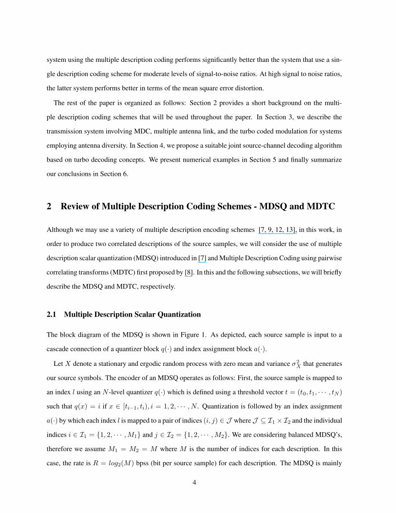
Figure 2: Block diagram for the MDTC.
2.2 Multiple Description Transform Coding
A different technique for multiple description coding was proposed in [8] by Wang et. al. and [23]. This
method makes use of linear transforms to introduce a controlled amount of correlation between the pairs
of random variables. Unlike MDSQ where a scalar source sample is described by the indices produced
by two separate quantizers, MDTC generates multiple streams of a pair of uncorrelated source samples
(or transform coefficients), first by creating some redundancy within the pairs using a correlating trans-
form and then quantizing the resulting pair. Such correlation reinforces the robustness against coefficient
losses, since one can estimate the lost coefficients from those that are received using the correlation.
Consider the transmission of a pair of samples X = (X1, X2)T ∈ C that denote the source descriptions
that are independent real-valued random variables. The block diagram of the MDTC is depicted in Figure
2. In the figure, [·]∆ represents the quantization operator that quantizes the samples to the nearest multiple
of ∆. We note that the quantization is performed before the transform, T , since quantization after the
continuous transform, i.e. Y∆ = [Tx]∆, results in non-square partition cells that are suboptimal [23].
Therefore, the source pairs are first quantized and then using a discrete version of the continuous trans-
form, T , the output vectors (Y1, Y2)T are calculated. The discrete transform T is achieved in two steps:
first, the continuous transform T is represented by a product of upper- and lower-triangular matrices, e.g.,
using LDU decomposition, and second, the transformation is performed with intermediate roundings as
T (x) = [T1[T2[T3x]∆]∆]∆
We can adjust the entries of the transform matrix to achieve any desired redundancy, or ρ, which is defined
to be the additional rate in excess of the minimum average rate R∗ that achieves the minimum average
6

distortion in redundancy rate distortion (RRD) curve. Simple analysis gives [23]
ρ =1
4log
(a211σ21 + a212σ
22)(a
221σ
21 + a222σ
22)
σ21σ22
For brevity, we will not go into the details of the MDTC, instead, we refer the interested reader to
[23]. Here, we wish to focus on the computation of conditional probabilities, i.e., the probability of
second description given the first description, P (Yk2 |Yk1), (k1, k2) ∈ Ck1,k2 , where Ck1,k2 is the set that
is mapped to (k1, k2)∆. The probability of x ∈ Ck1,k2 , pk1,k2 , is given by
P ((Y1, Y2) = (k1, k2)∆) = pk1,k2 =
∫
Ck1,k2
fx1,x2(x1, x2)dx1dx2 (1)
The conditional probability of one of the descriptions given the other follows as
P (Y2 = K2∆|Y1 = K1∆) =pK1,K2
∑
l pK1,l
If the source pairs x = (x1, x2)T have zero mean Gaussian components with variance σ21 and σ22 ,
respectively, then the expression in (1) have a closed form expression in terms of standard error function
pk1,k2=1
4(erf((j1 +
1
2)∆/
√
2σ21)− erf((j1 −
1
2)∆/
√
2σ21)·
(erf((j2 +1
2)∆/
√
2σ22)− erf((j2 −
1
2)∆/
√
2σ22))
where (j1, j2) : T ((j1, j2)∆) = (k1, k2)∆. We will later show in Section 4 how the conditional probabil-
ities can be utilized in the decoding to improve the performance by making use of the residual information
due to correlation between the multiple descriptions.
3 The Transmission System
Assume that we want to transmit the output of a source (such as speech data or image data) over a
wireless link. The sequence of the source symbols is coded into a sequence of information bits using a
multiple description encoder. Each of the descriptions are then channel coded separately using a turbo
code, the encoded bits from individual descriptions are passed through a serial to parallel converter, and
7

π
π
π
E
E
E
E
π
π
s/p
s/p
Description
Multiple
(MDSQ)
0
1
2
3
2
1 3
4
Encoder
Figure 3: Block diagram for the encoder.
.
.
.
hmn
h2n
h11
h12
h1n
hm1
hm2
1
2
.
.
.
h
h
1
2
m
21
22
1+
w
x
2+
w
x
+
w
1
2
2
1
m n xn
n
c
c
c
Figure 4: Multiple antenna link model.
are mapped to the signal constellation. The signals from each description are transmitted from different
transmit antennas simultaneously. The block diagram of the encoder, the components of which will be
explained in more detail in the following subsections, is given in Figure 3.
We assume that there are m transmit and n receive antennas as shown in Figure 4, and that each sub-
channel is Rayleigh fading, that is, the propagation coefficient between different transmit and receive
antenna pairs is a zero mean complex Gaussian random variable. We also assume that the channel is
block fading for which the propagation coefficients remain constant during the coherence time of the
channel, and they are independent of each other from one block to the next [24, 25]
3.1 Space-Time Turbo Coded Modulation with MDC
As shown in Figure 3, the output of the MDC (MDSQ or MDTC) is channel coded using a turbo code
and the encoded bits are then interleaved, passed through a serial to parallel converter, and mapped to a
signal constellation. The signal sequences corresponding to different descriptions are transmitted from
8

different antenna elements. We can obtain various spectral efficiencies by varying constellations and code
rates. We may also employ other channel codes such as convolutional codes that can be decoded using
soft-in soft out decoding algorithms [17]. We may imagine the encoding system as a super turbo code,
with constituent codes being turbo codes – with the exception that the input sequence to one of the codes
is, instead of the interleaved version of the other, a sequence that is correlated with the other.
The interleavers prior to signal mapping is used to decorrelate the log-likelihoods of the consecutive
bits being transmitted and hence, to distribute the burst errors due to a deeply faded block over the entire
frame. We note that there are a total of five different interleavers in the encoder: one for spreading the
encoded bits from each description (π3 and π4), one for each turbo encoder (π1 and π2) and one acting
over one of the descriptions from MDC in order to spread the correlation among the multiple descriptions
over independently faded blocks (π).
3.2 Multiple Antenna Link Model
We are considering a wireless communication link employing m antennas at the transmitter and n anten-
nas at the receiver (see Figure 4). We assume that each propagation coefficient between antenna pairs is
a zero mean complex Gaussian random variable. Also, we assume that the channel is block fading for
which propagation coefficients remain constant during the coherence time of the channel, i.e., during L
symbol periods, and they are independent from one block to the next. At time t, the received signal at the
jth receive antenna, xj(t), can be written as
xj(t) =
√
ρ
M
M∑
i=1
hijci(t) + wj(t), t = 1, ...L, n = 1, ..., r (2)
where the path gains hij and the noise samples wj(t) are the independent samples of a zero mean and
unit variance circularly symmetric complex Gaussian random variable. The transmitted signals ci(t)
can be chosen from an arbitrary signal constellation. The average energy of transmitted signal at time
t is normalized to unity over m antennas so that ρ is the expected signal to noise ratio at each receiver
antenna. In vector form, the above equation can be expressed as
X =
√
ρ
mHC+W (3)
9

where X is the n × 1 received signal vector, C is the m × 1 transmitted signal vector, H is the n ×m
channel transfer matrix and W is the n × 1 additive white Gaussian noise vector. We assume the the
CSI is known at the receiver. Given C and H, the vector X is a zero-mean circularly symmetric complex
Gaussian vector. The conditional probability density function of X is given by [26]
p(X|C,H) =1
πne−tr
{
(X−√ρ/mHC)(X−
√ρ/mHC)H
}
. (4)
4 Joint Source-Channel Decoding of the MDC with TCM
In this section, we will present a suboptimal joint source-channel decoding algorithm for the above system
adopted from [27]. The correlation introduced by the multiple description encoder will be exploited
via iterative decoding process that passes extrinsic information between the channel decoder and source
decoder.
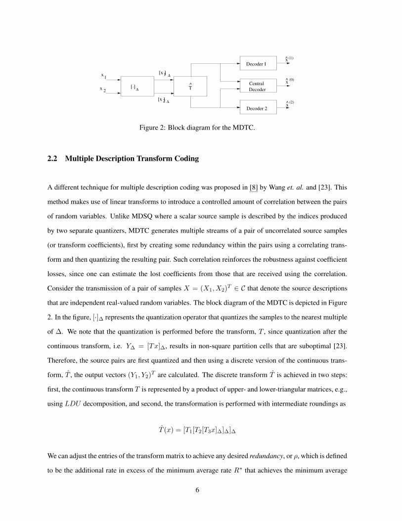
The block diagram of the receiver is given in Figure 5. There are two turbo decoding blocks associated
with the two turbo encoders. Decoding of any of the turbo coded modulation schemes is similar to the
decoding algorithm given in [22, 28, 29]. We first compute the log-likelihoods of the transmitted bits, and
then use them in the standard iterative turbo decoding as if they are the log-likelihoods of the observation
from a BPSK modulation over an additive white Gaussian noise channel. The decoding of the individual
turbo codes is performed as usual. That is, the two maximum a posteriori (MAP) decoders exchange
the extrinsic information between each other at each step of the iterations. However, additional extrinsic
information is also exchanged between the turbo decoders, which will be made clear shortly.
Assume that the size of the constellation is 2Rc , and denote the set of constellation points with
ci, i = 1, · · · , 2Rc . Then each constellation point corresponds to Rc bits and the received signal vector
at time t, xtj , j = 1, 2, · · · , n, corresponds to mRc bits, e = (e1, · · · , em, em+1, · · · , emRc). The bits
(e1, · · · , emRc/2) are the encoded bits of one description and the bits (emRc/2+1, · · · , emRc) are encoded
bits of the other description. Based on the bit block (e(i−1)Rc+1, · · · , eiRc), the signal ci is selected
and transmitted from ith transmit antenna . Using the similar derivation in [22] and (4) , we obtain the
log-likelihood of the lth bit in e
10
x s
x2 px sx1 p x1 p x2 p
y s
y1p
y p2
y s y1p y p2
D D Dπ
π
π
π
π
π 1−
π
0Computationratio
Log−likelihood
1−
1
1
1
12 2
2
1−π
D
2
Turbo Decoder I Turbo Decoder II
3
Figure 5: Block diagram for the iterative joint source-channel decoding of combined multiple descriptioncoding and space-time turbo coded modulation scheme.
Λ(el) = logPr(el = 1|X)Pr(el = 1|X)
The log-likelihood values Λ(e1), · · · ,Λ(emRc/2) are used by the turbo decoder I and
Λ(emRc/2+1), · · · ,Λ(emRc) are used by the turbo decoder II. Both turbo decoders are run in al-
teration and each of them generates the extrinsic information about the input bits, {bil}, l = 1, · · · , R,
i ∈ {1, 2}, corresponding to associated description.
For each of the turbo decoders in Figure 5, if the correlation between descriptions is not considered,
the iterative decoding of each turbo code is performed using standard forward and backward recursion
relations described in [30], and the extrinsic information for both the “present" constituent decoder, Dp,
and the “former" constituent decoder, Df , denoted by Pe(dk = z|Dp) and Pe(dk = z|Df ), respectively,
are computed. The bit dk is the information bit for the transition from step (k − 1) to step k and its a
priori probability, which is exchanged between the constituent decoders, is the key to the success of the
turbo decoding. At each iteration, the extrinsic information Pe(dk = z|Df ) from one of the constituent
decoders is used as the a priori probability of dk in the current MAP decoder.
Assuming that the extrinsic probabilities from the constituent convolutional decoders are independent,
we can write the extrinsic probabilities about the bits in the first description as [31]
Pe{b1l = z|TD1} = KPe{b1l = z|D0}Pe{b1l = z|D1}
where z ∈ {0, 1} and TD1, D0, D1 implies the extrinsic probabilities are from turbo decoder I, MAP
11

decoders 0 and 1, respectively. K is a normalization factor. Similarly, for the second turbo decoder,
Pe{b2l = z|TD2} = KPe{b12 = z|D2}Pe{b2l = z|D3}
When the descriptions are considered independently, both turbo decoders are run as described above
and the extrinsic probabilities due to the constituent decoders are the only information that is exchanged
between the MAP decoders D0/D1 or D2/D3.
In order to exploit the correlation between the descriptions of the MDC, we need to exchange the
additional extrinsic information obtained using the source a priori probabilities. We now focus on the
transfer of information between the turbo decoders I and II. Since the correlation between descriptions is
introduced in the index level, we should perform this transfer in the index level. The extrinsic probabilities
of the MDC indices vi, i = 1, 2, for the first or second description can be computed from the extrinsic
probabilities of the bits constituting that description as:
Pe(vi = I) =
R∏
l=1
Pe(bil|TDi), i ∈ {1, 2}, I = 1, 2, · · · ,M1
where bil is the lth bit in the binary representation of the index for the ith description and we assume that
the bits bi1, · · · , biR are independent. Given the probabilities for one description, the extrinsic probabilities
of the other description can be calculated using the a priori statistics of the source as
Pe(vi = J |TDi′) =
M1∑
k=1
P (vi = J |vi′ = k)Pe(vi′ = k|TDi′),
i, i′ ∈ {1, 2}, J = 1, 2, · · · ,M1
(5)
where the conditional probabilities of the indices P (vi = I|vi′ = J) can easily be computed using the
source p.d.f., threshold vector and the index assignment. We can now compute the extrinsic probabilities
for the information bits constituting this description (index) as
Pe(bir = z|TDp) =
∑
k:bir(k)=z
Pe(vi = k|TDi′), z ∈ {0, 1},
k = 1, · · · ,M1, i ∈ {1, 2}, r = 1, · · · , R(6)
12

where Pe(·|TDp) is extrinsic probability obtained using the extrinsic information from the former turbo
decoder TDi′ and the a priori source statistics, and bir(k) is the rth bit of the index k in the ith descrip-
tion. This probability (i.e., information from the former turbo decoder) is used as an additional extrinsic
information in the current turbo decoder. To achieve this, reverse and backward recursion relations of the
MAP algorithm for the constituent convolutional decoders are modified as shown in [31] such that the
a priori information for dk is obtained using both the extrinsic information from the constituent MAP
decoder and the additional information from the other turbo decoder.
We are now able to describe how the individual components of the joint source-channel decoder are
connected together. As shown in Figure 5, the component decoders D0 or D1 in turbo decoder I (D2 or
D3 in turbo decoder II) takes the log-likelihood values of the corresponding systematic and parity bits
computed by the log-likelihood computation block, the extrinsic information from the other decoder D1
or D0 ( D3 or D2) within the same turbo decoder, and also, takes the additional extrinsic information from
turbo decoder II (turbo decoder I) as computed using (6) , and then uses the MAP decoding algorithm
with the modified decoding to compute the new extrinsic information about the bits in the corresponding
description. At each iteration, the related extrinsic information is passed between the individual MAP
decoders, and between the turbo decoders I and II. The iterations proceed as the extrinsic information is
exchanged between the decoders until a desired performance is achieved at which point a final decision
is made based on the final log-likelihood ratio of information bits. Note that in all these operations, all
the likelihood ratio sequences and received sequences are suitably reordered and delayed.
After stopping the iterations, the final decision for the transmitted indices is made using
(i∗, j∗) = arg max(i,j)∈J
P (i, j) = arg max(i,j)∈J
P (i|j)P (j)
= arg max(i,j)∈J
P (j|i)P (i)
(7)
where P (i) and P (j) are the probabilities of the first and second indices of the MDSQ, respectively,
which are computed using the final log-likelihoods of the constituting bit sequences. Hence, we select the
indices that maximize the joint probability of the possible index pairs in the MDSQ scheme and based on
the decoded index pairs, the transmitted source sample is reconstructed at the receiver.
13

5 Examples
In this section, we present the performance of the proposed scheme using several simulations. The infor-
mation bits are generated either using the MDSQ or MDTC with natural binary code assignment where
we use the binary representations of the indices. The turbo codes in the system consists of two recur-
sive systematic convolutional codes described by the feedforward and feedback generating polynomials
(gn, gd). We assume that the interleaver is pseudorandom, and choose gn and gd to be 5octal and 7octal, re-
spectively, for both turbo codes. We obtain a rate 1/2 code by puncturing the parity bits periodically. The
encoded bits are multiplexed and then interleaved using pseudo random interleavers. In our examples, we
use QPSK modulation at each transmit antenna, and we employ two transmit antennas, each of which is
used to transmit the sequences due to one of the descriptions. We present the results for a receiver with a
single antenna element. We use the iterative decoding algorithm with 8 iterations.
In order to show the effectiveness of the joint source-channel decoding algorithm for the proposed
scheme, we first present the iterative decoding results obtained by using two correlated binary sources,
uik, i ∈ 1, 2 and k = 1, 2, · · · , where the correlation is created in the following way:
• Generate the i.i.d. bit sequence u1k such that P (u1k = 0) = P (u1k = 1) = 1/2.
• Construct the sequence u2k using u2k = u1k ⊕ ek where P (ek = 0) = 1− p and P (ek = 1) = p, and
⊕ is modulo 2 addition.
A measure of correlation between u1 and u2 can be defined in terms of entropy as [32]
ρ = 1− H(u2|u1)H(u1)
= 1− plog2(p)− (1− p)log2(1− p)
From this expression, it is clear that, if p < 1/2 decreases, the correlation between the two sequence
increases.For this case, the extrinsic information exchanged between the turbo decoders is simply
Λe(upk|TDp) = log
{
(1− p)Pe(ufk= 1|TDf ) + pPe(u
fk= 0|TDf )
}
{
(1− p)Pe(ufk= 0|TDf ) + pPe(u
fk= 1|TDf )
}
where the subscripts and superscripts p and f are used to denote the “former" or “present" iteration steps
at which the extrinsic probabilities Pe(uk|TD) from the constituent turbo decoders are obtained.
14

8 9 10 11 12 13 14 15 1610−5
10−4
10−3
10−2
10−1
100
SNR in [dB]
BE
R
Without JSCD With JSCD p=0.1With JSCD p=0.2
Figure 6: Bit error rate vs. SNR for the joint source-channel turbo decoding of correlated sources. Turbocode block size is 1300, m=2 transmit and n=1 receive antennas.
In Figure 6, we present the bit error rate results for the input scenario described above. The size of the
interleavers in the turbo codes are 1300. The path is assumed to be constant for a period of 130 symbols.
We observe that the joint source-channel decoding algorithm taking the source correlation into account
outperforms the standard iterative decoding where we do not exchange between the turbo decoders. At
a BER of 10−4, the joint source-channel decoding provides about 2.7 dB gain when p = 0.1 and about
0.5 dB gain when p = 0.2 over the standard decoding. These results imply that when the amount
of correlation between the source sequences is large, then using the extrinsic information due to the
correlation improves the performance dramatically. If the correlation between the sequences is reduced,
the performance improvement is also reduced, however, we can still expect some gain in exploiting this
correlation.
Next, we present the performance results for the combined multiple description coding and space-time
turbo coded modulation scheme. First, we will consider the use of MDSQ.
15

5.1 Case 1: MDSQ
In the following examples, we will introduce the correlation between the transmitted information se-
quences using various MDSQ schemes. We will also compare the results of iterative decoding of multiple
descriptions to the conventional single description schemes where we employ a single scalar quantization
(with a rate equal to the total rate of the MDSQ scheme) to generate our information sequence and trans-
mit them using the same space-time turbo coded modulation scheme. We note that the source sample
delay for the case of the single description based system equals half of the sample delay for the case
of MDC based system since we want to keep the interleaver sizes (and hence, complexities of the turbo
codes) in both cases almost similar. We also include performance comparisons with a single description
scheme using TCM with the same delay but employing single antenna. For this case, the signals are
selected from a larger constellation to provide the same spectral efficiency.
In Figure 7, we present the bit error rate comparison between the joint source-channel decoding al-
gorithm with the standard turbo decoding. In this example, we use MDSQ with M1 = M2 = 8 (i.e.,
R = 3 bpss/description) and using the index assignment scheme given in Table 1.b. We also plot the
bit error rate for a single description quantization scheme using 64-level uniform quantization (i.e., the
rate is 2R bpss). The channel is a Rayleigh block fading channel where the path gains are constant for a
period of 150 transmissions. The interleaver size in turbo codes is 1500 bits. We employ one receive and
two transmit antennas. We see that applying the joint source channel-decoding algorithm improves the
performance by about 0.5 dB at a bit error rate of 10−4 compared to the case of no joint decoding. We
further note that the system using a single description quantizer at a rate of 6 bpss and the same space-
time turbo coded modulation scheme is inferior to the system employing MDSQ. We obtain about 1.5 dB
performance improvement at a bit error rate of 10−4 by using MDSQ system and the joint source-channel
decoding. In this figure, we also plot the bit error rate of a single transmit antenna system (m = 1) using
TCM with an interleaver size of 3000 bits, so that the delays are the same with the MDC based scheme.
The transmitted signals ci are selected from 16−PSK constellation. We observe that the system using the
MDC scheme with 2 transmit antenna outperforms the single description scheme with a single transmit
antenna, e.g., by about 3 dB at a bit error rate of 10−4.
The performance in terms of square error distortion for the MDC system with joint source-channel
decoding and the single description systems (with 1 or 2 transmit antennas) is presented in Figure 8. For
16

8 10 12 14 16 18 2010−6
10−5
10−4
10−3
10−2
10−1
100
SNR in [dB]
BE
R
R=6 bps SQ R=3 bps/desc MDSQ with no JSCDR=3 bps/desc MDSQ with JSCD R=6 bps SQ, m=1
Figure 7: BER vs. SNR for the MDSQ with index assignment shown in Table 1. Turbo code block sizeis 1500, m=2 transmit and m=1 receive antennas. The block size for m = 1 is 3000.
this case, we present the mean square error distortions for two different MDSQ index assignments, which
are provided in Table 1. We apply the joint source-channel decoding algorithm. We observe that the
MSE distortion obtained using the MDSQ scheme is less than the systems with a single description finer
quantizer for a wide range of SNR levels, i.e., from 8 dB to about 15 dB. For larger SNRs, we observe
this is the other way around. We conclude that most of the errors during the transmission are corrected
by the iterative decoding at the high SNR values and the MSE distortion at these SNRs is mainly due
to the quantization error, which is, as expected, less for the single description system employing a finer
quantizer.
In Figures 9 and 10, we present the similar performance comparison for MSE distortions for the sys-
tems with R = 4 and R = 5 bps, respectively. For both cases, the MDC based system with/wothout
joint source-channel decoding outperforms the single description based systems for SNR values less than
about 17 dB. For larger SNR values, the single description quantization based system achieves smaller
values of MSE distortion. However, we observe that increasing the rate from R = 3 bpss to R = 5 bpss
reduces the performance gap (in terms of MSE distortion) between the MDC based system and single
description based system.
17

8 10 12 14 16 18 2010−3
10−2
10−1
100
101
SNR in [dB]
MS
E
R=6 bps SQ R=3 bps/desc MDSQ with JSCD Ex.1R=3 bps/desc MDSQ with JSCD Ex.2R=6 bps SQ, m=1
Figure 8: MSE vs. SNR for the MDSQ with index assignment shown in Table 1. Turbo code block sizeis 1500, m=2 transmit and n=1 receive antennas. The block size for m = 1 antenna is 3000.
8 10 12 14 16 18 2010−4
10−3
10−2
10−1
100
101
SNR in [dB]
MS
E
R=8 bps SQ R=4 bps/desc MDSQ with no JSCDR=4 bps/desc MDSQ with JSCD R=8 bps SQ, m=1
Figure 9: MSE distortion vs. SNR or the MDSQ with M1 = M2 = 16. Turbo code block size is 1500,n=1 receive and m=2 transmit antennas. The block size for m = 1 antenna is 3000.
18

8 10 12 14 16 18 2010−4
10−3
10−2
10−1
100
101
SNR in [dB]
MS
E
R=10 bps SQ R=5 bps/desc MDSQ with no JSCDR=5 bps/desc MDSQ with JSCD R=10 bps SQ, m=1
Figure 10: MSE distortion vs. SNR for the MDSQ with M1 =M2 = 32. Turbo code block size is 1500,m=2 transmit and n=1 receive antennas. The block size for m = 1 antenna is 3000.
In Figure 11, we present the comparison between a turbo coded MDC scheme and an uncoded MDC
scheme with multiple antennas. For the uncoded scheme, the descriptions are mapped to constellations
without any explicit channel coding. In order to make a fair comparison in terms of spectral efficiency,
we use a higher rate MDC for the uncoded case. We also use a symbol interleaver for the uncoded MDC
such that both systems will have equal interleaving delay. The coded case uses R = 3 bps/desc and a
rate 3/4 turbo code while the uncoded case uses R = 4 bps/desc. In this example, we see that the the
turbo coded MDC outperforms the uncoded system for SNR values between 16 − 34 dB. For example,
at a MSE distortion of 10−2, the performance improvement is about 6 dB. For larger SNR values, the
uncoded MDSQ converges to a smaller MSE distortion since the source code rate is higher than that for
the coded case.
5.2 Case 2: MDTC
In this part, we will present the turbo coded MDC results when MDTC is used as the multiple description
encoder. In the following graphs, we show the mean square error distortion. In our simulations, we use
transforms that give balanced rates, i.e., T is such that the descriptions have equal rates. A balanced-rate
19

0 5 10 15 20 25 30 35 40 45 5010−3
10−2
10−1
100
101
SNR in dB
MS
E d
irtor
tion
R=4 bps/desc uncoded MDSQ R=3 bps/desc TC MDSQ, rate=3/4 TC
Figure 11: MSE vs. SNR for the turbo coded MDSQ and uncoded MDSQ. Turbo code block size is 1500and r = 3/4, m = 2 transmit and n = 1 receive antennas. For fair comparison, uncoded MDSQ usesR = 4 bps/desc while TC MDSQ uses R = 3 bps/desc.
transform has the form, for any nonzero α
Tα =
α (2α)−1
−α (2α)−1
In Figure 12 and 13 are shown the MSE distortion plots for α = 1.2 and α = 1.79 for which the redun-
dancy, ρ, is 0.78 and 1.34 bps, respectively. The basic rate is approximately 4 bps for each component
of the input pairs and the pairs have independent components with σ21 = 1 and σ22 = 0.25. Fixed length
codewords are used to represent the MDTC outputs. The distortion for MDTC plots are evaluated using
an equally weighted averaging operation over the individual distortions for each component. An initial
observation from the plots is that the MSE distortion graphs have similar patterns as in the case of MDSQ
based system, that is, for low and high SNR region, the MDTC based systems with JSCD and without
joint decoding shows the same performance characteristics. Within the intermediate values of SNR, i.e.
from 10 to 17 dBs, JSCD improves the performance by about 0.7 dB at both values of α: although we
introduce more redundancy, or correlation, the performance improvement with JSCD is not augmented.
However, the improvement in the case of MDTC is slightly more than that in the case of MDSQ, which
20

0 2 4 6 8 10 12 14 16 18 20
10−2
10−1
100
101
SNR in [dB]
Ave
rage
MS
E
basic data rate ≈ 4 bps, σ12=1, σ
22=0.25, α=1.2
ρ=0.78 bps withput JSCDρ=0.78 bps with JSCD SDC same rate with MDTC
Figure 12: MSE vs. SNR for the MDTC with α = 1.2. Turbo code block size is 1500, m=2 transmit andm=1 receive antennas. The block size for m = 1 is 3000.
is mainly due to well-define correlation structure induced by the linear transform.
To this end, we presented the results for a Gaussian source. In a variety of multimedia applications,
we encounter source samples that are Laplacian distributed. In order to assess the performance of our
system for a Laplacian source, we conducted similar experiments and observed that the system performs
similarly for Laplacian distributed inputs.
The amount of correlation between the descriptions is an effective factor on the performance improve-
ment in the iterative JSCD. It is noteworthy to emphasize the distinct ways that the correlation is created
between the descriptions for MDSQ and MDTC. Recall that in the case of MDSQ, the correlation be-
tween the descriptions are induced by the index assignment and number of diagonals that are occupied.
With MDTC, one can obtain a more well-defined correlation between the descriptions. It is also easier
to provide a smooth tradeoff between the correlation introduced by MDC and the performance improve-
ment by JSCD that uses this correlation. MDTC is a technique that enables one to control the amount of
correlation as desired through linear transformation.
21

0 2 4 6 8 10 12 14 16 18 2010−3
10−2
10−1
100
101
SNR in [dB]
Ave
rage
MS
E
basic data rate ≈ 4 bps, σ12=1, σ
22=0.25, α=1.79
ρ=1.34 bps withput JSCDρ=1.34 bps with JSCD SDC same rate with MDTC
Figure 13: MSE vs. SNR for the MDTC with α = 1.79. Turbo code block size is 1500, m=2 transmitand m=1 receive antennas. The block size for m = 1 is 3000.
6 Conclusions
We proposed the use of multiple description coding over a wireless link with multiple transmit and receive
antennas. A scheme that combines a multiple description encoder with a multiple antenna transmission
system using turbo coded modulation scheme was introduced. We described an iterative joint source-
channel decoding algorithm that exploits the correlation between the descriptions of a multiple description
encoder. The simulations results showed that the performance of the multiple description coding system
with joint source-channel decoding is superior to the performance of the decoding without joint decoding.
Furthermore, the MDC system provides less distortion than a conventional single description system
having the same code rate for moderate SNR values while at high SNRs, the distortion is less for the
system with single description coding. However, performance in terms of the bit error rate is always
superior when we use MDC system with joint source-channel decoding.
There are several remaining research problems. For example, while we only considered the use of turbo
codes to encode the descriptions, one can easily generate the results for convolutional codes. Also, the
design of the MDC was performed independently from the space-time turbo coded modulation scheme.
Therefore, we need to develop design guidelines for the MDSQ an MDTC to optimize the over all distor-
22

tion.
References
[1] C. E. Shannon, “A mathematical theory of communications,” Bell System Technical Journal, pp.
1–10, Jan. 1948.
[2] N. Farvardin and V. Vaishampayan, “On the performance and complexity of channel optimized
vector quantizers,” IEEE Transactions on Information Theory, vol. 37, pp. 155–160, Jan 1991.
[3] K. Sayood and J. C. Borkenhagen, “Use of residual redundancy in the design of joint source-channel
coders,” IEEE Transactions on Communications, vol. 39, pp. 838–846, Jun 1991.
[4] J. Hagenauer, “Source-controlled channel decoding,” IEEE Transactions on Communications, vol.
43, pp. 2449–2457, Sep 1995.
[5] N. Gortz, “On the iterative approximation of optimal joint source-channel decoding,” IEEE Journal
of Selected Areas in Communications, vol. 19, no. 9, pp. 1662–1670, Sep 2001.
[6] T. Fingscheidt, T. Hindelang, R. V. Cox, and N. Seshadri, “Joint source-channel (de-)coding for
mobile communications,” IEEE Transactions on Communications, vol. 50, no. 2, pp. 200–212, Feb
2002.
[7] V.A. Vaishampayan, “Multiple description scalar quantization,” IEEE Transactions on Communi-
cations, vol. 39, no. 3, pp. 821–834, May 1993.
[8] Y. Wang, M. T. Orchard, and A. R. Reibman, “Multiple description image coding for noisy channels
by pairing transform coefficients,” in In Proc. 1997 IEEE First Workshop on Multimedia Signal
Processing, Princeton, NJ, Jun 1997, pp. 419–424.
[9] V. K. Goyal and J. Kovacevic, “Optimal multiple description transform coding of gaussian vectors,”
in Data Compression Conference, 1999, pp. 388–397.
[10] V. K. Goyal, J. Kovacevic, R. Arean, and M. Vatterli, “Optimal multiple description transform
coding of gaussian vectors,” in In Proc ICIP98, Chicago,IL, 1999, pp. 674–678.
23

[11] M. T. Orchard, Y. Wang, V. Vaishampayan, and A. R. Reibman, “Redundancy rate-distortion anal-
ysis of multiple description coding using pairwise correlating transforms,” in Proc. IEEE Int. Conf.
Image Process (ICIP97), Santa Barbara,CA, Oct. 1997, pp. 608–611.
[12] D Chung and W. Yang, “Multiple description image coding using signal decomposition and and
reconstruction based on lapped orthogonal transforms,” IEEE Trans. Ciruits and Systems for Video
Tech., pp. 895–908, Sept. 1999.
[13] P. A. Chou, S. Mehrotra, A. Wang, J. A. Storer, and M. Cohn, “Multiple description decoding
of overcomplete expansions using projections onto convex sets,” in Proceedings DCC’99 Data
Compression Conference, 1999, pp. 72–81.
[14] S. M. Yang and V.A. Vaishampayan, “Low delay communication for rayleigh fading channels: An
application of the multiple description quantizer,” IEEE Transactions on Communications, vol. 43,
no. 11, pp. 2771–2783, Nov 1995.
[15] N. At and Y. Altunbasak, “Multiple description coding for wireless channels with multiple anten-
nas,” in Proceedings of IEEE Global Communications Conference (GLOBECOM), Sept. 2001.
[16] N. Kamaci and Y. Altunbasak, “Multiple description coding with multiple transmit and receive
antennas for wireless channels: the case of digital modulation,” in Proceedings of IEEE Global
Communications Conference (GLOBECOM), Sept. 2001, pp. 3272–3276.
[17] M. Sirinavasan, “Iterative decoding of multiple descriptions,” in Proceedings of Data Compression
Conference DCC’99, Sept. 1999, pp. 463–472.
[18] E. Telatar, “Capacity of multi–antenna gaussian channels,” AT&T-Bell Labs Internal Tech. Memo.,
June 1995.
[19] G. J. Foschini, Jr. and M. J. Gans, “On limits of wireless communication in a fading environment
when using multiple antennas,” Wireless Personal Communication, Mar. 1998.
[20] V. Tarokh, N. Seshadri, and A. R. Calderbank, “Space-time codes for high data rate wireless commu-
nication: Performance criterion and code construction,” IEEE Transactions on Information Theory,
pp. 744–765, Mar. 1998.
24
[21] V. Tarokh, H. Jafarkhani, and A. R. Calderbank, “Space–time block codes for high data rate wireless
communications: Performance results,” IEEE Journal of Selected Areas in Communications, vol.
17, no. 3, pp. 451–460, Mar. 1999.
[22] A. Stefanov and T. M. Duman, “Turbo coded modulation for systems with transmit and receive
antenna diversity over block fading channels: System model, decoding approaches and practical
considerations,” IEEE Journal of Selected Areas in Communications, vol. 19, no. 5, pp. 958–968,
May 2001.
[23] V. K. Goyal and J. Kovacevic, “Generalized multiple description coding with correlating trans-
forms,” IEEE Transactions on Information Theory, vol. 47, no. 6, pp. 2199–2223, Sep 2001.
[24] R. Knopp and P. A. Humblet, “On coding for block fading channels,” IEEE Transactions on
Information Theory, vol. 46, pp. 189–205, Jan. 2000.
[25] E. Biglieri, J. Proakis, and S. Shamai (Shitz), “Fading channels: Information–theoretic and com-
munications aspects,” IEEE Transactions on Information Theory, pp. 2619–2692, Oct. 1998.
[26] B. M. Hochwald and T. L. Marzetta, “Unitary space time modulation for multiple-antenna com-
munications in rayleigh fading,” IEEE Transactions on Information Theory, vol. 46, no. 2, pp.
2041–2052, Mar 2000.
[27] J. Garcia-Frias, “Joint source channel decoding of correlated sources over noisy channels,” in
Proceedings of Data Compression Conference DCC’2001, 2001, pp. 283–292.
[28] S. Le Goff, A. Glavieux, and C. Berrou, “Turbo-codes and high spectral efficiency modulation,” in
Proceedings of IEEE International Conference on Communications (ICC), 1994, pp. 645–649.
[29] T. M. Duman, “Turbo codes and turbo coded modulation systems: Analysis and performance
bounds,” Ph.D. Dissertation, Electrical and Computer Engineering Department, Northeastern Uni-
versity, Boston, MA., May 1998.
[30] P. Robertson, “Illuminating the structure of code and decoder of parallel concatenated recursive
systematic (turbo) codes,” in Proceedings of IEEE Global Communications Conference (GLOBE-
COM), 1994, pp. 1298–1303.
25

[31] J. Garica-Frias and J. D. Villasenor, “Joint turbo decoding and estimation of hidden markov
sources,” IEEE Journal of Selected Areas in Communications, pp. 1671–1679, Sept. 2001.
[32] T. M. Cover and J. A. Thomas, Elements of Information Theory, John Wiley and Sons, Inc., 1991.
26