A System for Self-Guided Tours in Museums and Blind Indoor ...
31
technologies Article Blind MuseumTourer: A System for Self-Guided Tours in Museums and Blind Indoor Navigation † Apostolos Meliones 1, * and Demetrios Sampson 1,2 1 Department of Digital Systems, University of Piraeus, 185 34 Piraeus, Greece; [email protected] 2 School of Education, Curtin University, Perth, WA 6845, Australia; [email protected] * Correspondence: [email protected]; Tel.: +30-210-4142762 † This paper is an extended version of our paper published in Proceedings of the 10th International Conference on PErvasive Technologies Related to Assistive Environments (PETRA), Island of Rhodes, Greece, 21–23 June 2017. Received: 18 November 2017; Accepted: 29 December 2017; Published: 4 January 2018 Abstract: Notably valuable efforts have focused on helping people with special needs. In this work, we build upon the experience from the BlindHelper smartphone outdoor pedestrian navigation app and present Blind MuseumTourer, a system for indoor interactive autonomous navigation for blind and visually impaired persons and groups (e.g., pupils), which has primarily addressed blind or visually impaired (BVI) accessibility and self-guided tours in museums. A pilot prototype has been developed and is currently under evaluation at the Tactual Museum with the collaboration of the Lighthouse for the Blind of Greece. This paper describes the functionality of the application and evaluates candidate indoor location determination technologies, such as wireless local area network (WLAN) and surface-mounted assistive tactile route indications combined with Bluetooth low energy (BLE) beacons and inertial dead-reckoning functionality, to come up with a reliable and highly accurate indoor positioning system adopting the latter solution. The developed concepts, including map matching, a key concept for indoor navigation, apply in a similar way to other indoor guidance use cases involving complex indoor places, such as in hospitals, shopping malls, airports, train stations, public and municipality buildings, office buildings, university buildings, hotel resorts, passenger ships, etc. The presented Android application is effectively a Blind IndoorGuide system for accurate and reliable blind indoor navigation. Keywords: blind indoor navigation; blind and visually impaired; assistive application; indoor positioning system; Android; smartphone navigation; Tactual Museum; blind accessibility 1. Introduction Notably valuable efforts have focused on helping people with special needs. Daily routine, which is trivial for most of us, is a real survival problem for groups of people with special needs and abilities, especially in a society with the bad habit of pushing such people to the side. A modern pedestrian navigation system for blind and visually impaired people has been presented in [1]. BlindHelper primarily enhances the ability of a blind or visually impaired person (BVI) to navigate efficiently to desired destinations without the aid of guides. The BlindHelper system has been implemented as a smartphone application which interacts with a small embedded system responsible for reading simple user controls, high-accuracy global positioning system (GPS) tracking of pedestrian mobility in real time, and identifying near-field obstacles and traffic light status along the route. This information is communicated to the smartphone application, which in turn issues voice navigation instructions or undertakes further actions to help the user. An early BlindHelper prototype was presented in the 2016 Association for Computing Machinery (ACM) Pervasive Technologies Related Technologies 2018, 6, 4; doi:10.3390/technologies6010004 www.mdpi.com/journal/technologies
-
Upload
khangminh22 -
Category
Documents
-
view
0 -
download
0
Transcript of A System for Self-Guided Tours in Museums and Blind Indoor ...

technologies
Article
Blind MuseumTourer: A System for Self-GuidedTours in Museums and Blind Indoor Navigation †
Apostolos Meliones 1,* and Demetrios Sampson 1,2
1 Department of Digital Systems, University of Piraeus, 185 34 Piraeus, Greece; [email protected] School of Education, Curtin University, Perth, WA 6845, Australia; [email protected]* Correspondence: [email protected]; Tel.: +30-210-4142762† This paper is an extended version of our paper published in Proceedings of the 10th International
Conference on PErvasive Technologies Related to Assistive Environments (PETRA), Island of Rhodes,Greece, 21–23 June 2017.
Received: 18 November 2017; Accepted: 29 December 2017; Published: 4 January 2018
Abstract: Notably valuable efforts have focused on helping people with special needs. In this work,we build upon the experience from the BlindHelper smartphone outdoor pedestrian navigationapp and present Blind MuseumTourer, a system for indoor interactive autonomous navigation forblind and visually impaired persons and groups (e.g., pupils), which has primarily addressed blindor visually impaired (BVI) accessibility and self-guided tours in museums. A pilot prototype hasbeen developed and is currently under evaluation at the Tactual Museum with the collaborationof the Lighthouse for the Blind of Greece. This paper describes the functionality of the applicationand evaluates candidate indoor location determination technologies, such as wireless local areanetwork (WLAN) and surface-mounted assistive tactile route indications combined with Bluetoothlow energy (BLE) beacons and inertial dead-reckoning functionality, to come up with a reliable andhighly accurate indoor positioning system adopting the latter solution. The developed concepts,including map matching, a key concept for indoor navigation, apply in a similar way to other indoorguidance use cases involving complex indoor places, such as in hospitals, shopping malls, airports,train stations, public and municipality buildings, office buildings, university buildings, hotel resorts,passenger ships, etc. The presented Android application is effectively a Blind IndoorGuide systemfor accurate and reliable blind indoor navigation.
Keywords: blind indoor navigation; blind and visually impaired; assistive application; indoorpositioning system; Android; smartphone navigation; Tactual Museum; blind accessibility
1. Introduction
Notably valuable efforts have focused on helping people with special needs. Daily routine,which is trivial for most of us, is a real survival problem for groups of people with special needs andabilities, especially in a society with the bad habit of pushing such people to the side. A modernpedestrian navigation system for blind and visually impaired people has been presented in [1].BlindHelper primarily enhances the ability of a blind or visually impaired person (BVI) to navigateefficiently to desired destinations without the aid of guides. The BlindHelper system has beenimplemented as a smartphone application which interacts with a small embedded system responsiblefor reading simple user controls, high-accuracy global positioning system (GPS) tracking of pedestrianmobility in real time, and identifying near-field obstacles and traffic light status along the route.This information is communicated to the smartphone application, which in turn issues voice navigationinstructions or undertakes further actions to help the user. An early BlindHelper prototype waspresented in the 2016 Association for Computing Machinery (ACM) Pervasive Technologies Related
Technologies 2018, 6, 4; doi:10.3390/technologies6010004 www.mdpi.com/journal/technologies

Technologies 2018, 6, 4 2 of 31
to Assistive Environments Conference, winning the Best Innovation Paper Award among the set ofPETRA 2016 papers.
In this work, we build on the experience from BlindHelper and present Blind MuseumTourer,a system for indoor interactive autonomous navigation for BVI and groups (e.g., pupils) in museums.The application is executed on Android smartphones and tablets to implement a voice-instructed,self-guided navigation service inside museum exhibition halls and ancillary spaces. The developedconcept also applies to other indoor navigation use cases, such as in hospitals, shopping malls, airports,train stations, public services and municipality buildings, office buildings, university buildings, hotelresorts, passenger ships, etc. The presented application can be easily customized depending on theuse case. The museum use case application comprises an accurate indoor positioning system usingproximity sensors at the exhibits and unobtrusive assistive tactile route indicators marked on the floorof museum rooms (conforming to international standards for assistive tactile walking). In the nearfuture, the application will comprise an indoor positioning system for completely free travel insideindoor spaces exploiting Bluetooth low energy (BLE) beacons fitted around the space. A preliminarypilot prototype has already been developed and validated by blindfolded sighted users, and is currentlyunder fine tuning and evaluation with the collaboration of the Tactual Museum of the Lighthouse forthe Blind of Greece [2], towards the implementation of a brand new “best practice” regarding culturalvoice-guided tours targeting BVI visitors. The Tactual Museum [3], one of the 4–5 museums of its kindworldwide, was founded in 1984, realizing an excellent new way of approaching the ancient Greekcivilization through the ability to touch and feel the exhibits not only for blind but for sighted peopleas well. The exhibits in the Tactual Museum are exact replicas of the originals which are displayed inthe Museums of Greece. A key objective will be to render museums completely accessible to blind andvisually impaired people, using the proposed technology and implementing a success story which caneventually be sustainably replicated to all Greek museums using accessible acoustic and tactual routes.
Subsequent pilots will follow up with the National Archaeological Museum [4], the largestarchaeological museum in Greece, with more than 11,000 exhibits, providing a panorama of Greekcivilization from the beginnings of Prehistory to Late Antiquity, and the Acropolis Museum [5], focused onthe findings of the archaeological site of the Acropolis of Athens, exhibiting nearly 4000 objects over an areaof 14,000 square meters. Both museums are particularly interested in integrating interdisciplinary researchin personalization and adaptivity, digital storytelling, interaction methodologies, and narrative-orientedmobile and mixed reality technologies [6].
Both BlindHelper, now renamed Blind RouteVision and MuseumTourer, state-of-the-artnavigation applications for BVI, and other IndoorGuides to come (see Section 6), comprise the MANTOBlindEscort Apps (in ancient Greek mythology, Manto was a daughter and blind escort of famousblind seer Tiresias). The MANTO applications aim to resolve the accessibility problems of BVIduring pedestrian transportation and navigation in outdoor and indoor spaces. Independent livingmakes a key contribution to the social and professional inclusion, education and cultural edificationand quality of life of BVI. MANTO apps aim to provide an unparalleled aid to BVI all overthe world, so that they can walk outdoors safely and experience self-guided indoor navigation,including tours in museums. In parallel, the effort behind MANTO Blind MuseumTourer aims toenable and train cultural organizations to host and be accessible to people with such disabilities.These efforts will contribute decisively towards breaking social exclusion and address BVI at all ages.The development of the MANTO blind escort applications is supported by the Greek RTDI State AidAction RESEARCH-CREATE-INNOVATE of the National Operational Programme Competitiveness,Entrepreneurship and Innovation 2014–2020 in the framework of the MANTO project, with theparticipation of the Lighthouse for the Blind of Greece. The Lighthouse for the Blind of Greece(Greece has approximately 25,000 blind persons), founded in 1946, is a non-profit philanthropicorganization offering social, cultural and educational activities to the BVI community free of charge,including sheltered workshops and offering jobs to blind people.

Technologies 2018, 6, 4 3 of 31
The rest of the paper, starting from a rich literature review of blind indoor navigation systems,presents the application functionality with emphasis on the integrated indoor positioning system.It concludes with a preliminary system validation through blindfolded sighted user tests and avaluable discussion regarding key concerns in blind indoor navigation, outlining the strengths of thepresented solution.
2. Review of Blind Navigation Systems
2.1. Blind Outdoor Navigation
Since the GPS system was introduced there have been many attempts to integrate it into anavigation-assistance system for blind and visually impaired people. Loadstone GPS is an early effortfor satellite navigation for blind and visually impaired users that started in 2004 and is available inopen source [7]. It runs on the Symbian OS and on Nokia devices with the S60 platform and utilizes aGPS tracker, a screen reader application and the OpenStreetMap project. A similar project is LoroDuxdeveloped in JavaME, also using data imported from the OpenStreetMap project [8]. Relevant productson modern platforms include Mobile Geo running on Windows mobile smartphones, including a screenreader and integrating technology from former Braille navigation products [9]. The same companyhas also developed a similar application for the iOS platform, Seeing Eye GPS [10]. Features uniqueto blind users include a simple menu structure, automatic announcement of intersections and pointsof interest, and routes with heads-up announcements for approaching turns. It uses Foursquare andGoogle Places for points of interest and Google Maps for street info. Another application on the iOSplatform is BlindSquare, using crowd sourced data [11]. It uses Foursquare for points of interest andOpenStreetMap for street info.
Besides these commercial systems, several other research efforts have delivered relevant outcomes.Reference [12] proposes a tele-guidance system based on the idea that a blind pedestrian can be assistedby spoken instructions from a remote caregiver who receives a live video stream from a camera carriedby the BVI. Reference [13] describes a microprocessor-based system replacing the Braille keyboardwith speech technology and introducing a joystick for direction selection and an ultrasonic sensor forobstacle detection. The reported location accuracy is 5 m. Another similarly-aged approach based on amicroprocessor with synthetic speech output featuring an obstacle detection system using ultrasoundis presented in [14]. This system provides information to the user about urban walking routes topoint out what decisions to make and the nearest obstacles. Another well-known older system isDrishti [15] employing a “wearable” Pentium computer module and wired headset (quite weightyand intrusive nowadays), IBM’s ViaVoice vocal communication, and GIS database and Mapserver.It uses Differential-GPS (DGPS) as its outdoors location system and an ultrasound positioning systemto provide the precise indoor location. Navigation in all these systems ([13–15]) relies on the GIS-basedmodel described in [16], which provides a detailed valuable experiment on guidance. A valuableanalysis of problems during the process of blind navigation by means of tele-assistance can be foundin [17]. A substantial number of problems are related to navigation instructions. These findings canserve as a basis to improve the training for visually impaired people to make the wayfinding processmore efficient.
2.2. Blind Indoor Navigation
This section presents a literature review of blind indoor navigation systems, highlightingrepresentative and impressive research outcomes in the field. Research outcomes are classified intocategories according to the type of work and technology employed.
2.2.1. Requirement Analysis, Surveys and Future Directions
Several papers deal with user requirement analysis of indoor navigation applications which helpblind people navigating for themselves in public buildings independently. Reference [18] outlines the

Technologies 2018, 6, 4 4 of 31
needs and challenges for indoor wayfinding and navigation faced by BVIs based on the findings fromseveral years of needs assessment conducted with relevant experts and BVIs. Reference [19] defines aset of criteria for evaluating the success of a potential navigation device. The requirements analysishas been broken down into the subcategories of positioning accuracy, robustness, seamlessness ofintegration with varying environments and the nature of information that is outputted to a BVI user.This framework is applied to many existing navigation solutions for the BVI, drawing upon the notableachievements that have been made thus far and the crucial issues that remain unresolved or are yetto receive attention. It was found that these key issues, which existing designs fail to overcome, canbe attributed to the need for a new focus and user-centred design attitude—one which incorporatesuniversal design, recognises the uniqueness of its audience and understands the challenges associatedwith the system/device’s intended environment. Reference [20] additionally discusses a thorough userrequirement analysis for multimodal applications that can be installed on mobile phones, which havebeen carried out with blind users, while [21] identifies a number of research issues that could facilitatethe large scale deployment of indoor navigation systems.
Reference [22] highlights some of the navigational technologies available to blind individualsto support independent travel. The focus here is on blind navigation in large-scale, unfamiliarenvironments, but the technology discussed can also be used in well-known spaces. Reference [23]provides a comparative survey among portable/wearable obstacle detection/avoidance systems toinform the research community and users about the capabilities of these systems and about the progressin assistive technology for visually impaired people.
Interesting directions for future research related to indoor wayfinding and navigation tools to assistBVIs are discussed in [24]. Localization techniques incorporating a variety of sensors and crowdsourcing,user interfaces, landmark lists, accessibility instructions, floor plan representations and route planningwill be enhanced in the short term. The grander vision for accessible navigation solutions will certainlyinvolve a more systematic change in the general structure of urban environments, including buildingsmart cities and ubiquitous assistive robotics technology. Smartphones and other mobile devices will bethe primary modalities for BVI navigation accessibility.
2.2.2. RFID/NFC and Multimodal RFID Systems
Several systems exploit the concept of setting up a Radio Frequency IDentification (RFID)information grid for blind navigation and wayfinding in buildings and indoor environments [25–27].
The Blind Interactive Guide System (BIGS) [28] uses a RFID-based indoor positioning systemto acquire the current location information of the user. The system consists of a smart floor and aportable terminal unit. Each tile of the floor has a passive RFID tag which transmits a unique IDnumber. The portable terminal unit is equipped with an RFID reader as an input device so that BIGScan get the current location information of the user. Using the preinstalled map of the target floor,the BVI can navigate to the final destination.
The project “Ways4all” [29] is using passive RFID-tags to identify indoor routes and barriers forBVI as well as a tactile guidance system. At all strategic spots inside the building (entrance, platforms,intersections) a passive RFID-tag will be placed into the tactile guidance system. These RFID-tagssend their unique code through an RFID-reader to the user’s smartphone. The smartphone reads thecode and sends it on to an RFID-database server where all the tags together with some additionalinformation are saved as location points. On the smartphone the routing information will be sent in anacoustic way to the blind person.
The PERCEPT system [30] provides enhanced perception of the indoor environment using passiveRFID tags deployed in the environment, a custom-designed handheld unit and a smartphone carried bythe user, and a server that generates and stores the building information and the RFID tag deployment.When a user, equipped with the PERCEPT glove and a smartphone, enters a multistory buildingequipped with the PERCEPT system, s/he scans the destination at the kiosk located at the buildingentrance. The PERCEPT system directs the user to the chosen destination using landmarks (e.g., rooms,

Technologies 2018, 6, 4 5 of 31
elevator, etc.). The PERCEPT-II follow up system [31] allows the user to carry only a smartphoneand exploits near field communication (NFC) tags on existing signage at specific landmarks in theenvironment (e.g., doors, stairs, elevators etc.). The users obtain audial navigation instructions whenthey touch the NFC tags using their phone.
Reference [32] presents a smart robot (SR) for the BVI equipped with an RFID reader, GPS,and analog compass as input devices to obtain location and orientation. The SR can guide the user to apredefined destination, or create a new route on-the-fly for later use. The SR reaches the destination byavoiding obstacles using ultrasonic and infrared sensor inputs. The SR also provides user feedbackthrough a speaker and vibrating motors on the glove.
The SmartVision system [33] proposes the development of an electronic white cane that helpsmoving around, in both indoor and outdoor environments, providing contextualized geographicalinformation using RFID technology. The objective of using RFID technology is to correct the GPSerror in the case of outdoor positioning, since each tag cluster is appropriately georeferenced andto correct the Wi-Fi location error, in the case of indoor positioning. This also allows the user toreceive warnings and information relative to each specific point where the RFID tags are planted.The SmartVision system works autonomously in a mini laptop, carried by the user, loading andupdating the information required for the navigation/orientation from the GIS server through anInternet connection.
RSNAVI is an RFID-based, context-aware, indoor navigation system for the blind [34]. The systemuses 4D modelling of buildings—3D building and object geometry and the status of all sensors in time.To improve the navigation process, RSNAVI uses semantic-rich interior models to describe not only theposition and shape of all objects, but also their characteristics. The algorithm for route planning usesmulti-parametric optimization to obtain the optimal route for the BVI. The system allows automaticre-routing when the blind user deviates from the route or if it detects a change of status of the sensors,for example blocking access to a room due to a fire alarm.
Reference [35] presents a sophisticated system which accurately locates persons indoors by fusinginertial navigation system (INS) techniques with active RFID technology. The authors present atight (Kalman filter) KF-based INS/RFID integration, using the residuals between the INS-predictedreader-to-tag ranges and the ranges derived from a generic received signal strength (RSS) path-lossmodel. The presented approach further includes other drift reduction methods such as zero velocityupdates (ZUPTs) at foot stance detections, zero angular-rate updates (ZARUs) when the user ismotionless, and heading corrections using magnetometers. The integrated INS+RFID methodologyeliminates the typical drift of inertial measurement unit (IMU)-alone solutions (approximately 1% ofthe total traveled distance), resulting in typical positioning errors along the walking path (no matter itslength) of approximately 1.5 m.
2.2.3. Infrared, Visible Light and Commercial Ultra-Wideband (UWB) Systems
Reference [36] presents a system which determines the user’s trajectory, locates possible obstacleson that route, and offers navigation information to the user. The system’s main components are anaugmented white cane with various embedded infrared lights, two infrared cameras (embeddedin a Wiimotes unit), a computer running a software application that receives via Bluetooth theuser’s position and movement detected by the Wiimotes and processes information about theobstacles in the area, and a smartphone that delivers the navigation information to the user throughvoice messages.
Reference [37] describes the construction of a micro PC based portable personal navigationdevice which utilizes a commercial ultra-wideband (UWB) asset tracking system that provides currentposition, useful contextual wayfinding information about the indoor environment based on static anddynamic descriptions of the indoor environment and directions to a destination to greatly improveaccess and independence for people with low vision.

Technologies 2018, 6, 4 6 of 31
Reference [38] presents an indoor navigation system for BVI using visible light communicationthat makes use of LED lights and a geomagnetic sensor integrated into a smartphone.
Reference [39] presents the design of a cellphone-based active indoor wayfinding system for BVI,including a small wearable infrared (IR) receiver device and IR transmitter wall modules retrofitted atspecific locations in the building. These sensors transmit the unique IR tags corresponding to theirlocation perpendicular to the direction of the motion of the user. Using floor plan files, the systemprovides step-by-step directions to the destination from any location in the building.
2.2.4. Magnetic Systems
Reference [40] describes the development and evaluation of a prototype magnetic navigationsystem consisting of a wireless magnetometer, placed at the users’ hip, streaming magnetic readings toa smartphone processing location algorithms. Human trials were conducted to assess the efficacy of thesystem by studying route-following performance with blind and sighted subjects using the navigationsystem for real-time guidance. It is well known that environments within steel frame structures aresubject to significant magnetic distortions. Many of these distortions are persistent and have sufficientstrength and spatial characteristics to allow their use as the basis for a location technology.
In reference [41], the authors collected an extensive data set of 2000 measurements by employinga mobile phone with a built-in magnetometer. Using these fields, they can identify landmarks andguideposts and distinguish rooms and corridors and create magnetic maps of building floors.
2.2.5. 3D Space Sensing and Augmented Reality Systems
Reference [42] presents a system detecting changes in a 3D space based on fusing range data andimage data captured by cameras and creating a 3D representation of the surrounding space. This 3Drepresentation of the space and its changes are mapped onto a 2D vibration array placed on the chestof the blind user. The degree of vibration offers a sensing of the 3D space and its changes to the user.
Reference [43] presents a vision-based indoor location positioning system using augmentedreality. The proposed system automatically recognizes a location from image sequences of the indoorenvironment, and it realizes augmented reality by seamlessly overlaying the user’s view with locationinformation. To recognize a location, the authors pre-constructed an image database and locationmodel, which consists of locations and paths between locations, of an indoor environment. Location isrecognized by using prior knowledge of the layout of the indoor environment.
Reference [44] presents an indoor tracking model which manipulates the erratic and unstablereceived signal strength indicator (RSSI) signal to deliver stable and precise position information inan indoor environment. A sensor receives RSSI signals from at least three designated sensors andpredicts the location on the basis of trilateration. The nature of a limited indoor space is such that thereis signal fluctuation and noise in radio-frequency transmission between the sensors. Considering thisissue, the authors proposed an accuracy refinement algorithm to filter out noise in the received RSSIsignals. To display useful 3D information, an additional feature is required in conjunction with theuser’s position to illustrate the view of the user. A digital magnetic compass is used to determine theorientation of the target in real-time and a sensor wirelessly transmits digital magnetic compass (DMC)data to a receiver.
Reference [45] introduces a novel approach of utilizing the floor plan map posted on buildings toacquire a semantic plan. The visually extracted landmarks such as room numbers, doors, etc., act as aparameter to infer the waypoints to each room. The paper demonstrates the possibilities of augmentedreality (AR) as a blind user interface to perceive the physical constraints of the real world using hapticand voice augmentation. The haptic belt vibrates to direct the user towards the travel destinationbased on the metric localization at each step. Moreover, the travel route is presented using voiceguidance, which is achieved by accurate estimation of the user’s location and confirmed by extractingthe landmarks, based on landmark localization. The results show that it is feasible to assist a blind user

Technologies 2018, 6, 4 7 of 31
to travel independently by providing the constraints required for safe navigation with user-orientedaugmented reality.
Reference [46] developed a sensor module that can be handled like a flashlight by a blind userand can be used for searching tasks within the three-dimensional environment. By pressing keys,inquiries concerning object characteristics, position, orientation and navigation can be sent to aconnected portable computer, or to a federation of data servers providing models of the environment.Finally, these inquiries are acoustically answered over a text-to-speech engine.
Reference [47] presents a novel wearable RGBD (red, green, blue and depth)-camera-basednavigation system for the BVI. The system is composed of a smartphone user interface, a glass-mountedRGBD camera device, a real-time navigation algorithm, and a haptic feedback system. In order toextract the orientational information of the blind users, the navigation algorithm performs real-timesix-degrees-of-freedom (6-DOF) feature-based visual odometry using a glass-mounted RGBD cameraas an input device. The navigation algorithm also builds a 3D voxel map of the environment andanalyzes 3D traversability. A path planner integrates information from the egomotion estimation andmapping and generates a safe and and efficient path to a waypoint delivered to the haptic feedbacksystem. The haptic feedback system, consisting of four micro-vibration motors, is designed to guidethe visually impaired user along the computed path and to minimize cognitive load.
Reference [48] proposes an ego-motion tracking method that utilizes Google Glass visual andinertial sensors for wearable blind navigation. The authors introduce a visual sanity check to selectaccurate visual estimations by comparing visually-estimated rotation with measured rotation by agyroscope. The movement trajectory is recovered through the adaptive fusion of visual estimationsand inertial measurements employing a multirate extended Kalman filter, where the visual estimationoutputs motion transformation between consecutive image captures, and inertial sensors measuretranslational acceleration and angular velocities.
Reference [49] presents an indoor navigation wearable system based on visual marker recognitionand ultrasonic obstacle perception used as an audio assistance for BVIs. Visual markers identify thepoints of interest in the environment. A map lists these points and indicates the distance and directionbetween closer points, building a virtual path. The blind users wear glasses built with sensors likea RGB camera, ultrasonic, magnetometer, gyroscope, and accelerometer enhancing the amount andquality of the available information. The user navigates freely in the prepared environment identifyingthe location markers. Based on the origin point information or the location point information and onthe gyro sensor value the path to next marker (target) is calculated.
The EU Horizon 2020 Sound of Vision project [50] implements a non-invasive hardware andsoftware system to assist BVIs by creating and conveying an auditory representation of the surroundingenvironment (indoor/outdoor) to a blind person continuously and in real time, without the need forpredefined tags/sensors located in the surroundings. The main focus of the project is on design andimplementation of optimum algorithms for the generation of a 3D model of the environment and forrendering the model using spatial sound signals.
Reference [51] presents a novel mobile wearable context-aware indoor maps and navigationsystem with obstacle avoidance for the blind. The system includes an indoor map editor and an appon Google Tango device. The indoor map editor parses spatial semantic information from a buildingarchitectural model, and represents it as a high-level semantic map to support context awareness.An obstacle avoidance module detects objects in front using a depth sensor. Based on the ego-motiontracking within the Tango, integrating an RGB-depth camera with the capability of 6-DOF ego-motionvisual-inertial odometry (VIO) tracking and feature-based localization, localization alignment on thesemantic map, and obstacle detection, the system automatically generates a safe path to a desireddestination. A speech–audio interface delivers user input, guidance and alert cues in real-time using apriority-based mechanism to reduce the user’s cognitive load.
Travi-Navi [52] is another sophisticated vision-guided navigation system that enables aself-motivated user to easily bootstrap and deploy indoor navigation services on his/her smartphone,

Technologies 2018, 6, 4 8 of 31
without comprehensive indoor localization systems or even the availability of floor maps. Travi-Navirecords high-quality images during the course of a guider’s walk on the navigation paths, collects arich set of sensor readings, and packs them into a navigation trace. The followers track the navigationtrace, get prompt visual instructions and image tips, and receive alerts when they deviate from thecorrect paths. Travi-Navi also finds shortcuts whenever possible. The evaluation results show thatTravi-Navi can track and navigate users with timely instructions, typically within a four-step offset,and detect deviation events within nine steps.
Reference [53] introduces a validation framework for an indoor navigation system for BVI users.The validation framework includes the following three main components: (1) virtual reality-basedsimulation that simulates a BVI user traversing and interacting with the physical environment,developed using Unity game engine; (2) generation of action codes that emulate the avatar movementin the virtual environment, developed using a natural language processing parser of the navigationinstructions; and (3) accessible user interface, which enables the user to access the navigationinstructions. A case study illustrates the use of the validation tool using the PERCEPT system [26].
2.2.6. Map Matching
Reference [54] presents a wearable navigation system for BVI in unknown indoor and outdoorenvironments. This system will map and track the position of the pedestrian during the exploration ofan unknown environment. In order to build this system, the well-known simultaneous localizationand mapping (SLAM) from mobile robotics will be implemented. A similar approach is used in theenhanced RFID system presented in [32]. Once a map is created, the user can be guided efficiently by aroute-selecting method. The user will be equipped with a short range laser, an inertial measurementunit (IMU), a wearable computer for data processing and audio bone headphones. The purpose is togather contextual information to aid the user in navigating with a white cane.
Reference [55] presents an indoor navigation system with map-matching capabilities in real-timeon a smartphone. This work presents a map-matching algorithm based on a new reduced-particlefilter in order to use these maps later for real-time applications without an expensive laser ranger butrelying only on the dual inertial system. It can be used with both pre-processed SLAM maps or withalready available maps.
Reference [56] develops path-planning and path-following algorithms for use in an indoornavigation model used to assist BVI within unfamiliar indoor environments and used to reducethe required accuracy of the underlying positioning and tracking system.
The objective of the research in [57] was the implementation of a specific data model andnavigation routines for indoor applications. The use of map-matching algorithms in order to enhancethe navigation performance is absolutely necessary for indoor applications. The association betweenthe estimated position given by the system and the location on the map database provided improvedinformation to the user.
Reference [58] is another approach for developing indoor navigation systems for BVIs usingbuilding information modeling. BIM provides rich semantic information on all building elements,objects and users located in the building, and allows the extraction of information about the topologyof a specified part of the building, which is used by an algorithm for coarse-to-fine pathfinding.The proposed BIM can help solve existing problems in the area of indoor navigation for BVI.
2.2.7. WiFi Multimodal Systems
Reference [59] presents an indoor navigation assistance system combining WiFi and visioninformation for moving human detection and localization. This combination offers some benefitsin comparison with single technology systems such as setup cost, computational time and accuracy.Experimental results show that the proposed technologies are suitable for navigation assistance forvisually impaired people. However, so far, the accuracy of the localization solution (1.71 m withreliability of 90%) is insufficient in real applications.

Technologies 2018, 6, 4 9 of 31
Reference [60] presents a navigation structure for self-localization of an autonomous mobiledevice by fusing pedestrian dead reckoning and WiFi signal strength measurements. WiFi and inertialnavigation systems (INS) are used for positioning and attitude determination in a wide range ofapplications. Over the last few years, a number of low-cost inertial sensors have become available.Although they exhibit large errors, WiFi measurements can be used to correct the drift weakeningof navigation based on this technology. On the other hand, INS sensors can interact with the WiFipositioning system, as they provide high-accuracy, real-time navigation. A structure based on aKalman filter and a particle filter is proposed. It fuses the heterogeneous information coming fromthose two independent technologies. Finally, the benefits of the proposed architecture are evaluatedand compared with the pure WiFi and INS positioning systems.
Reference [61] presents an indoor positioning system that has been designed in that way,examining the requirements of the BVI in terms of accuracy, reliability and interface design. The systemruns locally on mid-range smartphone and relies at its core on a Kalman filter that fuses the informationof all the sensors available on the phone Wi-Fi chipset, accelerometers and magnetic field sensor.Each part of the system is tested separately as well as the final solution quality. The system managed a35% increase compared to the most advanced Wi-Fi-only algorithm.
2.2.8. Dead Reckoning Systems
Reference [62] describes the construction and evaluation of an inertial dead reckoning navigationsystem that provides real-time auditory guidance along mapped routes. Inertial dead reckoning is anavigation technique coupling step counting together with heading estimation to compute changesin position at each step. The research described here outlines the development and evaluation of anovel navigation system that utilizes information from the mapped route to limit the problematicerror accumulation inherent in traditional dead reckoning approaches. The prototype system consistsof a wireless inertial sensor unit, placed at the users’ hip, which streams readings to a smartphoneprocessing a navigation algorithm. Pilot human trials were conducted assessing system efficacy bystudying route-following performance with blind and sighted subjects using the navigation systemwith real-time guidance, versus offline verbal directions.
The proposed system in [63] is based on the inertial measurement unit, which is infrastructure-freeand robust. This work investigates the kinematic characteristics of walking. The step frequencydetection algorithm and the step length estimation method are developed. Moreover, an effectivepositioning correction algorithm has been proposed to improve locating accuracy.
2.2.9. Generation of Indoor Navigation Instructions
The complexity and diversity of indoor environments brings significant challenges to theautomatic generation of navigation instructions for BVIs. Reference [64] introduces a user-centric,graph-based solution for cane users that takes into account the blind users’ cognitive ability andmobility patterns. The generated graph describes all possible actions in the environment. Each actionis assigned a weight, which represents the cognitive load required to cross the specific link. The pathis represented by a linked list. Before it is translated into verbal sentences, it is segmented it intopieces properly, so that each segment fits into one instruction. The translation method is simply toconcatenate different prepared sentence patterns. The system has been tested successfully againstthe efficiency of the instruction generation algorithm, the correctness of the generated paths, and thequality of the navigation instructions.
The system presented in [65] generates shoreline-based optimal paths, including a series ofrecognizable landmarks and detailed instructions, which enables the visually impaired to navigate totheir destinations by listening to the instructions on their smartphones. The paths and instructions aregenerated on a computer installed on an indoor kiosk where the visually impaired enters his or herdestination, and then the generated instructions are wirelessly transferred to the user’s smartphone.

Technologies 2018, 6, 4 10 of 31
3. The Blind RouteVision Outdoor Blind Navigation Application Experience
Blind RouteVision, formerly BlindHelper, is an earlier application addressing the autonomous safepedestrian outdoor navigation of BVI. Building upon very precise positioning, it aims to provide anaccessibility, independent living, digital escort and safe walking aid for BVI demonstrating unparalleledstate-of-the-art functionality. The application operates on Android smartphones, exploiting GoogleMaps to implement a voice-guided navigation service. In the third quarter of 2016, Android managedto capture a record 88% of the global market, according to Strategy Analytics. These figures reveal notonly that the vast majority of people are using Android devices, but also fierce competition betweenAndroid smartphone manufacturers, which squeezes the product price, including the smartphone cost,to become lower than any other development platform. In the future, the application will be availablefor the iOS platform as well, as the perception of iOS superiority in accessibility applications is quitestrong in the blind community, but characteristically doubted at the same time. However, from thedevelopment viewpoint, iOS does not present any clear technical advantage over Android whichwould benefit the presented application. On the other hand, especially in the past, more blindaccessibility applications were available on the iOS platform and therefore many BVIs own iPhonedevices. Under these clarifications, the cost of the aid is the prevailing factor for the majority of BVIs inGreece, who would prefer an Android version unless they already use some assistive iOS accessibilityapplications. This was clearly stated in discussions with members of the managing board of theLighthouse for the Blind of Greece.
The smartphone application is supported by the following external components:
1. An external embedded device integrating a low power Atmega328p microcontroller.The microcontroller is the cornerstone of the embedded application, as it is running the coderesponsible for the reception of the geographic coordinates of the moving person, the handling ofthe keypad and user commands, the sending of application data to the Android application viaBluetooth, as well as measuring the object distance in real time along the route of the visuallyimpaired person. The right choice of uC is a definitive step towards system implementation,with an impact on the total cost and future upgrades of the embedded application.
2. A high-precision GPS receiver based on the u-blox NEO-6M chip exploiting up to 16 geostationarysatellites leading to a location accuracy of 0.11 m in the demanding context of pedestriannavigation for visually impaired people. Our trials measured deviations that are crucial forpedestrian mobility in the order of 10 m between the locations reported by the smartphoneGPS tracker and the corresponding real geographic coordinates, while the external GPS trackerdeviations were less than 0.4 m, receiving signal from 11 satellites.
3. A simple hex keypad (4 × 4 matrix) with dual button functionality to allow the BVI to interacteasily with the app to select routes and other functions among 32 available offerings.
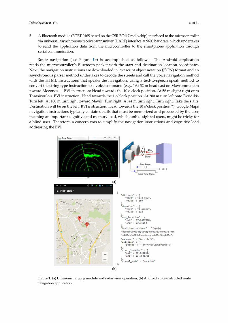
4. A sonar sensor (HC-SR04) mounted on a servomechanism able to quickly direct the sonarbeam across a viewing angle, similar to a radar view function, for the real-time recognition andbypassing of obstacles in the near field along the route of the BVI (see Figure 1a). To minimizethe annoying frequent issuing of unnecessary sonar information, the implemented radar viewfunctionality continuously calculates successive measurements and reports only those objects incollision trajectory which are stepwise approached by the BVI. Walking persons can be recognizedamong fixed obstacles via relevant velocity calculations. In case of a fixed obstacle identifiedby the radar in collision trajectory towards the BVI, the system issues avoidance commandsconsidering the width of the obstacle (e.g., “Obstacle at 2 m. Move 1.5 m to the right to avoidit”). The sonar/radar function is able to reliably guide the user to walk at a safe distance parallelto building walls along his/her route as well as at a safe distance from parked cars along thepavement. Near-ground obstacles and abnormalities (e.g., curbs, potholes etc.) cannot be easilyhandled by sonar. The BVI can instead sense such ground obstacles through his/her white cane.
Technologies 2018, 6, 4 11 of 31
5. A Bluetooth module (EGBT-046S based on the CSR BC417 radio chip) interfaced to the microcontrollervia universal asynchronous receiver-transmitter (UART) interface at 9600 baudrate, which undertakesto send the application data from the microcontroller to the smartphone application throughserial communication.
Route navigation (see Figure 1b) is accomplished as follows: The Android applicationreads the microcontroller’s Bluetooth packet with the start and destination location coordinates.Next, the navigation instructions are downloaded in javascript object notation (JSON) format and anasynchronous parser method undertakes to decode the streets and call the voice navigation methodwith the HTML instructions that speaks the navigation, using a text-to-speech speak method toconvert the string type instruction to a voice command (e.g., “At 32 m head east on Mavrommateontoward Mezonos→ BVI instruction: Head towards the 10 o’clock position. At 56 m slight right ontoThrasivoulou. BVI instruction: Head towards the 1 o’clock position. At 200 m turn left onto Evridikis.Turn left. At 100 m turn right toward Mavili. Turn right. At 44 m turn right. Turn right. Take the stairs.Destination will be on the left. BVI instruction: Head towards the 10 o’clock position.”). Google Mapsnavigation instructions typically contain details that must be memorized and processed by the user,meaning an important cognitive and memory load, which, unlike sighted users, might be tricky fora blind user. Therefore, a concern was to simplify the navigation instructions and cognitive loadaddressing the BVI.
Technologies 2018, 6, 4 11 of 30
for a blind user. Therefore, a concern was to simplify the navigation instructions and cognitive load
addressing the BVI.
(a)
(b)
Figure 1. (a) Ultrasonic ranging module and radar view operation; (b) Android voice-instructed route
navigation application.
Additional application features include a configurator to define a list of destinations which can
be selected through the keypad, app synchronization with traffic lights, weather information to help
with dressing appropriately (selected through the keypad and retrieved by the Android application
via a web service), dialing and answering phone calls, emergency notification of family and carers
about the current position of the BVI, and the exploitation of dynamic telematics information
regarding public transportation timetables and bus stops for building composite routes, which may
include public transportation segments in addition to pedestrian segments. The configurator allows
an assistant person to easily configure and store destination locations of interest in the application
for navigation purposes and to assign destinations and other useful functionality to the keypad
buttons. A future work item is to provide a personalized system which can be adapted to the
particular needs of the individual users. Furthermore, an innovative and challenging application
component is currently under development to provide real-time visual information to the BVI along
the route exploiting machine- and deep-learning technology.
The Blind RouteVision embedded device is a small wearable device meeting the requirement for
easy device portability. Currently, a few prototypes (see Figure 2) have been given to the Lighthouse
for the Blind of Greece in order to evaluate the system with real users and receive valuable feedback
for system functionality improvement. The bill of materials (BOM) cost of the prototype external
embedded device is less than $30 (samples price), confirming the absence of financial obstacles in the
way of the presented development. The pre-product embedded system is assembled on a small,
simple to produce, two-layer printed circuit board (PCB), which is housed in a plastic PCB enclosure,
Figure 1. (a) Ultrasonic ranging module and radar view operation; (b) Android voice-instructed routenavigation application.

Technologies 2018, 6, 4 12 of 31
Additional application features include a configurator to define a list of destinations which can beselected through the keypad, app synchronization with traffic lights, weather information to help withdressing appropriately (selected through the keypad and retrieved by the Android application via aweb service), dialing and answering phone calls, emergency notification of family and carers about thecurrent position of the BVI, and the exploitation of dynamic telematics information regarding publictransportation timetables and bus stops for building composite routes, which may include publictransportation segments in addition to pedestrian segments. The configurator allows an assistantperson to easily configure and store destination locations of interest in the application for navigationpurposes and to assign destinations and other useful functionality to the keypad buttons. A futurework item is to provide a personalized system which can be adapted to the particular needs of theindividual users. Furthermore, an innovative and challenging application component is currentlyunder development to provide real-time visual information to the BVI along the route exploitingmachine- and deep-learning technology.
The Blind RouteVision embedded device is a small wearable device meeting the requirement foreasy device portability. Currently, a few prototypes (see Figure 2) have been given to the Lighthousefor the Blind of Greece in order to evaluate the system with real users and receive valuable feedbackfor system functionality improvement. The bill of materials (BOM) cost of the prototype externalembedded device is less than $30 (samples price), confirming the absence of financial obstacles inthe way of the presented development. The pre-product embedded system is assembled on a small,simple to produce, two-layer printed circuit board (PCB), which is housed in a plastic PCB enclosure,mounting the keypad on the outer surface and with proper openings required for the operation of thesonar sensor.
Technologies 2018, 6, 4 12 of 30
mounting the keypad on the outer surface and with proper openings required for the operation of
the sonar sensor.
Figure 2. Blind RouteVision prototype embedded system hardware. The device components are
clearly shown (left to right): hex-keypad, high-precision GPS receiver with white square antenna, and
breadboard with directly plugged in Atmega uC tiny daughter board, Bluetooth transceiver (touching
the sonar left side) and sonar (top to bottom view, illustrated also in Figure 1a).
4. Indoor Positioning System
The operation of the Blind MuseumTourer system relies on a reliable indoor navigation
component that will help the BVI implement a self-guided visit across the museum. The system will
be able to identify in real-time the position of the BVI in the internal space and guide the user towards
the next exhibit along the guide route. When the exhibit is reached, it is presented orally to the user.
Different solutions to the problem of indoor positioning and navigation have been proposed
which often prove not reliable enough [66]. The satellite GPS system used for outdoor navigation
cannot be a reliable solution for indoor navigation due to the significant attenuation of the satellite
signal inside buildings. However, several proposed solutions adopt a similar geometric position-
detection method and try to detect the current user location considering the received strength at the
user device of the wireless radio frequency (RF) signals from multiple transmitters installed in the
internal space. Due to the reflections of the wireless signals in the internal space, a reliable solution
to the problem of indoor location detection for autonomous navigation is hard and highly
complicated, and quite often the deviation of the calculated location from the real location makes the
solution unreliable.
4.1. WLAN-Based Location Determination
Several research efforts have proposed GPS-like solutions to the indoor location detection
problem employing multiple WiFi access points. Many such solutions exploit a feature of smart-
phone/tablet devices, which calculates the signal strength received at the device from WLAN
transmitters operating in the internal space. Both the Android and iOS frameworks provide relevant
system calls. Simple implementations in this context usually fail to achieve very good location
detection accuracy and normally calculate the current distance of the user device from a WiFi
transmitter, considering the WiFi connection, the media access control (MAC) address and the RSSI
(received signal strength) indication of the smart-phone/tablet. Knowledge of that distance overlaid
on a map-making of the internal space can help estimate a most-likely current user location. The
current RSSI value is cross-checked in real time against offline measured normalized signal power
level values, stored in a database, across various distances from the transmitter and locations of the
indoor place. Using multiple access points can help improve location detection accuracy.
In the context of the aforementioned solutions, a few research efforts have demonstrated that it is
feasible to achieve adequate location detection accuracy (e.g., [67]), but most implementations employ
Figure 2. Blind RouteVision prototype embedded system hardware. The device components areclearly shown (left to right): hex-keypad, high-precision GPS receiver with white square antenna,and breadboard with directly plugged in Atmega uC tiny daughter board, Bluetooth transceiver(touching the sonar left side) and sonar (top to bottom view, illustrated also in Figure 1a).
4. Indoor Positioning System
The operation of the Blind MuseumTourer system relies on a reliable indoor navigation componentthat will help the BVI implement a self-guided visit across the museum. The system will be able toidentify in real-time the position of the BVI in the internal space and guide the user towards the nextexhibit along the guide route. When the exhibit is reached, it is presented orally to the user.
Different solutions to the problem of indoor positioning and navigation have been proposed whichoften prove not reliable enough [66]. The satellite GPS system used for outdoor navigation cannotbe a reliable solution for indoor navigation due to the significant attenuation of the satellite signalinside buildings. However, several proposed solutions adopt a similar geometric position-detectionmethod and try to detect the current user location considering the received strength at the user device

Technologies 2018, 6, 4 13 of 31
of the wireless radio frequency (RF) signals from multiple transmitters installed in the internal space.Due to the reflections of the wireless signals in the internal space, a reliable solution to the problem ofindoor location detection for autonomous navigation is hard and highly complicated, and quite oftenthe deviation of the calculated location from the real location makes the solution unreliable.
4.1. WLAN-Based Location Determination
Several research efforts have proposed GPS-like solutions to the indoor location detection problememploying multiple WiFi access points. Many such solutions exploit a feature of smart-phone/tabletdevices, which calculates the signal strength received at the device from WLAN transmittersoperating in the internal space. Both the Android and iOS frameworks provide relevant systemcalls. Simple implementations in this context usually fail to achieve very good location detectionaccuracy and normally calculate the current distance of the user device from a WiFi transmitter,considering the WiFi connection, the media access control (MAC) address and the RSSI (receivedsignal strength) indication of the smart-phone/tablet. Knowledge of that distance overlaid on amap-making of the internal space can help estimate a most-likely current user location. The currentRSSI value is cross-checked in real time against offline measured normalized signal power level values,stored in a database, across various distances from the transmitter and locations of the indoor place.Using multiple access points can help improve location detection accuracy.
In the context of the aforementioned solutions, a few research efforts have demonstrated that it isfeasible to achieve adequate location detection accuracy (e.g., [67]), but most implementations employcomplex and complicated methodologies and require computationally intensive calculations in theapplied mathematical models and methods. The generic outline of such solutions is the following:
1. A dense radio map is made for the indoor space including processing of various models whichconsiders the RSS from various transmitters in all radio map positions.
2. During the online operation of the application the current user location is detected using thesignal power level values received at the user device from a few access points operating in theindoor space. These signals comprise a received signal strength vector which is best matched interms of Euclidian distance with a pre-calculated RSSI vector indicating a point on the radio map.
Briefly, the process of implementing the solution comprises the following tasks:
• The radio map stores/represents the distribution of the signal power level received from theWLAN access points at every sampling position in the room which is included in the radio map(e.g., a radio map for a 40 m × 50 m indoor space in which the distance between neighboringpoints is 2 m yields a grid consisting of 500 sampling positions).
• Using clustering techniques, the positions in the radio map are clustered according to the coveragerange of the WLAN access points, thus reducing the computational requirements.
• A discrete space estimator is implemented that returns the radio map position which most likelymatches the current user position dynamically represented by an RSS vector.
• Using an auto-regressive correlation model, the correlation between successive power levelsamples from the same WLAN access point is recognized. The aim is to improve the accuracy ofthe discrete space estimator using the average value of N correlated samples.
• A continuous space estimator is implemented which takes as input the estimated discrete position(one of the radio map positions) and outputs a more accurate estimation of the real user positionin the continuous space.
• A small-scale compensator is implemented to manipulate small-scale variations in thewireless channel.
In conclusion, a reliable WLAN location determination component in support of the BlindMuseumTourer system/application requires extensive preparation actions and trials involving themuseums for which the application will be available. Under the assumption that the museum

Technologies 2018, 6, 4 14 of 31
administration gives the necessary permissions for the installation of multiple WLAN access pointsacross appropriate indoor spots and the realization of extensive measurements in the indoor spacerequired to build the radio map, as well as that installation is safe for public health, a WLAN-basedsolution can accurately determine the position of a moving person [68]. Therefore, it is feasible toimplement a system for the autonomous navigation and self-guidance of BVI inside museums using asmartphone which will vocally and accurately guide the user towards the exhibits.
Evidently, the implementation of a reliable WLAN-based location determination system is apretty challenging project. A rough estimation of the set up effort required only for carrying outthe measurements necessary to create a relatively dense radio map for a 30 × 45 m2 indoor roominvolving 600 sampling positions, in which the distance between neighboring points in the grid is1.5 m, could easily count 1–2 person weeks for just one museum hall. Creating a radio map coveringan entire typical museum, such as those which will be addressed by Blind MuseumTourer [3–5],could easily involve an effort which may well exceed 3–4 person months. The implementation of asimpler and still-reliable WLAN-based system should be feasible considering other parameters suchas predetermined, transparent to the public, linear tactile indicators mounted on the floor for BVI, userstep counting, positioning information from proximity sensors installed in the indoor space at exhibits,entrances/exits, columns and other guidance spots (see next section).
4.2. Location Detection Using Beacons and Surface Mounted Tactile Guiding Indicators
This section presents an indoor location detection technique which exploits beacons as proximitysensors at the museum exhibits and other guidance spots, along with tactile linear routes mountedon the floor of the museum rooms. A BVI who wishes to have an interactive autonomous navigationinside the museum can easily detect and follow these predetermined routes using the white cane.The marking of the linear blind navigation routes on the floors is according to the inclusive designand implementation guidelines issued by the public administration services for the facilitation ofpedestrian movement and the daily routine of people with special needs. These guidelines conformto the international standards for assistive tactile walking through surface indicators (TWSI) andhelp a BVI travel independently [69,70]. The guiding indications (such as strips, crossings, warningsand endings) which are surface mounted on the floor of the museum rooms are transparent andnon-invasive to the rest of museum visitors and neither affect nor hinder at all their movement.Figure 3 depicts the main standardized TWSI patterns and suitable simplified indoor guiding stripand warning stud implementations as a tactile orientation system for BVI [71].
Technologies 2018, 6, 4 14 of 30
inside the museum can easily detect and follow these predetermined routes using the white cane.
The marking of the linear blind navigation routes on the floors is according to the inclusive design
and implementation guidelines issued by the public administration services for the facilitation of
pedestrian movement and the daily routine of people with special needs. These guidelines conform
to the international standards for assistive tactile walking through surface indicators (TWSI) and help
a BVI travel independently [69,70]. The guiding indications (such as strips, crossings, warnings and
endings) which are surface mounted on the floor of the museum rooms are transparent and non-
invasive to the rest of museum visitors and neither affect nor hinder at all their movement. Figure 3
depicts the main standardized TWSI patterns and suitable simplified indoor guiding strip and
warning stud implementations as a tactile orientation system for BVI [71].
Figure 3. Two main patterns of TWSIs: “Attention” pattern and guiding” pattern.
Figure 4a illustrates a typical floor plan of a museum room with an assistive tactile guiding route
surface mounted on the floor for autonomous blind navigation/guidance, room dimensions, the
positions of the exhibits, as well as the sequence of the exhibits and corresponding vocal presentation
during the visit. Similar floor plans of all museum rooms will be designed and integrated with the
smartphone application. The lengths of the rectilinear segments of the route are calculated in analogy
with the x/y dimensions of the room. Proximity sensors at the exhibits inform the Blind
MuseumTourer smartphone application about the current location of the user when an exhibit is
approached and vocal presentation follows. The application interoperates with low cost Bluetooth
beacons transmitting a small amount of data (the exhibit ID) over a short distance using the Bluetooth
low energy (BLE) protocol [72]. The smartphone application receives the beacon signals and
determines the user location along the autonomous guidance route. At the same time, besides the
discrete-space-estimator beacon-signaled user location, the application continuously performs
inertial dead-reckoning calculations, i.e., BVI step counting and corresponding distance calculations
as well as heading and turn recognition, using the smartphone accelerometer which, being a
continuous space estimator, helps calculate the user trajectory and walked distance and determine
the user position in the continuous indoor space. In many cases, a beacon can represent multiple
exhibits, for instance exhibits No. 7 and 8 in Figure 4. Figure 4b depicts the corresponding
implementation of the concept in an Android activity (see details in Section 4).
BLE beacons usually do not interfere with other wireless networks and/or medical devices.
However, undesired interference may occur in the case of multiple WiFi signals, as BLE and WiFi
share the same 2.4 GHz frequency band. This potential problem can be easily avoided through
configuring the WLAN access points to use channels one and 6–12 only, while Bluetooth is using the
rest of the available channels in a uniform manner (frequency hopping).
Whenever the user enters a museum room, the event is detected by the application, which loads
the corresponding floor map and initiates the navigation process in the indoor space, such as in
Figure 4. The user can interrupt the self-guided tour anytime to dial a call or to proceed to the
restroom, the canteen/cafeteria, an information/emergency desk, or the exit. In the latter case, the
application guides the user via voice navigation instructions towards the point of interest. The guided
tour remains on pause until the user returns to the interruption point following the corresponding
vocal instructions to continue the tour.
Figure 3. Two main patterns of TWSIs: “Attention” pattern and guiding” pattern.
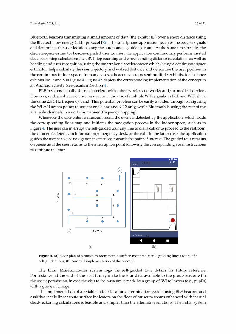
Figure 4a illustrates a typical floor plan of a museum room with an assistive tactile guidingroute surface mounted on the floor for autonomous blind navigation/guidance, room dimensions,the positions of the exhibits, as well as the sequence of the exhibits and corresponding vocalpresentation during the visit. Similar floor plans of all museum rooms will be designed andintegrated with the smartphone application. The lengths of the rectilinear segments of the routeare calculated in analogy with the x/y dimensions of the room. Proximity sensors at the exhibitsinform the Blind MuseumTourer smartphone application about the current location of the user whenan exhibit is approached and vocal presentation follows. The application interoperates with low cost
Technologies 2018, 6, 4 15 of 31
Bluetooth beacons transmitting a small amount of data (the exhibit ID) over a short distance usingthe Bluetooth low energy (BLE) protocol [72]. The smartphone application receives the beacon signalsand determines the user location along the autonomous guidance route. At the same time, besides thediscrete-space-estimator beacon-signaled user location, the application continuously performs inertialdead-reckoning calculations, i.e., BVI step counting and corresponding distance calculations as well asheading and turn recognition, using the smartphone accelerometer which, being a continuous spaceestimator, helps calculate the user trajectory and walked distance and determine the user position inthe continuous indoor space. In many cases, a beacon can represent multiple exhibits, for instanceexhibits No. 7 and 8 in Figure 4. Figure 4b depicts the corresponding implementation of the concept inan Android activity (see details in Section 4).
BLE beacons usually do not interfere with other wireless networks and/or medical devices.However, undesired interference may occur in the case of multiple WiFi signals, as BLE and WiFi sharethe same 2.4 GHz frequency band. This potential problem can be easily avoided through configuringthe WLAN access points to use channels one and 6–12 only, while Bluetooth is using the rest of theavailable channels in a uniform manner (frequency hopping).
Whenever the user enters a museum room, the event is detected by the application, which loadsthe corresponding floor map and initiates the navigation process in the indoor space, such as inFigure 4. The user can interrupt the self-guided tour anytime to dial a call or to proceed to the restroom,the canteen/cafeteria, an information/emergency desk, or the exit. In the latter case, the applicationguides the user via voice navigation instructions towards the point of interest. The guided tour remainson pause until the user returns to the interruption point following the corresponding vocal instructionsto continue the tour.Technologies 2018, 6, 4 15 of 30
(a) (b)
Figure 4. (a) Floor plan of a museum room with a surface-mounted tactile guiding linear route of a
self-guided tour; (b) Android implementation of the concept.
The Blind MuseumTourer system logs the self-guided tour details for future reference. For
instance, at the end of the visit it may make the tour data available to the group leader with the user’s
permission, in case the visit to the museum is made by a group of BVI followers (e.g., pupils) with a
guide in charge.
The implementation of a reliable indoor location determination system using BLE beacons and
assistive tactile linear route surface indicators on the floor of museum rooms enhanced with inertial
dead-reckoning calculations is feasible and simpler than the alternative solutions. The initial system
prototype integrates an indoor location determination component implemented according to the
aforementioned specifications.
5. Blind MuseumTourer Application Functionality
5.1. Application Activities and User Interaction
The Blind MuseumTourer application runs on an Android smartphone. An iOS version will be
made available in the near future. The use of headphones is recommended. Since drowning out the
nearby ambient sounds can be life-threating in some cases, especially in outdoor navigation, it is
advised to use bone conduction headphones allowing the BVI user’s ears to be unobstructed, so as to
be aware of the surrounding environment. When typical headphones are used, it is advised to use a
mono headphone, leaving one ear open to the traffic and ambient sounds.
The application is initiated through either a voice command or a widget on the smartphone
screen. A welcome splash screen is presented and the application reads a welcome message such as
the following, which at the same time informs the user how to interact with the application:
“Welcome to the museum self-guided tour application!
For your convenience, you may interrupt the guided tour anytime by double tapping at the upper screen
to move to the restroom, the cafeteria, or the exit, to talk to the help desk or make a phone call.
Anytime you wish to go back to the previous menu, double tap at the bottom screen.
To select an option double-tap the respective left, middle, or right section at the centre screen.
To hear a selection, please single-tap at the respective screen section.”
The application functionality is presented in the ensuing. First-time activation by a user will run
a configuration activity in which the user should declare some personal details. The main activity
will run next, presenting vocally four options to the user, dividing the smartphone touchscreen into
Figure 4. (a) Floor plan of a museum room with a surface-mounted tactile guiding linear route of aself-guided tour; (b) Android implementation of the concept.
The Blind MuseumTourer system logs the self-guided tour details for future reference.For instance, at the end of the visit it may make the tour data available to the group leader withthe user’s permission, in case the visit to the museum is made by a group of BVI followers (e.g., pupils)with a guide in charge.
The implementation of a reliable indoor location determination system using BLE beacons andassistive tactile linear route surface indicators on the floor of museum rooms enhanced with inertialdead-reckoning calculations is feasible and simpler than the alternative solutions. The initial system

Technologies 2018, 6, 4 16 of 31
prototype integrates an indoor location determination component implemented according to theaforementioned specifications.
5. Blind MuseumTourer Application Functionality
5.1. Application Activities and User Interaction
The Blind MuseumTourer application runs on an Android smartphone. An iOS version will bemade available in the near future. The use of headphones is recommended. Since drowning out thenearby ambient sounds can be life-threating in some cases, especially in outdoor navigation, it isadvised to use bone conduction headphones allowing the BVI user’s ears to be unobstructed, so as tobe aware of the surrounding environment. When typical headphones are used, it is advised to use amono headphone, leaving one ear open to the traffic and ambient sounds.
The application is initiated through either a voice command or a widget on the smartphonescreen. A welcome splash screen is presented and the application reads a welcome message such asthe following, which at the same time informs the user how to interact with the application:
“Welcome to the museum self-guided tour application!
> For your convenience, you may interrupt the guided tour anytime by double tapping at theupper screen to move to the restroom, the cafeteria, or the exit, to talk to the help desk or makea phone call.
> Anytime you wish to go back to the previous menu, double tap at the bottom screen.> To select an option double-tap the respective left, middle, or right section at the centre screen.> To hear a selection, please single-tap at the respective screen section.”
The application functionality is presented in the ensuing. First-time activation by a user will run aconfiguration activity in which the user should declare some personal details. The main activity will runnext, presenting vocally four options to the user, dividing the smartphone touchscreen into four largesections, which can be easily pointed to by the BVI user: “Routes” 1–2, “Help”, and “Back” (Figure 5a).The user interacts with the application either through a single tap for hearing a selection, a double tapfor confirming a selection, or through voice. Selecting a route initiates the self-guided tour activity(Figure 4b). This activity handles the dynamic navigation inside the museum rooms in real-time,determines the user location during the self-guided tour and presents the exhibits approached bythe user along the tour route. The help option available anytime allows the user to talk/find theway to the help desk (Figure 5b), or find the way to the restroom, to the canteen/cafeteria, or to theexit (Figure 5c), following the voice navigation instructions. Depending on the number of optionsoffered by the application’s activity screens, the smartphone touchscreen is divided into respectivesections (Figure 5b presents a bottom “back” touch section and left and right areas in the rest of thetouchscreen; Figure 5c divides the major touchscreen into three vertical areas corresponding to thethree available options). Figure 6 depicts indicative summary floor plans with exhibition routes at theNational Archaeological Museum and at the Acropolis Museum. The Blind MuseumTourer applicationintegrates an indoor positioning system using beacons and unobtrusive tactile route indicators onthe floor, enhanced with inertial dead-reckoning functionality to improve navigation accuracy andreliability, according to the principles presented in Section 4.2.

Technologies 2018, 6, 4 17 of 31
Technologies 2017, 5, x FOR PEER REVIEW 16 of 30
(a) (b) (c)
Figure 5. Blind MuseumTourer Android application activities: (a) Route selection; Selecting a route initiates the self-guided tour activity using a Guide Map of the indoor space (see Figure 4b); (b) Αsk help; (c) Get voice way-finding instructions to move to the WC/canteen/exit.
Figure 5. Blind MuseumTourer Android application activities: (a) Route selection; Selecting a routeinitiates the self-guided tour activity using a Guide Map of the indoor space (see Figure 4b); (b) Askhelp; (c) Get voice way-finding instructions to move to the WC/canteen/exit.Technologies 2018, 6, 4 17 of 30
(a) (b)
Figure 6. Summary floor plans with exhibition routes (a) at the Acropolis Museum; (b) at the National
and Archaeological Museum.
5.2. Inertial Dead Reckoning (IDR) Calculations
Besides the exploitation of a set of beacons as proximity sensors regarding points of interest
(POIs) in the area, the Blind MuseumTourer application relies additionally on a step metering
mechanism to implement precise positioning and a reliable system, which is crucial for BVI. Using
the integrated accelerometer of the smartphone device, continuously sampling its x, y, z coordinate
values (see Figure 7), the system continuously calculates and monitors the average BVI stride length
(distance from the heel of one foot to the heel of the other foot when taking a step) and pace along
route segments of a known distance (e.g., between successive exhibits) in order to issue precise
navigation instructions. Before starting the assisted self-guided tour, initial calculations can be
performed precisely along a predetermined short route segment. The accelerometer sensor can report
motion start and stop accurately and in real time. As the distance between successive exhibits along
the navigation route is known, the application notifies the BVI before reaching the next exhibit
announcing the number of remaining steps until the next POI. This way the BVI can be more
effectively and accurately guided, through the combined use of beacons and step metering
functionality, against typical positioning solutions relying on the exclusive use of beacons.
During the BVI self-guided tour, the step counting and associated distance calculation starts as
soon as the user starts walking and is paused when the user stops at an exhibit, where the application
reads a recorded message presenting information about the exhibit. Following a spoken presentation
session, the application guides the user towards the next exhibit until the self-guided tour is ended
or interrupted by the user.
Figure 6. Summary floor plans with exhibition routes (a) at the Acropolis Museum; (b) at the Nationaland Archaeological Museum.

Technologies 2018, 6, 4 18 of 31
5.2. Inertial Dead Reckoning (IDR) Calculations
Besides the exploitation of a set of beacons as proximity sensors regarding points of interest(POIs) in the area, the Blind MuseumTourer application relies additionally on a step meteringmechanism to implement precise positioning and a reliable system, which is crucial for BVI. Using theintegrated accelerometer of the smartphone device, continuously sampling its x, y, z coordinate values(see Figure 7), the system continuously calculates and monitors the average BVI stride length (distancefrom the heel of one foot to the heel of the other foot when taking a step) and pace along route segmentsof a known distance (e.g., between successive exhibits) in order to issue precise navigation instructions.Before starting the assisted self-guided tour, initial calculations can be performed precisely alonga predetermined short route segment. The accelerometer sensor can report motion start and stopaccurately and in real time. As the distance between successive exhibits along the navigation route isknown, the application notifies the BVI before reaching the next exhibit announcing the number ofremaining steps until the next POI. This way the BVI can be more effectively and accurately guided,through the combined use of beacons and step metering functionality, against typical positioningsolutions relying on the exclusive use of beacons.
During the BVI self-guided tour, the step counting and associated distance calculation starts assoon as the user starts walking and is paused when the user stops at an exhibit, where the applicationreads a recorded message presenting information about the exhibit. Following a spoken presentationsession, the application guides the user towards the next exhibit until the self-guided tour is ended orinterrupted by the user.Technologies 2018, 6, 4 18 of 30
Time (seconds)
Figure 7. Calculated sum of squared values of accelerometer sensor coordinates (value = x2 + y2 + z2)
over time during three steps (represented by the graph peaks) with short rests in between. Sampling
rate is five samples per second. Step pace and average step length over route sectors of known
distance can be trivially calculated.
The application further monitors the user turns to verify whether the user has acted according
to the turn instructions. This mechanism relies on sensor fusion using the accelerometer and a
rotation vector. Sensor fusion reports azimuth, pitch and roll values, with the first two values used
to detect the user turn. Finally, using the smartphone magnetometer sensor, the integrated inertial
dead-reckoning mechanism detects in real time the user heading through the relative orientation of
the user device relative to the Earth’s magnetic north. Figure 8 is a schematic depiction of the tracking
capability of our hybrid indoor positioning mechanism relying on inertial dead reckoning and
exploiting BLE beacons deployed in the indoor environment. Assuming the generic problem of BVI
free travel inside the indoor environment, the developed location tracking mechanism can determine
the motion trajectory of the BVI and represent it as a sequence of rectilinear segments, simulating
very close to reality how blind and visually impaired persons walk. The lengths of the rectilinear
segments are estimated using the integrated accelerometer, as explained, while their orientations,
shown exemplarily in the figure relatively to the y-axis, can be determined using the integrated
magnetometer. Magnetic north is assumed in the direction of the y-axis. In order to enhance the
accuracy and reliability of the inertial dead reckoning positioning mechanism, beacons can be
exploited for the verification and adjustment of the continuous real-time calculations and dynamic
parameter valuation and continuous calibration of the tracking mechanism during the execution of
the indoor navigation application.
Cal
cula
ted
acc
eler
om
eter
val
ue
Figure 7. Calculated sum of squared values of accelerometer sensor coordinates (value = x2 + y2 + z2)over time during three steps (represented by the graph peaks) with short rests in between. Sampling rateis five samples per second. Step pace and average step length over route sectors of known distance can betrivially calculated.
The application further monitors the user turns to verify whether the user has acted according tothe turn instructions. This mechanism relies on sensor fusion using the accelerometer and a rotationvector. Sensor fusion reports azimuth, pitch and roll values, with the first two values used to detect theuser turn. Finally, using the smartphone magnetometer sensor, the integrated inertial dead-reckoningmechanism detects in real time the user heading through the relative orientation of the user devicerelative to the Earth’s magnetic north. Figure 8 is a schematic depiction of the tracking capability of ourhybrid indoor positioning mechanism relying on inertial dead reckoning and exploiting BLE beaconsdeployed in the indoor environment. Assuming the generic problem of BVI free travel inside theindoor environment, the developed location tracking mechanism can determine the motion trajectoryof the BVI and represent it as a sequence of rectilinear segments, simulating very close to reality howblind and visually impaired persons walk. The lengths of the rectilinear segments are estimated usingthe integrated accelerometer, as explained, while their orientations, shown exemplarily in the figure
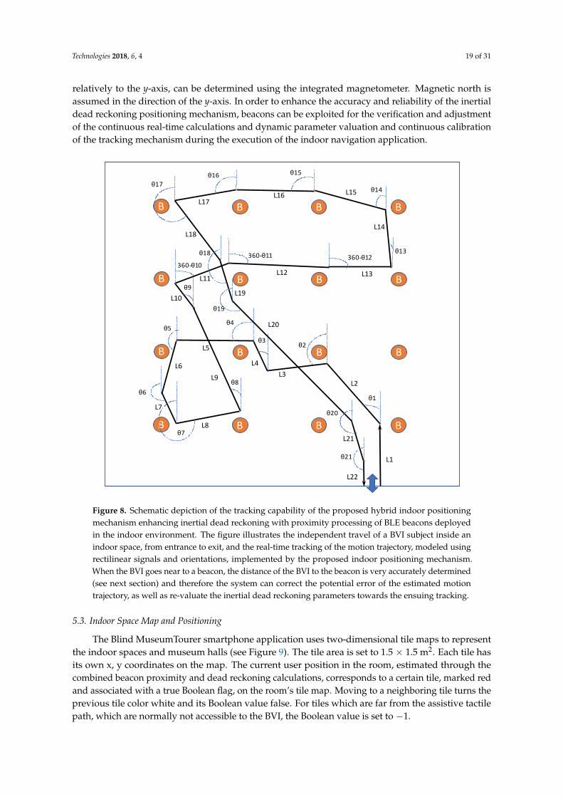
Technologies 2018, 6, 4 19 of 31
relatively to the y-axis, can be determined using the integrated magnetometer. Magnetic north isassumed in the direction of the y-axis. In order to enhance the accuracy and reliability of the inertialdead reckoning positioning mechanism, beacons can be exploited for the verification and adjustmentof the continuous real-time calculations and dynamic parameter valuation and continuous calibrationof the tracking mechanism during the execution of the indoor navigation application.
Technologies 2018, 6, 4 19 of 30
Figure 8. Schematic depiction of the tracking capability of the proposed hybrid indoor positioning
mechanism enhancing inertial dead reckoning with proximity processing of BLE beacons deployed in
the indoor environment. The figure illustrates the independent travel of a BVI subject inside an indoor
space, from entrance to exit, and the real-time tracking of the motion trajectory, modeled using
rectilinear signals and orientations, implemented by the proposed indoor positioning mechanism. When
the BVI goes near to a beacon, the distance of the BVI to the beacon is very accurately determined (see
next section) and therefore the system can correct the potential error of the estimated motion trajectory,
as well as re-valuate the inertial dead reckoning parameters towards the ensuing tracking.
5.3. Indoor Space Map and Positioning
The Blind MuseumTourer smartphone application uses two-dimensional tile maps to represent
the indoor spaces and museum halls (see Figure 9). The tile area is set to 1.5 × 1.5 m2. Each tile has its
own x, y coordinates on the map. The current user position in the room, estimated through the
combined beacon proximity and dead reckoning calculations, corresponds to a certain tile, marked
red and associated with a true Boolean flag, on the room’s tile map. Moving to a neighboring tile
turns the previous tile color white and its Boolean value false. For tiles which are far from the assistive
tactile path, which are normally not accessible to the BVI, the Boolean value is set to −1.
Figure 10 depicts a subset of an indoor guide map with three beacons installed along an assistive
tactile path for use by a BVI. The yellowish circular disks illustrate potential user positions than can
be detected by the beacons. Through proper calibration using a set of transmit and receive power
measurements, the application is able to report perfectly accurate positions (1 cm error) in distances
up to 3 m from a beacon. In case two or more beacons detect the user, the nearest beacon is weighted
more than the distant one when estimating the current user position.
B
B
B
B
B
B
B
B
B
B
B
B
B
B
B
B
θ1
L1
L2
θ2
L3
θ3
L4
L5
θ4θ5
L6
L7
θ6
L8θ7
L9θ8
L10
θ9
360-θ10
L11L12
360-θ11 360-θ12
L13
θ13
L14
L15 θ14L16
θ15
L17
θ16
θ17
L18
L19
θ18
L20
θ19
θ20
L21
θ21
L22
Figure 8. Schematic depiction of the tracking capability of the proposed hybrid indoor positioningmechanism enhancing inertial dead reckoning with proximity processing of BLE beacons deployedin the indoor environment. The figure illustrates the independent travel of a BVI subject inside anindoor space, from entrance to exit, and the real-time tracking of the motion trajectory, modeled usingrectilinear signals and orientations, implemented by the proposed indoor positioning mechanism.When the BVI goes near to a beacon, the distance of the BVI to the beacon is very accurately determined(see next section) and therefore the system can correct the potential error of the estimated motiontrajectory, as well as re-valuate the inertial dead reckoning parameters towards the ensuing tracking.
5.3. Indoor Space Map and Positioning
The Blind MuseumTourer smartphone application uses two-dimensional tile maps to representthe indoor spaces and museum halls (see Figure 9). The tile area is set to 1.5 × 1.5 m2. Each tile hasits own x, y coordinates on the map. The current user position in the room, estimated through thecombined beacon proximity and dead reckoning calculations, corresponds to a certain tile, marked redand associated with a true Boolean flag, on the room’s tile map. Moving to a neighboring tile turns theprevious tile color white and its Boolean value false. For tiles which are far from the assistive tactilepath, which are normally not accessible to the BVI, the Boolean value is set to −1.

Technologies 2018, 6, 4 20 of 31
Figure 10 depicts a subset of an indoor guide map with three beacons installed along an assistivetactile path for use by a BVI. The yellowish circular disks illustrate potential user positions than canbe detected by the beacons. Through proper calibration using a set of transmit and receive powermeasurements, the application is able to report perfectly accurate positions (1 cm error) in distancesup to 3 m from a beacon. In case two or more beacons detect the user, the nearest beacon is weightedmore than the distant one when estimating the current user position.
Technologies 2018, 6, 4 20 of 30
(a) (b) (c)
Figure 9. Indoor tiles map: (a) Example of current user position on the assistive tactile path calculated
in real time; (b) Example room tile map with user position at point (6, 7); (c) Room tile map illustrating
the user position on the highlighted assistive tactile navigation path.
Figure 10. Beacons detecting current indoor BVI user position.
Figure 4b illustrates a simple example of the implemented concepts, depicting a room tile map,
an assistive tactile path with turns and points of interest (e.g., exhibits, help desk, exit etc.). The time
on the upper left part of the screen reports the estimated time in seconds until the user reaches the
next exhibit depending on his/her average speed. The value reported on the upper right is the total
elapsed application time. The value reported on the lower left part of the screen is the distance in
meters until the next exhibit.
6. Blind IndoorGuide: A Complete Solution for Blind Indoor Navigation
This section discusses briefly the evolution of Blind MuseumTourer into a generic IndoorGuide
application and provides a brief technical insight regarding the navigation guidance process. The
concepts and corresponding implementation presented in this paper, exploiting surface-mounted
assistive tactile indicators, beacons as proximity sensors to POIs, inertial calculations and smartphone
functionality, can be applied in a similar way to effectively address the problem of blind indoor
navigation in many other indoor guidance use cases. BVI public indoor guidance needs can be
effectively addressed in hospitals, shopping malls, airports, train stations, public and municipality
buildings, office buildings, university campus buildings, hotel resorts, passenger ships, etc. The
presented application for indoor navigation can be easily modified and customized to a specialized
Blind IndoorGuide App, depending on the use case and can effectively assist a BVI in self-guiding
him/herself inside complex buildings with hundreds of POIs. The main differentiation of a specific
Blind IndoorGuide application addressing a particular use case against MuseumTourer is the
integration of a simple and efficient destination/POI selection mechanism, which triggers the
application to issue proper way-finding instructions from the current user position to the selected
destination POI using a shortest path routing algorithm. In this way, the BVI can effectively navigate
to a sequence of indoor POIs among a large available set of POIs.
Figure 11 illustrates the floor plan of the Department of Emergency Incidents of Evangelismos
Hospital, the largest Greek hospital in Athens. It additionally depicts an overlay drawing with
Figure 9. Indoor tiles map: (a) Example of current user position on the assistive tactile path calculatedin real time; (b) Example room tile map with user position at point (6, 7); (c) Room tile map illustratingthe user position on the highlighted assistive tactile navigation path.
Technologies 2018, 6, 4 20 of 30
(a) (b) (c)
Figure 9. Indoor tiles map: (a) Example of current user position on the assistive tactile path calculated
in real time; (b) Example room tile map with user position at point (6, 7); (c) Room tile map illustrating
the user position on the highlighted assistive tactile navigation path.
Figure 10. Beacons detecting current indoor BVI user position.
Figure 4b illustrates a simple example of the implemented concepts, depicting a room tile map,
an assistive tactile path with turns and points of interest (e.g., exhibits, help desk, exit etc.). The time
on the upper left part of the screen reports the estimated time in seconds until the user reaches the
next exhibit depending on his/her average speed. The value reported on the upper right is the total
elapsed application time. The value reported on the lower left part of the screen is the distance in
meters until the next exhibit.
6. Blind IndoorGuide: A Complete Solution for Blind Indoor Navigation
This section discusses briefly the evolution of Blind MuseumTourer into a generic IndoorGuide
application and provides a brief technical insight regarding the navigation guidance process. The
concepts and corresponding implementation presented in this paper, exploiting surface-mounted
assistive tactile indicators, beacons as proximity sensors to POIs, inertial calculations and smartphone
functionality, can be applied in a similar way to effectively address the problem of blind indoor
navigation in many other indoor guidance use cases. BVI public indoor guidance needs can be
effectively addressed in hospitals, shopping malls, airports, train stations, public and municipality
buildings, office buildings, university campus buildings, hotel resorts, passenger ships, etc. The
presented application for indoor navigation can be easily modified and customized to a specialized
Blind IndoorGuide App, depending on the use case and can effectively assist a BVI in self-guiding
him/herself inside complex buildings with hundreds of POIs. The main differentiation of a specific
Blind IndoorGuide application addressing a particular use case against MuseumTourer is the
integration of a simple and efficient destination/POI selection mechanism, which triggers the
application to issue proper way-finding instructions from the current user position to the selected
destination POI using a shortest path routing algorithm. In this way, the BVI can effectively navigate
to a sequence of indoor POIs among a large available set of POIs.
Figure 11 illustrates the floor plan of the Department of Emergency Incidents of Evangelismos
Hospital, the largest Greek hospital in Athens. It additionally depicts an overlay drawing with
Figure 10. Beacons detecting current indoor BVI user position.
Figure 4b illustrates a simple example of the implemented concepts, depicting a room tile map,an assistive tactile path with turns and points of interest (e.g., exhibits, help desk, exit etc.). The timeon the upper left part of the screen reports the estimated time in seconds until the user reaches the nextexhibit depending on his/her average speed. The value reported on the upper right is the total elapsedapplication time. The value reported on the lower left part of the screen is the distance in meters untilthe next exhibit.
6. Blind IndoorGuide: A Complete Solution for Blind Indoor Navigation
This section discusses briefly the evolution of Blind MuseumTourer into a generic IndoorGuideapplication and provides a brief technical insight regarding the navigation guidance process.The concepts and corresponding implementation presented in this paper, exploiting surface-mountedassistive tactile indicators, beacons as proximity sensors to POIs, inertial calculations and smartphonefunctionality, can be applied in a similar way to effectively address the problem of blind indoornavigation in many other indoor guidance use cases. BVI public indoor guidance needs can beeffectively addressed in hospitals, shopping malls, airports, train stations, public and municipalitybuildings, office buildings, university campus buildings, hotel resorts, passenger ships, etc.The presented application for indoor navigation can be easily modified and customized to a

Technologies 2018, 6, 4 21 of 31
specialized Blind IndoorGuide App, depending on the use case and can effectively assist a BVIin self-guiding him/herself inside complex buildings with hundreds of POIs. The main differentiationof a specific Blind IndoorGuide application addressing a particular use case against MuseumToureris the integration of a simple and efficient destination/POI selection mechanism, which triggers theapplication to issue proper way-finding instructions from the current user position to the selecteddestination POI using a shortest path routing algorithm. In this way, the BVI can effectively navigateto a sequence of indoor POIs among a large available set of POIs.
Figure 11 illustrates the floor plan of the Department of Emergency Incidents of EvangelismosHospital, the largest Greek hospital in Athens. It additionally depicts an overlay drawing withnavigation paths and POIs (red line segments and dots respectively), including connectors to otherfloors, handled by our Blind HospitalGuide application. The application is able to guide the BVIbetween any two points (red dots) across the navigation map. Evangelismos, like any large hospital,comprises numerous departments and dozens of medical units (nursing, diagnosis, surgical etc.)arranged across many floors. This is just an example of what a typical complex floor plan andnavigation path with many POIs inside a large building or complex indoor environment looks like,and the required complexity addressed by a Blind IndoorGuide application. Connectors to other floorsare used to interconnect floor navigation graphs during runtime depending on the destination POIselected by the user, thus enabling navigation across the whole building.
Technologies 2018, 6, 4 21 of 30
navigation paths and POIs (red line segments and dots respectively), including connectors to other
floors, handled by our Blind HospitalGuide application. The application is able to guide the BVI
between any two points (red dots) across the navigation map. Evangelismos, like any large hospital,
comprises numerous departments and dozens of medical units (nursing, diagnosis, surgical etc.)
arranged across many floors. This is just an example of what a typical complex floor plan and
navigation path with many POIs inside a large building or complex indoor environment looks like,
and the required complexity addressed by a Blind IndoorGuide application. Connectors to other
floors are used to interconnect floor navigation graphs during runtime depending on the destination
POI selected by the user, thus enabling navigation across the whole building.
Figure 11. Floor plan of the Department of Emergency Incidents (DEI) of Evangelismos Hospital, the
largest Greek hospital in Athens. Evangelismos, like any large hospital, comprises numerous
departments and medical units (nursing, diagnosis, surgical etc.) arranged across many floors. The
Blind HospitalGuide (or IndoorGuide) application that helps the BVI find his/her way accurately and
reliably inside the complex setting of a large hospital (or indoor environment) is built upon the same
principles presented in this paper. The figure illustrates the BVI navigation graph, comprising paths
and POIs (more than 70 depicted), across the DEI floor (areas accessible to public, depicted in grey)
handled by the application.
7. System Evaluation
Successful tests of the presented system were performed with three blindfolded sighted users in
the ground floor area of the University of Piraeus’ main building (Figure 12). The users were given a
Blind MuseumTourer smartphone and a cane at the entrance of the building. Guidelines on how to
use the application and the surface mounted indicators were provided by the trial staff and the
blindfolded users were left to navigate around the 1640 m2 space following a predetermined tour
between several POIs (30 POIs representing museum exhibits plus another four POIs: entrance/exit,
reception/helpdesk, canteen/cafeteria and rest room) guided by the Blind MuseumTourer
smartphone application. During the tour, the users were also able to interrupt the tour anytime asking
the application to guide them to a specific place (any of the four non-exhibit POIs) and subsequently
either resume the tour from the interruption point or move to the exit. Two shortcuts available in the
Figure 11. Floor plan of the Department of Emergency Incidents (DEI) of Evangelismos Hospital,the largest Greek hospital in Athens. Evangelismos, like any large hospital, comprises numerousdepartments and medical units (nursing, diagnosis, surgical etc.) arranged across many floors.The Blind HospitalGuide (or IndoorGuide) application that helps the BVI find his/her way accuratelyand reliably inside the complex setting of a large hospital (or indoor environment) is built upon thesame principles presented in this paper. The figure illustrates the BVI navigation graph, comprisingpaths and POIs (more than 70 depicted), across the DEI floor (areas accessible to public, depicted ingrey) handled by the application.

Technologies 2018, 6, 4 22 of 31
7. System Evaluation
Successful tests of the presented system were performed with three blindfolded sighted users inthe ground floor area of the University of Piraeus’ main building (Figure 12). The users were givena Blind MuseumTourer smartphone and a cane at the entrance of the building. Guidelines on howto use the application and the surface mounted indicators were provided by the trial staff and theblindfolded users were left to navigate around the 1640 m2 space following a predetermined tourbetween several POIs (30 POIs representing museum exhibits plus another four POIs: entrance/exit,reception/helpdesk, canteen/cafeteria and rest room) guided by the Blind MuseumTourer smartphoneapplication. During the tour, the users were also able to interrupt the tour anytime asking theapplication to guide them to a specific place (any of the four non-exhibit POIs) and subsequently eitherresume the tour from the interruption point or move to the exit. Two shortcuts available in the tour ring(between POIs No. 3 and 16, as well as across the short stairs) can be exploited by the application toshorten the path to the requested POI in that case. At the end of this experience, when the blindfoldedusers had reached the exit, they were asked to evaluate three critical factors of the indoor navigationapplication: reliability, instruction efficiency and ease of use. All users gave excellent grades in allaspects. Besides the important subjective evaluation, the trial additionally evaluated the inertial deadreckoning localization error per path segment between successive POIs.
Technologies 2018, 6, 4 22 of 30
tour ring (between POIs No. 3 and 16, as well as across the short stairs) can be exploited by the
application to shorten the path to the requested POI in that case. At the end of this experience, when
the blindfolded users had reached the exit, they were asked to evaluate three critical factors of the
indoor navigation application: reliability, instruction efficiency and ease of use. All users gave
excellent grades in all aspects. Besides the important subjective evaluation, the trial additionally
evaluated the inertial dead reckoning localization error per path segment between successive POIs.
Figure 12. Blind MuseumTourer indoor navigation and guidance system preliminary trials.
The problem of blind users possibly colliding during the self-guided navigation is resolved
either through enhancing the Blind MuseumTourer system with the external sonar device of the Blind
RouteVision outdoor navigation system (see Section 3) and mixing the sonar warnings with the
navigation instructions, or through implementing a server-side software and additional functionality
into the smartphone application in order to monitor in real time the positions of all blind persons
navigating in the place at the same time. In the latter case, the Blind MuseumTourer application keeps
reporting the current BVI position to the application server, reading at the same time the positions of
other BVIs along the navigation path. In case of a collision event with the blind person in front or
behind, the application promptly warns the user. Alternatively, a sonar unit such as the Smart Guide
developed by the Lighthouse for the Blind of Greece [73] can be used in parallel with the Blind
MuseumTourer application to ensure collisions along the navigation path are avoided.
Table 1 summarizes the measurements logged by the application regarding the trial. The length
of the trial tour ring was 246.2 m. Path segment lengths (in meters) in between successive POIs are
depicted, as well as the average time (in seconds) required by the blindfolded users to walk the
distance between successive POIs. The average total travel time assuming no stops at POIs was
1177 s (19 min and 37 s). When reaching an exhibit POI, the user stops for 30 s to hear the narration
and touch the exhibit. Therefore, another 900 s is added to the average total time of the self-guided
tour (35 min). Path segments in between successive POIs containing surface-mounted warning signs
for direction change reasonably take more time to travel against travelling the same distance directly.
Table 2 illustrates an extract of the navigation instructions during the self-guided tour.
Figure 12. Blind MuseumTourer indoor navigation and guidance system preliminary trials.
The problem of blind users possibly colliding during the self-guided navigation is resolvedeither through enhancing the Blind MuseumTourer system with the external sonar device of theBlind RouteVision outdoor navigation system (see Section 3) and mixing the sonar warnings with thenavigation instructions, or through implementing a server-side software and additional functionalityinto the smartphone application in order to monitor in real time the positions of all blind persons

Technologies 2018, 6, 4 23 of 31
navigating in the place at the same time. In the latter case, the Blind MuseumTourer application keepsreporting the current BVI position to the application server, reading at the same time the positionsof other BVIs along the navigation path. In case of a collision event with the blind person in frontor behind, the application promptly warns the user. Alternatively, a sonar unit such as the SmartGuide developed by the Lighthouse for the Blind of Greece [73] can be used in parallel with the BlindMuseumTourer application to ensure collisions along the navigation path are avoided.
Table 1 summarizes the measurements logged by the application regarding the trial. The lengthof the trial tour ring was 246.2 m. Path segment lengths (in meters) in between successive POIsare depicted, as well as the average time (in seconds) required by the blindfolded users to walk thedistance between successive POIs. The average total travel time assuming no stops at POIs was 1177 s(19 min and 37 s). When reaching an exhibit POI, the user stops for 30 s to hear the narration andtouch the exhibit. Therefore, another 900 s is added to the average total time of the self-guided tour(35 min). Path segments in between successive POIs containing surface-mounted warning signs fordirection change reasonably take more time to travel against travelling the same distance directly.Table 2 illustrates an extract of the navigation instructions during the self-guided tour.
As already stated, the trial evaluated the inertial dead reckoning localization error (in centimeters)per path segment between successive POIs. To this end, specific measurement functionality wasimplemented in the Blind MuseumTourer application, subtracting the Inertial Dead Reckoning (IDR)calculated localization information from the beacon one per segment. Despite the spoiling of thecalculated distance corresponding to the user steps caused by surface-mounted warnings signaling adirection change, our IDR mechanism achieves a lower than average error rate during path segments,including surface warnings, through exploiting the smartphone’s integrated gyroscope. The gyroscopetriggers the IDR mechanism to re-initialize the IDR calculations following a direction change until thenext exhibit is reached yielding a much smaller error, which typically corresponds to the fraction ofthe last straight segment over the total path length between successive POIs containing the directionchange warning sign. This yields an impressive 2.53% average error rate for our IDR mechanism,taking into account the typical IDR error rate figures (5–10%) reported in the literature.

Technologies 2018, 6, 4 24 of 31
Table 1. Blind MuseumTourer indoor navigation system blindfolded trial measurements.
POI R 1 2 3 4 5 6 7 8 9 10 11 12 13 W 14 15
Length 10.9 9.3 8.4 7.6 3.6 4.4 11.3 0 7.6 4 2.4 9.2 5.6 9.6 5.6 5.2 10.8Time 43.6 44.9 42.1 30.4 14.4 17.6 59.2 0 38.4 20 17.5 36.5 22.4 46.4 39.4 24.8 43.2IDRe - 34 25 30 14 13 8 0 15 12 4 −7 22 22 6 26 32
POI 16 17 18 19 20 21 22 23 24 25 C 26 27 28 29 30 E
Length 5.2 6 4.8 4.8 4.8 6.8 6.8 7.2 7.6 3.6 5.2 6.4 4.4 12.5 7.2 16.5 20.9Time 29.3 23.8 27.7 19.2 27.6 27.2 35.3 40 30.4 27.9 20.8 25.6 25.5 56.8 36.8 82.4 99.6IDRe 6 24 5 -8 13 33 7 11 38 10 31 19 13 22 5 14 28

Technologies 2018, 6, 4 25 of 31
Table 2. Blind MuseumTourer navigation instructions example.
Sequence No. Navigation Instructions
1
(User has entered the building and is approaching the Reception Desk).“Stop. Reception reached.” (System waits until user has stopped). (Possible adjustmentfollows, e.g., “Move 1 step/small step in front/behind.”)“Position at 3 o’clock.”“Exhibit 1 next.”
2
(User moves towards next exhibit).“Mind the short stairs in front.”“Exhibit 1 in 2 steps following the short stairs.”“Stop. Exhibit 1 reached.” (System waits until user has stopped). (Possible adjustmentfollows, e.g., “Move 1 step/small step in front/behind.”)“Position at 10 o’clock.”(Narration).“Exhibit 2 next in 13 steps following the right turn.”
3
(User moves towards next exhibit).“Stop. Exhibit 2 reached.” (System waits until user has stopped). (Possible adjustmentfollows, e.g., “Move 1 step/small step in front/behind.”)“Position at 10 o’clock.”(Narration).“Exhibit 3 next in 15 steps.”
4
(User moves towards next exhibit).“Stop. Exhibit 3 reached.” (System waits until user has stopped). (Possible adjustmentfollows, e.g., “Move 1 step/small step in front/behind.”)“Position at 2 o’clock.”(Narration).“Exhibit 4 next in 7 steps.”
5 (User is interrupting the tour asking wayfinding instructions to the rest room).
6
“Turn left on the sign.”(User moves along the tactile path)“Turn right on the sign.”(After exhibit 14 is reached and direction has changed through sensing the warning sign.)“Rest room next in 9 steps.”“Stop. Rest room reached.” (System waits until user has stopped). (Possible adjustmentfollows, e.g., “Move 1 step/small step in front/behind.”)“Position at 3 o’clock.”
8. Discussion
Unlike outdoor navigation, which exploits GPS technology to accurately resolve the problemof dynamic location determination and modern geo-information systems for routing determination,such as OpenStreetMap, Google Maps and Apple Maps services, there is no global solution to theindoor navigation problem. Especially regarding the problem of blind outdoor pedestrian navigation,there are several high-precision and reliable research and commercial systems available. Besides theaccuracy issue, ease of use is another critical factor for system adoption by the BVI.
Regarding indoor navigation, the main problems that should be tackled refer to both blindnavigation concerns. On the one hand, the accuracy of the positioning system is often unsatisfactory,with slight or major deviations from the real position coordinates causing problems to the BVI users.On the other hand, unlike outdoor map services exploiting satellite Earth observation technology,the creation of indoor environment maps of indoor navigation applications is performed on a per casebasis and requires considerable effort, involving time-consuming staff set up works and autopsy visitsto the indoor environments for the collection of map related measurements.
Nowadays, several technologies or technology combinations succeed in achieving very precise indoorpositioning, (see Sections 2.2 and 4.1), such as RFID and other various landmark/POI-understandingtechniques or WiFi systems combined with inertial dead reckoning, sophisticated WLAN location

Technologies 2018, 6, 4 26 of 31
determination, 3D space sensing and augmented reality systems, etc. Most such systems either entail anincreased cost of indoor navigation equipment to the BVI user (e.g., RFID reader, mobile robot, specializedcamera units, etc.) or require timely high-performance computations (e.g., 3D space representationand augmented reality systems). Furthermore, a consolidation of the use of smartphone devices inindoor navigation applications is undisputed nowadays. Their PC-like computational performance,integrated camera and inertial sensors, touch user interface, microphone, speaker, and speech recognitionfunctionality, enhancing accessibility, all-in-one small wearable device, provides an invincible candidatedevice for blind indoor navigation applications.
Taking into serious account the ascertainments made by the previous discussion, as wellas the uncompromised requirement for the ease-of-use of blind indoor navigation applications,we proposed and implemented a competitive system demonstrating the following advantages overother state-of-the-art solutions:
• Achieving exceptional indoor positioning accuracy through combining assistive tactile walkingthrough surface indicators (TWSIs) according to the International Organisation for StandardisationISO 23599:2012 standard, inertial dead reckoning functionality, and BLE beacons as proximitysensors to POIs inside the indoor space.
• The adoption of TWSI provides the advantage of creating a decisive safety and protection feelingfor the BVI during the indoor navigation.
• The adoption of BLE beacons over passive RFID tags to implement the positioning of POIs throughclose proximity identification allows the formation of one-to-many active–passive relationsbetween an indoor space and its BVI users at a firm unitary cost which sums up the cost of the set ofbeacons installed in the indoor space. The alternative of implementing one-to-many passive–activerelations between an indoor space and its BVI users entails a multiple total cost proportionalto the number of BVIs using the blind indoor navigation application (e.g., requirement for anindividual RFID reader per BVI).
• It emphasizes the decisive role of a smartphone as an enabling device in the context of blindindoor navigation applications, which interacts via Bluetooth with the indoor environmentbeacons representing the POI positions. It is showcased that no additional specialized userequipment is required to adequately address the application. The only requirement is to steadythe smartphone device in a belt around waist to constantly conform with the body orientation.BVIs holding their white cane in the right hand can steady the device on their left side, and viceversa for left-handed BVIs, so that they can easily interact with the touchscreen using their freehand. This approach was presented to blind users at the Lighthouse for the Blind of Greece andthey were quite happy with it.
• Besides the key importance of positioning accuracy and system reliability, our work emphasizesthe importance of another key requirement for BVI adoption, which is “ease of use” throughproper acoustic and touch interfaces. Unfortunately, several state-of-the-art applications disregardor do not focus enough on this critical issue. Any state-of-the-art indoor navigation applicationshould be typically easy to use.
• Finally, a successful blind indoor navigation application further relies decisively on the requiredindoor space mapping in the system context. Our system resolves the typical trade-off regardingindoor positioning systems between the quality of positioning accuracy and the complexity andcost of the manual indoor mapping process in favor of the simplification of the floor mappingprocess, while at the same time not compromising system positioning accuracy and reliability.
Future work on the Blind MuseumTourer and other IndoorGuide applications will focus onthe optimization of our inertial dead-reckoning mechanism (see Figure 8) and BVI acoustic userinterface (see Table 2), including simple POI selection, as well as an extensive and insightful systemvalidation with blind users. Following the pilot project with the Tactual Museum, Blind MuseumTourerwill be configured and proof tested at the National Archaeological Museum and at the Acropolis

Technologies 2018, 6, 4 27 of 31
Museum. In addition, several Blind IndoorGuide use cases will be implemented and evaluated in thefuture, such as addressing BVI indoor navigation in hospitals and other public indoor environments(see Section 6 and Figure 11, highlighting a Blind HospitalGuide use case). Another focus in the contextof further development of the MANTO Blind IndoorGuide applications will be the optimization of ouraccurate positioning mechanism through combining advanced inertial dead reckoning and processingof multiple beacon signals to efficiently handle BVI free travel indoors (see Section 5.2 and Figure 8).Besides technical innovations and improvements, all blind escort applications will be additionallymade available for the iOS platform to serve BVIs already owning an iPhone device.
9. Conclusions
This paper presented the case study of an innovative approach to a smartphone-based indoornavigation system for people who are blind or visually impaired, in places of high interest tothe world’s intellectual community (the Tactual Museum, the National Archaeological Museum,the Acropolis Museum, other major landmarks in Greece). The proposed system further intends toaddress BVI guidance needs in public indoor places, such as in hospitals, shopping malls, airports, trainstations, public and municipality buildings, office buildings, university buildings, etc. A lot of technicalexperimentation has been conducted, and important information is shared with openness, includinghelpful illustrations. User localization relies on beacon proximity combined with a sophisticatedinertial dead reckoning mechanism to implement an accurate positioning system. Beyond just thetechnical aspects, the authors hope that this contribution could be interesting to a variety of researcharenas, including, obviously, those studying BVIs, but also public media, media accessibility, mobilemedia, etc.
Acknowledgments: The authors would like to thank their students Costas Filios, Gerasimos Gkotsopoulos andOleg Popivtsak for contributing some parts of the system code. This research work is supported by the Greek RTDIState Aid Action RESEARCH-CREATE-INNOVATE of the National Operational Programme Competitiveness,Entrepreneurship and Innovation 2014–2020 in the framework of the MANTO project.
Author Contributions: Apostolos Meliones authored the paper and designed, implemented and validated thepresented system; Demetrios Sampson, following the taking of a close look at the BlindHelper application,triggered the design of the Blind MuseumTourer application in the context of a planned educational experimentinvolving museum visits for blind pupil groups.
Conflicts of Interest: The authors declare no conflict of interest.
References
1. Meliones, A.; Filios, C. BlindHelper: A Pedestrian Navigation System for Blinds and Visually Impaired.In Proceedings of the 9th ACM International Conference on Pervasive Technologies Related to AssistiveEnvironments, Corfu, Greece, 29 June–1 July 2016.
2. Lighthouse for the Blind of Greece. Available online: http://fte.org.gr (accessed on 18 November 2017).3. Tactual Museum. Available online: http://tactualmuseum.gr (accessed on 18 November 2017).4. National Archaeological Museum. Available online: http://namuseum.gr (accessed on 18 November 2017).5. The Acropolis Museum. Available online: http://theacropolismuseum.gr/en (accessed on 18 November 2017).6. Vayanou, M.; Karvounis, M.; Katifori, A.; Kyriakidi, M.; Roussou, M.; Ioannidis, Y. The CHESS Project:
Adaptive Personalized Storytelling Experiences in Museums. In Proceedings of the 22nd Conference onUser Modelling, Adaptation and Personalization, Aalborg, Denmark, 7–11 July 2014.
7. Loadstone GPS. Available online: http://www.loadstone-gps.com (accessed on 18 November 2017).8. LoroDux. Available online: http://wiki.openstreetmap.org/wiki/LoroDux (accessed on 18 November 2017).9. MobileGeo. Available online: http://www.senderogroup.com/products/shopmgeo.html (accessed on
18 November 2017).10. Seeing Eye GPS. Available online: http://www.senderogroup.com/products/shopseeingeyegps.html
(accessed on 18 November 2017).11. BlindSquare. Available online: http://blindsquare.com (accessed on 18 November 2017).
Technologies 2018, 6, 4 28 of 31
12. Chaudary, B.; Paajala, I.; Keino, E.; Pulli, P. Tele-guidance Based Navigation System for the VisuallyImpaired and Blind Persons. In Lecture Notes of the Institute for Computer Sciences, Social Informatics andTelecommunications Engineering; Giokas, K., Bokor, L., Hopfgartner, F., Eds.; Springer: Cham, Switzerland,2017; Volume 181.
13. Koley, S.; Mishra, R. Voice Operated Outdoor Navigation System for Visually Impaired Persons. Int. J. Eng.Trends Technol. 2012, 3, 153–157.
14. Bousbia-Salah, M.; Fezari, M. A Navigation Tool for Blind People. In Innovations and Advanced Techniques inComputer and Information Sciences and Engineering; Springer: Berlin/Heidelberg, Germany, 2007; pp. 333–337.
15. Ran, L.; Helal, S.; Moore, S. Drishti: An Integrated Indoor/Outdoor Blind Navigation System and Service.In Proceedings of the IEEE International Conference on Pervasive Computing and Communications(PerCom’04), Orlando, FL, USA, 14–17 March 2004; pp. 23–30.
16. Loomis, J.; Colledge, R.; Klatzky, R. Navigation System for the Blind: Auditory Display Modes and Guidance.Presence 1998, 7, 193–203. [CrossRef]
17. Balata, J.; Mikovec, J.; Maly, I. Navigation Problems in Blind-to-Blind Pedestrians Tele-Assistance Navigation.In Proceedings of the International Conference Human Computer Interaction (INTERACT 2015), Bamberg,Germany, 14–18 September 2015; pp. 89–109.
18. Dias, M.; Teves, E.; Zimmerman, G.; Gedawy, H.; Belousov, S.; Dias, M. Indoor Navigation Challenges forVsually Impaired People. In Indoor Wayfinding and Navigation; Karimi, H., Ed.; CRC Press: Boca Raton, FL,USA, 2015; pp. 141–163.
19. Gallagher, T.; Wise, E.; Yam, H.; Li, B.; Ramsey-Stewart, E.; Dempster, A.; Rizos, C. Indoor Navigation forPeople Who Are Blind or Vision Impaired: Where Are We and Where Are We Going? J. Locat. Based Serv.2014, 8, 54–73. [CrossRef]
20. Miao, M.; Spindler, M.; Weber, G. Requirements of Indoor Navigation System from Blind Users.In Proceedings of the Symposium of the Austrian HCI and Usability Engineering Group (USAB 2011)(LNCS 7058), Graz, Austria, 25–26 November 2011; pp. 673–679.
21. Fallah, N.; Apostolopoulos, I.; Bekris, K.; Folmer, E. Indoor Human Navigation Systems: A Survey.Interact. Comput. 2013, 25, 21–33.
22. Giudice, N.; Legge, G. Blind Navigation and the Role of Technology. In The Engineering Handbook of SmartTechnology for Aging, Disability, and Independence; Helal, A., Mokhtari, M., Abdulrazak, B., Eds.; John Wiley & Sons:New, York, NY, USA, 2008.
23. Dakopoulos, D.; Bourbakis, N. Wearable Obstacle Avoidance Electronic Travel Aids for Blind: A Survey.IEEE Trans. Syst. Man Cybernet. 2010, 40, 25–35. [CrossRef]
24. Dias, M.; Steinfeld, A.; Dias, M. Future Directions in Indoor Navigation Technology for Blind Travelers.In Indoor Wayfinding and Navigation; Karimi, H., Ed.; CRC Press: Boca Raton, FL, USA, 2015; pp. 203–222.
25. Willis, S.; Helal, S. RFID Information Grid for Blind Navigation and Wayfinding. In Proceedings of the 2005IEEE International Symposium on Wearable Computers (ISWC’05), Osaka, Japan, 18–21 October 2005.
26. Chumkamon, S.; Tuvaphanthaphiphat, P.; Keeratiwintakorn, P. A Blind Navigation System Using RFID for IndoorEnvironments. In Proceedings of the International Conference on Electrical Engineering/Electronics, Computer,Telecommunications and Information Technology (ECTI-CON 2008), Krabi, Thailand, 14–17 May 2008.
27. Giampaolo, E. A Passive-RFID Based Indoor Navigation System for Visually Impaired People. In Proceedingsof the 2010 International Symposium on Applied Sciences in Biomedical and Communication Technologies(ISABEL), Rome, Italy, 7–10 November 2010.
28. Na, J. The Blind Interactive Guide System Using RFID-Based Indoor Positioning System. In Proceedingsof the 2006 International Conference on Computers Helping People with Special Needs (ICCHP 2006)(LNCS 4061), Linz, Austria, 11–13 July 2006; pp. 1298–1305.
29. Kiers, M.; Kranjc, E.; Dornhofer, M.; Bischof, W. Evaluation and Improvements of an RFID Based IndoorNavigation System for Visually Impaired and Blind People. In Proceedings of the International Conferenceon Indoor Positioning and Indoor Navigation, Guimaraes, Portugal, 21–23 September 2011.
30. Ganz, A.; Schafer, J.; Gandhi, S.; Puleo, E.; Wilson, C.; Robertson, M. PERCEPT Indoor Navigation Systemfor the Blind and Visually Impaired: Architecture and Experimentation. Int. J. Telemed. Appl. 2012, 894869.[CrossRef] [PubMed]
Technologies 2018, 6, 4 29 of 31
31. Ganz, A.; Schafer, J.; Tao, Y.; Robertson, M. PERCEPT-II: Smartphone based indoor navigation system for theblind. In Proceedings of the 36th Annual International Conference of the IEEE Engineering in Medicine andBiology Society (EMBC 2014), Chicago, IL, USA, 26–30 August 2014.
32. Yelamarthi, K.; Haas, D.; Nielsen, D.; Mothersell, S. RFID and GPS Integrated Navigation System for theVisually Impaired. In Proceedings of the 2010 53rd IEEE International Midwest Symposium on Circuits andSystems (MWSCAS), Seattle, WA, USA, 1–4 August 2010.
33. Faria, J.; Lopes, S.; Fernandes, H.; Martins, P.; Barroso, J. Electronic White Cane for Blind People NavigationAssistance. In Proceedings of the World Automation Congress, Kobe, Japan, 19–23 September 2010.
34. Ivanov, R. RSNAVI: An RFID-Based Context-Aware Indoor Navigation System for the Blind. In Proceedingsof the International Conference on Computer Systems and Technologies (CompSysTech’12), Ruse, Bulgaria,22–23 June 2012.
35. Jiménez, A.; Seco, F.; Prieto, J.; Guevara, J. Accurate Pedestrian Indoor Navigation by Tightly CouplingFoot-Mounted IMU and RFID Measurements. IEEE Trans. Instrum. Meas. 2012, 61, 178–189. [CrossRef]
36. Guerrero, L.A.; Vasquez, F.; Ochoa, S.F. An Indoor Navigation System for the Visually Impaired. Sensors2012, 12, 8236–8258. [CrossRef] [PubMed]
37. Riehle, T.; Lichter, P.; Giudice, N. An Indoor Navigation System to Support the Visually Impaired.In Proceedings of the 30th Annual International IEEE Engineering in Medicine and Biology Society (EMBS)Conference, Vancouver, BC, Canada, 20–24 August 2008.
38. Nakajima, M.; Haruyama, S. New indoor navigation system for visually impaired people using visible lightcommunication. EURASIP J. Wirel. Commun. Netw. 2013, 37. [CrossRef]
39. Jain, D. Path-guided indoor navigation for the visually impaired using minimal building retrofitting.In Proceedings of the 16th International ACM SIGACCESS Conference on Computers & Accessibility,Rochester, NY, USA, 20–22 October 2014; pp. 225–232.
40. Riehle, T.; Anderson, S.; Lichter, P.; Giudice, N.; Sheikh, S.; Knuesel, R.; Kollmann, D.; Hedin, D. Indoor MagneticNavigation for the Blind. In Proceedings of the 34th Annual International Conference of the IEEE Engineeringin Medicine and Biology Society (EMBS), San Diego, CA, USA, 28 August–1 September 2012.
41. Gozick, B.; Subbu, K.P.; Dantu, R.; Maeshiro, T. Magnetic Maps for Indoor Navigation. IEEE Trans.Instrum. Meas. 2011, 60, 3883–3891. [CrossRef]
42. Bourbakis, N. Sensing Surrounding 3-D Space for Navigation of the Blind. IEEE Eng. Med. Biol. Mag. 2008.[CrossRef] [PubMed]
43. Kim, J.B.; Jun, H.S. Vision-Based Location Positioning using Augmented Reality for Indoor Navigation.IEEE Trans. Consum. Electron. 2008, 54. [CrossRef]
44. Lee, B.-G.; Chung, W.-Y. Multitarget Three-Dimensional Indoor Navigation on a PDA in a Wireless SensorNetwork. IEEE Sens. J. 2011, 11, 799–807. [CrossRef]
45. Joseph, S.; Zhang, X.; Dryanovski, I.; Xiao, J.; Yi, C.; Tian, Y. Semantic indoor navigation with a blind-useroriented augmented reality. In Proceedings of the 2013 International Conference on Systems, Man,and Cybernetics, Manchester, UK, 13–16 October 2013.
46. Hub, A.; Diepstraten, J.; Ertl, T. Design and Development of an Indoor Navigation and Object IdentificationSystem for the Blind. In Proceedings of the ACM SIGACCESS Conference on Computers and Accessibility(ASSETS’04), Atlanta, GA, USA, 18–20 October 2004.
47. Lee, Y.H.; Medioni, G. Wearable RGBD Indoor Navigation System for the Blind. In Computer Vision ECCV2014 Workshops; LNCS 8927; Agapito, L., Bronstei, M.M., Rother, C., Eds.; Springer: Cham, Switzerland, 2015;pp. 493–508.
48. He, Y.; Li, Y.; Guan, Y.; Tan, J. Wearable Ego-Motion Tracking for Blind Navigation in Indoor Environments.IEEE Trans. Autom. Sci. Eng. 2015, 12, 1181–1190. [CrossRef]
49. Simoes, W.; Lucena, V. Blind user wearable audio assistance for indoor navigation based on visual markersand ultrasonic obstacle detection. In Proceedings of the 2016 IEEE International Conference on ConsumerElectronics (ICCE), Las Vegas, NV, USA, 7–11 January 2016.
50. Sound of Vision. Research Project Funded under: H2020-EU.3.1.—SOCIETAL CHALLENGES—Health,Demographic Change and Well-Being. Available online: https://soundofvision.net (accessed on17 November 2017).

Technologies 2018, 6, 4 30 of 31
51. Li, B.; Munoz, P.; Rong, X.; Xiao, J.; Tian, Y.; Arditi, A. ISANA: Wearable Context-Aware Indoor AssistiveNavigation with Obstacle Avoidance for the Blind. In Proceedings of the European Conference on ComputerVision (ECCV 2016), Amsterdam, The Netherlands, 8–16 October 2016; pp. 448–462.
52. Zheng, Y.; Shen, G.; Li, L.; Zhao, C.; Li, M.; Zhao, F. Travi-Navi: Self-Deployable Indoor Navigation System.IEEE/ACM Trans. Netw. 2017, 25, 2655–2669. [CrossRef]
53. Tao, Y.; Ding, L.; Ganz, A. Indoor Navigation Validation Framework for Visually Impaired Users. IEEE Access2017, 5, 21763–21773. [CrossRef]
54. Kaiser, E.; Lawo, M. Wearable Navigation System for the Visually Impaired and Blind People. In Proceedingsof the 2012 IEEE/ACIS 11th International Conference on Computer and Information Science, Shanghai,China, 30 May–1 June 2012.
55. Ascher, C.; Kessler, C.; Wankerl, M.; Trommer, G. Dual IMU Indoor Navigation with Particle Filter basedMap-Matching on a Smartphone. In Proceedings of the 2010 International Conference on Indoor Positioningand Indoor Navigation (IPIN), Zürich, Switzerland, 15–17 September 2010.
56. Wu, H.; Marshall, A.; Yu, W. Path Planning and Following Algorithms in an Indoor Navigation Modelfor Visually Impaired. In Proceedings of the 2007 International Conference on Internet Monitoring andProtection (ICIMP 2007), Silicon Valley, CA, USA, 1–6 July 2007.
57. Gilliéron, P.-Y.; Büchel, D.; Spassov, I.; Merminod, B. Indoor Navigation Performance Analysis.In Proceedings of the 2004 European Navigation Conference on Global Navigation Satellite Systems(ENC GNSS 2004), Rotterdam, The Netherlands, 16–19 May 2004.
58. Ivanov, R. An approach for developing indoor navigation systems for visually impaired people usingBuilding Information Modeling. J. Ambient Intell. Smart Environ. 2017, 9, 449–467. [CrossRef]
59. Dao, T.; Tran, T.; Le, T.; Vu, H.; Nguyen, V.; Mac, D.; Do, N.; Pham, T. Indoor navigation assistance system forvisually impaired people using multimodal technologies. In Proceedings of the 2016 International Conferenceon Control, Automation, Robotics and Vision (ICARCV), Phuket, Thailand, 13–15 November 2016.
60. Evennou, F.; Marx, F. Advanced Integration of WiFi and Inertial Navigation Systems for Indoor MobilePositioning. EURASIP J. Appl. Signal Process. 2006. [CrossRef]
61. Gallagher, T.; Wise, E.; Li, B.; Dempster, A.; Rizos, C.; Ramsey-Stewart, E. Indoor Positioning System basedon Sensor Fusion for the Blind and Visually Impaired. In Proceedings of the 2012 International Conferenceon Indoor Positioning and Indoor Navigation, Sydney, Australia, 13–15 November 2012.
62. Riehle, T.; Anderson, S.; Lichter, P.; Whalen, W.; Giudice, N. Indoor Inertial Waypoint Navigation for theBlind. In Proceedings of the 35th Annual International Conference of the IEEE Engineering in Medicine andBiology Society (EMBS), Osaka, Japan, 3–7 July 2013.
63. Chen, D.; Feng, W.; Zhao, Q.; Hu, M.; Wang, T. An Infrastructure-Free Indoor Navigation System forBlind People. In Proceedings of the 2012 International Conference on Intelligent Robotics and Applications(ICIRA 2012), Part III, LNAI 7508, Montreal, QC, Canada, 3–5 October 2012; pp. 552–561.
64. Dong, H.; Ganz, A. Automatic generation of indoor navigation instructions for blind users using auser-centric graph. In Proceedings of the 36th Annual International Conference of the IEEE Engineering inMedicine and Biology Society (EMBC 2014), Chicago, IL, USA, 26–30 August 2014.
65. Oh, Y.; Kao, W.; Min, B. Indoor Navigation Aid System Using No Positioning Technique for Visually ImpairedPeople. In Proceedings of the 19th International Conference on Human-Computer Interaction (HCI 2017),Vancouver, BC, Canada, 9–14 July 2017; pp. 390–397.
66. Curran, K.; Furey, E.; Lunney, T.; Santos, J.; Woods, D.; Mc Caughey, A. An Evaluation of Indoor LocationDetermination Technologies. J. Locat. Based Serv. 2011, 5, 61–78. [CrossRef]
67. Youssef, M.; Agrawala, A. Horus WLAN Location Determination System. In Proceedings of the 3rd InternationalConference on Mobile Systems, Applications and Services (MobiSys’05), Seattle, WA, USA, 5 June 2005;pp. 205–218.
68. Fraunhofer IIS. Awiloc: Positioning in Communication Network; Fraunhofer IIS: Nürnberg, Germany,2012; Available online: https://www.zio.fraunhofer.de/content/dam/zio/de/documents/PDFs/Flyer/KOM_NAVI_MAL-1000564-0203-1307_awiloc%20positioning%20in%20communication%20networks.pdf(accessed on 17 November 2017).
69. ISO. Assistive Products for Blind and Vision-Impaired Persons—Tactile Walking Surface Indicators; ISO 23599:2012;ISO: Geneva, Switzerland, 2012.

Technologies 2018, 6, 4 31 of 31
70. Aoki, H.; Mitani, S. Tactile Walking Surface Indicators—Making Streets Safer for Visually Impaired Pedestrians;ISO Focus+; ISO: Geneva, Switzerland, 2012; pp. 28–31.
71. Handi-Friendly: Orientation Systems for the Blind and Visually Impaired. Available online: http://www.handi-friendly.com (accessed on 17 November 2017).
72. BrightTalk. Everything You Always Wanted to Know about Beacons; BrightTalk: San Francisco, CA, USA, 2014.73. Smart Guide. Lighthouse for the Blind of Greece. Available online: https://www.fte.org.gr/index.php/en/
links (accessed on 17 November 2017).
© 2018 by the authors. Licensee MDPI, Basel, Switzerland. This article is an open accessarticle distributed under the terms and conditions of the Creative Commons Attribution(CC BY) license (http://creativecommons.org/licenses/by/4.0/).