
A Sustainable Way to Generate Energy from Waste - Credit: 2 ...
35
Credit: 2 PDH Course Title: A Sustainable Way to Generate Energy from Waste 3 Easy Steps to Complete the Course: 1. Read the Course PDF 2. Purchase the Course Online & Take the Final Exam 3. Print Your Certificate Approved for Credit in All 50 States Visit epdhonline.com for state specific information including Ohio’s required timing feature. epdh.com is a division of Cer�fied Training Ins�tute
-
Upload
khangminh22 -
Category
Documents
-
view
2 -
download
0
Transcript of A Sustainable Way to Generate Energy from Waste - Credit: 2 ...

Credit: 2 PDH
Course Title: A Sustainable Way to Generate Energy from
Waste
3 Easy Steps to Complete the Course:
1. Read the Course PDF
2. Purchase the Course Online & Take the Final Exam
3. Print Your Certificate
Approved for Credit in All 50 StatesVisit epdhonline.com for state specific informationincluding Ohio’s required timing feature.
epdh.com is a division of Cer�fied Training Ins�tute

Chapter 1
Pyrolysis: A Sustainable Way to Generate Energyfrom Waste
Chowdhury Zaira Zaman, Kaushik Pal,Wageeh A. Yehye, Suresh Sagadevan,Syed Tawab Shah, Ganiyu Abimbola Adebisi,Emy Marliana, Rahman Faijur Rafique andRafie Bin Johan
Additional information is available at the end of the chapter
http://dx.doi.org/10.5772/intechopen.69036
Abstract
Lignocellulosic biomass is a potentially more valuable renewable resource that can be utilized effusively as a chief source of heat for cooking and can correspondingly subsi‐dize the production of electricity, heat, biofuels and chemicals including solid fuel like char or carbon. Lignocellulosic residues are mixed and burnt with coal to generate elec‐tricity. Presently, crude oil is replaced by bioethanol and biodiesel produced from bio‐mass substrate. Some special class of chemicals can be derived from biomass that can subsequently replace the usage of non‐renewable resources of oil and coal. Pyrolysis of woody biomass to obtain pyroliginous acid was started hundreds of years ago, which has versatile applications. The range of products that can be derived from biomass is huge, prompting extent of research using different types of thermal conversion technologies, including pyrolysis, gasification, torrefaction, anaerobic digestion and hydrothermal pro‐cessing. This chapter provides insights about the stages of reaction during pyrolysis and the outcome of reaction conditions on the products. Technical development and adjust‐ment of process condition can offer a suitable environmentally benign scheme to increase the energy density of the lignocellulosic residues.
Keywords: biomass, cellulose, hemicellulose, lignin, pyrolysis
1. Introduction
Lignocellulosic biomass is considered as a promising environmentally friendly substitute resource for carbon‐based fuels and chemicals. Existing global supply of energy depends on non‐renewable
© 2017 The Author(s). Licensee InTech. This chapter is distributed under the terms of the Creative CommonsAttribution License (http://creativecommons.org/licenses/by/3.0), which permits unrestricted use,distribution, and reproduction in any medium, provided the original work is properly cited.

fuels such as oil, gas and coal formed naturally beneath the earth crust. However, the amount of fossil fuel is limited now. Due to the growing population of world, the consumption of energy per capita is increasing. Thus the inevitability for continuing alternative to generate the possible sources of energy is evident. Utilization of biomass to produce value‐added products is receiving great attention by researchers. Furthermore, the inorganic constituent of biomass is negligible and it contains minor quantity of nitrogen, sulphur and ash. Therefore, combustion of biopmass is advantageous as it produces less toxic gas such as nitrogen oxides (NOx), sulphur dioxide (SO2) and smoke compared to other conventional fuels. Even the emission of carbon dioxide (CO2) can be controlled by recycling it by photosynthesis [1]. Though many theoretical methods were undertaken for the conversion in the short run; what is required are practical phase application and demonstration with appropriate calculation of material and energy balance. Industrial‐scale thermochemical production of liquids, bio‐oils, by fast or flash pyrolysis has been established but it has so far not been implemented for commercialization of the overall practice.
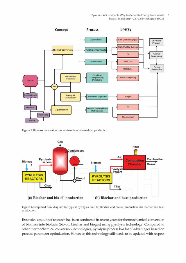
Different types of thermochemical even biological processes have been adopted to convert bio‐mass into value‐added products. Among those processes, pyrolysis is more convenient since it has several advantages of storing, transportation and flexibility in solicitation such as turbines, combustion appliances, boilers, engines, etc. In some cases, solid biomass and waste are precisely challenging to process for pyrolysis research. It is until now at a preliminary stage in terms of expansion and yet requires resolving numerous practical obstacles to contend with conventional fossil fuel–centred procedures [2, 3]. The preparation of liquid biofuels including other products like solid char and gas by pyrolysis of various lignocellulosic residues has been comprehensively explored earlier. Some of these biomass species are beechwood [4], bagasse [5] woody biomass [6, 7], straws [8], seedcakes [9] and municipal solid waste (MSW) [10, 11]. Figure 1 illustrates dif‐ferent types of existing biomass conversion process with their respective output.
Pyrolysis is defined as the thermal decomposition of lignocellulosic derivatives under inert con‐dition in oxygen‐deficient environment. The word is resulting from two Greek words: ‘pyro’, which means fire, and ‘lysis’, which means disintegration into integral parts. Pyrolysis tech‐nology is very old and earlier it was first used for preparation of charcoal in Middle East and Southern Europe before 5500 years ago [12]. Egyptian people used this technique to produce tar for sealing boats [13]. Subsequently then, practice of pyrolysis processes have been grow‐ing and are extensively carried out for charcoal and coke fabrication. Burning of charcoal can produce intensively high temperature to melt tin with copper to obtain bronze. Consequently, pyrolysis has been getting further consideration as an effective technique for transforming biomass into bio‐oil throughout the modern eras [14]. The eventual objective of pyrolysis is to yield high‐value energy products for contending with and gradually supplanting non‐renew‐able fossil fuels. Nevertheless, the expansion of progressive know‐hows is the ensuing chal‐lenge for the investigators to accomplish the objectives. It is required to transform biomass into bio fuels for uninterrupted usage in vehicles, trains, ships and aero‐planes to substitute diesel and petrol [15, 16]. Additional improvement of pyrolysis technology is enduring to produce solid fuel like char or carbonaceous materials, syngas, etc. Typically a pyrolysis system unit contains the equipment for lignocellulosic residues pre‐processing, the pyrolysis reactor, and subsequent unit for downstream processing. Mainly it can be classified as units that produces only heat and biochar (using slow pyrolysis) or units that produce biochar and bio‐oils (using fast pyrolysis). Figure 2 shows simple layout of pyrolysis units with its main products.
Pyrolysis4
Extensive amount of research has been conducted in recent years for thermochemical conversion of biomass into biofuels (bio‐oil, biochar and biogas) using pyrolysis technology. Compared to other thermochemical conversion technologies, pyrolysis process has lot of advantages based on process parameter optimization. However, this technology still needs to be updated with respect
Figure 1. Biomass conversion process to obtain value‐added products.
(a) Biochar and bio-oil production (b) Biochar and heat production
Air
Pyrolysisvapors
Combustion Chamber
Combustion GasesBiomas
s
Char
Heat
PYROLYSISREACTORSBio-oil
Condensers
Pyrolysis vaporsBiomas
s
Char
PYROLYSISREACTORS
Gas
Figure 2. Simplified flow diagram for typical pyrolysis unit. (a) Biochar and bio‐oil production. (b) Biochar and heat production.
Pyrolysis: A Sustainable Way to Generate Energy from Wastehttp://dx.doi.org/10.5772/intechopen.69036
5

Figure 3. Decomposition behaviour of biomass constituents at different temperature [19].
to its commercial applications. In this chapter, emphasis has been given to discuss the current status of pyrolysis technology and its prospective for commercial applications for biofuel, syngas and biochar production. Aspects of pyrolysis technology such as types of pyrolysis, pyrolysis principles, biomass compositions and characteristics, pyrolysis reactor design, pyrolysis prod‐ucts and their physiochemical properties and economics of biofuel production are presented. We have pointed out some of the inherent properties of bio‐oil that cause complications for the end use of the products. Finally, we take a brief look at some processes including catalytic pyrolysis process that aim to valorize bio‐oil by conversion to higher value liquid fuel products.
2. Basic principles of pyrolysis
The thermal decomposition process of pyrolysis using lignocellulosic biomass takes place in the absence of oxygen under inert atmosphere. As an inert atmosphere argon or nitrogen gas flow is usually needed. The fundamental chemical reaction is very complex and consists of several steps. The end products of biomass pyrolysis consist of biochar, bio‐oil and gases. Pyrolysis process emits mainly methane, hydrogen, carbon monoxide and carbon dioxide. The organic materials present in the biomass substrate starts to decompose around 350–550°C and it can proceed until 700–800°C without the presence of air/oxygen [17, 18]. Biomass is mainly composed of long polymeric chain of cellulose, lignin, hemicellulose, pectin and others. The larger molecules of organic materials start to decompose to yield smaller molecules, which are released from the process stream as gases, condensable vapours (tars and oils) and solid char during pyrolysis process. The proportion of each end product depends on the temperature, time, heating rate, and pressure, types of precursors and reactor design and configuration. Figure 3 illustrates the decomposition process of main lignocellulosic residues at different tem‐perature. The moisture content of biomass also plays a vital role in pyrolysis processes. The moisture content of the feedstock should be around 10% during fast pyrolysis process [18].
Pyrolysis6

Due to high moisture content, major products become liquids and if there is low level of water, there is high risk that the process produces huge amount of dust instead of oil. Thus sludge derived from waste stream and meat‐processing wastes require drying before exposing them finally to pyrolysis environment. Less than 450°C when the heating rate is slow, the main yield is biochar. However at higher temperature that is more than 800°C when the heating rate is high then larger fraction of ash and gaseous products are produced. Bio‐oil can be produced applying intermediate temperature using relatively high heating rates. During the beginning of the process around temperature 250–300°C, volatile materials are released at almost 10 times quicker than the subsequent step [20].
Woody biomass was initially used to produce charcoal. The charcoal based on wood during heating produces negligible amount of smoke. Earlier it was extensively used for melting of ore to extract iron. However, the process had drawbacks of less yield percentages, less energy and excessive air pollution. After that, modern technology was developed to extract maximum pos‐sible energy from biomass using combustion (exothermic), gasification (exothermic) and pyrol‐ysis (endothermic) [21]. Combustion deals with the burning of biomass in presence of oxygen to produce heat. The competence of this practice is not satisfactory [22, 23]. Gasification also takes place under oxygenated atmosphere which will yield gaseous fuels. Nevertheless, pyrol‐ysis is the leading phase for both gasification and combustion processes [24, 25]. Consequently pyrolysis can be considered as part of gasification and combustion [26]. The decomposition products yield of biomass during pyrolysis is provided by following Figure 4 [27].
Table 1 summarizes the list of main pyrolysis reactions at different temperature.
Figure 4. The decomposition products of pyrolysis of biomass [27].
Pyrolysis: A Sustainable Way to Generate Energy from Wastehttp://dx.doi.org/10.5772/intechopen.69036
7

3. Lignocellulosic biomass feedstock
3.1. Type and composition of biomass feedstock
The structure of biomass is complex and usually composed of three main natural biomacromol‐ecules: Cellulose, hemicellulose and lignin. Besides that it also has extractives and some min‐erals. The proportion and these basic constituents vary from biomass to biomass [11, 29, 30]. During pyrolysis, cellulose and hemicellulose yield condensable vapours or liquids and gas. Lignin decomposes to give liquid, gas and solid char. Extractives also produce liquid and gas due to simple volatilization or decomposition. The ash fraction inside the char matrix contains minerals. This distribution of components into products is shown schematically in Figure 5.
The vapours produced from initial decomposition of biomass undergoes for secondary reac‐tions to yield soot which also varies due to slow and fast pyrolysis process. Alkali metals act like catalyst by enhancing the char yield. The presence of minerals affects the ignition properties of biochar matrix [11]. It was observed that bio‐oil mainly derived from cellulosic substrate around 500°C [31] whereas biochar may be extracted from lignin. Thus the bio‐mass substrate which contains greater proportion of lignin derivatives can yield more bio‐oils yield. Table 2 shows a list of selected biomass containing different proportion of cellulose, hemicellulose and lignin substrate [11, 32–37].
3.2. Physiochemical properties of biomass
Based on process parameters and design of the reactor, presence of moisture can have sig‐nificant effect on products yield [11]. The charcoal‐making process proceeds through two distinct steps: drying and pyrolysis steps. During the initial phase of drying, combined water in the pores represented as free water is expelled around 110°C. As much as water is pres‐ent, it takes more energy to evaporate. After that between temperatures 150 and 200°C com‐bined water present inside the cellulosic chain of wood will be reduced. In the early stage of carbonization, water evaporates as white smoke from charcoal kiln. Fast pyrolysis process
Temperature Type of reaction End products
Less than 350°C Moisture loss, depolymerization, free radical generation
carbonyl and carboxyl group production, CO and CO2 gas liberation, biochar formation
Between 350°C and 450°C Substitution for breaking of glycoside chain of polysaccharide
Tar production containing levoglucosan, anhydrides and oligosaccharides
Above 450°C Dehydration, rearrangement and fission of sugar units
acetaldehyde, glyoxalin and acrolein production
Above 500°C A mixture of all above processes A mixture of all above products
Condensation Unsaturated products condense and cleave to the char
A highly reactive char residue containing trapped free radicals
Table 1. Pyrolysis reactions at different temperature [28].
Pyrolysis8
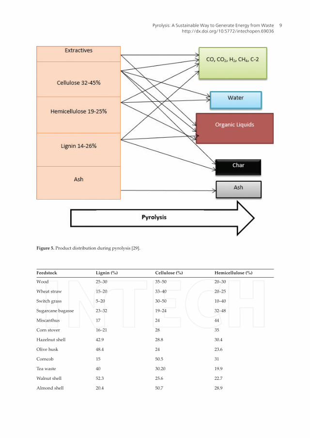
Figure 5. Product distribution during pyrolysis [29].
Feedstock Lignin (%) Cellulose (%) Hemicellulose (%)
Wood 25–30 35–50 20–30
Wheat straw 15–20 33–40 20–25
Switch grass 5–20 30–50 10–40
Sugarcane bagasse 23–32 19–24 32–48
Miscanthus 17 24 44
Corn stover 16–21 28 35
Hazelnut shell 42.9 28.8 30.4
Olive husk 48.4 24 23.6
Corncob 15 50.5 31
Tea waste 40 30.20 19.9
Walnut shell 52.3 25.6 22.7
Almond shell 20.4 50.7 28.9
Pyrolysis: A Sustainable Way to Generate Energy from Wastehttp://dx.doi.org/10.5772/intechopen.69036
9

is effective to dry the feed, so that the rate of temperature rise is not restricted by evapora‐tion of water [38]. Typically 15–20% moisture is present in wood [11]. During producing the activated carbon also, moisture can significantly affect the properties of final carbon sample [39]. The particle size of the biomass matrix will have greater influence between char and liquid yield. Larger proportion of char is formed when particle sizes are big. Larger particles restrict the rate of disintegration, resulting in the increased scope of secondary char form‐ing reaction [11]. Thus larger particle size is good to get more carbon yield whereas smaller particles are required to maximize liquid fractions during fast pyrolysis process. Higher pro‐portion of lignin and fixed carbon also can contribute in better yield of biochar substrate if pyrolysis is carried out at medium temperature of 500°C whereas higher percentages of volatile materials can generate higher yield of bio‐oil and syngas (Table 3) [28]. Therefore, the precursors like hazel nut shell, olive stone, walnut shell is better to produce good quality biochar due to their lignin content (Table 2). The biomass like cereal straw, grasses, energy crops like woody biomass that die to their low mineral and nitrogen content are suitable for bio‐oil and syngas production (Table 4) [40].
Based on composition, physiochemical properties as well as transformation mechanism, lig‐nocellulosic residues can yield different value‐added products as illustrated by Figure 6.
3.3. Controlling temperature profile and heating values of biomass
To optimize the product yield, controlling the temperature profile is the most important factor as it can partially influence the pressure, heating rate, peak temperature and contact time between
Feedstock Lignin (%) Cellulose (%) Hemicellulose (%)
Sunflower shell 17 48.4 34.6
Nut Shell 30–40 25–30 25–30
Paper 0–15 85–99 0
Rice straw 18 32.1 24
Stored refuse 20 60 20
Leaves 0 15–20 80–85
Cotton seed hairs 0 80–95 5–20
Barley straw 14–15 31–34 24–29
Oat straw 16–19 31–37 24–29
Bamboo 21–31 26–43 15–26
Rye straw 16–19 33–35 27–30
Coastal Bermuda grass 6.4 25 35.7
Jute fibre 21–26 45–53 18–21
Banana waste 14 13.2 14.8
Table 2. Chemical constituent of selected biomass.
Pyrolysis10
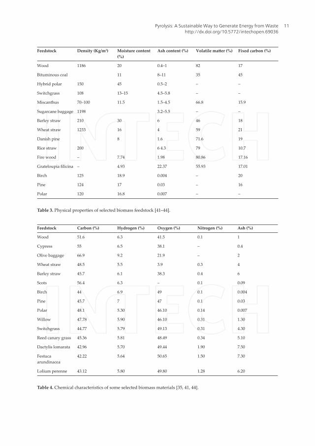
Feedstock Density (Kg/m3) Moisture content (%)
Ash content (%) Volatile matter (%) Fixed carbon (%)
Wood 1186 20 0.4–1 82 17
Bituminous coal 11 8–11 35 45
Hybrid polar 150 45 0.5–2 – –
Switchgrass 108 13–15 4.5–5.8 – –
Miscanthus 70–100 11.5 1.5–4.5 66.8 15.9
Sugarcane baggage 1198 3.2–5.5 – –
Barley straw 210 30 6 46 18
Wheat straw 1233 16 4 59 21
Danish pine 8 1.6 71.6 19
Rice straw 200 6 4.3 79 10.7
Fire wood – 7.74 1.98 80.86 17.16
Grateloupia filicina – 4.93 22.37 55.93 17.01
Birch 125 18.9 0.004 – 20
Pine 124 17 0.03 – 16
Polar 120 16.8 0.007 – –
Table 3. Physical properties of selected biomass feedstock [41–44].
Feedstock Carbon (%) Hydrogen (%) Oxygen (%) Nitrogen (%) Ash (%)
Wood 51.6 6.3 41.5 0.1 1
Cypress 55 6.5 38.1 – 0.4
Olive baggage 66.9 9.2 21.9 – 2
Wheat straw 48.5 5.5 3.9 0.3 4
Barley straw 45.7 6.1 38.3 0.4 6
Scots 56.4 6.3 – 0.1 0.09
Birch 44 6.9 49 0.1 0.004
Pine 45.7 7 47 0.1 0.03
Polar 48.1 5.30 46.10 0.14 0.007
Willow 47.78 5.90 46.10 0.31 1.30
Switchgrass 44.77 5.79 49.13 0.31 4.30
Reed canary grass 45.36 5.81 48.49 0.34 5.10
Dactylis lomarata 42.96 5.70 49.44 1.90 7.50
Festuca arundinacea
42.22 5.64 50.65 1.50 7.30
Lolium perenne 43.12 5.80 49.80 1.28 6.20
Table 4. Chemical characteristics of some selected biomass materials [35, 41, 44].
Pyrolysis: A Sustainable Way to Generate Energy from Wastehttp://dx.doi.org/10.5772/intechopen.69036
11

Figure 6. Biomass transformation to value‐added products.
solid and gaseous phases. Rapid heating and cooling rate is required for minimizing the extent of secondary reactions during fast pyrolysis. This will reduce liquid yield but product quality will be less. Even it will give a more complex mixture having higher viscosity [38]. On the other hand, the slow pyrolysis process uses slow heating rates which lead to higher char yields, but this is not consistent [11]. Higher temperature can ensure release of more volatile fractions to increase the carbon content of the char. However, longer residence time at higher temperature will significantly drop the product yield. The effect of temperature on liquid and gaseous frac‐tion is far more complex. When the pyrolysis temperature reaches up to 400–550°C, liquid yields are higher. Above this temperature, secondary reactions take place by decomposing the con‐densable vapour, which finally gives lesser liquid fractions. For fast pyrolysis, maximum liquid is obtained around 500°C [18]. It was reported also that the liquid yields was 28–41% at tem‐peratures between 377 and 577°C, depending on feedstock during the slow pyrolysis process [13]. Around 42–45% liquid fractions were obtained around temperature of 385–400°C using different straw feeds [45].
3.4. Effect of gas flow rates
Gas flow rate during the pyrolysis process affects the degree of secondary char formation. Lower flow rate is favourable for char formation during slow pyrolysis process whereas higher gas flows are provided during fast pyrolysis process to effectively strip off the vapours as soon as they are formed. Higher pressure intensifies the activity of vapours within the reac‐tor and at the surfaces of char particles to increase the secondary char formation. Conversely, pyrolysis under vacuum gives little char and gives more liquid fractions. For pyrolysis under pressure, moisture in the vapour phase can systematically upsurge the production of carbon. Because, in that case water is acting as catalyst by reducing the activation energy for pyrolysis reactions [46].The gas flow rate significantly influences the thermodynamics of the process. At higher pressure, the reaction is more exothermic using lower gas flow rates. Higher char yields can be ensured when pyrolysis process is exothermic and such conditions will favour
Pyrolysis12

the overall energy balance of the processes pursuing the carbon or char as main product. Thus it can be concluded that, any factor of pyrolysis conditions that increases the contact between primary vapours and hot char surface, including high pressure, lower flow rate of gas, larger particles size or slow heating is expected to favour the char formation with lower liquid yield.
4. Existing pyrolysis process
4.1. Fast pyrolysis
4.1.1. Garret pyrolysis
Pyrolysis, especially pyrolysis of coal, is an age‐long activity but biomass pyrolysis is a com‐pletely new entrant. The process is aimed to produce biofuel. In the garret process, solid waste (Biomass) is allowed to mix with hot char and hot recycle gas in a specially designed chamber. This is then followed by pyrolysis at high temperature, usually above 800°C, and at a holding time of about 10 s. After pyrolysis, the char is the removed while the liquid portion is collected. The resulting formed tar is then separated and further processed to produce the process heat as well as the char feed for further pyrolysis. The process is generally expected to lead to production of at least 40% liquid yield but has been found to produce more of gas at the carbonization temperature and time, thereby making the process uneconomical [47]. The whole process can be summarized into three main steps: The formation of turbulent gaseous stream by intermixing the carrier gas, the solid biomass and the hot char using a designed mixing zone, passing the gaseous steam into the pyrolysis chamber and allowing to go through pyrolysis at temperature of about 800°C for about 10 s, and finally removing the pyrolyzed gaseous stream from the pyrolysis chamber [47].
4.1.2. Georgia Tech entrained bed process
In this process, the main feed (biomass) is crushed and sieved into about 1 mm particle size. The precursor is then dried to about 10% moisture content and fed into the reactor where it is pyrolyzed using a preheated inert gas. At pyrolysis temperature of about 500°C, a maximum yield of about 50% liquid and 30% gas is expected. The holding carbonization time is usually calculated based on the reactor height and the gas flow rates but usually made of several seconds [48]. One major problem of this technique is the low heat produced by the entraining gas which usually leads to low liquid yield since biomass requires high heat for a high liquid yield. Another problem is that fresh solid waste exerts a catalytic effect on bio‐oil cracking leading to production of more char and gas [49].
4.2. Fluidized bed pyrolysis processes
The fluidized bed pyrolysis process possesses highly excellent mass transfer characteristics as it offers an effective and highly positive means of heating of finely chopped biomass in a rapid manner to achieve the pyrolysis temperature to the desired level. It is a well‐established pyrolysis technique that can be used on a large‐scale pyrolysis process as it is
Pyrolysis: A Sustainable Way to Generate Energy from Wastehttp://dx.doi.org/10.5772/intechopen.69036
13

capable of processing hundred tons of biomass per day. The advantages of this technique over conventional pyrolysis technique include improved performance of the system as well as lower viscosity coupled with higher energy content of the produced bio‐oil.
4.2.1. Waterloo flash pyrolysis process (WFPP)
The Waterloo flash pyrolysis process involves the production of organic liquids from biomass materials using continuous atmospheric pressure in the absence of oxygen. Generally, it is a carefully controlled process that produces a high liquid yield. The process has been widely demonstrated using hardwood solid waste to produce organic liquid yield as high as 70% of the feed material [50]. It is a process in which the pyrolysis reactor works on a very unique principle in which the char is not allowed to accumulate in the bed while the treatment of the sand may not be necessary. One big advantage of the process is that the liquid product obtained is usually acid and pours easily with relative stability [51].
4.2.2. RTI process
In order to satisfy certain criteria which have been left unsatisfied by other fast pyrolysis techniques, the RTI process was developed. This involves the use of deep fluid bed using very low temperatures with moderate heating rates and relatively long holding pyrolysis time. Satisfactory results have been obtained from pyrolysis of most biomass using this technol‐ogy which effectively leads to high liquid yields at temperature range of between 400 and 450°C with volatile holding time of about 0.8 s [52]. Fine sand is usually employed as the bed heat carrier. This allows a very low gas flow rate and this coupled with indirect heat applied results in a highly effective thermal efficiency. This is a very big advantage from economic point of view when capital and operating costs are considered [52].
4.2.3. Dynamotive process
This technology, incorporated in 1991 aimed at producing value‐added products from bio‐oil especially to produce biolime. The pyrolyzer operating heat usually comes from the gas or char, that is, the by‐products of the pyrolysis, while the fluidizing gas comes off from the pyrolysis gas [53]. The liquid product obtained is then utilized in the production of materi‐als such as biolime, slaked lime and in the control of SOx and NOx during combustion of coal [53].
4.2.4. Ensyn process
This process involves the utilization of wood and other lignocellulosic materials for the pro‐duction of fermentable sugar. The process involves the following notable steps: subjecting the biomass material to dilute acid treatment (usually dilute sulphuric acid is used to dissolve the hemicellulose while cellulose content is unaffected), separation of the solid residue containing the cellulose, pyrolyzing the separated solid residue at a controlled temperature (400–600°C), atmospheric pressure with short vapour holding time in a fluidized bed reactor, formation of aqueous phase through controlled adjustment of the content of the crude product and finally the separation of the aqueous phase follows [53].
Pyrolysis14

5. Types of pyrolysis
Overall the pyrolysis process can be classified as slow and fast depending on the heating rate. In slow pyrolysis process, the time of heating the biomass substrate to pyrolysis temperature is longer than the time of retention of the substrate at characteristic pyrolysis reaction tempera‐ture. However in fast pyrolysis, the initial heating time of the precursors is smaller than the final retention time at pyrolysis peak temperature. Based on medium, pyrolysis can be of another two types namely hydrous pyrolysis and hydro‐pyrolysis. Slow and fast pyrolysis is usually carried out in inert atmosphere whereas hydrous pyrolysis is carried out in presence of water and hydro‐pyrolysis is carried out in presence of hydrogen. The residence time of vapour in the pyrolysis medium is longer for slow pyrolysis process. This process is mainly used to pro‐duce char production. It can be further classified as Carbonization and Conventional. On the contrary, the vapour residence time is only for seconds or milliseconds. This type of pyrolysis, used primarily for the production of bio‐oil and gas, is of two main types: (1) flash and (2) ultra‐rapid. Table 5 summarizes some basic characteristics of different types of pyrolysis process.
5.1. Fast pyrolysis
During the fast pyrolysis process, biomass residues are heated in absence of oxygen at high temperature using higher heating rate. Based on the initial weight of the biomass, fast pyroly‐sis can provide 60–75% of liquid biofuels with 15–25% of biochar residues [54]. It can also yield 10–20% of gaseous phase depending on the biomass used [54]. The process is charac‐terized by small vapour retention time. However, quick chilling of vapours and aerosol can ensure higher bio‐oil yield [54]. It can provide liquid biofuel for turbine, boiler, engine, power supplies for industrial applications. Fast pyrolysis technology is getting implausible accep‐tance for producing liquid fuels due to certain technical advantages [55–57]:
1. It can ensure preliminary disintegration of the simple oligomer and lignin portions from lignocellulosic biomass with successive upgrading.
2. The scaling up of this process is economically feasible.
Pyrolysis types Retention time Rate of heating Final temperature (°C) Products
Fast <2 s Very high 500 Bio‐oil
Flash <1 s High <650 Bio‐oil, chemicals and gas
Ultra‐rapid <0.5 s Very high 1000 Chemical and gas
Vacuum 2–30 s Medium 400 Bio‐oil
Hydro‐pyrolysis <10 s High <500 Bio‐oil
Carbonization days Very low 400 Charcoal
Conventional 5–30 min Low 600 Char, bio‐oil and gas
Table 5. Different types of pyrolysis process.
Pyrolysis: A Sustainable Way to Generate Energy from Wastehttp://dx.doi.org/10.5772/intechopen.69036
15

3. It can utilize second generation bio‐oil feed stocks such as forest residues, municipal and industrial wastes.
4. It provides easy storability and transportability of liquid fuels.
5. It can ensure secondary transformation of motor fuels, additives or special chemicals.
5.2. Flash pyrolysis
The flash pyrolysis process of biomass can give solid, liquid and gaseous products. The bio‐oil production can go up to 75% using flash pyrolysis [58]. This procedure is carried out by speedy devolatilization under inert atmosphere using higher heating rate with high pyrolysis temperatures around 450 and 1000°C. In this process, the gas residence time (less than 1 s) is too little [59]. Nevertheless, this process has poor thermal stability. Due to cata‐lytic effect of the char, the oil becomes viscous and sometimes it contains some solid residues also [60].
5.3. Slow pyrolysis
Slow pyrolysis can yield good quality charcoal using low temperature and low heating rates. The vapour residence time can be around 5–30 min in this process. The volatile organic fractions present in vapour phase continue to react with each other to yield char and some liquid fractions [61]. The quality of bio‐oil produce in this process is very low. Longer resi‐dence time initiates further cracking to reduce the yield of bio‐oil. The process suffers from low heat transfer values with longer retention time leading to enhance the expenditure by higher input of energy [62, 63]. The stoichiometric equation for production of charcoal is shown by [11].
C 6 H 10 O 5 → 3.74C + 2 .65H 2 O + 1 .17CO 2 + 1.08 CH 4 (1)
Table 6 below gives the theoretical equilibrium yield of cellulose at different temperatures using slow pyrolysis [11].
% of products Temperature (°C)
200 300 400 500 600
C 32 28 27 27 25.2
H2O 36.5 32.5 27 27 22.5
CH4 8.5 10 10 10 9
CO2 23.9 28 35 35 36
CO 0 0 1.2 1.2 4.5
Table 6. Equilibrium concentration of gaseous products at different temperature.
Pyrolysis16

6. Catalytic pyrolysis
A mixture of hydrocarbon was produced earlier from methanol over zeolites like ZSM‐5 [64]. Another patent suggested passing the vapours from pyrolyzer over the bed of zeolite ZSM‐5 to produce short chain hydrocarbon [65]. It was reported that the catalyst of ZSM‐5 can convert bio‐oils generated from the pyrolyzer to alkylated benzene [66]. The disadvan‐tage of using ZSM‐5 as catalyst was coke formation [66]. The researchers concluded that low H/C ratio of bio‐oil caused rapid catalyst deactivation resulting in considerable amount of coke as waste materials [66]. However these disadvantages can be overcome by using circulating fluid bed technology where the fluidized bed can be prepared using different types of catalyst instead of sand [53]. A small‐scale pilot plant level (0.1 to 0.35 kg/h) has also been developed by RTI international [53]. This plant can successfully carry out the pyrolysis of locally available pine biomass to produce bio‐oil. This plant is also trying to carry out the catalytic pyrolysis of wooden chips where by 1 ton of biomass residues can yield 60 gallons of pyrolytic oil per day [53]. Recently other attempts have been made to produce aromatic compound specially benzene, xylene and toluene from biomass substrate [53]. Recently KiOR Inc. in Texas, USA, [53], has stated progress in case of scaling up of this kind of technology [53].
Recently attempt has been taken to develop catalyst from renewable sources. The ash gen‐erated from gasified biomass contains 70–87% of silica in amorphous form which has been used by researchers to produce ZSM‐5 and ZSM‐48 catalyst for bio‐oil upgrading [67]. The biochar derived from duckweed showed excellent catalytic activity for reforming of CH4‐CO2 around 800°C [68]. Catalysts can be mixed with the lignocellulosic substrate earlier to pyrolysis process or separately with the gaseous reactants to obtain desired products. It was revealed that parting of the catalyst and biomass was more operative for the trans‐formation of the required products [69]. This research used chromite (FeCr2O4) as catalyst and it demonstrated favourable outcomes in terms of restricted water production. Table 7 provides summary of zeolite‐based catalyst used for upgrading the lignocellulosic residues until now.
Catalyst Temp. (°C) Feedstock Catalyst effects Refs.
HZSM‐5 with varying Si/Al2O3 ratios
500–764 Kraft lignin Decreasing the SiO2/Al2O3 ratio from 200/1 to 25/1 and increasing the catalyst‐to‐lignin ratio from 1:1 to 20:1 decreased the oxygenates and increased the aromatics. Aromatics yield increased from 500 to 650°C and then decreased at higher temperatures. Under optimal reaction conditions, the aromatic yields were 2.0% (EHI 0.08) and 5.2% (EHI 0.35).
[70]
HZSM‐5, Na/ZSM5, HBeta, and H‐USY
650 Alkaline lignin H‐USY had the largest pore size and lowest Si/Al ratio (7) and had the best liquid yield of 75% and aromatic yield of 40%.
[71]
Pyrolysis: A Sustainable Way to Generate Energy from Wastehttp://dx.doi.org/10.5772/intechopen.69036
17

7. Catalytic hydro‐pyrolysis
Catalytic hydro‐pyrolysis is a kind of catalytic pyrolysis where the pyrolysis is carried out using fluidized bed reactor under the flow of hydrogen. In this process the fluidized bed is replaced by a transition metal catalyst. It was reported that the replacement inert sand with Ni‐based catalyst under atmospheric pressure can convert the bio‐oil into low molecular weight hydro‐carbons within short contact time [75]. Recently Gas Technology Institute, Illinois, USA, reported a new process where the overall process is carried out under 7–34 bar pressure [76]. Due to high pressure C1–C3 gases are evolved which after reforming produce large amount of hydrogen. However, the system is also very complex as it is combination of hydro‐pyrolysis and reform‐ing. There are some technical challenges like feeding biomass solids into the pressurized pyro‐lyzer under hydrogen must be overcome. Overall the establishment of this process is costly also.
8. Types of reactor
The importance of appropriate reactor in any process involving pyrolysis cannot be under‐estimated. Reactors have been designed in such a way as to satisfy specific conditions giving
Catalyst Temp. (°C) Feedstock Catalyst effects Refs.
ZSM‐5, Al/MCM‐41, Al‐MSU‐F, ZnO, ZrO2, CeO2, Cu2Cr2O5, Criterion‐534, alumina‐stabilized ceria MI‐575, slate, char and ashes derived from char and biomass
500 Cassava rhizome ZSM‐5, Al/MCM‐41, Al‐MSU‐F type, Criterion‐534, alumina‐stabilized ceria‐MI‐575, Cu2Cr2O5, and biomass‐derived ash were selective to the reduction of most oxygenated lignin derivatives. ZSM‐5, Criterion‐534, and Al‐MSU‐F catalysts enhanced the formation of aromatic hydrocarbons and phenols. No single catalyst was found to reduce all carbonyl products but ZSM‐5, Criterion‐534 and MI‐575 could reduce most of the carbonyl products that contained hydroxyl groups. ZSM‐5, Criterion‐534, Al/MCM‐41, Al‐MSU‐F, copper chromite, char and ashes increased acetic, formic, and lactic acid. MI‐575 did not increase acids.
[72]
Dolomite 500–800 Waste olive husks Dolomite increased cracking and gas production.
[73]
HZSM‐5, Al/MCM‐41, Al‐MSU‐F, and alumina‐stabilized ceria MI‐575, pore sizes 5.5, 31, 15, and NA, respectively
500 Cassava rhizome HZSM‐5 was the most effective catalyst for the production of aromatic hydrocarbons, phenols, and acetic acid and the reduction of oxygenated lignin‐derived compounds and carbonyls containing side chain hydroxyl groups. Only MI‐575 showed a decrease in acetic acid yields. MI‐575 also showed the most increase in methanol with HZSM‐5 a close second.
[74]
Table 7. Summary of zeolite‐based catalysts used for biomass upgrading.
Pyrolysis18

considerations to parameters such as heating temperature, vapour product residence time and required pressure, for a high bio‐oil yield. In considerations of the above, many types of reactors have been developed by researchers for specific assignments. These reactors include the following:
8.1. Fixed bed reactor
This is a very simple technology that gives priority to the production of bio‐oils, which are relatively uniform in size with low fines content [42]. It is made up of two basic components, that is, the gas cooling compartment and the cleaning system by filtering through cyclone, wet scrubbers and dry filters. During reaction, the solid sample is allowed to pass through a verti‐cal shaft where it encounters an upwardly moving counter current gas stream product. This reactor can be made using either steel, firebricks or concrete and composed of the feeding unit (fuel), a unit for removing the ash and the gas escape unit [77]. The reactor, which has its prior‐ity for applications involving small‐scale heat and power, has high ability to conserve carbon and can operate for long time for solid residence, low gas velocity and of course with a low ash carry‐over. It has its limitation in the problem usually encountered during tar removal [78].
8.2. Fluidized bed reactor
This reactor consists of a mixture of two phases, the solid and the liquid and usually accom‐plished by passing a pressurized fluid through the solid material. It is very popular for fast pyrolysis as it has the following advantages [79]:
1. The provision of heat transfer is rapid.
2. It has a good grip of pyrolysis reaction and vapour holding time control.
3. It has a sufficiently high surface area for contact between the two phases in the mixture.
4. The heat transfer in the system is exemplary, and
5. The relative velocity between the phases is very high.
There are different types of fluidized bed reactors, which include bubbling fluidized, circulat‐ing fluidized, ablative reactor, vortex reactor, rotating‐disk reactor, vacuum pyrolysis reactor, rotating cone reactor, PyRos reactor, auger reactor, plasma reactor, microwave reactor and solar reactor with each designed with different operating systems and for specific applications.
8.2.1. Bubbling fluidized bed reactor
The construction and operation of this reactor is very simple and is illustrated by Figure 7 [80]. The high presence of solid density in the bed ensures a better temperature control, smooth con‐tact between gas and solid, good transfer of heat and excellent storage capacity. The biomass is heated in an environment devoid of oxygen and decomposed into gas, vapour, aerosols and char and these components are finally collected from the reactor. While the charcoal is collected using the cyclone separator and stored, the vapour is cooled rapidly and condensed into high‐quality bio‐oil and stored with about 70% yield of biomass weight (dry weight) [80].
Pyrolysis: A Sustainable Way to Generate Energy from Wastehttp://dx.doi.org/10.5772/intechopen.69036
19

8.2.2. Circulating fluidized bed reactors
The features of this reactor is similar to that of a bubbling fluidized bed reactor described above except the fact that the residence time for the vapours and char is shorter. This makes the gas velocity and the content of char in the bio‐oil to be higher. However, it has a large throughputs advantage. Single and double types of this reactor are available [81]. The basic layout of this reactor is shown by Figure 8 [80].
8.3. Ablative reactor
In this reactor, heating is done through a molten layer on the surface of the hot reactor and in the absence of fluidizing gas. Biomass melting is done by pressing mechanically the biomass against the wall of a heated reactor and as the melted sample is moved, the pyrolysis vapours evaporate as oil. While this reactor allows for a large biomass particle size (up to 20 mm), the materials does not require excessive grinding [82]. However, the configuration of the reactor is a bit complex owing to the process nature which is mechanical. The reactor does not benefit from the same scale of economy as other reactors due to the fact that scaling functions linearly as heat transfer since it is surface area‐controlled. Two types of this reactor, that is, ablative vortex and ablative rotating disk are used commonly [82].
8.4. Vacuum pyrolysis reactor
This is a slow pyrolysis reactor with heat transfer rate very low. This results in a lower bio‐oil yield usually in the range of 35–50 wt% [83]. The design is highly complicated and requirement
Figure 7. Bubbling fluidized bed reactor [80].
Pyrolysis20

for investment and maintenance is always high thereby making the technology uneconomically suitable. The biomass is conveyed into the vacuum chamber with a high temperature with the aid of a conveyor metal belt with periodical stirring of the biomass by mechanical agitation [83]. The heat carrier is usually made of a burner while the biomass is melted by heating inductively using molten salts. It has the ability to process larger particle size biomass but requires special solids feeds special discharging devices in order to have an effective seal all the time [83]. The basic lay out of this type of reactor is shown by Figure 9 [83].
8.5. Rotating cone reactor
Unlike the fluidized bed reactor, the rotating cone reactor requires the mixing of biomass and hot sand is done mechanically and does not require the use of inert gas. The operating feature is shown by Figure 10 [74]. The feed and the hot sand are fed in from the bottom of the cone while they are transported to the lip of the cone during spinning using centrifugal force and as they get to the tip, the vapour generated is condensed by the condenser [74]. The char and the sand are combusted with the sand being heated up again and reintroduced to remix with fresh feedstock at the bottom of the cone. Though the design of this reactor might be complex, its high bio‐oil yield makes it desirable.
8.6. PyRos reactor
The aim of this reactor is to produce a bio‐oil that will not contain any particle. It uses a reactor that is cyclone in nature integrated with hot gas filter. Both the biomass feedstock and the inert
Figure 8. Recirculating fluidized bed reactor [80].
Pyrolysis: A Sustainable Way to Generate Energy from Wastehttp://dx.doi.org/10.5772/intechopen.69036
21
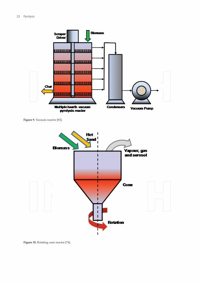
Figure 9. Vacuum reactor [83].
Figure 10. Rotating cone reactor [74].
Pyrolysis22

heat are fed into the cyclone as particles while the vapours that are recycled are made to transport the solids during the process. The particles move down to the bottom of the cyclone through a centrifugal force, during which time drying, heating up and devolatilization take place simulta‐neously. The heating temperature is usually 450–550°C with residence time of 0.5–1 s. The reactor is highly economical in terms of investment and bio‐oil yield [84].
8.7. Auger reactor
This reactor makes use of auger to move the sample feed through a cylindrical tube that is heated up and devoid of oxygen. During this process, the feedstock is pyrolyzed, devolatil‐ized and gasified at a temperature between 400 and 800°C, leading to production of char and condensation of gases into bio‐oil [30].
8.8. Plasma reactor
This reactor is made up of a quartz tube that is cylindrical and fitted with two electrodes made of copper. Feeding of the feedstock is done at the middle using screw with variable speed screw at the top of the tube [85]. The gas flows in the tube is powered by thermal energy produced by the electrodes connected to electrical power source. Inert gas is used to remove oxygen from the compartment as well as producing plasma. Apart from its high consumption of energy, it exhibits the ability to guide against the generation of tar as could be witnessed in slow pyrolysis [86].
8.9. Microwave reactor
This is one of the latest developments in pyrolysis. Here, transfer of energy occurs as a result of interaction between the molecules and atoms using microwave. The whole process of drying and pyrolysis are carried out in a microwave oven chamber connected to electricity source. The carrier gas is inert and is also used to create oxygen‐free chamber. The reactor has proven to be highly effective in chemical recovery from biomass [87]. Among its advantages include effectiveness in heat transfer, ability to effectively control the heating process as well as ability to guide against the formation of undesirable by‐products. It can be used effectively on industrial basis [87].
8.10. Solar reactor
With this technology, provision has been made for storage of solar energy as chemical energy. It is made up of quartz tube with external wall that is opaque, usually exposed to high con‐centration of solar radiation, capable of high temperature (>700°C) generation in the reactor [88, 89]. Pollution is reduced with this reactor as the feedstock is never tampered with during heating process unlike the slow pyrolysis where the process heat is generated by a part of the feedstock. Start up and shut down time is also very fast.
Table 8 illustrates the advantages and disadvantages of different types of reactors.
Pyrolysis: A Sustainable Way to Generate Energy from Wastehttp://dx.doi.org/10.5772/intechopen.69036
23

Reactor type Advantages Disadvantages
Fixed bed Simplicity in design Reliable results Biomass size independent
High carbon conservation Long solid residence time Low ash carry over Difficult to remove char
Bubbling fluidized bed Simple design Easy operational procedures
Good temperature control Suitable for large‐scale application Small particle sizes are needed
Circulating fluidized bed Well‐understood technology Better Thermal control Larger particle sizes can be processed
Large‐scale production difficult Complex hydrodynamics Char is too finer
Rotating cone Centrifugal force circulates hot sand and biomass substrate No carrier gas required
Difficult operational process Smaller particle sizes needed Large‐scale application is difficult
Vacuum The oil is clean Can process larger particles of 3–5 cm No carrier gas required Lower temperature required Condensation of liquid product is easier
Slow process Solid residence time is too high Require large‐scale equipment Poor heat and mass transfer rate Generates more water
Ablative Inert gas is not required Larger particles can be processed
System is more intensive Moderate temperature required Reactor is costly Lower reaction rate
Augercompact No carrier gas required Lower process temperature Moving parts in hot zone Heat transfer in larger scale is not appropriate
PyRos Compact and low cost Efficient heat transfer Short gas residence time
Complex design Solids in the oil Alkali dissolved in the oil High temperature required
Plasma High energy density High heat transfer Effective Process control High electrical power consumption
High operating costs Small particle sizes required
Microwave Efficient heat transfer Exponential control Compact structure Higher heating rate Large‐size biomass can be processed Uniform temperature distribution
High temperature High electrical power consumption High operating costs
Solar Use renewable energy Higher heating rate
High temperature High costs Weather dependent
Table 8. Advantages and disadvantages of different types of reactor [52, 90, 91].
Pyrolysis24

9. Pyrolysis products
9.1. Biochar
Biochar is solid amorphous carbonaceous materials obtained from thermal degradation of lig‐nin and hemicellulose polymer during the pyrolysis process. The physiochemical properties of biocar matrix greatly vary with reactor type and design, biomass composition, particle size and extent of drying, chemical activation, heating rate, reaction time, pressure, flow rate of inert gas, etc. [29, 92–96]. If higher heating rate up to 105–500°C/s is used for less retention time and finer particle size, finer biochar is produced during fast pyrolysis process, whereas larger par‐ticle‐sized feedstock during slow pyrolysis results in a coarser biochar. Usually woody biomass results in coarser biochar whereas crop residues and manures yield more fragile‐structured bio‐char [97]. Earlier investigation demonstrated that biochar yield varies for different temperature regions in a fluidized bed pyrolysis reactor [98]. The results showed that at a low temperature of around 450–500°C, the yield of biochar was high as the rate of devolatilization was low. At a temperature around 550–650°C, the yield of biochar was decreased. At that temperature maxi‐mum yield achieved was about 8–10% [98]. However at higher temperature, around 650°C, bio‐char yield was very low. Biochar predominantly contains larger portion of fixed carbon along with moisture, volatile materials, hydrogen and various other constituents in two structures: stacked crystalline graphene sheets and randomly ordered amorphous aromatic structures [99]. The aromatic portion of biochar contains H, O, N, P and S. These inorganic species have a pronounced impact on the physical and chemical properties of a biochar [100]. The percentages of these constituents depend on the type of biomass and the process of the pyrolysis process [101–103]. Biochar can be utilized as solid fuel in boilers. After catalytic pre‐treatment, it can be used to produce activated carbon, carbon nanotubes and gaseous fractions, etc.
9.2. Syngas
Based on biomass composition and process parameters of pyrolysis, the composition of syn‐gas varies. Usually gaseous products obtained after pyrolysis mostly comprises of H2 and CO. It also contains negligible fraction of CO2, N2, H2O, mixture of alkanes, alkenes and alkynes, such as CH4, C2H4, C2H6, tar, ash, etc. [104]. Higher pyrolysis temperature leads to endothermic reaction. With the increase of pyrolysis, the vaporization of moisture from the biomass takes place initially. After that, thermal degradation and devolatilization take place. At this stage, tar is produced and volatile species are released. A series of secondary reactions such as decarboxylation, decarbonylation, dehydrogenetaion, deoxygenation and cracking takes place to produce mixture of syngas. Therefore, higher temperature initiates the tar decomposition, which results in the production of syngas with decreased yield of oil and char. For a given temperature, dry biomass yields the highest amount of gas at the early stage of pyrolysis, whereas with wet biomass the production of the maximum quantity happens later in the process. This is evident and expected as increase in humidity results in increase in drying time. The cracking of hydrocarbon produces hydrogen at higher temperature. Due to presence of oxygen in biomass, CO and CO2 are produced. The presence of oxygenated polymer that is cellulose determines the evolution of carbonated oxides produced [105].
Pyrolysis: A Sustainable Way to Generate Energy from Wastehttp://dx.doi.org/10.5772/intechopen.69036
25
The lighter hydrocarbons such as CH4, C2H4, C2H6, etc. is formed due to reforming and crack‐ing of heavier hydrocarbons and tar in the vapour phase [106]. Plasma reactor using radio frequency can produce up to 76.64% syngas [85]. The advantages of using syngas are that it produces a considerably minor quantity of unburnt hydrocarbon (HC) and carbon monox‐ide (CO) with higher emissions of nitrogen oxides (NOx). It is reported that, CO and H2 in syngas have comparatively elevated flame speed and temperature which produce greater temperatures in engines to increase the speed of production of CO2and NOx [97–109]. Slow pyrolysis processes give about 10–35% of biogas. At higher temperature flash pyrolysis gives more syngas [110]. Calcined dolomite was used at 750–900°C as a catalyst using fixed bed reactor to produce syngas [110].
9.3. Bio‐oil
The oil extracted after pyrolysis is a mixture of about 300–400 compounds [111]. The oil obtained after pyrolysis has tendency to become viscous due to ageing as numerous physical and chemical changes with subsequent loss of volatile matters take place. However, the ageing process can be slowed down by storing them in cool places [35]. Previously it was found that energy crops can yield oil with high ash/metal content and water [112]. The presence of water will lower the heating values as well as it will make the phase separation difficult [112]. Thus for commercial application, presence of ash and lignin inside the biomass substrate should be carefully monitored. Earlier thermal efficiency of the pyrolysis oils was compared with diesel, but they demonstrated unwarranted delay in ignition [113]. On the other hand, the quantity, quality and constancy of pyrolysis oil can also be improved by method variables such as heating rate, temperature and retention times [114]. Type of different reactors (ablative and fixed), particle size and char accretion can disturb the amount and feature of the pyrolysis oil. Till currently, there is no inclusive research to diminish these things. Therefore, addi‐tional research is obligatory in order to achieve a complete representation of thermochemical transformation processes to yield superior quality pyrolysis oil. Bio‐oil which should be used commercially should preserve its chemical and physical properties such as constancy and vis‐cosity. If the oil contains low molecular weight compound, it is possible. The oil contains high molecular weight compounds if the starting biomass contains larger proportion of lignin.
10. Pyrolysis technology: current status
The utilization of food crops such as soybean, maize and sugarcane for producing ethanol and biodiesel may not endure for long since these crops are primarily cultivated for consump‐tion. The need therefore arise for a more sustainable means of generating these materials from other sources such as biomass materials in addition to others already being researched into. However, none of these has proven to be feasible economically yet, but there is great hope on utilizing lignocellulosic biomass for this purpose through pyrolysis process even though it is still faced by some teething challenges. Some tangible efforts have been made by Ensyn and Dyna Motive companies to commercialize the utilization of biomass materials and other agricultural wastes in the generation of biofuels through fast pyrolysis process. These materials are readily available at little or no cost thereby making their utilization highly
Pyrolysis26

economical. While Dyna Motive concentrates on how to make energy systems from the fuels produced more environmentally friendly, Ensyn on the other hand is looking towards uti‐lizing the chemicals that may be produced from the system as co‐products for other usage such as food smoking. These efforts have since led to production of biofuels from biomass materials. Other notable pyrolysis companies that have been involved in these activities are Pyrovac and Renewable Oil International which use vacuum pyrolysis technique in addition to other smaller pyrolysis plants which are available worldwide. From available data, it clear that fluidized bed reactor are mostly in use for production of bio‐oil using biomass while this is followed by other technologies.
11. Conclusions
The perusal of the literature showed that the transformation of biomass to value‐added prod‐ucts still needs to resolve some trials such as determining the relation between the starting precursors or feedstock and the overall operation of the pyrolysis plant, upgrading the consis‐tency of the pyrolysis reactions in terms of complete energy and material balances to become sustainable for profitable applications. This chapter elaborately described about the principle of pyrolysis technology including the choice of effective parameters for pyrolysis, types of reactor, etc., depending on the preferred output (bio‐oil, biochar or syngas) from the process. However, a comprehensive understanding of the typical process will permit to get maximum output. The chapter highlighted the resulting conclusions and recommendations for additional studies:
1. The major challenge of pyrolysis process is to improve the process by enhancing the product quality and quantity as well as lessening the costs and reduce hazardous environmental impact.
2. Appropriate selection of biomass is a crucial factor to obtain high bio‐oil yields. Biomass containing high cellulose content can be selected, as bio‐oils are mostly derived from it whereas lignin‐based biomass can be used for biochar production. Furthermore, biomass with low moisture content is appropriate to decrease the drying costs and enhance the quality of the extracted oil.
3. The kinetics of pyrolysis of biomass can proceed by several parallel paths. However, appli‐cation of low temperature would produce lower activation energy to yield mainly char and gas. On the contrary, an enhanced temperature will lead higher activation energy to pro‐duce mainly condensable vapours, oils and liquid aerosols. In order to obtain maximum liquid fuels, it is required to heat the biomass speedily at a suitable elevated temperature. Nevertheless, rapid heating of biomass needs smaller particle sizes of the precursors which can initiate constant particle heating. In this regard, fluidized beds are frequently used as efficient reactor type. The disadvantages of fluidized reactor have been overcome by us‐ing ablative pyrolysis and auger pyrolysis methods. These types of novel approaches can endure a wider range of variable sizes of the particles.
4. The separation process of the biochar should be effective and fast to reduce contamination of the bio‐oil.
Pyrolysis: A Sustainable Way to Generate Energy from Wastehttp://dx.doi.org/10.5772/intechopen.69036
27

5. Amendments should be done for upgrading the engine, turbine and boiler combustion systems for proper utilization of pyrolysis bio‐oil while the effect of physiochemical prop‐erties of the oil, emission of small particles, combustion efficiency and slag and carbon deposition during the burning process should be taken under considerations.
6. Until recently, sustainable industrial‐scale catalytic pyrolysis systems are not identified. Only some transition metal catalysts have been developed and studied for lab‐scale approach to improve gas production.
7. Though a lot of studies have been done on pyrolysis economy but most of those were re‐stricted for small‐ or pilot‐scale production. Detail calculation for industrial‐scale pyrolysis plant is essential to inaugurate this technology up to a larger extent for practical phase applications.
8. The usage of bio‐oil as a renewable liquid fuel is hindered due to its underprivileged phys‐icochemical properties. Presently, commercial projections for liquid fuel uses are depend‐ent on its successful alteration to gasoline, diesel or kerosene, or chemicals such as olefins or aromatics. However, these techniques are still in emerging stage.
Author details
Chowdhury Zaira Zaman1*, Kaushik Pal2, Wageeh A. Yehye1, Suresh Sagadevan3, Syed Tawab Shah1, Ganiyu Abimbola Adebisi1, Emy Marliana1, Rahman Faijur Rafique4 and Rafie Bin Johan1
*Address all correspondence to: [email protected]
1 Nanotechnology and Catalysis Research Center (NANOCAT), University Malaya, Kuala Lumpur, Malaysia
2 Wuhan University, Wuchang, PR China
3 Department of Physics, AMET University, Kanathur, Chennai, India
4 Kumoh National Institute of Technology (KIT), Gumi, South Korea
References
[1] Bridgwater AV. Biomass fast pyrolysis. Journal of Thermal Science. 2004;8:21‐49
[2] Downie A. BEST pyrolysis technology: A solution for the greenhouse challenge. BEST energies, Australia. Thermal Net Newsletter. 2007;5:5
[3] Demirbas A. Pyrolysis of ground beech wood in irregular heating rate conditions. Journal of Analytical and Applied Pyrolysis. 2005;73:39‐43
Pyrolysis28

[4] Asadullah M., Rahman M.A., Ali M.M., Motin M.A., Sultan M.B. Alam M.R. Production of bio‐oil from fixed bed pyrolysis of bagasse. Fuel. 2007; 86: 2514‐2520.
[5] Demiral I, Sensoz S. The effects of different catalysts on the pyrolysis of industrial wastes (olive and hazelnut bagasse). Bioresource Technology. 2008;99:8002‐8007
[6] Mohan D, Pittman CU, Bricka M, Smith F, Yancey B, Mohammad J. Sorption of arsenic, cadmium, and lead by chars produced from fast pyrolysis of wood and bark during bio‐oil production. Journal of Colloid and Interface Science. 2007;310:57‐73
[7] Aho A, Kumar N, Eranen K, Salmi T, Hupa M, Murzin DY. Catalytic pyrolysis of woody biomass in a fluidized bed reactor: Influence of the zeolite structure. Fuel. 2008;87:2493‐2501
[8] Karaosmanoglu F, Tetik E. Fuel properties of pyrolysis oil of the straw and stalk of rape plant. Renewable Energy. 1999;16:1090‐1093
[9] Jensen PA, Sander B, Dam‐Johansen K. Pretreatment of straw for power production by pyrolysis and char wash. Biomass Bioenergy. 2001;20:431‐446
[10] Putun E, Uzun BB, Putun AE. Fixed‐bed catalytic pyrolysis of cotton‐seed cake: Effects of pyrolysis temperature, natural zeolite content and sweeping gas flow rate. Bioresource Technology. 2006;97:701‐710
[11] Antal MJ, Grönli M. The art, science, and technology of charcoal production. Industrial & Engineering Chemistry Research. 2003;42:1619‐1640
[12] Mohan D, Pittman CU, Steele PH. Pyrolysis of wood/biomass for bio‐oil: A critical review. Energy Fuels. 2006;20:848‐889
[13] Demirbas A. Partly chemical analysis of liquid fraction of flash pyrolysis products from biomass in the presence of sodium carbonate. Energy Conversion and Management. 2002;43:1801‐1809
[14] Demirbas A. The influence of temperature on the yields of compounds existing in bio‐oils obtained from biomass samples via pyrolysis. Fuel Processing Technology. 2007;88:591‐597
[15] Demirbas A. Combustion characteristics of different biomass fuels. Progress in Energy and Combustion Science. 2004;30:219‐230
[16] Muradov NZ, Veziroglu TN. ‘Green’ path from fossil‐based to hydrogen economy: An overview of carbon‐neutral technologies. International Journal of Hydrogen Energy. 2008; 33:6804‐6839
[17] Bridgwater AV, Peacocke GVC. Fast pyrolysis processes for biomass. Renewable and Sustainable Energy Reviews. 2000;4:1‐73
[18] Bridgwater AV, Meier D, Radlein D. An overview of fast pyrolysis of biomass. Organic Geochemistry. 1999;30:1479‐1493
Pyrolysis: A Sustainable Way to Generate Energy from Wastehttp://dx.doi.org/10.5772/intechopen.69036
29

[19] Available from: http://documentslide.com/documents/biomass‐pyrolysis‐training‐on‐technologies‐for‐converting‐waste‐agricultural.html
[20] Lanzetta M, Blasi DC. Pyrolysis kinetics of wheat and corn straw. Journal of Analytical and Applied Pyrolysis. 1998;44:181‐192
[21] Frassoldati A, Migliavacca G, Crippa T, Velata F, Faravelli T, Ranzi E. Detailed kinetic modeling of thermal degradation of biomasses. In: Proceeding of the 29th Meeting on Combustion; September 2006; Napoli, Italia. Available from: ci.irc.na.cnr.it/download/proc%2006/documenti/Papers/09‐02‐frassoldati‐039.pdf (Accessed: 20 November 2012)
[22] Pei‐dong Z, Guomei J, Gang W. Contribution to emission reduction of CO2 and SO2 byhousehold biogas construction in rural China. Renewable & Sustainable Energy Reviews. 2007;11:1903‐1912
[23] Thornley P, Upham P, Huang Y, Rezvani S, Brammer J, Rogers J. Integrated assessment of bioelectricity technology options. Energy Policy. 2009;37:890‐903
[24] Somerville C. Energy from Biomass. Workshop Presentation for the Inter Academy Council Study Report; Lighting the Way: Towards Sustainable Energy Future. Amsterdam, The Netherlands: IAC; 2005
[25] Fisher T, Hajaligol M, Waymack B, Kellogg D. Pyrolysis behavior and kinetics of bio‐mass derived materials. Journal of Analytical and Applied Pyrolysis. 2002;62:331‐349
[26] Grønli MG, Varhegyi G, Blassi CD. Thermogravimetric analysis and devolatilization kinetics of wood. Industrial & Engineering Chemistry Research. 2002;41:4201‐4208
[27] International Energy Agency. Annual Report, 2006: IEA Bioenergy: Task 34, Pyrolysis of Biomass. Paris, France: International Energy Agency; 2006
[28] Jahirul ML, Rasul MG, Chowdhury AA, Ashwath N. Biofuel production through bio‐mass pyrolysis‐ a technological review. Energies. 2012;5:4952‐5001
[29] Brown R. Biochar production technology. In: Lehmann J, Joseph S, editors. Biochar for Environmental Management. London: Earthscan; 2009. Chapter 8.
[30] Mohan D, Pittman CU, Steele PH. Pyrolysis of wood/biomass for bio‐oil: A critical review. Energy and Fuels. 2006;20(3):848‐889
[31] Yang H, Yan R, Chen H, Lee DH, Liang DT, Zheng C. Pyrolysis of palm oil wastes for enhanced production of hydrogen rich gases. Fuel Processing Technology. 2006;87:935‐942
[32] Abbasi T, Abbasi SA. Biomass energy and the environmental impacts associated with its production and utilization. Renewable & Sustainable Energy Reviews. 2010;14:919‐937
[33] Yang H, Yan R, Chen H, Lee DH, Zheng C. Characteristics of hemicellulose, cellulose and lignin pyrolysis. Fuel. 2007;86:1781‐1788
[34] Wang J, Wang G, Zhang M, Chen M, Li D, Min F, Chen M, Zhang S, Ren Z, Yen Y. A comparative study of thermolysis characteristic and kinetics of seaweeds and fir‐wood. Process Biochemistry. 2006;41:1883‐1886
Pyrolysis30

[35] Fahmi R, Bridgwater AV, Donnison I, Yates N, Jones JM. The effect of lignin and inorganic species in biomass on pyrolysis oil yields, quality and stability. Fuel. 2008;87:230‐1240
[36] Demirbas A. Current technologies for the thermo‐conversion of biomass into fuels and chemicals. Energy Source Part A. 2004;26:715‐730
[37] Demirbas A. Calculation of higher heating values of biomass fuels. Fuel 1997;76:431‐434.
[38] Bridgwater AV, Peacocke GVC. Fast pyrolysis processes for biomass. Renewable and Sustainable Energy Reviews. 2000;4:1‐73
[39] Zanzi R, Bai X, Capdevila P, Bjornbom E. Pyrolysis of biomass in the presence of steam for preparation of activated carbon, liquid and gaseous products. 6th World Congress of Chemical Engineering; 23‐27 September 2001; Melbourne, Australia. 2001.
[40] Friedl A, Padouvas E, Rotter H, Varmuza K. Prediction of heating values of biomass fuel from elemental composition. Analytica Chimica Acta. 2005;544:191‐198
[41] Wang X. Biomass fast pyrolysis in a fluidized bed [Thesis]. The Netherlands: University of Twente, Enscheda; 2006
[42] A Review of fixed bed gasification systems for biomass. Agricultural Engineering International. 2007;5:1‐23
[43] McKendry P. Energy production from biomass (part 1): Overview of biomass. Bioresource Technology. 2002;83:37‐46
[44] Yaman S. Pyrolysis of biomass to produce fuels and chemical feedstocks. Energy Conversion and Management. 2004;45:651‐671
[45] Hornung A, Bockhorn H, Appenzeller K, Roggero CM, Tumiatti V. Plant for the ther‐mal treatment of material and operation process thereof. US Patent Application No.: 10/451018. 2004
[46] Brownsort PA. Review of scope, control and variability. 2009; UK Biochar Research Center, 1‐39. Available from:www. Biochar.org.uk
[47] Garrett DE, Mallan GM. Pyrolysis process for solid wastes. US Patent. 1979;4:153, 514
[48] Kovac RJ, Gorton CW, Knight JA, Newman CJ, O’Neil DJ. Research on the pyrolysis of hardwood in an entrained bed process development unit. 1991. DOI: 10.2172/5086913
[49] Maniatis K, Baeyens J, Peeters H, Roggeman G. The Egemin flash pyrolysis process: Commissioning and results. In: Bridgwater AV, editor. Advances in Thermochemical Biomass Conversion. Blackie; 1993. pp. 1257‐1264
[50] Scott DS, Piskorz J. The flash pyrolysis of Aspen‐Poplar wood. Canadian Journal Chemical Engineering. 1982;60: 666‐674
[51] Scott DS, Piskorz J. The continuous flash pyrolysis of biomass. Canadian Journal Chemical Engineering. 1984;62:404‐412
[52] Scott DS, Majerski P, Piskorz J, Radlein D. A second look at fast pyrolysis of biomass — the RTI process. Journal Analytical Applied Pyrolysis. 1999;51:23‐37
Pyrolysis: A Sustainable Way to Generate Energy from Wastehttp://dx.doi.org/10.5772/intechopen.69036
31

[53] Radlein D, Quignard A. A short historical rteview of fast pyrolysis of biomass, oil & gas science and technology. Rev. IFP Energy’s Novellas. 2013;68(4):765‐783
[54] Demibas A, Arin G. An overview of biomass pyrolysis. Energy Source Part A. 2002; 24:471‐482
[55] Venderbosch RH, Prins W. Review: Fast pyrolysis technology development. Biofuel. 2010;4:178‐208
[56] Chiaramonti D, Oasmaa A, Solantausta Y. Power generation using fast pyrolysis liquids from biomass. Renewable & Sustainable Energy Reviews. 2007;11:1056‐1086
[57] Bridgwater AV. Fast Pyrolysis of Biomass: A Handbook. Newbury, UK: CRL Press; 2005
[58] Demirbas A. Recent advances in biomass conversion technologies. Energy Education Science and Technology. 2000;6:77‐83
[59] Aguado R, Olazar M, Gaisan B, Prieto R, Bilbao J. Kinetic study of polyolefin pyroly‐sis in a conical spouted bed reactor. Industrial & Engineering Chemistry Research. 2002;41:4559‐4566
[60] Cornelissen T, Yperman Y, Reggers G, Schreurs S, Carleer R. Flash co‐pyrolysis of bio‐mass with polylactic acid. Part 1: Influence on bio‐oil yield and heating value. Fuel. 2008;87:1031‐1041
[61] Bridgwater AV, Czernik S, Piskorz J. An overview of fast pyrolysis. Progress in Thermochemical Biomass Conversion. 2001;2:977‐997
[62] Demirbas AH. Yields and heating values of liquids and chars from spruce trunkbark pyrolysis. Energy Source Part A. 2005;27:1367‐1373
[63] Tippayawong N, Kinorn J, Thavornun S. Yields and gaseous composition from slow pyrolysis of refuse‐derived fuels. Energy Source Part A. 2008;30:1572‐1578
[64] Weisz PB, Haag WO, Rodewald PG. Catalytic production of high‐grade fuel (Gasoline) from biomass compounds by shape‐selective catalysis. Science. 1979;5:57‐58. DOI: 10.1126/science.206.4414.57
[65] Frankiewicz TC. Process for converting oxygenated hydrocarbons into hydrocarbons. US Patent 4308411. 1981
[66] Diebold J, Scahill J. Biomass to gasoline. In: Soltes J, Milne TA, editors. Pyrolysis Oils from Biomass, ACS Symposium Series. Washington, DC: American Chemical Society; 1988. p. 376. DOI: 10.1021/bk‐1988‐0376.fw001
[67] Kuen‐Song L, Wang HP, Chang NB, Jou C, Hsiao M. Synthesis of ZSM‐type zeolites from bio‐waste gasification ashes. Energy Sources. 2003;25:565‐576
[68] Muradov N, Fidalgo B, Gujar AC, Garceau N, T‐Raissi A. Production and characteriza‐tion of lemna minor bio‐char and its catalytic application for biogas reforming. Biomass Bioenergy. 2012;42:123‐131
Pyrolysis32

[69] Samolada MC, Papafotica A, Vasalos IA. Catalyst evaluation for catalytic biomass pyrol‐ysis. Energy Fuels. 2000;14:1161‐1167
[70] Li X, Su L, Wang Y, Yu Y, Wang C, Li X, Wang Z. Catalytic fast pyrolysis of Kraft lignin with HZSM‐5 zeolite for producing aromatic hydrocarbons. Frontiers of Environmental Science & Engineering. 2012;6:295‐303
[71] Ma Z, Troussard E, van Bokhoven JA. Controlling the selectivity to chemicals from lig‐nin via catalytic fast pyrolysis. Applied Catalysis A: General. 2012;423‐424:130‐136
[72] Pattiya A, Titiloye JO, Bridgwater AV. Evaluation of catalytic pyrolysis of cassava rhi‐zome by principal component analysis. Fuel. 2010;89:244‐253
[73] Encinar JM, Gonzalez JF, Martinez G, Roman S. Catalytic pyrolysis of exhausted olive oil waste. Journal of Analytical and Applied Pyrolysis. 2009;85:197‐203
[74] Pattiya A, Titiloye JO, Bridgwater AV. Fast pyrolysis of cassava rhizome in the presence of catalysts. Journal of Analytical and Applied Pyrolysis. 2008;81:72‐79
[75] Radlein DSAG, Mason SL, Piskorz J, Scott DS. Hydrocarbons from the catalytic pyrolysis of Biomass. Energy Fuels. 1991;5:760‐763
[76] Marker TL, Felix LG, Linck MB, Roberts MJ. [Tcbiomass2011] integrated hydropyroly‐sis and hydroconversion (IH2) for the direct production of gasoline and Diesel fuels or blending components from biomass, Part 1: Proof of principle testing. Environmental Progress Sustainable Energy. 2012;31:191‐199. DOI: 10.1002/ep.10629
[77] Altafini CR, Wander PR, Barreto RM. Prediction of the working parameters of a wood waste gasifier through an equilibrium model. Energy Conversion and Management. 2003;44:2763‐2777
[78] Rao MS, Singha SP, Sodhaa MS, Dubey AK, Shyam M. Stoichiometric, mass, energy and exergy balance analysis of countercurrent fixed‐bed gasification of post‐consumer resi‐dues. Biomass Bioenergy. 2004;27:155‐171
[79] Lv PM, Xiong ZH, Chang J, Wu CZ, Chen Y, Zhu JX. An experimental study on biomass air–steam gasification in a fluidized bed. Bioresource Technology. 2004;95:95‐101
[80] Sadaka S, Boateng AA. Pyrolysis and Bio‐Oil, Agriculture and Natural Resources (2008); FSA1052. Fayetteville, AK, USA: University of Arkansas. Available from: http://www.uaex.edu/Other_Areas/publications/PDF/FSA‐1052.pdf [Accessed: 5 August 2010]
[81] Li XT, Grace R, Lim CJ, Watkinson AP, Chen HP, Kim JR. Biomass gasification in a circu‐lating fluidized bed. Biomass Bioenergy. 2004;26:171‐193
[82] Jones SB, Holladay JE, Valkenburg C, Stevens DJ, Walton CW, Kinchin C, Elliott DC, Czernik S. Production of Gasoline and Diesel from Biomass via Fast Pyrolysis, Hydrotreating and Hydrocracking: A Design Case; Report No. PNNL‐18284. Springfield, VA, USA: U.S. Department of Energy; 2009
Pyrolysis: A Sustainable Way to Generate Energy from Wastehttp://dx.doi.org/10.5772/intechopen.69036
33

[83] Roy C, Blanchette D, Korving L, Yang J, DeCaumia B. Development of a novel vacuum pyrolysis reactor with improved heat transfer potential. In: Bridgewater AV, Boocock DGB, editors. Developments in Thermochemical. Biomass Conversion. London, UK: Blackie Academic and Professional; 1997. pp. 351‐367
[84] Bramer EA, Holthuis MR. Clean liquid fuel through flash pyrolysis. In: The Development of the PyRos Process; AFTUR Final Report. Enschede, The Netherlands; University of Twente; 2005
[85] Tang L, Huang H. Plasma pyrolysis of biomass for production of syngas and carbon adsorbent. Energy Fuels. 2005;19:1174‐1178
[86] Chen G, Andries K, Luo Z, Spliethoff H. Biomass pyrolysis/Gasification for product gas production. The overall investigation of parametric effects. Energy Conversion and Management. 2003;44:1873‐1884
[87] Fernández Y, Menéndez JA. Influence of feed characteristics on the microwave‐assisted pyrolysis used to produce syngas from biomass wastes. Journal of Analytical and Applied Pyrolysis. 2011;91:316‐322
[88] Boutin O, Ferrer M, Lede J. Flash pyrolysis of cellulose pellets submitted to a concentrated radiation: Experiments and modeling. Chemical Engineering Science. 2002;57:15‐25
[89] Hofmann L, Antal MJ. Numerical simulations of the performance of solar fired flash pyrolysis reactors. Solar Energy. 1984;33:427‐440
[90] Menendez JA, Dominguez A, Inguanzo M, Pis JJ. Microwave pyrolysis of sewage sludge: Analysis of the gas fraction. Journal of Analytical and Applied Pyrolysis. 2004;71:657‐667
[91] Zhao X, Hunang H, Wu C, Li H, Chen Y. Biomass pyrolysis in an Argon/Hydrogen plasma reactor. Chemical Engineering & Technology. 2001;24:197‐199
[92] González JF, Román S, Encinar JM, Martinéz G. Pyrolysis of various biomass residues and char utilization for the production of activated carbons. Journal of Analytical and Applied Pyrolysis. 2009;85:134‐141
[93] Downie A, Crosky A, Munroe P. Physical properties of biochar. In: Lehmann J, Joseph S, editors. Biochar for Environmental Management: Science and Technology. London, UK: Earthscan; 2009
[94] Cetin E, Moghtaderi B, Gupta R, Wall TF. Influence of pyrolysis conditions on the struc‐ture and gasification reactivity of biomass chars. Fuel. 2004;83:2139‐2150
[95] Lua AC, Yang T, Guo J. Effects of pyrolysis conditions on the properties of activated carbons prepared from pistachio‐nut shells. Journal of Analytical and Applied Pyrolysis. 2004;72:279‐287
[96] Dawei A, Zhimin W, Shuting Z, Hongxing Y. Low‐temperature pyrolysis of municipal solid waste: Influence of pyrolysis temperature on the characteristics of solid fuel. International Journal of Energy Research. 2006;30:349‐357
Pyrolysis34

[97] Sohi S, Lopez‐Capel E, Krull E, Bol R. Biochar, Climate Change and Soil: A Review to Guide Future Research; CSIRO Land and Water Science Report. Canberra, Australia: CSIRO; 2009
[98] Rocha JD, Olivares‐Gómez E, Mesa‐Pérez JM, Cortez LAB, Seye O, Brossard‐González LE. The demonstration fast pyrolysis plant to biomass conversion in Brazil. In: Proceedings of World Renewable Energy Congress VII (WRC 2002); Cologne, Germany. 2002
[99] Verheijen F, Jeffery S, Bastos AC, van der Velde M, Diafas I. Biochar application to soils: A critical scientific review of effects on soil properties, processes and functions. European Commission Report No. EUR 24099 EN; European Communities, Ispara, Italy, 2010. Energies. 2012;5:4997
[100] Bourke J, Manley‐Harris M, Fushimi C, Dowaki K, Nunoura T, Antal Jr. MJ. Do all carbonised charcoals have the same structure? A model of the chemical structure of carbonized charcoal. Industrial & Engineering Chemistry Research. 2007;46:5954‐5967
[101] Van Zwieten L, Kimber S, Morris S, Chan KY, Downie A, Rust J, Joseph S, Cowie A. Effects of biochar from slow pyrolysis of papermill waste on agronomic performance and soil fertility. Plant and Soil. 2009;1‐12
[102] Amonette JE, Jospeh S. Characteristics of biochar: Microchemical properties. In: Lehmann J, Joseph S, editors. Biochar for Environmental Management Science and Technology. London, UK: Earthscan; 2009 (Second Edition)
[103] Gaskin JW, Steiner C, Harris K, Das KC, Bibens B. Effect of low‐temperature pyrolysis conditions on biochar for agricultural use. Transactions of the ASABE. 2008;51:2061‐2069
[104] Wei L, Thomasson JA, Bricka RM, Batchelor WD, Columbus EP, Wooten JR. Experimental Study of a Downdraft Gratifier; ASABE Meeting Paper No. 066029. St. Joseph, Michigan: American Society of Agricultural and Biological Engineers; 2006
[105] Couher C, Commandre JM, Salvador S. Failure of the component additively rule to pre‐dict gas yields of biomass in flash pyrolysis at 950°C. Biomass Bioenergy. 2009;33:316‐326
[106] He M, Xiao B, Liu S, Hu Z, Guo X, Luo S. Syngas production from pyrolysis of Municipal solid waste (MSW) with dolomite as downstream catalysts. Journal of Analytical and Applied Pyrolysis. 2010;87:181‐187
[107] Papagiannakis RG, Rakopoulos CD, Hountalas DT, Giakoumis EG. Study of the Performance and exhaust emissions of a spark‐ignited engine operating on syngas fuel. International Journal of Alternative Propulsion. 2007;2:190‐215
[108] McMillian MH, Lawson SA. Experimental and modeling study of hydrogen/syngas production and particulate emissions from a natural gas‐fueled partial oxidation engine. International Journal of Hydrogen Energy. 2006;31:847‐860
[109] Shudo T, Nagano T, Kobayashi M. Combustion characteristics of waste pyrolysis gases in an internal combustion engine. International Journal of Automotive Technology. 2003;4:1‐8
Pyrolysis: A Sustainable Way to Generate Energy from Wastehttp://dx.doi.org/10.5772/intechopen.69036
35

[110] Kantarelis E., Zabaniotou A. Valorization of cotton stalks by fast pyrolysis and fixed bed air gasification for syngas production as precursor of second generation biofuels and sustainable agriculture. Bioresource Technology. 2009;100:942‐947
[111] Oasmaa A, Meier D. Norms and standards for fast pyrolysis liquids: 1. Round robin test. Journal of Analytical and Applied Pyrolysis. 2005;73:323‐334
[112] Shihadeh A, Hochgreb S. Diesel engine combustion of biomass pyrolysis oils. Energy Fuels. 2000;14:260‐274
[113] Abdullah N. An assessment of pyrolysis for processing empty fruit bunches [Thesis]. Birmingham, UK: Aston University; 2005
[114] Evans R, Milne T. Molecular characterization of the pyrolysis of biomass 1. Energy Fuel. 1987;1:123‐137
Pyrolysis36