A Study on Partial Replacement of Cement with Silica Fume in Steel Fibre Reinforced Concrete
11
Volume III, Issue IX, September 2014 IJLTEMAS ISSN 2278 - 2540 www.ijltemas.in Page 89 A Study on Partial Replacement of Cement with Silica Fume in Steel Fibre Reinforced Concrete R. Ramasubramani, P.Naga kishore reddy, S.Divya Department of Civil Engineering, Faculty of Engineering and Technology SRM University, Kattankulathur-603 203, TamilNadu, India. Abstract:-This research investigates and evaluates the results for M-40 grade of concrete having mix proportion 1:1.45:3.12 with water cement ratio 0.35 of steel fibre reinforced concrete (SFRC) by partial replacing of cement with Silica Fume of 4% 6% 8% 10% and containing steel fibres of 2% and 2.5% volume fraction, steel fibres of 50 aspect ratio were used to study the compressive strength, flexural strength, Split tensile strength. A result data obtained has been analyzed and compared with a control concrete specimens (0% fibre). A relationship between percentages of silica fume vs. Compressive strength, flexural strength, and Split tensile strength respectively are represented graphically. Result data will be clearly shown the percentage increase in 28 days of Compressive strength, Flexural strength and Split Tensile strength for M-40 Grade of Concrete, and to study of application of material in Structural elements like long beam for the deflection check. Two long beams are casted with the minimum reinforcement, one with conventional concrete and one with optimum percentages of silica fume and steel fibres. The long beams are subjected to two point loading and deflections readings are recorded, analyzed and compared with conventional concrete and theoretical values respectively. The strength and deflection of optimum concrete mix are appreciable when compare with conventional mix. Key Words: Silica fume; steel fibre; concrete; reinforcement; deflection; cracks. I. INTRODUCTION 1.1 General he attention of the engineers in charge and users of cement is drawn to the fact that quality of various pozzolana cements is to be determined on the basis of its conformity to the performance characteristics given in the respective Indian standard specification for that cement concrete is most widely used construction material in the world due to its ability to get cast in any form and shape. It also replaces old construction materials such as brick and stone masonry. The strength and durability of concrete can be changed by making appropriate changes in its ingredients like cementious material, aggregate and water and by adding some special ingredients. Hence concrete has some deficiencies, to overcome these deficiencies different types of materials are used 1.2 Importance of High Strength Concrete High Strength Concrete (HSC) has been developed over the last two decades, and was primarily introduced through private sector architectural design and construction such as high rise buildings and parking garages. HSC is used for concrete mixtures, which possess high workability, high strength, high modulus of elasticity, high density, high dimensional stability, low permeability and resistance to chemical attack. According to ACI “High Strength Concrete is defined as concrete which meets special Strength and uniformity requirements that cannot always be achieved routinely by using conventional materials and normal mixing, placing and curing practices”. 1.3 Need for this study Since structural concrete is used extensively in the construction ofvarious kinds of buildings, consumed at a rate of approximatelyone ton for every living human beingand aggregate contributessignificantly to the structural performance of concrete, the highdemand for concrete using raw materials such as cement, sand and gravel drastically reduces the natural resources and this damages the environment thereby causing ecological imbalance. Therefore, there is a need to explore and to find suitable additive material to obtain the high strength concrete productions are metallic fibres, non- metallic, pozzolanas, admixtures, etc.,. Fibre reinforced concrete (FRC) is one of the special concrete under high strength concrete (HSC) which is recently developed in the concrete world. Though the basic properties of FRC, mechanical properties of FRC , bond properties of FRC and long term performance of FRC are in acceptable range, for structural applications, knowledge of the behavior of structures is essential for design so that an economical structures can be obtained consistent with safety and serviceability. Since, behaviors of reinforced lightweight FRC beam under flexure and shear had been already studied and published in the earlier publication, this study investigated and presented the experimental evaluation of partial replacement of cement with silica fume in Steel Fibre Reinforced concrete. II. SILICA FUME (SF) Silica fume is the most abundant mineral found in the crust of the earth. It forms an important constituent of practically all rock – forming minerals. Silica fume is a by product in the carbothermic reduction of high purity quartz with carbonaceous materials like coal, coke, wood – chips, in electric arc furnaces in the production of silicon and ferrosilicon alloys. It is found in variety of forms, as quartz crystals, massive forming hills, quartz sand (silica fume), sand stone, quartzite, Tripoli, diatomic, flint, opal, chalcedonic forms like agate, onyx etc.., and in with numerous other forms depending upon colour such T
-
Upload
independent -
Category
Documents
-
view
0 -
download
0
Transcript of A Study on Partial Replacement of Cement with Silica Fume in Steel Fibre Reinforced Concrete

Volume III, Issue IX, September 2014 IJLTEMAS ISSN 2278 - 2540
www.ijltemas.in Page 89
A Study on Partial Replacement of Cement with
Silica Fume in Steel Fibre Reinforced Concrete R. Ramasubramani, P.Naga kishore reddy, S.Divya
Department of Civil Engineering, Faculty of Engineering and Technology
SRM University, Kattankulathur-603 203, TamilNadu, India.
Abstract:-This research investigates and evaluates the results
for M-40 grade of concrete having mix proportion
1:1.45:3.12 with water cement ratio 0.35 of steel fibre
reinforced concrete (SFRC) by partial replacing of cement
with Silica Fume of 4% 6% 8% 10% and containing steel
fibres of 2% and 2.5% volume fraction, steel fibres of 50
aspect ratio were used to study the compressive strength,
flexural strength, Split tensile strength. A result data
obtained has been analyzed and compared with a control
concrete specimens (0% fibre). A relationship between
percentages of silica fume vs. Compressive strength, flexural
strength, and Split tensile strength respectively are
represented graphically. Result data will be clearly shown
the percentage increase in 28 days of Compressive strength,
Flexural strength and Split Tensile strength for M-40 Grade
of Concrete, and to study of application of material in
Structural elements like long beam for the deflection check.
Two long beams are casted with the minimum
reinforcement, one with conventional concrete and one with
optimum percentages of silica fume and steel fibres. The long
beams are subjected to two point loading and deflections
readings are recorded, analyzed and compared with
conventional concrete and theoretical values respectively.
The strength and deflection of optimum concrete mix are
appreciable when compare with conventional mix.
Key Words: Silica fume; steel fibre; concrete; reinforcement;
deflection; cracks.
I. INTRODUCTION
1.1 General
he attention of the engineers in charge and users of
cement is drawn to the fact that quality of various
pozzolana cements is to be determined on the basis of its
conformity to the performance characteristics given in the
respective
Indian standard specification for that cement concrete is
most widely used construction material in the world due
to its ability to get cast in any form and shape. It also
replaces old construction materials such as brick and stone
masonry. The strength and durability of concrete can be
changed by making appropriate changes in its ingredients
like cementious material, aggregate and water and by
adding some special ingredients. Hence concrete has some
deficiencies, to overcome these deficiencies different
types of materials are used
1.2 Importance of High Strength Concrete
High Strength Concrete (HSC) has been
developed over the last two decades, and was primarily
introduced through private sector architectural design and
construction such as high rise buildings and parking
garages. HSC is used for concrete mixtures, which
possess high workability, high strength, high modulus of
elasticity, high density, high dimensional stability, low
permeability and resistance to chemical attack. According
to ACI “High Strength Concrete is defined as concrete
which meets special Strength and uniformity requirements
that cannot always be achieved routinely by using
conventional materials and normal mixing, placing and
curing practices”.
1.3 Need for this study
Since structural concrete is used extensively in
the construction ofvarious kinds of buildings, consumed at
a rate of approximatelyone ton for every living human
beingand aggregate contributessignificantly to the
structural performance of concrete, the highdemand for
concrete using raw materials such as cement, sand and
gravel drastically reduces the natural resources and this
damages the environment thereby causing ecological
imbalance. Therefore, there is a need to explore and to
find suitable additive material to obtain the high strength
concrete productions are metallic fibres, non- metallic,
pozzolanas, admixtures, etc.,.
Fibre reinforced concrete (FRC) is one of the
special concrete under high strength concrete (HSC)
which is recently developed in the concrete world.
Though the basic properties of FRC, mechanical
properties of FRC , bond properties of FRC and long term
performance of FRC are in acceptable range, for structural
applications, knowledge of the behavior of structures is
essential for design so that an economical structures can
be obtained consistent with safety and serviceability.
Since, behaviors of reinforced lightweight FRC beam
under flexure and shear had been already studied and
published in the earlier publication, this study investigated
and presented the experimental evaluation of partial
replacement of cement with silica fume in Steel Fibre
Reinforced concrete.
II. SILICA FUME (SF)
Silica fume is the most abundant mineral found
in the crust of the earth. It forms an important constituent
of practically all rock – forming minerals. Silica fume is a
by product in the carbothermic reduction of high purity
quartz with carbonaceous materials like coal, coke, wood
– chips, in electric arc furnaces in the production of
silicon and ferrosilicon alloys. It is found in variety of
forms, as quartz crystals, massive forming hills, quartz
sand (silica fume), sand stone, quartzite, Tripoli, diatomic,
flint, opal, chalcedonic forms like agate, onyx etc.., and in
with numerous other forms depending upon colour such
T

Volume III, Issue IX, September 2014 IJLTEMAS ISSN 2278 - 2540
www.ijltemas.in Page 90
as purple quartz (amethyst), smoky quartz or false topaz
(citrine), rose quartz and milky quartz. One of the major
occurrences of silica is in sans stone.
Silica fume is an ultra fine material with
spherical particles less than I um in diameter, the average
being about 0.15 um. This makes it approximately 100
times smaller than the average cement particle. The bulk
density of silica fume depends on the degree of deification
in the silo and varies from 130(undensified) to 600 kg/m3.
The specific gravity of silica fume is generally in the
range of 2.2 to 2.3. The specific surface area of silica
fume typically ranges from 15,000 to 30,000 m2/kg.
III. FIBRE REINFORCED CONCRETE (FRC)
The presence of micro cracks in the mortar-
aggregate interface is responsible for the inherent
weakness of plain concrete. The weakness can be
removed by inclusion of fibres in the mixture. Different
types of fibers, such as those used in traditional composite
materials can be introduced into the concrete mixture to
increase its toughness, or ability to resist crack growth.
The fibres help to transfer loads at the internal micro
cracks. Such a concrete is called fibre-reinforced concrete
(FRC). Ordinary Portland cement, river sand, crushed
granite stones, steel fibres and water are the constituents
used for making FRC. Both for FRC and CC, minimum
compressive strength of 40 N/mm2 at 28-days was fixed
as target strength with minimum workability
considerations. If the steel fibres are used in FRC then the
concrete is called as steel fibre reinforced concrete
(SFRC). Steel fibres of aspect ratio (1/d ratio) 50 are
collected from the local dealer and transported to SRM
University premises. The Collected steel fibres and silica
fume are shown in Fig. 1a and 1b respectively. From the
previous studies, mix proportions were selected and the
properties of mixes are shown in Table 1.
Fig.1 a) silica fume
Fig.1 b) Steel fibre
Table 1 Properties of concrete used
Parameters Control concrete (CC) SFRC with SF
Minimum target strength (N/mm2) 40 - 45 40 - 45
Cement content (kg/m3) 480 480
Sand (kg/m3) 730 730
Crushed granite stone (CGS)
(kg/m3)
1510 1510
Silica fume % -- 0, 4, 6, 8 & 10
Steel fibre % -- 0, 2 & 2.5

Volume III, Issue IX, September 2014 IJLTEMAS ISSN 2278 - 2540
www.ijltemas.in Page 91
Water Cement Ratio (W/C) 0.35 0.4
Mix ratios 1:1.52:3.16:0.35
(Cement: Sand: CGS: W/C)
1:1.52:3.16:0.35
(Cement: Sand: CGS: W/C)
Slump (mm) 5 5
Fresh state density (kg/m3) 2486 2762
28 day hardened density (kg/m3) 2413 2658
IV. EXPERIMENTAL INVESTIGATION
4.1Test program
High strength concrete has been produced using
silica fume and steel fibre. Nine cubes, six cylinders and
three beams were casted and tested. Two long beams, one
with steel fibre – silica fume (optimum percentages) and
one with normal control concrete. Study includes the
general cracking behavior and analysis, crack width and
deflection.
4.2 Specimen and reinforcement details
The cross sectional dimension of beam was taken
as 100 × 100 mm and the length of the beam was taken as
500 mm, cylinder of 100mm dia with 200mm length,
cubes of 100 mm for both CC and SFRC-SFmixes. In
both the cases the grade of concrete has been considered
as M40. The cross sectional dimension of long beams was
taken as 150 × 200 and length was take as 1500 mm. The
Fe 415 grade of steel was used for both longitudinal and
transverse reinforcements. Table 2 show the details of
minimum longitudinal reinforcements and spacing of
transverse reinforcements required and actually provided
respectively.
Table 2 Details of reinforcements for both CC and OM long beams
Beams Id
Area of longitudinal
reinforcements (mm2)
Spacing of transverse reinforcements (mm)
Minimum Actually
Provided Minimum Actually Provided
CC & OM 217 227 142 150
CC: Conventional Concrete OM: Optimum Mix
The diameter and the number of bars used for longitudinal
reinforcements, diameter and the spacing of bars for
transverse reinforcements are calculated and given in
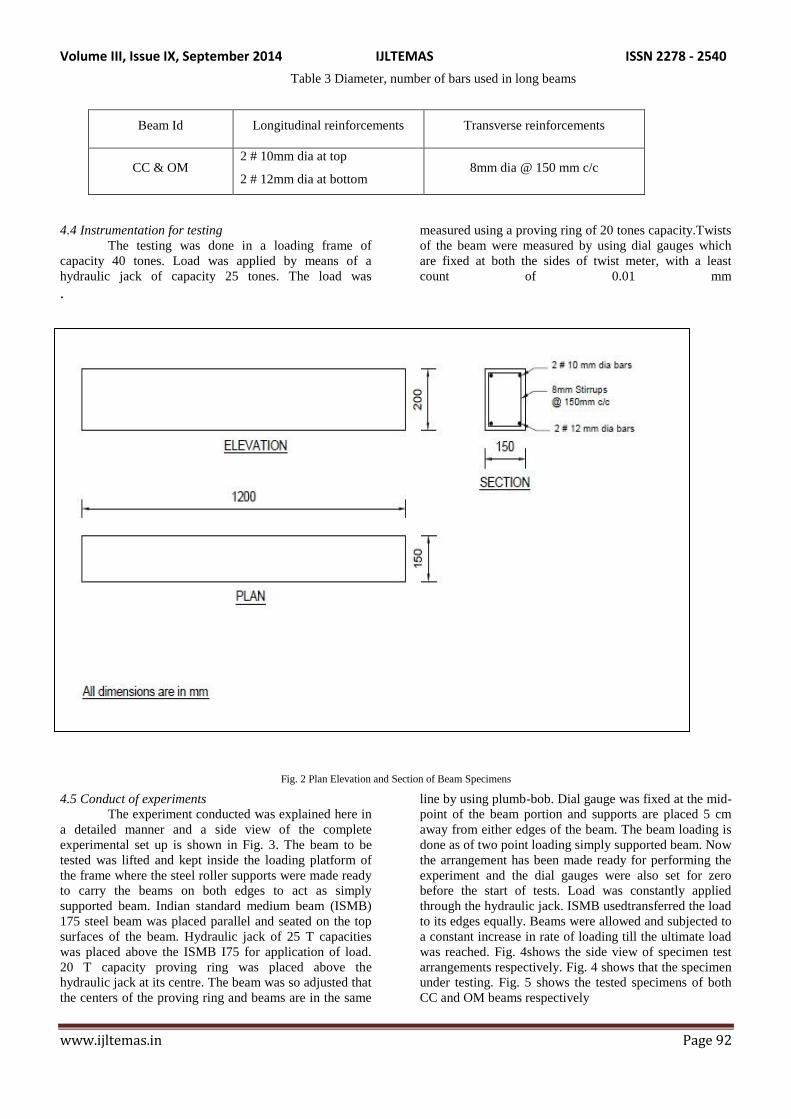
Table 3, respectively. Fig. 2shows the schematic diagram
of the plan, elevation and section of the specimen with
loading points. The beams has been designed and made
strong to avoid the failure, especially at the middle
portion.The cross sectional and the reinforcement details
of the portion are shown in fig. 2 The beam size and
length were chosen to ensure that the beams would fail in
deflection and also to testthe specimen with the loading
frame and the testing facilities available in the structural
laboratory of SRM University
4.3 Specimen preparation
Formwork making use of plywood was prepared
for the beam size. Reinforcements were made ready as per
the details given in Table 2 .The inner surfaces of the
mould were coated with a thin film of crude oil to prevent
adhesion of concrete with the mould before placing the
reinforcements. All the ingredients of the mix were
weighed and machine mixed. The concrete was placed in
three layers and internally compacted using a needle
vibrator after placing the reinforcements. Care was taken
to give uniform compaction for the specimens. Without
delay after the beam cast, the beams were covered with
plastic sheet to minimize the evaporation of water from
the surface of the beam specimen. After 24 h, the sides of
the formwork were removed and cured continuously with
wet gunny bag for 28days, after which the beams were
left alone until the time of test. Before testing, beamswere
whitewashed to facilitate the observations of cracking
patterns during the tests. Location of effective span, centre
lines and the loading points were measured and marked.
Volume III, Issue IX, September 2014 IJLTEMAS ISSN 2278 - 2540
www.ijltemas.in Page 92
Table 3 Diameter, number of bars used in long beams
Beam Id Longitudinal reinforcements Transverse reinforcements
CC & OM 2 # 10mm dia at top
2 # 12mm dia at bottom 8mm dia @ 150 mm c/c
4.4 Instrumentation for testing
The testing was done in a loading frame of
capacity 40 tones. Load was applied by means of a
hydraulic jack of capacity 25 tones. The load was
measured using a proving ring of 20 tones capacity.Twists
of the beam were measured by using dial gauges which
are fixed at both the sides of twist meter, with a least
count of 0.01 mm
.
Fig. 2 Plan Elevation and Section of Beam Specimens
4.5 Conduct of experiments
The experiment conducted was explained here in
a detailed manner and a side view of the complete
experimental set up is shown in Fig. 3. The beam to be
tested was lifted and kept inside the loading platform of
the frame where the steel roller supports were made ready
to carry the beams on both edges to act as simply
supported beam. Indian standard medium beam (ISMB)
175 steel beam was placed parallel and seated on the top
surfaces of the beam. Hydraulic jack of 25 T capacities
was placed above the ISMB I75 for application of load.
20 T capacity proving ring was placed above the
hydraulic jack at its centre. The beam was so adjusted that
the centers of the proving ring and beams are in the same
line by using plumb-bob. Dial gauge was fixed at the mid-
point of the beam portion and supports are placed 5 cm
away from either edges of the beam. The beam loading is
done as of two point loading simply supported beam. Now
the arrangement has been made ready for performing the
experiment and the dial gauges were also set for zero
before the start of tests. Load was constantly applied
through the hydraulic jack. ISMB usedtransferred the load
to its edges equally. Beams were allowed and subjected to
a constant increase in rate of loading till the ultimate load
was reached. Fig. 4shows the side view of specimen test
arrangements respectively. Fig. 4 shows that the specimen
under testing. Fig. 5 shows the tested specimens of both
CC and OM beams respectively

Volume III, Issue IX, September 2014 IJLTEMAS ISSN 2278 - 2540
www.ijltemas.in Page 93
Fig. 3 Test arrangement of specimen

Volume III, Issue IX, September 2014 IJLTEMAS ISSN 2278 - 2540
www.ijltemas.in Page 94
Fig. 4 specimen under testing
Fig. 5 Tested CC and OM beams
V. RESULTS AND DISCUSSION
Before the discussion about this study,
authors feel that it is necessary refresh the background of
Silica fume concrete and Fibre reinforced concrete
established elsewhere. These two concrete are belongs to
high strength concrete, the High-strength concrete has a
compressive strength greater than 40 MPa (5800 psi).
High-strength concrete is made by lowering the water-
cement (W/C) ratio to 0.35 or lower. Often silica fume is
added to prevent the formation of free calcium hydroxide
crystals in the cement matrix, which might reduce the
strength at the cement-aggregate bond. Low W/C ratios
and the use of silica fume make concrete mixes
significantly less workable, which is particularly likely to
be a problem in high-strength concrete applications where
dense rebar cages are likely to be used. As we known the
optimum percentage of silica replacement for cement is
about 7% to 8% this percentage gives 20% to 25% higher
strength with compare to conventional concrete. Where in
fibre reinforced concrete the 2% to 2.5% is optimum
percentage for addition of fibres in weight fraction.
In this study the M40 grade of concrete is
used, and the cement is partially replaced by 0%, 4%, 6%,
8% and 10% with of silica fume, the fibre is of 0%, 2%
and 2.5% to the weight of concrete. The results obtain in
this study was appreciable, the combined optimum
percentage is about 10% of silica fume replacement and
2.5% of fibre addition. This percentages give the more
appreciable results when compared with other percentages
and conventional concrete. The optimum percentages
gives 28%, 70% and more than 75% higher results in
compression test, split tensile test and flexure test
respectively when compare to conventional concrete.

Volume III, Issue IX, September 2014 IJLTEMAS ISSN 2278 - 2540
www.ijltemas.in Page 95
5.1 compression strength
Table 4 depicts that when cement is
replaced by SF and 2.5 % of steel fibres are added, the
maximum 7 days cube compression strength observed as
511.7 N/mm2 and 28 days strength obtained as 56.4
N/mm2
respectively when cement is replaced by SF. The
28 days compression strength curve is shown in Fig. 6
From the properties exhibited by concrete using silica
fume replacing cement it is observed that there may be
marginal loss of strength initially but the same improves
effectively both with the age and incorporation of SF in
place of cement. The increase in the strength development
is due to the fact that silica fume dissolves in saturated
solution of Ca(OH)2 within few minutes. Calcium Silica
Hydrate (C-S-H) gel is formed on the surface of silica
fume particles. This gel produced by SF concrete has
lower C:S ratio than that resulting from the normal
cement concrete without silica fume.
Table. 4 compression strength of concrete 3,7 & 28 days in N/mm2
Fig.6. 28days compression strength cruve
Fibre 2% Fibre 2.5% CC
silica 0 4 6 8 10 0 4 6 8 10 0
3 days 28.4 28.7 29.3 31.8 32.2 29.2 28.8 31.4 34.2 33.5 28.5
7 days 37.7 39.7 42.2 48.1 46.7 38.9 37.4 47.9 50.2 51.7 36.3
28 days 47.2 46.4 48.6 53.1 52.2 48.7 50.2 51.7 55.8 56.4* 43.9

Volume III, Issue IX, September 2014 IJLTEMAS ISSN 2278 - 2540
www.ijltemas.in Page 96
5.2 Splilt Tensile Strength
From Table 5.2 and Fig. 5.2 it is clear that
the maximum cylinder split tensile strength is found to
5.12 N/mm2 at 10% cement replaced by SF and adding
2.5% of fibres (70% more than that of normal
concrete).this tensile strength is mainly due to the
presence of steel fibres which are strong in tension. Due
to the presence of steel fibre the formation of micro cracks
are reduced very much due to this the steel fibre bears the
tensile load acting on the concrete, hence steel is good in
tension the failure of the concrete will be arrested at
higher loads. From the previous reasearch the silica fume
also contribute 25% to 30% increase of tenile strengh.
Table 5 Split tensile Strength of concrete for 3, 7 & 28 days in N/mm2
Fibre 2% Fibre 2.5% CC
Silica 0 4 6 8 10 0 4 6 8 10 0
3
days 3.24 3.43 3.47 3.59 3.50 3.56 3.78 3.85 3.69 4.04 2.29
7
days 3.31 3.66 4.26 3.98 4.04 4.04 3.85 4.48 4.39 4.64 2.48
28
days 4.64 4.74 4.80 4.90 5.02 4.71 4.82 4.91 5.06 5.12* 3.02
Fig.7 28days Split tensile strength cruve
5.3 Flexural Strength
From the Table 5.3 and Fig. 5.3 it is clear
that the maximum flexural strength is 6.4 N/mm2
at 10%
cement replaced by SF and 2.5% of fibres (75% more
than that of normal concrete)this value is far more than
the value calculated from the expressiom 0.7(Fck)1/2
as
specified by IS 456-2002 the Sf besides reacting with the
free lime of cement and contributing to bind themselves
tightly. The binding along the steel fibre results the
aggressive flexure results.
4.4
4.5
4.6
4.7
4.8
4.9
5
5.1
5.2
0 SF 4 SF 6 SF 8 SF 10 SF
Spli
t T
ensi
le S
tren
gth
N/m
m2
% OF Silica Fume2% FIBRE 2.5% FIBRE

Volume III, Issue IX, September 2014 IJLTEMAS ISSN 2278 - 2540
www.ijltemas.in Page 97
Table 5 Flexural Strength of concrete for 3, 7 & 28 days in N/mm2
Fig. 8 28days Flexural strength cruve
5.5 Deflection characteristics
Fibre 2% Fibre 2.5% CC
silica 0 4 6 8 10 0 4 6 8 10 0
3 days 2.4 1.6 2.4 2.8 3.2 1.2 2.4 2 2.4 3.6 1.2
7 days 2.4 2 2.8 3.2 3.6 2.8 2.4 3.2 4 4.8 2.8
28 days 3.6 4.4 4 5.6 5.6 4 3.6 3.6 5.6 6.4* 2.8
Volume III, Issue IX, September 2014 IJLTEMAS ISSN 2278 - 2540
www.ijltemas.in Page 98
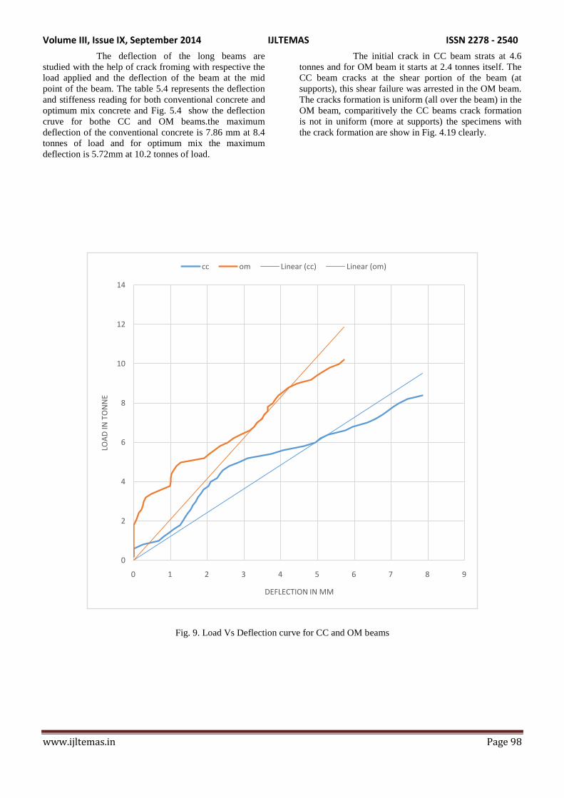
The deflection of the long beams are
studied with the help of crack froming with respective the
load applied and the deflection of the beam at the mid
point of the beam. The table 5.4 represents the deflection
and stiffeness reading for both conventional concrete and
optimum mix concrete and Fig. 5.4 show the deflection
cruve for bothe CC and OM beams.the maximum
deflection of the conventional concrete is 7.86 mm at 8.4
tonnes of load and for optimum mix the maximum
deflection is 5.72mm at 10.2 tonnes of load.
The initial crack in CC beam strats at 4.6
tonnes and for OM beam it starts at 2.4 tonnes itself. The
CC beam cracks at the shear portion of the beam (at
supports), this shear failure was arrested in the OM beam.
The cracks formation is uniform (all over the beam) in the
OM beam, comparitively the CC beams crack formation
is not in uniform (more at supports) the specimens with
the crack formation are show in Fig. 4.19 clearly.
Fig. 9. Load Vs Deflection curve for CC and OM beams
0
2
4
6
8
10
12
14
0 1 2 3 4 5 6 7 8 9
LOA
D IN
TO
NN
E
DEFLECTION IN MM
cc om Linear (cc) Linear (om)

Volume III, Issue IX, September 2014 IJLTEMAS ISSN 2278 - 2540
www.ijltemas.in Page 99
CONCLUSIONS
The 10% replacement of silica fume in cement
and 2.5% of fibre gives the optimum results. The quantity
calculation of steel fibre gives apreciable results with
weight fraction than volume fraction.The optimum mix
gives 40%, 65%, and 75% increase in compression
strength, split tensile strength and flexural strength
respectively when compared with conventional
concrete.The optimum mix concrete beam sustain 40%
higher load compare to conventional concrete beamThe
stifness increase about 60% with optimum mix compare
to conventional concrete
ACKNOWLEDGEMENT
The authors wish to thank the SRM University
Management, for their support to complete this study and
those who were directly or indirectly involved in this
study. Also thanks Dr. K. S. Satyanarayanan,
Professor, Civil, SRM University for his help in reviews
of this research works during its progress.
REFERENCES
[1] Uma, Shanmugapriya (2013), „Experimental
Investigation on Silica Fume as partial Replacement of
Cement in High Performance Concrete‟, The International Journal Of Engineering And Science 2319
– 1813.pp 40 – 44.
[2] Bhanja, Sengupta (2013). „Optimum silica fume content and its mode of action on concrete‟, ACI
MaterialsJournal, September – October 2003, pp 407 –
712. [3] Khedr, Abou-Zeid (1994), „Characteristics of silica-
fume concrete‟, J. Mater. Civ. Eng. ASCE 6 (3), 1994,
pp 357–375. [4] Dilip Kumar Singha Roy (2012), „Effect of Partial
Replacement of Cement by Silica Fume on Hardened
Concrete‟, International Journal of Emerging Technology and Advanced Engineering (ISSN 2250-
2459). pp 69 – 78.
[5] Anant M. Pande, Shende (2012), „Experimental Study on Steel Fiber Reinforced Concrete for M-40 Grade‟,
International Refereed Journal of Engineering and
Science (IRJES – 2319 - 1821). Pp 43 – 50. [6] Vikrant, Kavita (2012), „Introduction to Steel Fiber
Reinforced Concrete on Engineering Performance of
Concrete‟,International Journal of Scientific & Technology Research(ISSN 2277-8616) pp 139 – 145.
[7] Vandewalle (2000), „Cracking behaviour of concrete
beams reinforced with combination of ordinary reinforcement and steel fibers‟, ACI Materials and
Structures, Vol.33, No.227 pp 65 – 73.
[8] IS:456 (2000), Indian Standard Plain and Reinforced
Concrete -. Code of Practice. (Fourth Revision).
[9] IS:10262 (2009), Indian Standard Concrete Mix
Proportioning Guidelines. [10] IS:12269 (1987), Indian Standard for 53 grade OPC,
reaffirmed January (1999). [11] M S Shetty, Concrete technology theory and practice,
New Delhi India S Chand and Company Ltd 2006.
[12] M L Gambhir, Concrete technology- theory and practice Forth edition, Tata Mc Graw Pvt Ltd New
Delhi 2011.