A Study on Fp Z/8 of Anti-Backlash Gear in an Engine - Korea ...
7
한국기계가공학회지 제 권 제 호 , 19 , 10 , pp. 24 30(2020.10) ISSN 1598-6721(Print) Journal of the Korean Society of Manufacturing Process Engineers, Vol. 19, No. 10, pp. 24~30(2020.10) ISSN 2288-0771(Online) https://doi.org/10.14775/ksmpe.2020.19.10.024 Copyright The Korean Society of Manufacturing Process Engineers. This is an Open-Access article distributed under the terms of the Creative Commons Attribution-Noncommercial 3.0 License (CC BY-NC 3.0 http://creativecommons.org/licenses/by-nc/3.0) which permits unrestricted non-commercial use, distribution, and reproduction in any medium, provided the original work is properly cited. 1. Introduction In the working cycle of an engine, the piston undergoes reciprocating linear movement in the cylinder at high but uneven speeds, thereby generating large inertial forces. The crankshaft balancer can effectively balance first-order vibration, but not second-order vibration [1] . The balance box counteracts second-order vibration by generating a force in the opposite direction to the piston force. Finally, the anti-backlash gear is designed to reduce the additional vibration and noise introduced by the balance box. Fig. 1 shows a common commercial engine balance box, where the red area is the anti-backlash gear. The balance box consists of a drive gear, anti-backlash teeth, balance shaft, balance block, and shell body composition. The anti-backlash gear is a primary component for the function of the balance box, and consists of a fixed gear, bias gear, spring, circlip, and pin. The width of the bias gear is only 4mm, making its teeth difficult to grind. Many studies have been conducted on the processing of thin-walled and small-tooth width #1 Corresponding Author : [email protected] Tel: +86-576-8723-9883, Fax: +86-576-8723-9827 #2 Corresponding Author : [email protected] Tel: +82-55-772-2643, Fax: +82-55-772-1578 A Study on Fp Z/8 of Anti-Backlash Gear in an Engine Xing Zhong * , Jianhua Lv * , Hao Lu * , Rui Zhou * , Jianyu Guo * , Lang Kai * , Zhen Qin ** , Qi Zhang *, 1 , Sungki Lyu **, 2 * R&D Dept., Zhejiang Shuanghuan Driveline Co., LTD., China ** School of Mechanical & Aerospace Engineering, Gyeongsang National University, Korea 엔진용 백래쉬 방지 기어의 에 관한 연구 Fp Z/8 종흥 * 려건화 , * 로호 , * 주서 , * 곽검우 , * 개랑 , * 진진 , ** 장기 , *,#1 류성기 , **,#2 * 중국 절강쌍환전동유한회사, ** 경상대학교 대학원 기계항공공학부 (Received 04 July 2020; received in revised form 18 July 2020; accepted 19 July 2020) ABSTRACT The high speed of an engine balance box may cause significant additional gear noise. Gear accuracy is the most useful key to reduce gear noise, but the small tooth width and thin-walled anti-backlash gear introduce challenges to the manufacturing process. In order to reduce the gear noise caused by gear pitch error, this paper investigates the correlation between influencing factors and gear pitch error by analyzing the processing technology, tooling fixture, and equipment accuracy. By improving the process and optimizing the gear design, the gear machining accuracy was improved and the processing cost was saved. Keywords: Antibacklash Gear 백래쉬방지 ( 기어) 기어 연마 , Grinding Teeth( ), G 기어 소음 ear Noise( ) - 24 -
-
Upload
khangminh22 -
Category
Documents
-
view
3 -
download
0
Transcript of A Study on Fp Z/8 of Anti-Backlash Gear in an Engine - Korea ...
한국기계가공학회지 제 권 제 호, 19 , 10 , pp. 24 30(2020.10) ISSN 1598-6721(Print)
Journal of the Korean Society of Manufacturing Process Engineers, Vol. 19, No. 10, pp. 24~30(2020.10) ISSN 2288-0771(Online)
�������������������������������������������������������������������������������������������������������������
https://doi.org/10.14775/ksmpe.2020.19.10.024
Copyright The Korean Society of Manufacturing Process Engineers. This is an Open-Access article distributed under the terms of the Creative Commons Attribution-Noncommercial 3.0 License(CC BY-NC 3.0 http://creativecommons.org/licenses/by-nc/3.0) which permits unrestricted non-commercial use, distribution, and reproduction in any medium, provided the original work is properly cited.
1. Introduction
In the working cycle of an engine, the piston
undergoes reciprocating linear movement in the
cylinder at high but uneven speeds, thereby
generating large inertial forces. The crankshaft
balancer can effectively balance first-order vibration,
but not second-order vibration[1]. The balance box
counteracts second-order vibration by generating a
force in the opposite direction to the piston force.
Finally, the anti-backlash gear is designed to reduce
the additional vibration and noise introduced by the
balance box.
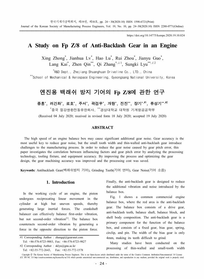
Fig. 1 shows a common commercial engine
balance box, where the red area is the anti-backlash
gear. The balance box consists of a drive gear,
anti-backlash teeth, balance shaft, balance block, and
shell body composition. The anti-backlash gear is a
primary component for the function of the balance
box, and consists of a fixed gear, bias gear, spring,
circlip, and pin. The width of the bias gear is only
4mm, making its teeth difficult to grind.
Many studies have been conducted on the
processing of thin-walled and small-tooth width
#1 Corresponding Author : [email protected]
Tel: +86-576-8723-9883, Fax: +86-576-8723-9827
#2 Corresponding Author : [email protected]
Tel: +82-55-772-2643, Fax: +82-55-772-1578
A Study on Fp Z/8 of Anti-Backlash Gear in an Engine
Xing Zhong*, Jianhua Lv*, Hao Lu*, Rui Zhou*, Jianyu Guo*,
Lang Kai*, Zhen Qin**, Qi Zhang*, 1, Sungki Lyu**, 2
*R&D Dept., Zhejiang Shuanghuan Driveline Co., LTD., China
**School of Mechanical & Aerospace Engineering, Gyeongsang National University, Korea
엔 용 백래쉬 방 기어의 에 한 연Fp Z/8
종흥* 려건화, * 로호, * 주서, * 곽검우, * 개랑, *, ** 장기, *,#1 류성기, **,#2
* 절강쌍환전동유한회사,
**경상대학 대학원 기계항공공학부
(Received 04 July 2020; received in revised form 18 July 2020; accepted 19 July 2020)
ABSTRACT
The high speed of an engine balance box may cause significant additional gear noise. Gear accuracy is the
most useful key to reduce gear noise, but the small tooth width and thin-walled anti-backlash gear introduce
challenges to the manufacturing process. In order to reduce the gear noise caused by gear pitch error, this
paper investigates the correlation between influencing factors and gear pitch error by analyzing the processing
technology, tooling fixture, and equipment accuracy. By improving the process and optimizing the gear
design, the gear machining accuracy was improved and the processing cost was saved.
Keywords: Antibacklash Gear 백래쉬방( 기어) 기어 연마, Grinding Teeth( ), G 기어 소음ear Noise( )
- 24 -
A Study on Fp Z/8 of Anti-Backlash Gear in an Engine 한국기계가공학회지 제 권 제 호: 19 , 9
�������������������������������������������������������������������������������������������������������������
Fig. 1 The anti-backlash gear in engine balance box
gears. Li Min et al. eliminated the reverse rattle of
gears between camshaft after implementing
anti-backlash gears[2]; Fu Jiangang studied the effect
of individual structural parameter changes in the
number of teeth, modulus, and tooth width on the
warpage deformation value[3]; Xu Xueli et al.
obtained high-precision grinding through analysis of
the preliminary processing methods, hot sleeve
equipment, and tooling fixtures of thin-walled gear
assemblies[4]; Lu Shuye analyzed thin-walled gear
parts with thinner thickness, higher processing
accuracy requirements, and easy deformation during
processing[5]. None of the above studies discussed
the effect of processing technology on the gear
pitch error. Therefore, this paper focuses on the
reasons for the excessive pitch and analysis of the
machining process and tooling fixtures to determine
the correlation.
The surface roughness obtained at various
grinding conditions was measured and analyzed, and
the quality of the grinding surface was analyzed
using three-dimensional measurements.
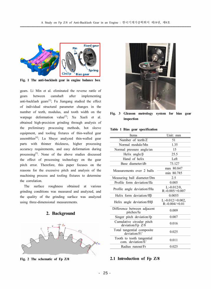
2. Background
Fig. 2 The schematic of Fp Z/8
Fig. 3 Gleason metrology system for bias gear
inspection
Table 1 Bias gear specification
Items Unit: mm
Number of teeth/Z 51
Normal module/Mn 1.35
Normal pressure angle/an 15
Helix angle/β 25.5
Hand of helix Left
Base diameter/db 73.127
Measurements over 2 ballsmax 80.847
min 80.785
Measuring ball diameter/Dm 2.5
Profile form deviation/ffa 0.005
Profile angle deviation/fHa L:-0.012/0,R:-0.005/+0.007
Helix form deviation/ffβ 0.0055
Helix angle deviation/fHβ L:-0.012/+0.002, R:-0.004/+0.01
Difference between adjacent pitches/fu 0.009
Singer pitch deviation/fp 0.007
Cumulative circular pitch deviation/Fp Z/8 0.016
Total tangential composite deviation/Fi’ 0.025
Tooth to tooth tangential com. deviation/fi’ 0.011
Radius runout/Fr 0.025
2.1 Introduction of Fp Z/8
- 25 -
Xing Zhong, Jianhua Lv, Hao Lu, Rui Zhou, Jianyu Guo,
Lang Kai, Zhen Qin, Qi Zhang, Sungki Lyu 한국기계가공학회지 제 권 제 호: 19 , 10
�������������������������������������������������������������������������������������������������������������
As shown in Fig. 2, Fpk is the algebraic
difference between the actual and theoretical arc
lengths of any k tooth distances, K=2 ~ Z/8
integers. The cumulative deviation of Fp Z/8, which
is Z/8 pitch, affects the stationeries of high-speed
transmission gears. The gear inspection of Fp Z/8,
shown in Fig. 3, is a detection diagram of the bias
gear using the Gleason gear metrology system, with
the chuck clamping the small boss, the probe
aligned with the inner hole, and the end face as the
reference[6]. The specification of the bias gear is
shown in Table 1.
2.2 Gear Problem & SOP
As shown in Fig. 4, this project was carried out
to the SOP (Standard Operating Procedure) stage. In
the OTS (Off Tooling Samples) stage, the deviation
was not found due to the lack of full inspection of
Fp Z/8. In the PPAP (Production Part Approval
Process) stage, three out of five products were
found to be out of tolerance (the general
requirement is 16 µm) during the sampling
inspection by the customer, and 300 products were
immediately returned to sort again, with a rejection
rate of about 8% after sorting.
SOP is forthcoming, but such a large defect rate
is severe. First, the company may face customer
complaints. Second, the project SOP was delayed,
resulting in loss of sales. Third, if the sorting of
returned goods in SOP occurs, a special gear
detection center would be needed, incurring a large
cost as well as a waste of manpower and material
resources.
Fig. 4 Fp Z/8 inspection of Bias gear
3. Analysis and Discussion
3.1 Cause Analysis of FP Z/8
In order to solve the Fp Z/8 problem, an internal
workshop was organized to analyze the causes with
respect to six aspects: human, machine, material,
method, loop, and measurement. The reasons for
investigating the four aspects are summarized as
follows.
3.1.1 Eccentric clamping
1) Installation eccentricity leads to deviation between
the actual indexing circle and the theoretical
indexing circle, and the positions of points on
the indexing circle are changed, resulting in Fp
error.
2) Fr is also affected.
3) Installation eccentricity includes machining
installation eccentricity and detection installation
eccentricity.
This factor will lead to a bad batch. At present,
the bad proportion is 8%, so the priority needs to
exclude.
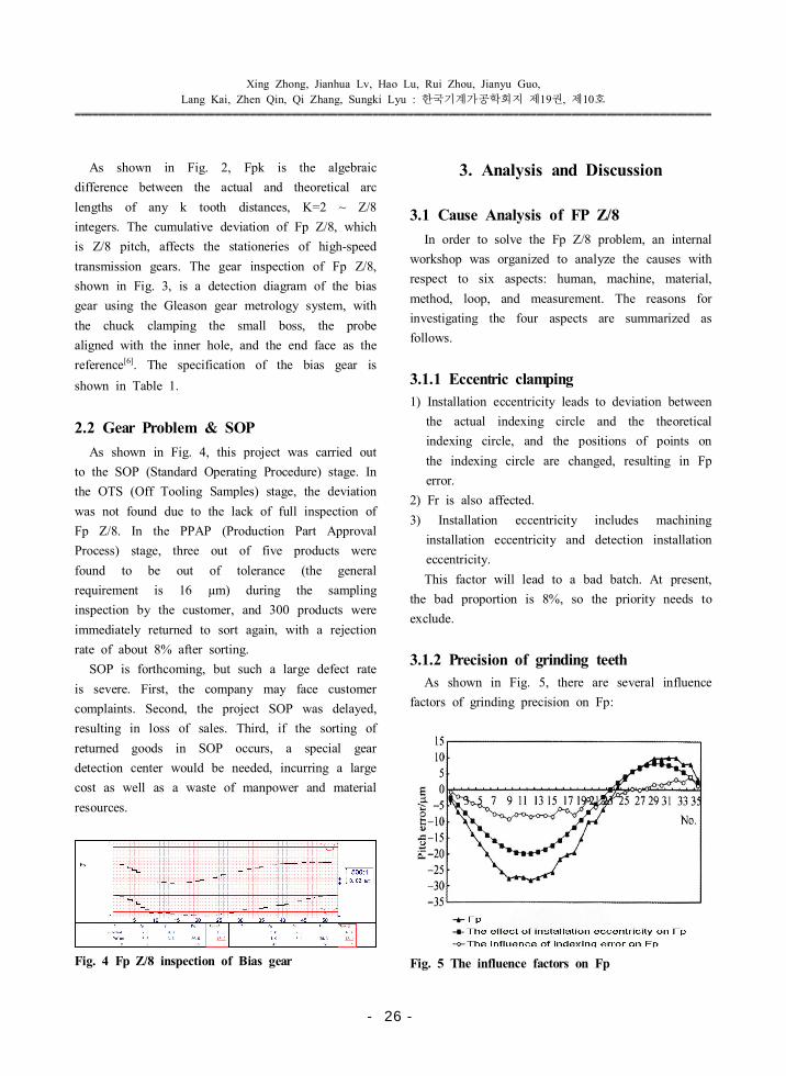
3.1.2 Precision of grinding teeth
As shown in Fig. 5, there are several influence
factors of grinding precision on Fp:
Fig. 5 The influence factors on Fp
- 26 -
A Study on Fp Z/8 of Anti-Backlash Gear in an Engine 한국기계가공학회지 제 권 제 호: 19 , 10
����������������������������������������������������������������������������������������������������������
1) The number of grinding wheels cannot be
divisible by the number of teeth.
2) The indexing mechanism of the gear grinding
machine is not accurate enough[7].
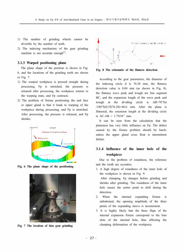
3.1.3 Warped positioning plane
The plane shape of the position is shown in Fig.
6, and the locations of the grinding teeth are shown
in Fig. 7.
1) The warped workpiece is pressed straight during
processing, Fp is stretched, the pressure is
released after processing, the workpiece returns to
the warping state, and Fp contracts.
2) The problem of fixture positioning the end face
or upper gland is that it leads to warping of the
workpiece during processing, and Fp is stretched.
After processing, the pressure is released, and Fp
shrinks.
Fig. 6 The plane shape of the positioning
Fig. 7 The location of bias gear grinding
Fig. 8 The schematic of the flatness detection
According to the gear parameters, the diameter of
the indexing circle d is 76.28 mm, the flatness
detection value is 0.04 mm (as shown in Fig. 8),
the flatness wave peak and trough are line segment
BC, and the expansion length of the wave peak and
trough at the dividing circle is AB=70°Xπ
/180°X(0.5X76.28)=46.6 mm. After the plane is
flattened, the extension length at the dividing circle
is AC-AB = 1.7X10⁻⁵ mm.
It can be seen from the calculation that the
planeness has very little influence on Fp. The defect
caused by the fixture problem should be batch,
unless the upper gland cross float is intermittent
failure.
3.1.4 Influence of the inner hole of the
workpiece
Due to the problem of roundness, the reference
and the tooth are eccentric.
1. A high degree of roundness of the inner hole of
the workpiece is shown in Fig. 9.
After clamping, Fp changes before grinding and
shrinks after grinding. The roundness of the inner
hole causes the center point to shift during the
detection.
2. When the internal expanding fixture is
unbuttoned, the opening amplitude of the three
petals of the expanding sleeve is inconsistent.
3. It is highly likely that the three flaps of the
internal expansion fixture correspond to the four
slots of the internal hole, thus affecting the
clamping deformation of the workpiece.
- 27 -
Xing Zhong, Jianhua Lv, Hao Lu, Rui Zhou, Jianyu Guo,
Lang Kai, Zhen Qin, Qi Zhang, Sungki Lyu 한국기계가공학회지 제 권 제 호: 19 , 10
�������������������������������������������������������������������������������������������������������������
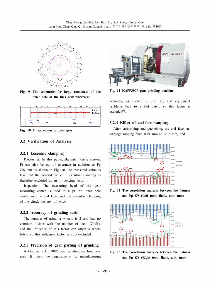
Fig. 9 The schematic for large roundness of the
inner hole of the bias gear workpiece
Fig. 10 Fr inspection of Bias gear
3.2 Verification of Analysis
3.2.1 Eccentric clamping
Processing: In this paper, the pitch circle run-out
Fr can also be out of tolerance in addition to Fp
Z/8, but as shown in Fig. 10, the measured value is
less that the general value. Eccentric clamping is
therefore excluded as an influencing factor.
Inspection: The measuring head of the gear
measuring center is used to align the inner hole
center and the end face, and the eccentric clamping
of the chuck has no influence.
3.2.2 Accuracy of grinding teeth
The number of grinding wheels is 2 and has no
common divisor with the number of teeth (Z=51),
and the influence of this factor can affect a whole
batch, so this influence factor is also excluded.
3.2.3 Precision of gear parting of grinding
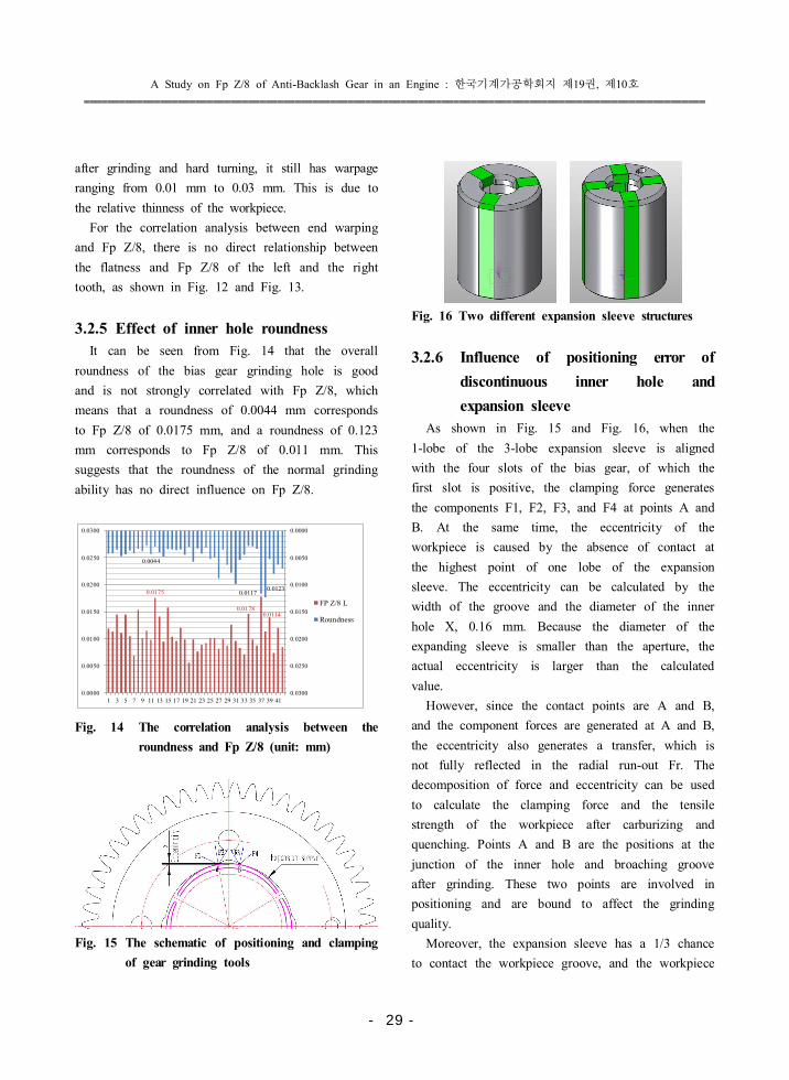
A German KAPP300P gear grinding machine was
used. It meets the requirements for manufacturing
Fig. 11 KAPP300P gear grinding machine
accuracy, as shown in Fig. 11, and equipment
problems lead to a bad batch, so this factor is
excluded[8].
3.2.4 Effect of end-face warping
After carburizing and quenching, the end face has
warpage ranging from 0.01 mm to 0.07 mm, and
0.010
0.017
0.019
0.019 0.020
0.010
0.016
0.027
0.016
0.026
0.018
0.024
0.016 0.015
0.025
0.012
0.015
0.011 0.011
0.013
0.017
0.014
0.021
0.017
0.013
0.022
0.014 0.014
0.022 0.020
0.026
0.009
0.028
0.009 0.010
0.011
0.035
0.018
0.023
0.016 0.017
0.016
0.012 0.011
0.015
0.011
0.015
0.011
0.007
0.015
0.010 0.012
0.010
0.018
0.014
0.010
0.016
0.010 0.010
0.012
0.010
0.006
0.010
0.008 0.009
0.009 0.010
0.010
0.008
0.010 0.009
0.013
0.010 0.008
0.007
0.015
0.010
0.009
0.018
0.011
0.014
0.007
0.012
0.009
0.000
0.005
0.010
0.015
0.020
0.025
0.030
0.035
0.040
0.045
0.050
Flatness
FP Z/8 L
Fig. 12 The correlation analysis between the flatness
and Fp Z/8 (Left tooth flank, unit: mm)
0.010
0.017
0.019 0.019
0.020
0.010
0.016
0.027
0.016
0.026
0.018
0.024
0.016 0.015
0.025
0.012
0.015
0.011 0.011
0.013
0.017
0.014
0.021
0.017
0.013
0.022
0.014 0.014
0.022 0.020
0.026
0.009
0.028
0.009
0.010 0.011
0.035
0.018
0.023
0.016 0.017
0.016
0.011 0.009
0.015
0.011
0.014
0.008
0.011
0.019
0.009
0.011
0.008
0.016
0.013
0.010
0.016
0.010 0.011
0.012
0.009
0.007
0.011
0.007 0.009
0.011 0.010
0.011
0.008
0.012
0.009
0.014
0.011
0.007 0.009
0.013
0.009 0.009
0.016
0.012 0.012
0.008
0.015
0.011
0.000
0.005
0.010
0.015
0.020
0.025
0.030
0.035
0.040
0.045
Flatness
FP Z/8 R
Fig. 13 The correlation analysis between the flatness
and Fp Z/8 (Right tooth flank, unit: mm)
- 28 -
A Study on Fp Z/8 of Anti-Backlash Gear in an Engine 한국기계가공학회지 제 권 제 호: 19 , 10
����������������������������������������������������������������������������������������������������������
after grinding and hard turning, it still has warpage
ranging from 0.01 mm to 0.03 mm. This is due to
the relative thinness of the workpiece.
For the correlation analysis between end warping
and Fp Z/8, there is no direct relationship between
the flatness and Fp Z/8 of the left and the right
tooth, as shown in Fig. 12 and Fig. 13.
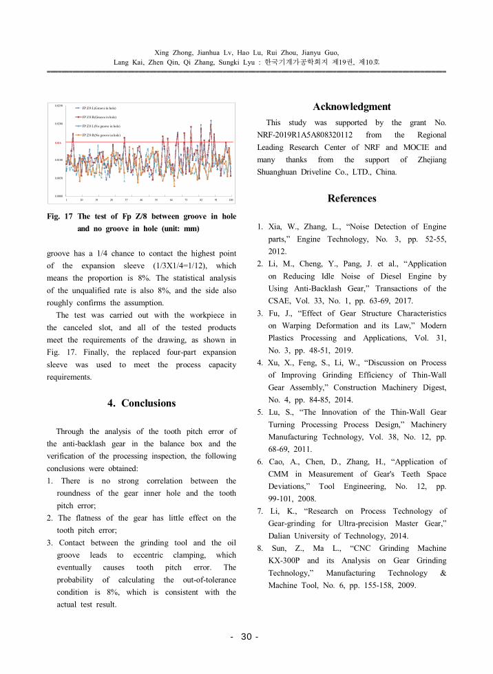
3.2.5 Effect of inner hole roundness
It can be seen from Fig. 14 that the overall
roundness of the bias gear grinding hole is good
and is not strongly correlated with Fp Z/8, which
means that a roundness of 0.0044 mm corresponds
to Fp Z/8 of 0.0175 mm, and a roundness of 0.123
mm corresponds to Fp Z/8 of 0.011 mm. This
suggests that the roundness of the normal grinding
ability has no direct influence on Fp Z/8.
0.0175
0.0178 0.0114
0.0044
0.0117 0.0123
0.0000
0.0050
0.0100
0.0150
0.0200
0.0250
0.03000.0000
0.0050
0.0100
0.0150
0.0200
0.0250
0.0300
1 3 5 7 9 11 13 15 17 19 21 23 25 27 29 31 33 35 37 39 41
FP Z/8 L
Roundness
Fig. 14 The correlation analysis between the
roundness and Fp Z/8 (unit: mm)
Fig. 15 The schematic of positioning and clamping
of gear grinding tools
Fig. 16 Two different expansion sleeve structures
3.2.6 Influence of positioning error of
discontinuous inner hole and
expansion sleeve
As shown in Fig. 15 and Fig. 16, when the
1-lobe of the 3-lobe expansion sleeve is aligned
with the four slots of the bias gear, of which the
first slot is positive, the clamping force generates
the components F1, F2, F3, and F4 at points A and
B. At the same time, the eccentricity of the
workpiece is caused by the absence of contact at
the highest point of one lobe of the expansion
sleeve. The eccentricity can be calculated by the
width of the groove and the diameter of the inner
hole X, 0.16 mm. Because the diameter of the
expanding sleeve is smaller than the aperture, the
actual eccentricity is larger than the calculated
value.
However, since the contact points are A and B,
and the component forces are generated at A and B,
the eccentricity also generates a transfer, which is
not fully reflected in the radial run-out Fr. The
decomposition of force and eccentricity can be used
to calculate the clamping force and the tensile
strength of the workpiece after carburizing and
quenching. Points A and B are the positions at the
junction of the inner hole and broaching groove
after grinding. These two points are involved in
positioning and are bound to affect the grinding
quality.
Moreover, the expansion sleeve has a 1/3 chance
to contact the workpiece groove, and the workpiece
- 29 -
Xing Zhong, Jianhua Lv, Hao Lu, Rui Zhou, Jianyu Guo,
Lang Kai, Zhen Qin, Qi Zhang, Sungki Lyu 한국기계가공학회지 제 권 제 호: 19 , 10
�������������������������������������������������������������������������������������������������������������
0.0000
0.0050
0.0100
0.0150
0.0200
0.0250
1 10 19 28 37 46 55 64 73 82 91 100
FP Z/8 L(Groove in hole)
FP Z/8 R(Groove in hole)
FP Z/8 L(No groove in hole)
FP Z/8 R(No groove in hole)
0.016
Fig. 17 The test of Fp Z/8 between groove in hole
and no groove in hole (unit: mm)
groove has a 1/4 chance to contact the highest point
of the expansion sleeve (1/3X1/4=1/12), which
means the proportion is 8%. The statistical analysis
of the unqualified rate is also 8%, and the side also
roughly confirms the assumption.
The test was carried out with the workpiece in
the canceled slot, and all of the tested products
meet the requirements of the drawing, as shown in
Fig. 17. Finally, the replaced four-part expansion
sleeve was used to meet the process capacity
requirements.
4. Conclusions
Through the analysis of the tooth pitch error of
the anti-backlash gear in the balance box and the
verification of the processing inspection, the following
conclusions were obtained:
1. There is no strong correlation between the
roundness of the gear inner hole and the tooth
pitch error;
2. The flatness of the gear has little effect on the
tooth pitch error;
3. Contact between the grinding tool and the oil
groove leads to eccentric clamping, which
eventually causes tooth pitch error. The
probability of calculating the out-of-tolerance
condition is 8%, which is consistent with the
actual test result.
Acknowledgment
This study was supported by the grant No.
NRF-2019R1A5A808320112 from the Regional
Leading Research Center of NRF and MOCIE and
many thanks from the support of Zhejiang
Shuanghuan Driveline Co., LTD., China.
References
1. Xia, W., Zhang, L., “Noise Detection of Engine
parts,” Engine Technology, No. 3, pp. 52-55,
2012.
2. Li, M., Cheng, Y., Pang, J. et al., “Application
on Reducing Idle Noise of Diesel Engine by
Using Anti-Backlash Gear,” Transactions of the
CSAE, Vol. 33, No. 1, pp. 63-69, 2017.
3. Fu, J., “Effect of Gear Structure Characteristics
on Warping Deformation and its Law,” Modern
Plastics Processing and Applications, Vol. 31,
No. 3, pp. 48-51, 2019.
4. Xu, X., Feng, S., Li, W., “Discussion on Process
of Improving Grinding Efficiency of Thin-Wall
Gear Assembly,” Construction Machinery Digest,
No. 4, pp. 84-85, 2014.
5. Lu, S., “The Innovation of the Thin-Wall Gear
Turning Processing Process Design,” Machinery
Manufacturing Technology, Vol. 38, No. 12, pp.
68-69, 2011.
6. Cao, A., Chen, D., Zhang, H., “Application of
CMM in Measurement of Gear's Teeth Space
Deviations,” Tool Engineering, No. 12, pp.
99-101, 2008.
7. Li, K., “Research on Process Technology of
Gear-grinding for Ultra-precision Master Gear,”
Dalian University of Technology, 2014.
8. Sun, Z., Ma L., “CNC Grinding Machine
KX-300P and its Analysis on Gear Grinding
Technology,” Manufacturing Technology &
Machine Tool, No. 6, pp. 155-158, 2009.
- 30 -