A Study on Agricultural Monitoring System with Zigbee Mesh ...
11
International Journal of Scientific Engineering and Research (IJSER) ISSN (Online): 2347-3878 Index Copernicus Value (2015): 56.67 | Impact Factor (2017): 5.156 Volume 6 Issue 7, July 2018 www.ijser.in Licensed Under Creative Commons Attribution CC BY Agricultural Monitoring System: A Study on Agricultural Monitoring System with Zigbee Mesh Implementation Swaty Dash Research fellow of Computer Science Department, ABIT Engg. College, Cuttack, India Abstract: Today energy resources are becoming scarcer and therefore more valuable. In conjunction with the population growth over last century, the need for finding new, more efficient, and sustainable methods of agricultural cultivation and food production has become more critical. To facilitate this process, we are designing, building, and evaluating a system for precision agriculture which provides farmers with useful data about the soil, the water supply, and the general condition of their fields in a user friendly, easily accessible manner. Our system aims to make cultivation and irrigation more efficient as the farmer is able to make better informed decisions and thus save time and resources. The diversity of location and climatic effects upon agricultural cultivation, along with other environmental parameters over time makes the farmer’s decision-making process more complicated and requires additional empirical knowledge. Applying wireless sensor networks for monitoring environmental parameters and combining this information with a user- customized web service may enable farmers to exploit their knowledge in an efficient way in order to extract the best results from their agricultural cultivation. The system can scale based on each farmer’s demands and the resulting ensemble of collected informa tion may represent a valuable resource for future use, in addition to its use for real-time decision making. The design of the precision agriculture system contains a prototype solution regarding the sensor platform and a customizable service that can be utilized in different ways and by several entities. The main objective of the thesis is to develop a smart wireless sensor network (WSN) for an agricultural environment. Monitoring agricultural environment for various factors such as temperature, gas and humidity along with other factors can be of significance. A traditional approach to measure these factors in an agricultural environment meant individuals manually taking measurements and checking them at various times. This thesis investigates a remote monitoring system using Zigbee which is comprised with X-CTU software with the help of Arduino circuit board. These nodes send data wirelessly to a central server, which collects the data, stores it and will allow it to be analyzed then displayed as needed and can also be sent to the client mobile. Keywords: Wireless Sensor Network, Zigbee, Arduino circuit board 1. Introduction This chapter introduces the general area of research and describes the purpose of this Master‟s thesis project. The introduction to the scientific area is followed by a description of the problems that set the goals for this project. The chapter ends with a description of the structure of this thesis. General introduction to the area 1.1 Agricultural Monitoring System The contemporary world is in a transition stage where problems concerning global issues, such as global warming and alternative energy sources, are combined with new challenges demanding immediate solutions. Society‟s focus has shifted from economic growth to sustainable development, where environmental, social, and economic aspects are considered together, rather than separately. Policies that promote sustainability in all sectors of the economy (manufacturing, agriculture, and services) are now considered as a part of good governance. Problems such as climate change, population growth, and poverty (especially hunger), occur in a context of a gradual depletion of natural resources and the fear of diminishing coal energy reserves. These are some of the global issues that are thought to require multidisciplinary approaches in order to be addressed successfully. In this Master‟s project we focus on agricultural production and cultivation. This overall process has a significant role in fulfilling the basic human need for food. The production, preparation, packaging, distribution, etc. of food also generates a lot of income. The aim of this Master‟s thesis project is to exploit modern technologies and tools to improve monitoring and management of crops, in order to improve the efficiency and sustainability of farming and food production. To this end, we have designed a system for precision agriculture, which relies on a wireless sensor network combined with a service to provide individual farmers with access to data that they find useful. The system utilizes wireless sensor nodes that collect and transmit data about the quality of the water supply, the soil, and other parameters in an agricultural field. While such sensor-based systems have been investigated earlier, one of the key innovations to be explored in this Master‟s thesis project is the combination of these sensors systems with a service- driven business model to increase their ease of use and to amplify the gains that can be realized via an integrated system. The goal is to give a agriculture a more complete picture of the current and historic crop status in order to faster better informed decision making. It is expected that such decisions will benefit both farming and irrigation by saving time and resources. Factors such as the diversity of conditions which vary depending on location combined with the in ability to predict the future characteristics of the environment during the different seasons over time complicate the decision making process and require specialized knowledge. This project is an attempt to bring some of these micro-environmental sources of information into the decision making process of agriculture. Paper ID: IJSER183 50 of 60
-
Upload
khangminh22 -
Category
Documents
-
view
0 -
download
0
Transcript of A Study on Agricultural Monitoring System with Zigbee Mesh ...

International Journal of Scientific Engineering and Research (IJSER) ISSN (Online): 2347-3878
Index Copernicus Value (2015): 56.67 | Impact Factor (2017): 5.156
Volume 6 Issue 7, July 2018
www.ijser.in Licensed Under Creative Commons Attribution CC BY
Agricultural Monitoring System: A Study on
Agricultural Monitoring System with Zigbee Mesh
Implementation
Swaty Dash
Research fellow of Computer Science Department, ABIT Engg. College, Cuttack, India
Abstract: Today energy resources are becoming scarcer and therefore more valuable. In conjunction with the population growth over
last century, the need for finding new, more efficient, and sustainable methods of agricultural cultivation and food production has
become more critical. To facilitate this process, we are designing, building, and evaluating a system for precision agriculture which
provides farmers with useful data about the soil, the water supply, and the general condition of their fields in a user friendly, easily
accessible manner. Our system aims to make cultivation and irrigation more efficient as the farmer is able to make better informed
decisions and thus save time and resources. The diversity of location and climatic effects upon agricultural cultivation, along with other
environmental parameters over time makes the farmer’s decision-making process more complicated and requires additional empirical
knowledge. Applying wireless sensor networks for monitoring environmental parameters and combining this information with a user-
customized web service may enable farmers to exploit their knowledge in an efficient way in order to extract the best results from their
agricultural cultivation. The system can scale based on each farmer’s demands and the resulting ensemble of collected information may
represent a valuable resource for future use, in addition to its use for real-time decision making. The design of the precision agriculture
system contains a prototype solution regarding the sensor platform and a customizable service that can be utilized in different ways and
by several entities. The main objective of the thesis is to develop a smart wireless sensor network (WSN) for an agricultural environment.
Monitoring agricultural environment for various factors such as temperature, gas and humidity along with other factors can be of
significance. A traditional approach to measure these factors in an agricultural environment meant individuals manually taking
measurements and checking them at various times. This thesis investigates a remote monitoring system using Zigbee which is
comprised with X-CTU software with the help of Arduino circuit board. These nodes send data wirelessly to a central server, which
collects the data, stores it and will allow it to be analyzed then displayed as needed and can also be sent to the client mobile.
Keywords: Wireless Sensor Network, Zigbee, Arduino circuit board
1. Introduction
This chapter introduces the general area of research and
describes the purpose of this Master‟s thesis project. The
introduction to the scientific area is followed by a
description of the problems that set the goals for this project.
The chapter ends with a description of the structure of this
thesis.
General introduction to the area
1.1 Agricultural Monitoring System
The contemporary world is in a transition stage where
problems concerning global issues, such as global warming
and alternative energy sources, are combined with new
challenges demanding immediate solutions. Society‟s focus
has shifted from economic growth to sustainable
development, where environmental, social, and economic
aspects are considered together, rather than separately.
Policies that promote sustainability in all sectors of the
economy (manufacturing, agriculture, and services) are now
considered as a part of good governance. Problems such as
climate change, population growth, and poverty (especially
hunger), occur in a context of a gradual depletion of natural
resources and the fear of diminishing coal energy reserves.
These are some of the global issues that are thought to
require multidisciplinary approaches in order to be
addressed successfully. In this Master‟s project we focus on
agricultural production and cultivation. This overall process
has a significant role in fulfilling the basic human need for
food. The production, preparation, packaging, distribution,
etc. of food also generates a lot of income. The aim of this
Master‟s thesis project is to exploit modern technologies and
tools to improve monitoring and management of crops, in
order to improve the efficiency and sustainability of farming
and food production. To this end, we have designed a system
for precision agriculture, which relies on a wireless sensor
network combined with a service to provide individual
farmers with access to data that they find useful. The system
utilizes wireless sensor nodes that collect and transmit data
about the quality of the water supply, the soil, and other
parameters in an agricultural field. While such sensor-based
systems have been investigated earlier, one of the key
innovations to be explored in this Master‟s thesis project is
the combination of these sensors systems with a service-
driven business model to increase their ease of use and to
amplify the gains that can be realized via an integrated
system. The goal is to give a agriculture a more complete
picture of the current and historic crop status in order to
faster better informed decision making. It is expected that
such decisions will benefit both farming and irrigation by
saving time and resources. Factors such as the diversity of
conditions which vary depending on location combined with
the in ability to predict the future characteristics of the
environment during the different seasons over time
complicate the decision making process and require
specialized knowledge. This project is an attempt to bring
some of these micro-environmental sources of information
into the decision making process of agriculture.
Paper ID: IJSER183 50 of 60

International Journal of Scientific Engineering and Research (IJSER) ISSN (Online): 2347-3878
Index Copernicus Value (2015): 56.67 | Impact Factor (2017): 5.156
Volume 6 Issue 7, July 2018
www.ijser.in Licensed Under Creative Commons Attribution CC BY
2. Problem definition
The process of utilizing technology in agriculture and
cultivation requires deep knowledge of agricultural
processes, biology, chemistry, and empirical knowledge.
There are many parameters which must be taken into
consideration and investigated in depth when designing a
system that should improve cultivation procedures by
making the whole process more effective and sustainable. In
order to design and build a precision agriculture system that
can be widely used by many users and applied in different
contexts, many questions need to be addressed. Some of
these questions are:
1) Is it feasible to design a system that will accommodate
every possible scenario in an agricultural context and do
so for all possible users?
2) Is automation in agriculture really useful and in what part
or parts of the cultivation process (e.g. seed planting,
growing, harvesting, selling) can it be applied?
3) What is the cost of the cultivation process and how can
this cost be reduced by automating one or more parts of
this process?
4) What is the most costly component of this process that
could be reduced? How and how much this cost could be
reduced?
5) Are geographic parameters such as location, altitude,
solar exposure, ground and air moisture, ground and air
temperature, mineral content of the soil, the (micro-)
climate, or the season, sufficient to make a significant
difference in the way that a crop is cultivated?
6) What are the sensitivities of the crop that should be taken
care of when agriculture?
7) What types of plants are to be planted and how long will
this crop be planted in this location? What is the planned
rotation of seeds? What are the plans for applying
fertilizer to this location? What is the level of the
agriculture‟s empirical knowledge?
8) Are there any abnormalities regarding the location,
season of the year, previous crops in a specific field, or a
combination of all these aspects which need to be
considered as part of an informed decision making
procedure by the agriculture?
Today, these open questions cannot be answered with
confidence even by experts. Agricultural science is a
multidisciplinary field and all of the above aspects need to
be taken into account when making decisions about
cultivation of a field on a farm. Furthermore, research in
agricultural science is strongly related to local areas. Climate
and soil properties vary from one place to another and from
time to time. Climate change and transformation of the
plants and soil occur as time passes, thus making successful
and sustainable cultivation a tough process for someone who
does not know the specific aspects of the locality and how
the process needs to evolve over time in this specific
geographical and microclimatic area.
Goals
The need for intelligent farming especially in developing
countries like India has grown to a greater extent. Moreover,
research in area of Zigbee based wireless sensor network in
agriculture, such as monitoring of environmental conditions
like weather, soil moisture content, temperature and
monitoring growth of the crop, precision agriculture,
automated irrigation facility has taken a new dimension.
Nowadays, awareness about implementing technology for
agricultural environment has been increased. Manual
collection of data for desired factors can be sporadic, not
continuous and produce variations from incorrect
measurement taking. This can cause difficulty in controlling
environmental important factors. Wireless distinct sensor
nodes can reduce time and effort required for monitoring the
environment. The logging of data allows for reduction of
data being lost or misplaced. Also it would allow placement
in critical locations without the need to put personnel in
hazardous situations. Monitoring systems can ensures
quicker response times to adverse factors and conditions.
The utilization of proposed technology would allow for
remote measurement of factors such as temperature,
humidity, soil moisture, water level. The purpose of
proposed system is to improve the irrigation system of
Indian agriculture and also to provide adequate irrigation to
particular area. Now-a-days every system is automated in
order to face new challenges. In the present days automated
systems have less manual operations, flexibility, reliability
and accuracy. Due to this demand every field prefers
automated control systems. Especially in the field of
electronics automated systems are giving good performance.
And this is realized by making use of Zigbee technology for
communication. In this aspect now days the whole world is
in our palm, due to IOT concept (Internet Of Thing ), WSN,
Arduino board, Zigbee Technology using various sensor like
Gas Sensor, Humidity Sensor and Temperature Sensor.
Diagram-1
Agricultural Monitoring System Using Various Sensor
linked with Cloud
Technology
In the concept of WSN, the new technology has been arise
which is implemented on Agricultural Monitoring System
are, 1) ARDUINO Circuit Board, 2) XBees- Zigbee S2c.
Paper ID: IJSER183 51 of 60
International Journal of Scientific Engineering and Research (IJSER) ISSN (Online): 2347-3878
Index Copernicus Value (2015): 56.67 | Impact Factor (2017): 5.156
Volume 6 Issue 7, July 2018
www.ijser.in Licensed Under Creative Commons Attribution CC BY
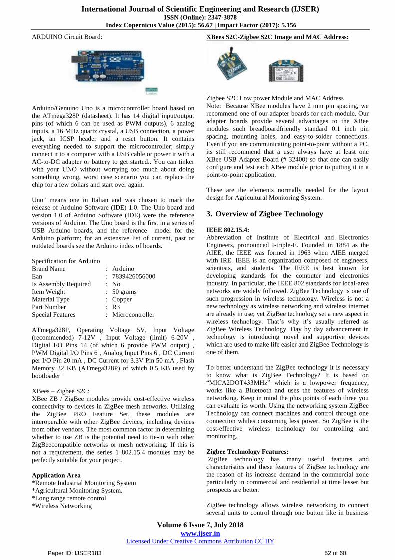
ARDUINO Circuit Board:
Arduino/Genuino Uno is a microcontroller board based on
the ATmega328P (datasheet). It has 14 digital input/output
pins (of which 6 can be used as PWM outputs), 6 analog
inputs, a 16 MHz quartz crystal, a USB connection, a power
jack, an ICSP header and a reset button. It contains
everything needed to support the microcontroller; simply
connect it to a computer with a USB cable or power it with a
AC-to-DC adapter or battery to get started.. You can tinker
with your UNO without worrying too much about doing
something wrong, worst case scenario you can replace the
chip for a few dollars and start over again.
Uno" means one in Italian and was chosen to mark the
release of Arduino Software (IDE) 1.0. The Uno board and
version 1.0 of Arduino Software (IDE) were the reference
versions of Arduino. The Uno board is the first in a series of
USB Arduino boards, and the reference model for the
Arduino platform; for an extensive list of current, past or
outdated boards see the Arduino index of boards.
Specification for Arduino
Brand Name : Arduino
Ean : 7839426056000
Is Assembly Required : No
Item Weight : 50 grams
Material Type : Copper
Part Number : R3
Special Features : Microcontroller
ATmega328P, Operating Voltage 5V, Input Voltage
(recommended) 7-12V , Input Voltage (limit) 6-20V ,
Digital I/O Pins 14 (of which 6 provide PWM output) ,
PWM Digital I/O Pins 6 , Analog Input Pins 6 , DC Current
per I/O Pin 20 mA , DC Current for 3.3V Pin 50 mA , Flash
Memory 32 KB (ATmega328P) of which 0.5 KB used by
bootloader
XBees – Zigbee S2C:
XBee ZB / ZigBee modules provide cost-effective wireless
connectivity to devices in ZigBee mesh networks. Utilizing
the ZigBee PRO Feature Set, these modules are
interoperable with other ZigBee devices, including devices
from other vendors. The most common factor in determining
whether to use ZB is the potential need to tie-in with other
ZigBeecompatible networks or mesh networking. If this is
not a requirement, the series 1 802.15.4 modules may be
perfectly suitable for your project.
Application Area
*Remote Industrial Monitoring System
*Agricultural Monitoring System.
*Long range remote control
*Wireless Networking
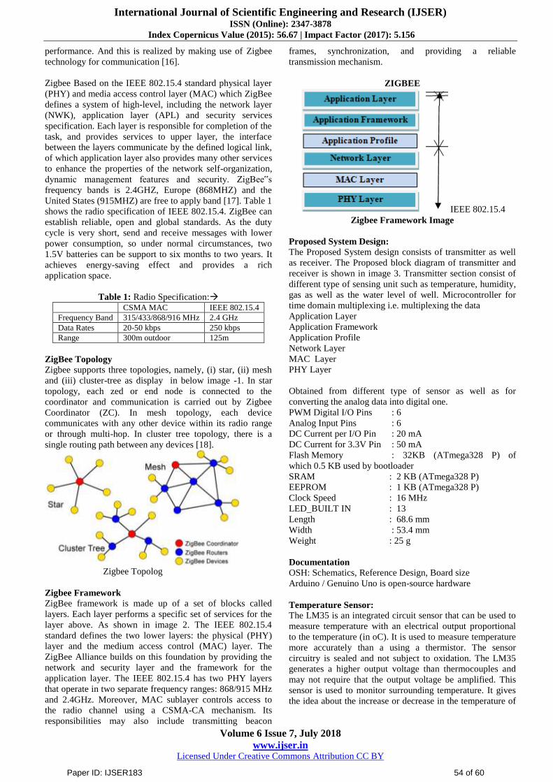
XBees S2C-Zigbee S2C Image and MAC Address:
Zigbee S2C Low power Module and MAC Address
Note: Because XBee modules have 2 mm pin spacing, we
recommend one of our adapter boards for each module. Our
adapter boards provide several advantages to the XBee
modules such breadboardfriendly standard 0.1 inch pin
spacing, mounting holes, and easy-to-solder connections.
Even if you are communicating point-to-point without a PC,
its still recommend that a user always have at least one
XBee USB Adapter Board (# 32400) so that one can easily
configure and test each XBee module prior to putting it in a
point-to-point application.
These are the elements normally needed for the layout
design for Agricultural Monitoring System.
3. Overview of Zigbee Technology
IEEE 802.15.4:
Abbreviation of Institute of Electrical and Electronics
Engineers, pronounced I-triple-E. Founded in 1884 as the
AIEE, the IEEE was formed in 1963 when AIEE merged
with IRE. IEEE is an organization composed of engineers,
scientists, and students. The IEEE is best known for
developing standards for the computer and electronics
industry. In particular, the IEEE 802 standards for local-area
networks are widely followed. ZigBee Technology is one of
such progression in wireless technology. Wireless is not a
new technology as wireless networking and wireless internet
are already in use; yet ZigBee technology set a new aspect in
wireless technology. That‟s why it‟s usually referred as
ZigBee Wireless Technology. Day by day advancement in
technology is introducing novel and supportive devices
which are used to make life easier and ZigBee Technology is
one of them.
To better understand the ZigBee technology it is necessary
to know what is ZigBee Technology? It is based on
“MICA2DOT433MHz” which is a lowpower frequency,
works like a Bluetooth and uses the features of wireless
networking. Keep in mind the plus points of each three you
can evaluate its worth. Using the networking system ZigBee
Technology can connect machines and control through one
connection whiles consuming less power. So ZigBee is the
cost-effective wireless technology for controlling and
monitoring.
Zigbee Technology Features:
ZigBee technology has many useful features and
characteristics and these features of ZigBee technology are
the reason of its increase demand in the commercial zone
particularly in commercial and residential at time lesser but
prospects are better.
ZigBee technology allows wireless networking to connect
several units to control through one button like in business
Paper ID: IJSER183 52 of 60

International Journal of Scientific Engineering and Research (IJSER) ISSN (Online): 2347-3878
Index Copernicus Value (2015): 56.67 | Impact Factor (2017): 5.156
Volume 6 Issue 7, July 2018
www.ijser.in Licensed Under Creative Commons Attribution CC BY
industry. This wireless networking avoids the threat of short
circuiting. Centralization control system reduces the man
power. As a wireless communication system ZigBee
technology helps to monitor the activities and manipulates in
a better way.
ZigBee technology used in the remote control devices helps
to control the function at a specific range. This feature of
ZigBee Technology is very attractive and effortless as all the
home appliances are mostly coming with remote control
system which is the essence of this ZigBee wireless
technology. In industry all the units are centralized in one
place with the help of remote control or switch-based
system. As ZigBee technology based devices are designed
on low-power frequency therefore are reliable. Lowpower
consumption feature of ZigBee technology helps to run a
device for a long duration or sometimes this duration is of
years.
Bluetooth application gives a unique feature of transferring
information or data from one place to another in a far better
way than Bluetooth itself.
Device type and Operating Mode
Zigbee technology is used in three different types of devices
which are used in networking according to its functionality.
As prominently ZigBee is a wireless technology for making
a network system, Zigbee coordinators (ZC): are the primary
devices to help in activation of the system by collecting the
data in form of memory.
Zigbee Router (ZR): Then router comes as a secondary
device to perform the function by sending information to the
destination.
Zigbee End Device (ZED): Third types of ZigBee based
devices are the end-user devices.
These are basically receiver so are not able to send
information itself. It remains in sleep mode while not in use
so less amount of battery us and resultantly longer life.
ZigBee is the set of specifications built around the IEEE
802.15.4 wireless protocol. ZigBee technology is a low data
rate, low power consumption, low cost, wireless networking
protocol targeted towards automation and remote control
applications ZigBee is a communication protocol that uses
small, lowpower digital radio signals based on the IEEE
802.15.4 standard.ZigBee operates in ISM radio bands: In
USA 915 MHz, in Europe 868 MHz and 2.4 GHz in other
parts of the globe. In the 2.4 GHz band there are 16 ZigBee
channels, with each channel requiring 2 MHz of bandwidth.
The most capable ZigBee node type is said to require only
about 10typical Bluetooth or Wireless Internet node, while
the simplest nodes are about 2However, actual code sizes are
much higher, closer to 50transmission range of Zigbee is
over 50 meters and speed is 20-250KB/s, it needs only 32K
of system resources. It is simple, effective and cheaper than
other WPANs like bluetooth, WiFi. ZigBee solves the needs
of remote monitoring and control, and sensor network
applications. It takes full advantage of a powerful physical
radio specified by IEEE802.15.4, adding logical network,
security and application software to the specification. Zigbee
based on the IEEE 802.15.4 standard physical layer (PHY)
and media access control layer (MAC) which ZigBee
defines a system of high-level, including the network layer
(NWK), application layer (APL) and security services
specification. Each layer is responsible for completion of the
task, and provides services to upper layer, the interface
between the layers communicate by the defined logical link,
of which application layer also provides many other services
to enhance the properties of the network self-organization,
dynamic management features and secure.ty. ZigBee‟s
frequency bands is 2.4GHZ, Europe (868MHZ) and the
United States (915MHZ) are free to apply band [2]. Table 1
shows the radio specification of IEEE 802.15.4. ZigBee can
establish reliable, open and global standards. As the duty
cycle is very short, send and receive messages with lower
power consumption, so under normal circumstances, two
1.5V batteries can be support to six months to two years. It
achieves energy-saving effect and provides a rich
application space.
Works of Zigbee:
ZigBee is a specification for a suite of high level
communication protocols using small, low-power digital
radios based on the IEEE 802.15.4-2003 standard for
wireless personal area networks (WPANs), such as wireless
headphones connecting with cell phones via short-range
radio. The technology defined by the ZigBee specification is
intended to be simpler and less expensive than other
WPANs, such as Bluetooth. ZigBee is targeted at radio-
frequency (RF) applications that require a low data rate, long
battery life, and secure networking. The ZigBee Alliance is
a group of companies which maintain and publish the
ZigBee standard.
The current list of application profiles either published or in
the works are: Home Automation
1) ZigBee Smart Energy
2) Telecommunication Applications
3) Personal Home and Hospital Care (a.k.a. medical)
The relationship between IEEE 802.15.4 and ZigBee is
similar to that between IEEE 802.11 and the WiFi Alliance.
The ZigBee 1.0 specification was ratified on 14 December
2004 and is available to members of the ZigBee Alliance.
Most recently, the ZigBee 2007 specification was posted on
30 October 2007. The first ZigBee Application Profile,
Home Automation, was announced 2 November 2007.
The purpose of proposed system is to improve the irrigation
system of Indian agriculture and also to provide adequate
irrigation to particular area. Nowadays every system is
automated in order to face new challenges. In the present
days automated systems have less manual operations,
flexibility, reliability and accuracy. Due to this demand
every field prefers automated control systems. Especially in
the field of electronics automated systems are giving good
Paper ID: IJSER183 53 of 60
International Journal of Scientific Engineering and Research (IJSER) ISSN (Online): 2347-3878
Index Copernicus Value (2015): 56.67 | Impact Factor (2017): 5.156
Volume 6 Issue 7, July 2018
www.ijser.in Licensed Under Creative Commons Attribution CC BY
performance. And this is realized by making use of Zigbee
technology for communication [16].
Zigbee Based on the IEEE 802.15.4 standard physical layer
(PHY) and media access control layer (MAC) which ZigBee
defines a system of high-level, including the network layer
(NWK), application layer (APL) and security services
specification. Each layer is responsible for completion of the
task, and provides services to upper layer, the interface
between the layers communicate by the defined logical link,
of which application layer also provides many other services
to enhance the properties of the network self-organization,
dynamic management features and security. ZigBee‟s
frequency bands is 2.4GHZ, Europe (868MHZ) and the
United States (915MHZ) are free to apply band [17]. Table 1
shows the radio specification of IEEE 802.15.4. ZigBee can
establish reliable, open and global standards. As the duty
cycle is very short, send and receive messages with lower
power consumption, so under normal circumstances, two
1.5V batteries can be support to six months to two years. It
achieves energy-saving effect and provides a rich
application space.
Table 1: Radio Specification: CSMA MAC IEEE 802.15.4
Frequency Band 315/433/868/916 MHz 2.4 GHz
Data Rates 20-50 kbps 250 kbps
Range 300m outdoor 125m
ZigBee Topology
Zigbee supports three topologies, namely, (i) star, (ii) mesh
and (iii) cluster-tree as display in below image -1. In star
topology, each zed or end node is connected to the
coordinator and communication is carried out by Zigbee
Coordinator (ZC). In mesh topology, each device
communicates with any other device within its radio range
or through multi-hop. In cluster tree topology, there is a
single routing path between any devices [18].
Zigbee Topolog
Zigbee Framework
ZigBee framework is made up of a set of blocks called
layers. Each layer performs a specific set of services for the
layer above. As shown in image 2. The IEEE 802.15.4
standard defines the two lower layers: the physical (PHY)
layer and the medium access control (MAC) layer. The
ZigBee Alliance builds on this foundation by providing the
network and security layer and the framework for the
application layer. The IEEE 802.15.4 has two PHY layers
that operate in two separate frequency ranges: 868/915 MHz
and 2.4GHz. Moreover, MAC sublayer controls access to
the radio channel using a CSMA-CA mechanism. Its
responsibilities may also include transmitting beacon
frames, synchronization, and providing a reliable
transmission mechanism.
ZIGBEE
IEEE 802.15.4
Zigbee Framework Image
Proposed System Design:
The Proposed System design consists of transmitter as well
as receiver. The Proposed block diagram of transmitter and
receiver is shown in image 3. Transmitter section consist of
different type of sensing unit such as temperature, humidity,
gas as well as the water level of well. Microcontroller for
time domain multiplexing i.e. multiplexing the data
Application Layer
Application Framework
Application Profile
Network Layer
MAC Layer
PHY Layer
Obtained from different type of sensor as well as for
converting the analog data into digital one.
PWM Digital I/O Pins : 6
Analog Input Pins : 6
DC Current per I/O Pin : 20 mA
DC Current for 3.3V Pin : 50 mA
Flash Memory : 32KB (ATmega328 P) of
which 0.5 KB used by bootloader
SRAM : 2 KB (ATmega328 P)
EEPROM : 1 KB (ATmega328 P)
Clock Speed : 16 MHz
LED_BUILT IN : 13
Length : 68.6 mm
Width : 53.4 mm
Weight : 25 g
Documentation
OSH: Schematics, Reference Design, Board size
Arduino / Genuino Uno is open-source hardware
Temperature Sensor:
The LM35 is an integrated circuit sensor that can be used to
measure temperature with an electrical output proportional
to the temperature (in oC). It is used to measure temperature
more accurately than a using a thermistor. The sensor
circuitry is sealed and not subject to oxidation. The LM35
generates a higher output voltage than thermocouples and
may not require that the output voltage be amplified. This
sensor is used to monitor surrounding temperature. It gives
the idea about the increase or decrease in the temperature of
Paper ID: IJSER183 54 of 60

International Journal of Scientific Engineering and Research (IJSER) ISSN (Online): 2347-3878
Index Copernicus Value (2015): 56.67 | Impact Factor (2017): 5.156
Volume 6 Issue 7, July 2018
www.ijser.in Licensed Under Creative Commons Attribution CC BY
surrounding. If the temperature changes it is observed on
LCD.
Temperature LM35 Sensor
Humidity Sensor:
Humidity is an expression of the amount of water vapour in
air. It is an invisible gas that varies between 1 - 4% of our
atmosphere by volume. SYHS-220 sensor module converts
relative humidity (3090%RH) to voltage and can be used in
weather monitoring application. This sensor is used to
monitor humidity i.e. moisture present in the surrounding.
Humidity Sensor
Gas Sensor-ePro Labs MQ-5:
The Grove - Gas Sensor(MQ5) module is useful for gas
leakage detection (in home and industry). It is suitable for
detecting H2, LPG, CH4, CO, Alcohol. Due to its high
sensitivity and fast response time, measurements can be
taken as soon as possible. The sensitivity of the sensor can
be adjusted by using the potentiometer. This is an Analog
output sensor. This needs to be connected to any one Analog
socket in Grove Base Shield. The examples used in this
tutorial makes uses of A0 analog pin. Connect this module
to the A0 port of Base Shield.
It is possible to connect the Grove module to Arduino
directly by using jumper wires by using the connection.
Different types of Gas Sensor:
Sensor : Gas Type
MQ2 : Combustible Gas, Smoke
MQ3 : Alcohol Vapor
MQ5 : LPG, Natural Gas, Town Gas
MQ9 : Carbon Monoxide, Coal Gas, Liquefied Gas
Gas MQ-5 Sensor
Water Level Detector:
This is used to detect/sense the water level of the well. The
sensor will detect the amount of water present in the well. If
the water level goes below minimum level or above
maximum level a control signal is send to LCD. In addition
to this a message is send to an observer situated at the
remote place.
Water Level detector
Zigbee Module:
The XBee RF Modules are designed to operate within the
ZigBee protocol and support the unique needs of low-cost,
low-power wireless sensor networks. The modules require
minimal power and provide reliable delivery of data between
remote devices. The modules operate within the ISM 2.4
GHz frequency band. It operates over a range of 100- 200
meters.Image-8, shows the zigbee module.
Zigbee Module
The receiver block diagram is shown in image-9. The
receiver module consists of an Xbee RF module which is
connected to computer system through MAX232.Thus the
monitoring data received by Zigbee module is directly
transferred to computer .
Receiver Block Diagram
Description Software
X-CTU stands for XTRA Intermodal. X-CTU is a Windows-
based application provided by Digi‟s. This program was
designed to interact with the firmware files found on Digi‟s
RF products and to provide a simple-to-use graphical user
interface to them. XCTU is designed to function with all
Windows-based computers running Microsoft Windows 98
SE and above. XCTU is a free multi-platform application
designed to enable developers to interact with Digi RF
modules through a simple-to-use graphical interface. It
includes new tools that make it easy to set-up, configure and
test XBee® RF modules. XCTU includes all of the tools a
developer needs to quickly get up and running with XBee.
Unique features like graphical network view, which
graphically represents the XBee network along with the
signal strength of each connection, and the XBee API frame
builder, which intuitively helps to build and interpret API
frames for XBees being used in API mode, combine to make
development on the XBee platform easier than ever.
Paper ID: IJSER183 55 of 60

International Journal of Scientific Engineering and Research (IJSER) ISSN (Online): 2347-3878
Index Copernicus Value (2015): 56.67 | Impact Factor (2017): 5.156
Volume 6 Issue 7, July 2018
www.ijser.in Licensed Under Creative Commons Attribution CC BY
Other highlights of XCTU include the following features:
You can manage and configure multiple RF devices, even
remotely (over-the-air) connected devices.
The firmware update process seamlessly restores your
module settings, automatically handling mode and baud rate
changes. Two specific API and AT consoles, have been
designed from scratch to communicate with your radio
devices.
You can now save your console sessions and load them in a
different PC running XCTU.
XCTU includes a set of embedded tools that can be executed
without having any RF module connected:
Frames generator: Easily generate any kind of API frame to
save its value. Frames interpreter: Decode an API frame
and see its specific frame values.
Recovery: Recover radio modules which have damaged
firmware or are in programming mode.
Load console session: Load a console session saved in any
PC running XCTU.
Installing X-CTU
Once X-CTU has been downloaded, the next step is to
install the program. When the program asks for updating
from Digi, we must answer „yes‟ so as to download all the
firmware versions for all the XBee modules.
Zigbee Module
Configuring X-CTU
When X-CTU has been properly installed, the Waspmote
Gateway can be connected to the computer. It will be
recognized as a „USB Serial Port‟. We have to know the
COM number given to this device in order to specify it in
the X-CTU (in our test, COM1 was the value given by
Window.
Finally, we launch X-CTU and the program will start. A
window like the one below will appear, showing the
different functions and the different COM ports detected.
Step 1
Select the COM ports where you‟ve connected the USB
adapters. To confirm you can verify your DEVICE
MANAGER for the proper COM ports.
X-CUT
Step-2:
Click on NEXT & accept the default PORT
PARAMETERS. 96008N1 is the default. 9600 is the
BAUD RATE, 8 Data Bits, No Parity & 1 Stop bit.
X-CTU
Step-3:
Click on FINISH. The XCTU scans the USB ports selected
& lists the RADIOs found with their unique 64 bit address.
X-CUT
Step-4:
Select both the devices & click ADD SELECTED
DEVICES. Now both the Radios appear on the left pane.
X-CUT
Step-5:
Let us configure the RADIO at COM3 as COORDINATOR
first. For this click on the COM3 RADIO to load the module
settings.
X-CUT
Paper ID: IJSER183 56 of 60

International Journal of Scientific Engineering and Research (IJSER) ISSN (Online): 2347-3878
Index Copernicus Value (2015): 56.67 | Impact Factor (2017): 5.156
Volume 6 Issue 7, July 2018
www.ijser.in Licensed Under Creative Commons Attribution CC BY
Step-6:
Once the parameter settings are loaded you can see that the
product family is XB24C (in case of old S2 it is XB24-ZB
& of S1 is 802.15.4) The function set of Firmware is
ZIGBEE TH Reg , the Reg stands for Regular & not PRO.
TH stands for THROUGH HOLE & not SMD.
X-CUT
Step-7:
First thing is to set the PAN ID of the Network. This can be
from 0 to FFFF hex.In my case I‟m setting it to 1234.The
other Radios also to be set in the same PAN ID. Scroll down
further & Enable the CE (Coordinator Enable)
X-CUT
Step-8:
The Destination address DH is left to default 0. The
Destination Address DL is set to hex FFFF which makes the
Radio work on BROADCAST mode, so that it can
communicate with all Radios in the same PANID. The Node
Identifier can be given any name like “Coordinator”. This
naming is optional.
X-CUT
Step-9:
Click on the PENCIL icon on top to WRITE the changes
made.
X-CTU
Step-10:
Now let us configure the second Radio as ROUTER. Click
on the second Radio on the left pane to load the settings.
X-CUT
Step-11:
The Router setting is quite simple. Enter the PANID as 1234
, same as that of Coordinator.
X-CUT
Software design flow for the proposed system:
A simplified operational flow is shown in IMAGE21(A),
shows the sensor unit and IMAGE-21(B) Microcontroller
section. The sensor unit will sense temperature, humidity
moisture, and toxic gas present in the air from the remote
place and send the data to microcontroller. For the water
level of well is string value „n‟ given it will start the motor
and if „m‟ given then it will stop the motor pump. In the
microcontroller section firstly initiations take place for
ADC, UART, and I2C. Then microcontroller receives data
from sensor unit and start analog to digital conversion. After
ADC conversion completion the data will be displayed on
LCD and signal is send to zigbee module for wireless
transmission at the receiver section. At the receiver section
zigbee module is interface with computer with the help of
Max232 and DB9. The data received from transmitter
section will be displayed on computer.
Paper ID: IJSER183 57 of 60

International Journal of Scientific Engineering and Research (IJSER) ISSN (Online): 2347-3878
Index Copernicus Value (2015): 56.67 | Impact Factor (2017): 5.156
Volume 6 Issue 7, July 2018
www.ijser.in Licensed Under Creative Commons Attribution CC BY
4. Simulation Process
Coding for temperature sensor
We are using Arduino Uno as our board and LM35 can be
connected to arduino as shown in circuit diagram. Note:-
LM35 is an analog temperature sensor. This means the
output of LM35 is an analog signal. Microcontrollers dont
accept analog signals as their input directly. We need to
convert this analog output signal to digital before we can
feed it to a microcontroller‟s input. For this purpose, we can
use an ADC( Analog to Digital Converter).If we are using a
basic microcontroller like 8051, we need to use an external
ADC to convert analog output from LM35 to digital. We
then feed the output of ADC (converted digital value) to
input of 8051. But modern day boards like Arduino and
most modern day micro controllers come with inbuilt ADC.
Our arduino uno has an in built 10 bit ADC (6 channel). We
can make use of this in built ADC of arduino to convert the
analog output of LM35 to digital output. Since Arduino uno
has a 6 channel inbuilt ADC, there are 6 analog input pins
numbered from A0 to A5. Connect analog out of LM35 to
any of these analog input pins of arduino.
LM35 and Arduino – Circuit Diagram
Connect LM35 to Arduino uno as shown in circuit diagram.
The +5v for LM35 can be taken from the +5v out pin of
arduino uno. Also the ground pin of LM35 can be connected
to GND pin of arduino uno. Connect Vout (the analog out of
LM35) to any of the analog input pin of arduino uno. In this
circuit diagram, we have connected Vout of LM35 to A1 of
arduino.
Note:-
LM35 is available in the market in 3 series variations –
LM35A, LM35C and LM35D series. The main difference
between these 3 versions of LM35 IC are in their range of
temperature measurements. The LM35D series is designed
to measure from 0 degree Celsius to 100 degree Celsius,
where as the LM35A series is designed to measure a wider
range of -55 degree Celsius to 155 degree Celsius. The
LM35C series is designed to measure from -40 degree
Celsius to 110 degree Celsius.
In our LM35 arduino example, we are using the LM35Dz
sensor- which falls under LM35D series. So our min-max
range of temperature measurement is 0 degree Celsius to
100 degree Celsius.
The Coding – LM35 and Arduino Interfacing
const int sensor=A1; // Assigning analog pin A1 to variable
'sensor' float tempc; //variable to store temperature in degree
Celsius float tempf; //variable to store temperature in
Fahreinheit float vout; //temporary variable to hold sensor
reading void setup() { pinMode(sensor,INPUT); //
Configuring pin A1 as input Serial.begin(9600); } void
loop() { vout=analogRead(sensor); vout=(vout*500)/1023;
tempc=vout; // Storing value in Degree Celsius
tempf=(vout*1.8)+32; // Converting to Fahrenheit
Serial.print("in DegreeC="); Serial.print("\t");
Serial.print(tempc); Serial.println(); Serial.print("in
Fahrenheit="); Serial.print("\t"); Serial.print(tempf);
Serial.println(); delay(1000); //Delay of 1 second for ease of
viewing }
START
Measure Temp, Humidity and Gas
Send data to MCU
Initiali se ADC, I2C.
MCU Receive data from sensor unit.
ADC Conversion Finish?
Display Result On LCD
Send signal to Zigbee for Transmission
So that‟s the arduino lm35 code for reading temperature and
displaying in degree Celsius and Fahrenheit. The program is
self explanatory.
Output
Output Image
Humidity Sensor Coding
The DHT11 humidity and temperature sensor makes it really
easy to add humidity and temperature data to your DIY
electronics projects. It‟s perfect for remote weather stations,
home environmental control systems, and farm or garden
monitoring systems.
Here are the ranges and accuracy of the DHT11:
1) Humidity Range: 20-90% RH
2) Humidity Accuracy: ±5% RH
3) Temperature Range: 0-50 °C
4) Temperature Accuracy: ±2% °C
5) Operating Voltage: 3V to 5.5V
The DHT11 measures relative humidity. Relative humidity
is the amount of water vapor in air vs. the saturation point of
water vapor in air. At the saturation point, water vapor starts
to condense and accumulate on surfaces forming dew. The
saturation point changes with air temperature. Cold air can
hold less water vapor before it becomes saturated, and hot
air can hold more water vapor before it becomes saturated.
Before you can use the DHT11 on the Arduino, you‟ll need
to install the DHTLib library. It has all the functions needed
Paper ID: IJSER183 58 of 60

International Journal of Scientific Engineering and Research (IJSER) ISSN (Online): 2347-3878
Index Copernicus Value (2015): 56.67 | Impact Factor (2017): 5.156
Volume 6 Issue 7, July 2018
www.ijser.in Licensed Under Creative Commons Attribution CC BY
to get the humidity and temperature readings from the
sensor. It‟s easy to install, just download the DHTLib.zip
file below and open up the Arduino IDE. Then go to
Sketch>Include Library>Add .ZIP Library and select the
DHTLib.zip file.
After it‟s installed, upload this example program to the
Arduino and open the serial monitor:
#include <dht.h>
dht DHT;
#define DHT11_PIN 7
void setup(){
Serial.begin(9600); }
void loop() { int chk = DHT.read11(DHT11_PIN);
Serial.print("Temperature=");
Serial.println(DHT.temperature);
Serial.print("Humidity= ");
Serial.println(DHT.humidity); delay(1000);
}
Gas Sensor Coding (MQ-5)
We have developed a Gas Leakage Detector using Arduino
and MQ5 with SMS Alert, Sound Alarm and Relay
activation. You can try this interesting project to gain more
knowledge and build a practical application using MQ5
sensor.
Interfacing MQ5 Gas Sensor Module to Arduino using
Digital Out Pin This is pretty simple. Connect the D0 pin of
MQ5 module to any digital pin of arduino. Lets connect D0
to pin 7 of arduino. Now we need to give power supply
(Vcc) and complete the circuit by connecting to ground
(Gnd). Refer the circuit diagram given below. Take a +5V
connection from arduino and connect it to Vcc of MQ5
module. Finally connect the GND pin of MQ5 module to
GND of arduino. That‟s all and we have finished the circuit.
Circuit Diagram of Interfacing MQ5 to Arduino
(Digital Out)
Note:-
MQ5 sensor has preheating requirement. We advise to keep
the sensor powered on (from arduino) for some 15 minutes
before applying gas to it.
CODING:
int sensor=7;
int gas_value;
void setup()
{
pinMode(sensor,INPUT);
Serial.begin(9600);
}
void loop()
{gas_value=digitalRead(sensor); Serial.println(gas_value); }
Note:-
To apply a “gas leak” to MQ5 sensor, you can simply use a
cigarette or cigar lighter! Press the trigger switch of cigarette
lighter gently (gentle enough so as gas leaks and spark is not
triggered) to get gas leaked continuously and place the
lighter near MQ5 sensor.
Image
Output: Simulation Output Result
The screenshots below shows serial monitor readings of
arduino before applying gas leak and after applying gas leak.
Before applying gas leak, MQ5 captures atmospheric air
concentration only (we get a HIGH in our digital out pin and
is measured by arduino as 1, as shown in serial monitor).
When we apply a “gas leak”, the heating element inside
MQ5 gets heated up and output voltage varies (we get a
LOW in our D0 pin and is measured by arduino as 0, as
shown in serial monitor output screenshot )
Output
Paper ID: IJSER183 59 of 60

International Journal of Scientific Engineering and Research (IJSER) ISSN (Online): 2347-3878
Index Copernicus Value (2015): 56.67 | Impact Factor (2017): 5.156
Volume 6 Issue 7, July 2018
www.ijser.in Licensed Under Creative Commons Attribution CC BY
5. Future Work Based on Conclusion
The System is designed for the betterment of farmers. The
uses of smart sensor based monitoring system for agriculture
have been used to increase the yield of crop by monitoring
the environmental conditions and providing information to
observer. It would be a promising technology for the
agriculturists all over the world in the present scenario of
unpredicted weather conditions.
References
[1] A Survey on Centralised and Distributed Clustering
Routing Algorithms for WSNs (PDF). IEEE 81st
Vehicular Technology Conference. Glasgow, Scotland:
IEEE. Spring 2015. Retrieved March 4, 2016.
[2] I. F. Akyildiz and I.H. Kasimoglu (2004). "Wireless
Sensor and Actor Networks: Research Challenges".
[3] Dargie, W. and Poellabauer, C. (2010). Fundamentals of
wireless sensor networks: theory and practice. John
Wiley and Sons. pp. 168–183, 191–192.
[4] Sohraby, K., Minoli, D., Znati, T. (2007). Wireless
sensor networks: technology, protocols, and
applications. John Wiley and Sons. pp. 203–209.
[5] Zhizhou Wu, Hao Chu, Yuqi Pan, Xiaoguang Yang,
“Bus Priority Control System Based on Wireless Sensor
Network (WSN) and Zigbee”, IEEE International
Conference on Vehicular Electronics and Safety, pp.
148 – 151, 2006.
[6] Wanjing MA, Xiaoguang YANG,“Design and
Evaluation of an Adaptive Bus Signal Priority System
Base on Wireless Sensor Network”, IEEE Proceedings
of the 11th International Conference on Intelligent
Transportation Systems, pp. 1073- 1077, 2008.
[7] Le et al. proposed an approach to construct a shortest
path tree for each sink and dynamically adjust to
balance the load among sinks. These works are based on
real systems, but do not provide theoretical insight into
maximization of lifetime.
[8] Dijun et al. studied the problem of finding an optimal
shortest path tree to prolong the lifetime of the network,
when in network aggregation is used.
[9] Y. Wu et al. considering the energy depletion in
transmitting and receiving messages, which are the two
major energy consuming operations.
[10] Yang et al. proposed Turbo-Like (TL) codes with two
simplified serial message passing algorithms for star-
WSN.
[11] Imad et al. proposed a new routing method for WSNs
to extend network lifetime using a combination of a
fuzzy approach and an A-star algorithm.
[12] A.S el al.proposed two schemes for key management in
clustered sensor networks with changing cluster head.
In Simple Secure Logical Ring (SSLR) scheme
communication and computation cost incurred for key
establishment is constant. Node compromise in the
proposed schemes is handled efficiently.
[13] Zhi et al.proposed algorithm considers remaining
energy when selecting cluster heads and uses
multiround clustering instead of clustering in every
round. Algorithm performs better in reducing the energy
consumption of nodes and effectively.
[14] Riggio et al.proposed an hybrid mesh/sensor network
architecture based on a sharing of tasks between mesh
routers and sensor nodes and reduce the network load
while preserving data confidentiality and integrity.
[15] Thuy et al. proposed a multipath solution for event-
driven clusterbased routing in WSN called
EnergyAware Mesh Routing Protocol (EMRP) with
main design features: reliable data transmission, load
balance and energy efficiency.
[16] T.Kalaivani, Aallirani, P.Priya, “A Survey on Zigbee
Based Wireless Sensor Networks in Agriculture”:
Department of ECE, 2011 IEEE.
[17] Wang Qing Hui, Bian Li Juan, Pang Yu jun, “Design of
the temperature monitoring system based on ZigBee
wireless sensor network College of Information
Technology”, 2011 IEEE.
[18] Huang Feng Yi. Design of the temperature monitoring
system based on ZigBee wireless sensor network
(Master thesis) [J] Shanghai Jiao Tong University,
2010.
[19] Yu Chengbo, Cui Yanzhe, Zhang Lian, Yang Shuqiang,
“ZigBee Wireless Sensor Network in Environmental
Monitoring Applications”, 2009 IEEE.
[20] Swarup S. Mathurkar, D. S. Chaudhari, “A Review on
Smart Sensors Based Monitoring System for
Agriculture”, Volume-2, Issue-4, March, IJITEE 2013.
[21] ww1.microchip.com “PIC 16F87X Datasheet” [7]
Mohini Reddy, Vidya Sawant WSN based.
[22] Mohini Reddy, Vidya Sawant WSN based Parameter
Monitoring and Control System for DC Motor. Volume-
3, Issue-9, February 2014
Paper ID: IJSER183 60 of 60