A Solution to the Recovery of Sha256crypt-hashed Passwords
23
IACR Transactions on Cryptographic Hardware and Embedded Systems ISSN 2569-2925, Vol. 2020, No. 4, pp. 1–23. DOI:10.13154/tches.v2020.i4.1-23 A Hybrid-CPU-FPGA-based Solution to the Recovery of Sha256crypt-hashed Passwords Zhendong Zhang and Peng Liu * College of Information Science and Electronic Engineering, Zhejiang University, Hangzhou, China {zhendong404,liupeng}@zju.edu.cn Abstract. This paper presents an accelerator design for the password recovery of sha256crypt based on hybrid CPU-FPGA devices. By applying the brute-force attack computation model proposed in this paper, we decompose the sha256crypt function into two types of operations, namely the data dispatching and the block transforming. The data dispatching operation generates message blocks and the block transforming operation transforms message blocks into digests. These two operations are efficiently accelerated by the customized data dispatch unit and the pipelined block transform unit, respectively. Difficulties of adopting the pipeline technique are addressed also with the following techniques. The group scheduling is used to solve the data dependency that stalls the pipeline. The look-ahead execution eliminates the uncertainty of the execution path. The data path pruning and spatial-temporal multiplexing reduce the resource overhead of non-computing units. The proposed accelerator design is implemented and evaluated on the Xilinx Zynq- 7000 XC7Z030-3 SoC. Our experimental results show that the proposed accelerator can improve energy efficiency by 2.54× over the state-of-the-art password recovery tool Hashcat running on an NVIDIA GTX1080Ti GPU. Compared with the pure FPGA-based implementation in John-the-Ripper, the proposed accelerator improves energy efficiency by 1.64× and improves resource efficiency by 1.69×. Keywords: Password recovery · Linux security · FPGA · sha256crypt · key derivation function 1 Introduction Password-based user authentication [Lam81] is the most commonly used method to protect user’s important information, since passwords are highly portable and easy to understand by users. To prevent the clear text password from being easily obtained by malicious attackers, most operating systems and applications apply key derivation functions (KDFs) to convert clear text passwords to password hashes. Since KDFs are one-way functions, the only way to recover the clear text password from the password hash is the brute-force attack, which searches the correct password by performing KDF on all possible passwords until the output of KDF matches the password hash [Mar08]. A typical diagram of the brute-force attack is shown in Figure 1. The time consumption of brute-force attack depends on the searching speed and the size of the searching space. As the searching space is huge in most scenarios, malicious attackers have to pay enormous time and energy cost, and it is the same for the users who want to retrieve forgotten passwords. To expedite password recovery with a reasonable amount of time and energy consumption, a fast and energy-efficient accelerator becomes necessary. * Corresponding author: Peng Liu. Licensed under Creative Commons License CC-BY 4.0. Received: 2020-04-15 Accepted: 2020-06-15 Published: 2020-08-26
-
Upload
khangminh22 -
Category
Documents
-
view
1 -
download
0
Transcript of A Solution to the Recovery of Sha256crypt-hashed Passwords
IACR Transactions on Cryptographic Hardware and Embedded SystemsISSN 2569-2925, Vol. 2020, No. 4, pp. 1–23. DOI:10.13154/tches.v2020.i4.1-23
A Hybrid-CPU-FPGA-based Solution to theRecovery of Sha256crypt-hashed Passwords
Zhendong Zhang and Peng Liu∗
College of Information Science and Electronic Engineering,Zhejiang University, Hangzhou, Chinazhendong404,[email protected]
Abstract. This paper presents an accelerator design for the password recovery ofsha256crypt based on hybrid CPU-FPGA devices. By applying the brute-forceattack computation model proposed in this paper, we decompose the sha256cryptfunction into two types of operations, namely the data dispatching and the blocktransforming. The data dispatching operation generates message blocks and the blocktransforming operation transforms message blocks into digests. These two operationsare efficiently accelerated by the customized data dispatch unit and the pipelinedblock transform unit, respectively. Difficulties of adopting the pipeline technique areaddressed also with the following techniques. The group scheduling is used to solvethe data dependency that stalls the pipeline. The look-ahead execution eliminatesthe uncertainty of the execution path. The data path pruning and spatial-temporalmultiplexing reduce the resource overhead of non-computing units.The proposed accelerator design is implemented and evaluated on the Xilinx Zynq-7000 XC7Z030-3 SoC. Our experimental results show that the proposed acceleratorcan improve energy efficiency by 2.54× over the state-of-the-art password recoverytool Hashcat running on an NVIDIA GTX1080Ti GPU. Compared with the pureFPGA-based implementation in John-the-Ripper, the proposed accelerator improvesenergy efficiency by 1.64× and improves resource efficiency by 1.69×.Keywords: Password recovery · Linux security · FPGA · sha256crypt · key derivationfunction
1 IntroductionPassword-based user authentication [Lam81] is the most commonly used method to protectuser’s important information, since passwords are highly portable and easy to understandby users. To prevent the clear text password from being easily obtained by maliciousattackers, most operating systems and applications apply key derivation functions (KDFs)to convert clear text passwords to password hashes. Since KDFs are one-way functions,the only way to recover the clear text password from the password hash is the brute-forceattack, which searches the correct password by performing KDF on all possible passwordsuntil the output of KDF matches the password hash [Mar08]. A typical diagram of thebrute-force attack is shown in Figure 1. The time consumption of brute-force attackdepends on the searching speed and the size of the searching space. As the searching spaceis huge in most scenarios, malicious attackers have to pay enormous time and energy cost,and it is the same for the users who want to retrieve forgotten passwords. To expeditepassword recovery with a reasonable amount of time and energy consumption, a fast andenergy-efficient accelerator becomes necessary.
∗Corresponding author: Peng Liu.
Licensed under Creative Commons License CC-BY 4.0.Received: 2020-04-15 Accepted: 2020-06-15 Published: 2020-08-26
2 A Solution to the Recovery of Sha256crypt-hashed Passwords
KDF
KDF
Match
P
P1
P2
PN
H
H1
H2
HN
Searchingspace
Originalpassword
Password hash to be cracked
Originalpassword
HX
PX
Figure 1: A typical diagram of the brute-force attack. The original password P is encryptedby the KDF to generate a password hash H. The attacker applies KDF to all passwords inthe searching space and matches every generated hash with the password hash H. If HXmatches the password hash H, the original password PX is retrieved.
As the details of different KDFs diverse from each other, for the sake of illustration,common features of the brute-force attack on KDFs are abstracted and summarized inFigure 2. A KDF thread repeatedly generates a message block from the password or theprevious digests, then transforms it to a new digest. Due to the data dependency betweentwo adjacent message blocks, blocks in a single KDF thread must be processed sequentially.As a result, many researchers aim at increasing the parallelism of hardware accelerators,so that more passwords could be processed concurrently.
Pwd 1
Pwd 2
Pwd N
Hash 1
Hash 2
Hash N
Thread 1:
Thread 2:
Thread N:
Block generation
A message block
Block transformation
A digest
Figure 2: Computation model of the brute-force attack on KDFs. N passwords areprocessed concurrently with N KDF threads. Each block depends on its previous block.All block transform operations cost the same time. The number of blocks may vary fordifferent passwords.
There are two types of parallelism in the brute-force attack of KDFs, the inter-blockparallelism and the intra-block parallelism. Both of them are important to the design ofaccelerators. The inter-block parallelism refers to the number of blocks that the acceleratorcan process at the same time. The intra-block parallelism refers to the number of operationsthat the accelerator can perform at the same time during the processing of one block,which is the reciprocal of the number of cycles to process one block.
Among many of the password recovery platforms, graphic process units (GPUs) andfield programmable gate arrays (FPGAs) are most widely used. GPU-based accelerators[QGG+16,HK17,AKSE18] utilize thousands of processing cores to achieve a high inter-block parallelism. However, suffering from its general-purpose architecture, GPU coststhousands of cycles to process one block with high clock frequency, which makes it inferiorto FPGA-based accelerators in terms of energy efficiency.
FPGA-based accelerators [KMB+16,LCL+16,AVWS14,DGK+12], on the other hand,can provide significant savings in terms of energy consumption [DK14]. They can process

Zhendong Zhang and Peng Liu 3
one block in dozens of cycles with customized high intra-block parallelism hash units. Thecustomized hash units can also explore the inter-block parallelism by implementing a deeppipeline. The problem is that most FPGA-based accelerators only focus on password-basedkey derivation functions (PBKDF, PBKDF2), which have unified execution paths andregular block generation patterns. For other KDFs such as sha256crypt, sha512crypt, andmd5crypt, the nonunified execution paths and complex block generation patterns make theimplementation of pipelined hash units very difficult. Although the accelerator in [Mag18]implements sha256crypt with non-pipelined multi-cycle hash units, it allocates too manyhardware resources for the complex control logic, which restricts its inter-block parallelismdue to the limited hardware resources available on an FPGA.
There are three major difficulties when applying the pipelined hash units on KDFs likesha256crypt.
1. Dependency between adjacent blocks may stall the pipeline.
2. The unpredictable number of blocks for different passwords leads to nonunifiedexecution paths and adds difficulties to the scheduling of pipeline.
3. The block generation patterns are related to the lengths of passwords, which compli-cate the memory access patterns and the design of the data path.
The emergence of hybrid CPU-FPGA devices [Xil16, Int20] provides a balance solutionto address above difficulties in terms of flexibility and energy efficiency. It shows greatperformance on energy efficiency when employed to the password recovery of bcrypt [MK14]and PBKDF2 [LLD19]. Specifically, for the password recovery of sha256crypt, the CPUcould handle the tasks with complex logic such as password generation and calculationsthat have nonunified execution paths. Then the FPGA is dedicated to the computationallyintensive tasks which have unified execution paths and can be accelerated by the pipelinedhash units.
To apply the pipeline technique on KDFs like sha256crypt, we propose an acceleratordesign based on hybrid CPU-FPGA devices. We analyze the sha256crypt function withour brute-force attack computation model and identify two basic operations. One is thedata dispatching and another is the block transforming. The data dispatching operationgenerates blocks and the block transforming operation transforms blocks into digests, whichare used to generate the subsequent blocks. With the definition of these two operations,it’s obvious that an accelerator design should make customized hardware to expedite themefficiently. Following this guideline, several accelerating cores are implemented on theFPGA and work together with the CPU. Each accelerating core has three key components:the data buffers, the data dispatch unit, and the SHA256 block transform unit with adeep pipeline. Exploiting the co-processing of CPU and the reconfigurability of FPGA,several techniques, such as group scheduling, look-ahead execution, data path pruning,and spatial-temporal multiplexing, are applied to improve the performance and reduce thehardware resource overhead.
1. Group scheduling is used to remove the data dependency between adjacent blocks insha256crypt so that the pipelined block transform unit is free from stalling.
2. Look-ahead execution eliminates the uncertainty of execution paths in sha256cryptby mapping the nonunified calculations to the CPU and reusing its results.
3. Data path pruning and spatial-temporal multiplexing are used to simplify the designof the data dispatch unit and reduce the hardware resource overhead.
To the best of our knowledge, this is the first open work about the pipelined passwordrecovery accelerator dedicated for the sha256crypt algorithm. The proposed accelerator isevaluated on a tailor-made development board with a Xilinx Zynq-7000 XC7Z030-3 SoC.
4 A Solution to the Recovery of Sha256crypt-hashed Passwords
Two accelerating cores are implemented based on the hardware resource available on theFPGA. The proposed accelerator achieves 2.54× improvement in terms of energy efficiencyover the state-of-the-art implementation [has20] running on an NVIDIA GTX 1080TiGPU. Compared with the pure FPGA-based accelerator reported in [Mag18], the proposedaccelerator achieves 1.64× energy efficiency and 1.69× resource efficiency, respectively.The techniques proposed in this paper are also validated with sha512crypt. It achieves2.39× energy efficiency over Hashcat running on GTX1080Ti.
The rest of this paper is structured as follows. Section 2 analyzes the details ofsha256crypt and points out the difficulties in hardware implementation. Section 3 illustratesthe overall architecture of the password recovery on a hybrid CPU-FPGA device. Thedetails of the techniques employed are provided in Section 4. Section 5 gives the evaluationresults of our design and Section 6 concludes the paper.
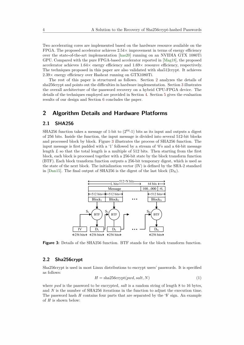
2 Algorithm Details and Hardware Platforms2.1 SHA256SHA256 function takes a message of 1-bit to (264-1) bits as its input and outputs a digestof 256 bits. Inside the function, the input message is divided into several 512-bit blocksand processed block by block. Figure 3 illustrates the process of SHA256 function. Theinput message is first padded with a ‘1’ followed by a stream of ‘0’s and a 64-bit messagelength L so that the total length is a multiple of 512 bits. Then starting from the firstblock, each block is processed together with a 256-bit state by the block transform function(BTF). Each block transform function outputs a 256-bit temporary digest, which is used asthe state of the next block. The initialization vector (IV) is defined by the SHA-2 standardin [Dan15]. The final output of SHA256 is the digest of the last block (DN).
Message 100...000 #L
Block1
BTF BTF
D1 D2 DNIV
Block2
BTF
BlockN
L bits512×N bits
512 bits 512 bits 512 bits
64 bits
256 bits256 bits
S1 S2 SN
Figure 3: Details of the SHA256 function. BTF stands for the block transform function.
2.2 Sha256cryptSha256crypt is used in most Linux distributions to encrypt users’ passwords. It is specifiedas follows:
H = sha256crypt(pwd, salt,N) (1)
where pwd is the password to be encrypted, salt is a random string of length 8 to 16 bytes,and N is the number of SHA256 iterations in the function to adjust the execution time.The password hash H contains four parts that are separated by the ‘$’ sign. An exampleof H is shown below:
Zhendong Zhang and Peng Liu 5
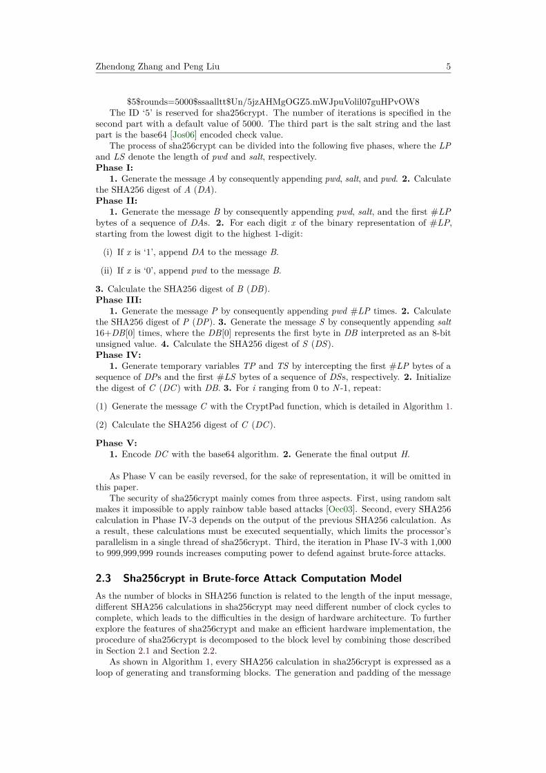
$5$rounds=5000$ssaalltt$Un/5jzAHMgOGZ5.mWJpuVolil07guHPvOW8The ID ‘5’ is reserved for sha256crypt. The number of iterations is specified in the
second part with a default value of 5000. The third part is the salt string and the lastpart is the base64 [Jos06] encoded check value.
The process of sha256crypt can be divided into the following five phases, where the LPand LS denote the length of pwd and salt, respectively.Phase I:
1. Generate the message A by consequently appending pwd, salt, and pwd. 2. Calculatethe SHA256 digest of A (DA).Phase II:
1. Generate the message B by consequently appending pwd, salt, and the first #LPbytes of a sequence of DAs. 2. For each digit x of the binary representation of #LP,starting from the lowest digit to the highest 1-digit:
(i) If x is ‘1’, append DA to the message B.
(ii) If x is ‘0’, append pwd to the message B.
3. Calculate the SHA256 digest of B (DB).Phase III:
1. Generate the message P by consequently appending pwd #LP times. 2. Calculatethe SHA256 digest of P (DP). 3. Generate the message S by consequently appending salt16+DB[0] times, where the DB[0] represents the first byte in DB interpreted as an 8-bitunsigned value. 4. Calculate the SHA256 digest of S (DS).Phase IV:
1. Generate temporary variables TP and TS by intercepting the first #LP bytes of asequence of DPs and the first #LS bytes of a sequence of DSs, respectively. 2. Initializethe digest of C (DC ) with DB. 3. For i ranging from 0 to N -1, repeat:
(1) Generate the message C with the CryptPad function, which is detailed in Algorithm 1.
(2) Calculate the SHA256 digest of C (DC ).
Phase V:1. Encode DC with the base64 algorithm. 2. Generate the final output H.
As Phase V can be easily reversed, for the sake of representation, it will be omitted inthis paper.
The security of sha256crypt mainly comes from three aspects. First, using random saltmakes it impossible to apply rainbow table based attacks [Oec03]. Second, every SHA256calculation in Phase IV-3 depends on the output of the previous SHA256 calculation. Asa result, these calculations must be executed sequentially, which limits the processor’sparallelism in a single thread of sha256crypt. Third, the iteration in Phase IV-3 with 1,000to 999,999,999 rounds increases computing power to defend against brute-force attacks.
2.3 Sha256crypt in Brute-force Attack Computation ModelAs the number of blocks in SHA256 function is related to the length of the input message,different SHA256 calculations in sha256crypt may need different number of clock cycles tocomplete, which leads to the difficulties in the design of hardware architecture. To furtherexplore the features of sha256crypt and make an efficient hardware implementation, theprocedure of sha256crypt is decomposed to the block level by combining those describedin Section 2.1 and Section 2.2.
As shown in Algorithm 1, every SHA256 calculation in sha256crypt is expressed as aloop of generating and transforming blocks. The generation and padding of the message
6 A Solution to the Recovery of Sha256crypt-hashed Passwords
Algorithm 1 Sha256crypt in the brute-force attack modelInput: pwd, salt,NOutput: DC
1: function sha256crypt(pwd, salt,N)2: Apad ← Pad(GenerateA(pwd, salt)), state← IV3: for each block in Apad do . loop14: BLK ← GetBlock(Apad)5: state← SHA256BTF(BLK, state)6: DA← state7: Bpad ← Pad(GenerateB(pwd,DA)), state← IV8: for each block in Bpad do . loop29: BLK ← GetBlock(Bpad)
10: state← SHA256BTF(BLK, state)11: DB ← state12: Ppad ← Pad(GenerateP(pwd)), state← IV13: for each block in Ppad do . loop314: BLK ← GetBlock(Ppad)15: state← SHA256BTF(BLK, state)16: DP ← state17: Spad ← Pad(GenerateS(salt,DB[0])), state← IV18: for each block in Spad do . loop419: BLK ← GetBlock(Spad)20: state← SHA256BTF(BLK, state)21: DS ← state22: TP ← GetTP(DP ), TS ← GetTS(DS)23: DC ← DB24: for i = 0→ N − 1 do25: Cpad ← Pad(CryptPad(TP , TS, DC, i))26: state← IV27: for each block in Cpad do . loop528: BLK ← GetBlock(Cpad)29: state← SHA256BTF(BLK, state)30: DC ← state31: return DC32: function CryptPad(TP, TS,DC, i)33: if i mod 2 6= 0 then34: message← TP35: else36: message← DC
37: if i mod 3 6= 0 then38: message← message||TS39: if i mod 7 6= 0 then40: message← message||TP41: if i mod 2 6= 0 then42: message← message||DC43: else44: message← message||TP45: return message
Zhendong Zhang and Peng Liu 7
A, B, P, and S exactly follow the steps detailed in Section 2.2. Then the state variable isinitialized with the IV, which is defined in [Dan15]. Inside each round of a loop, GetBlockfunction is first called to fetch a 64-byte block (BLK) from the input message and thenSHA256BTF is called with the BLK and state as its input. The output of SHA256BTF isused to update the state. After the last round of a loop completes, the value of the stateis outputted as the digest of the input message. It should be noticed that the messagegeneration and padding operations could be merged into the GetBlock function during theloop, which means there are mainly two types of operations in sha256crypt.
1. Generate a 64-byte block from input sources, which include the bytes in pwd, salt,32-byte digests (DA, DB, DC, DP, DS), temporary variables (TP, TS), 8-bytemessage length variable (L), constants (‘0x80’, ‘0x00’).
2. Perform SHA256 block transform function (SHA256BTF) and update the inputsources.
We refer the operation 1 as data dispatching and the operation 2 as block transform-ing. To make an efficient hardware implementation, the cycles needed to compute bothoperations have to be minimized.
2.4 Difficulties in Non-blocking Pipelined Accelerator DesignsA fully-pipelined hash unit outputs one digest per cycle, which means one 64-byte blockshould also be generated per cycle. However, some features of sha256crypt cause difficultiesin the pipelined hash hardware implementation.
The first feature lying in sha256crypt is the data dependency between adjacentSHA256BTFs. An operation can’t be executed until the previous operation completes,which stalls the pipeline and increases the average operation cycles.
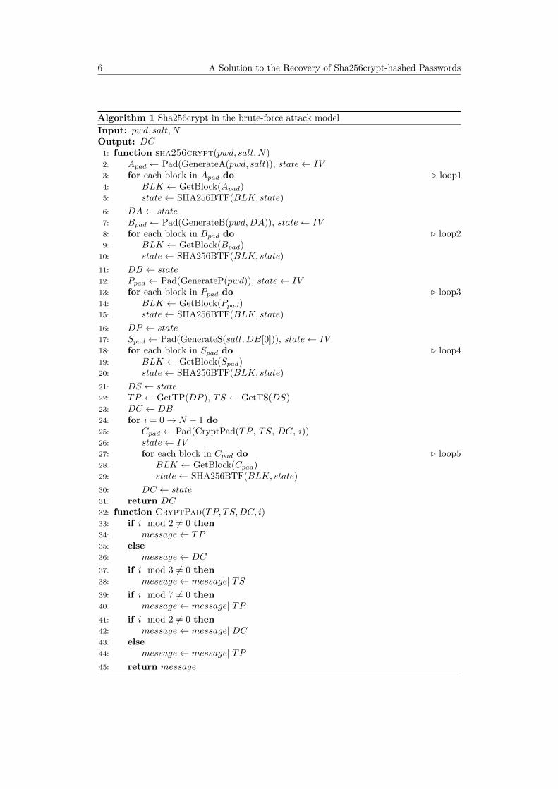
The second feature is the nonunified execution path. In sha256crypt, the number ofrounds in each loop is decided by the number of blocks in each input message (A, B,C, P, and S). The variety of the LP and the LS makes the lengths of input messagevary, which adversely impacts the schedule of the pipeline. Table 1 gives some examples.There is almost twice the difference between the number of rounds for different passwords,which reduces the efficiency since the fast thread has to wait for the slow thread. As thegeneration pattern of message S depends on DB[0], which could be considered as a randominteger within the interval [0, 255], the number of rounds in loop4 might be different evenfor passwords with the same length. There are 8 cases for the number of rounds in loop5,because the patterns that the CryptPad function uses to generate the message C is decidedby whether the iteration counter i is divisible by 2, 3 or 7, respectively.
Table 1: Number of rounds in each loop for different LP and LS with 5000 iterations.
LP LS loop1 loop2 loop3 loop4 loop5(each iteration)
loop5(5000 iterations)
6 8 1 2 1 3∼35 1,1,1,1,1,1,1,1 5,00016 8 1 3 5 3∼35 1,1,2,2,2,2,2,2 9,7616 16 1 2 1 5∼68 1,1,1,1,1,1,2,2 7,85716 16 1 3 5 5∼68 1,1,2,2,2,2,2,2 9,76132 16 2 5 17 5∼68 2,2,2,2,2,2,2,2 10,000
The last feature is the complex block generation pattern. The generation of a blockis equivalent to selecting 64 bytes from the source buffers (pwd, salt, DA, DB, etc.)and transmitting them to the destination buffer (BLK). Taking loop5 as an example,Figure 4 shows all of the 8 block generation patterns during the N iterations when LP

8 A Solution to the Recovery of Sha256crypt-hashed Passwords
= 6 bytes and LS = 8 bytes. Considering the most common case where LP 6 16 bytesand LS = 8 bytes, the total number of bytes in source buffers is 218 (pwd(16-byte),salt(8-byte), DX(32-byte×5), TP(16-byte), TS(8-byte), L(8-byte), constants(2-byte)). Tocomplete the generation in one cycle, all of the 64 bytes should be fetched simultaneously.If no optimization is applied, sixty-four 218-to-1 multiplexors are needed in hardwareimplementation, which introduces great overhead to hardware resources and critical pathlatency.
Case 0
Case 1
DCTP 0x80 padding 0 #46148 46 56 63477 13 55
TS0 45
DC TP 0x80 padding 0 #460 40 46 56 634739 45 55
TS3231
DC TP 0x80 padding 0 #440 38 44 56 634537 43 55
TP3231
DC 0x80 padding 0 #4412 44 56 6345 5543
TP65 11
TP0
DC 0x80 padding 0 #520 52 56 635331 55
TP32 37
TS TP38 45 46 51
DC 0x80 padding 0 #5220 52 56 635351 55
TP0 5
TS TP6 13 14 19
Case 2
Case 3
Case 4
Case 5
Case 6
Case 7
DC TP 0x80 padding 0 #380 32 38 56 633931 37 55
DCTP 0x80 padding 0 #3860 38 56 6339375 55
Figure 4: The 8 block generation patterns of loop5 when LP = 6 bytes and LS = 8 bytes.The numbers marked on each segment represent its position in the block.
2.5 Hybrid CPU-FPGA Platforms for Password RecoveryIn the field of password recovery, there’s always a trade-off between efficiency and flexibility.Processors with general-purpose architecture, such as CPU and GPU, could easily supportall KDFs and provide a flexible user interface. However, they tend to have higher energyconsumption than FPGA when performing brute-force attacks. On the other hand,although FPGA achieves better energy efficiency, its poor flexibility limits its applicationscenarios. Most pure FPGA-based accelerators target the PBKDF2 algorithm, which hasa regular and simple structure.
To combine the flexibility and efficiency, hybrid CPU-FPGA platforms, such as theZynq-7000 SoC series from Xilinx [Xil16] and Stratix 10 SoC series from Intel [Int20], wherefull-fledged processors are integrated together with configurable logic, can be used to buildup hardware password recovery accelerators with both high throughput and low energyconsumption [LLD19]. The CPU runs flexible software to make efficient scheduling whilethe FPGA implements customized hardware logic to provide high performance. Throughsoftware and hardware co-design, the designs on FPGA are simplified, thus achieve betterefficiency while still maintaining flexibility and low power consumption.
Compared with the discrete CPU-FPGA platforms, the hybrid CPU-FPGA systems likeZynq have additional advantages. First, the smaller chip count simplifies the board-levelhardware architecture, cuts down the form factor, and improves the system reliability.Second, the shorter distance between the CPU and the FPGA will cut down the communi-cation delays and of course require less power for the two devices to interact with eachother. Last but not least, the hybrid CPU-FPGA device is physically closer to and tightlyintegrated with its memory, which adds additional overall power saving [CEES14].

Zhendong Zhang and Peng Liu 9
3 Overview of System ArchitectureThe overall architecture of the proposed accelerator is shown in Figure 5. The systemconsists of a CPU, a secure digital memory card (SD card), and an FPGA with severalsha256crypt accelerating cores. The CPU and the FPGA are integrated on the samesystem on chip (SoC) and linked with AXI bus. The SD card’s functionality is to storethe bitstream files used to configure the FPGA.
SD card(Bitstream library)CPU
FPGAAccelerating
coreAccelerating
core
AXI bus
Figure 5: Overall architecture of the proposed password recovery accelerator.
To provide a user-friendly interface and an efficient task management, a passwordrecovery framework is deployed on the CPU. The framework has the same front end withthe famous password recovery tool Hashcat [has20], which supports flexible attack modes(dictionary, mask and rule, etc.) that allow users to accurately specify the passwordsearching space. The back end of the framework handles the task arrangement betweenthe CPU and the FPGA.
Figure 6 shows the flow chart of the sha256crypt password recovery. First, the passwordhash is parsed to get the salt, the iteration number (N ), and the decoded check value.Then, for each possible value of DB[0] in Phase III-3, the CPU generates a message Sand calculates its digest DS. This procedure is named as look-ahead execution. Next, agroup of passwords with the same length is generated from dictionaries or masks specifiedby the user. The FPGA will be reconfigured according to the length of the password ifnecessary. After that, the salt, N, pre-calculated DSs, and the passwords are transmittedto the accelerating cores on the FPGA through the AXI bus. When the accelerating corescomplete the sha256crypt computation, the results are sent back to the CPU. Finally,the CPU compares these results with the check value. If a match is found, the correctpassword will be outputted. Otherwise, the process above will be repeated until the correctpassword is found or the searching space is exhausted.
CPU
Parse hash
Look-ahead execution (loop4)
Flash bitstream
Generatepasswords
Check results
FPGA
Transmit data
Loop1 Loop2
Loop3Loop5
Figure 6: Flow chart of sha256crypt password recovery on the proposed accelerator.
The architecture of the accelerating cores is shown in Figure 7. There are threecomponents namely the data buffers, the data dispatch unit, and the block transformunit. The data buffers store the input sources, which include pwd, salt, DA, DB, etc. Thedata dispatch unit selects 64 bytes from the input sources to generate blocks under the

10 A Solution to the Recovery of Sha256crypt-hashed Passwords
control of the finite state machine (FSM). Then the block transform unit takes the blocksgenerated by the data dispatch unit and performs SHA256BTF to generate digests. Forthe advantage of high throughput, the pipeline technique is applied to the block transformunit. As the technique for efficient SHA256 implementations [MCMM06,CKSV08,RVS15]has been well studied, it is not the focus of our paper. Finally, these digests are sent tothe state buffer or data buffers to update the states or input sources. Operations abovefinish one round of a loop. When the last round of all the loops completes, the results aretransmitted back to the CPU for validating.
Accelerating core
Block transform unitData dispatch unit
Data buffers64-byteblock
FSM
CPU
Pipeline
Input sources
States
32-byte state
State buffer
Figure 7: Architecture of the proposed accelerating core.
Figure 8 shows the task arrangement between the CPU and the FPGA. The taskof checking results on the CPU and the acceleration on the FPGA are parallelized toimprove the efficiency. As it requires a substantial modification to Hashcat’s source codebut gains little improvement, the task of generating passwords is not parallelized. Thecommunication overhead comes from the transmission of the passwords and results.
G0
G0 G1
Accelerateon the FPGA
Check results
G0
Generatepasswords
Transfer passwords
Transfer check values
G1G1 G2G2
Figure 8: Task arrangement between the CPU and the FPGA. The task of checkingresults in the group 0 (G0) and the FPGA acceleration in the group 1 (G1) are processedconcurrently, which is the same for subsequent groups like the group 1 and group 2 (G2).
4 Hardware ImplementationHardware implementation details of our accelerator are provided in this section. Section4.1 discusses the group scheduling technique to eliminate data hazard of the pipelinedblock transform unit. Section 4.2 introduces the look-ahead execution technique to unifythe execution paths. Section 4.3 introduces the efficient design of the data dispatch unitusing the data path pruning and the spatial-temporal multiplexing techniques. Section4.4 shows the detailed architecture of the accelerating core with all these techniques puttogether.
4.1 Group SchedulingAs mentioned in Section 2.4, during the loop process, data dependency exists betweentwo adjacent block transform operations. As a result, each block has to wait M cycles

Zhendong Zhang and Peng Liu 11
until the processing of its previous block is finished, where M is the stage of the pipeline.For the convenience of hardware design, M is set to 64 in our implementation. We usethe utilization rate of the block transform unit to quantify the efficiency of the schedulingscheme, which is defined as follows:
Utilization rate = actual block throughputdesigned block throughput (2)
Since the designed block throughput is one block per cycle, the utilization rate alsoequals to the average number of blocks processed per cycle. If the data dependency is notsolved, the utilization rate of the block transform unit could only reach 1/64.
To eliminate the data dependency and improve the utilization rate of the pipelinedblock transform unit, the group scheduling technique proposed in [LLD19] is applied. Asthere is no data dependency between the processing of different passwords, a group ofG passwords can and shall be stored and processed together. We assume that all thepasswords in a group have the same number of blocks to process, which can be guaranteedby applying the look-ahead execution technique.
Figure 9 gives the comparison between pipelines with and without the group scheduling.By applying the group scheduling, the full-filled pipeline completes one block transformoperation per cycle. Taking the overhead of the pipeline full-filling into consideration,the utilization rate of the block transform unit will be G/(G+64). To maximize theutilization rate of the block transform unit, the group size G should be maximized underthe limitation of available BRAM resources.
State × G
Block × G
Digest × GBlock transform unit
State
Block
DigestBlock transform unit
1 block in 64 cycles
G blocks in G + 64 cycles
(a)
(b)
64 Stages
64 Stages
Figure 9: (a) Pipeline without group scheduling. (b) Pipeline with group scheduling.
4.2 Look-ahead ExecutionSection 2.4 has shown that different passwords and salts lead to different execution pathsof sha256crypt. This feature brings difficulties in group scheduling, since the threads inthe same group may have different numbers of blocks to process. As the salt remainsunchanged during the password recovery, the uncertainty of execution paths comes fromtwo aspects: the variation of password length and the unpredictable value of DB[0] inPhase III-3.
Variation of password length can be eliminated by sorting passwords by length whengenerating passwords on the CPU. Then passwords with the same length are grouped andtransferred to the accelerating core.
To remove the uncertainty caused by the unpredictable value of DB[0], we propose thelook-ahead execution technique based on the following observations. First, there is onlyone salt during the cracking of one password hash. Second, DB[0] has a range of 0 to 255.
12 A Solution to the Recovery of Sha256crypt-hashed Passwords
As a result, there are only 256 possible values of DS in total and we can reuse them for allpasswords.
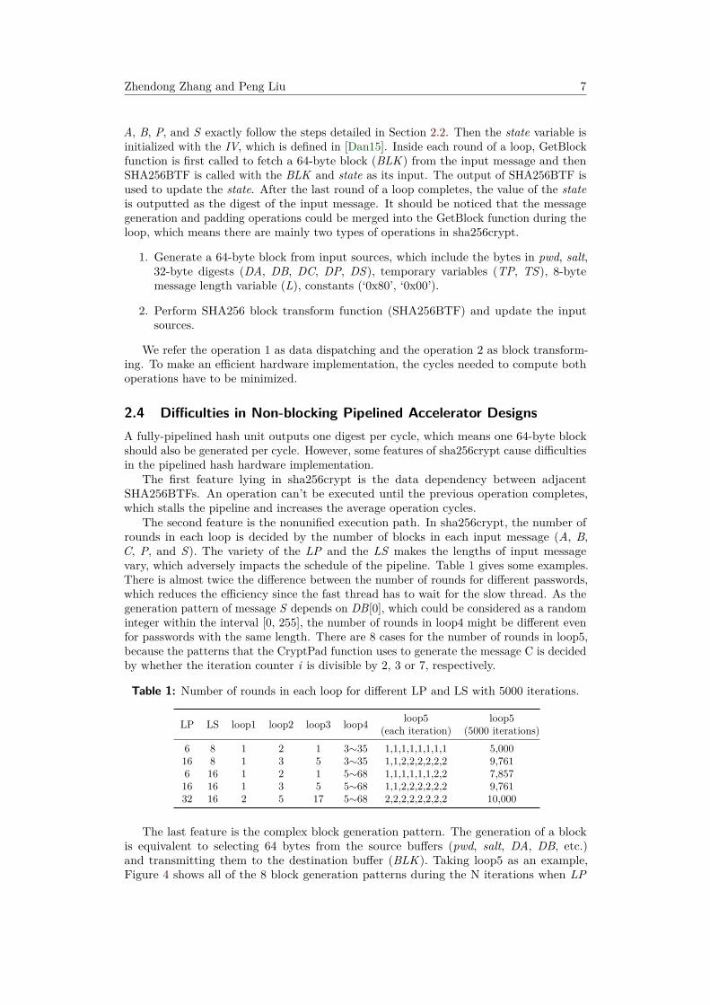
To this end, the calculation of DS (loop4) is mapped to the CPU. As shown in Figure 10,for each possible value of DB[0], a DS is calculated and stored in the LAE (Look-AheadExecution) buffer of the accelerating core. During the processing of the accelerating core,once the calculation of each DB completes, DB[0] is used to select corresponding DS from256 DSs in the LAE buffer. The results are stored in the DS buffer. With the look-aheadexecution technique, the value of DS is decided once the value of DB is calculated. Thus,all the passwords in the same group will follow the same execution path.
32-byte × 256
Dec
oder
32-byte × G
A0A1
A7
…
32-byte × G
DB buffer
DS buffer
DB[0]
LAE buffer
Pre-calculated DS values from CPU
DB from block transform unit
Figure 10: Schematic of the look-ahead execution technique.
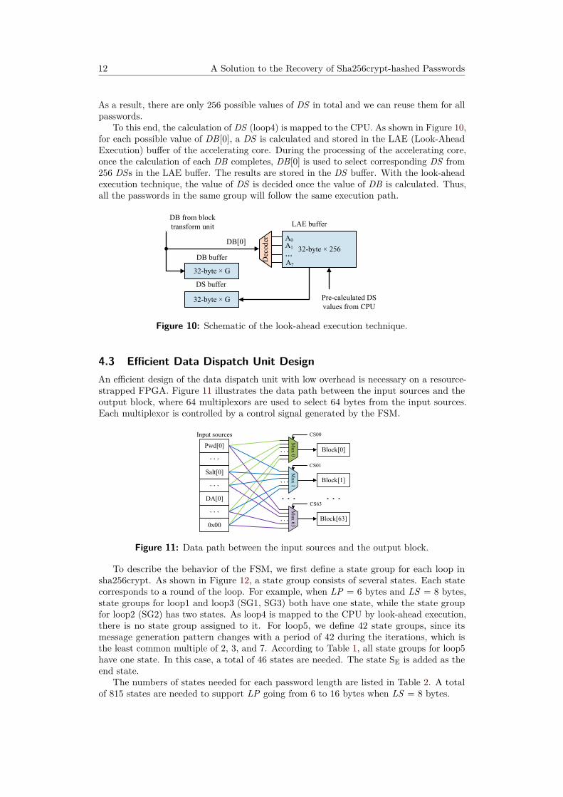
4.3 Efficient Data Dispatch Unit DesignAn efficient design of the data dispatch unit with low overhead is necessary on a resource-strapped FPGA. Figure 11 illustrates the data path between the input sources and theoutput block, where 64 multiplexors are used to select 64 bytes from the input sources.Each multiplexor is controlled by a control signal generated by the FSM.
Block[0]
Block[1]
Block[63]
Pwd[0]
Salt[0]
DA[0]
0x00
Mux 0
Mux 1
Mux 63
CS00
CS01
CS63
Input sources
Figure 11: Data path between the input sources and the output block.
To describe the behavior of the FSM, we first define a state group for each loop insha256crypt. As shown in Figure 12, a state group consists of several states. Each statecorresponds to a round of the loop. For example, when LP = 6 bytes and LS = 8 bytes,state groups for loop1 and loop3 (SG1, SG3) both have one state, while the state groupfor loop2 (SG2) has two states. As loop4 is mapped to the CPU by look-ahead execution,there is no state group assigned to it. For loop5, we define 42 state groups, since itsmessage generation pattern changes with a period of 42 during the iterations, which isthe least common multiple of 2, 3, and 7. According to Table 1, all state groups for loop5have one state. In this case, a total of 46 states are needed. The state SE is added as theend state.
The numbers of states needed for each password length are listed in Table 2. A totalof 815 states are needed to support LP going from 6 to 16 bytes when LS = 8 bytes.

Zhendong Zhang and Peng Liu 13
S0 S1 S2
S5 S4
S3
… …
SE
SG3SG2SG1
IC = 0
SG50SG51
… SG541
IC < N
IC < N
IC < N
IC < N
IC++
IC++
IC++
IC++
Figure 12: State diagram of the finite state machine for LP = 6 bytes and LS = 8 bytes.The IC (iteration counter) is set to 0 at S0. Each time when the FSM leaves SG5, the ICis increased by one. Once the IC equals the iteration number N, the FSM transits to theend state SE.
Table 2: Number of states needed in FSM for LP from 6 to 16 bytes when LS = 8 bytes.
LP 6 7 8 9 10 11 12 13 14 15 16# of states 46 46 71 71 71 73 85 85 88 88 90
Design of the FSM is shown in Figure 13. Benefiting from the unified execution path,the FSM can be simply implemented with a BRAM-based look-up-table. The content inthe look-up-table has 3 segments, which are the next state, the control signals, and the endof loop5 flag (EOL). At each state, the value in the state counter is used as the address toaccess the content in the look-up-table. Then the state counter is updated with the nextstate. The control signals from CS00 to CS63 are used to control the multiplexors of thedata path. The EOL flag is used to indicate whether a state group for loop5 is finished. Ifthe EOL is 1, the iteration counter should increase by one.
FSMLook-up-table
Address Next state
State counter
0x0000(S0)...
0x002D(S45)...
0x032E(SE)
CS00
CS63
...
S1...S4...-...
Mux
Dec
oder
SE
IC < N ?False
True
A0A1A2
CS00 CS63…
...
...
...
...-...
Next state
EOL
0...1...-...
Figure 13: Design of the finite state machine.
We adopt two factors to quantify the overhead of the data dispatch unit. The first isthe number of connections between the input sources and the output block. The numberof connections will influence the LUT resources that are used to implement multiplexors.Another factor is the size of the look-up-table, which affects the usage of BRAM resourceson FPGA.
Considering a simple and intuitive design where each multiplexor is connected directly

14 A Solution to the Recovery of Sha256crypt-hashed Passwords
with all input sources, as mentioned in Section 2.4, the number of connections for eachmultiplexor is 218. The total number of connections would be 218×64 = 13,952, which costs39,901 LUTs (about 50% of the total LUTs on our experimental platform). Meanwhile, fora 218-to-1 multiplexor, at least 8 bits of control signals are needed. Including 10 bits forthe next state segment and 1 bit for the EOL segment, the size of storage needed for eachstate is 8×64+10+1 = 523 bits. The total size of the look-up-table will be 523×815 =426,245 bits (about 52 KiB). To reduce the overhead of the data dispatch unit, we proposedata path pruning and spatial-temporal multiplexing techniques.A. Data path pruning
The data path pruning technique is based on the following observations. First, differentinput sources could share the same storage resources. For example, DB and DC couldshare the same buffer since they will not be used at the same time. Second, for a specificbyte in the block, its candidates only account for a part of all input sources, which meansa multiplexor doesn’t have to connect with all input sources.
Exploiting these observations, we reuse the buffers for multiple variables, which is listedin Table 3. Then, we customize the size of each multiplexor, so that only the possiblecandidates are connected to the inputs of a multiplexor. Figure 14(a) and Figure 14(b)show the number of connections before and after applying data path pruning. Afterpruning, the total number of bytes in input sources is decreased and each multiplexor hasfewer connections. Therefore, the total number of connections is reduced from 13,952 to3,086.
Table 3: Relationship between the variables and the buffers they use.
Buffer name pwd salt DA DB DSVariable name pwd, TP salt DA, DP, DC DB, DC DS, TS
(a) Unoptimized (b) After pruning (c) After pruning andspatial-temporal mul-tiplexing
Figure 14: Data path hotmap. Each grid represents a byte in the block. The numbermarked on the grid represents the number of connections for the corresponding multiplexor.
B. Spatial-temporal multiplexingIt should be noticed that the variation of password lengths also makes a great contri-
bution to the complexity of the data path. Figure 14(c) shows the number of connectionsactually used when the length of the password is fixed to 6 bytes. In this case, the numberof active connections is reduced to 394. This fact drives us to explore the temporal localityof the data path and propose the spatial-temporal multiplexing technique, which leveragesthe reconfigurability of the FPGA.
For password length from 6 bytes to 16 bytes, we prune the data path and generatea bitstream file for each length. Passwords with the same length are grouped and sentto the FPGA for processing. Every time the length of passwords changes, the FPGA isreconfigured with corresponding bitstream file. The software running on the CPU will sort
Zhendong Zhang and Peng Liu 15
the passwords by length to avoid frequent reconfiguration. With this technique, the wholedata path is separated and distributed into different bitstream files.
As the number of connections is reduced, each multiplexor needs fewer bits of controlsignals. What’s more, since each design only needs to store the states of a specific passwordlength, the total storage overhead can be further reduced. In the case where LP = 6 bytesand LS = 8 bytes, each control signal costs 4 bits and there are 47 states need to be stored.As a result, the storage overhead of the look-up-table is 47×(4×64+6+1)=12,361 bits,which is about 3% of the unoptimized design.
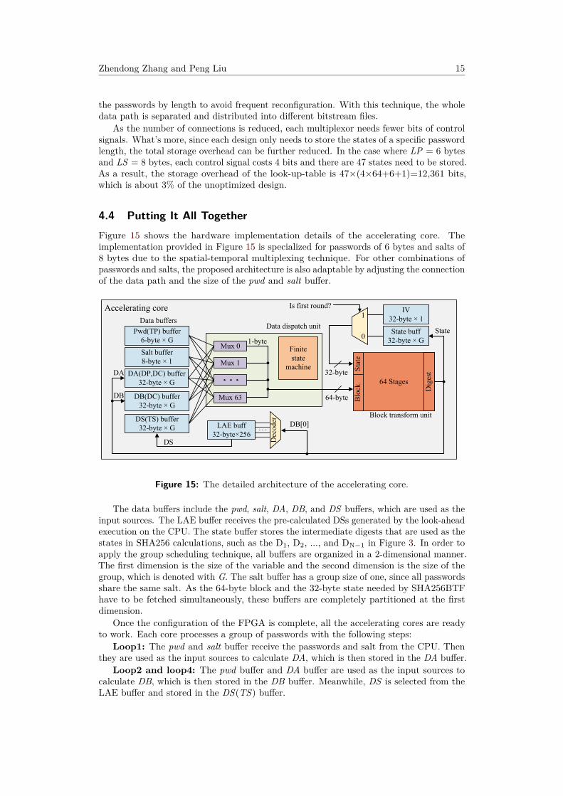
4.4 Putting It All TogetherFigure 15 shows the hardware implementation details of the accelerating core. Theimplementation provided in Figure 15 is specialized for passwords of 6 bytes and salts of8 bytes due to the spatial-temporal multiplexing technique. For other combinations ofpasswords and salts, the proposed architecture is also adaptable by adjusting the connectionof the data path and the size of the pwd and salt buffer.
Accelerating core
Dig
est
Blo
ckS
tate
Block transform unit
Data dispatch unitData buffers
Mux 0
Mux 1
Mux 63
Finitestate
machine
Pwd(TP) buffer6-byte × G
Salt buffer8-byte × 1
State buff32-byte × G
IV32-byte × 1
DS(TS) buffer32-byte × G
DB(DC) buffer32-byte × G
DA(DP,DC) buffer32-byte × G
DB[0]
DA
DB
DS
LAE buff32-byte×256
Dec
oder
Is first round?
0
1
64-byte
64 Stages32-byte
1-byte
State
Figure 15: The detailed architecture of the accelerating core.
The data buffers include the pwd, salt, DA, DB, and DS buffers, which are used as theinput sources. The LAE buffer receives the pre-calculated DSs generated by the look-aheadexecution on the CPU. The state buffer stores the intermediate digests that are used as thestates in SHA256 calculations, such as the D1, D2, ..., and DN−1 in Figure 3. In order toapply the group scheduling technique, all buffers are organized in a 2-dimensional manner.The first dimension is the size of the variable and the second dimension is the size of thegroup, which is denoted with G. The salt buffer has a group size of one, since all passwordsshare the same salt. As the 64-byte block and the 32-byte state needed by SHA256BTFhave to be fetched simultaneously, these buffers are completely partitioned at the firstdimension.
Once the configuration of the FPGA is complete, all the accelerating cores are readyto work. Each core processes a group of passwords with the following steps:
Loop1: The pwd and salt buffer receive the passwords and salt from the CPU. Thenthey are used as the input sources to calculate DA, which is then stored in the DA buffer.
Loop2 and loop4: The pwd buffer and DA buffer are used as the input sources tocalculate DB, which is then stored in the DB buffer. Meanwhile, DS is selected from theLAE buffer and stored in the DS(TS) buffer.

16 A Solution to the Recovery of Sha256crypt-hashed Passwords
Loop3: The pwd buffer is used as the input sources to calculate DP, which is thenstored in the DP buffer. Then the first #LP byte of DP is copied into the TP buffer.
Loop5: The TP, TS, and DB buffers are used as the input sources to calculate DC,which is then stored in the DA buffer. In the following iterations, the DA and DB buffersare alternatively used as the input sources and output buffer for DC.
At each round of a loop, the data dispatch unit switches to the corresponding blockgeneration pattern. One block is generated and sent to the block transform unit everycycle. The block transform unit performs SHA256BTF on these blocks and outputs thedigests. If the current round is not the last round of a loop, the digests will be storedin the state buffer as the intermediate states. Otherwise, they will be stored in the databuffers. After the processing of all G blocks in a group is finished, the data dispatch unitswitches to the next block generation pattern to start a new round. When all the roundsof all the loops are finished, the final digests of DC are sent back to the CPU to comparewith the password check value.
5 EvaluationThe performance and energy efficiency of our accelerator are evaluated on a Xilinx Zynq-7000 XC7Z030-3 SoC, which contains two ARM Cortex-A9 processors working at 666MHz and a 7 series programmable logic. Two sha256crypt accelerating cores working ata maximum frequency of 220 MHz are placed on the FPGA. The accelerating cores aresynthesized and implemented with the Xilinx Vivado 2016.3 toolset. To justify the proposeddesigns, the implementations are compared with the state-of-the-art password recoverytools Hashcat [has20] and John-the-Ripper (JtR) [Mag18]. The proposed accelerator isalso evaluated on a 16-node cluster which consists of the same Zynq devices, as is shownin Appendix A.
5.1 System PerformanceThe system performance of the proposed accelerator is shown in Table 4. As the number ofblocks in sha256crypt increases with the length of the password, the performance statisticsfor length from 6 bytes to 16 bytes are all reported. We use the number of passwords thatthe system can check per second as the indicator of speed. The power consumption ismeasured at the DC power supply of 5V. The energy efficiency indicates the energy costfor each password, which is calculated by speed/power. The proposed accelerator achievesa speed of 82,023 pwd/s when LP = 6 bytes. As the LP increases to 16 bytes, the speeddrops to 42,658 pwd/s since the number of blocks for each password increases. The powerconsumption of the proposed accelerator is about 15 Watts.
Table 4: System performance of the proposed accelerator
LP 6 7 8 9 10 11 12 13 14 15 16# of blocks 5,023 5,023 7,881 7,881 7,881 7,883 9,311 9,311 9,312 9,312 9,789
Speed (pwd/s) 82,023 82,016 52,992 52,844 52,834 52,881 44,882 44,686 44,799 44,797 42,658Power (Watt) 14.78 15.13 13.53 13.68 13.88 13.78 13.28 14.98 15.03 14.93 15.03
Energy efficiency(pwd/J) 5,550 5,421 3,918 3,867 3,807 3,838 3,381 2,983 2,981 3,001 2,838
5.2 Analysis of the Performance OverheadWe use the utilization rate of the block transform unit as the figure of merit to evaluatethe performance overhead, which mainly comes from the pipeline full-filling, the passwordgeneration, and the communication delay between the CPU and FPGA.

Zhendong Zhang and Peng Liu 17
The detailed time cost for each task when LP = 6 bytes is listed in Table 5. In ourimplementation, the group size G is set to 2048 to maximize the utilization rate under thelimitation of available BRAM resources. According to Table 1, each password has 5,004blocks to be processed on the FPGA. As the time of checking results on the CPU is hiddenbehind the time of acceleration on the FPGA, the processing of a password group costsabout 49,444 µs. The measured block throughput is about 4.15×10⁸ block/s. Table 6compares the theoretical utilization rate and the measured utilization rate. The proposedaccelerator reaches an average utilization rate of 94.3%. If we only consider the time forthe acceleration on the FPGA, the equivalent block throughput will be 4.25×10⁸ block/s,which is close to the theoretical value.
Table 5: Time cost for a group of 2048 passwords when LP = 6 bytes.
Task Blocks Time cost (µs) Throughput(block/s)
Generate passwords
2048×5004×2
572 -Transfer passwords 310 -
Accelerate on the FPGA(Check results)
48,230(18,339) 4.25×10⁸
Transfer check values 331 -Total 49,444 4.15×10⁸
Table 6: Utilization rate of the block transform unit (two cores).
# of Blocks Time (s) Throughput(block/s) Utilization rate
Theoretical 2048×2 (2048+64) ÷ (2.20×10⁸) 4.27×10⁸ 97.0%Measured 2048×5004×2 49444×10−6 4.15×10⁸ 94.3%
The time for the look-ahead execution on the CPU is negligible since it only executesonce. The time of each reconfiguration is 243 ms. The overhead introduced by reconfigura-tion is determined by the frequency of reconfiguration. For some small dictionaries wherethe FPGA needs to be reconfigured every 10 groups, the average time overhead for eachgroup is 24.3 ms, which will reduce the performance for about 33.5%. In some other caseswhere the mask mode is applied, the FPGA is reconfigured every 10,000 groups or more,which will bring down the time overhead to 24 µs or less, barely noticeable.
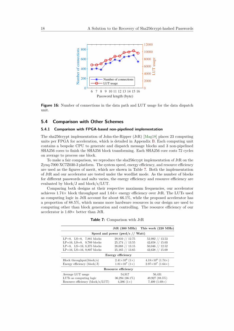
5.3 Analysis of the Data Path Overhead
As mentioned in Section 4.3, the number of connections in the data path affects thehardware resource overhead of the data dispatch unit. Figure 16 shows the number ofconnections and corresponding LUT usage of the data dispatch unit for different passwords.Compared with the unoptimized design, which uses 39,901 LUTs, the designs with thedata path pruning and spatial-temporal multiplexing techniques occupy about 6,000 to10,000 LUTs. The result also implies that as the number of connections changes with thepassword length, the LUT usage of the data dispatch unit changes with the same trend.In other words, the number of connections is a good indicator of the LUT usage of thedata dispatch unit.
18 A Solution to the Recovery of Sha256crypt-hashed Passwords
6 7 8 9 10 11 12 13 14 15 16
Password length (byte)
0
200
400
600
800
Nu
mb
er o
f co
nn
ecti
on
s
0
2000
4000
6000
8000
10000
12000
LU
T u
sag
e
Number of connections
LUT usage
Figure 16: Number of connections in the data path and LUT usage for the data dispatchunit.
5.4 Comparison with Other Schemes5.4.1 Comparison with FPGA-based non-pipelined implementation
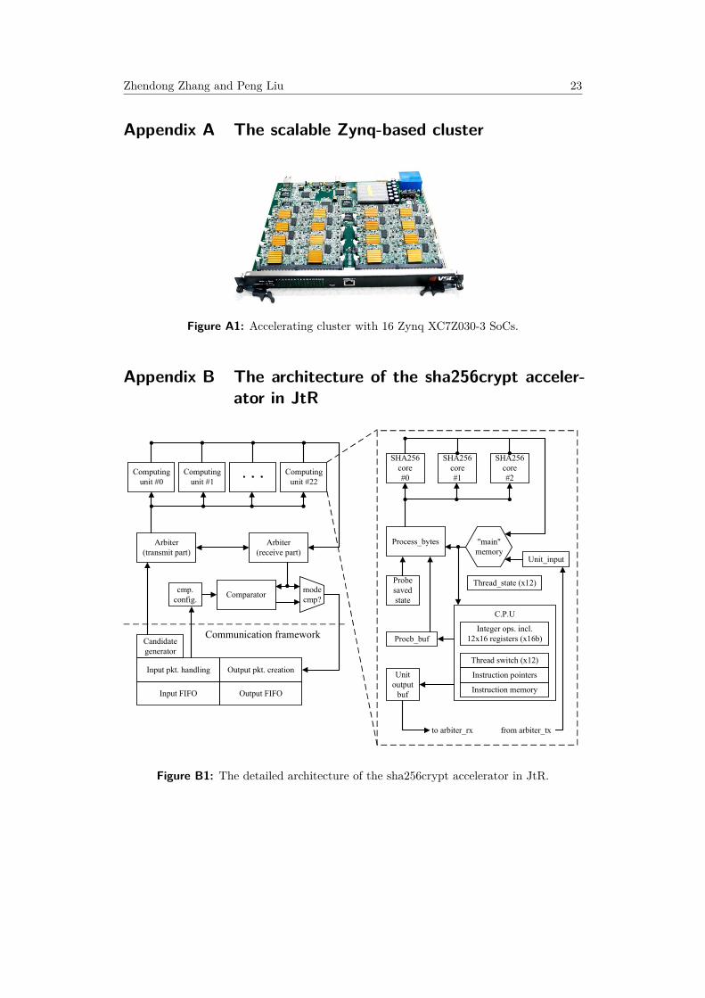
The sha256crypt implementation of John-the-Ripper (JtR) [Mag18] places 23 computingunits per FPGA for acceleration, which is detailed in Appendix B. Each computing unitcontains a bespoke CPU to generate and dispatch message blocks and 3 non-pipelinedSHA256 cores to finish the SHA256 block transforming. Each SHA256 core costs 72 cycleson average to process one block.
To make a fair comparison, we reproduce the sha256crypt implementation of JtR on theZynq-7000 XC7Z030-3 platform. The system speed, energy efficiency, and resource efficiencyare used as the figures of merit, which are shown in Table 7. Both the implementationof JtR and our accelerator are tested under the wordlist mode. As the number of blocksfor different passwords and salts varies, the energy efficiency and resource efficiency areevaluated by block/J and block/s/LUT.
Comparing both designs at their respective maximum frequencies, our acceleratorachieves 1.74× block throughput and 1.64× energy efficiency over JtR. The LUTs usedas computing logic in JtR account for about 66.1%, while the proposed accelerator hasa proportion of 88.5%, which means more hardware resources in our design are used tocomputing other than block generation and controlling. The resource efficiency of ouraccelerator is 1.69× better than JtR.
Table 7: Comparison with JtR
JtR (300 MHz) This work (220 MHz)Speed and power (pwd/s // Watt)
LP=8, LS=8, 7,881 blocks 29,810 // 12.75 52,992 // 13.53LP=16, LS=8, 9,789 blocks 25,174 // 13.55 42,658 // 15.03LP=8, LS=16, 8,375 blocks 28,088 // 13.15 50,046 // 12.52LP=16, LS=16, 9,807 blocks 25,165 // 13.65 42,638 // 15.69
Energy efficiencyBlock throughput(block/s) 2.41×10⁸ (1×) 4.18×10⁸ (1.74×)Energy efficiency (block/J) 1.81×10⁷ (1×) 2.97×10⁷ (1.64×)
Resource efficiencyAverage LUT usage 54,917 56,431LUTs as computing logic 36,294 (66.1%) 49,927 (88.5%)Resource efficiency (block/s/LUT) 4,386 (1×) 7,409 (1.69×)

Zhendong Zhang and Peng Liu 19
5.4.2 Comparison with GPU
Table 8 shows the comparison of the performance and energy efficiency between ouraccelerator and Hashcat(v5.1.0) [has20] running on an NVIDIA GTX1080Ti GPU. Besidethe normal mode, Hashcat provides an optimized mode which has better performance forpasswords shorter than 16 bytes. We choose the optimized mode as the baseline. Theresult has shown that the proposed accelerator achieves 2.54× improvement in energyefficiency than Hashcat running on GTX1080Ti. Although the block throughput of a singlenode is only 0.15× of Hashcat, when we test our design on the 16-node cluster, the blockthroughput is 2.41× better than Hashcat. The total power of the cluster is estimated tobe 16 times of the power consumed by a single node.
Table 8: Comparison with Hashcat running on a GTX1080Ti for sha256crypt.
Hashcatnormal
Hashcatoptimized
This worksingle node
This workcluster
Speed and power (pwd/s // Watt)LP=8, LS=8, 7,881 blocks 93,264 // 215 355,300 // 236 52,992 // 13.53 847,347 // 216.43LP=16, LS=8, 9,789 blocks 74,266 // 199 Unsupported 42,658 // 15.03 682,498 // 240.48LP=8, LS=16, 8,375 blocks 80,485 // 197 327,500 // 239 50,046 // 12.52 798,590 // 200.40LP=16, LS=16, 9,807 blocks 75,380 // 204 Unsupported 42,638 // 15.69 681,004 // 251.10
Energy efficiencyBlock throughput (block/s) 7.19×10⁸ (0.26×) 2.77×10⁹ (1×) 4.18×10⁸ (0.15×) 6.68×10⁹ (2.41×)Energy efficiency (block/J) 3.53×10⁶ (0.30×) 1.17×10⁷ (1×) 2.97×10⁷ (2.54×) 2.97×10⁷ (2.54×)
To evaluate the efficiency of the architectures between GPU and our accelerator, weuse the utilization rate of the computing unit as the figure of merit, which is calculatedby the measured block throughput divided by the maximum block throughput. Themaximum block throughput of our accelerator is 4.40×10⁸ block/s. The maximum blockthroughput of GTX1080Ti is reported by Hashcat’s SHA256 benchmark, which is 4.42×10⁹
block/s. The result shows that GTX1080Ti only utilizes 62.7% of its maximum ability,while our accelerator utilizes 94.5% of its maximum ability. The proposed architecture ofour accelerator makes better use of computing units than the general-purpose architectureof GPU.
5.5 Adapting to sha512cryptTo validate the adaptability of the techniques proposed in this paper, we also implementsha512crypt on the same platform. Since SHA512 costs more hardware resource thanSHA256, only one sha512crypt accelerating core is placed, which also works at 220 MHz.The performance comparison with Hashcat is shown in Table 9. The proposed acceleratorachieves 2.39× energy efficiency over Hashcat running on an NVIDIA GTX1080Ti GPU.
5.6 Disussion about CostCost of the password recovery mainly comes from two areas, the BOM (bill of materials)and the energy. The BOM cost is the one-time cost to build the hardware while the energycost is the recurring cost to run the hardware. Assuming that two password recoverysolutions have the same speed, the total cost increases linearly with time. Taking thedata from Table 8, a GTX1080Ti has the same speed with about 7 nodes of the proposedaccelerator while it needs 2.54× more electricity. The BOM costs of a GTX1080Ti andeach node of our accelerator are about 1,000 USD and 450 USD, respectively. Assumingthat the electricity price is 0.15 USD/kWh, we can find the dollar figure for the energyconsumption is 0.036 USD/h for a GTX1080Ti (240 W) and it would be 0.014 USD/h for
20 A Solution to the Recovery of Sha256crypt-hashed Passwords
Table 9: Comparison with Hashcat running on a GTX1080Ti for sha512crypt.
Hashcatnormal
Hashcatoptimized
This worksingle node
This workcluster
Speed and power (pwd/s // Watt)LP=8, LS=8, 5,014 blocks 26,384 // 175 192,900 // 245 41,086 // 18.91 667,774 // 302.60LP=16, LS=8, 5,016 blocks 26,407 // 184 192,100 // 241 40,855 // 21.23 652,368 // 339.63LP=8, LS=16, 5,023 blocks 26,304 // 182 190,300 // 242 41,083 // 18.91 656,388 // 302.60LP=16, LS=16, 7,882 blocks 24,642 // 193 188,900 // 243 26,317 // 17.66 419,909 // 282.48
Energy efficiencyBlock throughput (block/s) 1.48×10⁸ (0.14×) 1.09×10⁹ (1×) 2.06×10⁸ (0.19×) 3.29×10⁹ (3.02×)Energy efficiency (block/J) 8.02×10⁵ (0.18×) 4.51×10⁶ (1×) 1.08×10⁷ (2.39×) 1.08×10⁷ (2.39×)
our accelerator (7 nodes, 94 W). It will take 11 years of operation time until our acceleratorbeats the other party in total cost, which seems unacceptable at first sight.
However, as there are a lot of factors that affect the BOM cost and energy cost, thisconclusion may change for different cases. For example, if a company in Germany purchasesZynq devices in a large quantity to receive a deeply discount price of 200 USD and theelectricity price is 0.35 USD/kWh, it will only take 327 days, less than one year, to winover the GTX1080Ti-based solutions in a dollar sense.
6 Conclusion and Future WorkThis paper has proposed an efficient sha256crypt password recovery accelerator basedon the pipelined SHA256 unit. By analyzing the sha256crypt algorithm, we find thatpipelining is particularly suitable for accelerating the computation of KDFs which have astructure consisting of cascaded message blocks. Based on this important observation, wepropose a pipeline-based architecture. To overcome the difficulties in pipelined hardwareimplementation and reduce the hardware resource overhead, several techniques are proposed,such as group scheduling, look-ahead execution, data path pruning, and spatial-temporalmultiplexing. With these techniques, our accelerator achieves 2.54× improvement on energyefficiency compared with the state-of-the-art password recovery tool Hashcat running onan NVIDIA GTX1080Ti GPU. Compared with the pure FPGA-based accelerator in JtR,our accelerator achieves 1.64× energy efficiency and 1.69× resource efficiency. Our studyshows that the unified execution path and simple data flow are the keys to high efficiency,and high efficiency implies both high performance and low overhead for the passwordrecovery accelerators.
Without loss of generality, the techniques proposed in this paper can also be applied tothe KDFs that have similar features, such as sha512crypt and md5crypt. We appreciatethe design of such algorithms, as they help defend against the conventional pipelinedhardware attack by adding uncertainty to the memory access pattern and execution path.However, there are still structural weaknesses remaining. The calculation of DS in PhaseIII only depends on the salt string and the DB[0]. In the proposed accelerator, all of the256 possible values of DS are pre-computed and reused by all passwords to remove theuncertainty in the calculation of DS. This kind of structural weakness can be avoided ifdependency on the password string is involved. For example, future algorithm designerscan first add the password string to the message S before repeatedly adding the salt string.
Noticing that much of configuration remains the same for different bitstreams, it ispossible to optimize the system by utilizing the partial reconfiguration technology. Withpartial reconfiguration, the overhead of reconfiguration could be reduced to less than 50ms. However, it requires a great deal of work or even a new method to make our designcompatible with partial reconfiguration, which is hoped to be completed in the future.

Zhendong Zhang and Peng Liu 21
References[AKSE18] A Abdelrahman, H Khaled, Eman Shaaban, and Wail S Elkilani. WPA-WPA2
psk cracking implementation on parallel platforms. In 2018 13th InternationalConference on Computer Engineering and Systems (ICCES), pages 448–453.IEEE, 2018.
[AVWS14] Ayman Abbas, Rian Voß, Lars Wienbrandt, and Manfred Schimmler. Anefficient implementation of PBKDF2 with RIPEMD-160 on multiple FPGAs.In 2014 20th IEEE International Conference on Parallel and DistributedSystems (ICPADS), pages 454–461. IEEE, 2014.
[CEES14] Louise H Crockett, Ross A Elliot, Martin A Enderwitz, and Robert W Stewart.The Zynq Book: Embedded Processing with the ARM Cortex-A9 on the XilinxZynq-7000 All Programmable SoC. Strathclyde Academic Media, 2014.
[CKSV08] Ricardo Chaves, Georgi Kuzmanov, Leonel Sousa, and Stamatis Vassiliadis.Cost-efficient SHA hardware accelerators. IEEE Transactions on Very LargeScale Integration (VLSI) Systems, 16(8):999–1008, 2008.
[Dan15] Quynh H Dang. Secure hash standard. Technical report, 2015.
[DGK+12] Markus Dürmuth, Tim Güneysu, Markus Kasper, Christof Paar, Tolga Yalcin,and Ralf Zimmermann. Evaluation of standardized password-based keyderivation against parallel processing platforms. In European Symposium onResearch in Computer Security, pages 716–733. Springer, 2012.
[DK14] Markus Dürmuth and Thorsten Kranz. On password guessing with GPUs andFPGAs. In International Conference on Passwords, pages 19–38. Springer,2014.
[has20] Hashcat: Advanced password recovery. https://hashcat.net/hashcat/,2020. [Online; Accessed 9-July-2020].
[HK17] Ignatius Leo Sri Hendarto and Yusuf Kurniawan. Performance factors of aCUDA GPU parallel program: A case study on a PDF password crackingbrute-force algorithm. In 2017 International Conference on Computer, Control,Informatics and its Applications (IC3INA), pages 35–40. IEEE, 2017.
[Int20] Intel. Intel Stratix 10 SX SoC FPGAs. https://www.intel.com/content/www/us/en/products/programmable/soc/stratix-10.html, 2020. [Online;Accessed 9-July-2020].
[Jos06] Simon Josefsson. The base16, base32, and base64 data encodings. 2006.
[KMB+16] Markus Kammerstetter, Markus Muellner, Daniel Burian, Christian Kud-era, and Wolfgang Kastner. Efficient high-speed WPA2 brute force attacksusing scalable low-cost FPGA clustering [extended version]. arXiv preprintarXiv:1605.07819, 2016.
[Lam81] Leslie Lamport. Password authentication with insecure communication. Com-munications of the ACM, 24(11):770–772, 1981.
[LCL+16] Xiaochao Li, Chunhui Cao, Pengtao Li, Shuli Shen, Yihui Chen, and Lin Li.Energy-efficient hardware implementation of LUKS PBKDF2 with AES onFPGA. In 2016 IEEE Trustcom/BigDataSE/ISPA, pages 402–409. IEEE,2016.

22 A Solution to the Recovery of Sha256crypt-hashed Passwords
[LLD19] Peng Liu, Shunbin Li, and Qingyuan Ding. An energy-efficient acceleratorbased on hybrid CPU-FPGA devices for password recovery. IEEE Transactionson Computers, 68(2):170–181, 2019.
[Mag18] Magnumripper. John the ripper. https://github.com/magnumripper/JohnTheRipper/tree/bleeding-jumbo/src/ztex/fpga-sha256crypt,2018. [Online; Accessed 9-July-2020].
[Mar08] Simon Marechal. Advances in password cracking. Journal in ComputerVirology, 4(1):73–81, 2008.
[MCMM06] Robert P McEvoy, Francis M Crowe, Colin C Murphy, and William P Marnane.Optimisation of the SHA-2 family of hash functions on FPGAs. In IEEEComputer Society Annual Symposium on Emerging VLSI Technologies andArchitectures (ISVLSI), pages 317–322. IEEE, 2006.
[MK14] Katja Malvoni and Josip Knezovic. Are your passwords safe: Energy-efficientbcrypt cracking with low-cost parallel hardware. In 8th USENIX Workshopon Offensive Technologies (WOOT), 2014.
[Oec03] Philippe Oechslin. Making a faster cryptanalytic time-memory trade-off. InAnnual International Cryptology Conference, pages 617–630. Springer, 2003.
[QGG+16] Weidong Qiu, Zheng Gong, Yidong Guo, Bozhong Liu, Xiaoming Tang, andYuheng Yuan. GPU-based high performance password recovery technique forhash functions. Journal of Information Science and Engineering, 32(1):97–112,2016.
[RVS15] Manoj D Rote, N Vijendran, and David Selvakumar. High performance SHA-2core using the round pipelined technique. In IEEE International Conferenceon Electronics, Computing and Communication Technologies (CONECCT),pages 1–6. IEEE, 2015.
[Xil16] Xilinx. Zynq-7000 all programmable SoC. https://www.xilinx.com/support/documentation/product-briefs/zynq-7000-product-brief.pdf, 2016. [Online; Accessed 9-July-2020].
Zhendong Zhang and Peng Liu 23
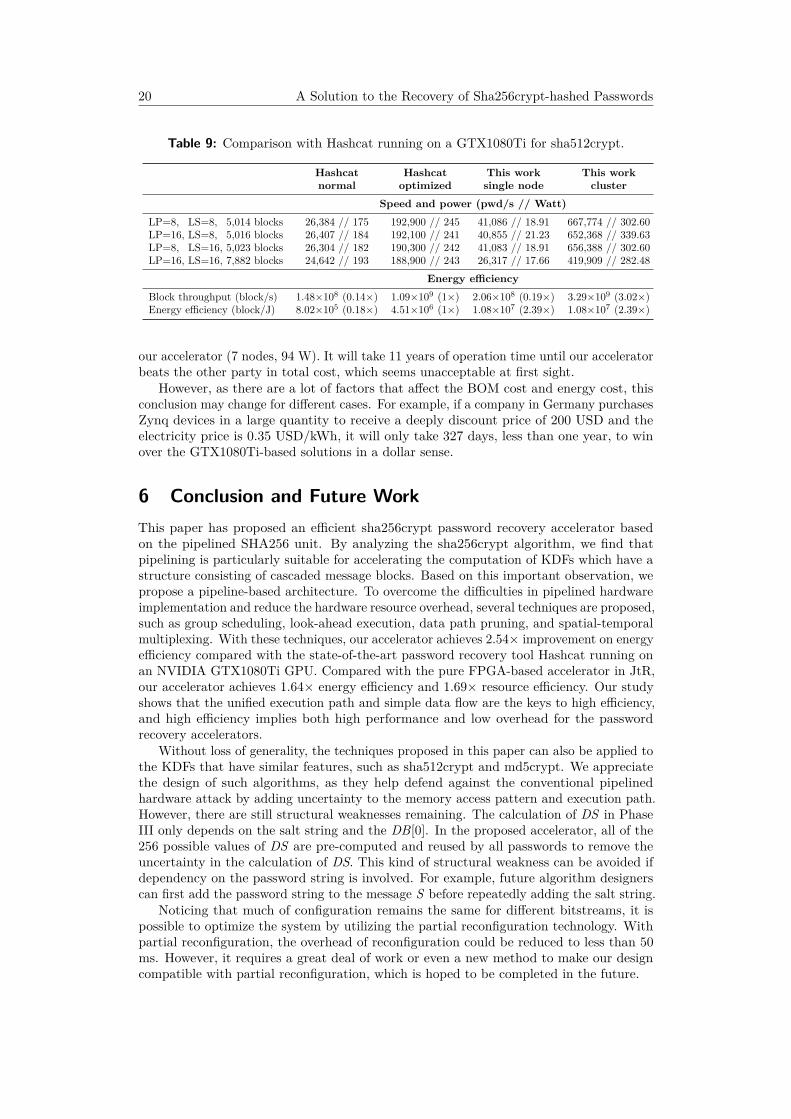
Appendix A The scalable Zynq-based cluster
Figure A1: Accelerating cluster with 16 Zynq XC7Z030-3 SoCs.
Appendix B The architecture of the sha256crypt acceler-ator in JtR
Computingunit #0
Computingunit #1
Computingunit #22
Arbiter(transmit part)
Arbiter(receive part)
Comparatorcmp.
config.modecmp?
Candidategenerator
Input pkt. handling Output pkt. creation
Input FIFO Output FIFO
Communication framework
SHA256core#0
SHA256core#1
SHA256core#2
Process_bytes "main"memory
Probesavedstate
Procb_buf
C.P.U
Integer ops. incl.12x16 registers (x16b)
Thread switch (x12)
Instruction pointers
Instruction memory
Thread_state (x12)
Unitoutput
buf
Unit_input
to arbiter_rx from arbiter_tx
Figure B1: The detailed architecture of the sha256crypt accelerator in JtR.