A simple finite element to consider the non-linear influence of the ballast on vibrations of railway...
6
Engineering Structures 33 (2011) 2597–2602 Contents lists available at ScienceDirect Engineering Structures journal homepage: www.elsevier.com/locate/engstruct A simple finite element to consider the non-linear influence of the ballast on vibrations of railway bridges Jean-Marc Battini ∗ , Mahir Ülker-Kaustell Department of Civil and Architectural Engineering, KTH, Royal Institute of Technology, SE-10044 Stockholm, Sweden article info Article history: Received 10 February 2011 Received in revised form 8 April 2011 Accepted 2 May 2011 Available online 11 June 2011 Keywords: Railway bridges Dynamic analyses Finite elements Ballast abstract This article proposes a new and simple finite element which can be used to analyze vertical vibrations in railway bridges. The main feature of the element is that the effect of the ballast is introduced through a non-linear longitudinal stiffness associated to the slip at the interface between the bridge and the ballast. Two numerical applications show that this element can be used to model the variation of the natural frequencies of the bridge as a function of the amplitude of vibration. © 2011 Elsevier Ltd. All rights reserved. 1. Introduction In the dynamic behavior of railway bridges, discrepancies between calculations and experiments are often observed. This problem especially applies to short or median span bridges for which important differences between calculated and measured natural frequencies can be obtained. Several studies, see e.g. [1,2], have also shown that, for such bridges, the natural frequencies vary as function of the amplitude of vibration. One difficulty in modeling relatively short railway bridges is that the influence of the track superstructure composed by rails, sleepers and ballast is not well known. For example, there is, so far, no clear recommendation in design codes to take the ballast into account in dynamic analyses. In several works about train–track–bridge dynamic interac- tion [3–6], the track and the bridge have been modeled by two beams and the effect of the ballast has been introduced using a more or less advanced system of viscoelastic spring/dampers and masses between the two beams. In [7], Liu et al. developed a 3D finite element model of the bridge using elastic solid elements for the ballast. Müller et al. [8] and Ruge and Birk [9], Ruge et al. [10] developed a truss model to study the longitudinal stresses due to temperature changes and train braking. Following the European codes, they introduced a non-linear stiffness between the bridge and the rail to represent the coupling effect of the ballast. ∗ Corresponding author. Tel.: +46 8 790 79 58. E-mail address: [email protected] (J.-M. Battini). The purpose of the present article is to propose a new and simple approach to model the effect of the ballast in vertical dynamic analyses of railway bridges. The idea is to use the methodology in [8–10] to develop a simple 2D beam finite element. In this element, the effect of the ballast is taken into account by introducing a linear or non-linear longitudinal stiffness associated to the slip at the interface between the bridge and the ballast. This approach has already been presented by Fink and Mähr [11], but in a continuum context, using differential equations. The organization of the paper is as follows: the derivation of the finite element is presented in Section 2. In Sections 3 and 4, two numerical applications, based on lab and in-situ experiments are proposed. In particular, it is shown that the present element can be used to model the variation of the lowest bending natural frequency as a function of the amplitude of vibration. Finally, conclusions are presented in Section 5. 2. Finite element formulation The finite element, see Figs. 1 and 2, consists of two layers. The layer (a) represents the bridge whereas the layer (b) represents the track superstructure composed by rails, sleepers and ballast. The slip at the interface between the two layers is considered. The element has four degrees of freedom. The horizontal displacements of the neutral axes of the two layers are not considered. It is assumed that the vertical displacements v and rotations θ of the neutral axis of the two layers are the same. The Bernoulli hypothesis is adopted, together with cubic shape functions, which 0141-0296/$ – see front matter © 2011 Elsevier Ltd. All rights reserved. doi:10.1016/j.engstruct.2011.05.005
Transcript of A simple finite element to consider the non-linear influence of the ballast on vibrations of railway...
Engineering Structures 33 (2011) 2597–2602
Contents lists available at ScienceDirect
Engineering Structures
journal homepage: www.elsevier.com/locate/engstruct
A simple finite element to consider the non-linear influence of the ballast onvibrations of railway bridgesJean-Marc Battini ∗, Mahir Ülker-KaustellDepartment of Civil and Architectural Engineering, KTH, Royal Institute of Technology, SE-10044 Stockholm, Sweden
a r t i c l e i n f o
Article history:Received 10 February 2011Received in revised form8 April 2011Accepted 2 May 2011Available online 11 June 2011
Keywords:Railway bridgesDynamic analysesFinite elementsBallast
a b s t r a c t
This article proposes a new and simple finite element which can be used to analyze vertical vibrations inrailway bridges. The main feature of the element is that the effect of the ballast is introduced through anon-linear longitudinal stiffness associated to the slip at the interface between the bridge and the ballast.Two numerical applications show that this element can be used to model the variation of the naturalfrequencies of the bridge as a function of the amplitude of vibration.
© 2011 Elsevier Ltd. All rights reserved.
1. Introduction
In the dynamic behavior of railway bridges, discrepanciesbetween calculations and experiments are often observed. Thisproblem especially applies to short or median span bridges forwhich important differences between calculated and measurednatural frequencies can be obtained. Several studies, see e.g. [1,2],have also shown that, for such bridges, the natural frequencies varyas function of the amplitude of vibration.
One difficulty in modeling relatively short railway bridges isthat the influence of the track superstructure composed by rails,sleepers and ballast is not well known. For example, there is, sofar, no clear recommendation in design codes to take the ballastinto account in dynamic analyses.
In several works about train–track–bridge dynamic interac-tion [3–6], the track and the bridge have been modeled by twobeams and the effect of the ballast has been introduced using amore or less advanced system of viscoelastic spring/dampers andmasses between the two beams. In [7], Liu et al. developed a 3Dfinite element model of the bridge using elastic solid elements forthe ballast.
Müller et al. [8] and Ruge and Birk [9], Ruge et al. [10] developeda trussmodel to study the longitudinal stresses due to temperaturechanges and train braking. Following the European codes, theyintroduced a non-linear stiffness between the bridge and the railto represent the coupling effect of the ballast.
∗ Corresponding author. Tel.: +46 8 790 79 58.E-mail address: [email protected] (J.-M. Battini).
0141-0296/$ – see front matter© 2011 Elsevier Ltd. All rights reserved.doi:10.1016/j.engstruct.2011.05.005
The purpose of the present article is to propose a new andsimple approach to model the effect of the ballast in verticaldynamic analyses of railway bridges. The idea is to use themethodology in [8–10] to develop a simple 2Dbeam finite element.In this element, the effect of the ballast is taken into account byintroducing a linear or non-linear longitudinal stiffness associatedto the slip at the interface between the bridge and the ballast. Thisapproach has already been presented by Fink andMähr [11], but ina continuum context, using differential equations.
The organization of the paper is as follows: the derivation ofthe finite element is presented in Section 2. In Sections 3 and 4,two numerical applications, based on lab and in-situ experimentsare proposed. In particular, it is shown that the present elementcan be used to model the variation of the lowest bending naturalfrequency as a function of the amplitude of vibration. Finally,conclusions are presented in Section 5.
2. Finite element formulation
The finite element, see Figs. 1 and 2, consists of two layers. Thelayer (a) represents the bridge whereas the layer (b) representsthe track superstructure composed by rails, sleepers and ballast.The slip at the interface between the two layers is considered. Theelement has four degrees of freedom. Thehorizontal displacementsof the neutral axes of the two layers are not considered. It isassumed that the vertical displacements v and rotations θ ofthe neutral axis of the two layers are the same. The Bernoullihypothesis is adopted, together with cubic shape functions, which

2598 J.-M. Battini, M. Ülker-Kaustell / Engineering Structures 33 (2011) 2597–2602
Fig. 1. Element kinematics.
Fig. 2. Slip at the interface.
gives
θ(x) =∂v
∂x= v′ (1)
v(x) = f1(x)v1 + f2(x)θ1 + f3(x)v2 + f4(x)θ2 (2)
with
f1(x) = 1 − 3xL
2+ 2
xL
3(3)
f2(x) = x1 −
xL
2(4)
f3(x) = 3xL
2− 2
xL
3(5)
f4(x) =x2
L
xL
− 1
. (6)
The bending strain and kinetic energy in the element arecalculated by
φbs =12
(EaIa + EbIb)∫L(v′′)2 dx (7)
φk =12
(ρaAa + ρbAb)
∫L(v̇)2 dx (8)
where Ei, Ai, ρi and Ii are the elastic modulus, the area, the densityand the second moment of area of the layer cross-section i.
This gives the classical stiffness and mass matrices as
k =EIL3
12 6L −12 6L6L 4L2 −6L 2L2
−12 −6L 12 −6L6L 2L2 −6L 4L2
(9)
m =ρAL420
156 22L 54 −13L22L 4L2 13L −3L2
54 13L 156 −22L−13L −3L2 −22L 4L2
(10)
with
EI = EaIa + EbIb ρA = ρaAa + ρbAb. (11)
Fig. 3. Bilinear shear force–slip law.
As shown in Figs. 1 and 2, the slip g at the interface between thebridge and the ballast is obtained as
g = hθ (12)
which, introducing Eqs. (1)–(6), gives
g = hGd (13)
with
G =f ′
1(x) f ′
2(x) f ′
3(x) f ′
4(x)
(14)
and
d =v1 θ1 v2 θ2
T. (15)
The effect of the ballast is modeled by a shear force F at theinterface. This force is taken as a non-linear function of the slip g .Following Müller et al. [8] and Ruge and Birk [9], Ruge et al. [10], abilinear law is adopted. It is shown in Fig. 3 and defined by
F = F(g) C =∂F∂g
. (16)
It can be observed that F is the resultant of the forces actingthrough the width of the interface and along a unit length. F istherefore in N/m.
The internal forces f at the nodes which give the same virtualwork as the force F in the element are defined by
δdTf =
∫LδgTF dx (17)
which, by introducing Eq. (13), gives
f = h∫LGTF dx. (18)
The corresponding tangent stiffness matrix, defined by
δf = ktδd (19)
is obtained from Eqs. (13), (16), (18) and (19) as
kt = h2∫LGTCG dx (20)
f and kt are calculated using three Gauss points along the lengthof the element (the positions of the Gauss points are indicatedby × in Fig. 1). It can be noted that G consists of polynomials ofsecond order and consequently an exact integration is obtained ifC is constant and taken as
C =Fogo
(21)

J.-M. Battini, M. Ülker-Kaustell / Engineering Structures 33 (2011) 2597–2602 2599
Fig. 4. Experimental bridge—model.
Table 1Experimental bridge—data.
Bridge EaIa = 1.1631 · 108 N m2
ρaAa = 635 kg/mm1 = 3193 kgm2 = 481 kg
Ballast EbIb = 1.2831 · 107 N m2
ρbAb = 3099 kg/m
whichmeans that only the linear part in Fig. 3 is considered. In thatcase, the tangent stiffness matrix is constant and is obtained as
ktc =Ch2
30L
36 3L −36 3L3L 4L2 −3L −L2
−36 −3L 36 −3L3L −L2 −3L 4L2
. (22)
Finally, the free vibrations of the composite beam are expressedby the non-linear equation
f (d, d̈) = md̈ + f + kd = 0 (23)
with
d̈ =v̈1 θ̈1 v̈2 θ̈2
T. (24)
Eq. (23) is solved step by step using the average accelerationmethod. For that, the expression
∂ f∂d
= kt + k (25)
is needed.The purpose of the present work is to study the free vibrations
of the lowest bendingmodes separately. Therefore the initial valueof the displacement vector d (or the acceleration vector d̈) is takenas the bending mode and is calculated by an eigenvalue analysisof Eq. (23) in which the non-linear term f is replaced by the linearterm
ktcd. (26)
The initial nodal velocities are taken to zero. By doing that,the vibration of the bridge is harmonic with the bending mode asshape. Using these initial conditions, the response of the structureis calculated by using time integration and the natural frequency isobtained by considering the times at which the displacements aremaximum. Then, by taking different initial amplitudes it is possibleto study the variation of the lowest natural frequencies in bending.
3. Example 1—experimental bridge
The first application is the experimental steel bridge developedand tested by Fink and Mähr at the Technical University ofVienna [11]. The main interest of this experiment is that itshows clearly that the ballast has an influence on the mechanicalproperties of the bridge and cannot be considered just as anadditional mass.
The bridge, see Fig. 4 and Table 1, has two main girdersconsisting of two HEA beams. The bridge deck is made of
Table 2Experimental bridge—results.
Max ampl. (×10−5) m (Hz) 175 302 407 489 532
Measured freq. 4.32 4.08 3.95 3.87 3.84Calculated freq. 4.27 4.18 3.97 3.84 3.77
timber beams and panels. The bending stiffness (EaIa) of thebridge is taken as the ones of the two HEA girders. The tracksuperstructure consists of a 55 cm thick ballast bed, reinforcedconcrete sleepers and two UIC 60 rails. The bending stiffness of thetrack superstructure (EbIb) is taken as the one of the two UIC 60rails, which means that it is assumed that the bridge and the railshave the same kinematics. The mass of the track superstructure(ρbAb) includes the ballast, the rails and the sleepers. The modalproperties of the bridge were measured using a system of twoeccentric weight vibration generators inducing a harmonic force.m1 andm2 are themass of the framework and generator atmidspanand the mass of the framework at the first and third quarter. Thebridge has been modeled using 8 beam elements.
The bridge was first tested without the ballast superstructure.Two tests, with different eccentric weights, were performed. Bothtests gave the same first resonance frequency, 4.66 Hz. Thisshows that without the ballast the bridge has a linear behavior.The calculated first natural frequency is 4.58 Hz. It can then beconcluded that the numerical model of the bridge is accurate.
The bridge was then tested with the ballast superstructure.Several tests, with different eccentric weights, were performed.In each test, the resonance appears at a different frequency,in the range of 3.84 and 4.32 Hz. The measured resonancefrequencies and the maximum midspan amplitudes at resonanceare given in Table 2. The first natural frequency calculated byintroducing only the stiffness of the rails (EbIb) and the mass ofthe ballast superstructure (ρbAb) is 2.66 Hz. These experimentaland numerical results show that the ballast introduces additionalstiffness and that this additional stiffness is not constant butdepends on the amplitudes of the vibration.
The bilinear shear force–slip law between the ballast and thebridge has then been added in the numerical model. Eq. (23) hasbeen solved by taking as initial displacements the first calculatedeigenmode with the five maximummidspan amplitudes observedin the tests. In each case, the first natural frequency has beencalculated from the numerical solution of Eq. (23) (free vibrationresponse). The parameters go and Fo have been calibrated sothat the difference between the 5 measured and the 5 calculatedfrequencies is as small as possible. For that, the MATLAB functionfminsearch has been used. The results shown in Table 2 have beenobtained with
go = 7.30 · 10−4 m Fo = 1.45 · 104 N/m. (27)Very good agreement between the measurements and the
numerical model can be observed. The largest difference, obtainedwith a measured frequency of 4.08 Hz, is only 2.4%.
It can also be observed that the obtained values are of the samemagnitude as the ones given in [9,10] (go = 2 · 10−3 m, Fo =
2·104 N/mfor an unloaded ballasted track in summer). However, itis not certain that a comparison is relevant since the values in [9,10]are used for static analyses of horizontal temperature effects.
Finally, the idea of the proposed approach is to consider theballast superstructure as a beam. Then, the additional stiffnessdue to the ballast is introduced only through a shear force at theinterface between the ballast and the bridge. Since the ballast isconsidered as a beam, another alternative to introduce additionalstiffness is to consider some bending stiffness in the ballastbeam. However, using this alternative, one must increase the totalbending stiffness of the system (EaIa + EbIb) from 1.3 · 108 N m2
to 3.3 · 108 N m2 in order to obtain a natural first frequency of4.27 Hz. It is clear that the ballast cannot give such additionalbending stiffness and consequently this alternative is not realistic.

2600 J.-M. Battini, M. Ülker-Kaustell / Engineering Structures 33 (2011) 2597–2602
Fig. 5. Composite bridge.
Fig. 6. Composite bridge—model.
Fig. 7. Composite bridge—cross-section.
Table 3Composite bridge—data.
Elements L (m) Aa (m2) Ia (m4) ρa (kg/m3)
1 0.3 0.3662 0.3852 216452 0.25 0.3662 0.3852 216453–7 0.75 0.3564 0.3154 220238–11 1 0.4042 0.3424 2033712–15 1 0.4744 0.3840 1849016–21 1 0.5042 0.3958 17932
4. Example 2—composite bridge
The bridge at Skidträsk (see Figs. 5–7) is a single span, concrete-steel composite bridge carrying one ballasted track. Its span is36 m. The rails are supported by concrete sleepers separated witha regular distance of 65 cm. These sleepers lie on ballast composedof rock particles with a diameter around 5 cm. The depth of theballast layer is approximately 50 cm. The sub-ballast, composedby particles with a diameter around 10 cm, has a depth of 50 cm. Areinforced concrete slab transfers the load from the track to twomain steel beams. The total width of the slab is 6.7 m and itsheight varies between 30 and 40 cm. The steel beams are simplysupported with respect to vertical bending moments. The line ofsupports is skewed relative to the longitudinal axis of the track.
The bridge has been modeled using 42 beam elements. Theequivalent steel section parameters (Ea = 210 GPa) are given inTable 3 for the 21 first elements, starting from the left side. The
Table 4Composite bridge—first natural frequency.
Measured acc. (m/s2) (Hz) 0.03 0.10 0.19 0.23 0.26
Measured freq. 3.84 3.75 3.60 3.46 3.30Calculated freq. 3.79 3.79 3.60 3.42 3.32
properties of the additional elements are obtained by symmetry.These properties have been calculated by considering a crackedconcrete section. The bending stiffness of the track superstructure(EbIb = 1.2831 · 107 N m2) is taken as one of the two UIC 60rails. The cross-section area and density of the ballast are 4 m2 and2040 kg/m3, which, by adding the contribution of the rails givesρbAb = 8280 kg/m.
The bridge has been instrumented to measure the verticalbridge deck acceleration during and after the passage of trains.Three accelerometers situated at the midpoint (a1 and a2) and atthe quarter-point (a3) have been used, see Fig. 7.
This study is based on the free vibration of the bridge just afterthe passage of a freight train at a speed of about 100 km/h. In orderto determine the first natural frequency in bending an averageacceleration, defined by
av =a1 + a2
2(28)
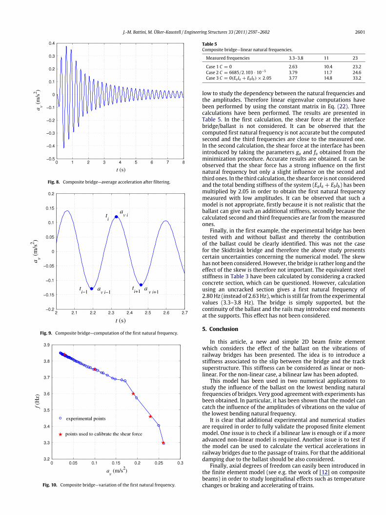
has been computed. A lowpass digital Butterworth filter has thenbeen applied in order to remove the contribution of the othermodes. The results are shown in Fig. 8. These results have beenused to study the influence of the amplitudes of the vibrationson the lowest natural frequency. The following method has beenused: at each maximum value of the average acceleration, acorresponding natural frequency has been calculated by using themaximum values before and after (see Fig. 9):
f (avi) =1
ti+1 − ti−1. (29)
The first maximum points of the average acceleration diagramhave not been used, firstly because these amplitudes are affectedby the filter, secondly because it is not certain that theseaccelerations have been registered after the passage of the train.
The results are presented in Fig. 10. It can be observed that thefirst natural frequency in bending increases from 3.3 to 3.85 Hzwhen the acceleration decreases from 0.26 to 0.03 m/s2.
The first natural frequency calculated without introducing thebilinear shear force–slip law is 2.63 Hz, which is quite far fromthe experimental results. The shear force between the bridge andthe ballast has then been introduced in the numerical model.The calibration has been performed using the same method as inthe first example. Five maximum amplitudes and correspondingnatural frequencies have been taken from Fig. 10. In each case,Eq. (23) has been solved by taking as initial accelerations thefirst calculated eigenmode with the maximum amplitude. Thefirst natural frequency has been calculated from the numericalsolution of Eq. (23). The parameters go and Fo have been calibratedso that the difference between the measured and the calculatedfrequencies is as small as possible. For that, the MATLAB functionfminsearch has been used. The results shown in Table 4 have beenobtained with
go = 2.103 · 10−5 m Fo = 6685 N/m. (30)
Very good agreement between the measurements and thenumerical model can be observed. The largest difference, obtainedwith an acceleration of 0.03 m/s2, is only 1.3%.
The second and third natural frequencies in bending have alsobeen identified from the records of the three accelerometers.However, the amplitudes of the corresponding modes were too
J.-M. Battini, M. Ülker-Kaustell / Engineering Structures 33 (2011) 2597–2602 2601
Fig. 8. Composite bridge—average acceleration after filtering.
Fig. 9. Composite bridge—computation of the first natural frequency.
Fig. 10. Composite bridge—variation of the first natural frequency.
Table 5Composite bridge—linear natural frequencies.
Measured frequencies 3.3–3.8 11 23
Case 1 C = 0 2.63 10.4 23.2Case 2 C = 6685/2.103 · 10−5 3.79 11.7 24.6Case 3 C = 0(EaIa + EbIb) × 2.05 3.77 14.8 33.2
low to study the dependency between the natural frequencies andthe amplitudes. Therefore linear eigenvalue computations havebeen performed by using the constant matrix in Eq. (22). Threecalculations have been performed. The results are presented inTable 5. In the first calculation, the shear force at the interfacebridge/ballast is not considered. It can be observed that thecomputed first natural frequency is not accurate but the computedsecond and the third frequencies are close to the measured one.In the second calculation, the shear force at the interface has beenintroduced by taking the parameters go and fo obtained from theminimization procedure. Accurate results are obtained. It can beobserved that the shear force has a strong influence on the firstnatural frequency but only a slight influence on the second andthird ones. In the third calculation, the shear force is not consideredand the total bending stiffness of the system (EaIa + EbIb) has beenmultiplied by 2.05 in order to obtain the first natural frequencymeasured with low amplitudes. It can be observed that such amodel is not appropriate, firstly because it is not realistic that theballast can give such an additional stiffness, secondly because thecalculated second and third frequencies are far from the measuredones.
Finally, in the first example, the experimental bridge has beentested with and without ballast and thereby the contributionof the ballast could be clearly identified. This was not the casefor the Skidträsk bridge and therefore the above study presentscertain uncertainties concerning the numerical model. The skewhas not been considered. However, the bridge is rather long and theeffect of the skew is therefore not important. The equivalent steelstiffness in Table 3 have been calculated by considering a crackedconcrete section, which can be questioned. However, calculationusing an uncracked section gives a first natural frequency of2.80Hz (instead of 2.63Hz),which is still far from the experimentalvalues (3.3–3.8 Hz). The bridge is simply supported, but thecontinuity of the ballast and the rails may introduce end momentsat the supports. This effect has not been considered.
5. Conclusion
In this article, a new and simple 2D beam finite elementwhich considers the effect of the ballast on the vibrations ofrailway bridges has been presented. The idea is to introduce astiffness associated to the slip between the bridge and the tracksuperstructure. This stiffness can be considered as linear or non-linear. For the non-linear case, a bilinear law has been adopted.
This model has been used in two numerical applications tostudy the influence of the ballast on the lowest bending naturalfrequencies of bridges. Very good agreementwith experiments hasbeen obtained. In particular, it has been shown that the model cancatch the influence of the amplitudes of vibrations on the value ofthe lowest bending natural frequency.
It is clear that additional experimental and numerical studiesare required in order to fully validate the proposed finite elementmodel. One issue is to check if a bilinear law is enough or if a moreadvanced non-linear model is required. Another issue is to test ifthe model can be used to calculate the vertical accelerations inrailway bridges due to the passage of trains. For that the additionaldamping due to the ballast should be also considered.
Finally, axial degrees of freedom can easily been introduced inthe finite element model (see e.g. the work of [12] on compositebeams) in order to study longitudinal effects such as temperaturechanges or braking and accelerating of trains.

2602 J.-M. Battini, M. Ülker-Kaustell / Engineering Structures 33 (2011) 2597–2602
References
[1] Rebelo C, da Silva LSimoes, Rigueiro C, Pircher M. Dynamic behaviour oftwin single-span ballasted railway viaducts-field measurements and modalidentification. Eng Struct 2008;30:2460–9.
[2] Ülker-Kaustell M, Karoumi R. The application of the continuous wavelettransform on the free vibrations of a steel–concrete composite railway bridge.Eng Struct 2011;33:911919.
[3] Biondi B,MuscolinoG, Sofi A. A substructure approach for the dynamic analysisof train–track–bridge system. Comput Struct 2005;83:2271–81.
[4] Rigueiro C, Rebelo C, da Silva LSimoes. Influence of ballast models in thedynamic response of railway viaducts. J Sound Vib 2010;329:3030–40.
[5] Wu Y-S, Yang Y-B. Steady state response and riding comfort of trains movingover a series of simply supported bridges. Eng Struct 2003;25:251–65.
[6] Yau J-D, Yang Y-B, Kuo S-R. Impact response of high speed rail bridges andriding comfort of rail cars. Eng Struct 1999;21:836–44.
[7] Liu K, Reynders E, De Roeck G, Lombaert G. Experimental and numericalanalysis of a composite bridge for high-speed trains. J Sound Vib 2009;320:201–20.
[8] Müller G, Jovanovic D, Haas P. Tracks–gravel–bridge interaction. ComputStruct 1981;13:607–11.
[9] Ruge P, Birk C. Longitudinal forces in continuouslywelded rails on bridgedecksdue to nonlinear track–bridge interaction. Comput Struct 2007;85:458–475.
[10] Ruge P, Widarda DR, Schmälzlin G, Bagayoko L. Longitudinal track–bridgeinteraction due to a sudden change of coupling interface. Comput Struct 2009;87:47–58.
[11] Fink J, Mähr T. Influence of ballast superstructure on the dynamics of slenderrailway bridge. In: NSCC. 2009.
[12] Nguyen QH, Hjiaj M, Uy B. Time-dependent analysis of composite beams withcontinuous shear connection based on a space-exact stiffness matrix. EngStruct 2010;32:2902–11.