a review of road embankment stability on soft ground
25
IIUM Engineering Journal, Vol. 20, No. 2, 2019 Mamat et al. https://doi.org/10.31436/iiumej.v20i2.996 A REVIEW OF ROAD EMBANKMENT STABILITY ON SOFT GROUND: PROBLEMS AND FUTURE PERSPECTIVE RUFAIZAL CHE MAMAT 1,3* , ANUAR KASA 1 , SITI FATIN MOHD RAZALI 2 1 Centre of Engineering and Built Environment Education Research (PeKA) 2 Smart and Sustainable Township Research Centre (SUTRA) Faculty of Engineering & Built Environment, Universiti Kebangsaan Malaysia, 43600 Bangi, Selangor, Malaysia. 3 Department of Civil Engineering, Politeknik Ungku Omar, Jalan Raja Musa Mahadi, 31400 Ipoh, Perak, Malaysia. * Corresponding author: [email protected] (Received: 4 th December 2018; Accepted: 30 th July 2019; Published on-line:2 nd December 2019) ABSTRACT: This paper presents an exhaustive review of the challenges faced in the construction of road embankments on soft ground and proposes a direction for future development. Frequently used techniques for soft ground improvement are discussed. The factors that contribute to the stability of the road embankment are reviewed by approach, results of past studies, and historical cases. The findings show that settlement, slope stability, and soil bearing capacity are all challenges to constructing the road embankment. Additionally, it is found that geometric data is a key factor in embankment design. Pre- loading with prefabricated vertical drain (PVDs) methods and lightweight fill were found to be widely used techniques in soft ground improvement. The information from this study can be used to develop design guidance systems, numerical modelling, and to give an overview and knowledge to other researchers who are or will conduct research in this field. Finally, future perspectives for research are related to predictions of factors that affect the stability of road embankment with an artificial intelligence approach. ABSTRAK: Kertas ini membentangkan ulasan kajian menyeluruh mengenai cabaran yang dihadapi dalam pembinaan benteng jalanraya di atas tanah lembut dan mencadangkan ke arah pembangunan kajian masa depan. Teknik-teknik penambahbaikan tanah lembut yang sering digunakan turut dibincangkan. Faktor- faktor yang menyumbang kepada kestabilan benteng jalanraya diulas dengan pendekatan kepada kajian lepas dan sejarah kes. Hasil kajian ini didapati bahawa enapan, kestabilan cerun dan keupayaan galas tanah merupakan cabaran dalam pembinaan benteng jalanraya. Selain itu, ia didapati bahawa data geometri merupakan faktor penting kepada rekabentuk benteng. Kaedah pra pembebanan dengan prefabrikasi saliran menegak (PVDs) dan isian ringan didapati teknik yang popular digunakan dalam pembaikkan tanah lembut masa kini. Maklumat dari kajian ini boleh digunakan untuk membangunkan sistem panduan reka bentuk, pemodelan berangka serta memberi gambaran dan ilmu kepada penyelidik lain yang sedang atau akan menjalankan kajian dalam bidang ini. Akhir sekali, perspektif masa depan untuk penyelidikan berkaitan ramalan faktor-faktor yang mempengaruhi kestabilan embankment jalanraya dengan pendekatan kepintaran buatan. KEYWORDS: road embankment; soft grounds; stability factors; ground improvement 32
-
Upload
khangminh22 -
Category
Documents
-
view
0 -
download
0
Transcript of a review of road embankment stability on soft ground

IIUM Engineering Journal, Vol. 20, No. 2, 2019 Mamat et al. https://doi.org/10.31436/iiumej.v20i2.996
A REVIEW OF ROAD EMBANKMENT STABILITY ON SOFT GROUND: PROBLEMS AND FUTURE
PERSPECTIVE
RUFAIZAL CHE MAMAT1,3*, ANUAR KASA1, SITI FATIN MOHD RAZALI2
1Centre of Engineering and Built Environment Education Research (PeKA) 2Smart and Sustainable Township Research Centre (SUTRA)
Faculty of Engineering & Built Environment, Universiti Kebangsaan Malaysia, 43600 Bangi, Selangor, Malaysia.
3Department of Civil Engineering, Politeknik Ungku Omar, Jalan Raja Musa Mahadi, 31400 Ipoh, Perak, Malaysia.
*Corresponding author: [email protected]
(Received: 4th December 2018; Accepted: 30th July 2019; Published on-line:2nd December 2019)
ABSTRACT: This paper presents an exhaustive review of the challenges faced in the construction of road embankments on soft ground and proposes a direction for future development. Frequently used techniques for soft ground improvement are discussed. The factors that contribute to the stability of the road embankment are reviewed by approach, results of past studies, and historical cases. The findings show that settlement, slope stability, and soil bearing capacity are all challenges to constructing the road embankment. Additionally, it is found that geometric data is a key factor in embankment design. Pre-loading with prefabricated vertical drain (PVDs) methods and lightweight fill were found to be widely used techniques in soft ground improvement. The information from this study can be used to develop design guidance systems, numerical modelling, and to give an overview and knowledge to other researchers who are or will conduct research in this field. Finally, future perspectives for research are related to predictions of factors that affect the stability of road embankment with an artificial intelligence approach.
ABSTRAK: Kertas ini membentangkan ulasan kajian menyeluruh mengenai cabaran yang dihadapi dalam pembinaan benteng jalanraya di atas tanah lembut dan mencadangkan ke arah pembangunan kajian masa depan. Teknik-teknik penambahbaikan tanah lembut yang sering digunakan turut dibincangkan. Faktor- faktor yang menyumbang kepada kestabilan benteng jalanraya diulas dengan pendekatan kepada kajian lepas dan sejarah kes. Hasil kajian ini didapati bahawa enapan, kestabilan cerun dan keupayaan galas tanah merupakan cabaran dalam pembinaan benteng jalanraya. Selain itu, ia didapati bahawa data geometri merupakan faktor penting kepada rekabentuk benteng. Kaedah pra pembebanan dengan prefabrikasi saliran menegak (PVDs) dan isian ringan didapati teknik yang popular digunakan dalam pembaikkan tanah lembut masa kini. Maklumat dari kajian ini boleh digunakan untuk membangunkan sistem panduan reka bentuk, pemodelan berangka serta memberi gambaran dan ilmu kepada penyelidik lain yang sedang atau akan menjalankan kajian dalam bidang ini. Akhir sekali, perspektif masa depan untuk penyelidikan berkaitan ramalan faktor-faktor yang mempengaruhi kestabilan embankment jalanraya dengan pendekatan kepintaran buatan.
KEYWORDS: road embankment; soft grounds; stability factors; ground improvement
32
IIUM Engineering Journal, Vol. 20, No. 2, 2019 Mamat et al. https://doi.org/10.31436/iiumej.v20i2.996
1. INTRODUCTION In road construction, the embankment is used to increase the height of the road
compared to the height of the surrounding area. It is a large earth structure and is often used in civil engineering applications related to infrastructure projects. The construction involves two essential construction components namely fill and foundation [1, 2]. These two components act as definitive parameters to analyse the embankment to find failure slope. Hence, a deep understanding and interpretation of the behaviours of these components such as deformation mechanisms can produce the collapse mechanism of the embankment.
Embankment fill is defined as selected fill placed and compacted with proper specifications so that it can display the required engineering performance [3]. The characteristics of fill material, the degree of compaction and the factors affecting the workability are considered for best results in the construction of embankment fill. Common fill materials are soil [4], natural aggregates [5] and lightweight filling material [6]. These fill materials must possess the required characteristics such as proper drainage to prevent saturation [7], good performance in compaction properties [8], compressibility [9], and shear strength [10]. Even if the embankment fill has the best material properties, instability can occur if it is built on unstable soft ground or soil with properties needing improvement.
The foundation serves as a placement for embankment structure and it may to be stable or unstable. The embankment foundation containing soft grounds is often a challenge for all engineers to ensure stability depending on the nature of the soil. Soft ground with fine particles such as silt, clay, and peat have high moisture content and are located near or below the groundwater level [11]. These soils also have the characteristics of high compressibility, high plasticity, high sensitivity, low shear strength, and low permeability [11,12]. Such features will lead to the problem of high settlement and low bearing capacity during post-construction work. This will reduce the strength of workability and shorten the embankment’s lifespan [13]. It will also lead to bumpy road surface and damage, subsequently causing accidents to road users.
Embankment stability is critical in road construction. Hence, before construction, the engineer must provide all geotechnical design reports and include drawings to be submitted to the relevant parties. The report shall state clearly the assumptions, parameter justifications and the methods used in the design to mitigate all issues or concerns. Geometric data is a general requirement in the preparation of design drawings while data materials contain the engineering parameters of fill and foundation of the embankment. Data materials are used in the engineering design of the embankment. The factor of safety (FoS) calculation is used to assess the performance of the embankment to ensure constant stability. The design report contains stability analyses, settlement analyses, the design of porewater pressure and technical recommendations for ground improvement. Embankments built on soft ground require the installation of monitoring instruments on site such as the inclinometer, settlement marker or rod settlement gauge and piezometer. The instrument will be monitored from time to time for the aid in the demonstration of compliance with minimum FoS during construction.
This paper reviews the literature on the challenges of embankment construction on soft ground and the latest techniques that are often used in improving soft ground. To achieve this objective, this paper has been divided into three sections. The first part deals with the factors that affect the embankment stability. The second part is about the factors affecting the design of the embankment, while the third is the latest soft soil improvement technique widely used with considerable aspects of sustainability, cost savings, and construction time. Finally, the main conclusions and future perspectives will be presented.
33
IIUM Engineering Journal, Vol. 20, No. 2, 2019 Mamat et al. https://doi.org/10.31436/iiumej.v20i2.996
2. THE CHALLENGE OF CONSTRUCTING EMBANKMENTS ON SOFT GROUND Soft ground has a high groundwater level and typically, it can be found near coastal
areas. The soil profile consists of a layer of crust at the top followed by a soft soil layer of either limited or unlimited thickness underneath. This soil is brown from light to dark [11]. In general, soft soil such as clay is dominated by particles of less than 0.002 mm in size and is pliable. It is formed from a combination of clay and mud and with almost 50% clay content [11]. The structure of this soil is identified as being dispersed, flocculated, bookhouse, turbostratic, and cohesive [14].
Soils are characterized by their physical, mechanical, chemical, and biological properties. Soil with poor geotechnical properties, such as soft clay, requires improvement technique application. Yalcin [15] investigated the effect of clay on a landslide in Kanlica Village, Turkey. As a result of laboratory tests, clay was found to contain illite and montmorillonite, which produced low shear strength and high swelling potentials making it prone to landslide problems. This conclusion is also supported by Ohlmacher [16], where the soil comprising mineral content such as illite has a high liquid limit contributing to very low strength parameters. Instability problems such as lateral deformations and excessive settlement often occur in structural and geotechnical construction on soft soils [17]. The load generated by the embankment fill drives the increase in soil stress and pore water pressure leading to deformation mechanisms. This causes the load to be undrained, where the behaviour is similar to the viscous fluid that can lead to critical conditions against structures such as bearing capacity problems. However, a thick hard layer built on the top can absorb the load produced by the fill of embankment.
An example of active embankment failure is the 1 km-long highway corridor located at the Eisenhower Tunnel, Colorado, USA. A survey by the Colorado Transport Department (CDOT) found that frequent slope settlement and failure problems have occurred over the last four decades [18]. The instability of the embankment due to movements of the side ground should be carefully considered during the design process and during engineering projects around the embankment. The road damage incident that occurred in September 2010 at the Port of Tanjung Priok, Jakarta was caused by embankment instability [19]. The embankment was built on clay with high plasticity. The movement of side ground caused the road surface to crack. Road embankment failure also happened in the Northland region of New Zealand [20], where the embankment was built on a soft soil characterized by a low strength with a highly sheared fabric. Other reasons for the failure are settlement and continuous soil movement that led to slope failure. An embankment failure occurred during the construction of a four-lane expressway in St. Stephen, New Brunswick, Canada across the USA border in July 2006, where failure was due to the rapid rate of construction and the intensity of loading for low-strength foundation soils [21]. The land in the foundation was composed of a soft marine clay layer which is a grey clay with a thickness of up to 15m.
Irsyam et al. [22] reported that a failure of the embankment slope occurred in Cipularang Toll Road located in West Java, Indonesia. Based on the record of slope monitoring indicators, the failure plane was due to low ground shear strength. Parameters of soil shear strength at failure conditions, i.e., cohesion and friction angle, were 5 kPa and 130 respectively from the toe of the embankment to the top of the embankment at the median of the highway. Additionally, a road connecting two villages, namely Nata and Pentalia in southwest Cyprus suffered 340 m of severe cracks even though the road was still under construction. The incident began in January 2002 where the foundation ground was
34
IIUM Engineering Journal, Vol. 20, No. 2, 2019 Mamat et al. https://doi.org/10.31436/iiumej.v20i2.996
composed of soft soil with high plasticity and low shear resistance [23]. The slope failure also occurred at the embankment due to high rates of rainfall.
Based on the case histories, it is clear that soil properties and rainfall are the cause of road embankment construction failures. To ensure embankment stability, the geotechnical design typically requires consideration of three factors namely: strength, deformation, and permeability or hydraulic conductivity. Bearing capacity and slope stability are among the important elements in the strength factor. Deformation is influenced by differential settlement, surface settlement, and lateral displacement of the ground while pore water pressure and seepage are elements affecting permeability.
2.1 Bearing Capacity Bearing capacity is one of the necessary steps in the design of the embankment. It is
the ability of the soil to bear the structural burden on the ground safely without any shear failure by accommodating a large settlement. This means that the foundation with shear failure involving general, local, or punching shear failure mechanisms will experience structure instability. Davis and Booker [24] have significantly contributed to understanding of the problem of clay-bearing capacity with increased strength with depth. Over the last few decades, much research has emphasized that embankment instability is due to a possible loss of bearing capacity of the foundation soil [25, 26]. During soft soil failure under the embankment, the fill moves downward with part of the foundation soil as a rigid body [25].
Several studies investigating the performance of the embankment on Muar clay [27], Bangkok clay [28], and Matagami lacustrine clay [29] were performed with low bearing capacity. Factors thought to influence bearing capacity have been explored in several studies. Popescu et al. [30] studied the effects of random heterogeneity of soil properties on bearing capacity with various shear strength values. On the other hand, Lehtonen et al. [31] investigated the effect of the trainload and the loading time on the embankment on soft soil. It is clear that careful study of the literature reveals that the soil shear strength, depth, and surcharges are the factors that influence the bearing capacity. A clear understanding of these factors is essential in the design of embankments on soft soils.
Over the past decade, some laboratory research projects have been conducted to investigate the soft soil performance based on the factors affecting bearing capacity. Kim and Lee [32] compared the bearing capacity of various sizes of gravel and sand. Two types of samples were composed of gravel and sand of compaction piles. The results revealed that coarse particles had a high bearing capacity compared to fine particles. It clearly showed that particle size contributes to higher bearing capacity, and it is noted that each type of soil has different strengths. Another study was performed with various strengths of soil stabilized by Portland cement [33]. The results found that the higher the percentage of cement mixture, the higher the maximum dry density and bearing capacity. This implies that the strength and density of the soil are higher, resulting in a high bearing capacity.
In order to improve soft soil bearing capacity, several researchers have suggested the application of basal reinforcement [34], chemical stabilization [11], and pile-supporting [35] in the embankment construction. However, cost, time and sustainable construction are the challenges of engineers choosing ground improvement techniques. A number of methods can be used to overcome this challenge with the 'Limited Life Geotextiles' [36] approach as basal reinforcement of embankments and fly ash [37] as a soft soil foundation stabilization.
2.2 Slope Stability Slopes are closely related to the height of an area, whereby the higher the area, the
steeper the slope. The stability of the slope is an important aspect in embankment
35
IIUM Engineering Journal, Vol. 20, No. 2, 2019 Mamat et al. https://doi.org/10.31436/iiumej.v20i2.996
construction due to its possible side effect of loss of human life and damage to property. A stable slope guarantees safety but otherwise, unstable slopes increase the risk of failure that can trigger landslides that cause the most damage and produce thousands of deaths every year and material losses of billions of dollars [38]. This is of increasing concern with this trend expected to continue in the next decade due to urbanization and development. Thus, the challenging task for engineers is to make decisions by paying more attention to the importance of public safety. Engineers need to understand the factors that led to the failure in order to assess slope stability.
Over the past decade, most research on slope failure was investigated and discussed based on studies and historical cases. Ballantyne [39] reviewed the literature from the period and identified factors that influenced slope failure in Scotland. A total of 740 incidents of landslides due to intense precipitation, engineering excavations, and mass weakening by fluctuating cleft-water pressures were studied. In 1993, over 800 slope failures were triggered by a rainstorm on Lantau Island, Hong Kong [40]. Ohlmacher [16] reports that the landslide that occurred in 1995 damaged two US$ 400,000 homes in Overland Park, Kansas. Based on the investigation, the slope angle was the main factor contributing to the problem of landslides in the study area. Davies [41] reported more than 50 slope failures in Kenya caused by natural geological and geomorphological conditions, coupled with high rainfall. A landslide that occurred in Wenchuan, China in 2008 was triggered by earthquakes and heavy rainfall [42].
Several studies investigating the factors of stability were performed by experiment. Xu et al. [43] studied gravity erosion on the steep loess slope by conducting a series of experiments in the laboratory to test slope stability against various geometry and rainfall rates. The analysis found that climate changes have significant influence over gravity erosion. Yong et al. [44] described the dynamic processes of grain comminution through grain size distribution of soils. High dynamic properties are found in granular soil exposed to soil evolution and mass movements, which can cause instability. The effect of slope length and slope angle on stability was successfully investigated based on laboratory tests by Kinnell [45].
Based on the evidence presented in this section, it is clear that nature, humans, and slope geometry are factors affecting stability. Landslides triggered by natural factors such as heavy rainfall and earthquake are the most common in the world. High intensity of rainfall is prone to contribute to weathering and rapid erosion of rock mass causing a reduction in the slope stability [45]. Erosion agents such as surface runoff enter the cracks, eroding the slope carrying with it a mud and soil stream while runoff absorbed into the soil weakens the bonds between soil particles on the slope surface. The pore water pressure that exists between the soil particles will affect the strength of the soil structure.
The earthquake phenomenon causes strong ground vibration that increases shear stress. The effect of the earthquake’s frequency and magnitude can overcome the force of adhesion to the ground and the retaining structure [42]. Besides, the vibration causes the movement of ground particles to be more likely to move according to gravity. Gravity is a force acting on the surface of the earth by pulling something towards the middle of the earth. Material on a flat surface will not move due to gravitational attraction unless the surface is sloped or angled.
Slope excavation is the human factor required for the construction of building foundations and roads because suitable engineering sites do not exist. This activity triggers the movement of slope and ground vibration will cause disturbance that will slide the mass, which makes the deformation accelerate [46]. Additionally, it will also destroy the
36
IIUM Engineering Journal, Vol. 20, No. 2, 2019 Mamat et al. https://doi.org/10.31436/iiumej.v20i2.996
vegetation on the slope surface and consequently, the reinforcing effect of the vegetation will be lost and precipitation will infiltrate the slope crack on the surface.
Geometric factors such as slope angle are the main components of the slope for measuring stability. As the slope angle increases, the shear stress in the soil and erosion will also increase [45]. The low slope angle is expected to be stable due to low shear stresses [47]. Conversely, with the increase in slope steepness, water infiltration decreases [48]. Thus, the slope angle is suspected of playing a major role in the control of infiltration and erosion that affects slope stability.
However, the slope stability problem varies between different geographical regions. For example, in European countries, slopes are exposed to varying temperatures and humidity, while in Malaysia, they are exposed to heavy rainfall with an average annual rainfall of 2500 mm. Lack of information on climate change, rainfall rates, and unpredictable clouding has caused engineers to fail to understand the mechanisms of slope failure. A detailed study is, therefore, needed and must be performed with appropriate technology to predict the parameters associated with slope failure factors.
2.2 Settlement Settlement is the total size of the vertical deformation on the soil surface. In theory,
embankment settlement occurs when increased compressive stress is generated by baseload compression. This process will cause vertical and horizontal deformation of the soil foundation. Besides changes in water content, soil mass and temperature can also distort soil. It is often associated with cohesive soil such as soft soil and can produce a large settlement for an extended period even under load [11]. During settlement, the ground transition at stress conditions is of its weight to the new state due to the extra load. The stress change caused by the additional load can produce a time-dependent accumulation of particle rolling, sliding, crashing, and elastic distortions in a limited influence zone beneath the loaded area. Hence, significant and excessive impacts will affect the road surface, where a decrease in height will occur and may cause flooding during heavy rains. Terzaghi [49] began the study of soft soil settlement. In theory, a settlement analysis comprises calculations of total and differential settlement, where total settlement is the magnitude of downward movement while the differential settlement is the vertical movement between two places.
The total settlement consists of three modes, namely elastic, consolidation, and creep deposition. Elastic settlement occurs due to the deformation of soil that is loaded without changes in water content and occurs within a short period [50]. It is also known as an undrained or immediate settlement. This type of settlement occurs instantaneously during the loading process with saturated soil that has low permeability and drainage ability. Consolidation settlement occurs due to the consolidation of soil in which water is slowly expelled from the soil cavity [51]. During the consolidation process, the deformation of the soil occurs with volume reduction over a long period. Creep or secondary compression is the same as compaction. It can occur when soil attempts to reposition itself in the cavity left by the water during consolidation settlement [52]. In the typical case, during embankment design, the computation of settlement involves elastic settlement and consolidation while post-construction involves creep.
Azzam and Basha [53] assessed the impact of improvements in the parameter of cohesive soil shear strength by using a soil nailing technique to reduce settlement. Brown to grey clay was taken from the Middle Delta of Egypt and stabilized using steel flat bars as vertical soil nails. The sample is then compressed with an unconfined compression machine
37
IIUM Engineering Journal, Vol. 20, No. 2, 2019 Mamat et al. https://doi.org/10.31436/iiumej.v20i2.996
with a low pressing rate. The study showed that increasing vertical inclusions significantly increases the shear strength and reduces settlement rates. Studies on the effects of creep on the side deformation of soil and pore pressure below the embankment were performed by Grimstad et al. [54]. The numerical method is used to investigate the embankment on the I-95 motorway in North Boston with a height of 12.2 m and built on Boston Blue Clay. The study shows that an increase in creep rate also increases soil settlement, pore pressure, and lateral deformations. Earthquakes can cause the settlement of saturated clay layers. This has been discussed in a study conducted by Sato et al. [55] using a Kaolinite clay sample, i.e. Tokyo bay clay, and Kitakyushu clay tested using uniform and irregular cyclic shear tests. The results of the study concluded that the Atterberg limits affect the settlement rate and pore water pressure accumulation during earthquakes. Accumulation and settlement of water pore pressure triggered by the friction cycle are measured by cumulative shear stress. To conclude, the studies conducted by the researchers clearly show that the type of soil, the underground conditions, the techniques to improve soil properties, and the soil drainage are factors that affect the settlement.
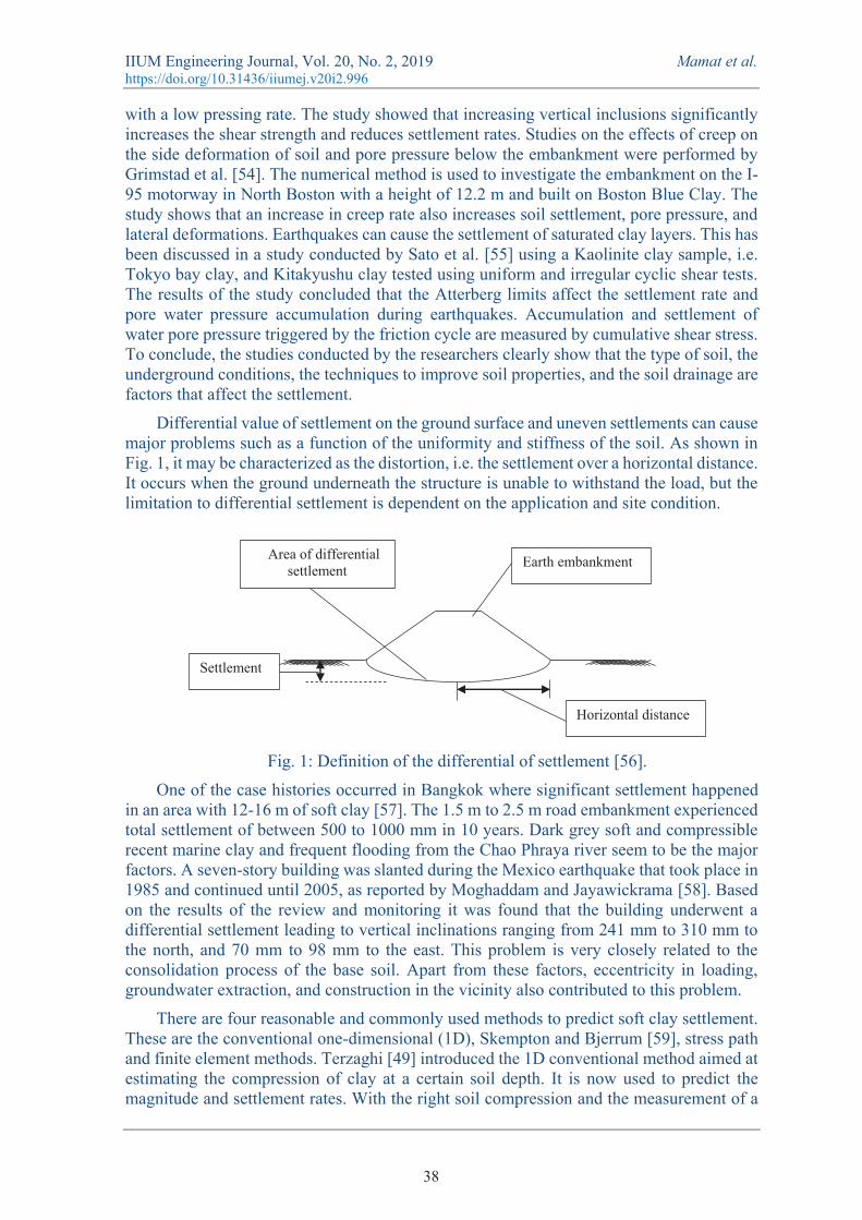
Differential value of settlement on the ground surface and uneven settlements can cause major problems such as a function of the uniformity and stiffness of the soil. As shown in Fig. 1, it may be characterized as the distortion, i.e. the settlement over a horizontal distance. It occurs when the ground underneath the structure is unable to withstand the load, but the limitation to differential settlement is dependent on the application and site condition.
Fig. 1: Definition of the differential of settlement [56].
One of the case histories occurred in Bangkok where significant settlement happened in an area with 12-16 m of soft clay [57]. The 1.5 m to 2.5 m road embankment experienced total settlement of between 500 to 1000 mm in 10 years. Dark grey soft and compressible recent marine clay and frequent flooding from the Chao Phraya river seem to be the major factors. A seven-story building was slanted during the Mexico earthquake that took place in 1985 and continued until 2005, as reported by Moghaddam and Jayawickrama [58]. Based on the results of the review and monitoring it was found that the building underwent a differential settlement leading to vertical inclinations ranging from 241 mm to 310 mm to the north, and 70 mm to 98 mm to the east. This problem is very closely related to the consolidation process of the base soil. Apart from these factors, eccentricity in loading, groundwater extraction, and construction in the vicinity also contributed to this problem.
There are four reasonable and commonly used methods to predict soft clay settlement. These are the conventional one-dimensional (1D), Skempton and Bjerrum [59], stress path and finite element methods. Terzaghi [49] introduced the 1D conventional method aimed at estimating the compression of clay at a certain soil depth. It is now used to predict the magnitude and settlement rates. With the right soil compression and the measurement of a
Settlement
Horizontal distance
Area of differential settlement Earth embankment
38
IIUM Engineering Journal, Vol. 20, No. 2, 2019 Mamat et al. https://doi.org/10.31436/iiumej.v20i2.996
thin layer of soil in the laboratory under a single load dimension, engineers can successfully and accurately predict performance [60]. According to the theory, stratum compressible is divided into several layers, while the calculation of the initial vertical effective stress and vertical stress increase using the Boussinesq stress [61] is based on the centre of each layer. At the end of the consolidation, when all excess pore water pressure is lost, the stress increase will become effective stress. The vertical strain of each layer can be obtained from the graph plotted between the void ratio with effective vertical stress as a result of the one-dimensional (odometer) compression experiment. This method was used in the study of the settlement of road embankment prediction [62]. However, Duncan [63] highlighted the limitations of this method; among others are the difference in the conditions between the field and the laboratory, the difference in load rates and tensions experienced by the soil between the laboratory and field, and the limitations found in 1D theory for three-dimensional (3D) problems. In addition, there are insufficient resources and documentation on the selection of parameters and the use of theory to predict settlement of silt compared to clay [64].
Skempton et al. [65] used 1D to calculate the total settlement of several buildings but admitted that undrained settlement is a significant parameter in the total settlement. As such, they used the elastic displacement theory to calculate the undrained settlement. The settlement forecasting in 3D has lower consistency compared to 2D due to pore pressure and the lower lateral deformation in 3D. They have thus put together a primary method to calculate the consolidation settlement caused by excessive dissipation of pore pressure. The settlement correction factors proposed in 1957 are dependent on geometric problems and pore pressure. This factor was also supported by Bergado and Teerawattanasuk [66] in their study that geometric effects should be considered as an important factor that could affect numerical simulation results. Bergado et al. [67] used this method to predict the embankment settlement of the Bangna-Bangpakong highway that was constructed on Bangkok soft clay. The study found that these methods provide reasonable estimates of long-term settlement.
The stress path method was proposed by Skempton [59] and developed further by Poulos and Davis [68]. It uses an uninterrupted sample under the appropriate underground depth to perform triaxial experiments under the appropriate initial in situ effective stresses. The purpose of vertical and horizontal stress without allowing drainage to be calculated is to determine vertical strain and excess pore pressure. When necessary, drainage was allowed, and applied stresses were adjusted to determine vertical stress and change in volume. The strain was then measured to obtain undrained settlement and consolidation. Studies on the performance of the screw plate test to determine the properties of deformability and consolidation of Bangkok clay was carried out by Bergado et al. [67]. Comparison of consolidation coefficients, non-flow and flow modulus between SPLIT and stress-path-controlled triaxial consolidation tests was performed. The findings of both experiments are similar to each other, implying the accuracy of the results to be sufficient for use for predictive purposes. Although logical, the method is complicated because the initial vertical and horizontal effective stresses must be known, and it requires advanced experimental skills. Isotropic and homogenous elasticity used to calculate the stress change and uncertainty in the accuracy of horizontal stresses exist. In addition, these experiments are highly costly and require a long time to conduct.
In recent times, numerical methods have been well received for predicting settlements because finite elements are carried out on non-homogeneous anisotropic elastic materials. Besides, it can handle nonlinear stress-strain behaviours of varying complexity. The engineers are more confident in the findings of finite elements because of its strength and
39
IIUM Engineering Journal, Vol. 20, No. 2, 2019 Mamat et al. https://doi.org/10.31436/iiumej.v20i2.996
flexibility, without realizing that this package contains inherent idealization and assumptions. Generally, the quality of data inputs plays an important role in determining the accuracy of the forecast. It is therefore important to evaluate and examine the constraints of the experiment as good control ensures high-quality data to be used for numerical analysis.
It was clear that settlement forecasting methods have undergone a sophisticated revolution moving from the classic 1D to numerical methods. The latter is able to solve a variety of complex issues because the program is equipped with advanced parameters and testing ground. The available features with sophisticated computing technology have led to this method becoming popular for application and development.
3. EMBANKMENT DESIGN The design of the embankment is extremely complex because it depends on the purpose
of construction, the environment, and the ground foundation conditions. When designing an embankment, engineers must plan, define geometric data, and analyse stability. The road embankment especially consists of a series of compacted layers placed on top of each other until the subgrade surface level is reached. It is also known as structural embankment and is divided into two types: the unreinforced [69] and reinforced, [70] which serves to distribute traffic load to soil foundation. Therefore, appropriate stability assessment and geometric data methods are essential to ensure the desired efficiency of construction. This section discusses three key aspects of geometric data, design, and analysis methods based on the recent literature.
3.1 Design and Analysis Methods The majority of today's engineers and researchers model the embankment design using
FEM. It is a numerical method that aims to design and analyse various engineering problems of both practical or research. It is also useful for problems with complicated geometries, loadings and material properties where analytical solutions cannot be obtained. There are three types of finite elements that are often used, namely one-dimensional (line), two-dimensional (plane), and three-dimensional (solid). From the literature, the use of two-dimensional is the choice of many researchers in the study of embankment stability. Plaxis [81], Abaqus [82] and Fast Lagrangian Analysis of Continua (FLAC) [83] are the types of software used for analysis, testing, and design in geotechnical engineering. However, the use of FLAC is less common in the study of the road embankment. Researchers and engineers more popularly use Plaxis as it is friendlier in soil modelling to solve simple problems in complex strata. Beyond that point, it can analyse all cases in geotechnical engineering including pile design [84], ground foundation [85], retaining wall [86], slope stability [87], and dam [88].
The driving force along the slopes that is greater than the resisting force restraining the movement of the slope is the basis of slope stability. Force imbalances such as increased resisting force will fail. Both forces are elements in slope design. The main driving force in most earth movements is gravity while the main resisting force is the material's shear strength. Slope stability is evaluated by calculating and assessing the stability index, or the FoS, defined as the ratio of ground resistance force along the failed surface to the instability force that illustrates the capabilities of a structure, such as an embankment [89]. Duncan [90] also explains that FoS is the ratio of real ground shear strength to the minimum shear strength required to prevent failure. Theoretically, a FoS value greater than 1 indicates a stable slope while a FoS value equal to 1 implies that the slope is in equilibrium.
40
IIUM Engineering Journal, Vol. 20, No. 2, 2019 Mamat et al. https://doi.org/10.31436/iiumej.v20i2.996
The slope stability analysis is divided into two, namely global and local stability. Global stability refers to the overall stability of soil mass along the slip surface and in multiple failure mechanisms by providing a lower safety factor. A sloping surface can withstand soil stress. For long-term and short-term flows, FoS ≥ 1.3 [91]. Most slope stability analysis software available, such as Slope/W, provides global FoS calculations. The global FoS calculation using the Phi-C reduction method was performed by Singh et al. [92] in the study of slope stability in Nainital, India. Iñeguez [93] in his study defines universal FoS by using a strength level approach. He also calculates local FoS using enhanced methods as the location of the most critical zone can be evaluated and used to guide the implementation of remedial measures. Local FoS are irregular and different at each point compared to conventional FoS which assumes that it remains constant along the slip surface.
In order to assess the stability of the slope, limit equilibrium (LE) analysis is commonly employed to determine the FoS by researchers and engineers. The LE technique such as the ordinary method of slices [94], Bishop simplified [95], Spencer [96], and Morgenstern-Price [97] methods have been widely used in the slope stability analysis. The slicing technique is known as an uncertain static problem, solved by assuming a distribution of internal forces. As such, different assumptions can result in varied results. Due to this inherent engineering practical weakness, FEM is now a choice. Some researchers have compared the results between LE method and FEM [98, 99], concluding that FEM provides the best and most accurate FoS result, as it is better able to explain the behaviour of soil stress and eliminate stress assumptions used in the LE method.
Strength reduction method (SRM) [100,101] and enhanced limit strength method (ELSM) [102, 103] are popular methods used in FEM although there are also ways to evaluate FoS using stress calculated directly through finite element modelling. The SRM has been used by Zienkiewicz et al. [104] to calculate slope safety factors based on the Mohr-Coulomb model. Most FoS formulas used now are obtained from the Mohr-Coulomb failure criterion [105]. SRM does not require assumptions on the form or location of the failure surface, because failures occur naturally through the zone in the soil mass where soil shear strength is unable to resist the applied shear stress [106]. This means that the critical slip surface is automatically obtained from the increased shear stress when the shear strength decreases. However, this method is unable to determine the position of the local minimum slip. ELSM is a hybrid between the LE method and FEM introduced by Kulhawy [107] as an independent assessment of the distribution of normal and shear stress along the assumed slip surface. Normal and shear stresses from elasticity analysis are used to calculate the overall FoS. In addition, this method uses FEM to estimate the magnitude of the stress as well as to find the critical slip surface with minimum FoS.
ELSM has the advantage over SRM in terms of time, as some finite element analyses need to be conducted separately. Besides, SRM is best suited for global FoS calculations while ELSM is for local FoS calculations. This is because local FoS calculations along the potential failure surface cannot be considered in the SRM procedure.
3.2 Geometry Analysis through FEM requires the establishment of data in constitutive relationships
and geometric modelling. Geometric data namely height, crest width, and gradient of side slope are among the important parameters in the production of design drawings. Engineers usually select the parameters based on their own experience. Based on observations, most studies conducted by researchers use embankments that are 1.5 m in height, have a crest width of between 35 m and 40 m, and have a 1:1.5 gradient of side slope (vertical: horizontal). In addition, road design manuals in several countries are described in Table 1.
41
IIUM Engineering Journal, Vol. 20, No. 2, 2019 Mamat et al. https://doi.org/10.31436/iiumej.v20i2.996
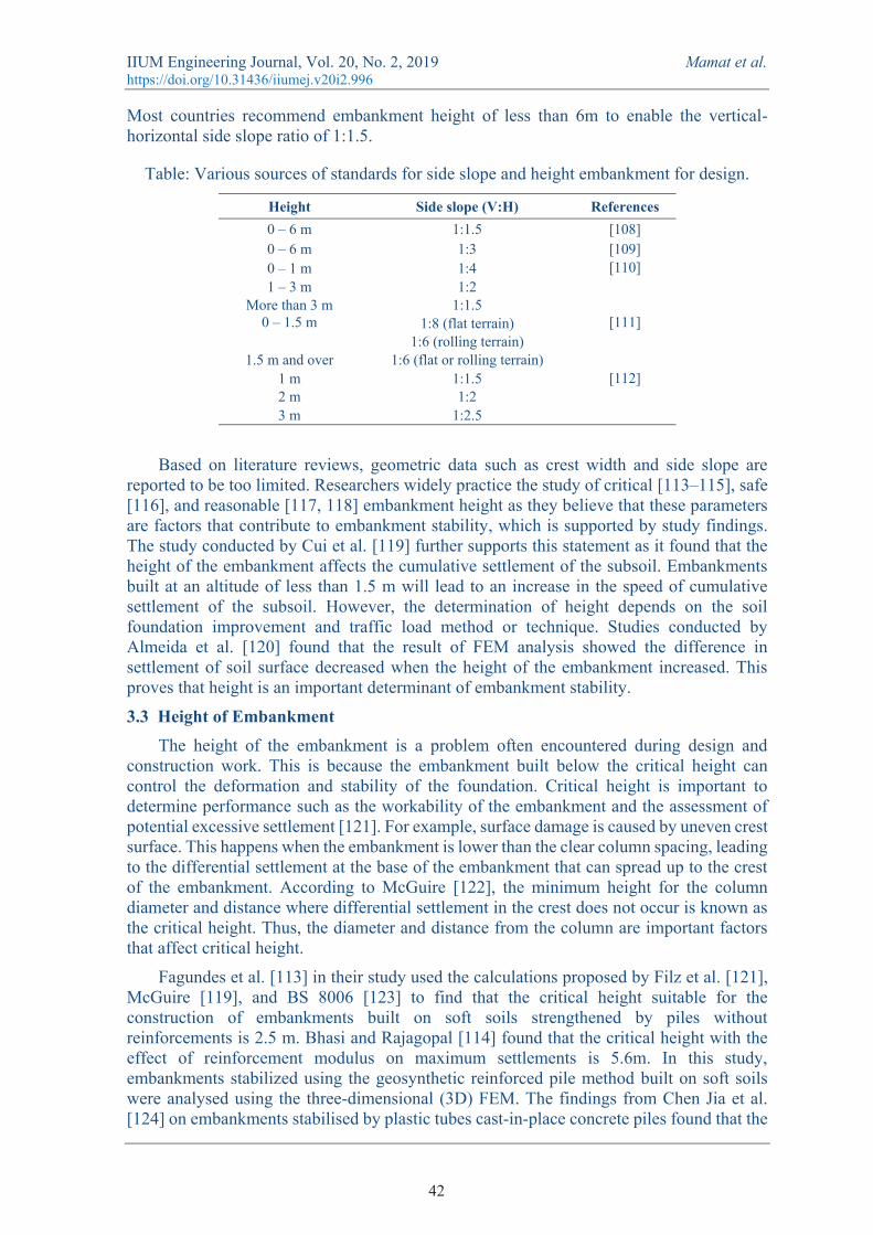
Most countries recommend embankment height of less than 6m to enable the vertical-horizontal side slope ratio of 1:1.5.
Table: Various sources of standards for side slope and height embankment for design.
Height Side slope (V:H) References 0 – 6 m 1:1.5 [108] 0 – 6 m 1:3 [109] 0 – 1 m 1:4 [110] 1 – 3 m 1:2
More than 3 m 1:1.5 0 – 1.5 m 1:8 (flat terrain) [111]
1:6 (rolling terrain) 1.5 m and over 1:6 (flat or rolling terrain)
1 m 1:1.5 [112] 2 m 1:2 3 m 1:2.5
Based on literature reviews, geometric data such as crest width and side slope are
reported to be too limited. Researchers widely practice the study of critical [113–115], safe [116], and reasonable [117, 118] embankment height as they believe that these parameters are factors that contribute to embankment stability, which is supported by study findings. The study conducted by Cui et al. [119] further supports this statement as it found that the height of the embankment affects the cumulative settlement of the subsoil. Embankments built at an altitude of less than 1.5 m will lead to an increase in the speed of cumulative settlement of the subsoil. However, the determination of height depends on the soil foundation improvement and traffic load method or technique. Studies conducted by Almeida et al. [120] found that the result of FEM analysis showed the difference in settlement of soil surface decreased when the height of the embankment increased. This proves that height is an important determinant of embankment stability.
3.3 Height of Embankment The height of the embankment is a problem often encountered during design and
construction work. This is because the embankment built below the critical height can control the deformation and stability of the foundation. Critical height is important to determine performance such as the workability of the embankment and the assessment of potential excessive settlement [121]. For example, surface damage is caused by uneven crest surface. This happens when the embankment is lower than the clear column spacing, leading to the differential settlement at the base of the embankment that can spread up to the crest of the embankment. According to McGuire [122], the minimum height for the column diameter and distance where differential settlement in the crest does not occur is known as the critical height. Thus, the diameter and distance from the column are important factors that affect critical height.
Fagundes et al. [113] in their study used the calculations proposed by Filz et al. [121], McGuire [119], and BS 8006 [123] to find that the critical height suitable for the construction of embankments built on soft soils strengthened by piles without reinforcements is 2.5 m. Bhasi and Rajagopal [114] found that the critical height with the effect of reinforcement modulus on maximum settlements is 5.6m. In this study, embankments stabilized using the geosynthetic reinforced pile method built on soft soils were analysed using the three-dimensional (3D) FEM. The findings from Chen Jia et al. [124] on embankments stabilised by plastic tubes cast-in-place concrete piles found that the
42
IIUM Engineering Journal, Vol. 20, No. 2, 2019 Mamat et al. https://doi.org/10.31436/iiumej.v20i2.996
critical height is 2.2 times the pile net spacing distance. The piles are driven by a distance of 1.0 to 1.5 m from one another. This means that the critical height is between 2.2 to 3.3 m. The three studies found that the critical height for the embankment built on soft soil and soil stabilized with piles is between 2.2 m and 5.6 m. However, there are very few studies on the critical height for embankments stabilized using other techniques such as vertical drains, preloading, grouting, and reinforcement.
A lot of research regarding reasonable height was conducted on the Qinghai-Tibet Highway (QTH) and the Qinghai-Tibet Railway (QTR). It was introduced by Zhang et al. [125] to protect the underlying permafrost during construction. The freezing and defrosting cycle of soil can lead to a settlement on the embankment. Hence, maintaining the magnitude of the embankment settlement to reasonable limits is key to ensure embankment stability [126]. The higher the embankment, the greater the differential settlement because an embankment that is not sufficiently high will lead to the freezing and defrosting cycle that affects tension and settlement. The foundation soil found along the highway and the railway is mostly silty clay, which is a type of soft ground.
QTH has a length of 1937 km and has a 632 km permafrost area. Among the studies to determine the reasonable elevation of the embankment in QTH were those carried out by Wang et al. [117] and Zhang et al. [127] who found, through site monitoring, that an embankment height of more than 4 m would lead to a reduction in the permafrost table. Therefore, reasonable elevation shall be determined to a limited extent. Wang et al. [117] have determined a reasonable embankment height for two typical geological sections along the QTH. The findings of the analysis are obtained through the modified numerical method, with a reasonable embankment height implied of 1.63 m. This is a significant study because reasonable height is important for maintaining the thermal and mechanical stability of highways located in the cold areas.
The QTR is 550 km long and has a permafrost area at an altitude of about 4500 m to 5000 m above sea level. Yue et al. [126] and Qi et al. [128] conducted analyses to obtain reasonable embankment of railroads in the permafrost state. The embankment should be built at a reasonable height of 4.0 m to reduce differential settlement [126]. The in-situ monitoring results in Qi et al. [128] showed that the reasonable height is 3.0 m and has a positive impact on frozen soil protection and promotes the increase of the permafrost table under the embankment. A study on the optimum design of crushed stone layers with shading board over the railway embankment on warm perma-frost was done by G. Li et al. [129] and found that the reasonable elevation is between 3.0 m to 5.0 m. The analysis of these findings is obtained through systematic numerical tests.
The safe embankment height is dependent on the gain in strength of soft subsoil and target FoS [130]. The study determines the height of each stage of construction based on increased shear strength to reach the FoS of 1.25. Through the iteration process, they have found the exact height of second-stage loading to be 3.02 m to achieve a total height of 5 m for the embankment. Meanwhile, the study conducted by Kasim et al. [116] concerning the safe height for the construction of the embankment on soft soil is summarised through the simulation results of PLAXIS Version 8.2 software that the maximum height is 4.9 m to ensure its stability against excessive settlement. This is also supported by Jin et al. [131], whereby increasing the height from 1.0 m to 4.0 m reduced the deformation value towards settlement.
Several factors affect the height of an embankment. We have reviewed critical, reasonable, and safe height, which have the same goal of ensuring embankment stability. Overall, height determination depends on several factors. The diameter and distance
43
IIUM Engineering Journal, Vol. 20, No. 2, 2019 Mamat et al. https://doi.org/10.31436/iiumej.v20i2.996
between planted pile stalks are factors that determine the critical height. Permafrost is one of the most dangerous elements and affects the stability of the embankment in cold areas. This is due to uncontrolled thaw settlement, and frost heaving processes that can cause settling problems and longitudinal cracks on the embankment. According to Wang et al. [132], embankment height is closely related to the problem. The reasonable height is interlinked with embankments built in areas prone to permafrost. Therefore, the temperature of the permafrost is also a factor in determining a reasonable height. FoS is the determinant of an embankment’s safe height. Most studies conducted to determine the safe height use Taylor's stability charts. The road design manual as in Table 1 suggested embankment height of up to 6 m. However, there are also researchers who employ the height in their study as 2.0 m [133], 3.0 m [134], 4.0 m [135] and 5.0 m [102]. We can conclude from the literature that 1.5 m to 6.0 m is the height range in embankment design that is able to ensure stability. The same height range is appropriate for the study or design of embankments. This range is relevant and useful as a guide for young engineers and researchers in the prediction and design of embankments.
4. SOFT GROUND IMPROVEMENT An engineer must possess several strategies that may be adopted to achieve project
goals when dealing with troubled ground conditions at the site. Various methods exist to improve compressible soils commonly applied on-site including preloading, lightweight fill, geosynthetic reinforcement, over-excavation and replacement, vertical drains, rigid piles, and injection. As mentioned in the literature review, enhancing density, increasing shear strength, and reducing compressibility can help in promoting stability. On the other hand, influencing permeability also decreases groundwater flow to increase consolidation rates. Despite the fact that existing methods may mitigate stability problems, selection factors need to be considered, such as sustainability, cost, and time of construction. All have become the topic of intense debate within the scholar community. Thus, this section will review the application of preloading with PVDs and geofoam as lightweight fill materials in the road embankment construction on soft ground by considering three selection factors.
4.1 Preloading and Prefabricated Vertical Drains Preloading methods are categorized as static consolidation and are cost-effective and
practical. They impose a temporary load to increase soil stress. This causes the substratum to densify and form stiffer support that will help reduce compressibility when the actual structure is built. This method commonly uses earth filled with a pre-determined height, and subsequent monitoring of settlement is conducted during a specific period until the deformation stops.
Dafalla [136] studied the performance of a stabilized soft ground settlement using the preloading and prefabricated vertical drains (PVDs) method along the coast of the Red Sea of Saudi Arabia and found that medium hard silty sand was beneath the site surface. Buildings and pedestrian pathways around the site have been damaged due to excessive settlement. The Saudi Ministry of Municipal and Rural Affairs has proposed that this method is applied for the project. The site uses preloaded sand of 4.5 m to 6 m high for six months and was monitored every week. The study concluded that this method reduces 20 % to 50 % of total settlement with sufficient time to prevent deformation. It can increase the strength of soft soils by accelerating the consolidation process so that the ground is able to bear the load. Therefore, sites with soft grounds are suitable for this method as they can be compressed in a relatively short time when loaded. Pressures exceeding what is required are placed above the soil and allowed to settle until the predicted settlement is reached. When
44
IIUM Engineering Journal, Vol. 20, No. 2, 2019 Mamat et al. https://doi.org/10.31436/iiumej.v20i2.996
the settlement has been reached, the excessive load is removed, and the service load is allowed on a strengthened foundation.
Recently, various innovations in this method have been created using modern technology. Among the successful modernizations of this method is combining the use of vertical drains or PVDs. Variation of this method has been successfully applied in many construction projects worldwide requiring ground improvements and reclamation [137]. Therefore, the theory, design, and construction methods for PVDs are significant issues in the preloading or consolidation method. The practice of using horizontal drainage began to emerge with drainage and then evolved into PVDs. Kjellman [138] introduced a combination of two materials, namely wood, and cardboard in 1947. Most PVDs have a width of about 100 mm with a thickness of 3.0 m to 6.0 m made of corrugated plastic cores surrounded by geotextile filters or a layer of natural fibres. It serves as artificial drain lines to accelerate the draining of water in the ground so that the time taken for the soft soil consolidation and the removal of excess pressure in the water pore can be significantly reduced. The elimination of pore water pressure increases soil strength, which would enable it to sustain the load. Da Silva et al. [81] studied the impact of PVDs installation on stability and embankment settlement. Using back-analysis to find sufficient material model and calculation of values using elastic-viscoplastic (EVP) through FEM to four dikes on very soft clay, it was found that PVDs very significantly accelerated settlement and increased FoS. Chu et al. [139] also conducted a study on the use of PVDs on soft clay soil which has a high moisture content for land reclamation projects. Evaluation of the consolidation effectiveness and suitability of the selected PVDs was performed through a large-scale laboratory model. The results showed that the installation of PVDs is very effective to accelerate the consolidation process. However, PVDs performance may decline as the consolidation process takes place due to the quality of the material that is unable to sustain the biological and chemical reaction between the filter and the soil surface. Besides, the soil undergoes a significant increase in undrained shear strength.
It is clear from the above study findings that the installation of the preloading and PVDs methods has advantages. A combination of both methods is efficient to be used in areas with soft ground. This method does not meet the green technology needs that emphasize the environmental impact of construction. This is because the surcharge fill usually involves cutting of high places such as hills, leading to various degrees of destruction and disasters. Although there are alternatives undertaken and introduced by Yang et al. [140], which use water as a surcharge, they are not suitable for areas with hot climates because the evaporation process will reduce the quantity of water and thus can affect the settlement monitoring readings. Besides, there are preloading methods using vacuum pressure [141, 142], which only use surcharges such as minimal soil but still require soil transportation from sources elsewhere. This method is also highly costly because it involves the pumping and plastic pipes that are often exposed to leakage. Therefore, environment-conscious methods should be developed based on the environmental and construction conditions of a particular location.
4.2 Geofoam as Lightweight Fill Material Construction challenges on soft grounds and lack of suitable soil for reclamation work
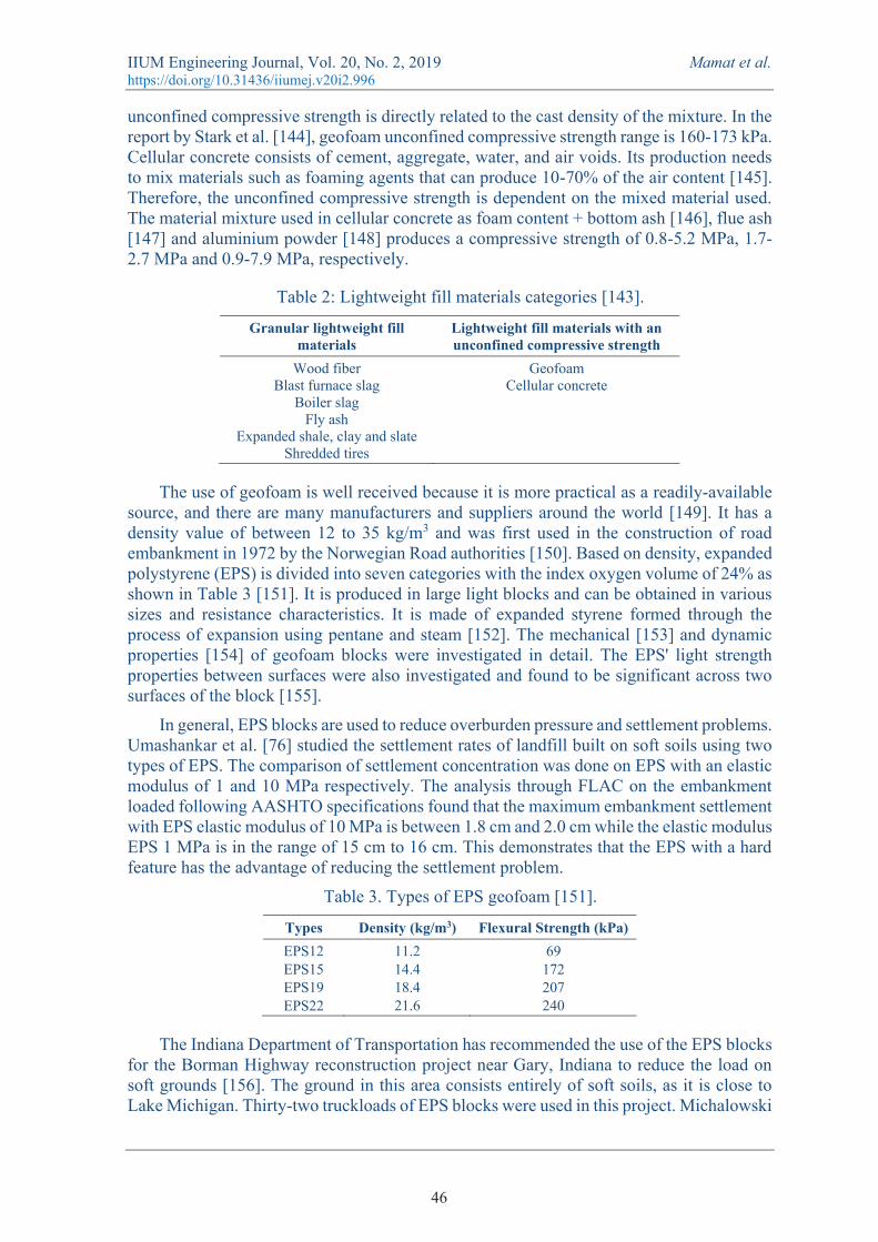
and environmental preservation led to a massive demand for innovative methods. The use of lightweight materials to replace fill material such as clay is an alternative. According to Schaefer et al. [143], lightweight fills are divided into two categories: materials that behave and have the same properties as soil particles, and materials with unconfined compressive strength that possess properties that are similar to the cohesive soil as shown in Table 2. The
45
IIUM Engineering Journal, Vol. 20, No. 2, 2019 Mamat et al. https://doi.org/10.31436/iiumej.v20i2.996
unconfined compressive strength is directly related to the cast density of the mixture. In the report by Stark et al. [144], geofoam unconfined compressive strength range is 160-173 kPa. Cellular concrete consists of cement, aggregate, water, and air voids. Its production needs to mix materials such as foaming agents that can produce 10-70% of the air content [145]. Therefore, the unconfined compressive strength is dependent on the mixed material used. The material mixture used in cellular concrete as foam content + bottom ash [146], flue ash [147] and aluminium powder [148] produces a compressive strength of 0.8-5.2 MPa, 1.7-2.7 MPa and 0.9-7.9 MPa, respectively.
Table 2: Lightweight fill materials categories [143].
Granular lightweight fill materials
Lightweight fill materials with an unconfined compressive strength
Wood fiber Blast furnace slag
Boiler slag Fly ash
Expanded shale, clay and slate Shredded tires
Geofoam Cellular concrete
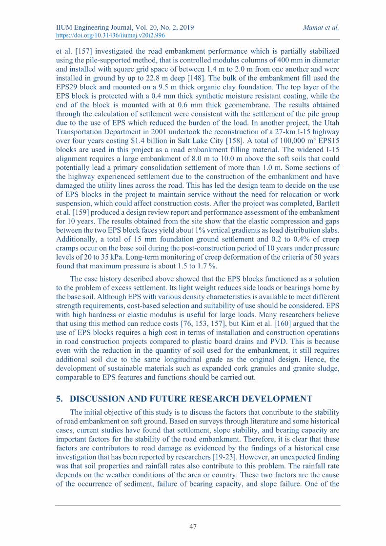
The use of geofoam is well received because it is more practical as a readily-available source, and there are many manufacturers and suppliers around the world [149]. It has a density value of between 12 to 35 kg/m3 and was first used in the construction of road embankment in 1972 by the Norwegian Road authorities [150]. Based on density, expanded polystyrene (EPS) is divided into seven categories with the index oxygen volume of 24% as shown in Table 3 [151]. It is produced in large light blocks and can be obtained in various sizes and resistance characteristics. It is made of expanded styrene formed through the process of expansion using pentane and steam [152]. The mechanical [153] and dynamic properties [154] of geofoam blocks were investigated in detail. The EPS' light strength properties between surfaces were also investigated and found to be significant across two surfaces of the block [155].
In general, EPS blocks are used to reduce overburden pressure and settlement problems. Umashankar et al. [76] studied the settlement rates of landfill built on soft soils using two types of EPS. The comparison of settlement concentration was done on EPS with an elastic modulus of 1 and 10 MPa respectively. The analysis through FLAC on the embankment loaded following AASHTO specifications found that the maximum embankment settlement with EPS elastic modulus of 10 MPa is between 1.8 cm and 2.0 cm while the elastic modulus EPS 1 MPa is in the range of 15 cm to 16 cm. This demonstrates that the EPS with a hard feature has the advantage of reducing the settlement problem.
Table 3. Types of EPS geofoam [151].
Types Density (kg/m3) Flexural Strength (kPa) EPS12 11.2 69 EPS15 14.4 172 EPS19 18.4 207 EPS22 21.6 240
The Indiana Department of Transportation has recommended the use of the EPS blocks for the Borman Highway reconstruction project near Gary, Indiana to reduce the load on soft grounds [156]. The ground in this area consists entirely of soft soils, as it is close to Lake Michigan. Thirty-two truckloads of EPS blocks were used in this project. Michalowski
46
IIUM Engineering Journal, Vol. 20, No. 2, 2019 Mamat et al. https://doi.org/10.31436/iiumej.v20i2.996
et al. [157] investigated the road embankment performance which is partially stabilized using the pile-supported method, that is controlled modulus columns of 400 mm in diameter and installed with square grid space of between 1.4 m to 2.0 m from one another and were installed in ground by up to 22.8 m deep [148]. The bulk of the embankment fill used the EPS29 block and mounted on a 9.5 m thick organic clay foundation. The top layer of the EPS block is protected with a 0.4 mm thick synthetic moisture resistant coating, while the end of the block is mounted with at 0.6 mm thick geomembrane. The results obtained through the calculation of settlement were consistent with the settlement of the pile group due to the use of EPS which reduced the burden of the load. In another project, the Utah Transportation Department in 2001 undertook the reconstruction of a 27-km I-15 highway over four years costing $1.4 billion in Salt Lake City [158]. A total of 100,000 m3 EPS15 blocks are used in this project as a road embankment filling material. The widened I-15 alignment requires a large embankment of 8.0 m to 10.0 m above the soft soils that could potentially lead a primary consolidation settlement of more than 1.0 m. Some sections of the highway experienced settlement due to the construction of the embankment and have damaged the utility lines across the road. This has led the design team to decide on the use of EPS blocks in the project to maintain service without the need for relocation or work suspension, which could affect construction costs. After the project was completed, Bartlett et al. [159] produced a design review report and performance assessment of the embankment for 10 years. The results obtained from the site show that the elastic compression and gaps between the two EPS block faces yield about 1% vertical gradients as load distribution slabs. Additionally, a total of 15 mm foundation ground settlement and 0.2 to 0.4% of creep cramps occur on the base soil during the post-construction period of 10 years under pressure levels of 20 to 35 kPa. Long-term monitoring of creep deformation of the criteria of 50 years found that maximum pressure is about 1.5 to 1.7 %.
The case history described above showed that the EPS blocks functioned as a solution to the problem of excess settlement. Its light weight reduces side loads or bearings borne by the base soil. Although EPS with various density characteristics is available to meet different strength requirements, cost-based selection and suitability of use should be considered. EPS with high hardness or elastic modulus is useful for large loads. Many researchers believe that using this method can reduce costs [76, 153, 157], but Kim et al. [160] argued that the use of EPS blocks requires a high cost in terms of installation and construction operations in road construction projects compared to plastic board drains and PVD. This is because even with the reduction in the quantity of soil used for the embankment, it still requires additional soil due to the same longitudinal grade as the original design. Hence, the development of sustainable materials such as expanded cork granules and granite sludge, comparable to EPS features and functions should be carried out.
5. DISCUSSION AND FUTURE RESEARCH DEVELOPMENT The initial objective of this study is to discuss the factors that contribute to the stability
of road embankment on soft ground. Based on surveys through literature and some historical cases, current studies have found that settlement, slope stability, and bearing capacity are important factors for the stability of the road embankment. Therefore, it is clear that these factors are contributors to road damage as evidenced by the findings of a historical case investigation that has been reported by researchers [19-23]. However, an unexpected finding was that soil properties and rainfall rates also contribute to this problem. The rainfall rate depends on the weather conditions of the area or country. These two factors are the cause of the occurrence of sediment, failure of bearing capacity, and slope failure. One of the
47
IIUM Engineering Journal, Vol. 20, No. 2, 2019 Mamat et al. https://doi.org/10.31436/iiumej.v20i2.996
issues emerging from this finding is that soft soil properties require a high cost for improvement.
Furthermore, these soil properties also require the installation of instruments and frequent lab and field tests during the design process. With the latest technology approaches such as artificial intelligence, it no longer requires excessive testing in the field or laboratory as it can predict the soil properties quickly and accurately. Artificial neural network (ANN), adaptive neuro-fuzzy inference system (ANFIS) and support vector machines (SVM) are artificial intelligence methods that are widely used today. Further work is required to develop a road embankment stability prediction system that includes the key aspects of settlement, soil bearing capacity, and slope stability based on soil properties.
The second objective of this study is to discuss the factors affecting the design of road embankments. In this study, geometric data is found to have an important role in the design. This is because geometric data such as embankment height, side slope, and crest width should be determined before the analysis of stability is done. What is interesting from the literature is that most researchers are more interested in investigating the height of the embankment. Three types of embankment height have been previously reported, which are critical [113, 124], safe [116], and reasonable height [117, 128]. However, most guidelines issued by enforcement agencies in many countries emphasize that slopes and side loads need to be complied with as stipulated. Most of the existing guidelines are limited regarding side slope determination criteria based on the height of the embankment. This is an important issue for future research to develop new guidance that has critical, safe, and reasonable side slope criteria. Moreover, the relationship between crest width, side slope, and embankment height may be investigated in the future to develop a standardized level or value range with critical, safe, and reasonable criteria.
The final objective of this study is to discuss effective soft soil improvement techniques. Based on literature and observations through some historical cases, preloading and prefabricated vertical drains [136, 138] and geofoam as lightweight fill materials [145, 146] are widely used today. The study found that both techniques are environmentally friendly. However, both of these techniques require a long construction time. The preloading and prefabricated vertical drains technique takes up 6-12 months for the soft ground to consolidate. Installation of geofoam is very complicated and requires the construction of a linked network that takes a long time. This problem can lead to cost implications for construction. Thus, this is an important issue for future research and development.
6. CONCLUSION The main goal of the current study was to review the challenges faced in the
construction of highway embankments on soft ground and suggest a direction for future development. This study has found that, generally, there are two major challenges that engineers need to face in the construction of road embankments on soft ground during the stability design and selection of improvement techniques. It also found three factors that engineers need to consider in the embankment stability analysis, i.e., bearing capacity, settlement, and slope stability. However, these factors depend on ground properties, rainfall rate, and earthquakes. Additionally, more significant findings in current studies have found that research that has been reported on a side slope and crest width was limited compared to the height of the embankment. Thus, future development studies need to be broadly comprehensible on these three geometric data by considering criteria such as critical, safe, and reasonable. In order to save construction time, this study found that the FEM approach in determining settlement rates and slope stability is useful. The most obvious finding to
48
IIUM Engineering Journal, Vol. 20, No. 2, 2019 Mamat et al. https://doi.org/10.31436/iiumej.v20i2.996
emerge from this study is that preloading with PVDs and geofoam is widely applied as a soft soil improvement technique as it is environmentally friendly, cost-effective, and saves construction time. The findings from this study make several contributions to the current literature. First, it extends our understanding of the latest issues in the construction of embankments on soft ground. Secondly, it adds to a growing body of literature on road embankment stability. Finally, it identifies the gap in previous studies for the development of future studies.
ACKNOWLEDGEMENT The authors wish to thank the Centre of Engineering and Built Environment Education Research (PeKA) and Smart and Sustainable Township Research Centre (SUTRA), Faculty of Engineering at and Built Environment, Universiti Kebangsaan Malaysia for providing the facility for this research work. Besides, the appreciation also goes to the Ministry of Education, Malaysia, for providing scholarships for the project. Moreover, we are grateful to Politeknik Ungku Omar for providing the opportunity to perform this project.
REFERENCES [1] Arulrajah A, Maghoolpilehrood F, Disfani MM, Horpibulsuk S. (2014) Spent coffee
grounds as a non-structural embankment fill material: Engineering and environmental considerations. Journal of Cleaner Production, 72:181-186.
[2] Yu Z, Jianhui Z, Xu Z, Xiaodong P, Hongwei L, Hao C. (2017) Finite Element Analysis of Embankment with Soft Foundation Reinforced by Geogrids. Modern Civil and Structural Engineering, 1(1):78-83.
[3] Watts K, Charles A. (2015) Building on fill: geotechnical aspects, Third. Garston, Watford: Building Research Establishment.
[4] Xue J feng, Chen J feng. (2015) Reinforcement strength reduction in FEM for mechanically stabilized earth structures. Journal of Central South University, 22(7):2691-2698.
[5] Zhuang Y, Wang K. (2017) Numerical simulation of high-speed railway foundation improved by PVD-DCM method and compared with field measurements. European Journal of Environmental and Civil Engineering, 21(11):1363-1383.
[6] Yu H, Wang Y, Zou C, Wang P, Yan C. (2017) Study on Subgrade Settlement Characteristics After Widening Project of Highway Built on Weak Foundation. Arabian Journal for Science and Engineering, 42(9):3723-3732.
[7] Quang ND., Dang SM. (2013) Settlement calculation and back-analysis of soil properties for a test embankment on a soft clay ground improved by PVD and vacuum-assisted preloading at a site in Vung Tau, Viet Nam. Springer Series in Geomechanics and Geoengineering, 3:317-322.
[8] Li S, Huang X, Zeng C. (2017) Performance of an Embankment Foundation with Sand over Clay : Experimental and Numerical Analyses. International Journal of Geomechanics, 17(6):1-11.
[9] Nazir R, Moayedi H, Subramaniam P, Gue S-S. (2017) Application and Design of Transition Piled Embankment with Surcharged Prefabricated Vertical Drain Intersection over Soft Ground. Arab J Sci Eng. doi: 10.1007/s13369-017-2628-6.
[10] Yean-Chin T, Peir-Tien L, Kuan-Seng K. (2016) Construction Control Chart Developed from Instrumented Trial Embankment on Soft Ground at Tokai of Kedah, Malaysia. Procedia Engineering, 143(Ictg):548-555.
[11] Che Mamat R. (2013) Engineering properties of Batu Pahat soft clay stabilized with lime, cement and bentonite for subgrade in road construction. MS Thesis, Faculty of Civil and Environmental Engineering, Universiti Tun Hussien Onn Malaysia.
[12] Liu SY, Cai GJ, Tong LY, Du GY. (2008) Approach on the Engineering Properties of Lianyungang Marine Clay from Piezocone Penetration Tests. Marine Georesources &
49
IIUM Engineering Journal, Vol. 20, No. 2, 2019 Mamat et al. https://doi.org/10.31436/iiumej.v20i2.996
Geotechnology, 26(3):189-210. [13] Horpibulsuk S, Wijitchot A, Nerimitknornburee A, Shen SL, Suksiripattanapong C. (2014).
Factors influencing unit weight and strength of lightweight cemented clay. Quarterly Journal of Engineering Geology and Hydrogeology, 47(1):101-109.
[14] Le TM, Fatahi B, Khabbaz H. (2012) Viscous Behaviour of Soft Clay and Inducing Factors. Geotechnical and Geological Engineering, 30(5):1069-1083.
[15] Yalcin A. (2007) The effects of clay on landslides: A case study. Applied Clay Science, 38(1-2):77-85.
[16] Ohlmacher GC. (2000) The Relationship between geology and landslide hazards of Atchison, Kansas, and vicinity. Current Research in Earth Sciences, 244(3):1-16.
[17] Oser C, Cinicioglu SF. (2017) Embankment Design Method Combining Limit-State Approach with Stress-Path Application. International Journal of Geomechanics ASCE, 17(4):1-16.
[18] Lu N, Wayllace A, Oh S. (2013) Infiltration-induced seasonally reactivated instability of a highway embankment near the Eisenhower Tunnel, Colorado, USA. Engineering Geology, 162:22-32.
[19] Rahadian H, Hendarto, Prasetya B. (2011) The Failure of Road Embankment Over North Java Soft Soil. In: Geotech. Eng. Disaster Mitig. Rehabil. Highw. Eng. pp 224-232.
[20] Tatarniuk C, Bowman ET. (2012) Case Study of a Road Embankment Failure Mitigated Using Deep Soil Mixing. In: Proc. Fourth Int. Conf. Grouting Deep Mix. American Society of Civil Engineers, pp 471-482.
[21] Mills B, McGinn J. (2010) Design, Construction, and Performance of a Highway Embankment Failure Repaired with Tire-Derived Aggregate. Transportation Research Record, (2170):90-99.
[22] Irsyam M, Susila E, Himawan A. (2007) Slope Failure of an Embankment on Clay Shale at km 97+500 of the Cipularang Toll Road and the Selected Solution. In: Int. Symp. Geotech. Eng. Gr. Improv. Geosynth. Hum. Secur. Environ. Preserv. Bangkok, Thailand, pp 531-540.
[23] Hadjigeorgiou J, Kyriakou E, Papanastasiou P. (2006) A Road Embankment Failure Near Pentalia in Southwest Cyprus. In: Int. Symp. Stab. Rock Slopes Open Pit Min. Civ. Eng. The South African Institute of Mining and Metallurgy, Cape Town, pp 343-352.
[24] Davis EH, Booker JR. (1973) The effect of increasing strength with depth on the bearing capacity of clays. Géotechnique, 23(4):551-563.
[25] Michalowski RL. (1992) Bearing Capacity of Nonhomogeneous Cohesive Soils Under Embankments. Journal of Geotechnical Engineering, 118(7):1098-1118.
[26] Michalowski RL. (1993) Bearing Capacity of Nonhomogeneous Clay Layers under Embankments. Journal of Geotechnical Engineering, 119(10):1657-1669.
[27] Indraratna B, Balasubramaniam AS, Balachandran S. (1992) Performance of test embankment constructed to failure on soft marine clay. Journal of Geotechnical Engineering, 118(1):12-33.
[28] Eide O, Holmberg S. (1972) Test fills to failure on soft Bangkok clay. In: Spec. Conf. Perform. Earth Earth-Supported Struct. ASCE, Lafayette, Indiana, United States, pp 159-180.
[29] Dascal O, Tournier JP, Tavenas F, Rochelle P La. (1972) Failure of a test embankment on sensitive clay. In: Spec. Conf. Perform. Earth Earth-Supported Struct. ASCE, Lafayette, Indiana, United States, pp 129-158.
[30] Popescu R, Deodatis G, Nobahar A. (2005) Effects of random heterogeneity of soil properties on bearing capacity. Probabilistic Engineering Mechanics, 20(4):324-341.
[31] Lehtonen VJ, Meehan CL, Länsivaara TT, Mansikkamäki JN. (2015) Full-scale embankment failure test under simulated train loading. Géotechnique, 65(12):961-974.
[32] Kim BB, Lee S. (2005) Comparison of Bearing Capacity Characteristics of Sand and Gravel Compaction Pile Treated Ground. KSCE Journal of Civil Engineering, 9(3):197-203.
[33] Lopez-Querol S, Arias-Trujillo J, GM-Elipe M, Matias-Sanchez A, Cantero B. (2017). Improvement of the bearing capacity of confined and unconfined cement-stabilized aeolian sand. Construction and Building Materials, 153:374-384.
[34] Rowe RK, Li AL. (2005) Geosynthetic-reinforced embankments over soft foundations.
50
IIUM Engineering Journal, Vol. 20, No. 2, 2019 Mamat et al. https://doi.org/10.31436/iiumej.v20i2.996
Geosynthetics International, 12(1):50-85. [35] Hewlett WJ, Randolph MF. (1988) Analysis of piled embankment. Ground Engineering,
21(3):12-18. [36] Sarsby RW. (2007) Use of ‘Limited Life Geotextiles’ (LLGs) for basal reinforcement of
embankments built on soft clay. Geotextiles and Geomembranes, 25(4-5):302-310. [37] Ozdemir MA. (2016) Improvement in Bearing Capacity of a Soft Soil by Addition of Fly
Ash. Procedia Engineering, 143(Ictg):498-505. [38] Brabb EE. (1991) The world landslide problem. Episodes, 14(1):52-61. [39] Ballantyne CK. (1986) Landslides and slope failures in Scotland: A review. Scottish
Geographical Magazine, 102(3):134-150. [40] Dai FC, Lee CF, Li J, Xu ZW. (2001) Assessment of landslide susceptibility on the natural
terrain of Lantau Island, Hong Kong. Environmental Geology, 40(3):381-391. [41] Davies TC. (1996) Landslide research in Kenya. Journal of African Earth Sciences,
23(4):541-545. [42] Tang C, Zhu J, Qi X, Ding J. (2011) Landslides induced by the Wenchuan earthquake and
the subsequent strong rainfall event: A case study in the Beichuan area of China. Engineering Geology, 122(1-2):22-33.
[43] Xu XZ, Liu ZY, Xiao PQ, Guo WZ, Zhang HW, Zhao C, Yan Q. (2015) Gravity erosion on the steep loess slope: Behavior, trigger and sensitivity. Catena, 135:231-239.
[44] Yong L, Chengmin H, Baoliang W, Xiafei T, Jingjing L. (2017) A unified expression for grain size distribution of soils. Geoderma, 288:105-119.
[45] Kinnell PIA. (2000) The effect of slope length on sediment concentrations associated with side-slope erosion. Soil Science Society of America Journal, 64(3):1004-1008.
[46] Hou Q, Wu G, Li H, Fan G, Zhou J. (2019) Large deformation and failure mechanism analyses of Tangba high slope with a high-intensity and complex excavation process. Journal of Mountain Science, 16(2):453-469.
[47] Duncan JM. (1996) Soil slope stability analysis. In: Turer KA, Schuster RI (eds) Landslides, Investig. Mitig. National Research Council, Washington, DC, US., pp 337-371.
[48] Huat BBK, Ali FH, Low TH. (2006) Water infiltration characteristics of unsaturated soil slope and its effect on suction and stability. Geotechnical & Geological Engineering, 24(5):1293-1306.
[49] Terzaghi K. (1925) Erdbaumechanik. Franz Deuticke, Leipzig and Vienna . [50] Kong X. (2016) Prediction of Subgrade Settlement Based Fuzzy Self Adaptable Method of
Artificial Intelligence. 9th International Symposium on Computational Intelligence and Design, (7):144-147.
[51] Zou C, Wang Y, Lin J, Chen Y. (2016) Creep behaviors and constitutive model for high density polyethylene geogrid and its application to reinforced soil retaining wall on soft soil foundation. Construction and Building Materials, 114:763-771.
[52] Zou L, Wang S, Lai X. (2013) Creep model for unsaturated soils in sliding zone of Qianjiangping landslide. Journal of Rock Mechanics and Geotechnical Engineering, 5(2):162–167.
[53] Azzam WR, Basha A. (2017) Utilization of soil nailing technique to increase shear strength of cohesive soil and reduce settlement. Journal of Rock Mechanics and Geotechnical Engineering, 9(6):1104-1111.
[54] Grimstad G, Haji Ashrafi MA, Degago SA, Emdal A, Nordal S. (2016) Discussion of ‘Soil creep effects on ground lateral deformation and pore water pressure under embankments’. Geomechanics and Geoengineering, 11(1):86-93.
[55] Sato H, Nhan TT, Matsuda H. (2018) Earthquake-induced settlement of a clay layer. Soil Dynamics and Earthquake Engineering, 104(May 2017):418-431.
[56] LaGatta MD, Boardman BT, Cooley BH, Daniel DE. (1997) Geosynthetic Clay Liners Subjected to Differential Settlement. Journal of Geotechnical and Geoenvironmental Engineering, 123(5):402-410.
[57] Paveenchana T, Arayasiri M. (2009) Solving the Problems of Differential Settlement of Pavement Structures in the Bangkok Area. In: GeoHunan Int. Conf. 2009. American Society of Civil Engineers, Changsha, Hunan, China, pp 180-185.
51

IIUM Engineering Journal, Vol. 20, No. 2, 2019 Mamat et al. https://doi.org/10.31436/iiumej.v20i2.996
[58] Moghaddam RB, Jayawickrama PW. (2017) General bearing capacity theory and soil extraction method for the mitigation of differential settlements. In: Geotech. Front. 2017. American Society of Civil Engineers, Orlando, Florida, pp 314-323.
[59] Skempton AW, Bjerrum L. (1957) A Contribution to the settlement analysis of foundations on clay. Géotechnique, 7(4):168-178.
[60] Bo MW, Fabius M, Chu J, A. Arulrajah. (2011) Predicting consolidation settlements using small strain, large-strain and stress path methods. In: Proc. 17th Int. Conf. Soil Mech. Geotech. Eng. pp 3481-3485.
[61] Boussinesq MJ. (1885) Application Des Potentiels. Gauthier-Villars, Paris [in French]: à l’Étude de l’Éqilibre et du Movvement Des Solides Elastiques.
[62] Disfani MM, Arulrajah A, Suthagaran V, Bo MW. (2013) Long-term settlement prediction for wastewater biosolids in road embankments. Resources, Conservation and Recycling, 77:69-77.
[63] Duncan M. (1993) Limitation of conventional analysis of consolidation settlement. Journal of Geotechnical Engineering, 119(9):1333-1359.
[64] Carroll R. (2011) Use of CRS test to predict settlement in an Irish silt. 21st Eur. Young Geotech. Eng. Conf. Rotterdam .
[65] Skempton AW, Peck RB, MacDonald DH. (1955) Settlement analyses of six structures in Chicago and London. Proceedings Institution of Civil Engineers, 4(4):525-542.
[66] Bergado DT, Teerawattanasuk C. (2008) 2D and 3D numerical simulations of reinforced embankments on soft ground. Geotextiles and Geomembranes, 26(1):39-55.
[67] Bergado D., Chong KC, Daria PAM, Alfaro MC. (1990) Deformability and consolidation characteristics of soft Bangkok clay using screw plate tests. Canadian Geotechnical Journal, 27(5): 531-545.
[68] Poulos HG, Davis EH. (1963) Triaxial testing and three dimensional settlement analysis. In: Proc. 4th Aust. New Zeal. Conf. SM FE, Adelaide. pp 233-243.
[69] Chai J chun, Shrestha S, Hino T, Uchikoshi T. (2017) Predicting bending failure of CDM columns under embankment loading. Computers and Geotechnics, 91:169-178.
[70] Smith CC, Tatari A. (2016) Limit analysis of reinforced embankments on soft soil. Geotextiles and Geomembranes, 44(4):504-514.
[71] Buttling S, Cao R, Lau W, Naicker D. (2018) Class A and Class C numerical predictions of the deformation of an embankment on soft ground. Computers and Geotechnics, 93:191-203.
[72] Keller GR. (2016) Application of geosynthetics on low-volume roads. Transportation Geotechnics, 8(April):119-131.
[73] Yapage N, Liyanapathirana S. (2018) Behaviour of geosynthetic reinforced column supported embankments. Journal of Engineering, Design and Technology, 16(1):44-62.
[74] Zhou WH, Lao JY, Huang Y, Chen R. (2017) Group effect on soil arching in geogrid-reinforced pile-supported embankments. Japanese Geotechnical Society Special Publication, 5(2):130-134.
[75] Hegde AM, Sitharam TG. (2015) Effect of infill materials on the performance of geocell reinforced soft clay beds. Geomechanics and Geoengineering, 10(3):163-173.
[76] Umashankar B, Mouli S, Hariprasad C. (2015) Settlement of Embankment Constructed with Geofoam. In: Iskander M, Suleiman MT, Anderson JB, Laefer DF (eds) Int. Found. Congr. Equip. Expo 2015. American Society of Civil Engineers, pp 161-170.
[77] Paolo Di Pietro. (2017) Practical Applications with Geosynthetic Mats Reinforced with Steel Wire Meshes to Prevent Embankment Damage by Burrowing Large Rodents and Beavers. Journal of Civil Engineering and Architecture, 11(1):8-15.
[78] Chaiyaput S, Bergado DT, Artidteang S. (2014) Measured and simulated results of a Kenaf Limited Life Geosynthetics (LLGs) reinforced test embankment on soft clay. Geotextiles and Geomembranes, 42(1):39-47.
[79] Marto A, Othman BA, Kasim F, Bakar I. (2012) Comparison of Field Performance between Bamboo-Geotextile Composite Embankment and High Strength Geotextile Embankment. Advanced Materials Research, 587:77-80.
[80] Lal D, Sankar N, Chandrakaran S. (2017) Effect of reinforcement form on the behaviour of
52
IIUM Engineering Journal, Vol. 20, No. 2, 2019 Mamat et al. https://doi.org/10.31436/iiumej.v20i2.996
coir geotextile reinforced sand beds. Soils and Foundations, 57(2):227-236. [81] Da Silva EM, Justo JL, Durand P, Justo E, Vázquez-Boza M. (2017) The effect of geotextile
reinforcement and prefabricated vertical drains on the stability and settlement of embankments. Geotext Geomembranes. doi: 10.1016/j.geotexmem.2017.07.001.
[82] Zhuang Y, Wang KY. (2016) Finite-Element Analysis on the Effect of Subsoil in Reinforced Piled Embankments and Comparison with Theoretical Method Predictions. International Journal of Geomechanics, 16(5):04016011-1–15.
[83] Parsa-Pajouh A, Fatahi B, Vincent P, Khabbaz H. (2014). Trial Embankment Analysis to Predict Smear Zone Characteristics Induced by Prefabricated Vertical Drain Installation. Geotechnical and Geological Engineering, 32(5):1187-1210.
[84] Sheil BB, McCabe BA. (2014) A finite element-based approach for predictions of rigid pile group stiffness efficiency in clays. Acta Geotechnica, 9(3):469-484.
[85] Rezania M, Nguyen H, Zanganeh H, Taiebat M. (2018) Numerical analysis of Ballina test embankment on a soft structured clay foundation. Computers and Geotechnics, 93:61-74.
[86] Xue JF, Chen JF, Liu JX, Shi ZM. (2014) Instability of a geogrid reinforced soil wall on thick soft Shanghai clay with prefabricated vertical drains: A case study. Geotextiles and Geomembranes, 42(4):302-311.
[87] Rabie M. (2014) Comparison study between traditional and finite element methods for slopes under heavy rainfall. HBRC Journal, 10(2):160–168.
[88] Ghafari A, Nikraz HR, Sanaeirad A. (2016) Finite element analysis of deformation and arching inside the core of embankment dams during construction. Australian Journal of Civil Engineering, 14(1):13-22.
[89] Zhao L, Yang F, Zhang Y, Dan H, Liu W. (2015) Effects of shear strength reduction strategies on safety factor of homogeneous slope based on a general nonlinear failure criterion. Computers and Geotechnics, 63:215-228.
[90] Duncan JM. (1996) State of the Art: Limit Equilibrium and Finite-Element Analysis of Slopes. Journal of Geotechnical Engineering, 122(7):577-596.
[91] Kirkby W, Pickett PE. (2018). Geotechnical Manual. Texas Department of Transportation. [92] Singh TN, Verma AK, Sarkar K. (2010) Static and dynamic analysis of a landslide.
Geomatics, Natural Hazards and Risk, 1(4):323-338. [93] Iñeguez JB. (2016) Enhanced Limit Method for Slope Stability Analysis. Electronic Journal
of Geotechnical Engineering, 21(26):10215-10232. [94] Fellenius W. (1936) Calculation of the stability of earth slope. In: Trans. 2nd Congr. Large
Dams. Washington, DC, US., pp 445-462. [95] Bishop AW. (1955) The use of slip circle in the stability analysis of slopes. Geotechnique,
5(1):7-17. [96] E. Spencer. (1967) A method of analysis of the stability of embankments assuming parallel
interslice forces. Géotechnique, 17(1):11-26. [97] Morgenstern NR, Price VE. (1965) The Analysis of the Stability of General Slip Surfaces.
Géotechnique, 15(1):79–93. [98] Liu SY, Shao LT, Li HJ. (2015) Slope stability analysis using the limit equilibrium method
and two finite element methods. Computers and Geotechnics, 63:291-298. [99] Guo T, He Z. (2012) Comparison of factor of safety of a roadway slope based on the limit
equilibrium method and shear strength reduction method. In: GeoHunan Int. Conf. American Society of Civil Engineers, Hunan, China, pp 34-40.
[100] Luo N, Bathurst RJ, Javankhoshdel S. (2016) Probabilistic stability analysis of simple reinforced slopes by finite element method. Computers and Geotechnics, 77:45–55.
[101] Alemdag S, Kaya A, Karadag M, Gurocak Z, Bulut F. (2015) Utilization of the limit equilibrium and finite element methods for the stability analysis of the slope debris: An example of the Kalebasi District (NE Turkey). Journal of African Earth Sciences, 106:134-146.
[102] Liu KW, Rowe RK. (2015) Numerical modelling of prefabricated vertical drains and surcharge on reinforced floating column-supported embankment behaviour. Geotextiles and Geomembranes, 43(6):493-505.
[103] Ishii Y, Ota K, Kuraoka S, Tsunaki R. (2012) Evaluation of slope stability by finite element
53
IIUM Engineering Journal, Vol. 20, No. 2, 2019 Mamat et al. https://doi.org/10.31436/iiumej.v20i2.996
method using observed displacement of landslide. Landslides, 9(3):335-348. [104] Zienkiewicz OC, Humpheson C, Lewis RW. (1975) Associated and non-associated visco-
plasticity and plasticity in soil mechanics. Géotechnique, 25(4):671-689. [105] Sun C, Chai J, Xu Z, Qin Y, Chen X. (2016) Stability charts for rock mass slopes based on
the Hoek-Brown strength reduction technique. Engineering Geology, 214:94-106. [106] Griffiths DV, Lane P a. (1999) Slope stability analysis by finite elements. Geotechnique,
49(3):387-403. [107] Kulhawy FH. (1969) Finite element analysis of the behavior of embankments. The
University of California at Berkeley, California. U.S.A. [108] Korea Expressway Corporation. (1996) Road design manual, soil and foundation (in
Korean). Korea Expressway Corporation. [109] Public Works Department Malaysia. (2010) Guideline for slope design.. [110] Ministry of Work Tanzania. (2011) Road geometric design manual.. [111] Texas Department of Transportation. (2014) Roadway Design Manual.. [112] New Jersey Department of Transportation. (2015) Roadway design manual.. [113] Fagundes D de F, Almeida M de SS de, Girout R, Blanc M, Thorel L. (2015) Behaviour of
Piled Embankment Without Reinforcement. Proceedings of the Institution of Civil Engineers - Geotechnical Engineering, 168(6):514-525.
[114] Bhasi A, Rajagopal K. (2014) Geosynthetic-Reinforced Piled Embankments: Comparison of Numerical and Analytical Methods. International Journal of Geomechanics, 15(5):1-12.
[115] Chen Y, Qi C, Xu H, Ng CWW. (2013) Field Test Research on Embankment Supported by Plastic Tube Cast-in-place Concrete Piles. Geotechnical and Geological Engineering, 31(4):1359-1368.
[116] Kasim F, Marto A, Othman BA, Bakar I, Othman MF. (2013) Simulation of Safe Height Embankment on Soft Ground Using Plaxis. APCBEE Procedia, 5:152-156.
[117] Wang S, Qi J, Liu F. (2016) Study on the Reasonable Height of Embankment in Qinghai–Tibet Highway. Geotechnical and Geological Engineering, 34(1):1-14.
[118] Lu Z, Wang H, Yao H. (2014) Method to determine height and water content of highway subgrade filled with fine grained soil materials. Materials Research Innovations, 18(sup5):S5-5-S5-8.
[119] Cui X, Zhang N, Li S, Zhang J, Wang L. (2015) Effects of embankment height and vehicle loads on traffic-load-induced cumulative settlement of soft clay subsoil. Arabian Journal of Geosciences, 8(5):2487-2496.
[120] Almeida MSS, Riccio M, Hosseinpour I. (2013) Performance of a geosynthetic-encased column (GEC) in soft ground: numerical and analytical studies. Geosynthetics International, 20(4):252-262.
[121] Filz G, Sloan J, McGuire MP. (2012) Column-Supported Embankments: Settlement and Load Transfer. GeoCongress 2012 Geotech Eng State Art Pract. doi: 10.1007/s13398-014-0173-7.2.
[122] McGuire MP. (2011) Critical Height and Surface Deformation of Column-Supported Embankments. Virginia Polytechnic Institute and State University, Blacksburg, VA.
[123] BS 8006. (2010) Code of practice for strengthened / reinforced soils and other fills. Br Stand Inst. doi: BS 8006:1995.
[124] Chen Jia F, Hai Bin W, Bao Ping A, Zhang P, Yang Peng Z. (2013) Application of BP neural network embankment settlement prediction in seasonal frozen areas. In: 2013 4th Int. Conf. Digit. Manuf. Autom. ICDMA 2013. pp 276-279.
[125] Zhang J, Zhang M, Lui Y. (2006) Study on the reasonable embankment height of Qinghai-Tibet railway in permafrost regions. China Railway Science, 27(5):28-34.
[126] Yue Z, Ge J, Li Z, Liu Y. (2007) Study on settlement of unprotected railway embankment in permafrost. Cold Regions Science and Technology, 48(1):24-33.
[127] Zhang J, Zhang M, Lui Y. (2009) Reasonable Height of Roadway Embankment in Permafrost Regions. In: 14th Conf. Cold Reg. Eng. American Society of Civil Engineers, pp 486-495.
[128] Qi C, Wu Q, Wu J. (2007) Analysis of Thermal State of Permafrost Under High Embankment Along Qinghai–Tibet Railway. Chinese Journal of Rock Mechanics and
54
IIUM Engineering Journal, Vol. 20, No. 2, 2019 Mamat et al. https://doi.org/10.31436/iiumej.v20i2.996
Engineering, 26(S2):4518-4524. [129] Li G, Li N, Kang J, Niu F, Yu W, Shi L, Bi G. (2008) Study on design optimization of a
crushed stone layer with shading board placed on a railway embankment on warm permafrost. Cold Regions Science and Technology, 54(1):36-43.
[130] Sinha AK, Havanagi VG, Mathur S. (2007) Inflection point method for predicting settlement of PVD improved soft clay under embankments. Geotextiles and Geomembranes, 25(6):336-345.
[131] Jin L, Wang S, Chen J, Dong Y. (2012) Study on the height effect of highway embankments in permafrost regions. Cold Regions Science and Technology, 83-84:122-130.
[132] Wang S, Chen J, Qi J. (2009) Study on the technology for highway construction and engineering practices in permafrost regions. Sciences in Cold and Arid Regions, 1(5):412-422.
[133] Aljanabi QA, Chik Z, Allawi MF, El-Shafie AH, Ahmed AN, El-Shafie A. (2018) Support vector regression-based model for prediction of behavior stone column parameters in soft clay under highway embankment. Neural Computing and Applications, 30(8): 2459–2469.
[134] Artidteang S, Chaiyaput S, Bergado DT, Tanchaisawat T. (2015) Embankment reinforced with limited life geotextiles on soft clay. Ground Improvement, 168(2):130-143.
[135] Zhuang Y, Wang K. (2017) Finite element analysis on the dynamic behavior of soil arching effect in piled embankment. Transportation Geotechnics, 14:8-21.
[136] Dafalla MA. (2009) Improvement of coastal silty sand of Saudi Arabia using preloading technique. In: GeoHunan Int. Conf. American Society of Civil Engineers, Changsha, Hunan, China, pp 100-105.
[137] Chan KF, Poon BM, Perera D. (2018) Prediction of embankment performance using numerical analyses – Practitioner’s approach. Computers and Geotechnics, 93:163-177.
[138] Kjellman W. (1948) Accelerating consolidation of fine grained soils by means of cardboard wicks. In: 2nd Int. Conf. Soil Mech. Found. Eng. Rotterdam, pp 302-305.
[139] Chu J, Bo MW, Choa V. (2006) Improvement of ultra-soft soil using prefabricated vertical drains. Geotextiles and Geomembranes, 24(6):339-348.
[140] Yang H, Xiao J, He Y. (2010) An Economical, Practical, and Environmental Friendly Surcharge Preloading Method to Improve Soft Ground of Municipal Road. In: GeoShanghai Int. Conf. American Society of Civil Engineers, pp 267-272.
[141] Sun L, Gao X, Zhuang D, Guo W, Hou J, Liu X. (2018) Pilot tests on vacuum preloading method combined with short and long PVDs. Geotextiles and Geomembranes, 46(2):243-250.
[142] Zhang Z, Ye GB, Xu Y. (2018) Comparative analysis on performance of vertical drain improved clay deposit under vacuum or surcharge loading. Geotextiles and Geomembranes, 46(2):146-154.
[143] Schaefer VR, Berg RR, Collin JG, Christopher BR, DiMaggio JA, Filz GM, Bruce DA, Ayala D. (2017) Ground modification methods reference manual – Volume I. U.S. Dep. Transp. Fed. Highw. Adm. FHWA-NHI-16-027 I:
[144] Stark TD, Horvath JS, Leshchinsky D. (2004) Guideline and Recommended Standard for Geofoam Applications in Highway Embankments. Washington, D.C.
[145] Panesar DK. (2013) Cellular concrete properties and the effect of synthetic and protein foaming agents. Construction and Building Materials, 44:575-584.
[146] Onprom P, Chaimoon K, Cheerarot R. (2015) Influence of Bottom Ash Replacements as Fine Aggregate on the Property of Cellular Concrete with Various Foam Contents. Advances in Materials Science and Engineering, 2015:381704.
[147] Struhárová A, Rouseková I. (2007) Porous Structure of Cellular Concrete and its Impact on Selected Physical- Mechanical Properties of Cellular Concrete. Slovak Journal of Civil Engineering, 2:35-43.
[148] Hu W, Neufeld RD, Vallejo LE, Kelly C, Latona M. (1997) Strength Properties of Autoclaved Cellular Concrete with High Volume Fly Ash. Journal of Energy Engineering, 123(2):44-54.
[149] Marradi a, Pinori U, Betti G. (2012) The Use of Lightweight Materials in Road Embankment Construction. Procedia - Social and Behavioral Sciences, 53(0):1000-1009.
55
IIUM Engineering Journal, Vol. 20, No. 2, 2019 Mamat et al. https://doi.org/10.31436/iiumej.v20i2.996
[150] Elias V, Welsh J, Warren J, Lukas R. (1999) Ground improvement technical summaries. Washington DC, US: Department of Transportation Federal Highway Administration.
[151] ASTM D6817 / D6817M-17. (2017) Standard Specification for Rigid Cellular Polystyrene Geofoam. ASTM Int. doi: 10.1520/D6817_D6817M-17.
[152] Koerner RM. (2012) Designing with geosynthetics, 6th ed. Bloomington, IN: Xlibris Corporation.
[153] Beju YZ, Mandal JN. (2017) Expanded Polystyrene (EPS) Geofoam: Preliminary Characteristic Evaluation. In: Procedia Eng. pp 239-246.
[154] Trandafir AC, Bartlett SF, Lingwall BN. (2010) Behavior of EPS geofoam in stress-controlled cyclic uniaxial tests. Geotextiles and Geomembranes, 28(6):514-524.
[155] Özer AT, Akay O. (2016) Interface Shear Strength Characteristics of Interlocked EPS-Block Geofoam. Journal of Materials in Civil Engineering, 28(4):04015156.
[156] Shong D, Sutmoller N. (2011) Project showcase: Highway reconstruction on sof soils not a problem with geofoam. Geosynthetics, 29(2):14-17.
[157] Michalowski RL, Asce F, Wojtasik A, Duda A, Florkiewicz A, Park D, Asce SM. (2018) Failure and Remedy of Column-Supported Embankment : Case Study. Journal of Geotechnical and Geoenvironmental Engineering, 144(3):1-14.
[158] Newman MP, Bartlett SF, Lawton EC. (2010) Numerical Modeling of Geofoam Embankments. Journal of Geotechnical and Geoenvironmental Engineering, 136:290-298.
[159] Bartlett SF, Lawton EC, Farnsworth CB, Perry MN. (2012) Design and Evaluation of Expanded Polystyrene Geofoam Embankments for the I-15 Reconstruction Project, Salt Lake City, Utah. Salt Lake City,US.
[160] Kim T-H, Lee HW, Hong S-W. (2016) Value engineering for roadway expansion project over deep thick soft soils. Journal of Construction Engineering and Management, 142(2):1-9.
56