A Proposed Technique for Solving the Triangle Routing Problem in Mobile IP
21
A Proposed Technique for Solving the Triangle Routing Problem in Mobile IP Eng. Sherif Kamel Hussein Ph.D. Student A. Prof. Imane Aly Saroit Ismail Information Technology Department Faculty of Computers and Information Cairo University Prof. S. H. Ahmed Vice Dean Faculty of Computers and Information Cairo University Abstract: Mobile IP has seen slow deployment for two major reasons; the need for enhancing edge routers with Home Agent/Foreign Agent functionality and the fact that triangle routing in such systems is not efficient. Triangle Routing is defined as the route that must be taken through the Home Agent for any traffic sent by the Correspondent Node to the Mobile Node. This route is triangle in nature and longer than the normal path between the Corresponded Node and the Mobile Node. Many protocols and research efforts have been developed to solve this problem. This paper proposes a technique called Internet Service Provider Mobile IP Border Gateway (ISP MBG) for solving the Triangle Routing Problem in conventional Mobile IP protocol using the Internet Service Providers separated by a Mobile IP Border Gateways (MBGs). This proposed technique has been implemented and tested on the Microsoft.net platform. Simulation results prove that the new framework has solved the Triangle Routing Problem in Mobile IP by providing a shorter route with a minimum transmission time for all the datagrams transferred between the Correspondent Nodes and the Mobile Nodes. Keywords: Mobile IP, Triangle Routing Problem, Route Optimization, Internet Service Provider, Point of Presence, Mobile IP Border Gateway, PoPs Virtual Network. Abbreviations:Correspondent Node (CN), Care-of-Address (CoA), Foreign Agent (FA), Home address (Ha), Home Agent (HA), Internet Service Provider (ISP), Mobile Node (MN), Point-of-Presence (PoP), Mobile IP Border Gateway (MBG), PoPs Virtual Network (PVN). وب مقترح ل أسم المتحركرنت نتثمثي في بروتوكول ار الملمساشكمة ا حل م ب ارنتشار المتحرك ارنتنتقد أبدى بروتوكول ا ل ي ئا ر تحاديارى تلايحتي ايين ا:ولن ميمااببي وذلاك لب آء محاددي دا ل ا:بلميا ات عالرلمبا ر ا اآا رنلن ال لا:ينباميل العال ربا للغيا ر داء ا متكا ر ن ما ا:ن ليا ذرلمبا ر اشا كميا د م لتوا يا تياما ل الم ويمكان تلريااما لر الملمبار ا عماي أنالقادع ي ال تلاربام دع الملقا ن ال تربال ماتال رت اللبيرنا ا اذي تتبلار اللمبار ا:بربالل الميار اللمارور عبارل اان ما وذلاك ملمتحركا احال لاد باذل ار محو م ودايانارك مي لاذكر أن براديراو ي وممارلمار ا المبرشكم مرنتنت بروتوكول ال مال و اتارتم ا يالبحاذا اا ال أبامواديرك التقميلمتحات انترناول اال بروتوكا امالر الملمبار اشاكمحال م لاو مار وبمي ي ببروتوكوللحادودرت ابارنت ذات بوانتدمرت ازودي م م لمقتار ا :بامود ا ويلتمااد مان مازوديلديدام الباتمي ا عمات والنترنابكرت ا شادما ملمتحارك عت انترناول الحادود لبروتوكا رت ابادام بوارباتم عان بلساير بال تل تالMBGs ذاا ا ومحركرعر امتبرد تم و المقترملل الدامباتمريق ا عننتت ميكروباو اتد أابتا و نتارئلمحركارع أن ا لمقتار ا :بامو ارم د لتقميا المتحرك ارنتنت بروتوكول ال امالر الم المبرشكم بحل م تقميالار مار أ مبارراتبارياق ت دي وذلاك عانقدع المتحركل الل تلربمقدع المل من الربم البيرنرت الممي لي برلر زمن ا
Transcript of A Proposed Technique for Solving the Triangle Routing Problem in Mobile IP

A Proposed Technique for Solving
the Triangle Routing Problem in Mobile IP
Eng. Sherif Kamel Hussein Ph.D. Student
A. Prof. Imane Aly Saroit Ismail Information Technology Department
Faculty of Computers and Information
Cairo University
Prof. S. H. Ahmed Vice Dean
Faculty of Computers and Information
Cairo University Abstract:
Mobile IP has seen slow deployment for two major reasons; the need for enhancing
edge routers with Home Agent/Foreign Agent functionality and the fact that triangle routing
in such systems is not efficient. Triangle Routing is defined as the route that must be taken
through the Home Agent for any traffic sent by the Correspondent Node to the Mobile Node.
This route is triangle in nature and longer than the normal path between the Corresponded
Node and the Mobile Node. Many protocols and research efforts have been developed to
solve this problem.
This paper proposes a technique called Internet Service Provider Mobile IP Border
Gateway (ISP MBG) for solving the Triangle Routing Problem in conventional Mobile IP
protocol using the Internet Service Providers separated by a Mobile IP Border Gateways
(MBGs). This proposed technique has been implemented and tested on the Microsoft.net
platform. Simulation results prove that the new framework has solved the Triangle Routing
Problem in Mobile IP by providing a shorter route with a minimum transmission time for all
the datagrams transferred between the Correspondent Nodes and the Mobile Nodes.
Keywords: Mobile IP, Triangle Routing Problem, Route Optimization, Internet Service
Provider, Point of Presence, Mobile IP Border Gateway, PoPs Virtual Network.
Abbreviations:Correspondent Node (CN), Care-of-Address (CoA), Foreign Agent (FA),
Home address (Ha), Home Agent (HA), Internet Service Provider (ISP), Mobile Node (MN),
Point-of-Presence (PoP), Mobile IP Border Gateway (MBG), PoPs Virtual Network (PVN).
حل مشكمة المسار المثمثي في بروتوكول اإلنترنت المتحركأسموب مقترح ل
داء محاددي آوذلاك لباببين ميماين ا:ولال ايحتيارى تلاي تحادي رئايلقد أبدى بروتوكول اإلنترنت المتحرك انتشاررًا ب تييااا لتواياااد مشاااكم المبااارر لياااذأل ا:ن مااا ن متكااار داء الغيااار ربااالعاللميل ا:ينبااالان الاااارنلال اآالمباااررات عاللميااال ا:ب
المباارر الااذي تتبلاا البيرناارت التاال ترباال ماان اللقاادع المرباام تلااي اللقاادع عمااي أناا المباارر المامااال ويمكاان تلرياا المامااال ومماار ااو ياادير برلااذكر أن ناارك مييااودًا ممحو ااًر ااد بااذل لحاال المتحركاا وذلااك ماان ماارل الماارور عباار اللمياال ا:برباال
مال ل بروتوكول اإلنترنتمشكم المبرر الماو ااو ماار لحاال مشااكم المباارر المامااال اال بروتوكااول اإلنترناات المتحاارك التقمياادي أباامو اال ااذا البحاا يااتم ا تاارا و
عماي اباتمدام اللدياد مان مازودي ويلتماد ا:بامو المقتار مزودي مدمرت اإلنترنت ذات بوابارت الحادود ببروتوكول يبميا ااذا MBGsتاال تل اال عاان بلسااير بربااتمدام بواباارت الحاادود لبروتوكااول اإلنترناات المتحاارك عمدماا شاابكرت اإلنترناات وال
ا:بامو المقتار المحركارع أن نتارئ و اد أابتات ميكروباو ت نتعن ريق اباتمدام اللمل المقتر و د تم امتبرر ومحركرعدي وذلاك عان رياق تتبارا مبارر أ ار ما تقميال بحل مشكم المبرر المامال ل بروتوكول اإلنترنت المتحرك التقميا د رم
زمن اإلربرل ليمي البيرنرت المربم من اللقدع المربم تلل اللقدع المتحرك

- - 2
1. Introduction
The two most powerful technology trends nowadays (The Internet and Mobile
Communication) are redefining the idea of how and when people access information. Now,
new devices like cellular phones and laptops and business practices are pushing the need for
"always on IP connectivity", or in other words the desire to have continuous network
connectivity to the internet regardless of the physical location of the node. The internet
protocol (IP) requires that hosts on any network have stationary IP addresses, by which the
host is uniquely identified. However, problems rise when a host starts to move away from its
Home Network since it has to change its IP address. Since the IP protocol requires that each
host has a fixed IP address in order to be reached, the moving host will no longer be
reachable [1].
Mobile IP is an open standard, defined by the Internet Engineering Task Force (IETF)
RFC 2002, that allows users keep the same IP address, stay, connected, and maintain ongoing
applications while roaming between networks, given that any media that can support IP can
support Mobile IP. Efforts were made to enhance the standard protocol and to be able to
achieve data transmission within the wireless infrastructure. However, in trying to achieve
this goal many problems have emerged and still proposals to solve them are evolving [2].
The key feature of Mobile IP design is that all required functionalities for processing
and managing mobility information are embedded in well-defined entities, the Home Agent
(HA), Foreign Agent (FA), and Mobile Nodes (MN). The Mobile Node is a host or router that
can change its location from one link to another without changing its IP address or
interrupting existing services. The Home Agent is a router with an interface on a Mobile
Node's home link that intercepts packets destined for the home address. It tunnels packets to
the mobi1e nodes most recently reported Care-of-Address. The Foreign Agent is a router on a
Mobile Node's visited network that provides routing services to the Mobile Node while it is
registered [3, 4].
Suppose that a Mobile Node moves from its Home Network to a Foreign Network, the
correct delivery of packets to its current point of attachment depends on the Mobile Node's IP
address, which changes at every new point of attachment. Therefore, to ensure packet delivery
to the Mobile Node, Mobile IP allows the Mobile Node to use two IP addresses: The Home
address and Care-of-Address (CoA) which is static and is used for instance, to identify TCP
connections. CoA changes at each new point of attachment and can be thought of as the
Mobile Node's topologically significant address. Whenever the Mobile Node is not attached
to its Home Network, the Home Agent gets all the packets destined for the Mobile Node and
arranges to deliver them to the Mobile Node's current point of attachment [2].
Triangle Routing Problem is considered as one of the main problems facing the
implementation of Mobile IP such as, when a Communicating Node (CN) sends traffic to the
Mobile Node, packets first get to the Home Agent, which encapsulates these packets and
tunnels them to the Foreign Agent. The Foreign Agent de-tunnels the packets and delivers
them to the Mobile Node. The route taken by these packets is triangular in nature, and the
most extreme case of routing can be observed when the Communicating Node and the Mobile
Node are in the same subnet [5, 6]. In recent literature, many protocols have been invented to
solve the Triangle Routing problem such as; Forward Tunneling and binding cache, Dynamic
Address Allocation, Bidirectional Route Optimization, and Internet Service Provider Points of
Presence (ISPPoPs) [7, 8, 9, 10].
This paper proposes a technique for solving Triangle Routing Problem in Mobile IP
based on using a number of Internet Service Providers (ISPs) separated by a multiple Mobile
IP Border Gateways (MBGs). The Internet Service Provider is allocated to provide services
for a definite number of geographical areas, each area is composed of a fixed number of zones
served by a fixed number of Points of Presence (PoPs), each PoP serving a number of nodes

- - 3
depends on their locations. Virtual networks between PoPs are established to facilitate the
accessing of the nodes' information without any redundancy. Having Mobile IP Border
Gateways (MBG) between different Internet Service Providers will maintain the data for all
the nodes, leaving their local Internet Service Provider and transferred to another Internet
Service Provider. Hence the level of security will be increased between them. A simulation
was built to evaluate this protocol; the performance of this technique was evaluated and
compared with the Conventional Mobile IP technique.
The paper is divided into seven sections. Section 2 presents some basic concepts about
Mobile IP while Section 3 introduces the concept of the Triangle Routing Problem in Mobile
IP. A fast survey of some recent protocols proposed for optimizing the Triangle Routing
Problem is also presented. Section 4 presents the proposed ISP MBG technique used to
optimize the Triangle Routing Problem in the Conventional Mobile IP technique. Section 5
introduces the analysis and evaluation of the proposed ISP MBG technique compared with the
conventional Mobile IP technique. Section 6 presents the concluding remarks. Finally,
Section 7 presents the future work.
2. Mobile IP
Mobile IP is a modification to IP that allows nodes to continue to receive datagrams no
matter where they happen to be attached to the Internet. It involves some additional control
messages that allow the IP nodes involved to manage their IP routing tables reliably.
Scalability has been a dominant design factor during the development of Mobile IP, because
in the future a high percentage of the nodes attached to the Internet will be capable of
mobility [5, 11, 12].
2. 1 Mobile IP Terminologies
Concerning the Mobile IP a set of terminologies are considered and defined as follows:
Mobile Node (MN) a host or router that changes its point of attachment from one
network or subnetwork to another
Home address (Ha) an IP address that is assigned for an extended period of time to a
Mobile Node in the Home Network.
Home Agent (HA) a router on a Mobile Node’s Home Network which tunnels
datagrams for delivery to the Mobile Node when it is away from
home, and maintains current location information for the Mobile
Node.
Home Network (HN) a network, possibly virtual, having a network prefix matching that
of a Mobile Node’s Home Address.
Foreign Agent (FA) a router on a Mobile Node’s Visited Network which provides
routing services to the Mobile Node while registered. The Foreign
Agent de-tunnels and delivers datagrams to the Mobile Node.
Foreign Network
(FN)
any network other than the Mobile Node’s Home Network.
Care-of-Address
(CoA)
the termination point of a tunnel toward a Mobile Node, for
datagrams forwarded to the Mobile Node while it is away from
home.
Correspondent Node
(CN)
a peer with which a Mobile Node is communicating, it may be
either mobile or stationary.
Link a facility or medium over which nodes can communicate at the link
layer. A link underlies the network layer.
Node a host or a router

- - 4
Tunnel the path followed by a datagram while it is encapsulated
Virtual Network a network with no physical instantiation beyond its router (with a
physical network interface on another network).
Visited Network a network other than a Mobile Node’s Home Network to which the
Mobile Node is currently connected.
Visitor List the list of Mobile Nodes visiting a Foreign Agent.
Mobile Binding the association of Home Network with a Care-of-Address, along
with the remaining lifetime of that association
2. 2 Operation of Mobile IP
Mobile IP is doing the following three relatively separate functions: Agent Discovery,
Registration and Tunneling [11, 12].
2. 2. 1 Agent discovery
The discovery process in Mobile IP is very similar to the router advertisement process defined
in Internet Control Message Protocol (ICMP). For the purpose of discovery, a router or
another network node that can act as an agent periodically issues a router advertisement ICMP
message with an advertisement extension [11, 12].
2. 2. 2 Registration
Once a Mobile Node has recognized that it has transferred on a Foreign Network and
has acquired a Care-of-Address, it needs to alert a Home Agent on its Home Network and
requests that the Home Agent forwards its IP traffics. The registration process involves four
steps: Registration Request to Foreign Agent, Foreign Agent Relays the Request to Home
Agent, Registration Reply from the Home Agent to the Foreign Agent and finally the Foreign
Agent Relays the Reply to the Mobile Node [11, 12].
2. 2. 3 Tunneling
Once a Mobile Node is registered with a Home Agent, the Home Agent must be able, to
intercept IP datagrams sent to the Mobile Node’s Home Network so that these datagrams can
be forwarded via tunneling.
In the most general tunneling case as shown in Figure 1; the source, the encapsulator,
the decapsulator and the destination are separate nodes. The encapsulator node is considered
the entry point of the tunnel, while the decapsulator node is considered the exit point of
tunnel. Multiple source-destination pairs can use the same tunnel between the encapsulator
and decapsulator [11, 12].
Figure 1. General Tunneling
Three options for encapsulation (tunneling) are available for use by the Home Agent on
behalf of the Mobile Node mainly: IP-ln-IP Encapsulation, Minimal Encapsulation, and
General Routing Encapsulation (GRE).
Encapsulation
Source
Decapsulation
Destination
Tunneling

- - 5
2. 3 Mobile IP Operation Sequence
With the three relatively separated functions; Agent Discovery, Registration and
Tunneling; a rough outlines of the operation of Mobile IP Protocol is described as shown in
Figure 2 [5].
Figure 2. Mobile IP Operation Sequence
Mobile agents (Foreign Agents and Home Agents) advertise their presence via agent-
advertisement messages. A Mobile Node receives an agent advertisement and determines
whether it is on its Home Network or a Foreign Network. When the Mobile Node detects that
it is located on its Home Network, it operates without mobility services. When a Mobile Node
detects that it has moved to a Foreign Network, it obtains a CoA on the Foreign Network. The
CoA can be either a Foreign Agent CoA or a Co-located CoA, then the Mobile Node registers
its new CoA with its Home Agent through the exchange of a registration request and
registration reply message, possibly by way of a Foreign Agent. Datagrams sent to the Mobile
Node’s Home Network are intercepted by its Home Agent, tunneled by the Home Agent to
the Mobile Node’s CoA, received at the tunnel endpoint (either at a Foreign Agent or at the
Mobile Node itself), and finally delivered to the Mobile Node. In the reverse direction,
datagrams sent by the Mobile Node may be delivered to their destination using standard IP
routing mechanisms, without necessarily passing through the Home Agent.
3. Triangle Routing Problem
One of the basic problems facing the implementation of Mobile IP is the Triangle
Routing Problem, since all the traffics between CN and MN should have to pass through a
longer path than the normal one. This section introduces the definition and the drawbacks of
the Triangle Routing Problem as shown in the following supsections.
3. 1 Triangle Routing Definition
Triangle Routing Problem is considered as one of the problems facing the
implementation of Mobile IP. When a CN sends traffics to a MN, the following sequence
must be done:
1. Packets first get the HA.
2. Home Agent encapsulates these packets and tunnels them to the FA.
3. The Foreign Agent de-tunnels the packets and delivers them to the Mobile Node.
Foreign Network
5.a. Reg.
Request
5.d. Reg.
Reply
HOME AGENT
3. Mobility
Binding
MOBILE
NODE
FOREIGN
AGENT
4.Visit list
5.b. Reg.
Request
5.c. Reg.
Reply
Correspondent
Node 7. Datagrams sent from MN to CN
Dat
a to
Mobil
e N
ode
Inte
rcep
ted b
y H
A
6.
2. Received Agent
Advertisement
1. Send Agent
Advertisement
1. Send Agent Advertisement

- - 6
As shown in Figure 3, the route taken by these packets is triangle in nature, and the most
extreme case of routing can be observed when the Correspondent Node and Mobile Node are
in the same subnet [7, 16].
Figure 3. Illustration of the Triangle Routing Problem in Mobile IPv4
3. 2 Triangle Routing Drawbacks
Conventional Mobile IP technique allows transparent interoperation between Mobile
Nodes and their Correspondent Nodes, but forces all datagrams for a Mobile Node to be
routed through its Home Agent. Thus, datagrams to the Mobile Node are often routed along
paths that are significantly longer than optimal. This indirect routing can significantly delay
the delivery of the datagrams to Mobile Nodes, and it places an unnecessary burden on the
networks and routers along its path through the internet. The Triangle Routing drawbacks can
be mentioned as follows:
1. Increases the delays per packet in datagrams transferred to the Mobile Node.
2. Wastes the network resources.
3. Home Agent bottle neck.
4. Delimits the scalability of Mobile IP protocol.
3. 3 Triangle Problem's Previous Solutions
Several research efforts were done to eliminate or address the Triangle Routing Problem
in Mobile IP [7, 8, 9, 10, 11, 12, 13, 14]. Some of such efforts are briefly mentioned as
follows:
[17, 18] presented a route optimization protocol which was developed to solve the
Triangular Routing Problem, by allowing each host to maintain a binding cache for a mobile
host wherever it is [7]. This Route Optimization technique provides a smooth handoff when
the Mobile Node moves and registers with a new Foreign Agent.
[8] presented a technique with an extension to the Mobile IP architecture. In this
technique, one Mobile Station (MS) is to handle two IP addresses between internet and intra-
domain, one is called a Current Address (CA) and another one is called a Register Address
(RA). Location Agent (LA) is a router responsible for translating both addresses between
internet and intra-domain. Register Address is used for packets routing in internet; Current
Address is used for packets in intra-domain. Mobile Agent (MA) is router on a Mobile
Station's current network which delivers packets to Mobile Station, it has a functionality
similar to FA and HA. Hard handoff technique is proposed to be used with this technique.
Also, a “packet retransmission” technique is used to avoid packet loss while hard handoff.
[9] presented a technique to support symmetric bidirectional route optimization in
Mobile IP considering ingress-filtering routers [19]. Subnet-based direct tunneling techniques
CN MN
FA
HA
Datagram MN-CN
Datagram CN- MN
Detunneld
Tunneled datagram
1
2
3

- - 7
are proposed to improve the routing efficiency for Mobile IP and a binding optimization
technique to reduce the handoff latency for Mobile Nodes. An enhanced correspondent agent
was introduced to collaborate with the Home Agent and the Foreign Agent to support these
techniques. Correspondent Agent will maintain the binding cache and intercepts all packets
sent to and from the Correspondent Nodes. Symmetrically, a Foreign Agent, at the other end
of the optimized route or tunnel, maintains a tunneling cache for bidirectional route
optimization.
[10] mentioned that, the basic idea in optimizing Triangle Routing is to get the HA as
close as possible to the MN, when the MN no longer in its Home Network. This is achieved
by shifting the Home Agent into the ISP's Domain. The ISP's network makes the Mobile IP
"aware" by enhancing ISP Points of presence (PoPs) and by creating a virtual network
composed of PoPs to distribute the state information about the MN at the original HA to all
PoPs. This ensures that no matter where the MN is, the HA is just a PoP away.
[11] presented a modified encapsulation technique is modified to give a better delay
performance for Mobile IP. Instead of encapsulation at the home agent, the encapsulation is
done at one level up in a hierarchical network. This reduces the delay of traveling the same
link twice. The processing delay is also reduced, as the processing is not centralized at the
home agent.
[12] has proposed certain extensions to Mobile IP to support route optimization. A
drawback of the proposed route optimization extensions to Mobile IP is the requirement for
the CN to be mobility aware. In this paper, the authors propose a port address translation
based route optimization technique. The proposed route optimization technique attempts to
reduce the overhead and delay involved with traditional mobile communication by means of
using port address translation (PAT) and routing the packet using an optimal path.
[13] presented a route optimization agent based, which moves the tasks of maintaining
and updating binding caches and encapsulating messages away from individual correspondent
nodes to the correspondent agents. A simulation environment has been setup to evaluate the
proposed methodology. Simulation results show that the proposed protocol outperforms the
existing protocols in terms of system message complexity, protocol simplicity, and scalability.
[14] mentioned that a permanent home address is not really necessary for many Internet
applications on a mobile host. Also, a mobile host's mobility is highly localized during a
certain period of time. By having a foreign network within a mobile host's localized footprint
to be it's virtual home network, it can greatly alleviate the triangle routing problem because of
the mobility locality nature, and, at the same time, enable the mobile host to communicate
with any conventional Internet hosts that are not mobility aware.
3. 4 Previous Route Optimization Techniques Drawbacks in Mobile IP
The great effect of using the Route Optimization techniques is to minimize the
transmission time (delay) between Correspondent Node (CN) and Mobile Node (MN) because
of the shortest path to reach Mobile Node and also to reduce the traffic and control signals
over the network. The drawbacks of the most Route Optimization techniques are classified as
follows:
1. Rigid requirements for an authentication of the clamed Care-of-Address especially when
both of Mobile Node and Correspondent Node are in different IP networks.
2. Increase the cost of hardware devices needed for the Route Optimization functions.

- - 8
3. Increase the amount of traffics over the network.
4. Increase the rate of buffering and storage buffers.
5. Increase the rate of blocking especially when the number of connections to Mobile Nodes
is increased which results in increasing in the transmission time between Correspondent
Node (CN) and Mobile Node (MN).
4. A Proposed Technique for Solving the Triangle Routing Problem
Before discussing the proposed technique it is important to mention the types of
communications in Mobile Networks. In this issue, communication types involve the
following [20]:
1. Communication between Mobile Node (MN) and Correspondent Node (CN) within the
same Network; in this case the Home Agent receives a packet destined to the Mobile
Node from a Correspondent Node and both of MN and CN are in the same network as
shown in Figure 4.
Figure 4. Connection between Two Mobile Terminals in the Same Network
2. Communication between Mobile Node (MN) and Corresponded Node (CN) in two
different Networks; when both of the Mobile Node and Correspondent Node are located
in different networks as shown in Figure 5. It is supposed for the binding information to
be transferred between the two networks and that will lead to a security related problem.
To solve this problem, Mobile IP Border Gateways (MBGs); which are devices within
the mobile networks; will maintain the binding information that must be added to the
Correspondent Node without adding functions to terminals in the external
networks [20, 21, 22].
Figure 5. Connection between Mobile Terminal and
Correspondent Node in two Different IP Networks
Other IP network
Mobile IP
network
Mobile
Terminal
FA FA
HA Gateway
Correspondent Node
HA: Home Agent
FA: Foreign Agent
Mobile IP
Core network
HA
FA FA
Mobile
Terminal
Mobile
Terminal
HA : Home Agent
FA: Foreign Agent

- - 9
4.1 Objectives of the Proposed Technique
The main objective of the proposed technique is to solve the Triangle Routing Problem
in the Conventional Mobile IP technique. The proposed technique aims are:
1. minimizing the average message delay.
2. maximizing the network throughput (minimize the network blocking rate).
3. using the network resources efficiently and eliminating the Home Agent (HA) processing
bottleneck due to the fact that all communication from Correspondent Node (CN) to
Mobile Node (MN) are necessarily routed through the Home Agent (HA).
4. increasing the level of security between different networks by using the Mobile IP Border
Gateway (MBG). This is important for maintaining the information that being used by the
Correspondent Node (CN) such as incoming packets from the external network are
tunneled or routed and delivered directly to the Mobile Node (MN) instead of routing
through the Home Agent (HA).
4. 1. 1 Architectural design of the proposed technique
Figure 6 presents the overall design of the proposed ISP MBG technique for the Route
Optimization Problem.
Figure 6. Global Views for the Proposed ISP MBG Technique
with an Example of PVN
The design introduces the following:
1. Having a number of N Internet Service Providers ISP1, ISP2,…….., ISPN each covers a
definite and different geographical place. They are separated by an L Mobile IP Border
Gateways (MBGs) [20]. MBGs will maintain either the binding (Home address, Care-of-
Address) or only the home information (Home address) for all the transferred nodes
(Mobile Nodes) from one Internet Service Provider to another. That depends on whether
we are using tunneling or routing technique to forward the traffics generated in one
Internet Service Provider and destined to Mobile Node located in another Internet Service
Agent 1
MBGL
ISP2 ISPN
MBG1
ISP1 ISPN-1
PoP1 PoP2
PoPK-1 PoPK
PoP1 PoP2
PoPK-1 PoPK
PoP1 PoP2
PoPK-1 PoPK
Zone 1 Zone 2 Zone M
PoP1 PoP2
PoPK-1 PoPK
PoP1 PoP2
PoPK-1 PoPK
PoP1 PoP2
PoPK-1 PoPK
PoP1 PoP2
PoPK-1 PoPK
PoP1 PoP2
PoPK-1 PoPK
PoP1 PoP2
PoPK-1 PoPK
PoP1 PoP2
PoPK-1 PoPK
PoP1 PoP2
PoPK-1 PoPK
PoP1 PoP2
PoPK-1 PoPK
Agent 2
Agent S-1
Agent S
Area 1
Area 2
Area S-1
Area S
PVN1

- - 10
Provider. Also, using multiple MBGs will distribute uniformly the processing load among
them.
2. Each Internet Service Provider is divided into a number of approximately S equal areas.
Each area is served by an Agent that is considered as Home Agent for the nodes within
that area and as Foreign Agent for all the nodes transferred from the other areas.
3. Each area is divided into multiple equal M zones where each zone is served by a fixed K
equal number of Points-of-Presence (PoPs).
Figure 7 shows an example of the areas and PoPs classifications of each area for an Internet
Service Provider.
Figure 7. PoPs Classifications for ISP
4. For each Internet Service Provider assuming that we have K PoPs virtual networks
(PVNs) that can be placed in a fashion that is similar to (Ping-Pong) overlay network
creation. This virtual network handles state information about all Mobile Nodes and
Correspondent Nodes. For example, when a Mobile Node registers with one Points-of-
Presence (PoPs), in one of the defined zones, the registration information will be available
to all other zones through the PVN connecting that PoP with the other equivalent PoPs in
the other zones. Figure 8 shows an example of PoPs Virtual Networks (PVNs) for ISP.
PVNi
i1..k
PoPi(Area1,Zone1), PoPi (Area1,Zone2),…, PoPi (Area1, ZoneM),
PoPi (Area2,Zone1), PoPi (Area2,Zone2), …., PoPi (Area2,ZoneM),…..,
PoPi (Areas ,Zone1), PoPi (AreaS,Zone2)……. PoPi (AreaS,ZoneM).
Figure 8. PVNs for ISP
5. Each PoP serving a definite X number of nodes with a range W of addresses. The nodes
that are within the same agent serving the PoP are called Local Nodes and those are in
different agents, and transferred to the agent serving that PoP; are called External Nodes.
The range of W addresses for each PoP is divided as follows:
1. A addresses for local nodes that are in service (Home address)
2. B addresses for local nodes that are in waiting (Home address)
3. C addresses for external nodes that are in service (Care-of- Address)
4. D addresses for external nodes that are in waiting (Care-of-Address)
ISP
Area 1
(Agent 1)
Area 2
(Agent 2)
Area S-1
(Agent S-1)
Area S
(Agent S)
Zone 1
Zone 2
Zone M-1
Zone M
PoP 1
PoP 2
PoP K-1
PoP K
- - 11
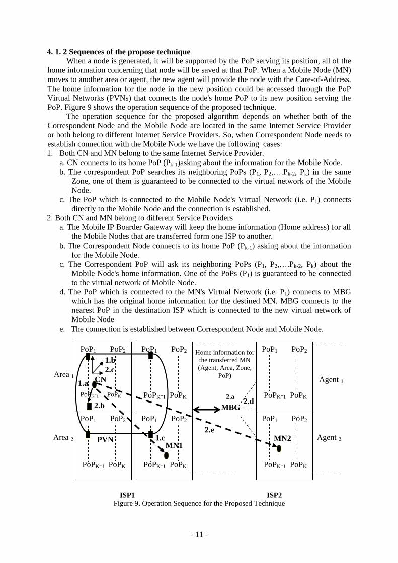
4. 1. 2 Sequences of the propose technique
When a node is generated, it will be supported by the PoP serving its position, all of the
home information concerning that node will be saved at that PoP. When a Mobile Node (MN)
moves to another area or agent, the new agent will provide the node with the Care-of-Address.
The home information for the node in the new position could be accessed through the PoP
Virtual Networks (PVNs) that connects the node's home PoP to its new position serving the
PoP. Figure 9 shows the operation sequence of the proposed technique.
The operation sequence for the proposed algorithm depends on whether both of the
Correspondent Node and the Mobile Node are located in the same Internet Service Provider
or both belong to different Internet Service Providers. So, when Correspondent Node needs to
establish connection with the Mobile Node we have the following cases:
1. Both CN and MN belong to the same Internet Service Provider.
a. CN connects to its home PoP (Pk-1)asking about the information for the Mobile Node.
b. The correspondent PoP searches its neighboring PoPs (P1, P2,….Pk-2, Pk) in the same
Zone, one of them is guaranteed to be connected to the virtual network of the Mobile
Node.
c. The PoP which is connected to the Mobile Node's Virtual Network (i.e. P1) connects
directly to the Mobile Node and the connection is established.
2. Both CN and MN belong to different Service Providers
a. The Mobile IP Boarder Gateway will keep the home information (Home address) for all
the Mobile Nodes that are transferred form one ISP to another.
b. The Correspondent Node connects to its home PoP (Pk-1) asking about the information
for the Mobile Node.
c. The Correspondent PoP will ask its neighboring PoPs (P1, P2,….Pk-2, Pk) about the
Mobile Node's home information. One of the PoPs (P1) is guaranteed to be connected
to the virtual network of Mobile Node.
d. The PoP which is connected to the MN's Virtual Network (i.e. P1) connects to MBG
which has the original home information for the destined MN. MBG connects to the
nearest PoP in the destination ISP which is connected to the new virtual network of
Mobile Node
e. The connection is established between Correspondent Node and Mobile Node.
ISP1 ISP2
Figure 9. Operation Sequence for the Proposed Technique
Agent 1
PoP1 PoP2
PoPK-1 PoPK
PoP1 PoP2
PoPK-1 PoPK
PoP1 PoP2
PoPK-1 PoPK
PoP1 PoP2
PoPK-1 PoPK
PoP1 PoP2
PoPK-1 PoPK
PoP1 PoP2
PoPK-1 PoPK
Agent 2
Area 1
Area 2
MBG
Home information for
the transferred MN
(Agent, Area, Zone,
PoP)
MN1 MN2
CN
PVN
1.c 2.e
2.d 2.a
1.a
2.b
1.b 2.c

- - 12
5. Evaluation of the Proposed Technique
Simulation modeling is based on system programming such as data structures,
flowcharts, programming languages and other tools that can be used to build up and
characterizing system performance. For simplicity, it is preferable to depend on the
simulation model.
5. 1 System Parameters
The key point for establishing any system is to define its main parameters. This section
introduces the simulation parameters, data structure and connection parameters for the
designated system respectively in the following three subsections:
5. 1. 1 Simulation parameters
A network with two Internet Service Providers is considered, each with two similar
areas. Each area is divided into two equal zones, where each zone is served by four PoPs.
Each PoP actually is serving 20 nodes with 30 addresses. The addresses are classified as 20
addresses for the nodes in service and 10 addresses for the nodes in waiting. The addresses for
the nodes in service are classified as 15 addresses for the local generating nodes and 5
addresses for the externally generating nodes. By the same way for the addresses concerning
the nodes in waiting. They are classified as 5 addresses for the local generating nodes and 5
addresses for the externally generating nodes. The addresses for the nodes are considered as
integer numbers given to each node consecutively and depend on the location of the node,
area, zone, PoP, and ISP it belongs to. Figure 10 shows an example of the nodes and address
classification for PoPi of the address classification for both PoP1 and PoP2 of area1, zone1 and
ISP1.
The total number of Zones all over the architecture design is 8 zones, each zone with 4
PoPs. The total number of PoPs is 32 PoPs and can be calculated by the following equation:
PN = PK x NZ where; PN is the total number of PoPs
PK is the number of PoPs within the Zone
NZ is the total number of Zones
Because of the total number of PoPs all over the architectural design is 32 PoPs and
each PoP is serving 20 nodes, the simulation is done for a total number of nodes equals to 640
nodes.
NT = PN x NC where; NT is the total number of generating nodes
NC is the number of generating nodes in each connection.
Figure 10. Nodes and Address Classifications for PoPi
PoP i
N1 N15 N16 N20 N21
N25
N26
N30
1-------15
Locally in
services
16-----20
Locally in
waiting
21-----25
Externally in
services
21-----25
Externally in
waiting

- - 13
5. 1. 2 Data structures
The main data structures implemented in the simulation are: nodes, PoPs, ISPs, Areas,
Agents, and Mobile IP Border Gateway (MBG). The class definitions and the structure
definitions for all the data structures are implemented using C Sharp on the Microsoft.net
platform.
5. 1. 3 Connection parameters
For the wireless communication design and implementation of the proposed technique,
the connection parameters for the implemented algorithm are the key point for running the
program. The connection parameters can be classified as follows:
1. The distance in kilometers equivalent to the distance of 1 pixel.
2. Link speed for PoP connection
3. Link speed for Agents connection
4. PoP nodes count to serve.
5. PoP nodes count to wait
6. Agent nodes count to serve
7. Agent nodes count to wait
5. 2 System Construction
Figure 11 shows the design architecture of the proposed ISP MBG technique. Each PoP
can be identified using the following three parameters respectively; ISP number, Agent
number and Zone number:
Pi = PoPj,k,l i = j,k,l where; Pi: the ith
PoP
j : Internet Service Provider number
k : Agent number
l : Zone number
Also, we have two similar PoPs Virtual Networks (PVNs) for the two Internet Service
Providers. Each is classified as follows: the first one connects all PoPs1, the second one
connects all PoPs2, the third one connects all PoPs3 and finally the fourth one connects all
PoPs4.
ISP 1 ISP2 Figure 11. Design Architecture
Zone 1 Agent 1 Zone
2
Zone 3 Agent 2 Zone 4
Zone 1 Agent 3 Zone 2
Zone 3 Agent 4 Zone
4
P1 P2
P3 P4
P1 P2
P3 P4
P1 P2
P3 P4
P1 P2
P3 P4
P1 P2
P3 P4
P1 P2
P3 P4
P1 P2
P3 P4
P1 P2
P3 P4
MBG
(1) (2)
(3) (4)

- - 14
1
1
.....
),(
zi
mm
m
PPD
1
1
.....
),(
Zm
mm
imL
PPD
5. 3 Performance Parameters
To evaluate the performance of the proposed ISP MBG technique, the following five
measuring criteria are measured: Link Distance, Transmission Time, Blocking, Buffering and
Security.
5. 3. 1 Link distance
The link distance is calculated in kilometers equivalent to the pixels distance between
the two connecting nodes through the PoP links or the Agent links (1 pixel = 0.2km). The link
distance can be calculated and formulated using the following equation:
Dt (Pi, Pz) =
Where; P: Transmission point (PoP or MBG)
D: Euclidian distance
Dt: Total link distance between two transmission points
5. 3. 2 Transmission time
Measuring the transmission time depends on the location of both Mobile Node (MN)
and Correspondent Node (CN) and whether both are located in the same area, same Internet
Service Provider or either in different areas or different Internet Service Providers. The
transmission time is calculated and formulated using the following general form of equation:
T (Pi, Pz) =
Where; P: Transmission point (PoP or MBG)
T (Pi, Pz):Total transmission time between two transmission points Pi and Pz
L: Link speed
D: Euclidian distance
5. 3. 3 Blocking
Blocking is an important parameter to measure the overall performance of the network
and its throughput. The blocking is measured as the number of blocked connections. Each
connection has a pair of connecting nodes, (i.e. N connections = 2N Nodes).
5. 3. 4 Buffering
Buffering is considered as one of the network resources that must be optimally used. In
the conventional Mobile IP technique, we have storage buffers for the agents whether they are
Home Agents or Foreign Agents. In the proposed ISP MBG technique, each PoP has its own
storage buffers which hold a limited number of nodes. The nodes are classified as nodes in
service and nodes in waiting, with a range of addresses for the nodes that are either locally
generated within the Agent (Home addresses) or imported from the other Agents. Using Point
of Presence Virtual Network (PVN) will provide an efficient tool for accessing the Node's
information between PoPs.[The measuring evaluation of this parameter is out of our scope].
5. 3. 5 Security

- - 15
It is one of the rigid requirements for the performance evaluation between the
conventional Mobile IP technique and the proposed one. It is measured as how much the
technique itself provides a self-securing technique to protect the data transferred among the
nodes located in different networks.[The evaluation of this parameter is out of our scope]
5. 4 Simulation Results
The purpose of the simulation is to evaluate the performance of the proposed technique
using Internet service Providers' PoPs and MBG compared with the conventional Mobile IP
technique. The running for the implemented algorithm is done and calculated based on
generating randomly a total number of nodes N= 640 nodes in 32 steps, each step includes 20
more nodes (i.e 10 connections). In each step, the whole algorithm is executed, and the
connection is also randomly done between each pair of nodes. To obtain real results, the
algorithm is executed many times and the comparison is done based on the average values of
the results.
5. 4. 1 Simulation results for link distance
Figures 12.a and 12.b show the total link distance and the average link distance per
connection for both the proposed ISP MBG and the conventional Mobile IP technique
respectively. It is clear that the proposed ISP MBG technique outperforms the conventional
Mobile IP technique. The route taken by the conventional Mobile IP technique has to pass
through the Home Agent which tunnels the data to the Foreign Agent. The route in the
proposed ISP MBG technique is taken through the home PoP of CN and the PoP virtual
network of MN which leads directly to the MN in case of one ISP. In case of using two
Internet service Providers the route has to pass through MBG to the MN's PoP virtual network
in the second ISP which leads directly to the MN.
At the point where no blocking appears (refer to section 5.3.3 where the number of
connections 28) the total link distance is increasing and the average link distance per
connections is almost constant, as all the entering connections will be served. At the point
where the blocking appears (refer to section 5.3.3 where the number of connections ≥ 28), the
total link distance and the average link distance will be slightly increased. As the rate of
blocking increases the total link distance is also increasing. For the case where the system is
saturated and due to the random generation of nodes and their connections are added to the
simulation, the distribution of nodes becomes more fair and the blocking is slightly decreased
which causes the average link distance to be consequently decreased.
(a) Comparison between total Link Distances
0
200
400
600
800
1000
1200
1 3 5 7 9 11 13 15 17 19 21 23 25 27 29 31
#of Connections (unit 10)
Dis
tanc
(km
)
ISP MBG Conventional Mobile IP
- - 16
(b) Comparison between Average Link Distances
Figure 12. Link Distance Comparison
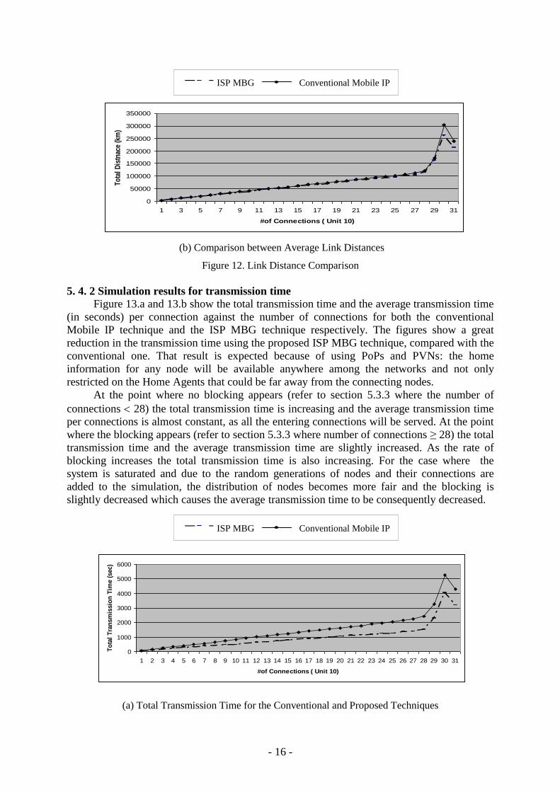
5. 4. 2 Simulation results for transmission time
Figure 13.a and 13.b show the total transmission time and the average transmission time
(in seconds) per connection against the number of connections for both the conventional
Mobile IP technique and the ISP MBG technique respectively. The figures show a great
reduction in the transmission time using the proposed ISP MBG technique, compared with the
conventional one. That result is expected because of using PoPs and PVNs: the home
information for any node will be available anywhere among the networks and not only
restricted on the Home Agents that could be far away from the connecting nodes.
At the point where no blocking appears (refer to section 5.3.3 where the number of
connections 28) the total transmission time is increasing and the average transmission time
per connections is almost constant, as all the entering connections will be served. At the point
where the blocking appears (refer to section 5.3.3 where number of connections ≥ 28) the total
transmission time and the average transmission time are slightly increased. As the rate of
blocking increases the total transmission time is also increasing. For the case where the
system is saturated and due to the random generations of nodes and their connections are
added to the simulation, the distribution of nodes becomes more fair and the blocking is
slightly decreased which causes the average transmission time to be consequently decreased.
(a) Total Transmission Time for the Conventional and Proposed Techniques
0
50000
100000
150000
200000
250000
300000
350000
1 3 5 7 9 11 13 15 17 19 21 23 25 27 29 31
#of Connections ( Unit 10)
To
tal
Dis
tnac
e (k
m)
ISP MBG Conventional Mobile IP
0
1000
2000
3000
4000
5000
6000
1 2 3 4 5 6 7 8 9 10 11 12 13 14 15 16 17 18 19 20 21 22 23 24 25 26 27 28 29 30 31
#of Connections ( Unit 10)
To
tal
Tra
nsm
issio
n T
ime (
sec)
ISP MBG Conventional Mobile IP

- - 17
(b) Average Transmission Time for the Conventional and Proposed Techniques
Figure 13. Transmission Time Comparison
5. 4. 3 Simulation results for blocking
Figure 14 details the average number of blocking in both the conventional Mobile IP
technique and the proposed one. Each blocked connection is considered as single pair of
connecting nodes. The figure shows that as long as the number of connections 28 (i.e.
number of nodes 560, "560= number of connections {28} x number of generating nodes in
each connection {20}") the blocking rate is almost zero in both the conventional mobile IP
technique and the proposed ISP MBG technique.
If the number of connection is increased (number of connections ≥ 28) meaning that the
number of nodes is also increased (number of nodes ≥ 560) the blocking rate will be increased
for both the conventional Mobile IP technique and the proposed one. The number of blocked
connections using the newly proposed ISP MBG technique is less than that the conventional
Mobile IP technique. In the conventional Mobile IP technique, the HA is overwhelmed with
an excessive amount of nodes' control messages compared with the proposed technique in
which the control messages are divided among the PoPs. Each PoP covers a number of nodes
and the virtual network between PoPs helps in getting the information easily.
Figure 14 Blocking Comparison
0
2
4
6
8
10
12
14
16
18
20
1 2 3 4 5 6 7 8 9 10 11 12 13 14 15 16 17 18 19 20 21 22 23 24 25 26 27 28 29 30 31
#of Connections (unit 10)
Tra
nsm
issio
n T
ime (
sec)
ISP MBG Conventional Mobile IP
0
2
4
6
8
10
12
14
1 3 5 7 9 11 13 15 17 19 21 23 25 27 29 31
#of Connections
Blo
cked
Con
nect
ions
ISP MBG Conventional Mobile IP

- - 18
As the number of blocked connections decreased that leads to increase the number of paired
successful connections which means the throughput will be increased.
5. 4. 4 Buffering
Concerning Buffering; it has been found that the proposed ISP MBG technique provides
better buffering than that the Conventional Mobile IP technique. This is due to the fact that
using PVN with the proposed technique facilitates the process of handling and accessing
information for the nodes in correspondences between PoPs without any redundancy.
Comparatively, the conventional technique requires more buffers due to the redundancy of
having a multiple copies of nodes' home information at each PoP of the Internet service
Provider. This leads to less use of buffering storages than that of the conventional technique
which needs storage buffer for each node to hold all of its information at each PoP. Also, as a
cost wise, it has been found that the cost for the Agent's buffers is higher than that of the
PoP's buffers
5. 4. 5 Security
The Security design has a great concern in Mobile IP. The proposed ISP MBG
technique is considered as the self securing system. Using Mobile IP Border Gateway (MBG)
will keep the information (Home address or binding information) for all Mobile Nodes
crossing their network to another network. So, any CN in one network does not need to
maintain any private external information concerning the new IP network were the MNs visit
and all of the MN's information could be accessed directly so the Mobile Border Gateway.
Comparatively, the conventional Mobile IP technique needs rigid requirements for the
authentication to prevent the malicious users from interrupting the connection between MN
and CN that maintains the binding information (Ha, CoA).
6. Concluding Remarks
In this paper, a proposed technique called Internet Service Provider Mobile IP Border
Gateway (ISP MBG), has been introduced to solve the Triangle Routing Problem in
conventional Mobile IP Protocol. The design of this technique is based on using a number of
Internet Service Providers (ISPs) separated by a Multiple Mobile IP Border Gateways
(MBGs) which are used to keep the binding information or the home information for the
transferred Mobile Nodes between ISPs. Each ISP is composed of an approximately a number
of an equal areas, each is served by an Agent and is composed of a multiple equal zones.
Each zone is served by a definite number of Points of presences (PoPs). Each PoP is serving
a number of nodes with a range of addresses. Virtual Networks are used to connect the PoPs
in such a way the redundancy in keeping the nodes information will be minimized or almost
cancelled. The main function of the proposed technique is to get the shortest routing path for
the packets transferred between the Correspondent Nodes and Mobile Nodes based on the
PoPs information, PVN and the MBG.
The simulated network design of our case study is based on using two Internet Service
Providers separated by one mobile IP border gateway. Each ISP is divided into two equal
areas. Each area is divided into two equal zones and each zone is served by four points of
presence (PoPs). Each PoP is serving 20 nodes with a range of 30 addresses. The simulation
results for the Link Distance, Transmission Time, Blocking, Buffering and Security show that
the proposed (ISP MBG) technique outperforms the conventional Mobile IP technique by
minimizing the Link Distance, Transmission Time, Blocking, Buffering. Also, it gives a
higher level of security than that used with conventional Mobile IP technique.

- - 19
Table 1 summarizes the performance comparison between the conventional Mobile IP
technique and ISP MBG technique.
Table 1. Comparative Parameters for the Conventional and Proposed Techniques
Technique
Parameters
ISP MBG
Technique
Conventional Mobile IP
Technique
Link Distance Short link distance Long link distance
Transmission Time Low transmission time High transmission time
Blocking low rate of blocking High rate of blocking
Buffering - Less buffering storages
- Low cost
- More buffering storages
- High cost
Security High level of security Low level of security
The ISP MBG technique is considered to be the best suited technique for the ISPs with
larger topographical reach, because of the drastic performance improvement obtained in this
case.
This work can be considered applicable for the following: better performance related to
the criteria of measuring parameters ,no addition of external hardware devices are required,
more reliablility and flexibility of the simulation model,and scalability for using more PoPs
and nodes .
The implemented algorithm could be extendable to any number of ISPs, Areas, Zones,
PoPs, Nodes, but the evaluation will be related to the configuration of the system that is used
in building up the simulator and how much the behavior of the system is adapted to the
measuring parameters.
7. Future Work
This work can be extended to include investigation of using multiple ISPs and multiple
MBGs. In that case MBG is not only restricted to hold the home information for the nodes
crossing their local ISP or to guide in establishing the route to the MN located in an external
ISP, but rather the investigated subjects in that area are continuing enhance the functionalities
of MBG to do more advanced tasks.Such tasks include, tunneling, conditional Processes for
the route optimization, and others .Moreover, using multiple MBGs will distribute the
processing load among the MBGs.
References
1. C. Smith and D. Collins, “3G Wireless Networks”, “McGraw-Hill, United States, 2002.
2. A. Jamalipour, “The Wireless Mobile Internet”, John Wiley & Sons Ltd., England, 2003.

- - 20
3. Philip J. and Nesser II, “Survey of IPV4 Addresses in Currently Deployed IETF
standards”, Internet-drafts, draft-ietf-ngtrans-ipv4 survey-01.text, Work on Progress,
August 2001.
4. S.Choi, R.Mukhtar, J.Choi, and M.Zukerman, “Efficient Marcro Mobility Management
for GPRS IP Networks”, Optical Internet Research Center (OIRC), Korea, May 2002.
5. W.Stallings, “Wireless Communications and Networks”, Prentice Hall, New Jersey,
United States, 2002.
6. T. Janevski, “Traffic Analysis and Design of Wirless IP Netowrks”, Artech House Inc.,
Boston, London, 2003.
7. C. Perkins, “IP Mobility Support for IPV4”, RFC 3344, Work on Progress, August 2002.
8. W.Wu, W.Chen, F.Young and H.Liao, “Dynamic Address Allocation in Mobile IP”,
Department of Electrical Engineerng ,Feng Chia University ,November,11999.
9. C.Wu, A.Cheng, S.Lee, J.Ho and D.Lee, “Bi-directional Route Optimization in Mobile IP
Over Wireless LAN”, Institute of Information Science, Academia Sinica, Taiper, Taiwan,
Vol. 2,PP.1168-1172,2002.
10. “An Efficient, Global Mobile IPV4 Routing Frame Work using Internet Service provider,
Point of Presence ISP PoP”, http:\\networks.ecse.rpi.edu/papers/mip.pdf.
11. C.Kumar, N.Tyagi , Tripathi R., "Performance of Mobile IP with new Route Optimization
Technique", IEEE International Conference, Institute of Engineering and Rural Technol,
Allahadad, India, PP. 522-526, January 23-25, 2005.
12. D.Badami, N.Thanthry, T.Best, R.Bhagavathula and R.Pendse., "Port Address Translation
based Route Optimization For Mobile IP", Vehicular Technology Conference, IEEE 60th
,
Department of Electrical and Computer Engineering, Wichita State University, KS, USA,
Vol. 5, PP. 3110-3114, September 26-29, 2004.
13. R.Vadali, L.Jianhui, W.Yiqiong and C.Guohong , "Agent based Route Optimization For
Mobile IP", Vehicular Technology Conference, IEEE VTS 54th
,Department of Computer
Science and Engineering, Pennsylvania State University, University Park, PA ,USA ,Vol.
4, PP. 2731-2735, October 7-11, 2001.
14. G.Qiang and A.Acampora , "A Virtual Home Agent based Route Optimization for Mobile
IP", Wireless Communication and Networking Conference, IEEE,Center for Wireless
Communications ,California University ,San Diego, La Jolla, Ca, USA, Vol. 2, PP. 592-
596, September 23-28, 2000.
15. C. Perkins “Mobile IP”, IEEE, 50th Anniversary Communicative Issue, PP. 66-82. May
2002.[Originally Published in IEEE Communication Magazine,Vol 35 ,Number 5 ,PP. 84-
98, May 1997].
16.C. Perkins, “Mobile IP: Design Principles and Practices”, Addison-Wesley, United States,
1998.
17. B.Ayani, “Smooth Handoff in Mobile IP”, Master Thesis presented to University of
California in Berkeley, May 2005.
18. T.Hille, J.Kempt, P.Mccann, A.Singh, H.Soliman, and S.thalanany, “Low Latency
Handoffs in Mobile IPV4”, Internet-drafts, ietf-mobileip-low laterncy-handoffs-v4-05. txt,
Work on Progress, December 2003.
19. G.Montenegro, “Reverse Tunneleng for Mobile IP", RFC 3024, Work on Progress,
January 2001.
20.Y.Takagi ,T.Ihara and H.Obnishi,"Mobile IP Route Optimization Method for Next
Generation Mobile Networks", Electonics-and-Communications in Japan,Part
1,Vol.86,No.2 ,PP.31-41, February 2003.
21.M.Caesar and J.Rexford , ,"BGP Routing Policies in ISP Networks " IEEE Network,
University of California and Princeton University ,PP.5-11,November/December 2005.

- - 21
22.T.Ihara, H.Ohnishi and Y.Takagi , "Mobile IP Route Optimization Method for a Carrier-
scale IP Netowrk",The Proceedings of 6th
IEEE International Conference on Engineering
of Complex Computer Systems, ICECCS 2000, , PP. 120-121, September 11-14, 2000.