A parallel processing architecture for DQDB protocol ...
86
Copyright Warning & Restrictions The copyright law of the United States (Title 17, United States Code) governs the making of photocopies or other reproductions of copyrighted material. Under certain conditions specified in the law, libraries and archives are authorized to furnish a photocopy or other reproduction. One of these specified conditions is that the photocopy or reproduction is not to be “used for any purpose other than private study, scholarship, or research.” If a, user makes a request for, or later uses, a photocopy or reproduction for purposes in excess of “fair use” that user may be liable for copyright infringement, This institution reserves the right to refuse to accept a copying order if, in its judgment, fulfillment of the order would involve violation of copyright law. Please Note: The author retains the copyright while the New Jersey Institute of Technology reserves the right to distribute this thesis or dissertation Printing note: If you do not wish to print this page, then select “Pages from: first page # to: last page #” on the print dialog screen
-
Upload
khangminh22 -
Category
Documents
-
view
2 -
download
0
Transcript of A parallel processing architecture for DQDB protocol ...

Copyright Warning & Restrictions
The copyright law of the United States (Title 17, United States Code) governs the making of photocopies or other
reproductions of copyrighted material.
Under certain conditions specified in the law, libraries and archives are authorized to furnish a photocopy or other
reproduction. One of these specified conditions is that the photocopy or reproduction is not to be “used for any
purpose other than private study, scholarship, or research.” If a, user makes a request for, or later uses, a photocopy or reproduction for purposes in excess of “fair use” that user
may be liable for copyright infringement,
This institution reserves the right to refuse to accept a copying order if, in its judgment, fulfillment of the order
would involve violation of copyright law.
Please Note: The author retains the copyright while the New Jersey Institute of Technology reserves the right to
distribute this thesis or dissertation
Printing note: If you do not wish to print this page, then select “Pages from: first page # to: last page #” on the print dialog screen

The Van Houten library has removed some of the personal information and all signatures from the approval page and biographical sketches of theses and dissertations in order to protect the identity of NJIT graduates and faculty.

ABSTRACT
A PARALLEL PROCESSING ARCHITECTURE
FOR DQDB PROTOCOL IMPLEMENTATION
by
Nilesh Vinubhai Gandhi
The high bandwidth transmission links, which have been provided by the
advances of Fiber Optics Technology, reduce drastically the packet transmission
times and place new demands on the nodal protocol processing. Segmentation and
reassembly of packets, computation of checksums, introduction of source and
destination addresses, etc., must be performed extremely fast in order to prevent
node processing from becoming the bottleneck of the transmission. Parallel
processing enables the execution of the previous tasks on multiple packets
simultaneously and therefore has the potential of addressing the issue of fast node
processing successfully. In this thesis we focus on the Medium Access Control
Protocol of the Distributed Queue Dual Bus (DQDB) which has been adopted by
IEEE as the 802.6 standard for Metropolitan Area Networks (MANS). We present
a parallel processing based architecture for the implementation of DQDB protocol
which can satisfy its stringent processing time requirements. The architecture
consists of a set of packet processors which have been provided with local memory
and can be accessed according to a round robin scheduling algorithm. In this way
the amount of contention in the local bus is drastically reduced and the processing
performance significantly improves. Both Transmitter and Receiver design are
presented.

A PARALLEL PROCESSING ARCHITECTURE
FOR DQDB PROTOCOL IMPLEMENTATION
by
Nilesh Vinubhai Gandhi.
A Thesis
Submitted to the Faculty of
New Jersey Institute of Technology
In Partial Fulfillment of the requirements for the degree of
Master of Science in Electrical Engineering
Department of Electrical and Computer Engineering
October 1993

APPROVAL PAGE
A PARALLEL PROCESSING ARCHITECTURE
FOR DQDB PROTOCOL IMPLEMENTATION
by: Nilesh Vinubhai Gandhi
Dr. Dennis Karvelas, Thesis Adviser (date)
Assistant Professor, Department of Computer and Information Science, NJIT.
Dr. S. Ziavras, Committee Member (date)
Assistant Professor, Department of Electrical and Computer Engineering, NJIT.
Dr. Nirwan Ansari, Committee Member (date)
Associate Professor, Department of Electrical and Computer Engineering, NJIT.


BIOGRAPHICAL SKETCH
Author :Nilesh Vinubhai Gandhi.
Degree : Master of Science in Electrical Engineering.
Date:October 1993
Undergraduate and Graduate Education:
• Master of Science in Electrical Engineering,
New Jersey Institute of Technology, Newark, NJ 1993
• Bachelor of Science in Electronic and Communication
Engineering, DDIT, Nadiad, INDIA 1990
Major: Electrical Engineering.
iv

This thesis is dedicated to
Manibhai M. Gandhi

ACKNOWLEDGMENT
The author wishes to express his sincere gratitude to his professor
Dennis Karvelas, for his guidance, friendship, and moral support throughout this
research.
Special thanks go to Professor S. Ziavras and Professor Nirwan Ansari for
serving as members of the committee. The author is also grateful to Dr. Misra and
Dr. Ali Akansu for their timely help.
vi

TABLE OF CONTENTS
Chapter Page
1. INTRODUCTION AND MOTIVATION 1
2. DQDB LAYER ORGANIZATION 4
2.1 DQDB a Public Metropolitan Area Network 4
2.1.1 Dual Bus Architecture 5
2.1.2 Access Control to the Dual Bus Subnetwork 6
2.2 DQDB Layer Service Definition 12
2.2.1 MAC Service to LLC 13
2.2.2 Isochronous services 15
2.2.3 Connection Oriented Data Service 15
2.3 Provision of DQDB Layer Services 16
2.3.1 Provision of MAC service to LLC 16
2.3.2 Provision of Isochronous services 26
2.3.3 Provision of Connection Oriented Data Service 26
2.4 Functional Architecture of a Node 26
2.4.1 Physical Layer Functions 27
2.4.2 DQDB Layer Functions 29
2.4.3 DQDB Layer Management Entity (LME) 32
3. INTERFACE ARCHITECTURE 33
3.1 Overview of System Architecture 33
3.2 System Operation 35
3.2.1 Receiving Operation 38
vii

Chapter Page
3.2.2 Transmitting Operations 40
3.3 Hardware Modules 41
3.3.1 Receiving Modules 42
Input Low Level Processor 42
R1_processor 42
CRC Unit 43
R2_processor 45
Direct Memory Access -Process 45
3.3.2Transmitting Modules 46
T1_processor 46
T2_processor 47
Output Low Level Processor 48
Buffer Memory 49
Buffer List Structure 50
3.3.3 Operation of DQSM 52
3.3.4 FPGA implementation of R1_processor 53
4. CONCLUSIONS 61
5. REFERENCES 63
viii

LIST OF FIGURES
Figures Page
2.1 Dual Bus Architecture 5
2.2 Access Unit of a Station 7
2.3 The queue Access Protocol............................................................................................ 8
2.4 Request Counter Operation 10
2.5 Segment Transmission on Bus A 11
2.6 DQDB Layer Services 13
2.7 IMPDU segmentation 17
2.8 DMPDU Format 18
2.9 IMPDU Structure 21
2.10 DMPDU Structure 24
2.11 DQDB Node Functional Architecture 28
3.1 Processing Architecture Overview 34
3.2 System Architecture I 36
3.3 System Architecture II 37
3.4 CRC Unit 44
3.5 Memory Block Design 49
3.6 Control Block Structure 51
3.7 Buffer List Datastructure 52
3.8 State Diagram of R1_processor 54
3.9 Parallel Processing Vs. Time 60
ix

LIST OF DEFINITIONS
Words in italics indicate terms that are defined later in the list.
Access Control Field (ACF). The field which contains the protocol control
information in a slot; that supports the access control function.
Access Control Function. The Queued Arbitrated (QA) Access and Pre-Arbitrated
(PA) Access Functions in the DQDB Layer that control access to the medium.
Access Unit (AU). The functional unit in a node that performs the DQDB Layer
Functions to control access to both buses. Access units attach to each bus via a
write connection and a read tap placed upstream of the write connection.
Address. An identifier that tells where a Service Access Point (SAP) may be
found.
Address Field. The part of a Protocol Data Unit (PDU) that contains an address
that identifies one or more addressable entities. ( The address may be a single-
source address, single-destination address, or multiple-destination address
(multicast ).)
Bandwidth Balancing Mechanism. A procedure to facilitate effective sharing of
the bandwidth, where a node occasionally skips the use of empty Queued
Arbitrated (QA) slots.
Bridge. A functional unit that interconnects two subnetworks that use a single
Logical Link Control (LLC) procedure but may use different Medium Access
Control (MAC) procedures. Local Area Network (LANs) and Metropolitan Area
Network (MAN) are examples of the subnetworks that a bridge may interconnect.
Broadcast address. A predefined destination address that denotes the set of all
service access points (SAPS) within a given layer.
Bus. The collection of the transmission links between nodes and the data paths
x

continuation of List of Definitions....
within the nodes that provide unidirectional transport of the digital bit stream
from the head of the bus function past the Access Unit (AU) of each node to the
end of the bus.
Busy slot. A slot that already contains information and is not available for Queued
Arbitrated (QA) access.
Connection. An association established by a layer between two or more users of
the layer service for the transfer of information.
Convergence Function. A function that has additional services which enable a
layer to provide the services expected by a particular higher layer.
Data Link Layer. The layer that provides services to transfer data over a
transmission link between open systems. In IEEE 802 Local Area Network
(LAN) standards, the Data Link Layer is formed by the operation of the LLC
Sublayer over the MAC Sublayer service offered by the DQDB Layer.
Derived MAC Protocol Data Unit (DMPDU). The protocol data units (PDUs) of
a length of 48 octets which are formed by the addition of protocol control
information to each of the 44-octet segmentation units created by the segmentation
of an Initial MAC Protocol Data Unit (IMPDU). Each DMPDU is carried as the
payload of a Queued Arbitrated (QA) segment.
Downstream. The direction of data flow along a bus, i.e., away from the head of
the bus.
DQDB Layer. The sublayer that uses the services of the Physical Layer to provide
the following:
• Medium Access Control (MAC) Sublayer service to the Logical
Link Control (LLC) Sublayer
• isochronous service
• connection-oriented data service.
xi

continuation of List of Definitions....
Dual bus. A pair of buses carrying digital bit streams flowing in opposite
directions. One bus is referred to as Bus A and the other bus as Bus B.
Empty Queued Arbitrated (QA) slot. A Queued Arbitrated (QA) slot that was
designated by the head of the bus function as being available for transfer of a QA
segment, and which does not contain yet a QA segment.
Gateway. A functional unit that interconnects a local area network (LAN) with
another network having different higher layer protocols.
Group address. A predefined destination address that denotes a set of selected
service access points (SAPs) from the Medium Access Control (MAC) Sublayer
service offered by the DQDB Layer to the Logical Link Control (LLC) Sublayer.
Head of Bus Function. The function that generates the empty Queued Arbitrated
(QA) slots, Pre-Arbitrated (PA) slots, and management information octets at the
point on each bus where data flow starts. The head of bus function also inserts the
virtual channel identifier in the PA segment header of PA slots.
Individual address. An address that identifies a single source or destination
service access point.
Initial MAC Protocol Data Unit (IMPDU). A protocol data unit (PDU) formed in
the DQDB Layer by the addition of protocol control information (including
address information) to a MAC Service Data Unit received from the Logical Link
Control (LLC) Sublayer. The IMPDU is segmented into 44-octet segmentation
units for transfer in Derived MAC Protocol Data Units (DMPDUs).
Isochronous. The time characteristic of an event or signal recurring at known,
periodic time intervals.
Isochronous Service octet. A single octet of data passed isochronously between
the DQDB Layer and the Isochronous Service User (ISU).
Isochronous Service User (ISU). The entity that uses the isochronous service
xii

continuation of List of Definitions....
provided by the DQDB Layer to transfer isochronous service octets over an
established isochronous connection.
Layer. A subdivision of the Open Systems Interconnection (OSI) architecture,
constituted by the subsystems of the same rank.
Layer Management. Functions related to the administration of a given Open
Systems Interconnection (OSI) layer. These functions are performed in the layer
itself according to the protocol of the layer and partly performed as a subset of
network management or systems management.
Layer Management Entity (LME). The entity in a layer that performs local
management of a layer. The LME provides information about the layer, effects
control over it, and indicates the occurrence of certain events within it.
Layer Management Interface (LMI). The service interface provided by the Layer
Management Entity (LME) to the Network Management Process (NMP).
Local Area Network (LAN). A non public data network in which serial
transmission is used without store and forward techniques for direct data
communication among data stations located on the users premises.
Logical Link Control (LLC) Sublayer. In a local area network (LAN) or a
metropolitan area network (MAN), that part of the Data Link Layer that supports
medium-independent data link functions, and uses the Medium Access Control
(MAC) Sublayer service to provide service to the Network Layer.
MAC address. An address that identifies a particular Medium. Access Control
(MAC) Sublayer service access point.
MAC service Data Unit (MSDU). The user data unit received in an MA-
UNITDATA request for transfer by the Medium Access Control (MAC) layer.
Management information octets. DQDB Layer Protocol Data Units (PDUs) used
to carry DQDB Layer Management Protocol information between peer DQDB
xiii

continuation of List of Definitions....
Layer Management Entities (LMEs).
Medium Access Control (MAC) Sublayer. In a local area network, the part of
Data Link Layer that supports topology-dependent functions and uses the
services of the Physical Layer to provide service to the Logical Link Control (LLC)
Sublayer.
Message Identifier. An identifier used to identify Derived MAC Protocol Data
Units (DMPDUs) derived form the same Initial MAC Protocol Data Unit
(IMPDU) .
MID (Message Identifier) page. A set of one message identifier value.
Multicast Address. Same as group address.
Network Layer. In Open Systems Interconnection (OSI) architecture, the layer that
provides service to establish a path between open systems with a predictable
quality of service.
Network Management Process (NMP). The entity that provides access to the
network management functions on behalf of the user of the network management
services. In order to perform this function, NMPs may intercommunicate in a peer-
to-peer manner and may use the services of NMPs in other nodes via a network
management protocol. The NMP at a node is the user of the service provided at the
Layer Management Interface (LMI).
Node. A device that consists of an access unit and a single point of attachment of
the access unit to each bus of a DQDB subnetwork for the purpose of transmitting
and receiving data on that subnetwork. Adjacent nodes are connected by a
transmission link.
Octet. A group of eight adjacent bits.
Offset. The octet position relative to the start of a Pre-Arbitrated (PA) segment
used to carry an isochronous service octet for a particular Isochronous Service
xiv

continuation of List of Definitions....
User (ISU).
Physical Layer. In Open Systems Interconnection (OSI) architecture, the layer that
provides services to transmit bits or group of bits (such as an octet) over a
transmission link between two open systems.
Pre-Arbitrated (PA) Access Function. The access control function that uses
assigned offsets in the Pre Arbitrated (PA) slots for the transfer of isochronous
service octets.
Pre-Arbitrated (PA) segment. A multi-user segment transferred using Pre-
Arbitrated Access (PA) Functions. The payload of the PA segment contains
isochronous service octets from zero or more Isochronous Service Users (ISUs).
Pre-Arbitrated (PA) slot. A slot that is dedicated by the head of bus function for
transfer of isochronous service octets in the payload of a PA segment.
Protocol Data Unit (PDU). Information that is delivered as a unit between peer
entities of a local area network or metropolitan area network and that contains
control information, address information, and may contain user data.
Queued Arbitrated (QA) Access Function. The access control function that uses
the Distributed Queue to access empty Queued Arbitrated (QA) slots for the
transfer of QA segments.
Queued Arbitrated (QA) segment. A segment transferred using Queued
Arbitrated (QA) Access Functions.
Queued Arbitrated (QA) slot. A slot that is used for the transfer of a QA segment.
Read. The process of an access unit copying bits of a data stream as they pass on
the bus.
Reassembly. The function in the DQDB Layer that provides for the reconstruction
of an Initial MAC Protocol Data Unit (IMPDU). Reassembly is performed by
concatenating the segmentation units received in Derived MAC Protocol Data
xv

continuation of List of Definitions....
Units (DMPDUs). This is the inverse process to segmentation.
Reconfiguration. The process by which the Configuration Control Function
activates and deactivates resources of a DQDB subnetwork to take account of a
change in the operational status of a cluster, node, or transmission link in the
subnetwork.
Router. A functional unit that interconnects two computer networks that uses a
single Network Layer procedure but may use different Data Link Layer and
Physical Layer procedures.
Segment. The protocol data unit of 52 octets transferred between peer DQDB
Layer entities as the information payload of a slot. It contains a segment header of
4 octets and a segment payload of 48 octets. There are two types of segments: Pre-
Arbitrated (PA) segments and Queued Arbitrated (QA) segments.
Segment header. The protocol control information in a segment.
Segment Payload. The unit of data carried by a segment.
Segmentation. The function in the DQDB Layer that fragments a variable length
Initial MAC Protocol Data Unit (IMPDU) into fixed-length segmentation units for
transfer in Derived MAC Protocol Data Units (DMPDUs).
Segmentation unit. The fixed-length data units of 44 octets formed by the
fragmentation of an Initial MAC Protocol Data Unit (IMPDU).
Service Access Point (SAP). The point at which services are provided by one layer
(or sublayer) immediately above it.
Service Data Unit (SDU). Information that is delivered as a unit between peer
service access points.
Service Primitive. An implementation-independent interaction between a service
provider and a service user.
Slot. The protocol data unit of 53 octets used to transfer segments. It contains a
xvi

continuation of List of Definitions....
segment of 52 octets and the 1 octet Access Control Field (ACF). There are two type
of slots: Pre-Arbitrated (PA) slots and Queued Arbitrated (QA) slots.
Sublayer. A subdivision of a layer in the Open System Interconnection (OSI)
reference model.
Subnetwork. It is the functional unit comprised of a single dual bus pair and those
access units attached to it. Subnetworks are physically formed by connecting
adjacent nodes with transmission links.
Transmission Link. The physical unit of a DQDB subnetwork that provides the
transmission connection between adjacent nodes. Each transmission link
accommodates both buses of the dual bus pair between the adjacent nodes.
Transmission Medium. The material on which information signals may be
carried; e.g. optical fiber, coaxial cable, and twisted-wire pair.
Upstream. The direction along a bus that is towards the head of bus function. This
is opposite to the direction of data flow along a bus.
Virtual Channel Identifier (VCI). A label that is used to distinguish between the
entities which enable identification, during the unidirectional transfer of segments
between the entities. Here, the VCI label can be used to allow a transmitter to
distinguish between different outgoing protocol data units (PDUs), and is used to
allow a receiver to determine whether to receive an incoming segment as well as
to distinguish between incoming PDUs.
Write. The process of an access unit sending data down stream on a bus by logical
ORing its outgoing data with the data pattern (normally all zeros) arriving from
upstream on that bus.
xvii

LIST OF ABBREVIATIONS
ACF Access Control Field
AU Access Unit
BAsize Buffer Allocation size
BEtag Beginning-End tag
BOM Beginning Of Message
BWBM BandWidth Balancing Mechanism
BWB_CNTR BandWidth Balancing CouNTeR
BWB_MOD BandWidth Balancing MODulus
CCITT the International Telegraph and Telephone
Consultative Committee
CD Count Down (counter)
CIB CRC32 Indicator Bit
COCF Connection-Oriented Convergence Function
COM Continuation Of Message
CRC Cyclic Redundancy Check
CRC32 32-bit Cyclic Redundancy Check
DA Destination Address
DMPDU Derived MAC Protocol Data Unit
DQDB Distributed Queue Dual Bus
DQSM Distributed Queue State Machine
EOM End Of Message
ETS External Timing Source
HCS (segment) Header Check Sequence
HEL Header Extension Length
xviii

continuation of List of Abbriviation....
HOB_A Head Of Bus A
HOB_B Head Of Bus B
ICF Isochronous Convergence Function
IMPDU Initial MAC Protocol Data Unit
ISDN Integrated Services Digital Network
ISDU Isochronous Service Data Unit
ISO International Organization for Standardization
ISU Isochronous Service User
LAN Local Area Network
LLC Logical Link Control
LMI Layer Management Interface
LME Layer Management Entity
MAC Medium Access Control
MAN Metropolitan Area Network
Mb/s Megabits per second
MCF MAC Convergence Function
MCP MAC convergence Protocol
MID Message IDentifier
MPA MID Page Allocation
MSAP MAC Service Access Point
MSDU MAC Service Data Unit
NMP Network Management Process
OSI Open Systems Interconnection
PA Pre-Arbitrated
PDU Protocol Data Unit
PI Protocol Identification
xix

continuation of List of Abbriviation....
PL PAD Length
PSR Previous Segment Received
QA Queued Arbitrated
QOS Quality Of Service
REQ REQuest
RQ ReQuest (counter)
RSM Reassembly State Machine
SA Source Address
SAP Service Access Point
SDU Service Data Unit
SSM Single Segment Message
VCI Virtual Channel Identifier
xx
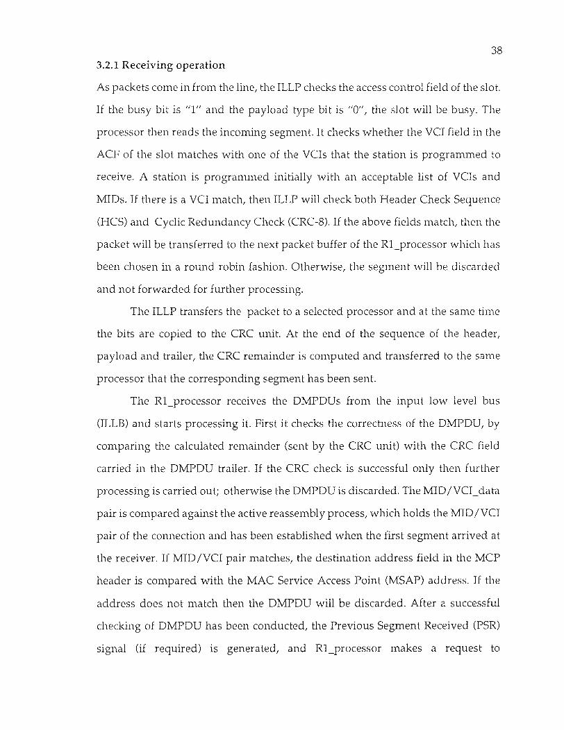
Chapter 1
Introduction and Motivation
Performance of transport protocols on multi-megabit networks tend to be limited
by overhead at both the transmitter and the receiver. For example, measurements
on Ethernet have indicated that network transmission time accounts for only 20%
of the elapsed time for transport-level communication operations, even with its
highly optimized protocol. Although processor times and memory cycle times
keep improving, with the communication network moving towards Gbits range,
we expect the processing to persist as a bottleneck unless significant improvement
in the network adapter design is achieved. We identify three major problems with
the current designs.
First, the host-to-network adapter impose excessive overhead, particularly
on a host, in the form of processor cycles, system bus capacity and host interrupts.
The processing overhead rises from calculating end-to-end checksums,
packetizing and depacketizing, as well as of conducting encryption for
communication. The memory intensive processing required by these functions
reduce the average instruction execution rate, especially, for a high performance
processor, in which memory reference operations are proportionally much slower
than register-only operations. The processing causes the data to move at least twice
over the system bus; once from the global memory to the processor (or its cache),
and once when the packet is copied to the network adapter. The increased traffic
wastes system bus bandwidth, a critical resource in microprocessor machines. In
current host-to-network adapter interfaces, a host is interrupted for each packet
received or transmitted. These per-packet interrupts force frequent context
switching with the attendant overheads. This has a bad effect on Hit to Miss ratio
1

2 in the microprocessor system with processor cache. For instance, in a workstation
attached to a 150 Mbps network with an interface interrupting at every 2.72
microseconds, the available time is hardly sufficient to do even minimal packet
processing.
Secondly, the "intelligent" network adapters that implement transport level
functions have lower performance at the transport-level as compared to the
alternative system where a network adapter does the programmed I/O transfer
and a host performs transport protocol functions. The primary reason is an
inadequate internal memory architecture. Currently, the data transfers into and
out of buffer memory reduce the number of memory cycles available for packet
processing. In future communication systems, the bus technology, with a high
transfer rate and burst mode transfer, and the network, with a high data rate, will
make this problem more acute.
Finally, conventional transport level protocols are too complex or awkward
for hardware implementation and are too slow without it. For a large packet, the
processing cost incurred in checksumming and encryption, dominates the packet
processing, since the cost increases in proportion with the size of the packet. The
hardware implementation of such key performance-critical functions would
substantially increase performance, but the packet format of the conventional
transport protocols does not facilitate hardware support or implementations.
An additional factor that motivates the design of network adapter
architectures is the problem of a host being bombarded by packets from other
hosts. The packet arrival rate, especially in the high speed network, can exceed the
rate at which a host can process and discard these packets, effectively
incapacitating the host from performing useful computation. Excessive packet
traffic can arise from failures or malicious behavior of a remote host. A well
designed network adapter acts as a "firewall" between the network and the host.

3 In this thesis we present a parallel processing based architecture for the
implementation of DQDB protocol, which can satisfy its stringent packet
processing time requirements. The multiprocecessor assembly of the receiver
consists of the receiving packet processors, R1_processors, and that of the
transmitter consists of the transmitting packet processors, T2_processors. The
multiprocessor assembly performs the protocol functions in parallel, on packets
coming in from the Input Low Level Processor (ILLP) and on packets going out to
the Output Low Level Processor (OLLP); ILLP and OLLP are responsible for
receiving and transmitting packets to the medium. Such a design of the assembly
enables the interface to match the average processing time of a packet with the
interarrival time of the packets from the line.
The organization of this thesis is as follows. In chapter 2 an introduction to
widely used terminology is provided. In chapter 2 the basic features of the
Distributed Queue Dual Bus (DQDB) protocol which are important for our
implementation are discussed. In chapter 3 the parallel processing architecture
design for the implementation of the DQDB protocol is presented. Finally, in
chapter 5, some concluding remarks and suggestions are provided.

Chapter 2
The DQDB Protocol
This chapter mainly presents the features and functions of the DQDB protocol that
are essential for its parallel processing based implementation provided in chapter
3. The additional features such as security, network administration, bandwidth
control, and charging facility make DQDB a useful public network. DQDB layer
relies on physical layer for the actual communication of the data from each node
to the others. The services provided by the DQDB layer are the MAC service, the
isochronous service and the connection oriented data service.
2.1 DQDB - A Public Metropolitan Area Network
The major components of DQDB network are a head station, two unidirectional
buses, and a number of Access Units (AUs) . The relative positions of the stations
on the buses are shown in figure 2.1. The head station generates the frame
synchronization on the forward bus and the end station generates the frame
pattern at the same rate on the reverse bus. Access units are attached to the bus via
read and write connections. According to the implementation that will be
presented in chapter 3, an AU reads and writes using the Input Low Level
Processor (ILLP) and the Output Low Level Processor (OLLP) respectively.
The DQDB protocol introduces distributed queueing. Furthermore, by
using a Bandwidth Balancing mechanism the bandwidth allocation to each station
can be controlled according to the requirements. In the subsequent sections, the
dual bus architecture and the access control to the dual bus subnetwork are
discussed.
4

5
2.1.1 Dual Bus Architecture
Figure 2.1 Dual Bus Architecture
The dual bus architecture consists of two unidirectional buses and a set of nodes
along the communication buses. As figure 2.1 shows, Bus A and Bus B support
communication in opposite directions, which allows full duplex communication
between any pair of nodes on the subnetwork. The operation of the two buses are
independent of each other. Both buses operate simultaneously, hence the capacity
of the network is twice the capacity of a single bus. The head of the bus generates
the slots. These slots are used to carry data between the nodes. The nodes may

6 write into slots under the control of the access protocol. All the slots are removed
at the end of the bus.
2.1.2 Access Control to the Dual Bus Subnetwork
The DQDB provides two modes of access control to the dual bus. These are the
Queue Arbitrated (QA) and Pre-Arbitrated (PA) modes, which use QA and PA
slots for access respectively. Each slot contains an access control field (ACE) and a
segment, which forms the payload of the slot.
Queued arbitrated access is controlled by the Distributed queuing protocol
and would be used typically to provide non-isochronous services. Pre-arbitrated
access would be used typically to provide isochronous services. The Distributed
Queued and Pre-Arbitrated access protocols are described below.
The Distributed Queue Access Protocol
Distributed queuing is a media access protocol that controls the access to the
payload of QA slots on the DQDB bus. The fixed length payload of a QA slot is
called a QA segment.
The operation of the protocol is based on two control fields: the BUSY bit,
which indicates whether or not a slot is used, and the REQUEST field, which is
used to indicate when a segment has been queued for access. Each node, by
counting the number of requests it receives and unused slots that pass, can
determine the number of segments queued (i.e. in line) ahead of it. This counting
operation establishes a single queue across the subnetwork of segments queued for
access to each bus.
With such queued access, levels of priority can be established by operating
a number of queues, one for each level. Segments will gain access as soon as
capacity becomes available, but priority is always given to segments in higher level
queues.

7
Figure 2.2 Access Unit Architecture
The operation of Distributed queuing is fundamentally different from other
MAC protocols. In Distributed queuing, information that explicitly indicates
queuing state of the subnetworks, is kept in the nodes. Hence, when a node has
data to transmit, the node does not need to derive information first from the
subnetwork to tell it when it can gain access.
With Distributed queuing, a current state record that holds the number of
segments waiting access to the bus is kept in every node. When a node has a
segment for transmission, it uses this count to determine its position in the
distributed queue. If no segments are waiting, permission for access is immediate,
otherwise preference is given to segments already queued. To facilitate effective

8
Figure 2.3 The QA access protocol
sharing of the bandwidth, the Distributed Queue protocol includes a bandwidth
balancing mechanism that occasionally skips the use of empty QA slots.
The Basic Distributed Queuing Algorithm
The operation of the basic Distributed Queuing algorithm for access to Bus A is
illustrated in Figure 2.3. In this case, Bus A is forward Bus and Bus B is the reverse

9 bus. An identical but independent, arrangement applies for access to the opposite
bus, Bus B. Each slot on the buses (whether a QA or PA slot) contains an Access
Control Field that includes a BUSY bit and a REQUEST field of three Request bits
one for each priority level. The busy bit indicates whether or not the slot is used.
The REQ bits are to signal when a QA segment has been queued on the reverse bus.
When an Access Unit has a QA segment for transmission on the forward
bus it will cause a single REQ to be sent on the reverse bus. This REQ eventually
will be written into the next free REQ bit of the required priority on the reverse bus.
The bit once written will pass to all upstream AUs of Bus A. This REQ bit serves as
an indicator to the upstream AUs that an additional QA segment is now queued
for access. For each AU, the distributed queuing algorithm allows, at most, one QA
segment per priority level, to be queued for access to each bus.
Each AU keeps track of the number of QA segments queued downstream
from itself for access to the forward bus by counting the REQ bits as they pass on
the reverse bus, as shown in figure 2.4. The request (RQ) counter is incremented
for each REQ passing on the reverse bus. For a node that is not queued to send, one
REQ in the RQ counter is cancelled each time an empty slot passes on the forward
bus. This is done since the empty slot that passes the AU will be used by one of the
downstream queued QA segments. Hence with these two actions, the RQ counter
keeps a record of the number of the segments queued downstream.
In addition to the REQ for the reverse bus, an AU with a QA segment to
send, will transfer the current value of the RQ counter to another counter, the
countdown (CD) counter, as shown in figure 2.5, with the RQ counter then being
reset to zero. This action loads the CD counter with the number of the downstream
segments queued ahead of it. This effectively places the QA segment in the
distributed queue. The distributed queue at a given level of priority approximates

10
Figure 2.4 Request Counter Operation
a first-in-first-out (FIFO) queue of the QA segments at the heads of the local queues
in each node.
To ensure that the segments registered in the CD counter gain access before
the newly queued segment in the given AU, the CD counter is decremented for
every empty slot that passes on the forward bus. This portion is shown in fig 2.5.
The given AU can transmit its QA segment in an empty slot provided that the CD
count is zero. For this single priority description, this is equivalent to claiming the
first free slot after the CD count reaches to zero, which ensures that no downstream
segment that queued after the given segment can access out of order.
During the time the AU is waiting for access for its segment, any new REQs
received from the reverse bus are added to the RQ counter, as shown in figure 2.5.

11
Figure 2.5 Segment transmission on bus A
Hence, the RQ counter still tracks the number of segments newly queued
downstream and the count will be correct for the next QA segment access.
Pre-Arbitrated Access Control
Pre Arbitrated (PA) slot access will be used typically to provide for transfer of
isochronous services octets. Pre arbitrated service is not implemented in this
design. The access to PA slots and the use of PA segment payloads differ from that
for a QA access. The access differs in that PA slots are designated by the node at
the head of bus and that more than one AU may share access to the slot. A PA
segment payload consists of a number of octets, each of which can be used by a
different AU. Therefore an AU may write zero, one or more isochronous service
octets into designated positions of a PA segment payload. The AU is notified of the
offsets of these octet positions relative to the start of the PA segment payload. The
AU is notified of the offsets of these octet positions relative to the start of the PA

12 segment payload via the DQDB Layer Management procedures.
The access for the PA slots by an AU commences by examining the VCI. For
each VCI value that the AU must access, the AU will have a table that indicates
which octet offsets within the slot the AU should use for reading and writing. The
AU will write Isochronous service octets into those write positions and will read
form positions the table has marked for reading. The PA slot is ignored if the VCI
is not one in use by the AU.
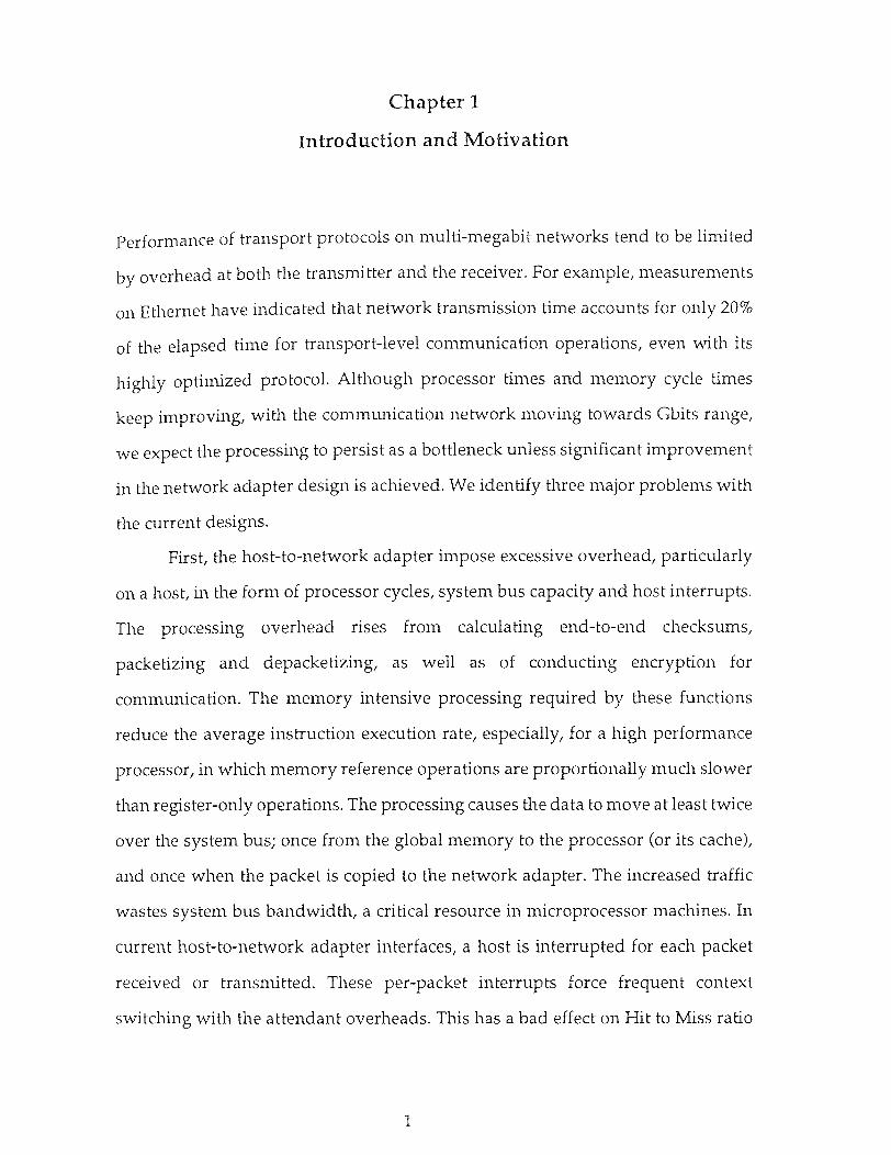
2.2 DQDB Layer Service Definition
A DQDB subnetwork of a MAN is capable of supporting a broad range of services
and applications. This chapter describes the services currently defined and
provided by the DQDB Layer. (fig 2.7). The DQDB services are as follows :
(1) The MAC service provided to the LLC Sublayer, operating over the
DQDB Layer, provides the service of OSI Data Link Layer and thus
supports data communications between two open systems.
(2)
Isochronous service, provided to an Isochronous Service User (ISU).
This service supports the transfer of isochronous service octets
with a constant interarrival time over an isochronous connection.
(3)
A connection-oriented data service that supports the transfer of
data over virtual channels. This service is asynchronous because
there is no guarantee of a constant interarrival time for data units.
13
Figure 2.6 DQDB Layer Services
2.2.1 MAC Services Provided to the LLC Sublayer
The MAC service to the LLC sublayer is defined in ISO. It is connectionless service
that supports the transfer of variable length MAC Service Data Units (MSDUs)
between LLC Sublayer peer entities, without the need for the LLC entities to
request the establishment of a connection between them. There is no guarantee of
delivery of the MSDUs by the MAC service.
The MAC service primitives and their parameters cited in this section are
those specified in ISO. These primitives are as follows.
MA-UNITDATA request
MA-UNITDATA indication
MA-STATUS indication

14
MA-UNITDATA request
This primitive requests the transfer of a MSDU from a local LLC Sublayer
entity to a single peer LLC entity, or multiple peer LLC entities in the case of group
addressing. The format of the request is :
MA-UNITDATA request
source address,
destination_address,
priority,
data,
service_class
The source address parameter specifies the individual MAC address
associated with the service access point (SAP) of the DQDB Layer through which
this primitive was issued. The destination_address parameter specifies either an
individual, multicast, or broadcast MAC address identifying the SAP (s) to which
the data is to be transferred. The priority parameter specifies one of the eight
possible priority values desired for the data transfer. The data parameter specifies
the MSDU to be transferred. The service_class parameter specifies the requested
class of MAC service for the data transfer.
MA-UNITDATA indication
This primitive indicates the delivery of a MSDU to an LLC Sublayer entity. In the
absence of errors that were not detected by the DQDB Layer, the delivered MSDU
will be identical to the MSDU sent in the corresponding MA-UNITDATA request
primitive.
MA-STATUS indication
This primitive informs an LLC Sublayer entity of a change in status of the
operation of the MAC service. The format of the request is :

15
MA-STATUS indication (
status )
The status parameter conveys an indication of the MAC service status.
Examples are as follows.
FAILURE_SOURCE_NODE_ISOLATED (MA-UNITDATA request
primitives cannot be acted on because the sending node is isolated.)
FAILURE_DISABLED (MA-UNITDATA request and indication primitives
are disabled because of subnetwork status; for example, the subnetwork is being
initialized or is undergoing reconfiguration.)
FAILURE OTHER (Failure of MAC service is due to other cases.)
NORMAL (The MAC service is operating normally, for example, following
initialization or indicating restoration after a failure.)
2.2.2 Isochronous Service
It specifies the isochronous service provided by the DQDB Layer once an
isochronous connection is established. The primitives used to describe the service
are the following:
ISU-DATA request
ISU-DATA indication
2.2.3 Connection-Oriented Data Service
The connection-oriented data service supports a virtual channel between a pair of
connection-oriented Data Service Users. The details of the service and service
primitives are still under study.

16
2.3 Provision of DQDB Layer Services
The Queued Arbitrated and Prearbitrated functions of the DQDB layer provide
access control to the dual buses. The access control functions are used by a range
of convergence functions to implement the DQDB Layer services shown in fig 2.11.
DQDB layer specifies the convergence function for the provision of the IEEE 802
MAC sublayer services to the LLC Sublayer (ISO), isochronous service, and
connection oriented data service.
2.3.1 Provision of MAC service to LLC
The provision of MAC service to LLC consists of the segmentation of the MAC
service Data Unit (MSDU) at the source into fixed-length units and the transfer of
these fixed length units to the destination, which reassembles them into the MSDU.
The segmentation process follows the formation of an initial MAC Protocol
Data Unit (IMPDU) by the addition of an IMPDU header, an optional header
extension, an optional 32-bit CRC, a common PDU trailer and a variable length
PAD field to the MSDU. The PAD field ensures that all of the fields added to the
MSDU are 32-bit aligned. The IMPDU is fragmented into fixed length
segmentation units, as shown in figure 2.7, for transfer in QA segment payloads.
There may be padding of the IMPDU with trailing zero octets to ensure complete
filling of the last segmentation unit. The IMPDU header is formed by the addition
of two types of header information. The first four octets of 24-octet IMPDU header
are called Common PDU header. The remaining 20 octets of the IMPDU header are
called the MAC convergence Protocol (MCP) header. The MCP header is specific
to transfer of a MSDU by the DQDB layer, and is not used to support the
connection-oriented data service.

17
Figure 2.7 IMPDU segmentation

18
All segment payloads that supports the MAC services are called Derived
MAC protocol data units (DMPDUs) and consists of a header field and a trailer
field along with the segmentation unit, as shown in figure 2.8. The DMPDU
Header consists of three subfields. The first is the Segment Type Subfield. The
second is Sequence Number Subfield. The third subfield is Message Identifier
(MID). The DMPDU trailer field consists of two subfields. The first is the Payload
Length Subfield. The second field is the Payload CRC.
Figure 2.8 DMPDU format
The MID is used to provide the logical linking between the segmentation
units derived from the same IMPDU, and should be unique on a subnetwork while
the IMPDU is being transferred. Each AU will have at least one unique MID. The
allocation of the MID numbers is controlled by the MID page allocation scheme,
which is distributed method for claiming and keeping MID values that are unique

19 across the whole subnetwork.
The MID identifies all of the DMPDUs derived from a single IMPDU, and
is used in the reassembly of the segmented IMPDU at the destination. To describe
the operation of this scheme, the segmentation of the IMPDU at the source is
described first and the reassembly at the destination is considered later.
Segmentation at the Source
The train of the DMPDUs sent as a QA segment payloads by the source is shown
in figure 2.8. The complete structure of an IMPDU is presented in figure 2.9 and
that of DMPDU is in figure 2.10. The first segmentation unit of a multi-segment
unit IMPDU is carried in a Beginning of Message (BOM) DMPDU. This DMPDU
is identified by the BOM code in the Segment Type Subfield and signifies the start
of a new IMPDU transfer. The MID subfield of this carries one of the MIDs
obtained by the source and not currently being used for sending of another
IMPDU by the source. The Sequence Number Subfield of the DMPDU carries the
initial value of the sequence numbers to be associated with sequential DMPDUs.
The segmentation unit of the BOM DMPDU will include the IMPDU header and
any header extension plus the first octets of the MSDU.
All subsequent segmentation units of the IMPDU until the last are placed in
the payload field of the train of the segments following the first segment. These
DMPDUs are identified by the COM (Continuation of Message) code in the
Segment Type Subfield. The transfer of the multi-segmentation unit IMPDU is
completed by sending the last segmentation unit in a DMPDU that contains the
EOM (End of Message) code in the Segment Type Subfield. The COM and EOM
DMPDUs carry the value of Sequence Number in the BOM DMPDU incremented
by one for each successive DMPDU. All COM DMPDUs and the EOM DMPDU
derived from an IMPDU carry the same MID value as the BOM DMPDU.
For the transfer of an IMPDU that only requires a single segmentation unit,

20 the SSM (Single Segment Unit Message) code is used in the Segment Type Subfield
of the DMPDU. The MID is not used in this case, thus it is set to the reserved value
of zero.
Each DMPDU trailer is constructed by writing into the Payload Length
Subfield the number of the IMPDU octets used in the segmentation unit. For the
connectionless MAC services to LLC, this number is always 44 for BOM and COM
DMPDUs. The number written into EOM DMPDUs indicate the remaining
number of the octets in IMPDU that need to be transferred. This number can be any
multiple of 4 in the range 4 to 44, inclusive. The number written into SSM DMPDUs
indicates the length of entire IMPDU. This number can be any multiple of 4 in the
range 28 to 44, inclusive. The payload CRC Subfield is a CRC computed over all
octets of the segment payload, including the DMPDU header, segmentation unit,
and DMPDU trailer.
Reassembly at the Destination
To receive IMPDUs segmented as described above, each AU will monitor all
segments passing on the bus. Each DMPDUs contain one of a particular set of VCI
values in the segment header. (The VCI value of all bits being set to one is reserved
as a default value for MAC service to LLC. All conforming stations must recognize
this VCI value and process the DMPDUs). If VCI value is one that the AU is
programmed to receive, the AU will verify the DMPDU by means of Payload CRC
Subfield. If the CRC verification fails then the DMPDU is not correct. It should be
discarded.
For each valid DMPDU with a BOM code in the Segment Type Subfield, the
AU will inspect the MCP header, which will be within the BOM segmentation unit.
If the MCP header indicates that the IMPDU is addressed to the AU then it will
copy the BOM segmentation unit. If the IMPDU is not addressed to AU, the
segmentation unit is not copied.

21
Figure 2.9 IMPDU structure
To receive the remainder of the IMPDU associated with the BOM
segmentation unit, the AU will also record the sequence number and MID value
from the BOM DMPDU. The following DMPDUs derived from the same IMPDU
should all be received with the same VCI value in the segment header, and an
incremented sequence number for each successive DMPDU, and the same MID
value in the DMPDU header. The DMPDUs are recognized by the AU using the
Payload CRC Subfield to verify the DMPDU header of all DMPDUs received on
the same VCI, and then comparing the verified MID value with the one recorded.

22 When a match is made, the layer copies the verified segmentation unit of the
DMPDU, provided the sequence number is the expected value. The complete
IMPDU is received when a verified DMPDU with matching MID value, expected
value of the sequence number, and EOM code in the Segment Type Subfield is
received and segmentation unit copied. Since segments are guaranteed to be
delivered in order across the DQDB subnetwork, the AU can reassemble the
received segmentation units into the original IMPDU by connecting them in the
order they were received.
The collection of all received segmentation units of an IMPDU is finally
verified by using two pieces of information contained in the common PDU header
and common PDU trailer. The length of the IMPDU, minus the length of common
PDU header and common PDU trailer, is sent in both common PDU header and
common PDU trailer. The length value received in common PDU trailer is
compared against the number of octets received for the IMPDU. A mismatch
causes the receiver to discard the IMPDU. This check is used to ensure that the
correct number of DMPDUs have been received, and thus protects against the loss
or insertion of COM DMPDUs.
The second piece of information is Beginning-End tag (BE tag). The same
value of BE tag is sent in both common PDU header and common PDU trailer of a
given IMPDU. The BE tag value is incremented for the next IMPDU sent by the
node. The two BE tag values for an IMPDU are compared at the receiver, and a
mismatch causes the receiver to discard the IMPDU. The BE tag is used to ensure
that the BOM DMPDU and the EOM DMPDU of a reassembled IMPDU were both
actually derived from the same source IMPDU. This protects against the loss of
EOM DMPDU from one IMPDU, loss of BOM from subsequent IMPDU, and loss
of the appropriate number of COM IMPDUs such that the IMPDU reassembled
from the received DMPDUs is still of length specified in the common PDU trailer.

23 If the node supports checking of the IMPDU using the 32-bit CRC, and if the
CRC Field is present in the receive IMPDU, as indicated by a bit in the MCP
header, the AU will verify the IMP DU by the means of the CRC32 Field. If the CRC
verification fails, then the IMPDU is discarded. If the CRC verification passes, the
IMPDU is accepted as valid. On the receipt of all DMPDUs of IMPDU, the
recorded MID value must be cleared because the source may reuse the same MID
for a different IMPDU transfer.
Single segmentation unit SSM DMPDUs, are received in a similar manner
to the BOM DMPDUs. The AU will verify the DMPDU using the payload CRC
subfield, inspect the MCP header Field in the segmentation unit, and copy the
segmentation unit if the payload CRC passes the IMPDUs, there is no need to
record the MID value. The IMPDU is completely received in this first DMPDU, and
is then validated using the length value in the common PDU trailer, the BE tag
values in the PDU header and common PDU trailer, and the CRC32 Field.

24
Figure 2.10 DMPDU structure

25 Bandwidth Balancing
The bandwidth balancing technique is used to ensure fair sharing of
bandwidth between stations operating at a single priority. "Fair", here means that
giving an approximately equal share of bandwidth to all stations attempting to
access the medium for transmission. When the physical conditions are as stated
above and when the offered load of all stations exceeds the bandwidth available
on the medium, the use of bandwidth balancing allows all stations to receive an
equal share of the bandwidth in the steady state. In the steady state, the medium
utilization is less than 100%, being equal to BWB_MOD/BWB_MOD+1) x 100% if
there is only one active node.
The bandwidth balancing mechanism divides bus bandwidth among the
stations and allows some bandwidth to go unused. For example, for a bus with N
stations, if all the following conditions are met-
• No station has any pre arbitrated traffic; • Each station always has Queued arbitrated segments waiting to be
transmitted on the bus;
• All the segments have the same priority;
• The value of the BWB_MOD at each station is M (this means that
each station uses a fraction of M/ (M+1) of the slots not used by the
other stations);
These load condition persist for a sufficiently long time;
then the bandwidth balancing mechanism provides each station with a steady
state average throughput of 1/ (N+1/M) segments per slot time. Here the
utilization increases as the BWB_MOD increases and as the number of active
stations increases. The station throughputs approach their steady-state values
gradually. The convergence is faster if the BWB_MOD is smaller.

26 2.3.2 Provision of Isochronous Services
The Pre Arbitrated access control mechanism does not necessarily accept or deliver
isochronous service octets in the isochronous fashion. The variation from the
isochronous delivery occurs when the node at head of bus does not guarantee Pre-
Arbitrated slots in an isochronous fashion. If the user of the isochronous service
requires the DQDB layer to accept and/or deliver the octets isochronously, there
is a requirement for some buffering. The nature of this buffering depends on the
isochronous service user and is performed as part of an isochronous convergence
function.
The isochronous service described provides only the DQDB layer Functions
required to access the medium to read and write isochronous services octets. This
is managed by the Pre Arbitrated Access Functions within each AU and the
periodic generation of the PA slots at the head of the bus.
2.3.3 Provision of Connection Oriented Data Service
This convergence function is under implementation that will allow the DQDB
Layer to support a connection-oriented data service that uses Queued Arbitrated
access. This will require the functions similar to the convergence functions to
support the MAC to LLC service.
2.4 Functional Architecture of a Node
The functional architecture for a DQDB node is shown in figure 2.11. It consists of
two layers: the Physical Layer and the DQDB Layer. The DQDB layer uses the
services of the Physical Layer to provide a number of different services. One of
these services is the MAC Sublayer service to the LLC sublayer. Other services
which are under study, include connection-oriented data services and
isochronous services.

27 2.4.1 Physical Layer Functions
The physical layer contains three components, Transmission System, Physical
Layer Convergence function and the layer management functions. The physical
layer service is provided to the DQDB Layer entity at a node through two SAPS.
Each SAP is associated with one duplex transmission link connecting the node to
an adjacent node. Transmission System functions provides an transmission
interface used to access the transmission link between adjacent nodes.
Physical Layer Convergence Function
In order to allow the DQDB layer to operate independently of the nature of the
transmission system, a physical layer convergence function is used. This function
provides the Physical Layer to DQDB Layer service, irrespective of the nature of
the transmission system.

28
Figure 2. 11 DQDB Node Functional Architecture

29 2.4.2 DQDB Layer Functions
Within the DQDB Layer there are four principle types of functions: the common
functions, the access control functions (Queued Arbitrated and Pre-Arbitrated),
the convergence functions, and the layer management functions. Each of these
functions is described below.
Common Functions
The Common Functions block acts as a DQDB Layer relay for the transfer of slots
and management information octets between the two SAPS to the local Physical
Layer entity. Thus the Common Functions block allows the QA Functions block
and PA Functions block to gain read and write access to the QA, and PA slots.
These functions include the head of the bus function, the Configuration
Control Function, and the MID Page Allocation Function, and are described as
follows.
The Configuration Control and MID Page Allocation Functions manage
DQDB Layer objects necessary for nodes to communicate on the subnetwork.
Hence these functions are part of the DQDB LME.
Head of Bus Function
The head of the bus function is performed by the node at the head of each bus and
by no other nodes on the dual bus. It includes the Slotmarking Function, which is
the process of creating empty slots that are to be written onto the bus. This includes
the marking of PA slots and the writing the VCI in the PA segment header. The
node at the head of each bus must also write appropriate values into the
management information octets.
Configuration Control Function
The Configuration Control Function is responsible for ensuring that the resources
of all nodes of a subnetwork are configured into a correct dual bus topology. The
Configuration Control Function will be employed at the subnetwork start-up or to

30 correctly configure the subnetwork. The Configuration Control Function will also
reconfigure the subnetwork in the case of bus failures. An example of the operation
of the Configuration Control Function is the activation and deactivation of the
head of bus functions at appropriate nodes during the process of reconfiguration.
MID Page Allocation Function
The MID Page Allocation Function participates in a distributed protocol with all
nodes on the subnetwork to control the allocation of the MID values to nodes. The
MID values are used by the node in the transfer of multiple segmentation unit
IMPDUs, described in 2.3.1. The MID Page Allocation Function will ensure that
two nodes are not allocated the same MID value.
Queued Arbitrated (QA) Functions
The QA functional entity provides an asynchronous data transfer service for 48-
octet segment payloads. The QA functional entity accepts the segment payloads
from a convergence function, and adds the appropriate segment header, including
VCI, to the segment payload to create a QA segment. The QA segment is queued
for access to the dual bus by use of the Distributed queuing Function. QA segments
received by the QA functional entity are stripped of the segment header and the
payload is passed to the correct convergence function, based on the VCI value in
the segment header.
Pre Arbitrated (PA) Functions
The PA functional entity provides access control for the connection-oriented
transfer over a guaranteed bandwidth channel of octets. The operation of the PA
functional entity requires the previous establishment of a connection. As a result
of the connection establishment, the PA functional entity will be informed of the
VCI value for segments used in the connection and the offset of the octets to be
used for reading and writing within the multiple user PA segment payload.
The PA entity accepts the single octets from a convergence function and

31 writes them into a pre-allocated positions within the payload of PA segments with
the appropriate VCI value in the segment header. The VCI value would have been
set by the Slot Marking Function at the head of the bus.
To receive an octet stream, the PA functional entity, on receiving a PA
segment with the correct VCI value, will copy octets from the pre-allocated
positions within the segment payload. The octets are passed the correct
convergence function, based on the VCI value in the segment header and the offset
of the octet in the PA segment payload.
Convergence Functions
It is intended that the DQDB layer will provide a range of services including
connectionless data transfer, isochronous data transfer, and connection-oriented
data transfer. The services are provided by the convergence functions placed
above the QA and PA functional entities.
MAC Convergence Function (MCF)
The MCF is responsible for adapting the segment-payload-based service provided
by the QA functional entity to the MAC service required by the LLC Sublayer.
The MCF transmit process involves encapsulating the LLC Protocol Data
Unit (MAC Service Data Unit) to form an initial MAC Protocol Data Unit
(IMPDU). The IMPDU is segmented into segmentation units of 44 octets, as
described in 2.3.1. Each segmentation unit has a segment type, sequence number,
and MID value prepended, and a payload length and payload CRC appended, to
form a Derived MAC Protocol Data Unit (DMPDU). This can be transferred by the
QA functional entity.
The MAC service process involves reassembly of the original IMPDUs at
the destination, as described in 2.3.1. The LLC Protocol Data Unit is extracted from
the received IMPDU and passed to the LLC entity.

32 Isochronous Convergence Function (ICF)
The ICF is for each Isochronous Service User (ISU). An ICF is responsible for
adapting the guaranteed bandwidth octet-based service provided by the PA
functional entity to an isochronous octet-based service.
In particular, the ICF will provide buffering both for the isochronous octets
to be transmitted on behalf of the ISU by the PA functional entity and for the
isochronous octets received from the PA functional entity and to be delivered to
the ISU.
Other Convergence Functions
The provision of a connection oriented data service by the DQDB layer is under
study. The Connection-Oriented Convergence Function (COCF) will adapt the
segment-payload-based service provided by the QA functional entity to a
connection-oriented data service. Connection oriented data service uses the same
segmentation and reassembly procedures same as that of MCF.
2.4.3 DQDB Layer Management Entity (LME)
The DQDB LME performs management of the local DQDB Layer Functions. It also
communicates with DQDB LMEs at other nodes to provide distributed
management of the DQDB Layer resources. The communication uses a DQDB
Layer Management Protocol is supported by the DQDB Layer Common Functions
block. The DQDB LME also provides the DQDB Layer Management Interface to
the Network Management Process for the remote management of the local DQDB
Layer subsystem.

Chapter 3
INTERFACE ARCHITECTURE
This chapter describes the system architecture, system operation and hardware
modules that implement the Queued Arbitrated functions of the Distributed
Queue Dual Bus Metropolitan Area Network (DQDB MAN). A Field
Programmable Gate Array (FPGA) design can be implemented by using the state
diagram of the processing units. We finally mention that the state transition
diagram of the receiver packet processor is also discussed in this chapter.
3.1 Overview of System Architecture
A higher level overview of the proposed architecture for such a system appears in
figure 3.1. The DQDB protocol functions are handled by the Multi Processor Pool
(MPP). The Low Level Processors (Input Low Level Processor & Output Low Level
Processor) handle physical interfaces while the Host Interface Processor (HIP) is
used for data transfer to and from host applications. The following design choices
have been made for reasons described below :
=> Round-robin Scheduling of Processors
=> Local Memory in Packet Processor
Local memory in packet processors minimizes the number of "copy" operations
and in conjunction with the round robin scheduling the use of processors is
maximized. Shared memory is used primarily for context records for each
connection, reducing memory contention considerably.
Figure 3.2, which shows a detailed system diagram, provides some architectural
details. The packet processors that handle the received packets are labeled
Each packet processor contains multiple packet buffers, local RAM, a CPU, and
33

34
interfaces to the ILLB (Input Low Level Bus) and the S_Bus (Shared Bus). The ILLB
is exclusively used for high speed data transfer from ILLP to Ri_processor and
from R1_processor to host. The components of the transmitter are shown in Figure
3.3.
Figure 3.1 Processing Architecture Overview
The DQDB Layer Protocol functions are performed by a set of programmable
packet processors, depicted as T1_processor and T2_processor, where the low
level functions are performed by the high speed hardware unit OLLP. All these

35 processors communicate with each other and shared memory, via the S_Bus. The
high speed Data Memory is used to buffer data received from host applications for
transmission. The OLLP transfers data out of the High Speed Data Memory via a
dedicated bus called Output Low Level Bus (OLLB). The T1_processor and the
data memory have a direct connection to the H_Bus (Host Bus) as well. We have
assumed a simple hardware arbitration mechanism to resolve simultaneous
attempts by the processors to access the shared resources. All requests are queued
and granted in the order that they were received. This manages to reduce the
contention between the processors adequately, without the cost or delays
associated with complex interconnection network. Simple I/O interfaces are
critical to maintain the required throughput. The high speed hardware units (ILLP,
OLLP) will offer a solution for this critical problem, as well as for the lower layer
protocol functions and error checking functions that cannot be handled by
programmable processors at Gbps rates.
3.2 System Operation
The system described in Figure 3.2 and Figure 3.3 shows the implementation of the
parallel processing architecture connected to one of the buses, Bus A or Bus B. This
design shows the receiving and transmitting sections separately on the same bus.
The incoming and outgoing lines from the bus are connected with the low level
processors. The Input low level processor (ILLP), is placed before Output low level
processor (OLLP) so that the data written by OLLP cannot affect the reading
operation of ILLP. First we will describe the receiving section and then the
operation of the transmitting section.

36
Figure 3.2 System Architecture - I

37
Figure 3.3 System Architecture - II
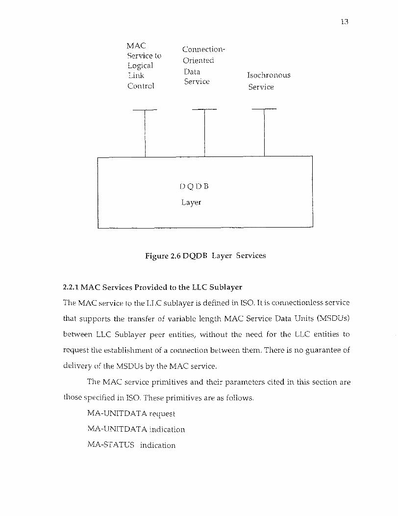
38 3.2.1 Receiving operation
As packets come in from the line, the ILLP checks the access control field of the slot.
If the busy bit is "1" and the payload type bit is "0", the slot will be busy. The
processor then reads the incoming segment. It checks whether the VCI field in the
ACF of the slot matches with one of the VCIs that the station is programmed to
receive. A station is programmed initially with an acceptable list of VCIs and
MIDs. If there is a VCI match, then ILLP will check both Header Check Sequence
(HCS) and Cyclic Redundancy Check (CRC-8). If the above fields match, then the
packet will be transferred to the next packet buffer of the R1_processor which has
been chosen in a round robin fashion. Otherwise, the segment will be discarded
and not forwarded for further processing.
The ILLP transfers the packet to a selected processor and at the same time
the bits are copied to the CRC unit. At the end of the sequence of the header,
payload and trailer, the CRC remainder is computed and transferred to the same
processor that the corresponding segment has been sent.
The R1_processor receives the DMPDUs from the input low level bus
(ILLB) and starts processing it. First it checks the correctness of the DMPDU, by
comparing the calculated remainder (sent by the CRC unit) with the CRC field
carried in the DMPDU trailer. If the CRC check is successful only then further
processing is carried out; otherwise the DMPDU is discarded. The MID/ VCI_data
pair is compared against the active reassembly process, which holds the MID/VCI
pair of the connection and has been established when the first segment arrived at
the receiver. If MID/VCI pair matches, the destination address field in the MCP
header is compared with the MAC Service Access Point (MSAP) address. If the
address does not match then the DMPDU will be discarded. After a successful
checking of DMPDU has been conducted, the Previous Segment Received (PSR)
signal (if required) is generated, and R1_processor makes a request to

39 R2_processorfor reassembly of the IMPDU. The PSR signal is generated only if the
destination address was a correct individual address. If it was a group address
then the PSR signal would not be generated. Once the PSR signal is generated, the
OLLP writes "1" in the PSR subfield of the access control field of the next slot on
the bus, irrespective of the type of the slot. The R1_processor have multi packet
buffers. The processed packet is held in one of the buffers of the R1_processor. If
the segment received by the R1_processor was a single segment message then it is
not necessary to send it for reassembly. the segment gets validated by
R1_processor.
As R2_processor gets a request for reassembly it starts a separate
reassembly process associated with that VCI and MID pair. R2_processor keeps a
copy of the beginning of the message (BOM DMPDU), which carries the IMPDU
header information. By doing this for each new message, more than one
reassembly processes can exist at the same time. However, there will be only one
reassembly process related with a single MID/VCI pair. As the 'Continuation Of
Message' segments (COMB) arrive, they will be appended to the corresponding
reassembly process associated with that MID/VCI_data pair. Upon receiving 'End
Of the Message' (EOM DMPDU), R2_processor starts validating IMPDU by the
length, Beginning-End (BE) tag and CRC-32 (optional). If the validation fails then
the IMPDU is discarded. If the IMPDU checking was successful, the extraction of
MSDU is carried out. Upon completion, the received data must be transferred to
the host. The R2_processor writes a request to the Host Interface Processor (HIP)
for the data transfer. The requests are queued up at the HIP_FIFO and are served
by HIP on a First Come First Serve (FCFS) basis. The request carries the destination
address in the host system, as well as, the total number of the bytes to be
transferred. The R1_processor holds the packet in the packet buffer until it gets
transferred to the host. The host interface processor transfers the data from the

40 packet processor into the host memory by the Direct Memory Access (DMA)
process via the Input Low Level Bus (ILLB) and the host interface bus. Thus, by
this technique, we avoid multiple write operations on the same packet.
In the proposed architecture, there are many processing units which use
shared resources. Such shared resources are the shared bus and the shared
memory. A conflict may arise while using those shared resources. To avoid
contention problems, all the requests to access the shared resources, are queued up
under a FIFO and are served in a first in first out manner.
3.2.2 Transmitting Operation
When the host station is ready to transmit, it sends a request to the T1_processor.
The request provides information about source, destination and the number of
bytes to be transferred. The information about the allocation of buffer memory is
kept in the shared memory. The T1_processor accesses the appropriate context
record and gets the memory address of the next available block in the buffer
memory. The T1_processor communicates that information to the host. The host is
now free to move data into the high speed static the buffer memory at the address
provided. After the completion of the data transfer, the host writes another tag to
the R1_processor with the destination address and number of bytes to be
transferred. The host now is not concerned any more with the actual transfer of the
data. The T1_processor then generates the headers and trailers of the initial MAC
protocol data unit (IMPDU). Upon the complete generation of IMPDU, it is
segmented in 44 octet QA payload segments. This segmentation is logical because
the data is stored physically in the data memory, thus T1_processor computes the
addresses and the length of the segments. The 'Beginning Of Message', BOM
DMPDU will be generated by the IMPDU header. Then each individual QA
payload are sent to available T2_processor according to round robin scheduling to

41 create QA segment.
The T2_processor then creates the header fields of DMPDU. It encodes the
payload length, CRC and MID values. Upon completion, it writes a control block
making a request to OLLP to transmit the segment. That request is queued up at
OLLP. The OLLP serves the request on first come first serve basis. When serving
the request, the OLLP reads the control block. As shown in figure 3.5, there are two
types of control blocks. The address field in type "1" control blocks points to next
block in the FIFO and that of type "2" points to data memory. During transmission,
the header and the trailer are transmitted from the next block on the queue, the
data from the data memory, and CRC field is appended as required. The dedicated
high speed output low level bus (OLLB) transfers the data from data memory to
OLLP. The data which is being written out to line is also copied to the dedicated
CRC unit. At the end of the bit stream the CRC unit generates CRC remainder,
which is read out and encoded in the trailer as required. When ILLP reads in a non
busy QA slot (Busy Bit "0" and Pay Load bit "0"), and the content of CD_CNTR is
zero, then OLLP can transmit QA segment in that slot.
We have succeeded in keeping the path of data, out of protocol processing.
Thus we do not perform multiple copying of data while transmission and
reception, which saves time and system resources.
3.3 Hardware Modules
The hardware modules concerned with this architecture can be divided into two
categories, receiving modules and transmitting modules. The Input Low Level
Processor (ILLP), the R1_processor, the CRC Unit, and the R2_processor constitute
transmitting modules. The T1_processor, the T2_processor, the Output Low Level
Processor (OLLP) and the buffer memory constitute the receiving modules. The
shared memory, the direct memory access process, and the distribute queue state

42 machine are also described.
3.3.1 Receiving Modules
The following modules comprise the receiver assembly. They work in parallel and
independently from each other. These modules are:
Input Low level Processor
This dedicated device is working at the front end of the network. ILLP observes
continuously the incoming slots. If a slot is busy, ILLP reads in the segment from
the slot and checks for the Virtual Channel Identifier (VCI). If VCI matches one at
this node, then the Header Check Sequence (HCS) (a Cyclic Redundancy Check
(CRC-8)) is checked. If VCI or HCS does not match the DMPDU is discarded. The
type of service required can also be determined by the VCI. By type of service we
mean MAC services or connection oriented services or isochronous services. ILLP
transfers the packet in the next packet buffer of the R1_processor which is chosen
in a round robin fashion. The PSR information, VCI, Payload Type, and the
segment priority are also copied to the buffer.
R1 processor
The R1_processor gets data from the Input Low Level Bus (ILLB). R1_processor
checks the correctness of the Derived MAC Protocol Data Unit (DMPDU) using the
CRC-10 field from the DMPDU trailer. This processor gets feedback information
about the active reassembly process from the R2_processor. The feedback
information contains the active MID/VCI pair.
While copying a packet into R1_processor's buffer, the same bits are fed into
the pipeline processing module of the CRC-10 check hardware. At the end of the
bit stream, the CRC remainder, generated by the CRC unit, is read and transferred
to the packet processor which was chosen in a round robin fashion. If the previous
segment received service is provided, the R1_processor checks the following :

43 (i) Whether QA is the Beginning Of a Message (BOM) as well as whether the
Destination Address (DA) in the MAC Convergence Protocol (MCP)
header is correct.
(ii) Whether QA is a Continuation Of Message (COM) or End Of Message
(EOM) as well as whether the Message Identifier (MID)/VCI_data pair
matches with the one of the active reassembly process.
Then R1_processor generates the Previous Segment Received (PSR) signal and
makes an entry into the FIFO queue of the R2_processor.
If QA is a Single Segment Message (SSM), then the DMPDU does not need
reassembly. Hence, the R1_processor starts validation of it, which generates the
following sequence.
(i) Check of MID subfield. If does not match, discard the DMPDU.
(ii) Check the DA field of the MCP header with the MAC Service Access Point
(MSAP). If it does not match, discard the DMPDU.
(iii) If the previous checking is correct, then generate the PSR_signal.
(iv) Hold the packet in the buffer and generate an entry to the service queue of
the Host Interface Processor (HIP) to move the data to the host application.
CRC Unit
The CRC unit is responsible for generating the CRC remainder for the incoming
string of data. Cyclic Redundancy Check codes are used for error detection. Let L
be the length of the CRC coding polynomial and K be the length of the string of
data bits. Then we can write them as the polynomials shown below:
s (D) = sK-1DK-1 + sK-2DK-2 + + s0
g (D) = DL + gL-1DL-1 + gL-2DL-2 + + g1D + 1
where s (D) is the information polynomial, and g (D) is the generator polynomial
of degree L.
For a given g (D), the mapping from the information polynomial, c (D), is given by,
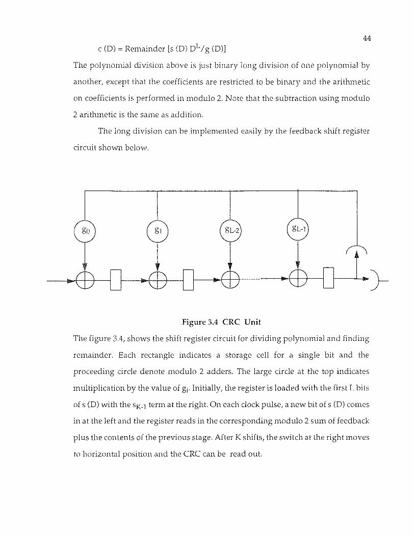
44 c (D) = Remainder [s (D) DL /g (D)]
The polynomial division above is just binary long division of one polynomial by
another, except that the coefficients are restricted to be binary and the arithmetic
on coefficients is performed in modulo 2. Note that the subtraction using modulo
2 arithmetic is the same as addition.
The long division can be implemented easily by the feedback shift register
circuit shown below.
Figure 3.4 CRC Unit
The figure 3.4, shows the shift register circuit for dividing polynomial and finding
remainder. Each rectangle indicates a storage cell for a single bit and the
proceeding circle denote modulo 2 adders. The large circle at the top indicates
multiplication by the value of Initially, the register is loaded with the first L bits
of s (D) with the sK-1 term at the right. On each clock pulse, a new bit of s (D) comes
in at the left and the register reads in the corresponding modulo 2 sum of feedback
plus the contents of the previous stage. After K shifts, the switch at the right moves
to horizontal position and the CRC can be read out.
45 R2 processor
After receiving the Beginning Of Message (BOM), the R2_processor starts the
reassembly process associated with the corresponding VCI_data and Message
Identifier (MID) pair. It matches the destination address in the MCP header with
that of the Service Access Point (SAP). On getting the EOM, validation of IMPDU
takes place. The R2_processor compares then the value of the Length subfield of
the common PDU trailer, with the actual number of octets received. If there is no
match the IMPDU is discarded. The actual number of the data octets in the IMPDU
will be {[no. of octets received for the IMPDU] - [common PDU header octets
[4]]+[number of PAD octets [0,3]1+ [common PDU trailer octets [4]]}. If there is no
match, the data is corrupted and the IMPDU is discarded. It also performs BE-tag
validation. If both, length and tag match then a MAC Service Data Unit (MSDU) is
created by using the IMPDU.
Extraction of MSDU from validated IMPDU:
The R2_processor will,
(i) Use the DA field of the MCP header to create the destination_address_
parameter.
(ii) Use the SA field of the MCP header to create the source_address_parame ter.
(iii) Use the Quality Of Service delay field to create the priority parameter.
(iv) Extract the MSDU information field to create the data parameter
Then UNIT_DATA indication is prepared. After extracting MSDU successfully,
make an entry into HIP_FIFO indicating the Destination Address, memory storage
address of segments and byte count for the data segment residing in, the packet
processor, R1_processor's local memory.
Direct Memory Access - Process
The R2_processor makes a request for Direct Memory Access in order to move
packets from the buffers of R1_processor to the host memory. The request contains

46 the number of bytes to be transferred, the memory read address (pointing to the
local memory of the R1_processor) and the memory write address (pointing to the
host application running in the host system). The R2_processor requests are
served by the Direct Memory Access controller. The DMA controller utilizes the
idle bus cycles, temporarily takes over the control of both the memory address bus
and the data bus and transfers the data to the host. This technique is called cycle
stealing technique.
3.3.2 Transmitting Modules
The description of the various transmitting modules follows below.
T1 processor
Upon the reception of a request from the host, the T1_processor gets the total
number of bytes to be transmitted by the Logical Link Control (LLC) sublayer
frames, as well as the destination address and source address. T1_processor then
accesses the appropriate record in the shared memory to find the address of the
buffer list for this request. From the buffer list data structure it obtains the pointer
to the next available block in the buffer memory, which communicates to the host.
The host eventually transfers the data block in the data memory. Meanwhile, it
creates the IMPDU header with the information carried by the MA_unit_data
request.
To create a common PDU Header the T1_processor :
(i) Encodes the reserved field.
(ii) Selects the Beginning and the End tag (BE) and encodes them.
(iii) Encodes the buffer allocation size field to a number of octets as {MCP
header octets + Header Extension Length (HEL) octets + MSDU
octets.
To create the MAC Convergence Protocol (MCP) header the T1_processor :

47 (i) Encodes the destination address.
(ii) Encodes the source address.
(iii) Encodes the Protocol Identifier (PI) (=1 for LLC frames)
(iv) Encodes the Qos_delay and Qos_loss parameters.
(v) Compares the parameters received in the MA_unit_data request with the
currently installed header extension selection values (within the MCF by
the DQDB Layer Management Entity (LME)). These values can be
modified by the Layer Management actions.
Finally, T1_processor encodes the the Bridging field by 'zero's.
The segmentation of an IMPDU then follows. The T1_processor segments the
IMPDU into a 44 octet QA payload. The only exception is the single segment
message and the end of message. Then the next available T2_processor, according
to round robin scheduling, is assigned to create a QA segment; using the QA
payload and the other related information.
T2 processor
This processor creates DMPDU headers and trailers. For a Single Segment Message
(SSM), the T2_processor :
(i) Encodes the segment type (11 for QA slots)
(ii) Encodes the MID subfield ('zero's for SSM)
(iii) Encodes the payload length in DMPDU trailer.
For more than one Segmentation units, the T2_processor :
(i) Encodes the segment type of BOM, COM or EOM as 1 0, 0 0 or 0 1
respectively.
(ii) Selects a MID value and encodes it; notice that this value is the same for
every DMPDU derived from a single IMPDU.
(iii) Encodes the payload_length in the trailer by the number of octets of the
IMPDU contained in the segmentation unit.

48 The T2_processor generates a segment by appending the payload to the header
and the trailer fields in the following way. In segment header field, the
T2_processor encodes the VCI_DATA, the Payload_type (0 0 for QA), the Segment
Priority (0 0) and the data by using the CRC-8 coding polynomial. It also calculates
the remainder and encodes it. Upon completion of these operations, an entry into
the FIFO of OLLP is generated.
Output Low Level Processor
Basically it is dedicated to the function of transferring data at high speeds out of
the data memory, and writing directly to output line using OR_writing. It also
includes the low level protocol functions. It acquires direct control when it has to
write into a Previous Segment Received (PSR) bit, or into the Request (REQ) bits of
the Access Control Field (ACF) of the next slot. OLLP reads the control blocks from
FIFO and determines the source of the next block of data to be transferred. This
control block may point to the very next block in the queue, in case of a packet
header, or to a location in the data memory. In both cases the number of bytes to be
transferred is also indicated. The OLLP includes the CRC unit working in parallel
with it. When the OLLP writes data on the outgoing line it also copies the data into
the CRC unit. At the end of the bit stream, the generated CRC remainder can be
read out from the unit and can be encoded into the corresponding field.

49 Buffer Memory
Figure 3.5 Memory Block Design
To minimize the contention, (see figure 3.5) the buffer memory uses the dual port
static RAM components, also referred to as Video RAM ICs. It provides multiple
buffers to hold packets until they get transmitted. This memory IC provides two
independently accessible ports: One providing high speed burst-mode transfer,

50 and the other providing random - access. The serially accessible port is used to
move a packet from the buffer memory to the network. The random accessible port
provides memory access for the host to copy the data which are to be transmitted.
The serial access does not need address set-up and decoding time, hence the read-
write times are faster on this port than the read-write times for a RAM array. For
instance in order to align the major host systems, using 32 bit wide memory, the
serial access time is 40 n.secs/word, and the cycle time for the random read write
access is 200 n.secs. This gives an effective transfer rate of 800 Mbps over a serial
port and 160 Mbps over a random access port. To provide an equivalent memory
bandwidth on a single ported 32 bit wide memory we would require a memory IC
with read/write cycle time of 33 n.secs. Currently such fast memory is available,
but it is costly and have less memory density than that of the Video RAMS.
A packet is transmitted to the network via a serial port from the shift
register contained in the Video RAM ICs. The shift register acts as a temporary
storage. When the block is completely transmitted, the next block is transferred
into the shift register, in a single memory cycle, from a row of the memory cell
array constituting the buffer memory. The host copies the blocks via the random
access port. The copying of a block continues without interference, while the next
packet is being transmitted, with the exception of one memory cycle which is
stolen for each transmitted block that is transferred from the memory cell array to
the shift register. We point out that Video RAM ICs provide good performance at
a fraction of the cost of the fast memory. They can also perform high speed block
transfer between the network, the buffer memory and the host.
Buffer List Data Structure in the shared memory
This data structure is defined for the purpose of managing data memory buffers in
the high speed static RAM. This structure exists for each active DQDB connection.
It is setup first, when the DQDB connection is established, and is physically

51 resident in the shared memory. Each cell, as it is shown in figure 3.7, consists of a
pointer to the next cell,
Figure 3.6 Control Block Structure.
which contains the address of the data buffer. The buffer size should be the same
as that of the block size which is likely to be used by the host application. The
structure is maintained via three variables: first_free, first_busy, and last_busy,
which are part of the record for each connection. The variable first_free points to
the next free buffer. Initially the first_free points to the first cell and the variables
first_busy through last_busy point to the buffers that contain the segments that
must be transmitted. Initially the first_busy and last_busy are set to point to the
first cell by the T1_processor. The value of the last_busy is updated by the
T1_processor every time a new buffer is allocated to the transmission packets.
Upon completion of the transmission of a packet by OLLP the value of first_busy
is updated. The T1_processor updates first_free every time it secures a new buffer
from this list. When the first free equals the first_busy, no additional data buffers
are available and the host application gets blocked.

52
Figure 3.7 Buffer List Data Structure.
3.3.3 Operation of Distributed Queue State Machine (DQSM)
The operations of the ILLP and OLLP are controlled by the DQSM which we
briefly describe below. According to this state machine each station maintains a
Request_I_Counter_X, counting requests at priority level I on bus X (A or B). If the
node is not queued for transmission then the above mentioned counter will get
incremented upon observing a request on the reverse bus or will get decremented
on observing an empty slot (Busy Bit & Type Bit as 00) on the transmission bus.
When a segment is queued for transmission, at the station transfers the contents of
REQ_I_CNTR_X to countdown counter CD_I_CNTR_X. The countdown counter
then gets incremented, by one for each coming request on bus X of higher priority

53 than the level I, or if the node itself generates a request at level higher than level I.
This counter gets decremented, if an incoming slot on the transmission bus is
empty i.e. if the Busy Bit and the Segment Type Bit in the Access Control Field
(ACF) of the slot are both "0". When the countdown counter reaches the null value
"0", the packet is transmitted in next available empty slot seen on the transmission
bus. The OLLP is informed when the countdown counter reaches "0", so that it can
activate the OR writing into the next free slot.
3.3.4 Field Programmable Gate Array (FPGA) implementation of R1_processor
Figure 3.8 shows the state diagram needed to implement the set of common
functions and QA functions that must be performed by an R1_processor. The
general functions of R1_processor, for processing of the incoming packets, are
discussed below. The state diagram shows state I, as a waiting state. When the
processor finishes the processing of the data packet, waits until the next processing
is assigned. In this state R1_processor checks continuously the status of a FlipFlop
(packet) {the FlipFlop is set when the new packet is assigned). If that FlipFlop is not
set the R1_processor will generate the 'Ready' control signal going to ILLP, and
will return to the same state. If the FlipFlop was set then the 'Busy' signal is
generated, indicating that R1_processor has already been assigned to process a
packet. The processor makes transition to state II.

54

55
In state II, R1_processor reads the 53 bytes of the incoming packet. At the
end of the bit stream, it also reads the 10 bits of the CRC remainder released by the
CRC unit. If the Previous Segment Received (PSR) bit is present then it sets the
FlipFlop (PSR) to 1. Thus this state needs a total of 14 memory reference operations
(considering 32 - bits wide data path) to read a 53 byte packet, 10 bits of the CRC,
and 1 bit from the CRC field.
In state III, the processor loads the 10 - bit CRC remainder from the CRC
unit and the 10 bits from the payload CRC field. R1_processor then compares them
in order to implement the checking of the received data. If the CRC field does not
match, then the received packet is discarded and the processor goes back to state

56 I. If the CRC field passes the comparison then the processor makes the transition
to the next state, i.e. state IV.
In state IV, the processor reads two bits from the fifth octate and decodes
them. Then R1_processor performs a comparison of the MID (10 bits) and VCI (20
bits) subfields, as well as the address field in the MCP header (8bytes) with the
values allocated to the node. When R1_processor checks the equal conditions for
the comparisons, and if they do not hold, it loops back to state I. If the conditions
are equal, it checks the decoded bits. If the decoding bits were 00 or 01 i.e., the
received segment was a Continuation of Message (COM) or an End of Message
(EOM). In this case R1_processor will make a transition to state V. If the decoding
bits were 10 i.e., the segment was a Beginning Of Message (BOM), R1_processor
will make a transition to state VI. Otherwise, i.e. the decoding bits were 11 (the
segment was a Single Segment Message), it will make a transition into state VII.
In state V, R1_processor will send the Previous Segment Received (PSR) bit,
if the FlipFlop (PSR) is set. R1_processor will write a request for reassembly of the
received DMPDU, to R2_processor along with the DMPDU information and
address.
In state VI, R1_processor writes the whole packet to R2_processor, because
the BOM DMPDU contains the header part of the IMPDU.
In state VII, R1_processor performs validation of the SSM, because the given
segment does not need reassembly. Rl_processor performs checking of the
payload length field (16 bits) and the Beginning and End tag (8 bits). It checks CRC
indicator bit (CIB) and writes the FlipFlop (CIB) accordingly. Furthermore, it
checks the header length extention field (8bits).
Table I shows the different states and number of Operations involved with
the state transition diagram described in figure 3.8. Figures in [ ] indicate number
of Bytes and figures in ( ) indicate number of Bits.

57
Table 1: States and Operations
States \Operations
Read Write Compare Total
I (1) # 1
II [53],(10),(1) # 16
III (10) # 2
IV (2)Rd&Dcod (10),(20),[8] # 9
V (1)
(1)
,[4],[4] # 4
VI [44] # 11
VII (1) (16),(8),(8) [4]
# 9
Total # 20 # 14 # 18 # 52
The state transition diagram shows that there are five valid paths, the
processor may follow. FPGA technology manages to execute read, write or
compare functions within 2 - 5 n.sec. In the sequel we provide a brief discussion on
possible alternative paths.
Upon getting a packet, R1_processor makes the transition to state II. Where it reads
the packet and the CRC bits from the Input Low Level Bus (ILLB). In state III,
R1_processor compares the CRC field of the DMPDU. If the packet fails to match
the CRC field then the received DMPDU is discarded and the processor makes the
transition to state I. A total of 19 memory reference operations (approx. delay of 4
µsec.) are related with this path.

58 Path II:
If R1_processor gets the DMPDU and follows the path through state III and there
is a match of the CRC subfield, then R1_processor will make the transition to state
IV. In state IV, R1_processor reads the segment type bits (2 bits) and decodes them.
Then, R1_processor performs a comparison of the subfields MID (10 bits), VCI (20
bits), and destination address in MCP header (8 bytes). If there is a match
R1_processor goes to a subsequent state which depends on the decoding of the two
bits. If there is not match, then R1_processor discards the DMPDU and returns to
state I. A total of 28 memory reference operations and an approximate delay of 6
µsec. are related to this path.
Path III:
If the R1_processor reaches the state IV, and the DMPDU passes the comparison
successfully, then R1_processor will make a transition to states V, VI or VII
corresponding to the decoding of the segment type. If the examined segment was
a Continuation Of Message (COM) or an End Of Message (EOM), then
R1_processor will make a transition to state V. R1_processor will write a request to
R2_processor with DMPDU information and its memory address. Upon
completion R1_processor will return to state I. The number of memory reference
operations related with this path are 32 and the approximate delay is 7 µsec.
Path IV:
If R1_processor reaches the state IV and the DMPDU matches the comparison and
the segment type is a beginning of a message, then R1_processor will write a whole

59 packet to R2_processor. Upon completion of the writing operation R1_processor
will make a transition to state I. The total of 39 memory reference operations are
performed along this path. The approximate delay of this path is 8 µsec.
If R1_processor reaches the state IV and the matched DMPDU is a single segment
message, then R1_processor will make the transition to state VII. This DMPDU is
carrying the whole DMPDU in it. The validation of the IMPDU is done here by
checking both the header and trailer fields of it. When finished the R1_processor
sends a request to the Host Interface Processor (HIP) to transfer the received
IMPDU to the host. A total of 37 memory reference operations are involved with
this path. The approximate delay of this path is 8 µsec.
Figure 3.9 provide, a diagram of the parallel processing with respect to time. In the
worst case scenario, where all packets on the bus have the same destination, a new
packet may may arrive at a node every 2.72µsec. We assume that there are four
processors in the receiver assembly and they are assigned to perform the
processing of the incoming packets. The first incoming packet goes to the first
processor. The next in the second processor and so on. We see that by the time the
fifth packet arrives at the node the first processor has completed serving the first
packet and can now accept the fifth packet. Then, when the sixth packet arrives,
the second processor is free. Therefore four processors are enough to handle all the
processing needs of the DQDB protocol inside each station. We also know that on
getting the EOM DMPDU the message is validated and transferred to the host.
Since the maximum MAC protocol data unit is 9188 octets, requiring 210 DMPDUs
for its transfer, we need a minimum of 54 packet buffers (of size 44 bytes each) to
accommodate the transfer of all of them.

60
Figure 3.9 Parallel Processing Vs Time

Chapter 4
Conclusions
This thesis provides a parallel processing based architecture for the
implementation of the Distributed Queue Dual Bus protocol. Parallel processing
enables the node to operate on many packets simultaneously and in this way it can
handle the incoming flow of packets from the high speed bus as well as fully utilize
the available channel bandwidths with its own transmissions.
The proposed architecture implements the multiprocessing assembly of
both receiver and transmitter. The concept of round robbin scheduling in the
multiple processor assembly minimizes the contention among the processors.
Furthermore, the host interface for the transmitter is simplified significantly by
using the T1_processor, which can absolve the host applications from any need to
know the specifics of the implementation or about the current state of the system.
In order for the data to be transmitted, the T1_processor interacts with the host
workstation. The data is then transferred directly into the dual ported buffer
memory. In this way the architecture manages successfully to keep the data for
transmission out of actual protocol processing. Moreover using the local memory
in the packet processors, the architecture is able to avoid unnecessary copy
operations on the same data.
The receiving processor assembly consists of four packet processors. Each
processor should have a minimum of 54 packet buffers in its local memory, which
facilitates the transfer of consecutively arriving full length IMPDUs. Allowing
more packet buffers enables a better congestion control during the burst mode
transfer. Furthermore the provision of a DMA process for the transfer of the
received packets, enables data transfer without interrupting the host workstation.
61

62 It is finally pointed that the proposed implementation can be easily
extended to support the DQDB isochronous and connection oriented services.

REFERENCES
1. IEEE Distributed Queue Dual Bus (DQDB) Subnetwork of a
Metropolitan Area Network (MAN). ANSI/IEEE 802.6 - 1990
(ISO DIS 8802-6,1991)
2. N. Jain, Mischa Schwartz and Theodore R. Bashkow, A Parallel
Processing Architecture for GBPS Throughput in Transport
Protocols, Proceed. of ICC '92, Chicago, June 1992.
3. H. Kanakia, David R. Cheriton, The VMP Network Adapter Board
(NAB): High Performance Network communication for
multiprocessors. Proceed. of SIGCOMM '88.
4. C. Kessler and David A. Train Metropolitan Area Networks:
Concepts, Standards and Services, McGrow Hill, 1992.
63