A Novel Multi-User Codebook Design for 5G in 3D-MIMO ...
17
electronics Article A Novel Multi-User Codebook Design for 5G in 3D-MIMO Heterogeneous Networks Muhammad Arshad 1 , Imran Khan 1 ID , Jaime Lloret 2, * ID and Ignacio Bosch 2 ID 1 University of Engineering & Technology, Peshawar 814 KPK, Pakistan; [email protected] (M.A.); [email protected] (I.K.) 2 Universitat Politècnica de València, 46022 Camino de Vera, Spain; [email protected] * Correspondence: [email protected]; Tel.: +34-609-54-90-43 Received: 7 July 2018; Accepted: 7 August 2018; Published: 10 August 2018 Abstract: The 2D precoding technology can only adjust the beam in a horizontal direction through data processing, which will cause serious problems for multiuser systems, especially at the edge of the base station it will cause serious inter-cell interference. To solve this problem, in the frequency-division duplex (FDD) 3D-MIMO Heterogeneous network system, the influence of feedback overhead on system performance under limited feedback mechanism is studied using random geometry. Based on the deployment of a uniform planar array (UPA) at the base station, a 3D-MIMO multiuser codebook design scheme based on horizontal transmission angle and the vertical down-tilt angle is proposed, and the codebook design scheme is simulated and analyzed. The results show that the feedback overhead and the micro base station density affect the system throughput and even affect the bit error rate (BER) of the 3D precoding scheme. Compared with the precoding scheme based on 2D and 3D discrete Fourier transform (DFT) codebooks, this scheme greatly reduces the system’s BER, improves the system’s throughput, and optimizes system performance. Keywords: 5G; MMSE channel estimation; pilot; precoding; Rayleigh entropy 1. Introduction Three Dimensional MIMO (3D-MIMO) is a type of Massive MIMO Technology which has the ability to move the beam horizontally as well as vertically. In recent years, with the widespread use of smartphones such as mobile phones and tablets, the volume of mobile data services has exploded, and existing wireless communication systems can no longer meet such huge business demands. Therefore, academia and industry have successfully conducted research on 5G mobile communication. Massive MIMO technology is one of the candidate key technologies for 5G. Compared with the existing 4G technologies, it can significantly improve the spectrum efficiency and energy efficiency of the communication system and has become a research hotspot at home and abroad [1]. The combination of Massive Multi-user MIMO (MU-MIMO) systems can further utilize spatial freedom to significantly increase system throughput and spectrum efficiency [2]. As a key technology of the MU-MIMO system, precoding can effectively suppress multi-user interference and improve the Signal-to-Noise Ratio (SNR) [3]. However, to make full use of the role of precoding, the transmitter must obtain enough channel state information (CSI). For Time Division Duplexing (TDD) systems, CSI can be obtained through the reciprocity of uplink and downlink channels, but susceptible to pilot contamination [4]. In a Frequency Division Duplex (FDD) system, CSI acquisition relies on a feedback link. In an actual system, the feedback link bandwidth is limited. Therefore, in FDD massive MU-MIMO systems, codebook-based Multi-user precoding scheme, in which codebook design and multi-user scheduling strategy, are particularly important. Electronics 2018, 7, 144; doi:10.3390/electronics7080144 www.mdpi.com/journal/electronics
-
Upload
khangminh22 -
Category
Documents
-
view
1 -
download
0
Transcript of A Novel Multi-User Codebook Design for 5G in 3D-MIMO ...

electronics
Article
A Novel Multi-User Codebook Design for 5G in3D-MIMO Heterogeneous Networks
Muhammad Arshad 1, Imran Khan 1 ID , Jaime Lloret 2,* ID and Ignacio Bosch 2 ID
1 University of Engineering & Technology, Peshawar 814 KPK, Pakistan;[email protected] (M.A.); [email protected] (I.K.)
2 Universitat Politècnica de València, 46022 Camino de Vera, Spain; [email protected]* Correspondence: [email protected]; Tel.: +34-609-54-90-43
Received: 7 July 2018; Accepted: 7 August 2018; Published: 10 August 2018�����������������
Abstract: The 2D precoding technology can only adjust the beam in a horizontal direction throughdata processing, which will cause serious problems for multiuser systems, especially at the edge of thebase station it will cause serious inter-cell interference. To solve this problem, in the frequency-divisionduplex (FDD) 3D-MIMO Heterogeneous network system, the influence of feedback overhead onsystem performance under limited feedback mechanism is studied using random geometry. Based onthe deployment of a uniform planar array (UPA) at the base station, a 3D-MIMO multiuser codebookdesign scheme based on horizontal transmission angle and the vertical down-tilt angle is proposed,and the codebook design scheme is simulated and analyzed. The results show that the feedbackoverhead and the micro base station density affect the system throughput and even affect the bit errorrate (BER) of the 3D precoding scheme. Compared with the precoding scheme based on 2D and 3Ddiscrete Fourier transform (DFT) codebooks, this scheme greatly reduces the system’s BER, improvesthe system’s throughput, and optimizes system performance.
Keywords: 5G; MMSE channel estimation; pilot; precoding; Rayleigh entropy
1. Introduction
Three Dimensional MIMO (3D-MIMO) is a type of Massive MIMO Technology which has theability to move the beam horizontally as well as vertically. In recent years, with the widespread useof smartphones such as mobile phones and tablets, the volume of mobile data services has exploded,and existing wireless communication systems can no longer meet such huge business demands.Therefore, academia and industry have successfully conducted research on 5G mobile communication.Massive MIMO technology is one of the candidate key technologies for 5G. Compared with the existing4G technologies, it can significantly improve the spectrum efficiency and energy efficiency of thecommunication system and has become a research hotspot at home and abroad [1]. The combinationof Massive Multi-user MIMO (MU-MIMO) systems can further utilize spatial freedom to significantlyincrease system throughput and spectrum efficiency [2]. As a key technology of the MU-MIMO system,precoding can effectively suppress multi-user interference and improve the Signal-to-Noise Ratio(SNR) [3]. However, to make full use of the role of precoding, the transmitter must obtain enoughchannel state information (CSI). For Time Division Duplexing (TDD) systems, CSI can be obtainedthrough the reciprocity of uplink and downlink channels, but susceptible to pilot contamination [4].In a Frequency Division Duplex (FDD) system, CSI acquisition relies on a feedback link. In an actualsystem, the feedback link bandwidth is limited. Therefore, in FDD massive MU-MIMO systems,codebook-based Multi-user precoding scheme, in which codebook design and multi-user schedulingstrategy, are particularly important.
Electronics 2018, 7, 144; doi:10.3390/electronics7080144 www.mdpi.com/journal/electronics

Electronics 2018, 7, 144 2 of 17
In the traditional MIMO system, the base station adopts a uniform linear array with a fixeddown-tilt angle, and the wireless channel exhibits two-dimensional (2D) characteristics, that is, onlythe horizontal dimension freedom is available, which is called 2D-MIMO. However, in massive MIMOsystems, base stations usually use 2D or 3D array antennas, which form the so-called 3D-MIMOtechnology [5,6]. Due to the expansion of the antenna array structure, 3D-MIMO channels exhibitdifferent spatial correlations [7,8], and they also include horizontal and vertical dimension channelinformation. Therefore, 3D beamforming techniques can accurately align different levels of thedimensional sum. Thus, reduce the interference between users.
This paper proposes a novel codebook design for 3D based MIMO system in heterogeneousnetwork scenarios. According to the quantization error and statistical characteristics of the randomdistribution of the system, the influence of feedback overhead and base station density on systemperformance is analyzed using stochastic geometry. An improved 3D precoding scheme basedon horizontal emission angle and vertical down-tilt is proposed. Through simulation analysis,the influence of feedback overhead on system throughput is compared, and the effects of traditionalDFT precoding methods in 2D and 3D environments and improved 3D precoding schemes on systemBER and throughput are compared. The simulation results show that the feedback overhead willreduce the system throughput and improve the system BER, while the improved precoding schemedue to the joint consideration of the horizontal emission angle and vertical down-tilt, thus effectivelyimproving the system throughput and reducing the system BER, optimized system performance.
The rest of the paper is organized as follows. Section 2 discusses the literature review. Section 3explains the system model. Section 4 provides system performance analysis based on randomgeometric finite feedback. Section 5 provides the improved 3D codebook design concepts. Section 6gives the simulations results and analysis while Section 7 concludes the paper.
2. Related Work
Massive multiple-input multiple-output (MIMO) has become one of the most importanttechnologies in wireless communication in the future [9]. Three-dimensional MIMO (3D-MIMO)is one of the main application scenarios of massive MIMO. Due to the limited space of these basestation (BS), 3D-MIMO can use the Uniform Planar Arrays (UPA) to place hundreds of antennas ina relatively small space. In addition, 3D-MIMO can control the beam in the horizontal and verticaldirections of the signal. Reasonable transmission and reception techniques can reduce multi-userinterference and greatly improve system performance [10]. As the urban environment becomesmore and more modern, the number of users in the community is increasing, and users are moreand more dispersed in three-dimensional space. Since traditional base station transmitter beam canonly be adjusted in the horizontal dimension, the vertical dimension is a fixed down dip for eachuser. However, the actual signal propagation channel has three-dimensional space characteristics,which can lead to serious inter-cell interference among the users of the cell, which greatly reducesthe cell edge user throughput [11]. The 3D-MIMO precoding technique can divide each verticalantenna element into a plurality of elements without changing the size of the existing antenna sothat the vertical dimension has a distinguishable pitch angle, which performed in the horizontaland vertical dimensions. Joint beamforming design can make full use of three-dimensional spacefreedom, bring more power interference control capabilities, and improve system performance [12].At present, the research on the codebook design scheme for 3D precoding has achieved certain results,but most studies are based on the discrete Fourier transform (DFT) codebook [13,14]. However, sincethe DFT codebook has strong beam directivity and uniform distribution, it is suitable for horizontaldimension codebooks using a uniform linear array (ULA). However, due to the narrow and nonuniformdistribution of the up-and-down inclination of the vertical direction, it is not applicable to the verticaldimension codebook using the uniform planar array (UPA) [15]. The improved codebook study stilluses the DFT codebook in the horizontal direction and uses the distribution characteristics of the verticaldown tilt in the vertical direction. Several discrete quantization angles are extracted in the vertical

Electronics 2018, 7, 144 3 of 17
down-tilt angle interval and constructed by the corresponding beam steering vectors. The verticalcodebook [16], or the codeword phase determined by the specific position of the antenna array element,is used to construct the vertical codebook [17], or on the basis of analyzing the correlation of the3D-MIMO channel, for the transmit correlation and receive correlation matrix in the decompositionof the horizontal and vertical dimensions, a new 3D codebook is constructed combining the DFTcodebook and the Grassmannian codebook in the 2D-MIMO channel [18]. However, these codebookdesigns do not consider the launch angle in the horizontal direction of the antenna array elements.Although the horizontal launch angle can be adjusted in a small range, if it is regarded as a fixed angle,the accuracy of the beam pointing will be reduced, causing inter-user interference, which seriouslyaffect system performance.
Based on the quantization error and statistical characteristics of the random distribution of3D-MIMO systems, the impact of stochastic geometry analysis feedback overhead on systemperformance was studied. Based on the deployment of UPA antenna at the base station, a horizontallaunch angle and vertical downcast angle and Kronecker were used. We construct a designscheme for the 3D-MIMO multiuser codebook and simulate and analyze the designed codebookscheme. The proposed scheme has obvious performance enhancement as compared with thetraditional schemes.
3. System Model
The traditional base station is equipped with a ULA array. As shown in Figure 1, multiple beamsfor a terminal cannot be implemented in the vertical plane, so that the base station can form threebeams in the horizontal dimension to align users with different angles from the base station, but in thehorizontal dimension. Users with the same angle as the base station, such as User Equipment 2 and 3(UE2 and UE3), whose beams interfere with each other. The 3D-MIMO technology provides verticalplane beamforming. As shown in Figure 2, UE2 and UE3 can be distinguished in the vertical dimensionto form the beams that are aligned with them to serve them, thereby controlling the interference ofadjacent cells and improving the spectrum efficiency [19].
Electronics 2018, 7, x FOR PEER REVIEW 3 of 17
steering vectors. The vertical codebook [16], or the codeword phase determined by the specific position of the antenna array element, is used to construct the vertical codebook [17], or on the basis of analyzing the correlation of the 3D-MIMO channel, for the transmit correlation and receive correlation matrix in the decomposition of the horizontal and vertical dimensions, a new 3D codebook is constructed combining the DFT codebook and the Grassmannian codebook in the 2D-MIMO channel [18]. However, these codebook designs do not consider the launch angle in the horizontal direction of the antenna array elements. Although the horizontal launch angle can be adjusted in a small range, if it is regarded as a fixed angle, the accuracy of the beam pointing will be reduced, causing inter-user interference, which seriously affect system performance.
Based on the quantization error and statistical characteristics of the random distribution of 3D-MIMO systems, the impact of stochastic geometry analysis feedback overhead on system performance was studied. Based on the deployment of UPA antenna at the base station, a horizontal launch angle and vertical downcast angle and Kronecker were used. We construct a design scheme for the 3D-MIMO multiuser codebook and simulate and analyze the designed codebook scheme. The proposed scheme has obvious performance enhancement as compared with the traditional schemes.
3. System Model
The traditional base station is equipped with a ULA array. As shown in Figure 1, multiple beams for a terminal cannot be implemented in the vertical plane, so that the base station can form three beams in the horizontal dimension to align users with different angles from the base station, but in the horizontal dimension. Users with the same angle as the base station, such as User Equipment 2 and 3 (UE2 and UE3), whose beams interfere with each other. The 3D-MIMO technology provides vertical plane beamforming. As shown in Figure 2, UE2 and UE3 can be distinguished in the vertical dimension to form the beams that are aligned with them to serve them, thereby controlling the interference of adjacent cells and improving the spectrum efficiency [19].
Figure 1. Conventional antenna beamforming. Figure 1. Conventional antenna beamforming.

Electronics 2018, 7, 144 4 of 17
Electronics 2018, 7, x FOR PEER REVIEW 4 of 17
Figure 2. 3D-MIMO antenna beamforming.
This paper adopts the space division multiple access (SDMA) heterogeneous network system model composed of the microbase station and macro base station and multiuser. The distribution of micro base station follows the isomorphous Poisson Point Process (PPP) ( ), with a density of . Each micro base station is equipped with an root antenna and the transmission power is ; the distribution of macro base station follows the isomorphism PPP ( ), where the density is , each macro base station is equipped with antennas and the transmission power is . Each base station serves users, ≤ and ≤ , and it is assumed that the user obeys the independent stable point process and is randomly distributed in a circle whose radius is centered on the serving base station. For the fading model, it is assumed that all point-point channels obey the unitary mean of independent, identically distributed Rayleigh block fading, and the received power varies with distance by , where α is the path loss index and α > 2.
The channel vectors from the micro base station , the th macro base station, and the th macro base station to the user ( )are represented as ∈ ℂ × , ∈ ℂ × , ∈ ℂ × , respectively, which are all composed of independent complex Gaussian random variables with zero mean unit variance. The normalized transmitted signal vectors of the micro base station , the th macro base station, and the th micro base station are respectively represented as ∈ ℂ × , ∈ℂ × , ∈ ℂ × , and the transmitted signal vector is a linear function = ∑ , where is the data symbol of the th user, is the unit norm beamforming vector for the th user.
Because the transmission power of the micro base station is low, the macro cell users far away from the micro base station can only obtain a small gain even if the macro base station and the micro base station cooperatively transmit data under the coordinated multipoint (CoMP) mechanism [20]. Therefore, this article only analyzes downlink information transmission for users in the micro base station. Assuming that the serving base station of each user is the closest base station to it, the micro base station serving the th specific user ( ) is represented as . Assuming that it is located at the origin, the distance between ( ) and is . Then the ( ) received sithe gnal can be expressed as: = + + +∈ ( )/∈ ( ) (1)
where, = / , = ,equivalent power allocation is used for analysis, is the distance between the user and the th macro base station in micro base station , is the distance between the user and the th micro base station in the micro base station , is the additive white Gaussian noise with variance .
Figure 2. 3D-MIMO antenna beamforming.
This paper adopts the space division multiple access (SDMA) heterogeneous network systemmodel composed of the microbase station and macro base station and multiuser. The distributionof micro base station follows the isomorphous Poisson Point Process (PPP) Φ(λ), with a density ofλ. Each micro base station is equipped with an Nt root antenna and the transmission power is P;the distribution of macro base station follows the isomorphism PPP Φ(λM), where the density is λM,each macro base station is equipped with NM antennas and the transmission power is nP. Each basestation serves K users, K ≤ Nt and NS ≤ NM, and it is assumed that the user obeys the independentstable point process and is randomly distributed in a circle whose radius is dmax centered on theserving base station. For the fading model, it is assumed that all point-point channels obey the unitarymean of independent, identically distributed Rayleigh block fading, and the received power varieswith distance d by d−α, where α is the path loss index and α > 2.
The channel vectors from the micro base station T0, the mth macro base station, and the ith macrobase station to the user U(k)
0 are represented as h0k ∈ CNS×1, hmk ∈ CNM×1, hik ∈ CNS×1, respectively,which are all composed of independent complex Gaussian random variables with zero mean unitvariance. The normalized transmitted signal vectors of the micro base station T0, the mth macrobase station, and the ith micro base station are respectively represented as x0 ∈ CNS×1, xm ∈ CNM×1,xi ∈ CNS×1, and the transmitted signal vector x is a linear function x = ∑K
k=1 WkSk, where Sk is thedata symbol of the kth user, Wk is the unit norm beamforming vector for the kth user.
Because the transmission power of the micro base station is low, the macro cell users far awayfrom the micro base station can only obtain a small gain even if the macro base station and the microbase station cooperatively transmit data under the coordinated multipoint (CoMP) mechanism [20].Therefore, this article only analyzes downlink information transmission for users in the micro basestation. Assuming that the serving base station of each user is the closest base station to it, the microbase station serving the kth specific user U(k)
0 is represented as T0. Assuming that it is located at the
origin, the distance between U(k)0 and T0 is dk. Then the U(k)
0 received sithe gnal can be expressed as:
y0k =√
ρ d−α2
k hH0kx0 +
√ρ′ ∑
m∈ Φ(λM)
l−α2
m hHmkxm +
√ρ ∑
i∈Φ(λ)/T0
D−α2
i hHik xi + n0k (1)

Electronics 2018, 7, 144 5 of 17
where, ρ = P/K, ρ′ = nPK , equivalent power allocation is used for analysis, lm is the distance between
the user and the mth macro base station in micro base station T0, Di is the distance between the userand the ith micro base station in the micro base station T0, n0k is the additive white Gaussian noisewith variance σ2.
In this paper, a limited feedback mechanism is adopted, and the base station can only acquire partof the channel state information (CSI) [21]. The micro base station T0 and the user U(k)
0 keep the samequantization codebook Ck =
{ck1, ck2, . . . ckN
}, which contains N = 2B unit norm vector codewords.
The kth user selects the quantization vector (codeword) hk closest to the channel direction hk = hk/hkfrom the codebook with B = ln(N) bit, and the user selects the optimal codeword from the codeworkby receiving the SNR maximization criterion:
hk = argmax
cki ∈ Ck
∣∣∣hHk Cki
∣∣∣2 (2)
After searching for the best-quantized codeword, the user feedbacks the index of the codeword tothe base station using B bit. After the base station receives the index, the codeword corresponding tothe index is found as a beamforming vector in the codebook, and then the related signal processing ismade [22].
The received signal interference–noise ratio (SINR) of user U(k)0 is given by:
SINR =ρS0kd−α
kIr + Ip + Iq + σ2 (3)
Ir = ∑m∈Φ(λM)
ρ′‖hHmkWm‖l−α
m (4)
Ip = ∑i∈Φ(λ)/T0
ρ‖hHik Wi‖D−α
i (5)
Iq = ∑j∈K, j 6=k
ρ∣∣∣hH
k Wj
∣∣∣2d−αk (6)
Among them, W = [w1, w2, . . . , wK], Ir is the inter-cell interference from the macro base stationPoisson domain Φ(λM), Ip is the inter-cell interference from the micro base station Poisson domainΦ(λ)/T0, Iq is the inter-user interference in the cell estimated from the quantized CSI.
The system throughput, that is, the regional spectrum efficiency, is defined as the product of theabsolute coverage probability and the maximum sum rate of transmission information per unit area.Let T be the SINR threshold, then the system throughput can be expressed as:
T = λK
∑k=1
P(T, α) ln(1 + T) (7)
The flowchart in Figure 3 explains the system procedure.

Electronics 2018, 7, 144 6 of 17
Electronics 2018, 7, x FOR PEER REVIEW 6 of 17
Start
End
Initialize system variables
Determine the Precoding Index Matrix According to the User
Feedback
Divide all users into different user subsets according to different sub-
codebooks
Do multiple users in the subset of users have the same Precoding Index Matrix?
Keep the user with the largest CQI value
Determine the system sum rate of each user subset, and select the
largest subset of users
Yes
No
Figure 3. Flowchart of the proposed 3D-MIMO codebook.
4. System Performance Analysis Based on Random Geometric Finite Feedback
According to the statistical characteristics of the random distribution of channel gain and Laplace transform, the system outage probability can be obtained [21,23]: ( , ) = ( > ) = ( ) ( ) ( ) (8)
where, = . According to the probability density function (PDF) and cumulative distribution function
(CDF) of the radius` in the 3D Poisson process, the inter-cell normalization from the Poisson domain ( ) of the microcell can be obtained through the probability generation functional (PGFL). The Laplace transform of the interference can be expressed as:
Figure 3. Flowchart of the proposed 3D-MIMO codebook.
4. System Performance Analysis Based on Random Geometric Finite Feedback
According to the statistical characteristics of the random distribution of channel gain and Laplacetransform, the system outage probability can be obtained [21,23]:
P(T, α) = P(SNR > T) = Lr(nξk)Lp(ξk)Lq(ξk)e− ξkσ2
ρ (8)
where, ξk = Tdαk .
According to the probability density function (PDF) and cumulative distribution function (CDF)of the radius’ r in the 3D Poisson process, the inter-cell normalization from the Poisson domain Φ(λ)

Electronics 2018, 7, 144 7 of 17
of the microcell can be obtained through the probability generation functional (PGFL). The Laplacetransform Lp of the interference Ip can be expressed as:
Lp(ξk) = exp
{−4πλ∫ ∞
0
[∫ ∞dk
(1− e−Tdα
k Sr−α)
r2dr]
f (s)ds
}(9)
By expanding and integration process we get:
= exp
{−4πλ∫ ∞
0
[∫ ∞dk
r2dr−∫ ∞
dke−Tdα
k Sr−αr2dr
]f (s)ds
}(10)
= exp
{−4πλ∫ ∞
0
[∫ ∞dk
r2dr− e−STdαk∫ ∞
dke−r−α
r2dr]
f (s)ds
}(11)
Putting limits and rearranging to PGFL form we get:
= exp
4πλd3
k3 − 4πλT3/αd3
kα
ES
[(S)3/α[Γ(− 3
α , TS)− Γ
(− 3
α
)]] (12)
where Γ(·) is the PGFL. The Laplace transform Lr of the inter-cell normalized interference Ir from themacro-cell Poisson domain Φ(λM) can be expressed as:
Lr(nξk) = exp
4πλMd3
k3 − 4πλM(nT)3/αd3
kα
ES
[(S)3/α[Γ(− 3
α , nTS)− Γ
(− 3
α
)]] (13)
For the interference term∣∣∣hH
k wj
∣∣∣2 = ‖hk‖2∣∣∣hH
k wj
∣∣∣2. ϕk represents the quantized distortion angle
between hk and hk, decomposing the normalized channel vector hk = (cos ϕk)hk + (sin ϕk)vk, wherevk is an isotropic unit norm vector that is distributed in the null space of hk and is independent ofsin ϕk. Since wj and vk are independent, they are
∣∣vHk wj
∣∣2 ∼ B(1, NS − 2) [23] and are independentof the quantization error sin ϕk. To normalize interference between users, we can write:
Iq = d−αk ‖hk‖2 sin2 ϕk ∑
j∈K,j 6=kB(1, Ns − 2) (14)
Among them, X = ‖hk‖2 sin2 ϕk ∼ Γ(Ns − 1, δ), ‖hk‖2, ϕk and B(1, Ns − 2) are independentof each other, δ = 2− B/(Ns−1) which follows the exponential distribution exp(1/δ) [22]. Let Iq =
d−αk Z, then Z ∼ Γ(K− 1, δ). Therefore, normalize the inter-user interference Iq ∼ Γ
(K− 1, δd− α
k).
The Laplace transformation of Iq is:
Lq(ξk) =1
(1 + Tδ)K−1 (15)
Putting Equations (12), (13), and (15) into Equation (7), we get:
= λK
∑k=1
{1− 4πλ
3×∫ ∞
0e−πλx(β1(λ,T,α)+β2(λ,T,α))−Tσ2xα/3
}× ln(1 + T) (16)
β1(λ, T, α) =4T3/α
α(1 + Tδ)K−1 × ES
[(S)3/α
[Γ
(− 3
α, TS
)− Γ
(− 3
α
)]](17)

Electronics 2018, 7, 144 8 of 17
β2(λ, T, α) =4(nT)3/α
α(1 + Tδ)K−1 × ES
[(S)3/α
[Γ
(− 3
α, nTS
)− Γ
(− 3
α
)]](18)
Among them, Γ(x) =∫ ∞
0 tx−1e−tdt is a gamma function.From Equations (16)–(18), the throughput is related to the SNR at the base station density and
the feedback overhead. The quantization error is reflected by the feedback overhead. The greaterthe feedback overhead, the greater the amount of information received by the base-stations from theuser feedback, the smaller the quantization error, the more accurate the beam vector, the smaller thethroughput loss, and the better the system performance. This article studies the improved 3D-MIMOprecoding scheme.
5. Improved 3D Codebook Design
As shown in Figure 4, the base station configures the UPA arrays, where the number of horizontalantenna array elements is Nh, the array element spacing is dh, the number of vertical antenna arrayelements is Nv, and the array element spacing is dv.
Electronics 2018, 7, x FOR PEER REVIEW 8 of 17
= 1 − 43 × ( , , ) ( , , ) / × ln(1 + ) (16)
( , , ) = 4 /(1 + ) × ( ) / − 3 , − − 3 (17)
( , , ) = 4( ) /(1 + ) × ( ) / − 3 , − − 3 (18)
Among them, ( ) = is a gamma function. From Equations (16) to (18), the throughput is related to the SNR at the base station density and
the feedback overhead. The quantization error is reflected by the feedback overhead. The greater the feedback overhead, the greater the amount of information received by the base-stations from the user feedback, the smaller the quantization error, the more accurate the beam vector, the smaller the throughput loss, and the better the system performance. This article studies the improved 3D-MIMO precoding scheme.
5. Improved 3D Codebook Design
As shown in Figure 4, the base station configures the UPA arrays, where the number of horizontal antenna array elements is , the array element spacing is , the number of vertical antenna array elements is , and the array element spacing is .
Figure 4. 3D-MIMO uniform planar array (UPA) antenna array configuration.
The horizontal codebook contains ( = 2 ) horizontal codewords, and the vertical codebook contains ( = 2 ) vertical codewords. As shown in Figure 5, the base station transmit antenna height is , the mobile subscriber receive antenna height is , is the distance between the th horizontal antenna array element and the base station, i.e., = , i =1, 2,…, , is the horizontal distance from the base station antenna for the beam alignment position formed by the th horizontal codeword.
Figure 4. 3D-MIMO uniform planar array (UPA) antenna array configuration.
The horizontal codebook contains Nh(
Nh = 2Bh)
horizontal codewords, and the vertical codebookcontains Nv
(Nh = 2Bv
)vertical codewords. As shown in Figure 5, the base station transmit antenna
height is HBS, the mobile subscriber receive antenna height is HUS, Li is the distance between theith horizontal antenna array element and the base station, i.e., Li = id, i = 1, 2, . . . , Nh, Sm is thehorizontal distance from the base station antenna for the beam alignment position formed by the mthhorizontal codeword.

Electronics 2018, 7, 144 9 of 17
Electronics 2018, 7, x FOR PEER REVIEW 9 of 17
Figure 5. Precoding scheme beam pattern.
The horizontal emission angle of the beamforming the th codeword is:
= arctan ( − ) + (19)
The base station antenna array phase difference is given by:
∆ = 2 cos (20)
The th horizontal codeword can be expressed as: ( ) = 1 1 … ( ) = 0, 1, …, − 1
(21)
where is the signal wavelength and the phase of the first antenna element is assumed to the reference phase 0.
Assuming that the horizontal distance of the beam alignment position formed by the th vertical codeword from the base station antenna is and the height of the first vertical antenna element is , the vertical downtilt angle of the beam formed by the th codeword is: = arctan , = 1,2, …, (22)
The base station antenna array phase difference is given by: ∆ = 2 cos (23)
Then the th vertical codeword can be expressed as: ( ) = 1 1 … ( ) = 0, 1, …, − 1
(24)
Figure 5. Precoding scheme beam pattern.
The horizontal emission angle θm of the beamforming the mth codeword is:
θm = arctan
√(HBS − HUS)
2 + S2m
Li(19)
The base station antenna array phase difference is given by:
∆ϕm =2πdh cos θm
λ(20)
The mth horizontal codeword can be expressed as:
(c(h)m = 1Nh
[1 ej 2πdh cos θm
λ . . . ej 2π(Nh−1)dh cos θmλ
]m = 0, 1, . . . , Nh − 1
(21)
where λ is the signal wavelength and the phase of the first antenna element is assumed to the referencephase 0.
Assuming that the horizontal distance of the beam alignment position formed by the nth verticalcodeword from the base station antenna is Sn and the height of the first vertical antenna element is Hl ,the vertical downtilt angle of the beam formed by the nth codeword is:
βn = arctan(
Hl − HUS
Sn
)l = 1, 2, . . . , Nv (22)
The base station antenna array phase difference is given by:
∆ϕn =2πdv cos βn
λ(23)

Electronics 2018, 7, 144 10 of 17
Then the nth vertical codeword can be expressed as:
c(v)n = 1Nv
[1 ej 2πdv cos βn
λ . . . ej 2π(Nv−1)dv cos βnλ
]n = 0, 1, . . . , Nv − 1
(24)
Combining horizontal and vertical codebook design, the Kronecker product codebook forimproved 3D-MIMO can be expressed as:
c = c(h)m⊗
c(v)n (25)
Substituting the codebook c into the system model to guide beamforming can optimize thesystem performance.
Since each array element has its own specific location in both horizontal and vertical directions,if the UPA array developed by the base station is regarded as a whole, the beam will be too divergent.In order to make the beam pointing more accurate, it is necessary to consider the position of the arrayelement in the horizontal and vertical directions at the same time. Based on previous studies, this paperconsiders the influence of the adjustable range of the horizontal launch angle on beamforming accuracy.Using the phase of the antenna array element and the phase difference between the array elements, animproved horizontal and vertical codeword is proposed and used the Kronecker product to get theimproved precoding codebook.
6. Simulation Results
Consider a two-layer 3D-MIMO heterogeneous network consisting of the macrobase station,a micro base station, and multiple users, where the serving base station is a micro base station. Let theserving base station is T0 collaborate with other micro base stations and macro base stations that greatlyinterfere with user terminals. At this time, the interference of the user terminal can be eliminated asmuch as possible. This heterogenous network simulation environment is built by MATLAB, and theimproved 3D codebook is brought into the process of system performance analysis. The simulationcurve of the closed-form solution of the system performance analysis illustrates the impact of variousperformance parameters and the improved 3D precoding scheme on system performance. The mainsimulation parameters are shown in Table 1.
Table 1. Simulation Parameters.
Parameter Description Settings
Nt Number of micro base station antennas 4NM Number of macro base station antennas 8
ρ× σ−2/dB Transmitter SNR 20α Path loss index 4dk The distance between the specific user and its serving base station 1.5
βk/dB The threshold for receiving the SINR for the specific user 1n Macro BS transmit power/Micro BS transmit power 2λ Micro BS density 0.9
λM Macro base station density 0.8B/bit Feedback Overhead 18sin ϕk Quantization Error 0.03
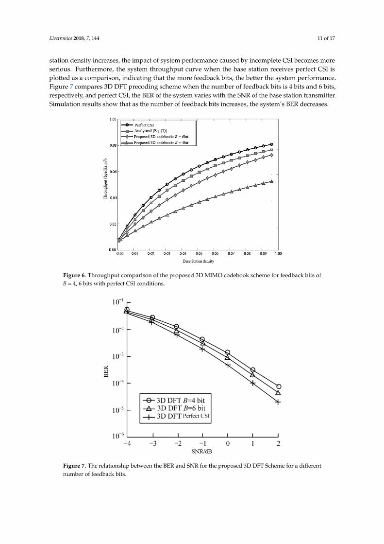
Figure 6 shows how the network throughput varies with the base station density. The proposed3D MIMO codebook scheme is compared with perfect CSI condition for feedback bits of 4 and 6respectively. The simulation results are consistent with the analysis results. As the base station densityincreases, the throughput gradually increases. It can be seen that proper adjustment of the base stationdensity can increase system throughput and optimize system performance. Moreover, as the base
Electronics 2018, 7, 144 11 of 17
station density increases, the impact of system performance caused by incomplete CSI becomes moreserious. Furthermore, the system throughput curve when the base station receives perfect CSI isplotted as a comparison, indicating that the more feedback bits, the better the system performance.Figure 7 compares 3D DFT precoding scheme when the number of feedback bits is 4 bits and 6 bits,respectively, and perfect CSI, the BER of the system varies with the SNR of the base station transmitter.Simulation results show that as the number of feedback bits increases, the system’s BER decreases.Electronics 2018, 7, x FOR PEER REVIEW 11 of 17
Figure 6. Throughput comparison of the proposed 3D MIMO codebook scheme for feedback bits of B = 4, 6 bits with perfect CSI conditions.
Figure 7. The relationship between the BER and SNR for the proposed 3D DFT Scheme for a different number of feedback bits.
Figure 8 compares the use of DFT precoding schemes in 2D and 3D environments, respectively, under the BER, and in the 3D-MIMO channel model, the performance difference between the improved precoding scheme and the DFT precoding scheme proposed in this paper in terms of system BET. The traditional DFT precoding scheme is not suitable for vertical dimension codebooks in a 3D environment in which the base station employs both planar and planar antenna arrays due to the problem of adjustable dynamic range and vertical distribution of the vertical dip and tilt angle,
Figure 6. Throughput comparison of the proposed 3D MIMO codebook scheme for feedback bits ofB = 4, 6 bits with perfect CSI conditions.
Electronics 2018, 7, x FOR PEER REVIEW 11 of 17
Figure 6. Throughput comparison of the proposed 3D MIMO codebook scheme for feedback bits of B = 4, 6 bits with perfect CSI conditions.
Figure 7. The relationship between the BER and SNR for the proposed 3D DFT Scheme for a different number of feedback bits.
Figure 8 compares the use of DFT precoding schemes in 2D and 3D environments, respectively, under the BER, and in the 3D-MIMO channel model, the performance difference between the improved precoding scheme and the DFT precoding scheme proposed in this paper in terms of system BET. The traditional DFT precoding scheme is not suitable for vertical dimension codebooks in a 3D environment in which the base station employs both planar and planar antenna arrays due to the problem of adjustable dynamic range and vertical distribution of the vertical dip and tilt angle,
Figure 7. The relationship between the BER and SNR for the proposed 3D DFT Scheme for a differentnumber of feedback bits.

Electronics 2018, 7, 144 12 of 17
Figure 8 compares the use of DFT precoding schemes in 2D and 3D environments, respectively,under the BER, and in the 3D-MIMO channel model, the performance difference between the improvedprecoding scheme and the DFT precoding scheme proposed in this paper in terms of system BET.The traditional DFT precoding scheme is not suitable for vertical dimension codebooks in a 3Denvironment in which the base station employs both planar and planar antenna arrays due to theproblem of adjustable dynamic range and vertical distribution of the vertical dip and tilt angle, andthis paper considers horizontal emission jointly. The 3D codebook is constructed by angle and verticaldown-tilt, so the performance of the improved precoding scheme proposed in this paper is better.
Electronics 2018, 7, x FOR PEER REVIEW 12 of 17
and this paper considers horizontal emission jointly. The 3D codebook is constructed by angle and vertical down-tilt, so the performance of the improved precoding scheme proposed in this paper is better.
Figure 8. The relationship between the BER and SNR for the proposed precoding scheme and other schemes.
Figure 9 shows the Cumulative Distribution Function (CDF) curves for different codebook schemes. It can be seen from the simulation results that the 3D DFT precoding scheme can effectively improve the system throughput compared to the 2D DFT precoding scheme because it fully utilizes the vertical dimension of the UPA array. The improved 3D precoding scheme proposed in this paper jointly considers the horizontal adjustable range and the vertical down-tilt adjustable range, and considers the specific location of the antenna array elements rather than the UPA array as a whole, so it is more effective. The proposed codebook scheme controls inter-user interference at the edge of the cell to significantly increase system throughput.
Figure 10 compares the spectral efficiency (SE) versus SNR of the proposed 3D codebook scheme with other state-of-the-art codebook schemes. As can be seen from Figure 10 that the proposed 3D codebook scheme outperforms the other codebook schemes which show its superior performance over other codebooks schemes. Moreover, the rate gap between the proposed scheme and other schemes increases with increasing SNR which means that the proposed 3D codebook scheme shows better SE performance in low as well as high SNR level. Such results cover the real-world aspect of the MIMO system deployment where the SNR changes due to certain channel impairments and there is a need for a flexible and robust codebook scheme which should provide better service in wireless communications systems.
Figure 11 shows the impact of the inter-cell interference on the system using different codebook schemes. As can be seen from the Figure 11, when the number of users increases, the interference from different cells increases which causes communication interruption. Moreover, the proposed 3D codebook scheme shows have lowest Inter-Cell Interference (ICI) level which is much better as compared with those of previous papers [24,25] and 2D DFT schemes. Therefore, the proposed 3D codebook scheme also shows better ICI performance which obviously makes it an attractive candidate to deploy in real-world application scenarios.
Figure 8. The relationship between the BER and SNR for the proposed precoding scheme andother schemes.
Figure 9 shows the Cumulative Distribution Function (CDF) curves for different codebookschemes. It can be seen from the simulation results that the 3D DFT precoding scheme can effectivelyimprove the system throughput compared to the 2D DFT precoding scheme because it fully utilizes thevertical dimension of the UPA array. The improved 3D precoding scheme proposed in this paper jointlyconsiders the horizontal adjustable range and the vertical down-tilt adjustable range, and considersthe specific location of the antenna array elements rather than the UPA array as a whole, so it is moreeffective. The proposed codebook scheme controls inter-user interference at the edge of the cell tosignificantly increase system throughput.
Figure 10 compares the spectral efficiency (SE) versus SNR of the proposed 3D codebook schemewith other state-of-the-art codebook schemes. As can be seen from Figure 10 that the proposed 3Dcodebook scheme outperforms the other codebook schemes which show its superior performance overother codebooks schemes. Moreover, the rate gap between the proposed scheme and other schemesincreases with increasing SNR which means that the proposed 3D codebook scheme shows betterSE performance in low as well as high SNR level. Such results cover the real-world aspect of theMIMO system deployment where the SNR changes due to certain channel impairments and thereis a need for a flexible and robust codebook scheme which should provide better service in wirelesscommunications systems.
Figure 11 shows the impact of the inter-cell interference on the system using different codebookschemes. As can be seen from the Figure 11, when the number of users increases, the interferencefrom different cells increases which causes communication interruption. Moreover, the proposed3D codebook scheme shows have lowest Inter-Cell Interference (ICI) level which is much better as

Electronics 2018, 7, 144 13 of 17
compared with those of previous papers [24,25] and 2D DFT schemes. Therefore, the proposed 3Dcodebook scheme also shows better ICI performance which obviously makes it an attractive candidateto deploy in real-world application scenarios.Electronics 2018, 7, x FOR PEER REVIEW 13 of 17
Figure 9. The CDF of different precoding schemes versus throughput.
Figure 10. Spectral efficiency comparison versus SNR for the proposed 3D codebook scheme with other state-of-the-art schemes.
Figure 9. The CDF of different precoding schemes versus throughput.
Electronics 2018, 7, x FOR PEER REVIEW 13 of 17
Figure 9. The CDF of different precoding schemes versus throughput.
Figure 10. Spectral efficiency comparison versus SNR for the proposed 3D codebook scheme with other state-of-the-art schemes.
Figure 10. Spectral efficiency comparison versus SNR for the proposed 3D codebook scheme withother state-of-the-art schemes.

Electronics 2018, 7, 144 14 of 17Electronics 2018, 7, x FOR PEER REVIEW 14 of 17
Figure 11. Comparison of the inter-cell interference versus a number of users for the proposed 3D codebook and other state-of-the-art schemes.
Figure 12 compares a number of feedback bits required versus the number of users for the proposed 3D MIMO codebook and other state-of-the-art schemes. It is clear from the results that the proposed scheme shows efficient performance as it requires a smaller number of feedback bits for channel estimation whereas the other codebook schemes require large number feedback bits which indicates that such schemes have large feedback overhead. Therefore, such comparison proves that the proposed 3D MIMO codebook scheme is also cost-effective as we know that feedback bits directly impact the system implementation cost, thus the proposed scheme is time-efficient and cost-efficient.
Figure 12. Comparison of feedback bits versus the number of users for the proposed 3D codebook scheme and other state-of-the-art schemes.
Figure 11. Comparison of the inter-cell interference versus a number of users for the proposed 3Dcodebook and other state-of-the-art schemes.
Figure 12 compares a number of feedback bits required versus the number of users for theproposed 3D MIMO codebook and other state-of-the-art schemes. It is clear from the results that theproposed scheme shows efficient performance as it requires a smaller number of feedback bits forchannel estimation whereas the other codebook schemes require large number feedback bits whichindicates that such schemes have large feedback overhead. Therefore, such comparison proves thatthe proposed 3D MIMO codebook scheme is also cost-effective as we know that feedback bits directlyimpact the system implementation cost, thus the proposed scheme is time-efficient and cost-efficient.
Electronics 2018, 7, x FOR PEER REVIEW 14 of 17
Figure 11. Comparison of the inter-cell interference versus a number of users for the proposed 3D codebook and other state-of-the-art schemes.
Figure 12 compares a number of feedback bits required versus the number of users for the proposed 3D MIMO codebook and other state-of-the-art schemes. It is clear from the results that the proposed scheme shows efficient performance as it requires a smaller number of feedback bits for channel estimation whereas the other codebook schemes require large number feedback bits which indicates that such schemes have large feedback overhead. Therefore, such comparison proves that the proposed 3D MIMO codebook scheme is also cost-effective as we know that feedback bits directly impact the system implementation cost, thus the proposed scheme is time-efficient and cost-efficient.
Figure 12. Comparison of feedback bits versus the number of users for the proposed 3D codebook scheme and other state-of-the-art schemes.
Figure 12. Comparison of feedback bits versus the number of users for the proposed 3D codebookscheme and other state-of-the-art schemes.

Electronics 2018, 7, 144 15 of 17
Figure 13 compares the spectral efficiency of the proposed 3D MIMO codebook scheme against thenumber antennas (Nv) and compares it with other schemes. As can be seen from Figure 13, when thenumber of antennas increases, the spectral efficiency increases for all codebook schemes. Furthermore,the proposed 3D DFT codebook scheme shows better performance than 2D and 3D DFT [11] codebookschemes. It is worth notable from the results that the proposed codebook scheme shows nearly optimalSE performance as its curve is closer to the ideal CSI performance. Therefore, such results show thatthe proposed codebook scheme have efficient performance in case of a large number of antennas.
Electronics 2018, 7, x FOR PEER REVIEW 15 of 17
Figure 13 compares the spectral efficiency of the proposed 3D MIMO codebook scheme against the number antennas (Nv) and compares it with other schemes. As can be seen from Figure 13, when the number of antennas increases, the spectral efficiency increases for all codebook schemes. Furthermore, the proposed 3D DFT codebook scheme shows better performance than 2D and 3D DFT [11] codebook schemes. It is worth notable from the results that the proposed codebook scheme shows nearly optimal SE performance as its curve is closer to the ideal CSI performance. Therefore, such results show that the proposed codebook scheme have efficient performance in case of a large number of antennas.
Figure 13. Spectral efficiency comparison against the number of antennas for the proposed 3D MIMO codebook scheme with other schemes.
7. Conclusions
This paper constructs a multi-user 3D-MIMO heterogeneous network system model. Through finite feedback quantization error analysis, according to the quantization error and statistical characteristics of the random distribution of the system, the influence of feedback overhead and base station density on system performance is analyzed using stochastic geometry technology. Based on the traditional precoding scheme, an improved 3D precoding scheme based on horizontal emission angle and vertical down-tilt is proposed. Through simulation analysis, the influence of feedback overhead on system throughput was compared, and the effects of traditional DFT precoding methods in 2D and 3D environments and improved 3D precoding schemes on system BER and throughput were compared. The simulation results show that the feedback overhead will reduce the system throughput and improve the system BER, while the improved precoding scheme due to the joint consideration of the horizontal emission angle and vertical down-tilt, thus effectively improving the system throughput and reducing the system BER, optimized system performance. Future work in this research is to incorporate mmWave with 3D-MIMO in order to utilize it underutilized bandwidth which ranges from 30–300 GHz. Also, various other important parameters such as Energy Efficiency and Normalized Mean Square Error (NMSE) can be analyzed in different deployment scenarios.
Author Contributions: M.A. provides extensive support in the overall research; I.K. conceived and designed the presented idea and developed the theory, performed the simulations, and wrote the paper; J.L. verified the
Figure 13. Spectral efficiency comparison against the number of antennas for the proposed 3D MIMOcodebook scheme with other schemes.
7. Conclusions
This paper constructs a multi-user 3D-MIMO heterogeneous network system model.Through finite feedback quantization error analysis, according to the quantization error and statisticalcharacteristics of the random distribution of the system, the influence of feedback overhead and basestation density on system performance is analyzed using stochastic geometry technology. Based on thetraditional precoding scheme, an improved 3D precoding scheme based on horizontal emission angleand vertical down-tilt is proposed. Through simulation analysis, the influence of feedback overheadon system throughput was compared, and the effects of traditional DFT precoding methods in 2Dand 3D environments and improved 3D precoding schemes on system BER and throughput werecompared. The simulation results show that the feedback overhead will reduce the system throughputand improve the system BER, while the improved precoding scheme due to the joint consideration ofthe horizontal emission angle and vertical down-tilt, thus effectively improving the system throughputand reducing the system BER, optimized system performance. Future work in this research is toincorporate mmWave with 3D-MIMO in order to utilize it underutilized bandwidth which ranges from30–300 GHz. Also, various other important parameters such as Energy Efficiency and NormalizedMean Square Error (NMSE) can be analyzed in different deployment scenarios.

Electronics 2018, 7, 144 16 of 17
Author Contributions: M.A. provides extensive support in the overall research; I.K. conceived and designedthe presented idea and developed the theory, performed the simulations, and wrote the paper; J.L. verified theanalytical methods and encouraged to investigate various relevant aspects of the proposed research; I.B. providedcritical feedback and helped shape the research, analysis, and manuscript. All authors discussed the results andcontributed to the final manuscript.
Acknowledgments: This work has been partially supported by the “Ministerio de Economía y Competitividad”in the “Programa Estatal de Fomento de la Investigación Científica y Técnica de Excelencia, Subprograma Estatalde Generación de Conocimiento” within the project under Grant BIA2017-87573-C2-2-P.
Conflicts of Interest: The authors declare no conflicts of interest.
References
1. Khan, I. A Robust Signal Detection Scheme for 5G Massive Multiuser MIMO Systems. IEEE Trans. Veh. Technol.2018. [CrossRef]
2. Gesbert, D.; Kountouris, M.; Heath, R.W. Shifting the MIMO Paradigm: From Single User to MultiuserCommunications. IEEE Signal. Process. Mag. 2007, 24, 36–46. [CrossRef]
3. Liu, G.; Hou, X.; Wang, F.; Jin, J.; Tong, H.; Huang, Y. Achieving 3D-MIMO With Massive Antennas fromTheory to Practice With Evaluation and Field Trial Results. IEEE Syst. J. 2016, 11, 62–71. [CrossRef]
4. Ngo, H.Q.; Marzetta, T.L.; Larsson, E.G. Analysis of the Pilot Contamination Effect in Very Large MulticellMultiuser MIMO Systems for Physical Channel Models. In Proceedings of the IEEE International Conferenceon Acoustics, Speech and Signal Processing, Prague, Czech Republic, 22–27 May 2011; pp. 3464–3467.
5. Lu, X.; Tolli, A.; Piirainen, O.; Juntti, M.; Li, W. Comparison of Antenna Arrays in a 3-D Multiuser MulticellNetwork. In Proceedings of the 2011 IEEE International Conference on Communications, Kyoto, Japan,5–9 June 2011; pp. 1–6.
6. Ng, B.L.; Kim, Y.; Lee, J.; Li, Y.; Nam, Y.-H.; Zhang, J.; Sayana, K. Fulfilling the Promise of Massive MIMOwith 2D Active Antenna Array. In Proceedings of the 2012 IEEE Globecom Workshops, Anaheim, CA, USA,3–7 December 2012; pp. 691–696.
7. Nadeem, Q.-U.-A.; Kammoun, A.; Debbah, M.; Alouini, M.-S. 3D Massive MIMO Systems: Modeling andPerformance Analysis. IEEE Trans. Wirel. Commun. 2015, 14, 6926–6939. [CrossRef]
8. Li, X.; Jin, S.; Suraweera, H.A.; Hou, J.; Gao, X. Statistical 3-D Beamforming for Large-Scale MIMO DownlinkSystems Over Rician Fading Channels. IEEE Trans. Commun. 2016, 64, 1529–1543. [CrossRef]
9. Khan, I.; Zafar, M.H.; Jan, M.T.; Lloret, J.; Basheri, M.; Singh, D. Spectral and Energy Efficient Low-OverheadUplink and Downlink Channel Estimation for 5G Massive MIMO Systems. Entropy 2018, 20, 92. [CrossRef]
10. Khan, I.; Singh, D. Efficient Compressive Sensing Based Sparse Channel Estimation for 5G Massive MIMOSystems. AEUE Int. J. Electron. Commun. 2018, 89, 181–190. [CrossRef]
11. Xie, Y.; Jin, S.; Wang, J.; Zhu, Y.; Gao, X.; Huang, Y. A Limited Feedback Scheme for 3D Multiuser MIMOBased on Kronecker Product Codebook. In Proceedings of the IEEE 24th Annual International Symposiumon Personal, Indoor, and Mobile Radio Communications, London, UK, 8−11 September 2013; pp. 1130–1135.
12. Khan, I.; Singh, M.; Singh, D. Compressive Sensing Based Sparsity Adaptive Channel Estimation for 5GMassive MIMO Systems. Appl. Sci. 2018, 8, 754. [CrossRef]
13. Halbauer, H.; Saur, S.; Koppenborg, J.; Hoek, C. 3D Beamforming: Performance Improvement for CellularNetworks. Bell Lab. Tech. J. 2013, 18, 37–56. [CrossRef]
14. Ogawa, S.; Nishimori, K.; Taniguchi, R.; Mitsui, T.; Hiraguri, T. Performance Evaluation of DownlinkMulti-Beam Massive MIMO with Simple Transmission Scheme at Both Base and Terminal Stations. Electronics2017, 6, 100. [CrossRef]
15. Han, Y.; Jin, X.; Huang, Y.; Jiang, L.; Wang, G. Design of double codebook based on 3D dual-polarizedchannel for multiuser MIMO system. EURASIP J. Adv. Signal. Process. 2014. [CrossRef]
16. Xu, Y.; Xia, X.; Xu, K.; Wang, Y. Three-Dimension Massive MIMO for Air-to-Ground Transmission:Location-Assisted Precoding and Impact of AoD Uncertainty. IEEE Access. 2017, 5, 15582–15596. [CrossRef]
17. Cheng, X.; Yu, B.; Yang, L.; Zhang, J.; Liu, G.; Wu, Y.; Wan, L. Communicating in the real world: 3D MIMO.IEEE Wirel. Commun. 2014, 21, 136–144. [CrossRef]
18. Xu, Z.; Yang, C.; Li, G.Y.; Liu, Y.; Xu, S. Energy-efficient CoMP Precoding in Heterogeneous Networks.IEEE Trans. Signal. Process. 2014, 62, 1005–1017. [CrossRef]

Electronics 2018, 7, 144 17 of 17
19. Kountours, M.; Andrews, J.G. Downlink SDMA with Limited Feedback in Interference-limited WirelessNetworks. IEEE Trans. Wirel. Commun. 2012, 11, 2730–2741. [CrossRef]
20. Love, D.J.; Heath, R.W.; Lau, V.K.N.; Gesbert, D.; Rao, B.D.; Andrews, M. An overview of limited feedback inwireless communication systems. IEEE J. Sel. Areas Commun. 2008, 26. [CrossRef]
21. Zhong, Z.; Peng, J.; Luo, W.; Huang, K. A Tractable Approach to Analyzing the Physical-layer Security inK-tier Heterogeneous Cellular Networks. China Commun. 2015, 12, 166–173. [CrossRef]
22. Li, W.; Wang, T.; Lan, X. Codebook Based Beamforming in MIMO Broadcast Channels with Finite RateFeedback. In Proceedings of the 1st International Conference on Information Science and Engineering,New York, NY, USA, 26–28 December 2009; pp. 2582–2585.
23. Zhang, J.; Heath, R.W.; Kountouris, M.; Andrews, J.F. Mode Switching for the multi-antenna BroadcastChannel Based on Delay and Channel Quantization. EURASIP J. Adv. Signal. Process. 2009, 1, 1–15.[CrossRef]
24. Wang, Z.; Liu, W.; Qian, C.; Chen, S.; Hanzo, L. Two-Dimensional Precoding for 3-D Massive MIMO.IEEE Trans. Veh. Technol. 2016, 66, 5485–5490. [CrossRef]
25. Li, X.; Zhao, H.; Zhao, L.; Zhao, W.; Zheng, S. Transmission Scheme with Limited Channel State InformationFeedback for 3D MIMO System. Int. J. Antennas Propag. 2015, 15, 1–12. [CrossRef]
© 2018 by the authors. Licensee MDPI, Basel, Switzerland. This article is an open accessarticle distributed under the terms and conditions of the Creative Commons Attribution(CC BY) license (http://creativecommons.org/licenses/by/4.0/).