5G scheduling algorithm for capacity improvement using ...
14
Journal of Engineering Science and Technology Vol. 16, No. 3 (2021) 1977 - 1990 © School of Engineering, Taylor’s University 1977 5G SCHEDULING ALGORITHM FOR CAPACITY IMPROVEMENT USING BEAM DIVISION AT CONGESTED TRAFFIC MAHMOD A. AL_ZUBAIDY 1 , ALI OTHMAN AL JANABY 1, *, SIDDEEQ Y. AMEEN 2 1 College of Electronics Engineering, Ninevah University, Mosul, Iraq 2 Quality Assurance Advisor, Duhok Polytechnique University, Duhok, Iraq *Corresponding Author: [email protected] Abstract With the increased access of Users Equipment’s (UE)s during congested or full load traffic, the existed beams for each base station (BS) will be less than the number of active (UE)s. At this challenging condition, it is essential to create additional beams to serve those (UE)s. In this paper, at congested traffic only, a beam assigned to any UE will be divided to serve the existing UE and the new UE. The division scheme is proposed by dividing any beam into two beams to overcome the beam leakage in the BSs when more (UE)s access the cell. The proposed new scheme will help to serve more than one adjacent or closest UE. The proposed scheme is implemented with the Vienna link-level (LL) and system-level (SL) simulators for the 5G networks. The simulation assessment shows that the new scheme performs, beam division, better than the state provides network improved fairness together with throughput increase by 50% than the state before beam division. Although the UE's throughput will be maintained constant or decreased, the cell capacity and system fairness are improved, and the network will serve additional (UE)s especially (UE)s at congestion and who attend the cell immediately. Also, for (UE)s moving at 75 km/h, which depicts that the throughput decreases as the velocity increased. Keywords: 5G, Beam division, Congested traffic, Massive MIMO, Resource allocation, System-level, (UE)s.
-
Upload
khangminh22 -
Category
Documents
-
view
1 -
download
0
Transcript of 5G scheduling algorithm for capacity improvement using ...

Journal of Engineering Science and Technology Vol. 16, No. 3 (2021) 1977 - 1990 © School of Engineering, Taylor’s University
1977
5G SCHEDULING ALGORITHM FOR CAPACITY IMPROVEMENT USING BEAM DIVISION AT CONGESTED TRAFFIC
MAHMOD A. AL_ZUBAIDY1, ALI OTHMAN AL JANABY1,*, SIDDEEQ Y. AMEEN2
1College of Electronics Engineering, Ninevah University, Mosul, Iraq 2Quality Assurance Advisor, Duhok Polytechnique University, Duhok, Iraq
*Corresponding Author: [email protected]
Abstract
With the increased access of Users Equipment’s (UE)s during congested or full load traffic, the existed beams for each base station (BS) will be less than the number of active (UE)s. At this challenging condition, it is essential to create additional beams to serve those (UE)s. In this paper, at congested traffic only, a beam assigned to any UE will be divided to serve the existing UE and the new UE. The division scheme is proposed by dividing any beam into two beams to overcome the beam leakage in the BSs when more (UE)s access the cell. The proposed new scheme will help to serve more than one adjacent or closest UE. The proposed scheme is implemented with the Vienna link-level (LL) and system-level (SL) simulators for the 5G networks. The simulation assessment shows that the new scheme performs, beam division, better than the state provides network improved fairness together with throughput increase by 50% than the state before beam division. Although the UE's throughput will be maintained constant or decreased, the cell capacity and system fairness are improved, and the network will serve additional (UE)s especially (UE)s at congestion and who attend the cell immediately. Also, for (UE)s moving at 75 km/h, which depicts that the throughput decreases as the velocity increased.
Keywords: 5G, Beam division, Congested traffic, Massive MIMO, Resource allocation, System-level, (UE)s.
1978 M. A. Al_Zubaidy et al.
Journal of Engineering Science and Technology June 2021, Vol. 16(3)
1. Introduction In recent cellular systems, the number of Users Equipment (UE)s is increasing vastly although the number of antennas equipped in the base station (BS) is increased. Multi-Users (MU) Multiple-input and multiple-output (MIMO) is one of the main vital technologies for the long-term evolution-advanced (LTE-A) system. MU-MIMO is a technology for wireless and cellular communication, in which a set of (UE)s, communicates to the BS to enhance the UE throughput [1]. Massive MIMO techniques are MU-MIMO systems using a huge number of antenna elements per BS at the downlink transmission. More antennas will focus their signal transmission into a huge number of narrow parallel beams to provide an improvement to the UE throughput [2]. So, it is the technique that increases the spectral efficiency (SE) of the wireless networks, by deploying antennas with a huge number of active elements at the eNBs to perform coherent receiver processing [3]. A massive MIMO technique enhances UE's throughput, as well as all SM schemes, enhances the network throughput [4, 5]. The Massive MIMO technique brings (UE)s throughput improvement by accumulating the spectral efficiency (SE) when using the shared BW with the SBSs deployment compared to LTE-MIMO technique [1, 6]. To decrease the feedback overhead, the massive MIMO systems utilize a determinate precoding matrix indicator (PMI) codebook (CB) [7]. In MU-MIMO systems, many (UE)s are instantaneously scheduled on the shared time-frequency resources, though, multiple CBs that diminish the multi-user interferences necessity be reported to avoid throughput degradation caused by interference [7].
5G networks use six main technologies. Massive MIMO is considered as one of these technologies used for 5G systems because it provides a huge number of antennas, each transmits a beam for each UE, to improve the system capacity by enabling the number of sub-carriers and sub-channels [2]. 5G BSs use massive MIMO, equipped with a few hundred antennas array that simultaneously serves an equal or a smaller number of the wireless devices, (UE)s as well as the huge number of device-to-device (D2D) service [2]. The massive MIMO technique provides a high-gain antenna with beamforming technique assigns each device or UE a single beam to ensure continuous communication to the BS with the required quality of service (QoS) compared to the similar bandwidth (BW) arrangement of the BS compared to LTE MIMO technique [3]. If the 5G applied the earlier (former) LTE scheduling algorithm concepts in the Massive MIMO system, with few hundreds of (UE)s at each of the available sub-channels, the receiver difficulty could be enormous, and the digital signal processing (DSP) circuits will be very expensive. With the use of the massive MIMO technique, each BS should be equipped with spatial multiplexing (SM) scheme that reduces the complexity [2]. Every Transmission Time Interval (TTI), the system assigns a single narrow beam to each UE [3].
Another recent technology used with 5G is the small cell base station technology. The new base station is called the small base station (SBS). The transmitted power will be very low compared to the 4G LTE system. The power compared to the former cellular system, the LTE will be distributed into a huge number of beams while in LTE, the number of high-power beams is very low.
Beamforming is a new technology, also, used with a 5G system. To perform beamforming at the downlink transmission with the massive MIMO systems, the BS, at the downlink, requires the channel state information (CSI). The main
5G Scheduling Algorithm for Capacity Improvement using Beam Division . . . . 1979
Journal of Engineering Science and Technology June 2021, Vol. 16(3)
influence of the beamforming scheme will expand the detected signal-to-noise ratio (SNR) and, finally, improve network capacity, especially when the number of antennas, at the BS, more than the mobile devices [5].
The motivation in this research is when the accessed (UE)s and the wireless devices are larger in number than the number of the antennas or the radio beams, the paper proposes to use the Beam Division Multiple Access (BDMA) to divide any beam. This will be used especially when the new UE near the existing UE or very close, to split the assigned beam into two beams if the system suffering from full traffic or when the number of (UE)s and devices more than the radio beams. When beam division is used, this means each antenna will serve two UE. This will affect the power of each antenna. For this reason, we propose that the UEs are adjacent and near to the BS. BDMA scheme [8] has been developed to improve the capacity of the network and to handle more (UE)s in 5G networks but did not propose to overcome the crises of the full traffic. Compared to the BDMA and MU-MIMO, the proposed idea is novel in the uses of beam division and the share of the divided beam to deal with more accessed (UE)s. The BDMA technique serves many users simultaneously by focusing the antenna beam towards the position of the (UE)s thereby giving numerous accesses to (UE)s and hence increasing the capacity of the system significantly [5, 9]. Each antenna beam is steered to the desired direction depending on the traffic environment with nulls placement in the undesired direction [5]. On the other hand, although BDMA is a new technique utilized to increase the capacity of the system, it has a drawback that the base station needs to install more antennas and its receiver must involve a complex DSP system [10].
An efficient method to enhance the SE of any wireless system is to use massive beams illuminations from the BS towards the (UE)s as depicted in Fig. 1. In this scheme, the number of active antennas must greater than the number of connected (UE)s. This will reduce the DSP and receiver complexity [11]. Another article assessed the influence of spatially multiplexing additional (UE)s within the massive MIMO system. They showed that the maximum summation of SE with the applied number of antenna elements would be achieved by decreasing the number of (UE)s before the summation of SE got its peak value. The recent one presented a measurement set-up for massive MIMO channel sounding showed good long-term phase stability [12]. Finally, various beamforming schemes for MIMO non-orthogonal multiple access (NOMA) scheme were developed [13]. Then, fairness-based beamforming approaches are proposed through a max-min formulation to maintain fairness between (UE)s [13]. Compared to this paper congestion problem overcome, our paper proposes an adaptive beam splitting to deal with the congestion problem.
Fig. 1. The downlink transmission in massive MIMO.
1980 M. A. Al_Zubaidy et al.
Journal of Engineering Science and Technology June 2021, Vol. 16(3)
This paper presents a new idea to overcome immediately the increased number of (UE)s access the cell by beam division, from a single beam to double beams. The paper contribution can be clarified as follows: when the traffic is congested or the network at full load, the network determines the number of (UE)s accessing the SBSs, if the number more than the number of beams, the SBS switches to the beam division state. This means that every single beam will serve more than (UE)s to produce two or more beams according to BDMA. When beam division is used, this means each antenna will serve two UE. This will affect the power of each antenna. For this reason, we propose that the UEs are adjacent and near to the BS. Moreover, compared to previous research [5], the power allocation algorithms for BDMA in multi-cell massive MIMO communication have been investigated. Researchers have focused on massive MIMO downlink only with statistical channel state information at the BS. They identified the orthogonality conditions for optimal power allocation only. Thus, it is worth searching for new methods to overcome the congestion problem. These methods need to be simulated to show how the proposed scheme enhancement in network capacity.
The paper will be systematized as follows; Section 2 presents beam division multiple access technologies. Section 3 presented the proposed new system, modeling, simulation together with the evaluation results. Finally, section 4 will conclude the simulation assessment.
2. Beam Division Multiple Access Technology
2.1. Beam division multiple access The beam division multiple access (BDMA) approach has been developed to increase the wireless system capacity and to provide access for a large number of (UE)s in 5G networks [8]. The proposed method serves multiple (UE)s by different beams simultaneously. This method diminishes the overhead of sub-channel vector estimation, reduces the receiver circuit and DSP complexity. Recent wireless communications systems utilize many division techniques, as time, frequency, and code division multiple access (CDMA) for time, frequency, and code sharing. But the time and frequency division among multiple (UE)s suffering from the increased number of (UE)s. (UE)s handover from one BS to the others results in dropped calls [8].
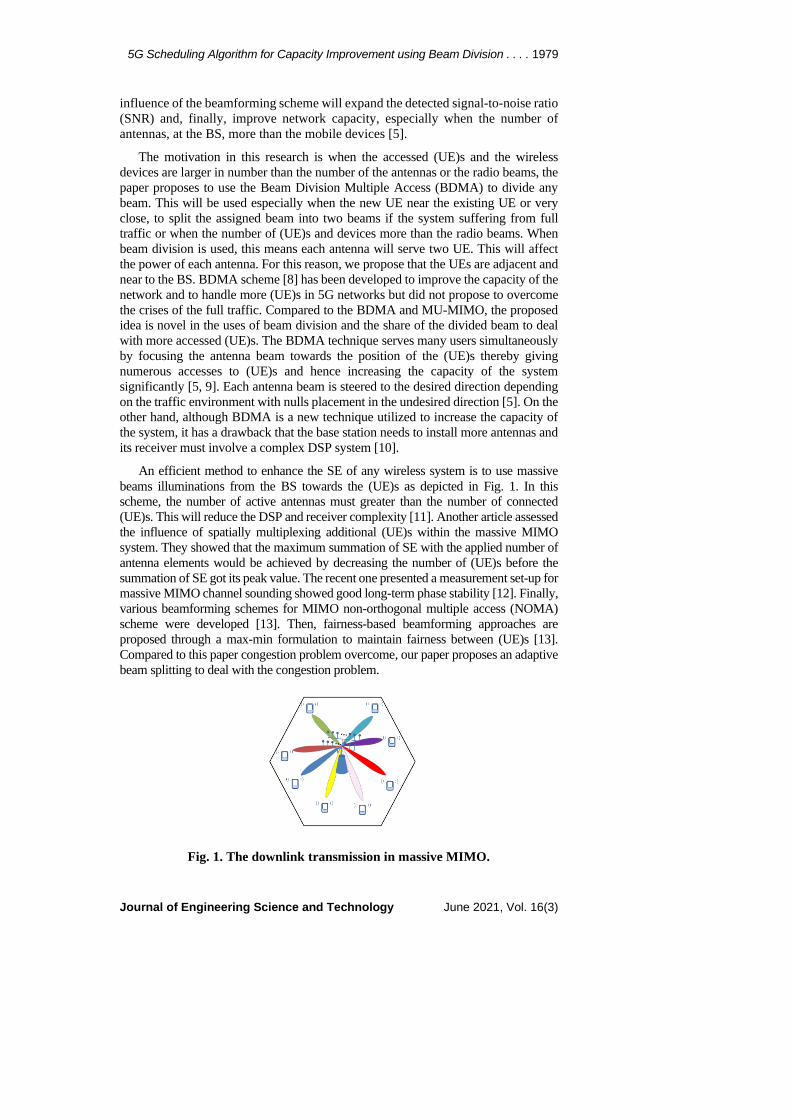
Recently, the BDMA scheme overcomes the problem of BW efficiency and capacity. Also, BDMA diminishes the SNR deterioration for the edge (UE)s. In BDMA technology, the BS assigns a single antenna beam to each UE. This would be done after estimation of (UE)s position as well as determining their moving speeds, then deciding widths and directions of beams for (UE)s with respect to the BS. (UE)s are communicating with BS when these are in line-of-sight (LoS). Thus, simultaneous data transmission is possible to different mobile (UE)s at different positions and angles [8] as shown in Fig. 2. To support a greater number of (UE)s, the beam should be divided. Mobile (UE)s located at similar angles can share one beam to communicate with the BS using TDMA.
2.2. Beamforming technique Beamforming technique is a technique that focuses the signal in a beam towards a specific receiving UE, rather than having the signal spread in all directions from a transmission antenna. The resulting more direct link is faster and more reliable than it
5G Scheduling Algorithm for Capacity Improvement using Beam Division . . . . 1981
Journal of Engineering Science and Technology June 2021, Vol. 16(3)
would be without beamforming with reduced power [14]. Beamforming methods can be characterized as follows [14]:
• Zero-forcing precoding for beamforming, which is an intuitive method for secured transmission and is done by sending the beam orthogonally to the UE [14].
• Generalized Singular Value Decomposition-based beamforming (GSVD); which is a precoding scheme utilized for security purposes in MIMO and Broadcast Channel (BC) and multicast channel.
• Convex optimization-based precoding; is an arithmetical solution based on convex optimization which has also been developed to compute a transmit covariance matrix for the secrecy capacity maximization in massive MIMO channels.
Fig. 2. Beam-division multiple-access.
In the mobile communication performance enhancement, researchers developed schemes conducting beamforming and massive MIMO techniques. In one of these research, a joint design of beamforming and power allocation for the MU-MIMO NOMA network was proposed [15, 16]. In this design, the BS coordinated multipoint for the downlink transmission. Other researchers studied scenarios where the (UE)s are grouped according to their SINR and QoS requirements, rather than their channel states.
With these performance improvements, a beam selection approach was proposed that exploits the geometric sparsity of the MU massive MIMO channel, using its beam space representation [17]. Conversely, others proposed a frequency domain back-off scheme dedicated to continuous beamforming space division multiple access (CB-SDMA) on massive antenna systems for wireless entrance [18].
3. The Proposed Scheme at Congested Traffic 5G BS uses massive MIMO, equipped with a hundred or more than antennas array that simultaneously serves an equal or a smaller number of the (UE)s allocated in the cell moving at different mobility. Most of the studies are assuming the number of (UE)s is less than the BS antennas and the target was to enhance the UE throughput by beam consolidation [4]. However, the challenge considered in the research is when the number of (UE)s and the D2D devices are more than the BS antennas. Thus, the paper proposes a scheme to divide a single beam into two beams

1982 M. A. Al_Zubaidy et al.
Journal of Engineering Science and Technology June 2021, Vol. 16(3)
when the number of (UE)s becomes more than the antenna. The idea is to divide a massive MU channel (beam) into two small dimensional single-user (SU) channels. The BDMA scheme with the beam-domain and consists of the subsequent steps: Acquiring channel coupling matrices (CCMs); Scheduling (UE)s and beams; Transmitting pilot and packets in the uplink and downlink.
In the proposed system scheme, a single BS is composed of six sectors. Each sector serving many (UE)s distributed, in a random manner, in the cell moving at different mobility and direction. Each sector is supposed to be equipped with a total number of 512 antenna elements (M=32 and N=16). Regarding the served (UE)s, every UE should provide at evert TTI its channel quality indicator (CQI) at the Uplink to the BS. At the downlink, the BS utilizes massive MIMO techniques where K is the number of connected (UE)s and U is the total number of (UE)s. The BS has equipped with a matrix of antennas in two dimensions, (M, N) antenna elements, arranged in N columns and M rows, respectively.
3.1. The proposed scheme modelling and assumption This paper focuses only on the downlink MU-MIMO system as a proposed model. This model composes of single BS consists of six sectors, each equipped with M antenna elements. Each having U (UE)s moving in the cell as shown in Fig. 3. The proposed system consists of a single BS and many (UE)s moving with random distribution in the cell. As mentioned before, the BS has equipped with a matrix of antennas arranged in two dimensions and uniformly set apart was represented by (M, N), antenna elements, arranged in N columns and M rows, respectively [4].
Denoting an effective channel with all Tx antennas and vertical tilting by H, the UE's received signal for a MU-MIMO scenario can be represented as:
𝑌𝑌 = 𝐻𝐻�𝑥𝑥 + 𝑛𝑛 (1)
Where x is the input signal vector, x= [x1, x2, x3, . . . , xk]T, of rank u, of the input covariance given by∑ = E[xxH] and n denotes the noise with interference included from adjacent BSs. In this paper, we ignore the noise and interference effects.
Now, let U denote a set of (UE)s that will be accessed for MU-MIMO transmission (|U|= u). Furthermore, let wu ϵ Ⱳ and du, u denotes UE (u= 1, …, u, u ϵ U), denote a beamforming vector and a data symbol for a UE, respectively. This paper assumes an equal power distribution to all (UE)s moving in the cell with a transmit power of P, the received signal for the UE is assumed as Eq. (2) and SNR for each UE is represented as Eq. (3).
𝑦𝑦𝑢𝑢 = �𝑃𝑃 𝑘𝑘� . � 𝐻𝐻𝑢𝑢𝑊𝑊𝑢𝑢 𝑑𝑑𝑢𝑢 + ∑𝑗𝑗∈𝑢𝑢Ѵ\𝑢𝑢 𝐻𝐻𝑢𝑢 𝑊𝑊𝑗𝑗 𝑑𝑑𝑗𝑗 � + 𝑛𝑛 (2)
𝑆𝑆𝑆𝑆𝑆𝑆𝑢𝑢 = |𝑔𝑔𝑢𝑢𝐻𝐻𝑢𝑢𝑊𝑊𝑢𝑢|2
𝐾𝐾𝐾𝐾 +𝑢𝑢2 �|𝑔𝑔𝑢𝑢𝐻𝐻𝑢𝑢𝑊𝑊𝑢𝑢|�𝐹𝐹2 (3)
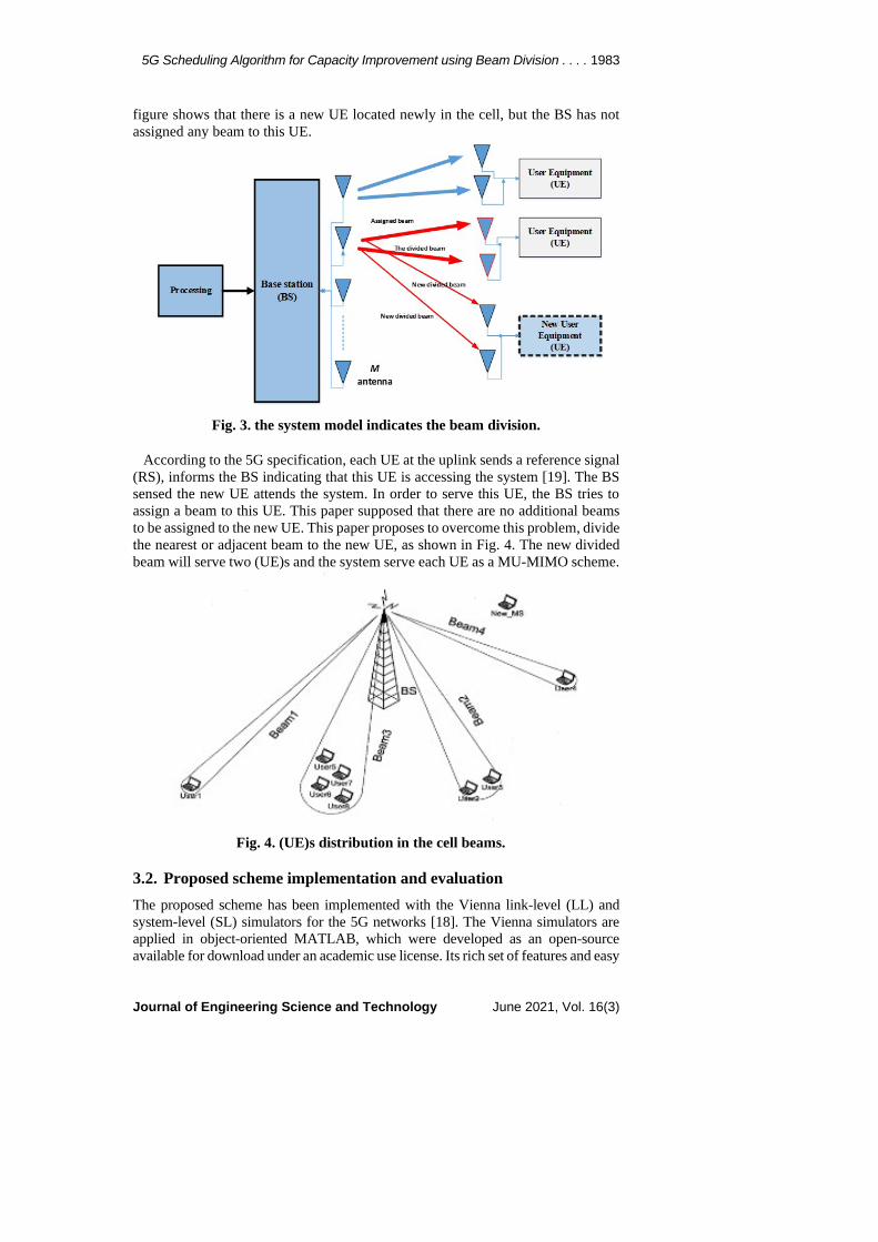
where 𝜎𝜎𝑢𝑢2 = |gu|2 𝜎𝜎𝑢𝑢2 /p, Wu denotes a precoding matrix that excludes the uth precoding vector (Wu=[w1,.wu-1, wu]) and gu is a Minimum Mean Square Error-Interference Rejection Combining (MMSE-IRC) filter used with the 5G receivers. The proposed scheme is applied as an added code to the 5G simulator. The model considers a multi (UE)s positioned randomly, as depicted in Fig. 3. The figure displays many beams, one of them covers four (UE)s, while the other beam covers two (UE)s. Another two beams show that each beam covers a single UE only. The
5G Scheduling Algorithm for Capacity Improvement using Beam Division . . . . 1983
Journal of Engineering Science and Technology June 2021, Vol. 16(3)
figure shows that there is a new UE located newly in the cell, but the BS has not assigned any beam to this UE.
Fig. 3. the system model indicates the beam division.
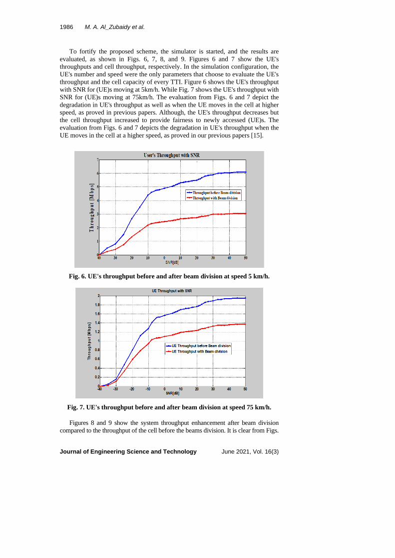
According to the 5G specification, each UE at the uplink sends a reference signal (RS), informs the BS indicating that this UE is accessing the system [19]. The BS sensed the new UE attends the system. In order to serve this UE, the BS tries to assign a beam to this UE. This paper supposed that there are no additional beams to be assigned to the new UE. This paper proposes to overcome this problem, divide the nearest or adjacent beam to the new UE, as shown in Fig. 4. The new divided beam will serve two (UE)s and the system serve each UE as a MU-MIMO scheme.
Fig. 4. (UE)s distribution in the cell beams.
3.2. Proposed scheme implementation and evaluation The proposed scheme has been implemented with the Vienna link-level (LL) and system-level (SL) simulators for the 5G networks [18]. The Vienna simulators are applied in object-oriented MATLAB, which were developed as an open-source available for download under an academic use license. Its rich set of features and easy

1984 M. A. Al_Zubaidy et al.
Journal of Engineering Science and Technology June 2021, Vol. 16(3)
adaptability including huge studies on energy-efficient cell-coordination schemes, handover schemes in self-optimizing networks (SON). The Vienna 5G system simulators consider a wireless network on a large-scale urban area, providing the possibility to simulate the proposed scheme that embraces huge numbers of (UE)s. The simulation steps start by setting the primary and main parameters according to UE and BS standard itemized in Table 1. In more detail, the steps describe the proposed system implementation; Step 1: Implementation of simulation starts with the system parameters initialization; Step 2: Resetting TTI; Step 3: Compare the number of antenna elements M with the number of (UE)s U. For the normal case, the number of M larger than the number of U, the system implements the scheme normally. For the case that the number of U is larger than M, then divide the single beam into double beams; Step 4: Again, check the number of antennas M compared to the number of (UE)s U. For the number of (UE)s U is greater than M, then divide more beams into double beams; Step 5: For U less than M, then assign a beam to each UE and schedule resources as conventional packet scheduling.
Table 1. Simulation assumption for dense urban-eMBB. Parameter Setting Carrier frequency 5.9 GHz Time slot duration 1 millisecond System bandwidth Variable Bandwidth
Number of beams (2D) 512 Subcarrier spacing 15 kHz Transmitted power from BS 43 dBm UE power 23 dBm Inter-site distance 200 meters Traffic model Full buffer UE speed 5, 75 km/h UE density 600 (UE)s Feedback delay 1 TTI Time of simulation 5000 frames
Figure 5 depicts how the single beam will be divided into two beams to create two beams, each having a narrower bandwidth. The division is done at each new UE accessing the cell. In this paper, we propose that every TTI new UE access the cell. The proposed scheme includes other important steps, as indicated in Table 2.
It is essential to know that in the implementation of the scheme that.
• The throughput calculation is supposed to be for 20 MHz bandwidth at modulation and coding schemes (MCS) is 16 QAM or 64 QAM. The time slot equal to 0.5 ms period time of the frame corresponding to 7 orthogonal frequency division multiplexing (OFDM) symbols when uses the normal cyclic prefix (CP) = 5 µsec.
• The RB consisting of 12 subcarriers in the frequency domain. Thus, 12 subcarriers × 7 symbols = 84 resource elements (RE). Since 12 subcarriers are used in RB, the number of subcarriers = 18 MHz/15 kHz = 1200 and the number of RBs =18 MHz/180 kHz = 100.
• Each of the MCS has its bits carrying capacity per symbol. One 16QAM symbol can carry 4-bits and 6-bits for 64 QAM symbols.

5G Scheduling Algorithm for Capacity Improvement using Beam Division . . . . 1985
Journal of Engineering Science and Technology June 2021, Vol. 16(3)
• To find the Maximum throughput through maximum bandwidth, the throughput is calculated as symbols per second. More, it is converted into bits per second depending on how many bits a symbol. There are 100 RBs and each RB has 12 × 7 × 2=168 Symbols per µs in case of Normal CP. Thus, there are 168 × 100=16800 Symbols/ms or 16.8 Msps.
• If the modulation used is 64 QAM (6 bits per symbol) then, the throughput will be 16.8 × 6=100.8 Mbps for a single chain. For the LTE system with 4 × 4 MIMO, the throughput will be four times compared to the case of the single chain, i.e., 403.2 Mbps.
Fig. 5. The proposed scheme flowchart.
Table 2. The proposed scheme steps. Step Description
1 The check of the number of CQI index every TTI. Each UE sends, via uplink, a CQI index to the BS.
2 The system counts the number of (UE)s communicate to the BS. 3 The scheme compares the number of (UE)s to the number of antennas, every TTI,
then the system decides to schedule the resources according to the comparison. When the comparison result determines that the number of antenna elements larger than the number of (UE)s, then the system follows the normal scheme.
4 When the comparison result shows that the number of antenna elements less than the number of (UE)s, then the scheme divides the beam.
5 The system checks again the number of (UE)s comparison to the number of antenna elements.
6 The scheme divides again another beam into two beams to accommodate newer (UE)s.
1986 M. A. Al_Zubaidy et al.
Journal of Engineering Science and Technology June 2021, Vol. 16(3)
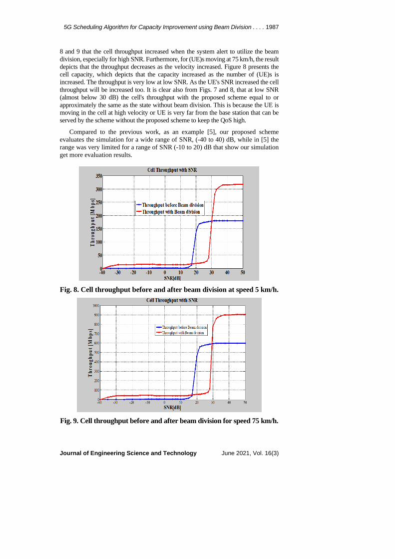
To fortify the proposed scheme, the simulator is started, and the results are evaluated, as shown in Figs. 6, 7, 8, and 9. Figures 6 and 7 show the UE's throughputs and cell throughput, respectively. In the simulation configuration, the UE's number and speed were the only parameters that choose to evaluate the UE's throughput and the cell capacity of every TTI. Figure 6 shows the UE's throughput with SNR for (UE)s moving at 5km/h. While Fig. 7 shows the UE's throughput with SNR for (UE)s moving at 75km/h. The evaluation from Figs. 6 and 7 depict the degradation in UE's throughput as well as when the UE moves in the cell at higher speed, as proved in previous papers. Although, the UE's throughput decreases but the cell throughput increased to provide fairness to newly accessed (UE)s. The evaluation from Figs. 6 and 7 depicts the degradation in UE's throughput when the UE moves in the cell at a higher speed, as proved in our previous papers [15].
Fig. 6. UE's throughput before and after beam division at speed 5 km/h.
Fig. 7. UE's throughput before and after beam division at speed 75 km/h.
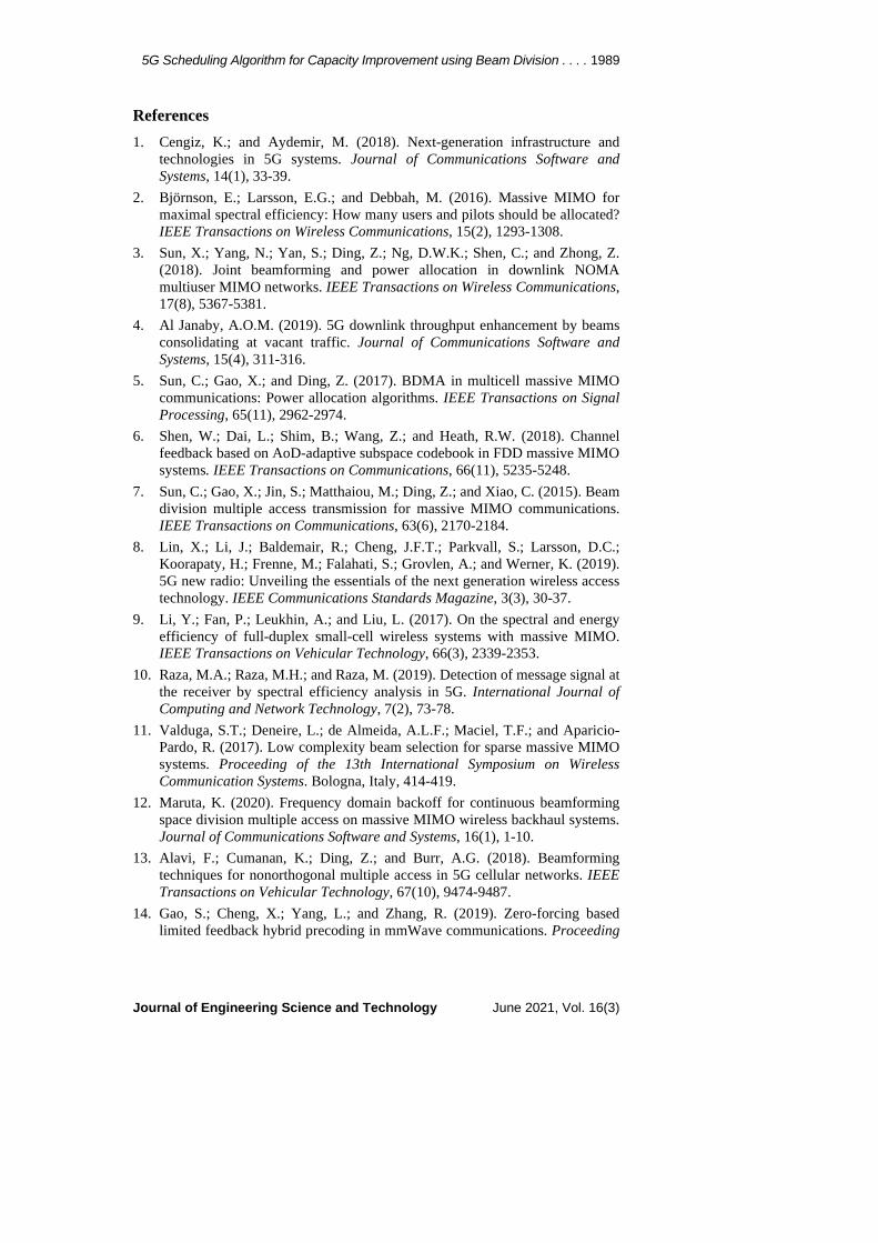
Figures 8 and 9 show the system throughput enhancement after beam division compared to the throughput of the cell before the beams division. It is clear from Figs.
5G Scheduling Algorithm for Capacity Improvement using Beam Division . . . . 1987
Journal of Engineering Science and Technology June 2021, Vol. 16(3)
8 and 9 that the cell throughput increased when the system alert to utilize the beam division, especially for high SNR. Furthermore, for (UE)s moving at 75 km/h, the result depicts that the throughput decreases as the velocity increased. Figure 8 presents the cell capacity, which depicts that the capacity increased as the number of (UE)s is increased. The throughput is very low at low SNR. As the UE's SNR increased the cell throughput will be increased too. It is clear also from Figs. 7 and 8, that at low SNR (almost below 30 dB) the cell's throughput with the proposed scheme equal to or approximately the same as the state without beam division. This is because the UE is moving in the cell at high velocity or UE is very far from the base station that can be served by the scheme without the proposed scheme to keep the QoS high.
Compared to the previous work, as an example [5], our proposed scheme evaluates the simulation for a wide range of SNR, (-40 to 40) dB, while in [5] the range was very limited for a range of SNR (-10 to 20) dB that show our simulation get more evaluation results.
Fig. 8. Cell throughput before and after beam division at speed 5 km/h.
Fig. 9. Cell throughput before and after beam division for speed 75 km/h.

1988 M. A. Al_Zubaidy et al.
Journal of Engineering Science and Technology June 2021, Vol. 16(3)
4. Conclusion With the increased number of (UE)s accessing the 5G cells a congested or full load traffic has occurred, the existed beams for each BS will be less than the number of active (UE)s. At this challenging condition, it is essential to create additional beams, additional antennas must be hardware added, to serve those (UE)s. In this paper, a 5G scheduling algorithm using beam division multiple access is presented to overcome congested traffic in cellular systems, when new users access the cell or newly attend the network, by beam division which is transmitted from massive MIMO antennas at the base station. The proposed scheme utilized the single beam for active UE to be divide into two beams if the system informed that there is a new overload (UE)s. The simulation shows that the proposed scheme increases the cell throughput by 50% in the case of an increased number of (UE)s in the system.
Abbreviations BC Broadcast Channel BDMA Beam Division Multiple Access BS Base Station BW Band Width CB-SDMA Continuous beamforming- space division multiple access CP Cyclic Prefix CSI Channel State Indicator D2D Device-to-Device DSP Digital Signal Processing eMBB Enhanced mobile broadband LL Link-Level LoS Line of Sight LTE Long Term Evolution LTE-A Long Term Evolution-Advanced NACA National Advisory Committee for Aeronautics NOMA Non-Orthogonal Multiple Access Msps Mega symbol per second MCS Modulation and Coding Scheme MIMO Multiple-Input Multiple-Output MU Multi-User OFDM Orthogonal Frequency Division Multiplexing PMI Precoding Matrix Indicator QAM Quadrature Amplitude Modulation QoS Quality of Service RB Resource Block SBS Small cell Base Station SL System Level SNR Signal to Noise Ratio SU Single-User TDMA Time Division Multiple Access TTI Transmission Time Interval UE User Equipment
5G Scheduling Algorithm for Capacity Improvement using Beam Division . . . . 1989
Journal of Engineering Science and Technology June 2021, Vol. 16(3)
References 1. Cengiz, K.; and Aydemir, M. (2018). Next-generation infrastructure and
technologies in 5G systems. Journal of Communications Software and Systems, 14(1), 33-39.
2. Björnson, E.; Larsson, E.G.; and Debbah, M. (2016). Massive MIMO for maximal spectral efficiency: How many users and pilots should be allocated? IEEE Transactions on Wireless Communications, 15(2), 1293-1308.
3. Sun, X.; Yang, N.; Yan, S.; Ding, Z.; Ng, D.W.K.; Shen, C.; and Zhong, Z. (2018). Joint beamforming and power allocation in downlink NOMA multiuser MIMO networks. IEEE Transactions on Wireless Communications, 17(8), 5367-5381.
4. Al Janaby, A.O.M. (2019). 5G downlink throughput enhancement by beams consolidating at vacant traffic. Journal of Communications Software and Systems, 15(4), 311-316.
5. Sun, C.; Gao, X.; and Ding, Z. (2017). BDMA in multicell massive MIMO communications: Power allocation algorithms. IEEE Transactions on Signal Processing, 65(11), 2962-2974.
6. Shen, W.; Dai, L.; Shim, B.; Wang, Z.; and Heath, R.W. (2018). Channel feedback based on AoD-adaptive subspace codebook in FDD massive MIMO systems. IEEE Transactions on Communications, 66(11), 5235-5248.
7. Sun, C.; Gao, X.; Jin, S.; Matthaiou, M.; Ding, Z.; and Xiao, C. (2015). Beam division multiple access transmission for massive MIMO communications. IEEE Transactions on Communications, 63(6), 2170-2184.
8. Lin, X.; Li, J.; Baldemair, R.; Cheng, J.F.T.; Parkvall, S.; Larsson, D.C.; Koorapaty, H.; Frenne, M.; Falahati, S.; Grovlen, A.; and Werner, K. (2019). 5G new radio: Unveiling the essentials of the next generation wireless access technology. IEEE Communications Standards Magazine, 3(3), 30-37.
9. Li, Y.; Fan, P.; Leukhin, A.; and Liu, L. (2017). On the spectral and energy efficiency of full-duplex small-cell wireless systems with massive MIMO. IEEE Transactions on Vehicular Technology, 66(3), 2339-2353.
10. Raza, M.A.; Raza, M.H.; and Raza, M. (2019). Detection of message signal at the receiver by spectral efficiency analysis in 5G. International Journal of Computing and Network Technology, 7(2), 73-78.
11. Valduga, S.T.; Deneire, L.; de Almeida, A.L.F.; Maciel, T.F.; and Aparicio-Pardo, R. (2017). Low complexity beam selection for sparse massive MIMO systems. Proceeding of the 13th International Symposium on Wireless Communication Systems. Bologna, Italy, 414-419.
12. Maruta, K. (2020). Frequency domain backoff for continuous beamforming space division multiple access on massive MIMO wireless backhaul systems. Journal of Communications Software and Systems, 16(1), 1-10.
13. Alavi, F.; Cumanan, K.; Ding, Z.; and Burr, A.G. (2018). Beamforming techniques for nonorthogonal multiple access in 5G cellular networks. IEEE Transactions on Vehicular Technology, 67(10), 9474-9487.
14. Gao, S.; Cheng, X.; Yang, L.; and Zhang, R. (2019). Zero-forcing based limited feedback hybrid precoding in mmWave communications. Proceeding

1990 M. A. Al_Zubaidy et al.
Journal of Engineering Science and Technology June 2021, Vol. 16(3)
of the 8th International Conference on Communications in China. Changchun, China, 362-366.
15. Othman, A.; Othman, S.Y.; Al-Omary, A.; and Al-Rizzo, H. (2015). Comparative performance of subcarrier schedulers in uplink LTE-A under high users' mobility. International Journal of Computing and Digital Systems, 4(4), 287-293.
16. Othman, A.; Ameen, S.Y.; and Al-Rizzo, H. (2018). Dynamic Switching of Scheduling Algorithm for Uplink LTE System. International Journal of Computing and Networks Technologies, 6(3), 76-82.
17. Riadi, A.; Boulouird, M.; and Hassani, M.M. (2017). An overview of massive-MIMO in 5G wireless communications. In Colloque International TELECOM, 2017 & 10ème JFMMA, Rabat, Morocco, 10-12.
18. Müller, M.K.; Ademaj, F.; Dittrich, T.; Fastenbauer, A.; Elbal, B.R.; Nabavi, A.; Nagel, L.; Schwarz, S.; and Rupp, M. (2018). Flexible multi-node simulation of cellular mobile communications: The Vienna 5G system level simulator. EURASIP Journal on Wireless Communications and Networking, 2018(227), 1-17.
19. Gauger, M.; Arnold, M.; and Brink, S.T. (2020). Massive MIMO channel measurements and achievable rates in a residential area. Proceeding of the 24th International ITG Workshop on Smart Anthennas. Hamburg, Germany.