
A novel control strategy for load converter of DC isolated distribution system under unbalanced...
10
Noroozian et al. / J Zhejiang Univ Sci A 2009 10(6):890-899 890 A novel control strategy for load converter of DC isolated distribution system under unbalanced loading conditions R. NOROOZIAN †1 , M. ABEDI 1 , G. B. GHAREHPETIAN 1 , S. H. HOSSEINI 2 ( 1 Department of Electrical Engineering, Amirkabir University of Technology, Tehran, Iran) ( 2 Department of Electrical and Computer Engineering, Tabriz University, Tabriz, Iran) † E-mail: [email protected] Received Apr. 18, 2008; Revision accepted Nov. 21, 2008; Crosschecked Apr. 10, 2009 Abstract: A novel control strategy for the load converter supplying the unbalanced AC load in a DC isolated distribution system is presented. The control algorithm results in balanced and sinusoidal load voltages under unbalanced AC loading. The unbalanced load is characterized in the d-q-0 rotating coordinate based on symmetrical sequence components. Also, the mathematical model of the load converter in both a-b-c and d-q-0 coordinates is derived by using the average large signal model. Then, two control strategies for the load converter are presented. The first one uses the conventional d-q-0 controller to ensure the voltage and current regulation. The second one is a newly proposed control strategy based on the decomposition of the voltage and current into in- stantaneous positive, negative, and zero sequences. These three sequences are controlled independently in their own reference frames as DC signals. The performance of the load converter using these two control strategies is compared. Simulation results show the validity and capability of the newly proposed control strategy. Key words: Unbalanced load, Power quality, Symmetrical components, Control strategy doi:10.1631/jzus.A0820294 Document code: A CLC number: TM7 INTRODUCTION Renewable energy resources are attractive op- tions for loads supplying places where a connection to the utility network is either impossible or unduly expensive (Daniel and AmmasaiGounden, 2004). Unbalanced AC loading could occur at different cur- rent levels among phases or at the same current level but with different phase shifts, or both. The unbal- anced loading results in unbalanced voltage, a poor power factor, power losses and other power quality disturbances. The aim of this paper is to supply the unbalanced AC load in a DC isolated distribution system by an autonomous DC/AC load converter. The load converter should deliver constant balanced AC voltage magnitude and frequency. In other research, the load converter controller has used a conventional d-q-0 rotating frame (Thandi et al., 1999), space vector modulation (Zhang, 1998), and simple V-f voltage regulator schemes (Saisho et al., 2002; Lu and Ooi, 2005). In a conventional d-q-0 controller, the compensation of the unbalanced voltage has used current and voltage regulation in a d-q-0 reference frame rotating at the fundamental frequency. How- ever, the voltage and current give rise to 2ω voltage and current ripples in the d-q channels. The 0 channel is similarly affected by the disturbance at ω. As a result, the performances of the conventional d-q-0 control strategy are insufficient (Lin and Lee, 2004; Blazic and Papic, 2004; Vechiu et al., 2007). Existing simple V-f voltage regulator schemes cannot deal with the zero sequence component caused by unbalanced loads (Saisho et al., 2002; Lu and Ooi, 2005). The space vector modulation schemes are implemented in a 2D space, and are therefore unable to deal with the zero sequence component caused by an unbalanced load. However, the developed d-q-0 rotating frame based on symmetrical components has been proposed. This controller is based on the decomposition of the voltage and current into instantaneous positive, Journal of Zhejiang University SCIENCE A ISSN 1673-565X (Print); ISSN 1862-1775 (Online) www.zju.edu.cn/jzus; www.springerlink.com E-mail: [email protected]
-
Upload
independent -
Category
Documents
-
view
1 -
download
0
Transcript of A novel control strategy for load converter of DC isolated distribution system under unbalanced...
Noroozian et al. / J Zhejiang Univ Sci A 2009 10(6):890-899 890
A novel control strategy for load converter of DC isolated distribution system under unbalanced loading conditions
R. NOROOZIAN†1, M. ABEDI1, G. B. GHAREHPETIAN1, S. H. HOSSEINI2
(1Department of Electrical Engineering, Amirkabir University of Technology, Tehran, Iran) (2Department of Electrical and Computer Engineering, Tabriz University, Tabriz, Iran)
†E-mail: [email protected] Received Apr. 18, 2008; Revision accepted Nov. 21, 2008; Crosschecked Apr. 10, 2009
Abstract: A novel control strategy for the load converter supplying the unbalanced AC load in a DC isolated distribution system is presented. The control algorithm results in balanced and sinusoidal load voltages under unbalanced AC loading. The unbalanced load is characterized in the d-q-0 rotating coordinate based on symmetrical sequence components. Also, the mathematical model of the load converter in both a-b-c and d-q-0 coordinates is derived by using the average large signal model. Then, two control strategies for the load converter are presented. The first one uses the conventional d-q-0 controller to ensure the voltage and current regulation. The second one is a newly proposed control strategy based on the decomposition of the voltage and current into in-stantaneous positive, negative, and zero sequences. These three sequences are controlled independently in their own reference frames as DC signals. The performance of the load converter using these two control strategies is compared. Simulation results show the validity and capability of the newly proposed control strategy. Key words: Unbalanced load, Power quality, Symmetrical components, Control strategy doi:10.1631/jzus.A0820294 Document code: A CLC number: TM7 INTRODUCTION
Renewable energy resources are attractive op-tions for loads supplying places where a connection to the utility network is either impossible or unduly expensive (Daniel and AmmasaiGounden, 2004). Unbalanced AC loading could occur at different cur-rent levels among phases or at the same current level but with different phase shifts, or both. The unbal-anced loading results in unbalanced voltage, a poor power factor, power losses and other power quality disturbances. The aim of this paper is to supply the unbalanced AC load in a DC isolated distribution system by an autonomous DC/AC load converter. The load converter should deliver constant balanced AC voltage magnitude and frequency. In other research, the load converter controller has used a conventional d-q-0 rotating frame (Thandi et al., 1999), space vector modulation (Zhang, 1998), and simple V-f voltage regulator schemes (Saisho et al., 2002; Lu and
Ooi, 2005). In a conventional d-q-0 controller, the compensation of the unbalanced voltage has used current and voltage regulation in a d-q-0 reference frame rotating at the fundamental frequency. How-ever, the voltage and current give rise to 2ω voltage and current ripples in the d-q channels. The 0 channel is similarly affected by the disturbance at ω. As a result, the performances of the conventional d-q-0 control strategy are insufficient (Lin and Lee, 2004; Blazic and Papic, 2004; Vechiu et al., 2007). Existing simple V-f voltage regulator schemes cannot deal with the zero sequence component caused by unbalanced loads (Saisho et al., 2002; Lu and Ooi, 2005). The space vector modulation schemes are implemented in a 2D space, and are therefore unable to deal with the zero sequence component caused by an unbalanced load. However, the developed d-q-0 rotating frame based on symmetrical components has been proposed. This controller is based on the decomposition of the voltage and current into instantaneous positive,
Journal of Zhejiang University SCIENCE A ISSN 1673-565X (Print); ISSN 1862-1775 (Online) www.zju.edu.cn/jzus; www.springerlink.com E-mail: [email protected]
Noroozian et al. / J Zhejiang Univ Sci A 2009 10(6):890-899 891
negative, and zero sequence components using phasor representation. These three sequences are controlled independently in their own reference frames as DC signals. The positive sequence, which rotates coun-terclockwise, is regulated by the proportional integral (PI) controllers in a positive reference frame. The negative sequence, which rotates clockwise at the same angular frequency, is regulated by the PI con-trollers in a negative reference frame. Also, the zero sequence is regulated by the PI controller in a zero reference frame.
In this paper, the unbalanced load is character-ized in the d-q-0 rotating coordinate. The large-signal models of the three-leg DC/AC converter are pre-sented in both a-b-c stationary and d-q-0 rotating coordinates. The conventional d-q-0 controller and developed d-q-0 controller based on symmetrical sequence components have been applied to the ref-erence voltages generation of the load converter. The theoretical formulation of these controllers has been analyzed and developed. It has been shown that the load converter can handle the unbalanced load.
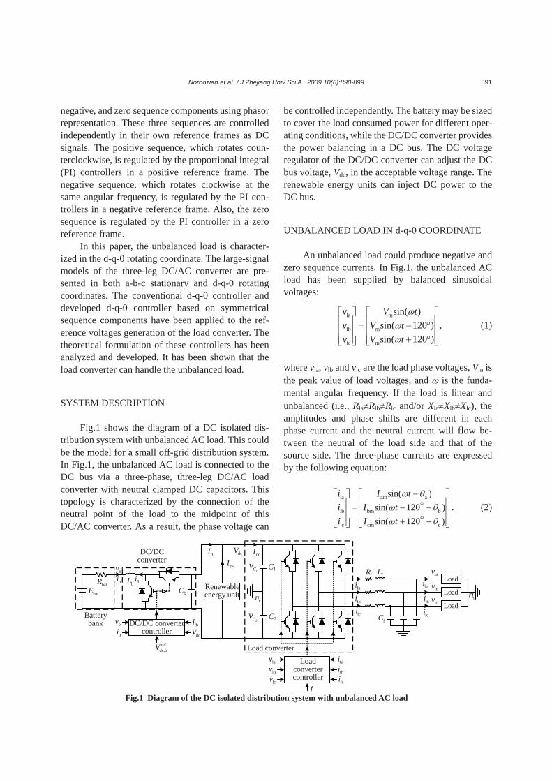
SYSTEM DESCRIPTION Fig.1 shows the diagram of a DC isolated dis-
tribution system with unbalanced AC load. This could be the model for a small off-grid distribution system. In Fig.1, the unbalanced AC load is connected to the DC bus via a three-phase, three-leg DC/AC load converter with neutral clamped DC capacitors. This topology is characterized by the connection of the neutral point of the load to the midpoint of this DC/AC converter. As a result, the phase voltage can
be controlled independently. The battery may be sized to cover the load consumed power for different oper-ating conditions, while the DC/DC converter provides the power balancing in a DC bus. The DC voltage regulator of the DC/DC converter can adjust the DC bus voltage, Vdc, in the acceptable voltage range. The renewable energy units can inject DC power to the DC bus.
UNBALANCED LOAD IN d-q-0 COORDINATE
An unbalanced load could produce negative and zero sequence currents. In Fig.1, the unbalanced AC load has been supplied by balanced sinusoidal voltages:
la m
lb m
lc m
sin( )sin( 120 ) ,sin( 120 )
ttt
v Vv Vv V
ωωω
= −⎡ ⎤ ⎡ ⎤⎢ ⎥ ⎢ ⎥°⎢ ⎥ ⎢ ⎥
+ °⎢ ⎥ ⎢ ⎥⎣ ⎦⎣ ⎦
(1)
where vla, vlb and vlc are the load phase voltages, Vm is the peak value of load voltages, and ω is the funda-mental angular frequency. If the load is linear and unbalanced (i.e., Rla≠Rlb≠Rlc and/or Xla≠Xlb≠Xlc), the amplitudes and phase shifts are different in each phase current and the neutral current will flow be-tween the neutral of the load side and that of the source side. The three-phase currents are expressed by the following equation:
la am a
lb bm b
lc cm c
sin( )sin( 120 )sin( 120 )
ttt
i Ii Ii I
ω θω θω θ
−= − −
+ −
⎡ ⎤ ⎡ ⎤⎢ ⎥ ⎢ ⎥⎢ ⎥ ⎢ ⎥⎢ ⎥ ⎢ ⎥⎣ ⎦ ⎣ ⎦
. (2)
1Cv
lnLoad
fcifbifai
fL
fC lcilbi
lai Load
Load
f
faifbifcilcv
lbvlav
Renewableenergy unit
bL
Batterybank
DC/DCconverter
dcIdcV
lcvlbvlav
Load converter
bI
rwI
batEbatR bi
bv
bibv DC/DC converter
controllerfbidcV
refdc,bV
fRfbi
bCcn
2Cv
Load converter controller
C1
C2
Fig.1 Diagram of the DC isolated distribution system with unbalanced AC load
Noroozian et al. / J Zhejiang Univ Sci A 2009 10(6):890-899 892
Using phasor representation, a three-phase un-balanced load current can be expressed by symmet-rical components of the positive sequence (ila,p, ilb,p and ilc,p), negative sequence (ila,n, ilb,n and ilc,n), and zero sequence (ila,0, ilb,0 and ilc,0), as follows:
la,p la,n la,0la
lb lb,p lb,n lb,0
lc lc,p lc,n lc,0
.i i ii
i i i ii i i i
=
⎡ ⎤+ +⎡ ⎤⎢ ⎥⎢ ⎥ + +⎢ ⎥⎢ ⎥⎢ ⎥⎢ ⎥ + +⎣ ⎦ ⎣ ⎦
(3)
The load currents can be transformed into the
d-q-0 synchronous reference frame, as follows:
ld,p ld,n ld,0ld
lq lq,p lq,n lq,0
l0 l0,p l0,n l0,0
.i i ii
i i i ii i i i
=
⎡ ⎤+ +⎡ ⎤⎢ ⎥⎢ ⎥ + +⎢ ⎥⎢ ⎥⎢ ⎥⎢ ⎥ + +⎣ ⎦ ⎣ ⎦
(4)
In the d-q-0 rotating frame, the load current
components in the d-q channels (ild, ilq) are given rise to 2ω current ripples. The zero component (il0) appears as a disturbance at ω (Blazic and Papic, 2004; Lin and Lee, 2004; Vechiu et al., 2007). The load current de-composed into symmetrical sequence components, the fundamental positive sequence components (ila,p, ilb,p and ilc,p) rotate counterclockwise with angular fre-quency, ω. Using this transformation, the positive sequence d-q currents (ild,p, ilq,p) appear as DC quan-tities (with ω=0). The negative sequence components (ila,n, ilb,n and ilc,n) rotate clockwise. Using this trans-formation, the negative sequence d-q currents (ild,n, ilq,n) appear as a ripple with the angular frequency of 2ω. The zero sequence current appears as a distur-bance on the 0 axes at ω, while the d and q compo-nents do not exist. However, the positive, negative, and zero sequences appear as DC signals in their own synchronously rotating reference frames. LOAD CONVERTER UNDER UNBALANCED LOADING CONDITIONS
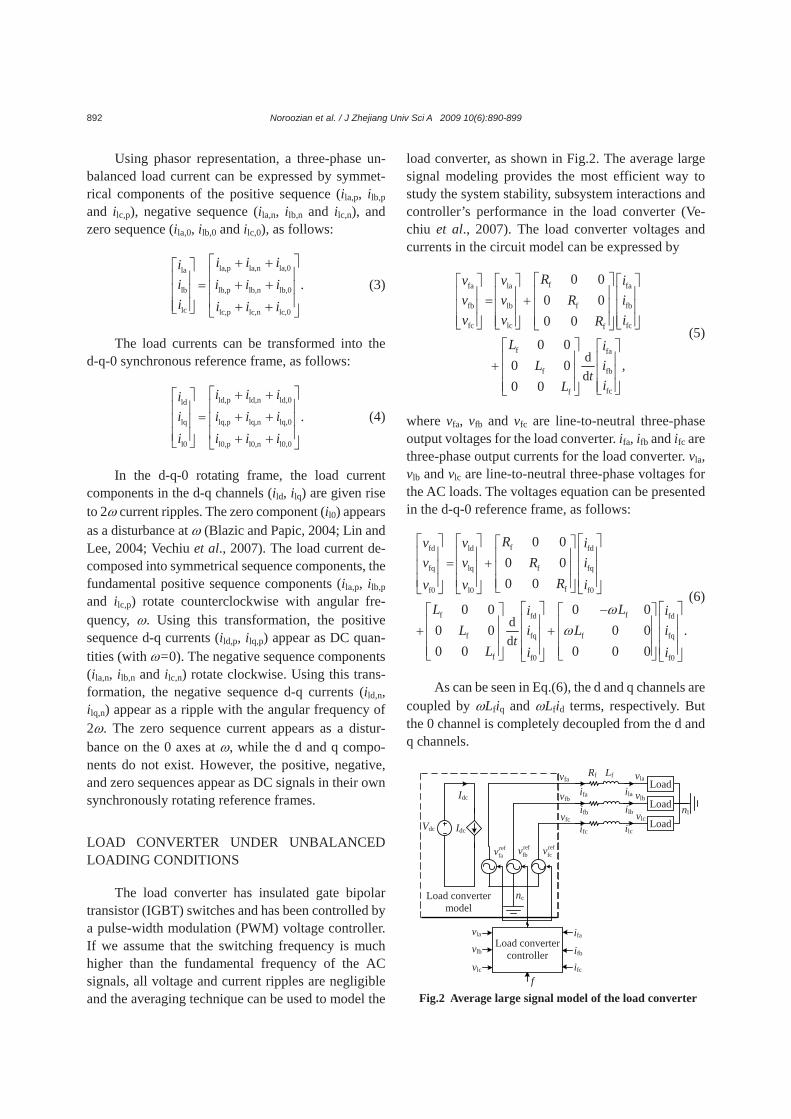
The load converter has insulated gate bipolar transistor (IGBT) switches and has been controlled by a pulse-width modulation (PWM) voltage controller. If we assume that the switching frequency is much higher than the fundamental frequency of the AC signals, all voltage and current ripples are negligible and the averaging technique can be used to model the
load converter, as shown in Fig.2. The average large signal modeling provides the most efficient way to study the system stability, subsystem interactions and controller’s performance in the load converter (Ve-chiu et al., 2007). The load converter voltages and currents in the circuit model can be expressed by
ffa la fa
fb lb f fb
fc lc fcf
f fa
f fb
fcf
dd
0 00 00 0
0 00 0 ,0 0
t
Rv v iv v R iv v iR
L iL i
iL
= +
+
⎡ ⎤⎡ ⎤ ⎡ ⎤ ⎡ ⎤⎢ ⎥⎢ ⎥ ⎢ ⎥ ⎢ ⎥⎢ ⎥⎢ ⎥ ⎢ ⎥ ⎢ ⎥⎢ ⎥⎢ ⎥ ⎢ ⎥ ⎢ ⎥⎣ ⎦ ⎣ ⎦ ⎣ ⎦⎣ ⎦
⎡ ⎤ ⎡ ⎤⎢ ⎥ ⎢ ⎥⎢ ⎥ ⎢ ⎥⎢ ⎥ ⎢ ⎥⎣ ⎦⎣ ⎦
(5)
where vfa, vfb and vfc are line-to-neutral three-phase output voltages for the load converter. ifa, ifb and ifc are three-phase output currents for the load converter. vla, vlb and vlc are line-to-neutral three-phase voltages for the AC loads. The voltages equation can be presented in the d-q-0 reference frame, as follows:
ffd ld fd
fq lq f fq
ff0 l0 f0
f ffd fd
f fq f fq
f f0 f0
dd
0 00 00 0
0 0 0 00 0 0 0 .0 0 0 0 0
t
Rv v iv v R i
Rv v i
L Li iL i L i
L i i
ωω
= +
+ +
⎡ ⎤ ⎡ ⎤ ⎡ ⎤⎡ ⎤⎢ ⎥ ⎢ ⎥ ⎢ ⎥⎢ ⎥⎢ ⎥ ⎢ ⎥ ⎢ ⎥⎢ ⎥⎢ ⎥ ⎢ ⎥ ⎢ ⎥⎢ ⎥⎣ ⎦⎣ ⎦ ⎣ ⎦ ⎣ ⎦
⎡ ⎤ ⎡ ⎤−⎡ ⎤ ⎡ ⎤⎢ ⎥ ⎢ ⎥⎢ ⎥ ⎢ ⎥⎢ ⎥ ⎢ ⎥⎢ ⎥ ⎢ ⎥⎢ ⎥ ⎢ ⎥⎢ ⎥ ⎢ ⎥⎣ ⎦ ⎣ ⎦⎣ ⎦ ⎣ ⎦
(6)
As can be seen in Eq.(6), the d and q channels are
coupled by ωLfiq and ωLfid terms, respectively. But the 0 channel is completely decoupled from the d and q channels.
Fig.2 Average large signal model of the load converter
reffcv
Vdc Idc
Idc
nc
reffav ref
fbv
Load converter controller
f
ifa ifb ifc vlc
vlb
vla
nlLoad
Lf Load
Load
Rf
Load convertermodel
ifa ifb ifc
vla vlb vlc
vfa vfb vfc
ila ilb ilc
Noroozian et al. / J Zhejiang Univ Sci A 2009 10(6):890-899 893
CONVENTIONAL CONTROL STRATEGY
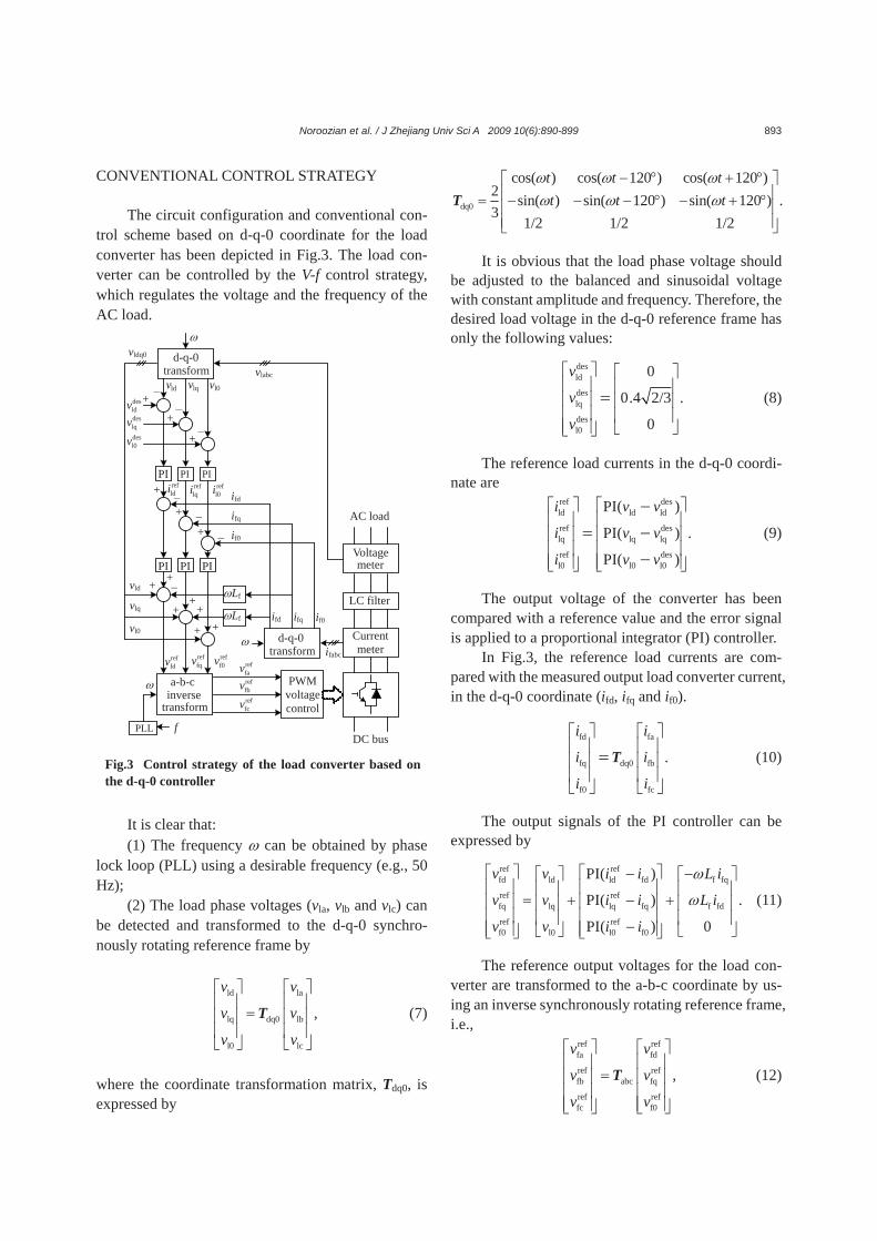
The circuit configuration and conventional con-trol scheme based on d-q-0 coordinate for the load converter has been depicted in Fig.3. The load con-verter can be controlled by the V-f control strategy, which regulates the voltage and the frequency of the AC load.
It is clear that: (1) The frequency ω can be obtained by phase
lock loop (PLL) using a desirable frequency (e.g., 50 Hz);
(2) The load phase voltages (vla, vlb and vlc) can be detected and transformed to the d-q-0 synchro-nously rotating reference frame by
ld la
lq dq0 lb
l0 lc
,
v v
v v
v v
⎡ ⎤ ⎡ ⎤⎢ ⎥ ⎢ ⎥
=⎢ ⎥ ⎢ ⎥⎢ ⎥ ⎢ ⎥⎣ ⎦ ⎣ ⎦
T (7)
where the coordinate transformation matrix, Tdq0, is expressed by
dq0
cos( ) cos( 120 ) cos( 120 )2 sin( ) sin( 120 ) sin( 120 ) .3
1/2 1/2 1/2
t t tt t t
ω ω ωω ω ω
− ° + °⎡ ⎤⎢ ⎥= − − − ° − + °⎢ ⎥⎢ ⎥⎣ ⎦
T
It is obvious that the load phase voltage should be adjusted to the balanced and sinusoidal voltage with constant amplitude and frequency. Therefore, the desired load voltage in the d-q-0 reference frame has only the following values:
desld
deslq
desl0
0
0.4 2/3 .
0
v
v
v
⎡ ⎤ ⎡ ⎤⎢ ⎥ ⎢ ⎥⎢ ⎥ ⎢ ⎥⎢ ⎥ ⎢ ⎥⎢ ⎥ ⎣ ⎦⎣ ⎦
= (8)
The reference load currents in the d-q-0 coordi-nate are
ref desld ld ld
ref deslq lq lq
ref desl0 l0 l0
PI( )
PI( ) .
PI( )
i v v
i v v
i v v
⎡ ⎤ ⎡ ⎤⎢ ⎥ ⎢ ⎥⎢ ⎥ ⎢ ⎥⎢ ⎥ ⎢ ⎥⎢ ⎥ ⎢ ⎥⎣ ⎦ ⎣ ⎦
−= −
− (9)
The output voltage of the converter has been compared with a reference value and the error signal is applied to a proportional integrator (PI) controller.
In Fig.3, the reference load currents are com-pared with the measured output load converter current, in the d-q-0 coordinate (ifd, ifq and if0).
fd fa
fq dq0 fb
f0 fc
.
i i
i i
i i
⎡ ⎤ ⎡ ⎤⎢ ⎥ ⎢ ⎥⎢ ⎥ ⎢ ⎥⎢ ⎥ ⎢ ⎥⎣ ⎦ ⎣ ⎦
=T (10)
The output signals of the PI controller can be expressed by
ref reffd ld ld fd f fq
ref reffq lq lq fq f fd
ref reff0 l0 l0 f0
PI( )
PI( ) .
PI( ) 0
v v i i L i
v v i i L i
v v i i
ω
ω
⎡ ⎤ ⎡ ⎤− −⎡ ⎤ ⎡ ⎤⎢ ⎥ ⎢ ⎥⎢ ⎥ ⎢ ⎥
= + − +⎢ ⎥ ⎢ ⎥⎢ ⎥ ⎢ ⎥⎢ ⎥ ⎢ ⎥⎢ ⎥ ⎢ ⎥−⎢ ⎥ ⎢ ⎥ ⎣ ⎦⎣ ⎦⎣ ⎦ ⎣ ⎦
(11)
The reference output voltages for the load con-verter are transformed to the a-b-c coordinate by us-ing an inverse synchronously rotating reference frame, i.e.,
ref reffa fd
ref reffb abc fq
ref reffc f0
,
v v
v v
v v
⎡ ⎤ ⎡ ⎤⎢ ⎥ ⎢ ⎥
=⎢ ⎥ ⎢ ⎥⎢ ⎥ ⎢ ⎥⎢ ⎥ ⎢ ⎥⎣ ⎦ ⎣ ⎦
T (12)
Fig.3 Control strategy of the load converter based on the d-q-0 controller
transform
AC load
meterVoltage
LC filter
DC bus
lqv ldv l0 v
Currentmeter
transform inverse a-b-c
PI PIPI
PI PI PI
vldq0
vlq vld
vl0
ω
transform d-q-0
ifq
ifd
if0
Lf ω Lf ω
ifabc
PWM
voltage control
ω
vlabc
ifq ifd
if0
−
+ −
+ −
+
−
+
−
+
−
+
+
+
+
+
+
−
+
+ ω
f PLL
d-q-0
reffcv
reffav reffbv
reff0vref
fdv reffqv
refl0i ref
ldi reflqi
desl0v
desldv deslqv
Noroozian et al. / J Zhejiang Univ Sci A 2009 10(6):890-899 894
where
abc
cos( ) sin( ) 1cos( 120 ) sin( 120 ) 1 .cos( 120 ) sin( 120 ) 1
t tt tt t
ω ωω ωω ω
−⎡ ⎤⎢ ⎥= − ° − − °⎢ ⎥⎢ ⎥+ ° − + °⎣ ⎦
T
Then, the available voltages in the a-b-c coor-
dinate are compared with the triangular wave pro-vided by the PWM voltage control module. Therefore, the output provides a suitable switching pattern for the load converter.
PROPOSED CONTROL STRATEGY
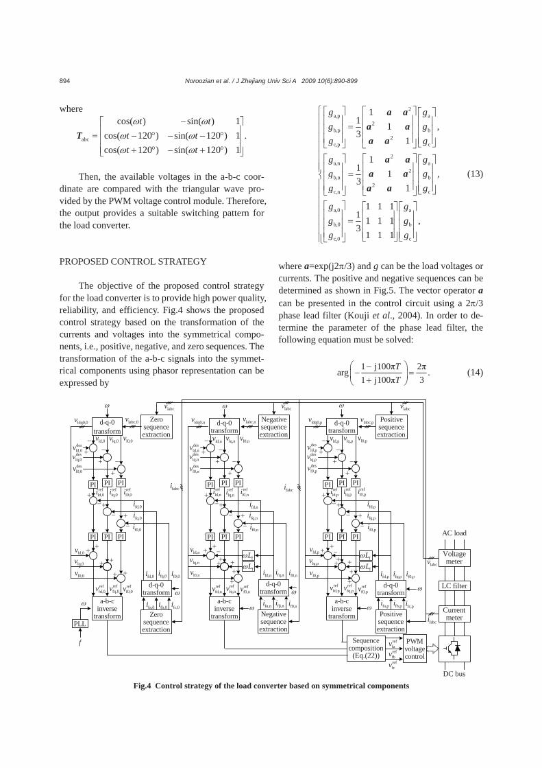
The objective of the proposed control strategy for the load converter is to provide high power quality, reliability, and efficiency. Fig.4 shows the proposed control strategy based on the transformation of the currents and voltages into the symmetrical compo-nents, i.e., positive, negative, and zero sequences. The transformation of the a-b-c signals into the symmet-rical components using phasor representation can be expressed by
.
2a,p a
2b,p b
2c,p c
2a,n a
2b,n b
2c,n c
a,0 a
b,0 b
c,0 c
11 1 ,3
1
11 1 ,3
1
1 1 11 1 1 1 ,3
1 1 1
g gg gg g
g gg gg g
g gg gg g
⎧ ⎡ ⎤⎡ ⎤ ⎡ ⎤⎪ ⎢ ⎥⎢ ⎥ ⎢ ⎥=⎪ ⎢ ⎥⎢ ⎥ ⎢ ⎥⎪ ⎢ ⎥⎢ ⎥ ⎢ ⎥⎣ ⎦⎣ ⎦ ⎣ ⎦⎪⎪ ⎡ ⎤⎡ ⎤ ⎡ ⎤⎪ ⎢ ⎥⎪⎢ ⎥ ⎢ ⎥=⎨ ⎢ ⎥⎢ ⎥ ⎢ ⎥⎪ ⎢ ⎥⎢ ⎥ ⎢ ⎥⎣ ⎦⎣ ⎦ ⎣ ⎦⎡ ⎤ ⎡ ⎤⎡ ⎤⎢ ⎥ ⎢ ⎥⎢ ⎥=⎢ ⎥ ⎢ ⎥⎢ ⎥⎢ ⎥ ⎢ ⎥⎢ ⎥⎣ ⎦ ⎣ ⎦⎣ ⎦⎩
a aa aa a
a aa aa a⎪
⎪⎪⎪⎪⎪
(13)
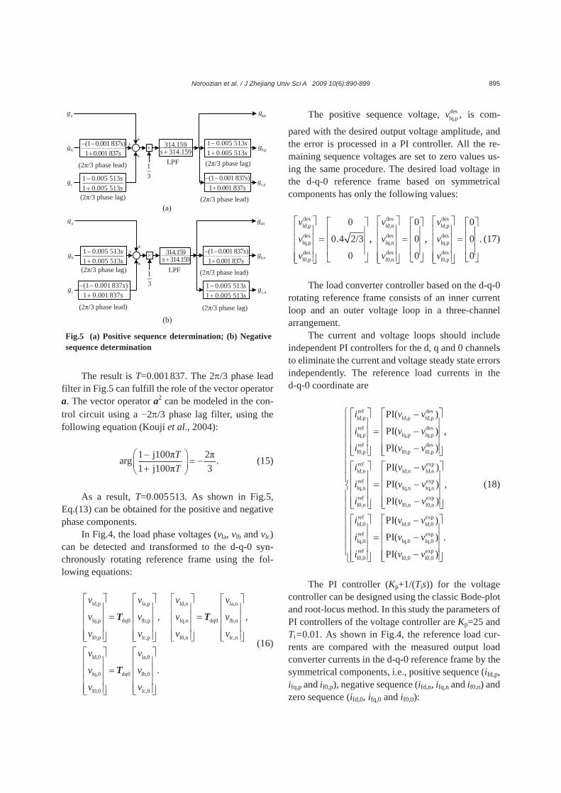
where a=exp(j2π/3) and g can be the load voltages or currents. The positive and negative sequences can be determined as shown in Fig.5. The vector operator a can be presented in the control circuit using a 2π/3 phase lead filter (Kouji et al., 2004). In order to de-termine the parameter of the phase lead filter, the following equation must be solved:
1 j100π 2πarg
1 j100π 3.T
T−
− =+
⎛ ⎞⎜ ⎟⎝ ⎠
(14)
AC load
Voltagemeter
LC filter
DC bus
Currentmeter
reffavreffbvreffcv
fabci
PWMvoltagecontrol
d-q-0transform
lq,0vld,0v l0,0v
a-b-cinverse
transform
PIPIPI
PIPIPI
ldq0,0v
lq,0vld,0v
l0,0vd-q-0
transform
fq,0ifd,0i f0,0i
ω
fq,0ifd,0i
f0,0i
−
+ −
+ −
+
reflq,0iref
ld,0i refl0,0i
−+
−+
−+
+ +
+ +
+ +
reffd,0v ref
fq,0v reff0,0v
deslq,0v
desld,0v
desl0,0v
Zerosequenceextraction
fa,0i fb,0i fc,0i
Zerosequenceextraction
d-q-0transform
lq,nvld,nv l0,nv
a-b-cinverse
transform
PIPIPI
PIPIPI
ldq0,nv
lq,nvld,nv
l0,nvd-q-0
transform
fα,ni fβ,ni f0,niω
labcv
fq,nifd,ni
f0,ni
−
+ −
+ −
+
reflq,niref
ld,ni refl0,ni
−+
−+
−+
+ +
++
++
reffd,nv ref
fq,nv reff0,nv
deslq,nv
desld,nv
desl0,nv
Negativesequenceextraction
Negativesequenceextraction
ω
fq,nifd,ni f0,ni
fLω
fLω+−
labc,0vlabcv
labc,nv
ω
d-q-0transform
lq,pvld,pv l0,pv
a-b-cinverse
transform
PIPIPI
PIPIPI
ldq0,pv
lq,pvld,pv
l0,pv
d-q-0transform
ω
labcv
fq,pifd,pi
f0,pi
−
+ −
+ −
+
reflq,piref
ld,pi refl0,pi
−+
−+
−+
+ +
++
++
reffd,pv ref
fq,pv reff0,pv
deslq,pv
desld,pv
desl0,pv
fa,pi fb,pi fc,pi
Positivesequenceextraction
fq,pifd,pi f0,pi
fLω
fLω+−
labc,pv
ω
Sequencecomposition
(Eq.(22))
labcv
fabcifabci
Positivesequenceextraction
ωωω
f
PLL
Fig.4 Control strategy of the load converter based on symmetrical components
Noroozian et al. / J Zhejiang Univ Sci A 2009 10(6):890-899 895
The result is T=0.001 837. The 2π/3 phase lead
filter in Fig.5 can fulfill the role of the vector operator a. The vector operator a2 can be modeled in the con-trol circuit using a −2π/3 phase lag filter, using the following equation (Kouji et al., 2004):
1 j100π 2πarg .1 j100π 3
TT
⎛ ⎞−= −⎜ ⎟+⎝ ⎠
(15)
As a result, T=0.005 513. As shown in Fig.5,
Eq.(13) can be obtained for the positive and negative phase components.
In Fig.4, the load phase voltages (vla, vlb and vlc) can be detected and transformed to the d-q-0 syn-chronously rotating reference frame using the fol-lowing equations:
ld,p la,p ld,n la,n
lq,p dq0 lb,p lq,n dq0 lb,n
l0,p lc,p l0,n lc,n
ld,0 la,0
lq,0 dq0 lb,0
l0,0 lc,0
, ,
.
v v v v
v v v v
v v v v
v v
v v
v v
⎡ ⎤ ⎡ ⎤ ⎡ ⎤ ⎡ ⎤⎢ ⎥ ⎢ ⎥ ⎢ ⎥ ⎢ ⎥
= =⎢ ⎥ ⎢ ⎥ ⎢ ⎥ ⎢ ⎥⎢ ⎥ ⎢ ⎥ ⎢ ⎥ ⎢ ⎥
⎢ ⎥ ⎢ ⎥⎢ ⎥ ⎢ ⎥ ⎣ ⎦ ⎣ ⎦⎣ ⎦ ⎣ ⎦⎡ ⎤ ⎡ ⎤⎢ ⎥ ⎢ ⎥
=⎢ ⎥ ⎢ ⎥⎢ ⎥ ⎢ ⎥⎢ ⎥ ⎢ ⎥⎣ ⎦ ⎣ ⎦
T T
T
(16)
The positive sequence voltage, deslq,p ,v is com-
pared with the desired output voltage amplitude, and the error is processed in a PI controller. All the re-maining sequence voltages are set to zero values us-ing the same procedure. The desired load voltage in the d-q-0 reference frame based on symmetrical components has only the following values:
des des desld,p ld,n ld,p
des des deslq,p lq,n lq,p
des des desl0,p l0,n l0,p
0 0 0
0.4 2/3 0 0 .
0 0 0
, ,v v v
v v v
v v v
⎡ ⎤ ⎡ ⎤ ⎡ ⎤⎡ ⎤ ⎡ ⎤ ⎡ ⎤⎢ ⎥ ⎢ ⎥ ⎢ ⎥⎢ ⎥ ⎢ ⎥ ⎢ ⎥
= = =⎢ ⎥ ⎢ ⎥ ⎢ ⎥⎢ ⎥ ⎢ ⎥ ⎢ ⎥⎢ ⎥ ⎢ ⎥ ⎢ ⎥⎢ ⎥ ⎢ ⎥ ⎢ ⎥⎢ ⎥ ⎢ ⎥ ⎢ ⎥⎣ ⎦ ⎣ ⎦ ⎣ ⎦⎣ ⎦ ⎣ ⎦ ⎣ ⎦
(17)
The load converter controller based on the d-q-0
rotating reference frame consists of an inner current loop and an outer voltage loop in a three-channel arrangement.
The current and voltage loops should include independent PI controllers for the d, q and 0 channels to eliminate the current and voltage steady state errors independently. The reference load currents in the d-q-0 coordinate are
ref desld,p ld,p ld,p
ref deslq,p lq,p lq,p
ref desl0,p l0,p l0,p
ref expld,n ld,n ld,n
ref explq,n lq,n lq,n
ref expl0,n l0,n l0,n
PI( )
PI( )
PI( )
PI( )
PI( )
PI( )
,i v v
i v v
i v v
i v v
i v v
i v v
⎡ ⎤ ⎡ ⎤−⎢ ⎥ ⎢ ⎥
= −⎢ ⎥ ⎢ ⎥⎢ ⎥ ⎢ ⎥
−⎢ ⎥ ⎢ ⎥⎣ ⎦ ⎣ ⎦⎡ ⎤ ⎡ −⎢ ⎥ ⎢
= −⎢ ⎥ ⎢⎢ ⎥ ⎢
−⎢ ⎥⎣ ⎦ ⎣ref expld,0 ld,0 ld,0
ref explq,0 lq,0 lq,0
ref expl0,0 l0,0 l0,0
,
PI( )
PI( ) .
PI( )
i v v
i v v
i v v
⎧⎪⎪⎪⎪⎪
⎤⎪⎥⎪⎥⎨⎥⎪
⎢ ⎥⎪ ⎦⎪⎡ ⎤ ⎡ ⎤−⎪⎢ ⎥ ⎢ ⎥⎪ = −⎢ ⎥ ⎢ ⎥⎪⎢ ⎥ ⎢ ⎥⎪ −⎢ ⎥ ⎢ ⎥⎣ ⎦ ⎣ ⎦⎩
(18)
The PI controller (Kp+1/(Tis)) for the voltage
controller can be designed using the classic Bode-plot and root-locus method. In this study the parameters of PI controllers of the voltage controller are Kp=25 and Ti=0.01. As shown in Fig.4, the reference load cur-rents are compared with the measured output load converter currents in the d-q-0 reference frame by the symmetrical components, i.e., positive sequence (ifd,p, ifq,p and if0,p), negative sequence (ifd,n, ifq,n and if0,n) and zero sequence (ifd,0, ifq,0 and if0,0):
×+
+
+
(1 0.001 837 )1 0.001 837
ss
− −+
1 0.005 5131 0.005 513
ss
−+
ag
bg
cg
(2π/3 phase lead)
(2π/3 phase lag)
13
314.159314.159s +
LPF (2π/3 phase lag)
(1 0.001 837 )1 0.001 837
ss
− −+
1 0.005 5131 0.005 513
ss
−+
(2π/3 phase lead)
a,pg
b,pg
c,pg
×+
+
+
(1 0.001 837 )1 0.001 837
ss
− −+
1 0.005 5131 0.005 513
ss
−+
ag
bg
cg
(2π/3 phase lead)
(2π/3 phase lag) 13
314.159314.159s+LPF
(2π/3 phase lag)
(1 0.001 837 )1 0.001 837
ss
− −+
1 0.005 5131 0.005 513
ss
−+
(2π/3 phase lead)
a,ng
b,ng
c,ng
(a)
(b)
Fig.5 (a) Positive sequence determination; (b) Negative sequence determination
Noroozian et al. / J Zhejiang Univ Sci A 2009 10(6):890-899 896
fd,p fa,p fd,n fa,n
fq,p dq0 fb,p fq,n dq0 fb,n
f0,p fc,p f0,n fc,n
fd,0 fa,0
fq,0 dq0 fb,0
f0,0 fc,0
, ,
.
i i i i
i i i i
i i i i
i i
i i
i i
⎡ ⎤ ⎡ ⎤ ⎡ ⎤ ⎡ ⎤⎢ ⎥ ⎢ ⎥ ⎢ ⎥ ⎢ ⎥
= =⎢ ⎥ ⎢ ⎥ ⎢ ⎥ ⎢ ⎥⎢ ⎥ ⎢ ⎥ ⎢ ⎥ ⎢ ⎥⎢ ⎥ ⎢ ⎥ ⎣ ⎦ ⎣ ⎦⎣ ⎦ ⎣ ⎦⎡ ⎤ ⎡ ⎤⎢ ⎥ ⎢ ⎥
=⎢ ⎥ ⎢ ⎥⎢ ⎥ ⎢ ⎥⎣ ⎦ ⎣ ⎦
T T
T
(19)
Then the output signals of the PI controller can
be expressed by
ref reffd,p ld,p ld,p fd,p fq,p
ref reffq,p lq,p lq,p fq,p f fd,p
ref reff0,p l0,p l0,p f0,p
reffd,n l
reffq,n
reff0,n
PI( )
PI( ) ,
PI( ) 0
fv v i i L i
v v i i L i
v v i i
v v
v
v
ω
ω
⎡ ⎤ ⎡ ⎤⎡ ⎤ − −⎡ ⎤⎢ ⎥ ⎢ ⎥⎢ ⎥ ⎢ ⎥
= + − +⎢ ⎥ ⎢ ⎥⎢ ⎥ ⎢ ⎥⎢ ⎥ ⎢ ⎥⎢ ⎥ ⎢ ⎥−⎢ ⎥⎢ ⎥ ⎢ ⎥ ⎣ ⎦⎣ ⎦⎣ ⎦ ⎣ ⎦⎡ ⎤⎢ ⎥
=⎢ ⎥⎢ ⎥⎢ ⎥⎣ ⎦
refd,n ld,n fd,n f fq,n
reflq,n lq,n fq,n f fd,n
refl0,n l0,n f0,n
ref reffd,0 ld,0 ld,0 fd,0
reffq,0 lq,0
reff0,0 l0,0
PI( )
PI( ) ,
PI( ) 0
PI(
i i L i
v i i L i
v i i
v v i i
v v
v v
ω
ω
⎡ ⎤⎡ ⎤ − −⎡ ⎤⎢ ⎥⎢ ⎥ ⎢ ⎥
+ − +⎢ ⎥⎢ ⎥ ⎢ ⎥⎢ ⎥⎢ ⎥ ⎢ ⎥−⎢ ⎥ ⎣ ⎦⎣ ⎦ ⎣ ⎦
⎡ ⎤ ⎡ ⎤ −⎢ ⎥ ⎢ ⎥
= +⎢ ⎥ ⎢ ⎥⎢ ⎥ ⎢ ⎥⎢ ⎥ ⎣ ⎦⎣ ⎦
reflq,0 fq,0
refl0,0 f0,0
)
PI( ) .
PI( )
i i
i i
⎧⎪⎪⎪⎪⎪⎪⎪⎨⎪⎪⎪ ⎡ ⎤⎪ ⎢ ⎥⎪ −⎢ ⎥⎪ ⎢ ⎥⎪ −⎢ ⎥⎣ ⎦⎩
(20)
In this study the parameters of PI controllers for
the current controller are Kp=12 and Ti=0.01. The output signals of the PI controller, the reference out-put voltages of the load converter in the symmetrical sequence—positive sequence ( ref
fd,p ,v reffq,pv and ref
f0,pv ),
negative sequence ( reffd,n ,v ref
fq,nv and reff0,nv ) and zero
sequence ( reffd,0 ,v ref
fq,0v and reff0,0v )—are transformed to
the a-b-c coordinate by using the inverse synchro-nously rotating frame:
ref ref ref reffa,p fd,p fa,n fd,n
ref ref ref reffb,p abc fq,p fb,n abc fq,n
ref ref ref reffc,p f0,p fc,n f0,n
reffa,0 f
reffb,0 abc
reffc,0
,, v v v v
v v v v
v v v v
v v
v
v
⎡ ⎤ ⎡ ⎤ ⎡ ⎤ ⎡ ⎤⎢ ⎥ ⎢ ⎥ ⎢ ⎥ ⎢ ⎥
= =⎢ ⎥ ⎢ ⎥ ⎢ ⎥ ⎢ ⎥⎢ ⎥ ⎢ ⎥ ⎢ ⎥ ⎢ ⎥⎢ ⎥ ⎢ ⎥ ⎢ ⎥ ⎢ ⎥⎣ ⎦ ⎣ ⎦ ⎣ ⎦ ⎣ ⎦⎡ ⎤⎢ ⎥
=⎢ ⎥⎢ ⎥⎢ ⎥⎣ ⎦
T T
T
refd,0
reffq,0
reff0,0
.v
v
⎡ ⎤⎢ ⎥⎢ ⎥⎢ ⎥⎢ ⎥⎣ ⎦
(21)
The reference voltages that should be applied to the load converter are obtained with the addition of the symmetrical components (Fig.4):
ref ref ref reffa fa,p fa,n fa,0
ref ref ref reffb fb,p fb,n fb,0
ref ref ref reffc fc,p fc,n fc,0
.
v v v v
v v v v
v v v v
⎡ ⎤ ⎡ ⎤ ⎡ ⎤ ⎡ ⎤⎢ ⎥ ⎢ ⎥ ⎢ ⎥ ⎢ ⎥
= + +⎢ ⎥ ⎢ ⎥ ⎢ ⎥ ⎢ ⎥⎢ ⎥ ⎢ ⎥ ⎢ ⎥ ⎢ ⎥⎢ ⎥ ⎢ ⎥ ⎢ ⎥ ⎢ ⎥⎣ ⎦ ⎣ ⎦ ⎣ ⎦ ⎣ ⎦
(22)
Then, the available voltages in the a-b-c coor-
dinate are compared with the triangular wave pro-vided by the PWM voltage control module. Therefore, the output provides a suitable switching pattern for the load converter.
The nonlinear loads have different harmonic contents and different phase sequences. For example, the fundamental 7th and 13th harmonics are positive- sequence components, the 5th and 11th harmonics are negative-sequence components and the 3rd and 9th are zero-sequence components.
In the d-q-0 rotating frame, odd non-triplen harmonic components become even harmonic com-ponents in the d and q channels and they are equal to zero in the 0 channel.
All triplen harmonic components will be pre-served in the 0 channel. As a result, each individual harmonic current of nonlinear loads can be decom-posed into symmetrical components. Therefore, the proposed control strategy can also provide the bal-anced sinusoidal voltages for nonlinear loads. SIMULATION RESULTS
The system shown in Fig.1 has been modeled and simulated by PSCAD/EMTDC software to ana-lyze and compare the performance of the load con-verter with the two control strategies. The simulation results show that the load converter can supply an unbalanced and nonlinear AC load by balanced si-nusoidal voltages. In this simulation, the DC distri-bution supplied the unbalanced resistive-inductive load by star connection. The system parameters cho-sen for the simulation shown in Fig.1 are listed in Table 1, which was loaded with 50 kW. The renew-able energy units generated 55 kW. The batteries bank, which ensures the power balance of the system, had a rated capacity of 285 A·h.
Noroozian et al. / J Zhejiang Univ Sci A 2009 10(6):890-899 897
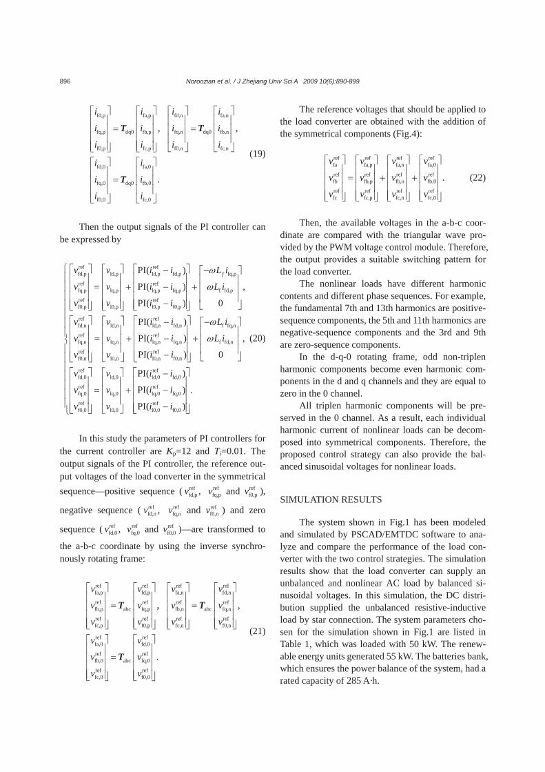
Fig.6a shows the unbalanced load phase currents.
As shown in Fig.6a, the load in phase a is discon-nected at t=1 s. It is found that the load phase currents are not sinusoidal. Fig.6b shows the simulation results in the case of a load converter with conventional d-q-0 controllers. In Fig.6b, it can be seen that the balanced voltages are not provided for the AC load while the load phase currents are not sinusoidal.
Fig.7 shows the load phase voltages in the d-q-0 reference frame. As shown in this figure, the refer-ence voltages generated by the d-q-0 controller and the generated voltage by load converters are not matching together, the vld, vlq and vl0 have a large ripple. In this case, the negative sequence unbalance is about 10%. It must be noted that the standards accept imbalances lower than 2% (Short, 2004).
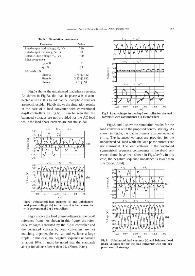
Figs.8 and 9 show the simulation results for the load converter with the proposed control strategy. As shown in Fig.8a, the load in phase a is disconnected at t=1 s. The balanced voltages are provided for the unbalanced AC load while the load phase currents are not sinusoidal. The load voltages in the developed symmetrical sequence components in the d-q-0 ref-erence frame have been shown in Figs.9a~9c. In this case, the negative sequence imbalance is lower than 1% (Short, 2004).
Table 1 Simulation parameters
Parameter Value Rated output load voltage, Vla (V) 230 Rated output frequency, f (Hz) 50 Rated DC bus voltage, Vdc (V) 750 Filter component
Lf (mH) 3 Rf (Ω) 0.1
AC loads (Ω) Phase a 1.75+j0.432 Phase b 3.25+j0.812 Phase c 7.5+j3.91
Fig.6 Unbalanced load currents (a) and unbalanced load phase voltages (b) in the case of a load converter with conventional d-q-0 controllers
t (s)
(a)
Volta
ge (V
) C
urre
nt (A
)
200150100
500
−50−100−150−200
ila ilb ilc
0.95 0.97 0.99 1.01 1.03 1.05
vla vlb vlc 400300200100
0−100−200−300−400
(b)
Fig.7 Load voltages in the d-q-0 controller for the load converter with conventional d-q-0 controllers
10
5
0
−5
−10
vld vldref
Volta
ge (V
)
360
340
320
300
280
vlq vlqref
t (s) 0.95 0.97 0.99 1.01 1.03 1.05
vl0 vl0ref
302010
0−10−20−30
Fig.8 Unbalanced load currents (a) and balanced load phase voltages (b) for the load converter with the pro-posed control strategy
vla vlb vlc
Volta
ge (V
) C
urre
nt (A
)
(b)
(a)
400300200100
0−100−200−300−400
0.95 0.97 0.99 1.01 1.03 1.05
ila ilb ilc 200150100
500
−50−100−150−200
t (s)
Noroozian et al. / J Zhejiang Univ Sci A 2009 10(6):890-899 898
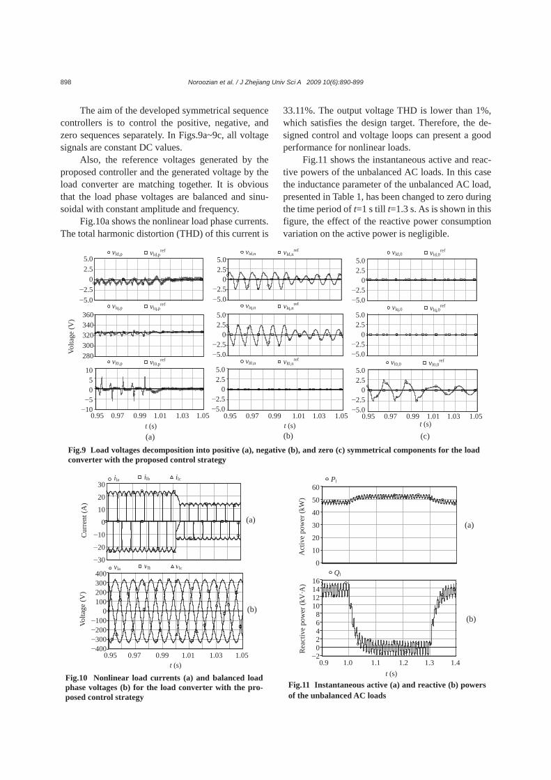
The aim of the developed symmetrical sequence controllers is to control the positive, negative, and zero sequences separately. In Figs.9a~9c, all voltage signals are constant DC values.
Also, the reference voltages generated by the proposed controller and the generated voltage by the load converter are matching together. It is obvious that the load phase voltages are balanced and sinu-soidal with constant amplitude and frequency.
Fig.10a shows the nonlinear load phase currents. The total harmonic distortion (THD) of this current is
33.11%. The output voltage THD is lower than 1%, which satisfies the design target. Therefore, the de-signed control and voltage loops can present a good performance for nonlinear loads.
Fig.11 shows the instantaneous active and reac-tive powers of the unbalanced AC loads. In this case the inductance parameter of the unbalanced AC load, presented in Table 1, has been changed to zero during the time period of t=1 s till t=1.3 s. As is shown in this figure, the effect of the reactive power consumption variation on the active power is negligible.
Fig.11 Instantaneous active (a) and reactive (b) powers
of the unbalanced AC loads
Ql
Rea
ctiv
e po
wer
(kV
·A)
(b)
16141210
86420−2
0.9 1.0 1.1 1.2 1.3 1.4 t (s)
Act
ive
pow
er (k
W)
(a)
60
50
40
30
20
10
0
Pl
Fig.10 Nonlinear load currents (a) and balanced load phase voltages (b) for the load converter with the pro-posed control strategy
ila ilb ilc
V
olta
ge (V
)
0.95 0.97 0.99 1.01 1.03 1.05
400300200100
0−100−200−300−400
30
20
10
0
−10
−20
−30
t (s)
(b)
(a)
Cur
rent
(A)
vla vlb vlc
Fig.9 Load voltages decomposition into positive (a), negative (b), and zero (c) symmetrical components for the load converter with the proposed control strategy
0.95 0.97 0.99 1.01 1.03 1.05
(b)(a)
1050−5−10
t (s)
Volta
ge (V
) 360340320300280
5.02.5
0−2.5−5.0
vld,p vld,pref
vlq,p vlq,pref
vl0,p vl0,pref
5.02.5
0−2.5−5.0
5.02.5
0−2.5−5.0
5.02.5
0−2.5−5.0
5.02.5
0−2.5−5.0
5.02.5
0−2.5−5.0
5.02.5
0−2.5−5.0
0.95 0.97 0.99 1.01 1.03 1.05 0.95 0.97 0.99 1.01 1.03 1.05
(c)
vld,n vld,nref
vlq,n vlq,nref
vl0,n vl0,nref
vld,0 vld,0ref
vlq,0 vlq,0ref
vl0,0 vl0,0ref
t (s) t (s)
Noroozian et al. / J Zhejiang Univ Sci A 2009 10(6):890-899 899
CONCLUSION
In this paper, the control of the load converter under unbalanced loading conditions for an isolated DC distribution system has been investigated, while the load converter model is presented and two dif-ferent control strategies are compared. The first one uses the conventional d-q-0 frame rotating controller with ω=314.159 rad/s and PI controllers to regulate the voltages and currents. The performances of this control strategy are insufficient. As a result, in this paper the proposed control strategy has been devel-oped. This strategy is based on the decomposition of the voltages and currents into instantaneous positive, negative, and zero sequence components. The de-composition method uses phasor representation. In this control strategy, the positive, negative, and zero sequences appear as DC signals in their own syn-chronously rotating reference frames. The inde-pendent control strategy makes it possible to elimi-nate the disturbance of the output voltage caused by the unbalanced load. Simulation results show the effectiveness of the proposed control strategy versus the conventional control strategy. References Blazic, B., Papic, I., 2004. A new mathematical model and
control of D-StatCom for operation under unbalanced conditions. Electr. Power Syst. Res., 72(3):279-287. [doi:10.1016/j.epsr.2004.04.012]
Daniel, S.A., AmmasaiGounden, N., 2004. A novel hybrid isolated generating system based on PV fed inverter- assisted wind-driven induction generators. IEEE Trans. Energy Conv., 19(2):416-422. [doi:10.1109/TEC.2004. 827031]
Kouji, F., Haque, M.T., Ise, T., Sadatoshi, K., 2004. A control strategy for active filters using quasi-instantaneous posi-tive sequence extraction filters. Electr. Eng. Jpn., 48(1): 54-65.
Lin, B.R., Lee, Y.C., 2004. Three-phase power quality com-pensator under the unbalanced sources and nonlinear loads. IEEE Trans. Power Electron., 51(5):1009-1017.
Lu, W., Ooi, B.T., 2005. Premium quality power park based on multi-terminal HVDC. IEEE Trans. Power Del., 20(2): 978-983. [doi:10.1109/TPWRD.2004.838633]
Saisho, M., Ise, T., Tsuji, K., 2002. Configuration of DC Loop Type Quality Control Center. Proc. Power Conversion Conf., Osaka, Japan, p.434-439. [doi:10.1109/PCC.2002. 997557]
Short, T., 2004. Electric Power Distribution Handbook. CRC Press, New York, USA.
Thandi, G.S., Zhang, R., Xing, K., Lee, F.C., Boroyevich, D., 1999. Modeling, control and stability analysis of a PEBB based DC DPS. IEEE Trans. Power Del., 14(2):497-505. [doi:10.1109/61.754094]
Vechiu, I., Camblong, H., Tapia, G., Dakyo, B., Curea, O., 2007. Control of four leg inverter for hybrid power sys-tem applications with unbalanced load. Energy Conv. Manag., 48(7):2119-2128. [doi:10.1016/j.enconman. 2006.12.019]
Zhang, R.S., 1998. High Performance Power Converter Sys-tem for Nonlinear and Unbalanced Load/Source. PhD Thesis, Department of Electrical and Computer Engi-neering, Virginia Polytechnic Institute and State Univer-sity, Blacksburg, Virginia, USA.